
Updates:
- 2022/08/25: extending for more details of
config.glimit switches - 2022/08/16: starting notes
Table of Contents
Introduction
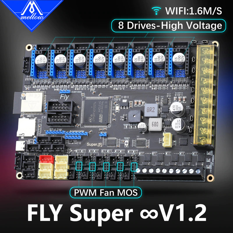
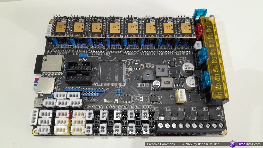
I have become a big fan of Duet3 boards running RepRapFirmware, and as I was looking for a suitable board, and I came across Mellow Fly Super8 V1.2 board, 8 steppers TMC 2209, and 4 possible hotends.
- STM42F407ZGT6 (ARM Cortex-M4), 168MHz, 1MB Flash, 192KB RAM
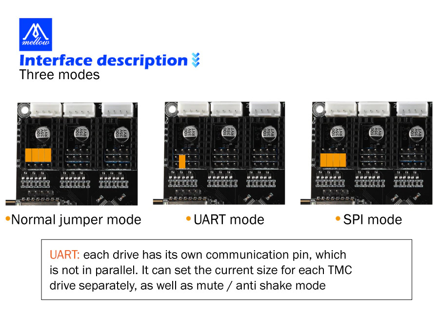
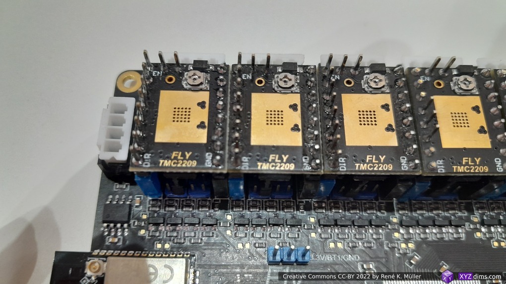
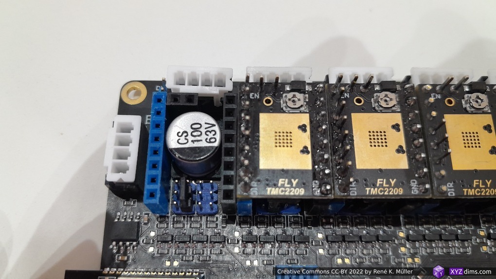
- 8 stepper drivers TMC2209, configured in UART mode
- 3x X, Y, Z(2 using splitter)
- 5x extruders
- Fly MINI 12864 display
- 12V power in/out
- 4 hotends & bed heating
- Price ~EUR 80 (2022/08) incl. 8 stepper drivers TMC 2209 and 12864 display
Pros:
- cost effective, EUR 80 (2022/08) with 8x stepper drivers TMC 2209 and 12864 display
- runs RepRapFirmware
- most configuration is done with
.gfiles using G-code notion - only new non-supported kinematics require recompiling
- most configuration is done with
- USB & Wifi connectivity (both simultaneously possible)
- relative simple configuration (compared to Marlin firmware)
Cons:
- no Ethernet (Wifi is less reliable)
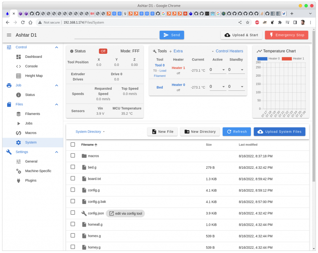
Software Configuration
Majority of configuration is done via a file-system on a SD card which contains a bunch of .g files which define basic settings of the board and machine it operates:
I operate the board direct with USB and Wifi, not in SBC (Single Board Computer) setup.
- download firmware, single .bin file from (e.g. firmware-stm32f4-wifi-3.4.1_102.bin) and put it into
/(root) folder and rename tofirmware.bin– it will vanish once installed on the board - download web GUI (e.g. DuetWebControl-SD.zip) and then unzip on the SD card, rename folder name as
www/ - run online configurator to get basic configuration
config.g,board.txtand multiple other files (all zipped together)- enable Wifi: enter your Wifi Name and Wifi Password
- you get a single zip file, unzip in the
/(root) folder
- insert SD card into the board, restart board
- eventually the board will join your Wifi network, scan the network to find out which IP it has, then access the board via web-browser, e.g. http://192.168.1.174/
I operate my 3D printers (3x Ashtar K, 1x Ashtar C, 1x CTC DIY I3 Pro) which use different controller boards all accessed via USB cables and Print3r as main interface (CLI) – having an additional Web-GUI aside allows to operate in parallel beside the USB connectivity.
- 12864 display with knob to configure on the printer
- USB connectivity to deliver print job
- Wifi connectivity to access printer via Web-GUI (simultaneously to USB connectivity)
Hardware Configuration
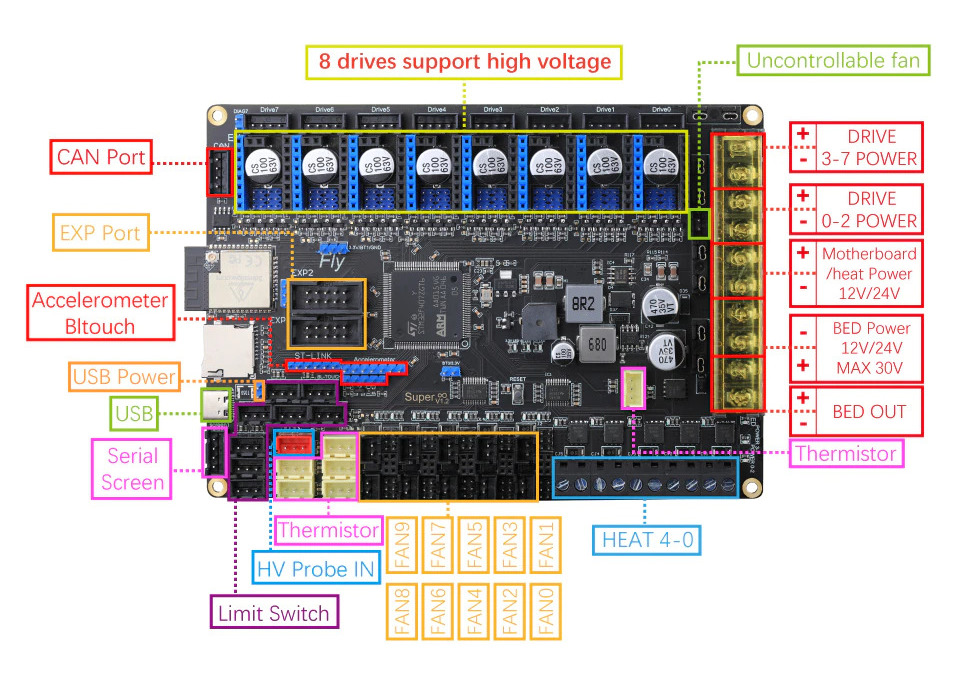
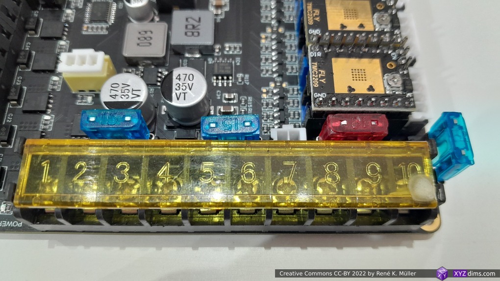
Important is to put the fuses first, otherwise the board won’t operate, further the stepper driver settings, pluggeable fan MOS, limit switches:
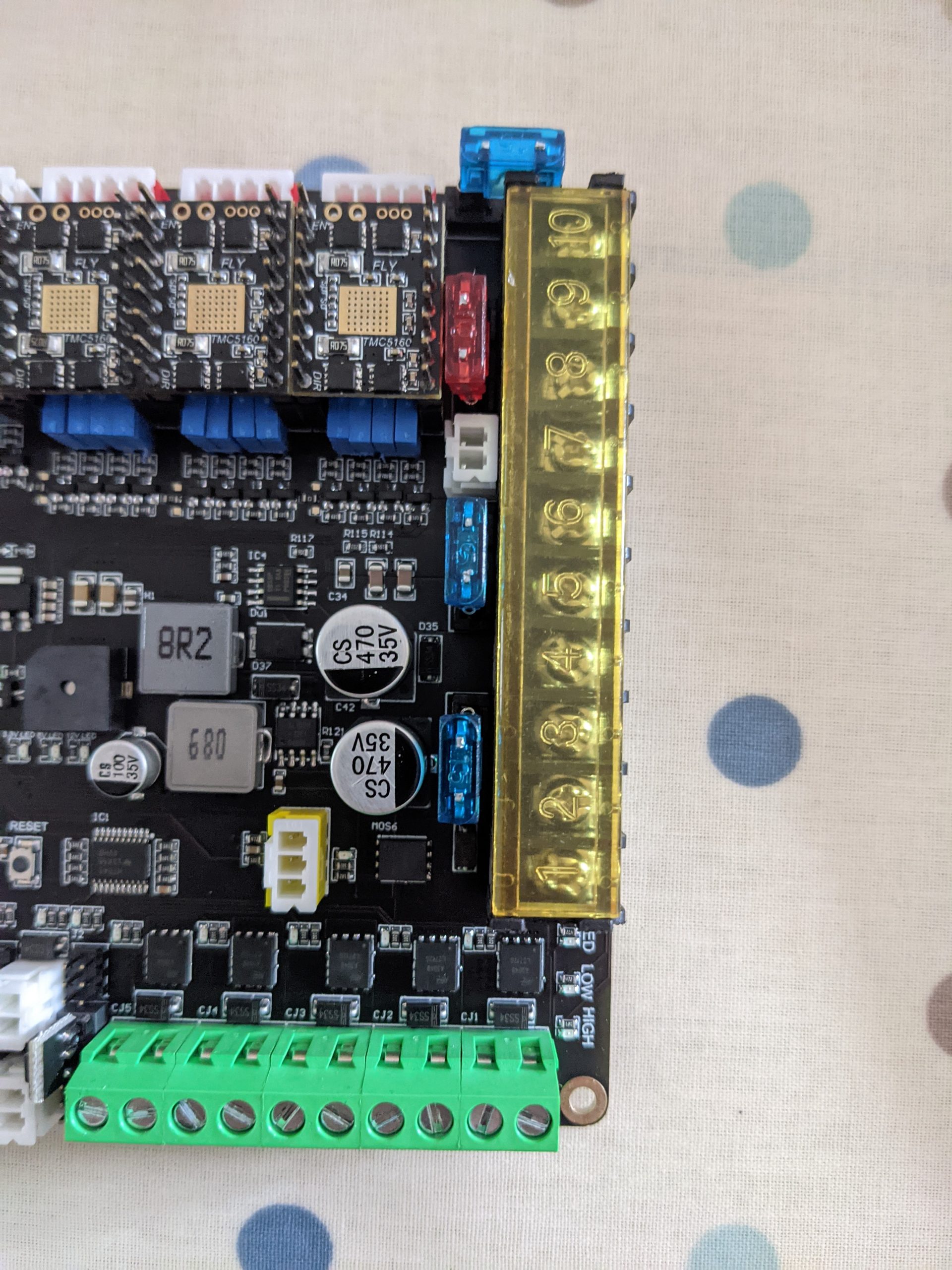


I configured the board first using simple USB power delivery, later when the 12V power supply is attached I remove the small jumper to avoid the USB powers the board.
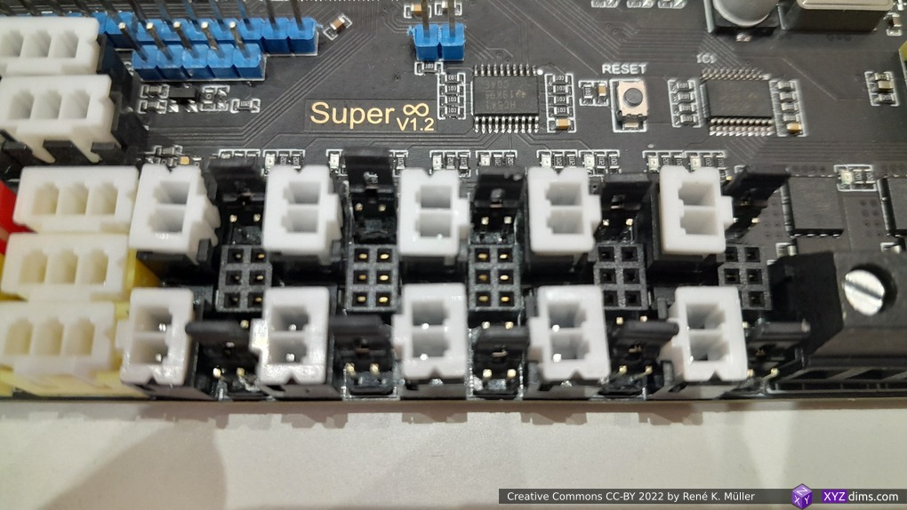
Limit Switches / Endstops
In config.g following lines define the limit switches / endstops:
; Endstops
M574 X1 S1 P"io0"                            ; configure switch-type (e.g. microswitch) endstop for low end on X via pin io0
M574 Y1 S1 P"io1"                            ; configure switch-type (e.g. microswitch) endstop for low end on Y via pin io1
M574 Z1 S1 P"io2"                            ; configure switch-type (e.g. microswitch) endstop for low end on Z via pin io2
therefore the endstops are laid out as such:
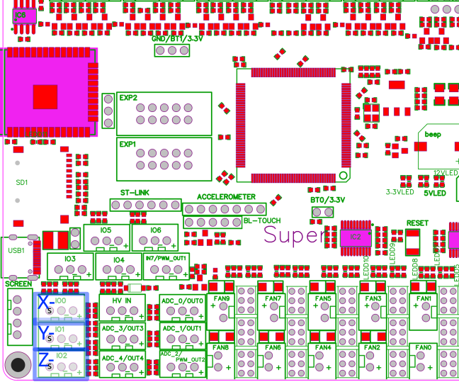
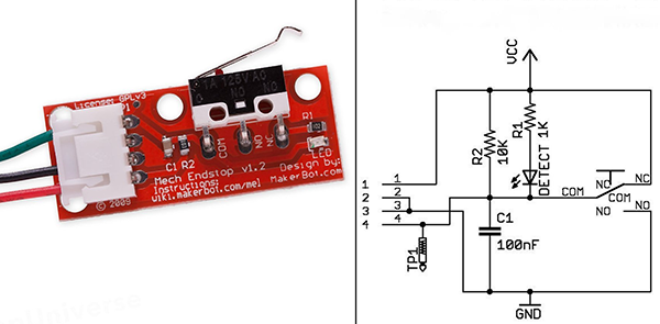
Attention: the limit switch with three wires must be inserted correctly, otherwise you short GND with 5V when pushing the switch. The proper layout of io[012] pins (left-to-right):
- Signal
- GND
- 5V
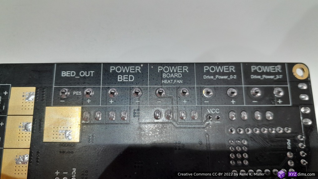
Bed Heating & Hotends
Given the config.g defines the heaters as such:
; Heaters
M308 S0 P"ADC_0" Y"thermistor" T100000 B4092 ; configure sensor 0 as thermistor on pin ADC_0
M950 H0 C"bed" T0                            ; create bed heater output on bed and map it to sensor 0
M307 H0 B0 S1.00                             ; disable bang-bang mode for the bed heater and set PWM limit
M140 H0                                      ; map heated bed to heater 0
M143 H0 S120                                 ; set temperature limit for heater 0 to 120C
M143 H0 S120                                 ; set temperature limit for heater 0 to 120C
M308 S1 P"ADC_1" Y"thermistor" T100000 B4092 ; configure sensor 1 as thermistor on pin ADC_1
M950 H1 C"heat0" T1                          ; create nozzle heater output on heat0 and map it to sensor 1
M307 H1 B0 S1.00                             ; disable bang-bang mode for heater  and set PWM limit
M143 H1 S280                                 ; set temperature limit for heater 1 to 280C

; Fans
M950 F0 C"fan0" Q500                         ; create fan 0 on pin fan0 and set its frequency
M106 P0 S0 H-1                               ; set fan 0 value. Thermostatic control is turned off
therefore the connections are:
- Bed Temperature Sensor ADC0
- Bed Heater BED_OUT
- Hotend 1 Temperature Sensor ADC1
- Hotend 1 Heater HEAT0
- Part Cooler FAN0
M503 Dump for Ashtar D
M503 dump for Ashtar D (Classic XY) with 400×400 bed, single extruder:
> M503
; Configuration file for Fly Super8 (firmware version 3)
; executed by the firmware on start-up
;
; generated by RepRapFirmware Configuration Tool v3.4.0-LPC-STM32+4 on Tue Aug 16 2022 20:32:44 GMT+0200 (Central European Summer Time)

; General preferences
G90                                          ; send absolute coordinates...
M83                                          ; ...but relative extruder moves
M550 P"Ashtar D1"                            ; set printer name
;M669 K1                                      ; select CoreXY mode

; Network
M552 S1                                      ; enable network
M586 P0 S1                                   ; enable HTTP
M586 P1 S0                                   ; disable FTP
M586 P2 S0                                   ; disable Telnet

; Drives
M569 P0 S1                                   ; physical drive 0 goes forwards using default driver timings
M569 P1 S1                                   ; physical drive 1 goes forwards using default driver timings
M569 P2 S1                                   ; physical drive 2 goes forwards using default driver timings
M569 P3 S1                                   ; physical drive 3 goes forwards using default driver timings
M569 P4 S1                                   ; physical drive 4 goes forwards using default driver timings
M584 X0 Y1 Z2:3 E4:5                         ; set drive mapping: Z drivers port 3&4, E drives 4&5
M350 X16 Y16 Z16 E16 I1                      ; configure microstepping with interpolation
M92 X80.00 Y80.00 Z3200.00 E420.00            ; set steps per mm
M566 X900.00 Y900.00 Z30.00 E120.00          ; set maximum instantaneous speed changes (mm/min)
M203 X6000.00 Y6000.00 Z150.00 E1200.00      ; set maximum speeds (mm/min)
M201 X500.00 Y500.00 Z20.00 E250.00          ; set accelerations (mm/s^2)
M906 X800 Y800 Z800 E800 I30                 ; set motor currents (mA) and motor idle factor in per cent
M84 S30                                      ; Set idle timeout

; Axis Limits
M208 X0 Y0 Z0 S1                             ; set axis minima
M208 X380 Y380 Z380 S0                       ; set axis maxima

; Endstops
M574 X1 S1 P"!io0"                            ; configure switch-type (e.g. microswitch) endstop for low end on X via pin io0
M574 Y1 S1 P"!io1"                            ; configure switch-type (e.g. microswitch) endstop for low end on Y via pin io1
M574 Z1 S1 P"!io2"                            ; configure switch-type (e.g. microswitch) endstop for low end on Z via pin io2

; Z-Probe
;M558 P0 H5 F120 T6000                        ; disable Z probe but set dive height, probe speed and travel speed
;M557 X15:215 Y15:195 S20                     ; define mesh grid

; Heaters
M308 S0 P"ADC_0" Y"thermistor" T100000 B4092 ; configure sensor 0 as thermistor on pin ADC_0
M950 H0 C"bed" T0                            ; create bed heater output on bed and map it to sensor 0
M307 H0 B0 S1.00                             ; disable bang-bang mode for the bed heater and set PWM limit
M140 H0                                      ; map heated bed to heater 0
M143 H0 S120                                 ; set temperature limit for heater 0 to 120C
M143 H0 S120                                 ; set temperature limit for heater 0 to 120C
M308 S1 P"ADC_1" Y"thermistor" T100000 B4092 ; configure sensor 1 as thermistor on pin ADC_1
M950 H1 C"heat0" T1                          ; create nozzle heater output on heat0 and map it to sensor 1
M307 H1 B0 S1.00                             ; disable bang-bang mode for heater  and set PWM limit
M143 H1 S280                                 ; set temperature limit for heater 1 to 280C

; Fans
M950 F0 C"fan0" Q500                         ; create fan 0 on pin fan0 and set its frequency
M106 P0 S0 H-1                               ; set fan 0 value. Thermostatic control is turned off

; Tools
M563 P0 D0 H1 F0                             ; define tool 0
G10 P0 X0 Y0 Z0                              ; set tool 0 axis offsets
G10 P0 R0 S0                                 ; set initial tool 0 active and standby temperatures to 0C

; Custom settings are not defined

; Miscellaneous
M501                                         ; load saved parameters from non-volatile memory

; 12864 Display                              ; https://teamgloomy.github.io/fly_super8_screen_12864.html
;M950 P1 C"LCD_D4"
;M42 P1 S0
;G4 P500
;M42 P1 S1
;M918 P2 C30 F100000 E4

; M918 P1 E-4 F2000000                        ; https://github.com/jadonmmiller/UltimateDuetMenuSystem

M950 P1 C"LCD_D4"
M42 P1 S0
G4 P500
M42 P1 S1
M918 P2 C30 F100000 E4
Multiple Materials/Colors
With 8 stepper drivers one is able to run:
- 3x motors for X, Y, Z(2) – attach two Z stepper motors to one driver via splitter
- 5x extruders (colors or materials), the board supports 4 hotends (4 different temperatures)
Gallery
Board Comparison 2022
As of 2022 (I intend to update this) following boards are suitable for my cases:
| MKS Monster8 V1.0/V2.0 & 12864 display | Mellow Fly Super8 V1.2 & 12864 display | Duet 3 Mini 5+ & Duet 3 Mini 2+ | Duet 3 MB 6HC & Duet 3 Expansion 3HC | |
| Price | 55 EUR | 80 EUR | 155 EUR (120+35) | 385 EUR (255+130) |
| Stepper Drivers | 8 | 8 | 7 (5+2) | 9 (6+3) |
| Stepper Connectors | 9 (dual Z) | 8 | 7 | 9 |
| Hotends | 3 | 4 | 5 (2+3) | 6 (3+3) |
| USB | YES (USB-C) | YES (USB-C) | YES (MicroUSB) | YES (MicroUSB) |
| WIFI | – / YES3) | YES | YES1) | YES1) |
| Ethernet | – | – | YES1) | YES1) |
| Firmware | Marlin 2.x | Marlin 2.x RepRapFirmware 3.4.x | RepRapFirmware | RepRapFirmware |
Alternatively, there are Duet 2 & 3 clones available on the market:
| Duet 2 WIFI Clone | Duet 2 WIFI Original | Duet 3 6HC FYSETC Clone with Duet 3 3HC | Duet 3 6HC Original with Duet 3 3HC | |
| Price | 30-50 EUR2) | 175-185 EUR1) | 225 EUR (150+75) | 385 EUR (255+130) |
| Stepper Drivers | 5 | 5 | 9 (6+3) | 9 (6+3) |
| Stepper Connectors | 6 | 6 | 9 | 9 |
| Hotends | 2 | 2 | 7 (4+3) | 6 (3+3) |
| USB | YES (MicroUSB) | YES (MicroUSB) | YES (MicroUSB) | YES (MicroUSB) |
| WIFI | YES | YES1) | – | YES1) |
| Ethernet | – | YES1) | YES | YES1) |
| Firmware | RepRapFirmware | RepRapFirmware | RepRapFirmware | RepRapFirmware |
- either WIFI or Ethernet
- without or with display
- MKS Monster8 V2.0 has Wifi module option
As of 2022, RepRapFirmware has become quasi standard in professional level 3D printing; while a lot of people run Klipper & Marlin together I can’t see the point doing this*) but rather have a more capable microcontroller like the Duet boards have to run the printer and manage WIFI / Ethernet at the same time. The only reason to run Klipper on a Single Board Computer (SBC) setup like Raspberry Pi is cost and enhance simple microcontrollers functionality this way.
| Marlin | Klipper & Marlin | RepRapFirmware with Duet | |
| CPUs | 1x Simple Microntroller | 1x SBC + 1x Simple Microcontroller | 1x Capable Microcontroller |
| Connectivity | USB only | USB, Ethernet and/or WIFI | USB and Ethernet or WIFI |
| Configuration | 3x .h files, recompiling required | single .cfg file | single .g file**) |
| Boot Time | 3s | Klipper 30s, Marlin 3s | 3s |
*) running different kinematics on the SBC converting G-code on the fly might be a reason
**) multiple .g file can be used optionally
If you are cheap, buy the Duet clones, if you want to support Open Source and Open Hardware community, buy from Duet3d.com direct, pricing is +45% of the clone prices, whereas the Duet resellers add another +15% (Clone: EUR 150, Duet3d.com: 220 EUR, Reseller 255 EUR)
RepRapFirmware: Mind the SD Card
Whether to run an original Duet board or a clone, one thing though one might pay attention to is the SD card, it is the weakest link as far I can tell:
- SD card needs to be present at all time to provide configuration
- SD card is not written regularly to unless the logging is enabled
After power-cycling the board, as it was in a strange state no longer responding to G-code properly, the display remained blank, no response to G0/G1 – after investigation it turned out, a single file vanished from the SD card: config.g – the main configuration file, and that is bizarre. The board appeared to be broken, when in truth, the SD card came to its end of life of operating reliably already after only ~1.5 years. The SD card was the one originally shipped with. In this light, a Marlin-based board requiring no SD card being present operates more reliable, unless one uses an industrial grade SD card.
