Status: This is a work in progress – and will likely will receive more updates, files not yet released.
Updates
- 2018/09/14: Added H Plate (4 wheels) and h_plate() reference.
- 2018/09/01: Added v_plate() variables and numbers for common wheels
- 2018/07/28: Adding another example with Z axis X gantry adapter & X gantry horizontal beam mount.
- 2018/07/21: Supporting Delrin R 21.5 or 23mm/7mm wheel as well.
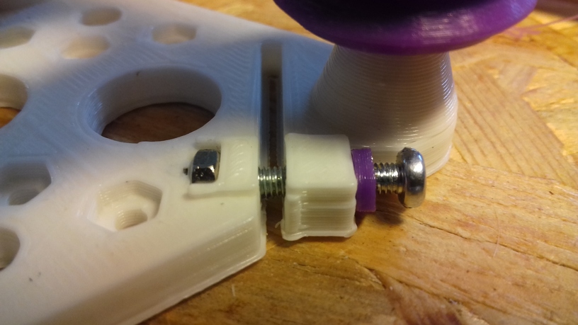
- 2018/07/20: Version 0.6 added, with ordered mounting holes and nut insets, screw which controls distance inside the plate to reduce overhead
- 2018/07/19: New version 0.2 with M3 has controlling distance of the 3rd wheel
- 2018/07/17: First basic design (Version 0.1), few tests made
Introduction
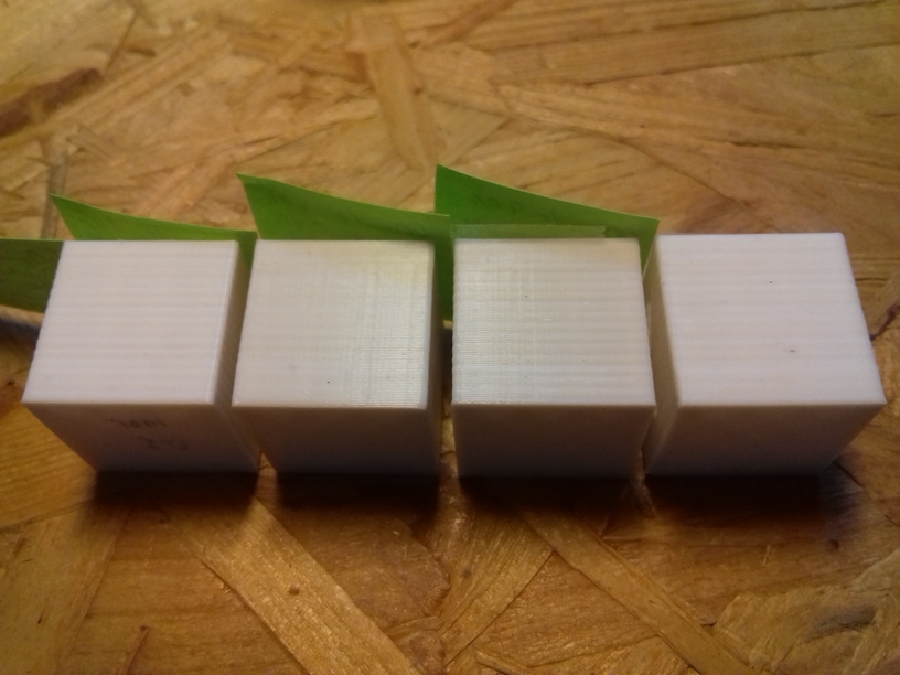
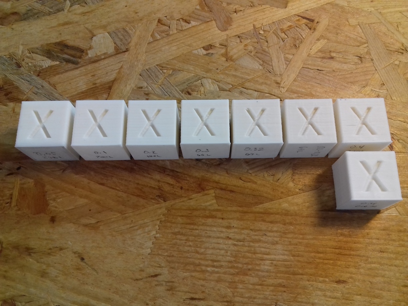
As part of developing various designs around Aluminium extrusions, a few tests. Early tests I printed the wheels in PLA just for sake of testing the dynamics, once the wheels arrived real applications were sought:
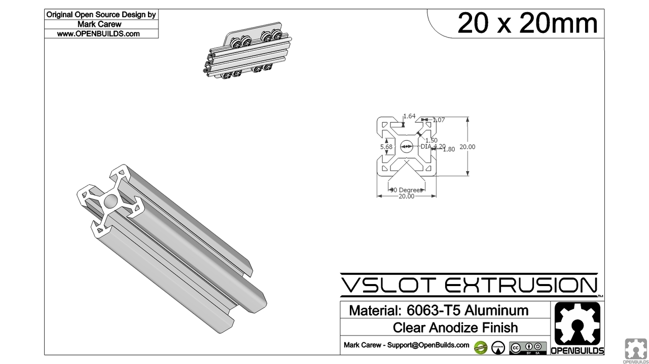
The possible parts are 2020 alu extrusions and Dual V wheel by OpenRail:
-
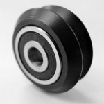
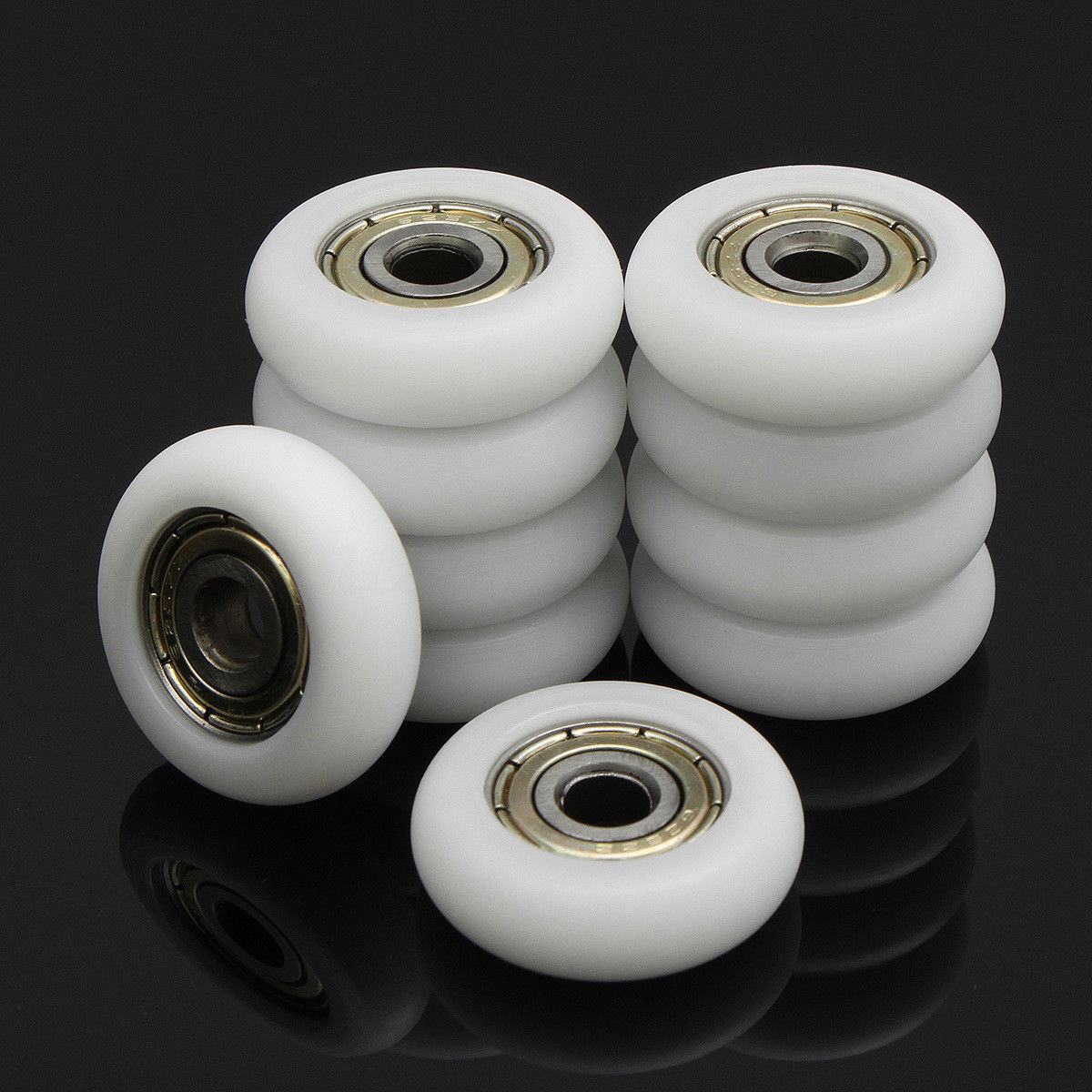
- V Wheel
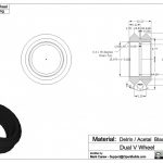
and the “Delrin R” V type nylon wheel (21.5/23mm diameter, 7/7.3mm thickness and 5mm hole):
Later in the research the difference between 7.0mm and 7.3mm thickness nylon wheels were significantly, as the shape of the wheel differ, and the ticker one (7.3mm) actually sat better in the T slot groove.
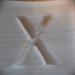
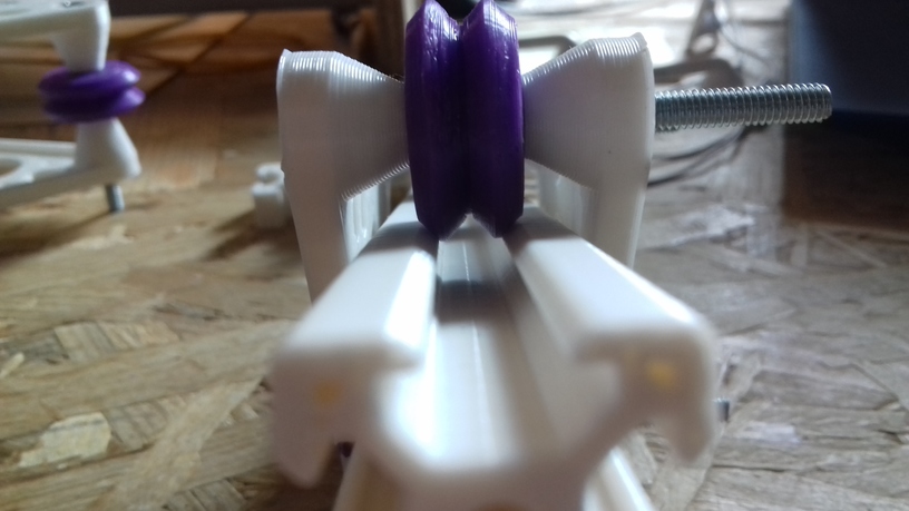
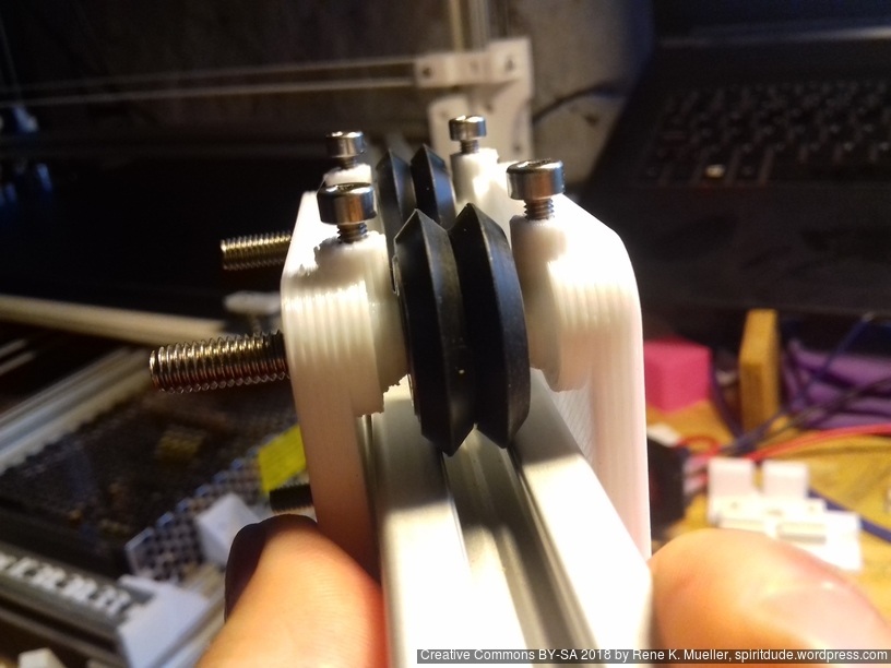
2020 V-Slot with Double V Wheels
The V-Slot alu extrusions usage test.
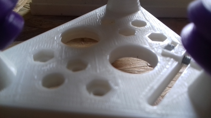
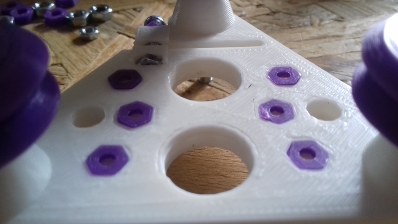
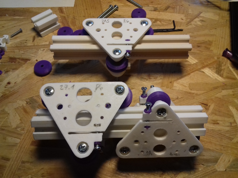
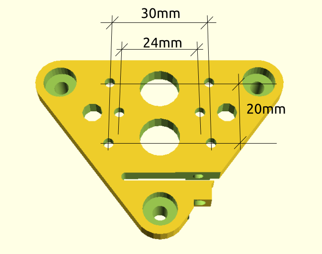
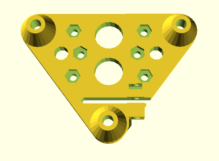
V Plate (Version 0.6)
Ordered mounting holes (2x 30mm apart horizontally x 2 20mm vertically apart) plus 24mm apart near center, all with M3 nut insets so both surfaces (inside and outside) are nearly flat and mounts easily attached.
Hole-to-hole distance: 40.5mm (20.5 + 20)
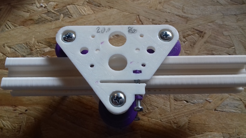

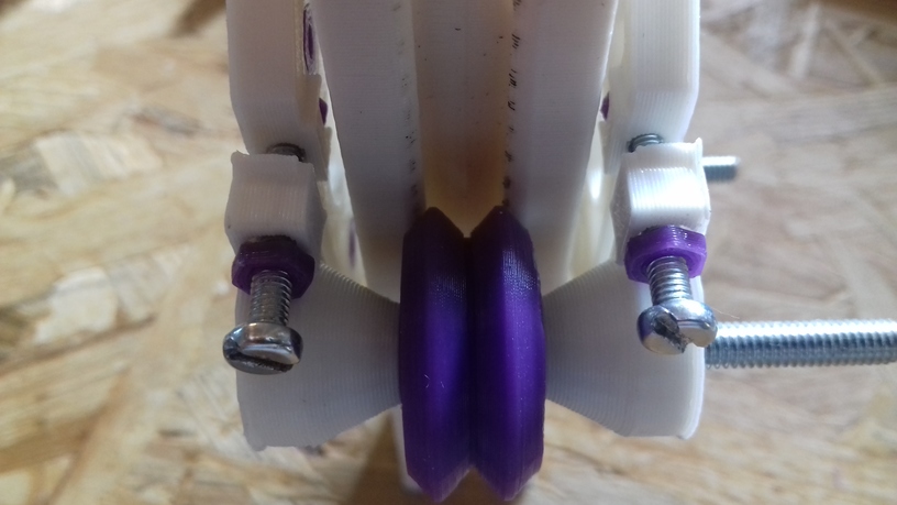
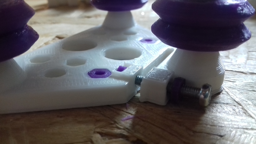
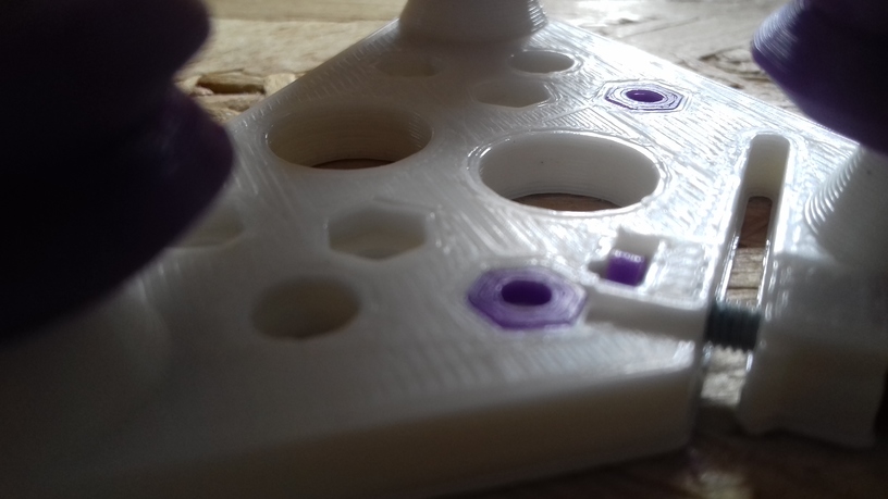
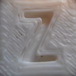
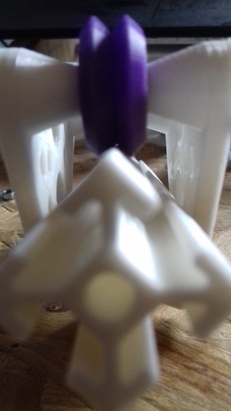
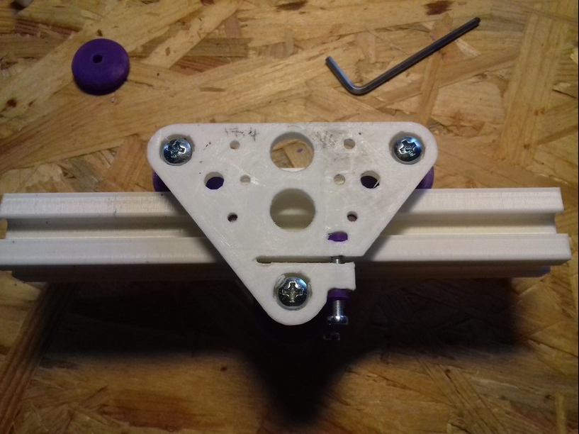
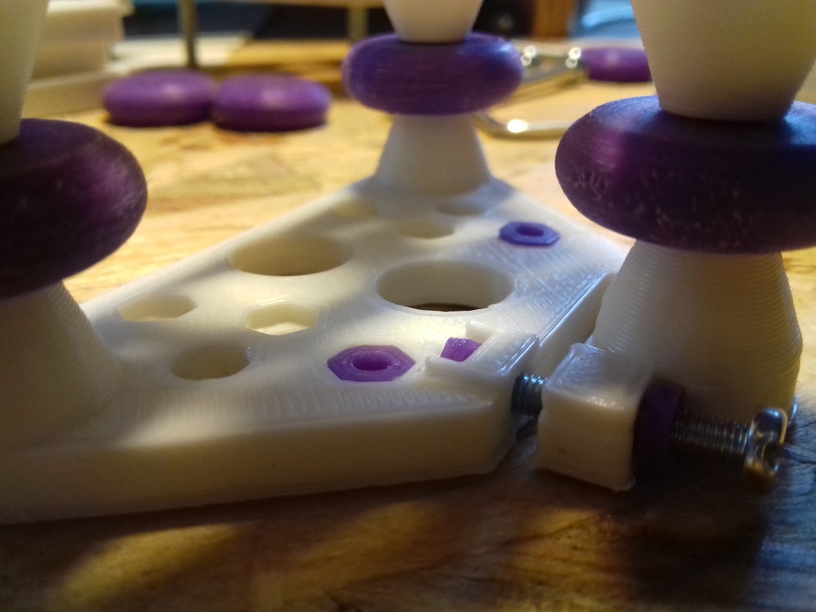
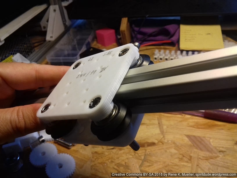
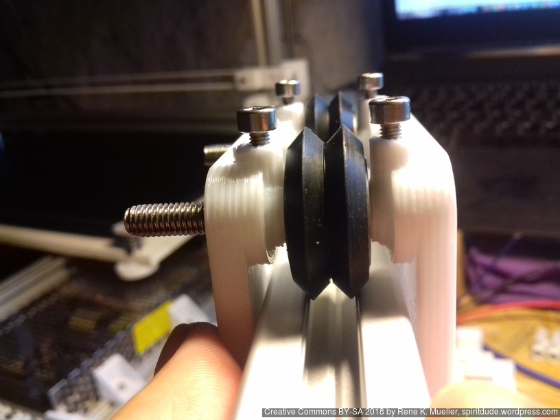
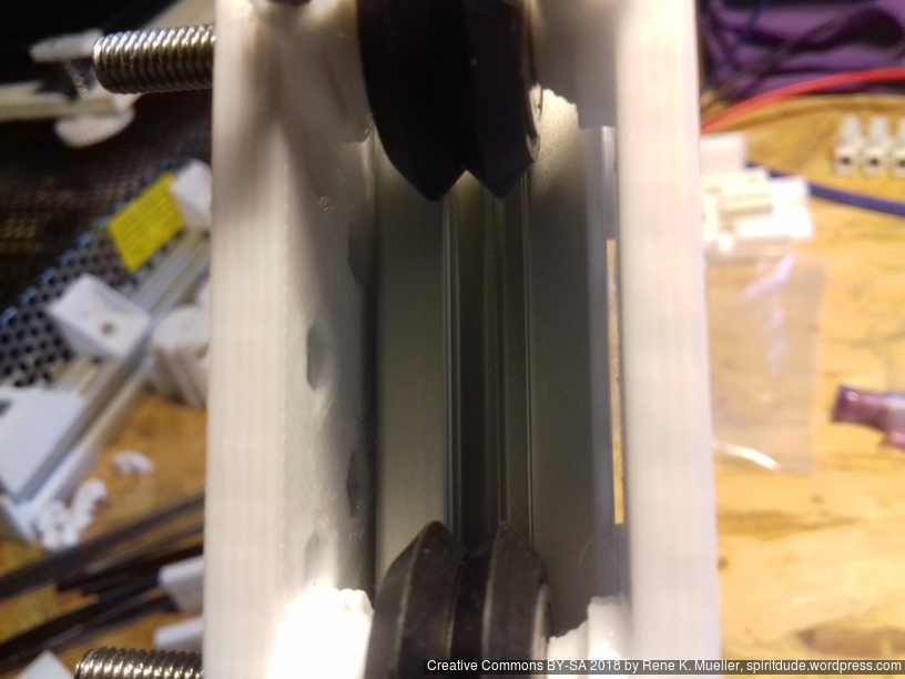
2020 T-Slot Diagonal with Double V Wheel
Using the traditional T-slot Aluminium extrusion without proper wheel groove but rotating so the edges are used as rail and the 90 degree inner groove of the Dual V wheel.

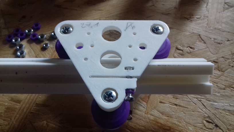
Version 0.6
Moving the adjuster into the plate to save some space, and adding some insets for the M3 mount holes (2x 30mm apart and 20mm height distance, 2x 24mm apart (Prusa i3 extruder).
Hole-to-hole distance: 47.1mm (27.1 + 20)
2020 T-Slot with Delrin R Wheels
Since the V plate is parametric designed (controlling thickness, distances etc) I thought to support also the “Delrin R” nylon wheels:
V Plate (Version 0.6)
Hole-to-hole distance:
- 21.5mm diameter wheel: 37.4mm (17.4 + 20)
- 23.0mm diameter wheel: 38.9mm (18.9 + 20)


V-Slot vs Diagonal
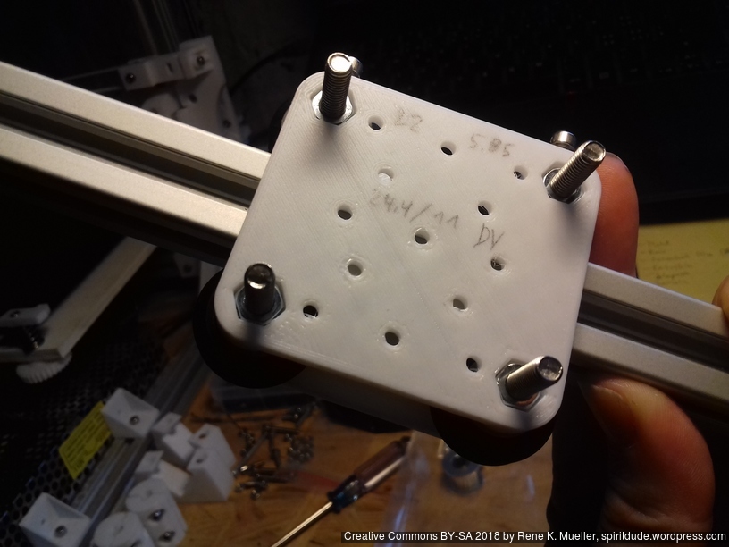
Mounting Holes
Since the V plate, either used with V Slot alu profile or diagonal, has 6 fixed holes with nut insets to attach adapters:
- 2x 30mm apart horizontally, 2nd row 20mm apart vertically
- 2x 24mm apart horizontally centered vertically on the plate
An adapter plate or area of 40 x 35mm is guaranteed to be flat, and 5mm thick, with the given mounting holes as mentioned.
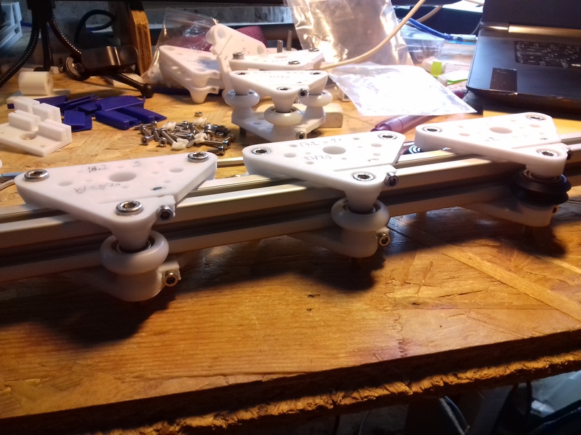
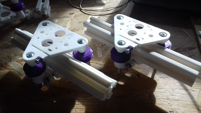
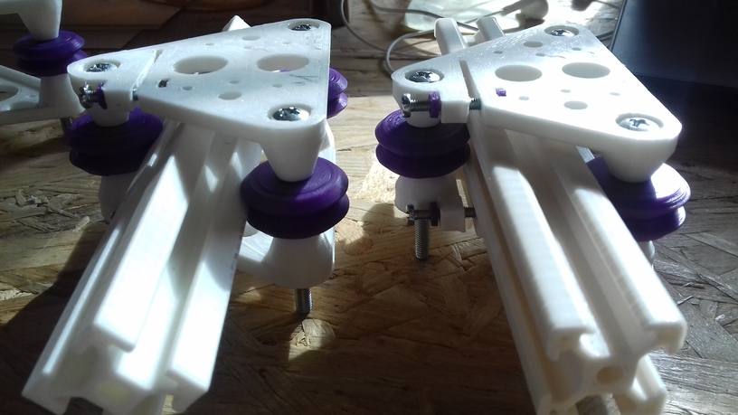
Usage
2x V plates (top/bottom) with its 3x wheels each are made so I can use it as a “V module”:
Prusa i3 Style
- X extruder: 1x V module with extruder adapter
- X gantry: 2x V module with Z axis threaded rod adapter
- Y gantry: 3x V module without adapter, but mounting top V plates direct to Y carriage
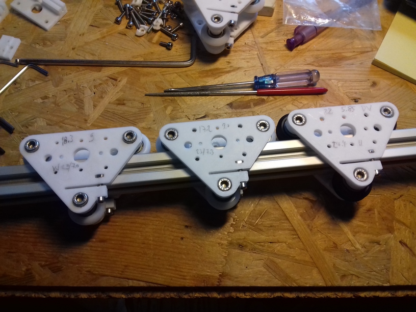
OpenSCAD v_plate()
v_plate() takes multiple arguments:
- d: distance of holes (-20mm)
- h: height/distance of the wheel to plate
- orientation: -1 or 1 (back / front)
- f: multiplier horizontal distance gap (default: 1)
- g: multiplier vertical distance gap (default: 1)
Here for 2020 T Slot B-Type in groove usage:
- Nylon wheel 23.0mm OD / 7.3mm width: d=17.2, h=9.0
- Nylon wheel 23.00mm OD / 7.0mm width: d=18.3, h=9.0
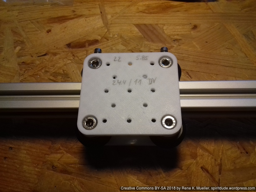
- OpenRail Double V 24.4mm OD / 11mm width: d=22.0, h=5.85
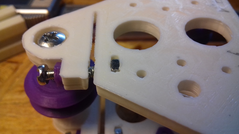
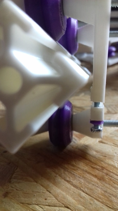
Use
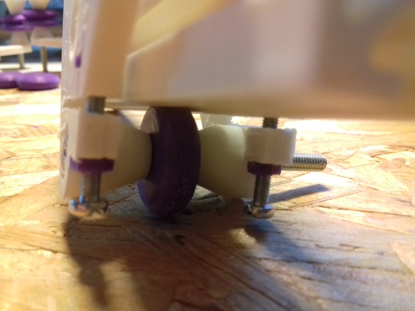
- 1x screw M3 x 16 with M3 nut (push it carefully yet forcefully so it aligns top/bottom flat) for distance control, put a drop of oil on the tip of the M3 screw before you screw the first time.
- 3x screw M5 x 30mm with cylinder head with hex inset, and 3 M5 nuts to mount the wheels per double V plate to make up a V module
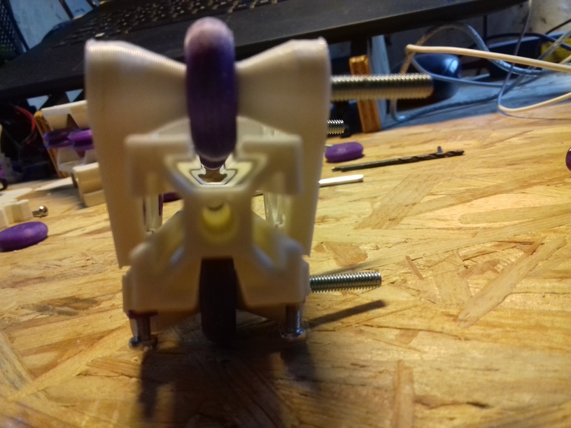
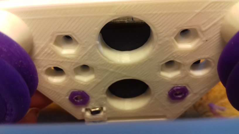
Four Wheels: H Plate
For the X carriage with the hotend I thought to add another wheel to improve tilt rigidity (e.g. when overruning bumpy unclean or over-extrusions) – ideally triangle like with V plate/module it’s easy to adjust, four wheels means two wheels need to be adjustable, and those are harder to align properly.
H Plate (Version 0.1)
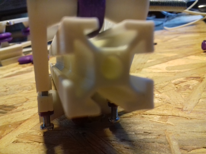
First version I decided to use a simple solution, have some larger vertical extended 5mm holes and M3 screw which carves its own thread to control the distance – this means the H plate should be used in double to make up a H module, this is the short/narrow 48mm wide H plate:
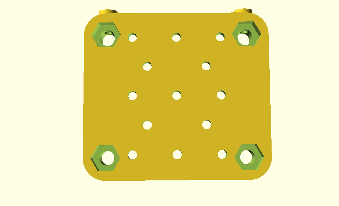
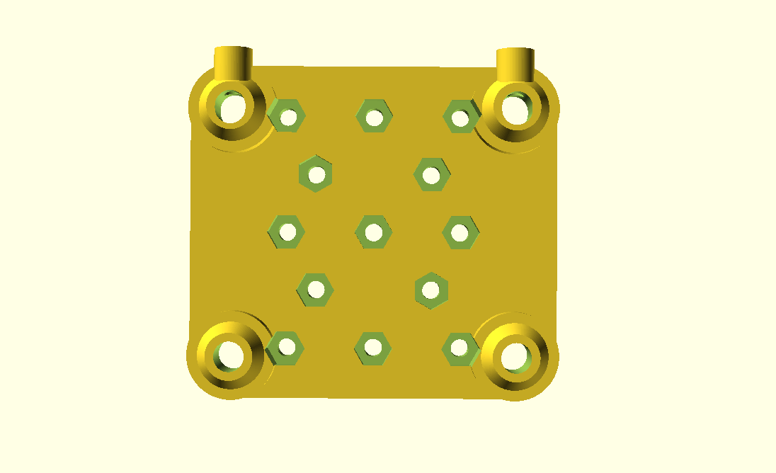
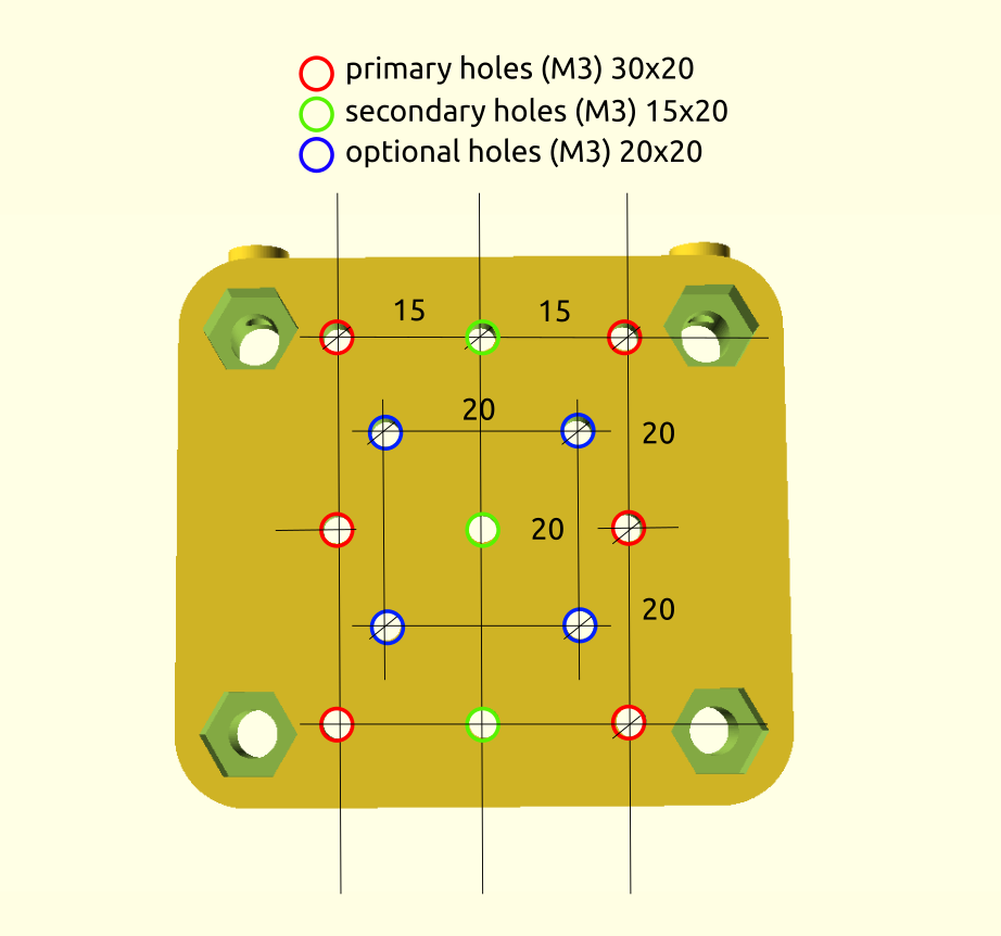
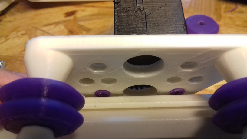
The plate contains a set of 30mm and 20mm spaced mounting holes, all M3 – requires support from bed only (not “everywhere”) so the M5 nut and screw heads insets are printed nicely for the wheels:

h_plate() settings – same as for v_plate():
- Nylon wheel 23.0mm OD / 7.3mm width: d=17.2, h=9.0
- Nylon wheel 23.00mm OD / 7.0mm width: d=18.3, h=9.0
- OpenRail Double V 24.4mm OD / 11mm width: d=22, h=5.85
For the short version, width=48 (less won’t work).
Examples
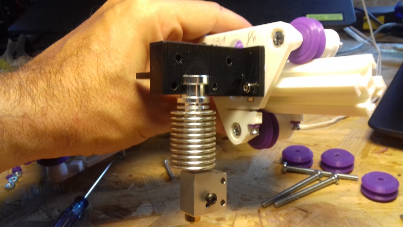
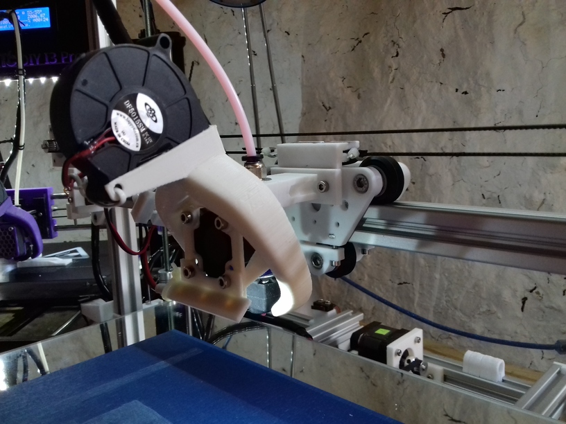
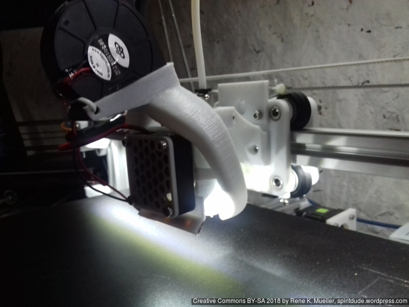
Extruder/Hotend Adapter
Attaching E3D V6 hotend on a pair of 30mm holes with M3x8 (M3x10 might work as well) with M3 nuts (in this example printed in purple PLA):
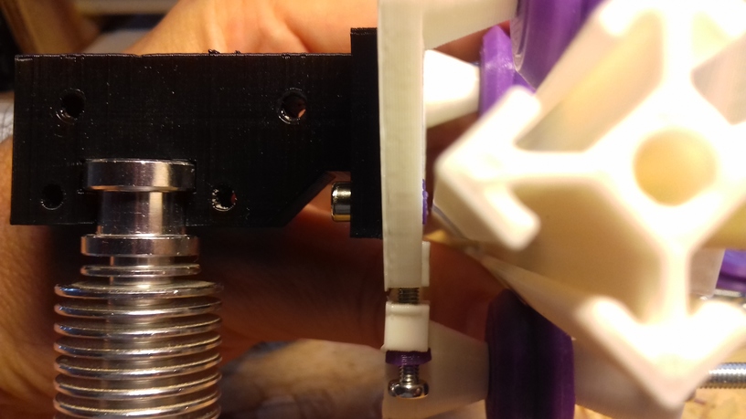

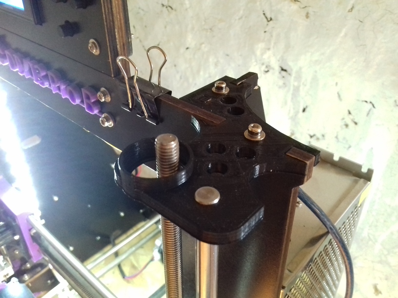
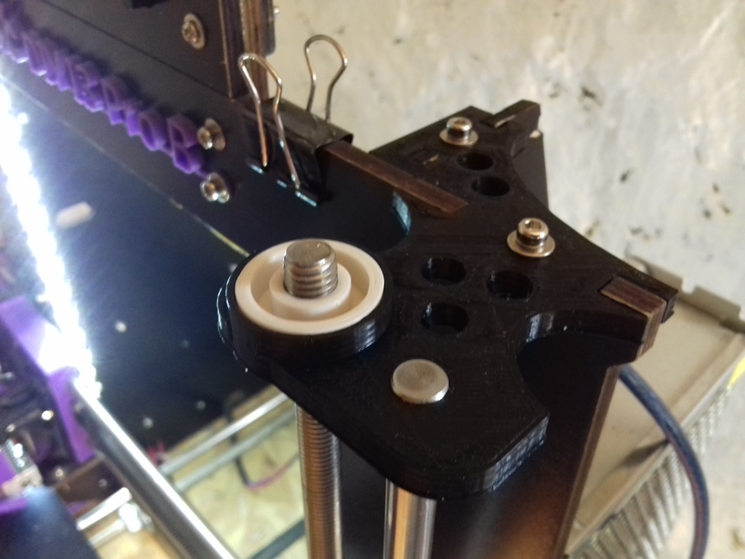
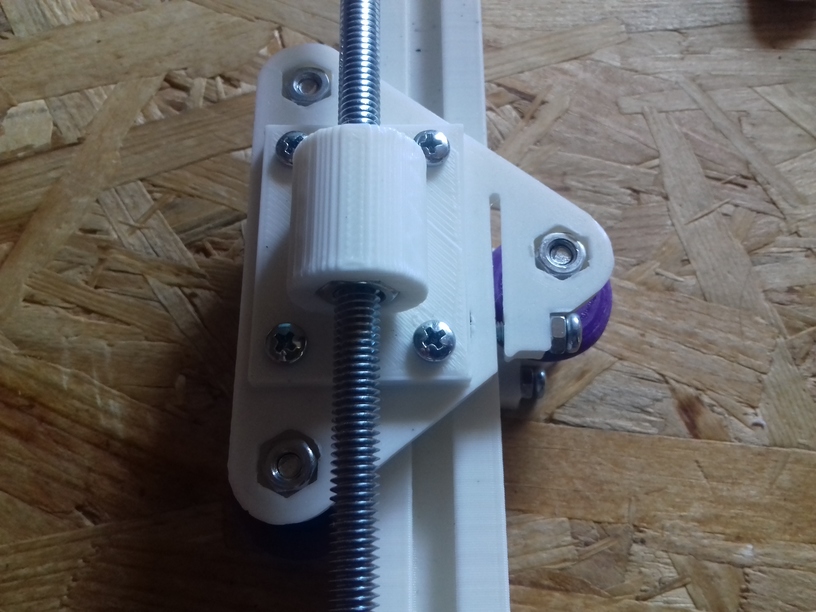
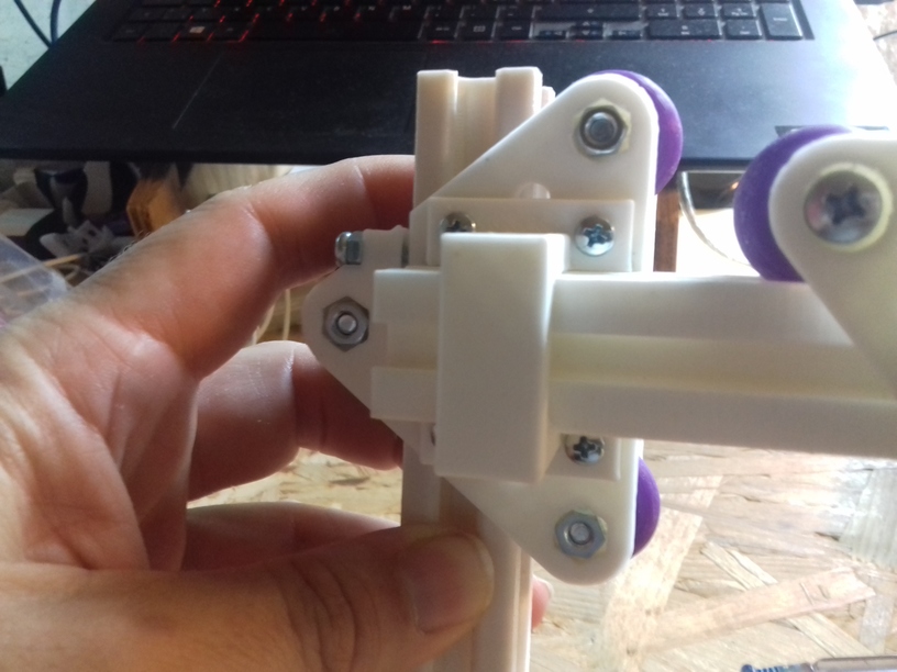
Z Axis Adapter
A simple Z axis adapter, here with M6 threaded rod with M6 nut:
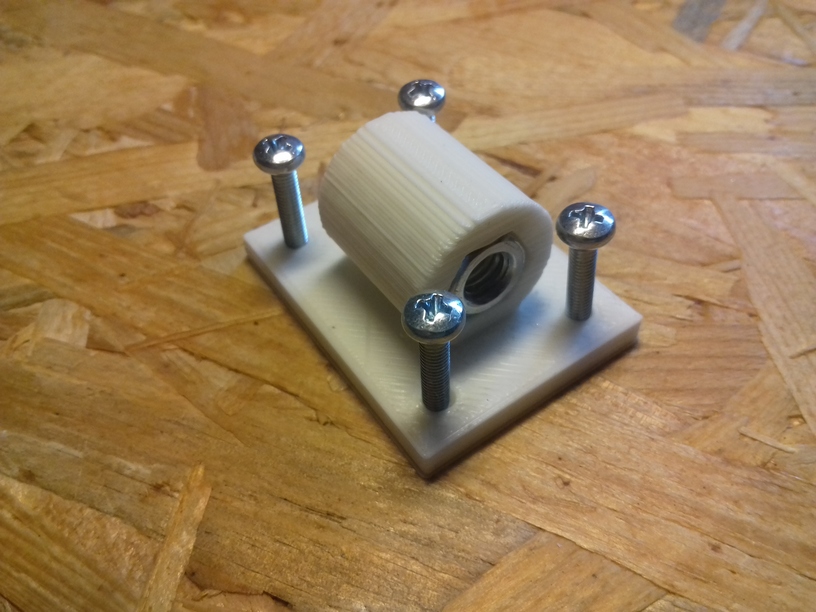
The adapter is 4mm thick, and M3 x 10 should work (in this example I used M3 x 16 which are too long, but still work).
X Gantry Horizontal Beam Mount
A small simple piece to mount the 2020 horizontal X axis on Z axis V module:
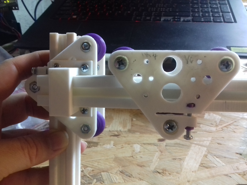
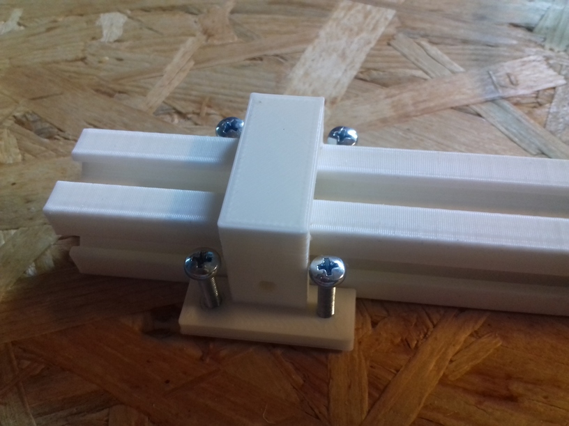
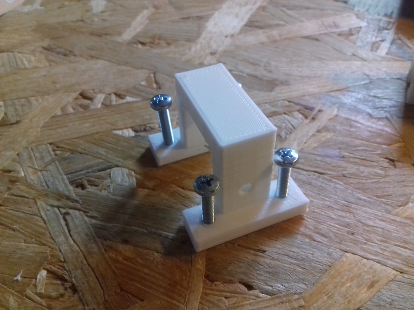
Additional holes to fasten beam with T nuts as well (top and bottom of the bridge).
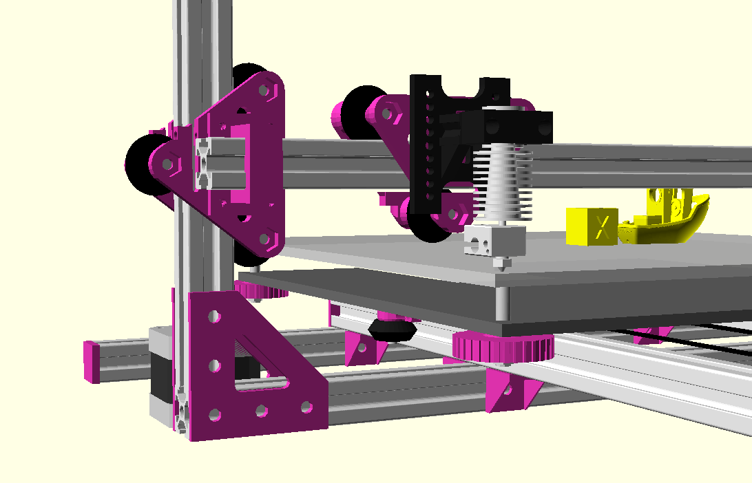
V and H modules used as part of the Ashtar K 3D Printer:
Related Projects
- D-Slot (Diagonal V-Slot)
- Cheap Roller Carriage for DLT-180 (Chinese Kossel 2020)
- Phineas 3DP: 2020 based Delta
End of Page