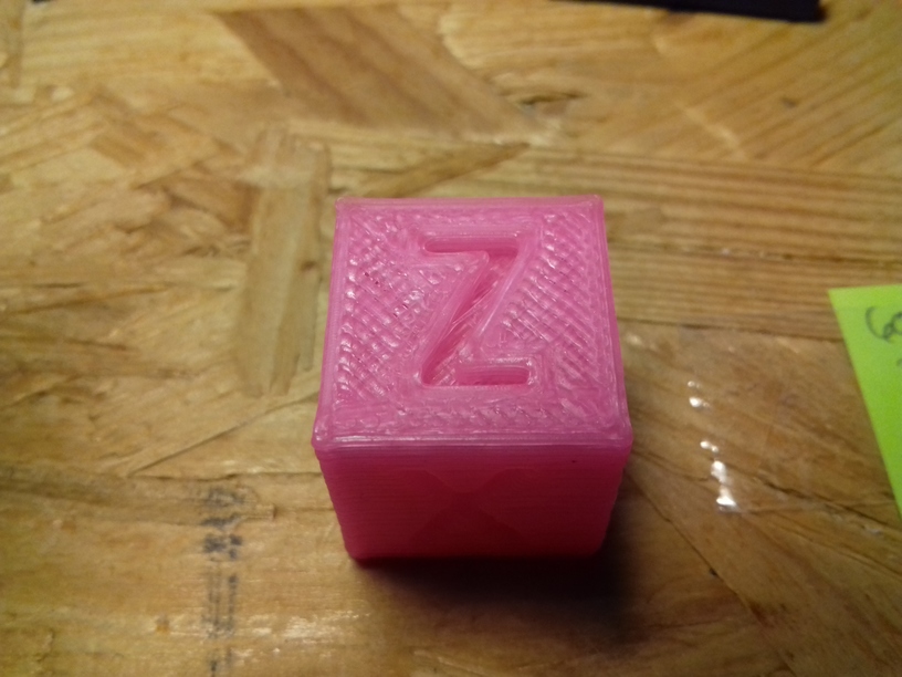
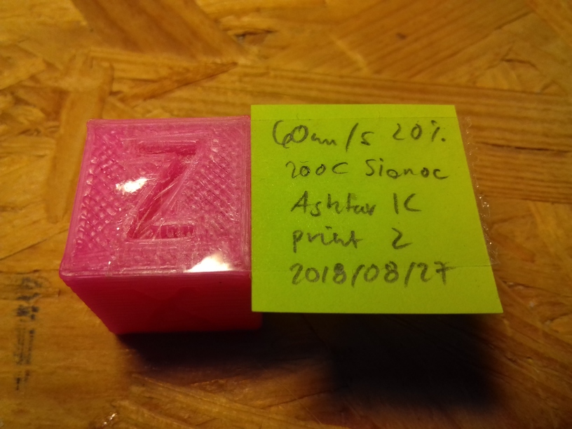
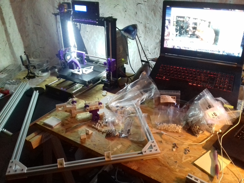
Well, after merely 3 months (2018/06/06) when I started to code the first lines of OpenSCAD to develop a series of parametric Prusa i3-like designs, and few weeks ago decided to go with the “K” series with 2020 alu profiles: simple 11x 500mm beam T slot (B-Type) alu profiles – the 1st prototype happen to print the 20mm XYZ Calibration Cube as of 2018/08/27:
-
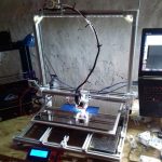
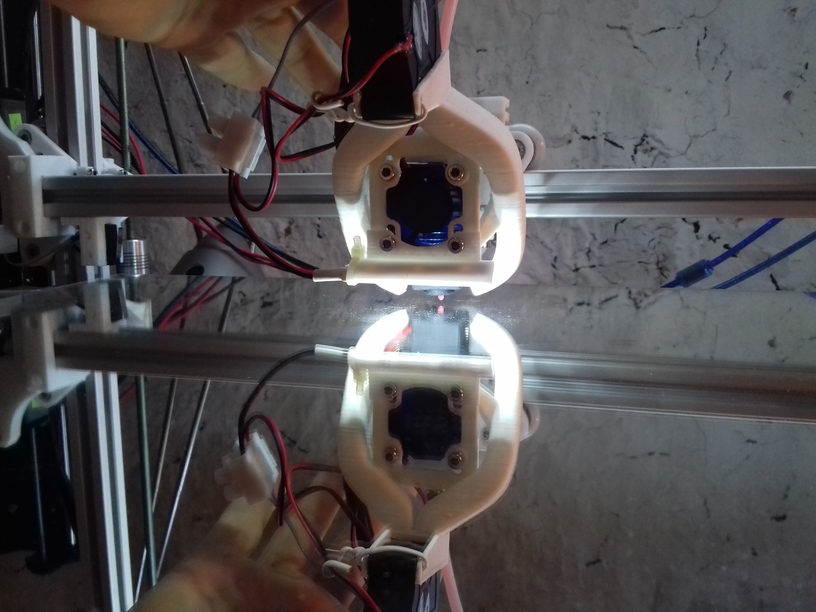
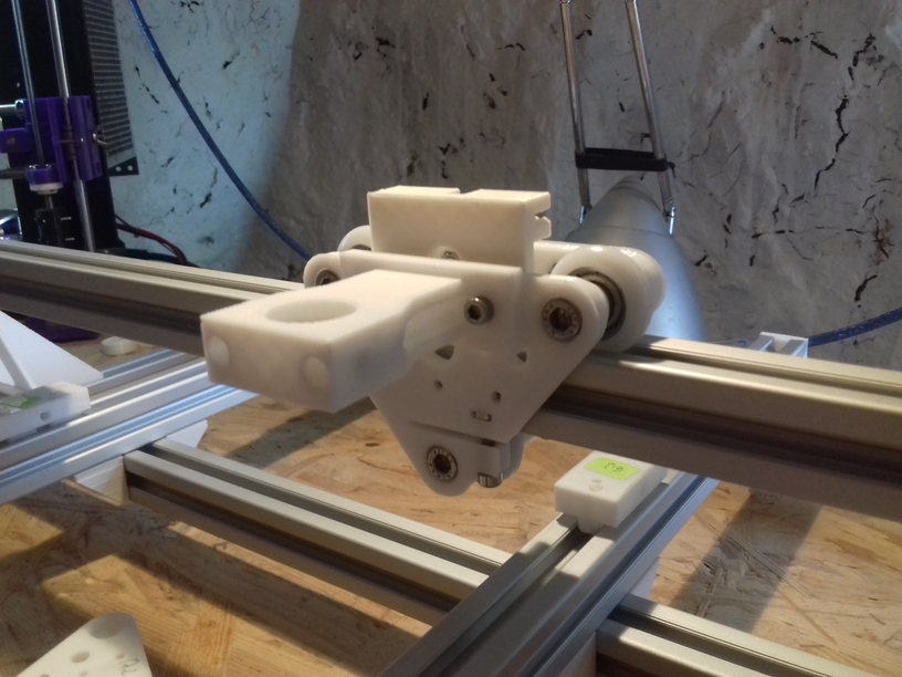
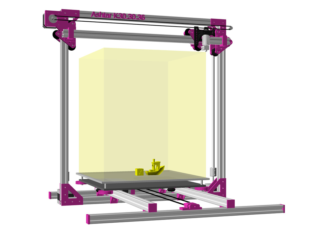
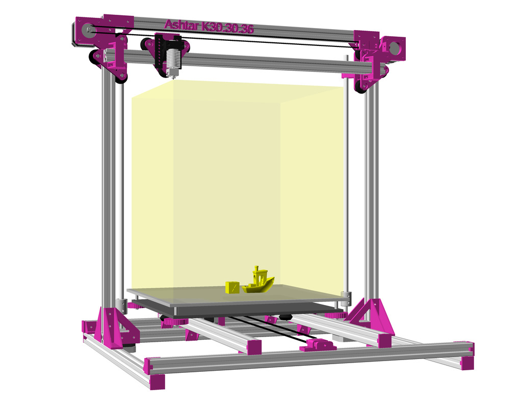
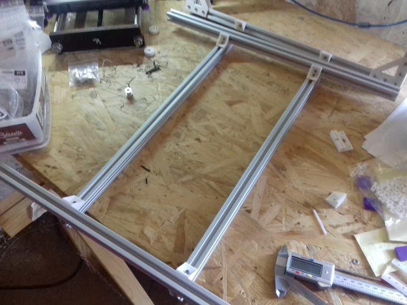
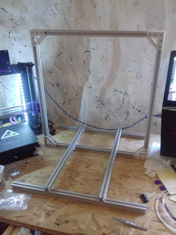
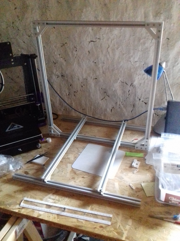
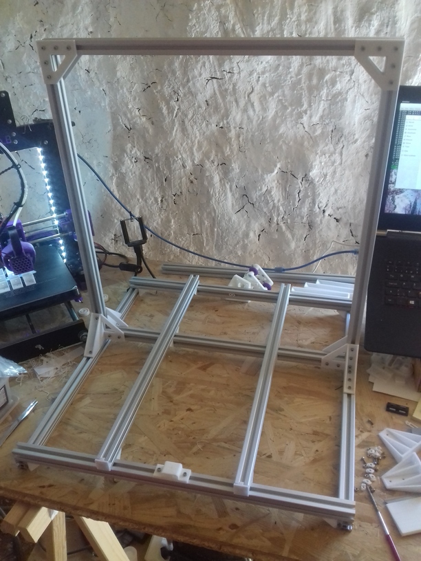
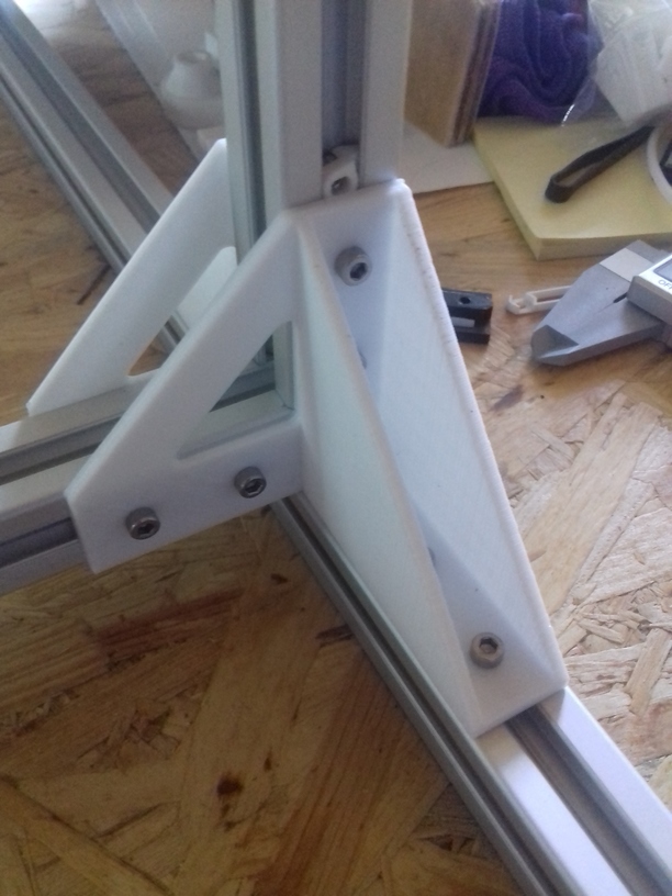
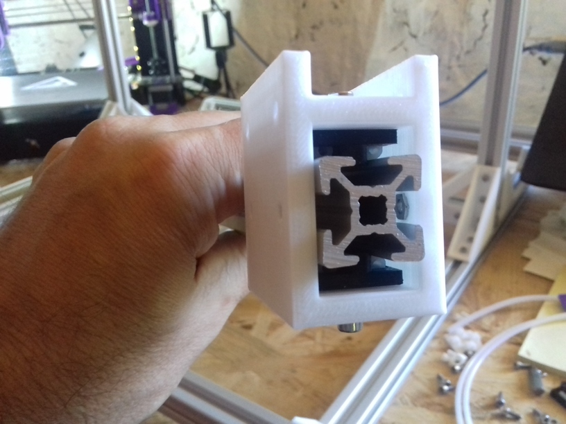
- Ashtar K 38.30.33
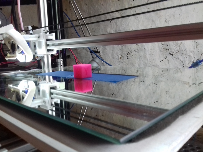
The bed is very temporarly fasten with tape, as I haven’t decided on the actual details of the bed mounting yet and leveling details – but I wanted to see how well the mechanics already works – and it performed quite well so far.
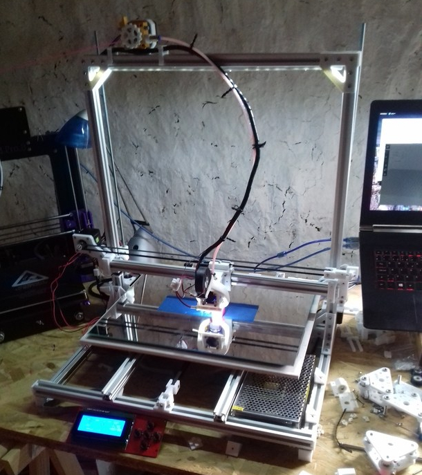
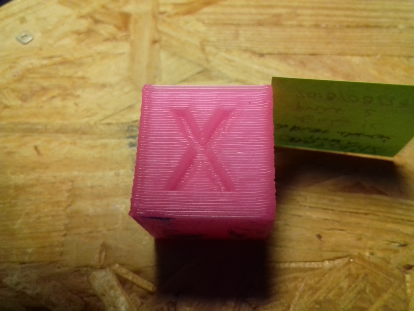
1st print came out mediocre, when I realized I had to tighten X and Y belts more, 2nd print came out much better; 0.5mm nozzle with 0.4mm layer height, merely printed in 8mins with 60mm/s print speed and 80mm/s 20% infill:
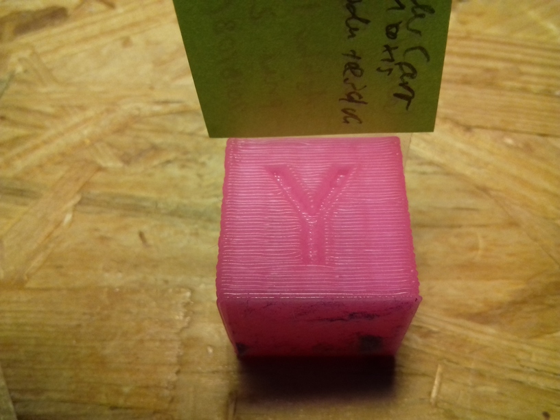
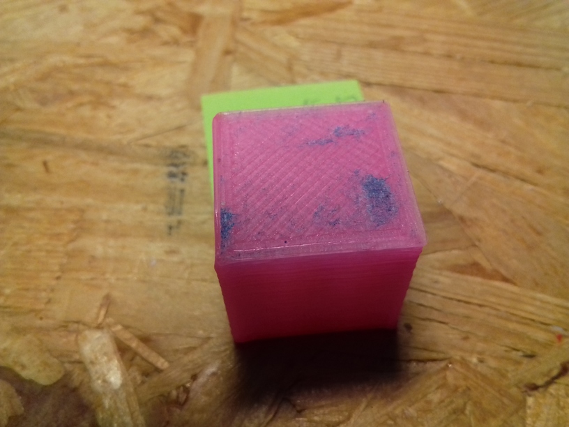
And just for the fun of it, 0.2mm layer height with 0.5mm nozzle, at 70mm/s:
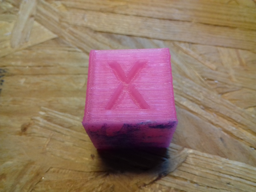
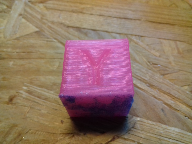
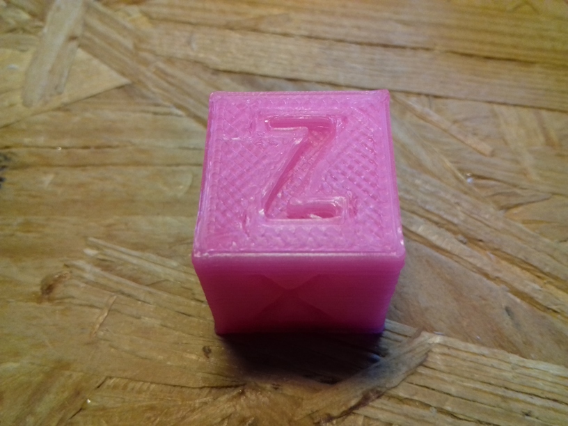
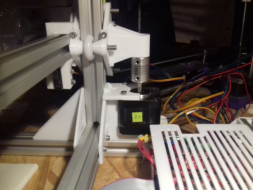
Incredible quality: X and Y surface very good, some inconsistency at “X”, on the “Y” side some slight ghosting; but most surprising is the edges on the Z axis – I operate with a simple M6 threaded rod and M6 nut – that’s all – moving nylon wheel-based carriage up and down – sure, I require to print more tests, in particular larger prints to really see how well all axis print up to 300mm.
I had to use blue tape on the mirror otherwise PLA would not stick – eventually I will use the black sticker as I used for the CTC DIY printer which worked quite well.
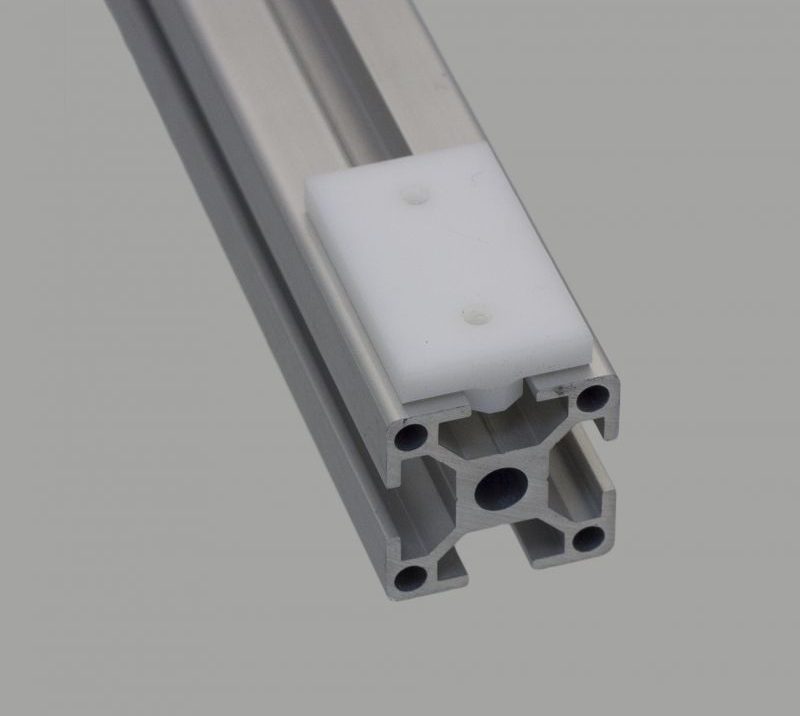
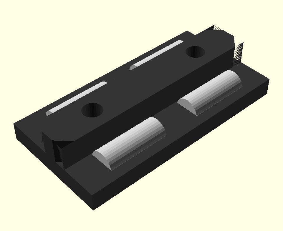
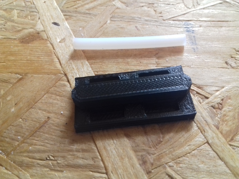
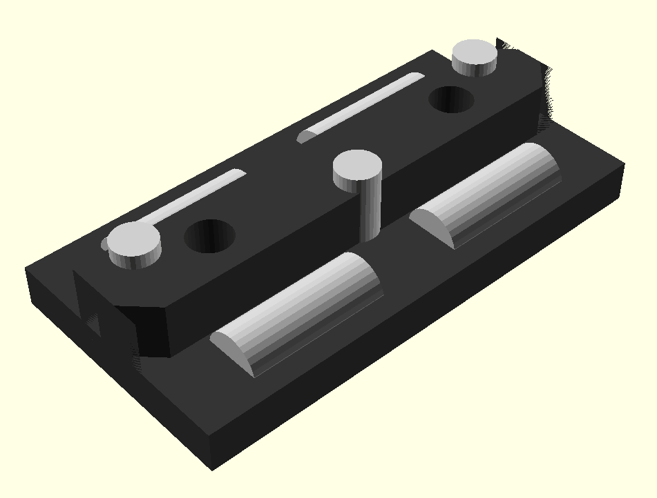
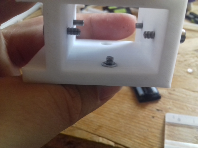
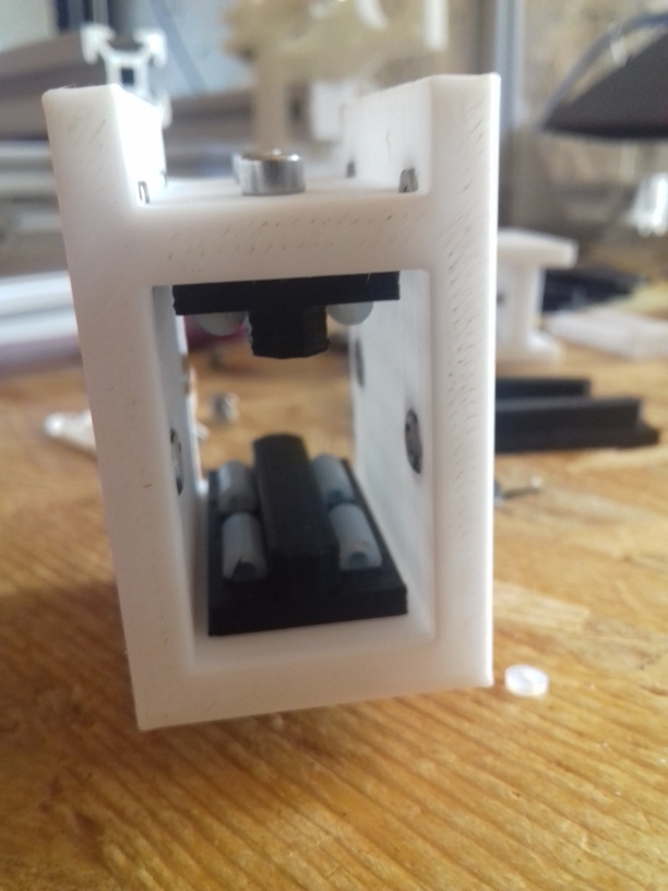
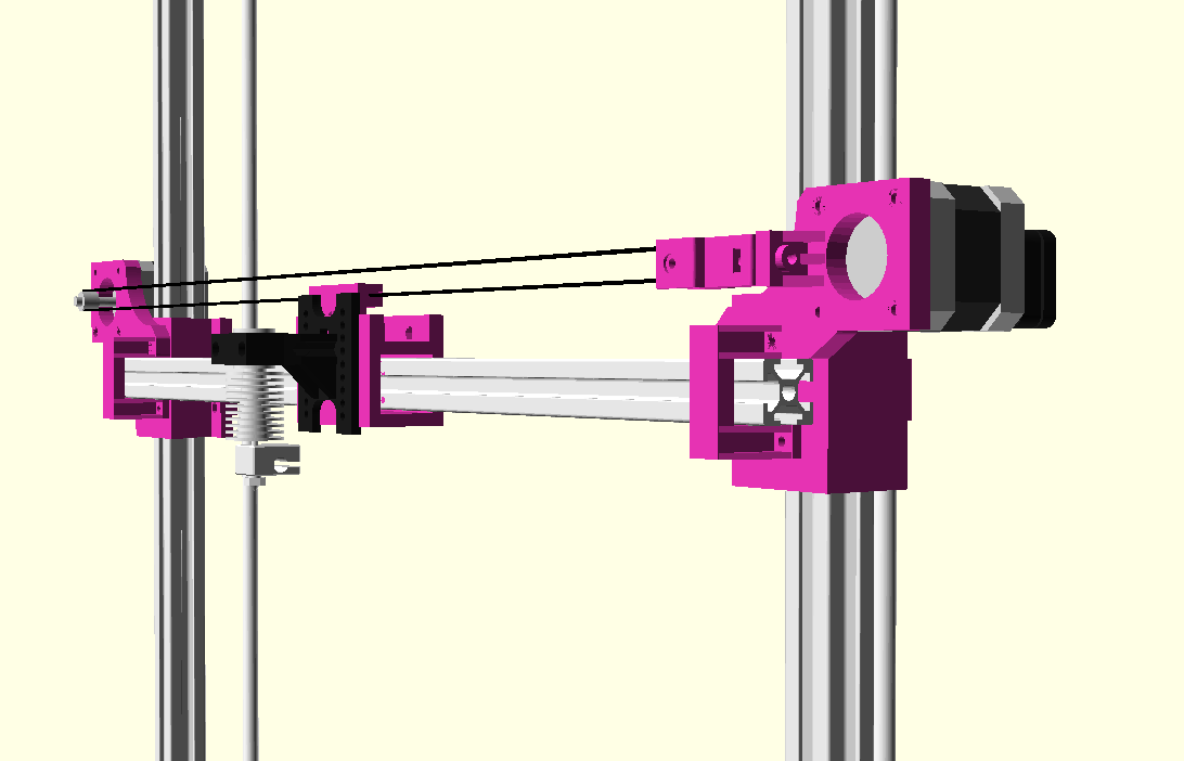
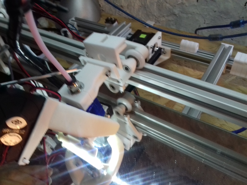
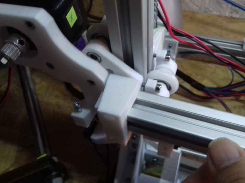
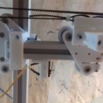
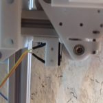
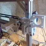
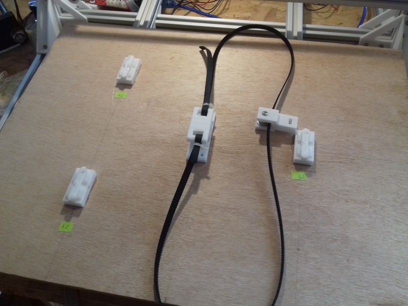
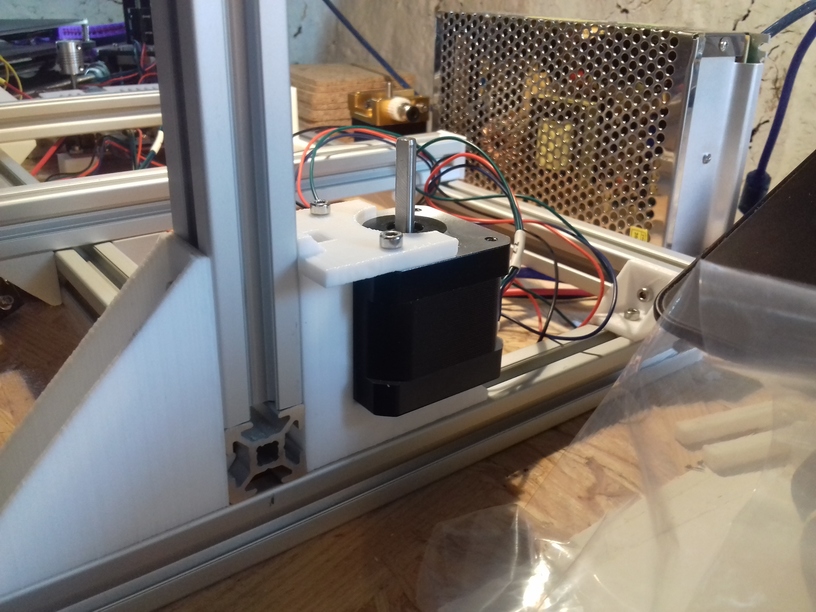
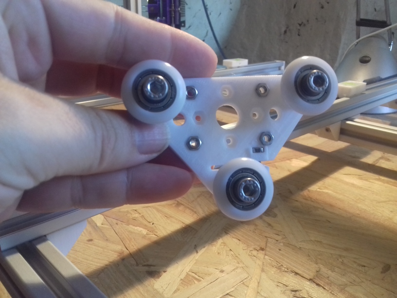
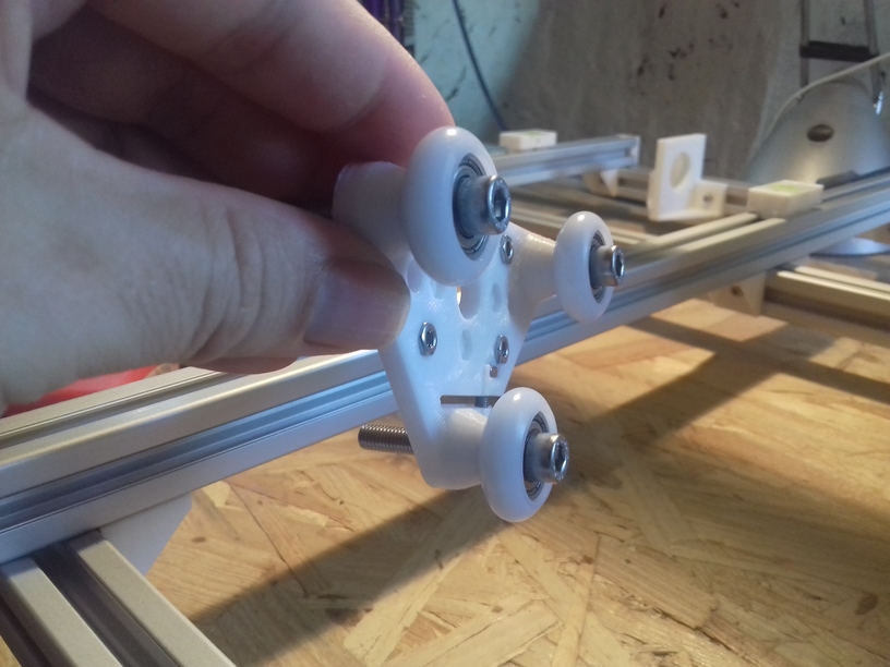
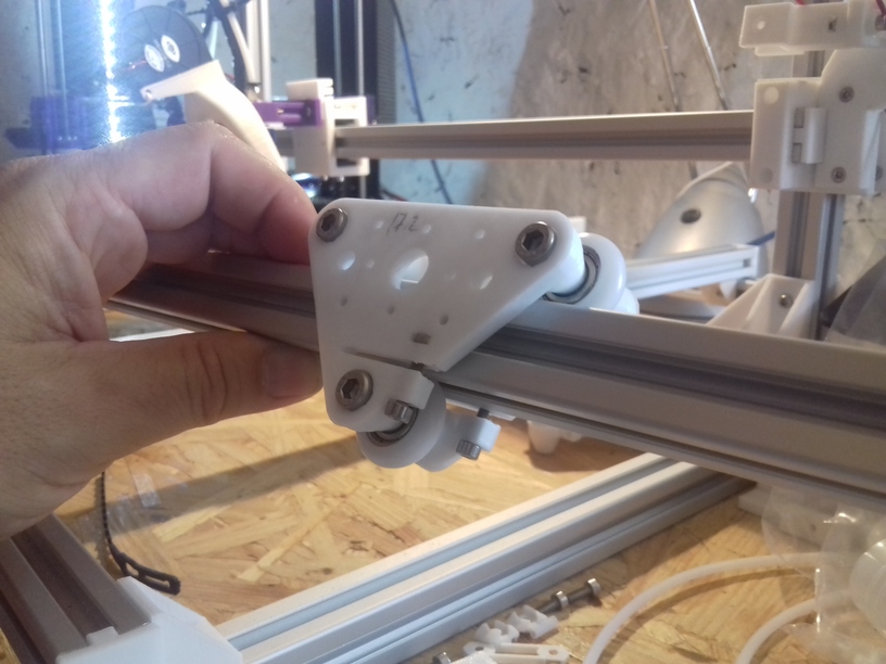
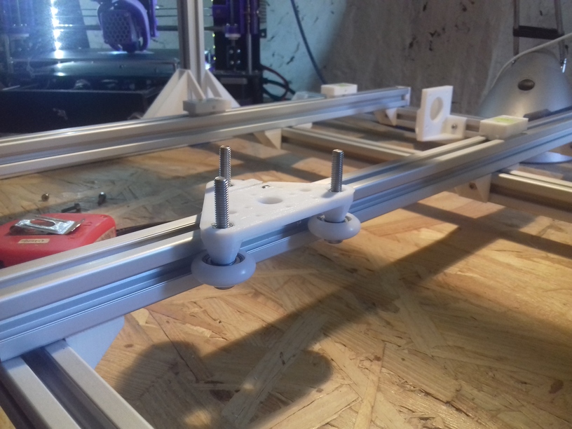
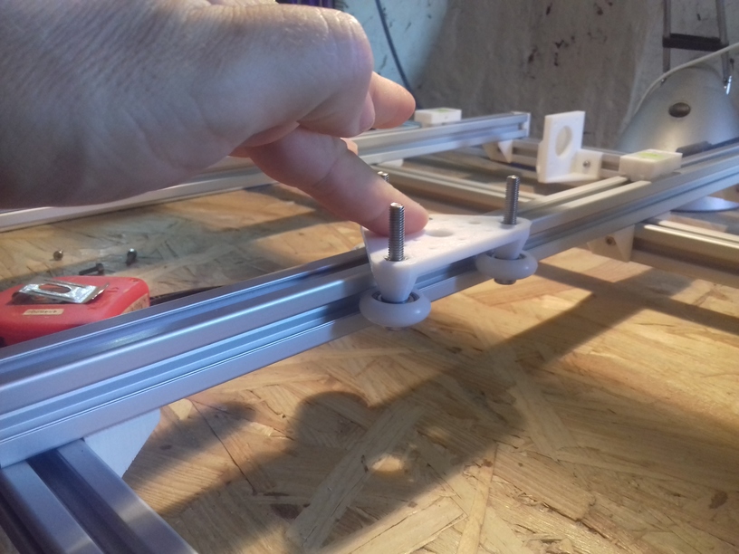
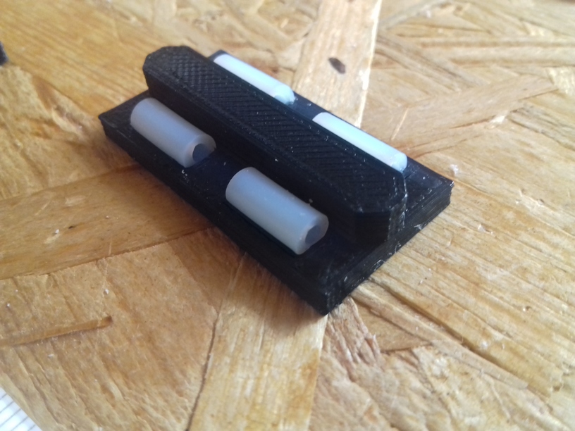
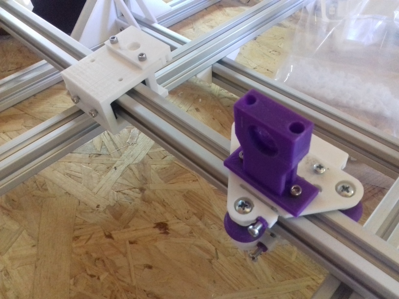
Nylon Wheels vs Sliders
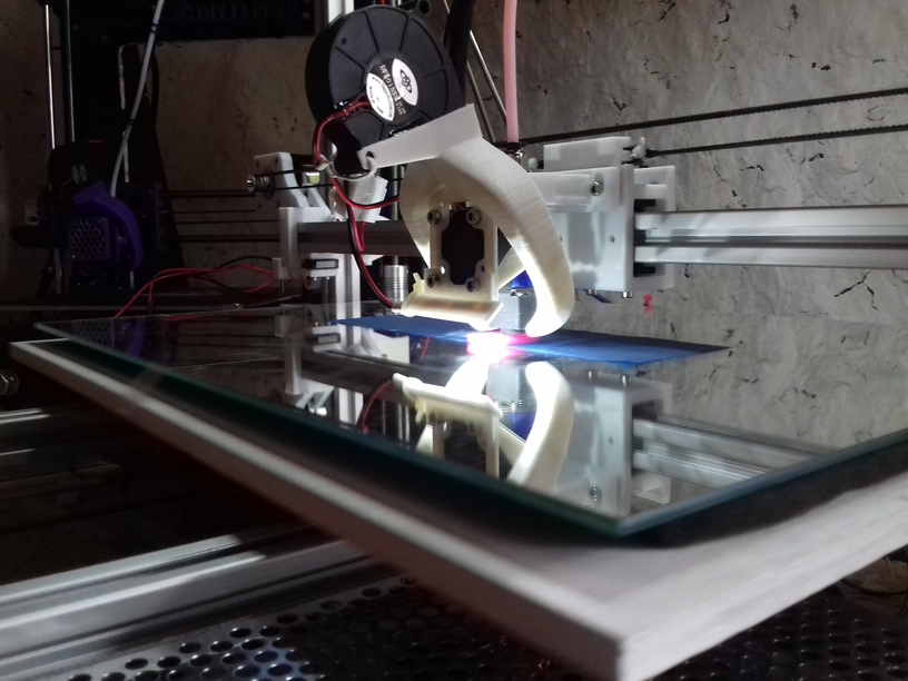
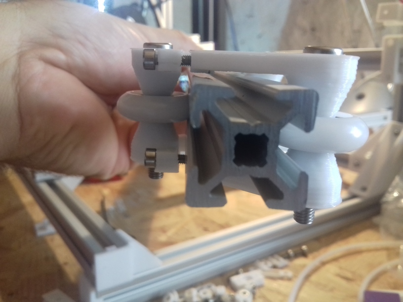
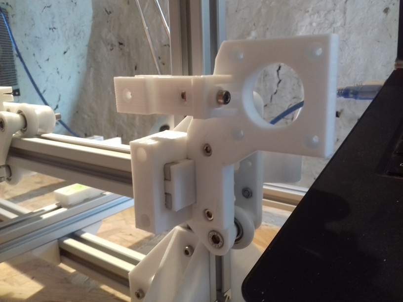
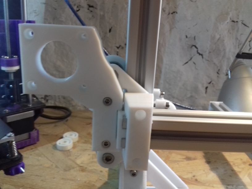
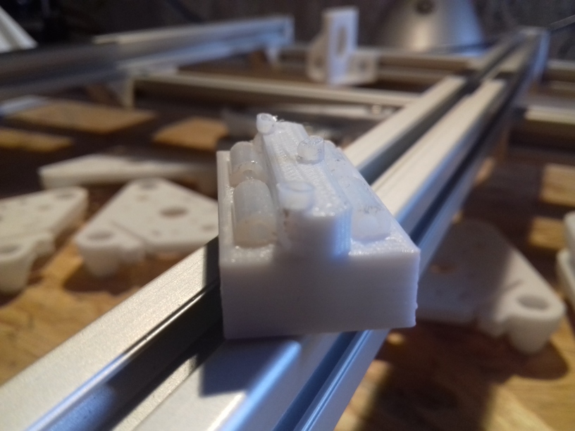
The past 2-3 weeks, while waiting the nylon wheels to arrive, I decided to check alternatives such as sliders with PTFE tubes – and this paid off: the nylon wheels 23.0mm OD with 7.3mm width sit quite nicely into the T slot (B-type) but when used in real life, like with X carriage, I had some sinus wobble in the vertical – apprx. 0.5mm to 1mm – way too much. So, I exchanged the wheel-based X carriage with the slider-based carriage, remounted the hotend with Bowden setup, and after 5mins the exchange was done:
-
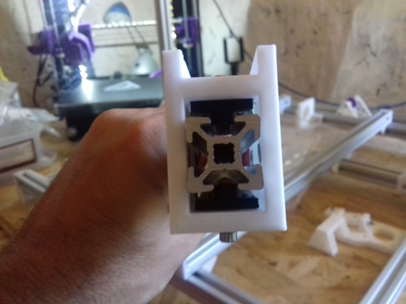
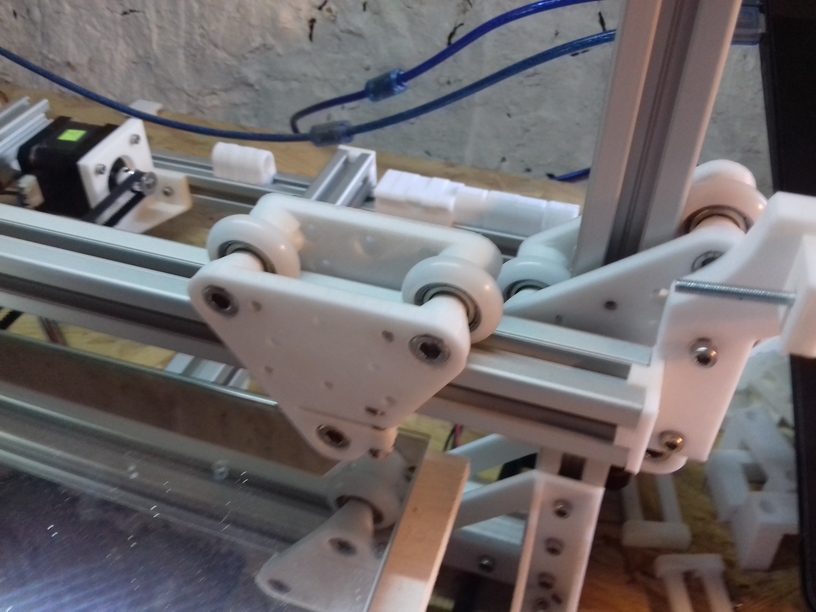
- X carriage with white nylon wheels (23.mm OD / 7.3mm width)
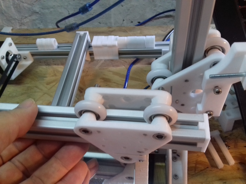
Current setup:
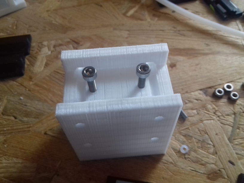
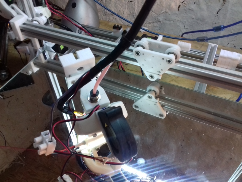
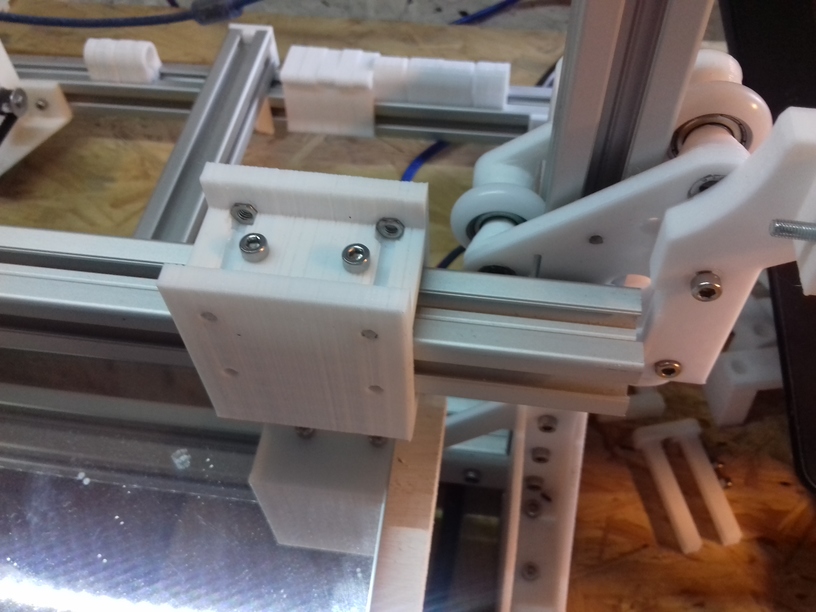
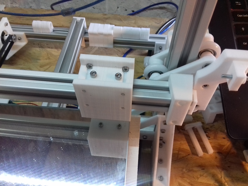
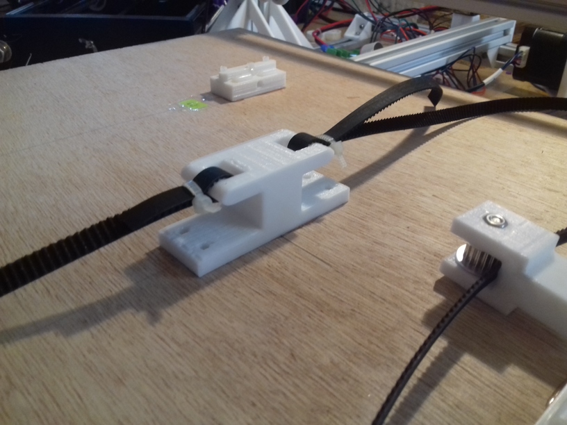
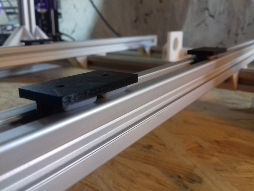
- X axis: slider-based carriage, holding on top and bottom side with 2 tightening screws
- Y axis: simple sliders (just sitting on the groove)
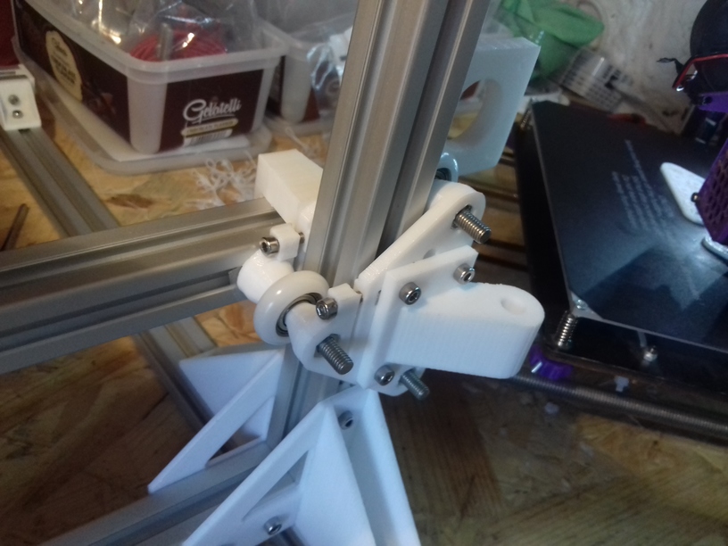
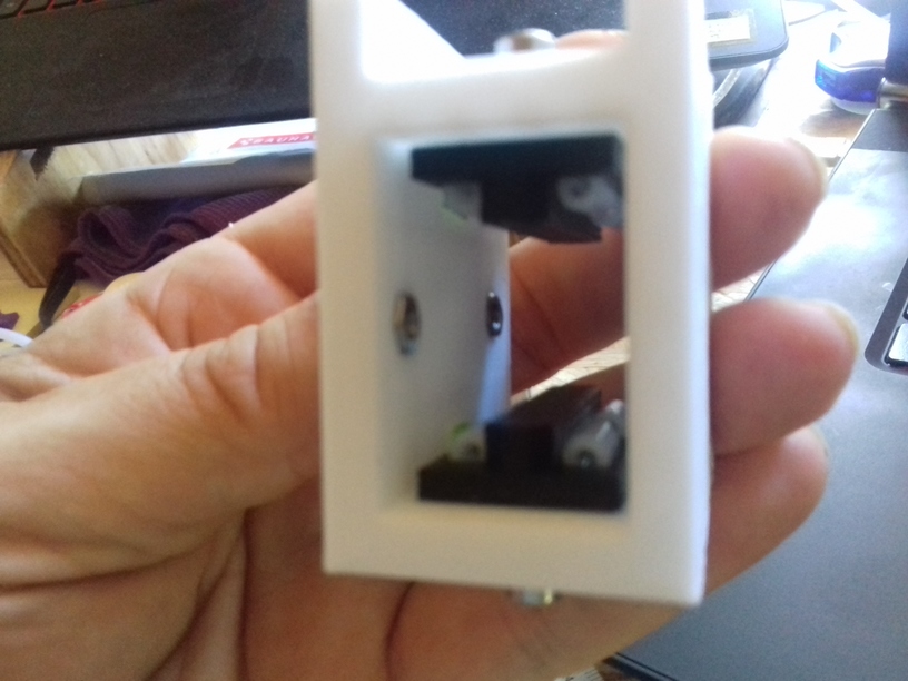
- Z axis: nylon wheel (23.0/7.3mm) based carriage
The next days and weeks I will review my options:
- slider-based carriage with
- 1 axis support or
- 2 axis support
- wheel-based carriage with
- nylon wheels 23.0/7.3 and 23.0/7.0
- double V wheels
both on T slot alu extrusion – I know ideally would be proper V slot alu extrusions, but I like to find out how good it works with the easily available T slot extrusions. Worst case is, I have to use on X and perhaps Z axis proper V slot alu extrusions, on the Y axis it seems the simple sliders (just a block) work fine.
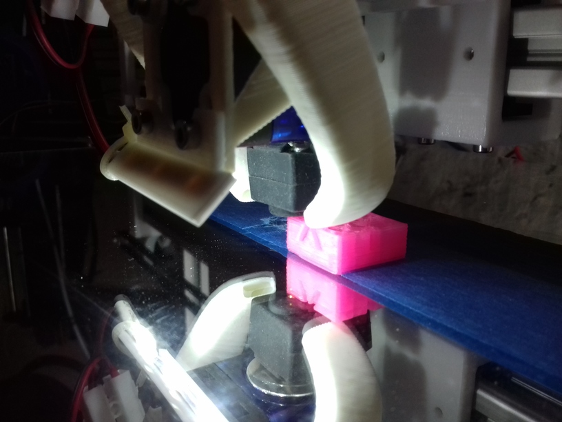
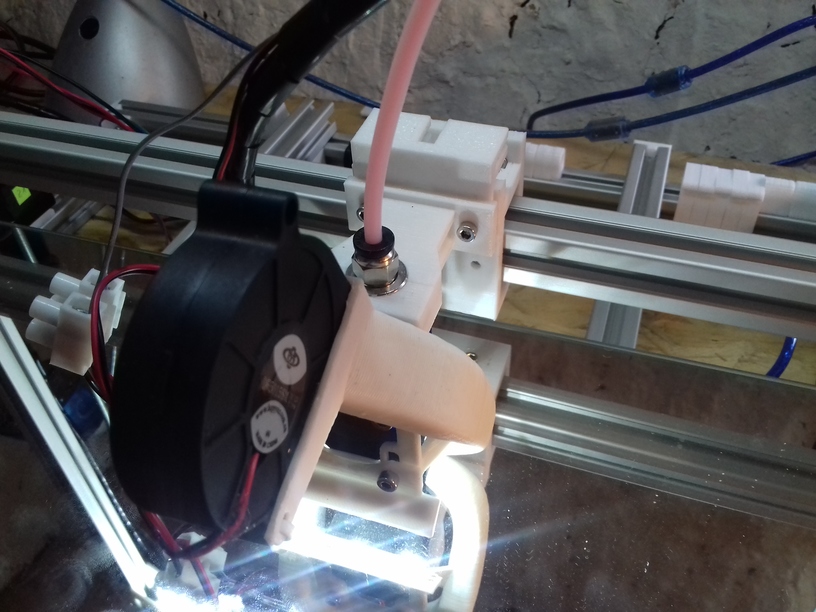
0.5mm Nozzle
Since I deal with nearly 3x the bed surface compared to 200×200 I thought I have to use a bigger nozzle as well, as a bigger build volume would imply larger objects to be printed. The increase from 0.4mm to 0.5mm diameter also implies 1.5x or +50% more material being extruded and I still desire to print with 60mm/s average with 80mm/s infill – this means I have to test well the hotend performs with that speed and higher throughput of material.
Specifications
Current specifications of Ashtar K 3d printer:
- 380 x 300 x 320 mm build volume (400 x 300 bed)
- E3D V6 clone hotend
- 0.5mm nozzle
- Anet 1.0 controller board
- 210 x 210mm 12V heatbed
TODO
- bed mounting & leveling
- 300×300 or 400×300 220V heatbed
- proper print surface (likely black sticker 300×300 or 400×300)
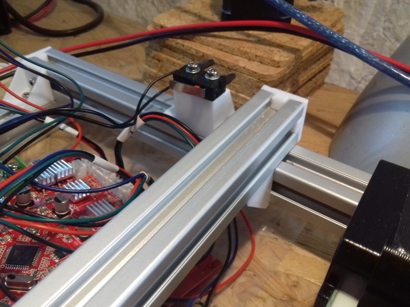
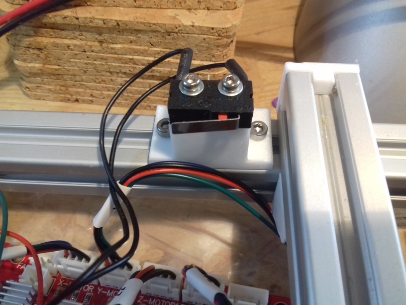
- improving cable management:
- Y carriage and heatbed with proper cable chain
- deciding on position of LCD display


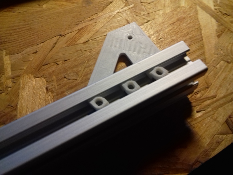


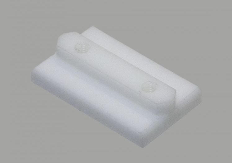
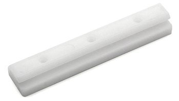 Commercially manufactured, apprx. cost EUR 2.50 per piece, sold in 10 pieces bag.
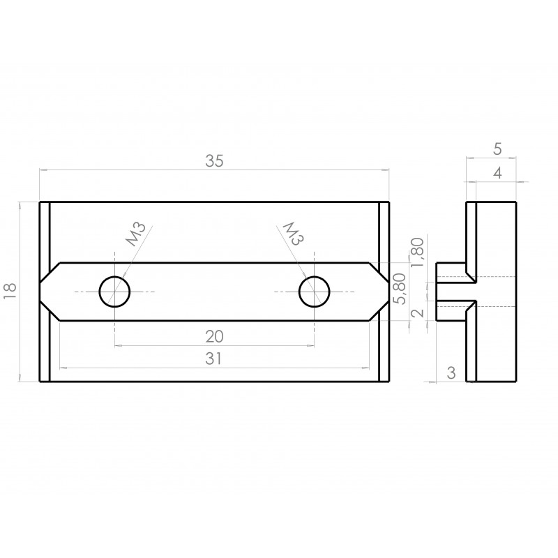
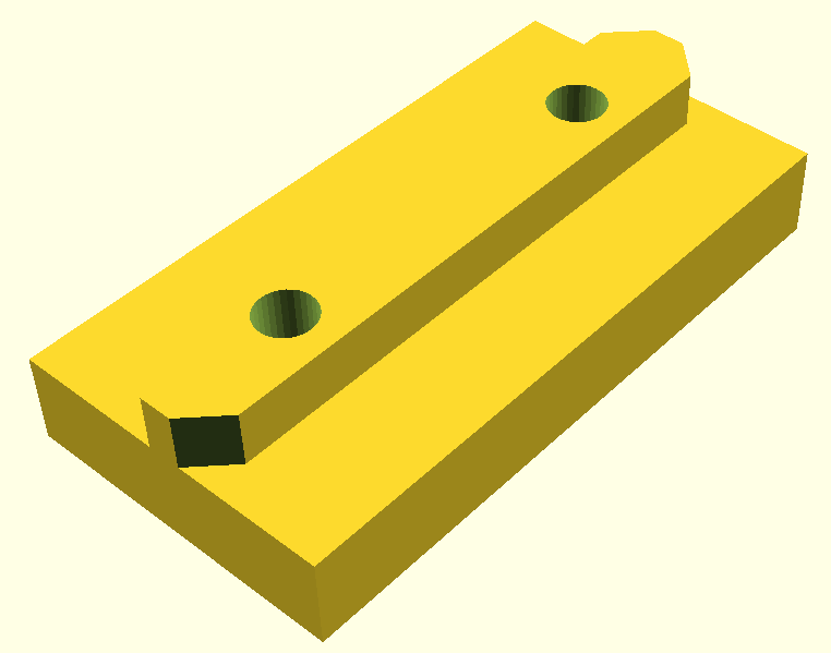