
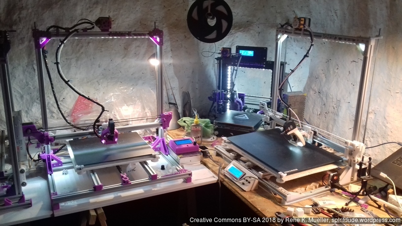
Status: fully functional and fine-tuned, two printers in use, my working horses

Updates:
- 2021/02/11: Multiple Switching Extrusion (MSE), Rotating Tilted Nozzle (RTN) and Penta Axis (PAX) Option added (drafts)
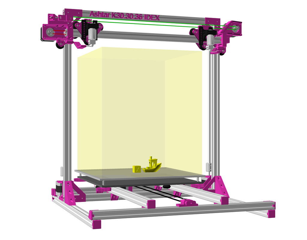
- 2021/01/14: Option for IDEX (Independent Dual Extrusion), early draft (not yet tested)
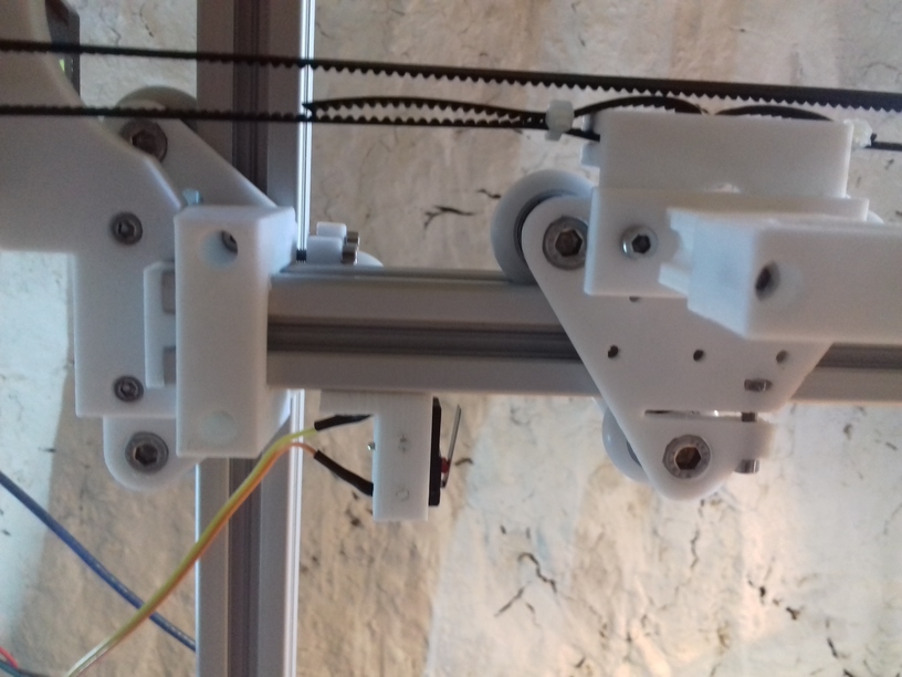
- 2019/09/02: Modification of routing belt within 2020 alu profile
- 2019/03/04: Updated photos and removed outdated parts
- 2018/12/10: Added Bowden extruder photos and BOM
- 2018/11/15: 2nd build of “Ashtar K #2” also 380x330x300 with 500mm alu extrusions
- 2018/10/31: Z axis modules assembly detailed photos.
- 2018/10/28: More details on BOM (Bill of Materials): printed and non-printed parts
- 2018/09/30: More details on Y carriage / bed, short video of mounting bed.
- 2018/08/27: It’s alive – means it prints . . .
- 2018/08/26: Partial functional, X, Y and Z motors and belts and threaded rods mounted with end stopper, board been flashed with Marlin 1.1.8
- 2018/08/24: More photos about XZ frame bracket with integrated Z motor mount, Y belt mount and sliders
- 2018/08/20: Short video testing X and Z axis with nylon wheel based carriages
- 2018/08/15: Added photos of composing the frame (XZ + Y) and changing design slightly to add 2 more beams so XZ frame is more sturdy, early tests with sliders, as alternative with wheel based carriages
- 2018/08/01: More details, extruder motor on the right side with belt idler mount, short video showing some details.
- 2018/07/30: Updated images, more examples of prototyping V modules
- 2018/07/21: Published with few drawings, short part list.
Table of Contents
Introduction
In summer 2018 I pondered on a parametric Prusa i3 3d printer designs, composed with 2020, 2040 aluminium extrusions / profile, hereby I document the development here.
The Ashtar W Series and Ashtar T Series are fully parametric, from 200mm^3 to 500mm^3 build volume, whereas this Ashtar K Series focuses on single beam length construction with 2020 alu extrusions.
Parametric Designing
Unlike traditional CAD (Computed Aided Design) sketched constructions, a coded parametric design is actually textual coded a design, defining which parts depend on which, and align according some variables, which can be changed. In this case, the input is the building volume X, Y and Z, and all parts are calculated accordingly, using OpenSCAD as programming language.
Following notion has been introduced:
X,YandZare the starting point, the printable volumeIX,IY, andIZare the inner dimension of the construction needed to makeX,YandZbuild volume work, hence,IX,IYandIZare greater thanX,YandZ- all constructions depends on
IX,IYandIZ XE,YEandZEare the position of hotend ranging between0..X,0..Yand0..ZXP,YPandZPis the calculated position of the hotend in physical space
These notions, in retrospect, allowed me to code all the different printer types: Ashtar K (Prusa i3), Ashtar C (CoreXY), Ashtar M (Prusa i3 MG), Ashtar D (Classic XY) coherently.
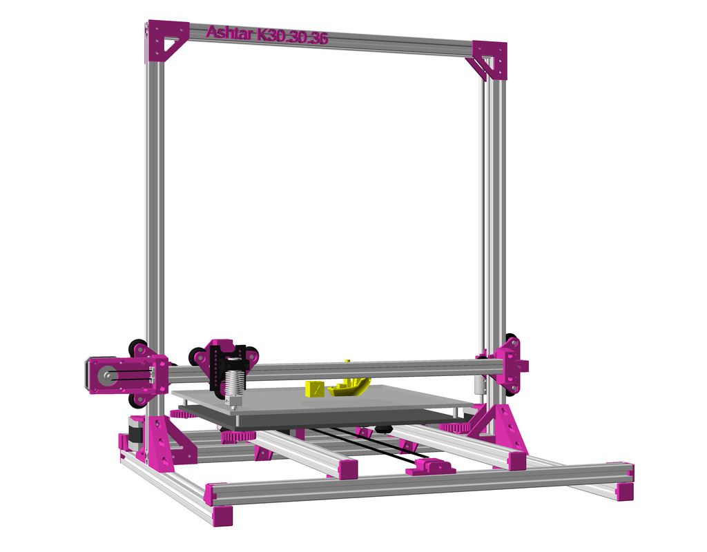
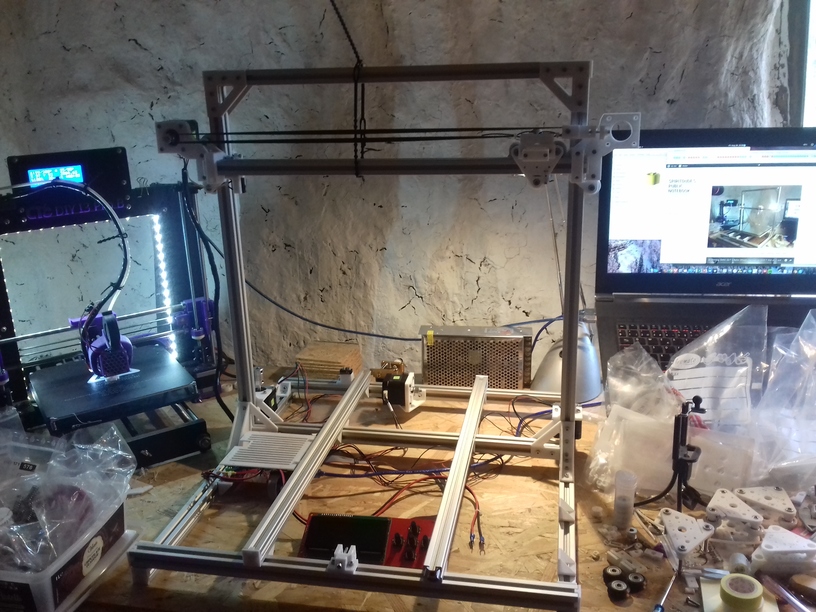
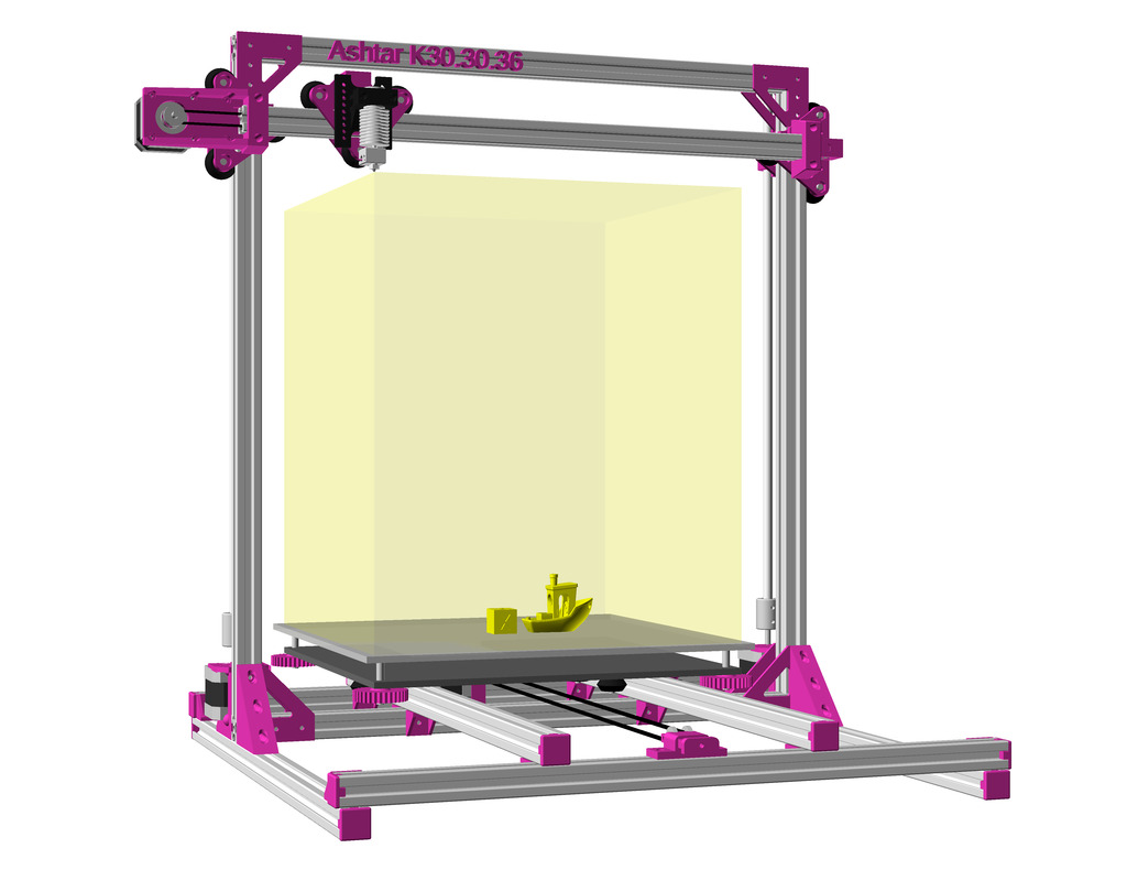
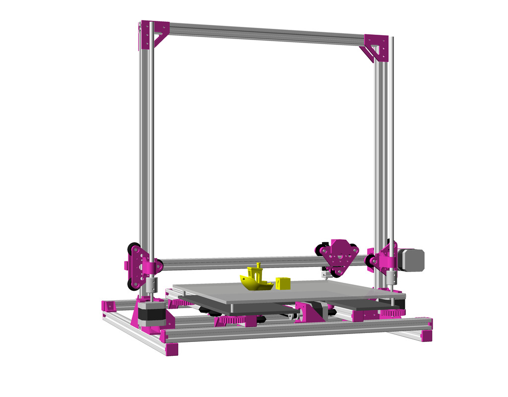
Ashtar K: 500mm 2020 Extrusions as Rails
This is a single size design optimized: 300(-380) x 300 x 360mm build volume, composed by 11x 2020 500mm B-type or V-slot beams:
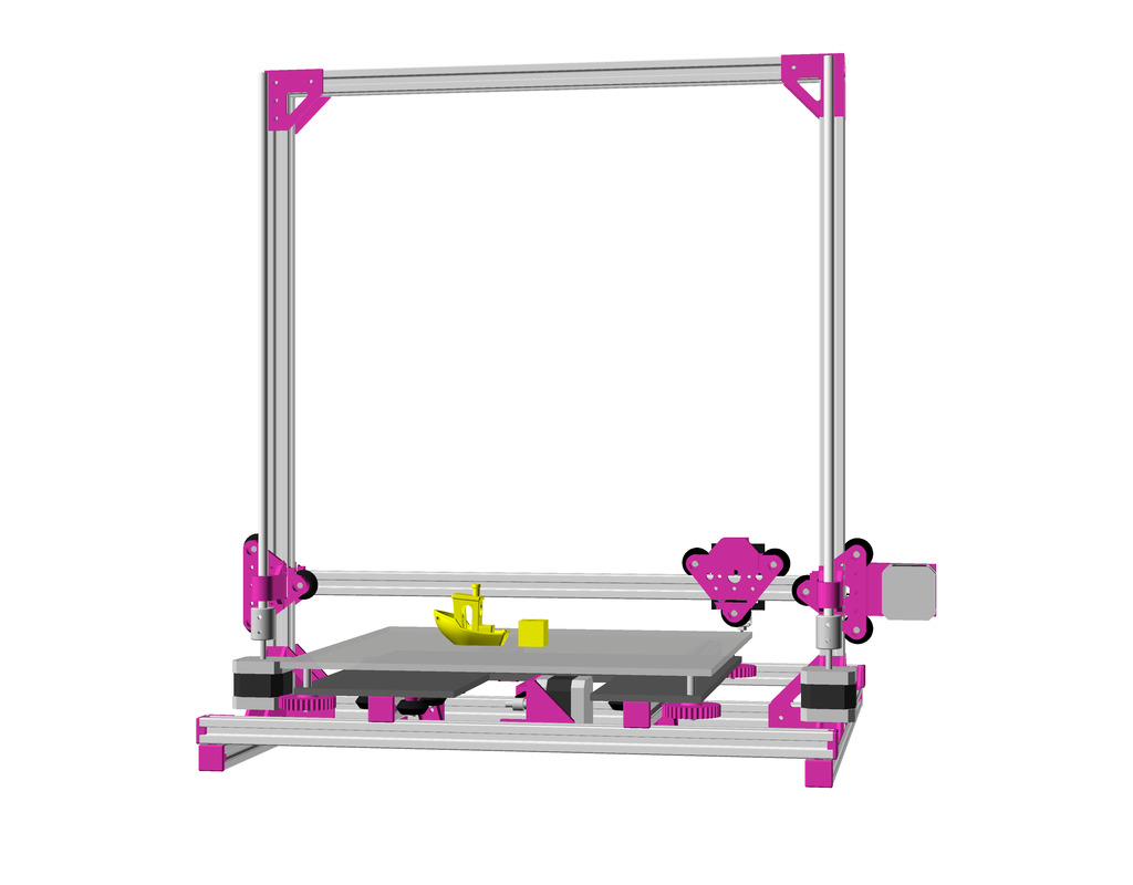
Backside:
Bottom view:
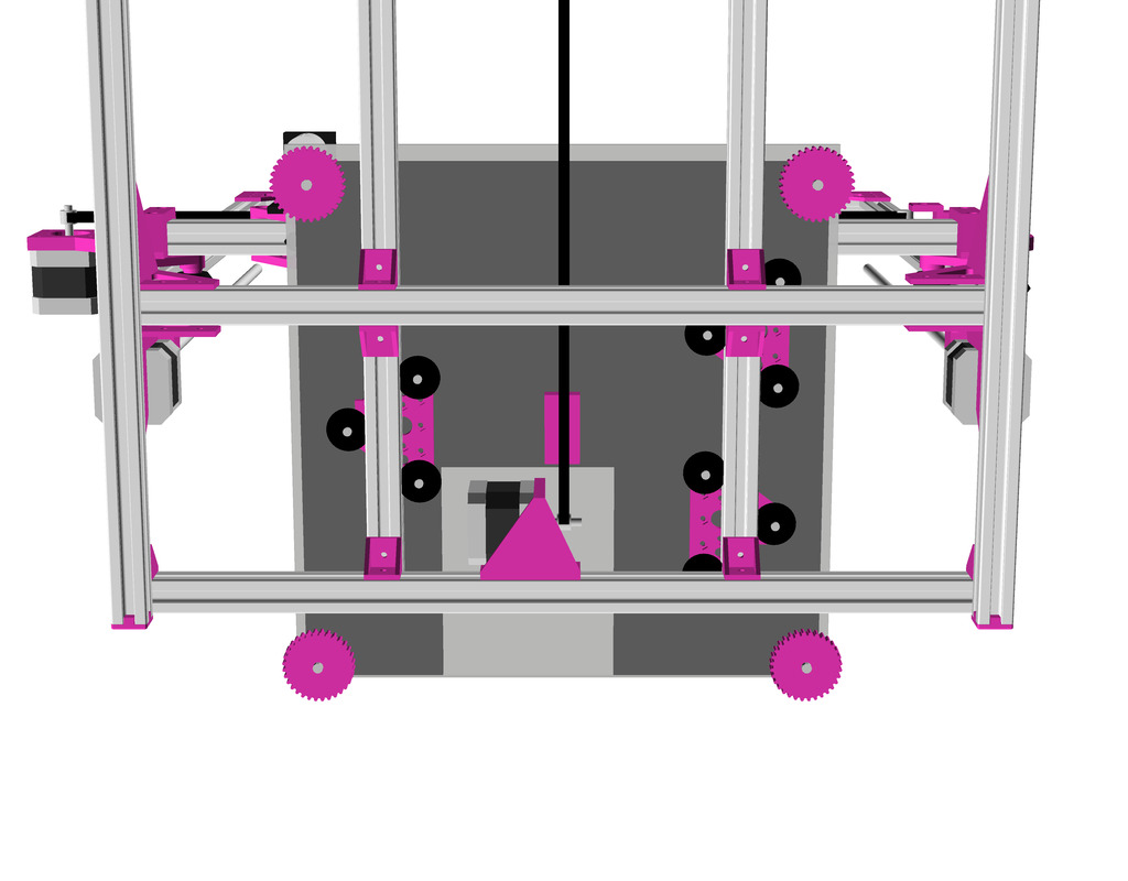
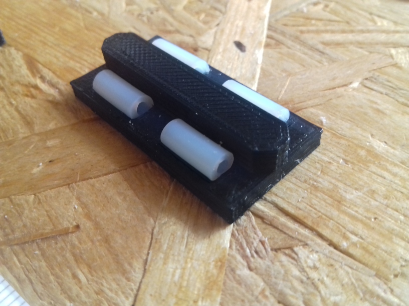
The rollers on the Y axis can be likely reduced to minimum of 3 total, instead of 9 (3×3), it really depends how well the rollers have a grip on the extrusions. Majority of the printed parts are custom. I settled with DIY sliders with small PTFE tubes instead, they were simpler and turned out reliable enough for my use case, see below “Y Carriage Slider”.
The Y axis is quite short to match 500mm beam length, and the Y bed fits barely as you can see in this bottom view, but it should work:
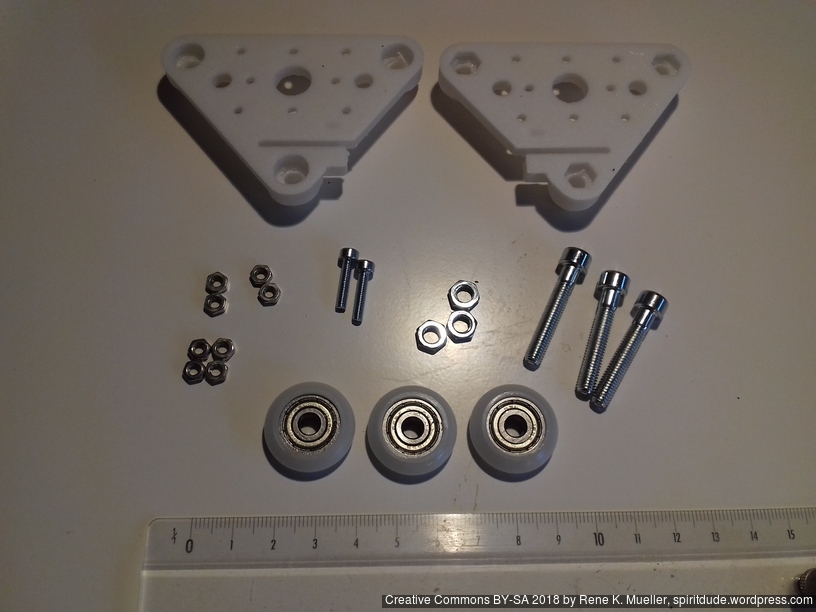
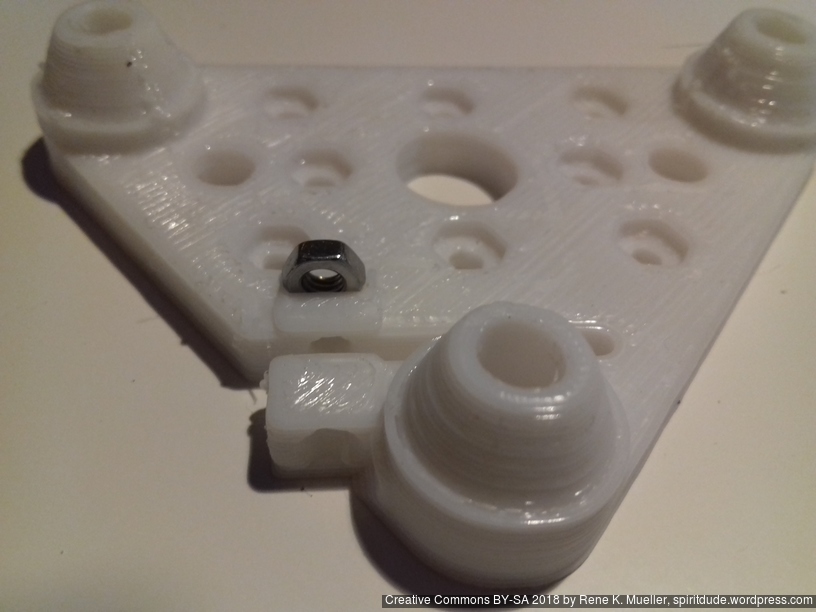
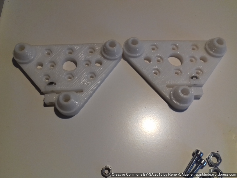
Moveable V Modules
The V modules, composed by 2x V plates, which holds the wheels running on the alu extrusion, I document separately at 3D Printing: Wheels on Alu Extrusions and is used:
- 2x Z axis motion
- 1x X axis motion
- 3x Y axis motion (perhaps a dedicated module to reduce amount of wheels) or
- 3x or 4x Y axis sliders
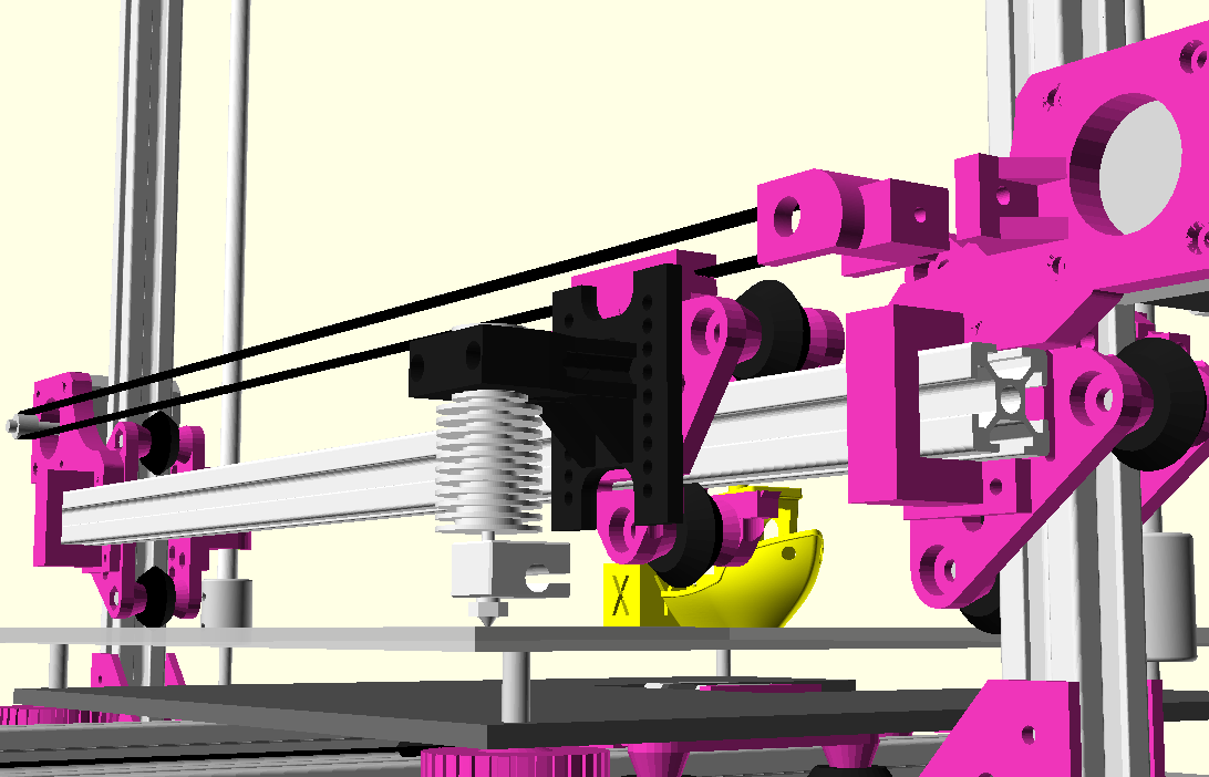
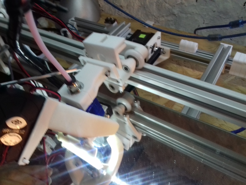
V Module X Axis
As first I mounted existing direct drive extruder piece to the module, although due the thin 2020 profile I likely have to run it with Bowden setup to make sure the moving extruder is light enough.
40mm fan with 5015 fan fang on top, X carriage with 3 wheels (V module) 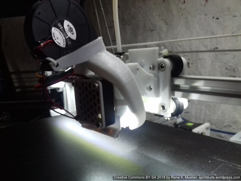
40mm fan with 515 fan fan on top, X carriage with 4 wheels (H module)
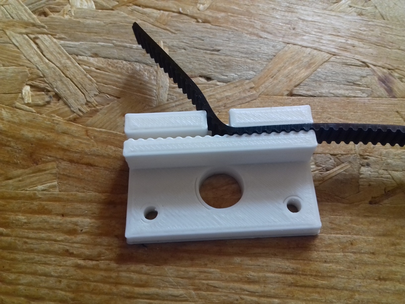
Small belt mount, 1st version is one sided, 2nd version goes both ways to be more flexible:

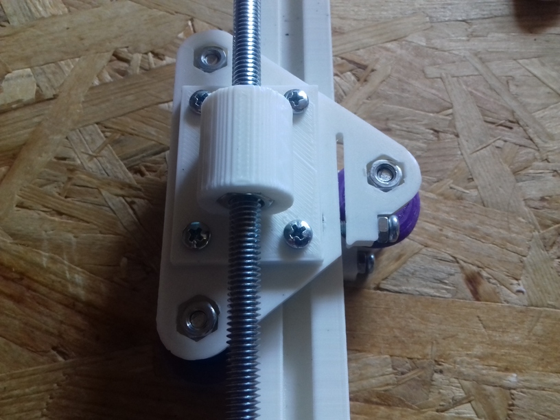
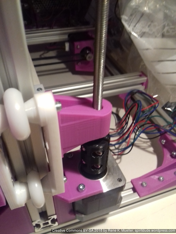
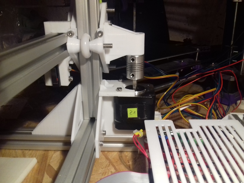
V Module Z Axis
Z Axis V module is a bit more complex, it takes the X axis beam and the Z axis leadscrew or threaded rod, and the X motor mount:

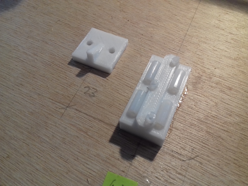
Slider-based Carriages
Aside of wheel-based carriage, I thought of trying and playing with some slider-based carriages as well:

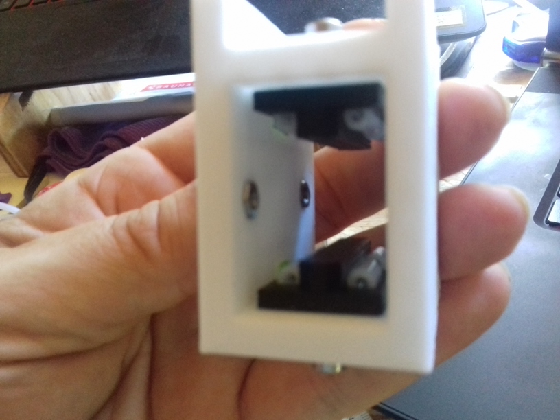
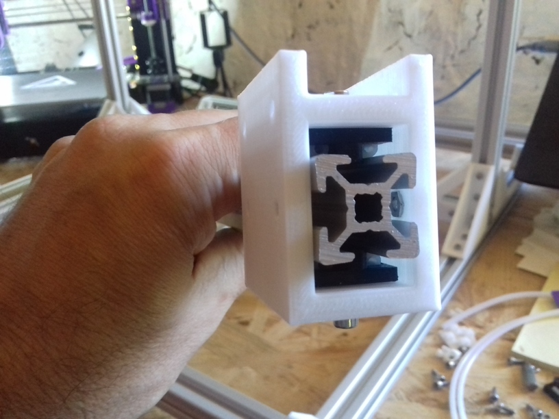
for more details see my blog post on 3D Printing: Sliding on Alu Extrusions. It eventually didn’t work that well, with time it became wobbling, and the friction increased – so I switched to wheel-based V modules.
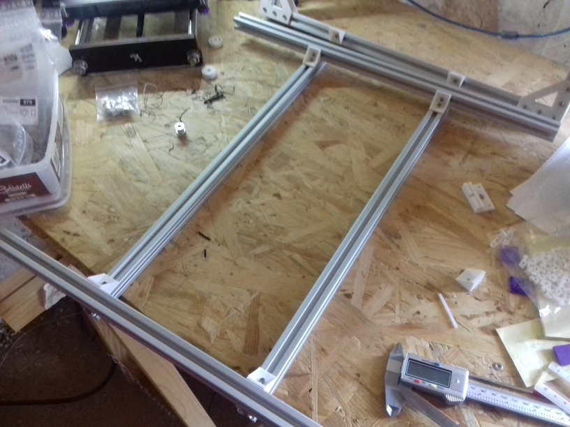
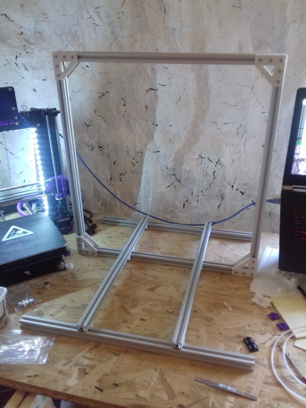
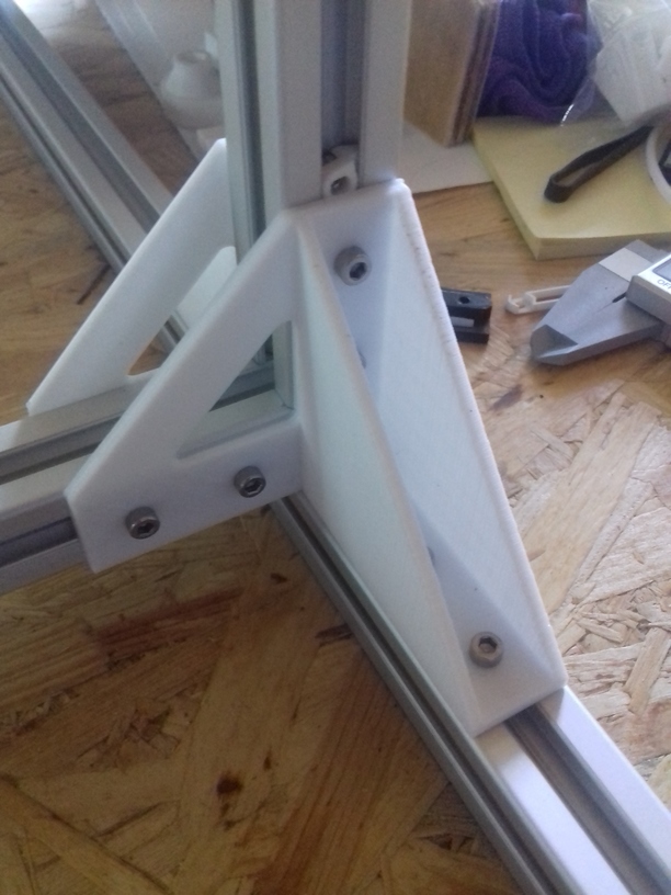
Frame
Some photos of early tests with building the frame. I changed the frame design an add two more beams to stabilize the XZ frame with the Y bed more; using 11x 500mm beams now – and some strong bracket at the bottom:


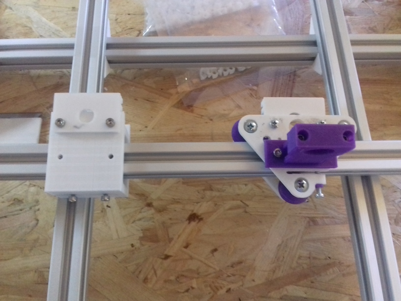
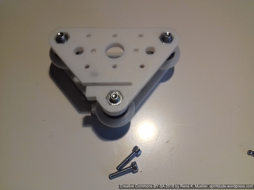
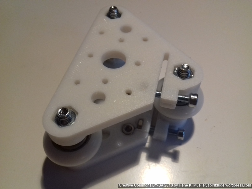
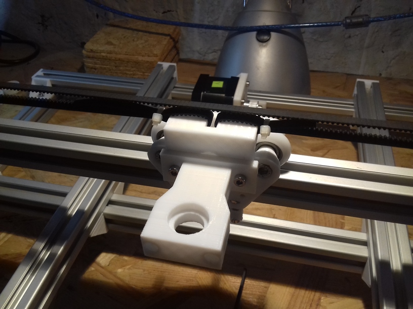
X Axis Module
Two options are available:
- 2020 T-Slot 6 (B-Type): using 3x Nylon wheels 23.0 OD / 7.3 wide
- 2020 V-Slot 6: using 3 or 4x OpenBuild 24.4 OD / 11 wide V wheels
The V-Slot beam is more suitable as the X carriage will be more stable and sturdy when printing – yet, V-Slot 2020 beams aren’t easily available or with high shipment costs.
Four options I tried: the 1st with a slider worked only briefly, then 2nd I switched to white Nylon wheels which wasn’t stable enough but wobbled in Z a bit on T-Slot beam, the 3rd was 3x wheel V module, or the 4x wheel H module on V-Slot which worked best.


Belt mount and hotend holder using same mounting holes
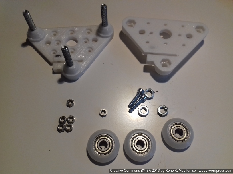
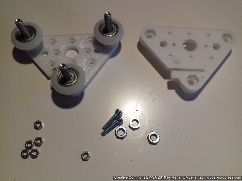
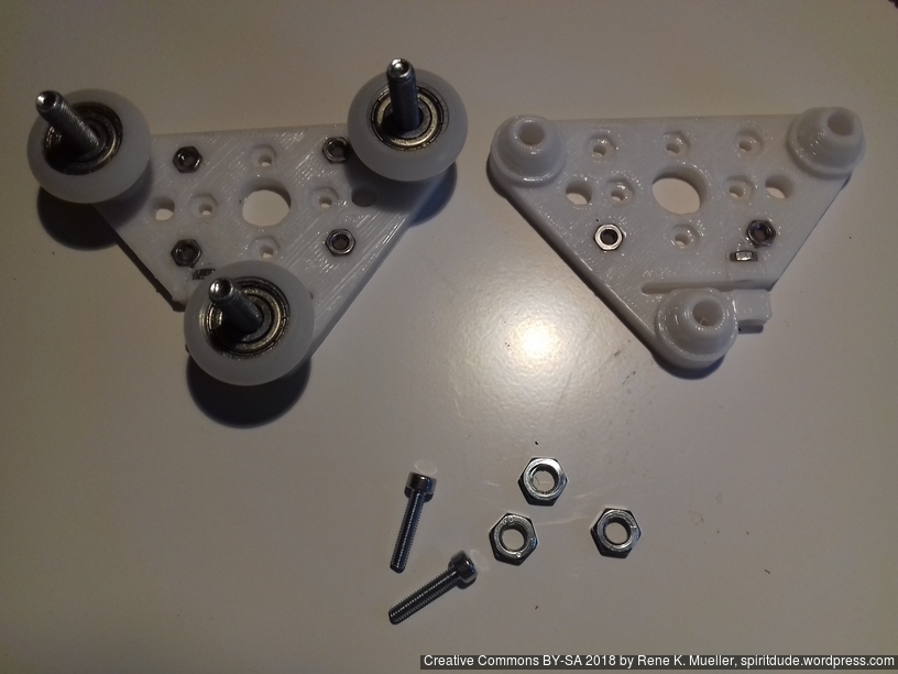
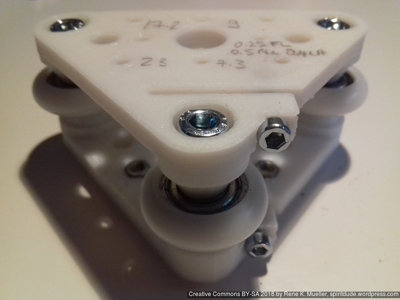
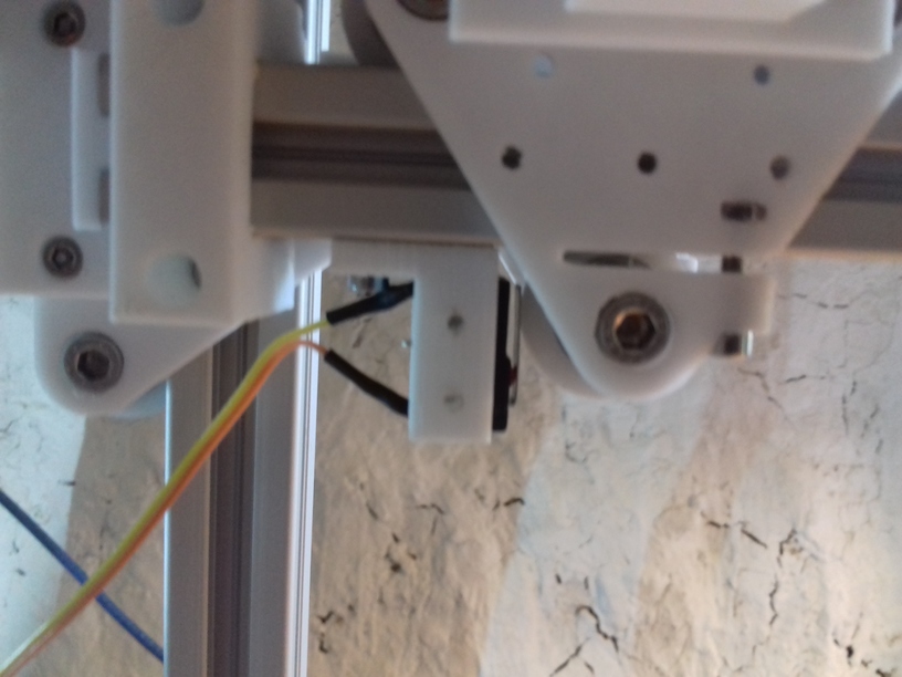
Z Axis Modules
Two V modules (each with 2 plates) assembly for 2020 T slot 6 B-Type beams, per module:
- 3 x M5 x 30
- 3 x M5 nuts
- 4 + 2 + 2 M3 nuts (4 front insets, 2 back insets, and 2 for adjustment screws)
- 2 x M3 x 14 or x 16 (adjustment screws)
- 3 x Nylon wheels 23.0 OD / 7.3 wide (do not use 23.0/7.0 wheels, but 23.0/7.3)


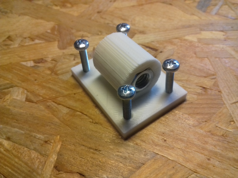
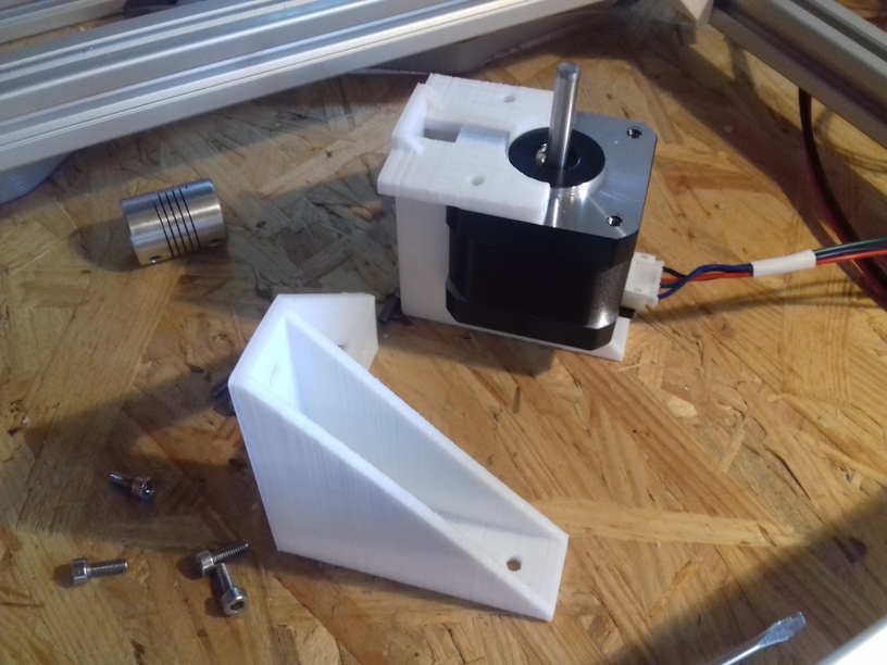
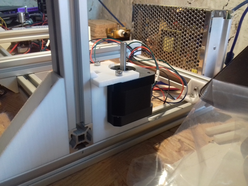
X, Y and Z Axis Motors
All motors mounted with belts and threaded rods:
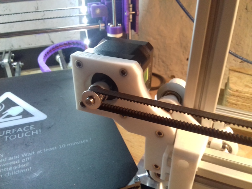


and all 3 axis in motion (without extruder and without bed heating/leveling):
and early tests show with the nylon wheel (23.0mm OD, 7.3mm width) based carriage a build volume of 380 x 300 (+10mm outside of bed) x 320mm.
Other carriage, e.g. the slider based, might result in smaller or bigger build volume.
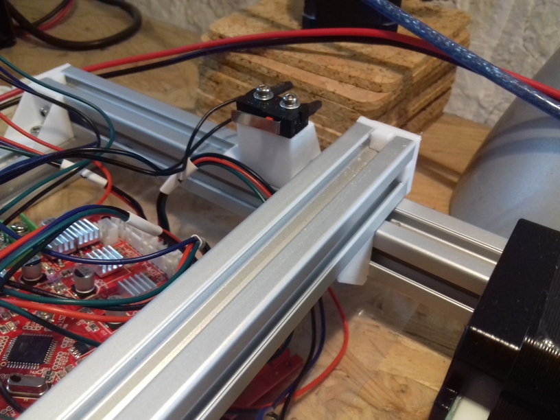
Controller Board
For now I use an Anet 1.0 controller board (as part of a “CTC DIY Kit”), and it required some preparation:
- using Arduino Uno R3 (clone) and upload “Arduino ISP”
- attach Anet 1.0 board (detach all other cables) to Uno R3
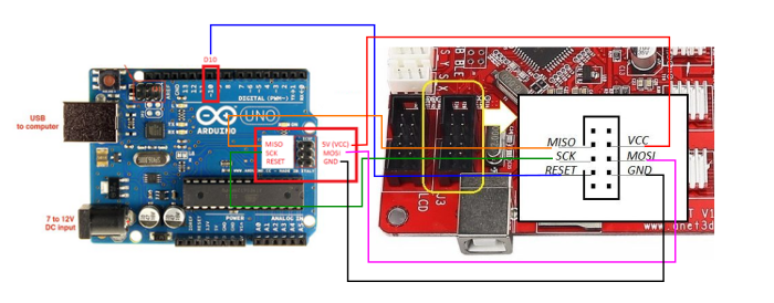
- run “Burning Bootloader” with “Arduino as ISP” as writer
- downloading Marlin and edit main Configuration.h to match my specifications
- upload new firmware Marlin to Anet 1.0 via USB upload

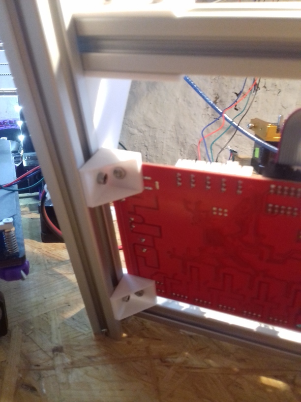
I mounted the board first in the farther left corner (in the photo), but the Z stepper motor new mount required to move the board in front of the XZ frame on the left side. The position and casing for the LCD display I haven’t decided yet.
Y Carriage
Current bed setup (top to bottom):
- 400x300mm black sticker (“frosted sticker”), apprx. 0.6mm thick
- 400x300mm 3mm thick mirror
- 210x210mm 12V alu heat bed (optional)
- various cork patches under heat bed
- 10mm light black foam material
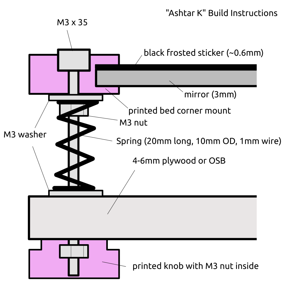 420x320mm 6mm OSB (white painted) as Y carriage
- 4x printed corner mounts holding 3.7mm thick sticker/mirror combo
- M3 x 35
- M3 washer (below printed corner mount)
- Spring (20mm long, ~10mm OD, 1mm wire), compressed to 10mm
- M3 washer
- printed knob (below plywood/OSB), 30mm OD, 8mm thick, M3 nut inserted
I currently use the white PU steel enhanced GT2 belts, and it produces hard edges, some ghosting, but more precise prints than the black rubber GT2 belts which just stretch too much – I have to research this more closely – about the type of reinforcement and the use with more heavy beds (Y carriage).
420×320 carriage:
- 4mm plywood flexes, but has been quite flat – not recommended
- 6mm plywood hardly flexes, but has been hard to buy truly flat – and so far my attempt to flatten it did not work well – not recommend unless it’s flat
- 6mm OSB quite flat, does not flex much (3 or 4 sliders) – recommended
320×320 carriage (for 300×300 bed):
- 4mm plywood works (3 sliders, 4 sliders recommended)
- 6mm plywood works (3 sliders, 4 sliders possible if plywood is truly flat <0.2mm difference)
- 6mm OSB quite flat, doesn’t flex (not yet tested)
Just to explain my thought or decision process for my setup:
- the mirror should not be bend (of course)
- the support structure should not be the edge mounts, but the foam in between
- the carriage can be bent, but not flex
- revelation: already bent means the springs with screws might extend the bent further with a flexing carriage, and not counter act – as the mirror should stay flat
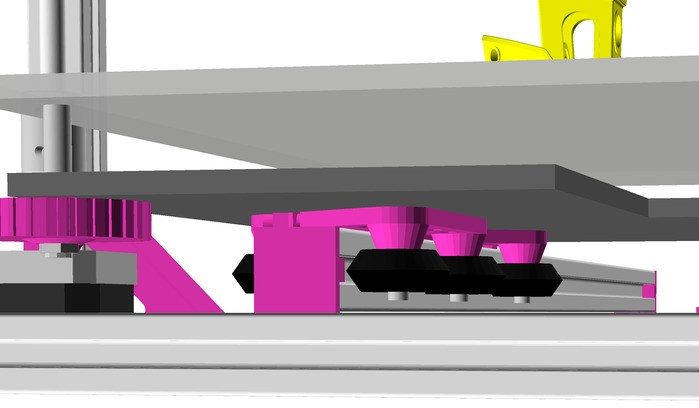
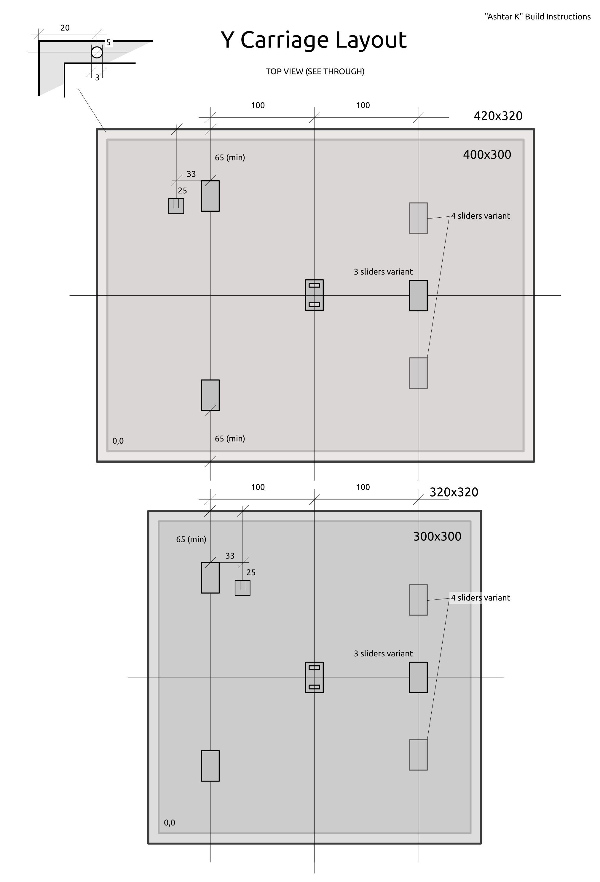
Sliders & Belt Mount Positions
Top view with see-through (best mark “0,0” on both sides so you keep proper reference) – if your carriage is truly flat, choose 4 sliders, otherwise 3 sliders.
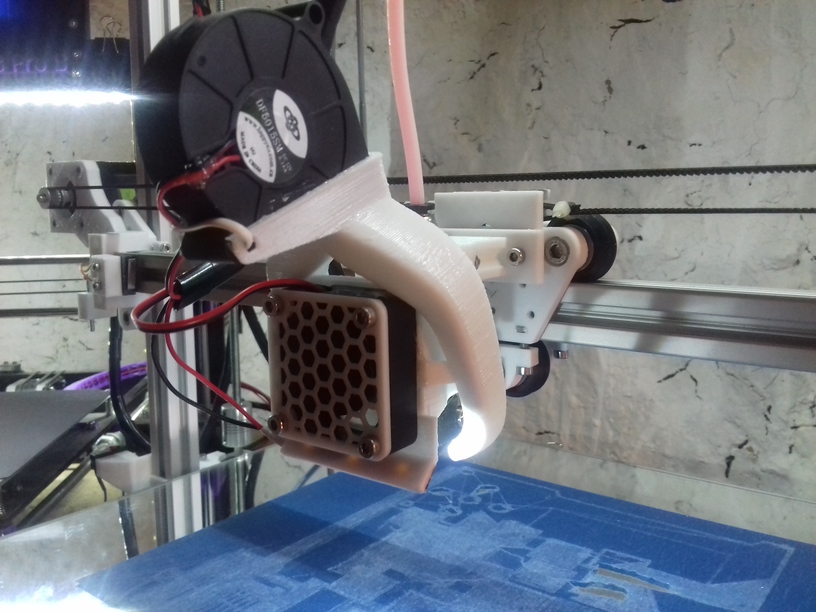
Bowden Extruder
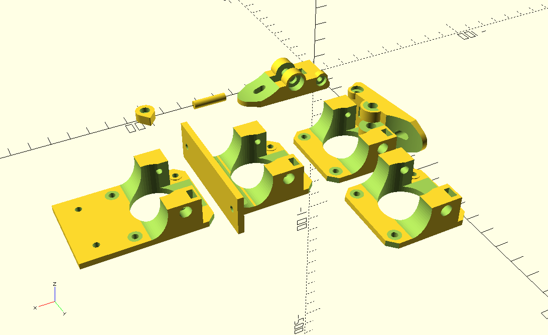
After few weeks I decided to do my own extruder, adapting the design of the “Compact Extruder” which has low complexity and low amount of parts to achieve simple extruder functionality; here my redesign:
and in a functional state:
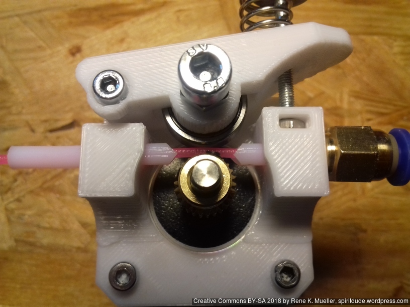
Assembled Simple Extruder 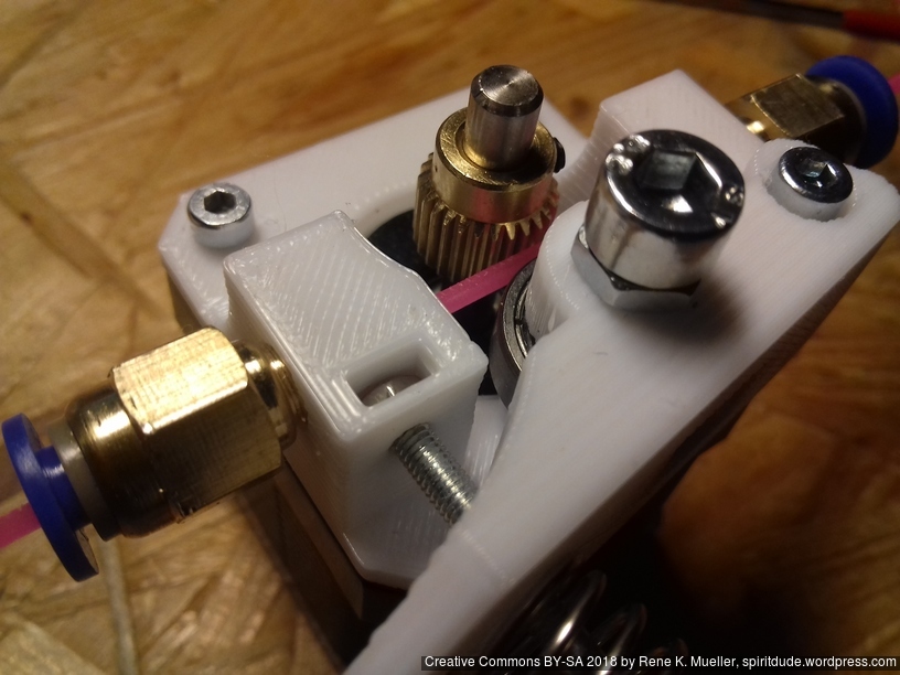
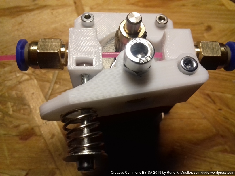
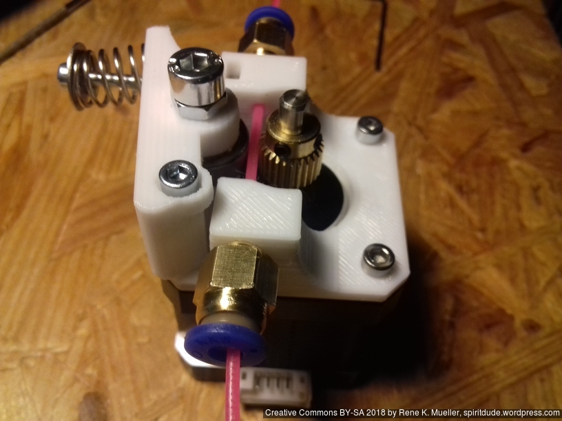
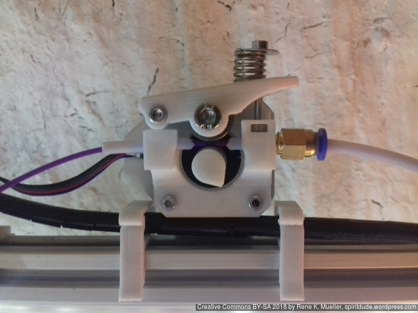
Assembled Simple Extruder on Ashtar K #1 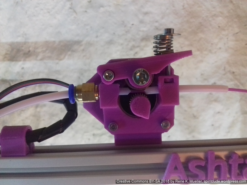
Assembled Simple Extruder on Ashtar K #2
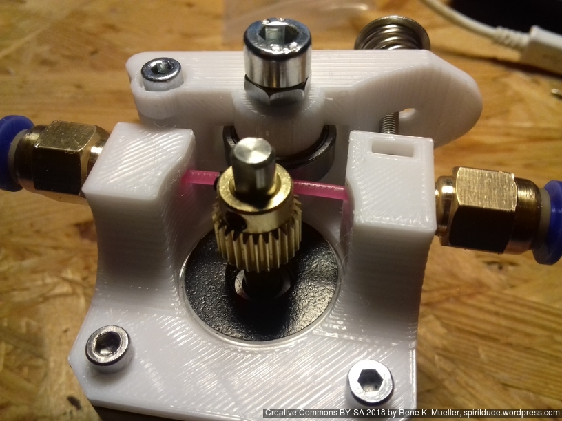
It’s published at thing:3265864, it’s based on 625ZZ bearing:
- 625ZZ bearing (16mm OD, 5mm ID)
- M5x14: mounting bearing
- 2x M3x25: one to attach handle, another to hold spring
- 2x M3x8: mounting to stepper motor
- M3 nut: insert into slot
- M3 washer: to hold spring
- 3-8mm OD 20mm long spring
- hobbed gear OD 11mm
- 4mm OD / 2mm ID PTFE for filament guides
- PC4-M6 for outgoing Bowden tube
Gallery


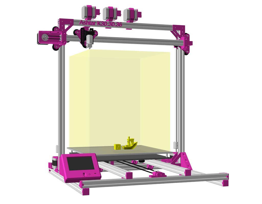
Ashtar K with 3 extruders and LCD controller 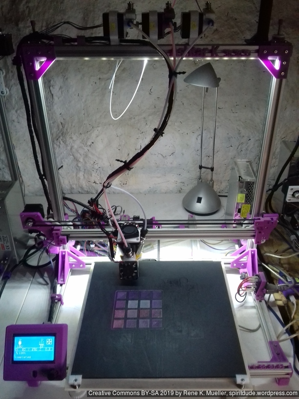
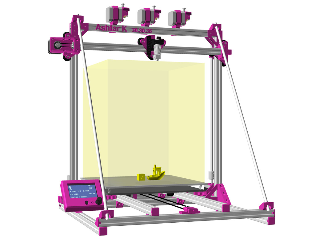
Ashtar K with stabilizing rods 
Ashtar K with parametric clear enclosure
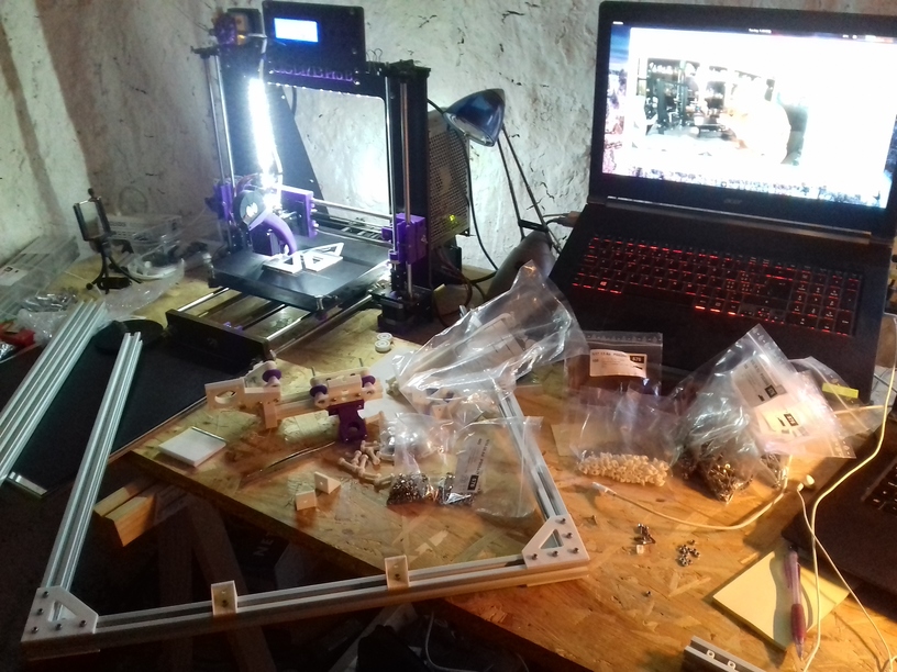
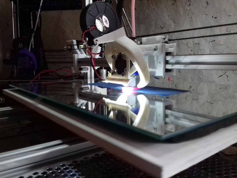
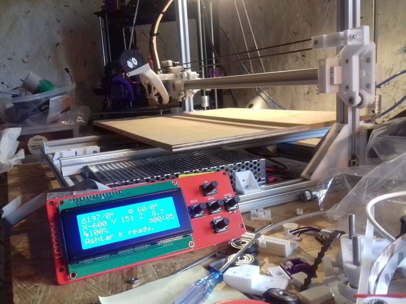
In Action
After 3 months (2018/06 – 2018/08), since I started to code the first OpenSCAD lines, the “K” prototype happen to print the 20mm XYZ Calibration Cube:
And roughly 2 months later Ashtar K #2 (with RAMPS 1.4 board) was printing as well, on a smaller 300x300mm unheated bed:
TODO
proper bed mounting and leveling: donebed heating: running without heat bed- better cable management (in particular heatbed / Y carriage)
- release sources
- complete instructions
- complete part list (printed / non-printed)
Parts
This is a preliminary part list (no files yet published):
Printed
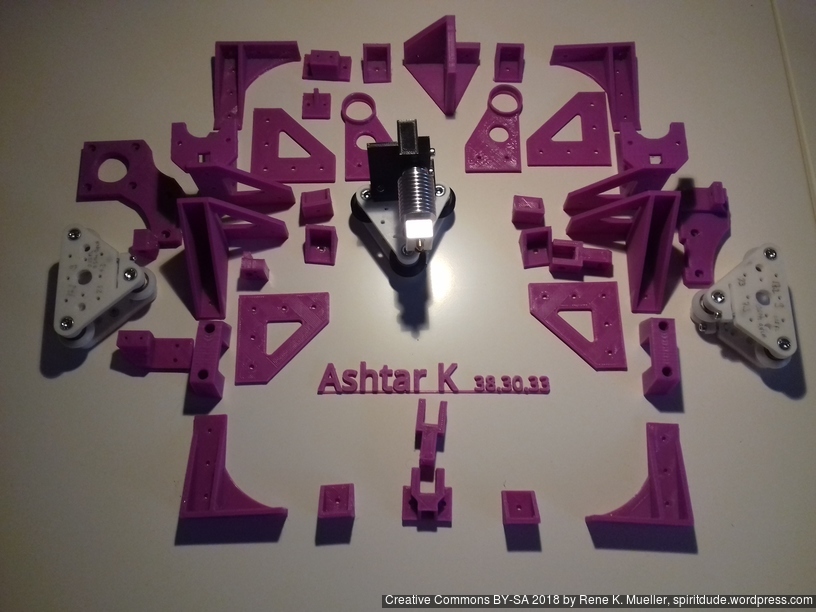
- V plates (2 plates = 1 module) with 3 x or 4 x M5 x 30:
Note: for each axis the plates must be printed with the same print settings to be symmetric when assembled, recommended setting: 1.5mm top and bottom thickness and wall thickness, layer height ~60% or less of nozzle diameter- X module (with 3 or 4 x black OpenWheels 24.4/11):
- short 3 wheel carriage:
- 1x v_plate-2020-double-v-244-110-48w-a
- 1x v_plate-2020-double-v-244-110-48w-b
- short 4 wheel carriage:
- 1x h_plate-2020-double-v-244-110-48w-a
- 1x h_plate-2020-double-v-244-110-48w-b
- short 3 wheel carriage:
- 2 x Z modules (with 3 x white Nylon 23/7.3 wheels) each
- 3 wheel carriage:
- 1x v_plate-2020-delrin-230-73-10-a
- 1x v_plate-2020-delrin-230-73-10-b
- 3 wheel carriage:
- 3 or 4 x Y modules (1 module = 1 slider, per slider 4 x 10mm long x 4mm PTFE + 3x 8mm long x 3mm PTFE)
- 3 or 4 x slider_2020-ptfe=true,td=4,td2=3,axis=2,closed=true,hplus=5,hole=true
- X module (with 3 or 4 x black OpenWheels 24.4/11):
- X carriage:
- 1x xcarriage_short_hmount_motor-endstop-left
Note: minimum 1.5mm top and bottom thickness, and 1.5mm wall thickness, 30% infill, layer height ~60% or less of nozzle diameter - 1x xcarriage_short_hmount_motor-right
Note: minimum 1.5mm top and bottom thickness, and 1.5mm wall thickness, 30% infill, layer height ~60% or less of nozzle diameter - 2x xcarriage_short_hmount
- 1x xcarriage_beltmount-y=7,w=25
- 1x pulley_holder
- 1x endstop_mount
- 1x xcarriage_short_hmount_motor-endstop-left
- Printhead/Hotend:
- 1x e3d_mount
- 2x M3x12 (mounting to x carriage), 2x M3 nuts for insets for clamp (use M3x12 to draw nuts into inset)
- 1x e3d_mount-type=clamp
- 2x M3x16 (clamp E3D v6)
- 1x e3d_mount
- Y carriage:
- 4x knob_30,8,6 (bed level wheels)
- 1x ymotor_mount
- 1x ycarriage_mount-h=15
- 1x yendstop_bumper
- 1x yendstop_mount
- 1x pulley_holder
- 1x ybelt_mount
- Z carriage:
- 2x zcarriage_short_mount-6,30 (for M6 threaded Z rods)
- 1x ztop_bracket-left
- 1x ztop_bracket-right
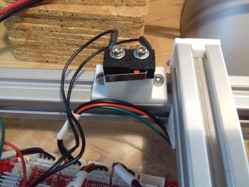
- 1x zendstop_mount
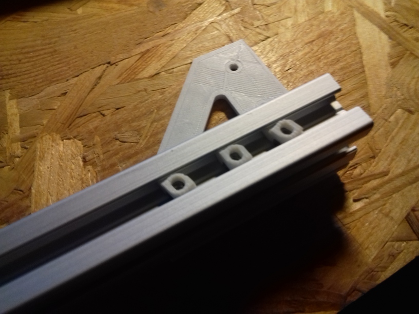
- Frame
- 8x c_2020 (simple 2020 corners)
- 2x l_2020-a (short L bracket)
- 2x l_2020-b
- 1x ll_2020-a, 3 perimeters/wall line count
- 1x ll_2020-b, 3 perimeters/wall line count
- 1x ll_2020-type=nema17-a (X/Z bracket + Z motor mount)
Note: 3 perimeters/wall line count with layer height ~60% of nozzle diameter (e.g. 0.25mm @ 0.4mm nozzle or 0.3mm @0.5mm nozzle) - 1x ll_2020-type=nema17-b (same notes as above)
- 2x c2_2020-a (strong L for bottom frame)
- 2x c2_2020-b
- 12x e_2020 (end caps)
Non-Printed (Vitamins)
- 11x 500mm 2020 alu extrusions (T slot 6 B-type or V-slot 6)
- Double or single V slot wheels (OpenWheel 24.4/11) and/or 18x (6 x 3) x Delrin R nylon (23/7.3) wheels (see printed parts above which are needed)
- Screws & Nuts:
- 200x M3 nuts
- 100x M3 8mm
- 20x M3 10mm
- 20x M3 15mm
- 150x M3 Hammer Nuts for T slot/V slot 6
- 20x M5 x 30
- 20x M5 nuts
- Y carriage / bed:
- 420 x 320 or 320 x 320 OSB 6mm as Y carriage
- 400 x 300 or 300 x 300 3mm thick mirror
- 400 x 300 or 300 x 300 frosted bed sticker
- 4 x springs 20mm long, compressed 10mm
- Belts:
- 2x GT2 pulleys (ID 3, OD 16, 6 wide with teeths)
- ~220cm GT2 6mm belt (200cm might be sufficient but without any cutting margins)
- Printhead:
- E3D V6 original / clone with 0.4mm or 0.5mm (recommended) nozzle
- 100cm PTFE 4mm OD / 2mm ID (60cm for Bowden tube, reuse rest for sliders)
- 1x Pneumatic Connector PC4-01
- 1x Pneumatic Fittings PC4-M6 Bore 4.3mm for 4mm PTFE
- Electronics:
- 5x stepper motors Nema17 42-45NM (40mm height) with 1m wires
- 1x control board (with Marlin support), e.g. Anet V1.0 or Makerbase MKS Gen L board
- 2 x endstops with 1m wires
IDEX Option
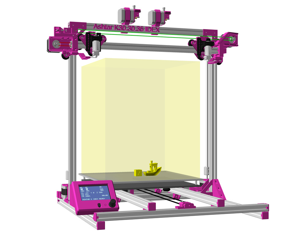
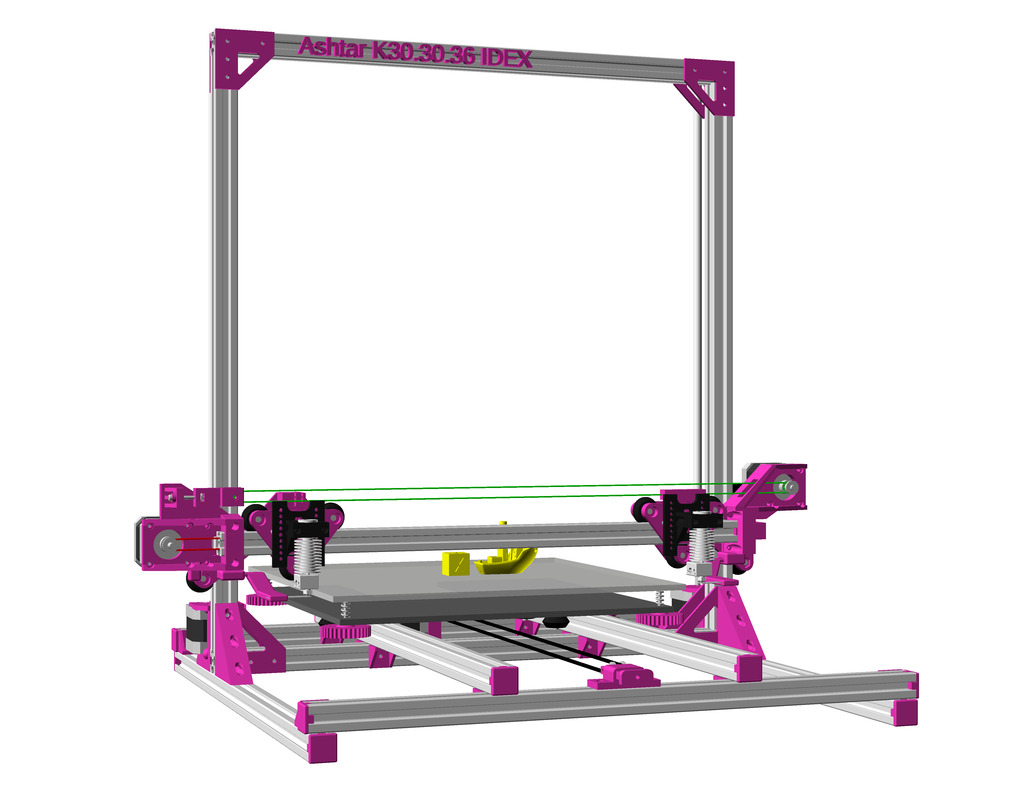
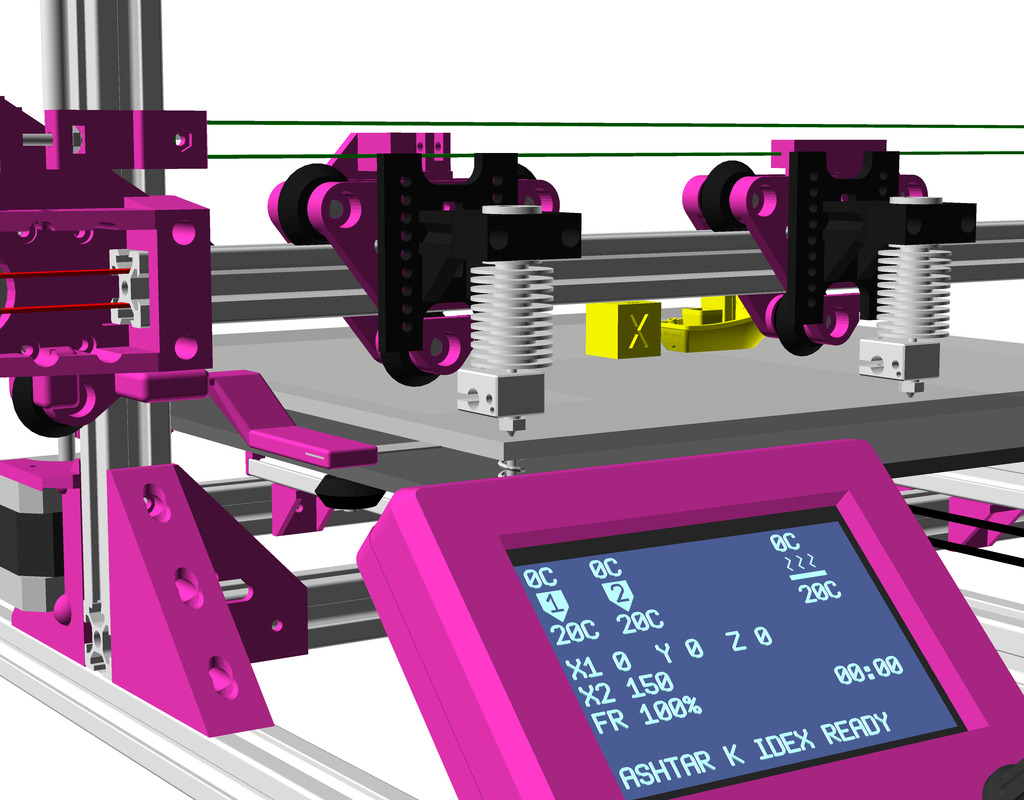
In order to run two independent printheads aka IDEX (Independent Dual Extrusion) see this blog-post on Ashtar K IDEX with the details and those new pieces are needed:
Printable
- 1x xcarriage_short_hmount_motor_2020-endstop-idex-left
- 1x xcarriage_short_hmount_motor_2020-idex-right
- 1x xcarriage_beltmount_2020-idex
- 1x pulley_holder
- 1x xcarriage_nose-idex-left
- 1x xcarriage_nose-idex-right
Non-Printable
- 1x Nema17 42-45Nm (39-40mm height) with 1m wires
- belt ~110cm GT2 6mm
- 1x pulley
- 1x idler
As soon I tested this option I will document it in more details, like electronics, changes in firmware, slicer settings etc.
Other Options

Multiple Switching Extrusions (MSE) Rotary Y 2 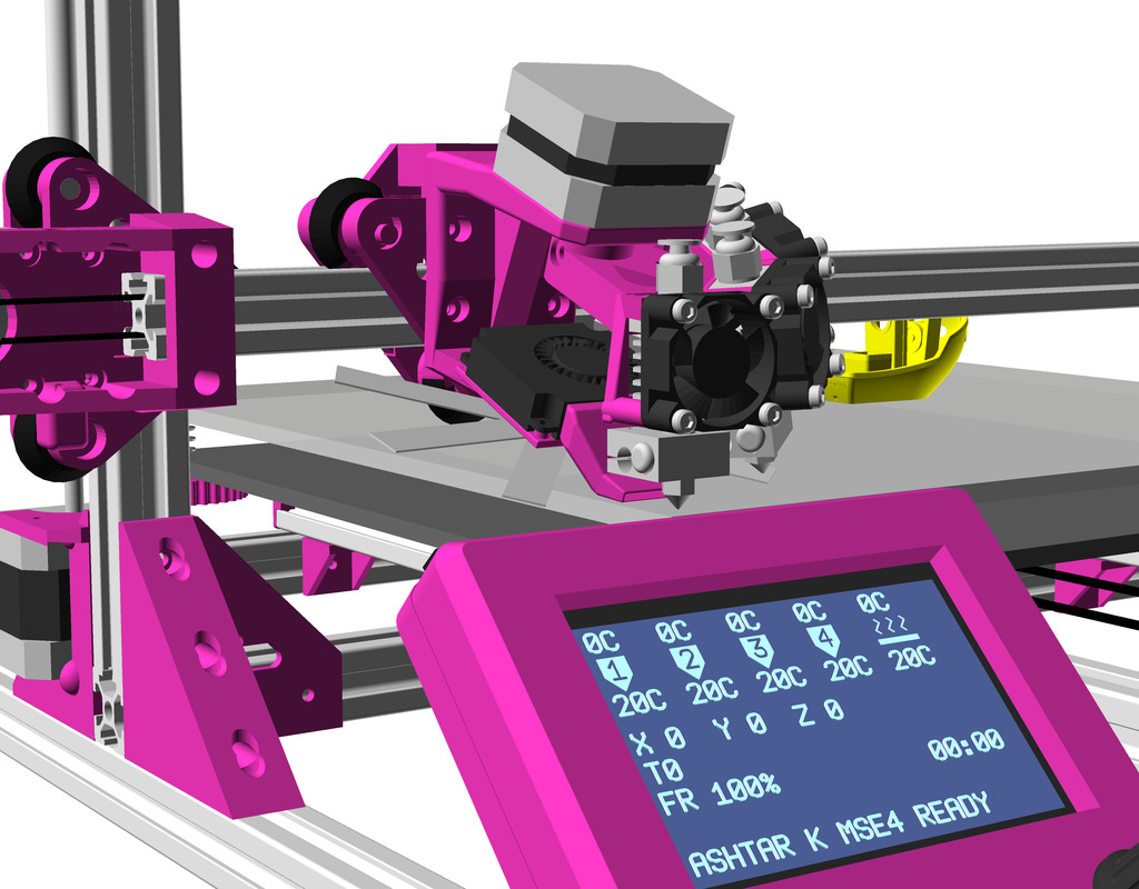
Multiple Switching Extrusions (MSE) Rotary X 4 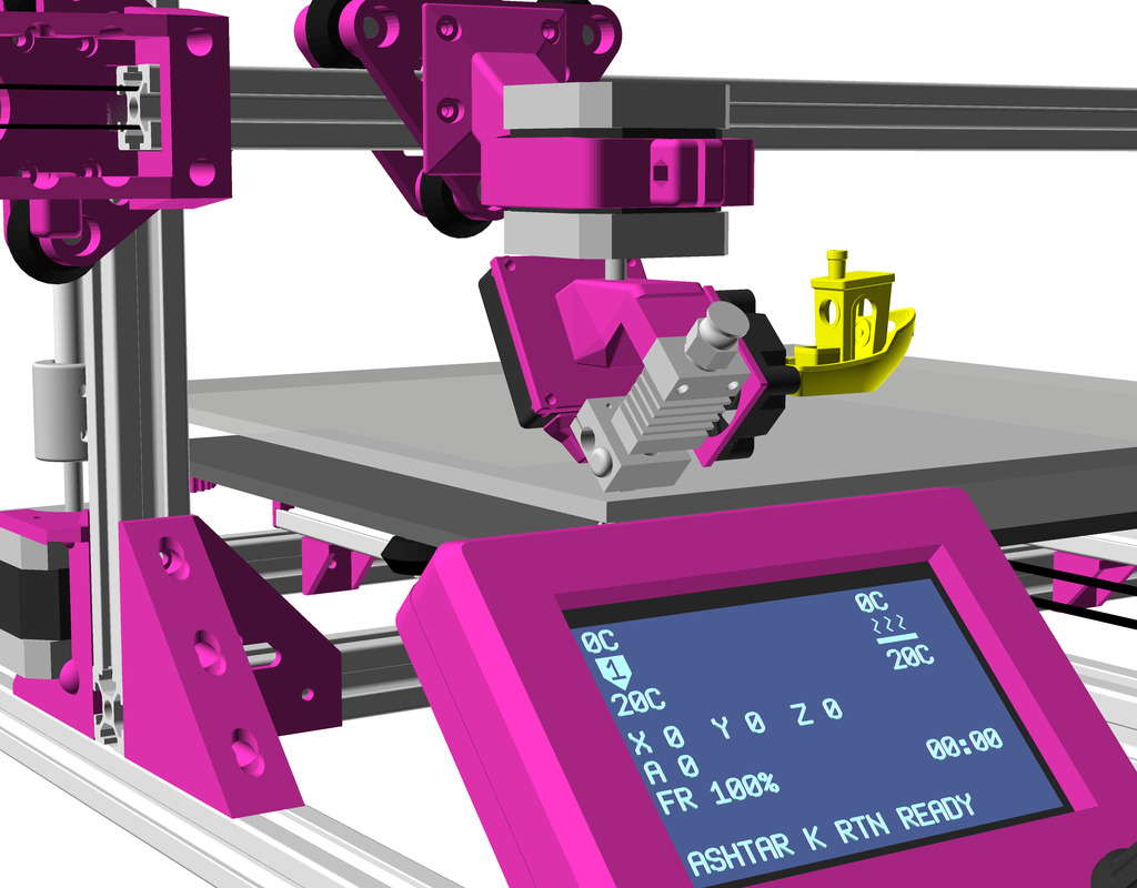
Rotating Tilted Nozzle (RTN) 
Penta Axis (PAX)
- Multiple Switching Extrusions (MSE) Rotary Y (2), Rotary (2-4)
- Rotating Tilted Nozzle (RTN)
- Penta Axis / 5 Axis Printhead (PAX)
Related Projects
- Easy Multi-functional Prusa: 2020 alu extrusions with 23mm nylon wheels
- Piper 1 V2: composed by conduit pipes and a lot of printed parts