Updates:
- 2024/10/23: finally published
- 2024/10/11: ready for publishing
- 2024/01/26: starting write-up
Introduction
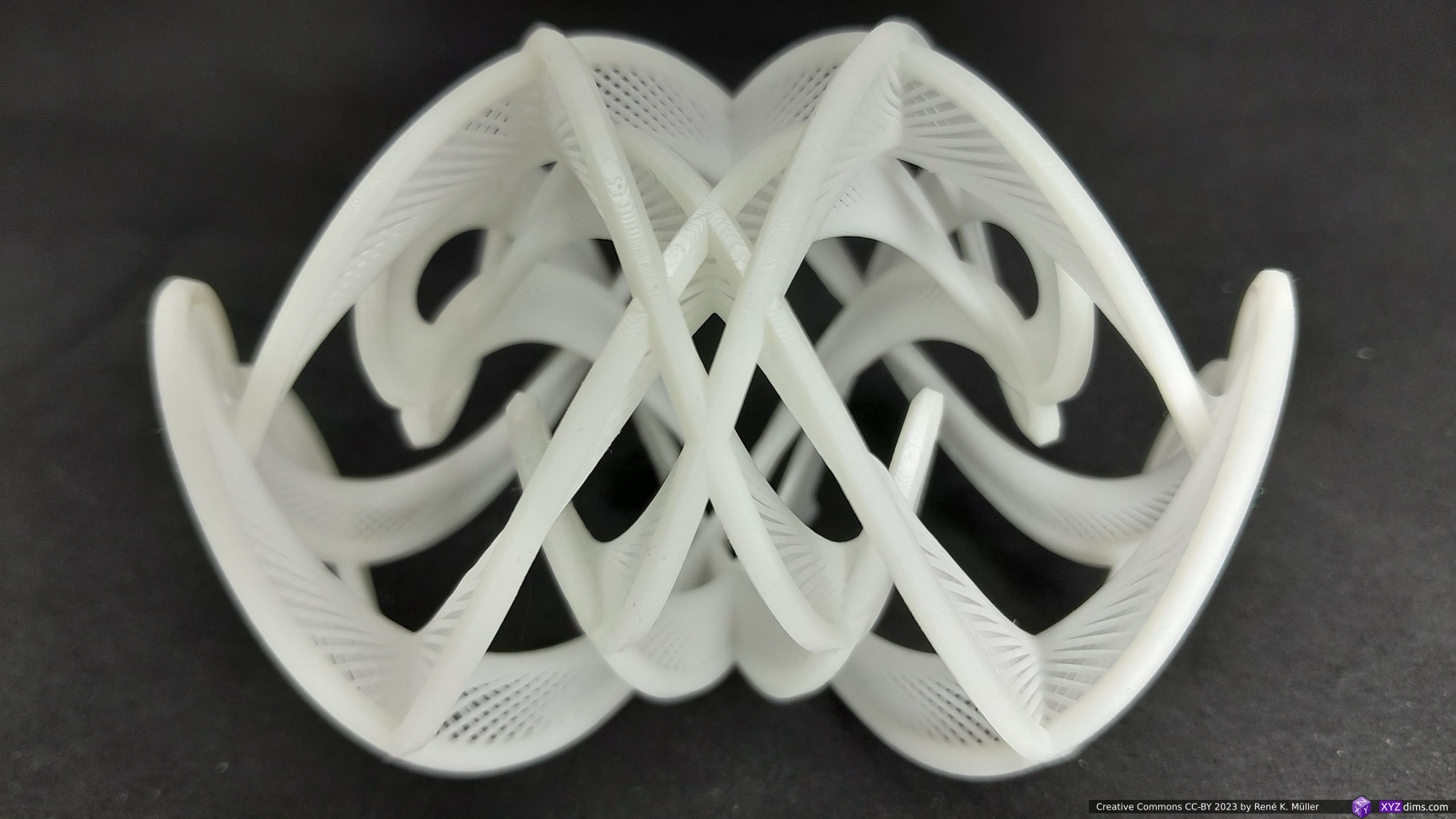
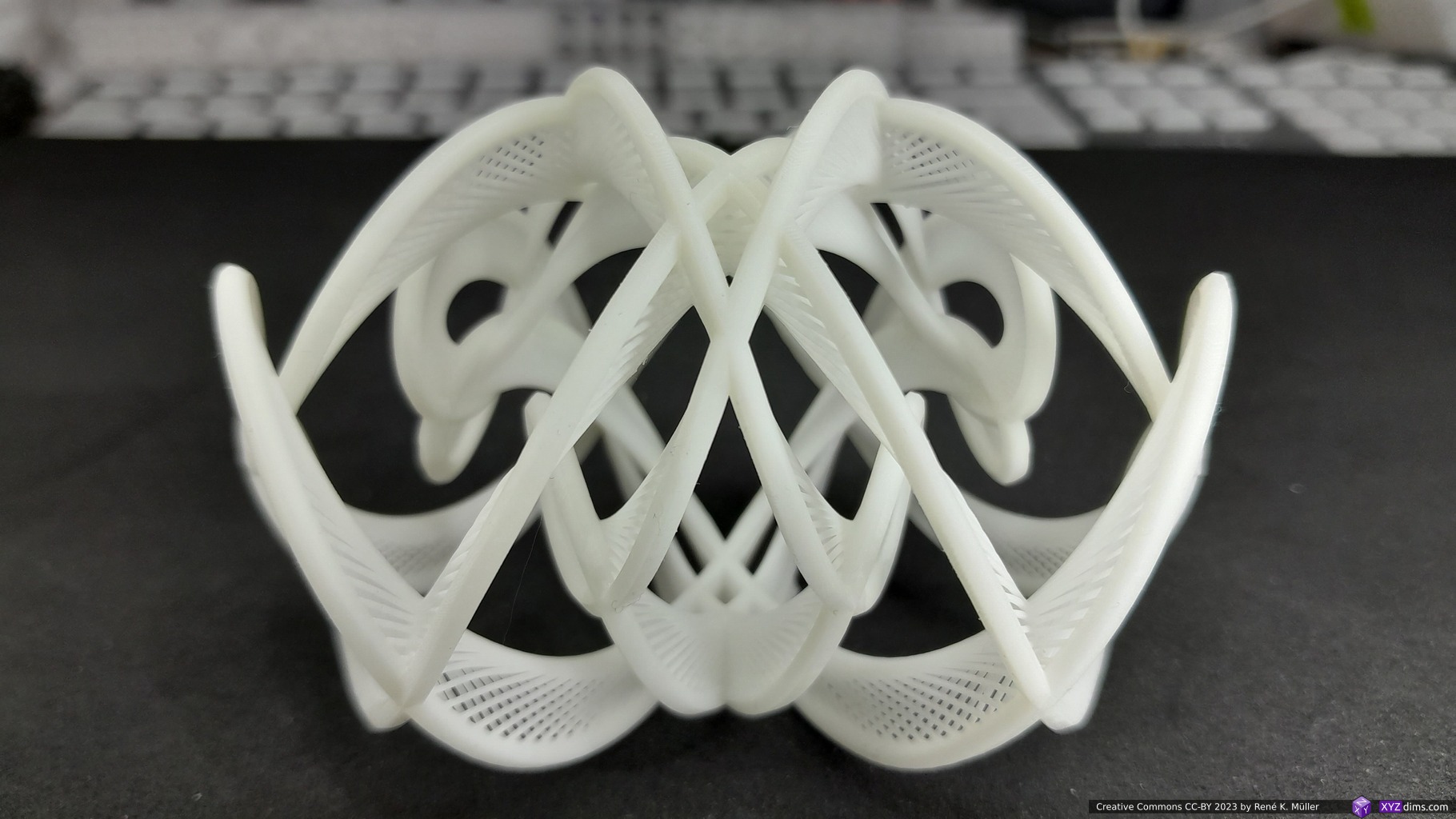
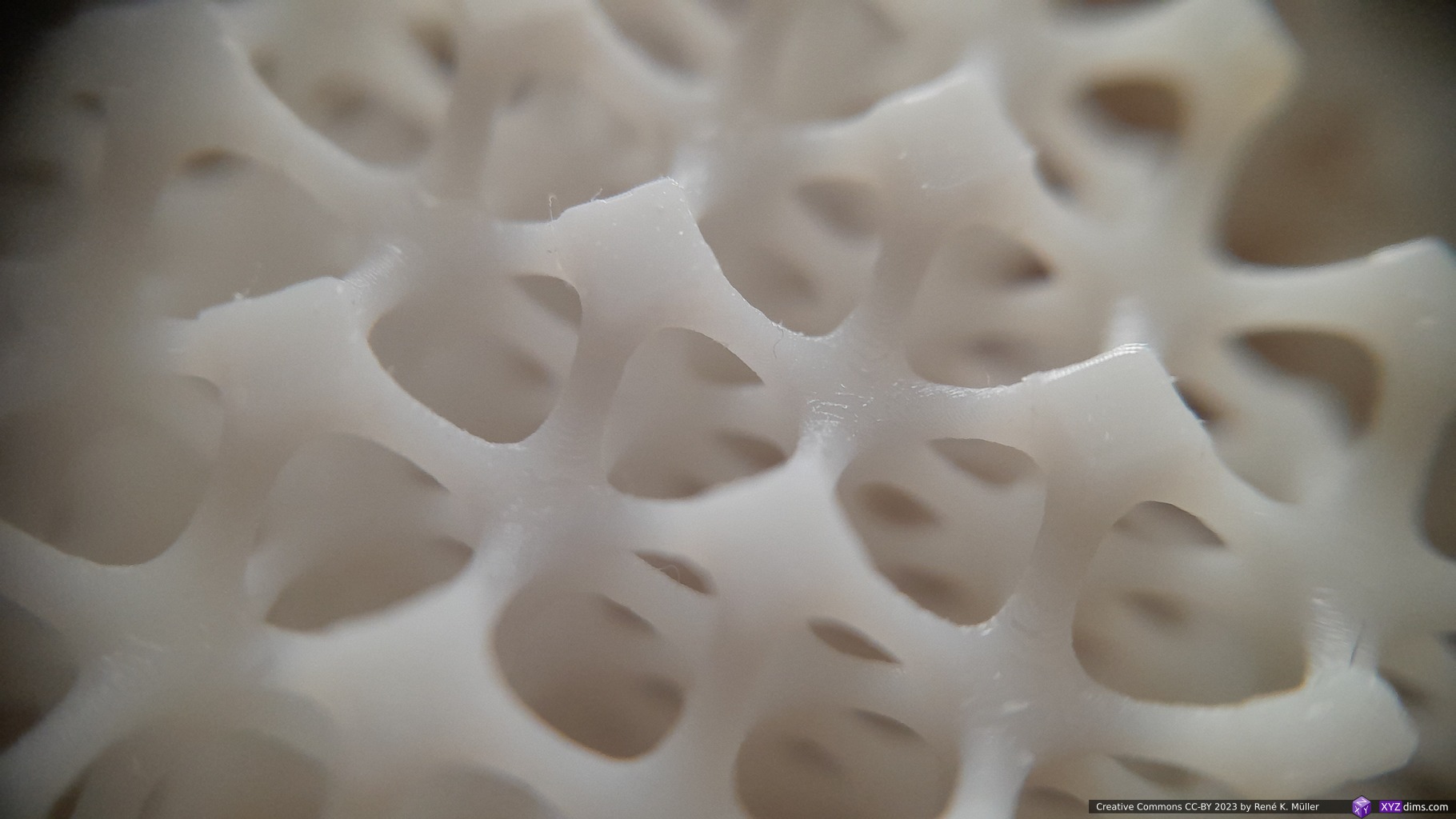
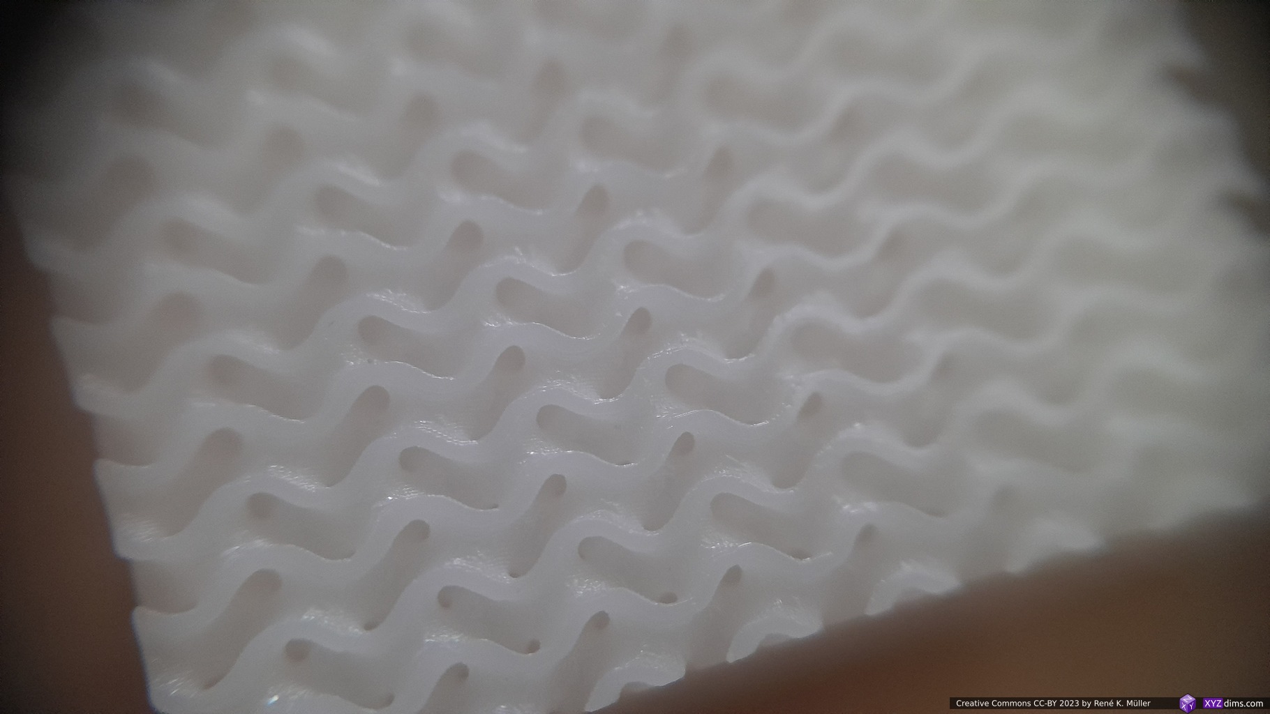
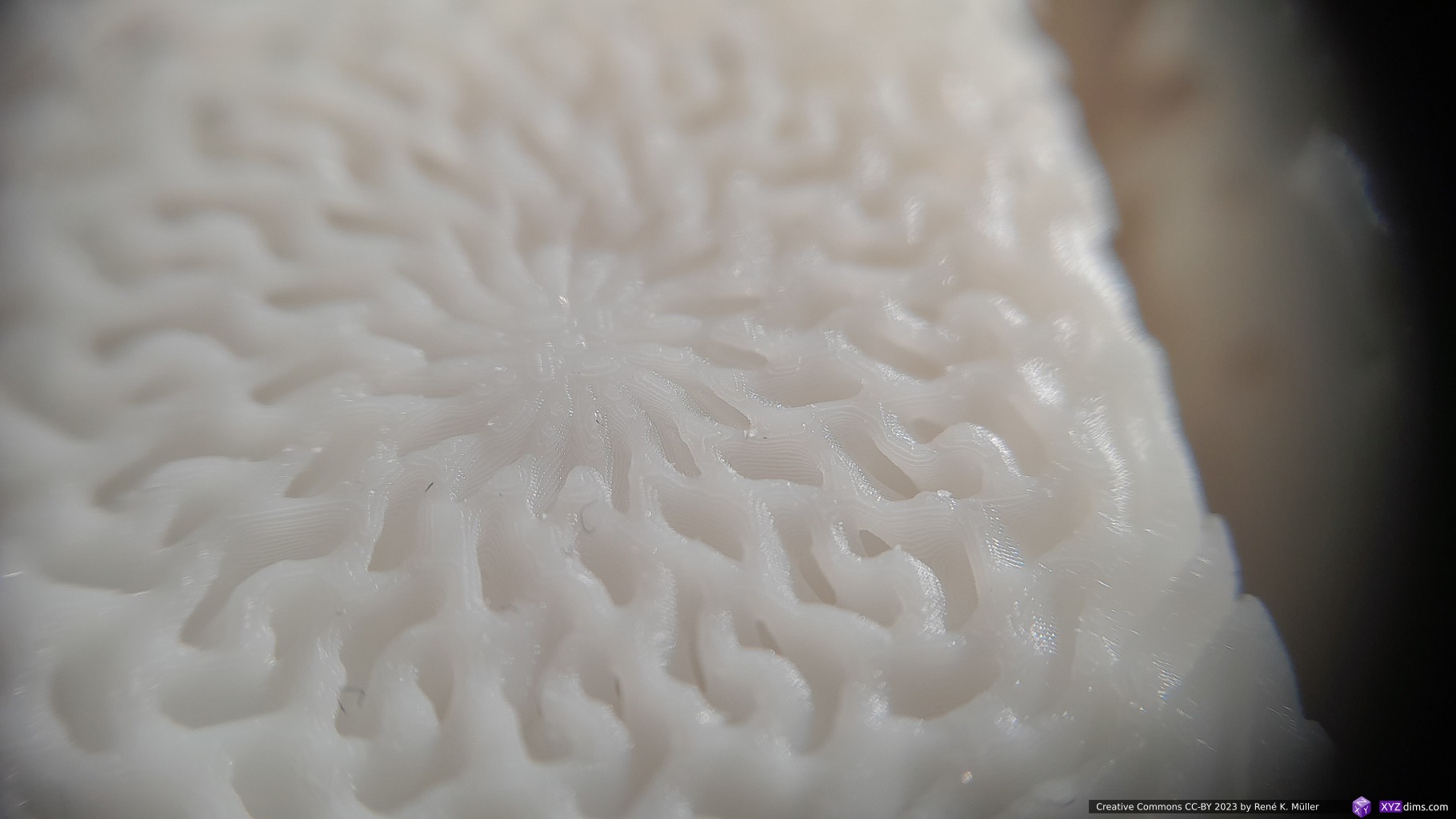
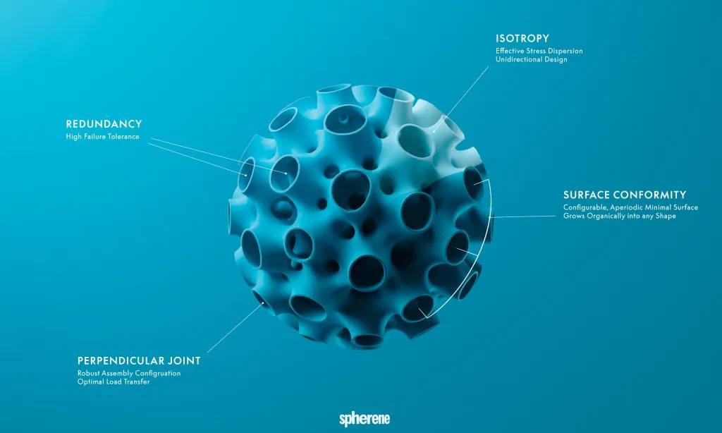
At Formnext 2023 I spent some unexpected time to discover a new class of procedural structure called “Spherene” (“sphere” + “graphene”), it’s a name as introduced by a company with the same name.
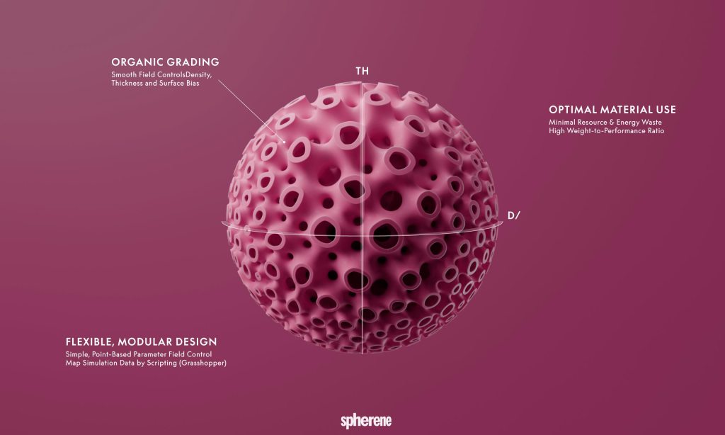
It’s main feature is isotropic (“all directions”) distribution of forces. Their service provides the creation of this structure based on:
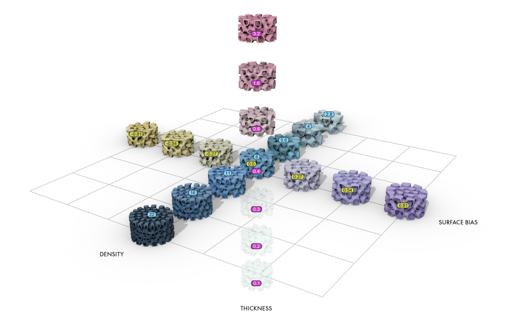
- density (ratio of material vs empty space), hence their term of Adaptive Density Minimal Surface (ADMS)
- form
- wall thickness
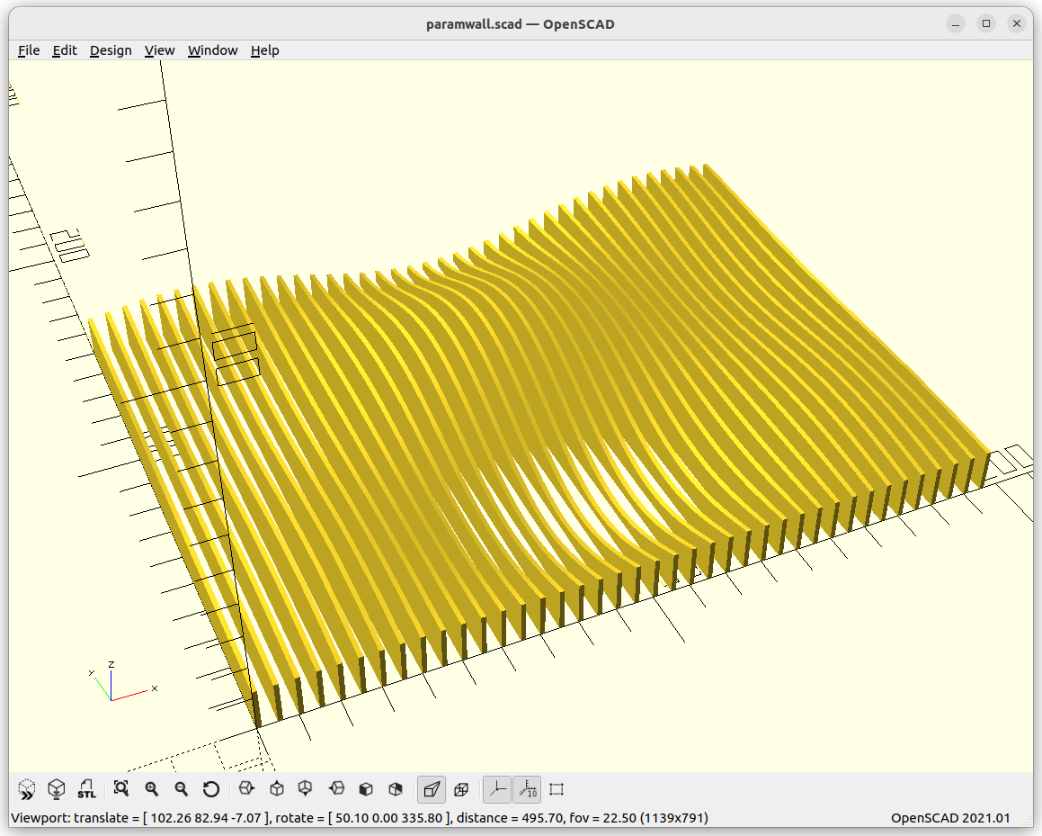
where all of them are freely definable in 3D space contained within an overall boundary. Their service “renders” a mesh which complies with such, like defining at some point a lower or higher density, and transits in 3D space from one to another.
Patent
My immediate impulse was to code the Spherene aside of the existing TPMS’s, but I realized their business core is the service of creating meshes based on their procedure as described in a patent:
- Method of Additively Manufacturing a Minimal Surface Structure (Original, 2023), PDF available
- Method of Additively Manufacturing a Minimal Surface Structure (2023, PDF OCR processed / machine readable)
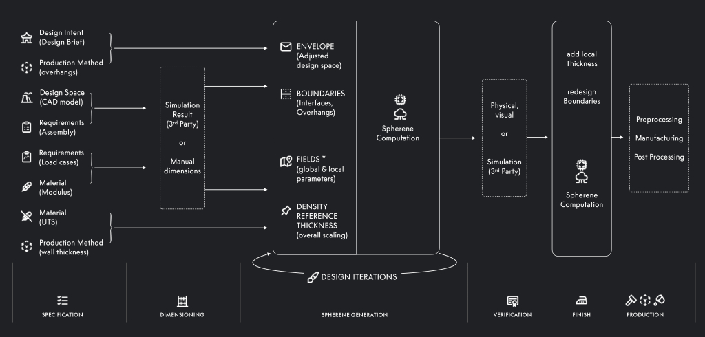
- at its core it describes 6 steps (abbreviations added for clarity)
- creating envelope
- creating density field
- adaptive Voronoi tesselation (AVT),
- 1st skeleton graph (SG) associated to AVT (SG-AVT1)
- generated from the edges of the Voronoi cells
- 2nd skeleton graph associated to SG-AVT1 (SG-AVT2)
- generated using Delaunay tetrahedralization
- minimal surface from SG-AVT1 and SG-AVT2, using equidistant from both skeleton graphs, with minimal wall thickness requirements
- Abstract: A method of additively manufacturing a minimal surface structure of a three-dimensional article includes a computer executing the steps of recording, in the computer,
- an envelope of the three-dimensional article; generating a density field across a volume enclosed by the envelope with densities of the density field corresponding to local requirement values of at least one physical parameter at respective positions of the three-dimensional article;
- generating an adaptive Voronoi tessellation of the volume using the density field;
- generating a first skeleton graph associated with the adaptive Voronoi tessellation;
- generating a second skeleton graph associated with the first skeleton graph; and
- generating a digital minimal surface model from the first and second skeleton graphs.
- The method may further include a 3D printer additively manufacturing the minimal surface structure according to the digital minimal surface model.
I think if Spherene is truly as significant for Additive Manufacturing, and an essential invention, it has to move beyond the grip of a single company and its patents – time will tell.
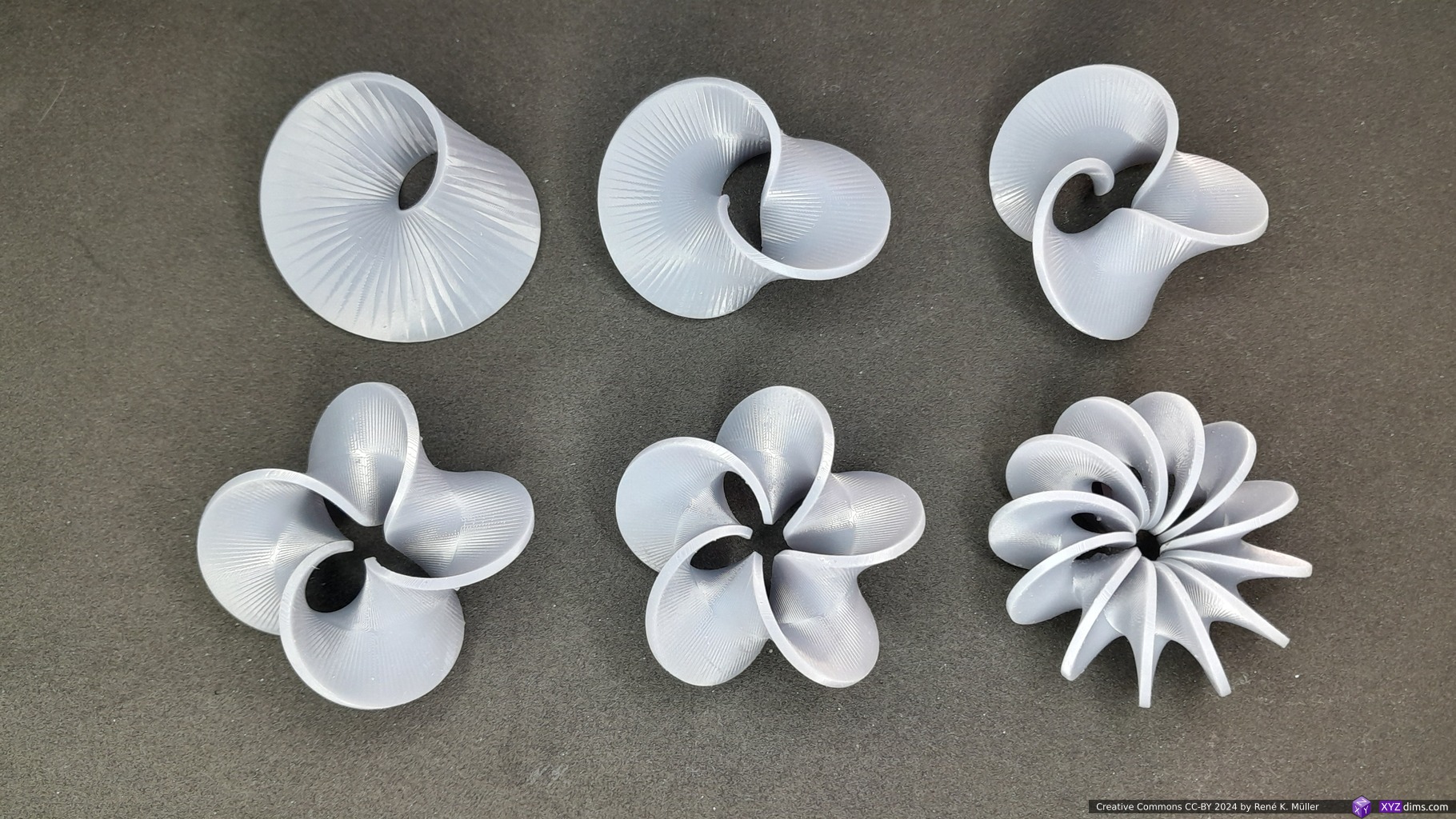
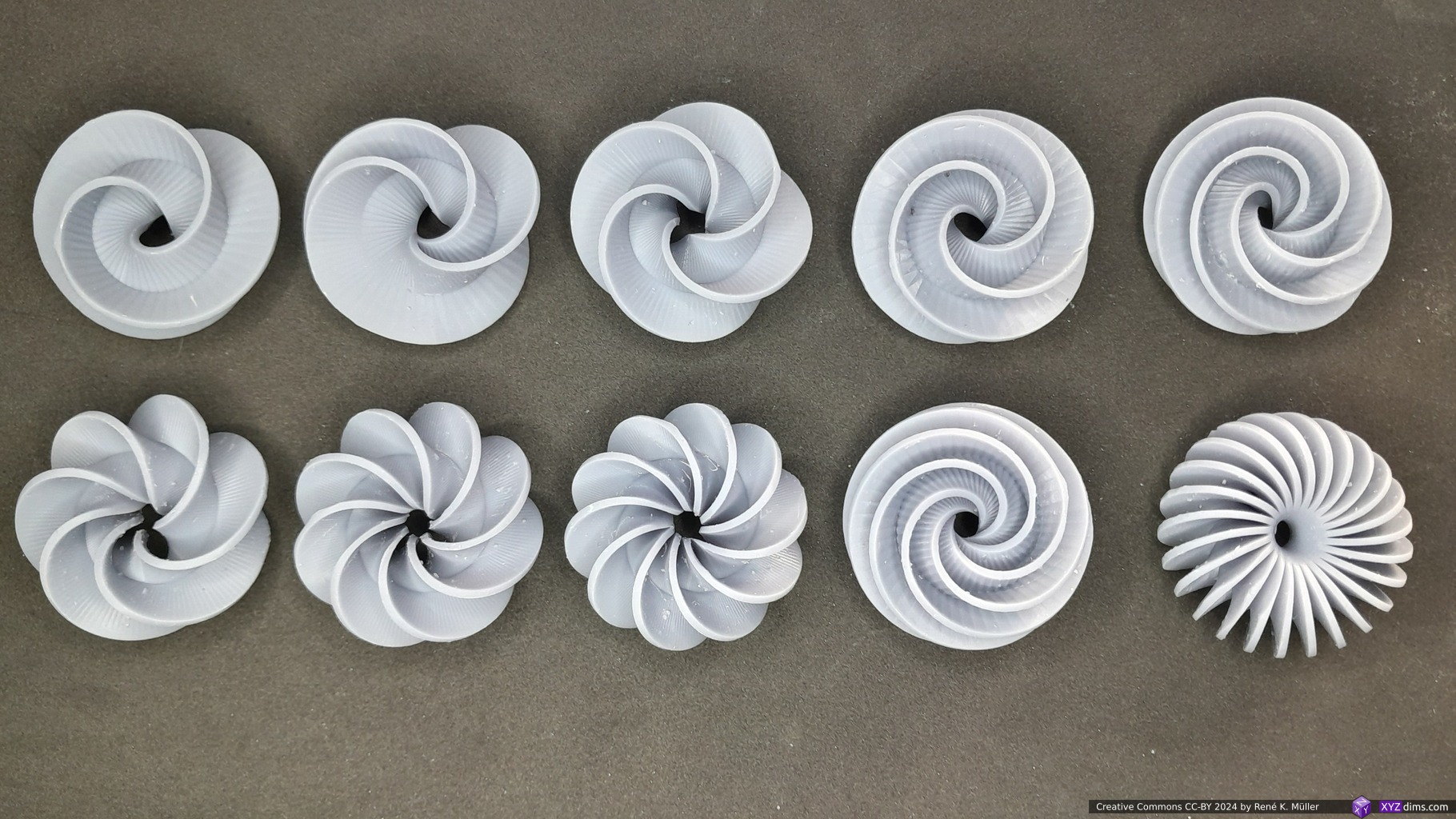
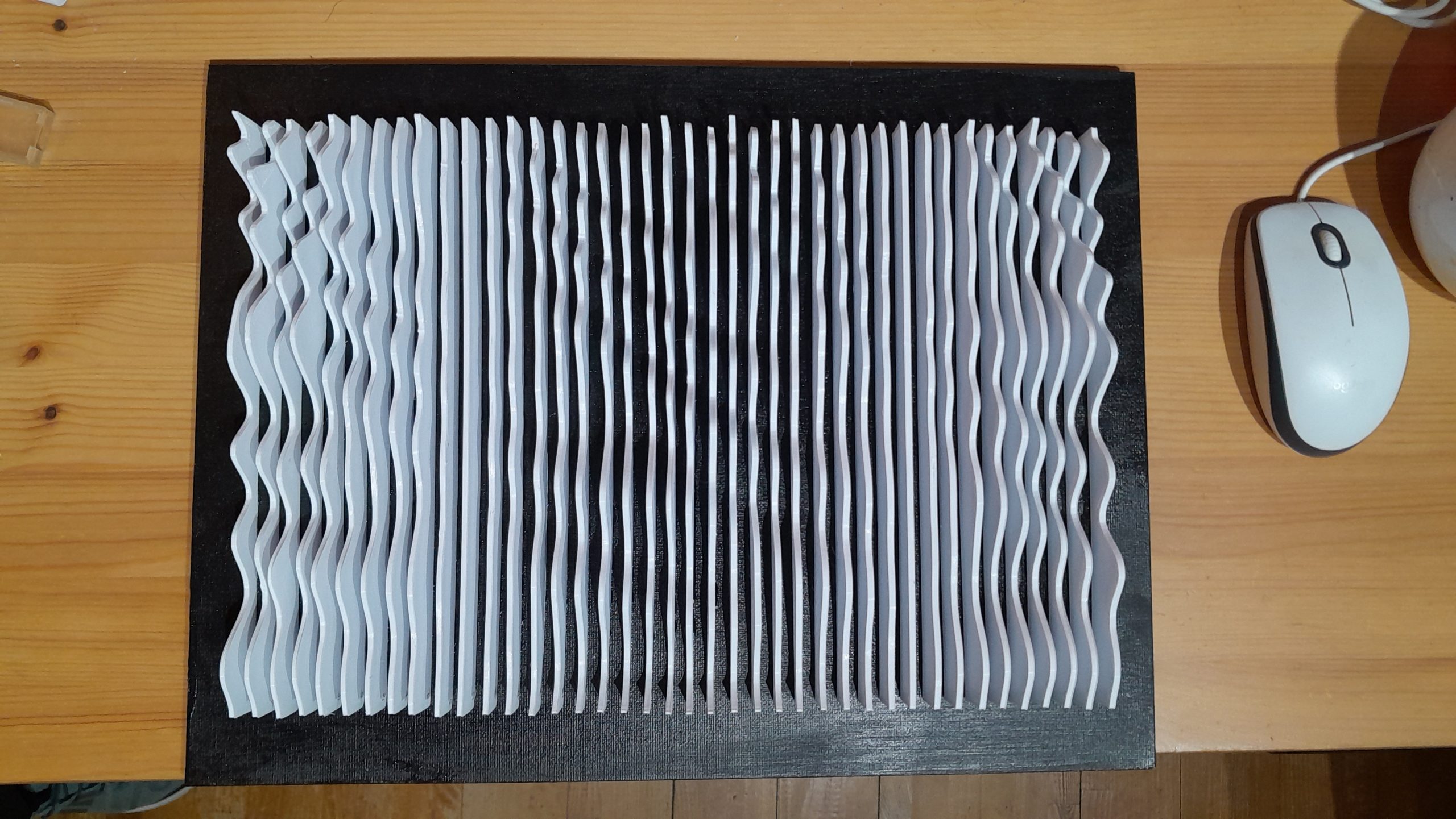
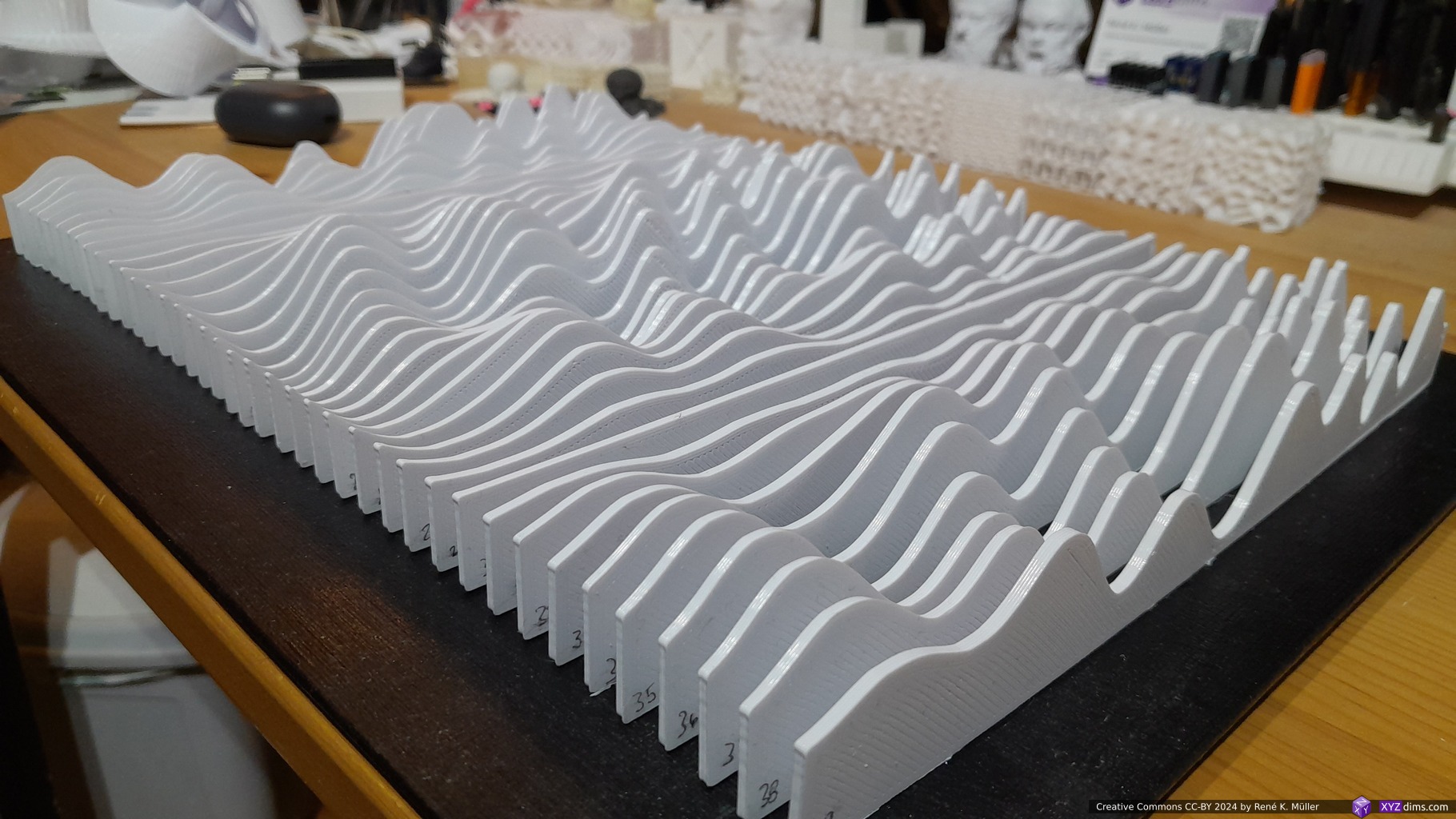
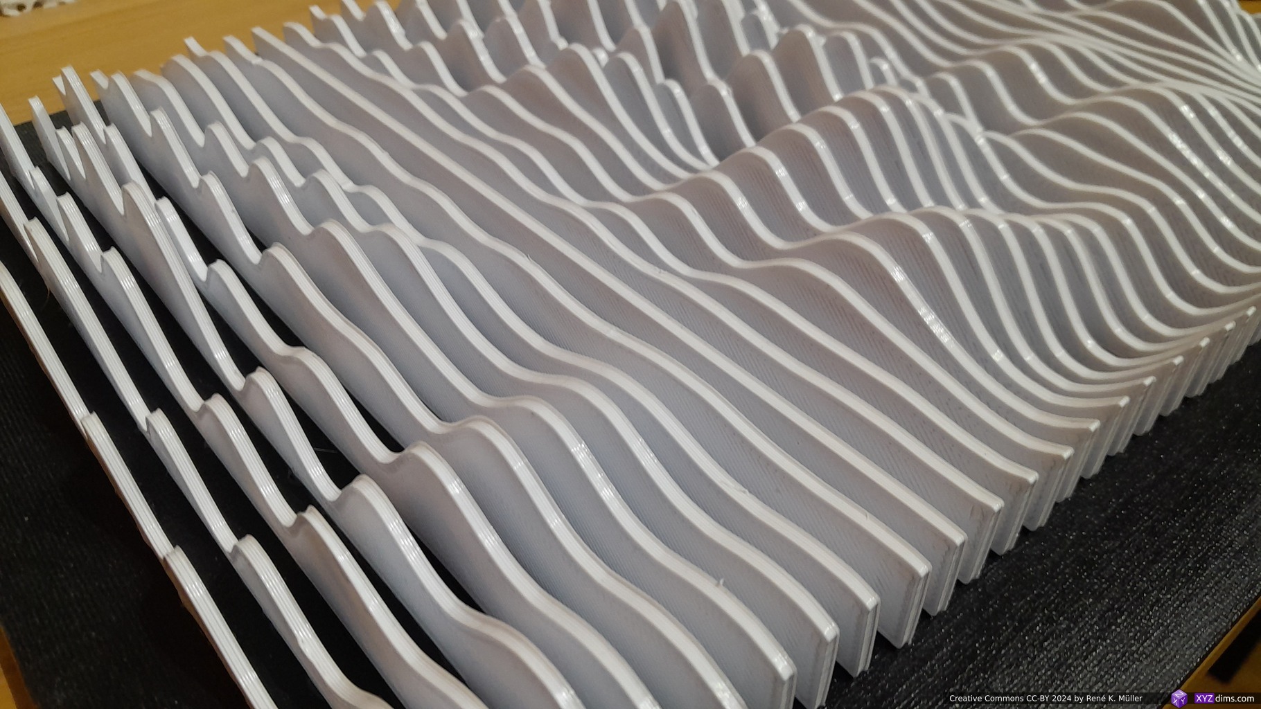
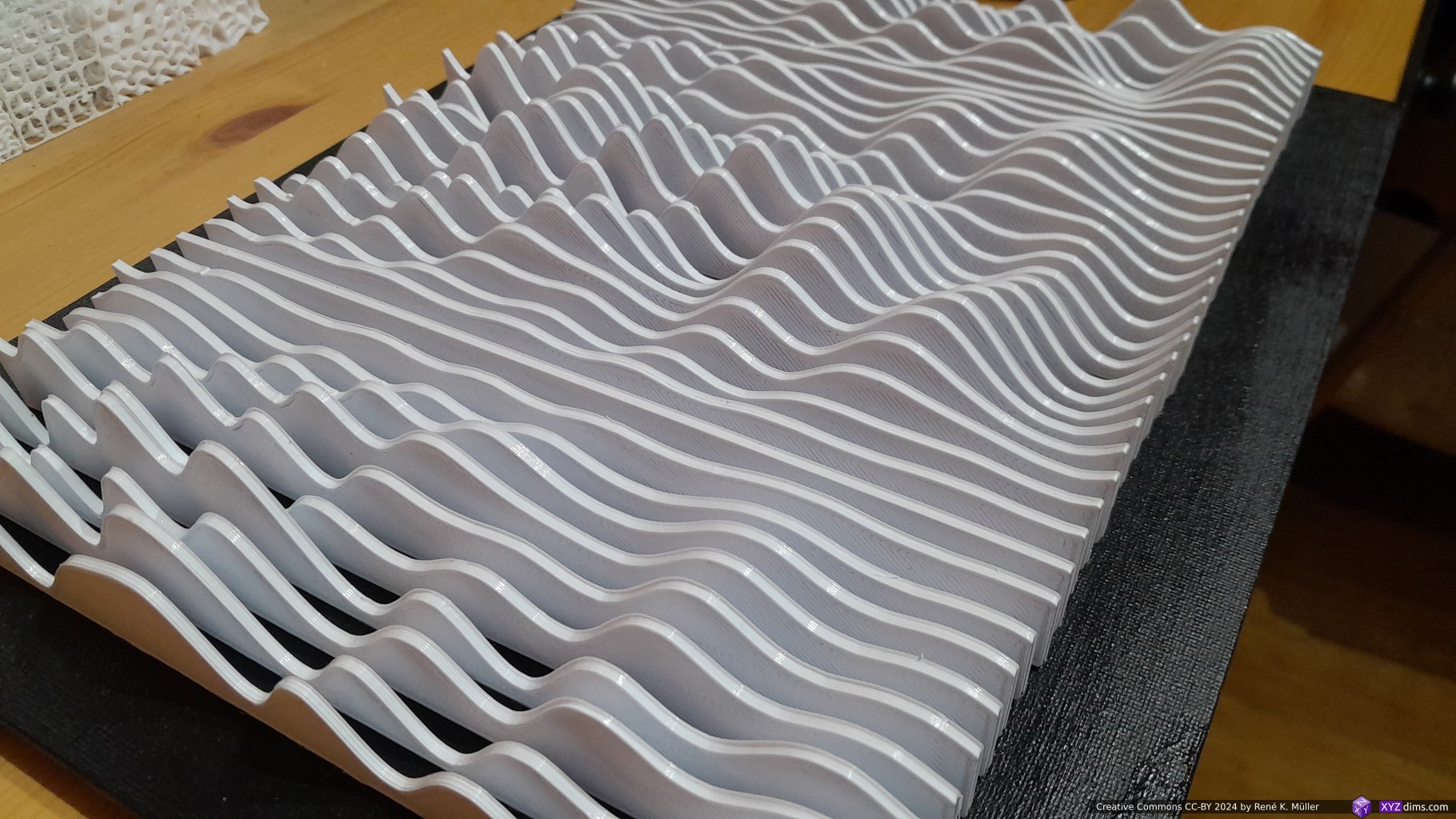
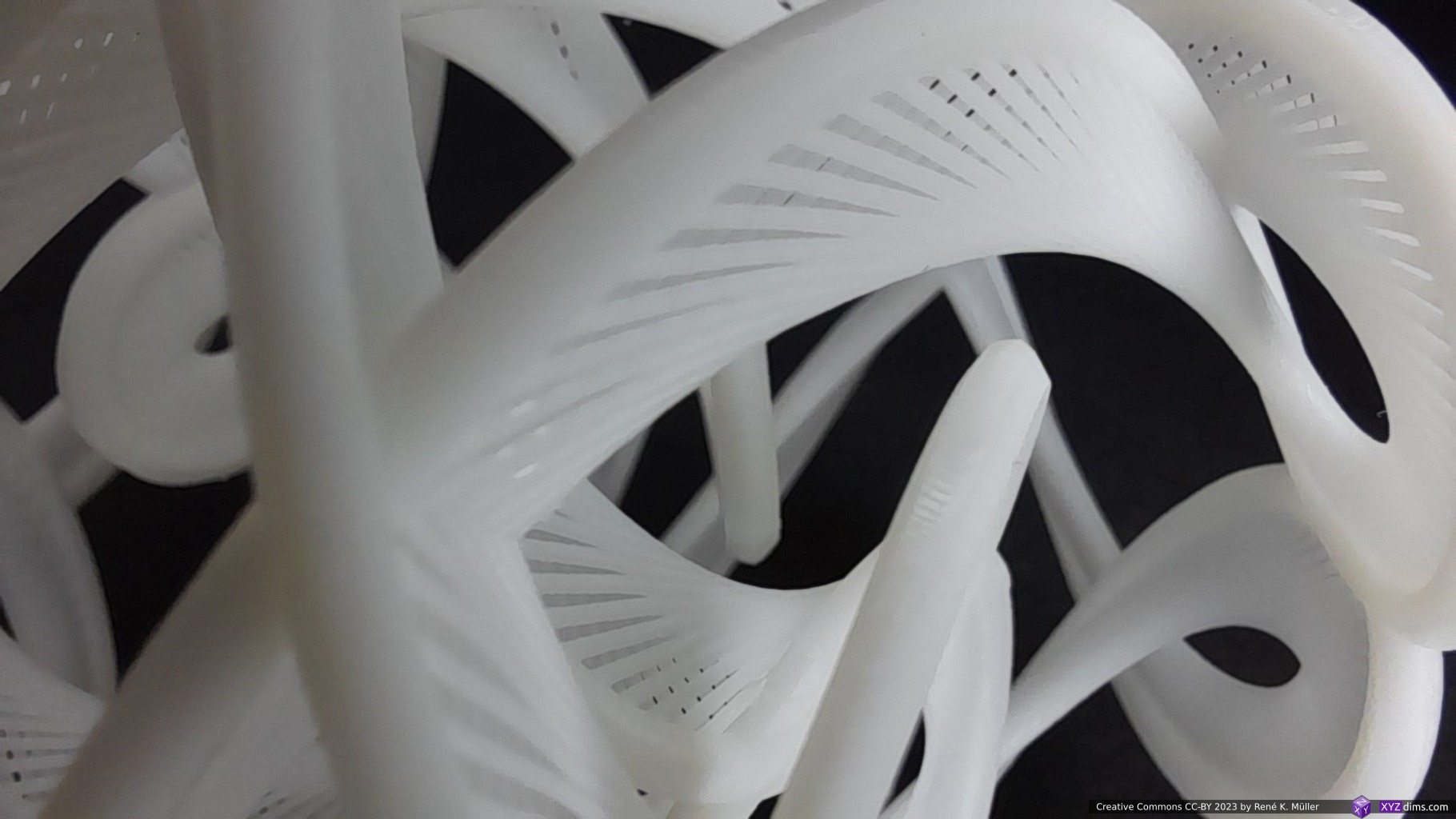
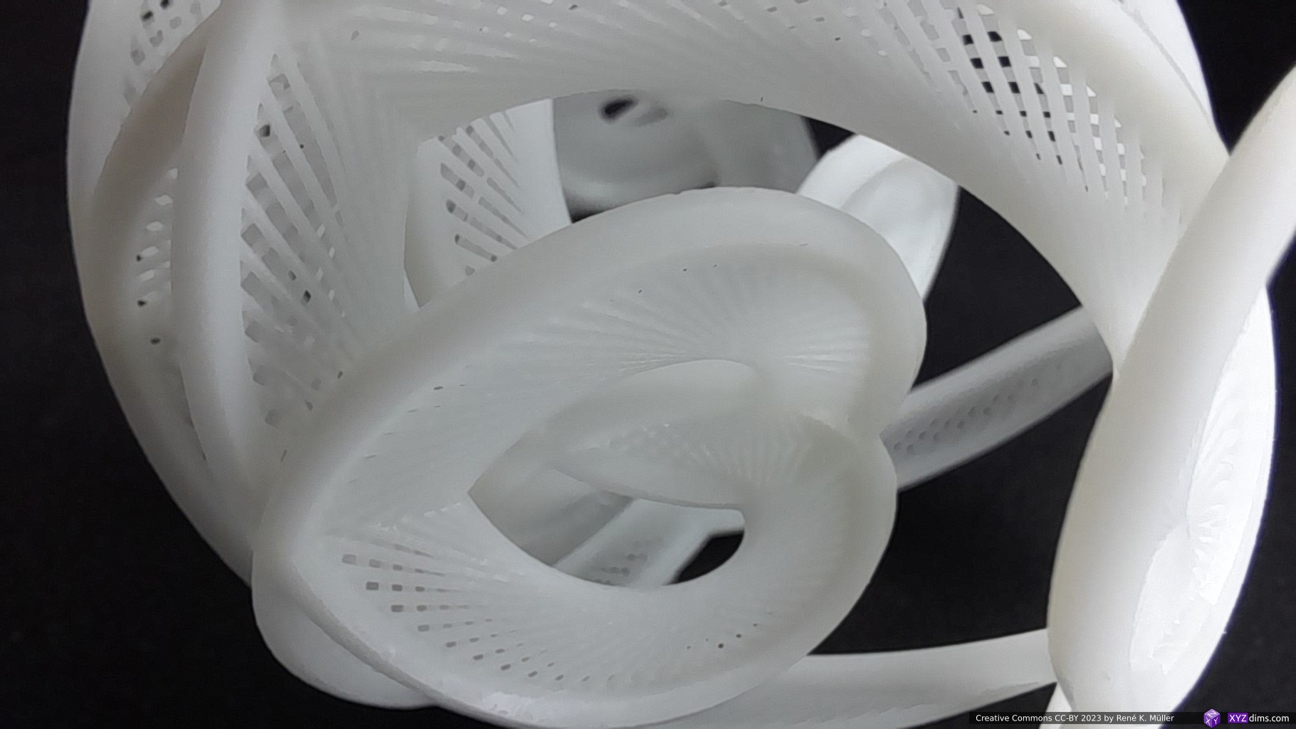
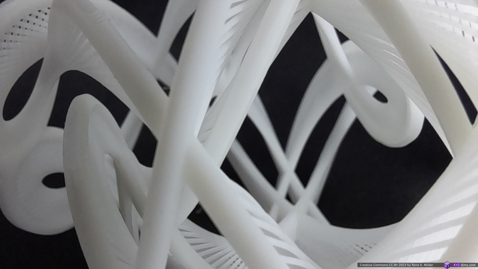
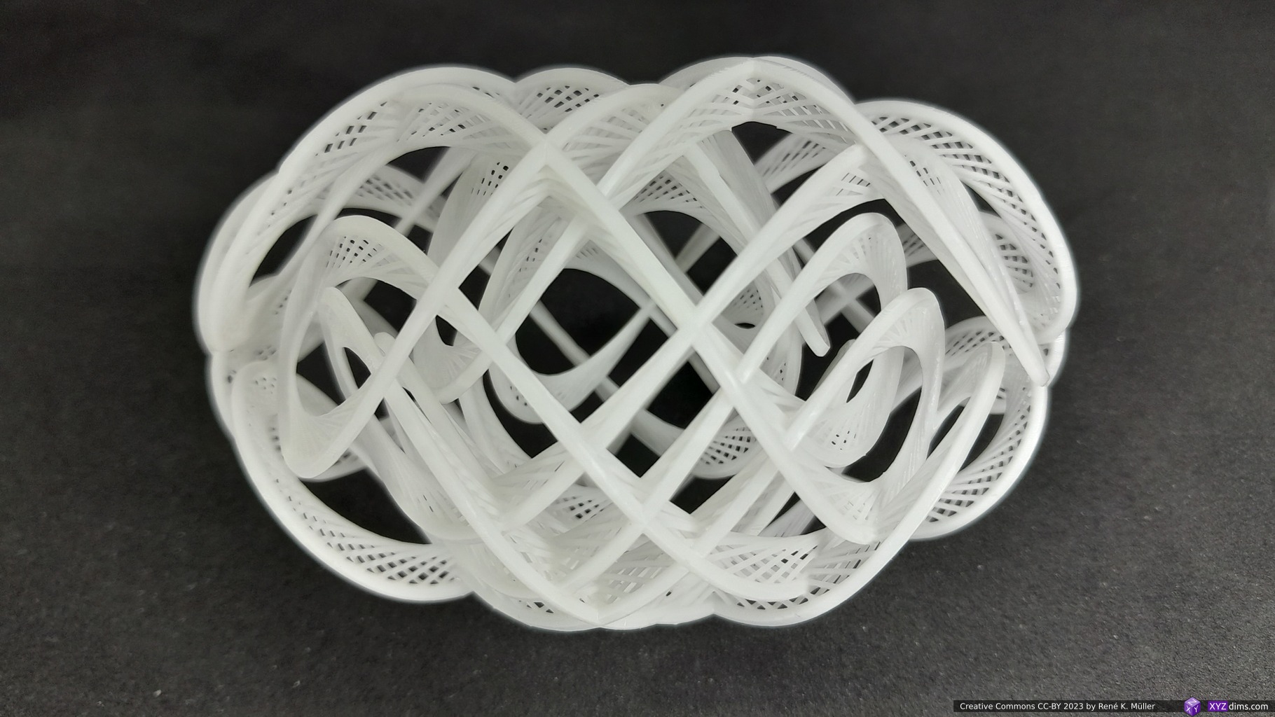
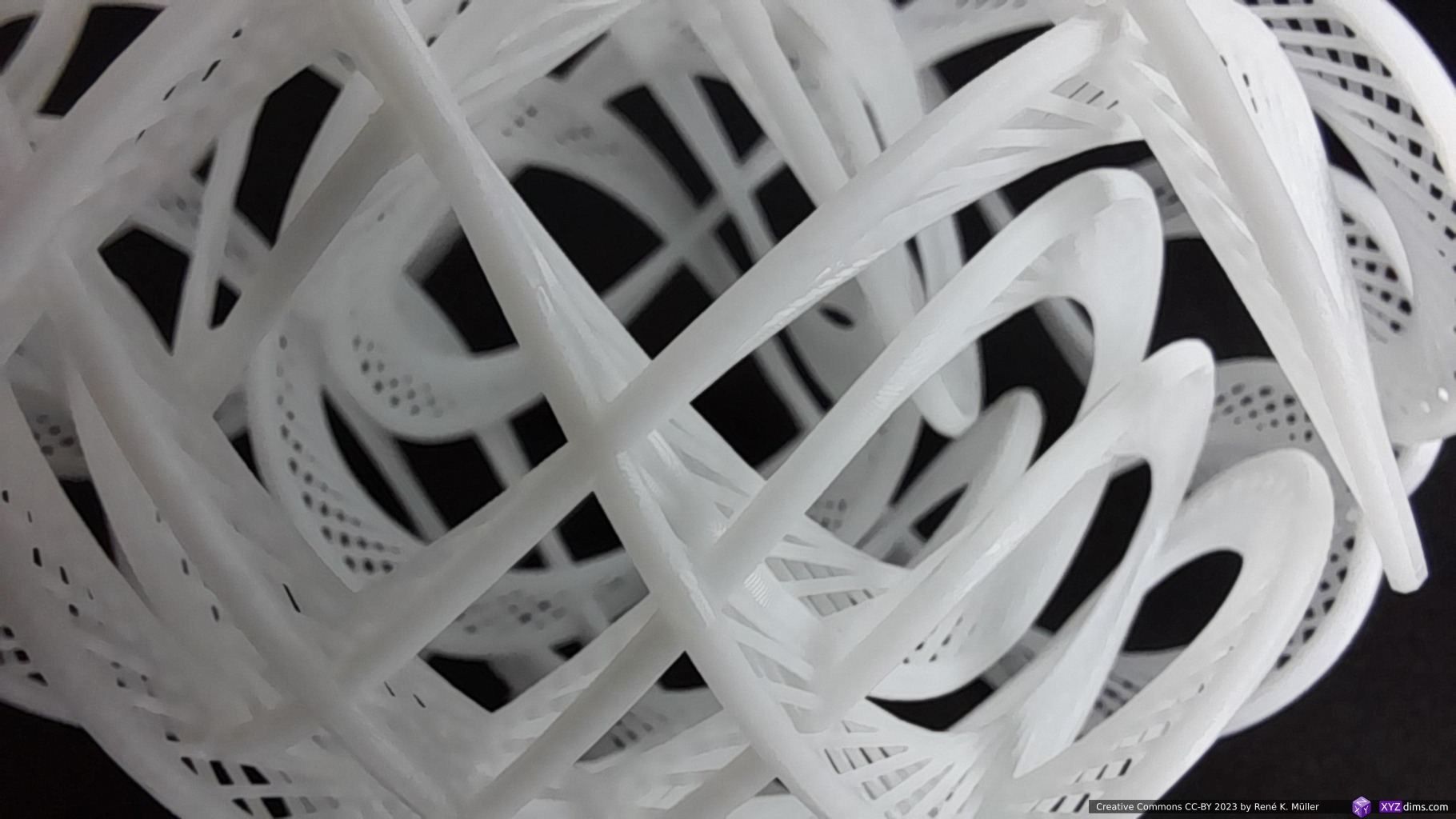
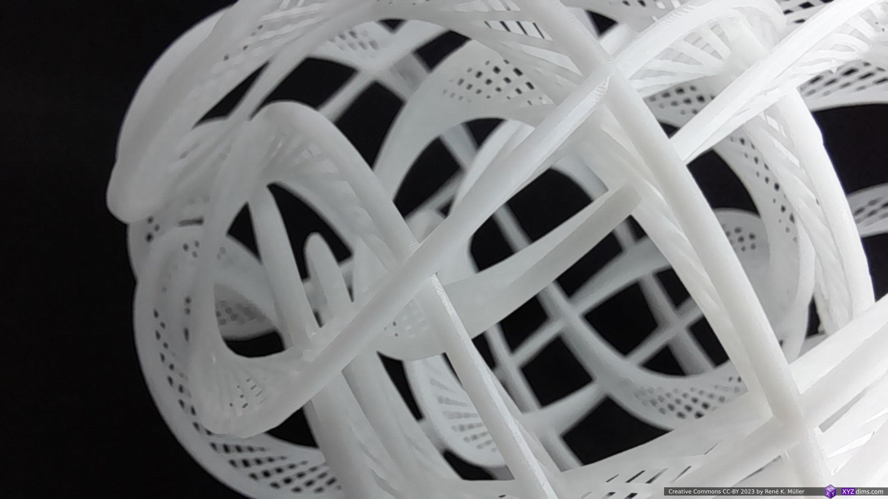
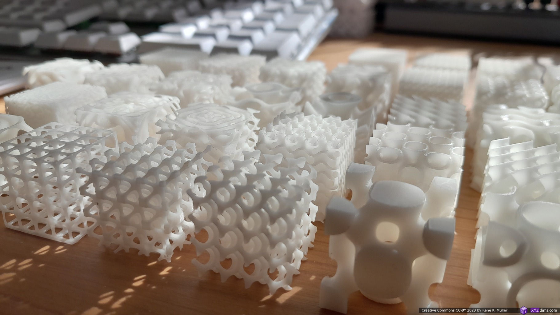
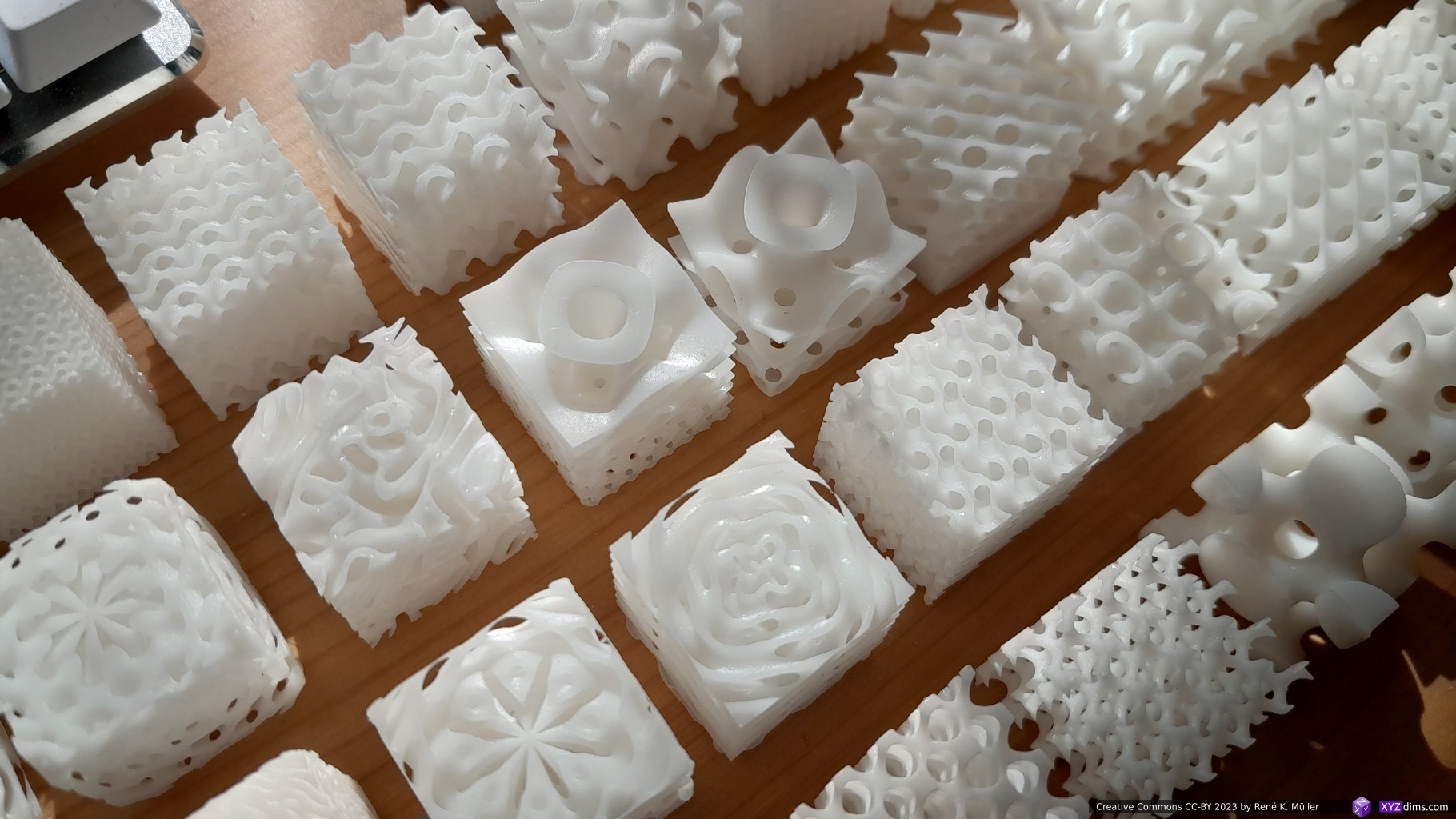
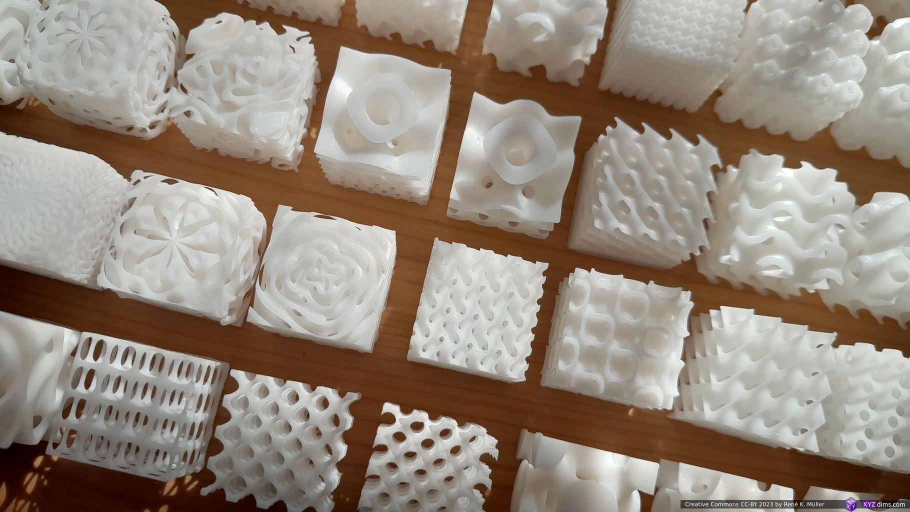
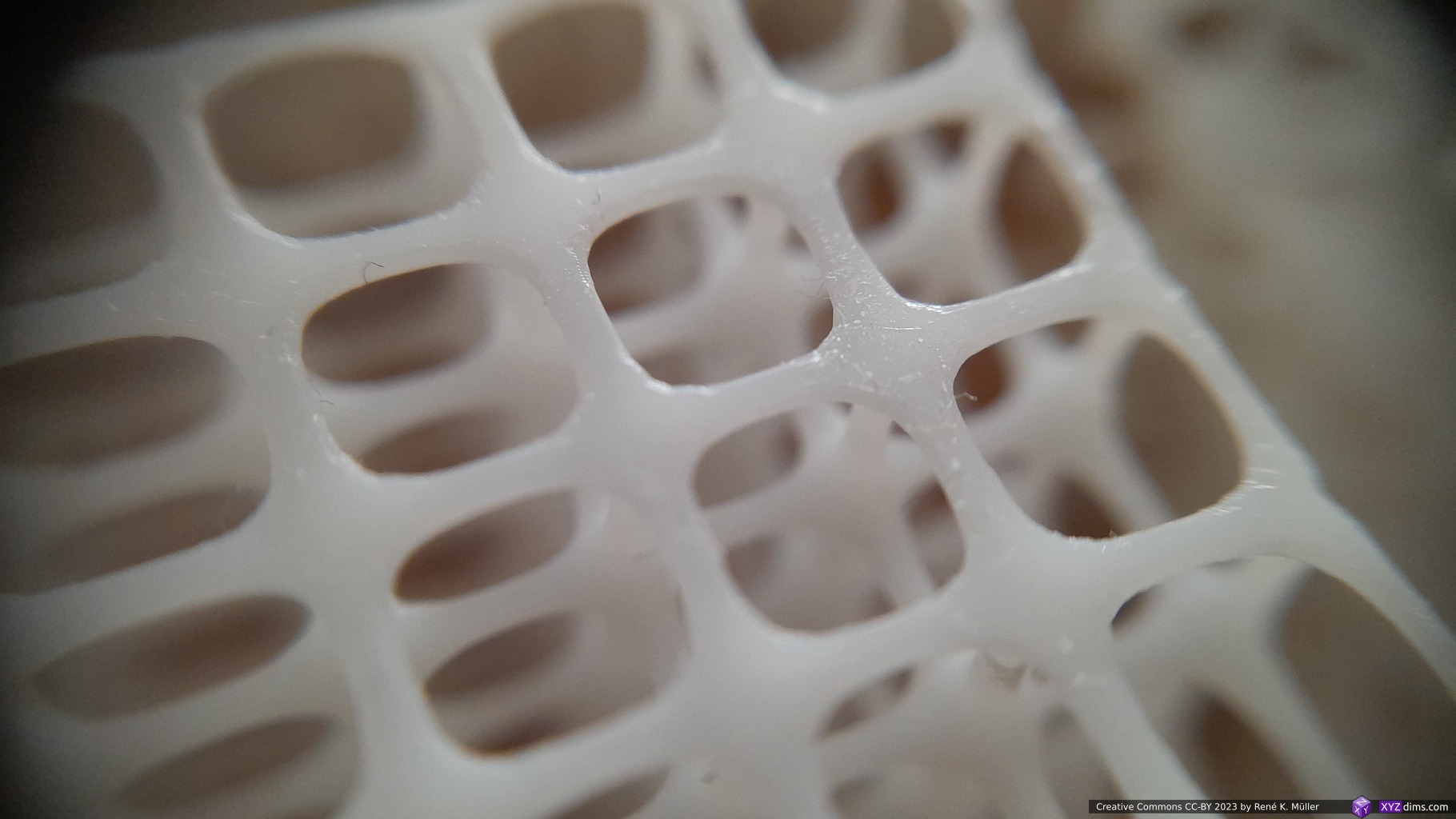
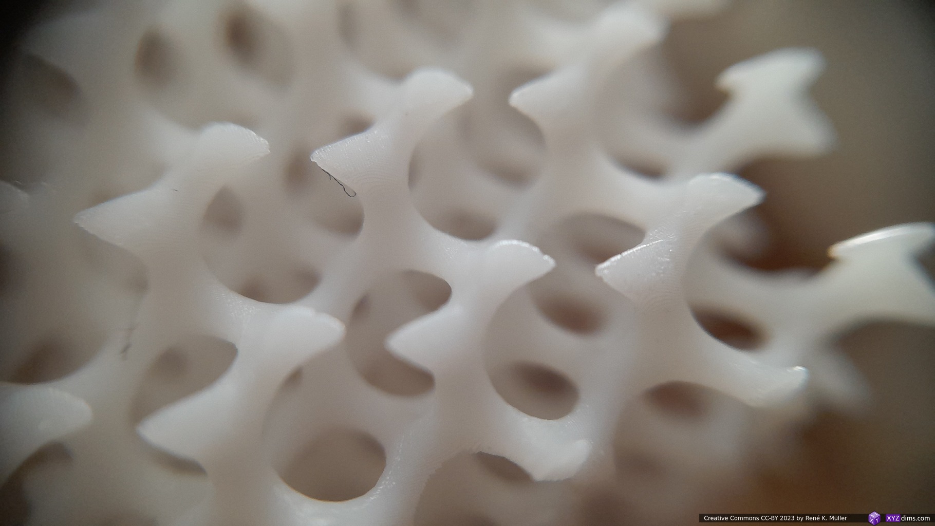
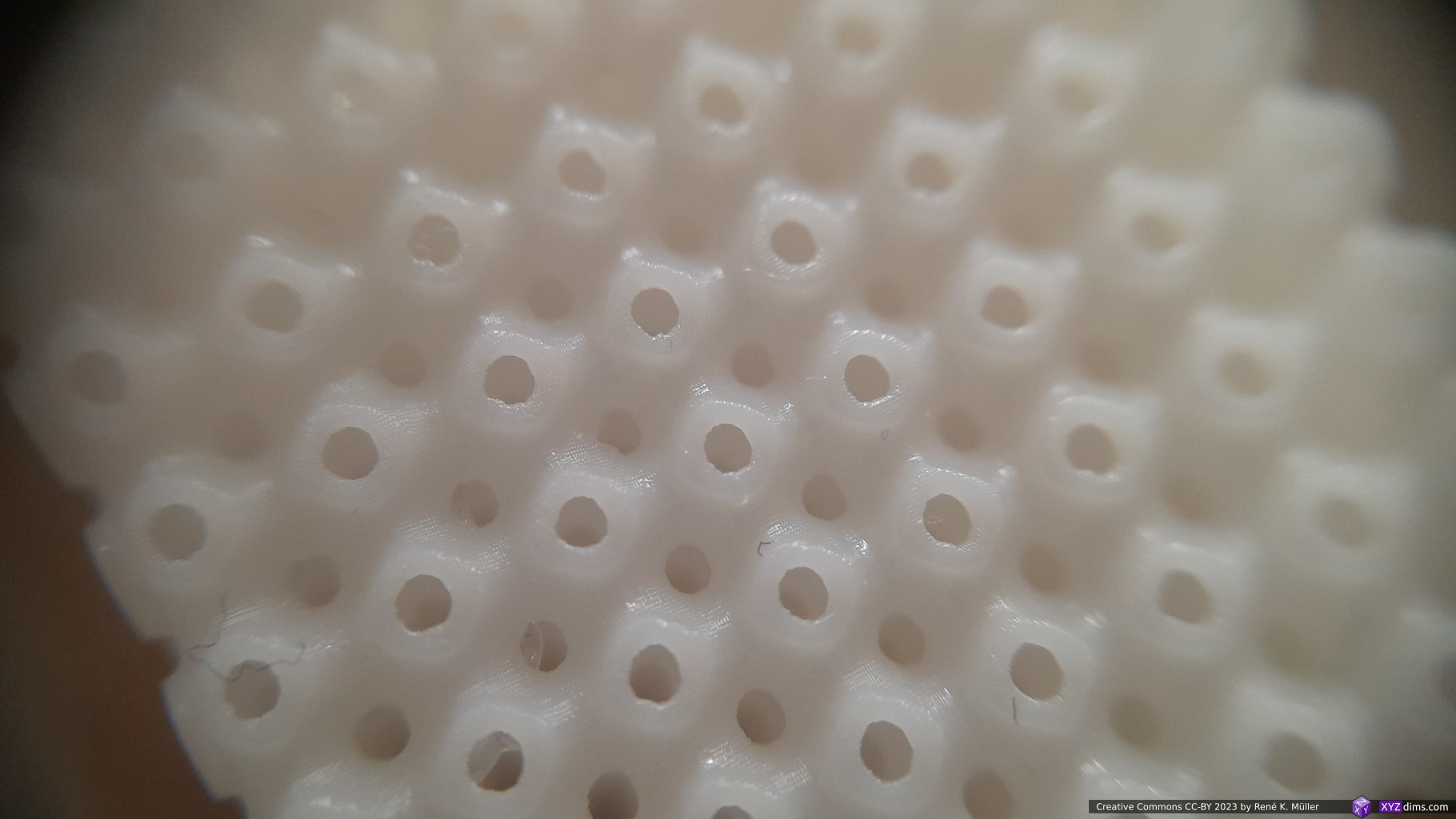
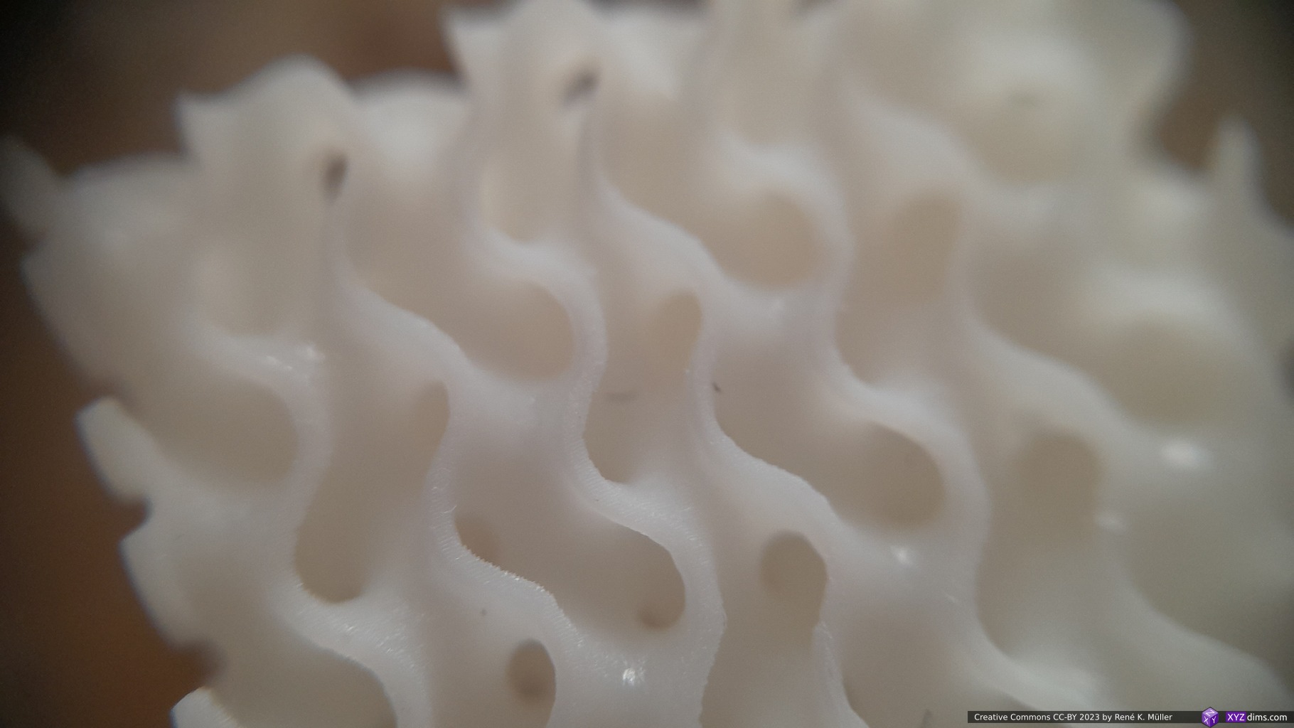
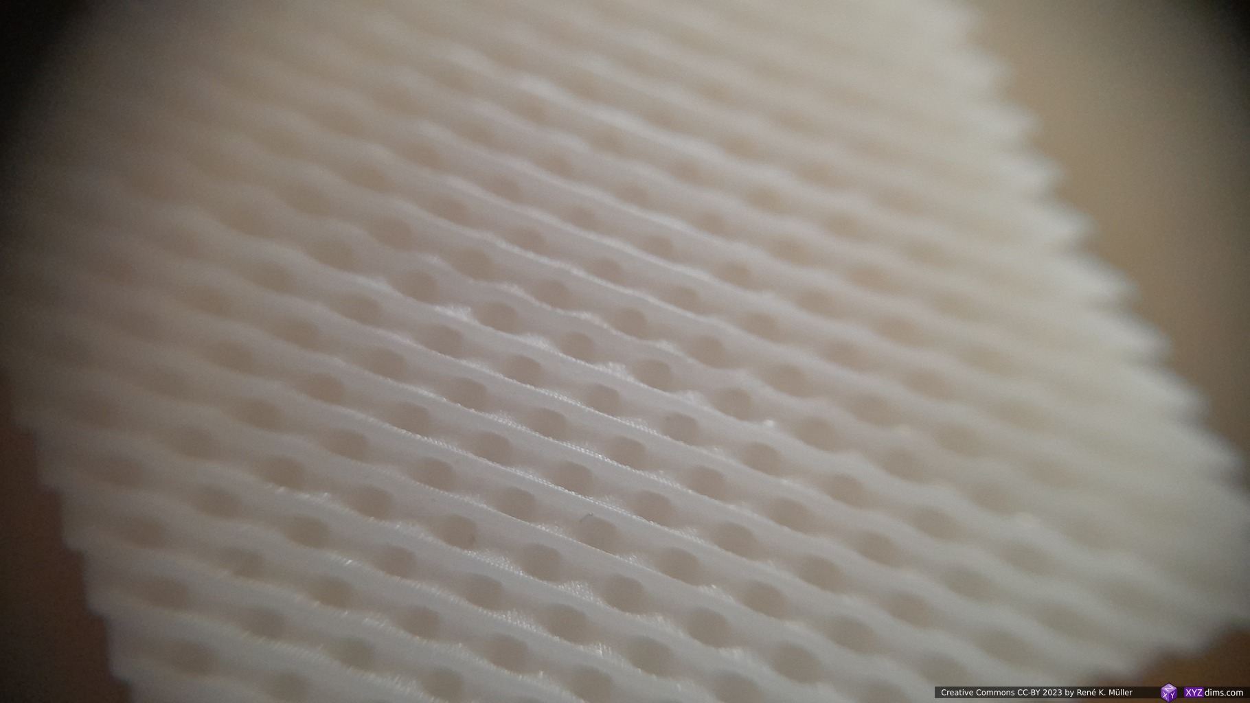
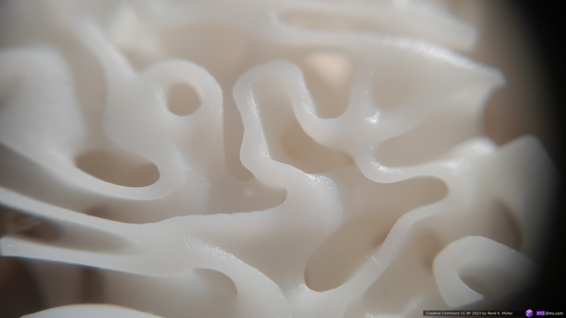
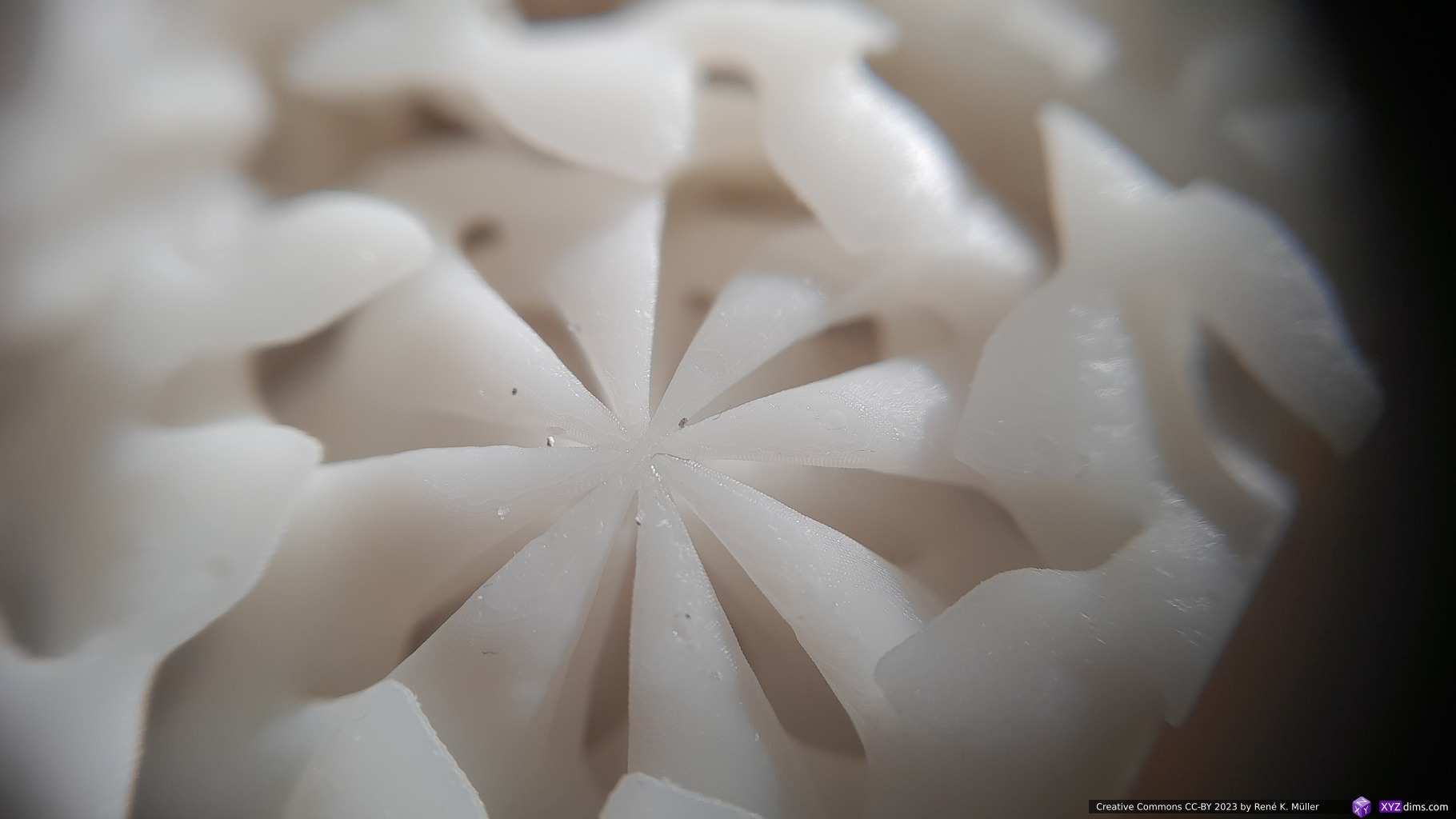
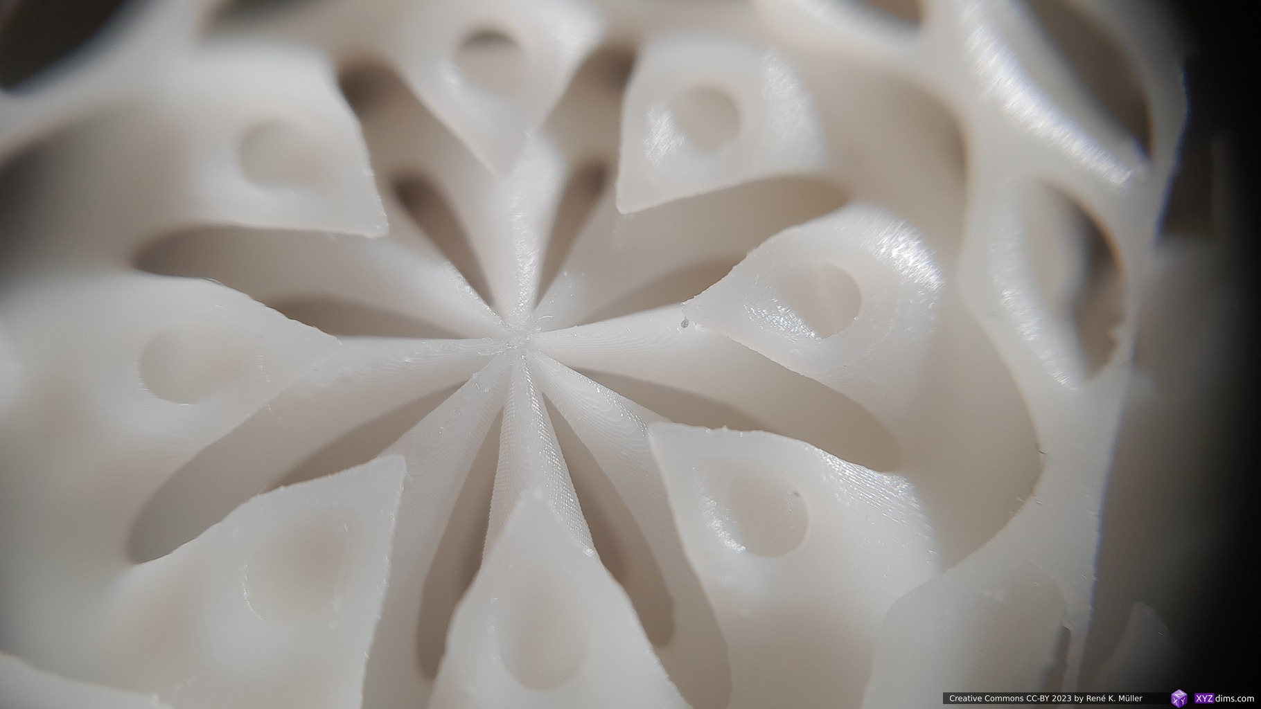
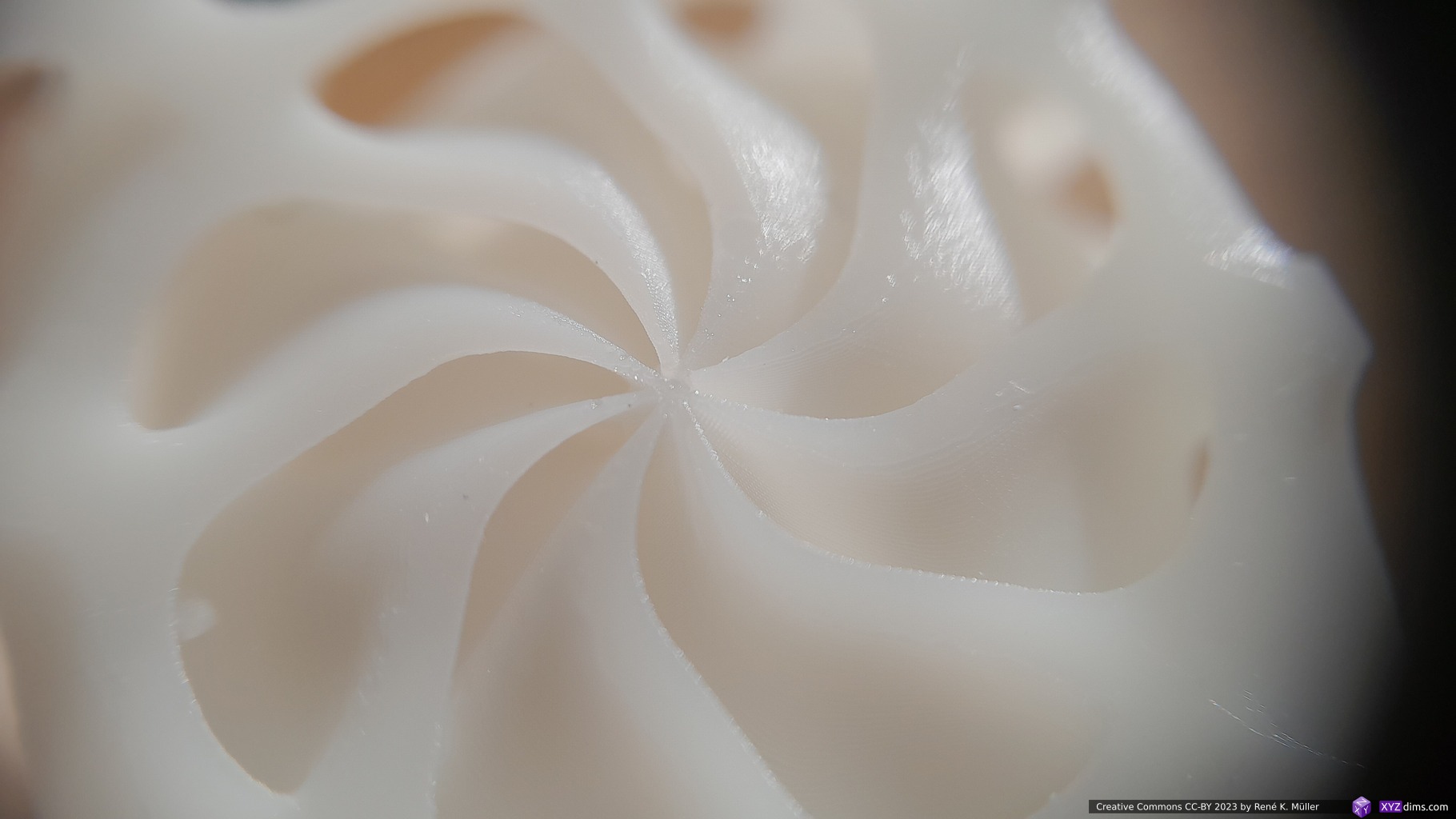
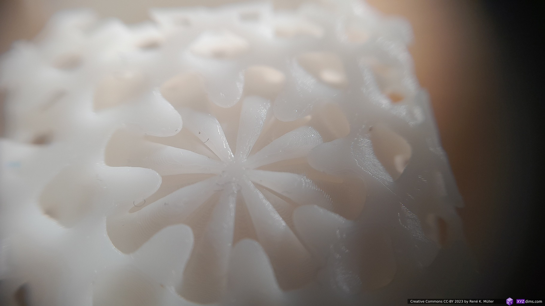
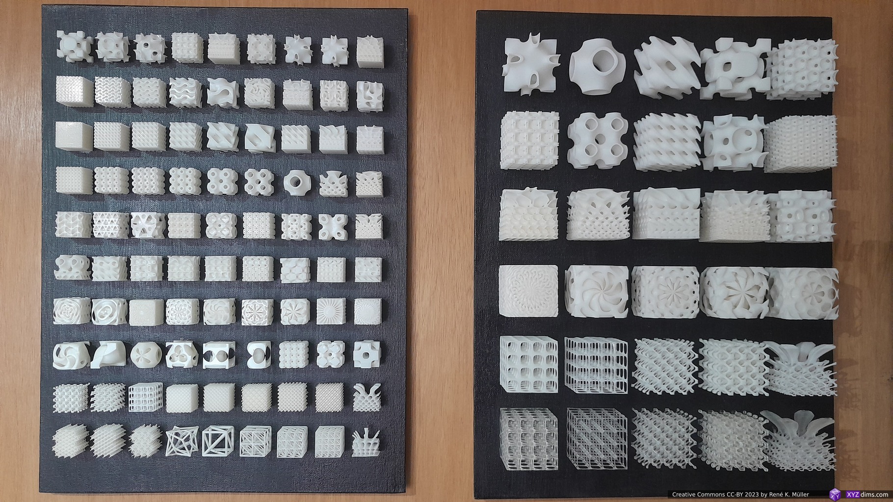
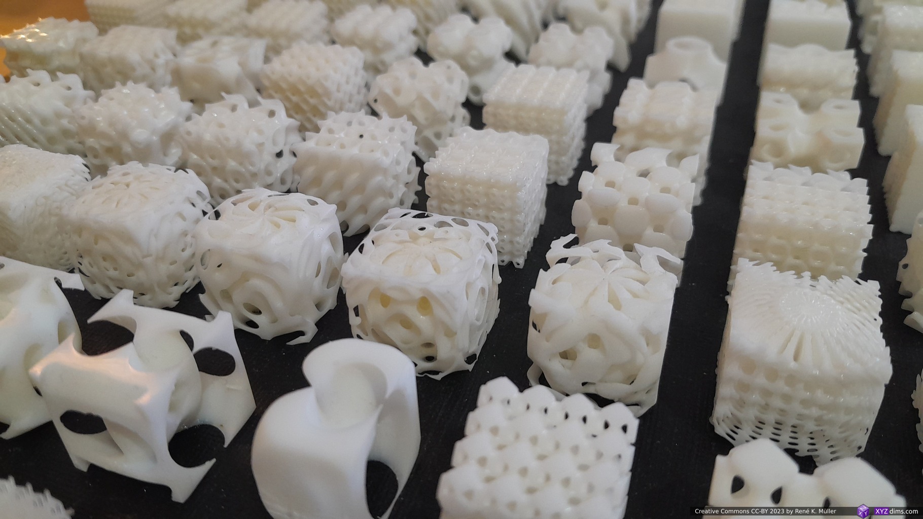
Samples
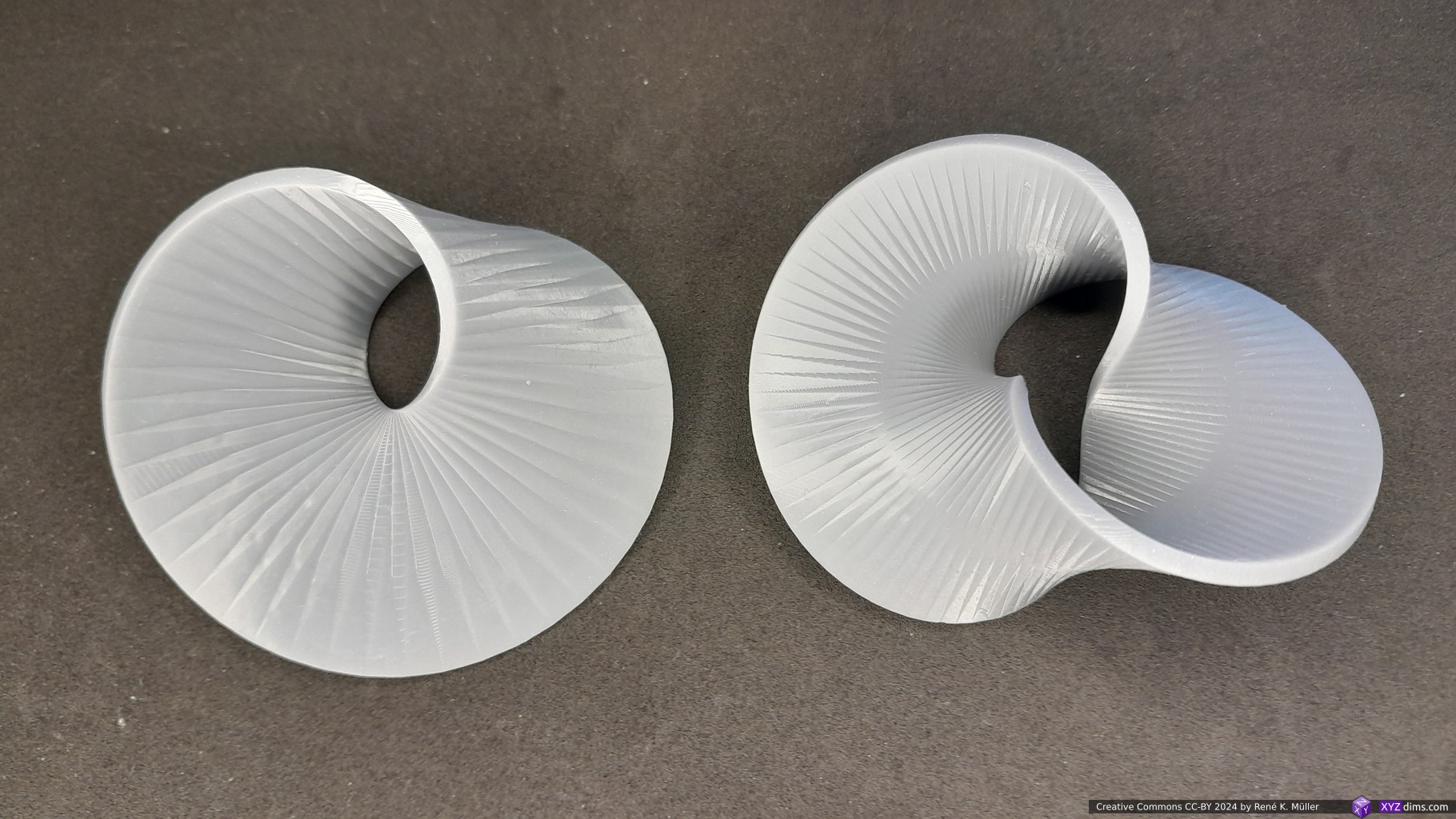
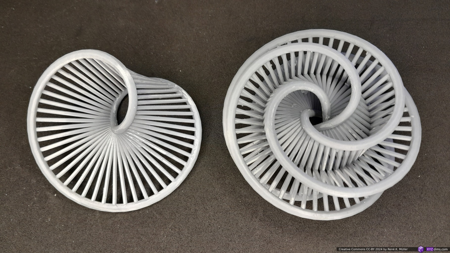
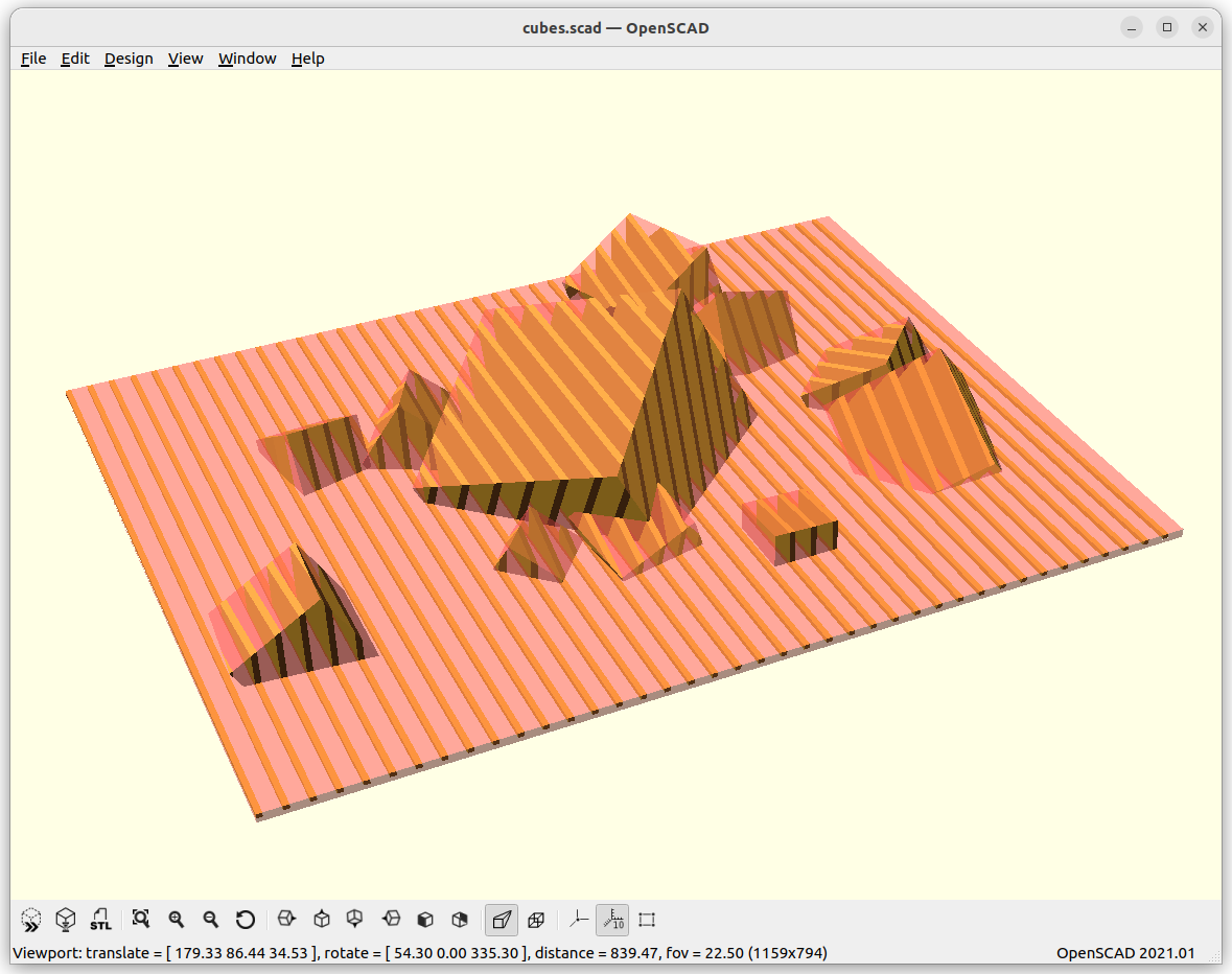
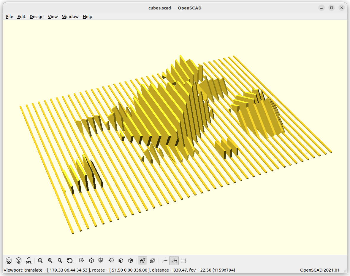
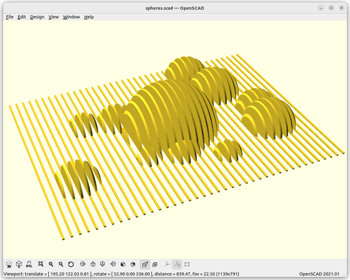
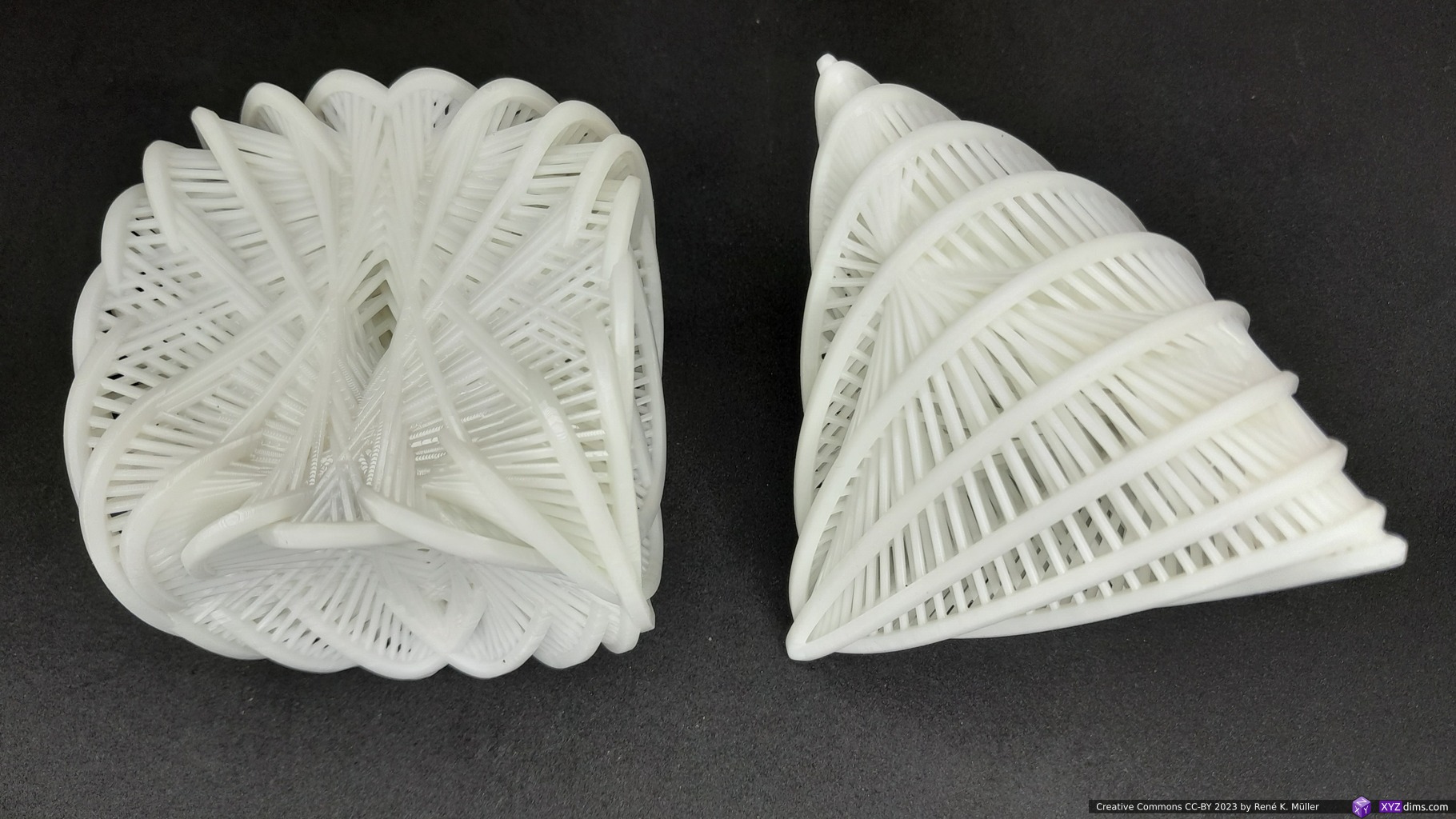
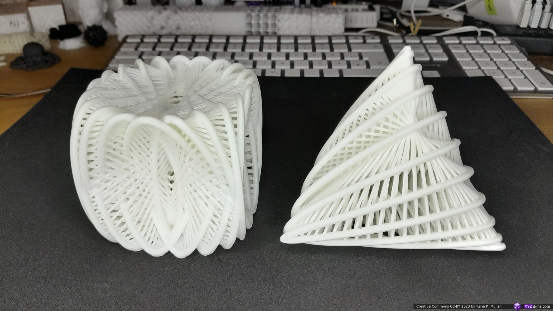
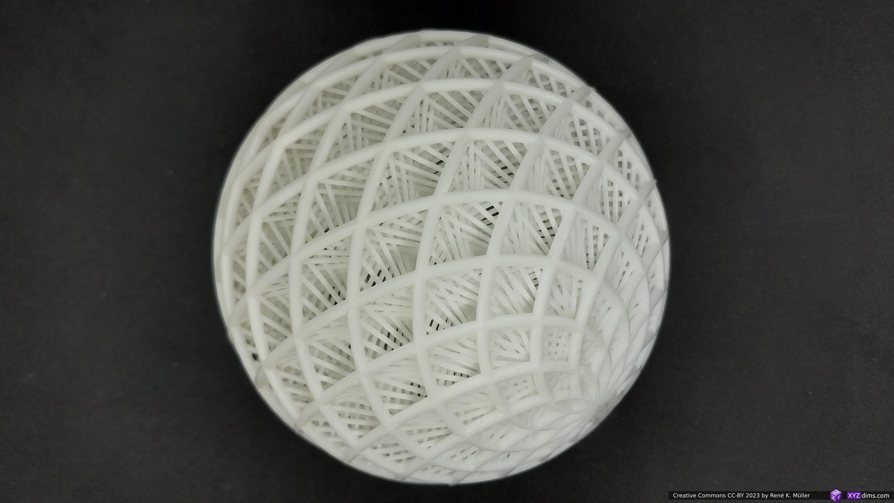
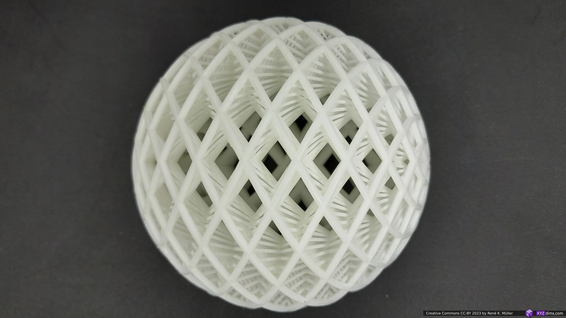
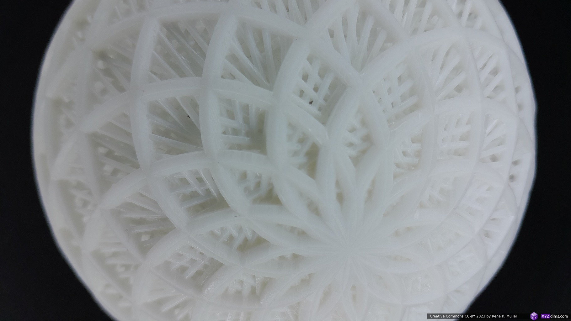
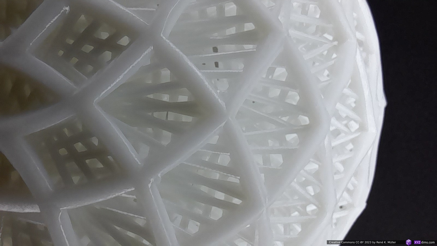
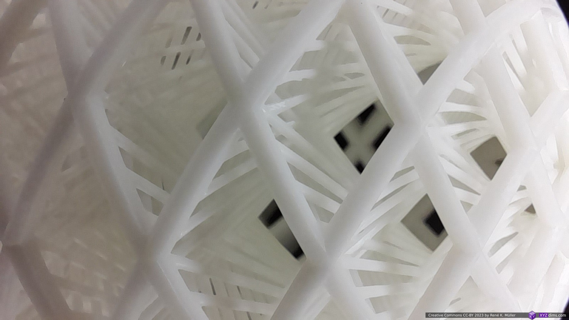
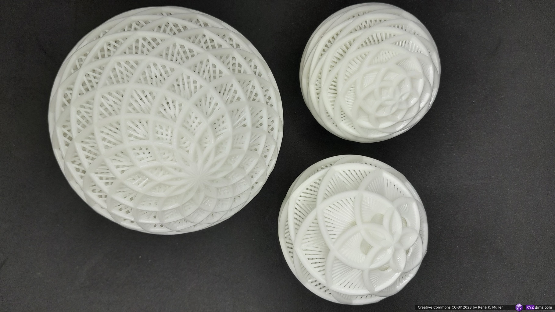
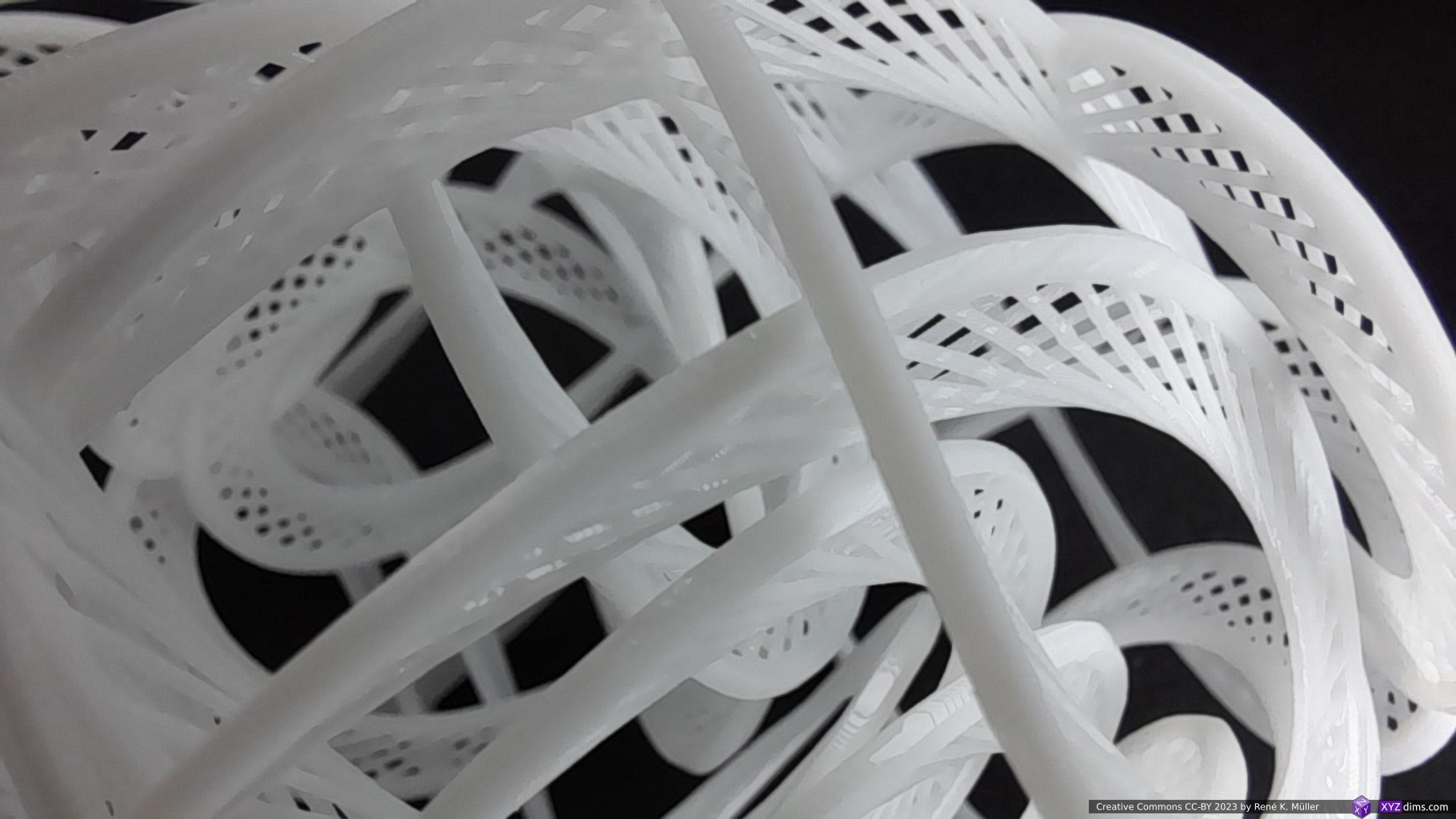
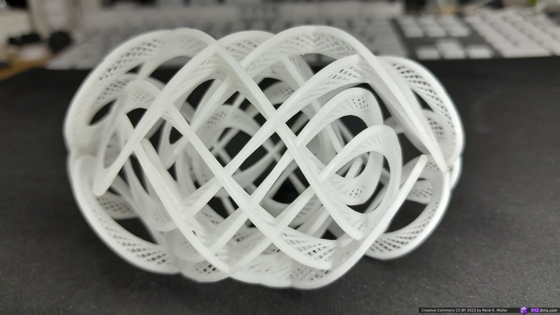
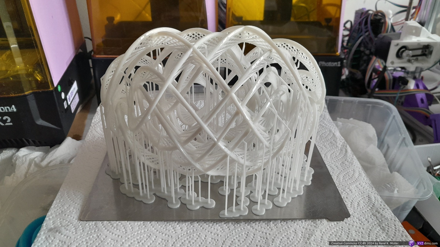
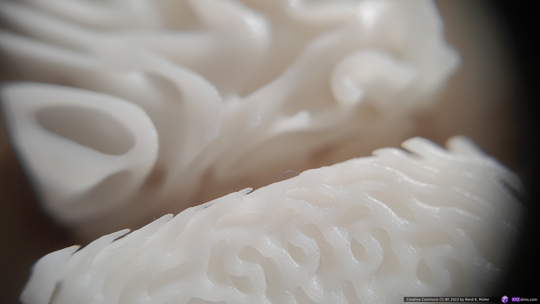
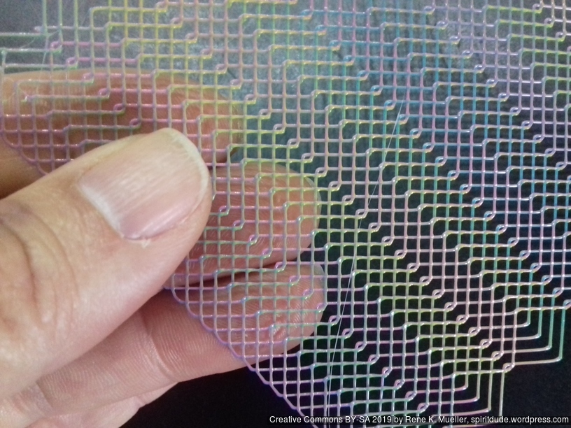
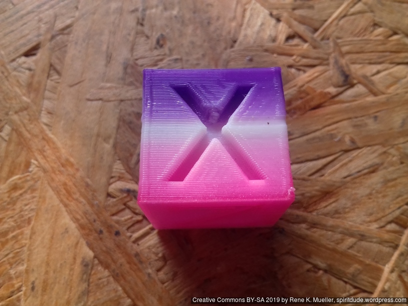
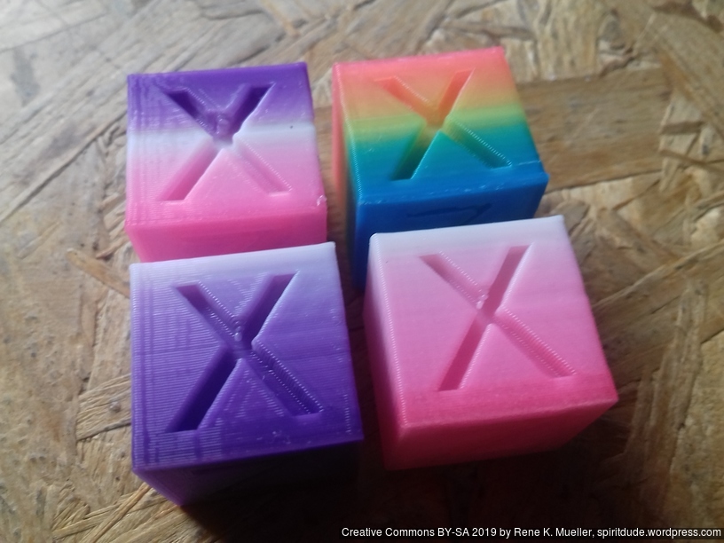
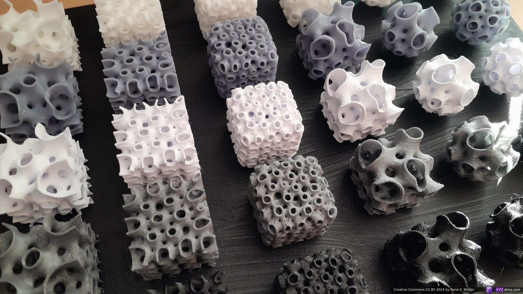
Daniel Bachmann from Spherene Inc. kindly shared with me a few samples, 20x20x20mm cubes, and 20mm diameter spheres with Spherene infills, illustrating their properties:
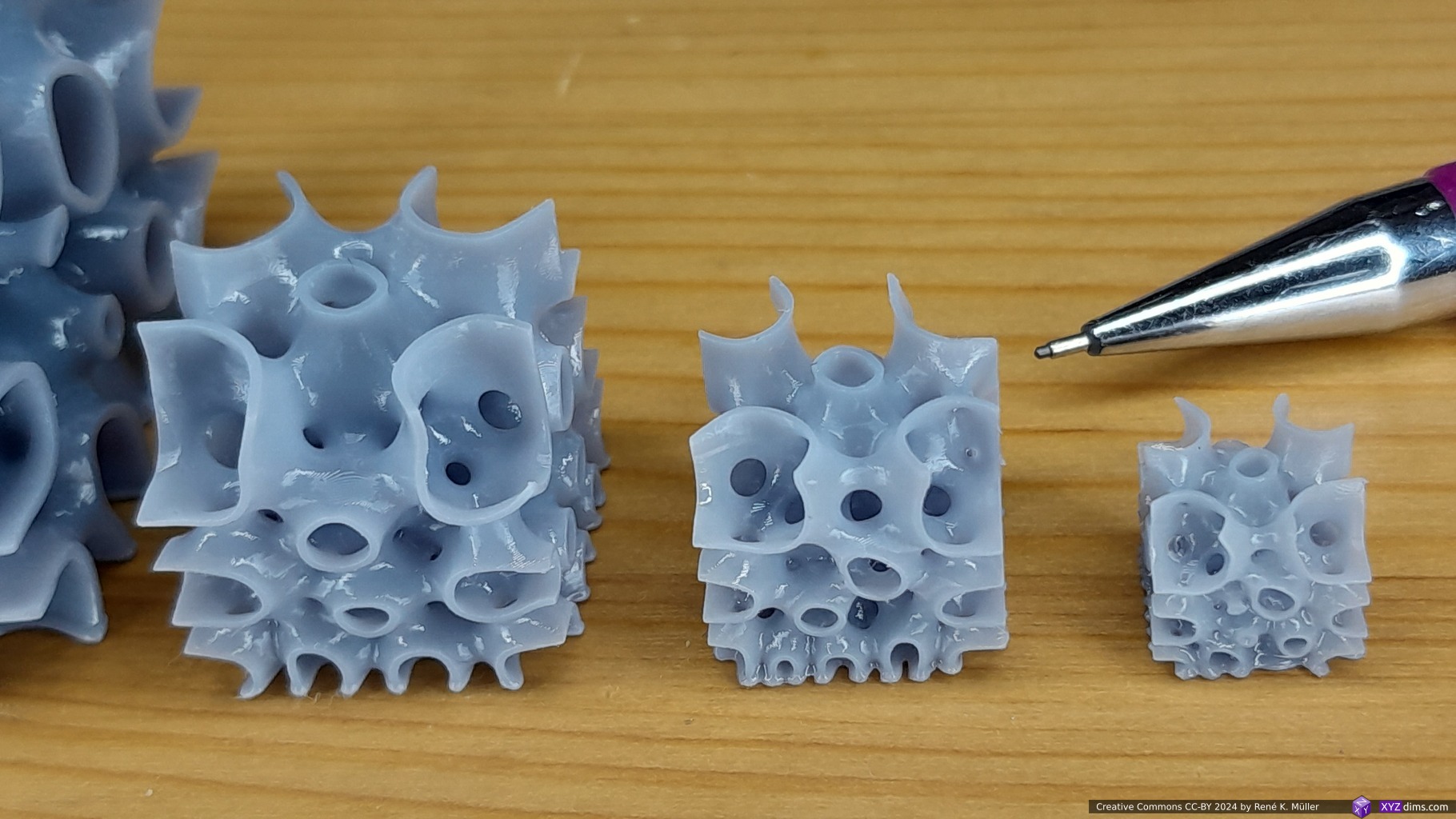
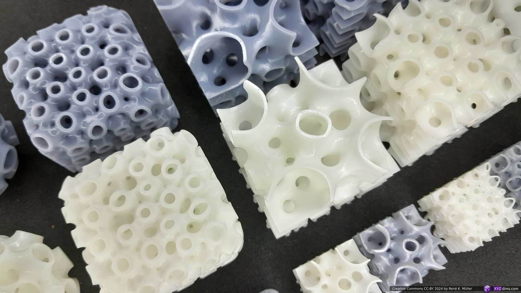
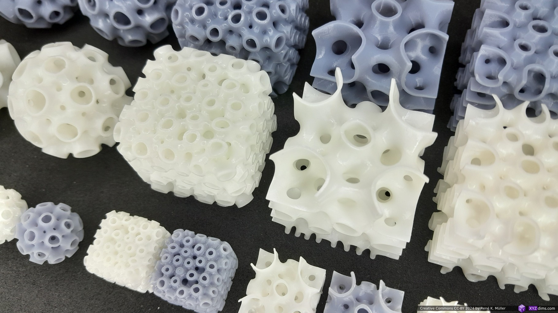
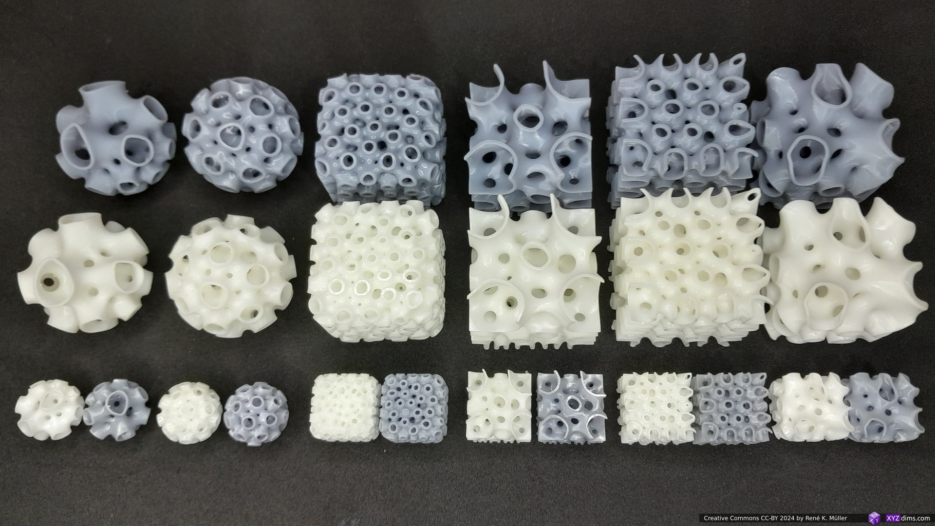
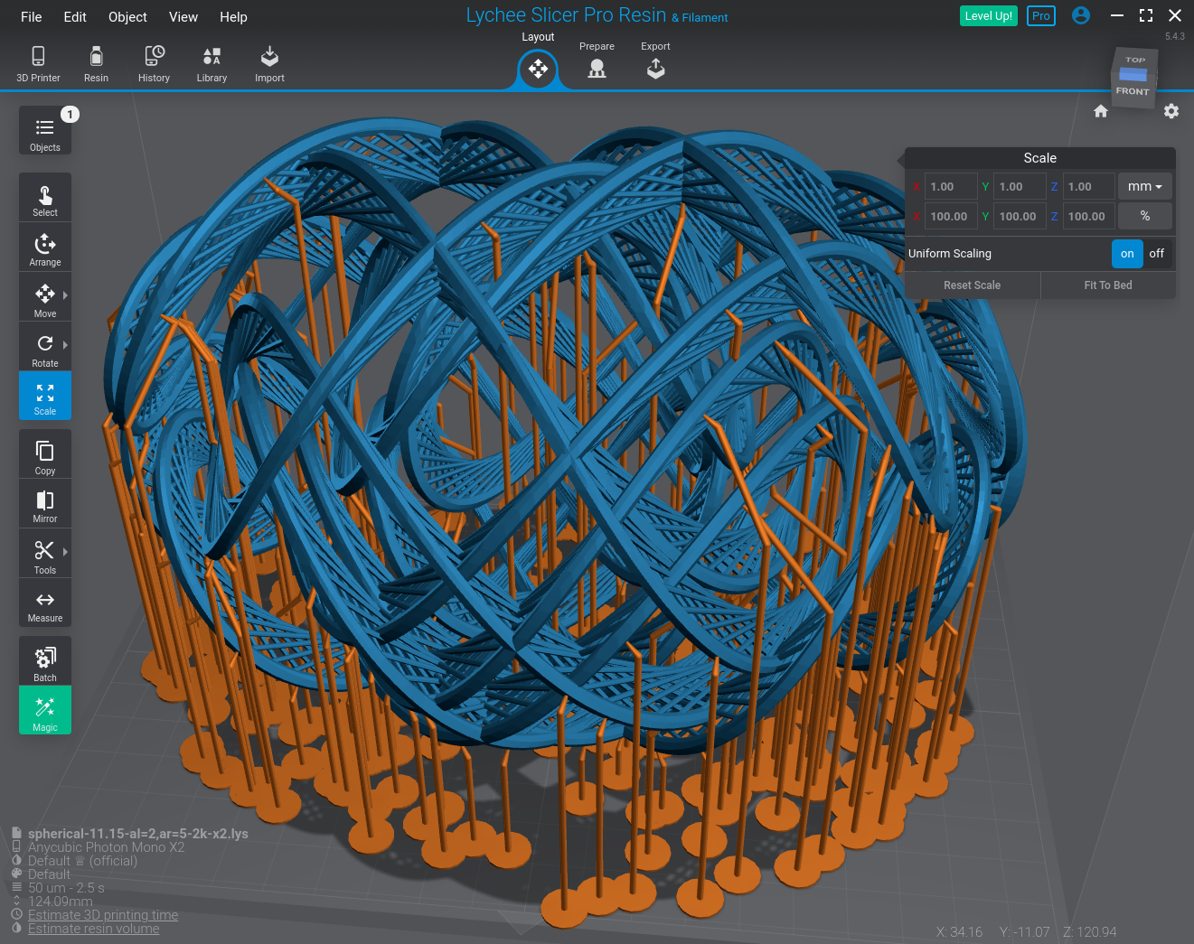
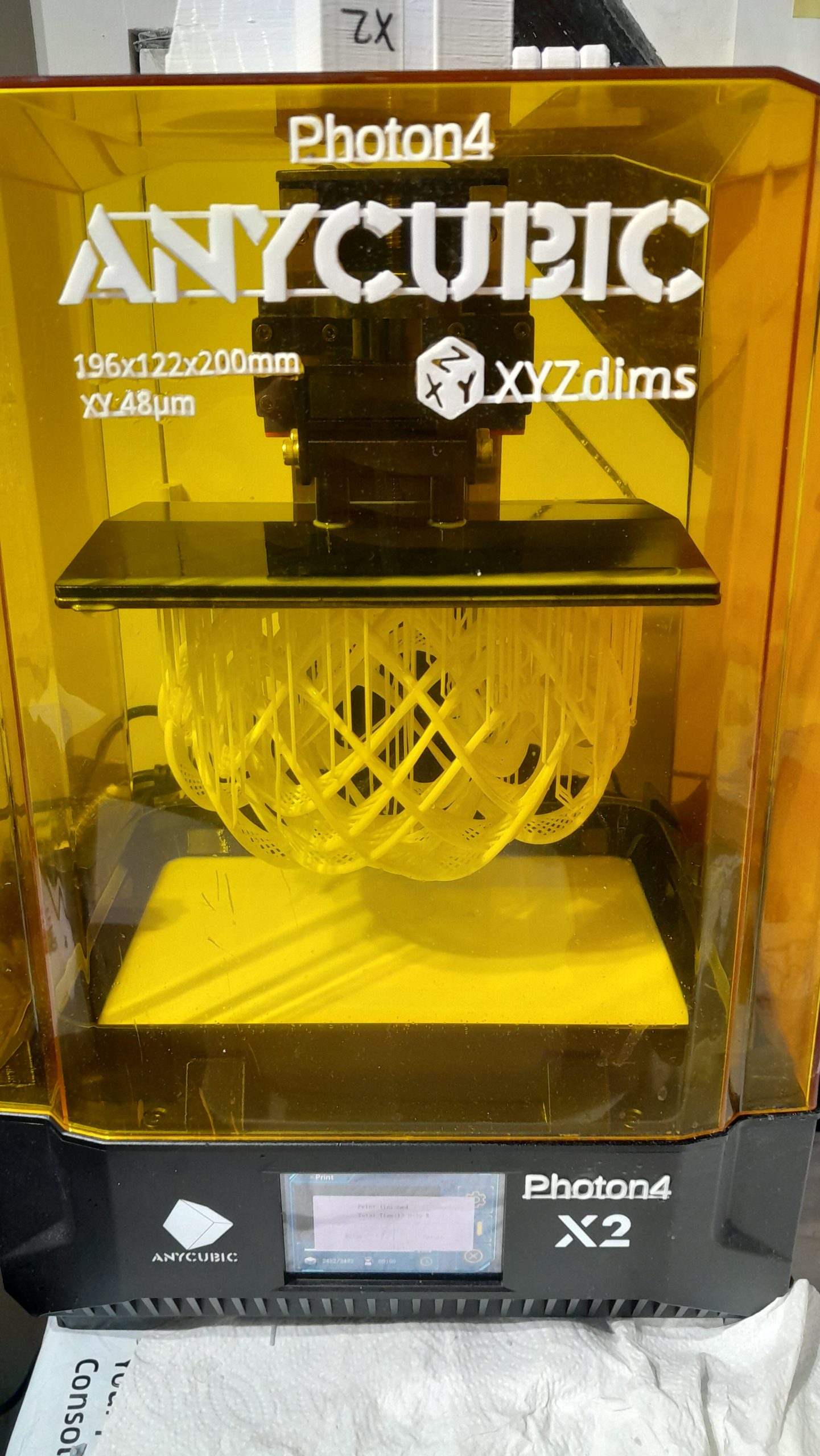
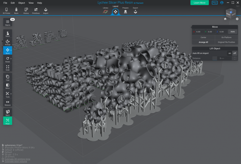
A few support structures were required for the spherical samples, the cubic samples did not require such:
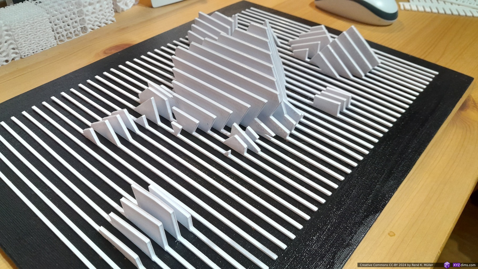
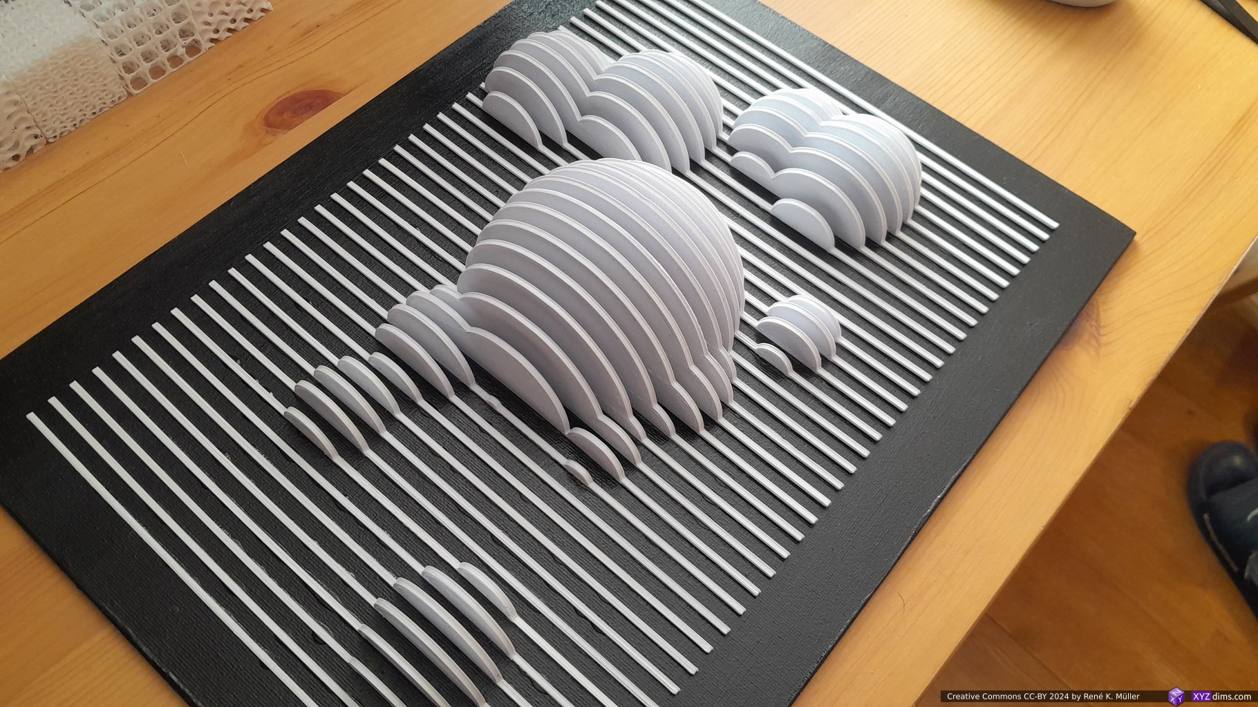
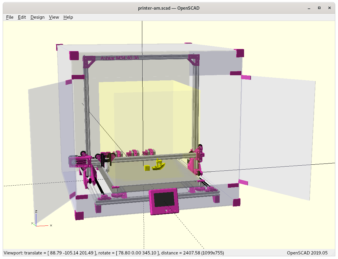
Additionally I printed a few cubic samples with FDM on my CoreXY Ashtar C without supports at 40x40x40mm scale.
Subtractive Manufacturing & Molding Usage
The structure cannot very well machined with subtractive manufacturing processes – or only if the piece is sub-divided so all indentations can be milled, and sequentially fused or welded again.
Another approach comes to my mind is to form dedicated bricks, e.g. for large scale application like a building, and have a limited kinds of bricks depending on their position and use case, and have molds to form those limited kinds in larger quantities.
In order to produce a mold one would inverse the original model, the negative volume, that would be produced using additive manufacturing and then produce lost-form casting molds, or highly simplify the form so one can remove the positive without destroying the mold.