Updates:
- 2020/12/31:
rcube()extended,RCUBE_FLAT{BOTTOM, TOP, FRONT, BACK, LEFT, RIGHT}support added,rcylinder()withRCYLINDER_FLAT{TOP, BOTTOM} - 2020/12/30:
rcube()source code extended, supportRCUBE_FLATX, RCUBE_FLATY, RCUBE_FLATZ - 2020/12/28: inital post
While working on Ashtar D (Classic XY) I looked at some pieces I rushed to design with cube() and hull() and they didn’t appeal to me – yes, it kind of hurt my eyes.
A while back I coded a simple rcube([x,y,z],r) which takes r as a radius for the edges, internally it’s an OpenSCAD module which uses 8 spheres and hulls them together, providing round edges; but I hesitated to actually use it in my designs – until now. Further I thought, let’s do the same with cylinder() using rcylinder(d=10,h=5,r=1) providing round edges by using two torii and hull them together.
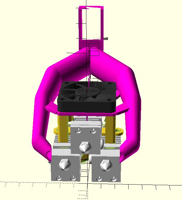
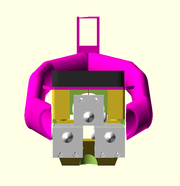
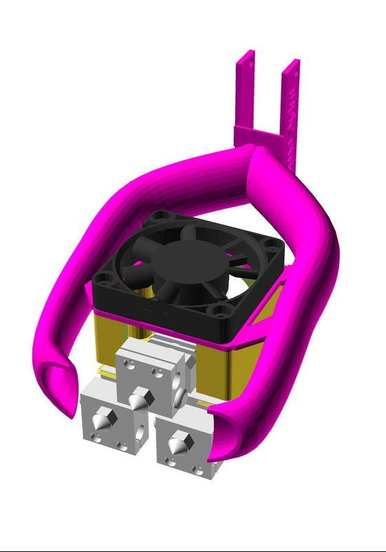
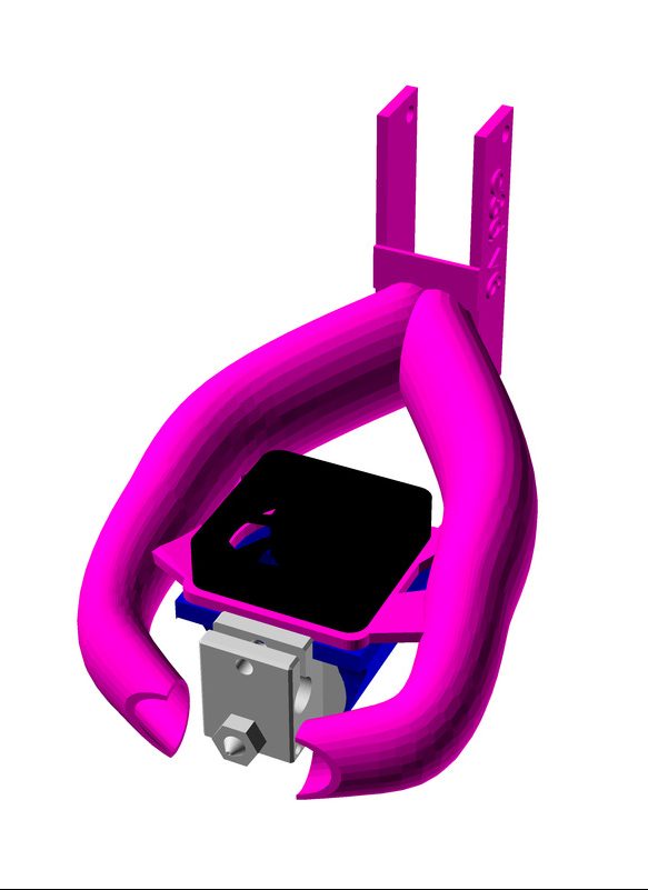
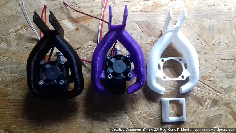
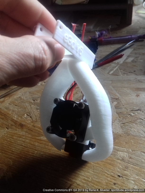
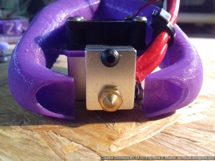
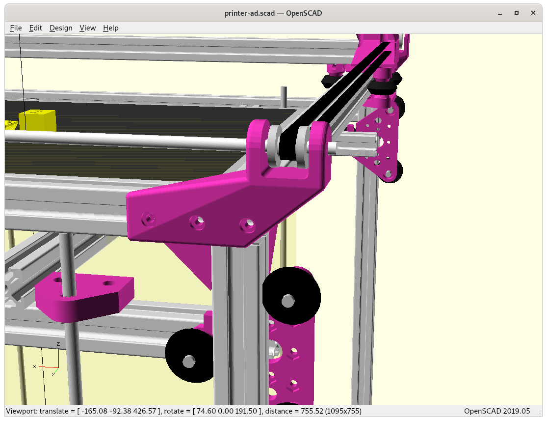
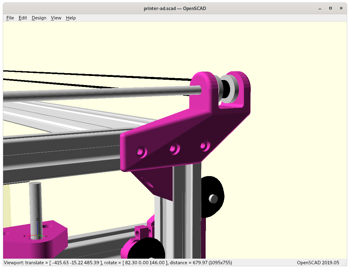
These two new functions, rcube([x,y,z],r) and rcylinder(h,d,r) allow to create more organic and elegant pieces, see for yourself:
From Bulky To Elegance
The position of the Y pulley mount is given, a bit of an X- & Y-offset to ensure printable area is not sacrificed for the Y carriage:

Using cube()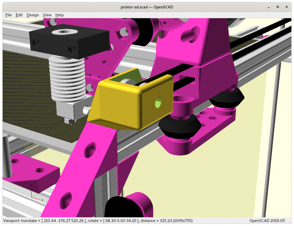
Using rcube()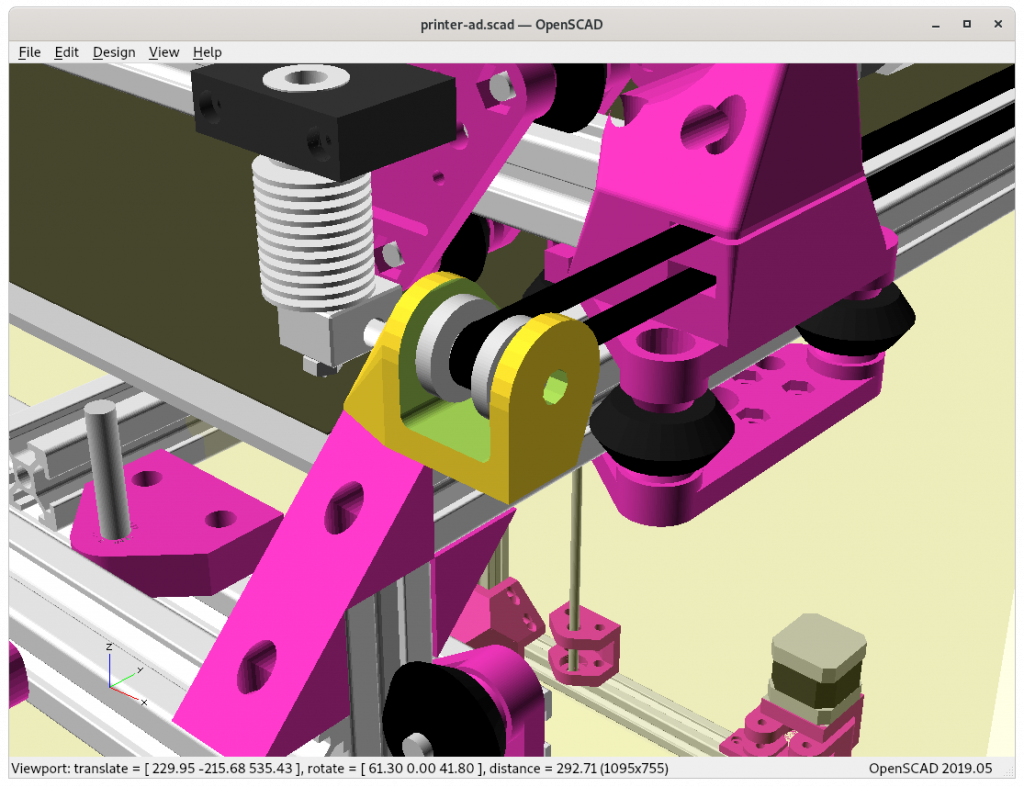
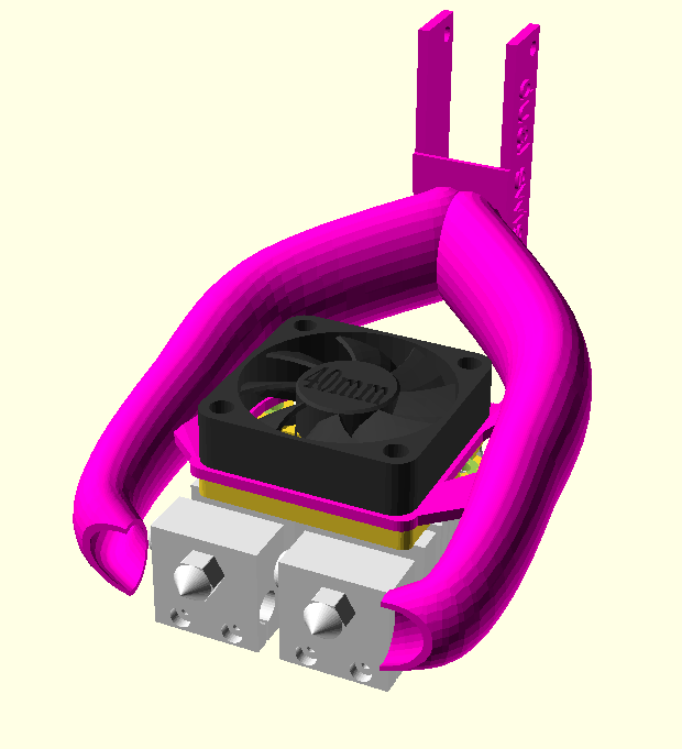
Using cylinder()&cube()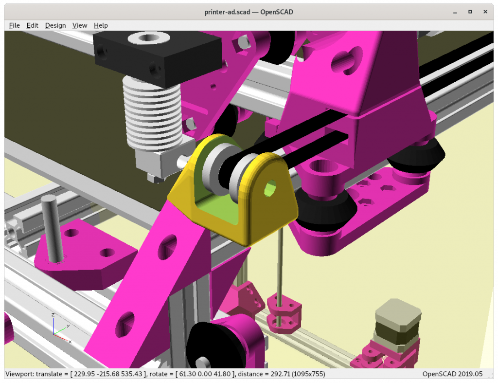
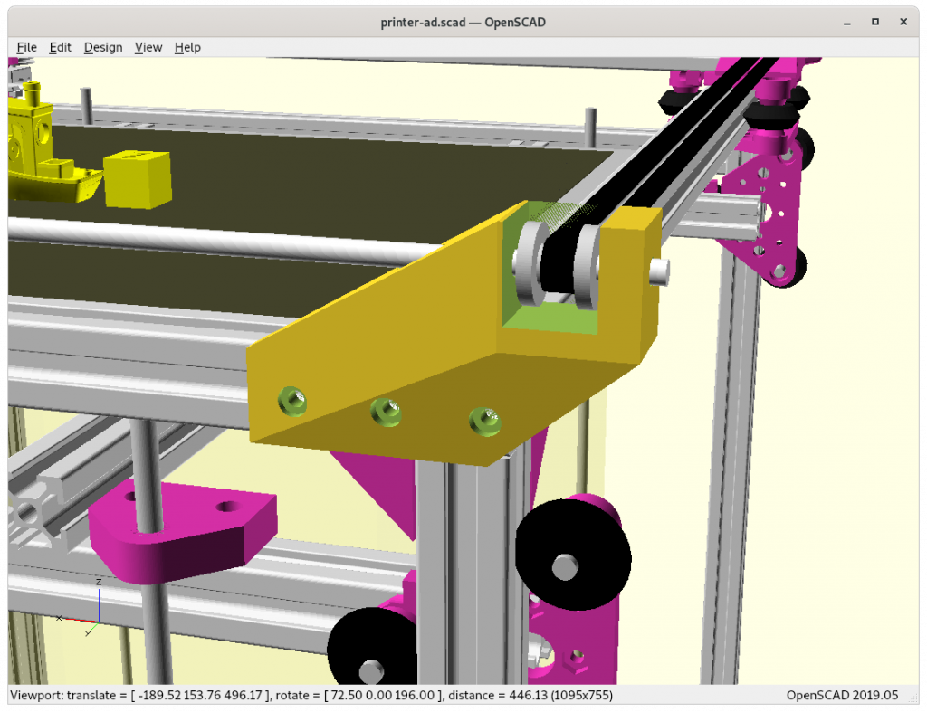
Using rcylinder()&rcube()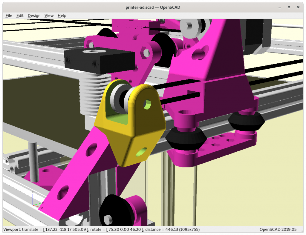
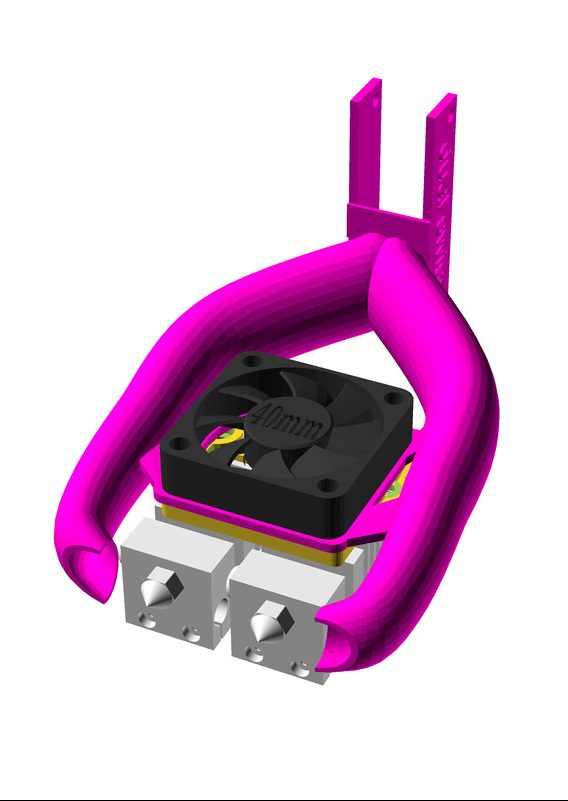
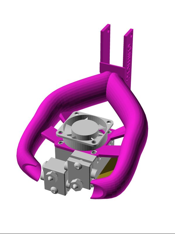
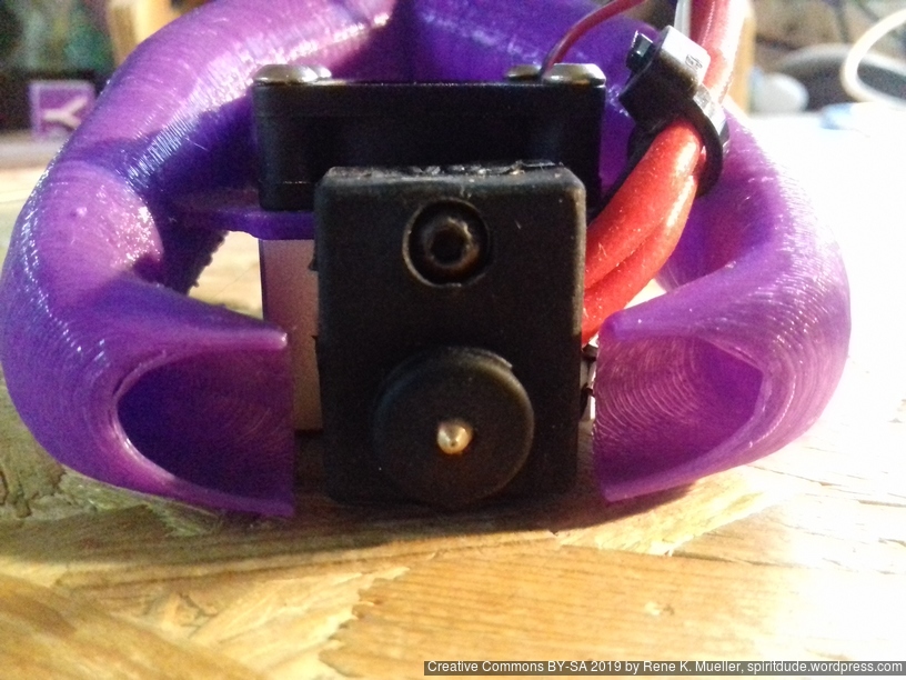
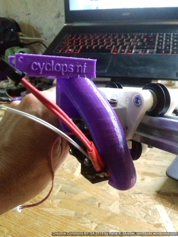
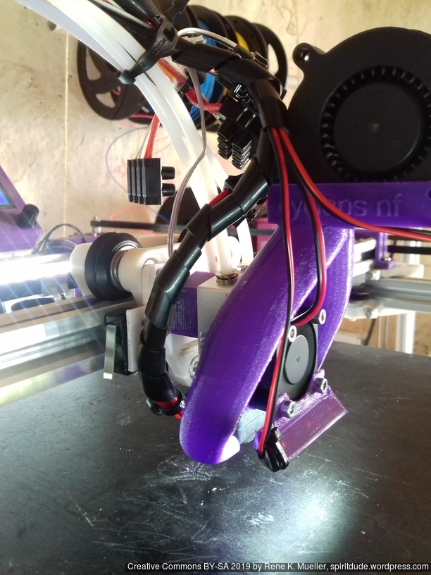
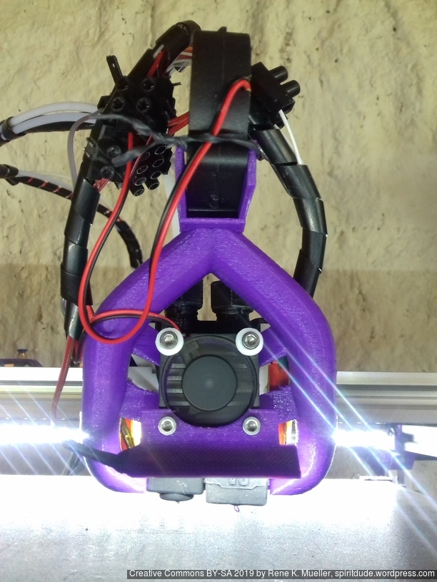
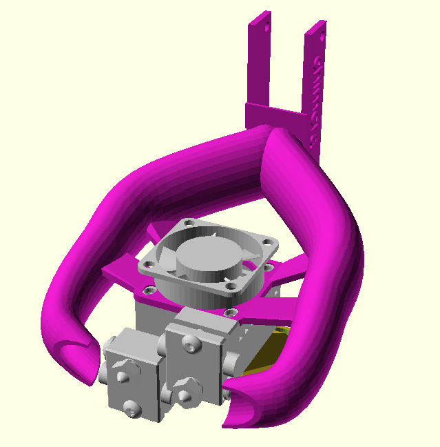
Final version, rcylinder()&rcube()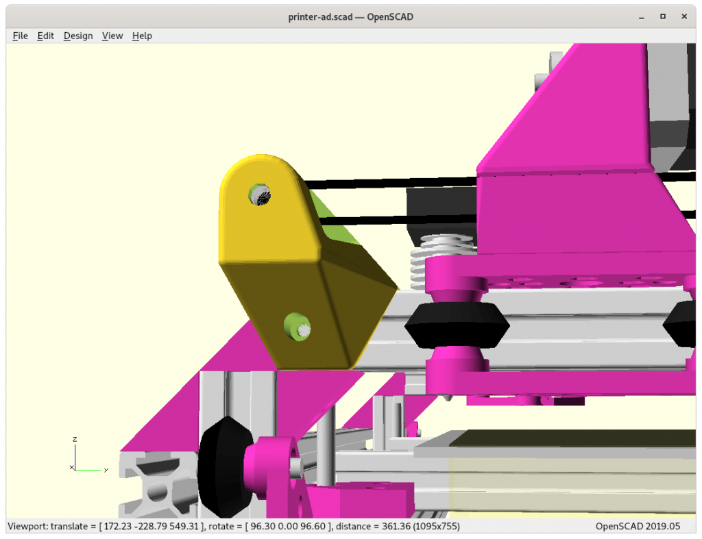
Final version 
Final version
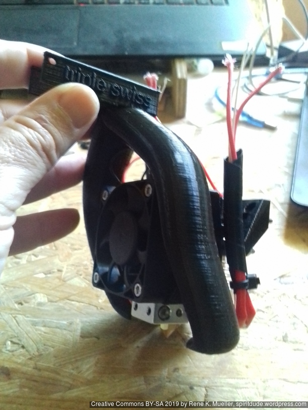
Using Chained Hulls
And another example . . . replacing hull() with chainhull():
Just cube()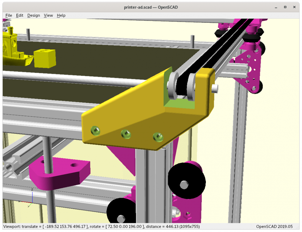
Just rcube()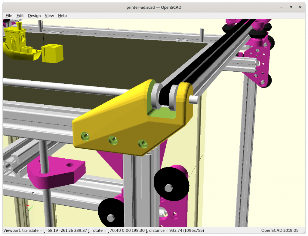
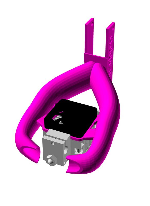
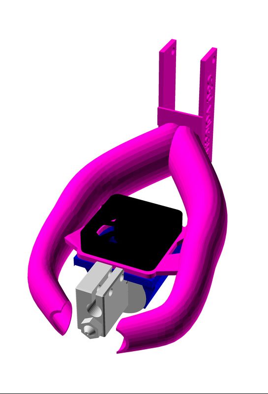
Using rcube()andrcylinder()
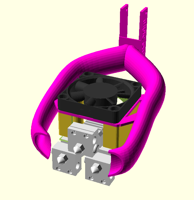
Final version, using chainhull()instead ofhull()
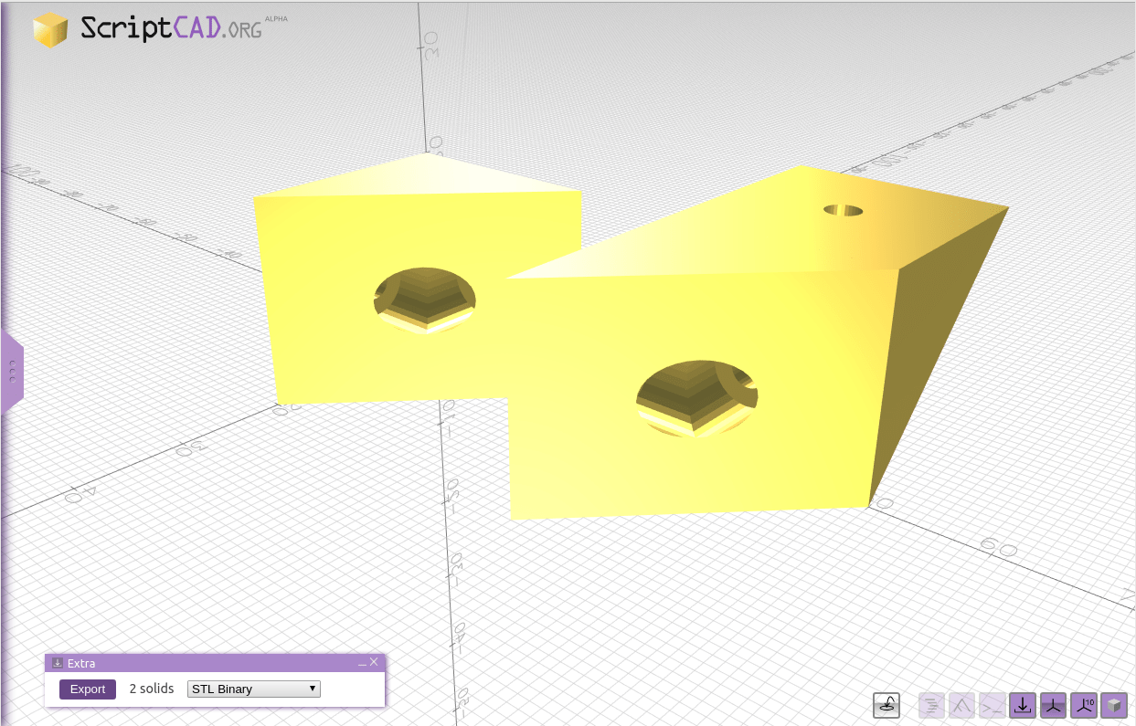
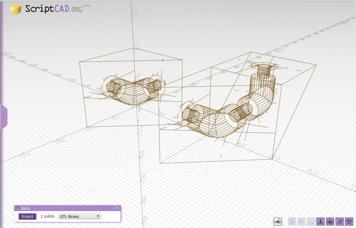
Final version: main body with only 3 pieces: 1 rcylinder()and 2rcube()
The final version is composed by only 3 pieces chain hulled together:
difference() {
   chainhull() {
      rcylinder(...);
      translate([0,0,-20]) rcube(...);
      translate([...,-60]) rcube([5,20,50],2); // 2020 mount plate
   }
   rcube(...);     // pulley cutout
}
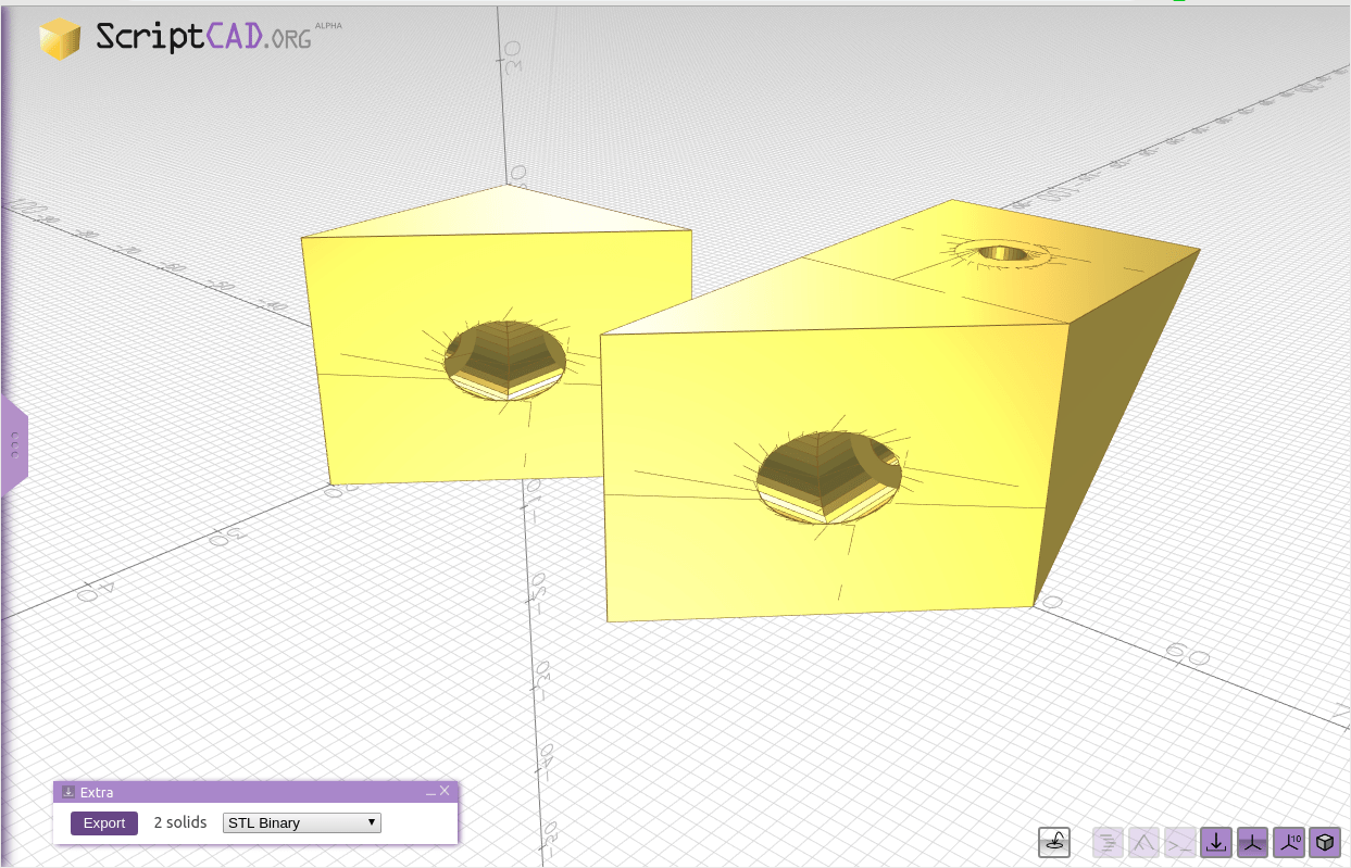
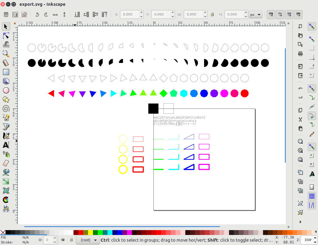
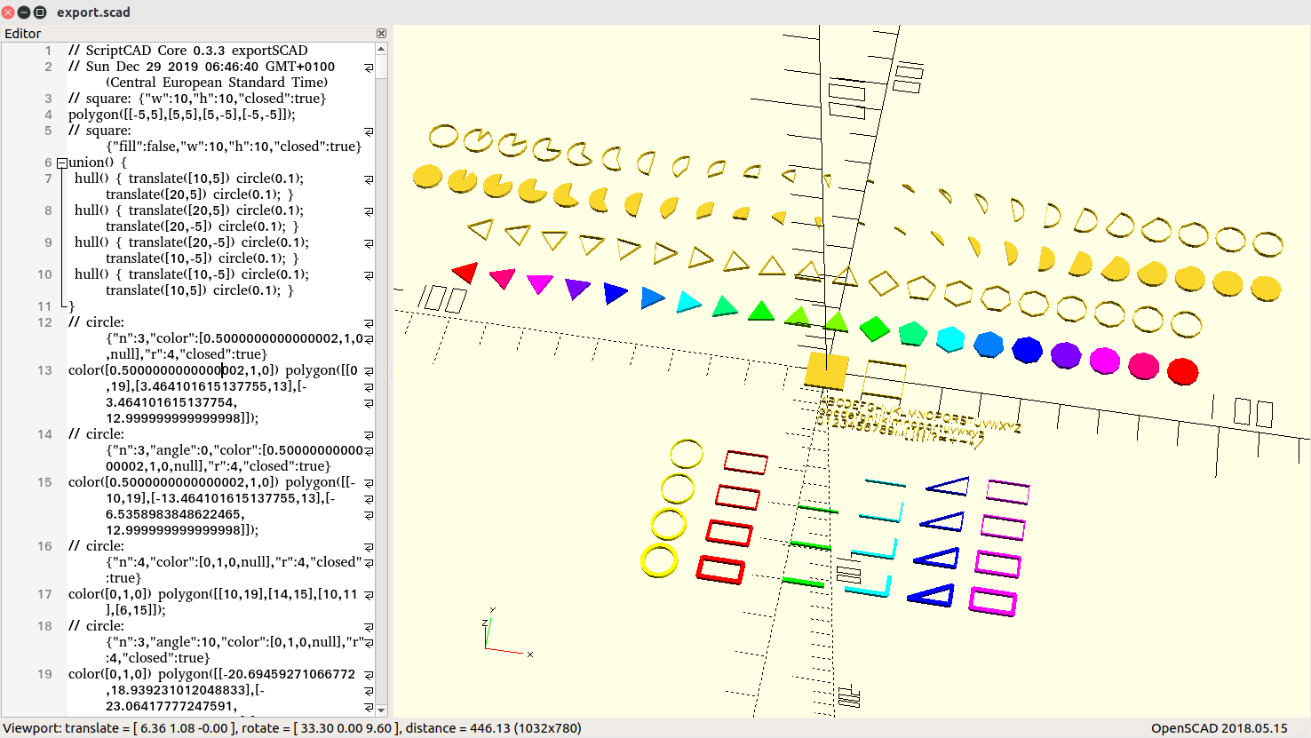
rcube() & rcylinder()
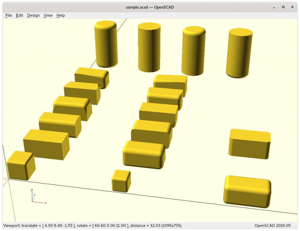
rcube();
translate([5,0,0]) rcube(0.75);
translate([10,0,0]) rcube([2,1,1],0.2);

translate([0,2,0]) rcube([2,1,1],0.2,false);
translate([5,2,0]) rcube([2,1,1],0.2,true);

translate([0,4,0]) rcube([2,1,1],0.2,RCUBE_FLATX);
translate([5,4,0]) rcube([2,1,1],0.2,RCUBE_FLATY);
translate([10,4,0]) rcube([2,1,1],0.2,RCUBE_FLATZ);

translate([0,6,0]) rcube([2,1,1],0.2,RCUBE_FLATBOTTOM);
translate([5,6,0]) rcube([2,1,1],0.2,RCUBE_FLATTOP);

translate([0,8,0]) rcube([2,1,1],0.2,RCUBE_FLATFRONT);
translate([5,8,0]) rcube([2,1,1],0.2,RCUBE_FLATBACK);

translate([0,10,0]) rcube([2,1,1],0.2,RCUBE_FLATLEFT);
translate([5,10,0]) rcube([2,1,1],0.2,RCUBE_FLATRIGHT);

translate([0+1,14,0]) rcylinder(3,1.5,0.2);
translate([3+1,14,0]) rcylinder(3,1.5,0.2,false);
translate([6+1,14,0]) rcylinder(3,1.5,0.2,RCYLINDER_FLATBOTTOM);
translate([9+1,14,0]) rcylinder(3,1.5,0.2,RCYLINDER_FLATTOP);
The library code (I might later release it as a separate library):
// Title: rcube(), rcylinder() & torus()
// Author: Rene K. Mueller
// License: MIT License 2020
// Version: 0.0.2

RCUBE_FLATX = [false,true,true];
RCUBE_FLATY = [true,false,true];
RCUBE_FLATZ = [true,true,false];
RCUBE_FLATBOTTOM = [false,false,false,false,true,true,true,true];
RCUBE_FLATTOP = [true,true,true,true,false,false,false,false];
RCUBE_FLATFRONT = [false,false,true,true,false,false,true,true];
RCUBE_FLATBACK = [true,true,false,false,true,true,false,false];
RCUBE_FLATLEFT = [false,true,true,false,false,true,true,false];
RCUBE_FLATRIGHT = [true,false,false,true,true,false,false,true];

module rcube(a=1,r=0.1,rd=[true,true,true],center=false,$fn=32) {
    if(FAST_RCUBE)
       cube(a);
    else {
       x = len(a) ? a[0] : a;
       y = len(a) ? a[1] : a;
       z = len(a) ? a[2] : a;
       rd = len(rd) ? rd : [rd,rd,rd];

          if((len(rd)==3 && rd[0] && rd[1] && rd[2]) || (len(a)==0 && rd)) // rd=[true,true,true] or true
             hull() {
                translate([r,r,r]) sphere(r);
                translate([x-r,r,r]) sphere(r);
                translate([x-r,y-r,r]) sphere(r);
                translate([r,y-r,r]) sphere(r);
                translate([r,r,z-r]) sphere(r);
                translate([x-r,r,z-r]) sphere(r);
                translate([x-r,y-r,z-r]) sphere(r);
                translate([r,y-r,z-r]) sphere(r);
             }
          else                                                        // anything else
             hull() {
                translate([r,r,r]) rcube_prim(r,rd,0);
                translate([x-r,r,r]) rcube_prim(r,rd,1);
                translate([x-r,y-r,r]) rcube_prim(r,rd,2);
                translate([r,y-r,r]) rcube_prim(r,rd,3);
                translate([r,r,z-r]) rcube_prim(r,rd,4);
                translate([x-r,r,z-r]) rcube_prim(r,rd,5);
                translate([x-r,y-r,z-r]) rcube_prim(r,rd,6);
                translate([r,y-r,z-r]) rcube_prim(r,rd,7);
             }
    }
 }

module rcube_prim(r,rd,i) {
    a = len(rd);
    if(a<=3) {
       if(a && rd[0] && rd[1] && rd[2])
          sphere(r);
       else if(a && rd[0] && rd[1])
          translate([0,0,-r]) cylinder(r=r,h=r*2);
       else if(a && rd[1] && rd[2])
          translate([-r,0,0]) rotate([0,90,0]) cylinder(r=r,h=r*2);
       else if(a && rd[0] && rd[2])
          translate([0,-r,0]) rotate([-90,0,0]) cylinder(r=r,h=r*2);
       else
          translate([-r,-r,-r]) cube(r*2);
    } else
       if(rd[i])
          sphere(r);
       else
          translate([-r,-r,-r]) cube(r*2);
 }

RCYLINDER_FLATBOTTOM = [false,true];
RCYLINDER_FLATTOP = [true,false];

module rcylinder(h=2,d=1,r=0.1,rd=[true,true],$fn=40) {
    if(FAST_RCYLINDER)
       cylinder(d=d,h=h);
    else
       hull() {
          translate([0,0,r])
             if(len(rd) && rd[0]) torus(do=d,di=r*2); else translate([0,0,-r]) cylinder(d=d,h=r);
          translate([0,0,h-r])
             if(len(rd) && rd[1]) torus(do=d,di=r*2); else cylinder(d=d,h=r);
       }
 }

 module torus(do=2,di=0.1,a=360) {
    rotate_extrude(convexity=10,angle=a) {
       translate([do/2-di/2,0,0]) circle(d=di,$fn=20);
    }
 }
chainhull()
module chainhull() {
    for(i=[0:1:$children-2])
       hull() {
          children(i);
          children(i+1);
       }
 }
There is one drawback using chainhull() { } as you can’t use conditional if else with { } within as it combines them as a group and becomes a child structure and so it will act as hull(), so you only can list non-conditional pieces within chainhull() as of OpenSCAD 2019.05, perhaps at a later time this limit vanishes.
That’s it.