Updates:
- 2021/01/31: added comparison regarding Multiple Switching Extrusions (MSE)
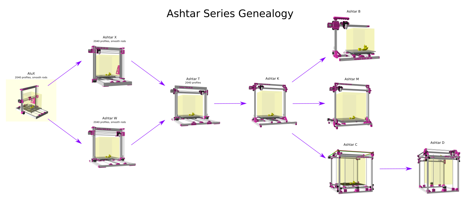
- 2021/01/18: added IDEX Features with Pros/Cons, Ashtar Series Genealogy, Comparison Dual Material approaches, and brief Hardware Requirements
- 2021/01/15: first version with overview side-by-side
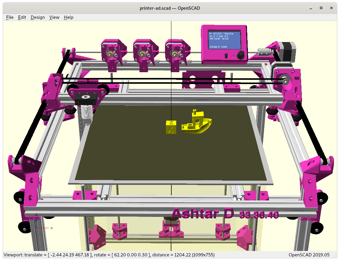
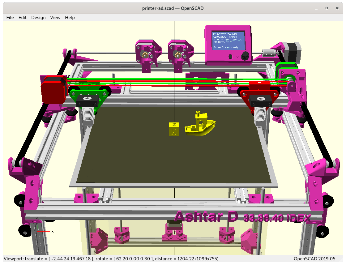
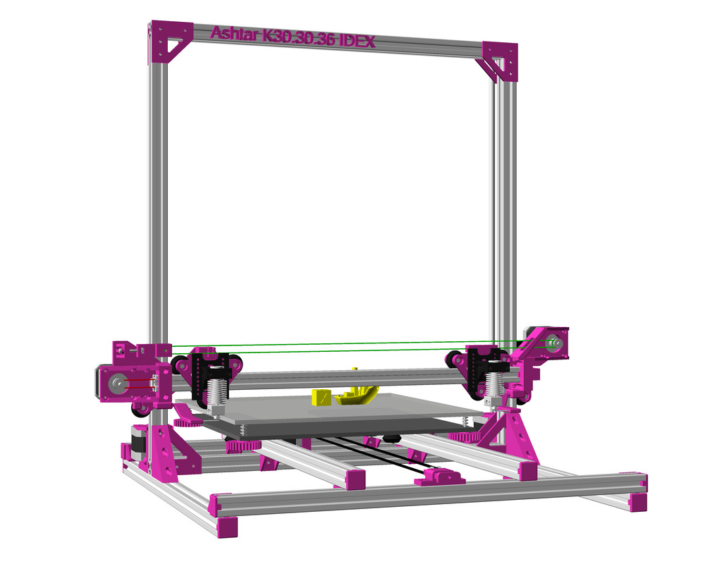
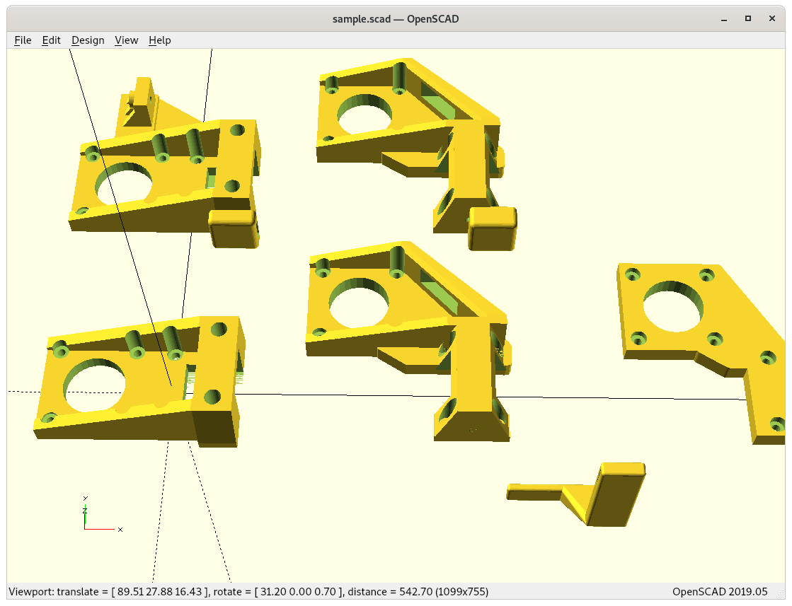
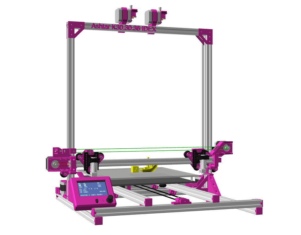
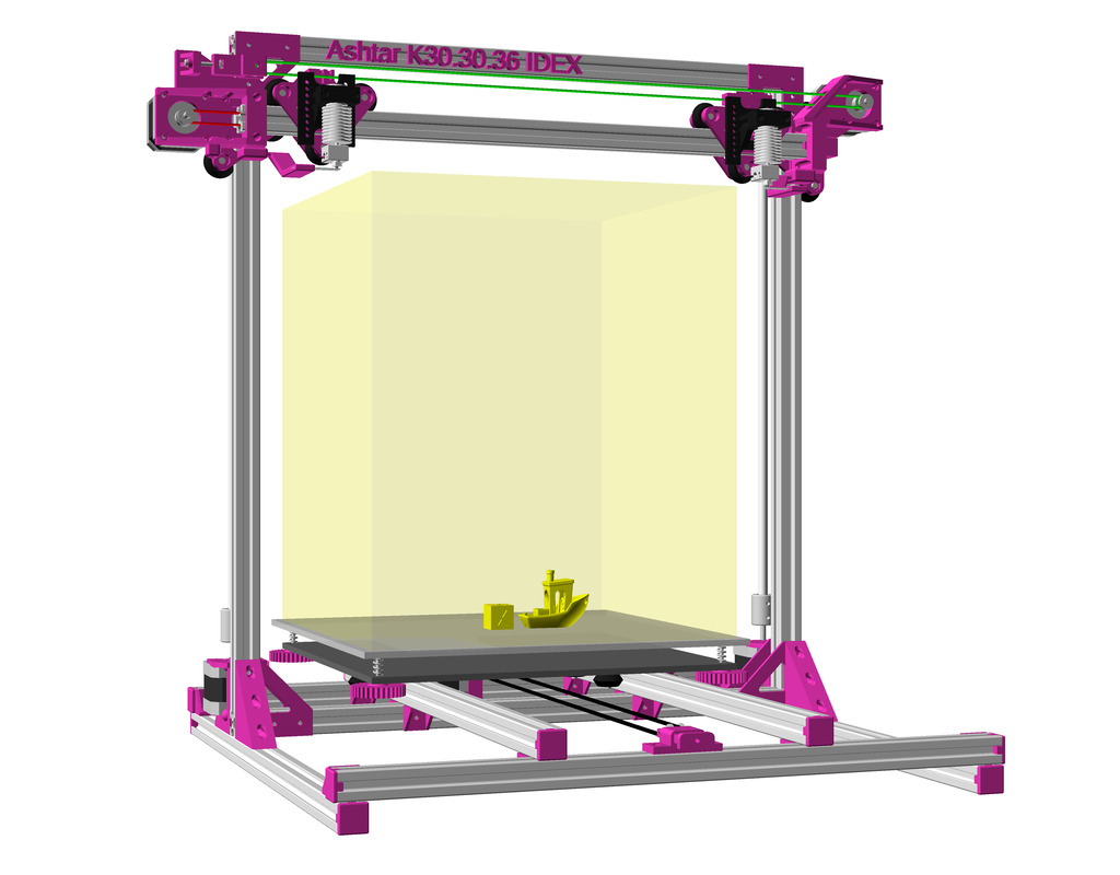
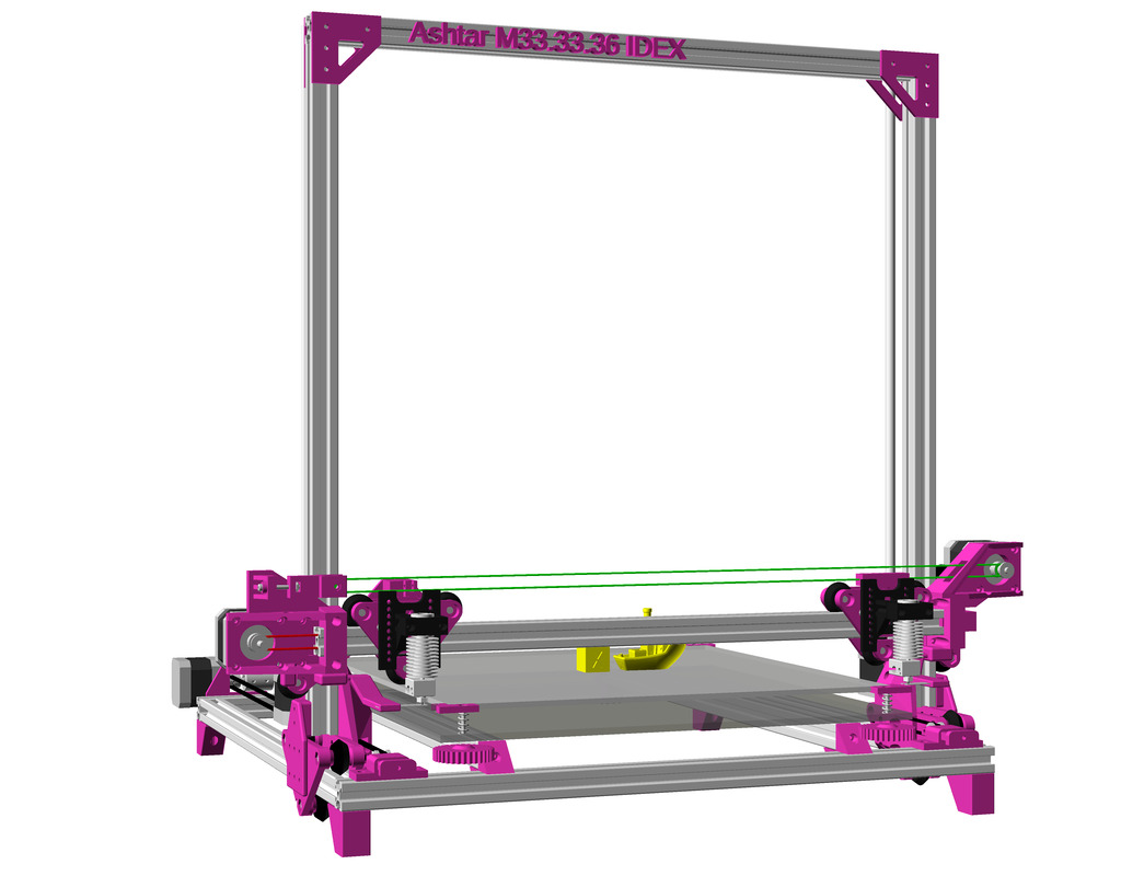
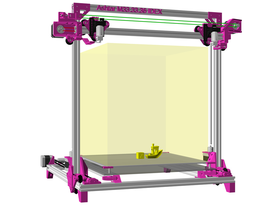
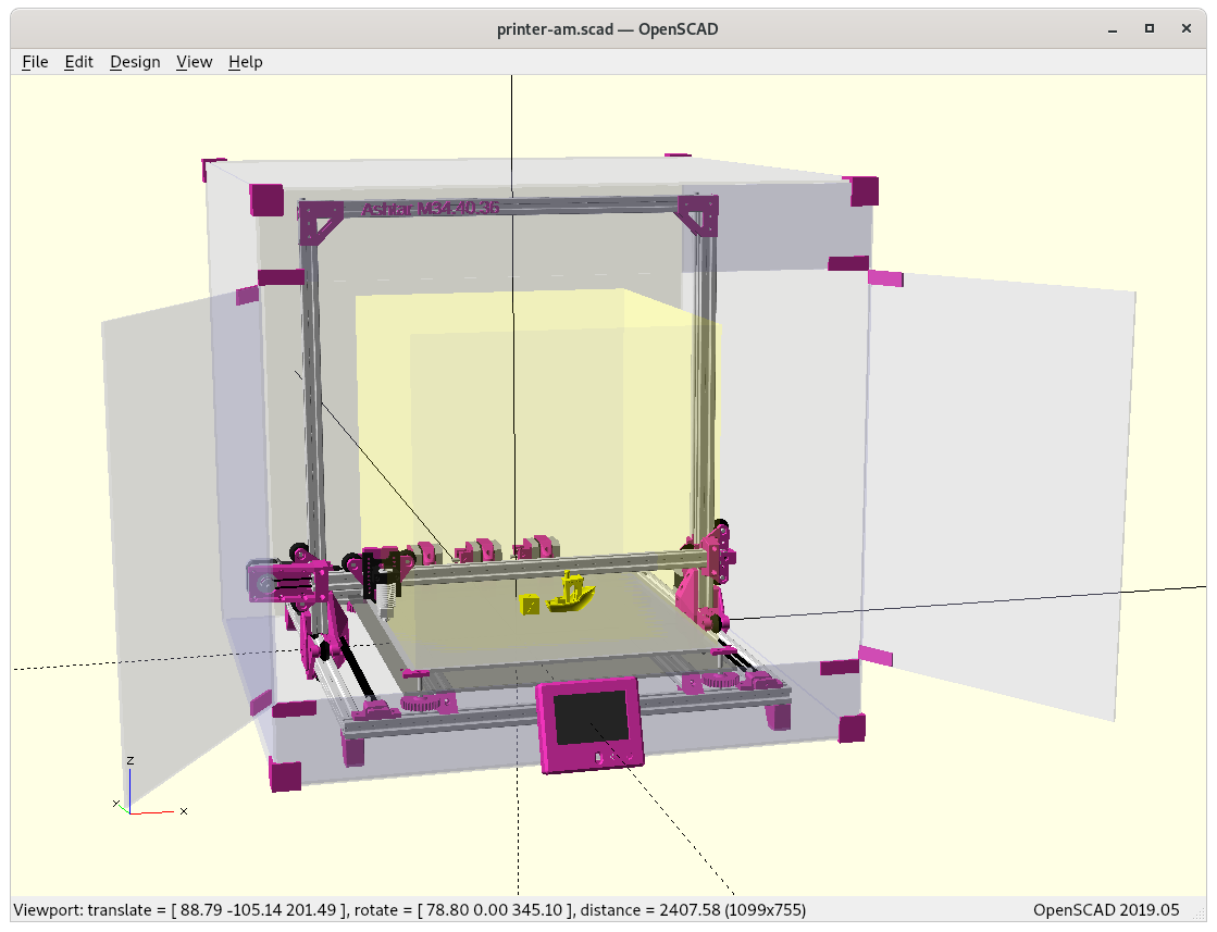
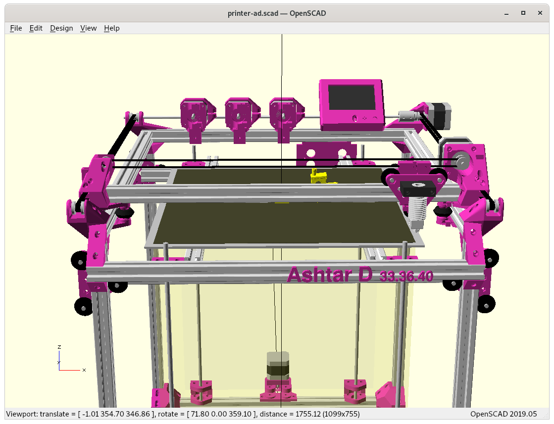
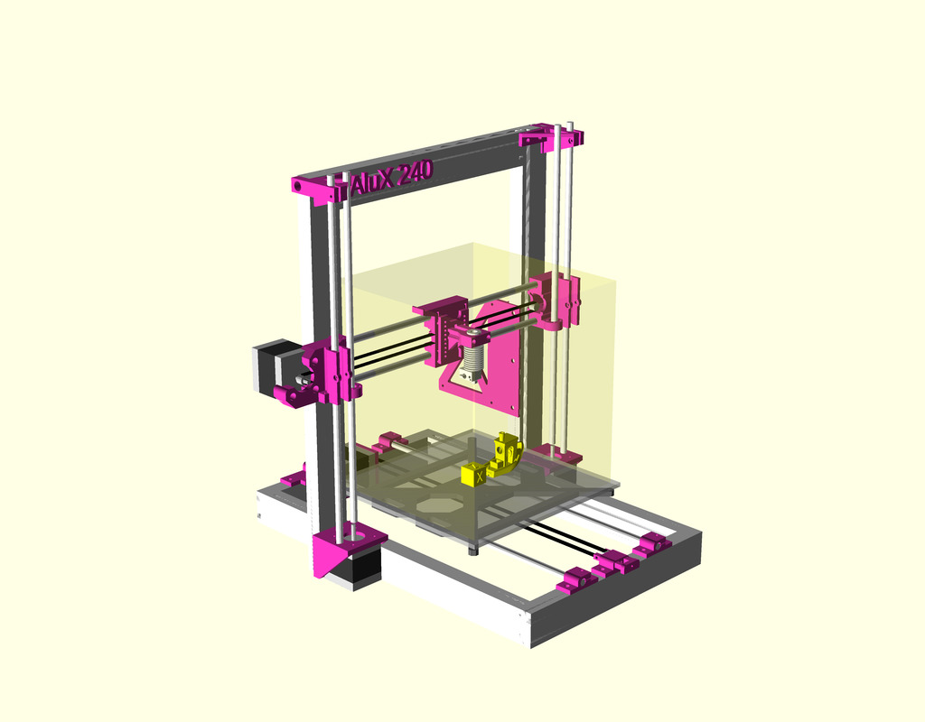
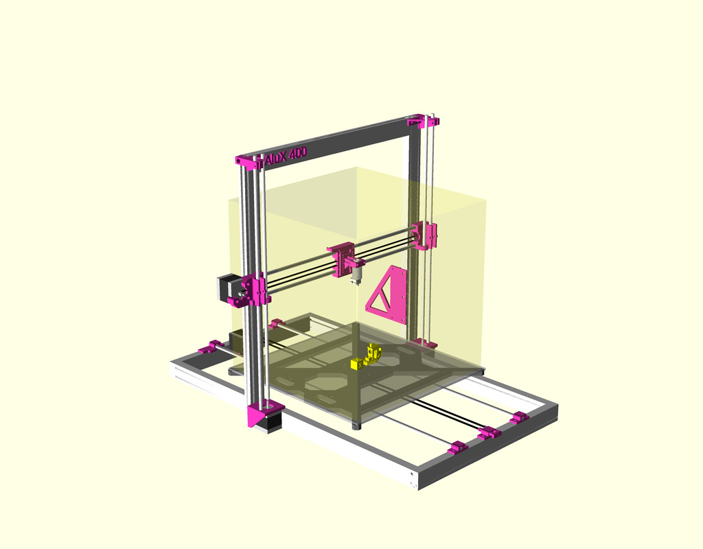
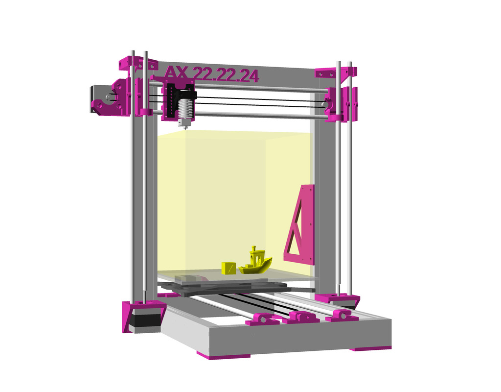
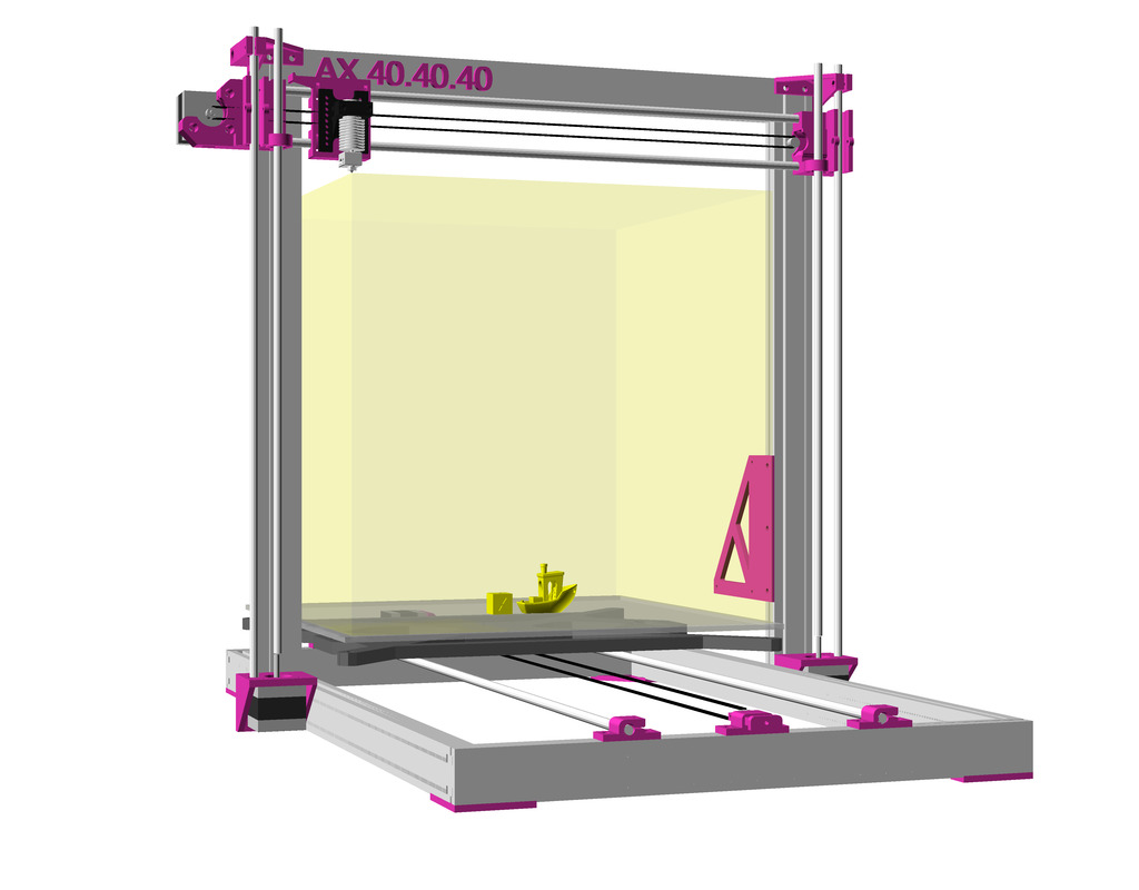
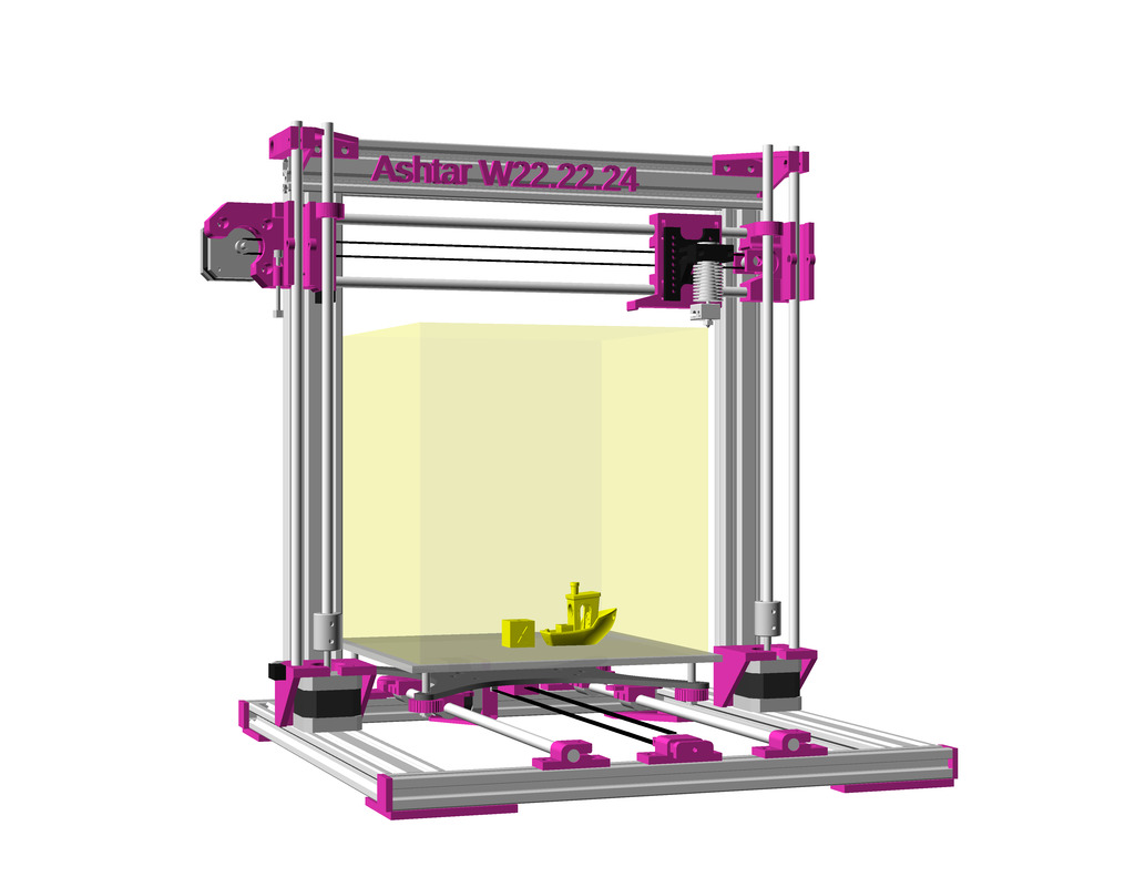
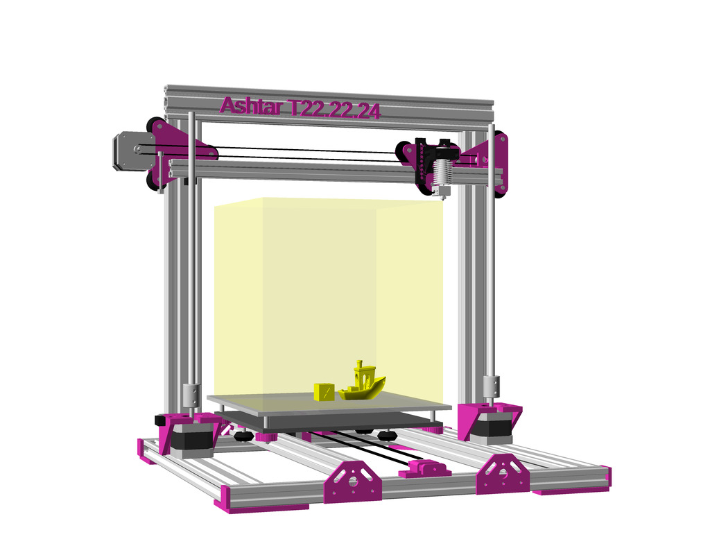
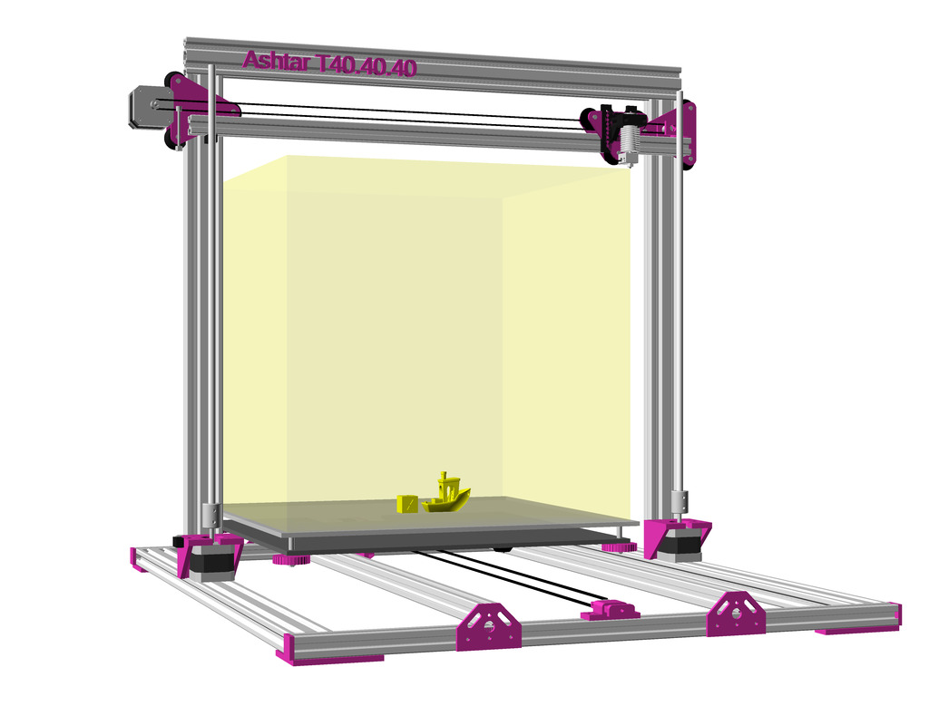
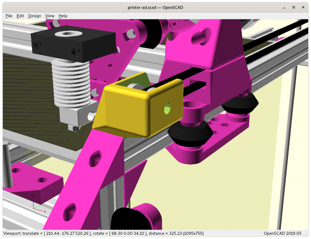
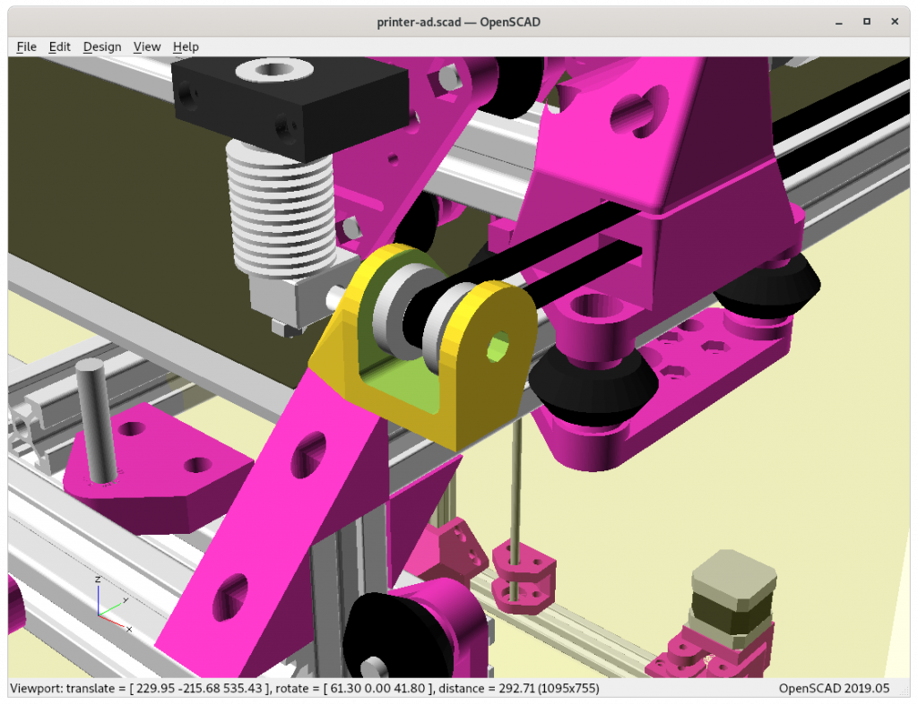
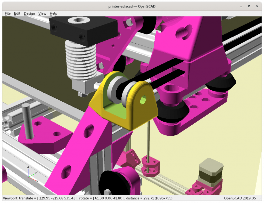
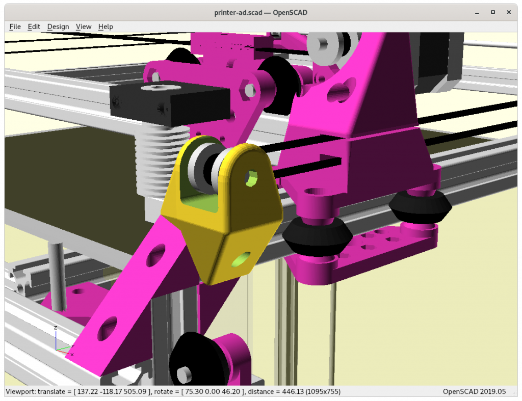
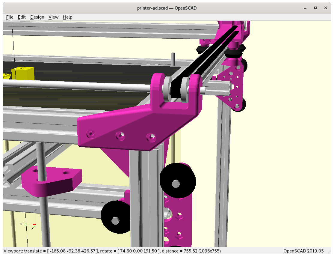
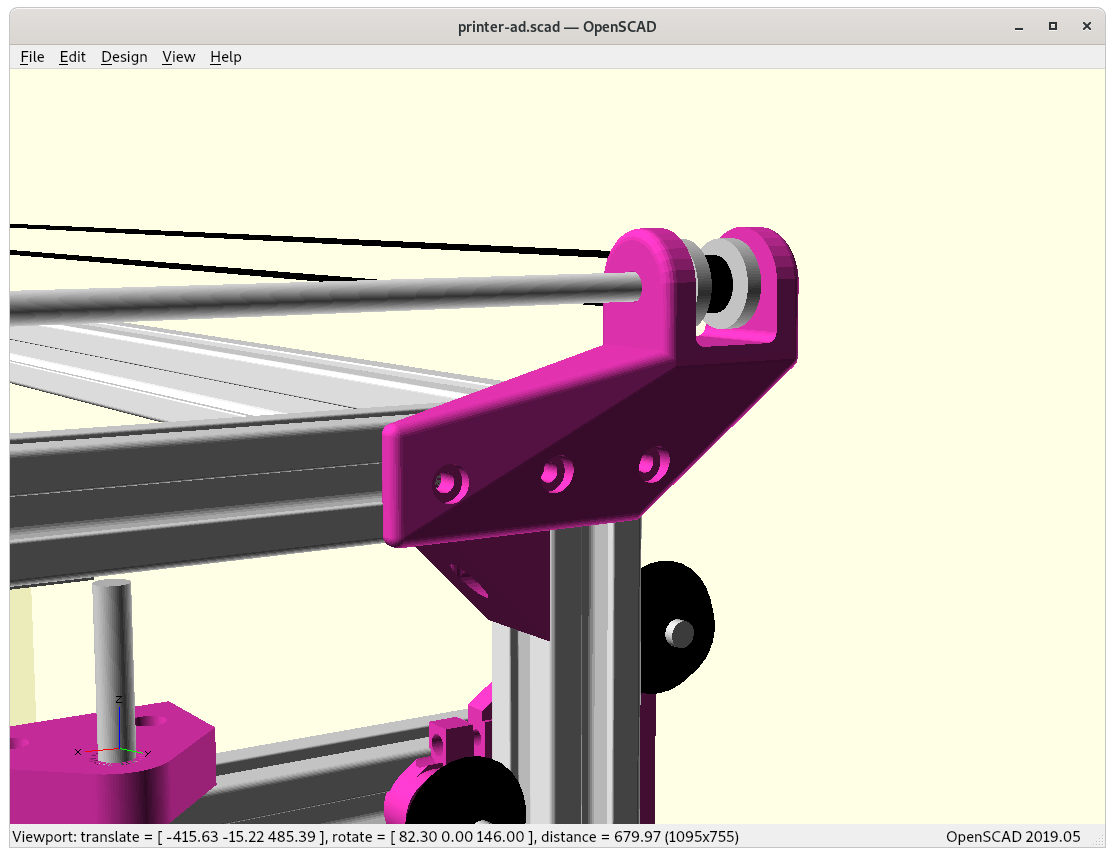
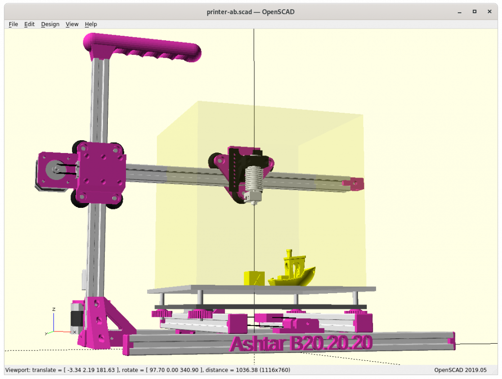
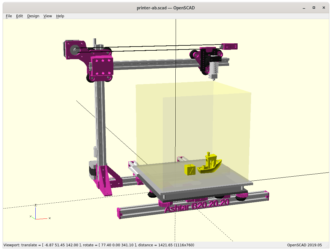
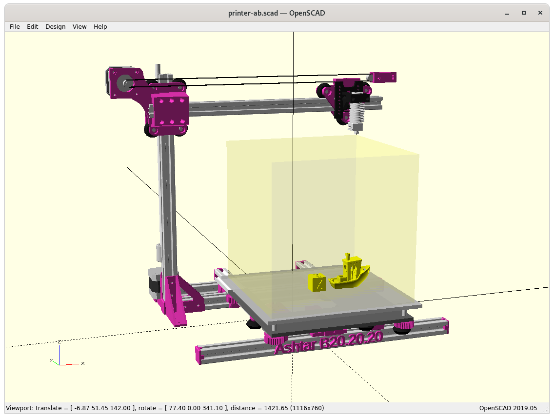
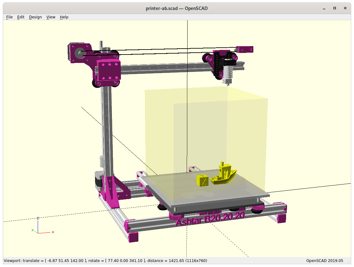
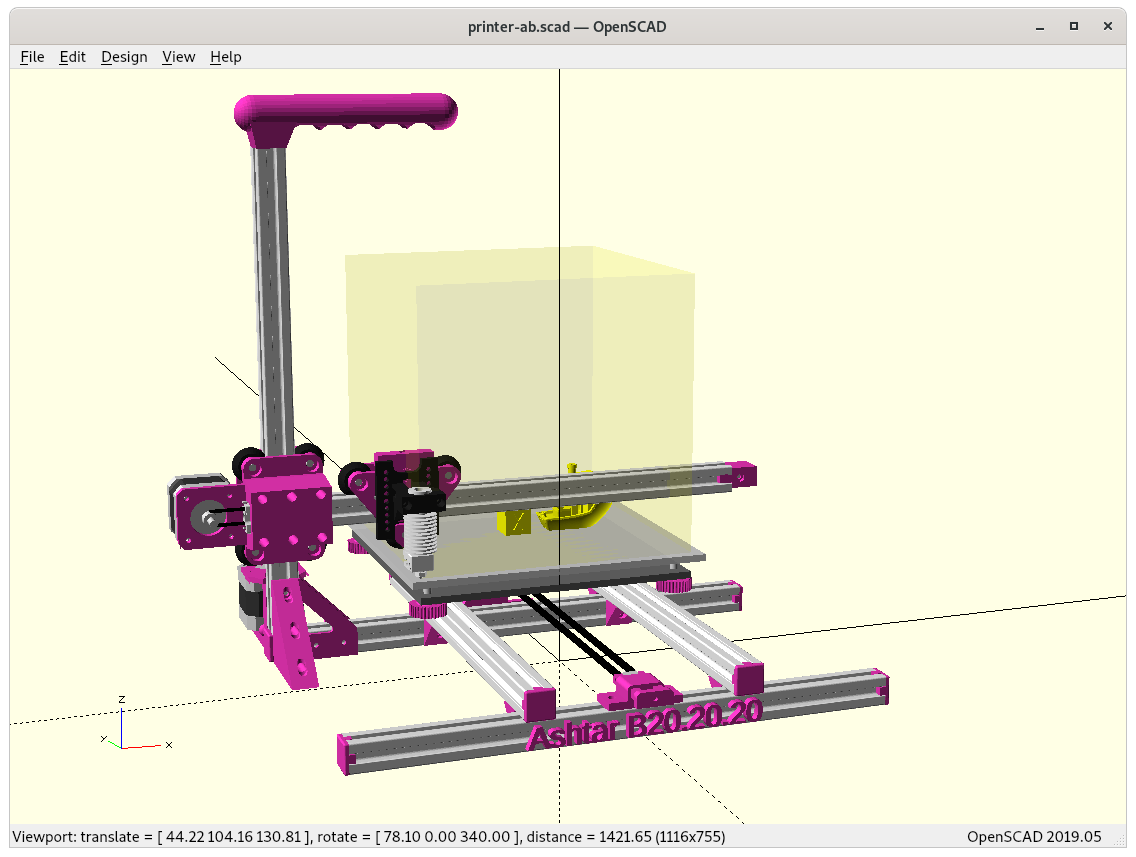
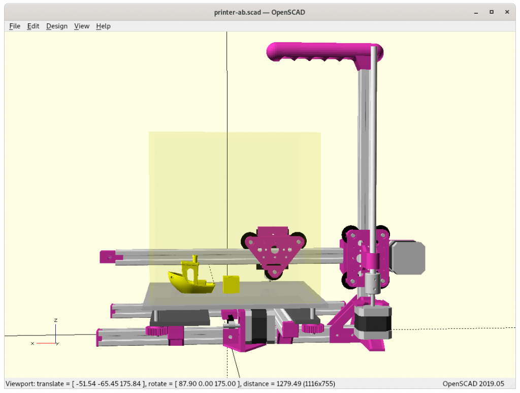
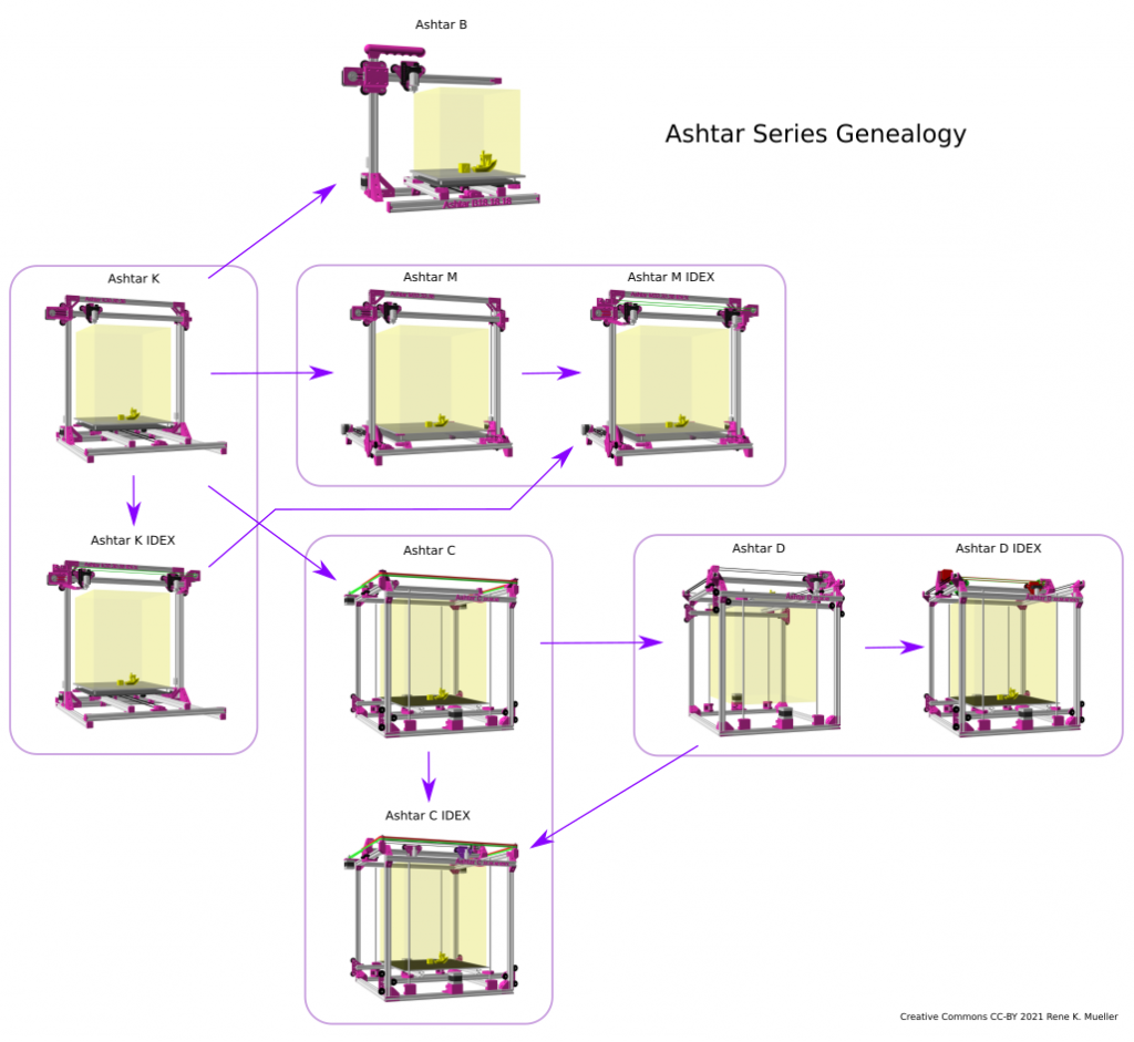
Mid of January 2021 (01/12 – 01/14) I added IDEX (Independent Dual Extrusion) option to 4 designs, all still in early draft stage – here as a summary side-by-side:
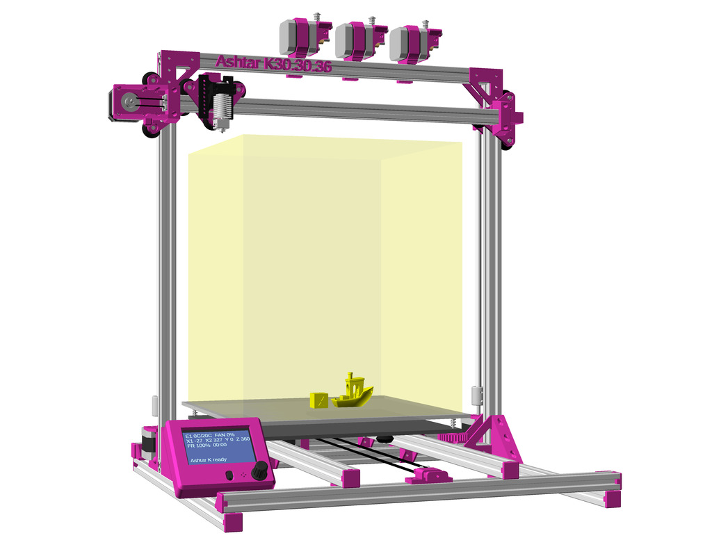
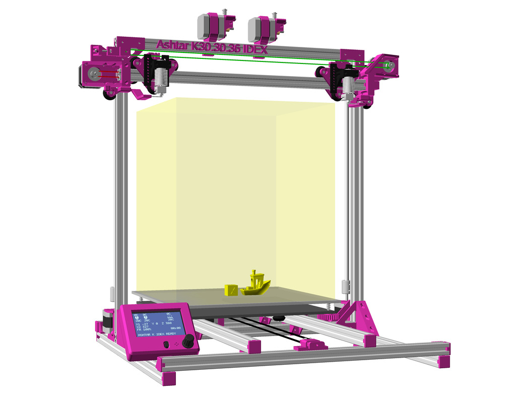
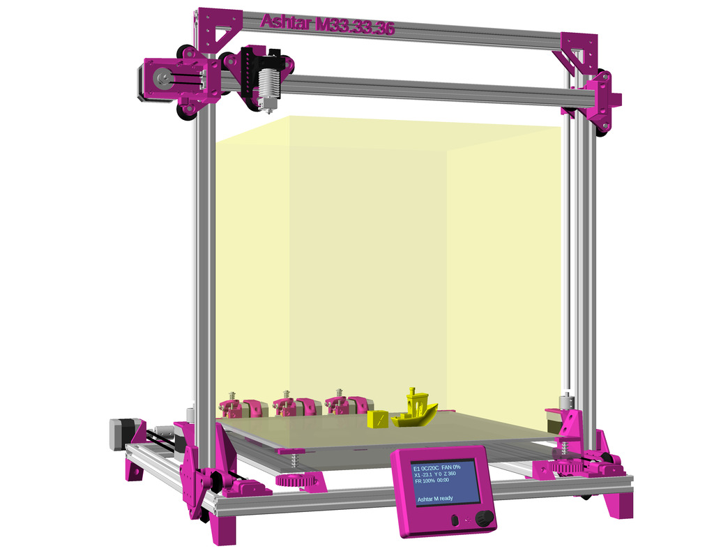
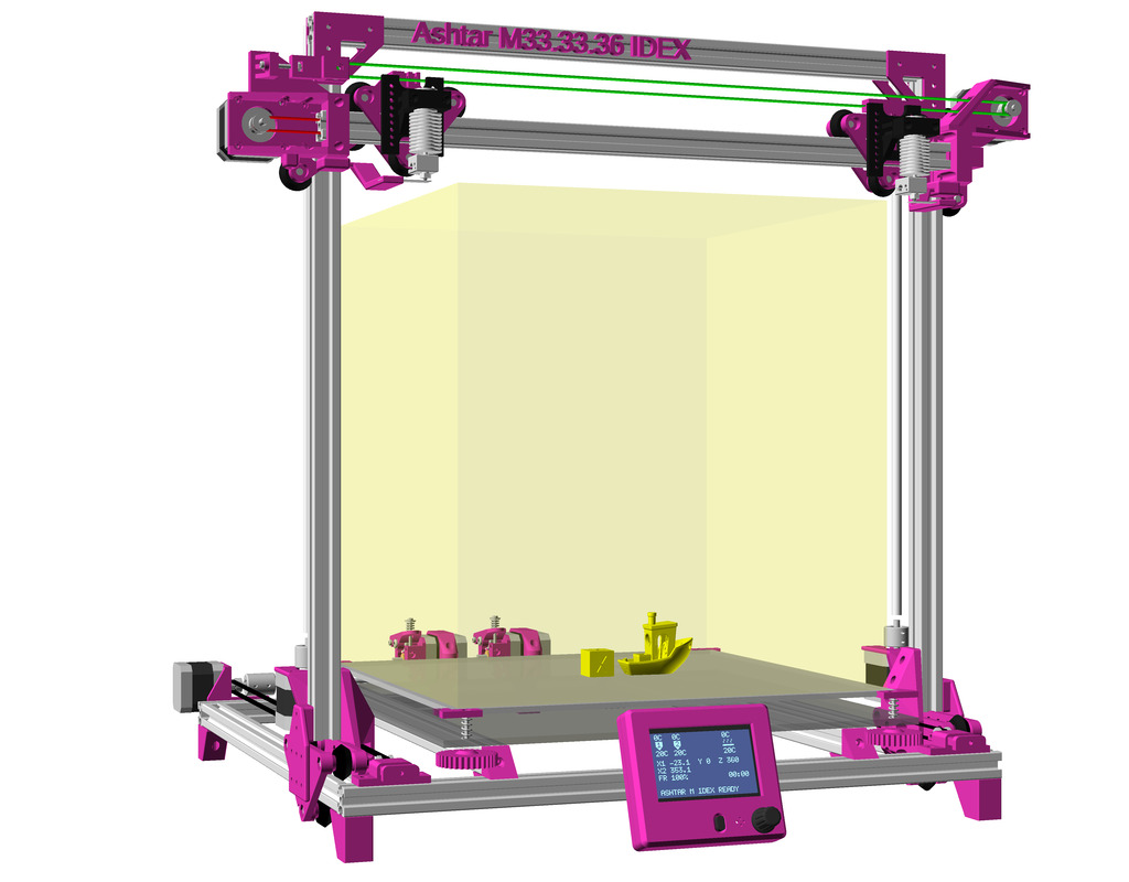
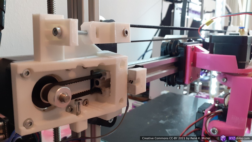
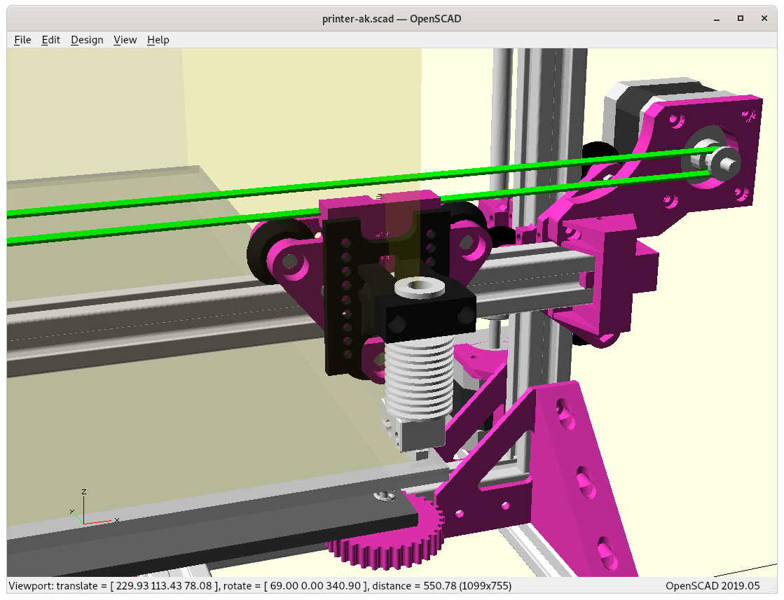
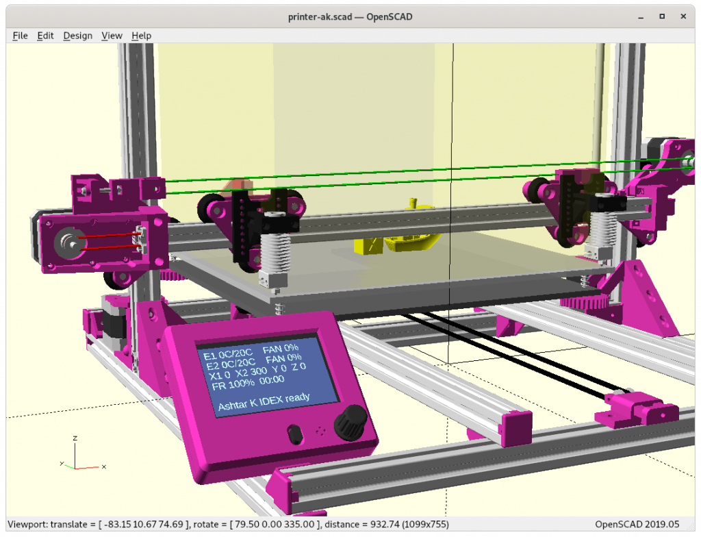
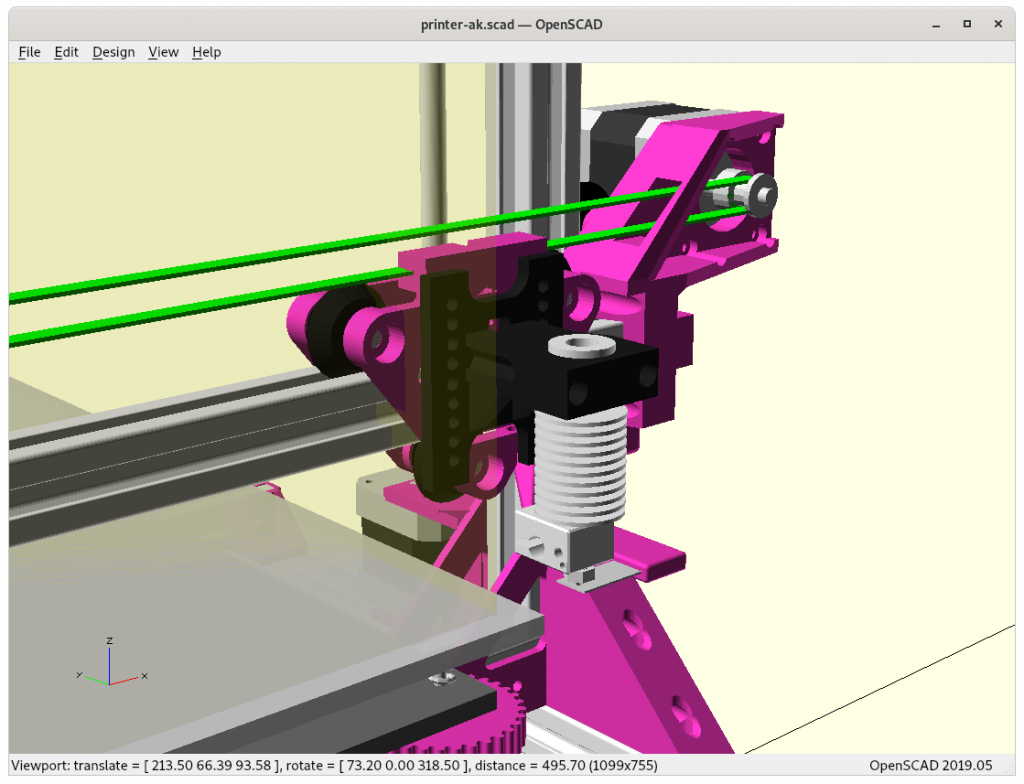
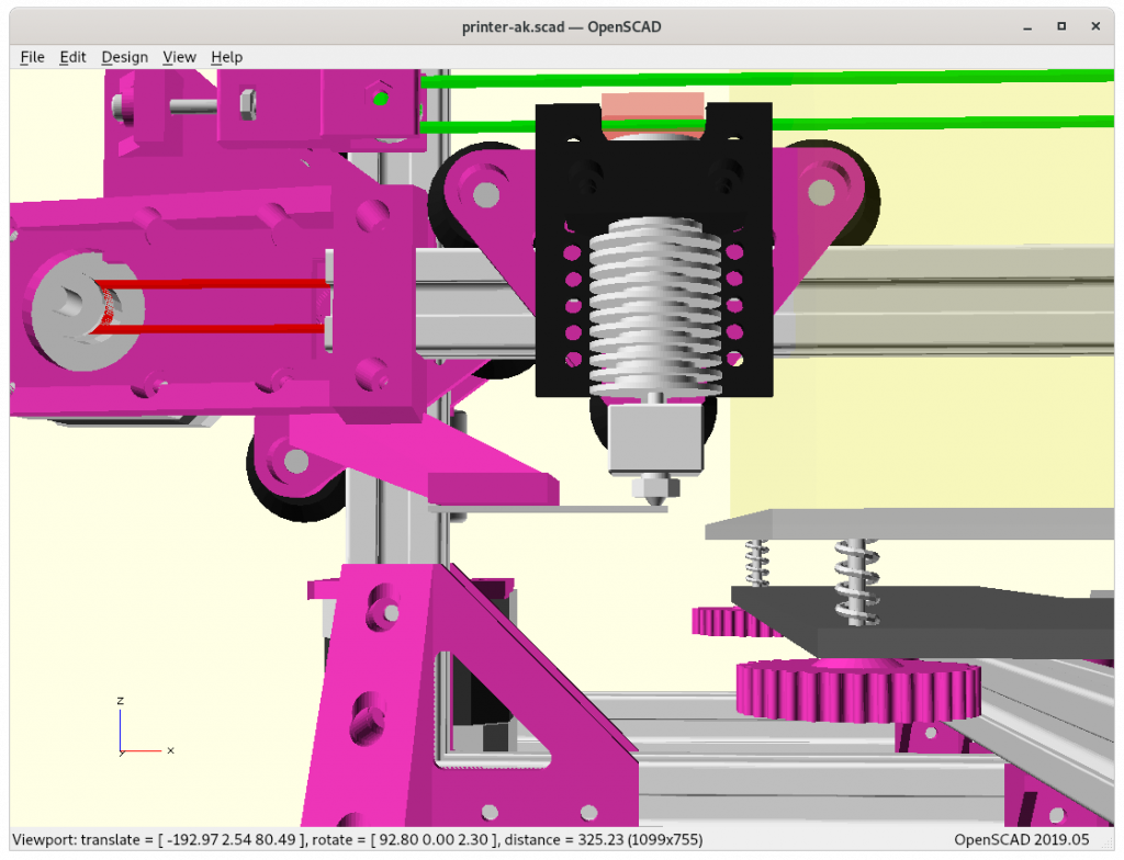
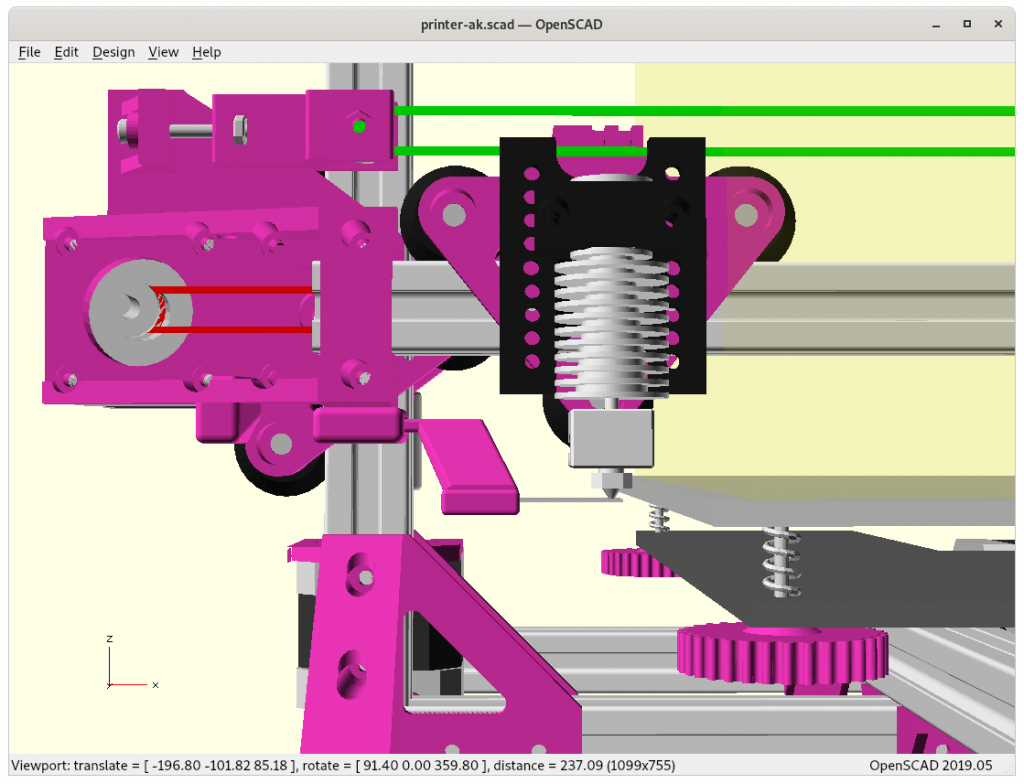
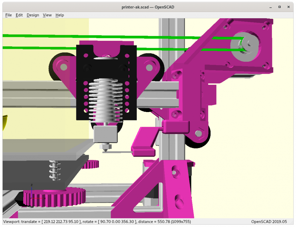
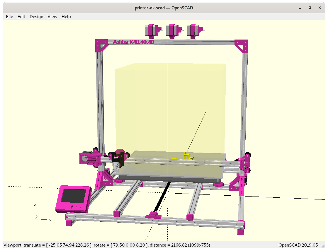
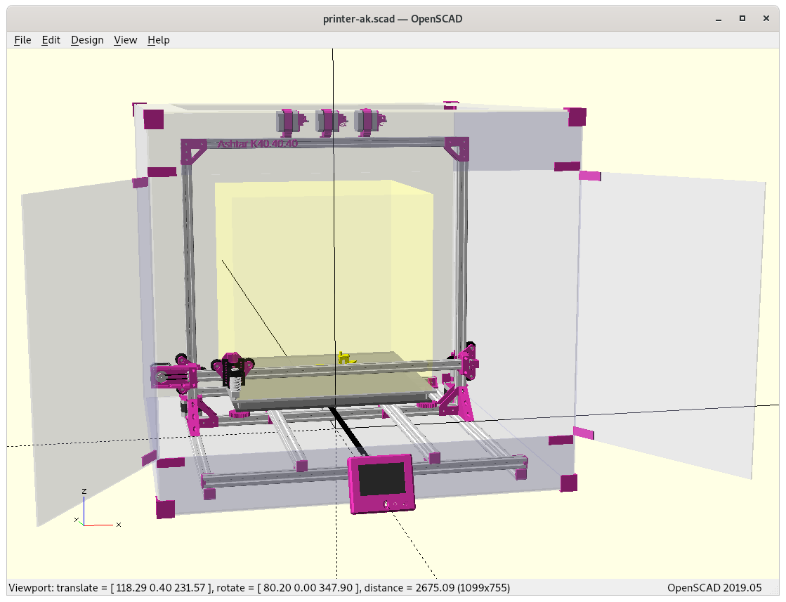
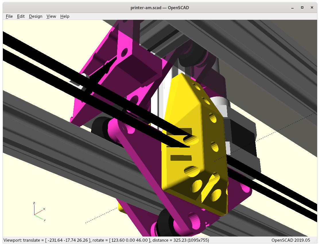
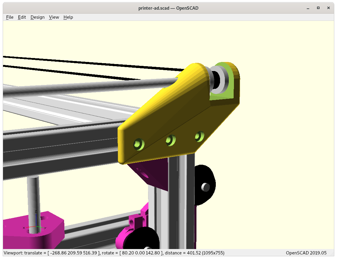
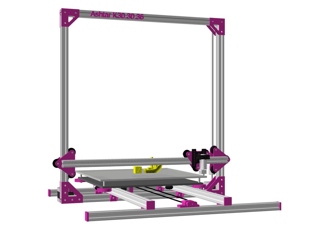
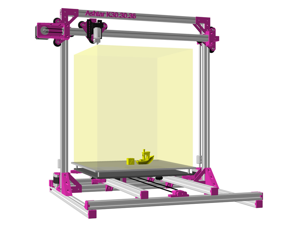
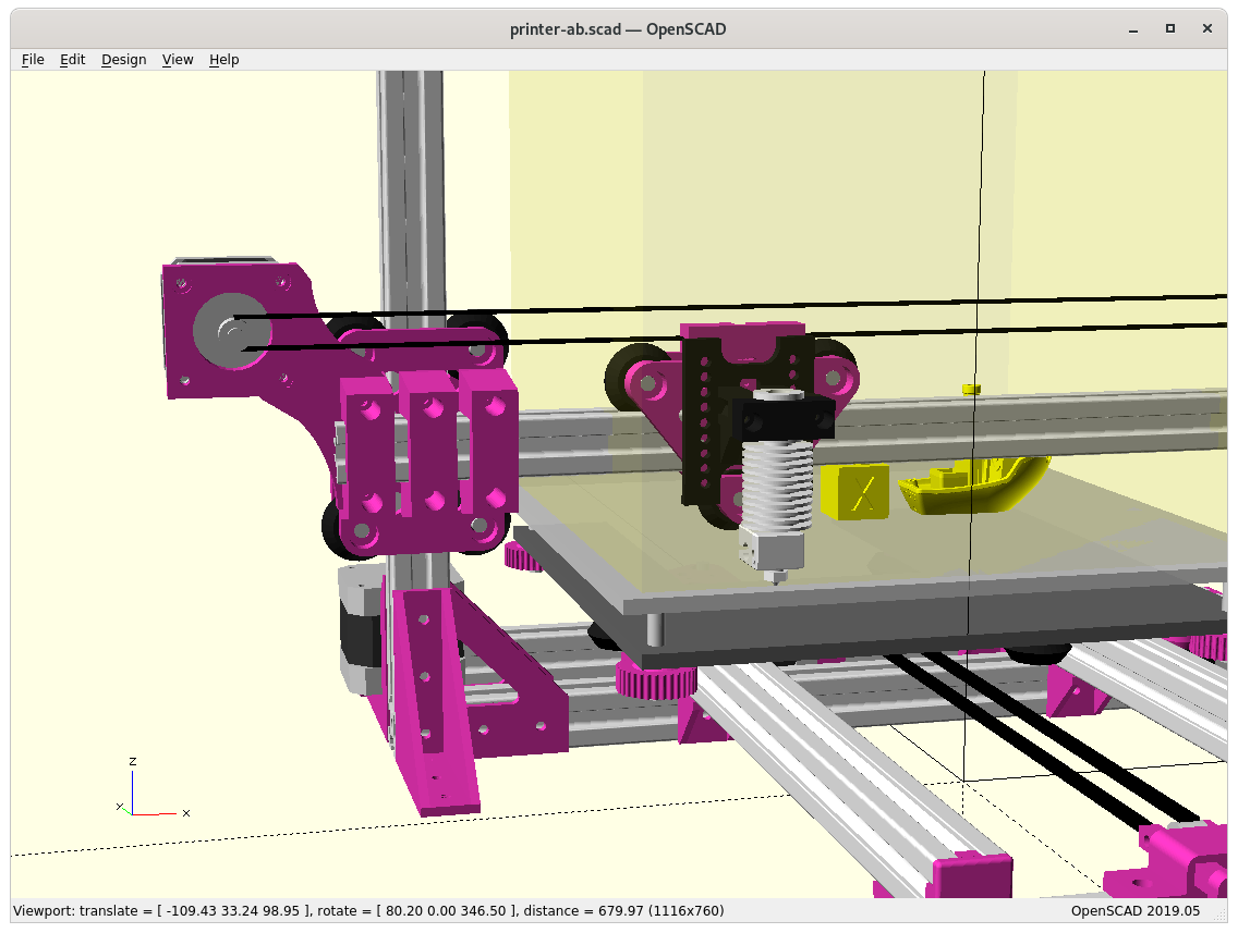
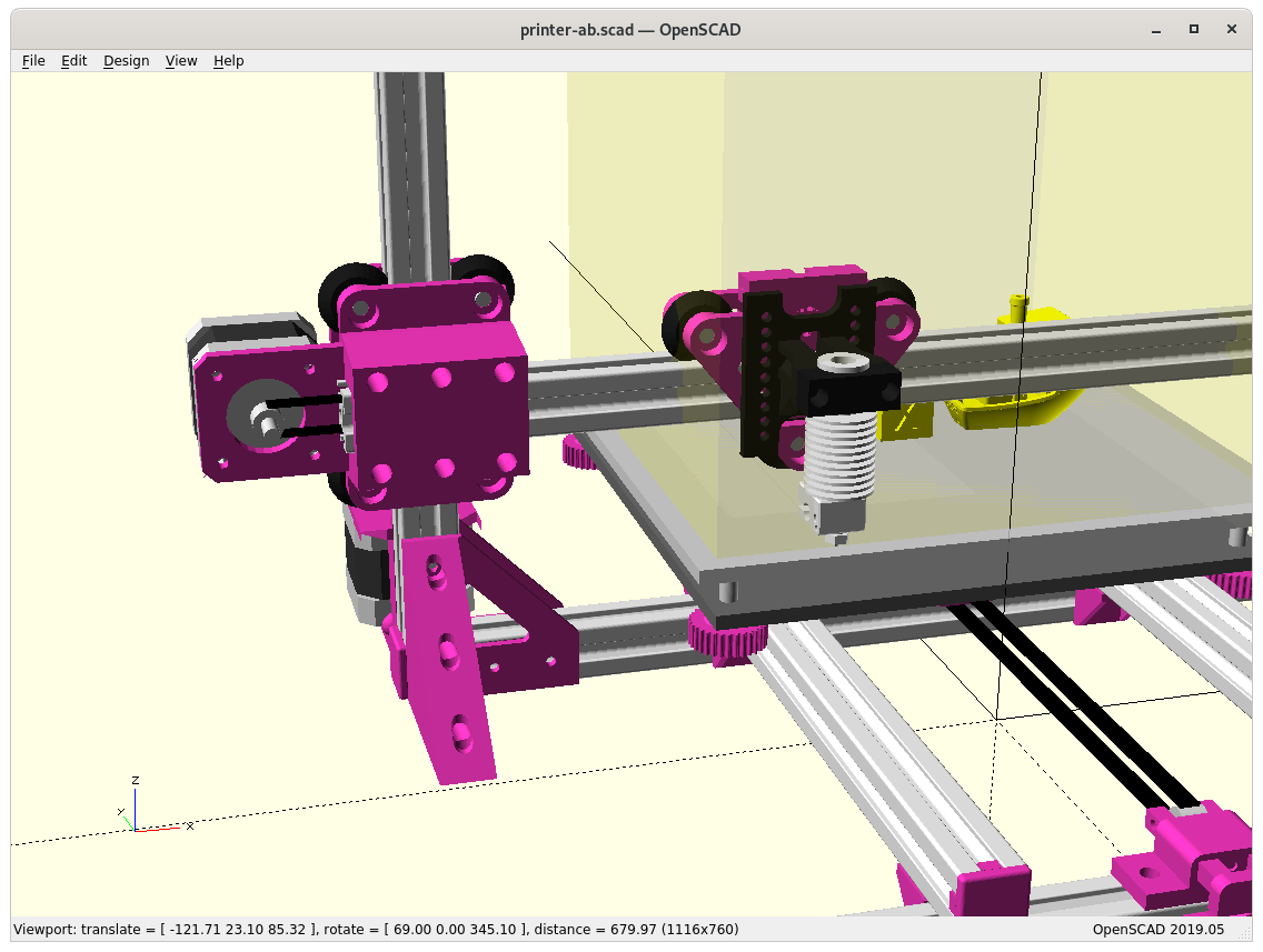
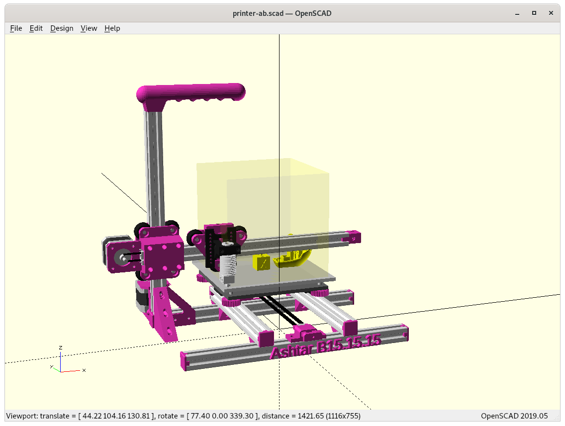
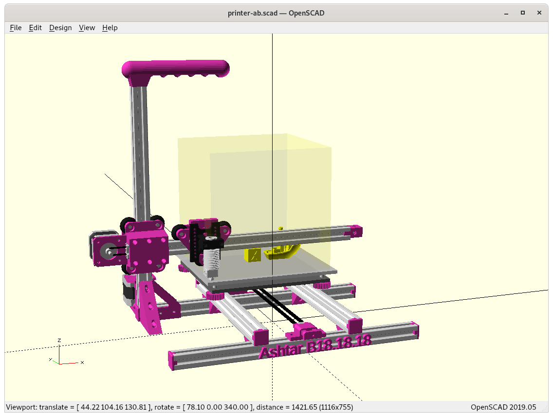
Ashtar K IDEX has been fairly easy, as I was using an improved “old” design of the X motor mount for the 2nd motor and 2nd belt, and since Ashtar M IDEX is using the same XZ frame, it was a matter of a few minutes to port that option as well.
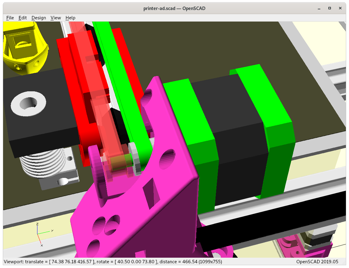
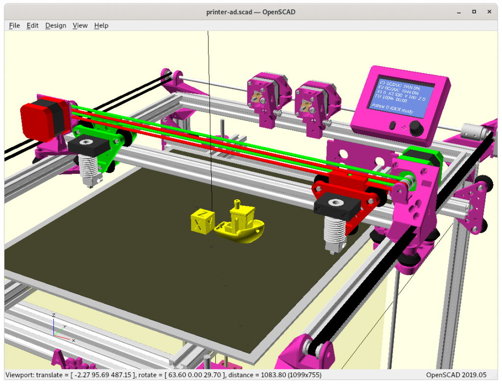
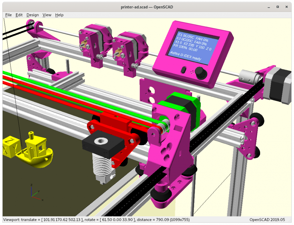
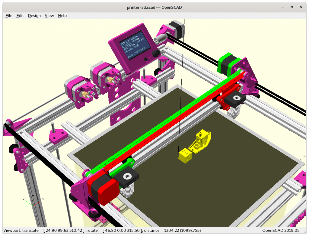
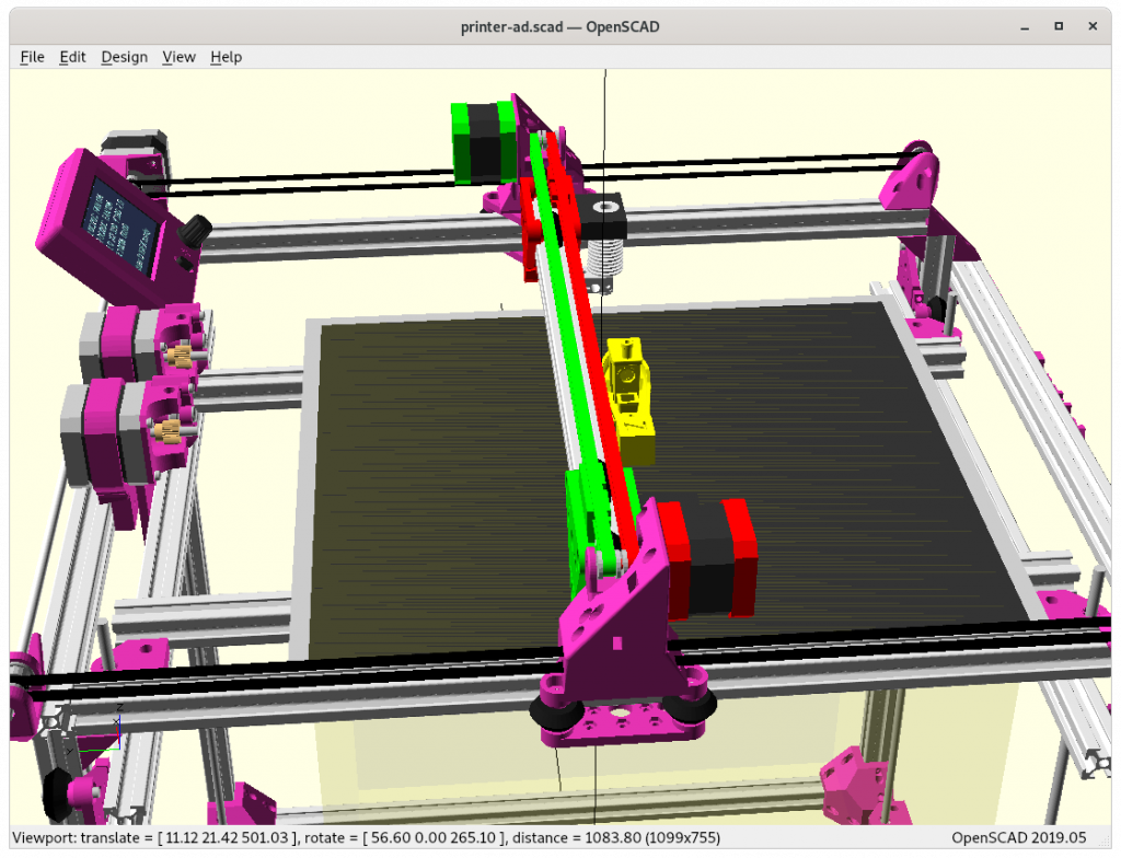
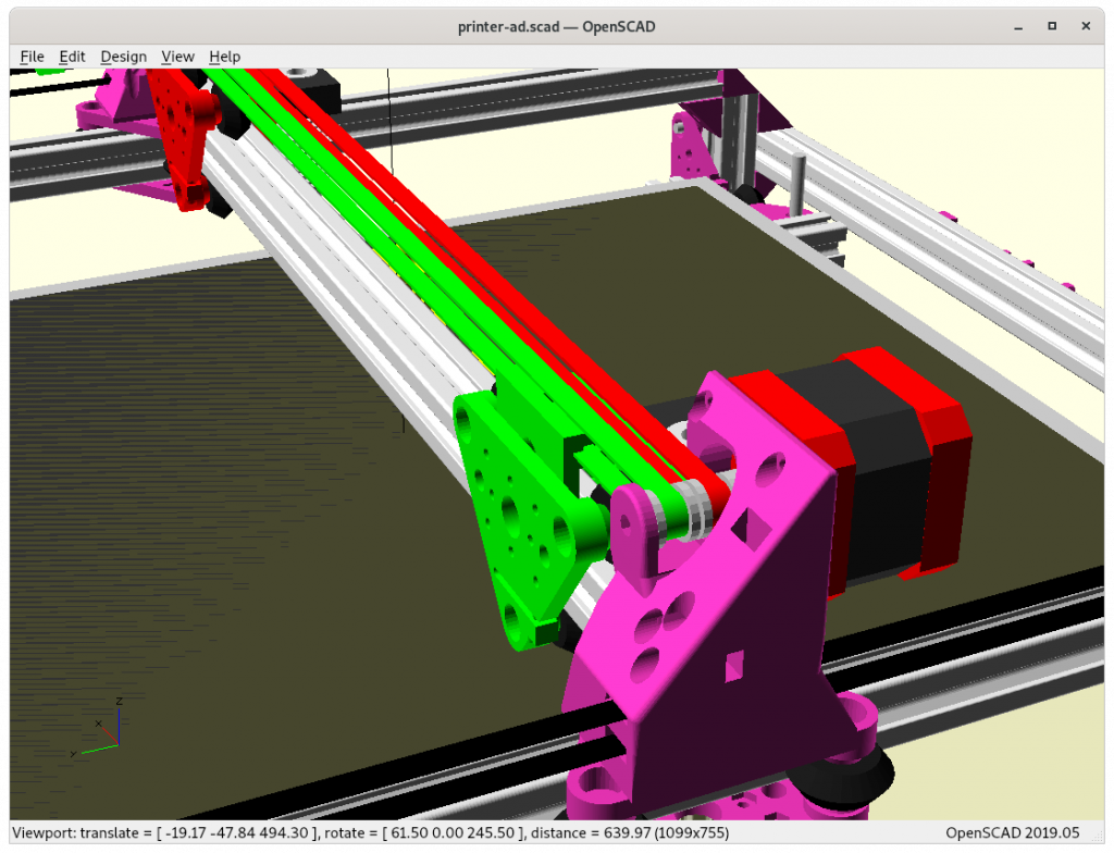
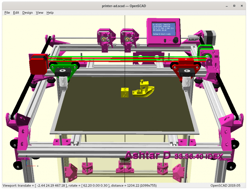
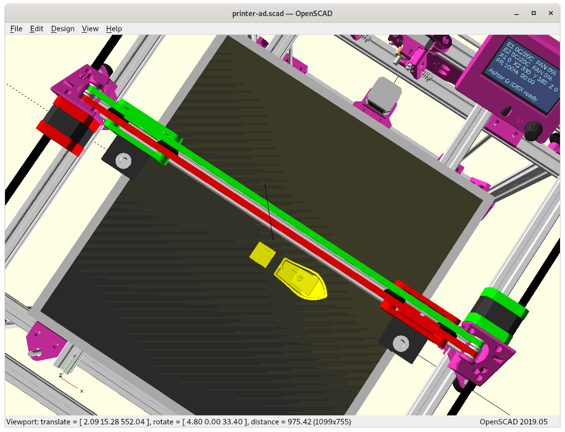
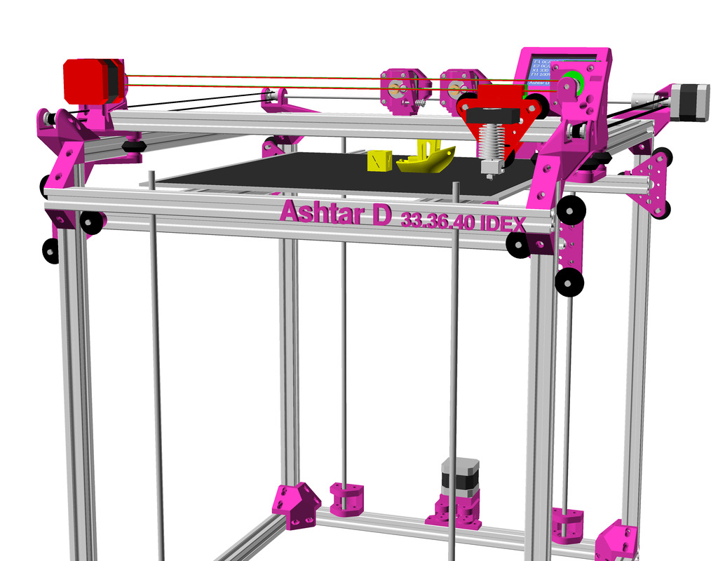
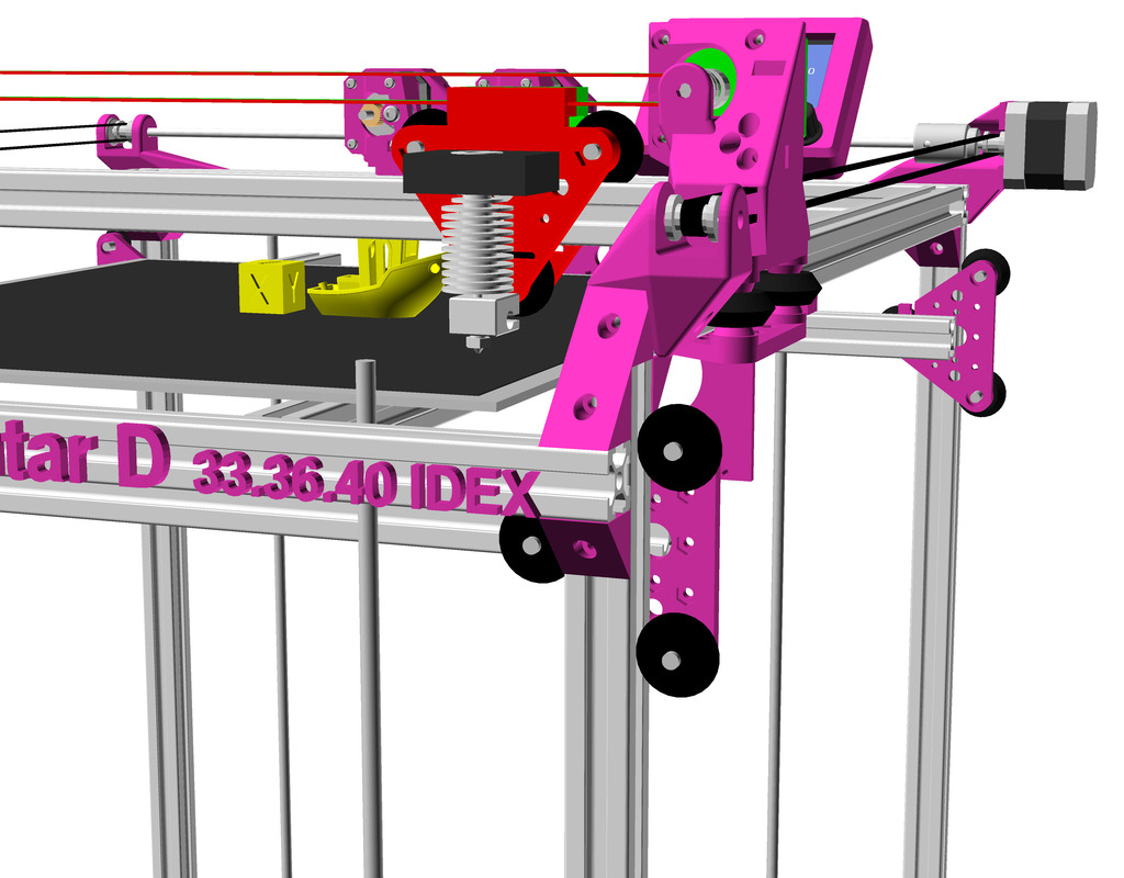
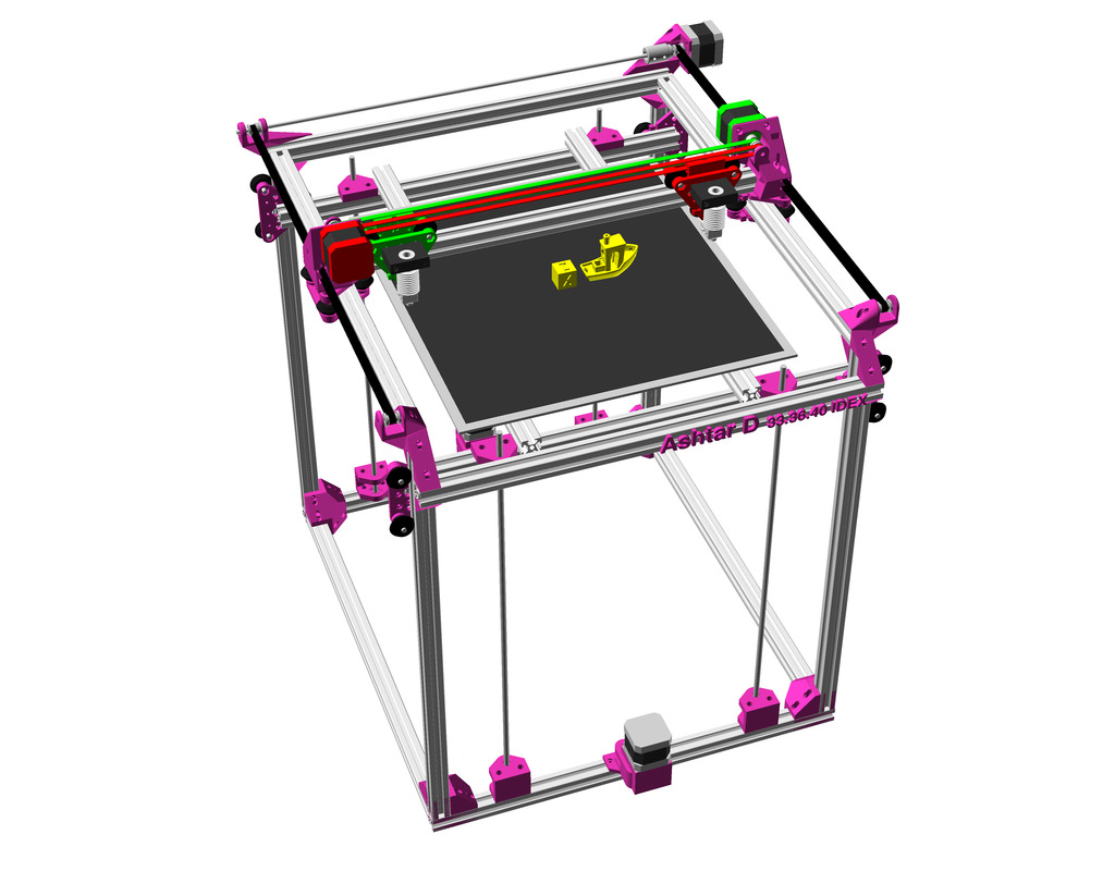
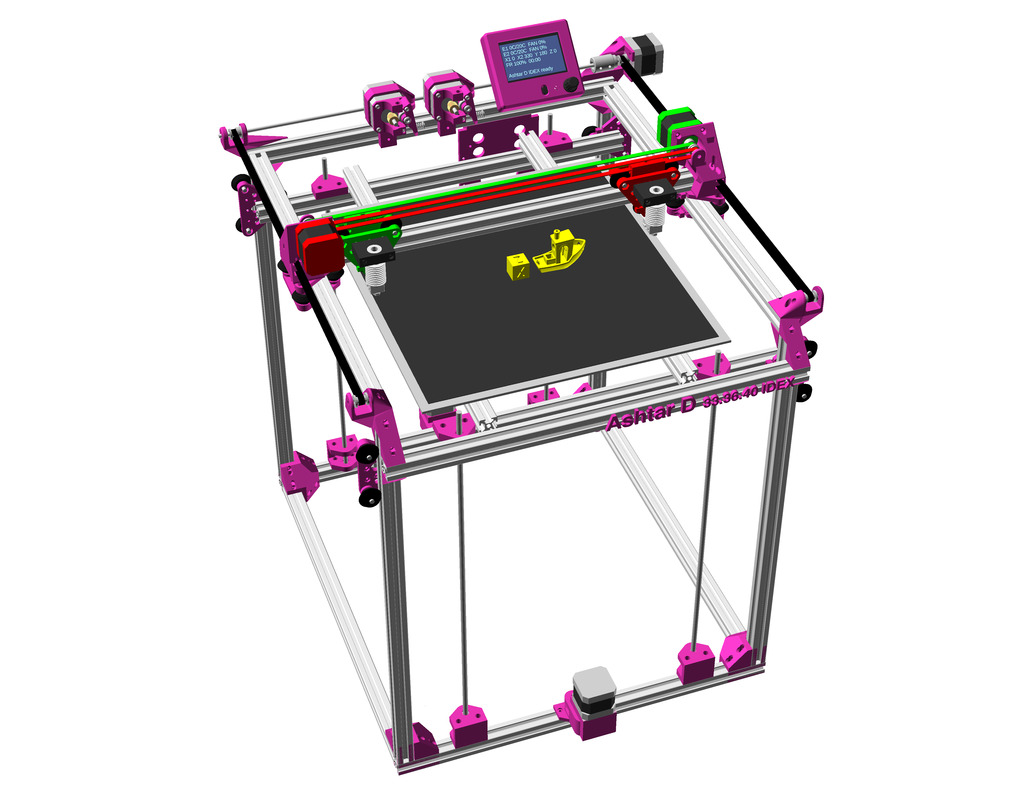
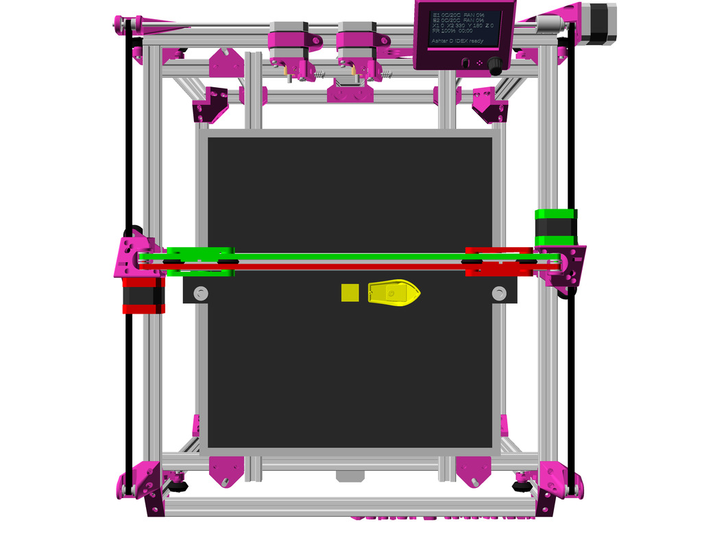
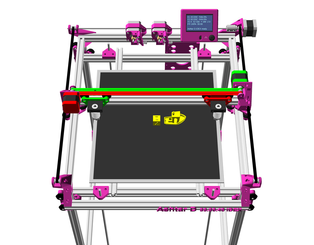
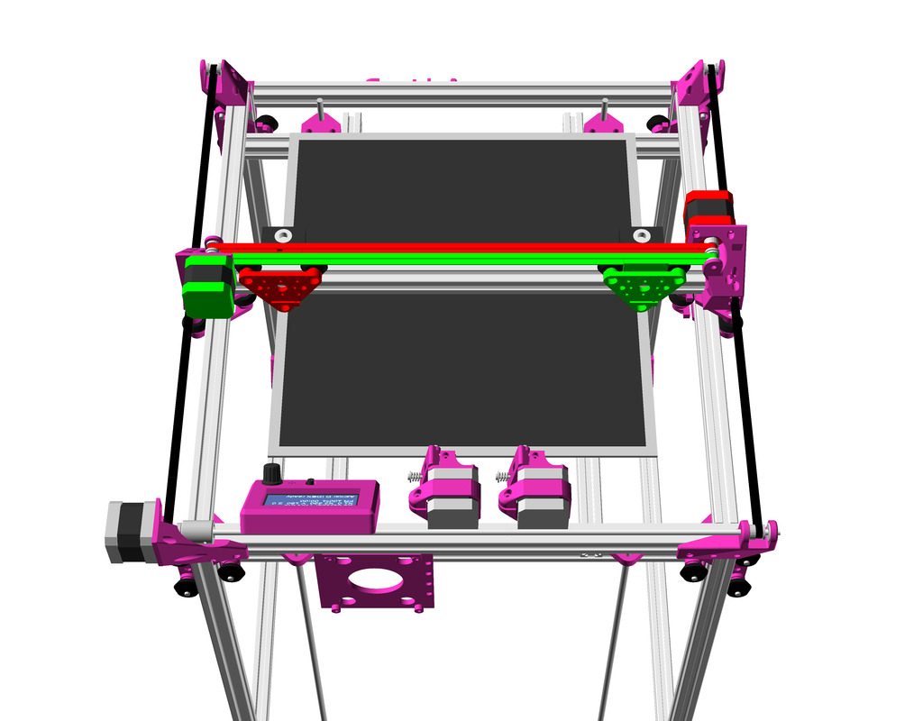
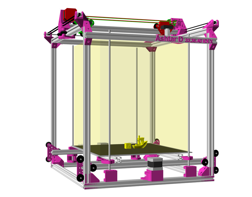
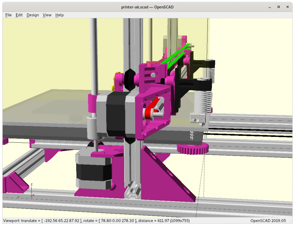
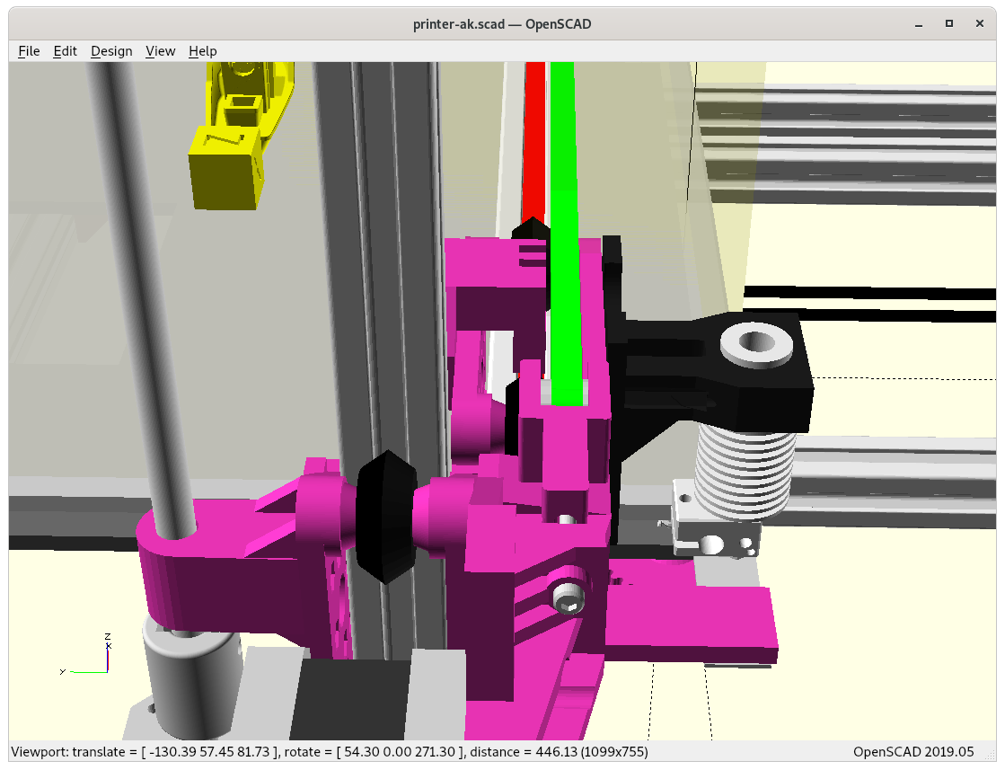
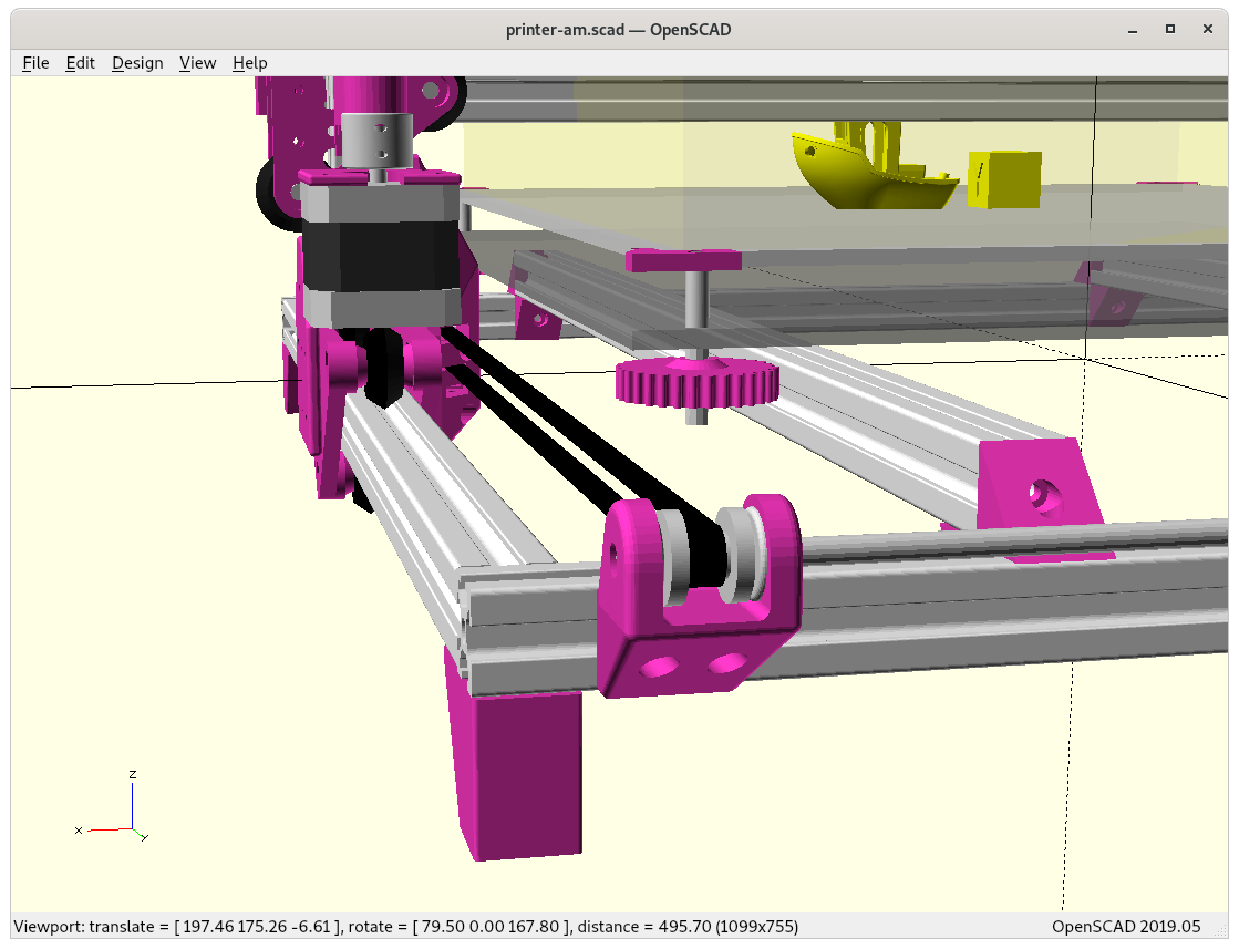
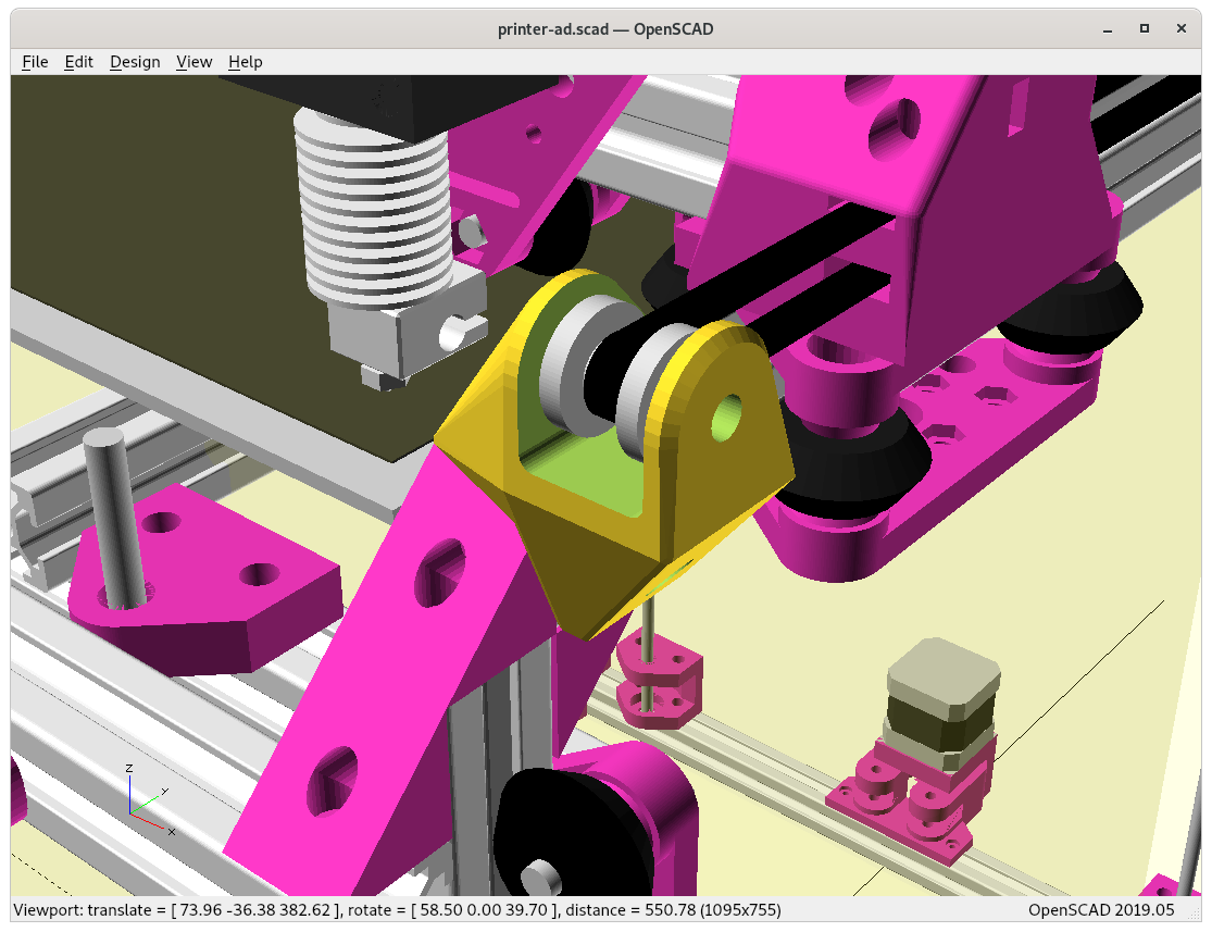
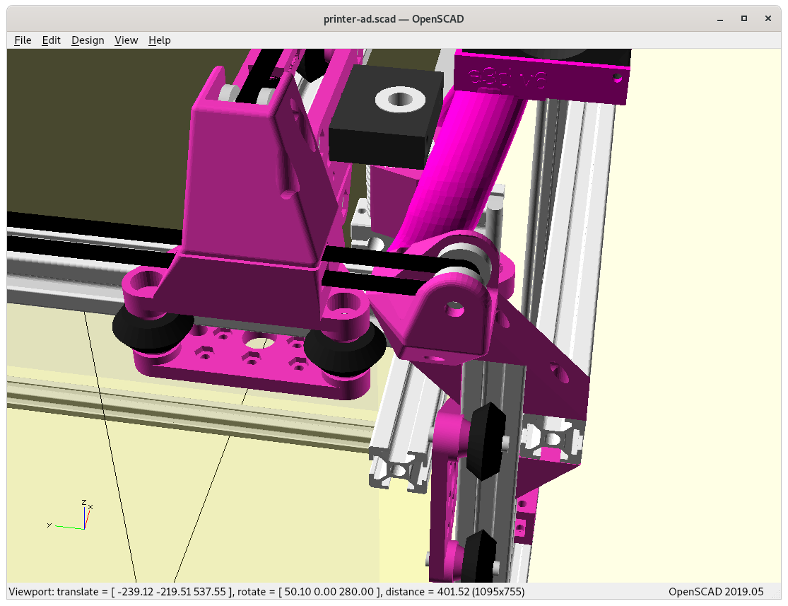
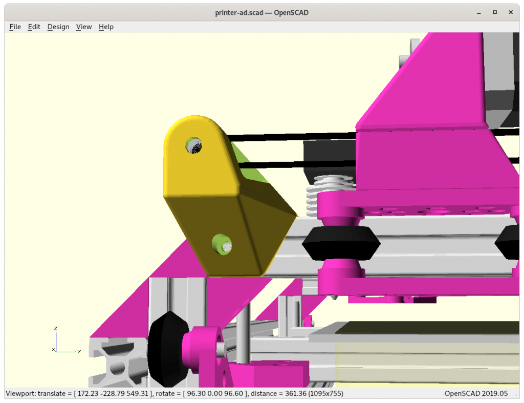
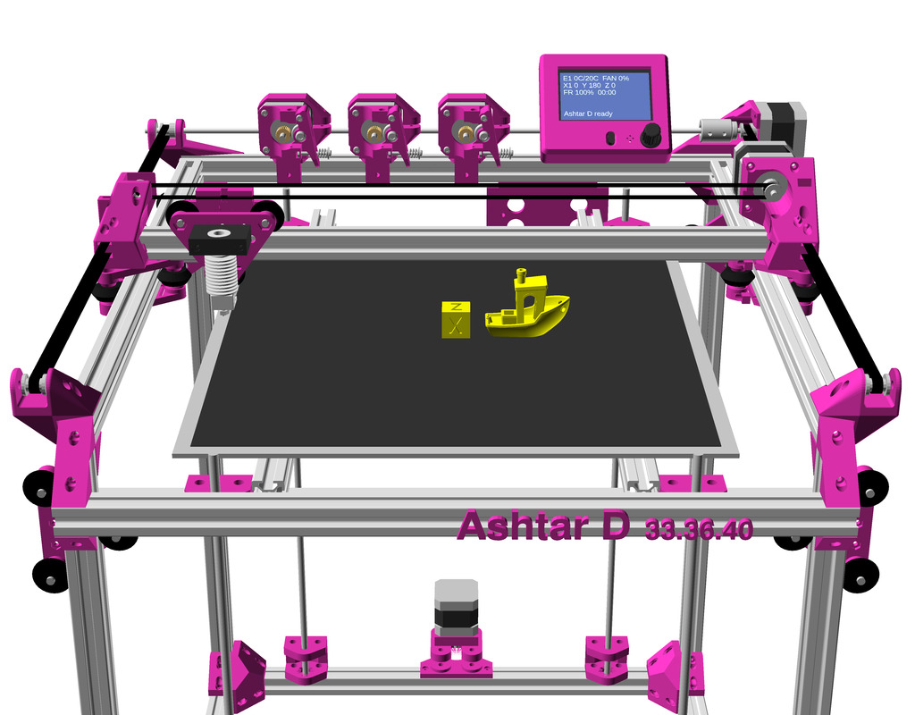
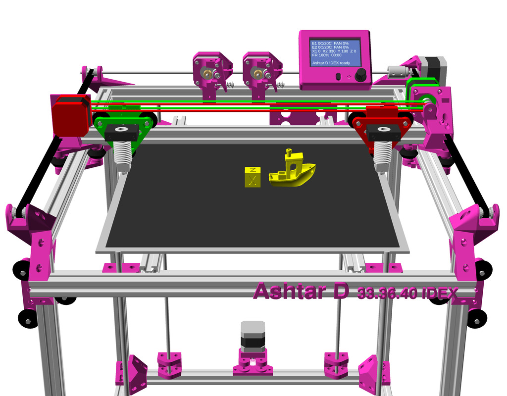
Ashtar D IDEX with Classic XY belt routing was more tricky as there was little space left to add another motor, so I realized I need to utilize what’s there and take advantage of it – result is a very space saving solution, but it needs to be verified in real life first.
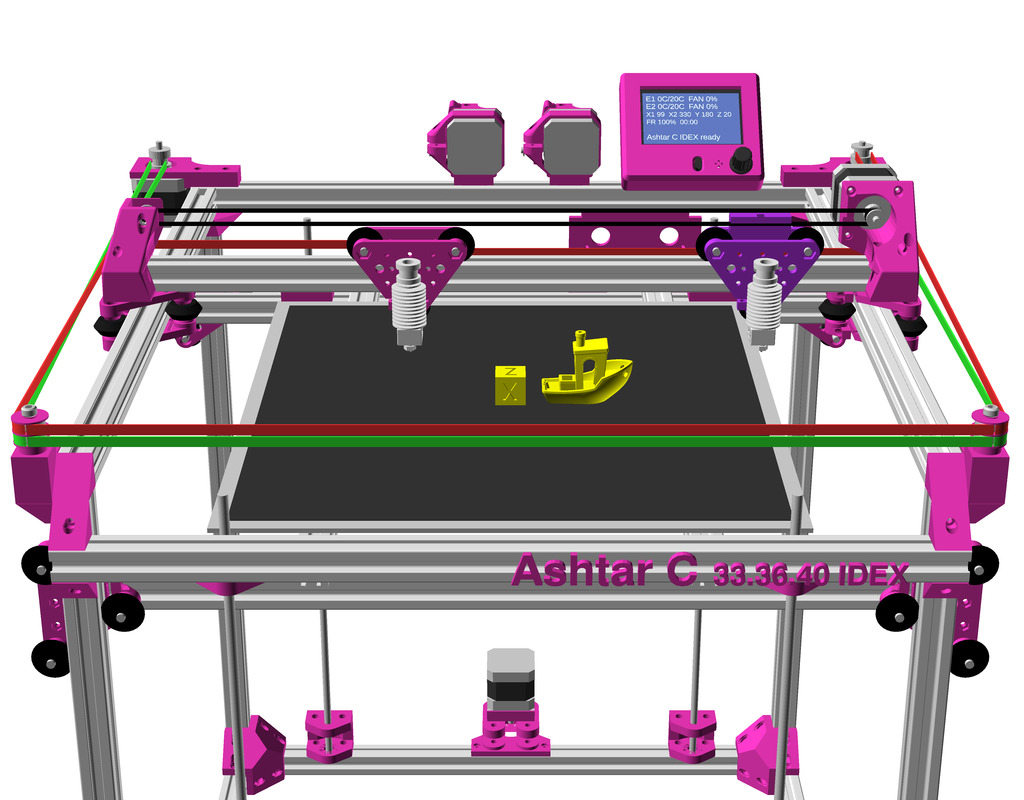
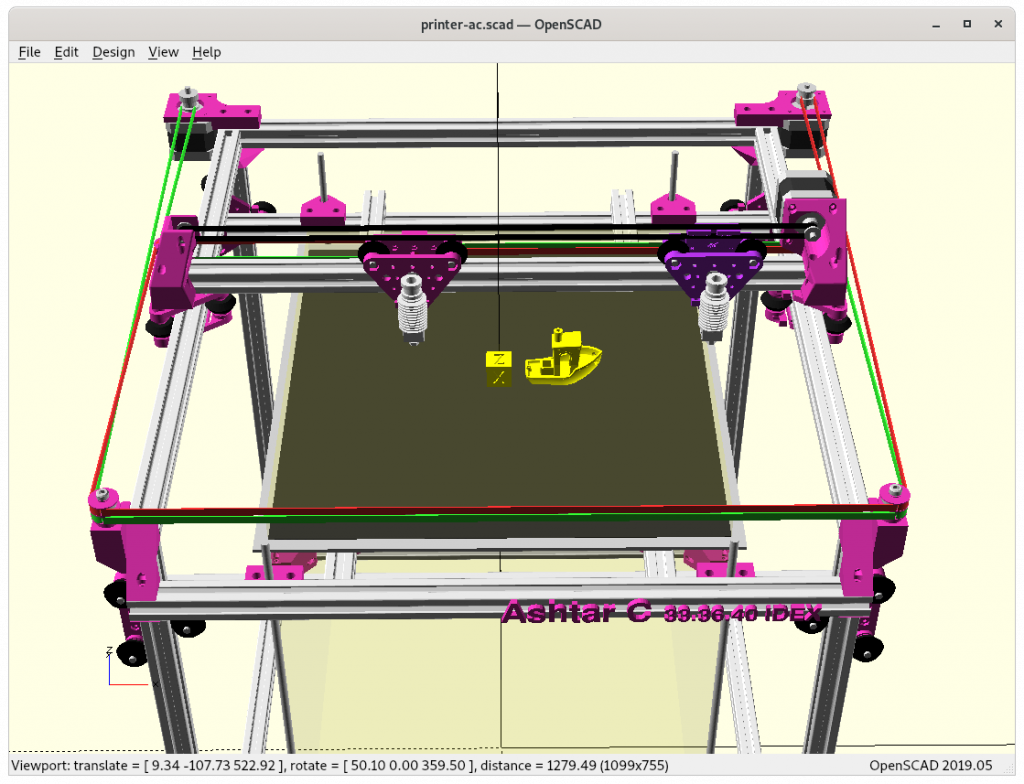
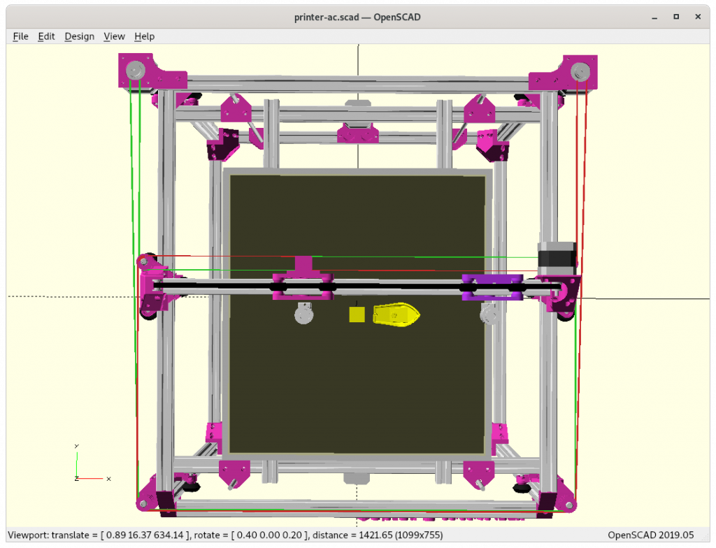
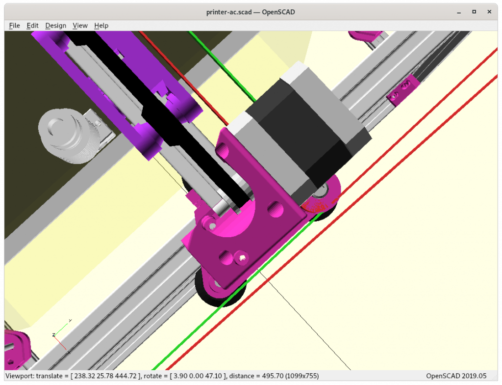
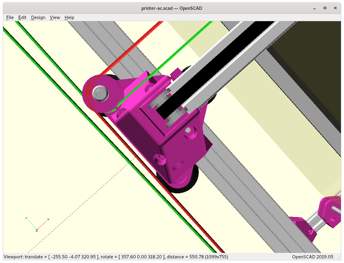
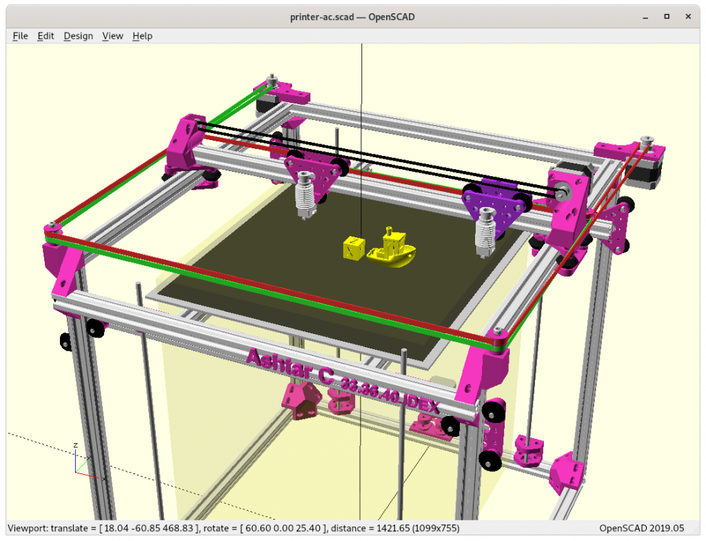
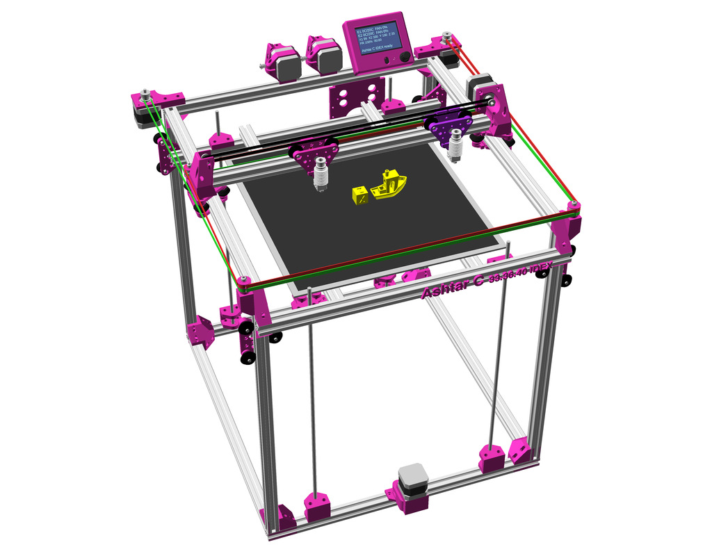
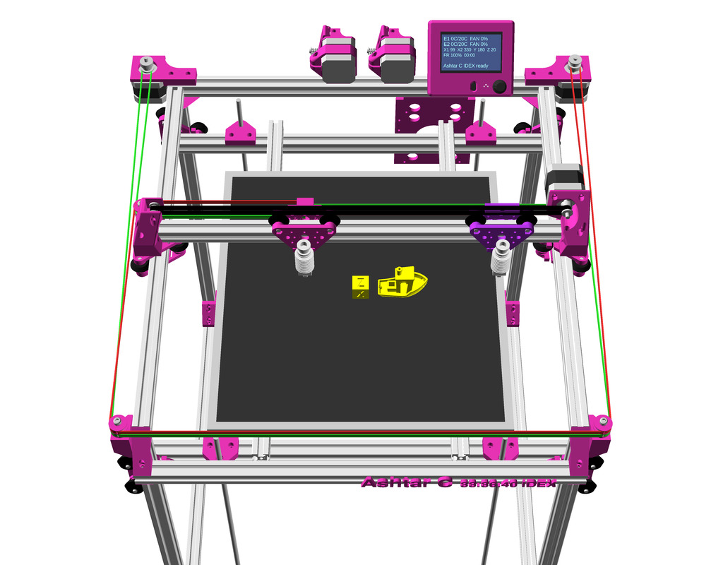
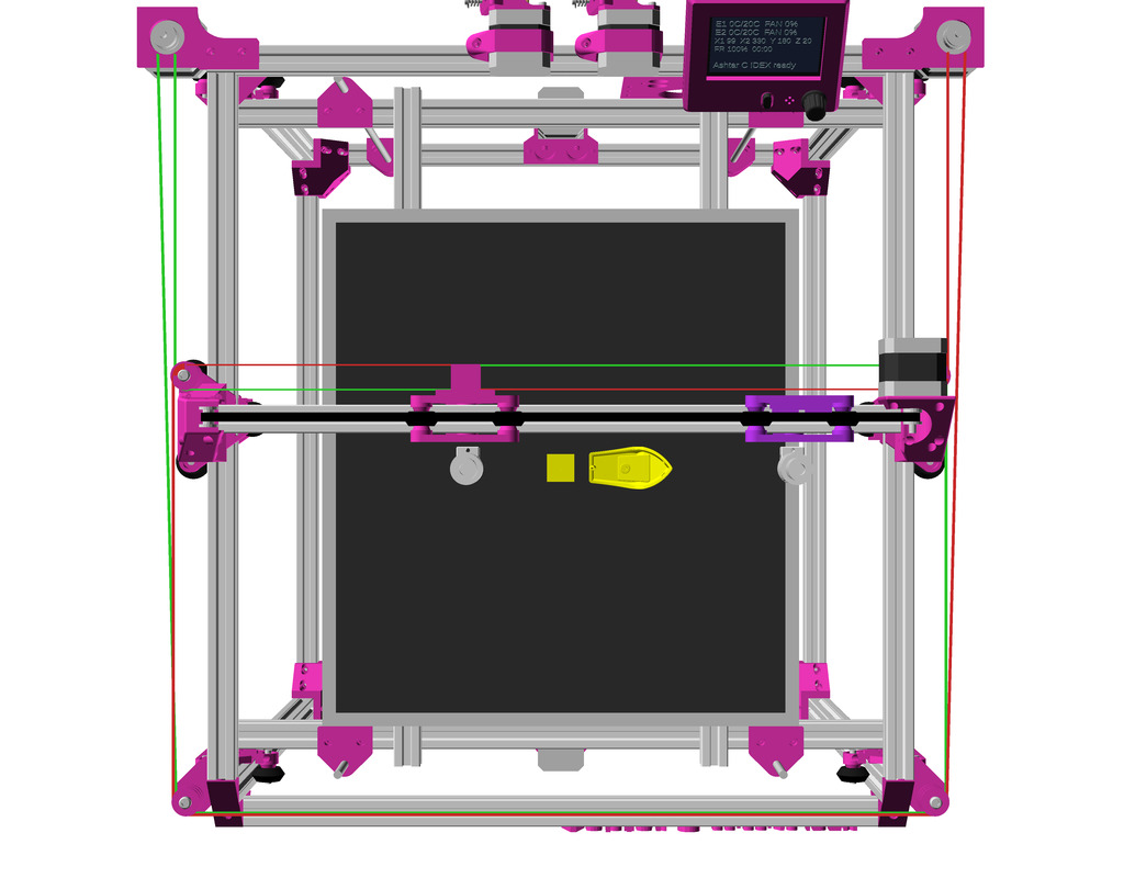
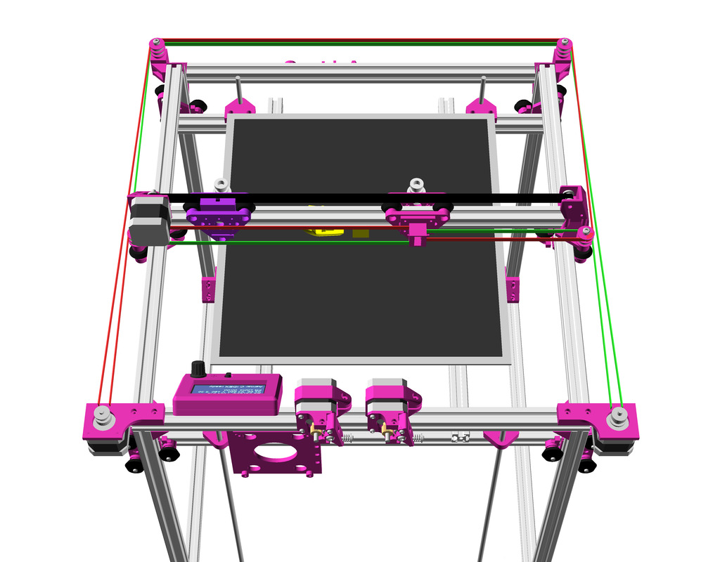
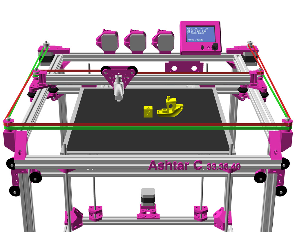
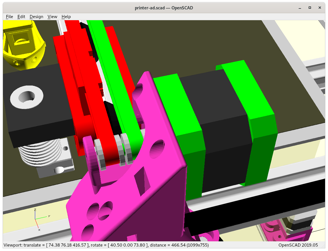
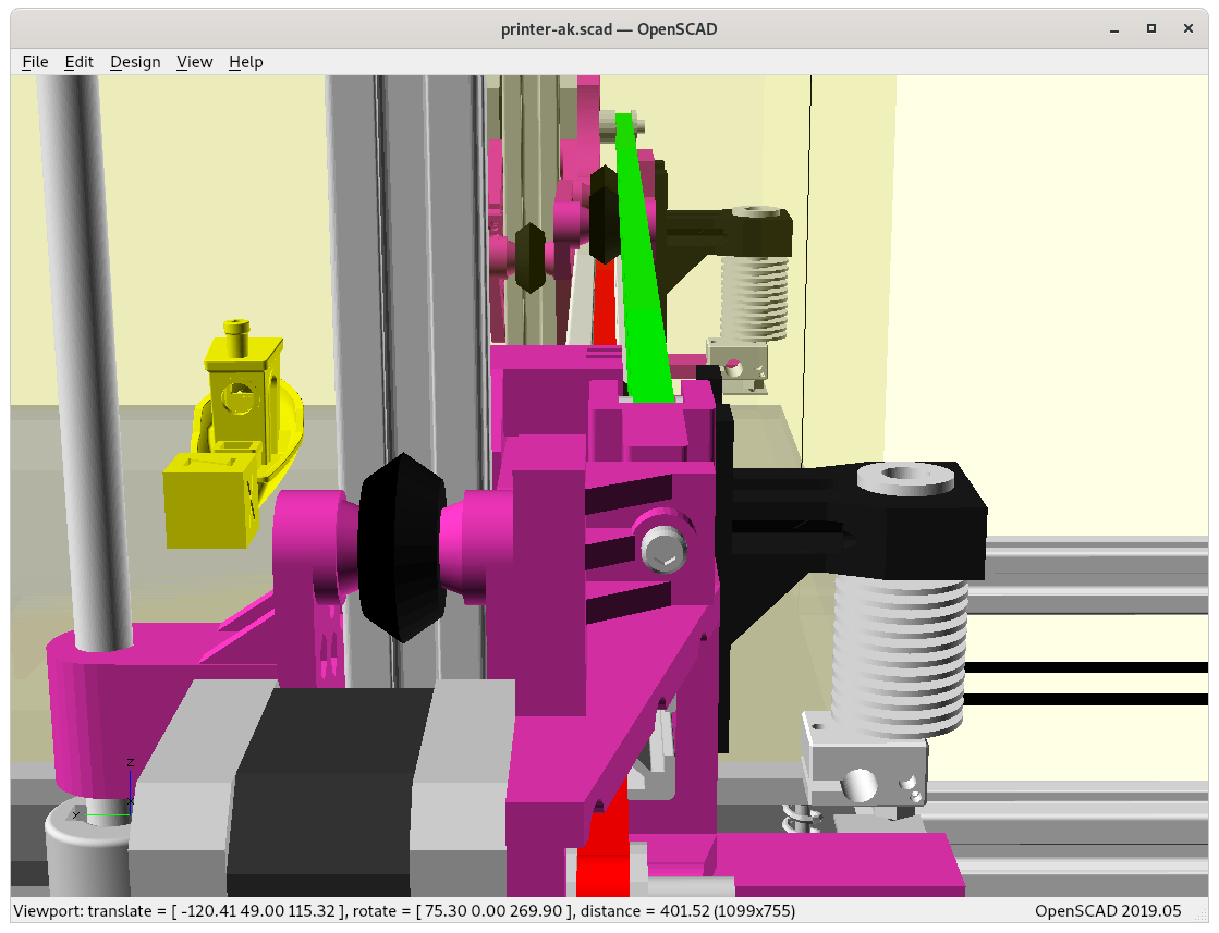
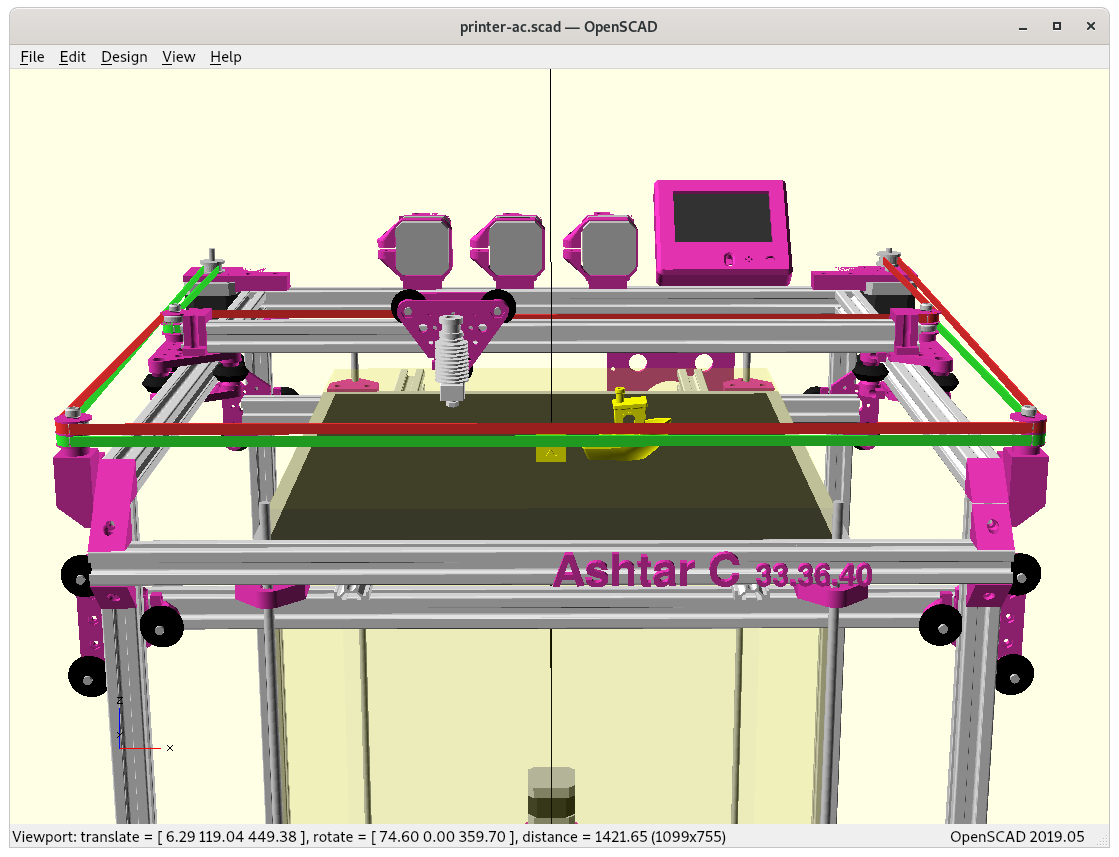
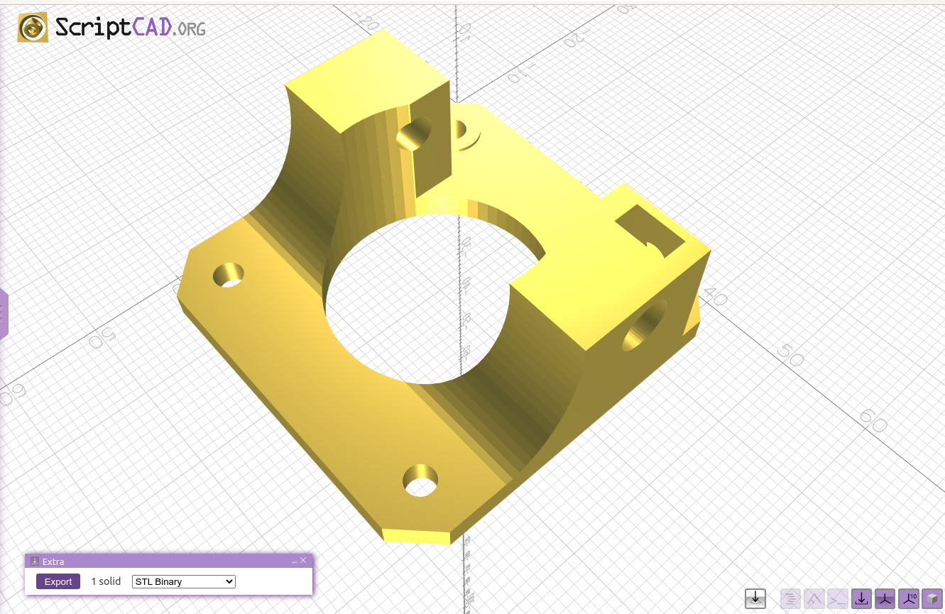
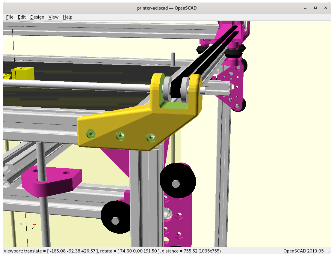
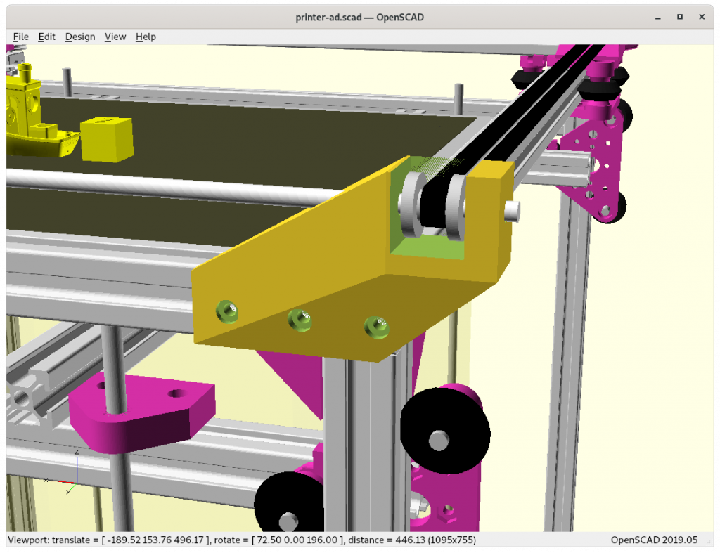
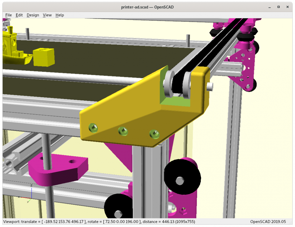
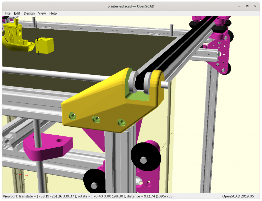
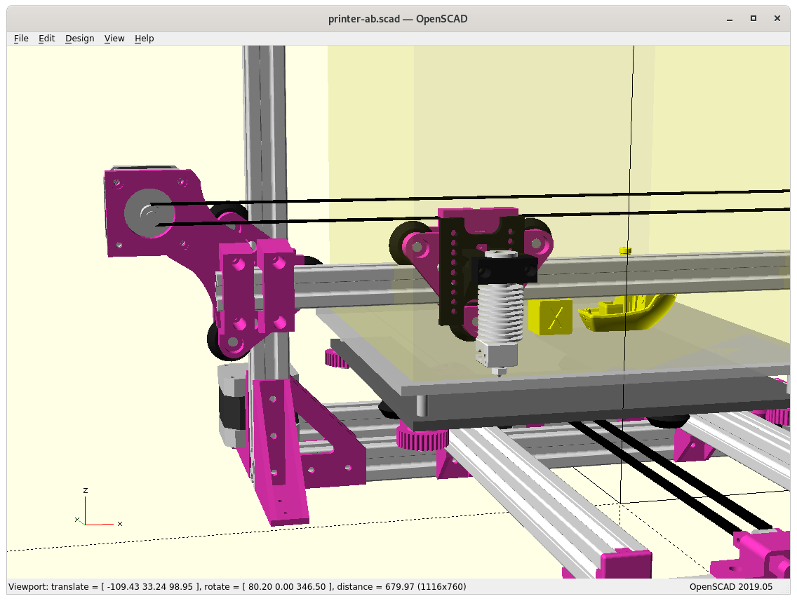
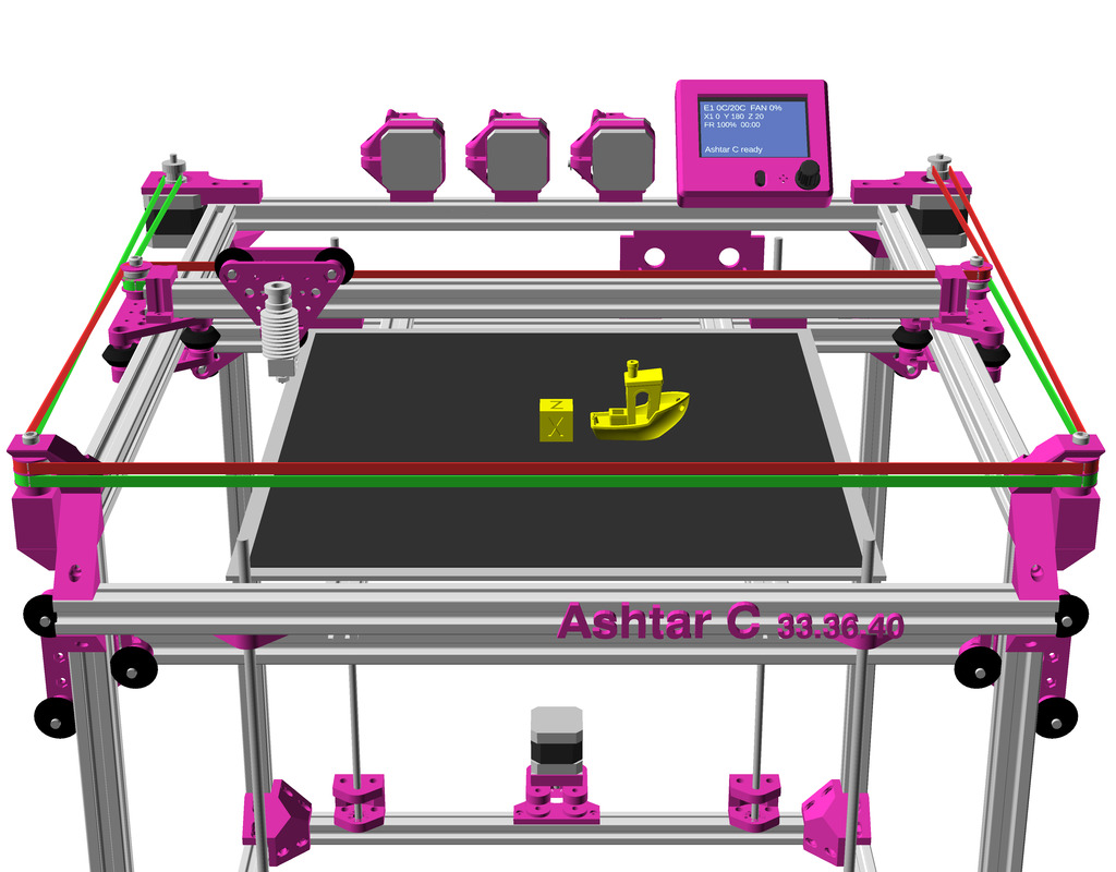
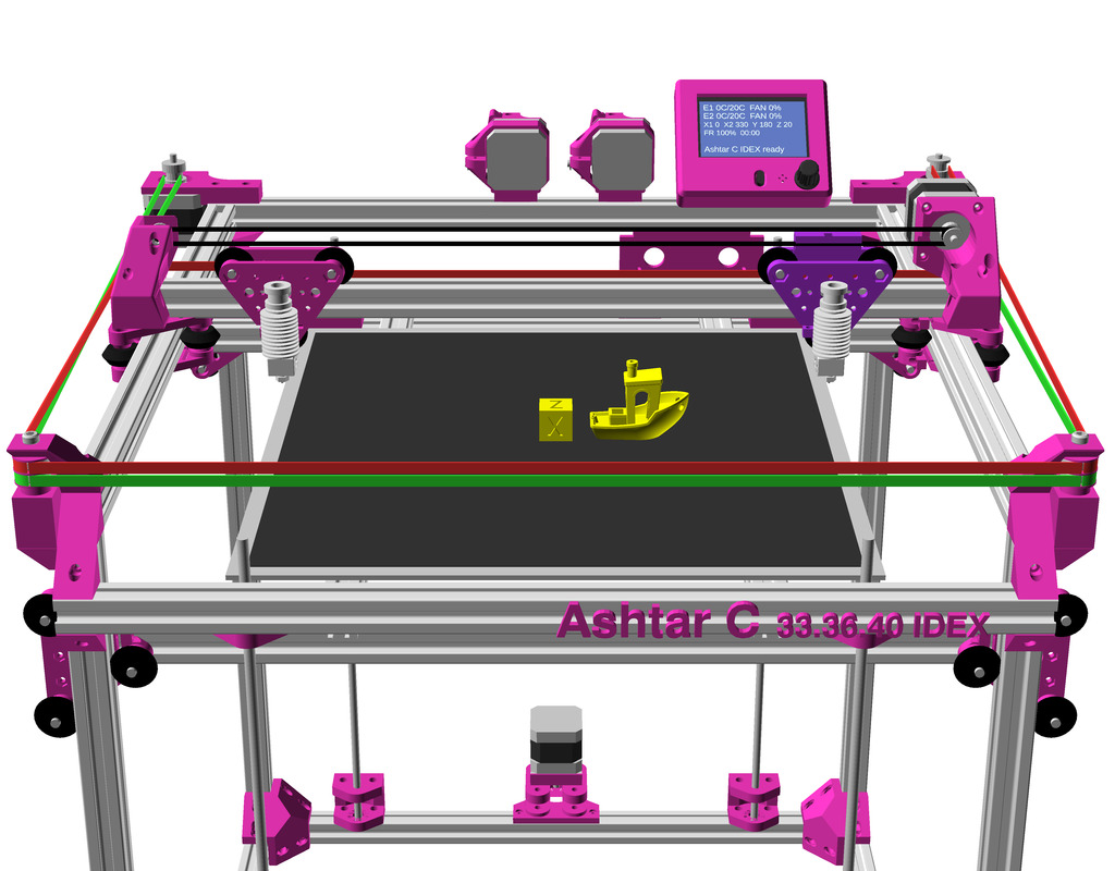
Ashtar C IDEX with Core XY with an additional X motor was easy, I just reused a slightly altered X motor/pulley mount of Ashtar D, so that was done fairly quickly as well, yet the challenge will be the firmware support, as currently (2021/01) only Duet RepRap firmware supports the CoreXYU as my design falls under.
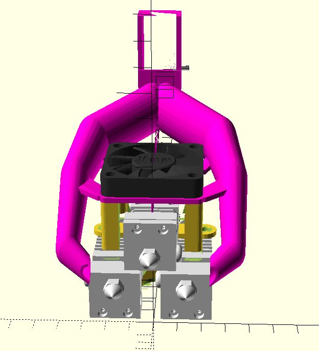
Features of IDEX
Pros:
- double printing: duplicate or mirror mode
- double printing volume at same duration
- two materials with different melting points
- two colors (non-mixing) with
- more reliable than dual nozzle setups, as inactive nozzle does not run over existing printed piece often
- possibly different nozzle sizes
- dedicated nozzle for infill vs outline
Cons:
- slightly reduced build-volume in X-axis
- added complexity
Comparison Dual/Multi Color/Material Extrusions
blue = relevant positive
red = relevant negative
Independent Dual Extrusions (IDEX)
- complex setup
- moderate cost
- non-mixing
- dual nozzles
- dual heatblocks
- dual heatsinks
- normal retraction
- no purge block 1)
- no oozing over print
- no inactive nozzle traveling
- reliable 2)
★★★★★
Dual Hotends 2-in-2
- simple setup
- low cost
- non-mixing
- dual nozzles
- dual heatblocks
- dual heatsinks
- normal retraction
- no purge block
- inactive nozzle oozing over prints
- inactive nozzle travels over print
- moderate reliability
★★★★★
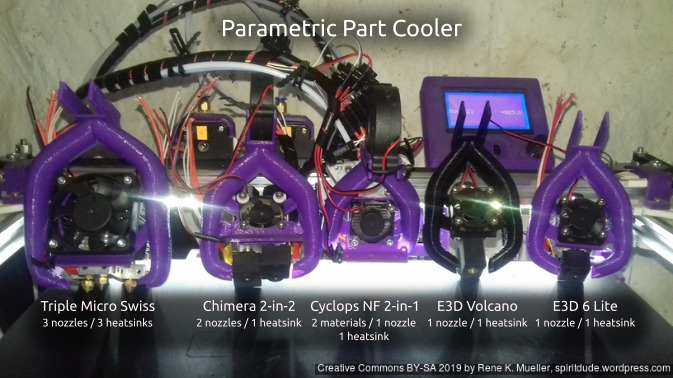
Chimera 2-in-2
- simple setup
- clone: low cost
- original: high cost
- non-mixing
- dual nozzles
- dual heatblocks
- single heatsink
- normal retraction
- no purge block
- oozing of inactive material
- inactive nozzle travels over print
- moderate reliability
★★★★★
Cyclops 2-in-1
- simple setup
- clone: low cost
- original: high cost
- mixing
- single nozzle
- single heatblock
- single heatsink
- normal retraction
- purge block required
- no oozing of inactive material
- clone: unreliable
★★★★★ (clone)
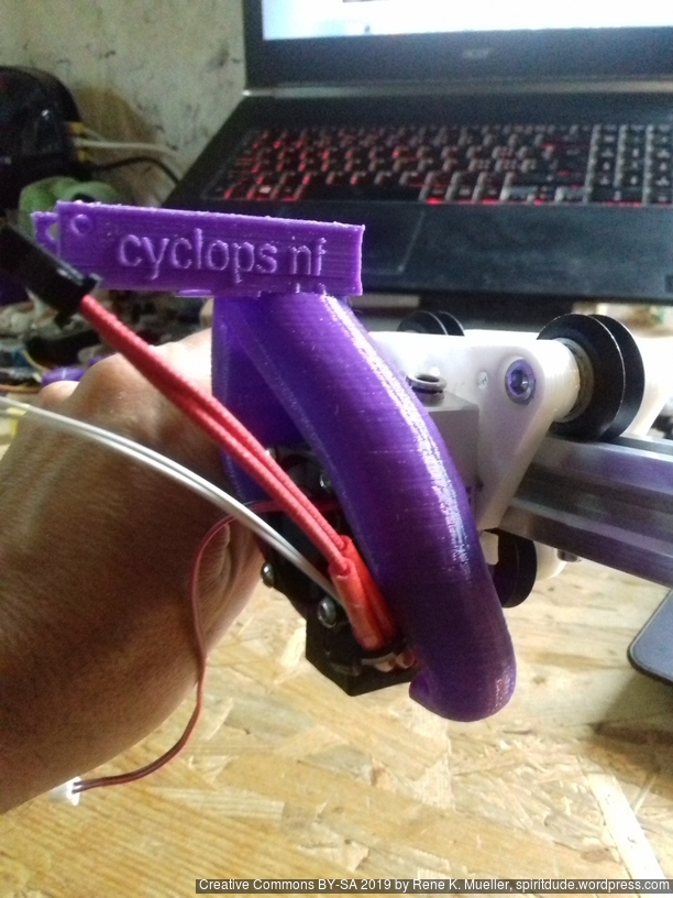
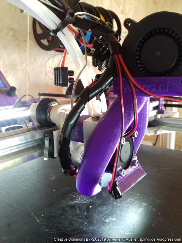
Cyclops NF 2-in-1
- simple setup
- low cost
- non-mixing
- single nozzle
- single heatblock
- single heatsink
- complex retraction
- no oozing of inactive material
- moderate reliability
★★★★★
Diamond Hotend 3-in-1
- complex setup
- clone: low cost
- original: high cost
- mixing
- single nozzle
- single heatblock
- 3 heatsinks
- tricky retraction
- purge block required
- no oozing of inactive material
- moderate reliability
★★★★★
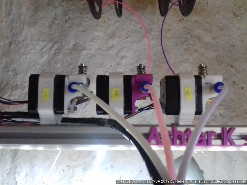
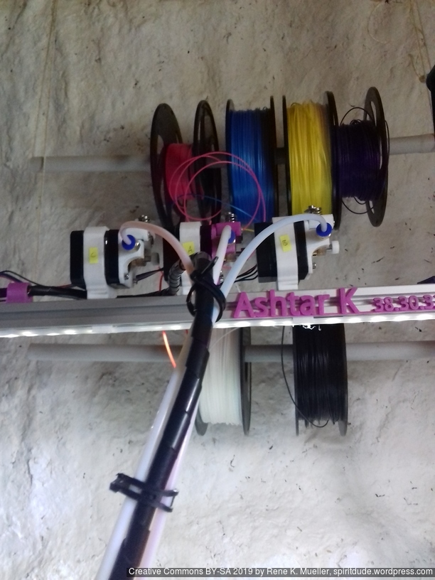
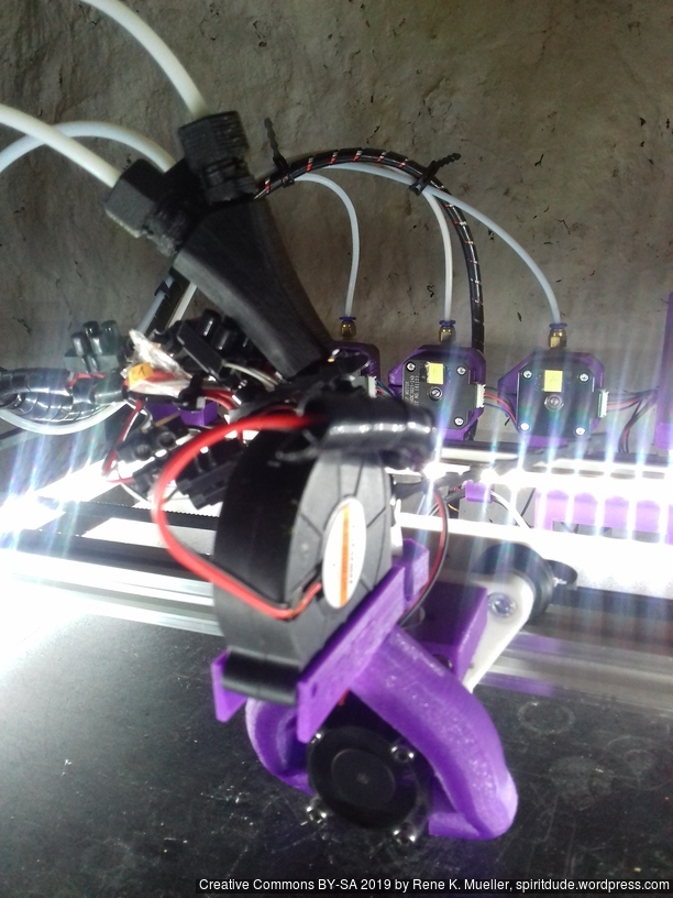
Multiple Switching Extrusions (MSE) 2-in-2, 3-in-3, 4-in-4
- moderate complex setup
- requires additional servo or motor
- extendable 2, 3, or 4 colors/materials
- low cost
- non-mixing
- multiple nozzles / heatblocks / heatsinks
- normal retraction
- no purge block 1)
- no oozing of inactive material
- no inactive nozzle touching print
- reliable 2)
(rating comes later)
Y Splitter x-in-1
- simple setup
- extendable 2, 3, or 4 or more colors / materials
- low cost
- non-mixing
- single nozzle
- single heatblock
- single heatsink
- complex retraction
- purge block required
- no oozing of inactive material
- moderate reliability
★★★★★
Tool Changer
- complex setup
- extendable to n-colors or materials
- moderate cost
- non-mixing
- multiple nozzles / heatblocks / heatsinks
- normal retraction
- no oozing of inactive material
- no inactive nozzle touching print
- moderate reliability
(rating comes later)
Footnotes
- in theory no purge block, but if ooze shields are shared among switching extrusions (more than 2 extrusions) there may be cross-contamination between colors/materials
- the printheads individually are proven to be reliable
Hints:
- single heatblock = same print temperature
- dual heatblock = different print temperatures possible
- dual nozzle = different nozzle sizes possible
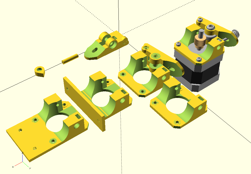
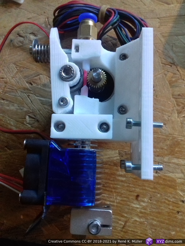
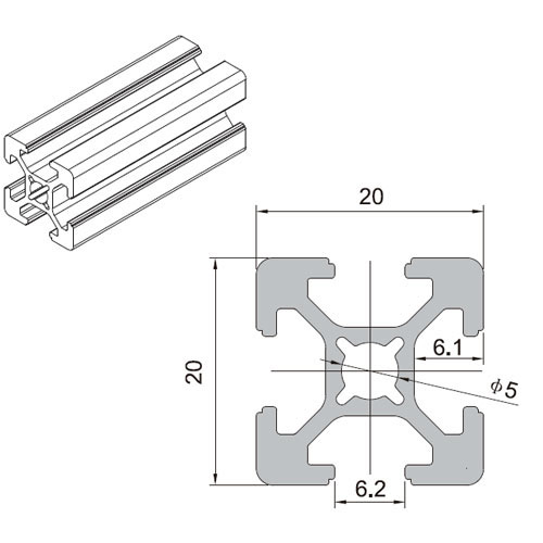
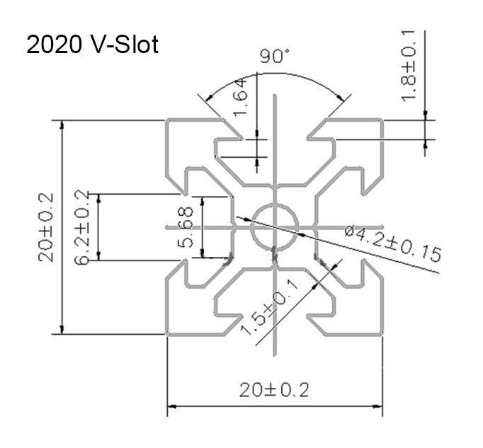
Hardware Requirements
- 1x NEMA 17 42-45Nm with wire, extra stepper motor driver on motherboard
- 100-110cm long 6mm wide GT2 belt
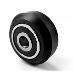
- 1x pulley and 1x idler
- 1x hotend (nozzle, heatblock, heat cartridge, heatbreak, heatsink), extra heating connector on motherboard
That’s it.