Update:
- 2022/11/20: Linux DFU upload details added
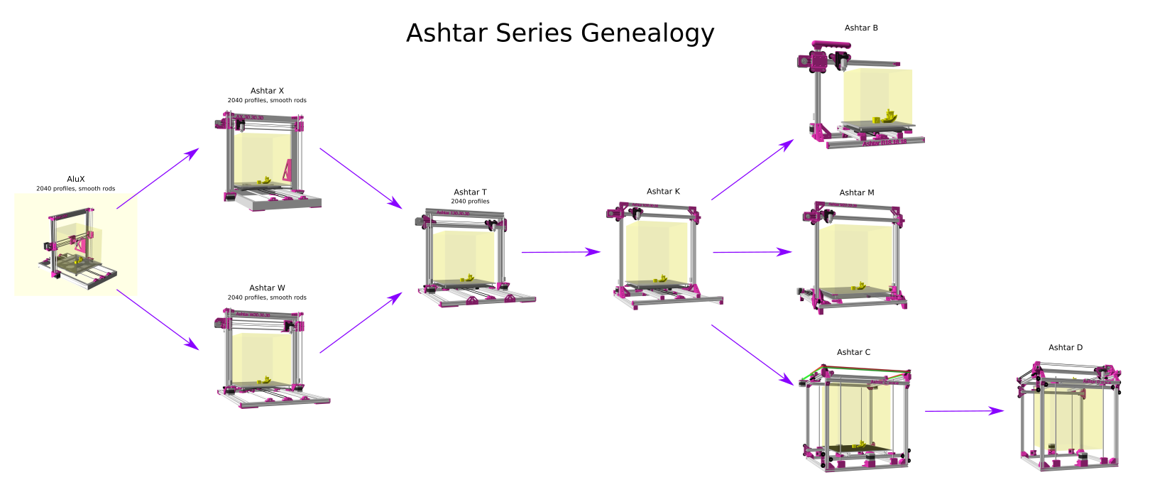
- 2022/09/19: adding Ashtar C
M503dump beside Ashtar K - 2022/08/24: extending with part cooler fan and extruder fan connection
- 2022/08/14: starting with the notes
Introduction
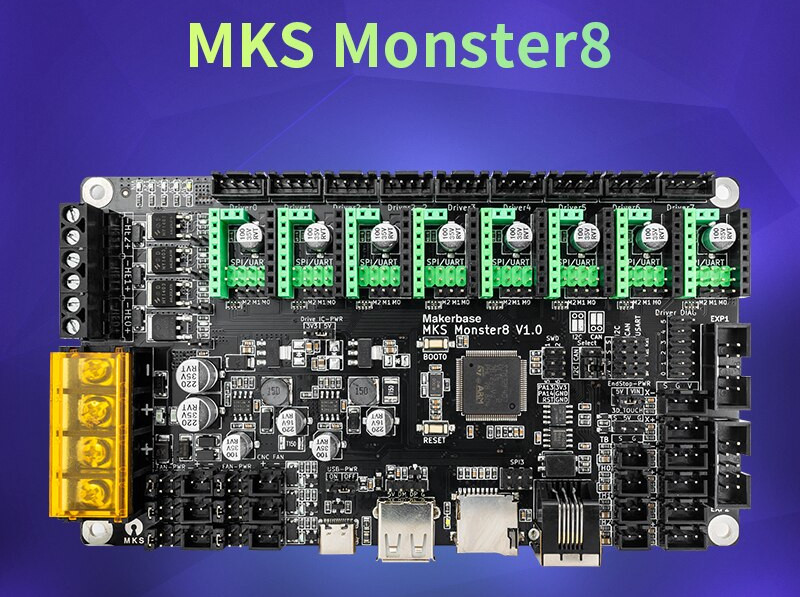
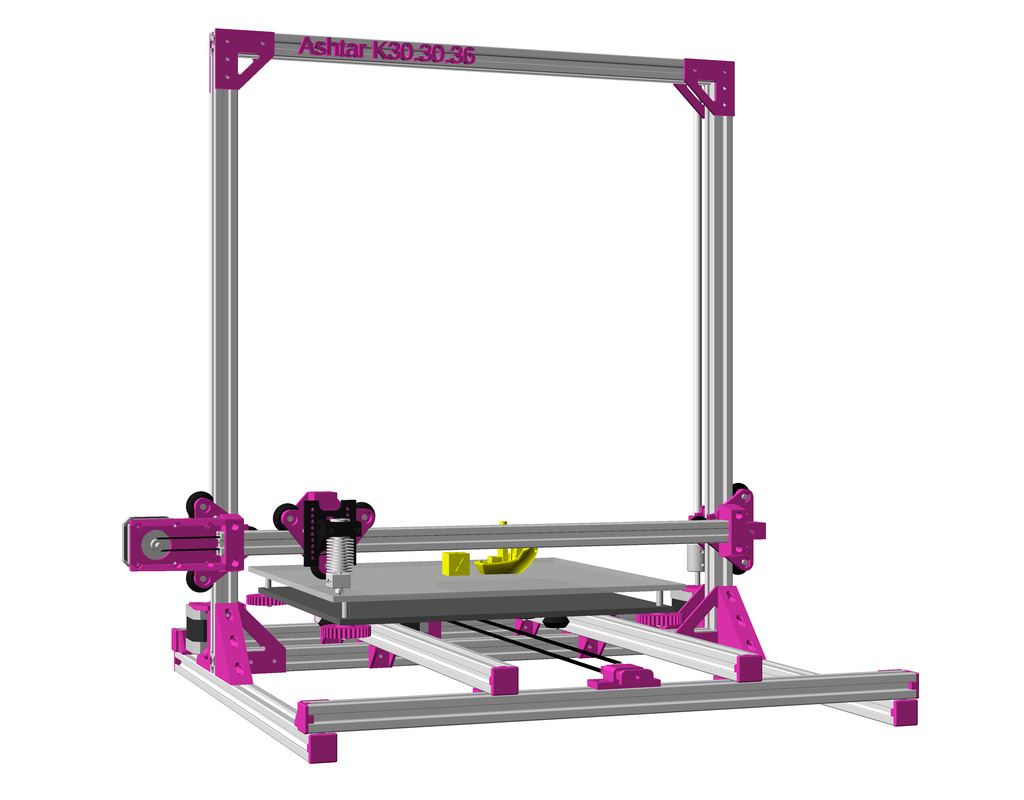
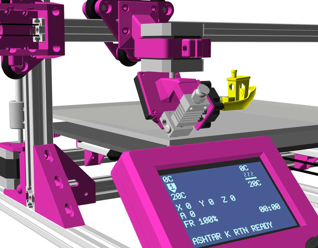
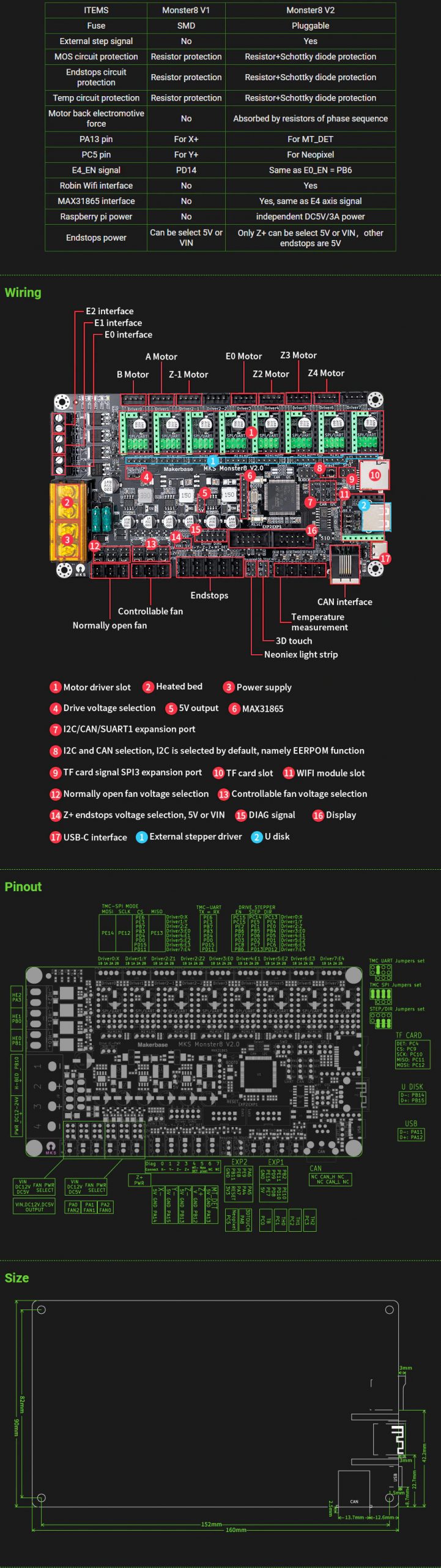
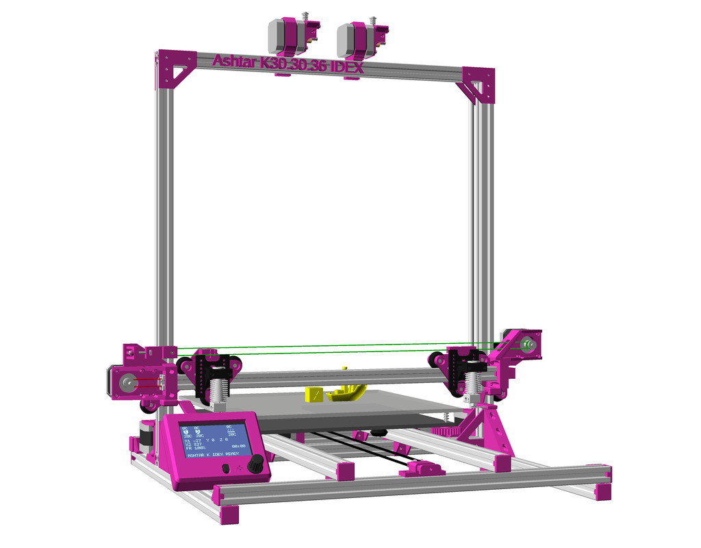
These are just my notes for configuring Makerbase (MKS) Monster8 V1.0 for Ashtar K and Ashtar C:
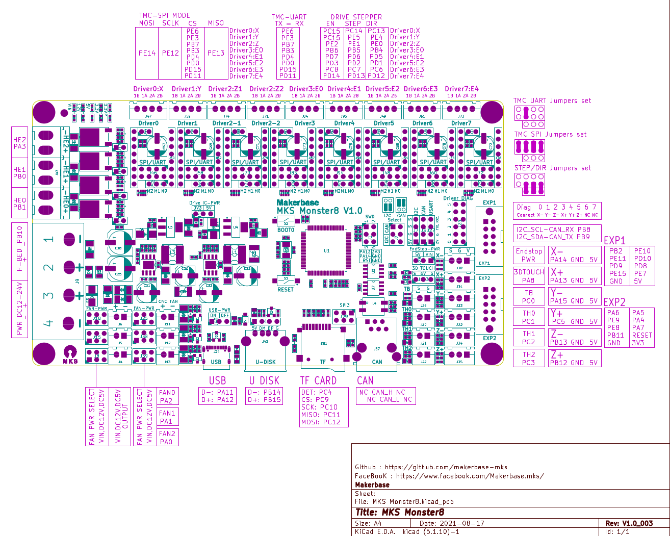
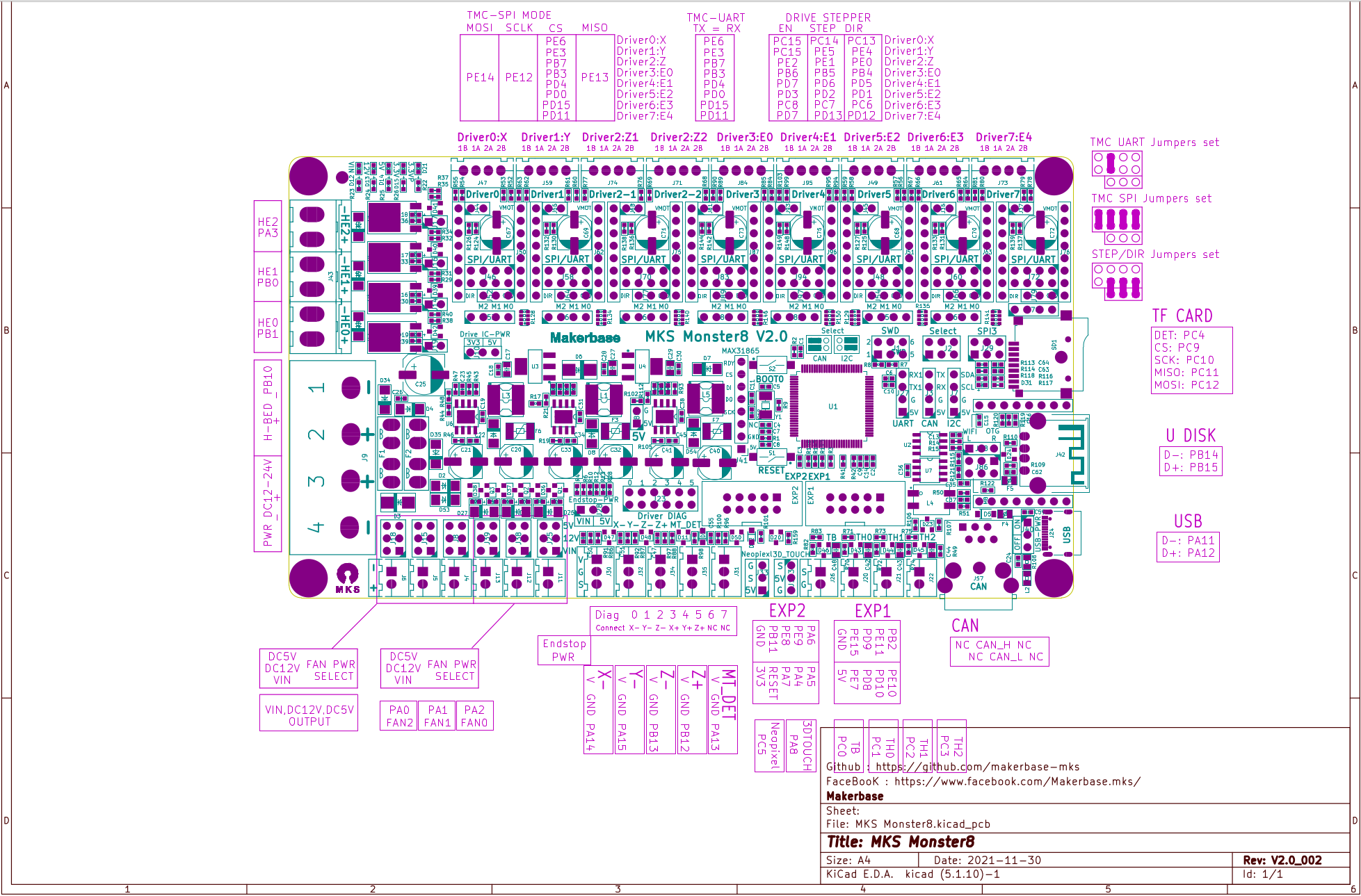
- STM32M407VET6 (ARM Cortex M4), 168MHz, 512KB Flash, 192KB RAM
- 8 stepper drivers TMC2209, configured in UART mode
- MKS MINI 12864 V3 display (the “V3” is relevant)
- 12V power in/out
- 3 hotends & bed heating
- Price ~EUR 55 (2022/08) incl. 8 stepper drivers TMC 2209 and 12864 display
Pros:
- cost effective, EUR 55 (2022/08) incl. 8x TMC 2209 stepper drivers and 12864 display
- 8 stepper drivers: e.g. X, Y, Z1/Z2 (on-board splitter) and 5 extruders (e.g. E0, E1, E2, E3, E4 – but only 3 hotends possible)
- TMC 2208 or TMC 2209 silent drivers
- good connectors on board, clean setup
- github with Marlin source (partially preconfigured) for Arduino*) & PlatformIO
Cons:
- no RepRapFirmware
- no Wifi (the V2.0 version has optional Wifi board to attach)
- no Ethernet
- requires Marlin with PlatformIO (tedious to configure, recompiling required, reupload)
- limited documentation: actual details are scattered around
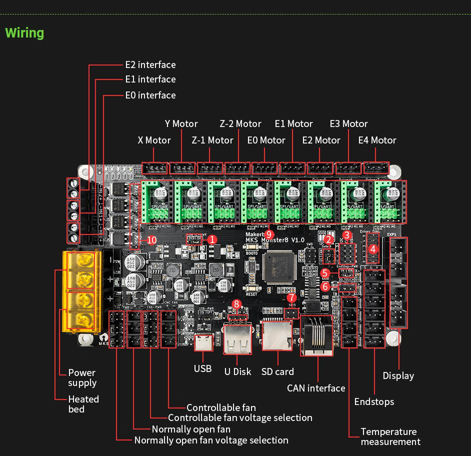
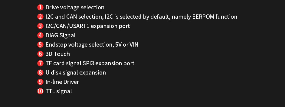
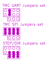
Stepper Motor UART Mode
As first putting in the jumpers on all the driver sockets, in my case I choose UART mode for each one of the 8 drivers:
Marlin with Arduino vs PlatformIO
As of 2022/08, it seems Arduino is no longer able to compile Marlin-2.x (various compile errors within Arduino), at least with this board and everybody moved on the PlatformIO, which really surprised me.
PlatformIO CLI
As of 2022/08 there is no Linux GUI for PlatformIO but only PlatformIO CLI, but it’s simple enough:
pip3 install platformioDownload
As next download the firmware, Marlin 2.0.x source from github:
git clone https://github.com/makerbase-mks/MKS-Monster8/
Building
By default the board is configured for Voron 2.4 CoreXY, with 3x Z motors and Z probing in the midst of the bed and other things, so I had to edit Marlin/Configuration.h:
#define MACHINE_UUID "..."(use online generator to generate one)#define CUSTOM_MACHINE_NAME "Ashtar K #x L8", given Lead 8×8 are used#define LINEAR_AXES 3#define EXTRUDERS 1(or 2, 3 max)- comment out
//#define PREVENT_COLD_EXTRUSIONneeded for calibration - comment out
//define COREXY - define
[XYZ]_DRIVER_TYPEandE[012]_DRIVER_TYPE #define DEFAULT_AXIS_STEPS_PER_UNITaren’t that important, as one can define it withM92andM500saving to EEPROM- comment out
//#define Z_MIN_PROBE_USES_Z_MIN_ENDSTOP_PIN - test motors regarding
#define INVERT_[XYZ]_DIR trueorfalse - test motors regarding
#define INVERT_E[012]_DIR trueorfalse #define [XYZ]_HOME_DIR -1#define X_BED_SIZE 380#define Y_BED_SIZE 300#define Z_MAX_POS 330
and Configuration_adv.h:
#define NUM_Z_STEPPER_DRIVERS 1even when two Z-stepper motors are attached- if you want an automatic E0 fan which turns on only when nozzle is heated:
#define E0_AUTO_FAN_PIN PA1and attach extruder fan (watch polarity) on FAN1/J12 connector
once those changes are made, build the firmware:
cd marlin\ firmware/MKS_MONSTER_Marlin-2.0.x/Marlin-2.0.x/
platformio run
After a short while (~1min) it should finish successfully (if not, edit files).
Firmware Installation
SD Card Firmware Update
Use a SD card, e.g. 8GB with simple FAT filesytem, and copy .pio/build/mks_monster8_usb_flash_drive/firmware.bin and mks_monster8.bin on the SDcard.
Insert the SD card into the Monster8 board next to the USB connector, and turn off and on the board (power cycle) – wait 5-10 seconds so the new firmware is installed, then the display should show the Marlin splashscreen eventually, and the board becomes available as USB device, in my case as /dev/ttyACM0 on Linux Ubuntu 20.04 LTS.
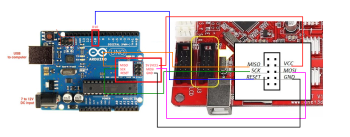
DFU Util Firmware Update
- connect board with USB cable and optionally select POWER USB (via jumper)
- power cycle board (e.g. via USB cable) while you push
BOOT 0button in the center of the board briefly (~2 secs) - the device will appear as a new USB device
Linux: install apt install dfu-util and then
% sudo dfu-util -a 0 -s 0x0800C000:leave -D .pio/build/mks_monster8_usb_flash_drive/mks_monster8.bin -d 0483:df11
dfu-util 0.9
Copyright 2005-2009 Weston Schmidt, Harald Welte and OpenMoko Inc.
Copyright 2010-2016 Tormod Volden and Stefan Schmidt
This program is Free Software and has ABSOLUTELY NO WARRANTY
Please report bugs to http://sourceforge.net/p/dfu-util/tickets/
dfu-util: Invalid DFU suffix signature
dfu-util: A valid DFU suffix will be required in a future dfu-util release!!!
Opening DFU capable USB device...
ID 0483:df11
Run-time device DFU version 011a
Claiming USB DFU Interface...
Setting Alternate Setting #0 ...
Determining device status: state = dfuERROR, status = 10
dfuERROR, clearing status
Determining device status: state = dfuIDLE, status = 0
dfuIDLE, continuing
DFU mode device DFU version 011a
Device returned transfer size 2048
DfuSe interface name: "Internal Flash "
Downloading to address = 0x0800c000, size = 178820
Download [=========================] 100% 178820 bytes
Download done.
File downloaded successfully
Transitioning to dfuMANIFEST state
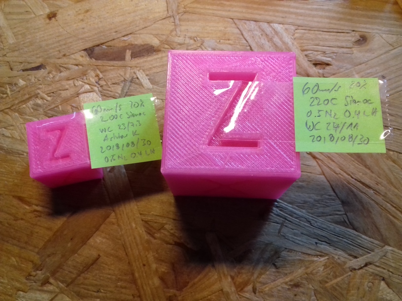
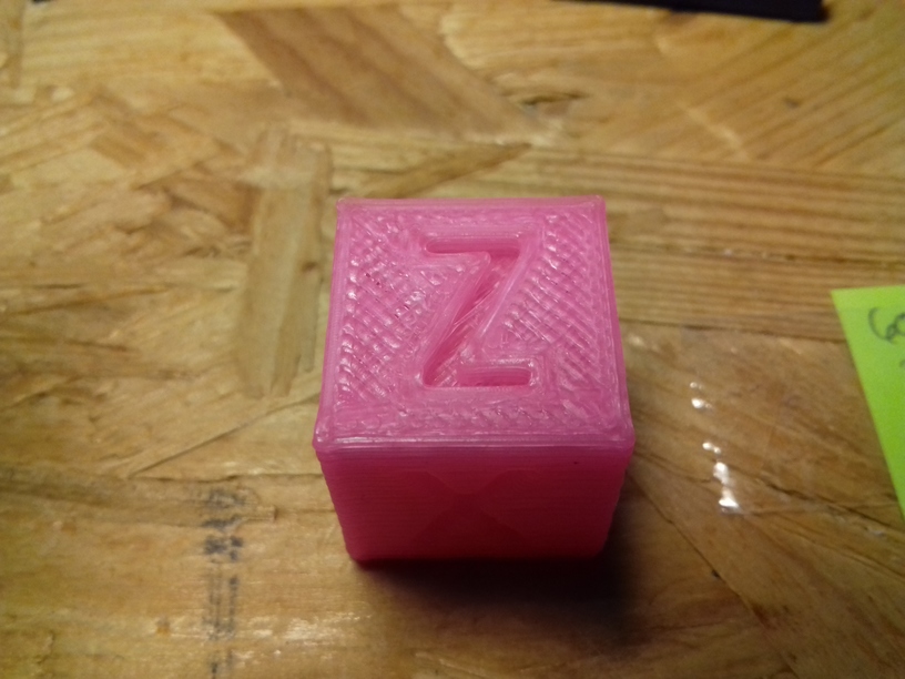
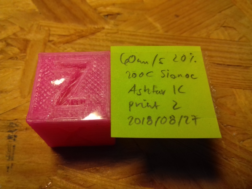
% M503 Dump for Ashtar K
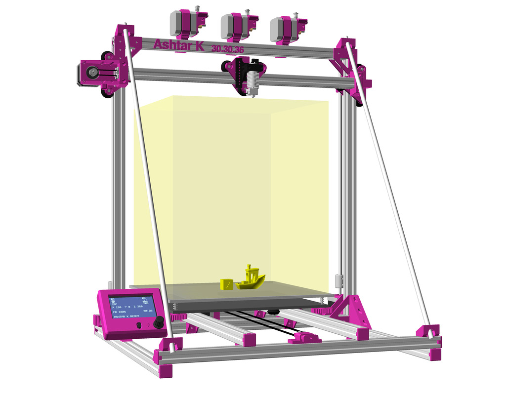
Ashtar K with 300×300 bed, single extruder:
> M503
-----
echo: G21 ; Units in mm (mm)
echo: M149 C ; Units in Celsius
echo:; Filament settings: Disabled
echo: M200 S0 D1.75
echo:; Steps per unit:
echo: M92 X100.00 Y100.00 Z400.00 E95.00
echo:; Maximum feedrates (units/s):
echo: M203 X300.00 Y300.00 Z5.00 E25.00
echo:; Maximum Acceleration (units/s2):
echo: M201 X2500.00 Y2500.00 Z100.00 E5000.00
echo:; Acceleration (units/s2): P<print_accel> R<retract_accel> T<travel_accel>
echo: M204 P3000.00 R3000.00 T3000.00
echo:; Advanced: B<min_segment_time_us> S<min_feedrate> T<min_travel_feedrate> X<max_x_jerk> Y<max_y_jerk> Z<max_z_jerk> E<max_e_jerk>
echo: M205 B20000.00 S0.00 T0.00 X10.00 Y10.00 Z0.30 E5.00
echo:; Home offset:
echo: M206 X-35.00 Y-3.00 Z0.15
echo:; Material heatup parameters:
echo: M145 S0 H180.00 B70.00 F0
echo: M145 S1 H240.00 B110.00 F0
echo:; PID settings:
echo: M301 P22.20 I1.08 D114.00
echo:; LCD Contrast:
echo: M250 C255
echo:; Power-Loss Recovery:
echo: M413 S1
echo:; Stepper driver current:
echo: M906 X500 Y500 Z700
echo: M906 T0 E500
echo:; Driver stepping mode:
echo: M569 S1 X Y Z
echo: M569 S1 T0 E
ok
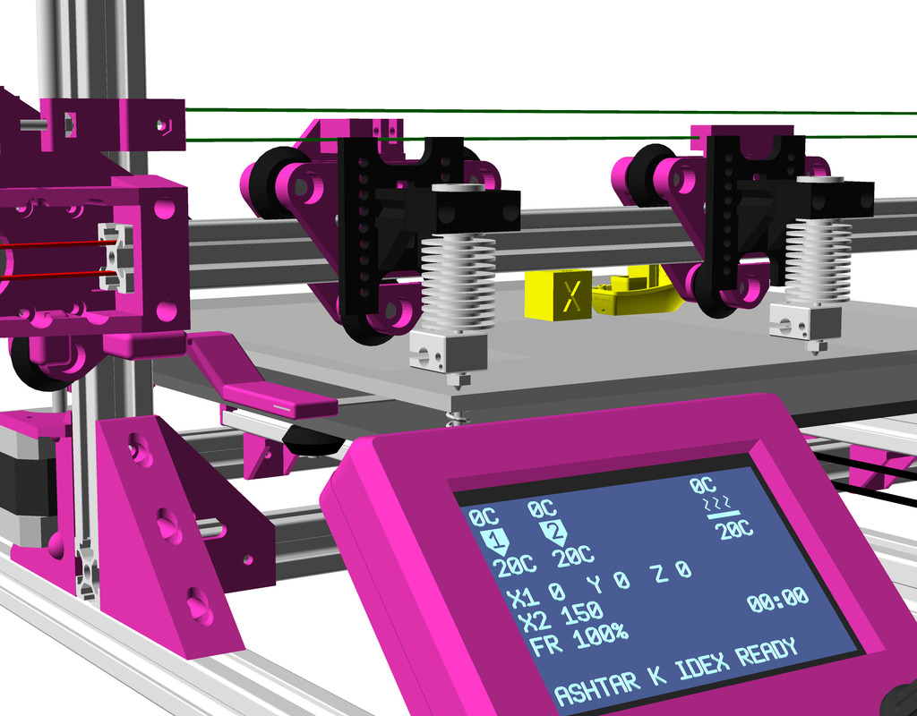
>M503 Dump for Ashtar C
Ashtar C with 400×400 bed, 3 extruders with single nozzle:
> M503
-----
echo: G21 ; Units in mm (mm)
echo: M149 C ; Units in Celsius
echo:; Filament settings: Disabled
echo: M200 T0 D1.75
echo: M200 T1 D1.75
echo: M200 T2 D1.75
echo: M200 S0
echo:; Steps per unit:
echo: M92 X100.00 Y100.00 Z3200.00 E102.00
echo:; Maximum feedrates (units/s):
echo: M203 X500.00 Y500.00 Z2.00 E120.00
echo:; Maximum Acceleration (units/s2):
echo: M201 X9000.00 Y9000.00 Z50.00 E10000.00
echo:; Acceleration (units/s2): P<print_accel> R<retract_accel> T<travel_accel>
echo: M204 P1500.00 R1500.00 T1500.00
echo:; Advanced: B<min_segment_time_us> S<min_feedrate> T<min_travel_feedrate> X<max_x_jerk> Y<max_y_jerk> Z<max_z_jerk> E<max_e_jerk>
echo: M205 B20000.00 S0.00 T0.00 X10.00 Y10.00 Z0.20 E2.50
echo:; Home offset:
echo: M206 X0.00 Y-5.00 Z0.15
echo:; Material heatup parameters:
echo: M145 S0 H180.00 B70.00 F0
echo: M145 S1 H240.00 B110.00 F0
echo:; PID settings:
echo: M301 P22.20 I1.08 D114.00
echo:; LCD Contrast:
echo: M250 C255
echo:; Power-Loss Recovery:
echo: M413 S1
echo:; Stepper driver current:
echo: M906 X700 Y700 Z1000
echo: M906 T0 E700
echo: M906 T1 E700
echo: M906 T2 E700
echo:; Driver stepping mode:
echo: M569 S1 X Y Z
echo: M569 S1 T0 E
echo: M569 S1 T1 E
echo: M569 S1 T2 E
echo:; Tool-changing:
echo: Z2.00
ok
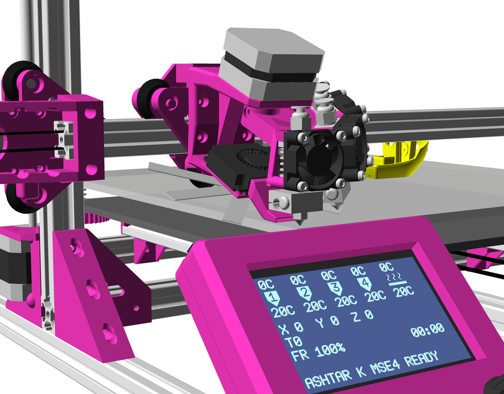
>Fans
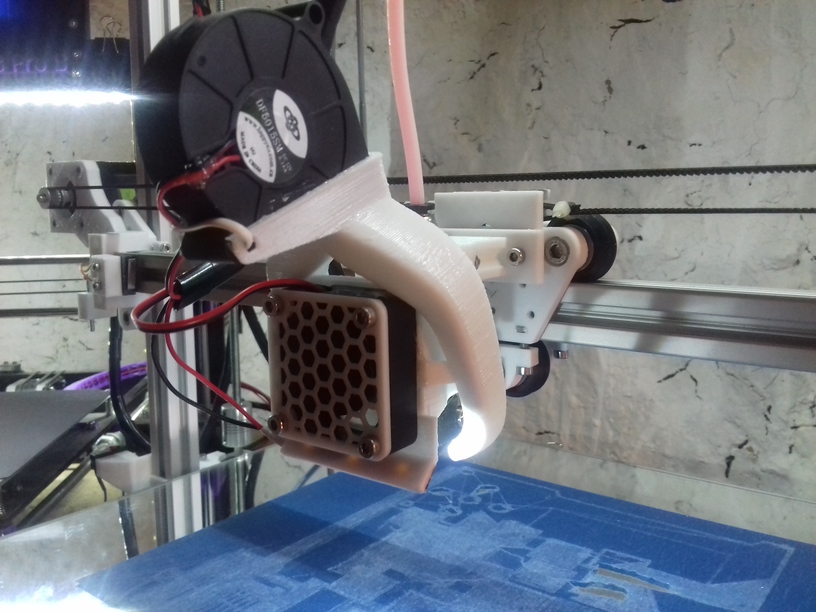
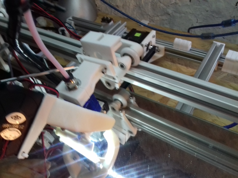
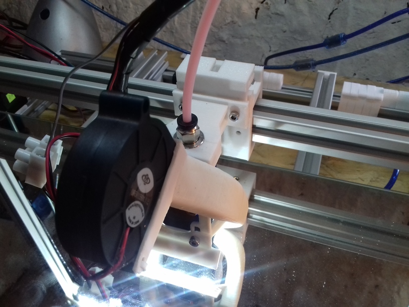
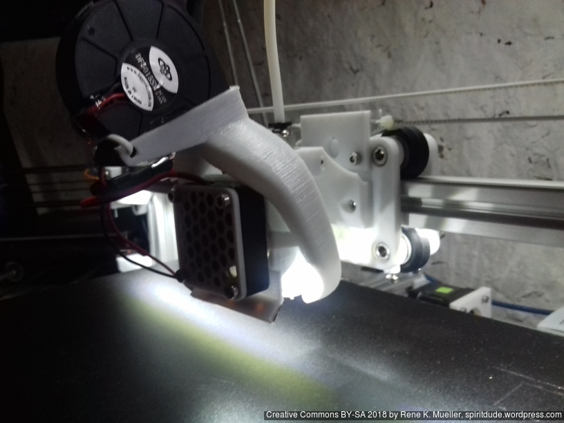
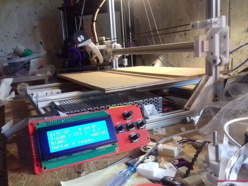
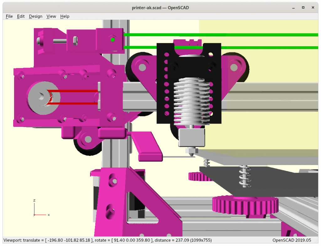
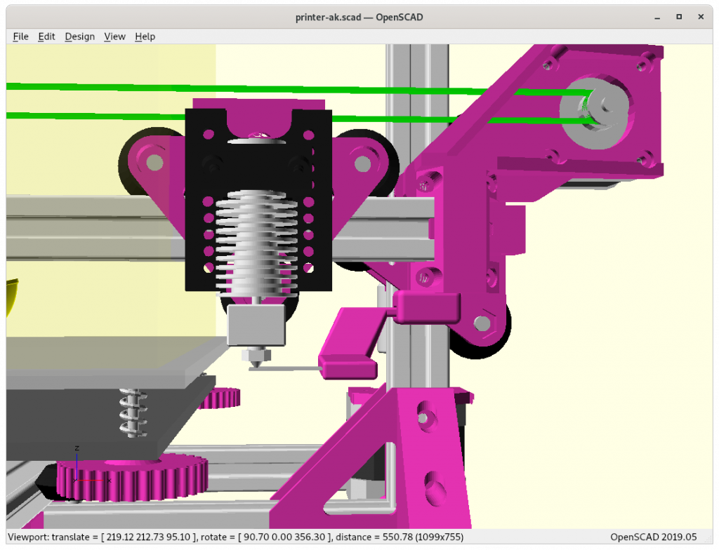
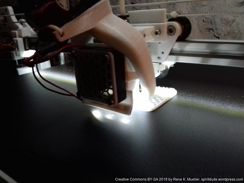
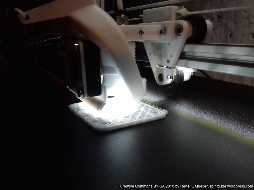
Part cooler fan is plugged into FAN0/J11, and if you enabled extruder fan (temperature dependent), plug it in FAN1/J12.
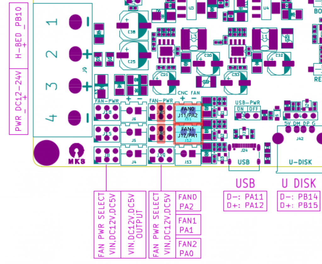
- Part Cooler Fan (FAN0): cools the extruded filament, the filament which becomes the part you print
- Extruder Fan (FAN1): cools the heatsink near the heatbreak, when attached to FAN1/J12 it only runs when the hotend is hotter than 50C° as defined in Marlin.
The jumpers are needed next to the fan connectors to define the voltage, either Vin (left) which is 12V-24V depending on the power input of the board, or 12V (middle) or 5V (right).
Multiple Materials/Colors
With 8 stepper drivers one is able to run:
- 3+1x motors for X, Y, Z(2)
- 5x extruders (colors or materials), the board supports 3 hotends (3 different temperatures)
Monster8 V1.0 vs V2.0
The boards differ in physical layout such as connectors, but the firmware is the same, incl. the pin for the hotend cooler fan (which switches on conditionally when hotend heats up).
Update V2.0
Board Comparison 2022
As of 2022 (I intend to update this) following boards are suitable for my cases:
| MKS Monster8 V1.0/V2.0 & 12864 display | Mellow Fly Super8 V1.2 & 12864 display | Duet 3 Mini 5+ & Duet 3 Mini 2+ | Duet 3 MB 6HC & Duet 3 Expansion 3HC | |
| Price | 55 EUR | 80 EUR | 155 EUR (120+35) | 385 EUR (255+130) |
| Stepper Drivers | 8 | 8 | 7 (5+2) | 9 (6+3) |
| Stepper Connectors | 9 (dual Z) | 8 | 7 | 9 |
| Hotends | 3 | 4 | 5 (2+3) | 6 (3+3) |
| USB | YES (USB-C) | YES (USB-C) | YES (MicroUSB) | YES (MicroUSB) |
| WIFI | – / YES3) | YES | YES1) | YES1) |
| Ethernet | – | – | YES1) | YES1) |
| Firmware | Marlin 2.x | Marlin 2.x RepRapFirmware 3.4.x | RepRapFirmware | RepRapFirmware |
Alternatively, there are Duet 2 & 3 clones available on the market:
| Duet 2 WIFI Clone | Duet 2 WIFI Original | Duet 3 6HC FYSETC Clone with Duet 3 3HC | Duet 3 6HC Original with Duet 3 3HC | |
| Price | 30-50 EUR2) | 175-185 EUR1) | 225 EUR (150+75) | 385 EUR (255+130) |
| Stepper Drivers | 5 | 5 | 9 (6+3) | 9 (6+3) |
| Stepper Connectors | 6 | 6 | 9 | 9 |
| Hotends | 2 | 2 | 7 (4+3) | 6 (3+3) |
| USB | YES (MicroUSB) | YES (MicroUSB) | YES (MicroUSB) | YES (MicroUSB) |
| WIFI | YES | YES1) | – | YES1) |
| Ethernet | – | YES1) | YES | YES1) |
| Firmware | RepRapFirmware | RepRapFirmware | RepRapFirmware | RepRapFirmware |
- either WIFI or Ethernet
- without or with display
- MKS Monster8 V2.0 has Wifi module option
As of 2022, RepRapFirmware has become quasi standard in professional level 3D printing; while a lot of people run Klipper & Marlin together I can’t see the point doing this*) but rather have a more capable microcontroller like the Duet boards have to run the printer and manage WIFI / Ethernet at the same time. The only reason to run Klipper on a Single Board Computer (SBC) setup like Raspberry Pi is cost and enhance simple microcontrollers functionality this way.
| Marlin | Klipper & Marlin | RepRapFirmware with Duet | |
| CPUs | 1x Simple Microntroller | 1x SBC + 1x Simple Microcontroller | 1x Capable Microcontroller |
| Connectivity | USB only | USB, Ethernet and/or WIFI | USB and Ethernet or WIFI |
| Configuration | 3x .h files, recompiling required | single .cfg file | single .g file**) |
| Boot Time | 3s | Klipper 30s, Marlin 3s | 3s |
*) running different kinematics on the SBC converting G-code on the fly might be a reason
**) multiple .g file can be used optionally
If you are cheap, buy the Duet clones, if you want to support Open Source and Open Hardware community, buy from Duet3d.com direct, pricing is +45% of the clone prices, whereas the Duet resellers add another +15% (Clone: EUR 150, Duet3d.com: 220 EUR, Reseller 255 EUR)
RepRapFirmware: Mind the SD Card
Whether to run an original Duet board or a clone, one thing though one might pay attention to is the SD card, it is the weakest link as far I can tell:
- SD card needs to be present at all time to provide configuration
- SD card is not written regularly to unless the logging is enabled
After power-cycling the board, as it was in a strange state no longer responding to G-code properly, the display remained blank, no response to G0/G1 – after investigation it turned out, a single file vanished from the SD card: config.g – the main configuration file, and that is bizarre. The board appeared to be broken, when in truth, the SD card came to its end of life of operating reliably already after only ~1.5 years. The SD card was the one originally shipped with. In this light, a Marlin-based board requiring no SD card being present operates more reliable, unless one uses an industrial grade SD card.
References
- github: MKS Monster8 V1/V2: minimalistic information, PDFs and Marlin firmware for V1.0 and V2.0 of the board
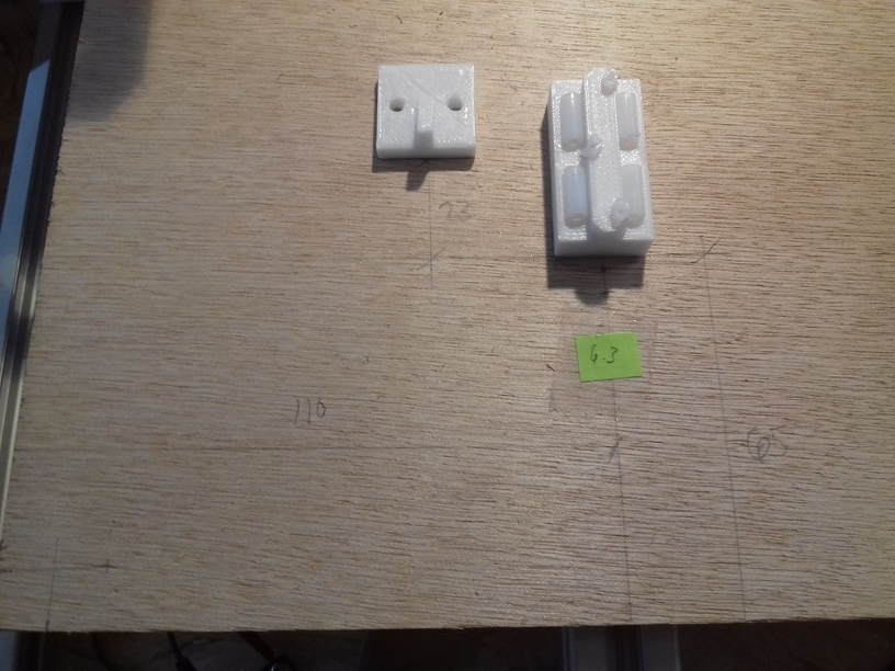
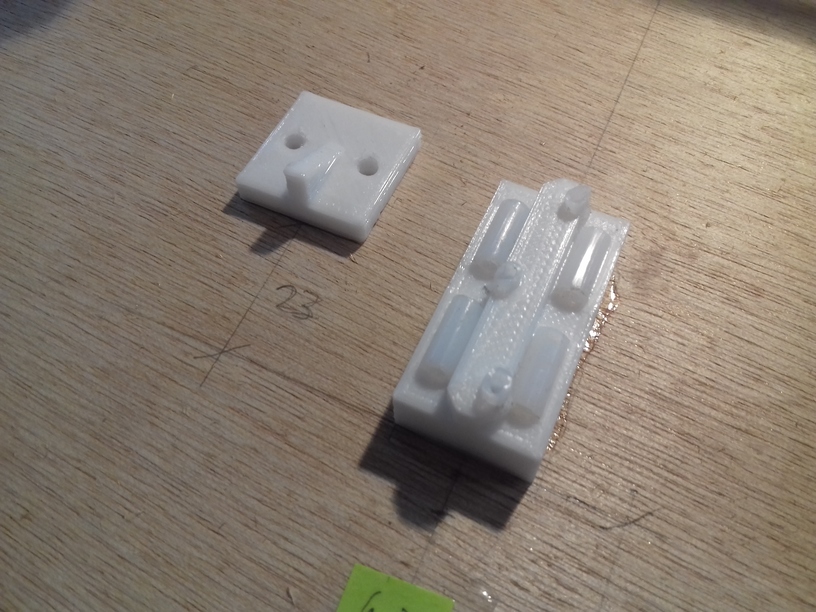
- github: MKS MINI 12864 V3 cases (STL), unfortunately the MKS MINI 12864 V3 display has a slightly different form factor, and existing cases don’t fit

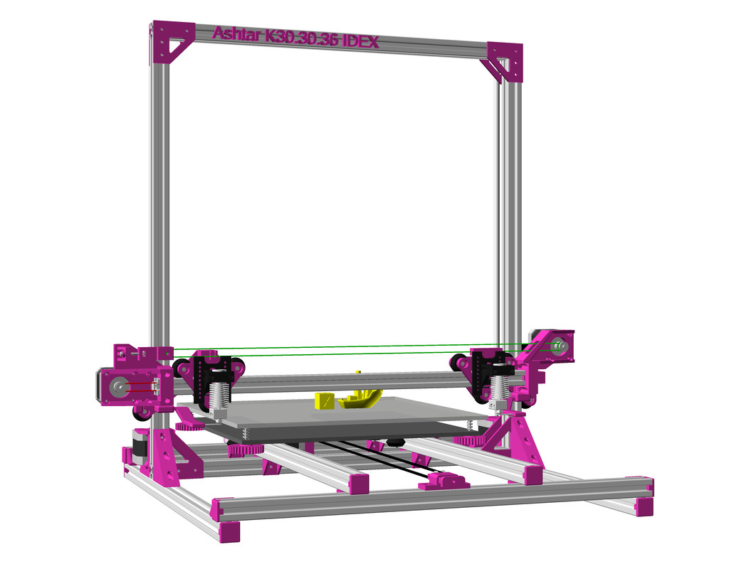
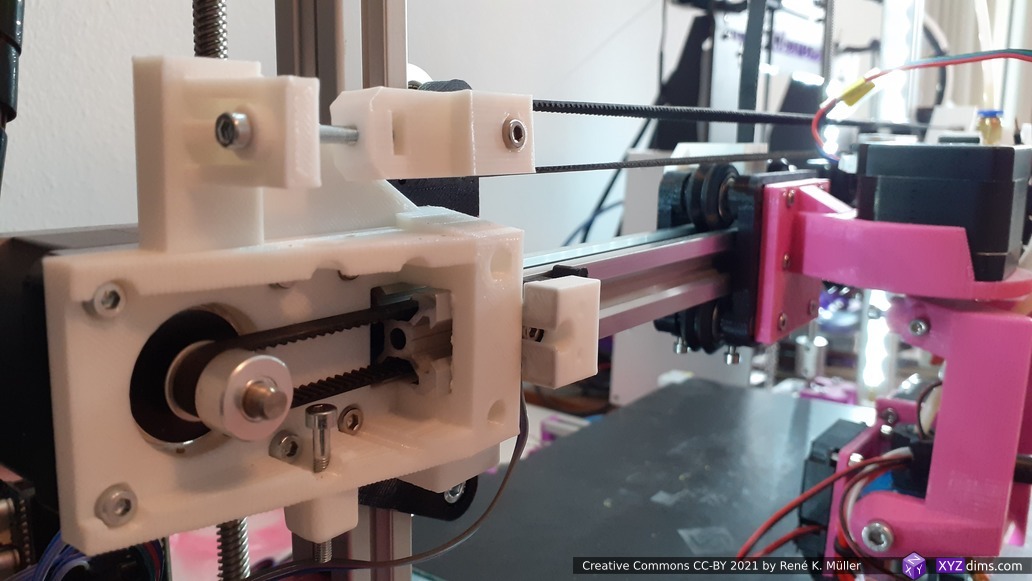

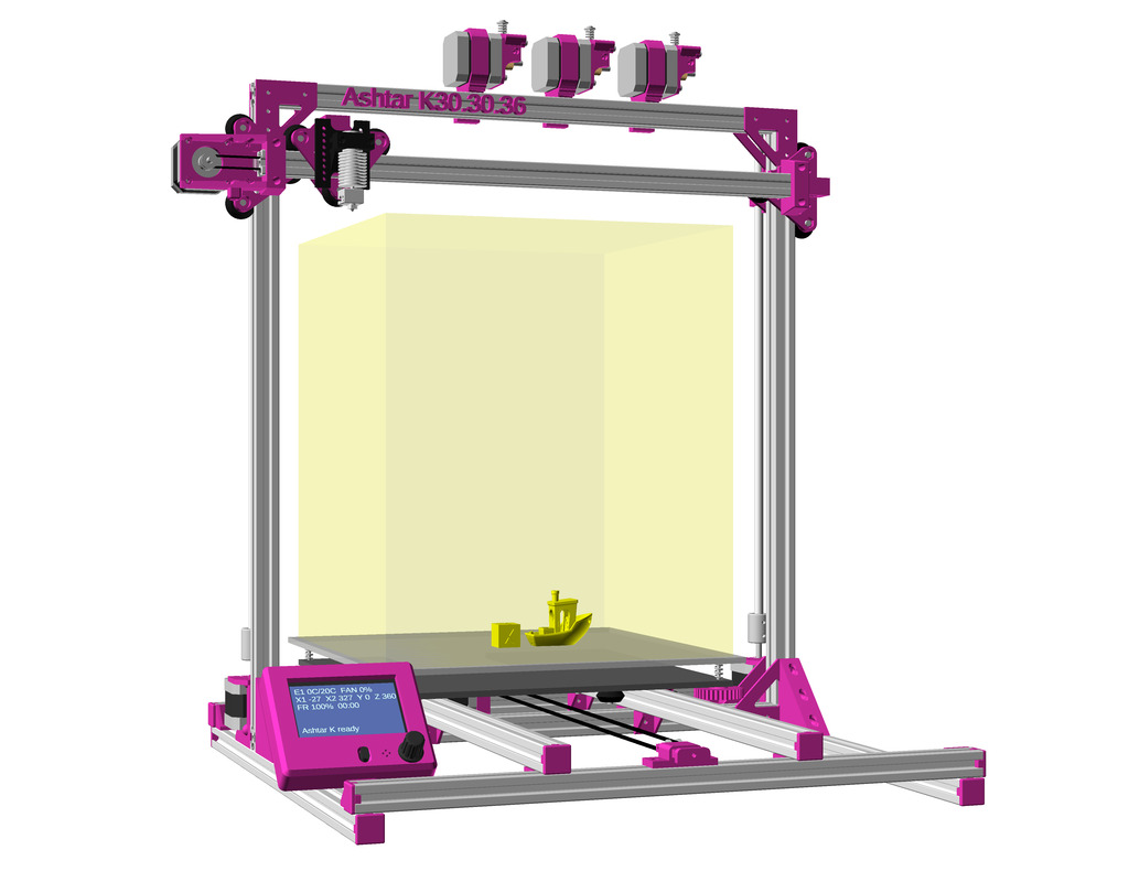


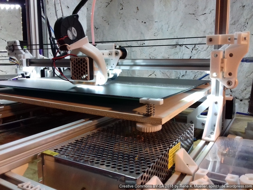

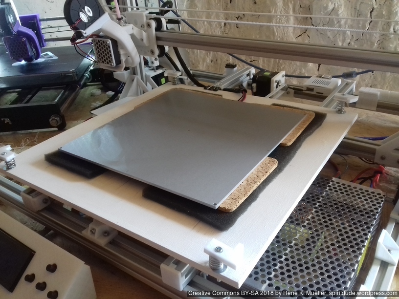
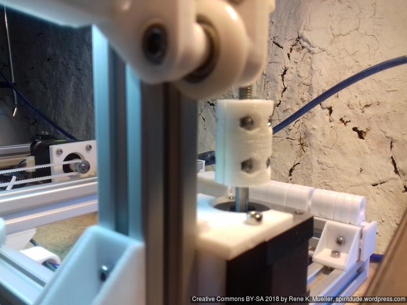
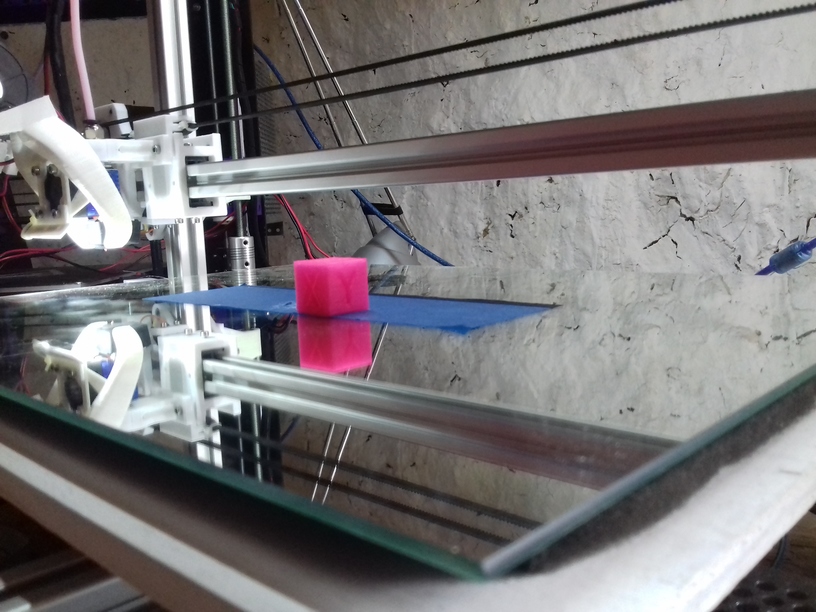
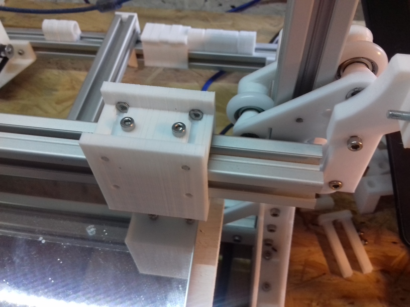
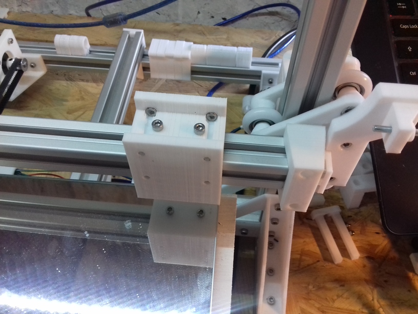
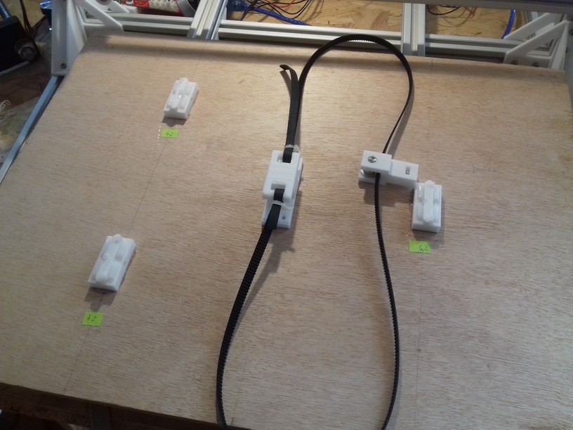
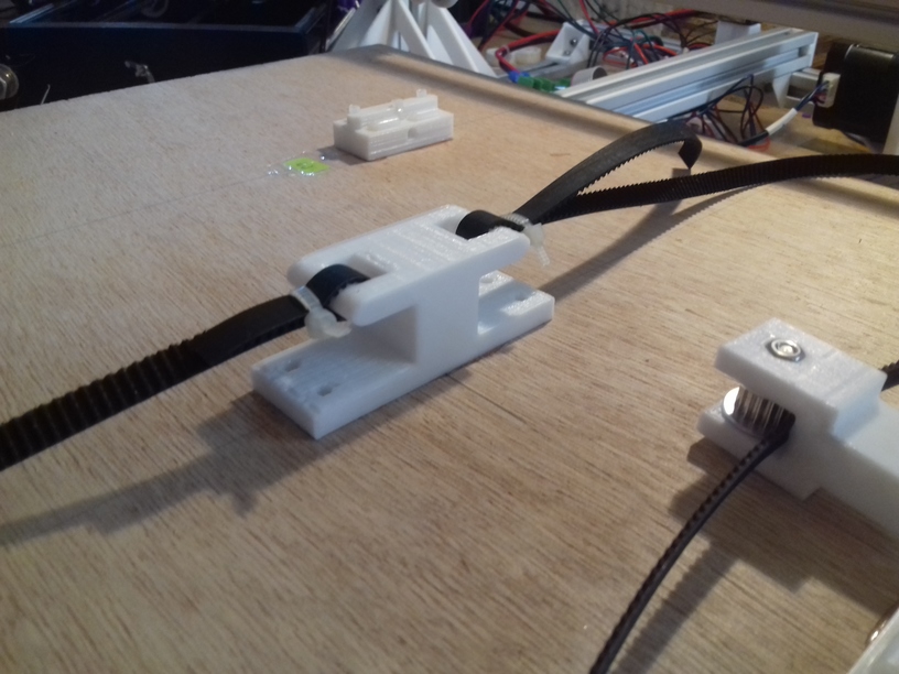
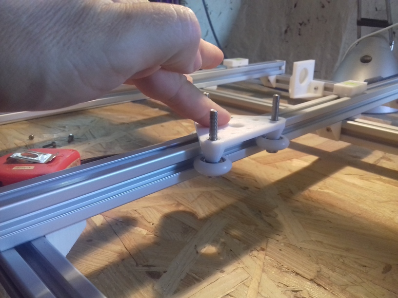
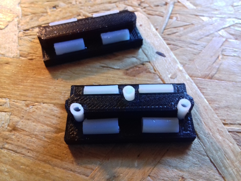
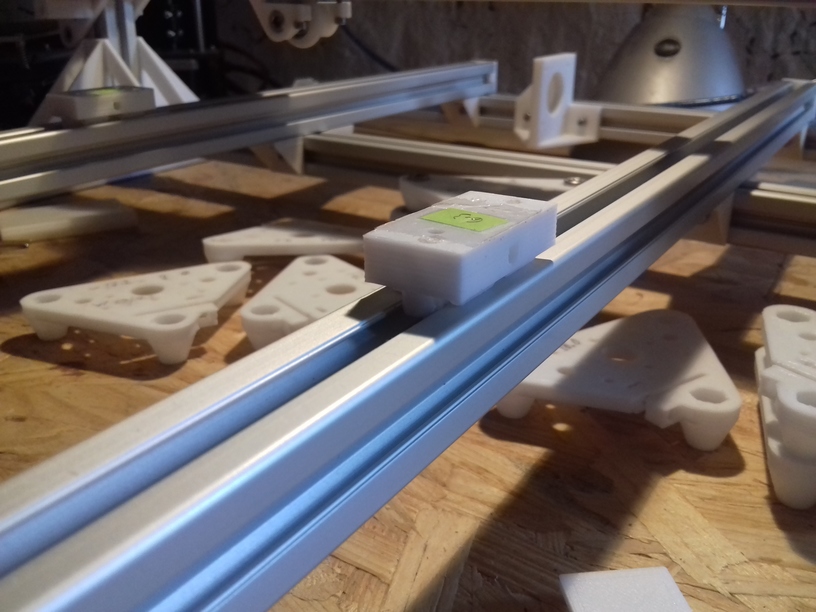
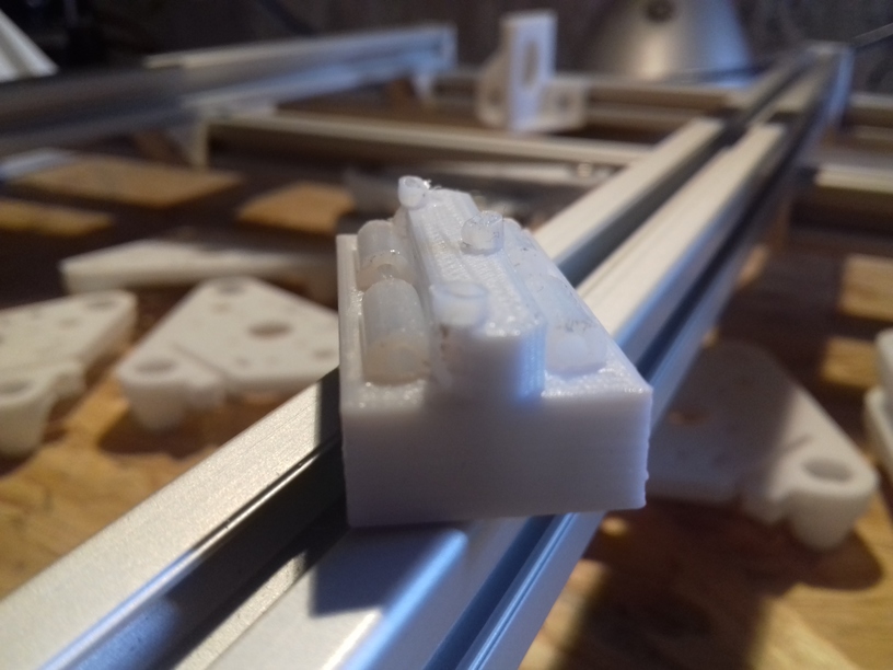
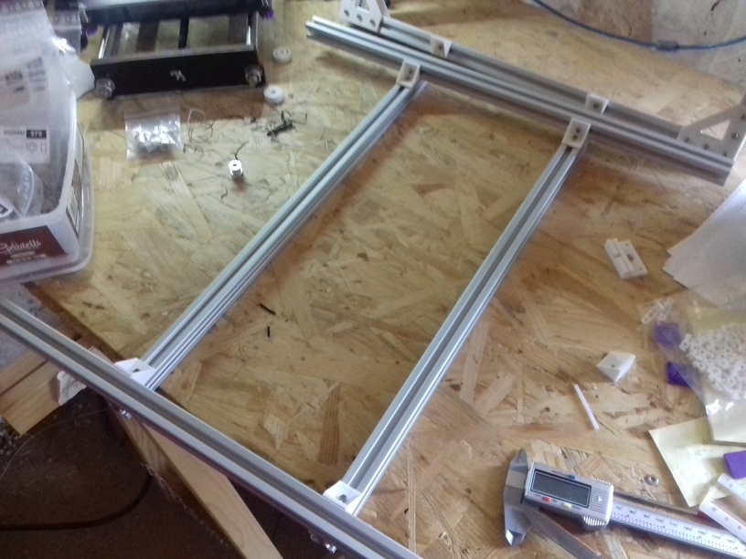
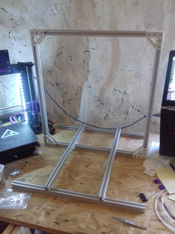
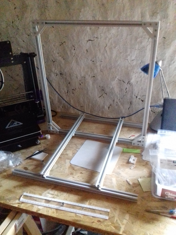
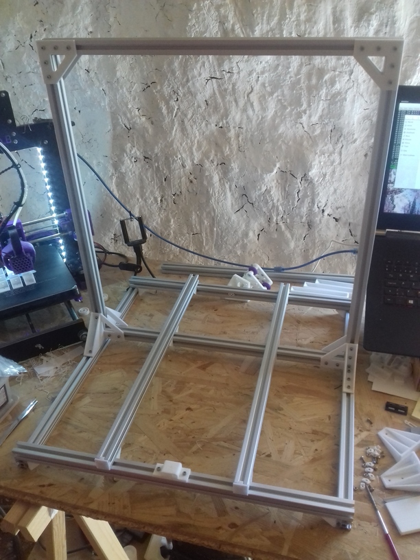
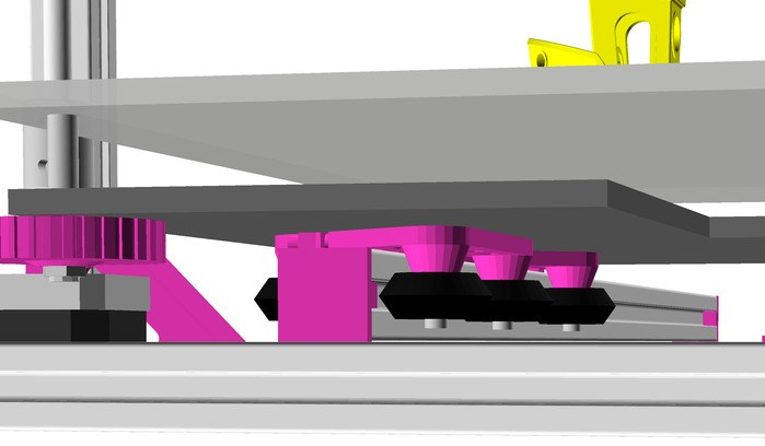
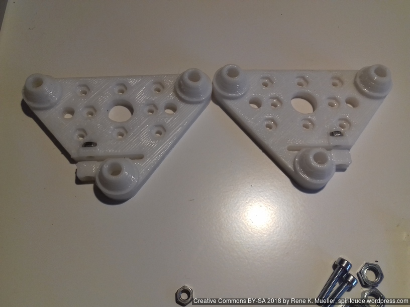
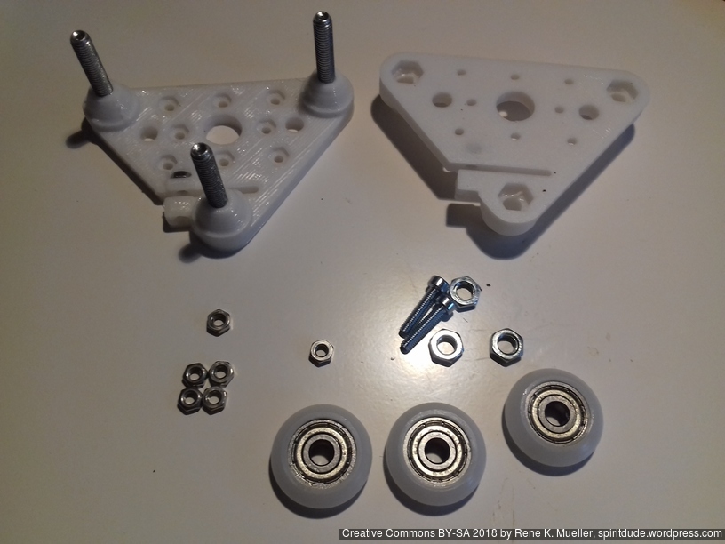
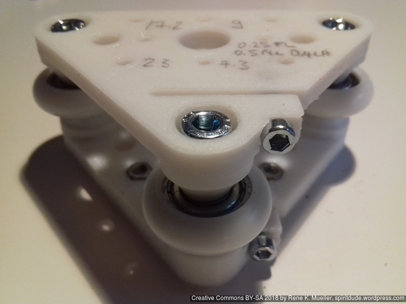
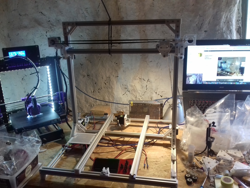
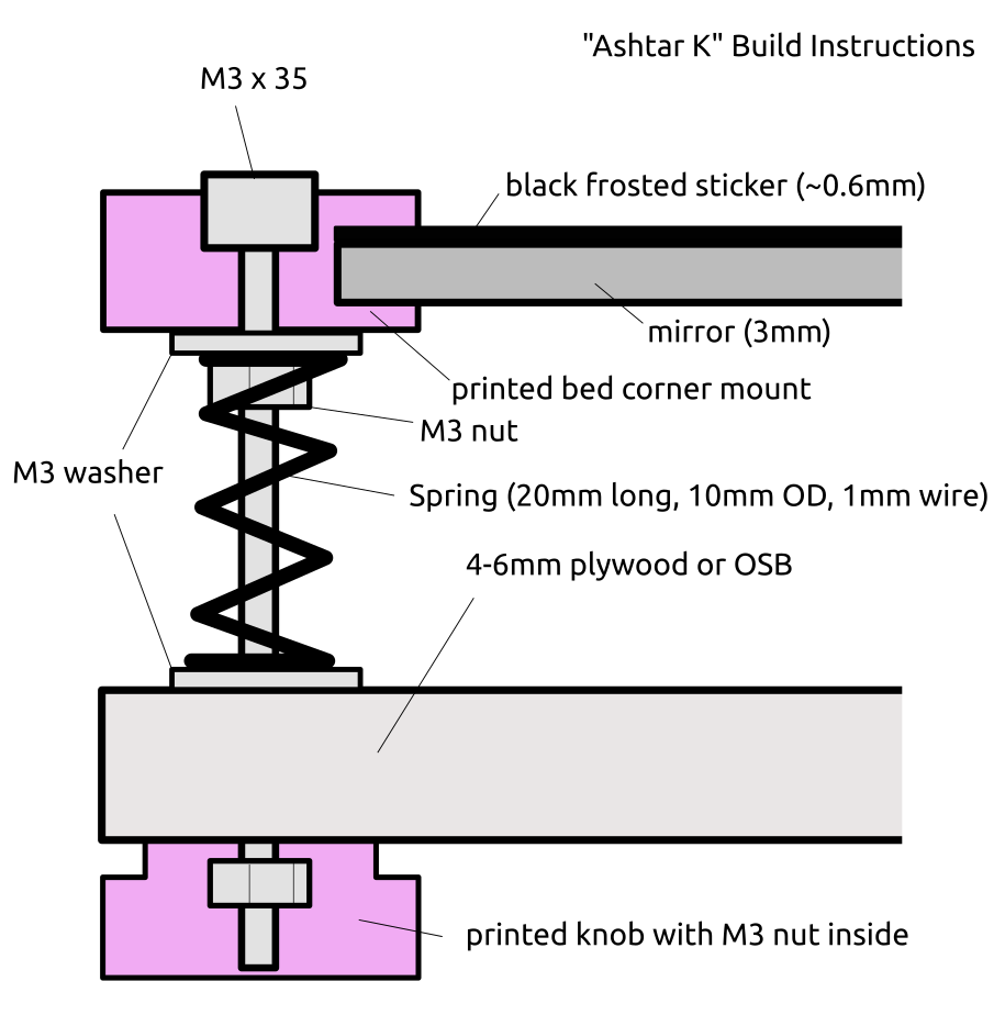 Current bed setup (top to bottom):