Replicating Rapid Prototyping: 3D print parts for 3D printers.
Updates:
- 2020/12/29: adding Ashtar K photos and “genealogy” tree or lineage.
- 2020/12/28: published
Introduction
Adrian Bowyer, an academic at the University of Bath, coined the term RepRap as “RepRap is an open-source self-replicating rapid prototyping machine”. It became obvious that RepRap also meant that the plans would be Open Source, so the developers could iterate and improve the design over generations, like a biological development.
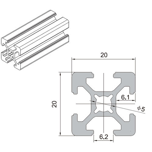
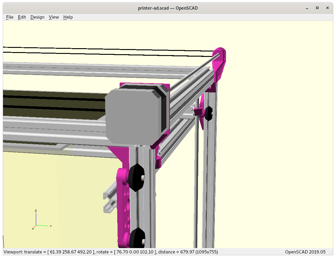
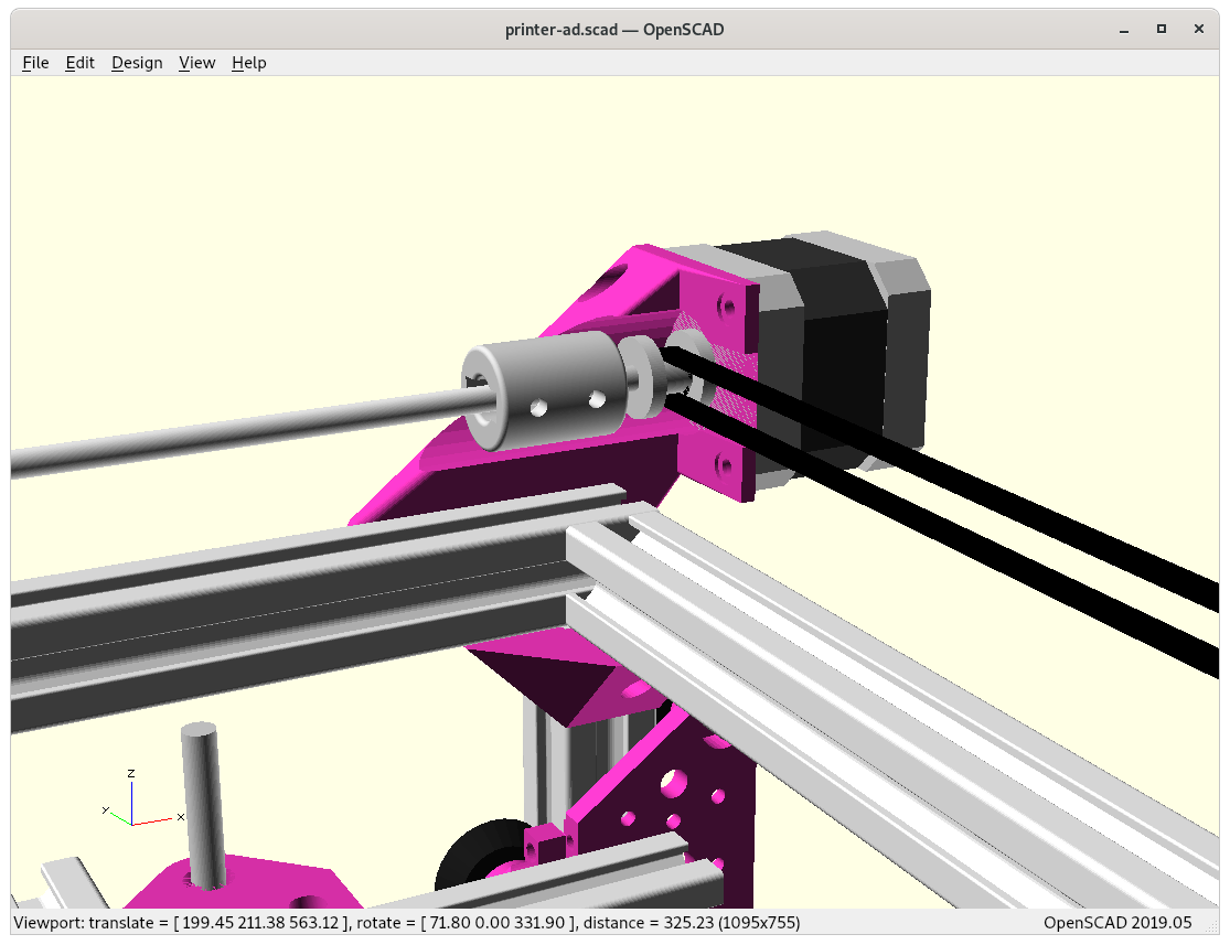
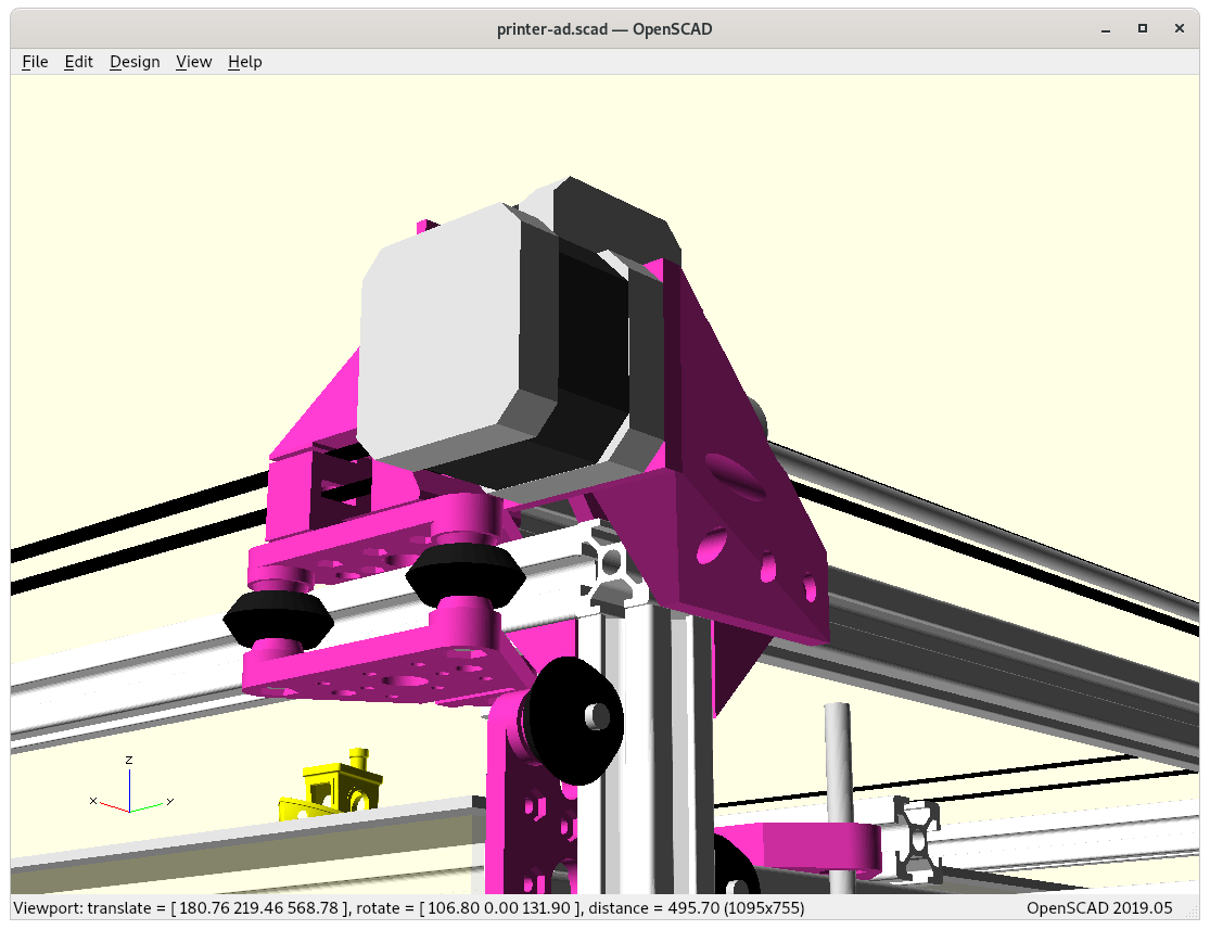
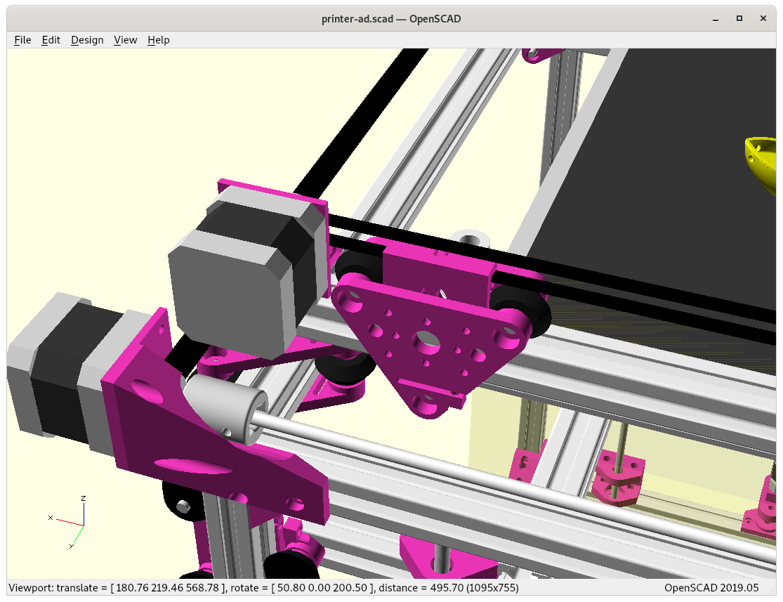
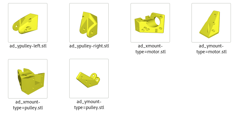
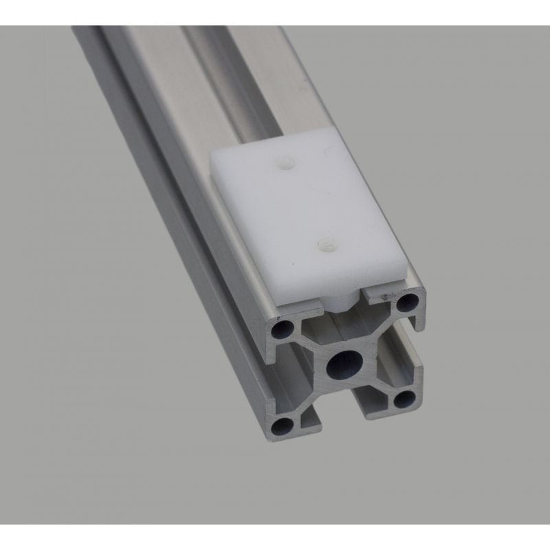
Adrian’s focus was on easy to source parts, such as threaded rods, nuts and bolts, beside the 3D printed parts which connected the non-printed parts together:
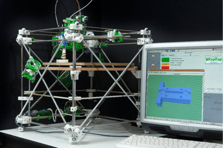
The first RepRap was named “Darwin”, a cubic frame work with printhead XY (left/right, forward/backward) and bed Z (up/down) – its printable parts were printed by a “Stratasys Dimension“ – a commercial 3D printer, see also 3D Printer History.
RepRap “Darwin” and the research behind is well documented in this paper:
- RepRap – The Replicating Rapid Prototyper (PDF, 2010/10/27)
by Rhys Jones, Patrick Haufe, Edward Sells, Pejman Iravani, Vik Olliver, Chris Palmer (aka NopHead) and Adrian Bowyer
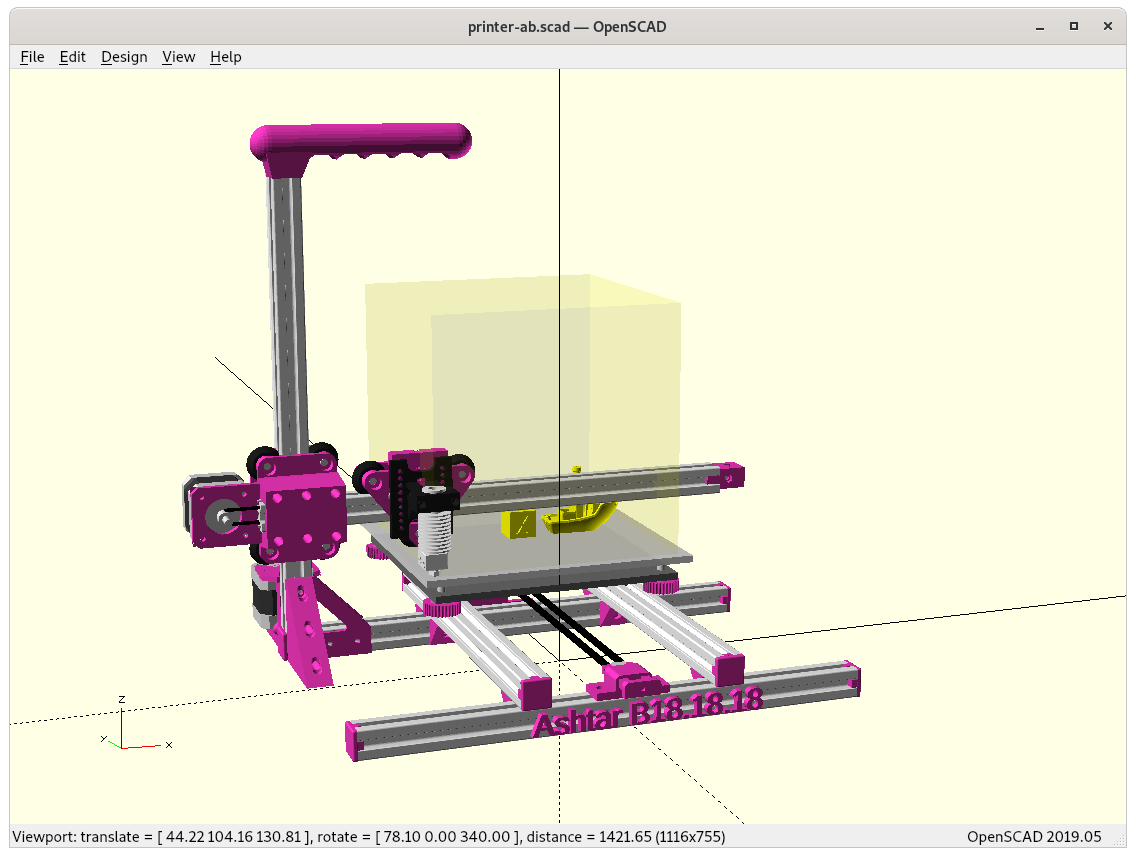
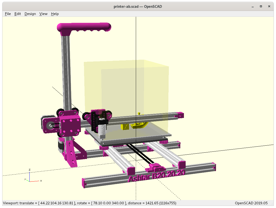
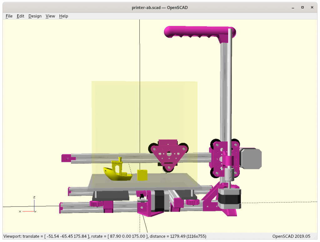
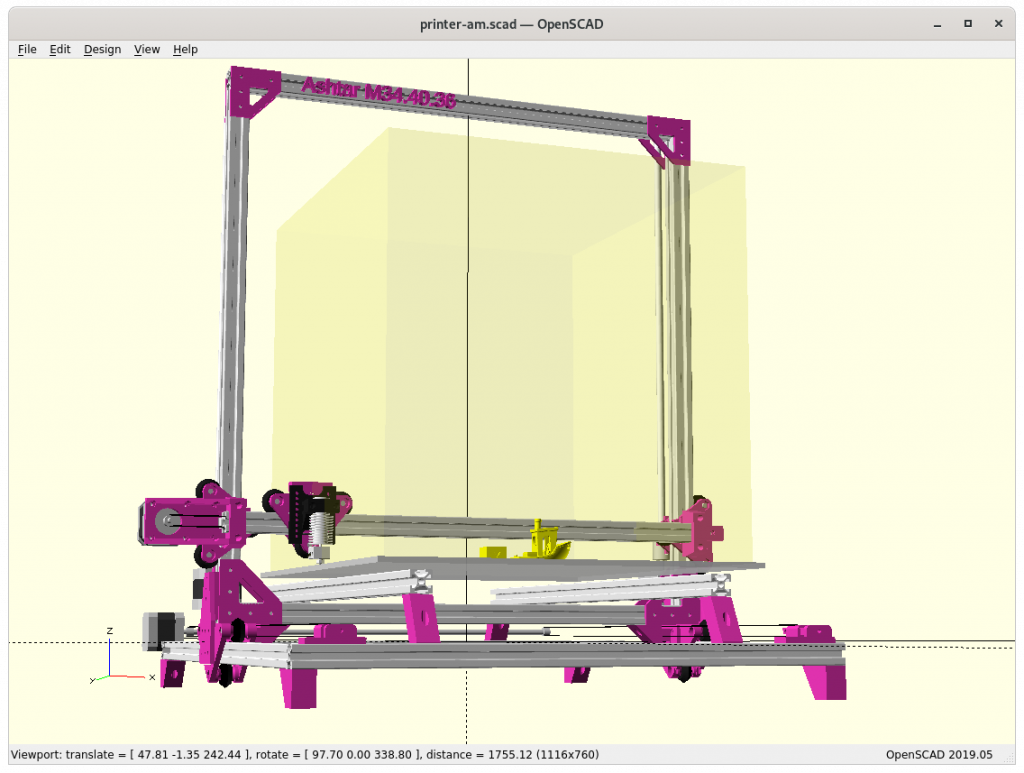
The design eventually got simplified, the amount of parts of printed and non-printed (aka vitamins) were reduced:
RepRap Darwin (2007) 
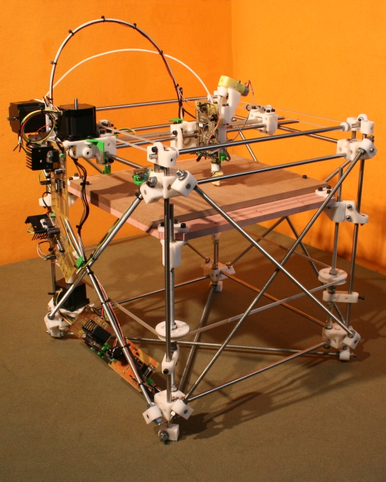
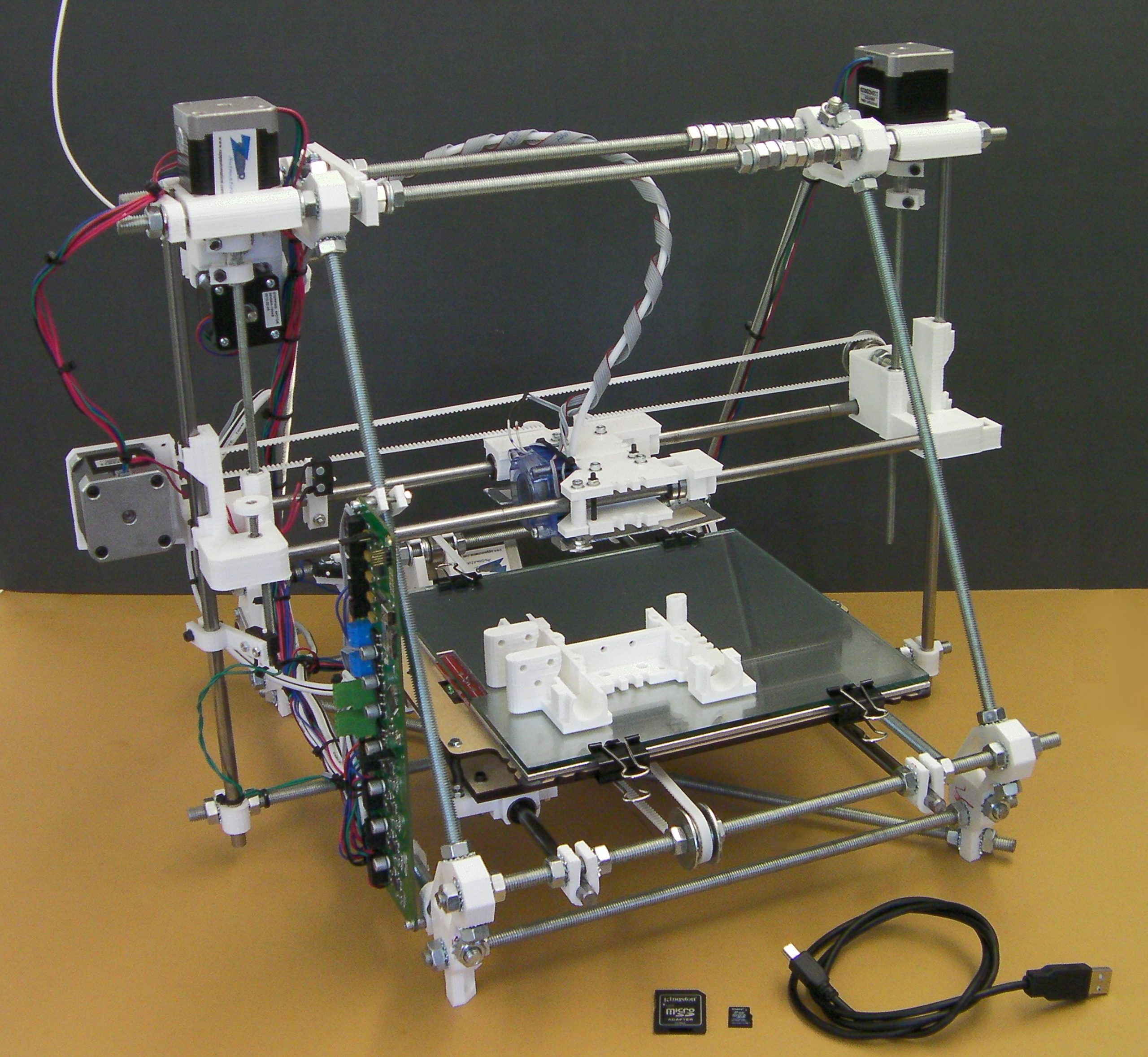
RepRap Mendel (2009) 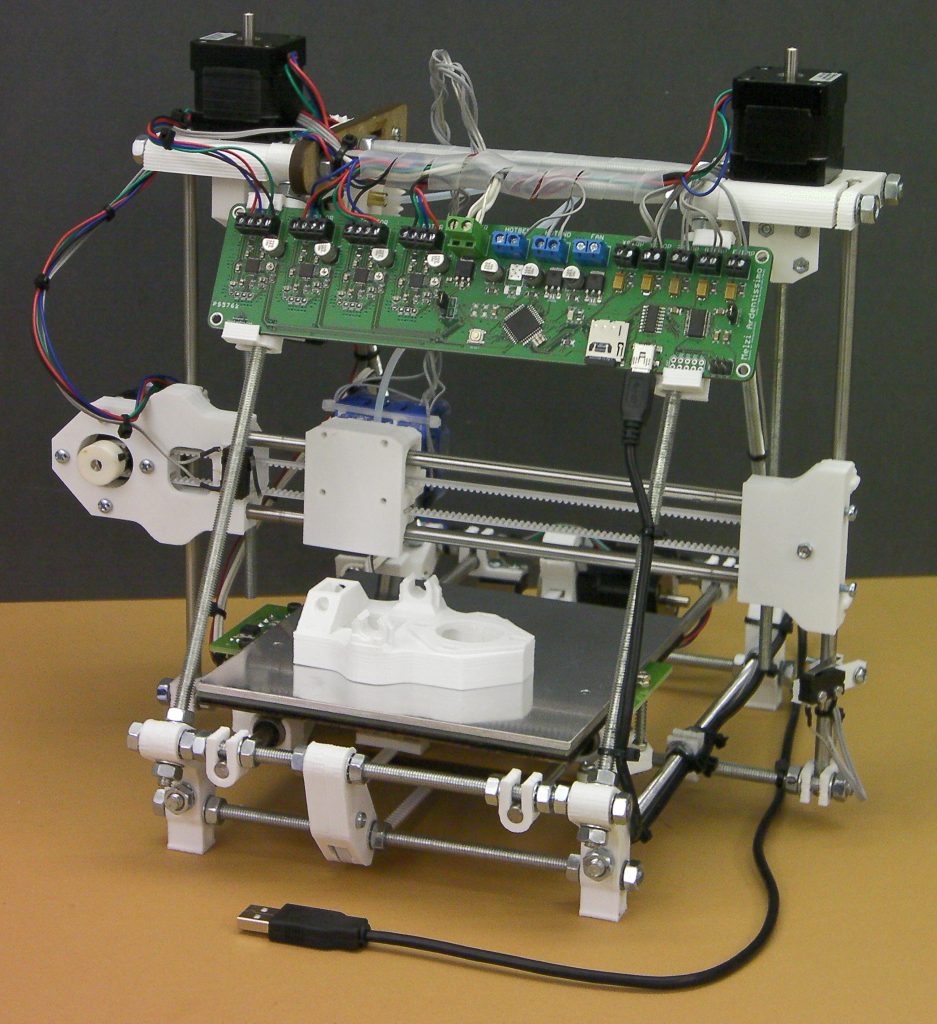
RepRap Huxley (2010) 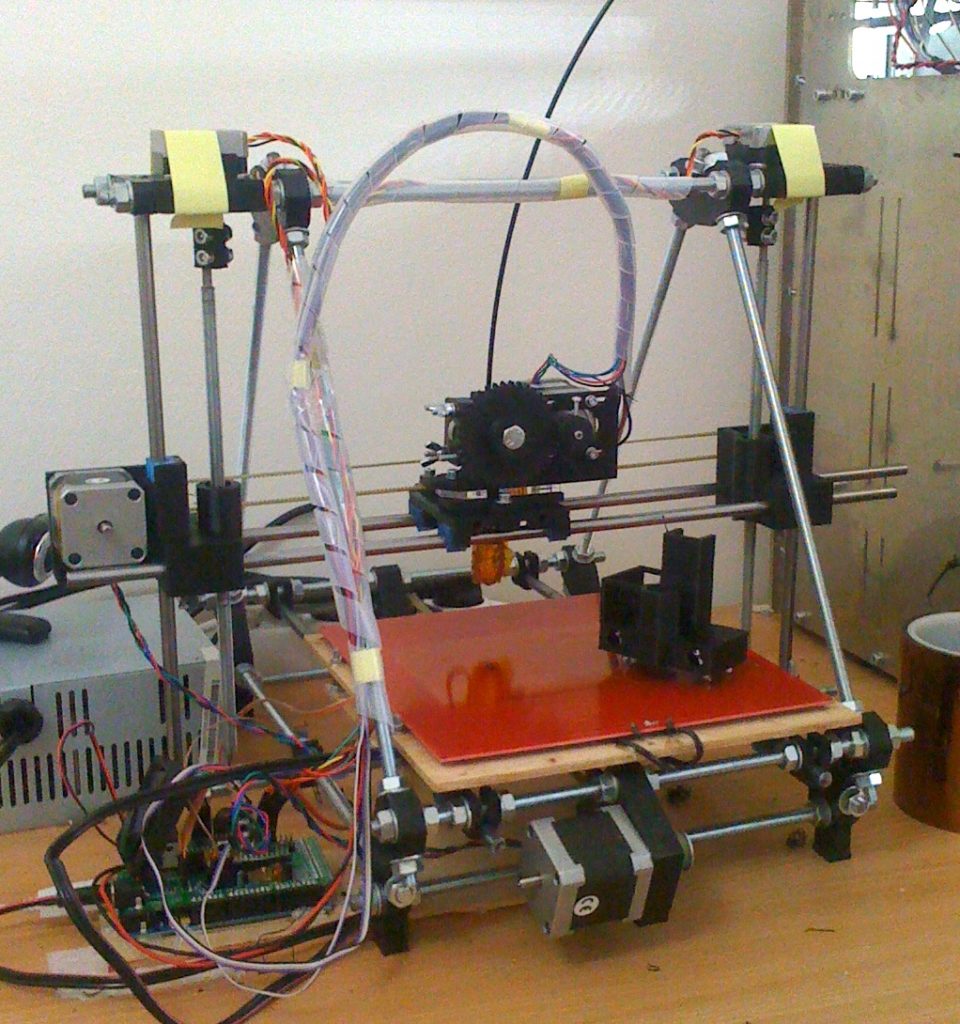
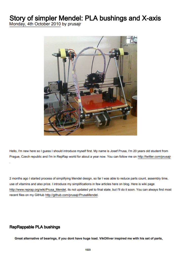
Mendel Prusa (2010) 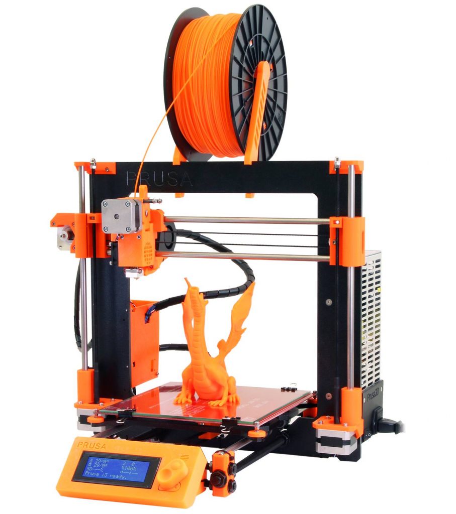
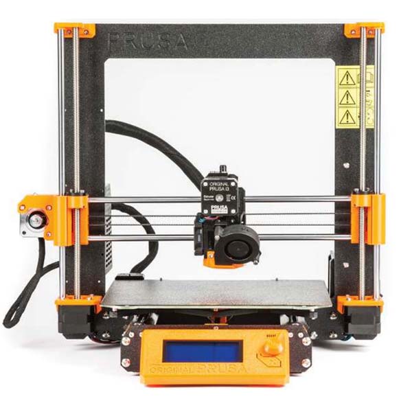
Prusa i3 (2012)


A major step was done by Josef Prusa, who joined the RepRap movement with his “Mendel Prusa” (2010), which he iterated into “(Mendel) Prusa i3” in 2012, the XZ axes were no longer build with threaded rods but a laser cut frame.
During 2010’s laser cutters began to be considered part of common Maker (maker = Do It Yourself or DIY) equipment and so it became a viable approach to build 3D printers:

Makerbot Cupcake CNC 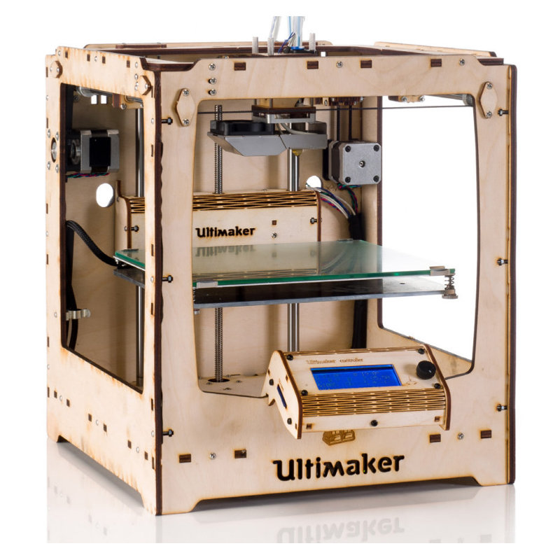
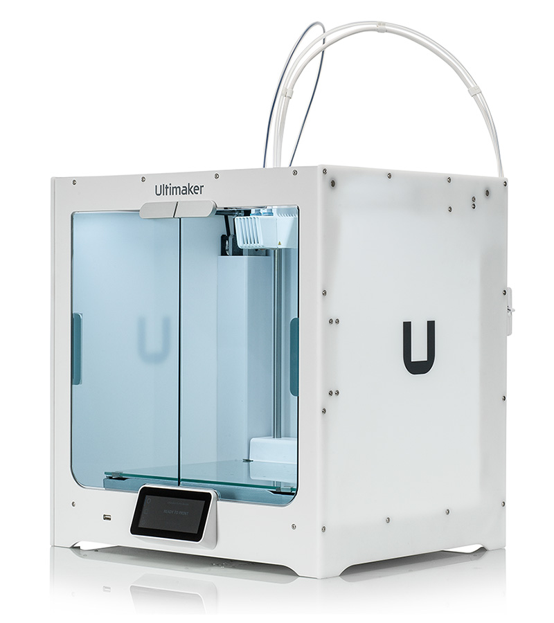
Ultimaker 1 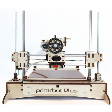
Printrbot Plus
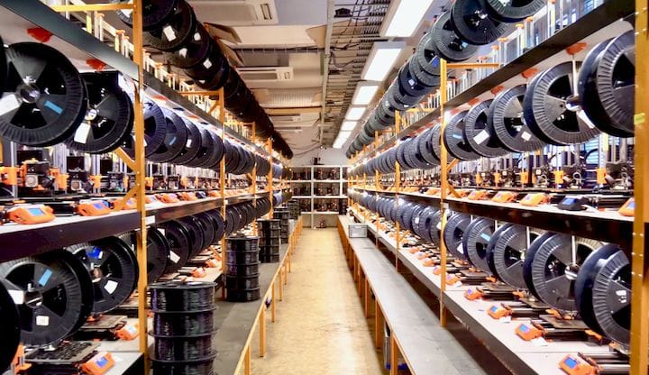
Josef Prusa started his Prusa Research company and still follows the RepRap principle (2020) by 3D printing parts of his Prusa i3 series on a 3D printer farm:
Other companies like Makerbot, Ultimaker, and the many chinese manufacturer used other means to fulfill their needs for fast and scalable production of parts.
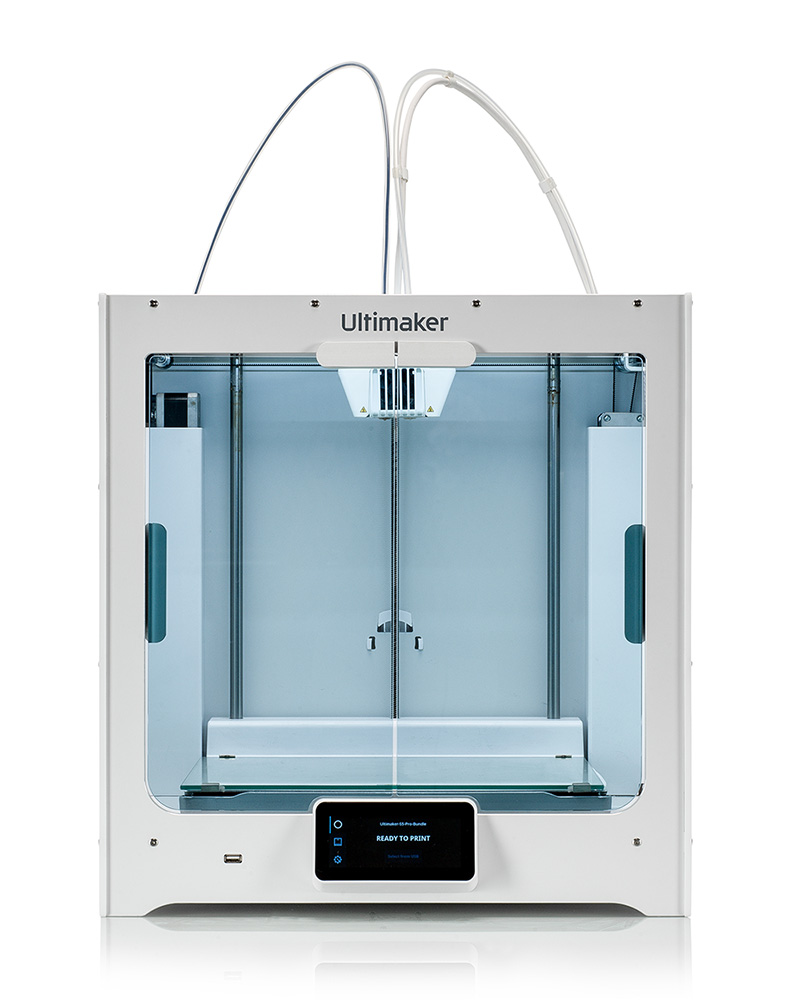
Ultimaker S5 
Makerbot Replicator 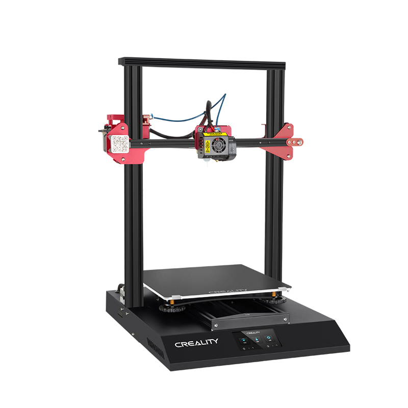
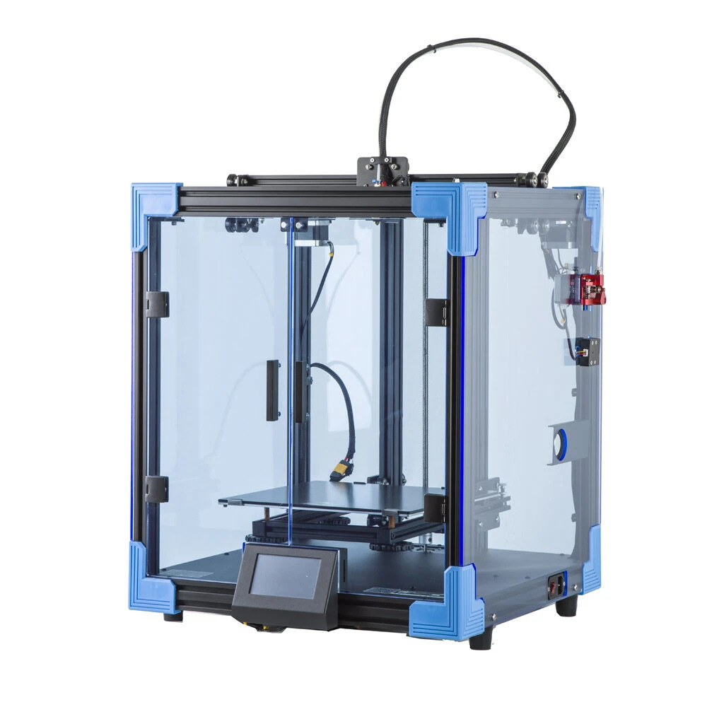
Creality CR10S
And therein lies also the limitations of the RepRap, 3D printing is slow compared to injected mold or sheet bending based production, it doesn’t scale well for centralized production.
- 3D Printer History, an overview how it all happened, where RepRap history is part of it
- RepRap.org Blog Archive, detailed research protocol
In this particular interview Adrian Bowyer shares some historic perspective of the early days of RepRap, highly recommended:
Deeper Roots of RepRap
I gonna quote a larger part of the paper on RepRap – The Replicating Rapid Prototyper, to illustrate the deeper thoughts behind the idea of self-replicating machine:
(— start of quote —)
The Genesis of RepRap
Sometimes the progress and the reporting of a project can obscure the train of thought that instigated the project. Typically, that train of thought was incomplete, or sometimes downright wrong. In this section, we attempt to set down as a matter of record the ideas that led one of us (Bowyer) to invent RepRap.
Understandably, the design of most practical artificial reproducers starts with proposed solutions to many technical problems of getting a kinematic machine copy itself. However, RepRap was not instigated in that way at all. RepRap was instigated by biomimetically considering extant naturally evolved strategies for reproduction.
Biologists categorise most bacteria, archaea, protists and plants as autotrophic because they are capable of selfnourishment using inorganic materials as a source of nutrients and using photosynthesis or chemosynthesis as a source of energy. However, almost without exception, all the natural species of reproducers in the world (including those in the previous sentence) depend upon other species in some way for their survival and successful breeding – by this light they are all assisted self-reproducers. A few lithophile micro-organisms can survive alone in what are essentially mineral environments, but their numbers are vanishingly insignificant compared with those of the interdependent species. Clearly, primordial organisms must have been completely autotrophic, but now that way of life has all but disappeared because the environment in which modern organisms have evolved consists, to a first approximation, entirely of other reproducers.
Yet research into artificial reproduction often concentrates upon making the reproducer as autotrophic as possible (like the lithophiles), and researchers regard this as an important aim. Clearly this aim is important for an extraterrestrial reproducer, but why so for a terrestrial one? Why try to follow a strategy that biology has all but abandoned? An artificial reproducer designed to be interdependent with the natural reproducers that will make up its environment would be more likely to be successful.
Dependencies between species take one of the following three forms: predation, commensalism, or mutualism. Predation is well understood: lions eat antelope; antelope eat grass. Commensalism usually implies some sort of scavenging – lions and antelope are uninterested (though not ultimately disinterested) in what the grass does with their dung, their urine and their exhaled CO2. Mutualism implies a symmetry of dependencies giving benefit to both partners: the pistol shrimp digs a burrow in which it then lives with a goby fish; the shrimp is nearly blind and the fish warns it of danger.
This variety of dependencies prompts a choice in the design of an artificial reproducer: Which type of dependencies should our artificial reproducer exploit, and with which natural species? Beneficial options to people might include predation upon pests, commensal gathering of waste, or mutualism with a species whose welfare we wished to promote (such as an endangered or an agricultural one).
However, clearly the most interesting natural species with which our proposed artificial reproducer might exhibit a dependency is ourselves. This makes the choice more sharply cut: it would be foolhardy to make ourselves the prey for our artificial reproducer; having it collect our waste commensally might be useful, but the option most pleasing to our evolved senses of morality and symmetry would be to make ourselves a reproducing mutualist. In other words, we should make an artificial reproducer that would benefit from us, and we from it.
The most famous mutualism in nature, and the one that we all learn about first at school, is a reward for a service. Butler said of this in Erewhon:
Does any one say that the red clover has no reproductive system
because the humble bee (and the humble bee only) must aid and
abet it before it can reproduce? No one. The humble bee is a part
of the reproductive system of the clover.
Moreover, he might have added, the bee is rewarded with nectar.
Mutualism between the flowers and the insects evolved about 140 mya in the late Jurassic period and is one of the most enduring phenomena in biology. For both sets of species it is an evolutionarily stable strategy corresponding to a particularly unshakable Nash equilibrium.
What service could our mutualist reproducer ask from us? Moreover, with what could it reward us? It would seem sensible to play to the differing strengths of artificial kinematic machines and people. Artificial kinematic machines can make objects accurately, repeatably and tirelessly. In contrast, they fumble at manipulative tasks that would not tax a small child. People are exquisitely dexterous. (Aristotle called the human hand, the instrument of instruments.) But – though with practice people may carve and mould beautifully – they cannot do so accurately, repeatably and tirelessly.
So our self-reproducing kinematic machine could be designed to manufacture a kit of parts for a copy of itself, and to need the assistance of people to assemble that copy (that is, it would be an assisted reproducer along the lines of NASA’s unit-reproducer). The people would be the humble bee, and the kinematic machine the clover. And what about the nectar?
If the kinematic machine were sufficiently versatile to make its own parts, then chances are that it would also be able to make many other items useful to people. When it was not reproducing itself, it would be rewarding its assistants with a supply of consumer goods. This idea of a self-reproducing machine also making useful things for people is not new. It goes back through von Neumann to Butler. But we contend that regarding this as a form of biological mutualism and deliberately seeking to achieve that in order to position both reproducers at an evolutionary Nash equilibrium for each is a novel idea.
This was the genesis of the RepRap machine. It was designed to make its own parts to be assembled by people into another RepRap. The people would be driven to do this by the fact that the machine, when not reproducing, could make them all manner of useful products. It seemed (and still seems) likely that this would lead to a mutualist relationship between people and the machine that would inherit some of the longevity and the robustness of the evolutionarily stable strategies of the insects and the flowering plants.
Finally in this section, we note that flowers do not attempt some biological equivalent of copyrighting or patenting the “intellectual property” of their genomes. Such a genome builds the flower with the sole intent† of spreading itself with the most promiscuous fecundity possible. Any genome mutation that arose that – for example – attempted to extract some payment (like the nectar) in return for a copy of itself would clearly have a lower reproductive fitness. The nectar and the information are not in any way equivalent. The nectar is a real material resource. In contrast, the immaterial genome information has been arranged purely because of its success in copying itself as freely as it can, and any impediment placed in the way of that would be to its detriment. For this reason, it was decided to follow the principles of the free software movement and to distribute every piece of information required to build RepRap under a software libre licence that requires no royalty payments whatsoever. This would allow private individuals to own the machine, and to use it freely to make copies for their friends.
The RepRap machine is intended to evolve by artificial rather than natural selection; that is, to evolve as the Labrador has evolved from the wolf, rather than as the wolf has evolved from its ancestors. It is hoped that this evolution will come about by RepRap users posting design improvements on-line that may be adopted in future designs of the machine and then in turn downloaded by old and new users. That is why the General Public Licence was chosen as the RepRap licence, as that obliges people who improve the machine to make public their improvements under a similar free licence.
(— end of quote —)
Limits of RepRap & Future
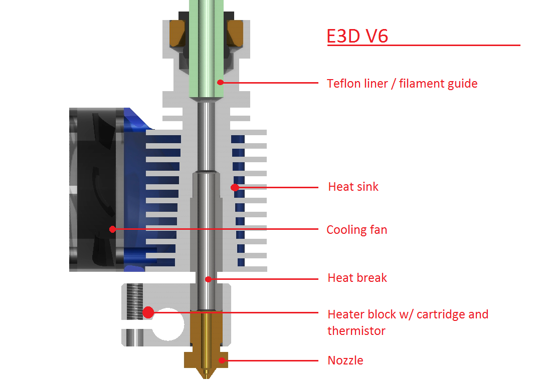
In its current form (2020) RepRap is a principle which allows a low entry in regards of complexity, cost and availability to 3D printing. Many pieces, which cannot be printed yet, need to be machined separately, e.g. with programmable CNC machines, like the hotend: heatsink, heating block, the nozzle; those pieces need to withstand the heat which is needed to melt the plastics which RepRap’s currently use to create a piece – the machine itself cannot be fully plastic, as it needs to bring the plastic in a formable or molten state to position and deposit it in space.
A future RepRap might function differently, e.g. programmable self-organizing machine which positions molecules which form a bacteria, which create nano bots and nano motors, which boot strap an assembly and create a machine again, one which can arrange molecules – there it will not be the issue of molten plastic, but the separation of what the machine is and what the in-progress machine would be; if that separation would not be regarded, such a future RepRap would blend into the 2nd machine while it would make it, and it would evolve without generating a child, it would morph into a new machine instead. Right now (2020) RepRap’s are not in danger to morph into themselves, as the pieces are plastic, and many non-printable pieces limit the completeness of self-replication.
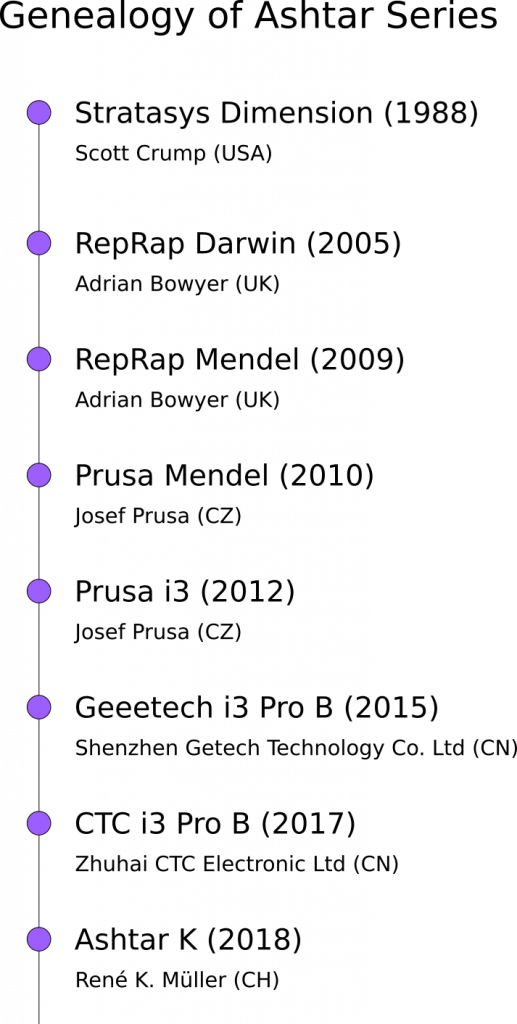
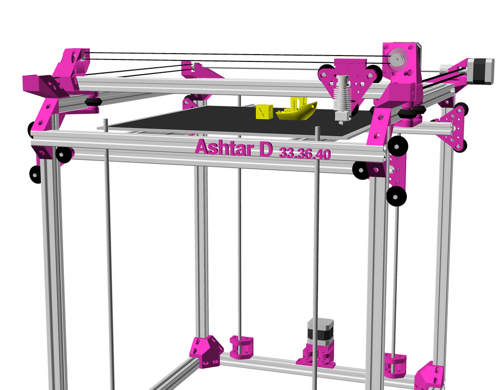
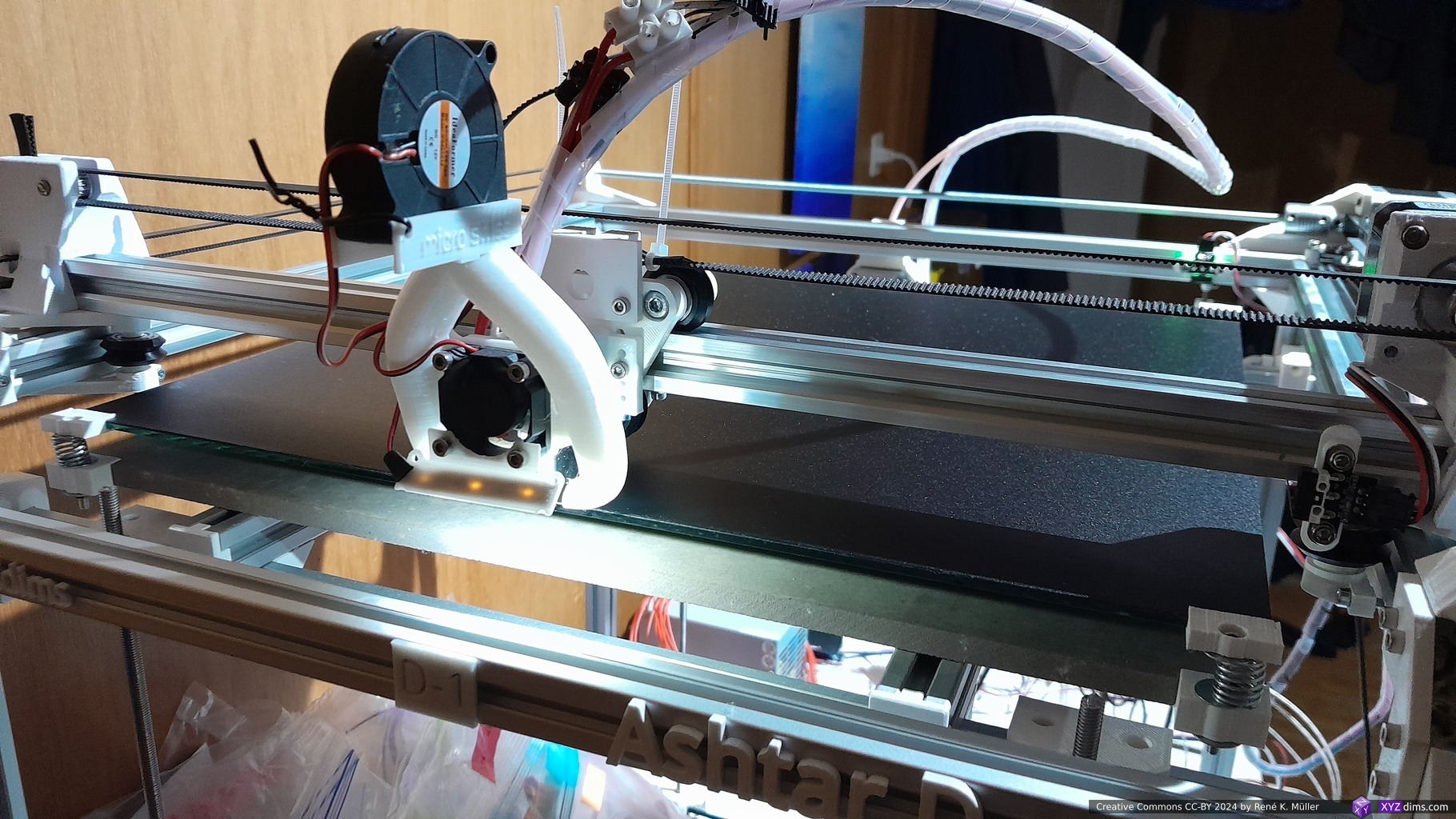
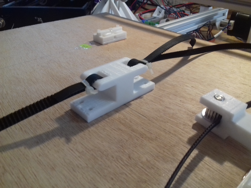
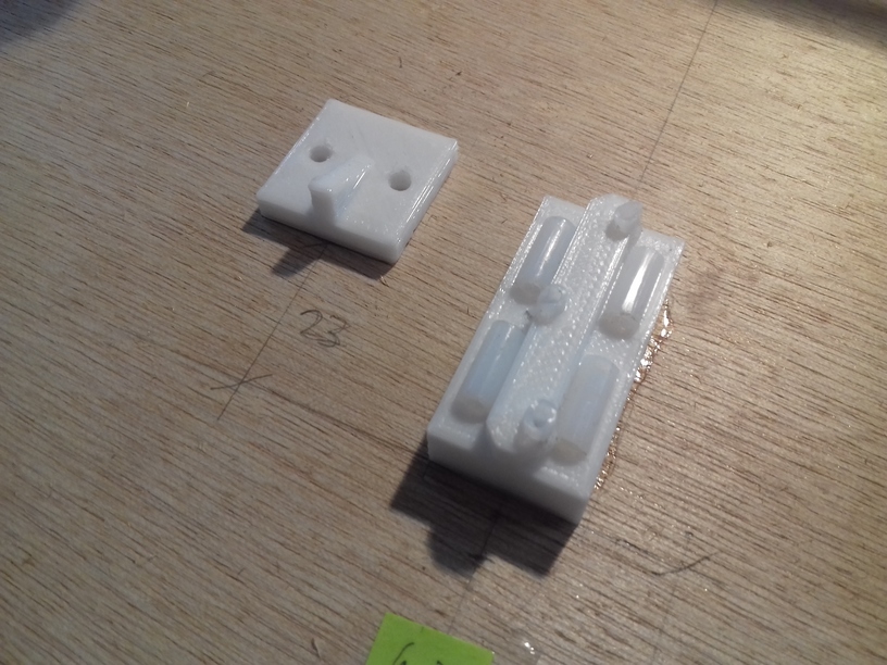
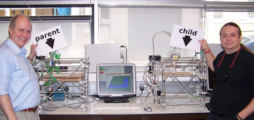
Yet, on one occasion it happened when I was printing pieces on an Ashtar K #1 (Prusa i3) for another “Ashtar K #2” printer – quasi the child – and due some mechanical mishaps the piece was printed too close to the bed fasteners, which were printed in PLA – so they fused in that moment (failed print) – in that moment it also became clear to me, that the separation of what the machine is and what the piece it produces is, is essential. I had to break the newly printed piece apart, but it damaged the bed fastener with the hot nozzle . . . and as the morphing or fusion was so good, it no longer was clear were the bed fastener (parent) and the new piece (child) began.
So, if a RepRap comes close to create nearly 100% replicate of itself, it requires a marker and safeguards to distinguish the parent from the child in-progress to be produced, and ensure it does not morph or blend into each other.
Needless to say, self-replicating machines is reinventing life from the gross technological level downward, whereas physical life emerges from the entire stack of sub-atomic, atomic, molecular, DNA, cell, organ, body-level to planet-sized ecosystem with many species.
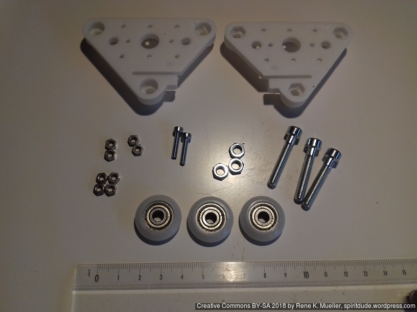
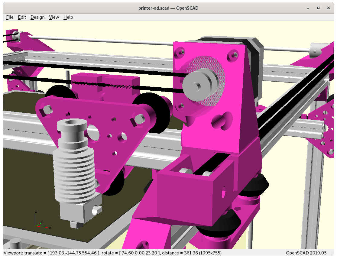
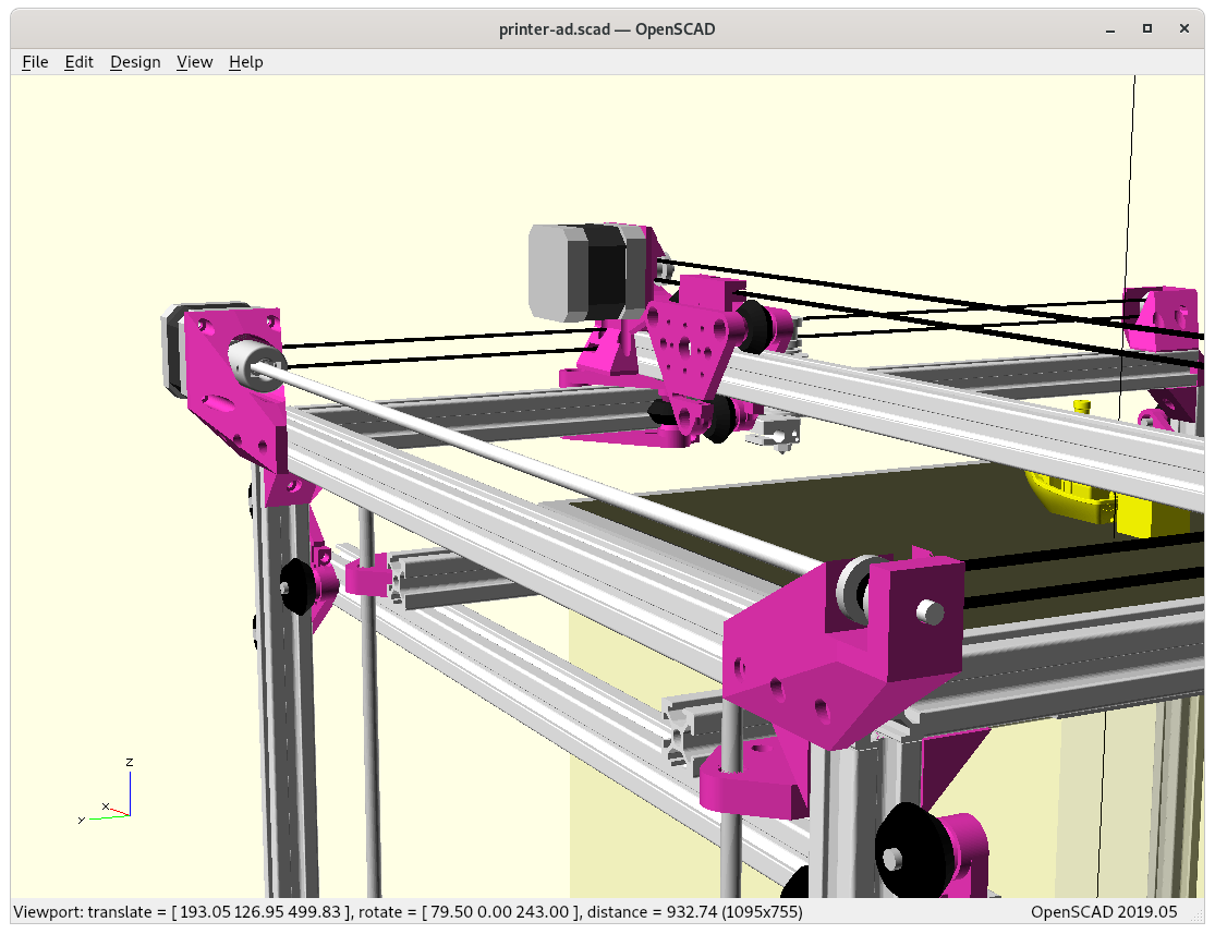
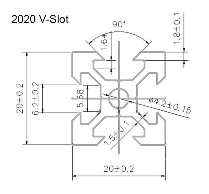
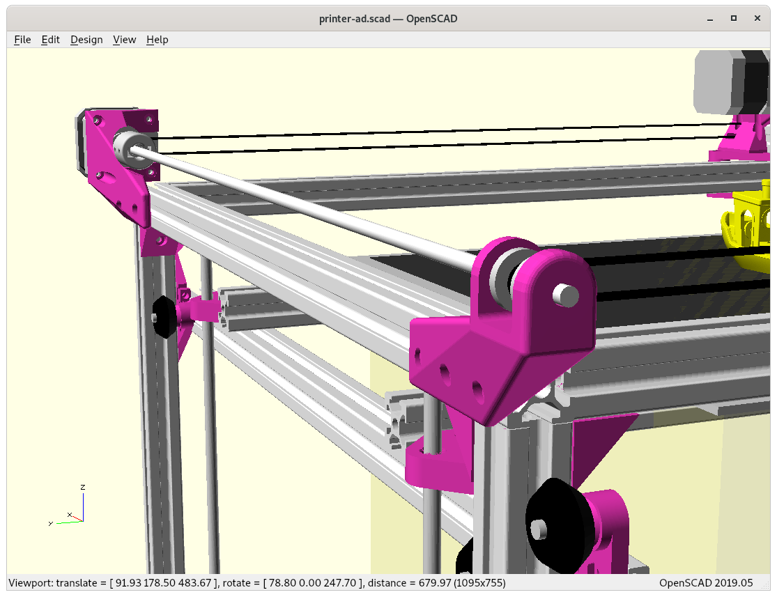
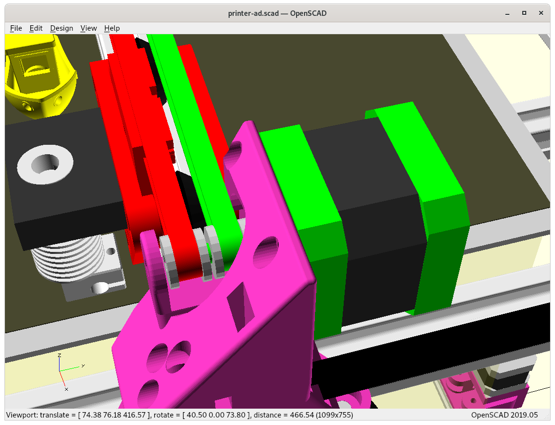
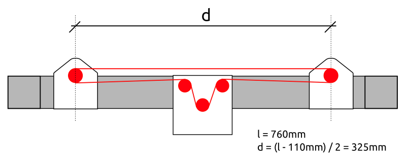
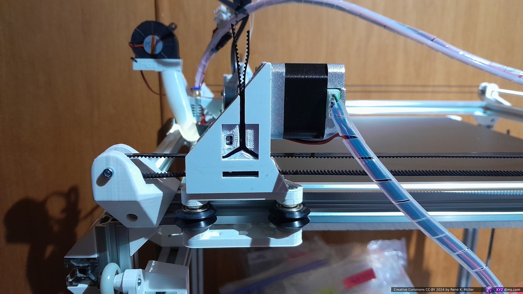
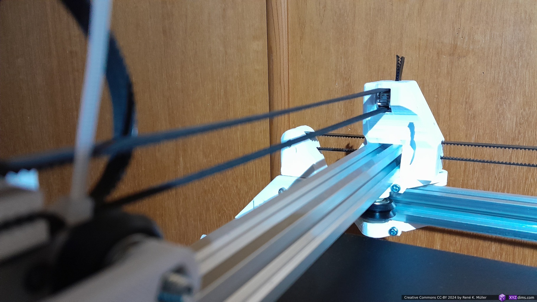
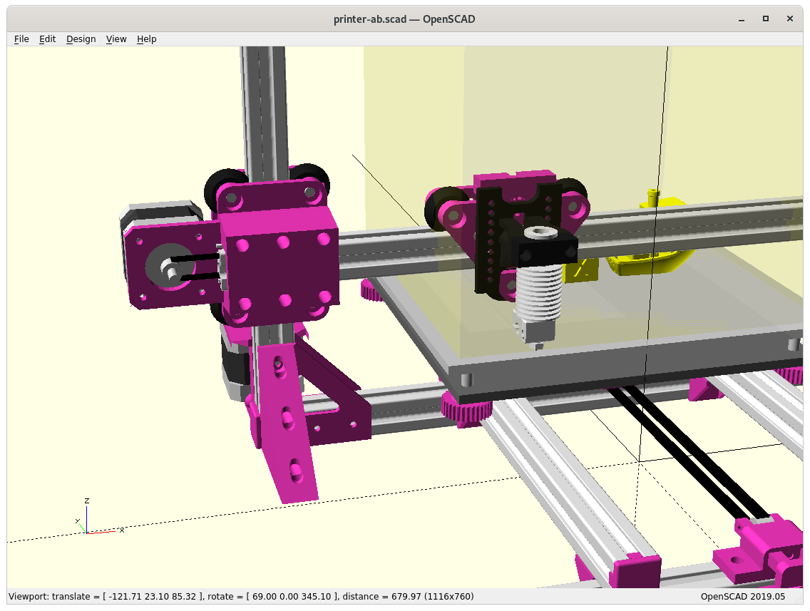
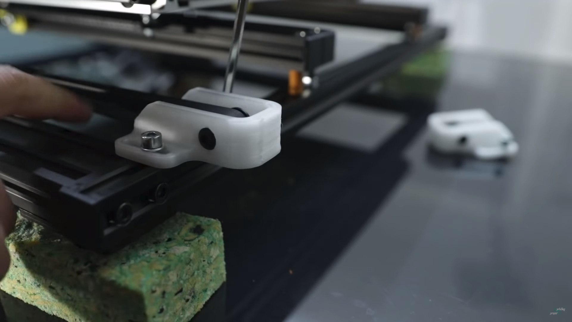
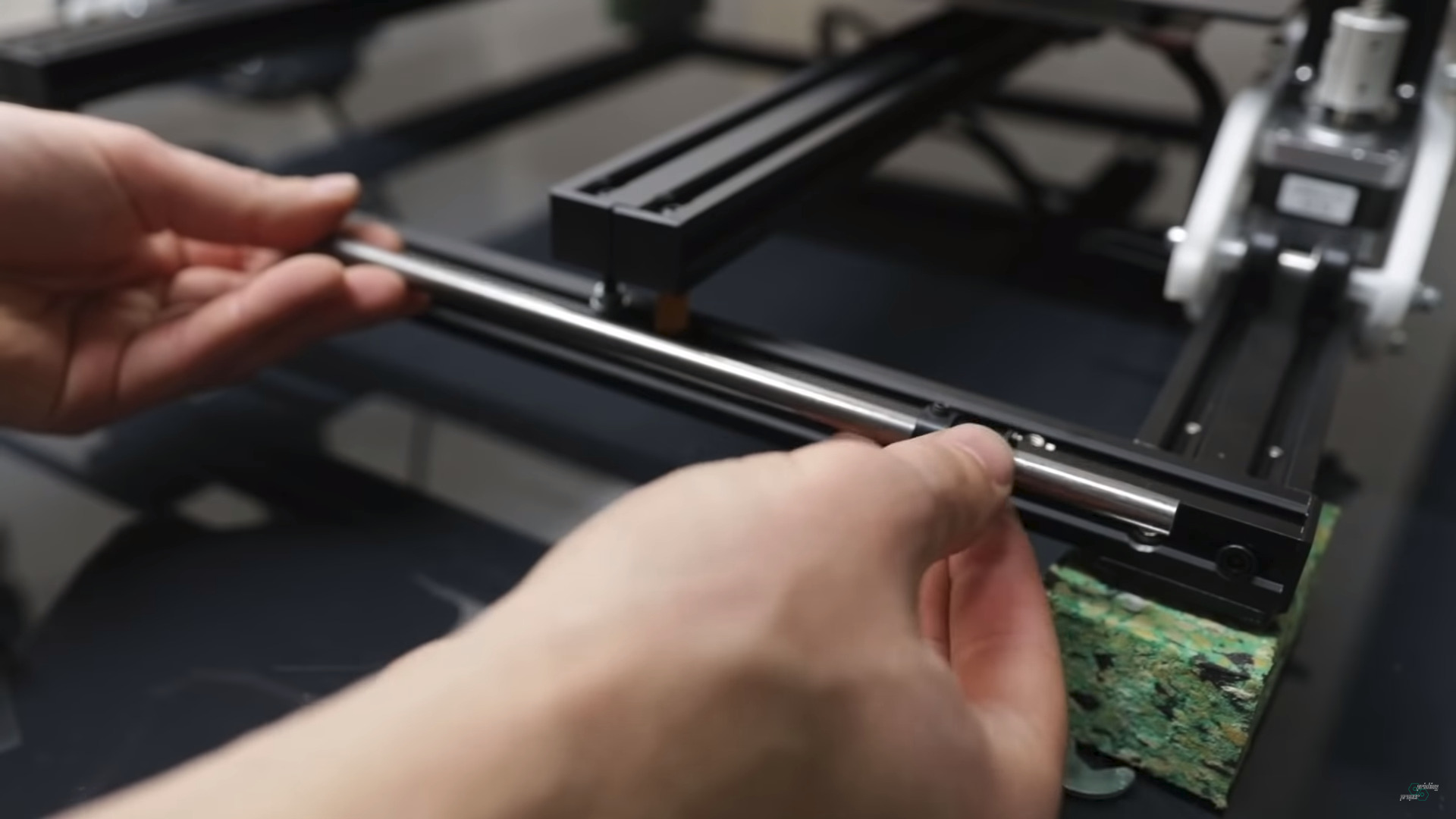
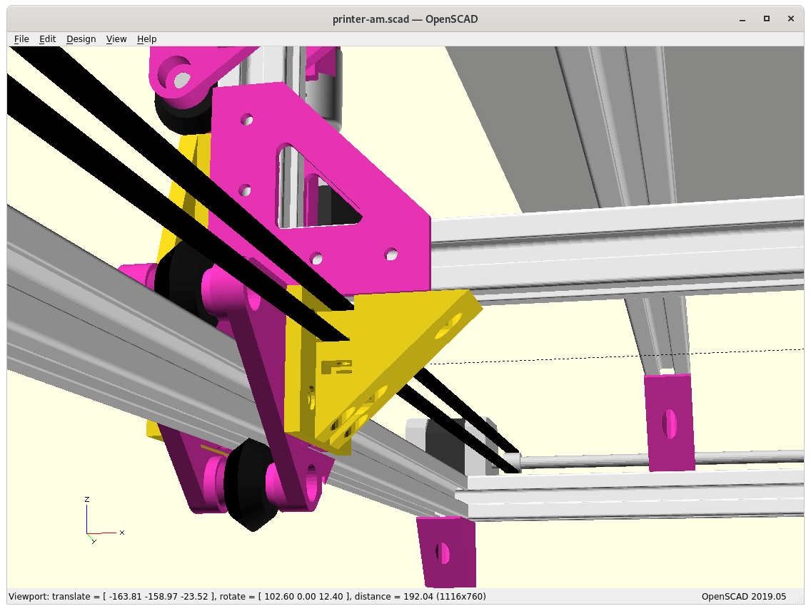
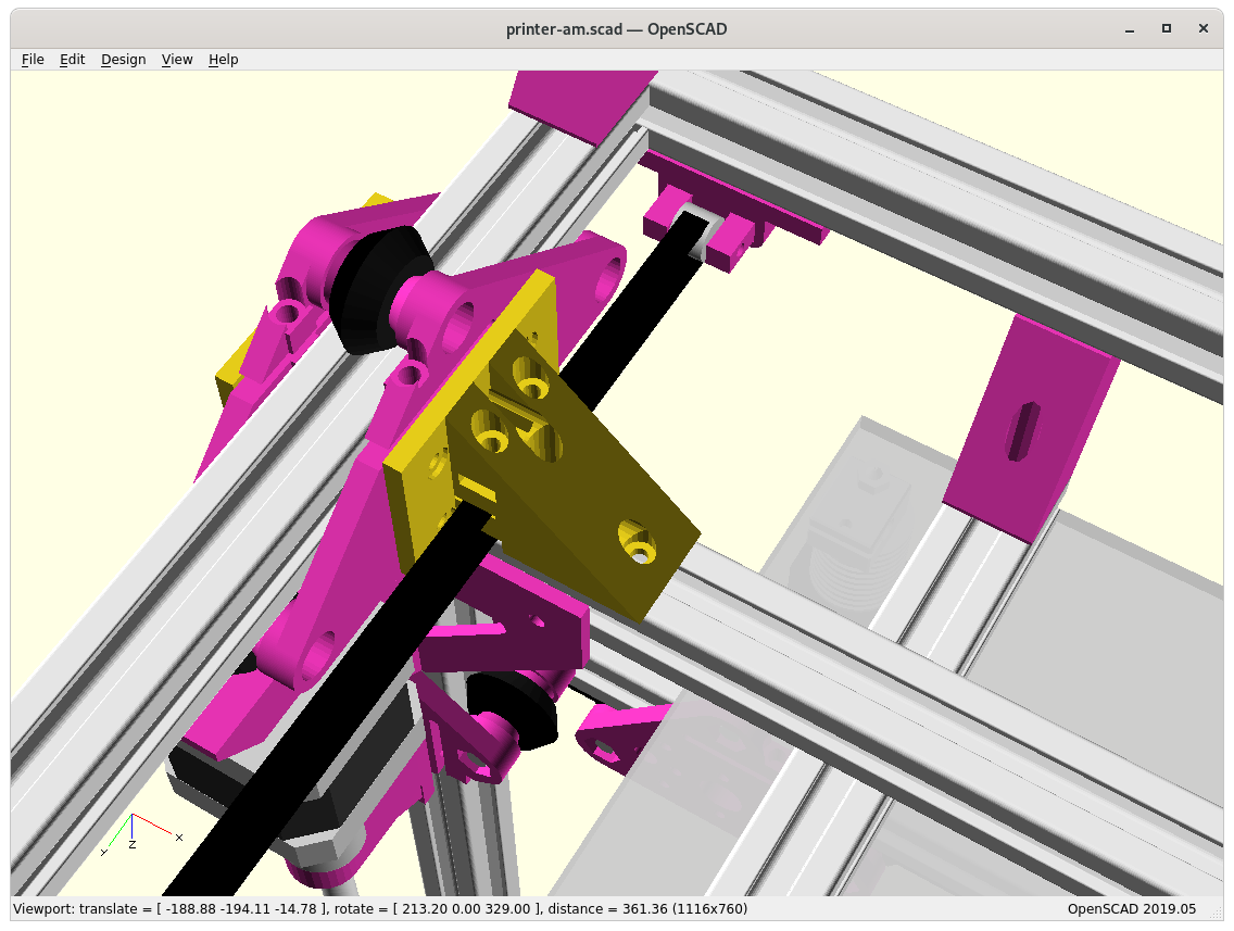
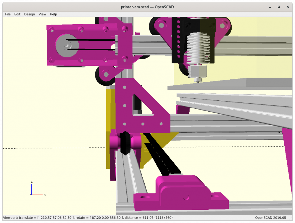
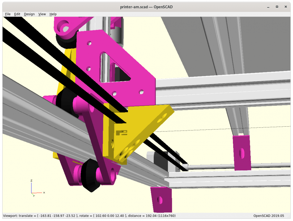
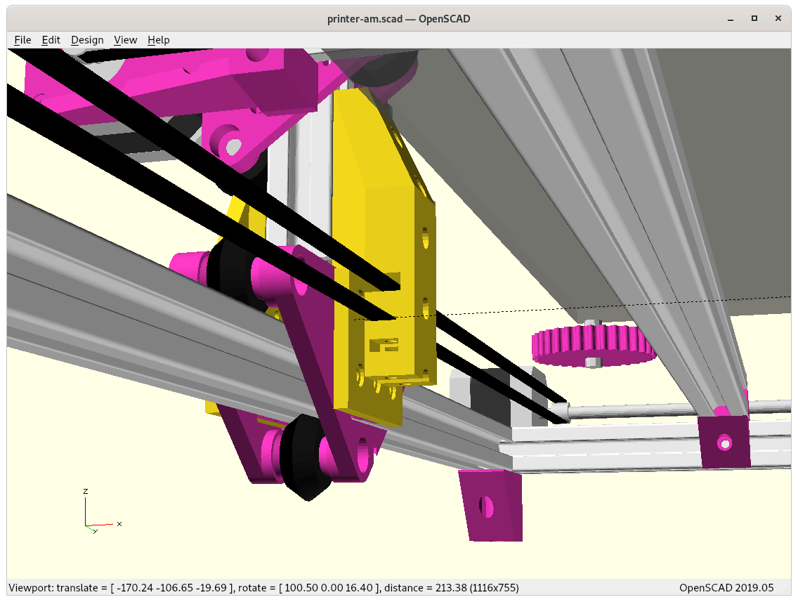
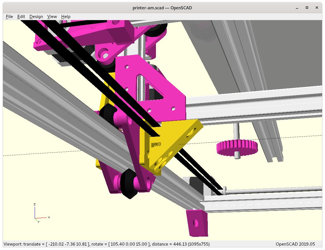
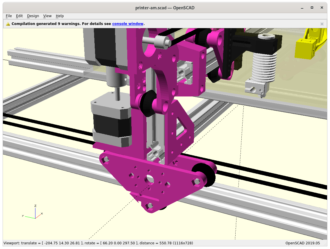
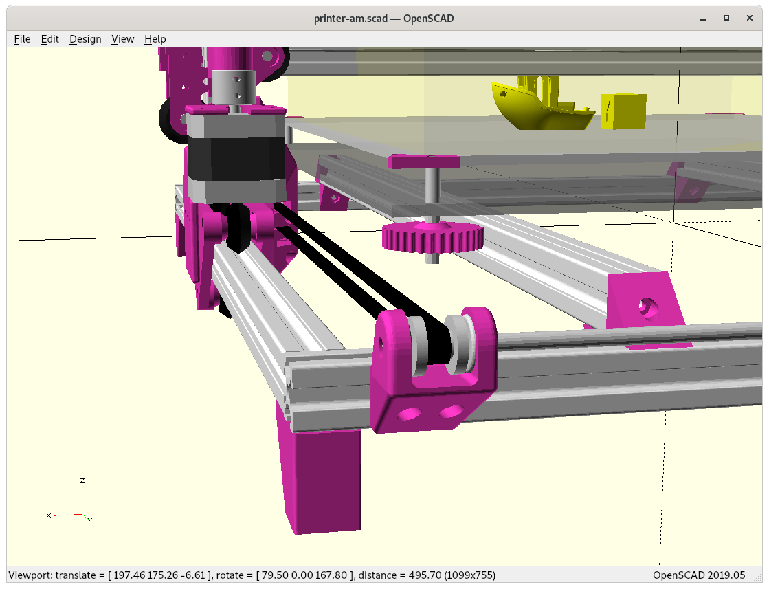
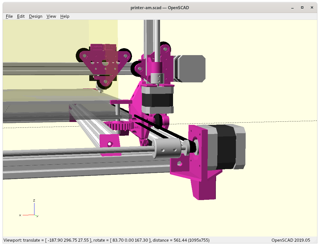
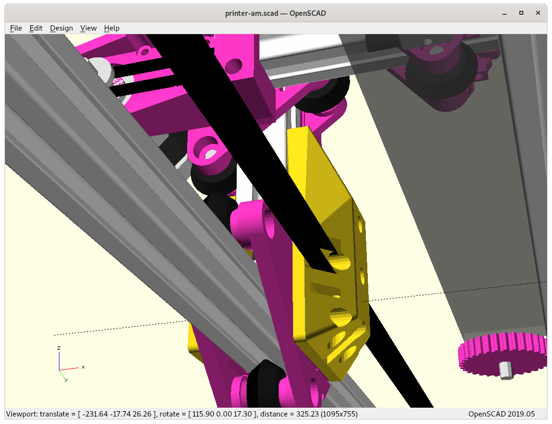
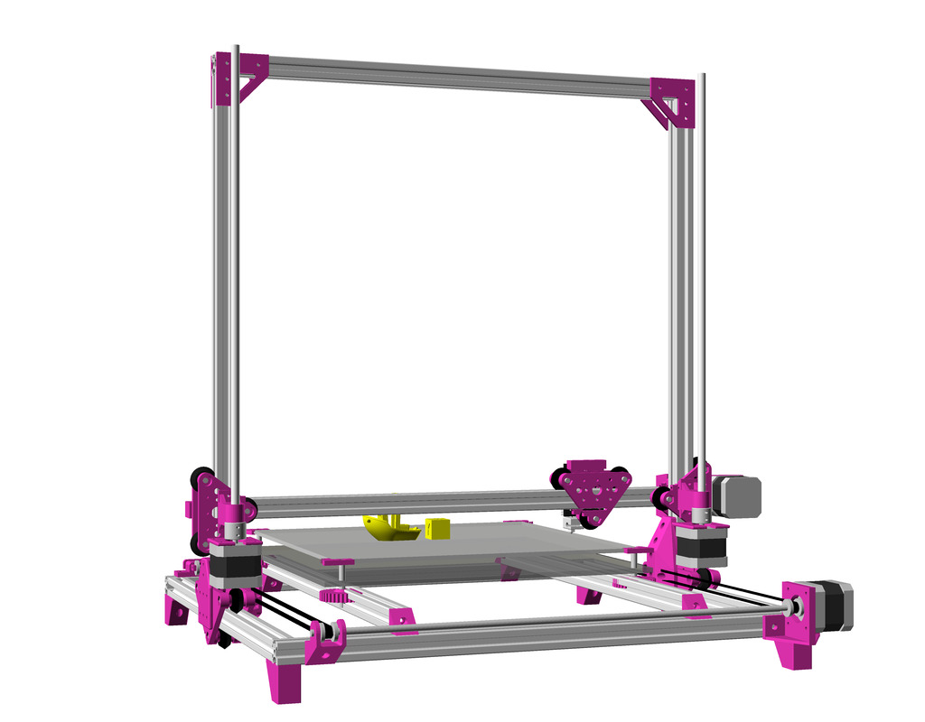
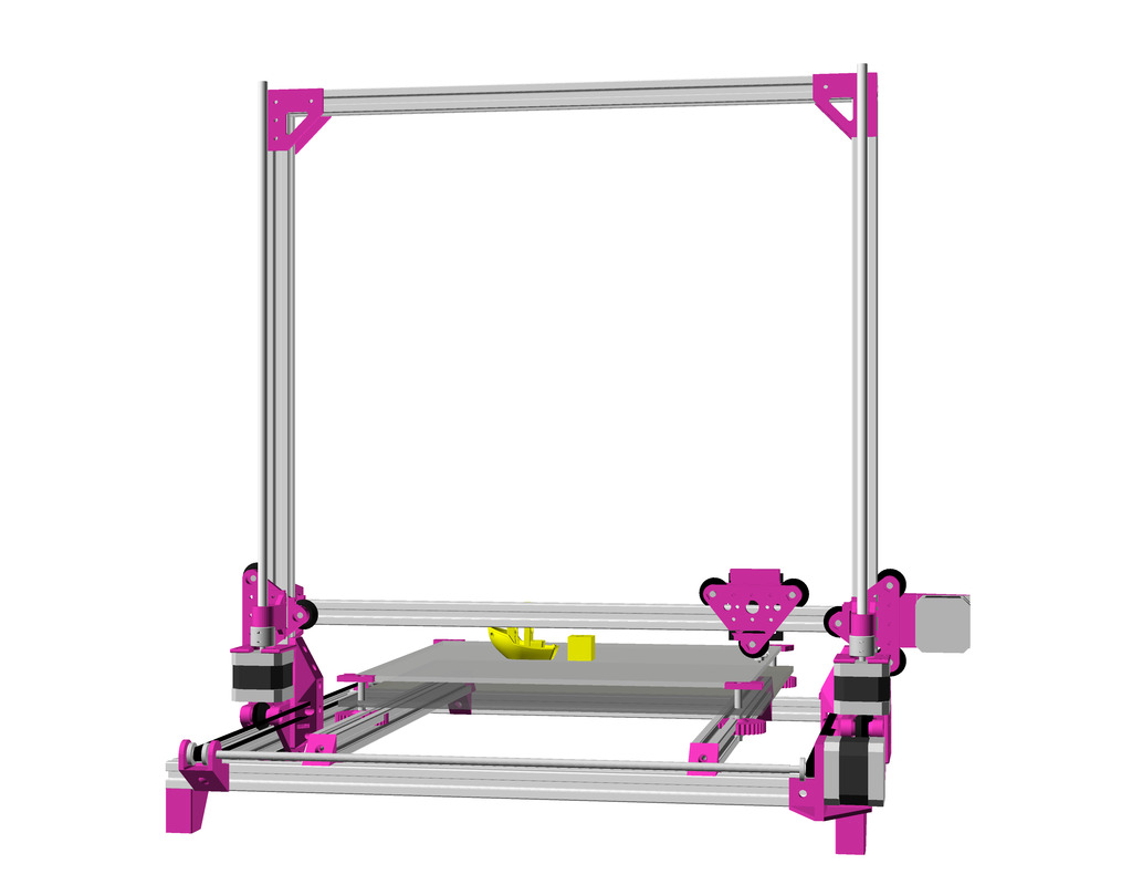
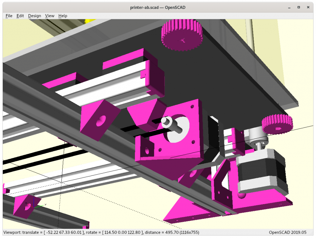
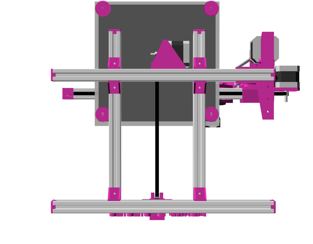
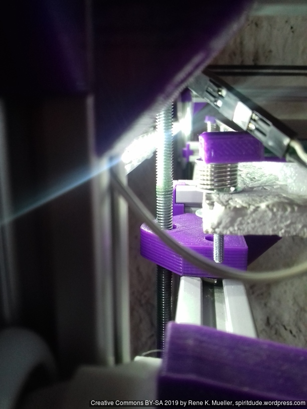
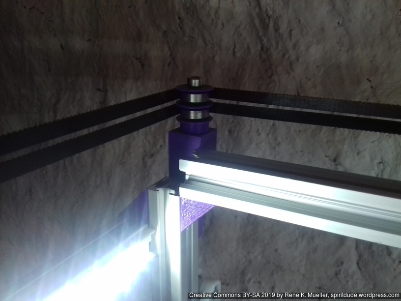
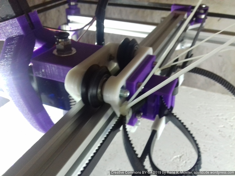
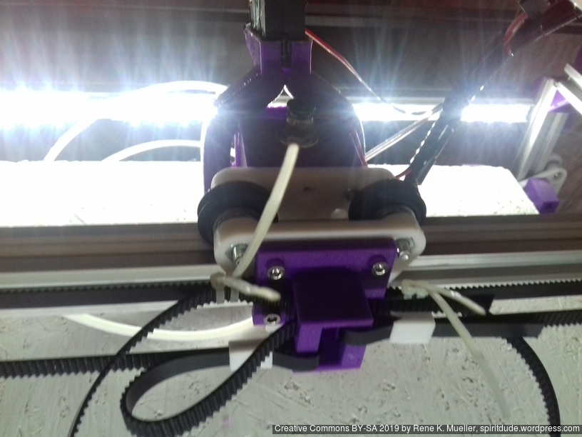
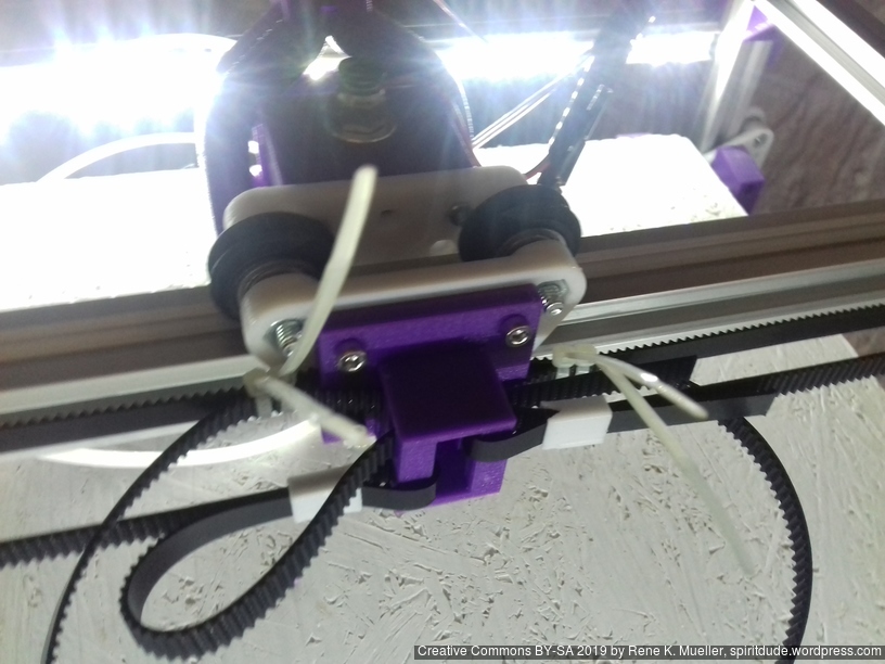
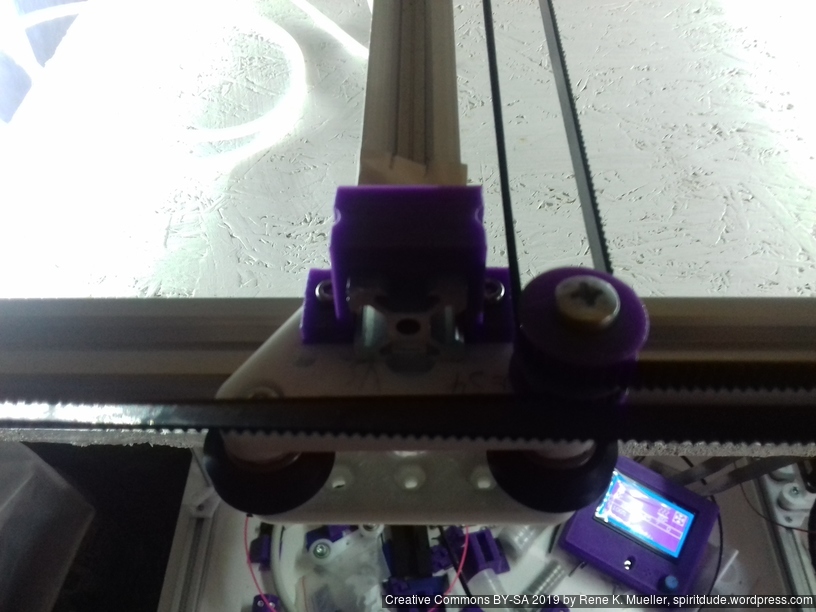
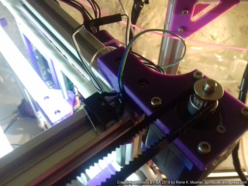
V-module: 2x printed parts,
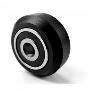
M3 & M5 screws & nuts, 3x nylon wheels
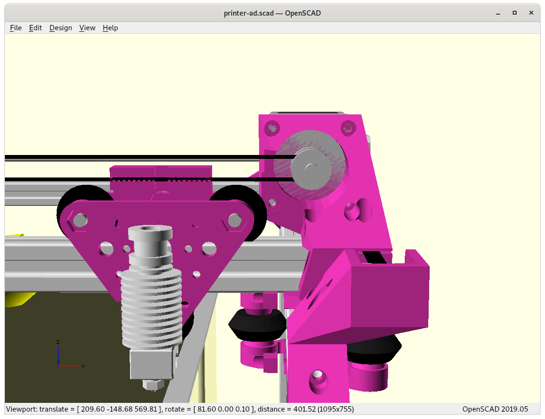
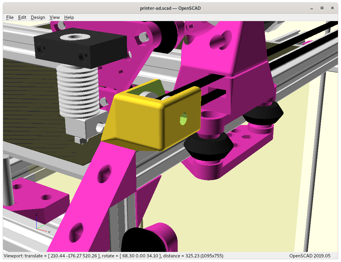
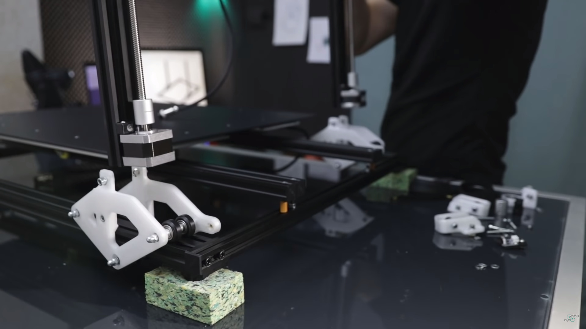
V-shaped carriage 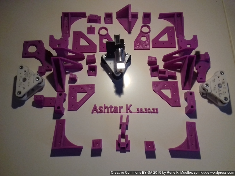
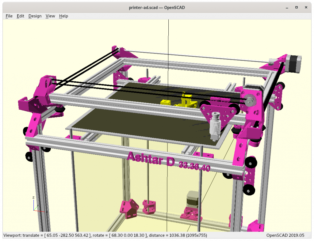
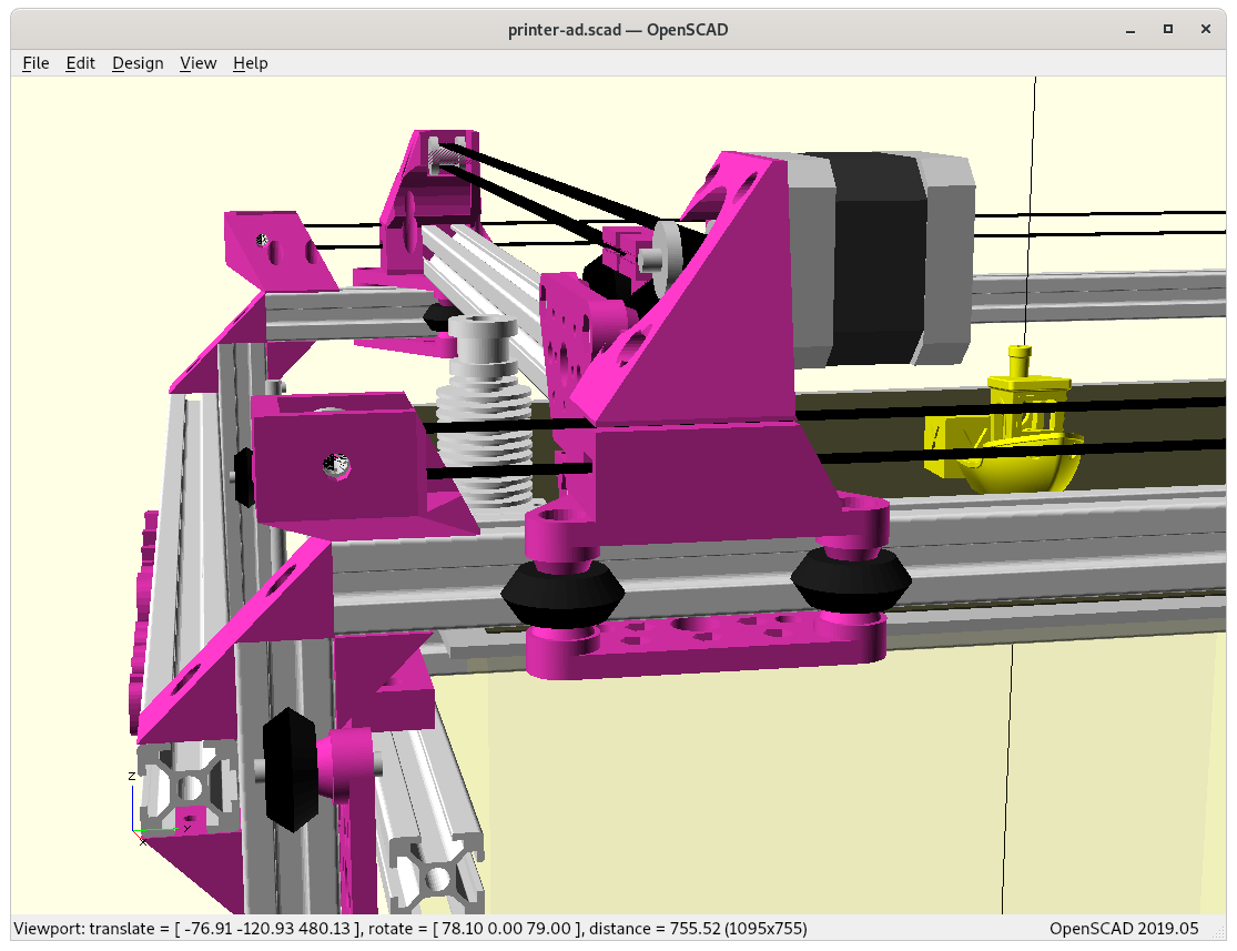
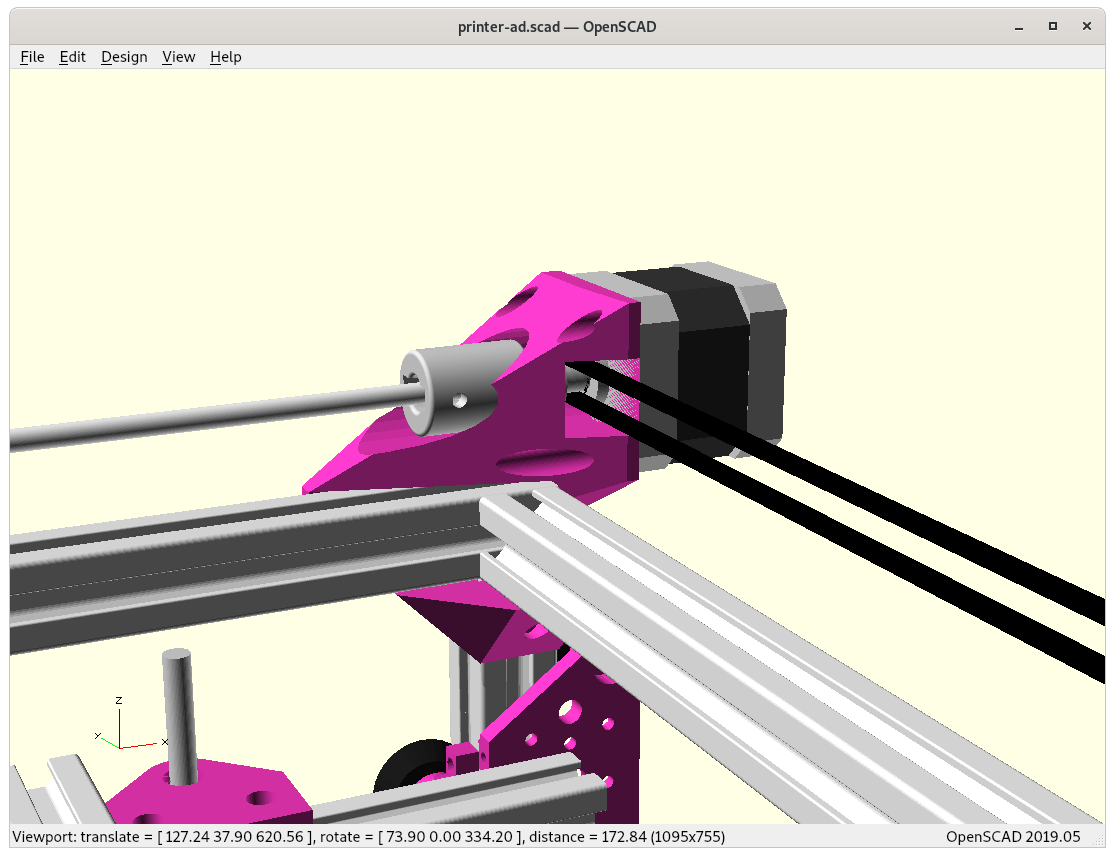
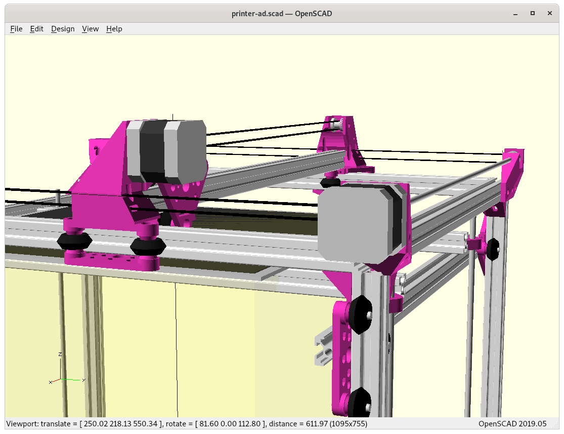
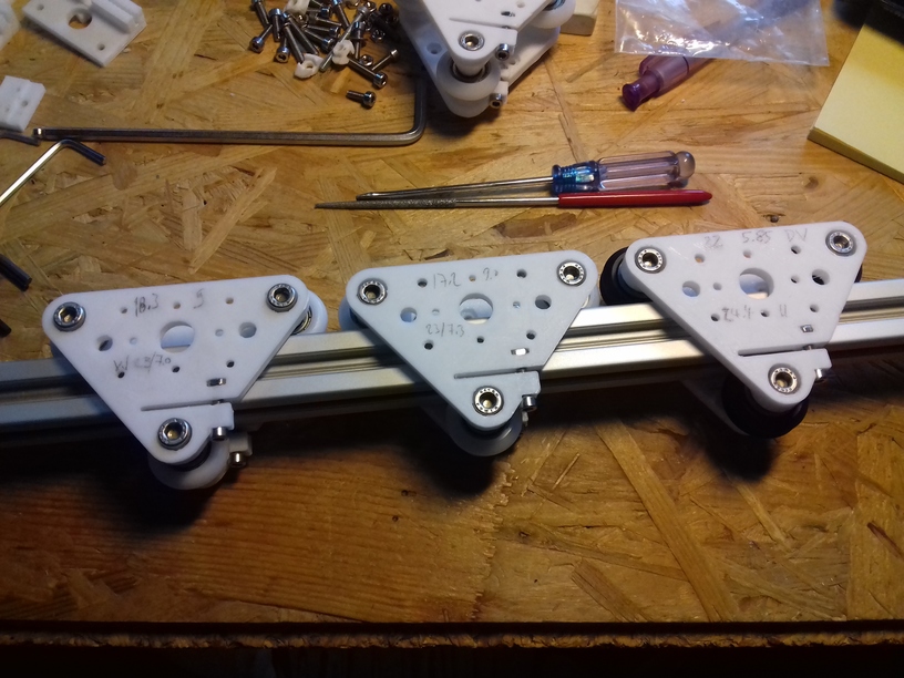
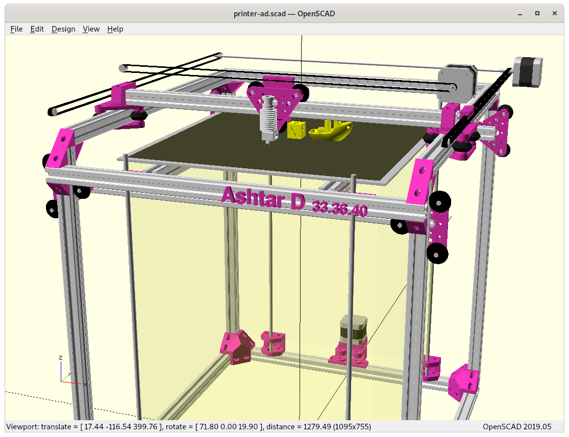
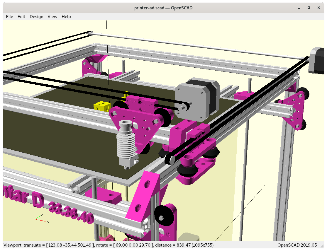
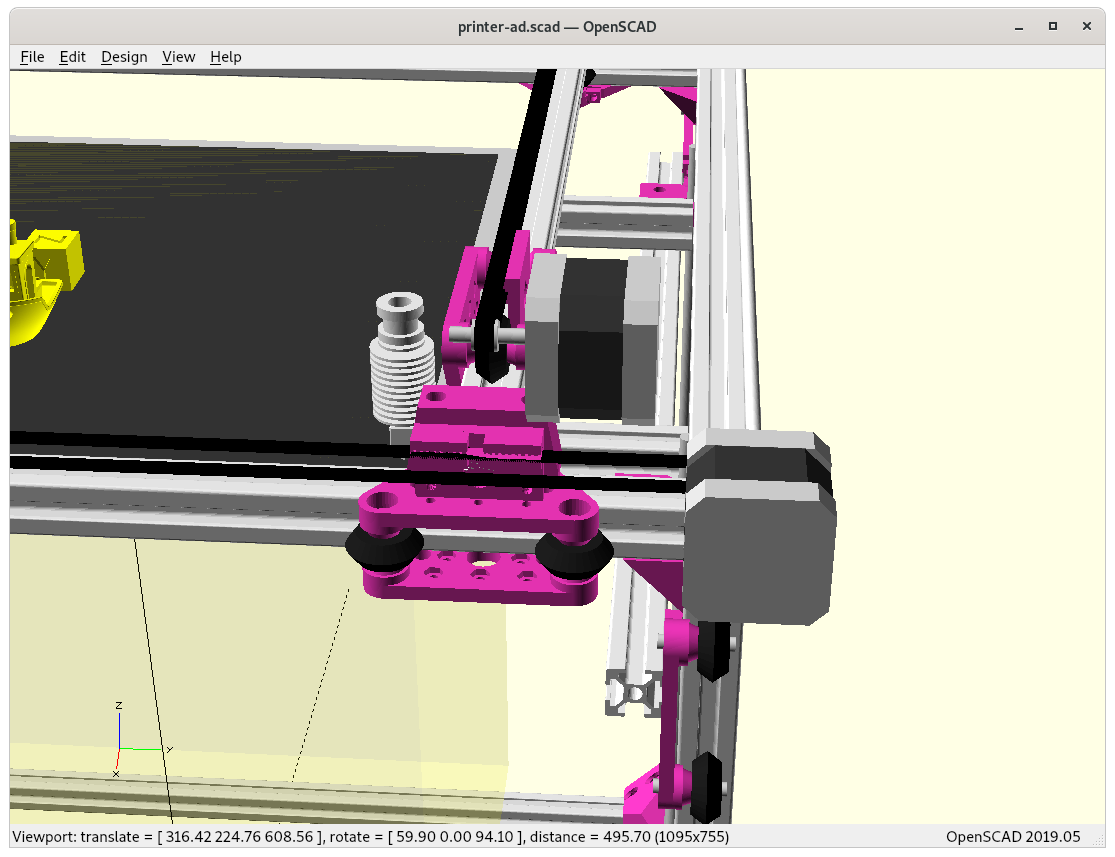
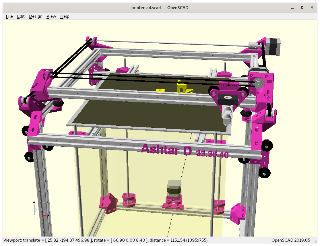
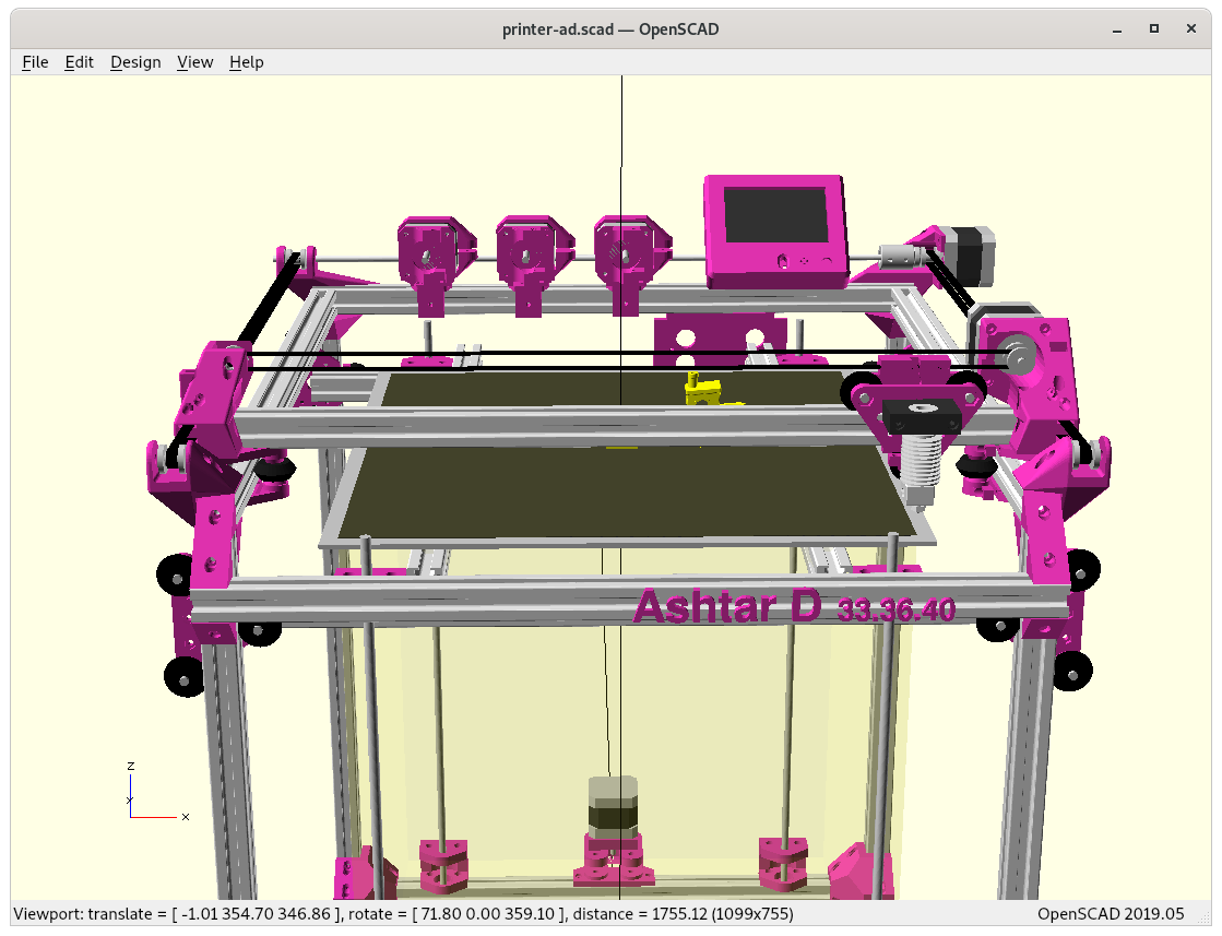
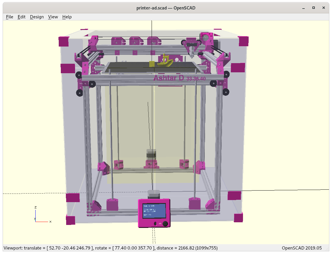
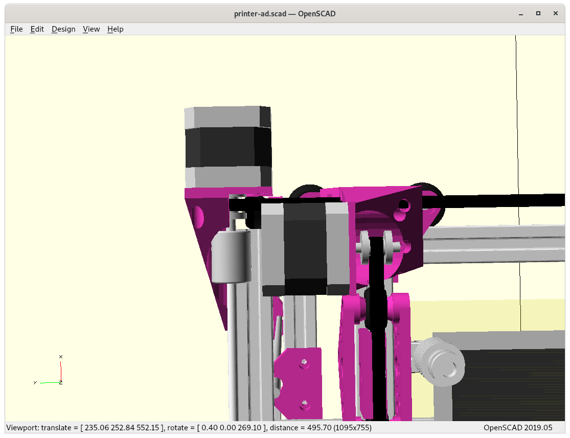
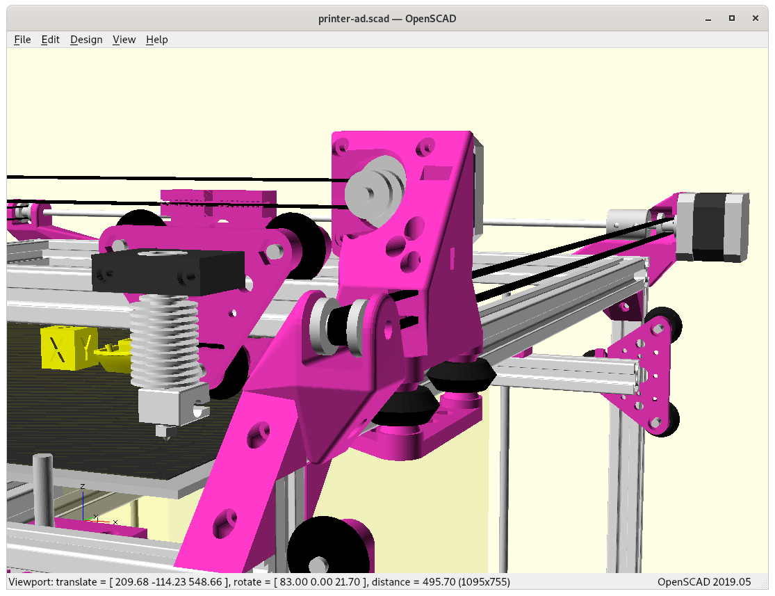
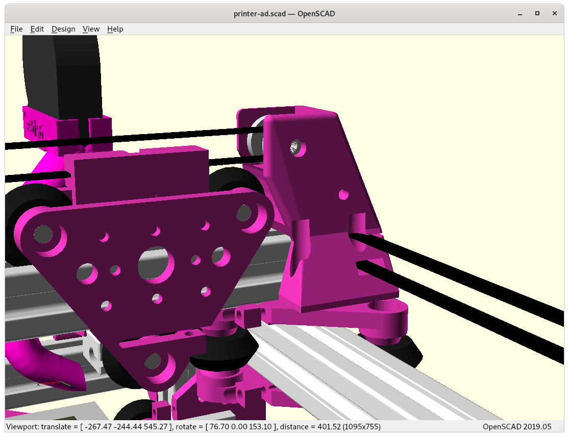
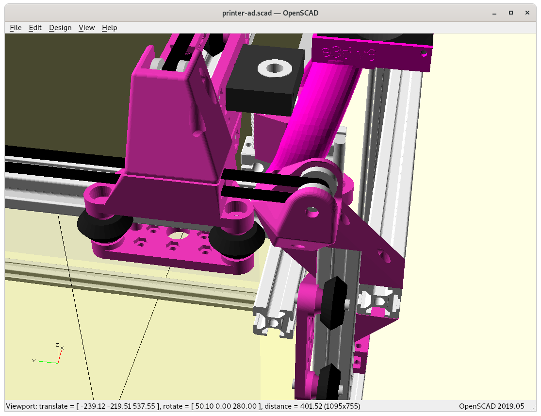
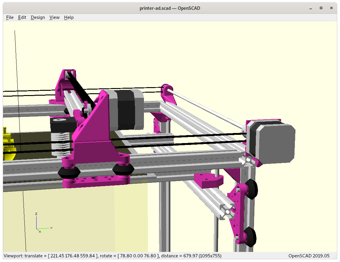
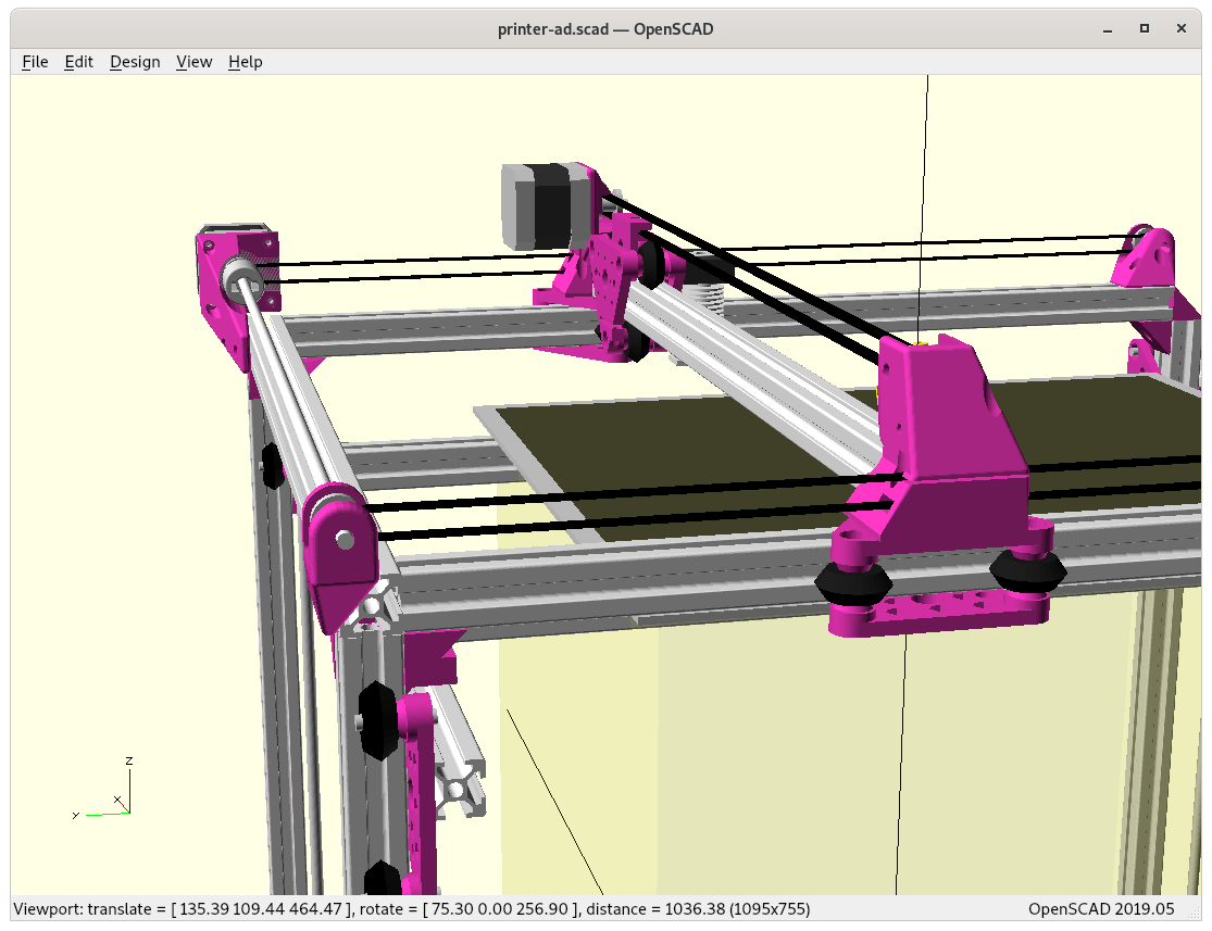
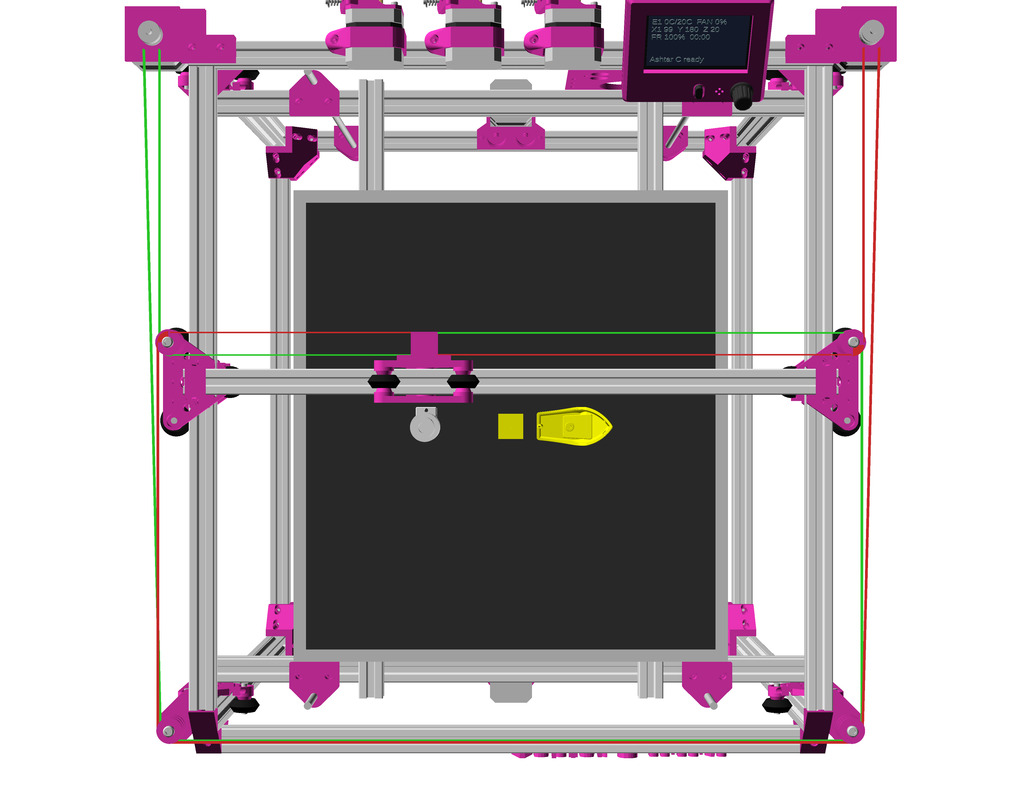
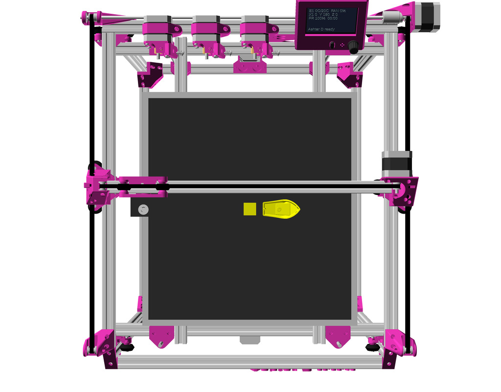
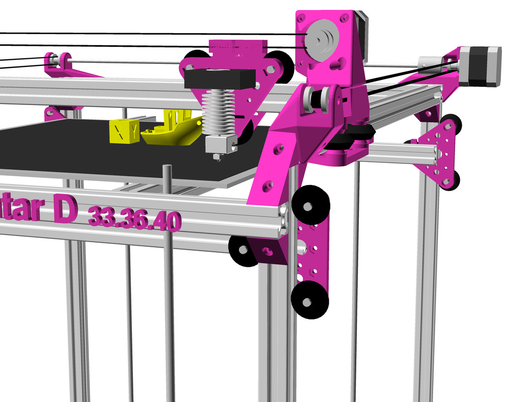
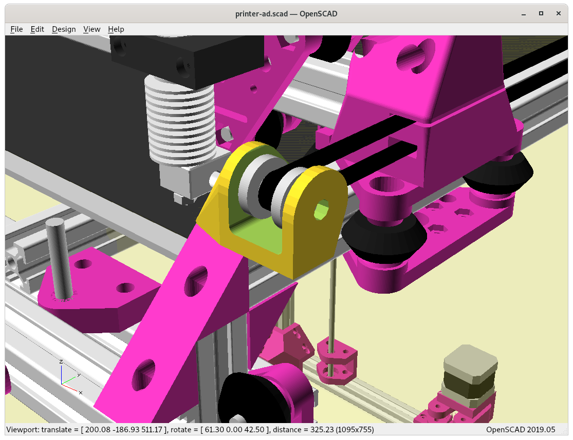
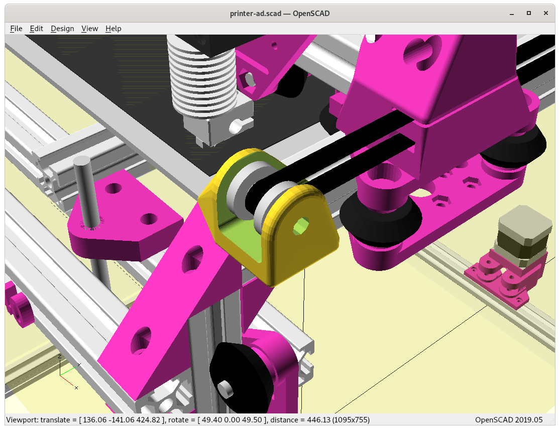
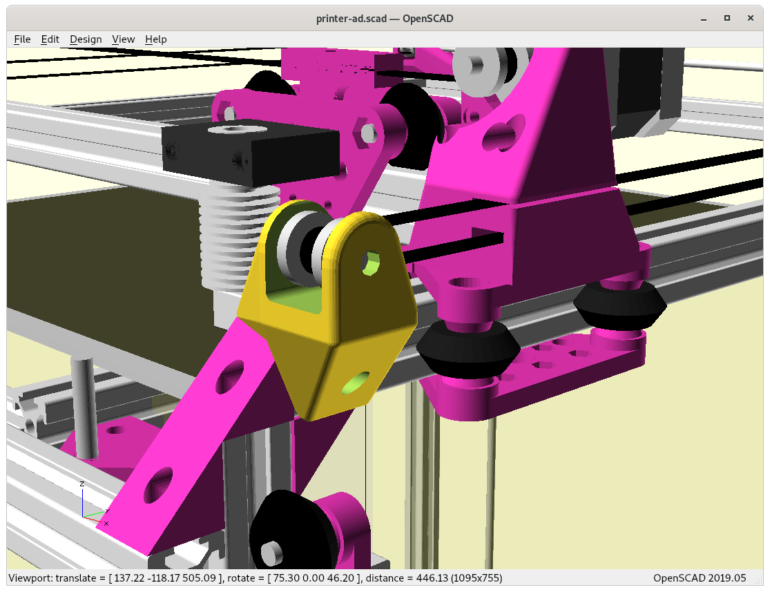
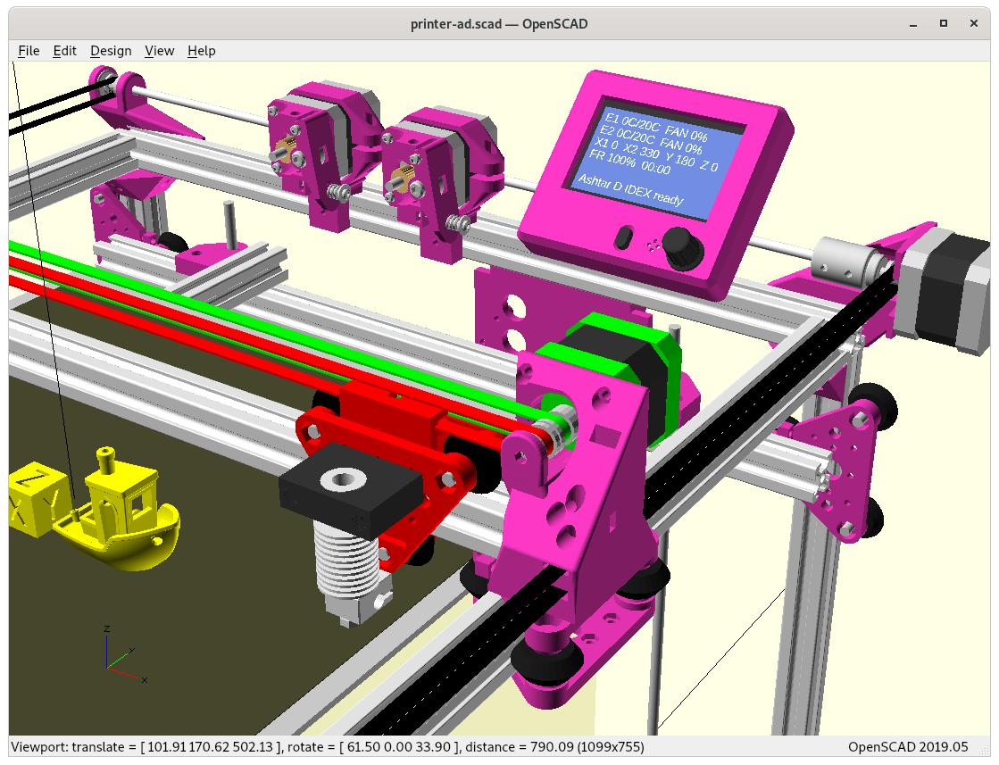
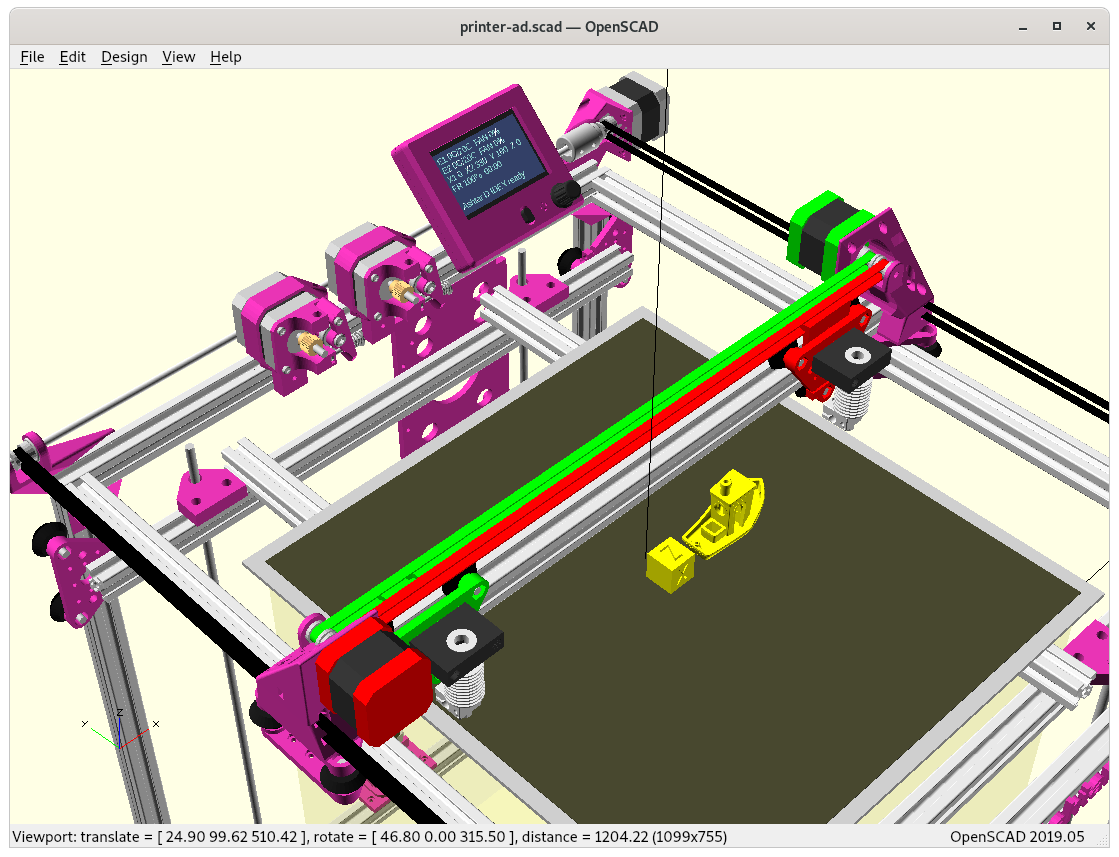
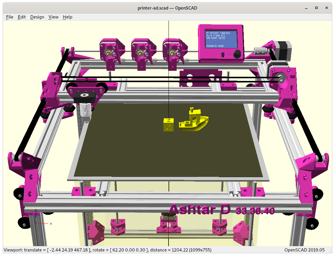
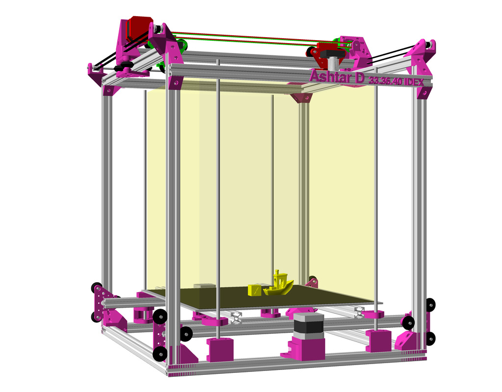
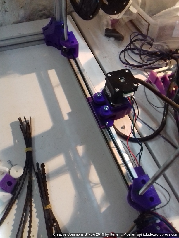
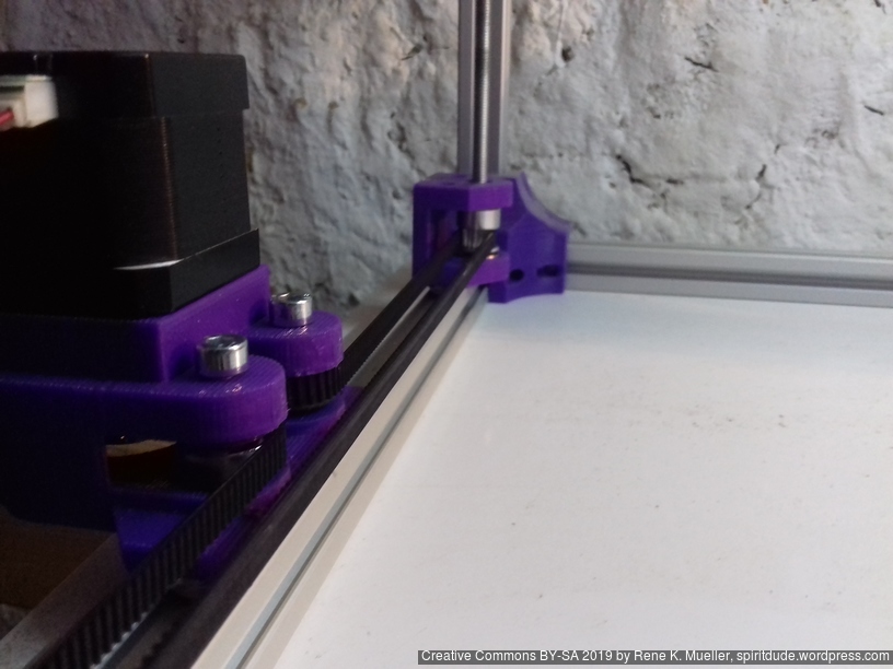
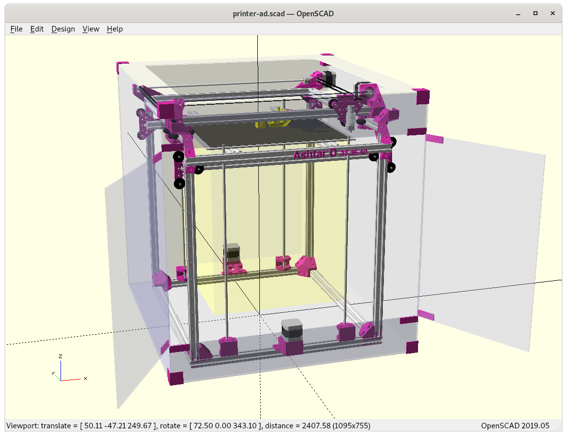
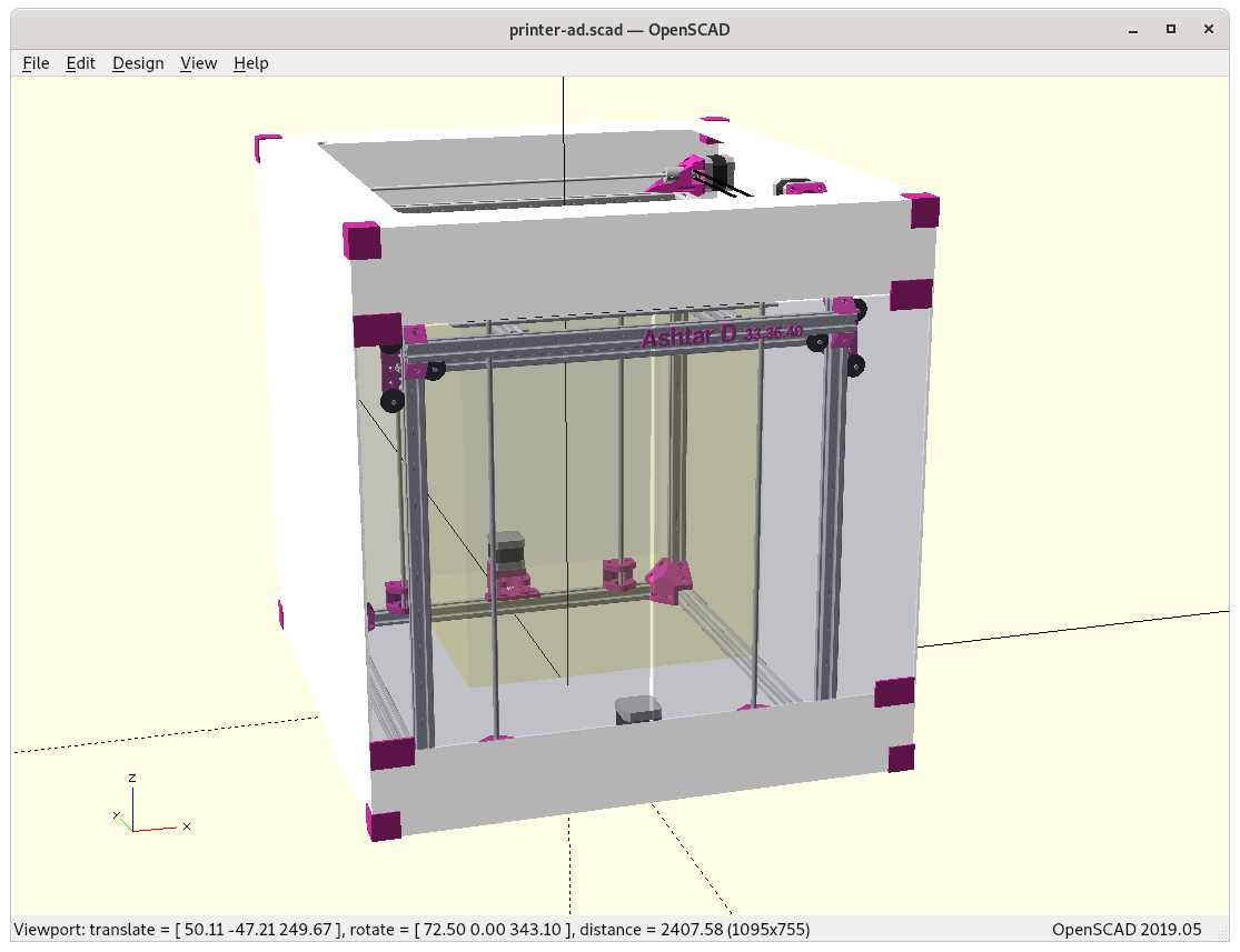
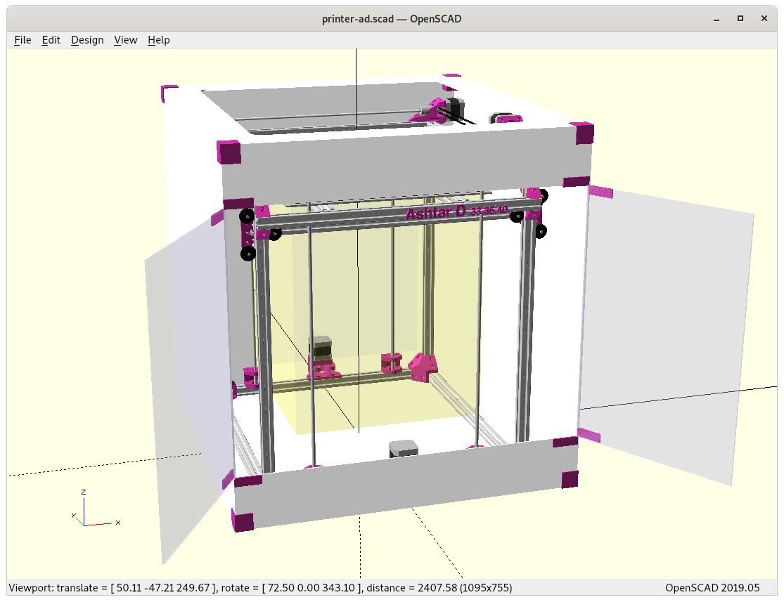
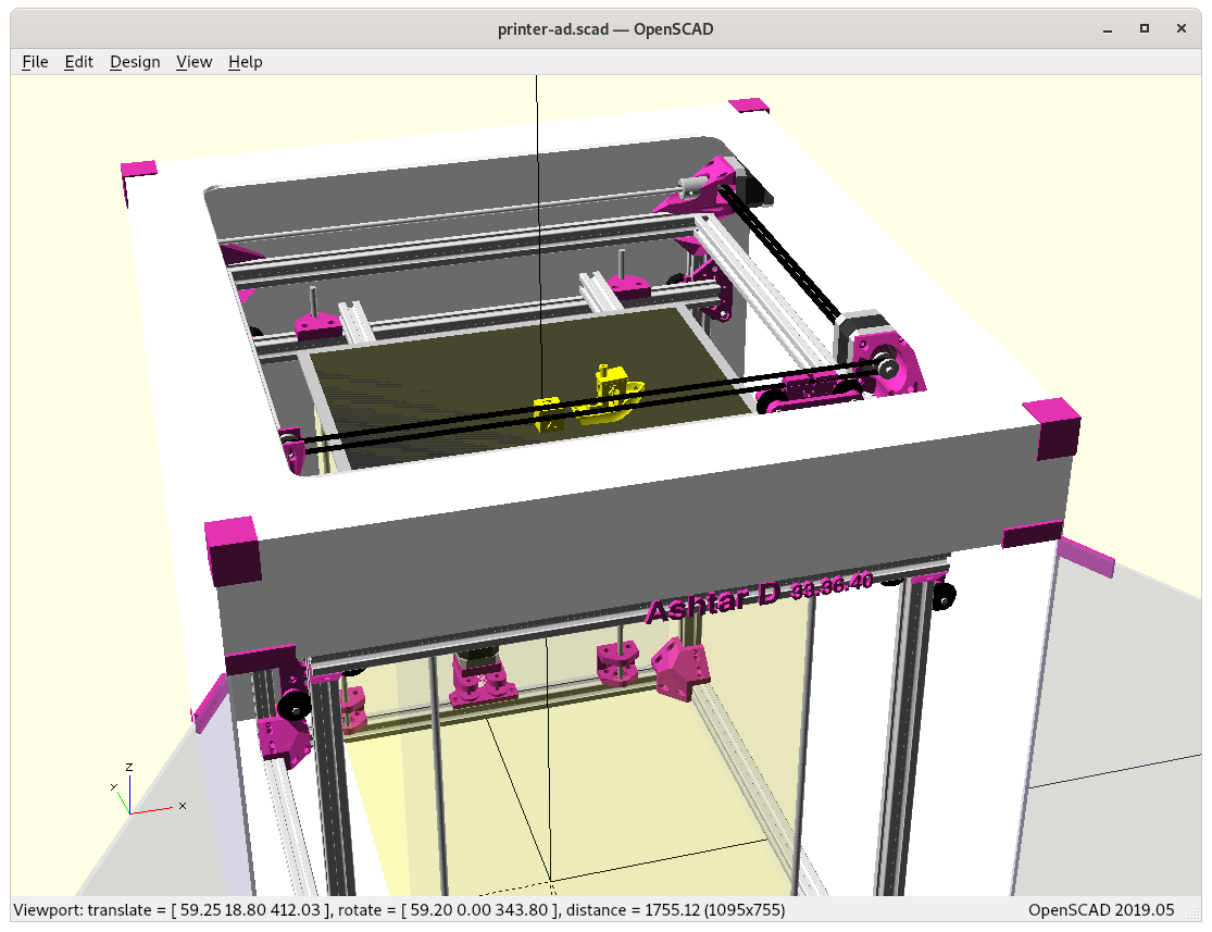
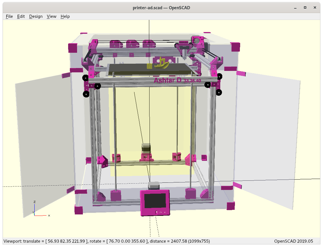
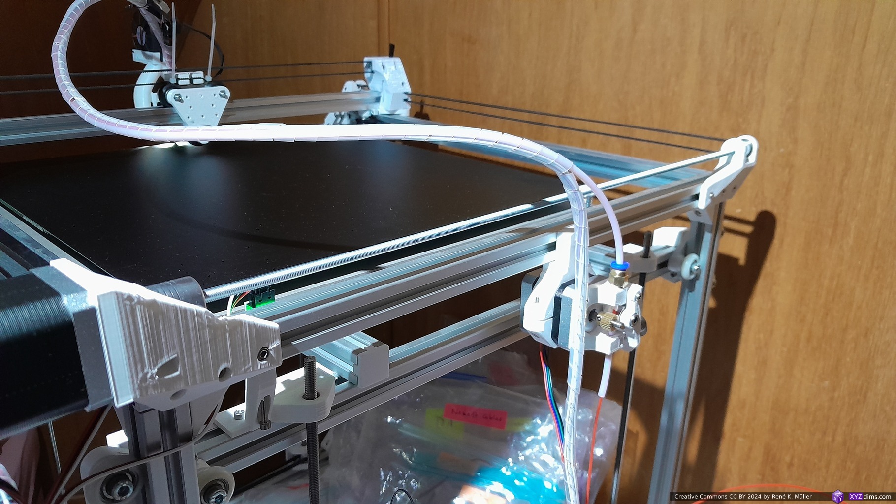
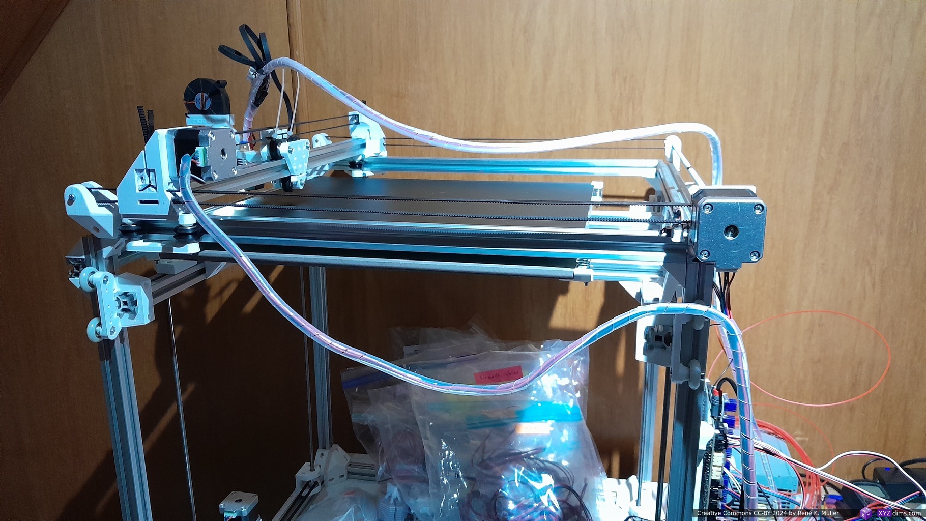
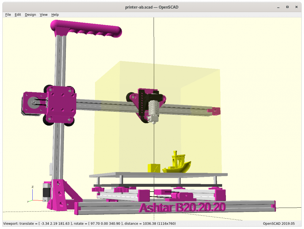
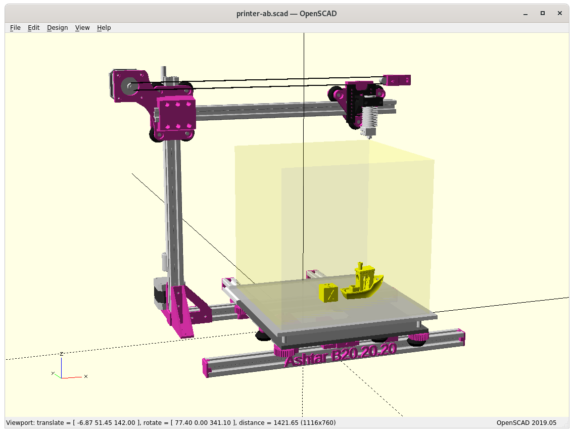
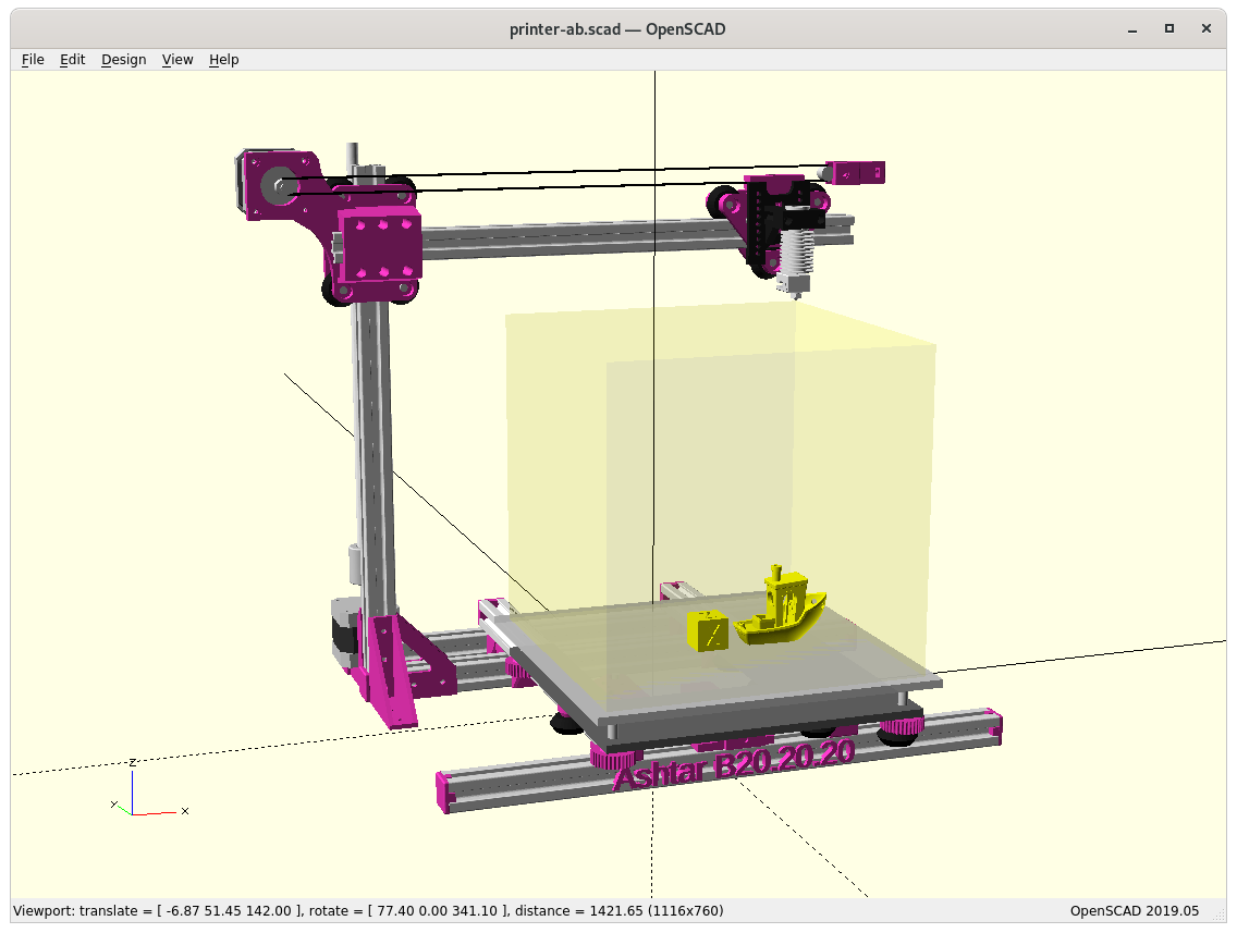
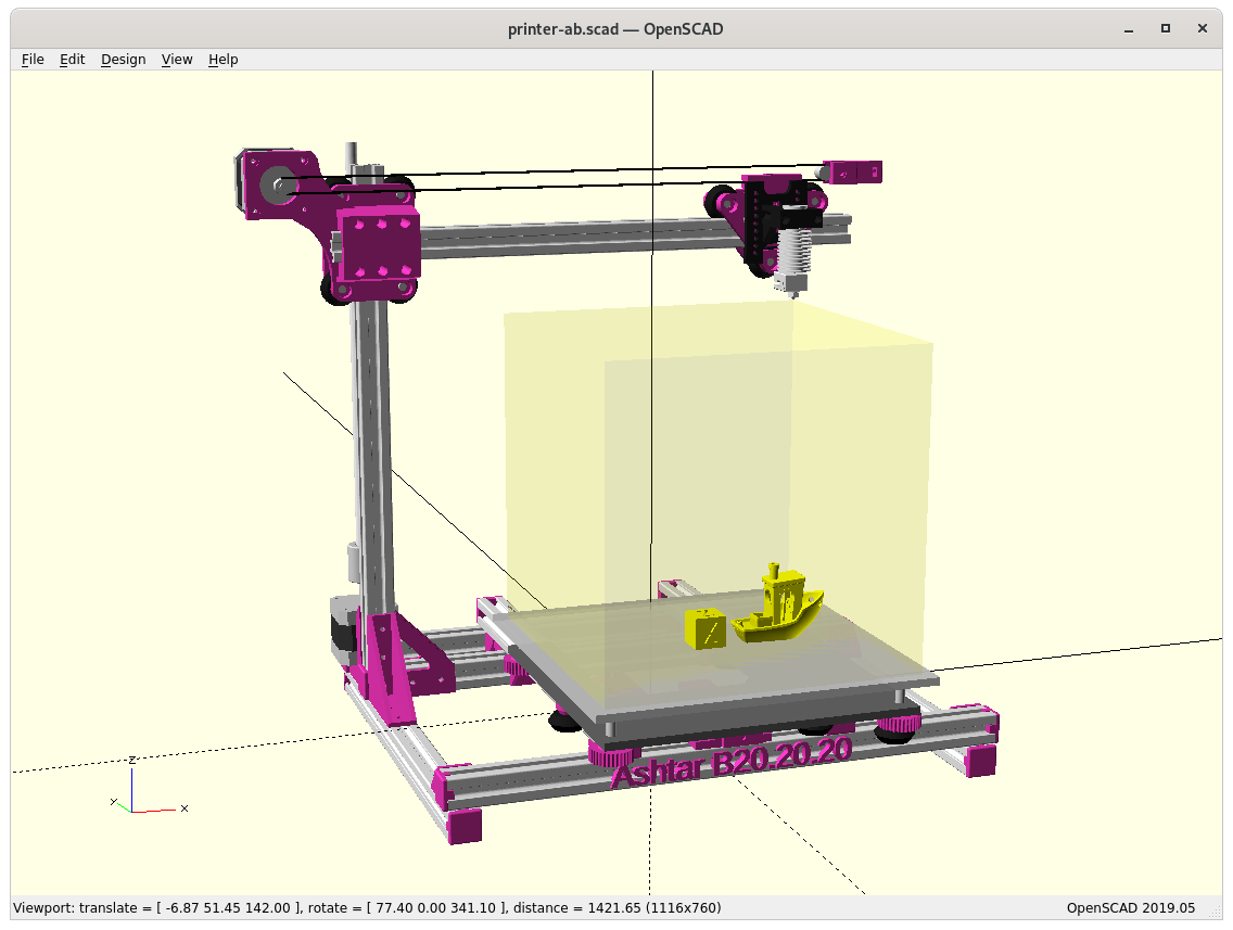
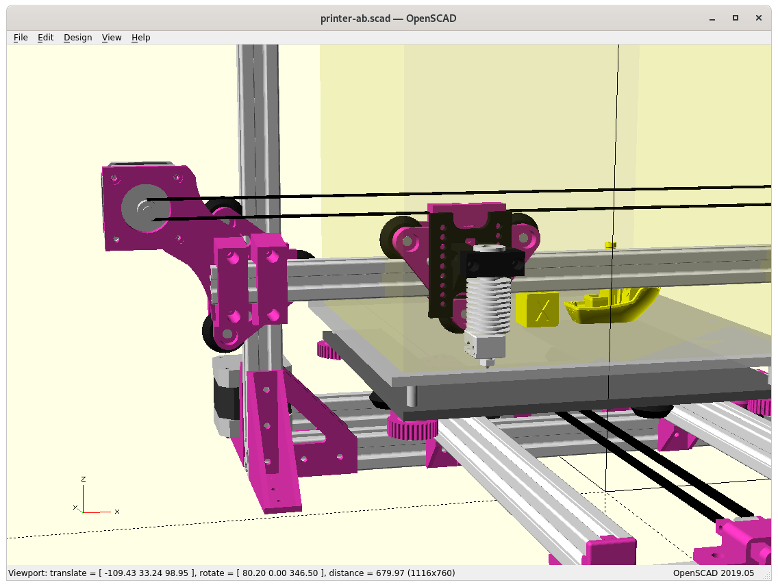
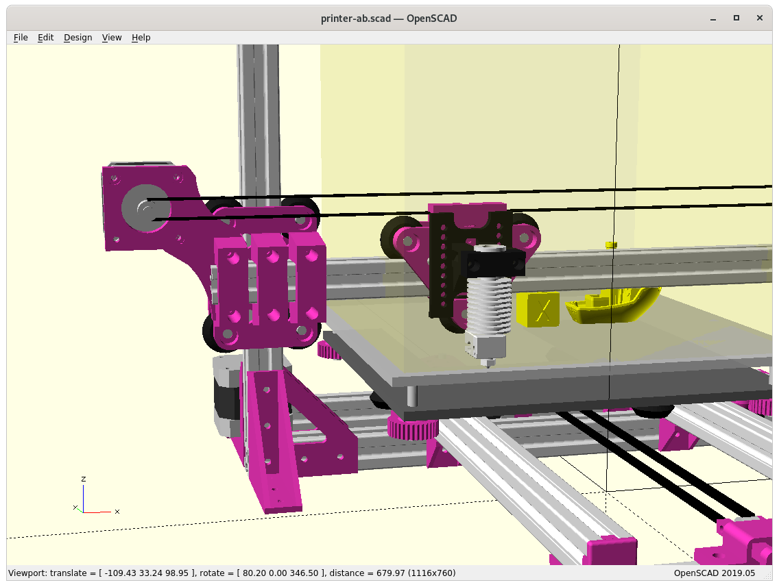
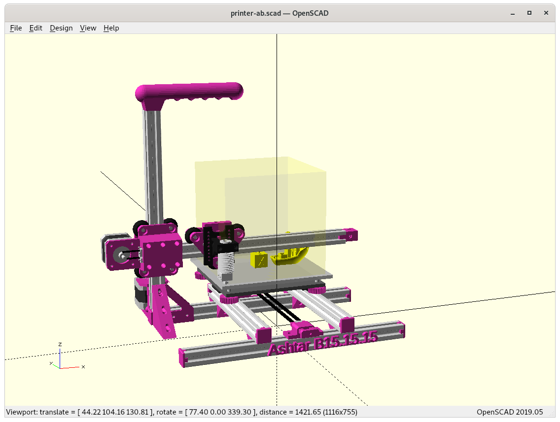
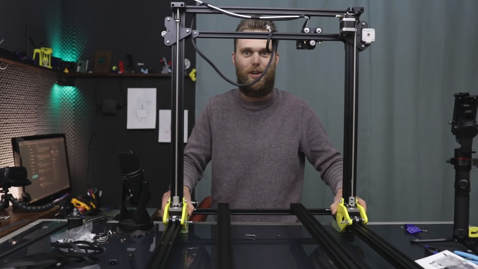
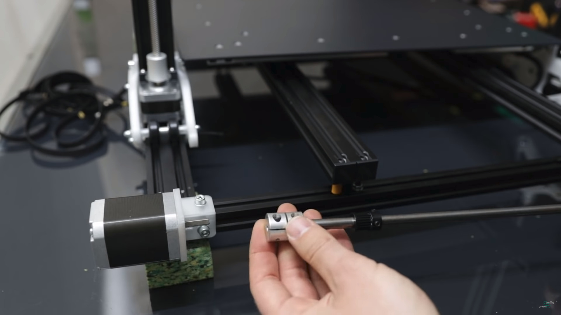
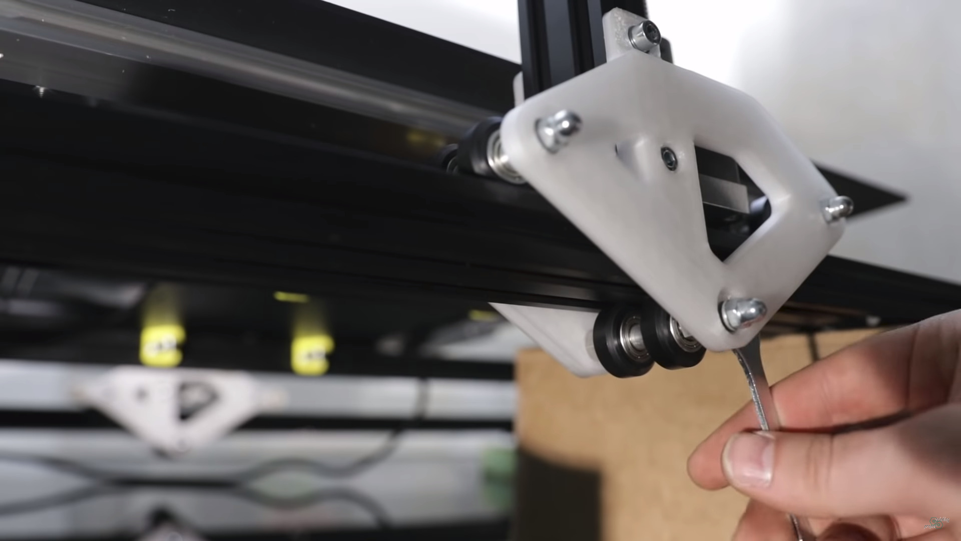
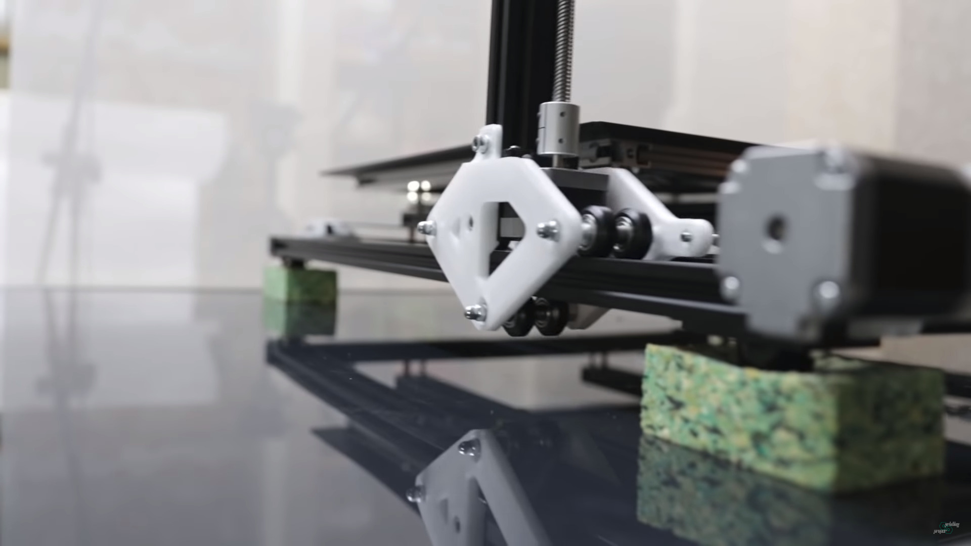
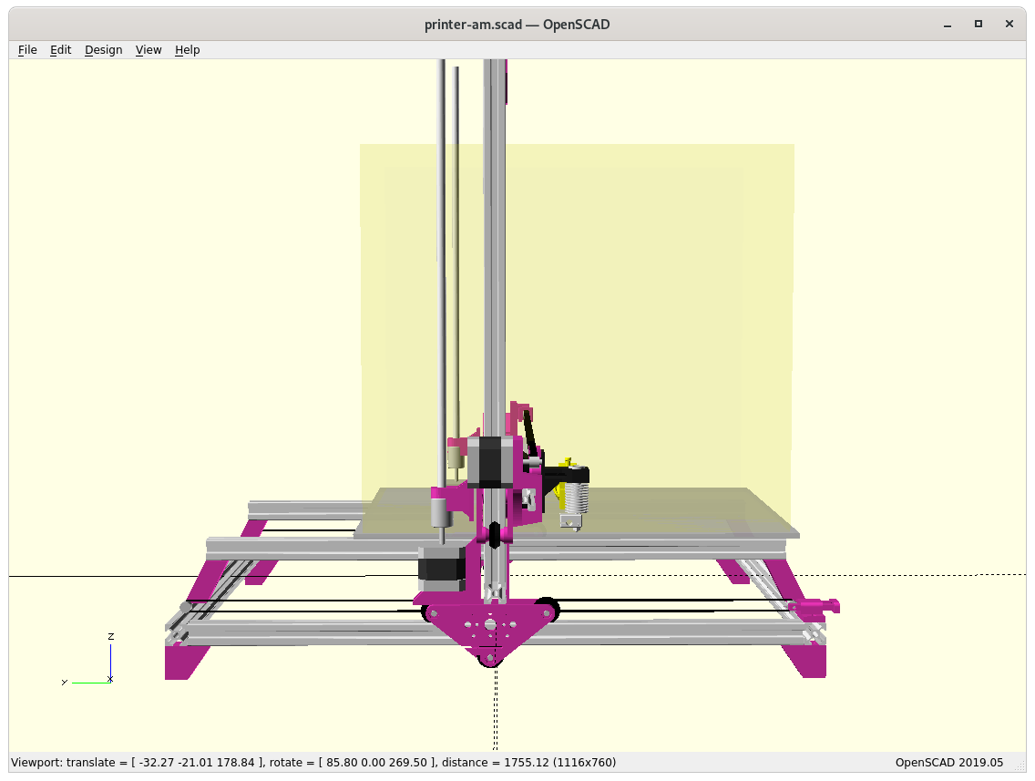
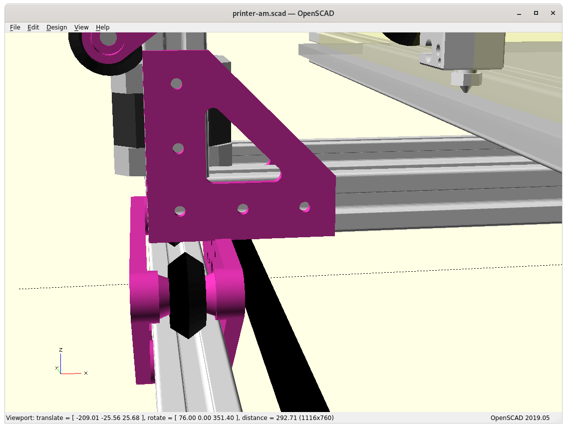
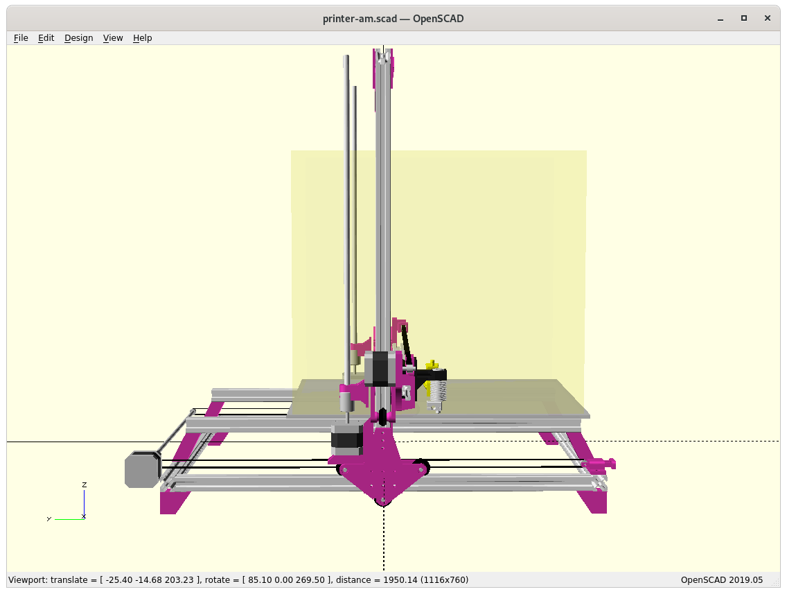
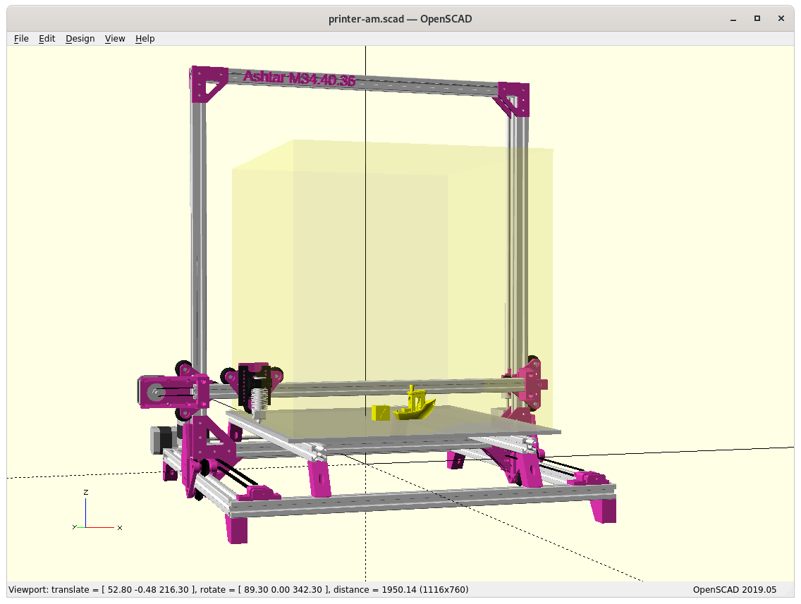
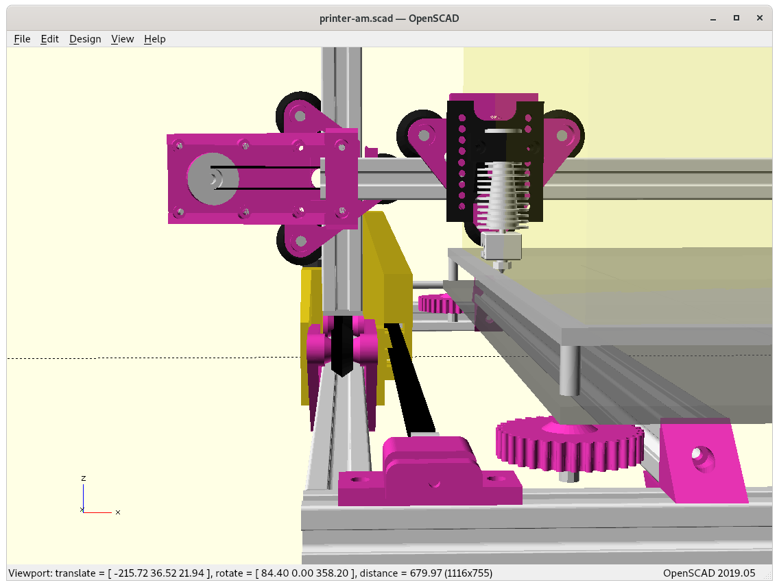
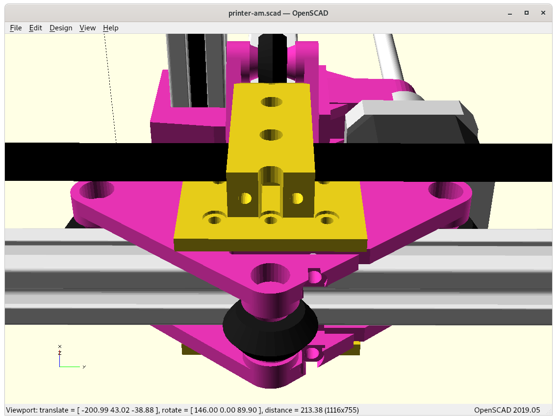
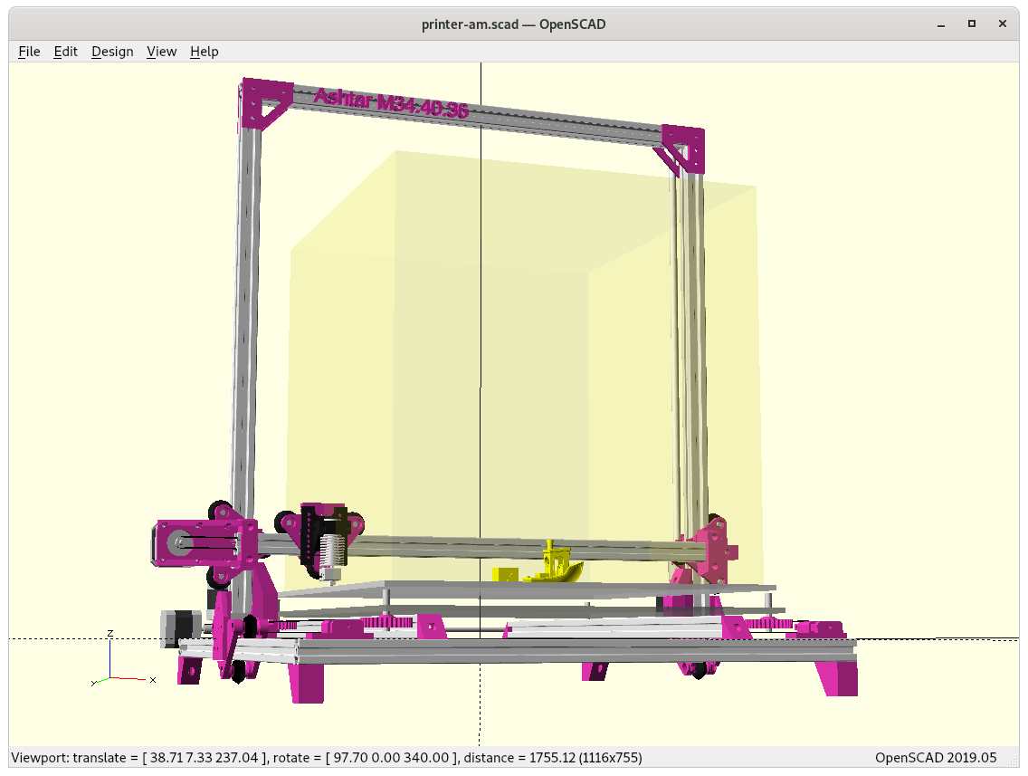
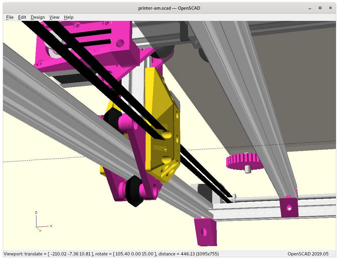
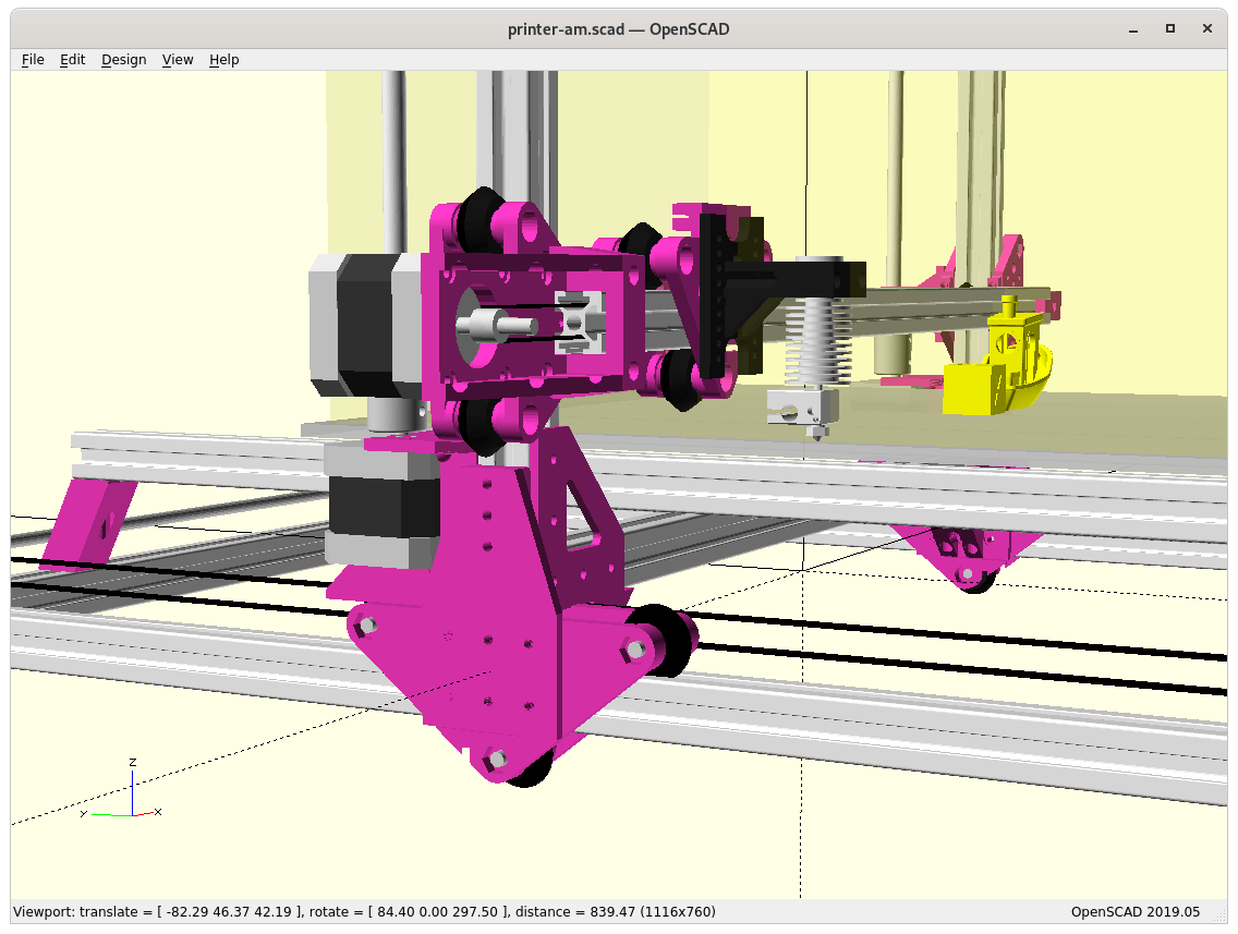
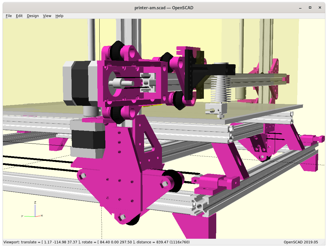
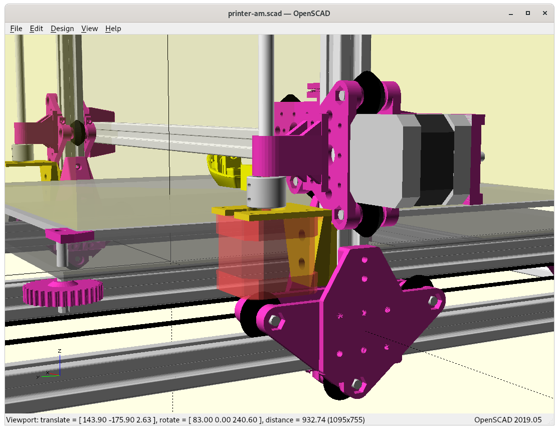
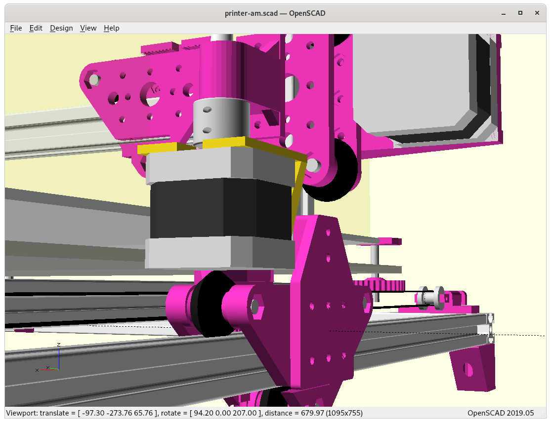
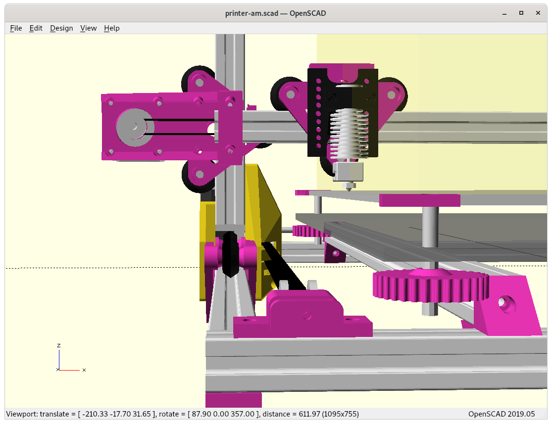
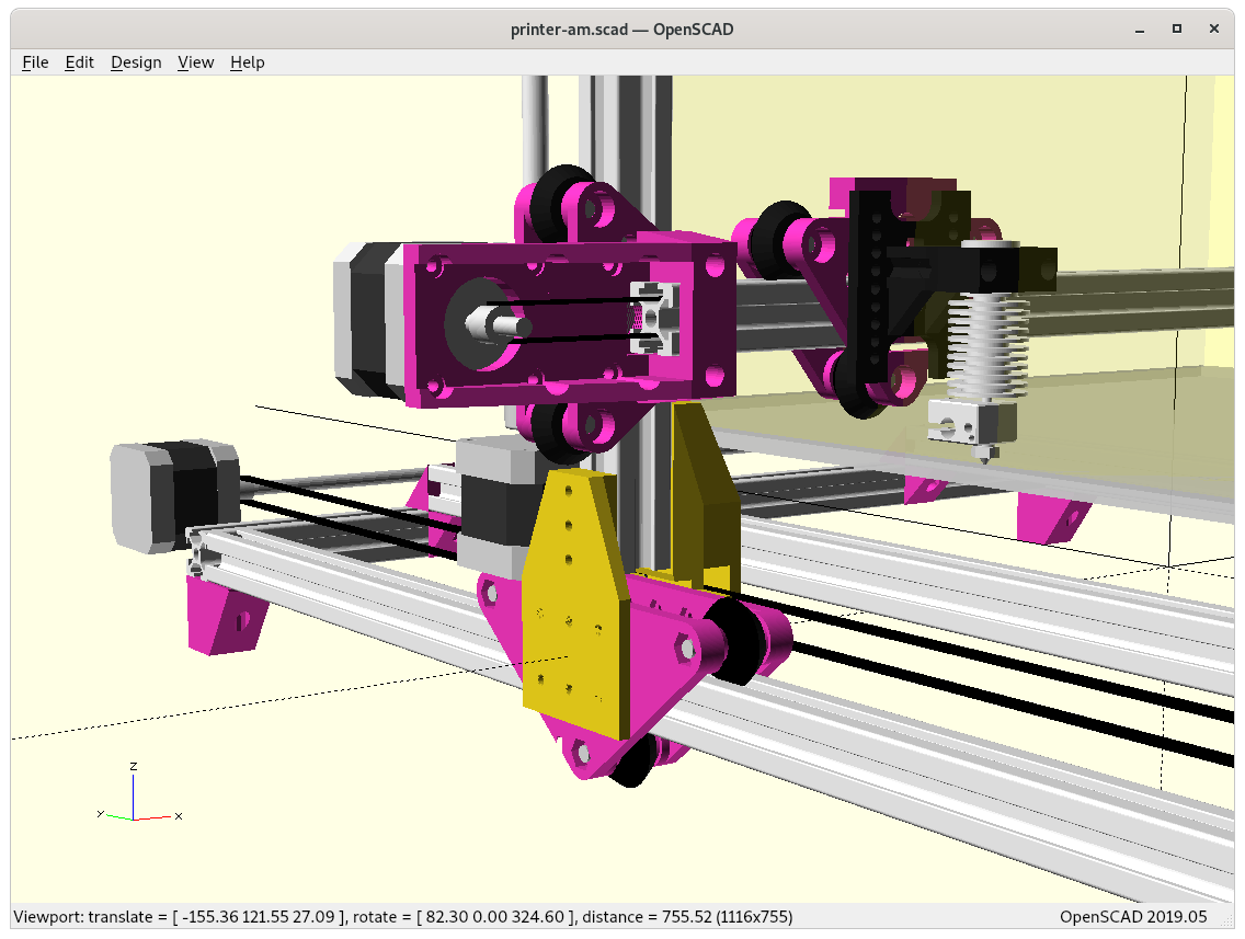
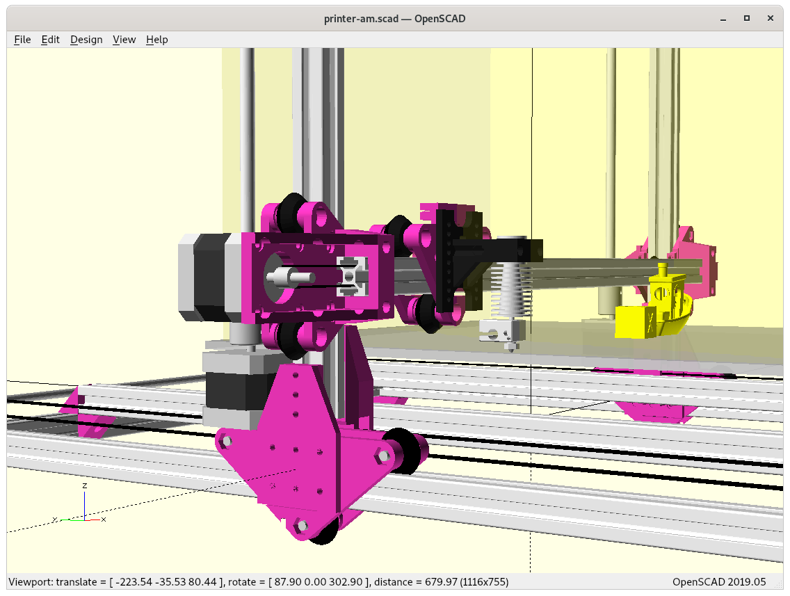
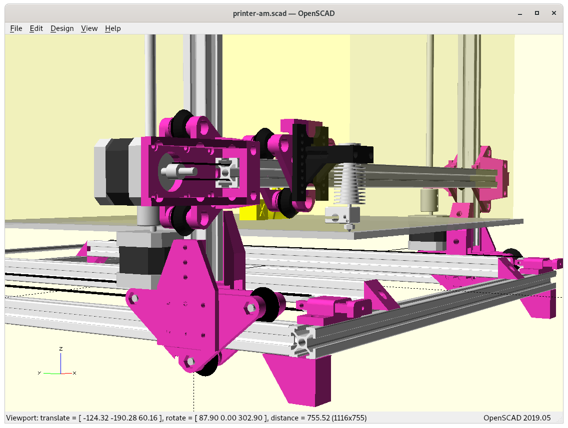
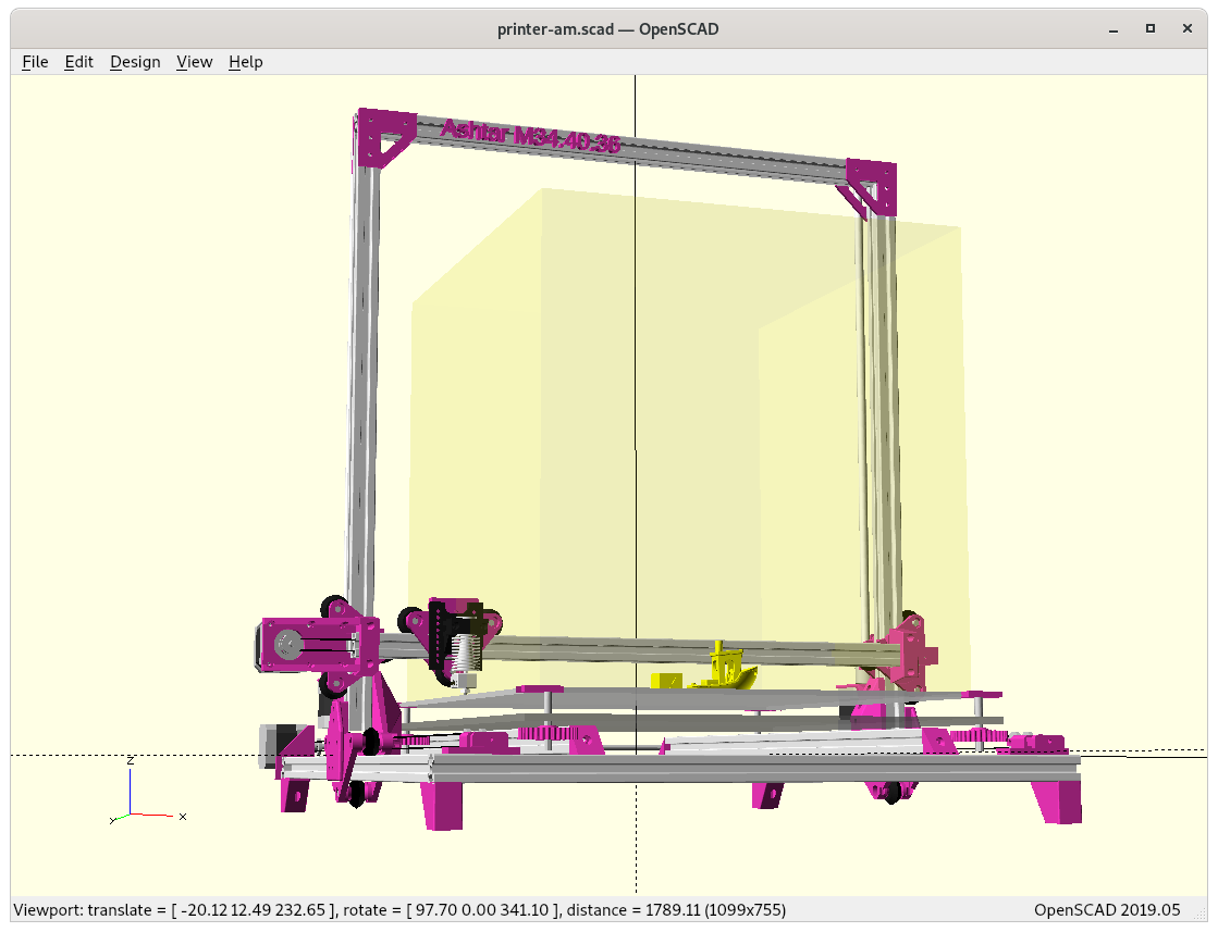
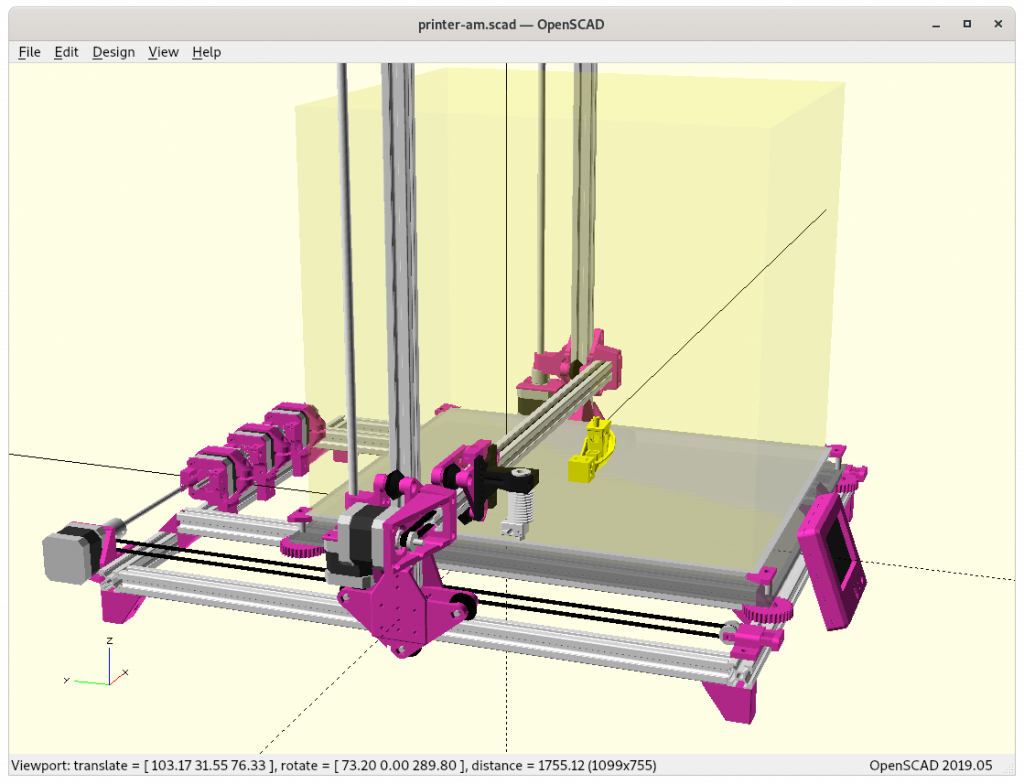
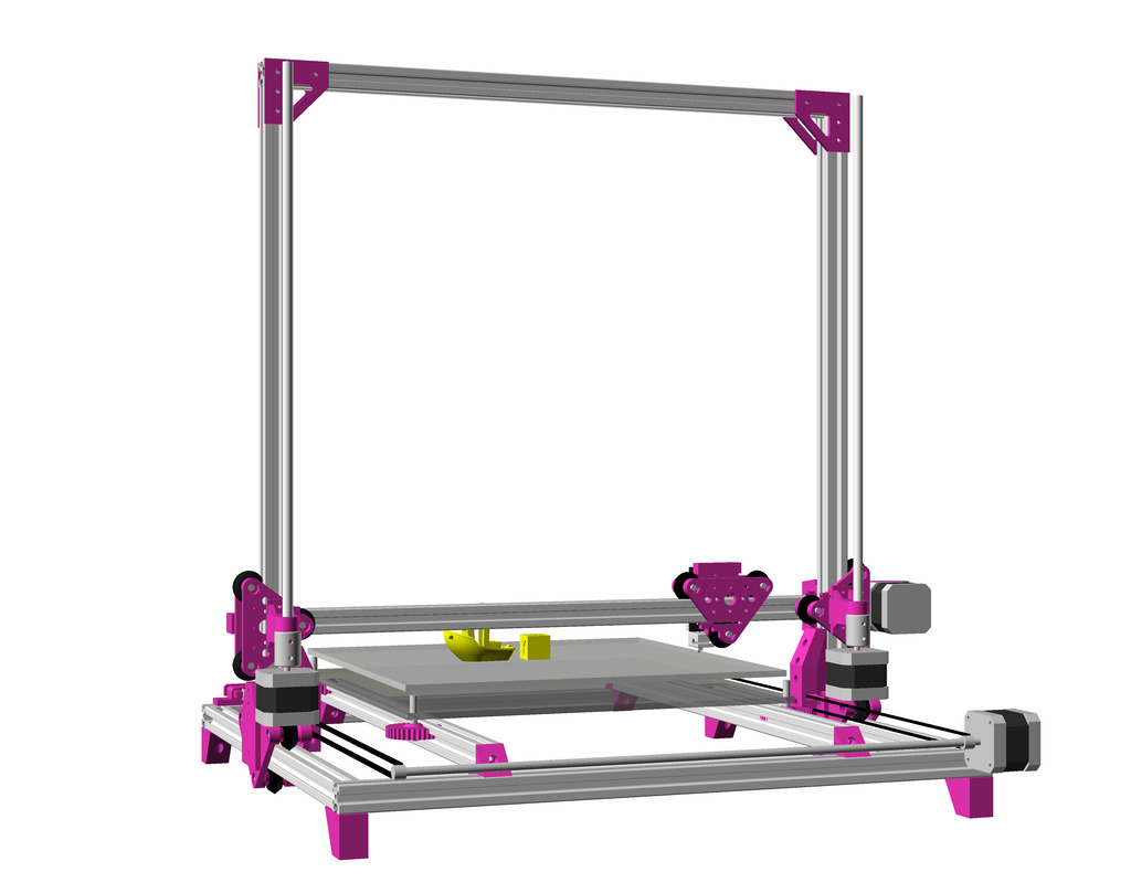
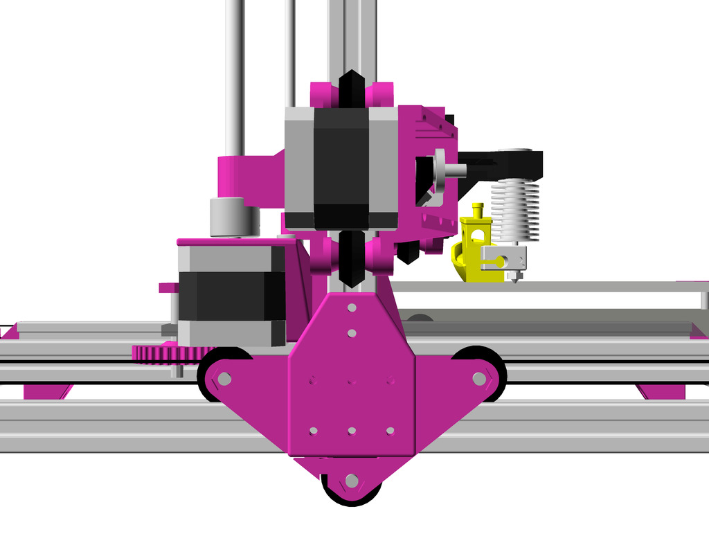
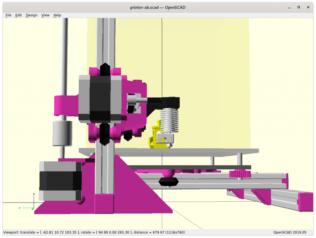
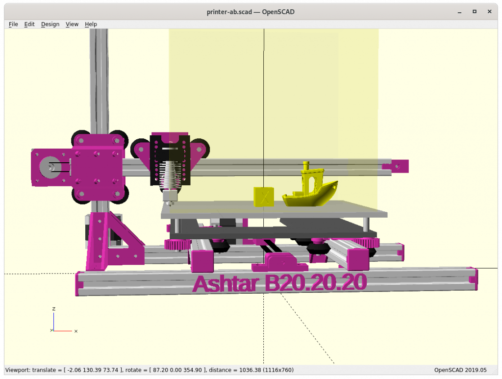
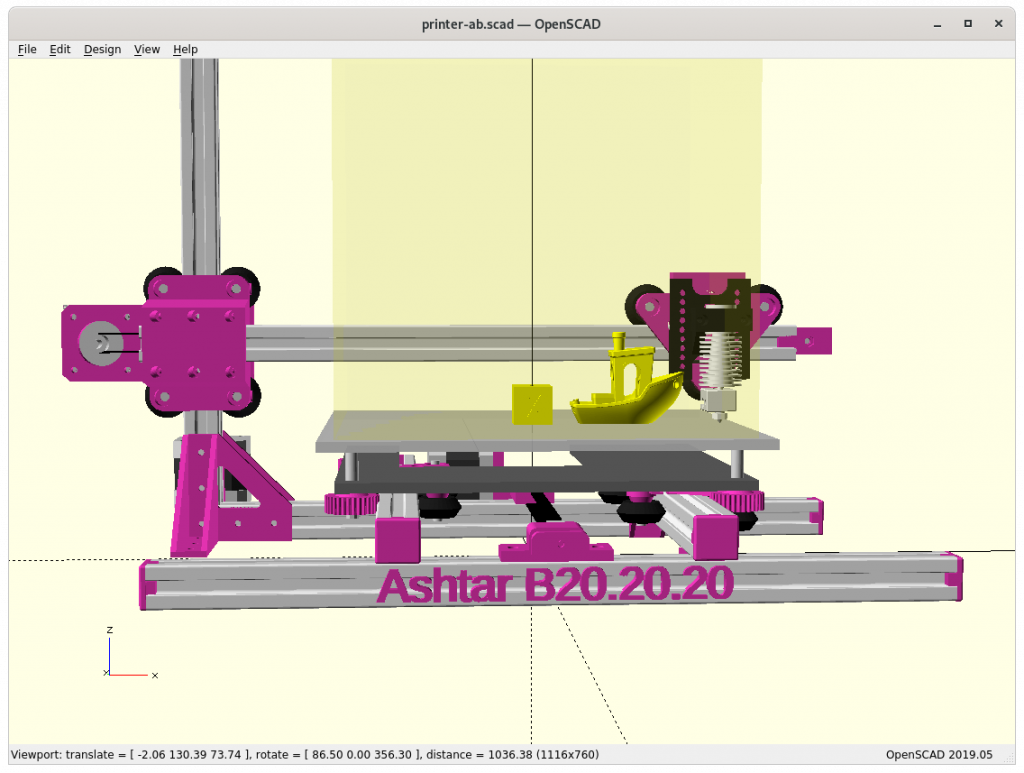
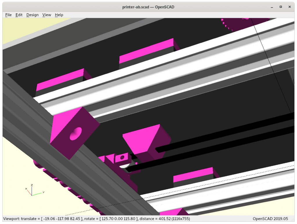
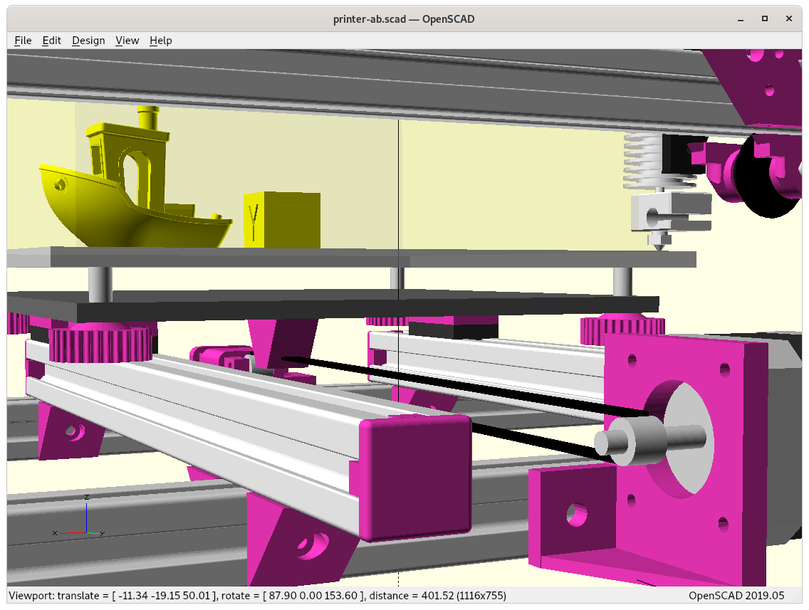
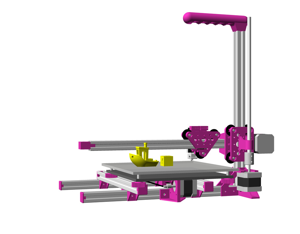
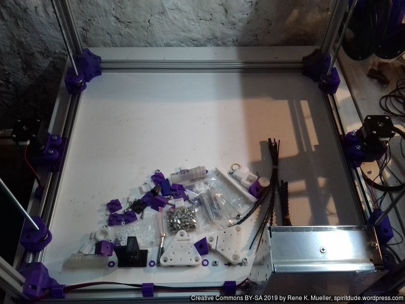
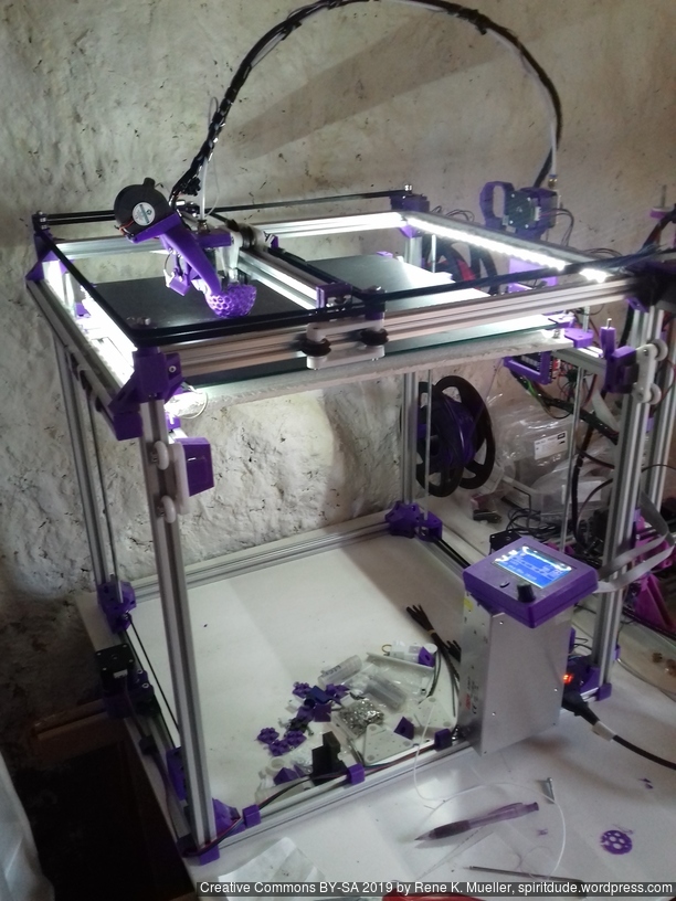
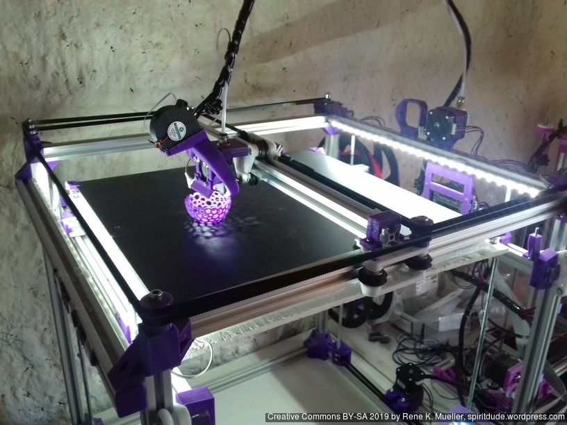
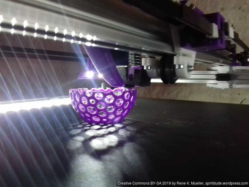
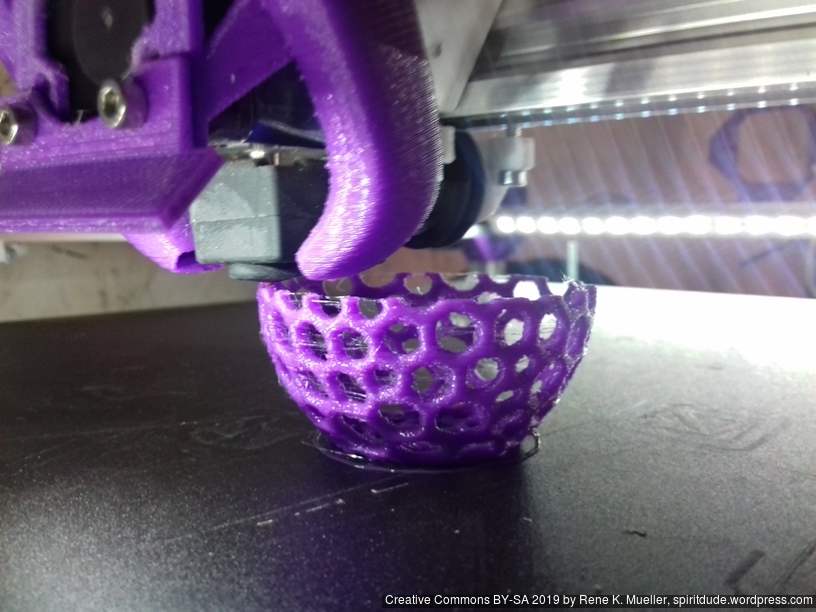
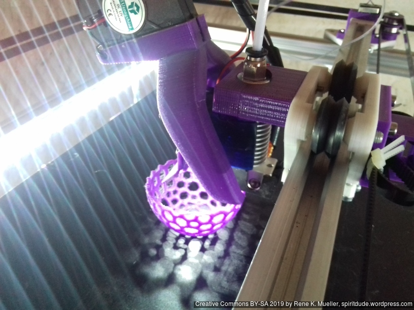
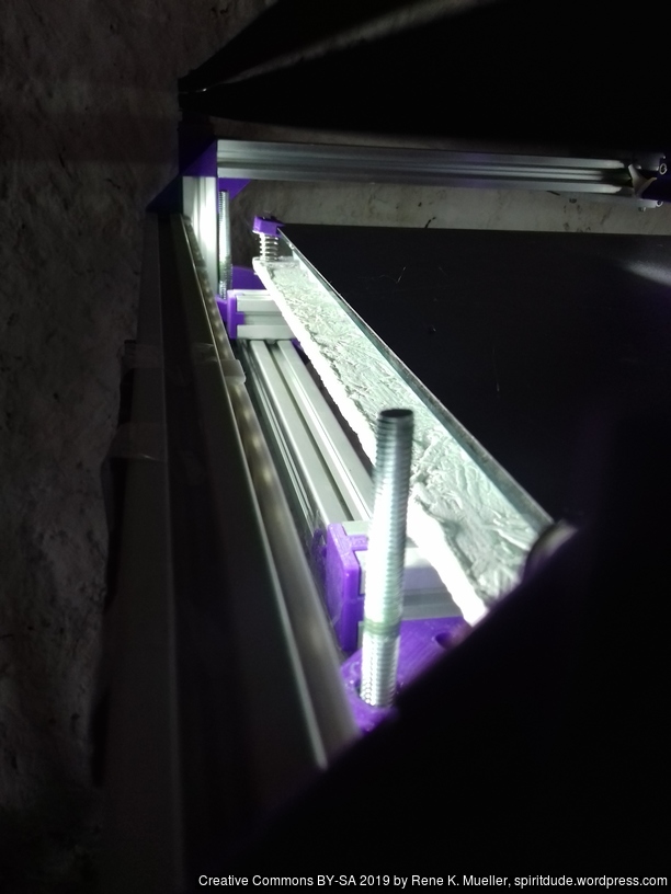
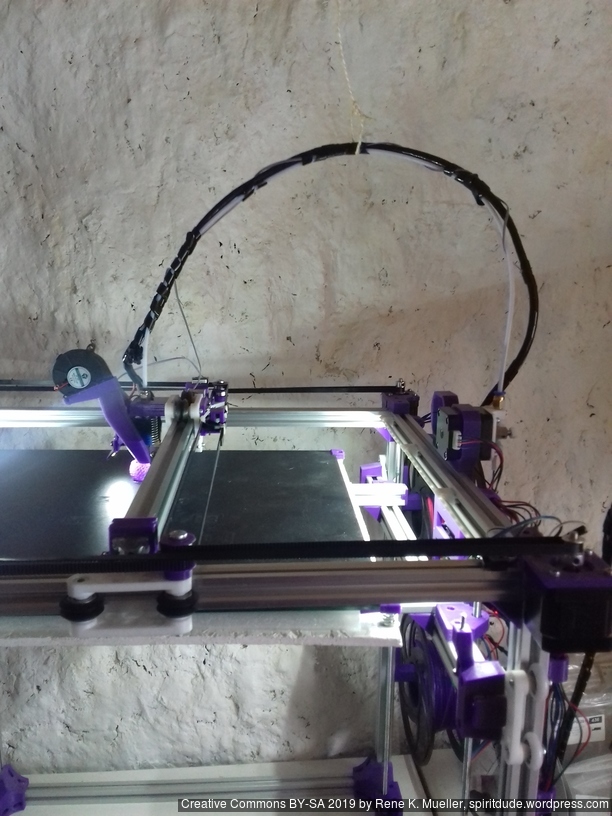
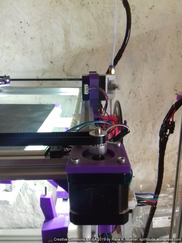
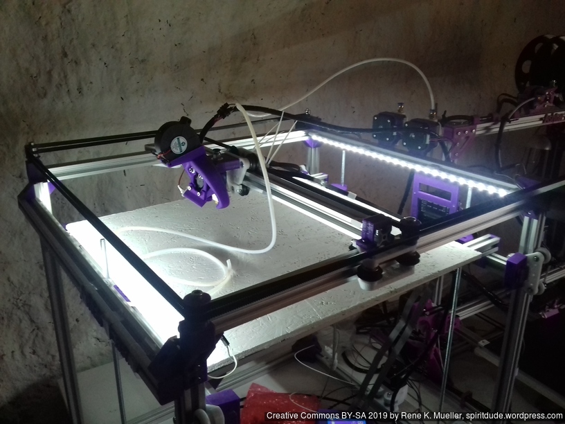
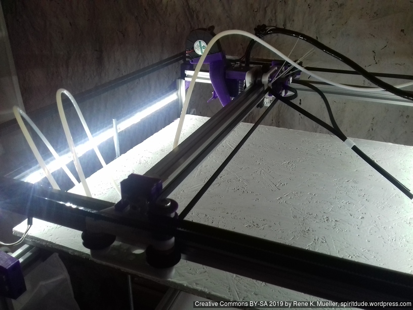
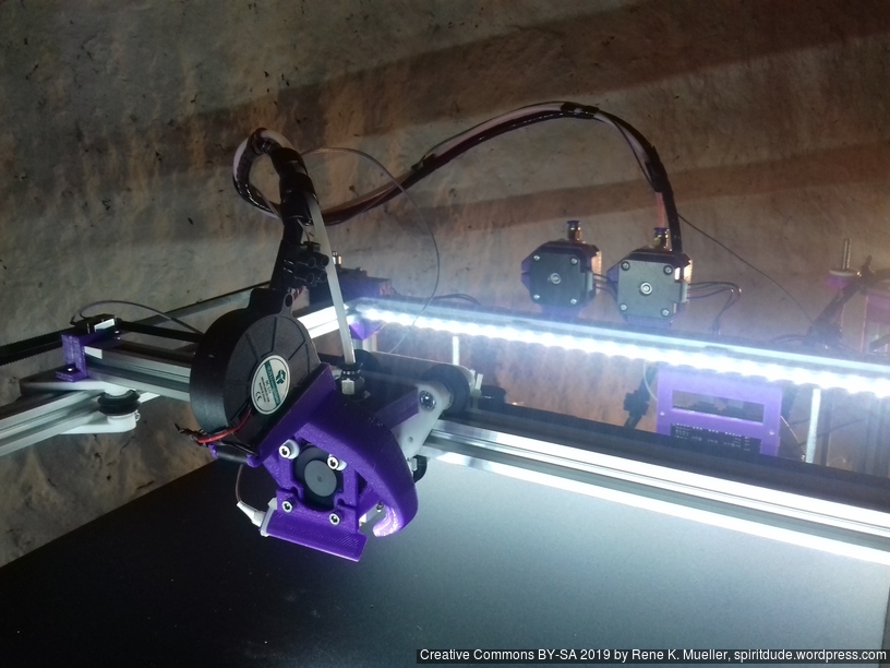
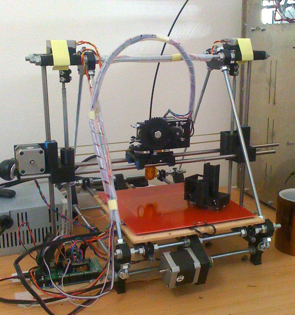
Ashtar K: most of the printed parts 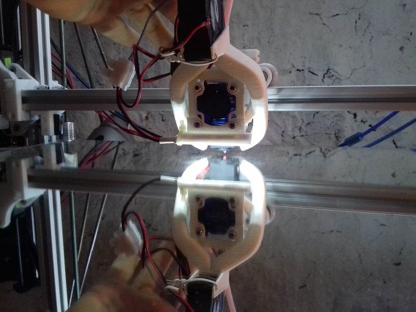
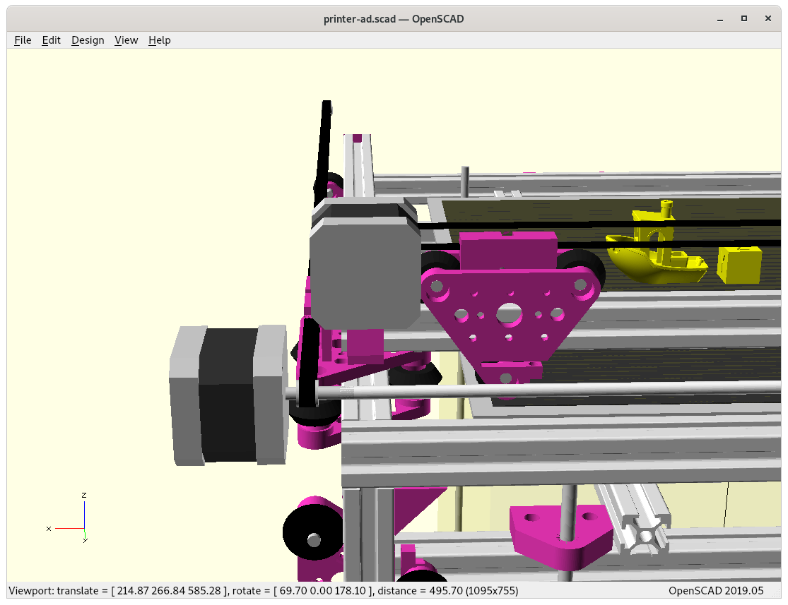
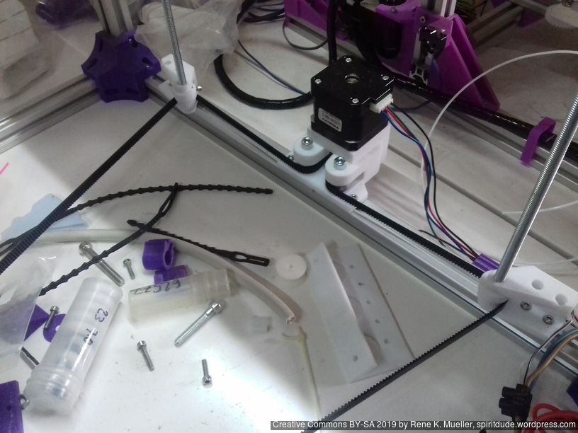
X carriage with white nylon wheels 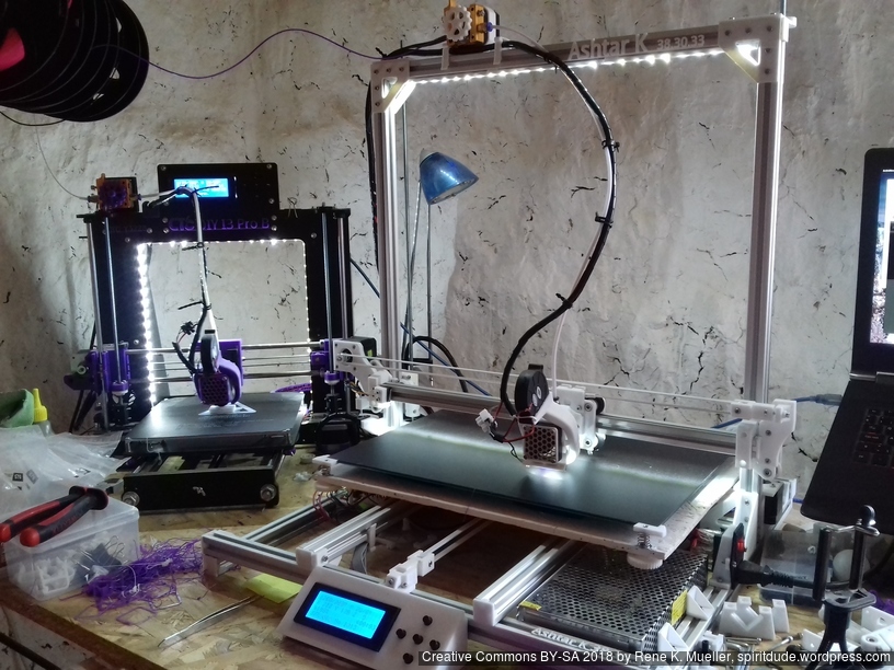
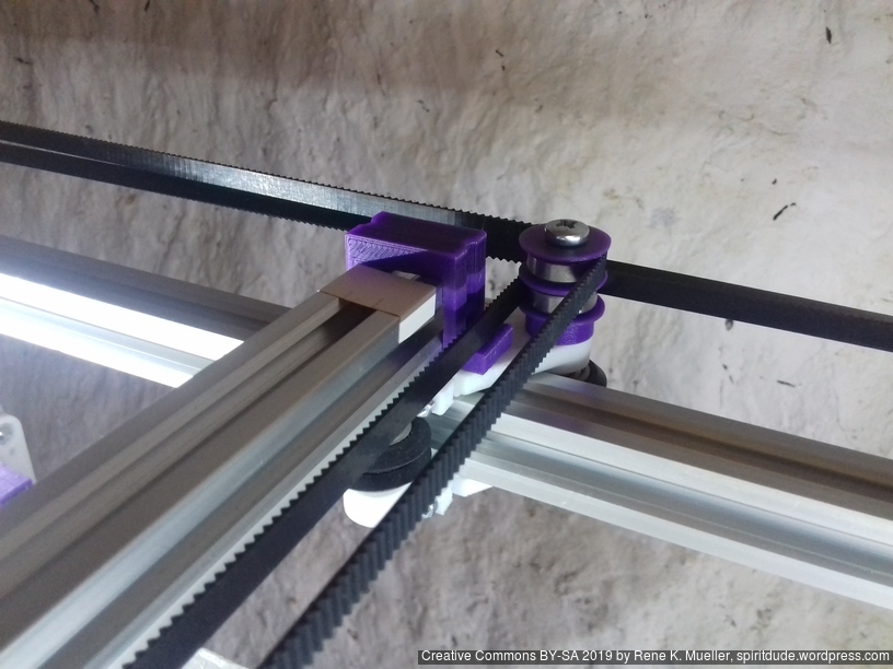
CTC DIY i3 Pro B (left) printed parts for Ashtar K #1 (right)
Thanks to Scott Crump, Adrian Bowyer, Vik Olliver, Josef Prusa, Shenzen Getech Technology, Zhuhai CTC Electronic Ltd and Marius Kintel (OpenSCAD) to provide the base for my 3D printing adventure . . .
References
- RepRap.org
- RepRap – The Replicating Rapid Prototyper (PDF, 2010/10/27)
- RepRap 10th Anniversary Interviews (2018) at 3D Printing Industry
- Interview with Adrian Bowyer (2018)
- Self-Replicating Mechanisms/Machines: Penrose Block Replicators (1957)
- Wikipedia: Nanorobotics
Continue with 3D Printer History or RepRap Blog Archive.