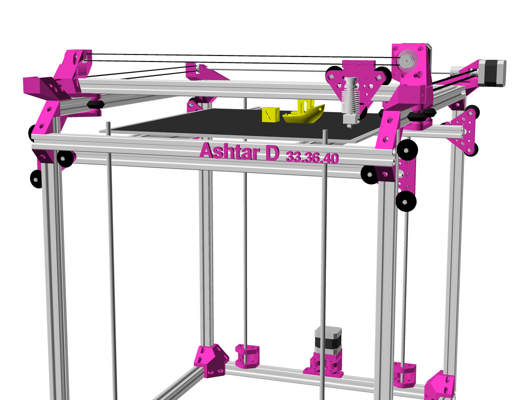
After the Core XY implementation of Ashtar C I pondered on changing the kinematic to a more classic approach to separate X and Y axis motors, but otherwise keep the setup and frame, hence Ashtar D:
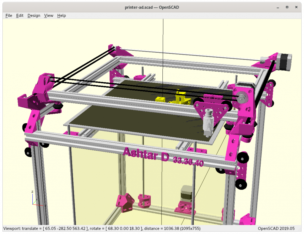
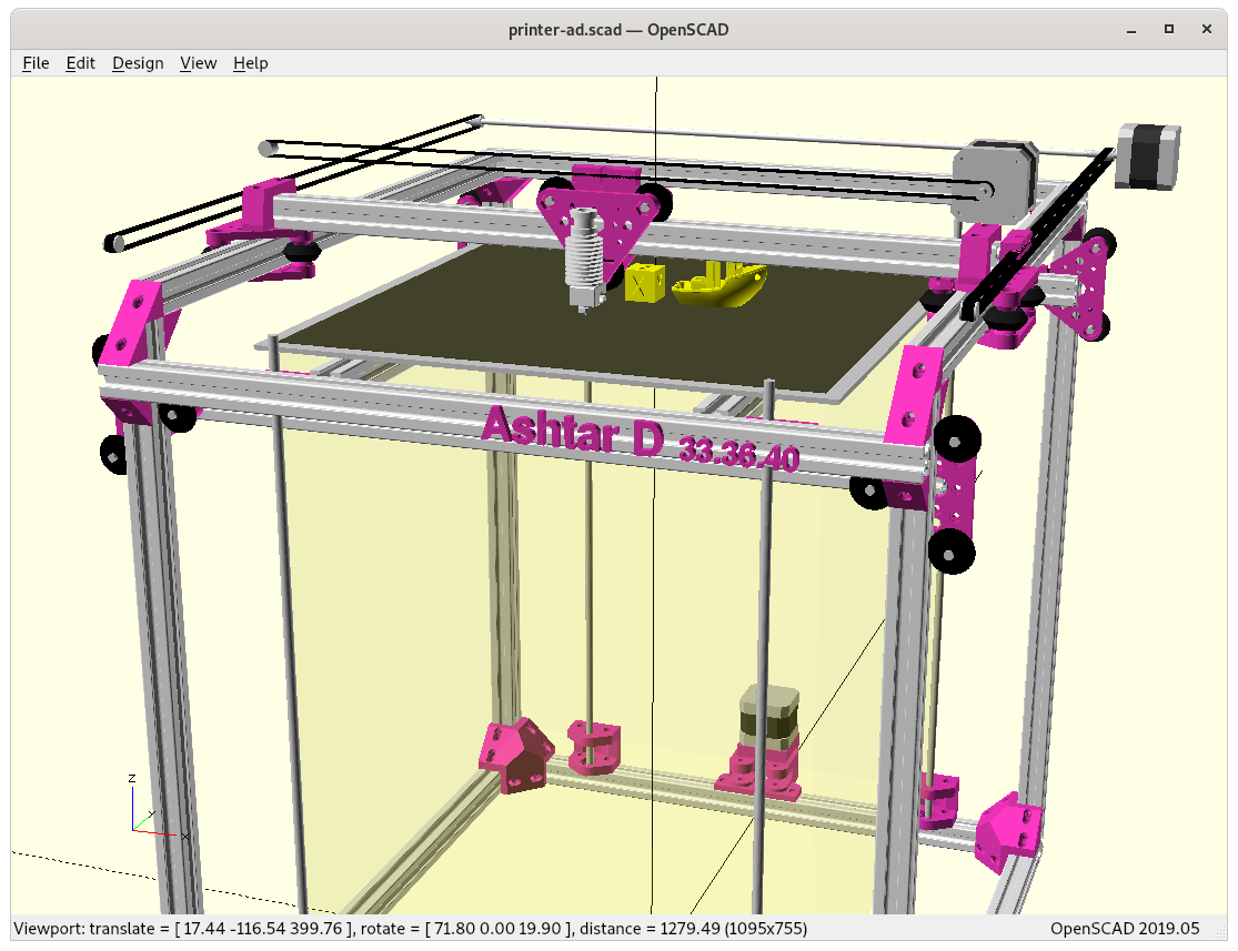
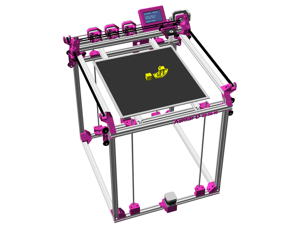
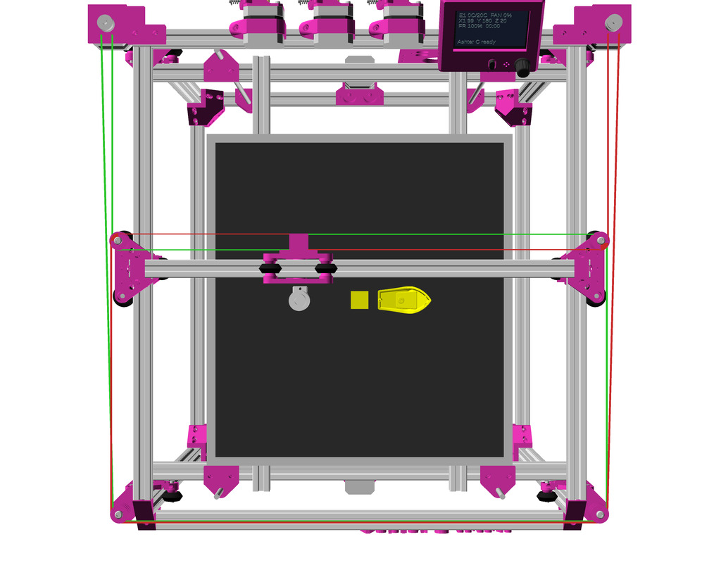
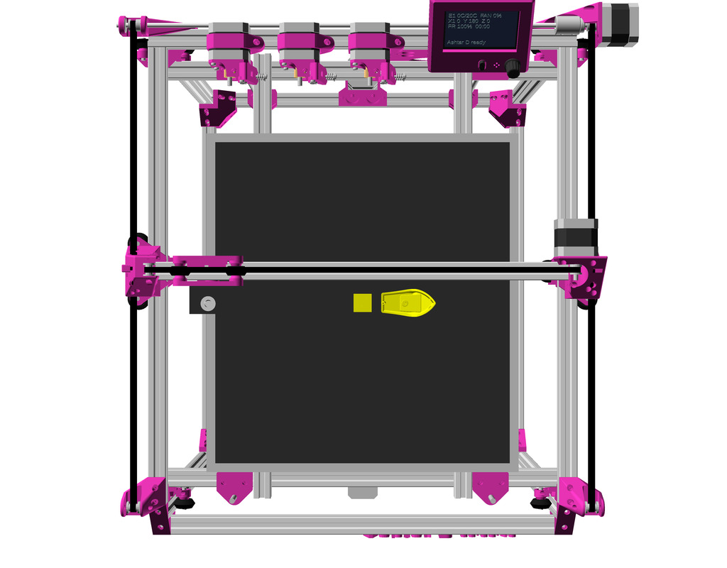
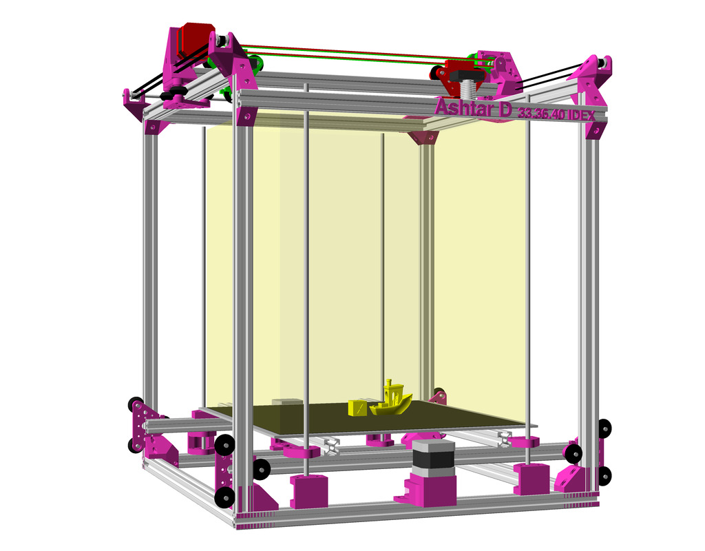
Ashtar D: classic independent XY kinematic: head XY, bed Z setup, with 500mm 2020 alu profiles
Draft
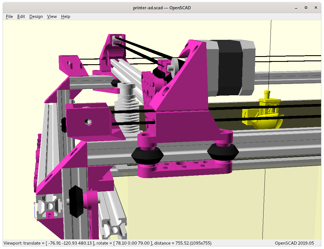
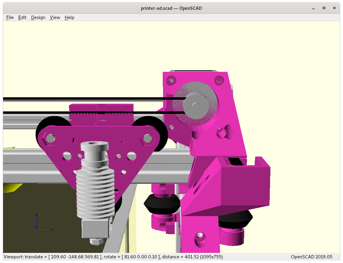
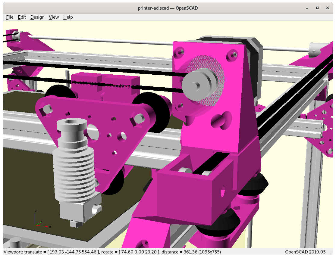
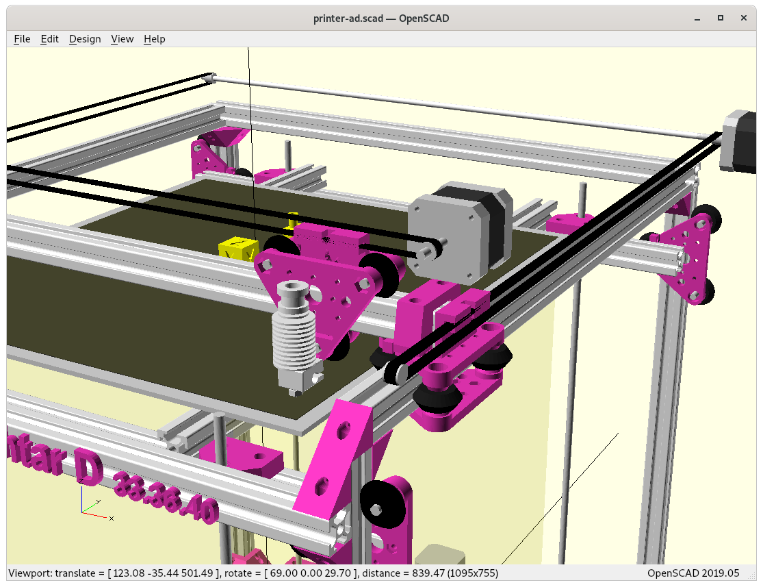
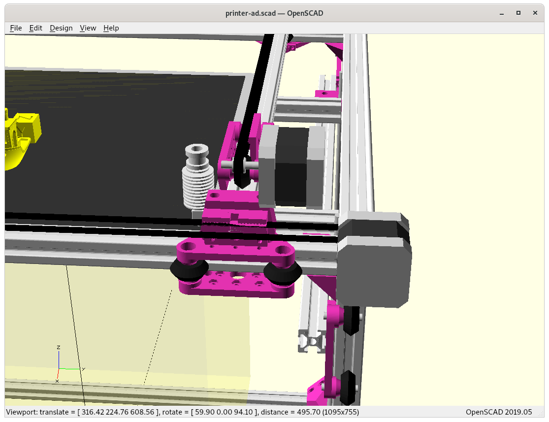
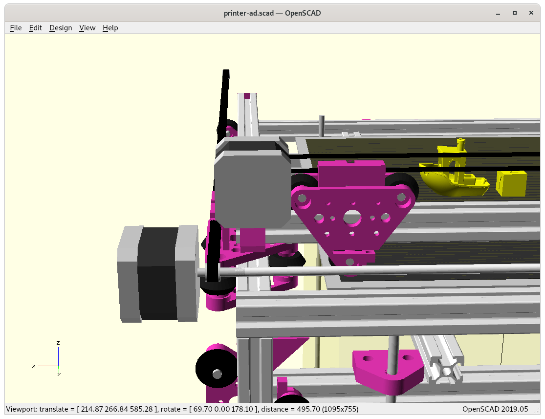
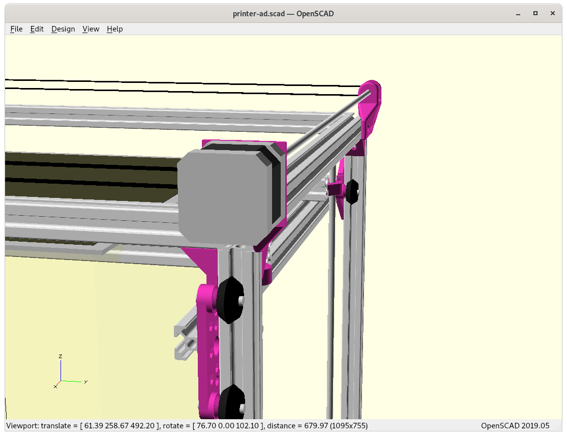
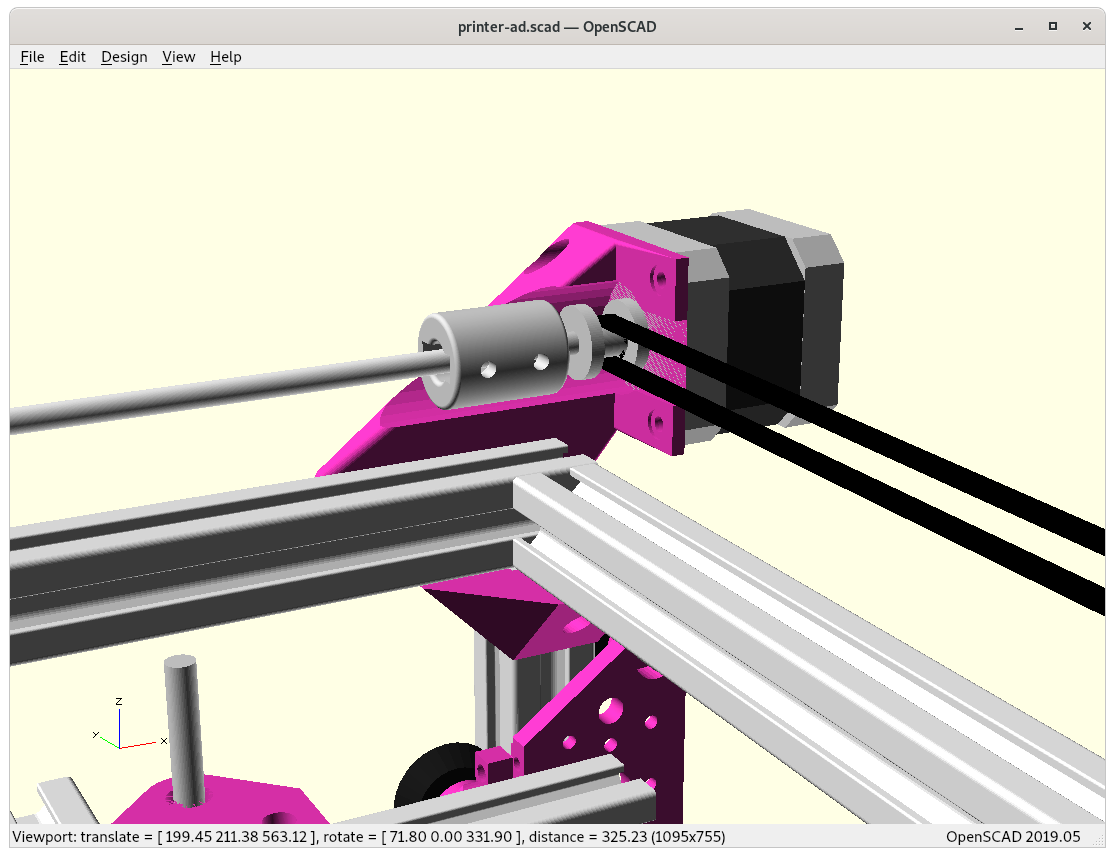
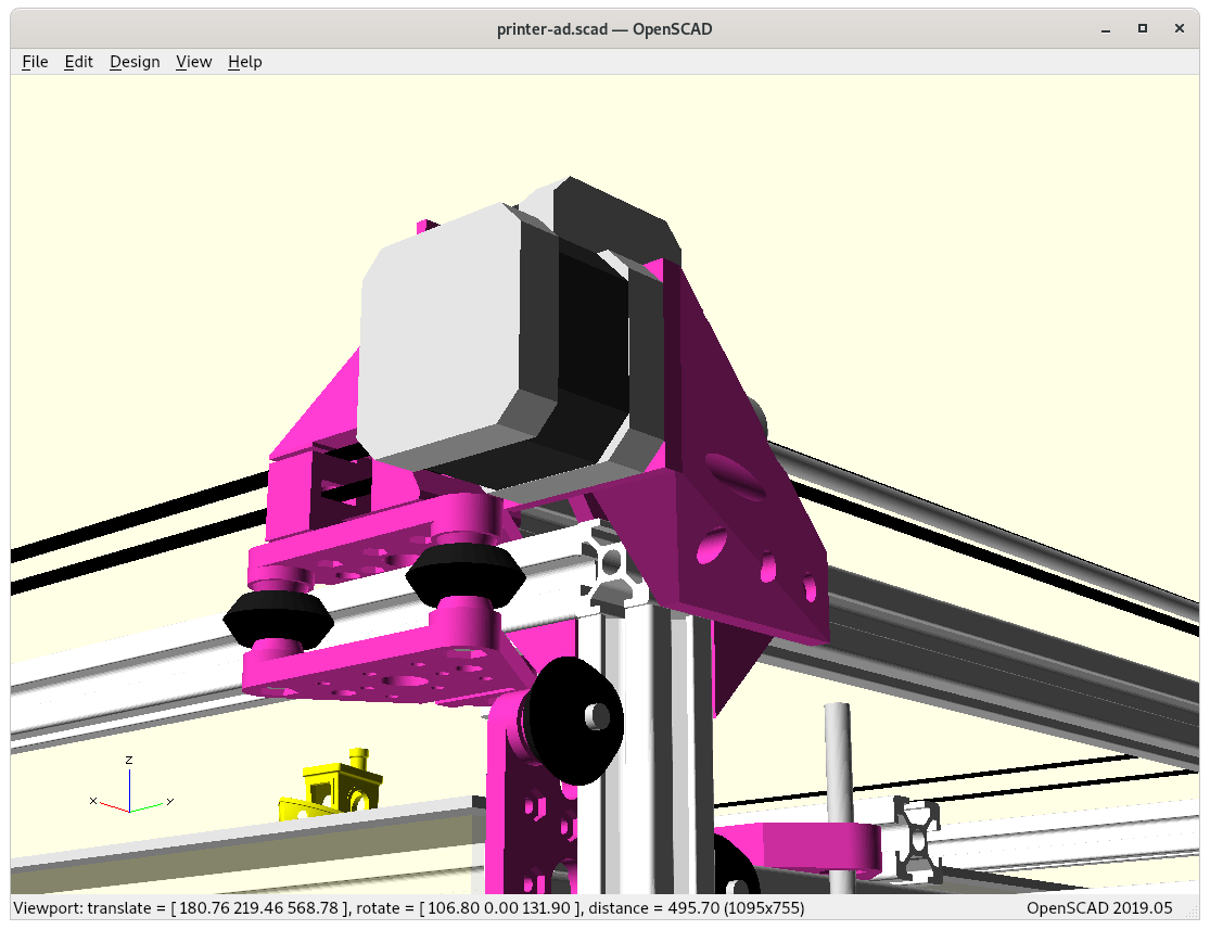
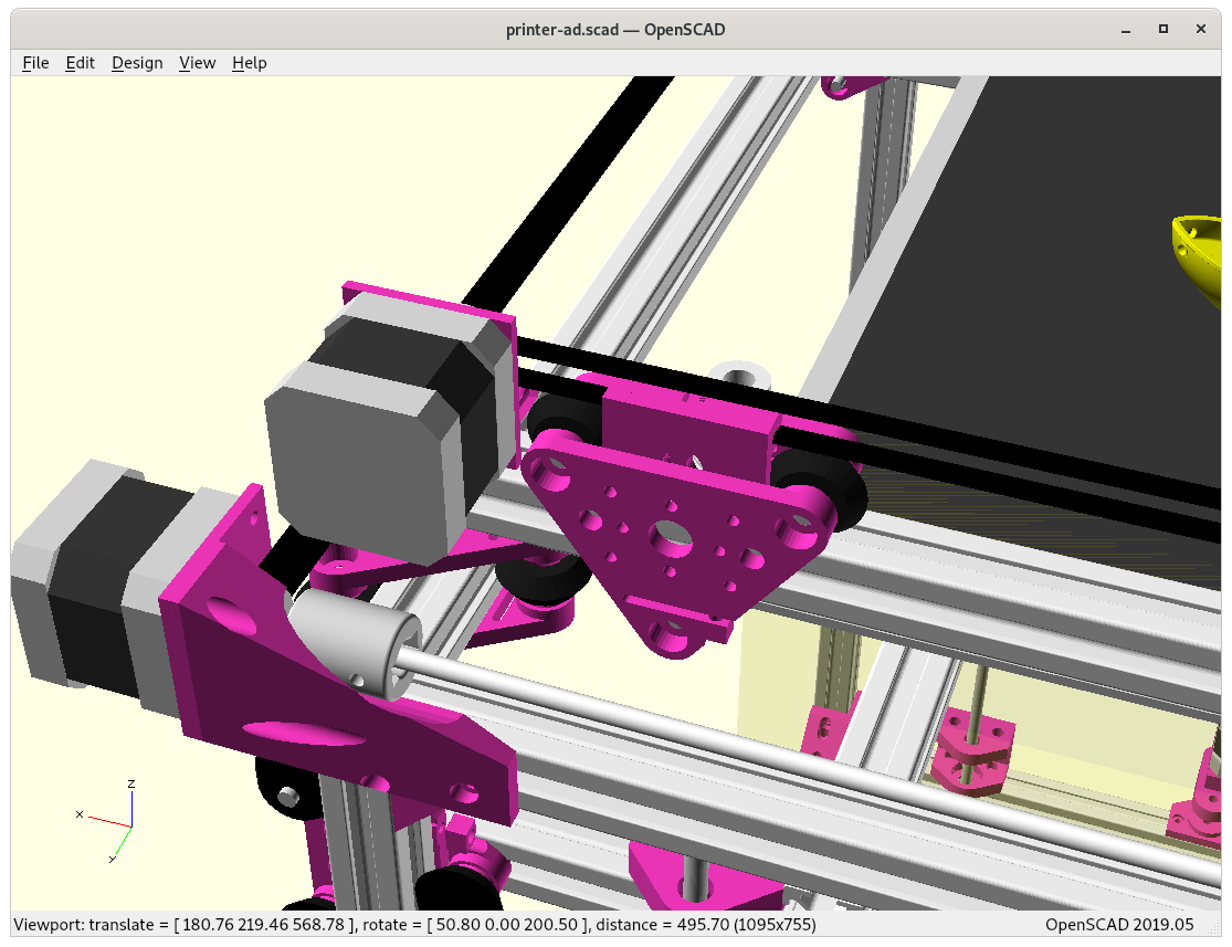
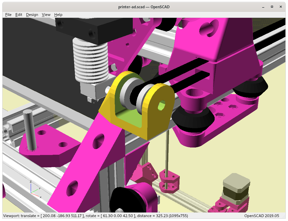
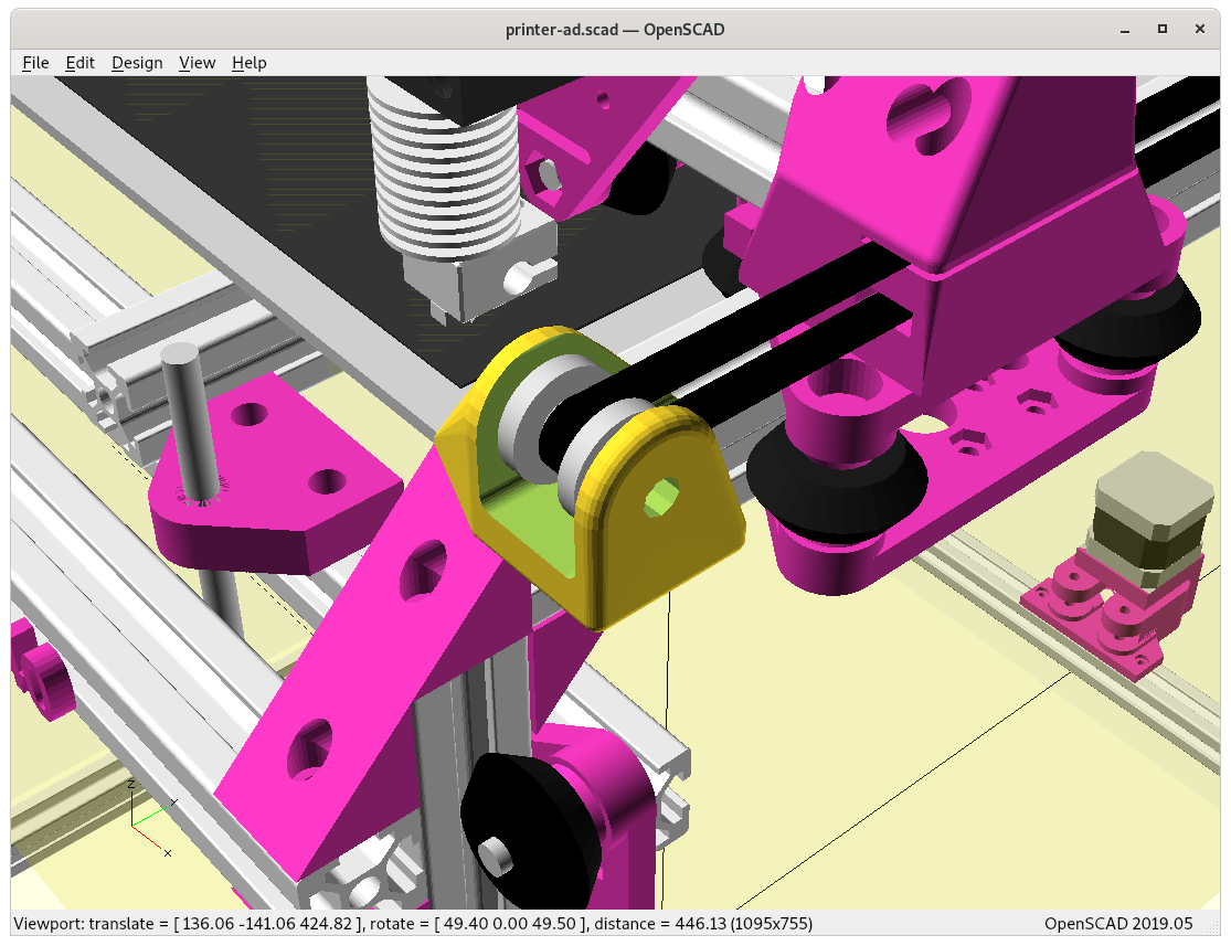
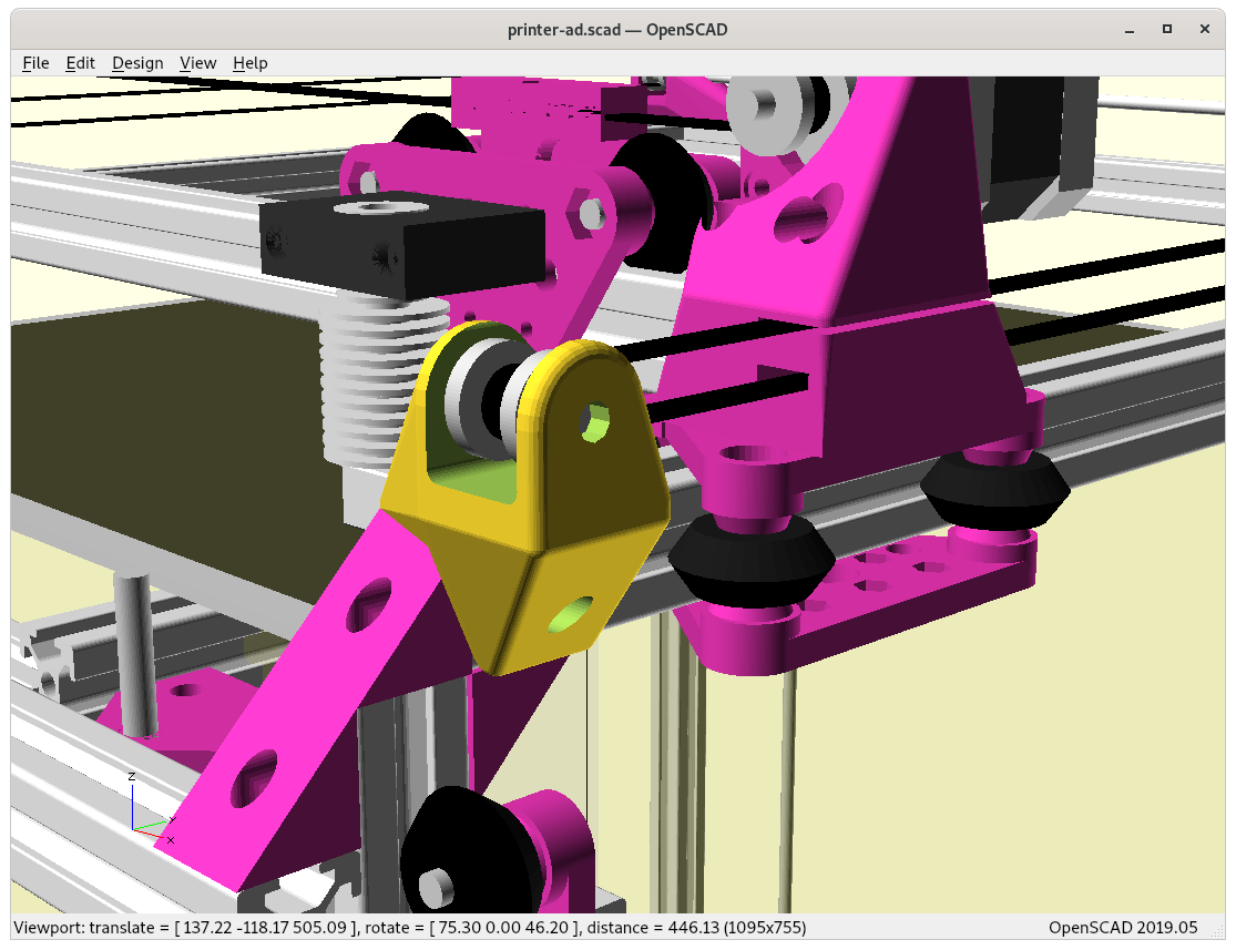
X motor mount with Y carriageX carriage with hotend and X motor mountX carriage with hotend and X motor mountY motor mountY carriage and Y motor with shaft extenderY motor with shaft extender
Again using 500mm alu profiles, utilizing the frame itself as rails:
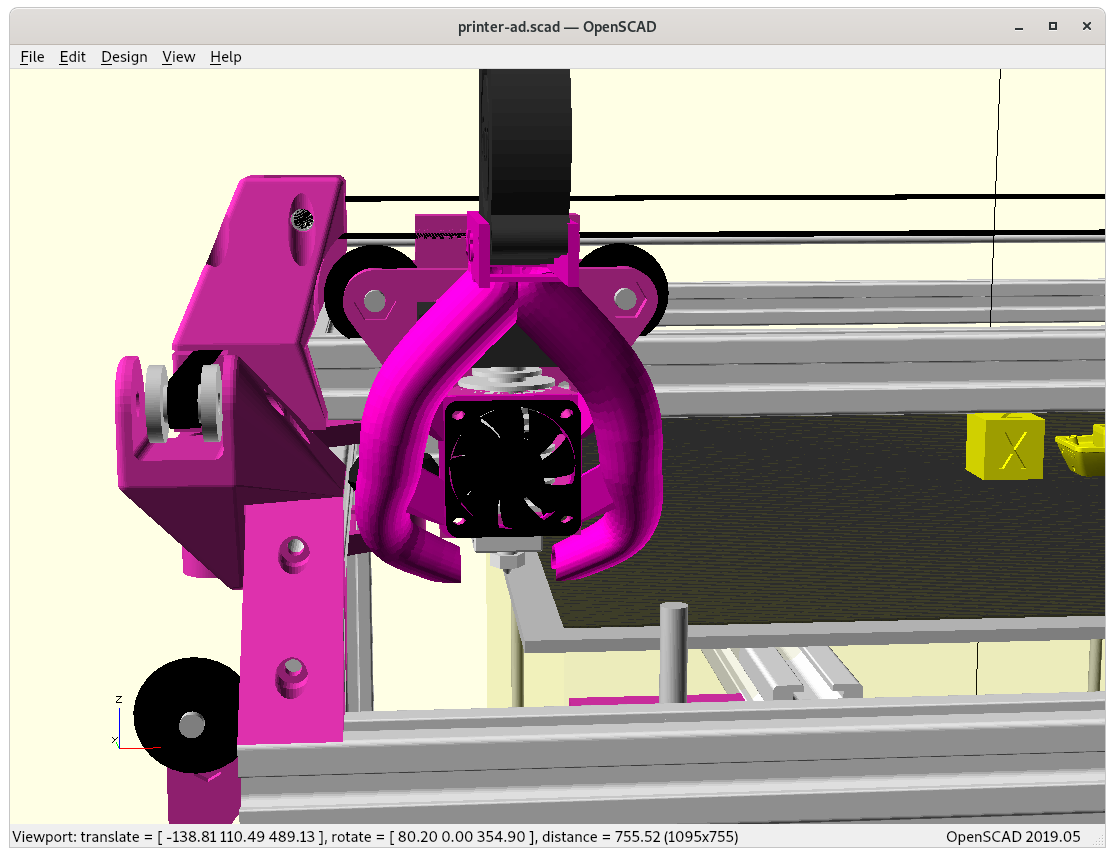
1 V-slot beam for X axis with V-carriage/module (triangle shaped carriage) as X carriage with hotend
2 V-slot beams for Y axis, 2 V-carriages/modules with the X beams on it
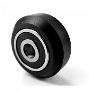
using classic V wheels
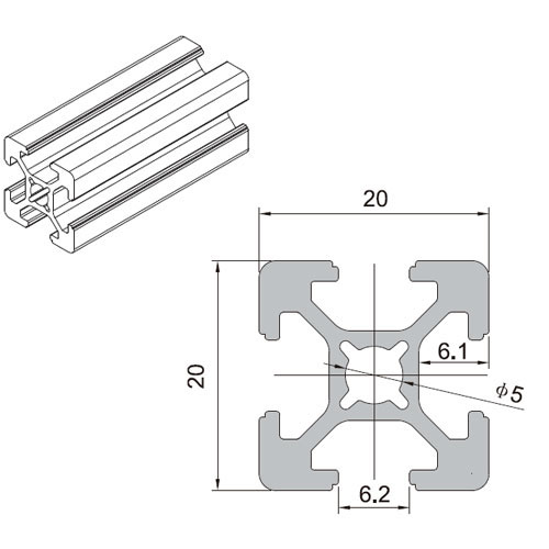
14 T-slot beams for the rest of the frame
Z bed: white 7.3mm thick Delrin wheels on T-slots
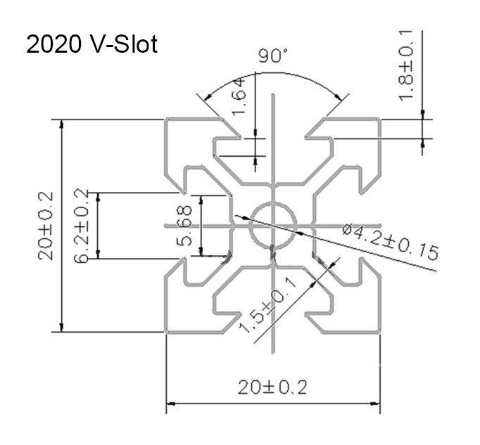
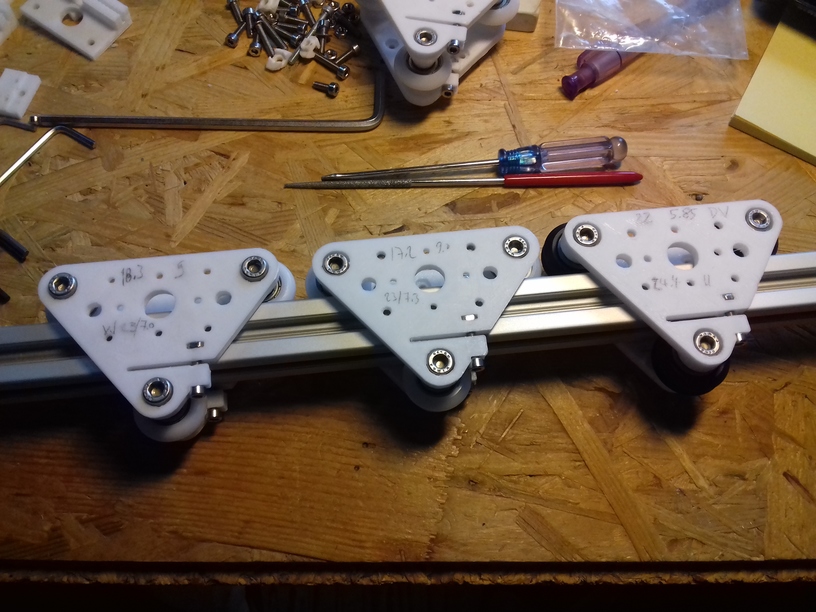
T-Slot 2020V-Slot 2020V wheelV modules with different kind of wheels.
The target is again a 400x400mm printbed, probably 380x400x380mm build volume alike with Ashtar C (Core XY), perhaps a bit less X-wise due the more complex pieces to mount the X motor and pulleys.
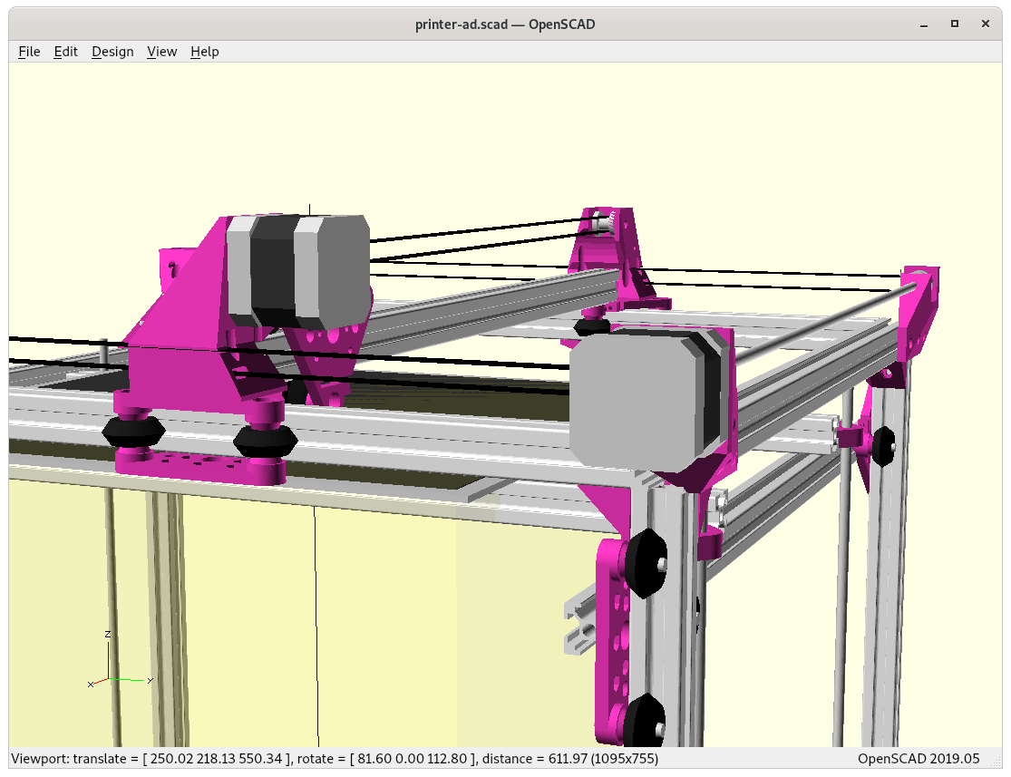
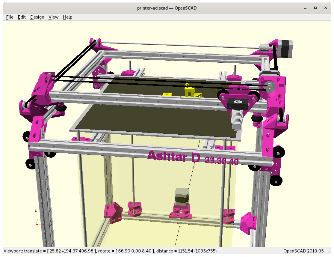
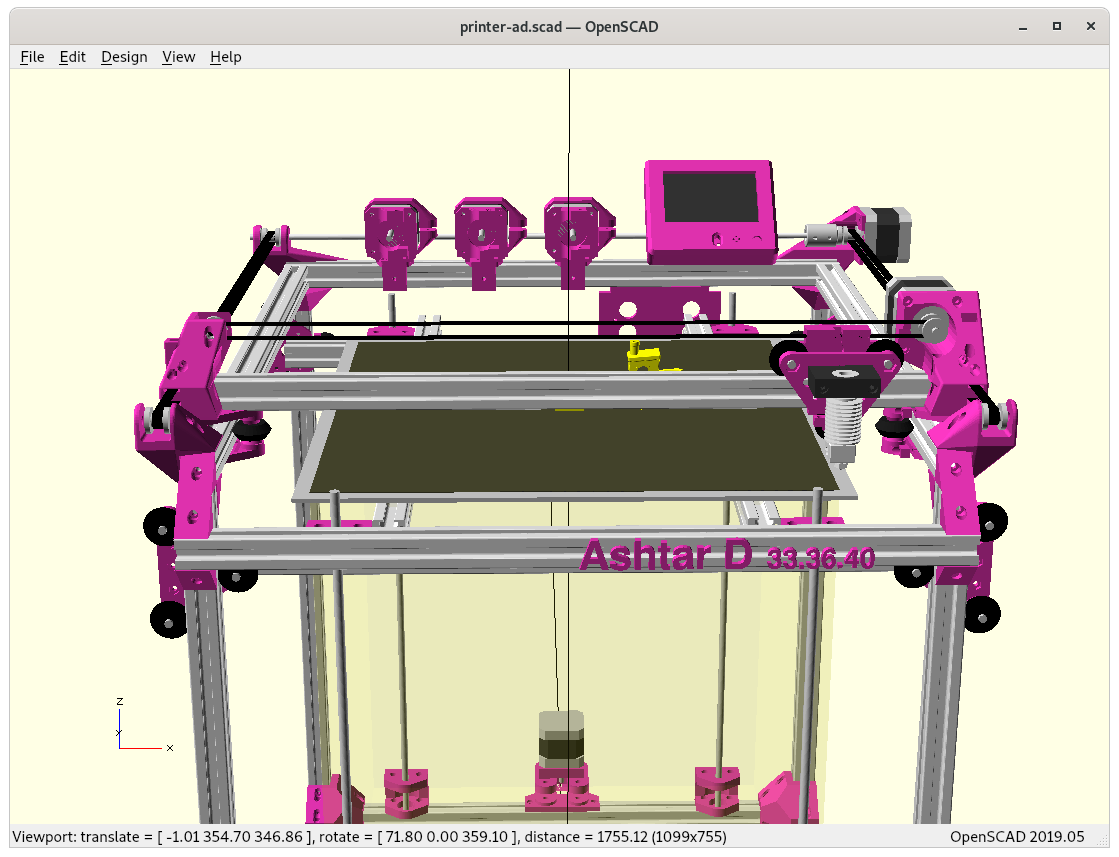
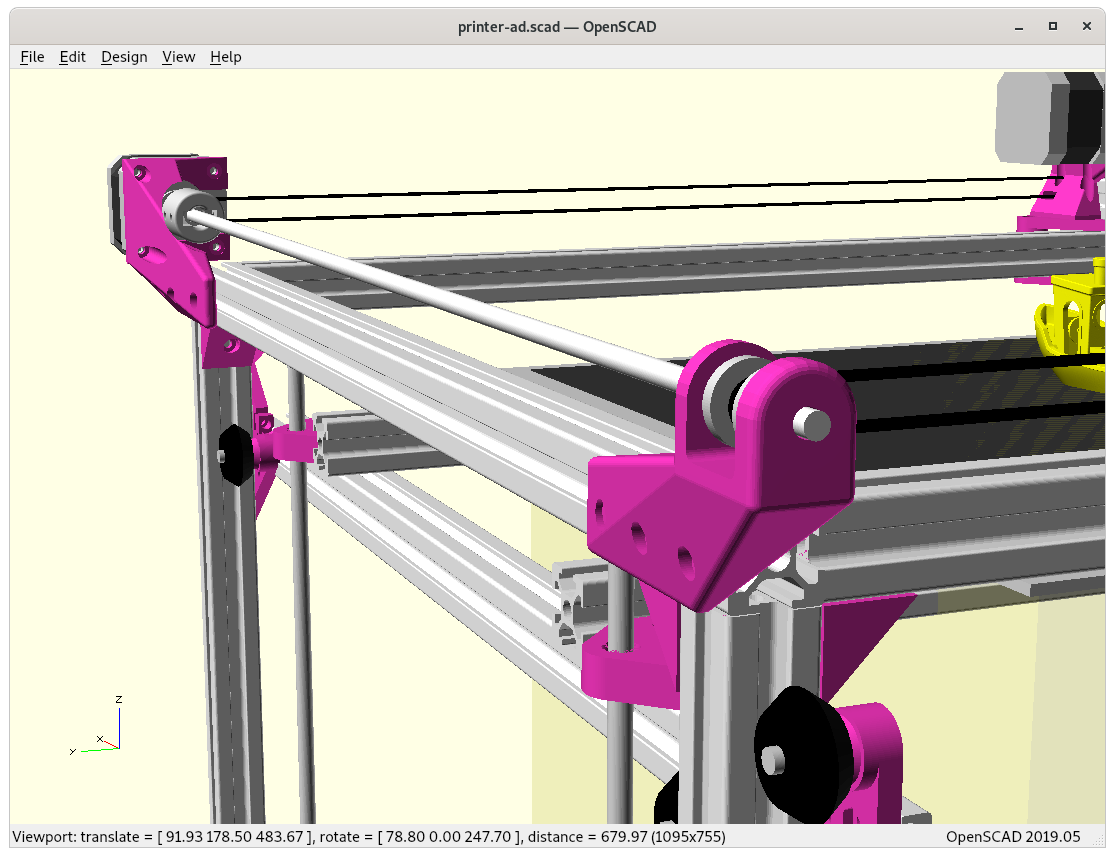
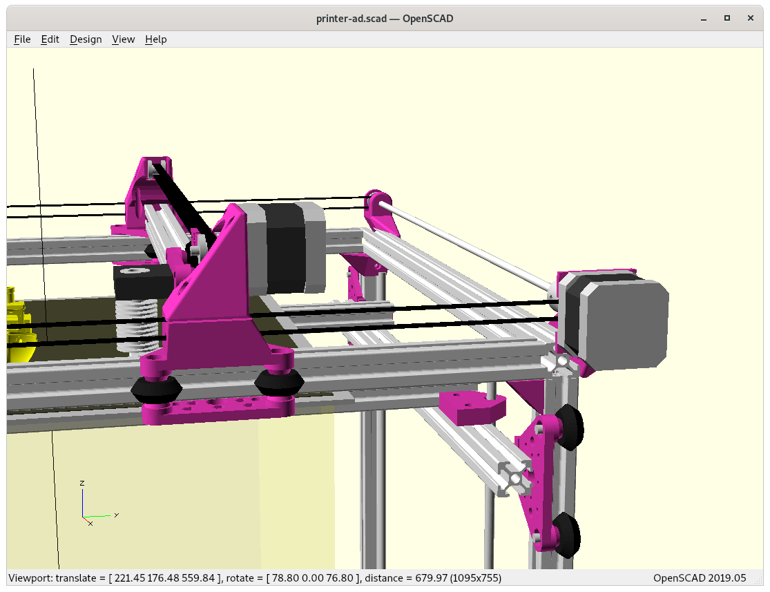
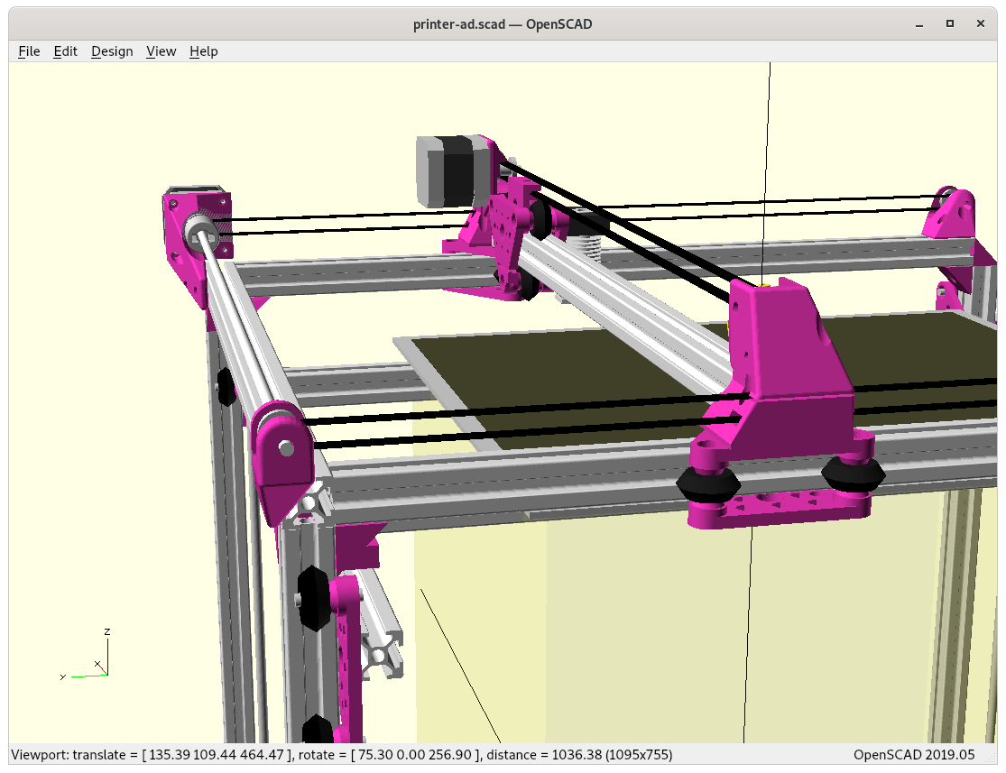
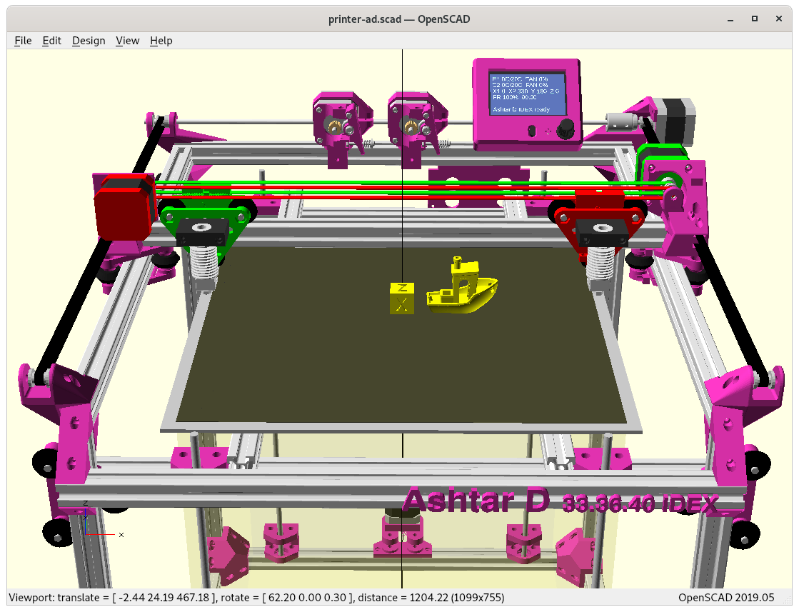
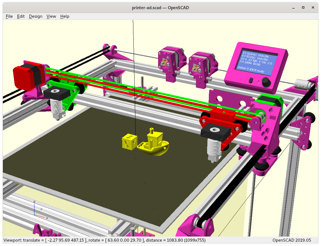
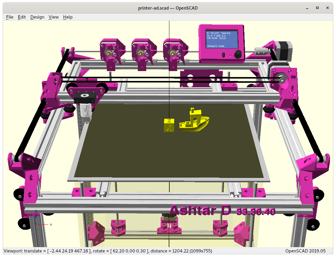
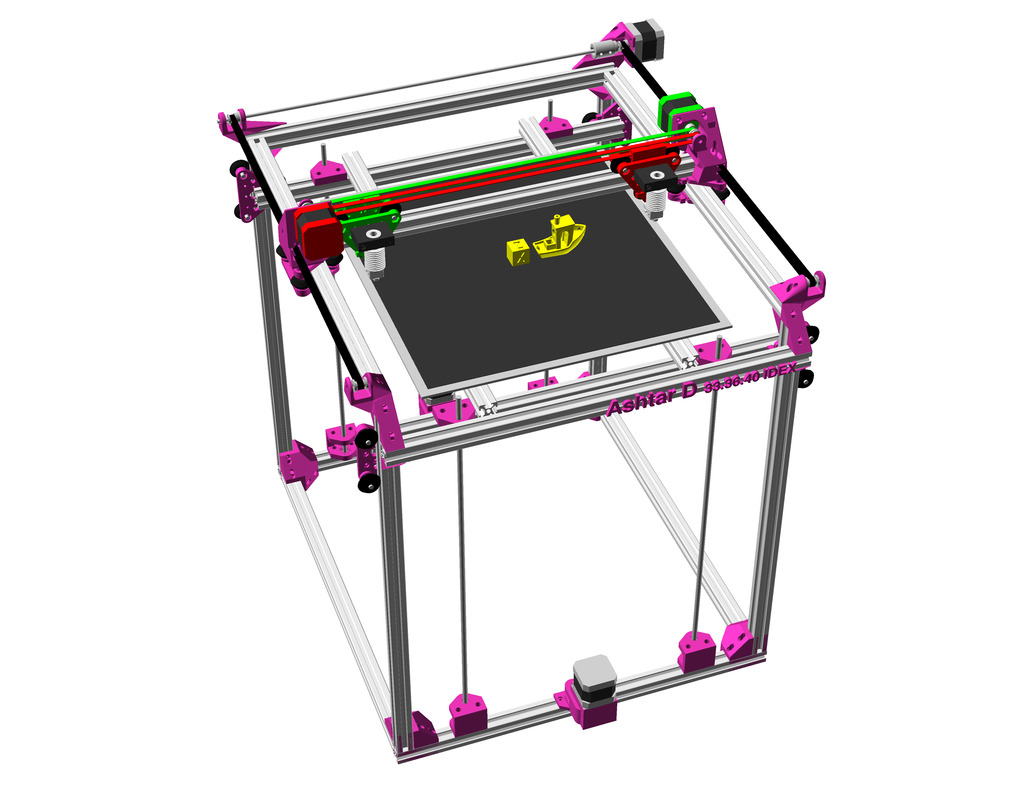
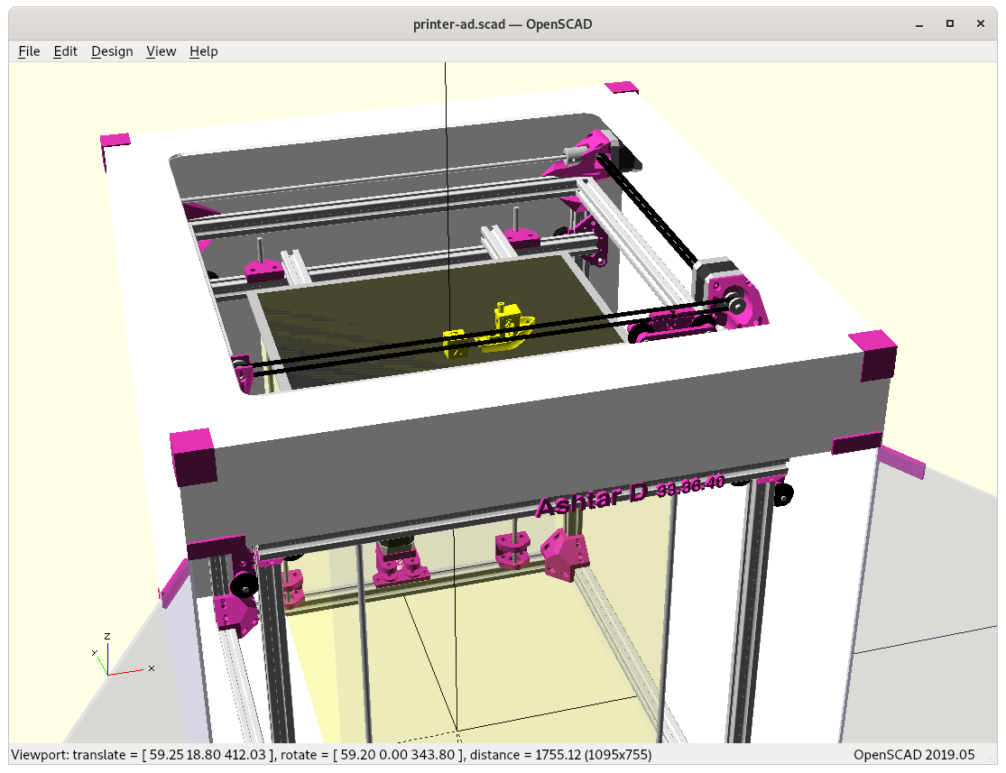
More high resolution renderings:
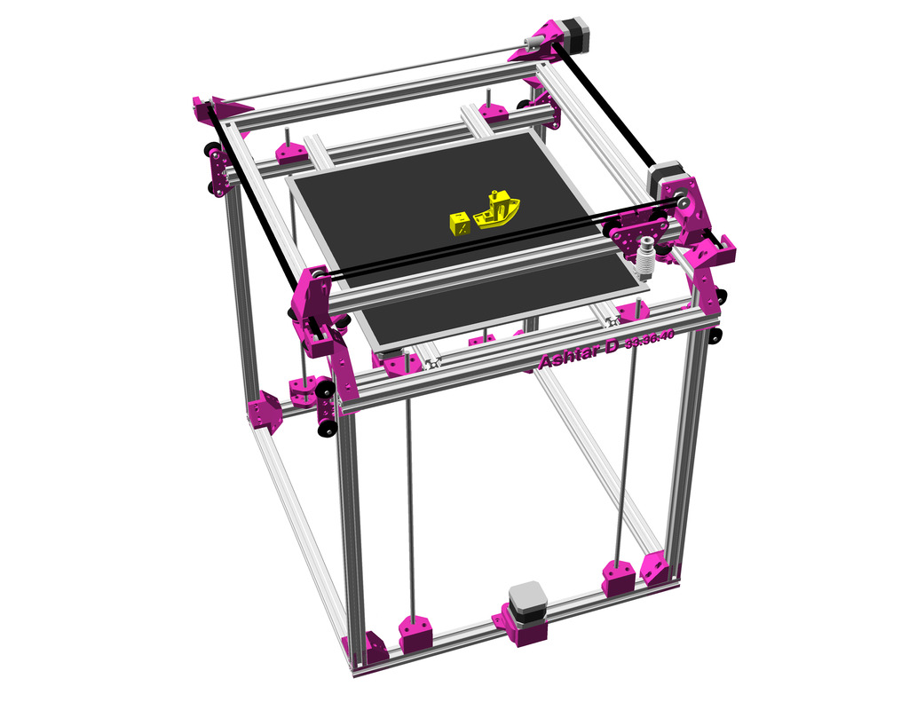
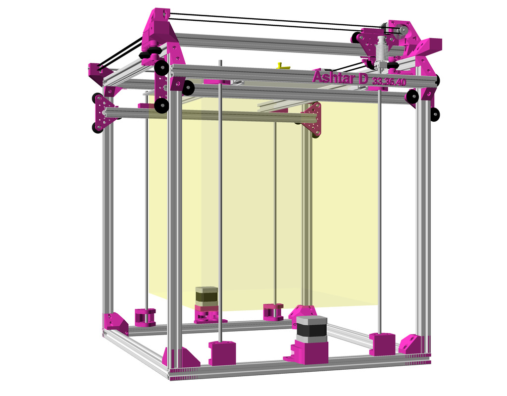
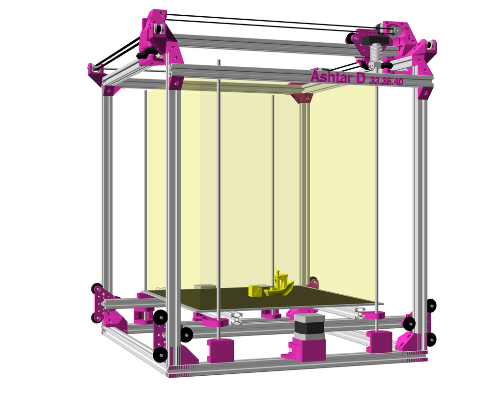
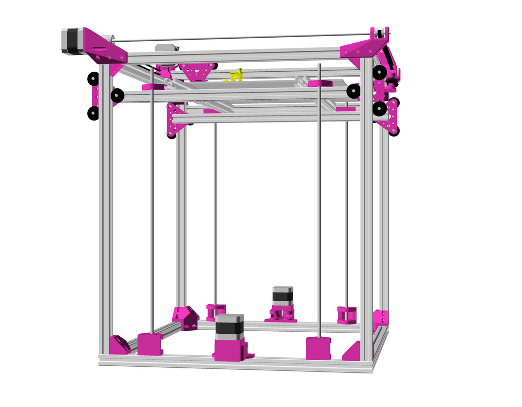
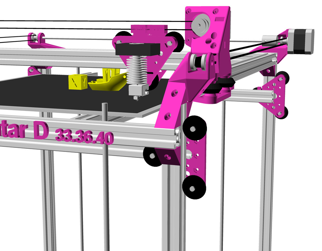
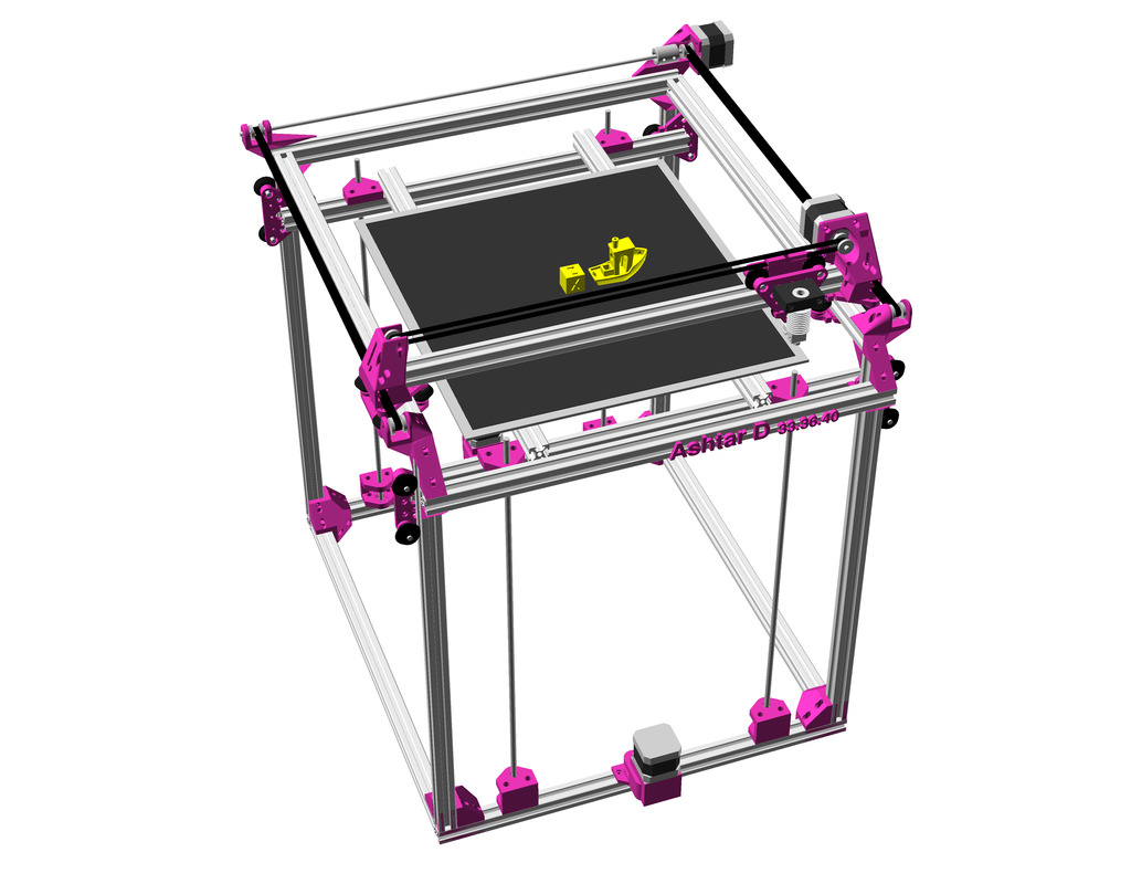
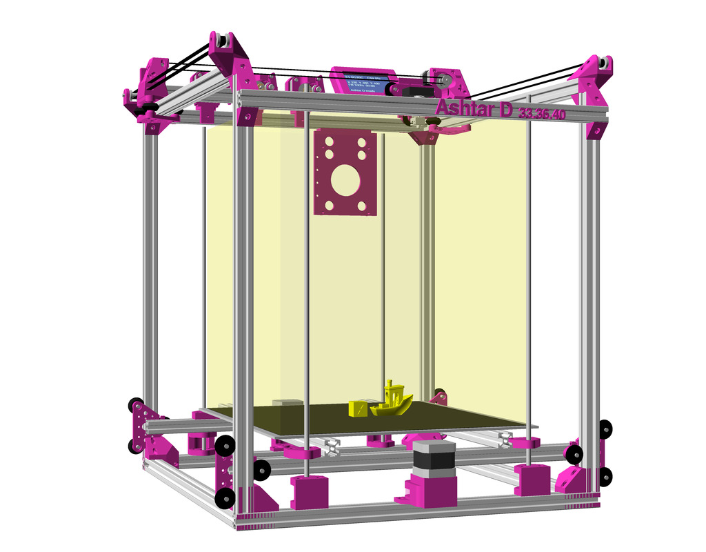
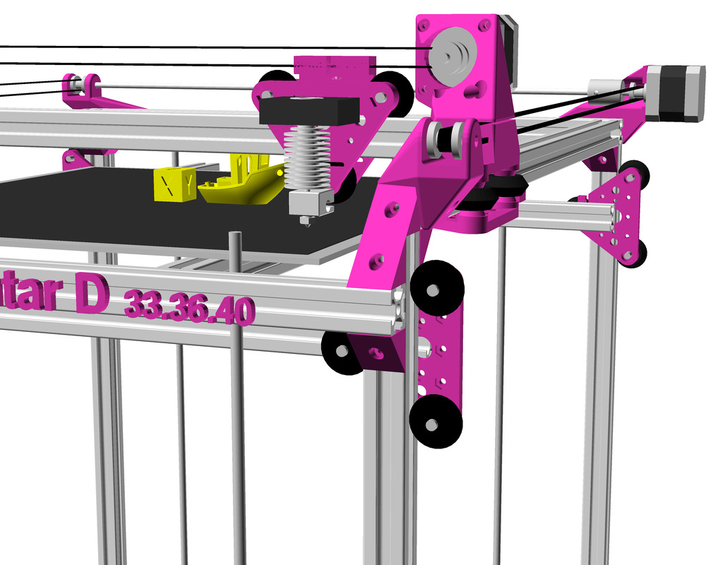
Ashtar D: top viewAshtar D: Closeup X carriage with hotend and Y carriageAshtar D: tilted top vewAshtar D: Cubic Frame, Head XY, Bed Z
The project page on Ashtar D summarizes the current state of the project.
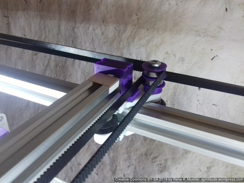
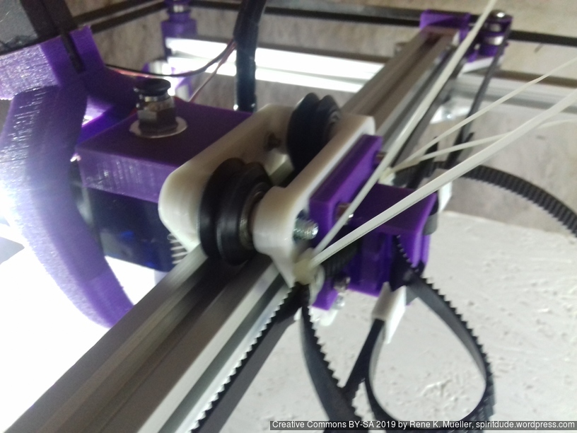
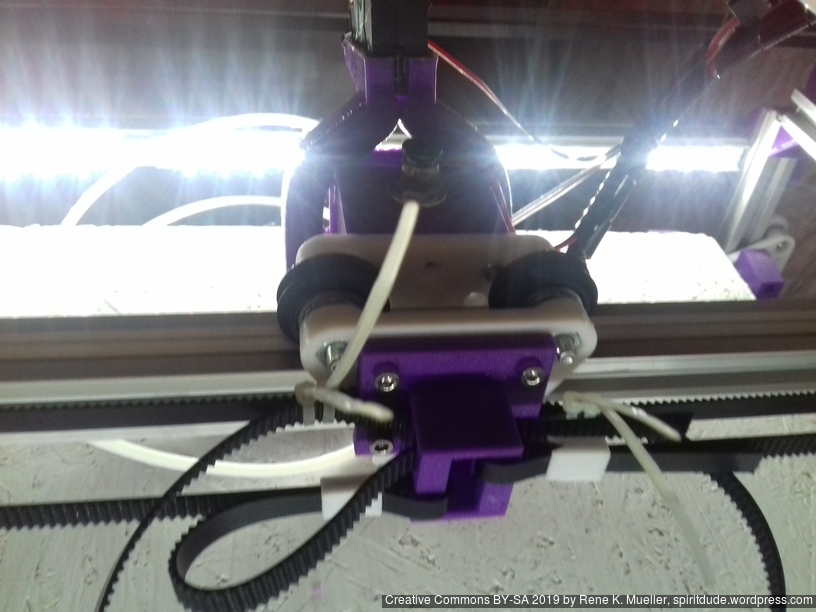
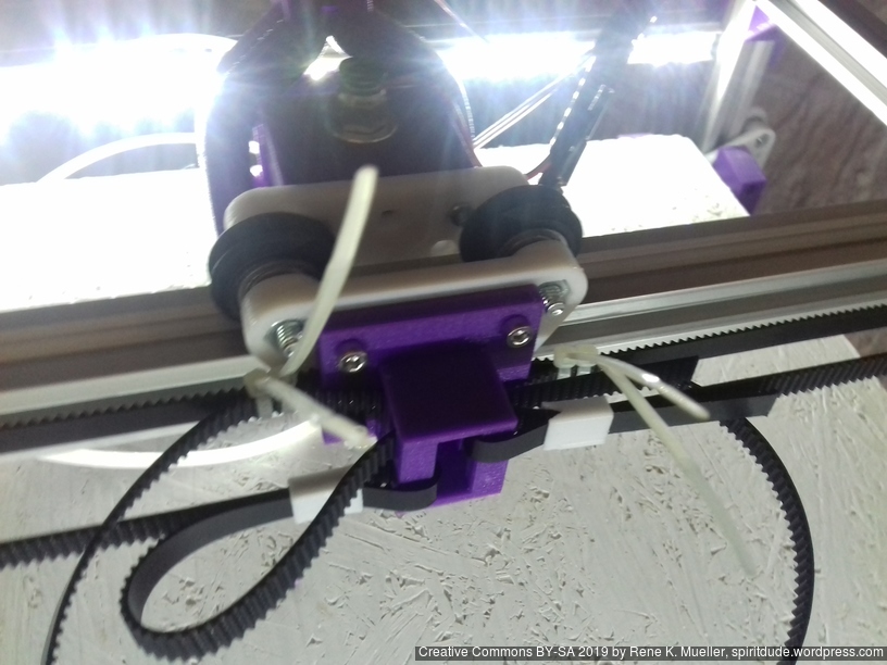
2021/01/08: starting with details of Y belt/pulley (non-)printable parts
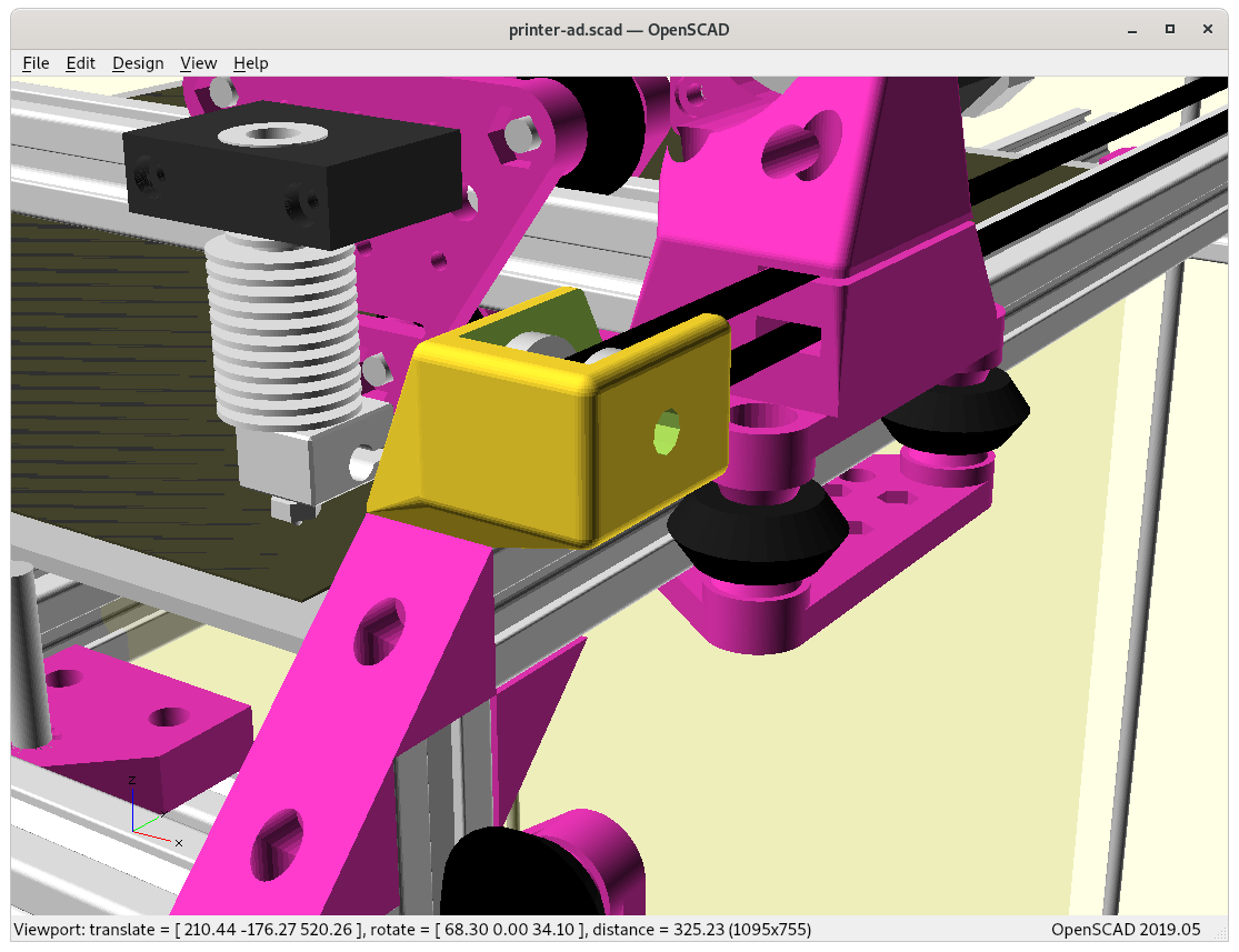
2020/12/28: beautifying X & Y motor and pulley mounts with rcube(), rcylinder() and chainhull()
2020/12/25: starting with some basic parametric enclosure, refining some details
2020/12/24: X & Y motor mounts as well X & Y pulley mounts done
2020/12/23: starting with Ashtar C frame and transforming it to classic X/Y head, X/Y motor mounts and pulleys mounts missing
Introduction
After the Core XY of Ashtar C I thought to convert it to a more classic kinematic X/Y head with two dedicated NEMA17 motors for each axis – independent XY. Mostly using the same frame setup with 500mm alu extrusions, same V-carriages/modules as before, but reposition both motors to dedicate for X and Y axis now. The main goal is to achieve 400x400mm print area with 500mm alu extrusions.
Ashtar D (Classic XY)
X motor & Y motor
no XY frame tension
shorter belts
one moving motor (Y-wise)
Ashtar C (Core XY)
Core XY with motor A & B
XY frame tension
long belts
no moving motors
Draft
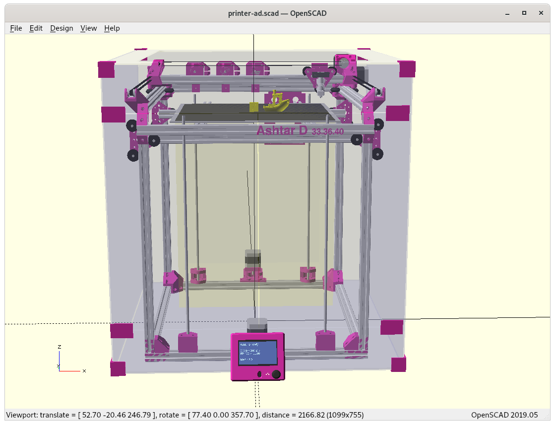
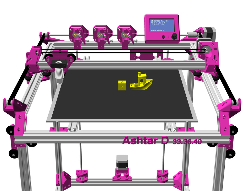
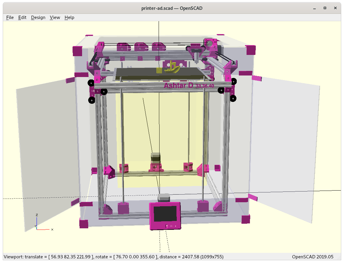
Bare without mountsX = max, Y = 0X = max, Y = maxWith X & Y motor mounts and X & Y pulley mountsIncluding 3 Bowden extruders and LCD controller3 Bowden extruders and LCD controllerParametric enclosure for Ashtar D, moving LCD controller in front bottom
After the rough design was OK, with X = 0 .. max and Y = 0 .. max and maintaining max of printable area, I went ahead and did basic Y motor mount and X motor mount, and I was designing the pieces in OpenSCAD, the ad_[xy]mount(type="motor" or "pulley") and I changed the 42×42 interface for NEMA17 to pulley holder which made it quite a fast design – so motor-side and pulley-side are very similar made with the same OpenSCAD module:
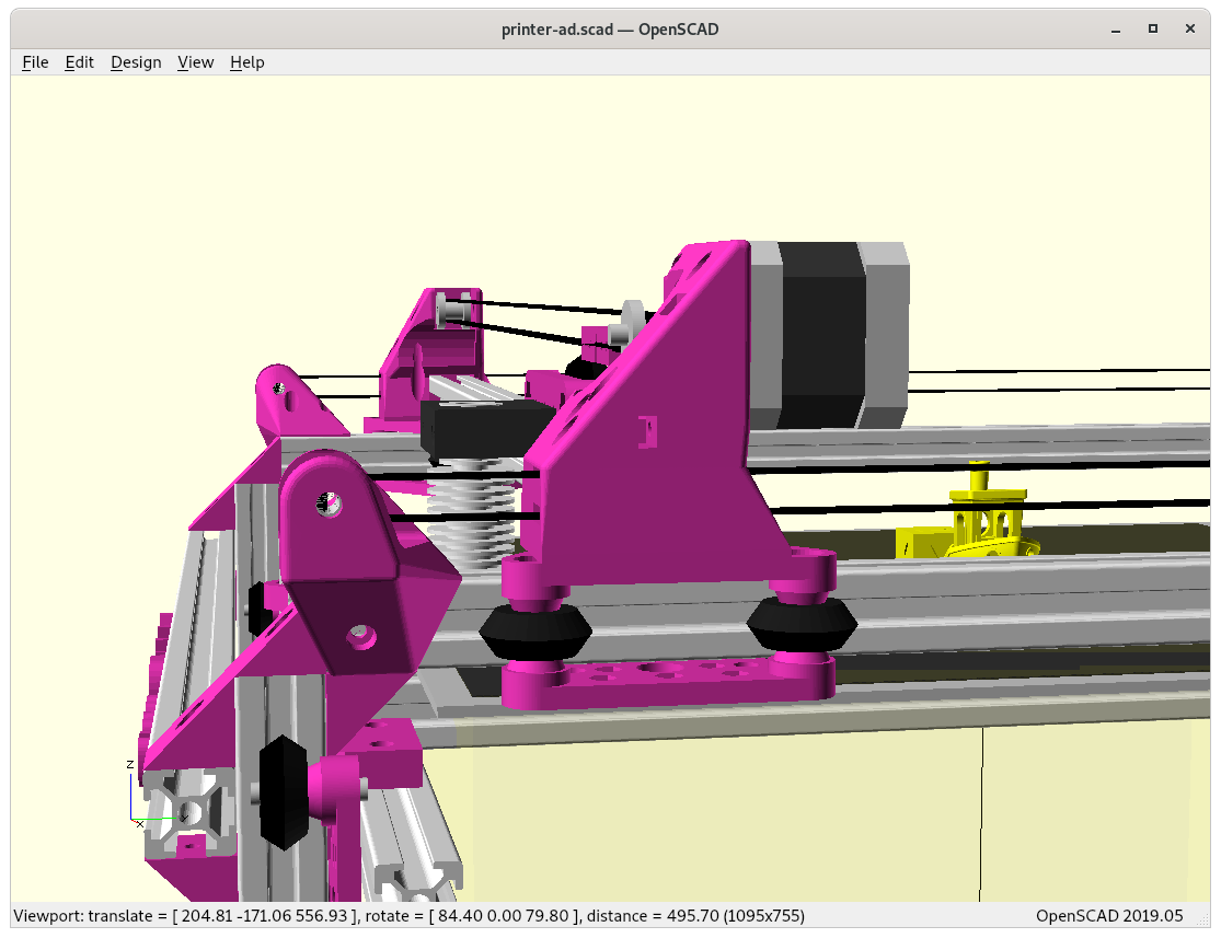
Y Motor Mount
ad_ymount(type=”pulley”) in the front, and ad_ymount(type=”motor”) in the back
At Y = max + Y margin (beyond print bed, but not yet touching anything else):
At Y = max+ Y marginBack viewTop view
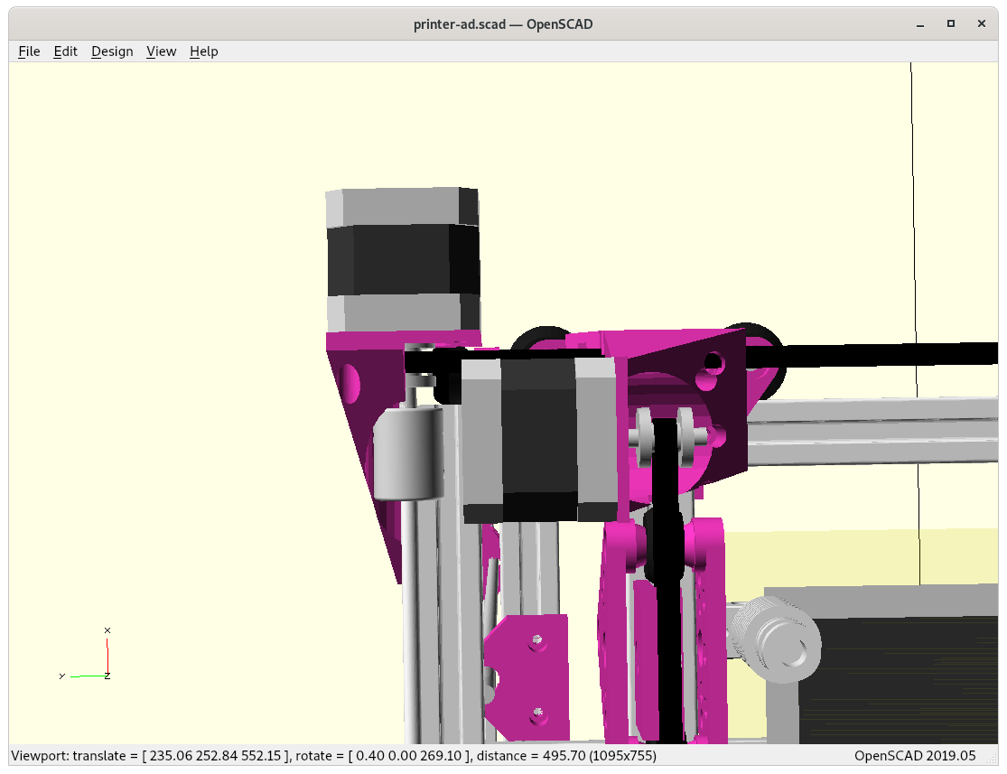
X Motor Mount
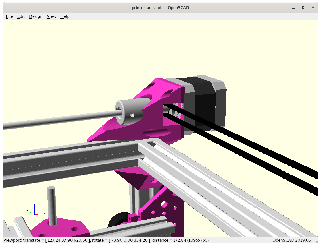
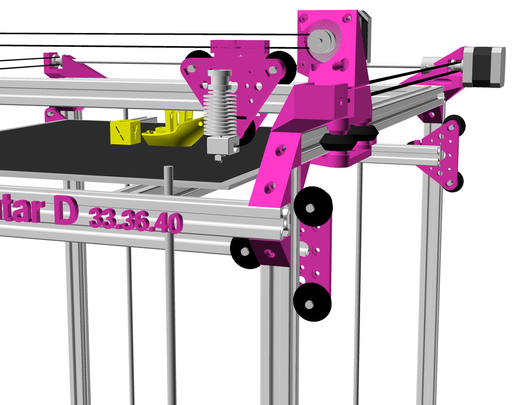
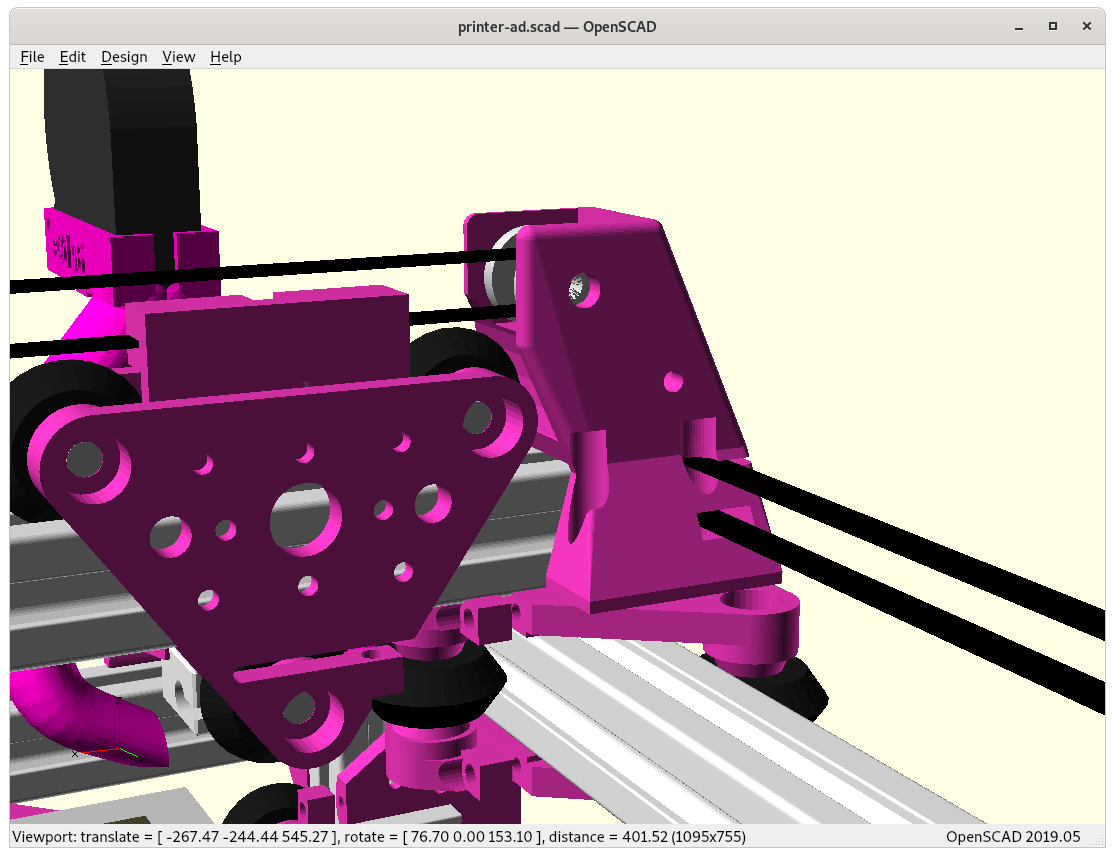
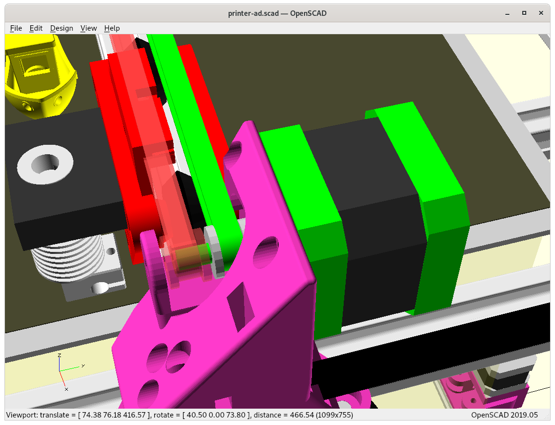
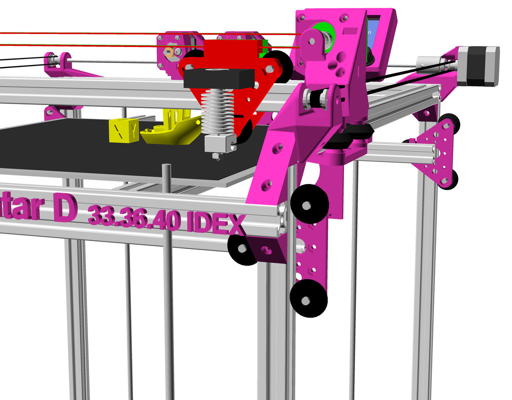
Exploring the X & Y minimum, how X carriage can as close as possible with the part cooler attached:
At X = -12, Y = 0At X = -12, Y = 0At X = -12, Y = -10
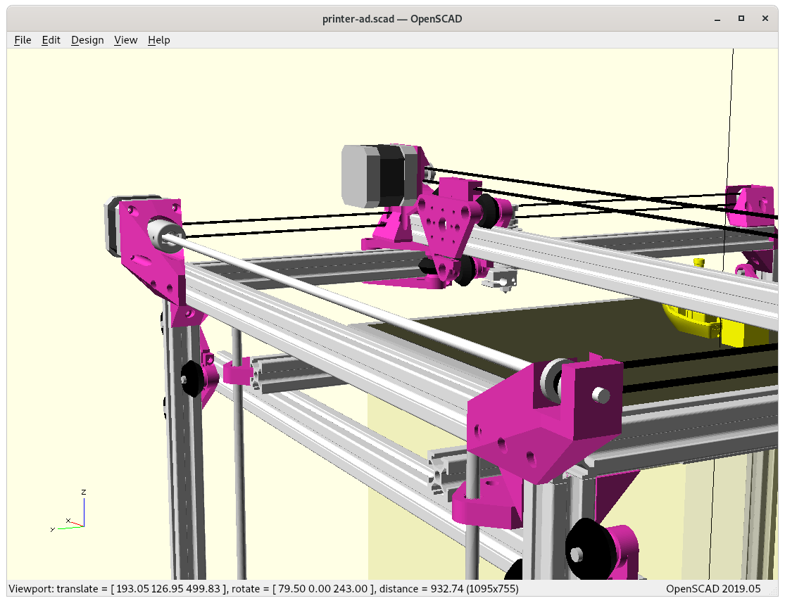
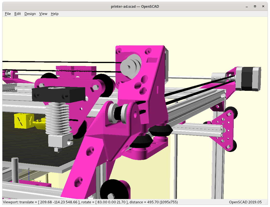
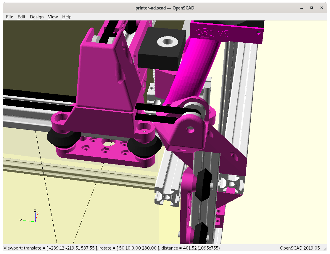
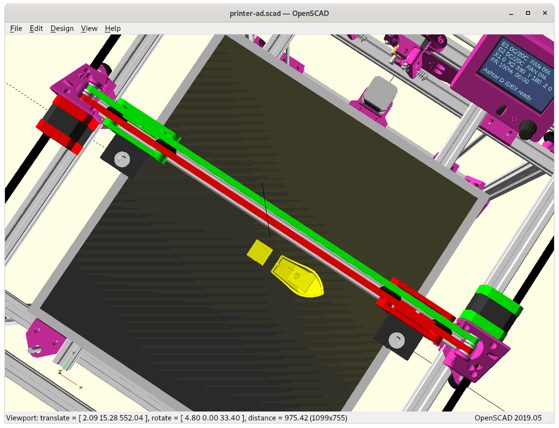
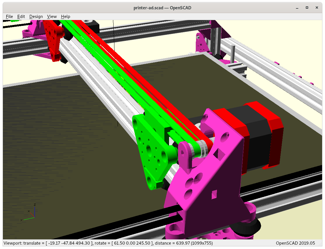
X & Y Motors / Axis
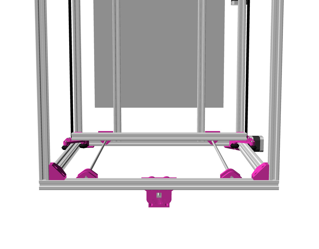
Ashtar D: Y carriage with X motor mount and X pulley (on the other side) Y motor mount and shaft extender and Y pulleyAshtar D: Y pulley mount and X pulley mount on Y carriage (in the front)
Specifications
Build Volume: ~380 x 400 x 380mm (not yet finalized)
Frame: 17x 500mm 2020 alu profiles
14x 500mm 2020 T-slot alu profiles
3x 500mm 2020 V-slot alu profiles
T-Slot 2020
V-Slot 2020
V wheel
Issues to Resolve
mounting X motor, resolved
mounting X pulleys, done
mounting Y motor, resolved
mounting Y pulleys, done
using M6 or M5 smooth or threaded rod to extend Y motor shaft
Y belt mount to carriage, done
positioning: extruders, controller, power-supply (like Ashtar C)
positioning: X, Y and Z end-switches
tuning toward 400x400x400mm build volume with 500mm 2020 alu profiles
build printer
print tests
release parts
release code
Gallery
Classic XY vs Core XY
Compared to Ashtar C Core XY the Ashtar D is less elegant, more complex parts but better setup using the rather thin 2020 alu profiles for such a big build volume.
Just cube()Using rcube()Using cylinder() & cube()Using rcylinder() & rcube()Final version, using rcylinder() and rcube()
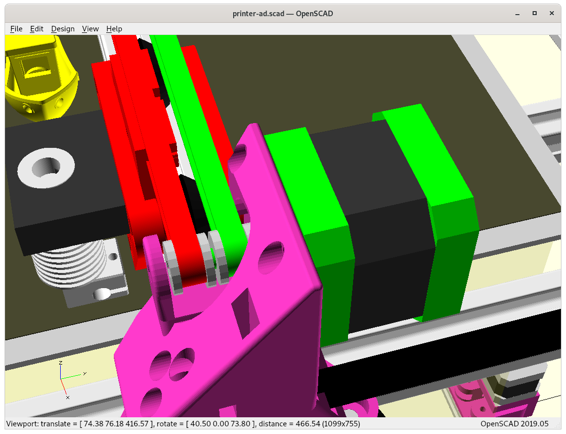
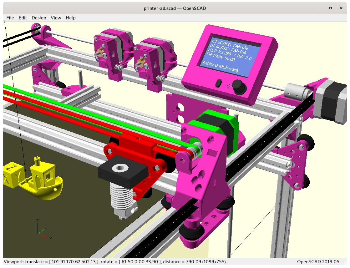
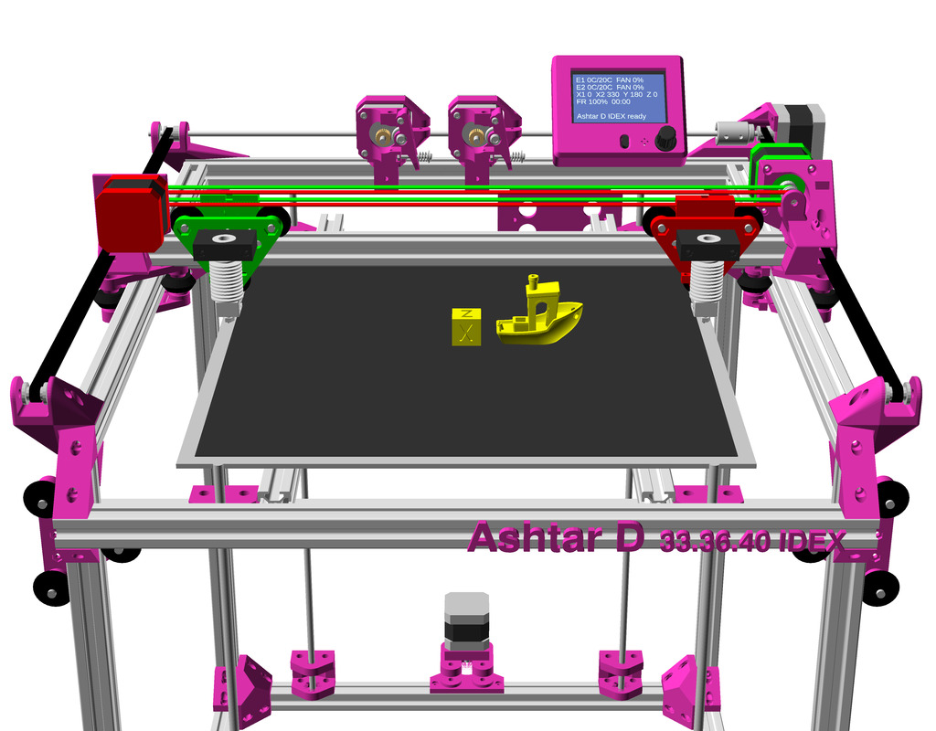
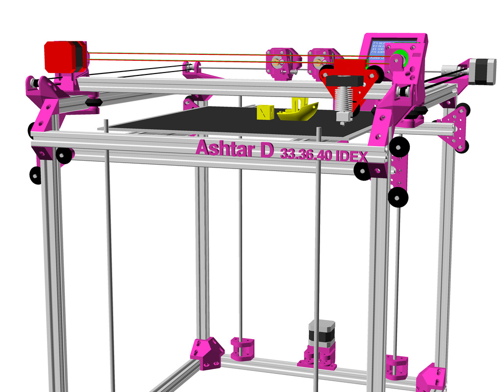
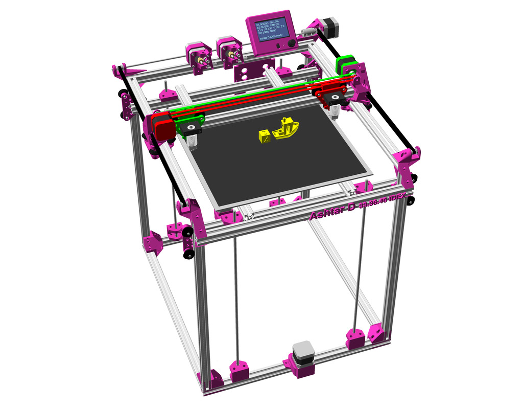
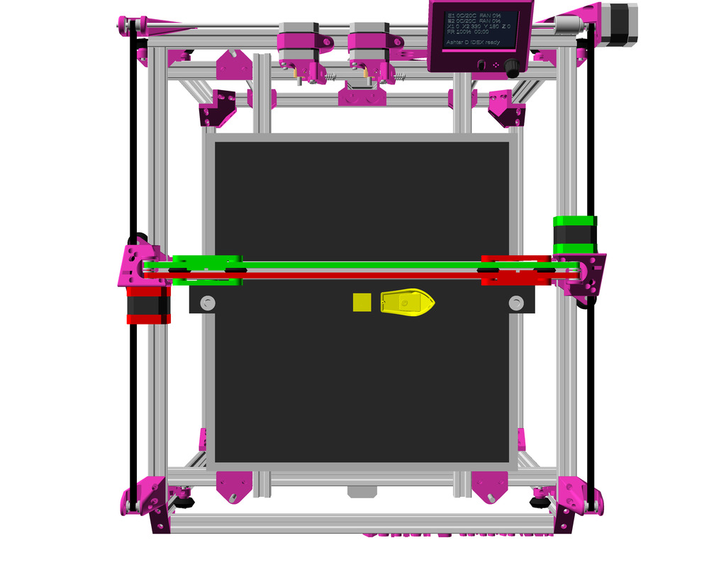
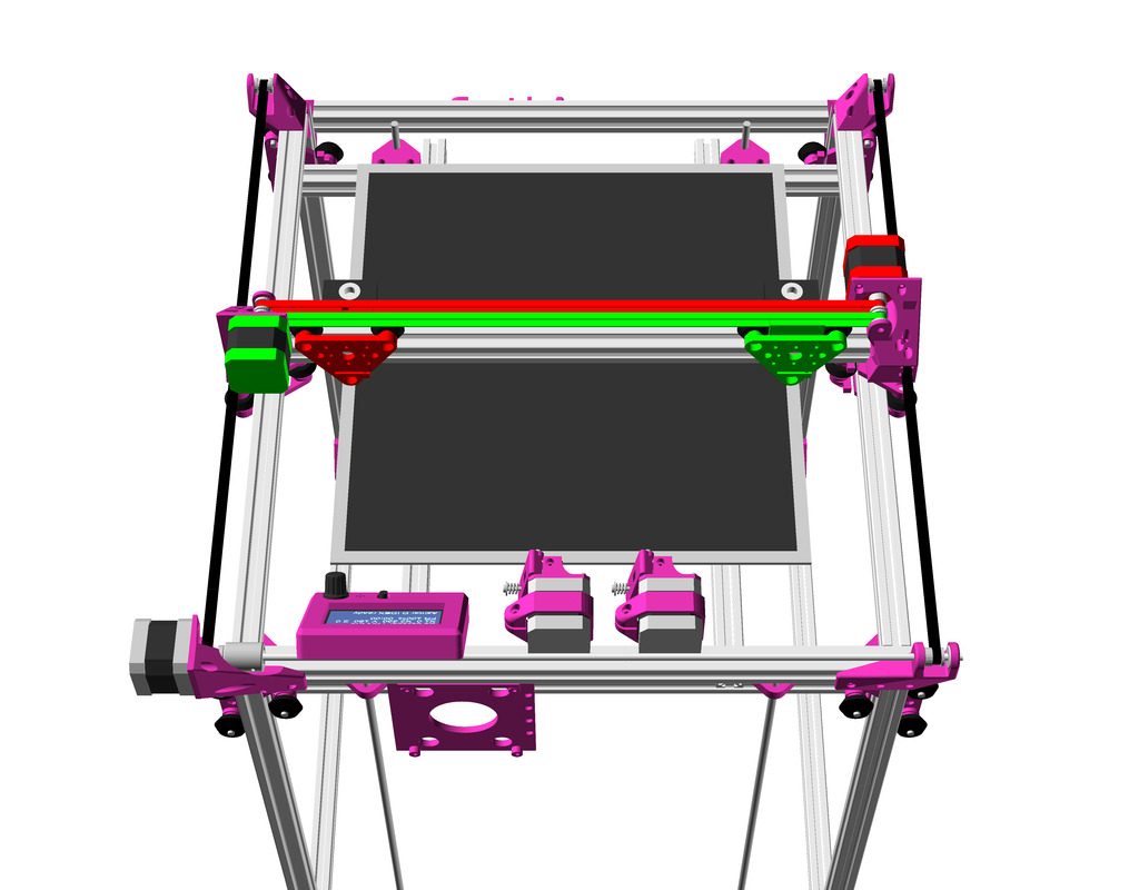
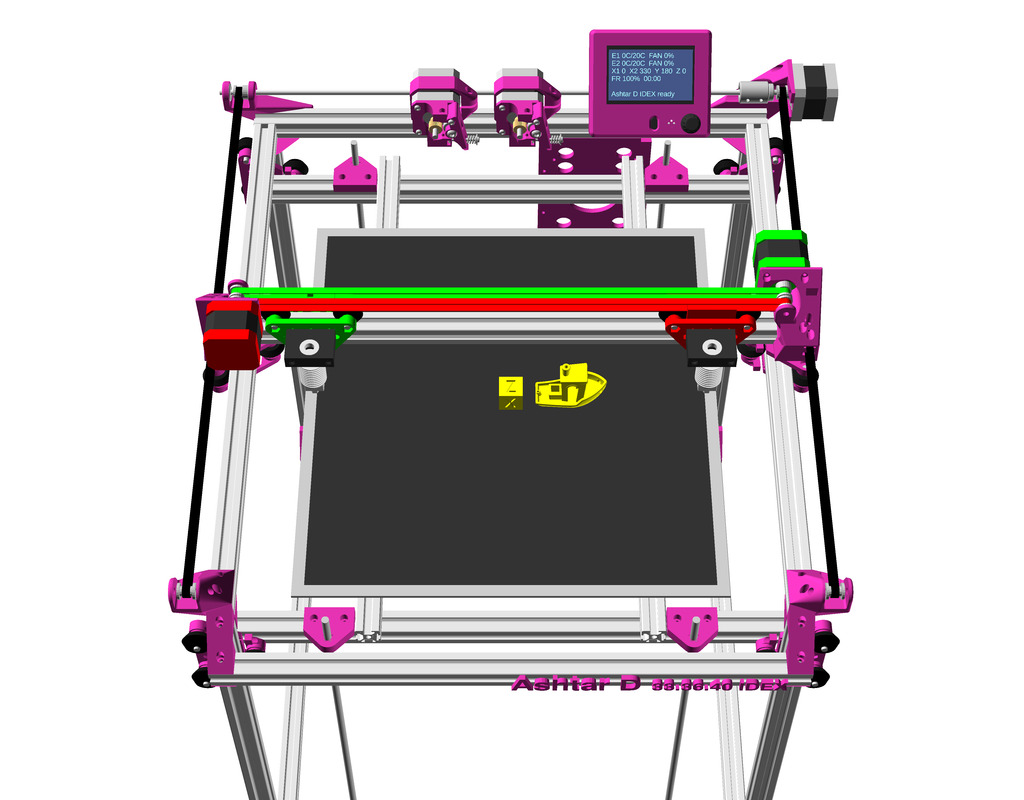
IDEX Option
In order to provide Dual Independent Extrusion (IDEX) a 2nd belt and motor is required, yet, the Y carriage is quite delicate in this current setup but after some pondering I think I came up with an elegant solution: the main idea is to utilize the NEMA 17 shaft as axis for 2nd belt idler:
Reusing NEMA 17 shaft as axis for idlerReusing NEMA 17 shaft as axis for idler (see through)
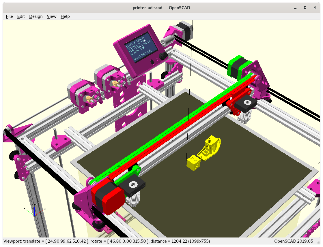
and then rotate the same Y carriage on the other side:
Since the entire Ashtar D design is still just a draft, this IDEX setup is also very experimental in nature and only actual build will tell if it’s feasible.
Ashtar DAshtar D IDEXAshtar DAshtar D IDEX
Gallery
Z Axis & Motors
It has been tested successfully with Ashtar C, so I use the same setup again:
Ashtar C/D: Z Axis / Motor
Ashtar C/D: Z motor mountAshtar C/D: Z motor and Z axis
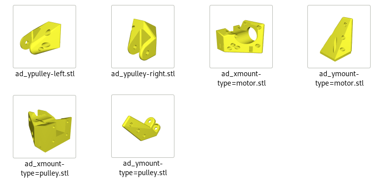
Parts
Printable Parts
1x ad_xmount-type=motor
1x ad_xmount-type=pulley
1x ad_ymount-type=motor
1x ad_ymount-type=pulley
1x ad_ypulley-left
1x ad_ypulley-right
Note: the new parts aren’t released yet until I used them in a test setup.
Non-Printable Parts
2x 625ZZ bearings ID=5mm
2x for 1x ad_ymount-type=pulley
12x 629ZZ bearings ID=6mm
8x for 4x Z thread holder (2x bottom)
4x for 4x Z thread holder (top)
nx pulleys (dimension not yet determined)
2x (5mm hole) for 2x Z motors
1x (5mm hole) for 1x X motor
2x (5mm hole) for 1x Y motor, 1x ad_ymount-type=pulley
4x (6mm hole) for Z threaded rods
nx idlers (with 3 or 5mm hole)
2x (3mm hole) for 1x ad_ypulley-left, 1x ad_ypulley-right
~520 mm M5 smooth or threaded rod (Y shaft extension)
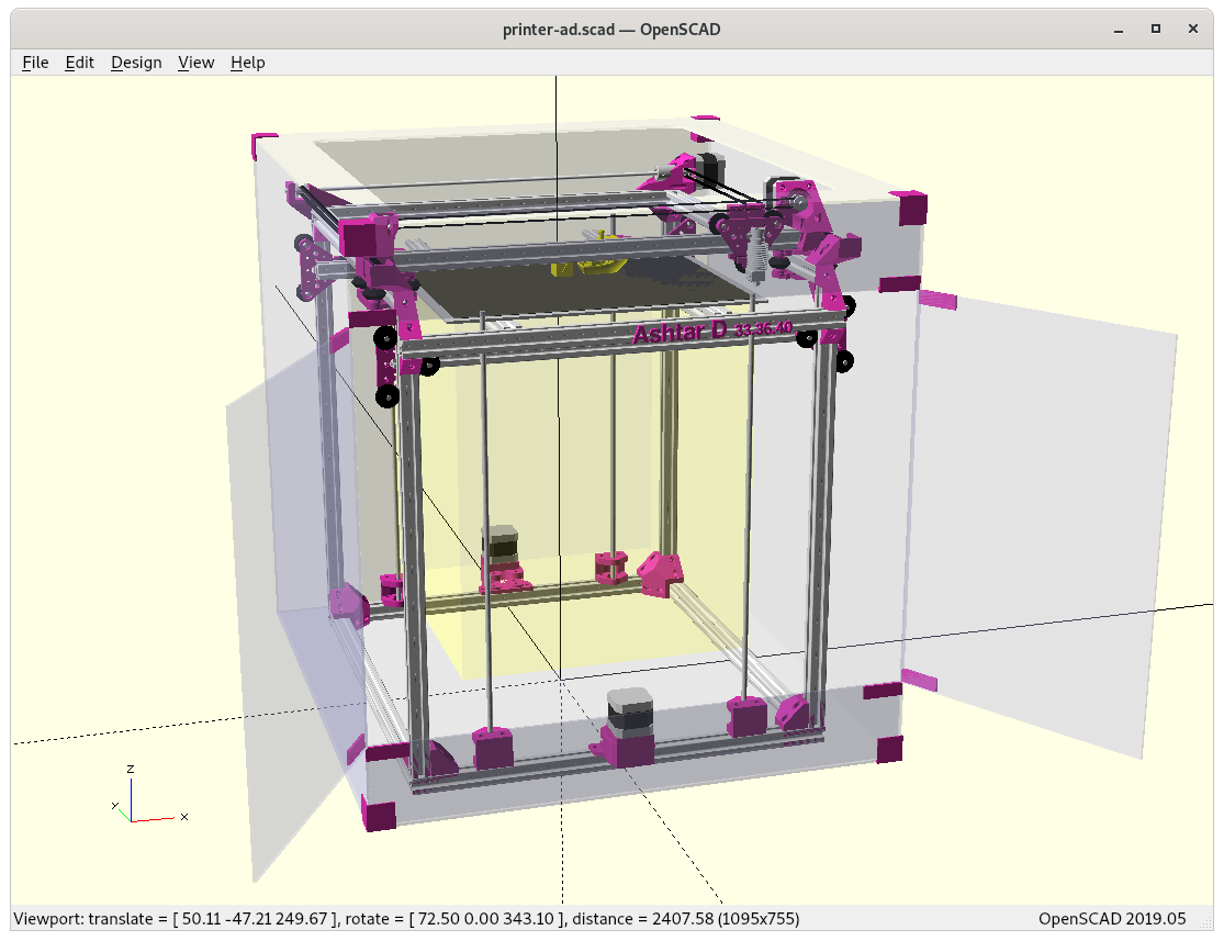
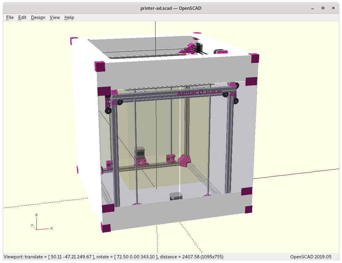
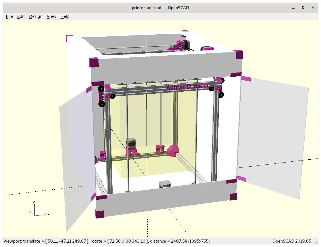
Enclosure
Developing some enclosure, either attach to the Z beams – as one side is free to fasten pieces and use acrylic sheets – or enclose entire frame, like with
With the enclosure the display must be reachable, and therefore likely be on the front and longer wires from the controller board, which most likely resides on the back right side as with Ashtar C.
Build Volume: 380 x 400 x 380mm (57.7Kcm3 / 57.7L) = 100%
Device Dimension: 590 x 650 x 620mm (237Kcm3 / 237L)
Build vs Device Volume: 4.11
Creality CR5
Build Volume: 300 x 225 x 380mm (25.6Kcm3 / 25.6L) = 44%
Device Dimension: 530 x 487 x 621mm (160Kcm3 / 160L)
Build vs Device Volume: 6.25
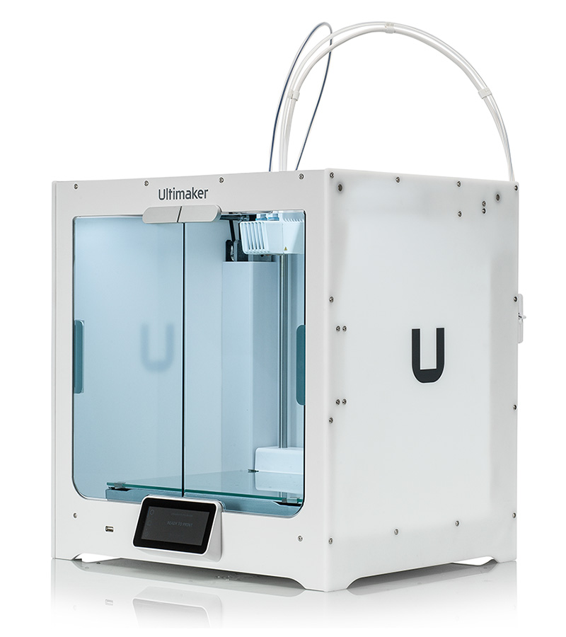
Ultimaker S5
Build Volume: 320 x 240 x 300mm (23.0Kcm3 / 23L) = 40%
Device Dimension: 495 x 585 x 780mm (225Kcm3 / 225L)
Build vs Device Volume: 9.78
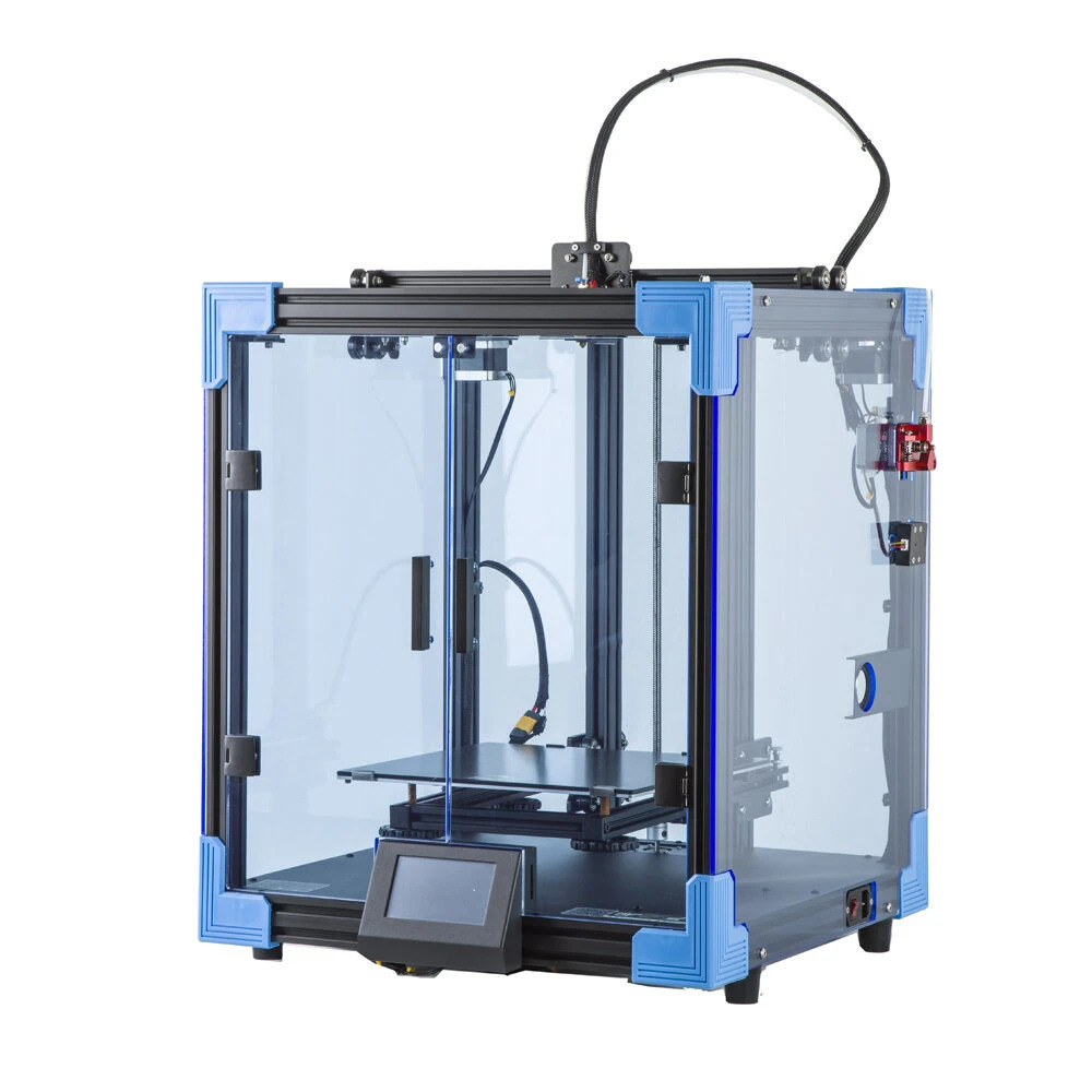
Creality Ender 6
Build Volume: 250 x 250 x 400mm (25.0kcm3 / 25L) = 43%
Device Dimension: 495 x 495 x 650mm (159Kcm3 / 159L)
Build vs Device Volume: 6.36
Ashtar D and Ultimaker S5 device volumes are nearly the same, 237Kcm3 vs 225Kcm3, but Ashtar D would print more than the double of the volume – so it would be volume-wise more efficient. Creality CR5 and Creality Ender 6 are more volume efficient than the Ultimaker S5, but not as good Ashtar D. Let’s see if I can keep this advantage for the final implementation.
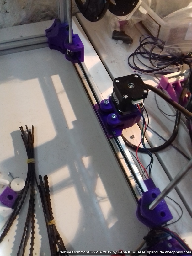
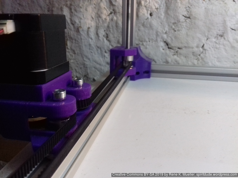
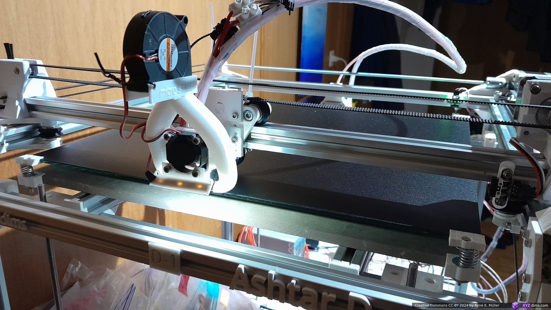
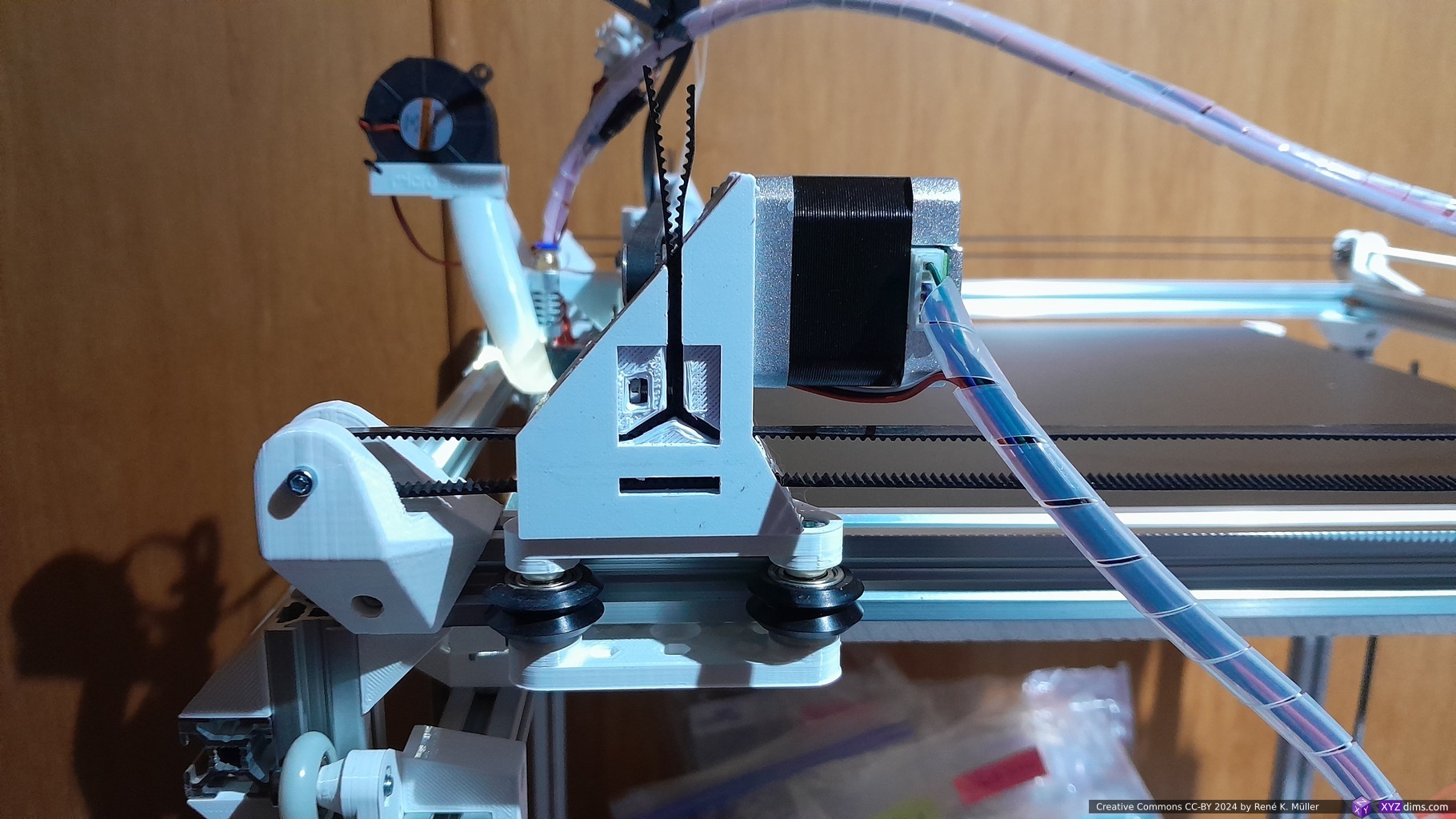
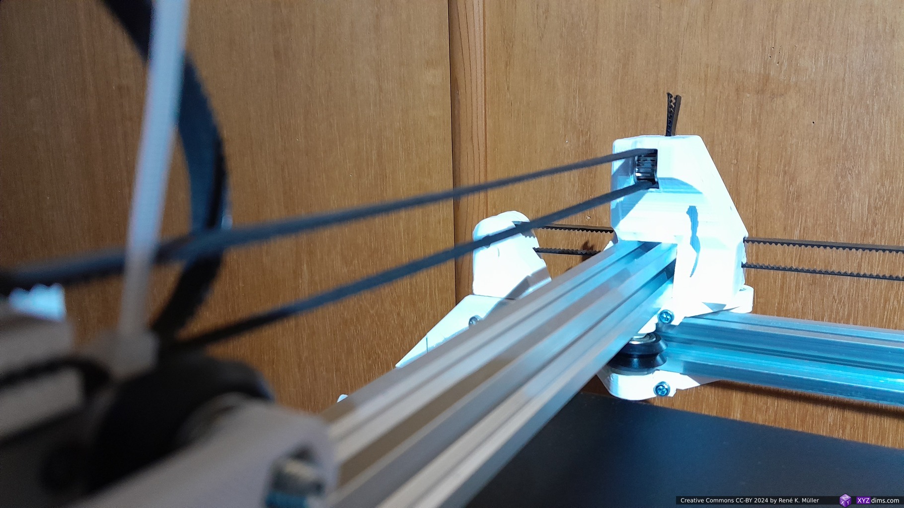
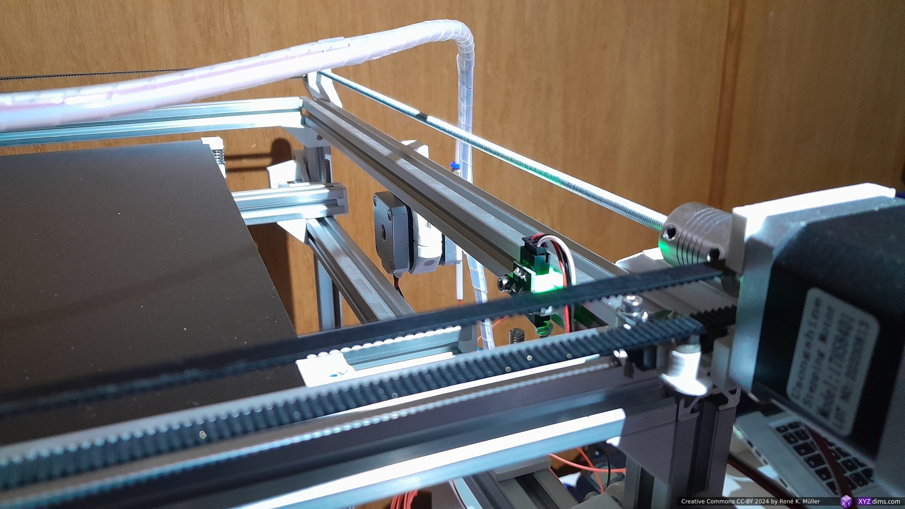
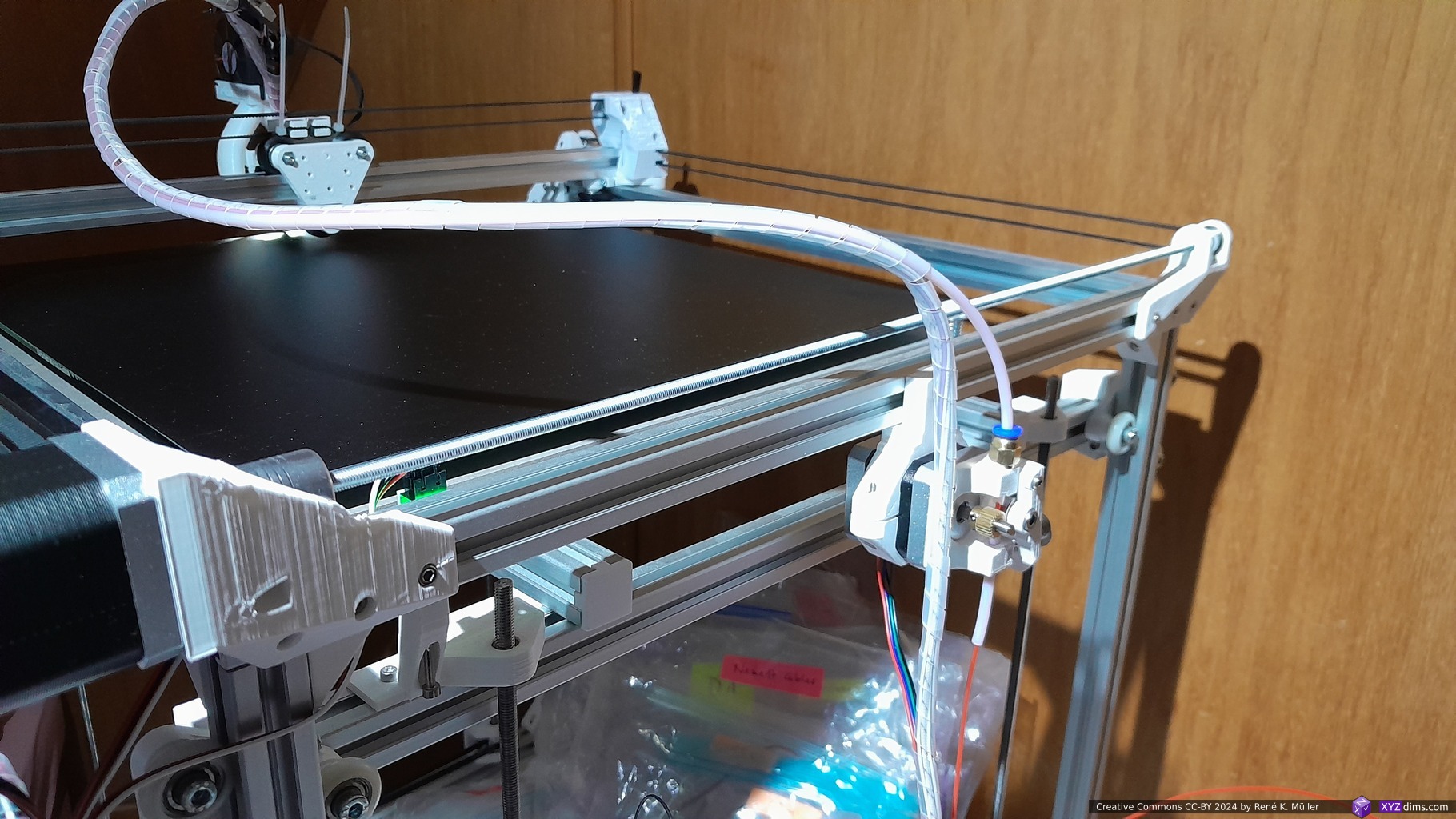
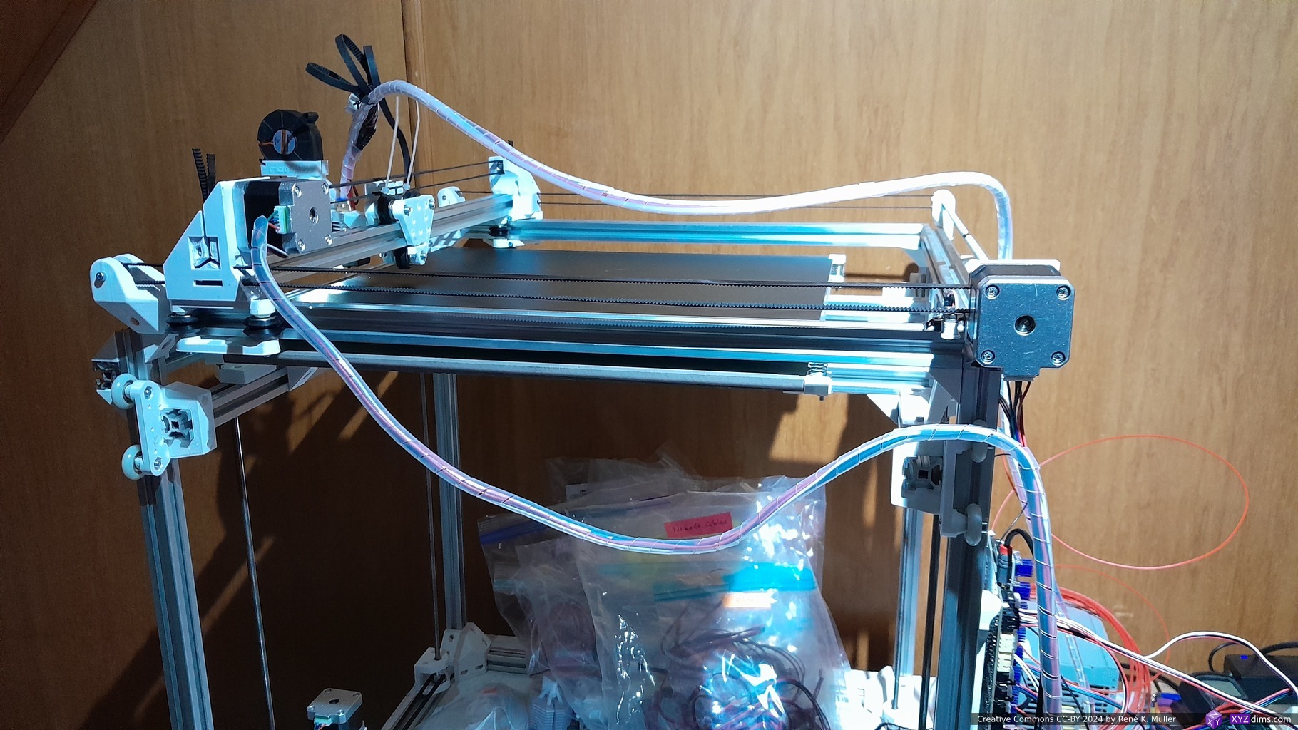
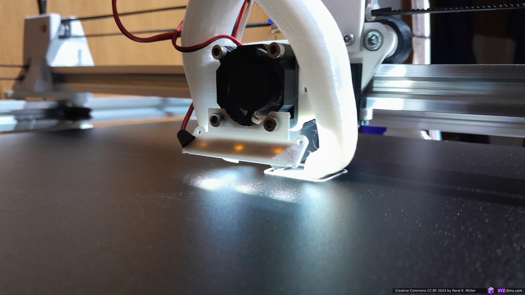
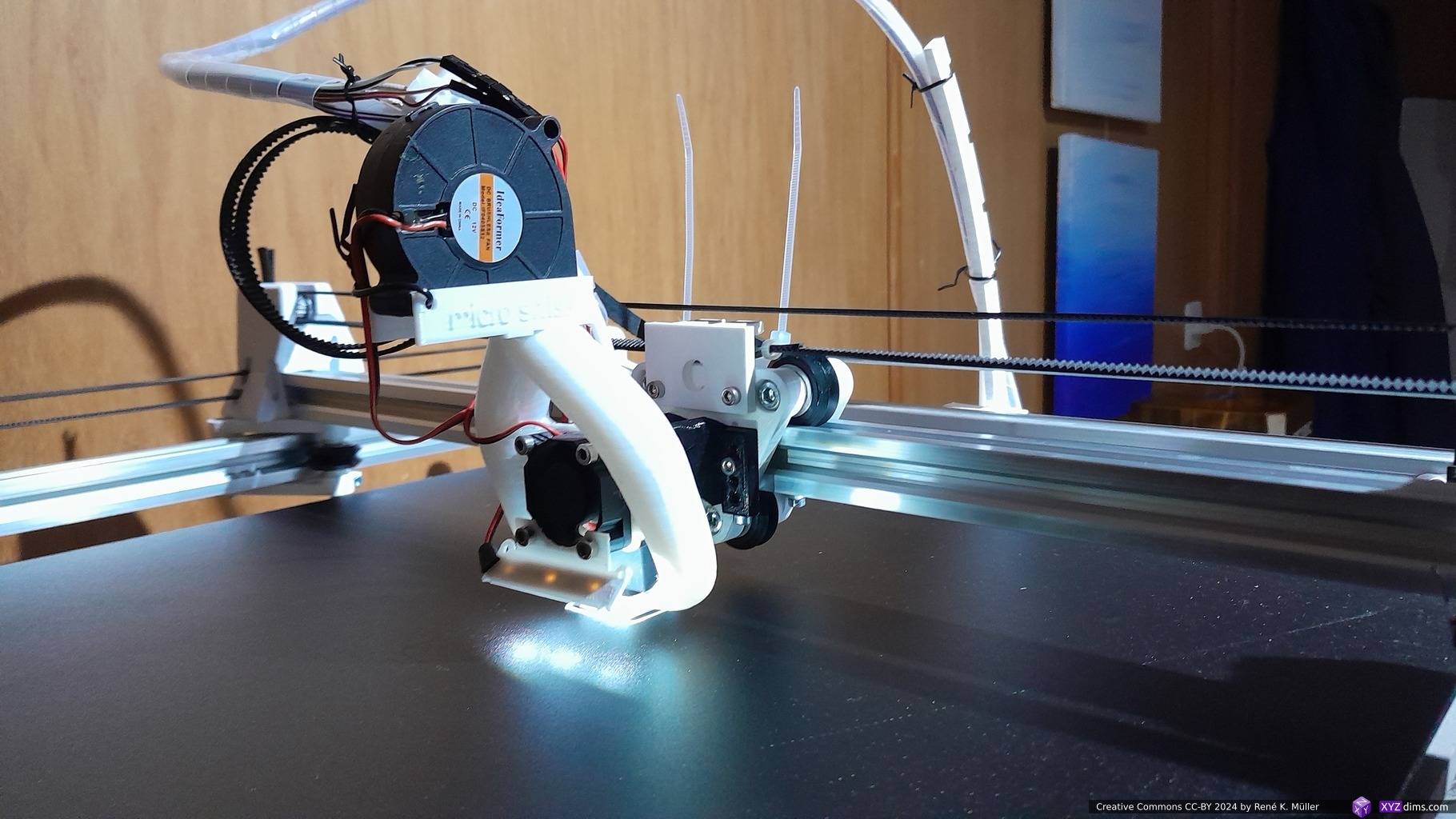
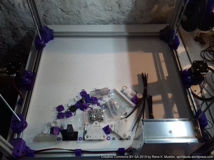
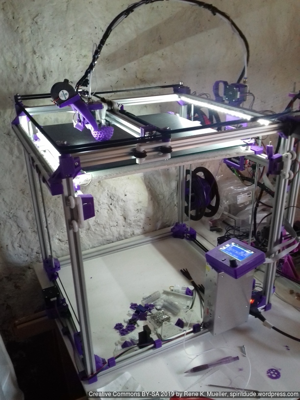
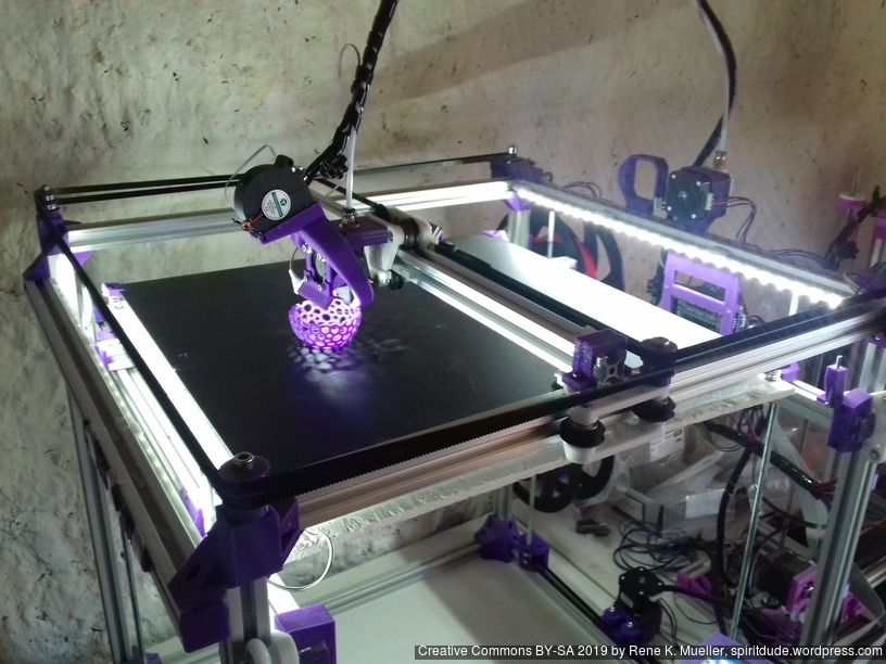
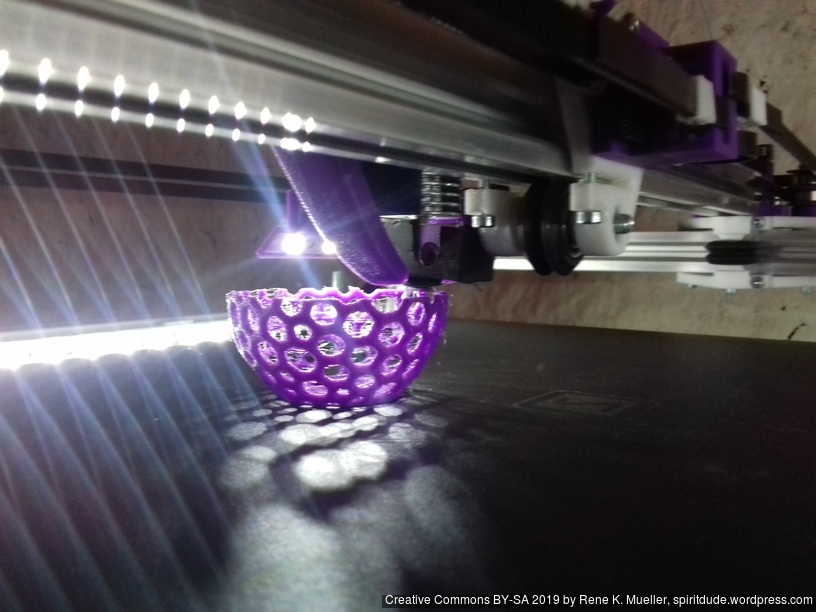
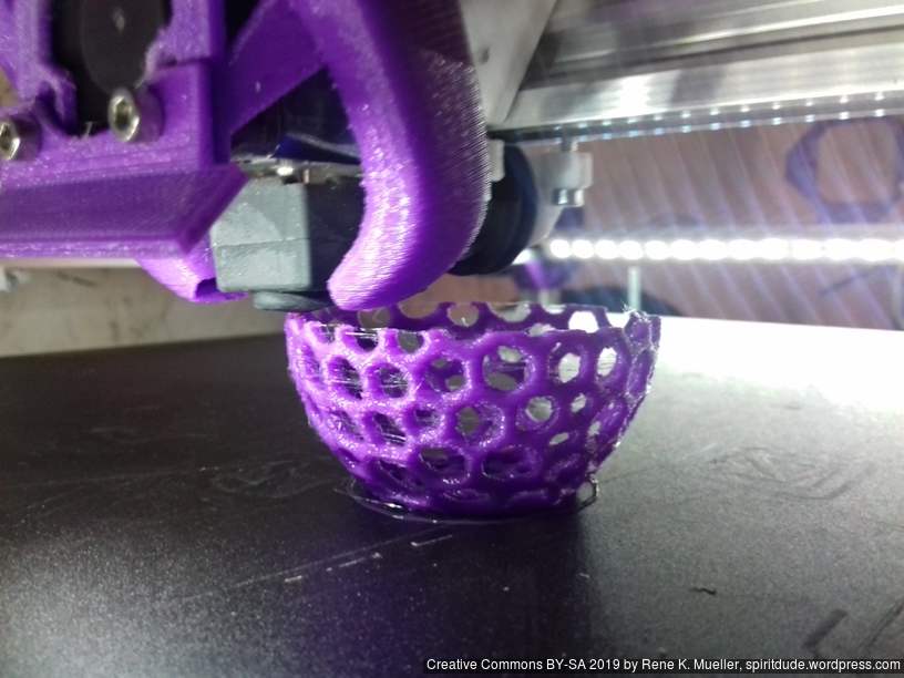
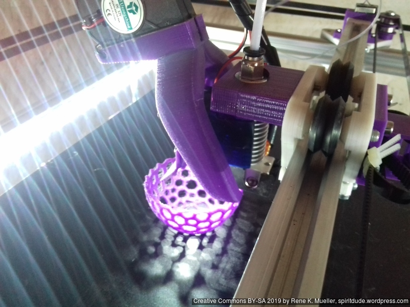
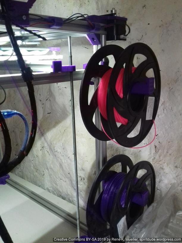
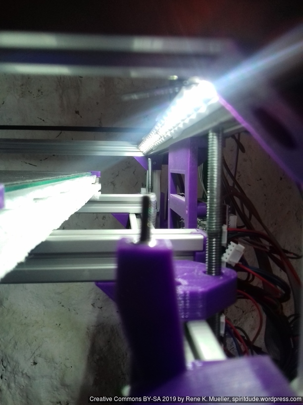
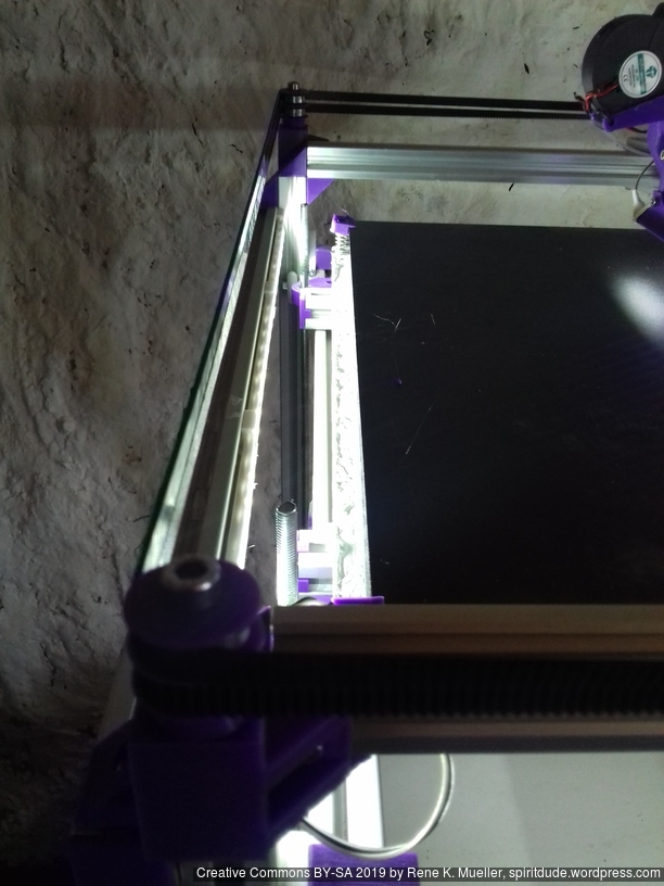
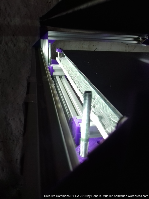
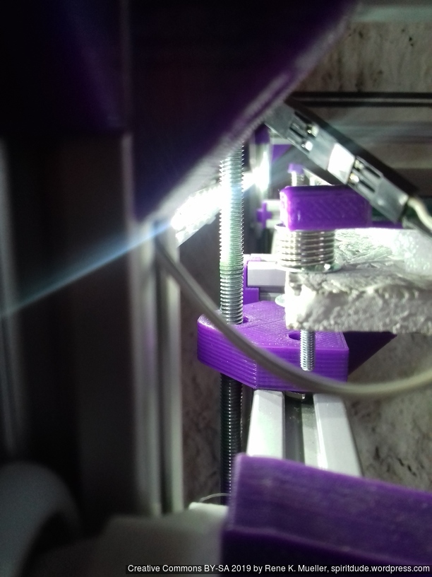
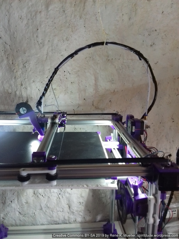
Building Ashtar D
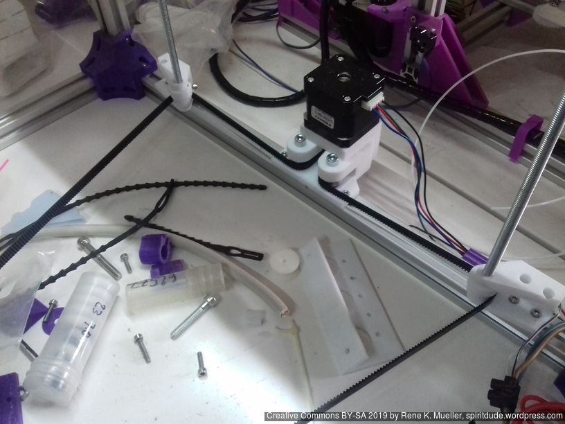
It took a while to build the Ashtar D #1 as the other variants like Ashtar K and Ashtar C worked so well – here some of the early tests in 2022/12/09:
References
Ultimaker S5: different XY head design using smooth rods, head: XY, bed: Z, build volume: 330 x 240 x 300mm, swapable hotends/printcores; priced at EUR/USD 6,500+ (2020/12)
Makerbot Replicator: head: XY, bed: Z, build volume: 295 x 195 x 165mm, priced EUR/USD 2,400 (2020/12)
Creality CR5: blatant copy of Ultimaker 2, S3 & S5 case design, head: XY, bed: Z, build volume: 300 x 225 x 380mm, priced EUR/USD 1,500 (2020/12)
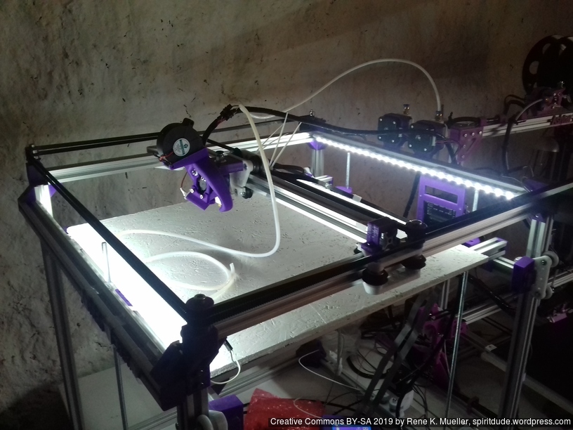
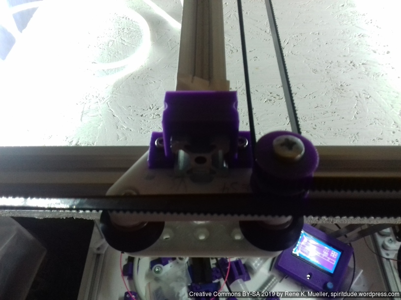
Back in September 2018 I started to code the first parts for Ashtar C, a “Core XY” type 3d printer – finally, after several weeks waiting for the several parts (bearings, closed loop belts), I was able to finalize the bed and Z axis (2018/01/30) and perform the first test prints of Ashtar C #1 composed with 500mm 2020 T-slot and V-slot alu extrusions:
Specifications
CoreXY style
Build Volume: 380 x 400 x 380mm
Frame Size: ~500 x 500 x 500mm
Bed
400 x 400mm black bed sticker (~0.7mm thick)
400 x 400 x 4mm mirror (custom order)
4x bed corner mounts (printed), with M3 x 30 and spring and 4x washers each
420 x 420 x 4mm OSB
residing on 2020 T-slot alu extrusions.
Z Axis
1524mm GT2 closed belt: even though driving 4 threaded rods worked somehow, but not reliably therefore:
Option A
2x Nema17 (45Nm) stepper motor with 18 teeth GT2 pulley 5mm bore
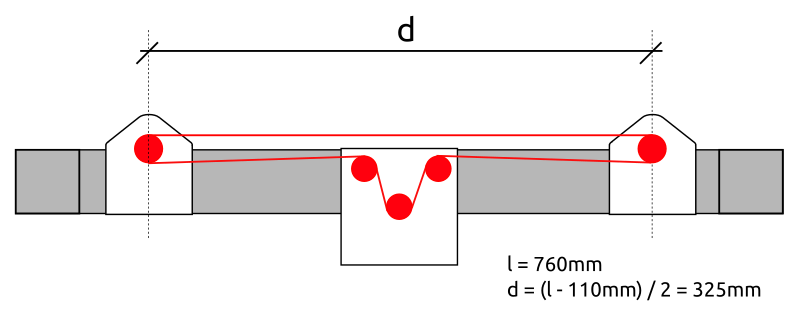
2x 760mm closed belt
Option B
Using 3 or higher : 1 gear box (e.g. 3:1 gearbox could be used, but external shaft isn’t strong enough stabilized versus tilt) or alike to increase torque and still drive 4 threaded rods
4x M6 x 490mm threaded rods
4x M6 nuts with bed mounts (printed)
4x bottom Z rod mount (printed)
8x 606ZZ bearings (each rod has 2 bearings)
4x 18 teeth GT2 pulley 6mm bore
Challenges
Following challenges came up in the first test prints:
CoreXY principle works well, yet, the friction of each idler really matters as it increases risk of missing steps, well greased and well positioning mandatory
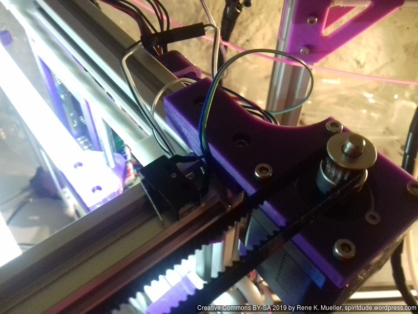
X endstop: right now positioned on the left hand side of the X beam, but the cable hangs down – likely need to reposition X endstop on the X carriage itself
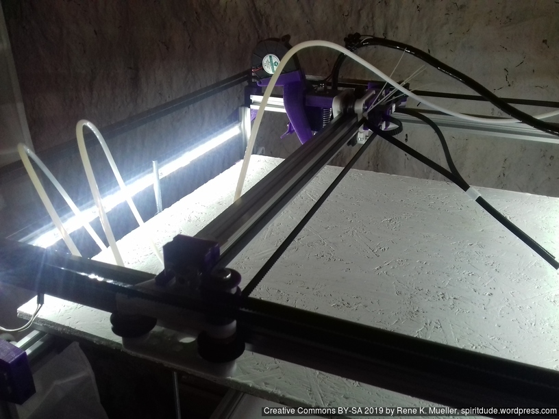
the Bowden tube is long and so hangs to the bed, the tube (4mm OD, 2mm ID) isn’t stiff enough to bend upward, so requires some guidance to ensure it doesn’t ride on the bed surface and entangles with print process
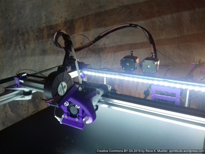
E3D V6 clone this time really does not perform well: extrusion is not even, and missing steps of the extruder; requires further investigation.
thermistor seems off, increasing to “220C” print temperature, gave better and cleaner prints
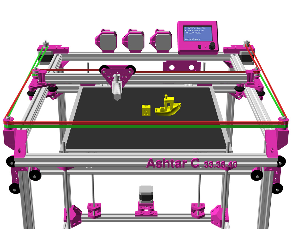
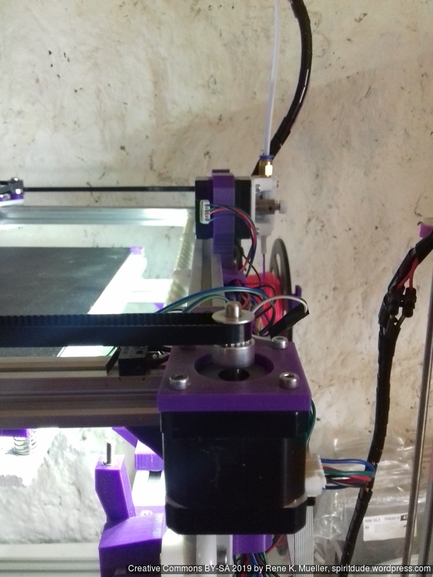
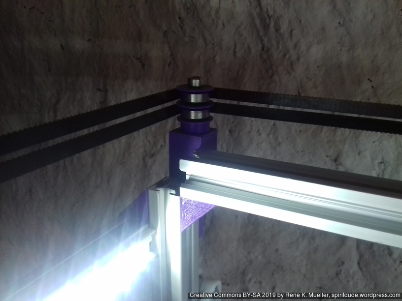
After some delay of parts, I finally was able to finalize the belt routing and configure the firmware for Ashtar C #1:
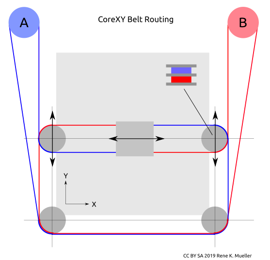
Belt Routing
CoreXY belt routing of Ashtar C
Early on I decided to separate belts of motors A and B in the Z axis, so they would not cross as such, and also hoped one axis of the carriage holding the X beam would allow some idlers to redirect the belts – to save space and keep frame dimension and build (or printable space) dimension close.
The Bowden tube and the wires of the hotend are preliminary arranged:
Firmware
To configure the Marlin firmware turned out not that simple, as CoreXY has its own interdependencies of A & B motors: first X axis was reversed, whereas Y axis worked correctly, the INVERT_X_DIR setting on Configuration.h of Marlin did not help, it reversed the stepper motor direction, but not the actual X axis direction. After many attempts to use COREYX instead of COREXY I ended up
swap cables of A & B stepper motors
keep #define COREXY
#define INVERT_X_DIR = true and #define INVERT_Y_DIR = true
and X and Y direction worked correctly.
Preflight (no extrusion, just X & Y axis movement testing):
The stepper drivers still need some tuning, as I saw or rather heard a few missed steps at fast movement.
X & Y Endstops
The preliminary positions of the endstop are:
X endstop resides on the X beam left-hand side (USE_XMIN_PLUG)
Y endstop resides on the right-hand backside, (USE_YMAX_PLUG and HOME_DIR_Y 1)
X endstop
Y endstop
Z Axis
I postponed the actual details of the Z axis, as my main concern of the design was to have a good CoreXY setup and then see how I would achieve the Z axis.
In order to use 625ZZ bearings I started to use them as idlers directly (after cleaning the grease off their surfaces) and also use them to increase contact surface when driving a closed belt which drives 3 or 4 threaded rods M6 x 500mm:
Since the surface of the threaded rods is rough, I realized I need dedicated bearings to hold the rods at the bottom, otherwise the friction would wear on the mounts and increase its diameter. So, the Z axis isn’t finalized yet, but close.