
Table of Contents
Introduction
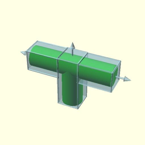
In order to take advantage of 4- and 5-axis non-planar FDM1) printing (e.g. tilted, conic, cylindrical, spherical) the model may be segmented and then dedicate slicing methods can be assigned to such sub-volumes.
A few basic examples combining planar and non-planar slicing methods on sub-volume segmented models illustrating the possibilities printing without support structures:
- Fused Deposition Modeling (FDM) also known as Fused Filament Fabrication (FFF)
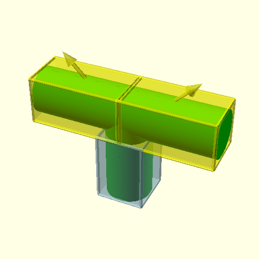
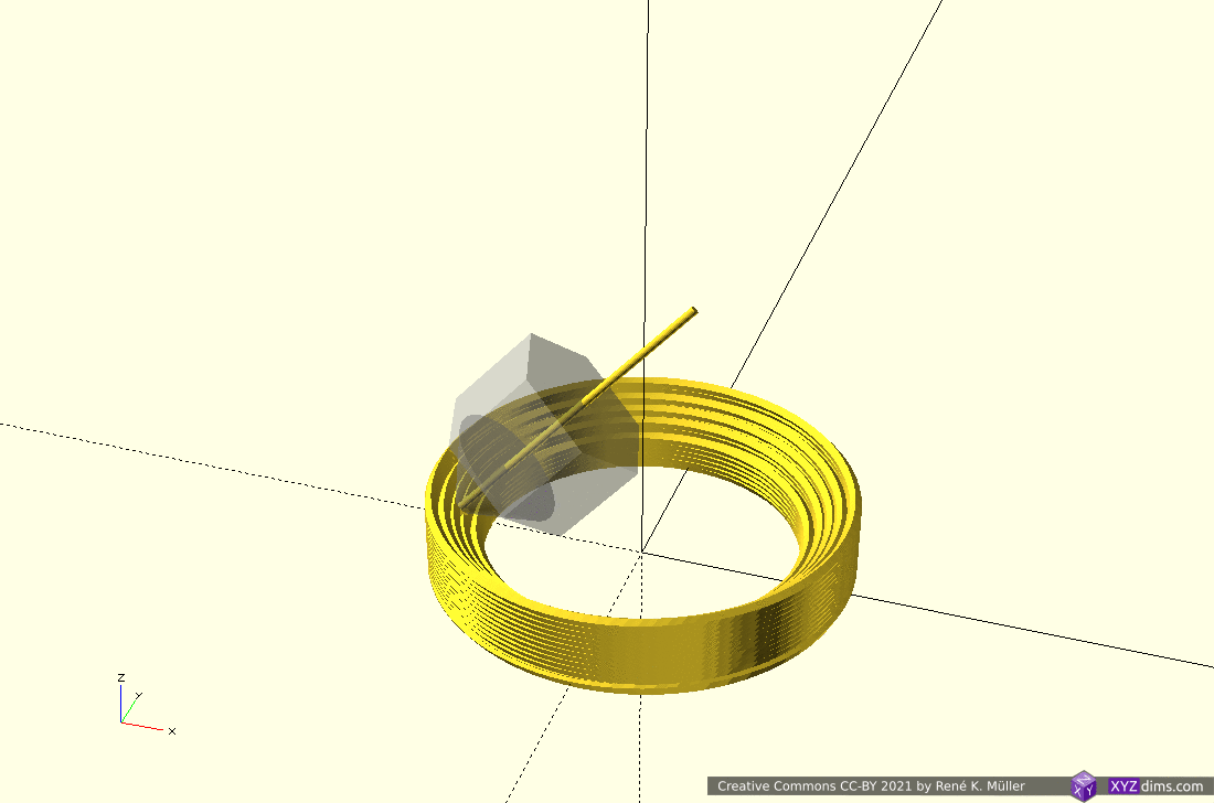
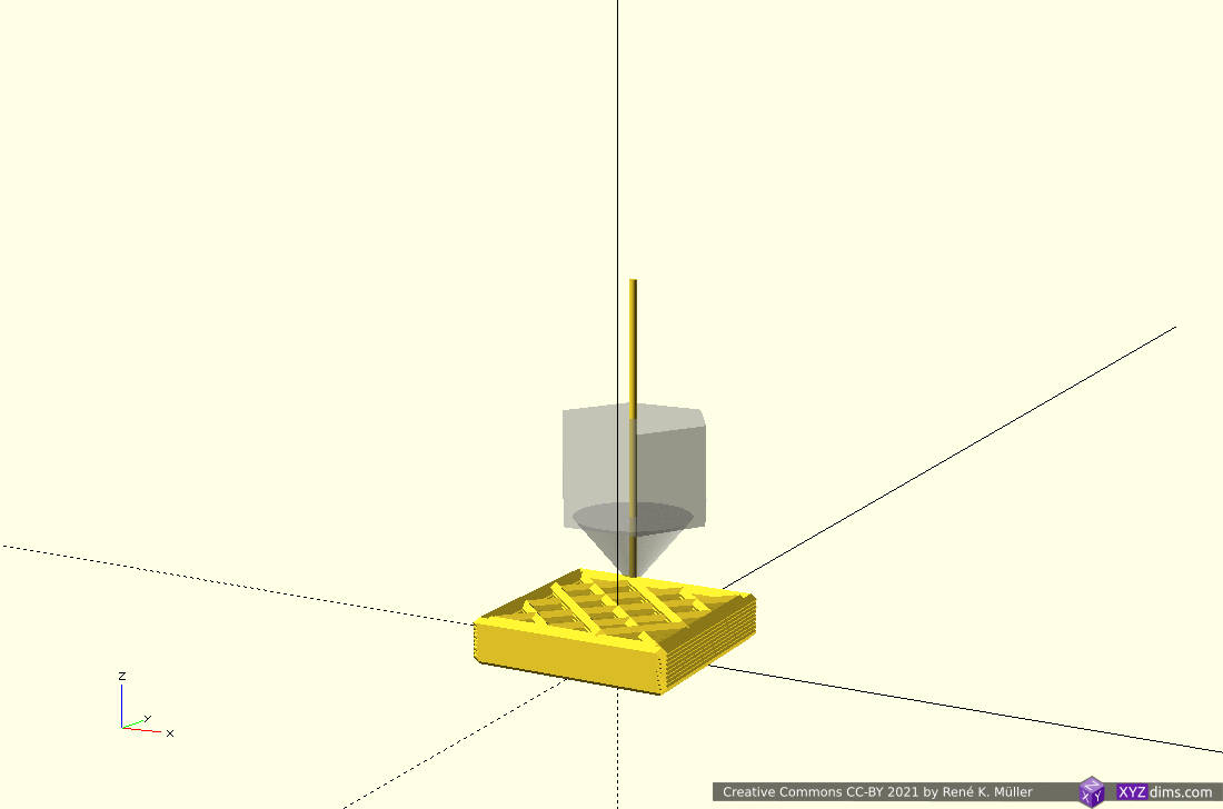
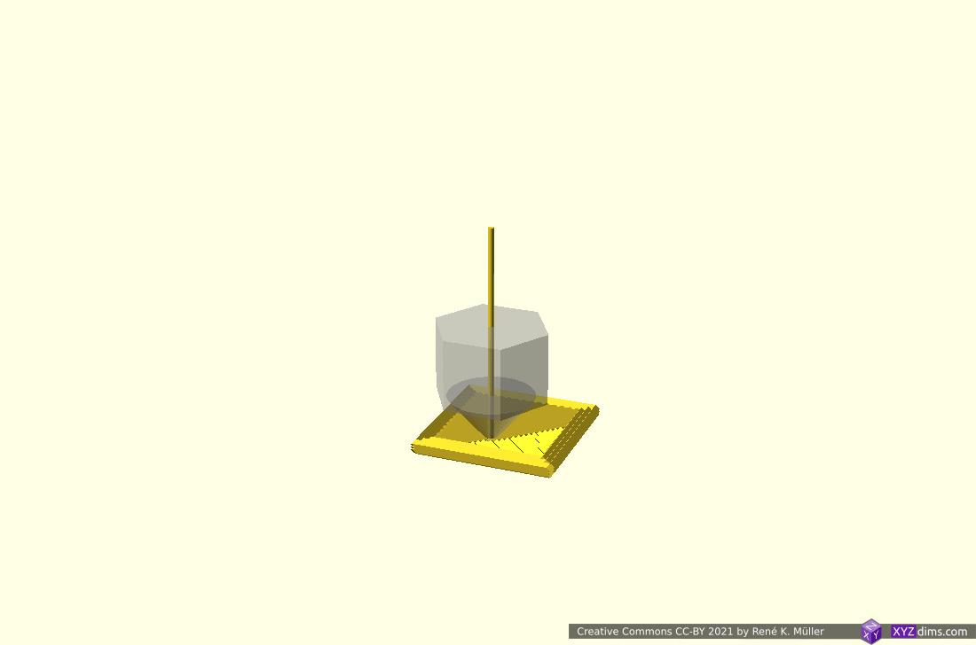
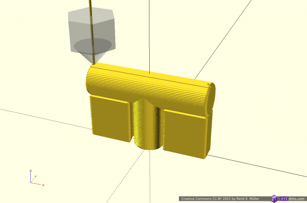
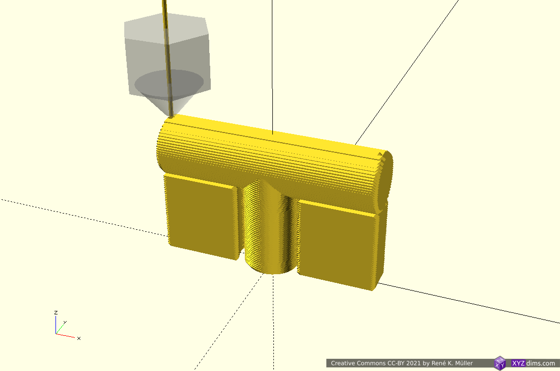
T-Model: 2 Segments: Z-planar & Conic
Utilizing novel conic slicing as introduced by ZHAW researchers in 2020/2021:

2 segments: z-planar, conic (outside-cone) 
starting z-planar 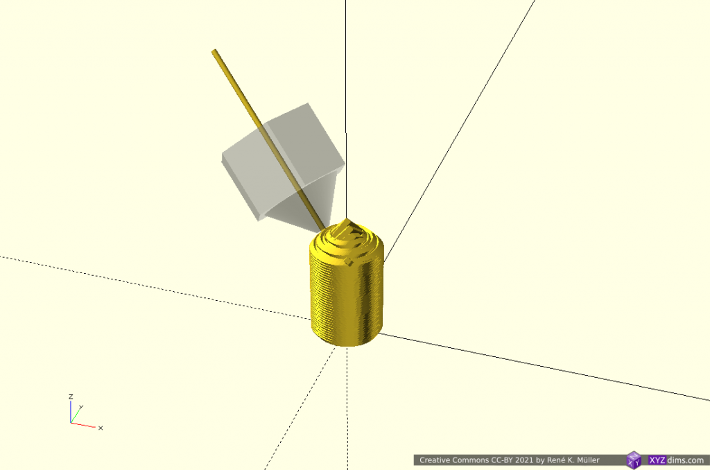
2nd segment conic on top 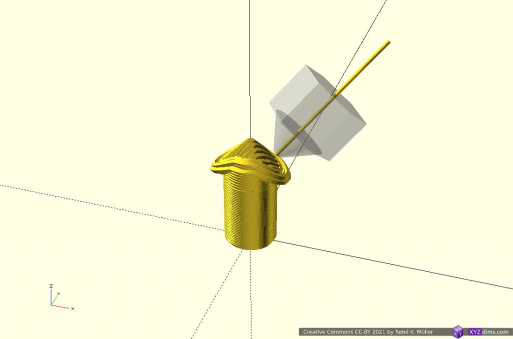
conic segment going overhang 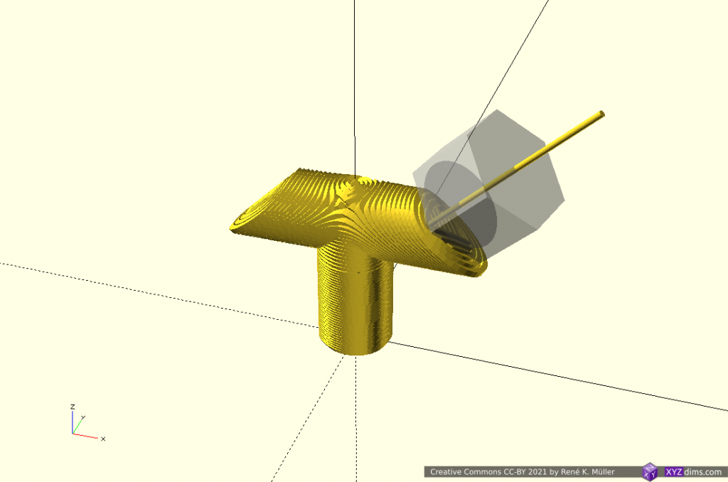
extending both sides 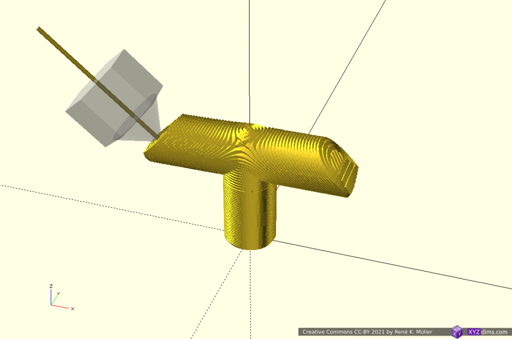
extending both sides 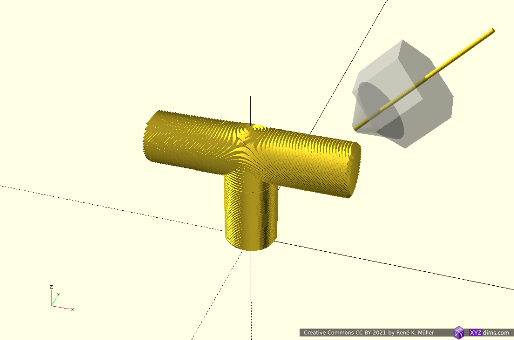
finished piece
Conic slices can be printed with 4-axis Rotating Tilted Nozzle (RTN) although printing the Z-planar sliced part might not give goods surface results but rather using a 5-axis Penta Axis (PAX) printhead to cover both cases easily.
T-Model: 3 Segments: Z-planar & 2x Tilted
Using non-rotating but tilted sliced (like used with belt-printers) but in two distinct directions:
3 segments: z-planar & 2x tilted 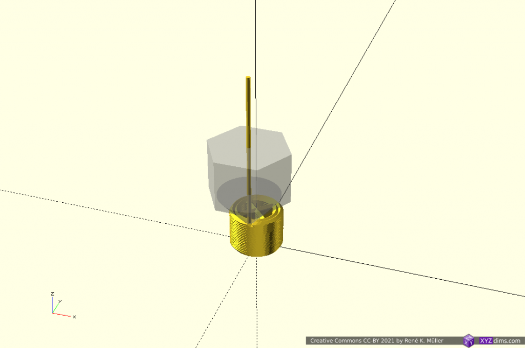
starting z-planar 
finishing z-planar 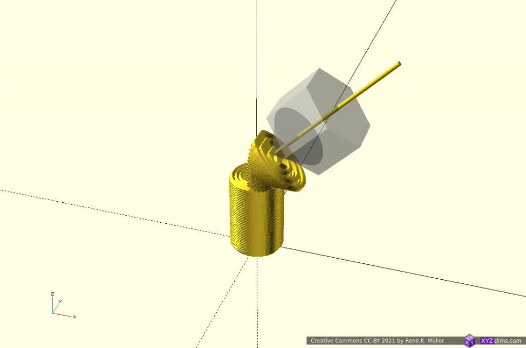
starting 2nd segment with tilted slices into one direction 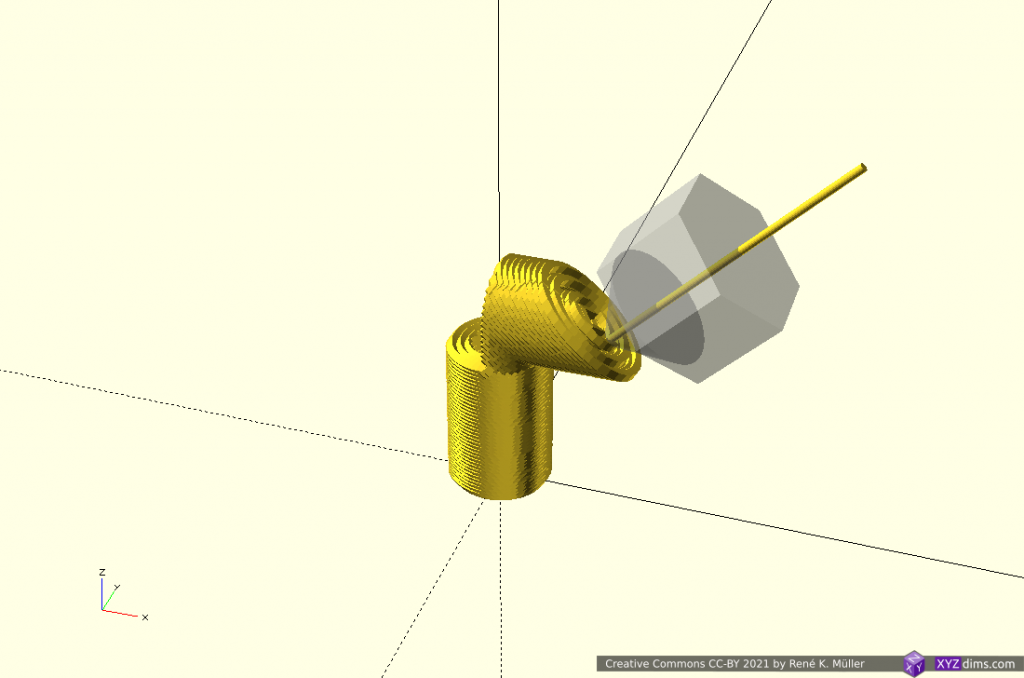
2nd segment tilted continuing 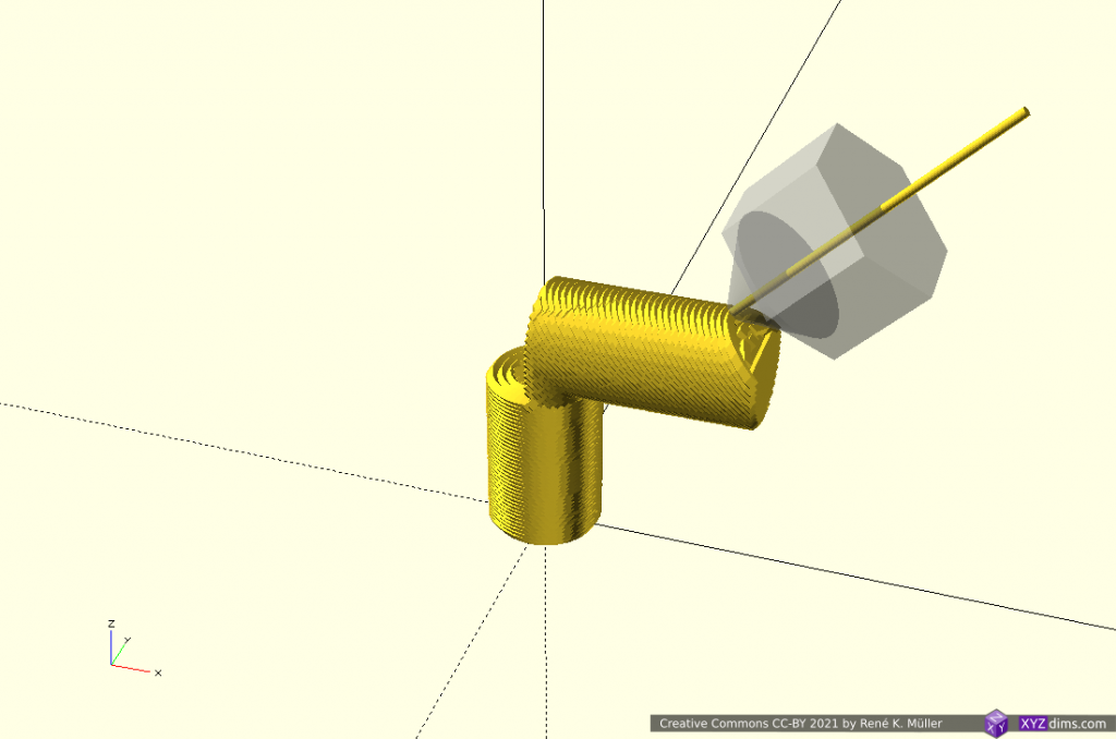
2nd segment tilted finishing 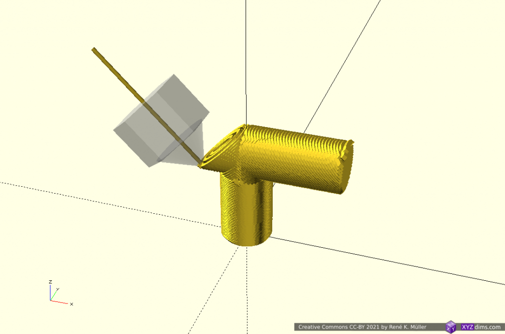
3rd segment tilted into other direction 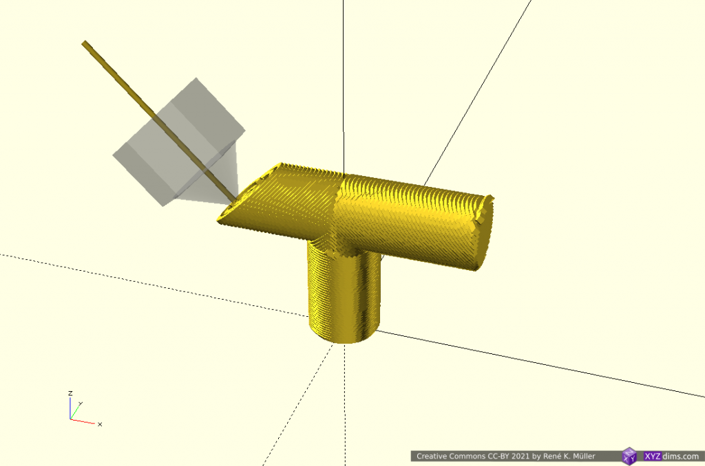
extending 3rd segment further 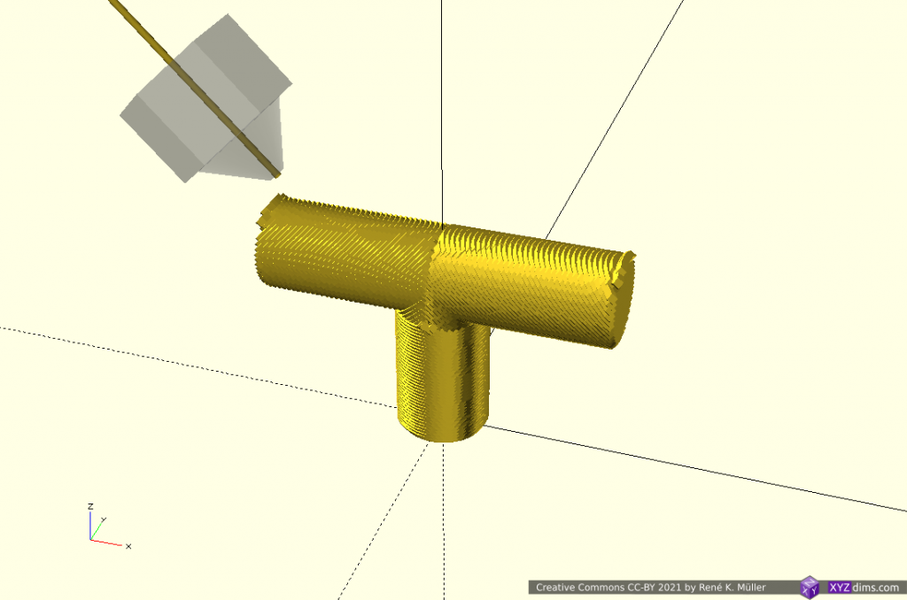
finished piece
Tilted slices can be printed with 4-axis Rotating Tilted Nozzle (RTN) but the first Z-planar part, as mentioned above, might not provide sufficient surface quality, whereas a 5-axis Penta Axis (PAX) printhead can print both segments easily.
T-Model: 3 Segments: Z-planar & 2x X-planar
A more classic planar approach but with different planes as reference, first Z-planar then twice X-planar in different directions:
3 segments: z-planar, 2x x-planar 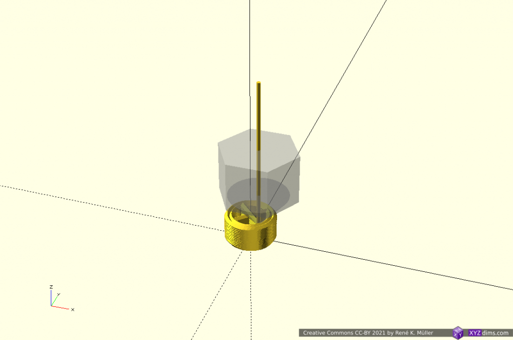
building up 1st segment z-planar 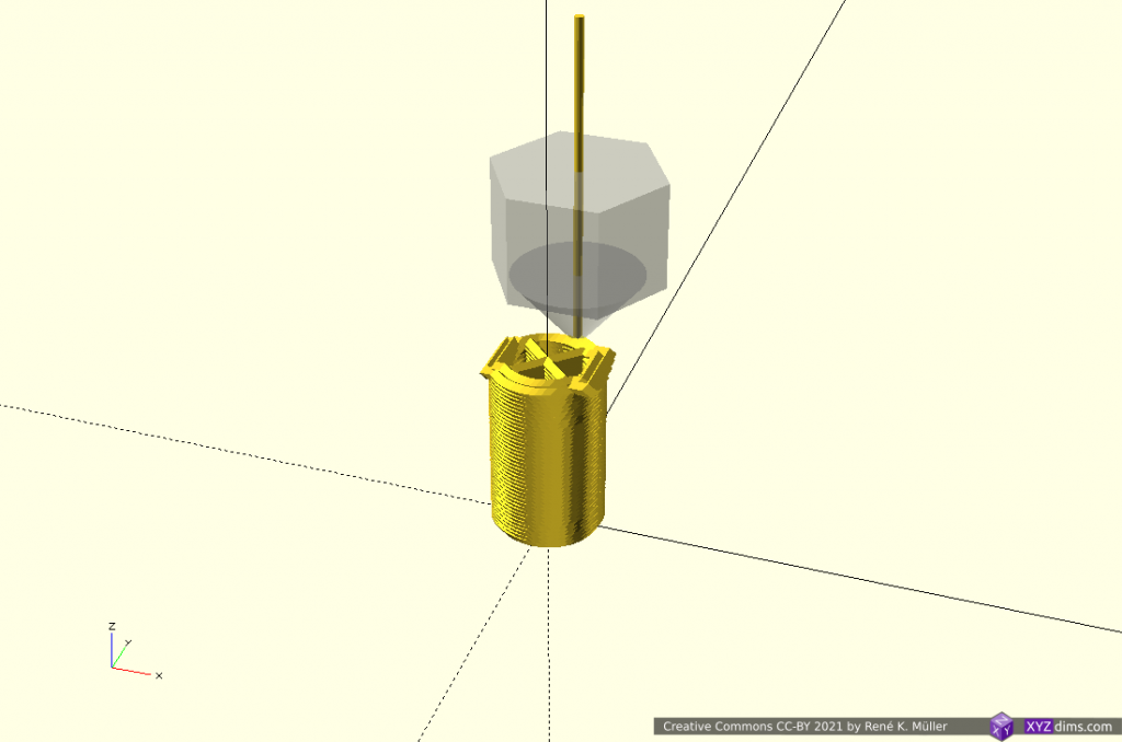
finishing z-planar segment 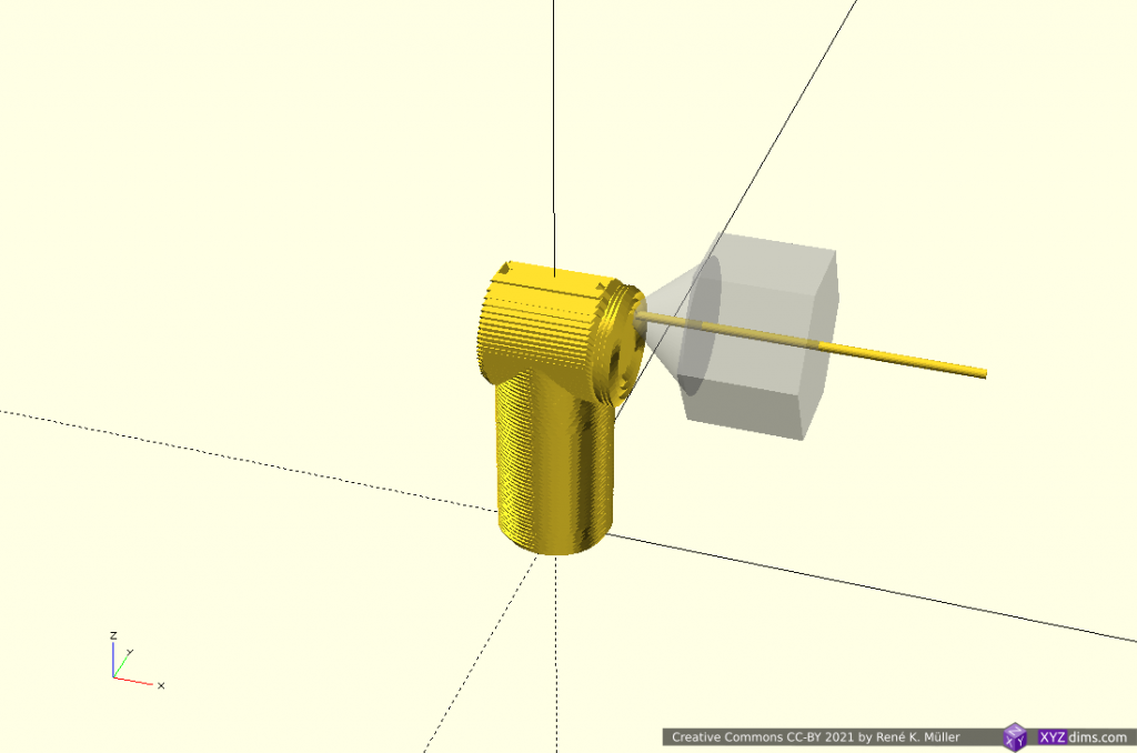
switching to 2nd segment, x-planar 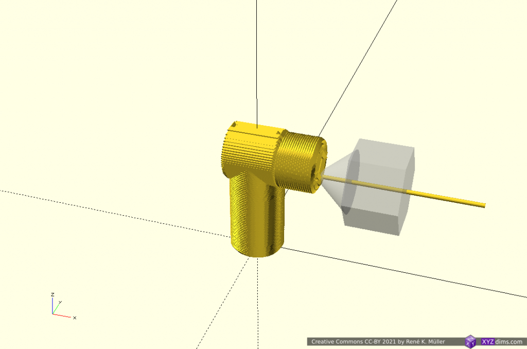
extending x-planar 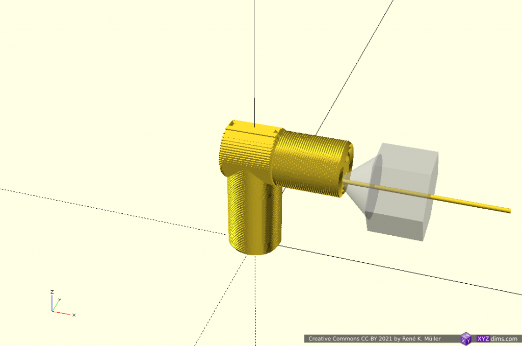
finish 2nd segment x-planar 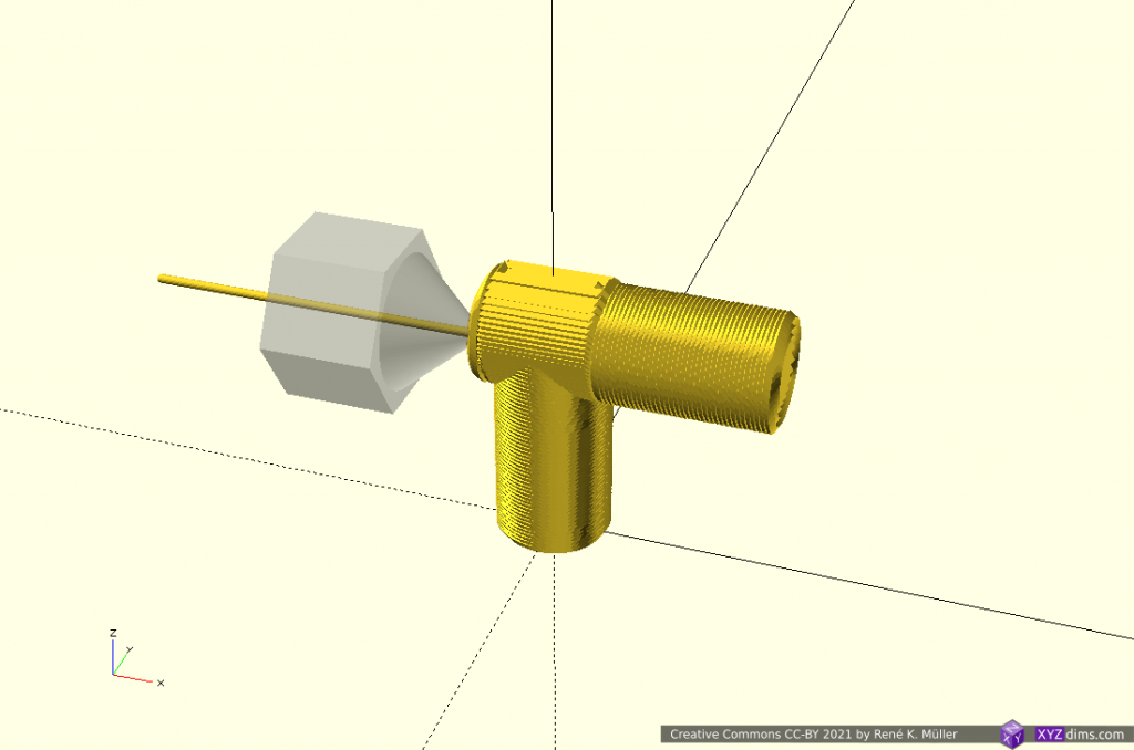
switching other side x-planar opposite direction, 3rd segment 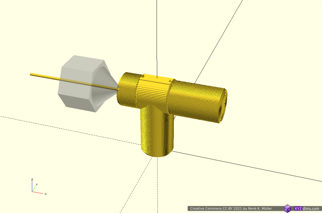
extending 3rd segment x-planar 
finished piece
X-planar printing requires either 5-axis Penta Axis (PAX) printhead or the ability to tilt the bed.
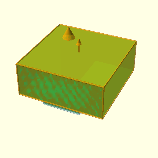
Overhang In/Out: 2 Segments: 2x Conic
Lower part is sliced with conic slicing with inside-cone mode to print in-going overhang, whereas the upper part is sliced with outside-cone mode to cover the out-going overhang:
bottom: inside-cone, top: outside-cone 
inside cone mode for 1st segment 
inside cone mode 
inside cone mode actual inner overhang 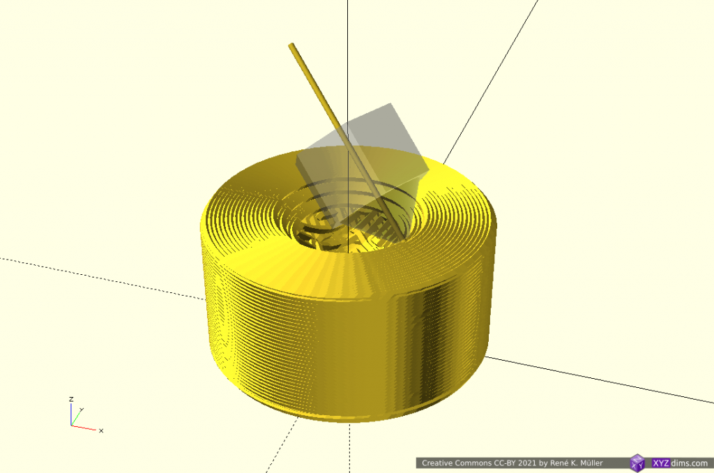
finishing inner overhang 
switching to outside cone mode 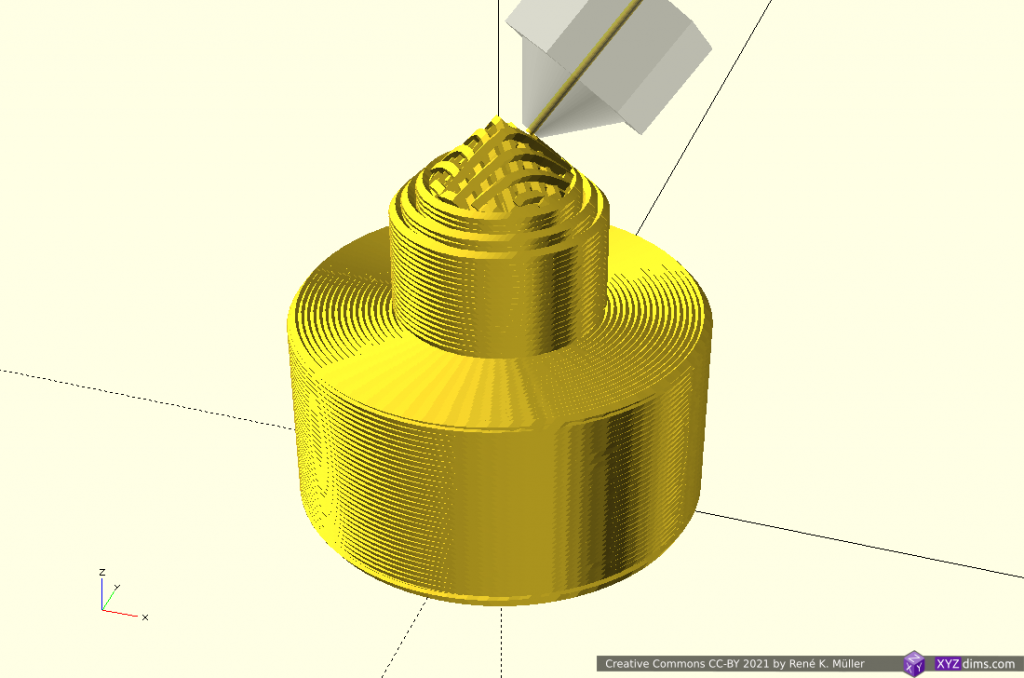
building up 2nd segment 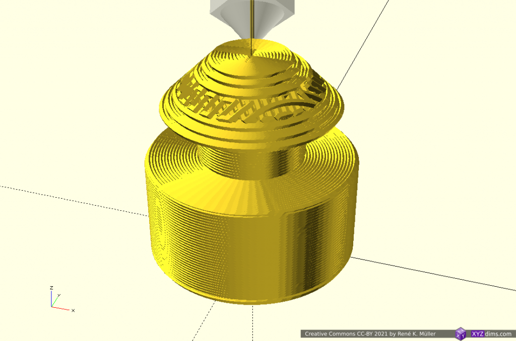
outside cone mode actual outer overhang 
extending outer overhang 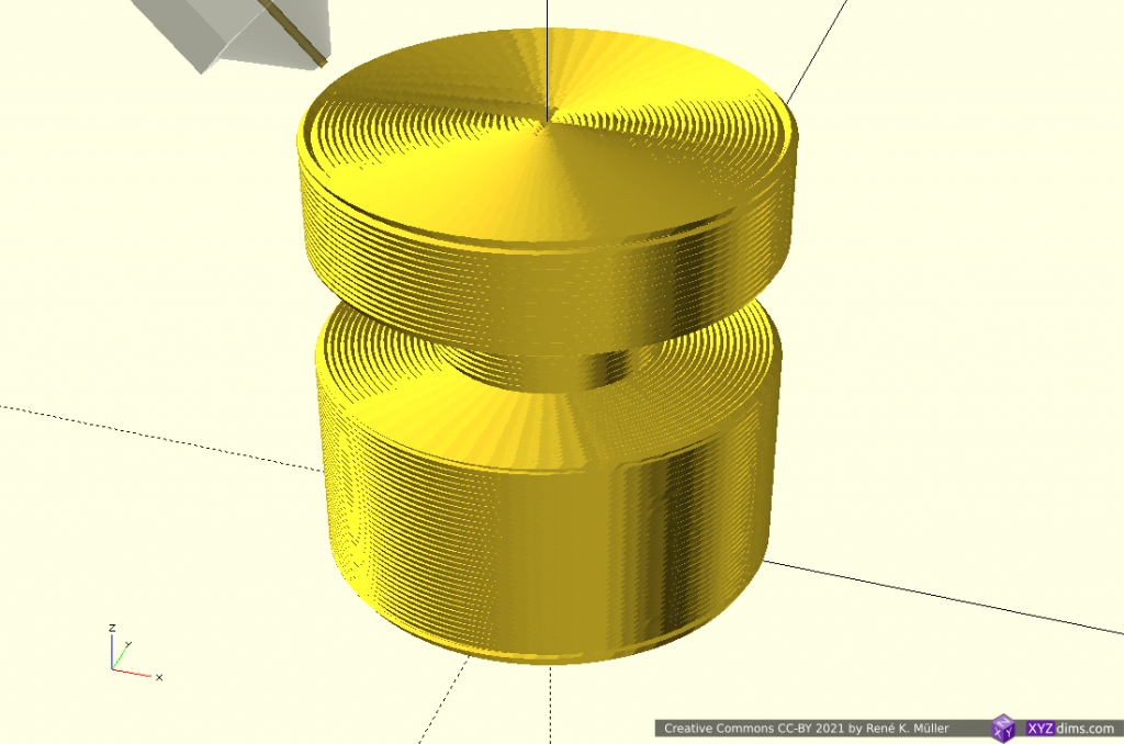
finished piece
This model covers the classic case of 4-axis Rotating Tilted Nozzle (RTN) application: rotating 45° tilted nozzle printing in two different modes (outside-cone and inside-cone); a 5-axis Penta Axis (PAX) printhead also can print such.
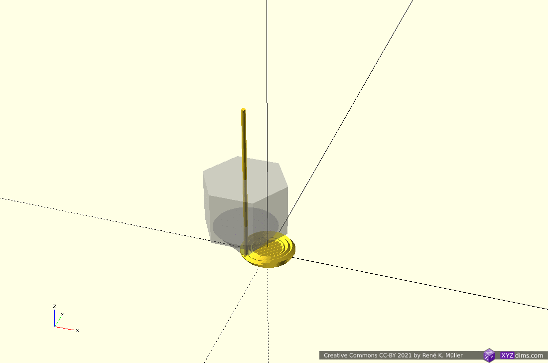
Overhang Out No 5: 2 Segments: Z-planar & Conic
Another overhang piece, stretching out into one direction; the lower part Z-planar, and the overhang conic (outside-cone mode) with an offset to align better with the lower segment:
2 segments: planar (bottom), conic with center offset (top) 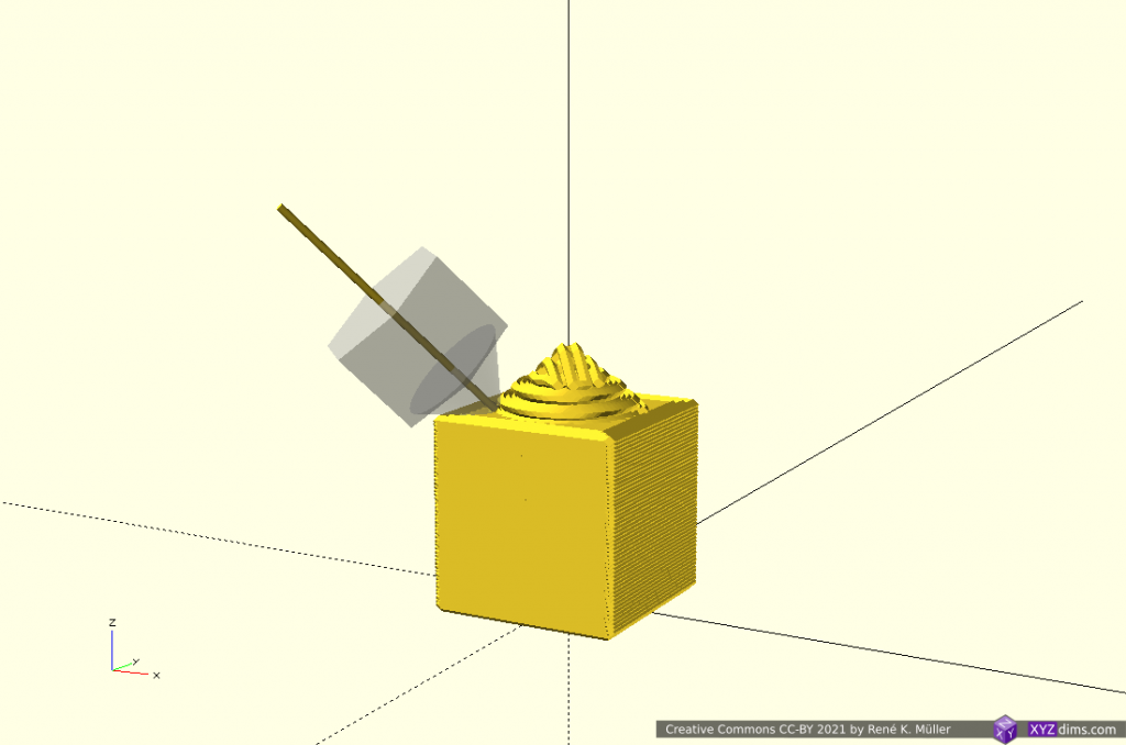
after z-planar switching to conic (outside cone), conic center align with lower segment 
conic part reaching edge of lower segment 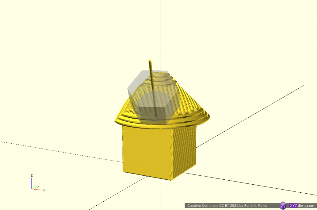
full height of overhang segment 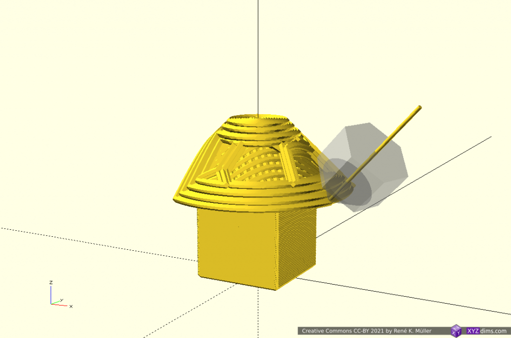
extending the overhang further 
conic part asymmetrically extending 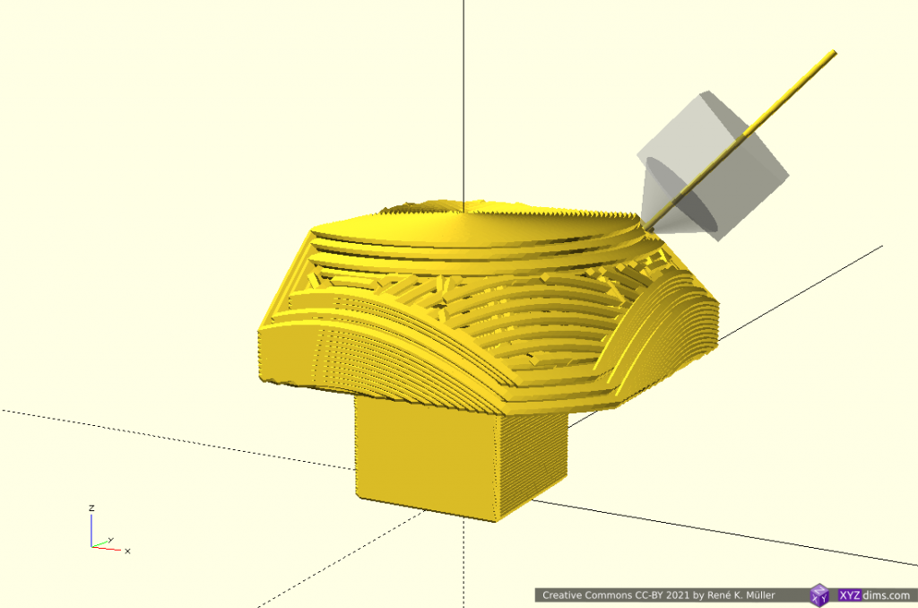
conic parts reached all horizontal model limits 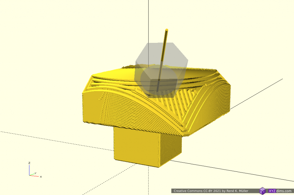
finishing up the segment 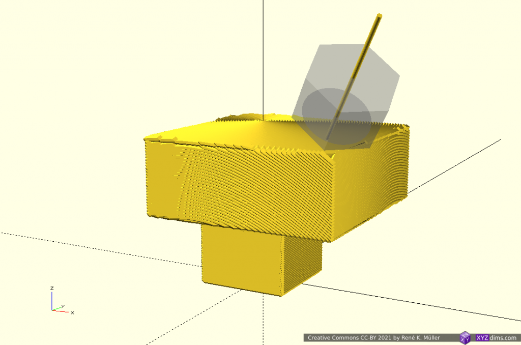
finished piece
Overhang Out No 5: 3 Segments: 2x Z-planar & Conic
Perhaps a more realistic approach using the conic part as a “balcony” just for the overhang part sufficiently thick to carry next segment and switching back to Z-planar:
3 segments: planar (bottom), conic (middle) and planar (top) 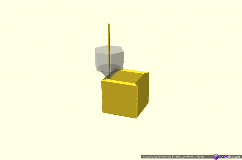
z-planar segment 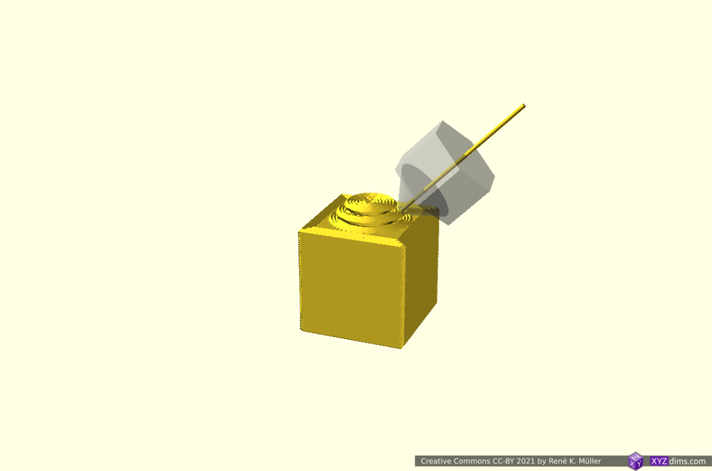
changing to conic segment 
building up the conic overhang segment 
actual overhang with conic slices 
reaching out the 2mm thick segment 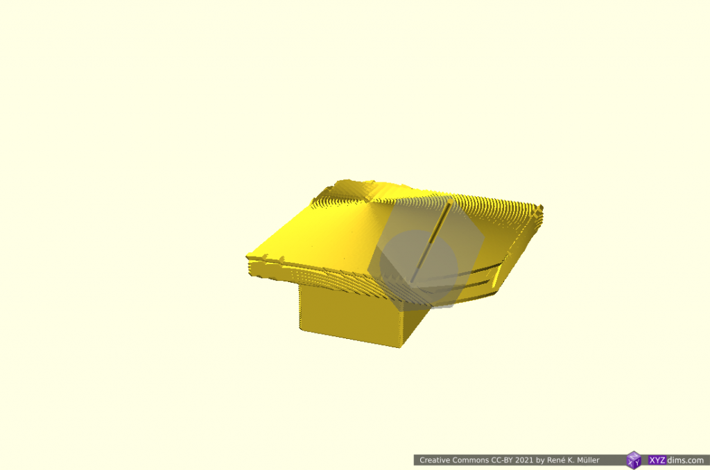
finishing the 2mm thick conic segment 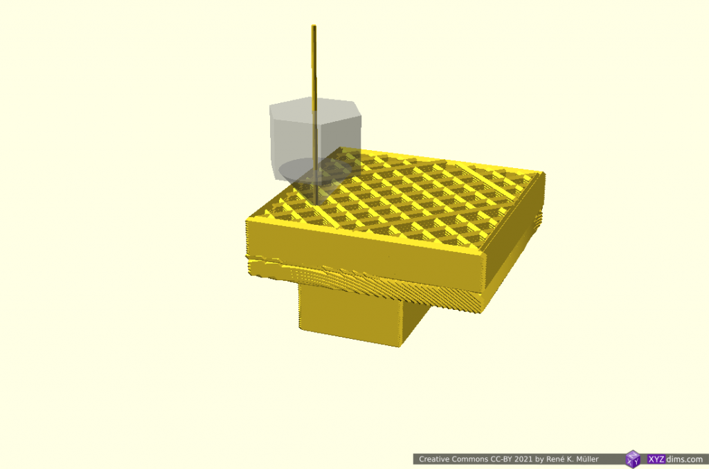
and continuing with z-planar segment 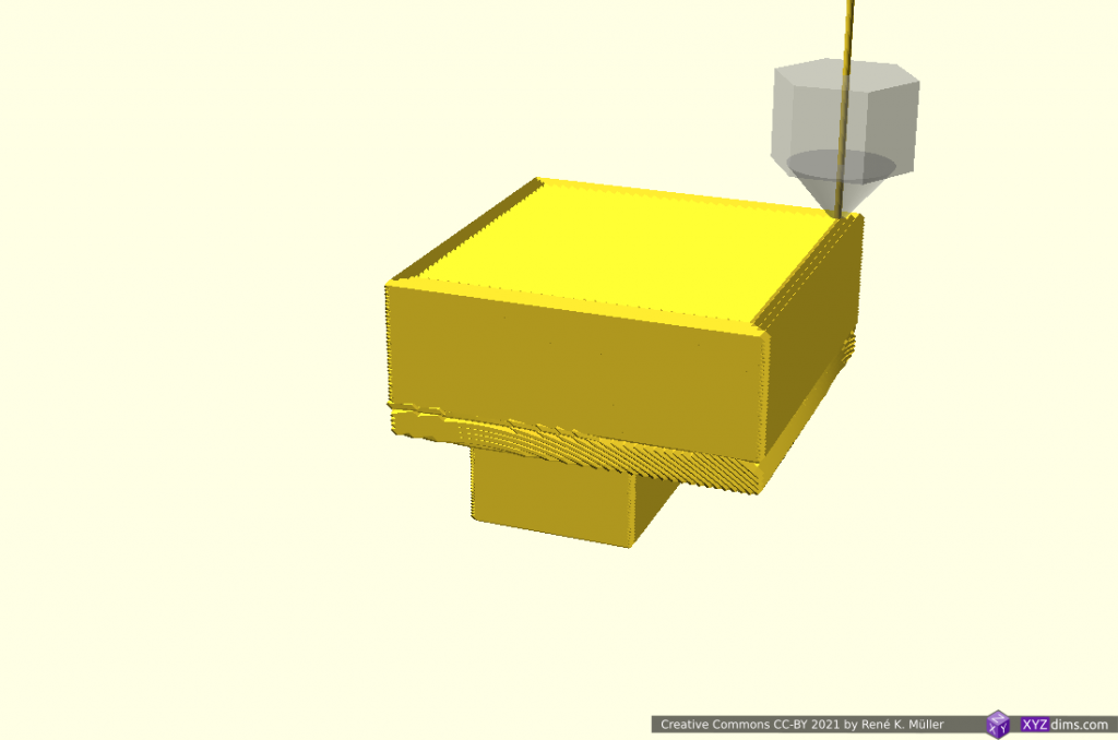
finished piece
Early tests have shown the thickness of the conic overhang “balcony” depends on the actual length of the in-air overhang, where print speed, part-cooling capacity and extrusion consistency determine the geometrical accuracy. More examples with “balcony” printed with 3-axis FDM printer followed.
Conclusion
Unlike with ordinary Z-planar slicing, it may be suitable to dedicate a particular slicing method and orientation for sub-volumes in order to take advantage of the possibilities like avoiding support structure, particular strength properties or surface quality.
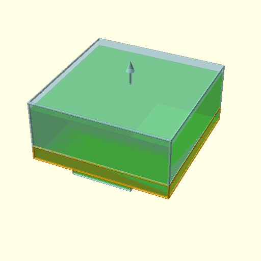
solely z-planar sliced, support structure required using 3-axis FDM printer sub-volume segmented, z-planar and conic sliced printable without support structure using 5-axis FDM printer
This of course opens a wide-range of possibilities and complexity therefore:
- where to segment
- which slicing method to use
- in which orientation the slicing is performed
but I think it’s worth it, in particular when a piece is printed more than once like with small series manufacturing / production.
The examples have been produced with various slicers and combined with a new application coordinating the segmenting and dedicated slicing methods, which currently (2021/04) is in development; it also involves a new file-format describing the segmenting and its slicing settings. The segment positioning was done manually as a start, but I expect with more experience and research some cases can be detected automatically.
Sub-volume segmenting is just one approach to take advantage of 5-axis FDM printing, another is continuous slicing along the form.
References
- [Coyetaux, Crook, Pauwels, Whelan] 5-Axis 3D Printing (2018) – free paper (PDF)
- [Wuethrich, Elspass, Bos, Holdener] Novel 4-axis 3D printing process to print overhangs without support material (2020) – non-free paper (PDF)
See Also
- 5-axis Penta Axis (PAX): development overview with more references
- 4-axis Rotating Tilted Nozzle (RTN): development overview as well
- Non-Planar Slicing with Planar Slicer, more groundwork for slicing non-planar
PS: All animations I combined in a short 3min video: Mixing Planar & Non-Planar Slicing Methods for 3D Printing Overhangs without Support Structure (YouTube)
