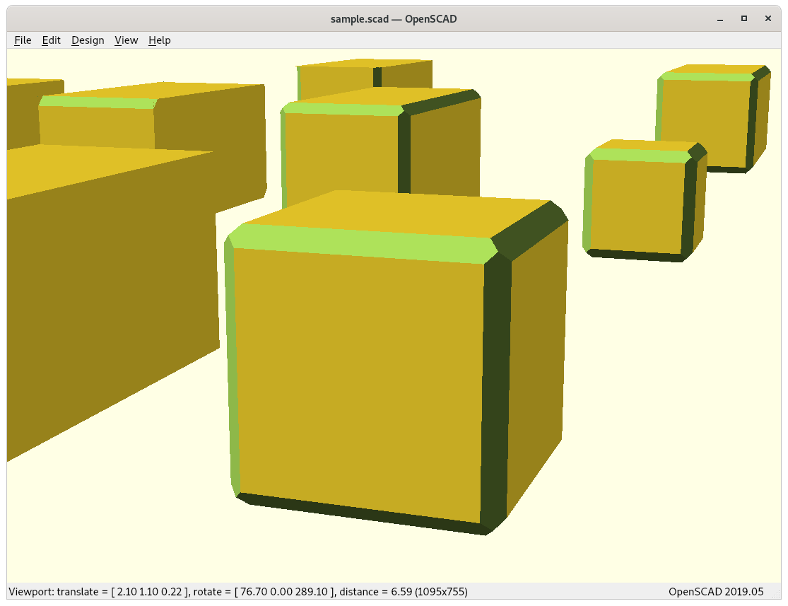
Status: early draft with rotary Z 4 printheads and rotary Y 2 printheads

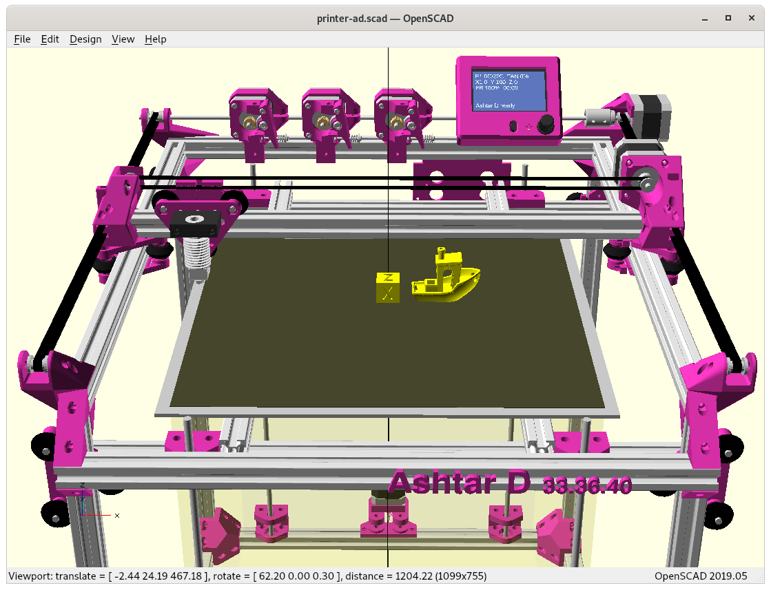
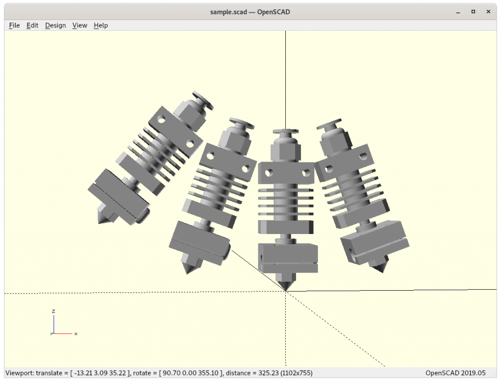
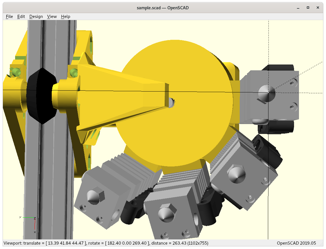
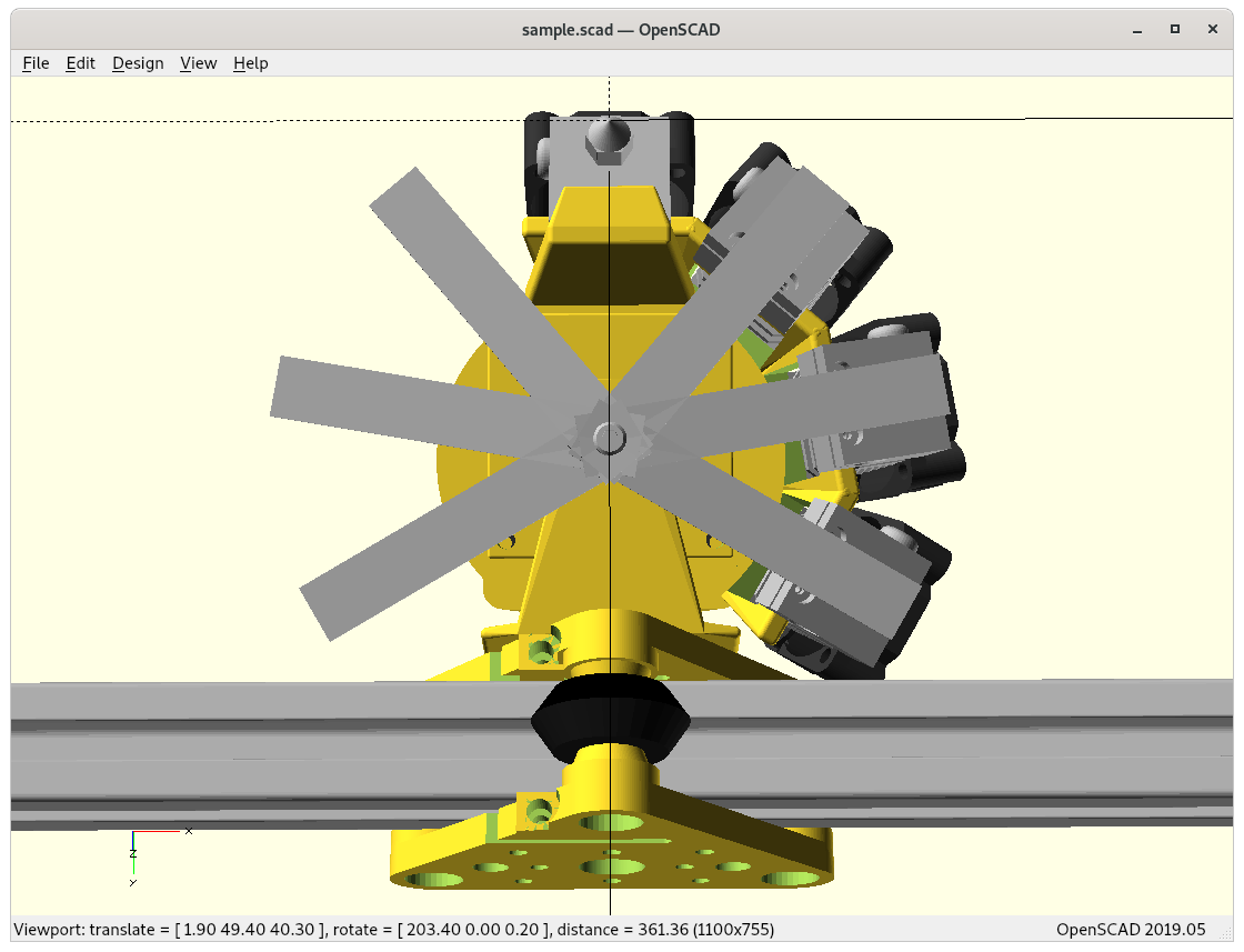
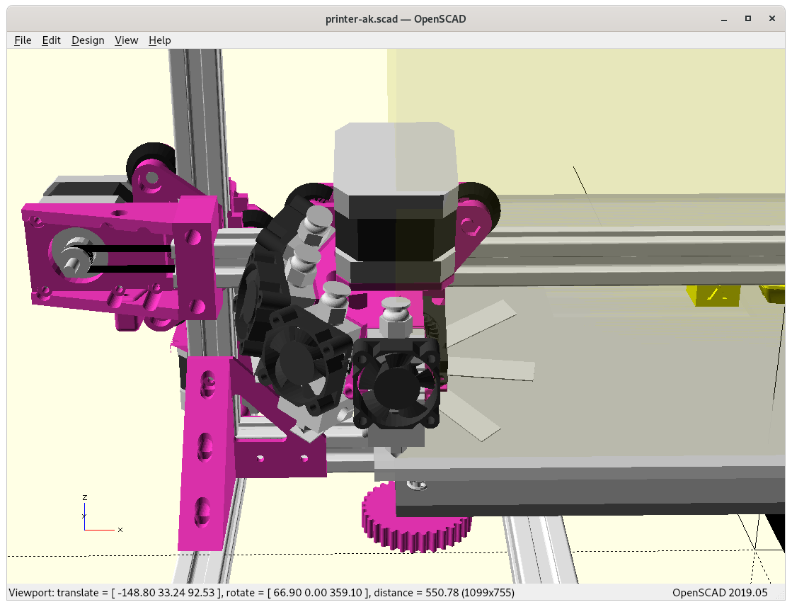
4 printheads on rotary Z MSE, tool 0 selected 
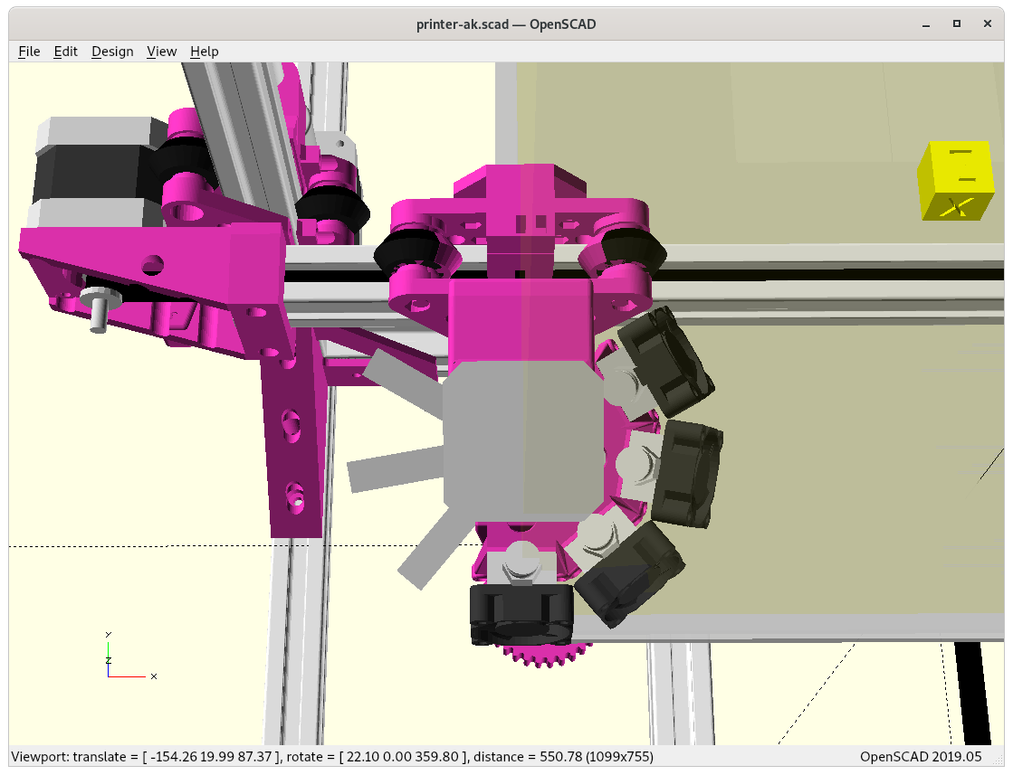
4 printheads on rotary Z MSE, tool 0 selected (top view) 
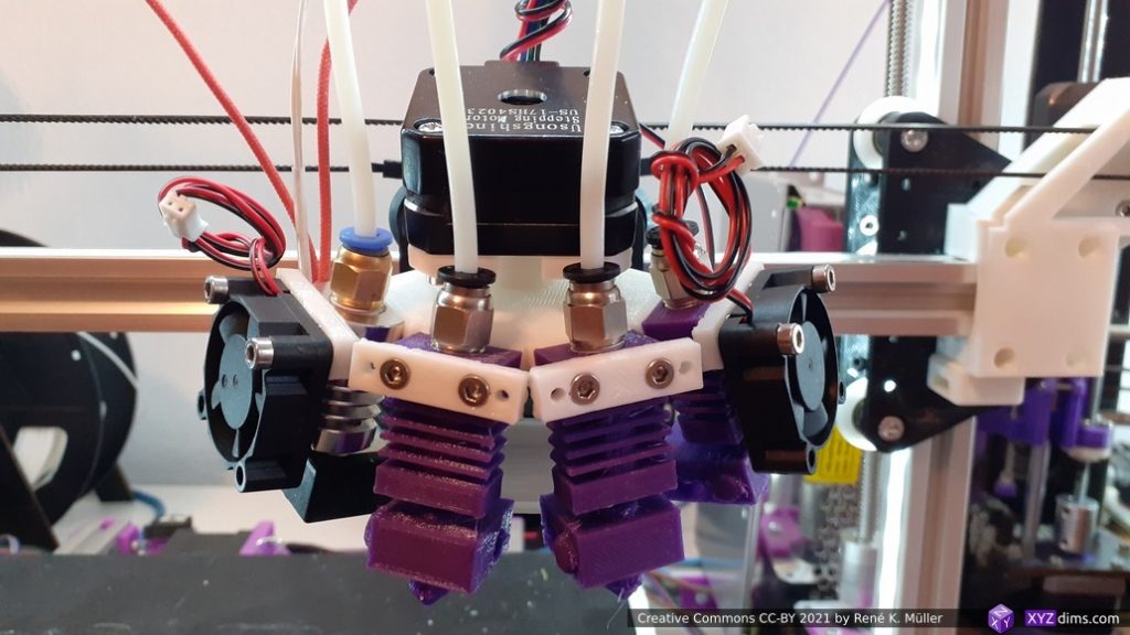


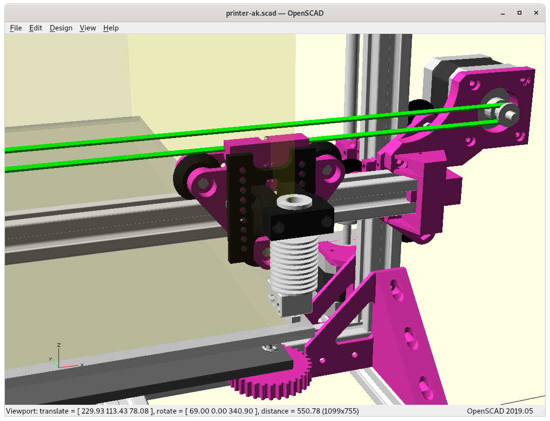
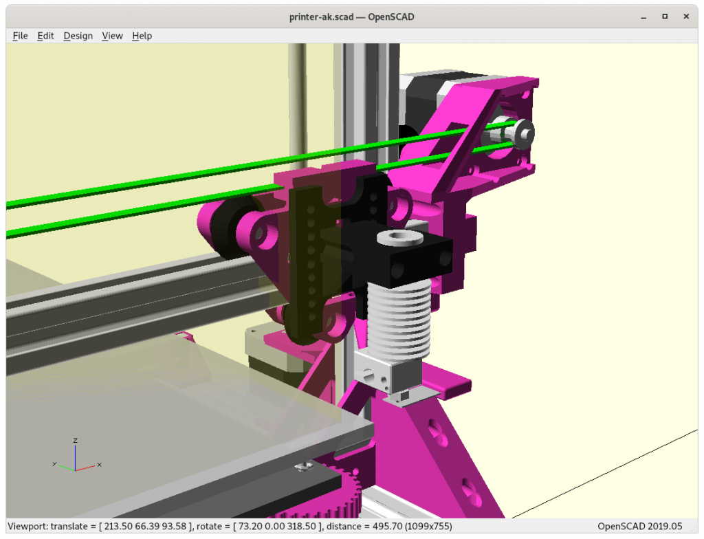
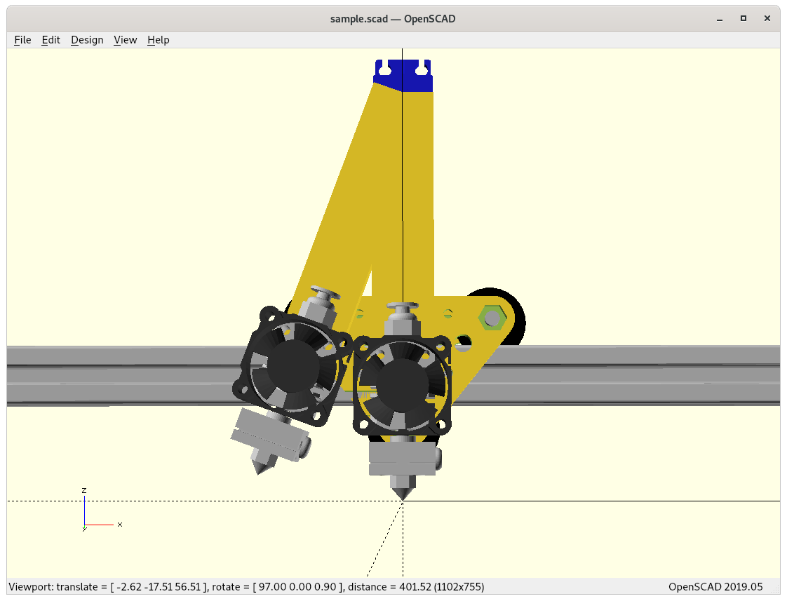
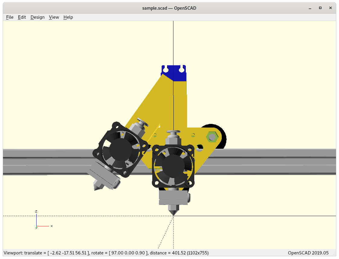
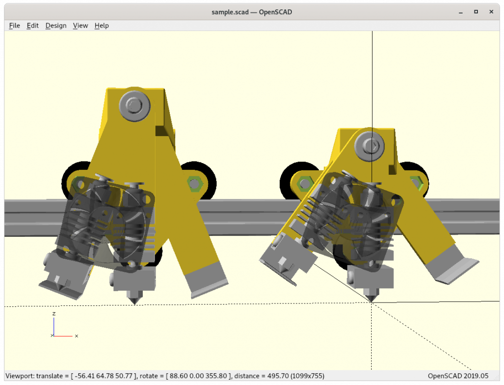
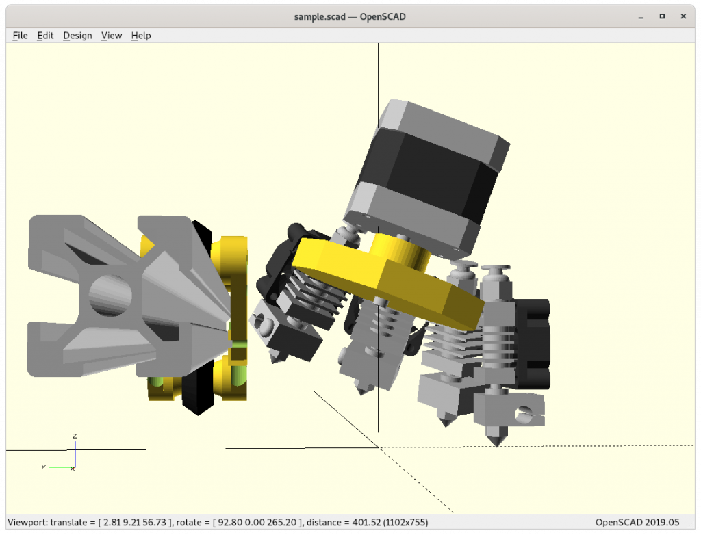
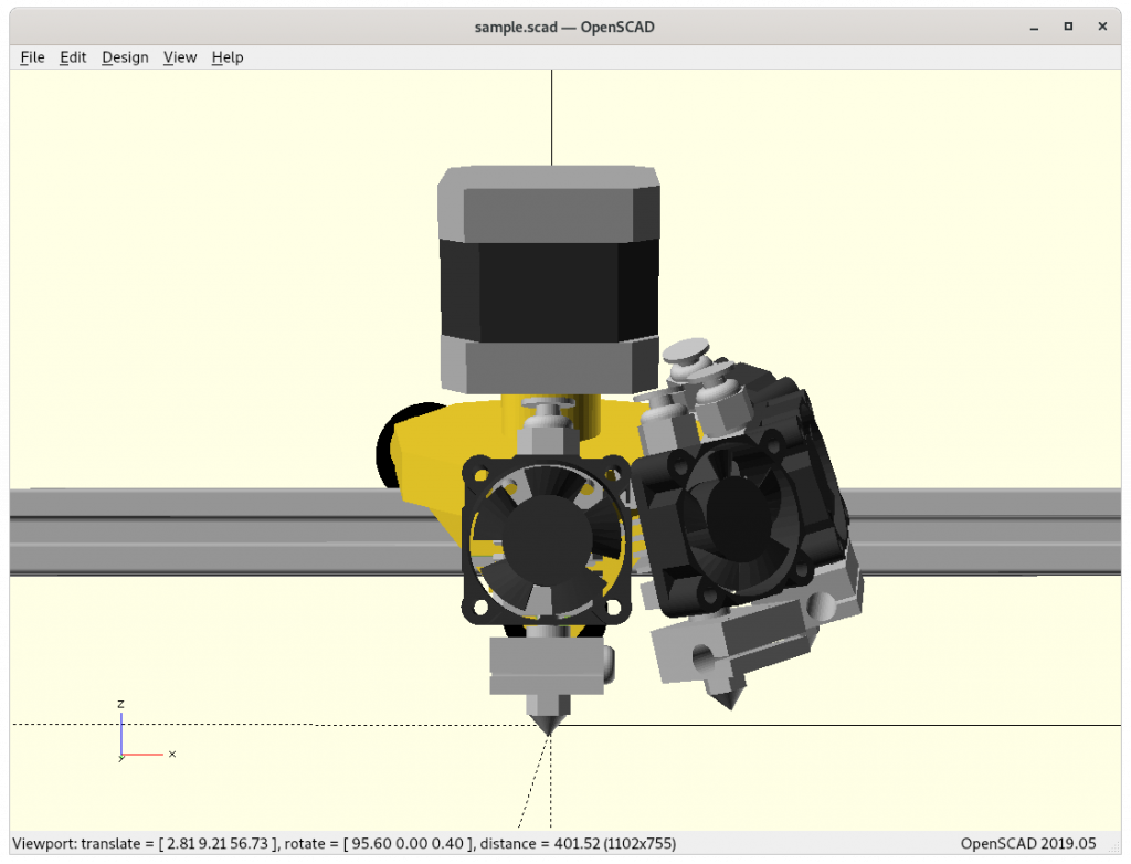
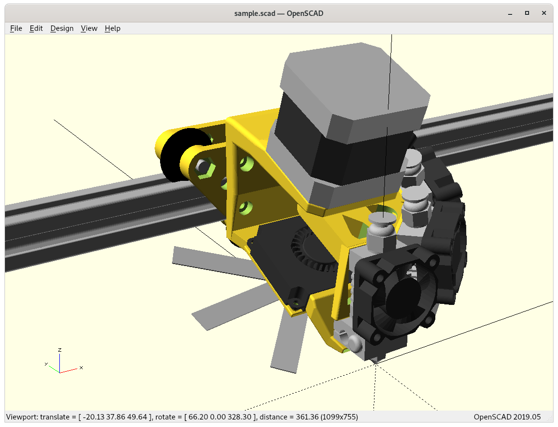
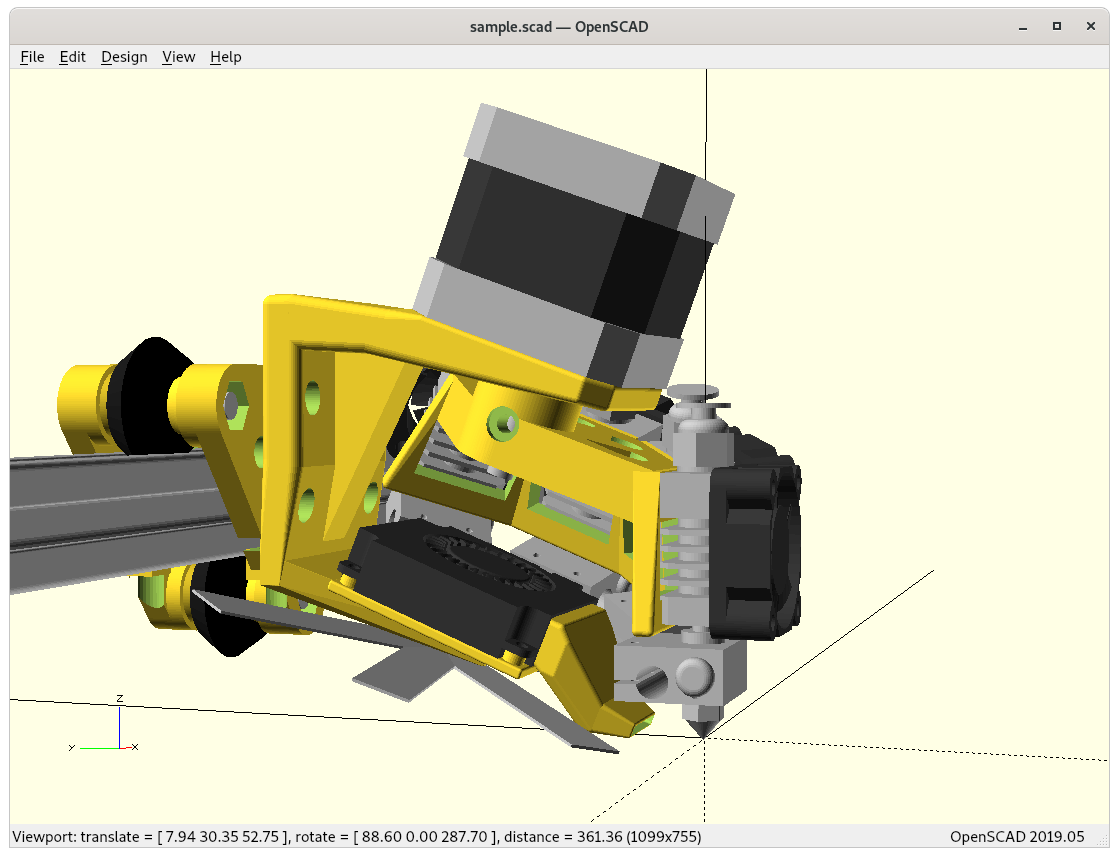
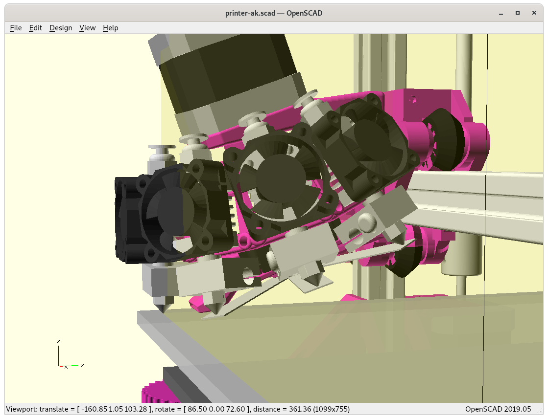
2 printheads in rotary Y MSE, tool 0 selected 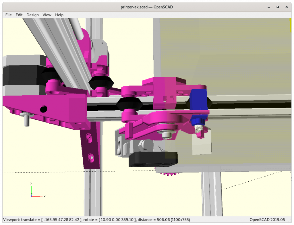
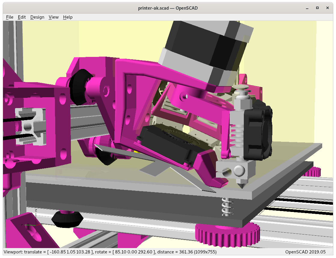
2 printheads in rotary Y MSE, tool 0 selected (top view) 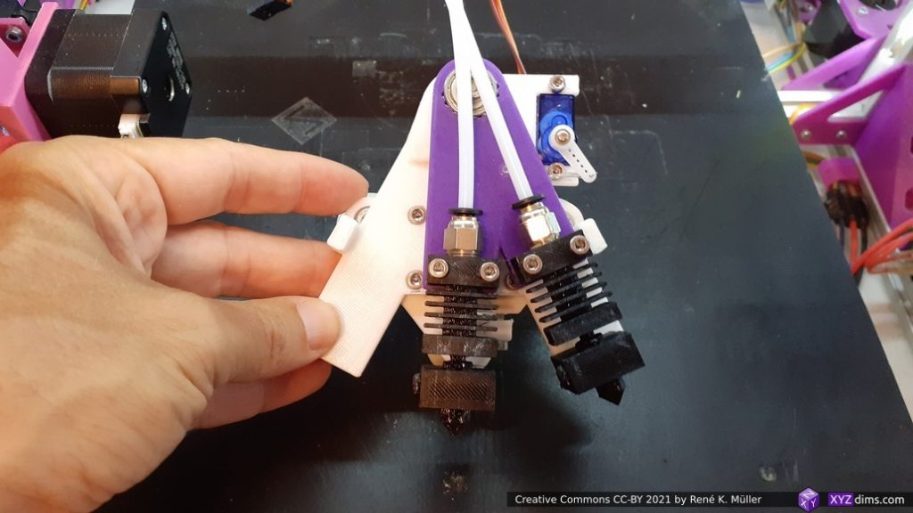
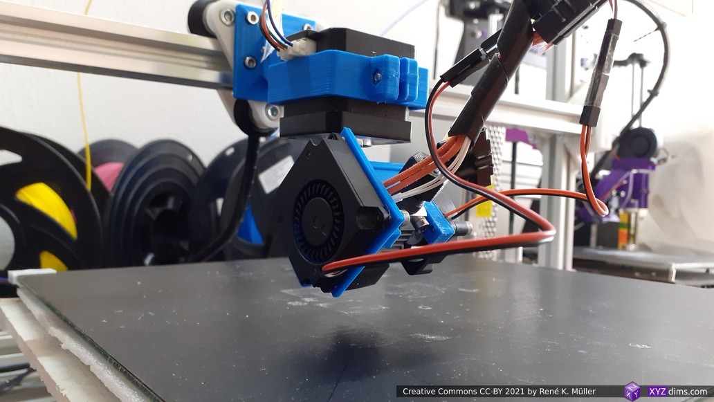
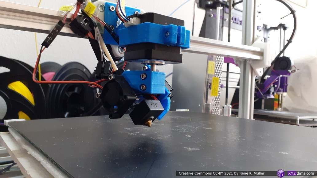
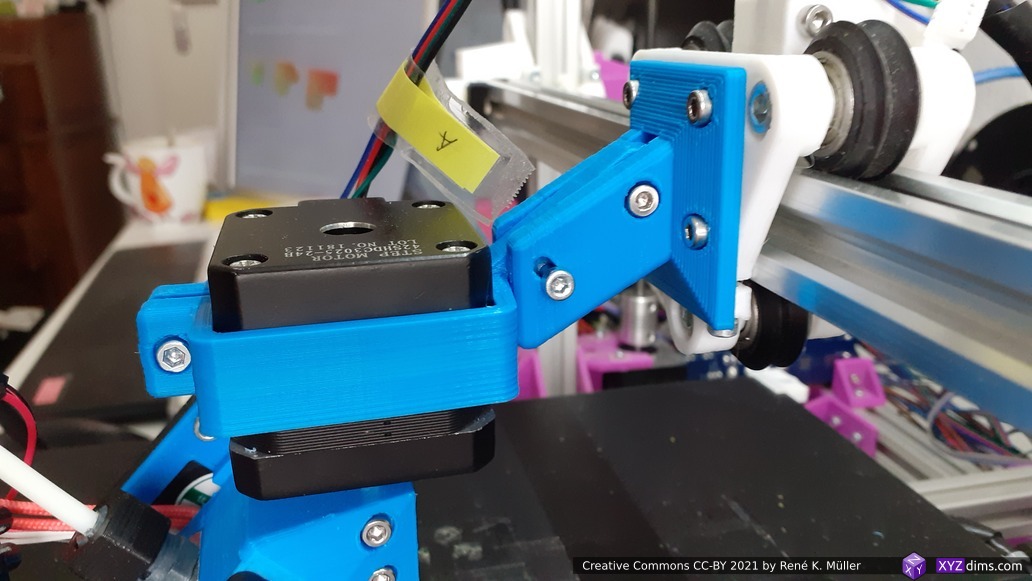
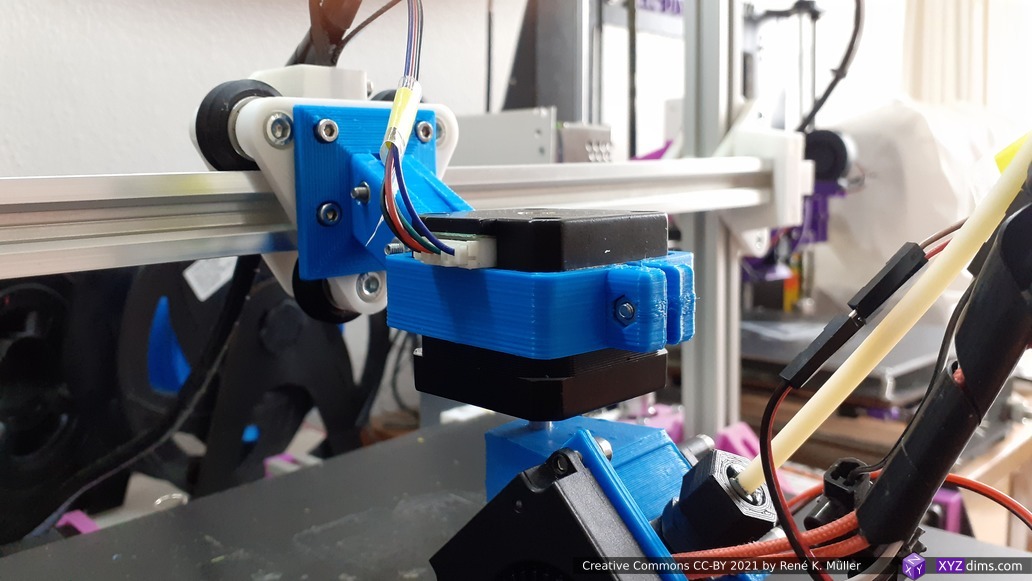
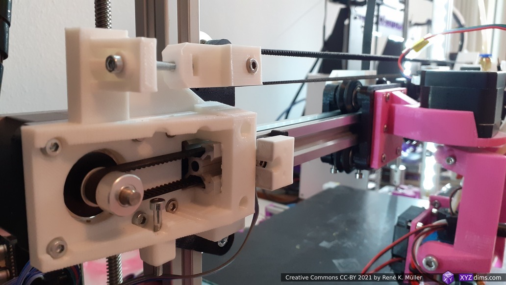
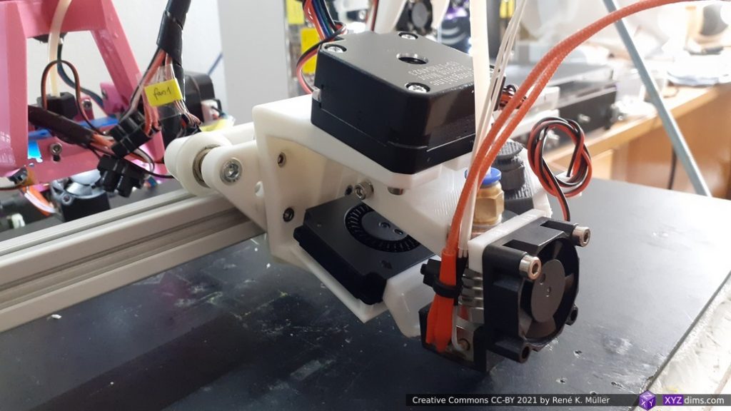
MSE Y2 Mockup, testing motion & precision


Updates:
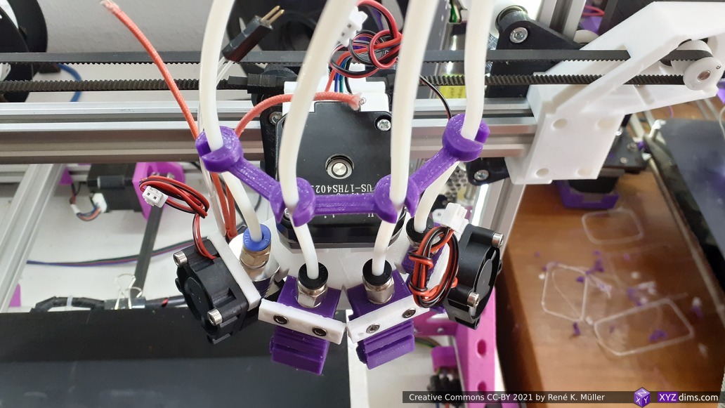
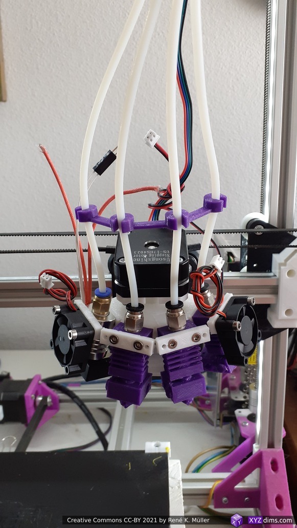
- 2021/08/01: MSE Z4 printed & mounted
- 2021/02/09: matured Rotary Y MSE dual with a servo
- 2021/01/31: added more drafts and formulated Pros and Cons for Rotary Z MSE, post published, with part cooler
- 2021/01/29: starting with collecting existing solutions and consider my options, Rotary Y (max 2 printheads) and Rotary Z (max. 4 printheads) design started
Introduction
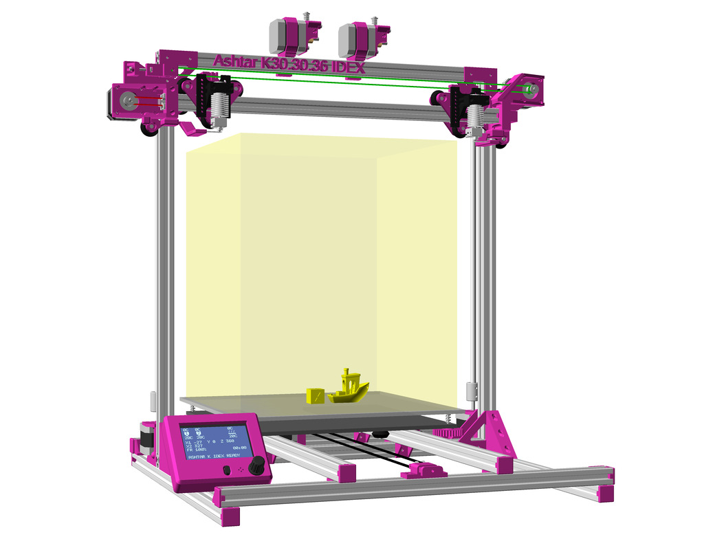
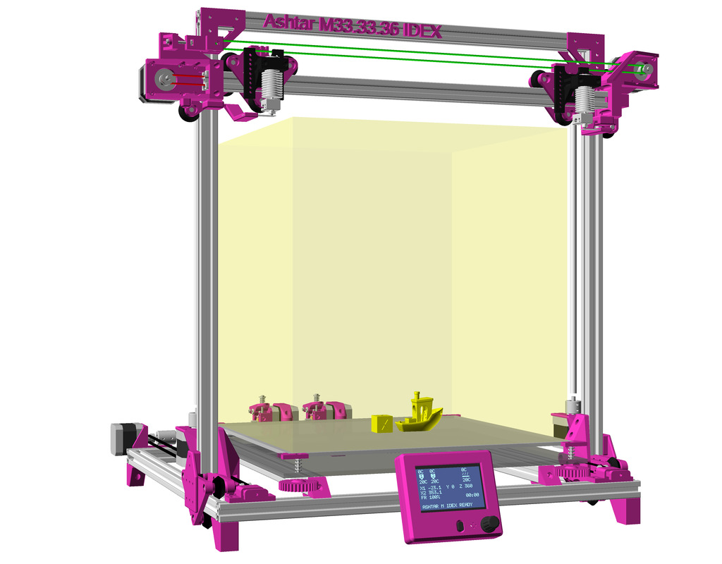
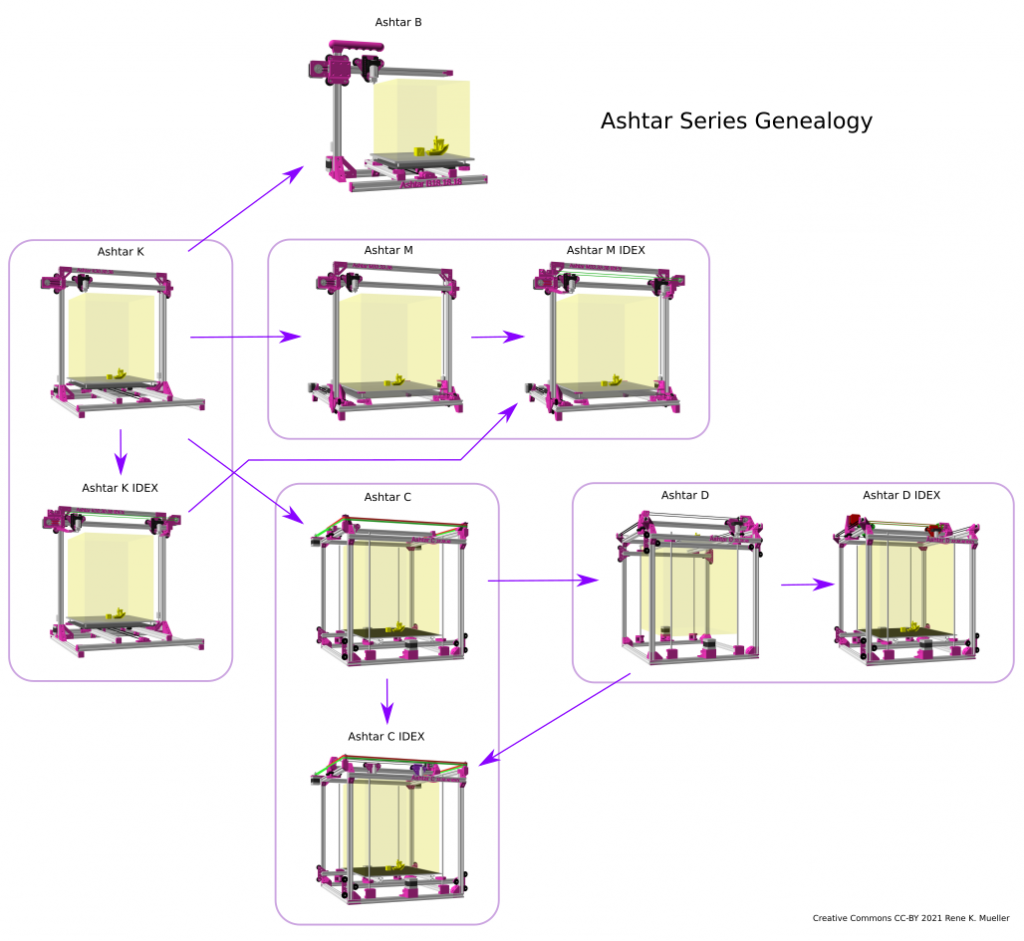
Since I dedicated some time for the IDEX upgrade on all the 4 Ashtar Series: K, C, M and D, I realized one of the main advantages of IDEX is to have the non-active printhead aside and not moving over existing prints and certainly not oozing over it.
There is another way to achieve such, by having multiple printheads mounted on the X carriage and mechanically switch them so only one nozzle actually touches the Z plane to print, all other printheads aside and sealing their nozzle with anti-oozing measure like an underlying metal sheet.
Existing Solutions on Thingiverse
- Panning Dual Hotend for Prusa i3: multiple Bowden tubes, two printheads E3D V6s
- Tiny Switch Dual Bowden Extruder: multiple Bowden tubes, two printheads Micro Swiss
- Parking dual extruder, Prusa i3 X axis mod, hexagon extruders: two passive X carriages with printheads, single motorized X carriage using magnets to attach passive carriages – quasi IDEX with single X motor – interesting
As I like to have my own solution in OpenSCAD source, so let’s dive into the design process:
Multiple Switching Extrusions (MSE)
Design Goals
- 2, 3 perhaps 4 heads switching, only one printhead/nozzle at Z printing head
- share one heatsink fan
- share one part cooler setup and fan
- simple adjustable calibration of X, Y, Z repeatability
- ideally interchangable between
- E3D V6: proven reliability
- Micro Swiss / CR 10 clone: single screw to set Z distance
- ideally interchangable between
- inactive printheads non-ooze with shield
- keep it simple, don’t overengineer, keep construction simple and light
Drafts
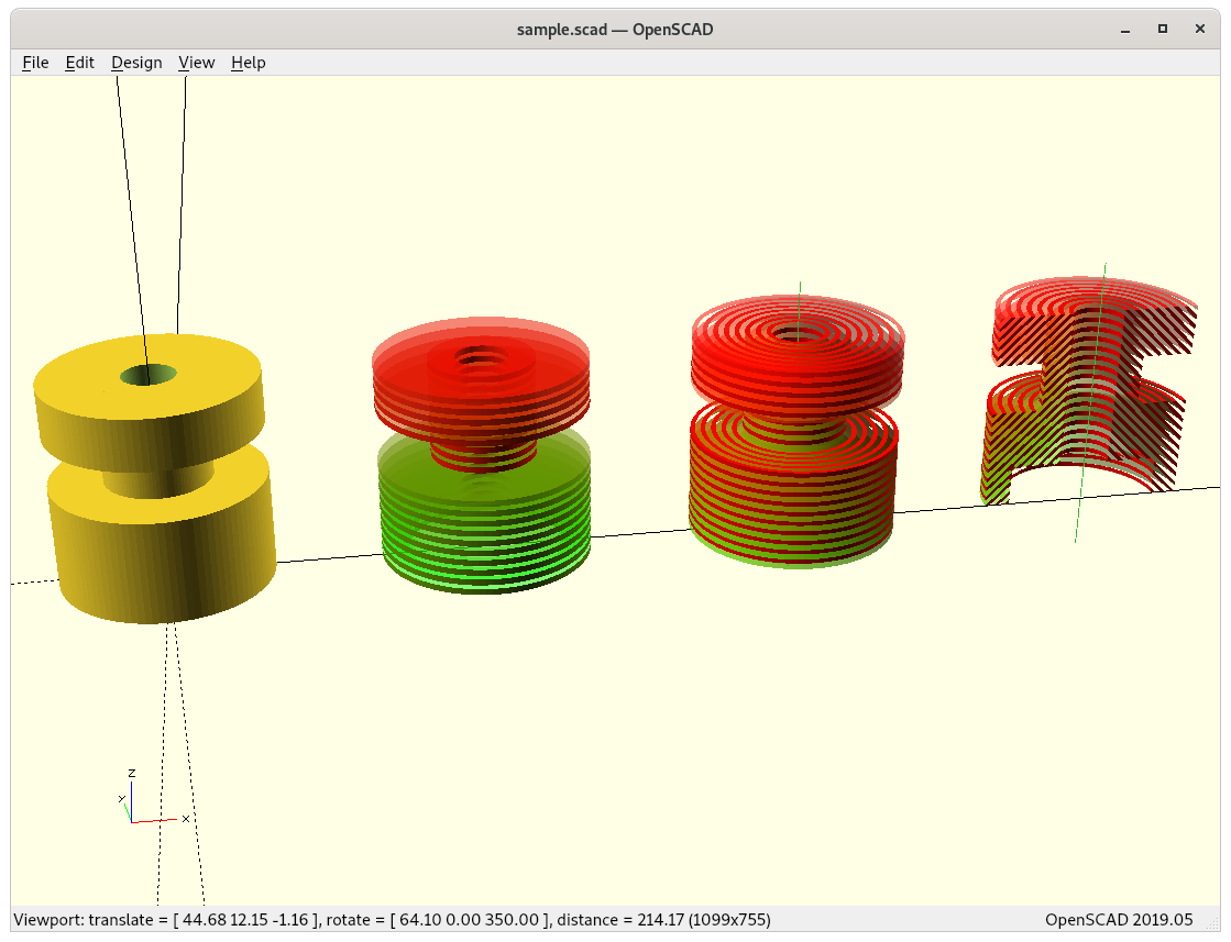
Rotary Y-Wise
Rotating around the Y axis, suitable for 2 printheads only, as 3 or more printheads use up too much in X space:

40mm fan 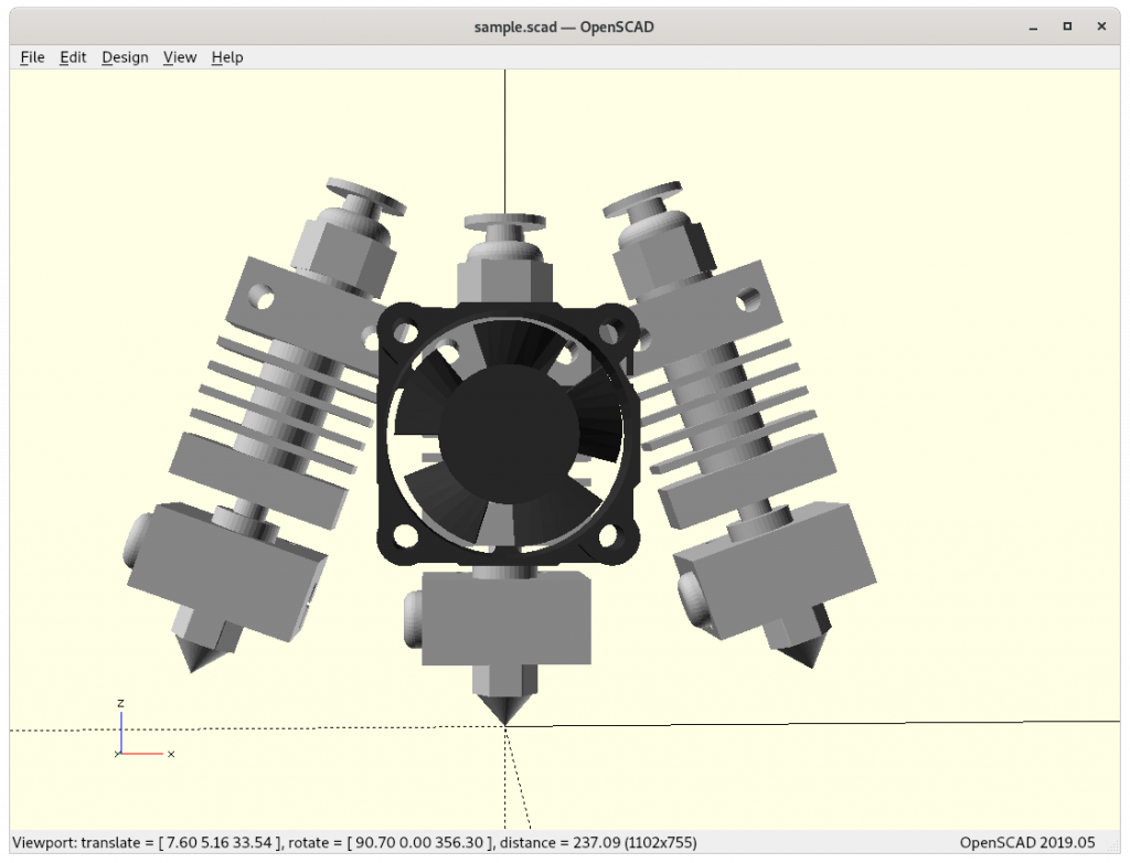
30mm fan 
30mm fan each 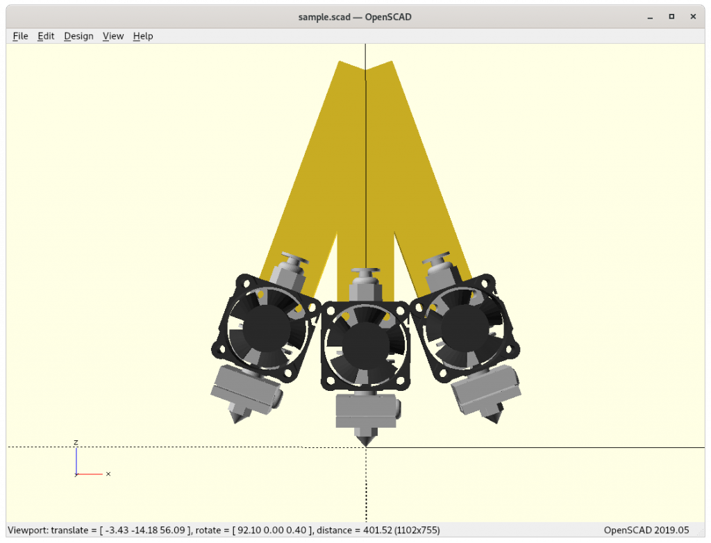
132mm distance, 20° 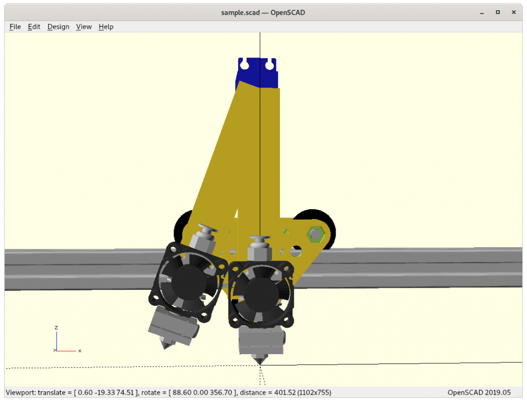
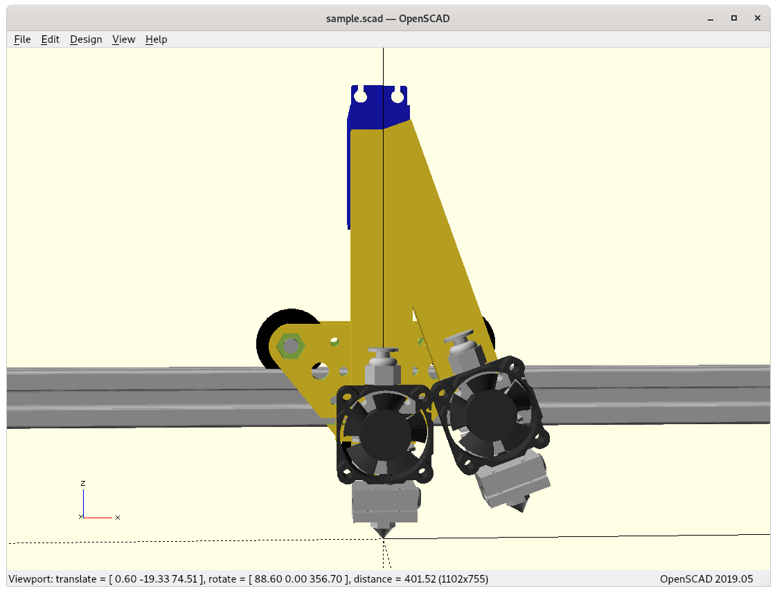
2 printheads using SG90 servo, 132mm/20°, tool 0 
2 printheads using SG90 servo, 132mm/20°, tool 1 
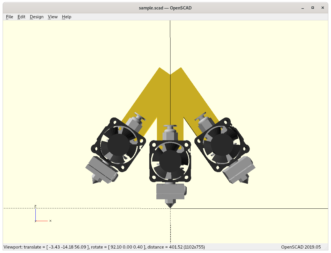
3 printheads, 100mm distance, 30° 
2 printheads using SG90 servo 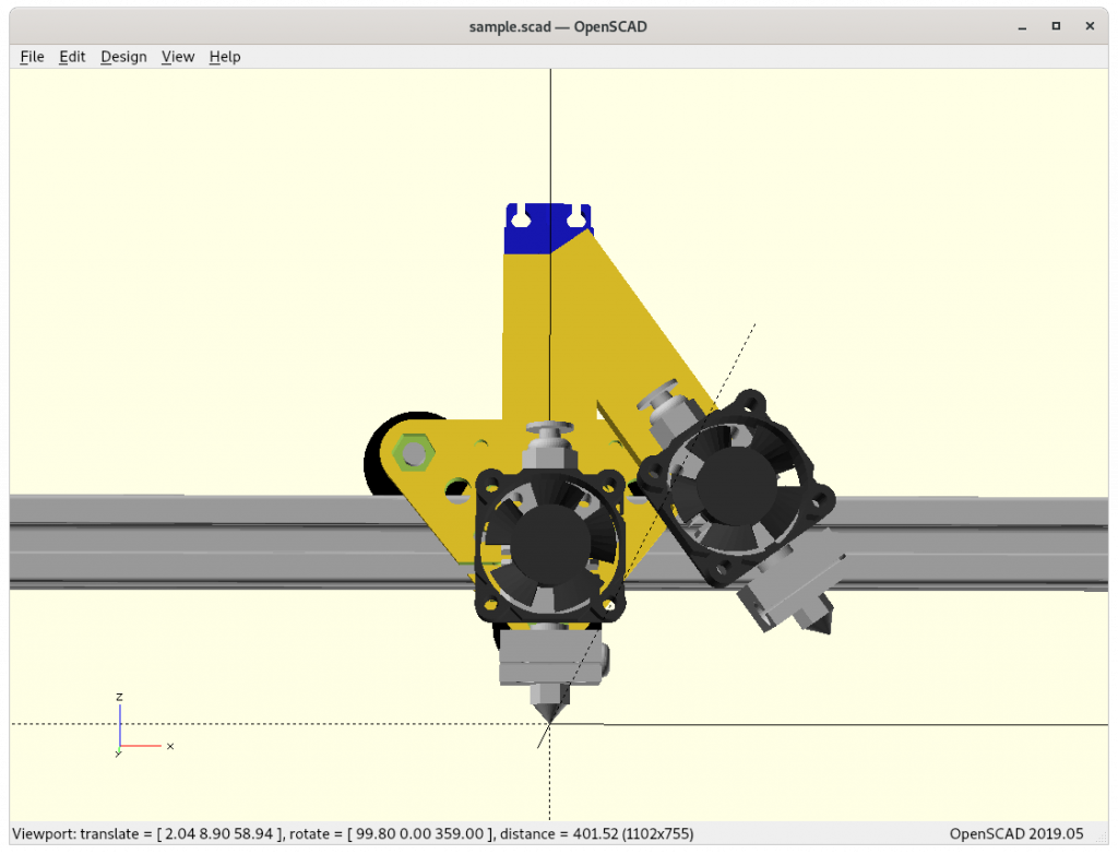
2 printheads, 100mm/30°, tool 0 
2 printheads, 100mm/30°, tool 1


Simple design, shared fan is difficult, as I like to go with Micro Swiss as it’s very compact, I likely end up with dedicated heatsink fans as all printheads in use will be heating and the heatsinks require fanned air. The ooze-shields are easy to attach.
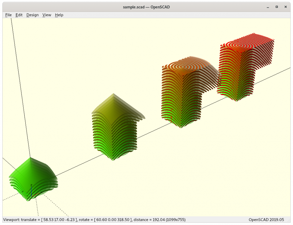
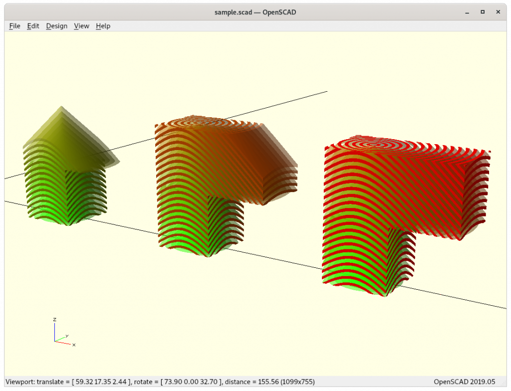
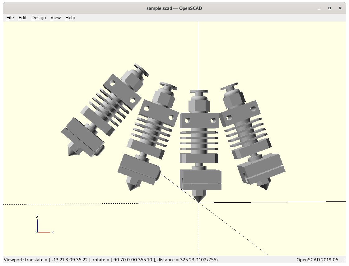
132mm / 20 degrees 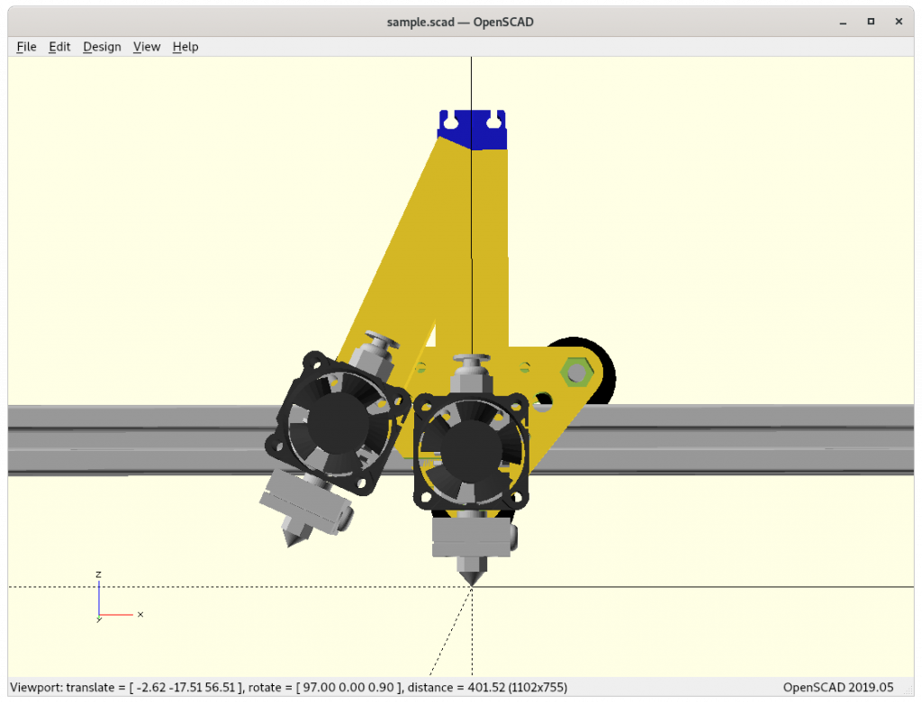
120mm / 24 degrees 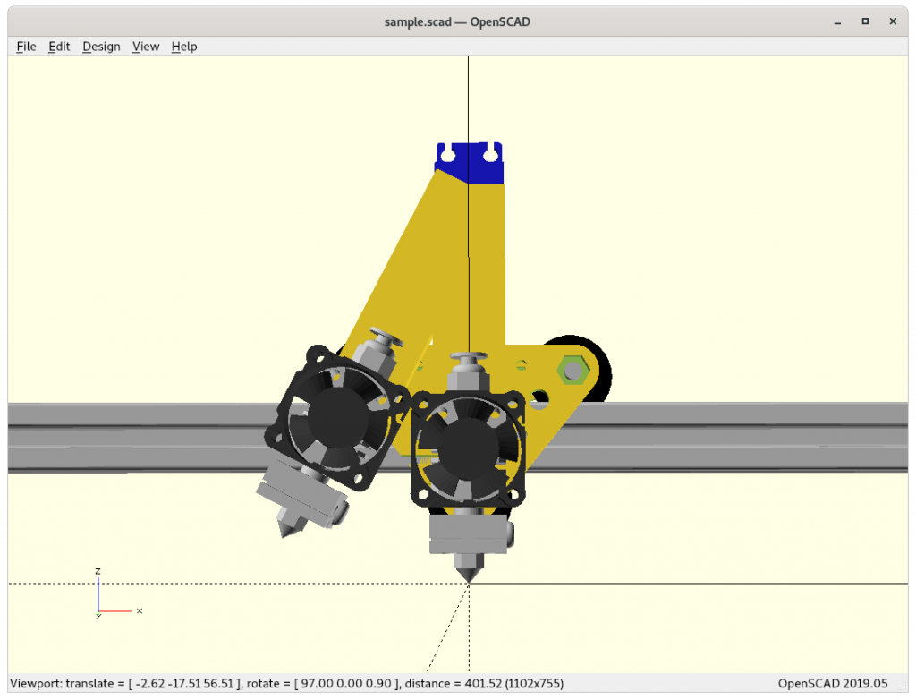
110mm / 27 degrees 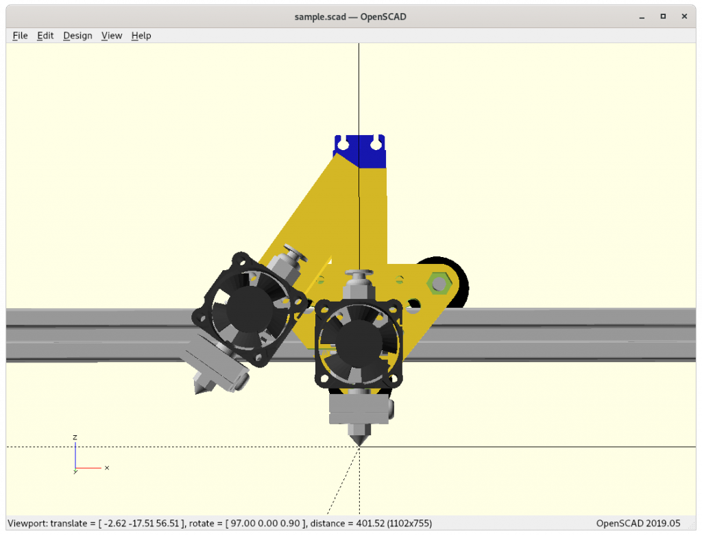
100mm / 35 degrees


- 132mm / 20°: tall (not good), narrow X space (good)
- 120mm / 24°: still ok
- 110mm / 27°: extending X space usage
- 100mm / 35°: low but extending too much in X
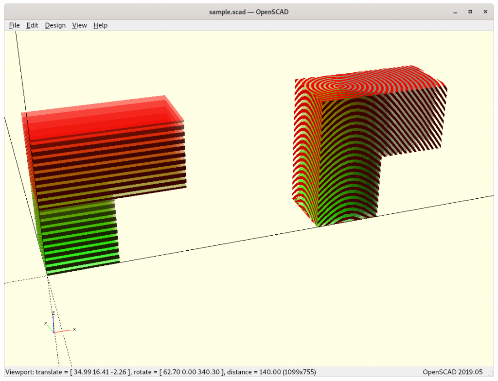
So let’s combine most narrow with a common fan approach, for a compact dual switching printhead/extrusion sacrificing as little X space as possible:
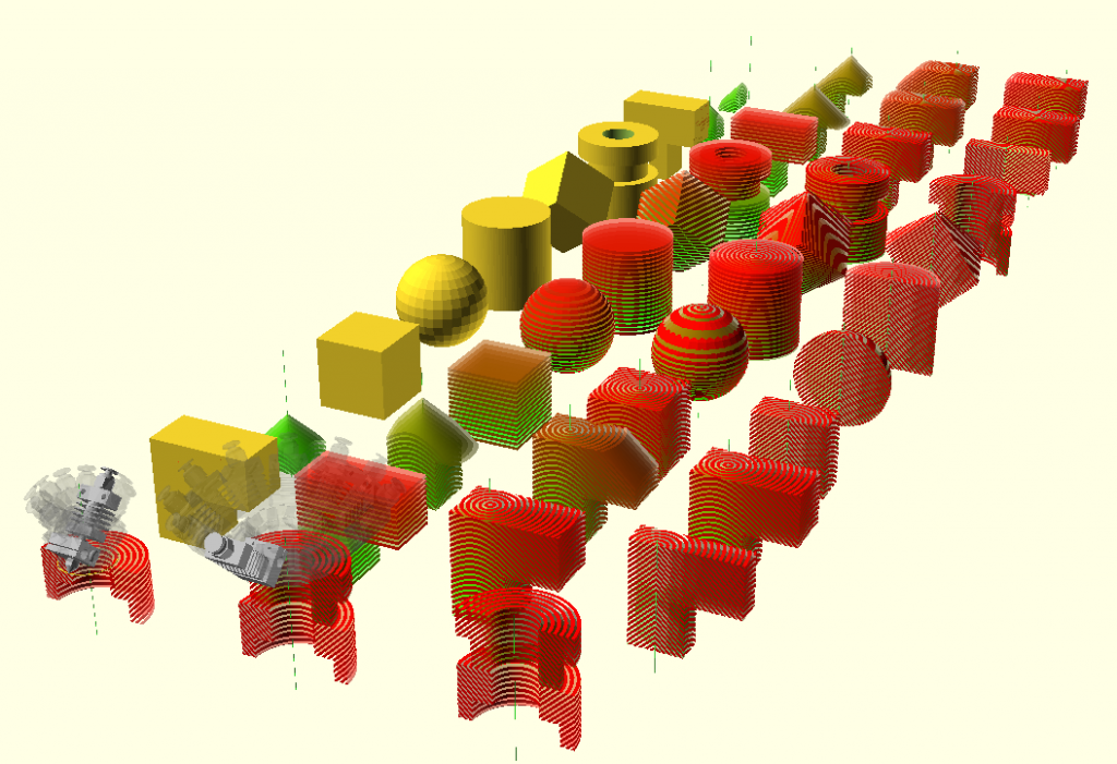
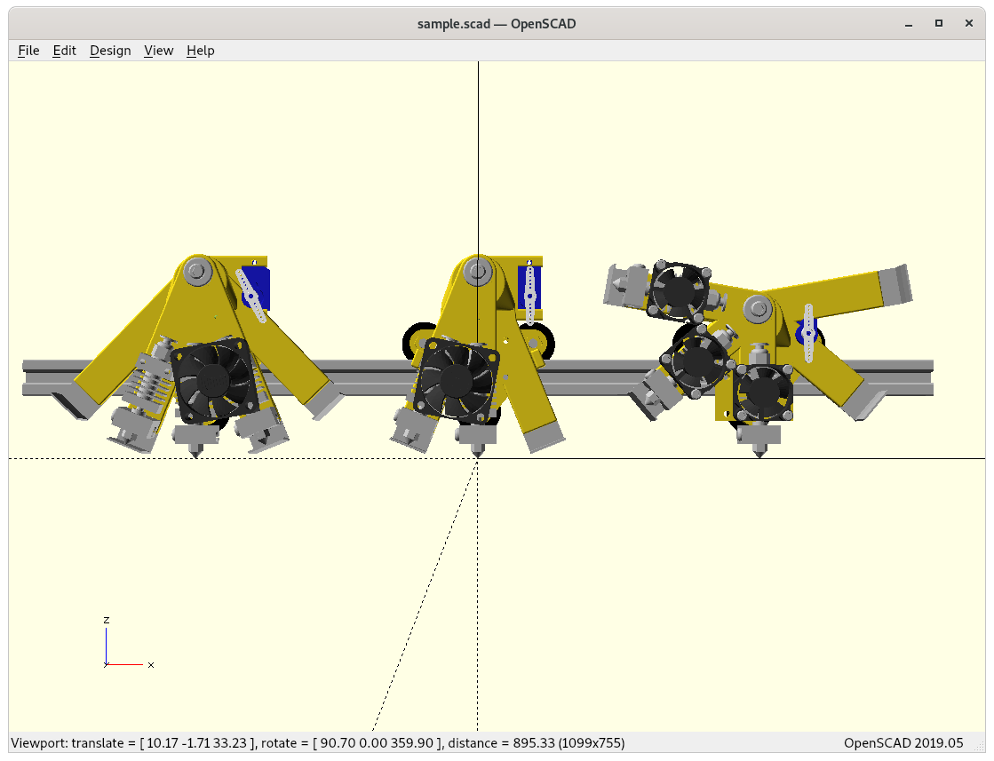
2 extrusion at 100mm/22° vs 80mm/36° 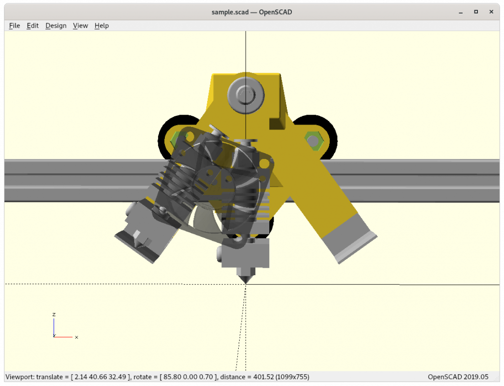
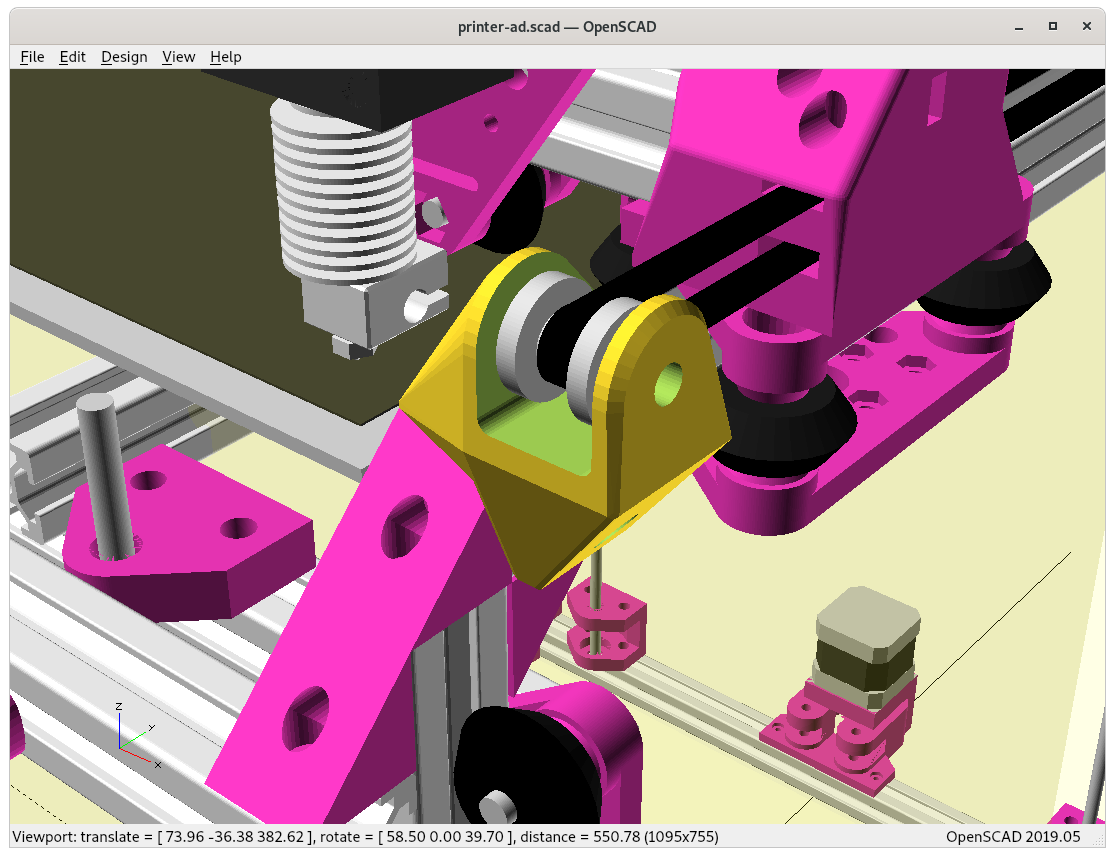
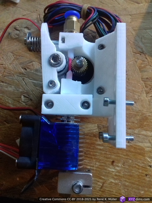
2 extruders, 100mm / 36°, with 2x 625zz bearings, ooze shields 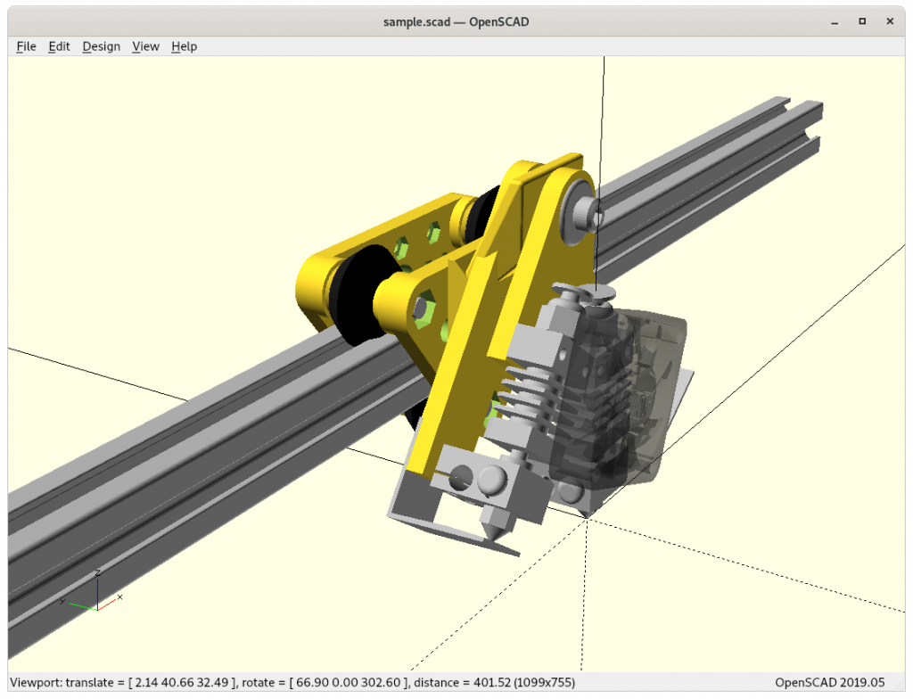
2 extruders, 100mm / 36°, with 2x 625zz bearings, ooze shields 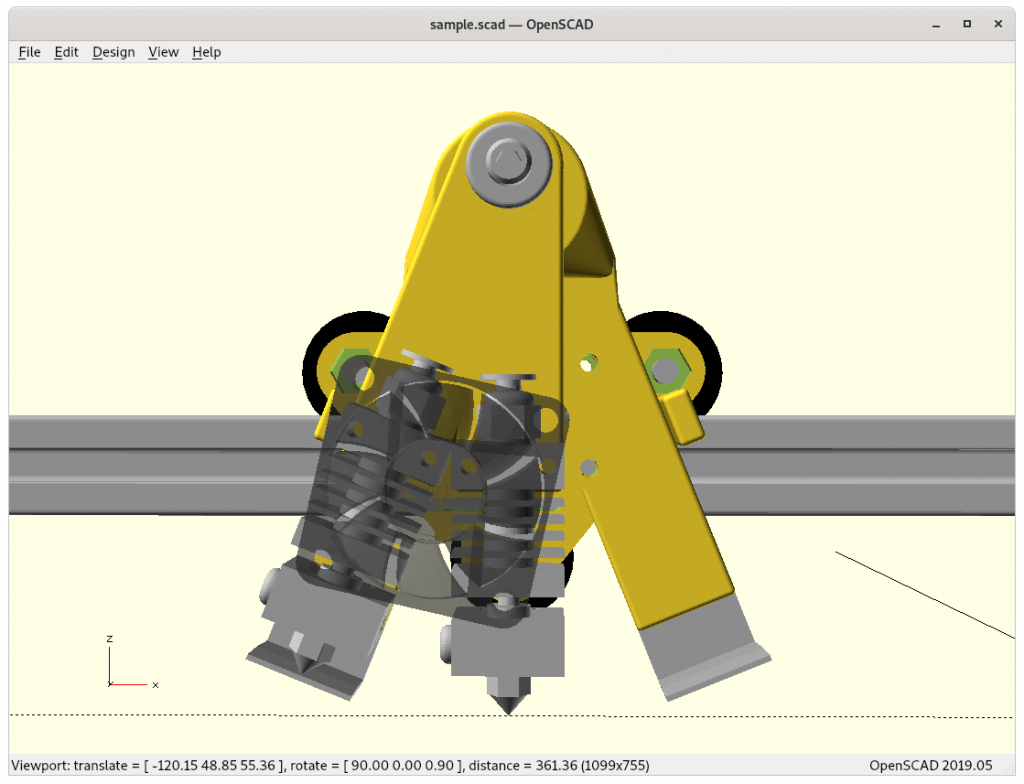
position stoppers added 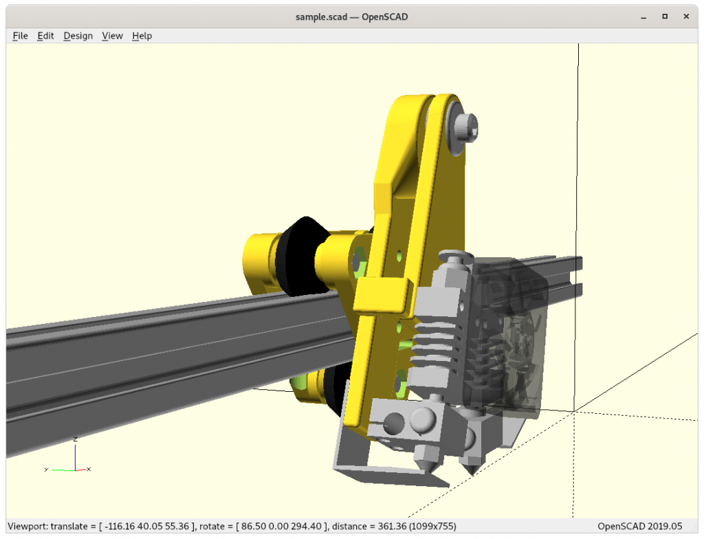
position stoppers added 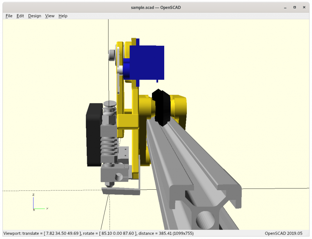
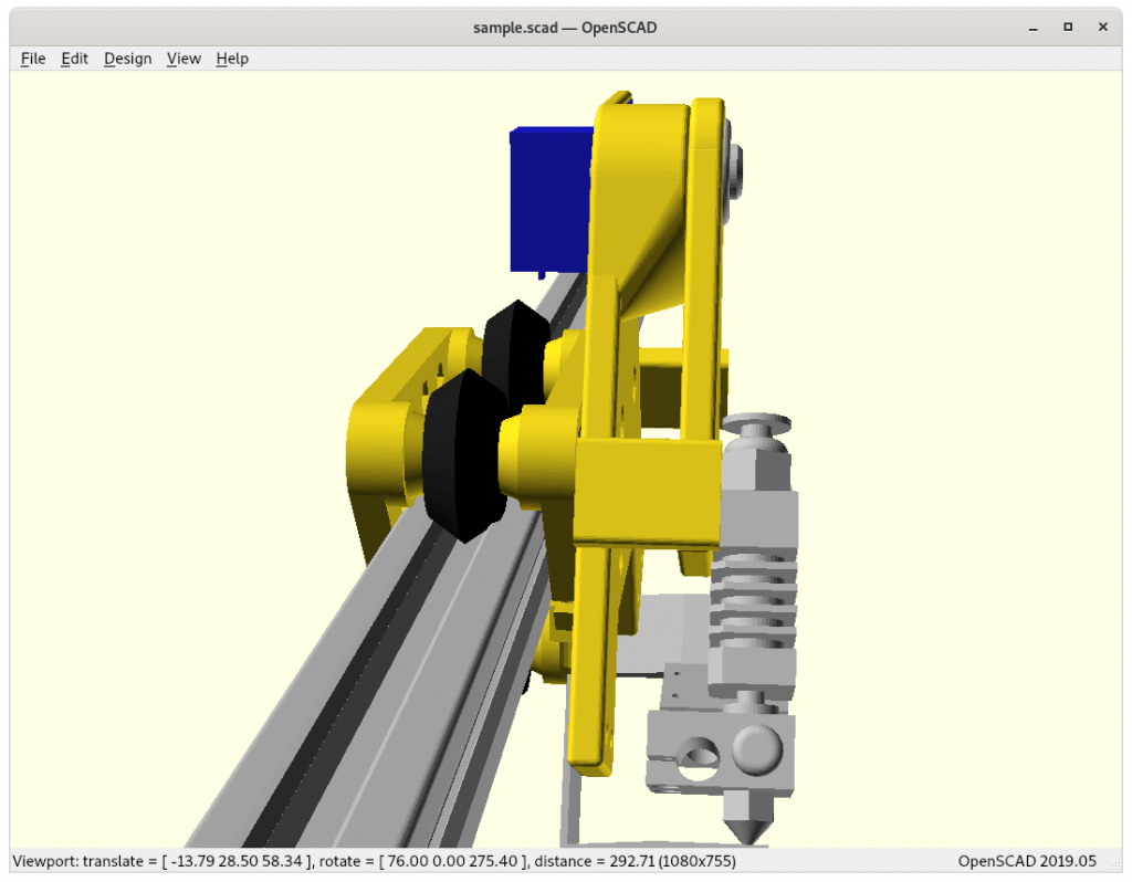
adding SG90 servo 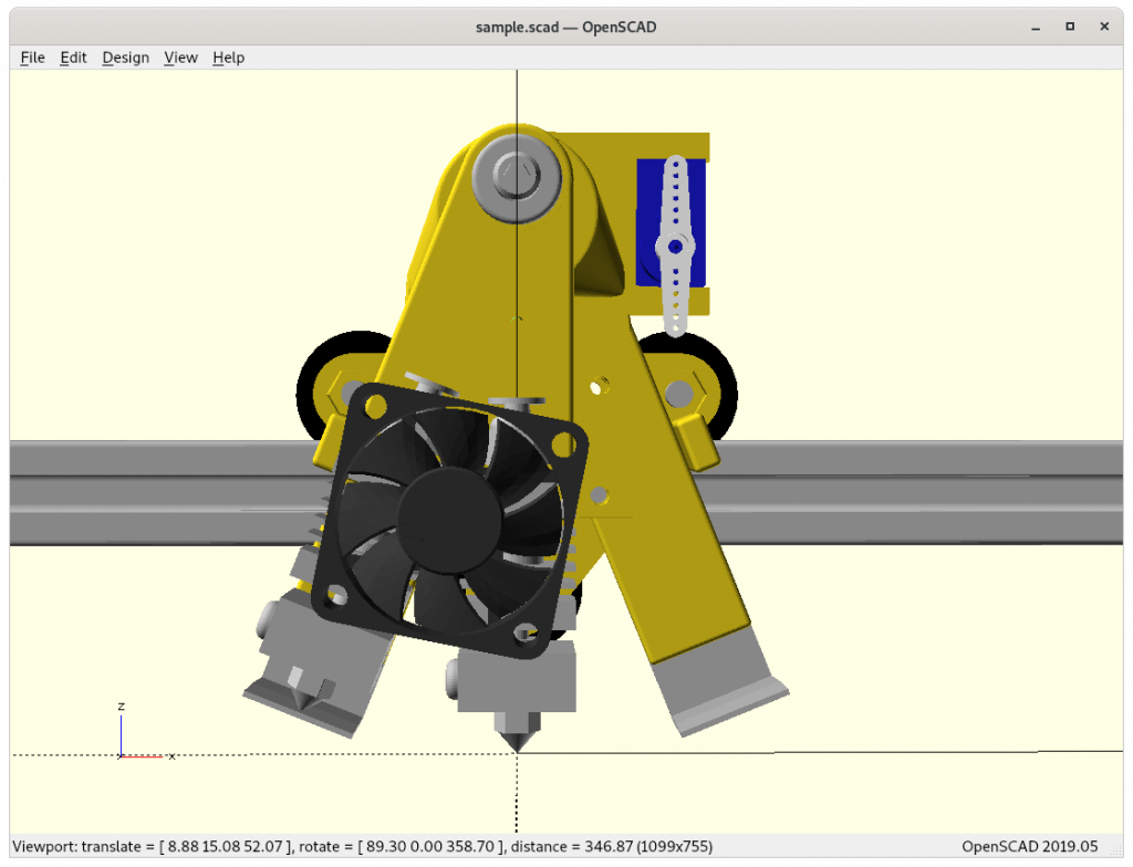
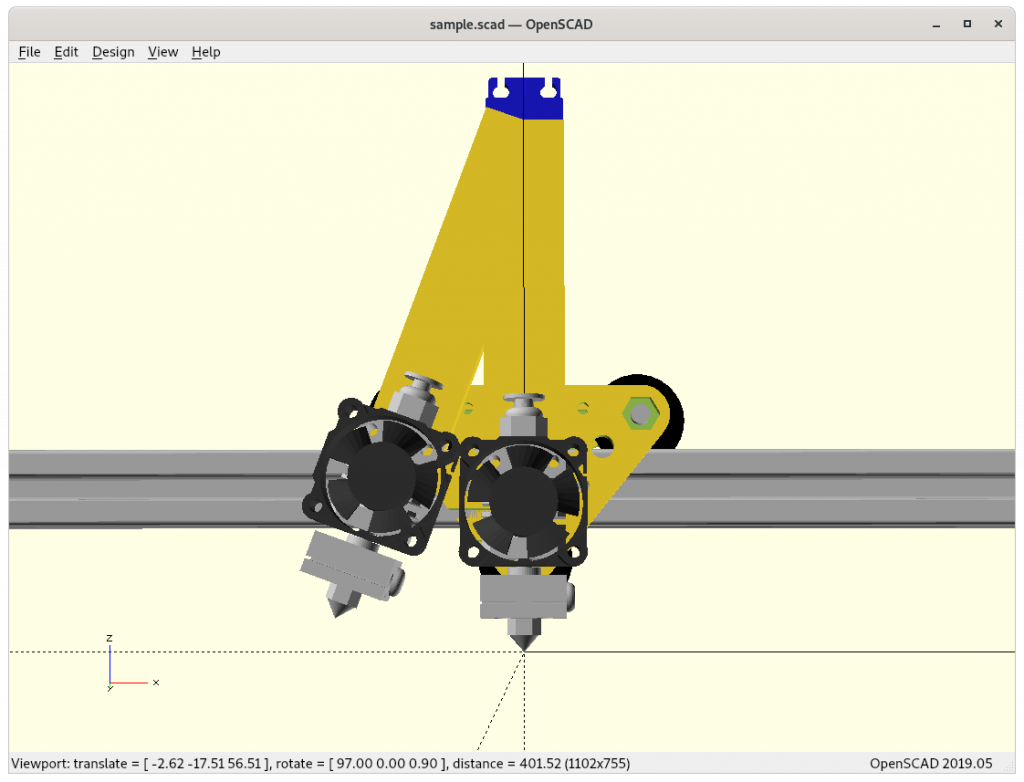
using SG90 servo to switch extruders (only for dual extruder setup), tool 0 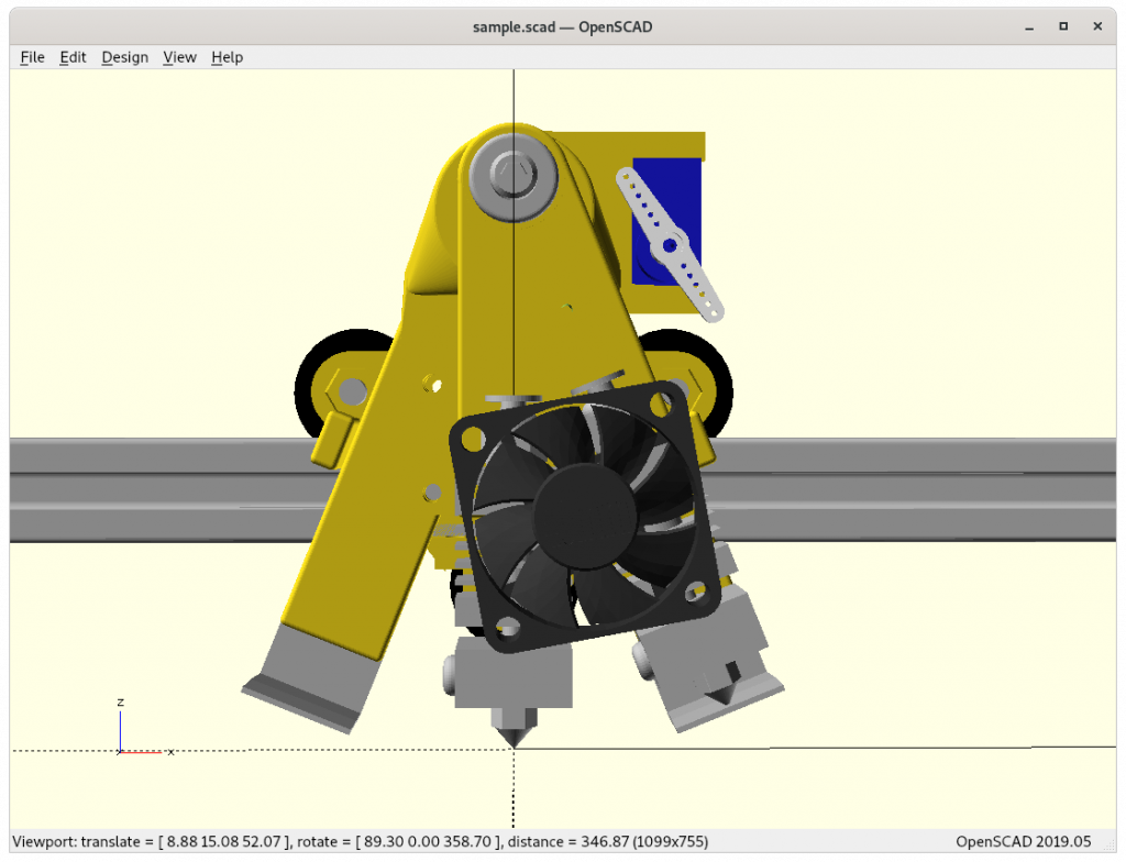
using SG90 servo to switch extruders (only for dual extruder setup), tool 1 
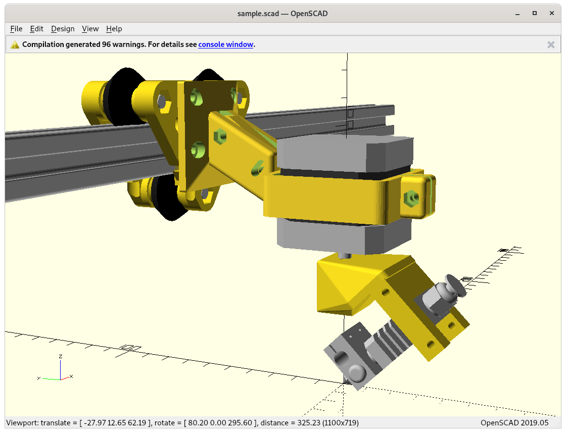
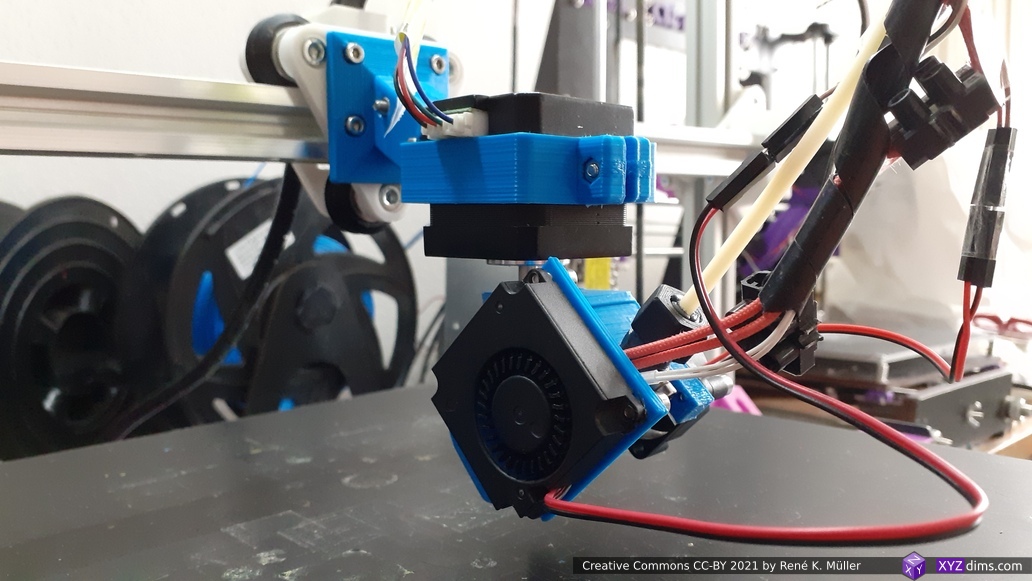
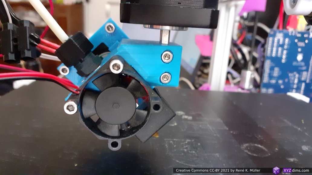
including part cooler in front
The actual axis of rotation can be moved lower by becoming an arc or swing, which will make the construction more complex, but likely more reliable as the servo cannot be trusted to keep position exact enough – so a spring to keep the swing in either two position, or constant force to push to a left or right limit in dual extrusion setup – for now I use a small SG90 servo to push toward the mechanical stoppers, either left or right hence only usable in dual setup, and using a 1mm wire to connect the swing with the servo.
increased distance of base to anchor, to support silicon sock on hotend 
single bearing on anchor 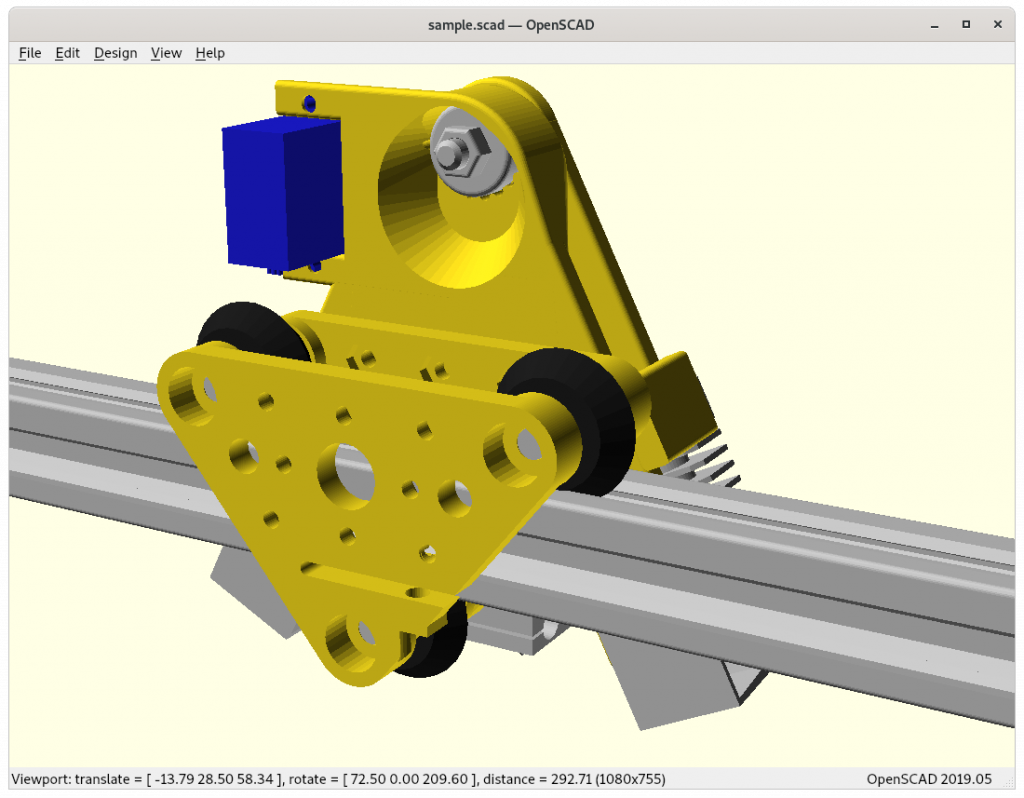
dual bearings on base & anchor
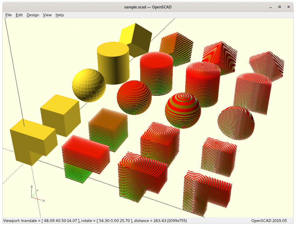
The Rotary Y approach definitely is only suitable for dual extrusion setup, as anything else, as seen on this comparison, uses up too much X space for my consideration.
Addendum: DerM4209 did a design with 6 extruders on full 360° rotary, and as the setup shows, he has plenty X-axis space to dedicate to such.
Let’s explore another idea . . .
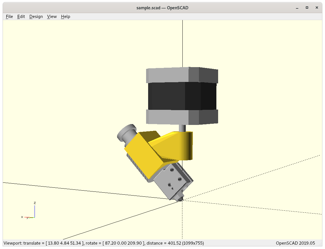
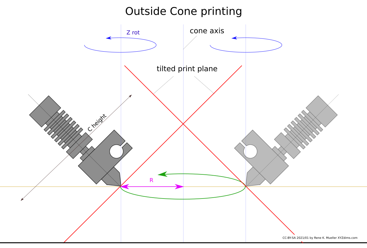
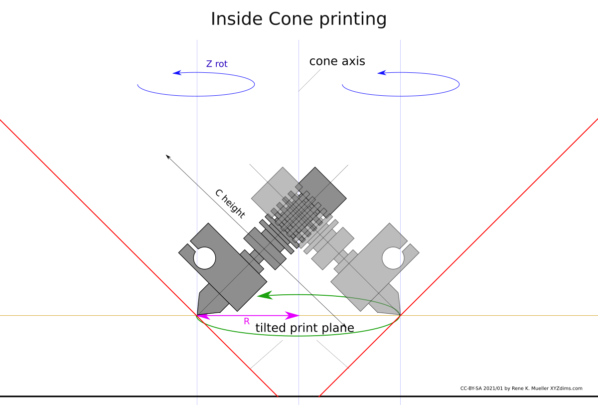
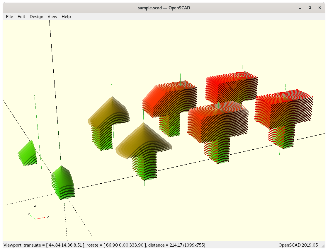
Rotary Z-Wise
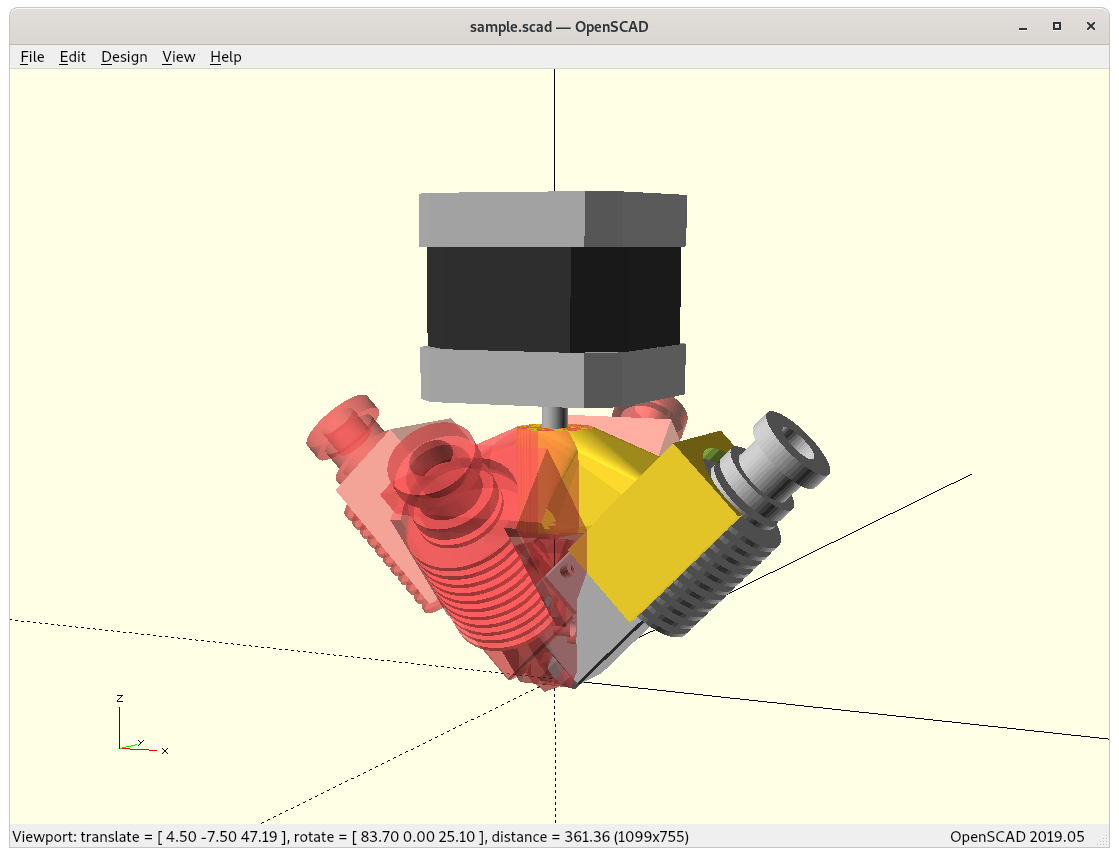
This design is heavier with NEMA17 motor, and with the focus of more than 2 printheads but 3, or 4 printheads, inspired by the Rotating Tilted Nozzle:
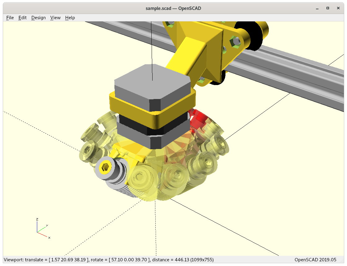
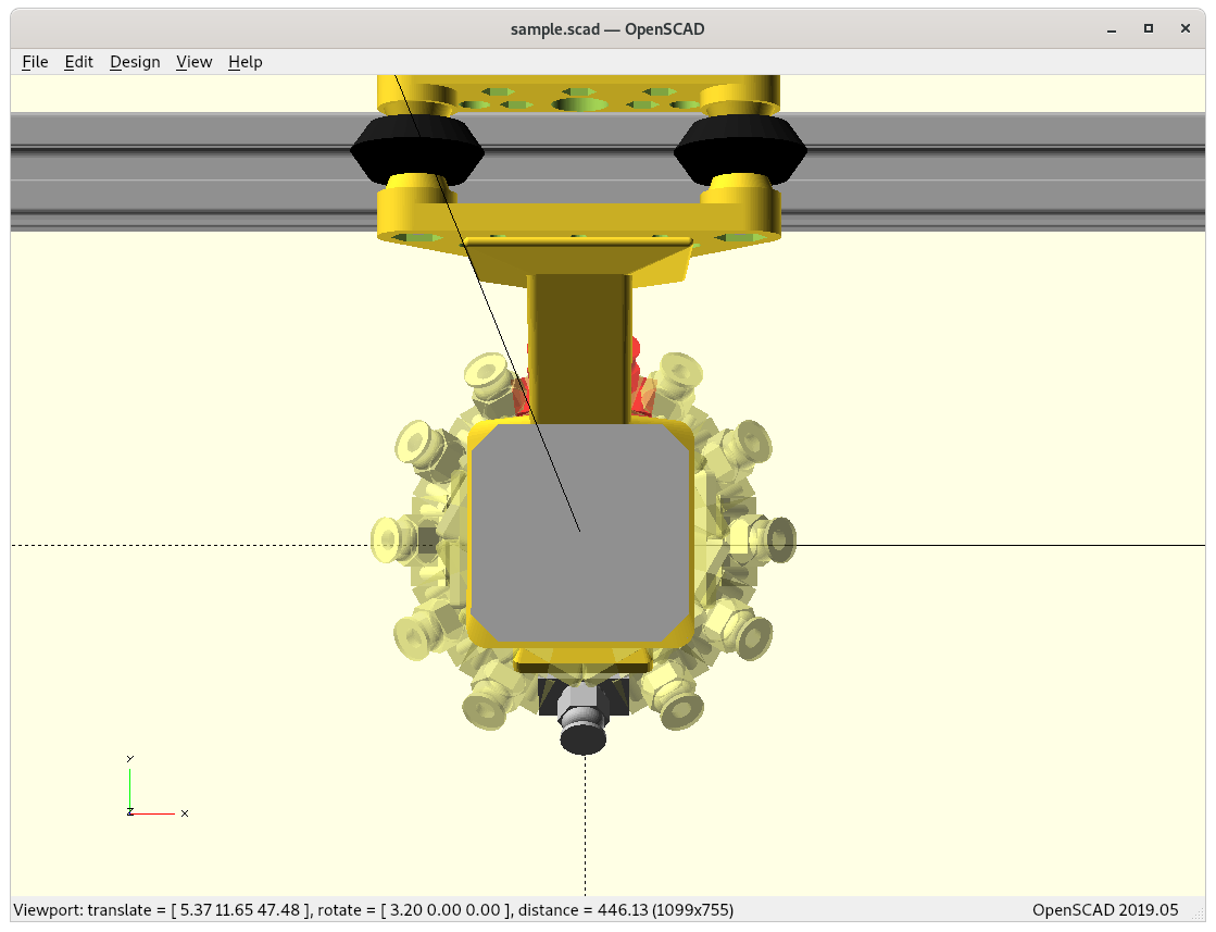
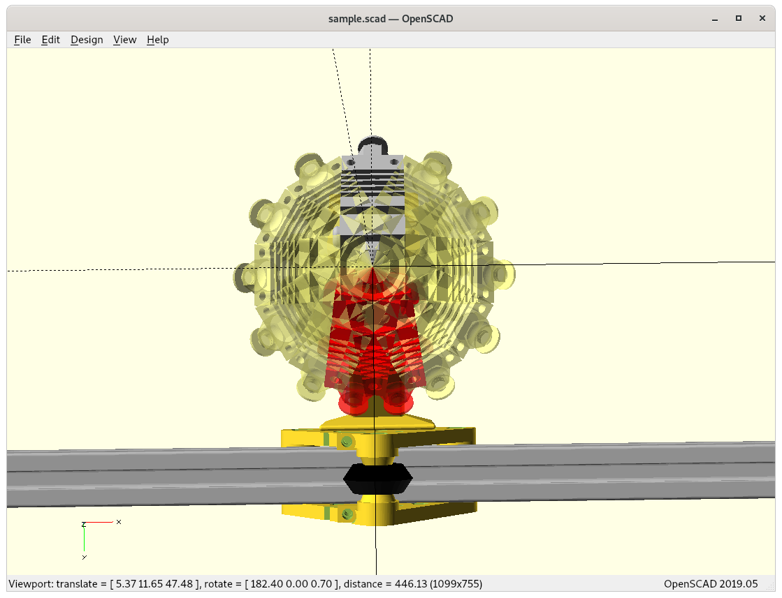
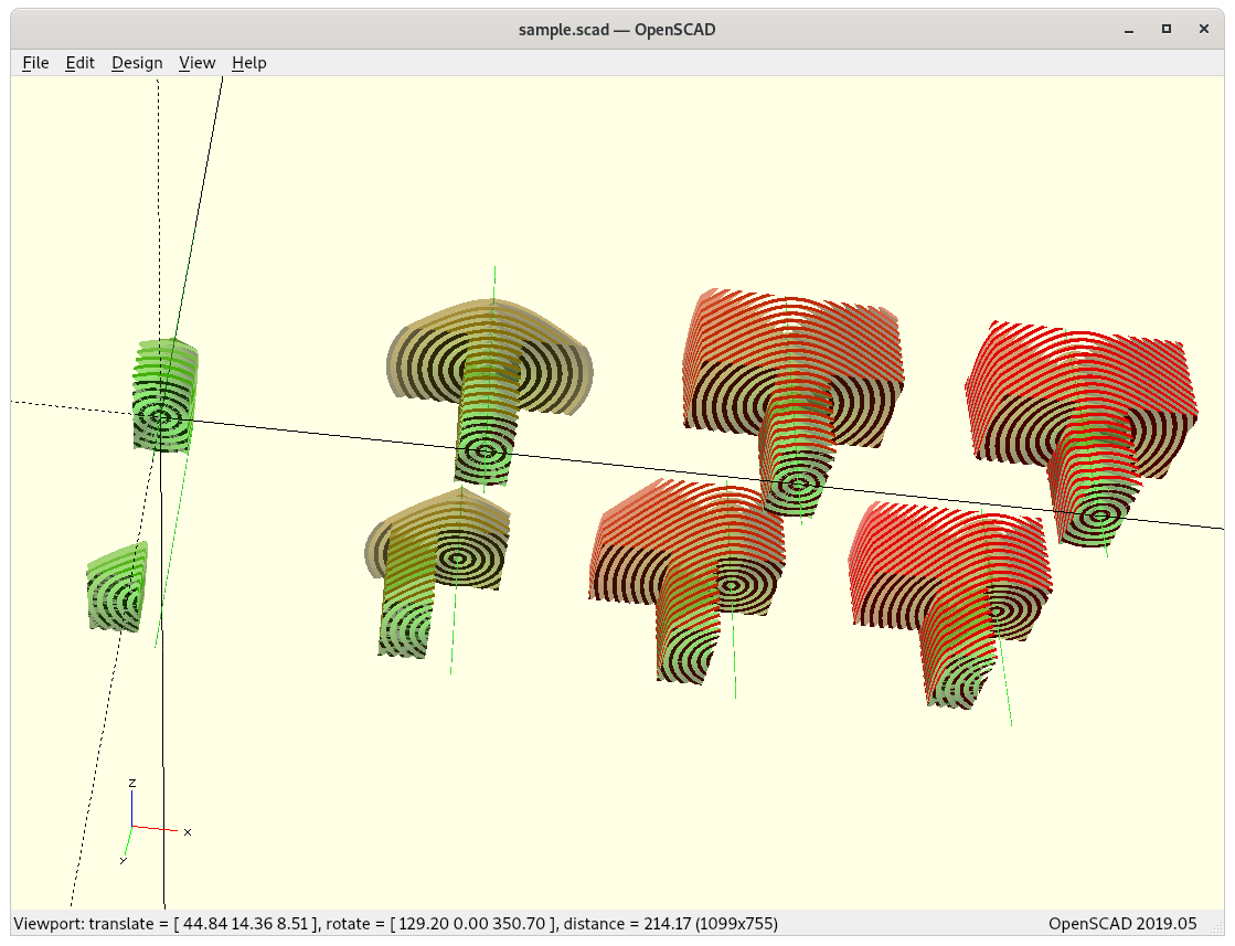
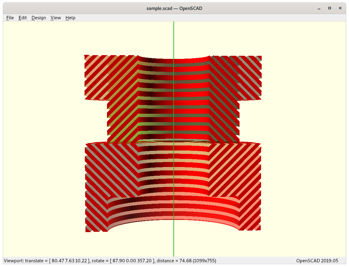
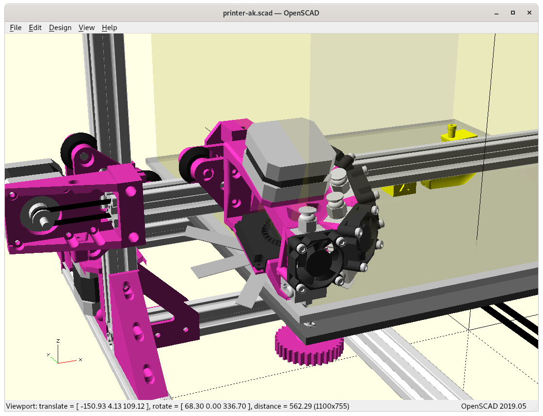
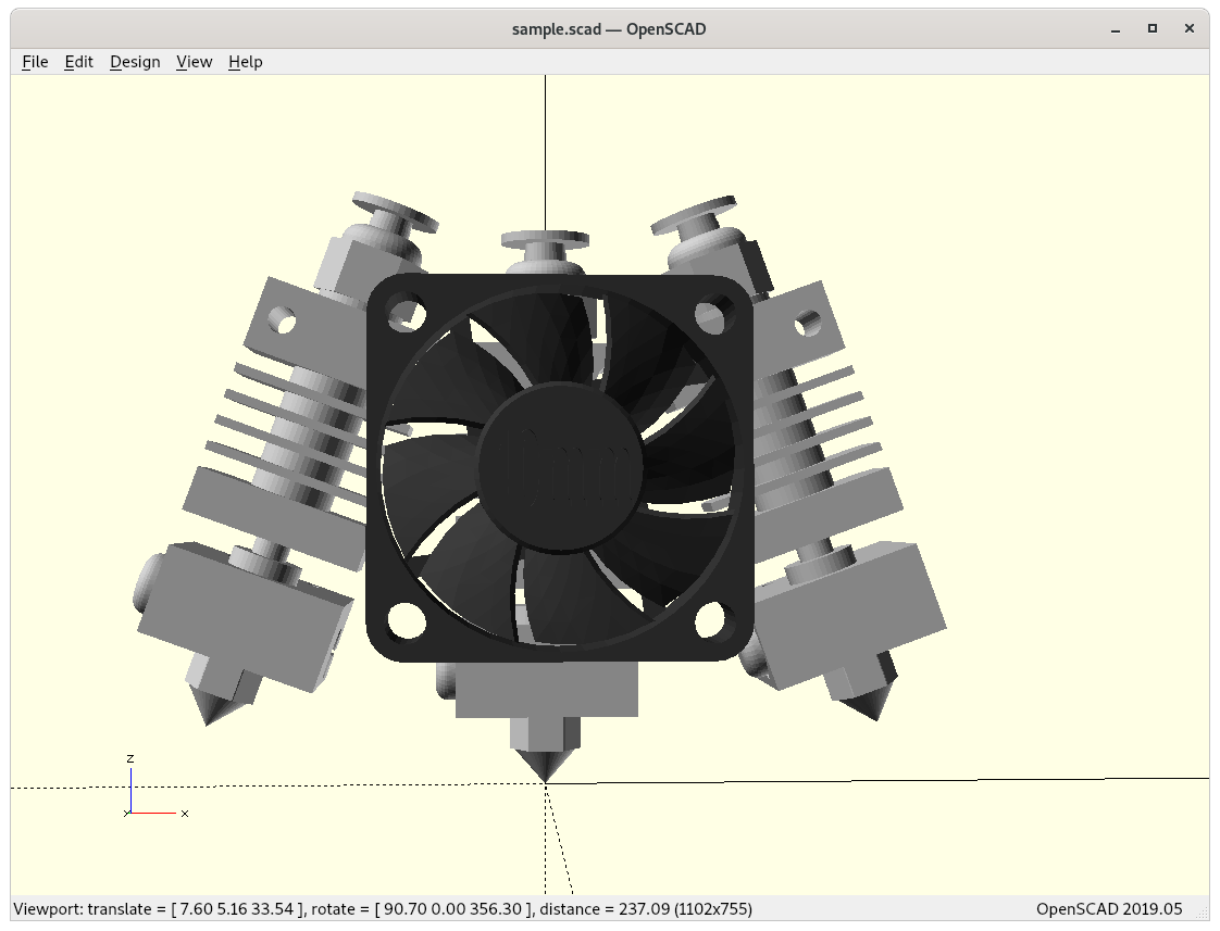
4 printheads on 9 sided polygon, 20° tilted
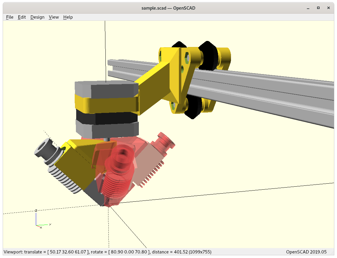
4 printheads, tool 0 (front view) 
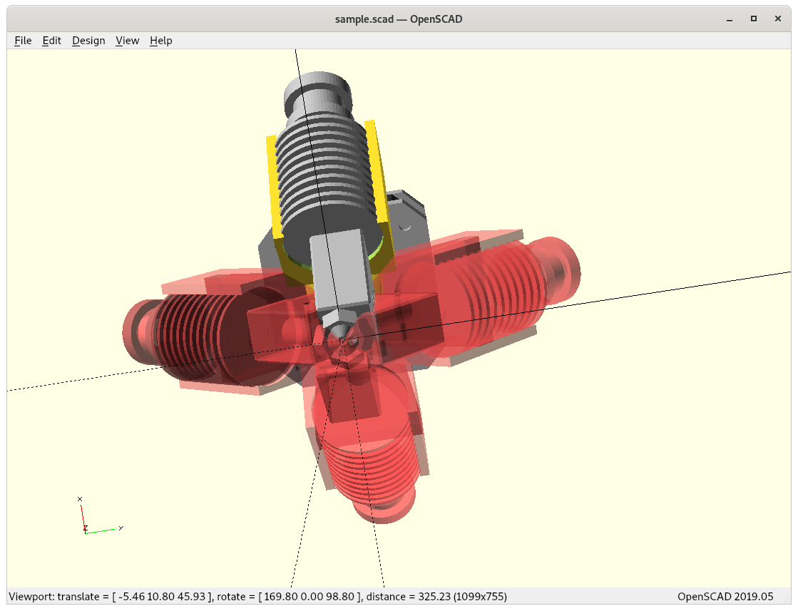
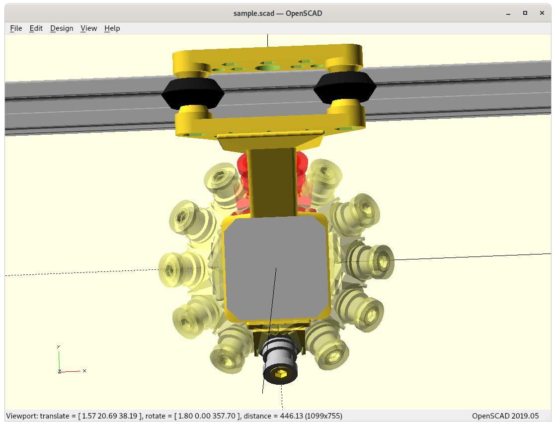
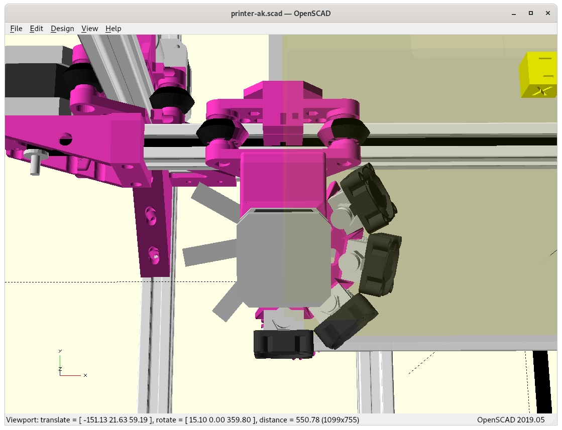
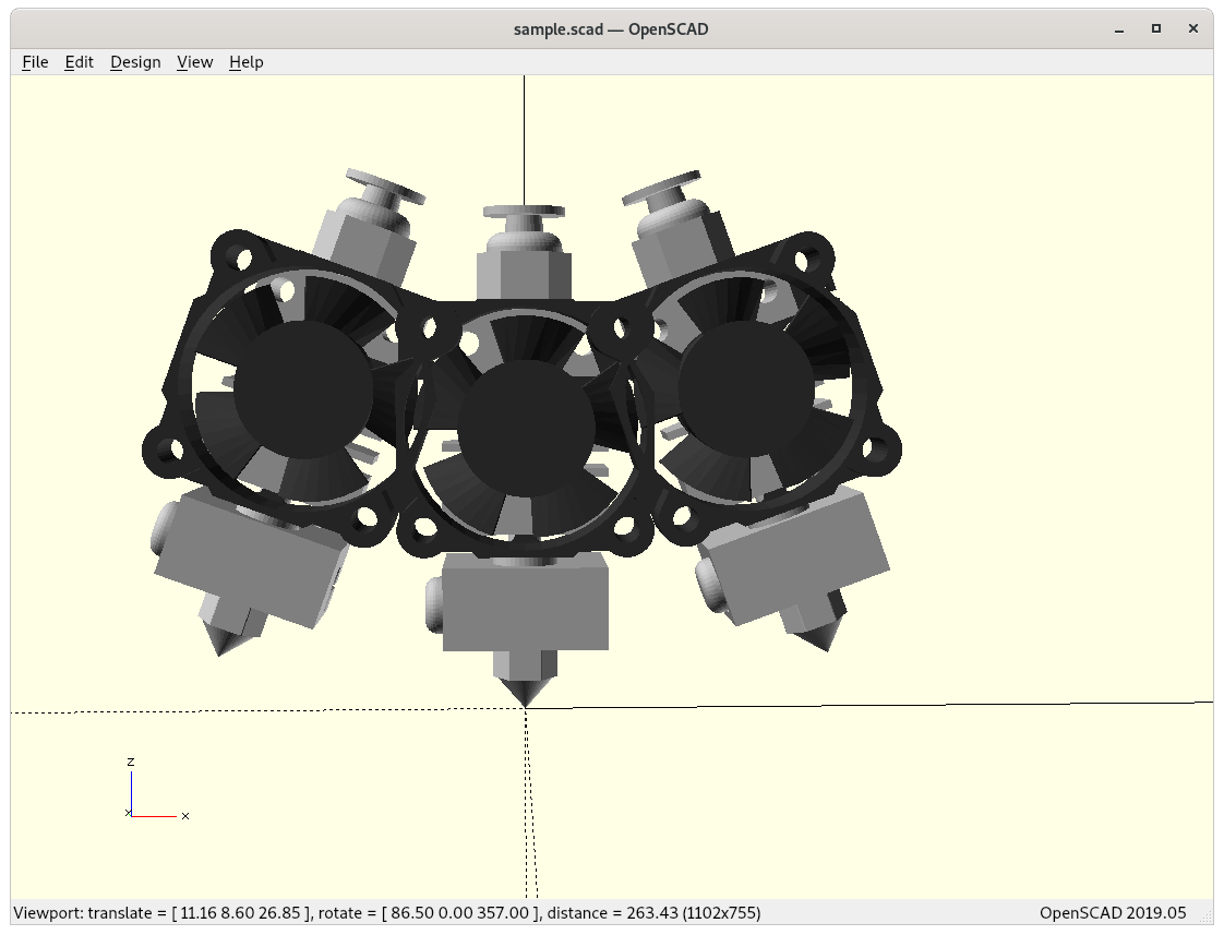
4 printheads, tool 0 (top view) 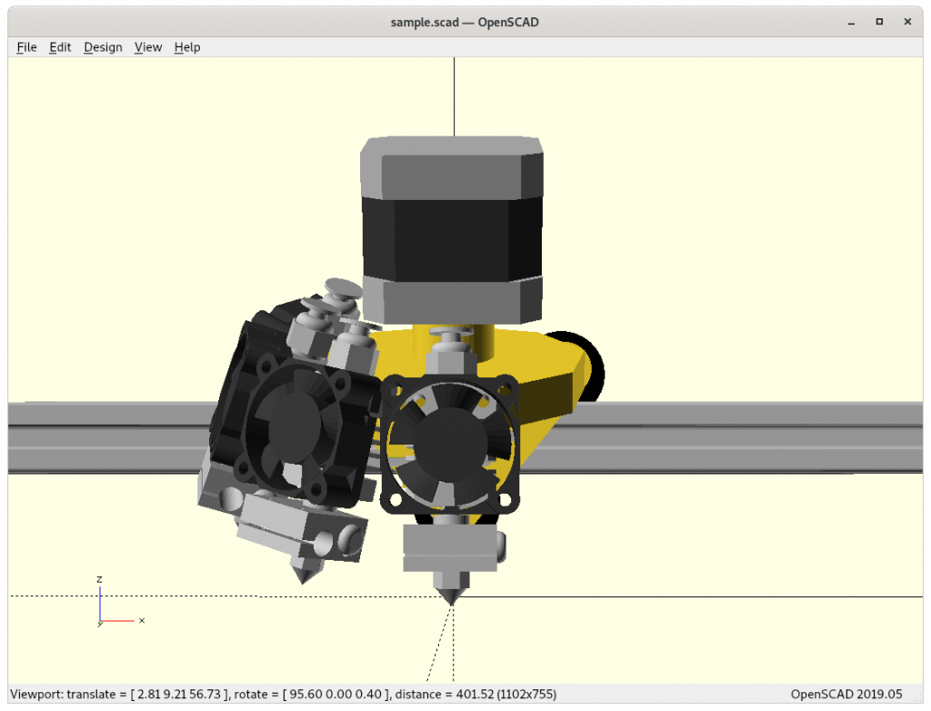
4 printheads, tool 3 (front view) 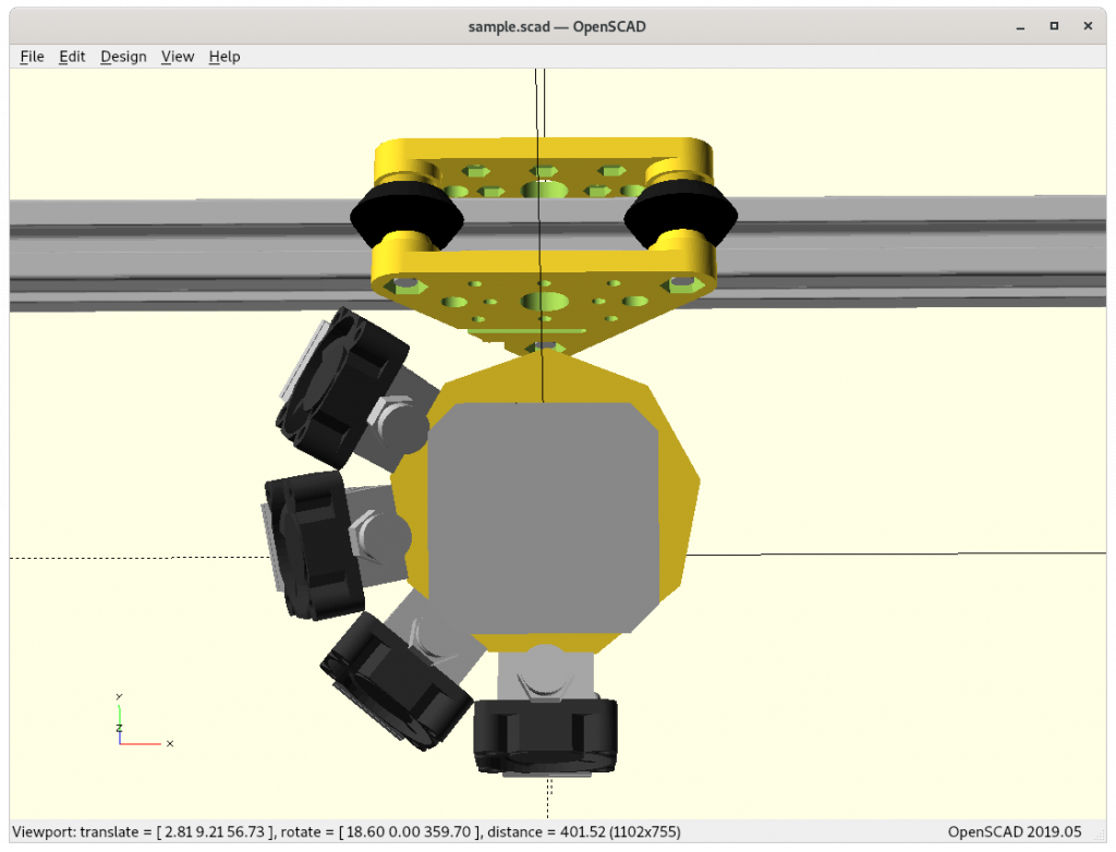
4 printheads, tool 3 (top view) 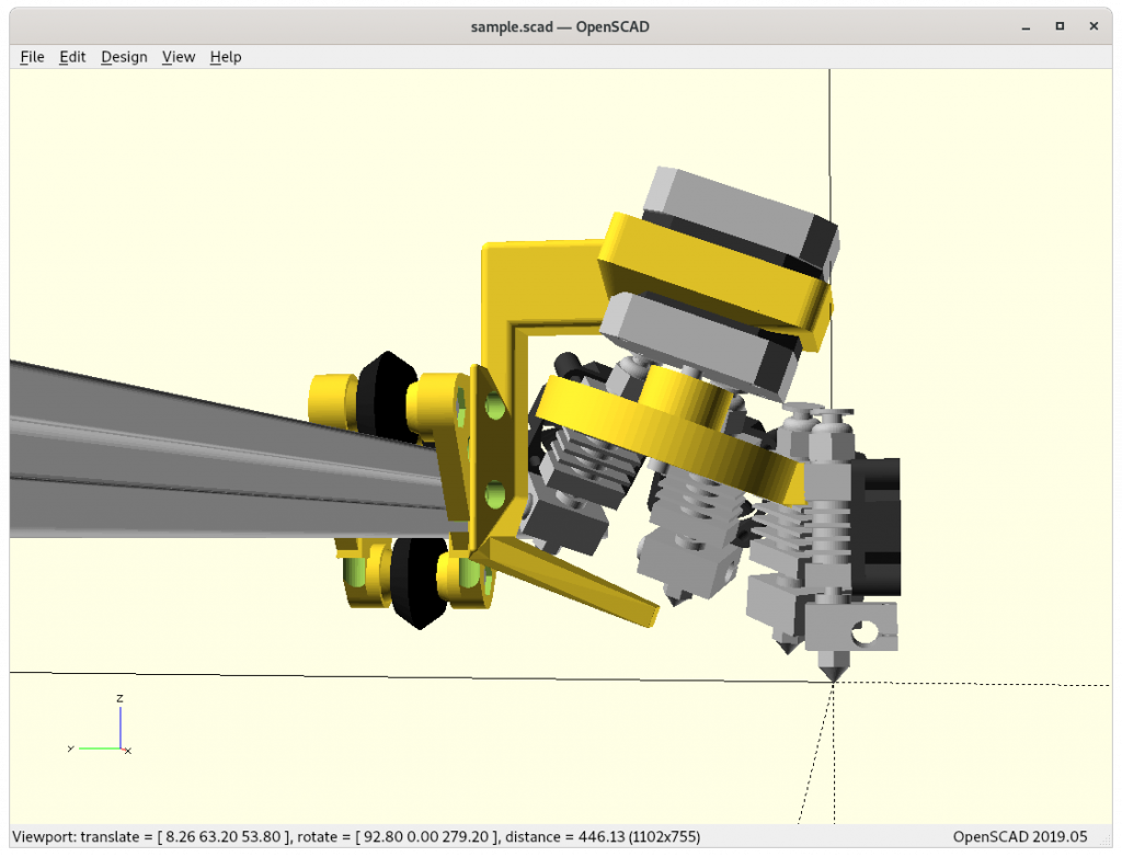
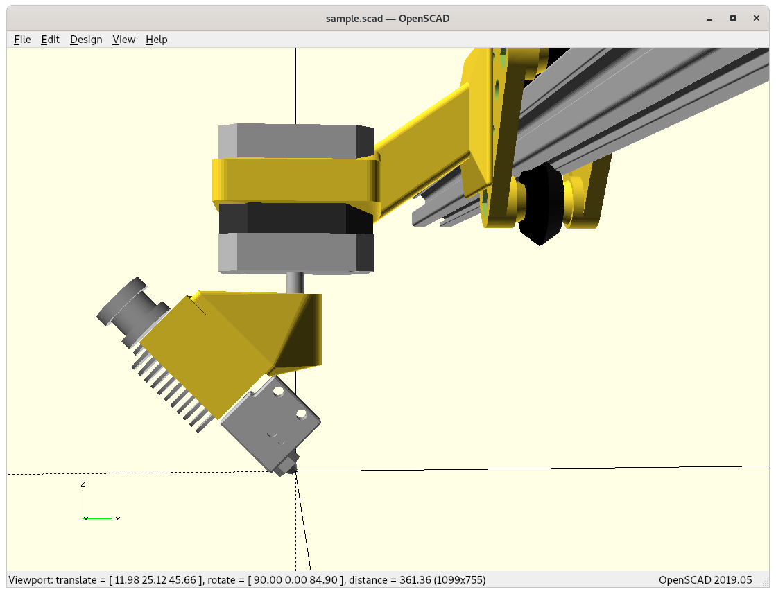
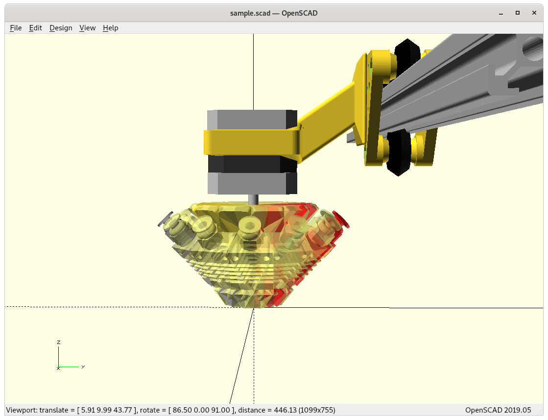
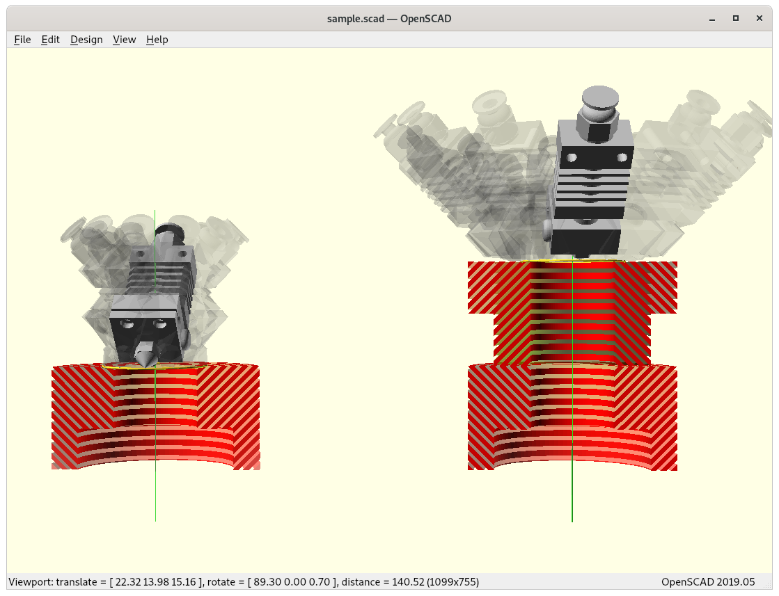
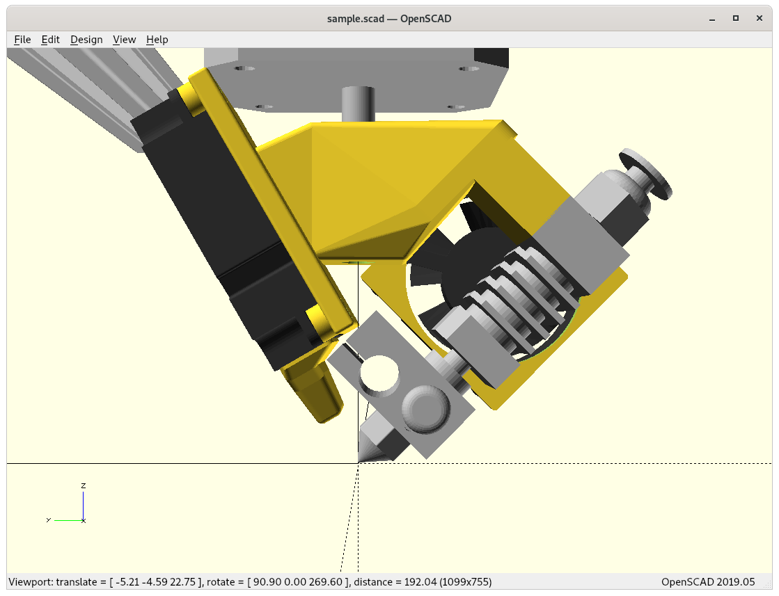
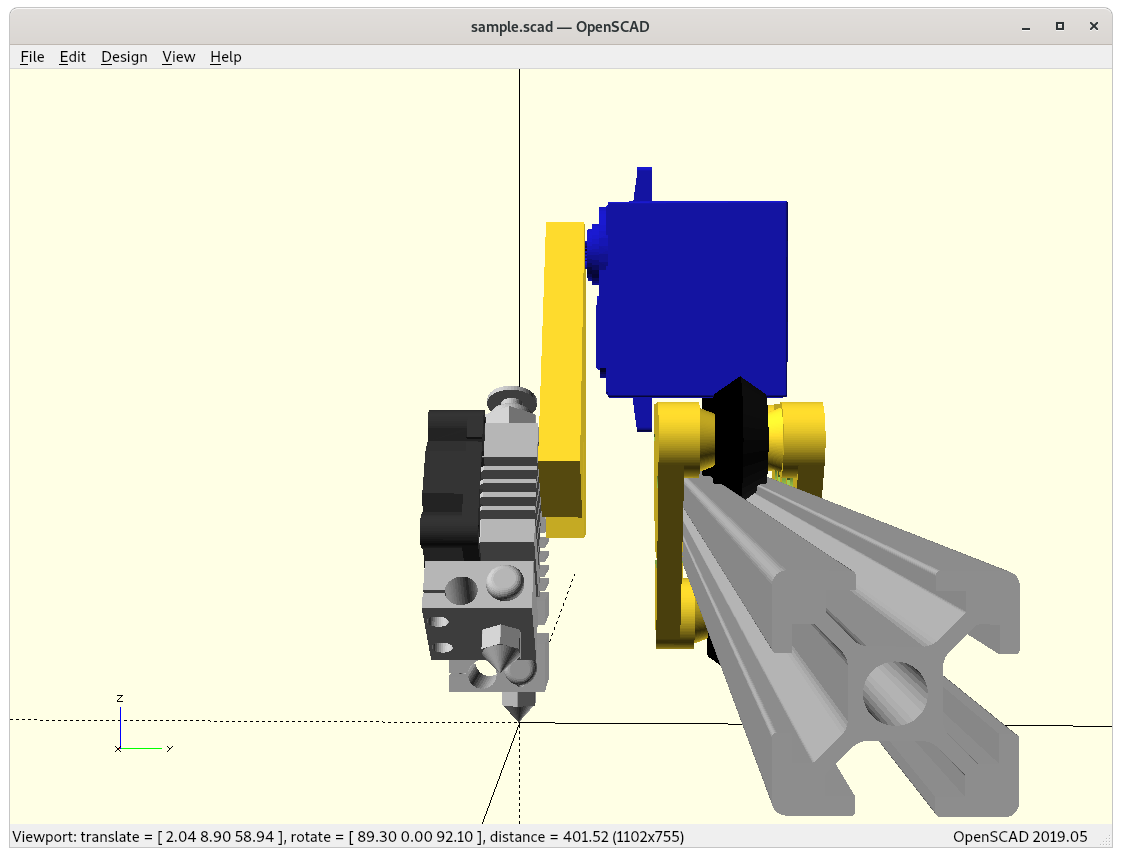
4 printheads, tool 0, full mount (side view) 
4 printheads, tool 0, full mount (side view) 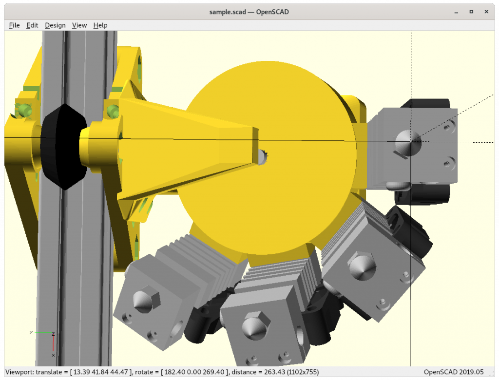
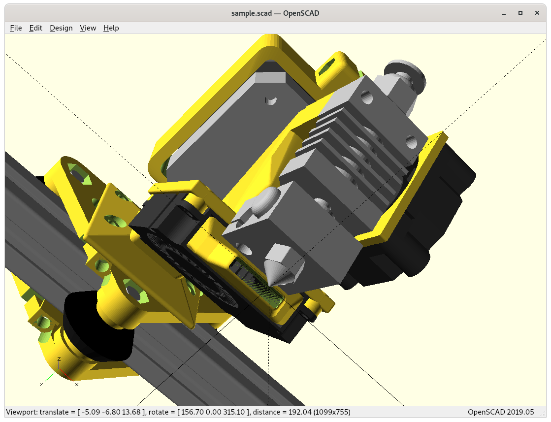
4 printheads, tool 0, full mount (bottom view) 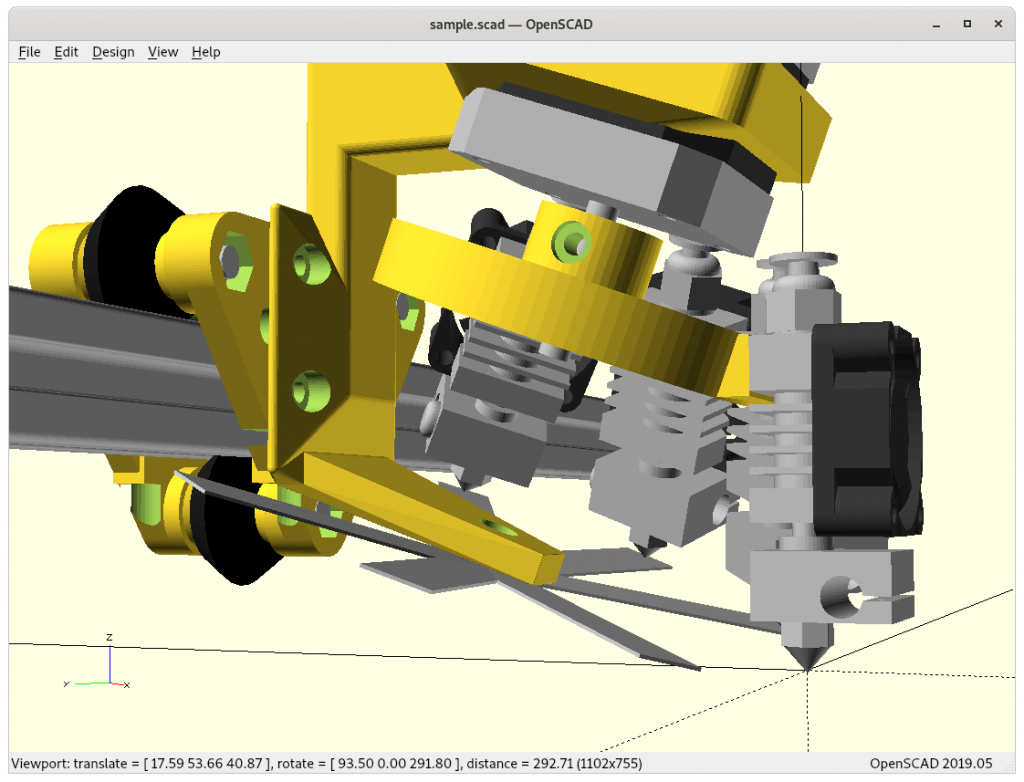
4 printheads with ooze shields (metal sheets) 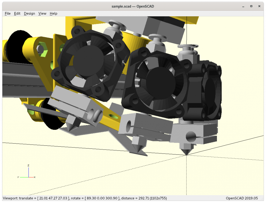
4 printheads with ooze shields (metal sheets), tool 2 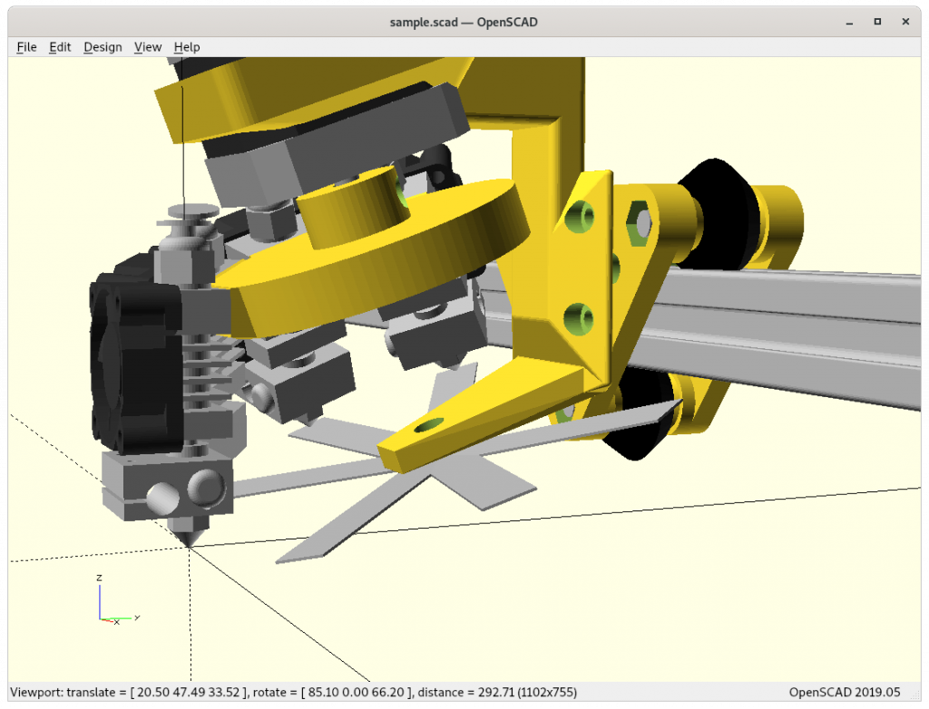
4 printheads with ooze shields (metal sheets), tool 3 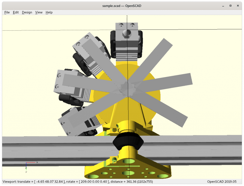
4 printheads with ooze shields (metal sheets) (bottom view) 
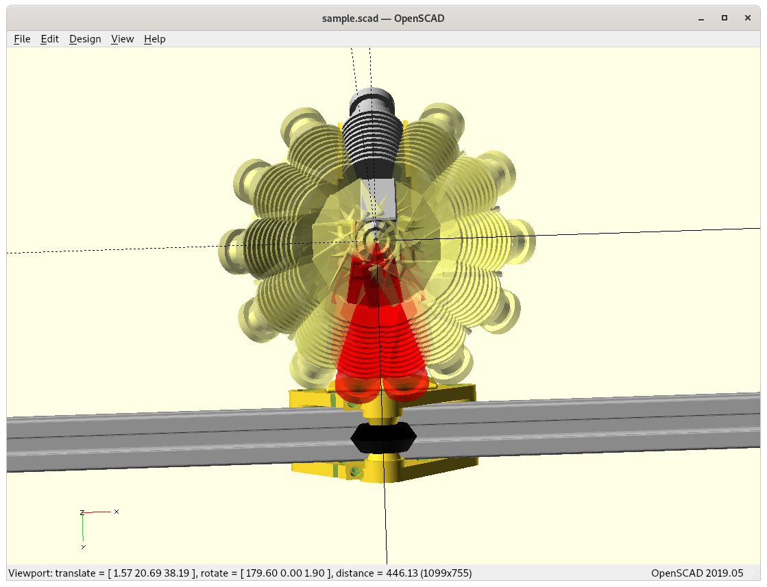
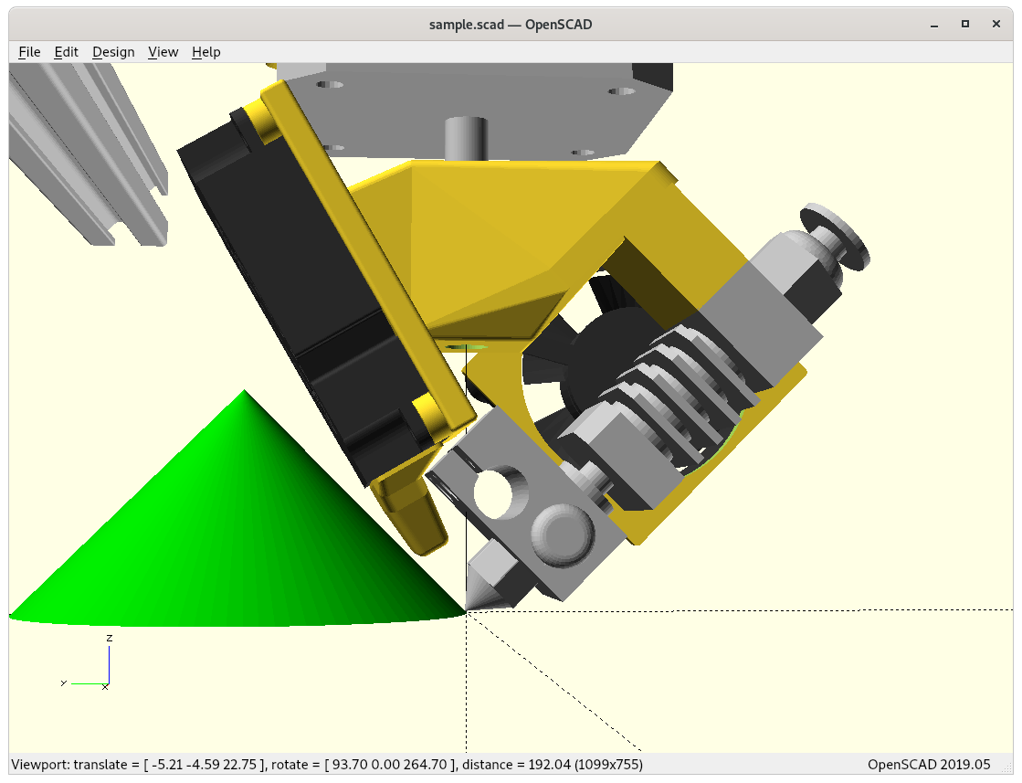
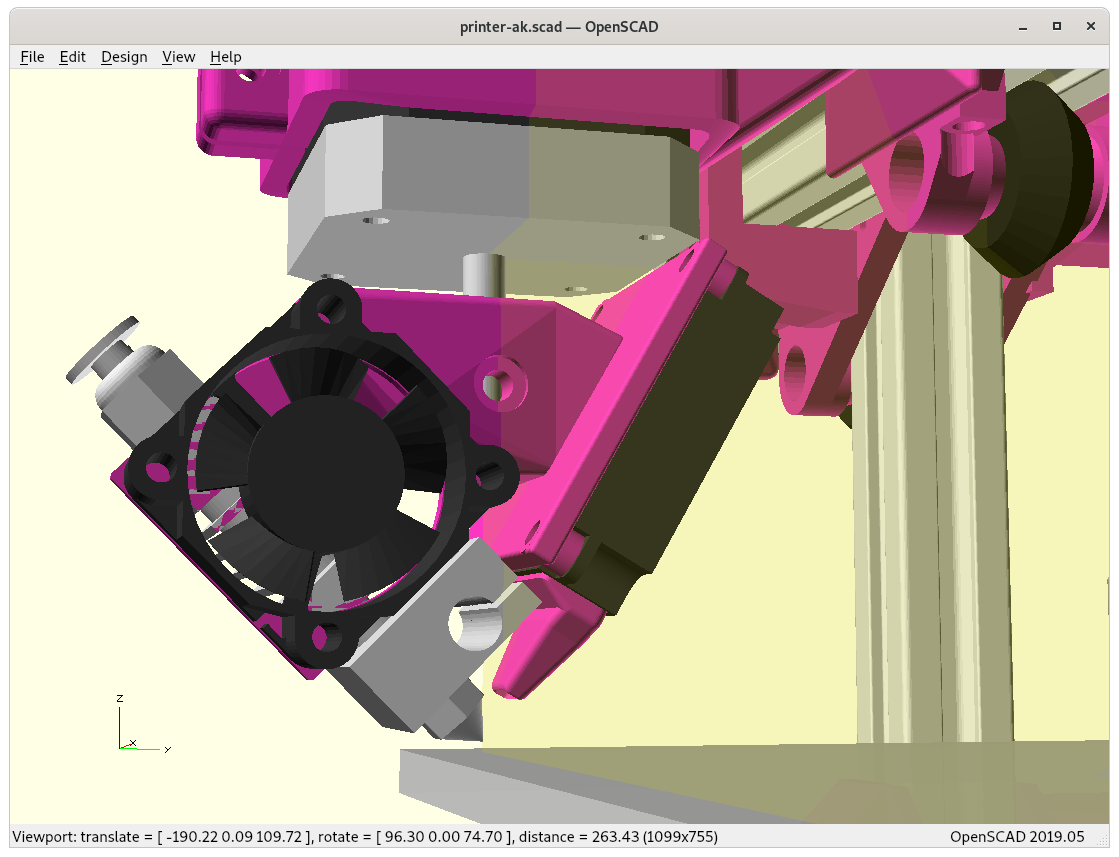
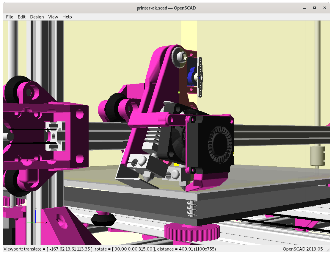
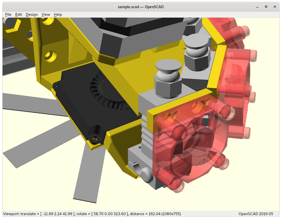
4 printheads with ooze shields & part cooler 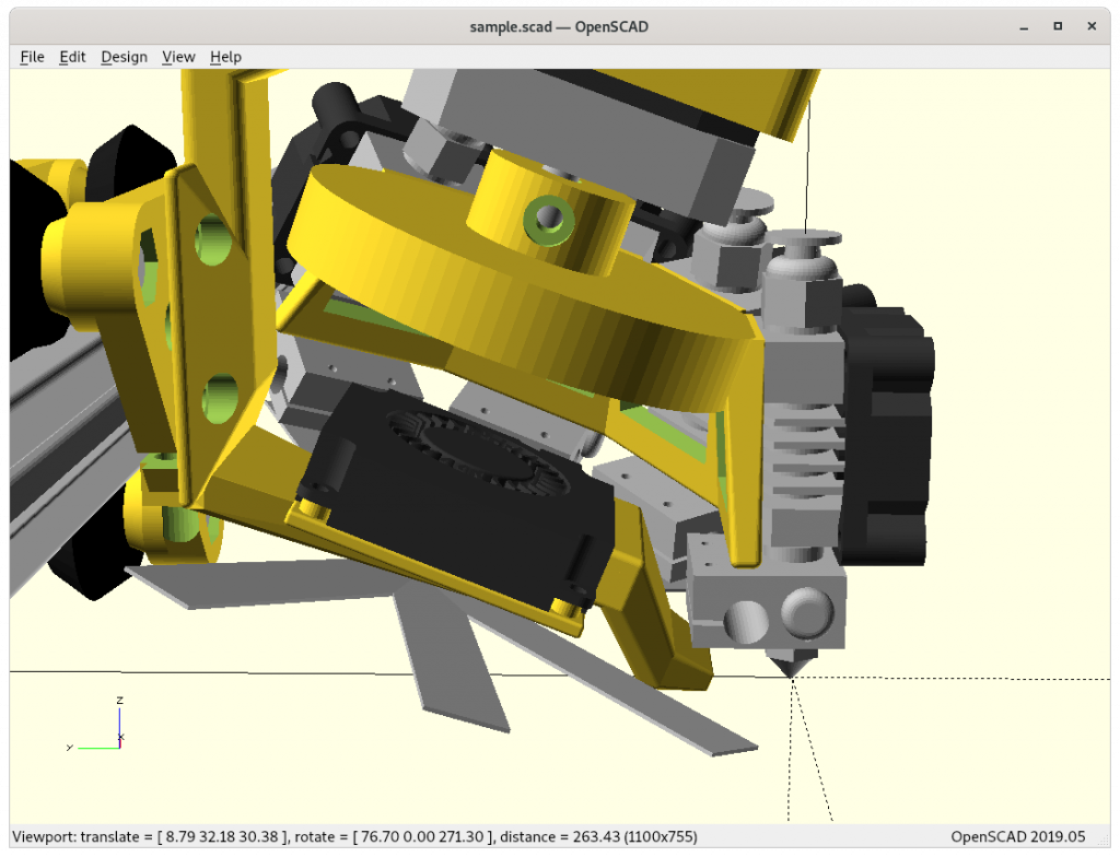
part cooler (close up) 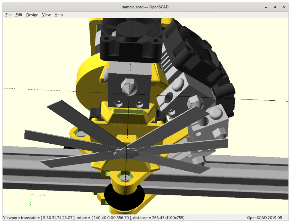
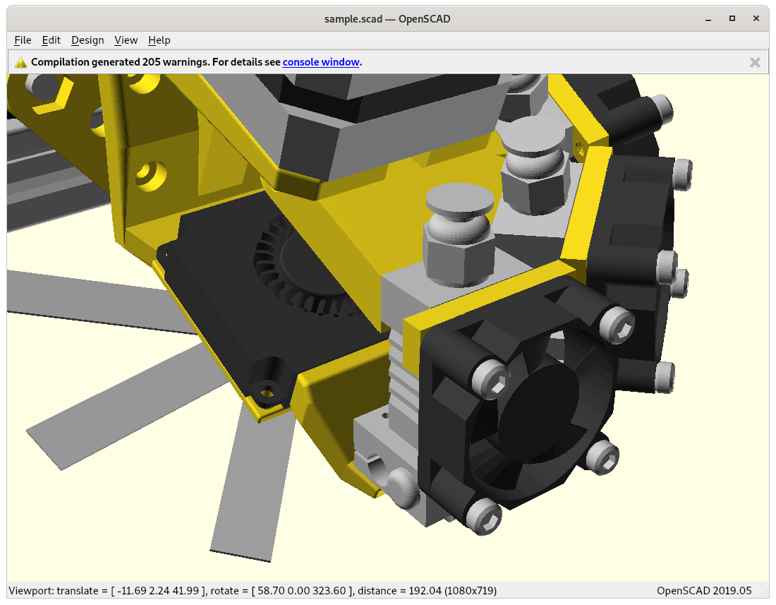
4 printheads full assembly 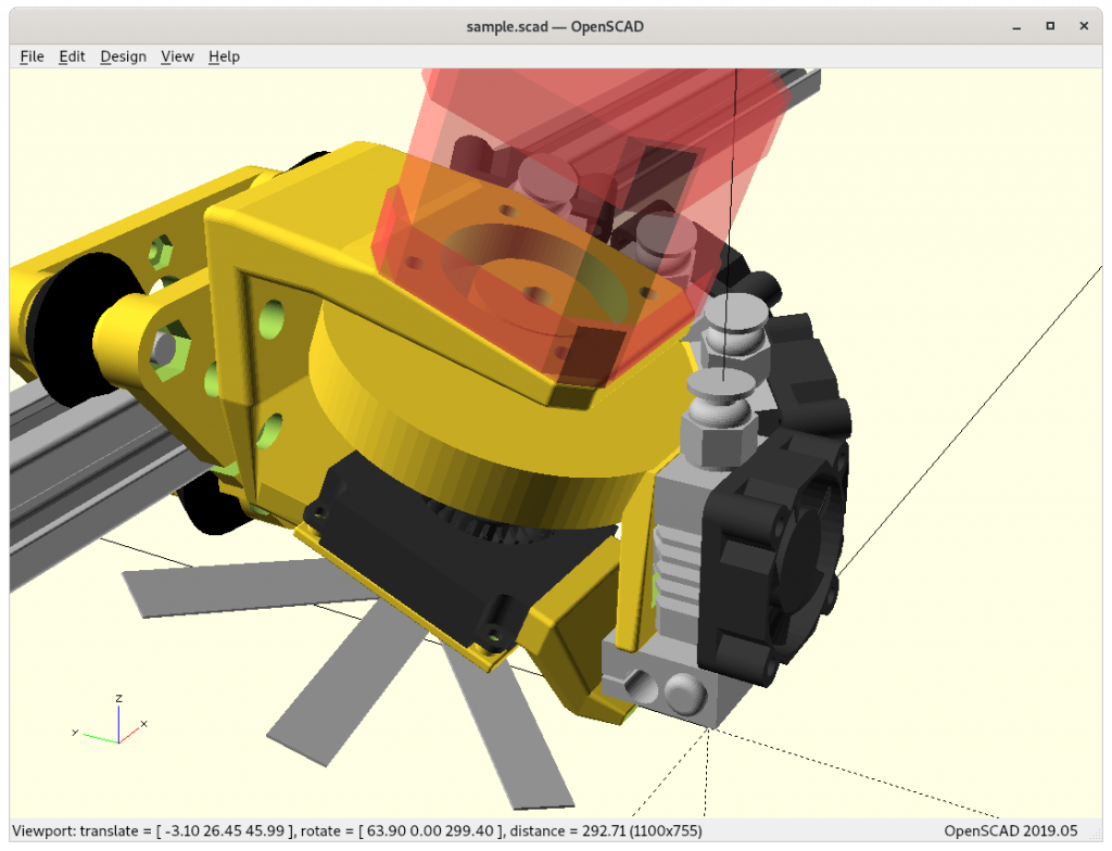
moving mount beneath NEMA 17 to save space for rotating Bowden tubes 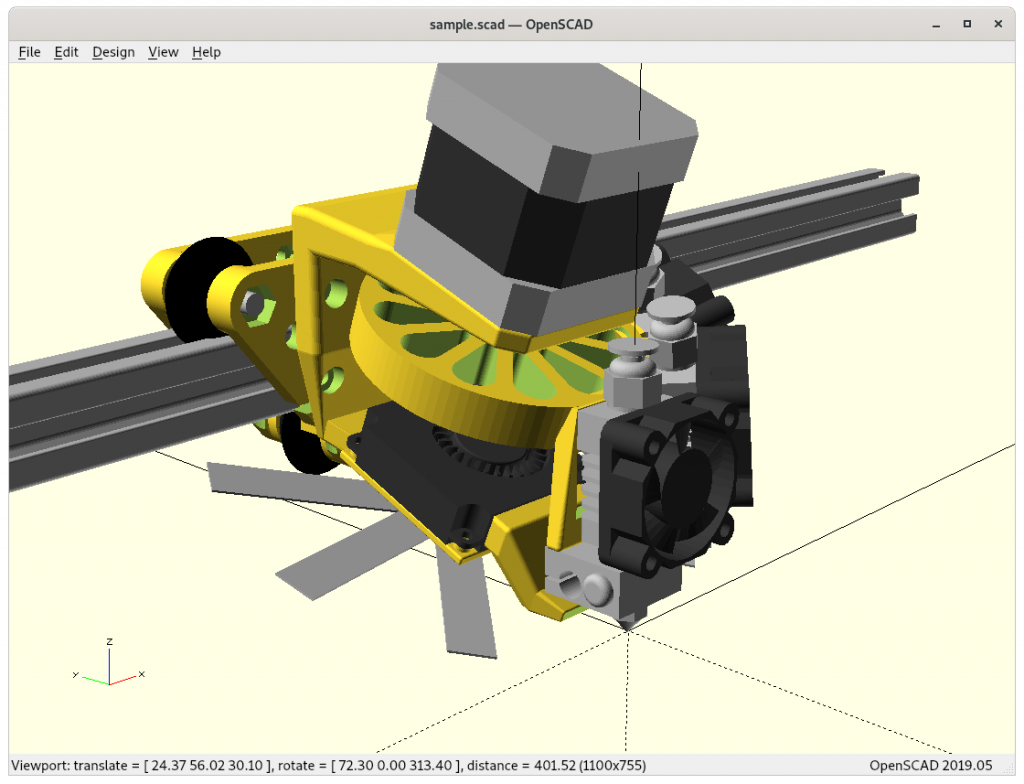
moving mount beneath NEMA 17 to save space for rotating Bowden tubes 
removing excessive material of the rotor 
adding support with new space given 
simplifying fan mount 
simple fan mount


I first went for 9 sided regular polygon, and then switch to 360°/9 angle and only make a connector where the heatsink/printhead is mounted to.
I could tilt the other way and regain some of the Y offset, but the Bowden tube and cable of the printheads would clash with the mount – the same problem arise when I would position the full circle with printheads, it looks nice but doesn’t work with Bowden tubes:
tilted forward, clashes with mount (won’t work) 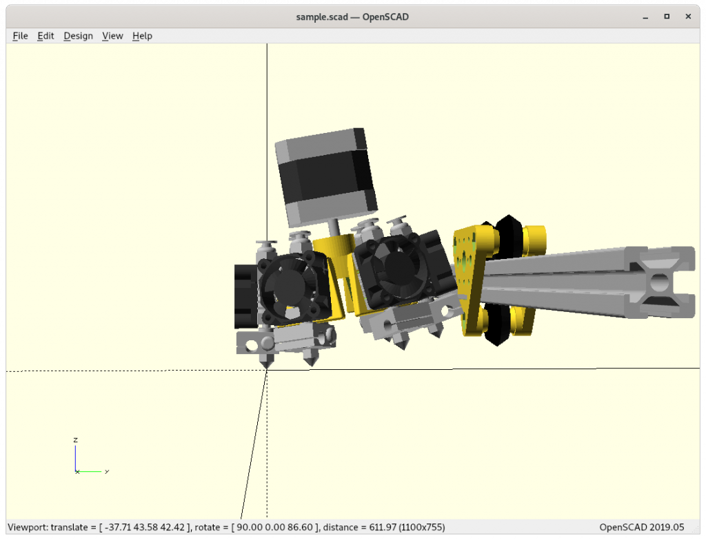
tilting 10 degrees and position 6 printheads full circle (won’t work) 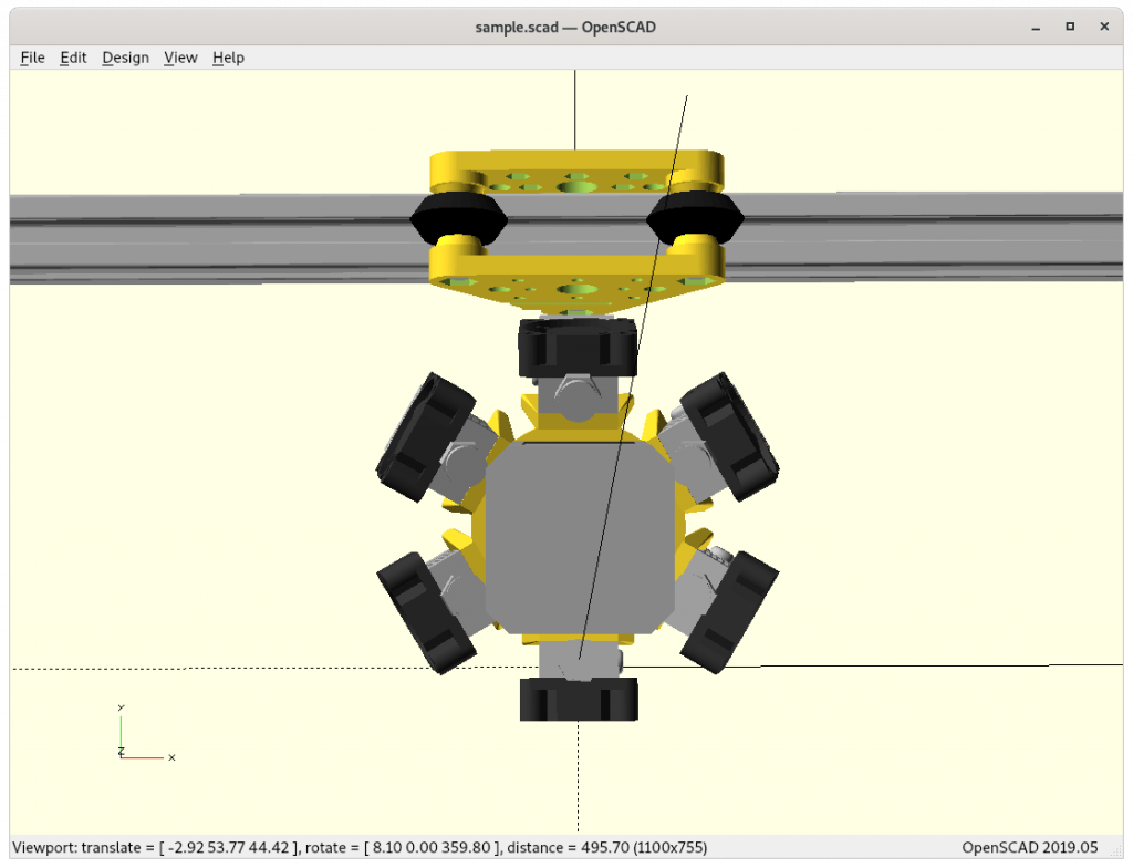
6 printheads won’t work as Bowden tubes will clash with mount
So for the moment I stay with 360°/9 angle and explore further on the details with 4 printheads/extrusions.
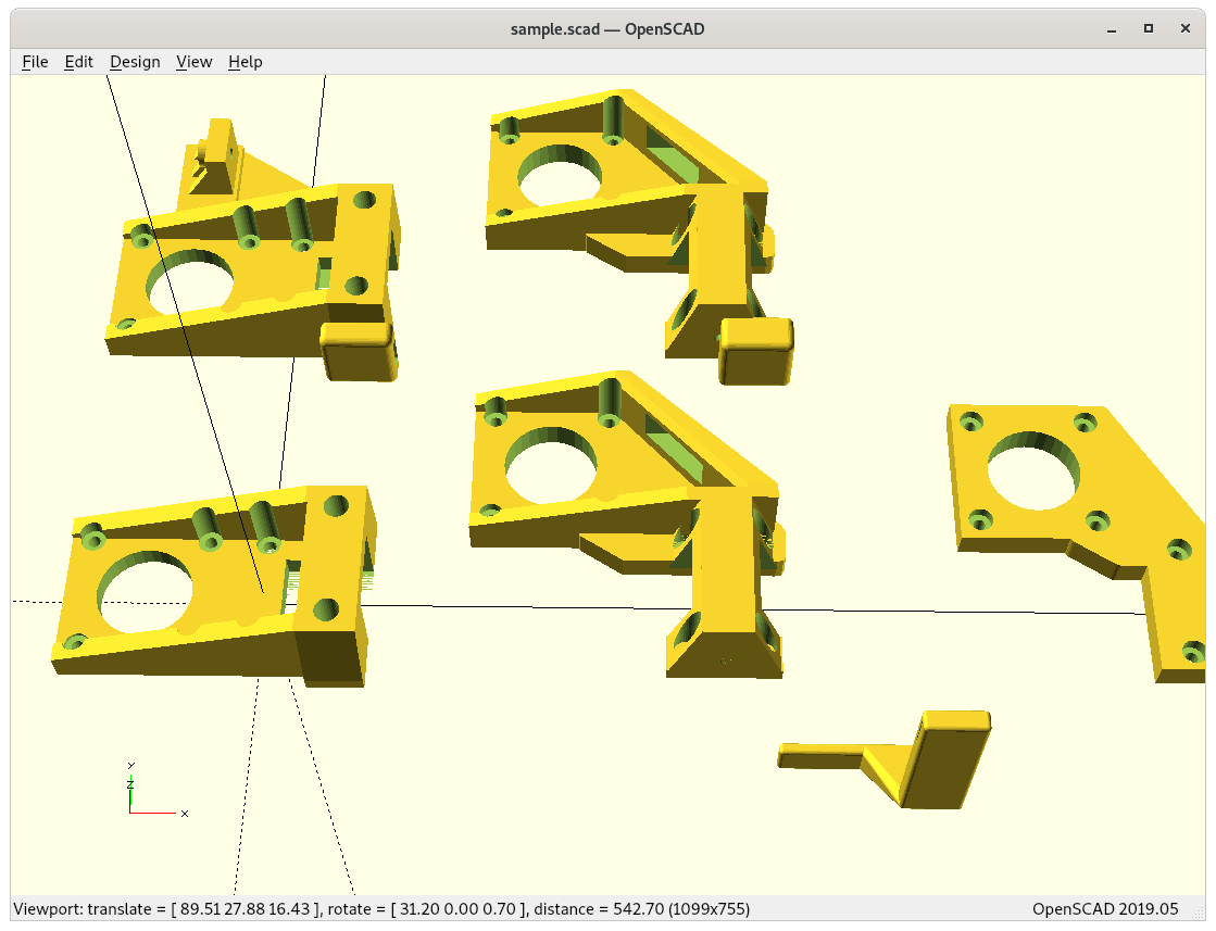
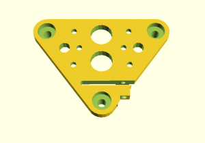
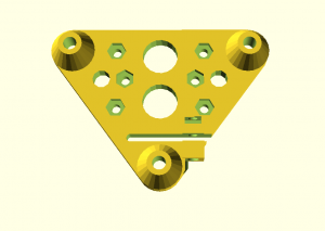
Printable Parts
MSE Y2
Not yet.
MSE Z4
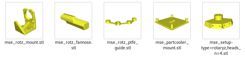
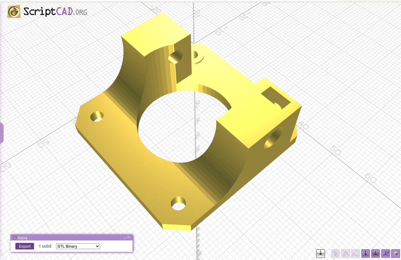
mse_rotz_mountmse_setup-type=rotaryz,heads_n=4mse_partcooler_mountcr10_hotend_fan_mount_simple(4x)mse_rotz_fannose
Assembly
- Each hotend is mounted with 2x M3x20 mounting heatsink, and
- 2x M3x16 mounting the 30mm fan on top.
- 4x M3 x 8mm used to mount NEMA 17 on top of
mse_rtz_mount, and - 4x M3x8 to mount it to the X carriage.
- The part cooler mount is attached with M3x10 with a M3 nut and can be adjusted.
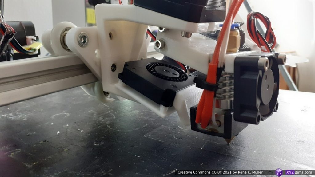


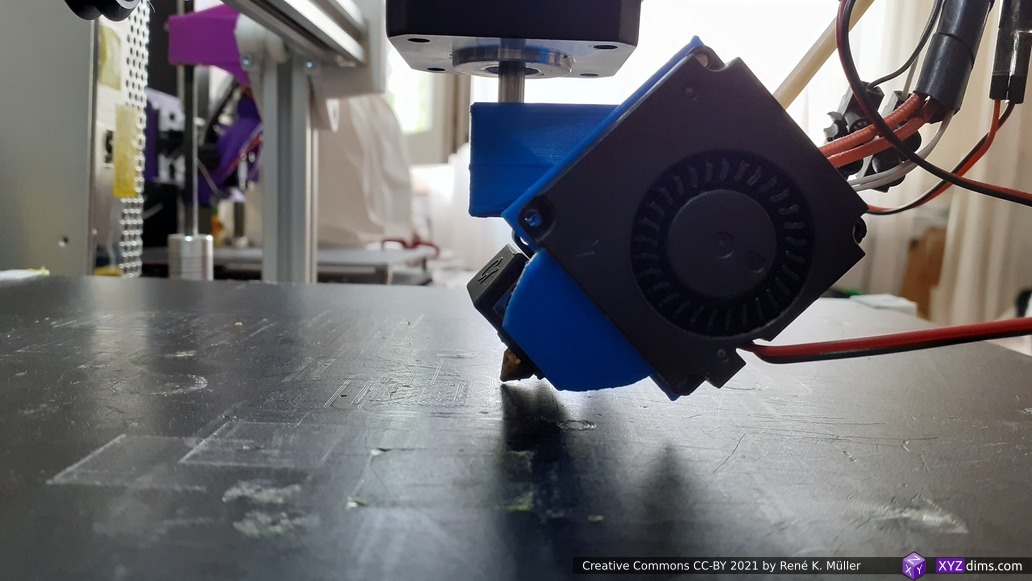
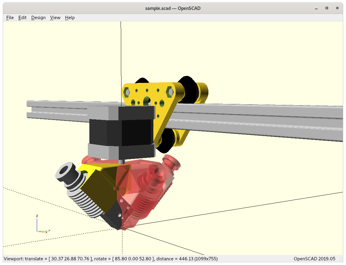
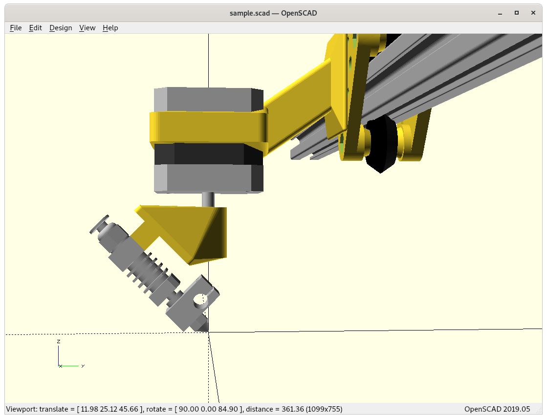
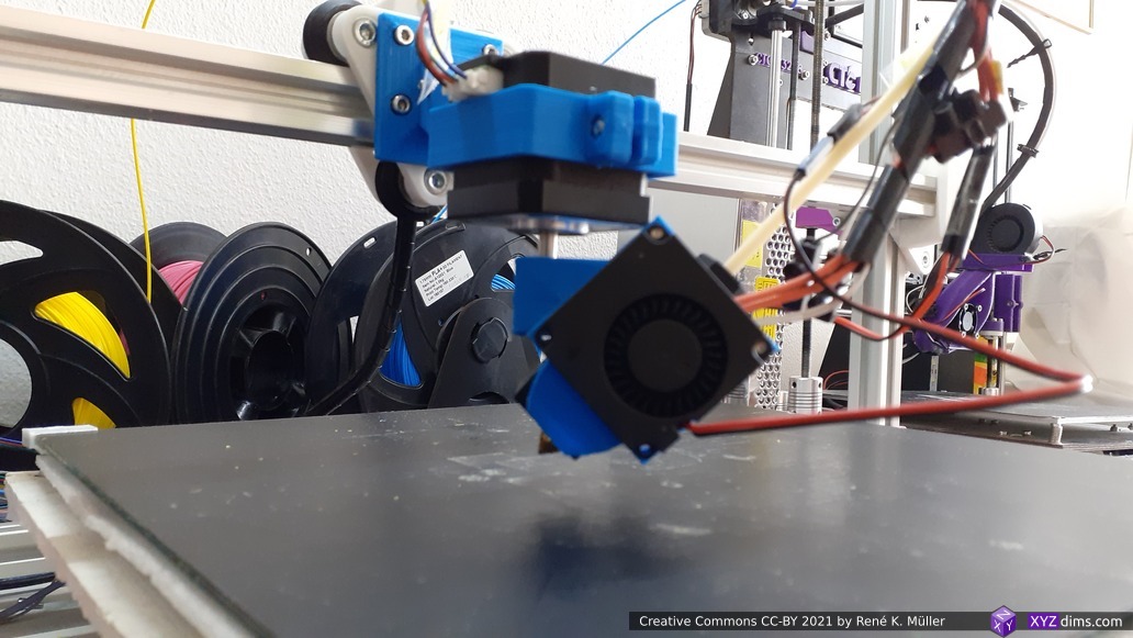
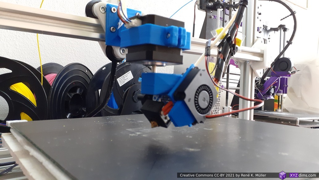
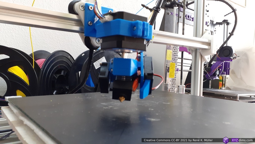
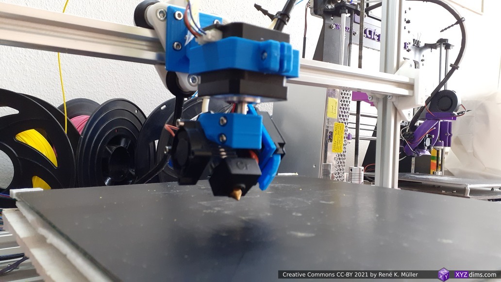
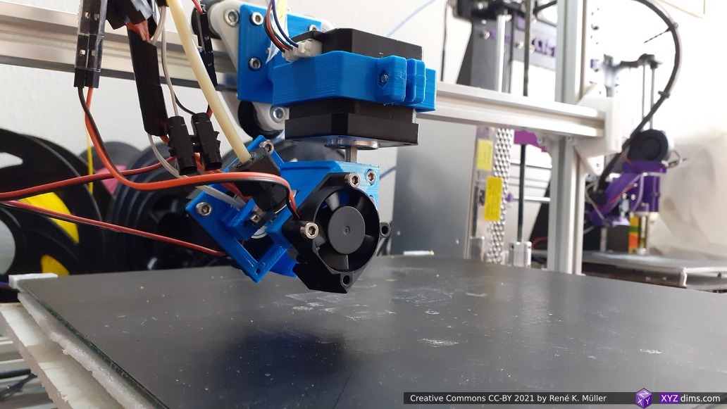
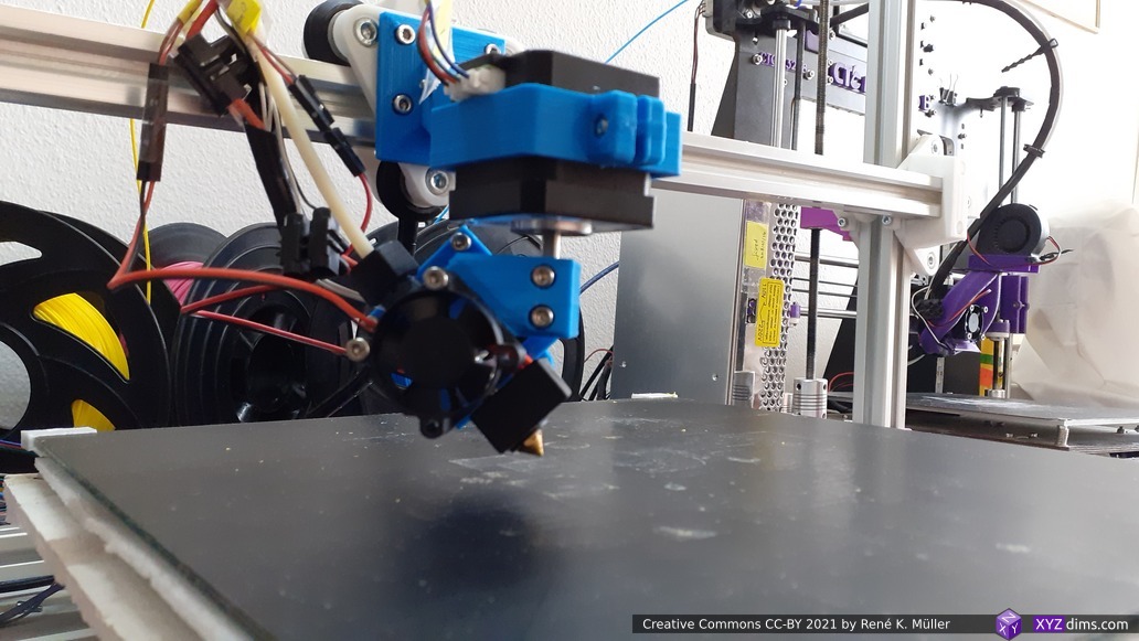
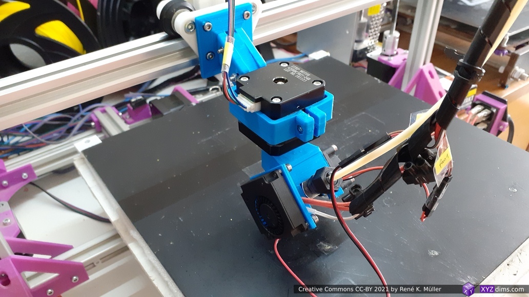
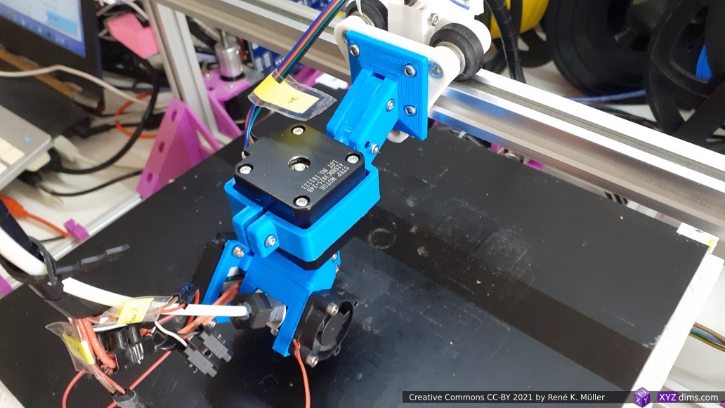
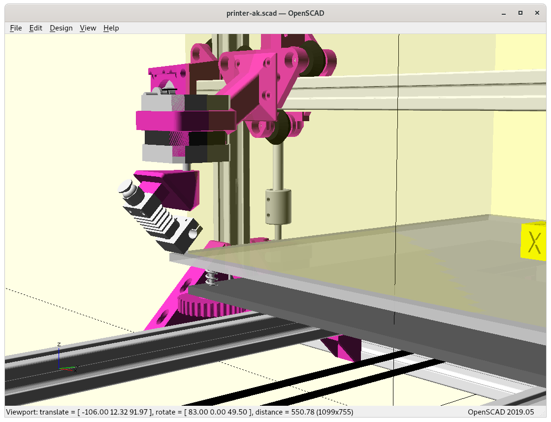
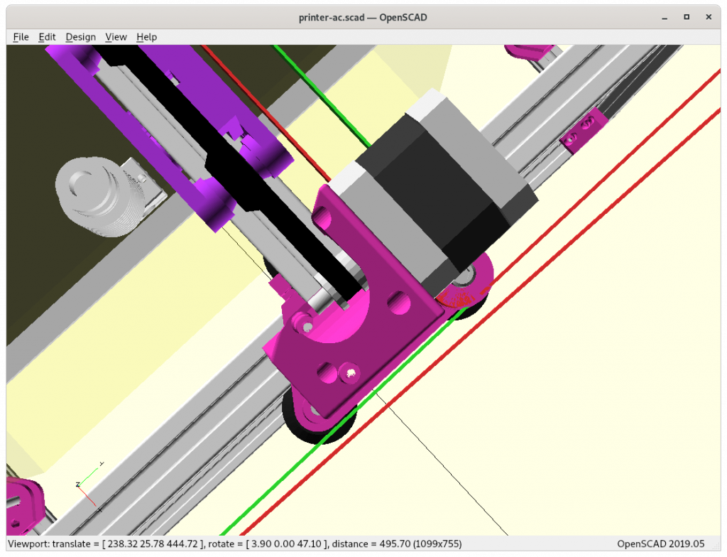
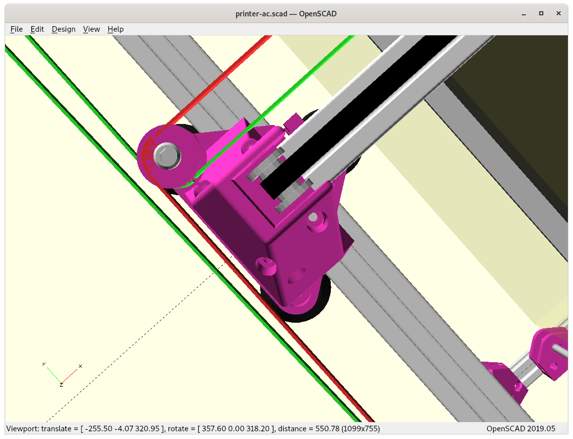
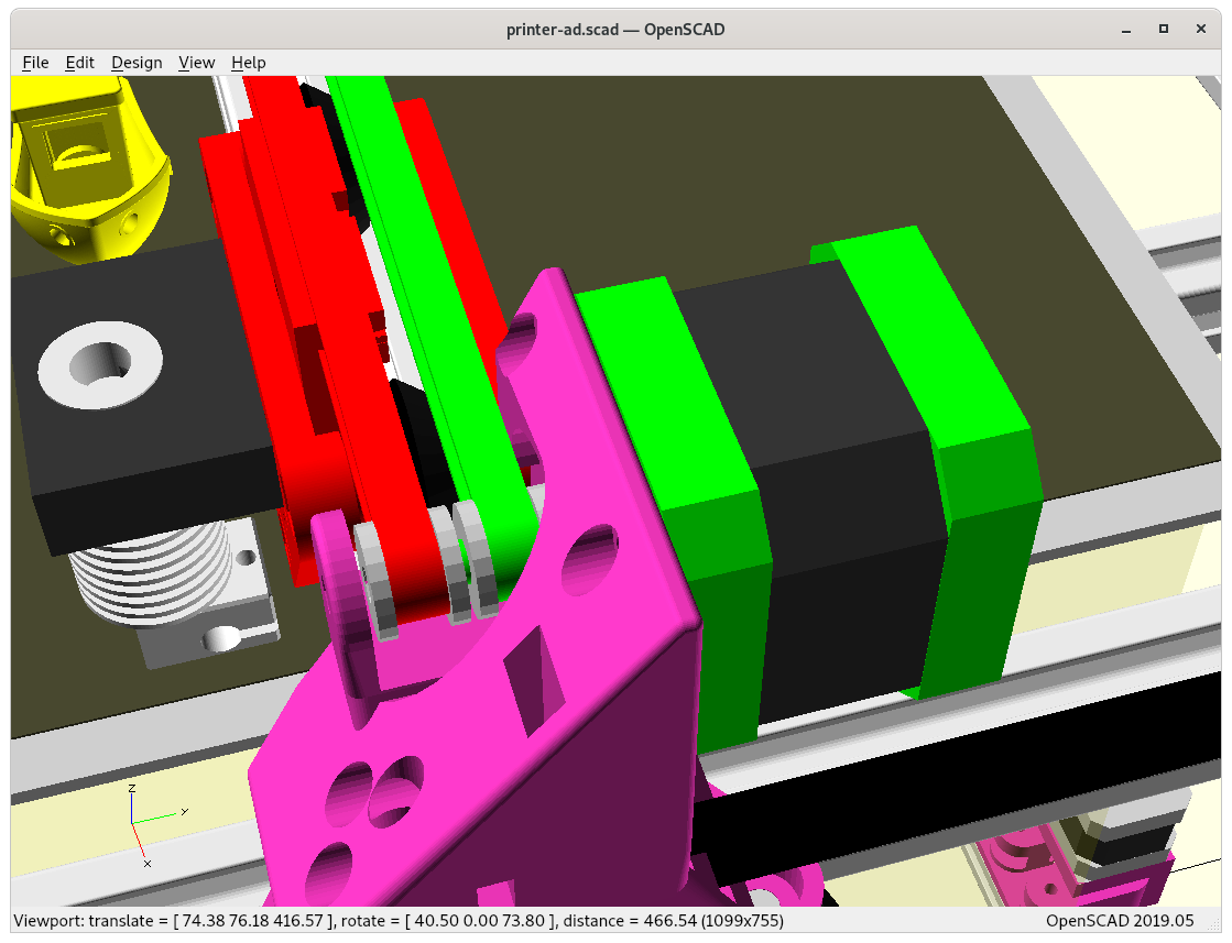
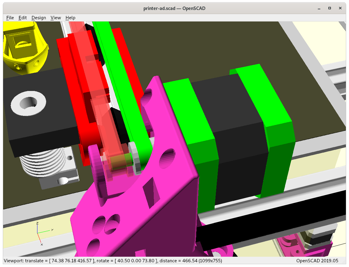
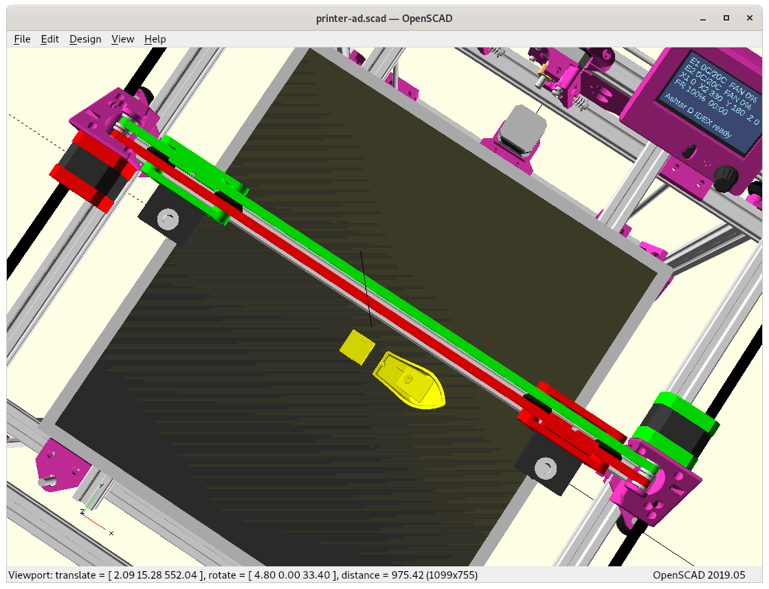
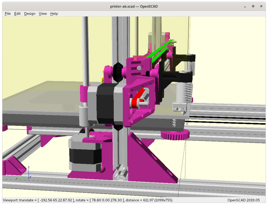
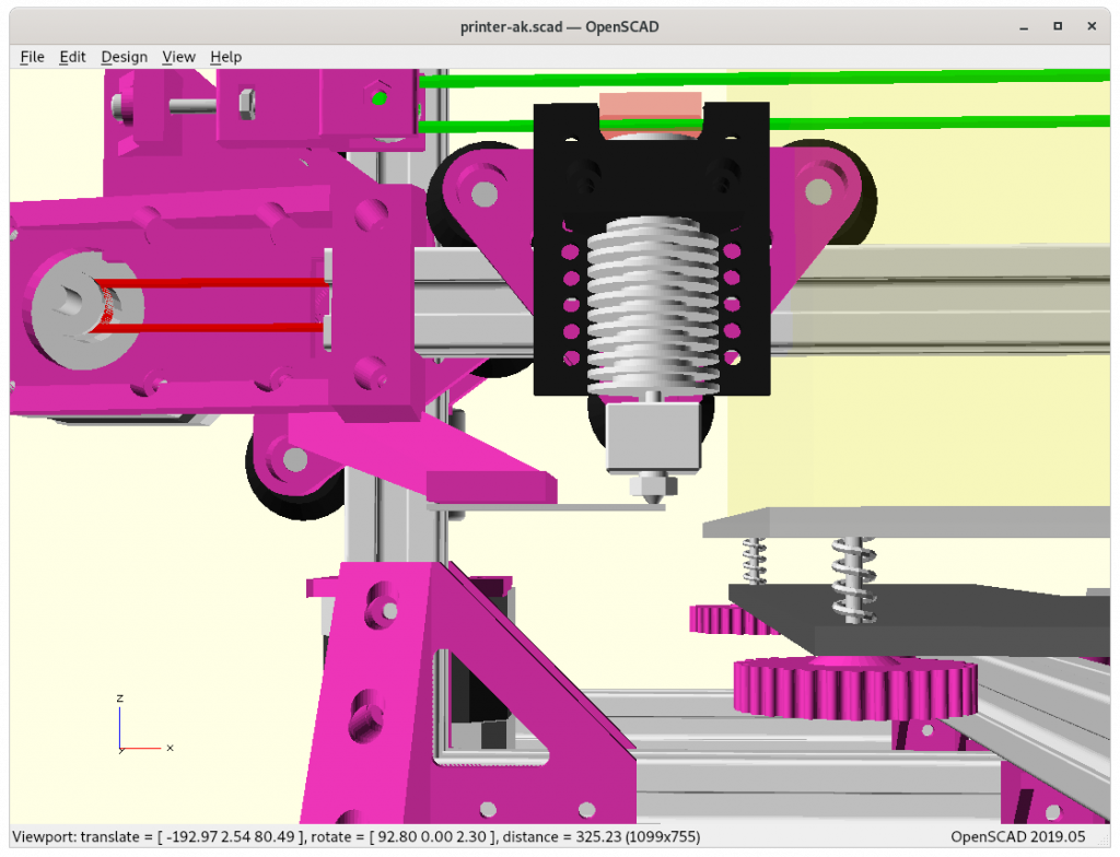
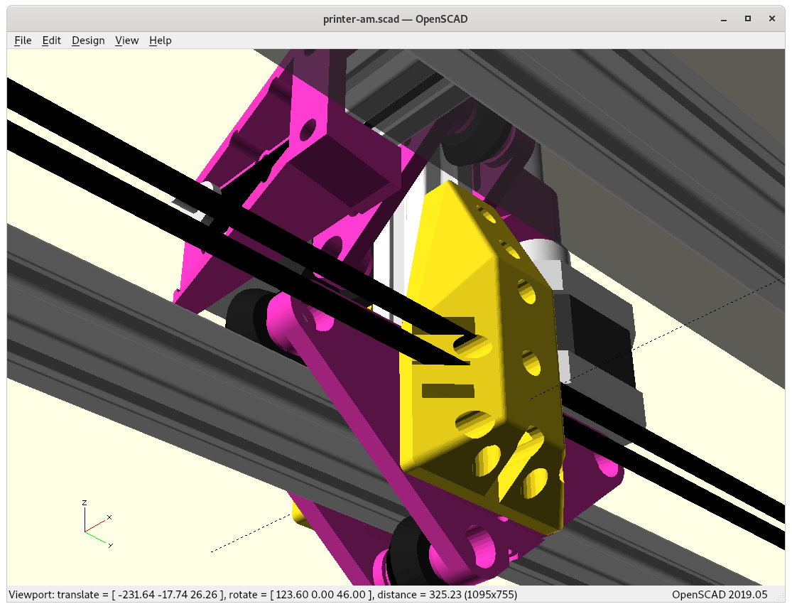
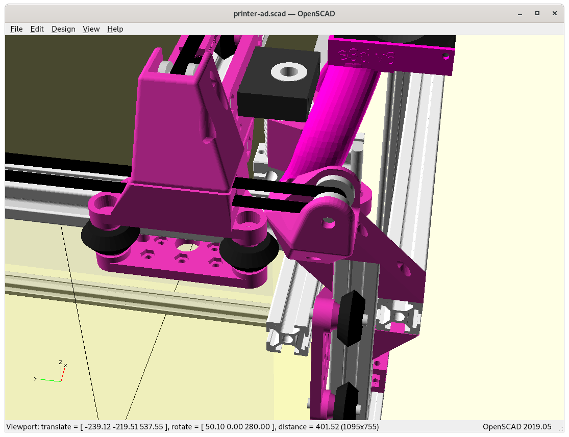
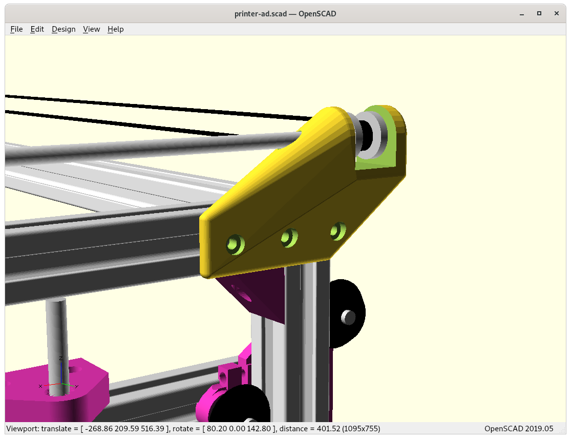
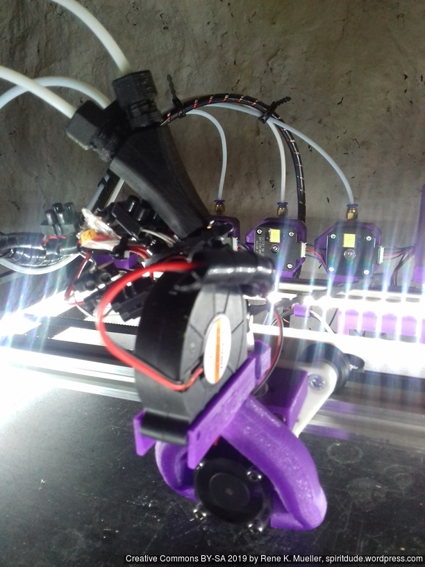
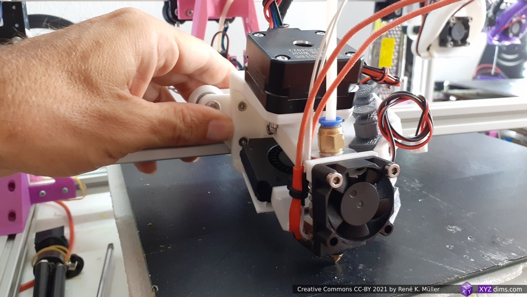
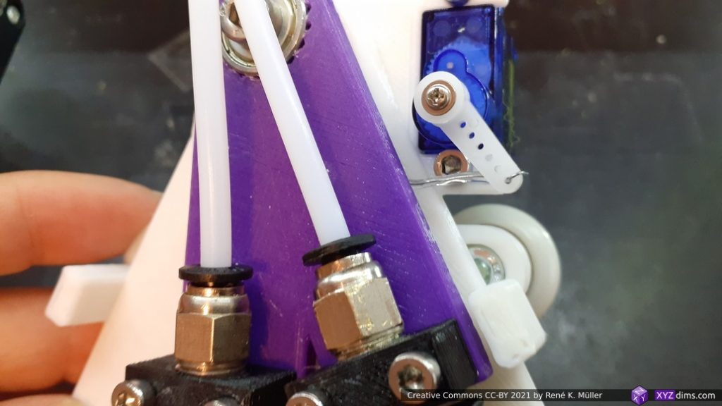
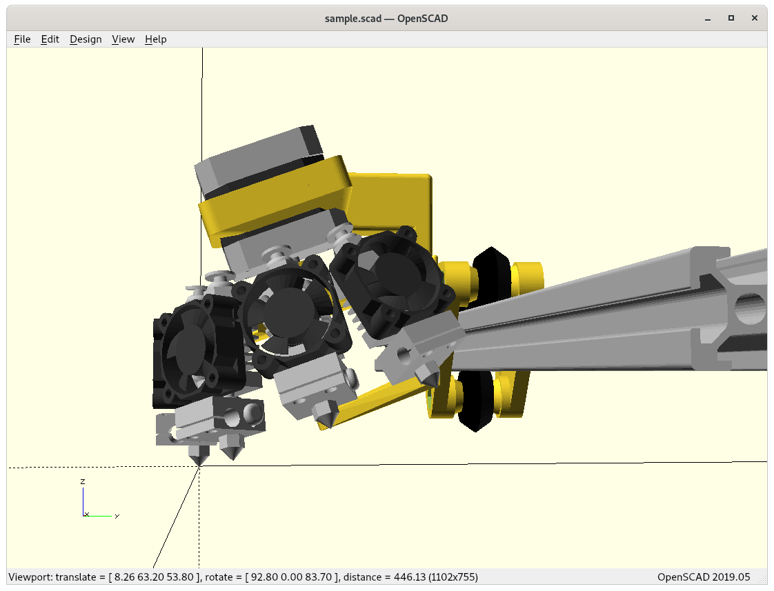
MSE Z4 experimental mount on X-carriage
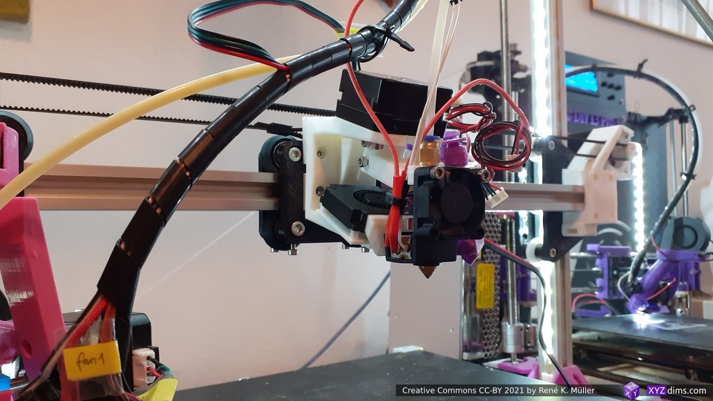
Brief tool changing test:
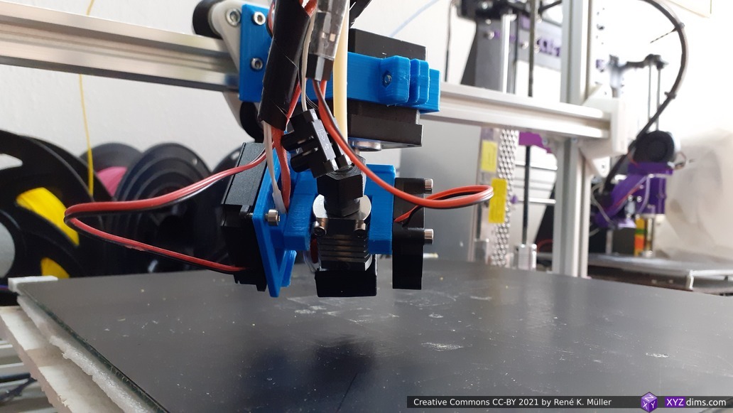
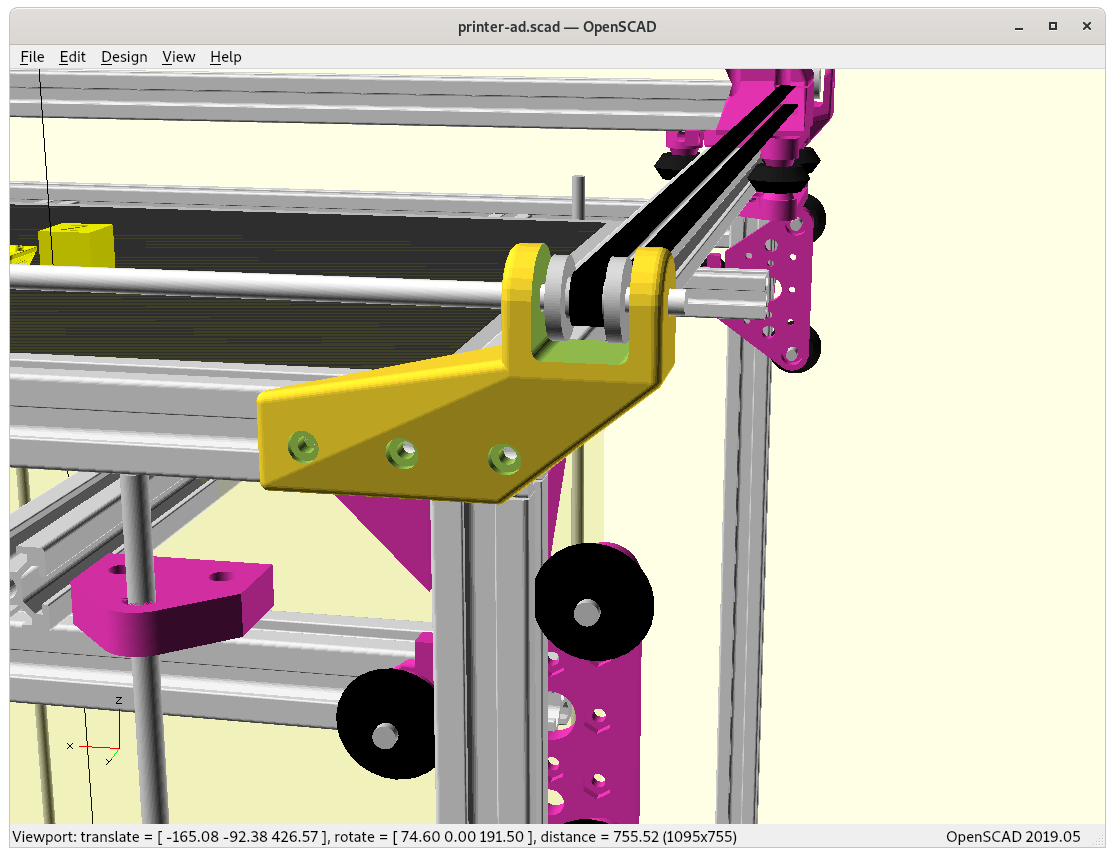
and guiding the PTFE tubes with a guide:
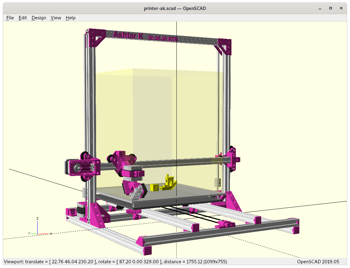
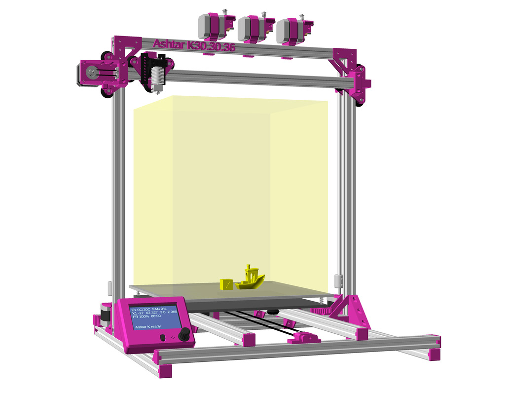
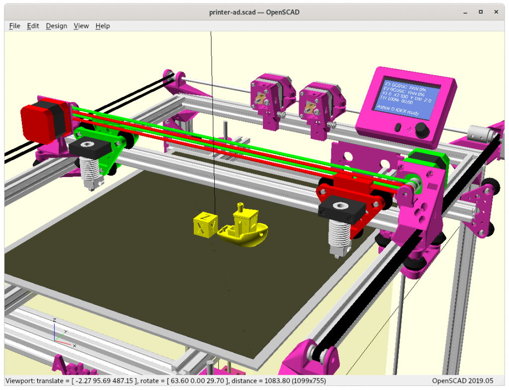
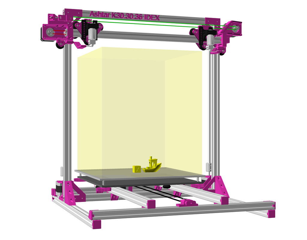
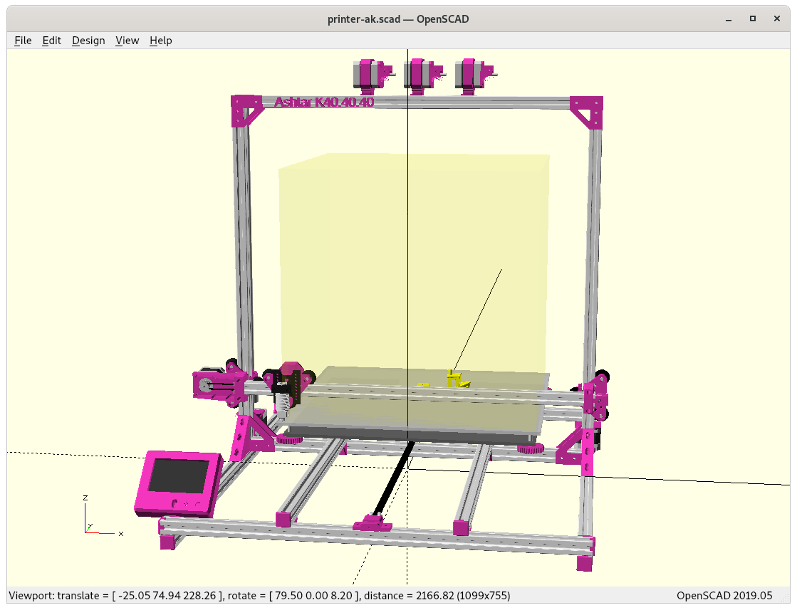
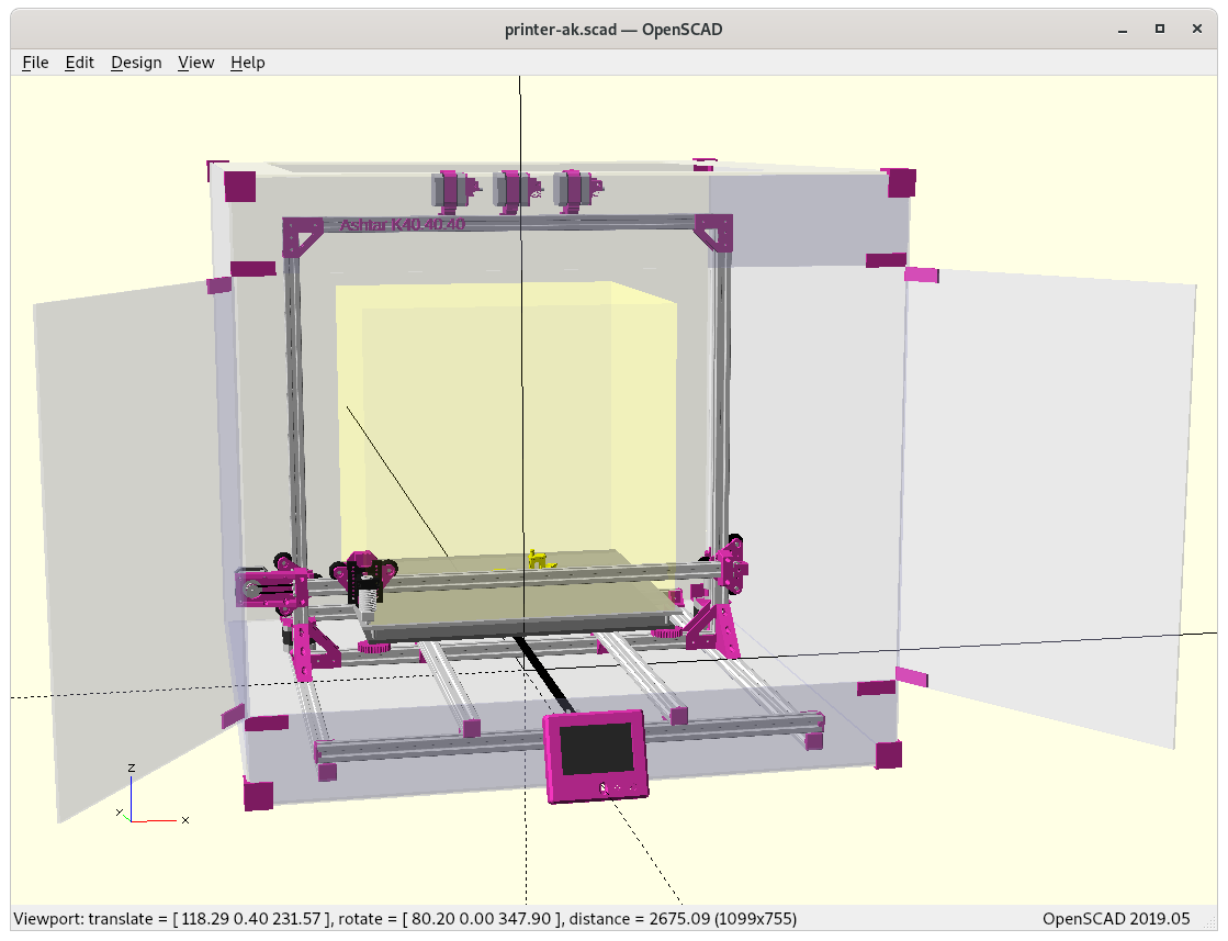
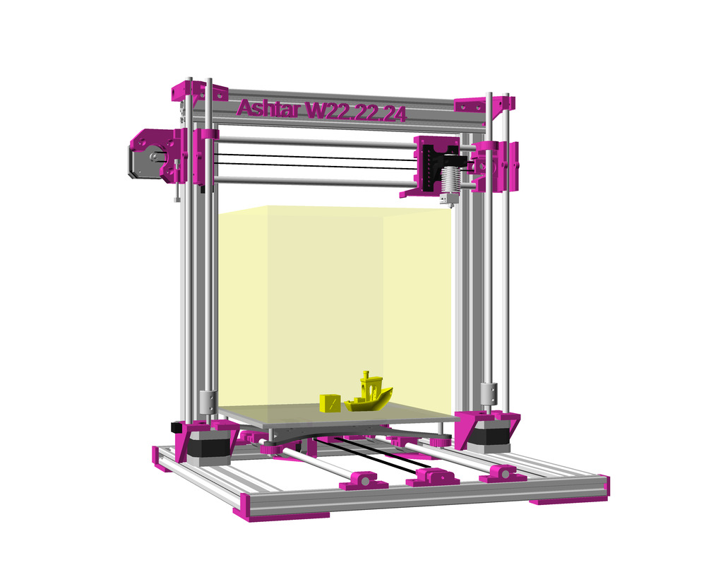
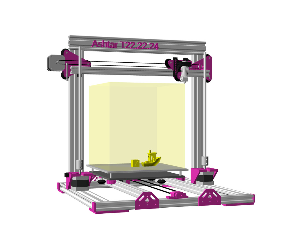
Ashtar K with Multiple Switching Extrusions (MSE)
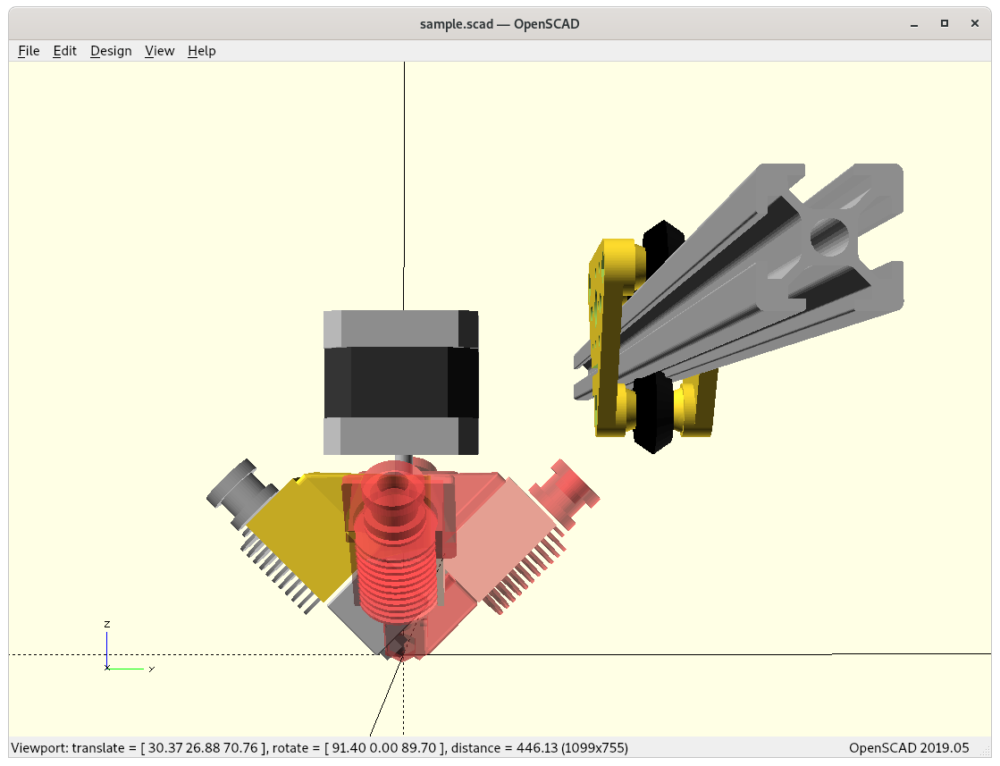
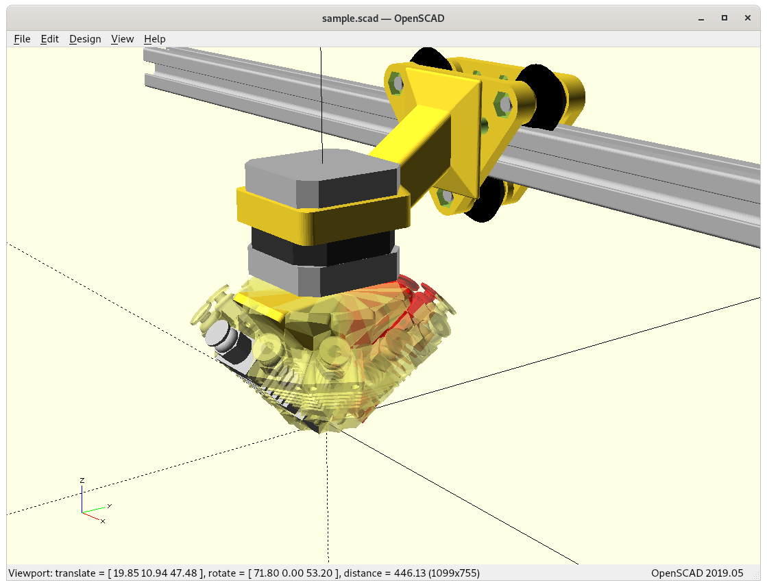
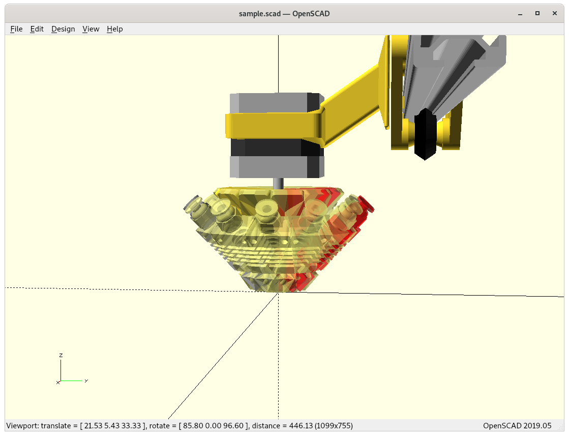
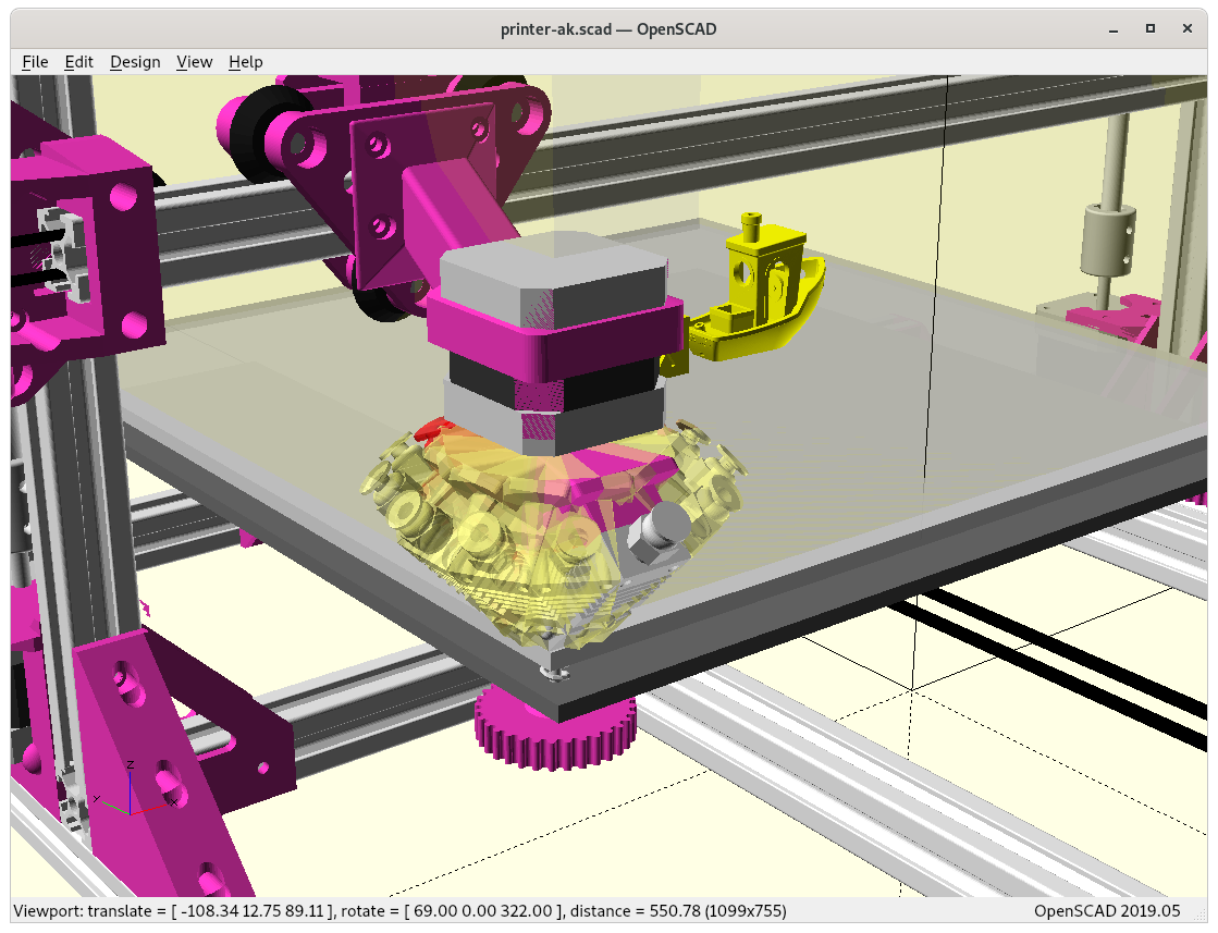
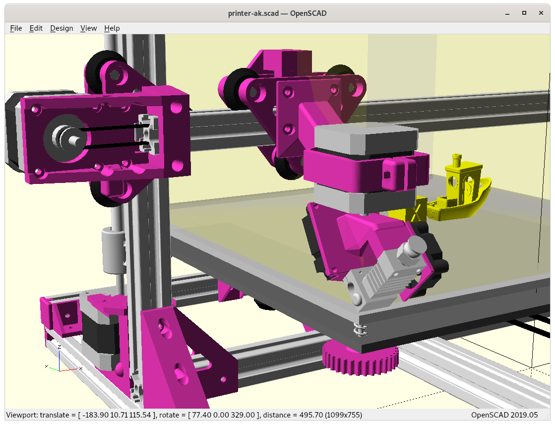
Rotary Z with 4 printheads mounted on Ashtar K to see how much space X and Y is sacrificed or otherwise fit with existing design – so far it looks good:
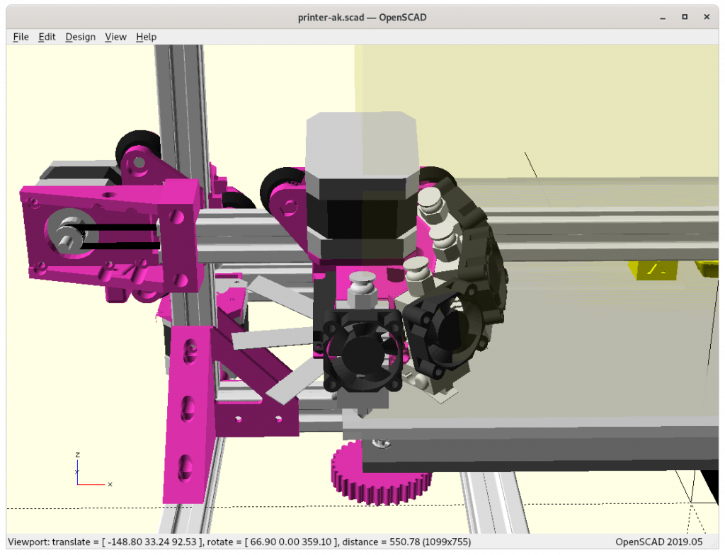
4 printheads, tool 0 
4 printheads, tool 3 
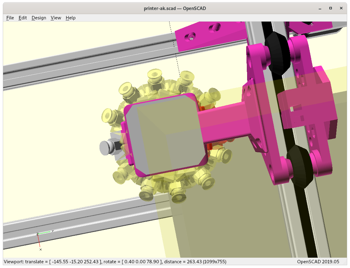
4 printheads, tool 0 (top view) 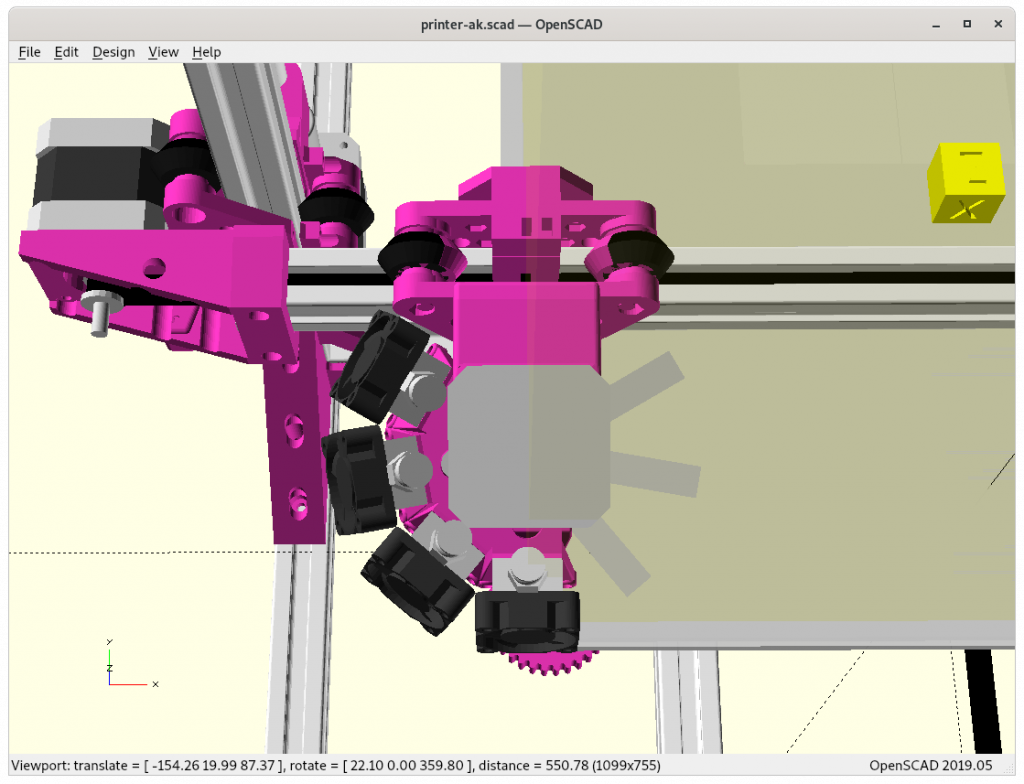
4 printheads, tool 3 (top view) 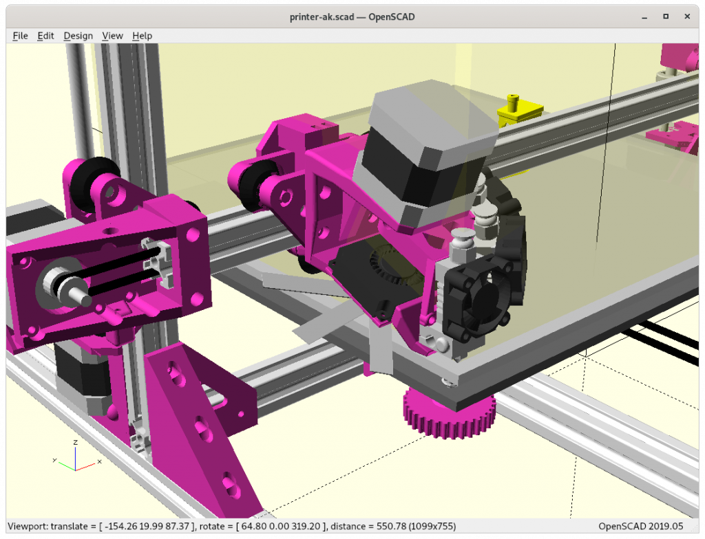
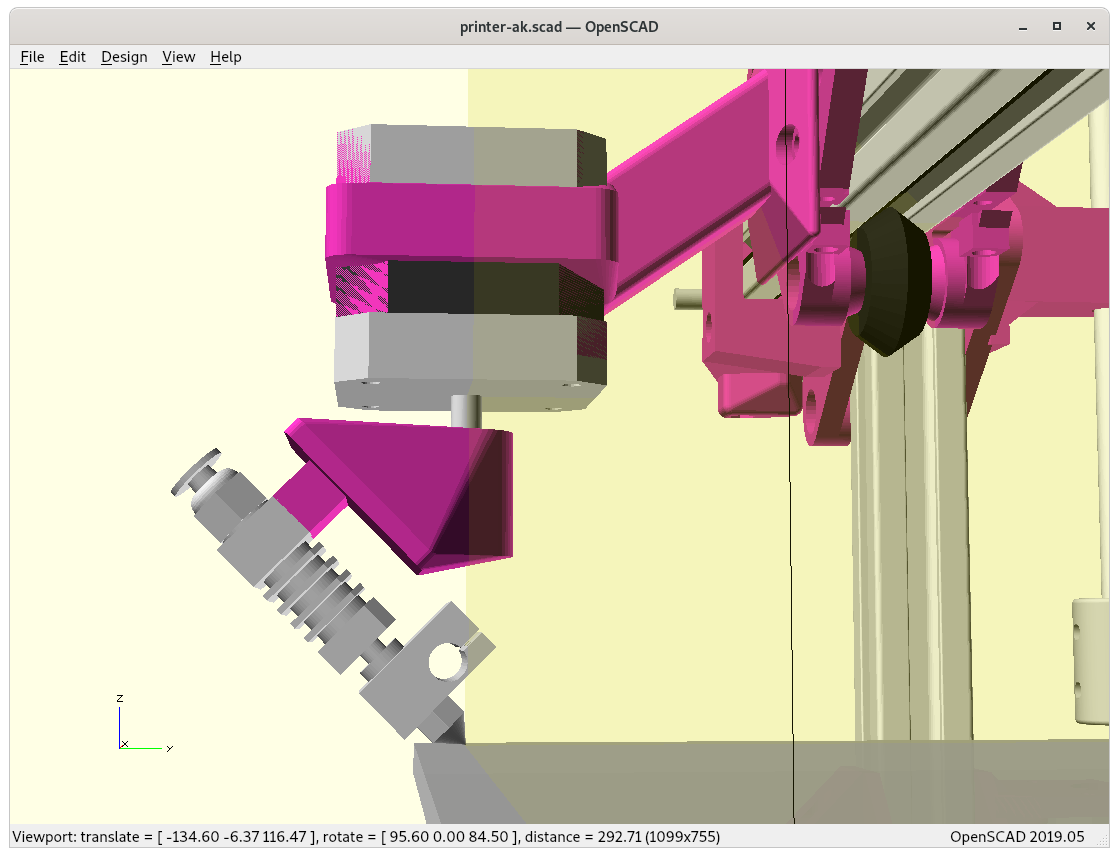
4 printheads, tool 0 
4 printheads, tool 0 (side view) 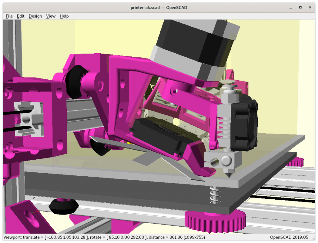
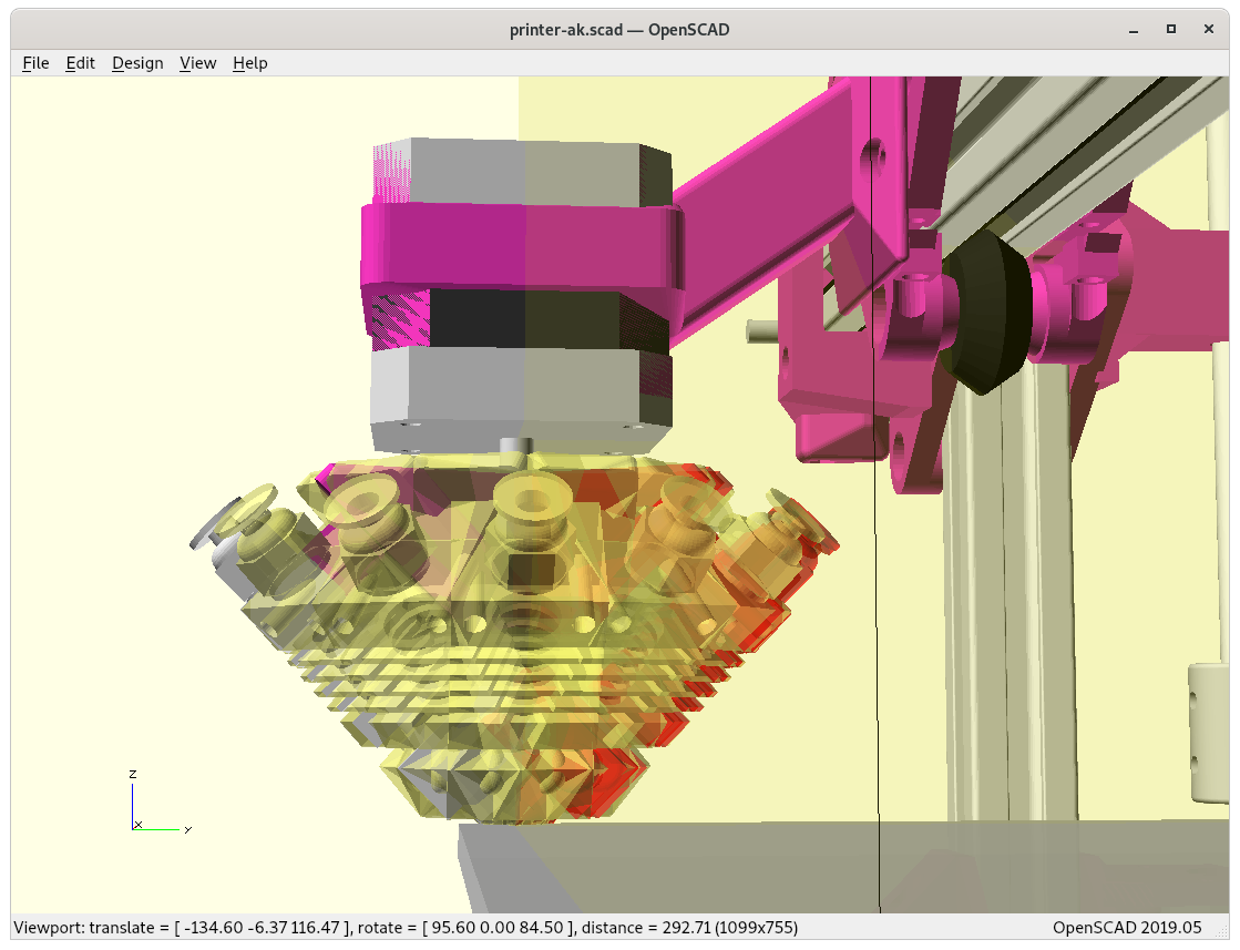
4 printheads with part cooler 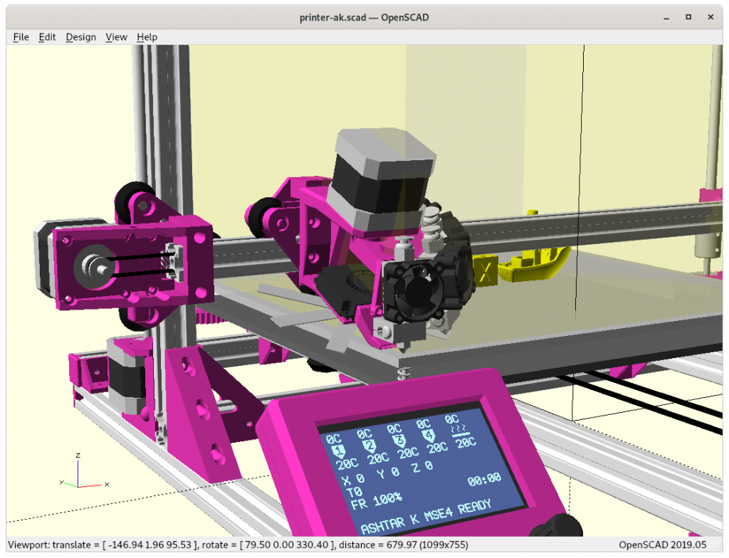
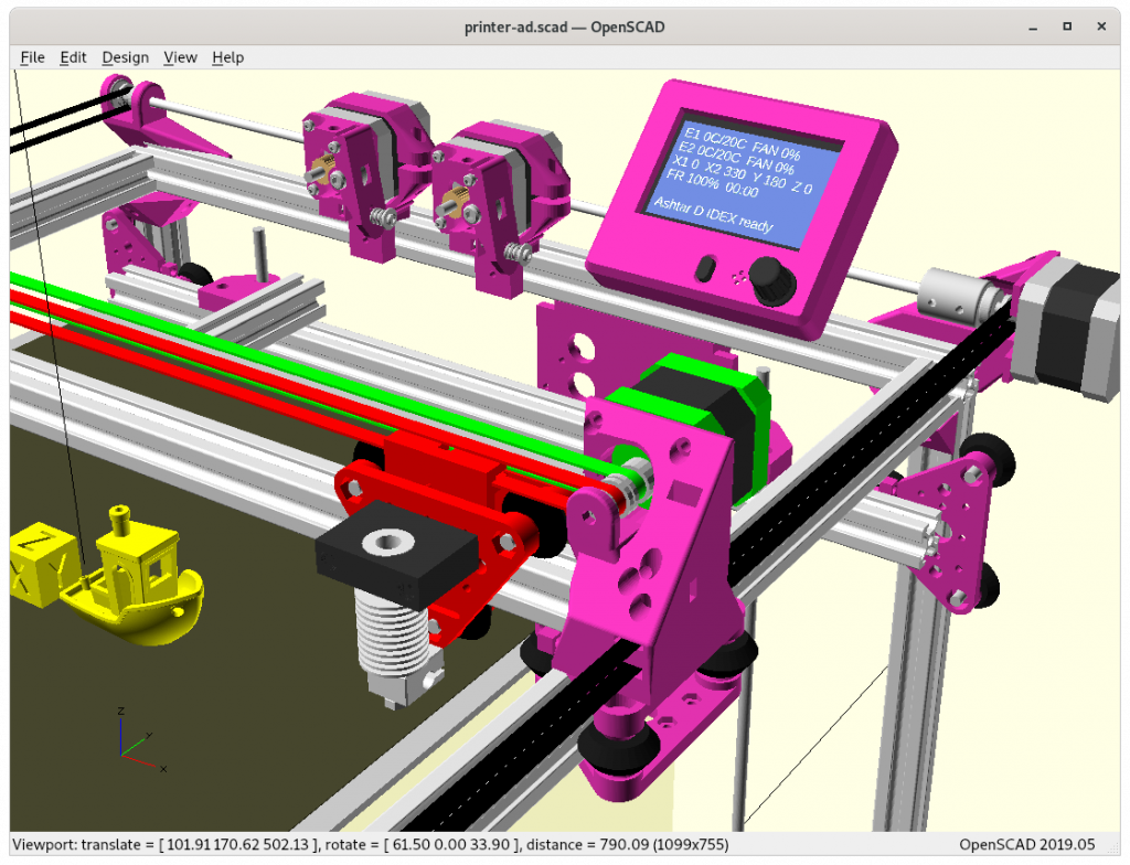
with controller/display, tool 0 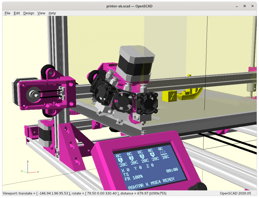
with controler/display, tool 3 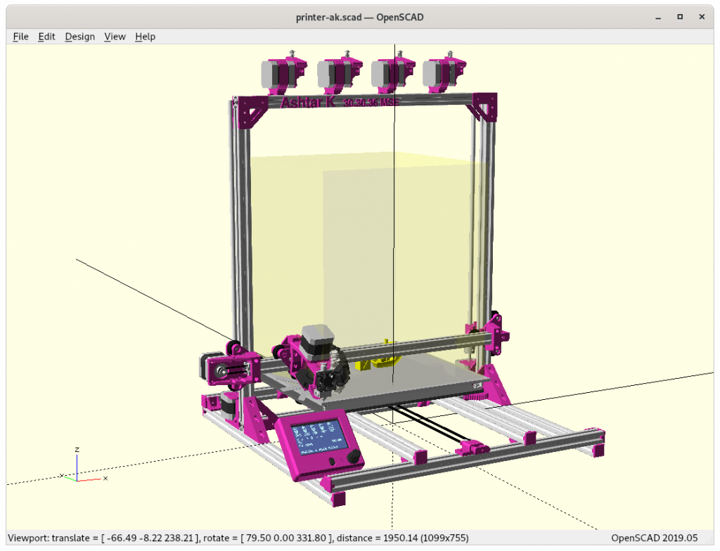
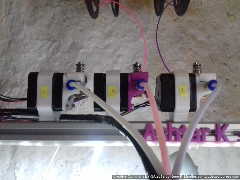
4 printheads & 4 extruders


This design is more flexible and extendable, the ooze shields are mounted on the “nose” underneath using metal sheets.
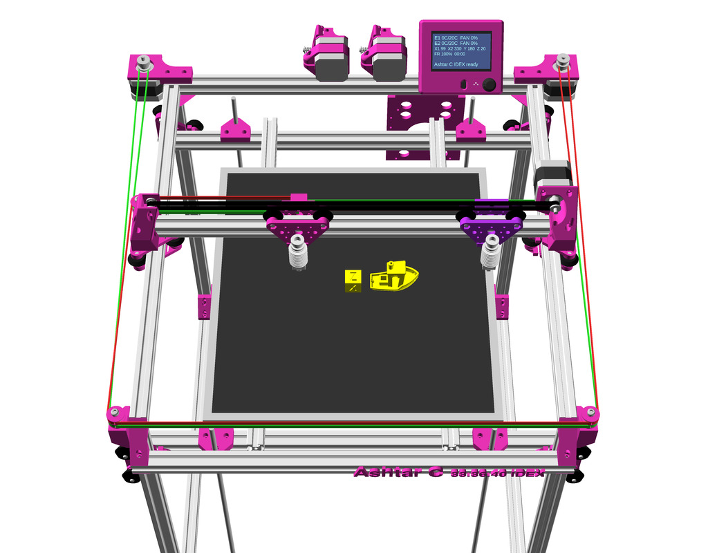
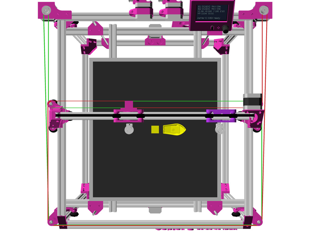
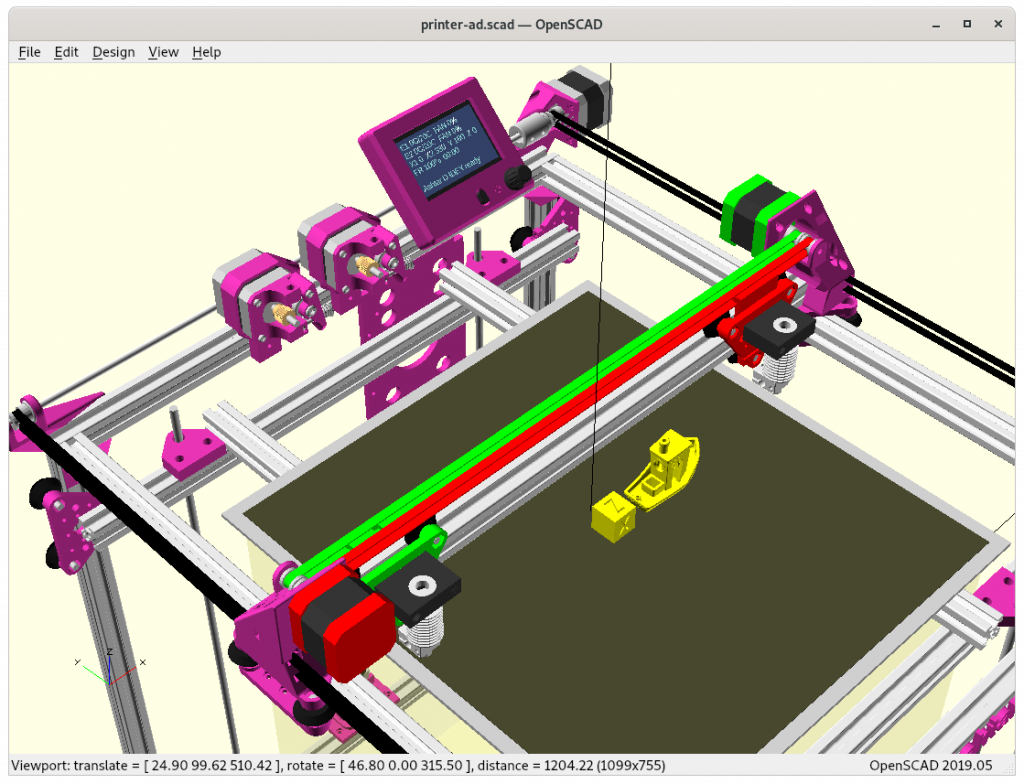
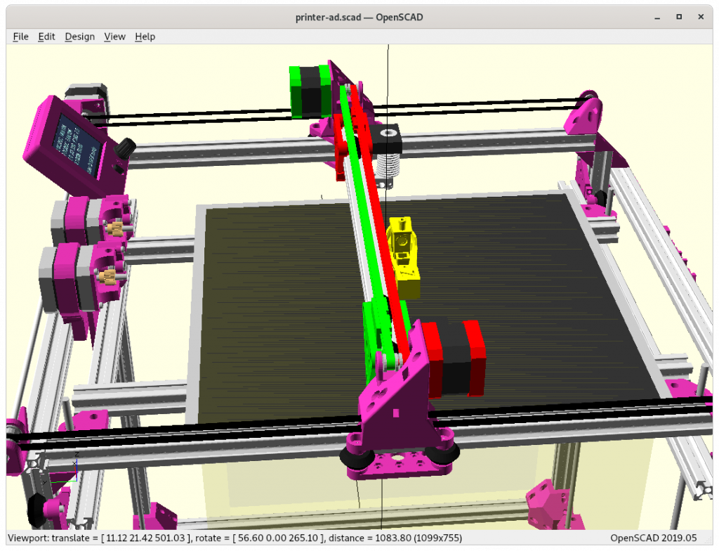
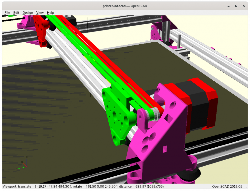
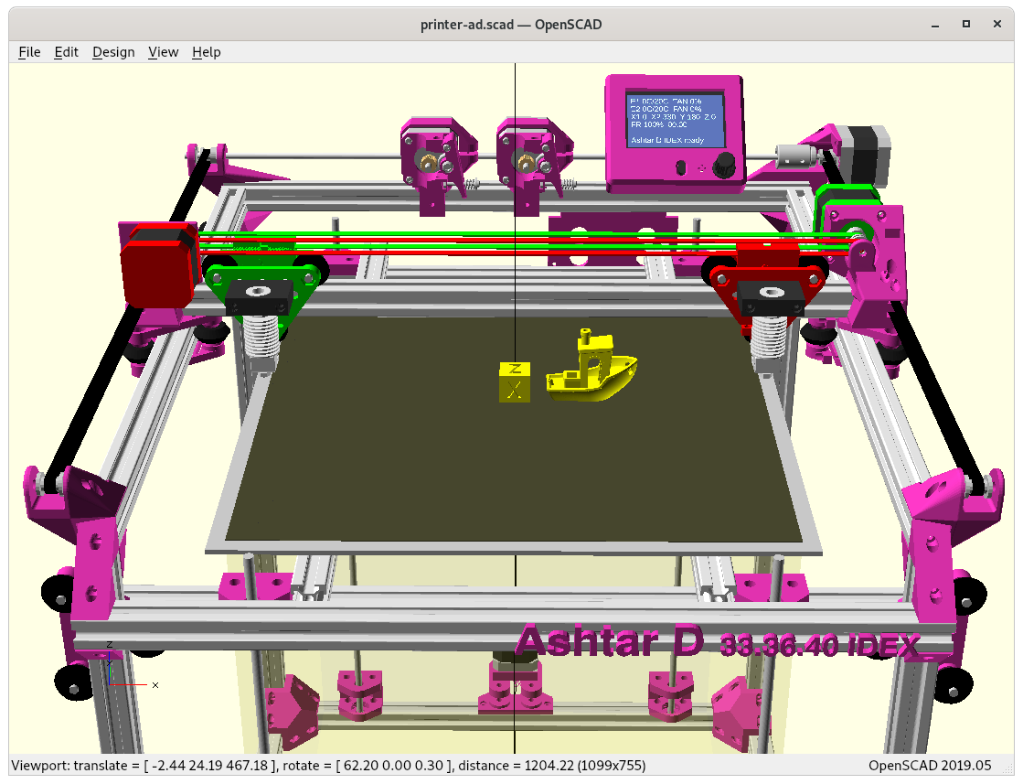
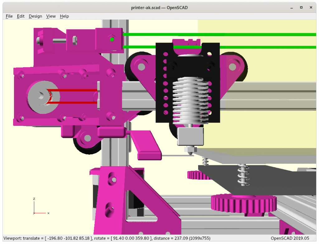
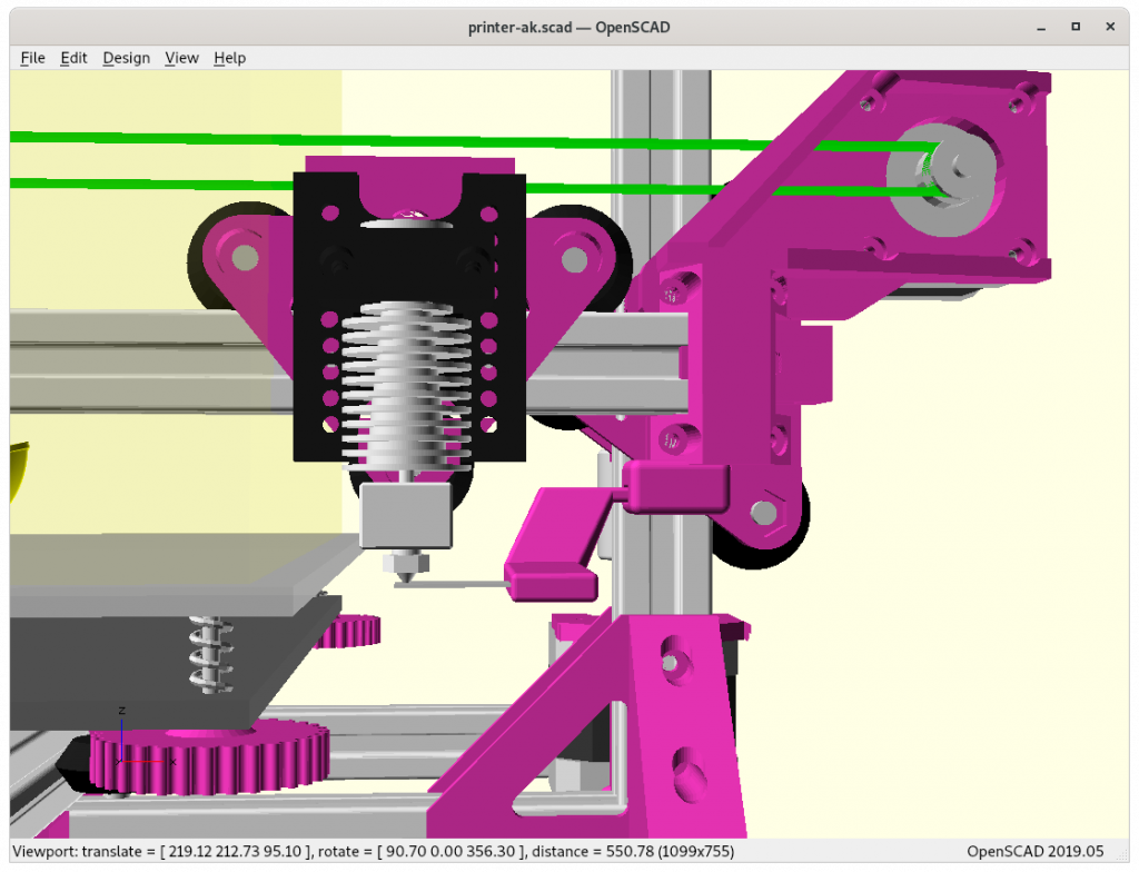
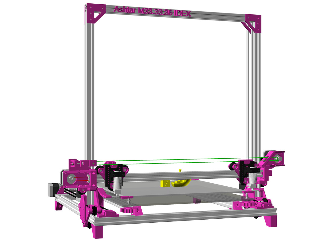
And the Rotary Y with 2 printheads (MSEY2) mounted looks good so far, sacrificing little X space as well:
2 printheads on MSEY2, tool 0 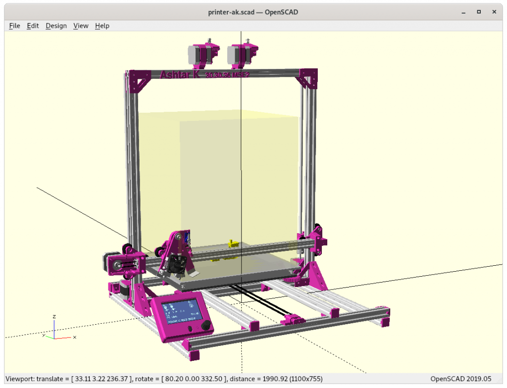
2 printheads & 2 extruders

Issues to Resolve
Rotary Y with Servo
mature draft to something actually promising, done with SG90 servo- strength to hold angle, likely use servo to constantly push toward a mechanical limit, dual mode: left/right limit,
tripple mode some kind of spring the servo has to overcome- alternatively using magnets (e.g. 6mm/0.8mm) on anchor and stoppers: pushing anchor without servo or motor, but pushing carriage to X home left and X home right to switch between two states
- reposition reliability, some kind of spring mechanism, and servo is only used to “jump” to new position
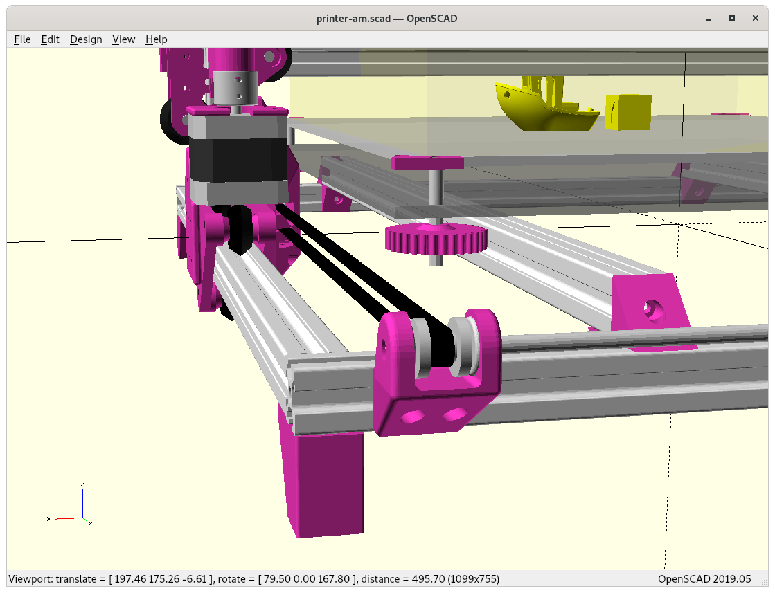
mount to X carriage, servo clashes with belt mount, resolved- press-fit 625 ZZ bearings based switch axis
sufficiently narrow play/margins for printing? tests needed- dual bearings still wobbles in Y-axis (when mounted)
- single bearing doesn’t wobble, more friction when switching
Rotary Z with NEMA 17
- early draft,
untested- rotation tested: 40° per tool, e.g.
G1 A0,G1 A40in RepRapFirmware (Duet3D boards) - testing holding torque when printing (nozzle running over overextruded parts)
- rotation tested: 40° per tool, e.g.
mount heatsink fans, done- rotary angle calibration at start, position/tool #0 (
0..heads_n-1) => tool number (e.g.T2)- either mechanical homing of the rotation to position/tool #0 or
- end stop switch to home rotation position
ooze shields. mounting for metal sheets prepared & illustrated- heat creep toward the “nose”?
- do ooze shields add to cross-contaminating when changing tools
- paying attention to details how to bend metal sheets
mount to X carriage, donepart cooler, will be tricky as, resolvedabove mount won’t work due Bowden tubes cross throughmount via “nose” where the non-ooze metal sheets are mounted, done
- Marlin firmware tool changing Gcode support with NEMA17 rotating?
Bowden tube guides, ensuring smooth rotating of Bowden tubes & wires- rings around NEMA 17, in particular around the edges
- combine tubes & wires above the motor
Considerations
Rotary Y 2
Pros
- simple mechanical setup incl. ooze shields
- fast switching of extruders
Cons
- servo SG90-based: only suitable for dual setup (not extendable to 3 extruders)
Rotary Z 4
Pros
- fast switching of extruders
- heavier than a servo, but more reliable holding position
- simple design, as this design mounts on all of Ashtar Series (K, C, M & D)
- 2, 3 or 4 printheads/extruders mountable, more flexible than IDEX which only has 2 printheads and requires more modifications
Cons
- additional moving weight on X axis (NEMA17)
- loss of build volume in X space ~5-10mm left and right
- optional loss of build volume in Y space, it can be compensated if printer is used with MSE option only, otherwise some Y space sacrificed as well ~20-30mm
- ooze shields may contaminate material to rotating nozzles, needs to be tested
- all nozzles are heated even when not currently selected but will be used during the print
- some people still print a purge block to purge material from the nozzle newly selected – fast switching material should be ok, long wait between switches may require purging of material – tests needed
Requirements
Rotary Y
- 1x SG90 servo
- 2x 625ZZ bearings
- 1x M5x25 screw
- 1x M5 nut
- 50mm x 1mm wire, bend as hinge
Rotary Z
- 1x rotating motor (NEMA17 20/25/39 mm) with motor driver
- per additional printhead (given there is a single printhead already installed)
- an extruder (incl. NEMA17)
- motor driver on the mainboard
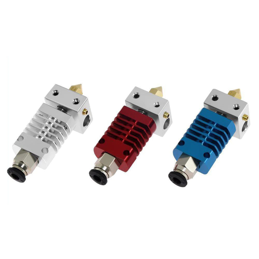
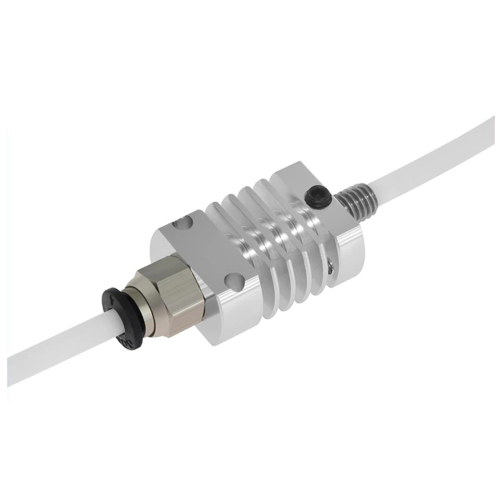
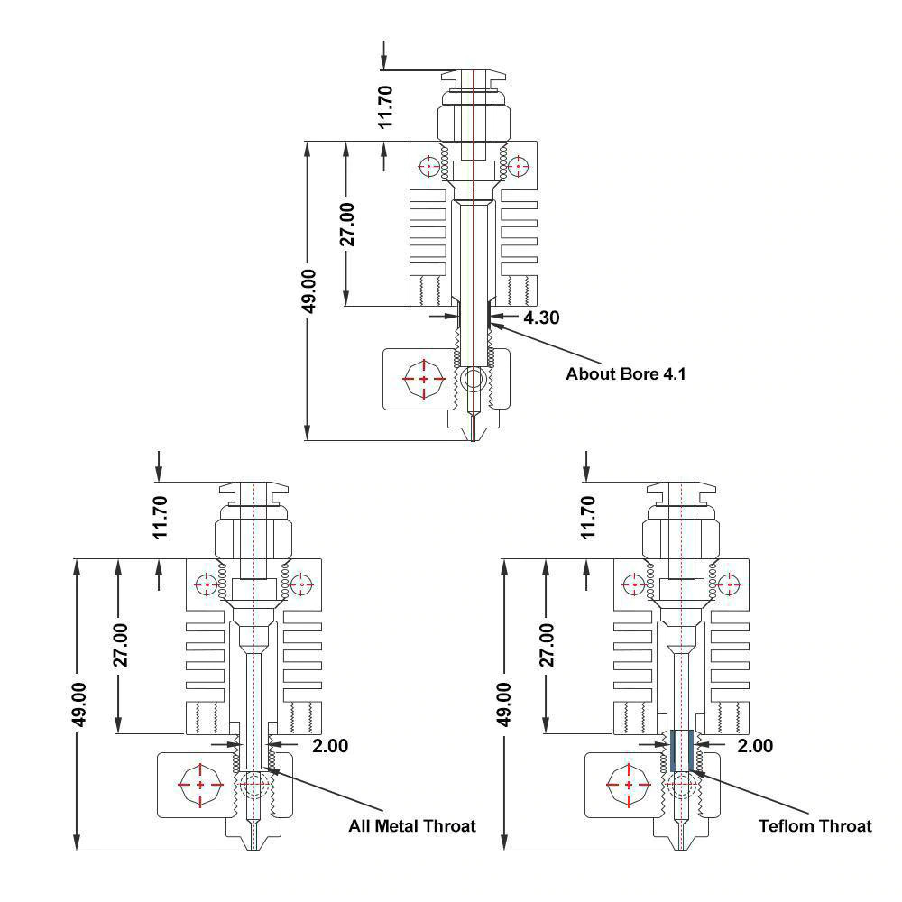
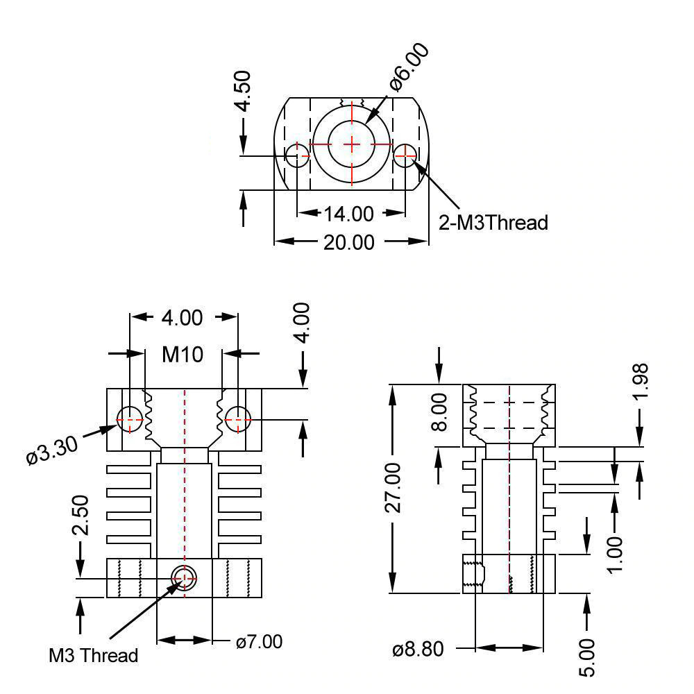
- printhead (heatsink, heatbreak, heatblock, heat cartridge, nozzle, push fit adapter for bowden)
- heating driver on the mainboard
- thermistor input on the mainboard
So for
- 2 printheads: 2x additional NEMA17 (1x rotating motor + 1x additional extruder), 2x 40W = 80W power
- 3 printheads: 3x additional NEMA17 (1x rotating motor + 2x additional extruders), 3x 40W = 120W power
- 4 printheads: 4x additional NEMA17 (1x rotating motor + 3x additional extruders), 4x 40W = 160W power
Obviously you need a mainboard with sufficient heating drivers or (1 digital output and MOSFETs per hotend) and thermistor inputs (ADC), the motor drivers can be added to 2 digital outputs (STEP & DIR) and external motor driver. More detailed informotation will be added later.
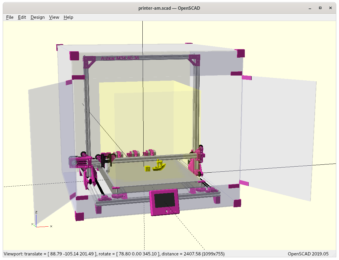
Gallery
Very early draft to see how MSE4 looks mounted on Ashtar K, C, D and M:
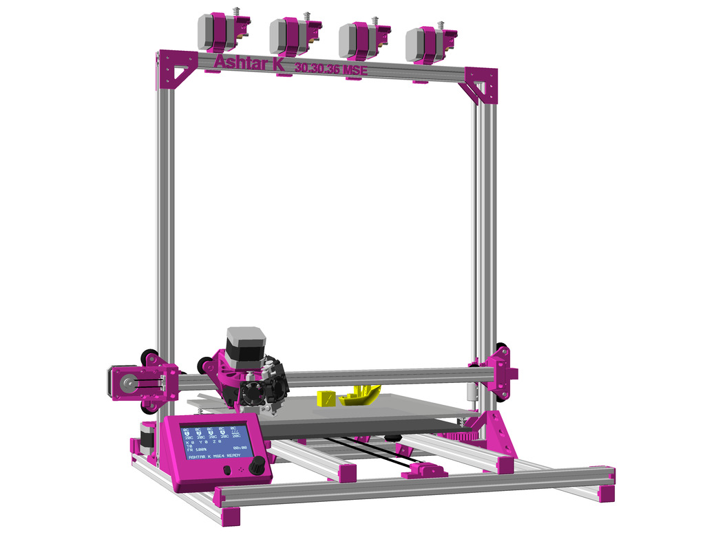
Ashtar K MSE4 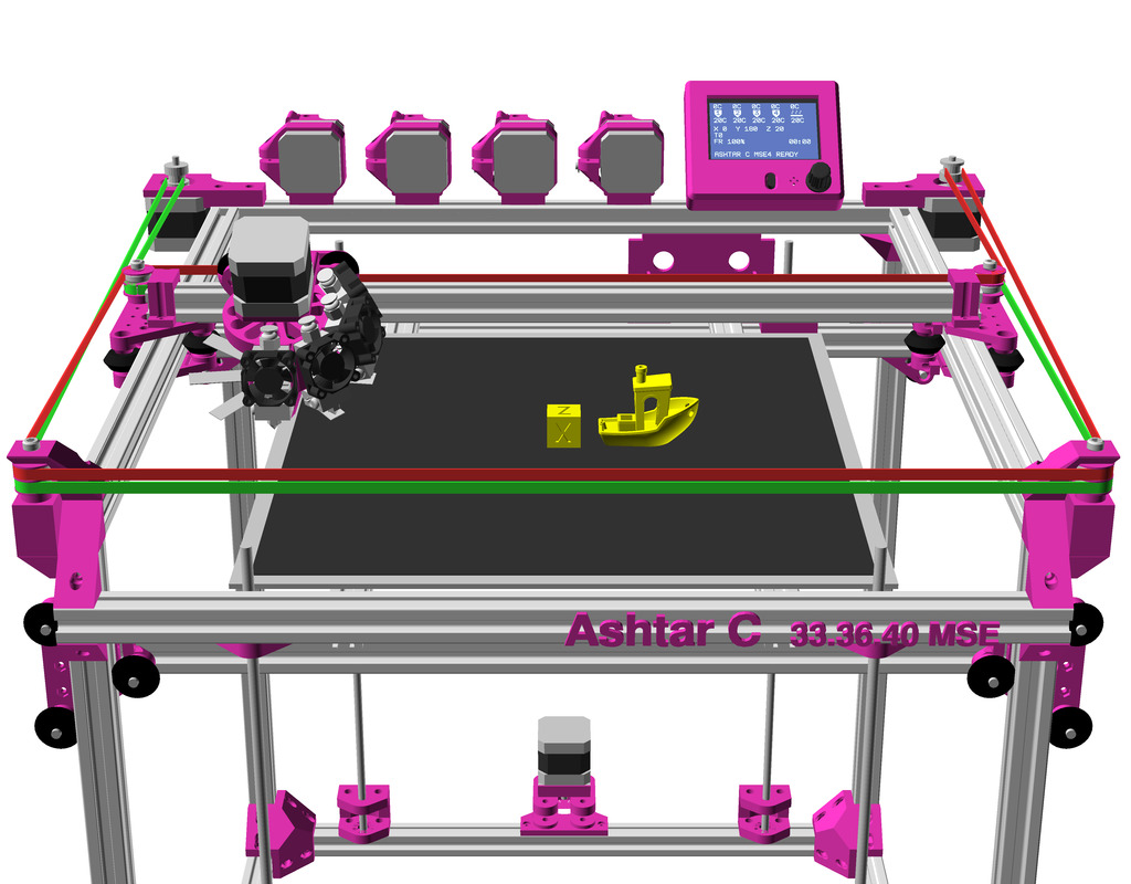
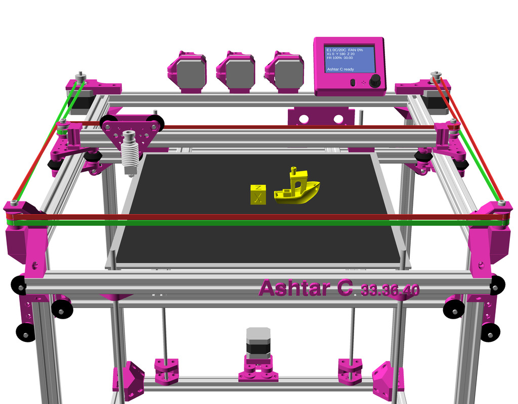
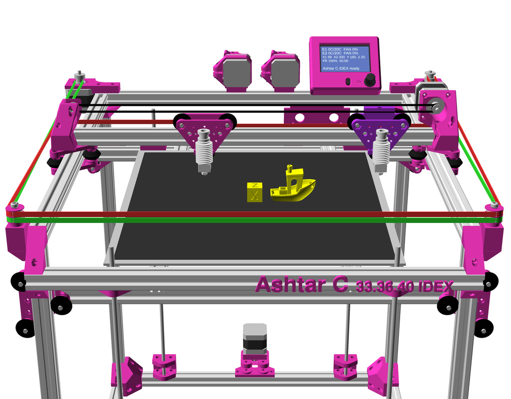
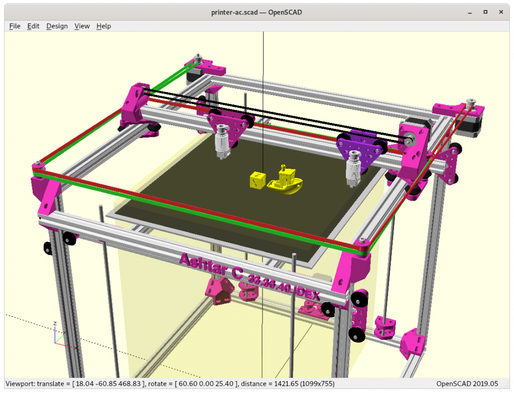
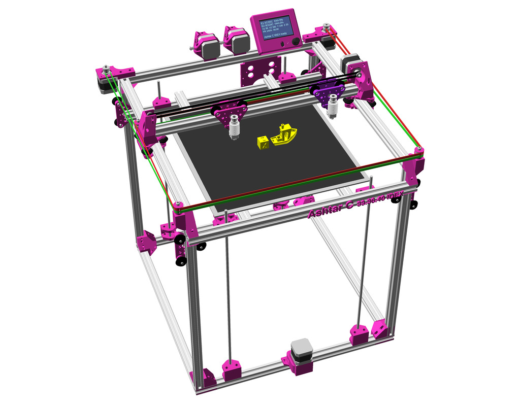
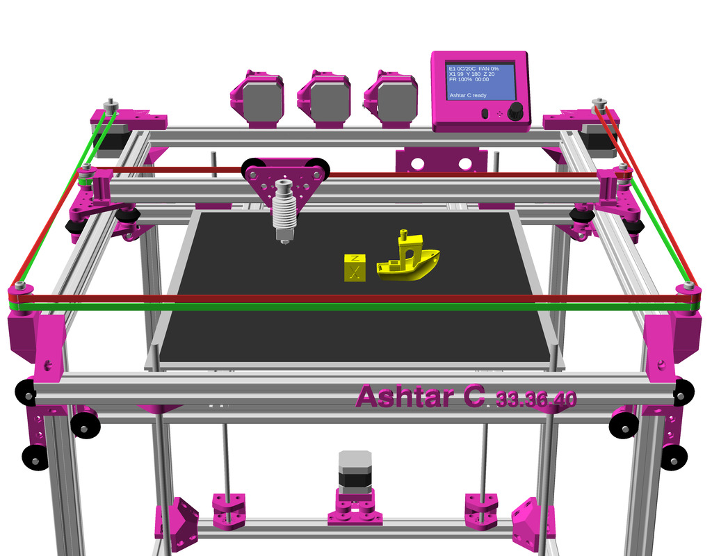
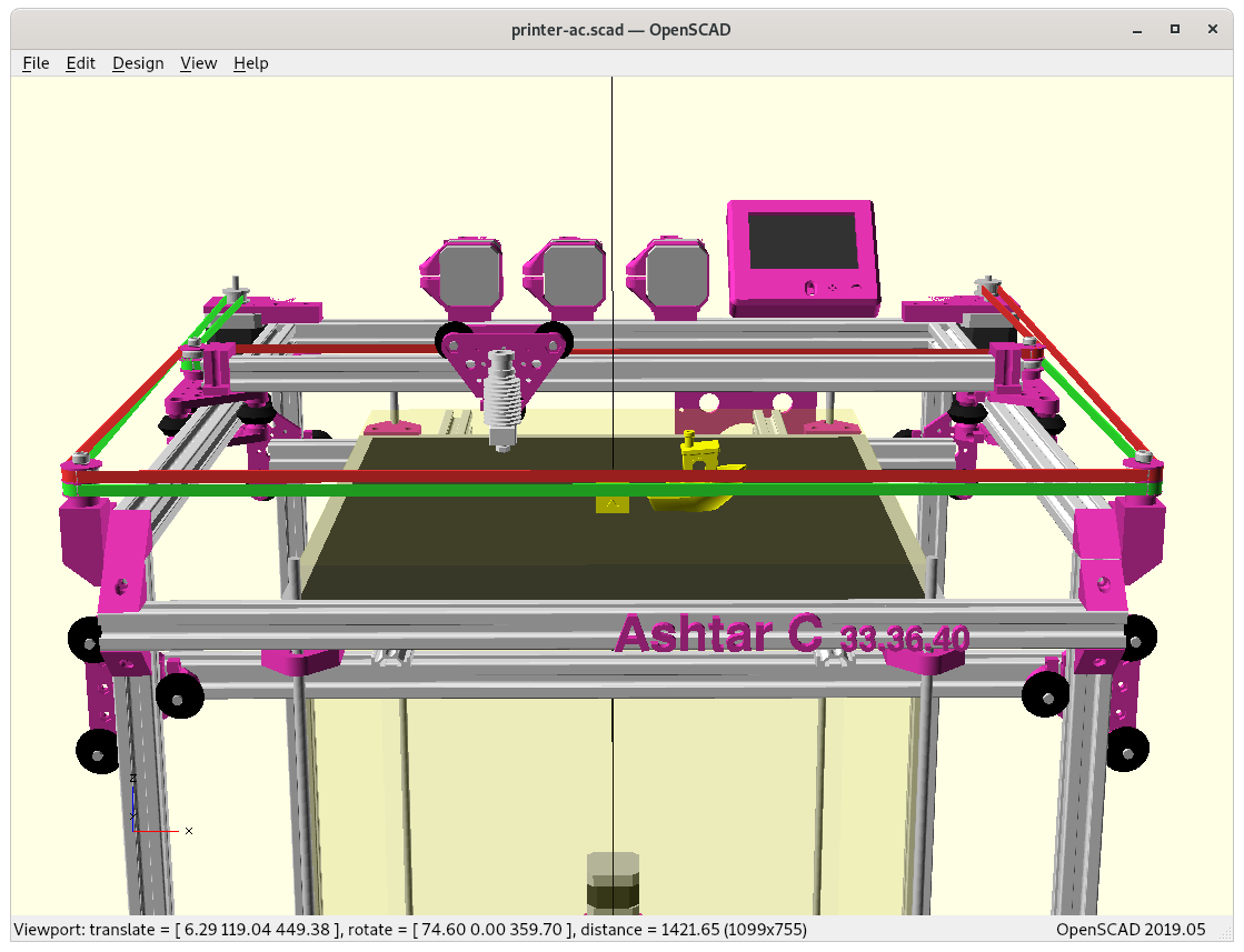
Ashtar C MSE4 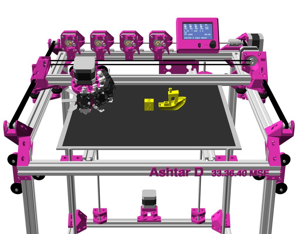
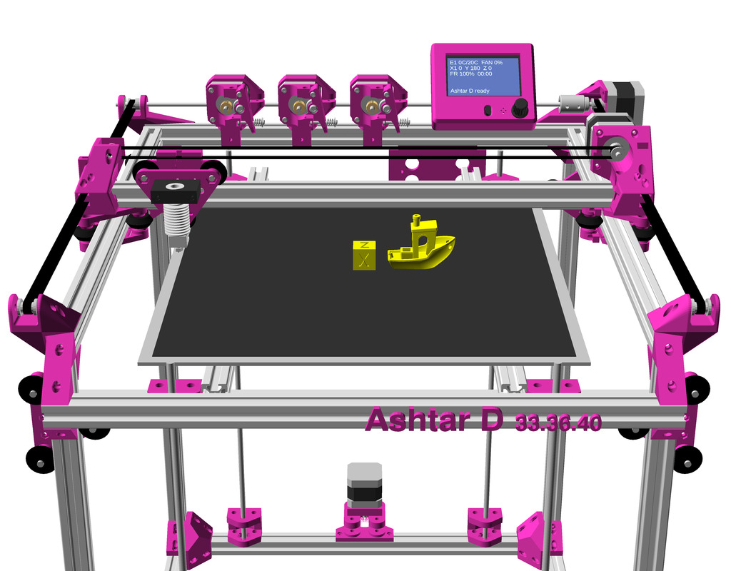
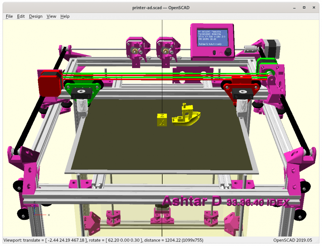
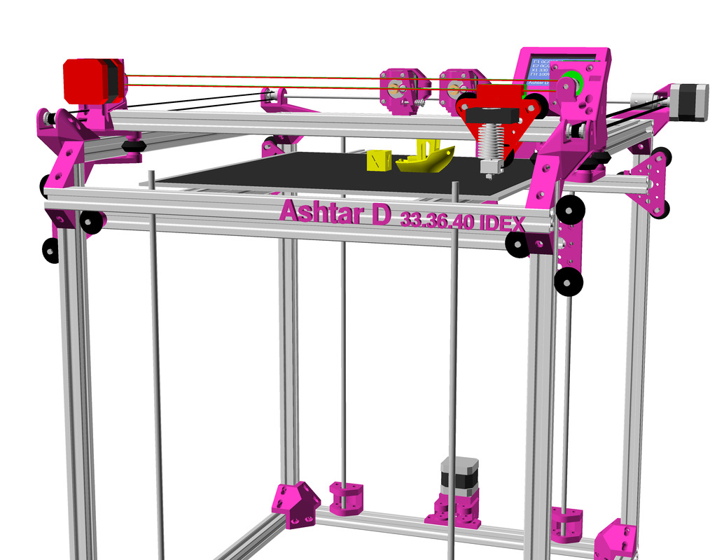
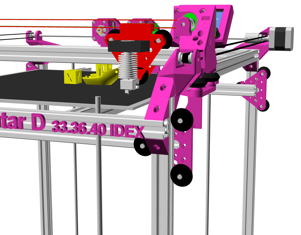
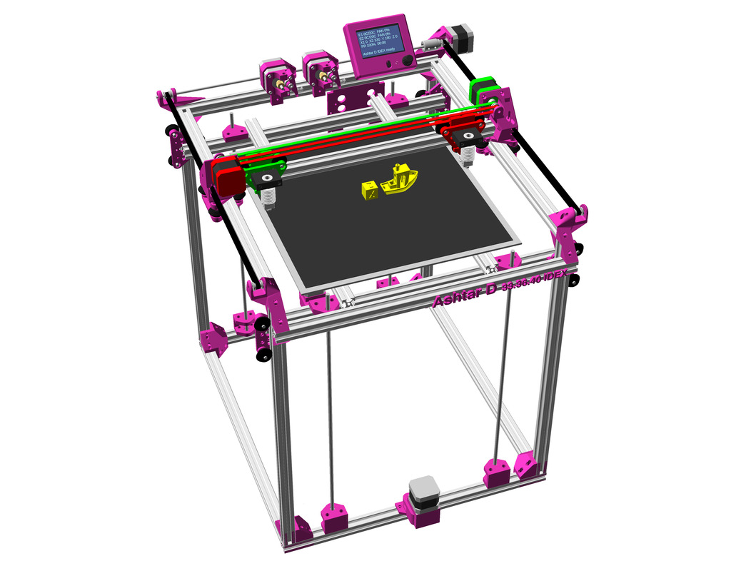
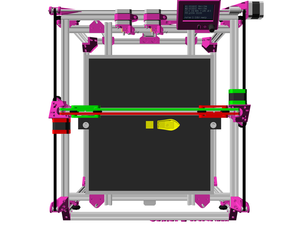
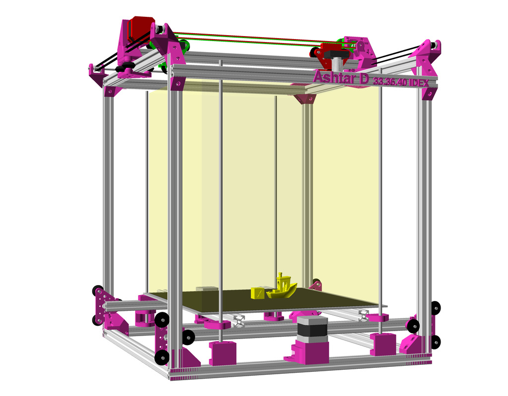
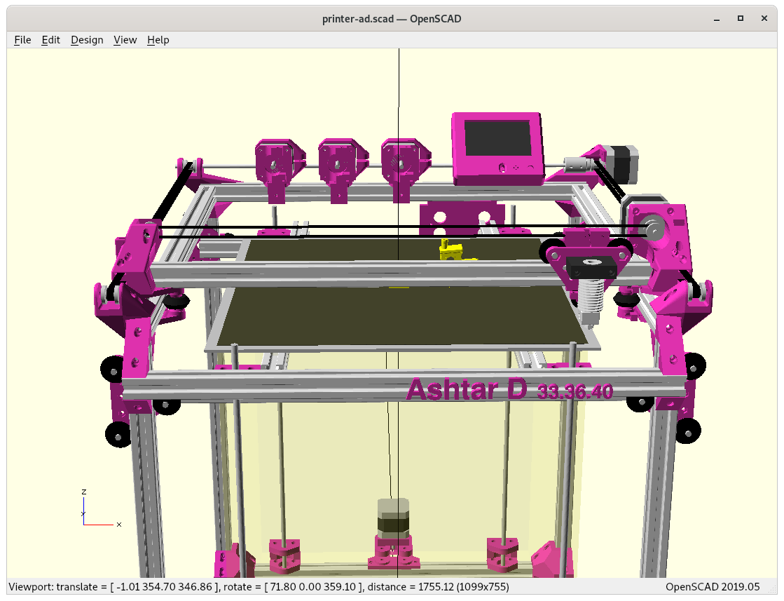
Ashtar D MSE4 
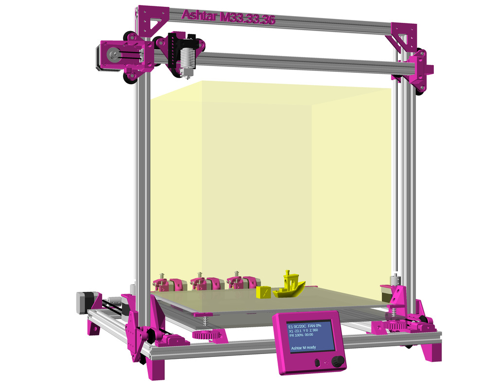
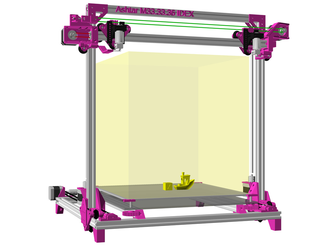
Ashtar M MSE4
- Ashtar K has sufficient space for extruders
- Ashtar C may have more extruders, not sure where beyond 4 extruders
- Ashtar D reaches its limits with 4 mounted extruders, unless the controller/display is moved away
- Ashtar M might not be the best candicate to have a heavier X carriage as it will affect print quality at higher Z positions

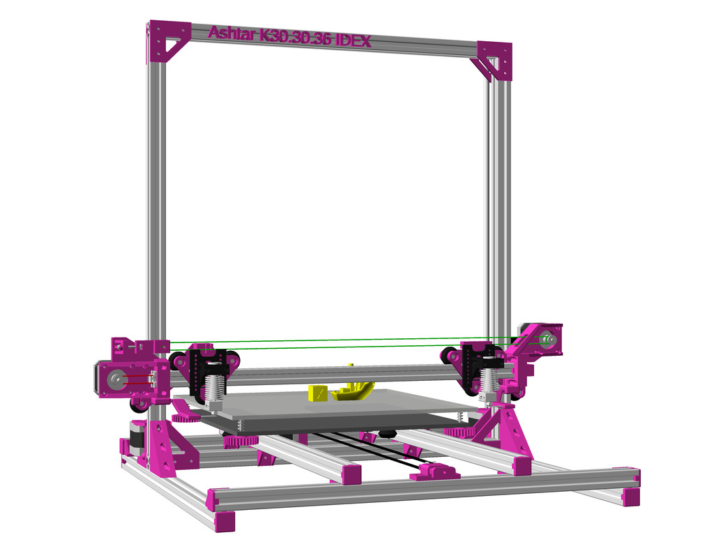
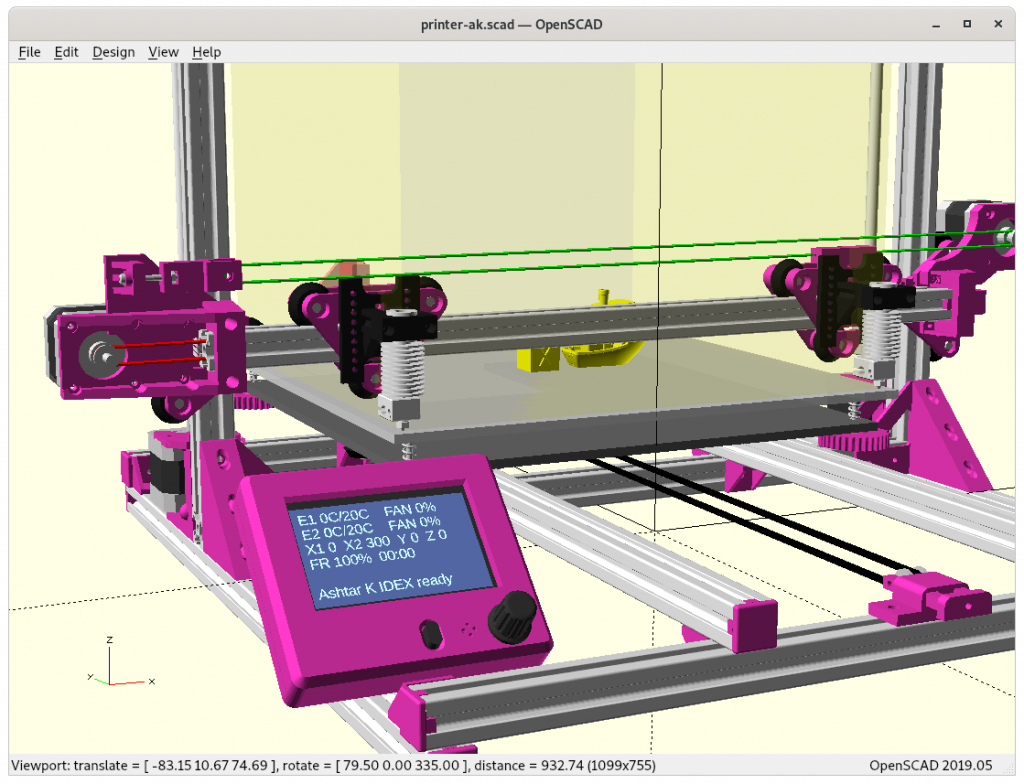
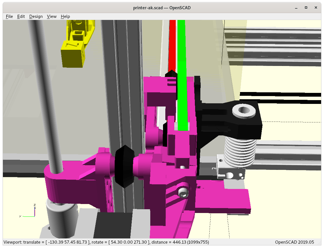
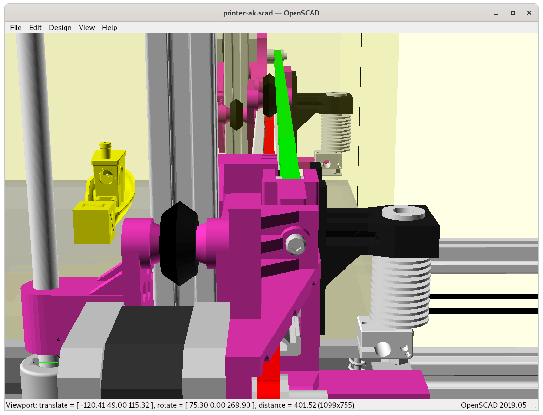
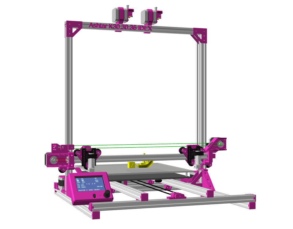
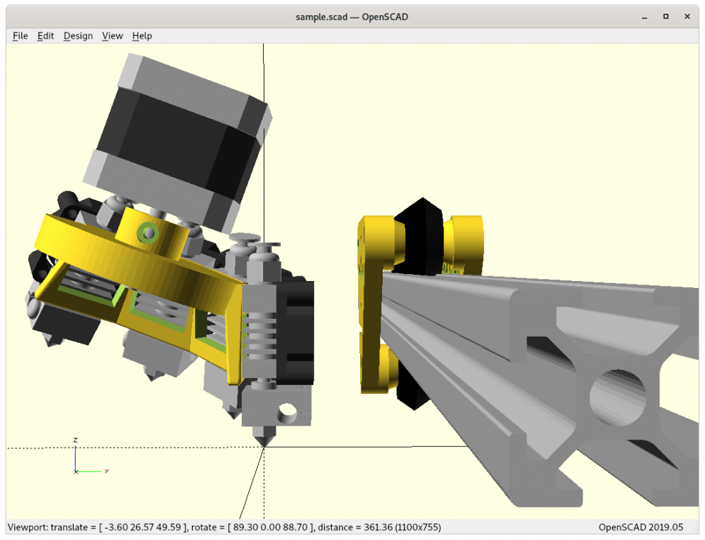
MSE Y 2 mounted on Ashtar K 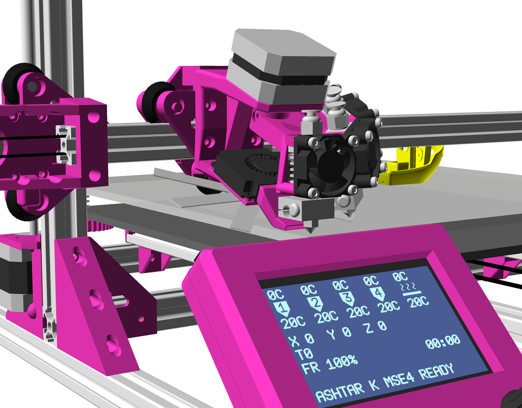
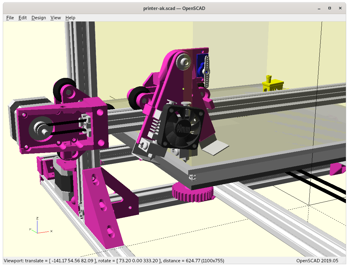
Lighter 25mm long NEMA17 MSE Z 4 on Ashtar K 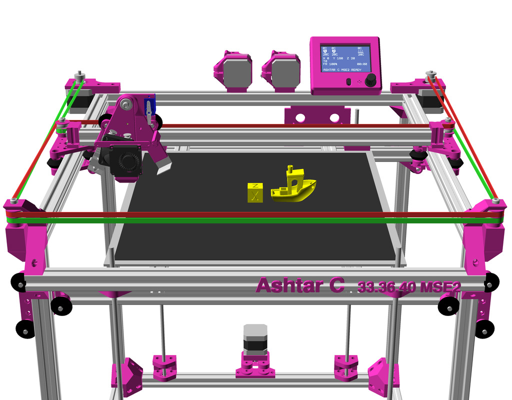
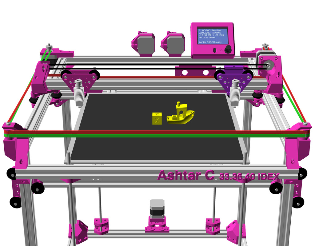
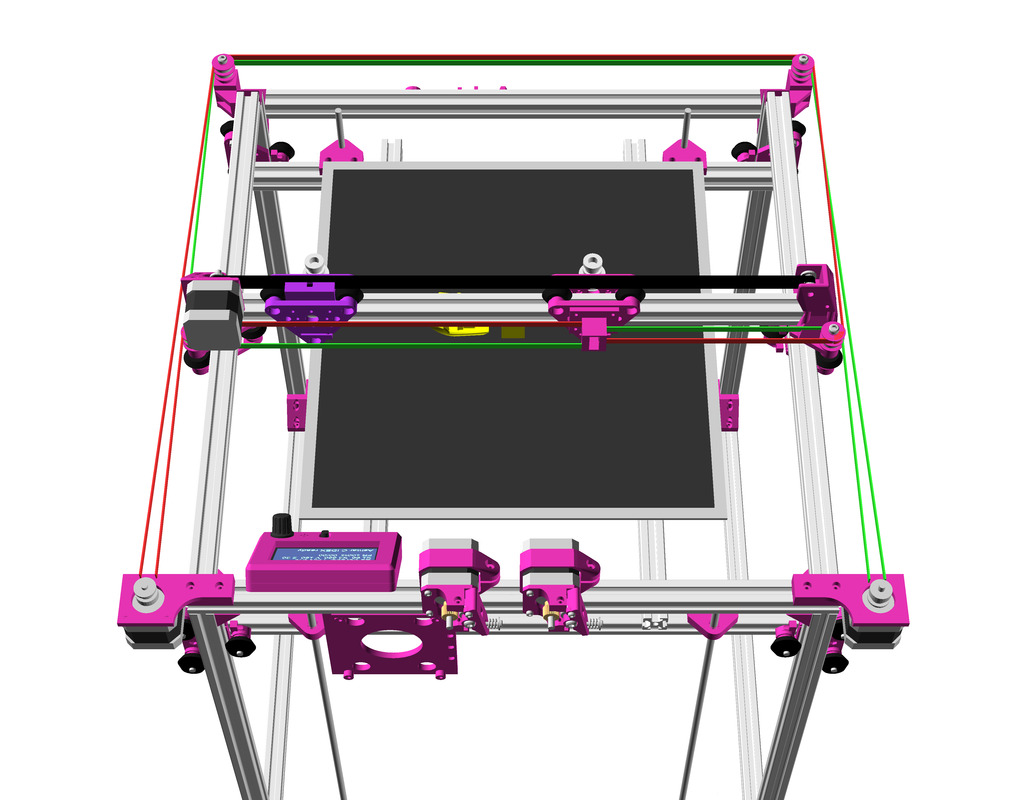
MSE Y 2 mounted on Ashtar C 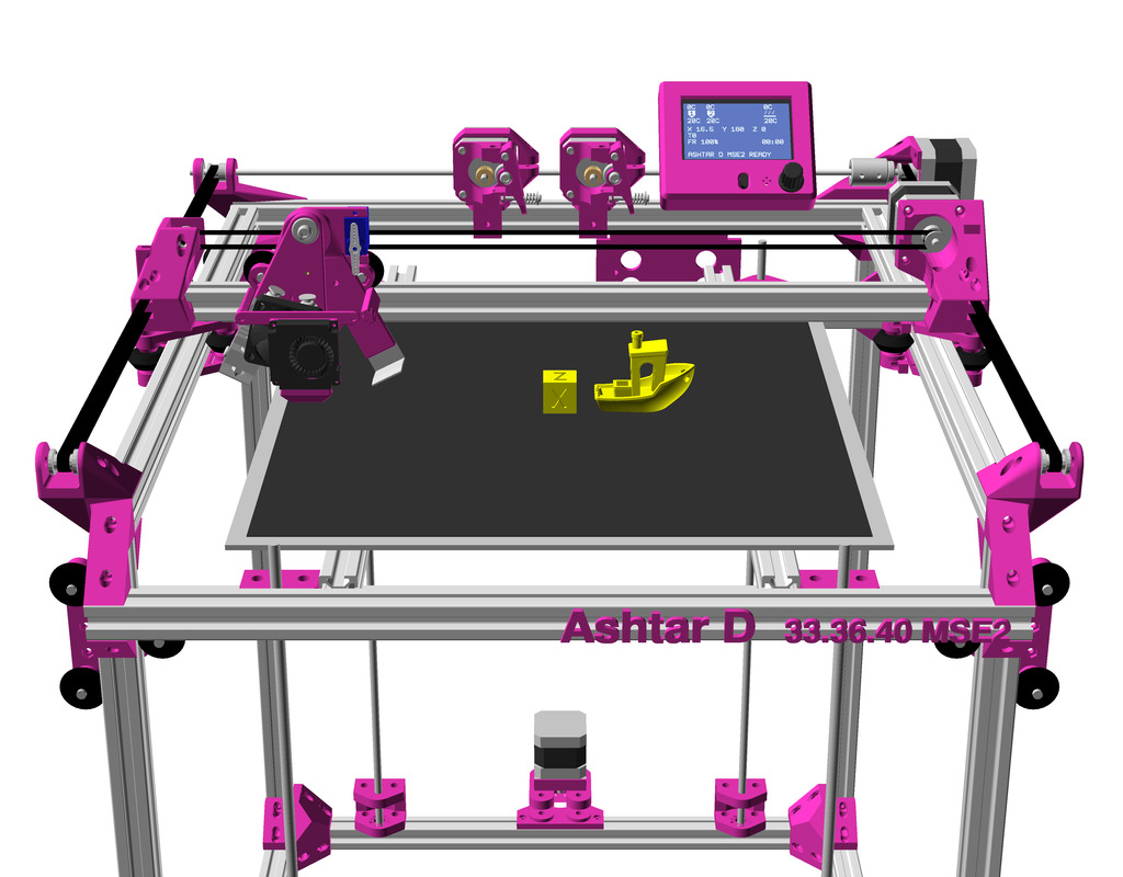
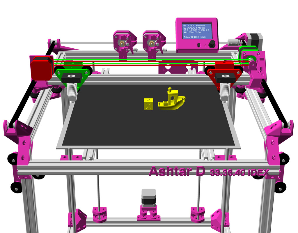
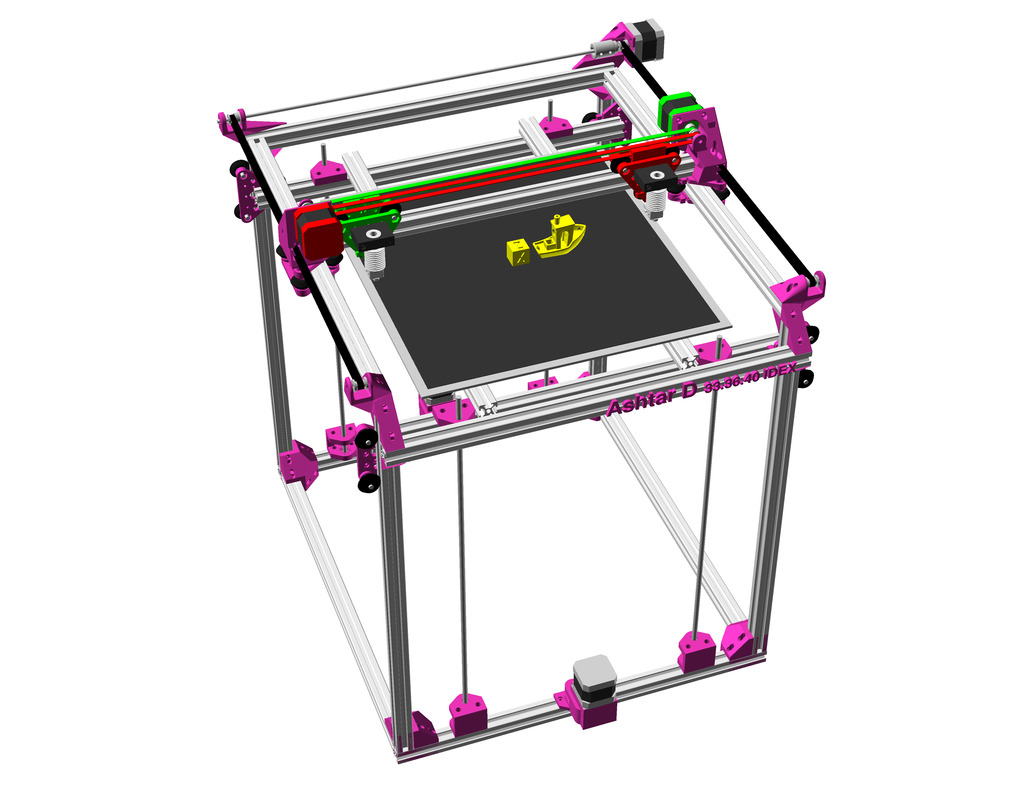
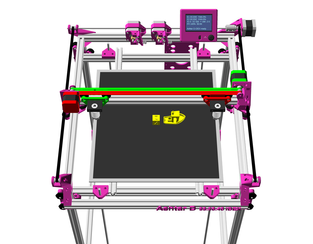
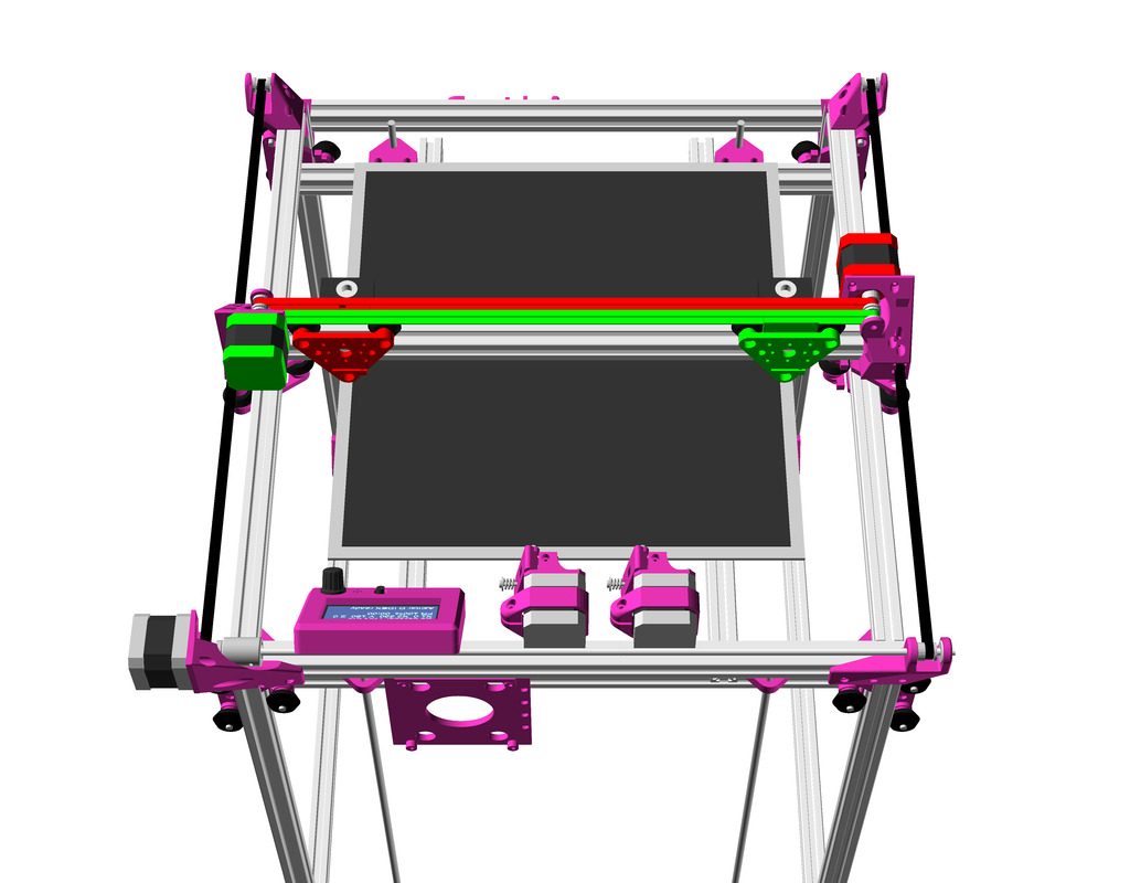
MSE Y 2 mounted on Ashtar D
I keep updating this blog-post as I progress.
Comparison Dual/Multi Color/Material Extrusions
blue = relevant positive
red = relevant negative
Independent Dual Extrusions (IDEX)
- complex setup
- moderate cost
- non-mixing
- dual nozzles
- dual heatblocks
- dual heatsinks
- normal retraction
- no purge block 1)
- no oozing over print
- no inactive nozzle traveling
- reliable 2)
★★★★★
Dual Hotends 2-in-2
- simple setup
- low cost
- non-mixing
- dual nozzles
- dual heatblocks
- dual heatsinks
- normal retraction
- no purge block
- inactive nozzle oozing over prints
- inactive nozzle travels over print
- moderate reliability
★★★★★
Chimera 2-in-2
- simple setup
- clone: low cost
- original: high cost
- non-mixing
- dual nozzles
- dual heatblocks
- single heatsink
- normal retraction
- no purge block
- oozing of inactive material
- inactive nozzle travels over print
- moderate reliability
★★★★★
Cyclops 2-in-1
- simple setup
- clone: low cost
- original: high cost
- mixing
- single nozzle
- single heatblock
- single heatsink
- normal retraction
- purge block required
- no oozing of inactive material
- clone: unreliable
★★★★★ (clone)
Cyclops NF 2-in-1
- simple setup
- low cost
- non-mixing
- single nozzle
- single heatblock
- single heatsink
- complex retraction
- no oozing of inactive material
- moderate reliability
★★★★★
Diamond Hotend 3-in-1
- complex setup
- clone: low cost
- original: high cost
- mixing
- single nozzle
- single heatblock
- 3 heatsinks
- tricky retraction
- purge block required
- no oozing of inactive material
- moderate reliability
★★★★★
Multiple Switching Extrusions (MSE) 2-in-2, 3-in-3, 4-in-4
- moderate complex setup
- requires additional servo or motor
- extendable 2, 3, or 4 colors/materials
- low cost
- non-mixing
- multiple nozzles / heatblocks / heatsinks
- normal retraction
- no purge block 1)
- no oozing of inactive material
- no inactive nozzle touching print
- reliable 2)
(rating comes later)
Y Splitter x-in-1
- simple setup
- extendable 2, 3, or 4 or more colors / materials
- low cost
- non-mixing
- single nozzle
- single heatblock
- single heatsink
- complex retraction
- purge block required
- no oozing of inactive material
- moderate reliability
★★★★★
Tool Changer
- complex setup
- extendable to n-colors or materials
- moderate cost
- non-mixing
- multiple nozzles / heatblocks / heatsinks
- normal retraction
- no oozing of inactive material
- no inactive nozzle touching print
- moderate reliability
(rating comes later)
Footnotes
- in theory no purge block, but if ooze shields are shared among switching extrusions (more than 2 extrusions) there may be cross-contamination between colors/materials
- the printheads individually are proven to be reliable
Hints:
- single heatblock = same print temperature
- dual heatblock = different print temperatures possible
- dual nozzle = different nozzle sizes possible
That’s it.