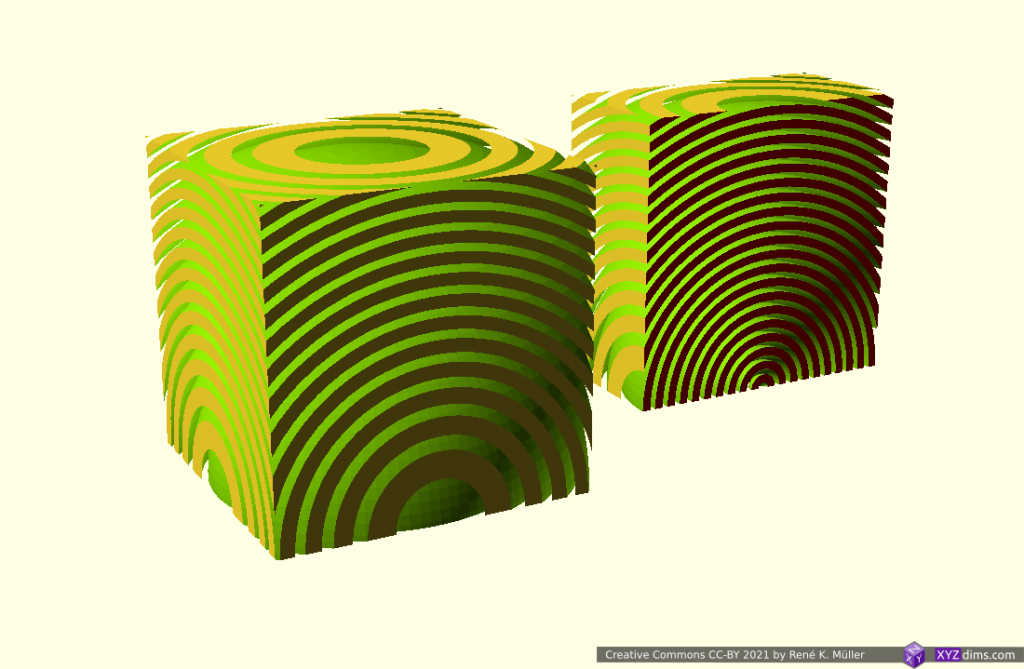
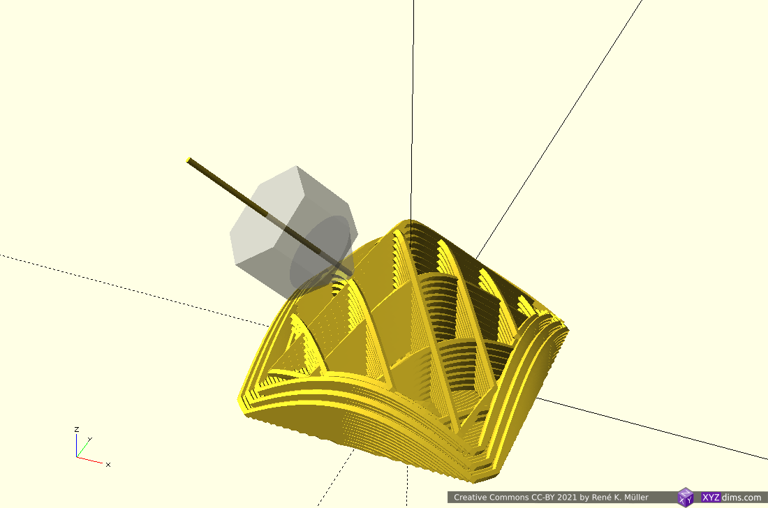
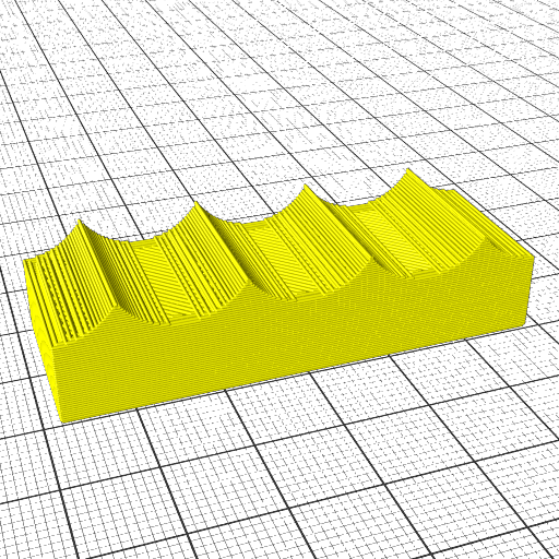
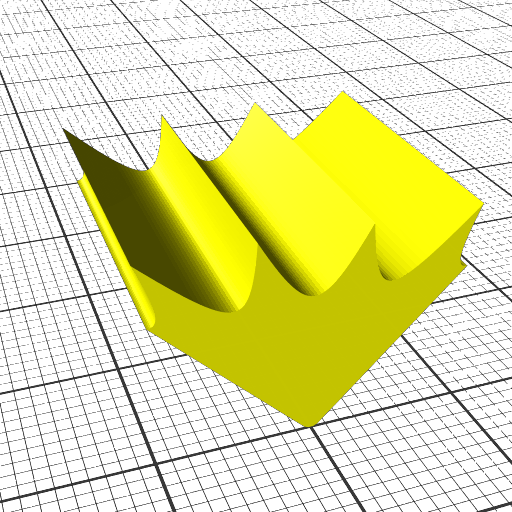
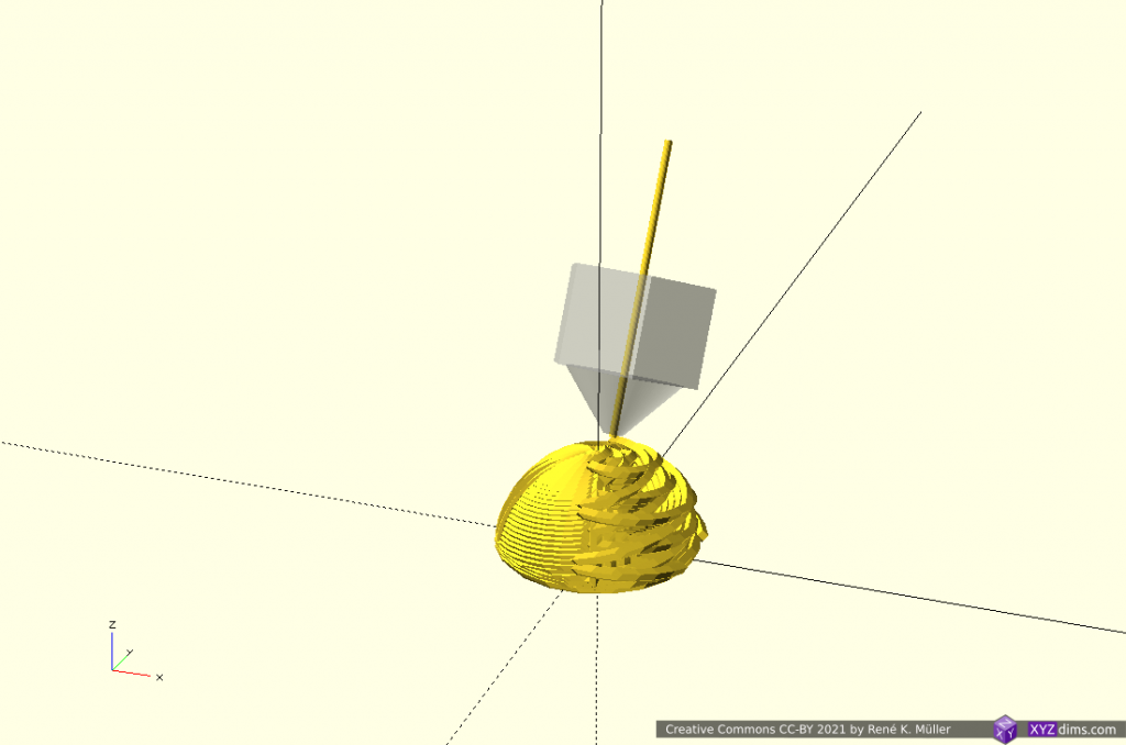
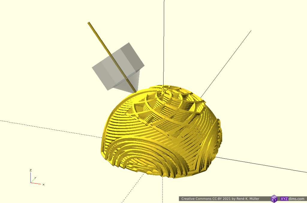
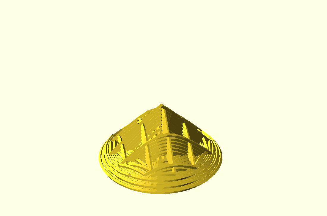
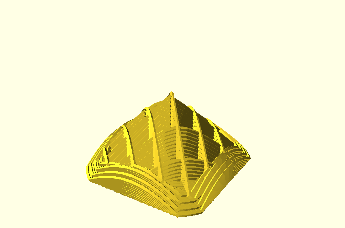
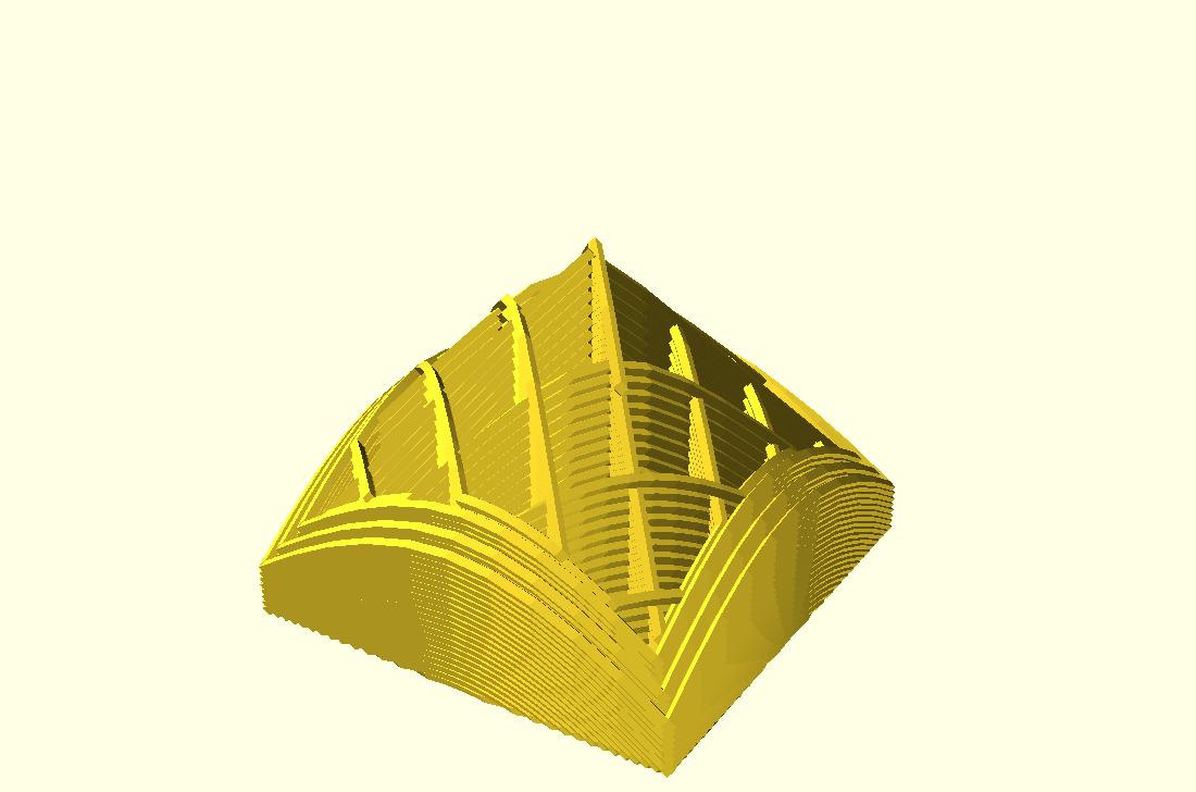
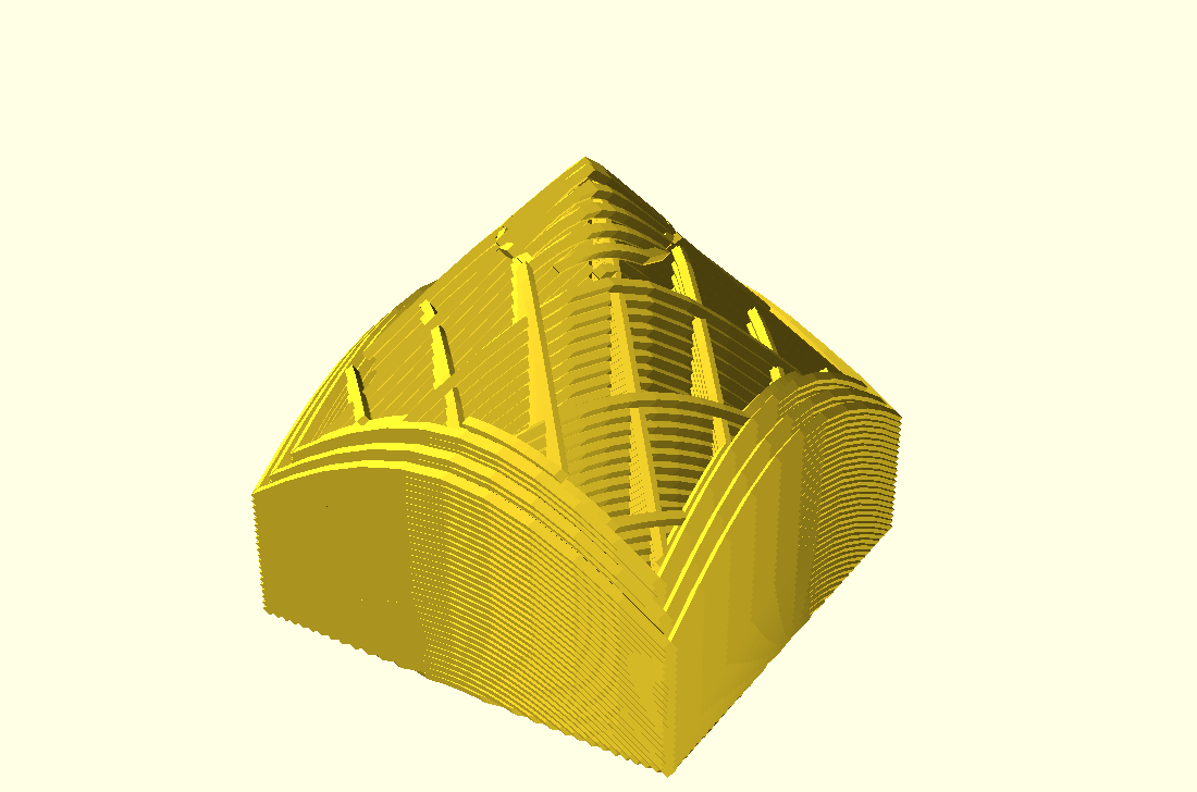
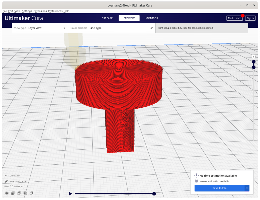
can print 90° overhangs, two distinct modes: inside out (outside cone), or outside in (inside cone) depending on direction to a central slicing cone center
angle of conic slicing can be changed from 45° to 20° and models become printable with vertical nozzle with reduced print quality
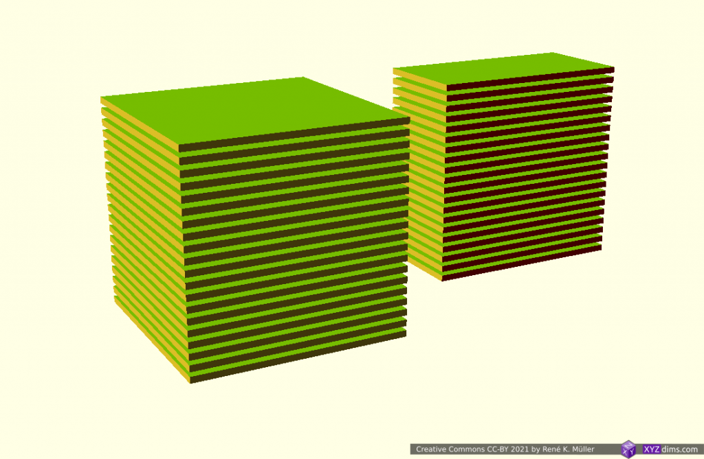
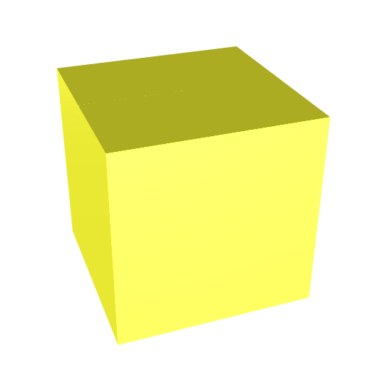
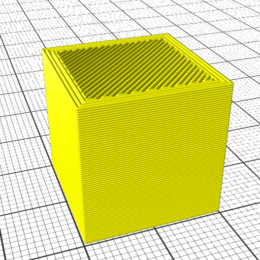
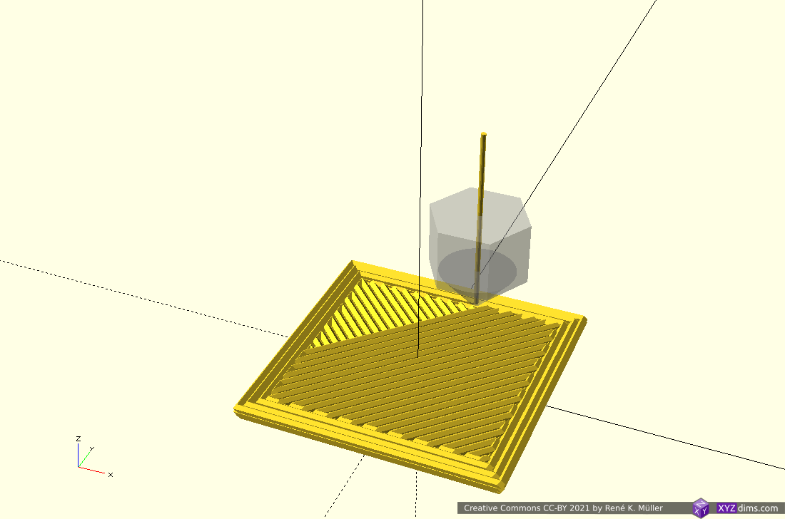
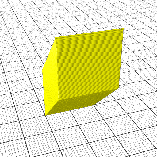
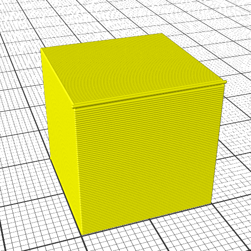
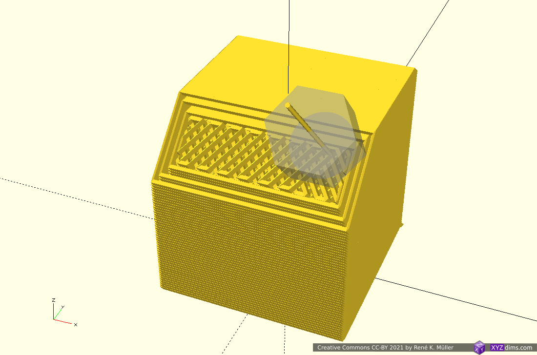
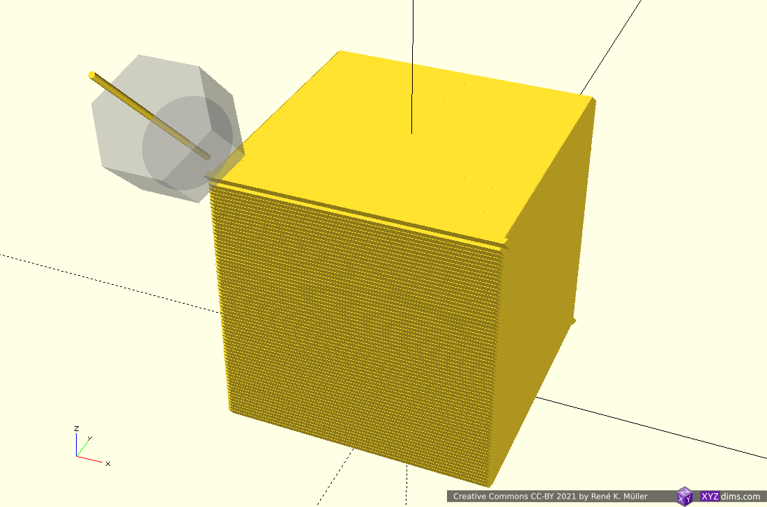
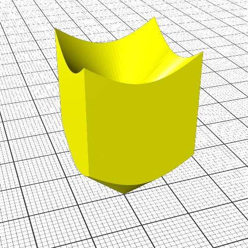
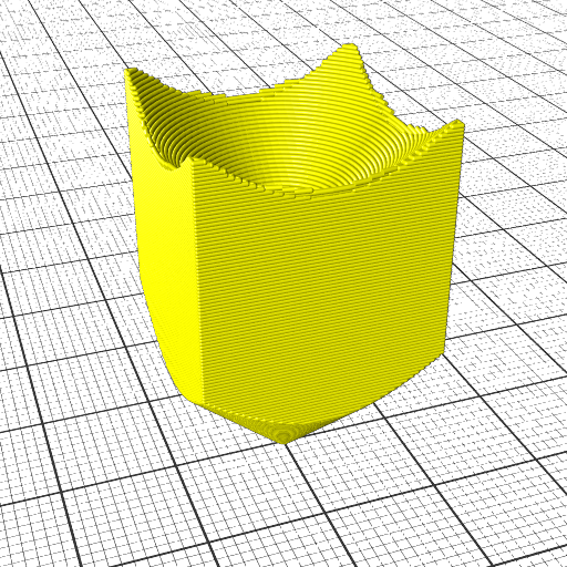
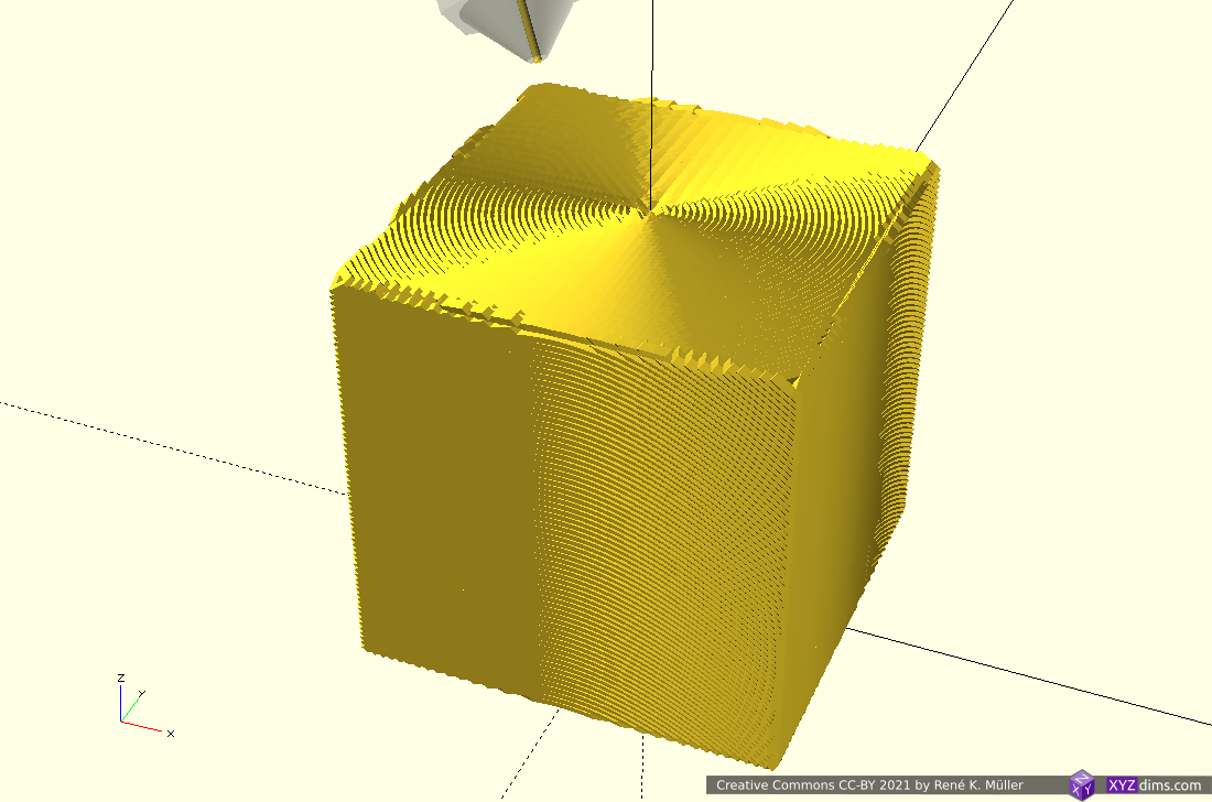
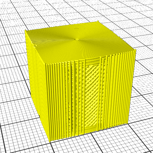
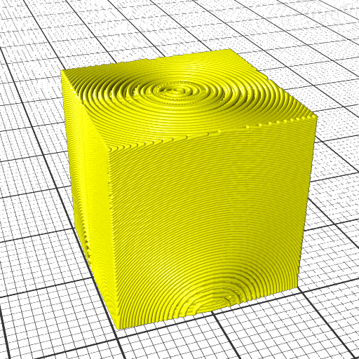
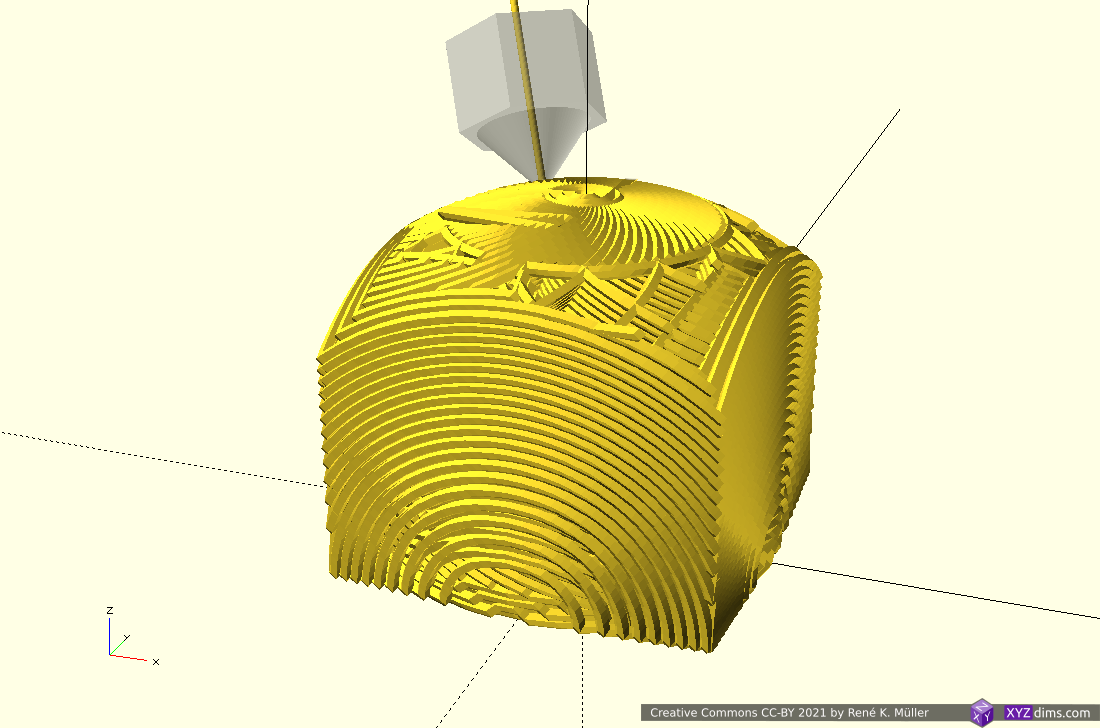
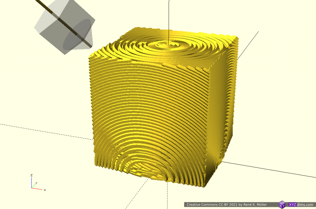
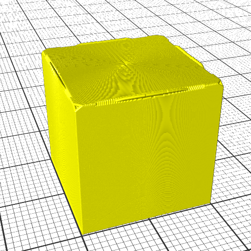
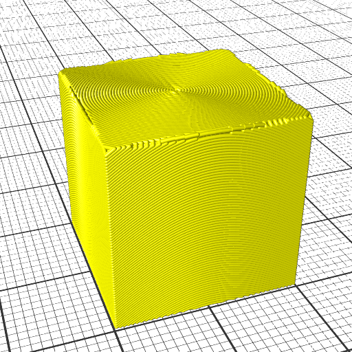
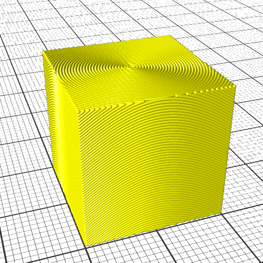
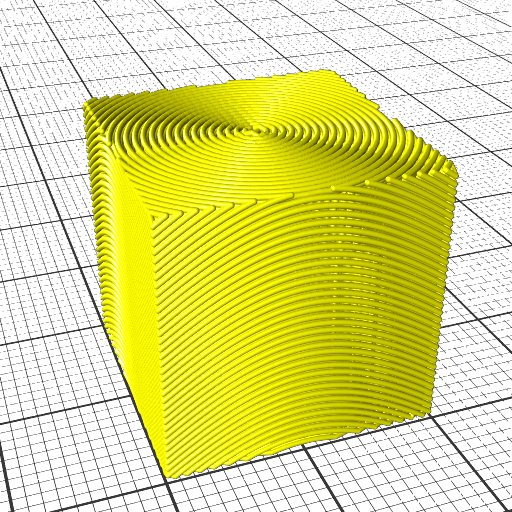
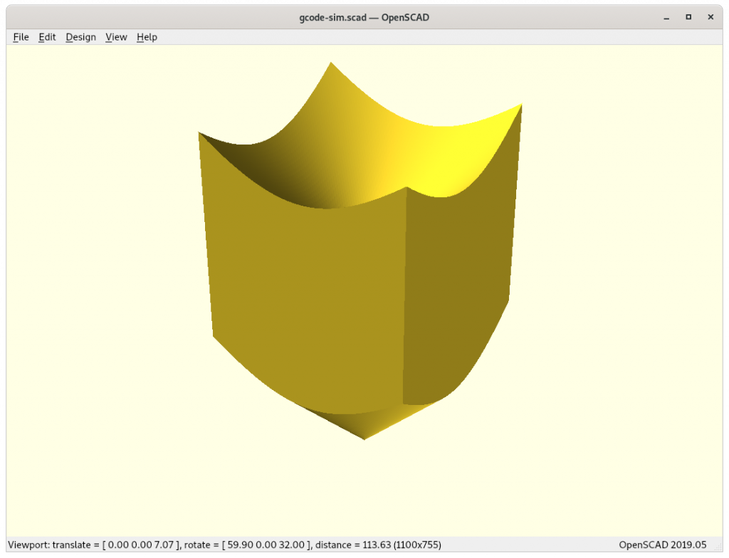
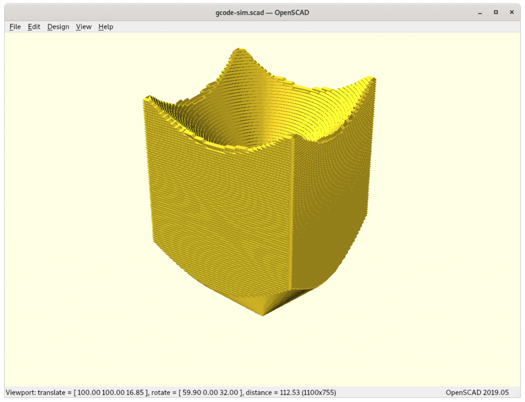
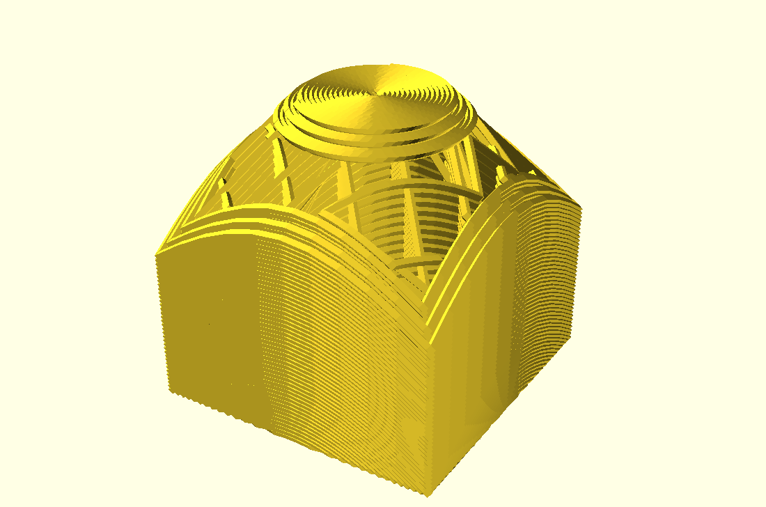
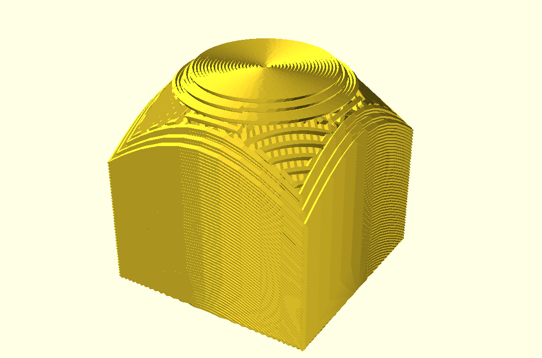
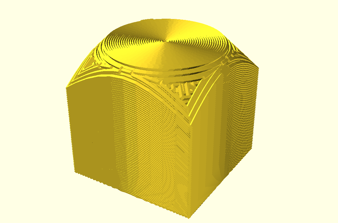
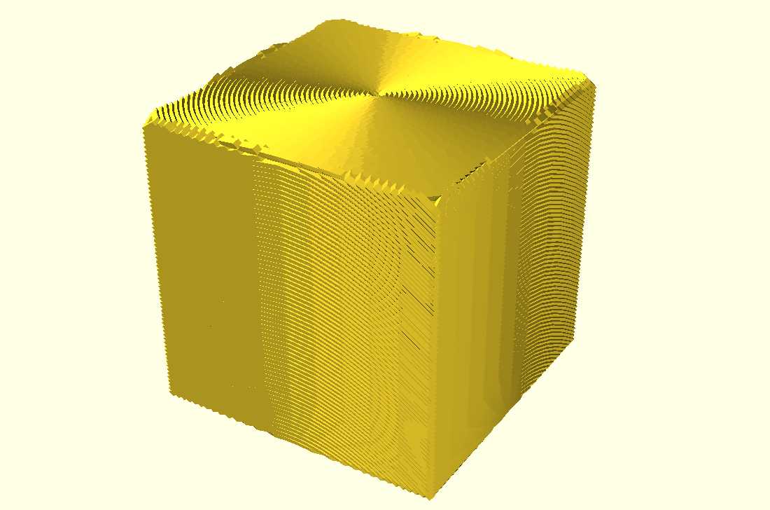
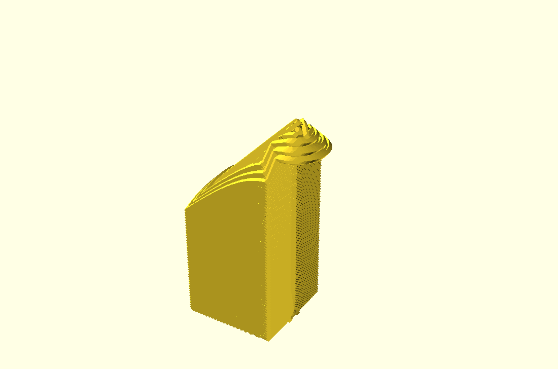
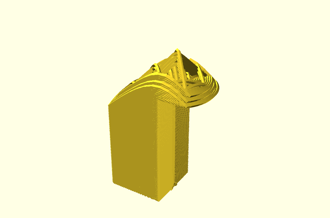
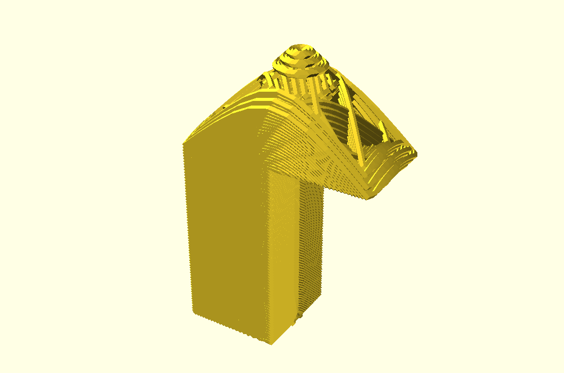
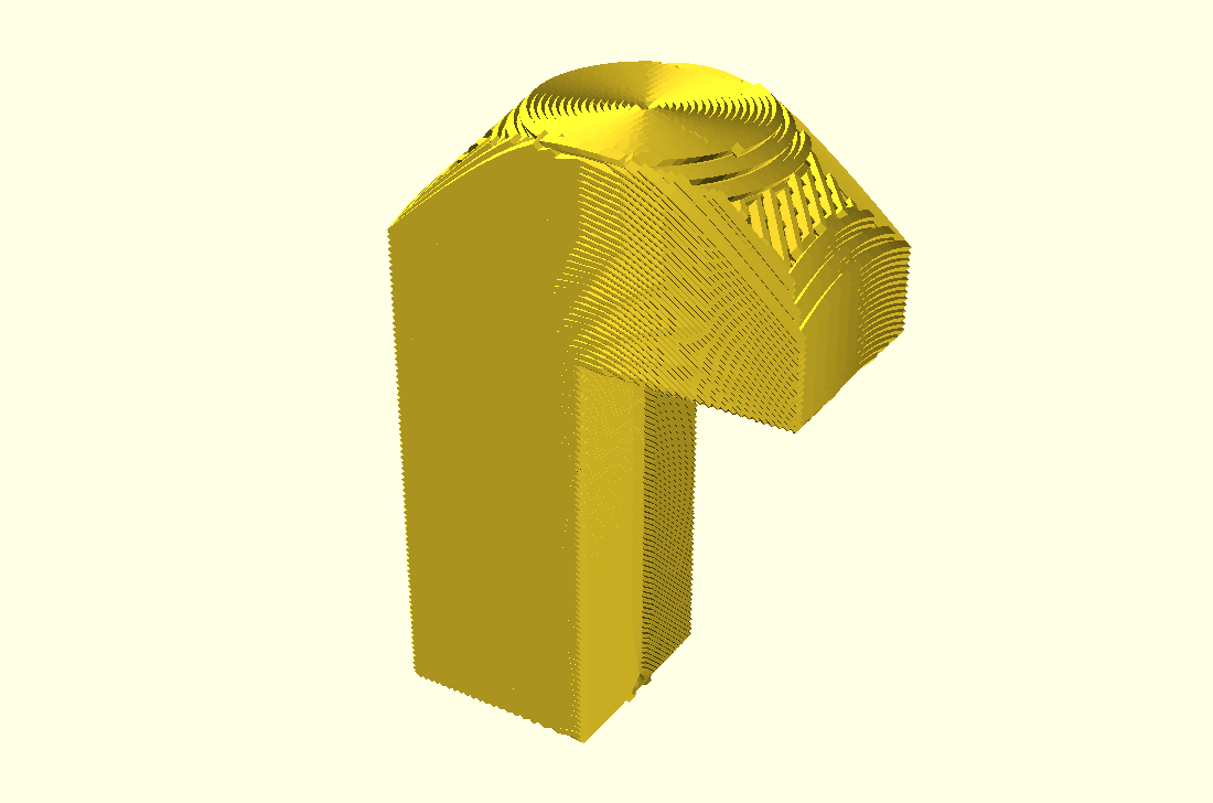
20mm cube
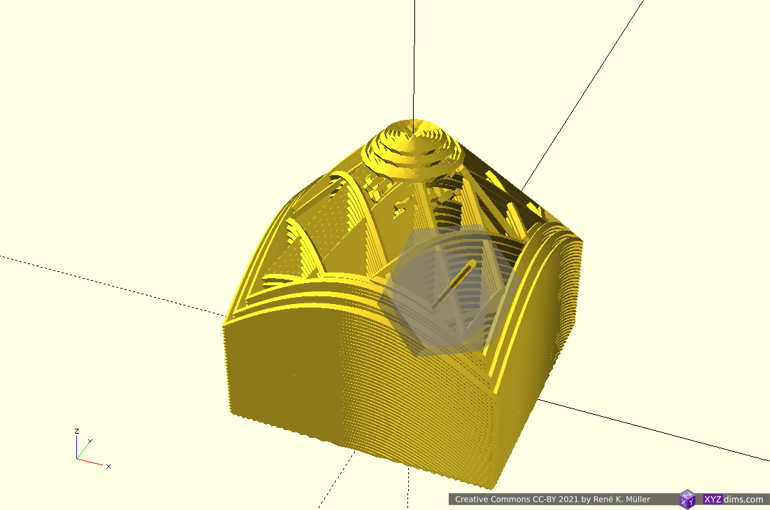
conic mapped
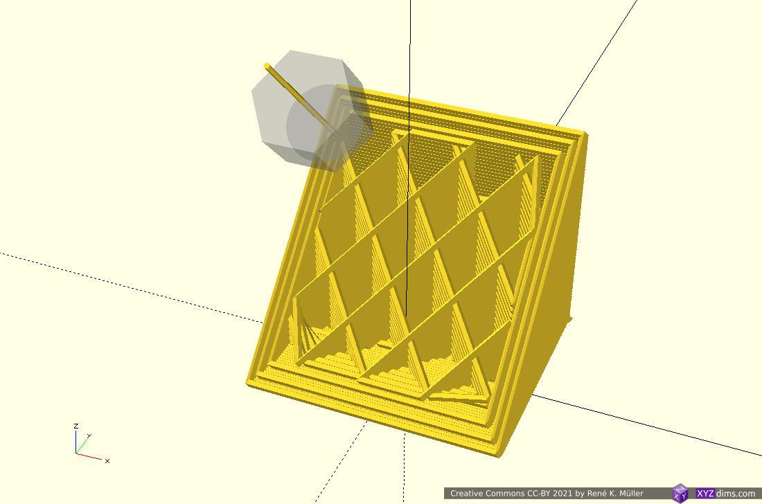
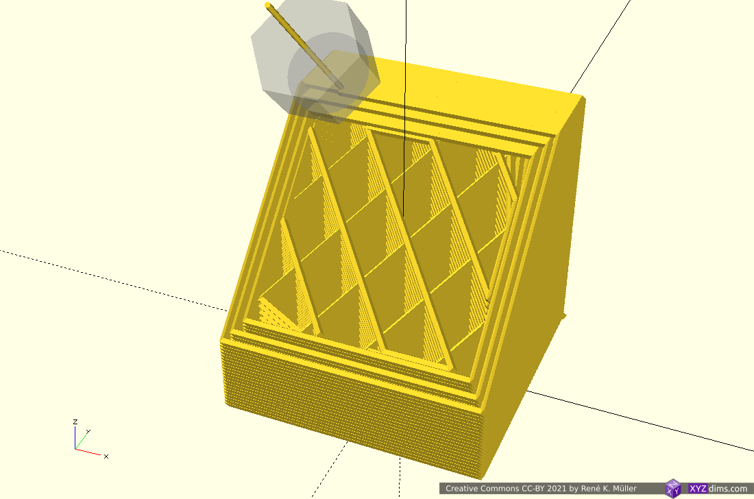
conic mapped sliced
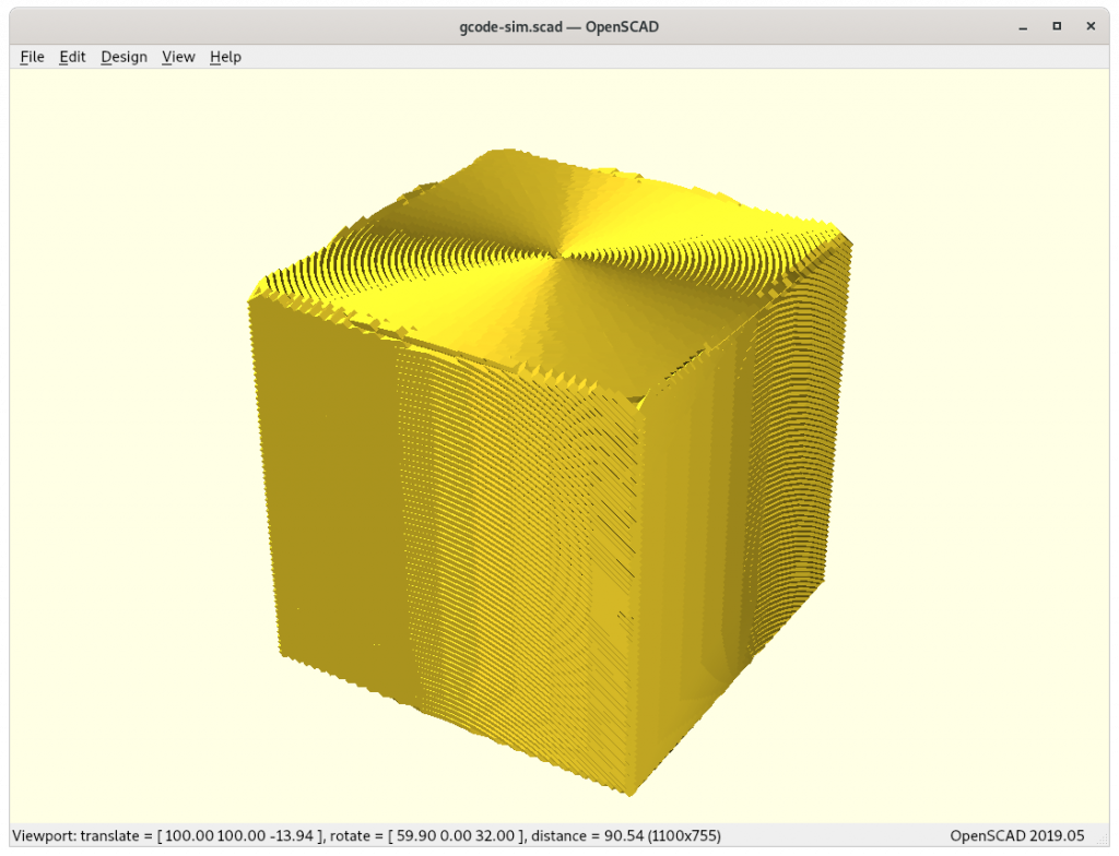
20mm cube conic sliced
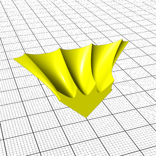
Transformation is [ x, y, z + sqrt(x2 + y2) ]
I implemented a conic slicer named Slicer4RTN in 2021/03. There are more complex conic transformations possible, e.g. map the x/y angle via atan(y/x) but just adding sqrt(x2 + y2) to z does achieve a conic slice.
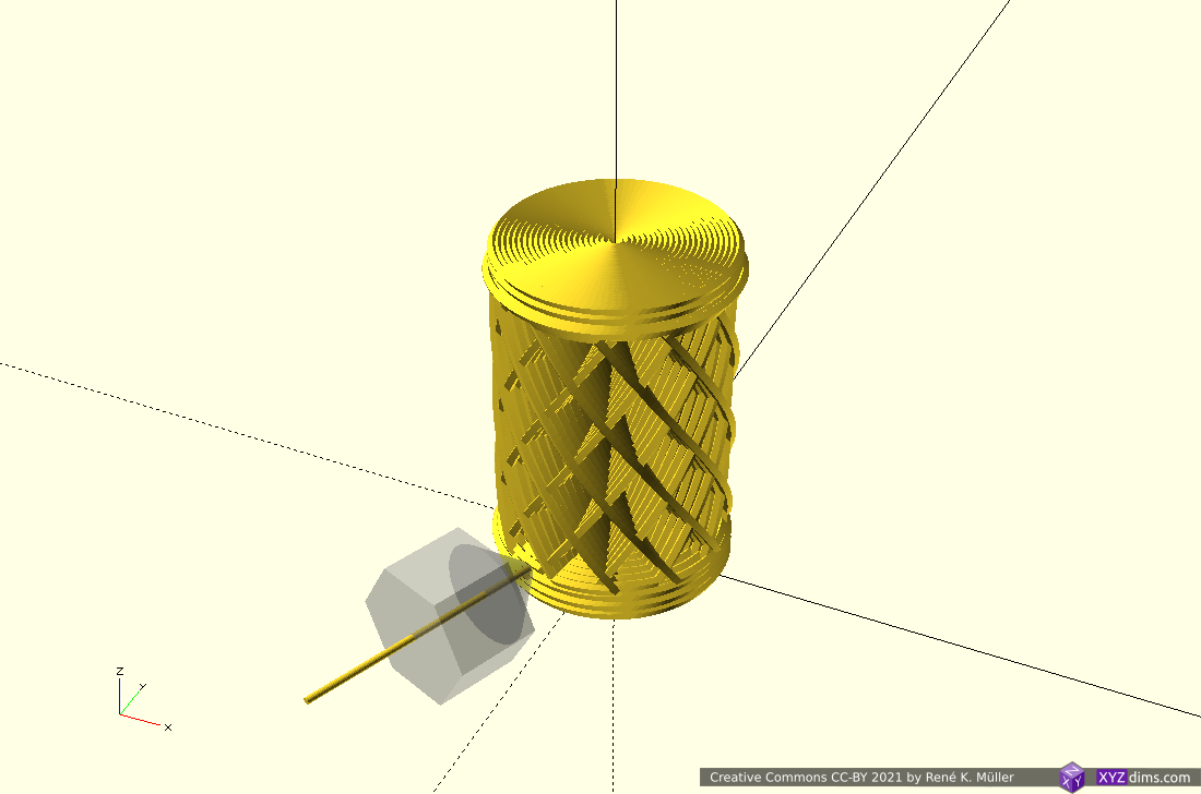
Cylindrical Slices
Early tests using planar slicers to slice also cylindrical, like this:
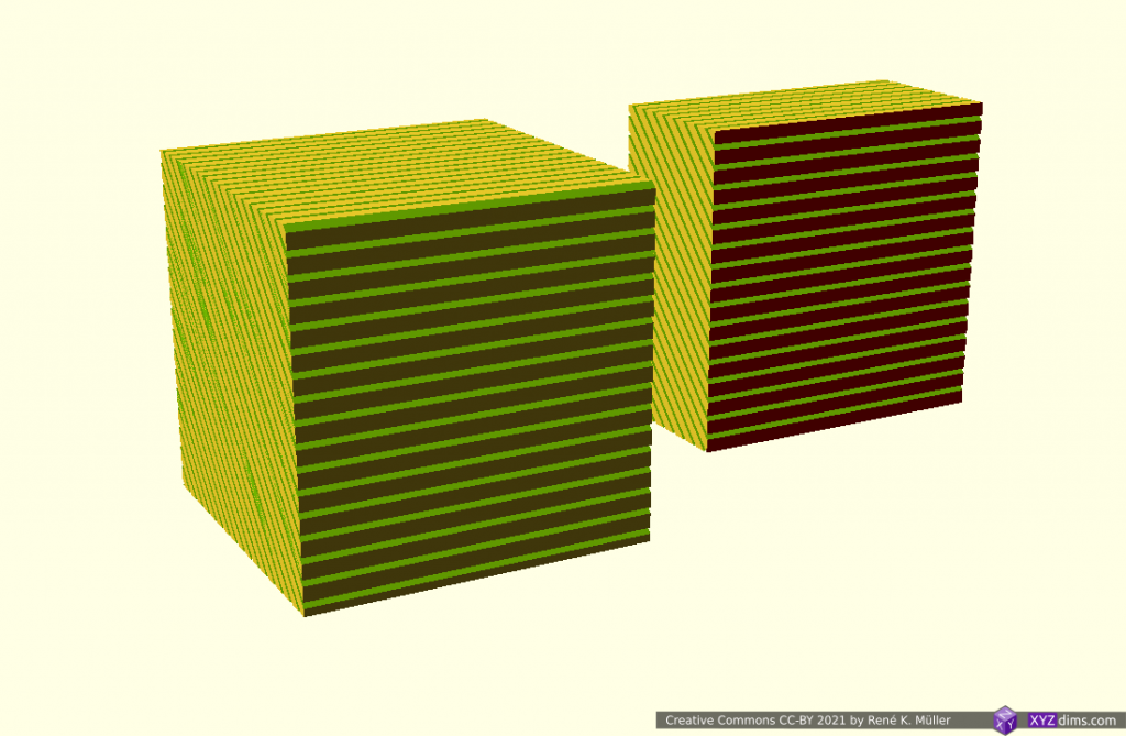
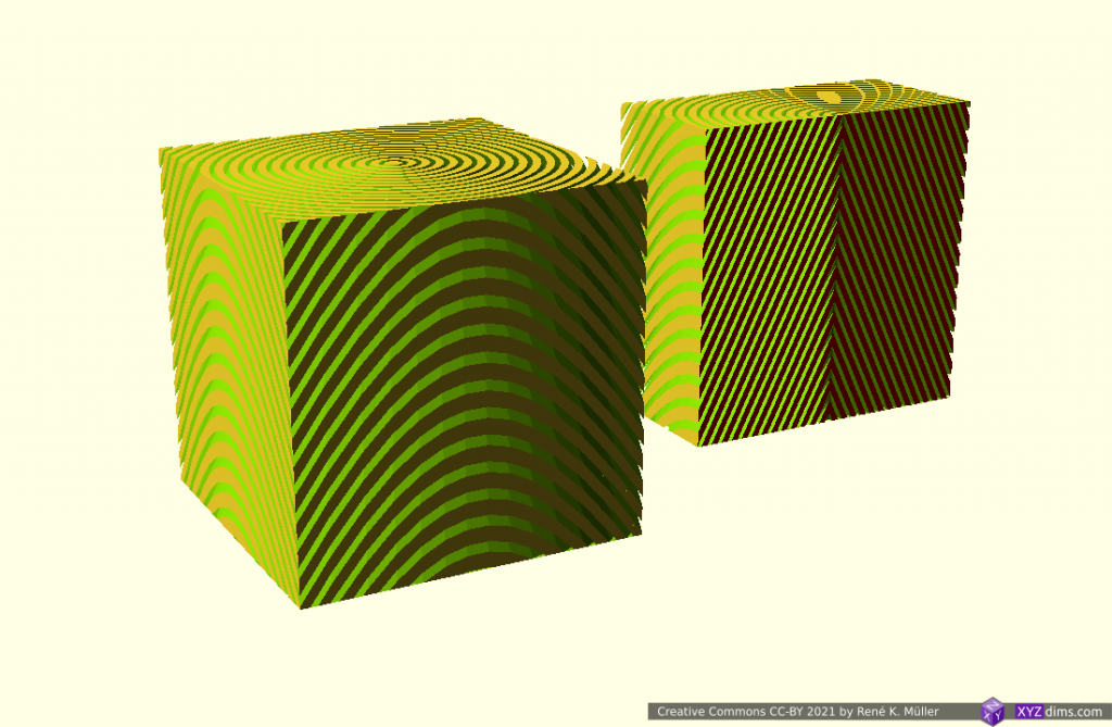
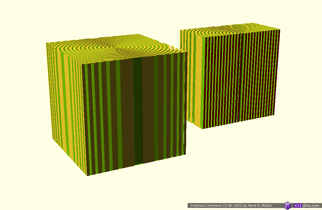
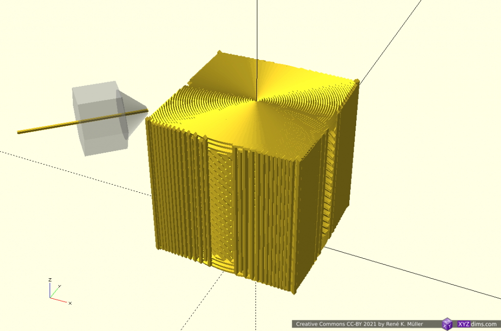
20mm cube
cylinderical mapped
cylinderical mapped planar sliced
cylindrical radius corrected mapped
cylindrical radius corrected planar sliced
20mm cube cylindrical sliced
Transformation is [ atan(y/x), z, sqrt(x2 + y2) ]
It can be printed on a fixed vertical rod, with a rotating and tilting nozzle, or horizontal rotating rod (like a lathe) and vertical nozzle then:
I came up with this way by myself based on the study on conic(al) slicing but I was made aware researchers Coupek, Friedrich, Battran, Riedel back in 2018 published a paper on this method already.
(Hemi-)Spherical Slices
Early tests using planar slicers to slice also spherical, like this:
It can be printed with a 5-axis like PAX printhead, it’s main advantage is to getting close to print continuous overhangs of any angle.
I suspect at least one more suitable and simpler sphere transformation, as soon I came up with such I add it on this blog-post.
Conclusion
It is possible to slice non-planar with planar slicers by mapping to and from the space of the slicing you like to have; yet in the slicing procedure some margins are introduced which need to be compensated – the planar slicer needs to work reliable, Slic3r1.2.9 and CuraEngine 4.4.1 / cura-slicer perform reliable, whereas PrusaSlicer 2.1.1 makes assumptions of the printability and exits when no printable G-code can be produced, not recommended for this case therefore.
The simpler the transformation forward and backward, the more precise G-code can be obtained, e.g. tilted and conic slices provide precise G-code, whereas cylindrical and spherical slices are harder to tune with the planar slicer.
2021/09/28: added reference to newly published paper by ZHAW
2021/03/22: 0.4.5: source released on github, page published
2021/03/20: 0.4.2: adding more core slicer examples
2021/03/17: 0.3.1: start writing page, provide overview of settings
Introduction
Slicer4RTN aka “Slicer for Rotating Tilted Nozzle (RTN)” is a highly experimental conic slicer utilizing existing planar slicer like Slic3r with pre- and post-processing to create G-code which can be printed with a 4-axis RTN, allowing to print particular overhangs without support:
printing 90° – 110° overhangs without support, given some conditions
unidirectional tilted slicing (tilted nozzle)
variable tilt angle
printing 90° – 110° overhangs in one direction, like possible with a belt printer
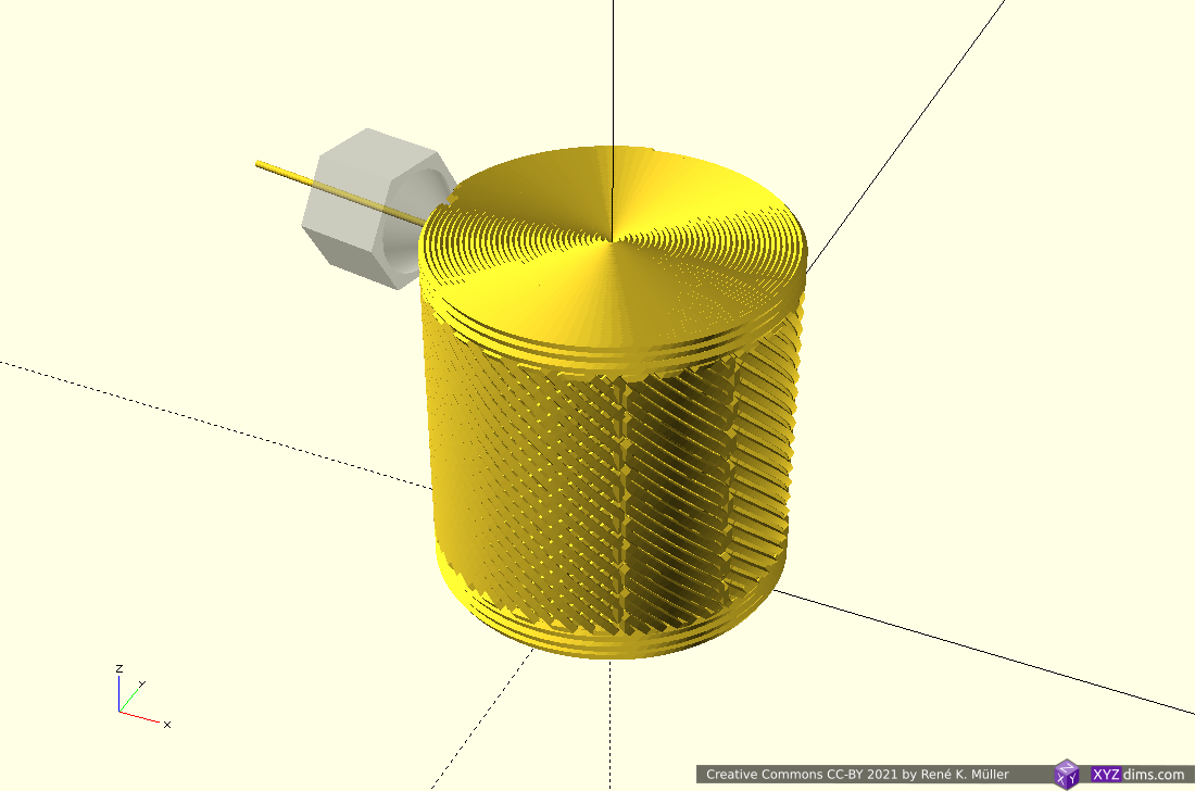
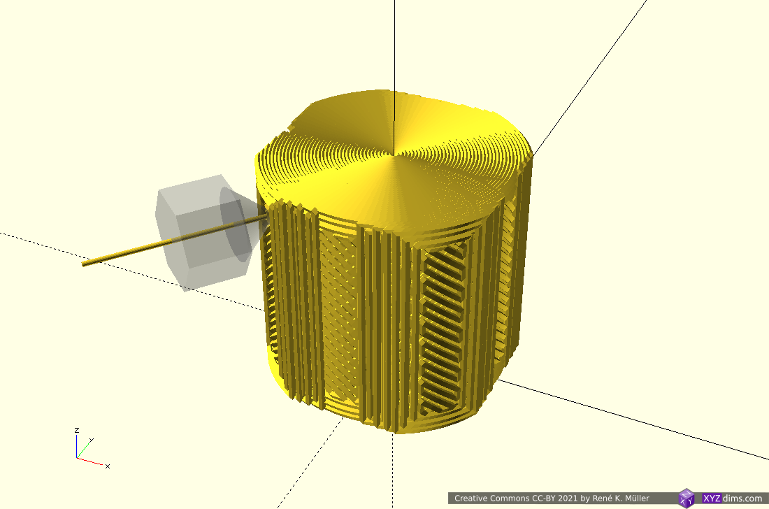
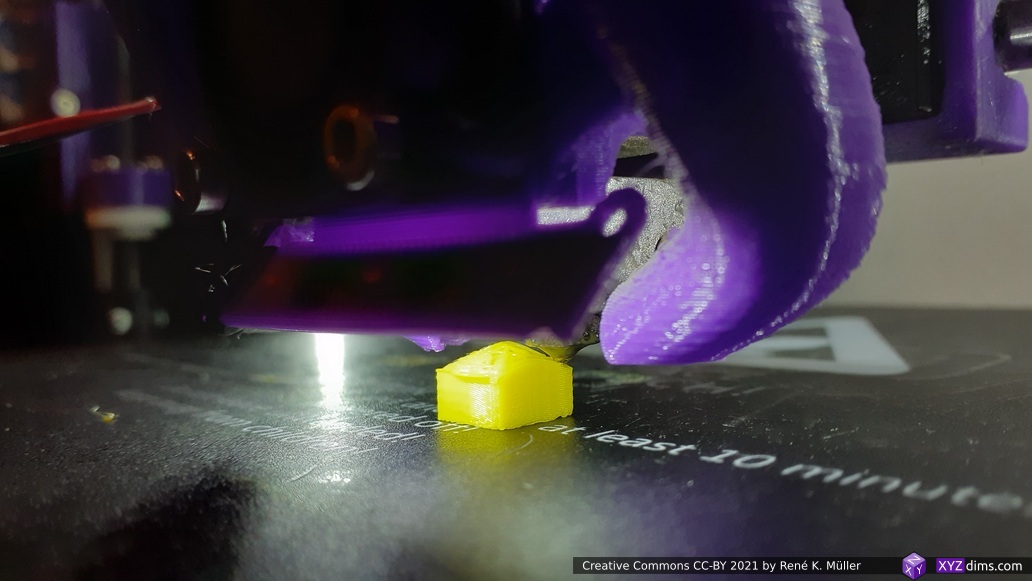
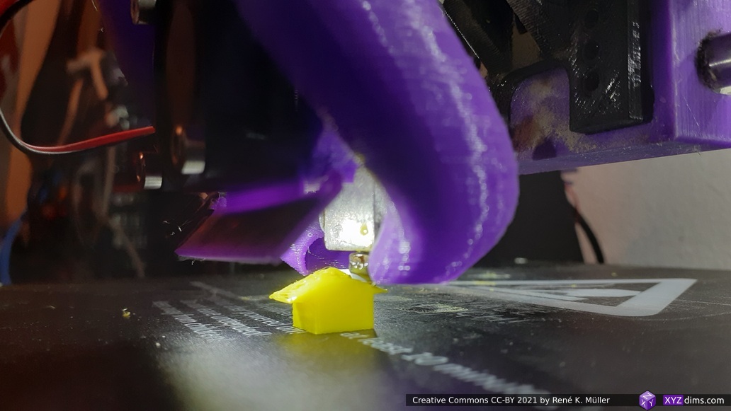
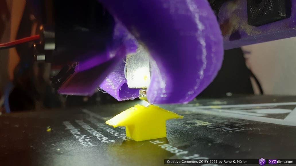
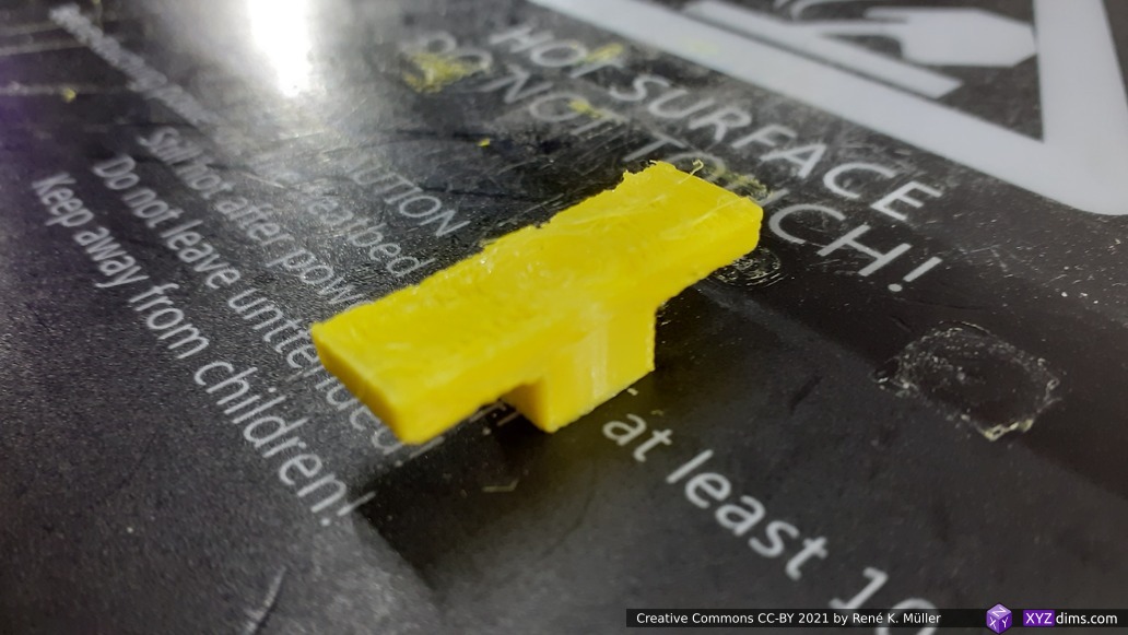
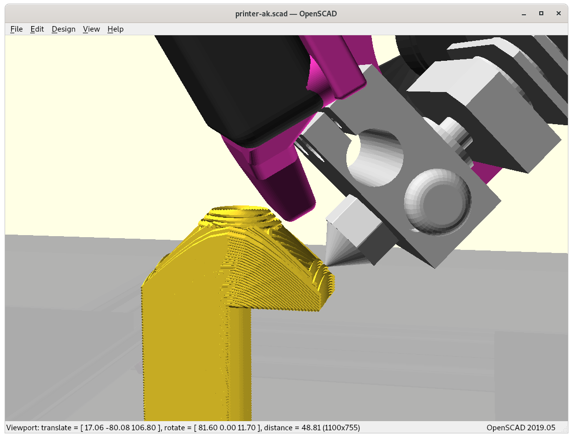
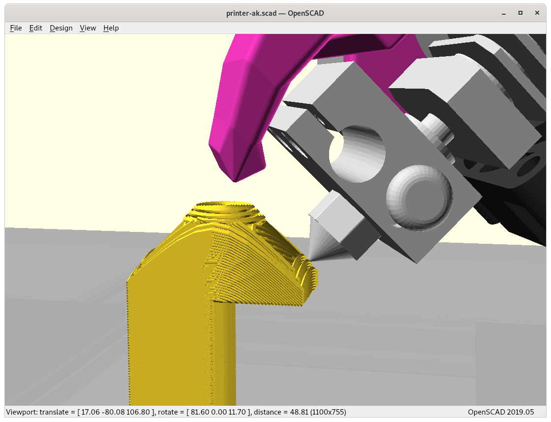
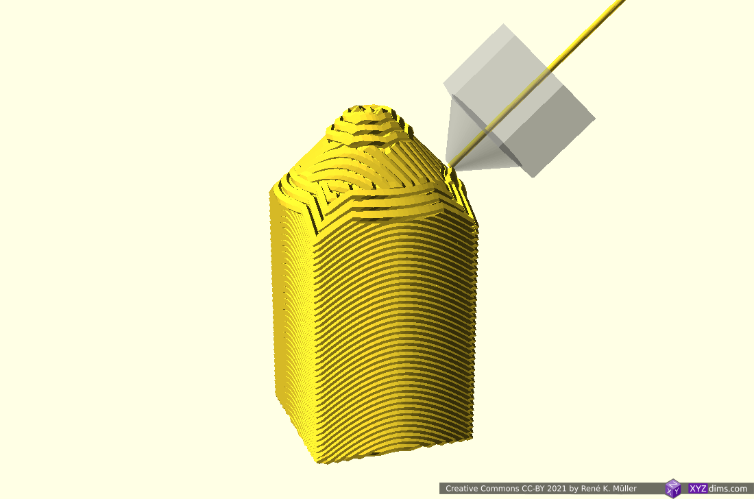
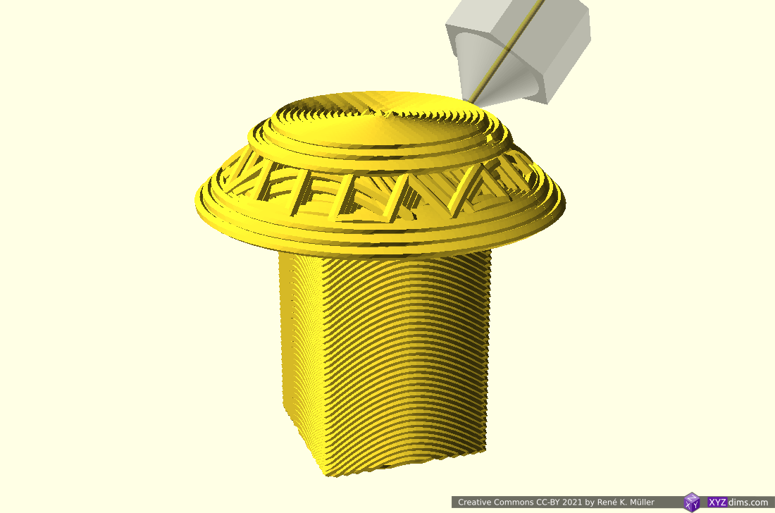
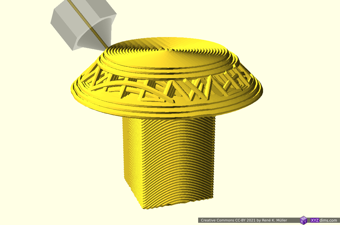
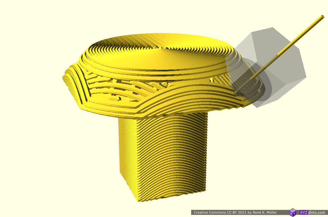
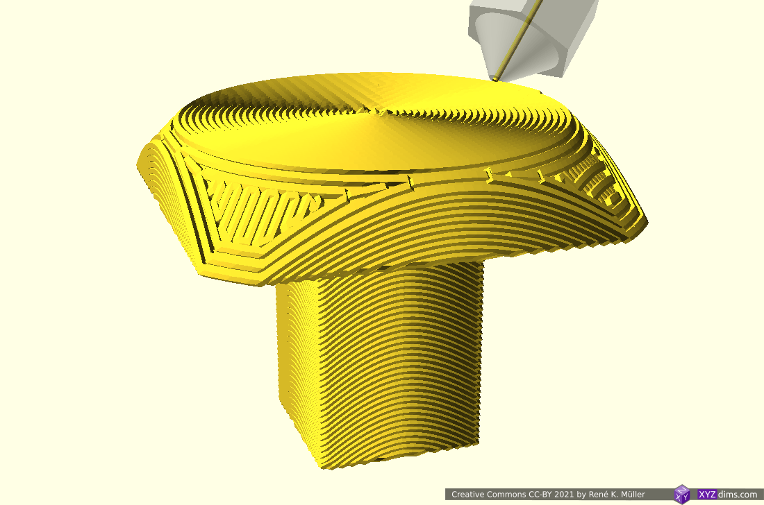
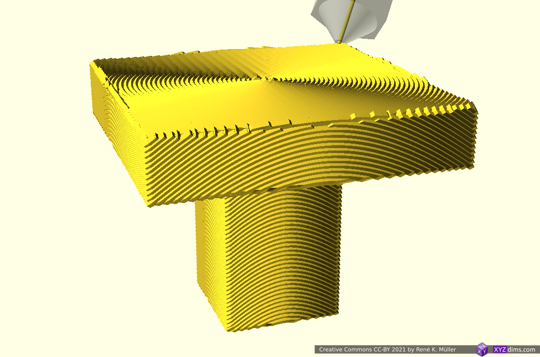
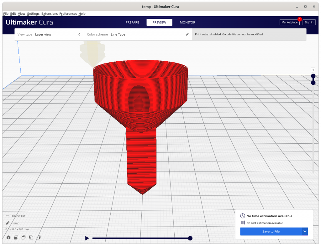
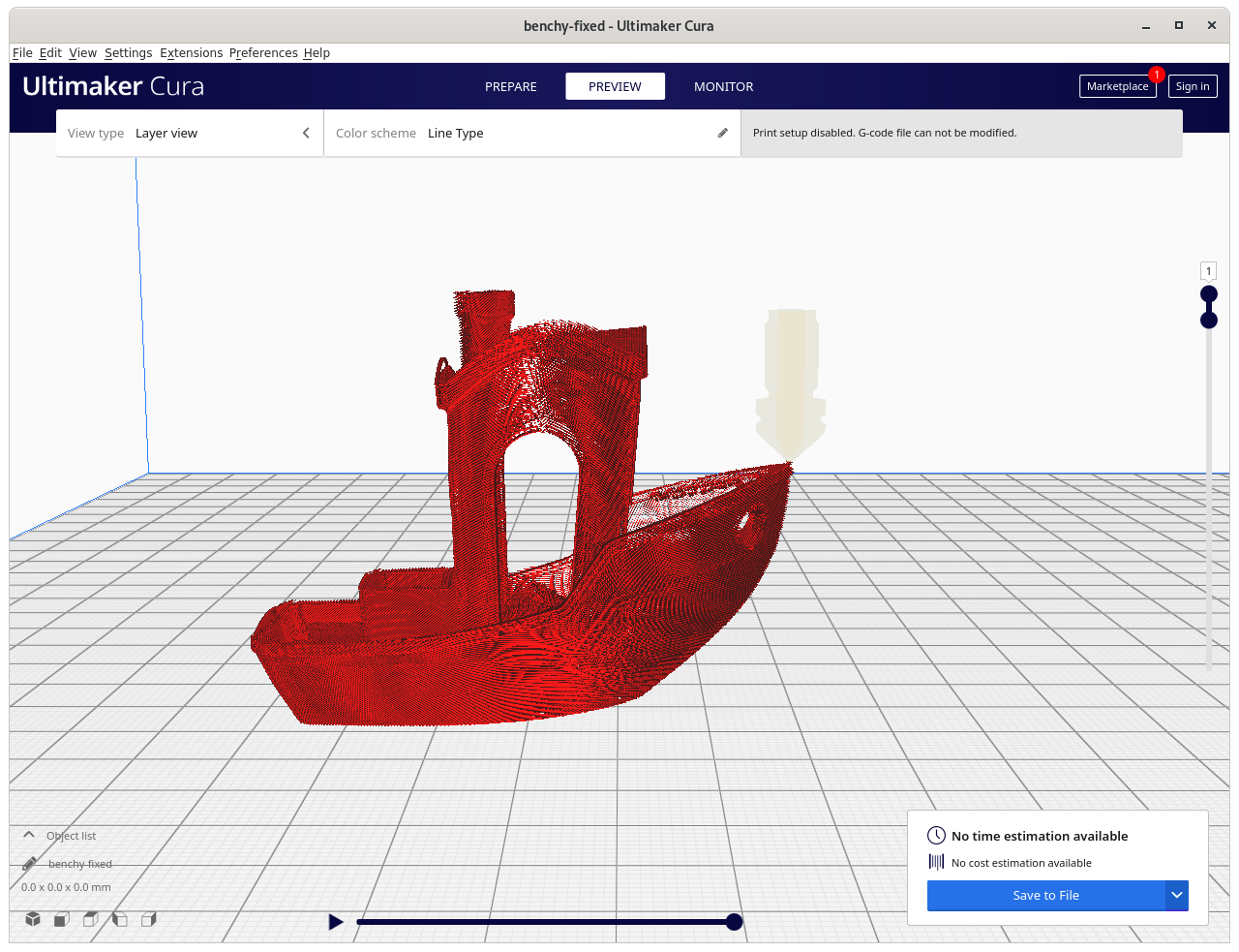
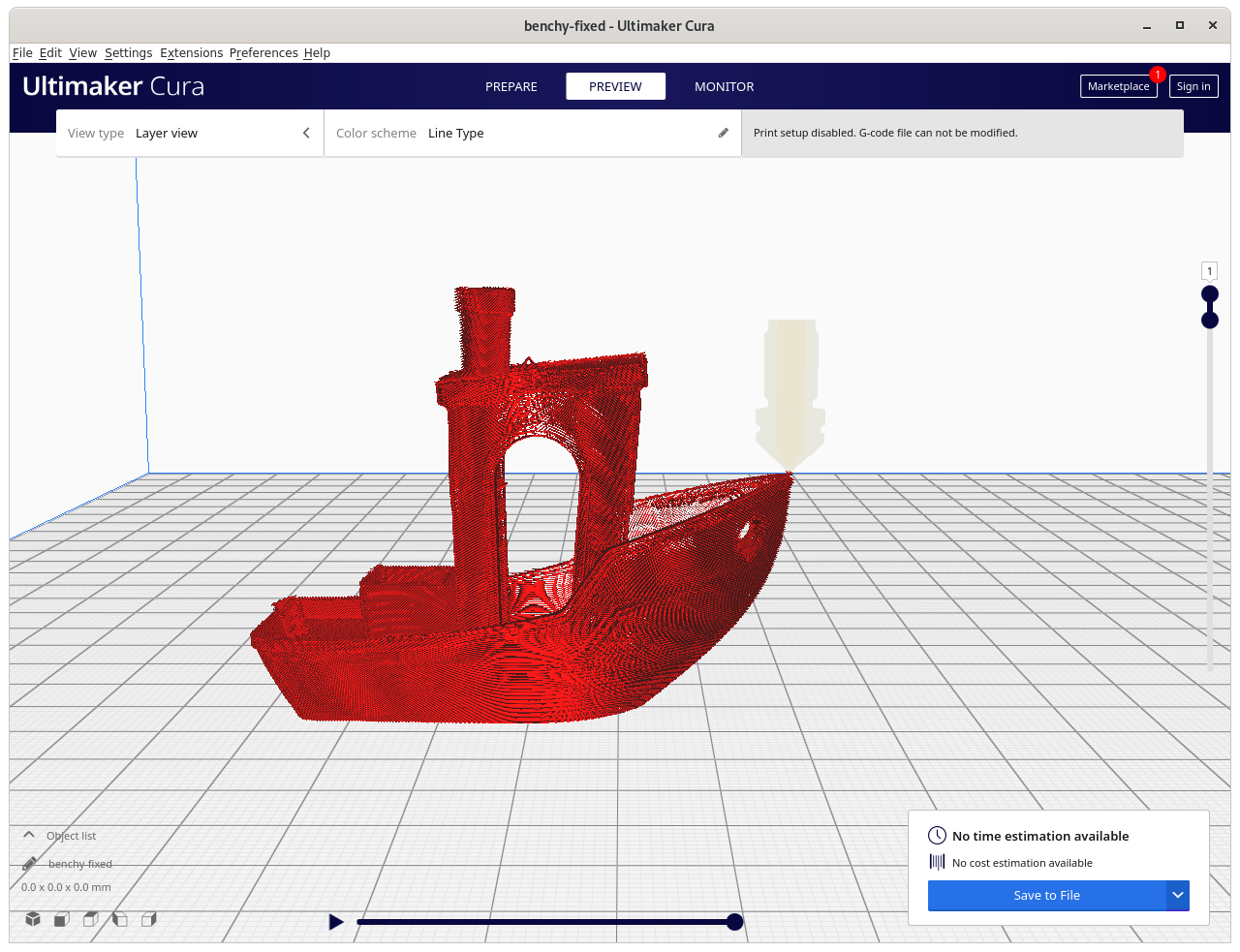
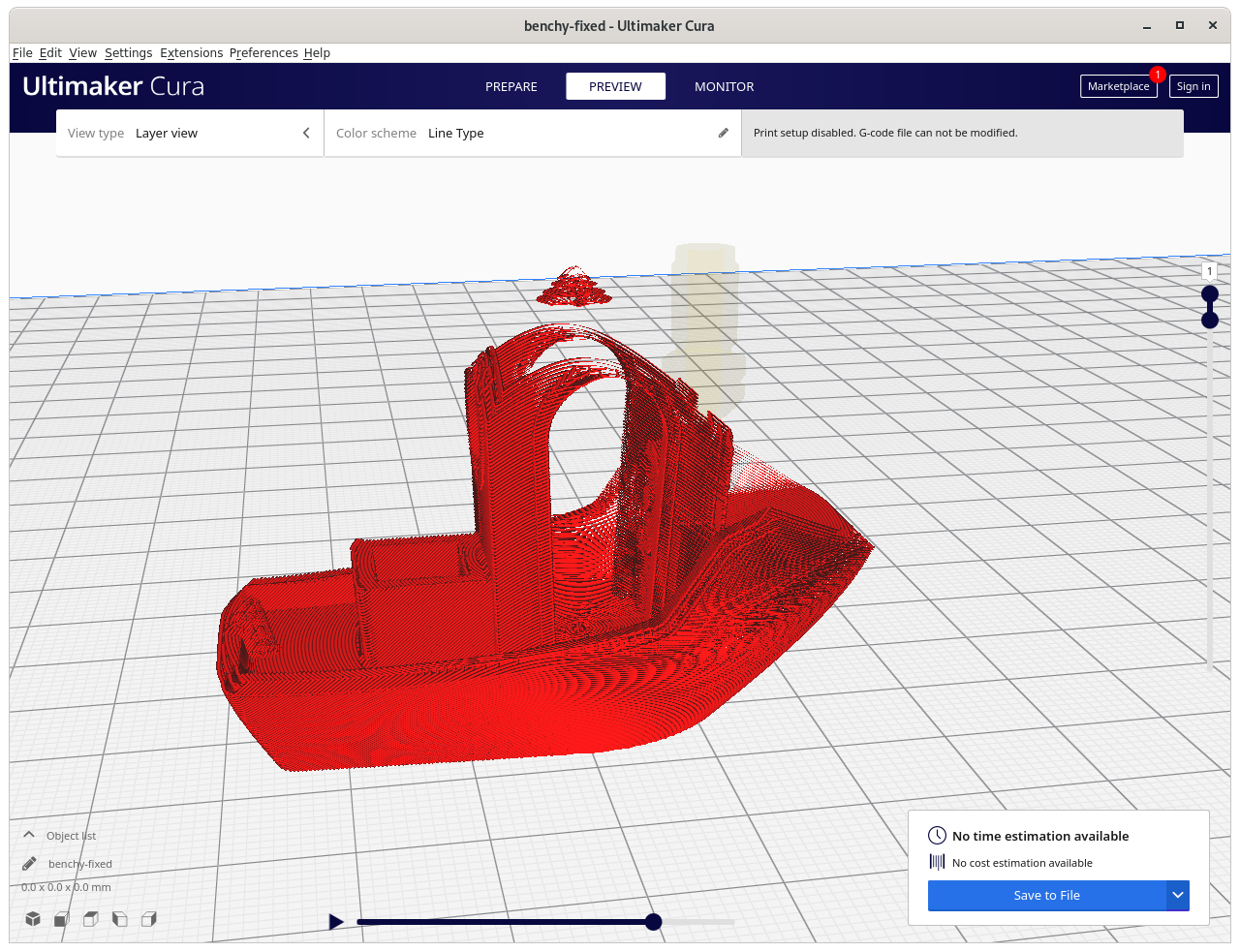
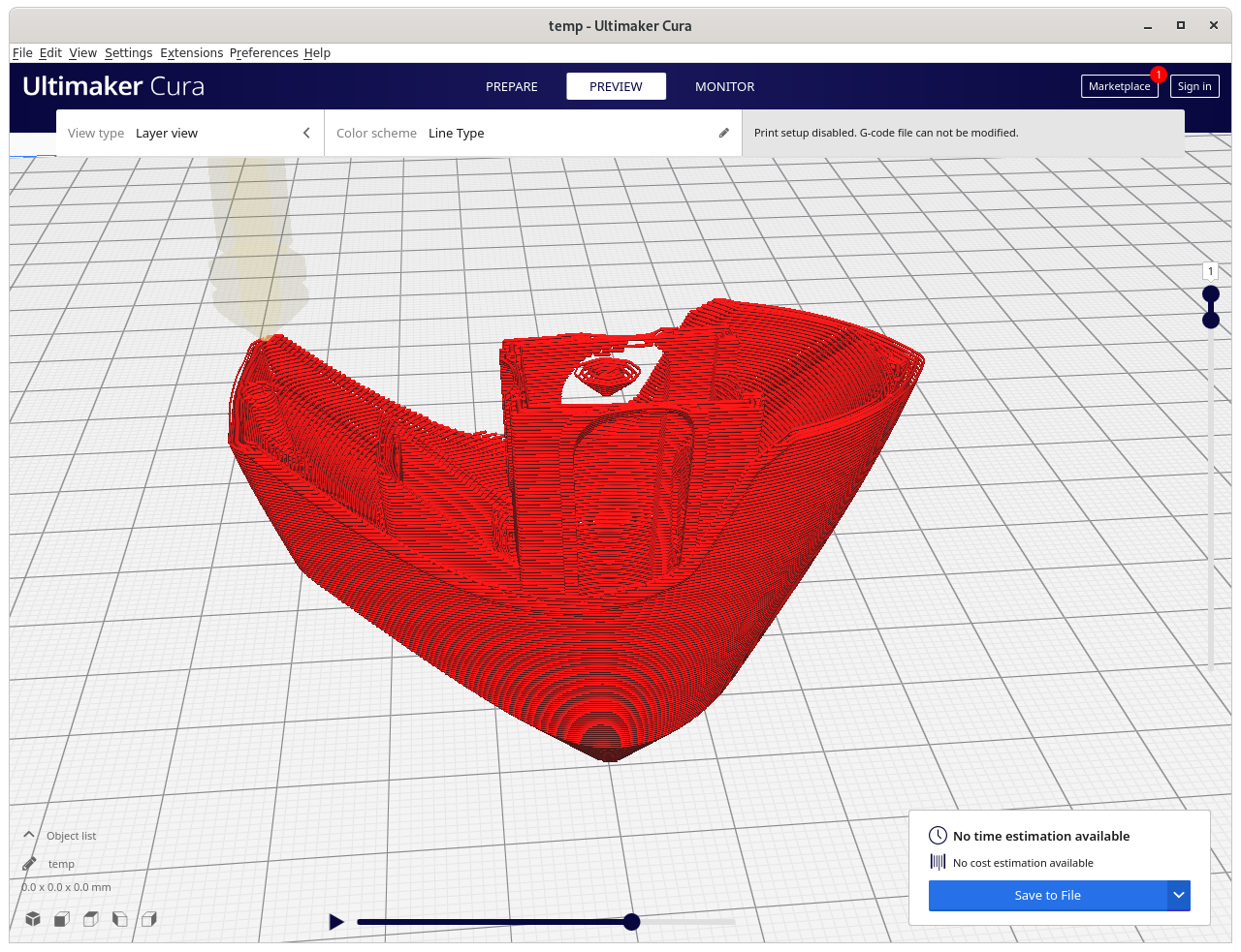
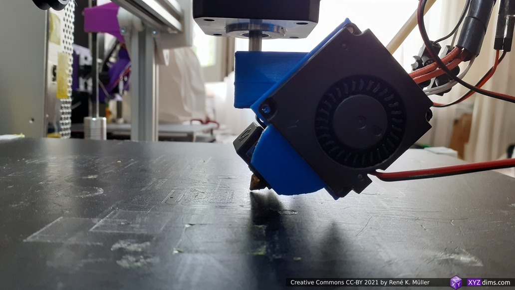
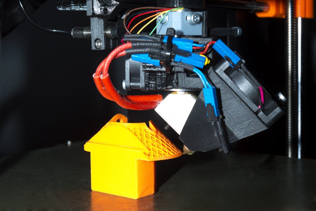
And yes you can print non-planar conic sliced G-code with an ordinary 3-axis 3D printer if you dare, something like this:
Just keep your expectation on the print quality low, as you try to print with a vertical nozzle which is meant to be printed with a tilted nozzle, but you will be able to print 90° overhangs without support structure.
% slicer4rtn
USAGE Slicer4RTN 0.4.4: [<opts>] <file.stl> ...
options:
-v or --verbose increase verbosity
--version display version and exit
-k or --keep keep all temporary files (temp.stl, temp.gcode)
--recenter recenter model X- & Y-wise
--subdivide=<n> set midpoint subdivisions (default: 2)
--mode=<mode> set cone mode, either 'outside' or 'inside' (default: 'outside')
--output=<fname> override default naming convention file.stl -> file.gcode
--axis=<axis> set axis count of printer: 3, 4 or 5 (default: 4)
--angle=<angle> set angle of cone (default: 45)
--center=<cx,cy> set conic slicing center (default: 0,0)
--bed-center=<cx,cy> set bed-enter, only affects output G-code (default: 100,100)
--layer-height=<z> set conic layer height (default: 0.2)
--rot-gcode=<v> set G-code symbol for rotation (default: A)
--rot-revolv=<mode> set rotation revolution, 0 = unlimited, 1 = once (default: 1)
--rot-offset=<a> set rotation offset (default: -90)
--rot-fixed=<angle> set fixed rotation angle, usable if --axis=3 but 4-axis or 5-axis printer is target
--tilt-gcode=<v> set G-code symbol for tilt for 5-axis operation (default: B)
--zoff=<v> set z-offset, will be added to G1 ... Z<v>
--erate=<f> set extrusion rate (multiplier, default: 1)
--efmin=<v> set extrusion factor minimum, (default: 0.01)
--efmax=<v> set extrusion factor maximum, (default: 3)
--inter-steps=<n> set interpolation steps per mm (default: 2)
--motion-minz=<v> set minimum Z level for motion (without extrusion) (default: 0.2)
--max-speed=<s> set maximum speed (default: 0)
--slicer=<slicer> set slicer (default: 'slic3r')
--slicer.<k>=<v> add additional slicer arguments, e.g. --slicer.infill-density=0
--<k>=<v> all other arguments not for slicer4rtn will be passed to the core slicer (slic3r)
examples:
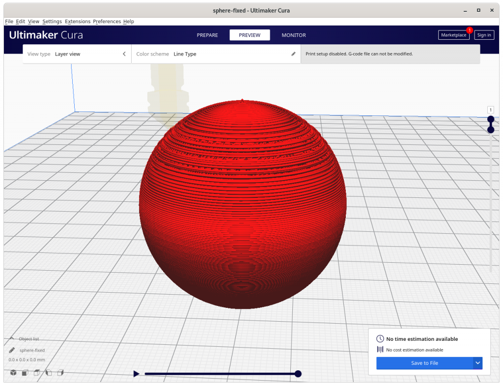
slicer4rtn sphere.stl
slicer4rtn overhang.stl --output=sample.gcode
slicer4rtn overhang.stl --axis=5 --output=sample.gcode
slicer4rtn overhang.stl --axis=3 --output=sample-belt-printer.gcode --fill-density=5
slicer4rtn model-6.stl --angle=25 --subdivide=5
Options
subdivide
By default the faces of model is 2x subdivided, you can turn it off by --subdivide=0 or increase like --subdivide=5 for a cube. The current algorithm depends on sufficient detailed faces.
original STLsubdivide=0subdivide=1subdivide=2subdivide=3subdivide=4subdivide=5
So for simple STLs choose subdivide=5 or higher, for already complex STLs with thousands of faces, you may go with the default.
recenter
If you slice a model you did not create yourself, very likely the model might not be properly aligned or centered, with --recenter you can enforce recentering the model X- and Y-wise.
mode
By default outside mode is used, you may change it with --mode=inside which slices for inside-cone printing. Currently slicer4rtn does not segment parts according their required mode, you have to do this manually right now. This may change with a later version.
mode=outside for outside overhangsmode=inside for inside overhangsVolume segmenting (not yet implemented): inside overhang printed in inside-cone mode, and outside overhang printed in outside-code mode
Needless to say, this mode switch is very basic and only makes sense for very simple models.
axis
By default G-code for 4-axis Rotating Tilted Nozzle (RTN) is generated (--axis=4), which includes rotational information.
--axis=3 generates tilted slices at angle 45° (which can be changed with --angle=..) which means overhangs can only be printed in one direction; the G-code can be printed with a 3-axis 3D printer now like a belt-printer; also --rot-fixed=.. one controls the direction of the tilt slicing
--axis=4 is the default, a 45° tilted nozzle is implied
--axis=5 adds an additional fixed tilt into the G-code like B45 and is printable on a 5-axis Penta Axis (PAX) printer
--axis=3--axis=4 for RTN--axis=5 for PAX
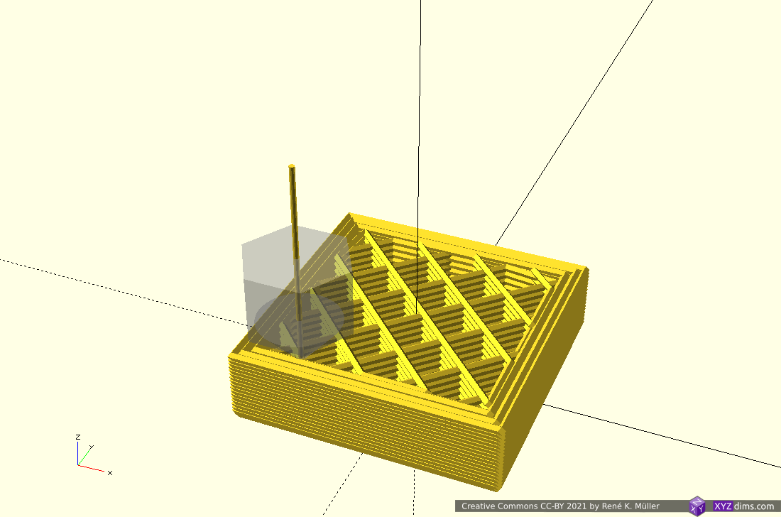
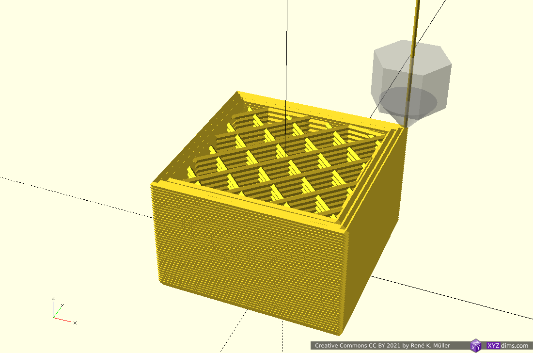
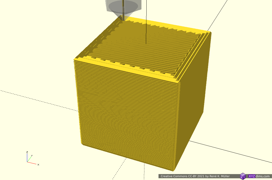
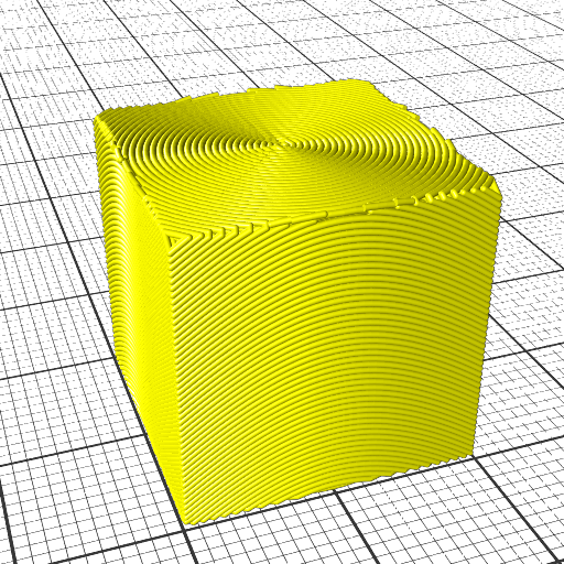
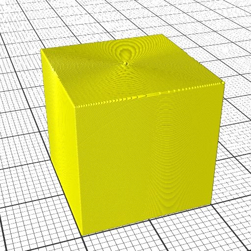
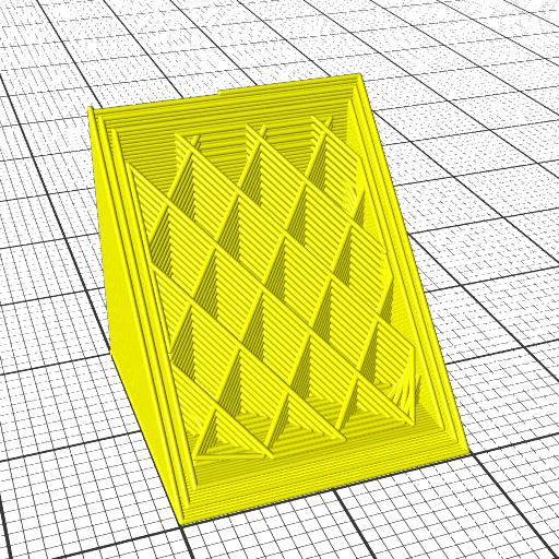
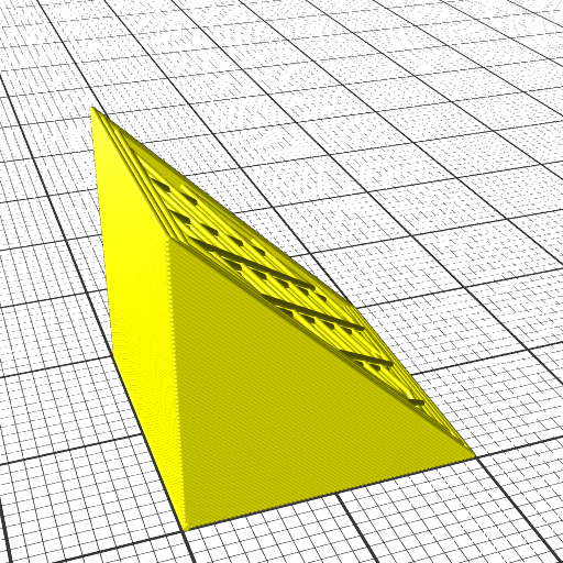
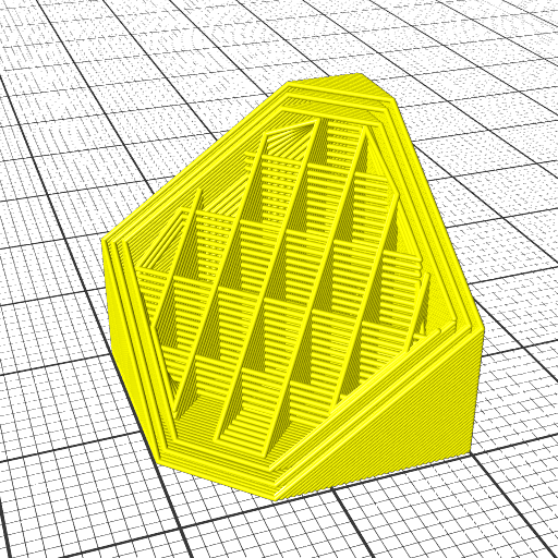
angle
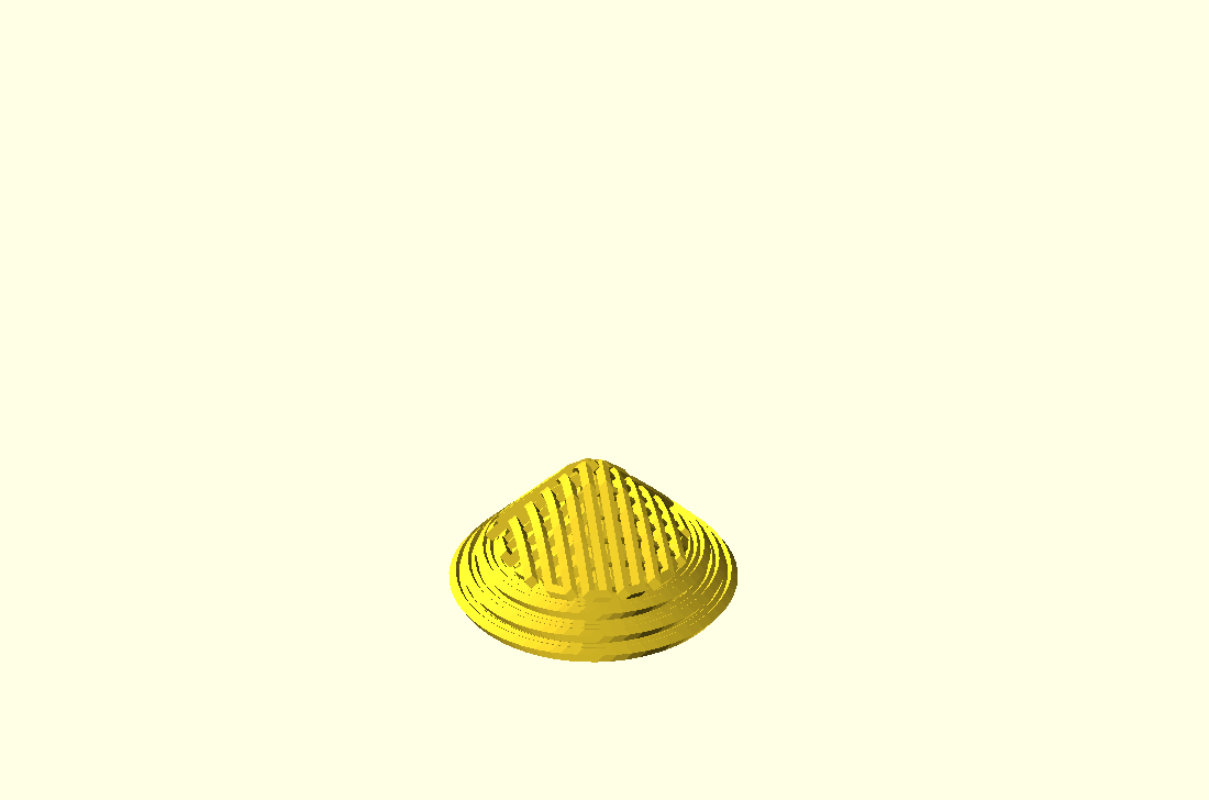
By default the conic angle is set to 45° and can be changed with --angle=.., e.g. for a 3-axis 3D printer the angle can be set to 15..25° to print conic slices with a vertical nozzle.
angle=45 (default)angle=30angle=2020mm cube conic sliced at 45°, printed with rotating 45° tilted nozzle (animated)20mm cube conic sliced at 20°, printed with vertical nozzle (animated)
You may use --recenter switch to force the model be recentered X- & Y-wise; this is recommended if you did not create the model yourself and the STL is not centered properly.
bed-center
The slicer final output will be offsetted by these coordinates, by default it is 100,100 which should work for most 3D printers.
layer-height
By default 0.2mm conic layer height is set, and can be changed with --layer-height=h [mm]
Note: the layer height for the core slicer is calculated and might exceed the hard limits of the core slicer, so reduce the layer height so that slicer4rtn doesn’t stumble.
rot-gcode
By default the rotational angle is passed to G-code with A and can be changed, e.g. the RotBot uses U in the firmware to process the rotation angle, hence using --rot-gcode=U
rot-revolv
By default the printhead can only revolve once (-180°..180°), hence --rot-revolv=1; a more mechanical complex RTN is the RotBot by ZHAW which permits unlimited rotations with a slip ring, then use --rot-revolv=0
rot-revolv=1rot-revolv=0 (unlimited)
Note: rot-revolv=0 resets at layer change the rotation angle to mod(360) again.
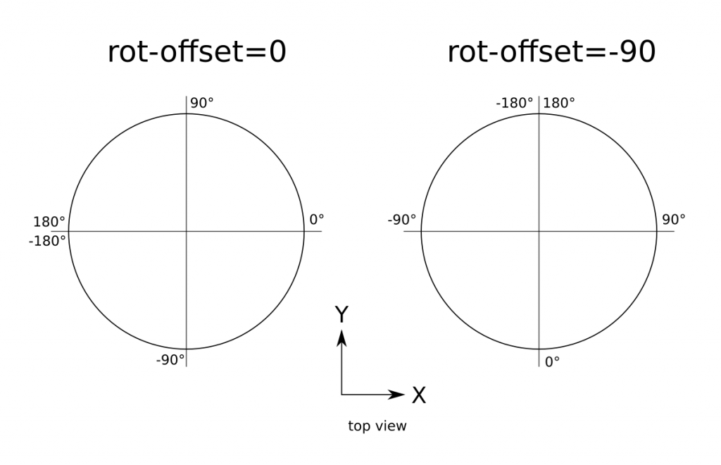
rot-offset
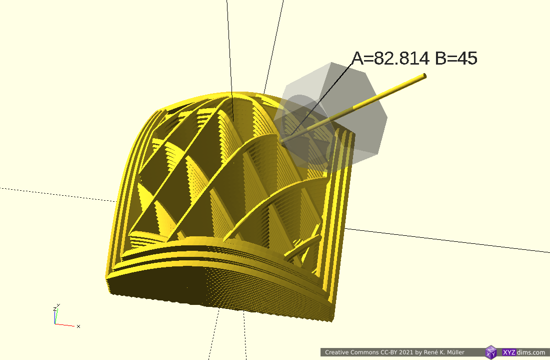
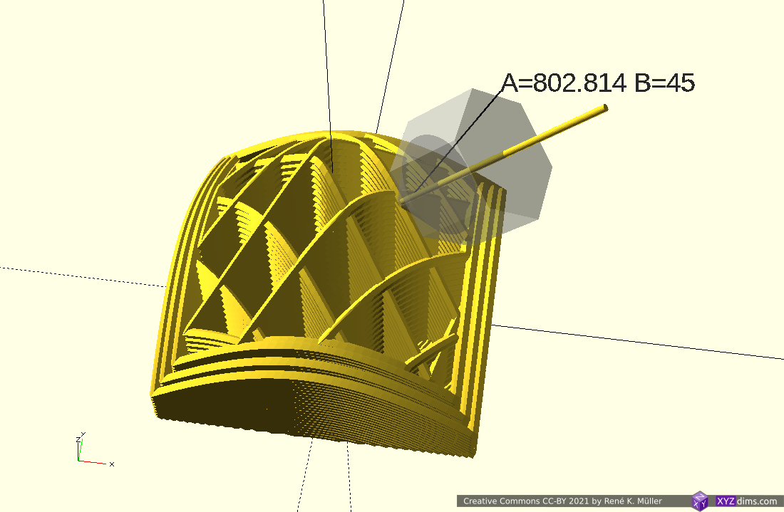
The rotation angle of the tilted nozzle is calculated by the traditional X/Y coordinate system; as I designed my Rotating Tilted Nozzle (RTN) I defined the 0° to be in front, and traditional counter-clockwise with increasing angle; so by default rot-offset is equal -90°.
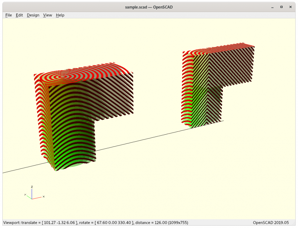
20mm cube conic sliced, printed with 4/5-axis nozzle, rot-offset=-90 rotation angle A, and tilt angle B shown
rot-fixed
In case you like to have non-rotating printing and single direction slicing therefore, then fix the angle with --rot-fixed=angle.
20mm cube 50% printed with axis=320mm cube 50% printed with axis=3 rot-fixed=9020mm cube 50% printed with axis=3 rot-fixed=-45
tilt-gcode
In case when targeting 5-axis Penta Axis (PAX)--axis=5 the tilt G-code is added as default as Bangle, you may change the code with --tilt-gcode=V for example.
erate
In case you have trouble with under- or over-extrusion you can change the multiplier with --erate=f for example to reduce extrusion by 10% use --erate=0.9
inter-steps
By default 2 steps per mm are interpolated per planar G1 extrusion, you may refine it by increasing it, e.g. --inter-steps=4; be aware it creates larger G-code outputs.
slicer
By default Slic3r (slic3r) is used as core slicer, an overview of current supported core slicers, selectable with --slicer=...
Slic3r 1.2.9 (slic3r): gives good results so far with minimal configuration ★★★★★
Prusa Slicer 2.1.1 (prusa-slicer): struggles to slice inverted conic models and fails to create G-code with a message like Empty layers detected, the output would not be printable. It may help to increase --subdivide=n, be aware of immense amount of faces ★★★★★
Mandoline (mandoline): fails mostly to slice inverted conic models, but could become relevant in later development ★★★★★
CuraEngineLegacy 15.10 (CuraEngineLegacy): outdated but surprisingly gives good results, easy to use on command-line ★★★★★
CuraEngine 4.4.1 (CuraEngine): gives good results, but is tedious to configure on command-line as requires base configuration in .json, which changes with each new version; it gives warnings & errors for small polygons but makes an effort regardless giving G-code (good behavior, better than Prusa Slicer) ★★★★★
Cura CLI Wrapper (cura-slicer): same as CuraEngine but easier to configure (allows to query hundreds of possible settings directly with cura-slicer (recommended)
Slic3r 1.2.9 performs reliable on 20mm cube and overhang nr 3 4mm model, and CuraEngine 4.4.1 gives excellent results as long layer-height is low (below 0.2), whereas older Cura 3.8.x struggles – so definitely use Cura 4.x series.
G-code Size
As conic slices range over X, Y and Z, the G-code becomes quite verbose compared to horizontal slices, for example20mm cube sliced both times with Slic3r 1.2.1:
horizontal slices: 152 KiB (4.7K G1 lines)
conic slices: 7,565 KiB (93.6K G1 lines)
which is a significant increase of 50x size of G-code and 20x more G1 statements.
Common Settings
By default
/usr/share/slicer4rtn/slicer4rtn.ini (system-wide) and
~/.config/slicer4rtn/slicer4rtn.ini (user)
are considered where all settings can be listed to provide new defaults for slicer4rtn, for example:
# my own settings:
layer-height = 0.15
bed-center = 120,100
rot-offset = 0
rot-resolv = 0
You can use ‘#‘ as a leading indication that the rest of the line is a comment and disregarded.
Note: It is recommended to only list slicer4rtn specific settings there, not slicer specific settings (see below).
Slicer Specific Settings
Each core slicer may have their own base settings, so you don’t need to add it everytime when calling slicer4rtn, so include them in your user settings:
User Slicer Settings
~/.config/slicer4rtn/slic3r.ini
~/.config/slicer4rtn/prusa-slicer.ini
~/.config/slicer4rtn/mandoline.ini
~/.config/slicer4rtn/CuraEngine.ini
~/.config/slicer4rtn/CuraEngineLegacy.ini
~/.config/slicer4rtn/cura-slicer.ini
Make your changes in those files, as they will not be overwritten when you upgrade slicer4rtn in the future, for example slic3r.ini:
external-perimeter-speed = 10%
Note: slic3r and prusa-slicer directly load their slicer specific settings from the file, whereas the other slicers the settings will be parsed by slicer4rtn and passed on via internal command-line execution.
System-Wide Slicer Settings
By default make install installs some base system-wide configs in /usr/share/slicer4rtn with the same filenames as mentioned above, those will be overwritten in future releases of Slicer4RTN, but your user settings will not be overwritten.
When running slicer4rtn is executed first are the system-wide configs loaded, then the user specifics.
Print3r & Slicer4RTN
As of print3r 0.3.2 or later slicer4rtn is supported as well:
.config/print3r/printer/<yourprinter>.ini and make a copy like .config/print3r/printer/<yourprinter>-rtn.ini add following lines:
slicer = slicer4rtn
# slicer4rtn specific seeting prepend 'slicer4rtn.' for settings, like:
# slicer4rtn.slicer = prusa-slicer
angle = 25
and alter the start-gcode line with increasing Z motion as well, e.g for my Prusa-i3 clone it has a M6 threaded rod, which means one revolution (200 full steps) 1mm Z motion, hence
start-gcode = ".....\nM203 Z6\n...."
increased Z motion speed to come close to X- and Y- speed, it creates more even extrusions, nicer prints.
Actual use with print3r goes then like this, my Prusa-i3 clone named y3228-rtn now:
it slices and forwards the G-code according your setup without the requirement to invoke slicer4rtn manually anymore.
References
RotBot by ZHAW, the inventors of the Rotating Tilted Nozzle (RTN) approach by Prof. Dr. Wilfried Elspass, Dr. Christian Jaeger, Michael Wüthrich, Maurus Gubser, Philip Bos and Simon Holdener
State: early draft, mostly simulations with a few tests with 3-axis printer only
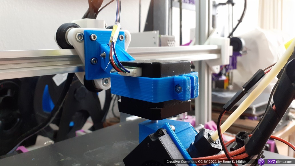
Conic sliced overhang model with two overhangs, printing with Rotating Tilted Nozzle (RTN) 90° overhang structure without support structure
Updates:
2021/09/28: added reference to paper by ZHAW describing slicing procedure
2021/03/22: slicer4rtn released, see dedicated page Slicer4RTN
2021/03/16: removing details on slicer4rtn as a new dedicated page is in the working (coming soon)
2021/03/08: slicer4rtn 0.2.3 reached (still unreleased), better prints, documenting various settings in more details
2021/03/05: added proper ZHAW reference in the introduction and a few notes
2021/02/27: removed some redundant illustrations and remade some of them, outside-cone vs inside-cone mode & printing
2021/02/26: added inside-cone printing example for inner overhang mode, also early information of slicer4rtn; more animations to observe details of produced G-code, using now also OpenSCAD to simulate G-code and actual nozzle position
2021/02/24: better tests with 20mm cube and overhang structure, included two short G-code simulations as videos, added 20mm sphere and 3D Benchy and discover first issues with volume decomposition and overhang recognition
2021/02/23: first write up, pseudo code and first attempt to conic slice 20mm cube
As I progress I will update this blog-post.
Introduction
The main idea is to utilize existing 3D printing slicers but create conic slices for the Rotating Tilted Nozzle (RTN) 4 Axis Printer. ZHAW published in their announcement in 2021/01 something about utilizing existing slicers, but the details remained concealed and later published as a paper but I did not want to wait and pondered on the problem, and came up with a solution. In its current state it’s purely theoretical and untested for now (2021/02)barely tested yet.
Michael Wüthrich confirmed my solution is comparable with their solution. ZHAW planned their paper to be published sometime 2021. So, the main credit goes to ZHAW and the researchers (Prof. Dr. Wilfried Elspass, Dr. Christian Jaeger, Michael Wüthrich, Maurus Gubser, Philip Bos and Simon Holdener) there, I was just impatient and tried to find a solution with the information available.
The 4-axis Rotating Tilted Nozzle (RTN) physical setup implies its slices are of non-planar conic shape, allowing to print overhangs without support structure, such as:
Conic slices of an overhang model
I also like to master the conic slices properly as they promise to become a subset of 5 axis printhead (PAX) features too – so it’s worth the effort even if the RTN itself might be too limited in its application with its fixed tilt – we will see.
function conicSpaceMapping(cx,cy,x,y,z,dir='direct') {
   dx = x-cx;
   dy = y-cy;
   d = sqrt(dx*dx + dy*dy);
   rot = atan2(dy,dx);
   return (x,y,dir=="direct" ? z-d : z+d,rot);
}
Pseudo-Code
The entire procedure goes like this:
m = loadModel("cube.stl");
m = subDivide(m,5);
for(p of m.vertices) {
    m.vertices[i] = conicSpaceMapping(cx,cy,p.x,p.y,p.z,'inverse');
    i++;
}

gcode = sliceModel(m);

foreach(line of gcode) {
   (code,x,y,z,e) = extractCoordsExtrusion(line);
   (x1,y1,z1,zrot) = conicSpaceMapping(cx,cy,x,y,z,'direct');
   outputGcode(code,x1,y1,z1,e,zrot);
}
Note: the pseuco-code is incomplete as extrusion E is not yet taken care of, as soon I found a definitive solution I will write it up.
Examples
I implemented the pseudo-code with some more details like taking care of G-code E extrusion as well and fine-step linear extrusion – here some early tests using OpenSCAD as STL & G-code viewer and Slic3r as actual slicer:
find good pre-processing face sub-division strategy
in its current form the algorithm requires fine-grained sub-divided faces otherwise inaccurate G-code is created which cannot be recovered
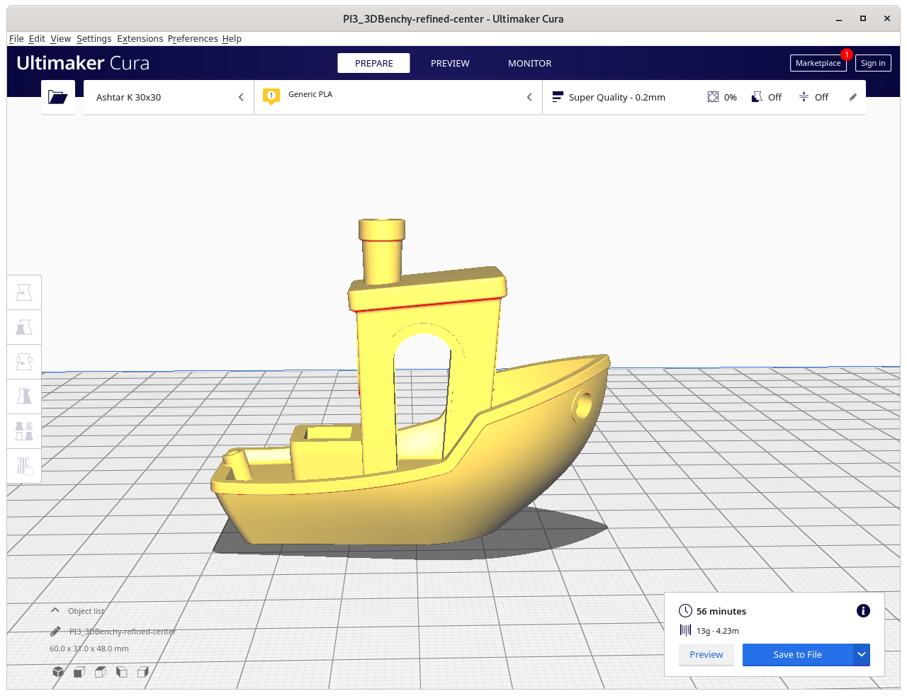
3D Benchy conic sliced with Original Faces
3D Benchy conic sliced with Refined Faces
slice more complex parts
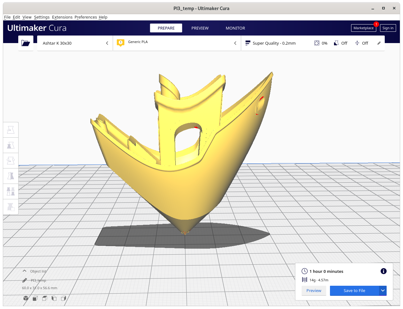
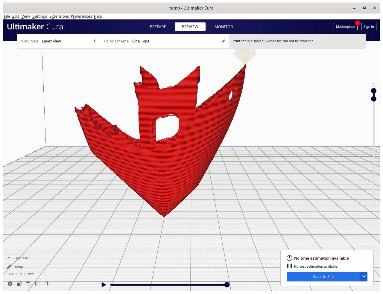
3D Benchy: requires more thorough examination, e.g. volume decomposition to segment roof apart:
Impossible printing: current conic slicing needs to recognize overhangs and apply volume decomposition to choose right strategies – otherwise new issues arise which in Z planar slicing do not exist
Same G-code position of the Inverse Conic sliced model: > 90° overhang created, and causes in-air structure – might require actual support structure (!!), volume decomposition required
document all details
release source code to public
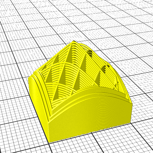
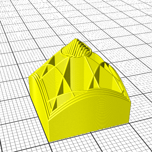
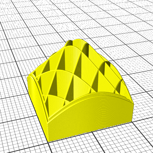
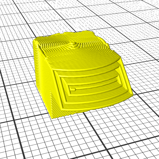
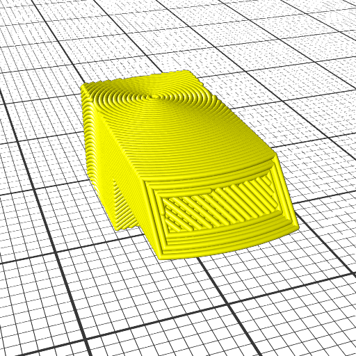
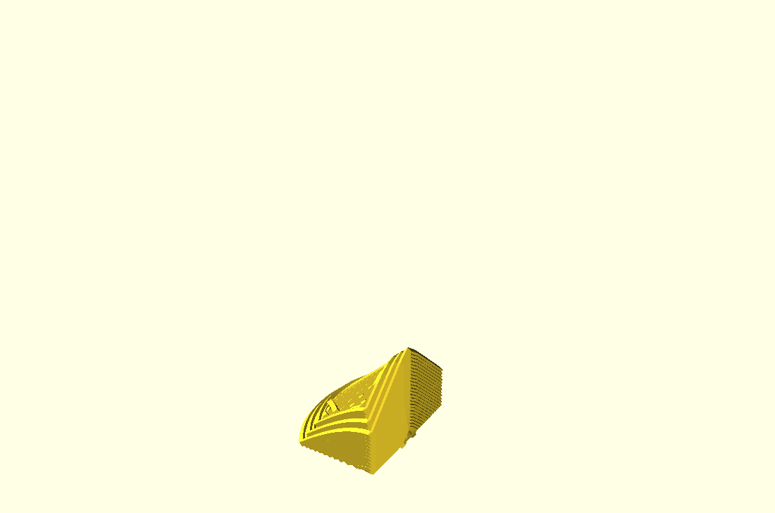
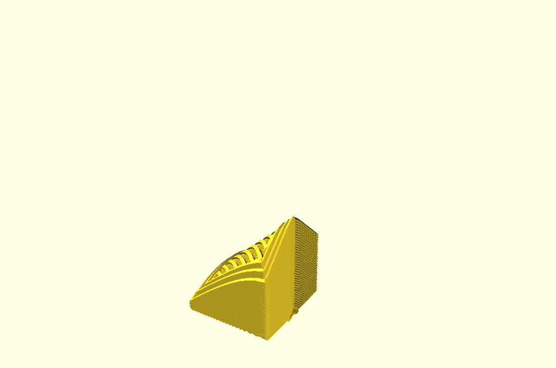
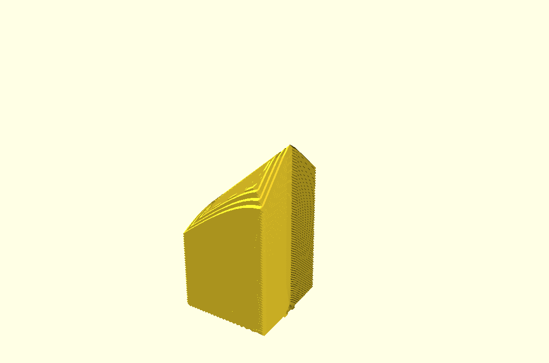
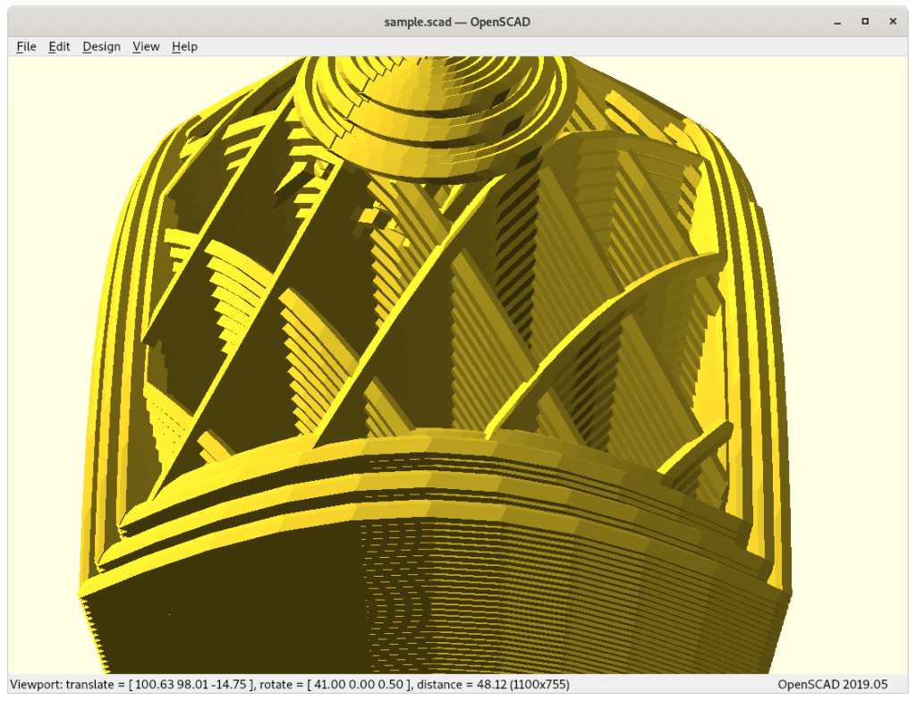
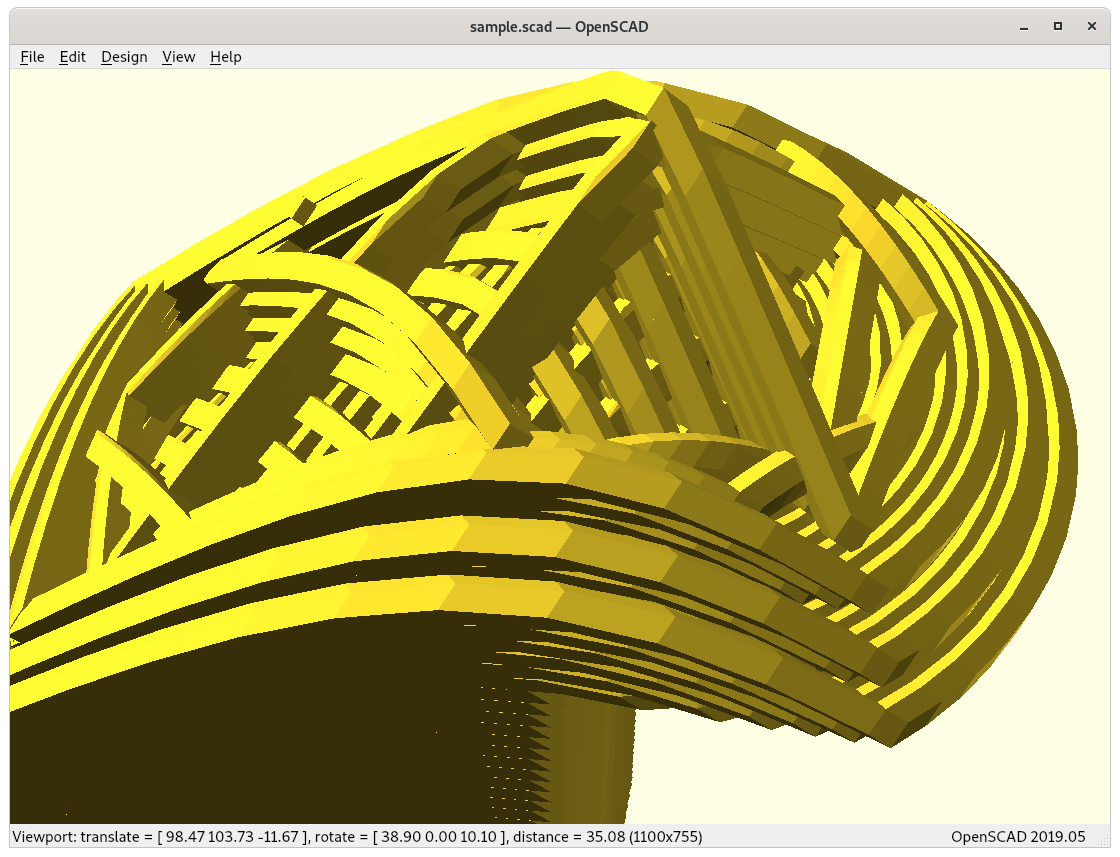
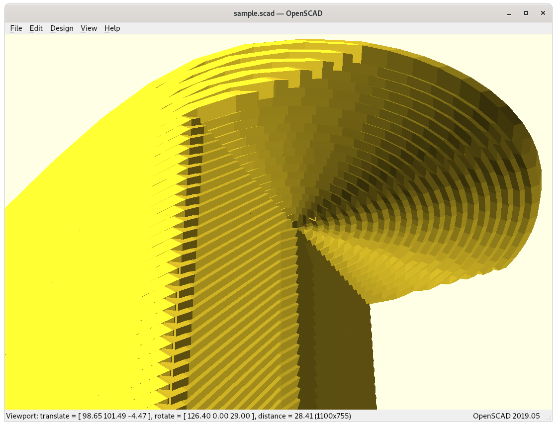
Close-Ups
Some close-ups of conic sliced models:
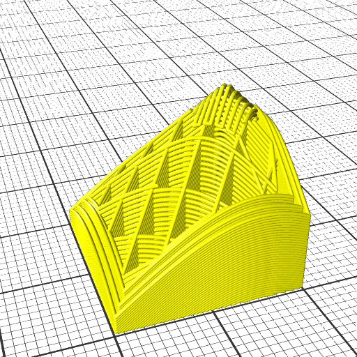
20mm cube (partial)
3D Benchy (roof & chimney)
3D Benchy (cabin)
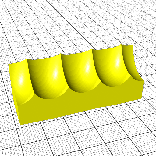
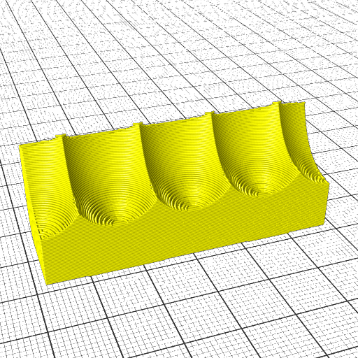
Overhang model (top view)
Overhang model (view on actual overhang)
Outside- vs Inside-Cone Printing
As pointed out in the previous blog-post, the RTN has two main modes of operation, outside-cone and inside-cone printing to cover outside overhangs and inside overhangs – the slicer must recognize those and switch operation mode. Further, these two modes cannot easily be mixed, and need to be segmented or separated, hence speaking of volume segmentation.
Outside Cone printing
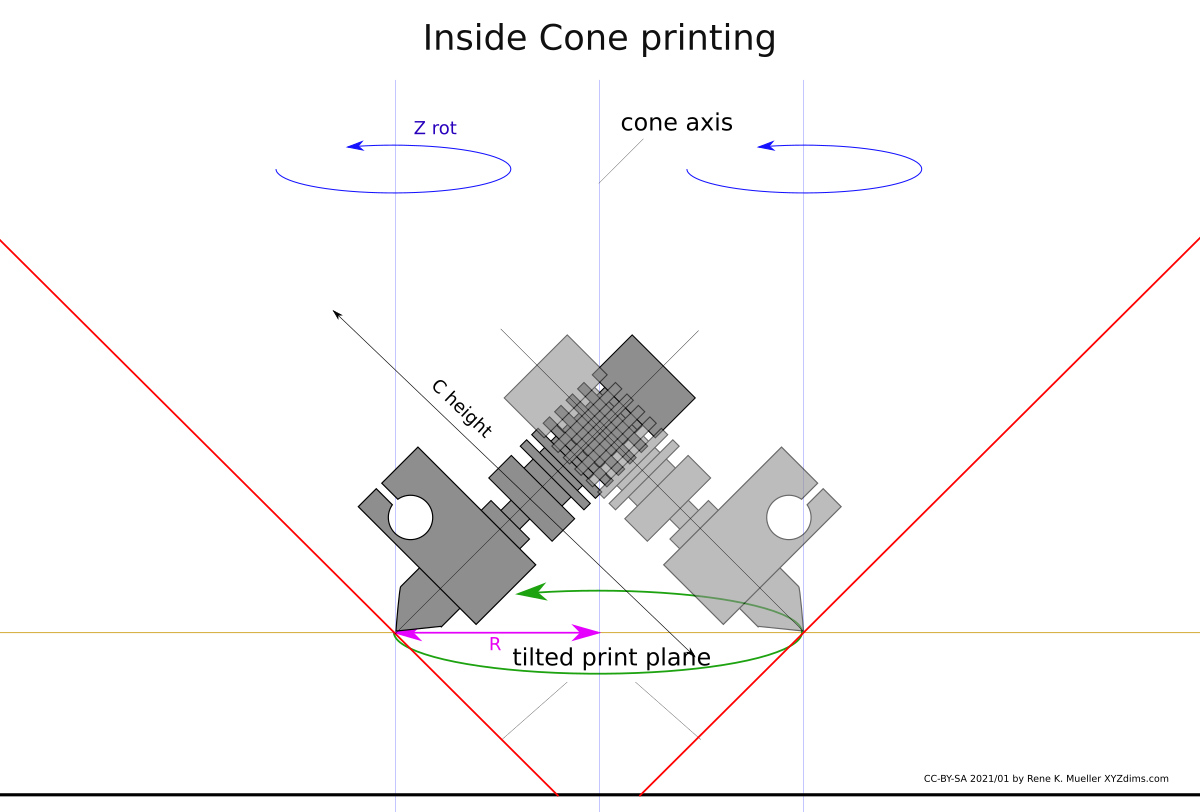
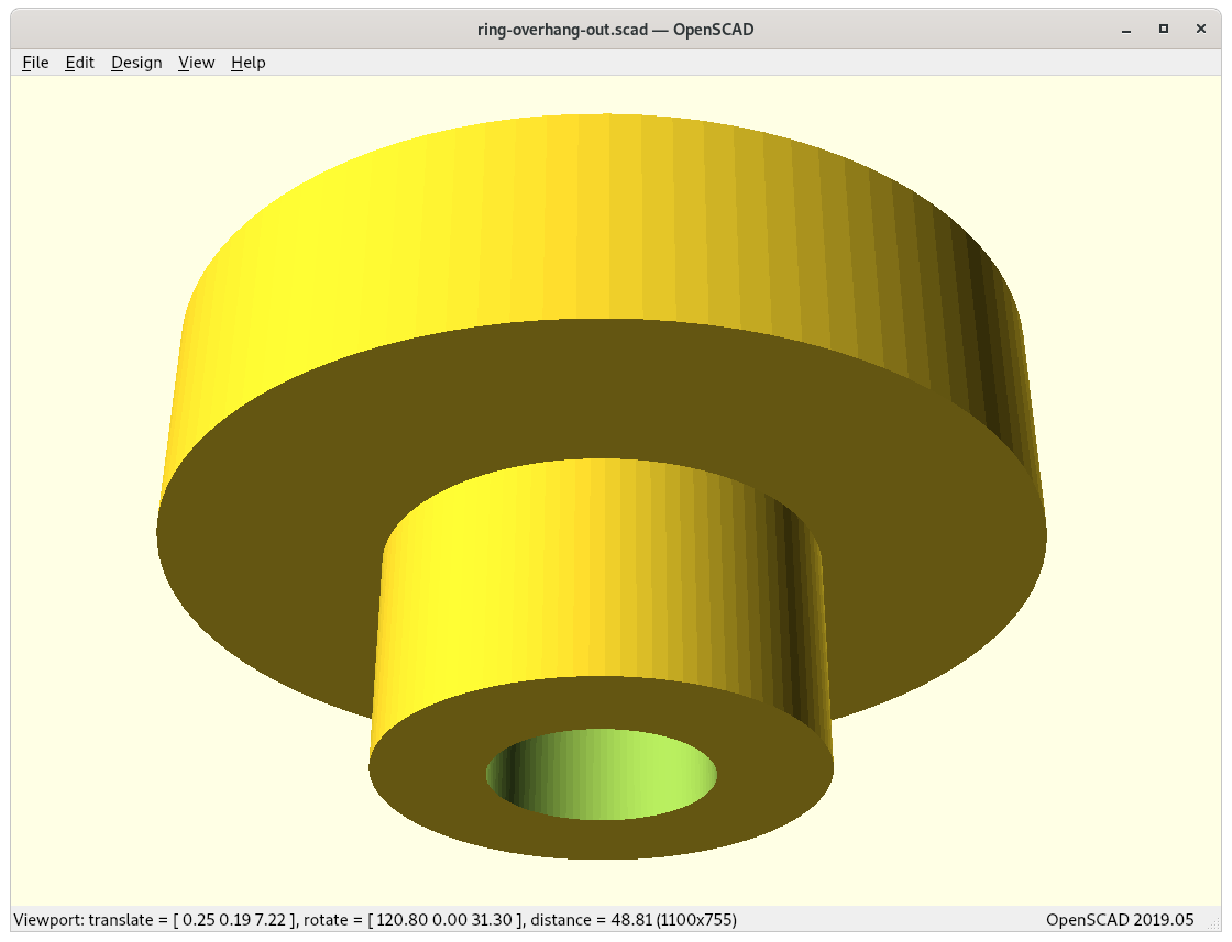
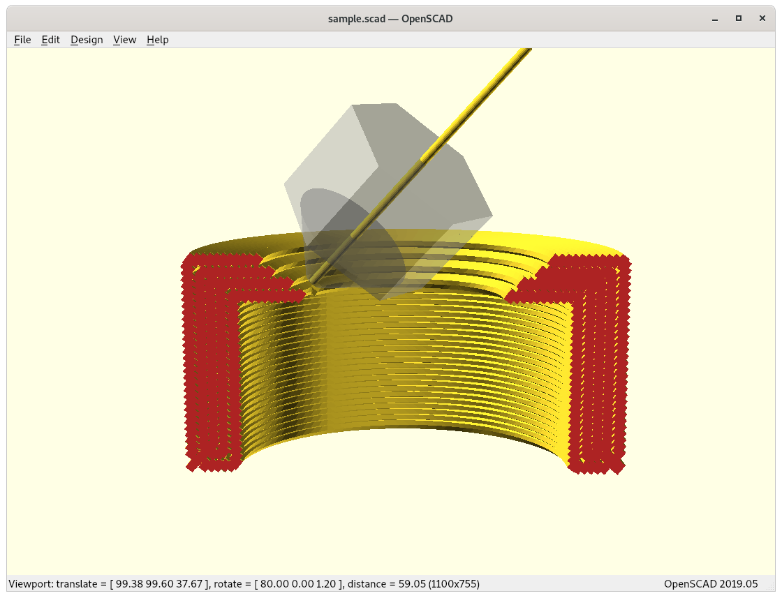
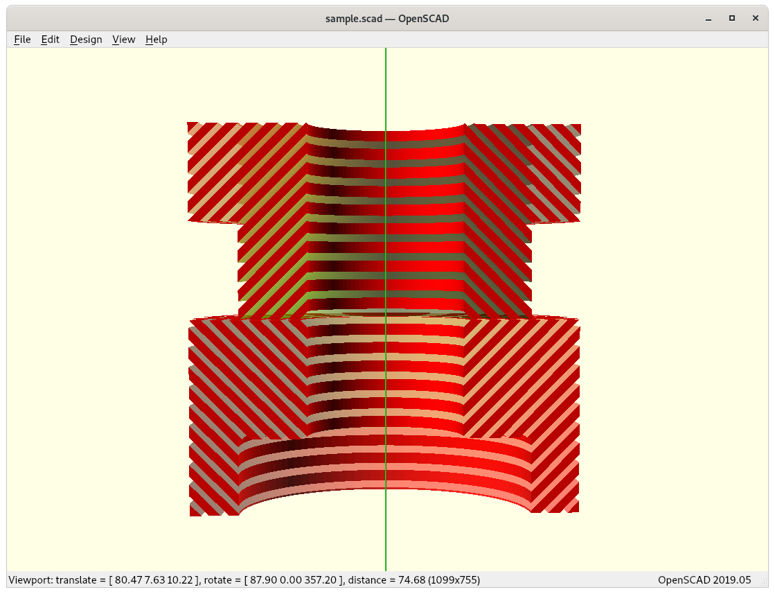
Inside Cone printing
outer overhang
inner overhang
outside-cone printing for outside overhangs
inside-cone printing for inside overhangs
Inside cone for inner overhangs (bottom) vs outside cone for outside overhangs (top)
This poses significant grow of complexity from just planar slicing, the 4-axis RTN provides features to print 90° overhangs without support structure, but only when the part can be properly analysed and segmented so that those operational mode can be applied.
The difference between inside- and outside-cone printing is to change the order of conic mapping for the model and post slicing:
outside-cone mode
map model inverse conic
slice model
map G-code direct conic
inside-cone mode
map model direct conic
slice model
map G-code inverse conic, Zrot + 180°
Slicer4RTN
The pseudo-code turned into an actual application I named slicer4rtn and is a command-line tool, slicing STL into G-code:
I gonna released Slicer4RTNeventually 2021/03/22, in its early version the model currently can only be sliced for outside-cone or inside-cone printing, so the volume decomposition or segmentation needs to be done separately. For now it helps me to verify some of the 4-axis and 5-axis printer designs I work on.
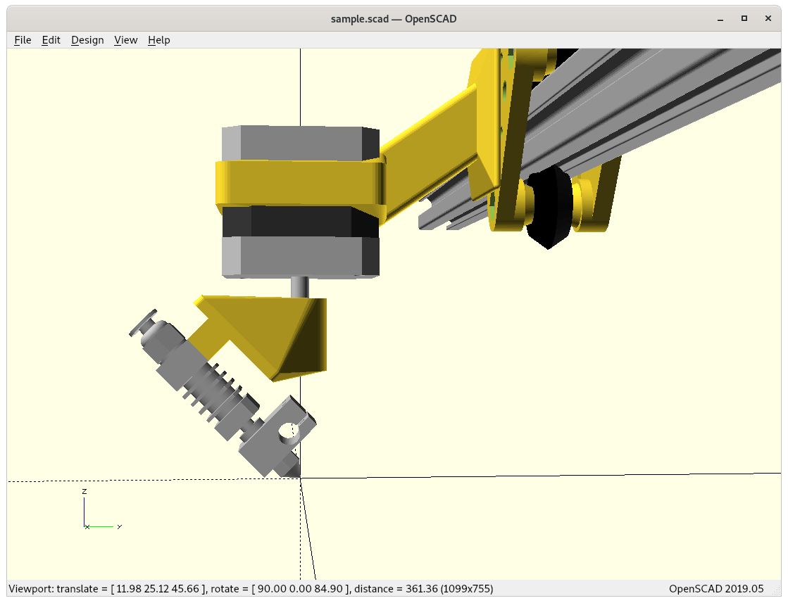
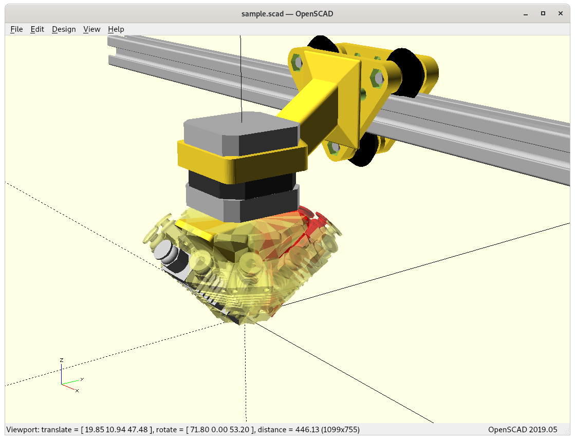
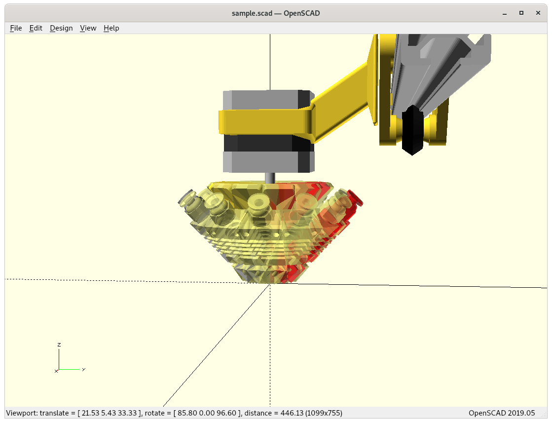
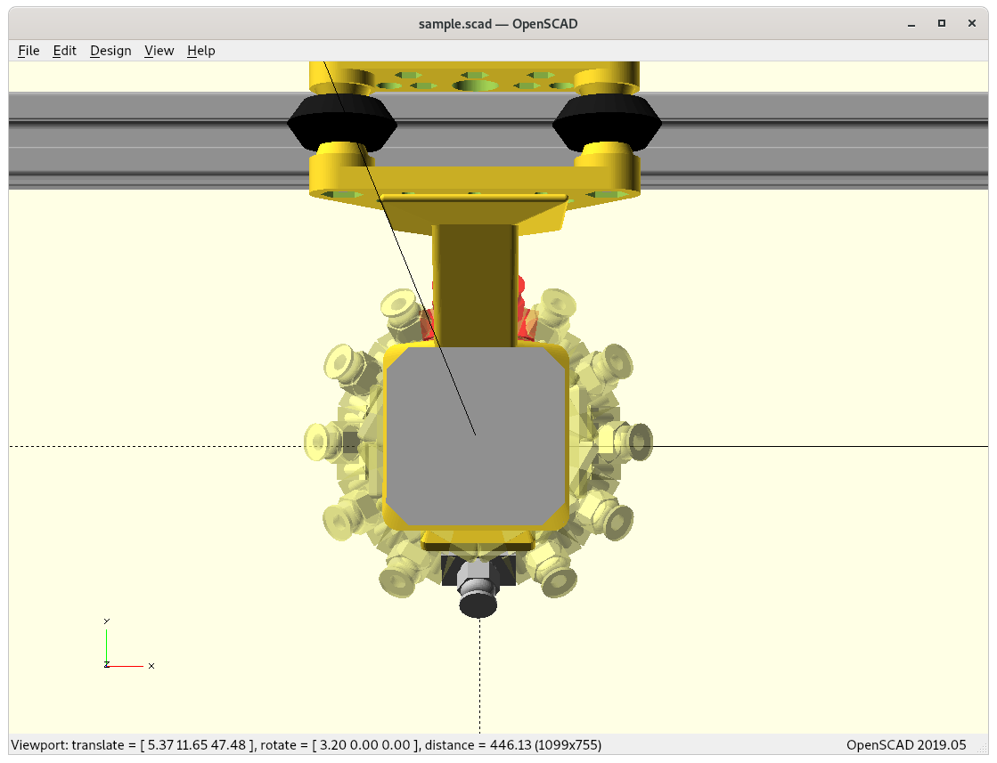
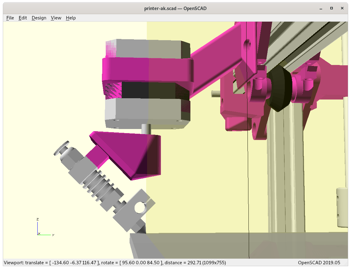
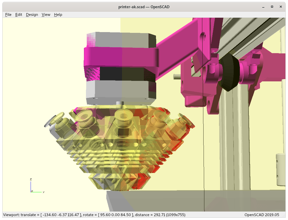
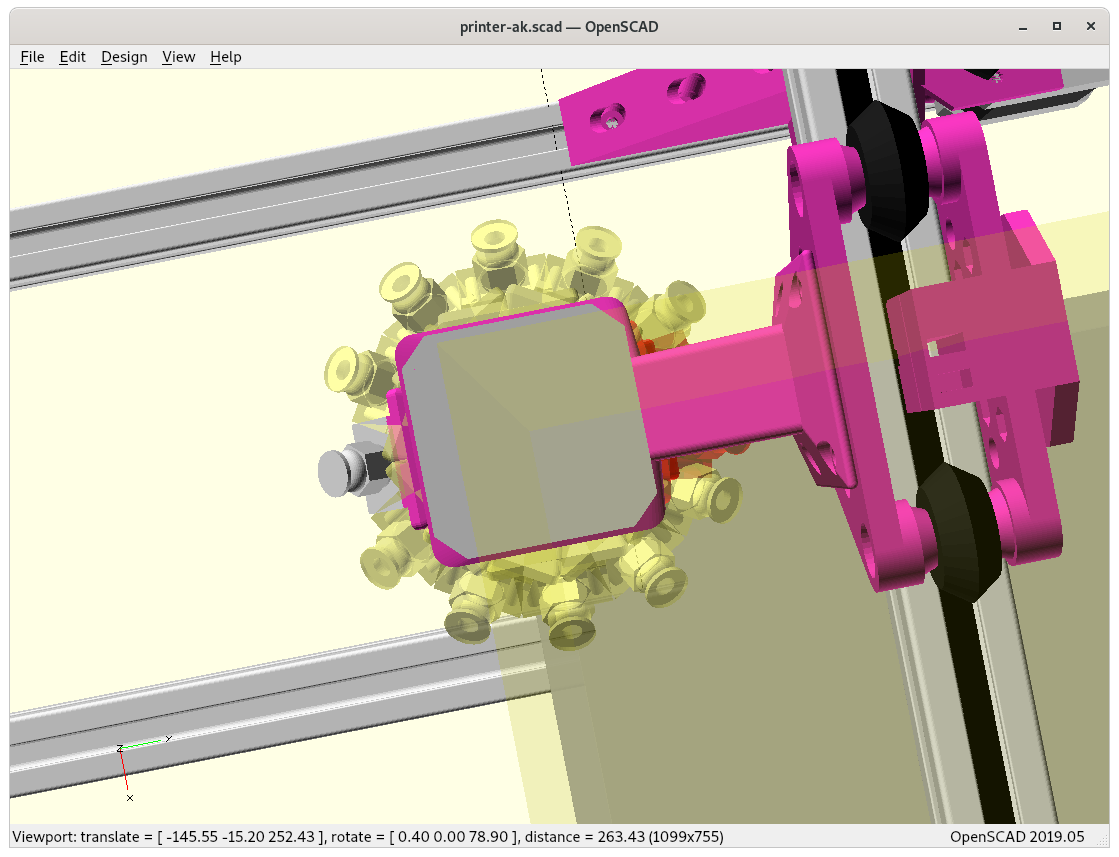
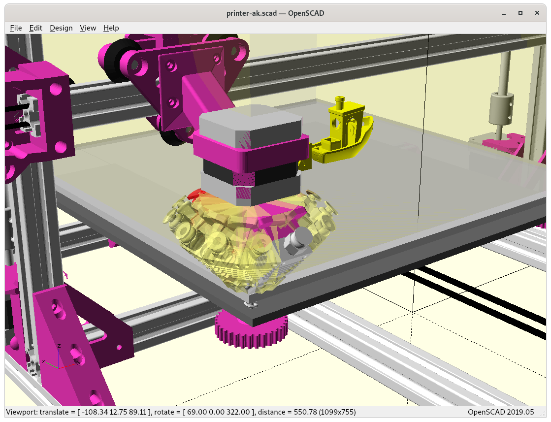
Ashtar K RTN printing conic sliced 20mm cube (close up, animation)Ashtar K RTN printing conic sliced overhang model without support structure (close up, animation)Ashtar K RTN printing conic sliced overhang model nr 6 (table-like) without support structure (close up, animation)
RotBot by ZHAW, the inventors of the Rotating Tilted Nozzle (RTN) approach by Prof. Dr. Wilfried Elspass, Dr. Christian Jaeger, Michael Wüthrich, Maurus Gubser, Philip Bos and Simon Holdener
[..] a novel 4-axis FDM printing process with a newly designed printhead, for the printing of overhangs without support structures. With conventional FDM printing, overhangs of more than 45deg–60deg must be supported.
For this novel printing process, the printhead is rotated 45° around a horizontal axis and equipped with a vertical, rotational axis. The printhead no longer follows layers parallel to the build platform, but moves on the surface of a 45deg cone. The printing cone increases in diameter from layer to layer. With this cone-shaped layers, the printable angles increases by 45°, which leads to printable overhangs of up to approximately 100°.
New slicing strategies for this printing process have been developed to slice the parts for the novel printing process. The feasibility of the concept has been prototypically demonstrated. The novel design achieves the advantages of higher speed and quality with lower cost at the same time.
A brief video sequence of printing (YouTube) shows the machine movement. Unfortunately, as of 2021/01 not much more details have been published by ZHAW except a paywalled paper [sigh] which contains useful overview of their research. I contacted ZHAW and Michael Wuethrich mentioned that they are in negotiations with different companies to develop a product (2021/01) and eventually release the details of their slicing approach with pre- and post-processing while using an ordinary slicer.
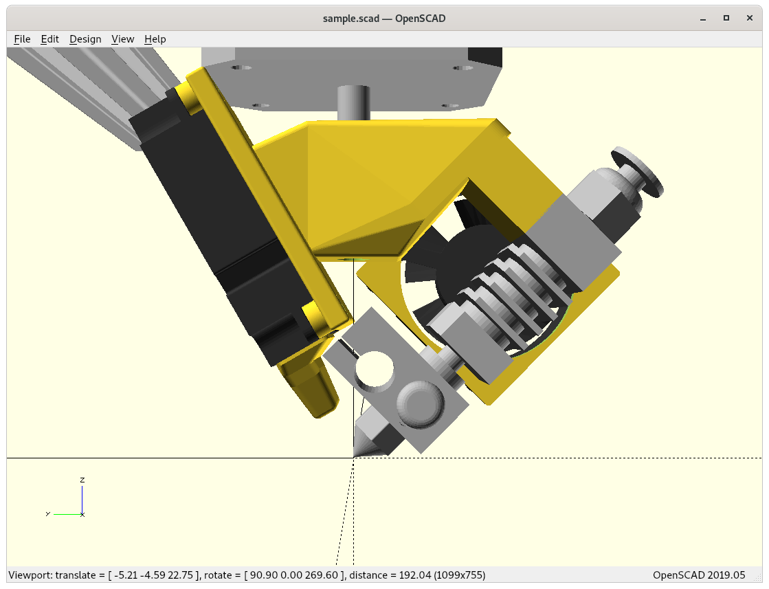
I thought to try my own implementation of this Rotating Titled Nozzle 4 Axis option. The main idea to keep the entire hotend in Bowden style and rotate that around only once (non-continuous) with all wires, that would simplify things greatly:
45° titled nozzlerotating 45° tilted nozzlerotating 45° tilted nozzleat 0° rotation positionyet no space for bowden tube at -180° or +180°… therefore to make some distance.. with proper mount
The challenge is the +/-180° position when the nozzle opening looks forward, where the printhead bowden tube (and all cables) comes most close to the X beam. As a consequence only -180° to +180° rotation is allowed and not multiple revolutions.
It would also mean, once the printhead reaches -180°, and it has to rotate to +180° and decrease from there again to fulfill 360° rotation – whether this is suitable has to be seen, this likely creates a seam there.
The main advantage of this simplified 4 axis approach is to use existing pieces plus just an additional NEMA 17 motor.
Update 2021/01/26: Wuethrich from ZHAW mentioned that they started first also with a full printhead rotating but then switched to the more complex continuous rotating printhead to avoid a seam, have direct drive extruder, faster prints as simpler decision making to change rotation direction and no start/stop of rotation and de/acceleration when reaching -180/+180° position.
Single Revolution with Rotation Shadow
As I pondered on the limits of single rotation approach, there is a range where the bowden tube (and all wires with it) is touching and bending on the X carriage or printhead holder – let’s call it the rotation shadow – ideally it would be zero or slightly sub-zero to have a bit overlap to conceal a possible seam with “ironing” the section (move nozzle over section without extruding).
E3D Volcano
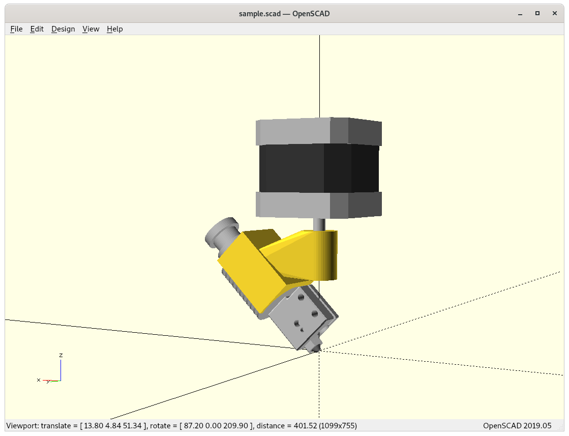
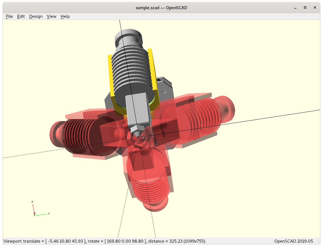
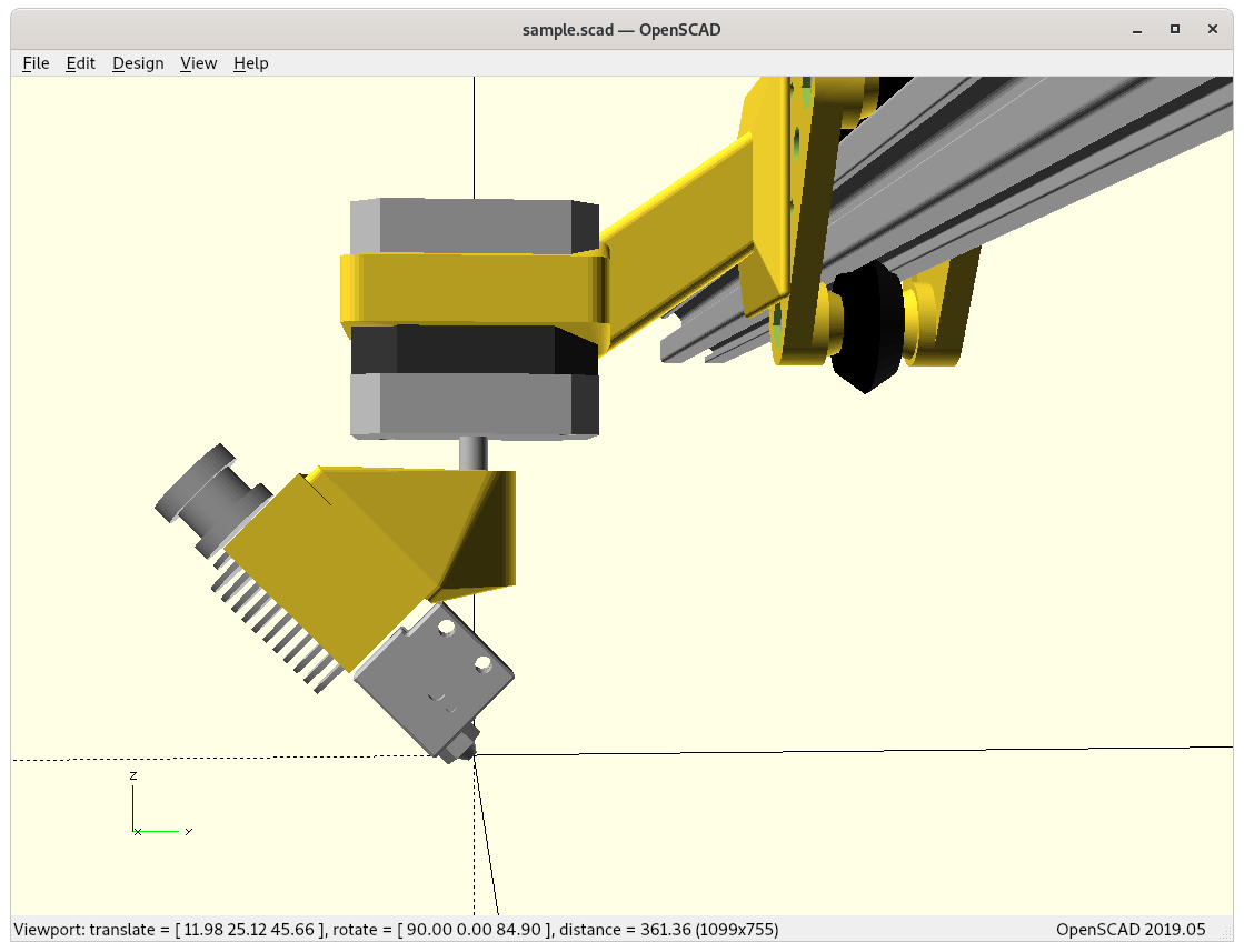
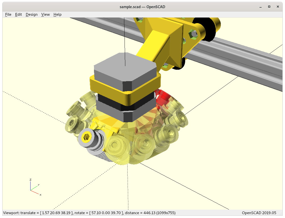
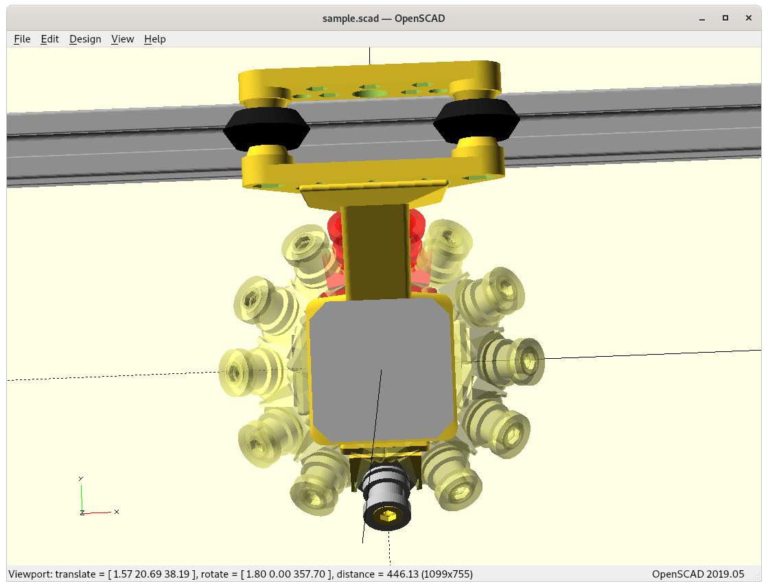
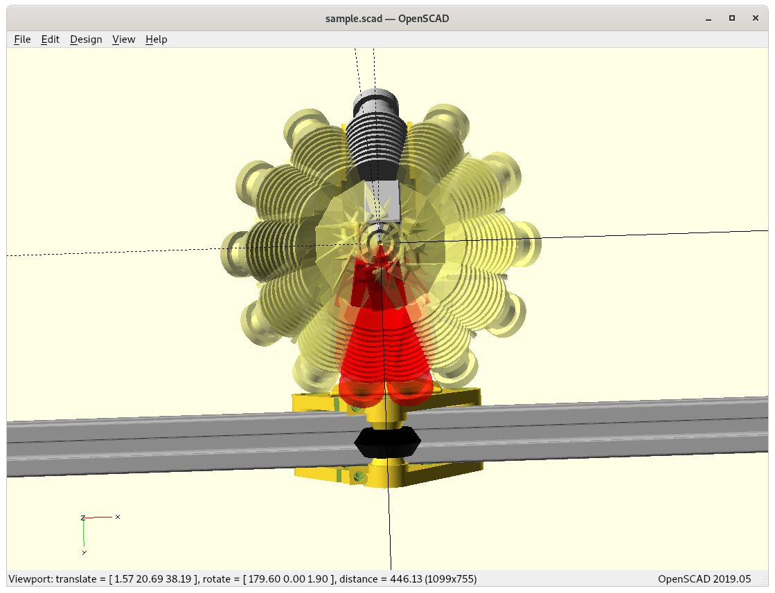
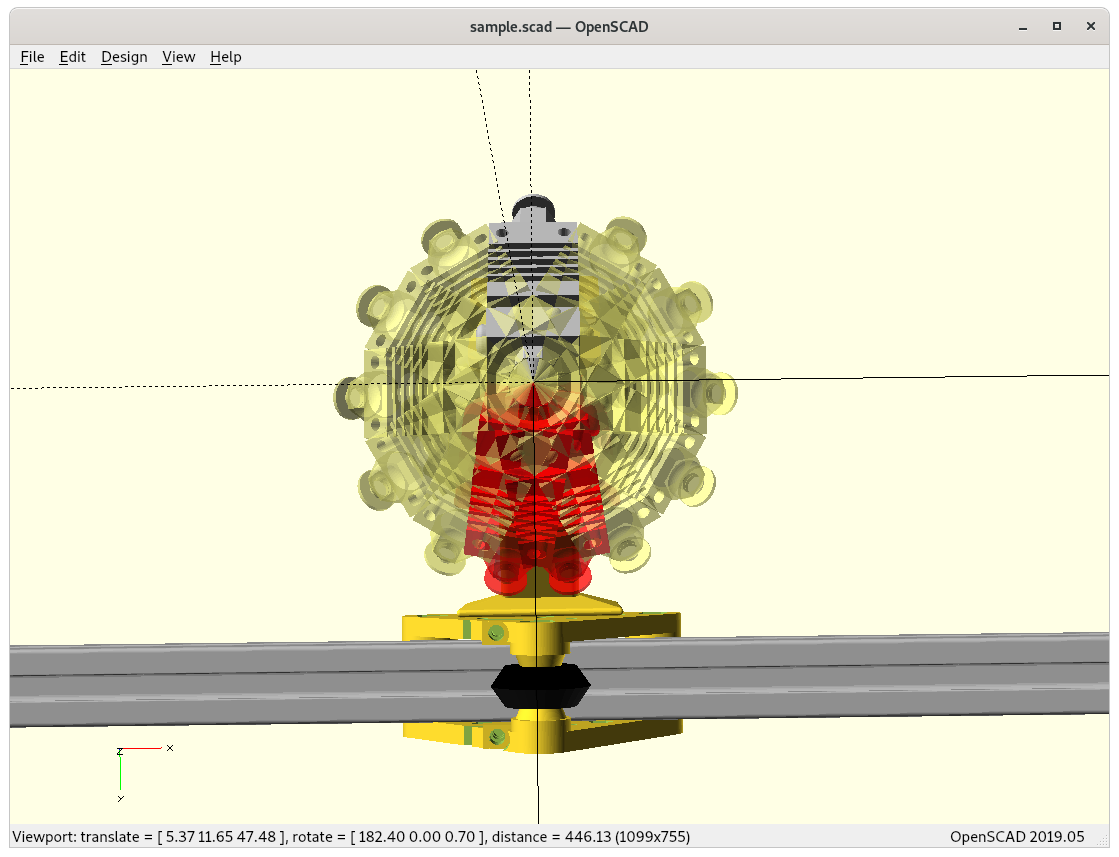
My first attempt is modeling with E3D Volcano hotend like the RotBot by ZHAW:
4D E3D Volcano at 0° Z rotation4D E3D Volcano4D E3D Volcano4D E3D Volcano: rotation shadow (red) – top view4D E3D Volcano: rotation shadow (red) – bottom view
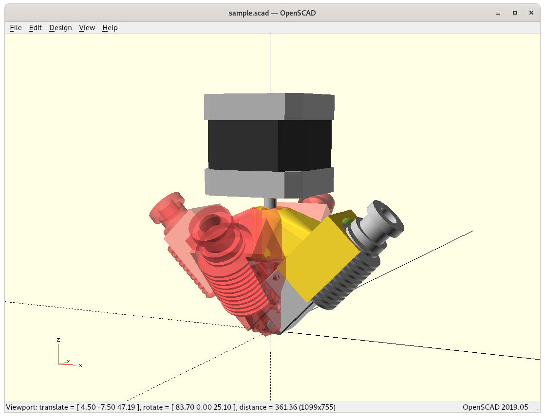
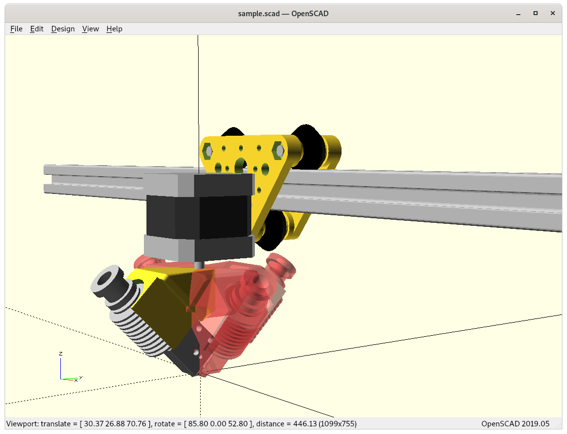
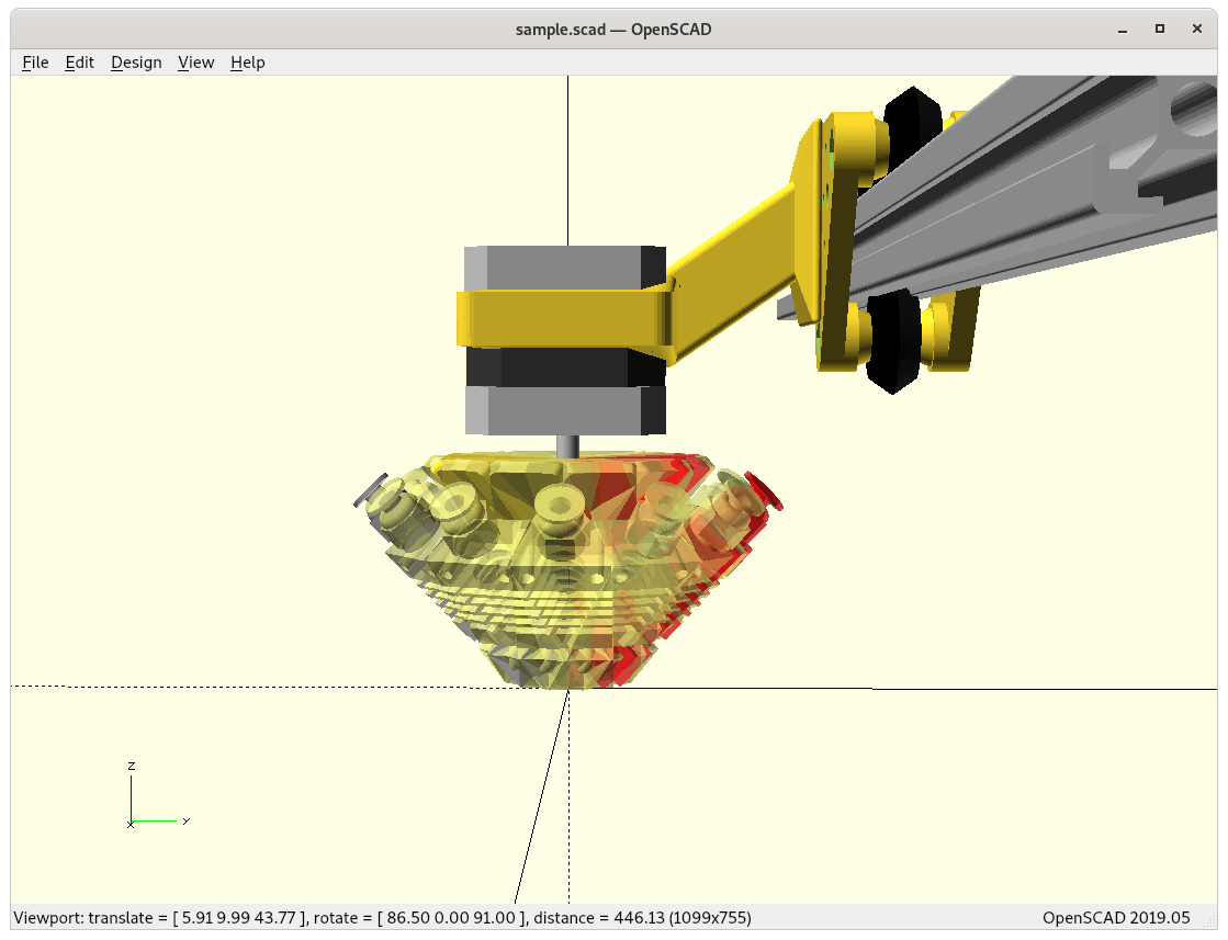
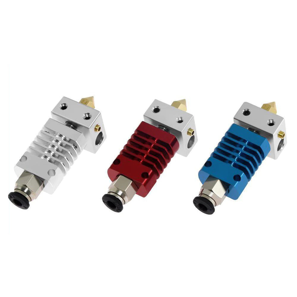
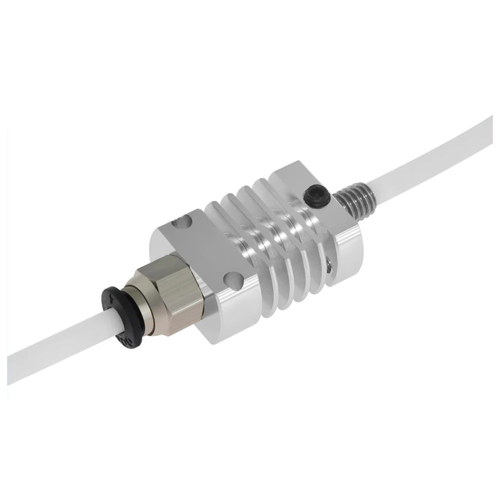
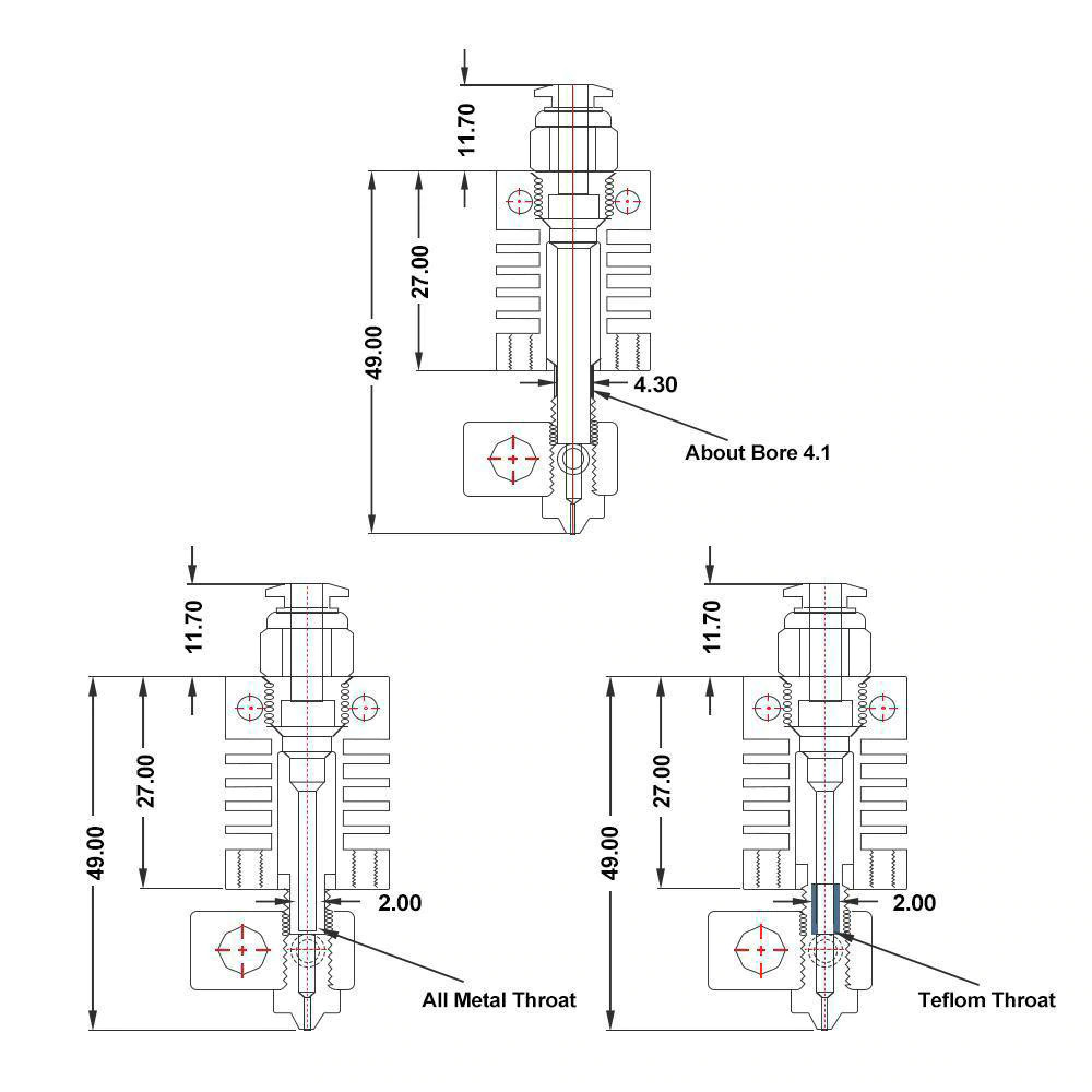
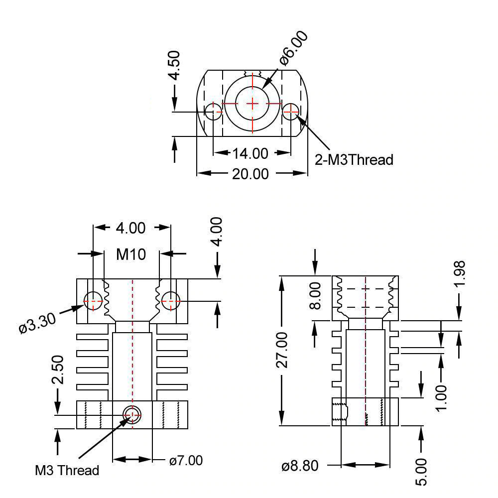
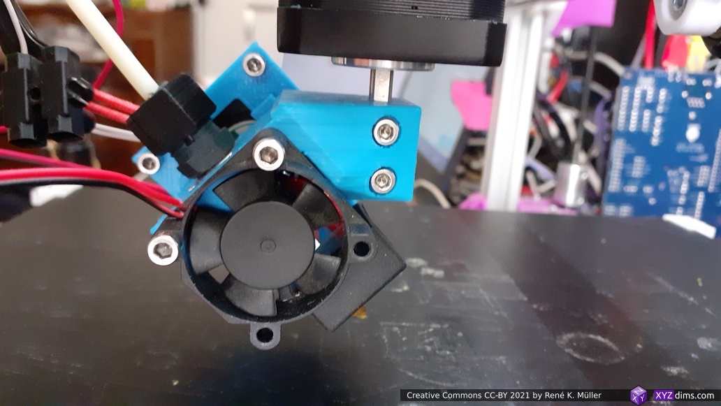
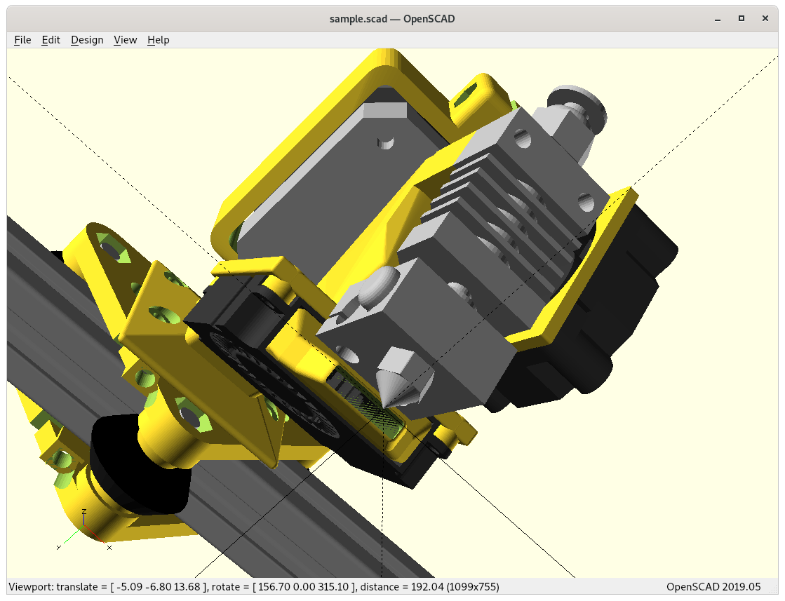
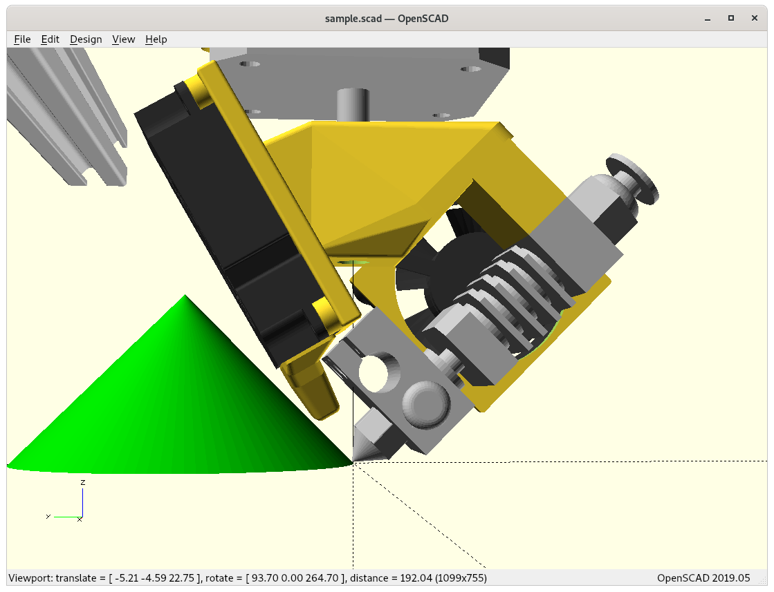
Micro Swiss / CR 10 Hotend
And as alternative the smaller Micro Swiss / CR 10 printhead which gives significant more space for the bowden tube (and all wires with it) to bend or flex near -180/+180°:
4D Micro Swiss at 0° Z rotation4D Micro Swiss4D Micro Swiss4D Micro Swiss: rotation shadow (red) – top view4D Micro Swiss: rotation shadow (red) – bottom view
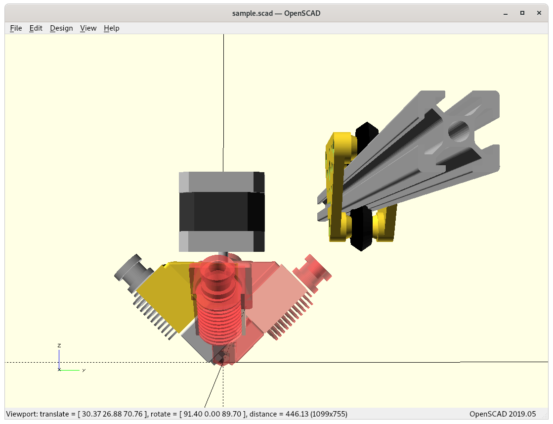
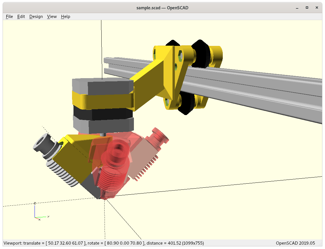
Comparison Volcano vs Micro Swiss
4D with E3D Volcano4D with E3D Volcano4D with E3D Volcano4D with Micro Swiss / CR10 hotend4D with Micro Swiss / CR10 hotend4D with Micro Swiss / CR10 hotend
At this point I continue with the Micro Swiss (MS) option, as the smaller heatsink gives me more space to make full 360° turn with -180° to +180° and have ~0° rotation shadow, perhaps even sub-zero as of overlapping.
This particular Swiss Micro clone aka CR10 hotend comes without screws stabilzing the heatblock, and just a small worm-screw fastening the heatbreak on the heatsink, yet make it easy to adjust the overall length, which in this case is desired.
Prototype
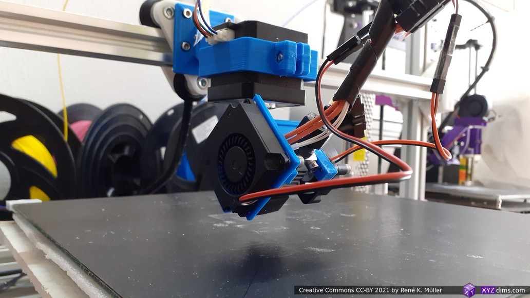
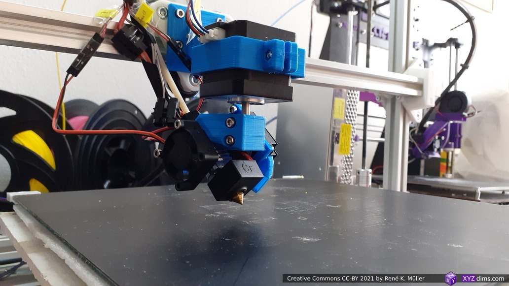
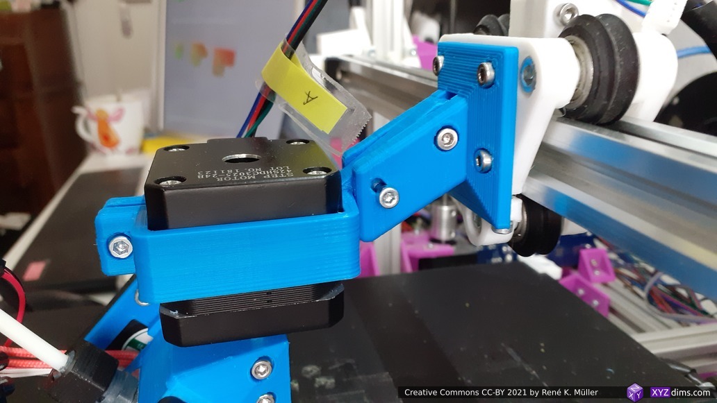
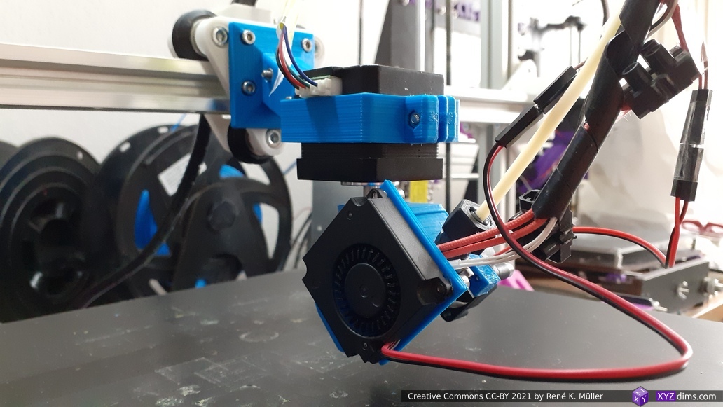
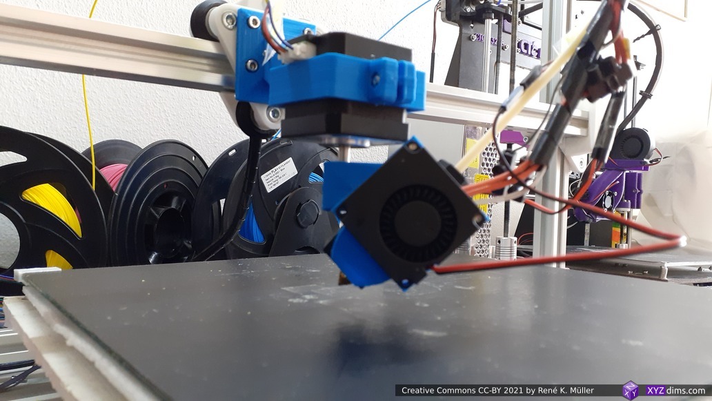
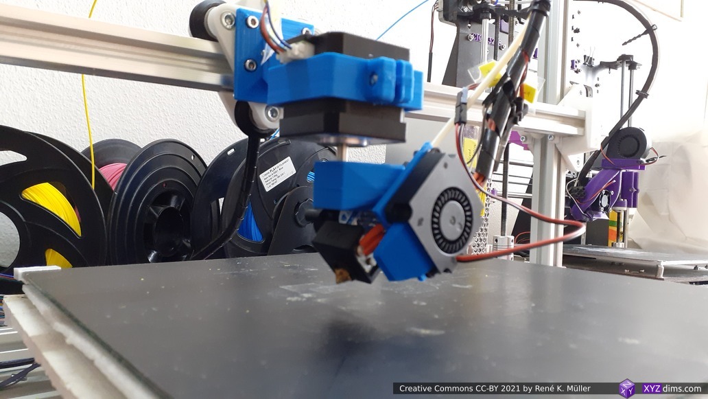
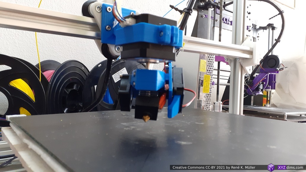
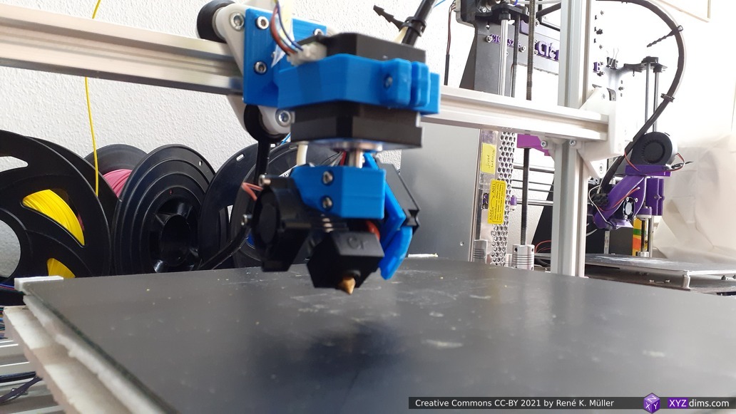
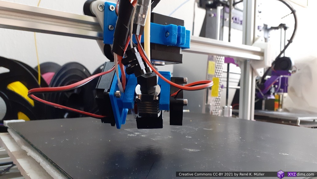
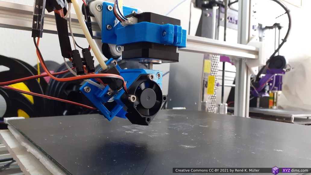
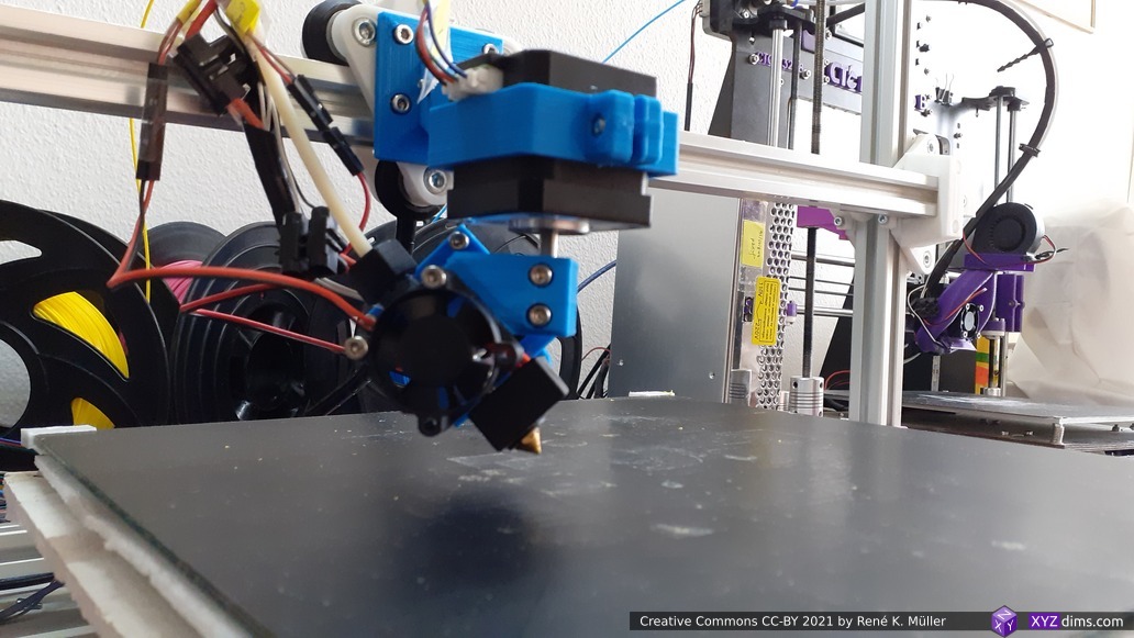
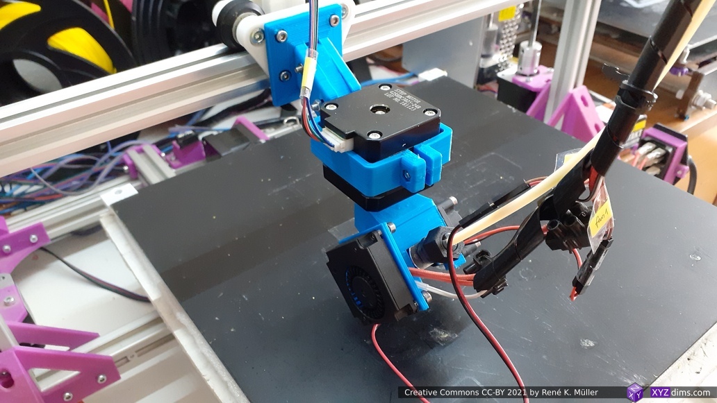
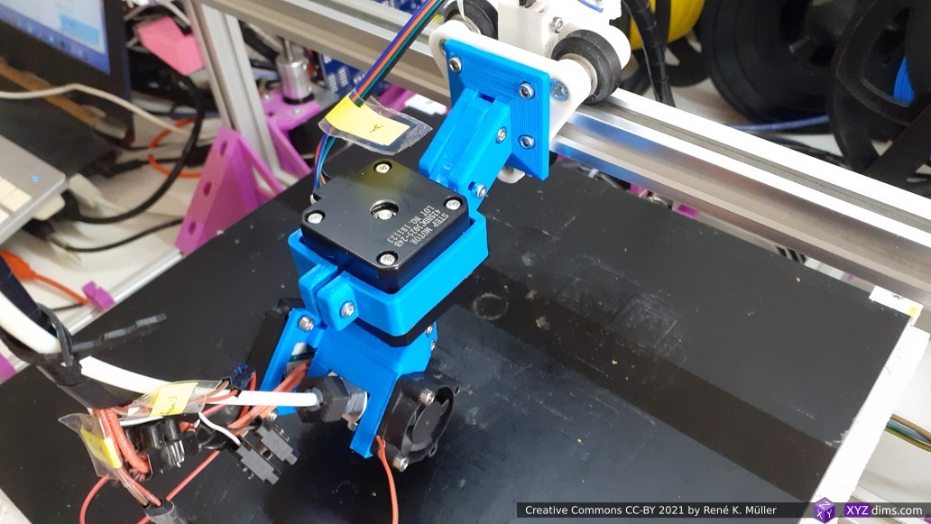
Eventually I took the time to print and assemble my Micro Swiss-based Rotating Tilted Nozzle (RTN):
RTN at default position Zrot=0°Zrot=45°Zrot=90°Zrot=135°Zrot=180°Zrot=-45°Zrot=-90°Zrot=-135°Zrot=-180°heatsink fan & shaft fastenersadjustable arm (to compensate tilt)
First test run revealed:
rotation 170°..180° and -170°..-180° were not reliable with NEMA 17 37mm as skipping steps due the stiffness of PTFE tube with filament – resolvement: increase arm length (away from X carriage down/forward)
partially resolved by limiting A to -170°..170°: M208 A-170 S1 and M208 A170 S0 in config.g of Duet 3 Mini 5+ setup
micro swiss / CR 10 hotend heatblock socket touches the bed (same height as nozzle), fixed due slight tilt from X carriage due weight, newer design allows angle readjustment
single rotation requires refinement by the Slicer4RTN, addressed partially with Slicer4RTN 0.6.0, might require more fine-tuning.
I’m focusing on the hardware-side on the Penta Axis (PAX) 5-Axis printhead and transfer some of the experiences back into the RTN design.
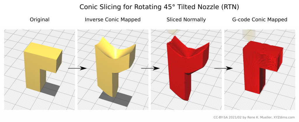
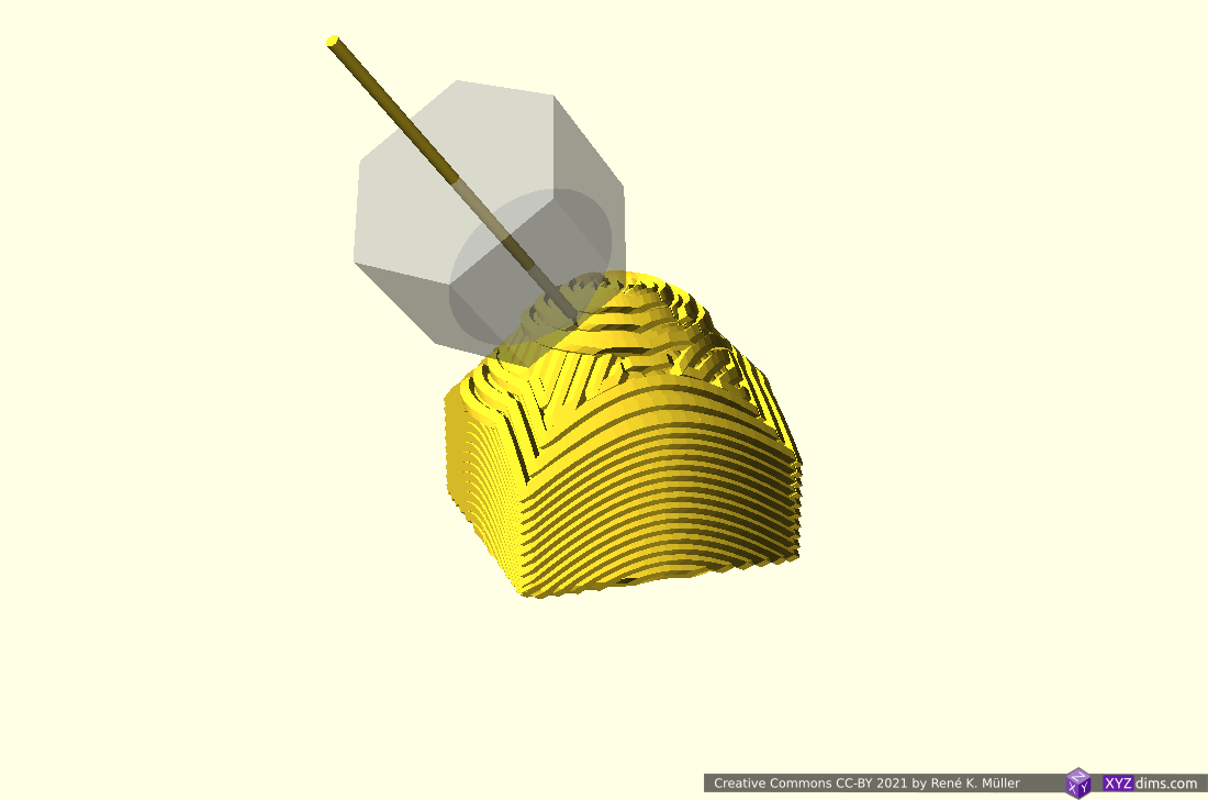
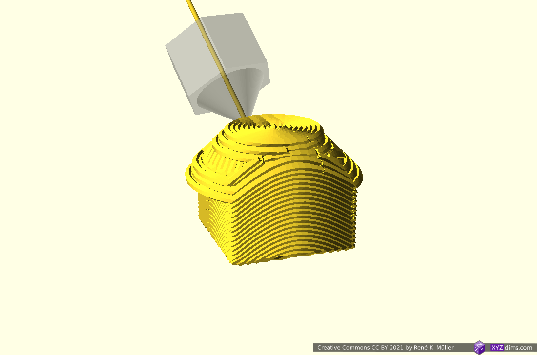
Slicing for Rotating Tilted Nozzle: Conic Slicing
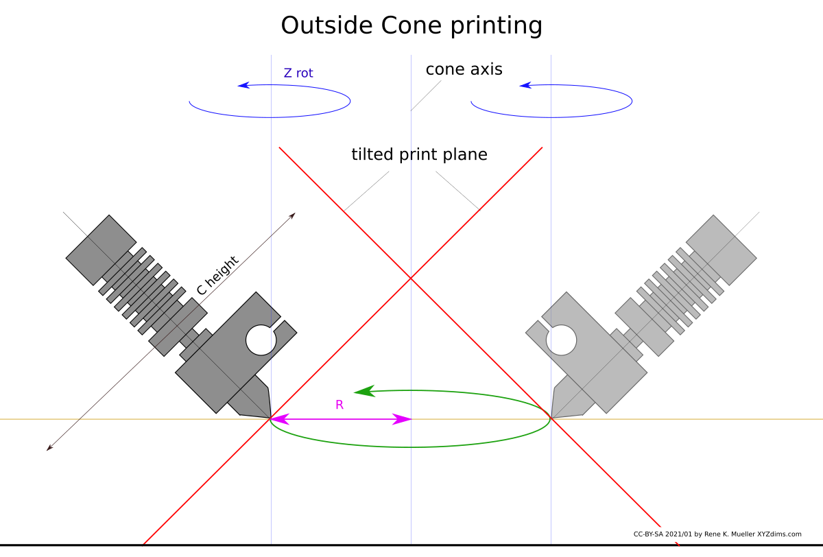
I had to visualize the novel conic slicing approach as mentioned in the article and in the video:
Rotating Tilted Nozzle: Outside Cone – tilted print plane with Z axis rotating leads to conic print planeRotating Tilted Nozzle: Inside Cone – tilted print plane with Z axis rotating leads to conic print plane
f(Z rot, C height, R) ⟹ X, Y, Z
X = sin(Z rot) * R Y = -cos(Z rot) * R Z = C height / sqrt(2)
Z rot = atan2( -Y, X ) R = sqrt( X*X + Y*Y ) C height = Z * sqrt(2)
A single conic slice is covered by Z rot, C height and R, whereas slices are separated by increasing Z offset to C height, forming conic slices on top of each other:
Let’s inspect the motion of a single layer: it’s curved – obviously – in X, Y and Z – this means, the Z axis has way more motion than in cartesian XZ Prusa-Mendel setup where the Z axis only changes once a layer is finished, here with cone-slicing every trace or track all traditional 3 axis are in motion, plus the 4th – the tangent on that conic trace.
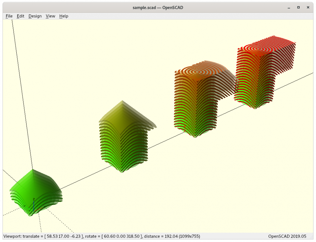
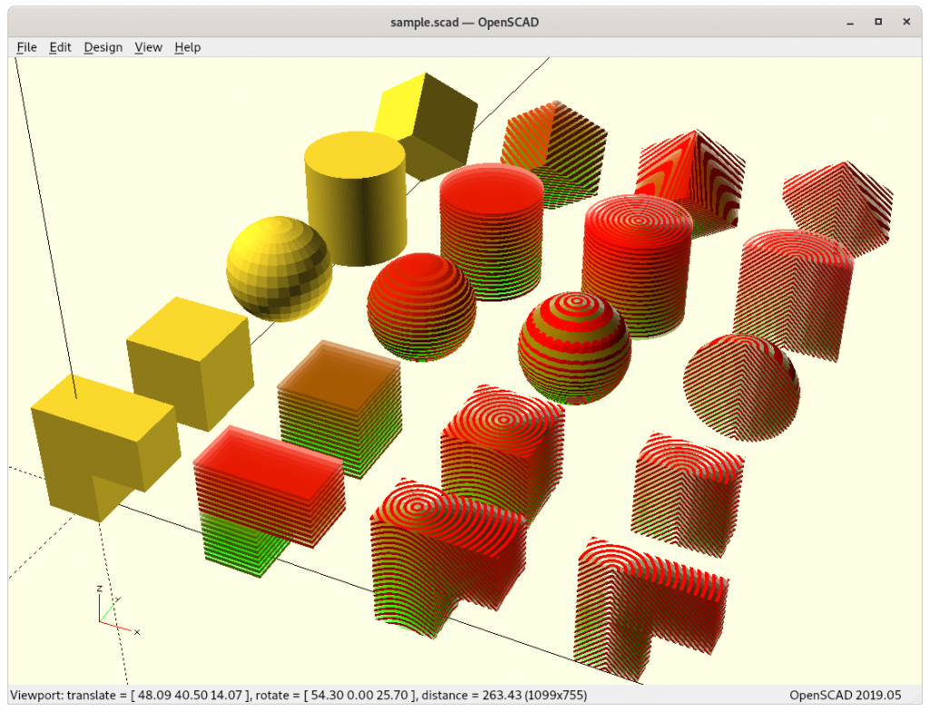
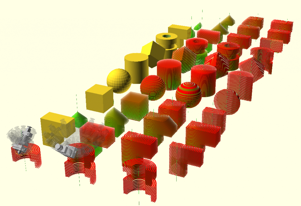
Planar vs Conic LayersMultiple solids sliced planar and in conic manner
The 45° tilted printhead allows three print modes:
non-rotation nozzle with planar Z layers (with ordinary slicer), acts like belt-printer in one direction: overhangs in one direction without support
rotation nozzle with planar Z layers (requires dedicated slicer), might support near 90° overhangs of a certain length in all X/Y plane directions as well – but needs to be tested
rotation nozzle with conic Z layers (requires dedicated slicer or pre- and post-processing while using ordinary slicers)
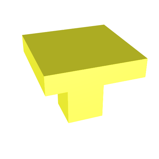
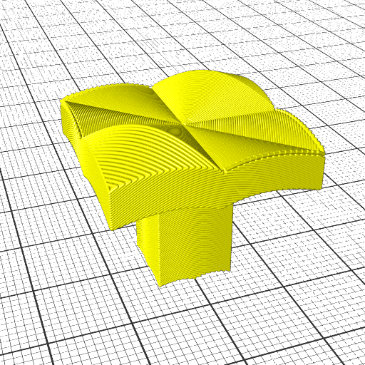
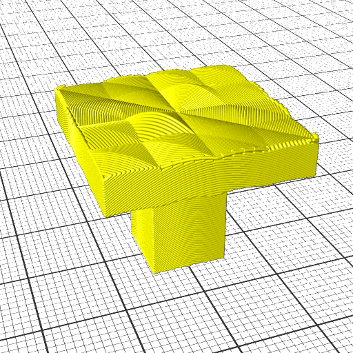
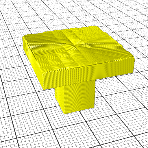
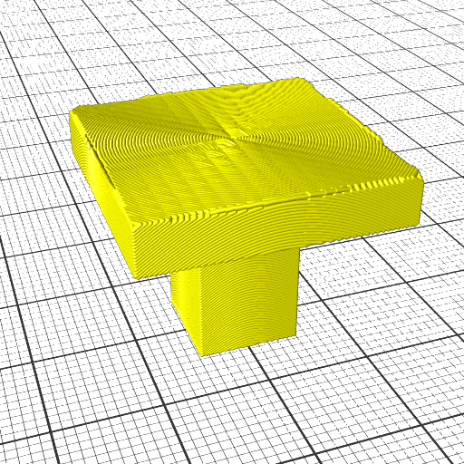
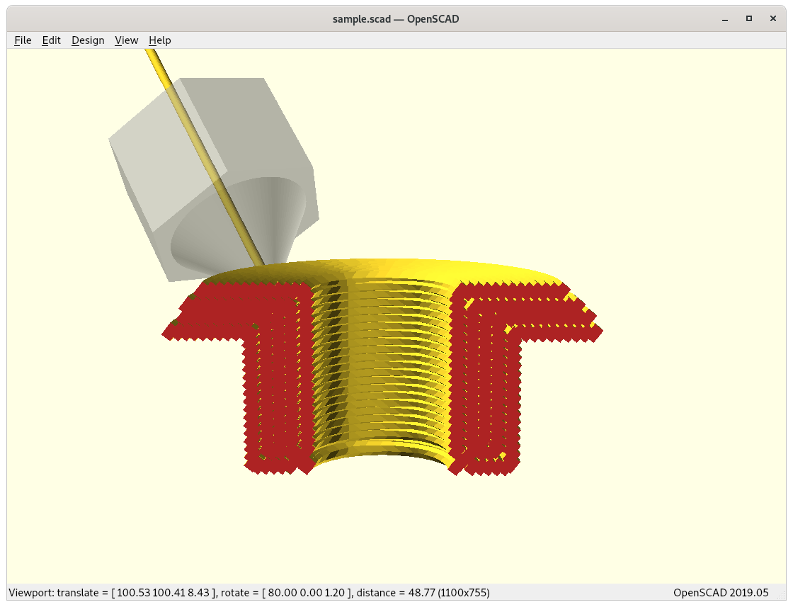
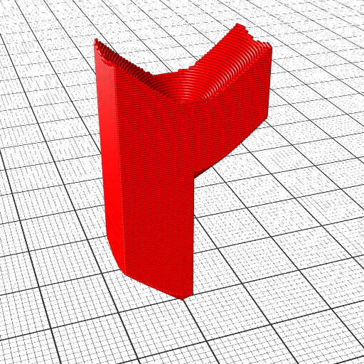
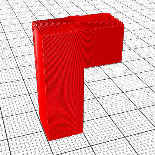
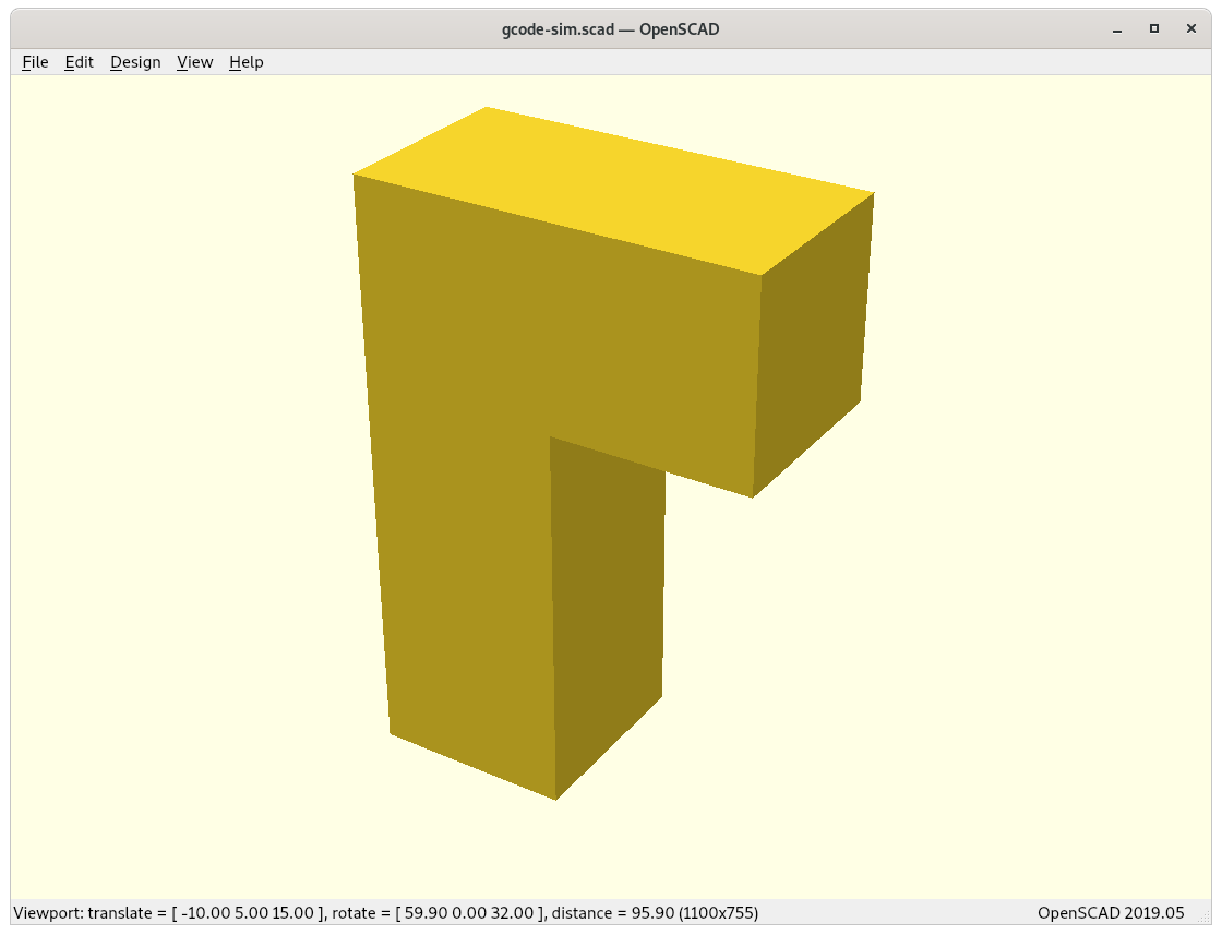
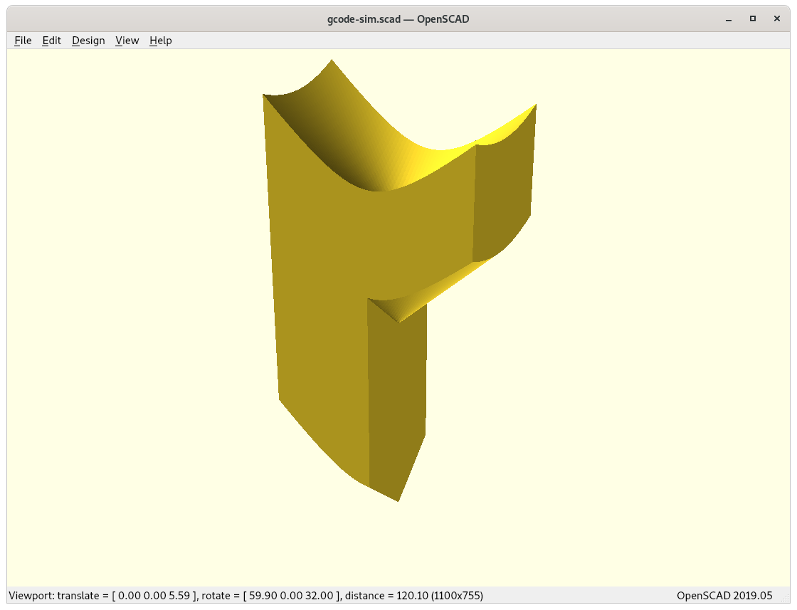
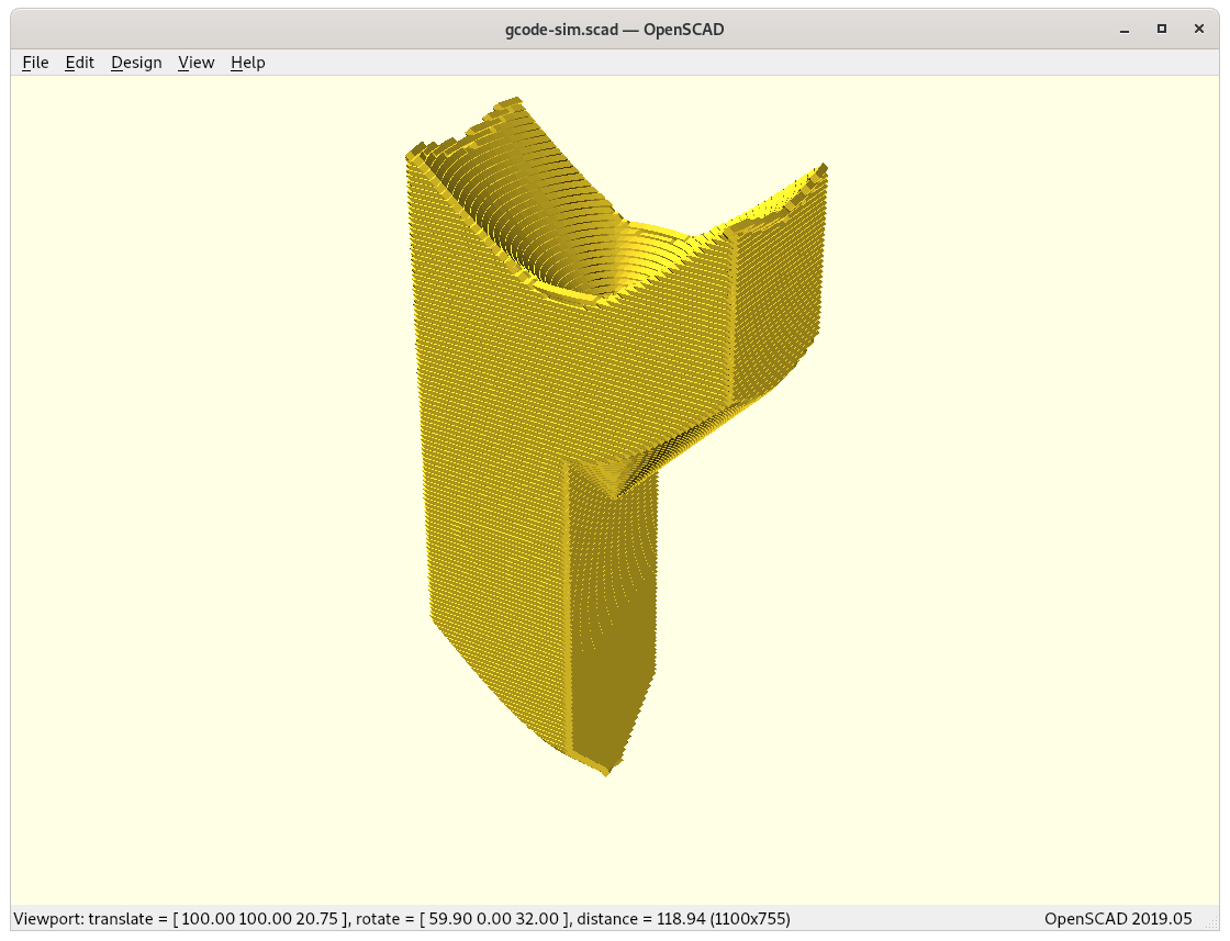
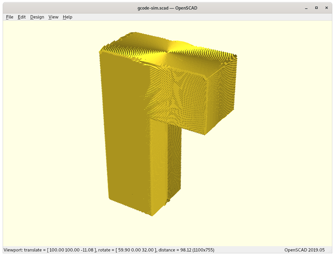
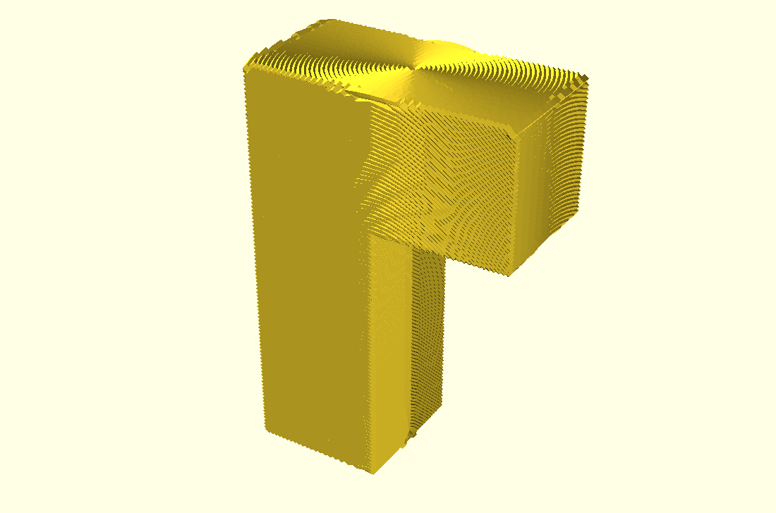
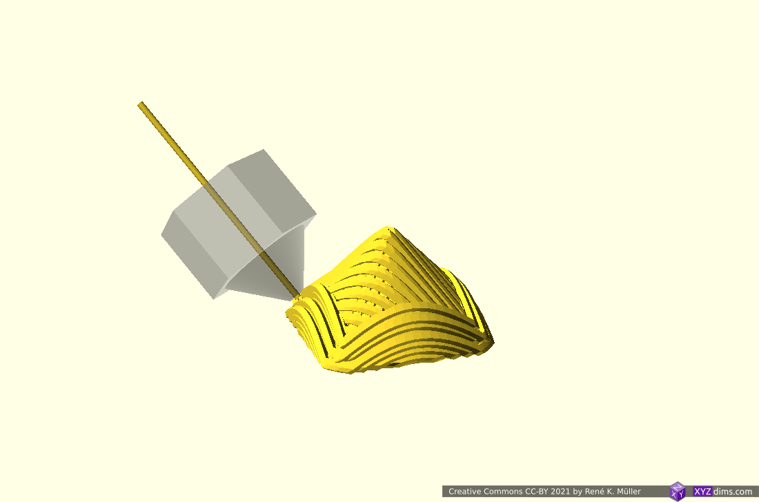
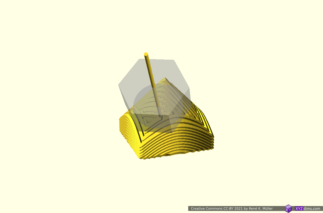
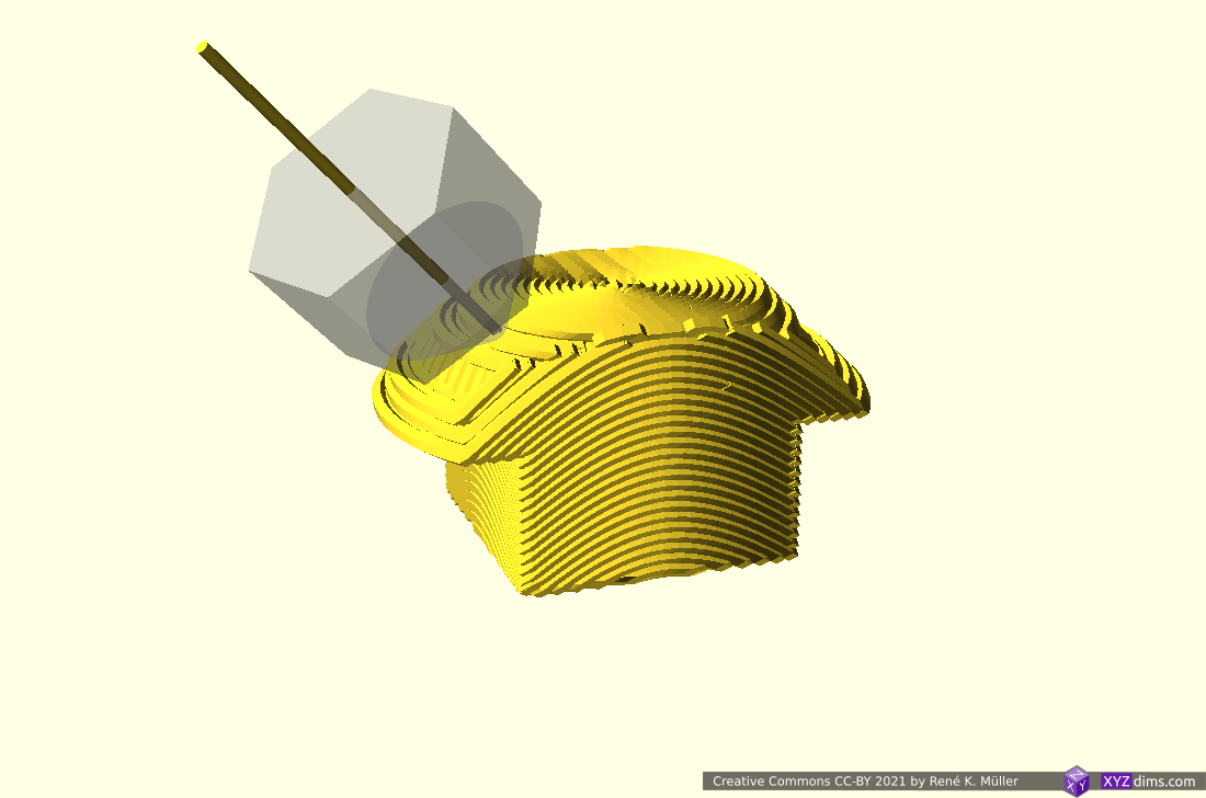
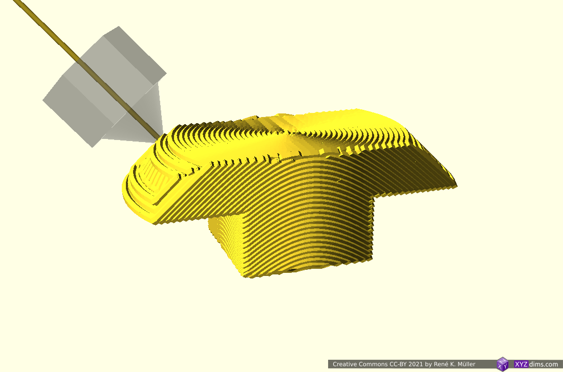
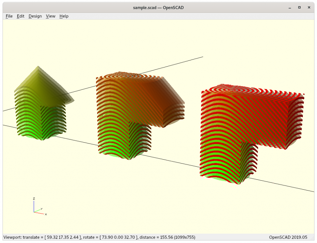
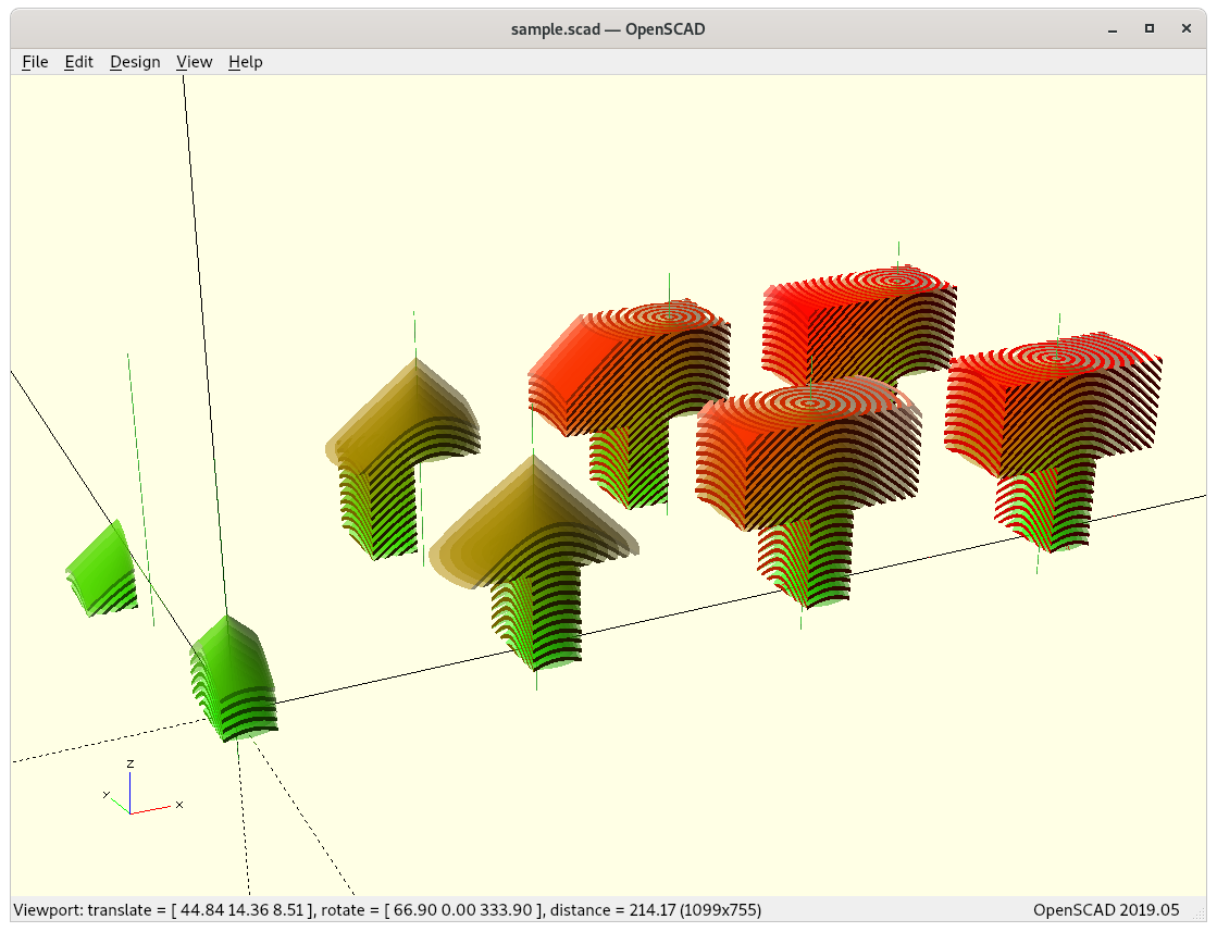
And by choosing the position of the “axis” of the conic slicing within the model and the cone direction matters then as well:
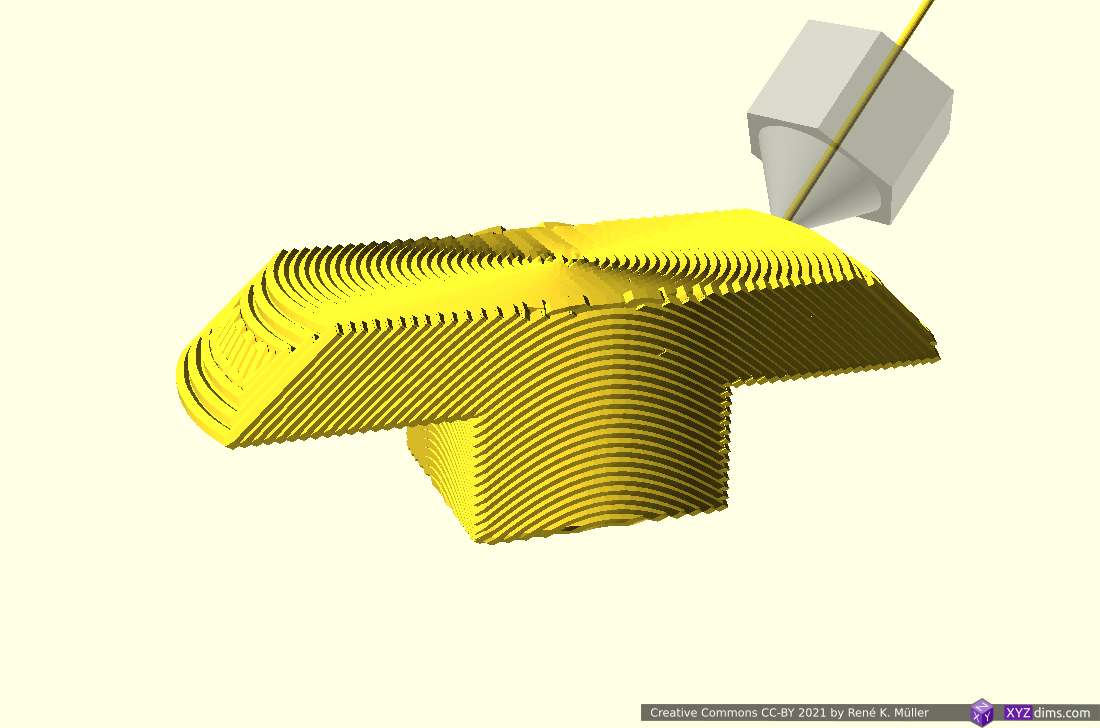
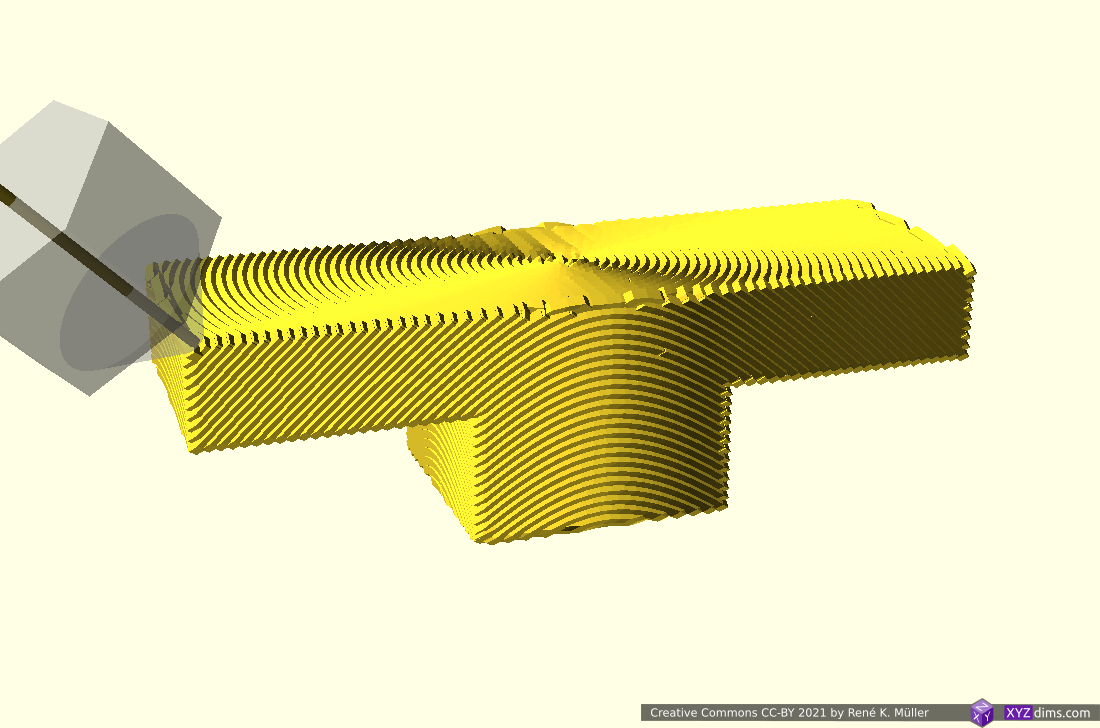
T-piece slicedT-piece with different axis centers: axis center determines printable overhangs or not (2nd row isn’t printable that way)T-piece with different axis centers: axis center determines printable overhangs or not(2nd row isn’t printable that way)overhangs toward and away from axis
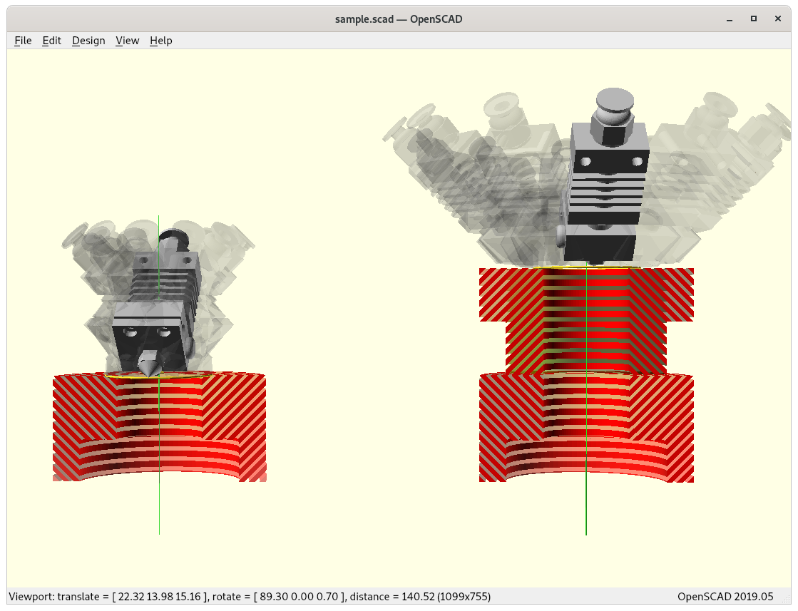
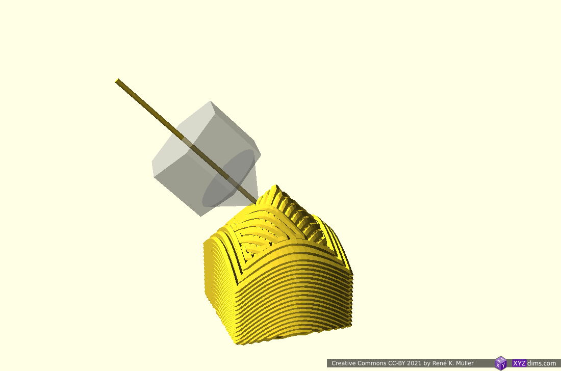
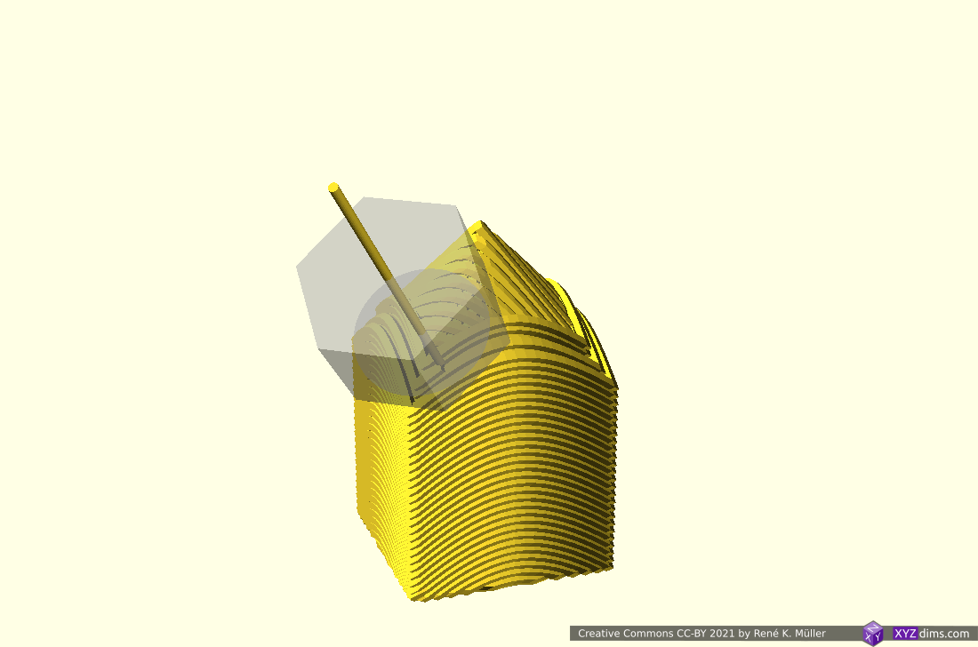
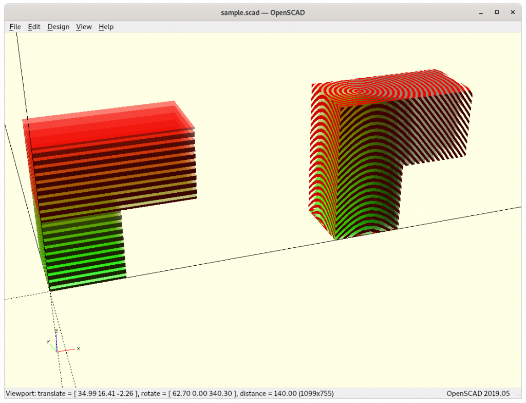
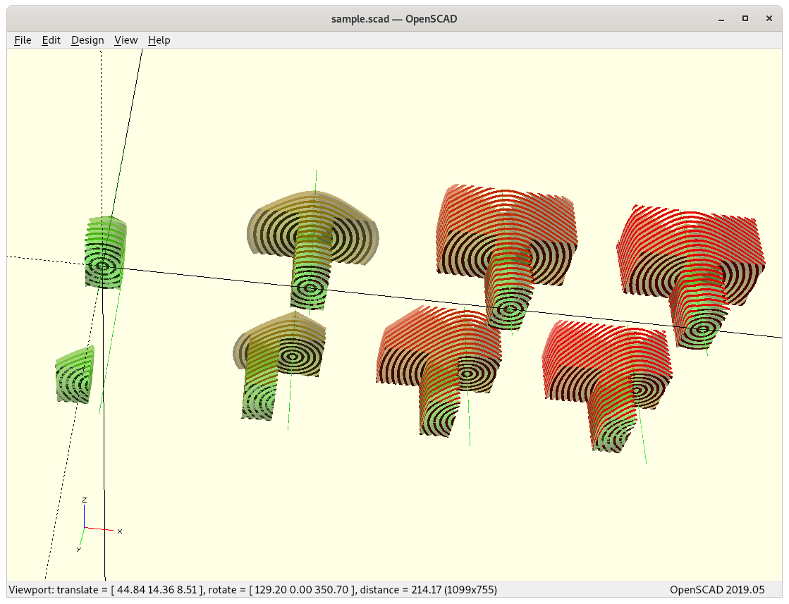
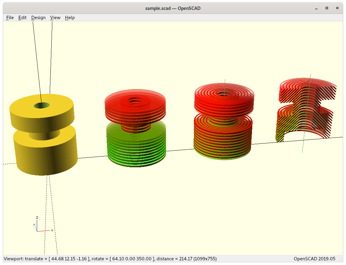
The last piece with inside and outside looking overhangs requires a switch of nozzle direction, e.g by default the sliced cones are ordered ▲ (outside-in or outside-cones) where outward overhangs work, but for inward overhangs the opposite direction of the nozzle looking outside is required ▼(inside-out or inside-cones), like this piece:
Vertical splitted: bottom half with overhang toward cone axis Inside Cone print, upper half with overhang away from cone axis Outside Cone printing, all without supportVertical splitted: bottom half with overhang toward cone axis Inside Cone print, upper half with overhang away from cone axis Outside Cone printing, all without support
So the slicing software needs to recognize this, and the sliced cones switched either ▼ or ▲ according Z level.
These aspects opens a whole new range of considerations how to orient a piece and where to position the newly introduced slicing axis, and which kind of cones need to laid at which level.
Issues to Resolve
Heatsink fan mount: needs to be mounted for both variants, Micro Swiss and E3D Volcano ideally
Part cooler:
have the part cooler rotate on Z axis as well? yes for now
using a flexible pipe to blow air near the nozzle instead
heatsink fanwith part coolerpart cooler nozzleensuring the part cooler doesn’t collide/intersect with conic slice
Z rotation calibration:
alike with X or Y stop, but a trigger rotating from one direction only and then set a angle offset
Z rotation motor mount adaptable for different kind of printheads
keep it modular
ensure the nozzle end is centered (allow simple center calibration)
Properly document design and features of Rotating Tilted Nozzle as there isn’t much detail information available
dedicate slicer for conic slicing, e.g. adapt Mandoline Py
Considerations
Pros
conic layers: printing 90° overhangs without support, given some conditions are met:
overhangs must be horizontally or vertically rotational symmetric and aligned with the cone axis to switch from outside to inside cone printing or vice-versa (to do: more use cases explored and documented)
conic layers: stronger pieces as layers cross X, Y and Z in non-planar manner, mechanical forces distribute further than just planar layers
planar layers / rotating nozzle: perhaps close to 90° overhangs (speculative) requires new overhang algorithms in slicer
conic layers: more things to consider (preferably recognized by the slicing software):
overhangs must be horizontally or vertically rotational symmetric and align with cone axis to take advantage of it (complex compartmentalizing of different cone-direction per overhang and newly introduced seams between those)
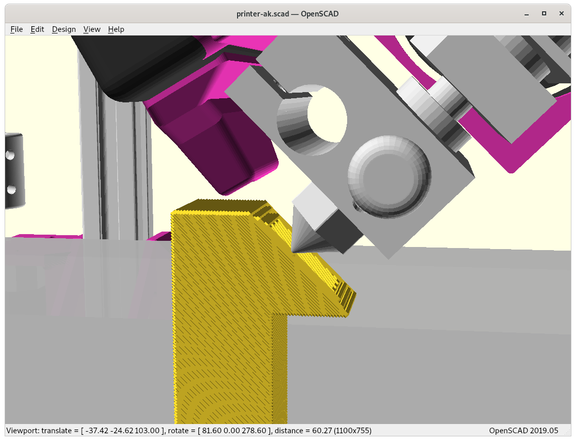
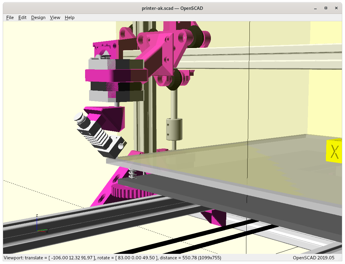
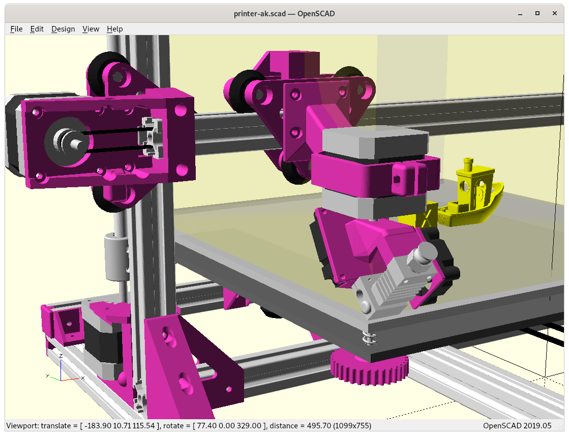
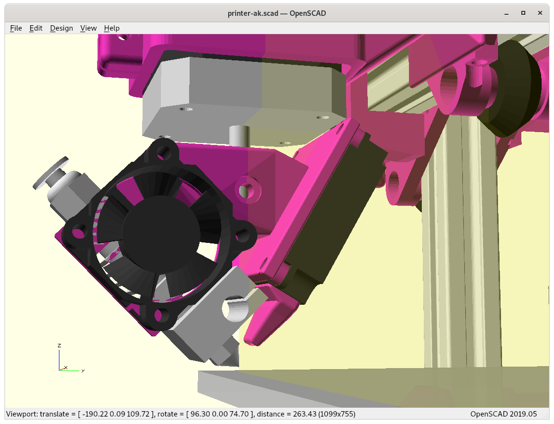
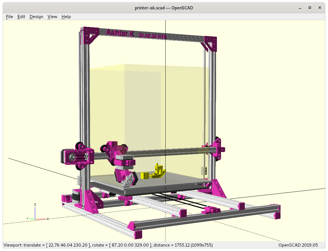
Ashtar K with Rotating Tilted Nozzle (RTN)
The additional Y offset is about 20mm, and losing apprx. 50 mm in Z build volume in its current form:
at X=0, Y=0, Z=0, Zrot=0 positionat 0,0,0,0 positionadding heatsink fan & part coolerAshtar K RTNAshtar K RTN (animated)Ashtar K RTN printing conic sliced overhang model (animated)
Fallback Print Horizontal Slices
Some parts may not require conic slices, e.g. introducing new unprintable overhangs which in horizontal slices would not exist, so a simple way to print traditional sliced models is by adding a proper rotation angle (e.g. G-code A..) so the nozzle extrudes nicely, something like:
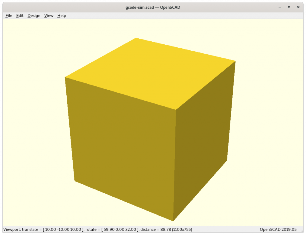
Horizontally sliced 20mm cube printing with enhanced G-code with rtnenhancer
I wrote a small script called rtnenhancer which converts existing G-code to enhanced G-code.