State: early draft, mostly simulations with a few tests with 3-axis printer only
Updates:
- 2021/09/28: added reference to paper by ZHAW describing slicing procedure
- 2021/03/22:
slicer4rtnreleased, see dedicated page Slicer4RTN - 2021/03/16: removing details on
slicer4rtnas a new dedicated page is in the working (coming soon) - 2021/03/08:
slicer4rtn0.2.3 reached (still unreleased), better prints, documenting various settings in more details - 2021/03/05: added proper ZHAW reference in the introduction and a few notes
- 2021/02/27: removed some redundant illustrations and remade some of them, outside-cone vs inside-cone mode & printing
- 2021/02/26: added inside-cone printing example for inner overhang mode, also early information of
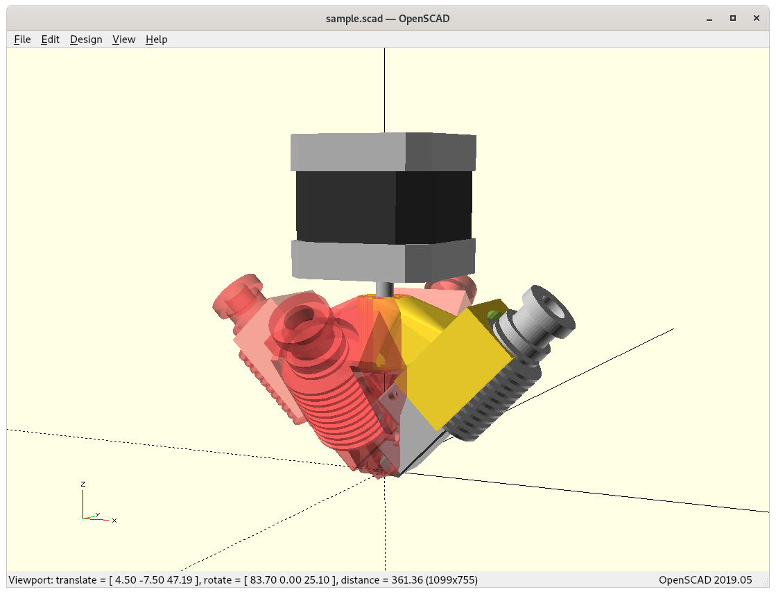
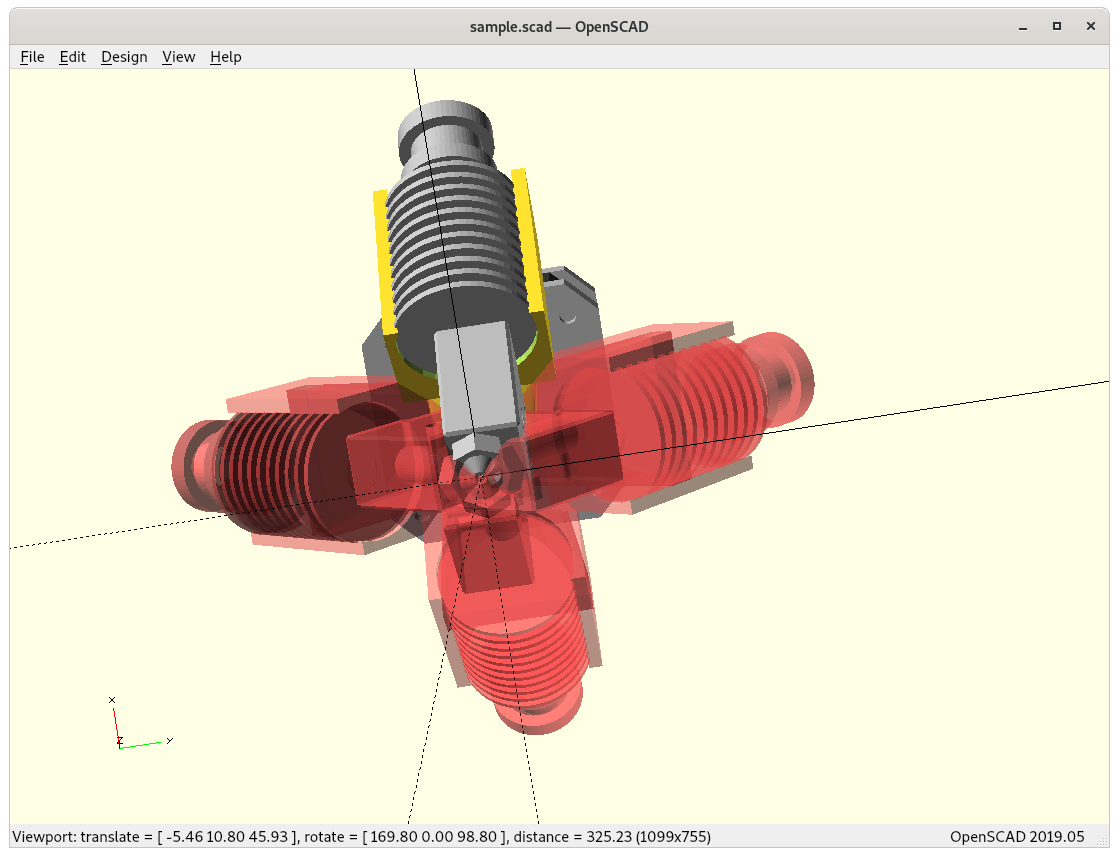
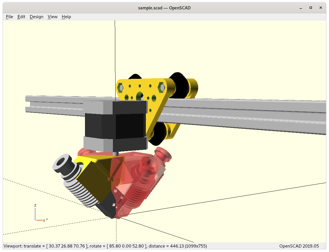
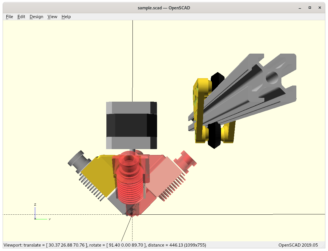
slicer4rtn; more animations to observe details of produced G-code, using now also OpenSCAD to simulate G-code and actual nozzle position - 2021/02/24: better tests with 20mm cube and overhang structure, included two short G-code simulations as videos, added 20mm sphere and 3D Benchy and discover first issues with volume decomposition and overhang recognition
- 2021/02/23: first write up, pseudo code and first attempt to conic slice 20mm cube
As I progress I will update this blog-post.
Introduction
The main idea is to utilize existing 3D printing slicers but create conic slices for the Rotating Tilted Nozzle (RTN) 4 Axis Printer. ZHAW published in their announcement in 2021/01 something about utilizing existing slicers, but the details remained concealed and later published as a paper but I did not want to wait and pondered on the problem, and came up with a solution. In its current state it’s purely theoretical and untested for now (2021/02) barely tested yet.
Michael Wüthrich confirmed my solution is comparable with their solution. ZHAW planned their paper to be published sometime 2021. So, the main credit goes to ZHAW and the researchers (Prof. Dr. Wilfried Elspass, Dr. Christian Jaeger, Michael Wüthrich, Maurus Gubser, Philip Bos and Simon Holdener) there, I was just impatient and tried to find a solution with the information available.
I also adapted some of the notions Wüthrich introduced in the Novel 4-Axis 3D Printing Process to Print Overhangs Without Support Material paper, e.g. “outside-cone” and “inside-cone” printing as featured in an earlier blog-post already.
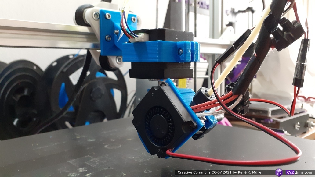
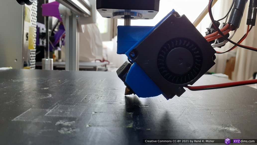
Non-Planar Conic Slices
The 4-axis Rotating Tilted Nozzle (RTN) physical setup implies its slices are of non-planar conic shape, allowing to print overhangs without support structure, such as:
I also like to master the conic slices properly as they promise to become a subset of 5 axis printhead (PAX) features too – so it’s worth the effort even if the RTN itself might be too limited in its application with its fixed tilt – we will see.
Theory
In a nutshell the steps are following:
- sub-divide faces of the model (fine-grained)
- map model to inverse conic space
- send to slicer
- remap G-code to conic space
- adding Zrot to G-code
Conic Space Mapping
(x1,y1,z1,rot) = conicSpaceMapping(cx,cy,x,y,z,dir);
whereas
cx, cyare the conic axis coordinatesx, y, zare the input coordinatesx1, y1, z1are the output coordinatesrotthe rotation anglex,yvscx,cydiris eitherdirect(default) orinverse
function conicSpaceMapping(cx,cy,x,y,z,dir='direct') {
   dx = x-cx;
   dy = y-cy;
   d = sqrt(dx*dx + dy*dy);
   rot = atan2(dy,dx);
   return (x,y,dir=="direct" ? z-d : z+d,rot);
}
Pseudo-Code
The entire procedure goes like this:
m = loadModel("cube.stl");
m = subDivide(m,5);
for(p of m.vertices) {
    m.vertices[i] = conicSpaceMapping(cx,cy,p.x,p.y,p.z,'inverse');
    i++;
}

gcode = sliceModel(m);

foreach(line of gcode) {
   (code,x,y,z,e) = extractCoordsExtrusion(line);
   (x1,y1,z1,zrot) = conicSpaceMapping(cx,cy,x,y,z,'direct');
   outputGcode(code,x1,y1,z1,e,zrot);
}
Note: the pseuco-code is incomplete as extrusion E is not yet taken care of, as soon I found a definitive solution I will write it up.
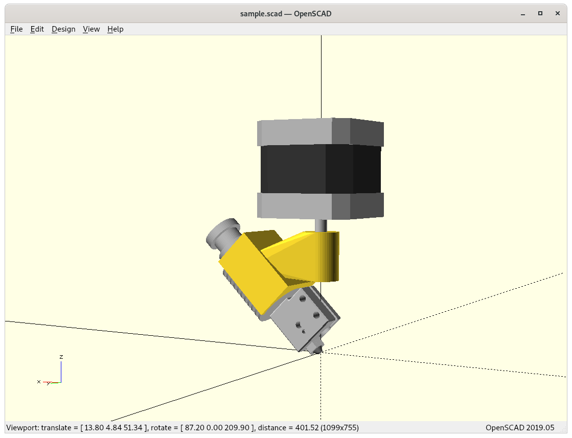
Examples
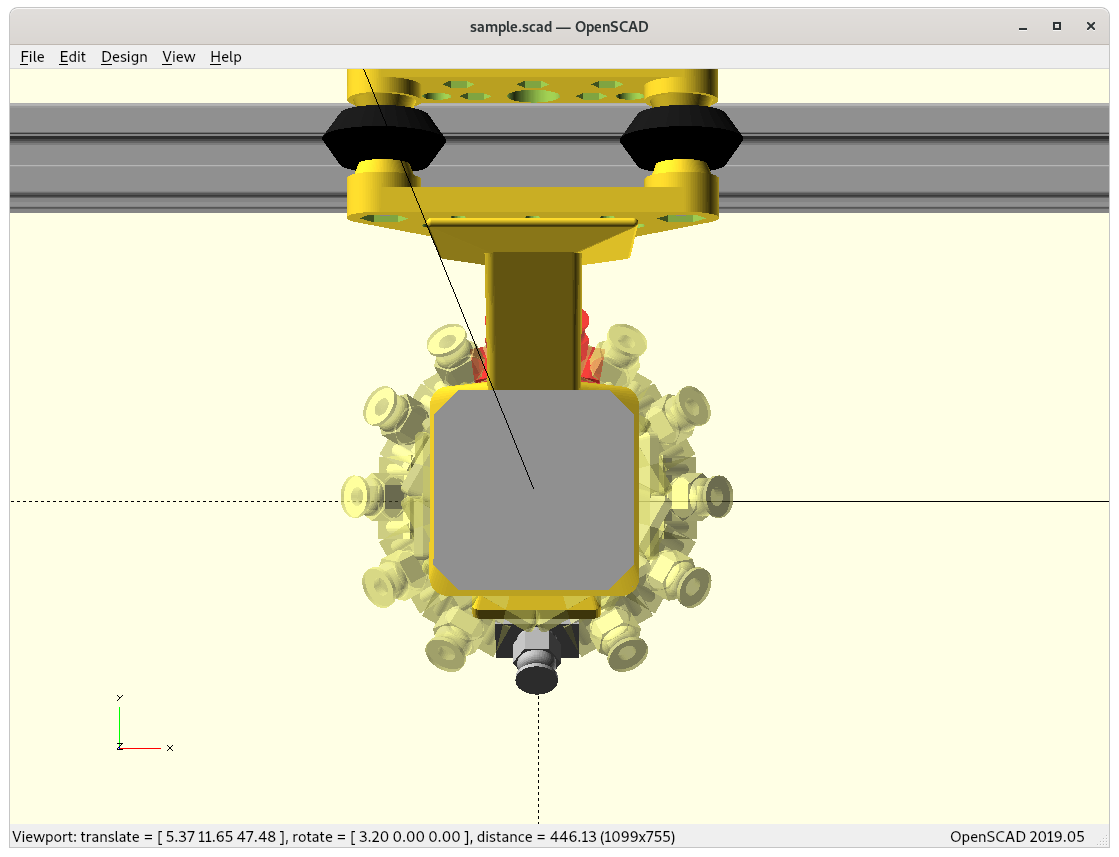
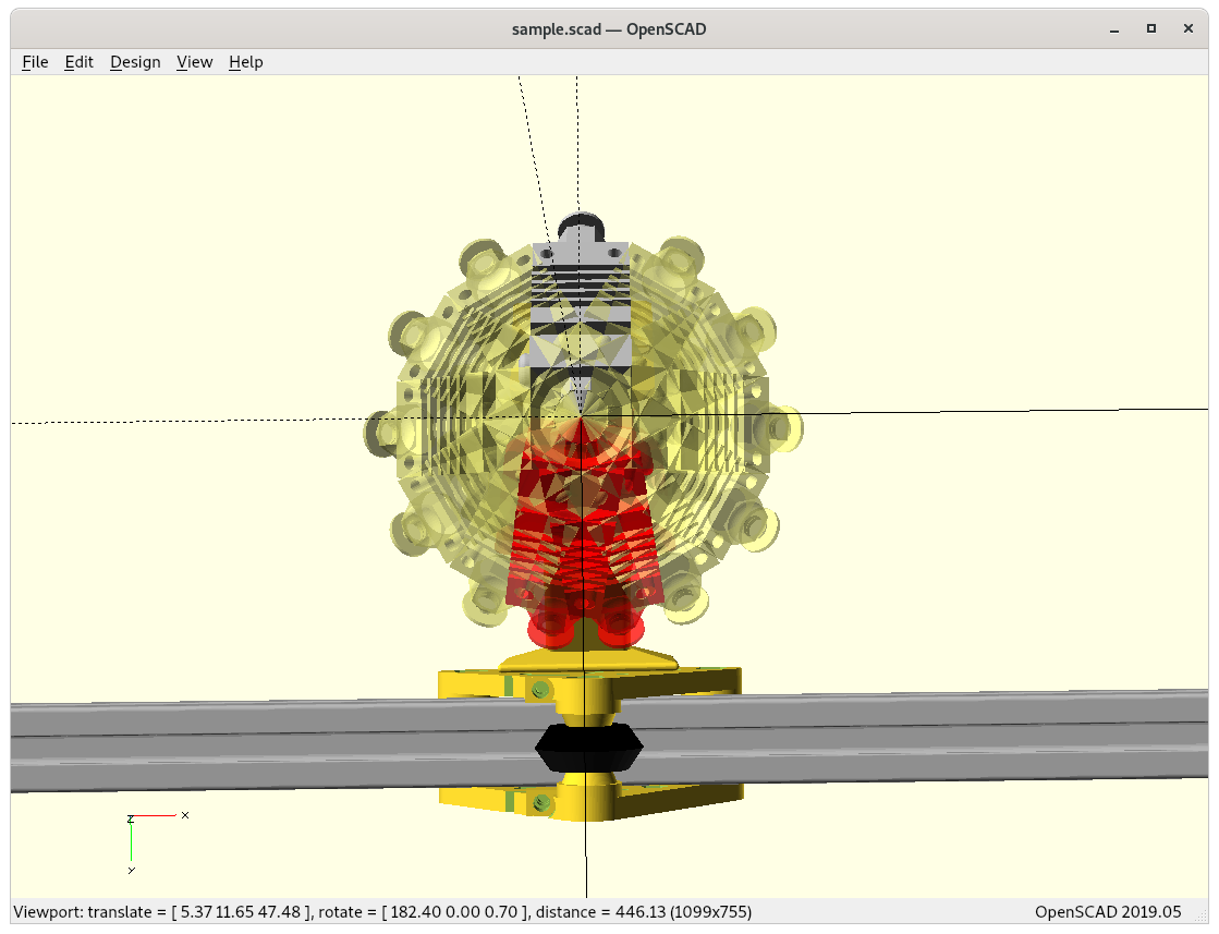
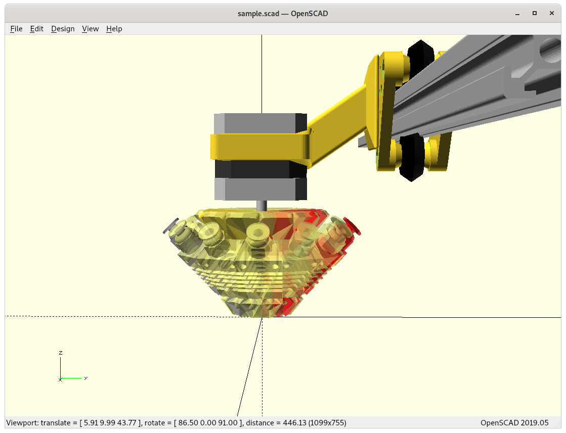
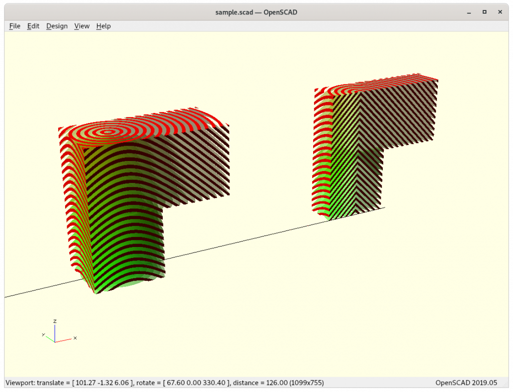
I implemented the pseudo-code with some more details like taking care of G-code E extrusion as well and fine-step linear extrusion – here some early tests using OpenSCAD as STL & G-code viewer and Slic3r as actual slicer:
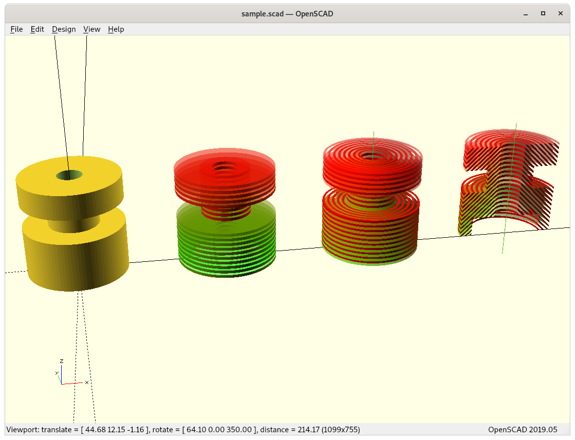
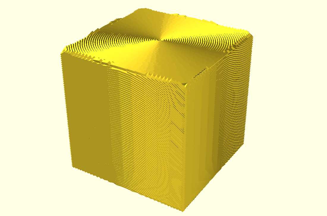
20mm Cube Conic Sliced
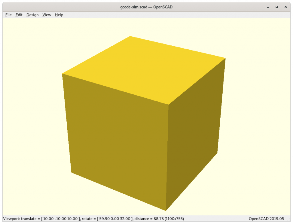
20mm cube 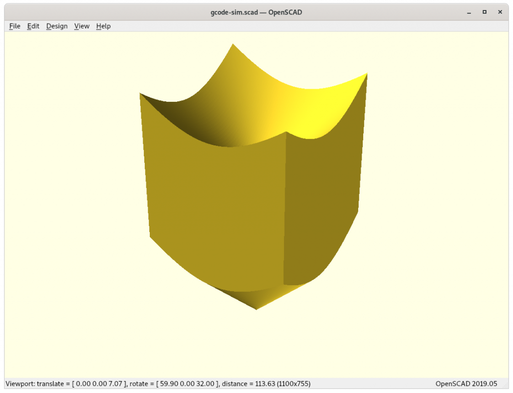
20mm cube (inverse conic mapped) 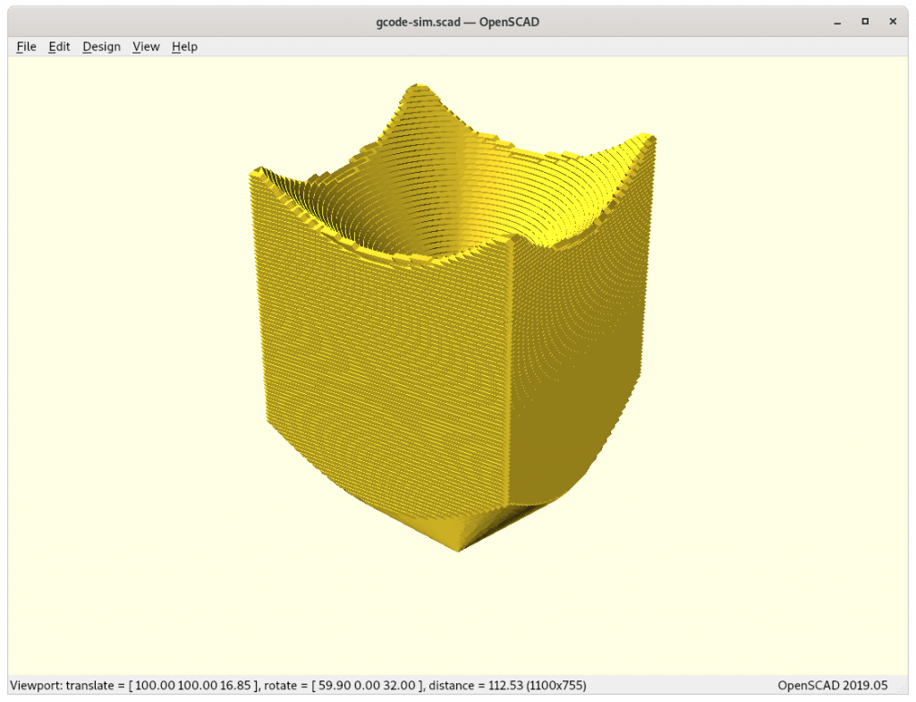
20mm cube (inverse cubic mapped & sliced) 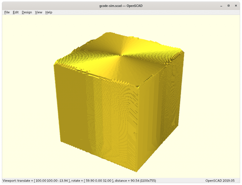
20mm cube (G-code direct conic mapped)
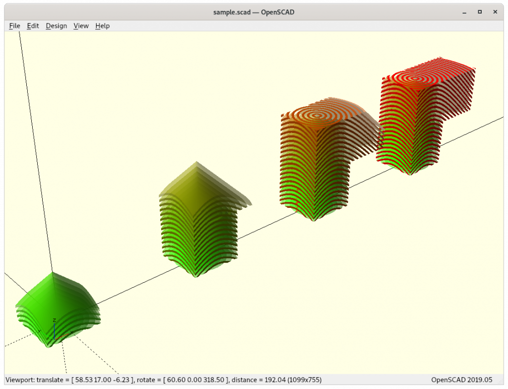
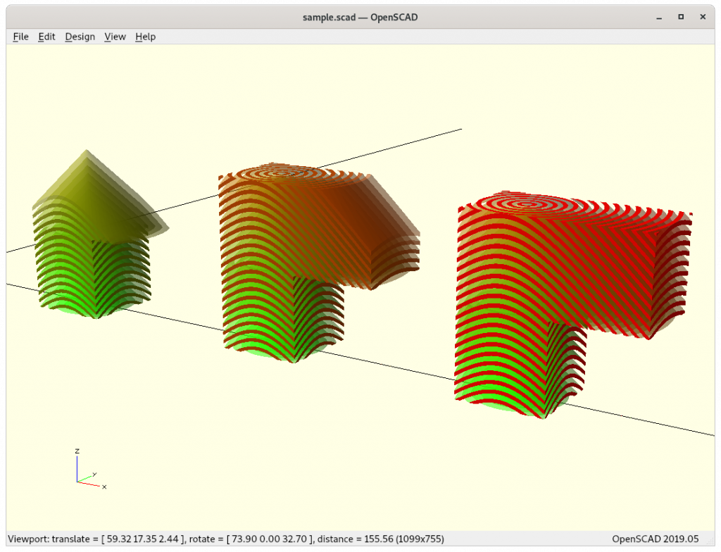
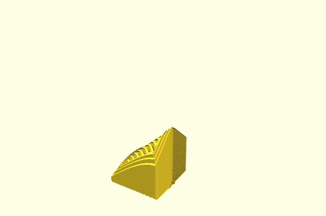
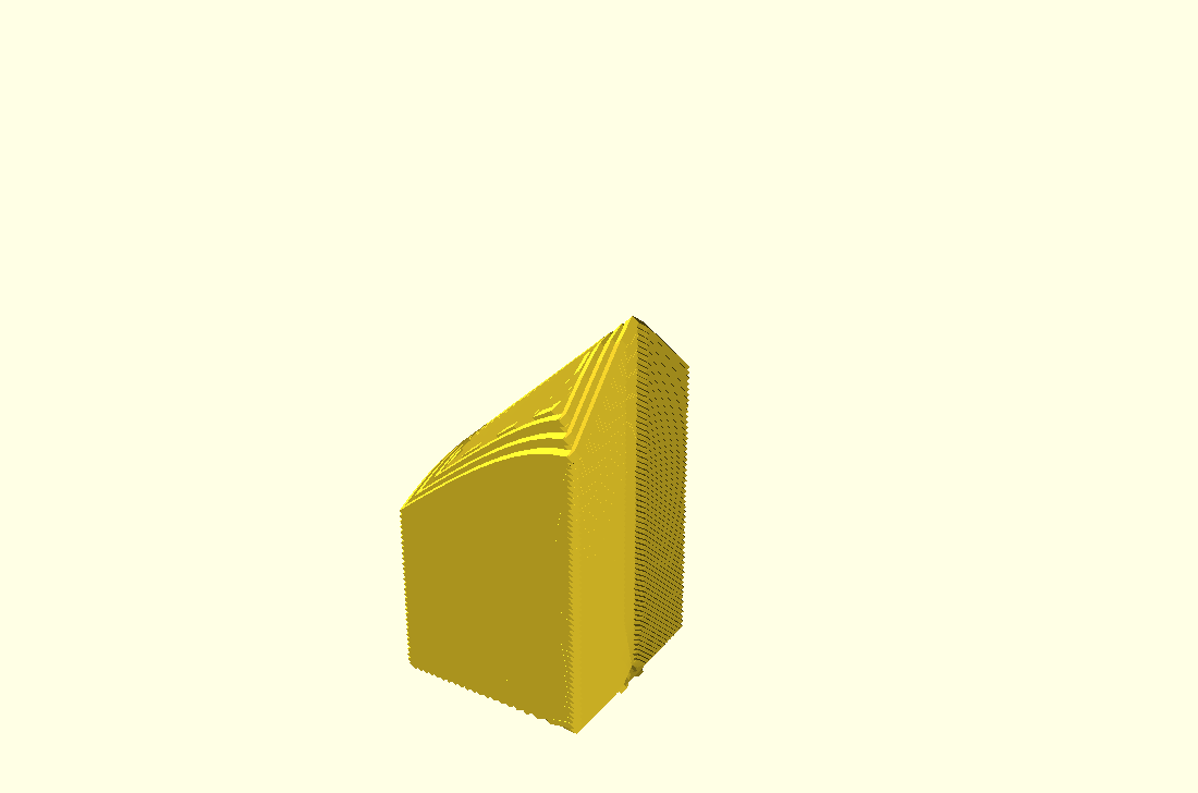
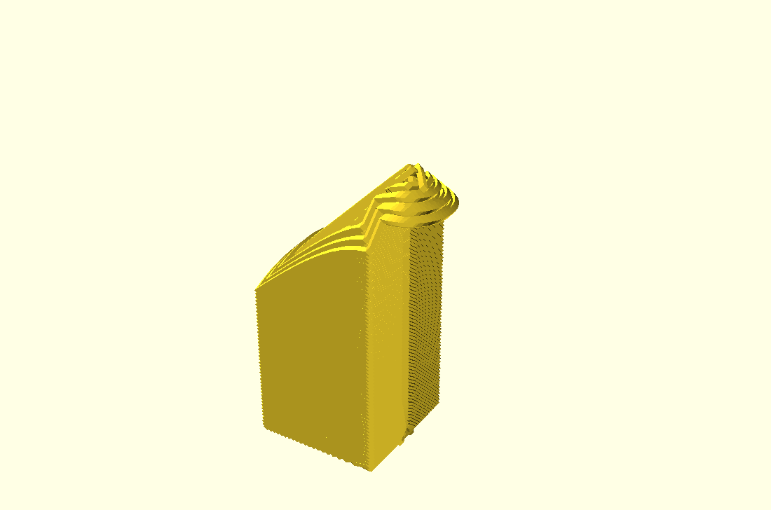
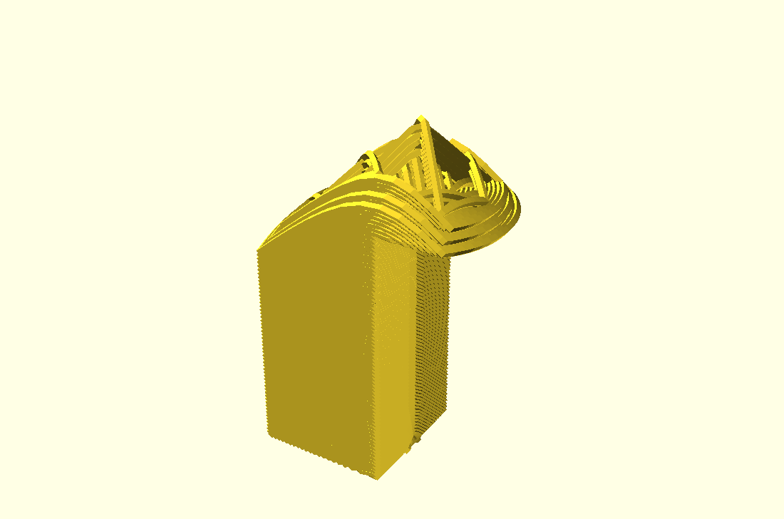
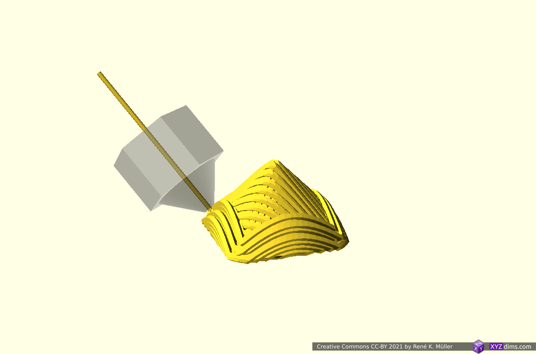
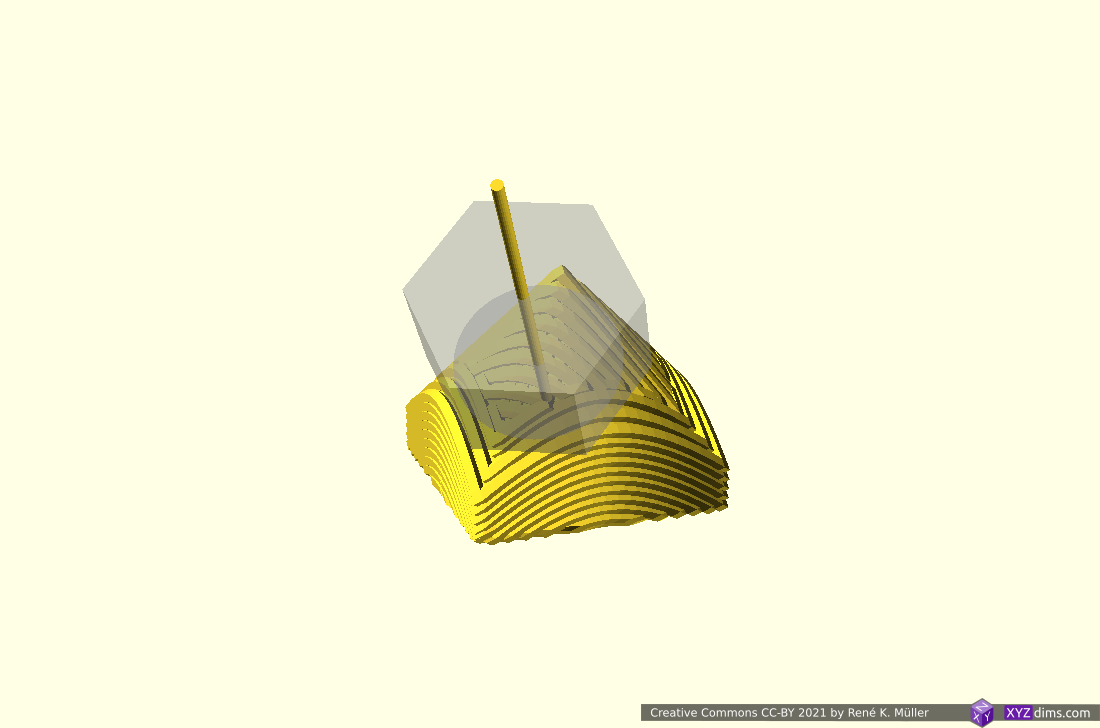
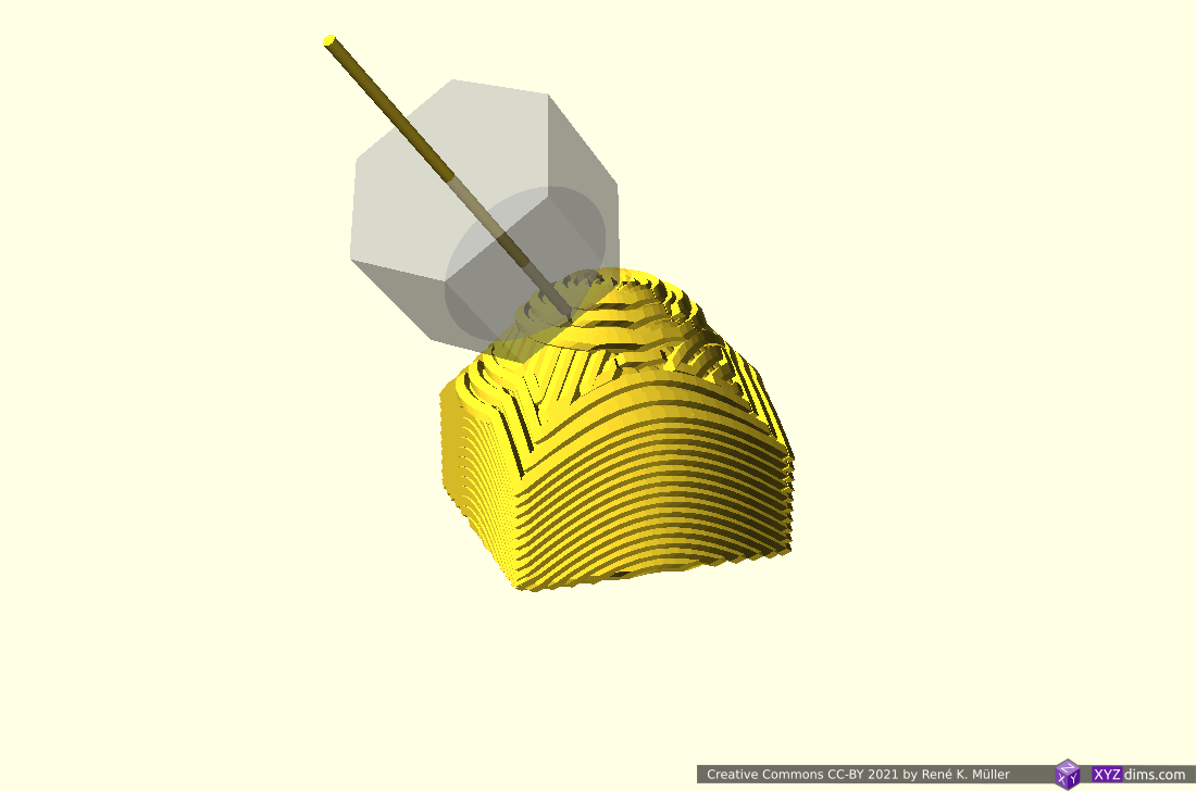
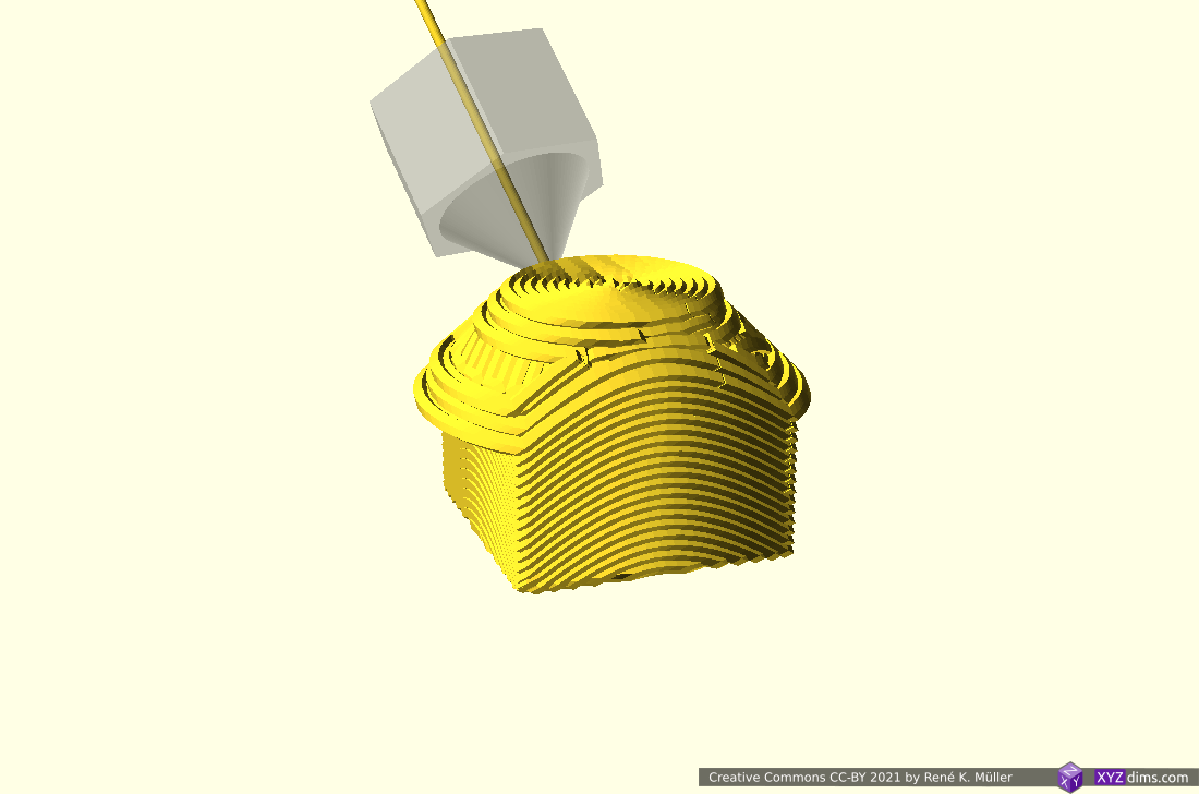
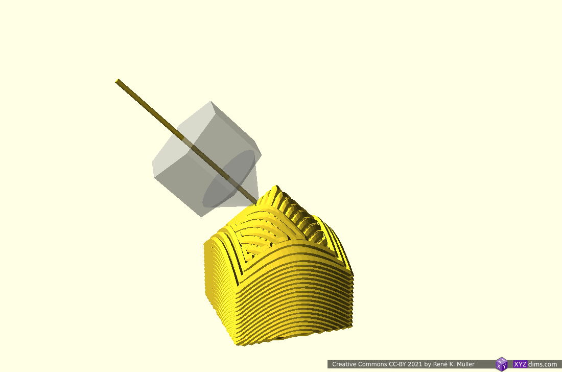
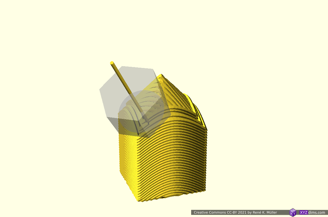
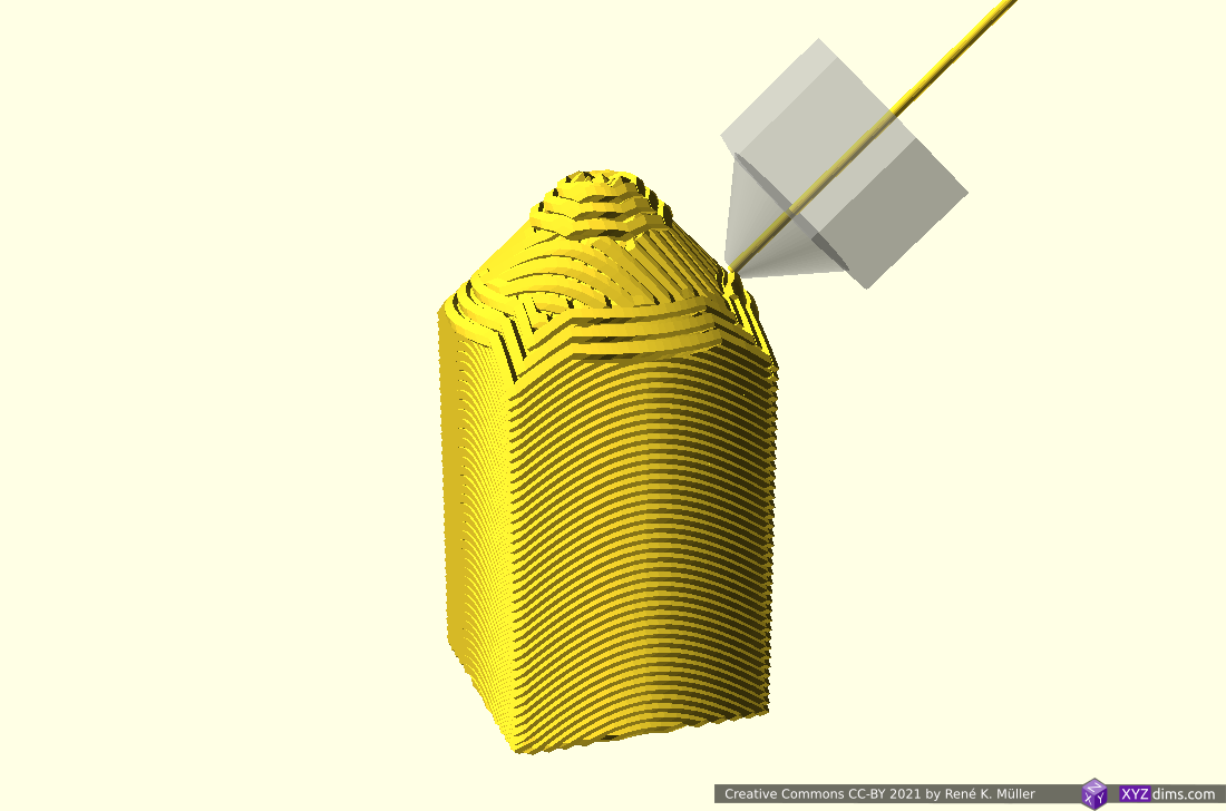
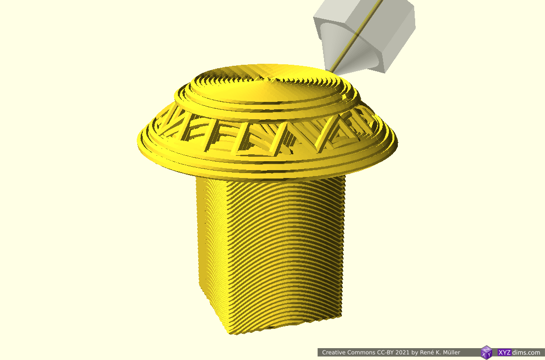
Snapshots of progress of conic sliced 20mm cube:
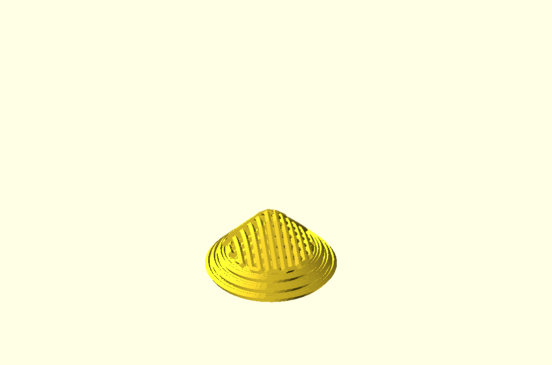
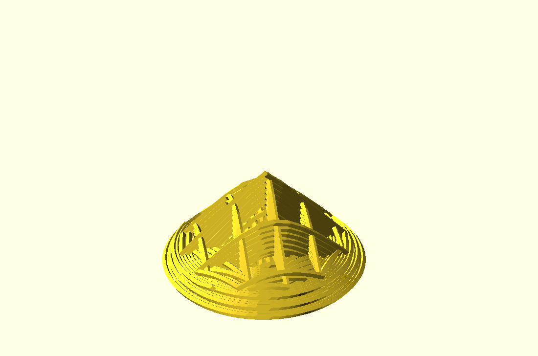
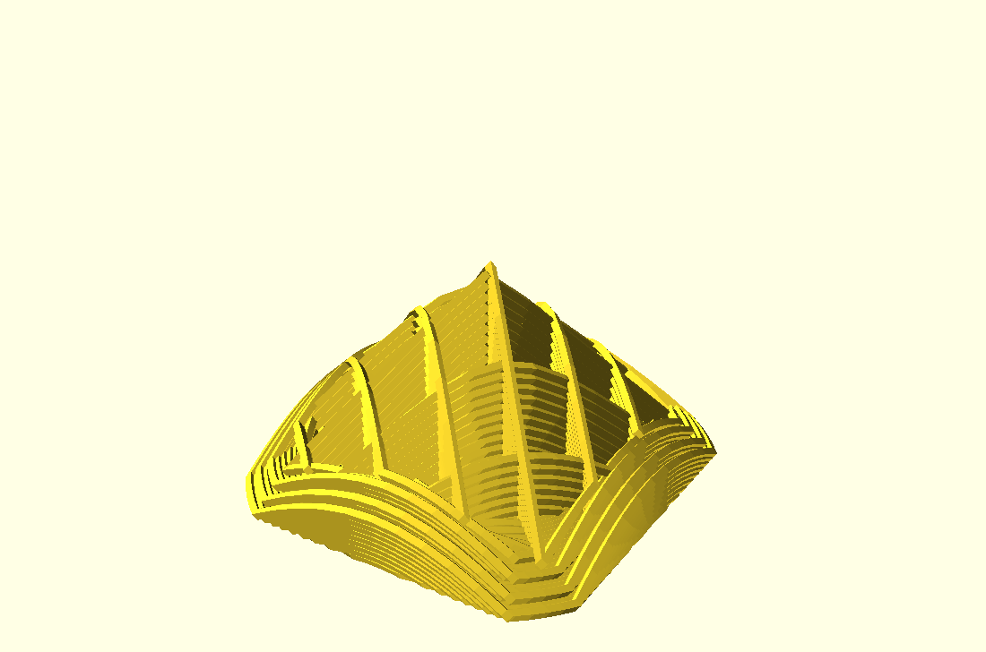
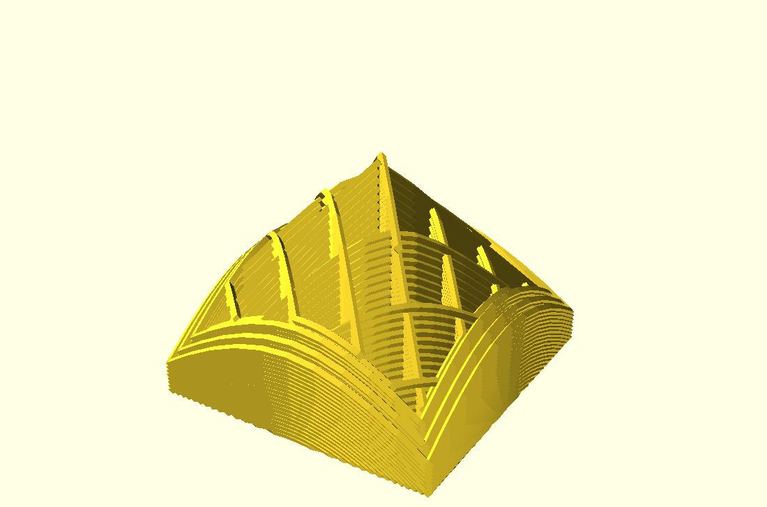
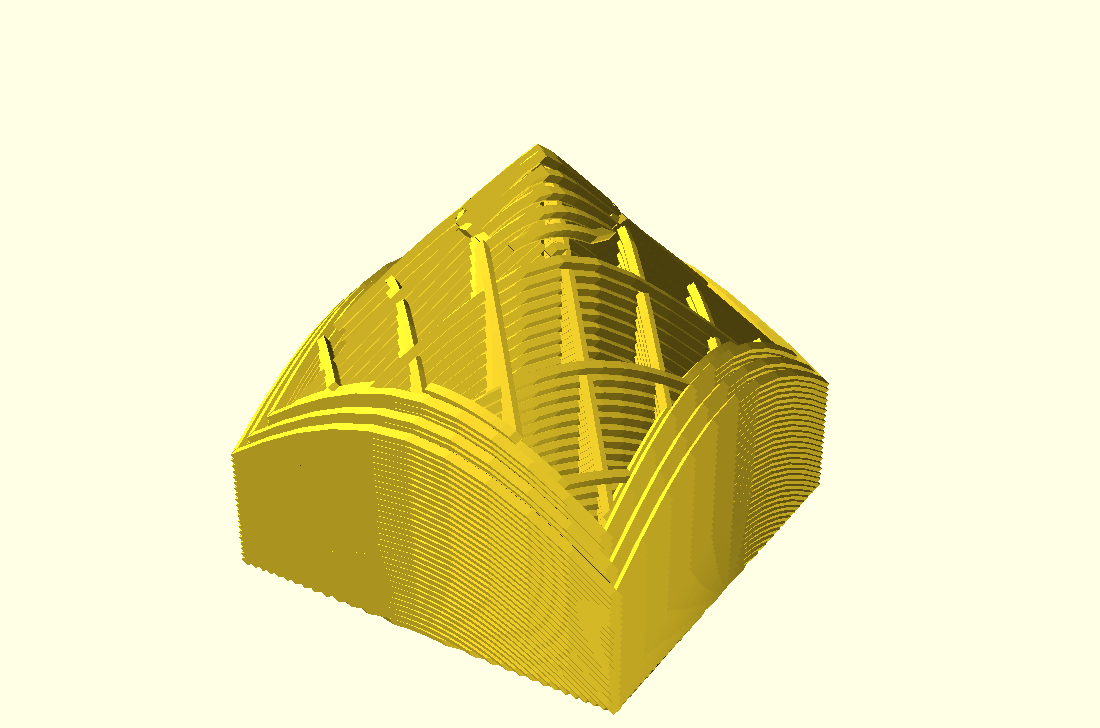

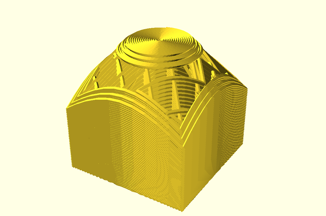
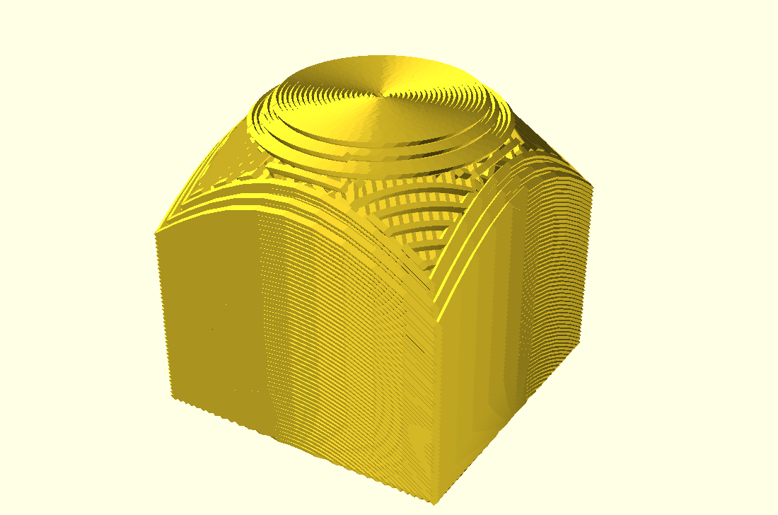
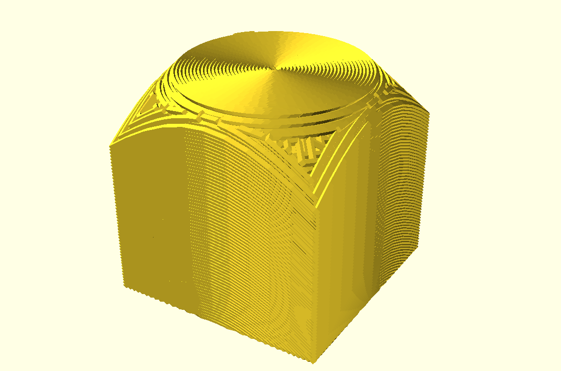

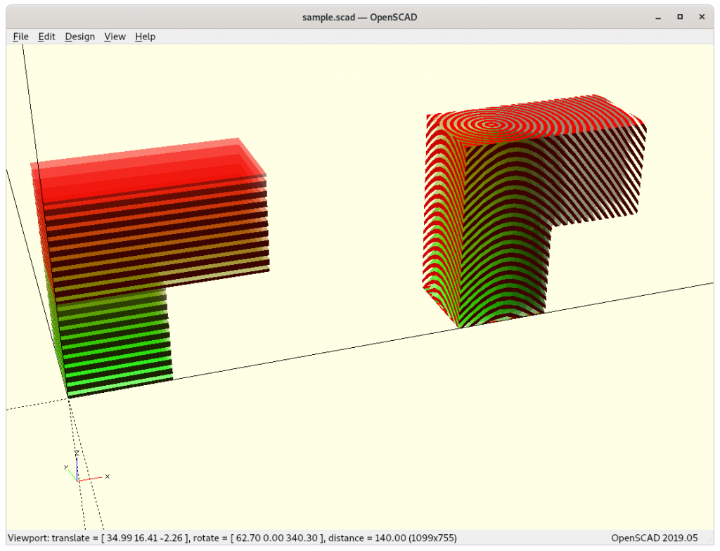
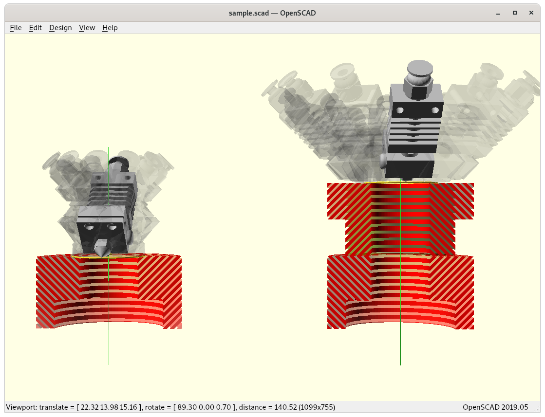
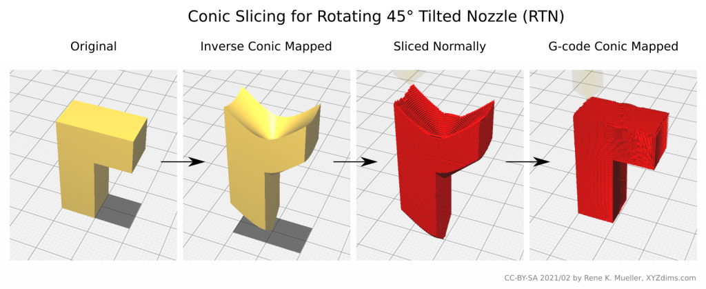
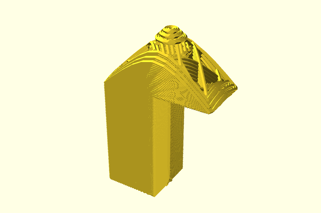
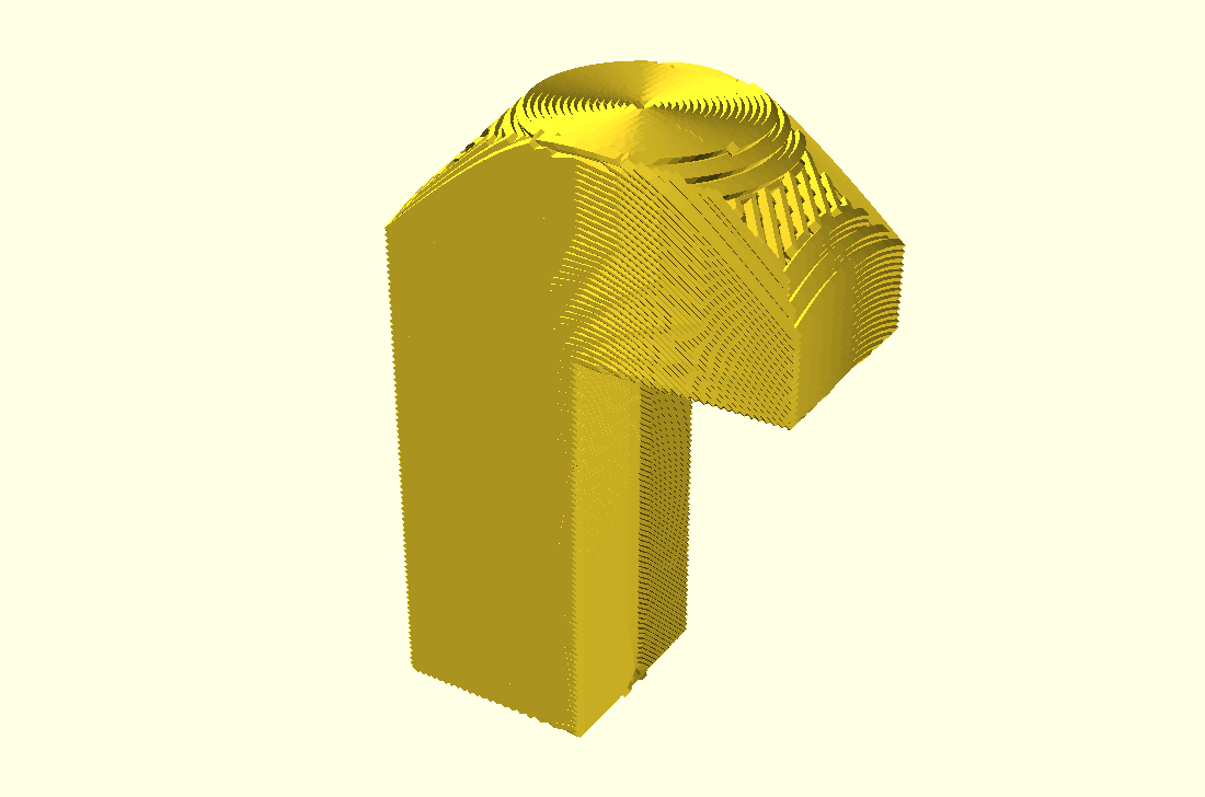
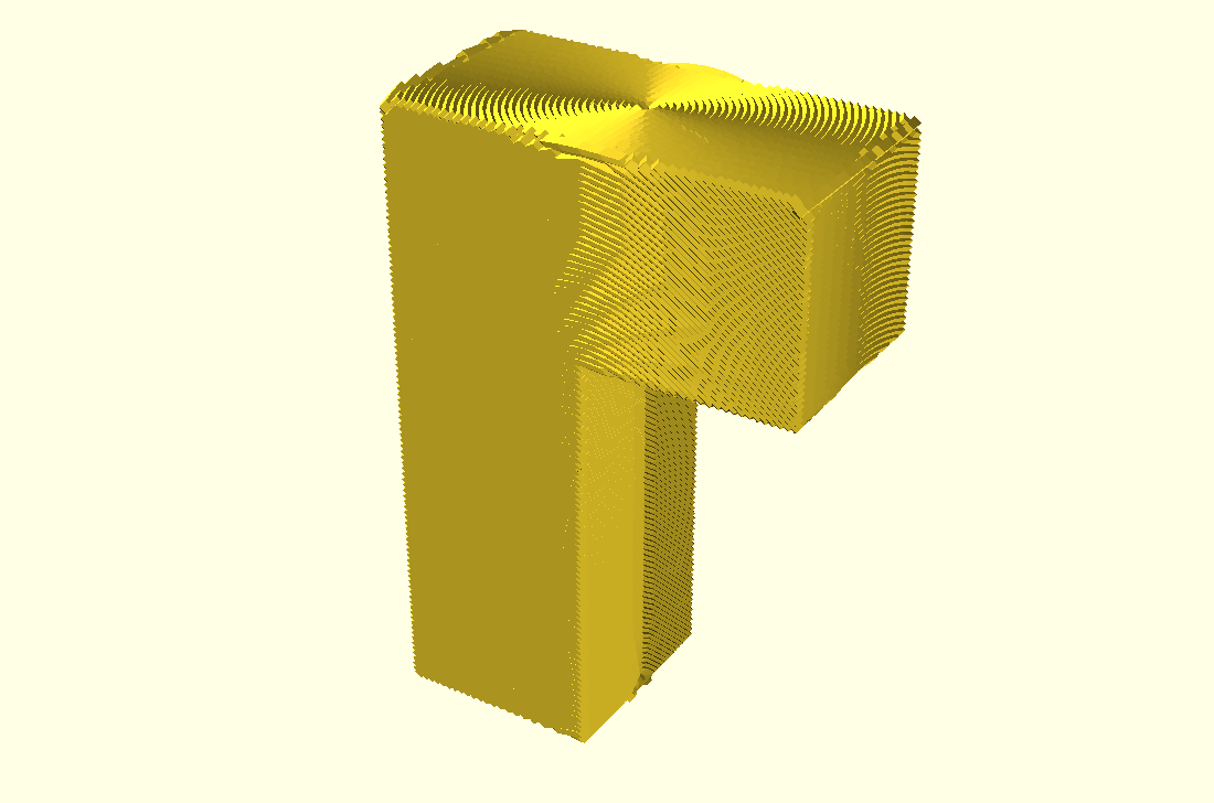
Overhang Conic Sliced
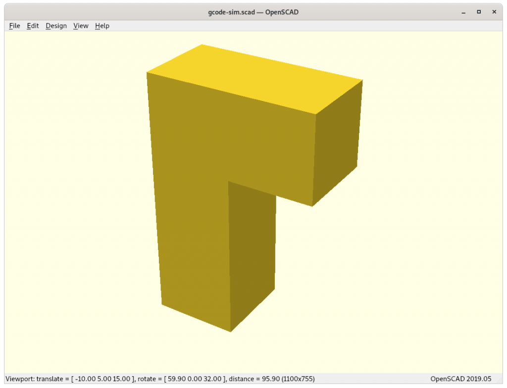
overhang model 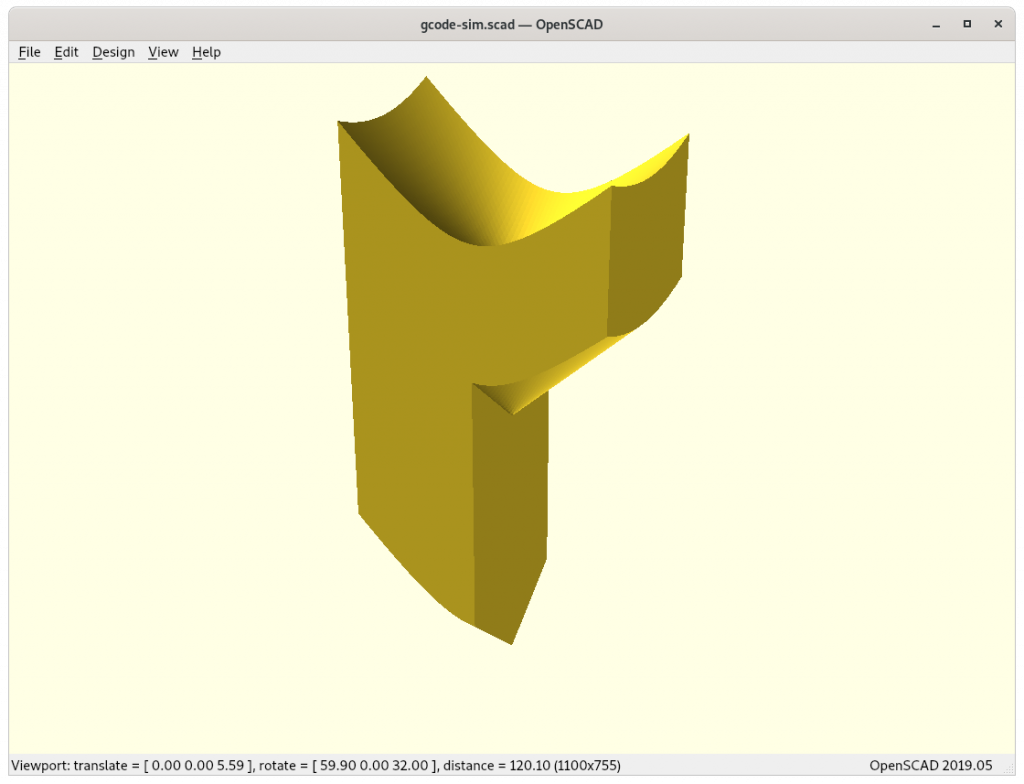
overhang model (inverse conic mapped) 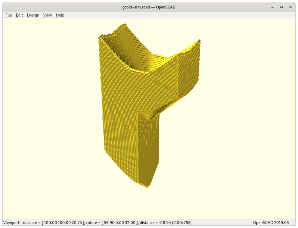
overhang model (inverse cubic mapped & sliced) 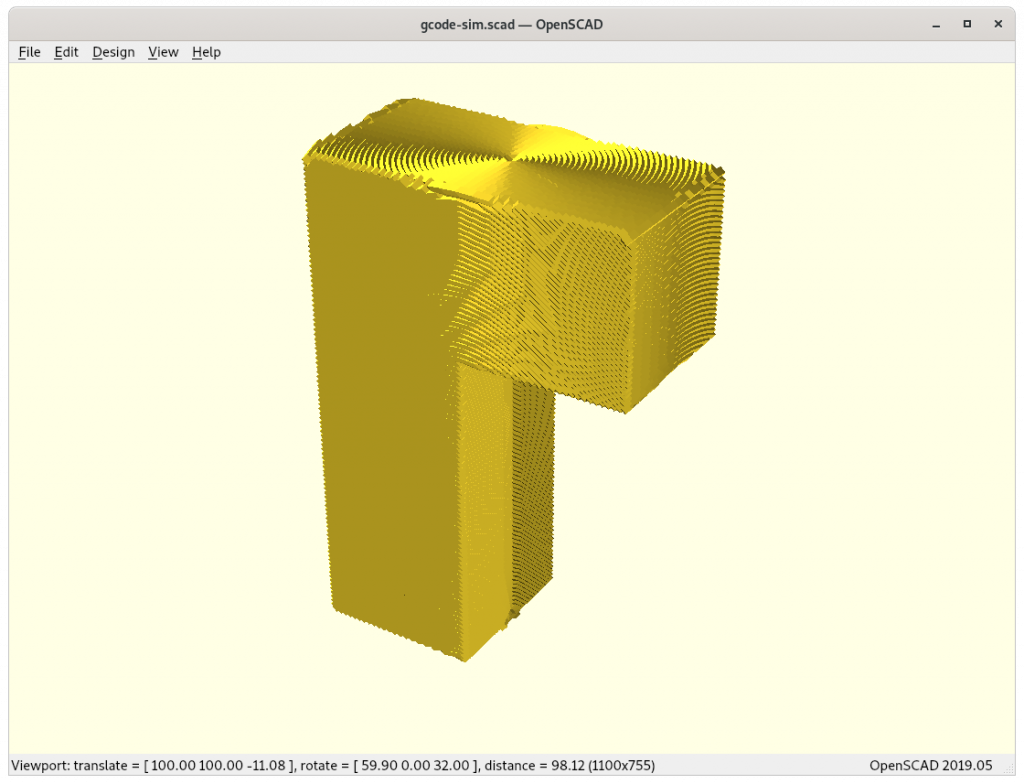
overhang model (G-code direct conic mapped)


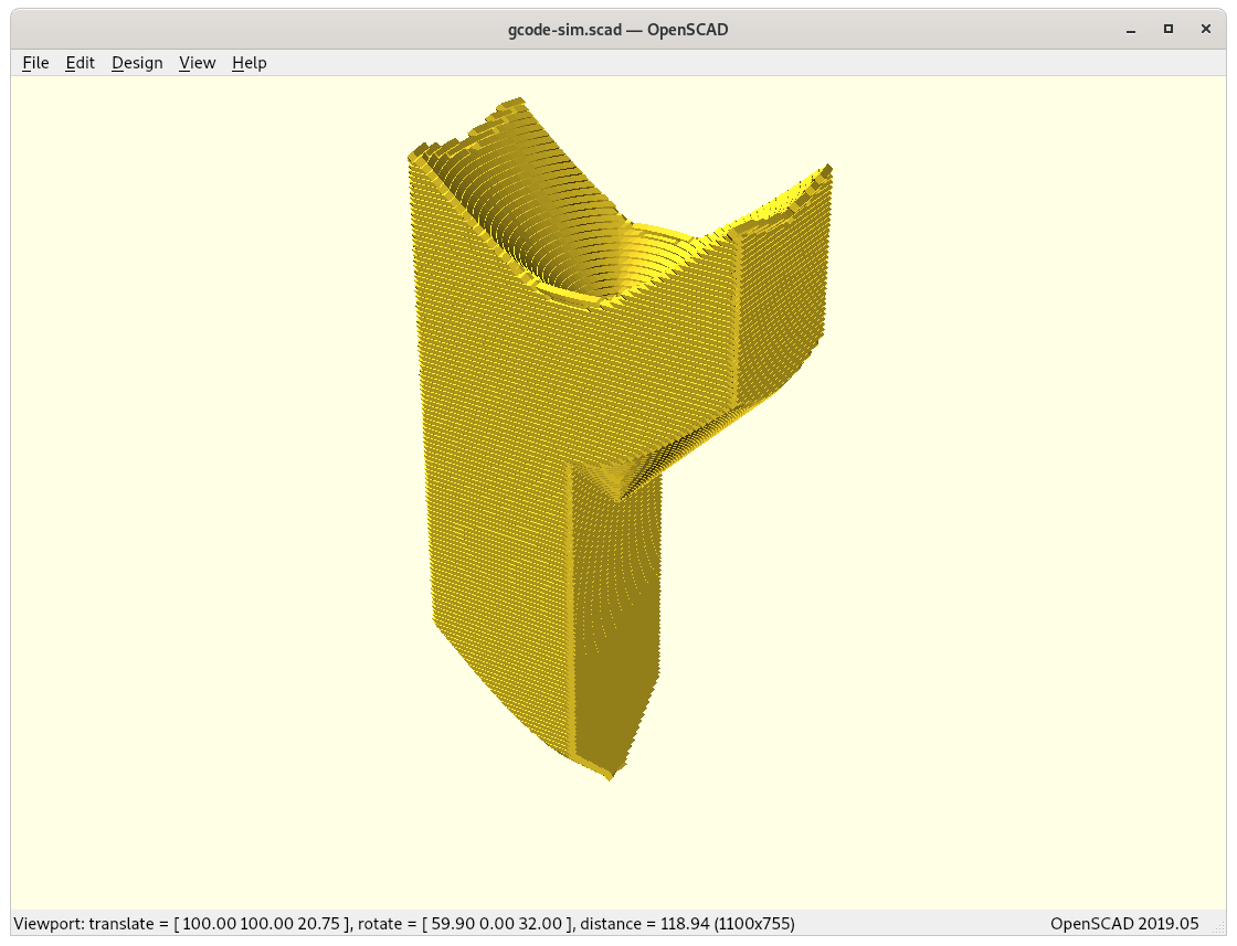

Snapshots of progress of conic sliced Overhang:


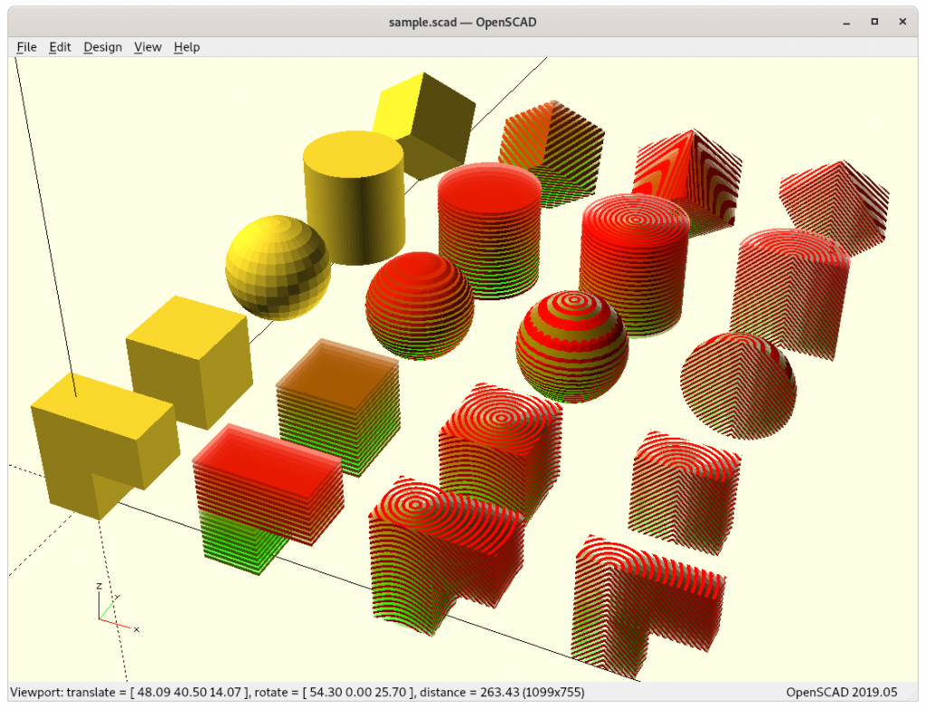
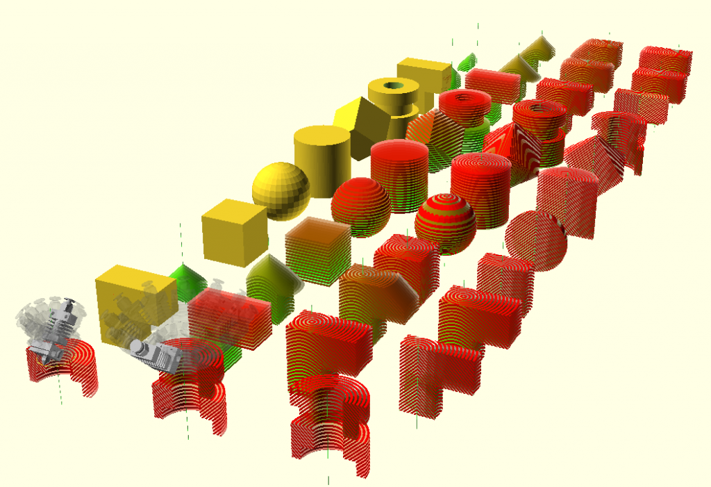
Gallery of Conic Sliced Models
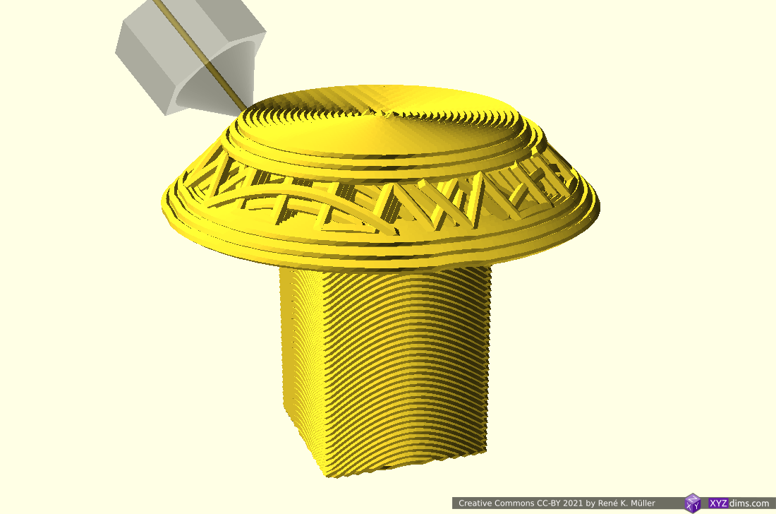
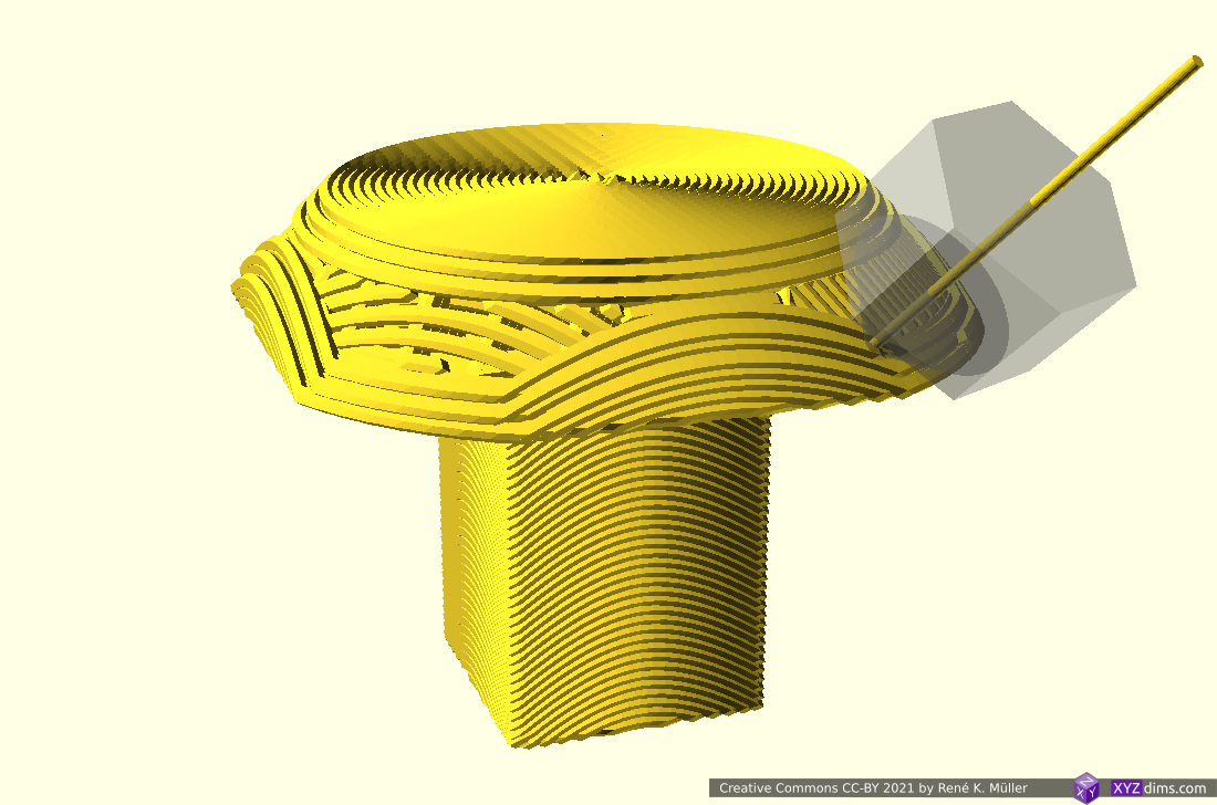
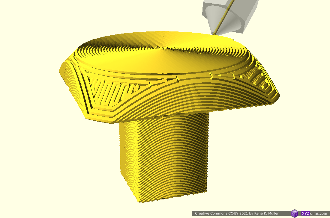
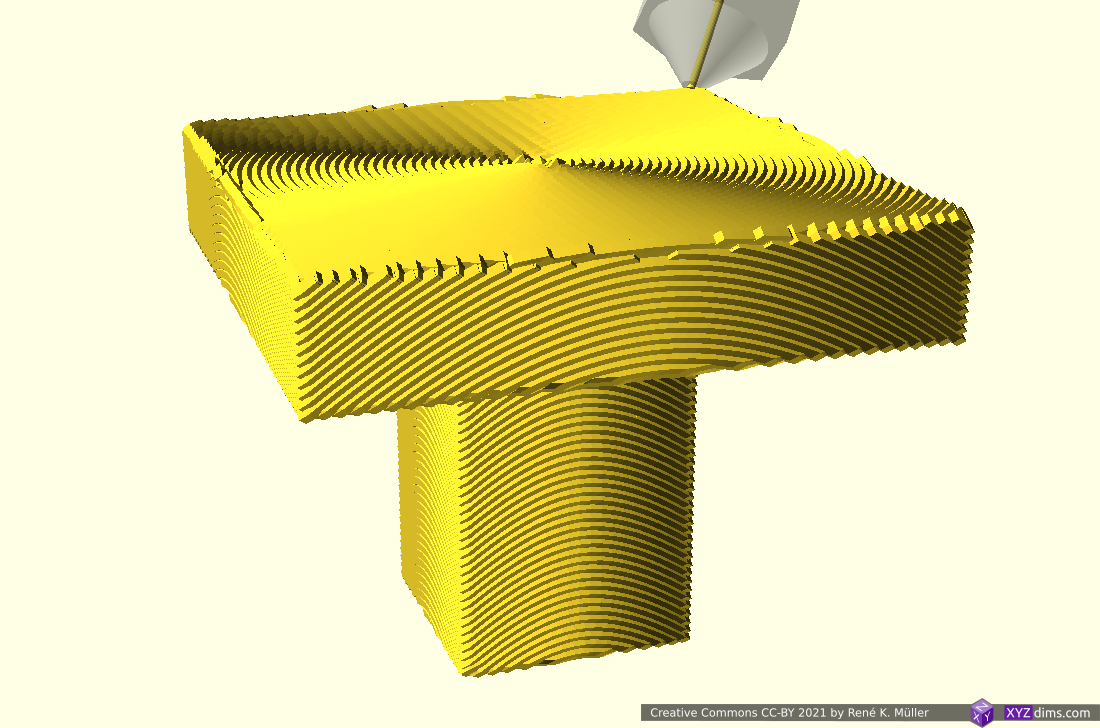
Detailed snapshots of overhang nr 3

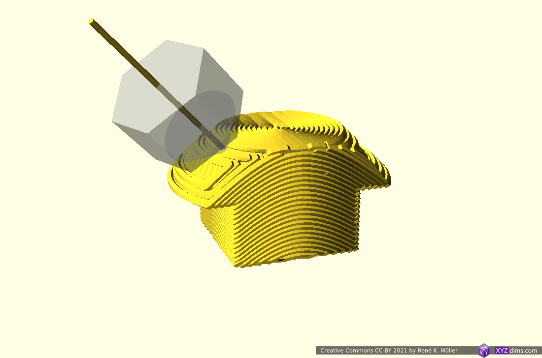

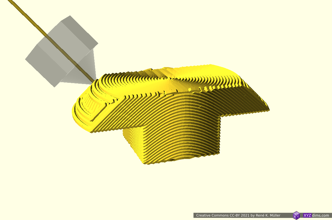
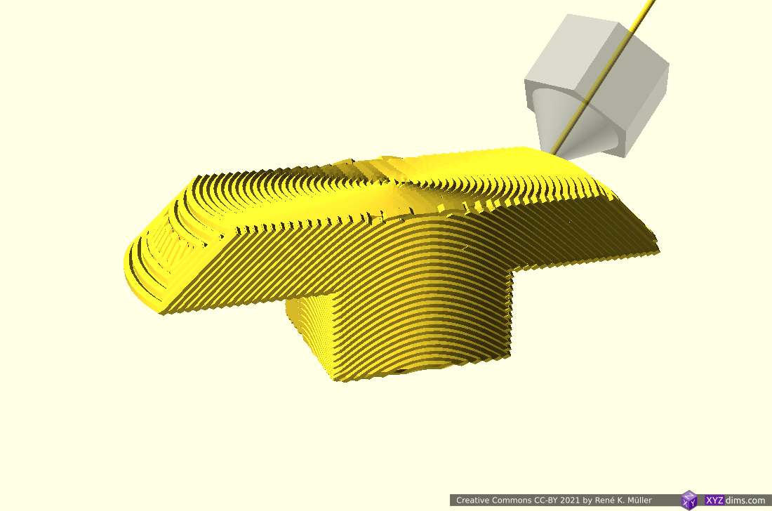
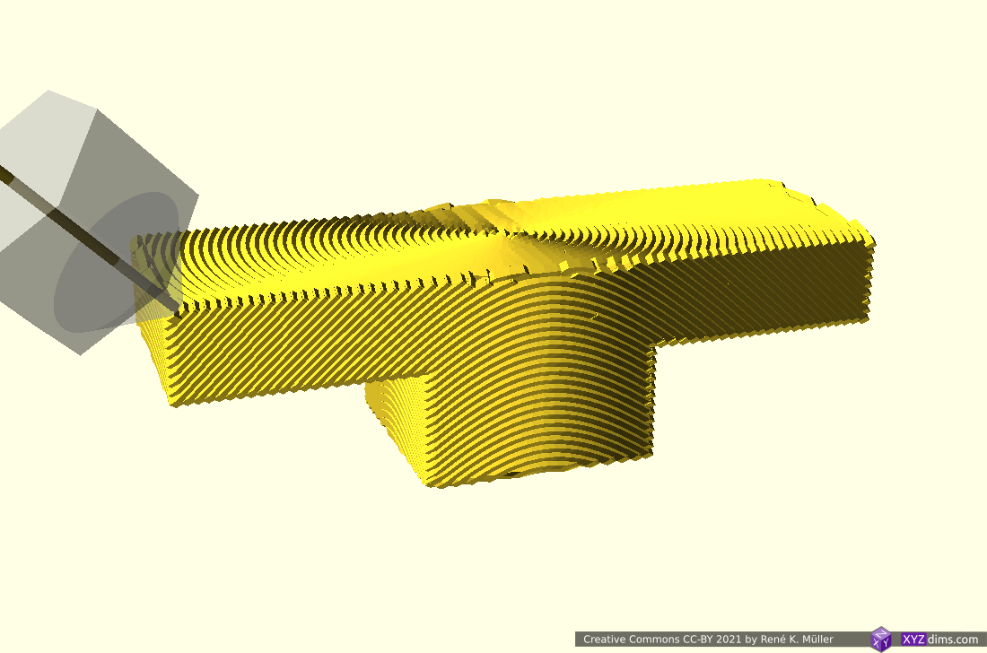
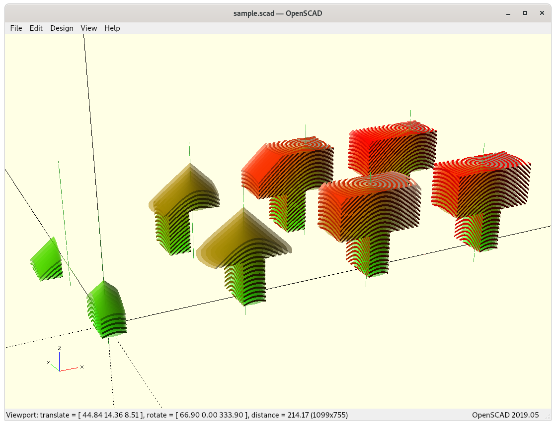
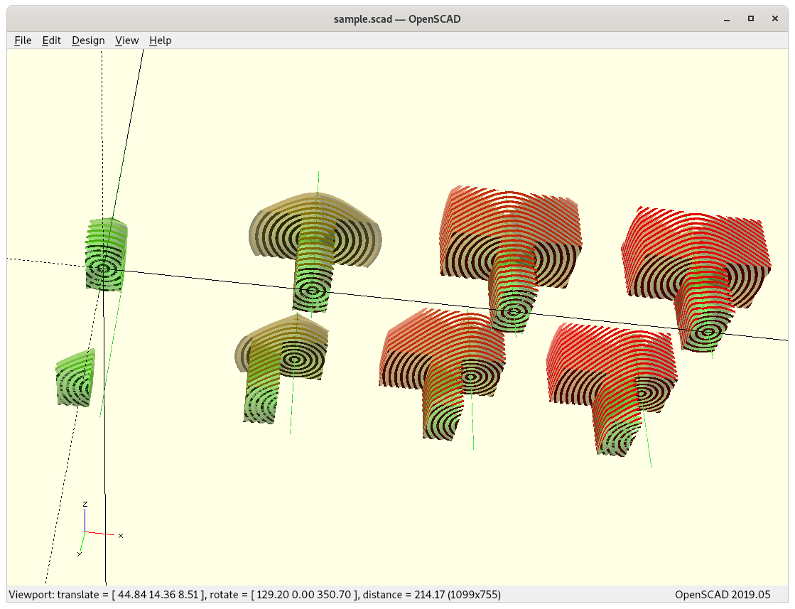
Detailed snapshots of model nr 6 (table-like)


Some more models with their in-between states, using Cura as model and G-code viewer:
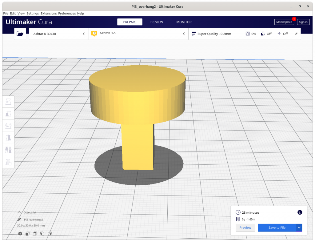
overhang 2 (original) 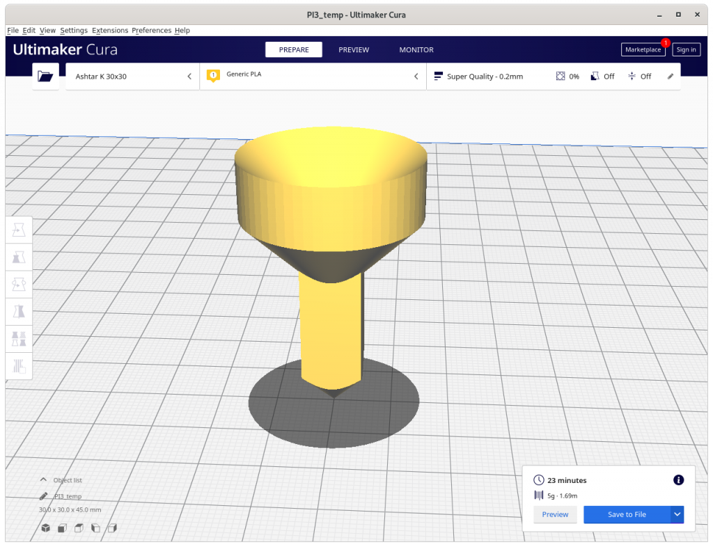
overhang 2 (inverse conic) 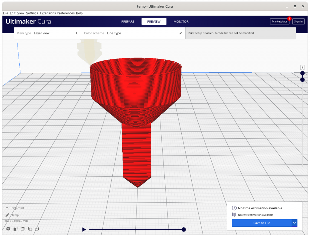
overhang 2 (inverse conic sliced) 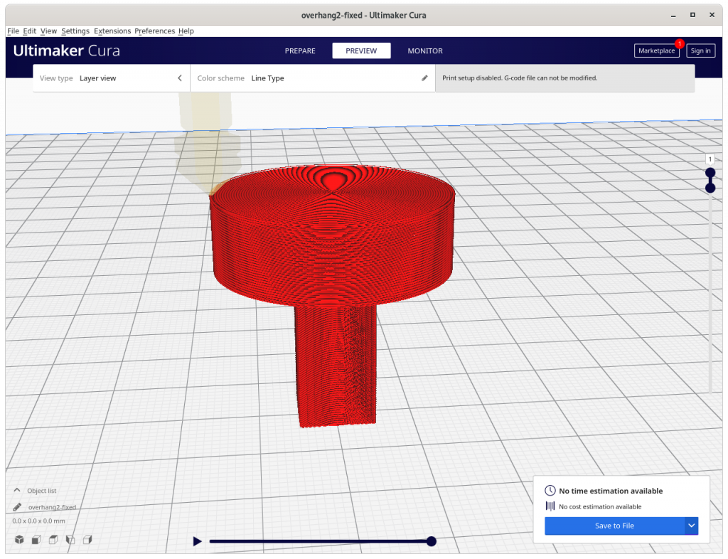
overhang 2 (conic sliced) 
sphere (original) 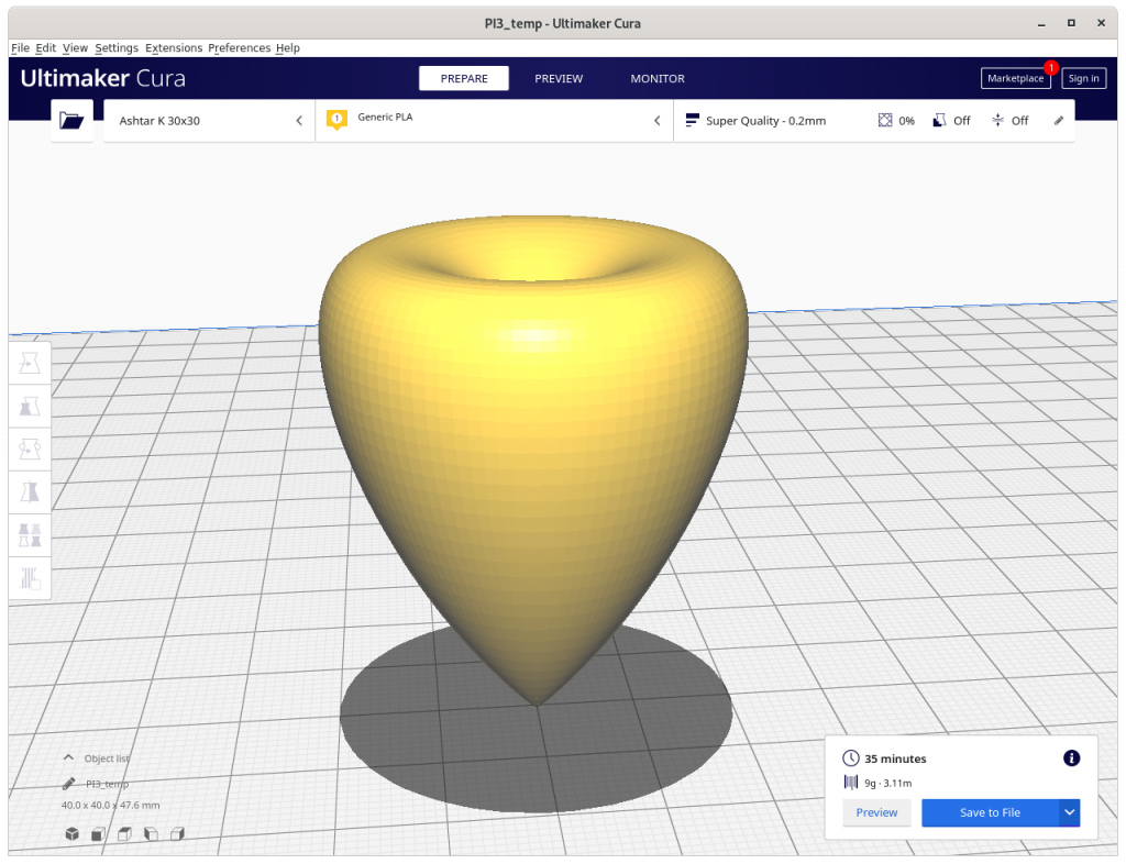
sphere (inverse conic) 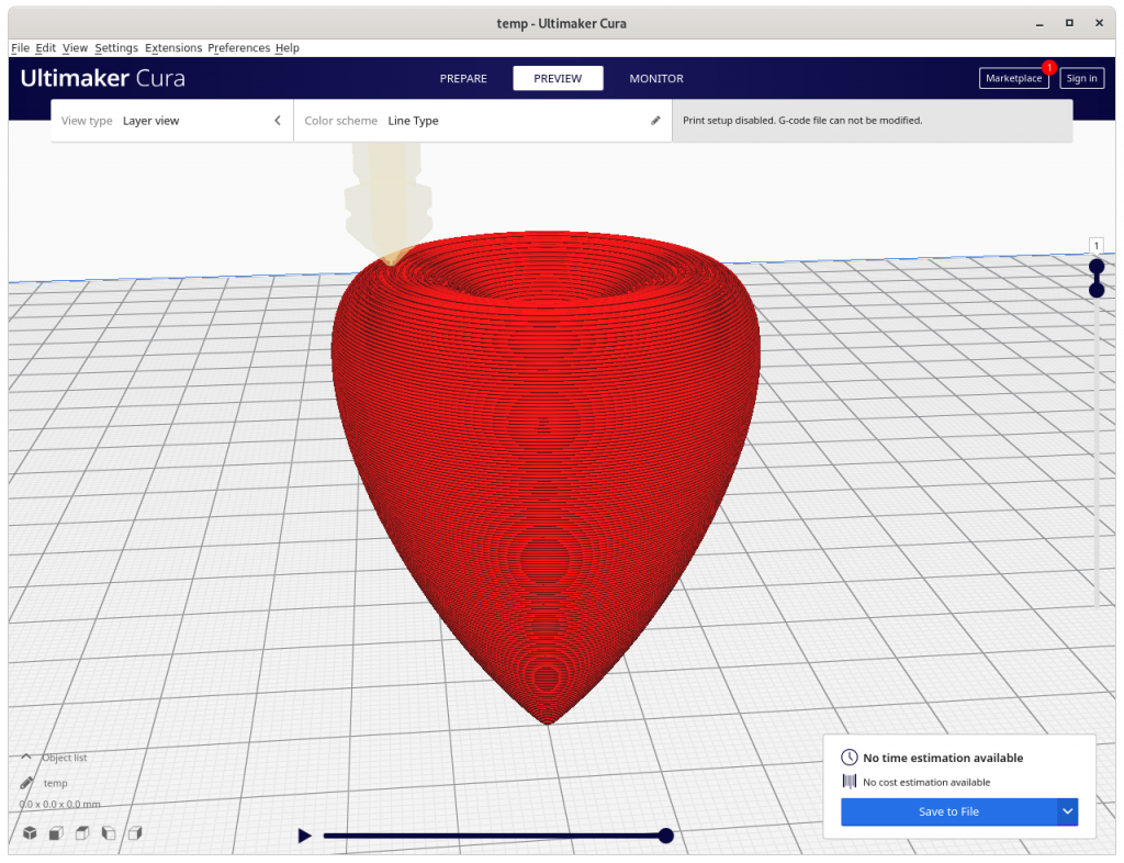
sphere (inverse conic sliced) 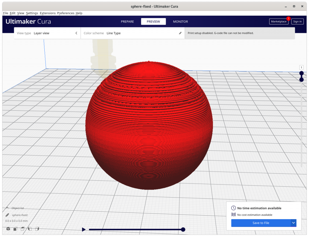
sphere (conic sliced) 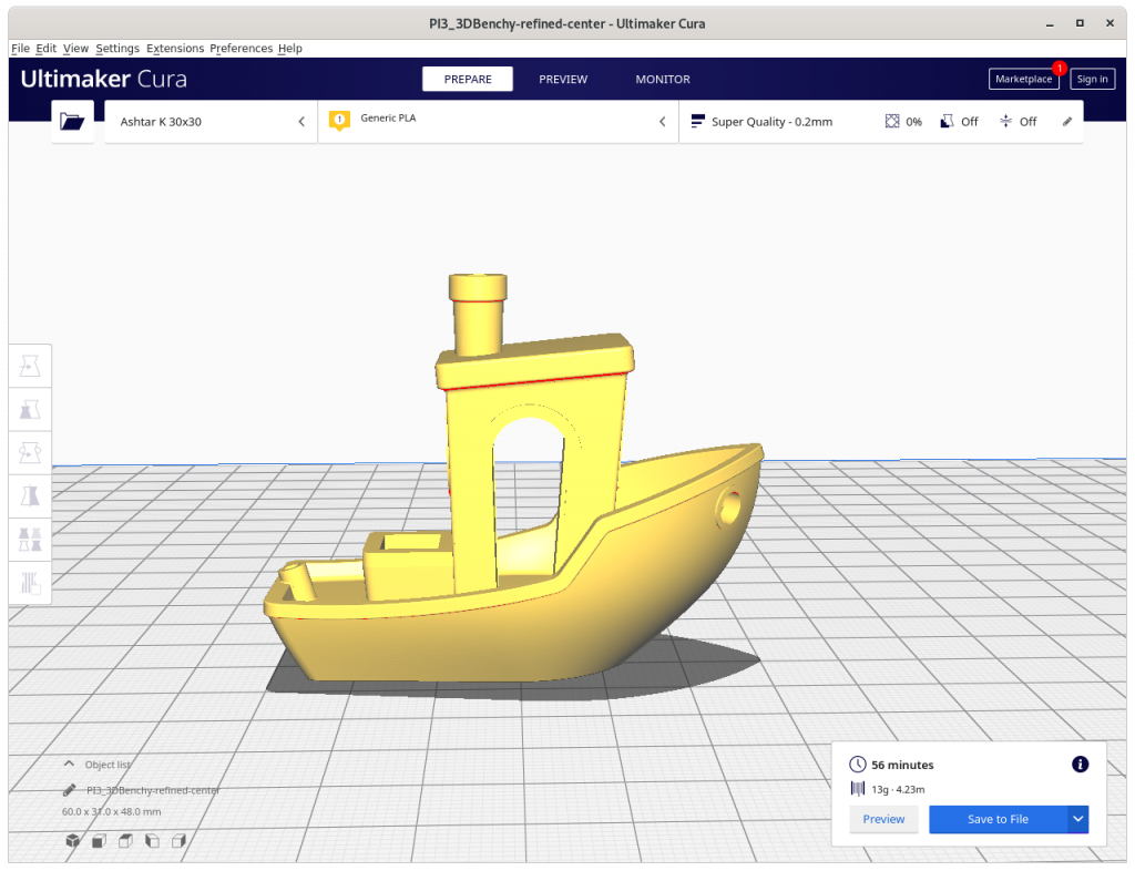
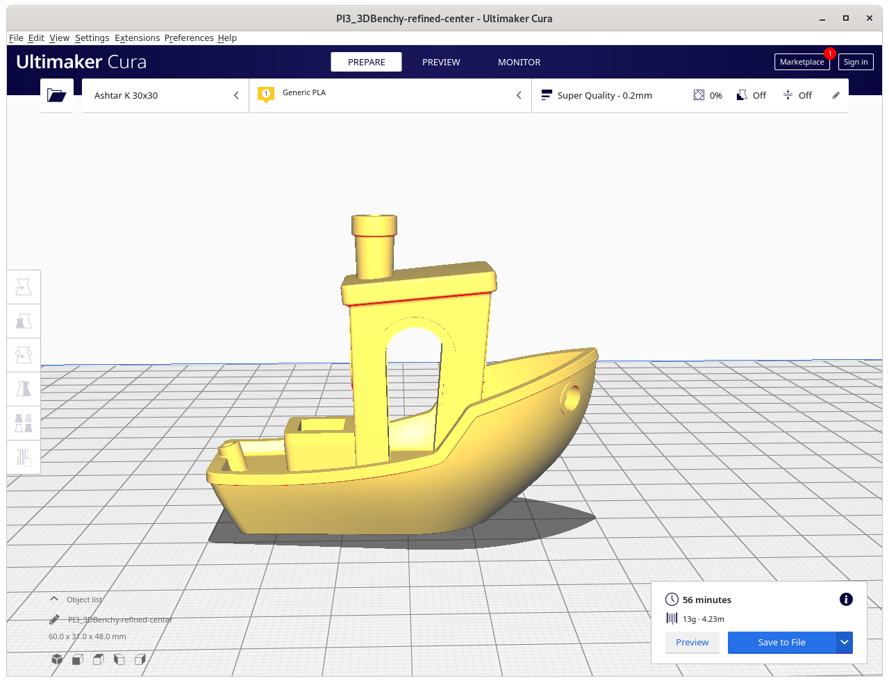
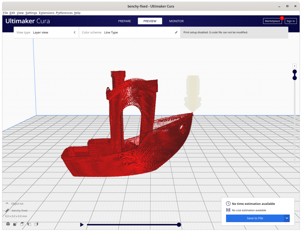
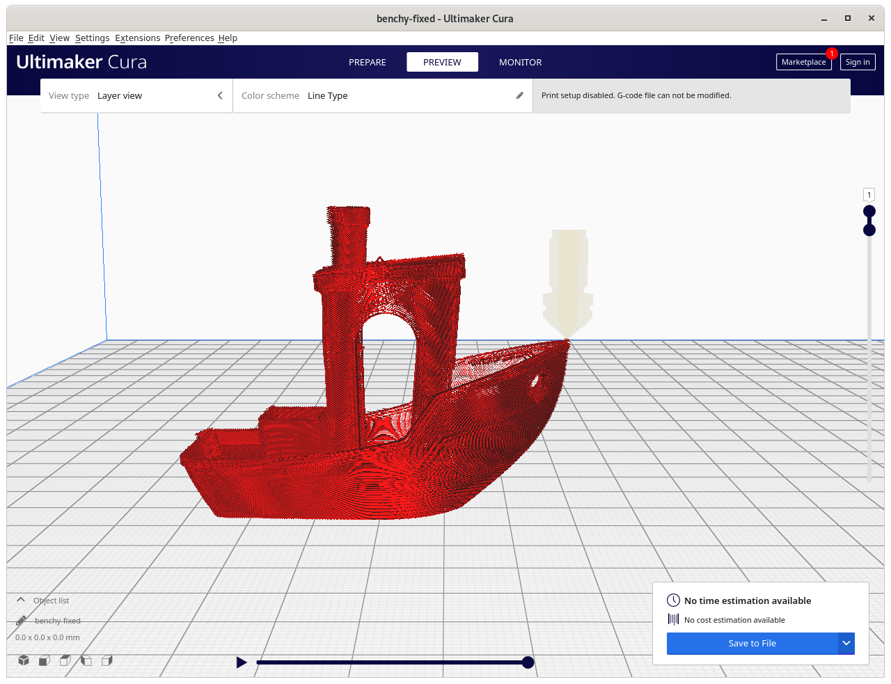
3D Benchy (original) 
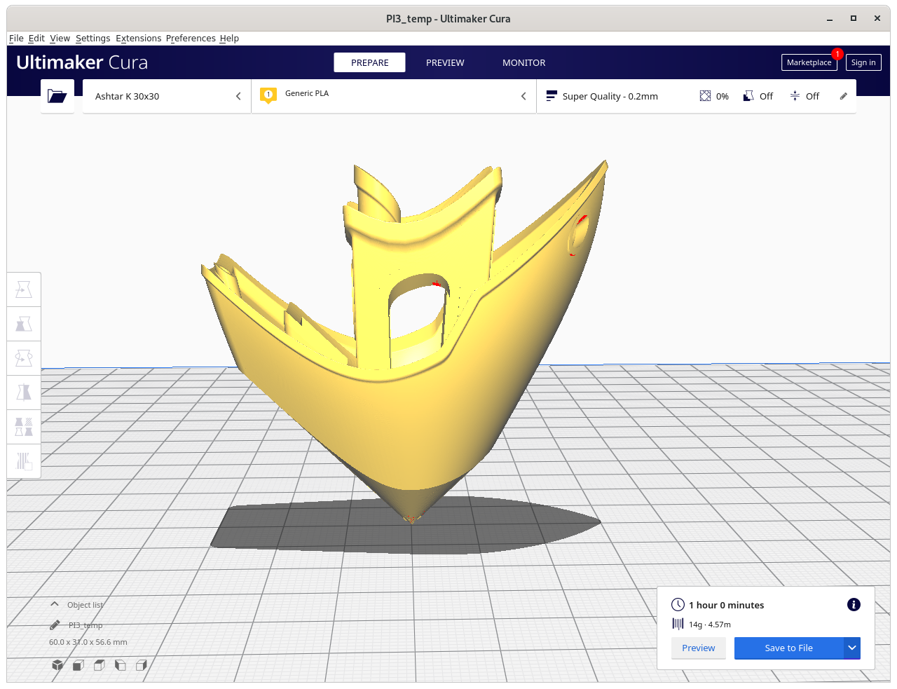
3D Benchy (inverse conic) 
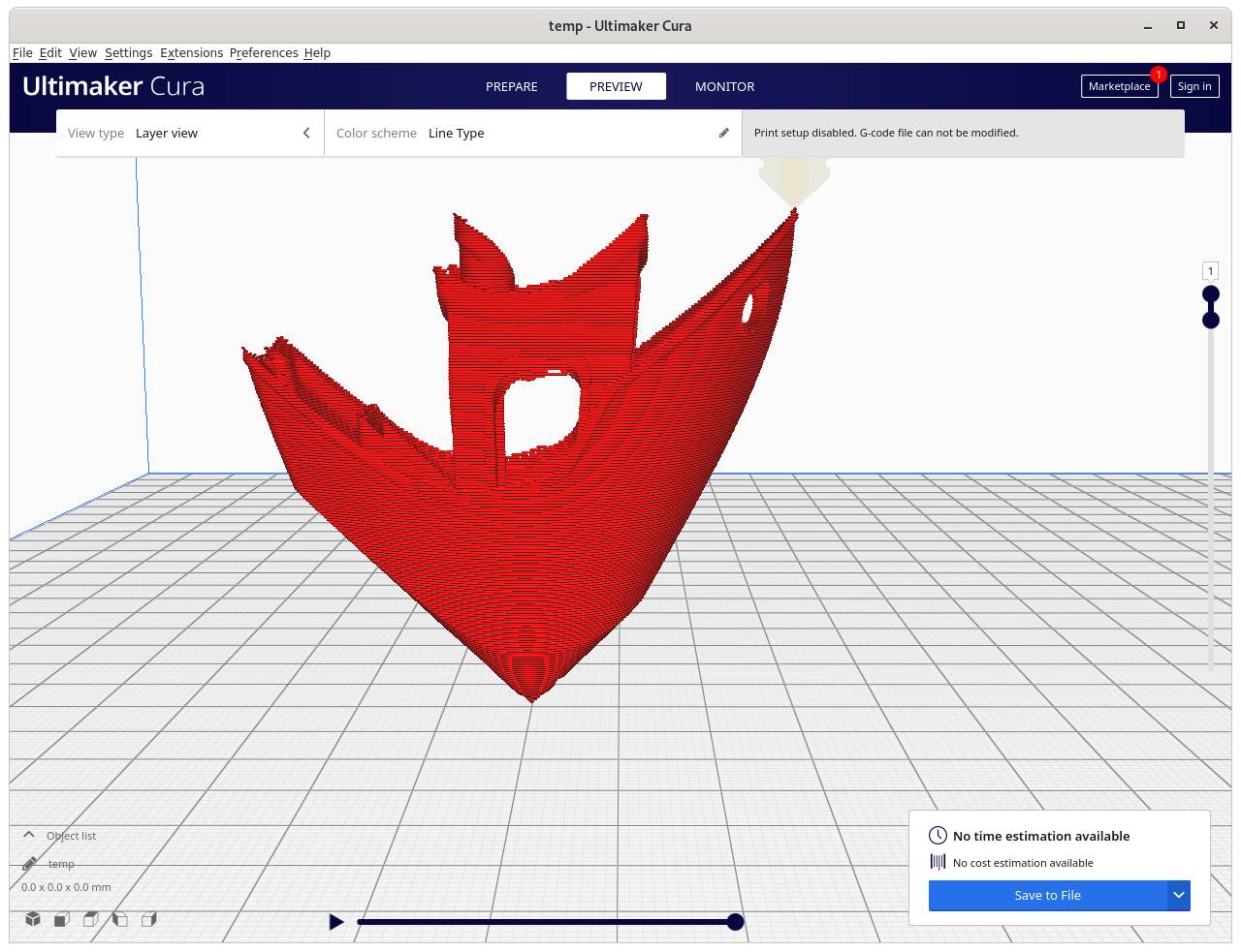
3D Benchy (inverse conic sliced) 
3D Benchy (conic sliced)

Issues to Resolve
- test actual G-code in real life
verify, verified with G-code simulator coded with OpenSCADAxxx/ Zrot- verify
Exxxinterpolation (some experiences with printing with vertical nozzle)
- find good pre-processing face sub-division strategy
in its current form the algorithm requires fine-grained sub-divided faces otherwise inaccurate G-code is created which cannot be recovered
3D Benchy conic sliced with Original Faces 
3D Benchy conic sliced with Refined Faces

- slice more complex parts
- 3D Benchy: requires more thorough examination, e.g. volume decomposition to segment roof apart:
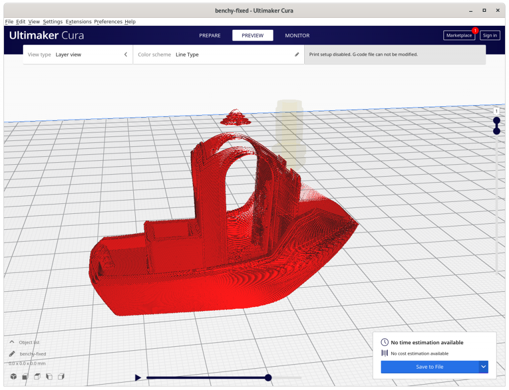
Impossible printing: current conic slicing needs to recognize overhangs and apply volume decomposition to choose right strategies – otherwise new issues arise which in Z planar slicing do not exist 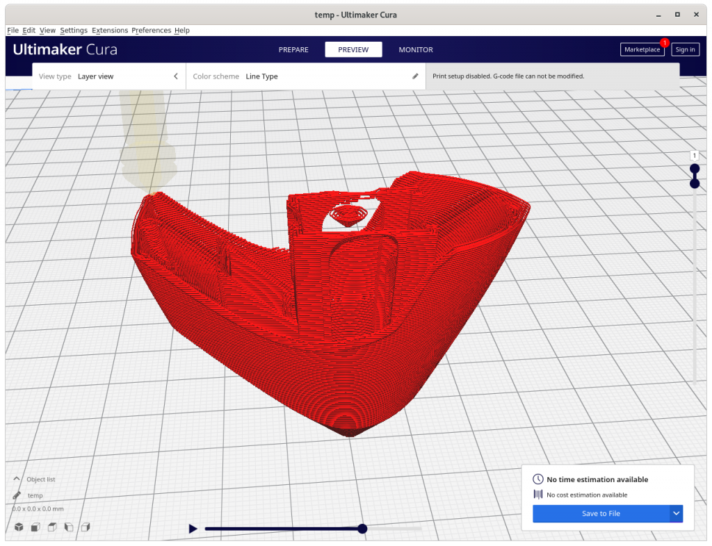
Same G-code position of the Inverse Conic sliced model: > 90° overhang created, and causes in-air structure – might require actual support structure (!!), volume decomposition required


- document all details
- release source code to public
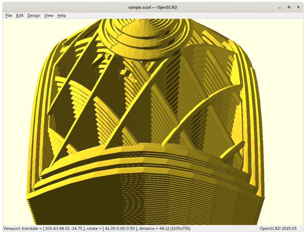
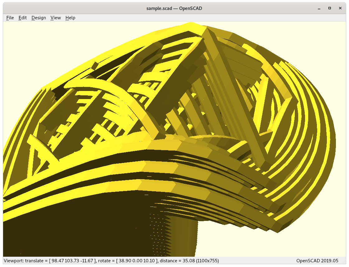
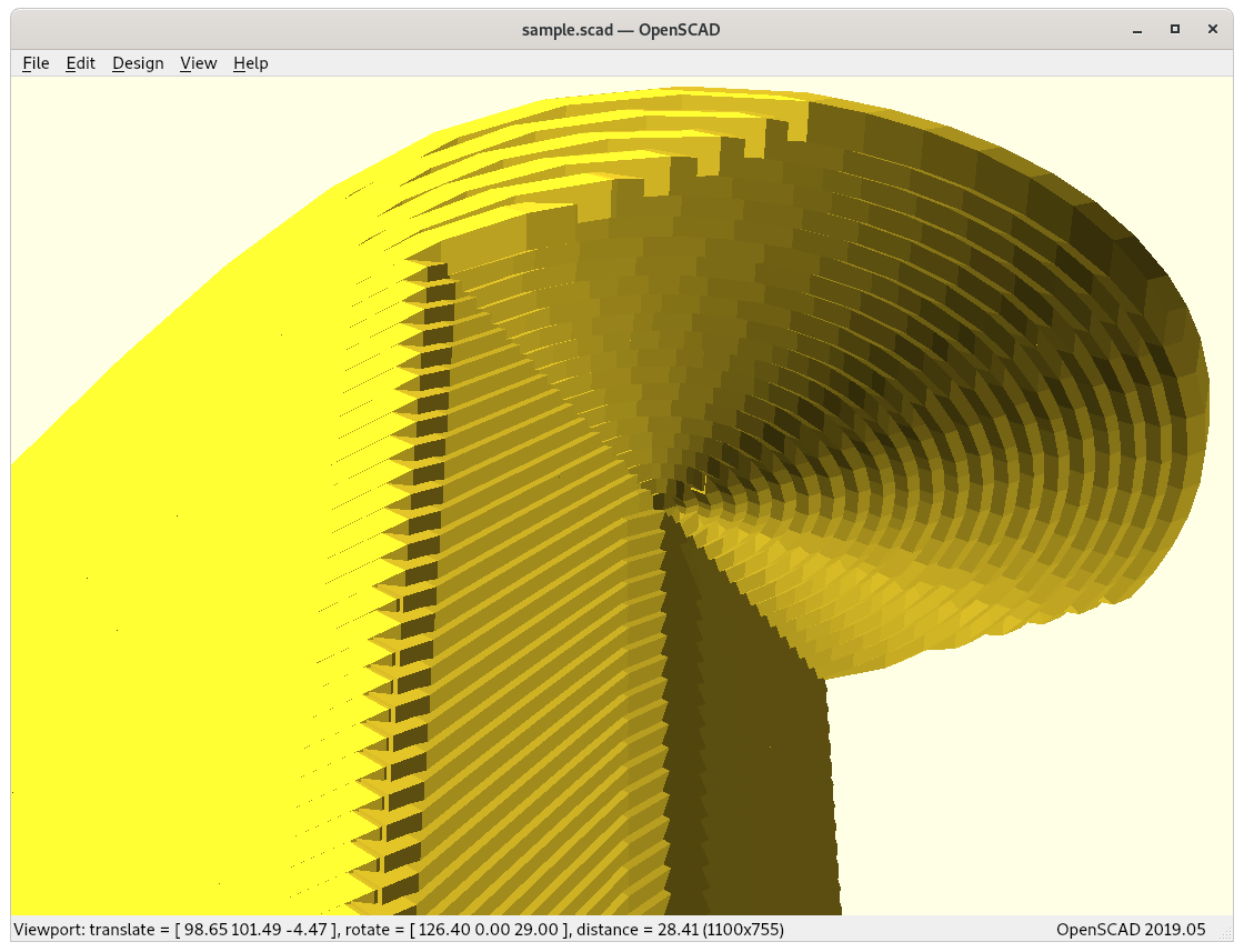
Close-Ups
Some close-ups of conic sliced models:
20mm cube (partial) 
3D Benchy (roof & chimney) 
3D Benchy (cabin) 
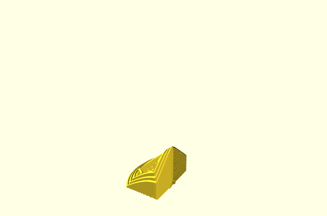
Overhang model (top view) 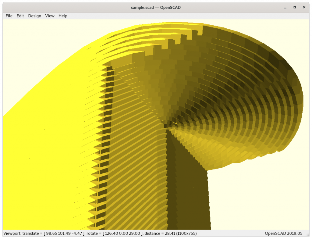
Overhang model (view on actual overhang)
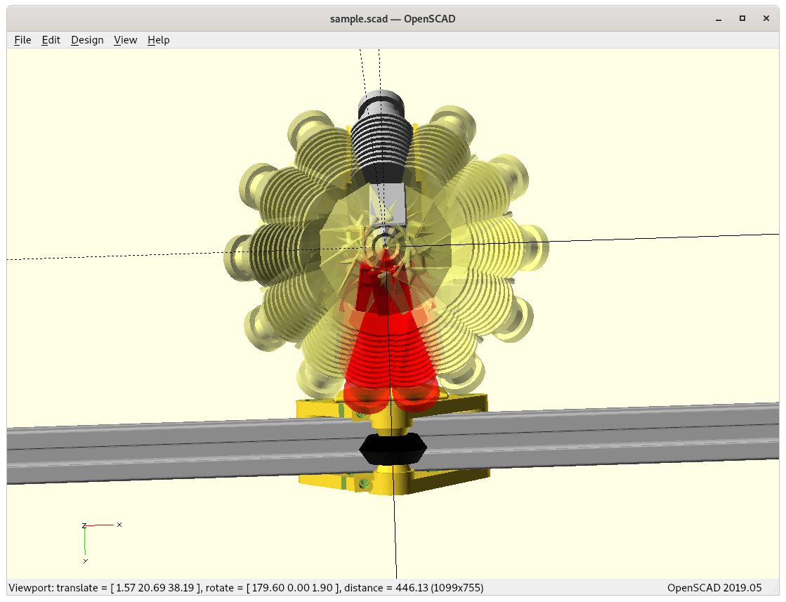
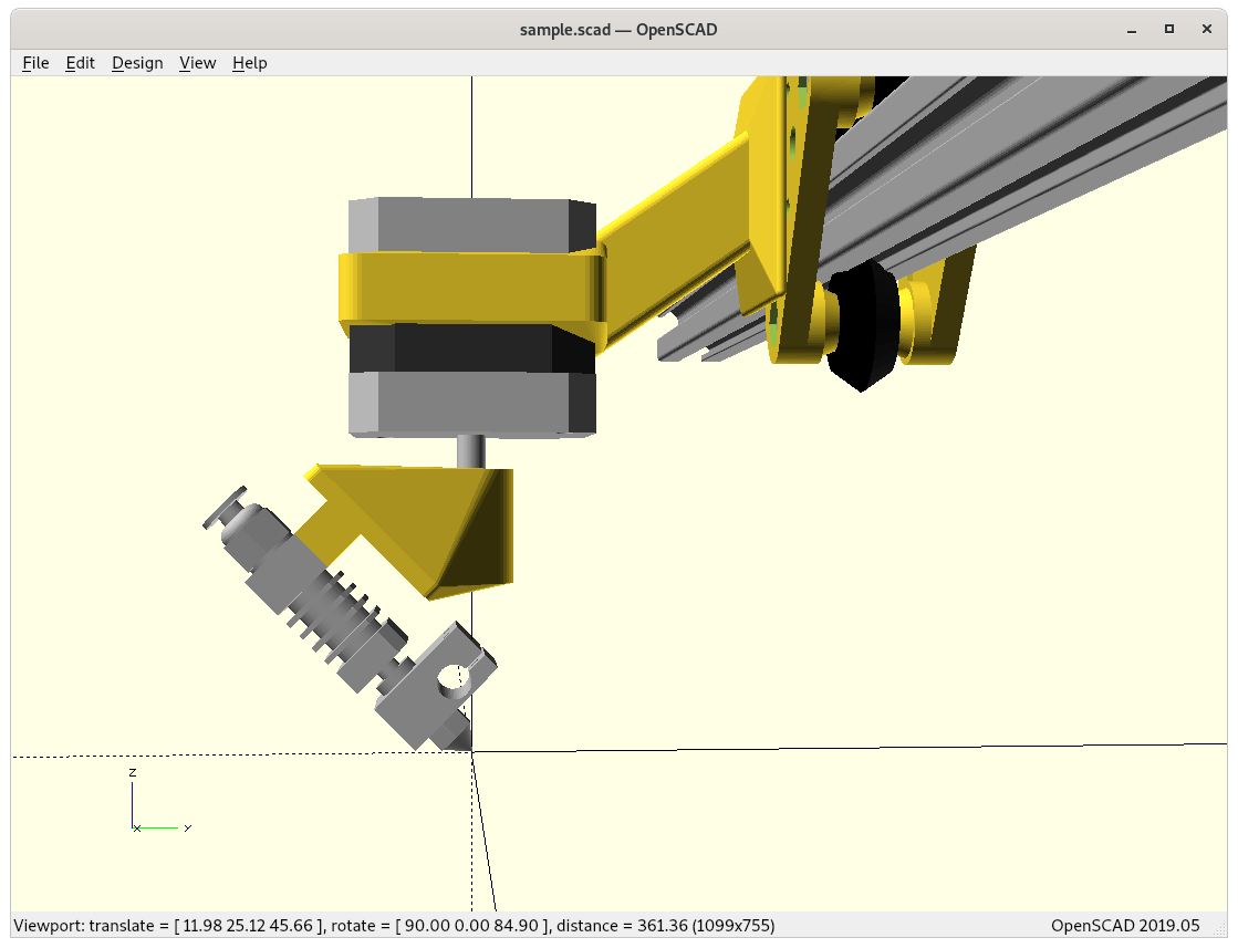
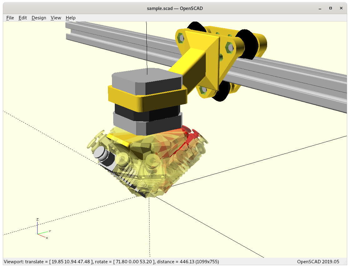
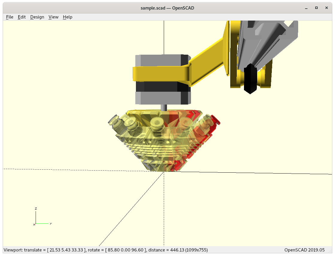
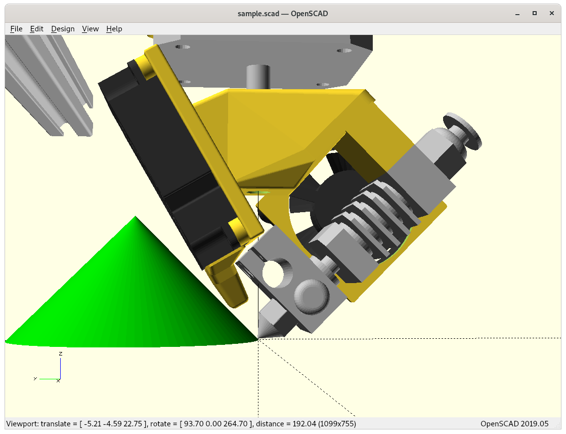
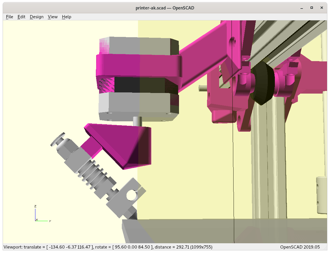
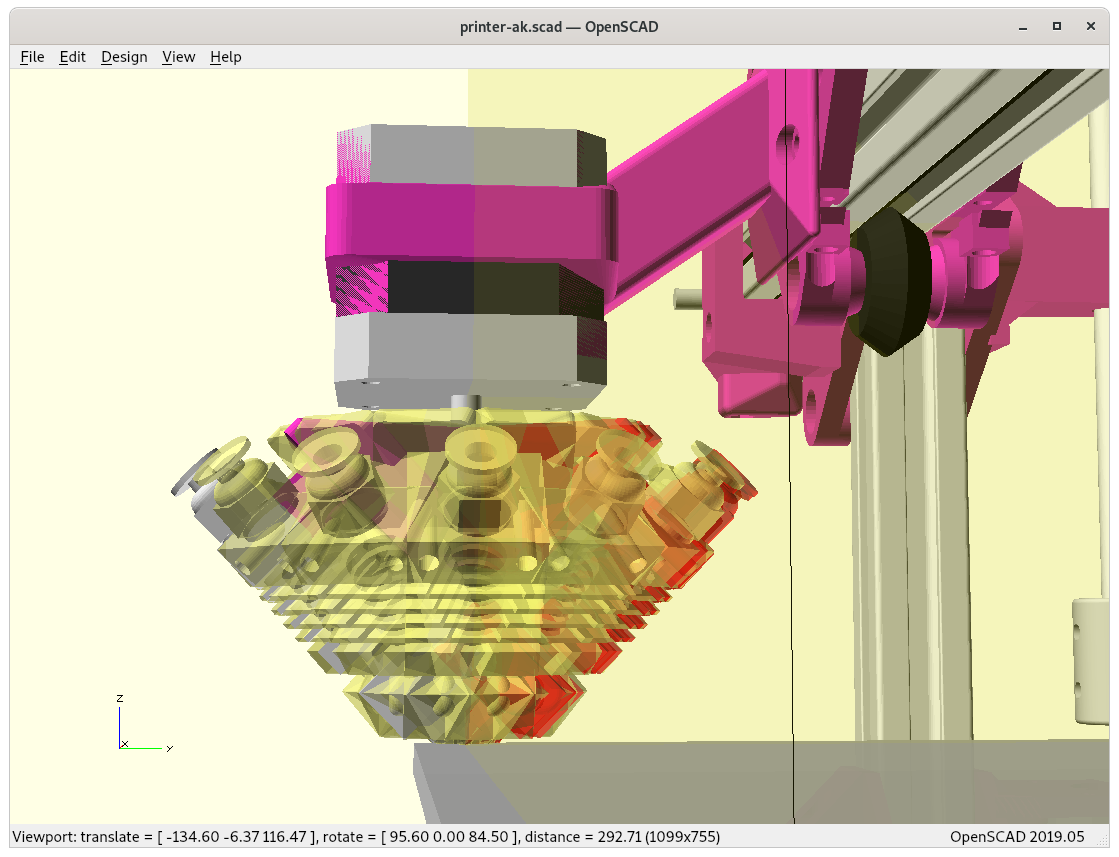
Outside- vs Inside-Cone Printing
As pointed out in the previous blog-post, the RTN has two main modes of operation, outside-cone and inside-cone printing to cover outside overhangs and inside overhangs – the slicer must recognize those and switch operation mode. Further, these two modes cannot easily be mixed, and need to be segmented or separated, hence speaking of volume segmentation.

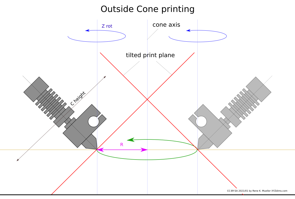
Outside Cone printing 
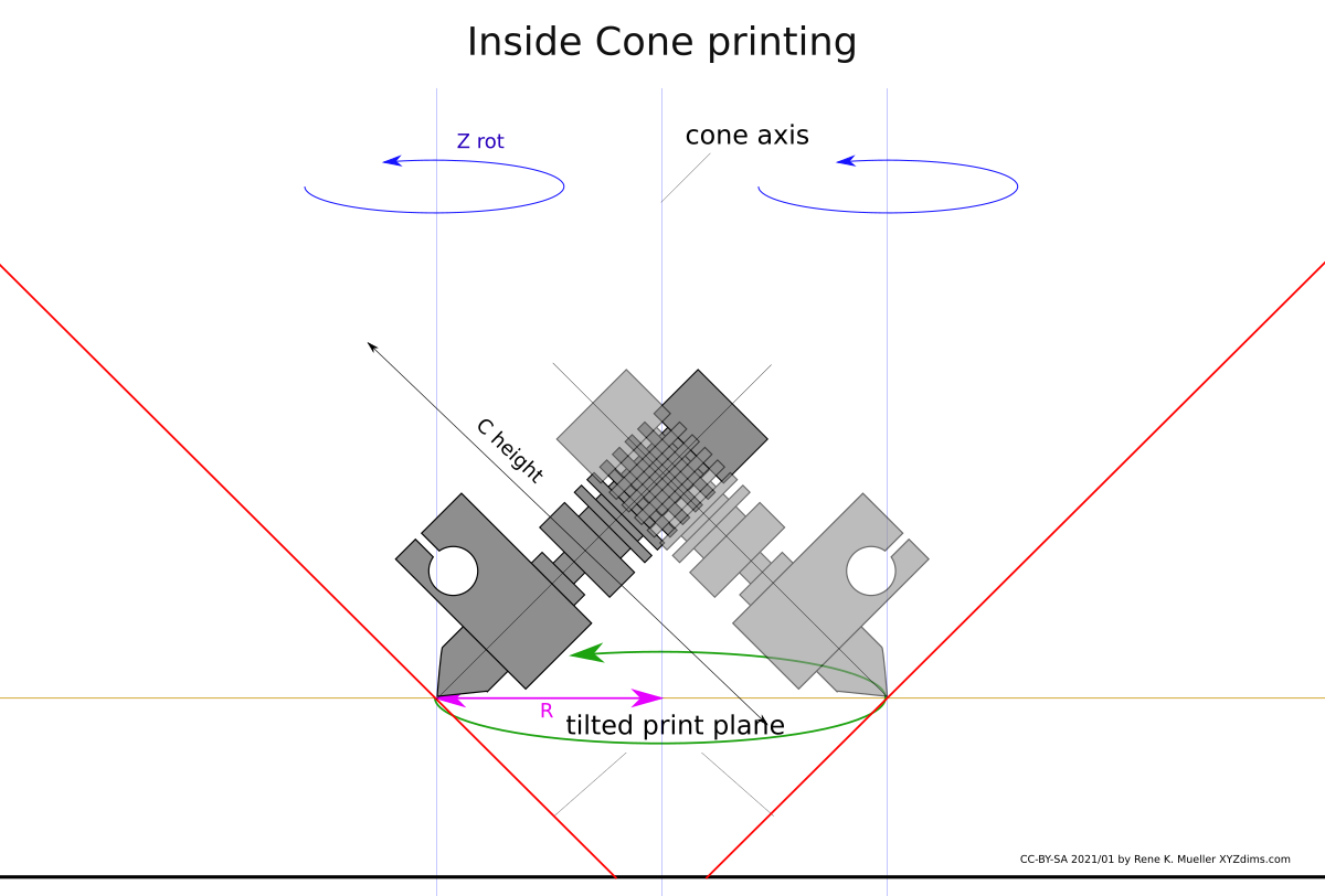
Inside Cone printing 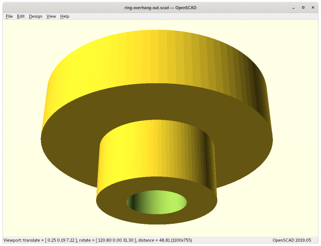
outer overhang 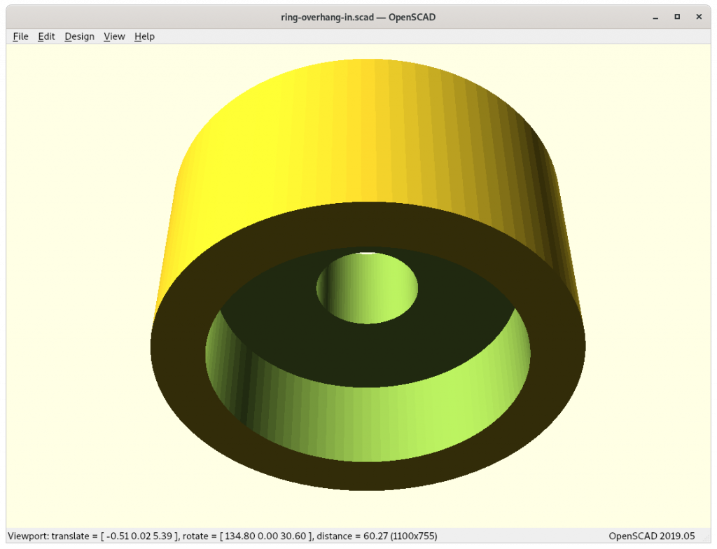
inner overhang 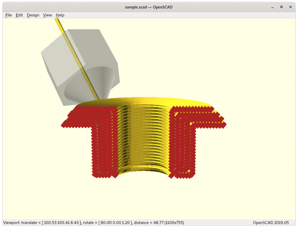
outside-cone printing for outside overhangs 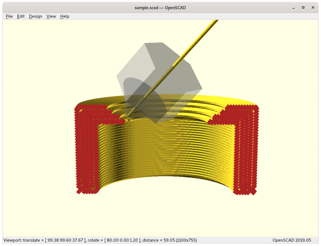
inside-cone printing for inside overhangs 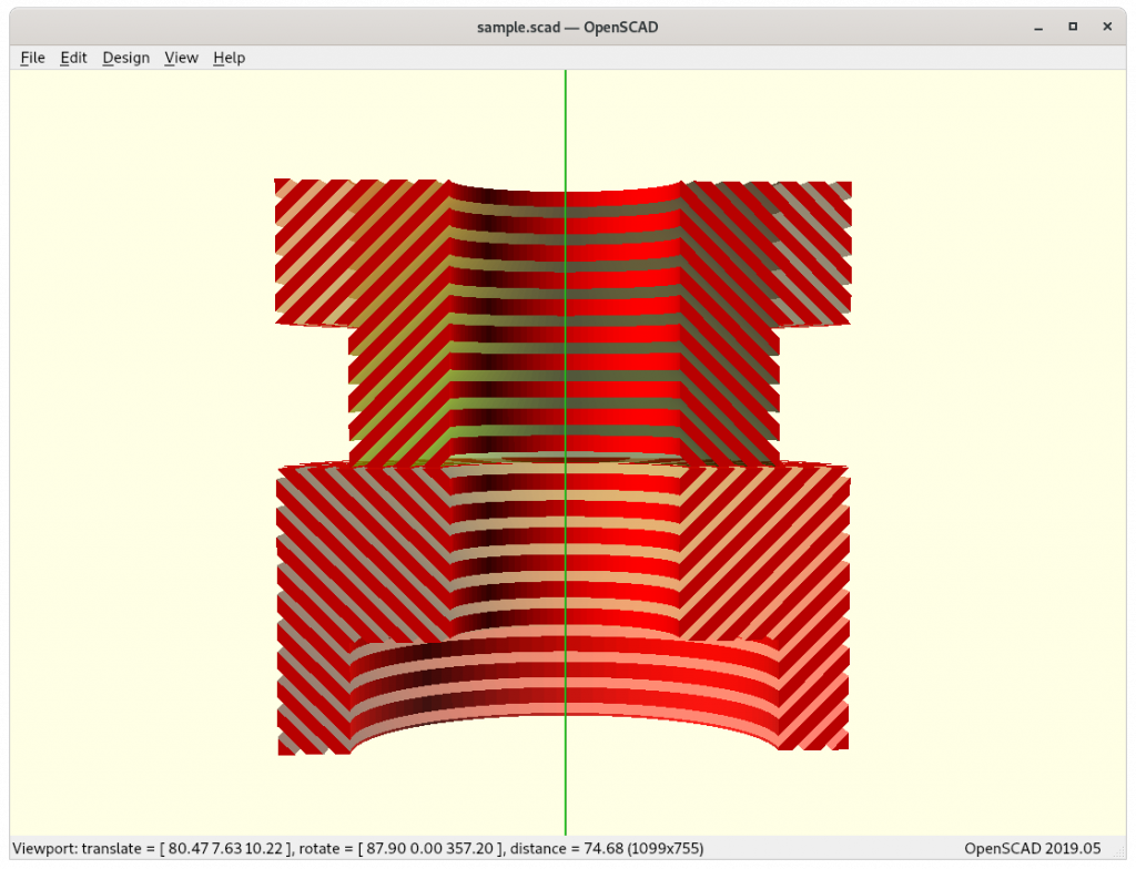
Inside cone for inner overhangs (bottom) vs
outside cone for outside overhangs (top)


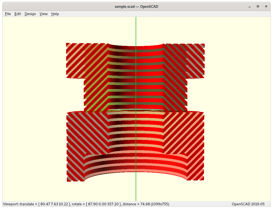
This poses significant grow of complexity from just planar slicing, the 4-axis RTN provides features to print 90° overhangs without support structure, but only when the part can be properly analysed and segmented so that those operational mode can be applied.
The difference between inside- and outside-cone printing is to change the order of conic mapping for the model and post slicing:
outside-cone mode
- map model inverse conic
- slice model
- map G-code direct conic
inside-cone mode
- map model direct conic
- slice model
- map G-code inverse conic, Zrot + 180°
Slicer4RTN
The pseudo-code turned into an actual application I named slicer4rtn and is a command-line tool, slicing STL into G-code:
% slicer4rtn --subdivide=5 --recenter cube.stl
== Slicer4RTN 0.4.1 ==
processing 'cube.stl':
   1/5 read stl
      1/5 subdivide (44 vertices)
      2/5 subdivide (188 vertices)
      3/5 subdivide (764 vertices)
      4/5 subdivide (3068 vertices)
      5/5 subdivide (12284 vertices)
   2/5 map vertices
   3/5 write temporary stl
   4/5 slice (slic3r) stl
=> Processing triangulated mesh
=> Generating perimeters
=> Preparing infill
=> Infilling layers
=> Exporting G-code to ./temp-603919.gcode
Done. Process took 0 minutes and 1.362 seconds
Filament required: 710.9mm (5.0cm3)
   5/5 remap gcode to 'cube.gcode' (16214 lines)
== took 3 secs total, done.
I gonna released Slicer4RTN eventually 2021/03/22, in its early version the model currently can only be sliced for outside-cone or inside-cone printing, so the volume decomposition or segmentation needs to be done separately. For now it helps me to verify some of the 4-axis and 5-axis printer designs I work on.
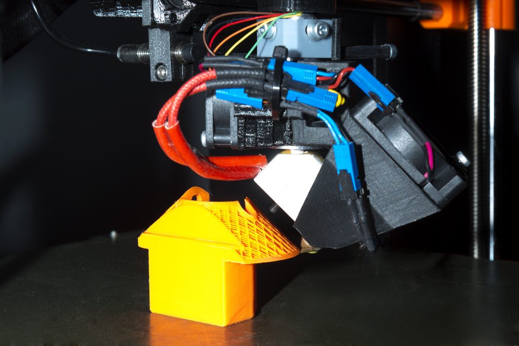
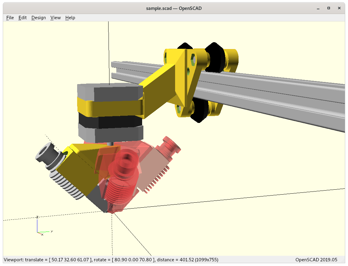
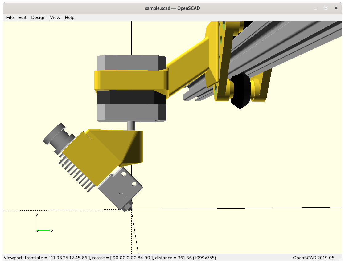
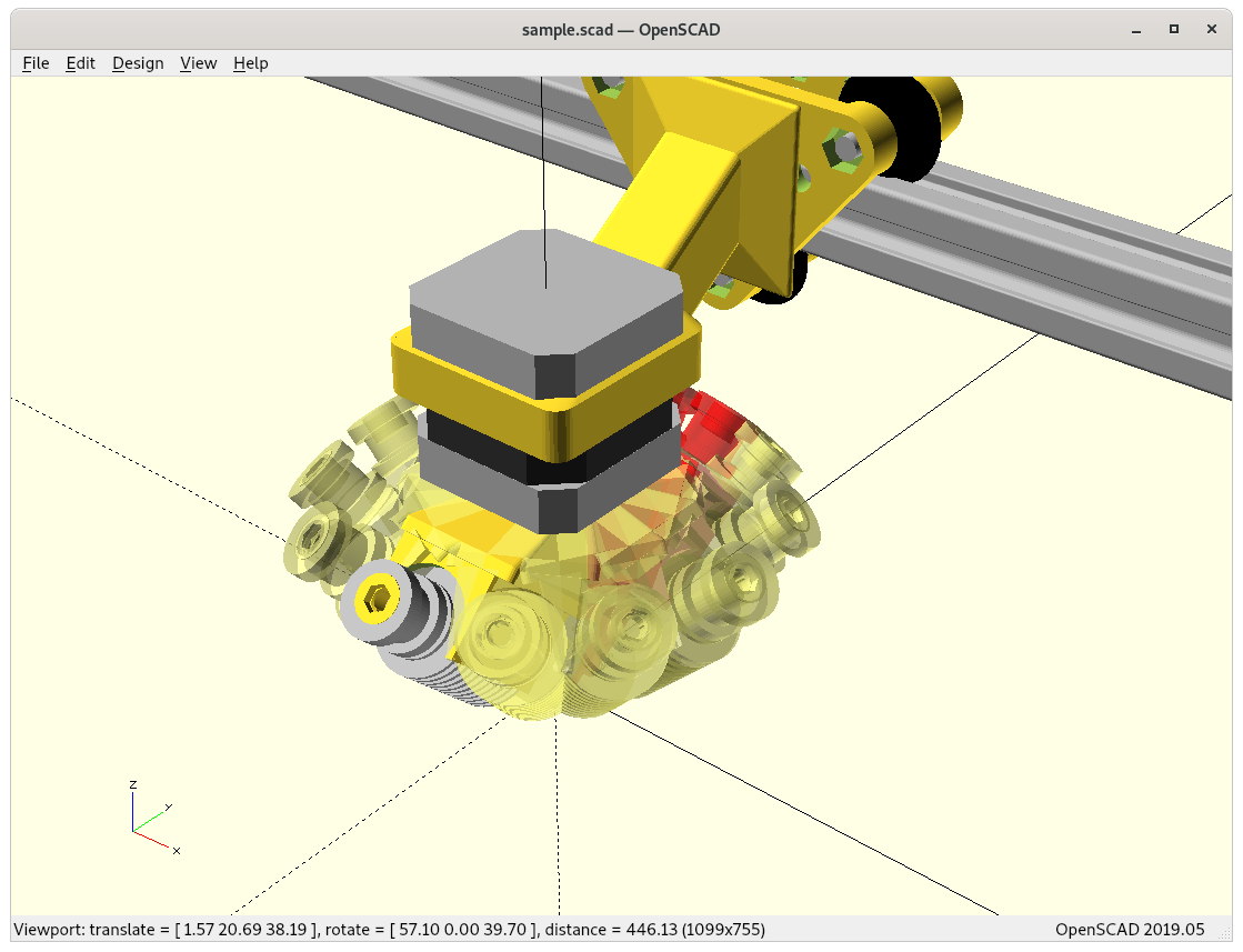
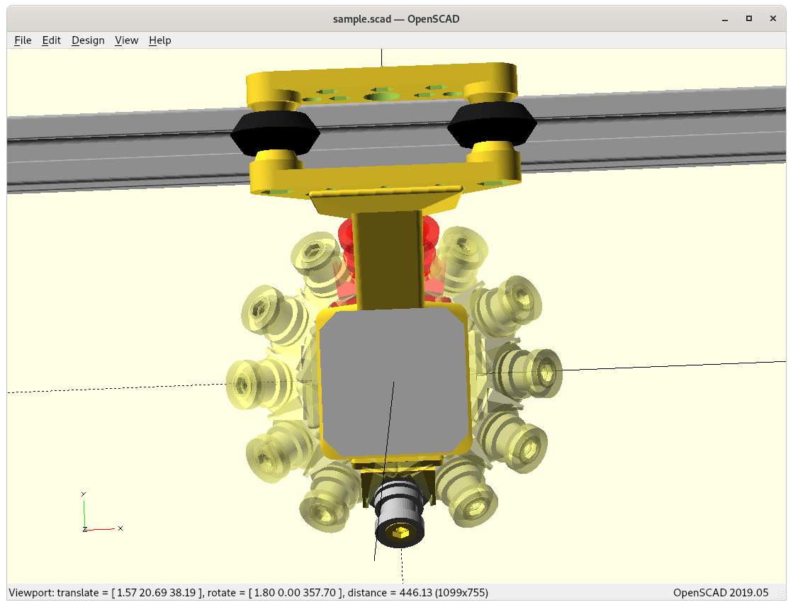
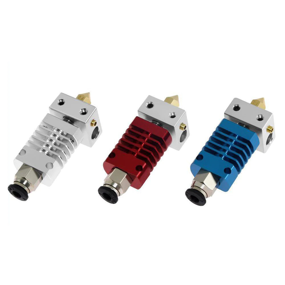
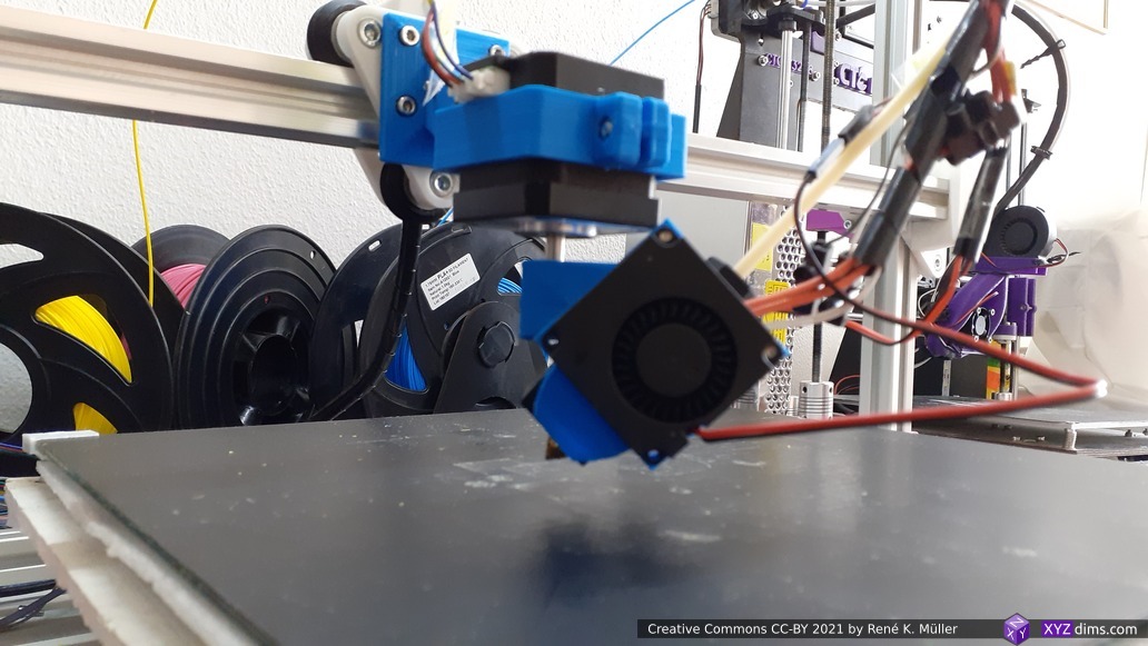
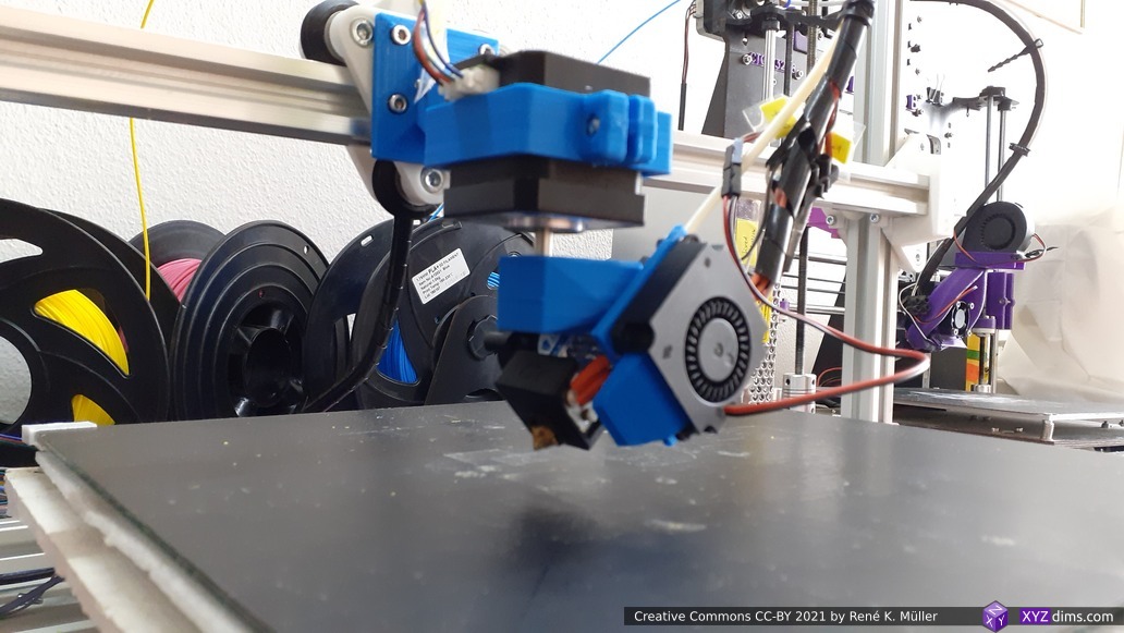
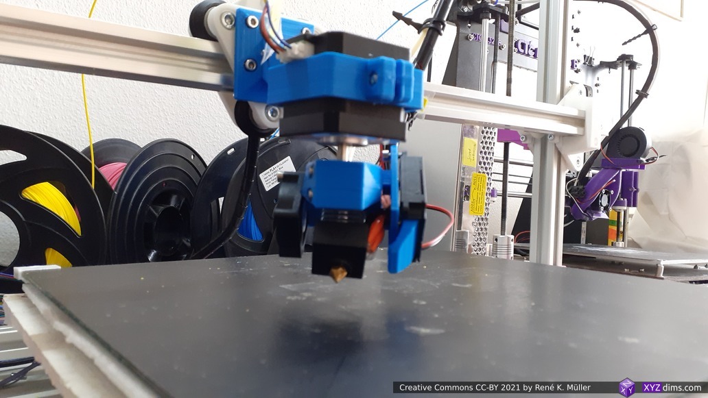
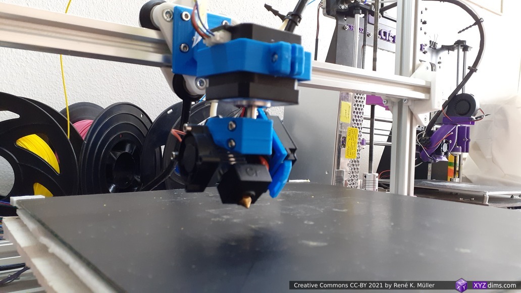
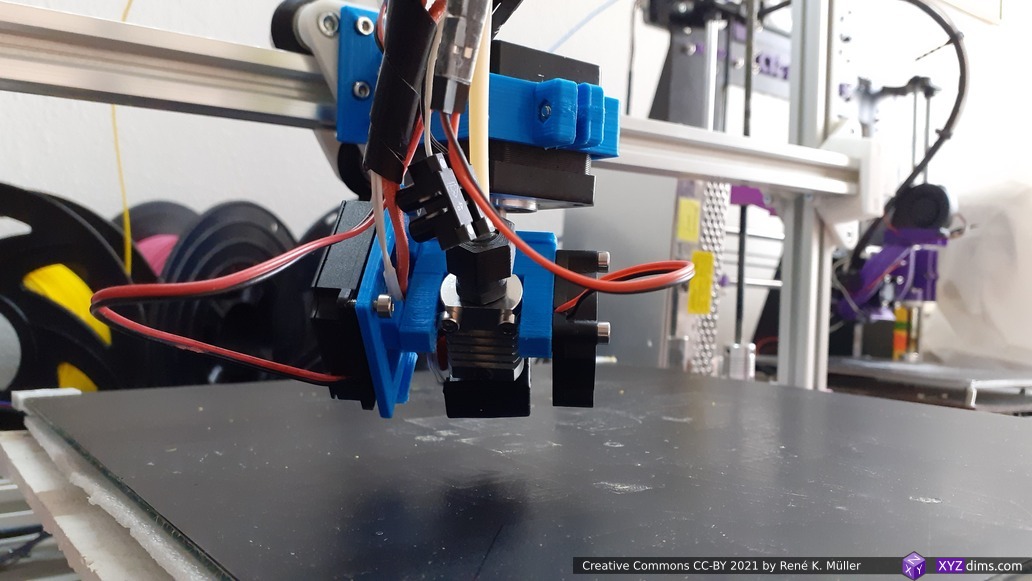
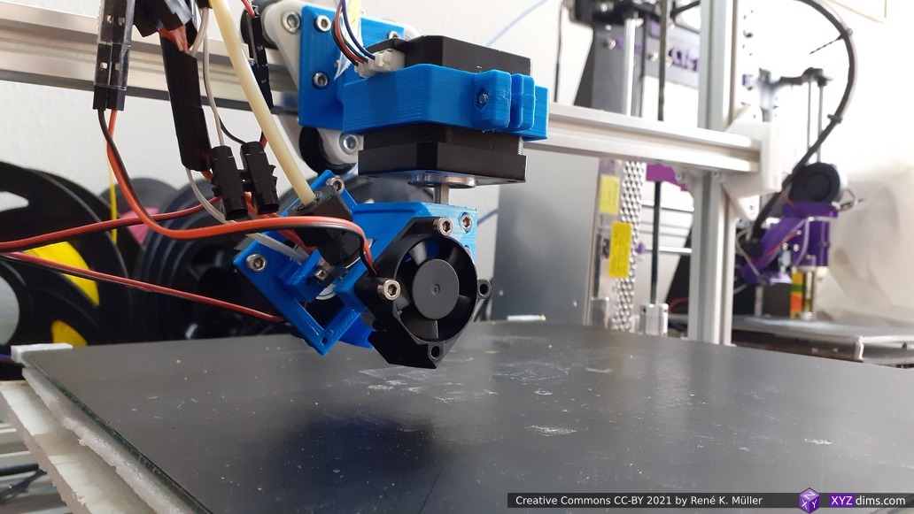
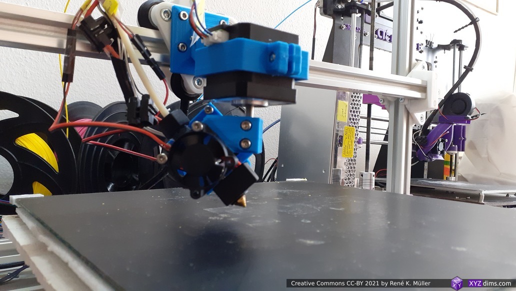
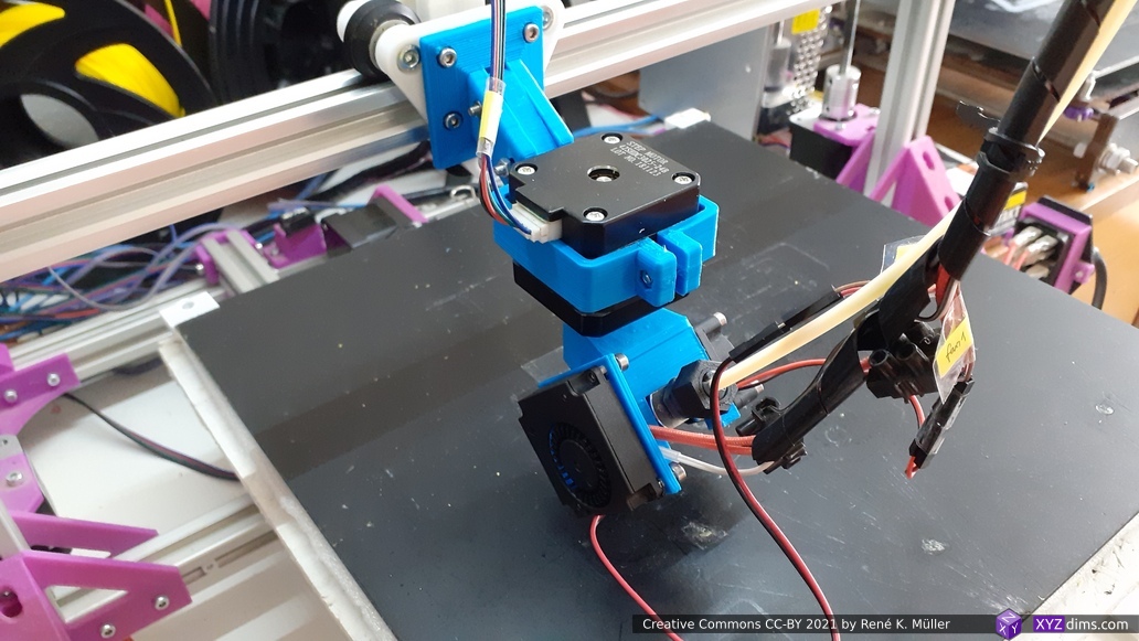
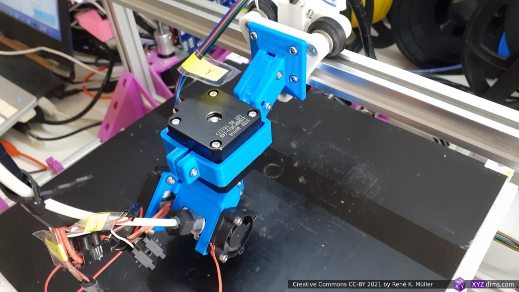
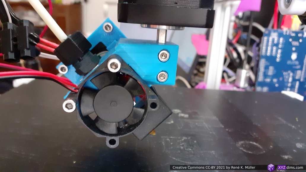
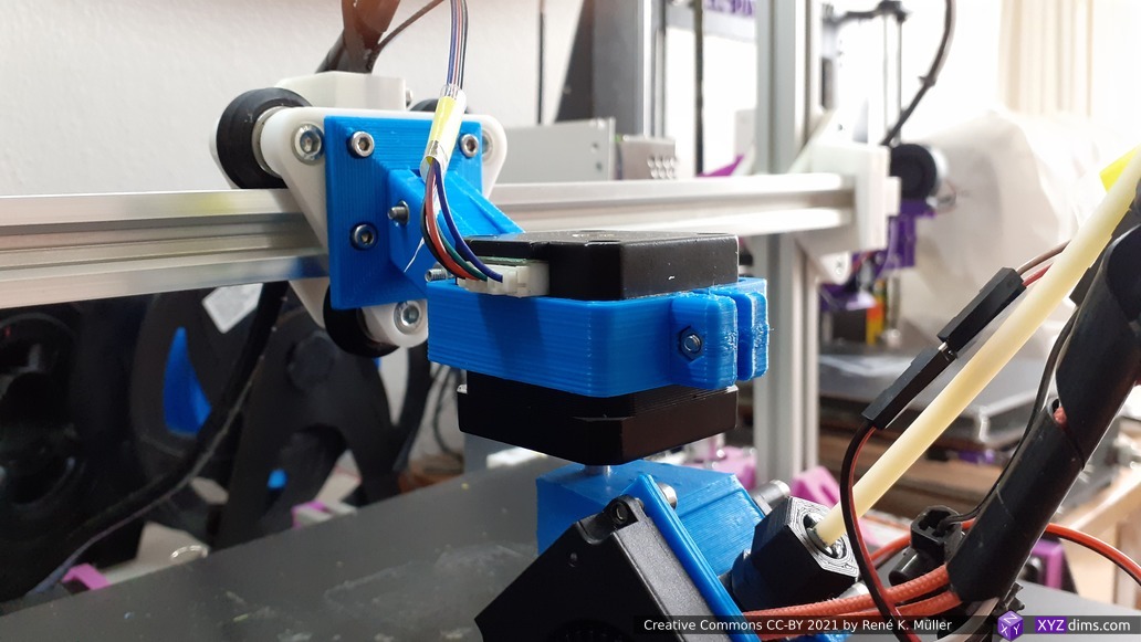
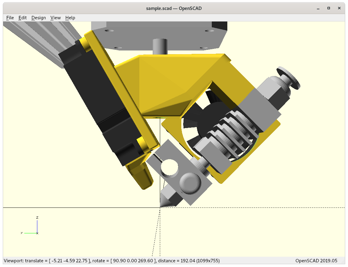
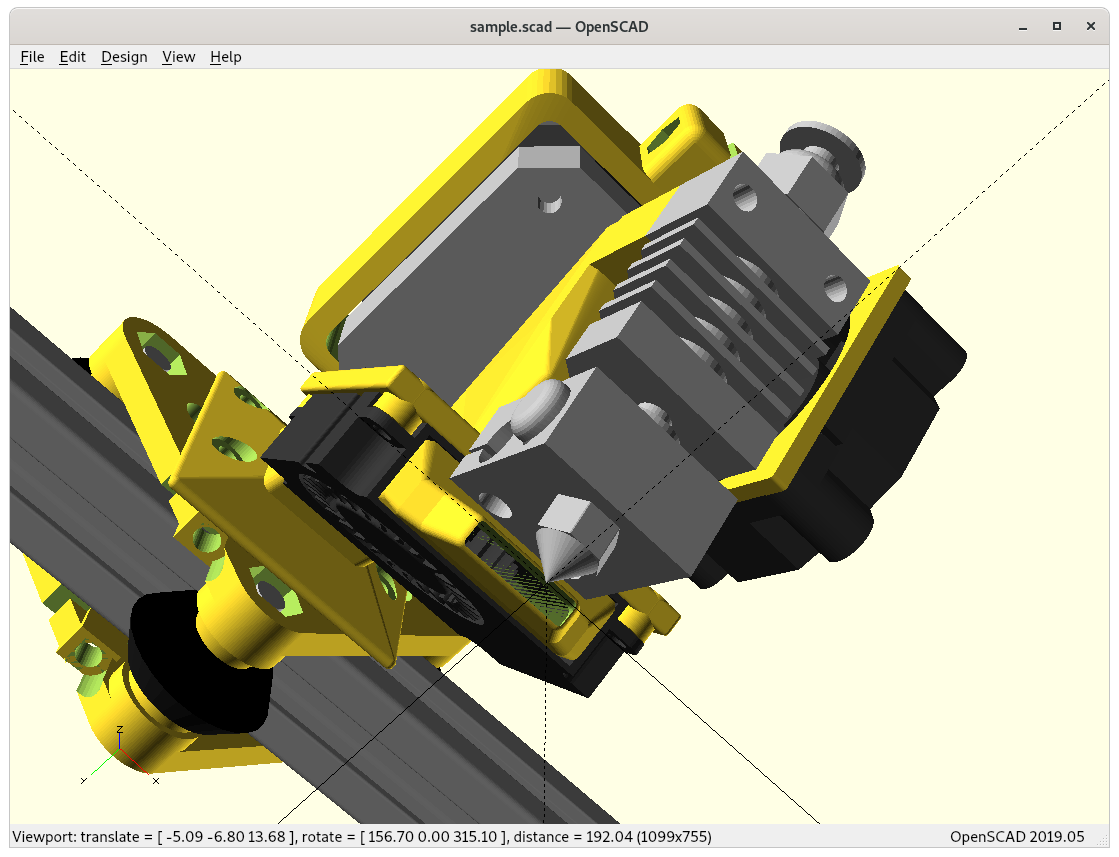
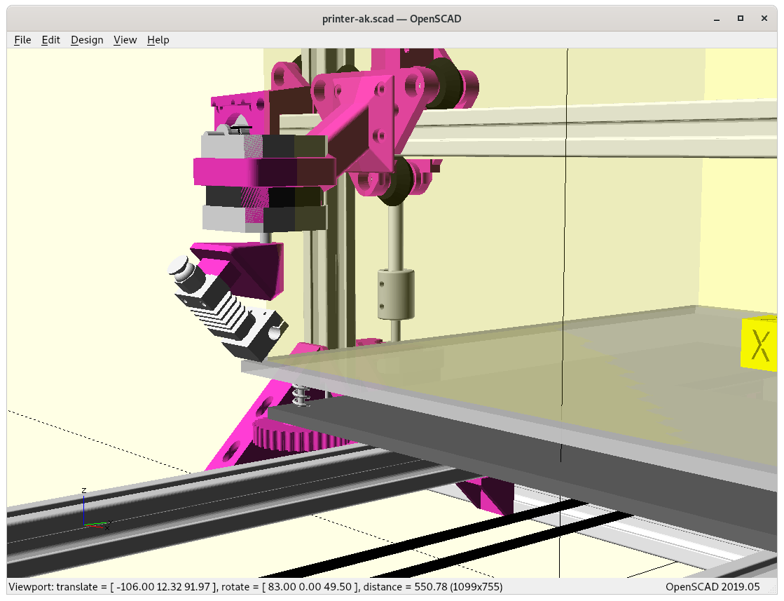
Test Prints
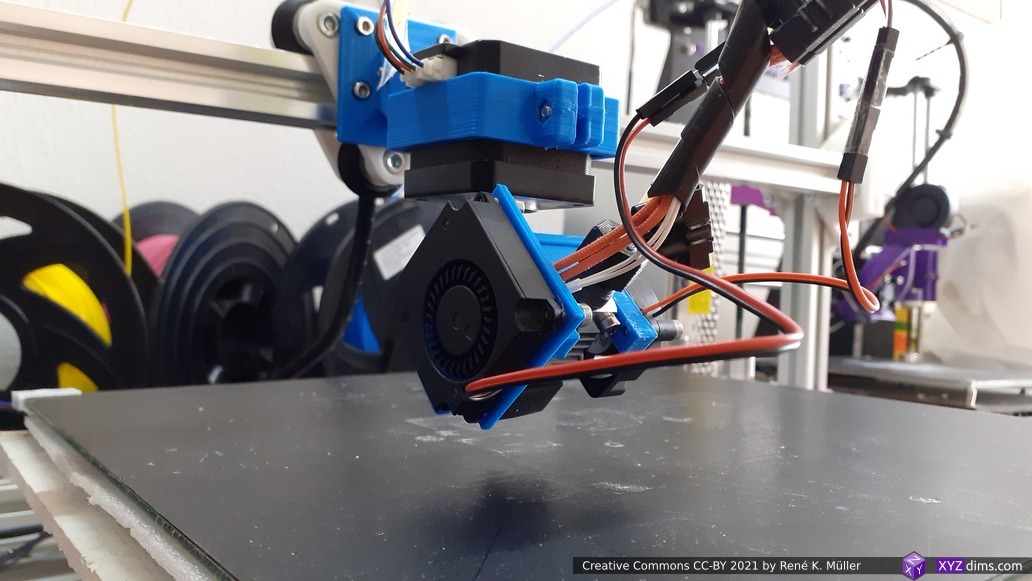
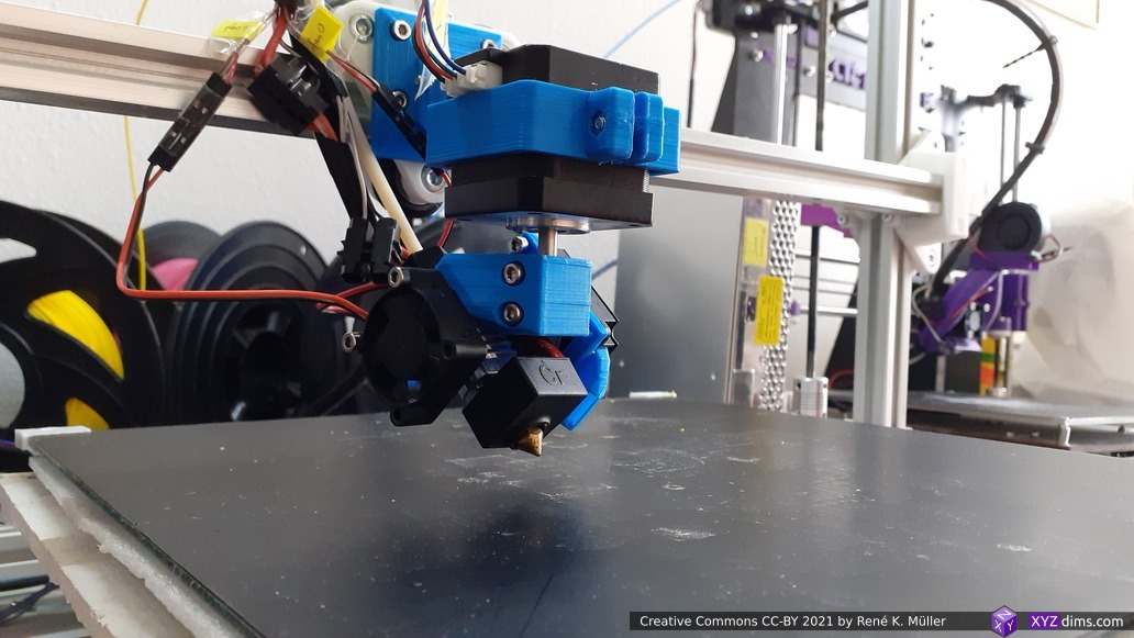
As soon I built the RTN printhead on one of my printers I will post photos of the first prints. For now (2021/03) I only printed conic sliced pieces on a 3-axis 3D printer.
References
- RotBot by ZHAW, the inventors of the Rotating Tilted Nozzle (RTN) approach by Prof. Dr. Wilfried Elspass, Dr. Christian Jaeger, Michael Wüthrich, Maurus Gubser, Philip Bos and Simon Holdener
- A Novel Slicing Strategy to Print Overhangs without Support Material (published 2021/09/27, free PDF)
See Also
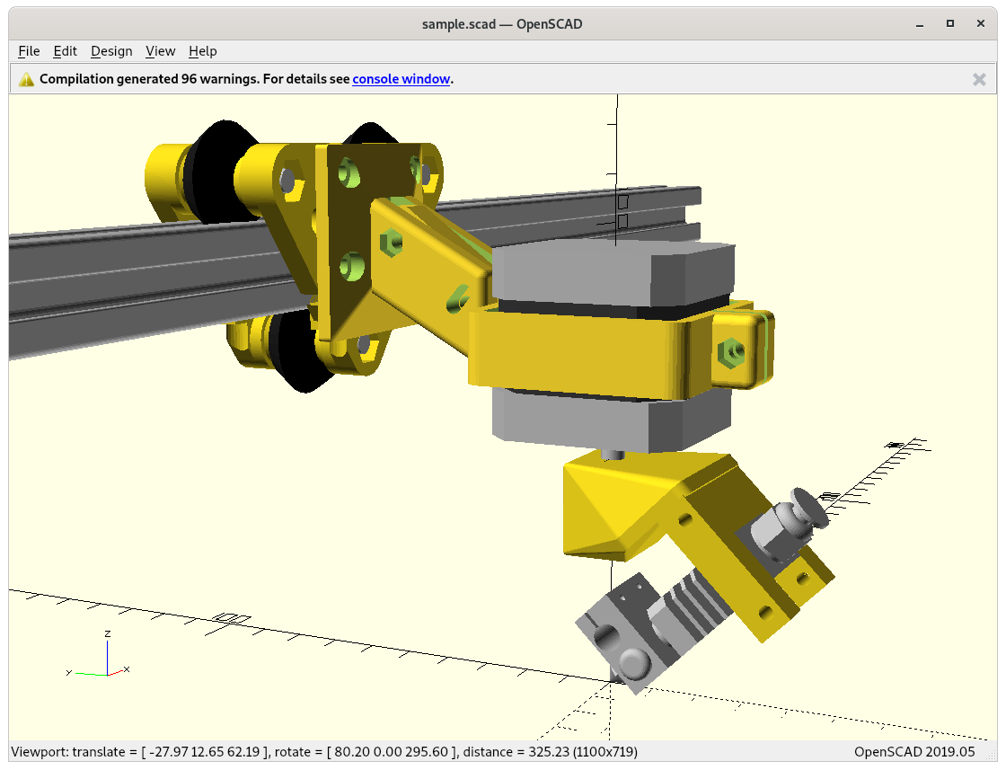
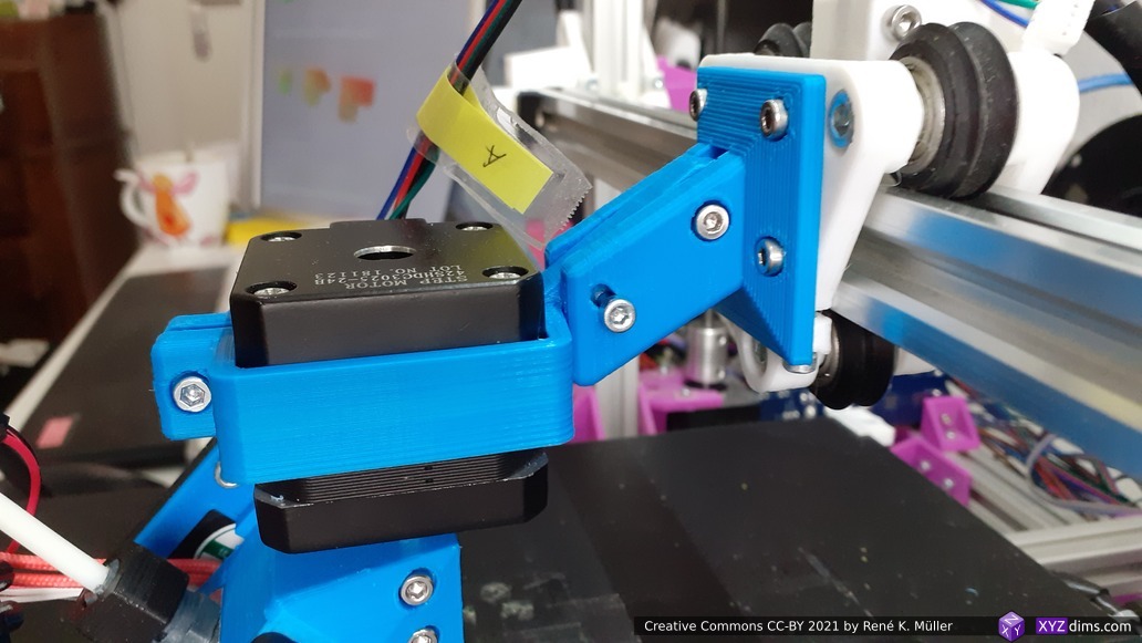
- Rotating Tilted Nozzle (RTN), my own approach
- Penta Axis / 5-axis (PAX) can print 4-axis/RTN conic sliced models too
- Non-Planar Slicing with Planar Slicer, general overview
- Sub-Volume Segmenting & (Non-)Planar Slicing, taking advantage of non-planar slicing
With conic sliced G-code there are many first layers . . .
That’s it.