State: early draft, mostly simulations with a few tests with 3-axis printer only
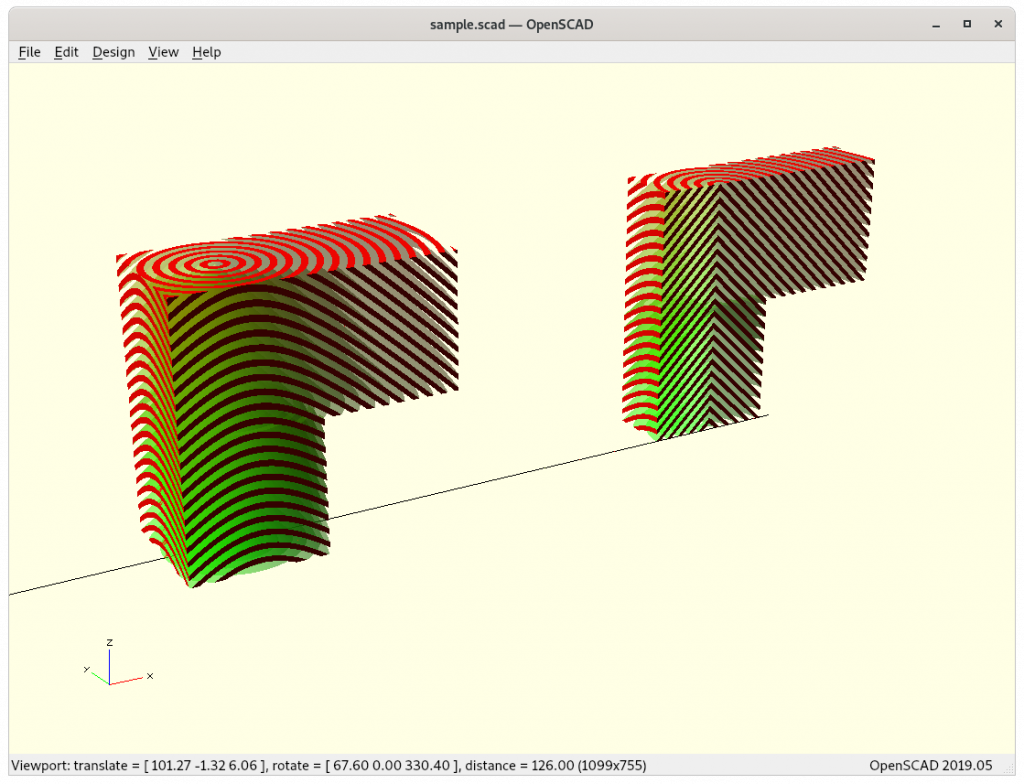
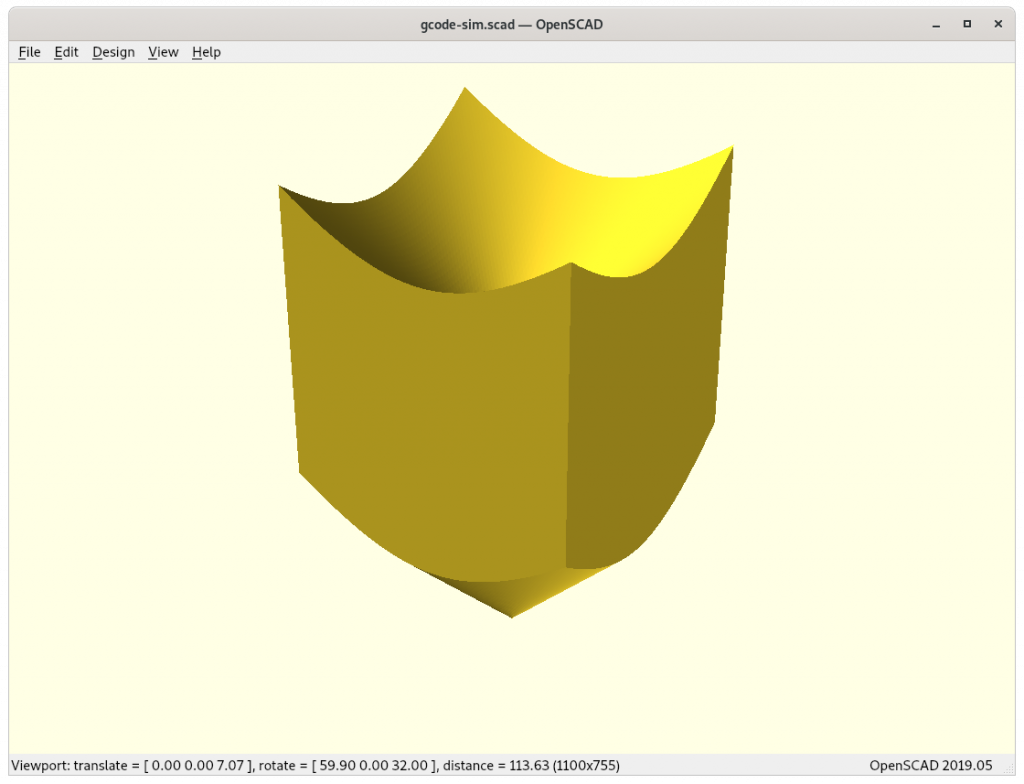
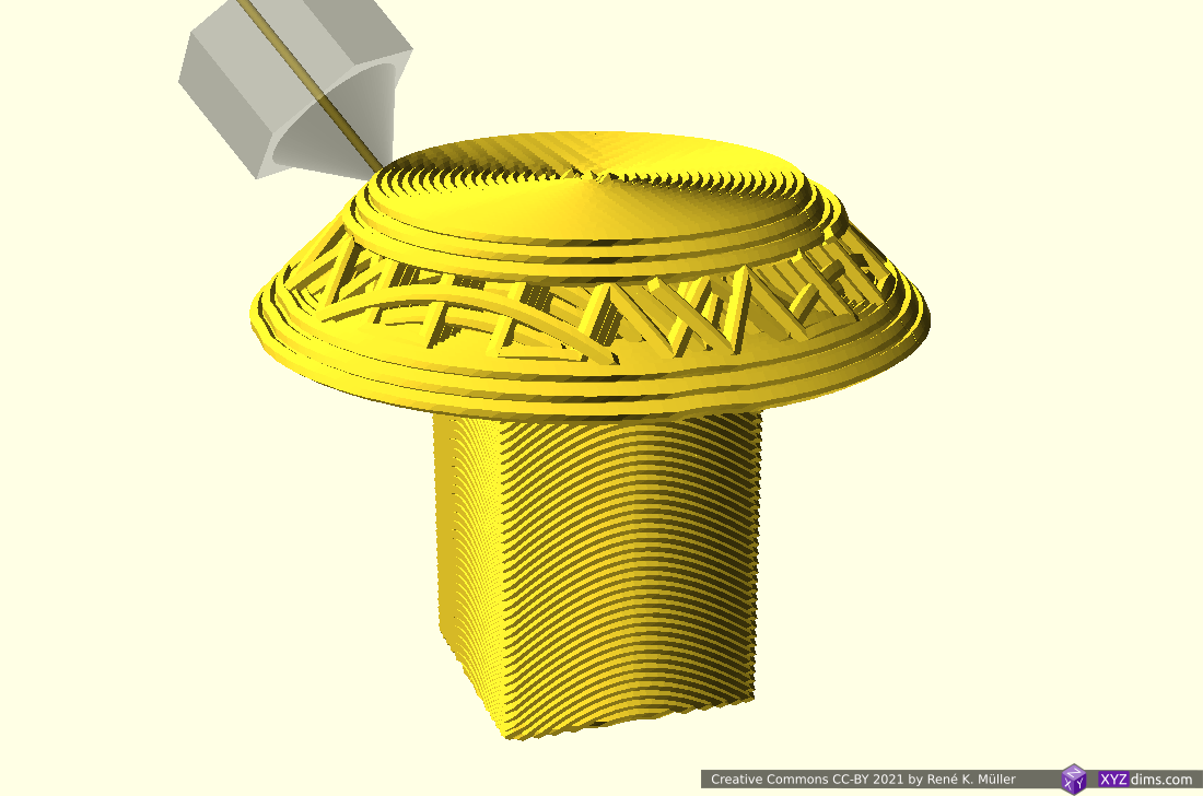
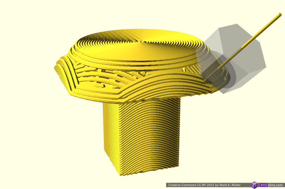
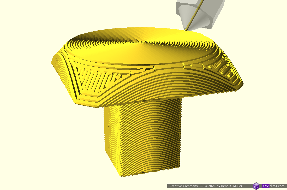
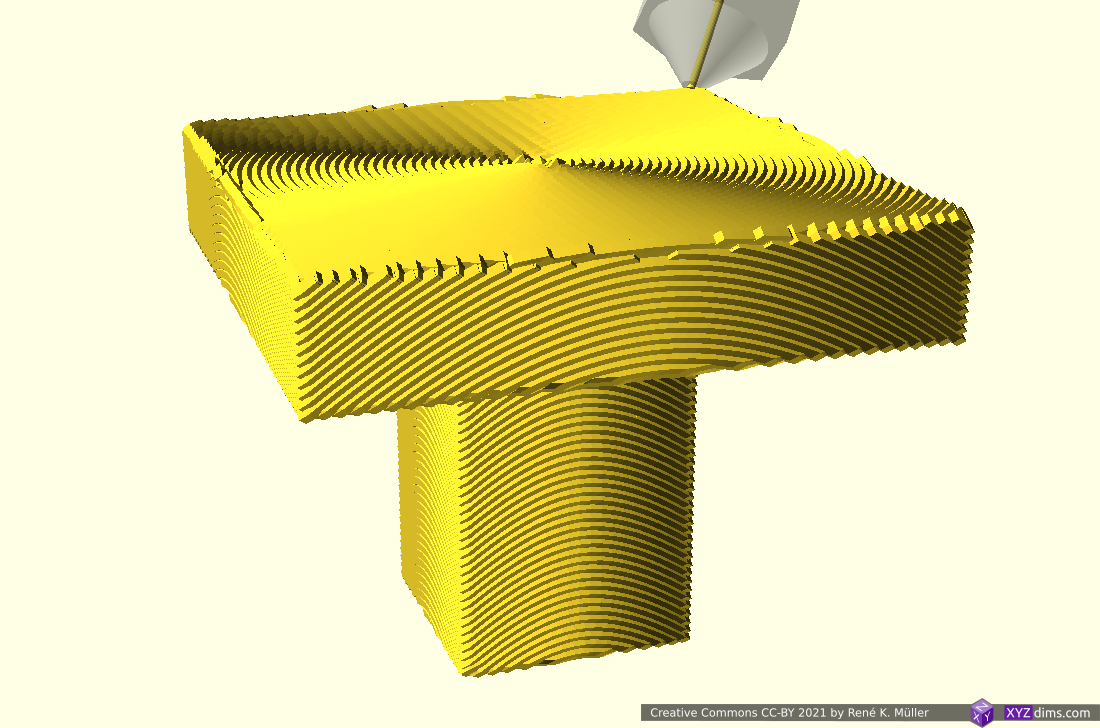
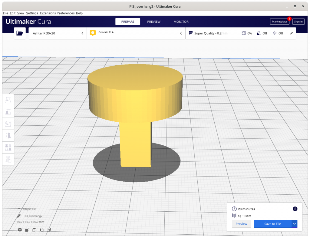
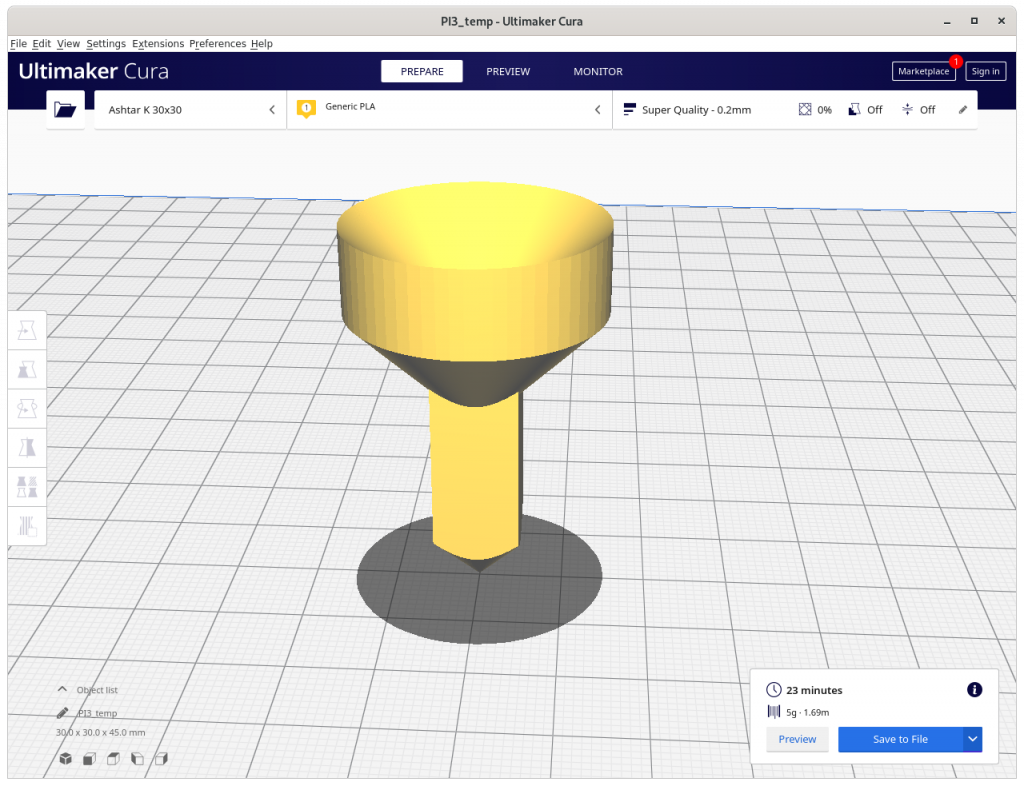
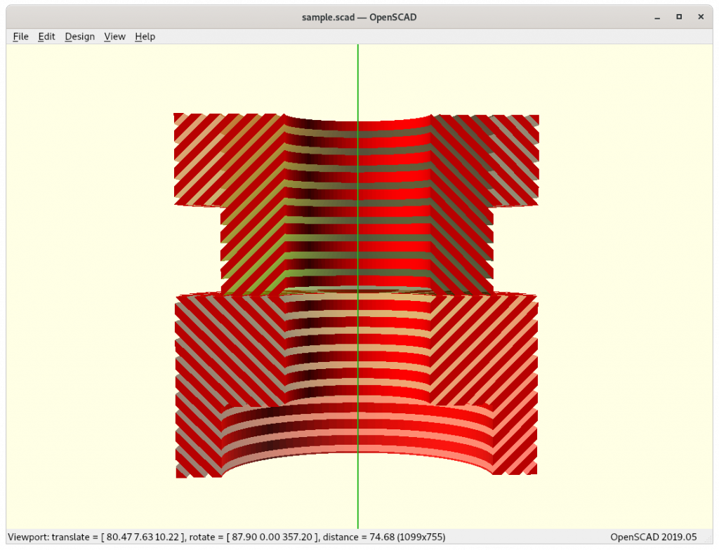
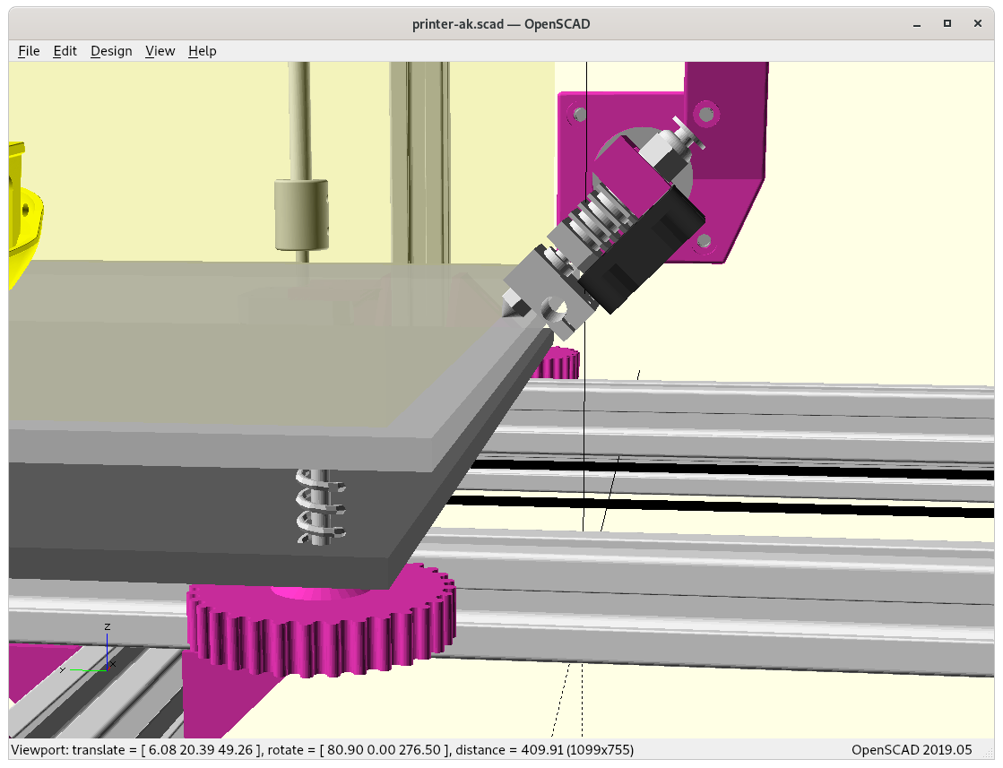
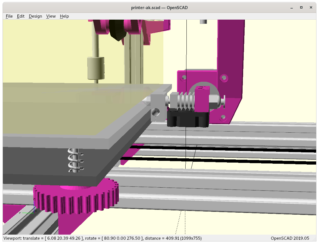
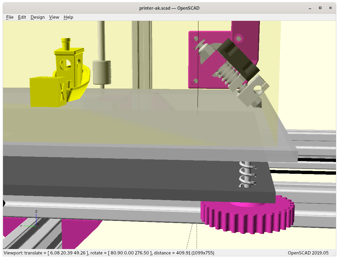
Conic sliced overhang model with two overhangs, printing with Rotating Tilted Nozzle (RTN) 90° overhang structure without support structure
Updates:
2021/09/28: added reference to paper by ZHAW describing slicing procedure
2021/03/22: slicer4rtn released, see dedicated page Slicer4RTN
2021/03/16: removing details on slicer4rtn as a new dedicated page is in the working (coming soon)
2021/03/08: slicer4rtn 0.2.3 reached (still unreleased), better prints, documenting various settings in more details
2021/03/05: added proper ZHAW reference in the introduction and a few notes
2021/02/27: removed some redundant illustrations and remade some of them, outside-cone vs inside-cone mode & printing
2021/02/26: added inside-cone printing example for inner overhang mode, also early information of slicer4rtn; more animations to observe details of produced G-code, using now also OpenSCAD to simulate G-code and actual nozzle position
2021/02/24: better tests with 20mm cube and overhang structure, included two short G-code simulations as videos, added 20mm sphere and 3D Benchy and discover first issues with volume decomposition and overhang recognition
2021/02/23: first write up, pseudo code and first attempt to conic slice 20mm cube
As I progress I will update this blog-post.
Introduction
The main idea is to utilize existing 3D printing slicers but create conic slices for the Rotating Tilted Nozzle (RTN) 4 Axis Printer. ZHAW published in their announcement in 2021/01 something about utilizing existing slicers, but the details remained concealed and later published as a paper but I did not want to wait and pondered on the problem, and came up with a solution. In its current state it’s purely theoretical and untested for now (2021/02)barely tested yet.
Michael Wüthrich confirmed my solution is comparable with their solution. ZHAW planned their paper to be published sometime 2021. So, the main credit goes to ZHAW and the researchers (Prof. Dr. Wilfried Elspass, Dr. Christian Jaeger, Michael Wüthrich, Maurus Gubser, Philip Bos and Simon Holdener) there, I was just impatient and tried to find a solution with the information available.
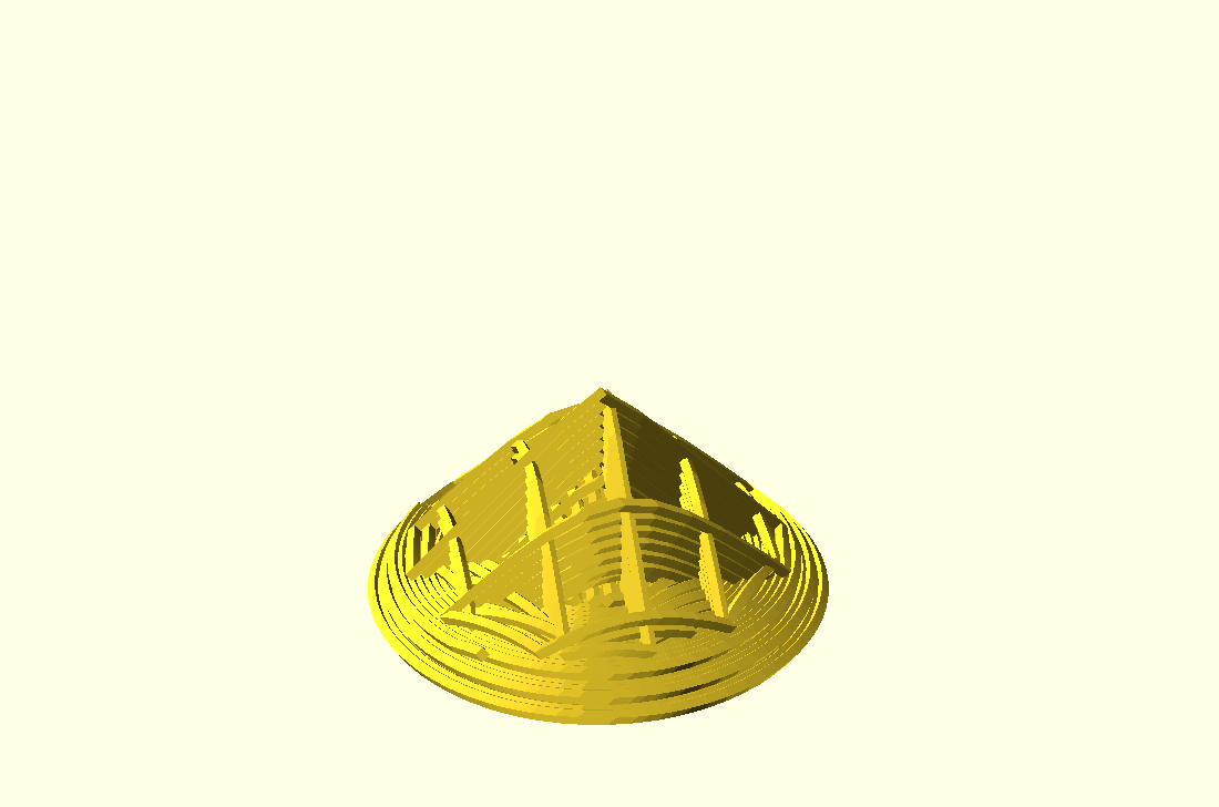
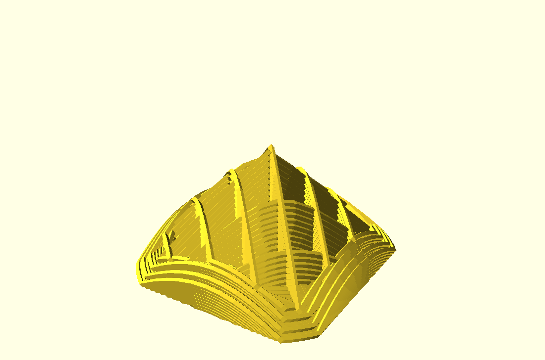
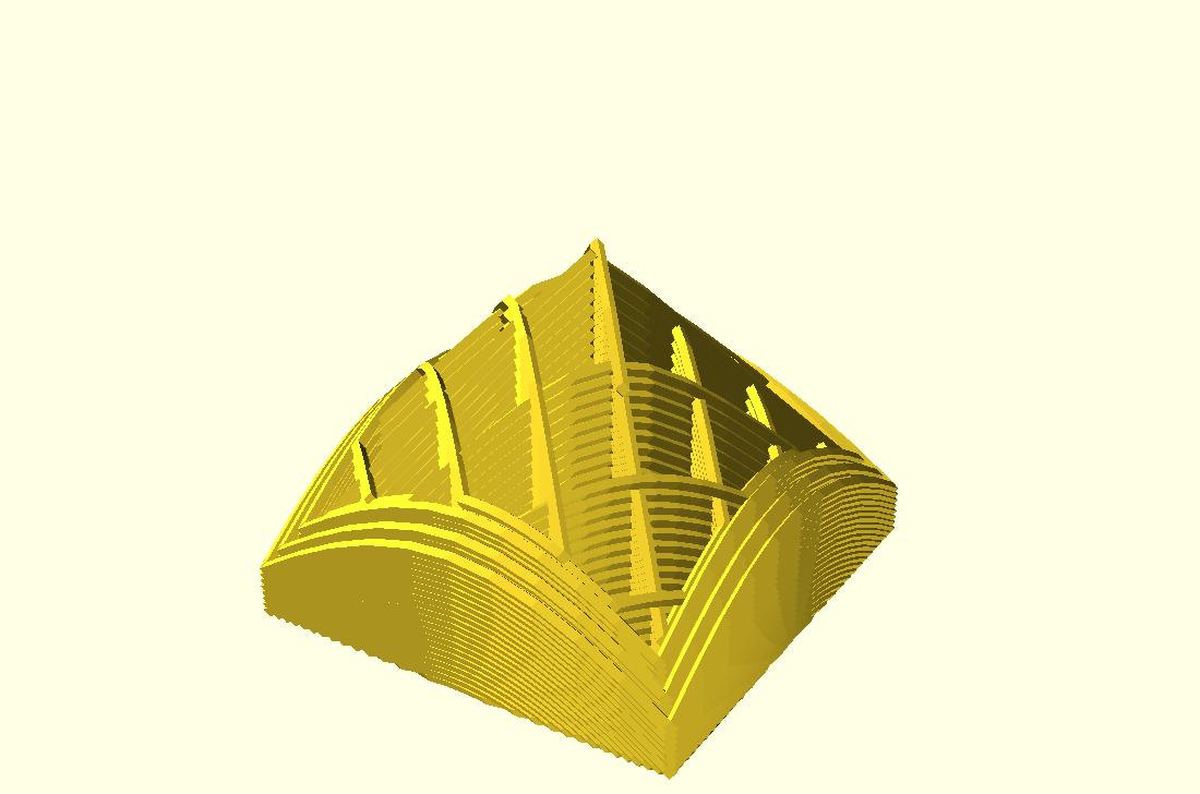
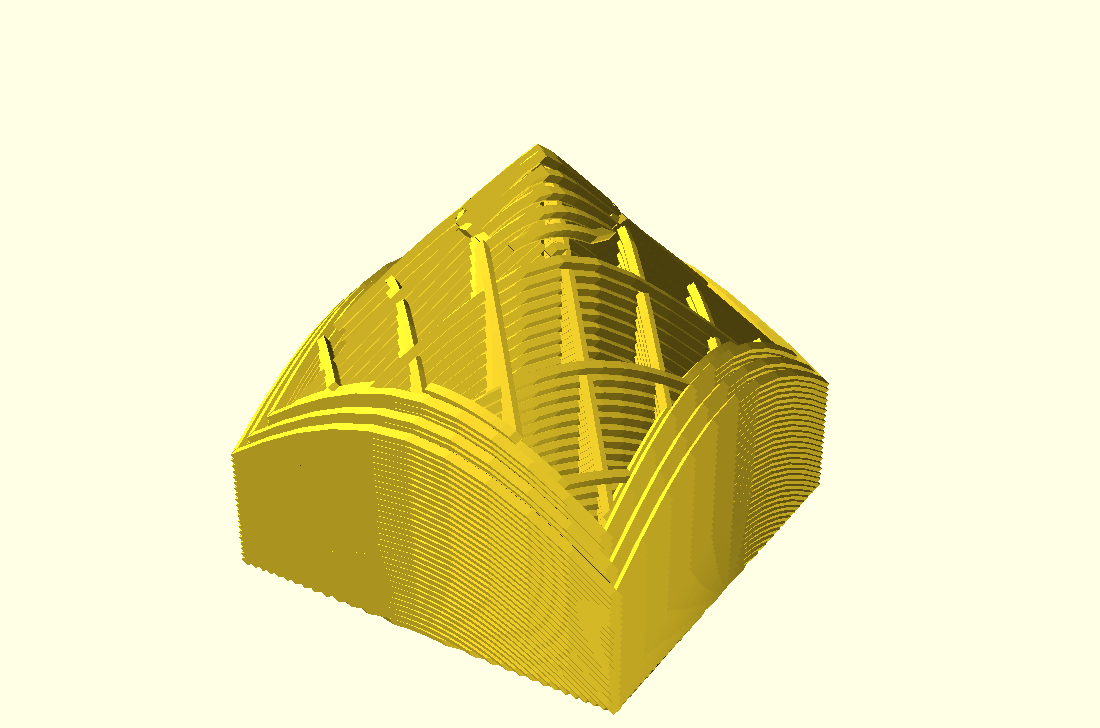
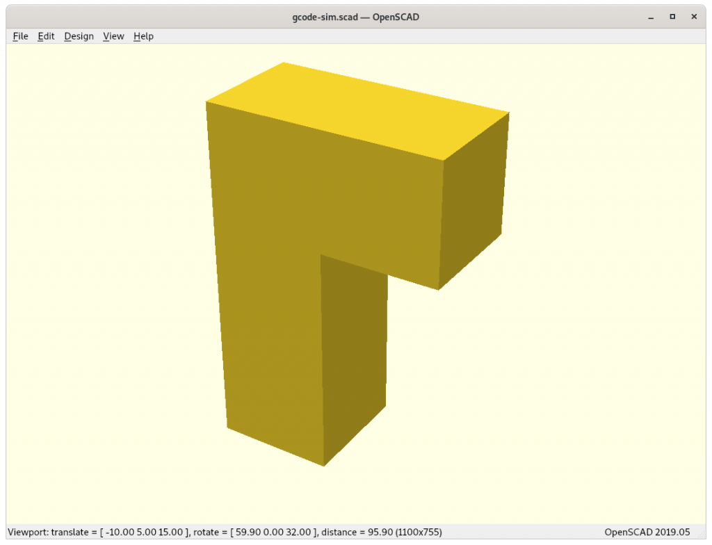
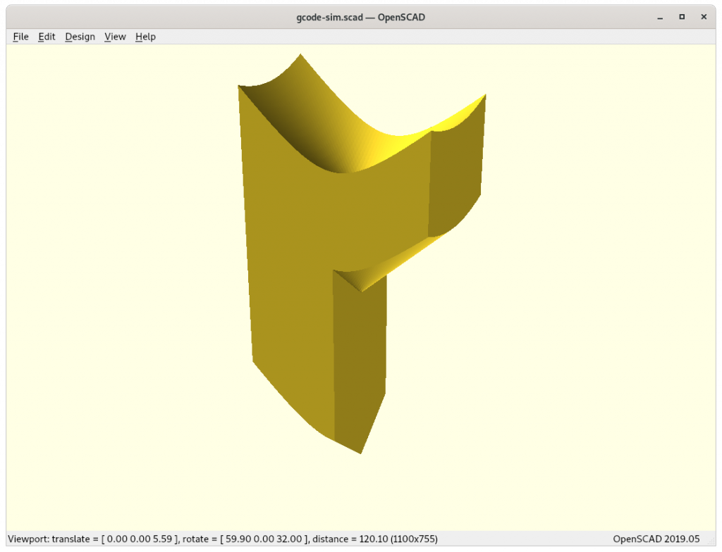
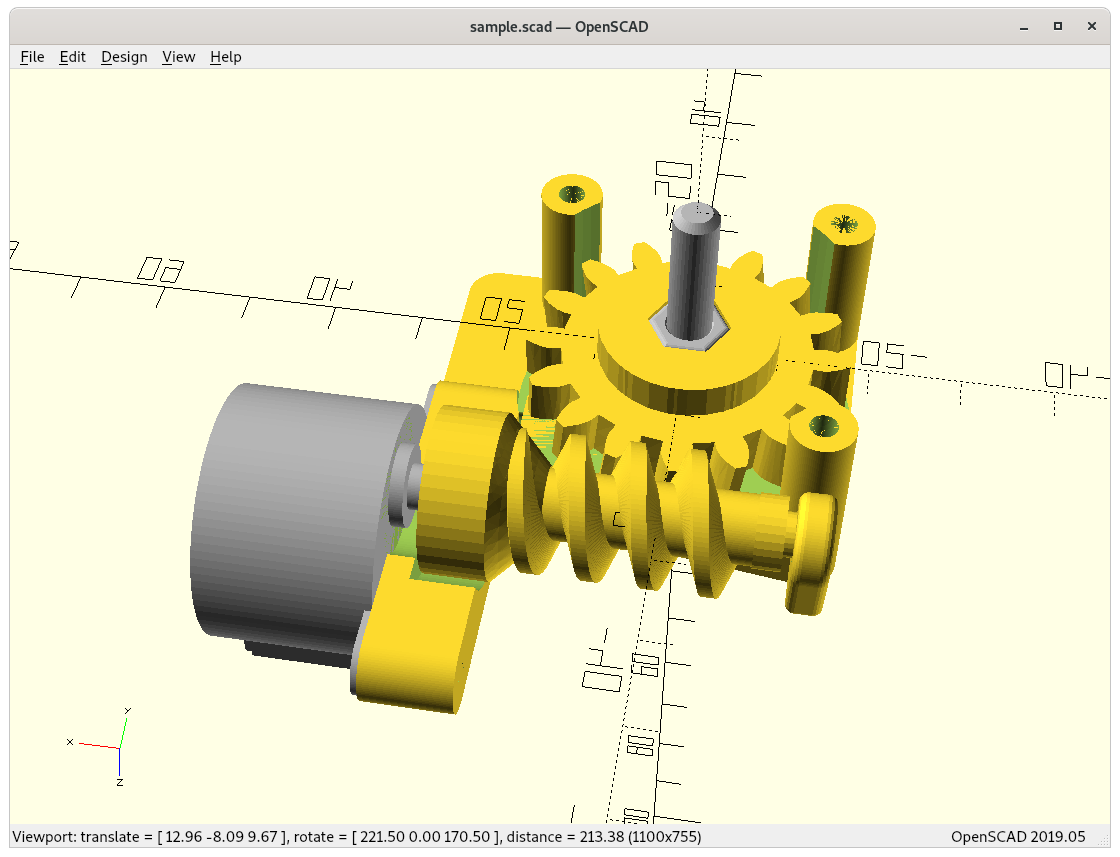
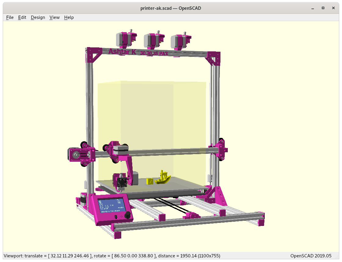
The 4-axis Rotating Tilted Nozzle (RTN) physical setup implies its slices are of non-planar conic shape, allowing to print overhangs without support structure, such as:
Conic slices of an overhang model
I also like to master the conic slices properly as they promise to become a subset of 5 axis printhead (PAX) features too – so it’s worth the effort even if the RTN itself might be too limited in its application with its fixed tilt – we will see.
function conicSpaceMapping(cx,cy,x,y,z,dir='direct') {
   dx = x-cx;
   dy = y-cy;
   d = sqrt(dx*dx + dy*dy);
   rot = atan2(dy,dx);
   return (x,y,dir=="direct" ? z-d : z+d,rot);
}
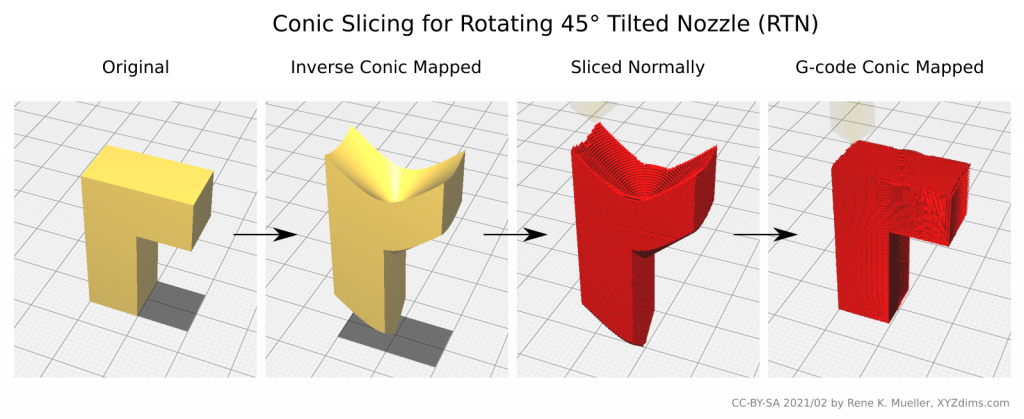
Pseudo-Code
The entire procedure goes like this:
m = loadModel("cube.stl");
m = subDivide(m,5);
for(p of m.vertices) {
    m.vertices[i] = conicSpaceMapping(cx,cy,p.x,p.y,p.z,'inverse');
    i++;
}

gcode = sliceModel(m);

foreach(line of gcode) {
   (code,x,y,z,e) = extractCoordsExtrusion(line);
   (x1,y1,z1,zrot) = conicSpaceMapping(cx,cy,x,y,z,'direct');
   outputGcode(code,x1,y1,z1,e,zrot);
}
Note: the pseuco-code is incomplete as extrusion E is not yet taken care of, as soon I found a definitive solution I will write it up.
Examples
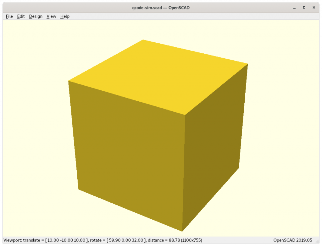
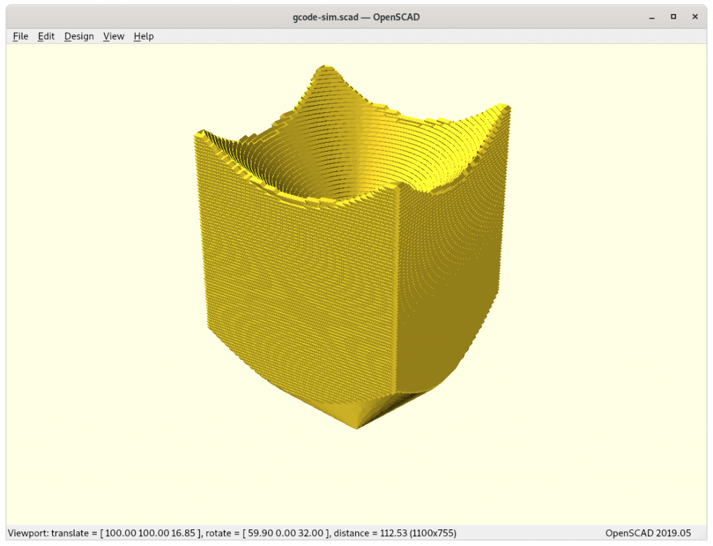
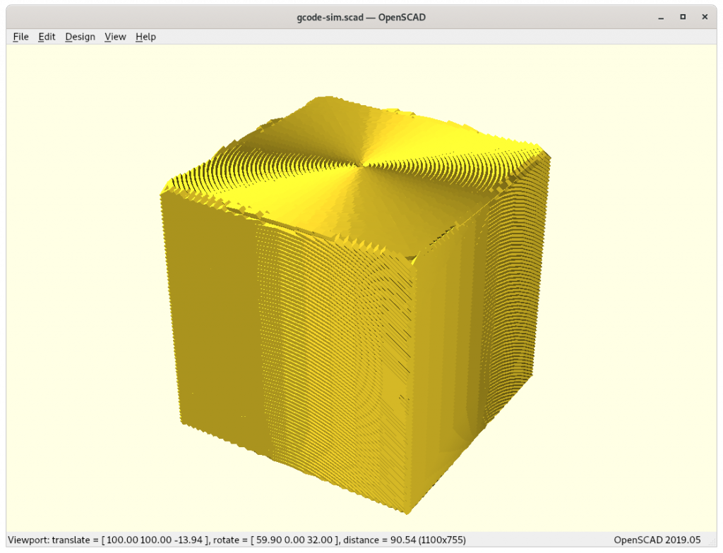
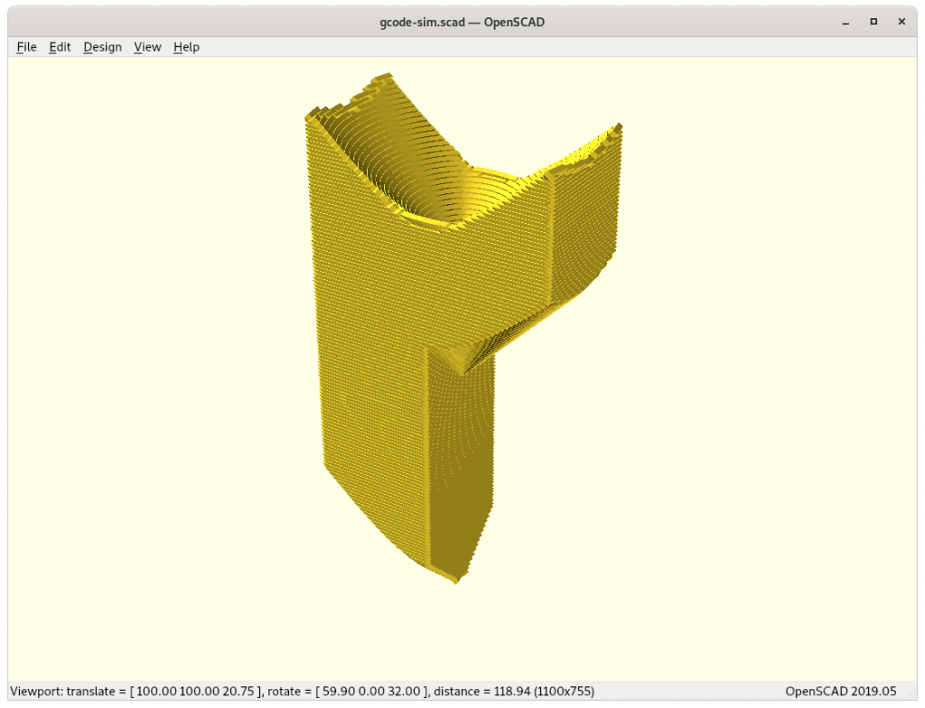
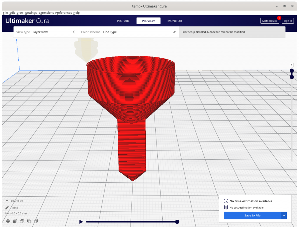
I implemented the pseudo-code with some more details like taking care of G-code E extrusion as well and fine-step linear extrusion – here some early tests using OpenSCAD as STL & G-code viewer and Slic3r as actual slicer:
find good pre-processing face sub-division strategy
in its current form the algorithm requires fine-grained sub-divided faces otherwise inaccurate G-code is created which cannot be recovered
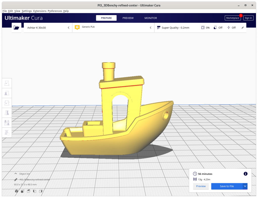
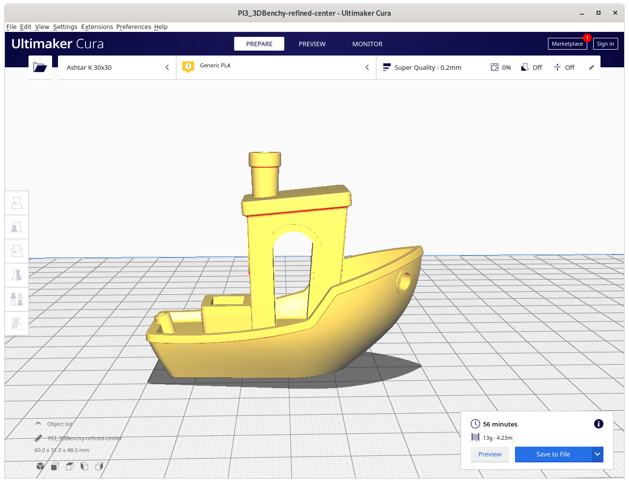
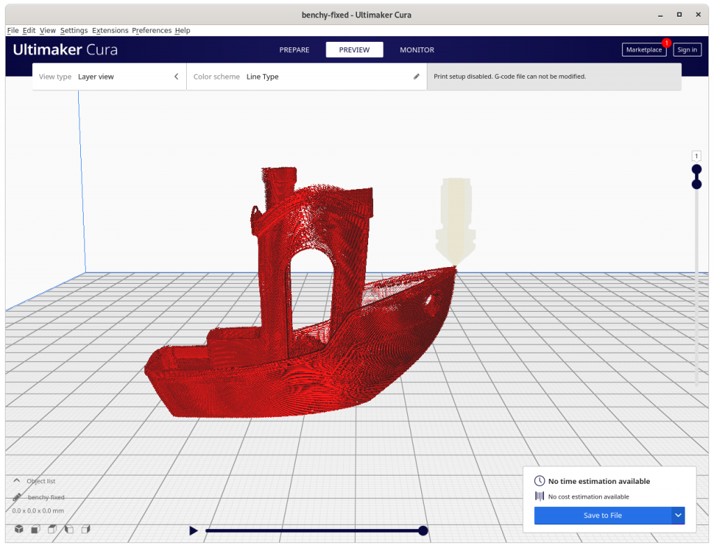
3D Benchy conic sliced with Original Faces
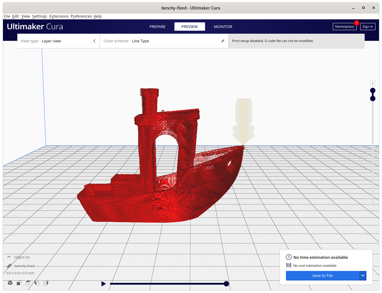
3D Benchy conic sliced with Refined Faces
slice more complex parts
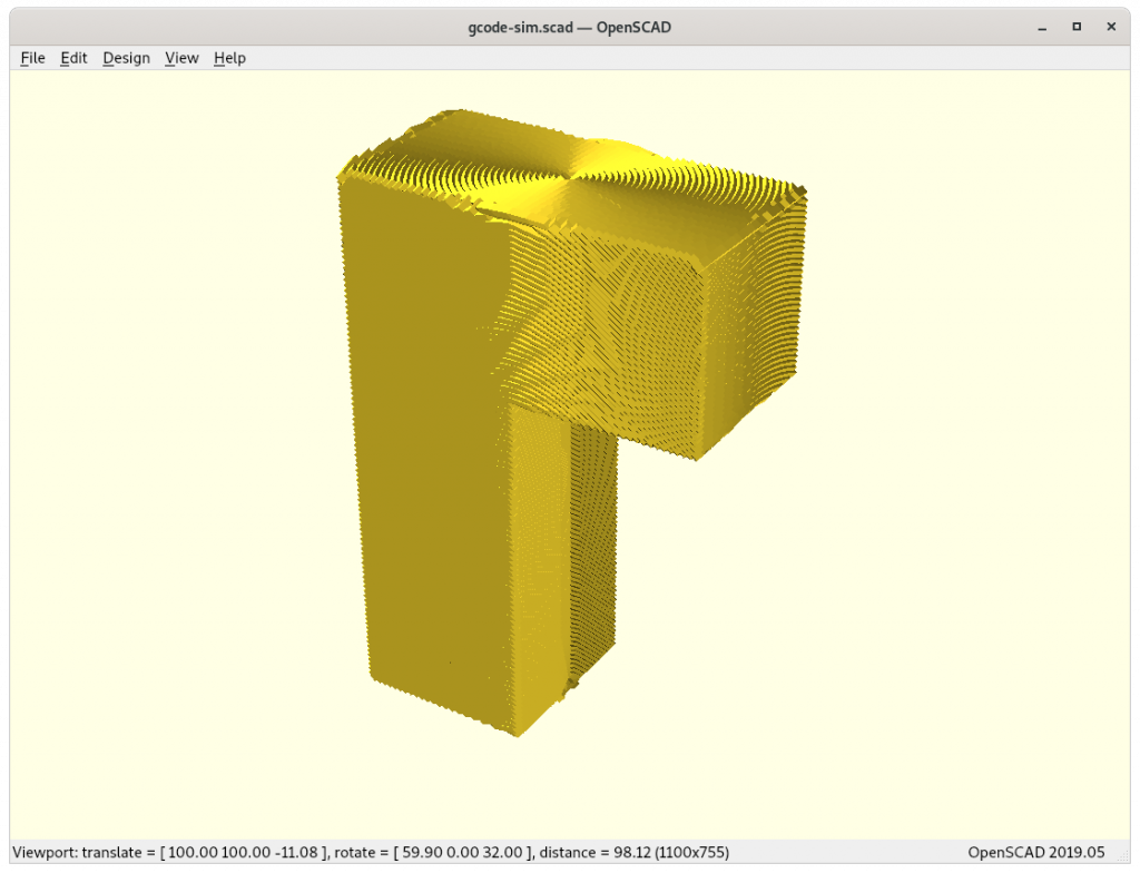
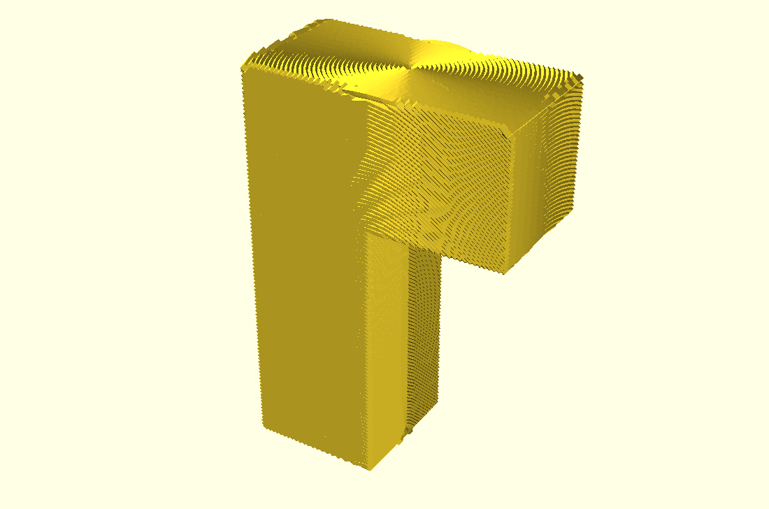
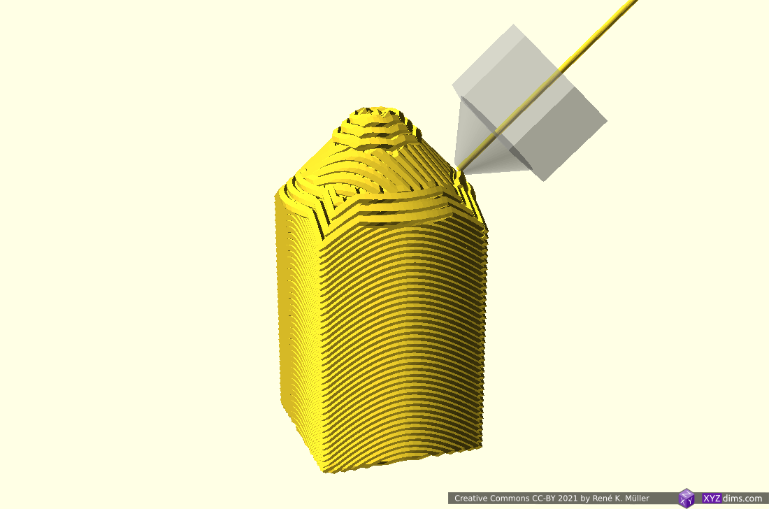
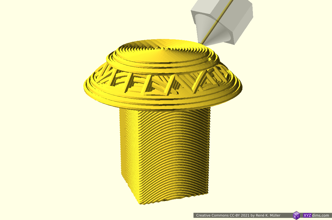
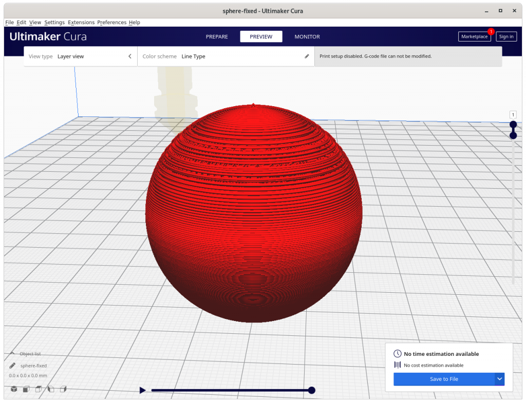
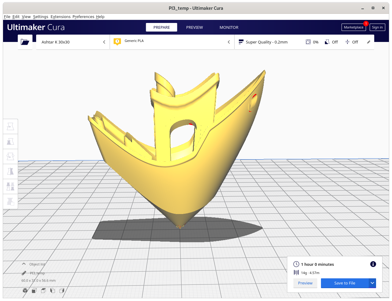
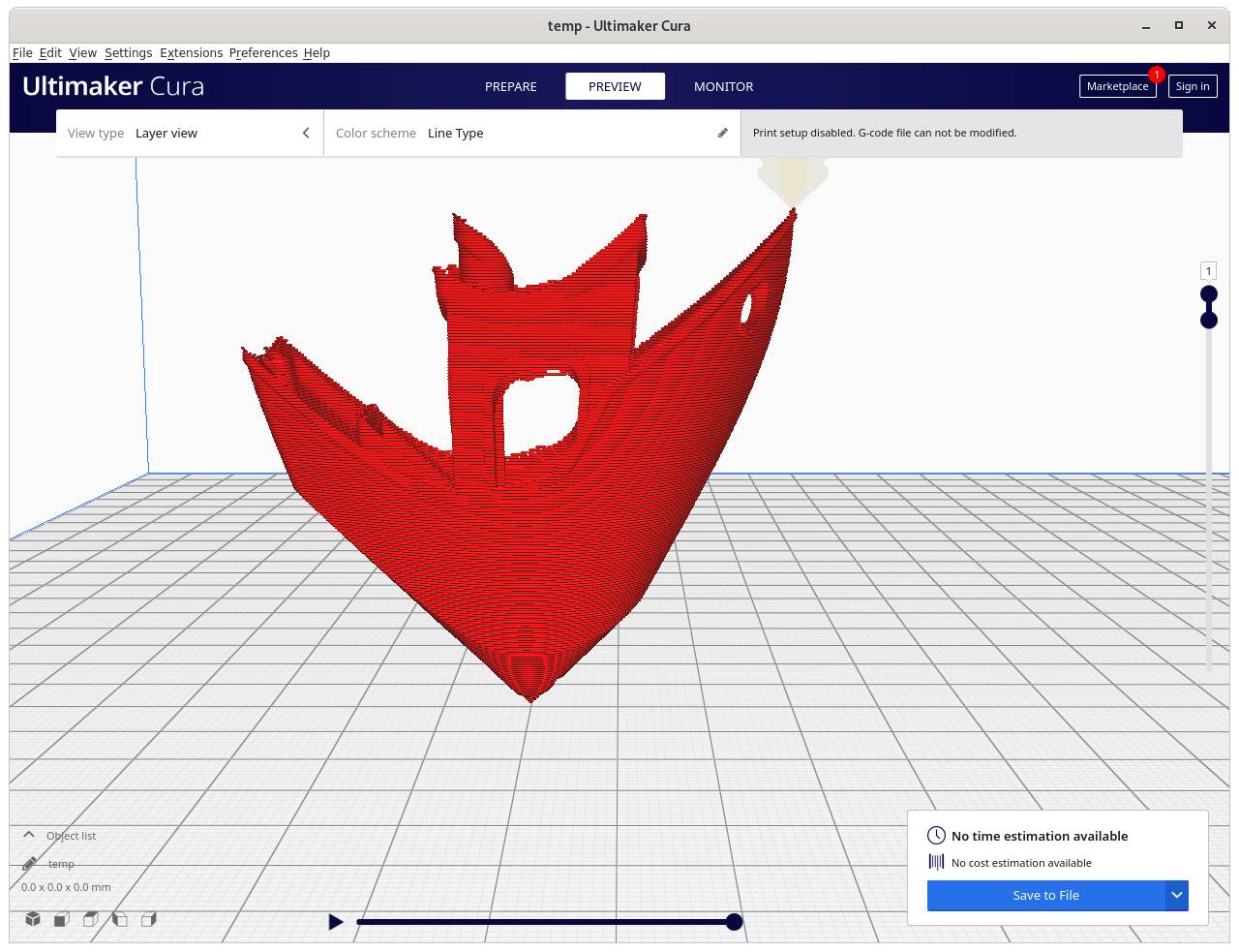
3D Benchy: requires more thorough examination, e.g. volume decomposition to segment roof apart:
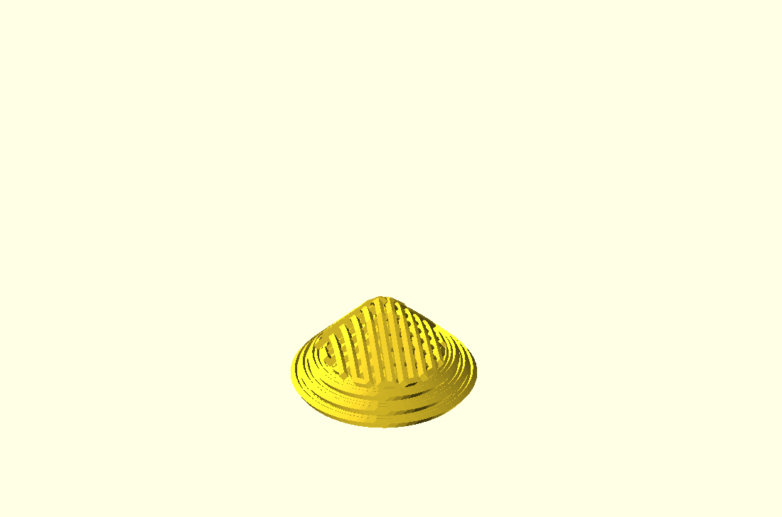
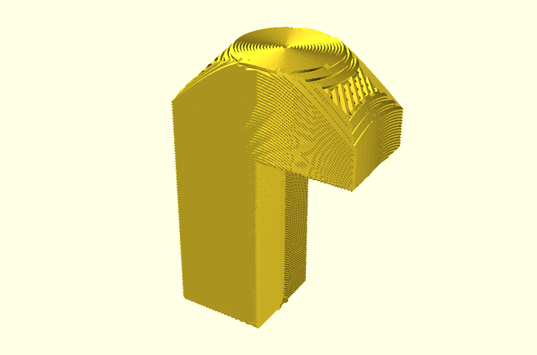
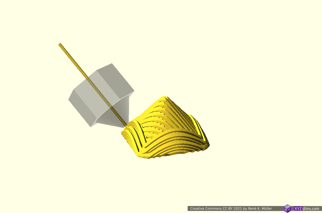
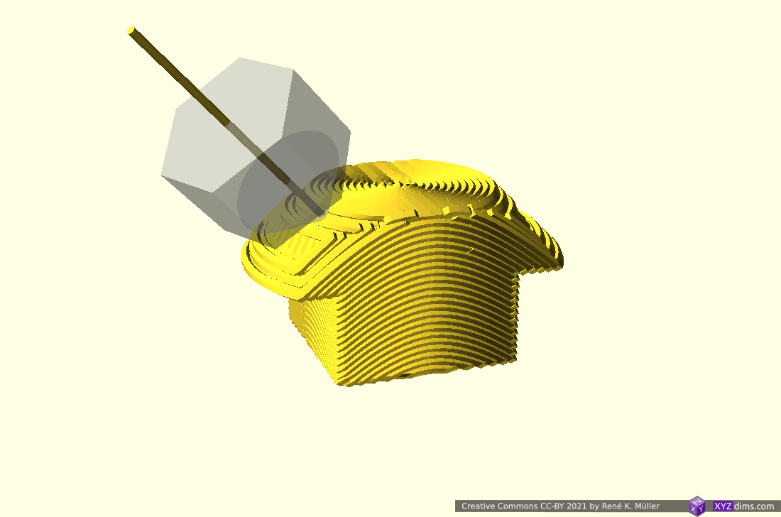
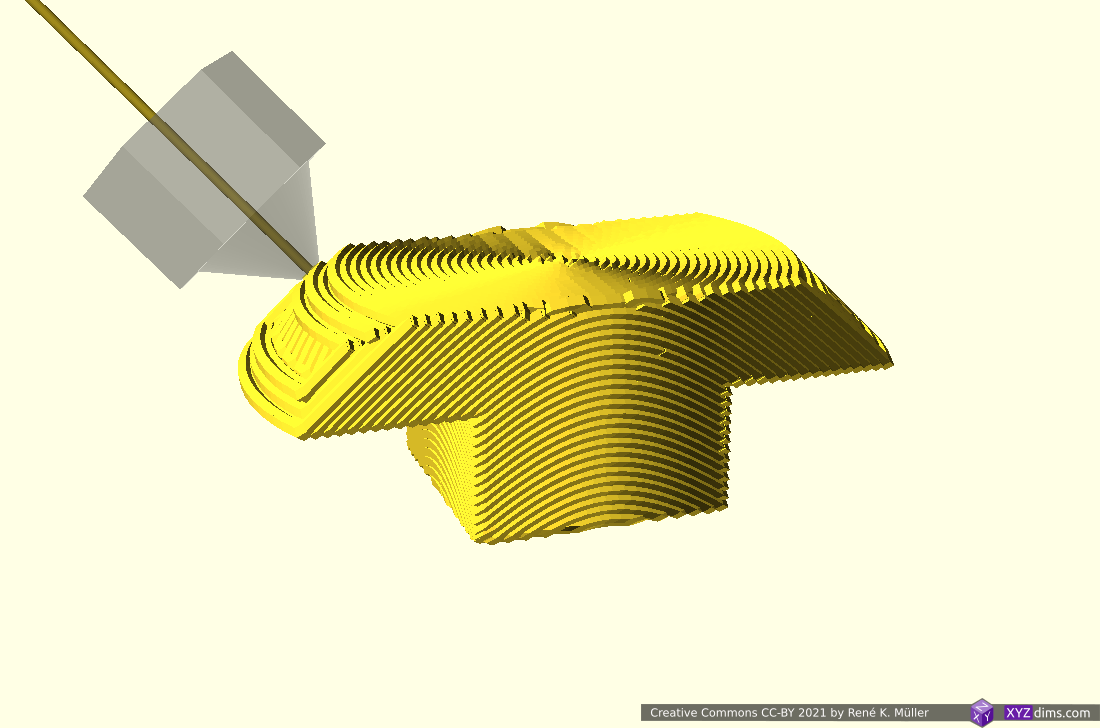
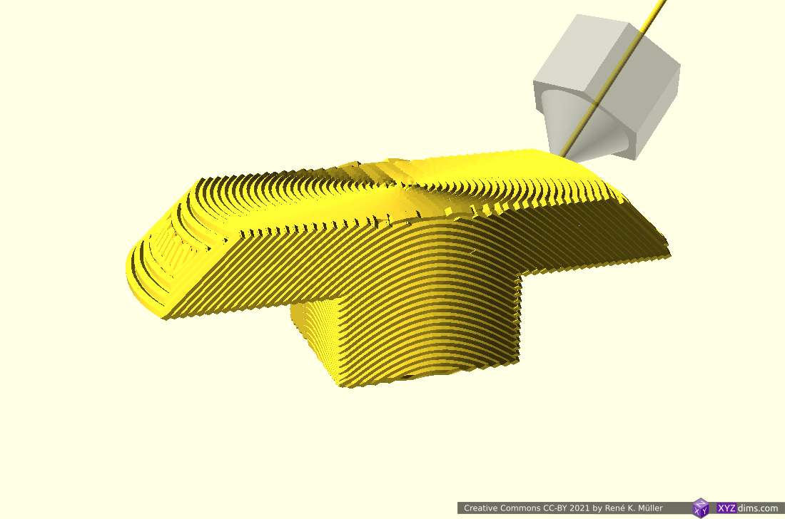
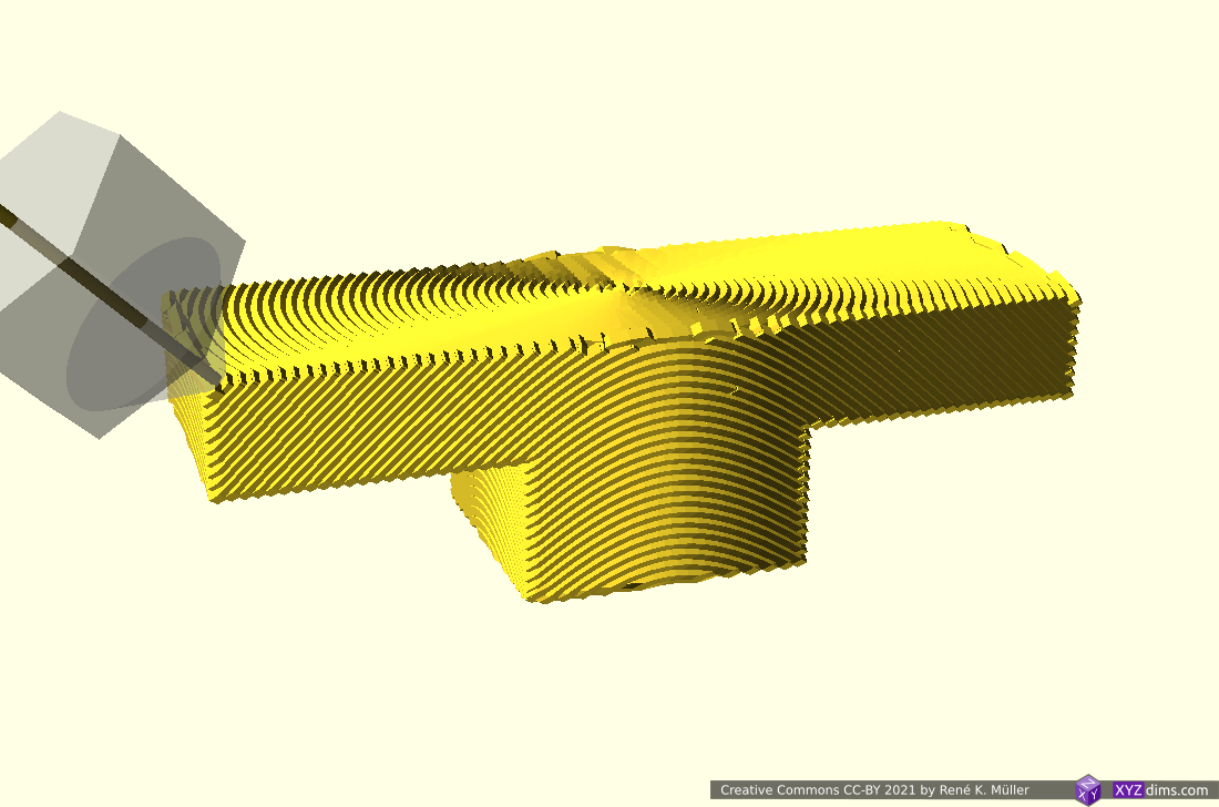
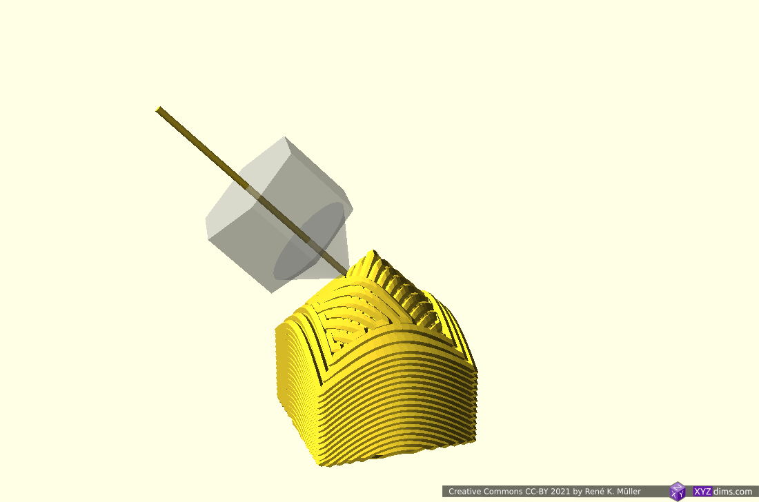
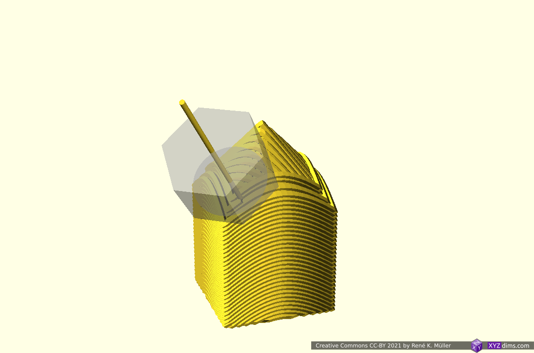
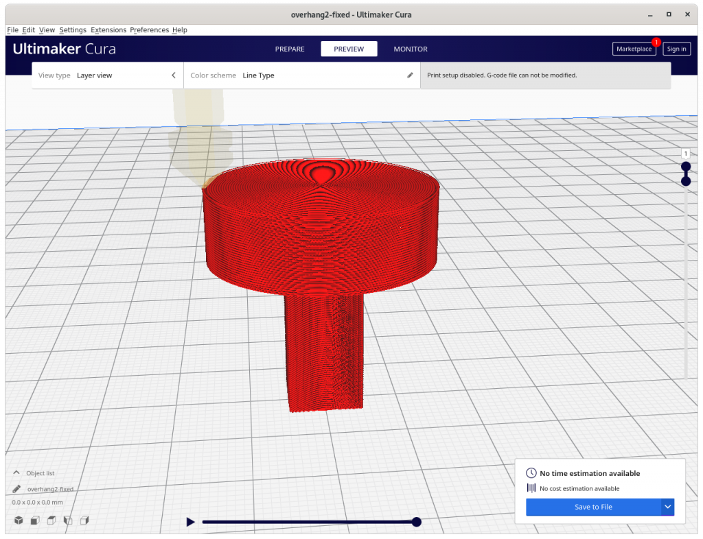
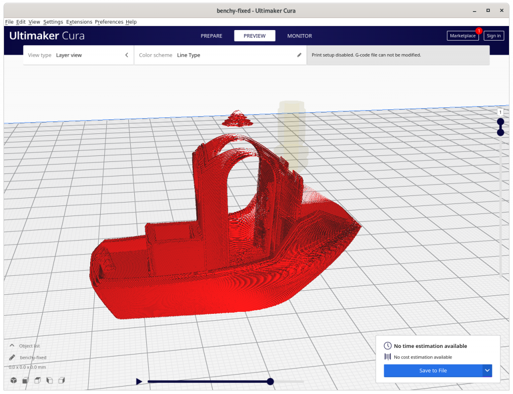
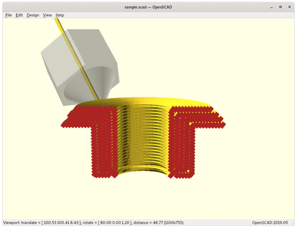
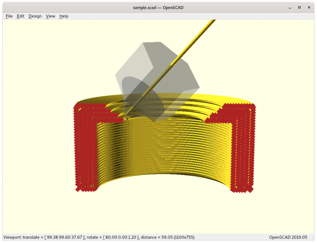
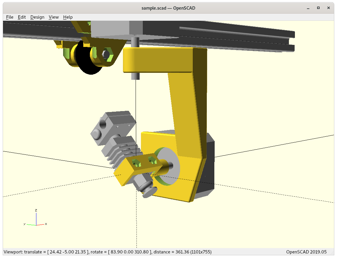
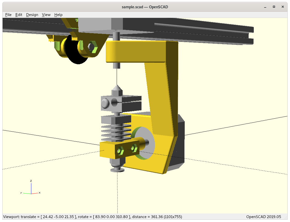
Impossible printing: current conic slicing needs to recognize overhangs and apply volume decomposition to choose right strategies – otherwise new issues arise which in Z planar slicing do not exist
Same G-code position of the Inverse Conic sliced model: > 90° overhang created, and causes in-air structure – might require actual support structure (!!), volume decomposition required
document all details
release source code to public
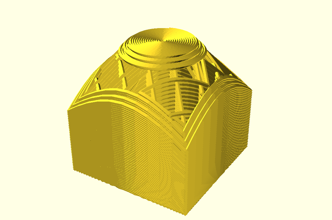
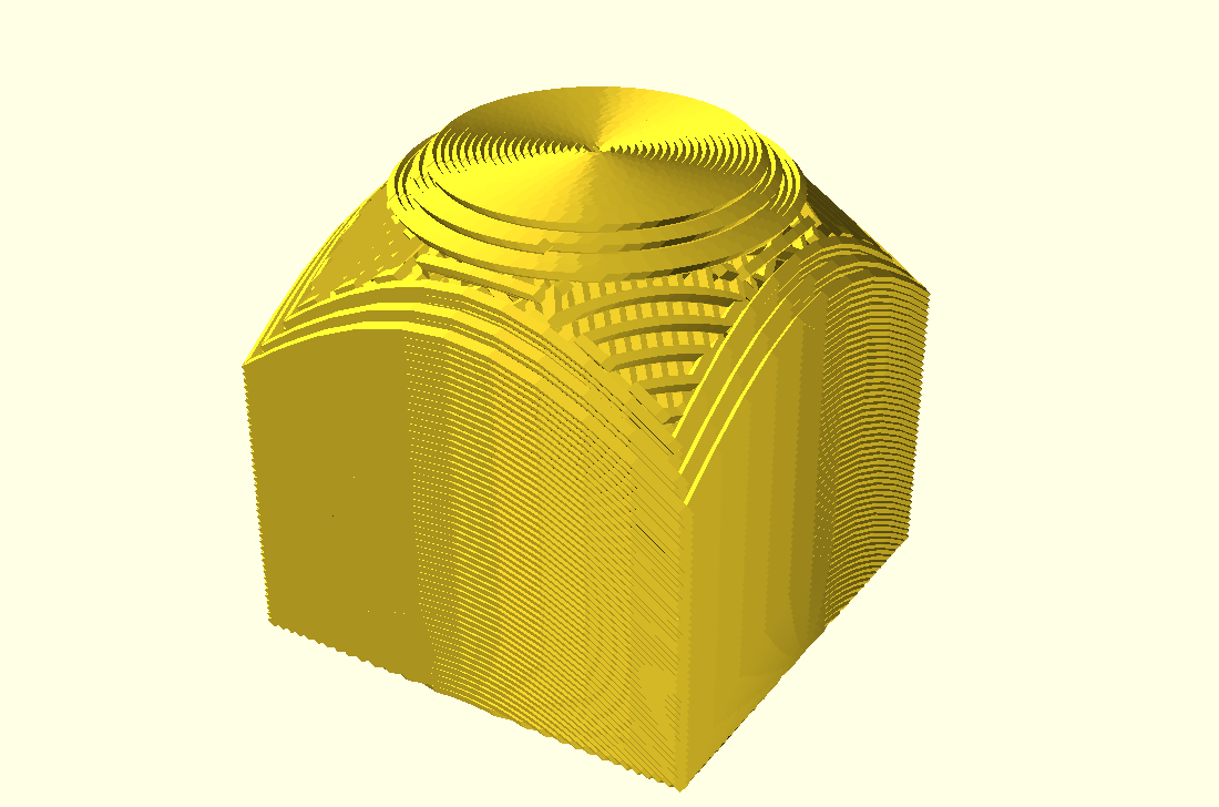
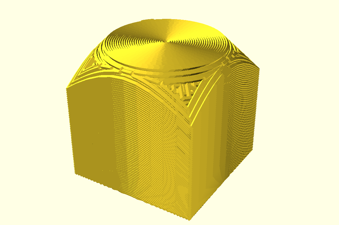
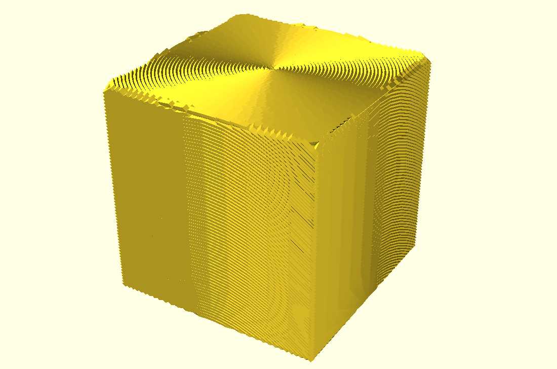
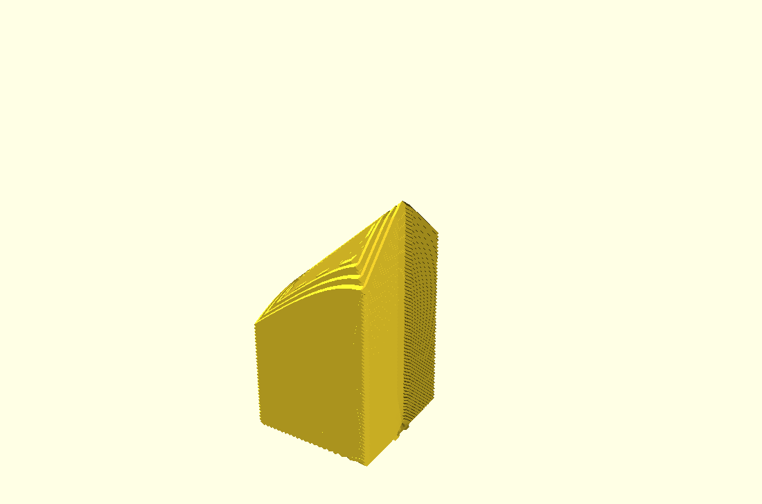
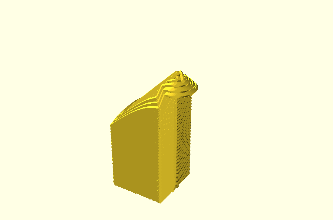
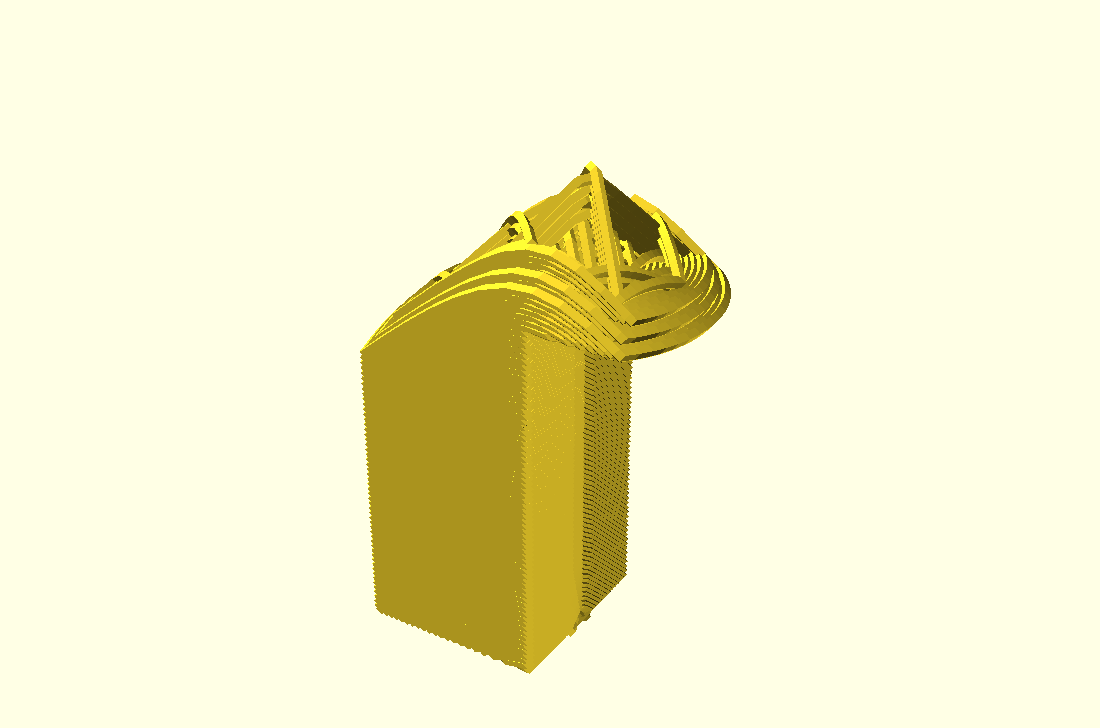
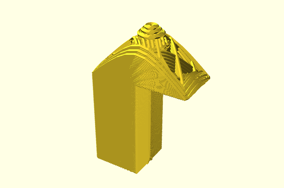
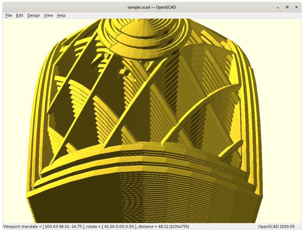
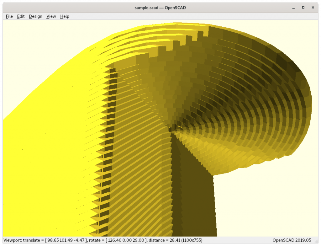
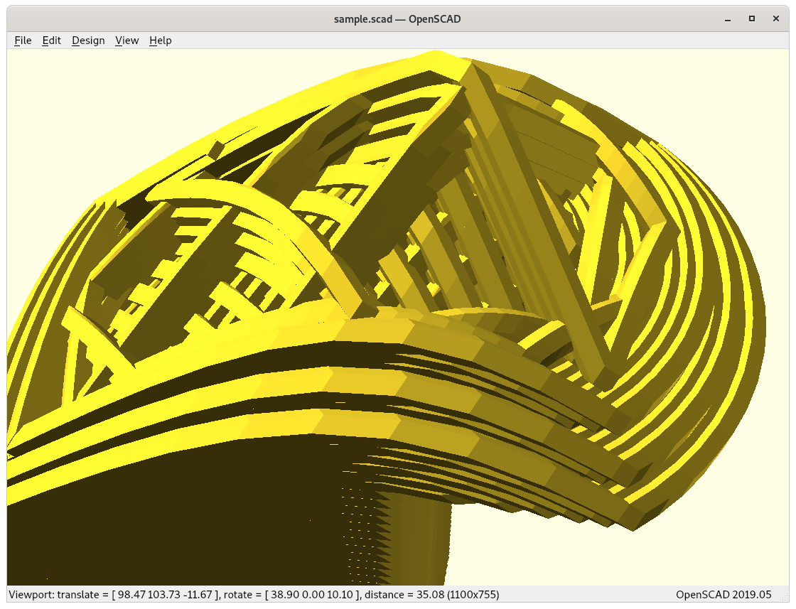
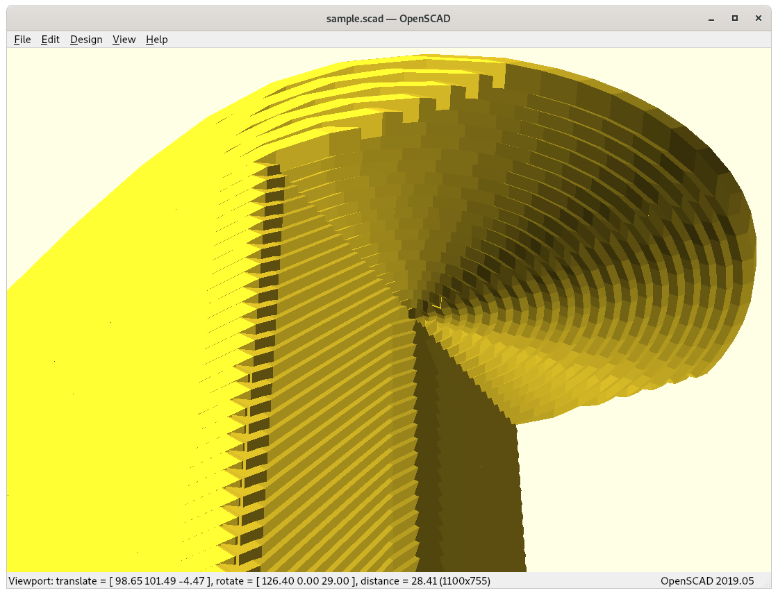
Close-Ups
Some close-ups of conic sliced models:
20mm cube (partial)
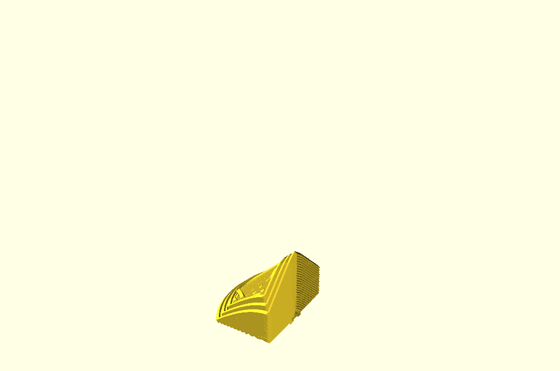
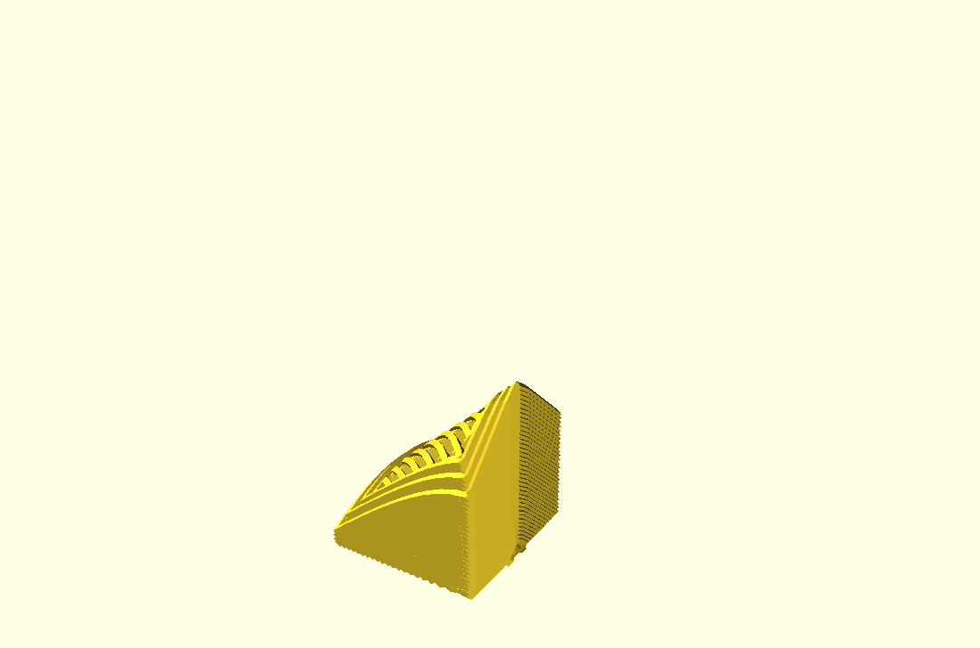
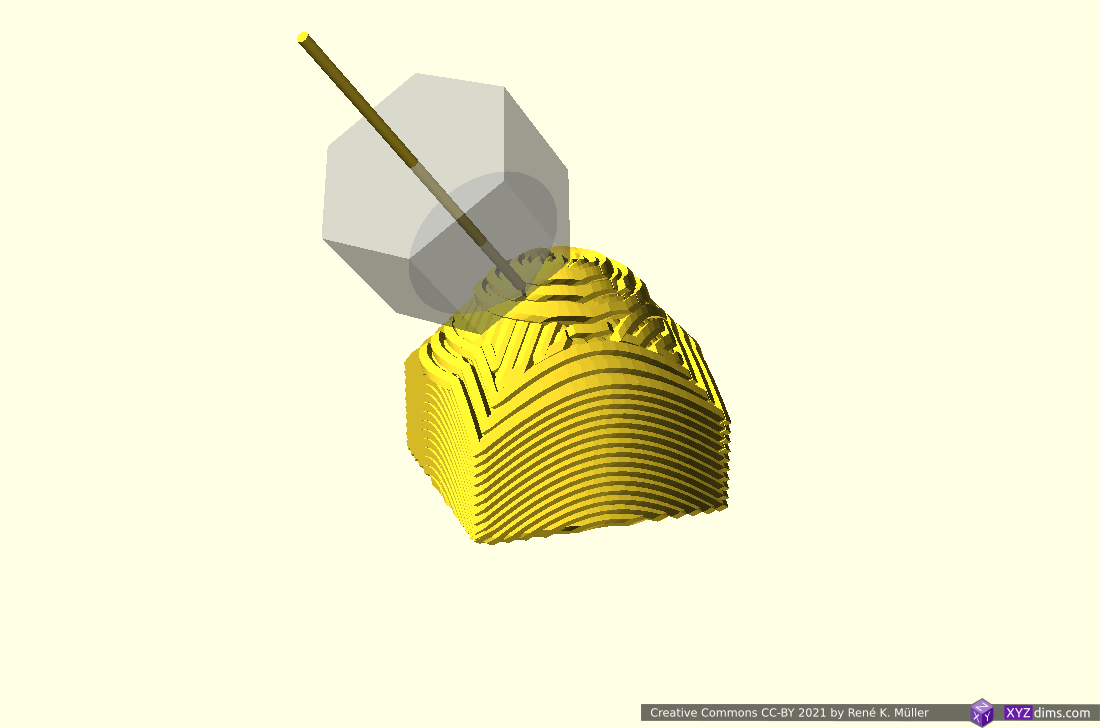
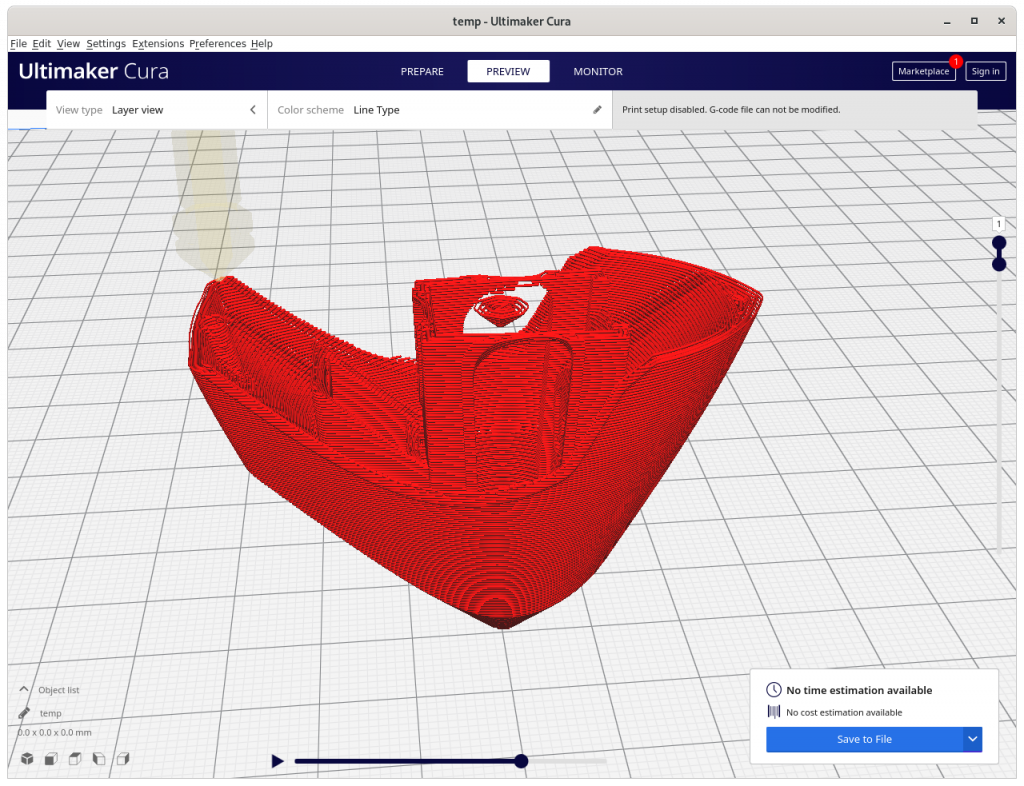
3D Benchy (roof & chimney)
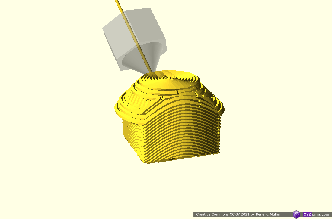
3D Benchy (cabin)
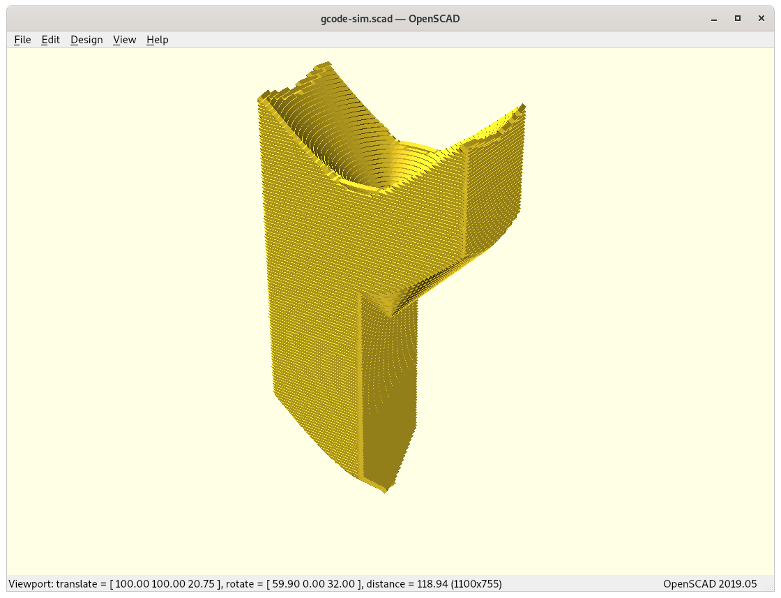
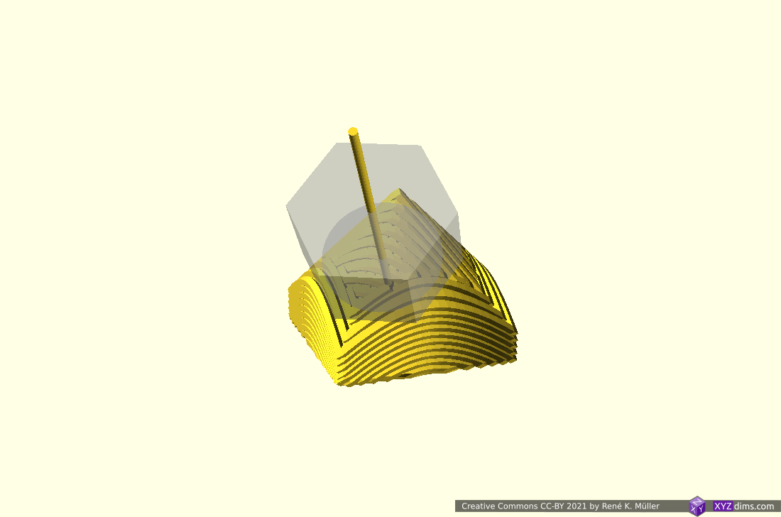
Overhang model (top view)
Overhang model (view on actual overhang)
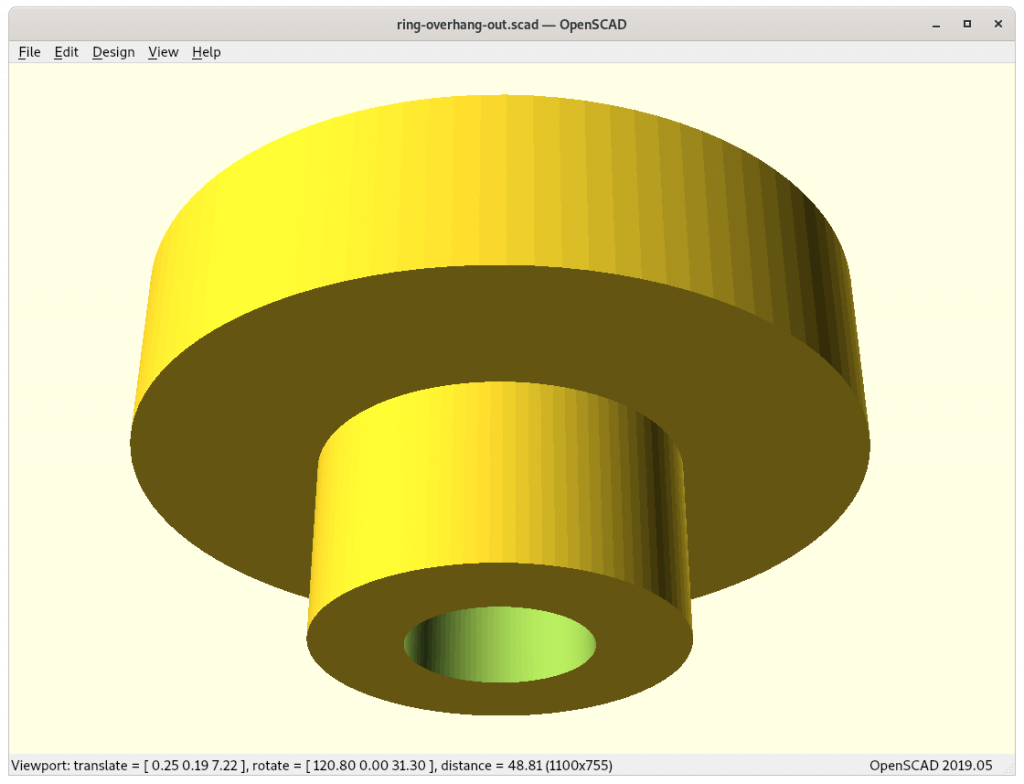
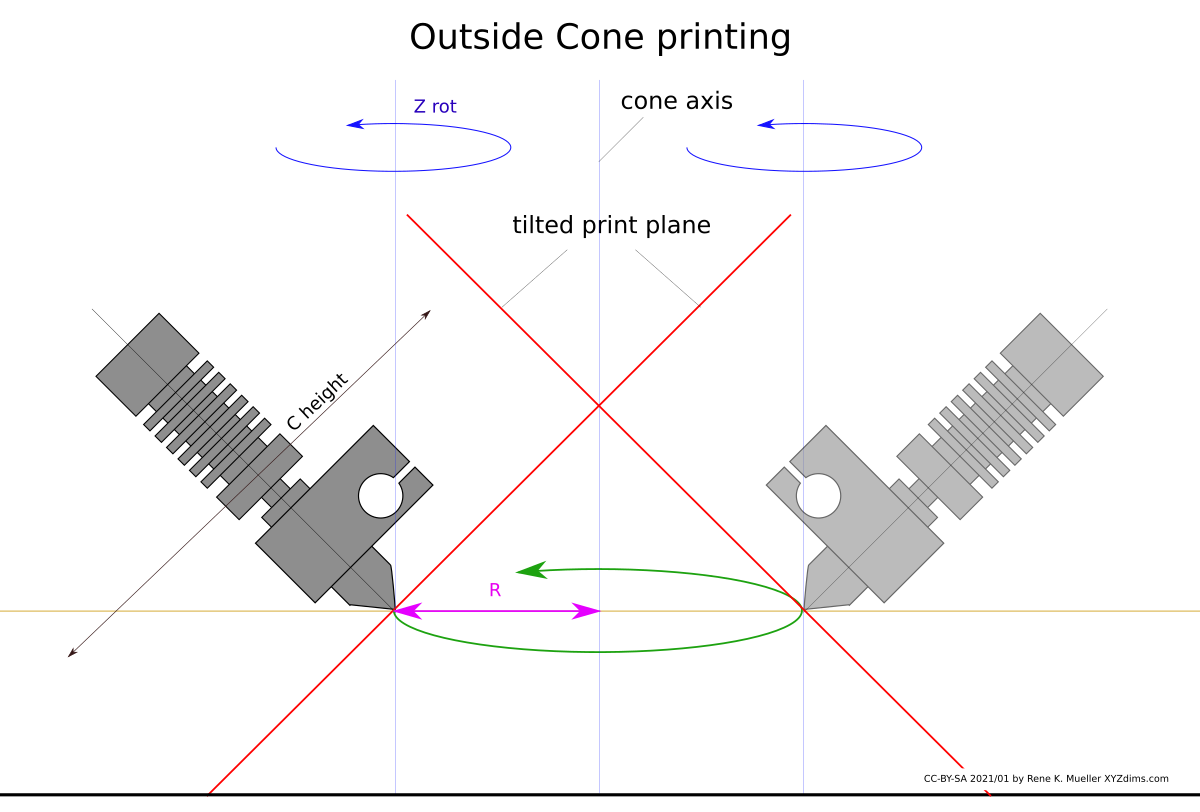
Outside- vs Inside-Cone Printing
As pointed out in the previous blog-post, the RTN has two main modes of operation, outside-cone and inside-cone printing to cover outside overhangs and inside overhangs – the slicer must recognize those and switch operation mode. Further, these two modes cannot easily be mixed, and need to be segmented or separated, hence speaking of volume segmentation.
Outside Cone printing
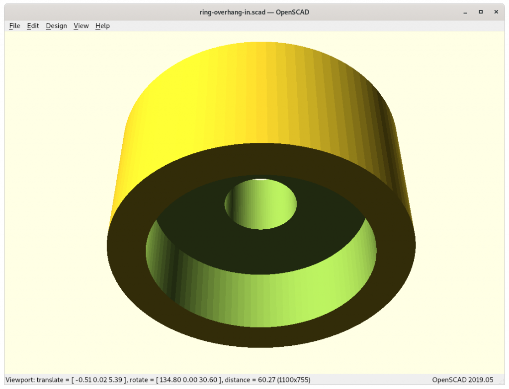
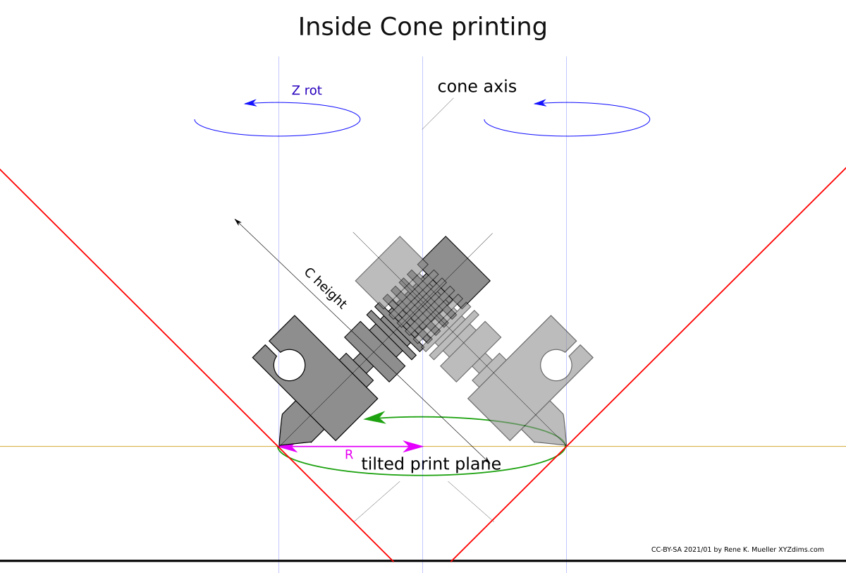
Inside Cone printing
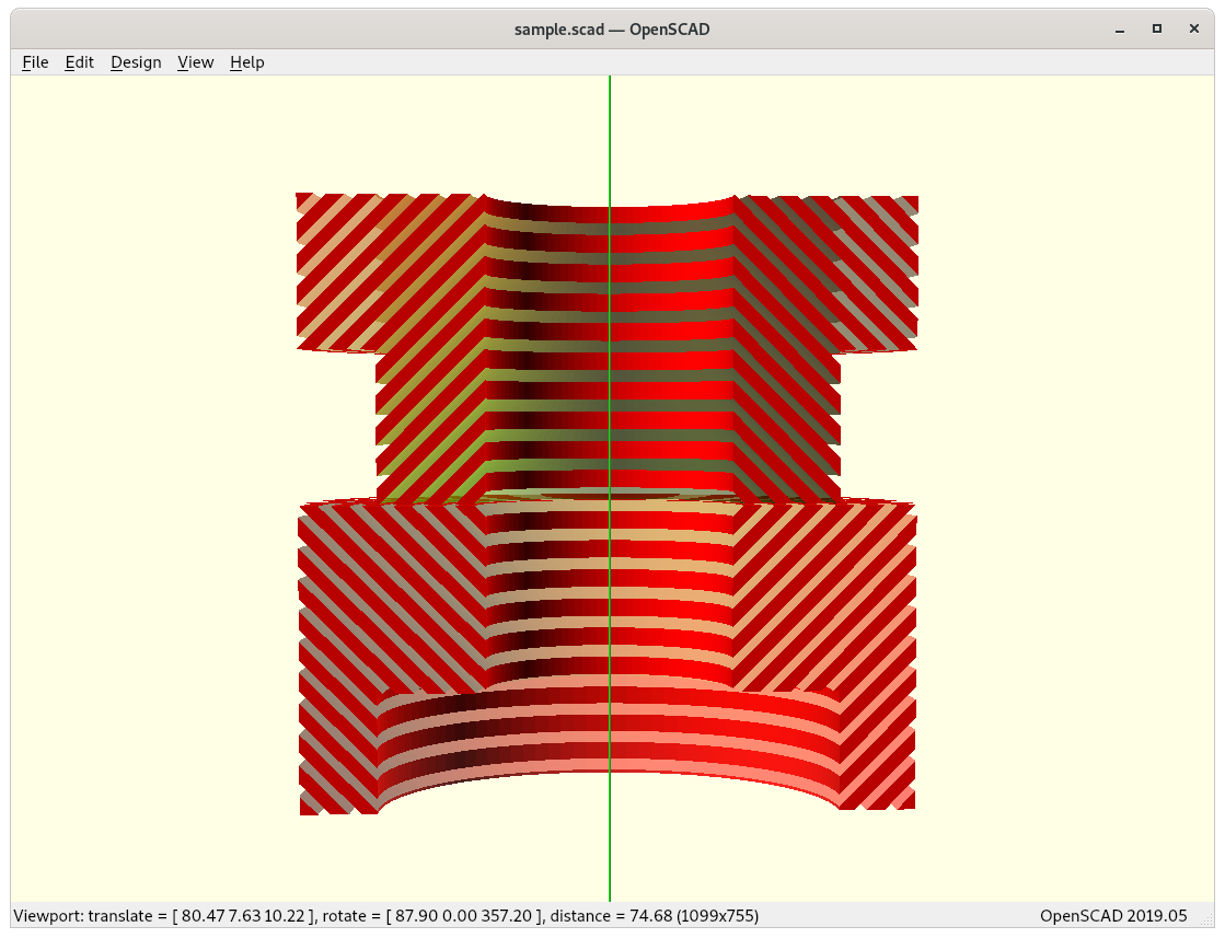
outer overhang
inner overhang
outside-cone printing for outside overhangs
inside-cone printing for inside overhangs
Inside cone for inner overhangs (bottom) vs outside cone for outside overhangs (top)
This poses significant grow of complexity from just planar slicing, the 4-axis RTN provides features to print 90° overhangs without support structure, but only when the part can be properly analysed and segmented so that those operational mode can be applied.
The difference between inside- and outside-cone printing is to change the order of conic mapping for the model and post slicing:
outside-cone mode
map model inverse conic
slice model
map G-code direct conic
inside-cone mode
map model direct conic
slice model
map G-code inverse conic, Zrot + 180°
Slicer4RTN
The pseudo-code turned into an actual application I named slicer4rtn and is a command-line tool, slicing STL into G-code:
I gonna released Slicer4RTNeventually 2021/03/22, in its early version the model currently can only be sliced for outside-cone or inside-cone printing, so the volume decomposition or segmentation needs to be done separately. For now it helps me to verify some of the 4-axis and 5-axis printer designs I work on.
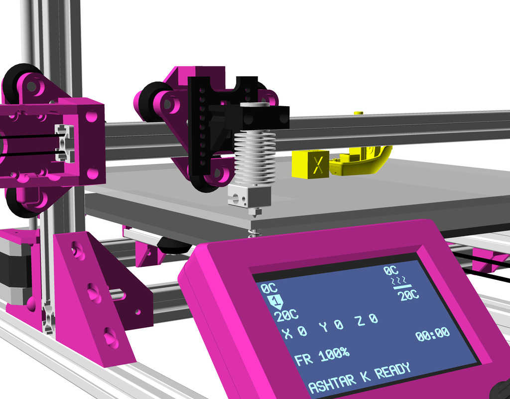
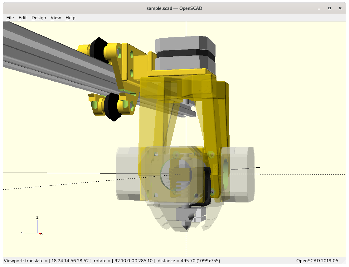
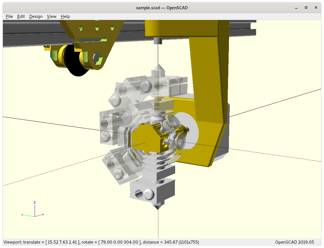
Ashtar K RTN printing conic sliced 20mm cube (close up, animation)Ashtar K RTN printing conic sliced overhang model without support structure (close up, animation)Ashtar K RTN printing conic sliced overhang model nr 6 (table-like) without support structure (close up, animation)
RotBot by ZHAW, the inventors of the Rotating Tilted Nozzle (RTN) approach by Prof. Dr. Wilfried Elspass, Dr. Christian Jaeger, Michael Wüthrich, Maurus Gubser, Philip Bos and Simon Holdener
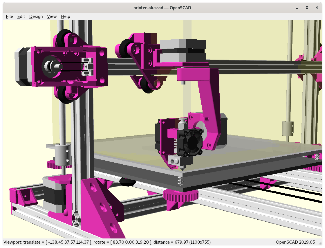
The past weeks (2021/02) I worked on various printhead designs, to summarize and provide an overview by mounting them on Ashtar K:
E3D V6 (bare without fans), 2019/09
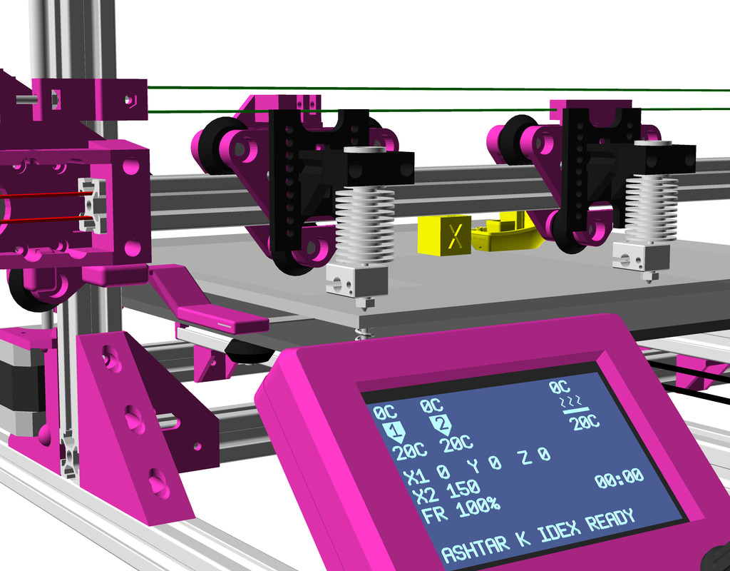
Dual Independent Extruders (IDEX), 2020/12
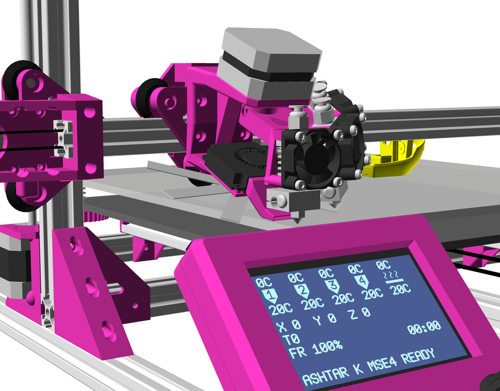
Multiple Switching Extrusions (MSE), Rotary Y 2, 2021/02
Multiple Switching Extrusions (MSE), Rotary Z 4, 2021/01
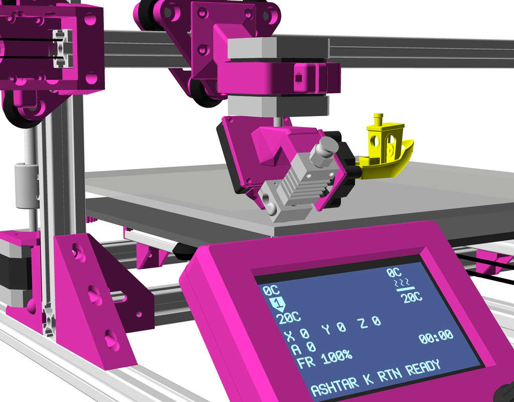
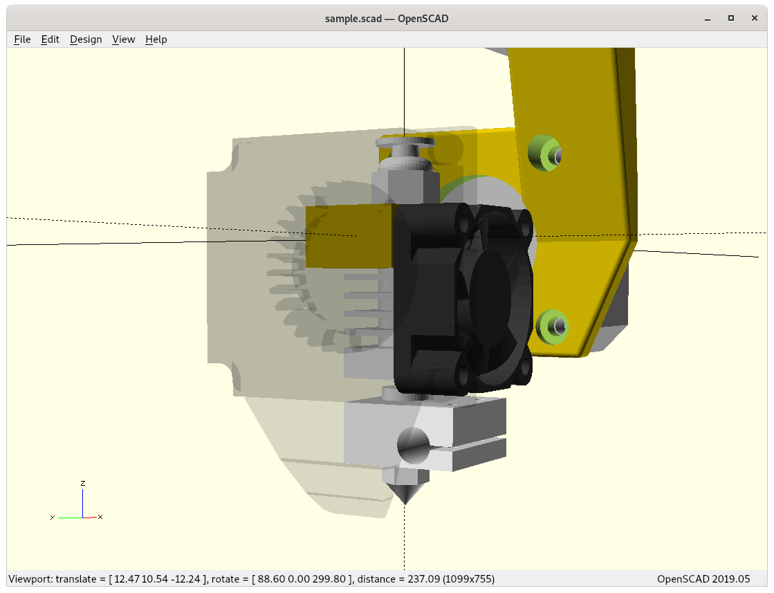
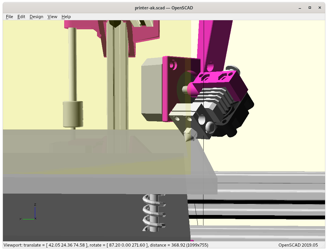
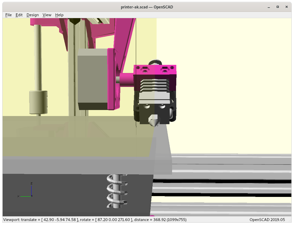
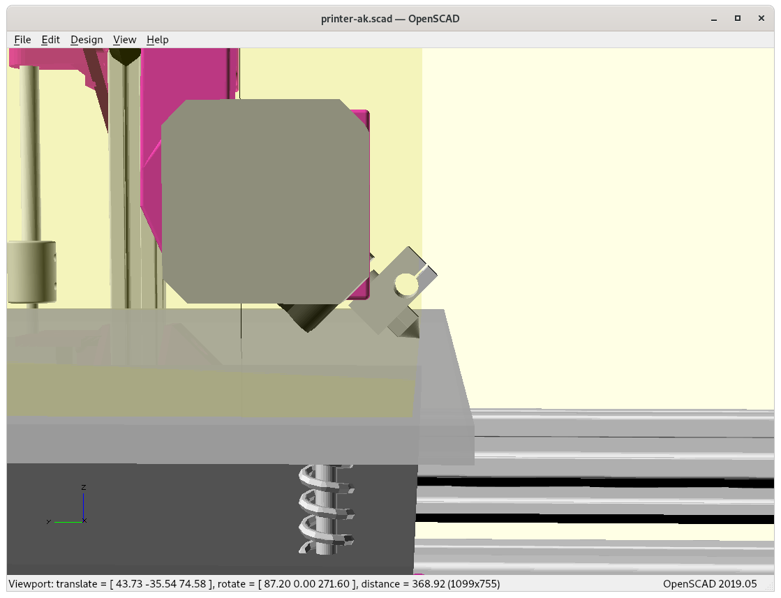
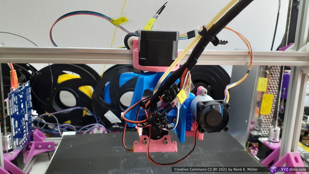
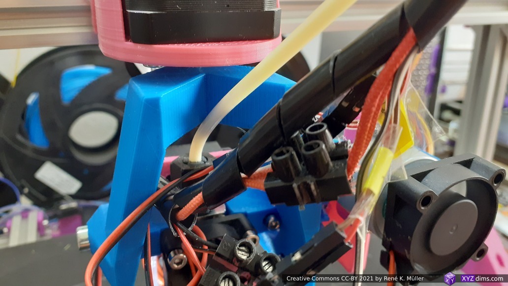
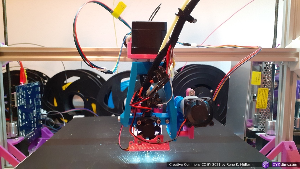
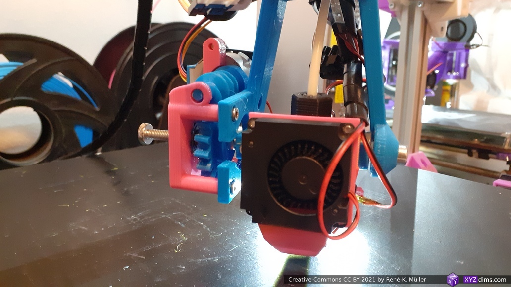
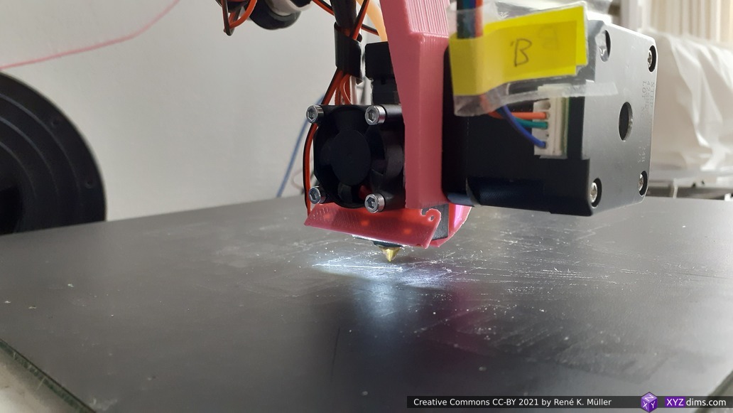
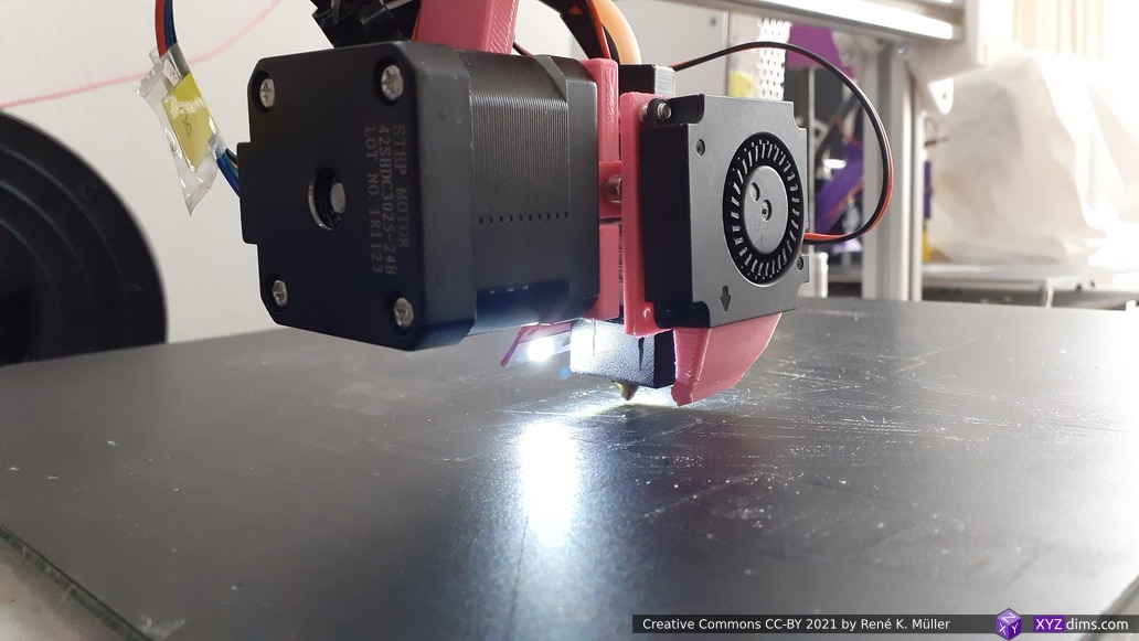
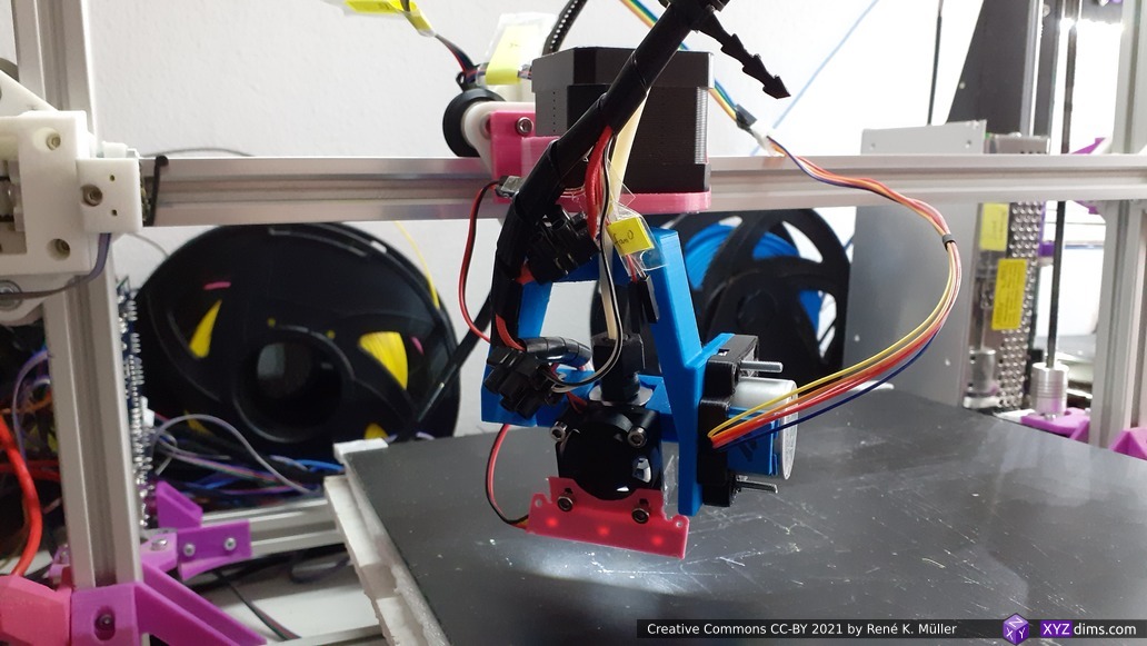
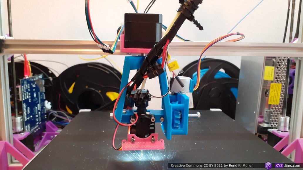
4 Axis Rotating Tilted Nozzle (RTN), 2021/01
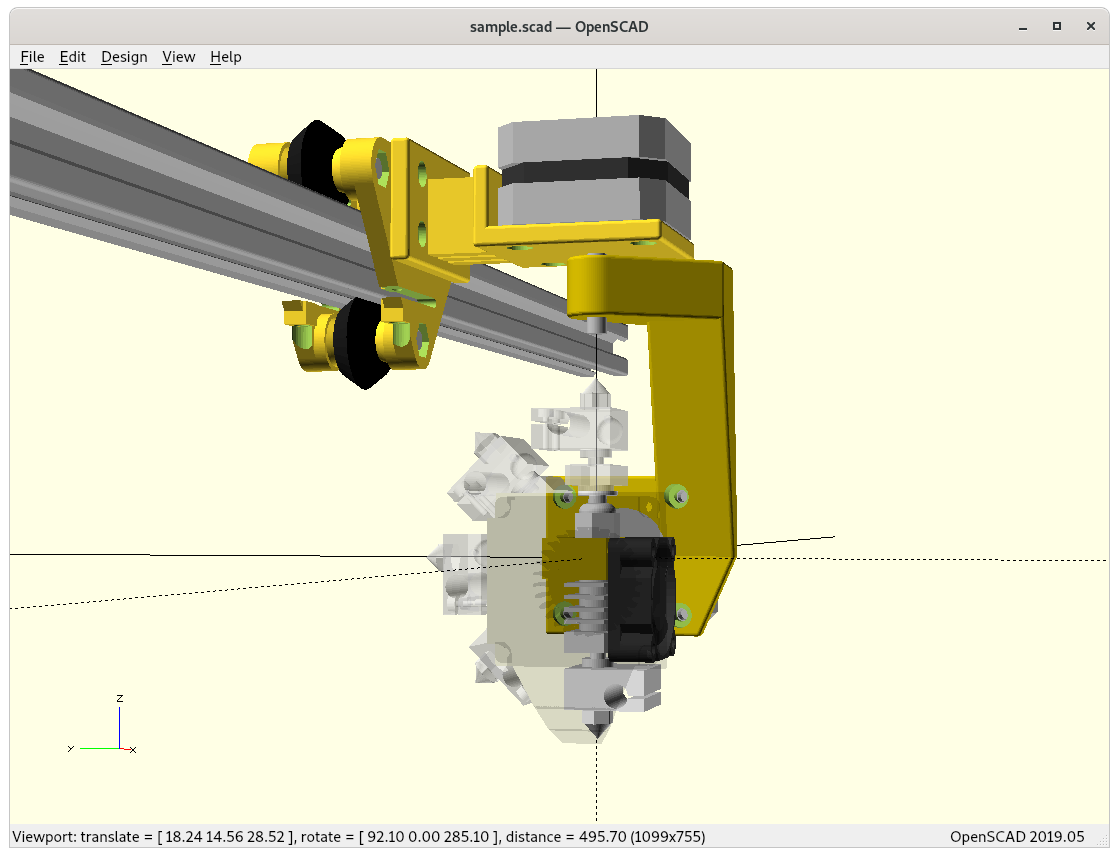
5 Axis Printhead (PAX), 2021/02
Also improved the display controller to simulate Marlin firmware and list heads and tool selection (MSE), coordinates (IDEX) or rotation angles (RTN & PAX).
So far all options are available for Ashtar C, D and M as well, but currently (2021/02) are just in draft and mostly untested.
RTN and PAX promise printable support-free overhangs, yet no public available slicing software exists to really take advantage of those two designs, as new algorithms of volume decomposition, sub-volume sequencing, collision detection are required and mostly debated in scientific papers as 2021/02 and only few companies, e.g. HAGE and VSHAPER, implemented new 5-axis 3D printing procedures, and DotXControl advertises a 5 Axis Slicer.
Status: inverse kinematics resolved and implemented in the firmware as well
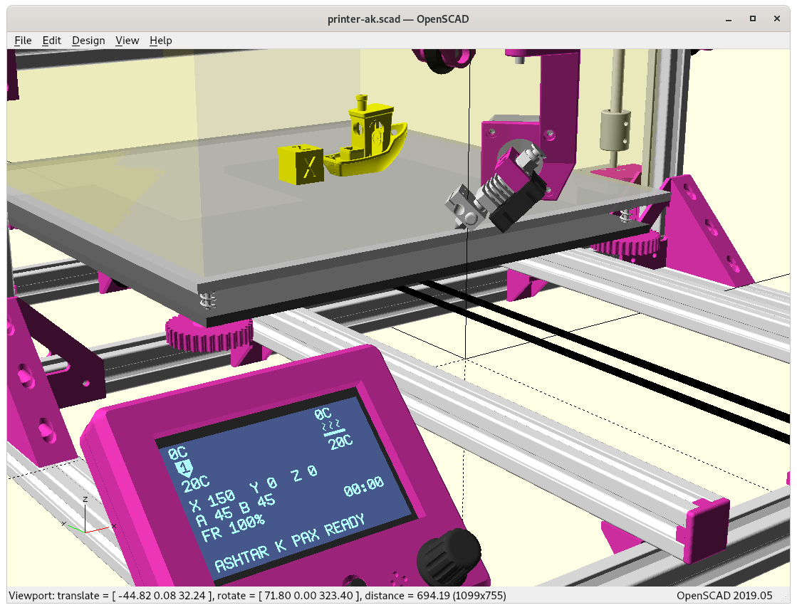
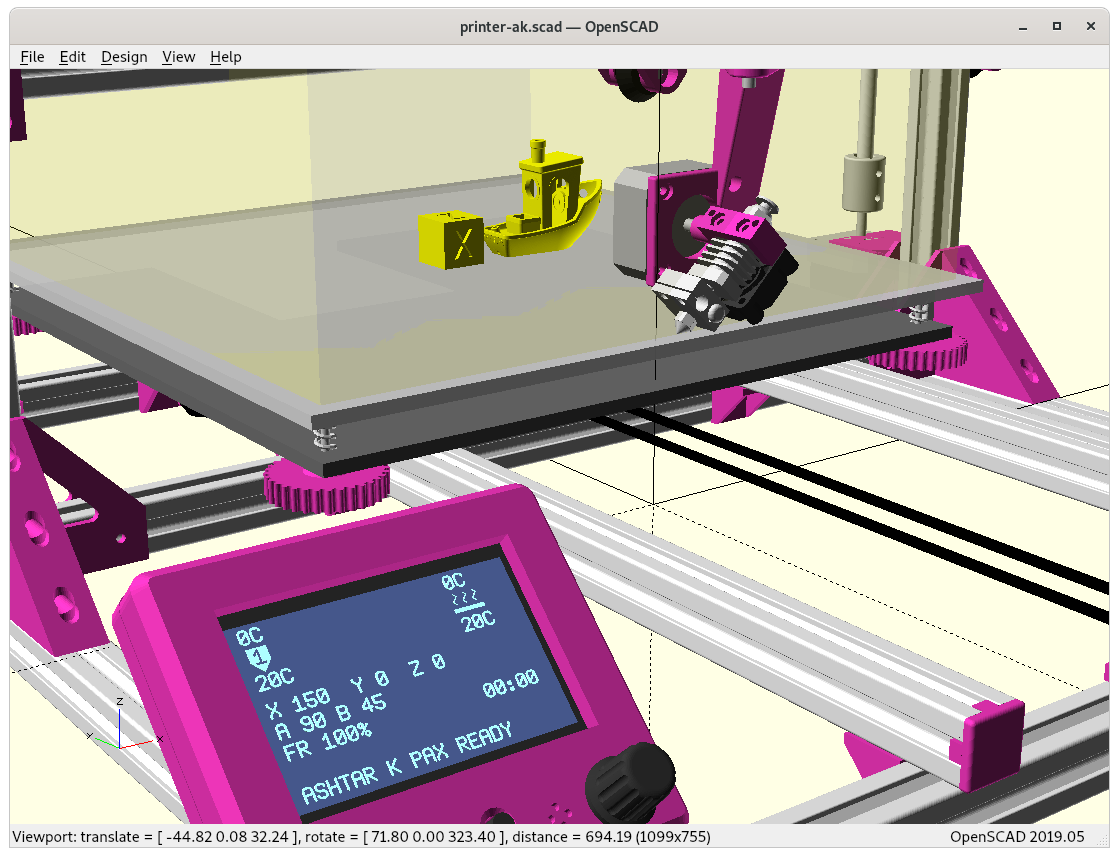
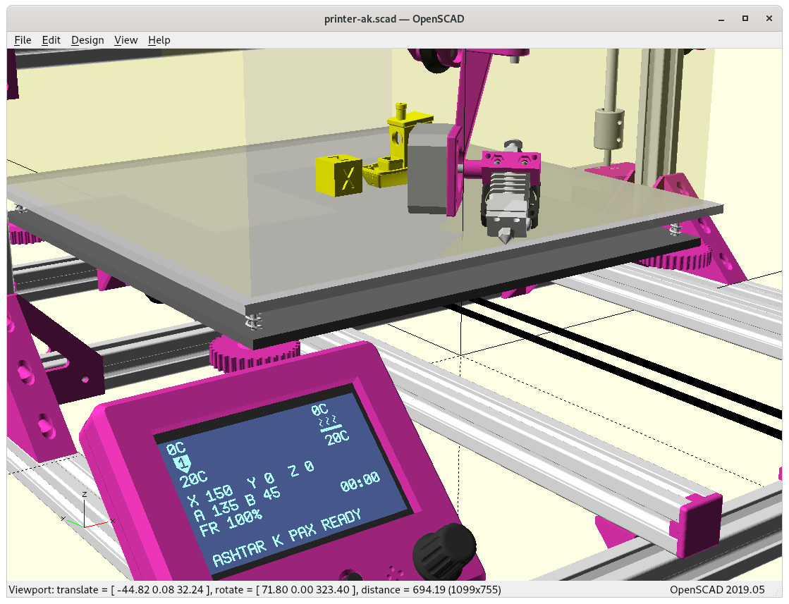
Tilt rotation 0° ..180°Z rotation -180° .. 180°PAX 180 printhead mounted on Ashtar K (Draft)Heavy setup: PAX 90 printhead (2x NEMA17 37mm) mounted on Ashtar KHeavy setup: PAX 135 Dual Hinge printhead (2x NEMA17 37mm) Lightweight setup: PAX 135 Dual Hinge printhead (1x NEMA17 37mm 1x 28BYJ-48 with worm gear & cooling fan) mounted on Ashtar K
Updates:
2021/07/14: PAX inverse kinematics finally working on firmware level too
2021/05/25: using worm gear with 28BYJ-48 stepper motor to drive tilt rotation
2021/05/14: adding Duet 3 Mini 5+ Setup details (inverse kinematic not yet done in firmware), first motion tests made with 2x NEMA 17 (40mm)
2021/02/28: added animation PAX printing a 4-axis/RTN sliced overhang model
2021/02/17: added two brief animations of inverse kinematics
2021/02/08: inverse kinematics working, printhead mounted on Ashtar K as draft
2021/02/06: machine vs nozzle coordinates, forward/reverse transformation requirements, heatsink fan and part cooler added
2021/02/04: starting with collecting ideas and first drafts
Introduction
After I saw 5- and 6-axis printers at Formnext 2019 and particularly seeing the belt printers able to print 90° overhangs in one direction without support, and then RotBot by ZHAW, a Rotating Tilted Nozzle (RTN) printer, where the 90° overhangs in different directions (given some conditions) can be printed without support – so it was more natural to consider to make the tilting nozzle angle (trot) flexible as well, 0 – 180°.
0°: nozzle looking down, ordinary orientation with Z sliced layers 3D printing
45°: belt printer or rotating tilted nozzle (RTN) printer, printing 90° overhangs in one or more directions *)
90°: printing horizontally outward
135°: printing upward 45°
180°: printing upward entirely
*) Rotating Tilted Nozzle capability printing 90° overhangs depends on location and symmetric alignments, noslicing software yet available.
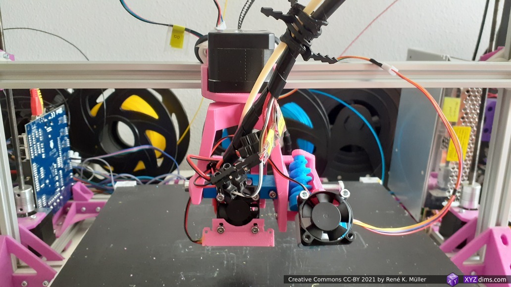
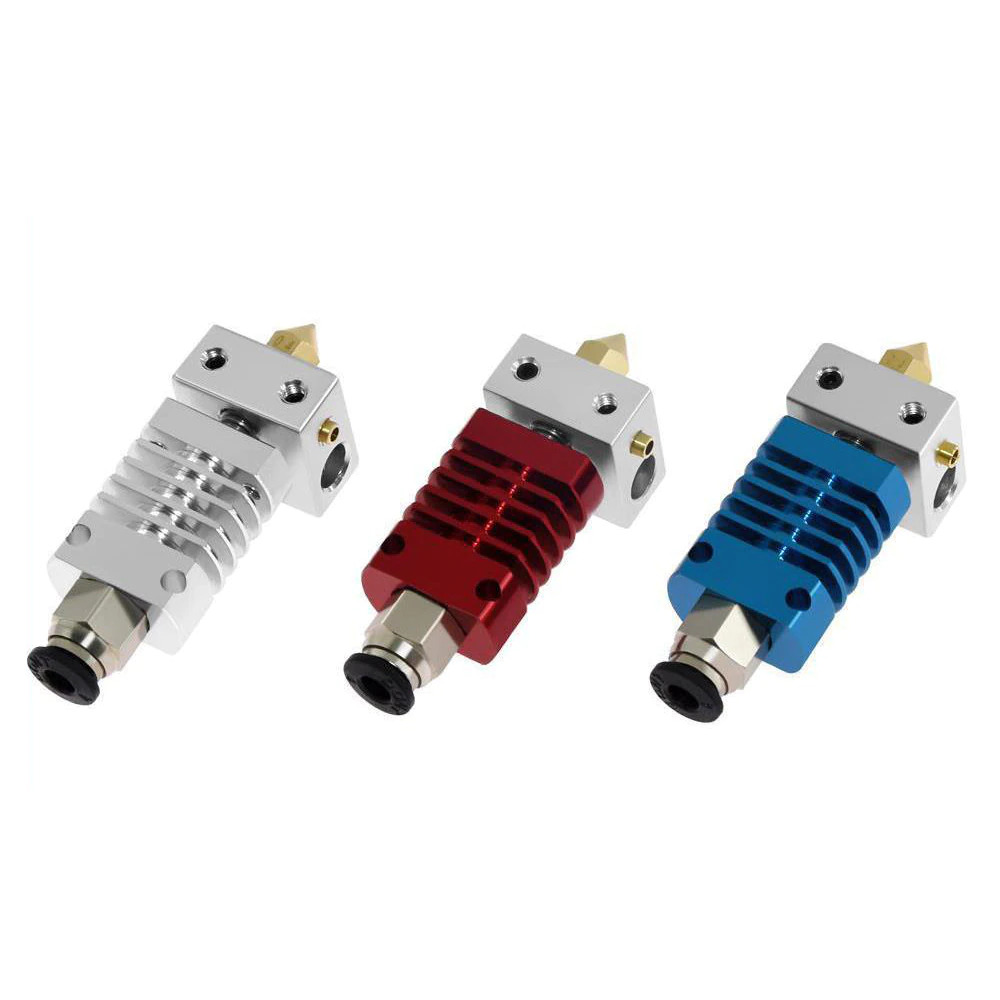
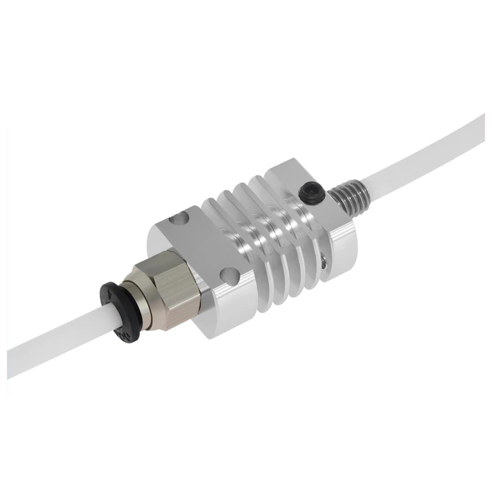
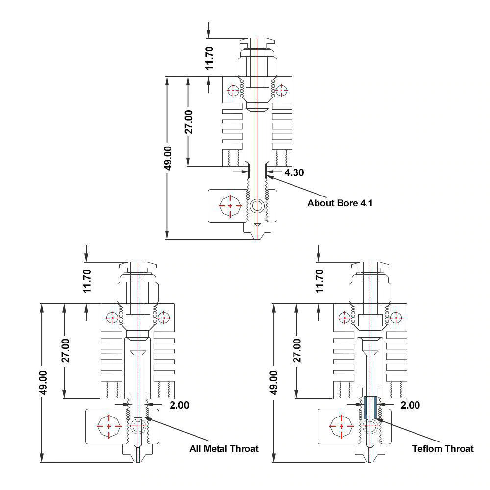
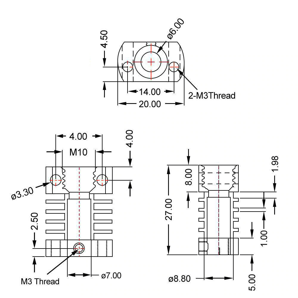
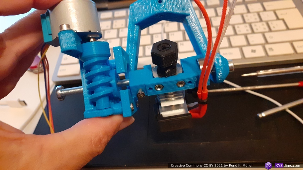
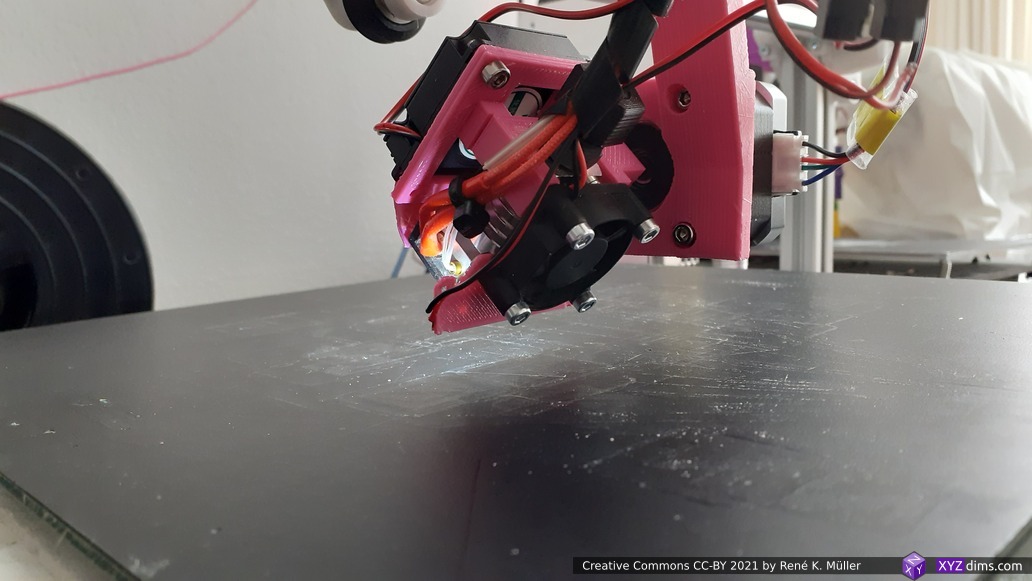
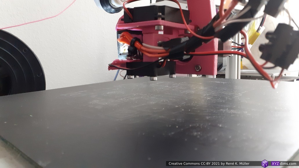
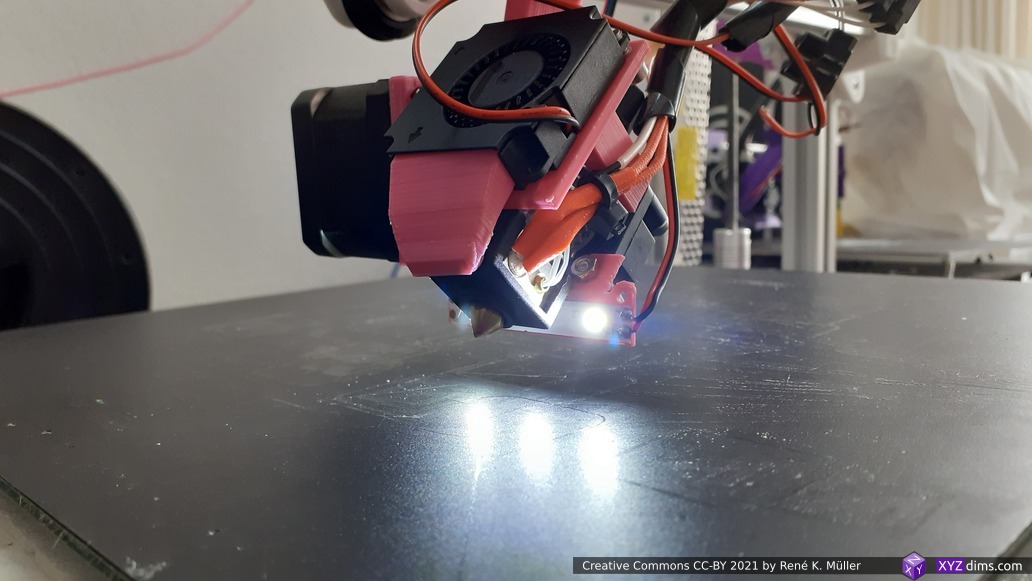
I chose Micro Swiss clone aka CR10 hotend as printhead as it’s small and compact, and easy to adapt and source.
Micro Swiss clone aka CR10 hotendsingle worm screw to attach heatbreak to heatsink
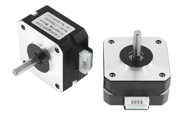
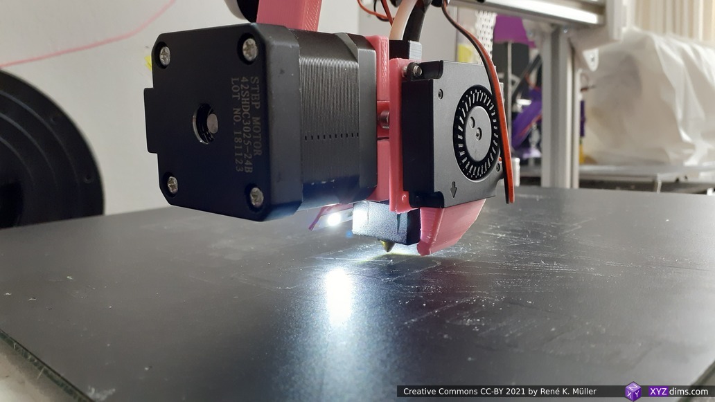
NEMA 17 37mm/263g: strong enough, but too heavy, my X gantry rattles and introduces ~ 1 to 2mm errors before swinging in; verdict: unusable
NEMA 17 23mm/131g: too weak, can’t hold position Z rotation (A) or tilt (B); verdict: unusable
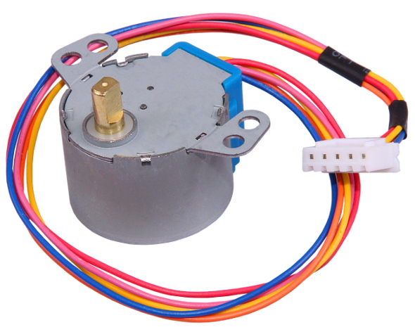
28BYJ-48 33g: requires ULN2003 or adjustment to drive with stepper driver like A4988; verdict: unusable due the rotation and tilt tolerance; with a more elaborate gearbox might be usable
N20 BLDC motor with gearbox & encoder 10g: requires dedicated controller; verdict: <untested>
Different combinations:
2x NEMA 17 37mm/263g (Z rotation (A) + Tilt (B)): strong enough, but too heavy, my X gantry rattles and introduces ~ 1 to 2mm errors before swinging in; verdict: unusable unless entire X gantry/carriage is strengthened
2x NEMA 17 23mm/131g (Z rotation (A) + Tilt (B)): too weak, can’t hold position Z rotation (A) or tilt (B) on PAX 180/90 due PTFE with filament stiffness; verdict: unusable
1x NEMA 17 37mm/263g (Z rotation (A)): strong enough to position with PTFE with filament and cables + 1x 28BYJ-48 (Tilt (B)):
direct drive
PAX 90 arm (dual hinge): PTFE with filament stiffness prevents 0° tilt, but 15° at minimum: unreliable
PAX 180 arm (dual hinge): a bit better, but still problem to reliable position tilt from 0° to 90° and back to 0°: still unreliable
worm gear
PAX 90 arm (dual hinge): barely works (tilt: -5° to 85°)
PAX 180 arm (dual hinge): works so far (tilt: -20° to 170°)
Let’s look at bit closer to the new rotating axes implemented with direct drive NEMA 17 stepper motors:
Z rotation (aka Zrot) with
NEMA 17 37/40mm/263g long (45Ncm) or
NEMA 17 23mm/131g (13Ncm)
Tilt rotation (aka Trot) with
NEMA 17 20mm/140g (16Ncm) or
NEMA 17 23mm/131g (13Ncm)
both provide 1.8° (or optionally 0.9°) resolution per full step, or
8 microsteps (20% force) 0.225° @1.8°step (0.1125° @0.9°step) per microstep
Z rotation 9 Ncm (or 2.6Ncm)
T rotation 3.2 Ncm
16 microsteps (10% force) 0.1125° @1.8°step (0.0565° @0.9°step) per microstep
Z rotation 4.5 Ncm (or 1.3Ncm)
T rotation 1.6 Ncm
For now, for sake of simplicity, both axes are in direct drive – if precision requirements dictate a simple reduction gear 1:4 or 1:5 (see below for some more details).
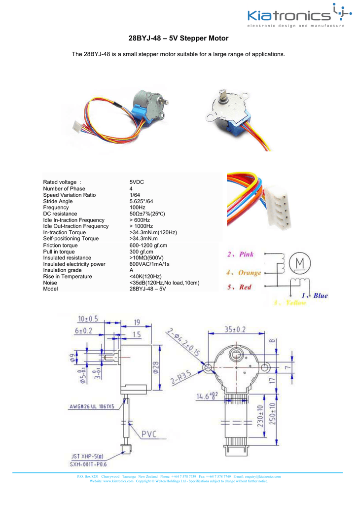
28BYJ-48
28BYJ-48 (33g)
With just 33g weight and easy to source this stepper motor is quite remarkable. With a small modification, the 28BYJ-48 can be driven in bi-polar mode and then connected with the existing stepper drivers.
apprx. 2-3° rotation backlash (last gear of the shaft has 31 tooths, 360° / 31 = 11.6°)
apprx. 0.5mm tolerance of the shaft itself, causing at the tip of the shaft > 1mm tolerance or margin
possible solutions:
add another gearbox in front and introduce more stable (longer) shaft (pros: still light solution, cons: more mechanical complexity)
worm gear: works
Even though it’s a low-cost stepper motor and introduces backlash and tolerances to take care of, the lightness of just 33g which is about 12.5% of the NEMA 17 40mm or 25% of NEMA 17 23mm while actually provide sufficient holding torque due the gears.
Duet 3 Mini 5+ config.g changes, using it just the tilt rotation (B):
M906 B200   ; set motor current (mA)
M360 B1 I0  ; turn off microstepping without interpolation
M92 5.66    ; 32 steps / revolution x 63.68395 = 2038 => 2038 / 360 deg => 5.66 steps / deg
The 200mA setting caused the motor to warm up to apprx. 50°C, so likely to reduce the current to 100mA – if a gearbox with a worm is used, likely the reduced current still provides sufficient torque (or alternatively add a small fan to cool the motor). So I went ahead to use a worm gear setup, as direct drive was too weak – for now I use PAX 180 (long arm) to have sufficient space to flex PTFE/filament on top of the printhead.
worm gear for 28BYJ-48 stepper motorPAX 90 with vertical worm gearPAX 135: acceptable PTFE bendingPAX 135 with NEMA17 37mm Z rotation, 28BYJ-48 stepper motor with worm gear for tilt rotationPAX 135 with NEMA17 37mm Z rotation, 28BYJ-48 stepper motor with worm gear for tilt rotation
In 5 axis CNC context there are multiple configurations possible such as table/table, head/head and table/head – as I came from the Rotating Tilted Nozzle (RTN) the extra 2 axis are added to the head, hence head/head configuration.
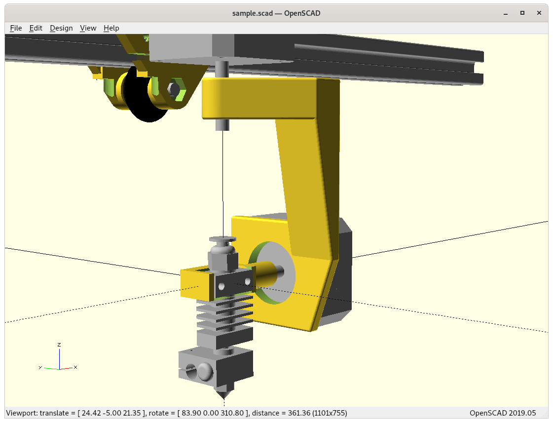
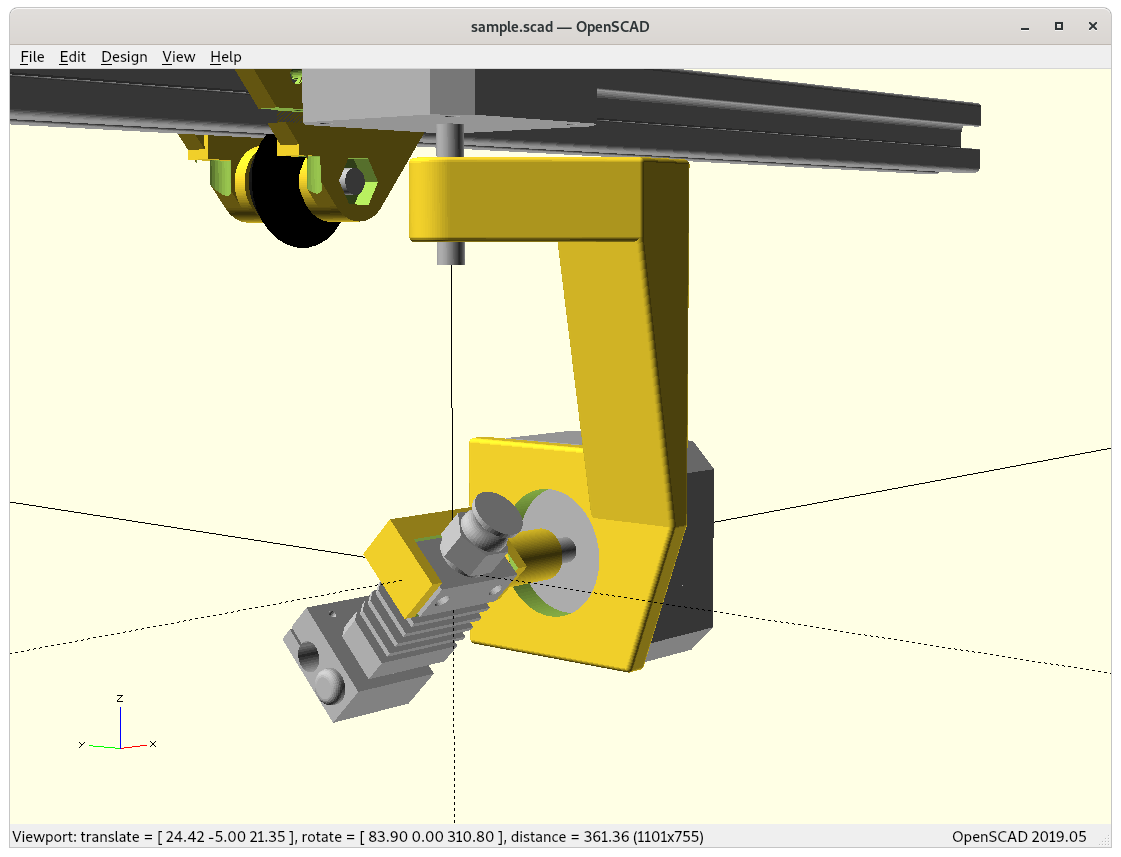
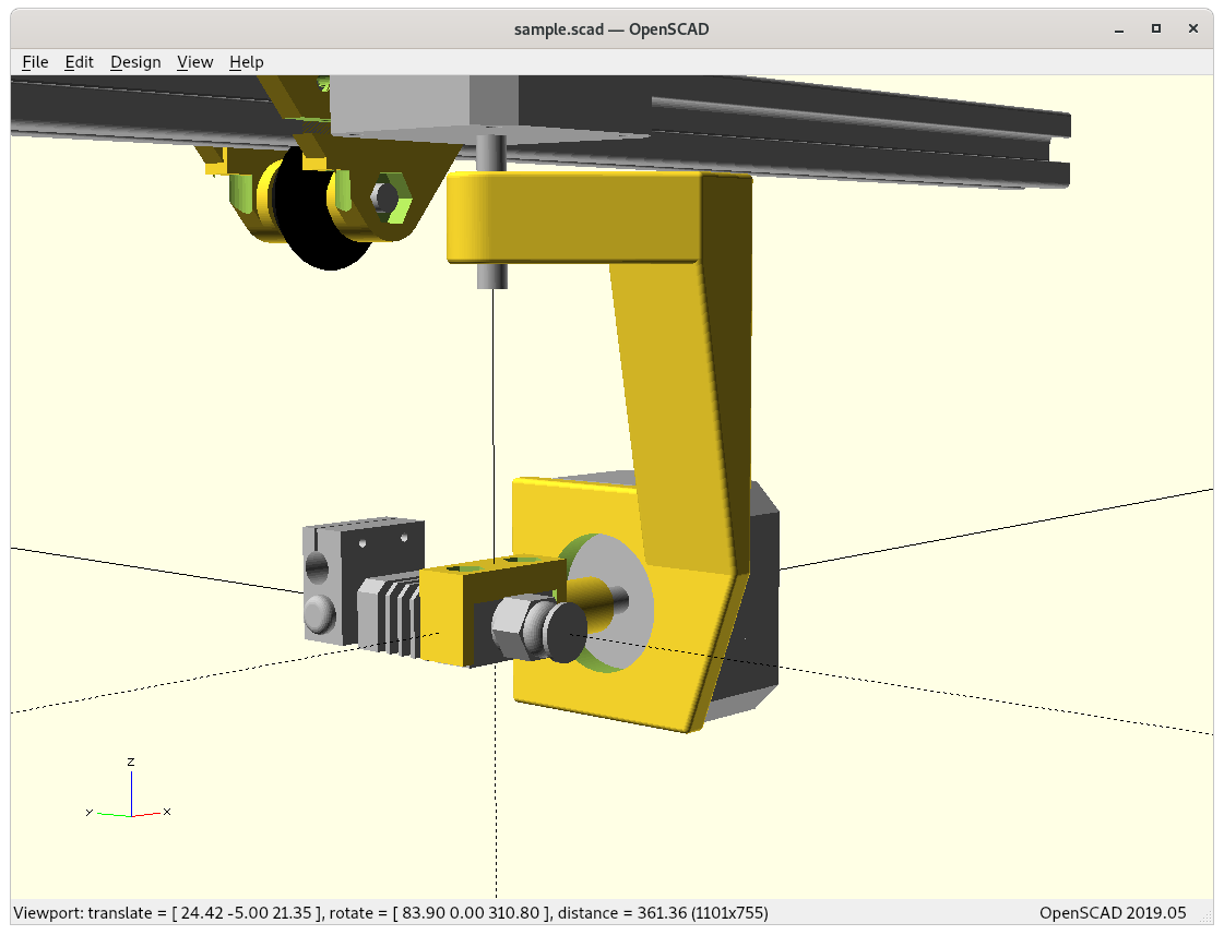
Tilt rotation 0 .. 180°
The Trot of 0° is the equivalent of ordinary 3D printer with top/down oriented nozzle, the 45° the belt printer or RotBot/RTN, and 90° printing vertical walls with the nozzle perpendicular, and 90-135° printing up-side down – I’m not sure if 135-180° is that useful, perhaps making underlying structures really smooth. For now I keep the tilt rotation from 0° to 180° even though I think I’m going to use 0-135° in real life application when the actual print procedure is developed, planar or non-planar slicing.
Dual Hinge
Mathematics
5 Axis Kinematics
LinuxCNC 5 Axis kinematics describes the notations and provides a starting point and I realized quickly that in CNC context the 5 axis operations is quite thoroughly explored, but much fewer focus on 5 axis additive manufacturing yet (see below at References).
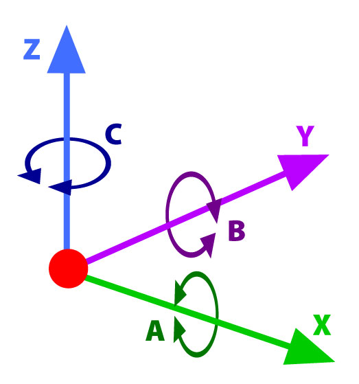
In order to reflect the rotation per axis, the notion A, B and C are adopted, which can be described in OpenSCAD as
translate([X,Y,Z]) rotate([A,B,C]) ...
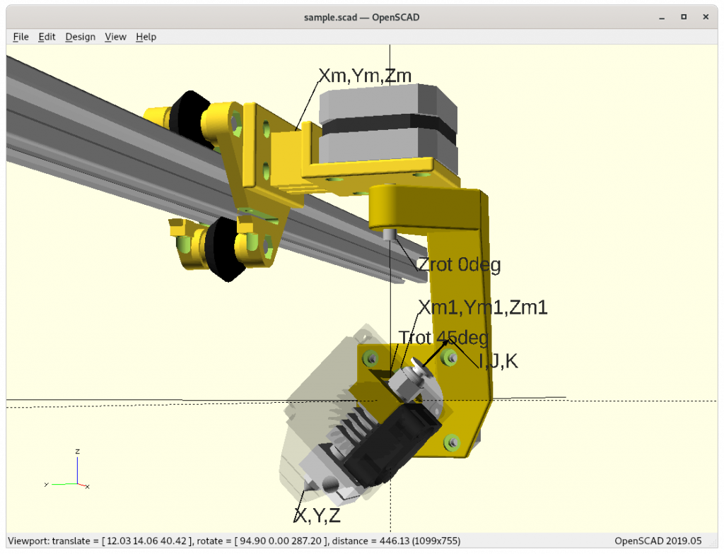
X,Y,Z (tool coordinate) and I,J,K (tool vector)
Further the CNC notion I, J and K are used as tool vector, the way the nozzle points away. G-code supports natively G1 X Y Z I J K which is machine independent. The machine specific firmware then computes the machine coordinates and rotating angles so the machine tool tip reaches those coordinates with that particular tool vector.
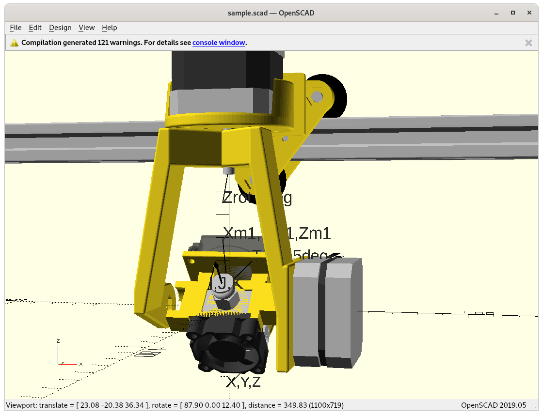
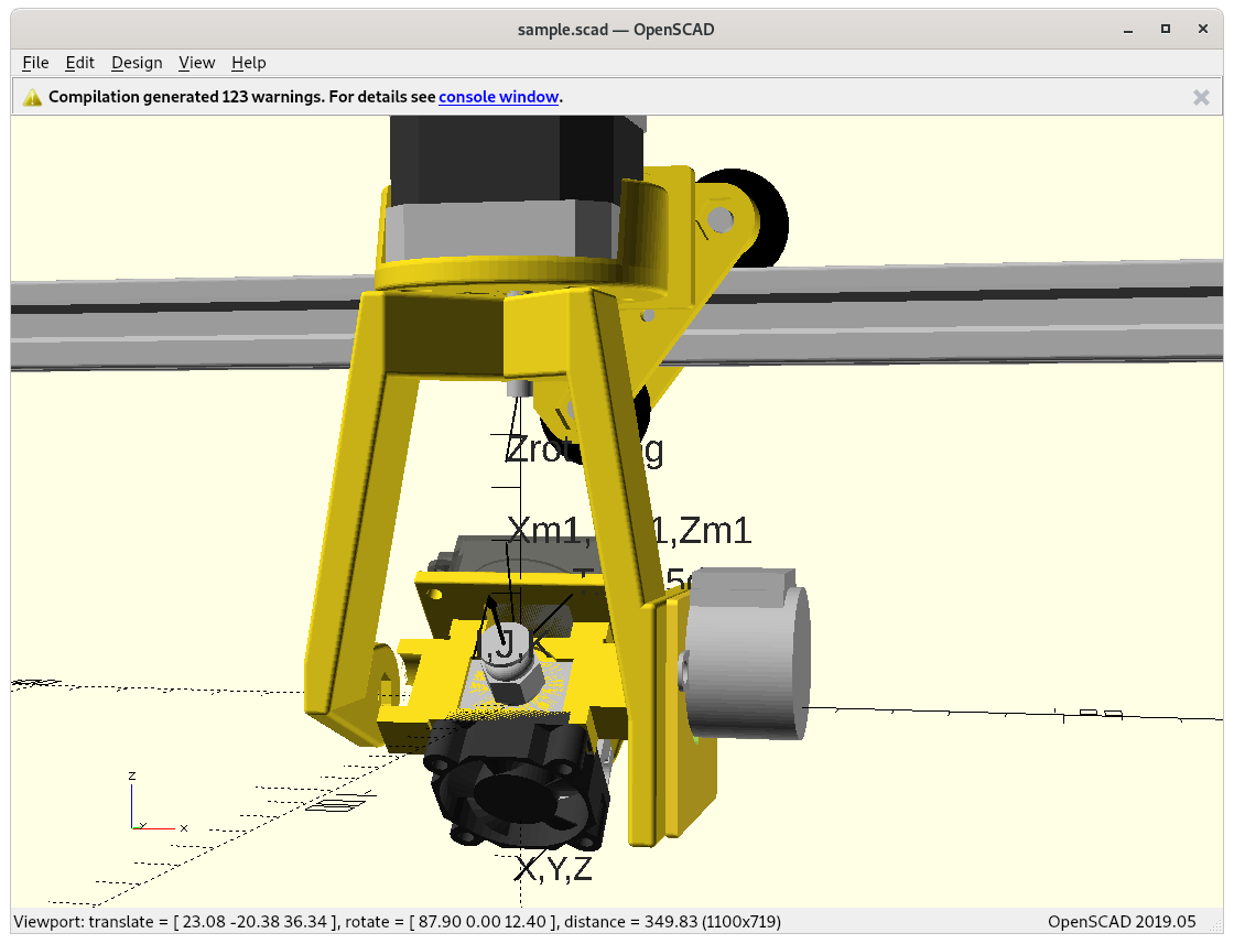
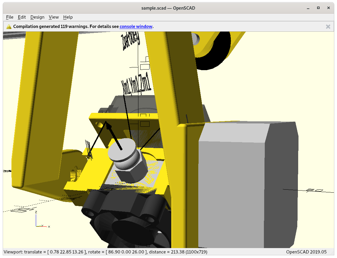
Tool/Nozzle vs Machine Coordinates
Absolute coordinates X, Y, Z of the nozzle tip and angles Zrot, Trot and given the Z rotation arm there is a mapping required to Xm, Ym, Zm with same Zrot, Trot.
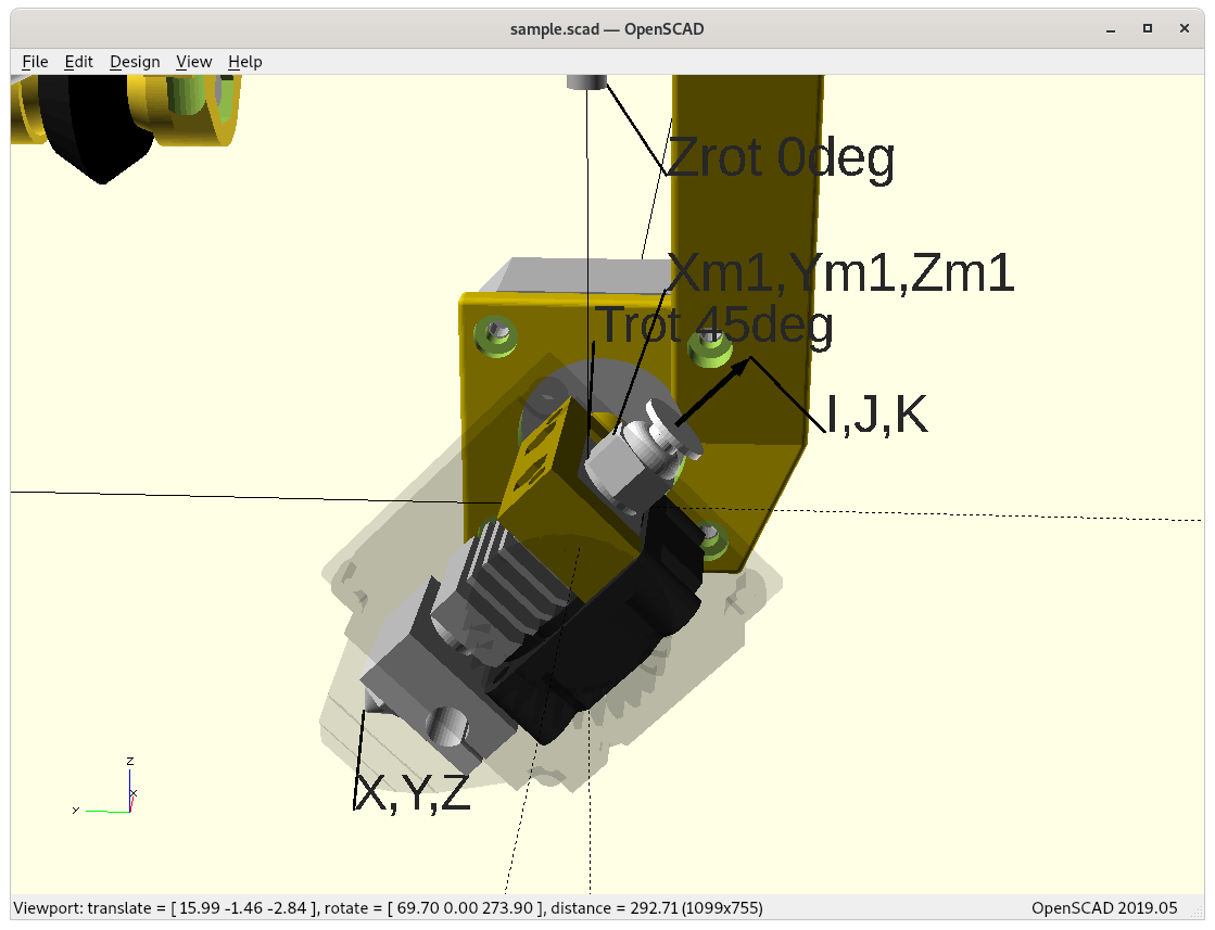
The forward transformation in OpenSCAD:
translate([Xm,Ym,Zm]) rotate([0,0,Zrot]) rotate([Trot,0,0]) translate([0,0,-45]) sphere(0.1); // nozzle tip at X, Y, Z with I, J, K
45mm vertical offset of tilt axis to nozzle tip
or expressing it as a list:
at 0, 0, 0 (origin)
translate([Xm,Ym,Zm])
rotate([0,0,Zrot])
rotate([Trot,0,0])
translate([0,0,-45])
at X, Y, Z
The -45 is the 45mm vertical offset of the tilt rotation to the tip of the nozzle.
In OpenSCAD it’s the reverse order, and enumerate matrices (used further below):
at X, Y, Z
translate([0,0,45]) aka M1
rotate([-Trot,0,0]) aka M2
rotate([0,0,-Zrot]) aka M3
translate([ Xm, Ym, Zm ]) aka MR, by inverting matrix the Xm, Ym, Zm can be extracted
at 0, 0, 0 (origin)
Each transformation can be represented by a 4×4 matrix, the sequence of transformations are the multiplication of such, and when multiplying symbolical a single 4×4 matrix will result. When keeping the symbolical notion the inverse transformation can be obtained with one operation and getting Xm, Ym, Zm from X, Y, Z, Zrot, Trot, and that very computation needs to be done in the firmware and controller in order to process X, Y, Z, Zrot, Trot as G1 X.. Y.. Z.. A.. B.. and the internally Xm, Ym, Zm is processed to achieve that tool coordinate; A = Zrot, B = Trot .
G-code
G1 X.. Y.. Z.. A.. B..
Firmware
Zrot = A Trot = B Xm, Ym, Zm computed via reverse/inverse transformation on the controller
Numerical Inverse Transformation
Just for sake of confirming the reverse/inverse transformation utilizing m4.scad:
so MR contains the inverse matrix of the previous transformations, so I can extract the translation vector, the 4th column [ MR[0][3], MR[1][3], MR[2][3] ] or m4trv(MR) to compensate X, Y, Z, Zrot, Trot -> Xm, Ym, Zm:
Perhaps it’s worth to actually calculate symbolical forward and inverse transformation matrix using e.g. Matlab or alike to have transformations in one operation instead multiplying three matrices and inverting it – depending what hardware is used as controller multiplying individual matrices is faster than trying to have a complex single step matrix construct.
Although Marlin firmware supports Delta printer with complex delta inverse kinematics, not sure I can add mine as well, or I have to go with Duet RepRap firmware which seems more suitable (see notes below).
Nozzle Precision from Trot
The 45mm offset of the last rotation massivly contributes to the loss of nozzle position resolution:
s = 2 π * r / 360 = section length per degree
s = π * 45mm / 180 = 0.785mm/° which means:
8 microsteps with 1.8° full step: 0.225°/microstep => 176.7μm/microstep
16 microsteps with 1.8° full step: 0.1125°/microstep => 88.3μm/microstep
8 microsteps with 0.9° full step: 0.1125°/microstep => 88.3μm/microstep
16 microsteps with 0.9° full step: 0.0565°/microstep => 44.4μm/microstep
so the direct drive using the shafts of the NEMA 17 will provide OK resolution, but for anything a bit more serious, a reduction gear might be worth to use.
G-code & Firmware
As I likely will generate machine independent G-code as G1 X Y Z I J K, the slicer stage will likely operate in X, Y, Z and Zrot and Trot as well – so we end up with a data pipeline like this:
Slicer: X, Y, Z, Zrot, Trot
G-code: G1 X Y Z I J K
Firmware: X Y Z I J K => Xm, Ym, Zm and I J K => Zrot, Trot
Alternatively, instead using I J K notion use the G-code A and B as two rotational axes as Duet RepRap Firmware offers G1 X Y Z A B then it’s a bit simpler:
Slicer: X, Y, Z, Zrot=>A, Trot=>B
G-code G1 X Y Z A B
Firmware: X Y Z A B => Xm, Ym, Zm and A=>Zrot, B=>Trot
Reviewing existing slicer/printing software to see which notion is more suitable, and perhaps cover both to stay flexible.
From Xm, Ym, Zm, Zrot, Trot to X, Y, Z
Issues to Resolve
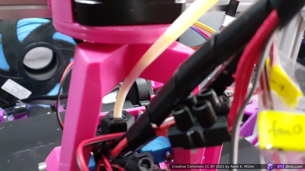
Bowden tube- & cable management: properly resolve it, guides etc.
Develop the transformation/inverse kinematics X, Y, Z, Zrot, Trot <=> Xm, Ym, Zm, Zrot, Trot as well X, Y, Z, I, J, K <=> Xm, Ym, Zm, Zrot, Trot as required for slicing, and firmware stage, done
Calculate the precision of X, Y, Z in relation of Xm, Ym, Zm and Zrot, Trot, whether or how the motor resolution affect axes => getting a grasp how the overall precision of the final setup
Direct drive mechanical precision with 8/16 microsteps, repeatability, and heat dissipation from motor (see tweet)
Marlin firmware capabilities, as it support Delta printers, inverse kinematics (IK) calculations seem supported well, question is how simple to add my own custom IK as well
printing: recognize model features or base design on seams or boundaries, like OPENCASCADE (STEP/IGES support)
printing: use vertical slicing as fallback, given no other printing method is suitable
recognize rotational objects: print from inside out like with a lath but adding material
detect steep overhangs, find proper way to print them
collision detection, e.g. tilt rotation becomes available at a certain Z level as below the upside looking nozzle will touch the build plate with the opposite end – the slicing/print software must be aware of the printhead geometry to calculate what’s possible to print and how
Considerations
Pros
many new ways to print in (almost) all directions
hopefully print 90° and more overhangs without support at all
Cons
significant mechanical complexity
mechanical limitations arise with new freedom of rotation of printhead
collision detection becomes essential which in Z sliced layers is not an issue at all
significant software complexity, no current 3D printing software available to take advantage of 5 axis printing
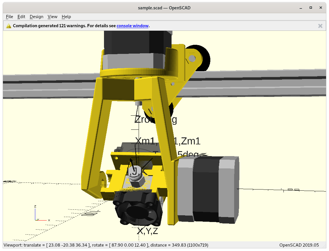
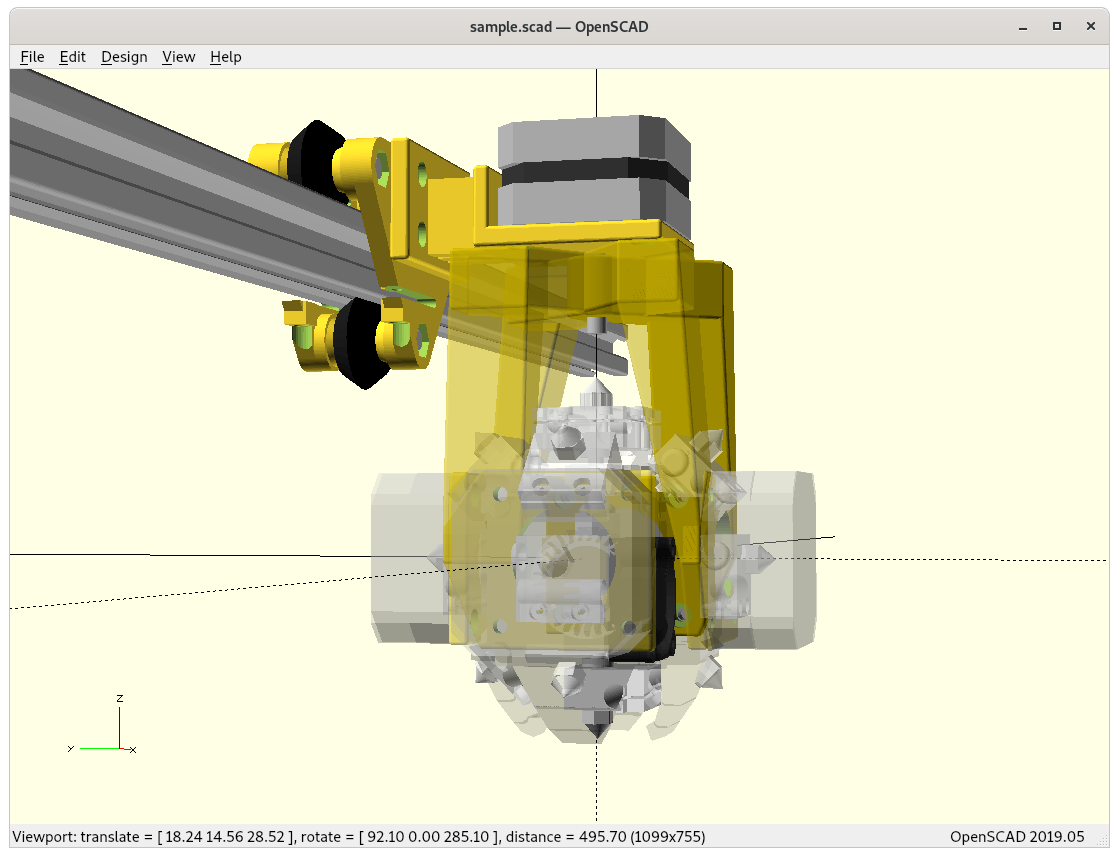
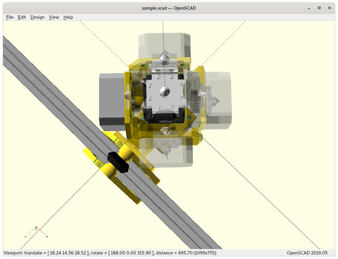
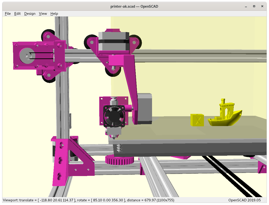
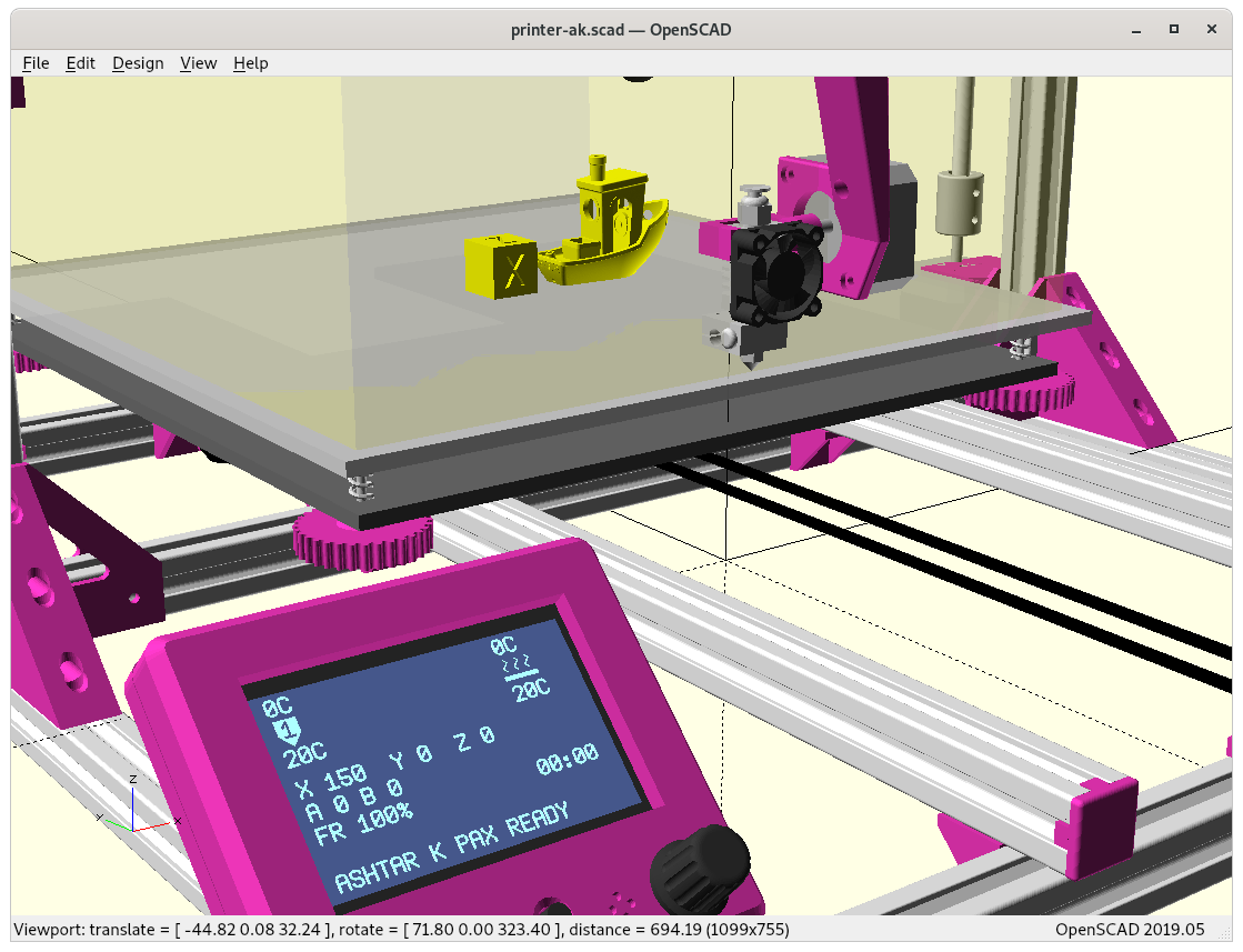
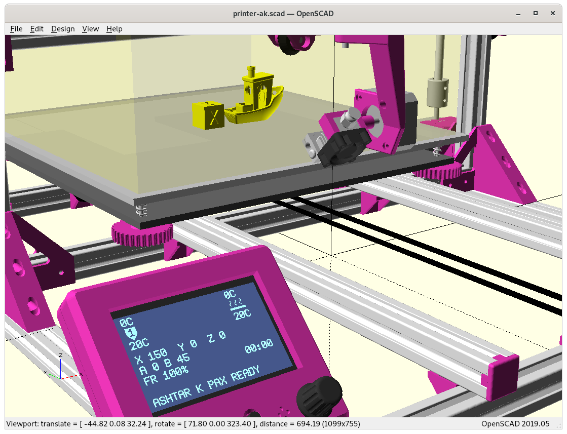
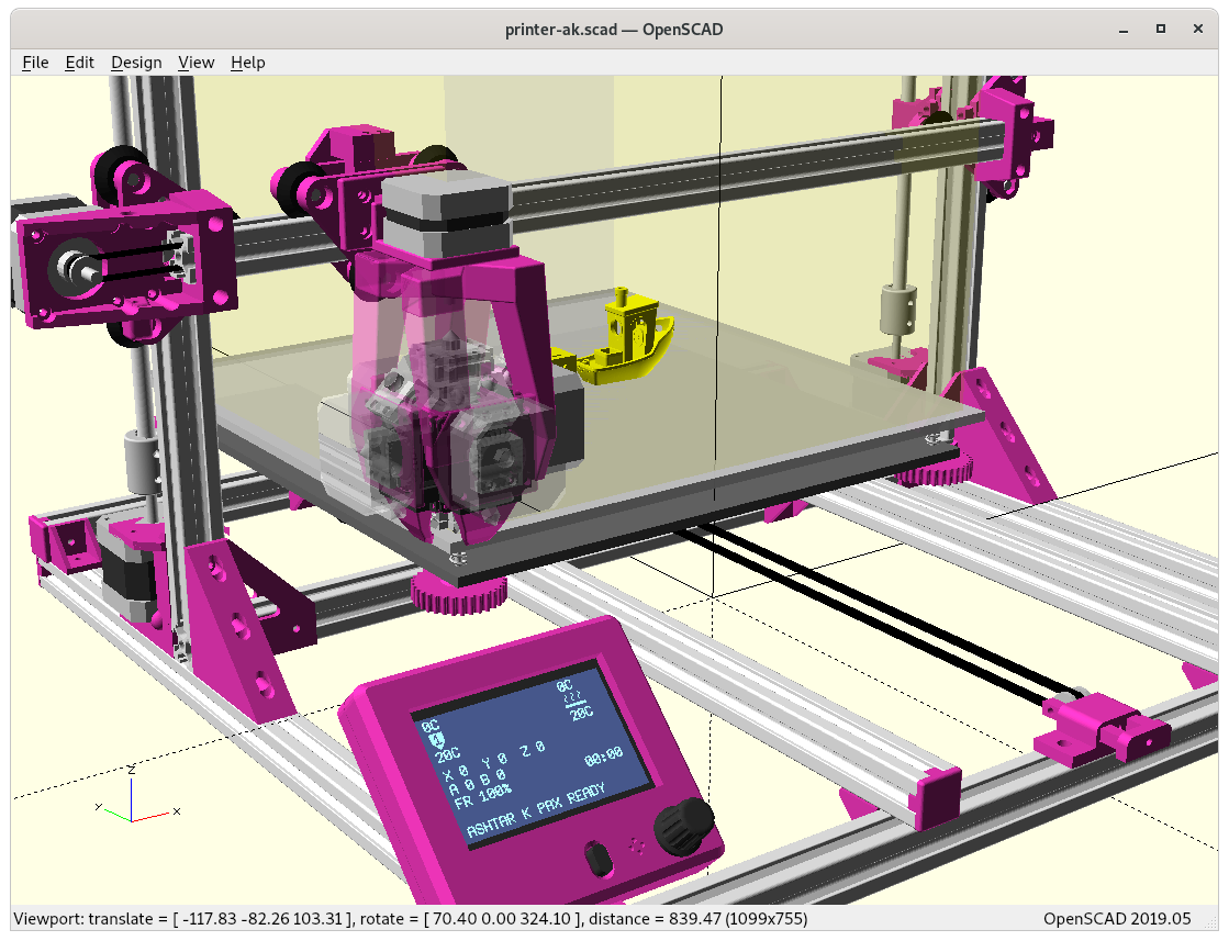
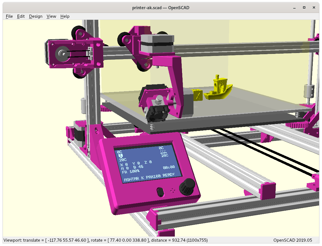
Ashtar K with 5 Axis (PAX) Printhead
Experimental mounting on Ashtar K to see how it looks, including display showing rotations of Zrot (A), Trot (B) too.
Note: the display shows original tool coordinates, whereas the firmware does tool translation aka inverse kinematics as shown in the screenshots with the display readable.
PAX printhead on Ashtar K with virtual Marlin firmware display (animated)
With all the freedom to angle the nozzle, all of the sudden the part cooler air nozzle shape becomes an issue, and has to become narrow as well; and overall geometry of the printhead becomes quite relevant when planning print sequences (collision detection).
Ashtar K PAX printing 4-axis/RTN sliced overhang model (animation)
PAX Tilt 180, 135 and 90
The PAX which tilts up to 180° will be referenced further as PAX or PAX 180, the 360° Z rotation is implied then too, as comparison of PAX 90 tilting to 90° only with shorter arm:
PAX 180 (Trot 0..180°)PAX 90 (Trot 0..90°)
As the slicing strategy isn’t determined, it’s not yet clear if tilt 90..180° is required or not. In case only 0..90° is sufficient, the Z rotation arm can be shortened.
PAX 180 with NEMA17 37mmPAX 90 with NEMA17 37mmDual Hinge PAX 90 at 0° tiltDual Hinge PAX 90: sharp bent PTFE & filament at 0° tiltDual Hinge PAX 180 at 0° tiltDual Hinge PAX 180 at 0° tiltDual Hinge PAX 135Dual Hinge PAX 135 with acceptable PTFE bending
As I experimented, I realized an option in between PAX 180 and PAX 90, hence PAX 135, and seemed to compromise between angular range of the tilt and PTFE tube bending.
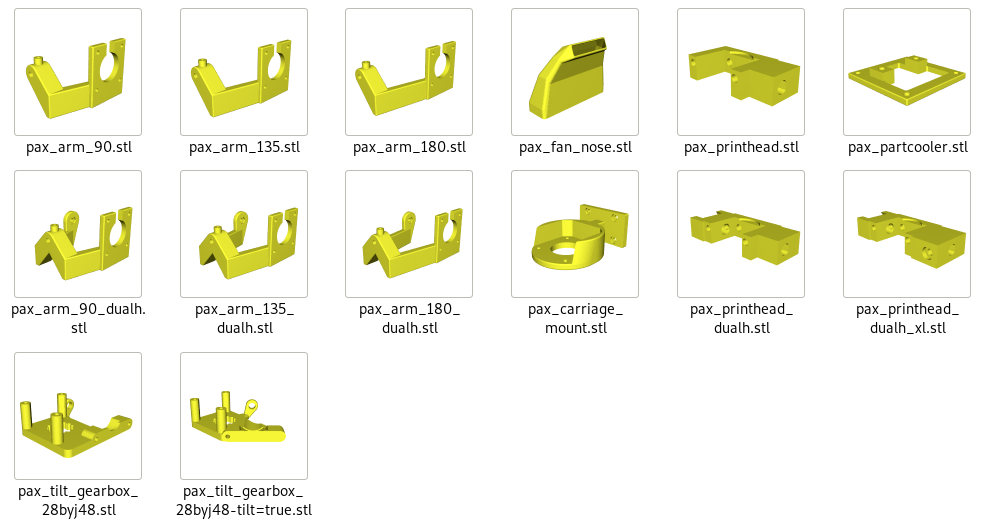
Printable Parts
Print with 0.4-0.5mm nozzle @ 0.20 – 0.25mm layer height:
pax_arm: connects motor A / Zrotation with motor B/tilt
pax_arm_90 & pax_arm_90_dualh
pax_arm_135 & pax_arm_135_dualh (recommended)
pax_arm_180 & pax_arm_180_dualh
pax_carriage_mount: holds motor A / Zrotation connects to X carriage
pax_printhead: connects motor B with printhead, @ 0.1mm layer height
pax_printhead
pax_printhead-dualh: for NEMA 17 for tilt
pax-printhead_dualh_xl: for 28BYJ-48 direct drive or tilt gearbox (worm gear)
pax_tilt_gearbox_28byj48:
pax_tilt_gearbox_28byj48: PAX 180
pax_tilt_gearbox_28byj48-tilt=true: use with PAX 90/135/190 (recommended)
pax_partcooler: connects part cooler fan with printhead
pax_fan_nose: part cooler fan nose, @ 0.1mm layer height
28byj_cooler
28byj_cooler-type=single: PAX 90/135
28byj_cooler-type=dual: PAX 90/135/180
Hardware
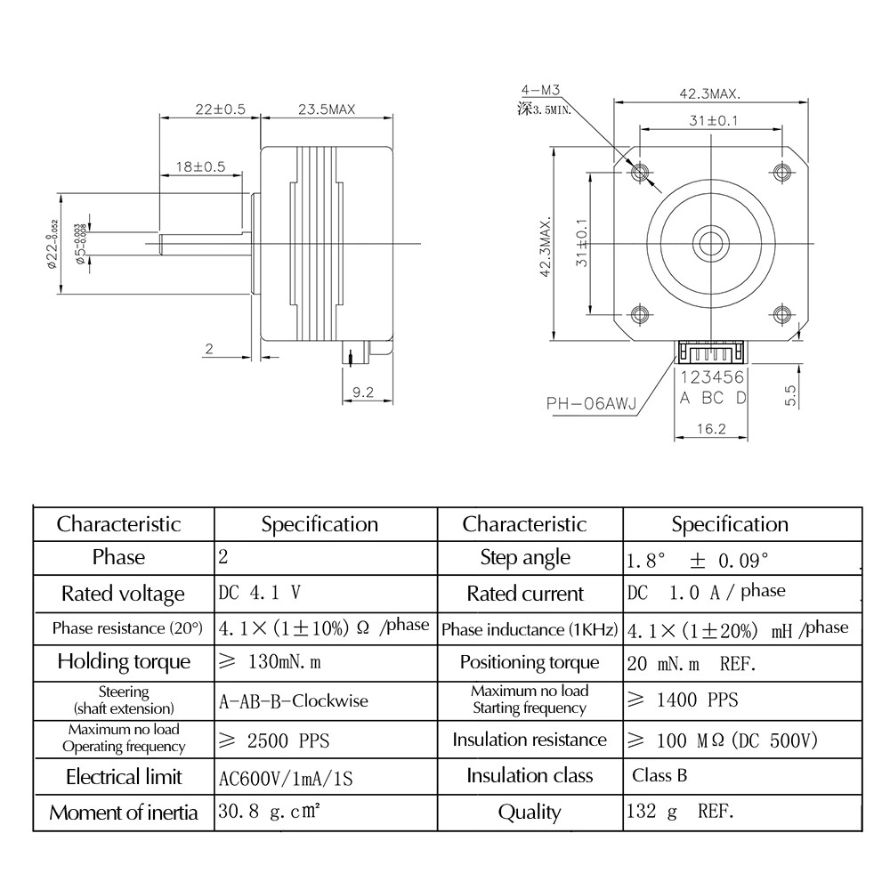
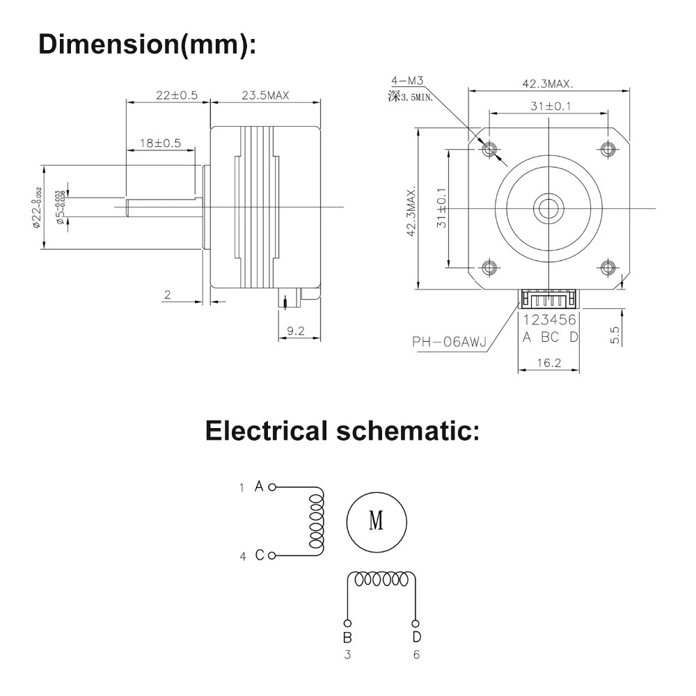
NEMA 17 23mm Datasheet (17HS4023)
For for my own reference, a few details of stepper motor for Z-rotation (“A” axis) and tilt (“B” axis):
Note: early tests have shown the NEMA 17 23mm “thin” stepper motor has too weak holding torque (without gear reduction) with the stiffness of PTFE/filament and cables for Z rotation (A) and tilt rotation (B) – so I switched back to heavy NEMA 17 40mm “long” stepper motor – but that meant the mounting pieces need to be stronger.
NEMA17 (23mm): too weak to hold position due the PTFE/filament & cablesNEMA 17 (40mm) holding torque sufficientNEMA 17 (40mm) on shorter PAX 90
If I find a low-overhead and space efficient gear reduction perhaps the NEMA 17 23mm may still have a chance to be used in this setup.
28BYJ-48 Datasheet
Note: early tests have shown for tilt rotation (B) in direct drive it’s too weak, but with worm gear setup it seems to work, though quite slow, and with just 33g weight it’s quite an advantage in this regard compared to heavy NEMA17.
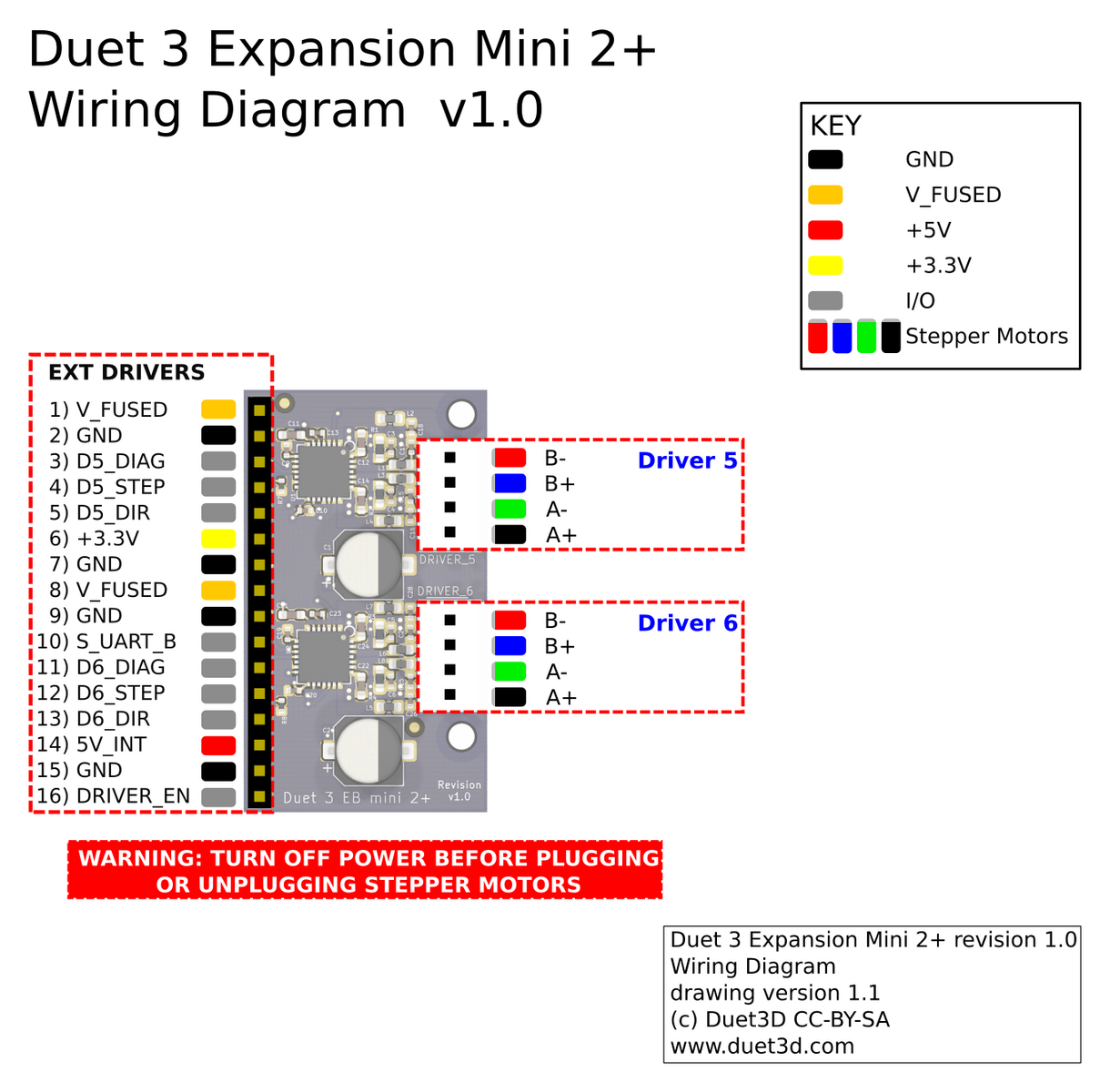
Duet 3 Mini 5+ & Mini 2 Expansion
Duet 3 Mini 5+ & Expansion Mini 2 provides 7 stepper motors drivers (TMC 2209) with microstep interpolation:
Stepper 0: X-axis
Stepper 1: Y-axis
Stepper 2/3: 2x Z-axis (I could runs 2 Steppers on on the same driver, but since I run quick Z changes, I keep it dedicated driver for each)
Stepper 4: E0
Stepper 5 (Expansion 0): A (Z rotation)
Stepper 6 (Expansion 1): B (tilt rotation)
config.g
; Default config.g template for Duet 3 Mini 5+
; Replace this with a proper configuration file (e.g from https://configtool.reprapfirmware.org)

M575 P1 B57600 S1                             ; Enable UART

; test network enable
;M552 P192.168.2.14
M552 P10.0.0.100
M552 S1

M550 P"Ashtar K2 PAX"                         ; Name the board/machine

; config drivers -> motors: X, Y, Z(dual), E0, A & B
M584 X0 Y1 Z2:3 E4
M584 A5 B6 S1

M208 X-10 Y-10 Z0 A-185 B-40 S1               ; Set axis minima
M208 X320 Y320 Z300 A185 B100 S0              ; Set axis maxima

M92 X100 Y100 Z3200 E95                       ; Set axis steps/mm
M92 A9 B9                                     ; Set axis steps/degrees

M350 X16 Y16 Z16 E16 I1                       ; Set 16x microstepping with interpolation
M350 A4 B4 I1                                 ; Set 4/8/16x microstepping with(out) interpolation

M906 X800 Y1000 Z800 E800 A1000 B1000         ; Set motor currents (mA)

M201 X400 Y400 Z15 E1000                      ; Accelerations (mm/s^2)
M201 A800 B800

M203 X10000 Y10000 Z360 E3600                 ; Maximum speeds (mm/min)
M203 A20000 B20000                            ; Maximum speed (mm/min)

M566 X600 Y600 Z30 E20                        ; Maximum jerk speeds (mm/min)
M566 A300 B300

; Define end-stops:
M574 X1 S1 P"io0.in"
M574 Y1 S1 P"io1.in"
M574 Z1 S1 P"io2.in"
;M574 A1 S1 P"io3.in"
;M574 B1 S1 P"io4.in"
M564 H0                       ; Allow (all) axis without homing (required for A/B)

M918 P1                       ; Set 12864 display (doesn't work yet)

M569 P0 S1                    ; Set motor drive P0 (X)
M569 P1 S1                    ; Set motor drive P1 (Y)
M569 P2 S1                    ; Set motor drive P2 (Z1)
M569 P3 S1                    ; Set motor drive P3 (Z2)
M569 P4 S0                    ; Set motor drive P4 (E0)
M569 P5 S0                    ; Set motor drive P5 (A/Zrot)
M569 P6 S0                    ; Set motor drive P6 (B/tilt)

M563 P0 D0 H1 F0       		  ; Define tool 0
G10 P0 X0 Y0 Z0       		  ; Set tool 0 axis offsets
G10 P0 R0 S0                      ; Set initial tool 0 active and standby temperatures to 0C
; M572 D0 S0.06			      ; Set pressure Advance

; Bed Heater
; M308 S0 P"temp0" Y"thermistor" B4725 C7.060000e-8 					; configure sensor 0 as thermistor on pin temp0
; M950 H0 C"out0" Q25 T0                           					; create bed heater output on out0 and map it to sensor 0, PWM frequency: 25Hz
; M307 H0 R0.262 C338.0 D10.52 S1.00 V11.8 B0							; Bed tuning values, enable PID
; M140 H0                                                    			; Bed uses Heater 0
; M143 H0 S120                                               			; Set temperature limit for heater 0 to 120C Bed

; Hotend heater
M308 S1 P"temp1" Y"thermistor" T100000 B4725 C7.060000e-8 					; configure sensor 1 as thermistor on pin temp1
M950 H1 C"out1" T1                           						; create nozzle heater output on out1 and map it to sensor 1
M307 H1 B0 S1.00                             						; disable bang-bang mode for heater  and set PWM limit
M143 H1 S295                                 						; set temperature limit for heater 1 to 295C
M302 S170 R170                                         				; allow extrusion starting from 170°C and retractions already from 170°C

; Part cooling fan
M950 F0 C"out3" Q100          ; Create fan 0 part cooler on pin out3 and set its frequency
M106 P0 S0 H-1                ; Set fan 0 value. Thermostatic control is turned off

; Heatsink cooling fan
M950 F1 C"out4" Q1000		  ; Create fan 1 heatsink fan an pin out4 and set its frequency
M106 P1 T45 S255 H1  	      ; Set fan 1 value. Thermostatic control is turned on > 45C turn on
;M106 P1 S255 H-1

M302 P1                       ; Allow cold extrusion (for testing)
T0                            ; Set tool 0 (default extruder)

G21                           ; Work in millimetres
G90                           ; Send absolute coordinates...

; pre 3.3 (3.2.x)
G92 A-1 B-1                   ; Make Zrot & Tilt active
G1 A0 B0
; 3.3 or later
;M17 A B

G92 A0 B0
G1 A0 B0 F20000
Endstops:
X: io_0 (Pin 2/3)
Y: io_1 (Pin 2/3)
Z: io_2 (Pin 2/3)
[optional] A: io_3 (Pin 2/3)
[optional] B: io_4 (Pin 2/3)
Thermistors:
temp0: bed
temp1: hotend
Heating:
out0: bed (max 15A)
out1: hotend (max 5A, 60W@12V)
Fans:
out3: part cooling fan (Pin 2/4)
out4: heatsink fan (Pin 2/4) or 12V: heatsink fan (always on)
So far Duet 3 Mini 5+ with RepRap Firmware V3.2 works well with the first motion tests. It took me an afternoon to configure the board without the web configurator but direct editing config.g on the web-console and reading documentation for each individual G-code configuration as part of getting to know the Duet 3D approach using G-code to configure the entire firmware (except the inverse kinematic).
The inverse kinematic with adjustable offsets comes next.
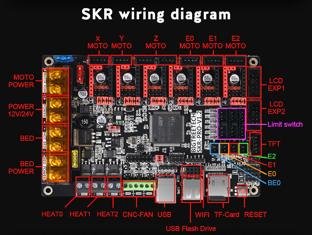
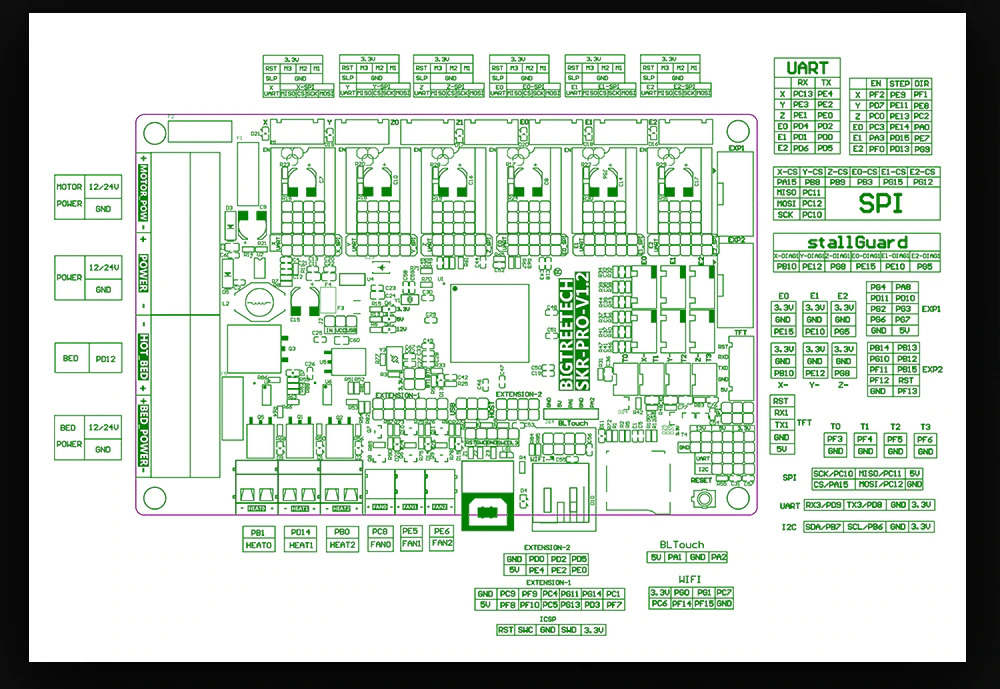
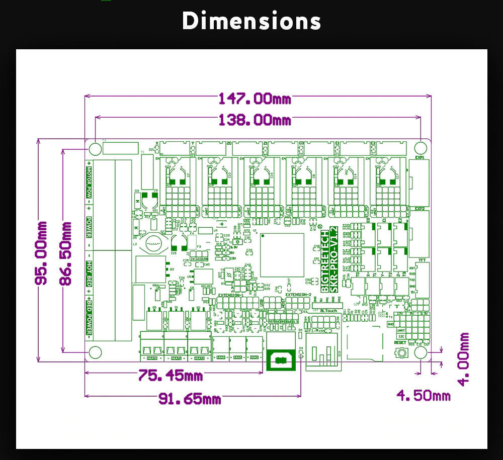
SKR Pro 1.2
Alternatively the SKR Pro V1.2 also can run Duet 3D RepRap Firmware V3.x
SKR Pro 1.2 provides 6 stepper motors drivers, whereas Z stepper driver provide dual connectors:
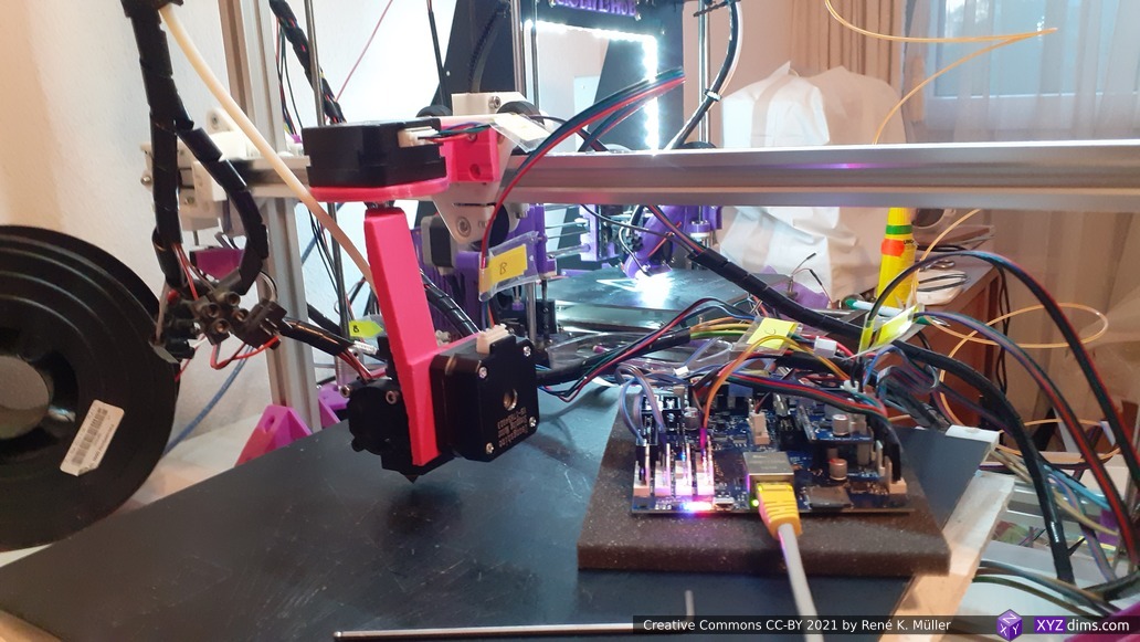
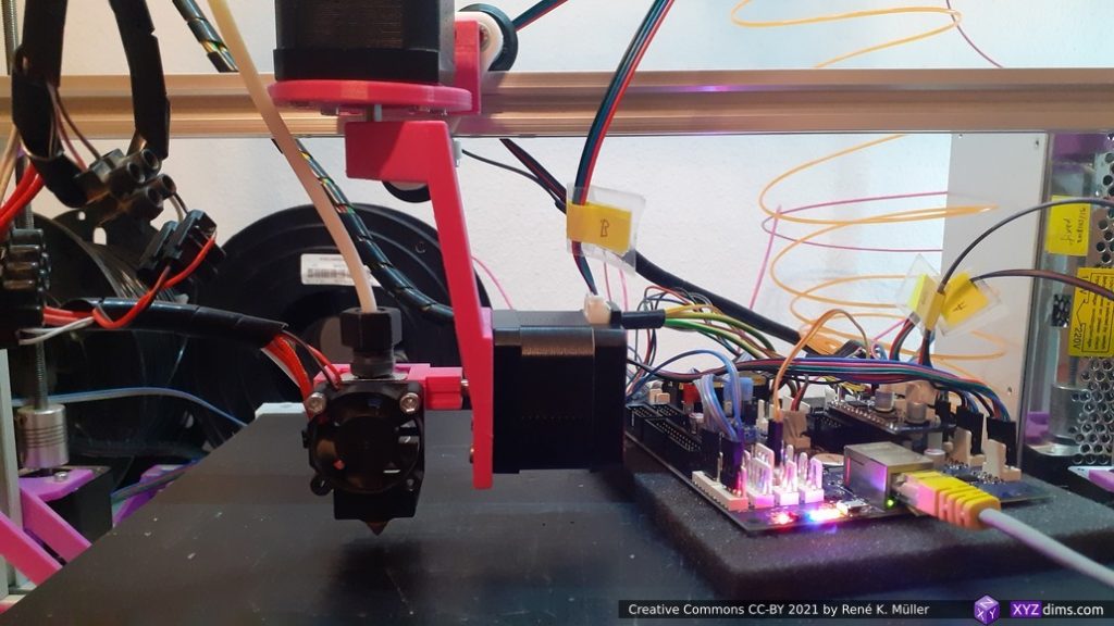
Duet 3 Mini 5+ with Expansion Mini 2 with 2x NEMA 17 (40mm) without gear reduction:
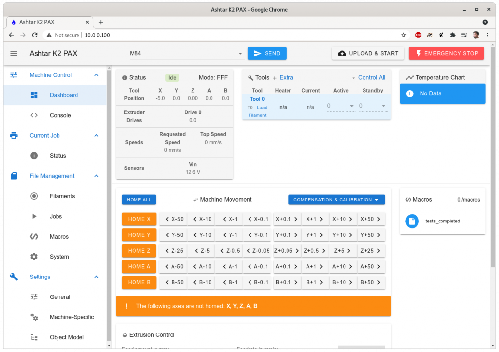
Duet Web Console (DWC) for Ashtar K2 with PAX printheadTest Setup of PAX printhead mounted on Ashtar K (#2) with Duet 3 Mini 5+ (Ethernet)
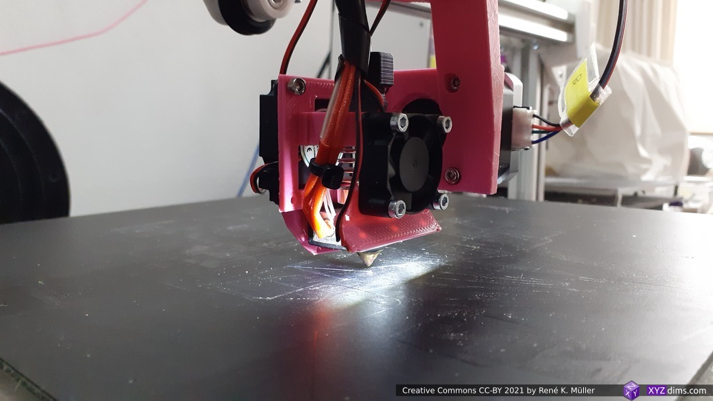
and first movement with NEMA 17 (40mm) with enhanced carriage mount, manually entered G1 A B motions, a shorter yet stiffer PAX 90 arm (means tilt only 0..90): A=-180..180 and B=0..90:
Closer look:
And alternatively 24-BYJ-48 stepper motor direct drive or with worm gear, with a dual hinge arm:
PAX 90 (Dual Hinge): Z rotation with NEMA17, tilt rotation with 28BYJ-48 stepper motor (with modification)PAX 180 (Dual Hinge): Z rotation with NEMA17, tilt rotation with 28BYJ-48 stepper motor (with modification) using worm gearPAX 135 (Dual Hinge): Z rotation with NEMA17, tilt rotation with 28BYJ-48 stepper
RepRapFirmware (RRF) vs Marlin 2.x
Duet 3D RepRapFirnware (RRF) natively supports multiple axis, and since RRF V3.2 also treats axis A-D as rotational axis by default. So far Marlin 2.x does not support multiple axis yet, but there is a fork / PR available (reviewed 2021/05/14) which introduces the functionality and be available soon.
RRF Inverse Kinematics (PAXKinematics)
The key element of course is the dedicated inverse kinematics, which I implemented and finally works rudimentary within RRF (2021/07/14), still some small things to take care:
The nozzle tip stays in place, but Zrot and tiltrot is changed; this allows machine independent G-code to be processed.
References
5 Axis
Pentarod, 5 axis RepRap, 2 axis added to bed (not head), master thesis (see also paper), most useful