Updates:
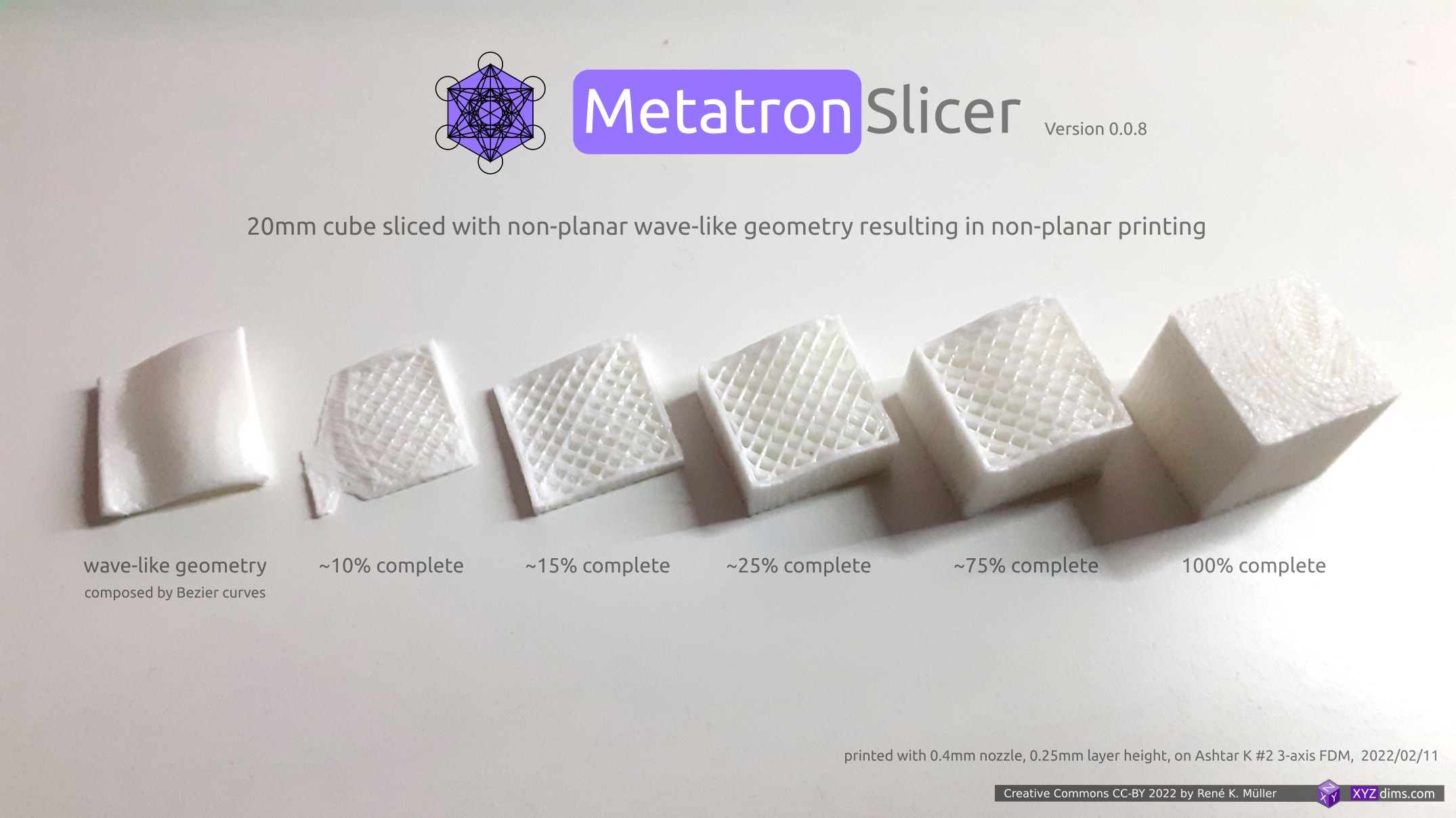
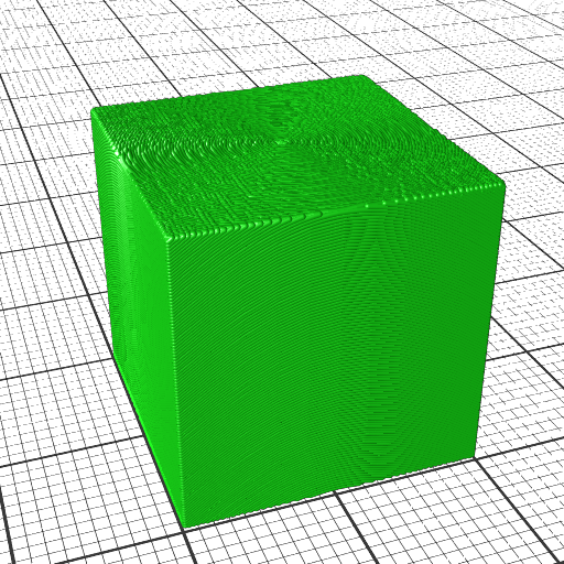
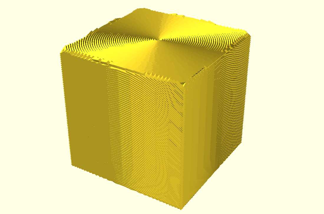
- 2022/04/25: added single photo with various 20mm cube prints
- 2022/04/01: rewording to avoid confusion of “planar slicing” with non-planar geometries
- 2022/03/26: finally published
- 2022/03/25: adding “Benefits of Non-Planar Printing” and “Blind Spots of CAD Systems” and “Scale and Functional Quality”
- 2022/02/18: getting ready to publish
- 2022/02/15: adding different slicing geometries and the resulting G-code
- 2022/02/12: starting write-up
Introduction
After researching non-planar slicing using planar slicers it was obvious to find a way to slice with any kind of geometry, and it meant to step back and formalize slicing procedure in a general manner like “Universal Slicing” – and look at the procedure of slicing itself.
Two classes were defined:
- Class 1: using a geometry, either planar or non-planar, and slicing with a static slicing path
- Class 2: slicing with variable slicing path and/or variable slicing geometry while slicing
This document/blog-post features a solution for Class 1 Universal Slicing.
My video Non-Planar 3D Printing: Slicing with Non-Planar Geometries goes through this information in an animated form, this is the textual form.
Slicing with Non-Planar Geometry (Class 1 Universal Slicing)
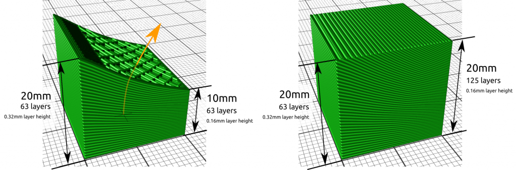
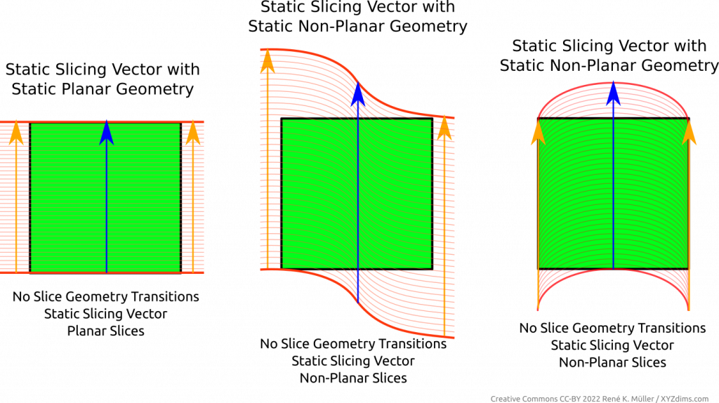
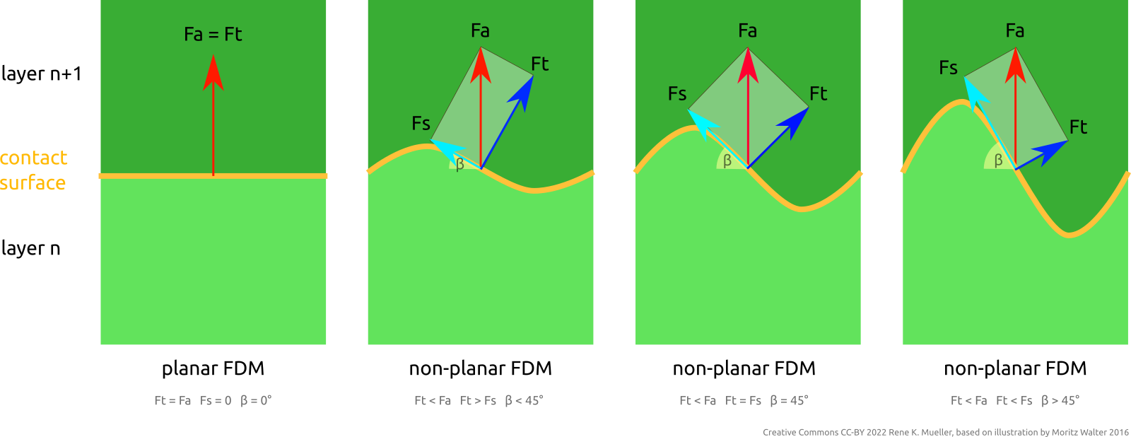
When using a static planar slicing vector one usually uses a plane, hence the term “planar slicing”, yet, there is also the possibility to use a non-planar geometry and slice in a planar direction (introducing ambiguity what planar and non-planar slicing actually mean). Regardless which slicing geometry is used in this procedure, the thickness of the sliced layer stays the same.
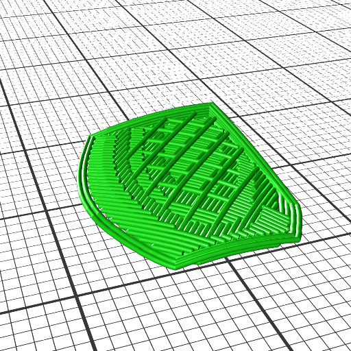
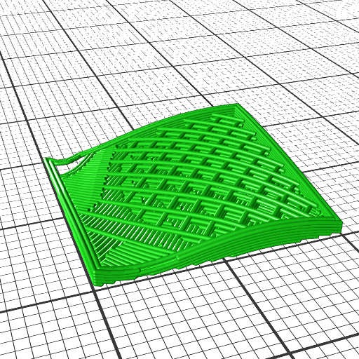
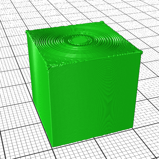
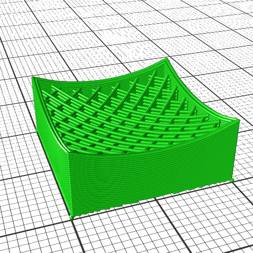
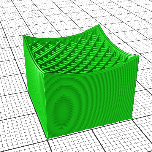
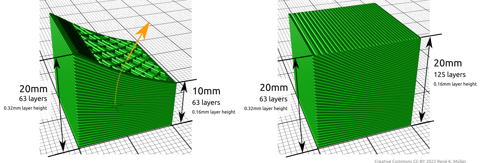
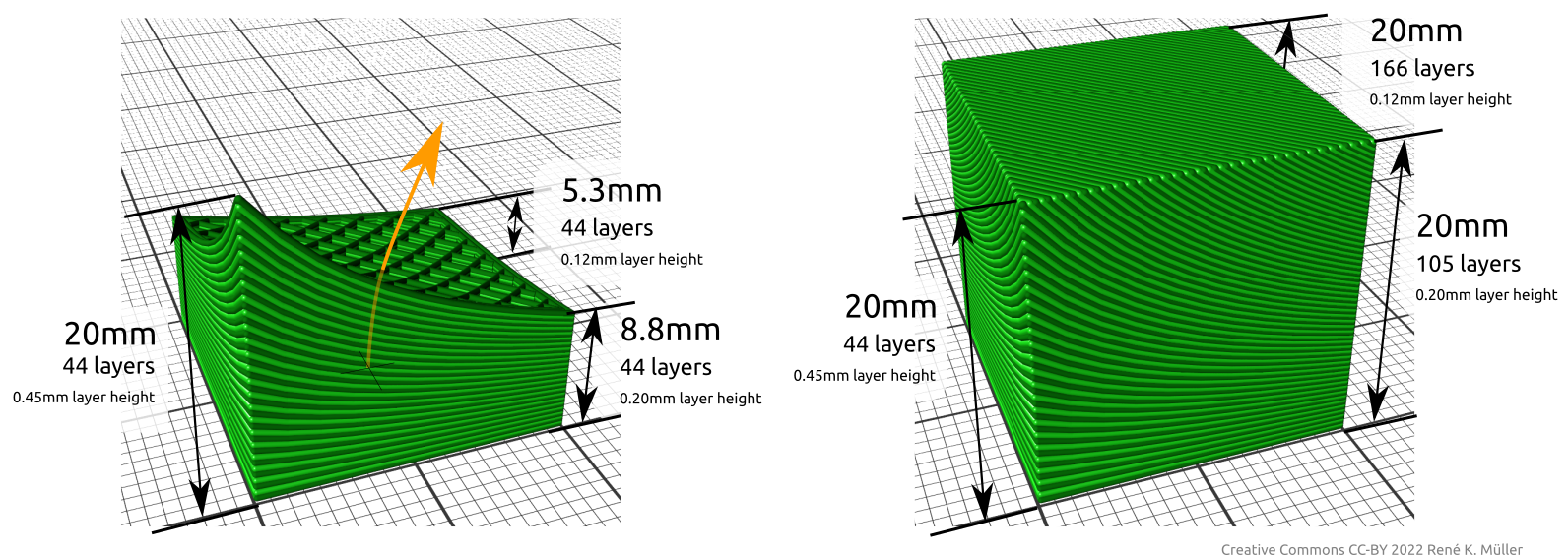
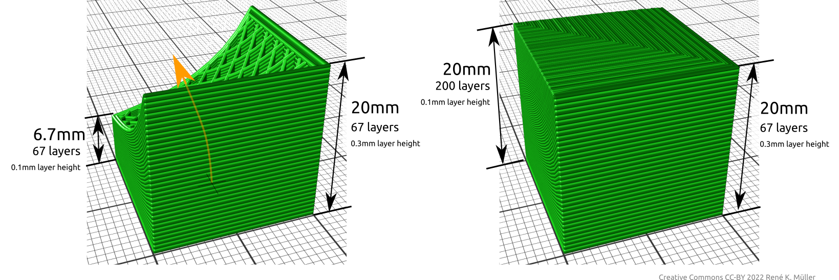
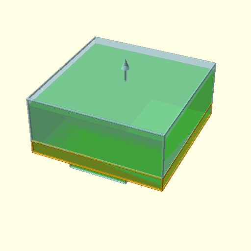
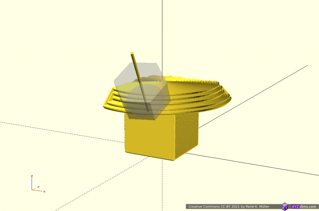
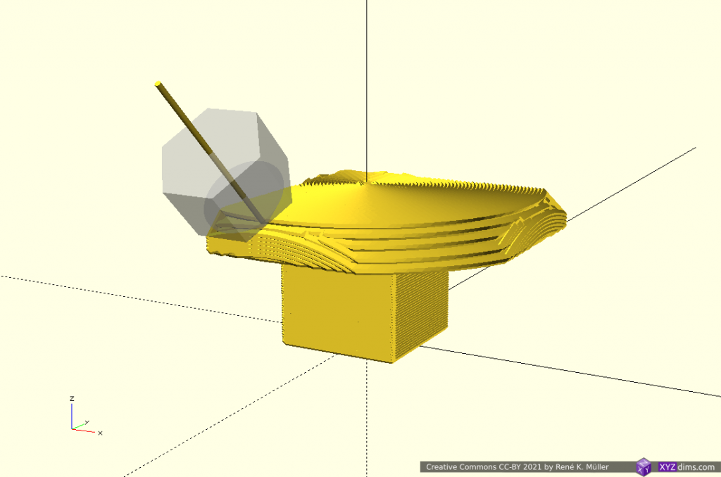
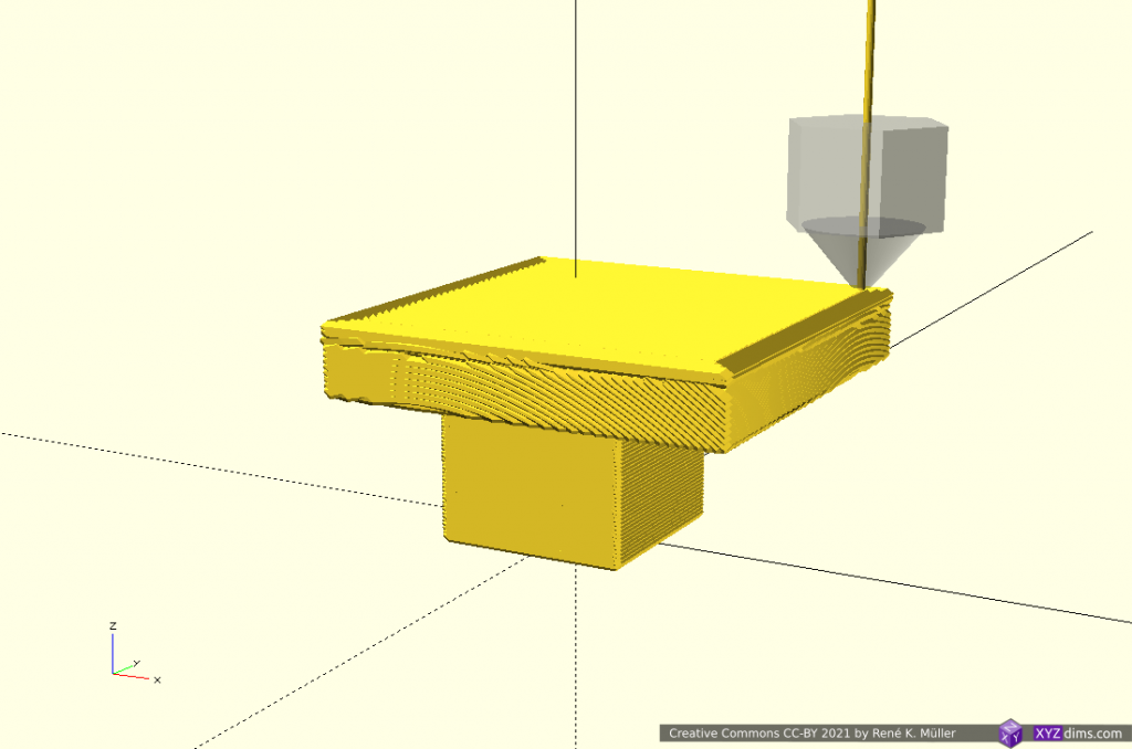
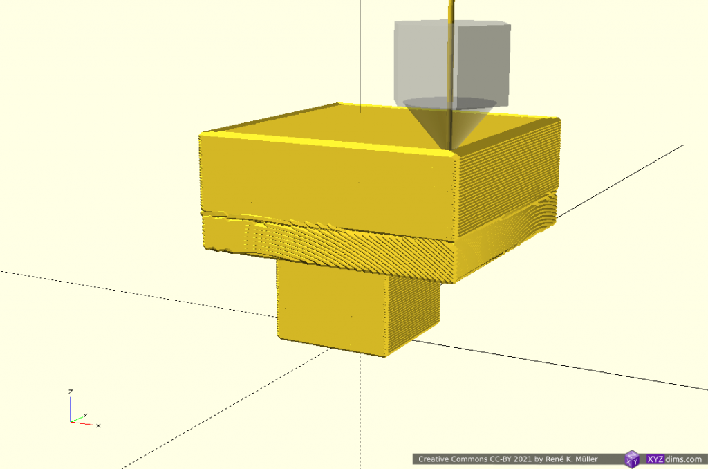
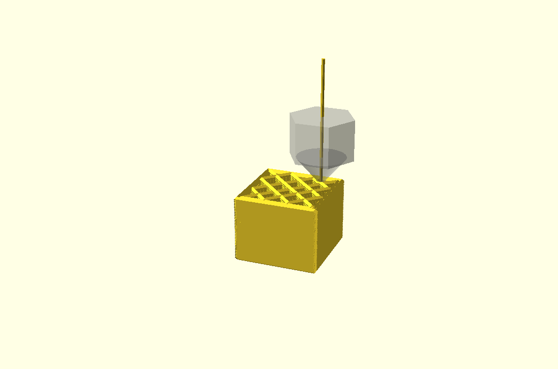
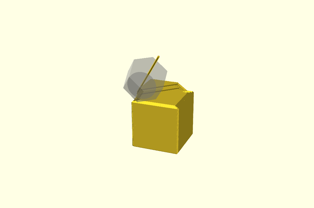
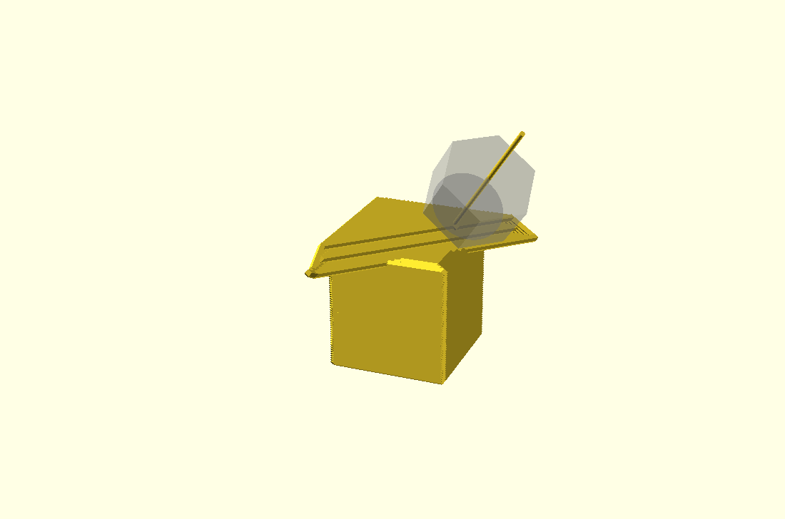
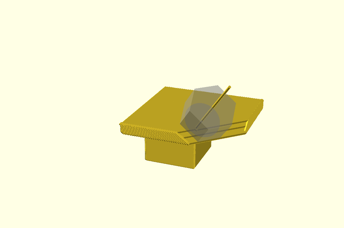
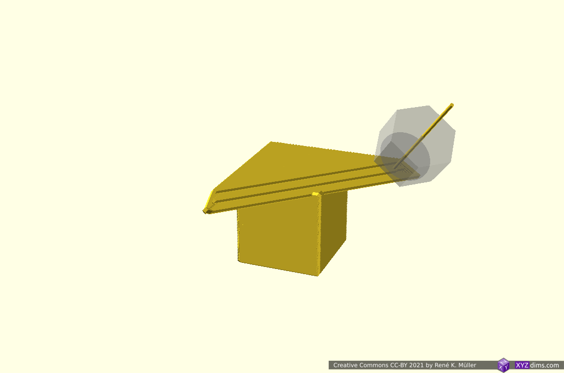
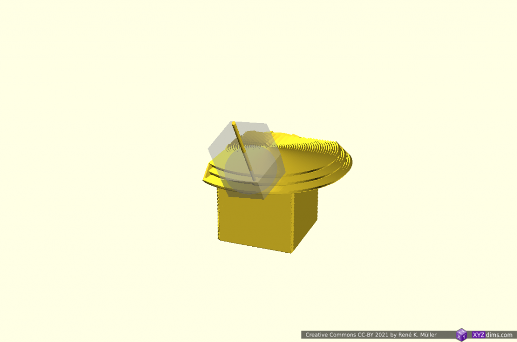
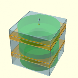
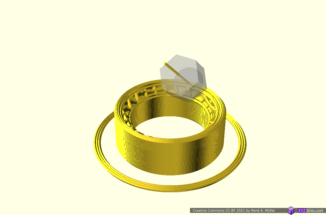
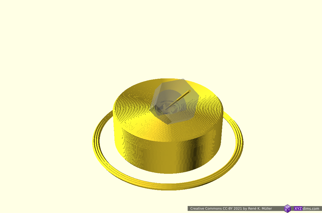
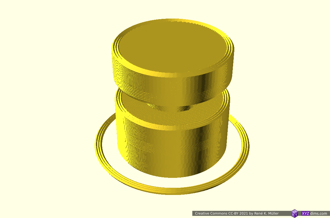
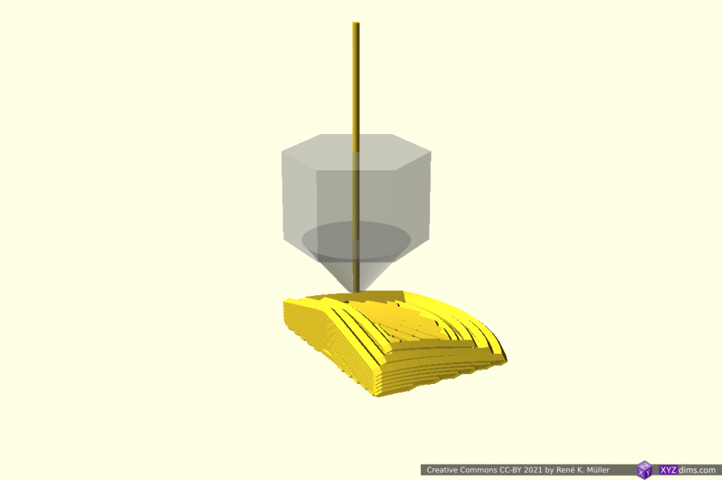
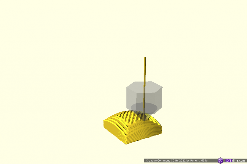
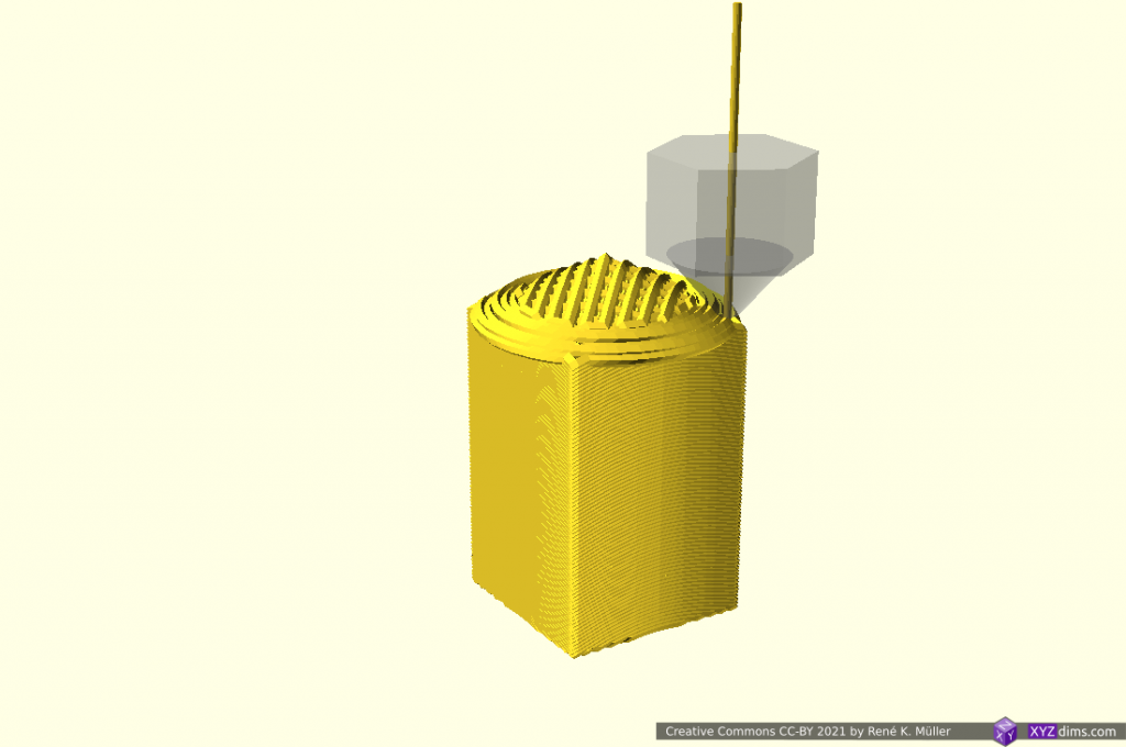
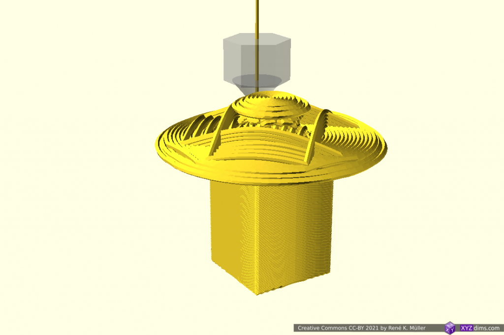
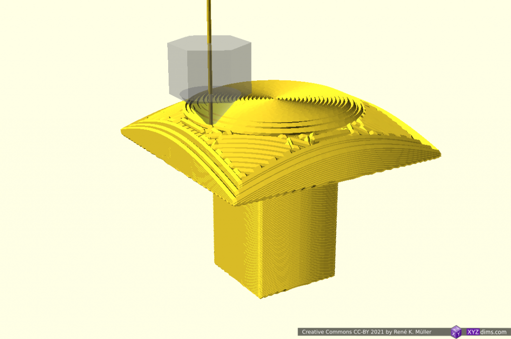
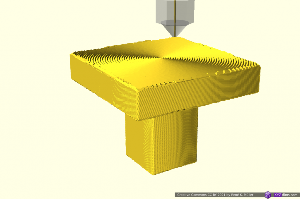
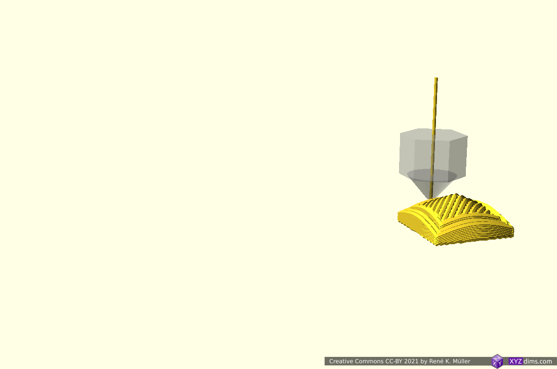
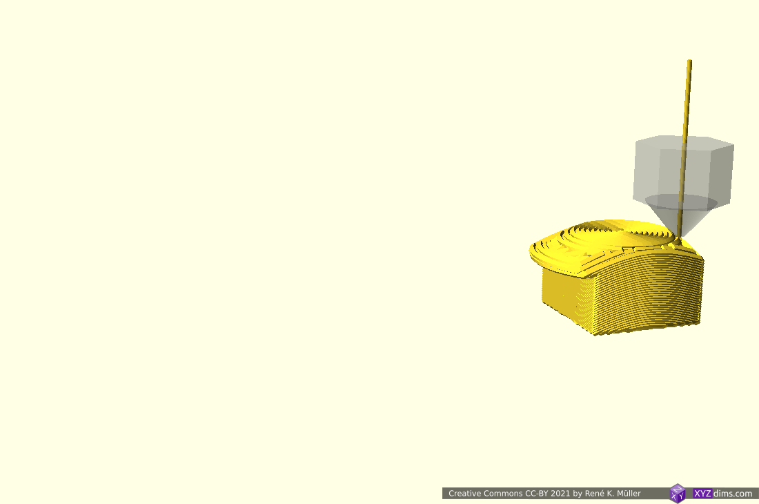
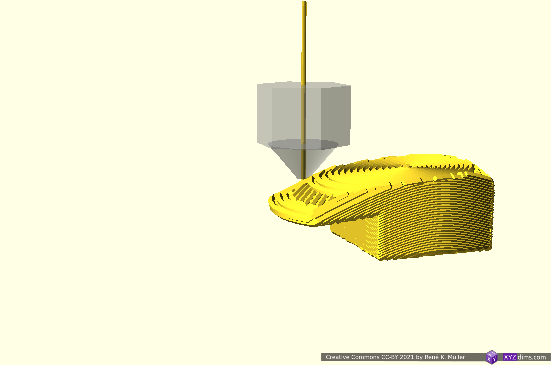
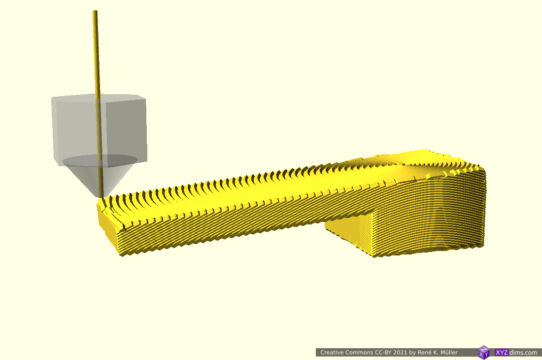
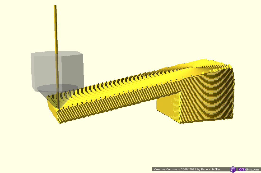
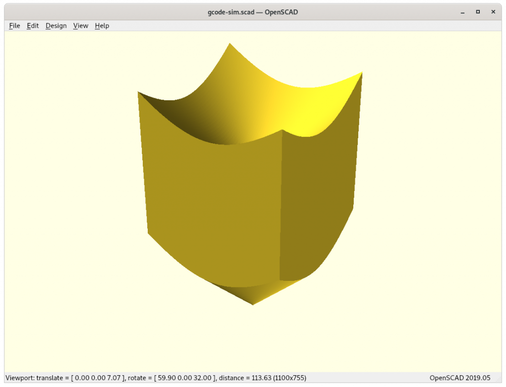
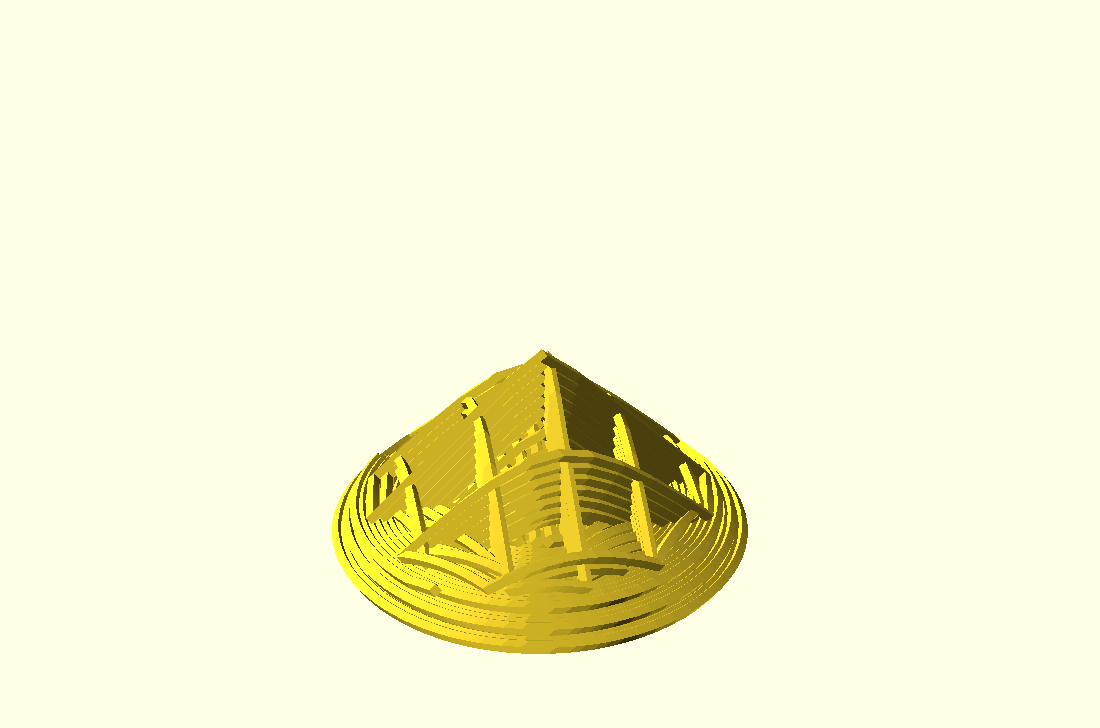
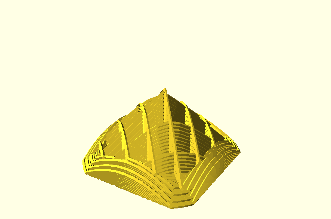
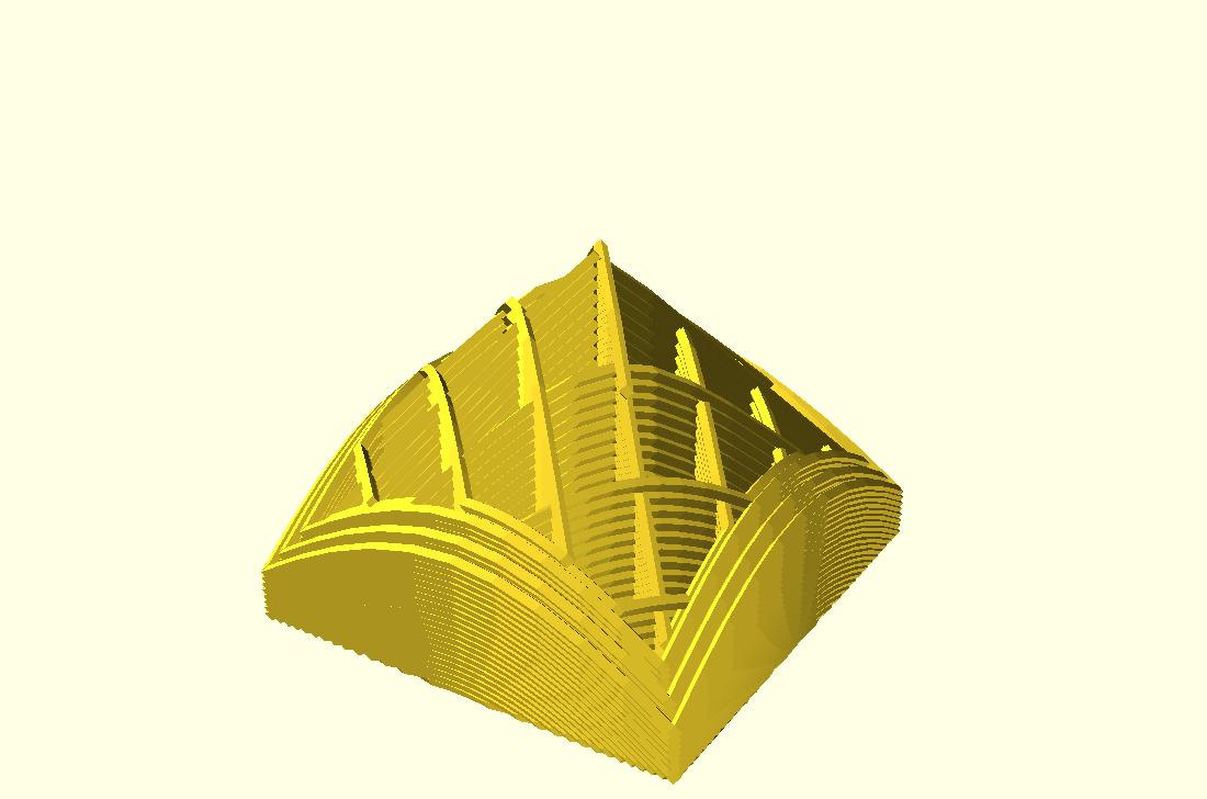
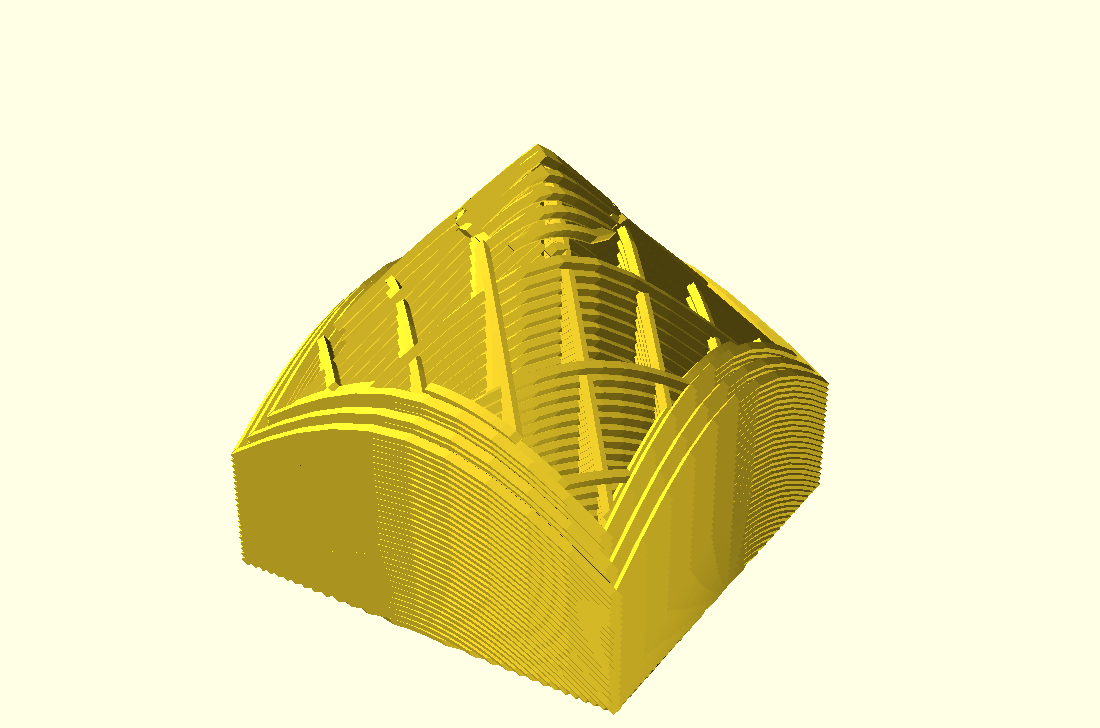
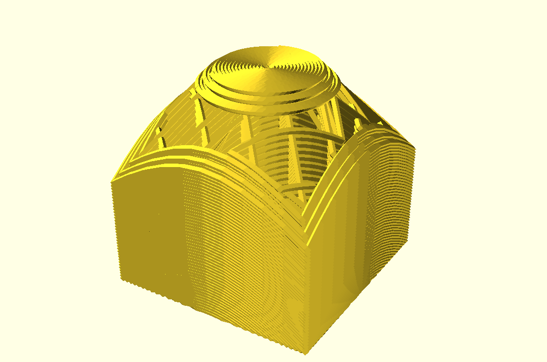
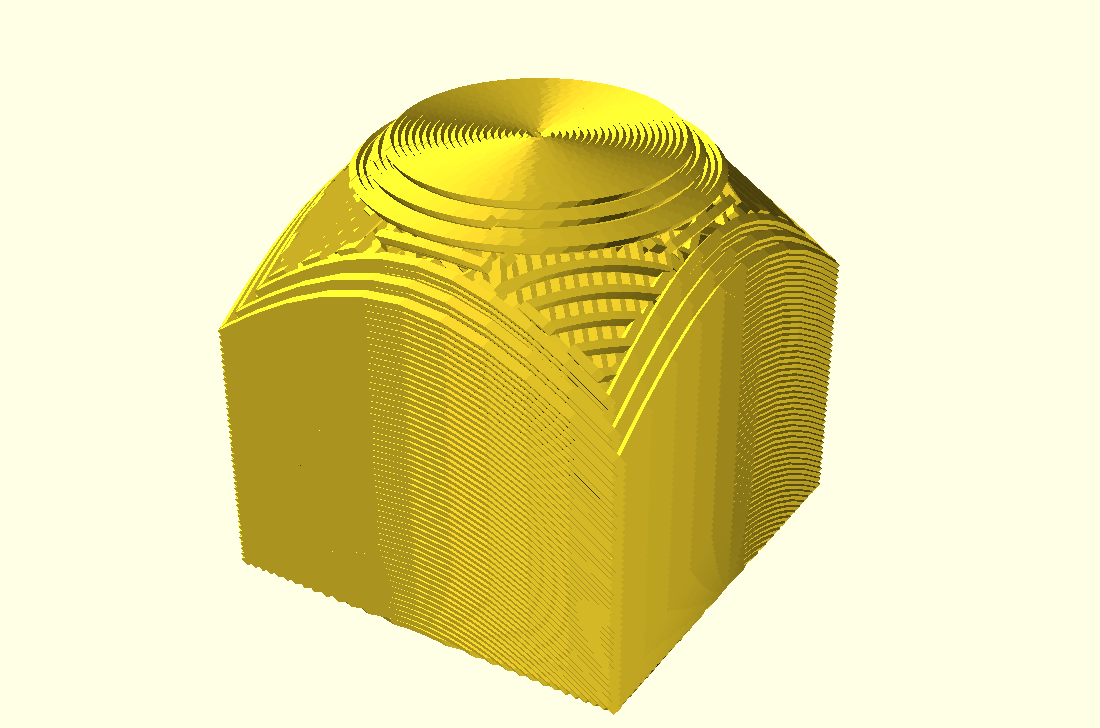
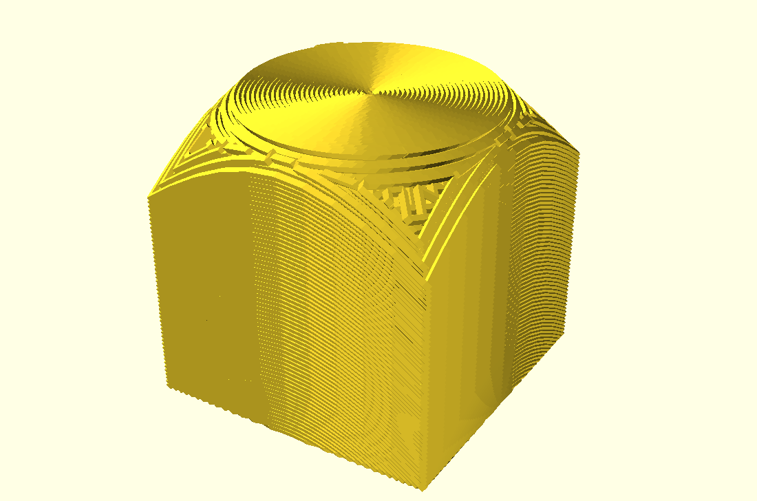
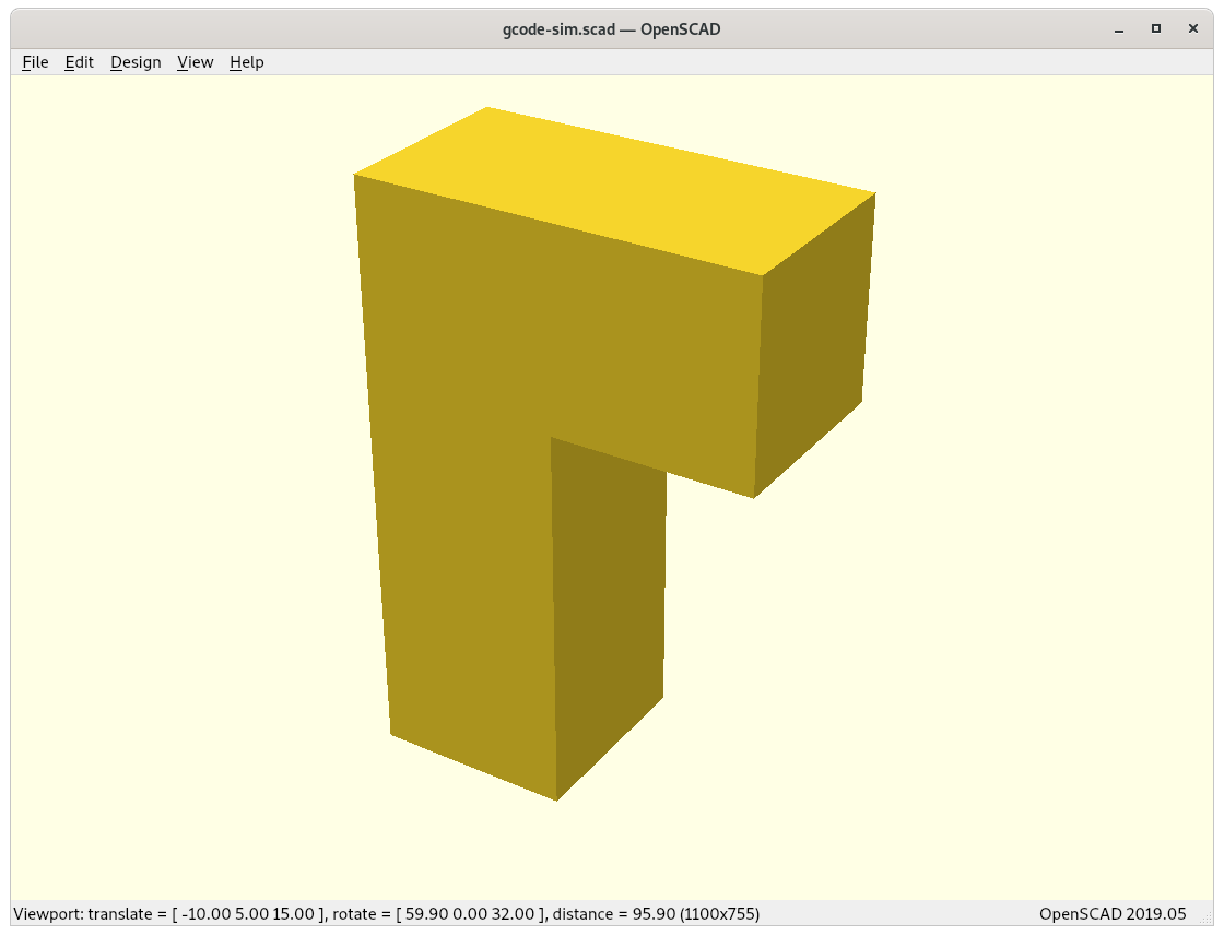
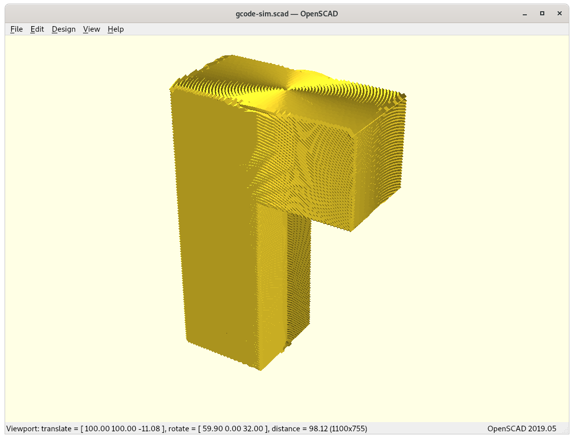
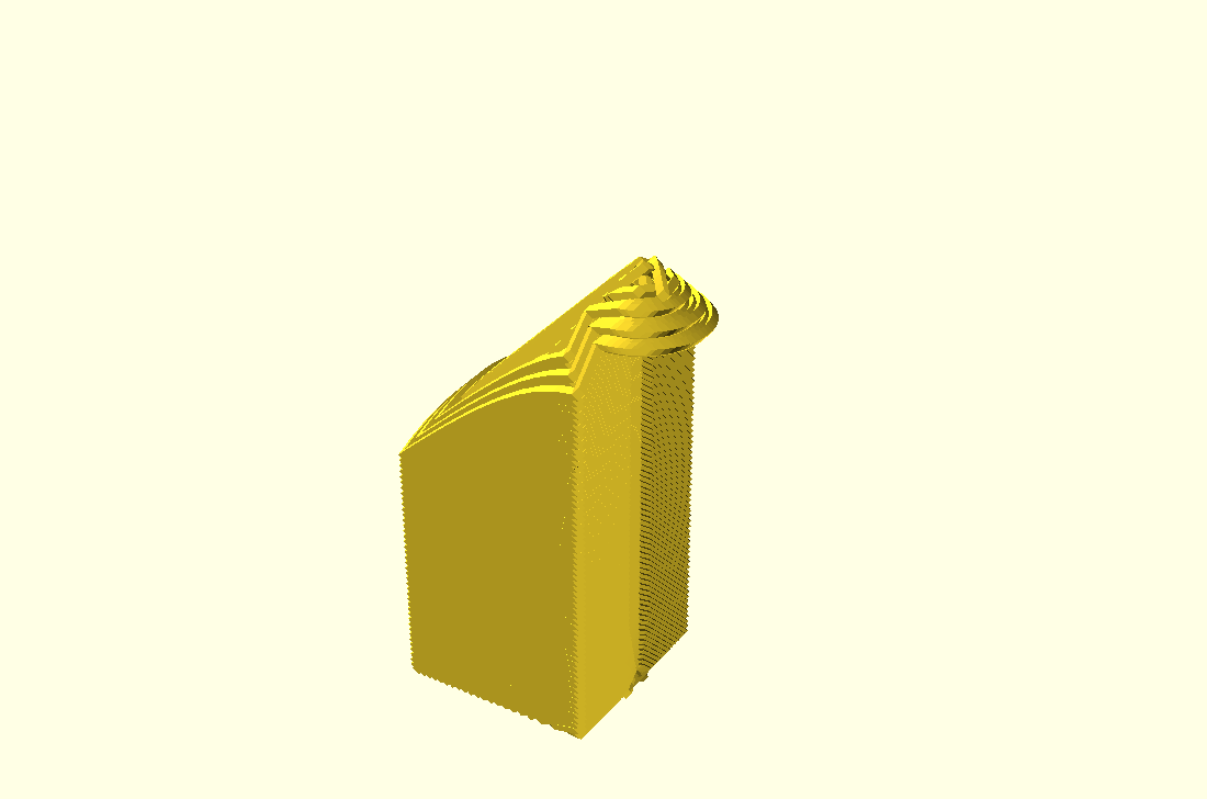
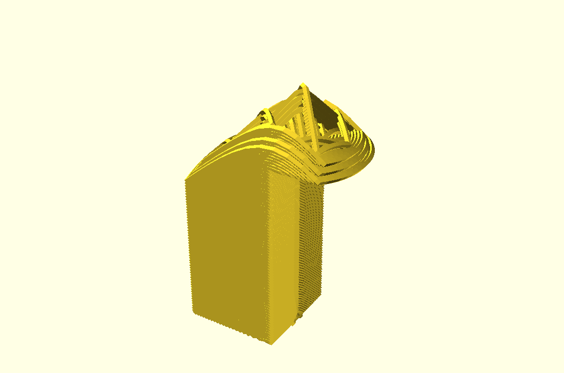
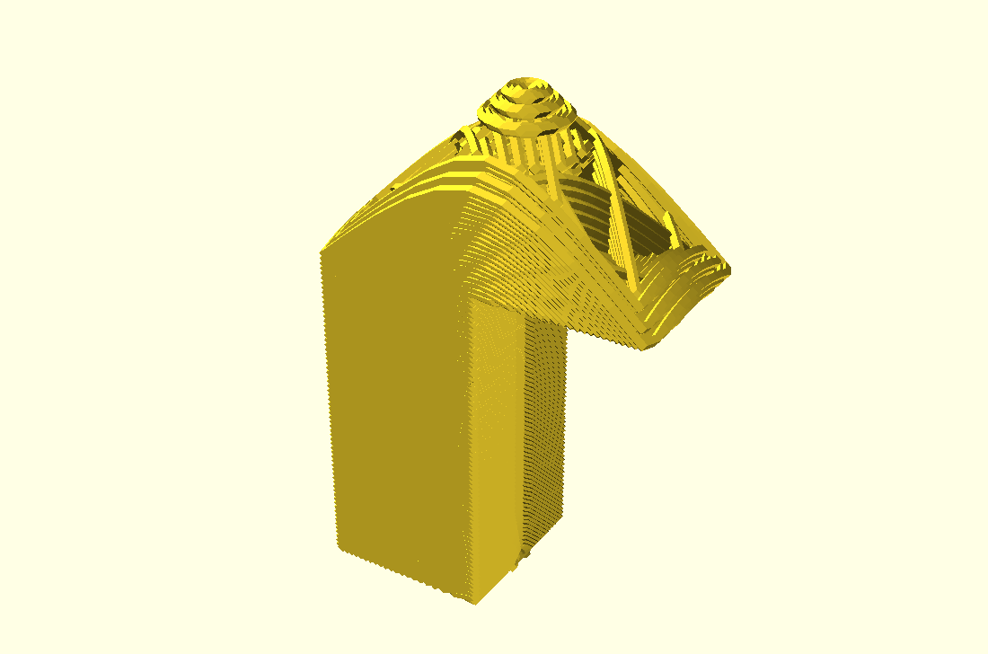
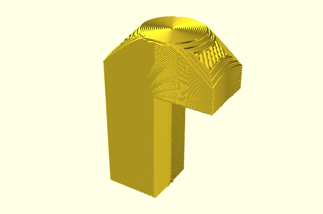
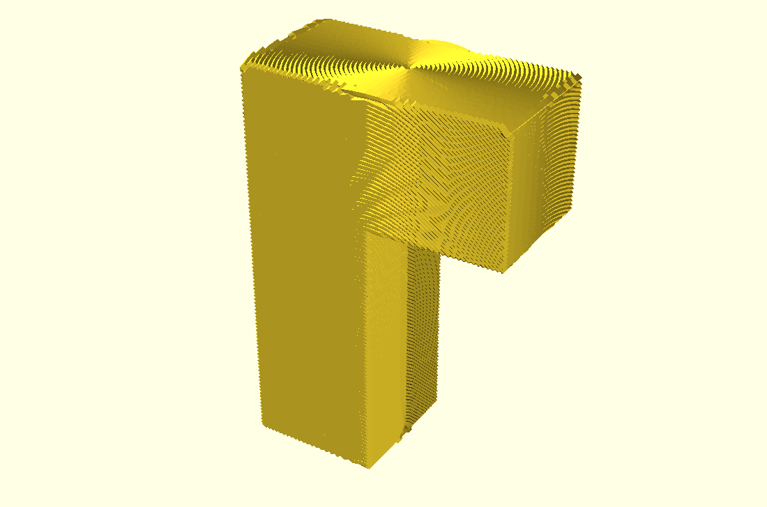
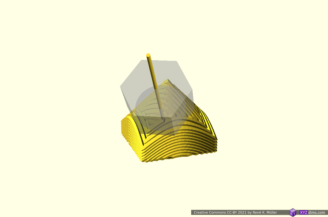
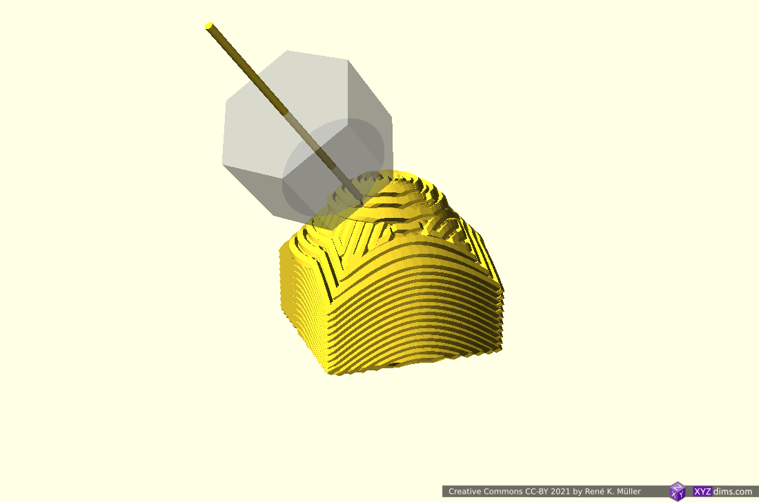
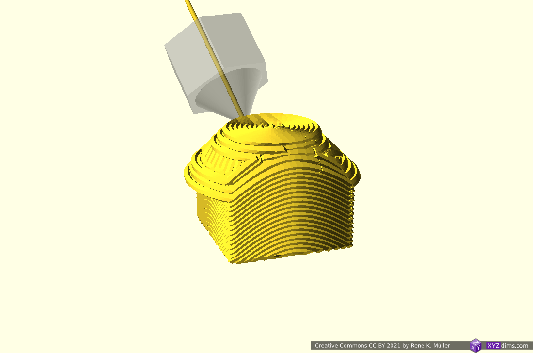
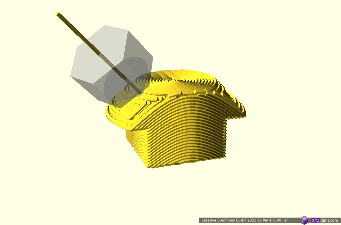
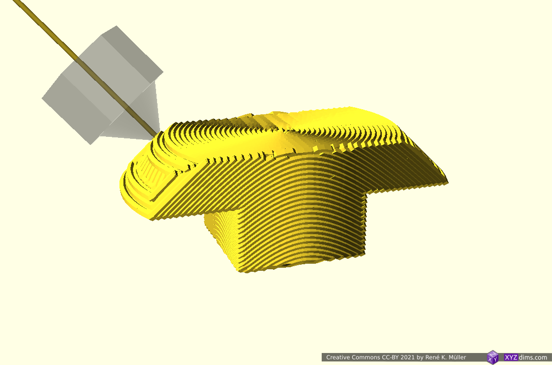
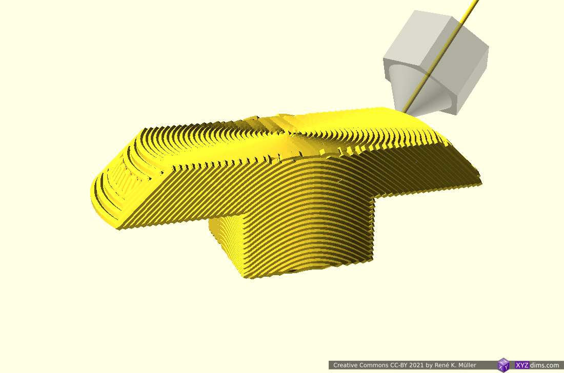
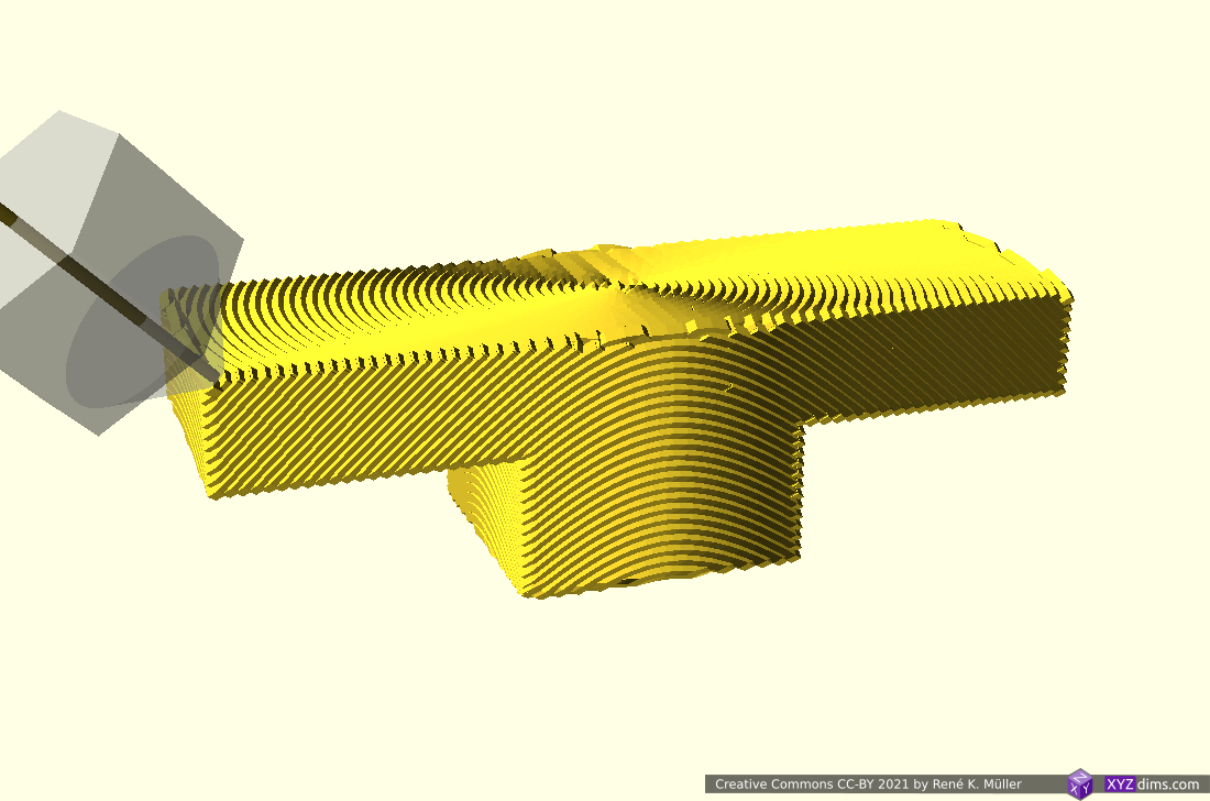
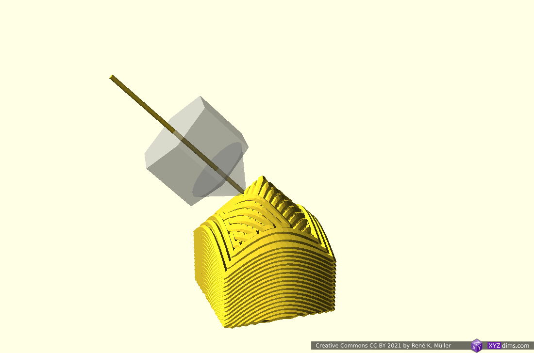
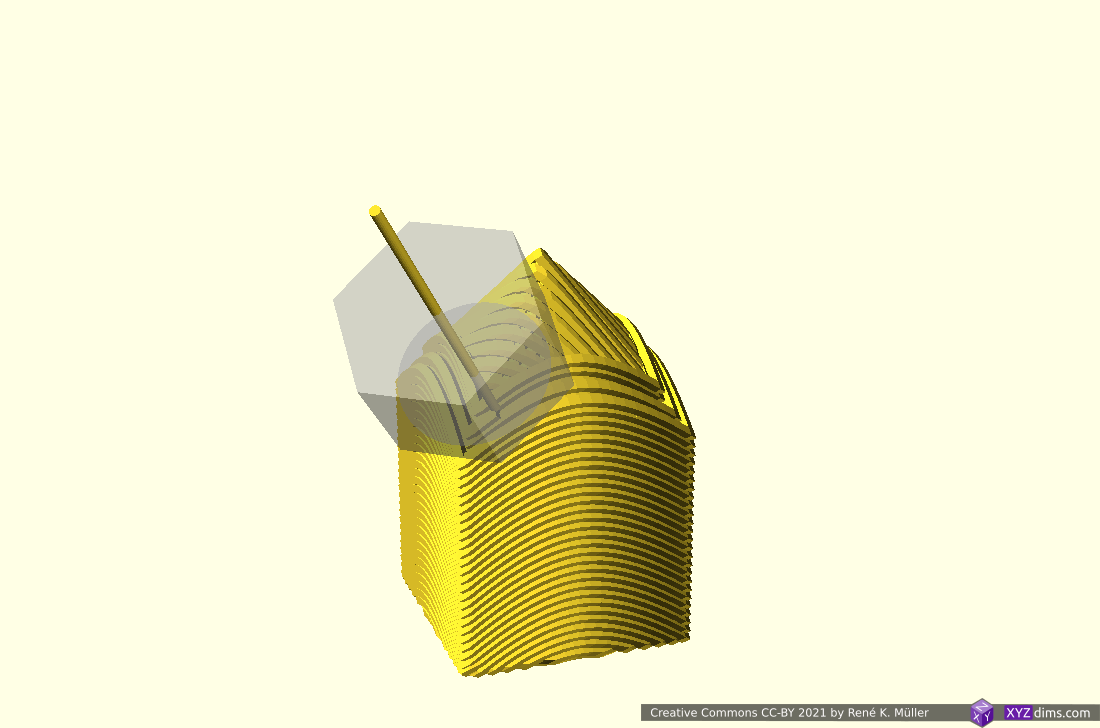
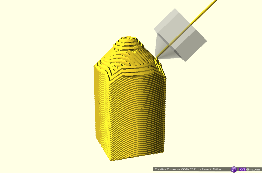
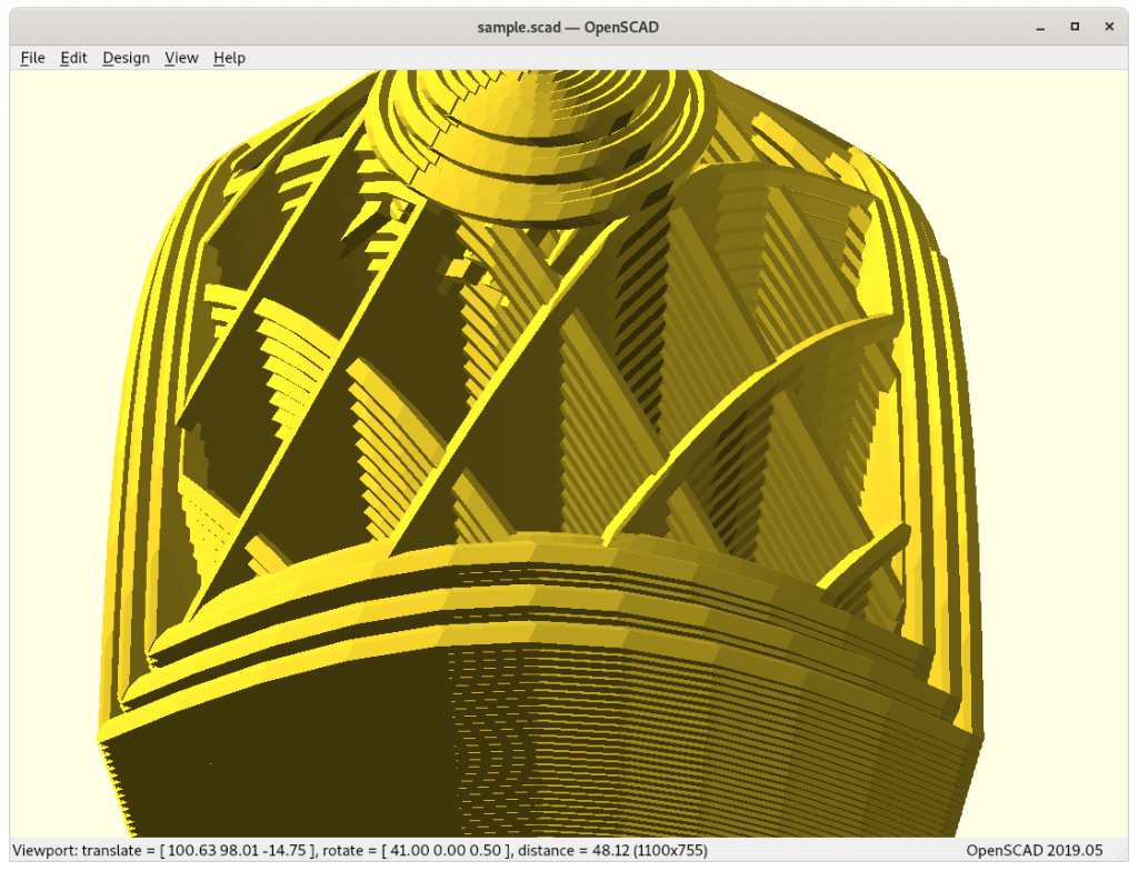
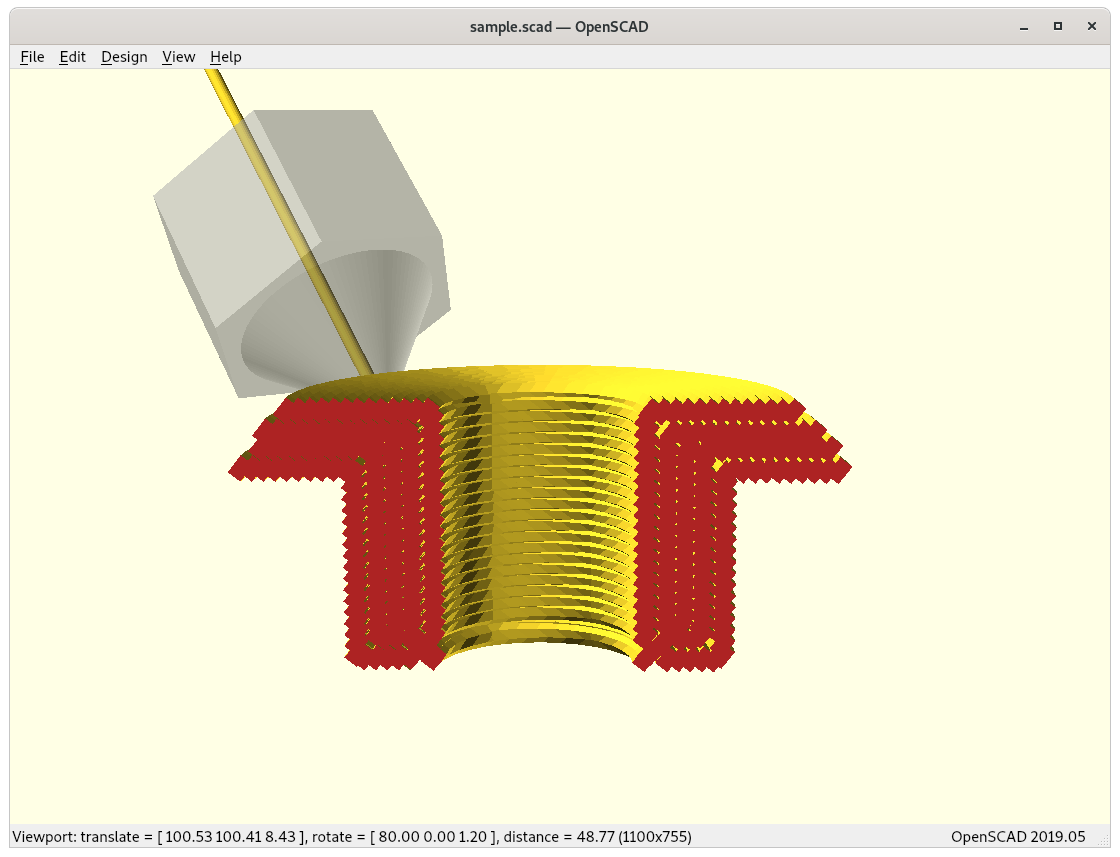
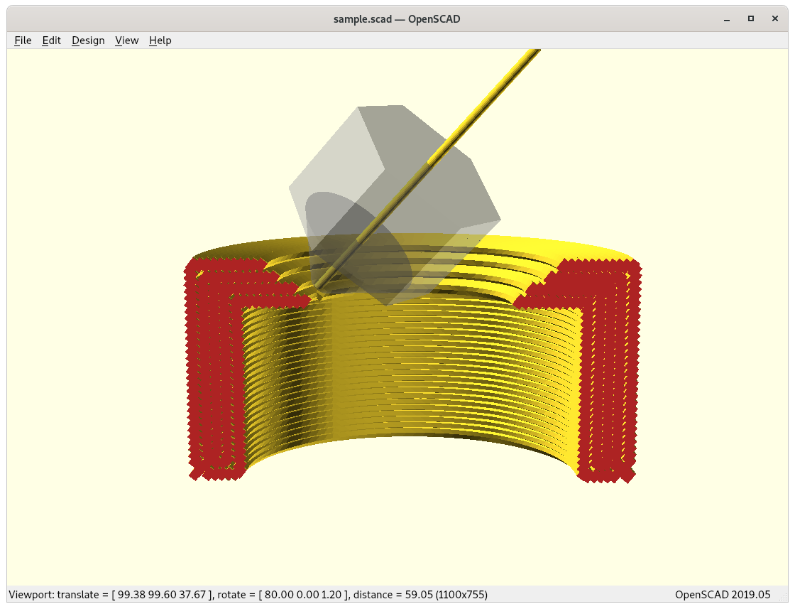
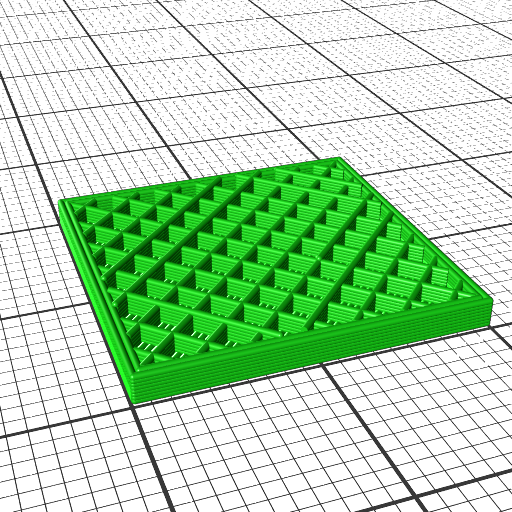
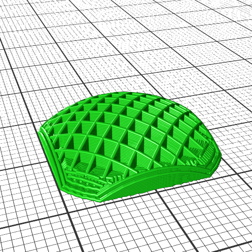
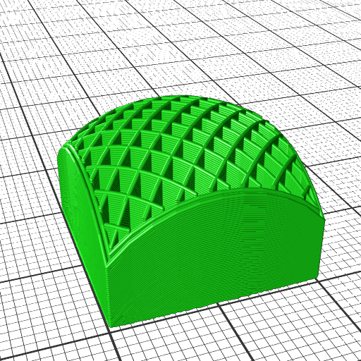
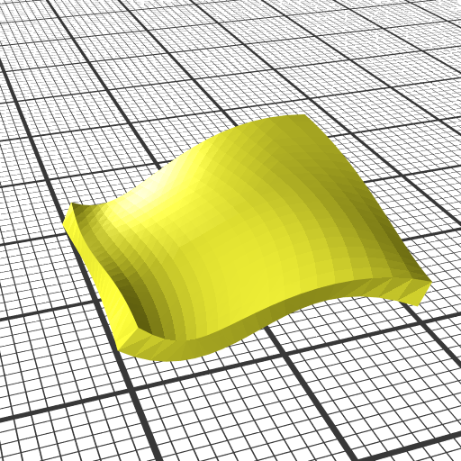
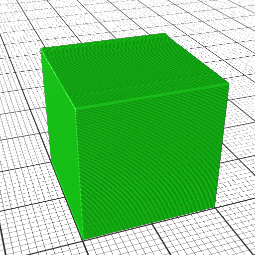
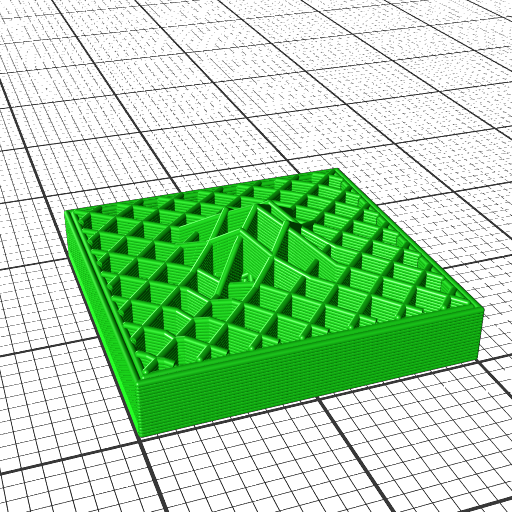
Slicing 20mm cube with wave-like geometry
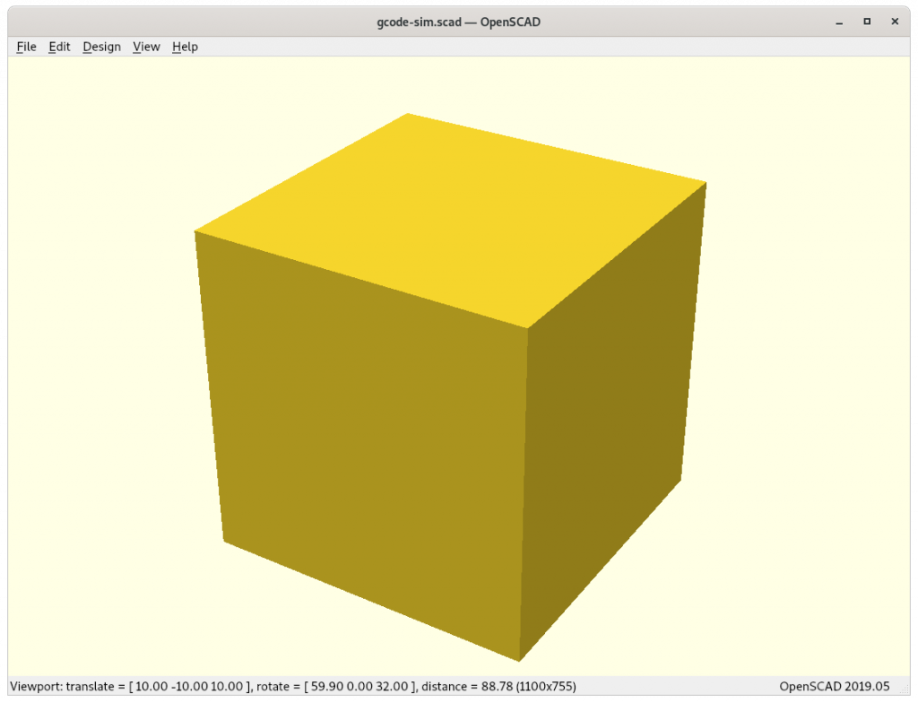
In order to explore non-planar slices, using a wave-like geometry composed by Bezier curves and slice a 20mm cube:
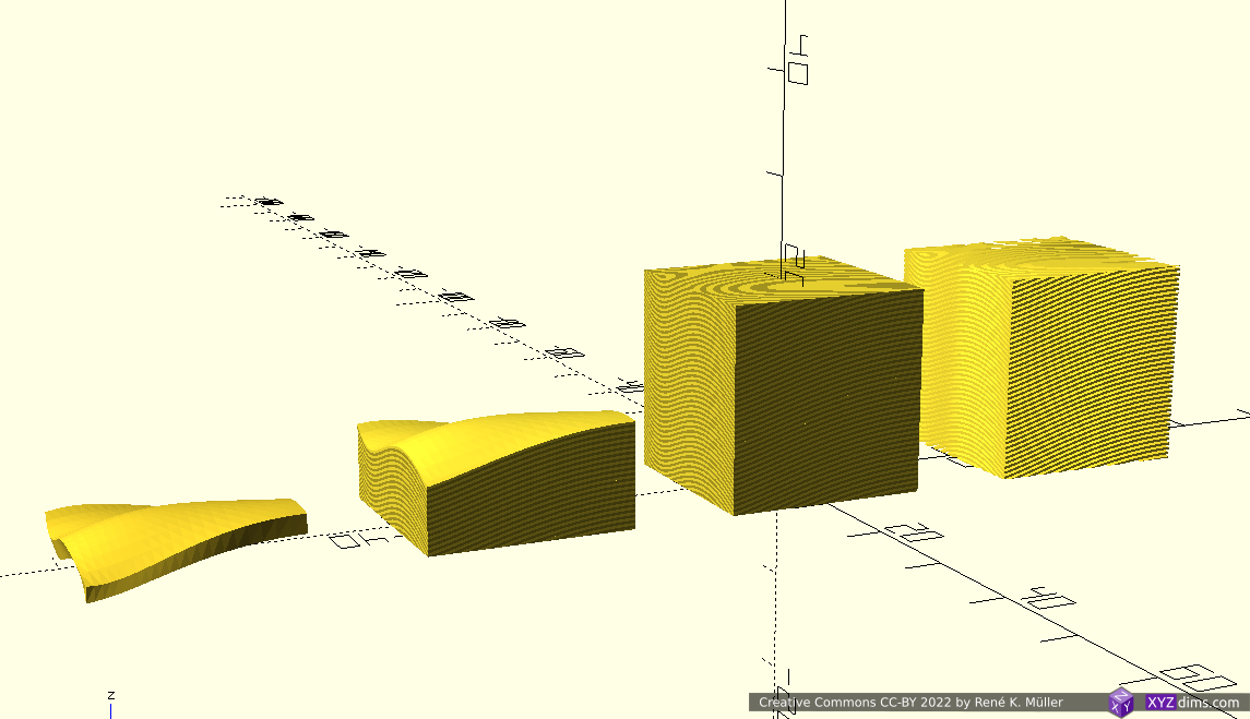
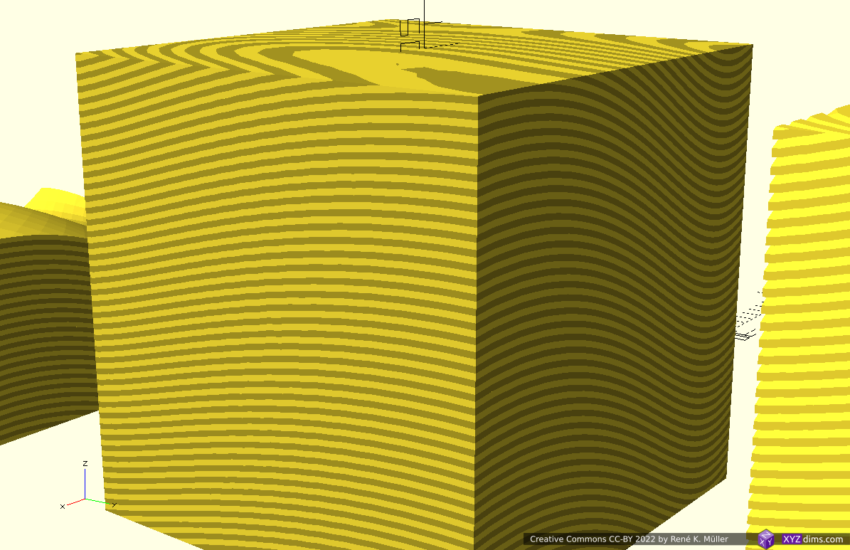
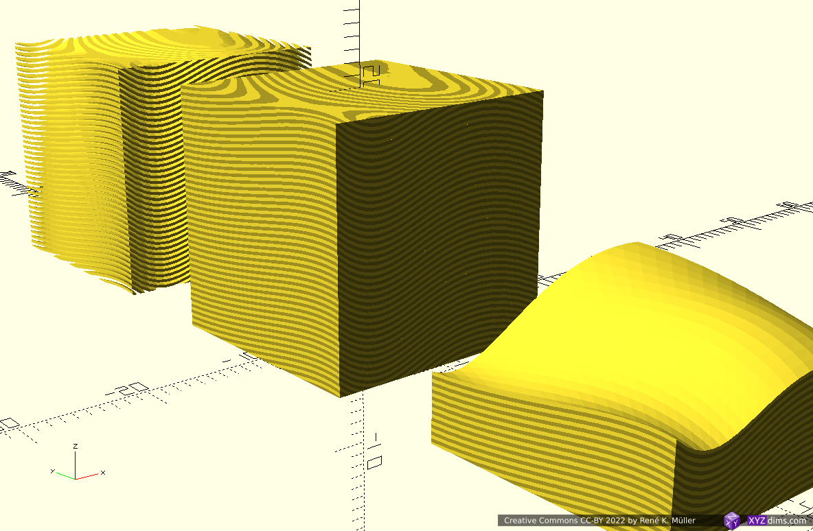
Note: OpenSCAD is used solely used as 3D viewer, the slicing itself is performed by an experimental slicer.
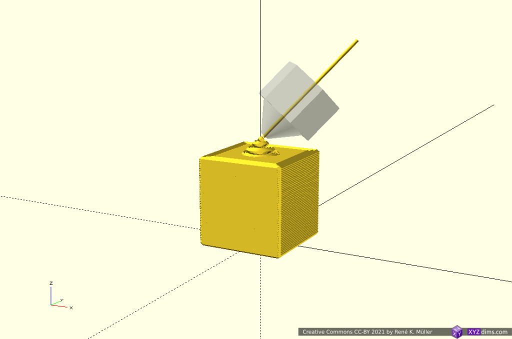
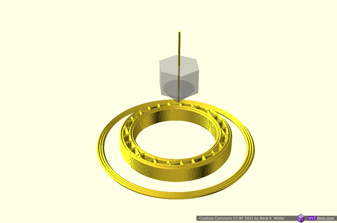
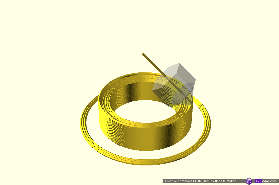
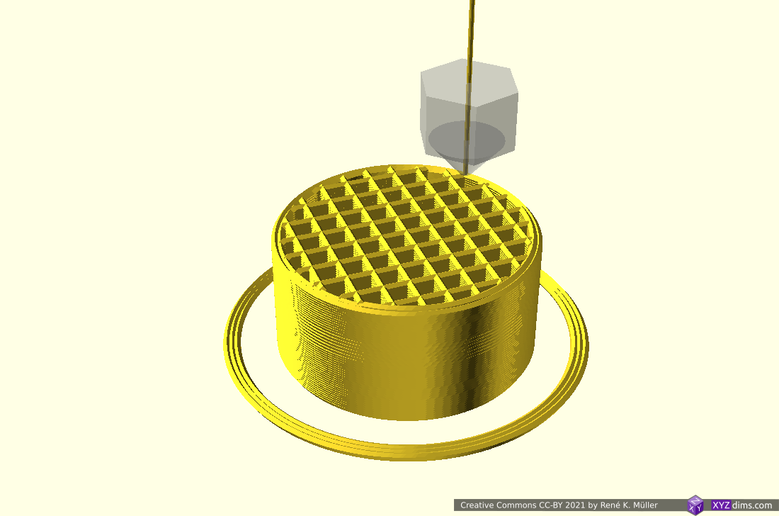
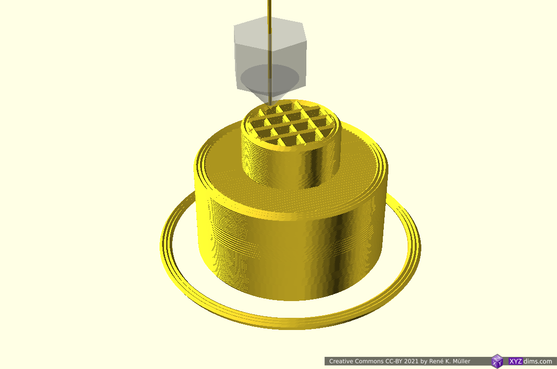
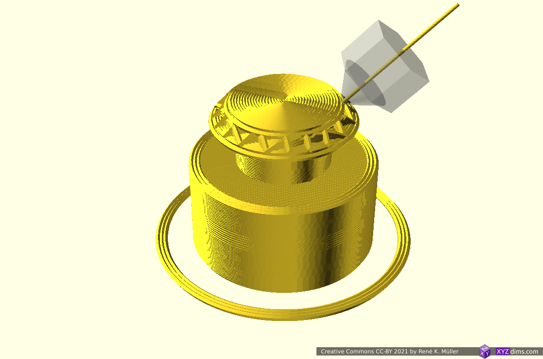
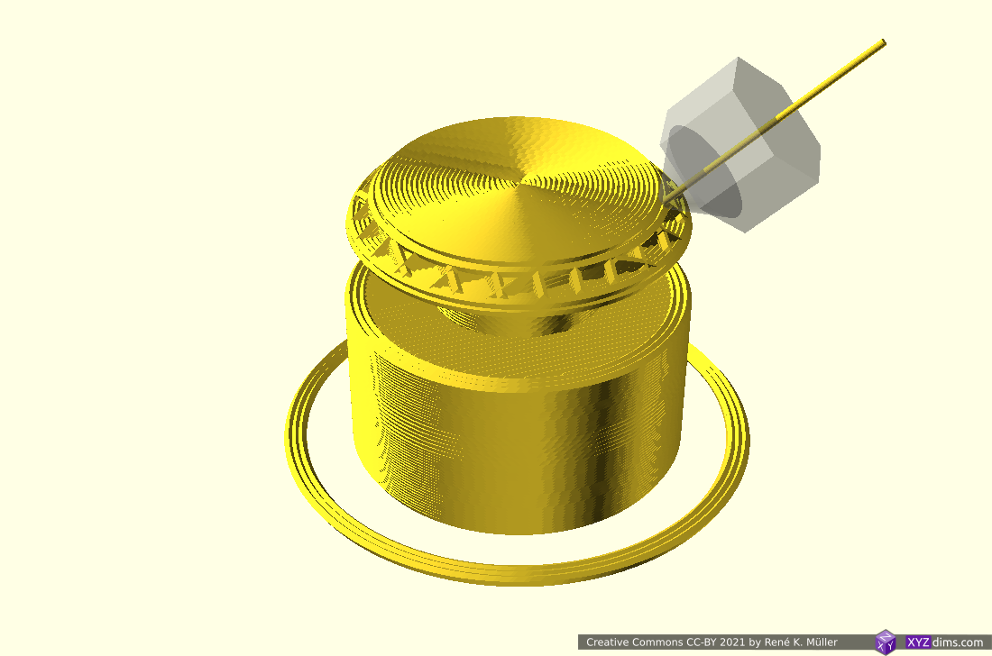
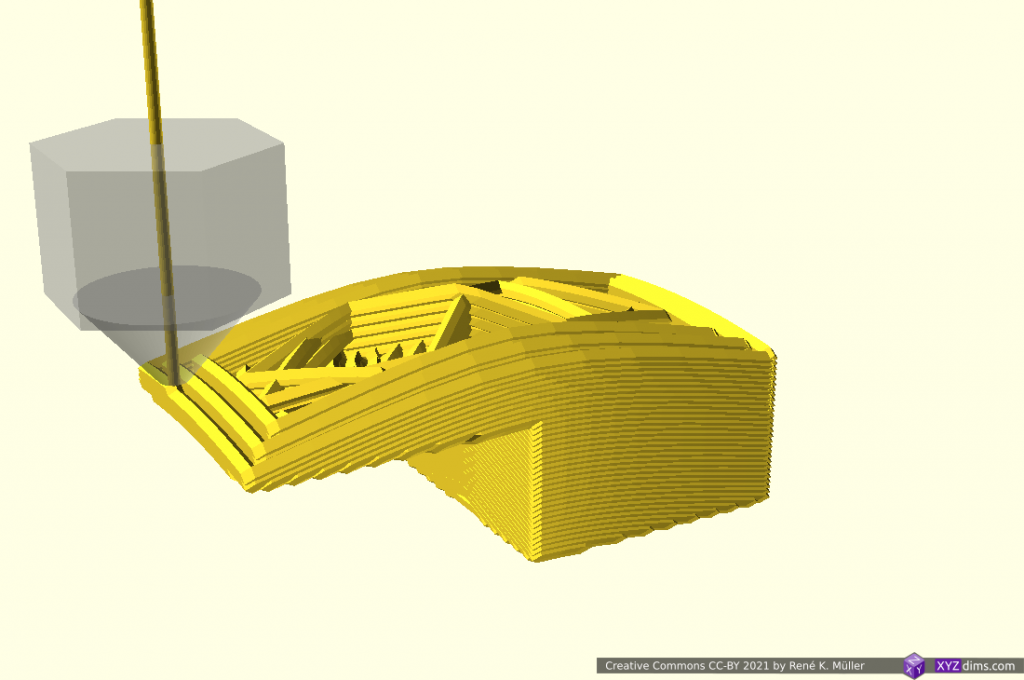
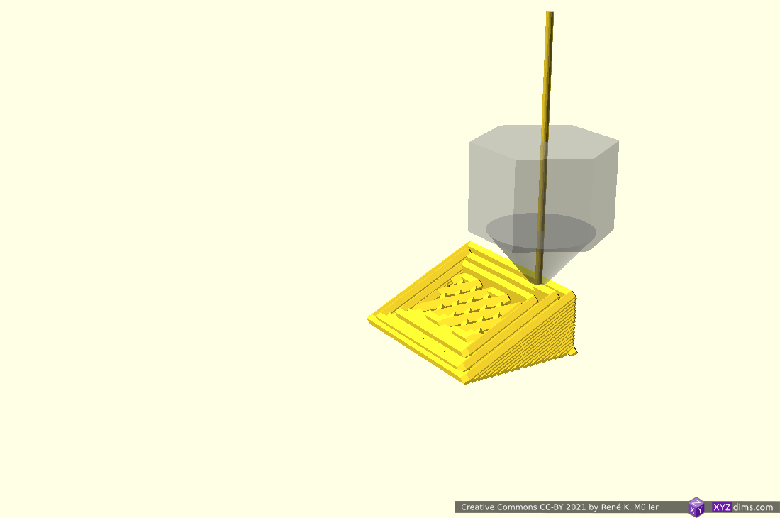
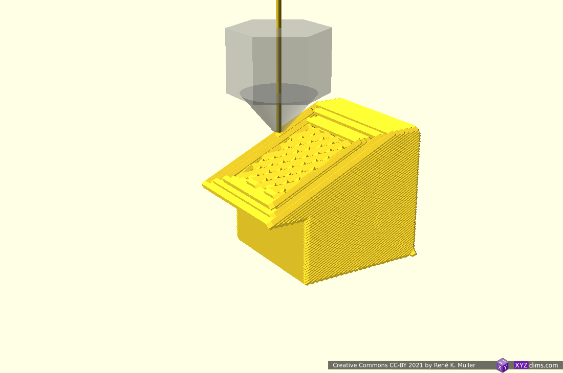
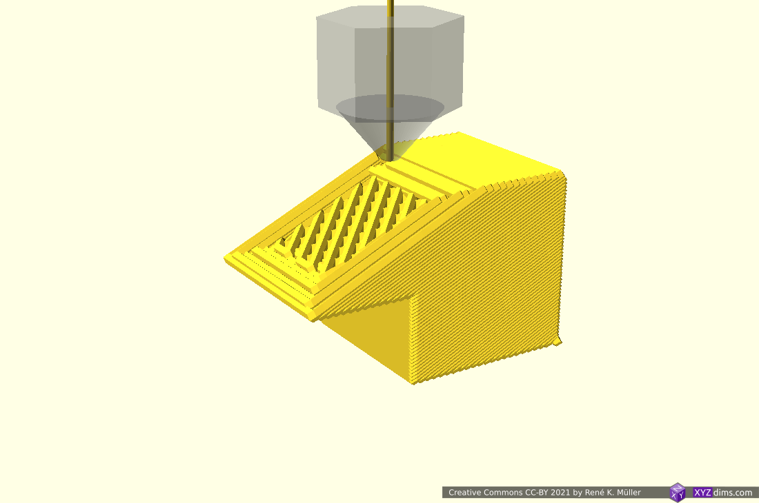
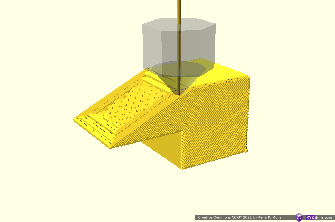
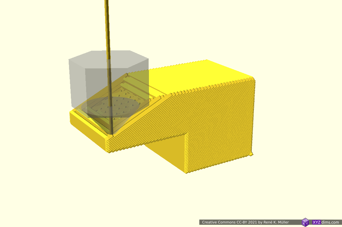
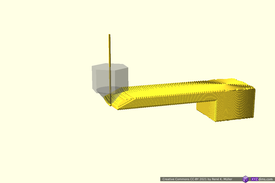
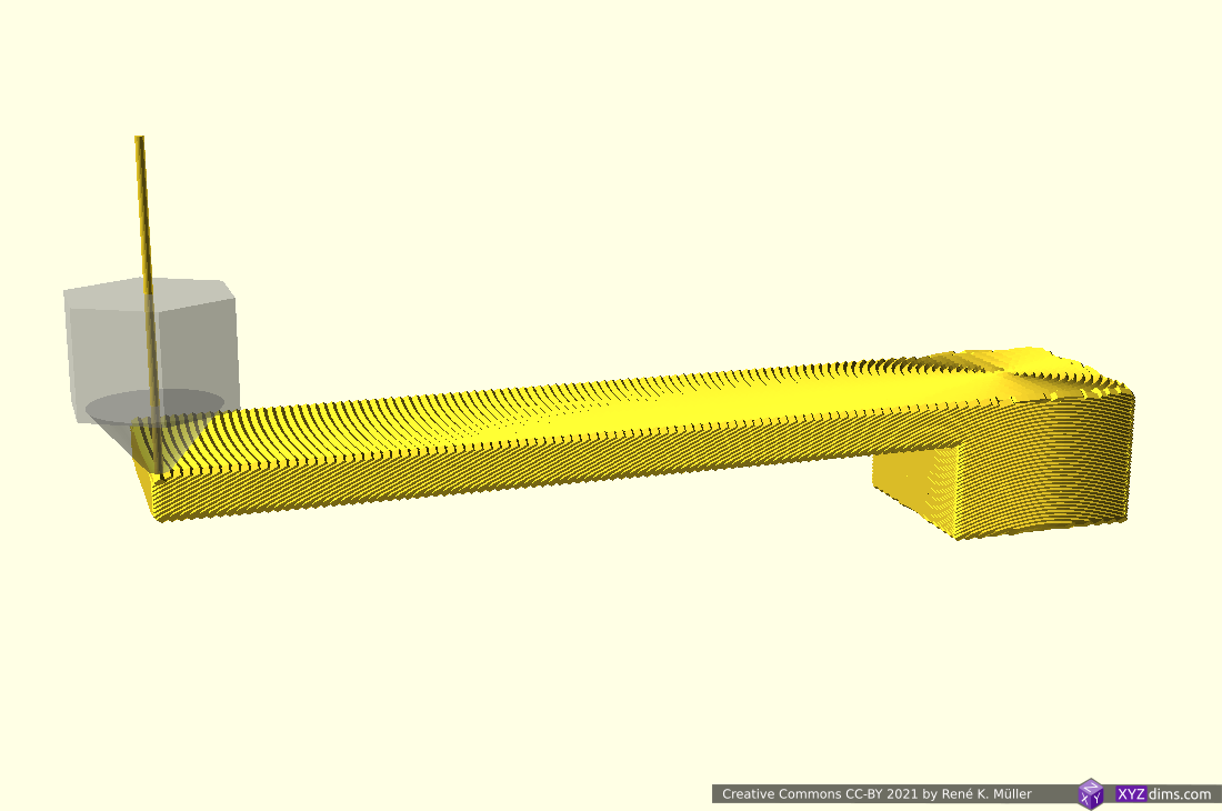
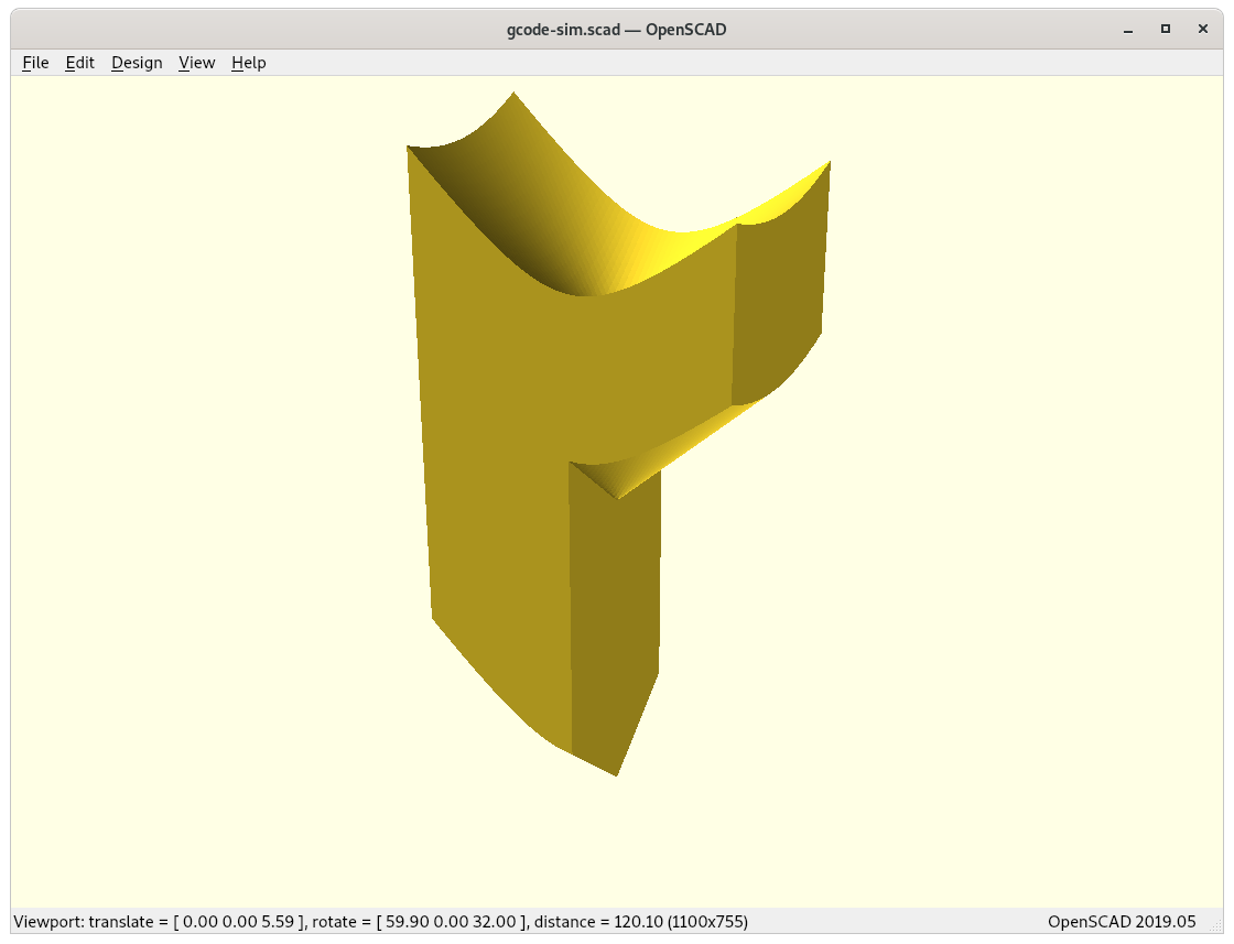
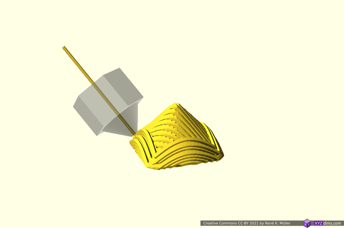
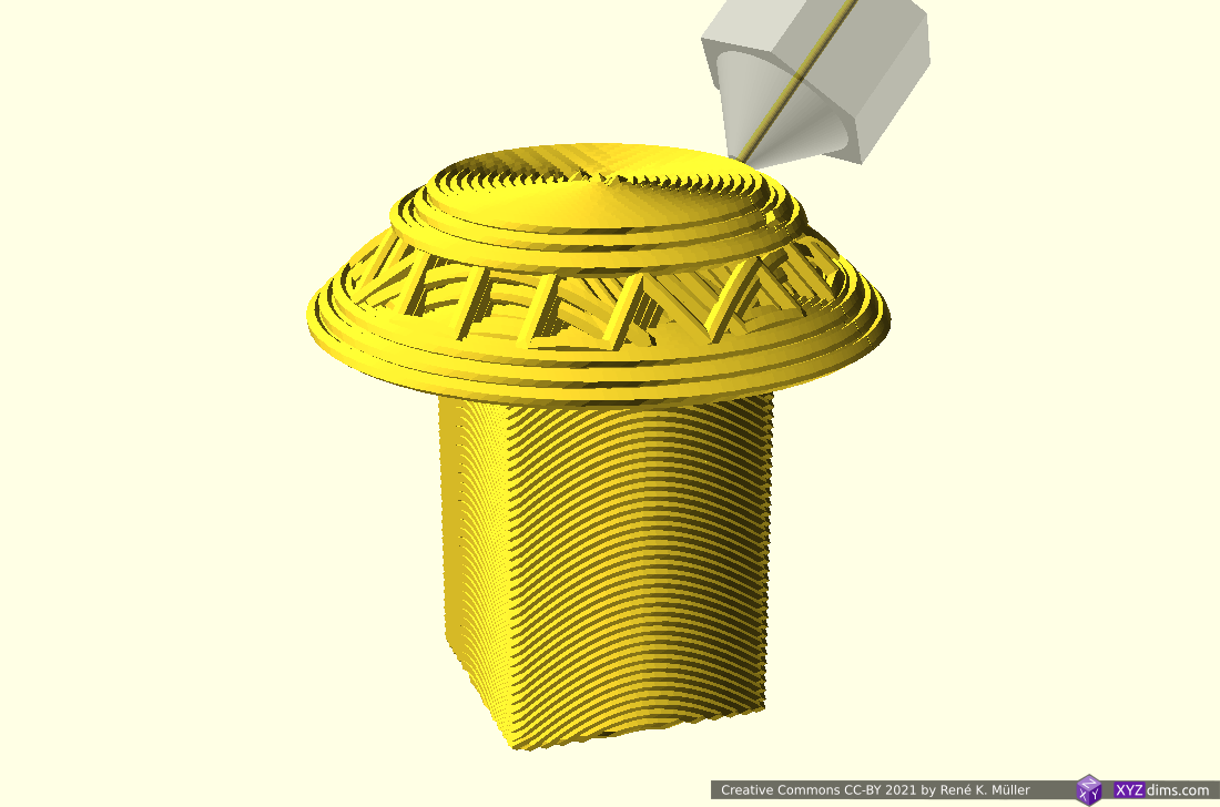
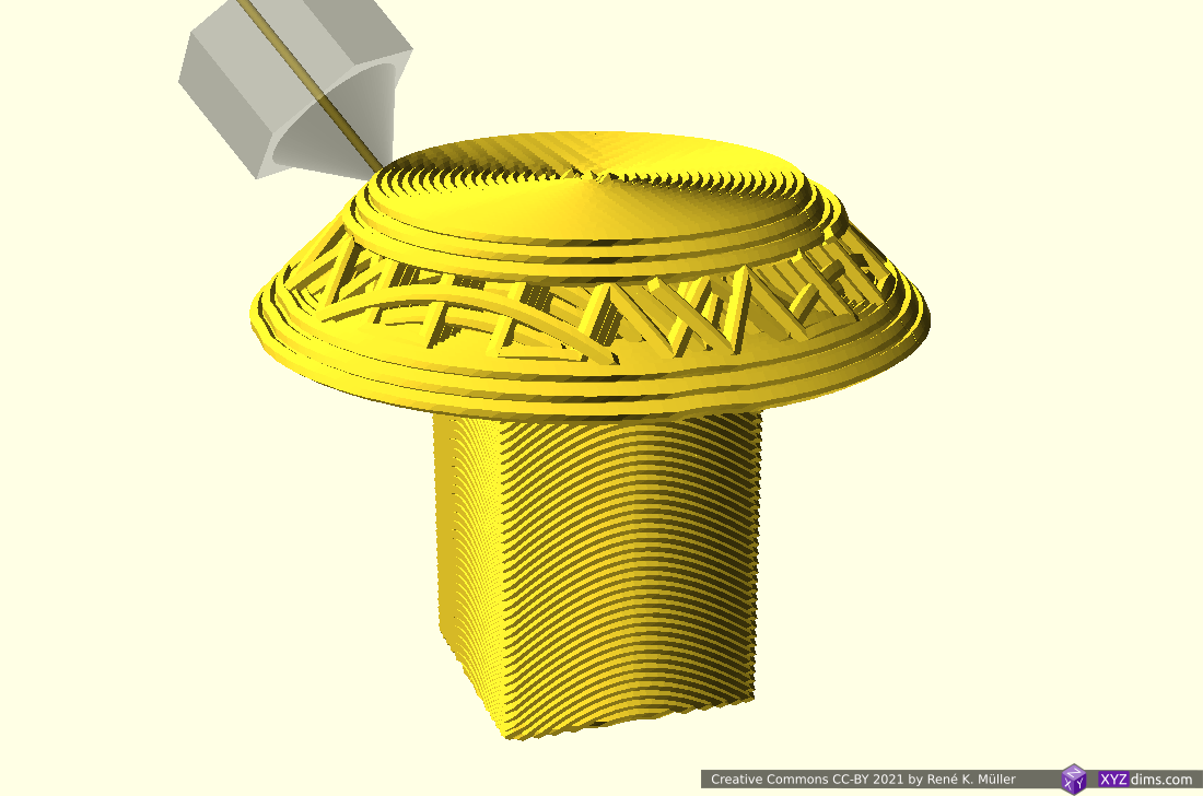
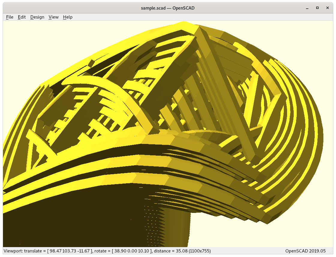
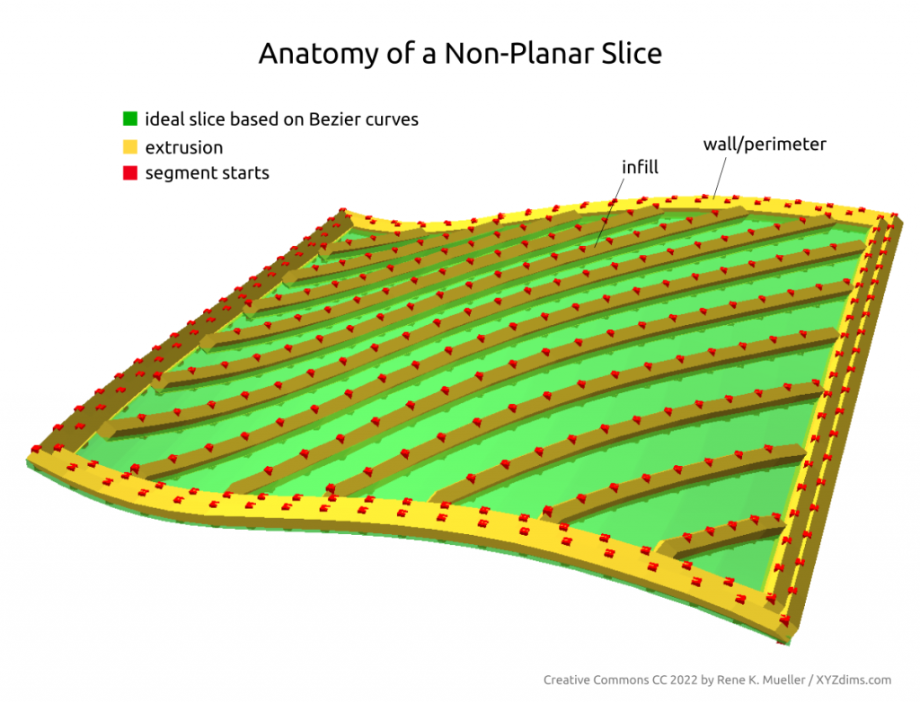
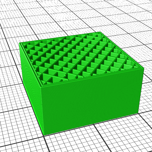
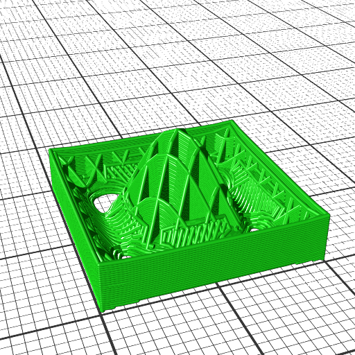
Routing a single non-planar slice
A single slice is routed to wall/perimeter and infill extrusion:
There are several approaches to achieve this:
- slice non-planar, map single slice 3d to 2d, route with 2d offsetting, and map back to 3d space (MetatronSlicer)
- map entire mesh and slice planar, and map routes or resulting G-code back again (EnochSlicer)
and likely other more complex means.
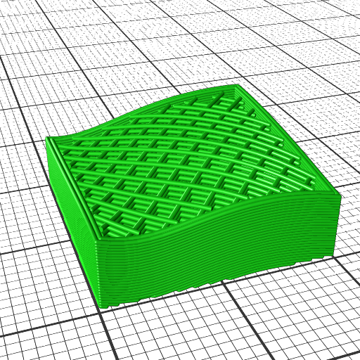
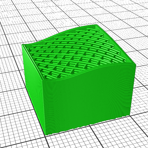
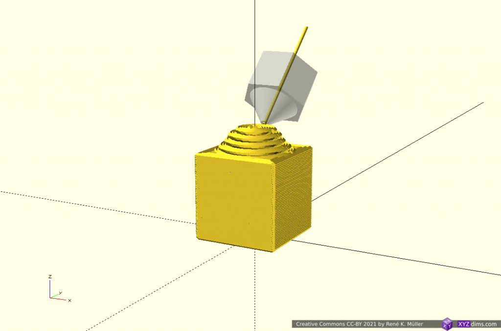
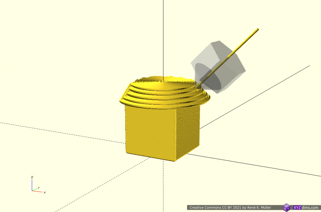
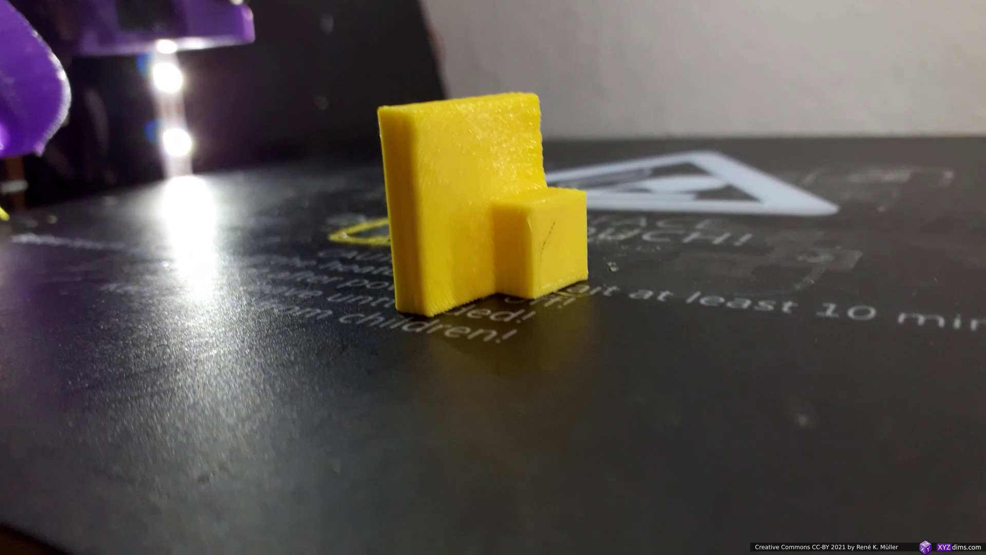
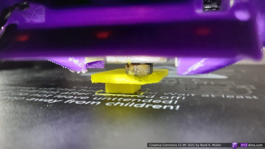
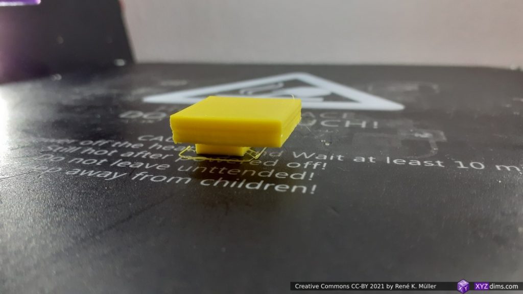
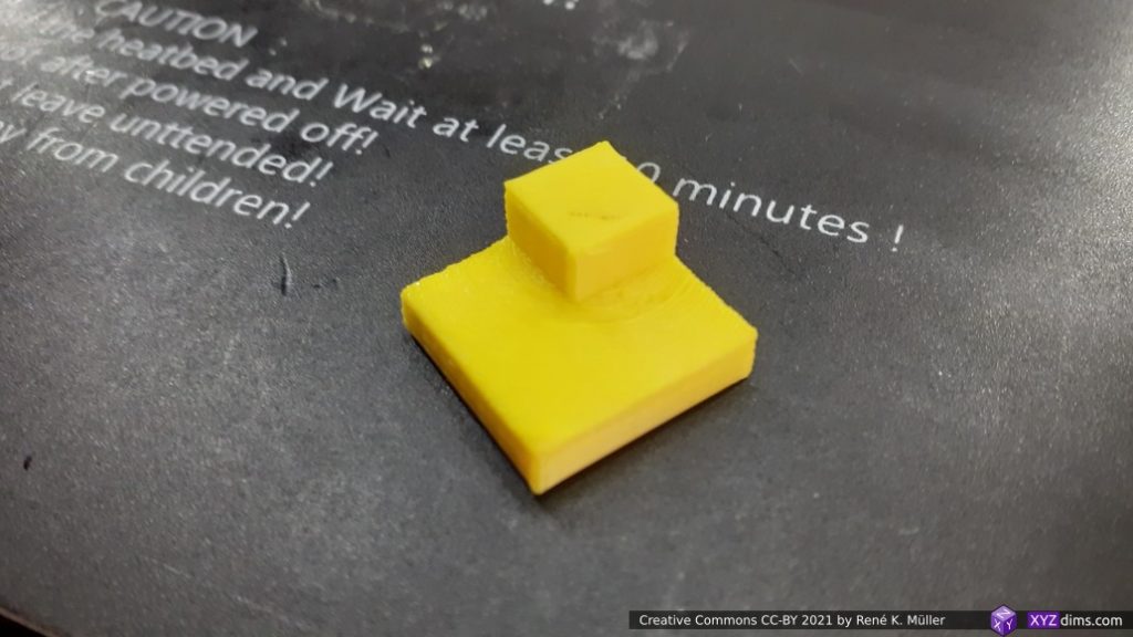
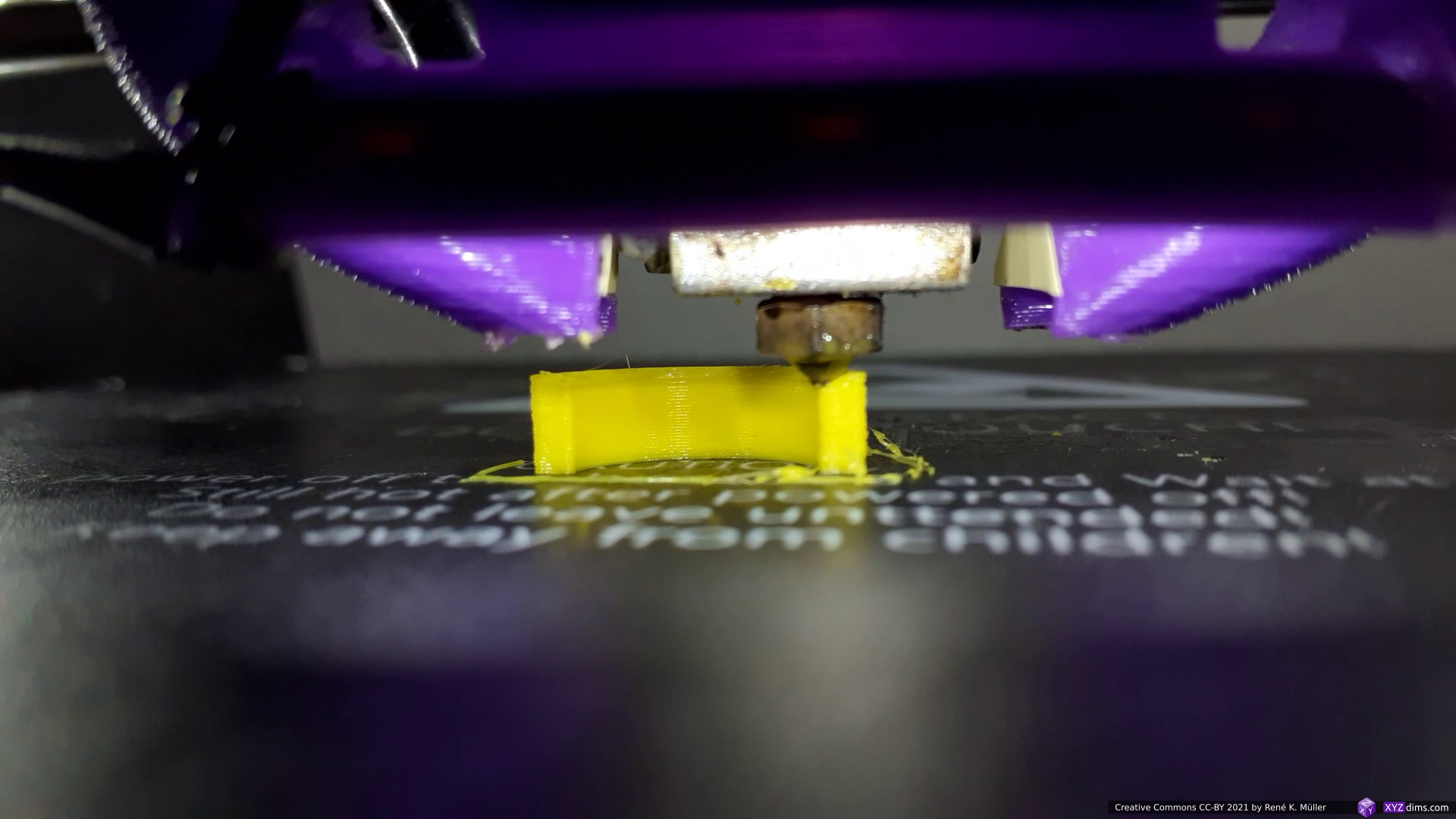
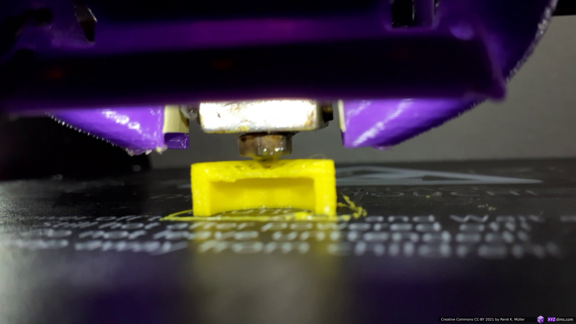
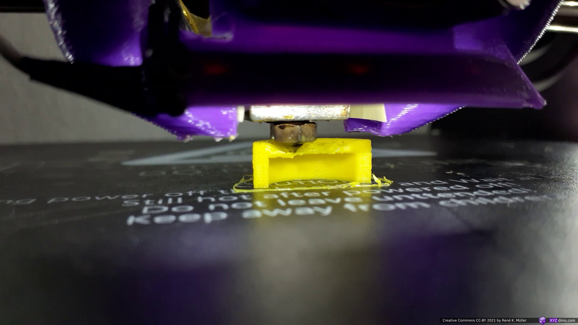
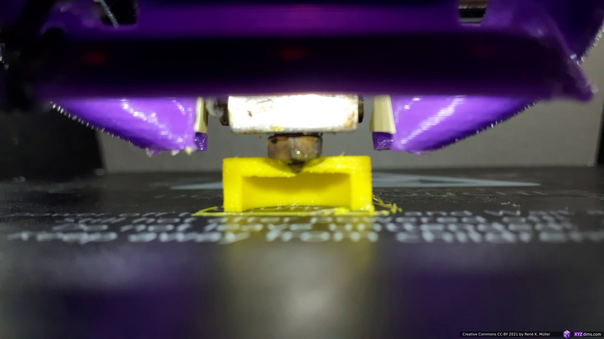
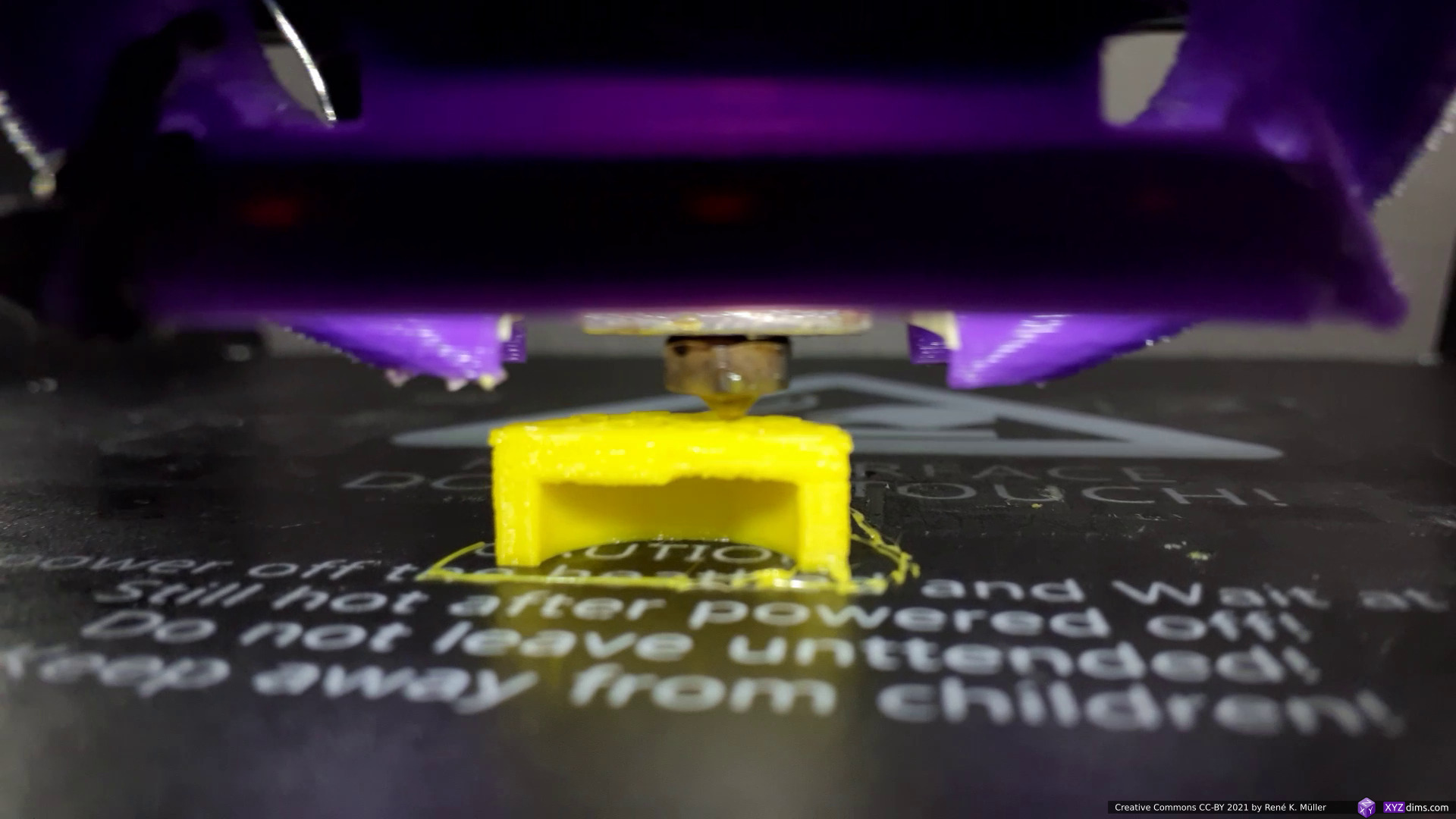
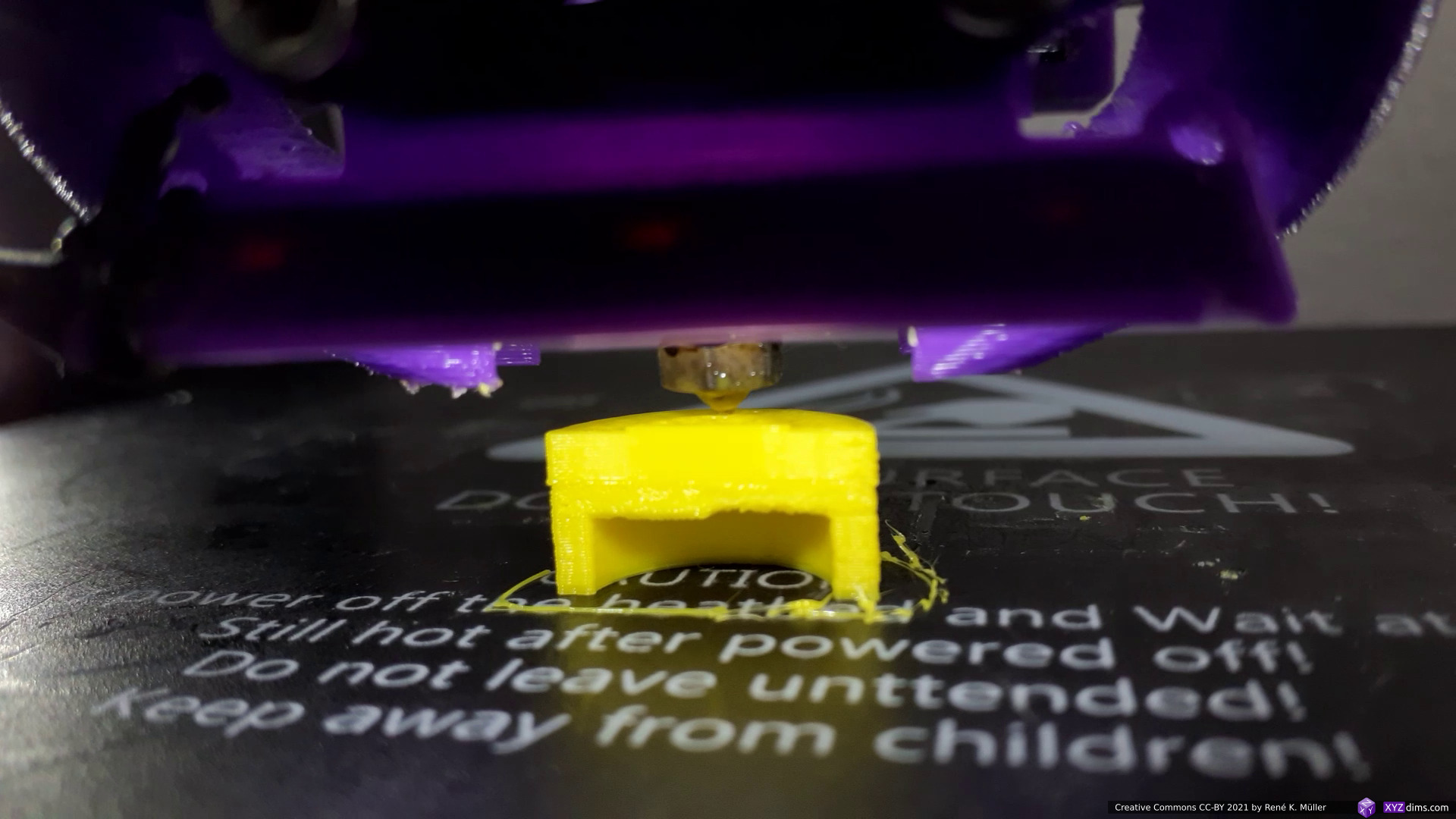
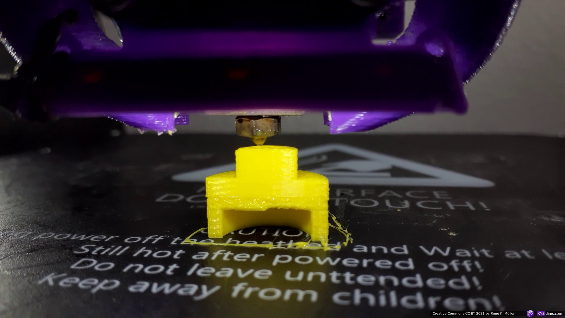
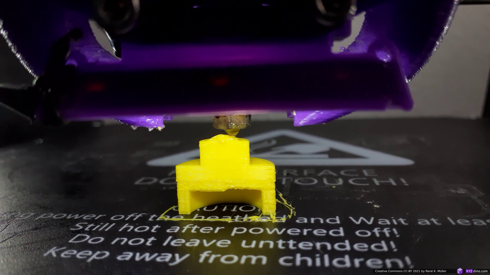
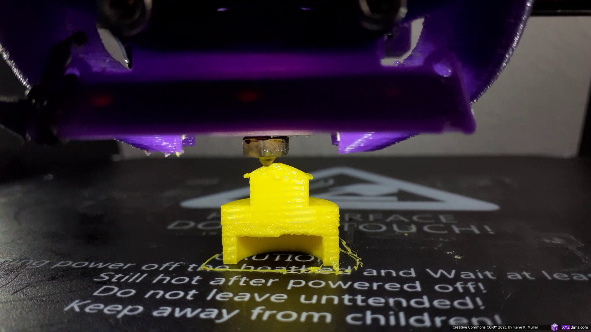
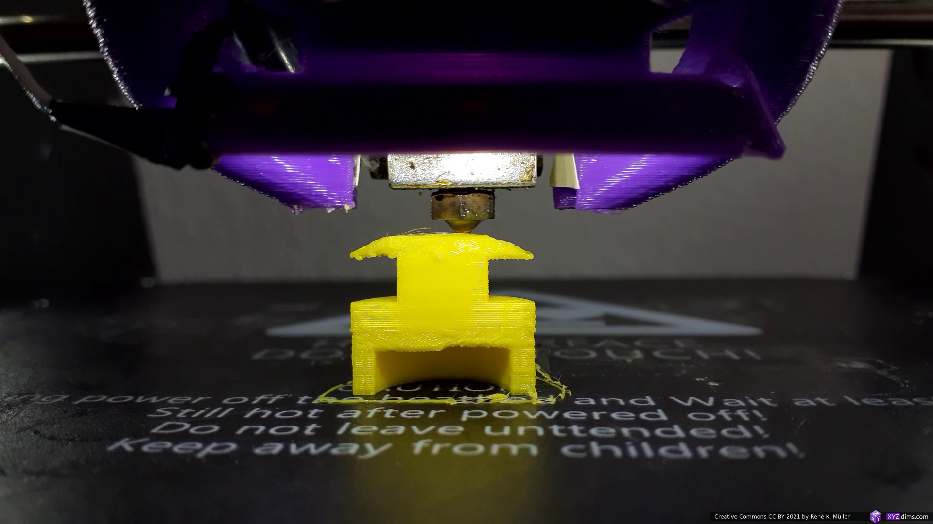
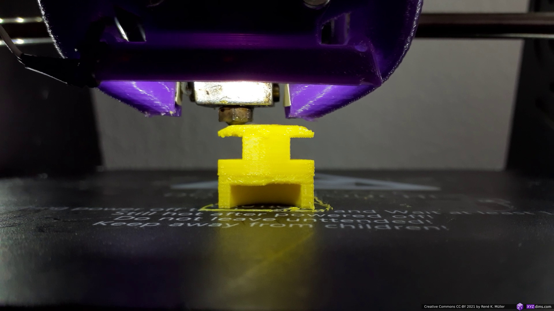
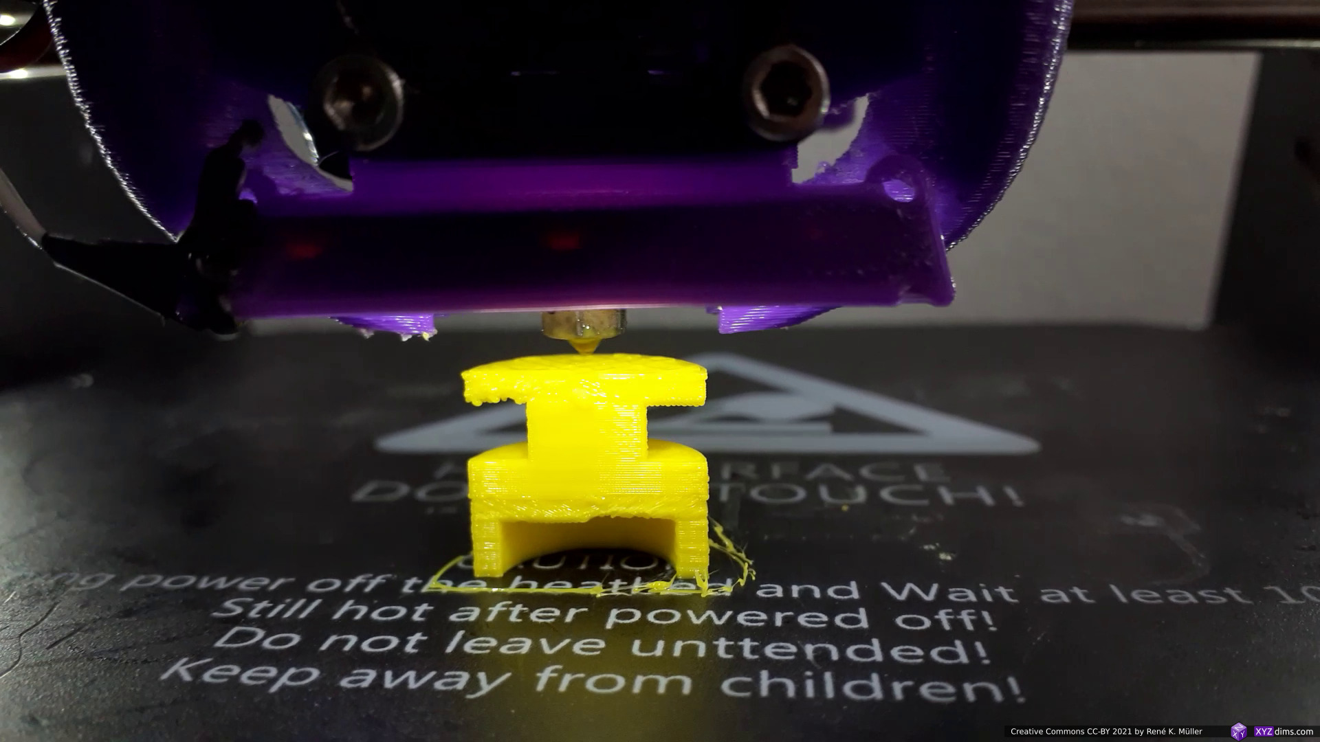
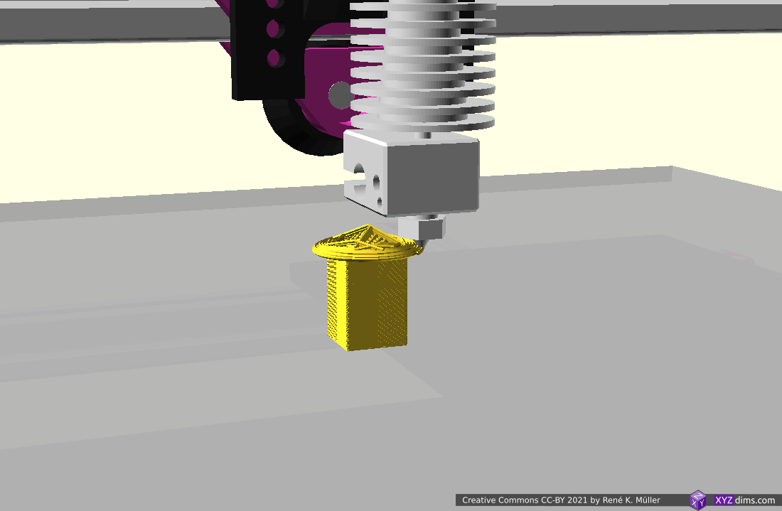
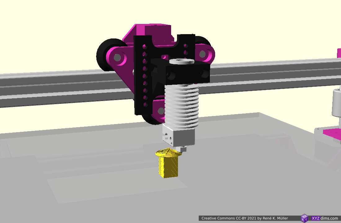
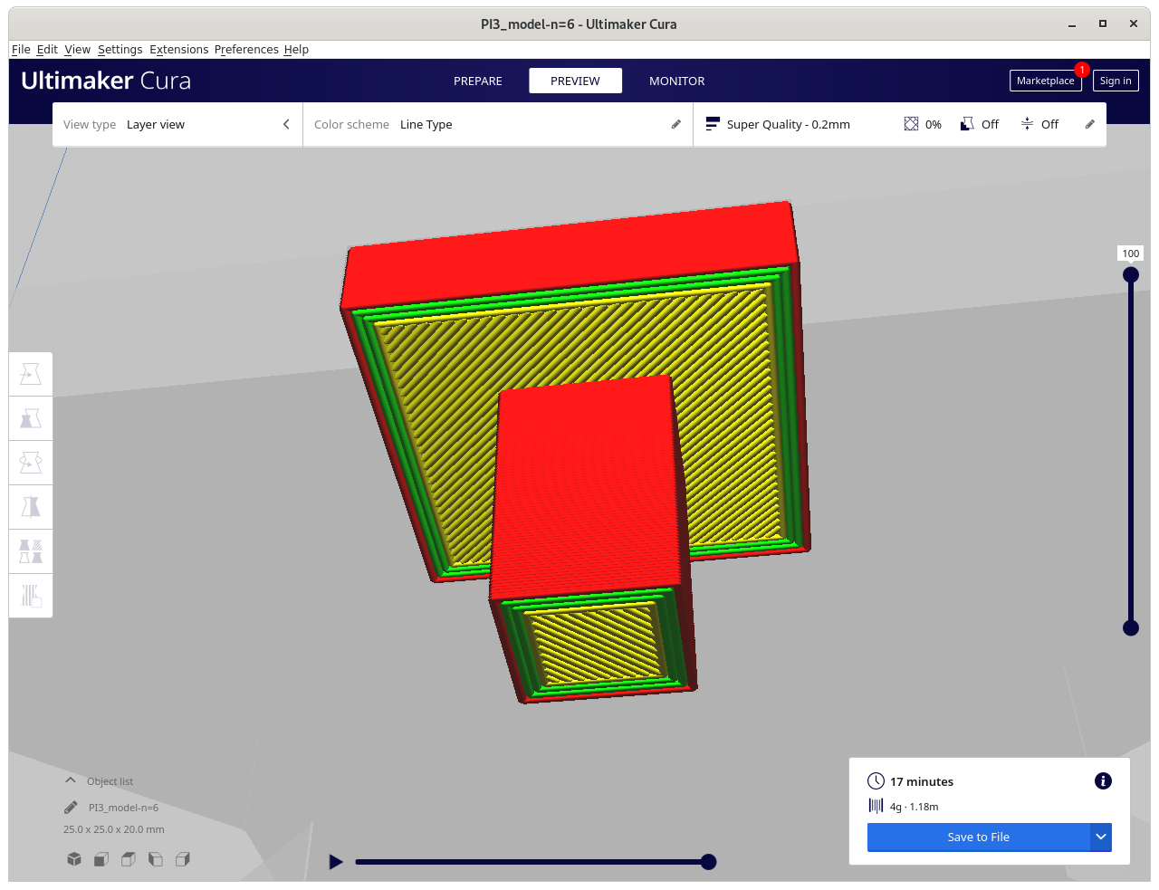
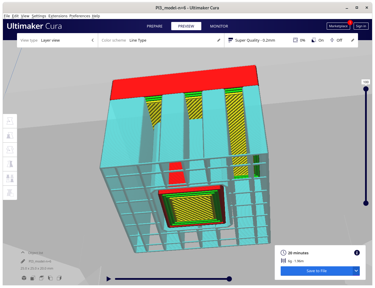
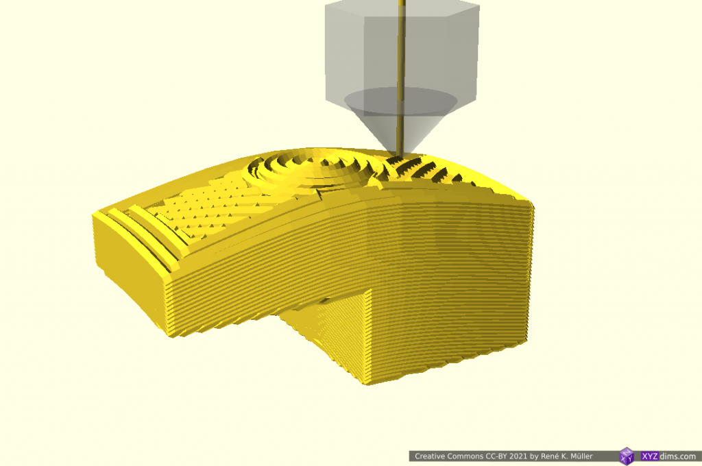
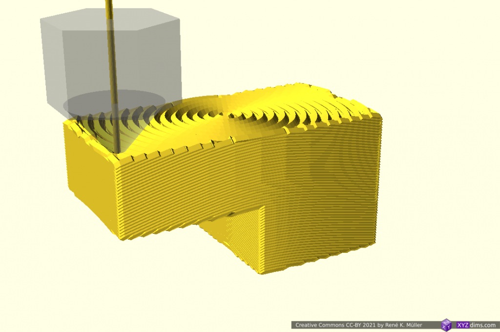
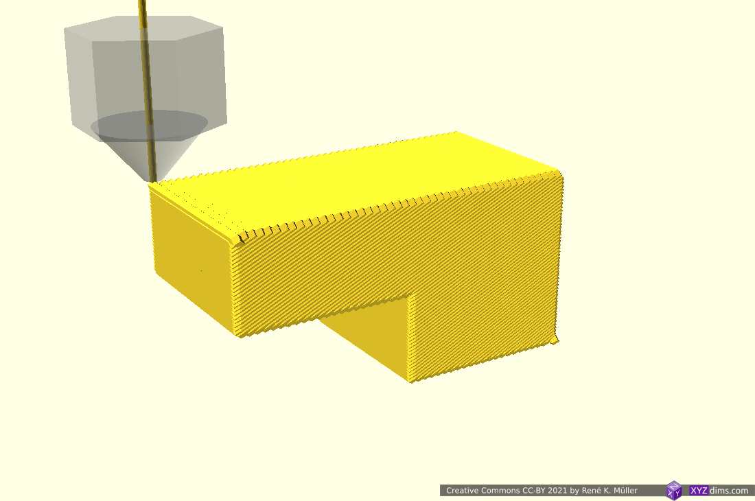
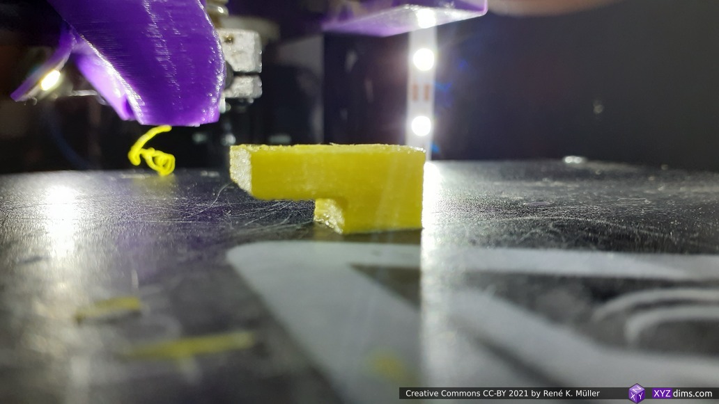
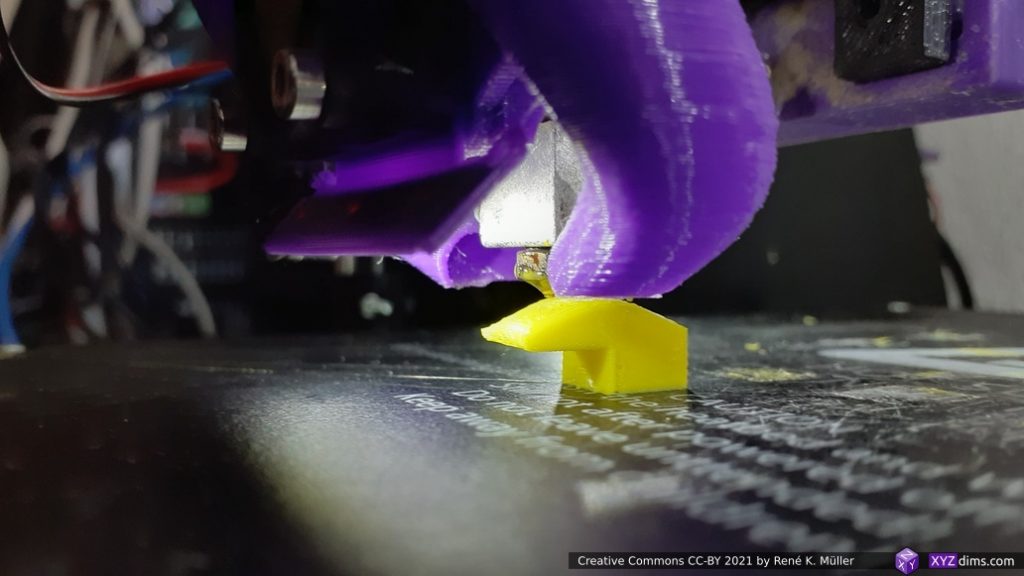
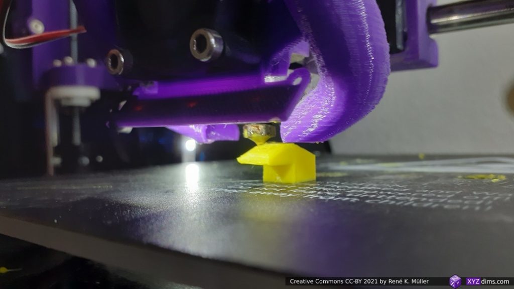
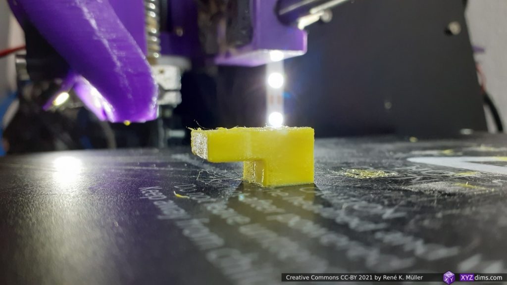
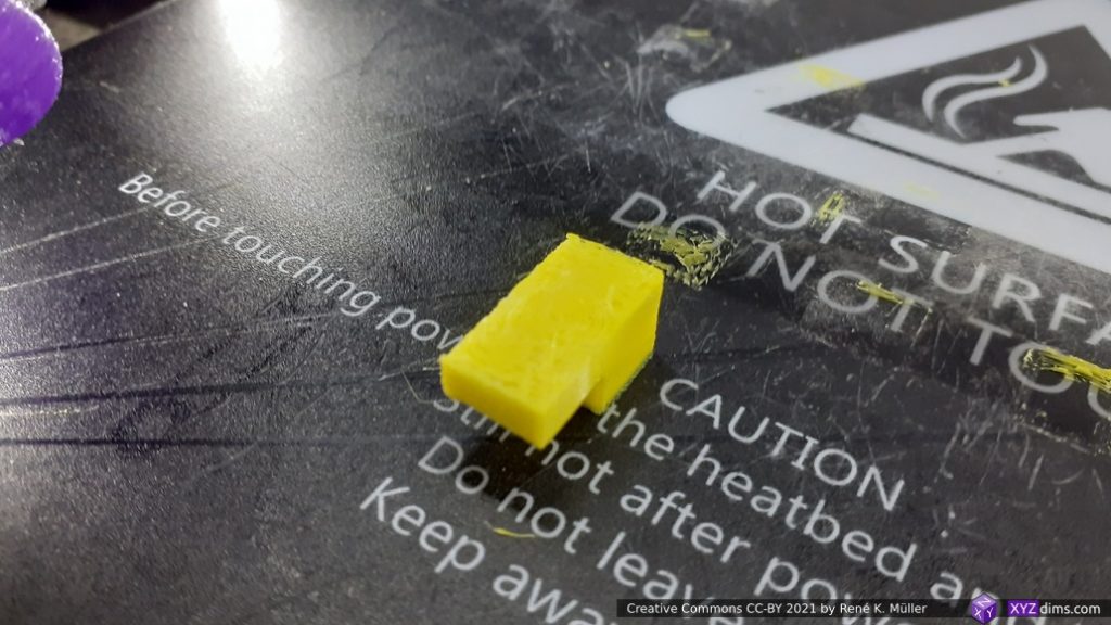
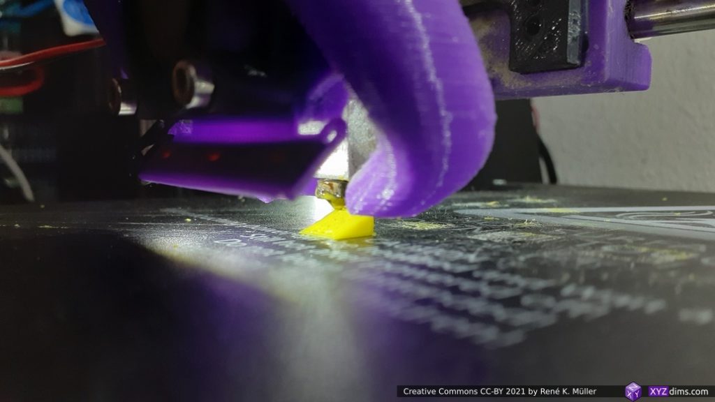
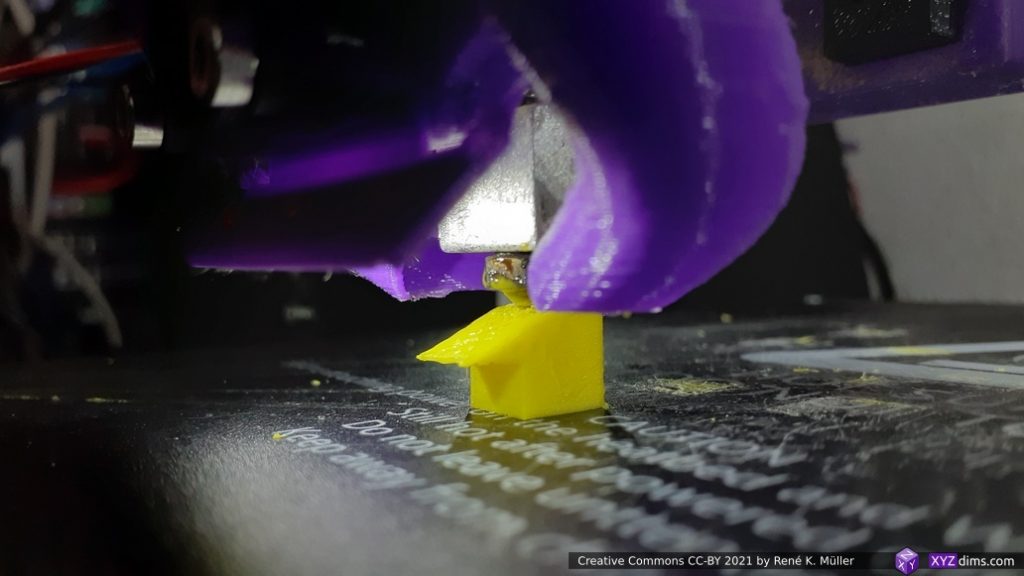
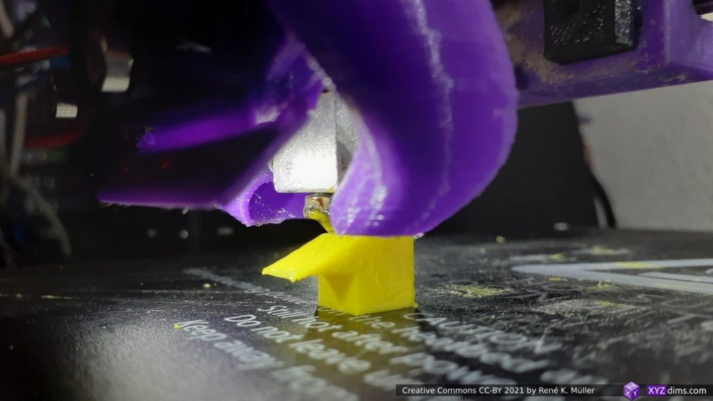
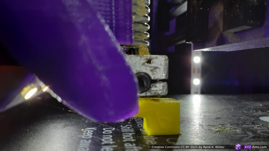
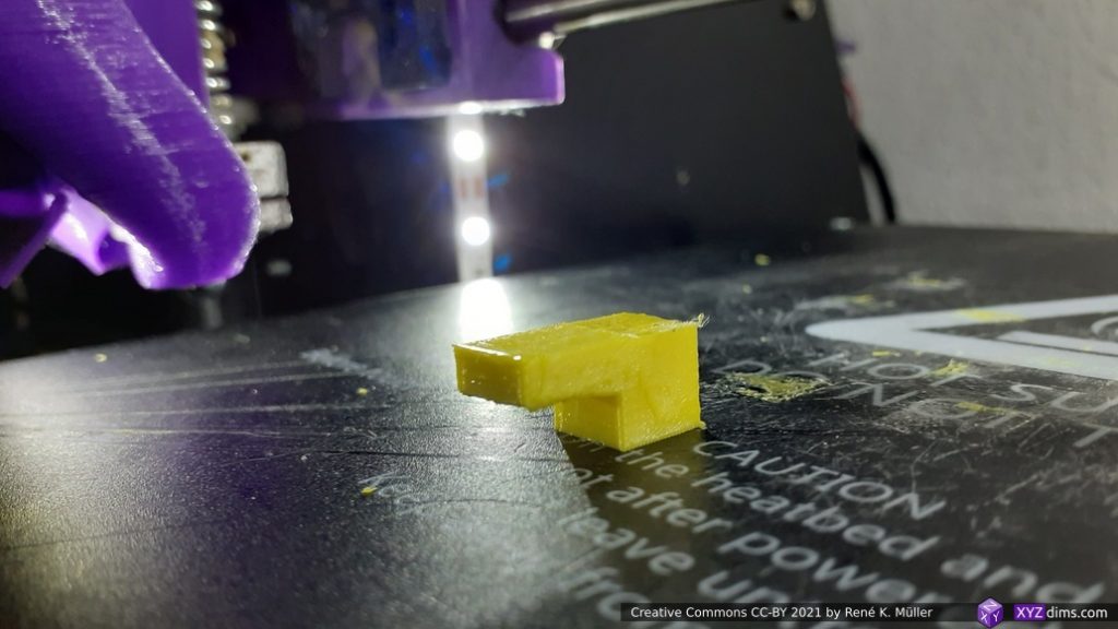
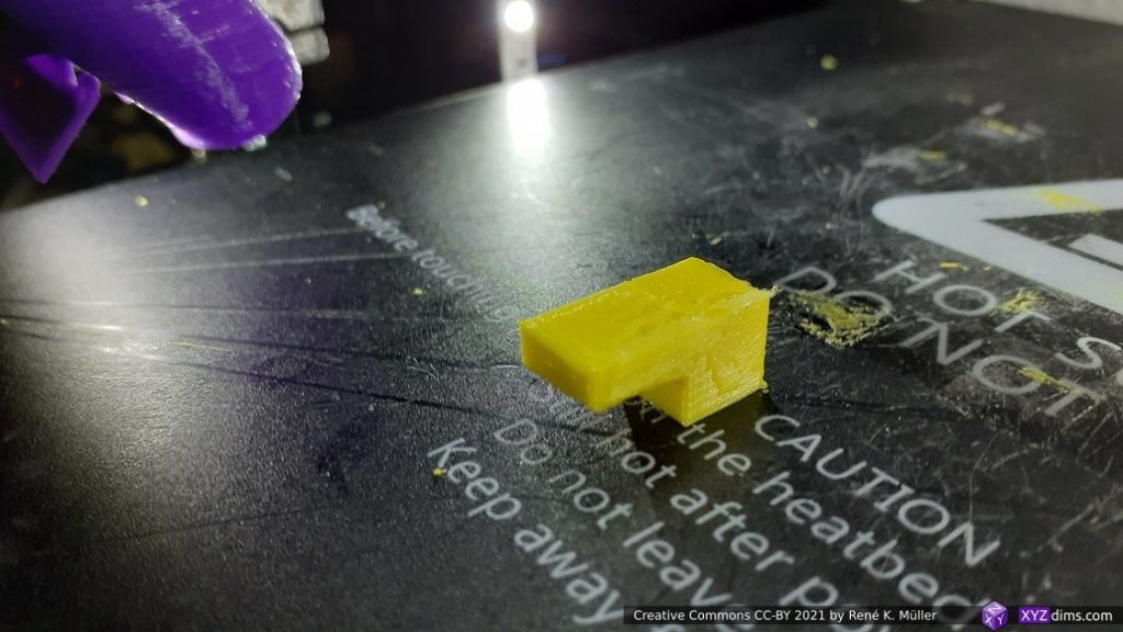
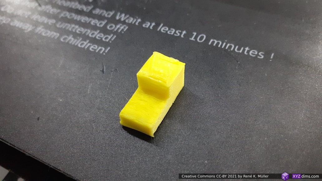
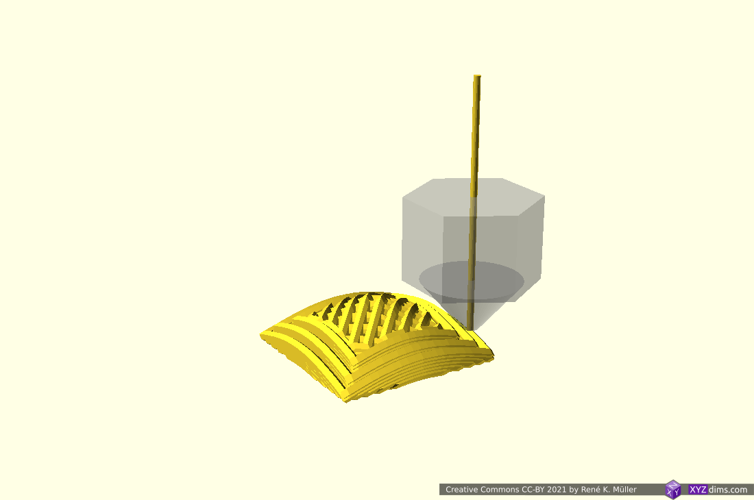
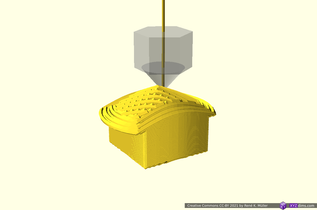
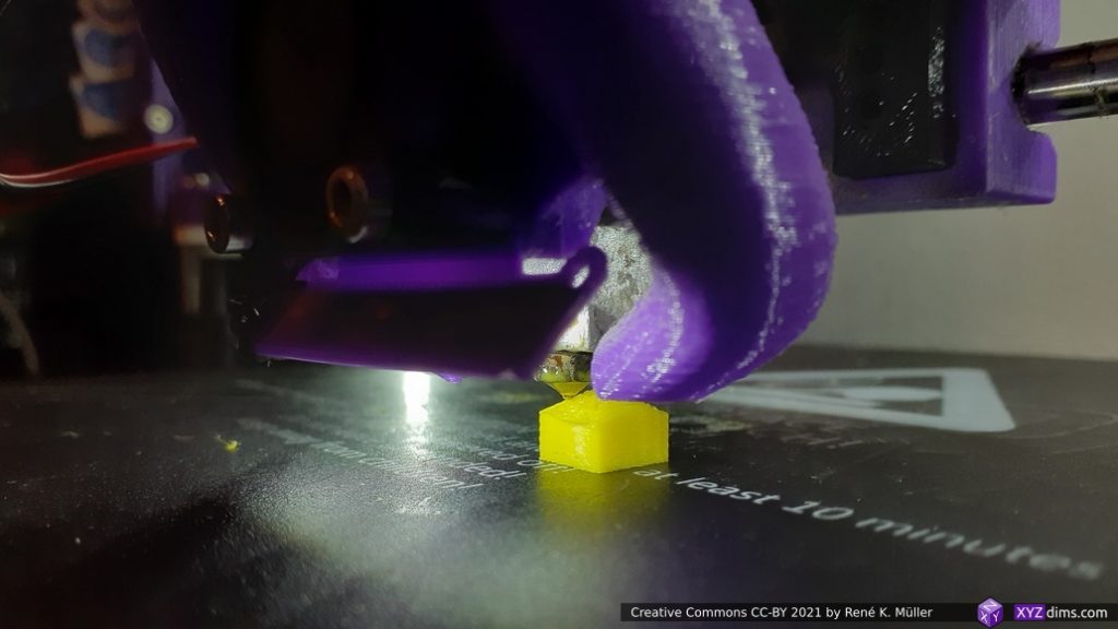
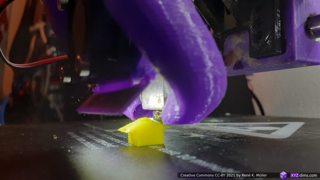
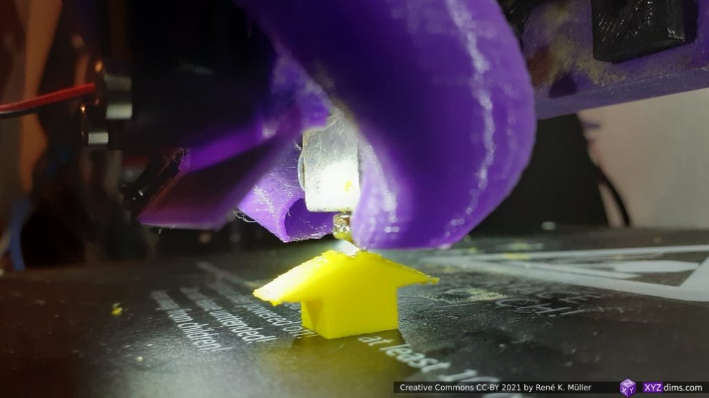
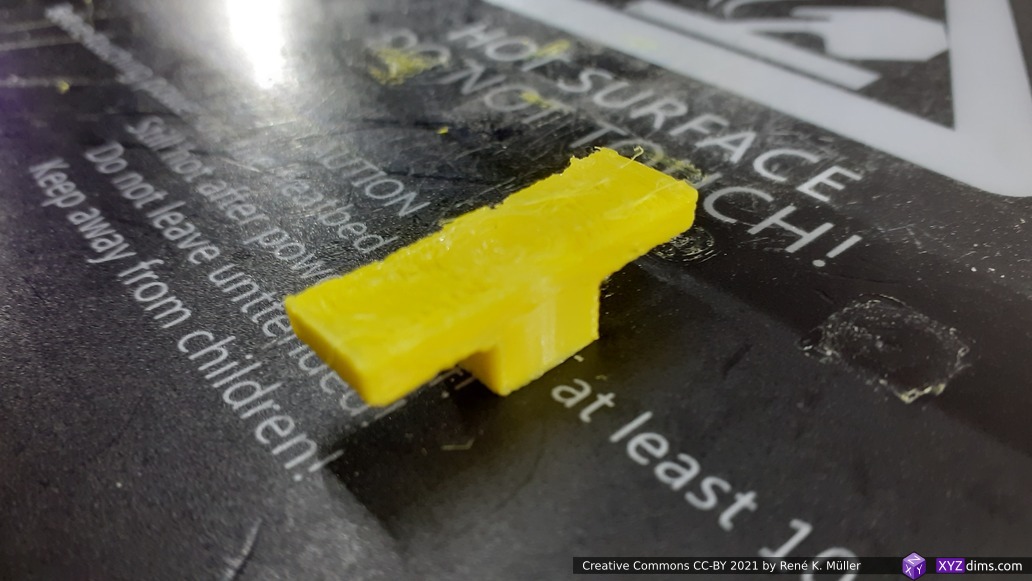
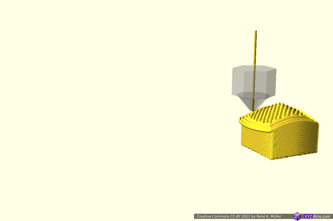
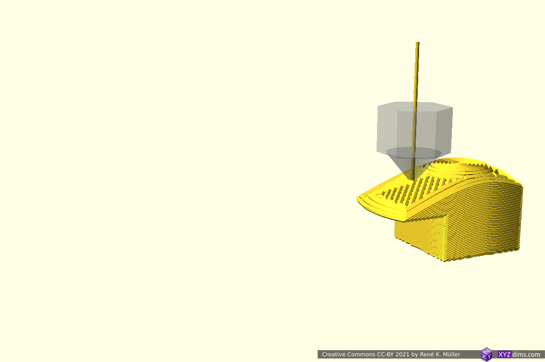
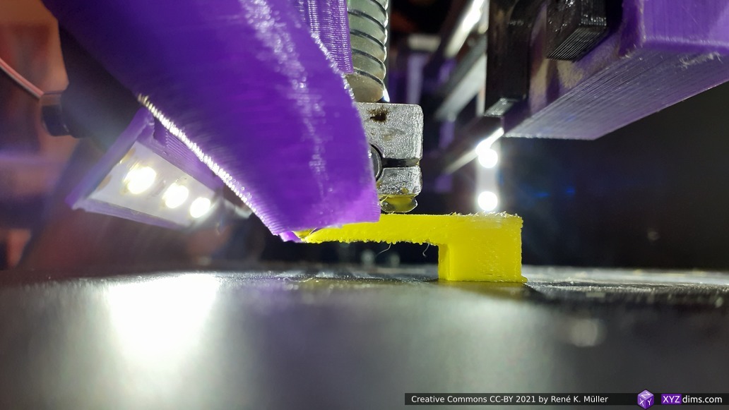
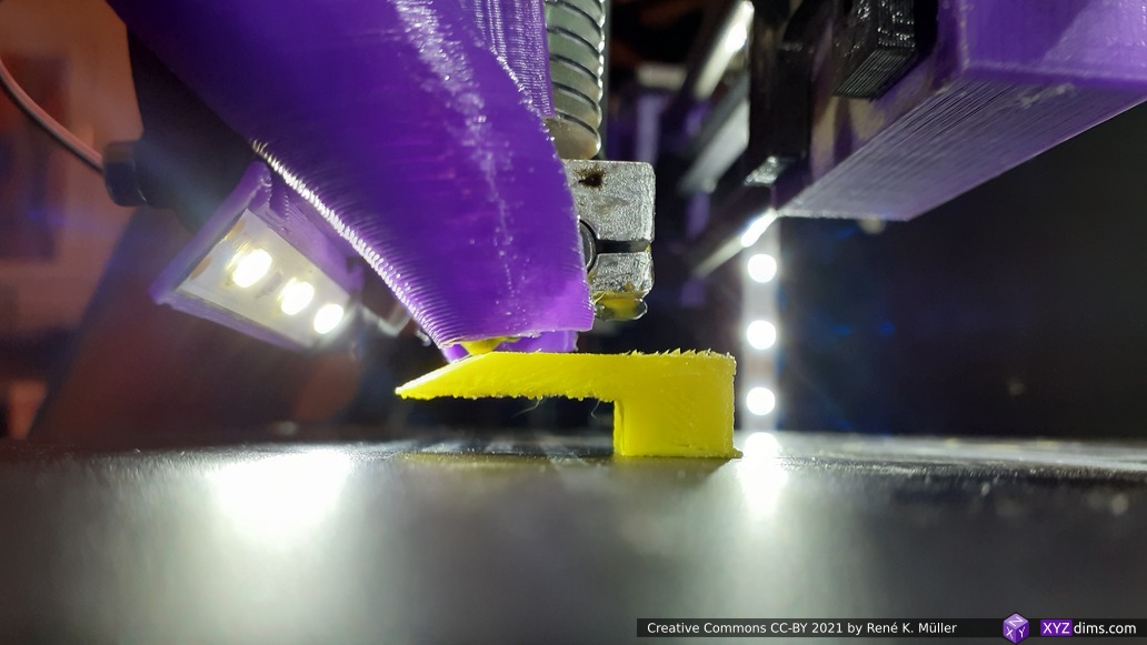
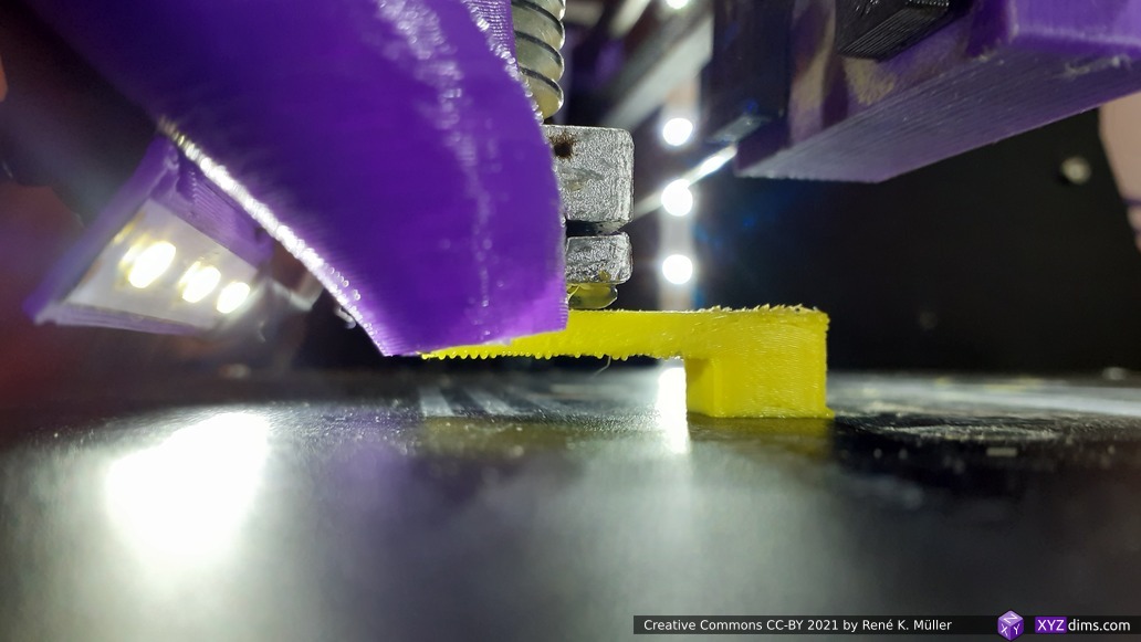
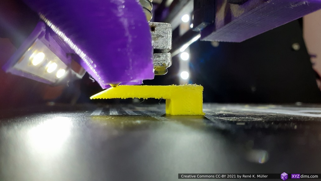
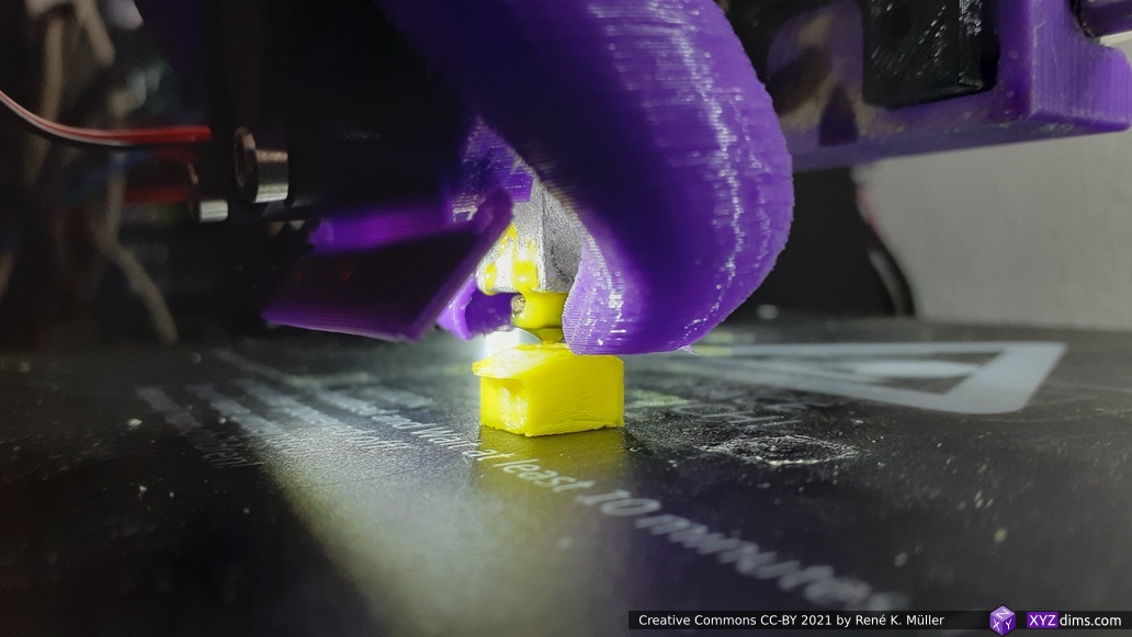
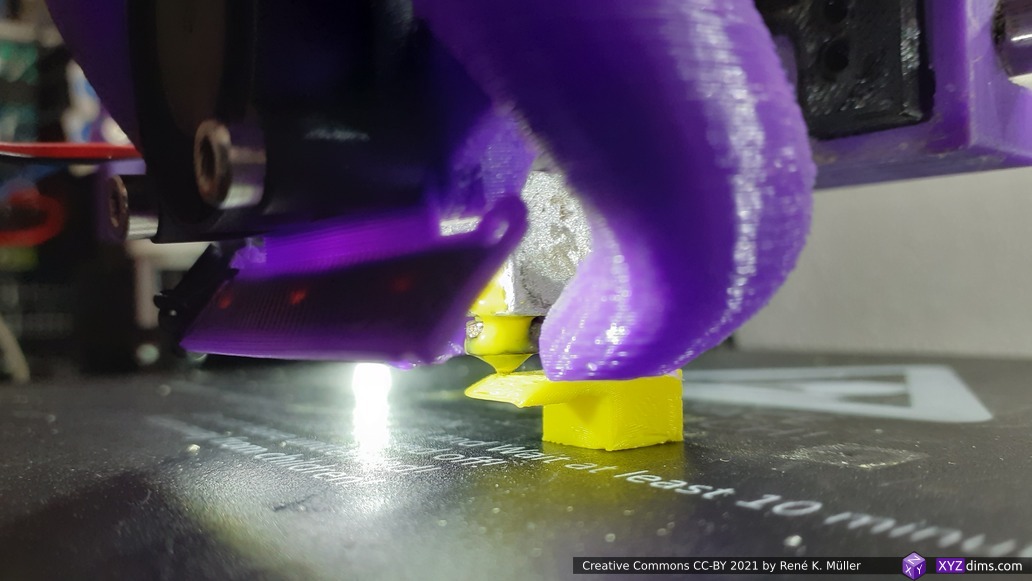
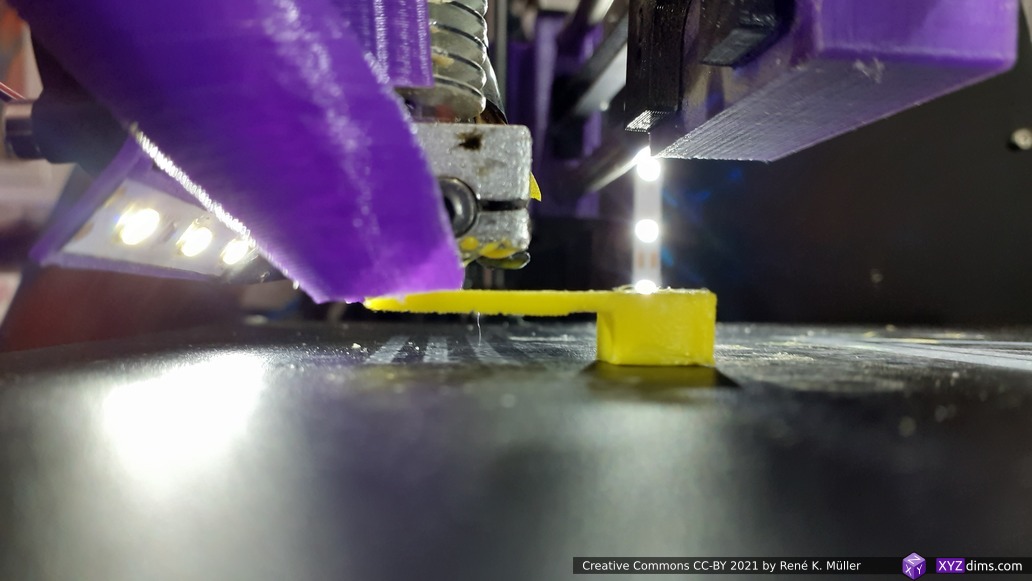
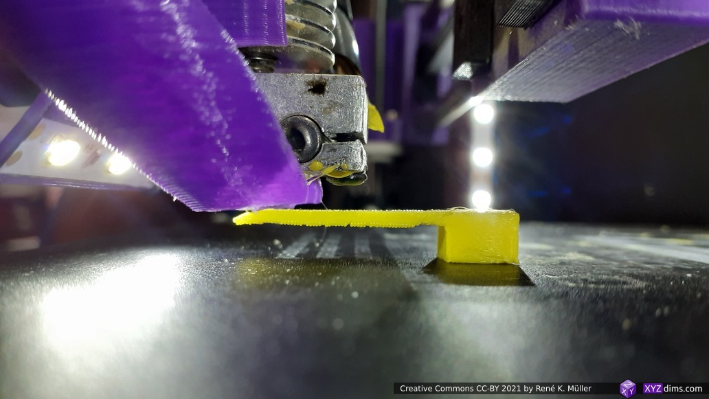
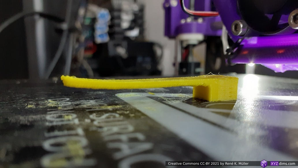
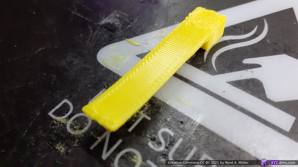
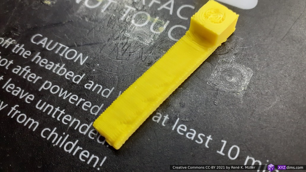
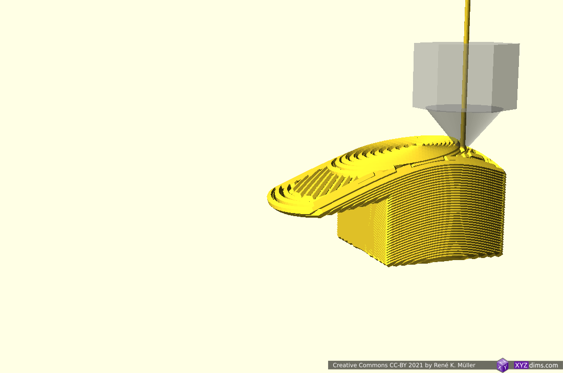
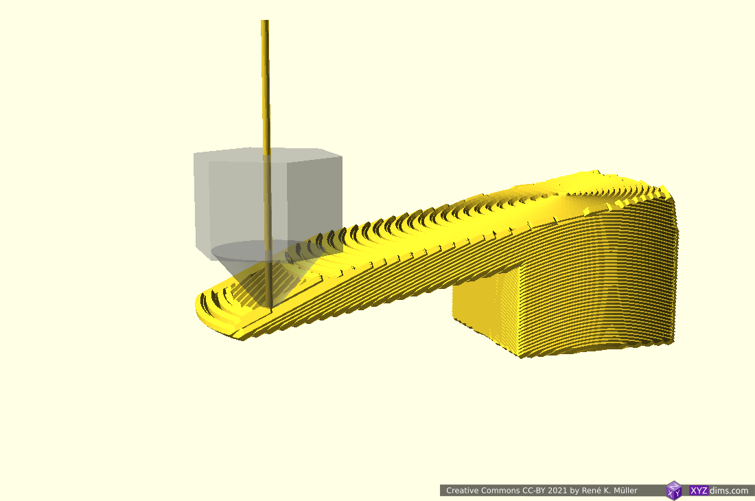
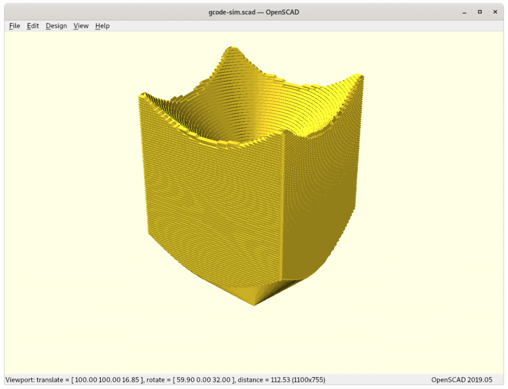
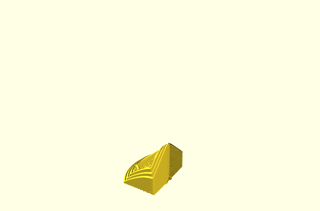
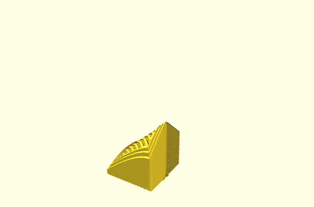
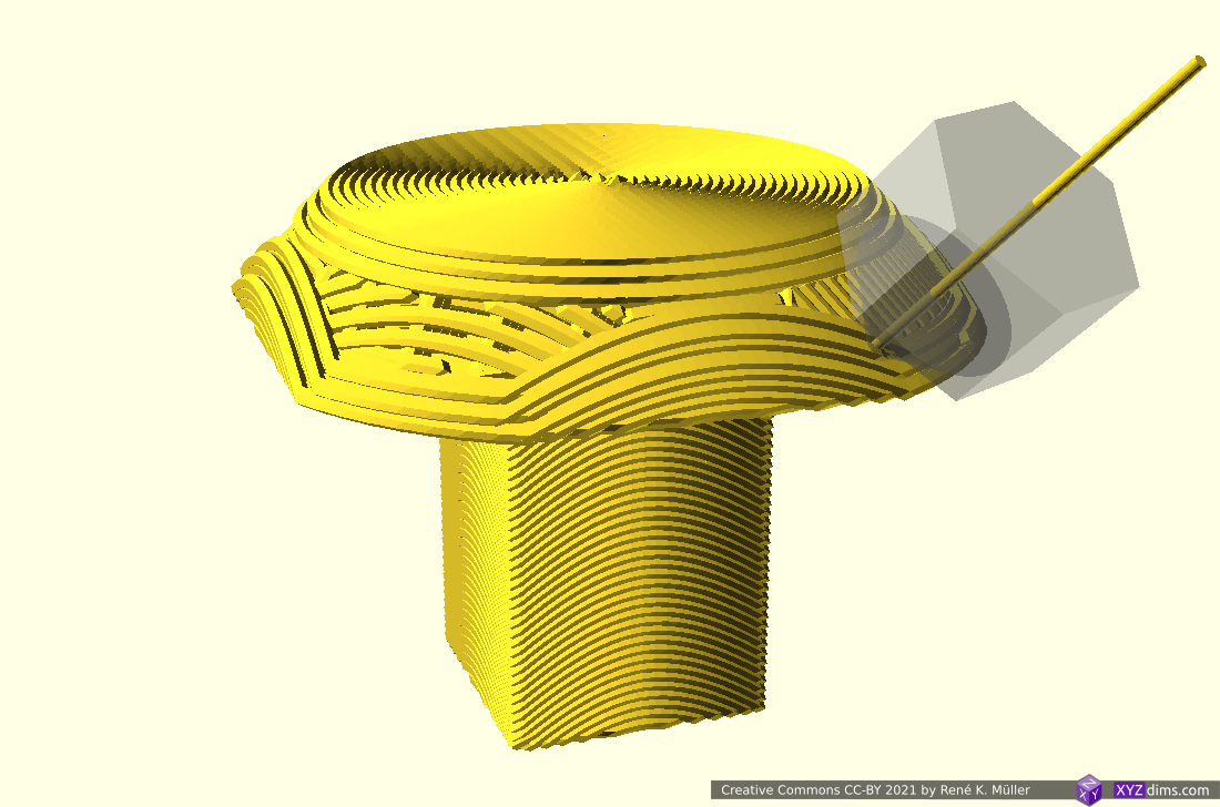
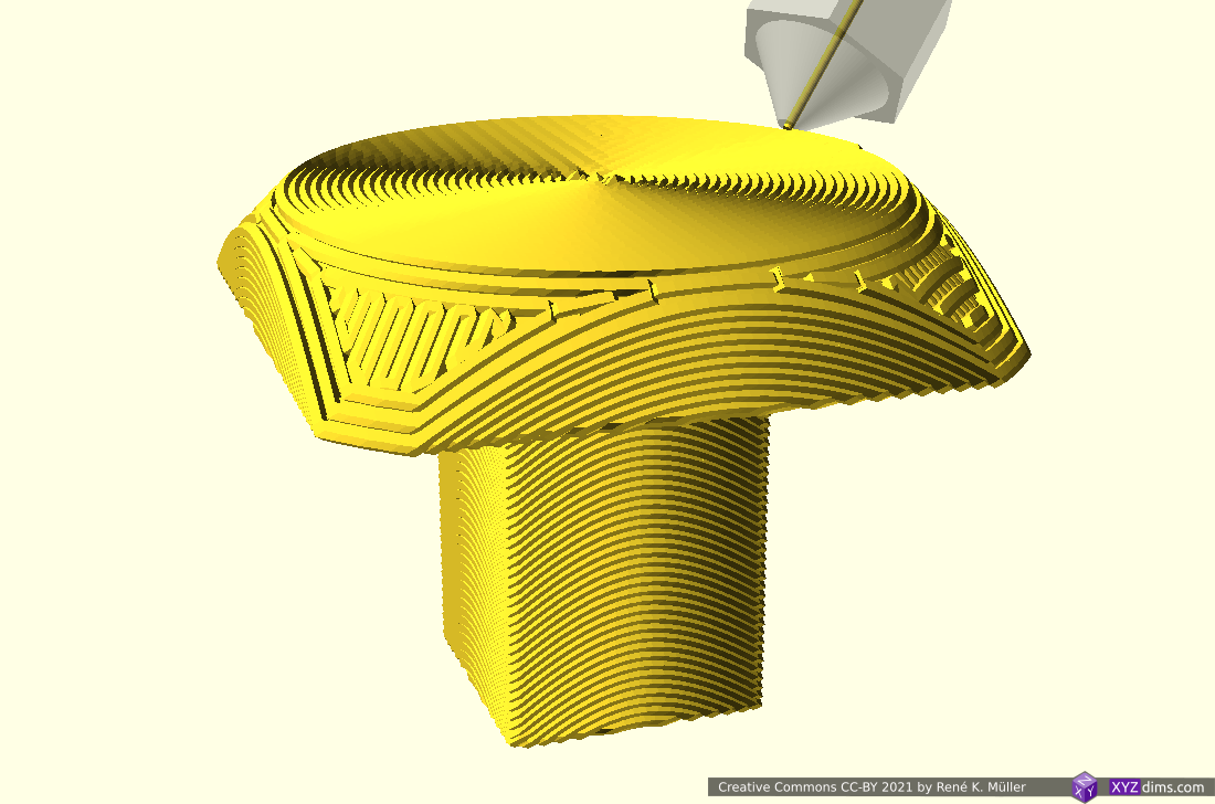
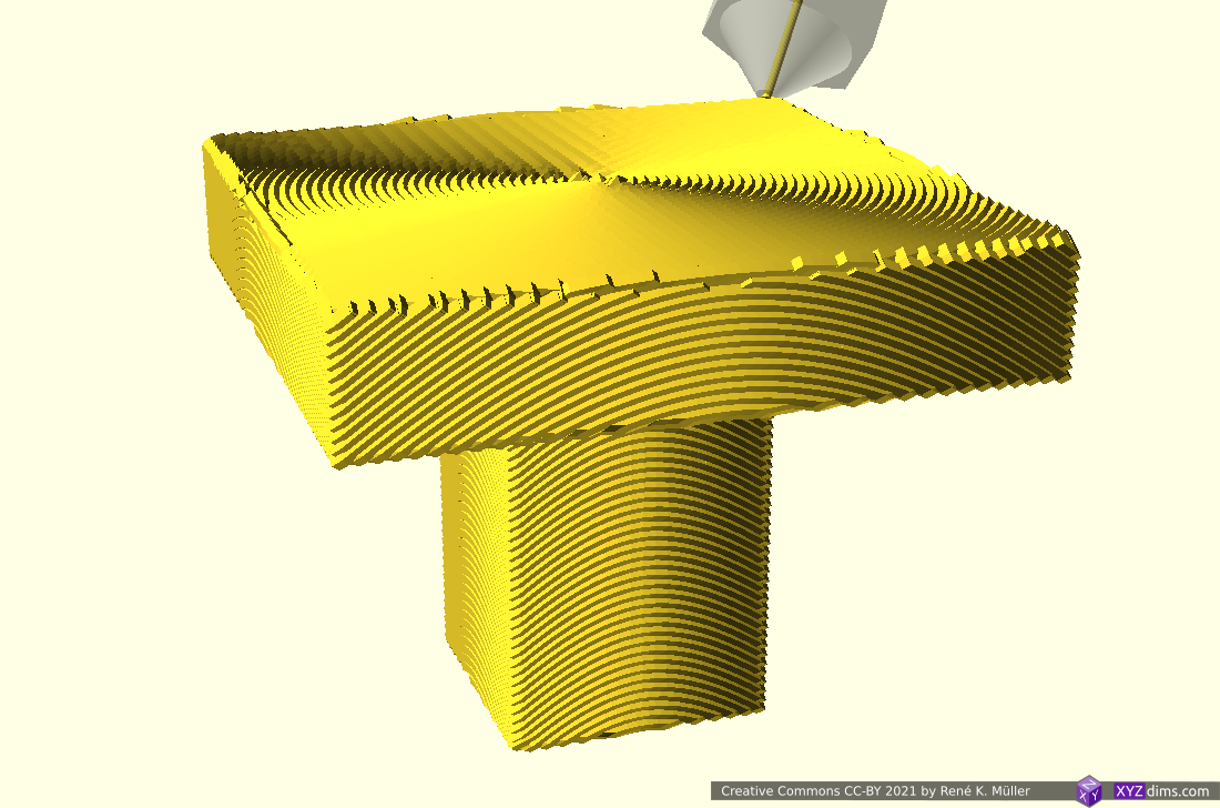
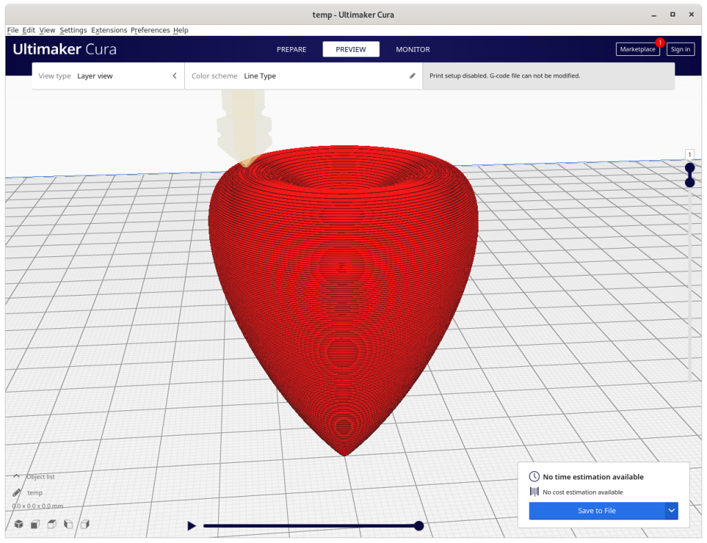
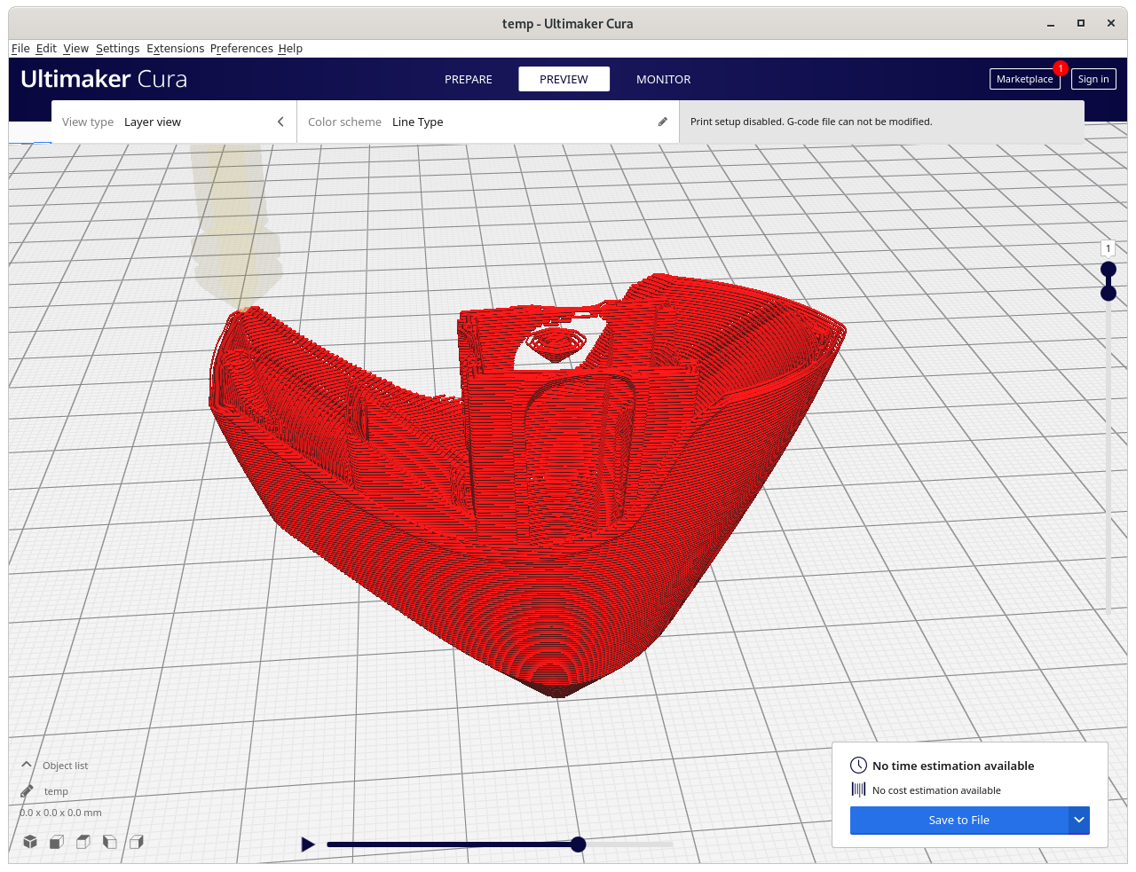
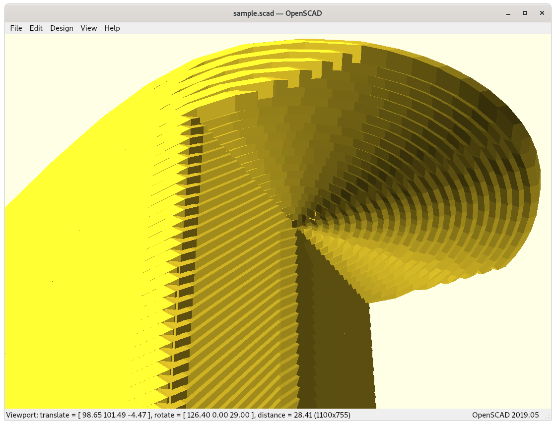
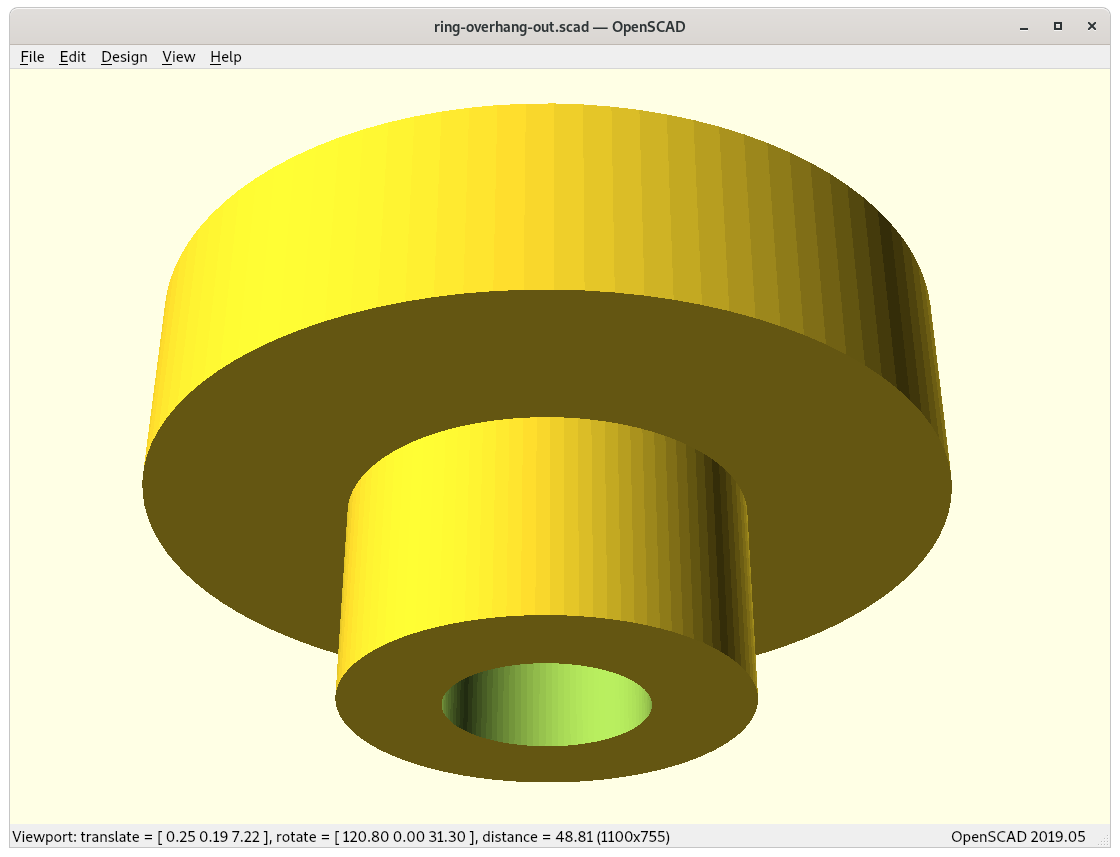
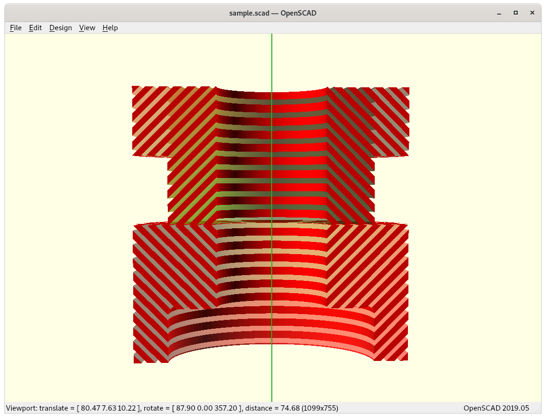
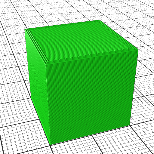
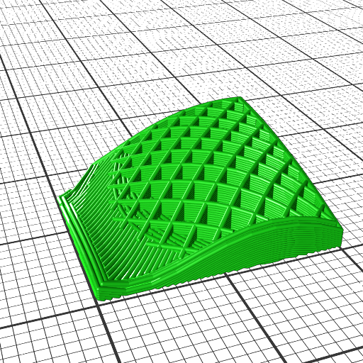
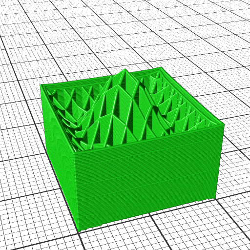
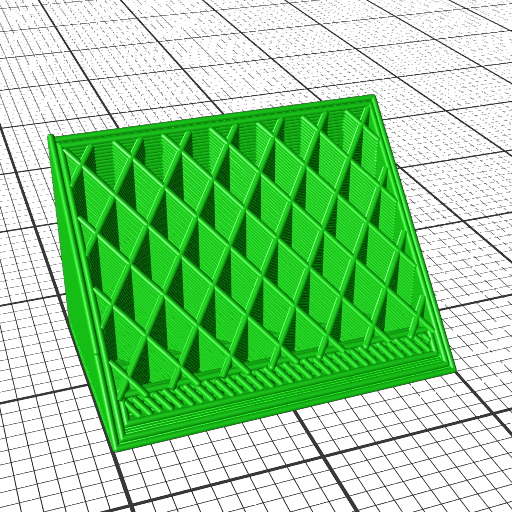
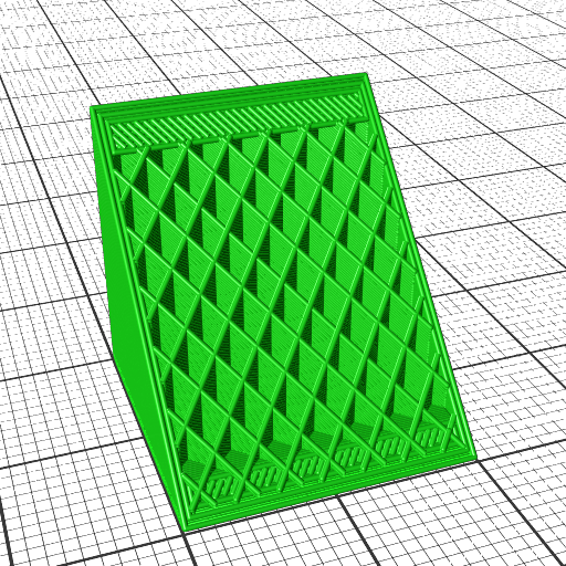
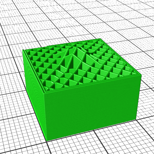
Non-planar Printed Wave-like Sliced 20mm Cube
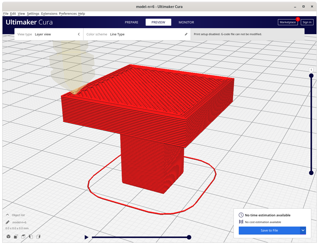
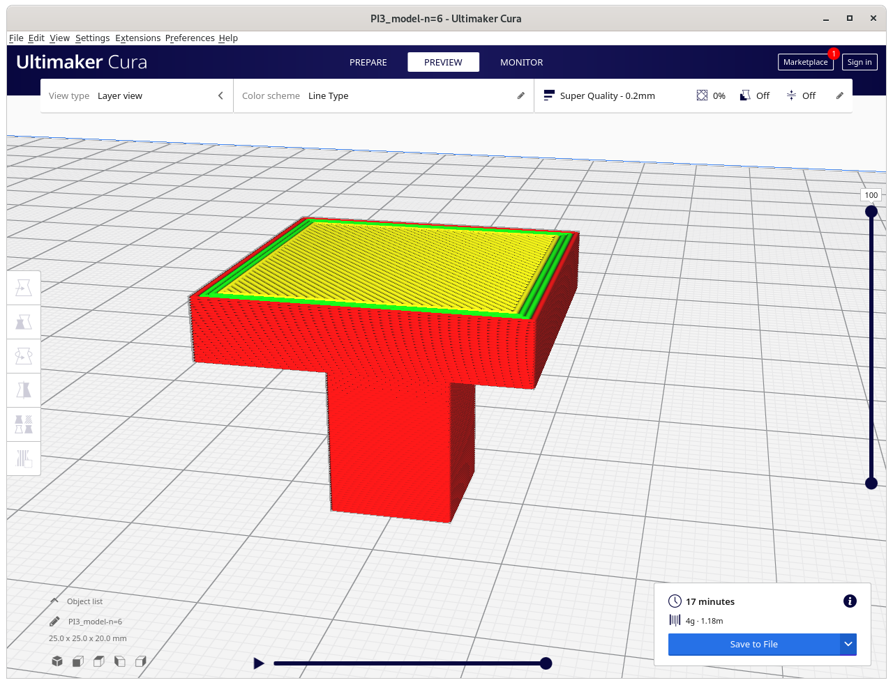
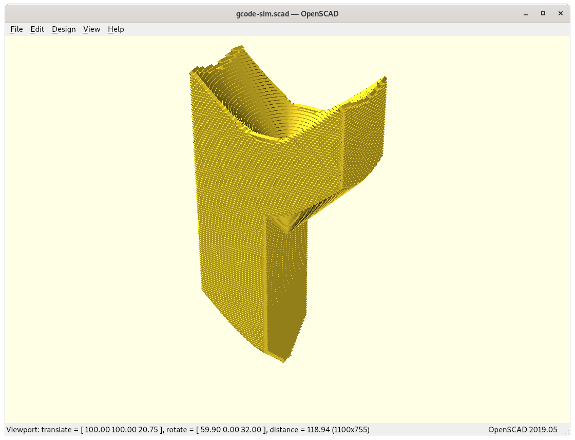
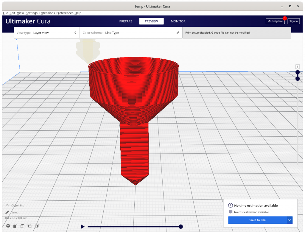
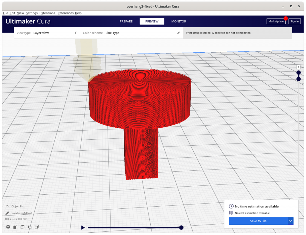
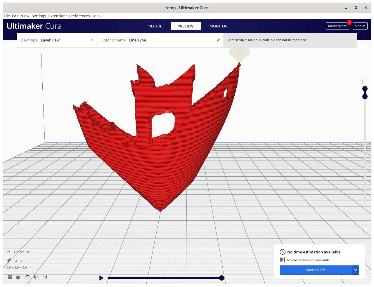
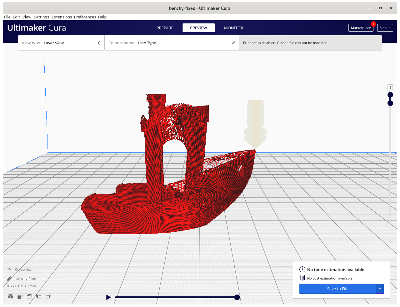
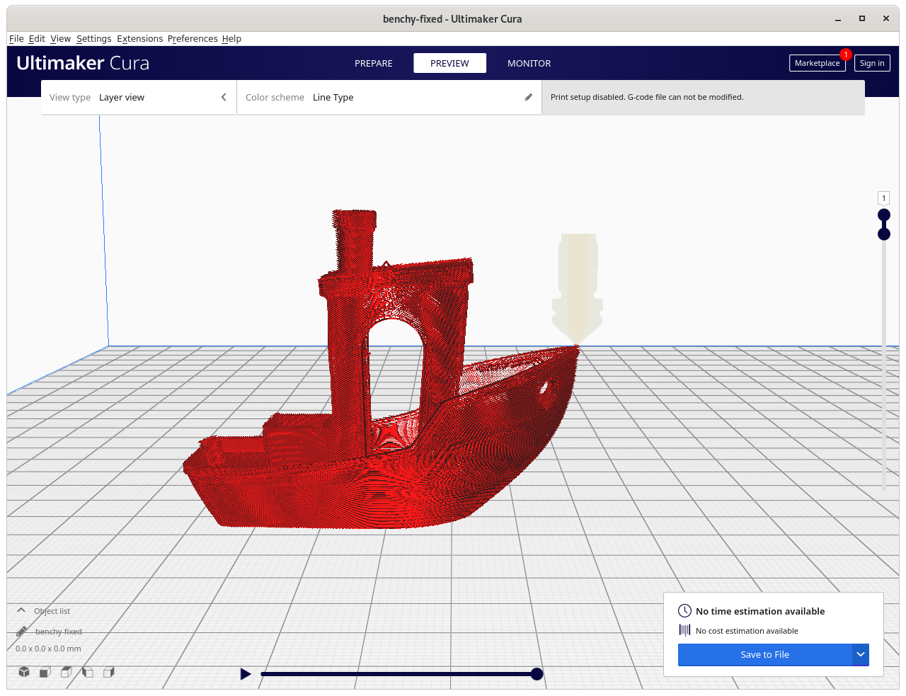
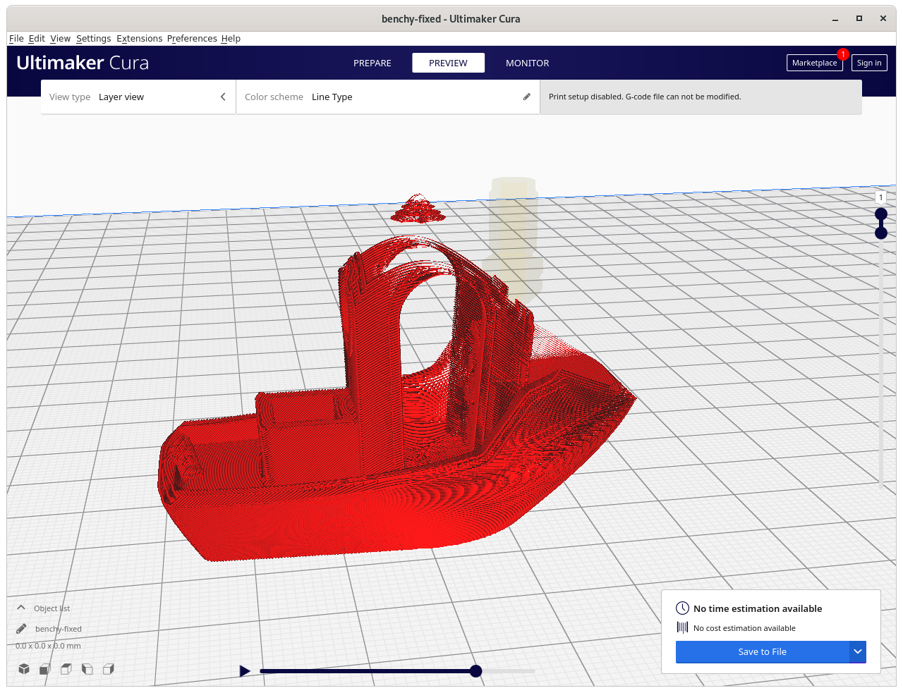
Preview of the complete G-code:
and a brief and fast printing simulation showing the entire print:
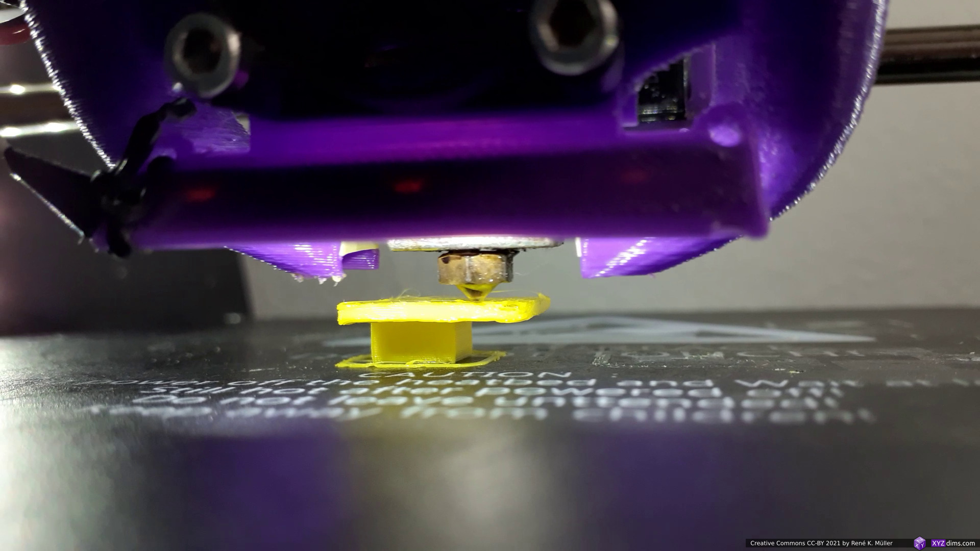
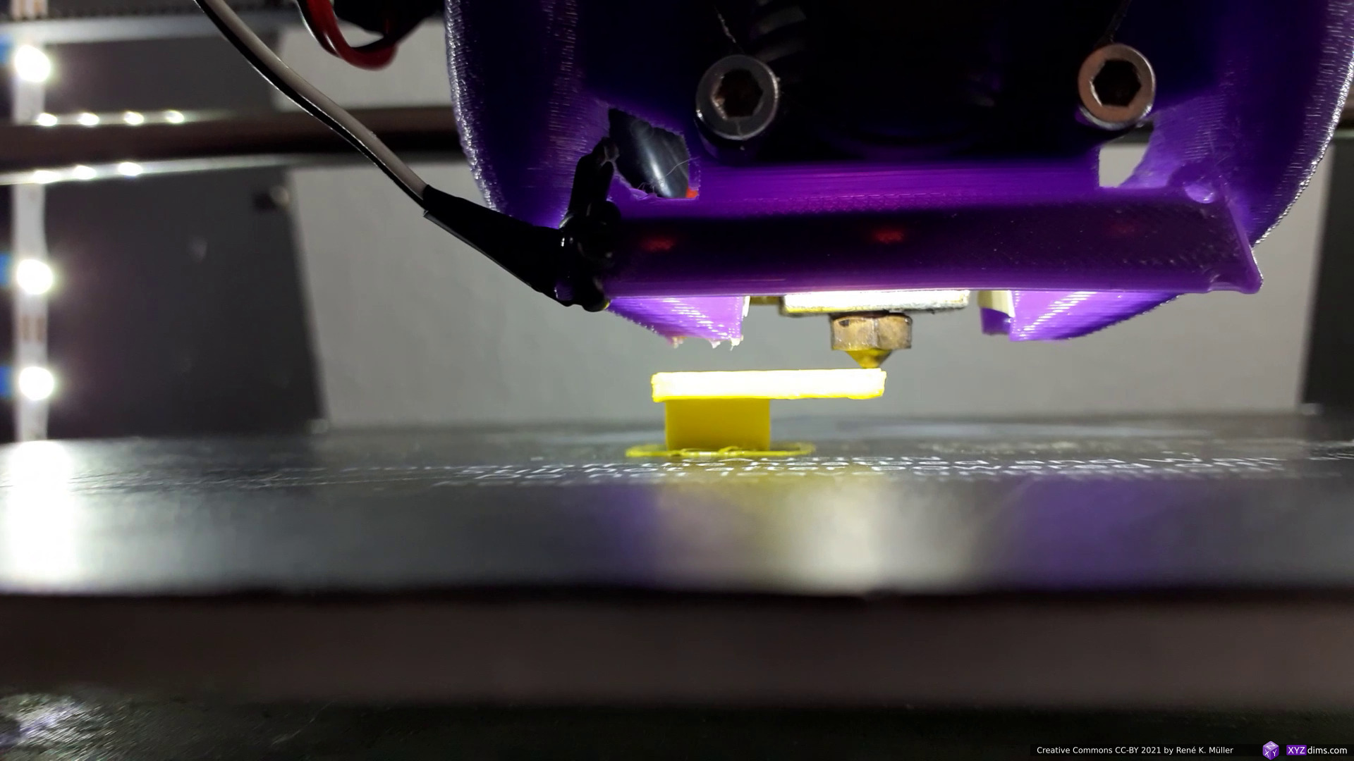
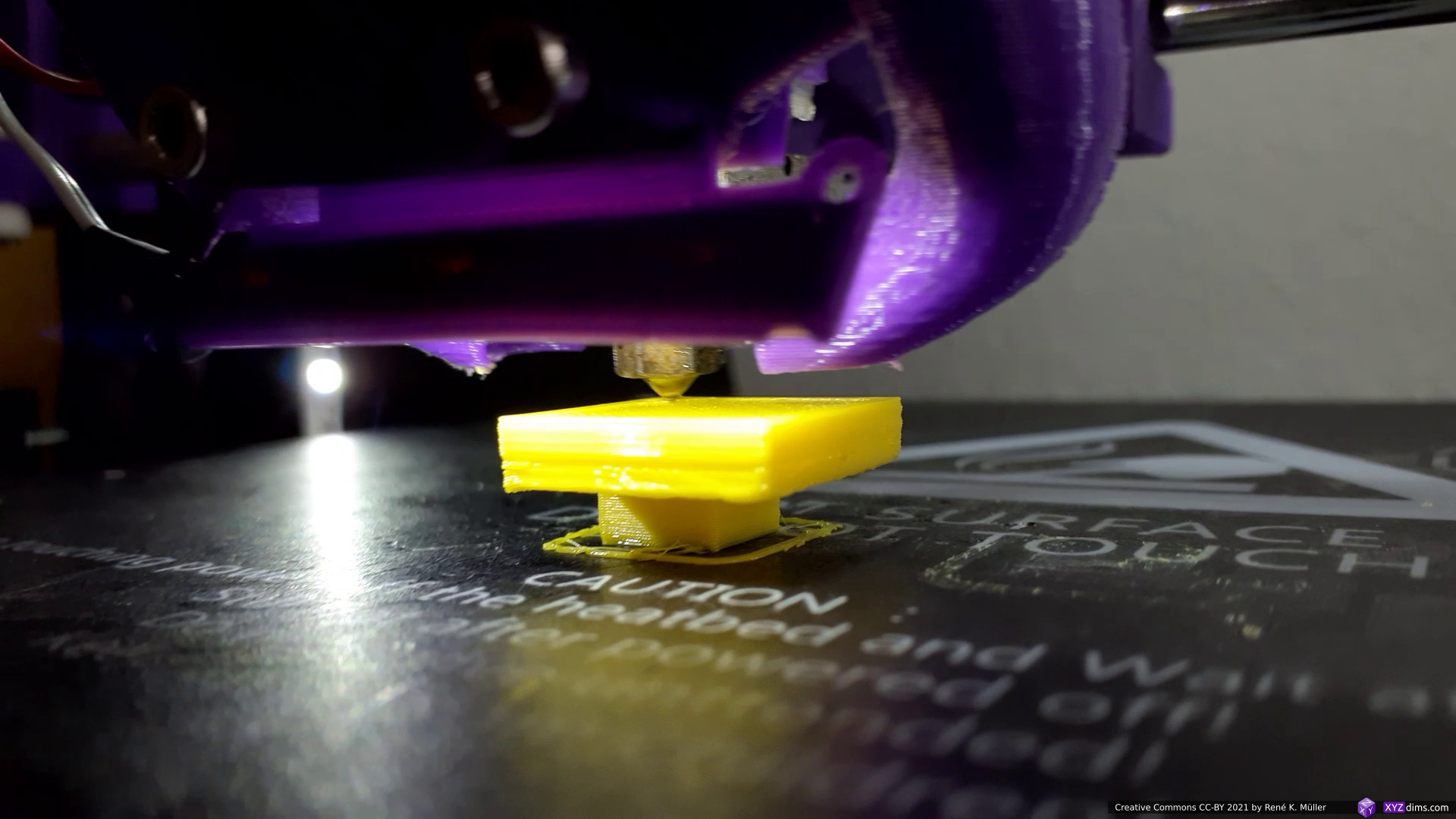
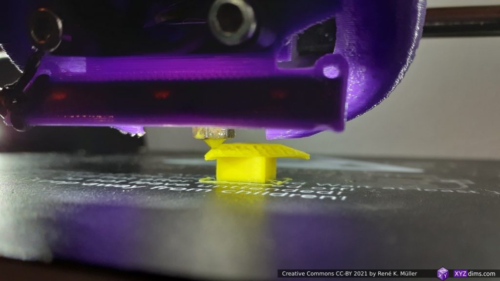
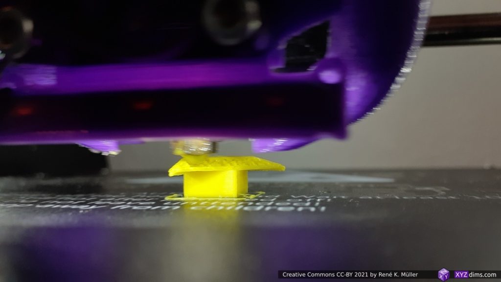
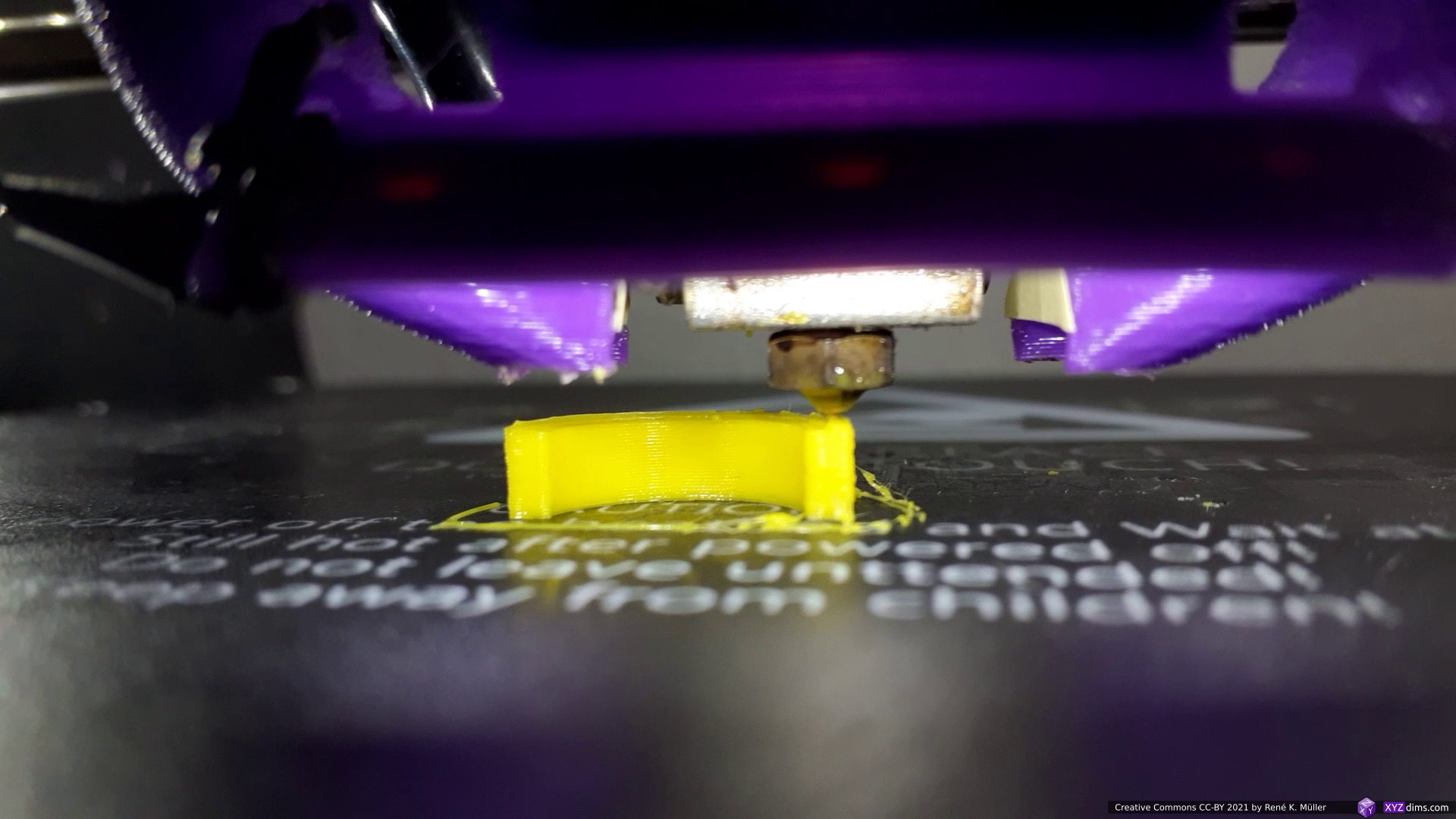
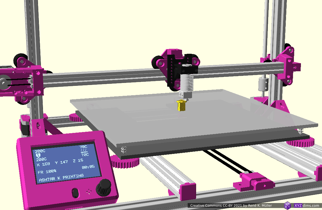
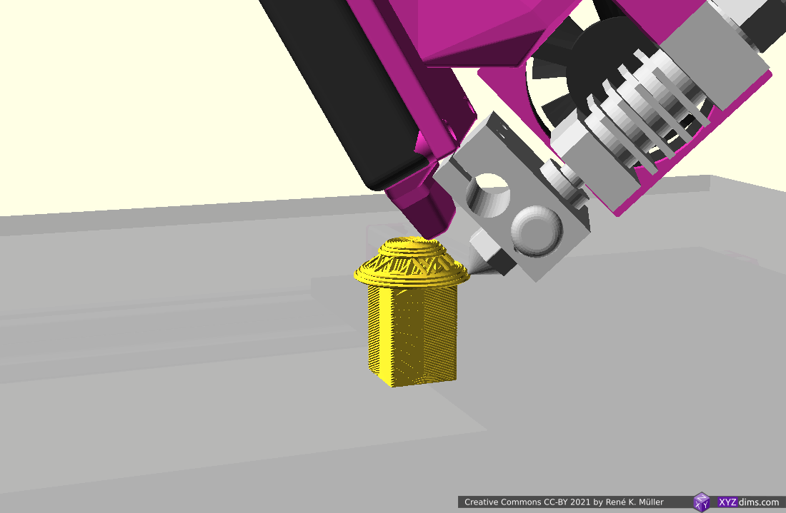
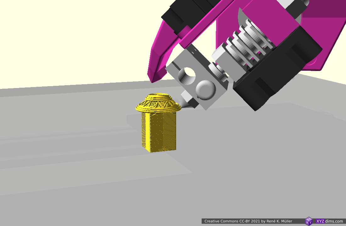
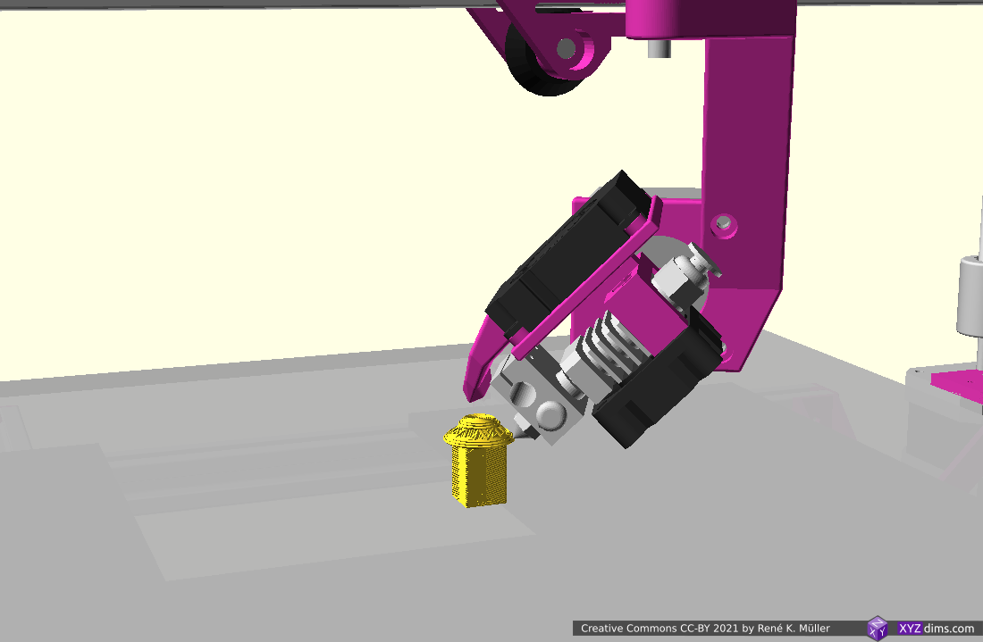
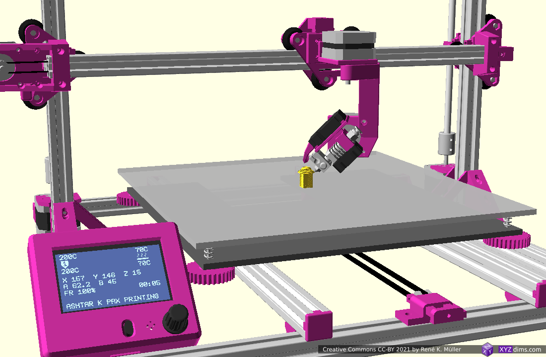
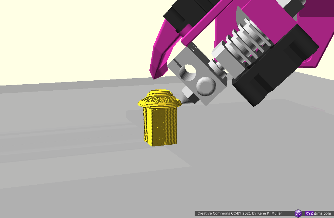
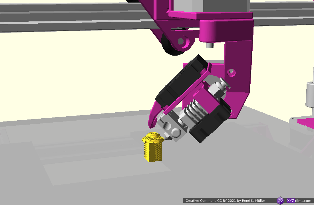
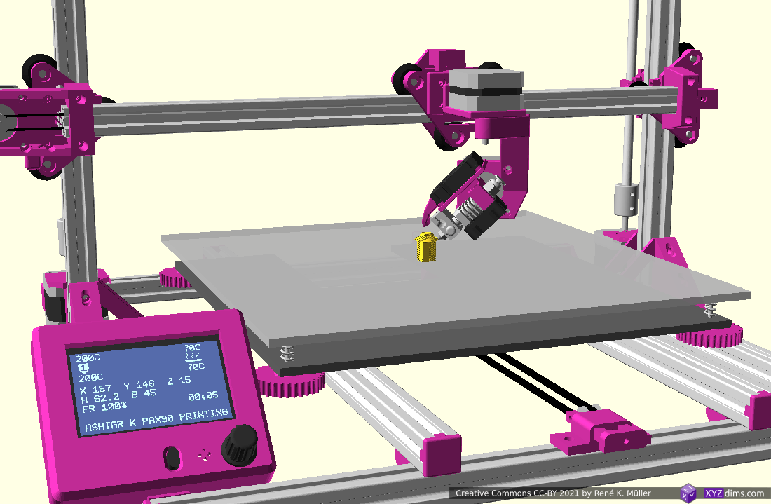
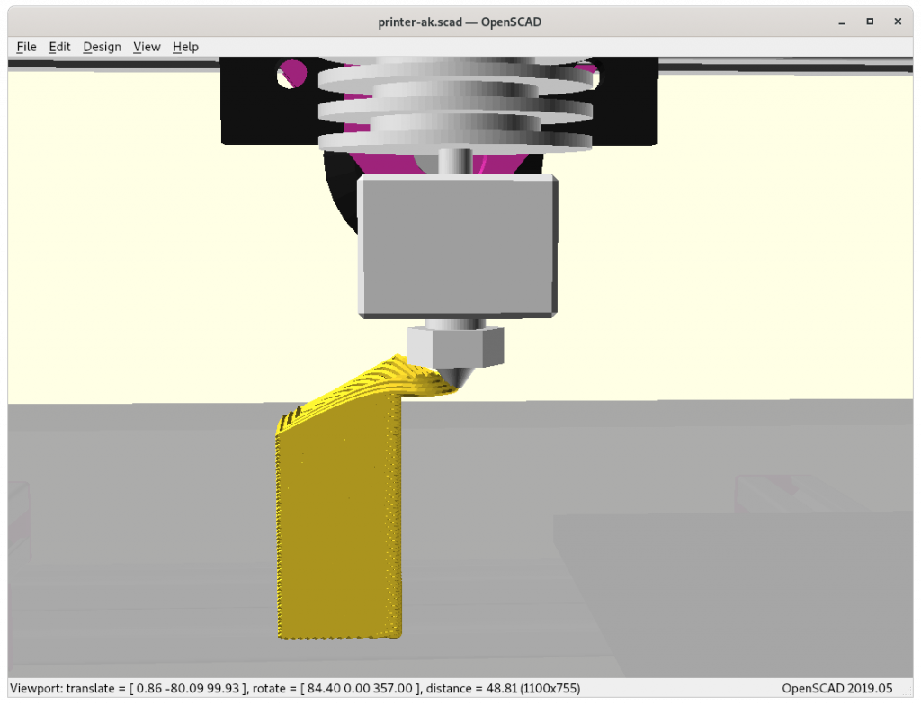
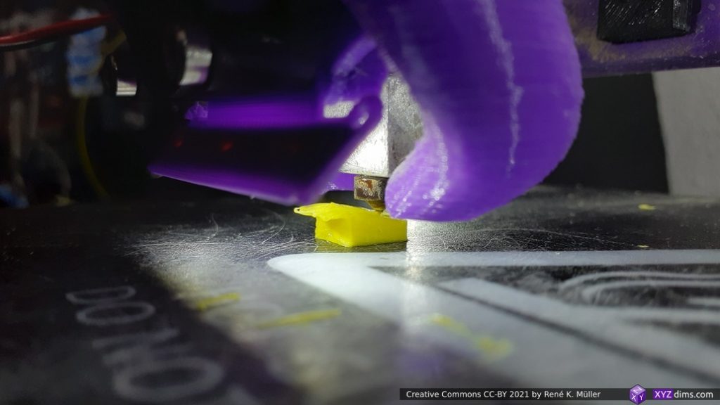
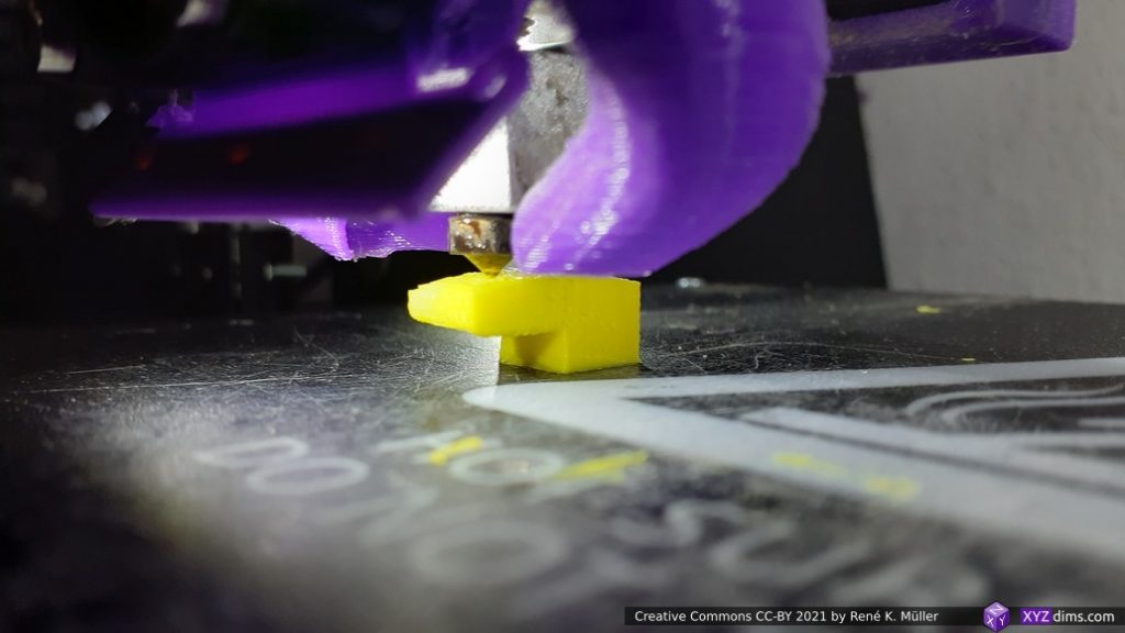
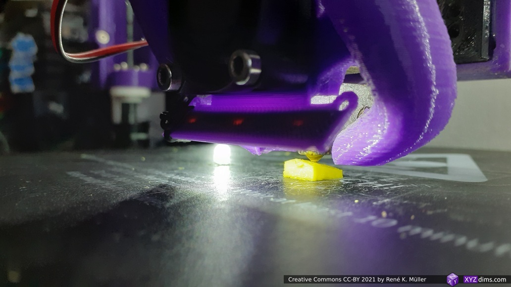
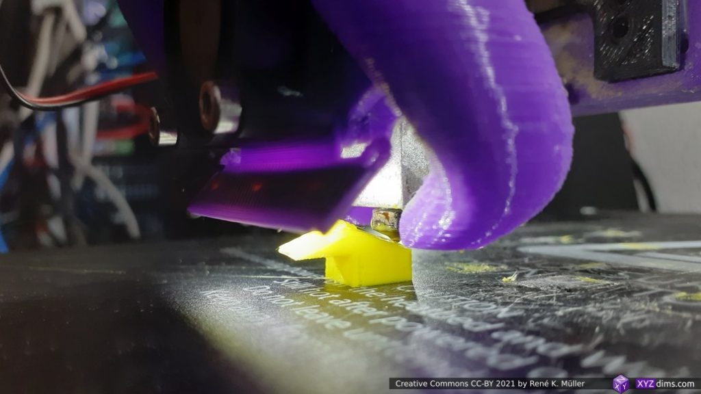
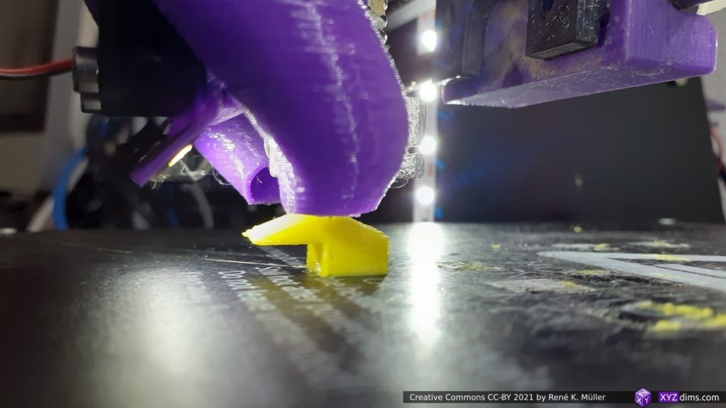
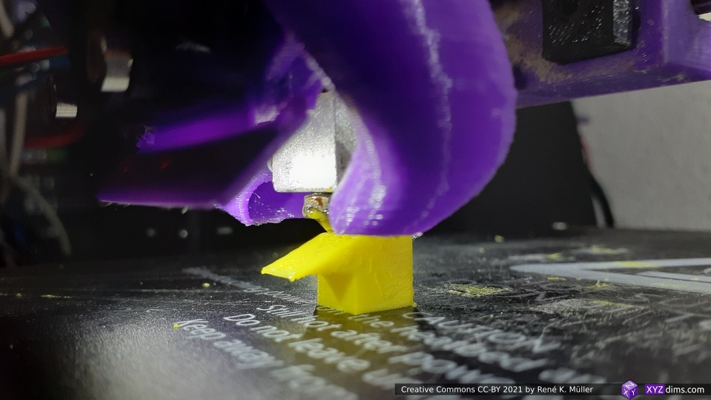
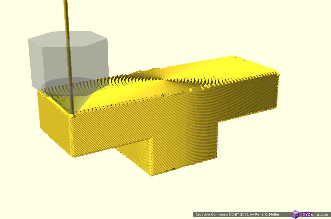
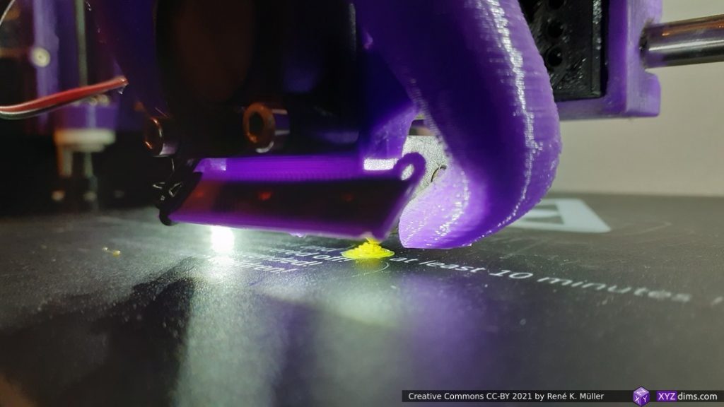
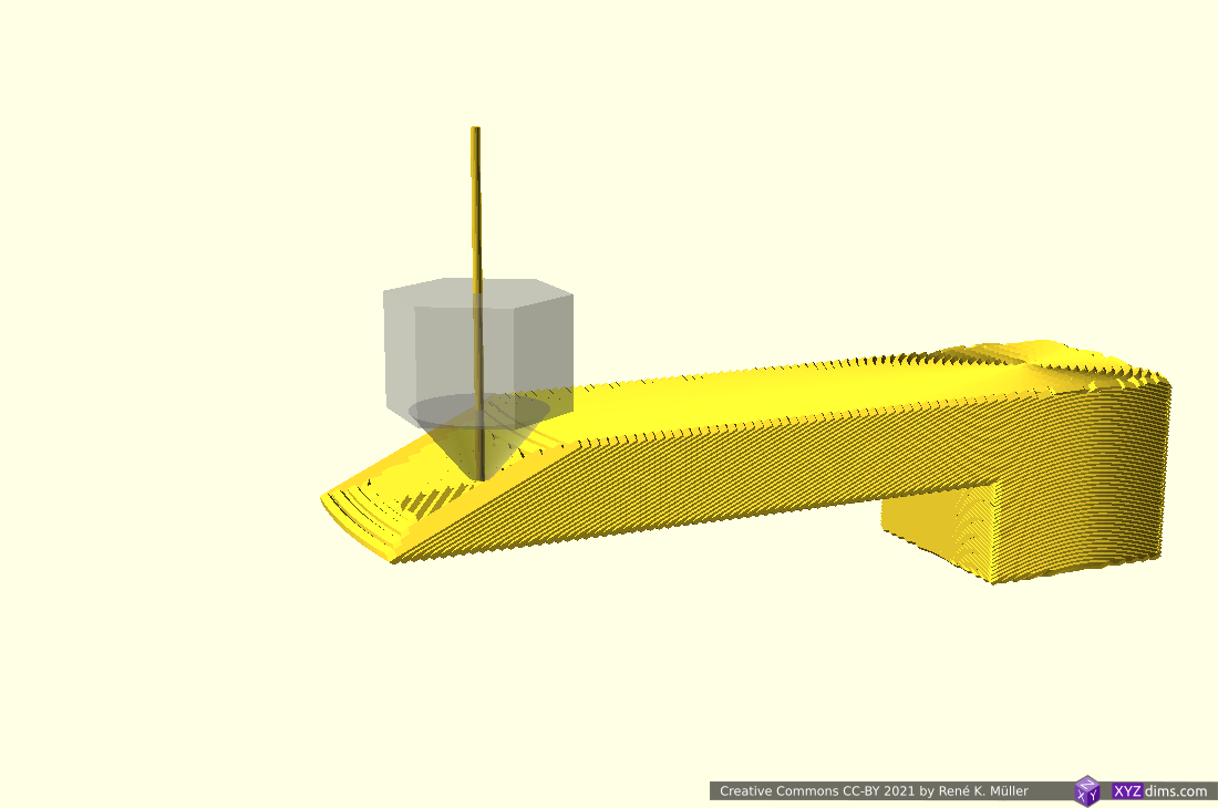
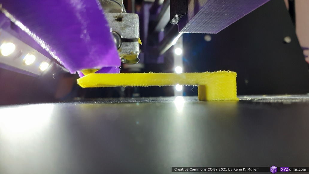
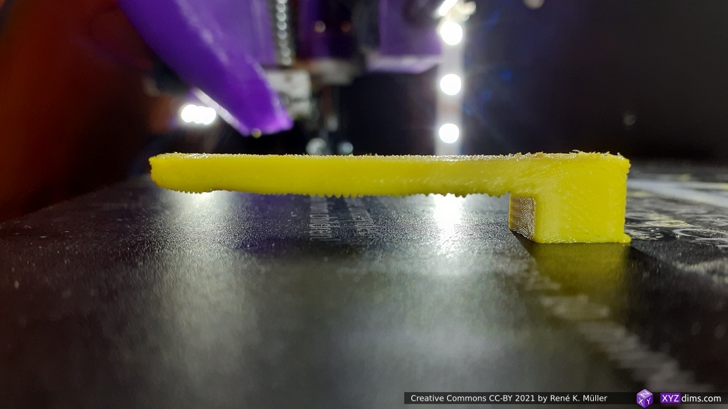
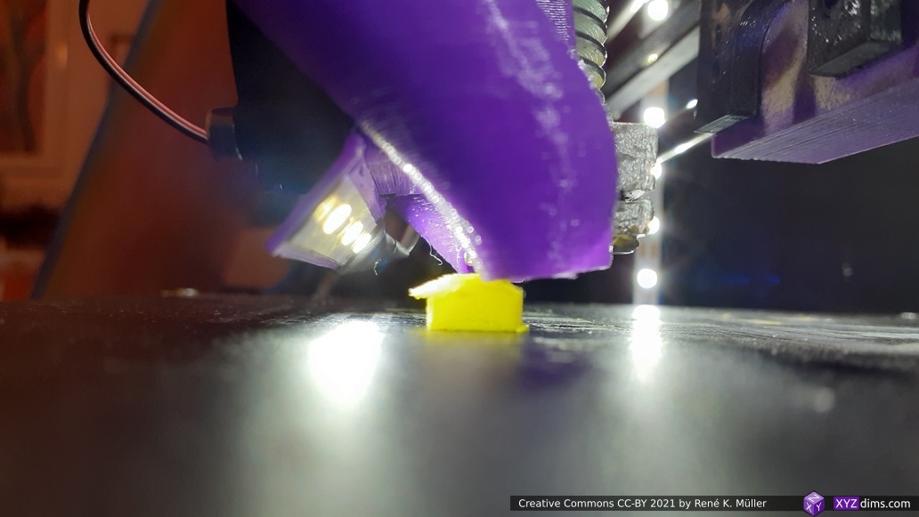
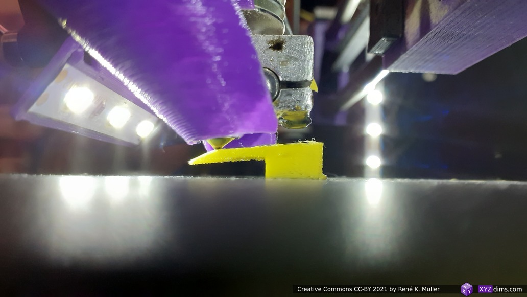
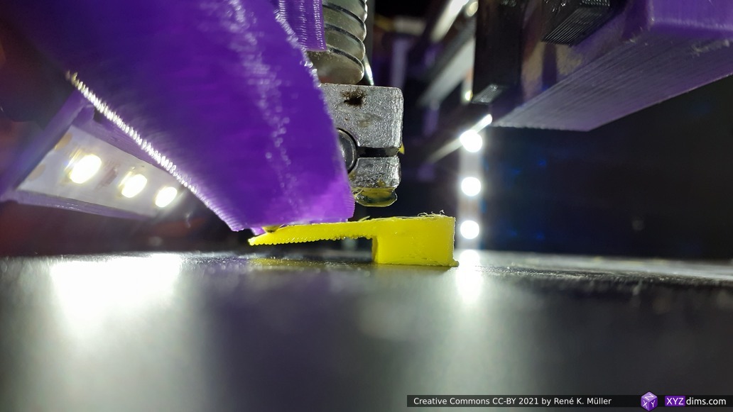
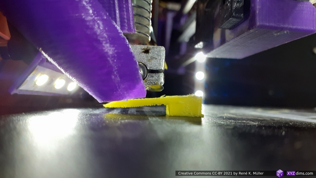
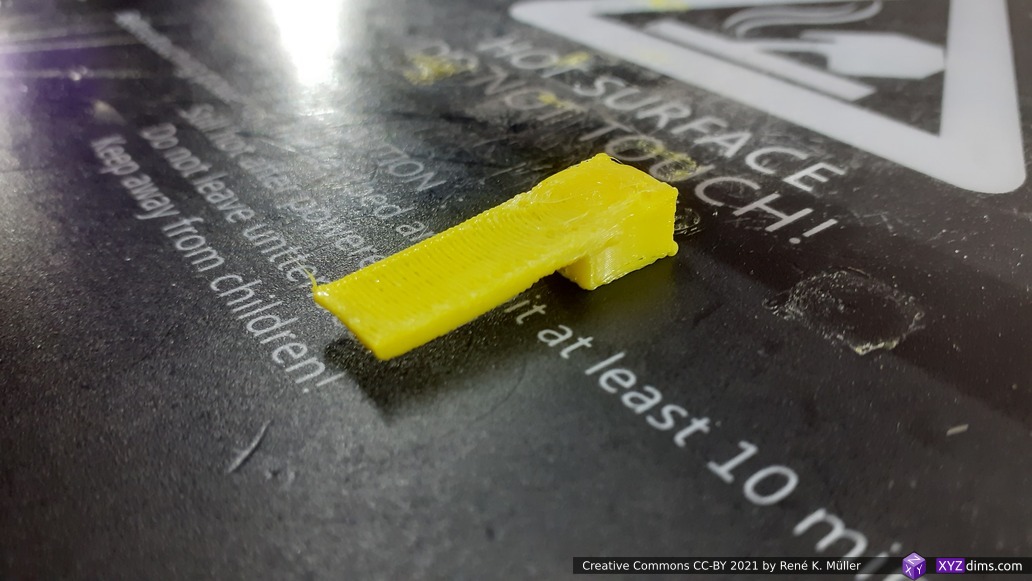
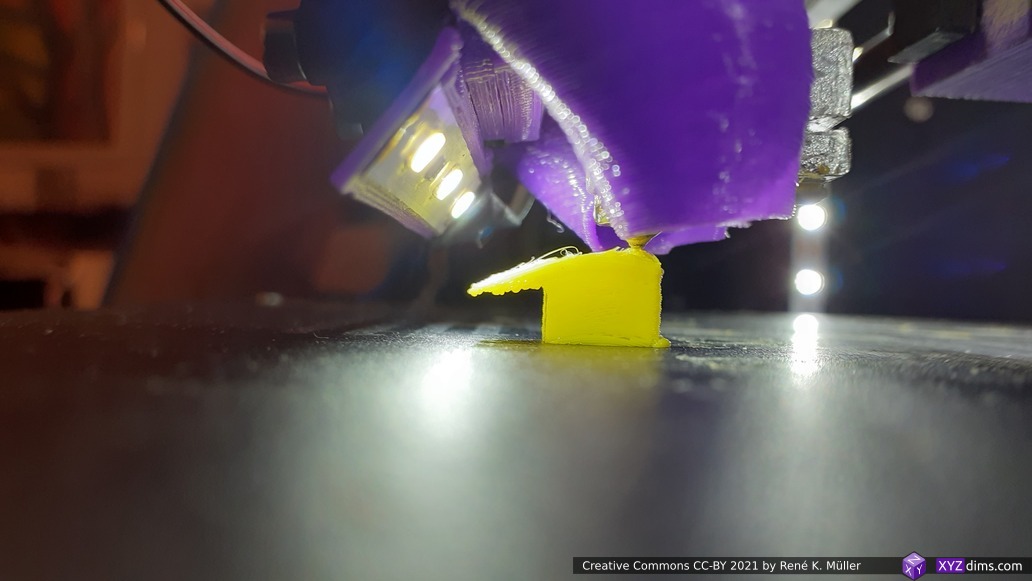
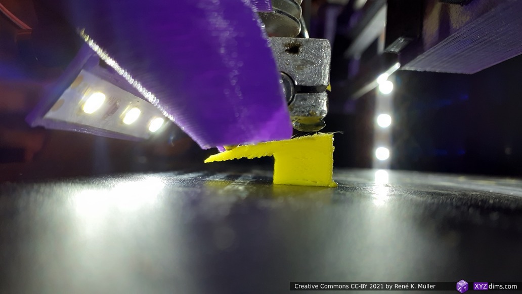
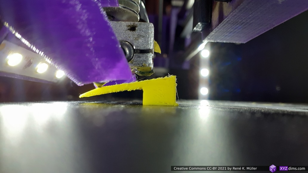
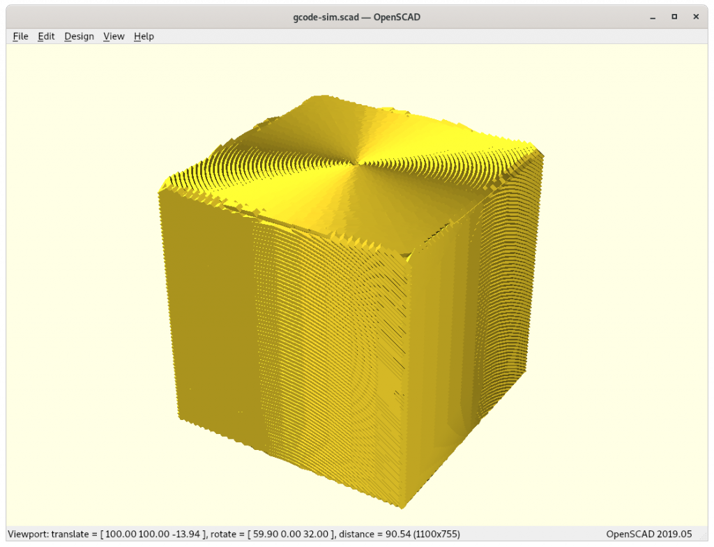
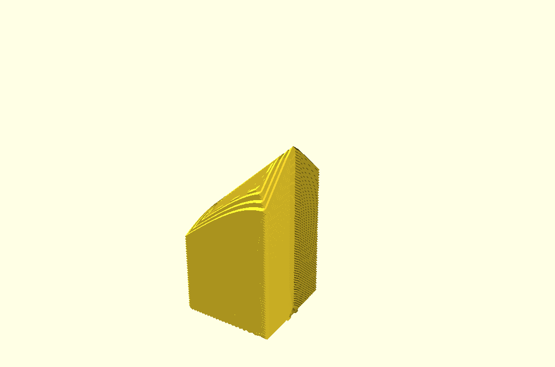
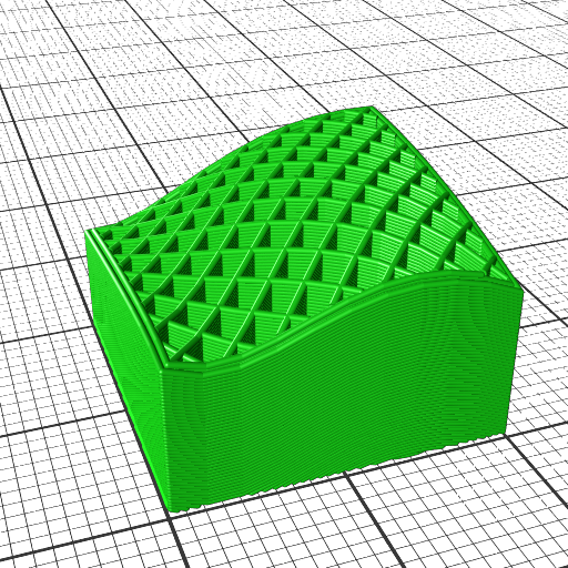
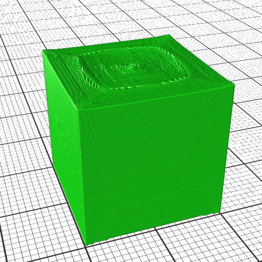
The computed G-code printed with a 3D printer, e.g. an ordinary 3-axis FDM:
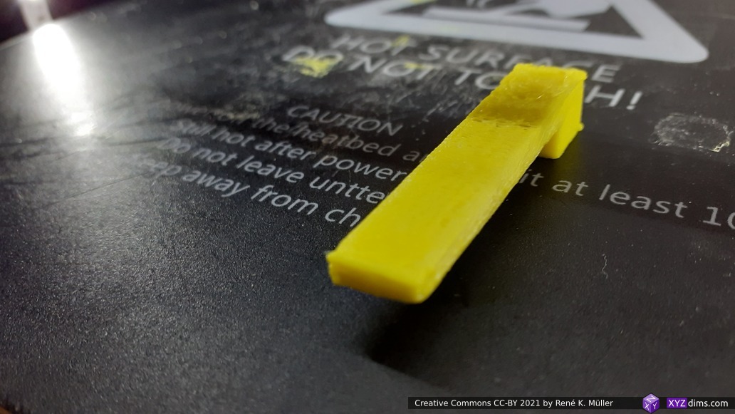
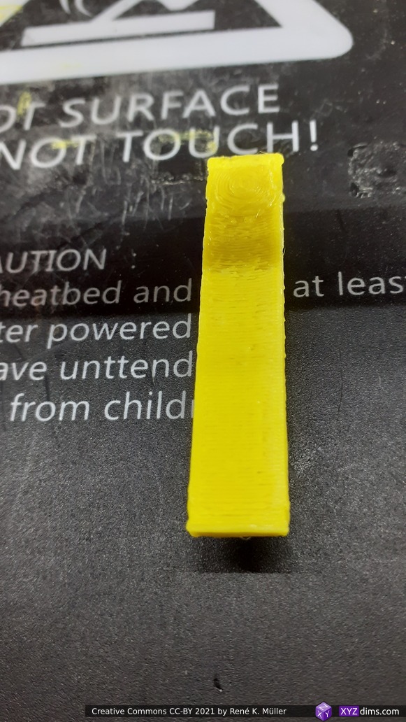
and produces output like this:
Implementing Non-Planar Slicing Geometries Slicer
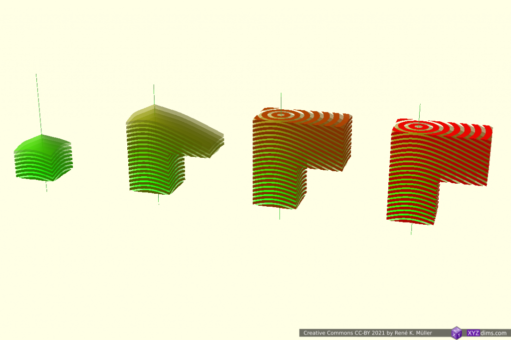
The illustrations and actual G-code above were produced by two new in-house slicers which are in early development (2022/03):
left-to-right: MetatronSlicer (0.0.7), EnochSlicer (0.0.2)
- MetatronSlicer: boundary-based (BREP / OpenCASCADE) and voxel-based (OpenVDB) geometry engine, performing true non-planar slicing, and LabSlicer performing routing and G-code creation; slower slicing yet precise G-code
- EnochSlicer: mesh and G-code transformation approach, fast slicing yet less accurate G-code
The extrusion precision is still rough, but overall concept and algorithms have been proven to work.
Results & Achievement
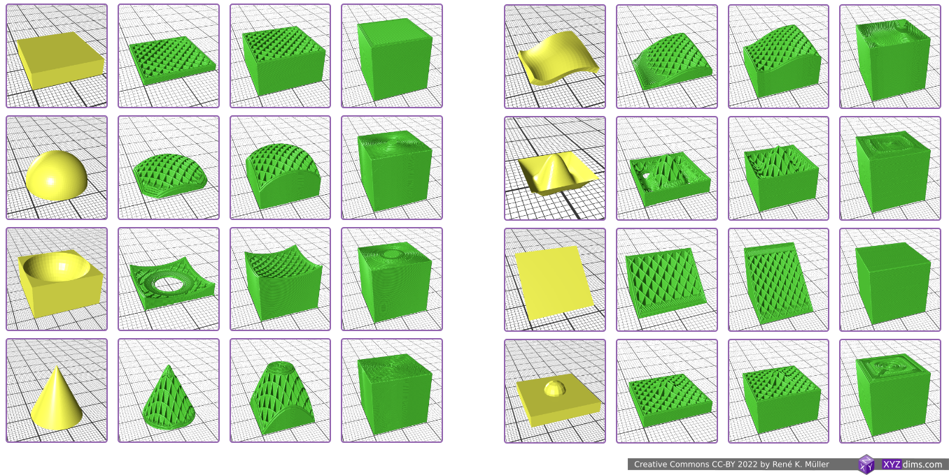
This work as presented here resolves a long pending issue of slicing meshs “non-planar”, or general “non-planar slicing” with all its inherent ambiguity – consider it as given that
one can use any 3D geometry with sufficient upper “surface” to slice a mesh with
and create printable G-code for 3- and 5-axis FDM:
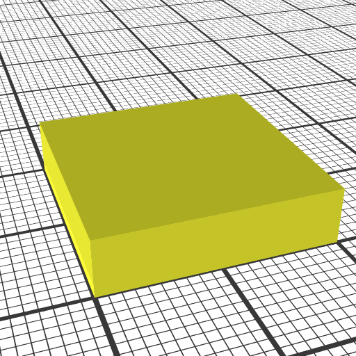


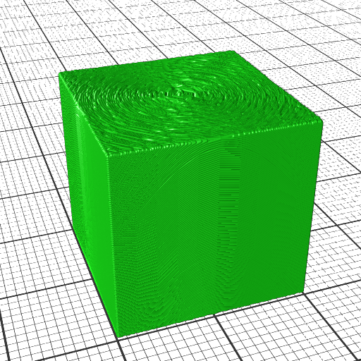

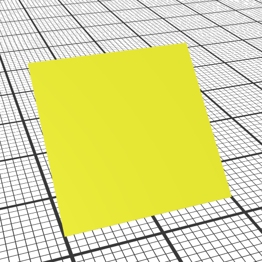

- using a block as planar blueprint
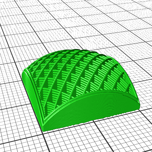
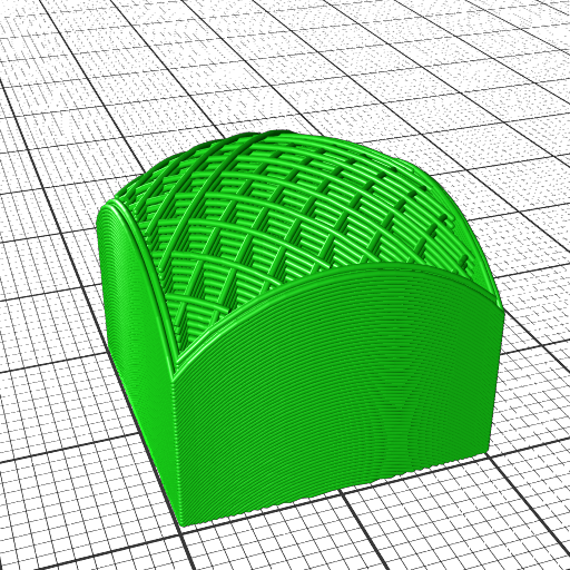
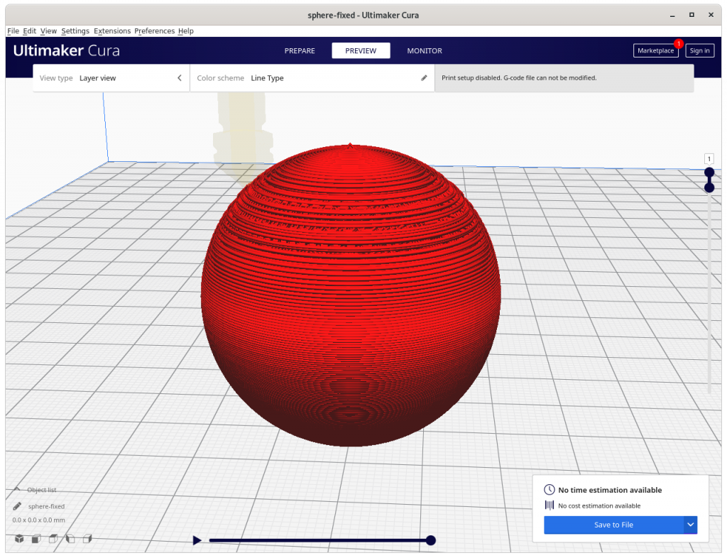
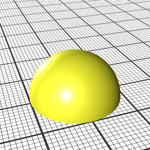
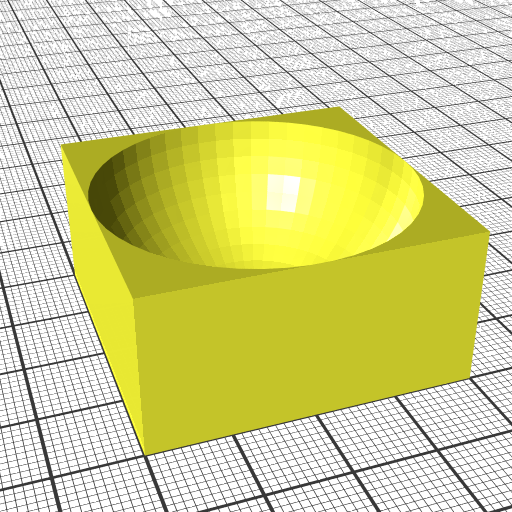
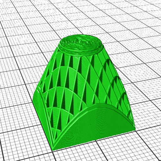
- hemisphere, convex
- hemisphere reverse, concave
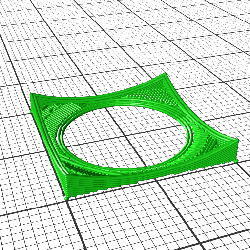
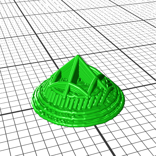
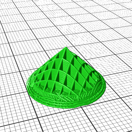
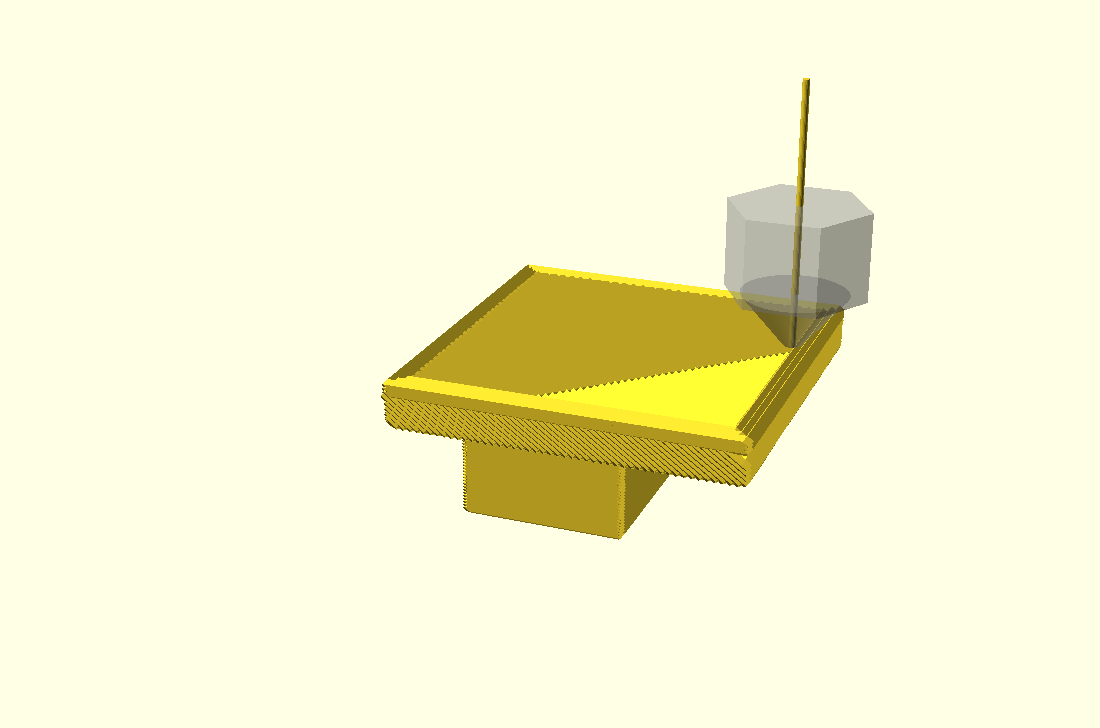
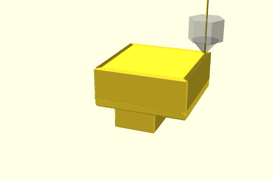
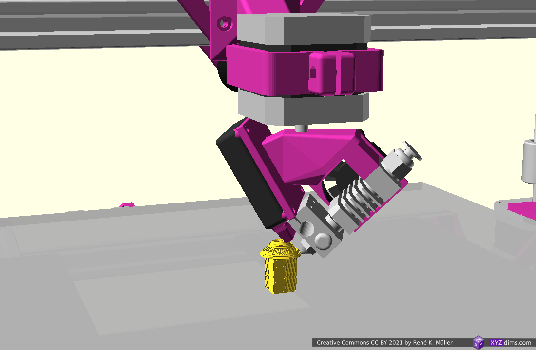
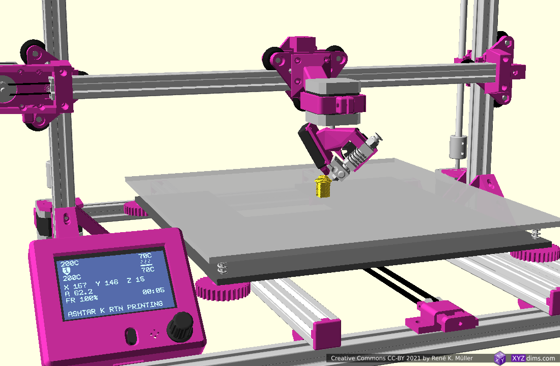
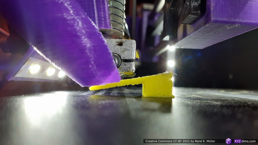
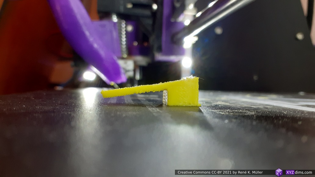
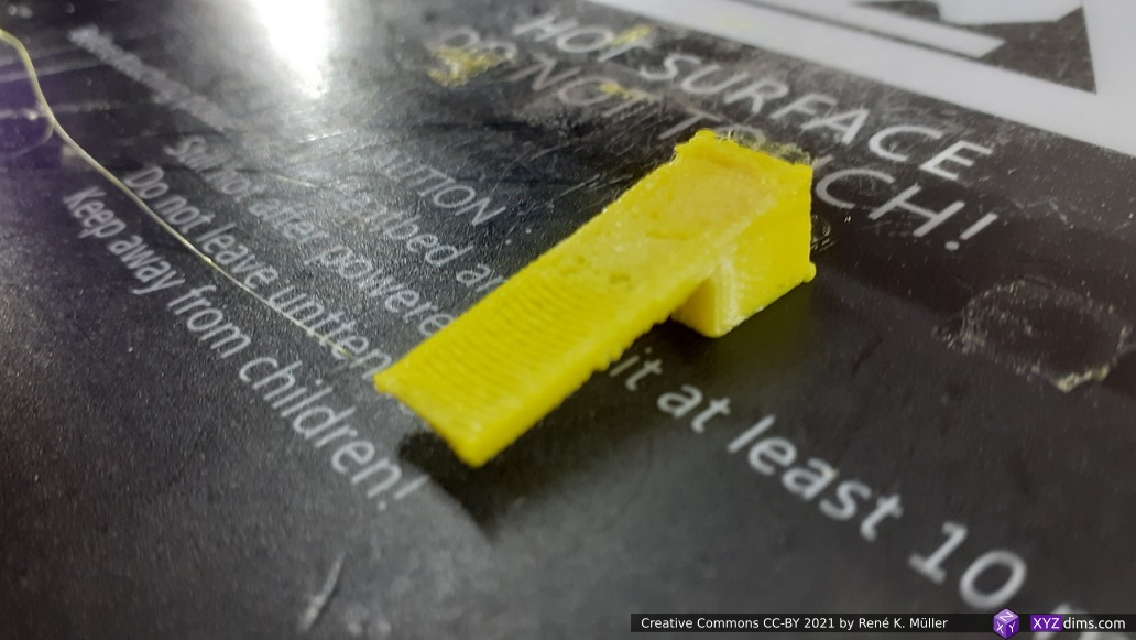
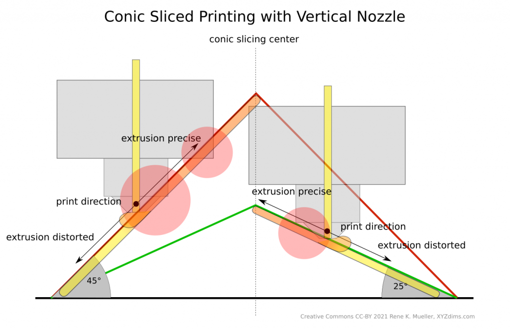
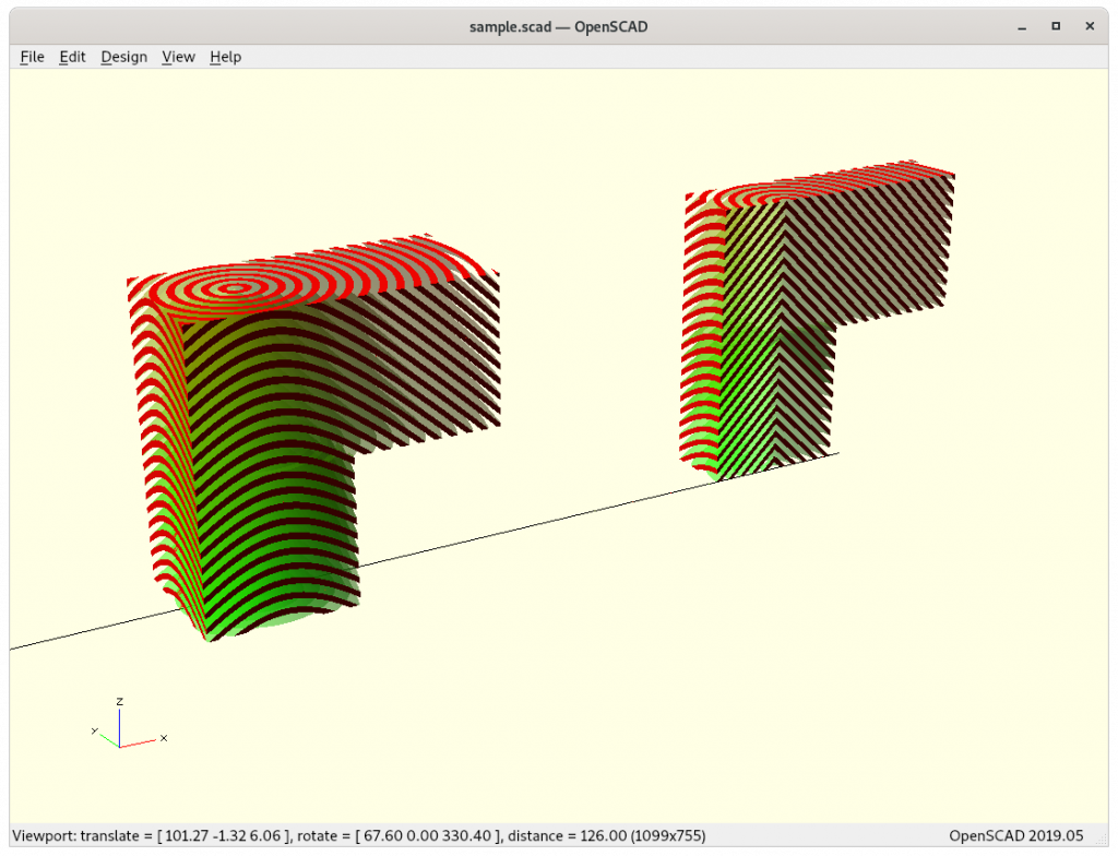
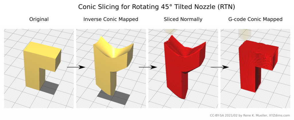
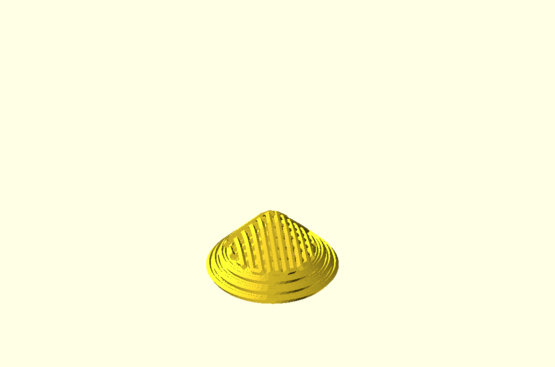
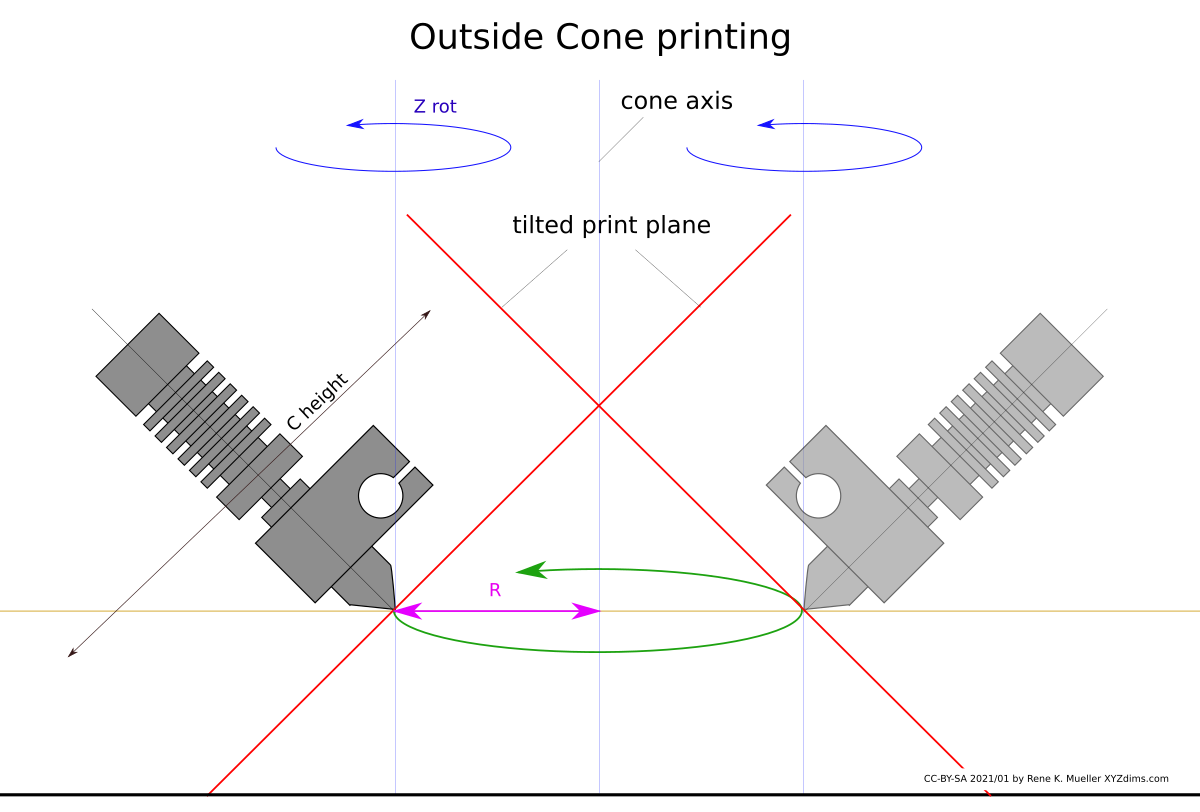
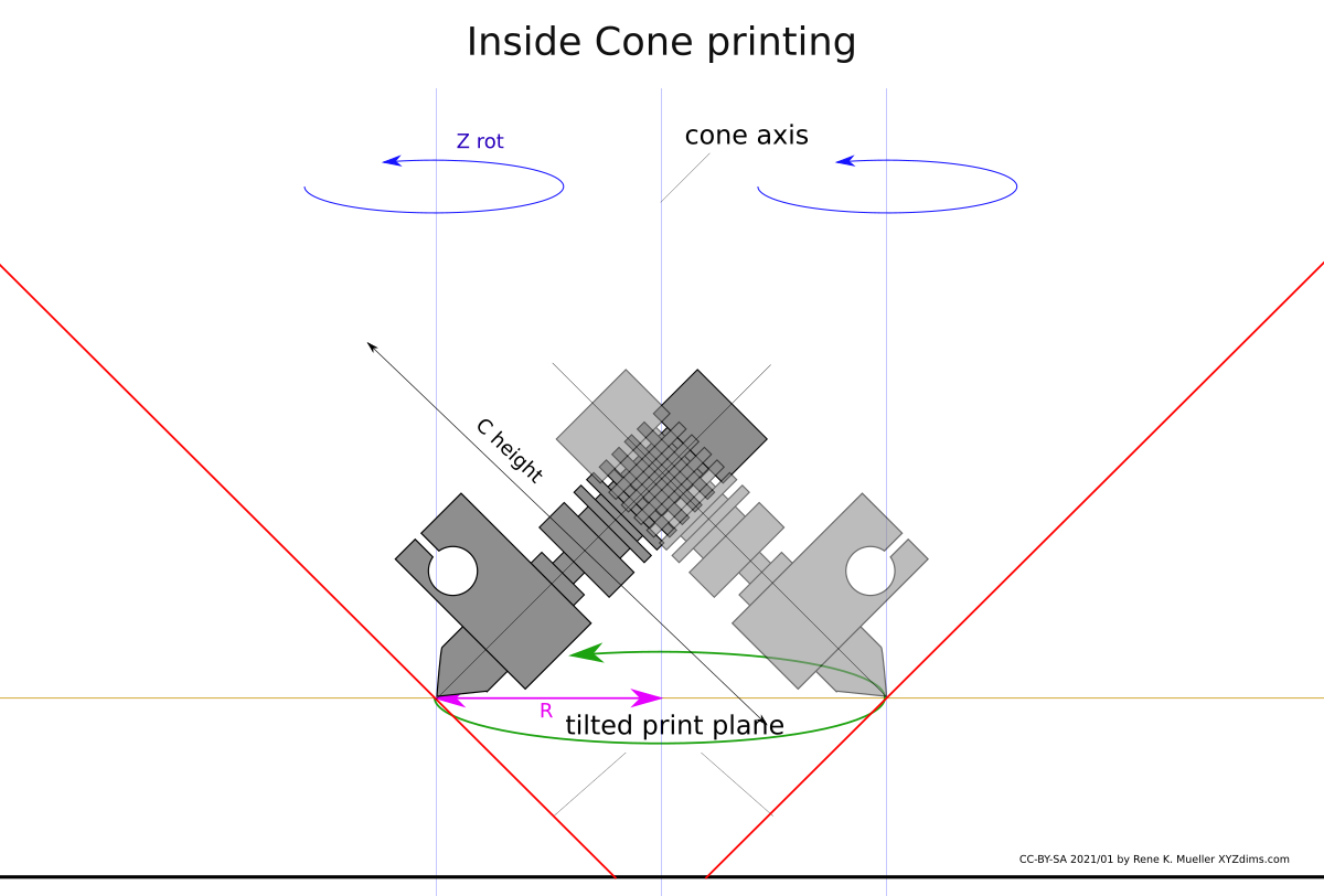
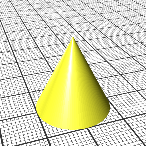
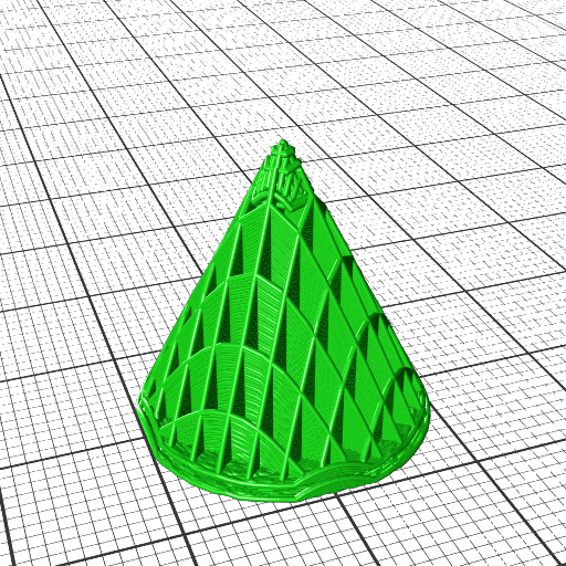
- cone, slicing conical like for Rotating Tilted Nozzle
- wave-like defined via Bezier curves
- wave-like defined via NURBS (Non-Uniform Rational B-Splines) curves
- tilted plane, slicing for belt printer with 45° tilted XY frame toward Z belt
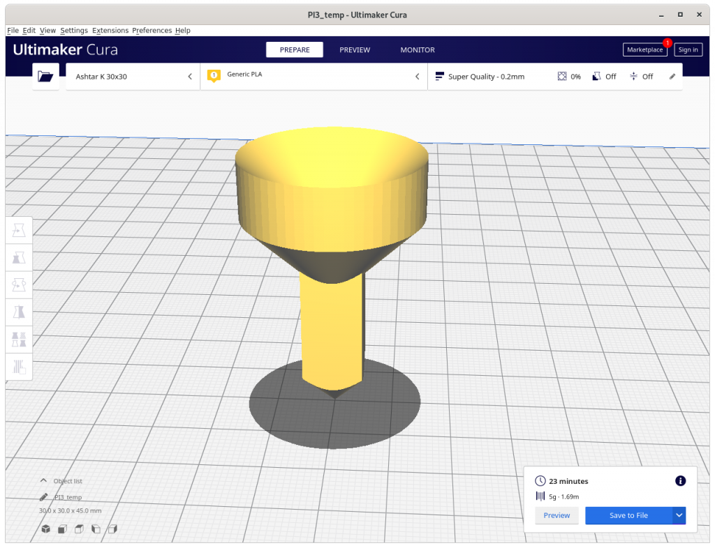
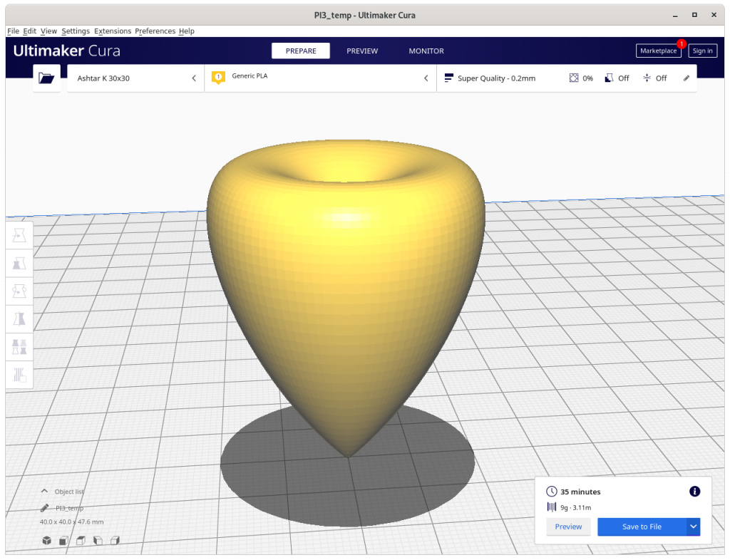
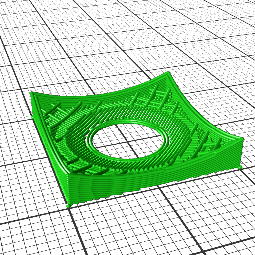
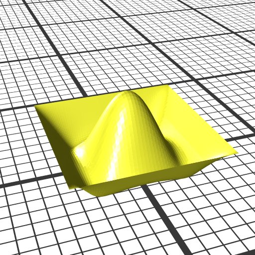
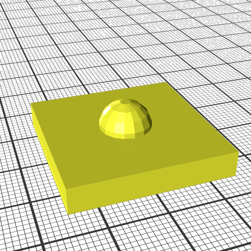
- pimple-like
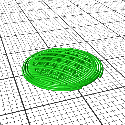
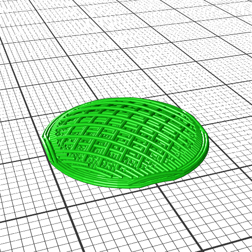
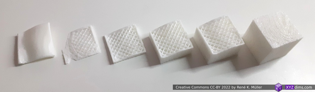
Along with volume segmentation as presented previously and conical, cylindrical and spherical slicing now any kind of slicing geometry can be used.
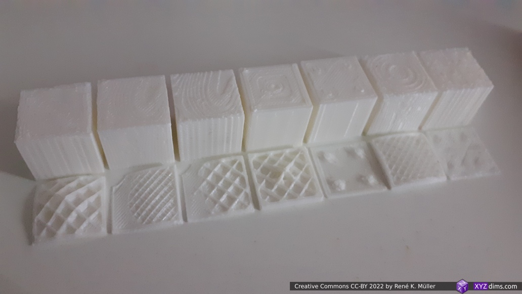
1. conic (EnochSlicer), 2. wave (MetatronSlicer), 3. wave (EnochSlicer), 4. pimple (EnochSlicer), 5. pimple 2x tiled (EnochSlicer), 6. hemisphere (EnochSlicer), 7. tetrahedron 2x tiled (EnochSlicer)
limited to 3mm Z amplitude, printed on 3-axis FDM (Ashtar K #2)
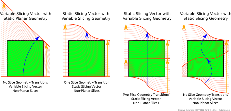
As pointed out in Universal Slicing, this “Planar Slicing with Non-Planar Geometries” is Class 1 of Universal Slicing whereas Class 2 covers changing slicing geometry and/or flexible slicing path along the slicing.
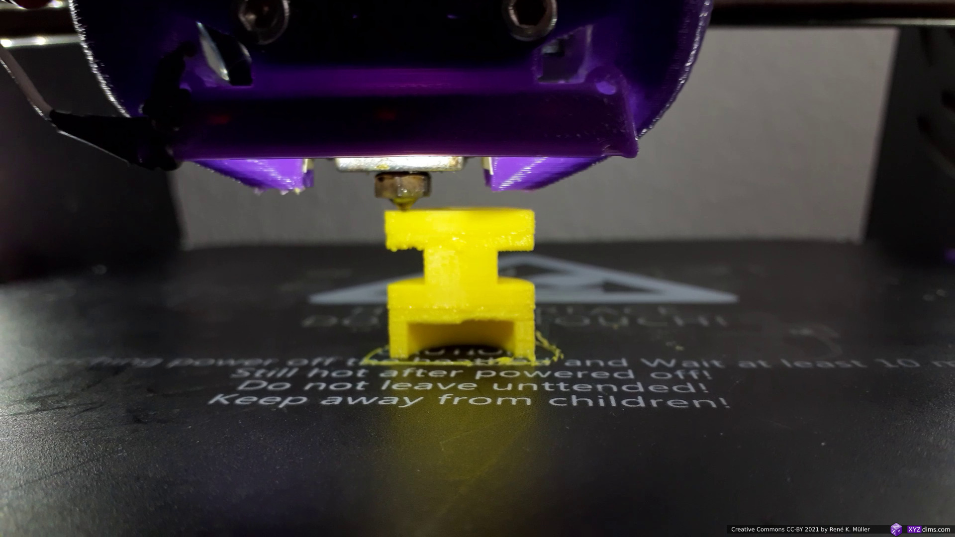
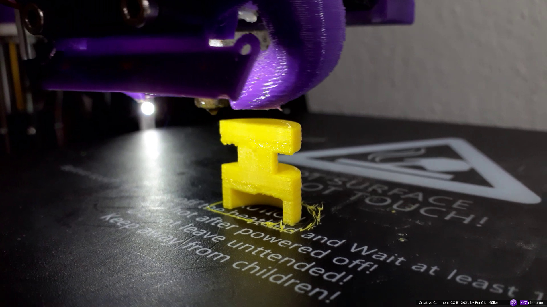
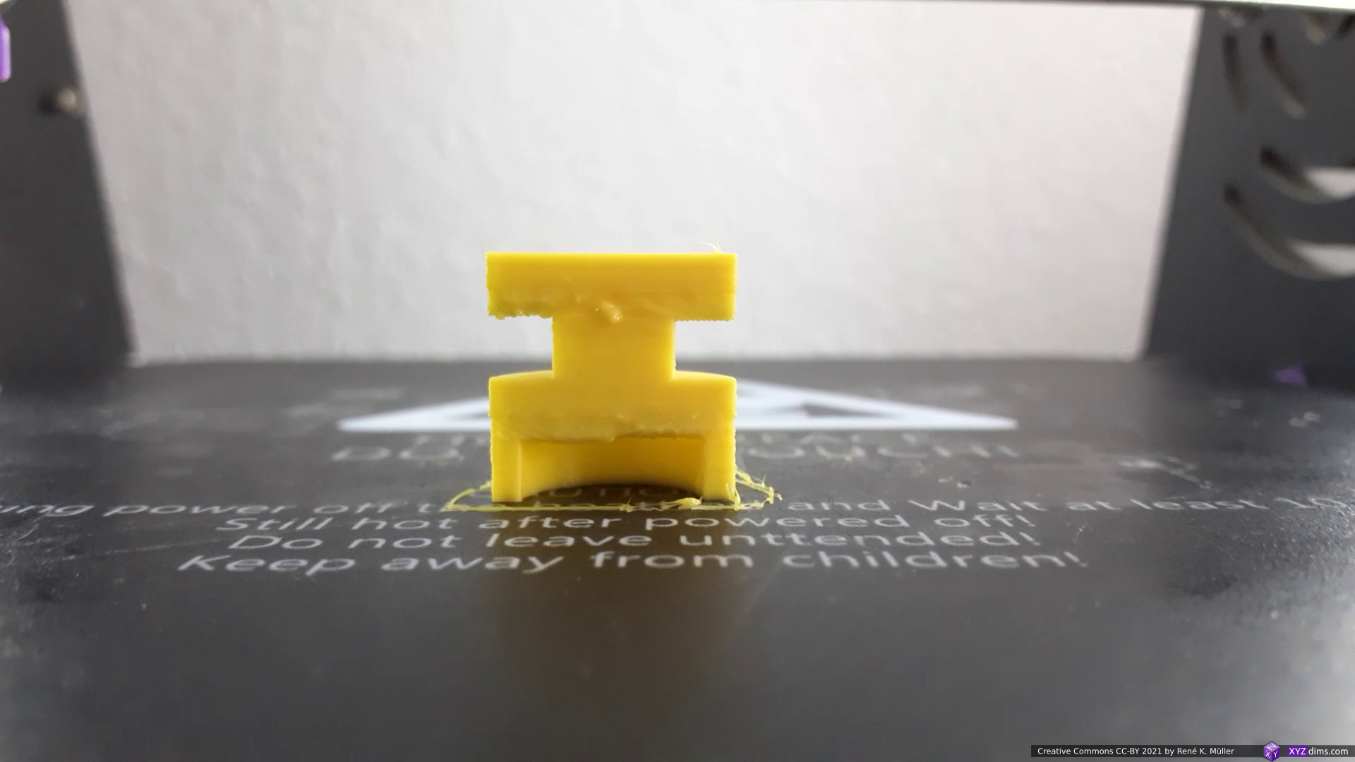
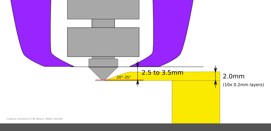
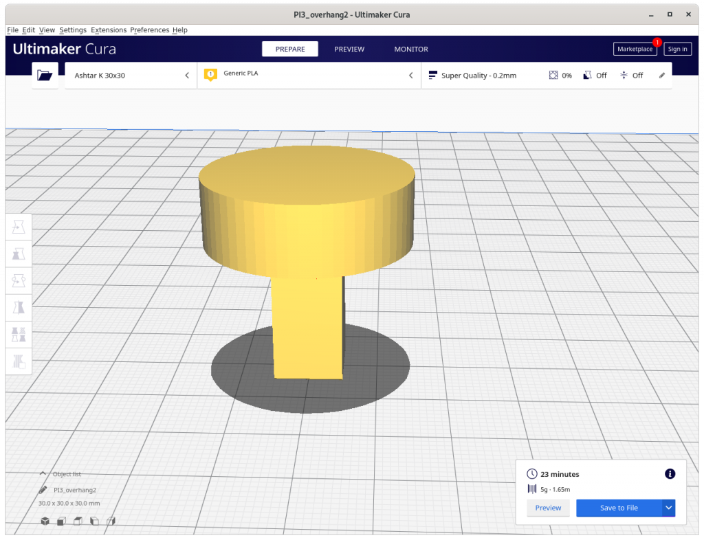
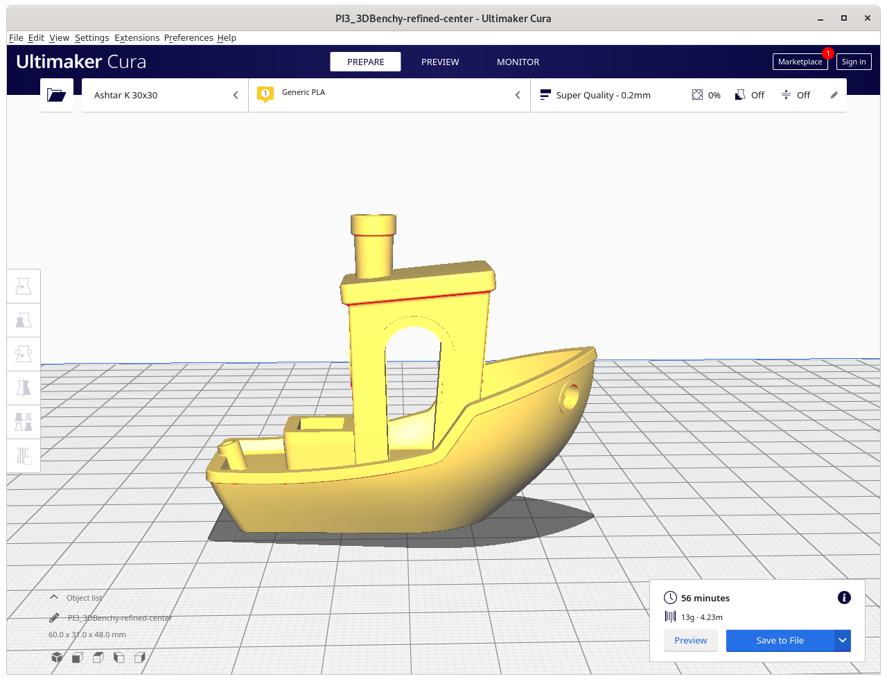
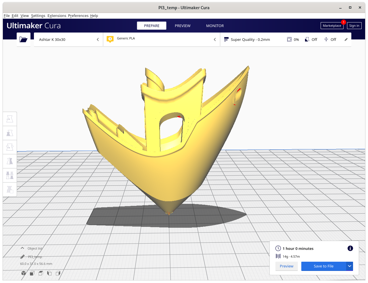
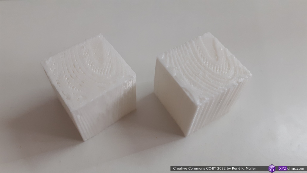
Limiting Non-Planar Height for 3-axis FDM
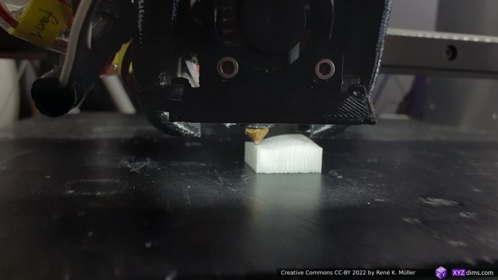
When using non-planar geometries to slice a model also non-planar G-code is produced and possibly significant Z motion occurs, and when printing with an ordinary 3-axis FDM 3D printer it may be suitable to limit the Z motion aka Z amplitude to 2-3mm in order to avoid part-cooler or other parts of the print head to collide with the already printed part:
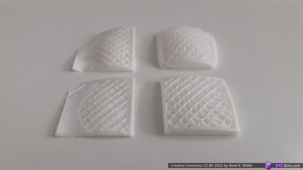
top row: full range, bottom row: limited to ~3mm Z amplitude
Future blog-posts will go into further details implementing Universal Slicing using those two slicers MetatronSlicer and EnochSlicer.
Regarding naming the slicers: Metatron is an archangel in jewish mythology – consider an “angel” as a fundamental intelligence, and in esoteric context Metatron is the being responsible for Form or Geometry itself – separating one into many in a spatial manner; whereas Enoch as a human, who ascended to become the archangel Metatron. I use those names in deep reverence for these two projects.
Blind Spot of CAD Systems
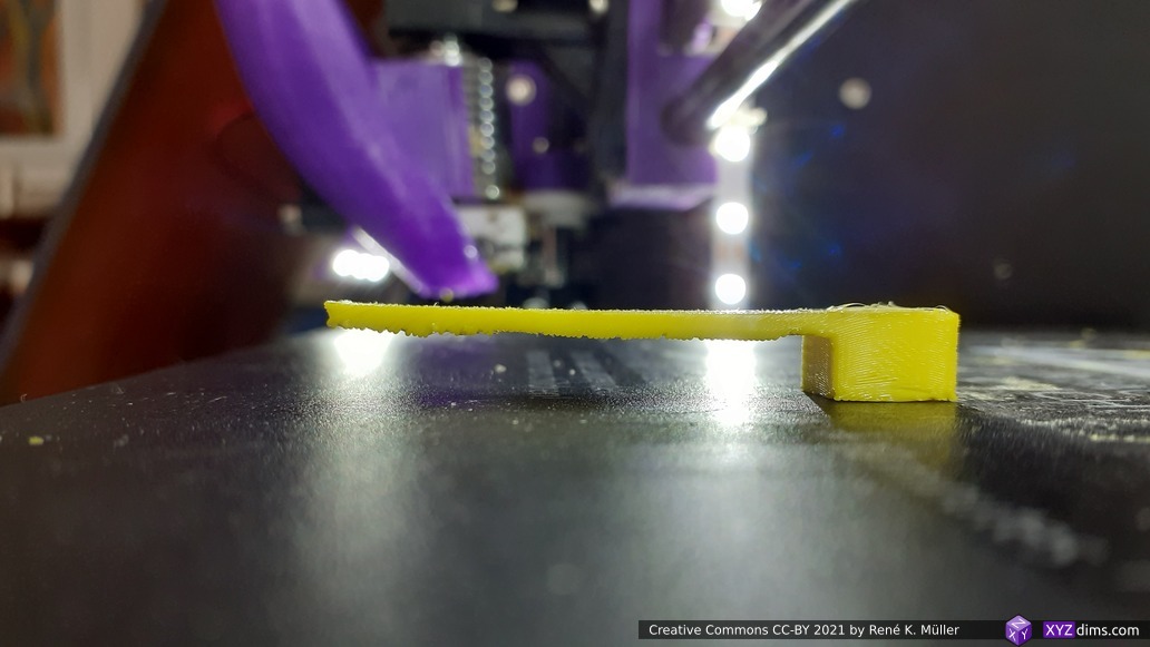
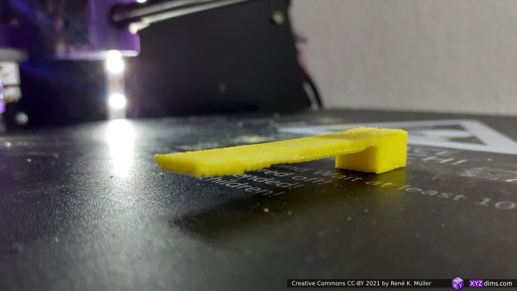
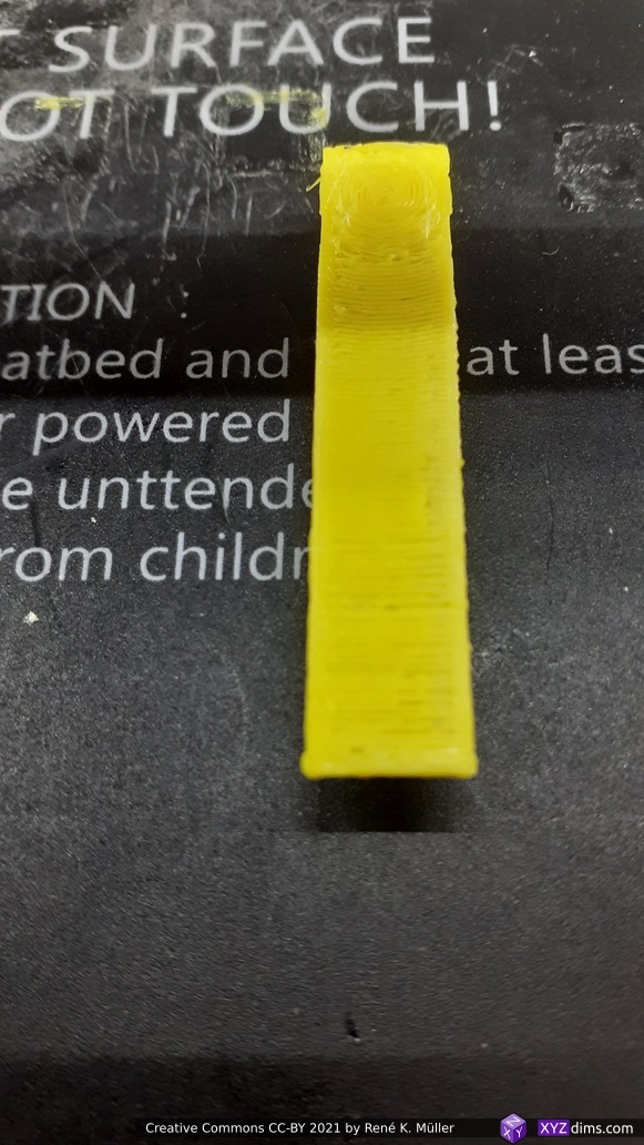
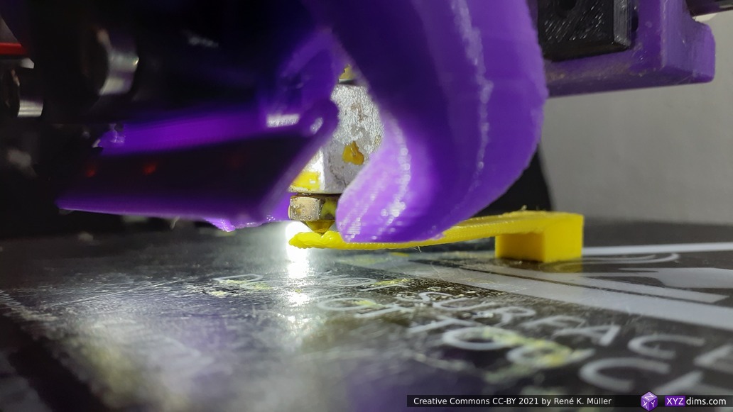
Current CAD systems (2022) neglect or actually are unaware of the inner vs outer structure – because only one kind of the “structure” is known, e.g. a piece is designed because of a certain function, which defines its outer form, e.g. a wrench to use a simple example – but how about the inner structure? This isn’t defined in the CAD, it is defined at the manufacturing stage, yet with 3D printing this can be described and designed even in a parametric way as well, the slicing or general 3D printing stage with different materials.
We require 2 or 3 abstraction layers to design a functional piece:
- the functional description (doesn’t exist yet)
- the inner structure (description how material is deposited in Additive Manufacturing, e.g. the infill geometry as of with FDM, incl. non-planar printing, or lattice structures as with SLA or SLS)
- the outer structure (e.g. mesh, boundaries)
So far CAD systems only covers the 3rd point, the outer structure.
The functional description is almost non-existent in the CAD world, and only becomes some attention when Finite Element Analysis is made and the form is changed, it is kind of hidden in plain sight.
In future blog-posts I will address and elaborate on these issues further.
Scale and Functional Qualities
To put the flexible slicing geometry in the grander context of 3D printing engineering:
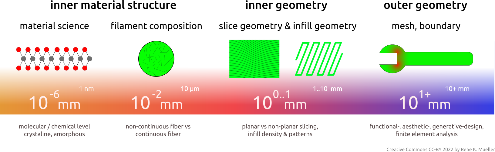
3D printing engineering starts at nanometer scale (10-6mm) with material science level, over to filament composition at 1 to 10 micrometer scale (10-2mm) such as fibers, inner geometry where slicing geometry & procedure and infill geometry define strength properties at millimeter scale (100mm), and outer geometry with the shape of the object itself provide the final stage of mechanical properties.
This entire “scale chain” as a whole defines the mechanical property of the final 3D printed object.
That’s it.
References
- Universal Slicing
- Video: Mastering Non-Planar Printing: Slicing with Non-Planar Geometries
- MetatronSlicer (Class 1, partial Class 2 Universal Slicer)
- EnochSlicer (Class 1, partial Class 2 Universal Slicer)
- 3D Printing: Sub-Volume Segmenting & (Non-)Planar Slicing
- Involved tools: YAGV, G-code Previewer, Gcode2png, LabSlicer
- HackaDay: 3D Printering: Non-Planar Layer FDM (2016), brief overview
- Inner Structure Approaches
- Hyperganic: software designing parts based on actual function and strength properties, voxel-based, output for SLS, SLA, FDM – very little information available on the net (2022/02), secretively operating company
- nTopology: generative design using implicit modeling, more open company, they even have a Github presence