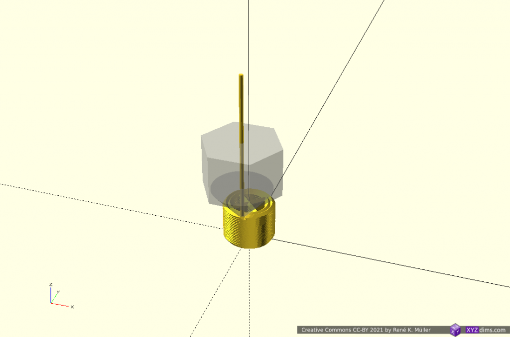
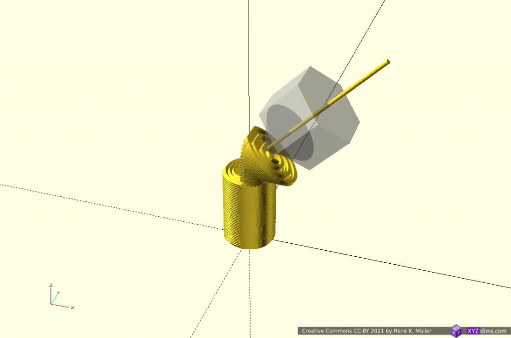
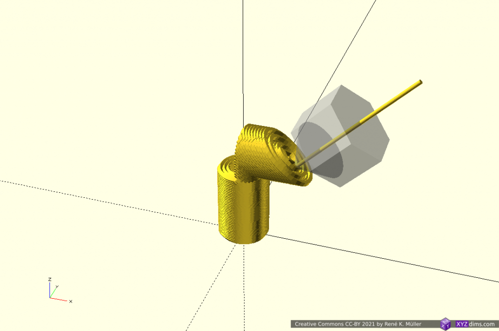
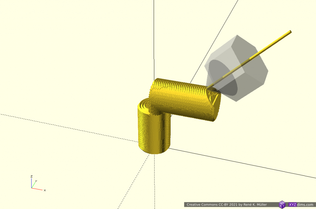
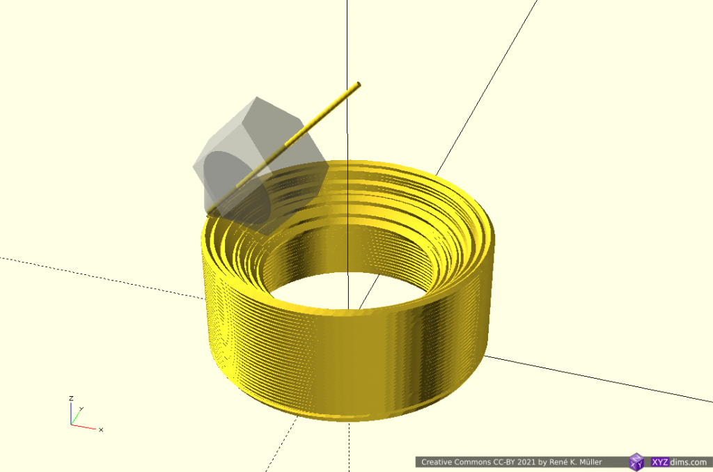
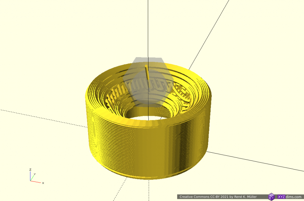
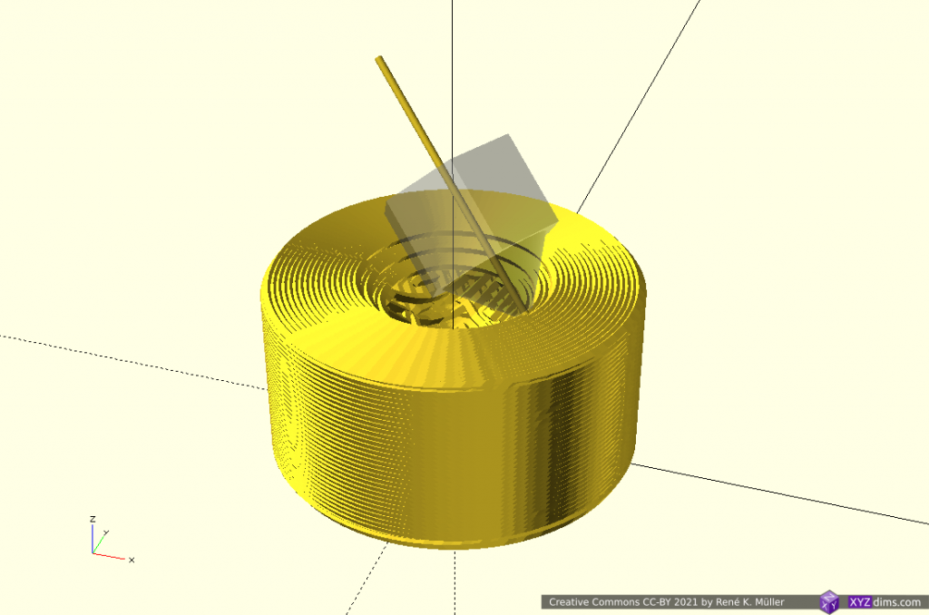
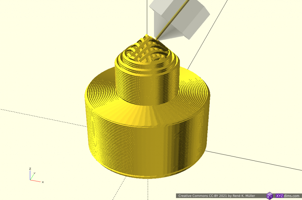
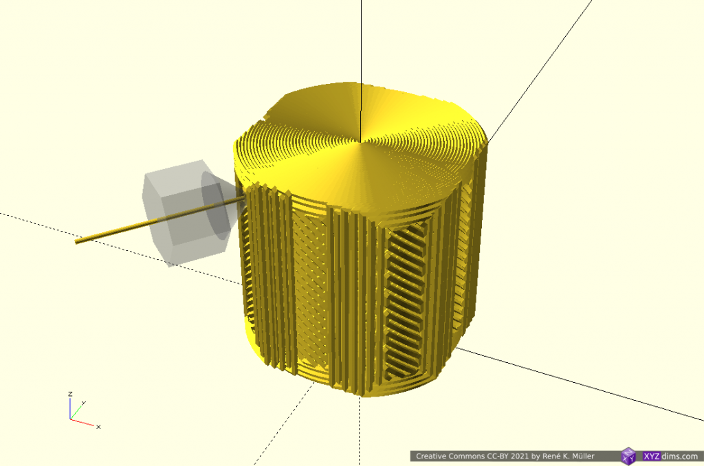
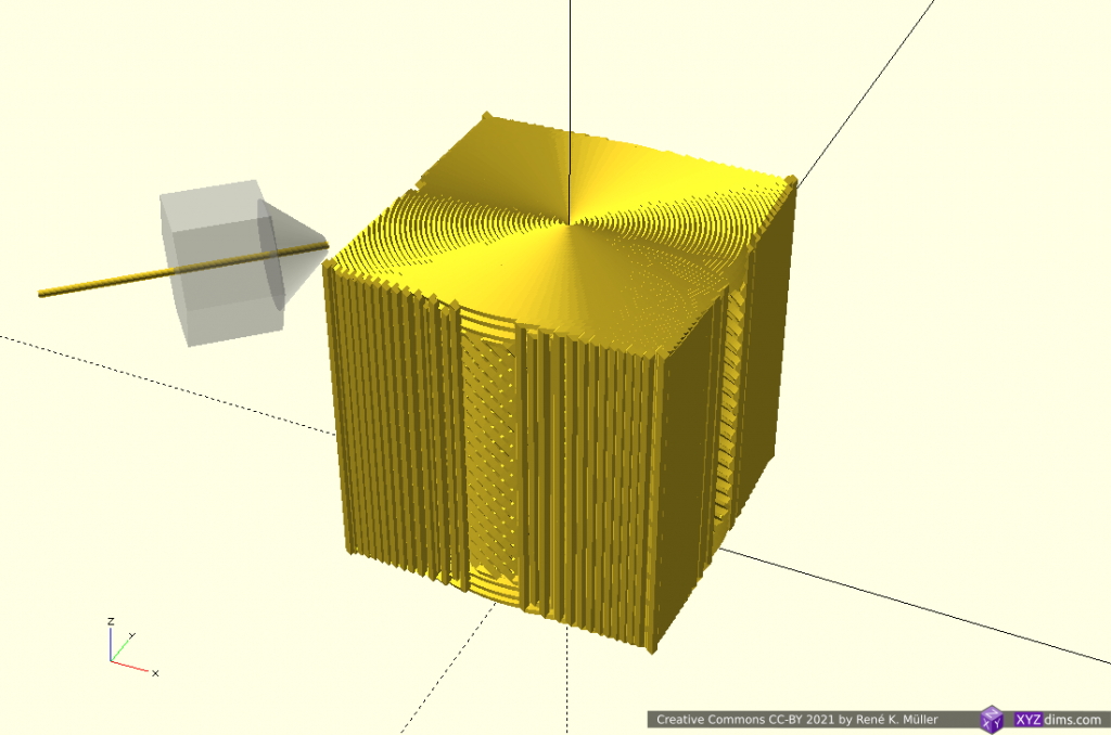
Tag Archives: Research Paper

3D Printing: Slicing with Non-Planar Geometries

Updates:

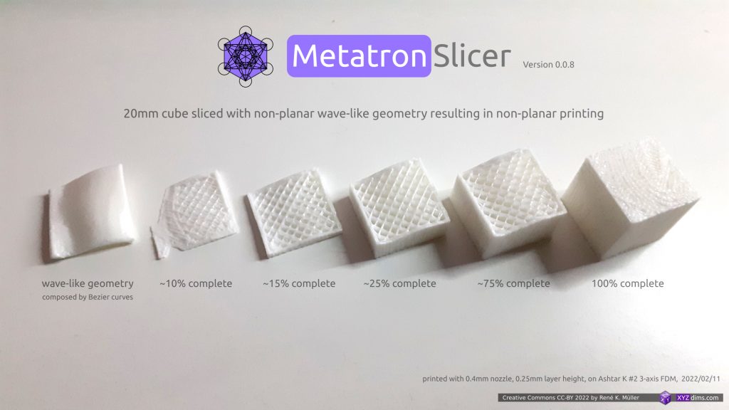
  • 2022/04/25: added single photo with various 20mm cube prints
  • 2022/04/01: rewording to avoid confusion of “planar slicing” with non-planar geometries
  • 2022/03/26: finally published
  • 2022/03/25: adding “Benefits of Non-Planar Printing” and “Blind Spots of CAD Systems” and “Scale and Functional Quality”
  • 2022/02/18: getting ready to publish
  • 2022/02/15: adding different slicing geometries and the resulting G-code
  • 2022/02/12: starting write-up

Introduction

After researching non-planar slicing using planar slicers it was obvious to find a way to slice with any kind of geometry, and it meant to step back and formalize slicing procedure in a general manner like “Universal Slicing” – and look at the procedure of slicing itself.

Two classes were defined:

  • Class 1: using a geometry, either planar or non-planar, and slicing with a static slicing path
  • Class 2: slicing with variable slicing path and/or variable slicing geometry while slicing

This document/blog-post features a solution for Class 1 Universal Slicing.

My video Non-Planar 3D Printing: Slicing with Non-Planar Geometries goes through this information in an animated form, this is the textual form.

Slicing with Non-Planar Geometry (Class 1 Universal Slicing)

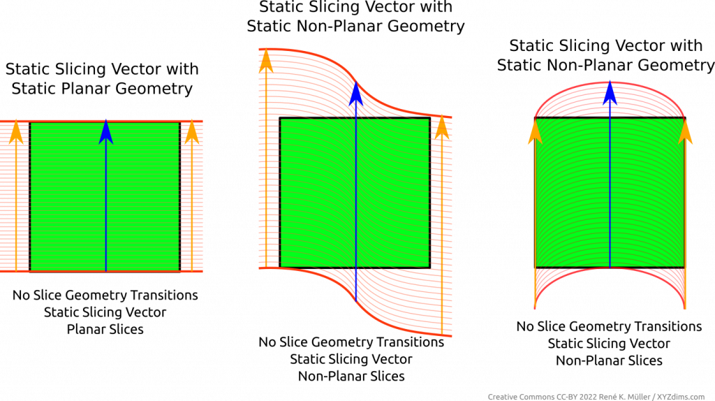
When using a static planar slicing vector one usually uses a plane, hence the term “planar slicing”, yet, there is also the possibility to use a non-planar geometry and slice in a planar direction (introducing ambiguity what planar and non-planar slicing actually mean). Regardless which slicing geometry is used in this procedure, the thickness of the sliced layer stays the same.

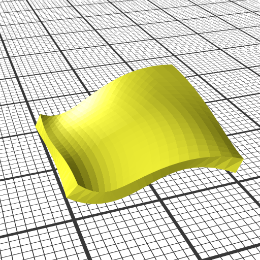
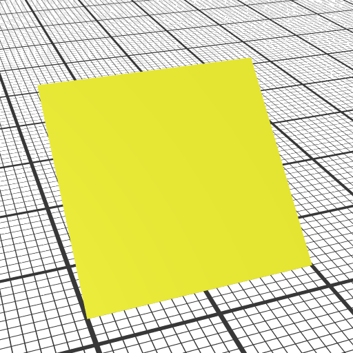
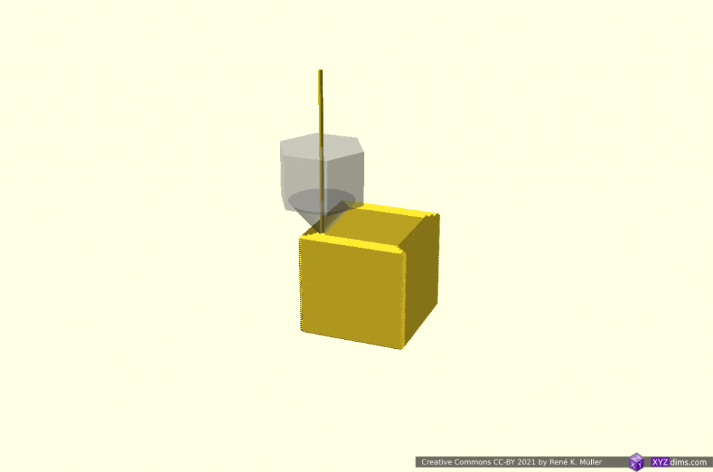
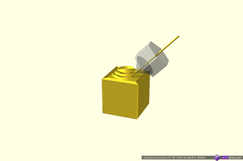
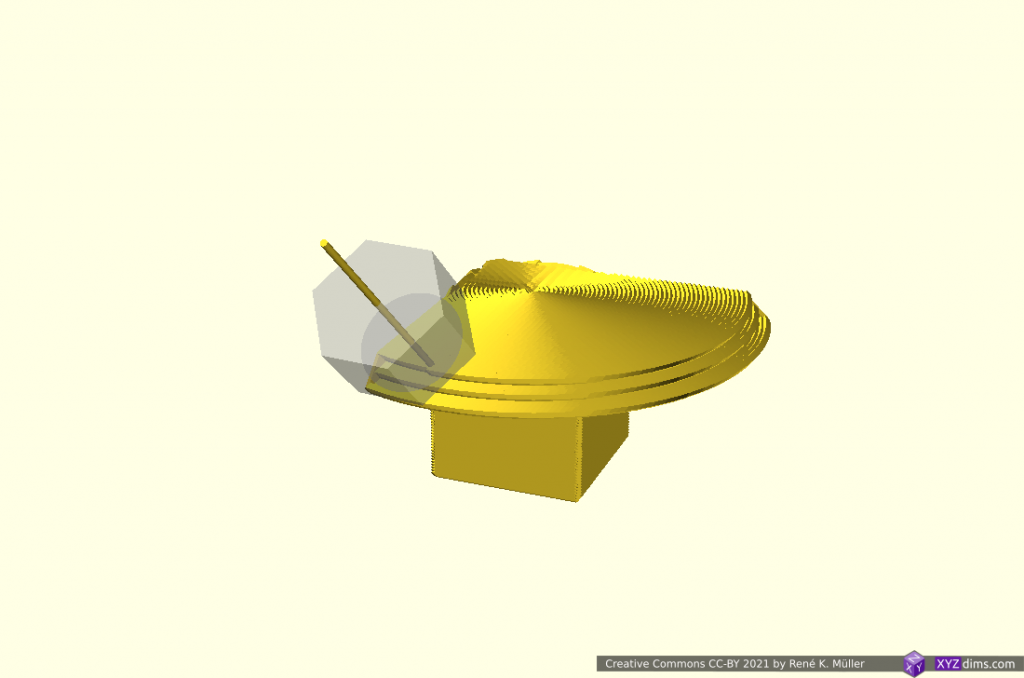
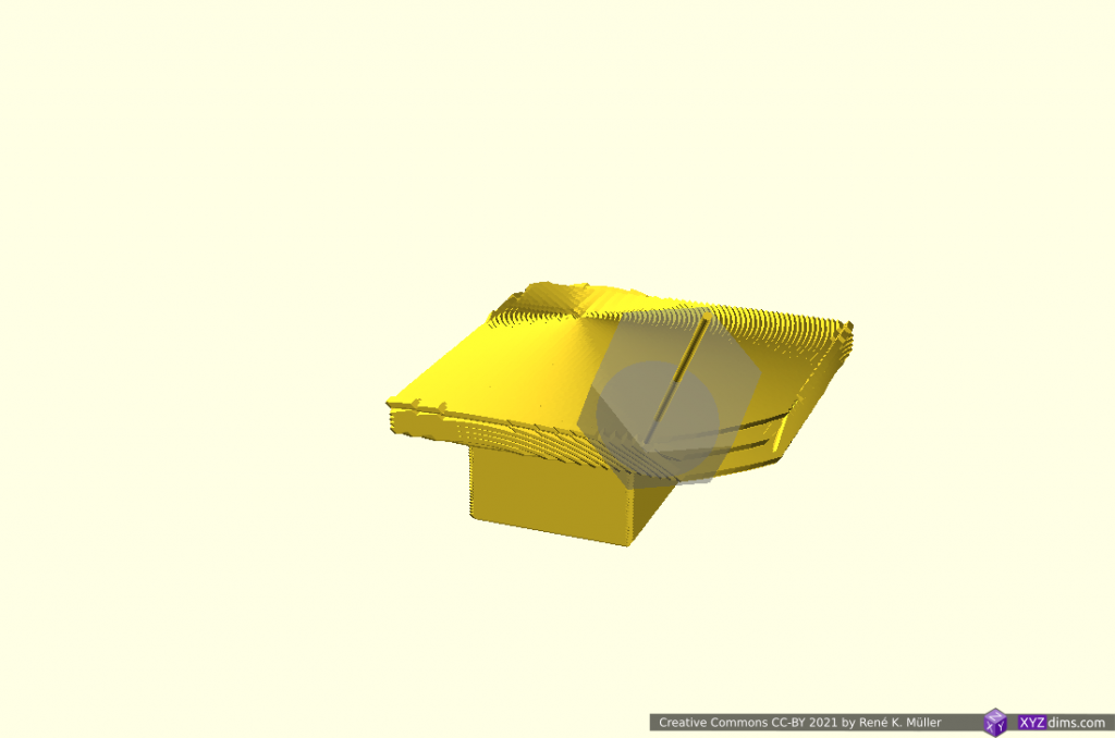
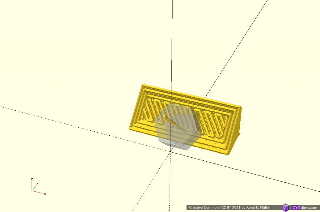
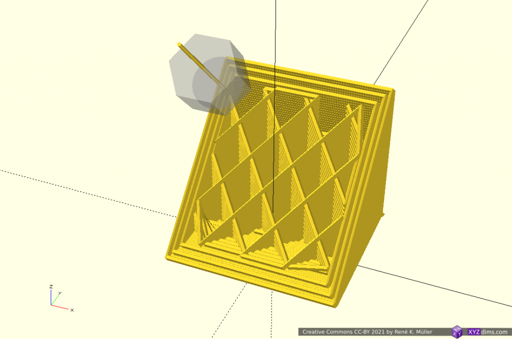
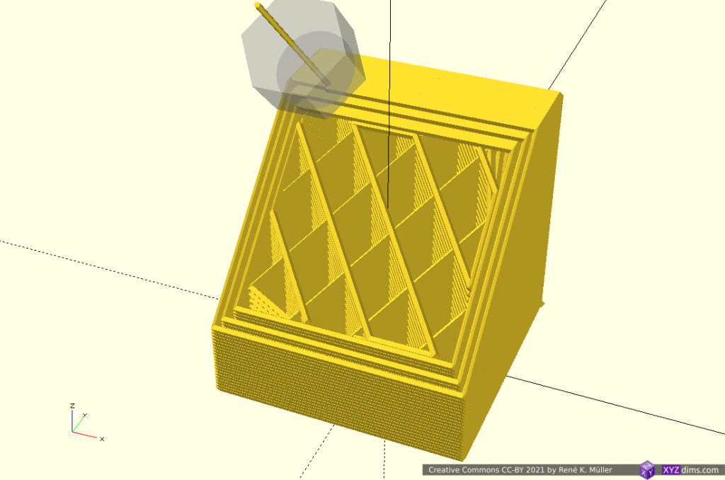
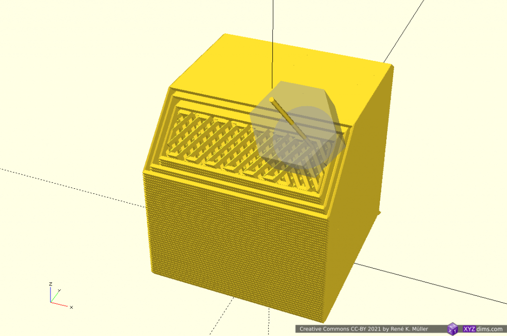
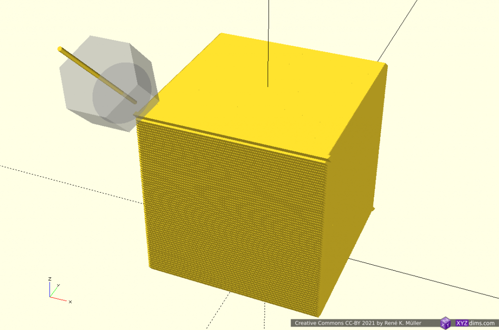
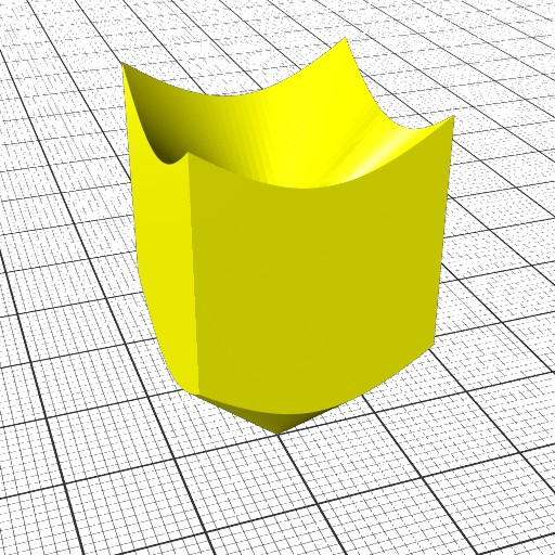
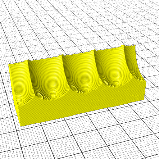
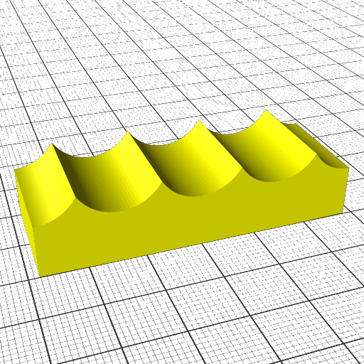
Slicing 20mm cube with wave-like geometry

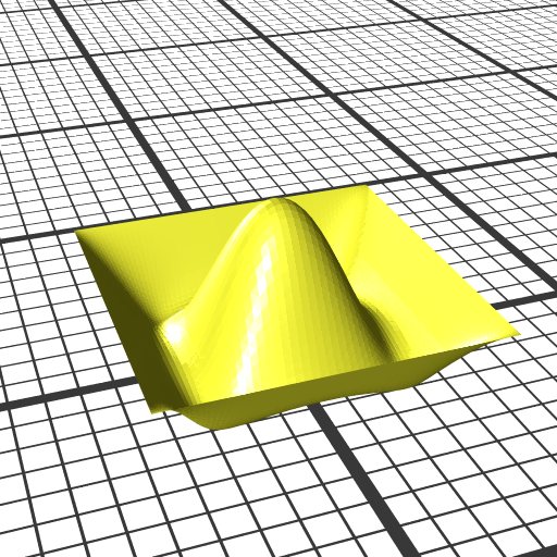
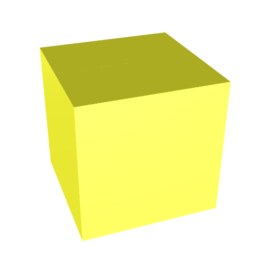
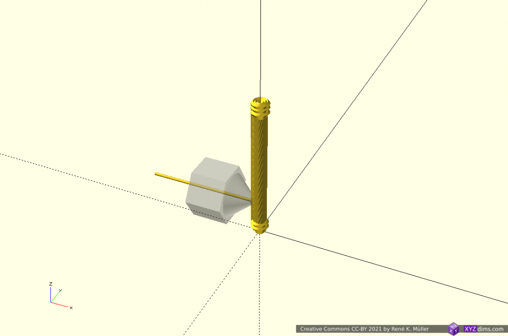
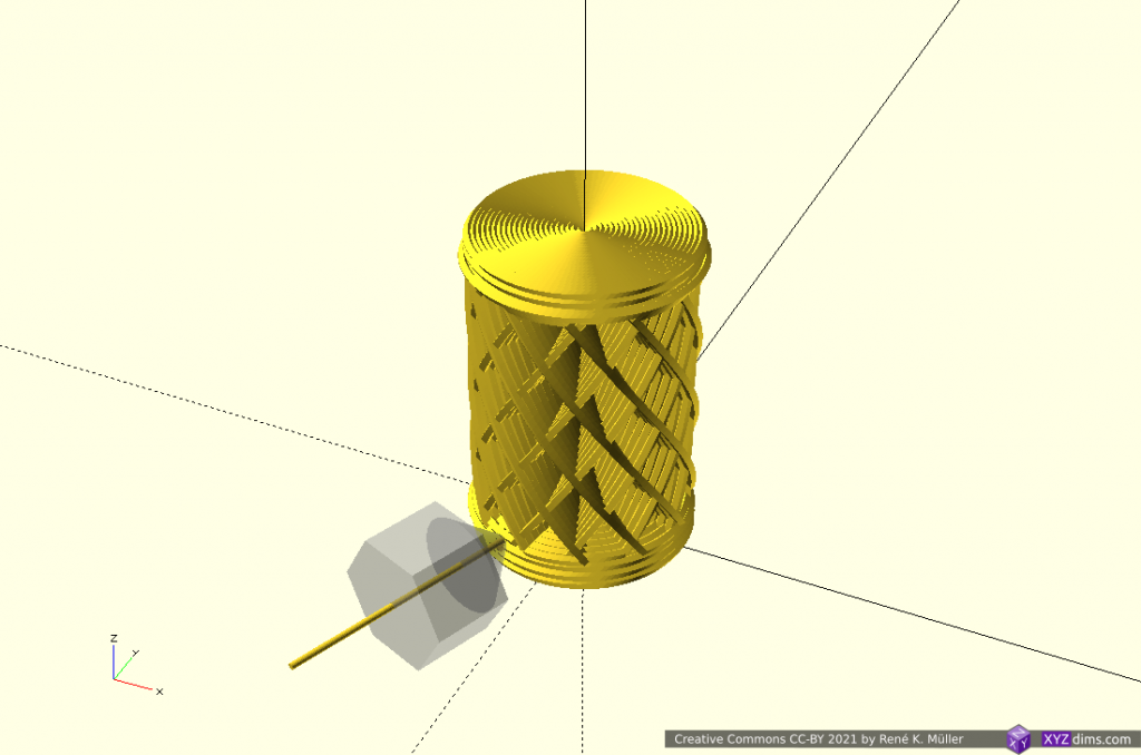
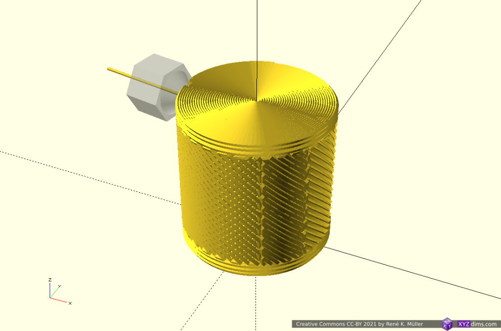
In order to explore non-planar slices, using a wave-like geometry composed by Bezier curves and slice a 20mm cube:
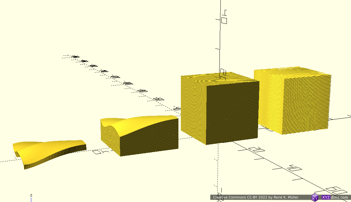
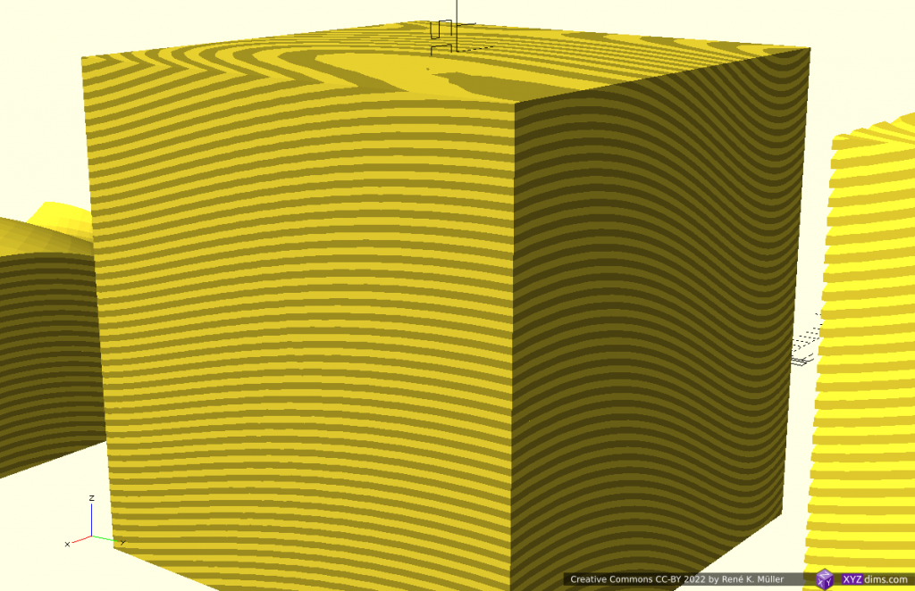
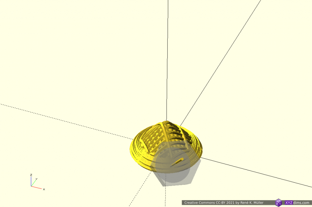
Note: OpenSCAD is used solely used as 3D viewer, the slicing itself is performed by an experimental slicer.

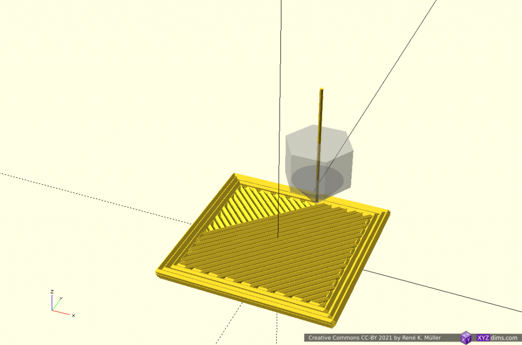
Routing a single non-planar slice

A single slice is routed to wall/perimeter and infill extrusion:
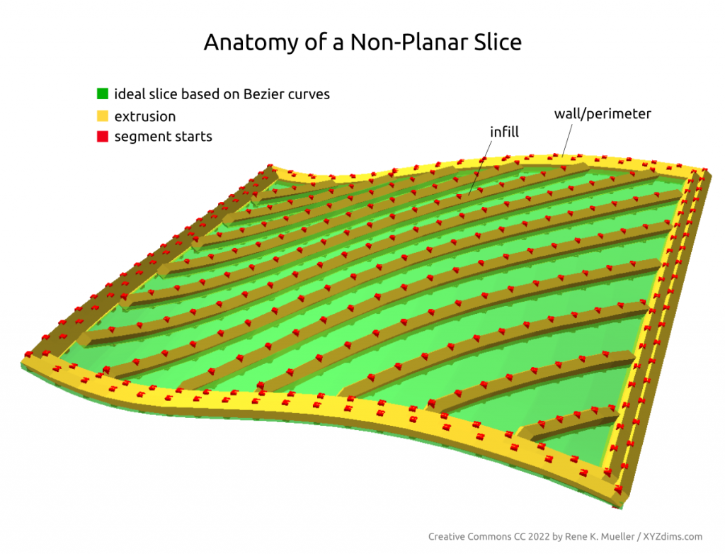
There are several approaches to achieve this:

  • slice non-planar, map single slice 3d to 2d, route with 2d offsetting, and map back to 3d space (MetatronSlicer)
  • map entire mesh and slice planar, and map routes or resulting G-code back again (EnochSlicer)

and likely other more complex means.

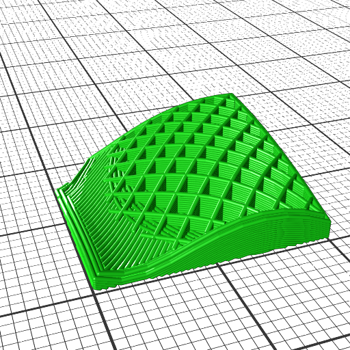
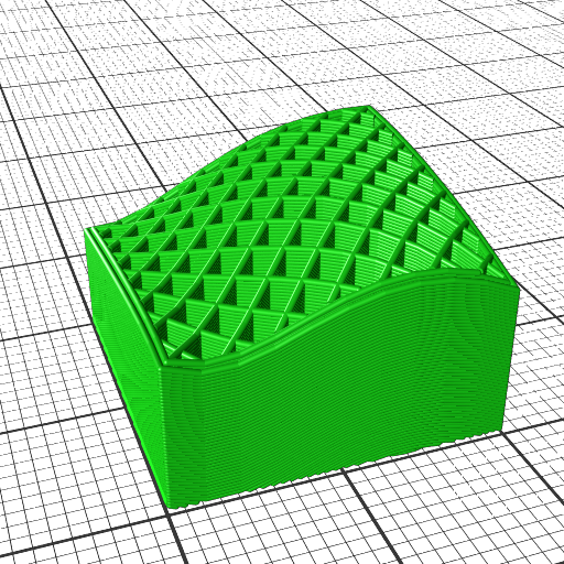
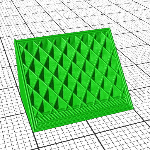
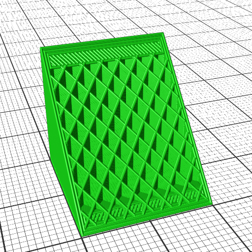
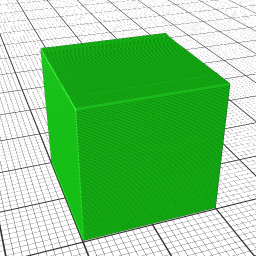
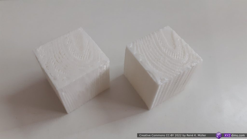
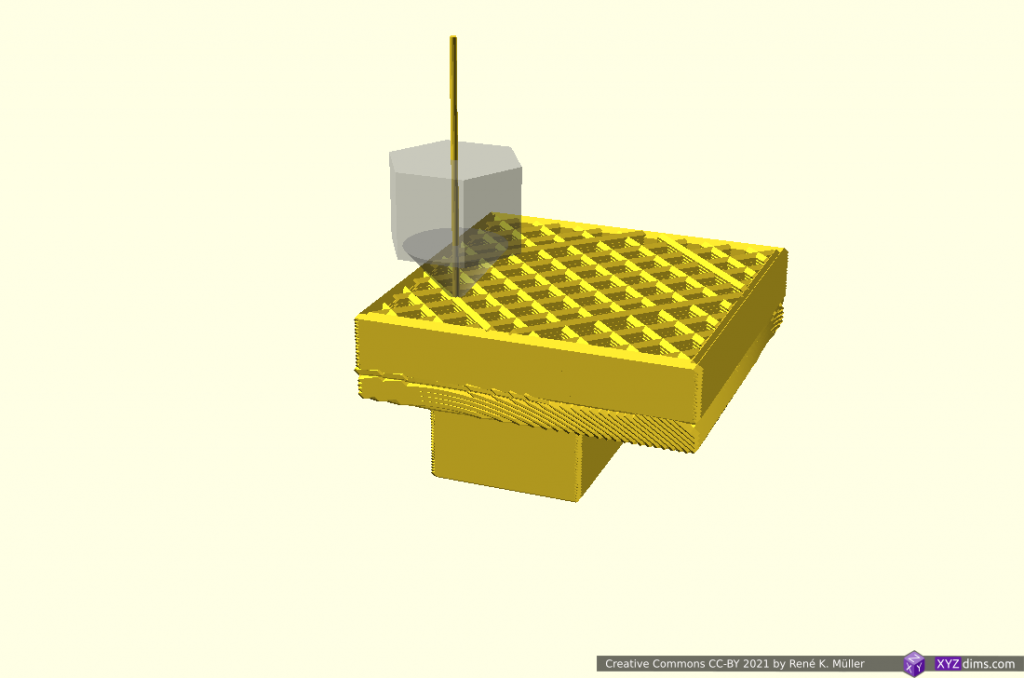
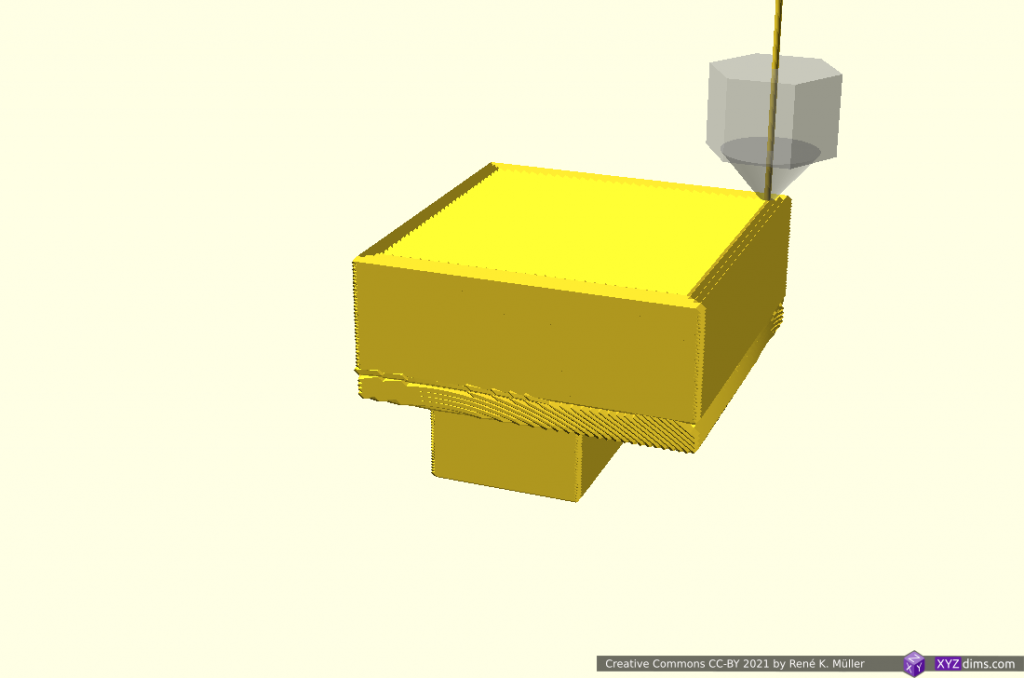
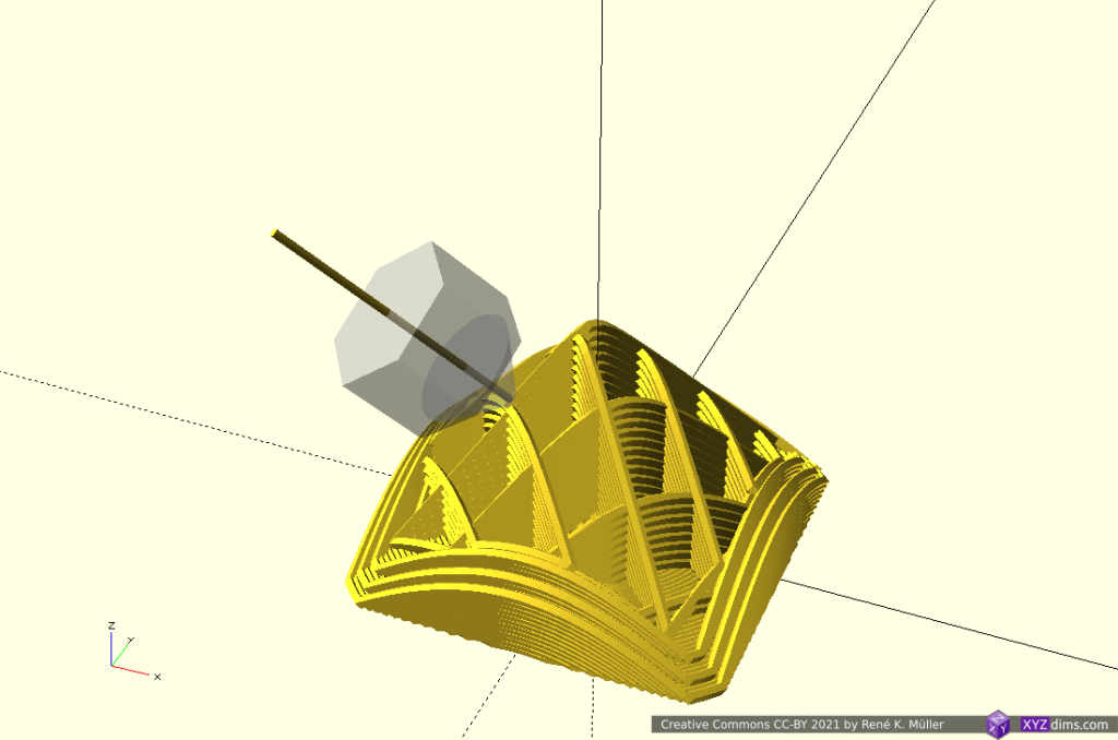
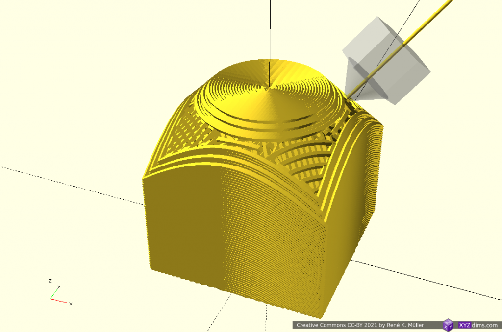
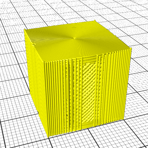
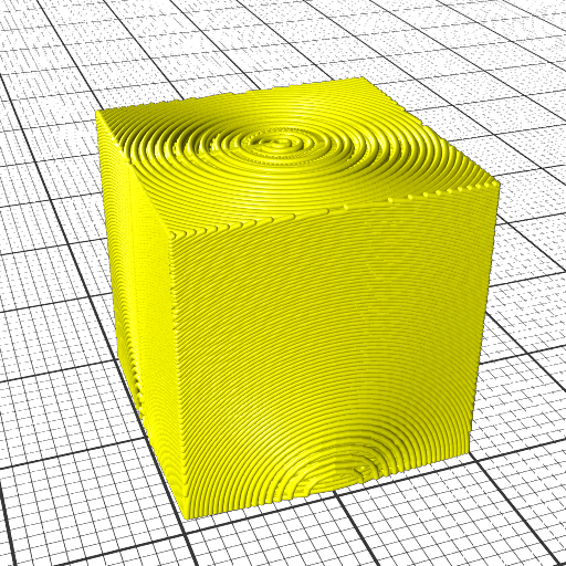
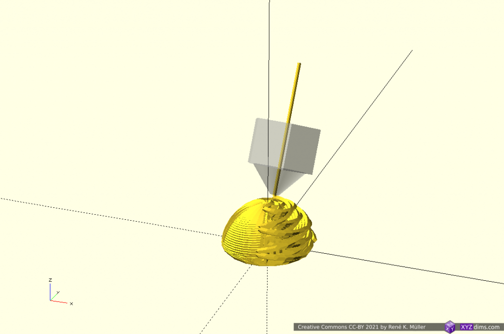
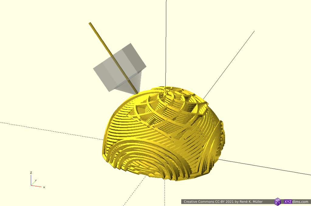
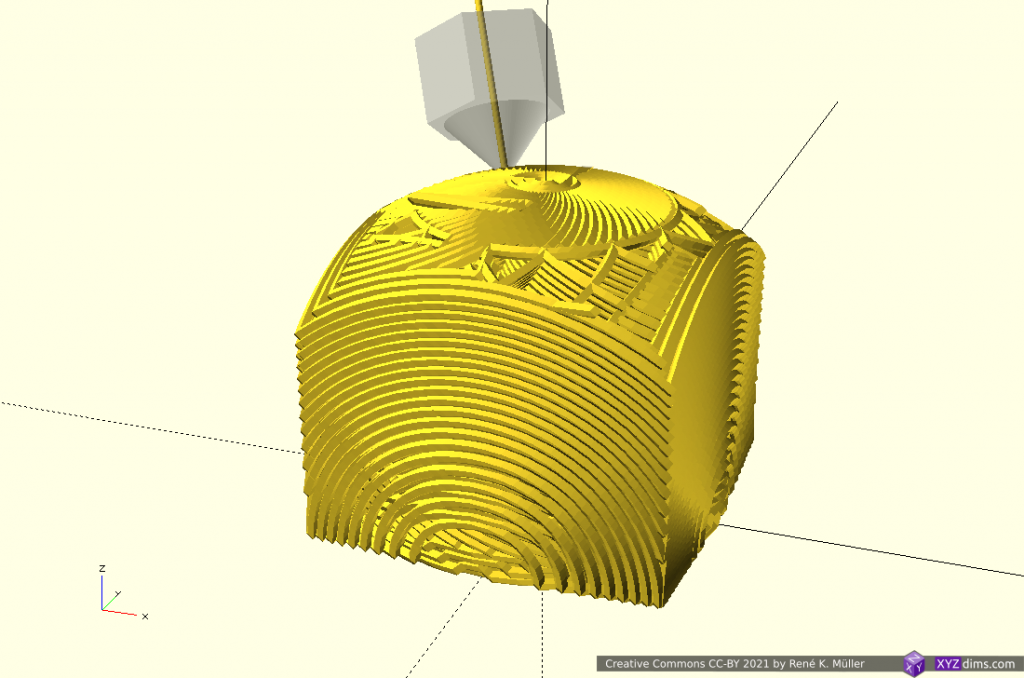
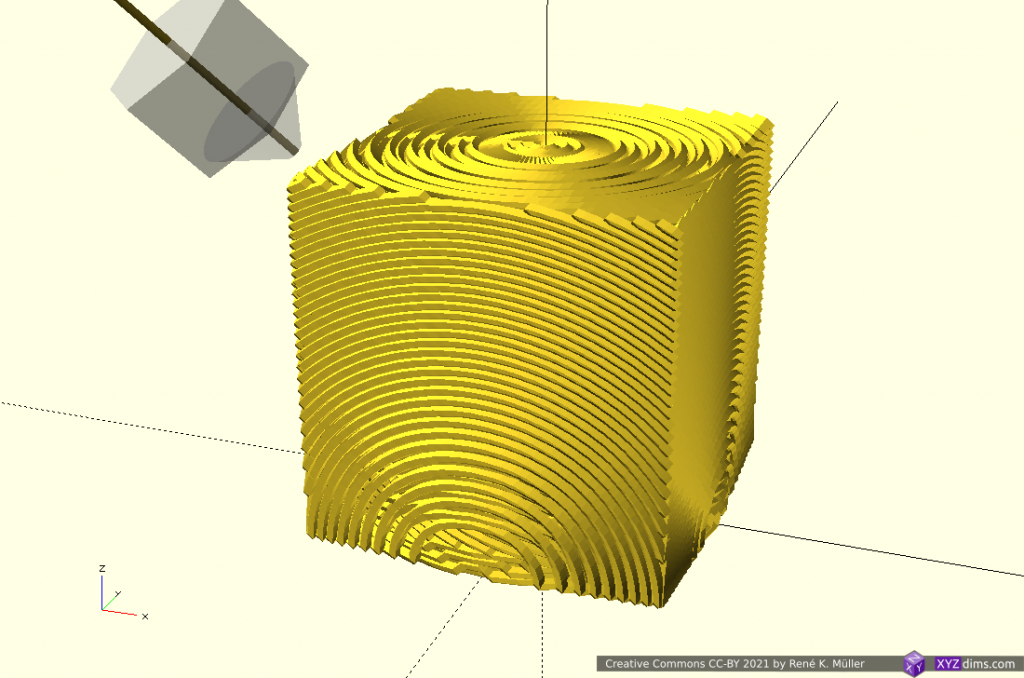
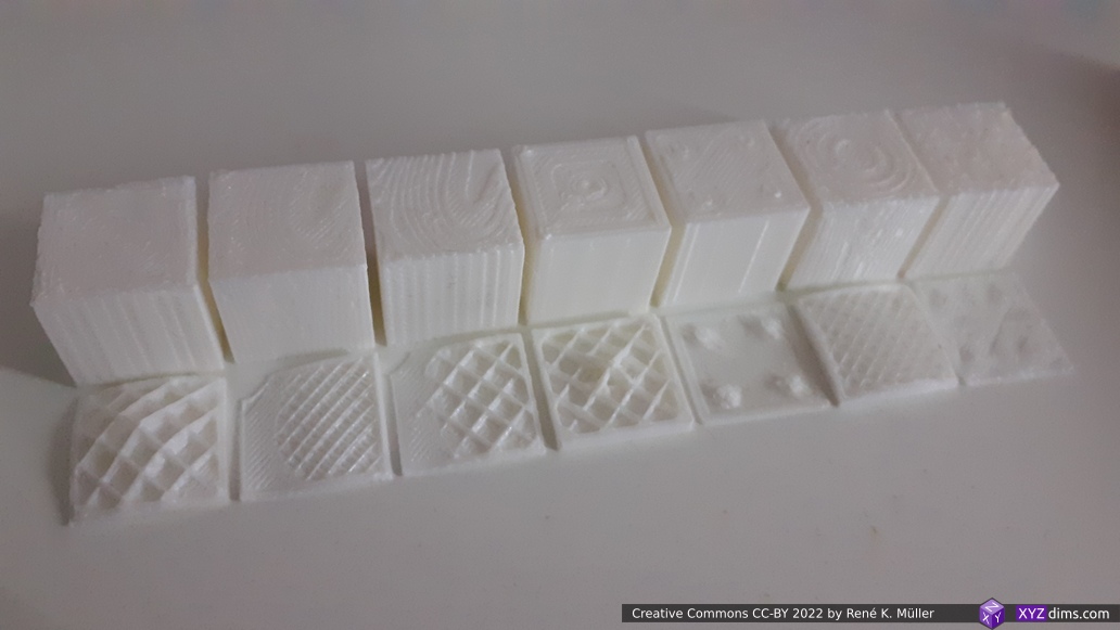
Non-planar Printed Wave-like Sliced 20mm Cube

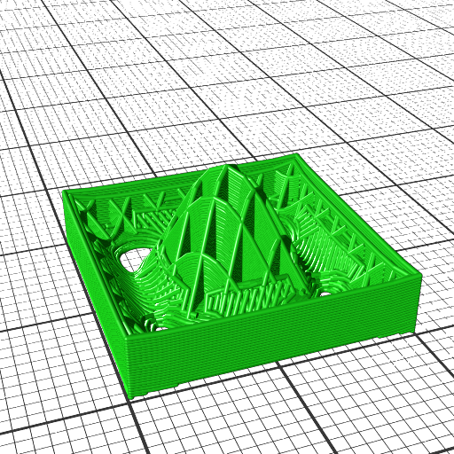
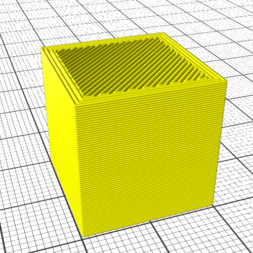
Preview of the complete G-code:

Preview the non-planar G-code of 20mm cube sliced with wave-like geometry

and a brief and fast printing simulation showing the entire print:

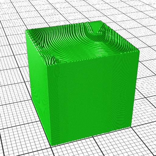
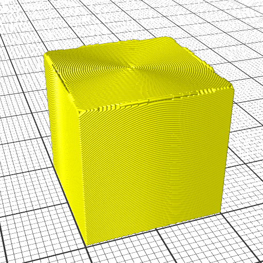
The computed G-code printed with a 3D printer, e.g. an ordinary 3-axis FDM:

Non-Planar 3D Printing: 20mm cube sliced with wave-like geometry (1x speed with a few skips)

and produces output like this:

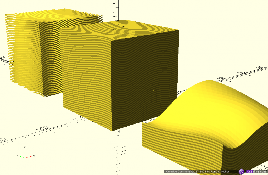
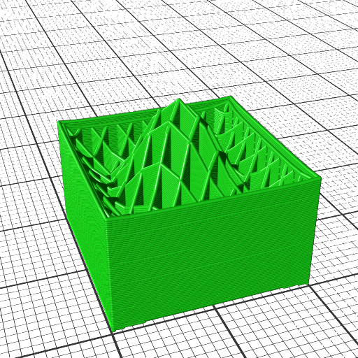
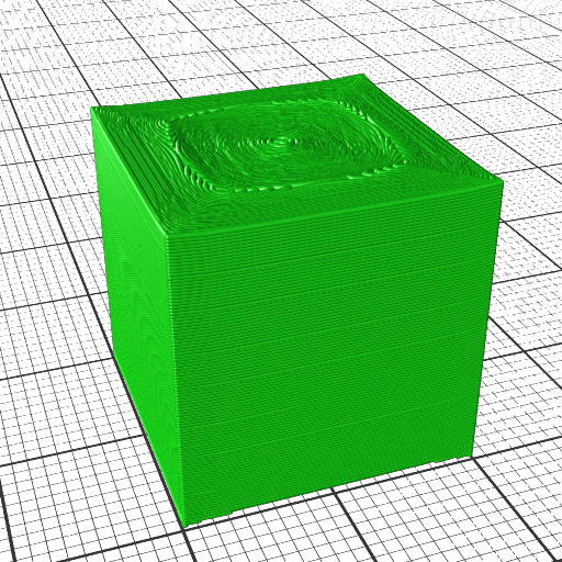
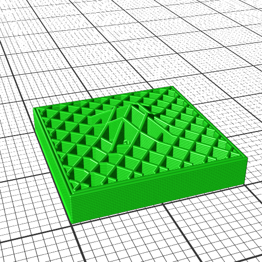
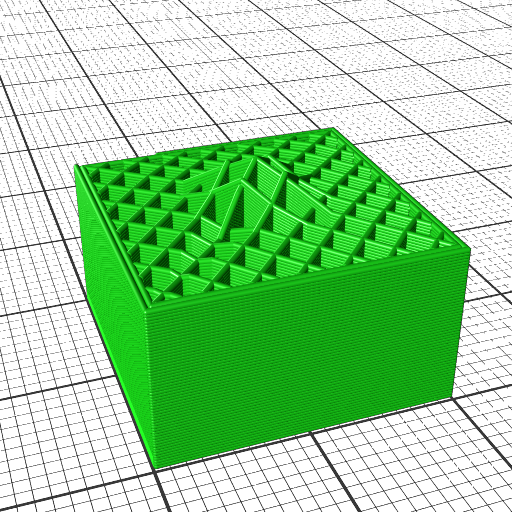
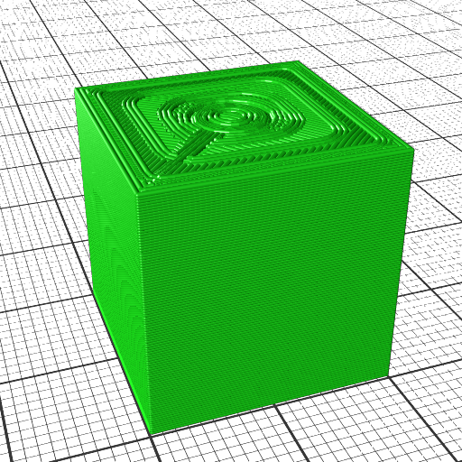
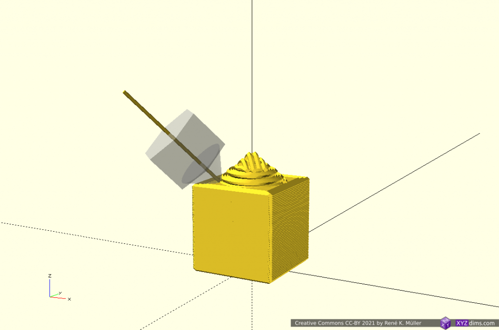
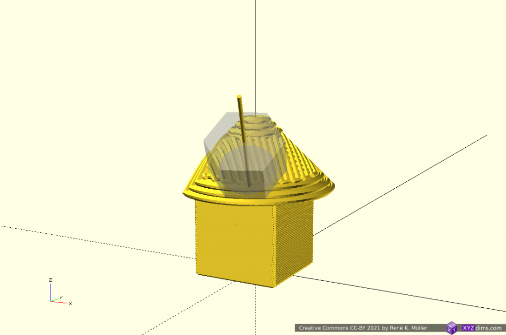
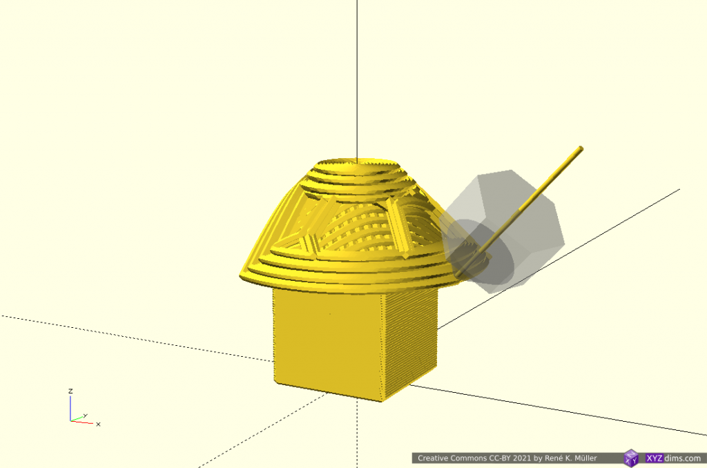
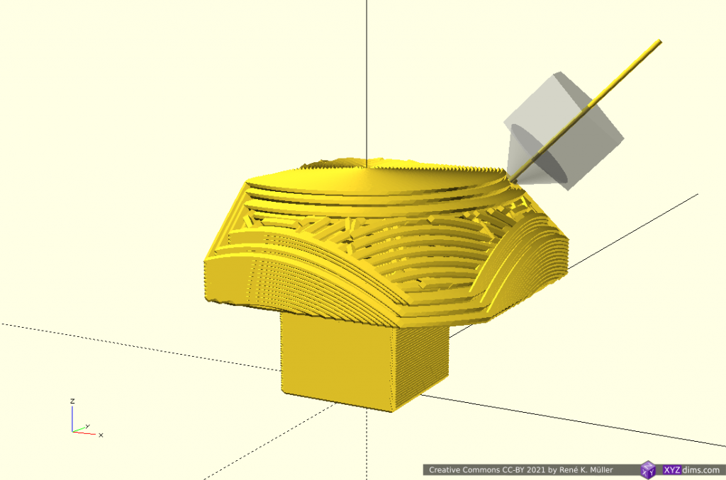
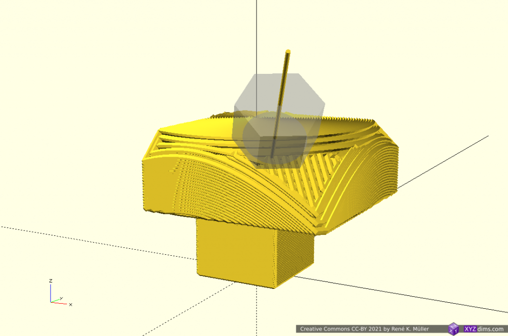
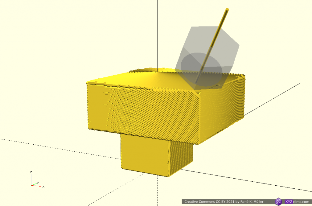
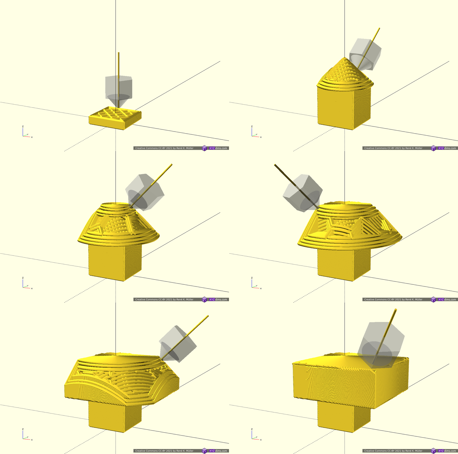
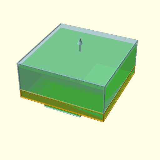
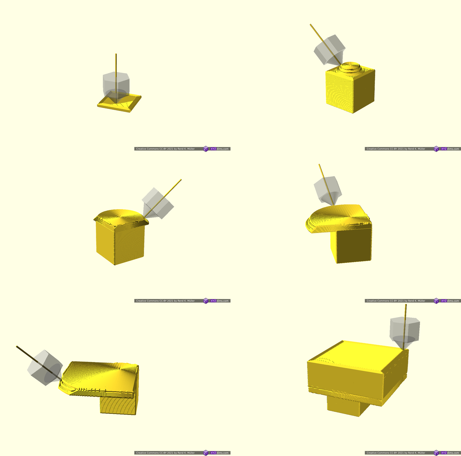
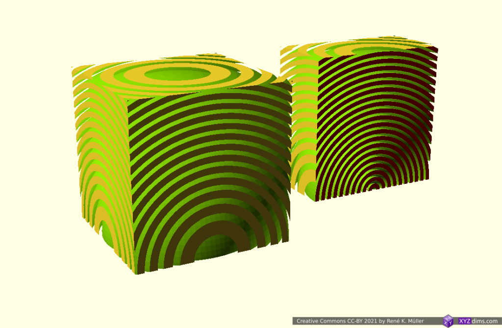
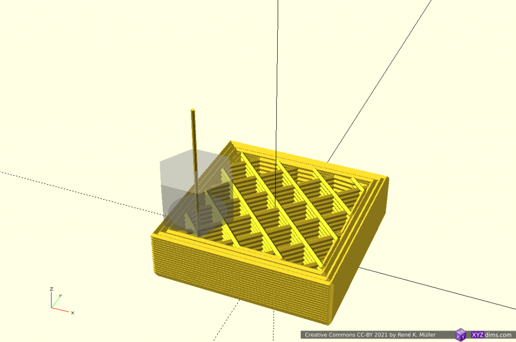
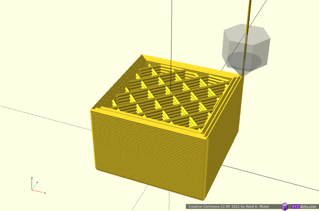
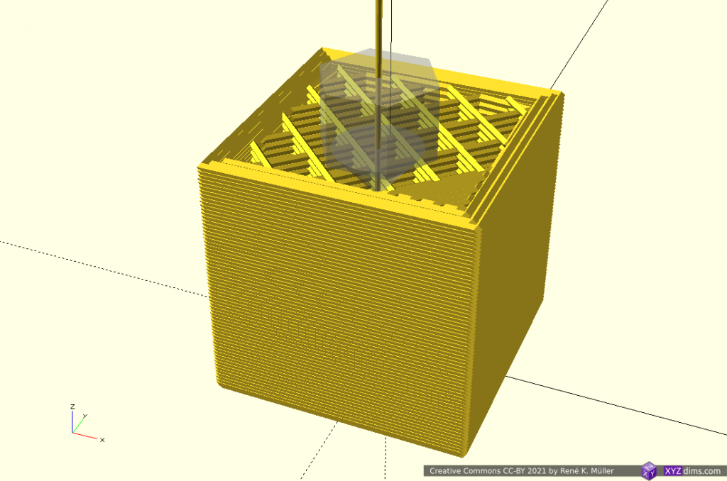
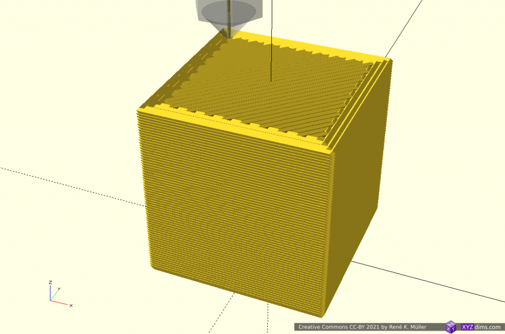
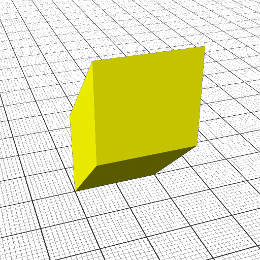
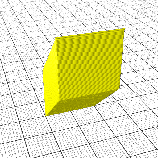
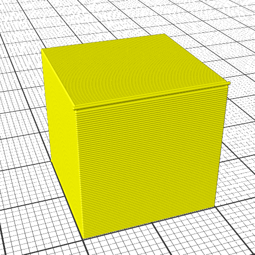
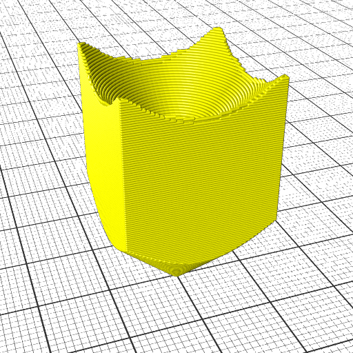
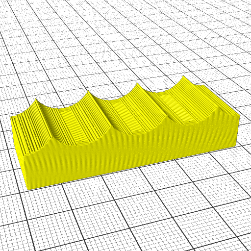
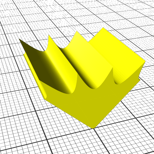
left-to-right: wave-like geometry itself, progressive state of 20mm cube sliced with wave-like geometry at 0.25mm layer height

Implementing Non-Planar Slicing Geometries Slicer

The illustrations and actual G-code above were produced by two new in-house slicers which are in early development (2022/03):

20mm cube sliced with wave-like geometry
left-to-right: MetatronSlicer (0.0.7), EnochSlicer (0.0.2)
  • MetatronSlicer: boundary-based (BREP / OpenCASCADE) and voxel-based (OpenVDB) geometry engine, performing true non-planar slicing, and LabSlicer performing routing and G-code creation; slower slicing yet precise G-code
  • EnochSlicer: mesh and G-code transformation approach, fast slicing yet less accurate G-code

The extrusion precision is still rough, but overall concept and algorithms have been proven to work.

Results & Achievement

This work as presented here resolves a long pending issue of slicing meshs “non-planar”, or general “non-planar slicing” with all its inherent ambiguity – consider it as given that

one can use any 3D geometry with sufficient upper “surface” to slice a mesh with

and create printable G-code for 3- and 5-axis FDM:
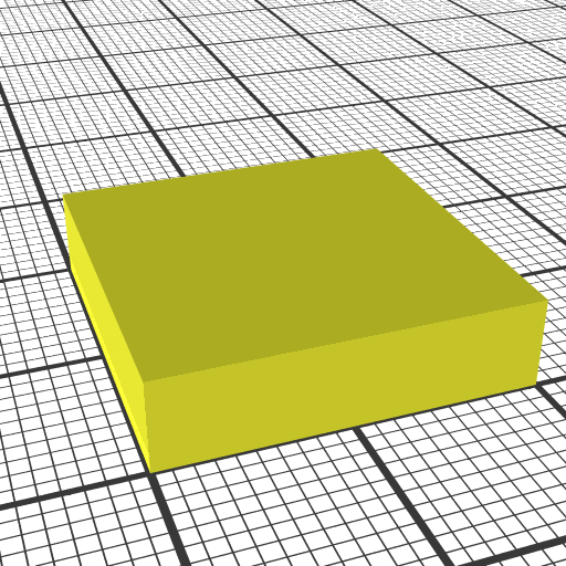
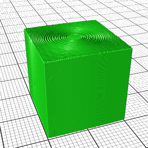
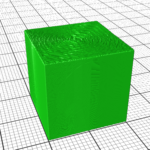
  1. using a block as planar blueprint
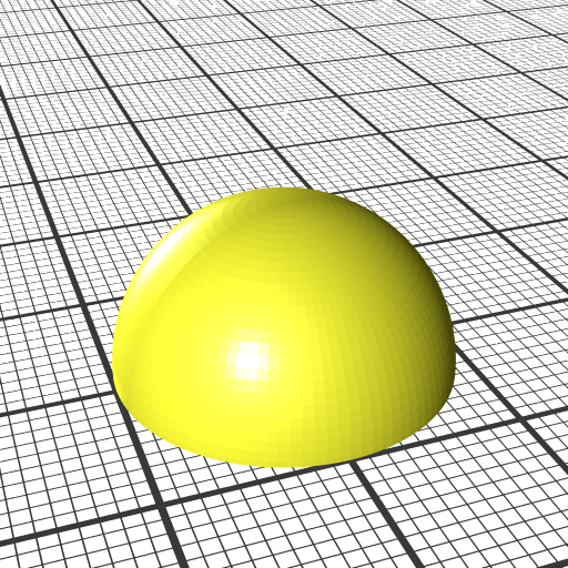
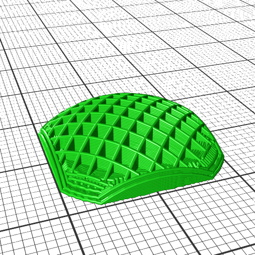
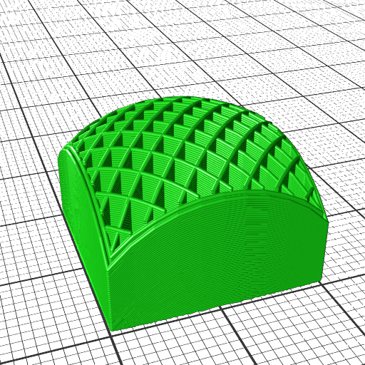
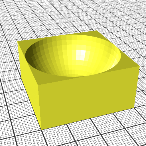
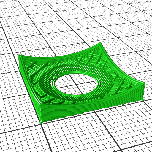
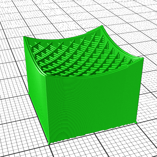
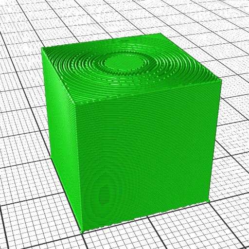
  2. hemisphere, convex
  3. hemisphere reverse, concave
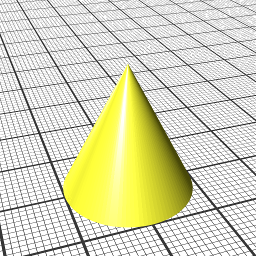
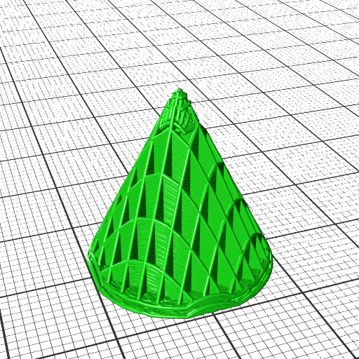
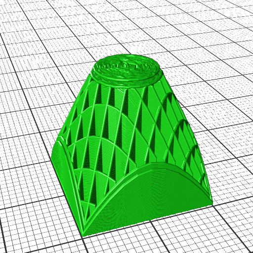
  4. cone, slicing conical like for Rotating Tilted Nozzle
  5. wave-like defined via Bezier curves
  6. wave-like defined via NURBS (Non-Uniform Rational B-Splines) curves
  7. tilted plane, slicing for belt printer with 45° tilted XY frame toward Z belt
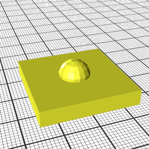
  8. pimple-like

Along with volume segmentation as presented previously and conical, cylindrical and spherical slicing now any kind of slicing geometry can be used.
As pointed out in Universal Slicing, this “Planar Slicing with Non-Planar Geometries” is Class 1 of Universal Slicing whereas Class 2 covers changing slicing geometry and/or flexible slicing path along the slicing.

Limiting Non-Planar Height for 3-axis FDM
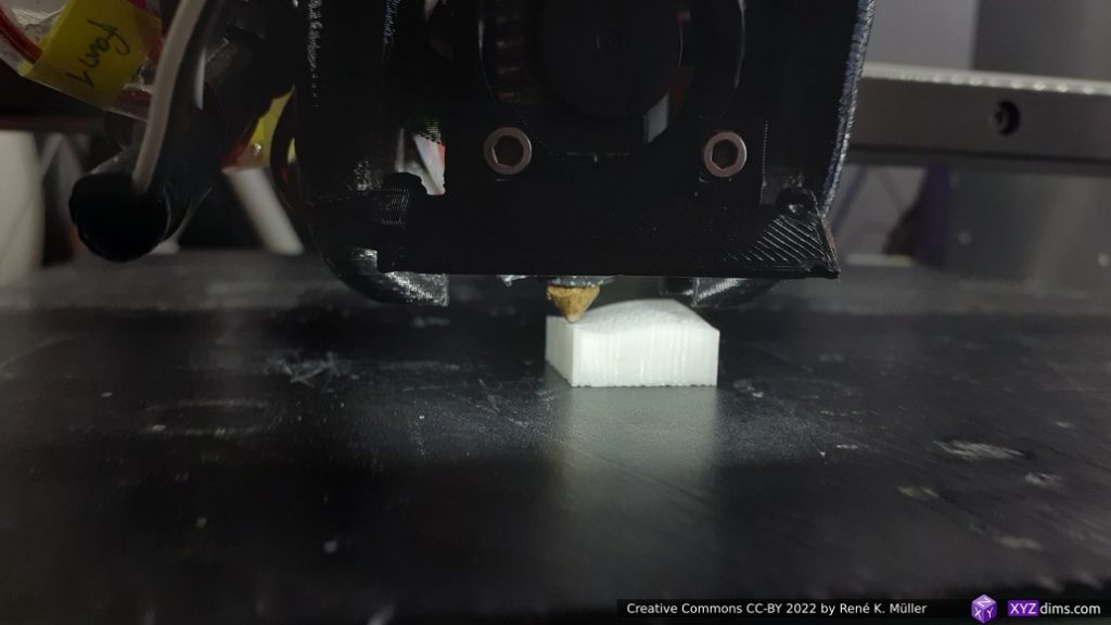
When using non-planar geometries to slice a model also non-planar G-code is produced and possibly significant Z motion occurs, and when printing with an ordinary 3-axis FDM 3D printer it may be suitable to limit the Z motion aka Z amplitude to 2-3mm in order to avoid part-cooler or other parts of the print head to collide with the already printed part:
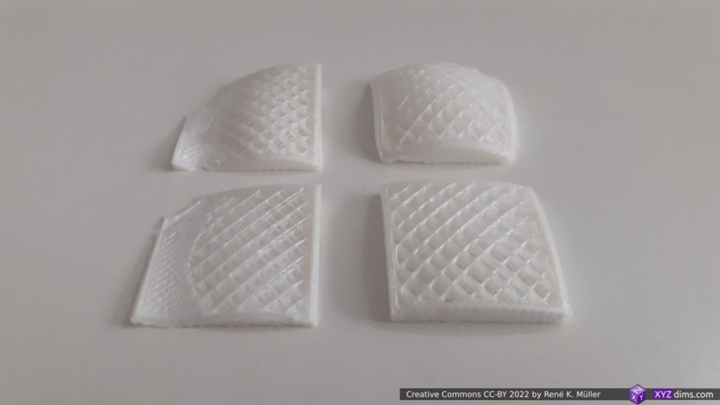
left column: wave-like slicing, right column: hemisphere slicing
top row: full range, bottom row: limited to ~3mm Z amplitude

Future blog-posts will go into further details implementing Universal Slicing using those two slicers MetatronSlicer and EnochSlicer.

Regarding naming the slicers: Metatron is an archangel in jewish mythology – consider an “angel” as a fundamental intelligence, and in esoteric context Metatron is the being responsible for Form or Geometry itself – separating one into many in a spatial manner; whereas Enoch as a human, who ascended to become the archangel Metatron. I use those names in deep reverence for these two projects.

Blind Spot of CAD Systems

Current CAD systems (2022) neglect or actually are unaware of the inner vs outer structure – because only one kind of the “structure” is known, e.g. a piece is designed because of a certain function, which defines its outer form, e.g. a wrench to use a simple example – but how about the inner structure? This isn’t defined in the CAD, it is defined at the manufacturing stage, yet with 3D printing this can be described and designed even in a parametric way as well, the slicing or general 3D printing stage with different materials.

We require 2 or 3 abstraction layers to design a functional piece:

  1. the functional description (doesn’t exist yet)
  2. the inner structure (description how material is deposited in Additive Manufacturing, e.g. the infill geometry as of with FDM, incl. non-planar printing, or lattice structures as with SLA or SLS)
  3. the outer structure (e.g. mesh, boundaries)

So far CAD systems only covers the 3rd point, the outer structure.

The functional description is almost non-existent in the CAD world, and only becomes some attention when Finite Element Analysis is made and the form is changed, it is kind of hidden in plain sight.

In future blog-posts I will address and elaborate on these issues further.

Scale and Functional Qualities

To put the flexible slicing geometry in the grander context of 3D printing engineering:

3D printing engineering starts at nanometer scale (10-6mm) with material science level, over to filament composition at 1 to 10 micrometer scale (10-2mm) such as fibers, inner geometry where slicing geometry & procedure and infill geometry define strength properties at millimeter scale (100mm), and outer geometry with the shape of the object itself provide the final stage of mechanical properties.
This entire “scale chain” as a whole defines the mechanical property of the final 3D printed object.

That’s it.

References

Universal Slicing

Updates:

  • 2022/04/01: changing wording of “non-planar” vs “planar” slicing but describe actual slicing vector and geometry
  • 2022/03/26: published finally
  • 2022/03/24: added “Tensile & Shearing Force” illustration
  • 2022/03/10: added “Scale & Functional Qualities”
  • 2022/02/27: added Class 2 example
  • 2022/02/18: removed MetatronSlicer example and move to new page, keeping page focused on general and theoretical aspect of Universal Slicing
  • 2022/02/12: adding MetatronSlicer example as first attempt of an Universal Slicer
  • 2022/01/28: separating from another blog-post, solely focusing on Universal Slicing
  • 2022/01/16: starting write-up

Introduction

While conceptualizing the in-house LabSlicer (2021/2022) and the two subsequent slicers afterwards (Vox3lSlicer & VoxGLSlicer), I realized it would be useful to formulate a general or universal description of slicing, hence I propose an universal definition of slicing as such:

Universal slicing means free slicing geometry along a free path.

“free (definable) slicing geometry”: any kind of geometry, may it be a solid or just a surface defining the slicing geometry.
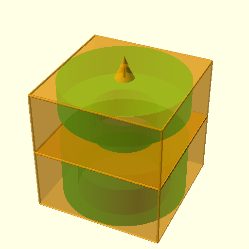
“free (definable) path”: the slicing procedure can go in any direction, curvature and steps.

To put this in context:

  • “planar slicing” is plane or quasi box geometry with layer height thickness, sliced along a static 3D path vector of [ 0, 0, 1 ], aka “planar” or “Z-planar” with vector steps of [ 0, 0, layer height ], whereas layer height can change in that case it’s “variable” or “adaptive layer height”
  • “conic slicing” is a cone geometry with layer height thickness, sliced along a static path vector of [ 0, 0, 1 ] with vector steps of [ 0, 0, cos( layer height )] or scaling a stationary conic to match layer height
  • “cylindrical slicing” is a cylinder which stays positioned static at [ 0, 0, 0 ] and variable scaled to match layer height with [ s, s, 1 ], slicing pipe-like layers
  • “spherical slicing” is a sphere geometry with scales in size to match layer height, the position stays [ 0, 0, 0 ], whereas the geometry is scaled by [ s, s, s ], slicing thin sphere layers
SlicingSlicing GeometrySlicing VectorVector StepsGeometry Scale
planarplane[ 0, 0, 1 ][ 0, 0, t ][ 1, 1, 1 ]
coniccone[ 0, 0, 1 ][ 0, 0, t ][ 1, 1, 1 ]
cone[ 0, 0, 0 ][ 0, 0, 0 ][ s, s, s ]
cylindricalcylinder[ 0, 0, 0 ][ 0, 0, 0 ][ s, s, 1 ]
sphericalsphere[ 0, 0, 0 ][ 0, 0, 0 ][ s, s, s ]

The actual implementation, how slices are routed and then G-code is created, is up to the slicer; an Universal Slicer is a slicer which implements Universal Slicing paradigm.

Class 1: Static Slicing Vector, Static Slicing Geometry

There are two distinct cases of class 1 slicing:

  • slicing with planar geometry, a plane – also known as “planar slicing”
  • slicing with non-planar geometry, like a wave, a hemisphere, a cone, etc.

Static slicing vector means here, there is an equal distance among all points of a slice to the next or previous slice at the same [ x, y ] position according the slicing vector:

Class 1 Universal Slicing: Static Slicing Vector with Planar and Non-Planar Geometries

Regardless of the slicing geometry, the layer height or thickness remains the same along the slice or layer itself.

The layer height or thickness may vary from layer to layer, this is known as “variable layer height” or “adaptive layer height” but only means among layers or slices, but not within a single layer or slice.

Class 1 Examples

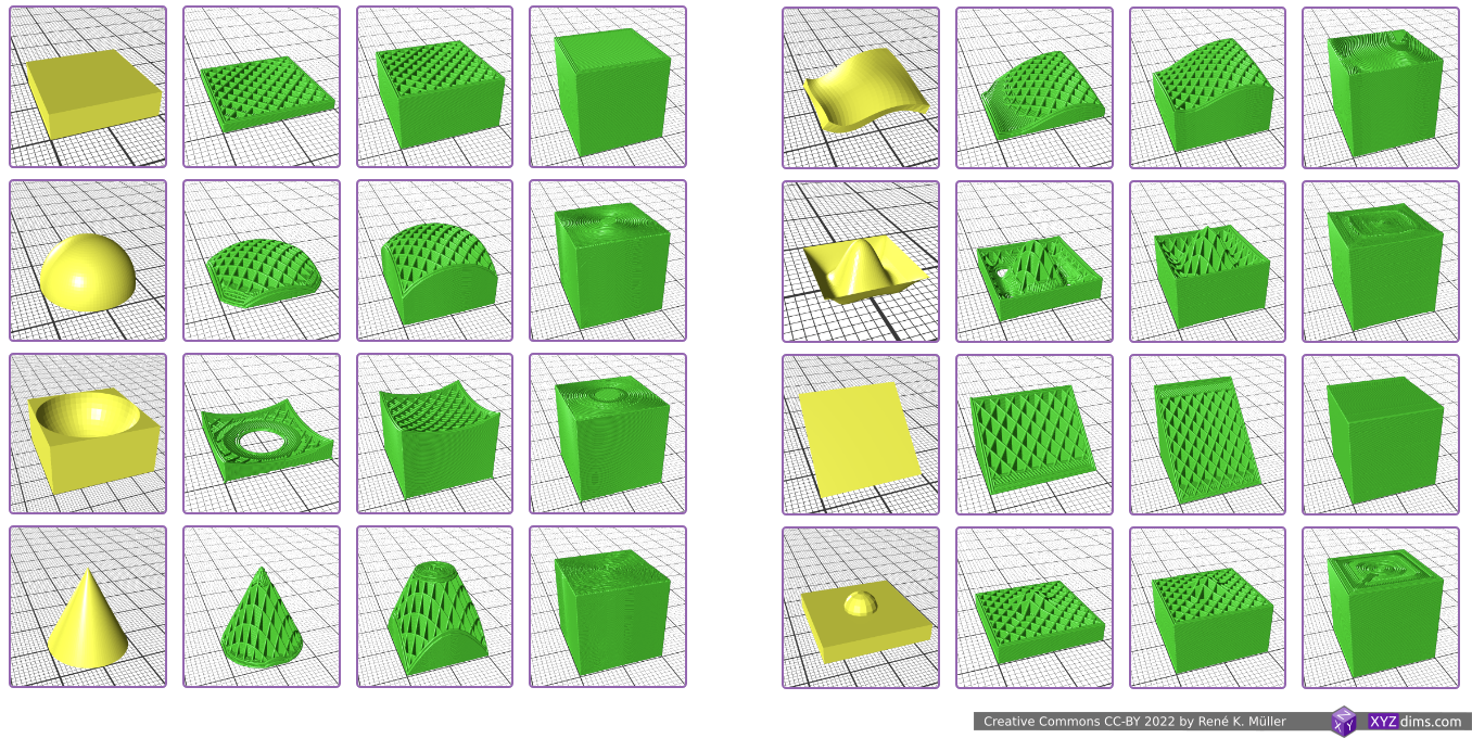
Examples of Class 1 Universal Slicing with planar and non-planar geometries and the respective G-code outputs (produced by MetatronSlicer and EnochSlicer):

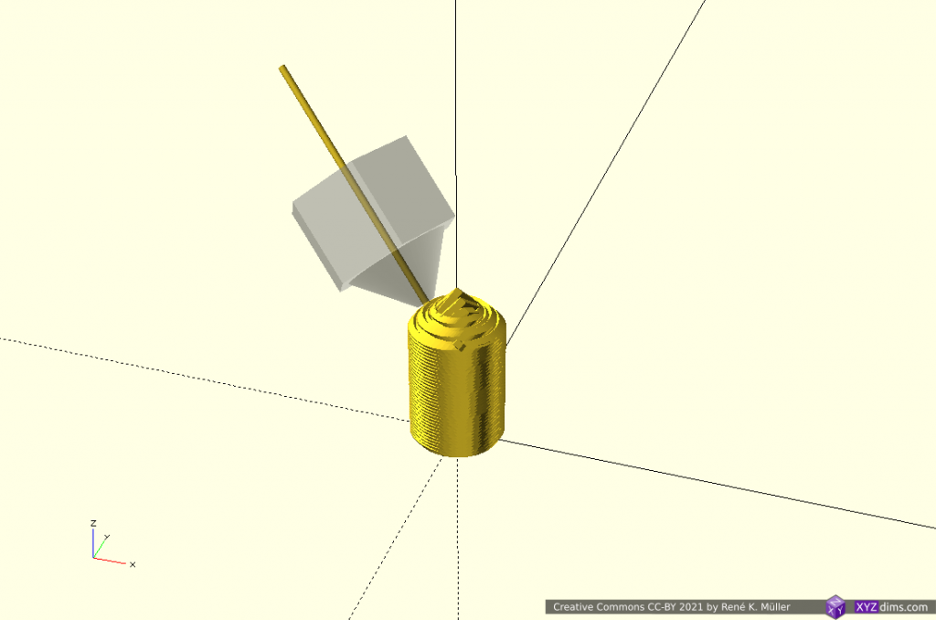
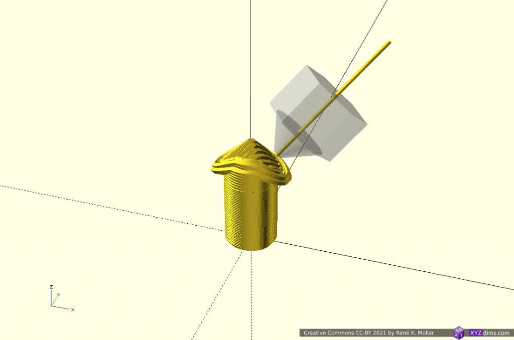
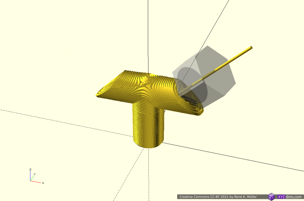
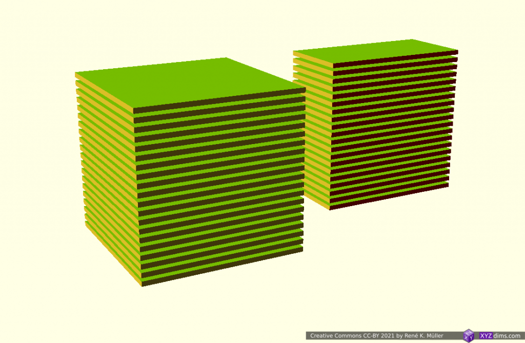
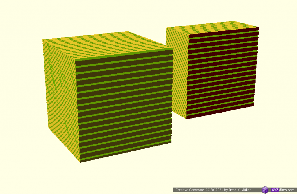
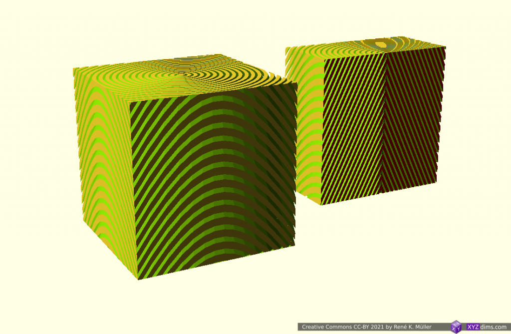
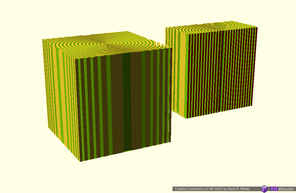
Class 1 Universal Slicing: Planar Slicing with Non-Planar Geometries: planar, hemisphere convex, hemisphere concave, conic, wave-like Bezier & NURBS, tilted, pimple-like
  1. using a block as planar blueprint
  2. hemisphere, convex
  3. hemisphere reverse, concave
  4. cone, slicing conical like for Rotating Tilted Nozzle
  5. wave-like defined via Bezier curves
  6. wave-like defined via NURBS (Non-Uniform Rational B-Splines) curves
  7. tilted plane, slicing for belt printer with 45° tilted XY frame toward Z belt
  8. pimple-like

Class 2: Variable Slicing Vector or Variable Slicing Geometry

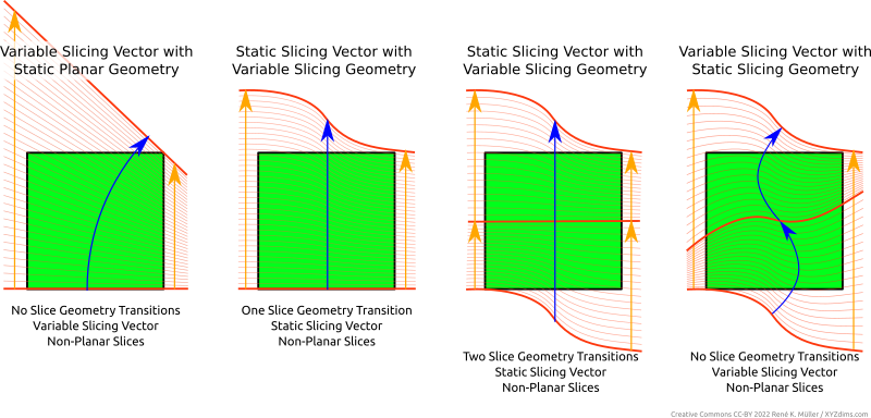
Variable slicing vector or changing slicing geometry (often refered as “non-planar slicing” without the specifics) means the slice itself has variable layer height or thickness – to be more precise:

  • change of slicing geometry, e.g. transitioning from one slicing geometry to another
  • change of slicing vector, e.g. change in steps, or curvature
Class 2 Universal Slicing: Variable Slicing Geometry, Variable Slicing Vector

It may not be always clear at first sight whether there is a transition of a slicing geometry or a change of slicing vector, as the changed slicing vector can also be looked as another slicing geometry – yet I think it makes more sense to differentiate between a slicing vector and slicing geometry when laying out a slicing procedure.

Class 2 Examples

Example of Class 2 of Universal Slicing (produced by EnochSlicer):

It is important to realize, that change of slicing geometry and/or slicing vector implies the slice or layer has variable thickness, hence, might have to comply with physical limits like maximum layer height printable with FDM and a given nozzle diameter – the actual implementation of an Universal Slicer has to adhere this.

Slicing Vector vs Slicing Geometry

Slicing VectorSlicing GeometrySlices / 3D PrintingSlice Thickness
staticplanarplanarstatic
non-planarnon-planarstatic
variableplanarnon-planarvariable
non-planarnon-planarvariable

Implementing Universal Slicing

The implementation of such Universal Slicing can be achieved in many ways and procedures. It is important to name features and describe what it they mean, such as:

  • Universal Slicing: is the ability to choose slice geometry and slice path freely
  • Universal Slicer: slicer which implements Universal Slicing in parts or fully – if it only implements part it shall be declared so
  • Class 1 Universal Slicing: static slicing path of [ 0, 0, 1 ], but with any kind of slicing geometry, static planar or static non-planar
  • Class 2 Universal Slicing: flexible slicing path, ability to change slicing geometry while slicing
ClassSlicing PathSlicing Geometry
Class 1staticstatic (planar or non-planar)
Class 2flexibleflexible (planar or non-planar)

Universal Slicers

  • MetatronSlicer (in-house XYZdims, status 2022/03):
    • slicing with (non-)planar geometries (Class 1)
    • partial support for slicing with change of slicing geometry (Class 2)
  • EnochSlicer (in-house XYZdims, status 2022/03):
    • slicing with (non-)planar geometries (Class 1)
    • partial support for slicing with change of slicing path & geometry (Class 2)
  • DotXControl 5-Axis Slicer (status 2022/03): supposedly supports Class 1 + 2 based on illustrations on the web-site
  • AI-Build (AI Build): requires NDA to even see a demo (!!) therefore difficult to conclude capabilities, might supports Class 1 + 2 based on illustrations and brief videos
MetatronSlicer: slicing with wave-like geometry a 20mm cube, printed with 3-axis FDM

Benefits of Non-Planar 3D Printing FDM

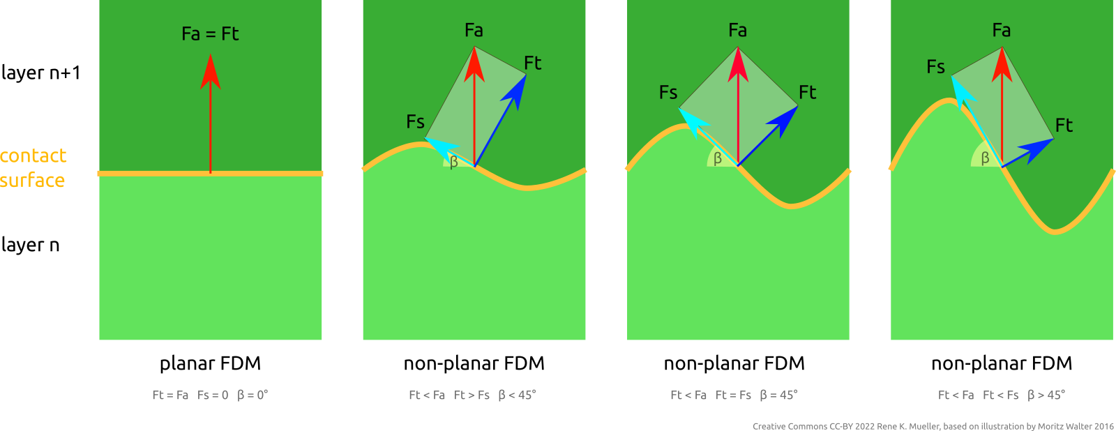
Layer adhesion tensile and shearing forces of planar and non-planar FDM
Fa = attacking force; Ft = tensile component of Fa; Fs = shearing component of Fa; β = tangent angle

One advantage resides in the ability to address FDM Z-layer adhesion issues by distributing force or stress vectors along any kind of trajectory and optimize material vs strength of the overall printed piece, e.g. when using continuous fiber filament and lay it along most stressed locations.

Further, the ability to have top layers align to object’s surface directly, no more layer lines. Essentially being able to define and manufacture a piece based on inner structure requirements and its outer form requirements.

References

3D Printing: Sub-Volume Segmenting & (Non-)Planar Slicing

Introduction

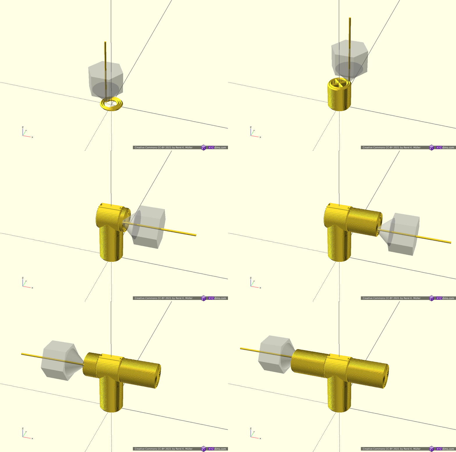
In order to take advantage of 4- and 5-axis non-planar FDM1) printing (e.g. tilted, conic, cylindrical, spherical) the model may be segmented and then dedicate slicing methods can be assigned to such sub-volumes.

A few basic examples combining planar and non-planar slicing methods on sub-volume segmented models illustrating the possibilities printing without support structures:

  1. Fused Deposition Modeling (FDM) also known as Fused Filament Fabrication (FFF)

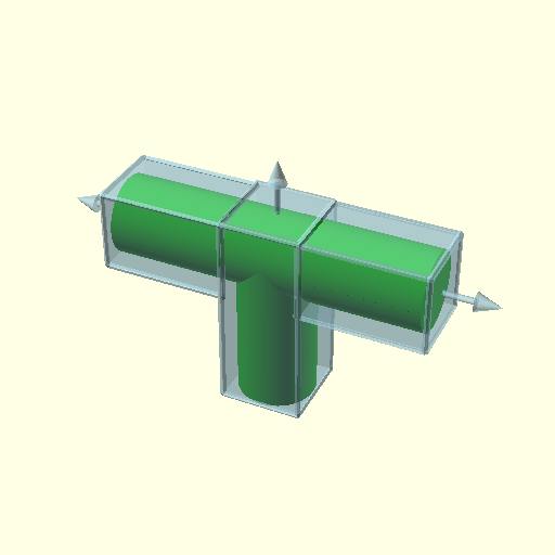
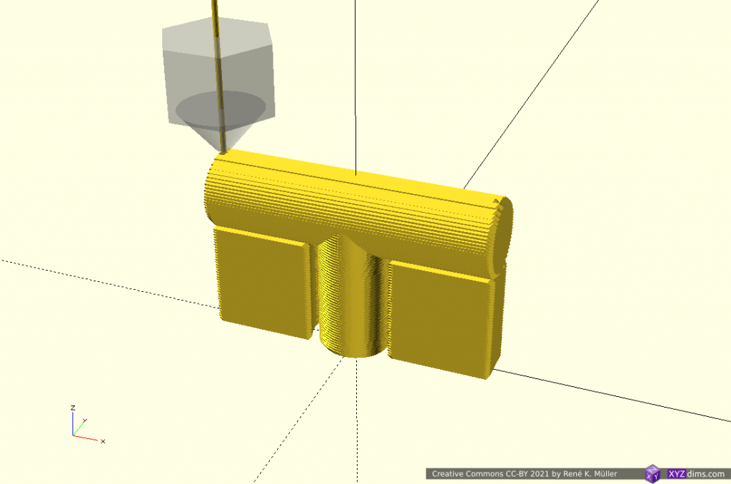
T-Model: 2 Segments: Z-planar & Conic

Utilizing novel conic slicing as introduced by ZHAW researchers in 2020/2021:

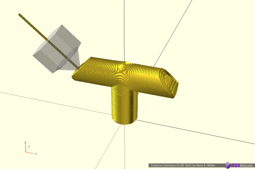
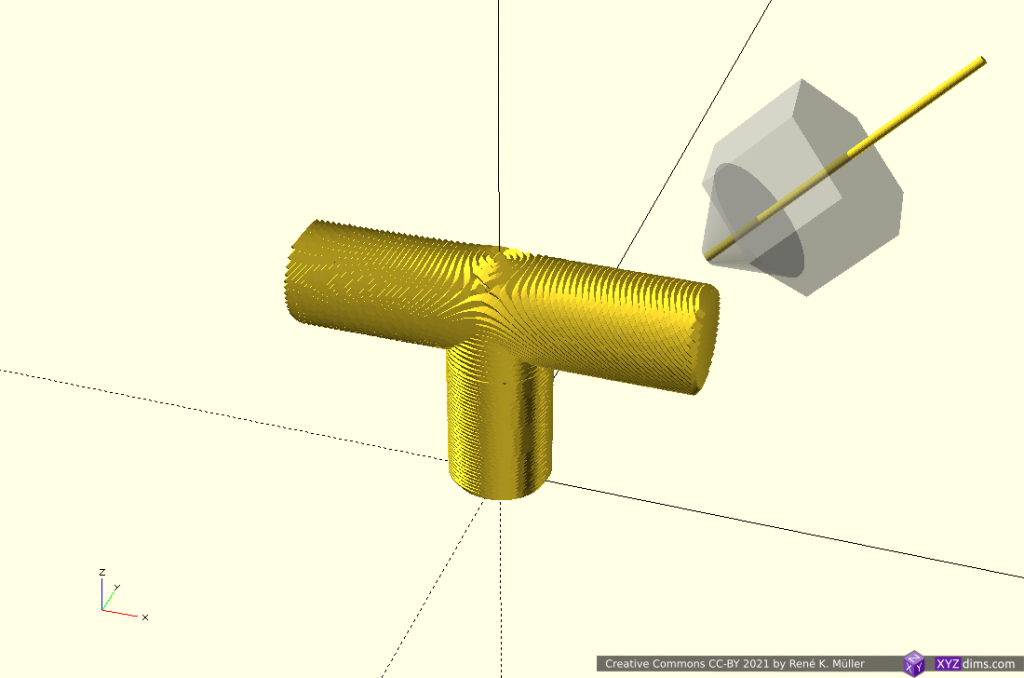
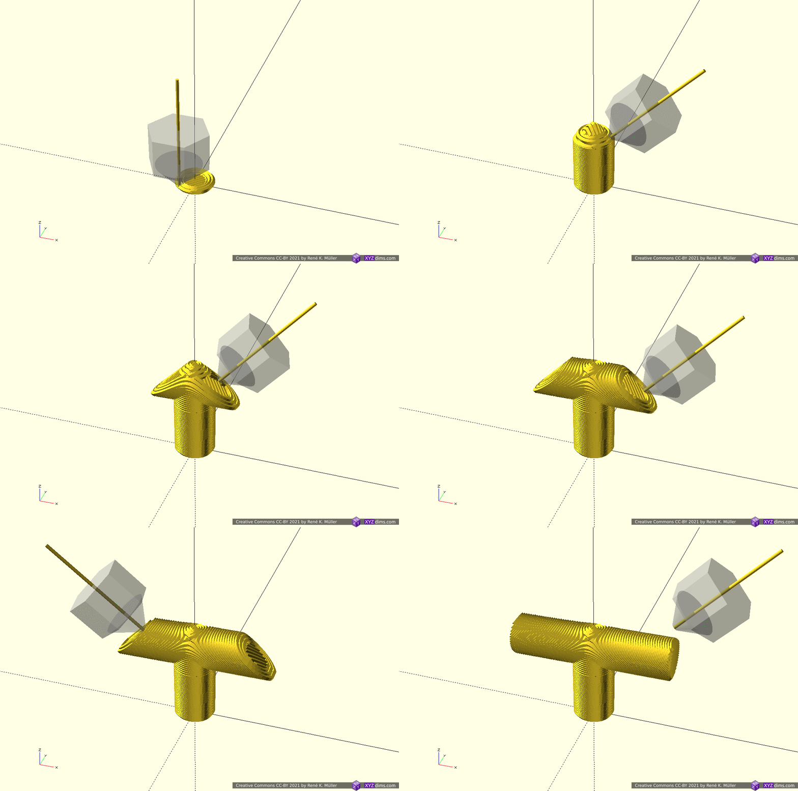
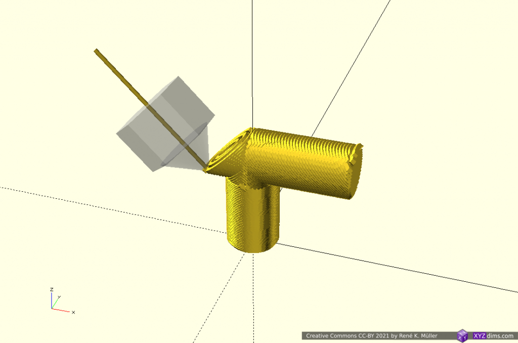
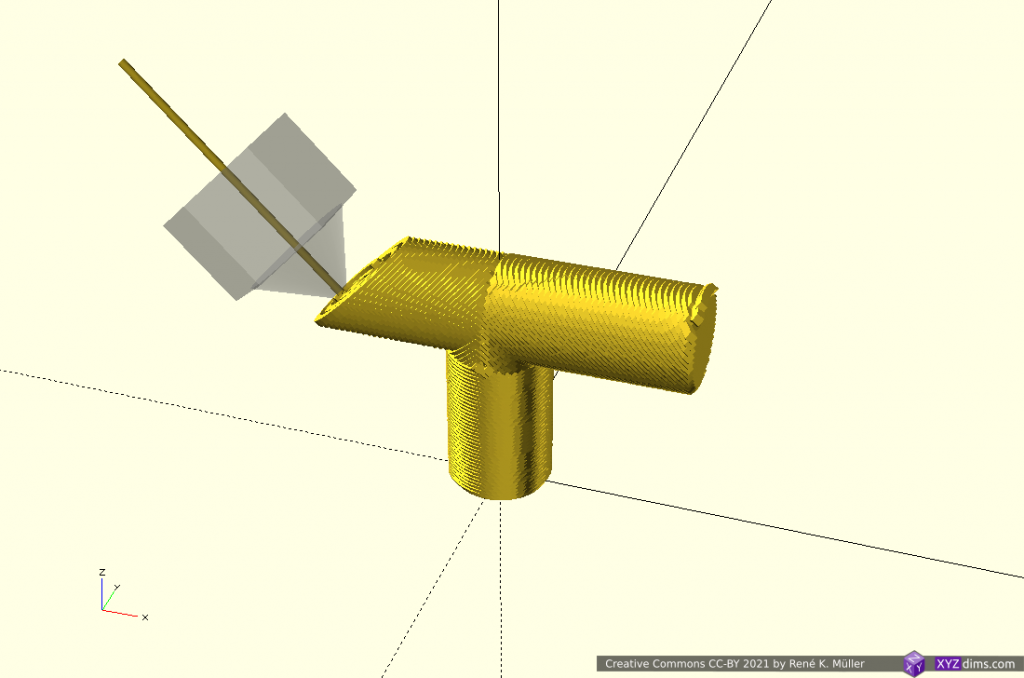
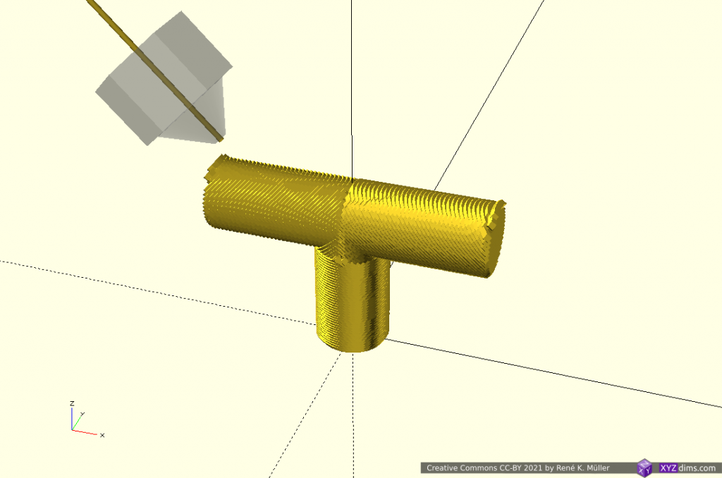
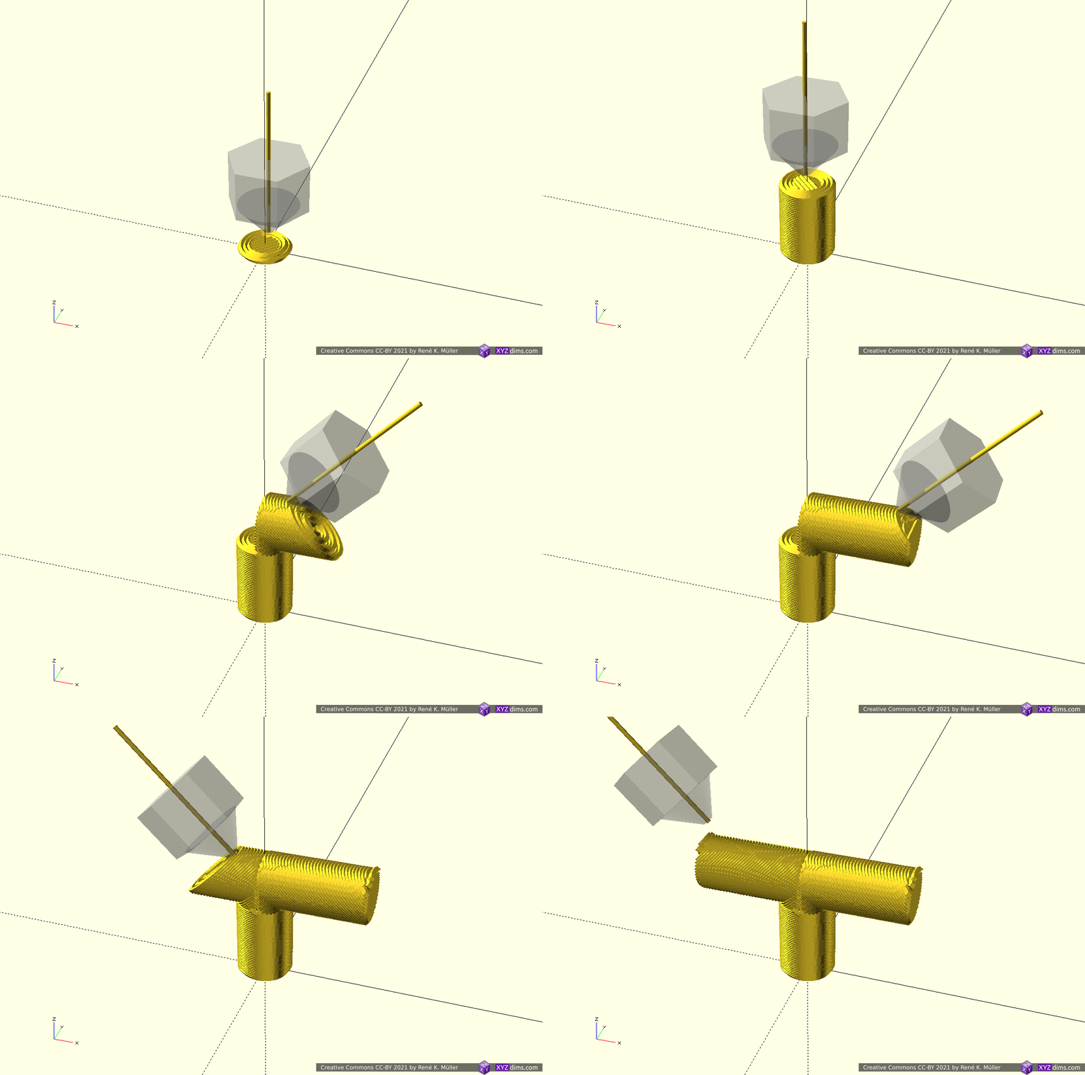
T-model segmented into 2 sub-volumes, sliced z-planar and conic (outside-cone mode)

Conic slices can be printed with 4-axis Rotating Tilted Nozzle (RTN) although printing the Z-planar sliced part might not give goods surface results but rather using a 5-axis Penta Axis (PAX) printhead to cover both cases easily.

T-Model: 3 Segments: Z-planar & 2x Tilted

Using non-rotating but tilted sliced (like used with belt-printers) but in two distinct directions:

T-model segmented into 2 sub-volumes, sliced z-planar and twice tilted in opposite directions

Tilted slices can be printed with 4-axis Rotating Tilted Nozzle (RTN) but the first Z-planar part, as mentioned above, might not provide sufficient surface quality, whereas a 5-axis Penta Axis (PAX) printhead can print both segments easily.

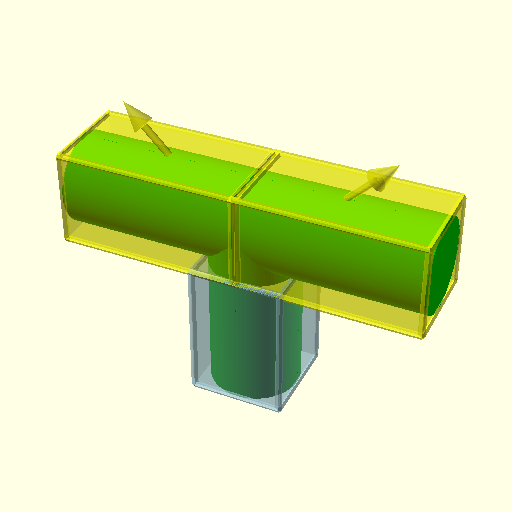
T-Model: 3 Segments: Z-planar & 2x X-planar

A more classic planar approach but with different planes as reference, first Z-planar then twice X-planar in different directions:

T-model segmented into 3 sub-volumes, sliced z-planar and twice x-planar

X-planar printing requires either 5-axis Penta Axis (PAX) printhead or the ability to tilt the bed.

Overhang In/Out: 2 Segments: 2x Conic

Lower part is sliced with conic slicing with inside-cone mode to print in-going overhang, whereas the upper part is sliced with outside-cone mode to cover the out-going overhang:

Overhang in/out model segmented into 2 sub-volumes: lower part is sliced conic (inside-cone mode) and upper part conic (outside-cone mode)

This model covers the classic case of 4-axis Rotating Tilted Nozzle (RTN) application: rotating 45° tilted nozzle printing in two different modes (outside-cone and inside-cone); a 5-axis Penta Axis (PAX) printhead also can print such.

Overhang Out No 5: 2 Segments: Z-planar & Conic

Another overhang piece, stretching out into one direction; the lower part Z-planar, and the overhang conic (outside-cone mode) with an offset to align better with the lower segment:

Overhang Out No 5 model segmented into 2 sub-volumes: z-planar at the bottom and overhang segment conic (outside-cone mode)

Overhang Out No 5: 3 Segments: 2x Z-planar & Conic

Perhaps a more realistic approach using the conic part as a “balcony” just for the overhang part sufficiently thick to carry next segment and switching back to Z-planar:

Overhang Out No 5 model segmented into 3 sub-volumes: z-planar first, then conic (outside-cone) building a thin “balcony” as support for the z-planar part on top again

Early tests have shown the thickness of the conic overhang “balcony” depends on the actual length of the in-air overhang, where print speed, part-cooling capacity and extrusion consistency determine the geometrical accuracy. More examples with “balcony” printed with 3-axis FDM printer followed.

Conclusion

Unlike with ordinary Z-planar slicing, it may be suitable to dedicate a particular slicing method and orientation for sub-volumes in order to take advantage of the possibilities like avoiding support structure, particular strength properties or surface quality.

This of course opens a wide-range of possibilities and complexity therefore:

  • where to segment
  • which slicing method to use
  • in which orientation the slicing is performed

but I think it’s worth it, in particular when a piece is printed more than once like with small series manufacturing / production.

The examples have been produced with various slicers and combined with a new application coordinating the segmenting and dedicated slicing methods, which currently (2021/04) is in development; it also involves a new file-format describing the segmenting and its slicing settings. The segment positioning was done manually as a start, but I expect with more experience and research some cases can be detected automatically.
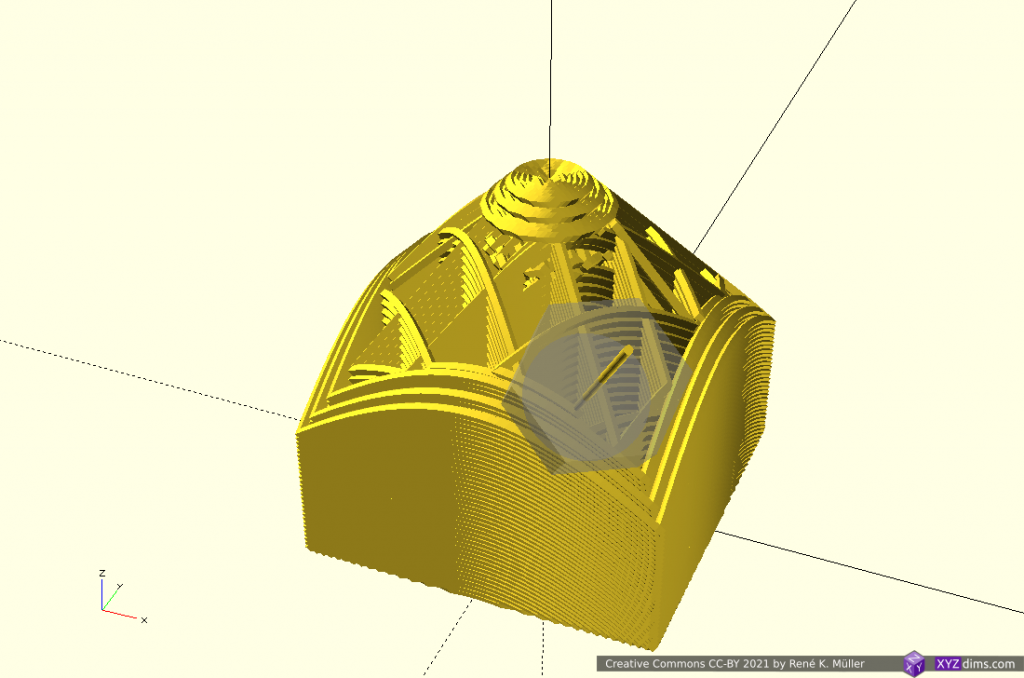
Sub-volume segmenting is just one approach to take advantage of 5-axis FDM printing, another is continuous slicing along the form.

References

See Also

PS: All animations I combined in a short 3min video: Mixing Planar & Non-Planar Slicing Methods for 3D Printing Overhangs without Support Structure (YouTube)

3D Printing: Non-Planar Slicing with Planar Slicer

Updates:

  • 2021/04/09: spherical slicing redone, slightly better than before
  • 2021/04/03: cylindrical & spherical slices added
  • 2021/03/26: refocusing to non-planar slicing with planar slicing
  • 2021/03/14: starting write-up with basic illustrations

Introduction

After discovering the 4-axis Rotating Tilted Nozzle (RTN) and its prototype of RotBot as developed by ZHAW and their conic slicing method, it became clear to me a 5-axis 3D printer with variable tilting nozzle is the way to go as it is a superset of 4-axis and 3-axis 3D printing.

With that in mind, I realized there was time to explore non-planar slicing with planar slicers in more details.

Slicing Methods

Let’s provide an overview of various slicing methods:

Horizontal Slices

Vertical slicing creates horizontal slices, the traditional aka planar slicing method, so issues and limitations are well known:

  • simple to slice
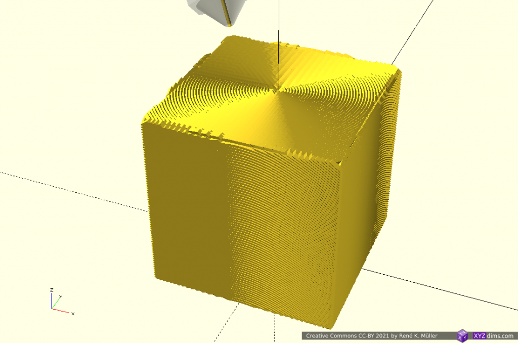
  • only challenge is to create support structure for overhangs to ensure all printed layers have layers beneath
  • no collision detection needed, as all already printed layers are beneath

Tilted Slices

Tilted slices are kind of new(er) and became known with belt printers, usually 45° tilted:

Transformation is [ x, y, z – y ]

  • simple to slice
  • belt-printer: no collision detection is needed
  • can print 90° overhangs in one direction only

There are patches for Cura available to slice for belt printer, additional the experimental Slicer4RTN also provides tilted slicing.

Conical Slices

New slicing method as introduced by ZHAW researchers and announced in 2021/01 utilizing planar slicer:

  • requires a center of the conic layers
  • can print 90° overhangs, two distinct modes: inside out (outside cone), or outside in (inside cone) depending on direction to a central slicing cone center
  • requires rotating and tilted nozzle aka Rotating Tilted Nozzle (RTN)
  • angle of conic slicing can be changed from 45° to 20° and models become printable with vertical nozzle with reduced print quality

Transformation is [ x, y, z + sqrt(x2 + y2) ]

I implemented a conic slicer named Slicer4RTN in 2021/03. There are more complex conic transformations possible, e.g. map the x/y angle via atan(y/x) but just adding sqrt(x2 + y2) to z does achieve a conic slice.

Cylindrical Slices

Early tests using planar slicers to slice also cylindrical, like this:

Transformation is [ atan(y/x), z, sqrt(x2 + y2) ]

It can be printed on a fixed vertical rod, with a rotating and tilting nozzle, or horizontal rotating rod (like a lathe) and vertical nozzle then:

I came up with this way by myself based on the study on conic(al) slicing but I was made aware researchers Coupek, Friedrich, Battran, Riedel back in 2018 published a paper on this method already.

(Hemi-)Spherical Slices

Early tests using planar slicers to slice also spherical, like this:

Transformation is [ sqrt(x2 + y2 + z2), atan(y/x), atan(z/sqrt(x2 + y2)) ]

It can be printed with a 5-axis like PAX printhead, it’s main advantage is to getting close to print continuous overhangs of any angle.

I suspect at least one more suitable and simpler sphere transformation, as soon I came up with such I add it on this blog-post.

Conclusion

It is possible to slice non-planar with planar slicers by mapping to and from the space of the slicing you like to have; yet in the slicing procedure some margins are introduced which need to be compensated – the planar slicer needs to work reliable, Slic3r 1.2.9 and CuraEngine 4.4.1 / cura-slicer perform reliable, whereas PrusaSlicer 2.1.1 makes assumptions of the printability and exits when no printable G-code can be produced, not recommended for this case therefore.

The simpler the transformation forward and backward, the more precise G-code can be obtained, e.g. tilted and conic slices provide precise G-code, whereas cylindrical and spherical slices are harder to tune with the planar slicer.

References