
Status: prototype doing test prints
Updates:
- 2021/05/31: first prototype photos with dry run
- 2021/03/13: fallback printing horizontal slices animation added
- 2021/03/01: added brief animation of simulated print of conic sliced overhang model
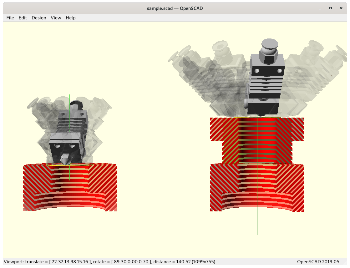
- 2021/02/23: added brief animation (Zrot=-180° .. 180°)
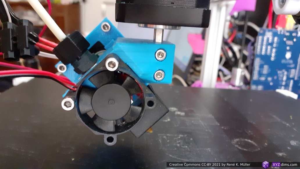
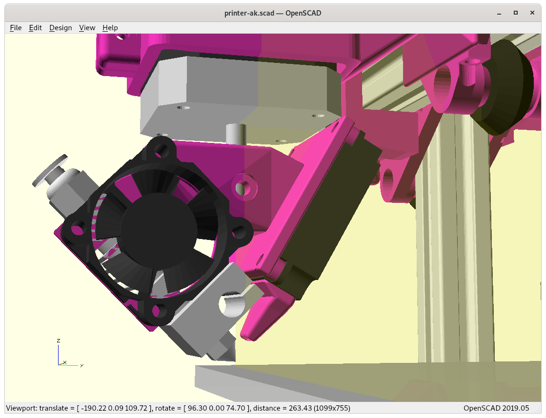
- 2021/01/31: maturing printhead with heatsink fan and part cooler
- 2021/01/28: Outside/Inside Cone printing explained with example, Considerations (Pros/Cons) added
- 2021/01/27: more detailed illustrations and slicing renderings, published as a draft
- 2021/01/22: adding conic slicing examples
- 2021/01/21: first version with rotating bowden printhead
I will update this blog-post as I progress or find other people with alike ideas and summarize the findings.
Table of Contents
Introduction
RotBot by ZHAW School of Engineering Zurich
As featured on Hackaday January 16, 2021 and other sites, a “Novel 4-Axis 3D Printing Process to Print Overhangs Without Support Material” by ZHAW School of Engineering (Zurich, Switzerland), from the abstract of the paper:
[..] a novel 4-axis FDM printing process with a newly designed printhead, for the printing of overhangs without support structures. With conventional FDM printing, overhangs of more than 45deg–60deg must be supported.
For this novel printing process, the printhead is rotated 45° around a horizontal axis and equipped with a vertical, rotational axis. The printhead no longer follows layers parallel to the build platform, but moves on the surface of a 45deg cone. The printing cone increases in diameter from layer to layer. With this cone-shaped layers, the printable angles increases by 45°, which leads to printable overhangs of up to approximately 100°.
New slicing strategies for this printing process have been developed to slice the parts for the novel printing process. The feasibility of the concept has been prototypically demonstrated. The novel design achieves the advantages of higher speed and quality with lower cost at the same time.
A brief video sequence of printing (YouTube) shows the machine movement. Unfortunately, as of 2021/01 not much more details have been published by ZHAW except a paywalled paper [sigh] which contains useful overview of their research. I contacted ZHAW and Michael Wuethrich mentioned that they are in negotiations with different companies to develop a product (2021/01) and eventually release the details of their slicing approach with pre- and post-processing while using an ordinary slicer.
Update 2021/02/27: I started with a 4-axis conic slicer.
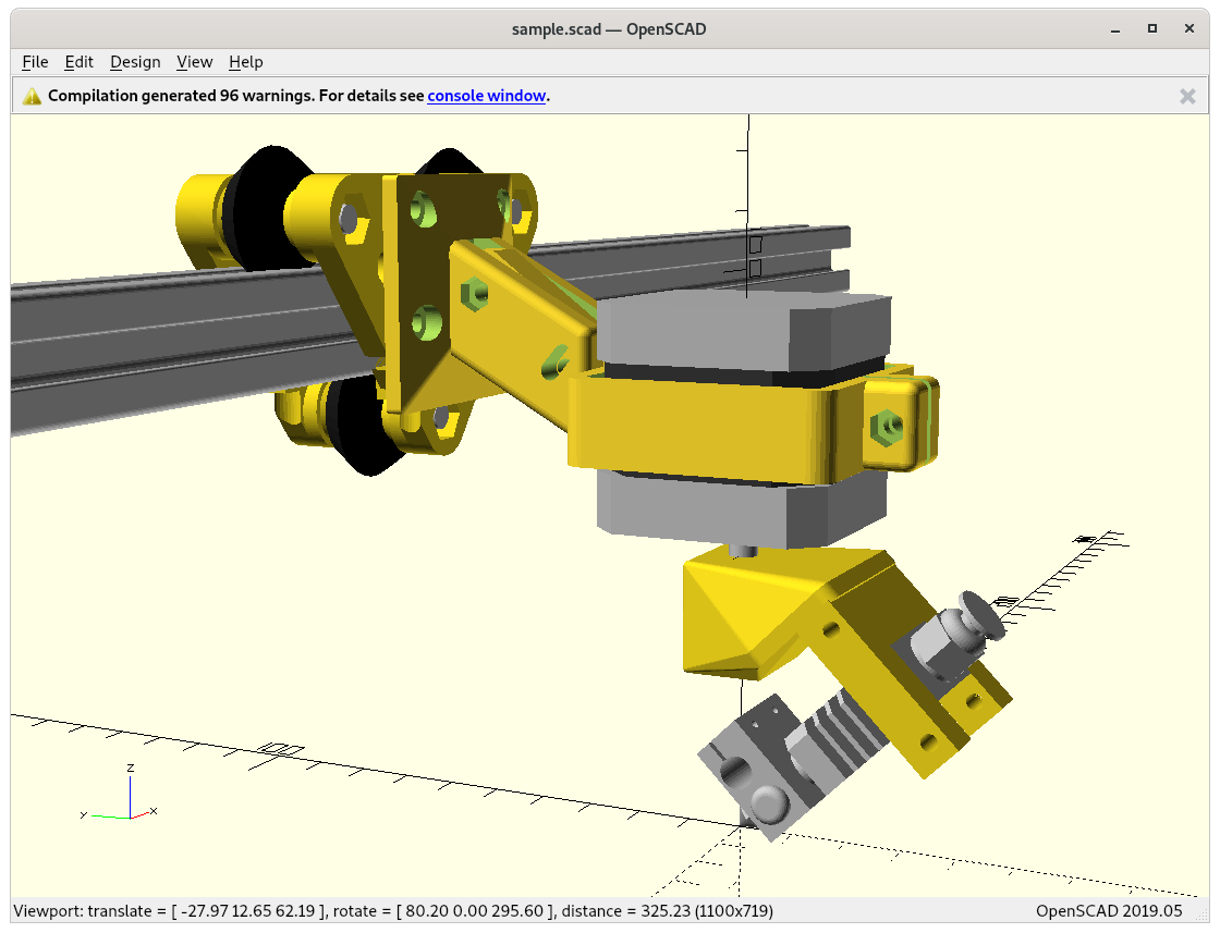
Rotating Tilted Nozzle (RTN) Option
I thought to try my own implementation of this Rotating Titled Nozzle 4 Axis option. The main idea to keep the entire hotend in Bowden style and rotate that around only once (non-continuous) with all wires, that would simplify things greatly:

The challenge is the +/-180° position when the nozzle opening looks forward, where the printhead bowden tube (and all cables) comes most close to the X beam. As a consequence only -180° to +180° rotation is allowed and not multiple revolutions.
It would also mean, once the printhead reaches -180°, and it has to rotate to +180° and decrease from there again to fulfill 360° rotation – whether this is suitable has to be seen, this likely creates a seam there.
The main advantage of this simplified 4 axis approach is to use existing pieces plus just an additional NEMA 17 motor.
Update 2021/01/26: Wuethrich from ZHAW mentioned that they started first also with a full printhead rotating but then switched to the more complex continuous rotating printhead to avoid a seam, have direct drive extruder, faster prints as simpler decision making to change rotation direction and no start/stop of rotation and de/acceleration when reaching -180/+180° position.
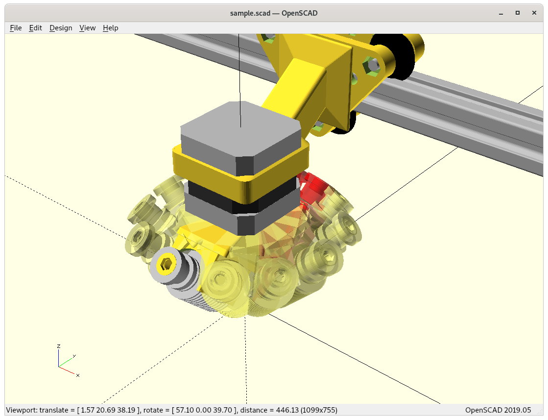
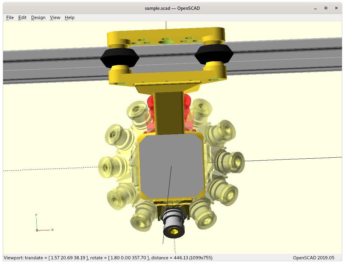
Single Revolution with Rotation Shadow
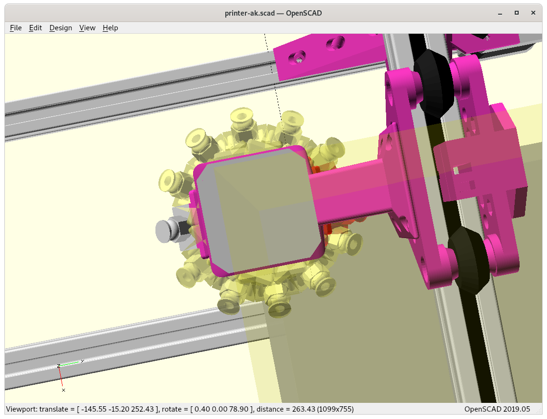
As I pondered on the limits of single rotation approach, there is a range where the bowden tube (and all wires with it) is touching and bending on the X carriage or printhead holder – let’s call it the rotation shadow – ideally it would be zero or slightly sub-zero to have a bit overlap to conceal a possible seam with “ironing” the section (move nozzle over section without extruding).
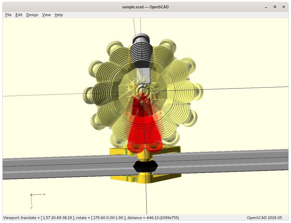
E3D Volcano
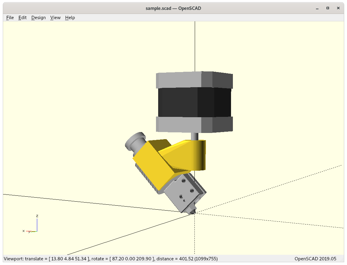
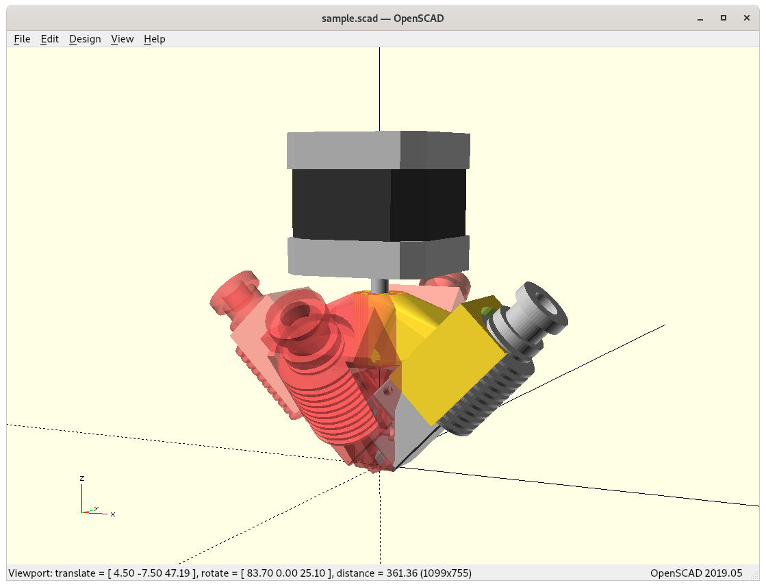
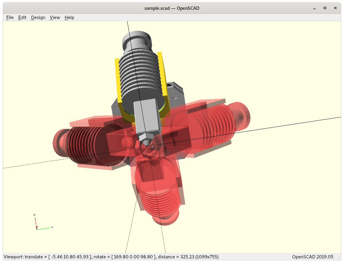
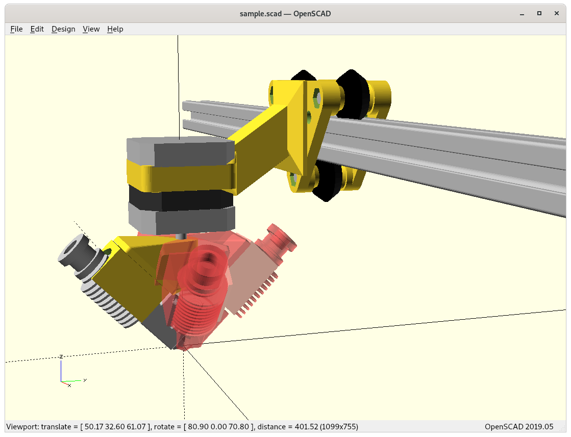
My first attempt is modeling with E3D Volcano hotend like the RotBot by ZHAW:
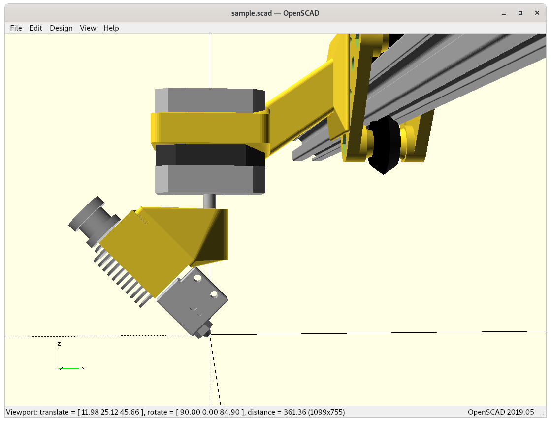

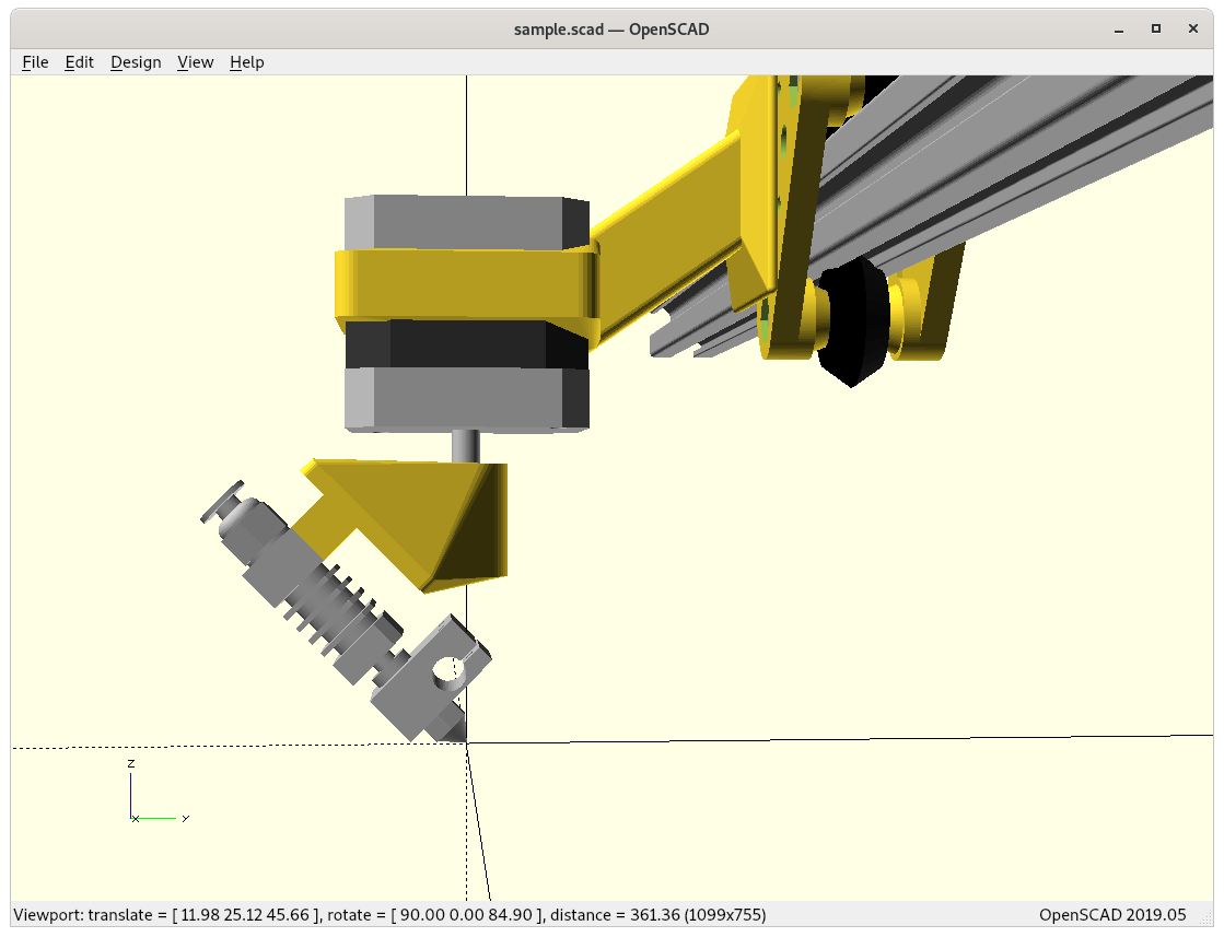
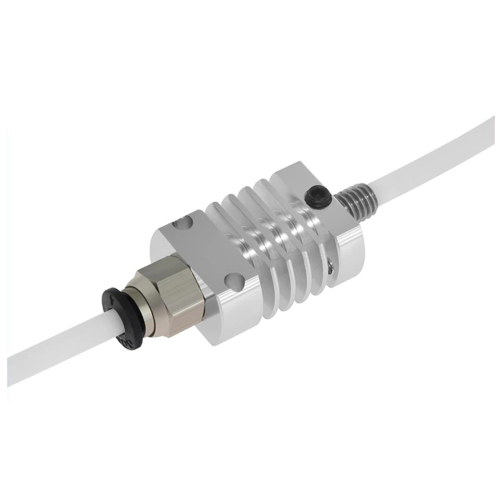
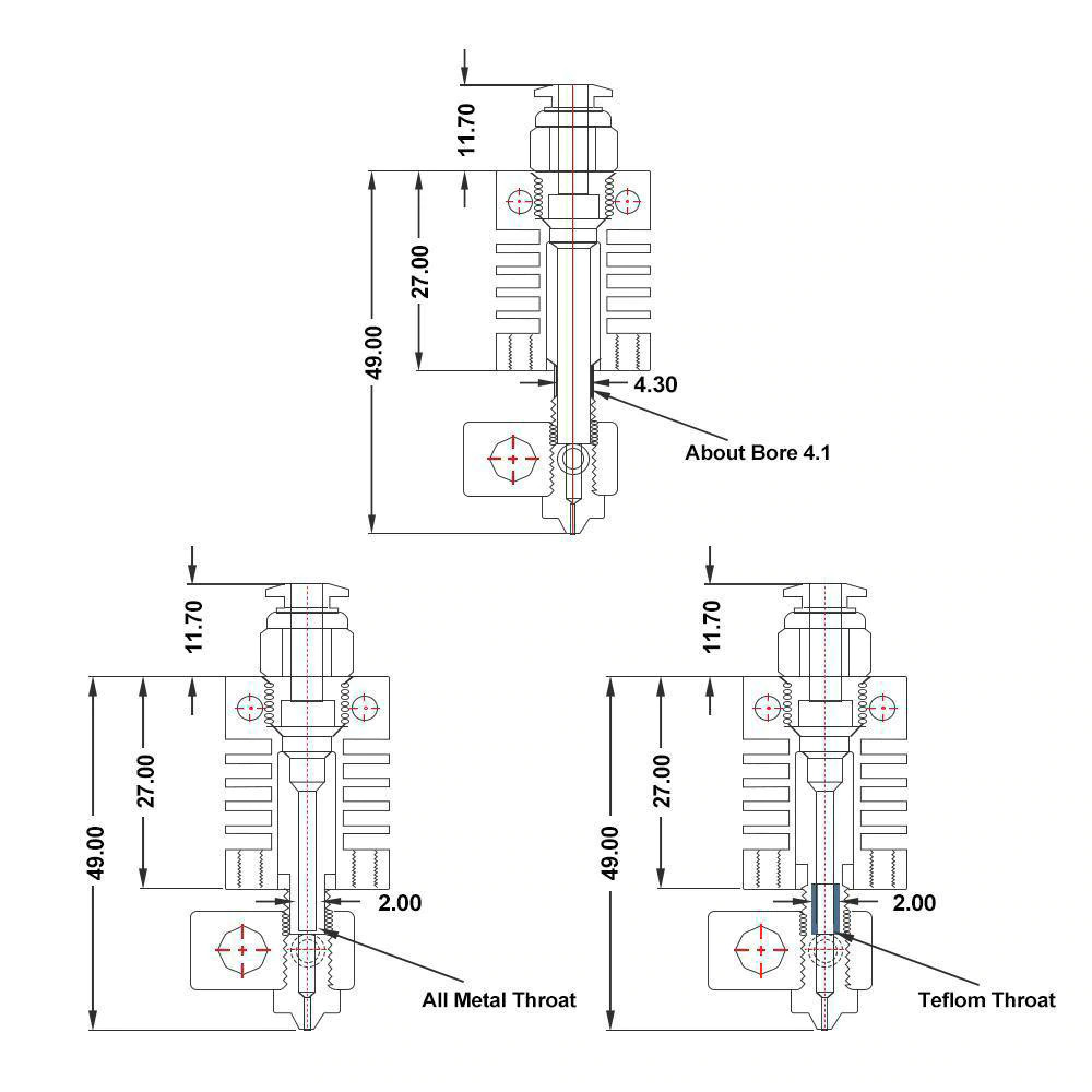
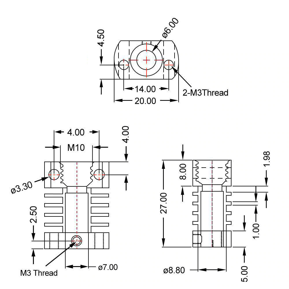
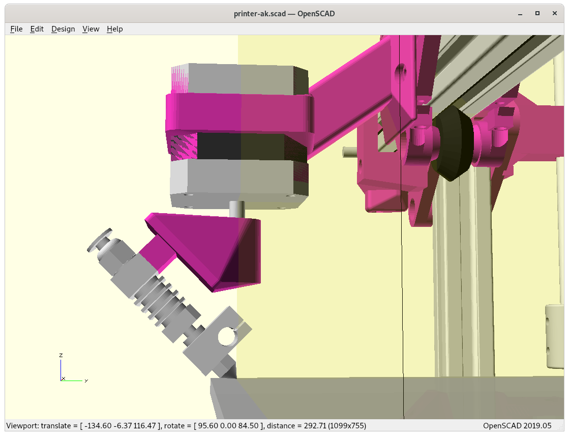
Micro Swiss / CR 10 Hotend
And as alternative the smaller Micro Swiss / CR 10 printhead which gives significant more space for the bowden tube (and all wires with it) to bend or flex near -180/+180°:
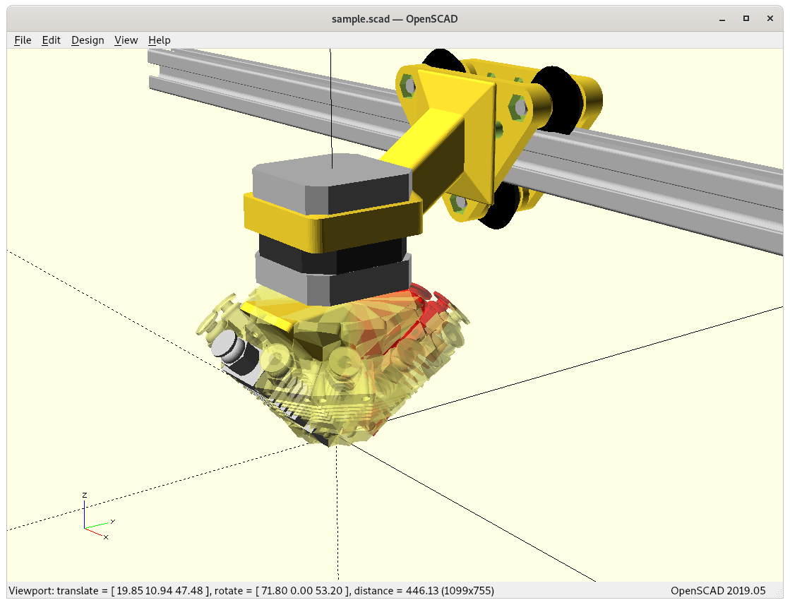
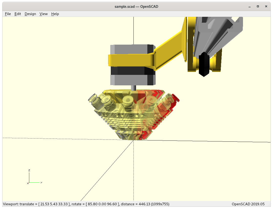
Comparison Volcano vs Micro Swiss
At this point I continue with the Micro Swiss (MS) option, as the smaller heatsink gives me more space to make full 360° turn with -180° to +180° and have ~0° rotation shadow, perhaps even sub-zero as of overlapping.
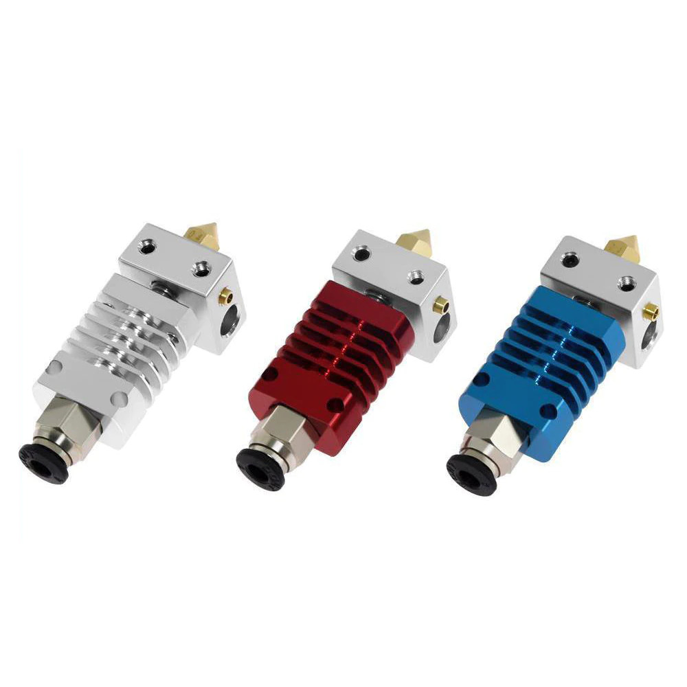
This particular Swiss Micro clone aka CR10 hotend comes without screws stabilzing the heatblock, and just a small worm-screw fastening the heatbreak on the heatsink, yet make it easy to adjust the overall length, which in this case is desired.
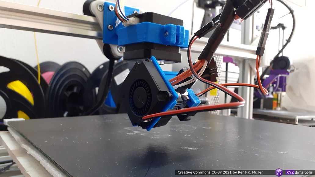
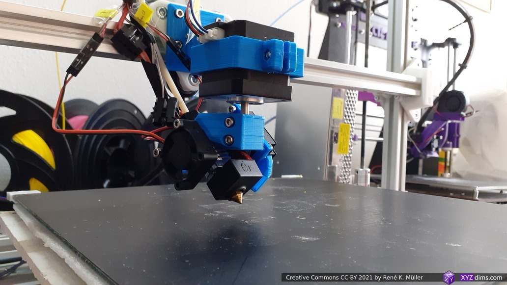
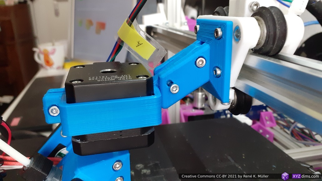
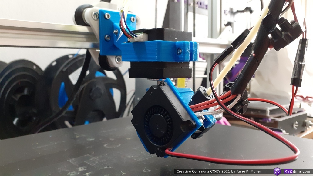
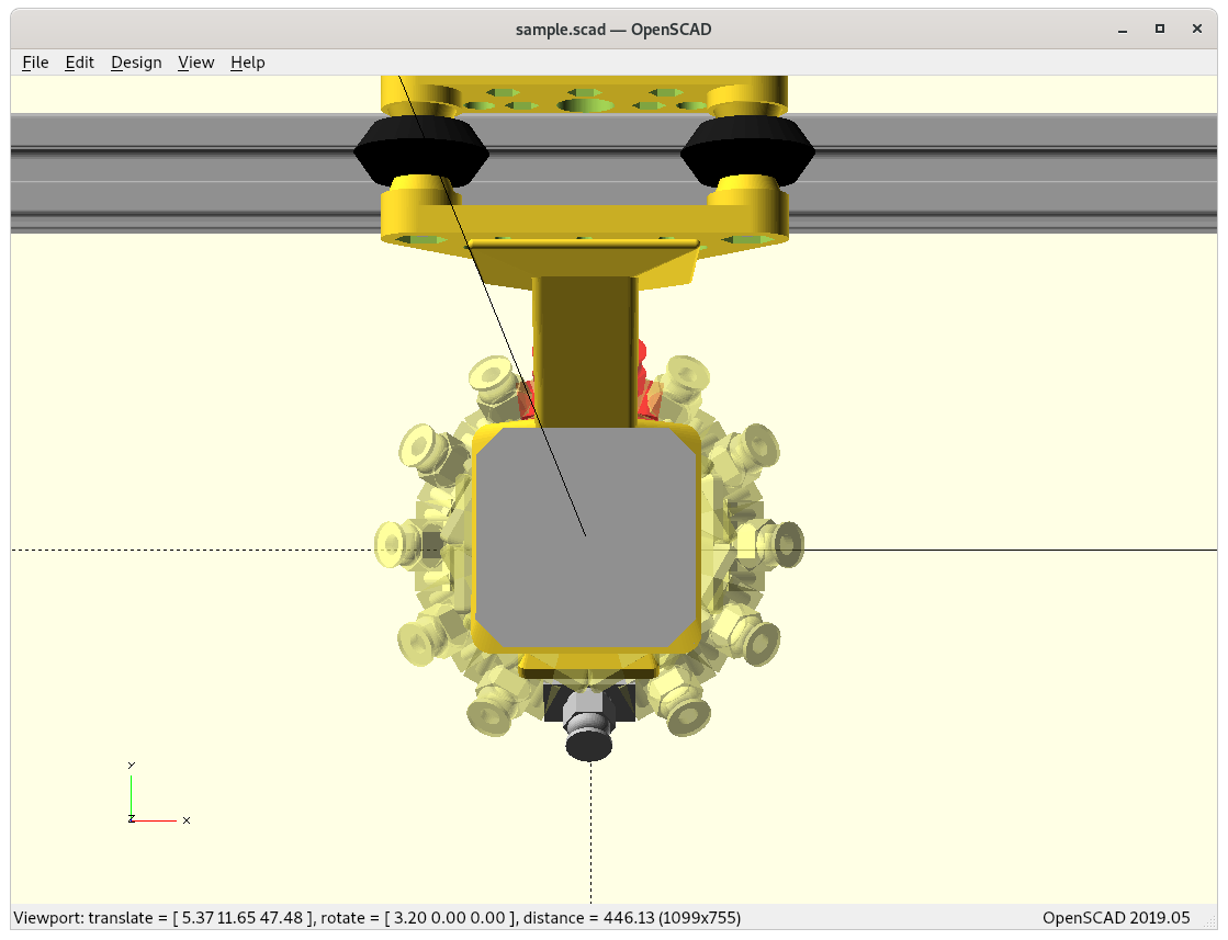
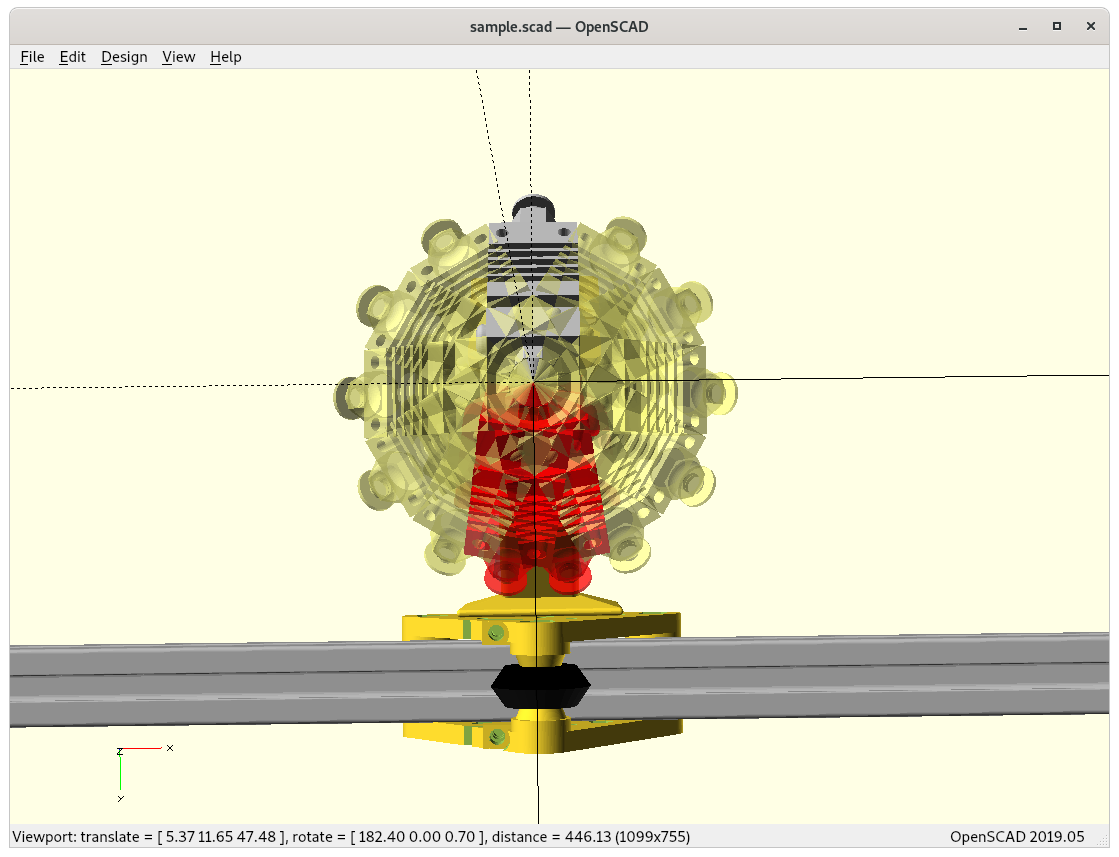
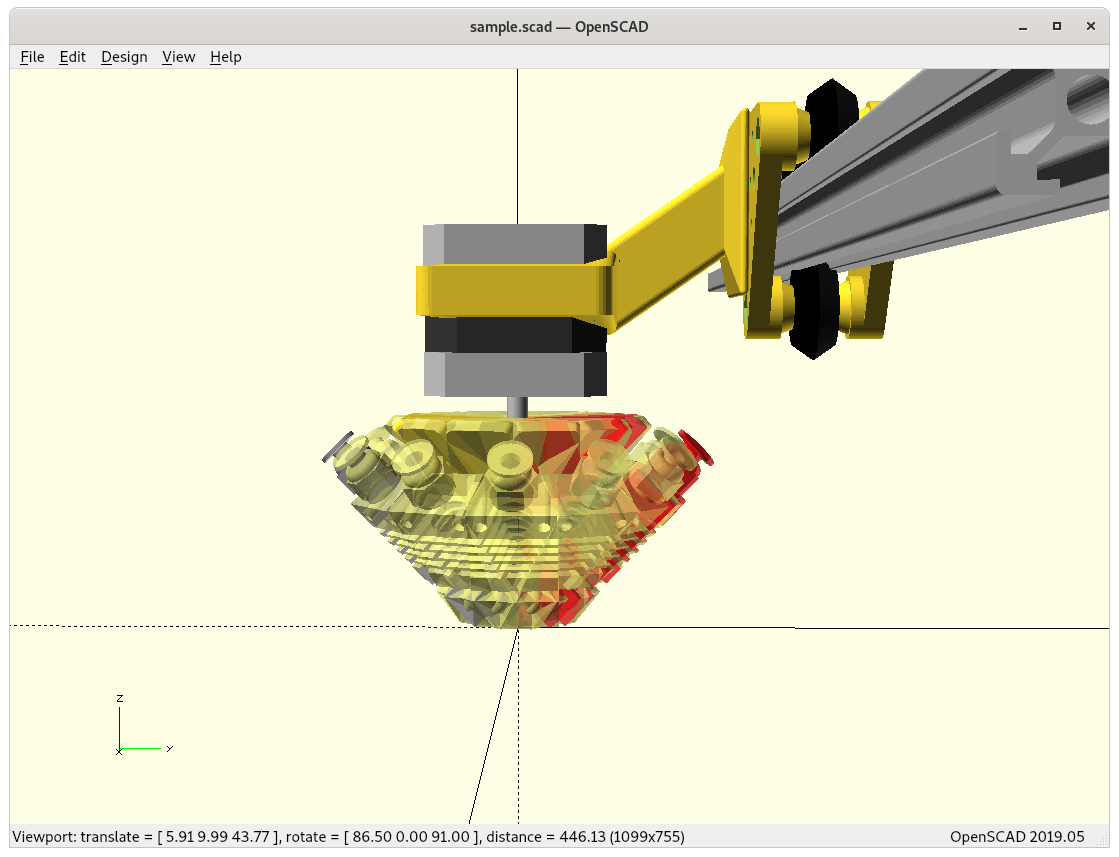
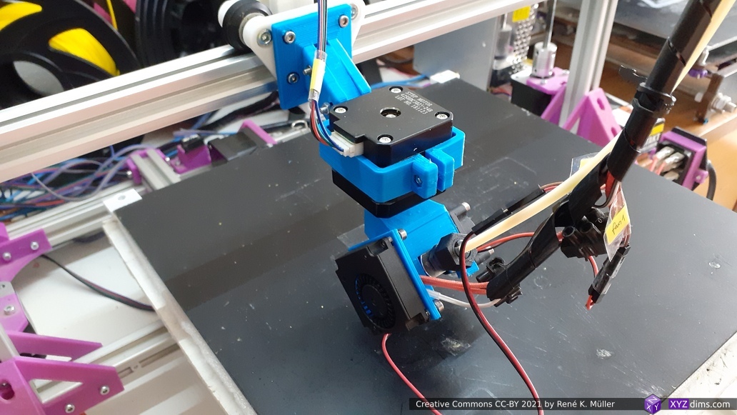
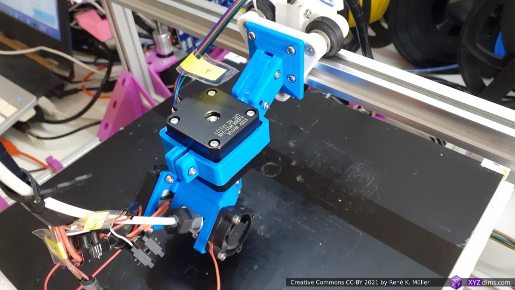
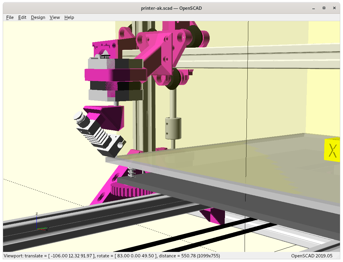
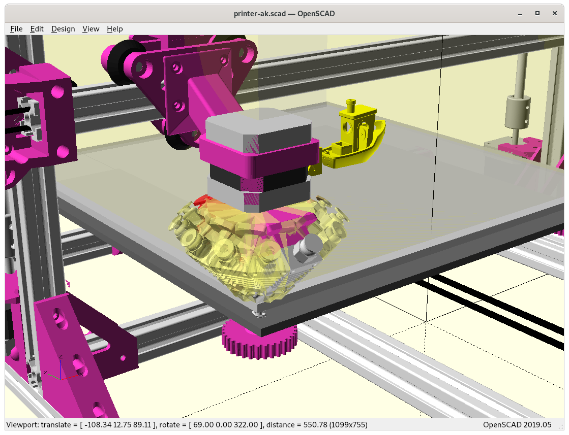
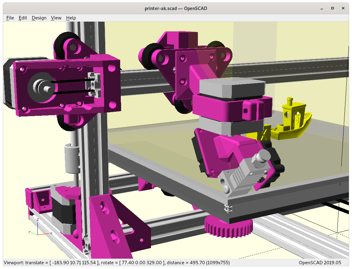
Prototype
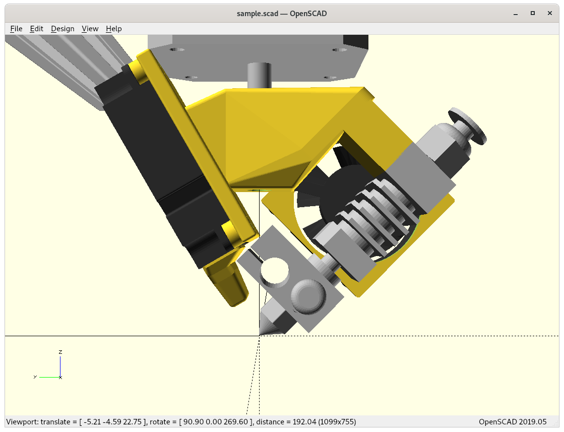
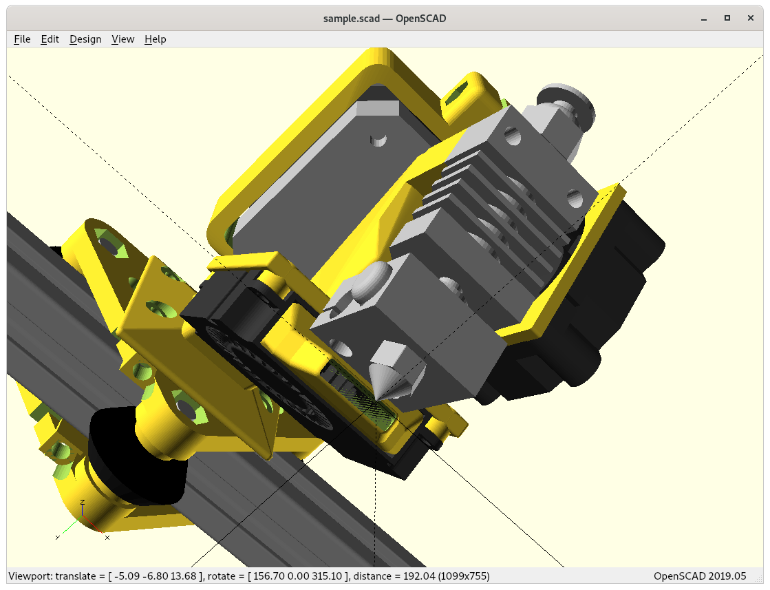
Eventually I took the time to print and assemble my Micro Swiss-based Rotating Tilted Nozzle (RTN):
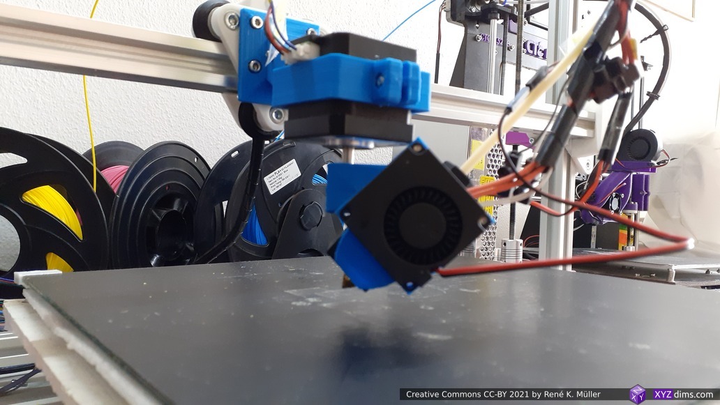
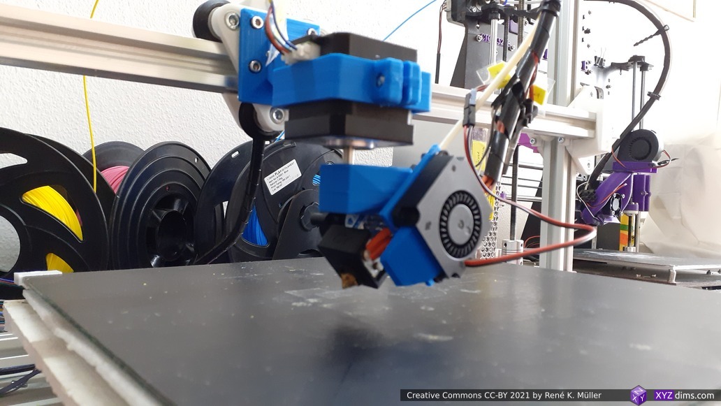
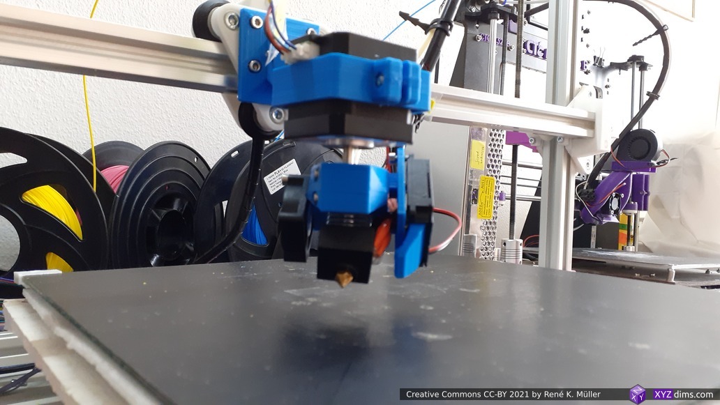
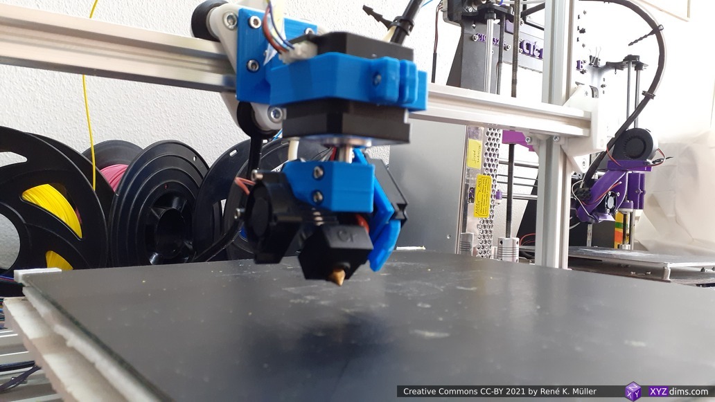
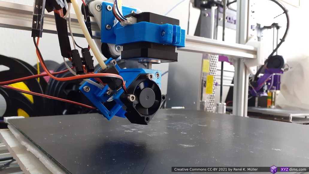
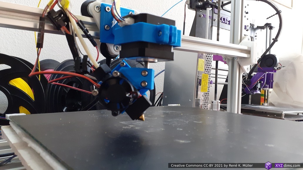
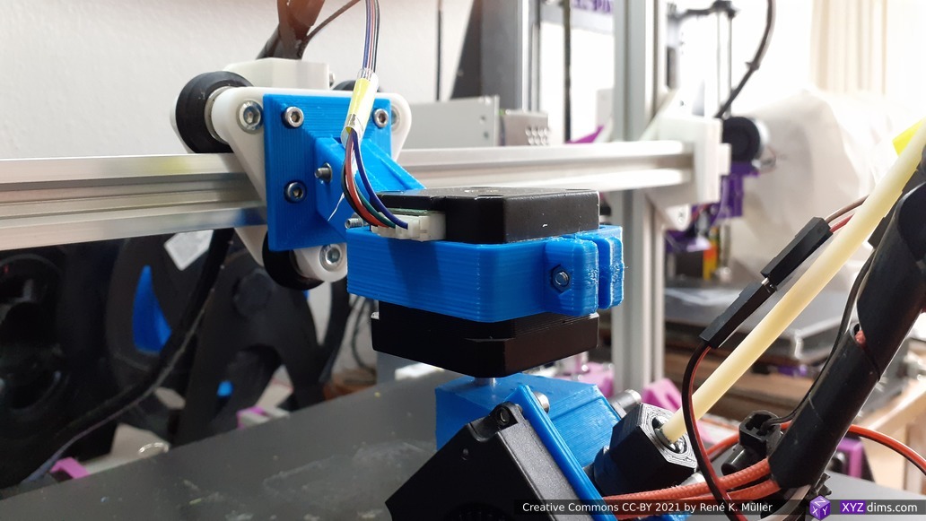
First test run revealed:
- rotation 170°..180° and -170°..-180° were not reliable with NEMA 17 37mm as skipping steps due the stiffness of PTFE tube with filament – resolvement: increase arm length (away from X carriage down/forward)
- partially resolved by limiting A to -170°..170°:
M208 A-170 S1andM208 A170 S0inconfig.gof Duet 3 Mini 5+ setup
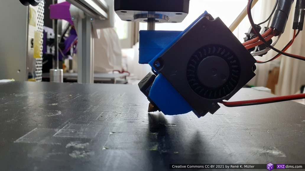
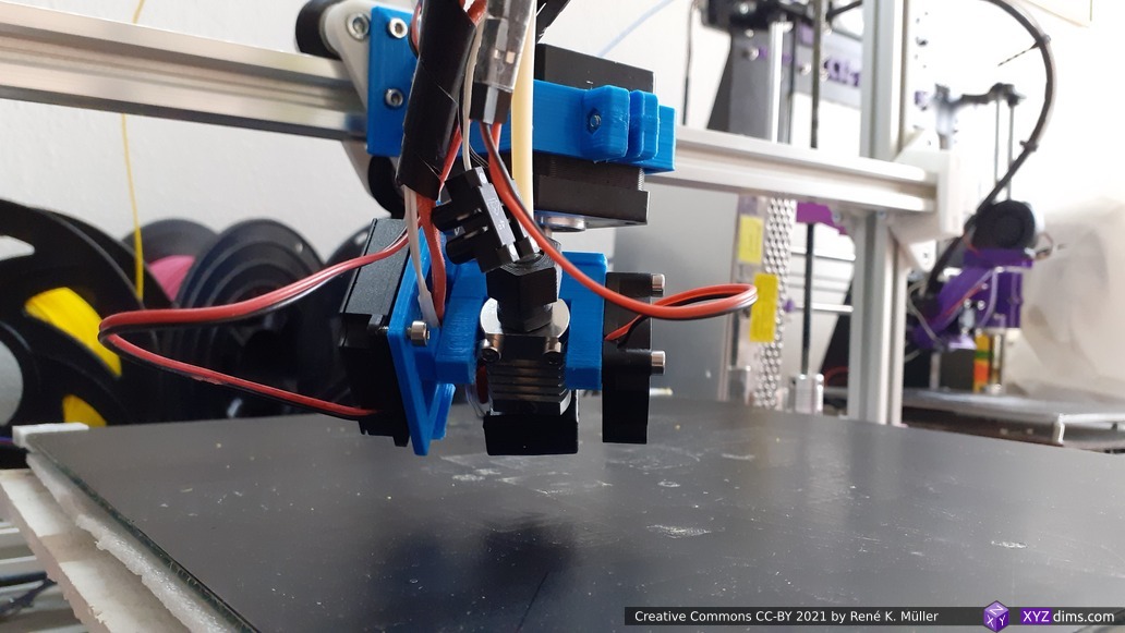
- partially resolved by limiting A to -170°..170°:
micro swiss / CR 10 hotend heatblock socket touches the bed (same height as nozzle), fixed due slight tilt from X carriage due weight, newer design allows angle readjustmentsingle rotation requires refinement by the Slicer4RTN, addressed partially with Slicer4RTN 0.6.0, might require more fine-tuning.
I’m focusing on the hardware-side on the Penta Axis (PAX) 5-Axis printhead and transfer some of the experiences back into the RTN design.
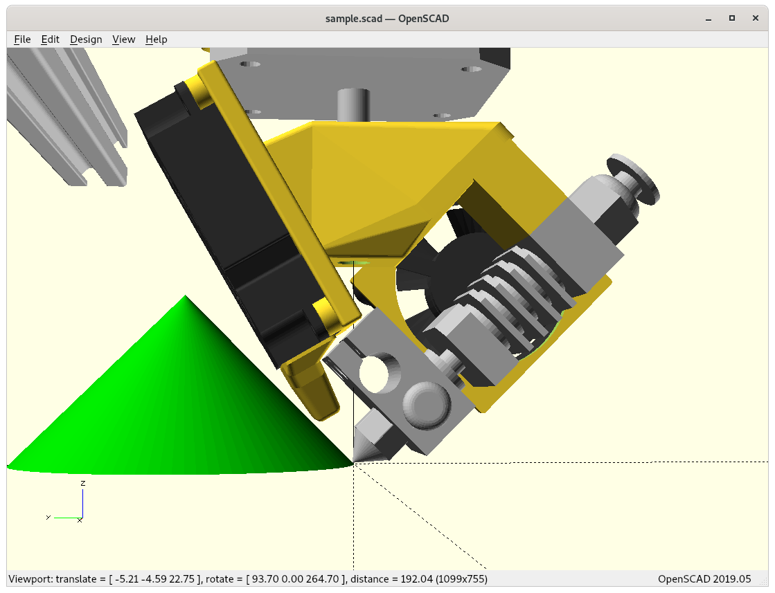
Slicing for Rotating Tilted Nozzle: Conic Slicing
I had to visualize the novel conic slicing approach as mentioned in the article and in the video:
f(Z rot, C height, R) ⟹ X, Y, Z
X = sin(Z rot) * R
Y = -cos(Z rot) * R
Z = C height / sqrt(2)
Z rot = atan2( -Y, X )
R = sqrt( X*X + Y*Y )
C height = Z * sqrt(2)
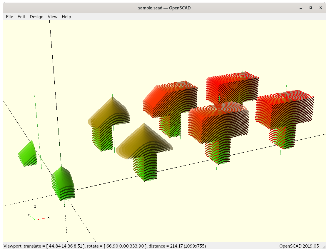
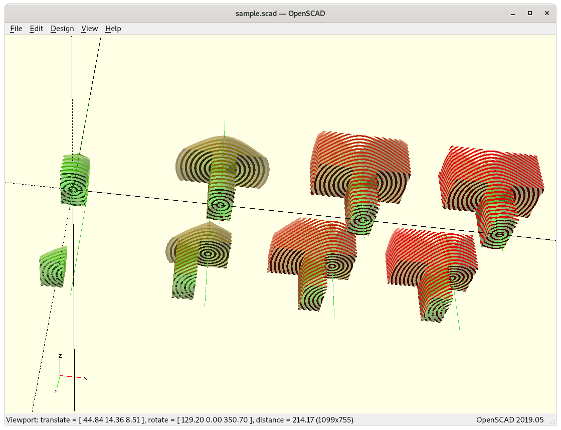
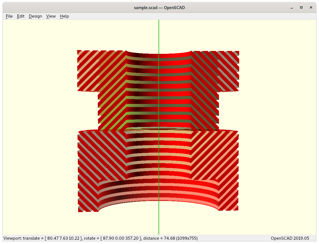
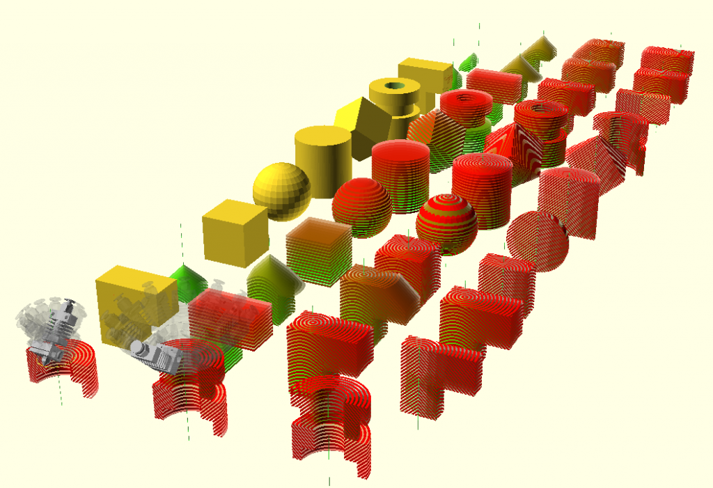
A single conic slice is covered by Z rot, C height and R, whereas slices are separated by increasing Z offset to C height, forming conic slices on top of each other:
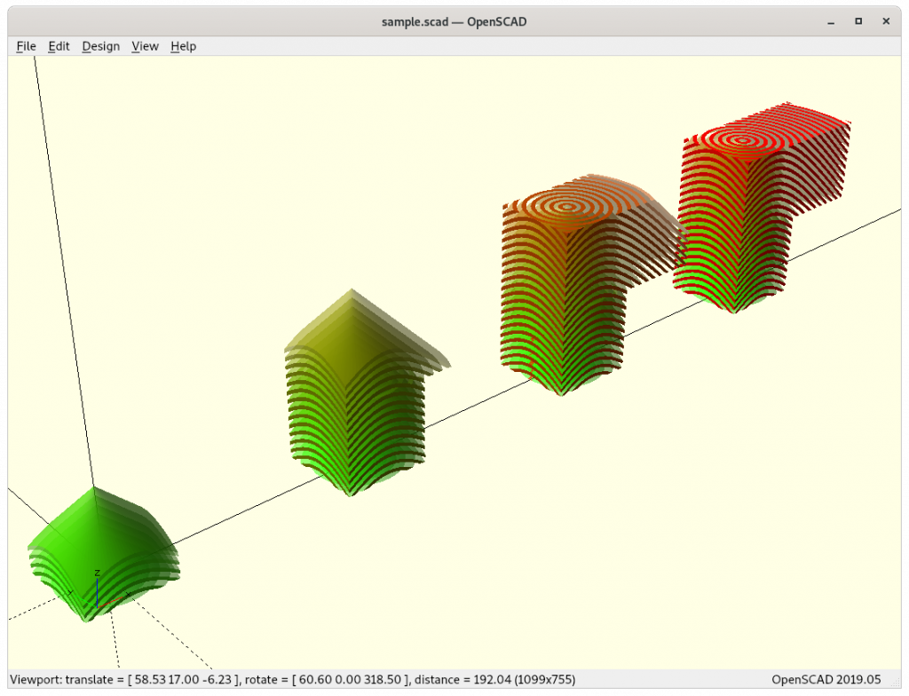
Let’s inspect the motion of a single layer: it’s curved – obviously – in X, Y and Z – this means, the Z axis has way more motion than in cartesian XZ Prusa-Mendel setup where the Z axis only changes once a layer is finished, here with cone-slicing every trace or track all traditional 3 axis are in motion, plus the 4th – the tangent on that conic trace.
See more details on Conic Slicing for Rotating Tilted Nozzle (RTN).
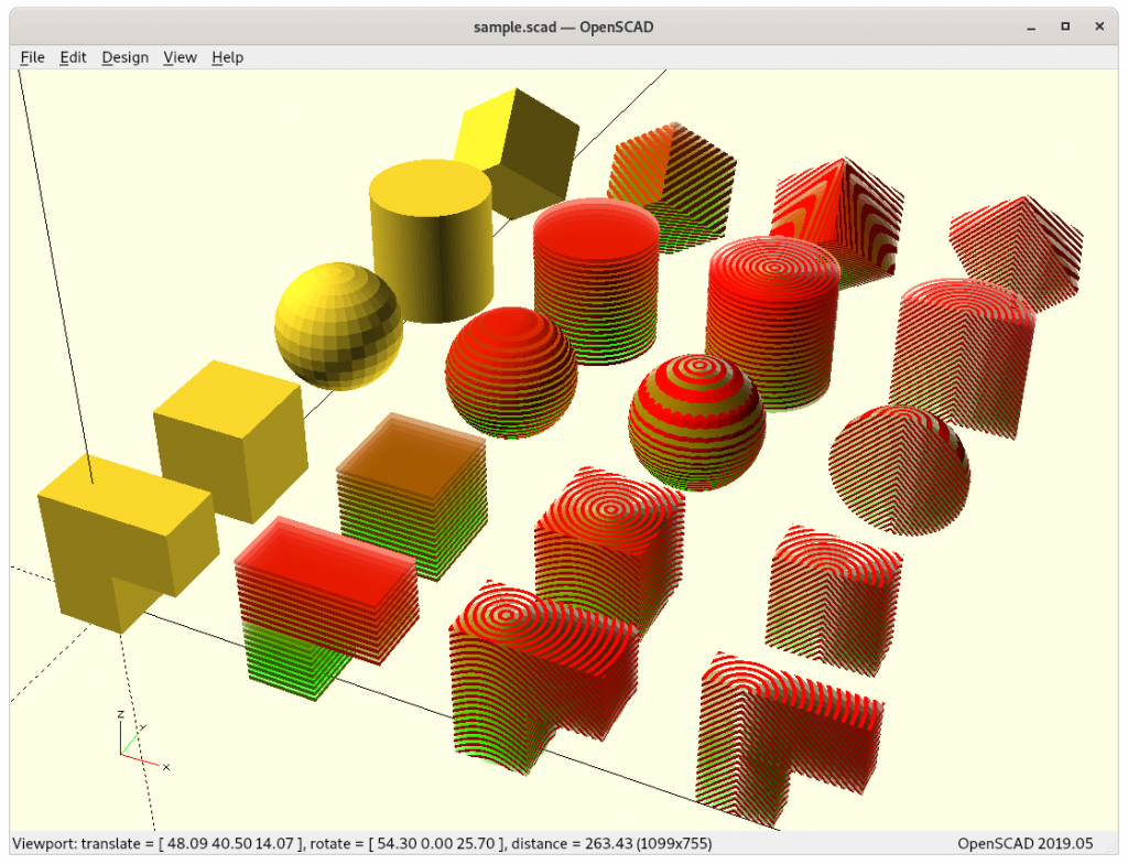
Different Print Modes
The 45° tilted printhead allows three print modes:
- non-rotation nozzle with planar Z layers (with ordinary slicer), acts like belt-printer in one direction: overhangs in one direction without support
- rotation nozzle with planar Z layers (requires dedicated slicer), might support near 90° overhangs of a certain length in all X/Y plane directions as well – but needs to be tested
- rotation nozzle with conic Z layers (requires dedicated slicer or pre- and post-processing while using ordinary slicers)
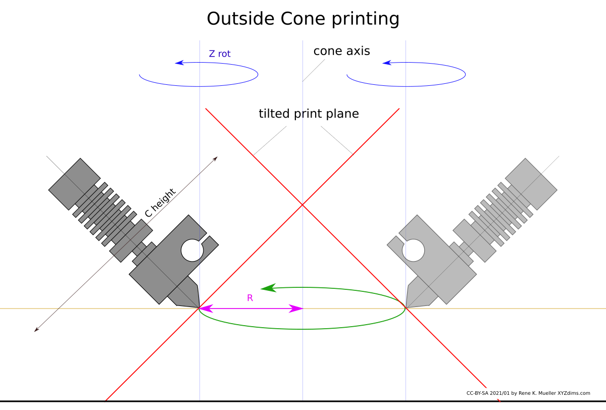
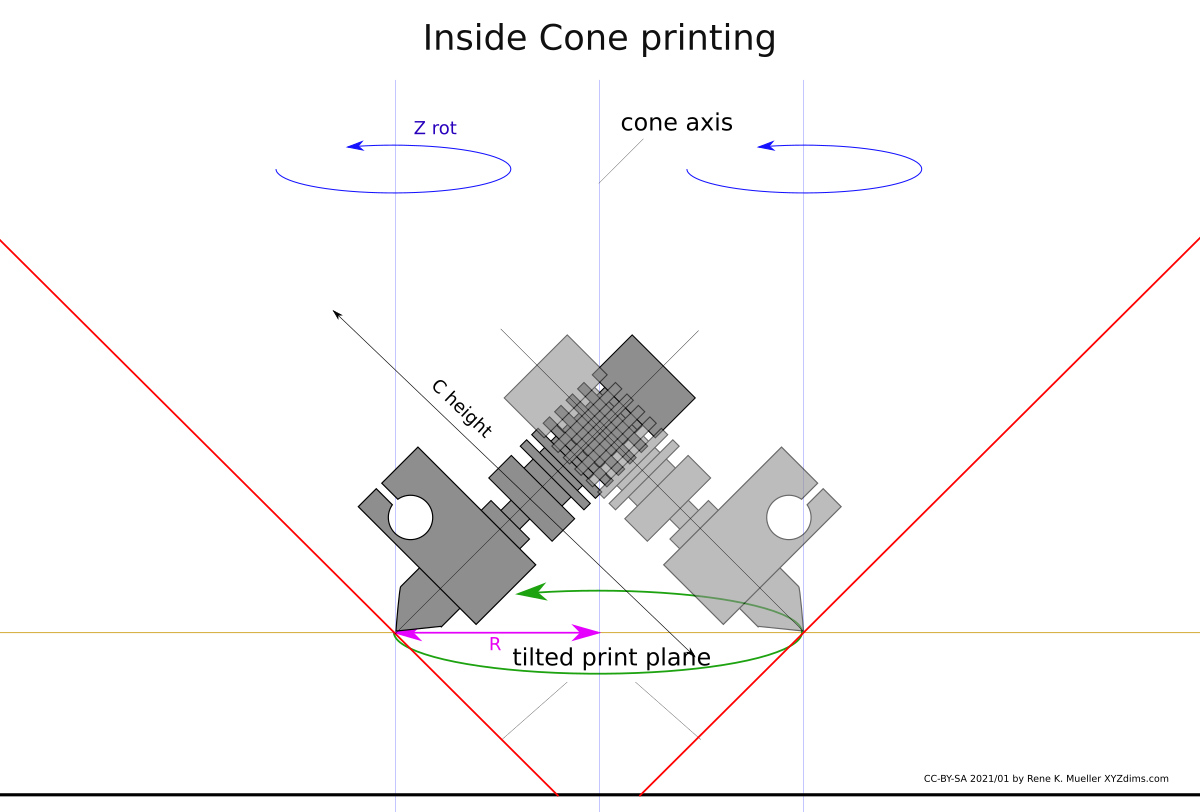
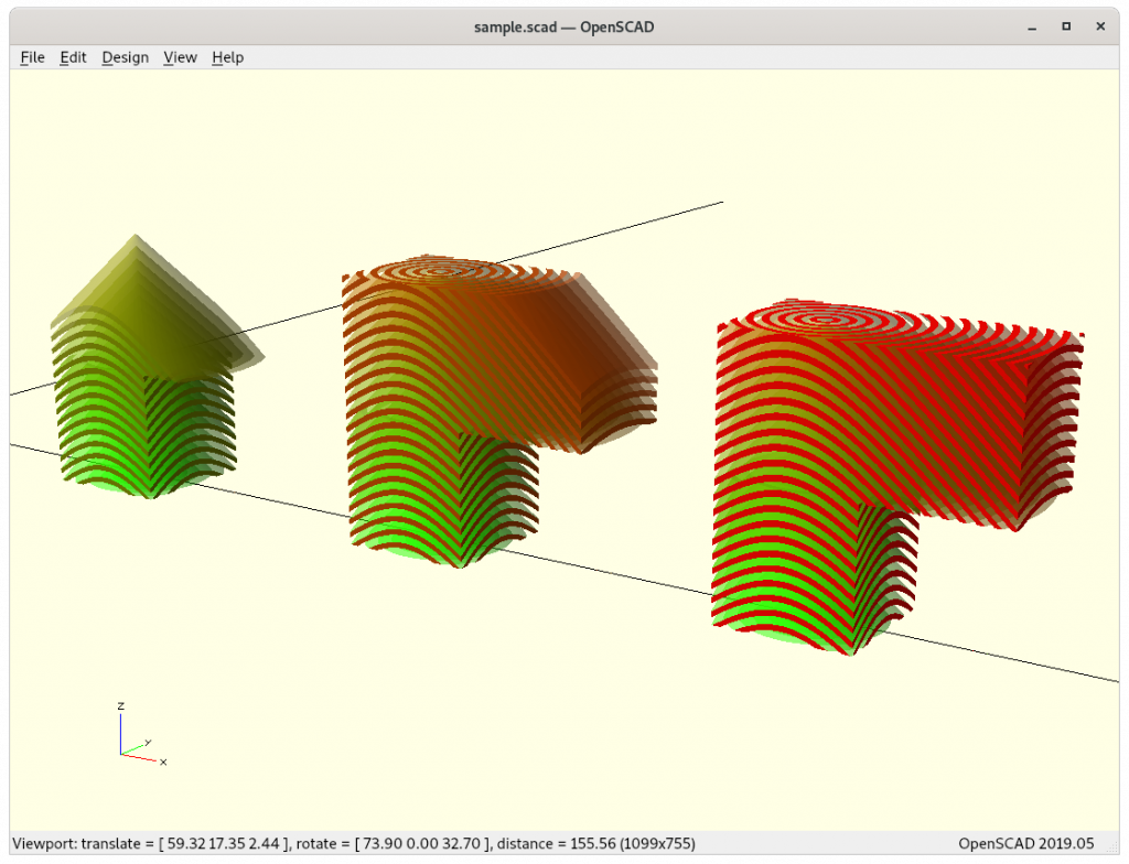
And by choosing the position of the “axis” of the conic slicing within the model and the cone direction matters then as well:

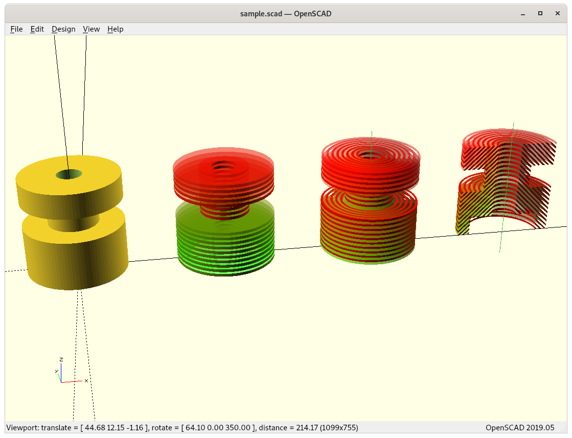
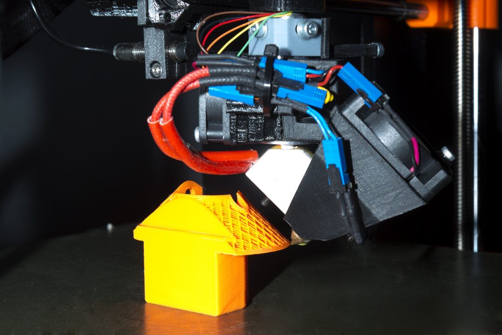
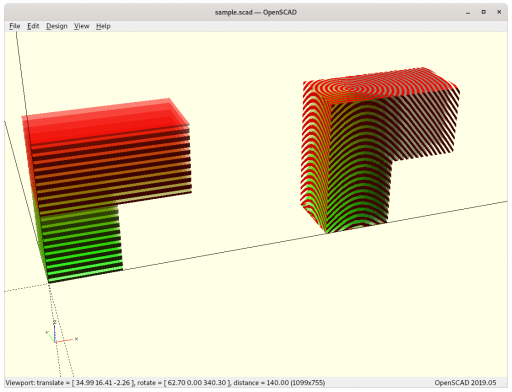
The last piece with inside and outside looking overhangs requires a switch of nozzle direction, e.g by default the sliced cones are ordered ▲ (outside-in or outside-cones) where outward overhangs work, but for inward overhangs the opposite direction of the nozzle looking outside is required ▼(inside-out or inside-cones), like this piece:
upper half with overhang away from cone axis Outside Cone printing, all without support
upper half with overhang away from cone axis Outside Cone printing, all without support
So the slicing software needs to recognize this, and the sliced cones switched either ▼ or ▲ according Z level.
These aspects opens a whole new range of considerations how to orient a piece and where to position the newly introduced slicing axis, and which kind of cones need to laid at which level.
Issues to Resolve
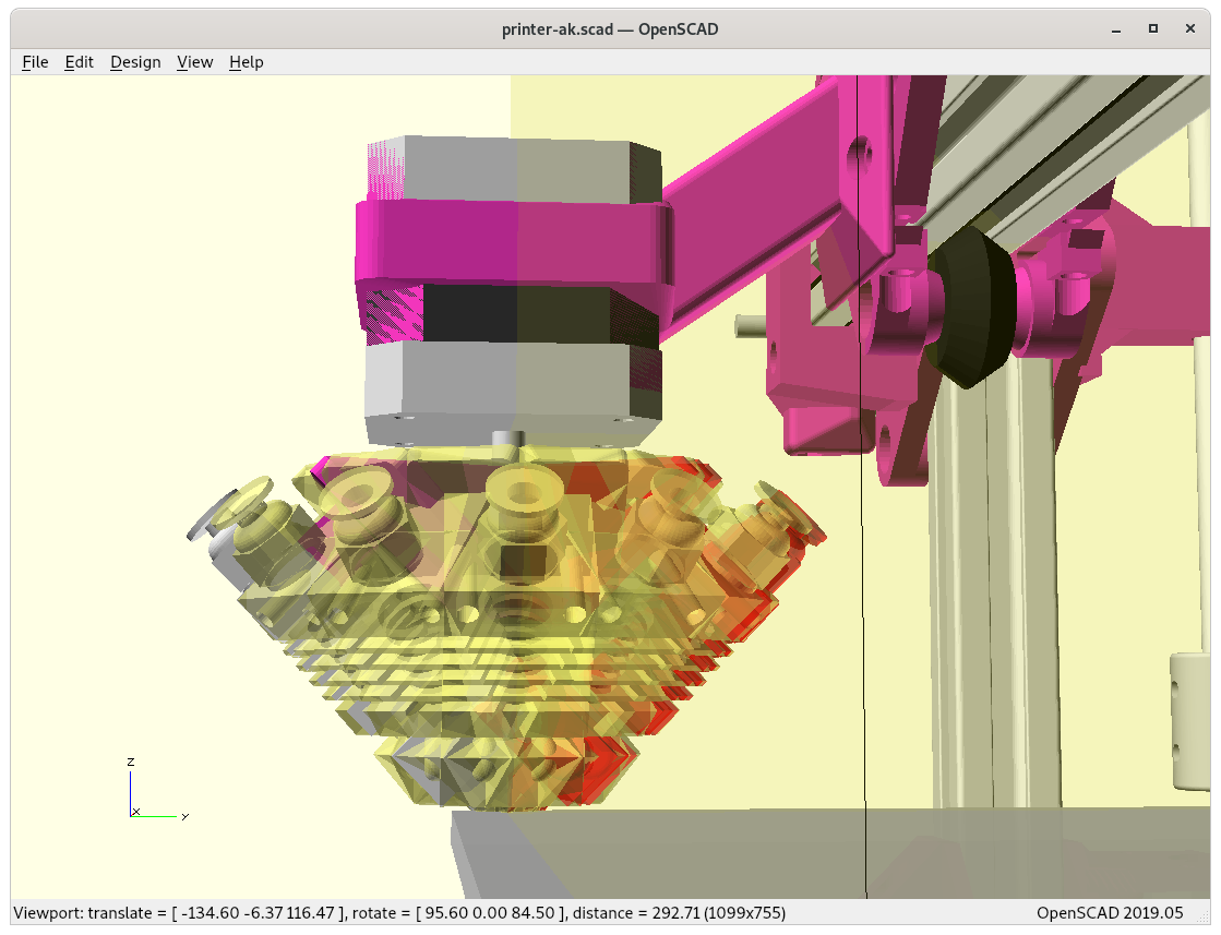
- Heatsink fan mount: needs to be mounted for both variants, Micro Swiss and E3D Volcano ideally
- Part cooler:
- have the part cooler rotate on Z axis as well? yes for now
using a flexible pipe to blow air near the nozzle instead

- Z rotation calibration:
- alike with X or Y stop, but a trigger rotating from one direction only and then set a angle offset
- Z rotation motor mount adaptable for different kind of printheads
- keep it modular
- ensure the nozzle end is centered (allow simple center calibration)
- Properly document design and features of Rotating Tilted Nozzle as there isn’t much detail information available
- 3D printer firmware support
- Marlin: support for 4th axis?
- 3D slicing software support
- adapt ZHAW’s approach with pre- and post-processing but use existing slicers; Update 2021/02/26: separate blog-post going into the details of Conic Slicing
- dedicate slicer for conic slicing, e.g. adapt Mandoline Py
Considerations
Pros
- conic layers: printing 90° overhangs without support, given some conditions are met:
- overhangs must be horizontally or vertically rotational symmetric and aligned with the cone axis to switch from outside to inside cone printing or vice-versa (to do: more use cases explored and documented)
- conic layers: stronger pieces as layers cross X, Y and Z in non-planar manner, mechanical forces distribute further than just planar layers
- planar layers / rotating nozzle: perhaps close to 90° overhangs (speculative) requires new overhang algorithms in slicer
Cons
- additional mechanical complexity
- fine-tuning nozzle center calibration
- additional slicing software complexity
- new slicer software supporting different printing modes (conic layers, planar layers w/ rotating nozzle)
- conic layers: more things to consider (preferably recognized by the slicing software):
- overhangs must be horizontally or vertically rotational symmetric and align with cone axis to take advantage of it (complex compartmentalizing of different cone-direction per overhang and newly introduced seams between those)
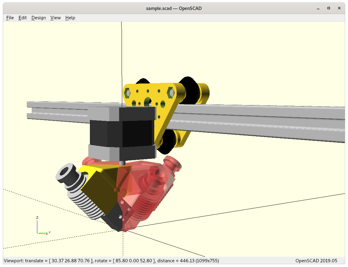
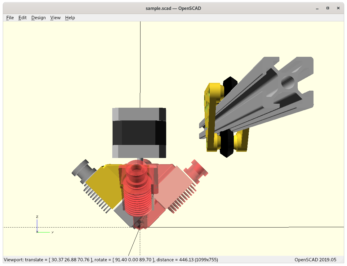
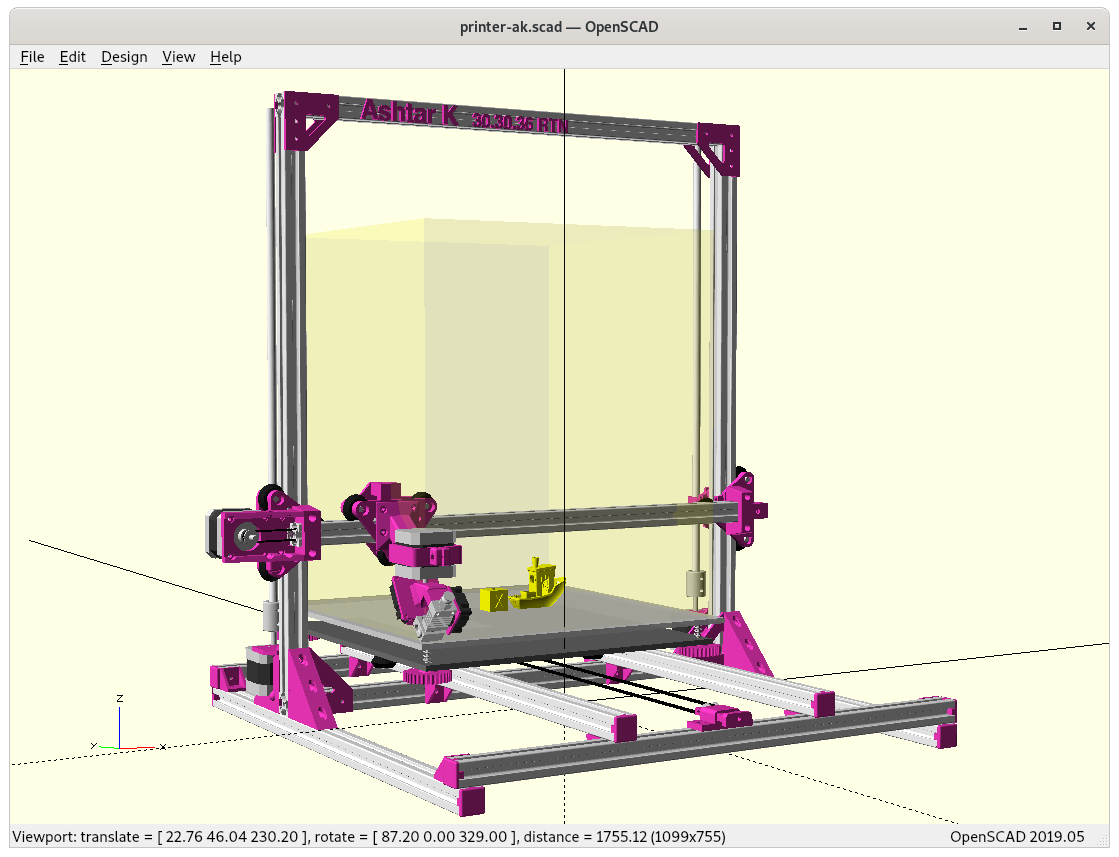
Ashtar K with Rotating Tilted Nozzle (RTN)
The additional Y offset is about 20mm, and losing apprx. 50 mm in Z build volume in its current form:

Fallback Print Horizontal Slices
Some parts may not require conic slices, e.g. introducing new unprintable overhangs which in horizontal slices would not exist, so a simple way to print traditional sliced models is by adding a proper rotation angle (e.g. G-code A..) so the nozzle extrudes nicely, something like:
rtnenhancerI wrote a small script called rtnenhancer which converts existing G-code to enhanced G-code.
References
- Novel 4-Axis 3D Printing Process to Print Overhangs Without Support Material (english) by ZHAW
- Multi-Axis 3D Printing Technique Improves FDM Strength Over 2X (see also paper)
See Also
- Conic Slicing for 4-Axis Rotating Tilted Nozzle (RTN)
- Penta Axis (PAX) / 5 Axis Printing Option
- Non-Planar Slicing with Planar Slicer, research overview
- Sub-Volume Segmenting & (Non-)Planar Slicing, mixing different slicing methods together
Misc 4-Axis Printers
- Joshua Bird’s Polar 4-Axis Printer (2024/12): hardware & software
- polar printing, and also cylindrical (Z-planar) possible, yet with single rotational point, see also this post
That’s it.
