Updates:
- 2019/04/17: more photos of examples incl. macro closeups
- 2019/04/15: 16 palette mixed colors from cyan, yellow and glowing magenta (CMY) photo added, best result of mixing colors
- 2019/04/12: added Firmware Retraction changes in Marlin, updated Trinary Color Palette
- 2019/04/10: initial post
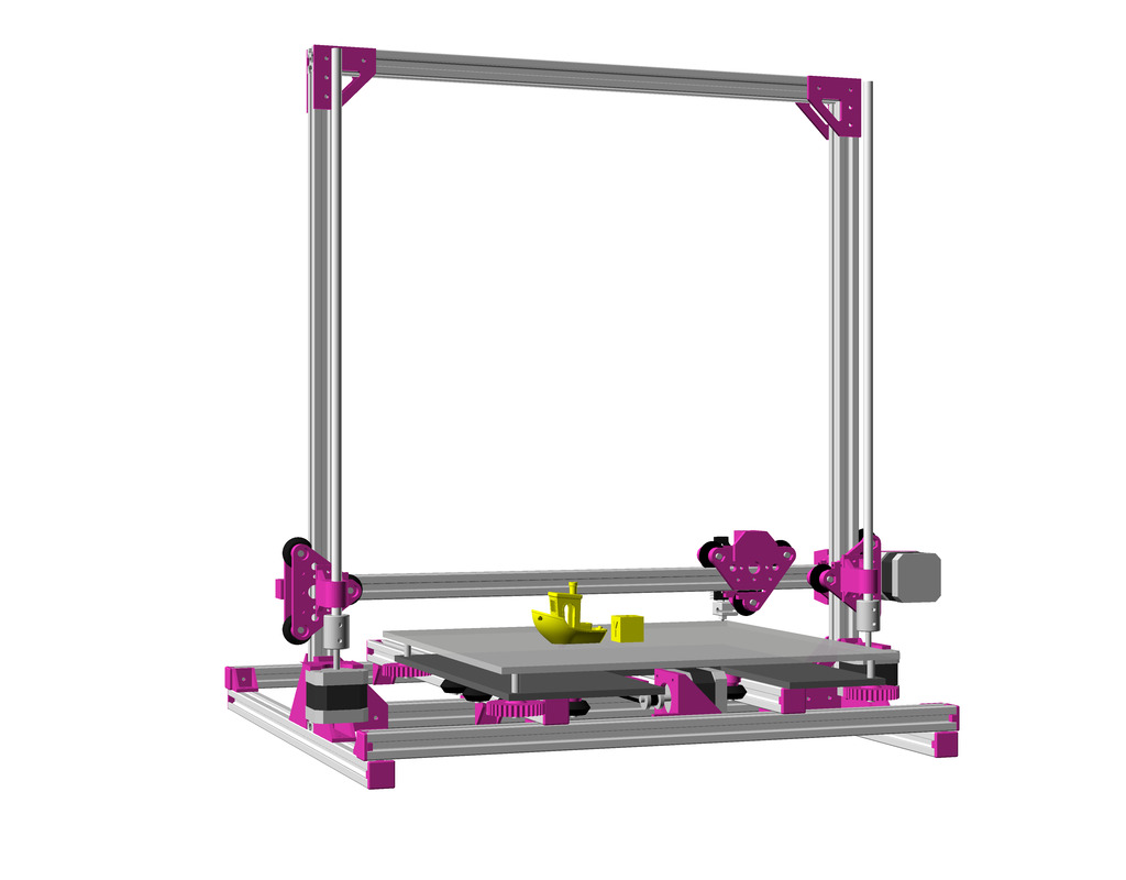
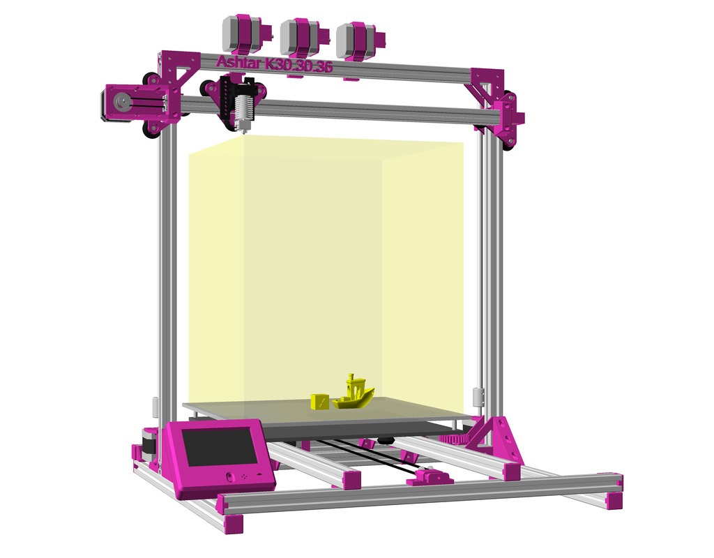
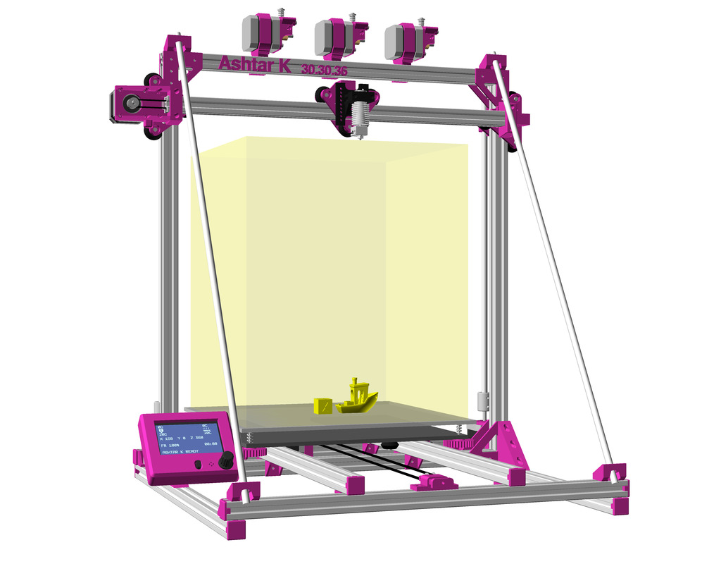
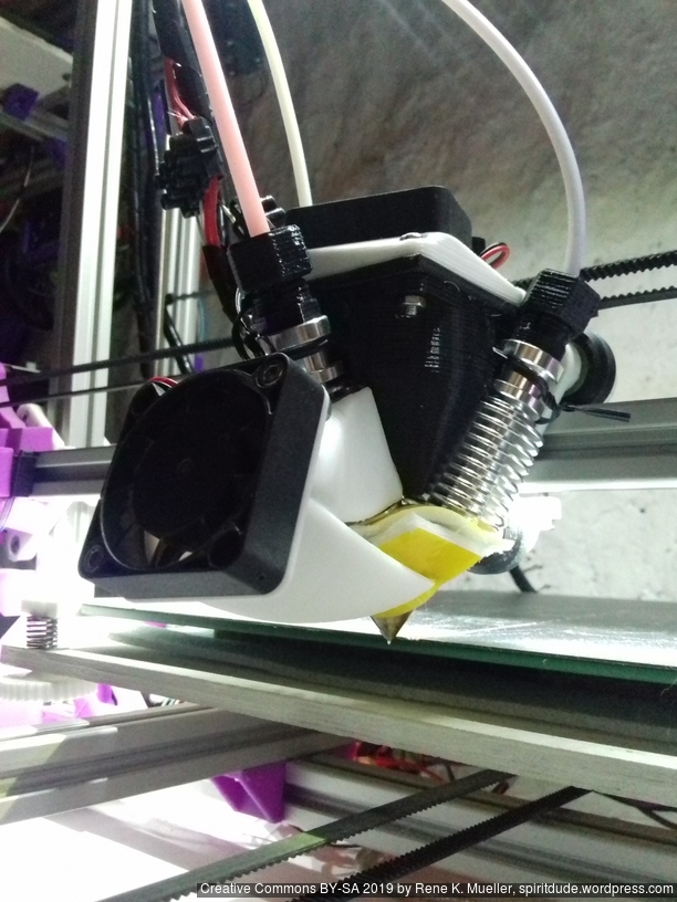
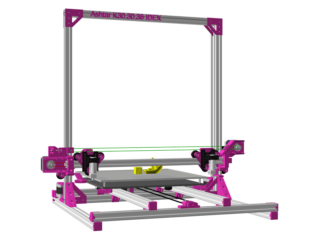
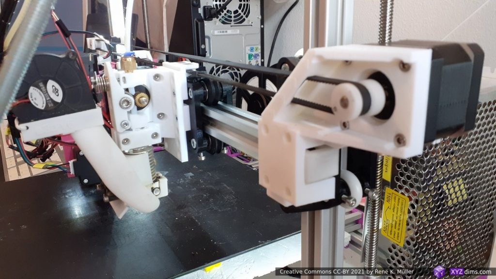
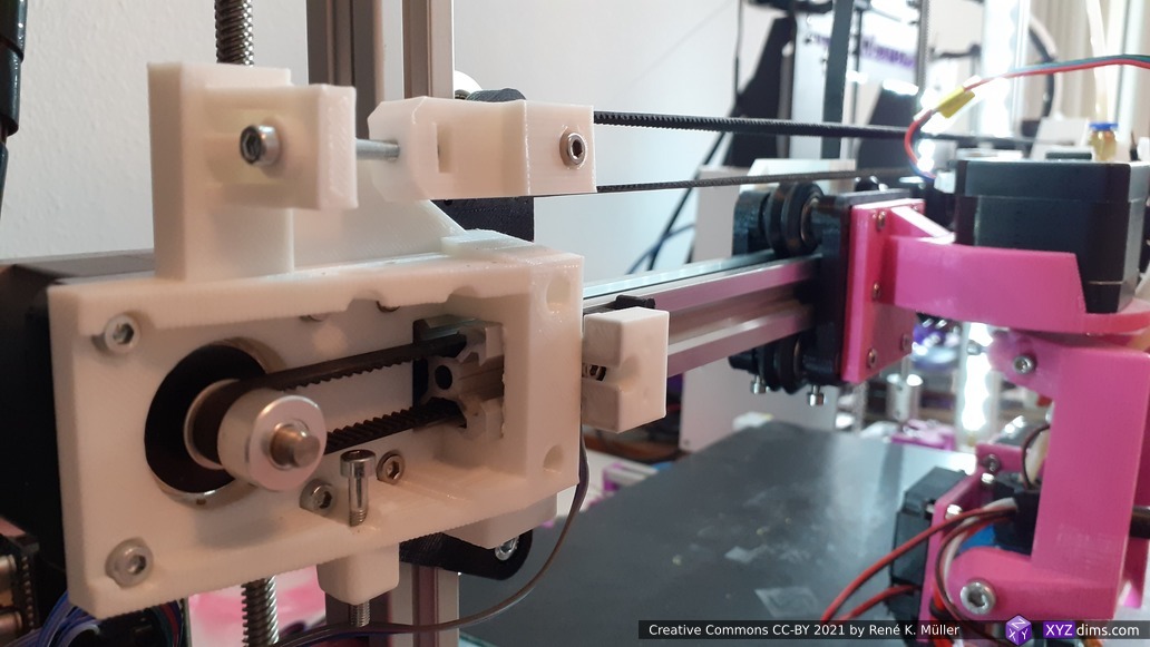
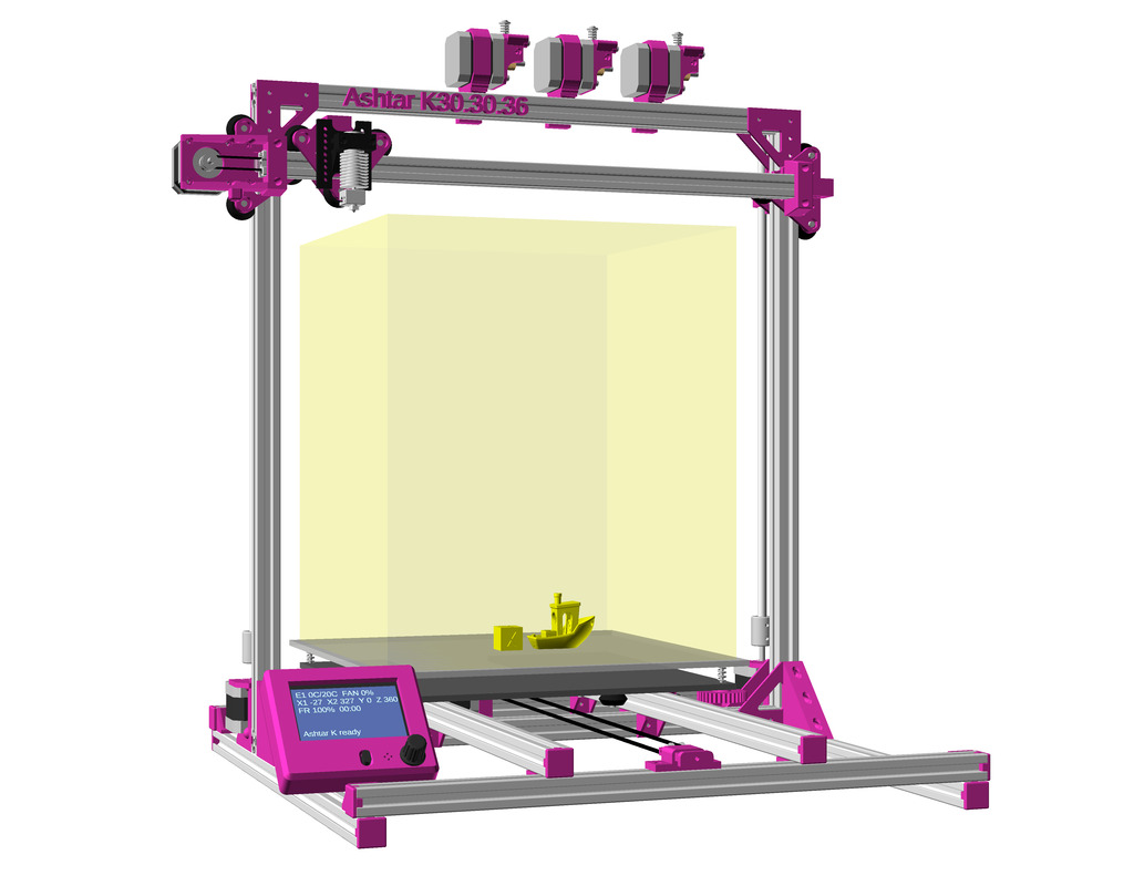
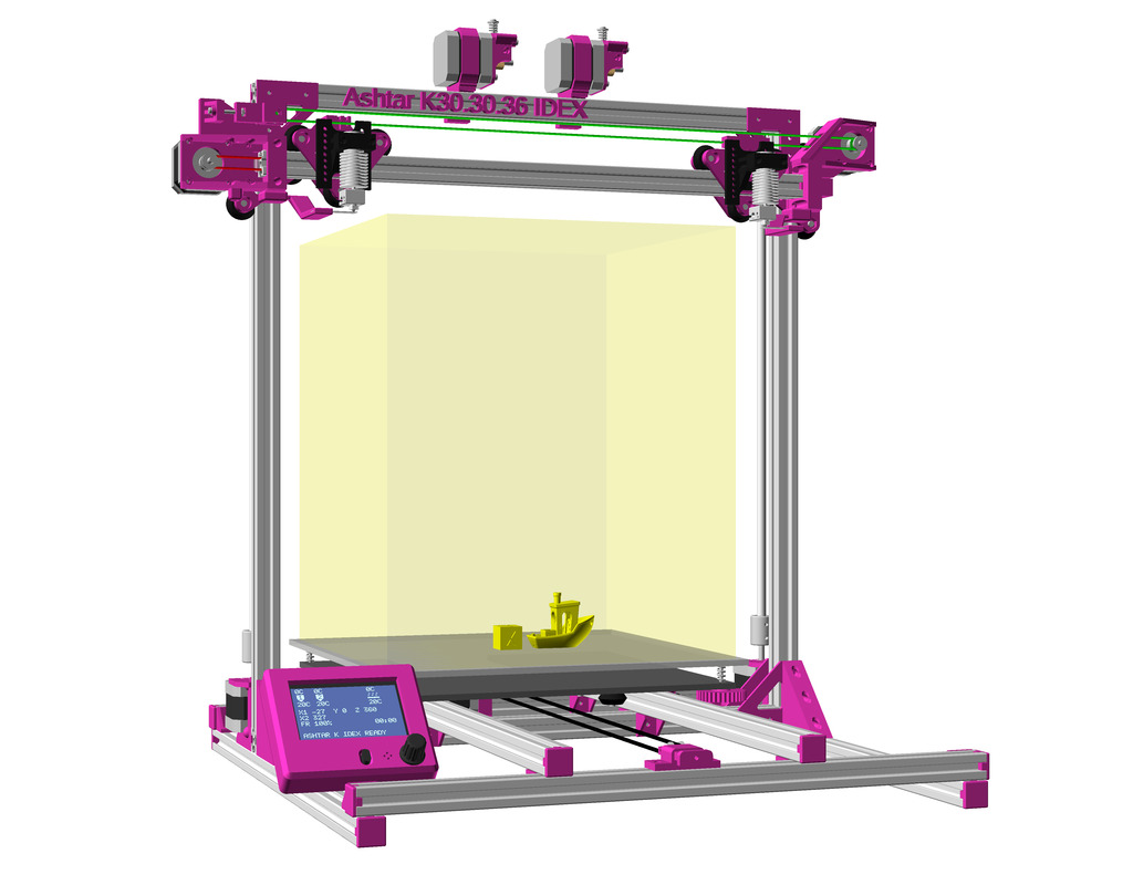
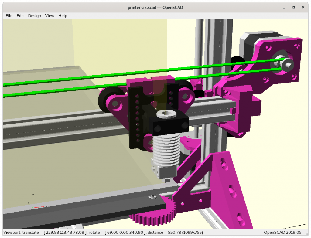
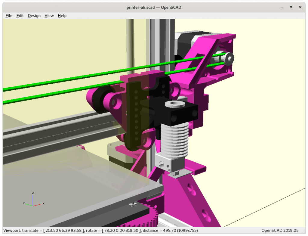
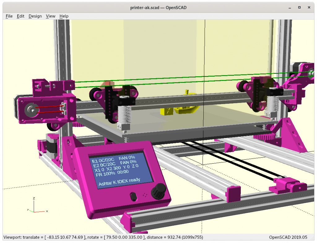
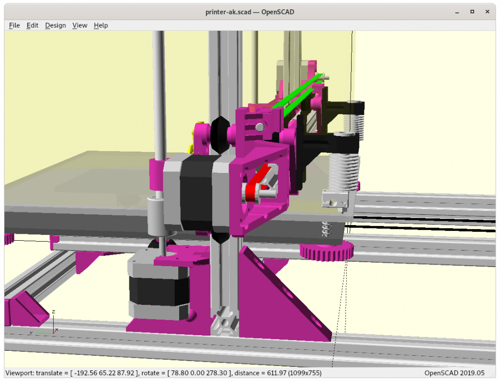
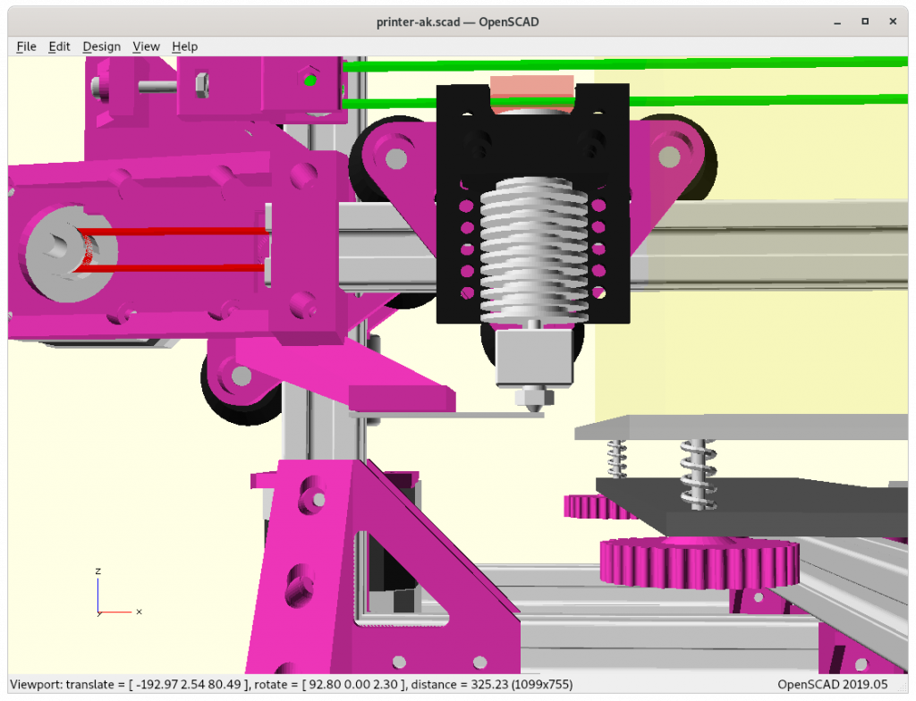
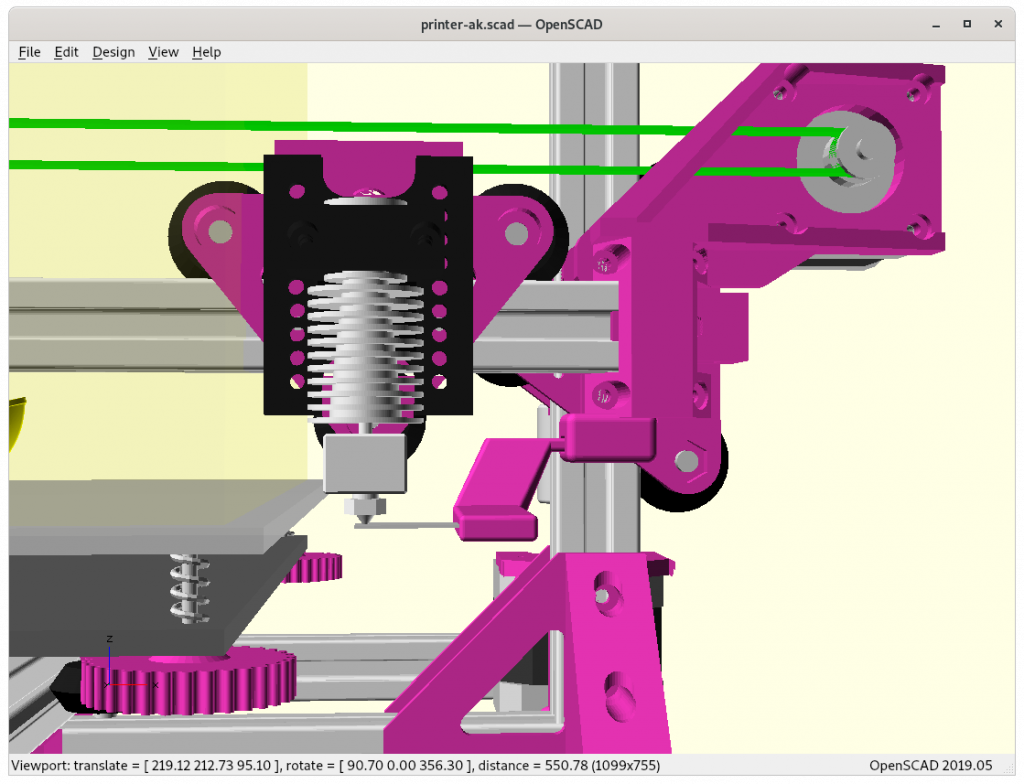
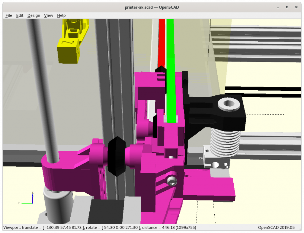
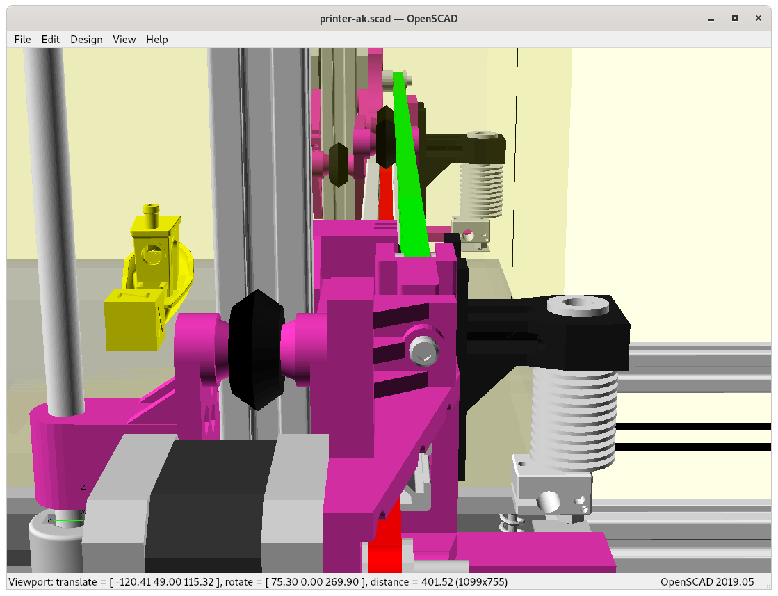
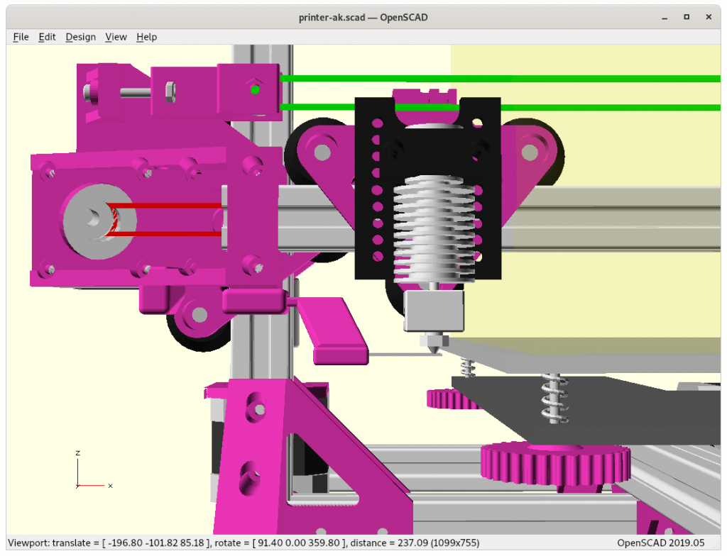
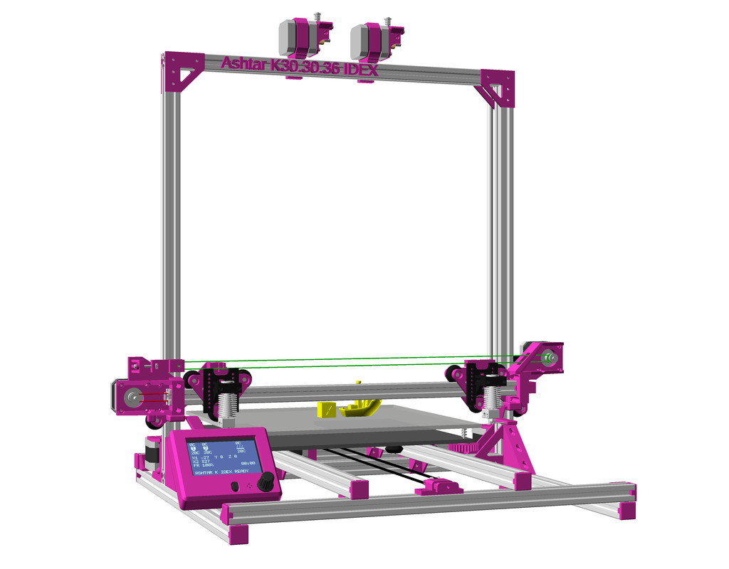
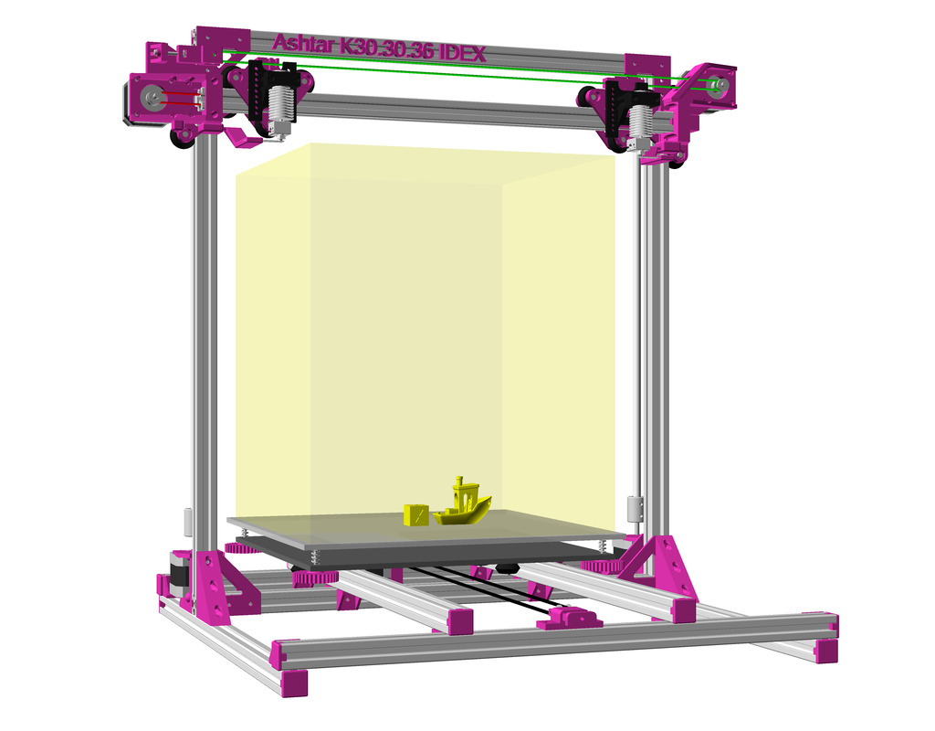
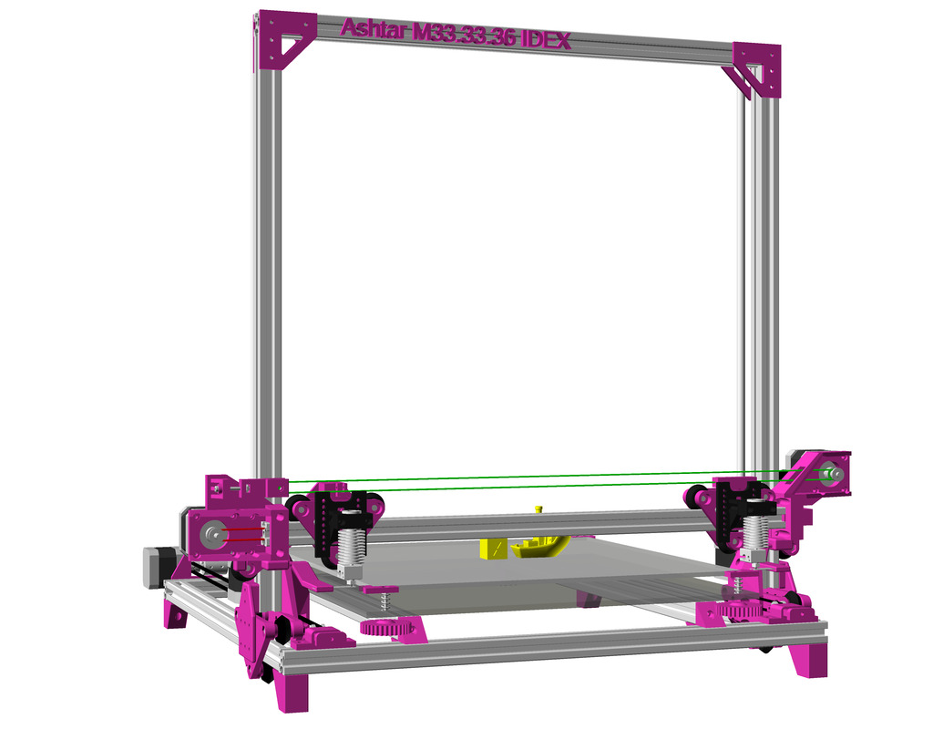
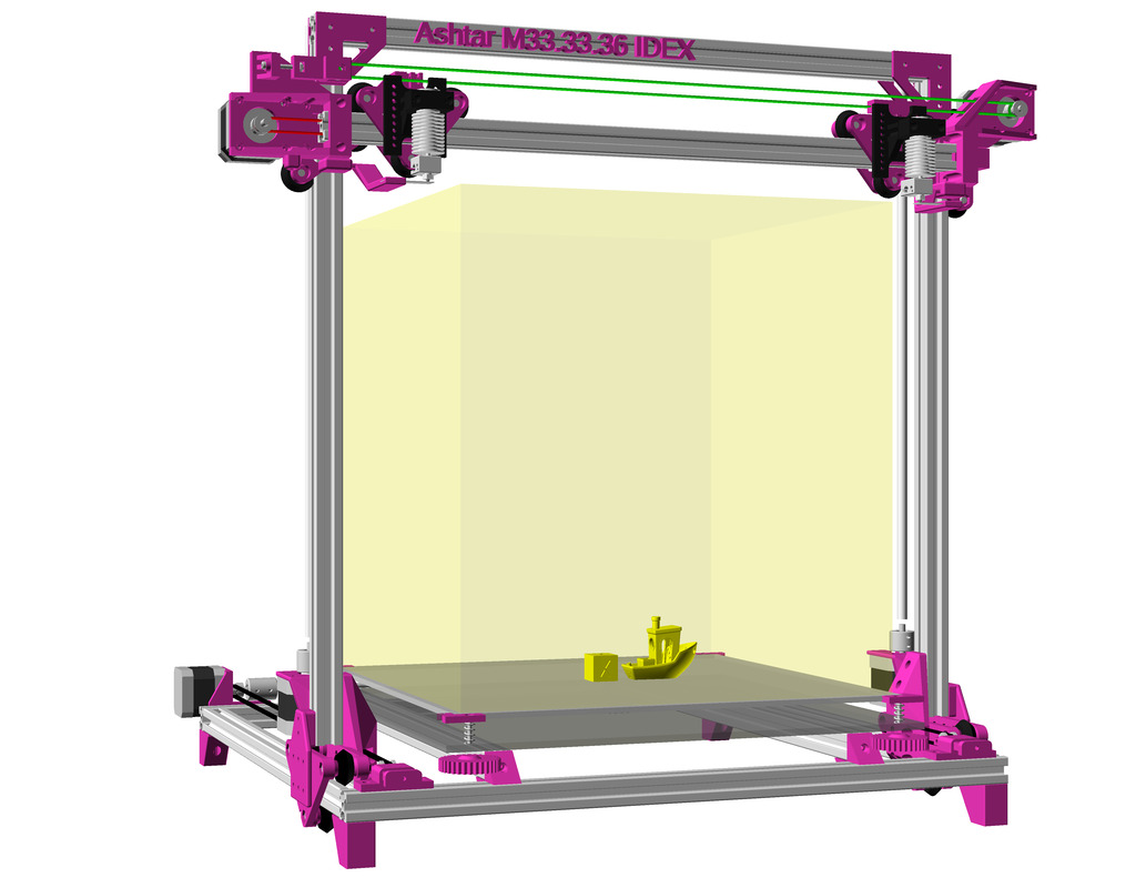
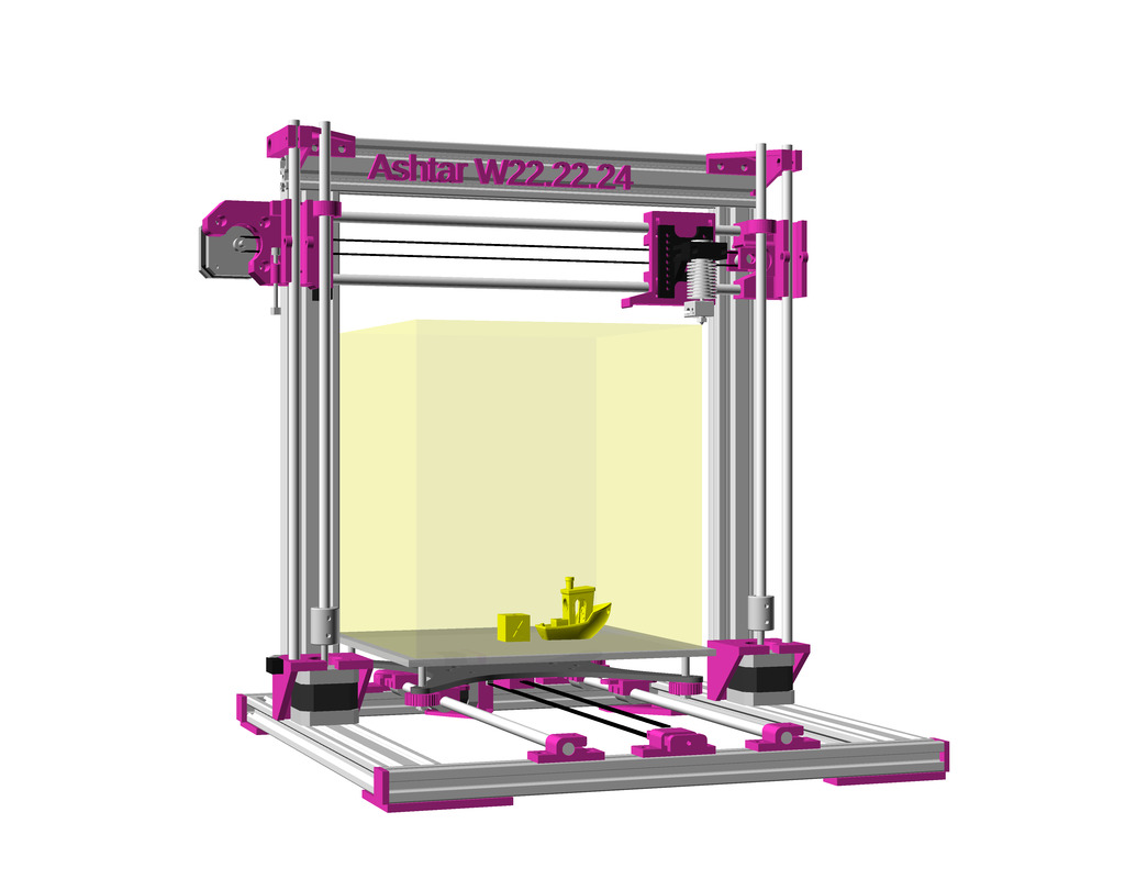
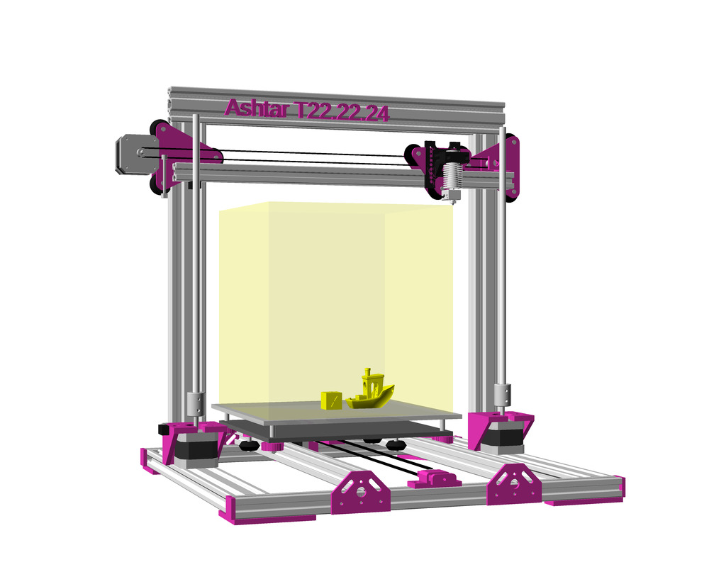
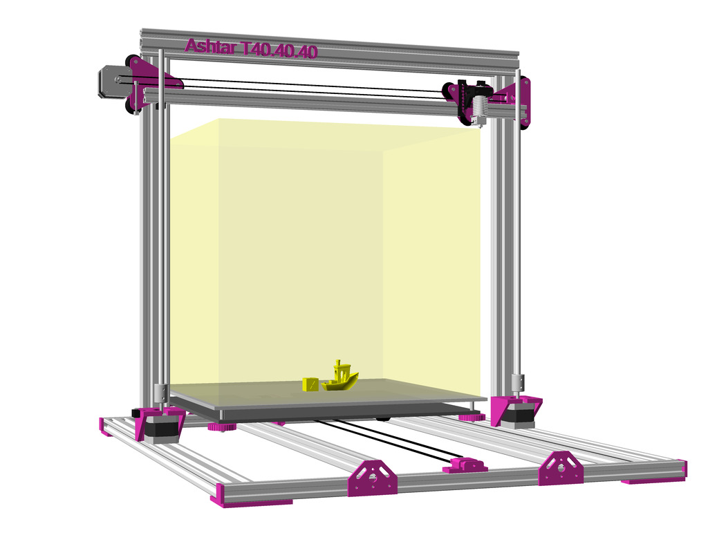
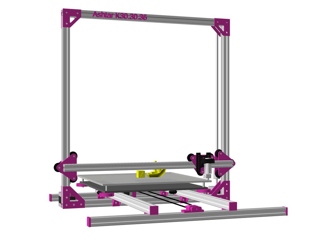
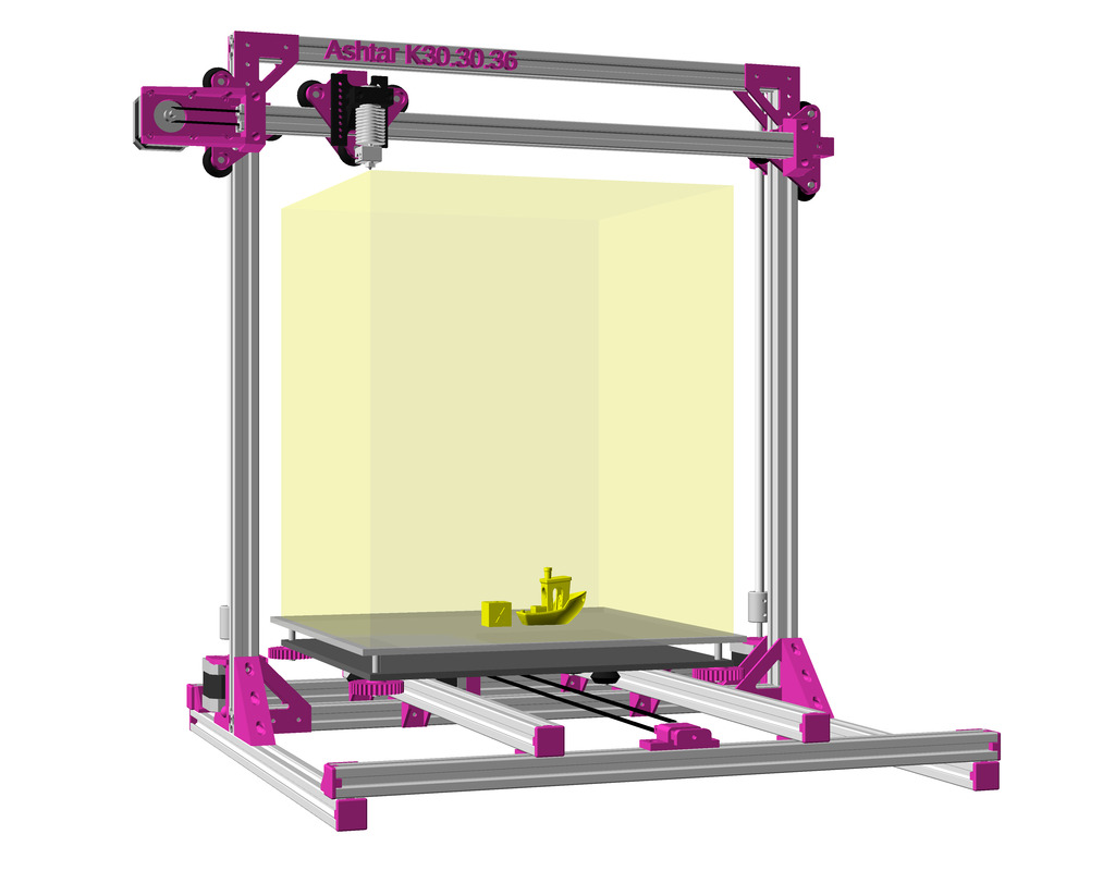
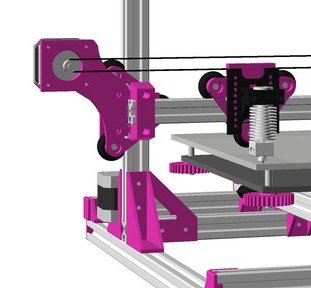
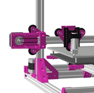
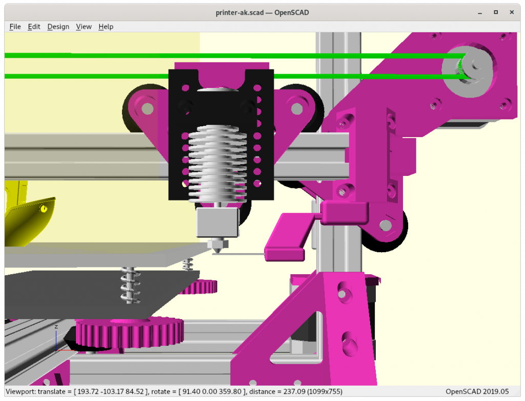
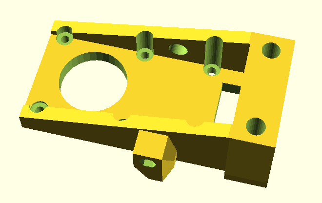
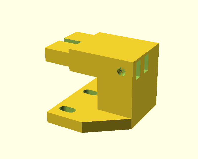
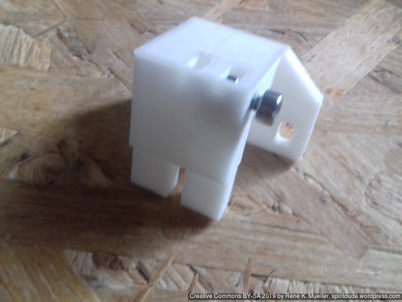
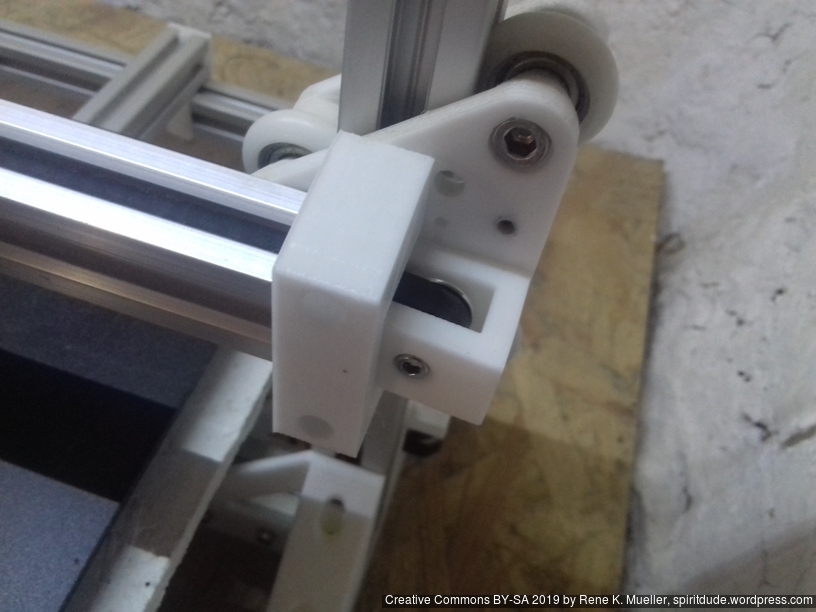
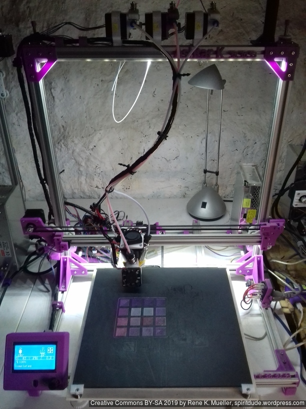
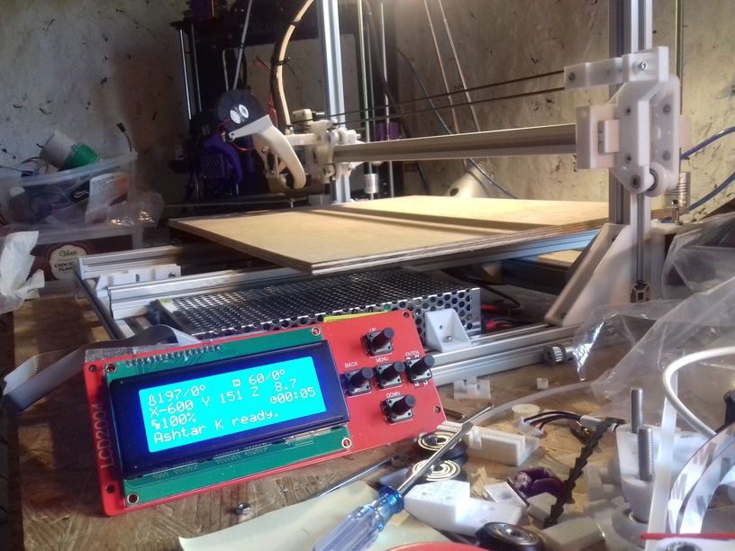
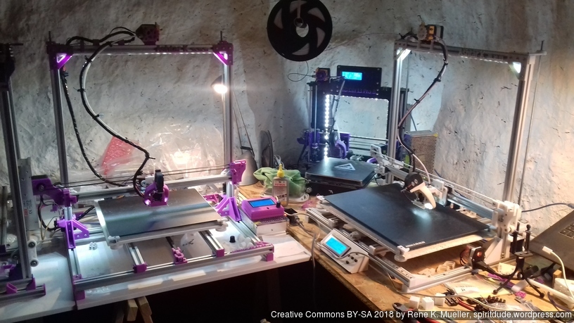
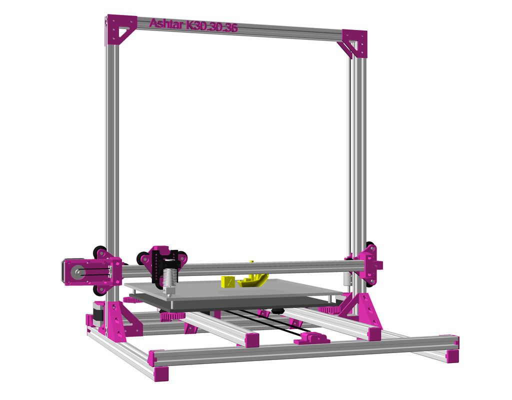
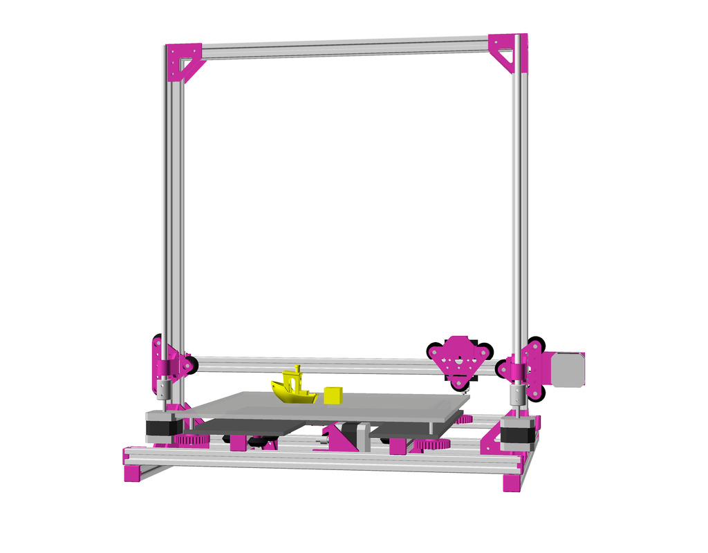
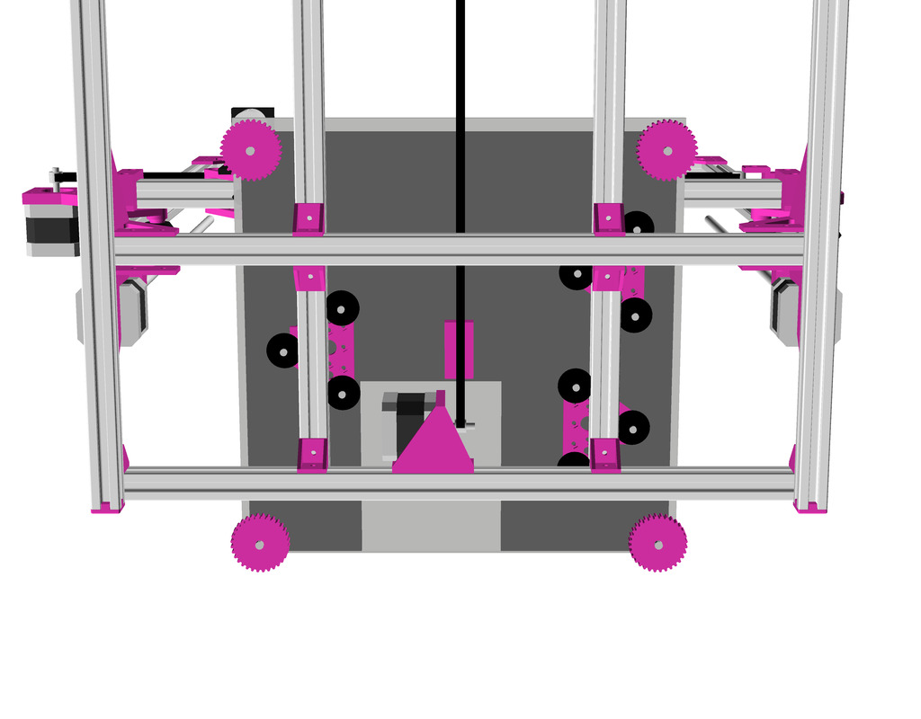
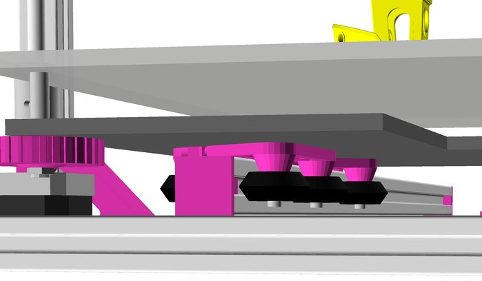
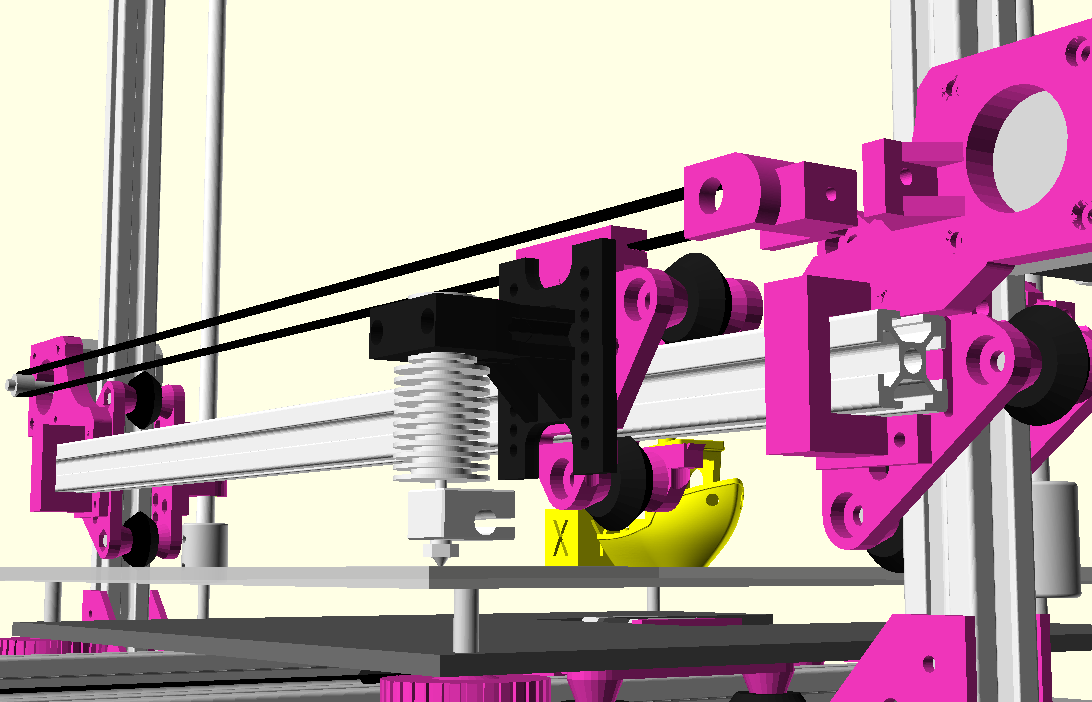
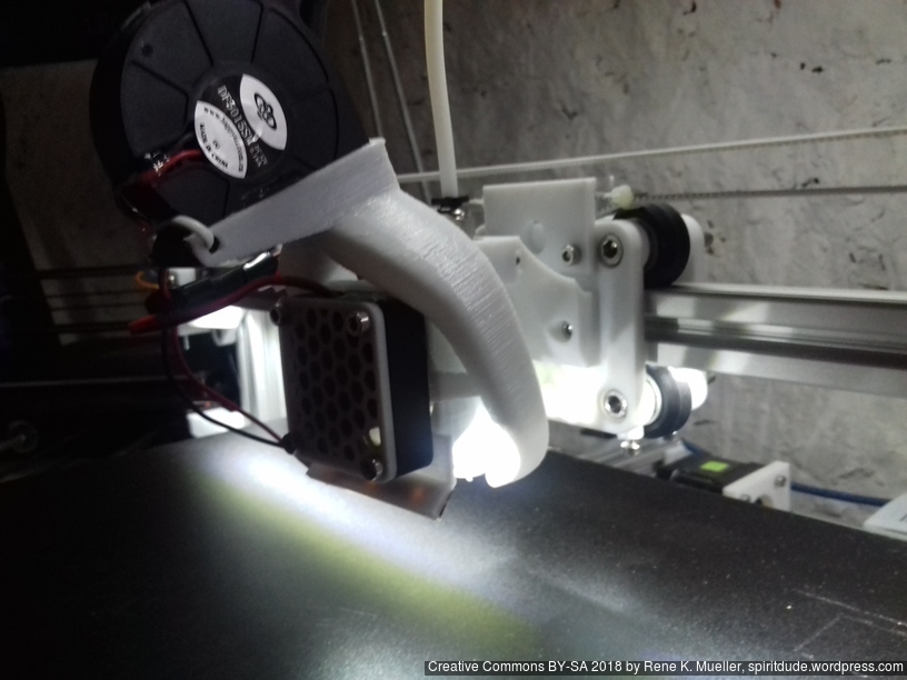
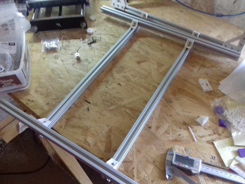
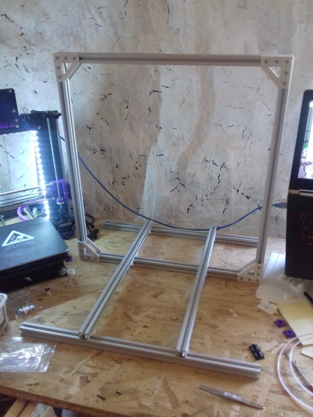
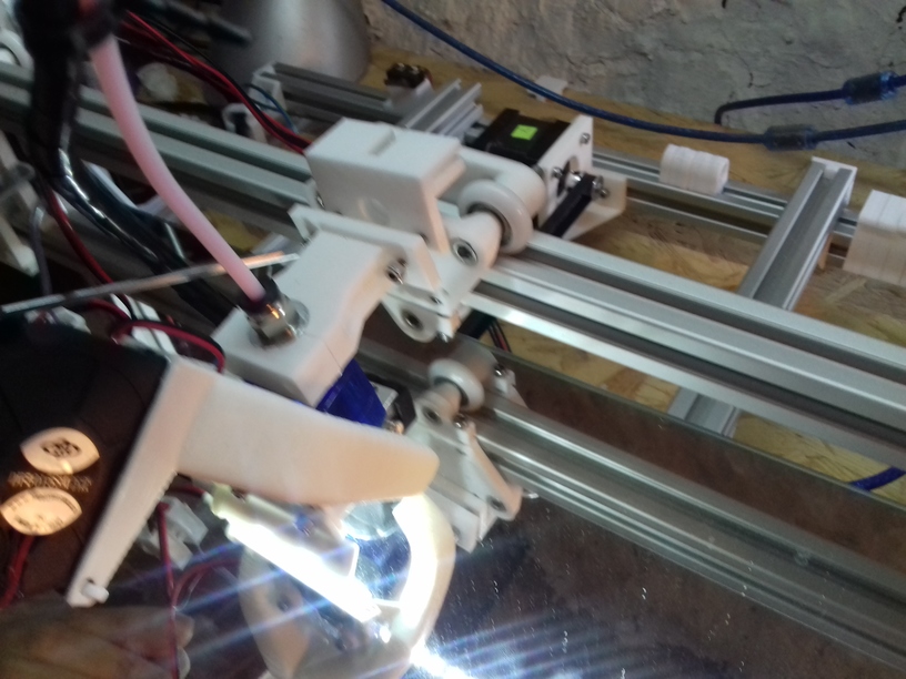
I print with Ashtar K #1 and #2 since a couple of months and since about 4 months with Ashtar C #1 successfully, and thought to convert Ashtar K #2 (300×300 build-plate) with a Diamond Hotend with 3 colors/extruders, renamed to “Ashtar K E3“:
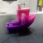
Producing stuff like this:
Cyan, Yellow, Glowing Magenta, Cyan Z-transition
Firmware (Marlin) & Hardware (RAMPS 1.4)
In the Marlin following settings are required:
Configuration.h
#define EXTRUDERS 1
Counter intuitively using 3 extruders with single nozzle in mixing operations, keep EXTRUDERS 1 and do not enable SINGLENOZZLE but leave is disabled.
Enable MIXING_EXTRUDER:
/**
 * "Mixing Extruder"
 *   - Adds a new code, M165, to set the current mix factors.
 *   - Extends the stepping routines to move multiple steppers in proportion to the mix.
 *   - Optional support for Repetier Firmware M163, M164, and virtual extruder.
 *   - This implementation supports only a single extruder.
 *   - Enable DIRECT_MIXING_IN_G1 for Pia Taubert's reference implementation
 */
#define MIXING_EXTRUDER
#if ENABLED(MIXING_EXTRUDER)
  #define MIXING_STEPPERS 3        // Number of steppers in your mixing extruder
  #define MIXING_VIRTUAL_TOOLS 32  // Use the Virtual Tool method with M163 and M164
  #define DIRECT_MIXING_IN_G1    // Allow ABCDHI mix factors in G1 movement commands
#endif
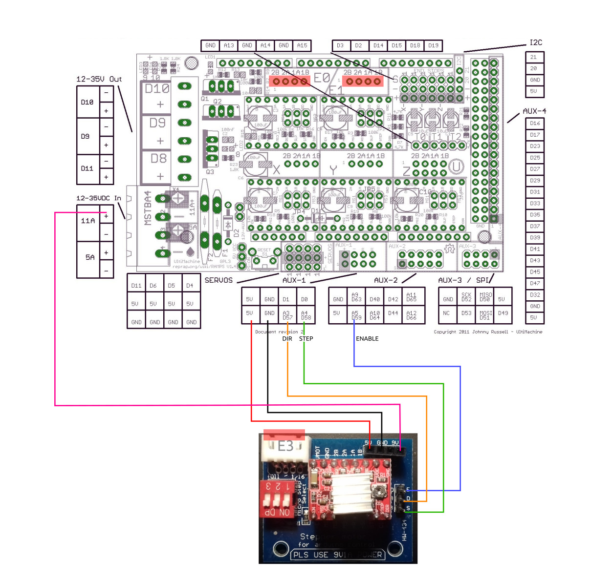
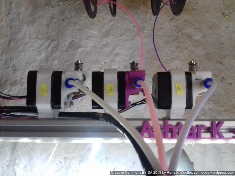
Use E0 for Extruder #1, E1 for Extruder #2, and use an Stepper Extender for Extruder #3:
Configuration_adv.h
Enable FWRETRACT:
#define FWRETRACT // ONLY PARTIALLY TESTED
#if ENABLED(FWRETRACT)
#define MIN_AUTORETRACT 0.1 // When auto-retract is on, convert E moves of this length and over
#define MAX_AUTORETRACT 10.0 // Upper limit for auto-retract conversion
#define RETRACT_LENGTH 3 // Default retract length (positive mm)
#define RETRACT_LENGTH_SWAP 13 // Default swap retract length (positive mm), for extruder change
#define RETRACT_FEEDRATE 45 // Default feedrate for retracting (mm/s)
#define RETRACT_ZLIFT 0 // Default retract Z-lift
#define RETRACT_RECOVER_LENGTH 0 // Default additional recover length (mm, added to retract length when recovering)
#define RETRACT_RECOVER_LENGTH_SWAP 0 // Default additional swap recover length (mm, added to retract length when recovering from extruder change)
#define RETRACT_RECOVER_FEEDRATE 8 // Default feedrate for recovering from retraction (mm/s)
#define RETRACT_RECOVER_FEEDRATE_SWAP 8 // Default feedrate for recovering from swap retraction (mm/s)
#endif
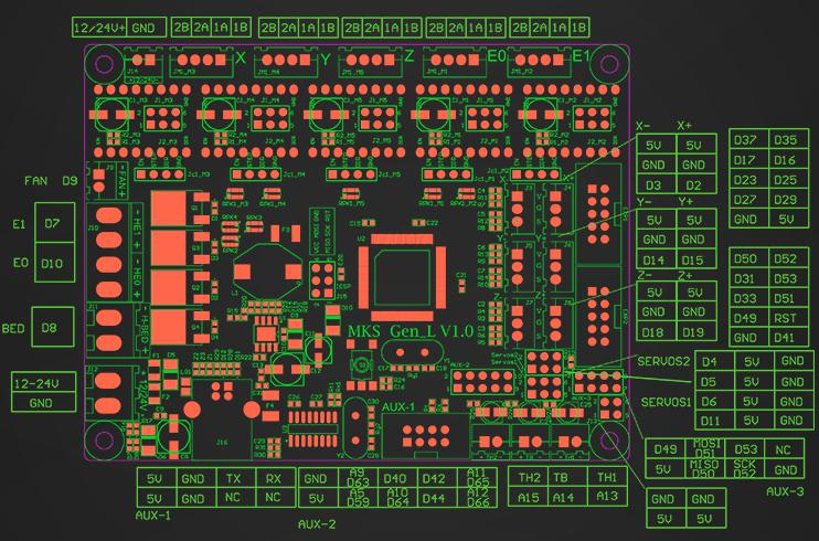
pins_RAMPS.h
Add following lines below E1_CS_PIN:
#define E2_STEP_PIN 58
#define E2_DIR_PIN 57
#define E2_ENABLE_PIN 59
#define E2_CS_PIN -1
In case the Extruder #3 (E2) runs reverse, invert it in Configuration.h:
#define INVERT_E2_DIR true
Mixed Colors Prints
Two ways to print mixed colors:
M163/M164: define mixing ratio palette and define a virtual tool per mixing ratio which can be used as “T<n>” in Gcode laterM165: define mixing ratio right away
Virtual Tools Color Palette
Within ~/.config/print3r/printer/ashtar-k-2-e3.ini I added in start_gcode different palettes:
Trinary Palette
A general palette of 19 mixed colors using 3 colors defined in Gcode:
M163 S0 P1
M163 S1 P0
M163 S2 P0
M164 S0

M163 S0 P0
M163 S1 P1
M163 S2 P0
M164 S1

M163 S0 P0
M163 S1 P0
M163 S2 P1
M164 S2

M163 S0 P1
M163 S1 P1
M163 S2 P0
M164 S3

M163 S0 P0
M163 S1 P1
M163 S2 P1
M164 S4

M163 S0 P1
M163 S1 P0
M163 S2 P1
M164 S5

M163 S0 P1
M163 S1 P1
M163 S2 P1
M164 S6

M163 S0 P2
M163 S1 P1
M163 S2 P0
M164 S7

M163 S0 P2
M163 S1 P0
M163 S2 P1
M164 S8

M163 S0 P2
M163 S1 P1
M163 S2 P1
M164 S9

M163 S0 P1
M163 S1 P2
M163 S2 P0
M164 S10

M163 S0 P0
M163 S1 P2
M163 S2 P1
M164 S11

M163 S0 P1
M163 S1 P2
M163 S2 P1
M164 S12

M163 S0 P1
M163 S1 P0
M163 S2 P2
M164 S13

M163 S0 P0
M163 S1 P1
M163 S2 P2
M164 S14

M163 S0 P1
M163 S1 P1
M163 S2 P2
M164 S15

M163 S0 P2
M163 S1 P2
M163 S2 P1
M164 S16

M163 S0 P2
M163 S1 P1
M163 S2 P2
M164 S17

M163 S0 P1
M163 S1 P2
M163 S2 P2
M164 S18
After that, the virtual tools T0 – T18 are available, printing different mix ratios.
Full Saturated True Color (Hue) Palette
The following (source) defines 16 different mix ratios of common colors with Cyan, Yellow and Magenta:
; Cyan
M163 S0 P1
M163 S1 P0
M163 S2 P0
M164 S0

; Ocean
M163 S0 P5
M163 S1 P1
M163 S2 P0
M164 S1

; Blue
M163 S0 P1
M163 S1 P1
M163 S2 P0
M164 S2

; Violet
M163 S0 P1
M163 S1 P5
M163 S2 P0
M164 S3

; Magenta
M163 S0 P0
M163 S1 P1
M163 S2 P0
M164 S4

; Raspberry
M163 S0 P0
M163 S1 P5
M163 S2 P1
M164 S5

; Red
M163 S0 P0
M163 S1 P5
M163 S2 P1
M164 S6

; Orange
M163 S0 P0
M163 S1 P1
M163 S2 P1
M164 S7

; Yellow
M163 S0 P0
M163 S1 P0
M163 S2 P1
M164 S8

; Spring Green
M163 S0 P1
M163 S1 P0
M163 S2 P5
M164 S9

; Green
M163 S0 P1
M163 S1 P0
M163 S2 P1
M164 S10

; Turquoise
M163 S0 P5
M163 S1 P0
M163 S2 P1
M164 S11

; Cyan-Brown
M163 S0 P2
M163 S1 P1
M163 S2 P1
M164 S12

; Magenta-Brown
M163 S0 P1
M163 S1 P2
M163 S2 P1
M164 S13

; Yellow-Brown
M163 S0 P1
M163 S1 P1
M163 S2 P2
M164 S14

; Brown
M163 S0 P1
M163 S1 P1
M163 S2 P1
M164 S15
After that, the virtual tools T0 – T15 are available, printing different mix ratios.
I used following code to purge 30mm (10+10+10mm) filament from all 3 colors at once at the very beginning (start_gcode):
M165 A0.33 B0.33 C0.33  ; 1/3 for each filament
G92 E0
G1 E30 F100     ; extrude 30mm
G92 E0
Additionally, define the firmware retraction:
M207 F3000 S4 Z0.3   ; set firmware retraction 50mm/s 4mm, 0.3mm zhop
M209               ; use firmware retraction
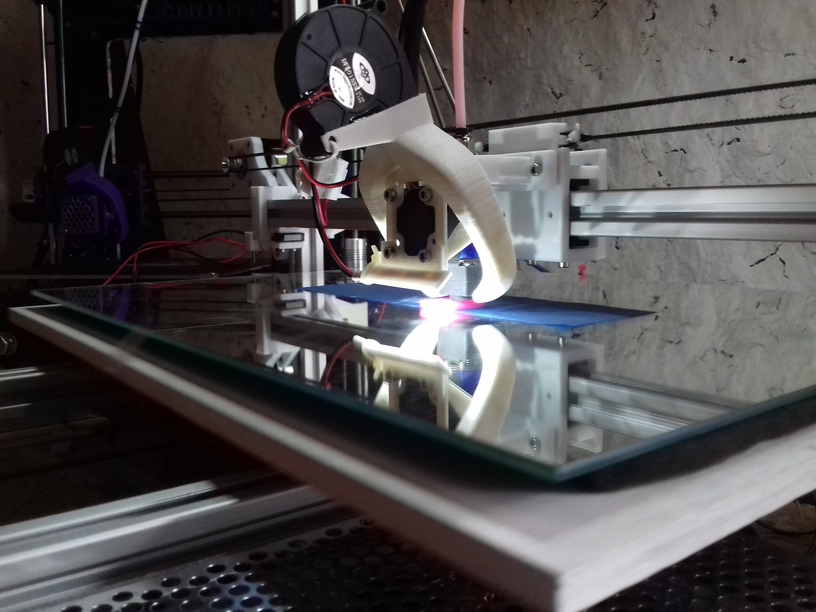
Printing
For test purpose I have:
- Extruder 1 (E0 or A): glowing magenta PLA
- Extruder 2 (E1 or B): violett PLA
- Extruder 3 (E2 or C): white PLA
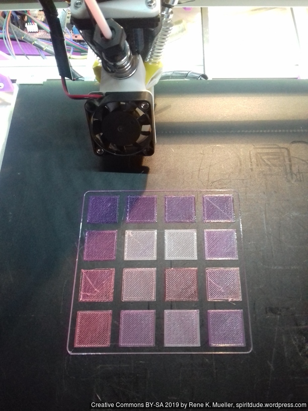
As such I prepared 16x 20×20 plates with 1 layer height:
print3r --printer=ashtar-k-2-e3 --slicer=cura --random-placement --scad --multiply-part=16 --output=plates-16.gcode slice 'cube([20,20,0.2])'
which gave me plates-16.gcode which I edited and inserted the “16 colors palette” Gcode, and after each “WALL-INNER” lines I added T0, T1 etc. T15 to switch to another tool (mixing colors ratios) for each plate:
There is no purge block, but I wanted to see how fast the switch is possible. Some issues are once the mix changes the first 10-20mm extrusion may come out under-extruded.
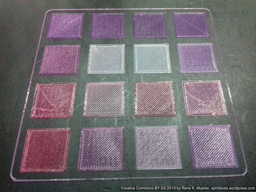
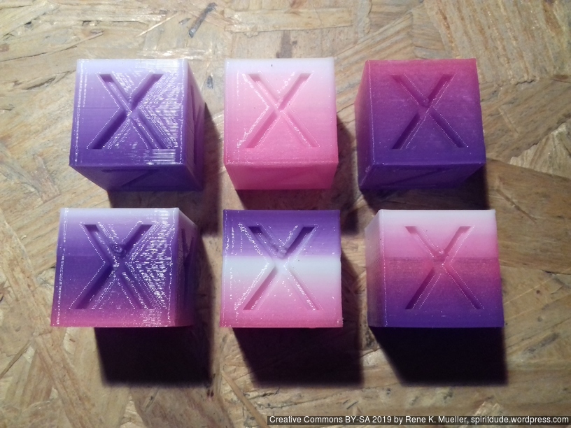
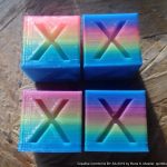
16 mixed colors from 3 colors (Glowing Magenta, Violet, White)
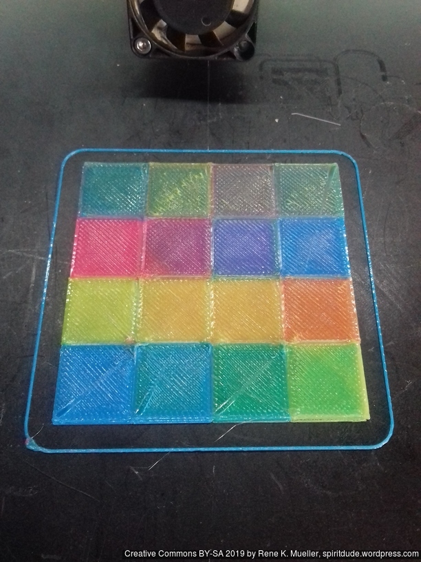
16 mixed colors from 3 colors (Light Blue/Cyan, Yellow and Glowing Magenta)
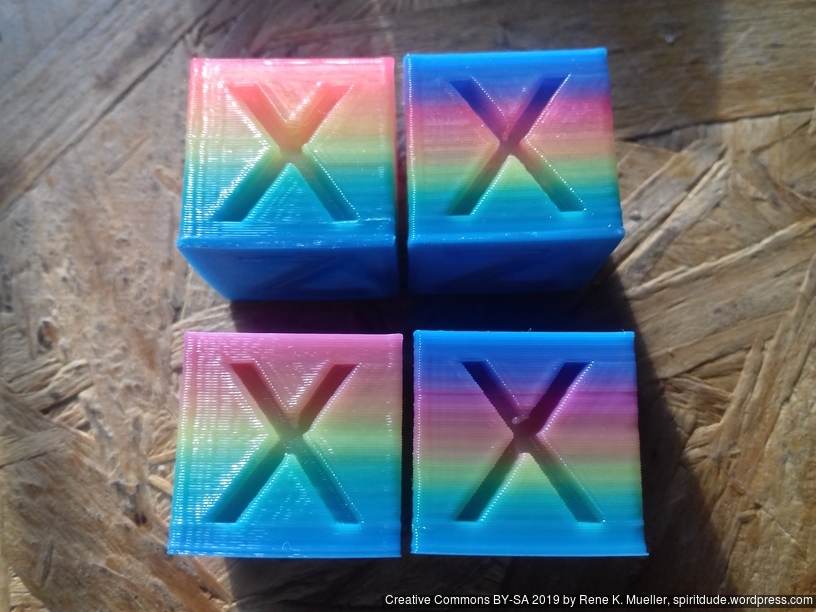
With light-blue/cyan, yellow and glowing magenta gave decent results: the green turned out well, the orange as well, even the violet and darker blue came out well.
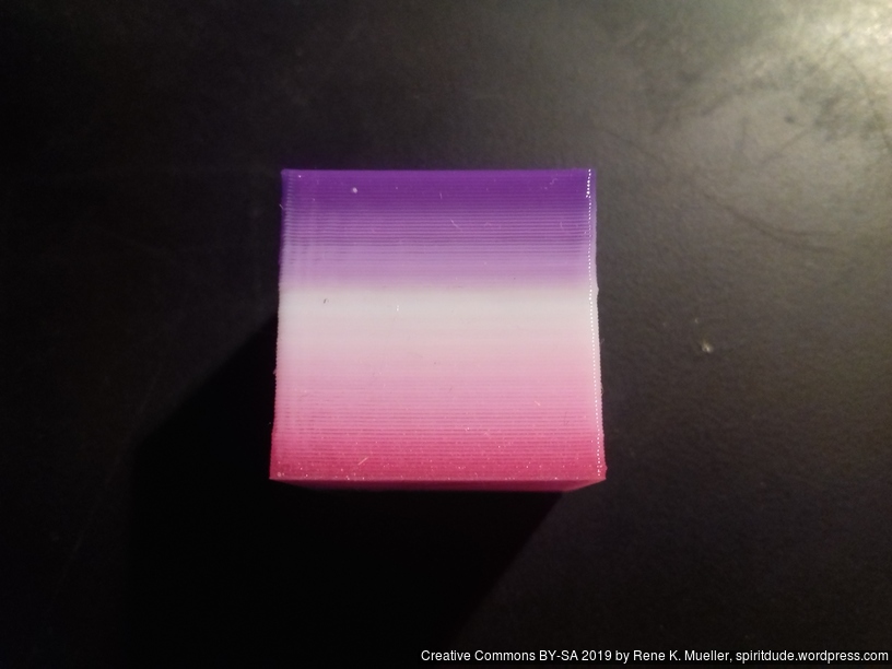
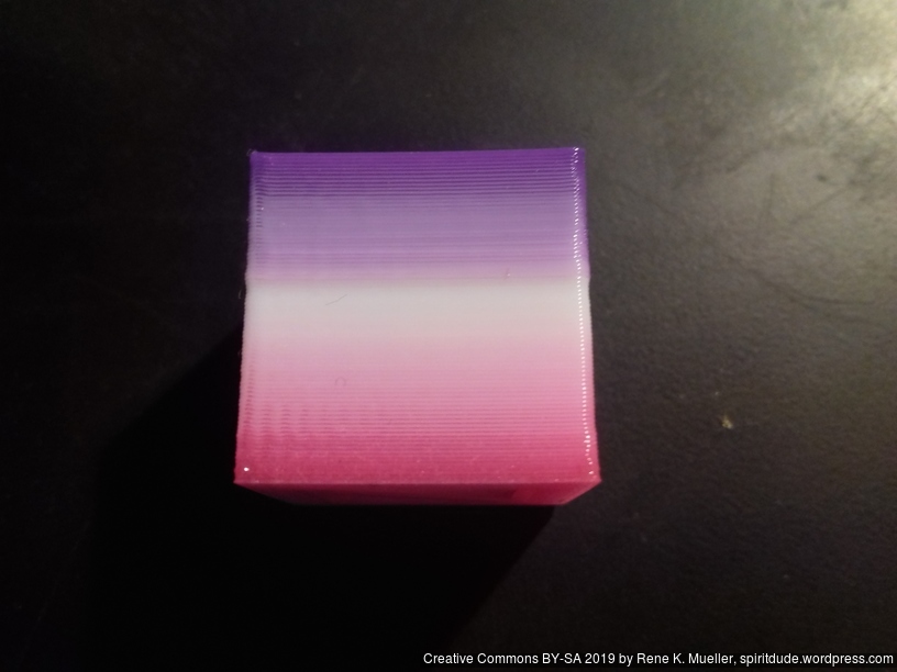
And finally some cubes with 2- and 3-color transitions in the Z axis:
where I used print3r directly, using --layer-gcode=... feature (I just added 2019/04/10):
2-color 2 phases: use variables a2 (fades 1..0), and b2(fades 0..1):
- fade A->B:
'--layer-gcode=M165 A${a2} B${b2}'
- fade B->C:
'--layer-gcode=M165 B${a2} C${b2}'
- fade A->C:
'--layer-gcode=M165 A${a2} C${b2}'
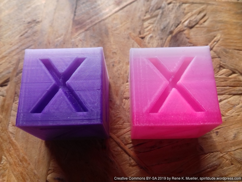
Violet to White, Glowing Magenta to White Z-transition
3-color 3 phases: use variables a3 (fades 1..0 first half), b3 (fades 0..1..0), and c3 (fades 0..1 for second half):
- fade A->B->C:
'--layer-gcode=M165 A${a3} B${b3} C${c3}'
- fade A->C->B:
'--layer-gcode=M165 A${a3} B${c3} C${b3}'
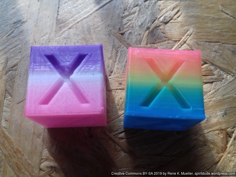
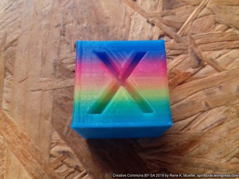
Glowing Magenta, White, Violet and Cyan, Yellow, Glowing Magenta Z-transition
3-color 4 phases: use variable a34 (1..0..0..1), b34 (fades 0..1..0..0) and c34 (fades 0..0..1..0)
- fade A->B->C->A:
'--layer-gcode=M165 A${a34} B${b34} C${c34}'
- fade A->C->B->A:
'--layer-gcode=M165 A${a34} B${c34} C${b34}'
Cyan, Yellow, Glowing Magenta, Cyan Z-transition
Cyan, Yellow, Magenta, Cyan Z-transition: Cyan, Green, Yellow, Orange, Pink/Magenta, Violet, Blue
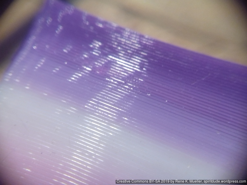
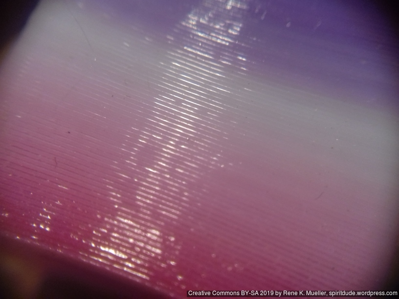
Partial Mixing
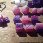
 At closer inspection, the Diamond Hotend doesn’t perfectly mix the filament:
- left/back: white PLA
- front/center: glowing magenta PLA
- right/back: violet PLA
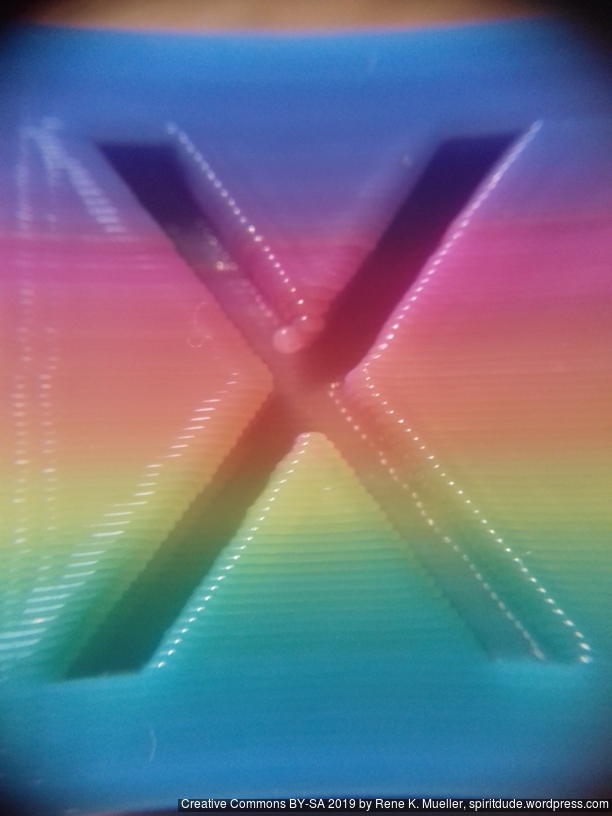
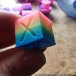
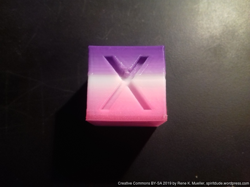
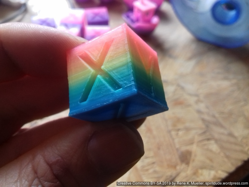
Now, let’s rotate the XYZ Hollow Cube around the Z axis:
-
-
front
-
-
right-hand side
-
-
back
-
-
left-hand side
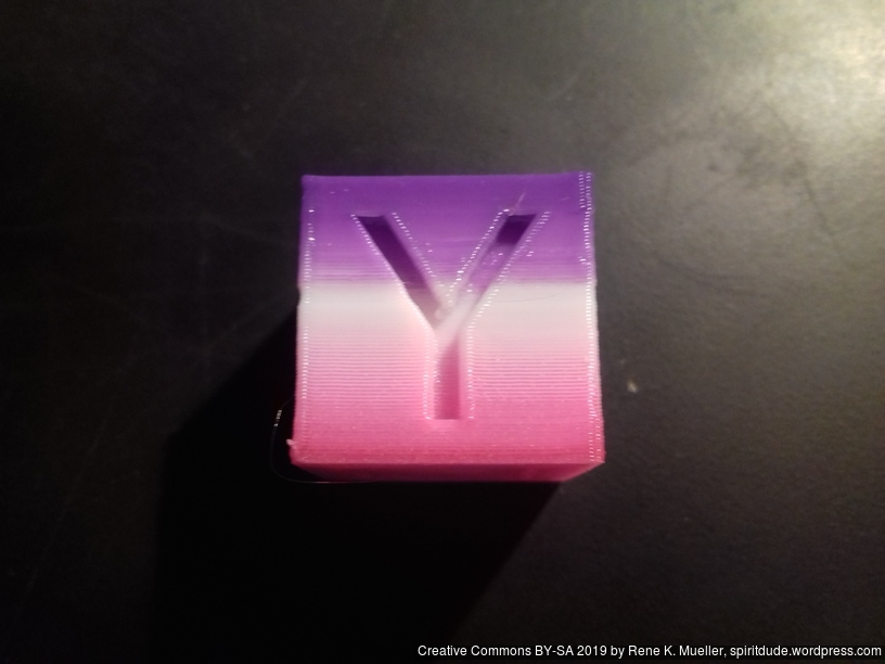
In front with “X” the violet prominently comes soon, the “Y” (right-hand side) looks OK, whereas the back side the white/violet transition is not smooth, the same for the left-hand side.
Jamming
Quickly after trying more complex and longer prints, I experienced filament jamming:
I chose Violet -> Magenta -> White Z-axis transition, and the jamming occured with the Magenta PLA about 5-6min after the start, not always the same height; I tried several things like feeding a minimum of 5% of each filament, but then lower the print temperature from 205C to 198C, and things worked:
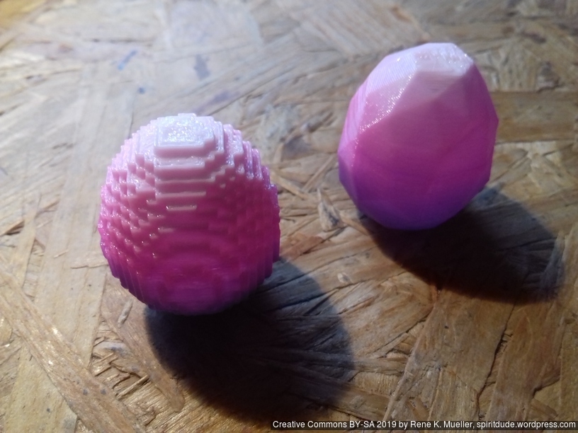
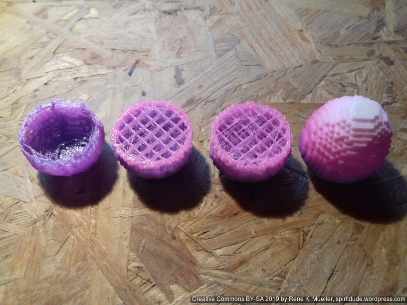
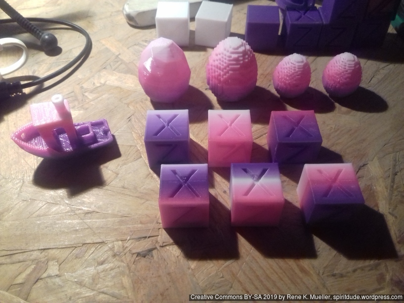
LowRes-Minecraft and LowRes-LowPoly Easter Eggs (35mm height, 0% infill, no support)
I print with first layer (layer 0) 210C usually on cold bed, and dropping to 195C for the rest usually let the nozzle temperature sink below 190C, sometimes even 185C before reaching 195C again due the thermal mass of the Diamond Hotend, and below 190C risk of under extrusion is high (layer 2-3), therefore I now use 195-198C to limit that risk.
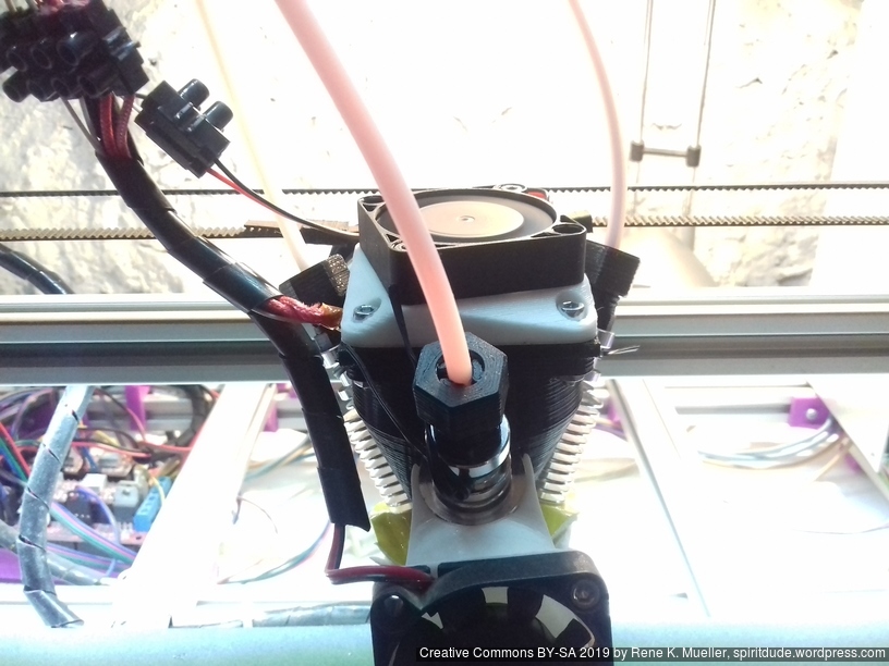
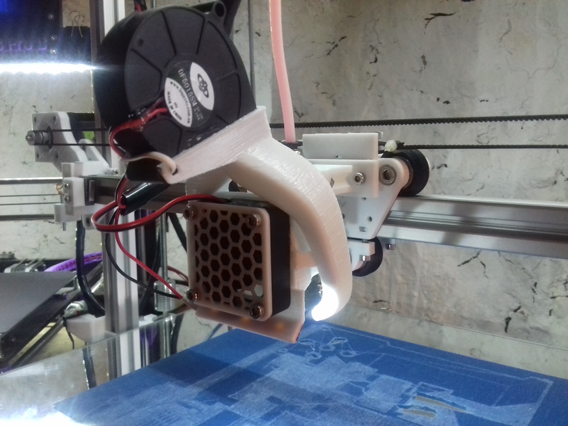
It’s recommended to increase printing temperature with Diamond Hotend to achieve better mixing of the filament, yet, it seems also increases the risk of clogging/jamming of filament as in my case. Although, I currently use an 40mm fan on top of the Diamond Hotend instead of 50mm fan – the heatsinks left/back and right/back are warm, whereas the center/front (with magenta) is cooler. So, I might use a bigger fan and see how things behave then.
-
-
-
Glowing Magenta (top) vs Magenta (bottom)
-
-
-
20mm XYZ Hollow Calibration Cube, CMY transition (C=Bright Blue, M=Glowing Magneta, Y=Yellow; from Sienoc)
That’s it.


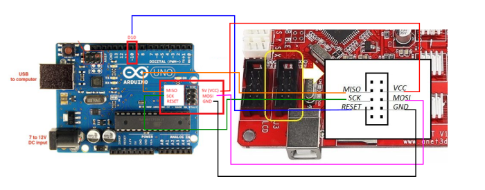

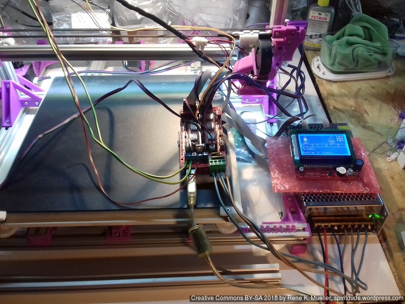
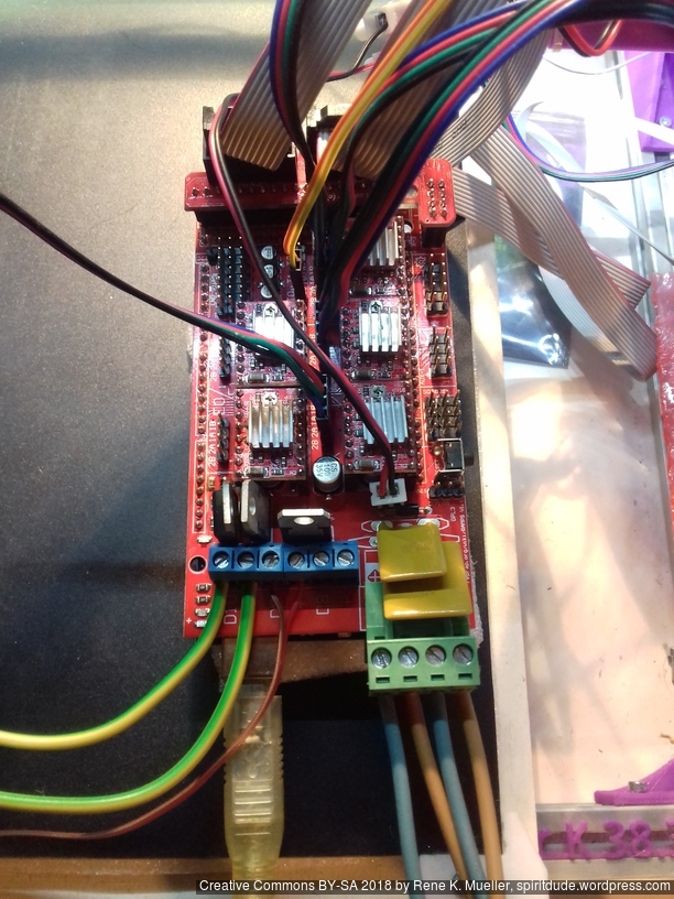
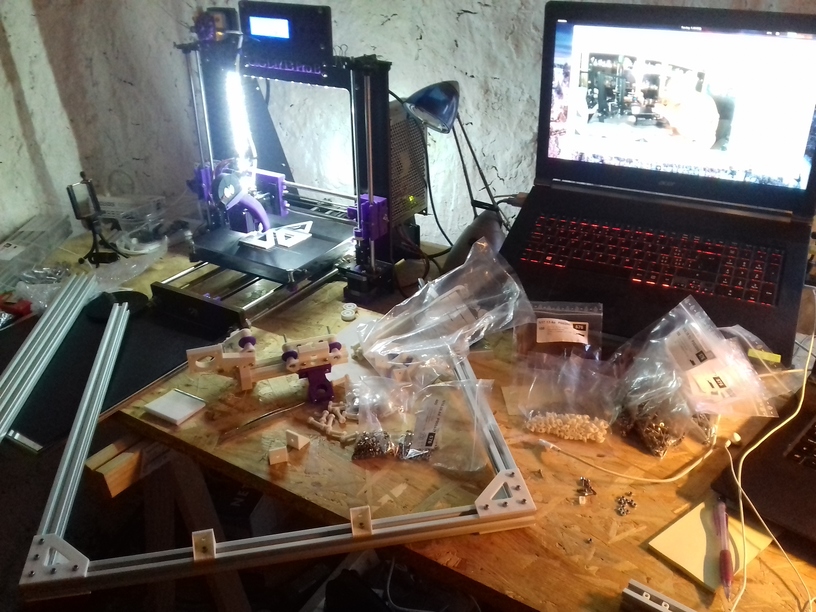
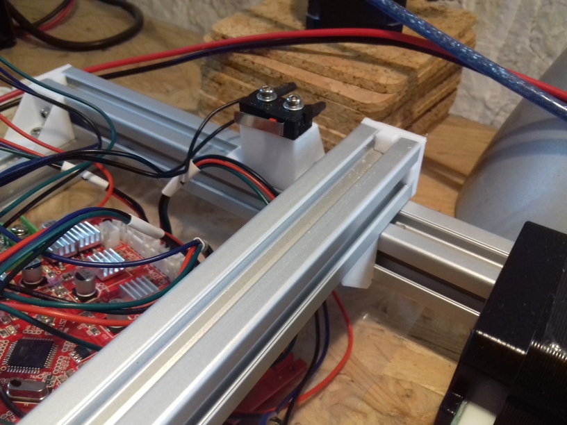
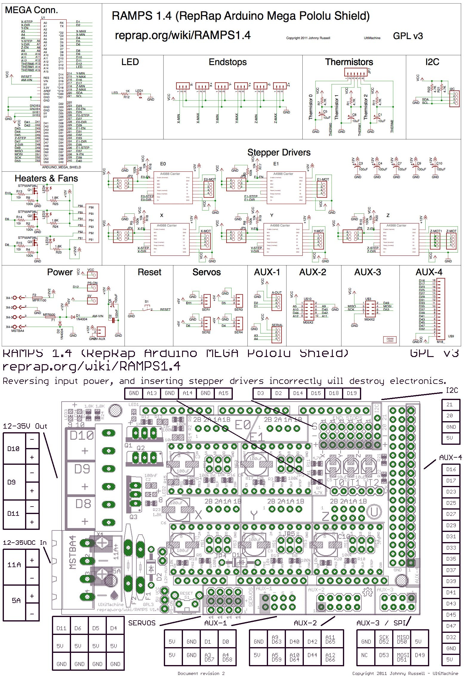 For the 2nd Ashtar K 3D Printer I used (2018/11) RAMPS 1.4 combo with Arduino Mega, which was easy to upload new firmware. RAMPS 1.4 is Open Hardware,
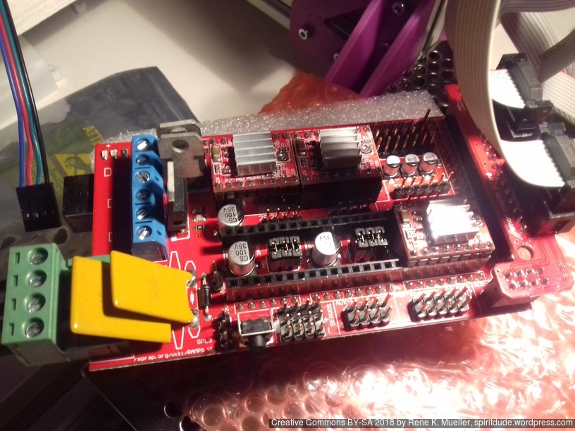


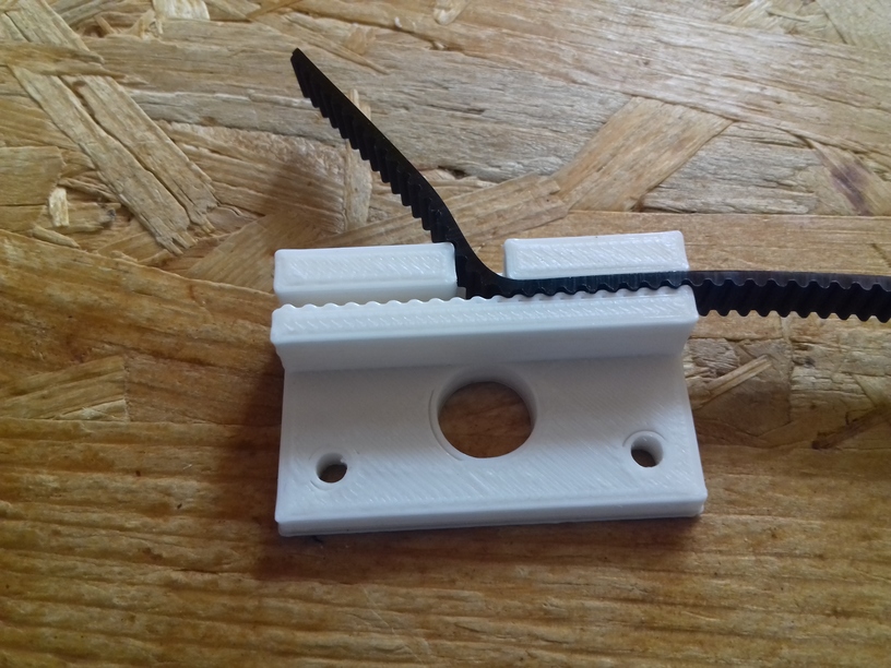


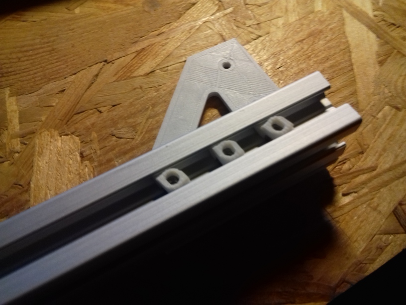


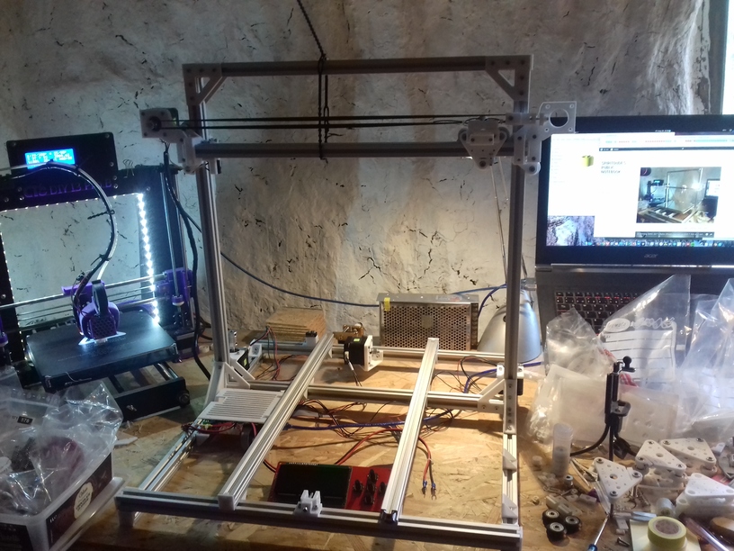
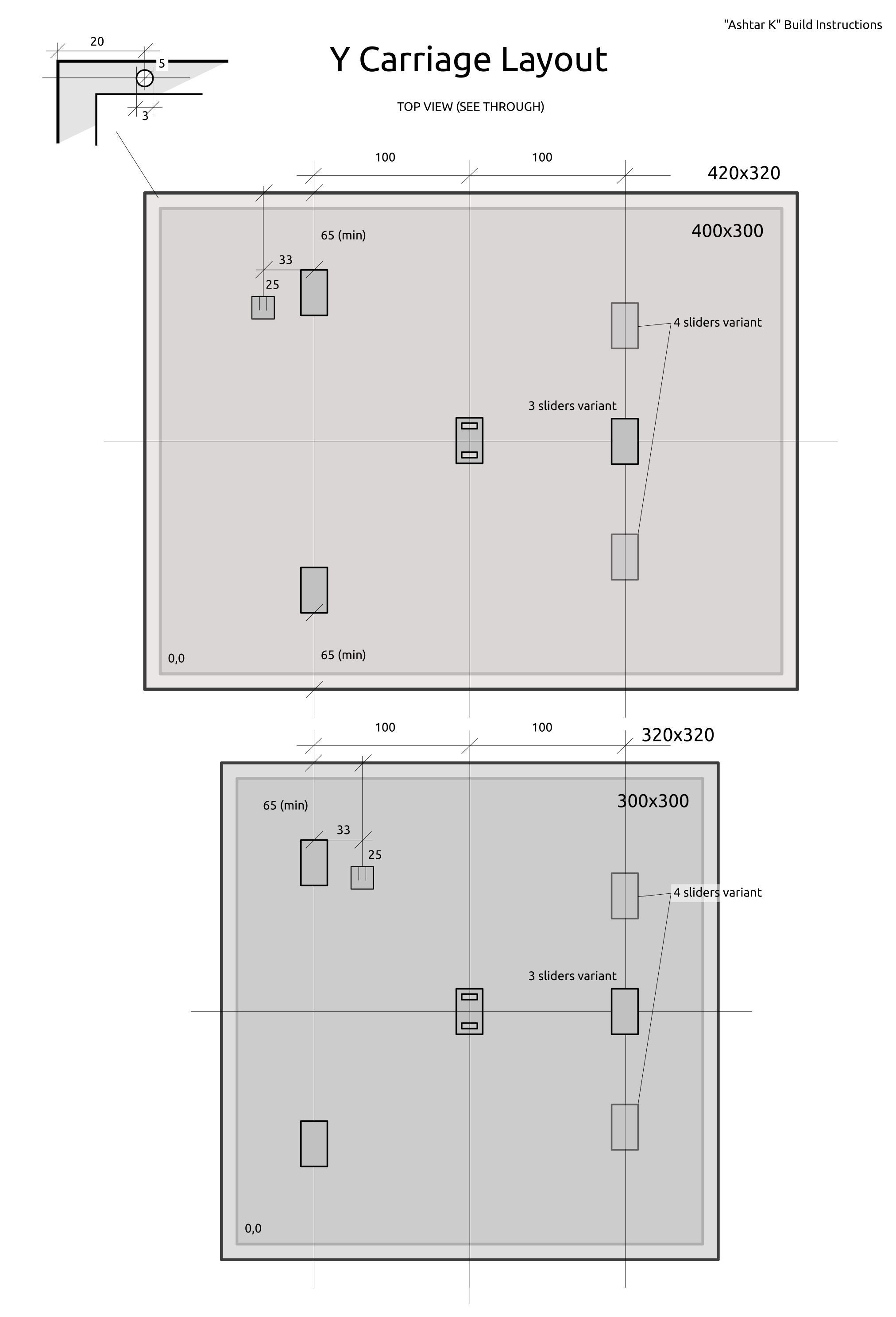
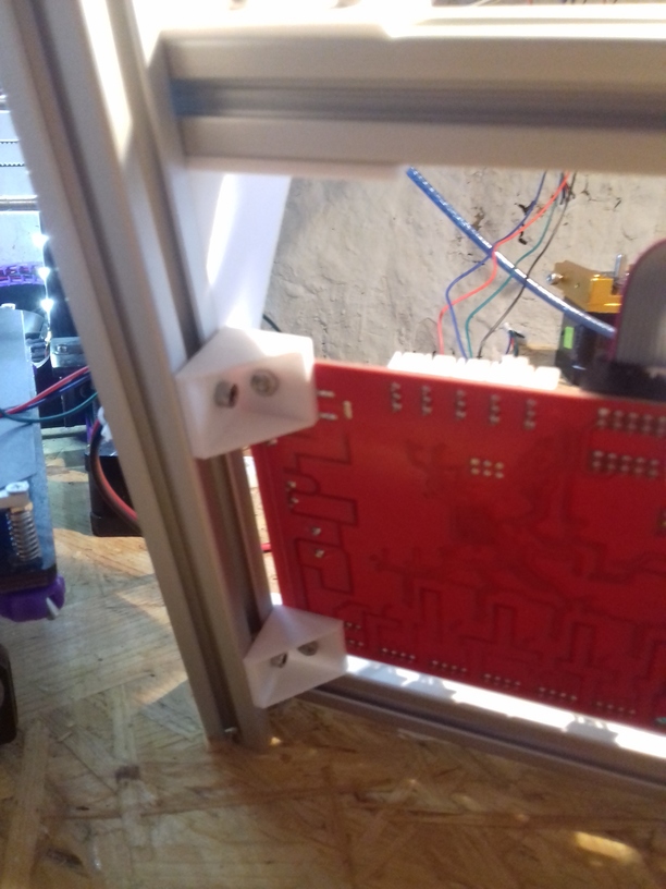
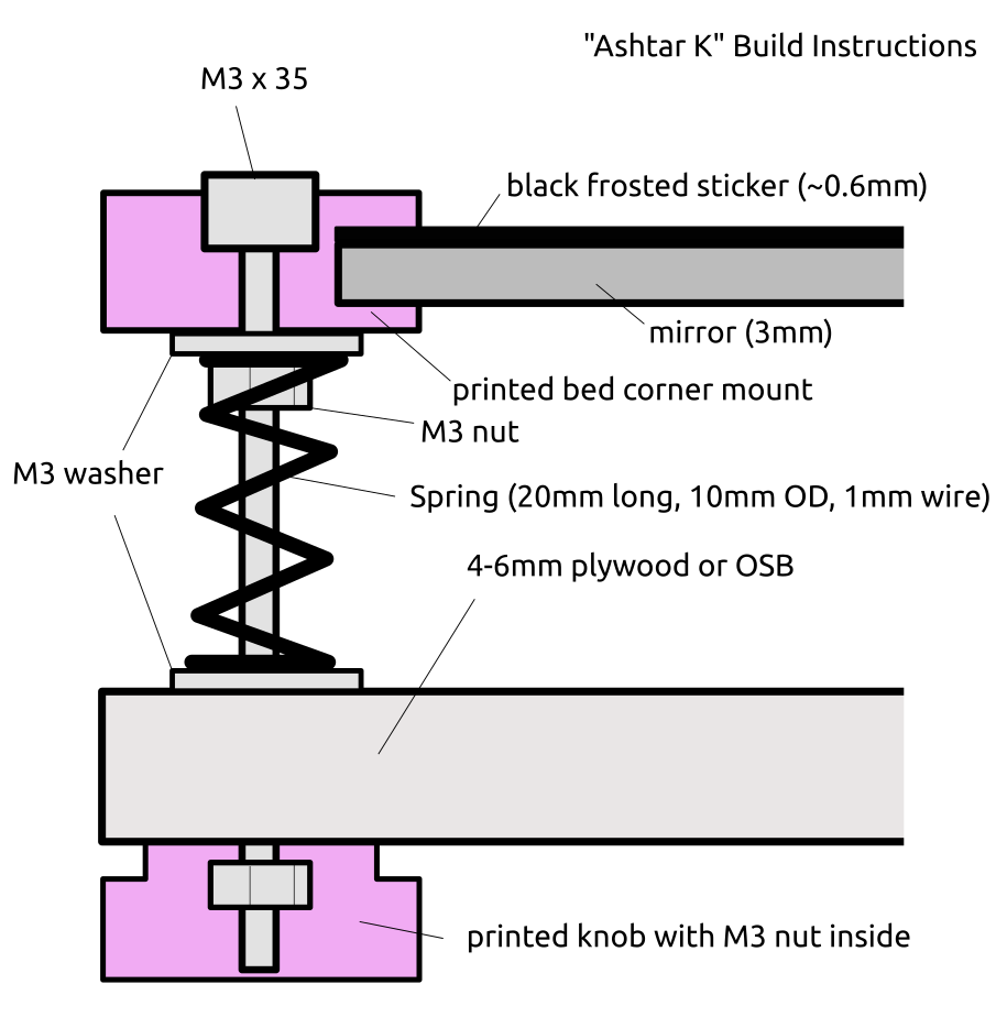 420x320mm 6mm OSB (white painted) as Y carriage