Status: just a draft
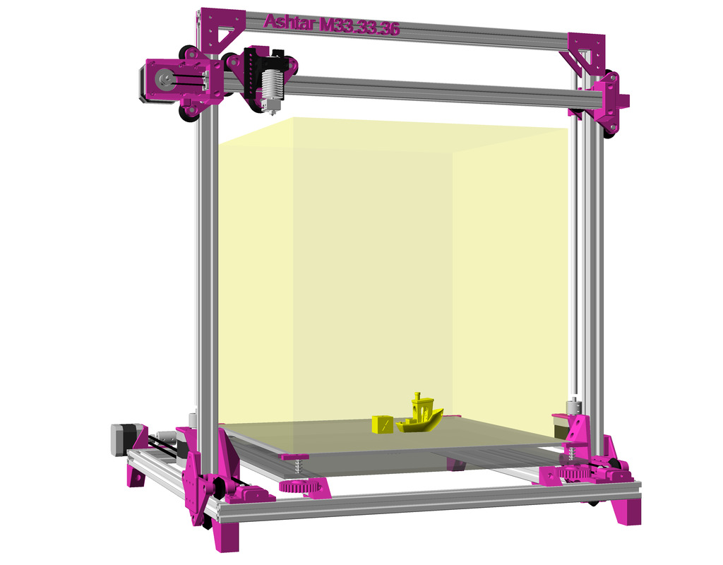

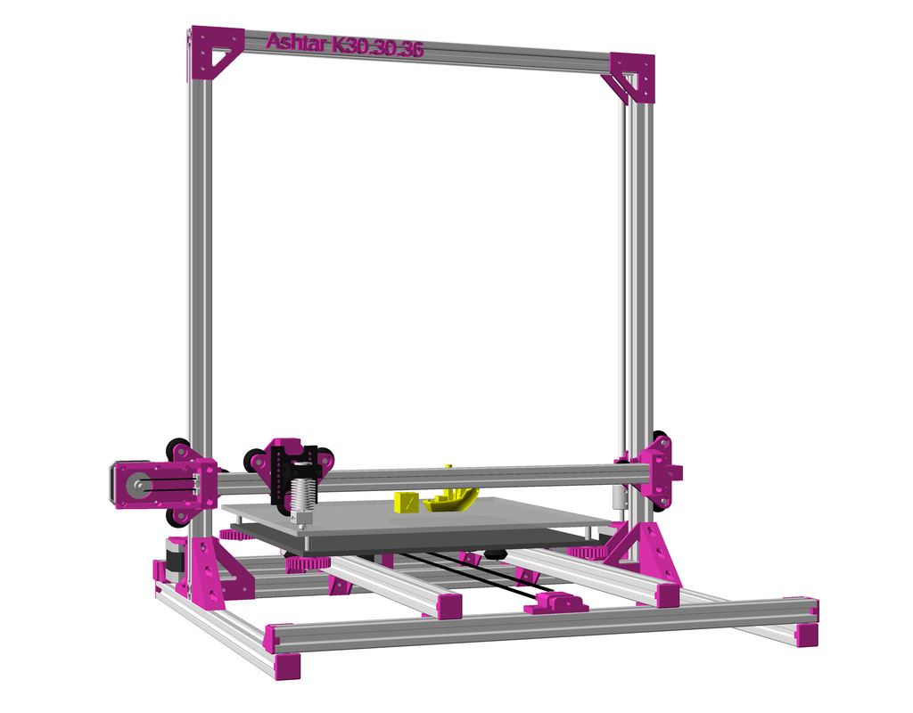
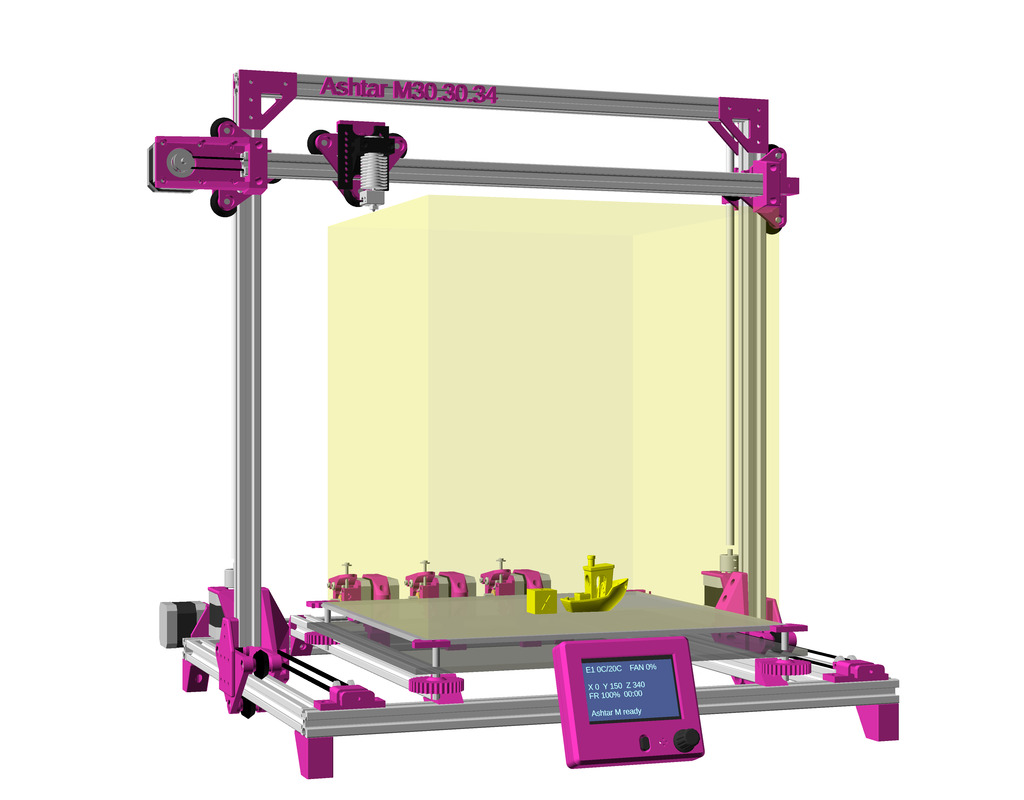
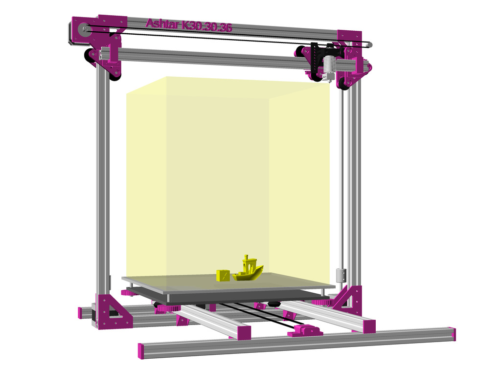
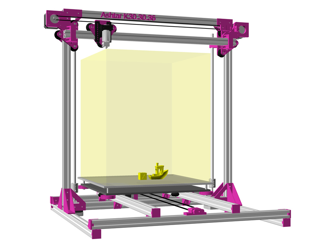
Ashtar M: Moving Frame 
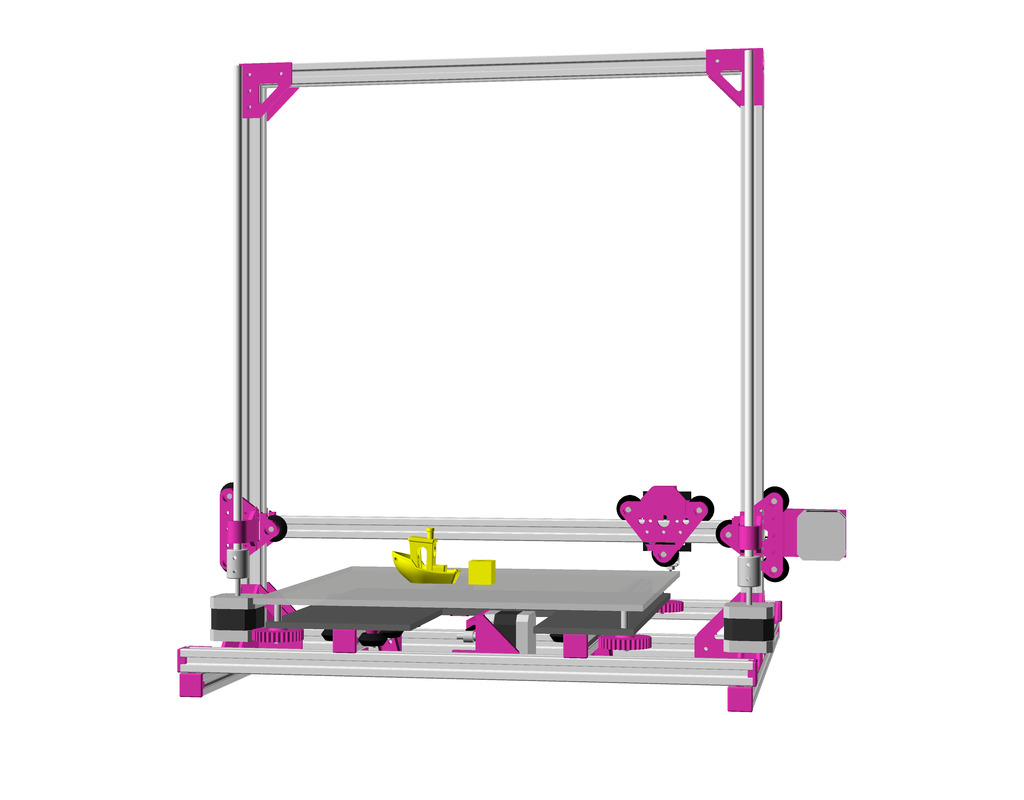
Ashtar M: Moving Arch
Updates:
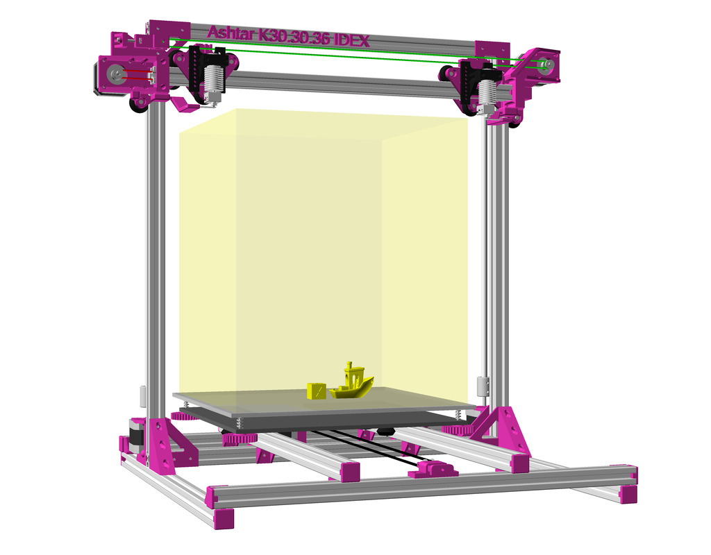
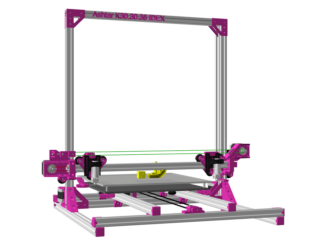
- 2021/01/14: Option IDEX (Independent Dual Extrusion), early draft (not yet tested)
- 2021/01/07: Y motor and shaft extension with Y pulley holder added
- 2021/01/03: Z motor mounts added, Y carriage to XZ frame/arch pieces refined using
rcube() - 2020/12/19: new “XZ Arch” option (removing lower X beam from XZ frame)
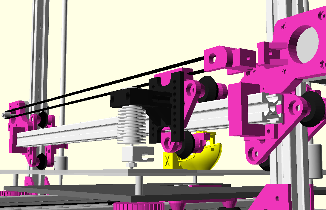
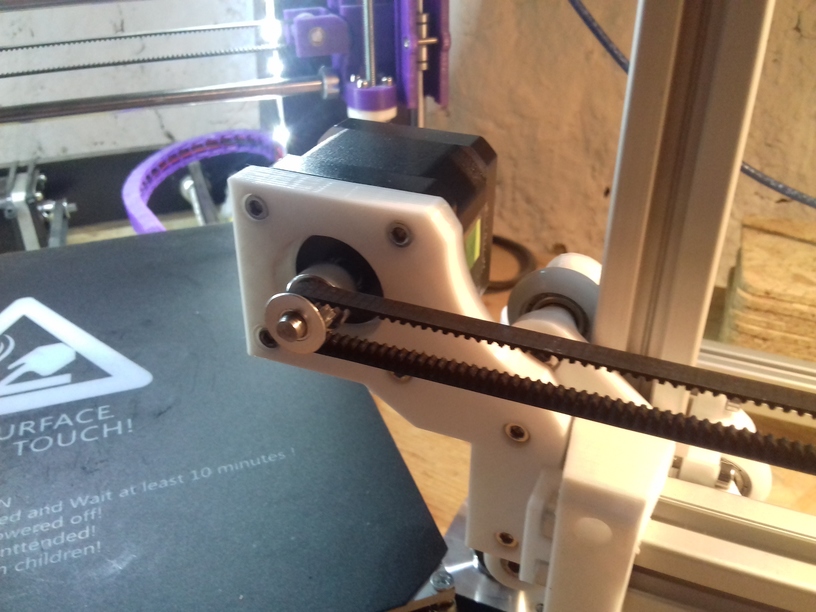
- 2020/12/17: change X carriage, routing X belt inside 2020 alu extrusion
- 2020/12/12: first drafts, just a skeleton, details still to be worked out
Introduction
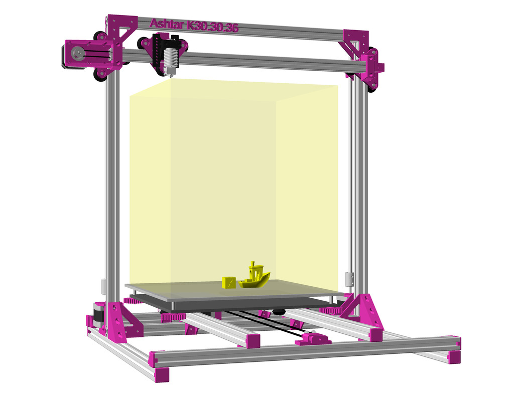
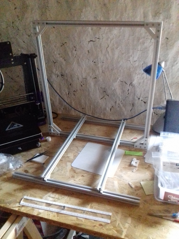
Jon Schone (@properprinting) did a “Moving Portal” (MP) mod for his CR-10 in April 2020, and I thought to adapt his approach as “Ashtar M” as Moving Gantry (MG) using CNC terminology.
Instead to move the bed in Y axis to move the entire XZ frame or gantry – the rest of the Prusa i3 style printer remains the same.
Reducing Moving Weight

This variant only makes sense when the weight of the bed exceeds the weight of the XZ frame + X carriage, in order to reduce the moving weight as of inertia – so only for large(r) build volume this makes sense:
weight(XZ frame + X carriage) < weight(bed)
and as I compose my Ashtar 3D printer series with alu extrusions (beams) I can say:
weight(XZ frame) = beam X * 2 + beam Z * 2 + NEMA17 * 2
weight(bed) = X * Y
and it becomes here clear, the bed weight grows X * Y whereas XZ frame only (X + Z) * 2, but also 2* NEMA17 motors of the Z axis are part of the XZ frame.
The main differences of Ashtar M and Ashtar K:
Ashtar M (Prusa i3 MG)
- static bed
- 2x Y belts
- 1x Y motor
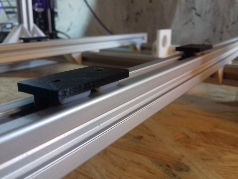
- 2x Y beams: V-slot 2020 alu
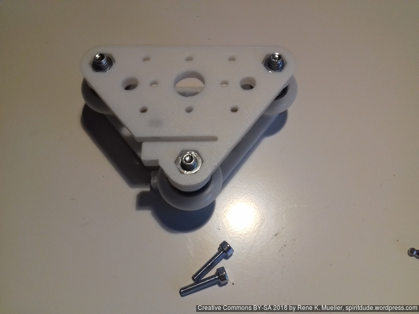
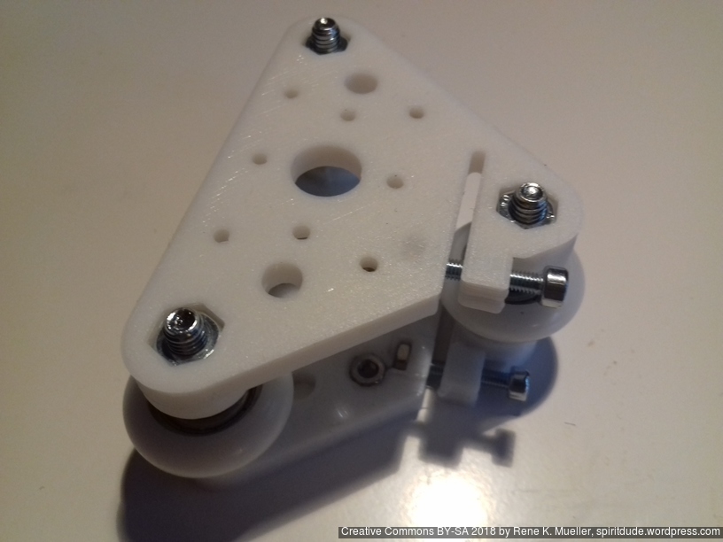
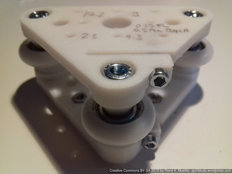
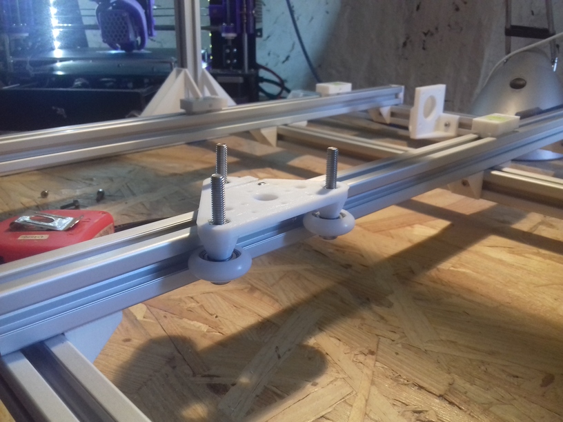
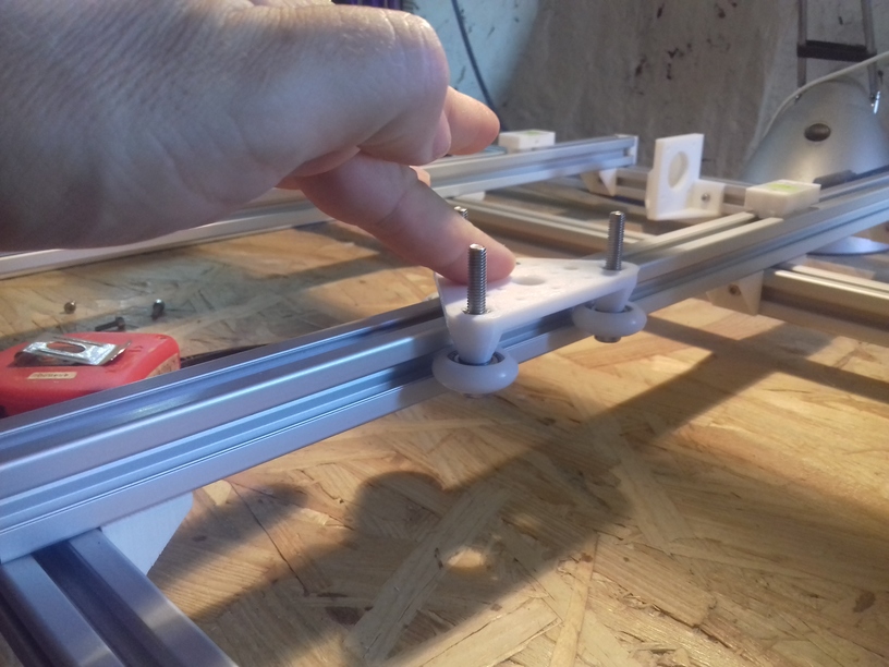
- Y axis: 2x V carriages (each 3 wheels)
- XZ frame is moving (do not add anything more)
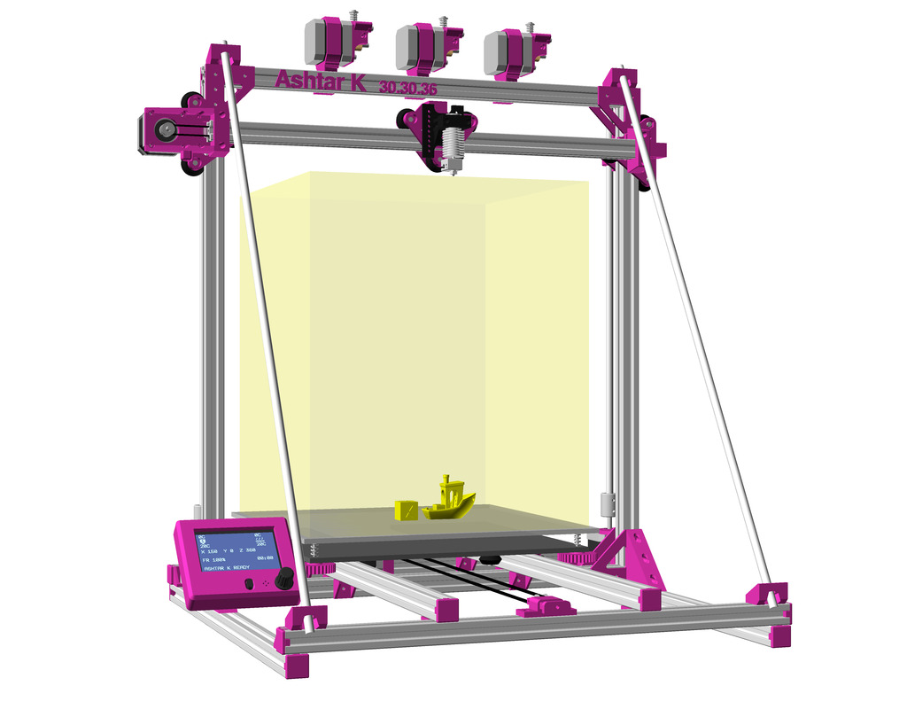
Ashtar K (Prusa i3)
- movable bed with simple sliders
- 1x Y belt
- 1x Y motor
- 2x Y beams: T-slot 2020 alu
- XZ frame is static (can hold filament, extruders etc)
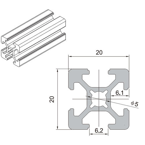
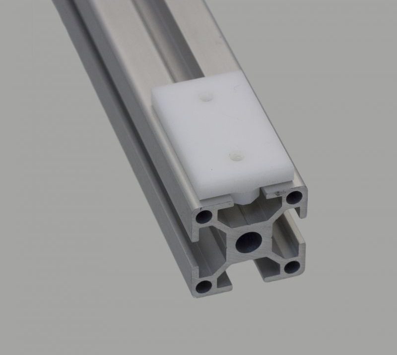
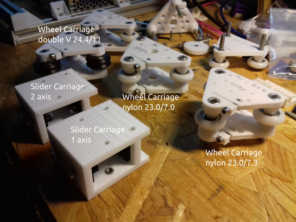
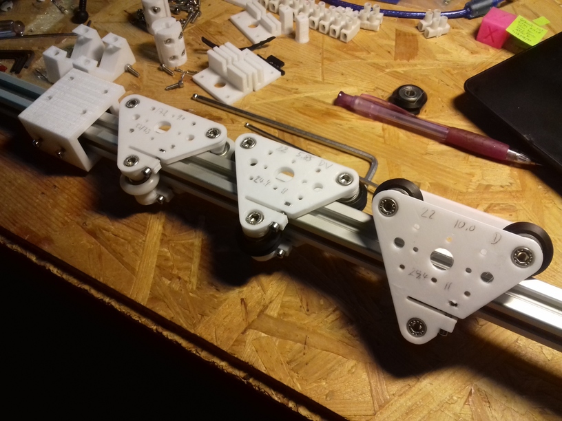
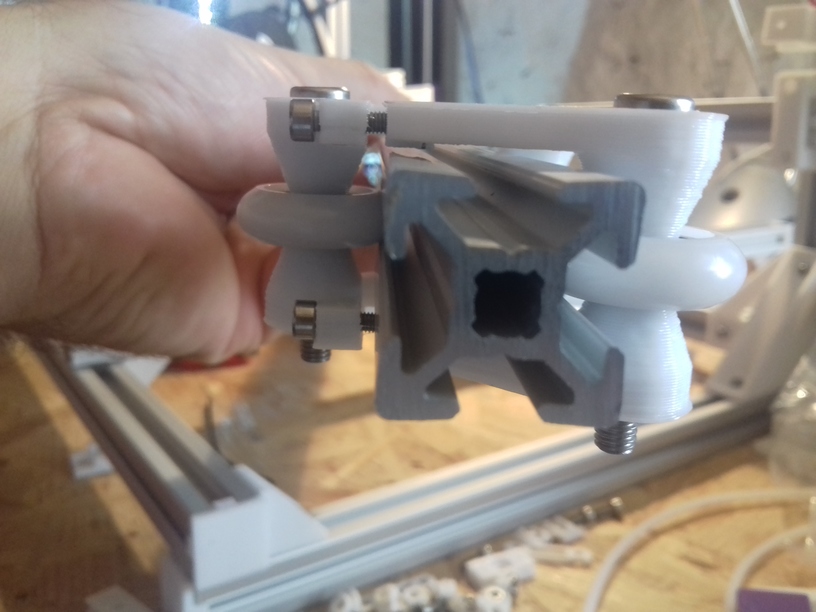
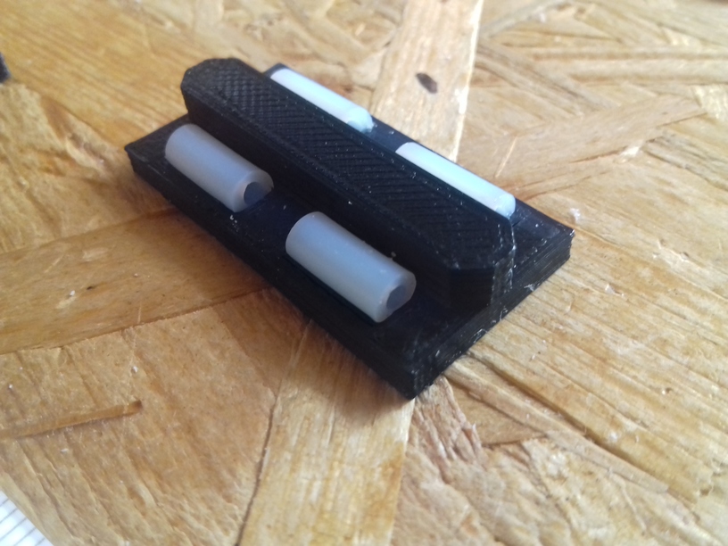
T-Slot 2020 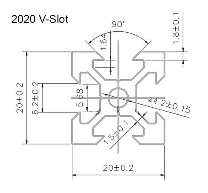
V-Slot 2020 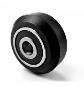
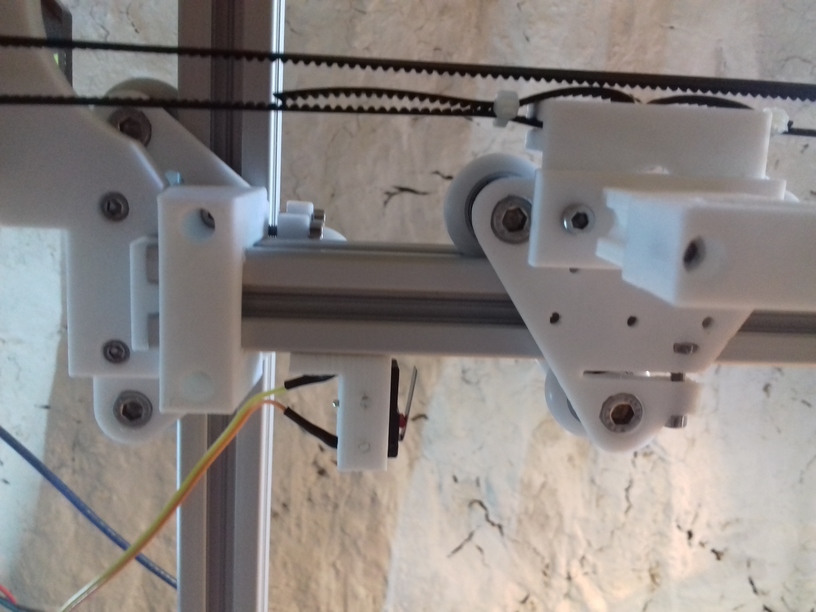
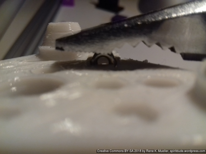
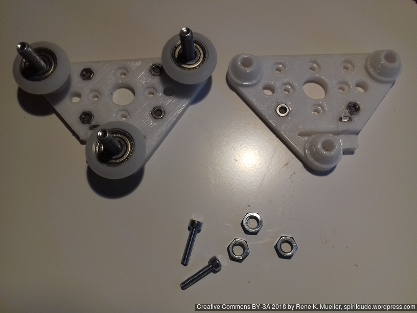
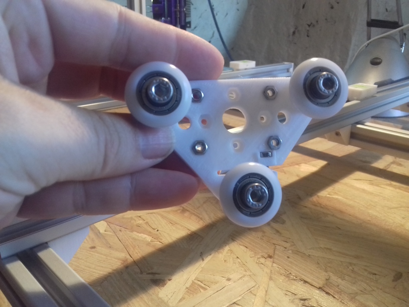
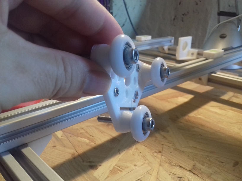
V wheel
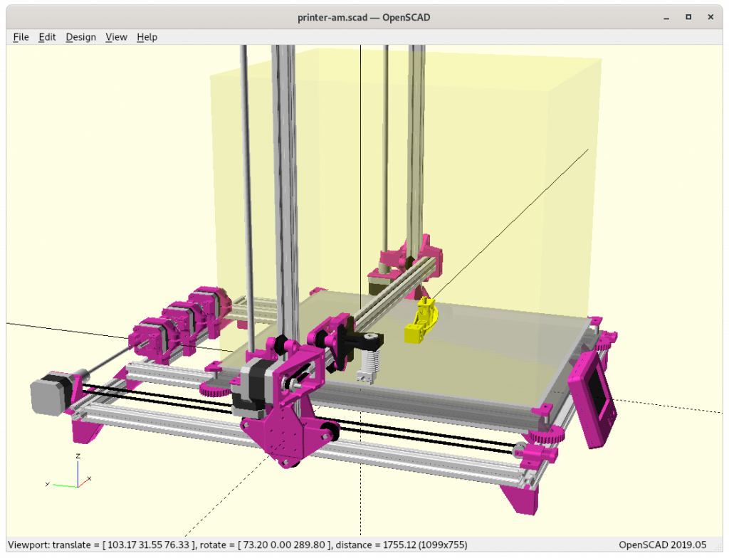
Draft
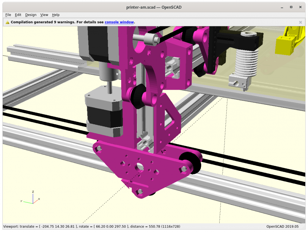
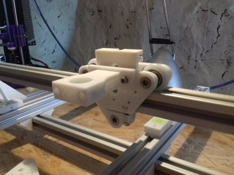
At position 0,0,0 
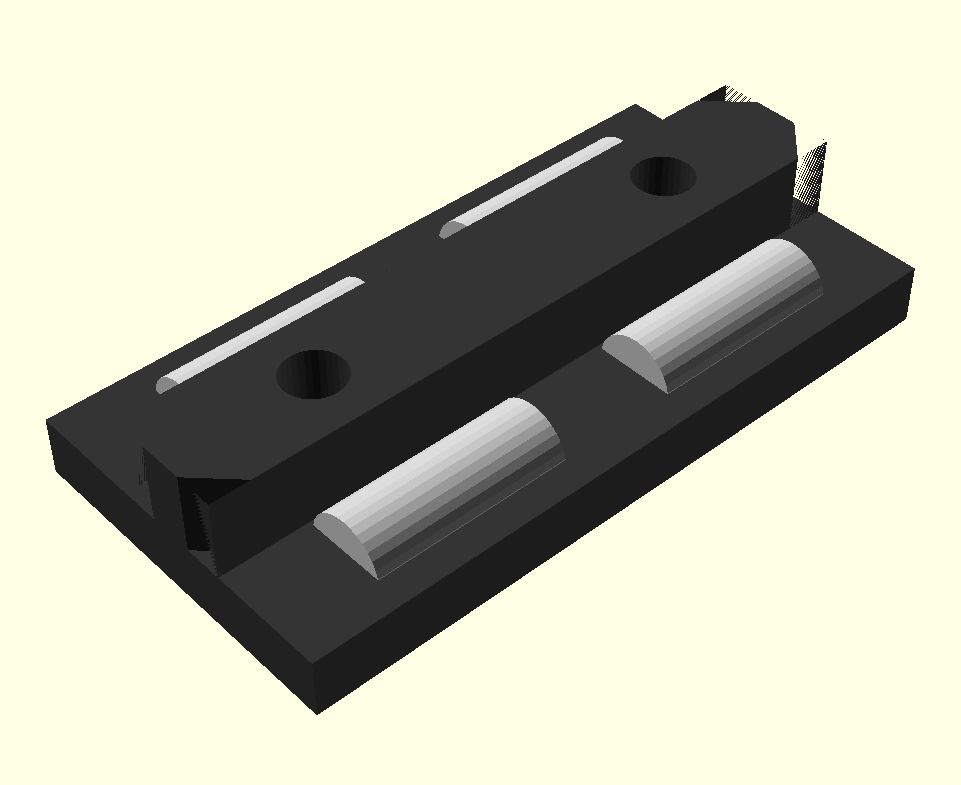
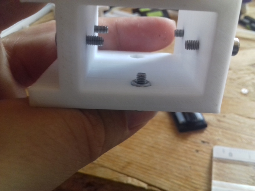
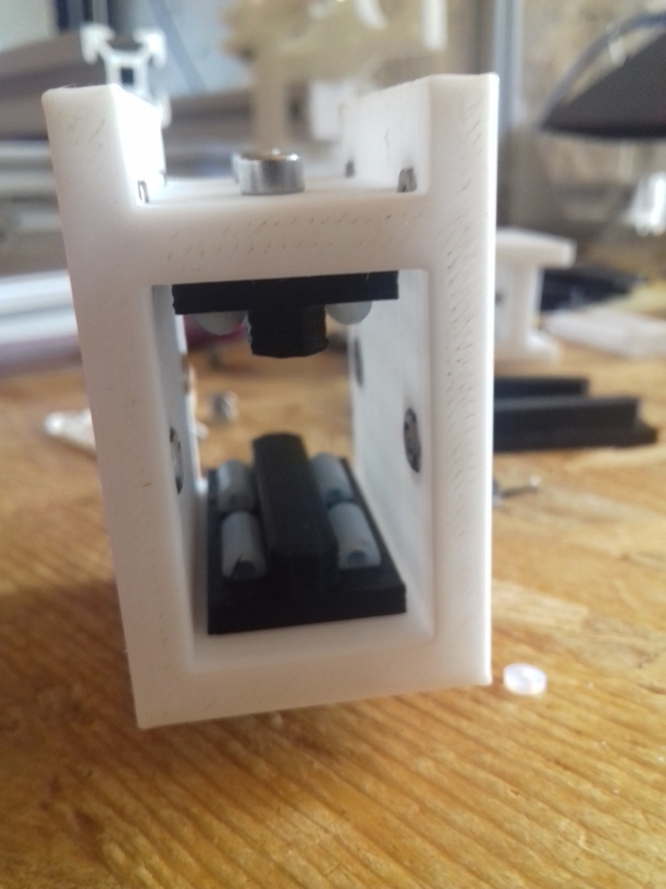
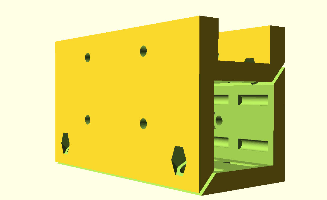
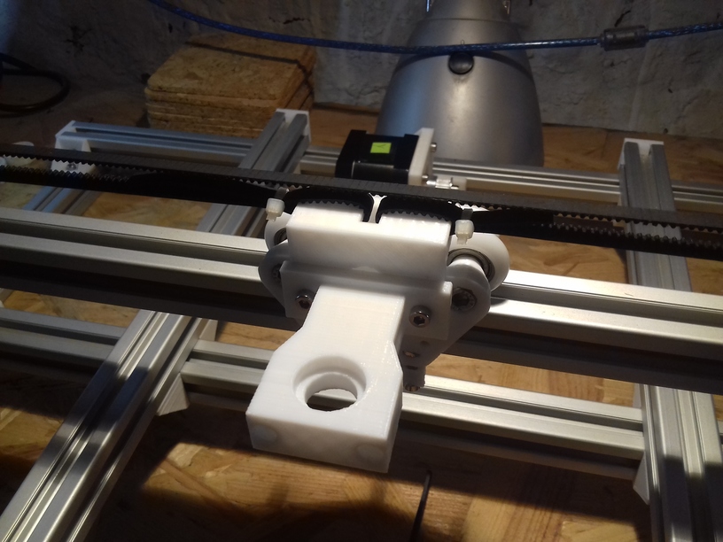
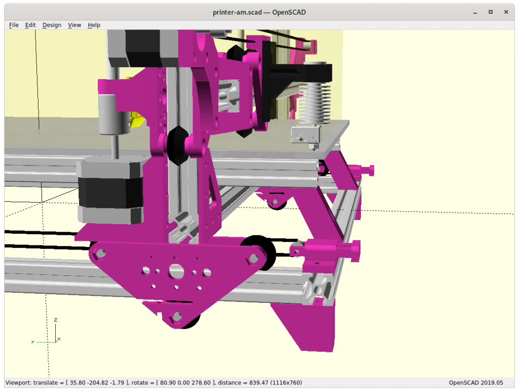
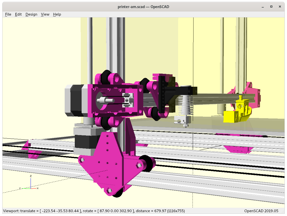
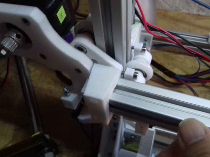
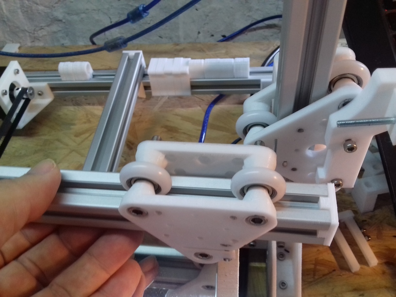
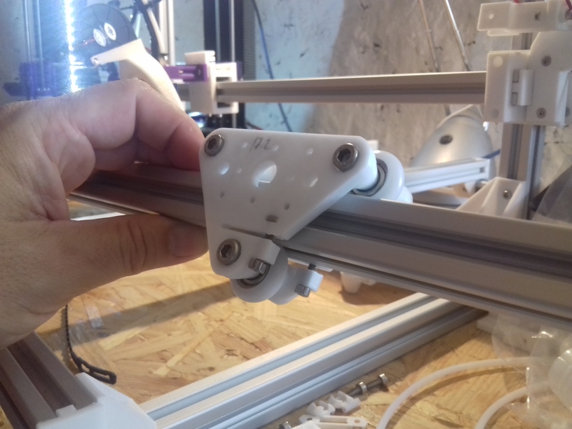
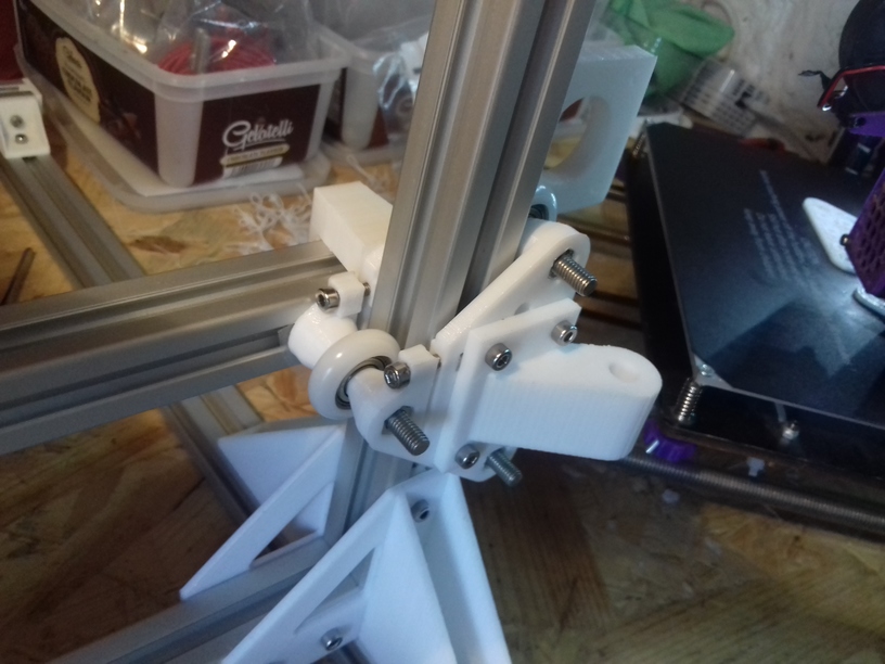
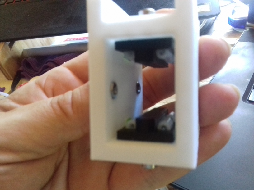
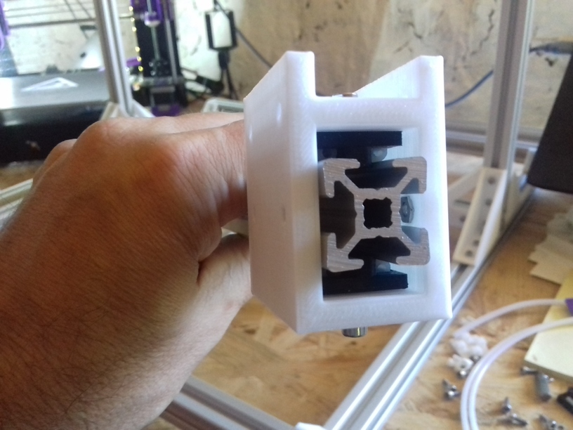
Bare view of Y carriage to XZ frame 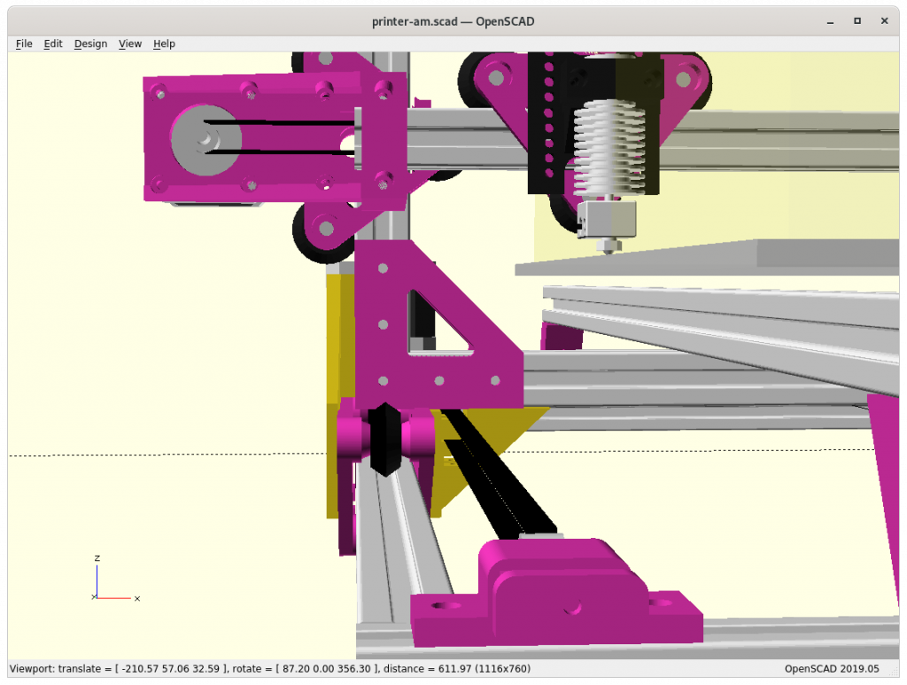
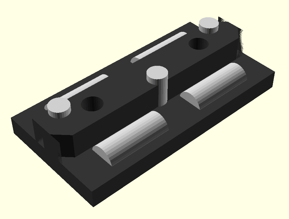
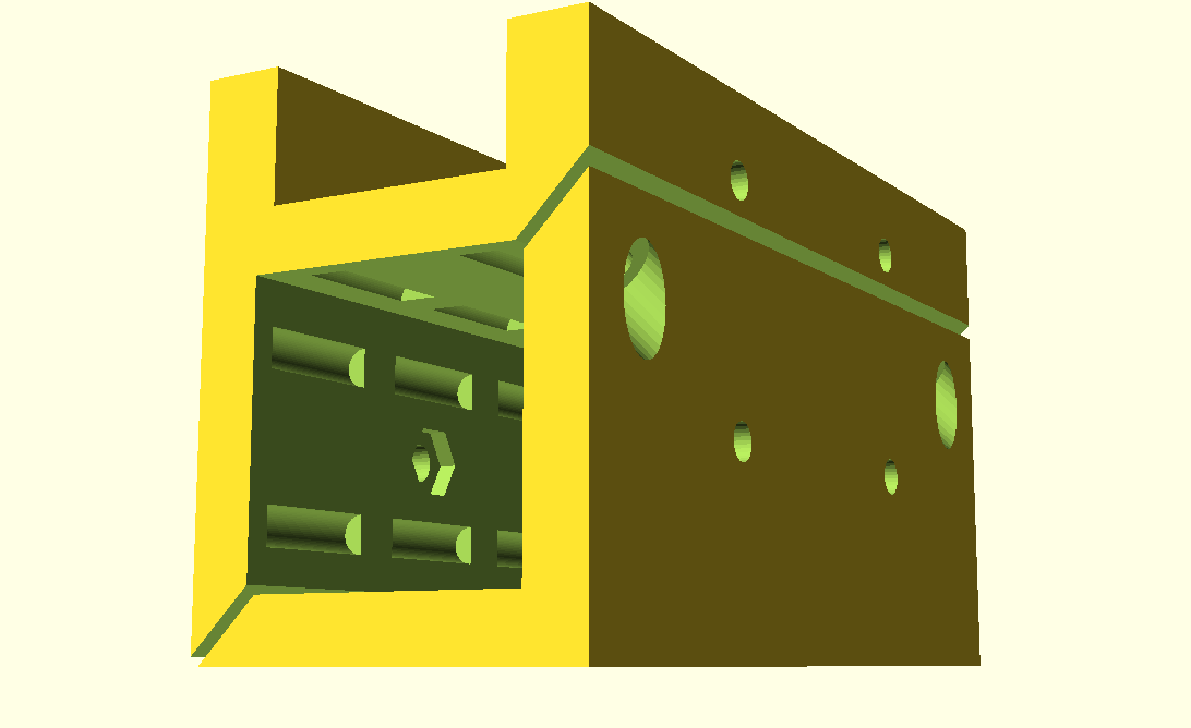
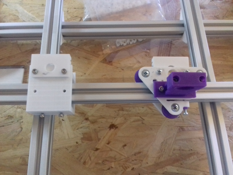
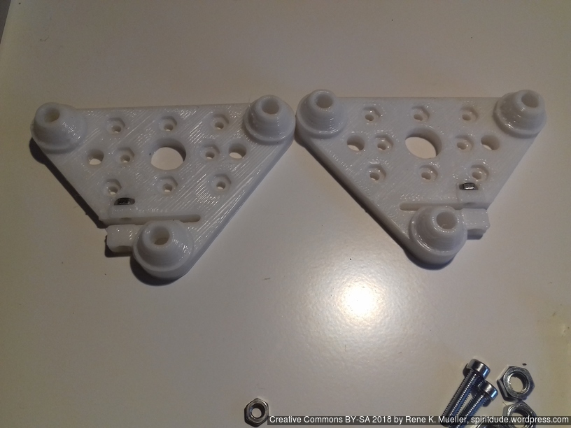
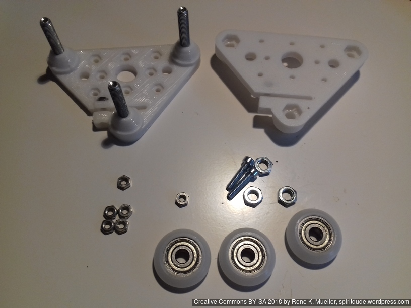
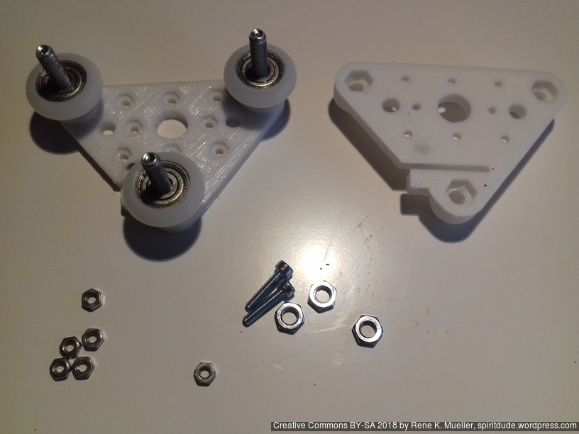
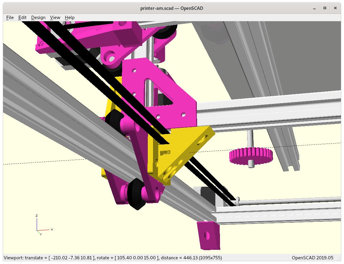
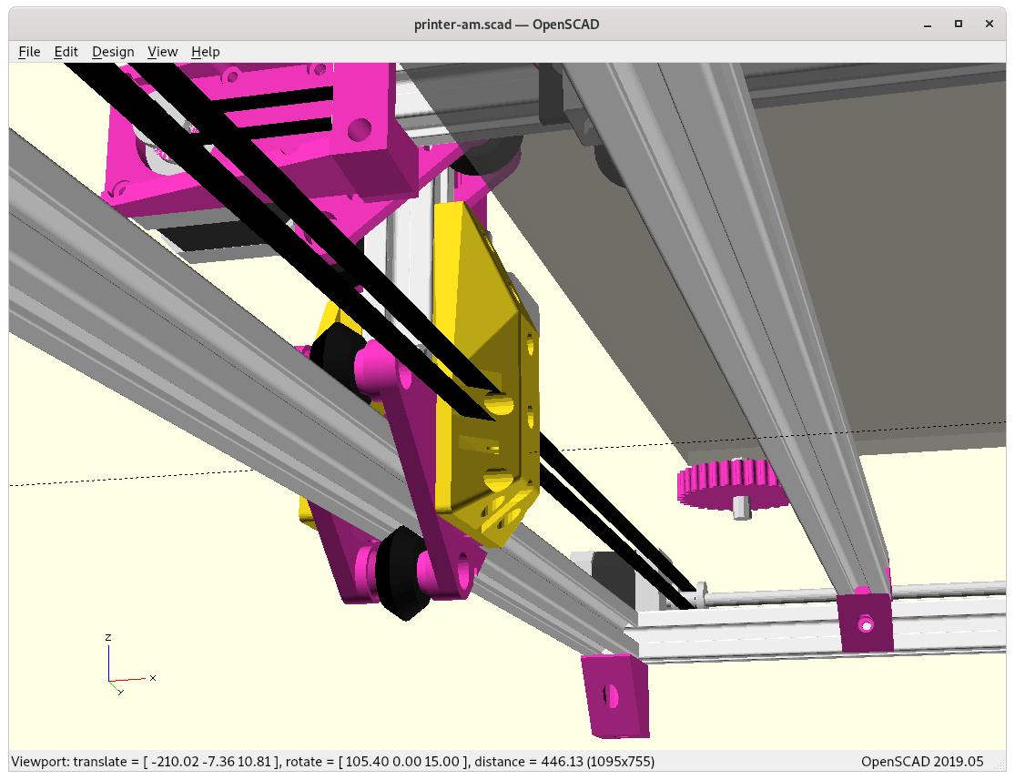
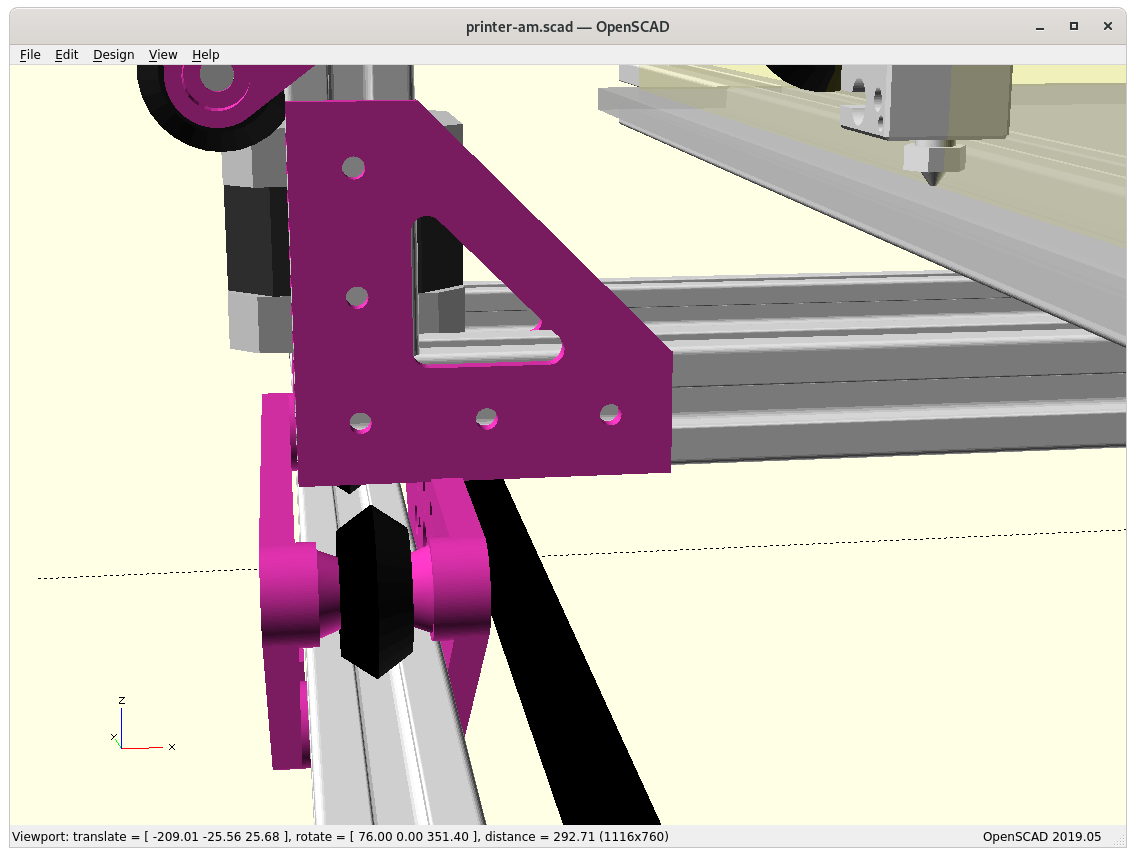
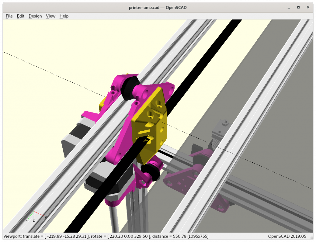
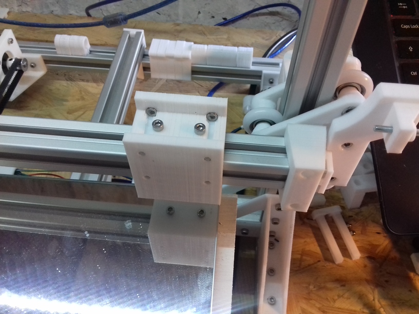
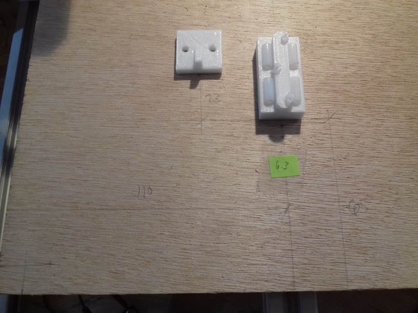
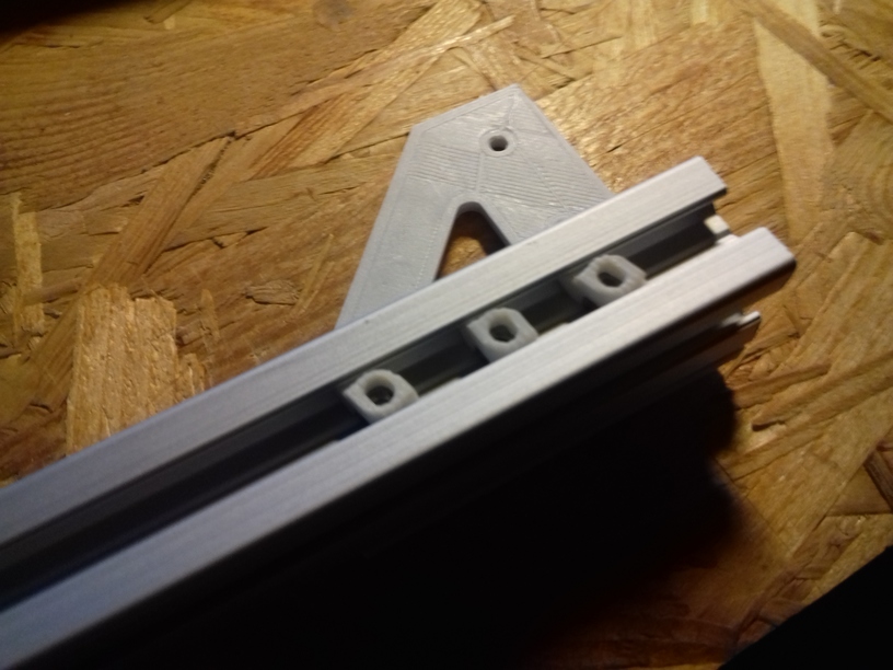
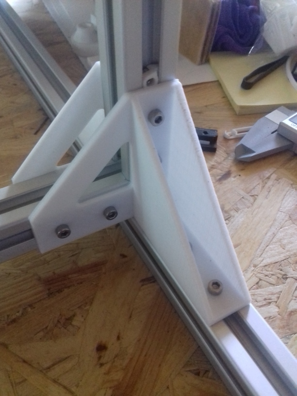
Adding side pieces “A” & “B” 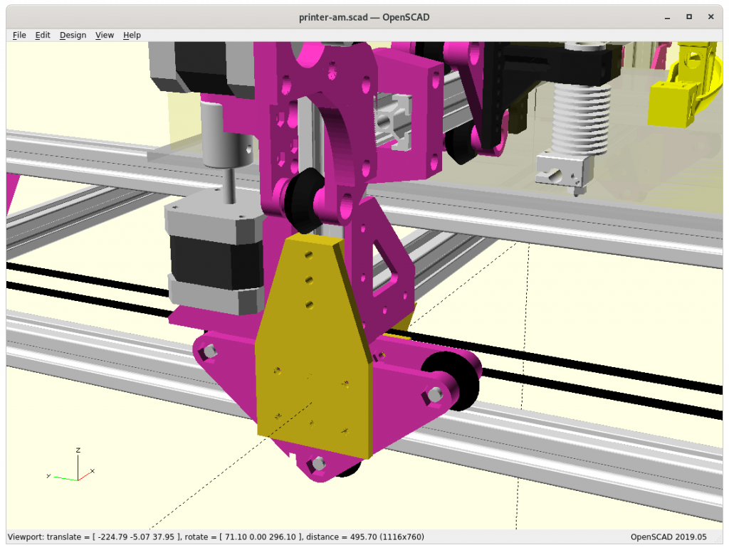
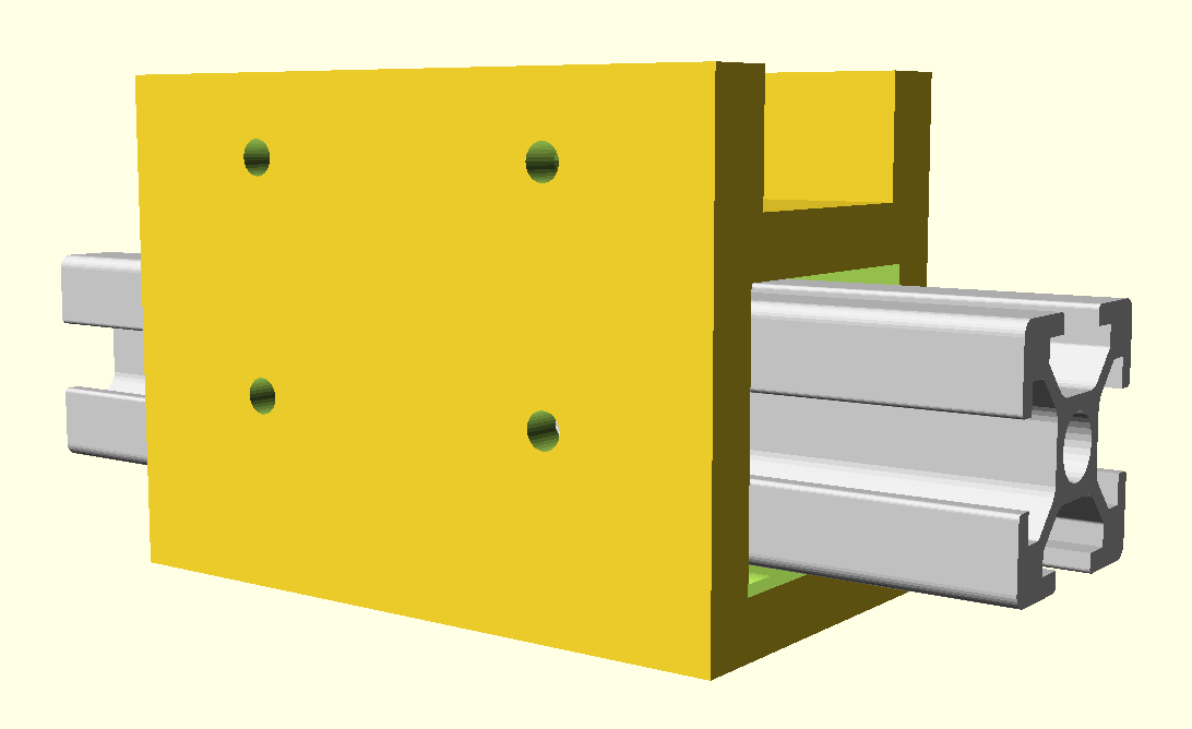
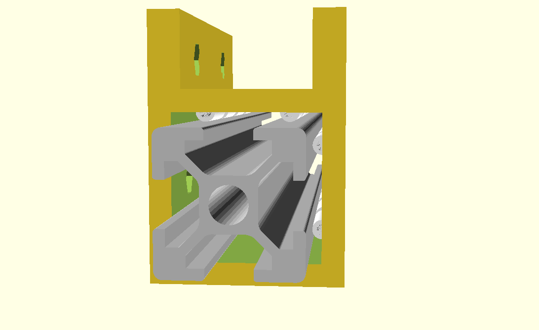
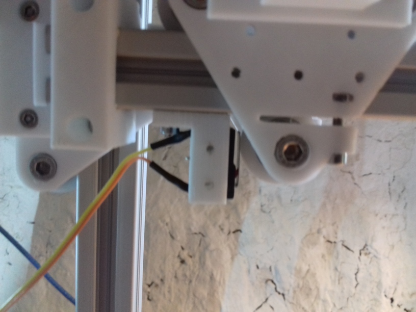
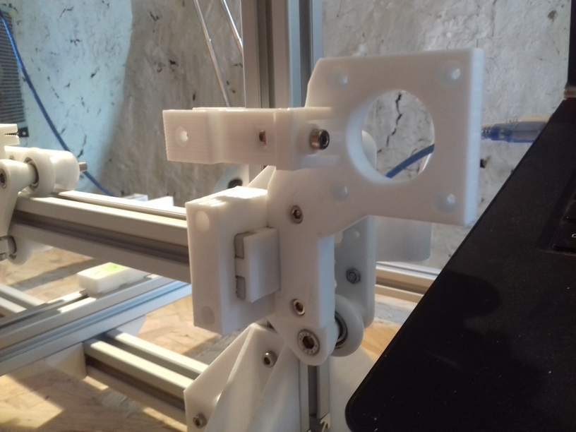
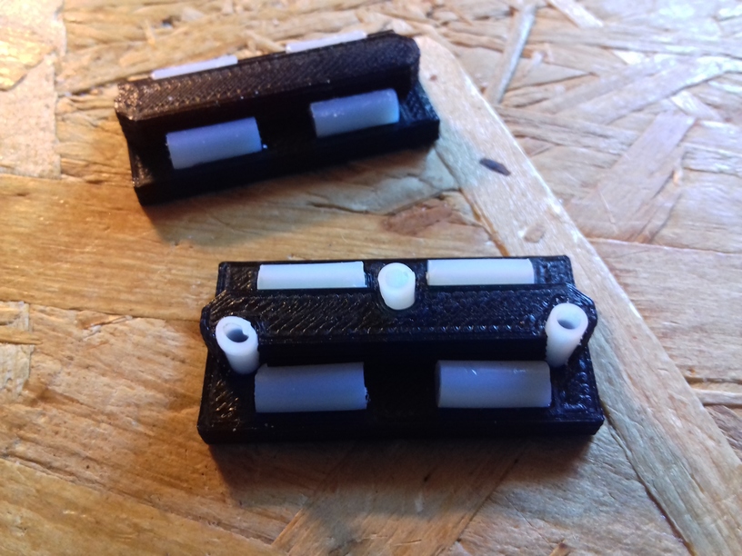
Side piece “A” Y carriage to XZ frame 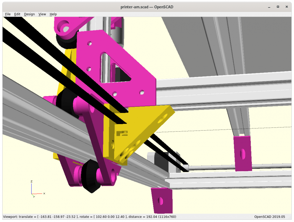
Side piece “B” Y carriage to XZ frame 
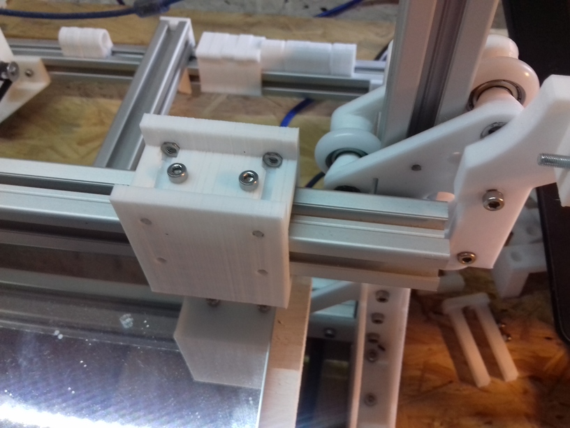
Side piece “B” bottom view 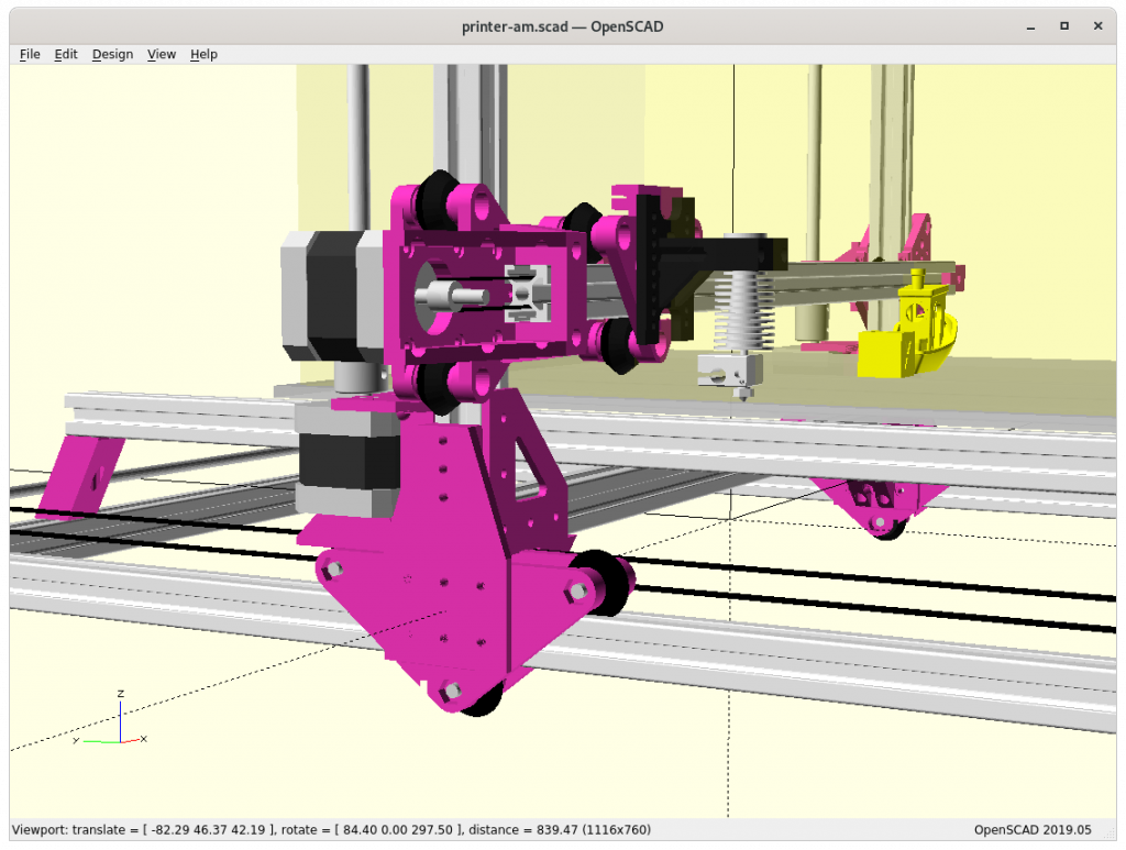
At position 0,0,0 
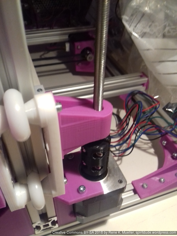
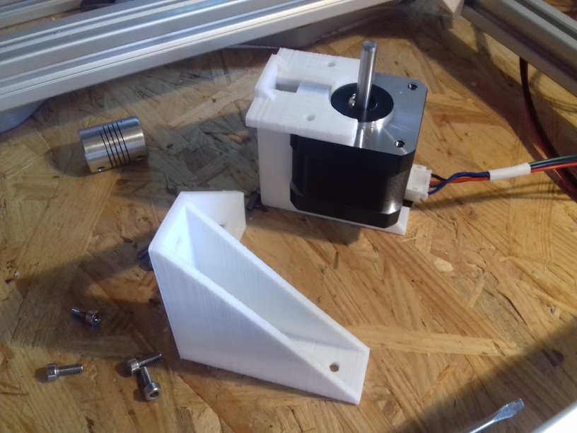
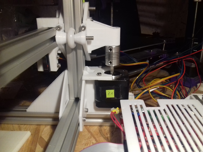
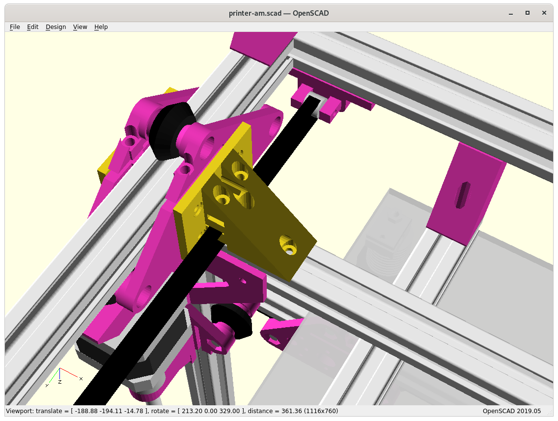
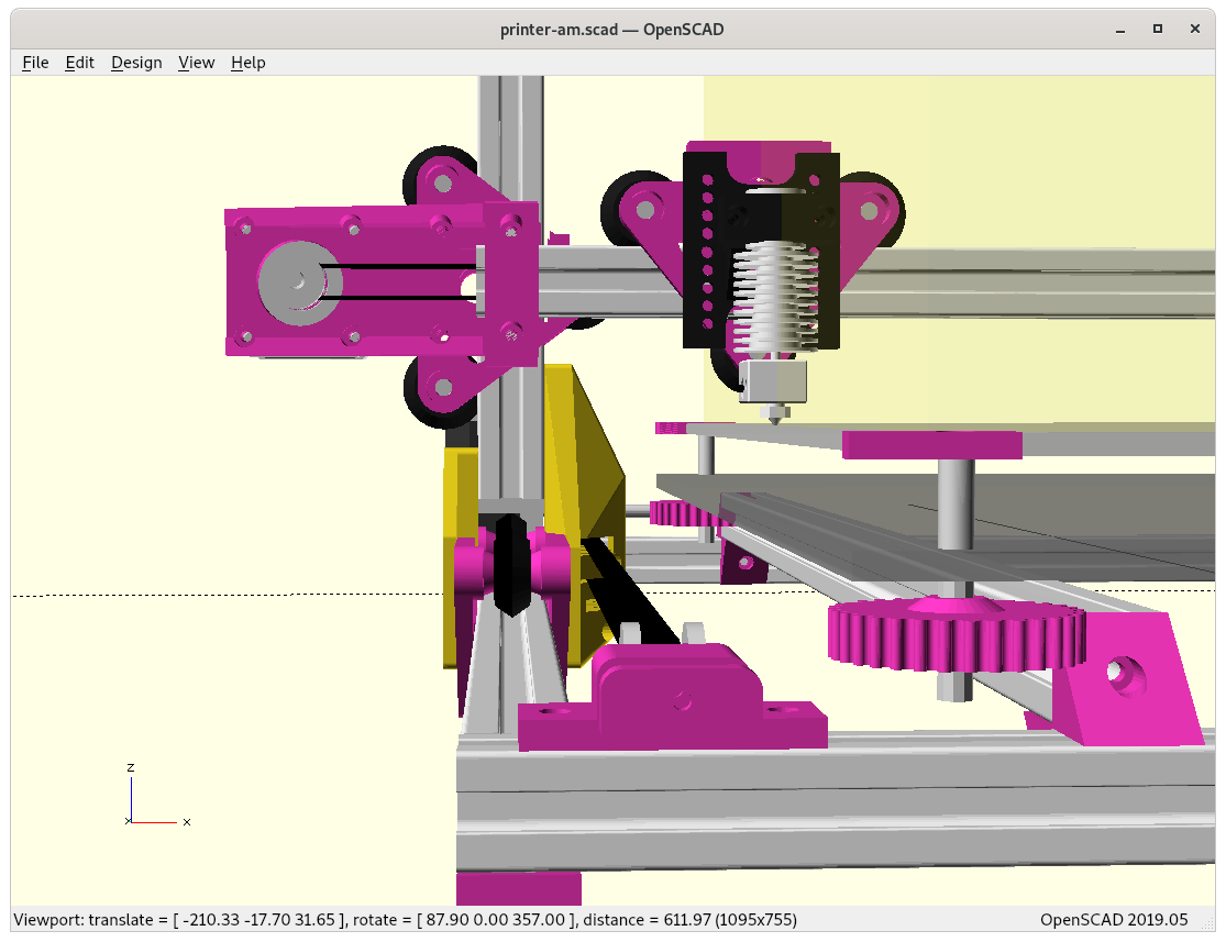
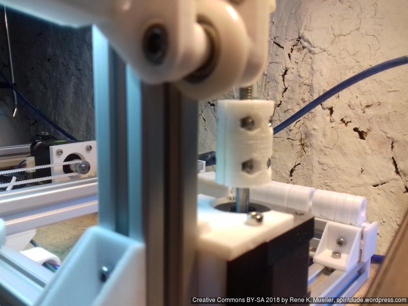
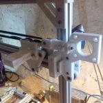
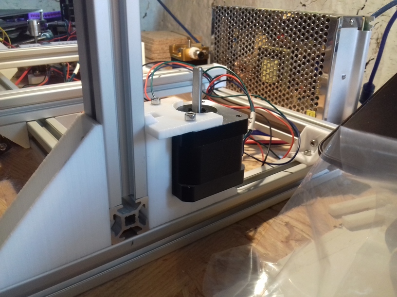
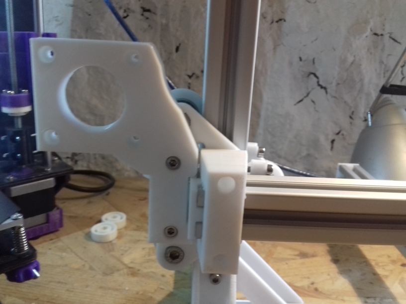
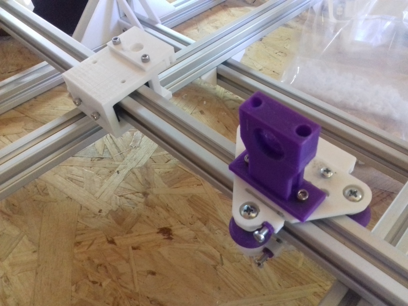
Z motor mount 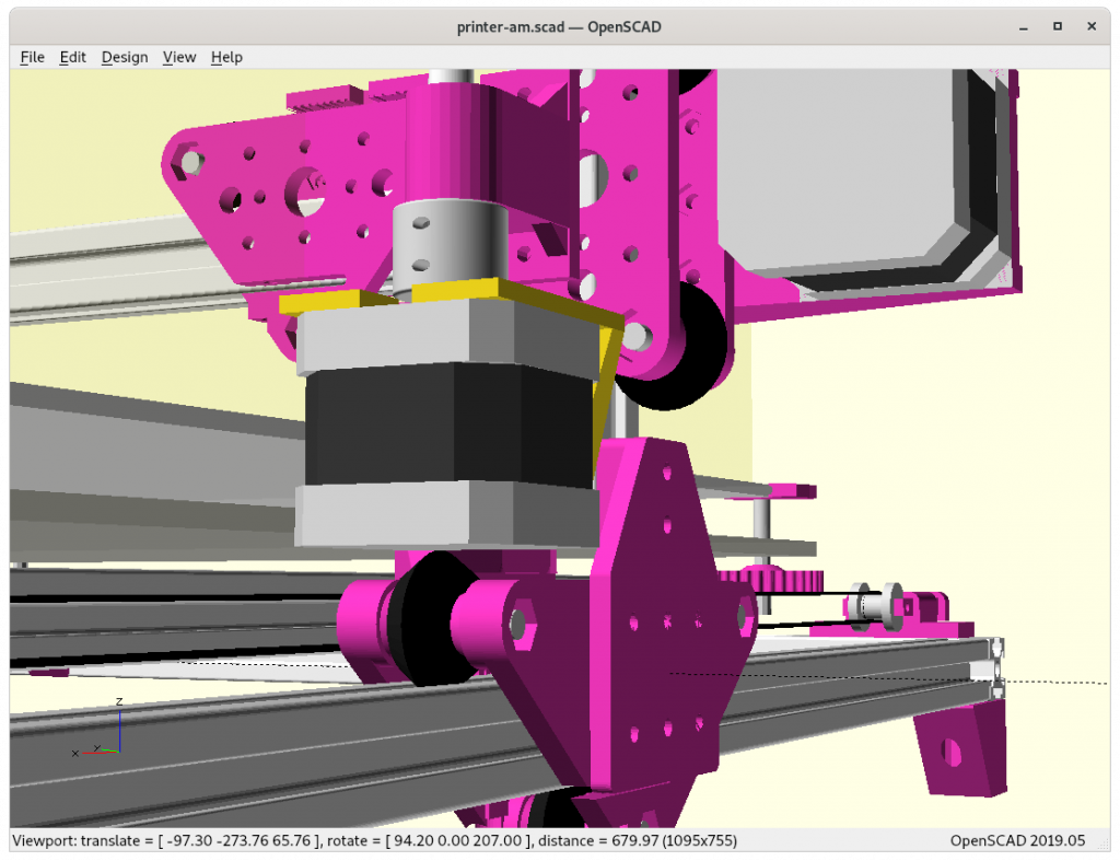
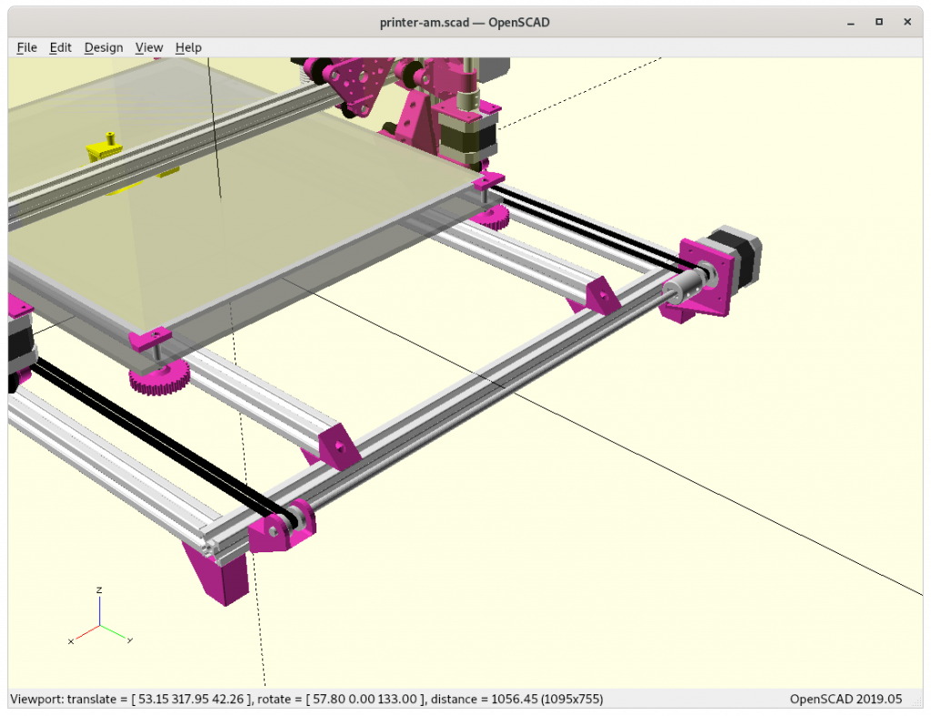
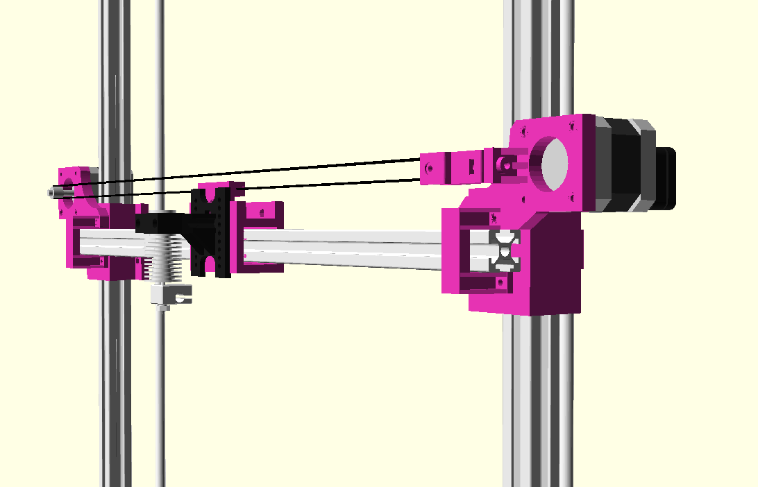
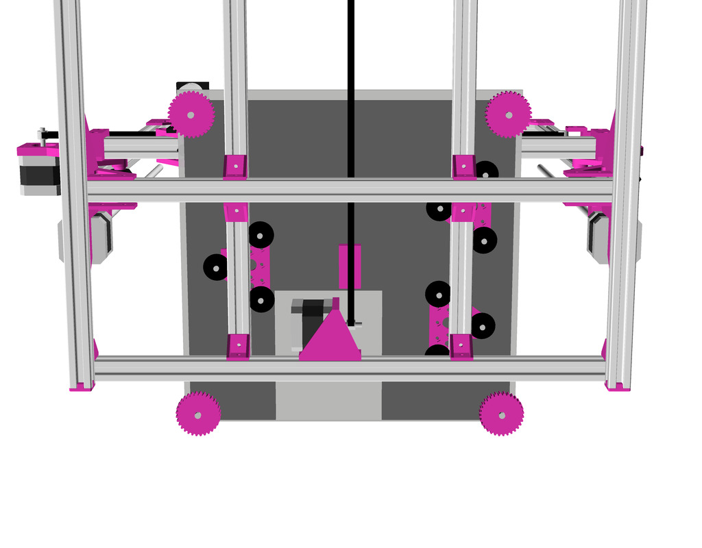
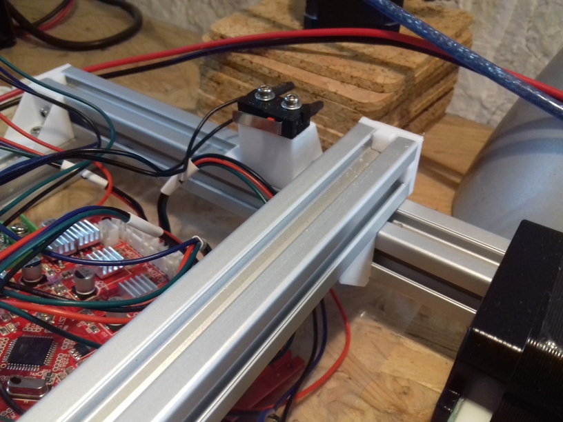
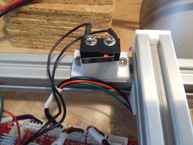
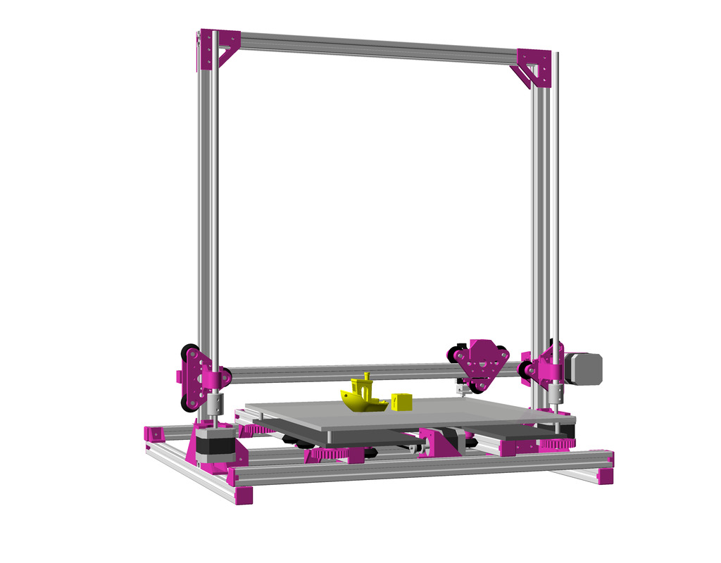
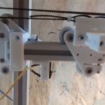
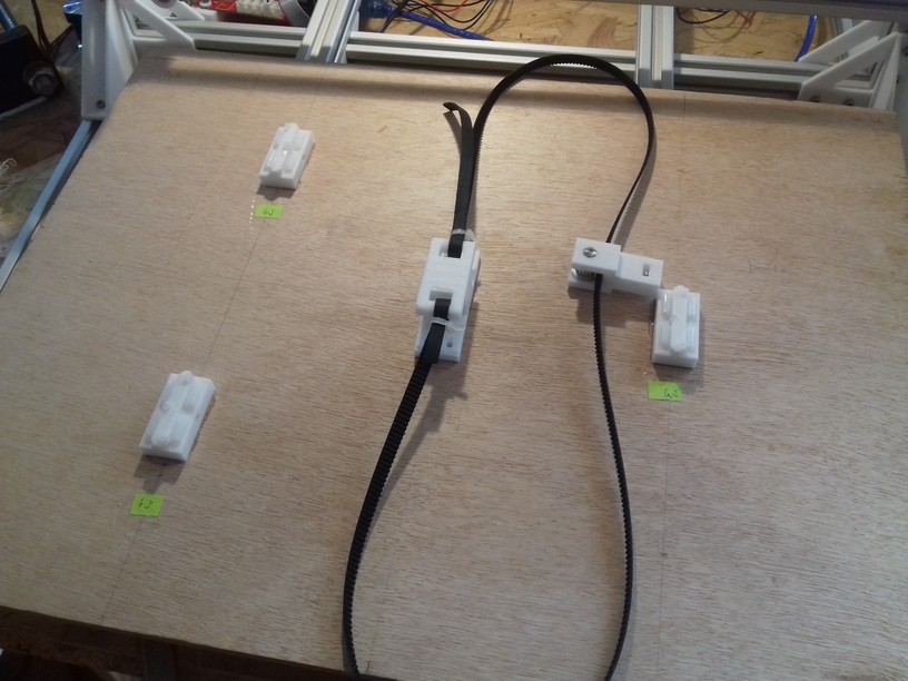
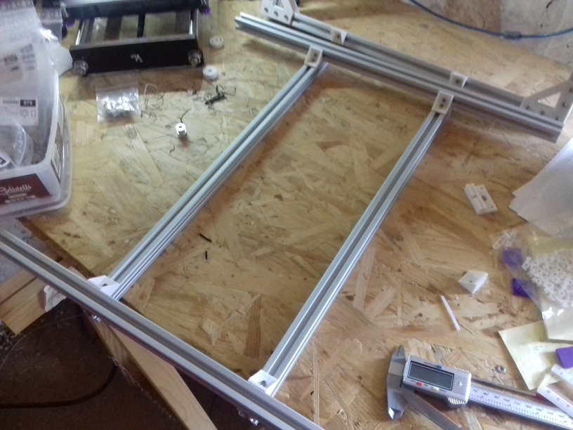
Y belts & Y motor 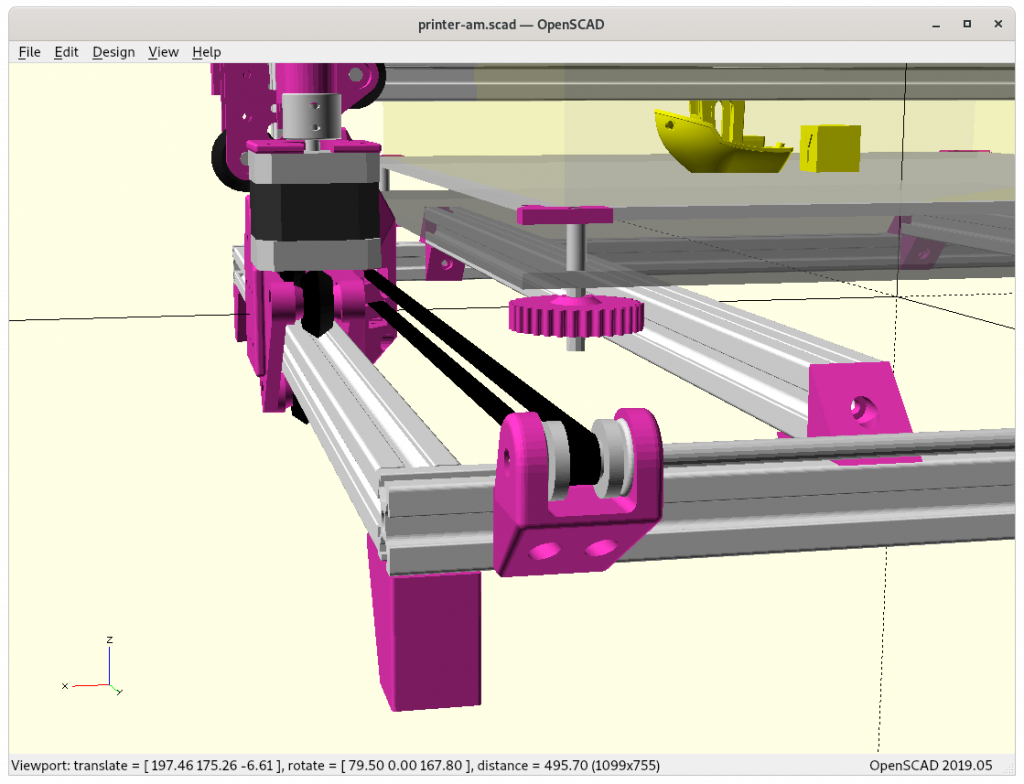
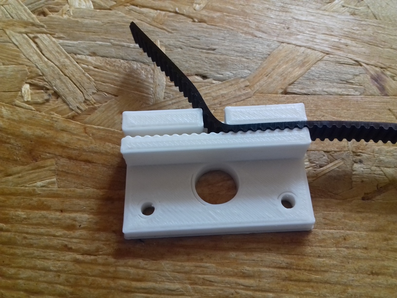
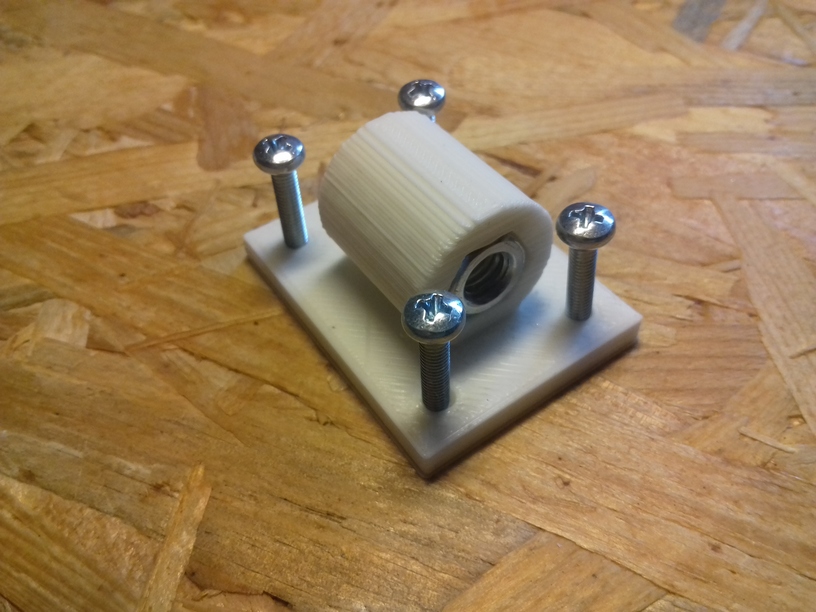
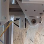
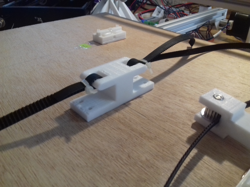
Y pulley holder 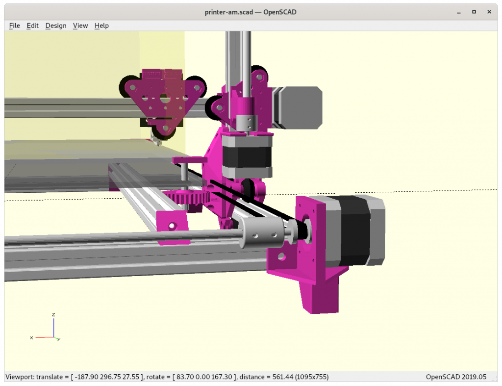
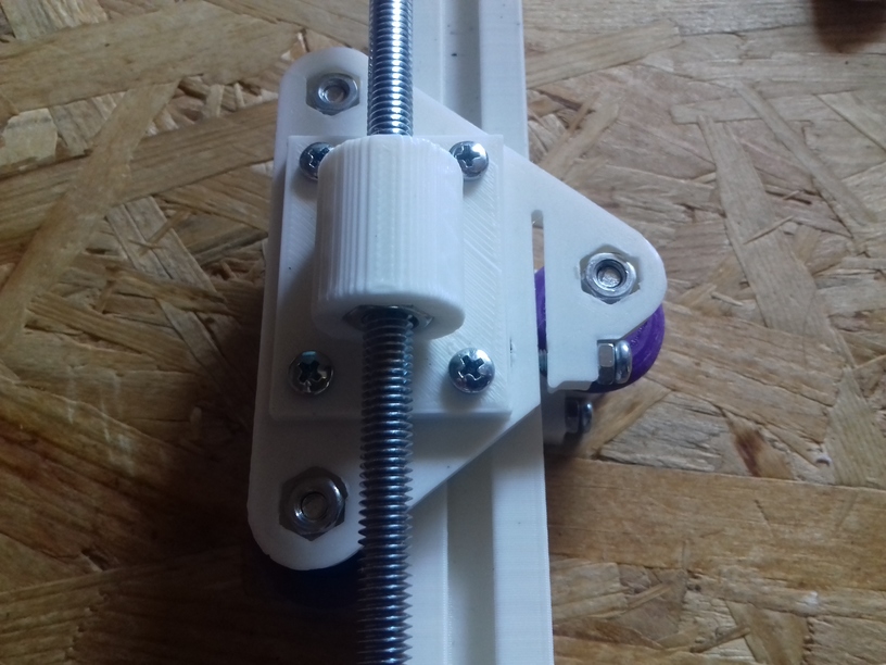
Y motor mount


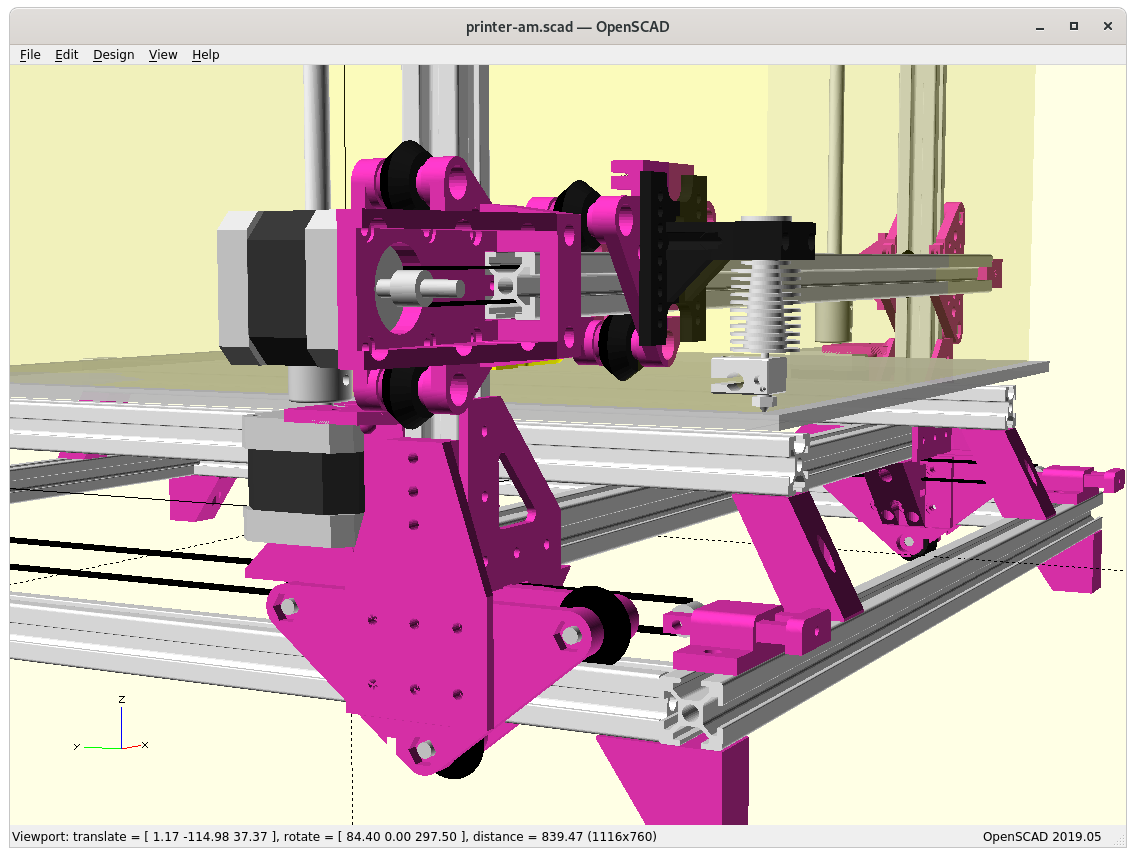


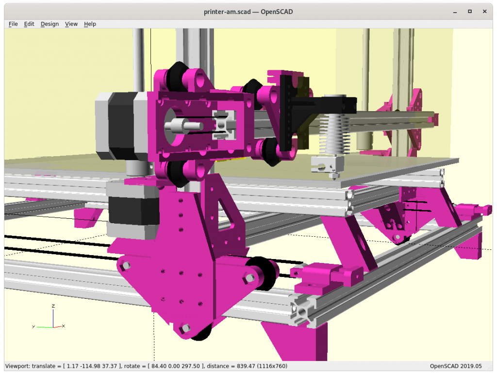
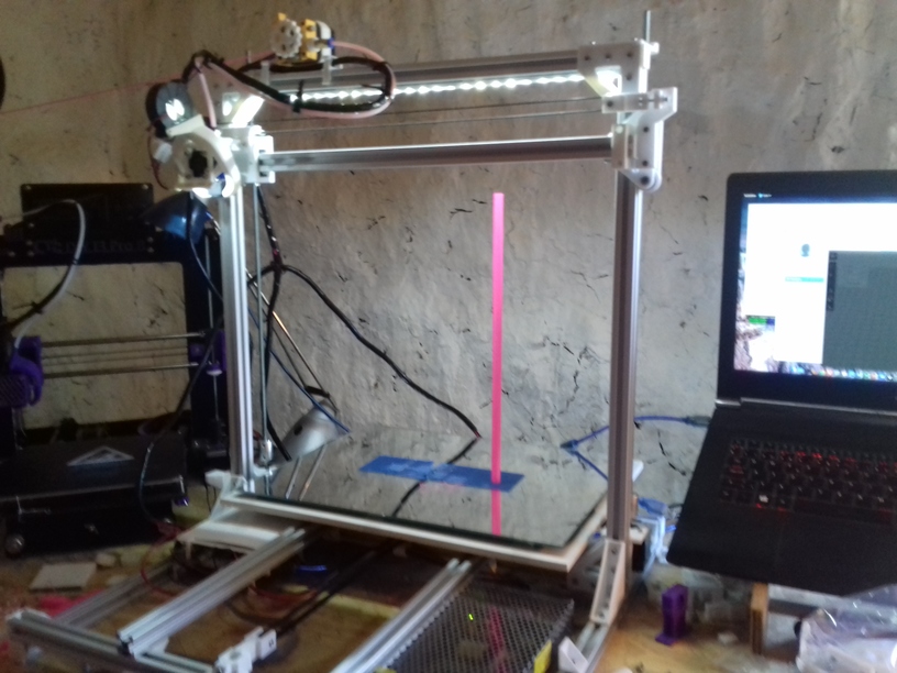
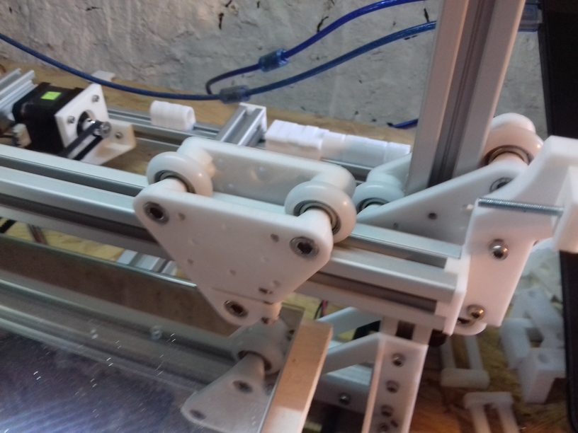
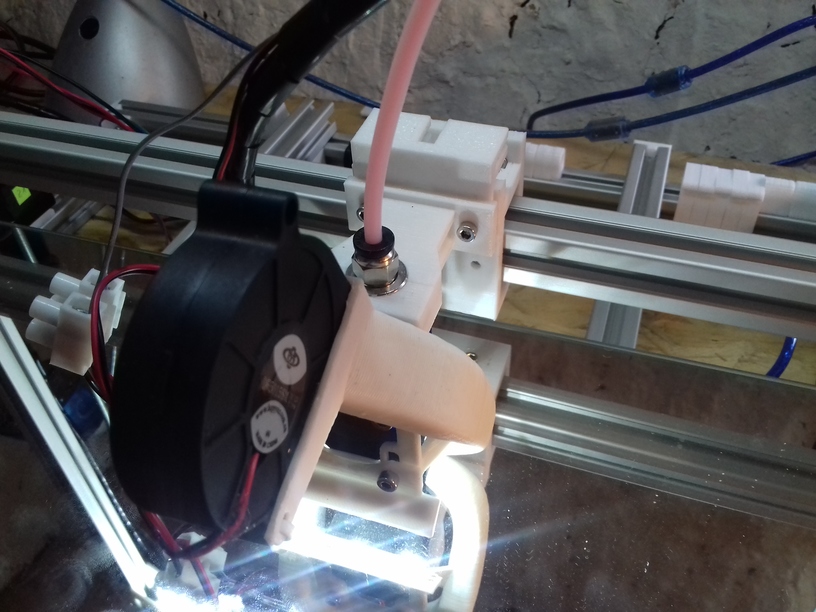
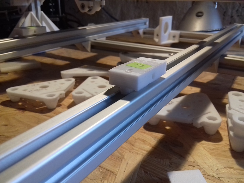
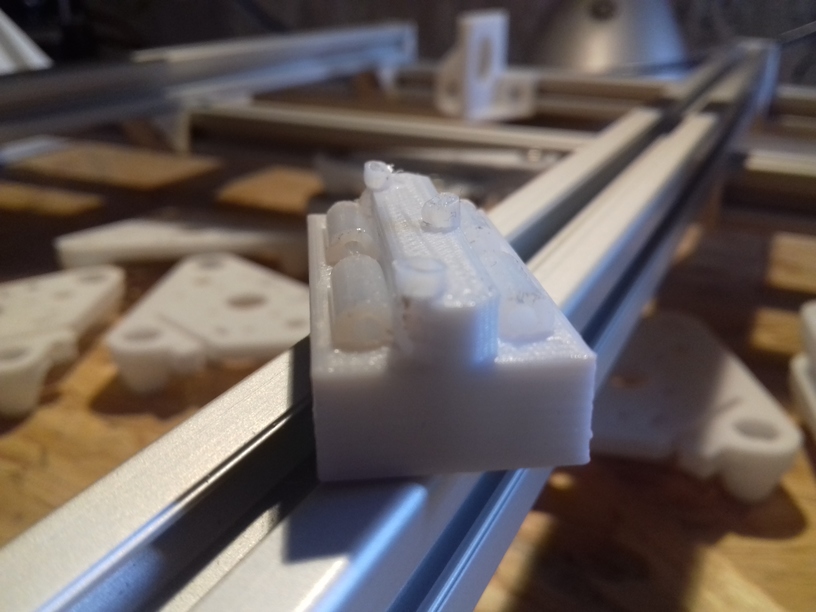
For now I decided to use my V modules as Y carriages with width of 100mm vcarriage2(width=100) but actual tests are required how stable the moving XZ frame will be.
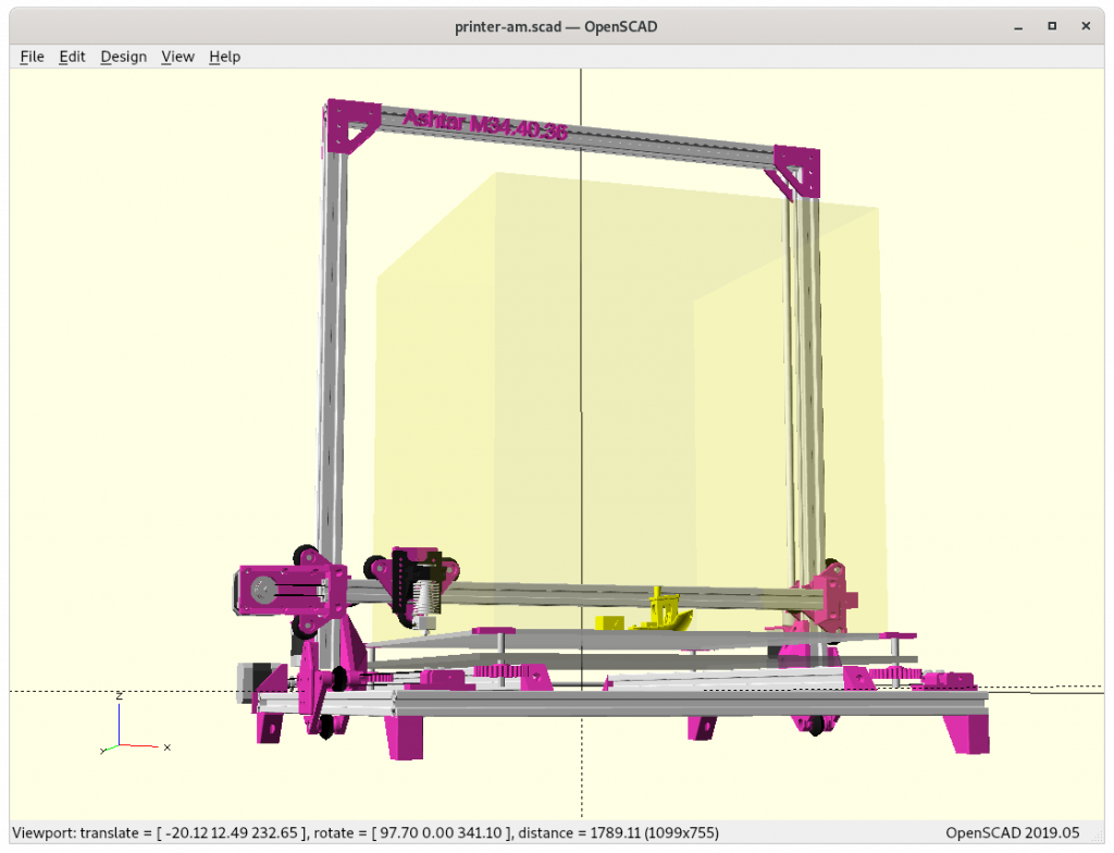
As you can see on the draft, I lose some build volume because I stack on top of the Y carriage instead within, but if I put the gantry / XZ frame between the Y carriage I need extra long X beams for the outer frame, and make it impossible to achieve uni-length design (same beam length for all); it’s all about balancing a compromise.
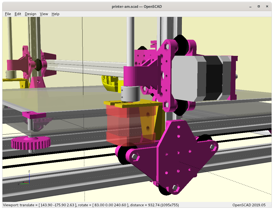
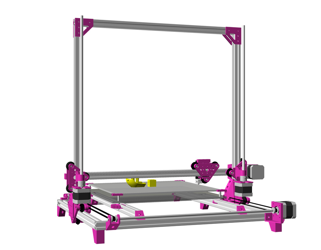
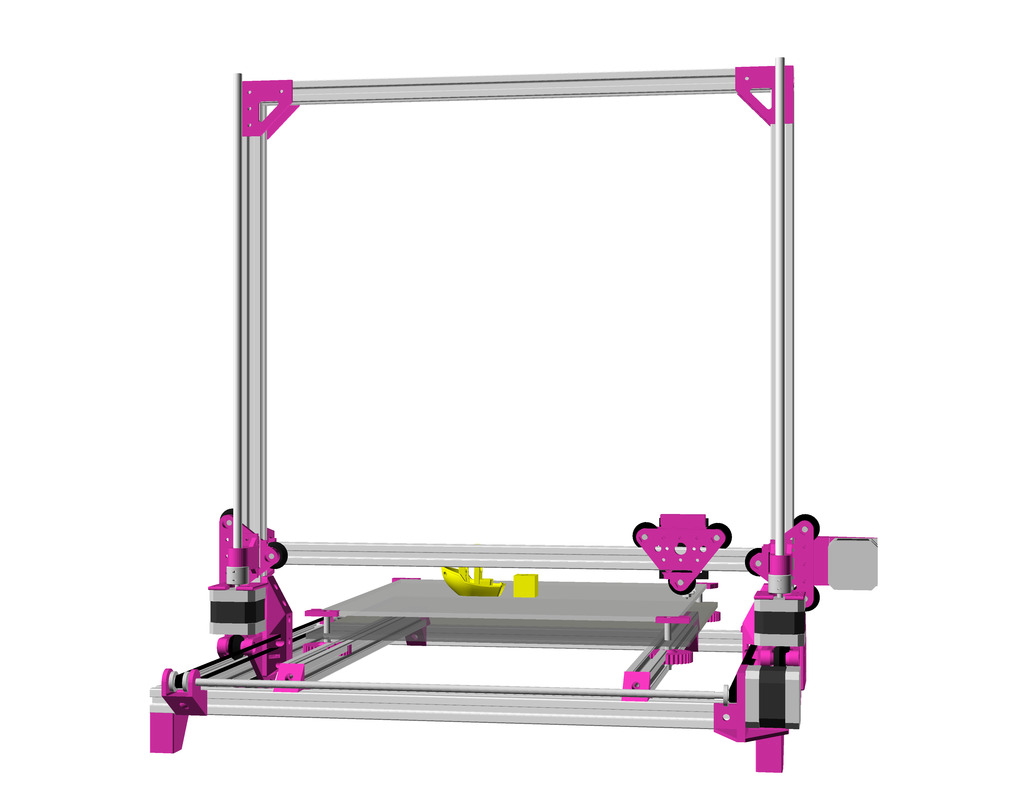
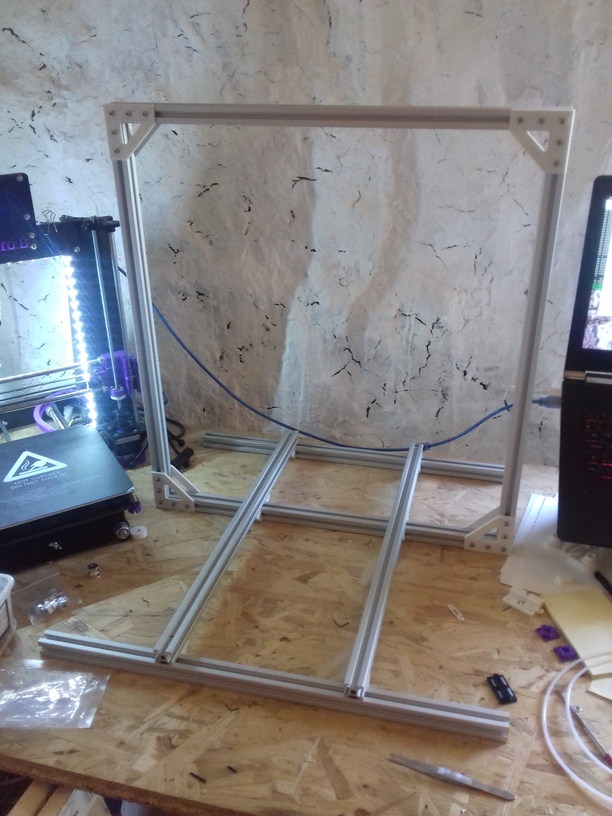
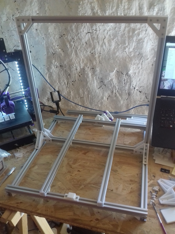
XZ Arch Option
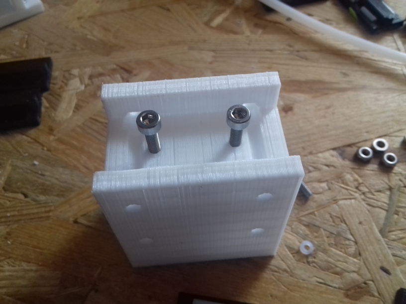
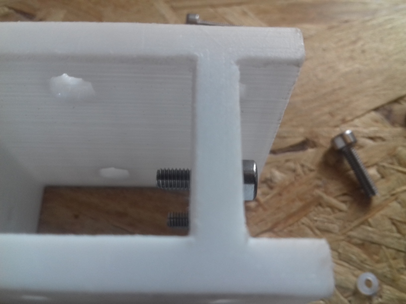
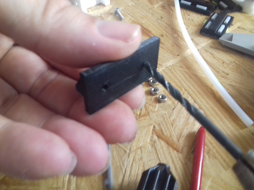
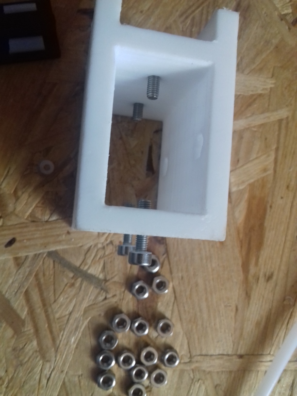
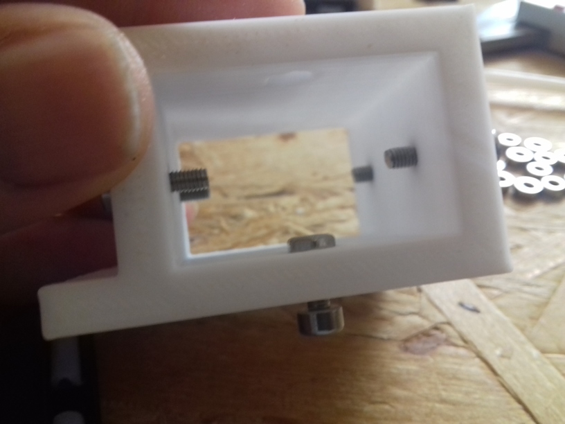
The “XZ Arch” option is removing the lower X beam from the XZ frame, hence, extends Z build space as the print bed also goes lower – for now I moved the Y beams supporting the print bed on the lower framework, details how the print bed will be mounted not yet determined. The side piece “A” is a bit shorter, and side piece “B” is a bit more solid – the way the Y belt is fastened remains the same: Y belt ends come out downward, and are fastened with M3 screws & M3 nuts inserts.

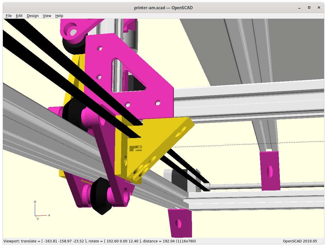
Side pieces “A” & “B” with Arch (lower X-beam removed) 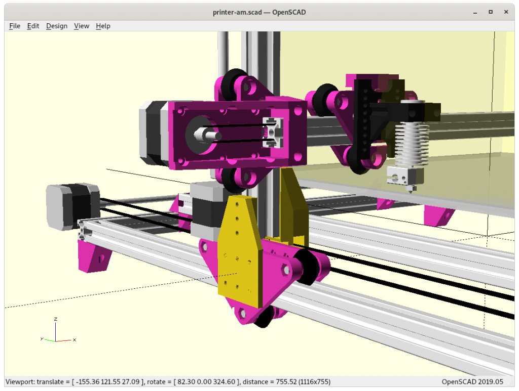
Side piece “A” 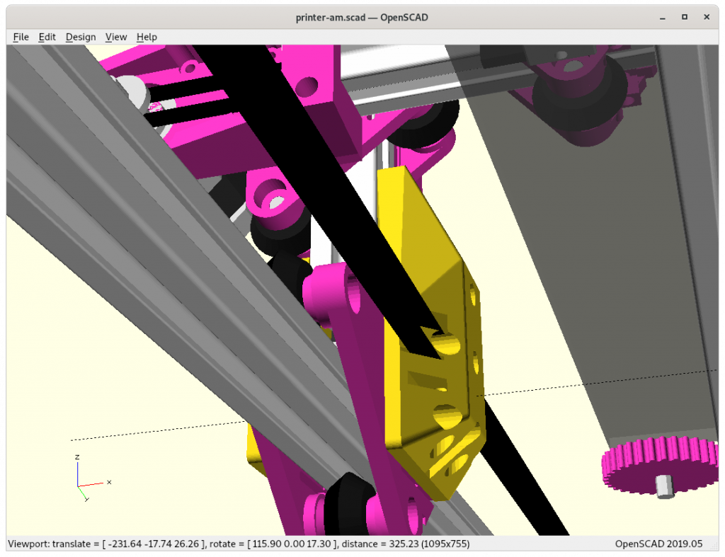


At position 0,0,0 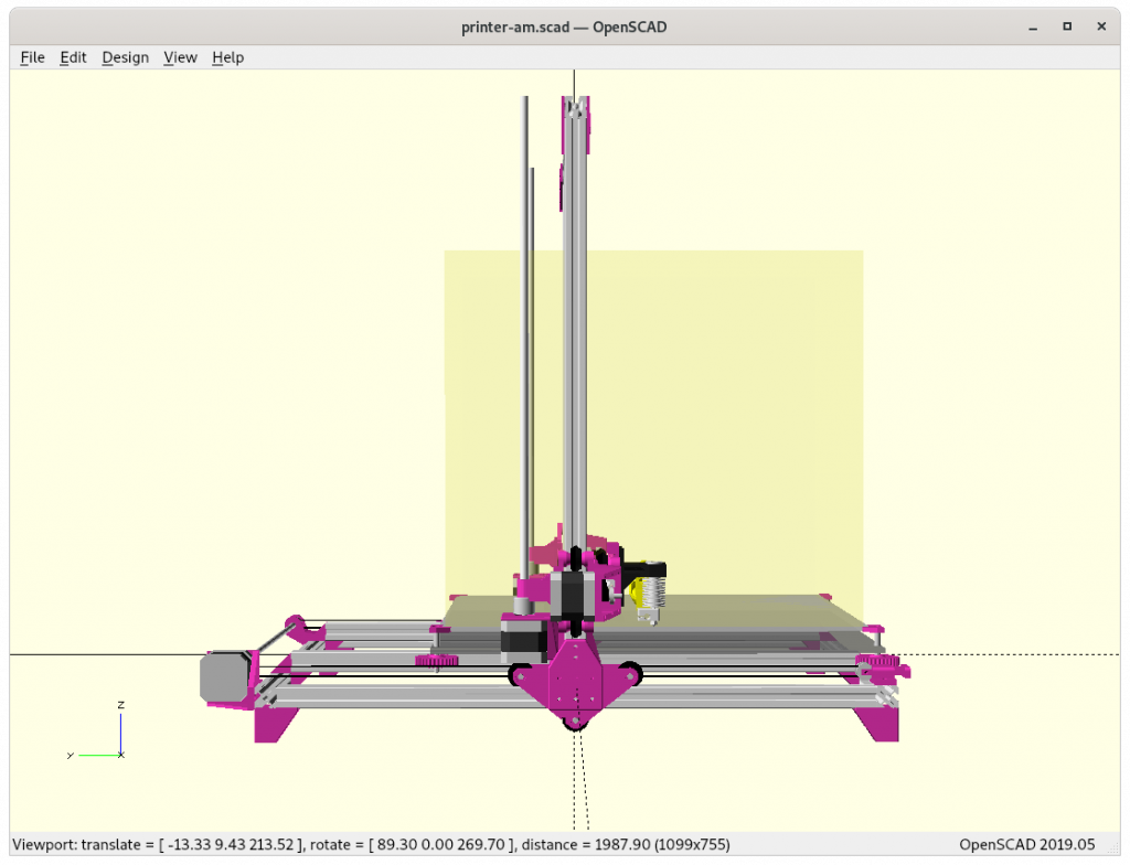


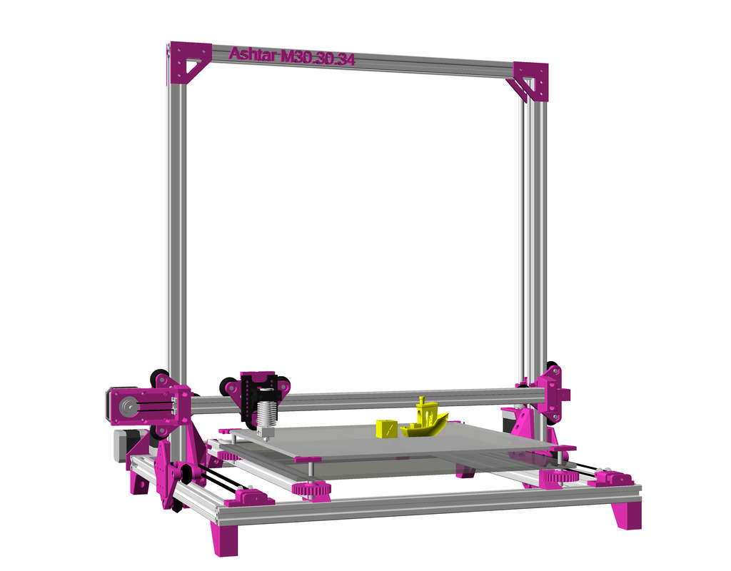
Specifications
- Build Volume: ~380x400x380mm
- Frame: 10x 500mm 2020 alu profiles (XZ arch option)
- 3x or 5x V-Slot 2020 (X, Y and optional Z axis)
- 7x or 5x T-Slot 2020
Issues to Resolve
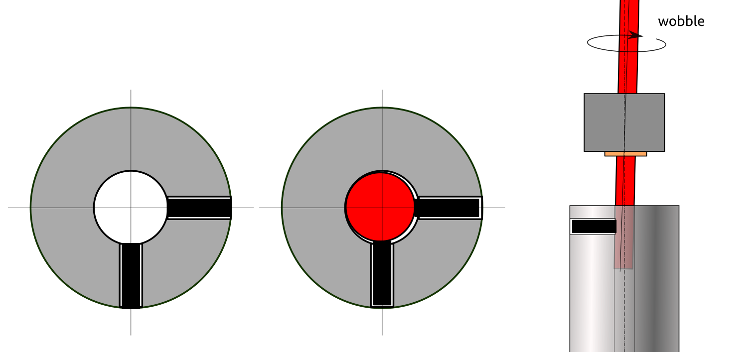
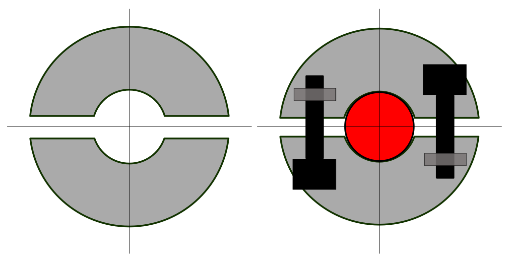
Y motor & Y pulley holder, likely using 6mm smooth or threaded rod as extender, resolved, details defined with 625ZZ bearings- print bed mounting with adjusting nobs to level bed
- optional remove lower beam of the XZ frame and make it just a gantry, would allow to lower supporting bed beams (space for springs and nobs etc) – but might introduce weaker XZ gantry geometry
- Y Carriage to XZ Frame mount:
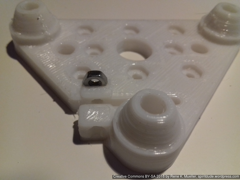
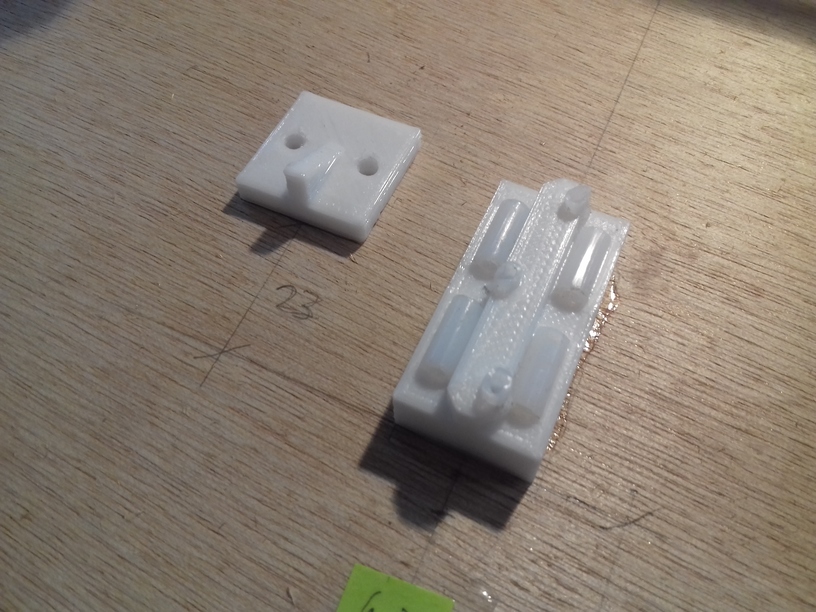
either combine the L shape of XZ frame, or have a separate piece to attach – that part likely is the most challenging to get right, using two pieces “A” and “B” to connect to XZ frame with Y carriage- resolved in theory, but in actual implementation it will be tricky, as the piece “A” aka
ycarriage_xzframe_mount_a()will be printed flat, and quantized by layer height, but the thickness has to be very precise as +/- 0.05mm not to introduce any tilt on the Y carriage (it would damage the V module and/or V wheels and introduce wobble Y-wise), hence 0.1mm layer height required for pieceycarriage_xzframe_mount_a()mounted outside, andycarriage_xzframe_mount_b()(◤-like piece) mounted inside:
- resolved in theory, but in actual implementation it will be tricky, as the piece “A” aka
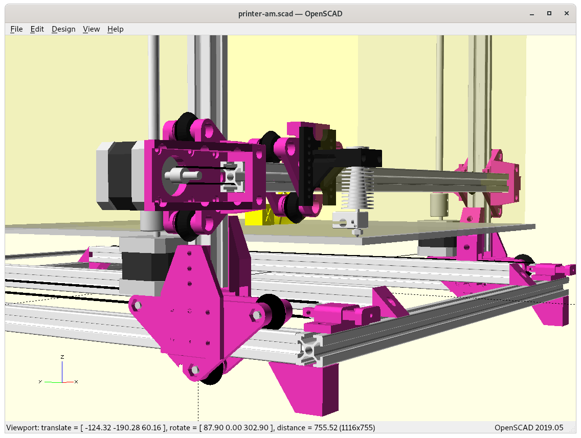
Side pieces “A” & “B” with full XZ Frame 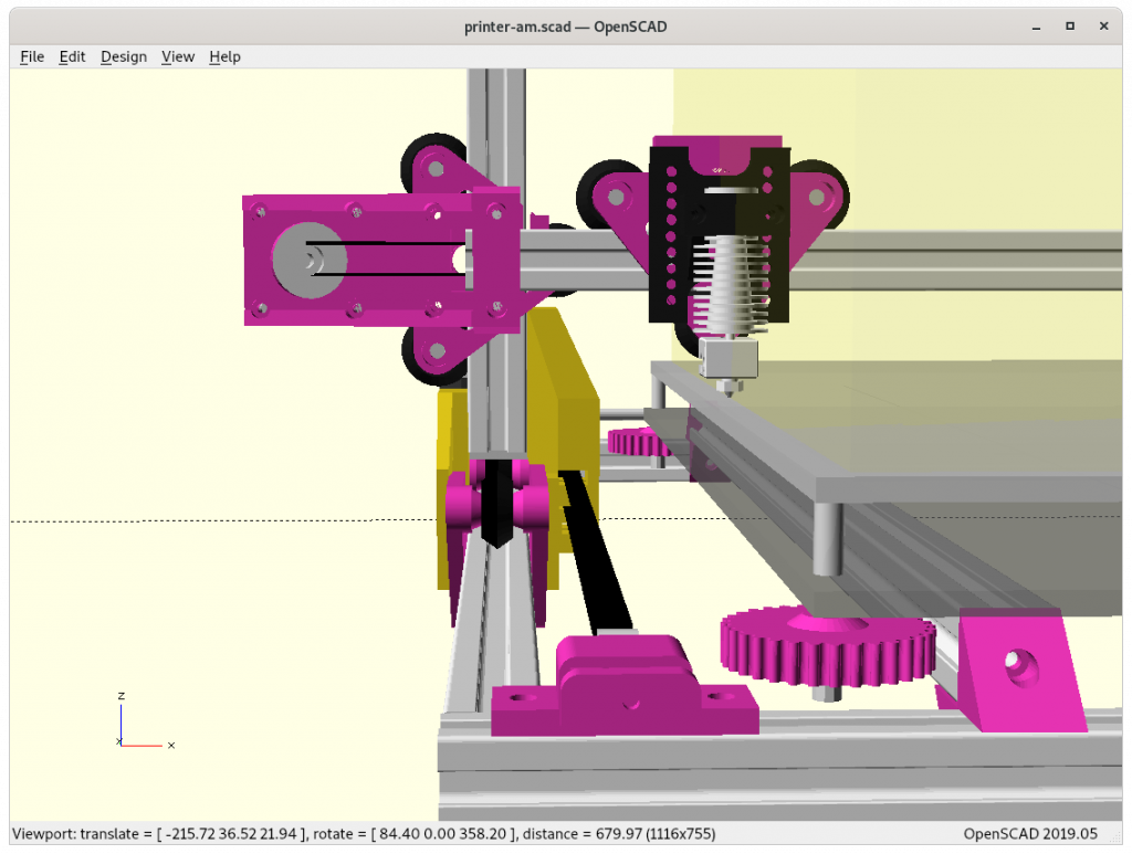
Side pieces “A” & “B” with XZ Arch

Z motor mounts, resolved: how stable it is needs to be tested- cabels & bowden tube routing
- XZ frame moves as well – lot of motion involved – likely not put bowden extruder motor on it and avoid to add additional weight again
- cable chain to ensure it bends in a controlled manner
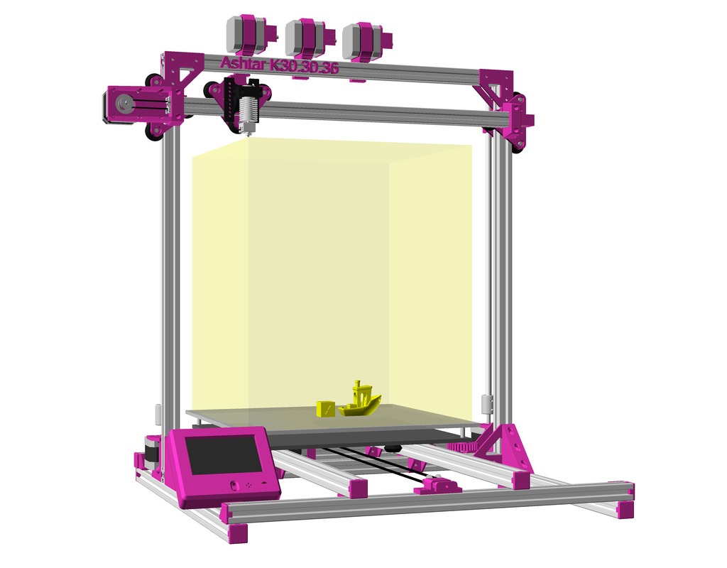
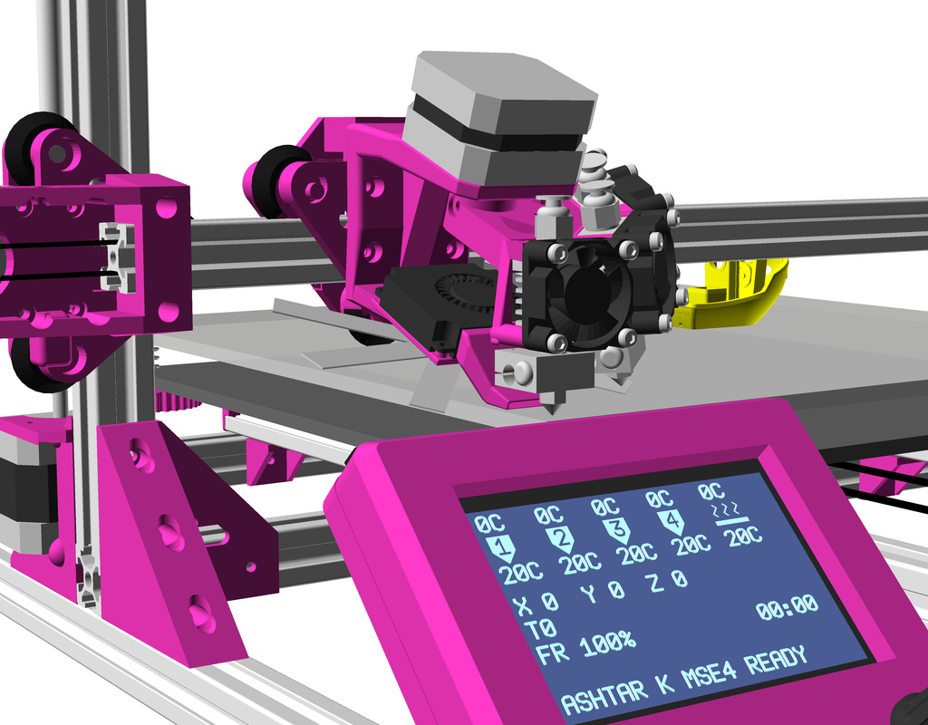
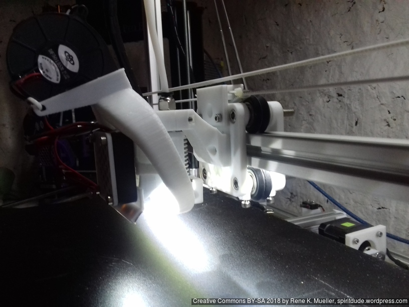
Preliminary position of multiple extruders: X back beam, hence, very long Bowden tubes
- positioning: controller, display, power-supply, optional: filament holder
- none of them can be put on the moving XZ frame anymore
- tuning to common to build-volume with uni-length beams
- likely 400x400mm build plate achievable, but perhaps 380×400 printable, losing 10-15mm on left- and right-hand side.
- XZ frame vs XZ arch: to be determined if it’s essential with actual tests

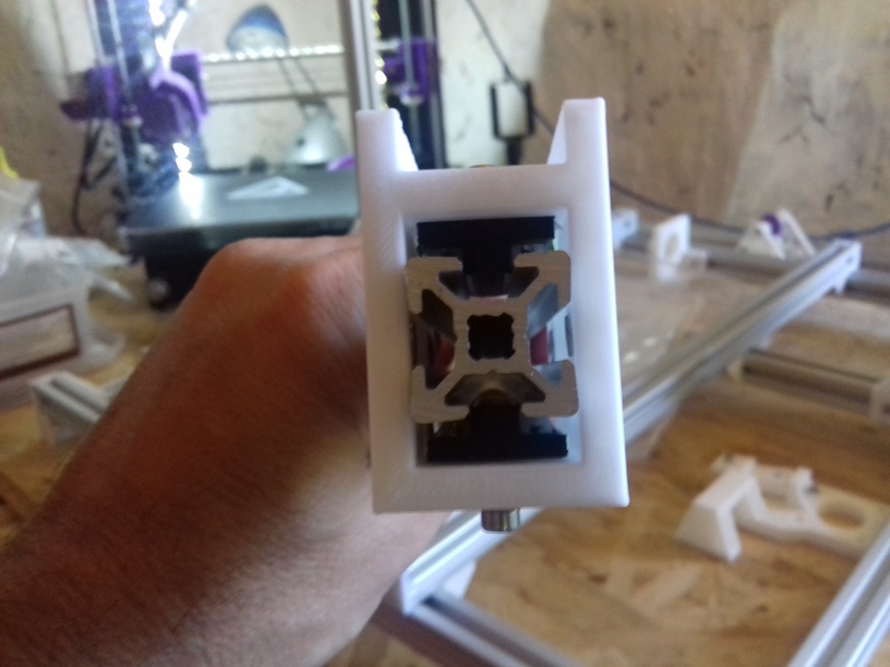
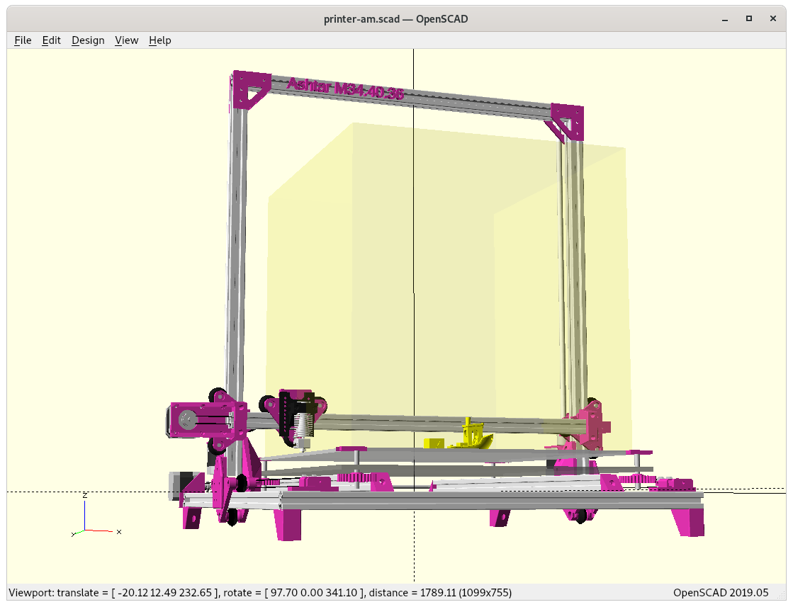
XZ frame (back view) 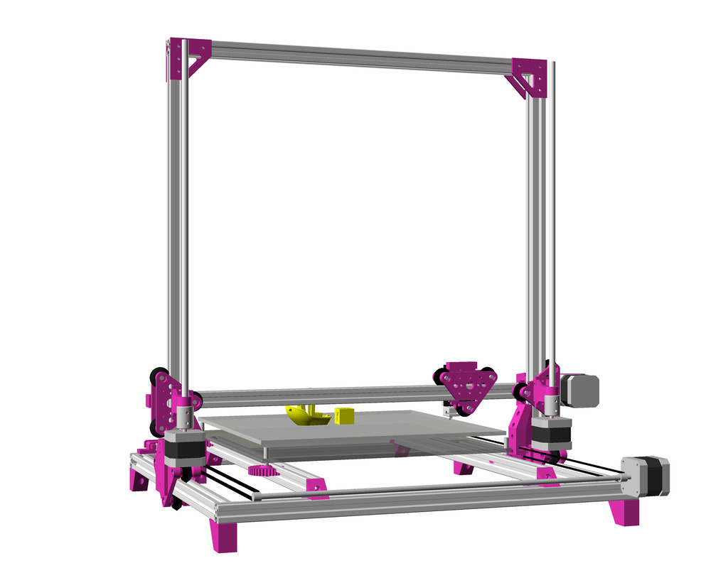
XZ arch (back view)
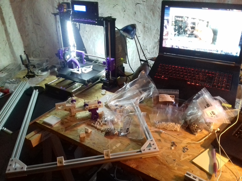
- build printer
- print tests
- release parts
- release code
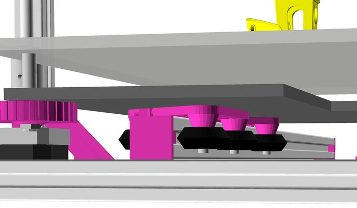
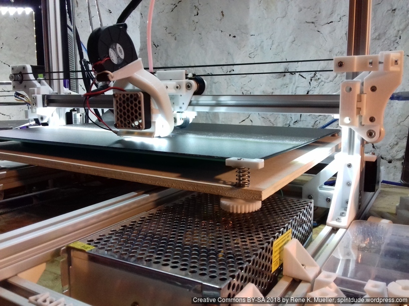
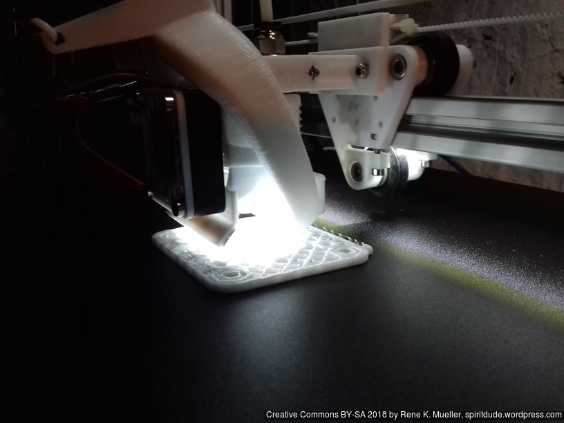
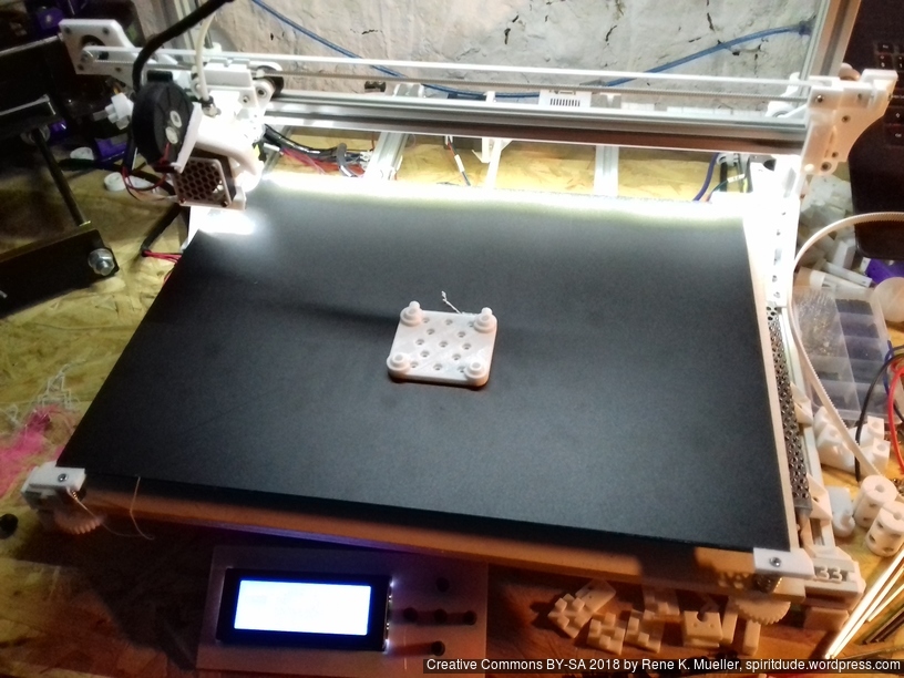
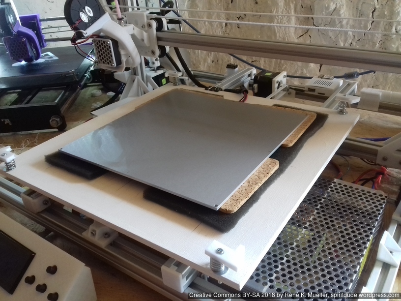
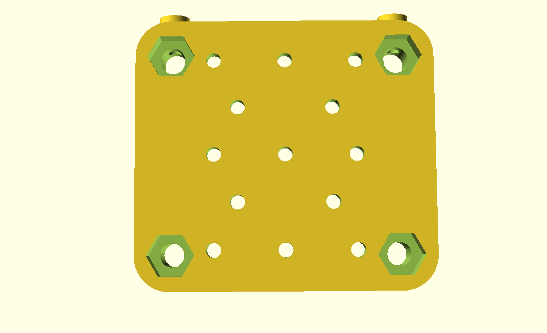
Bed
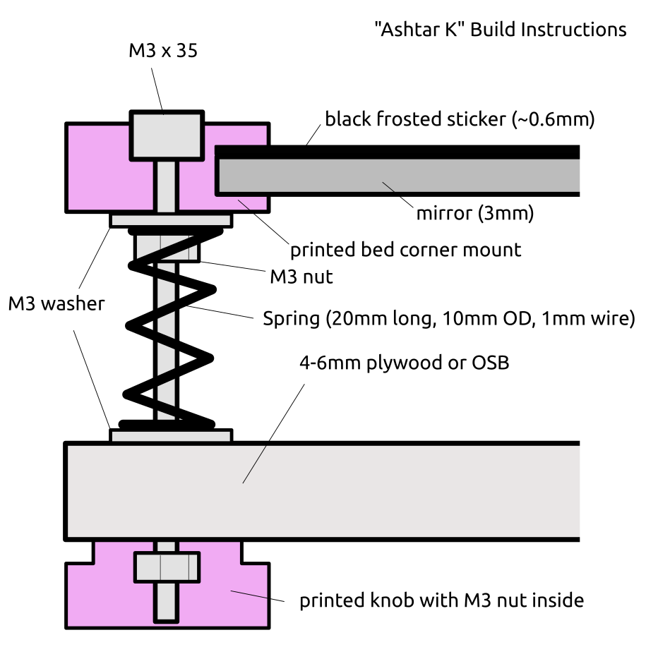
The bed is stationary, so it’s relatively simple, a bed carriage it still required so the fine level adjustment is possible with some knobs – using the same setup as for Ashtar K.
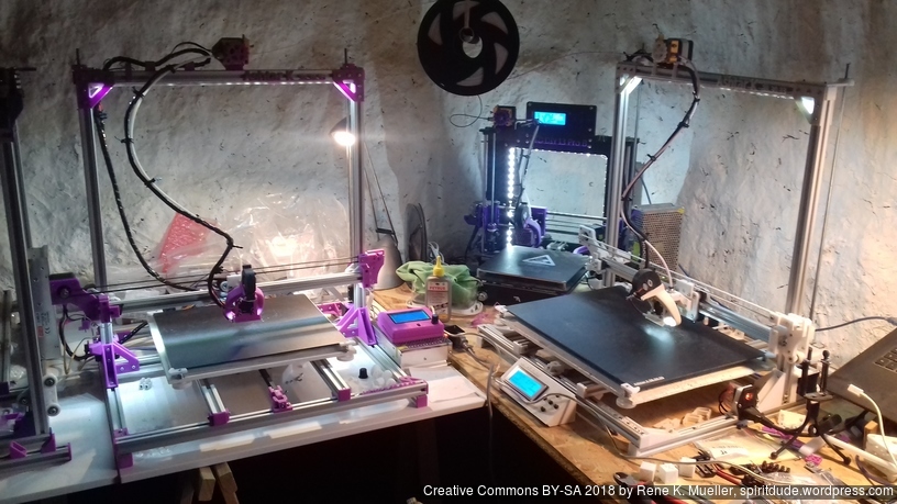
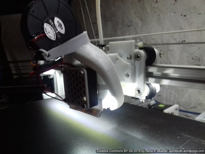
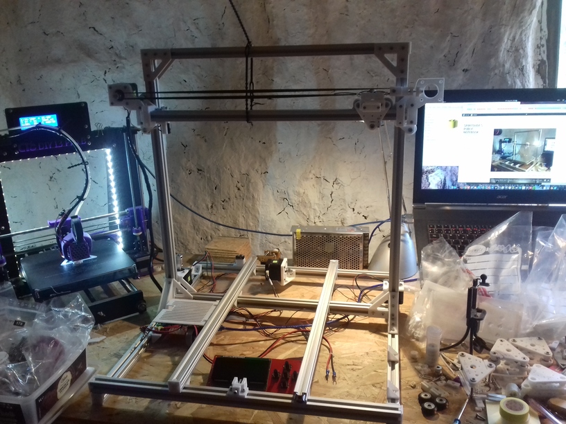
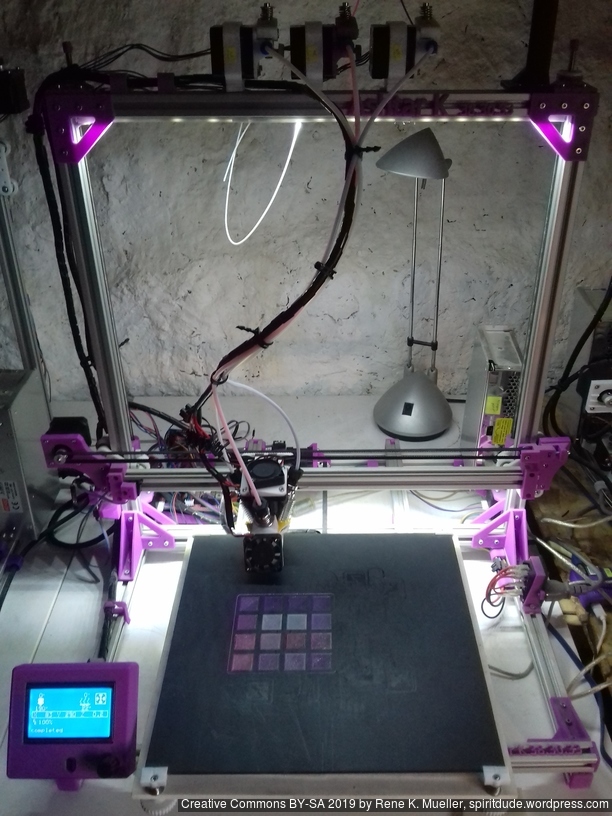
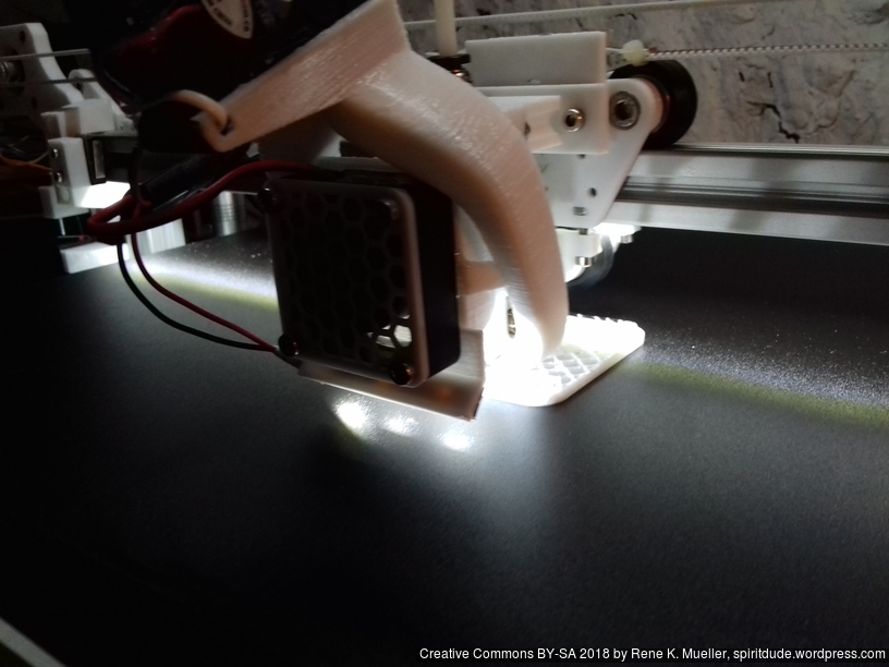
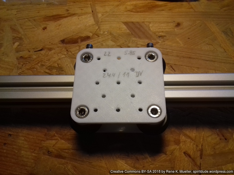
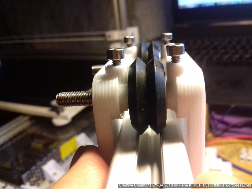
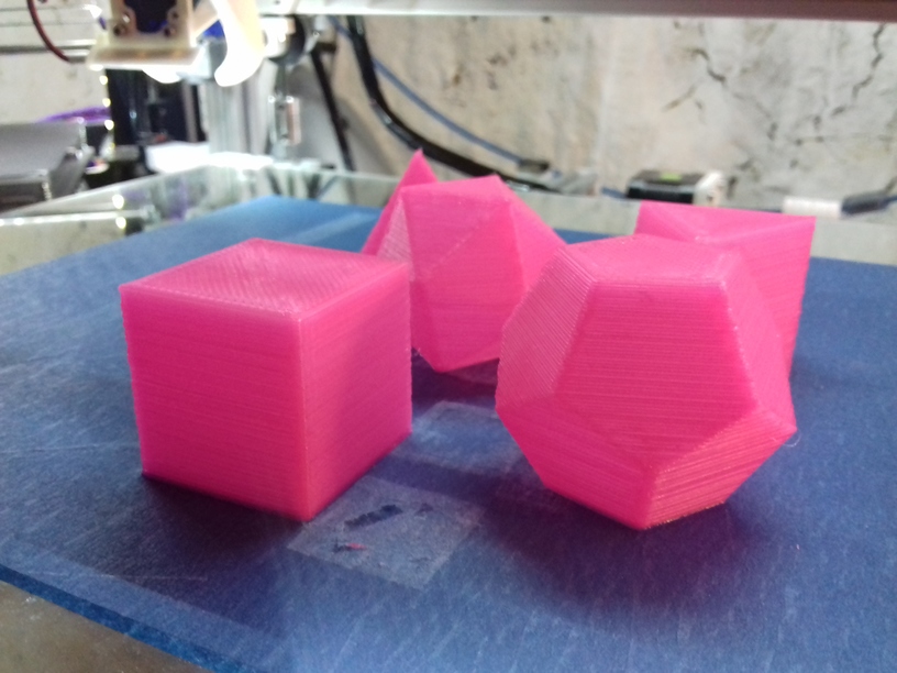
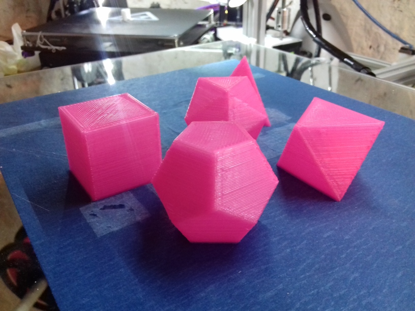
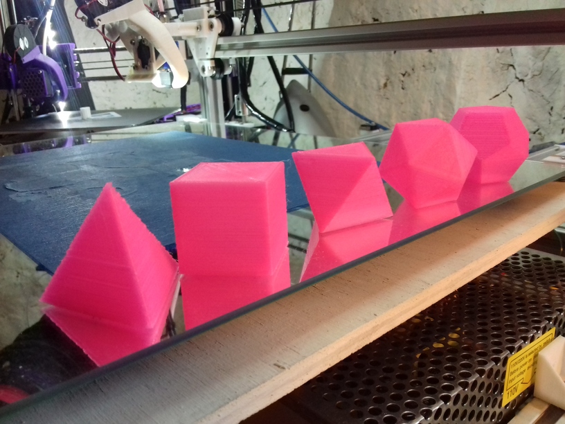
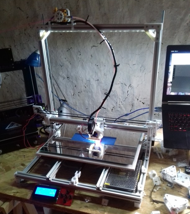
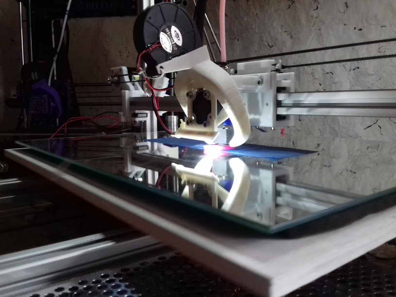
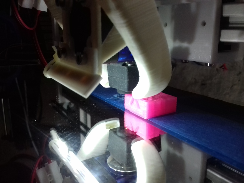
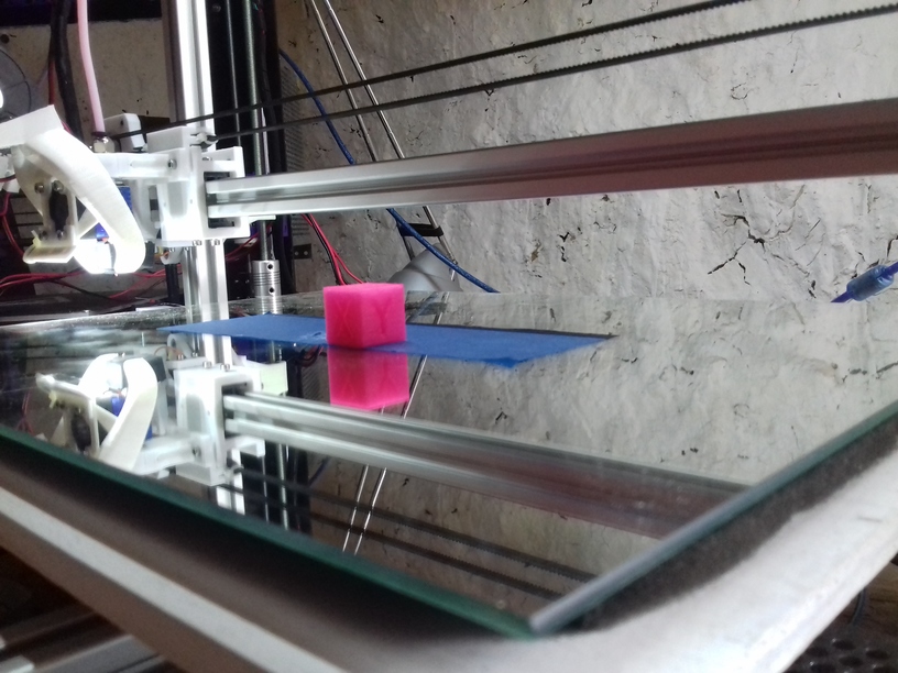
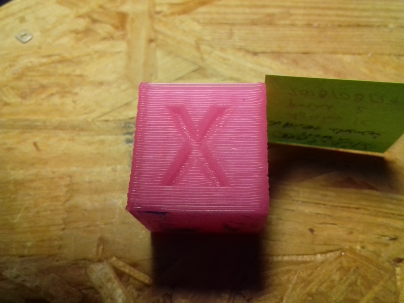
Gallery


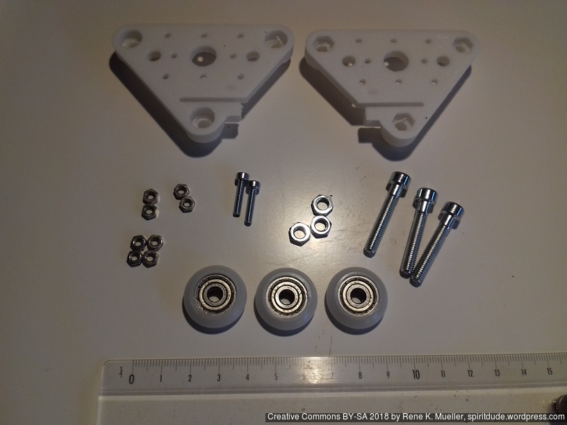
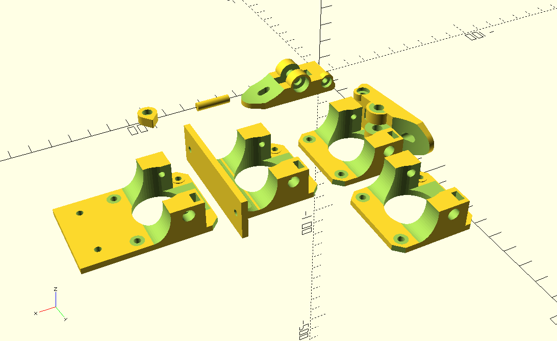
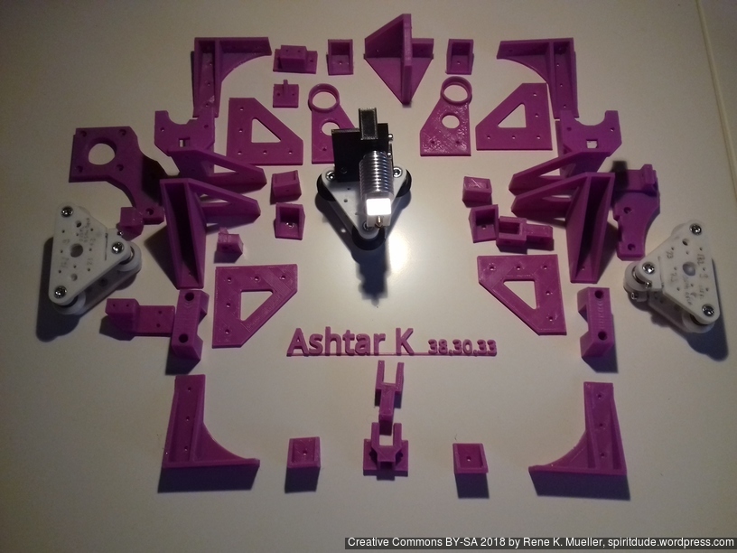
Parts
Printable Parts
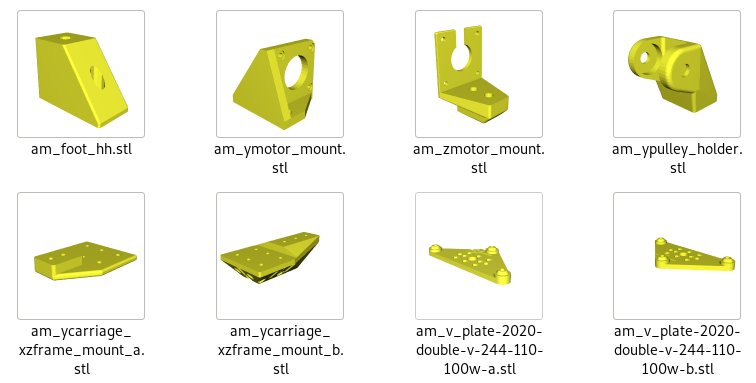
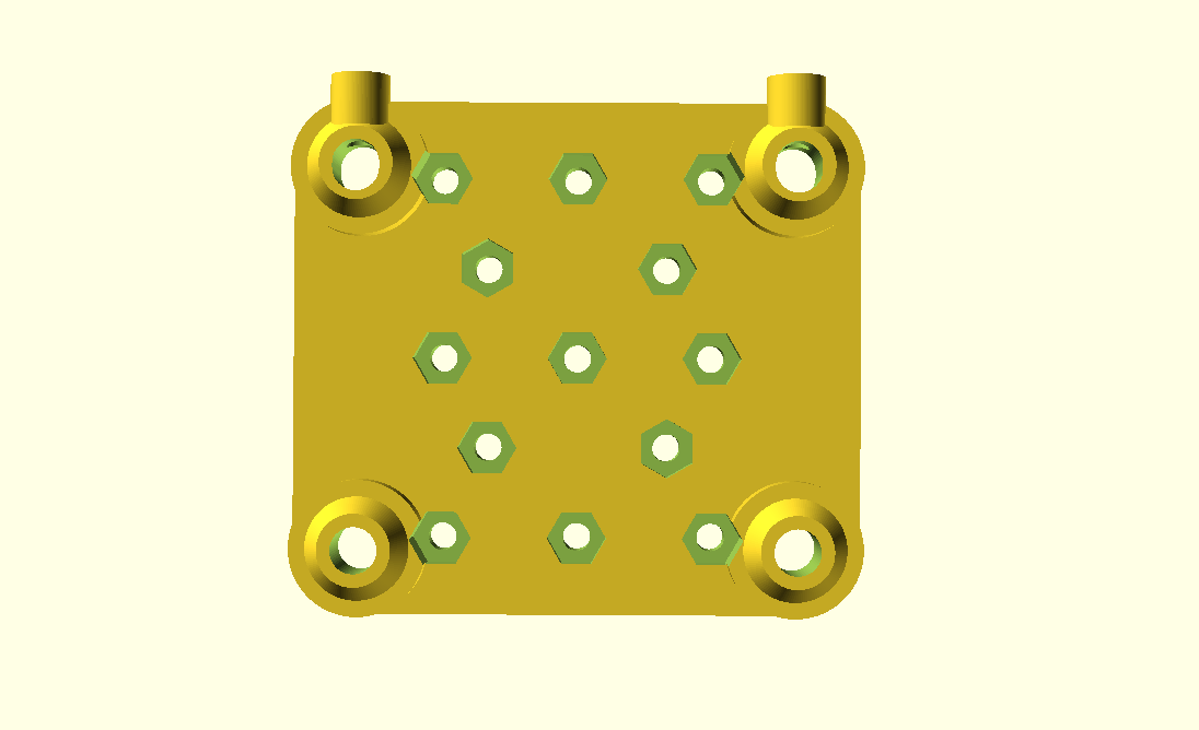
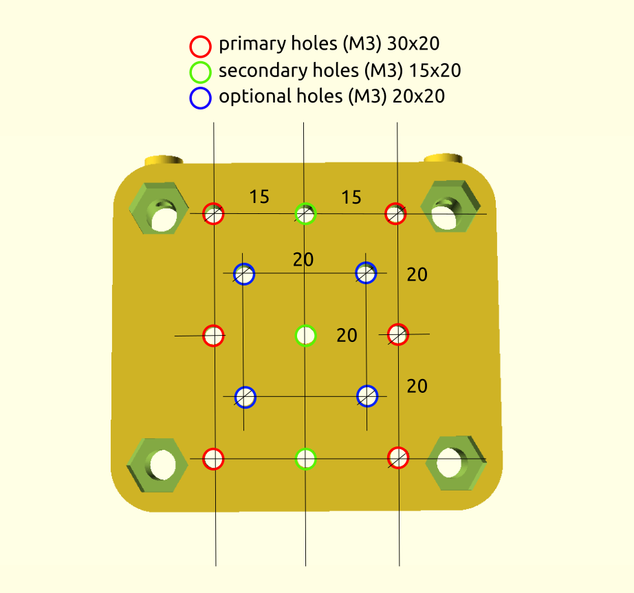
- Y carriage:
- 2x
am_v_plate-2020-double-v-244-110-100w-a - 2x
am_v_plate-2020-double-v-244-110-100w-b
- 2x
am_zmotor_mount - 2x
am_ycarriage_xzframe_mount_a - 2x
am_ycarriage_xzframe_mount_b
- 2x
- 1x
am_ypulley_holder - 1x
am_ymotor_mountor2020_Y_motor_mount - 4x
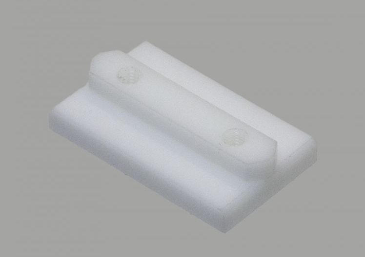
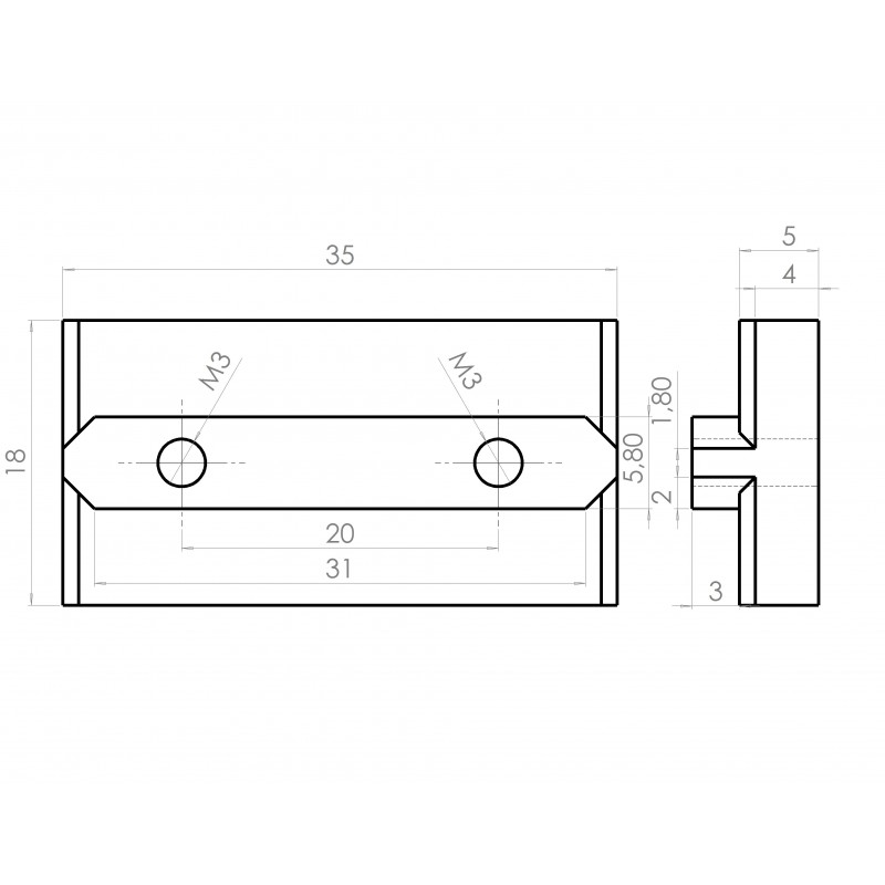
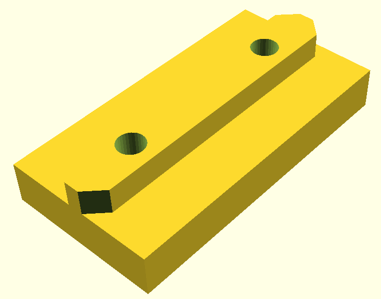
am_foot_hh
Non-Printable Parts
- 2x 625ZZ bearings
- 2x for 1x
am_pulley_holder
- 2x for 1x
- nx pulleys (dimension not yet determined)
- 2x (5mm hole) for 1x Y motor, 1x
am_ypulley_holder - 1x (5mm hole) for 1x X motor
- 2x (5mm hole) for 1x Y motor, 1x
- nx idlers (with 3 or 5mm hole)
- 1x (3mm hole) for 1x X belt
- 2x (3mm hole) for 2x Y belts
- ~490-500 mm M5 smooth or threaded rod (Y shaft extension)
See the on-going blog-posts on Ashtar M development, with some more details than the overall page here.
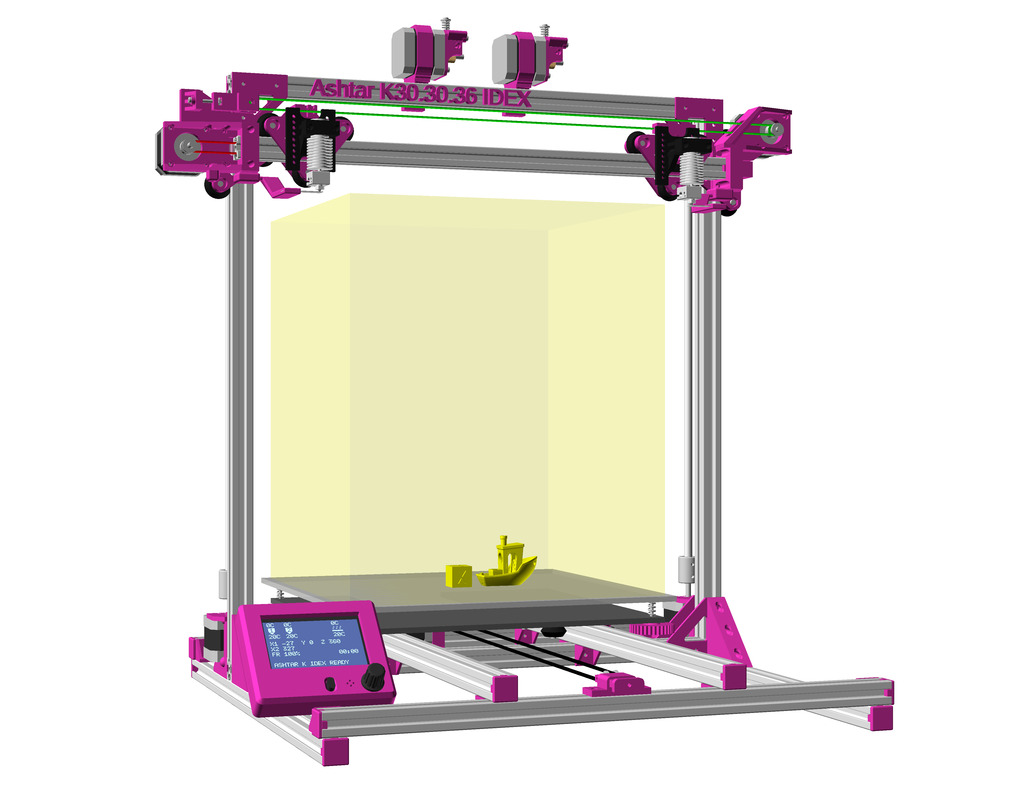
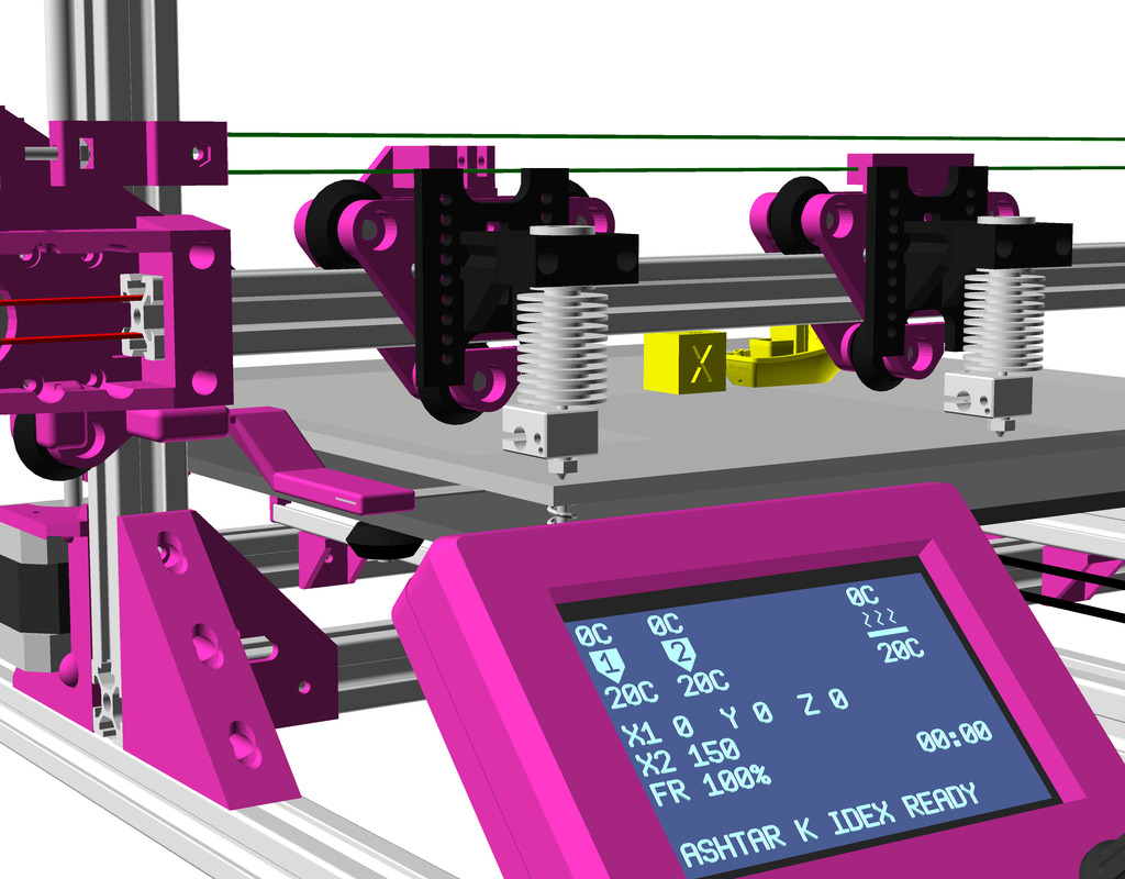
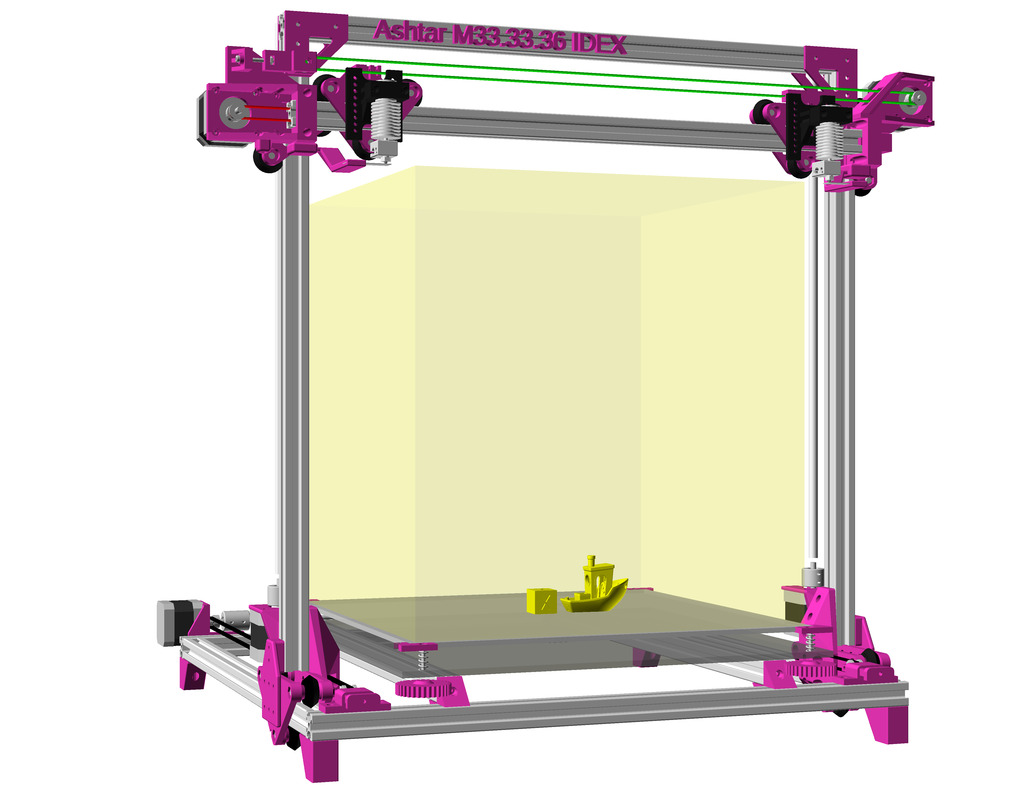
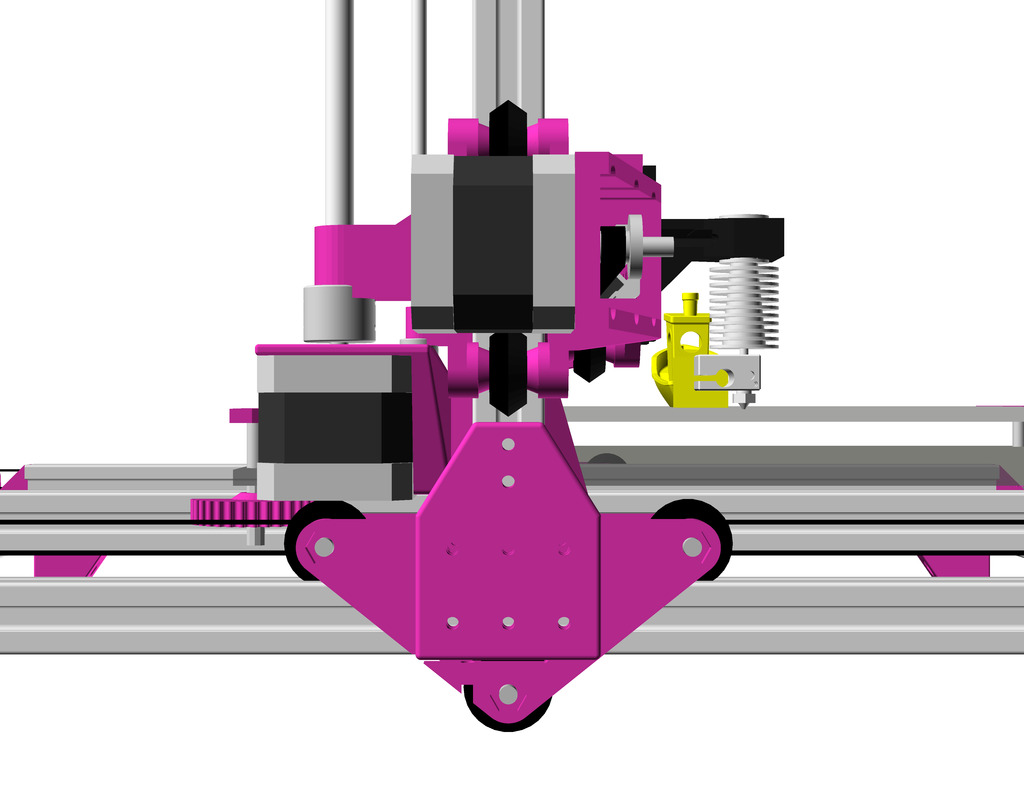
IDEX Option
As Ashtar M shares much of Ashtar K design, the IDEX option comes easily – yet, adding a 2nd motor on the moveable XZ frame/gantry definitely pushes the limits of Ashtar M, significant forces will be applied at high Z positions while moving Y axis.
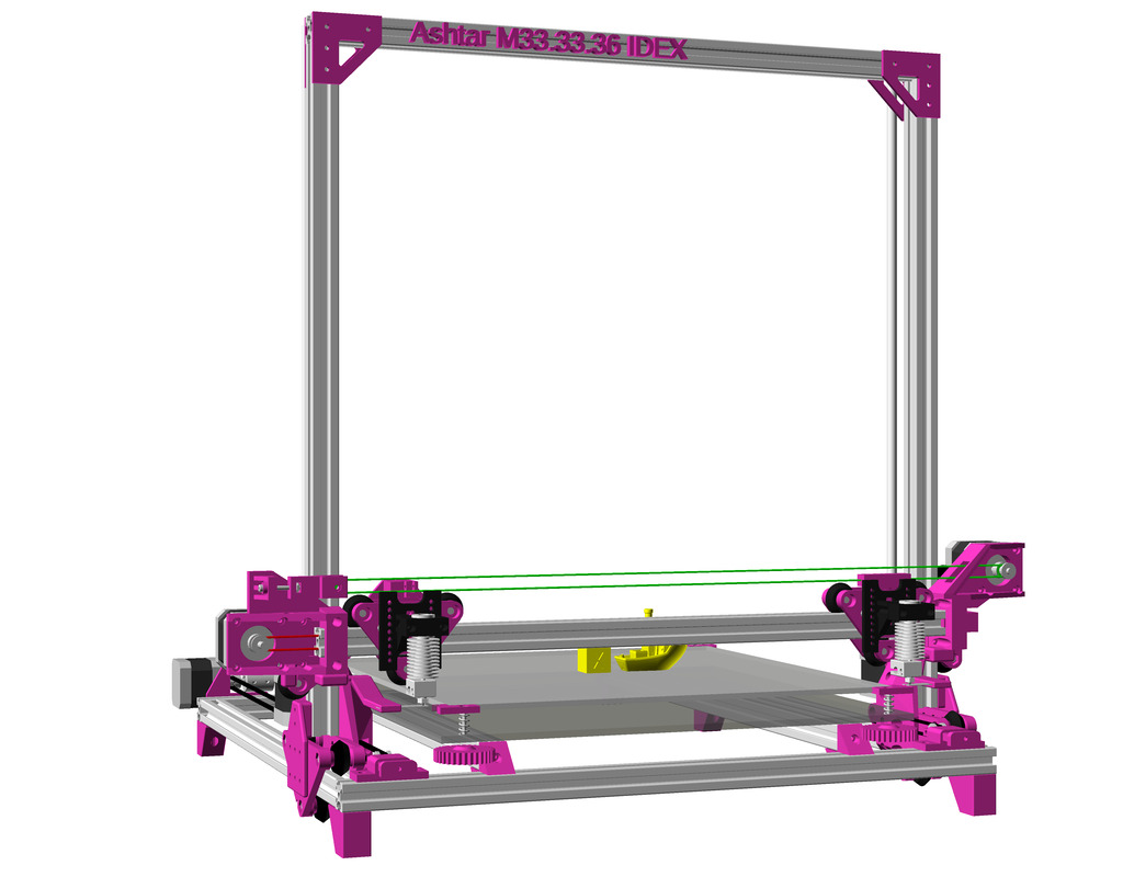
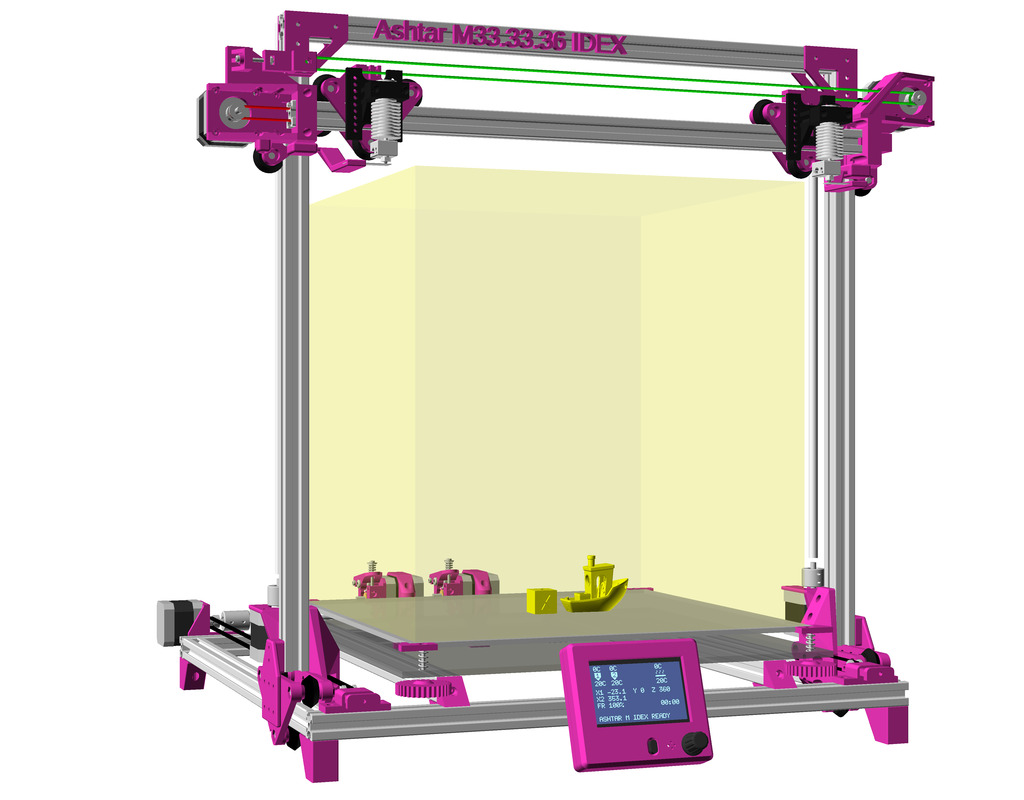
In order to run two independent printheads (Independent Dual Extrusion) following changes are needed:
Printable
- 1 x
xcarriage_short_hmount_motor_2020-endstop-idex-left - 1 x
xcarriage_short_hmount_motor_2020-idex-right - 1 x
xcarriage_beltmount_2020-idex - 1 x
pulley_holder
Non-Printable
- 1x Nema 17 42-45Nm (39-40mm height) with 1m wires
- belt ~110cm GT2 6mm
- 1 x pulley
- 1 x idler
As soon I tested this option I will document it in more details, like electronics, changes in firmware, slicer settings etc.

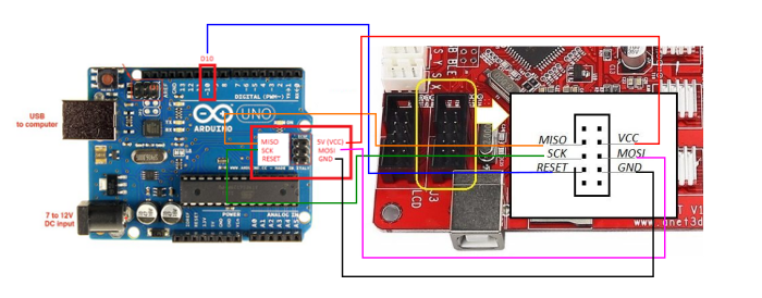

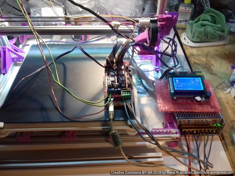
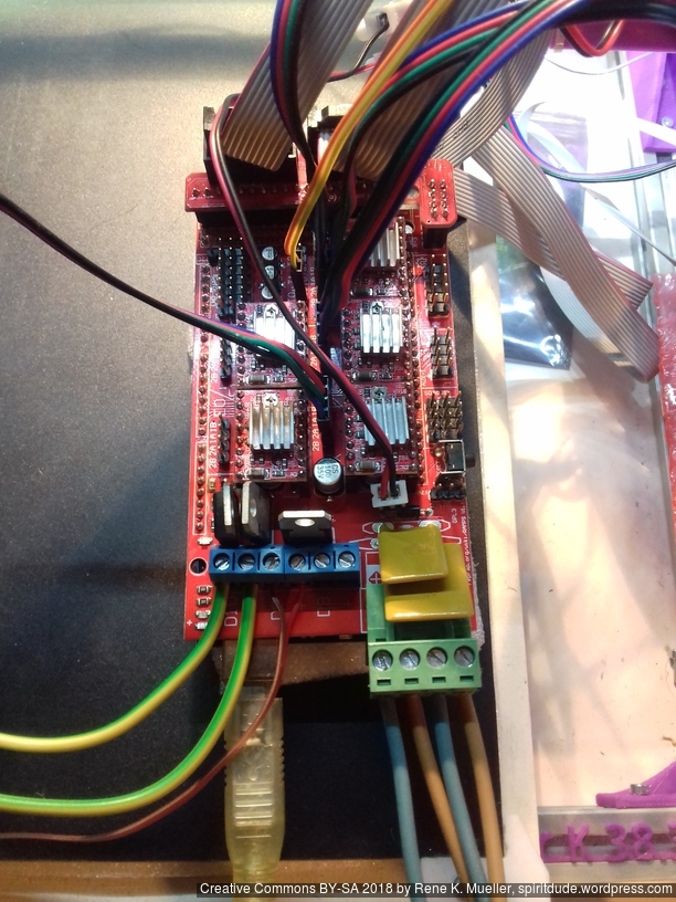
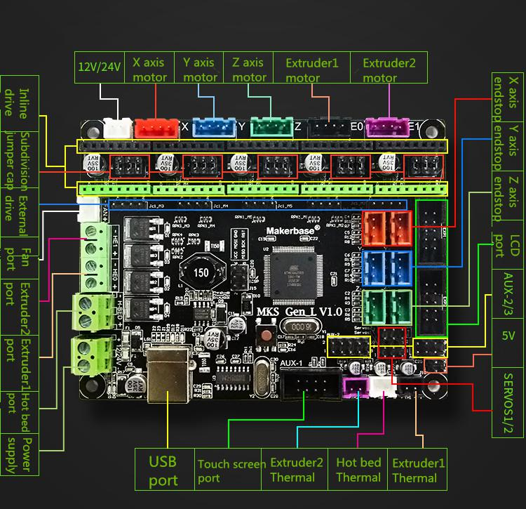
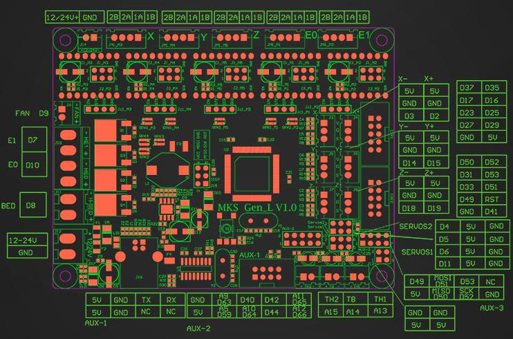
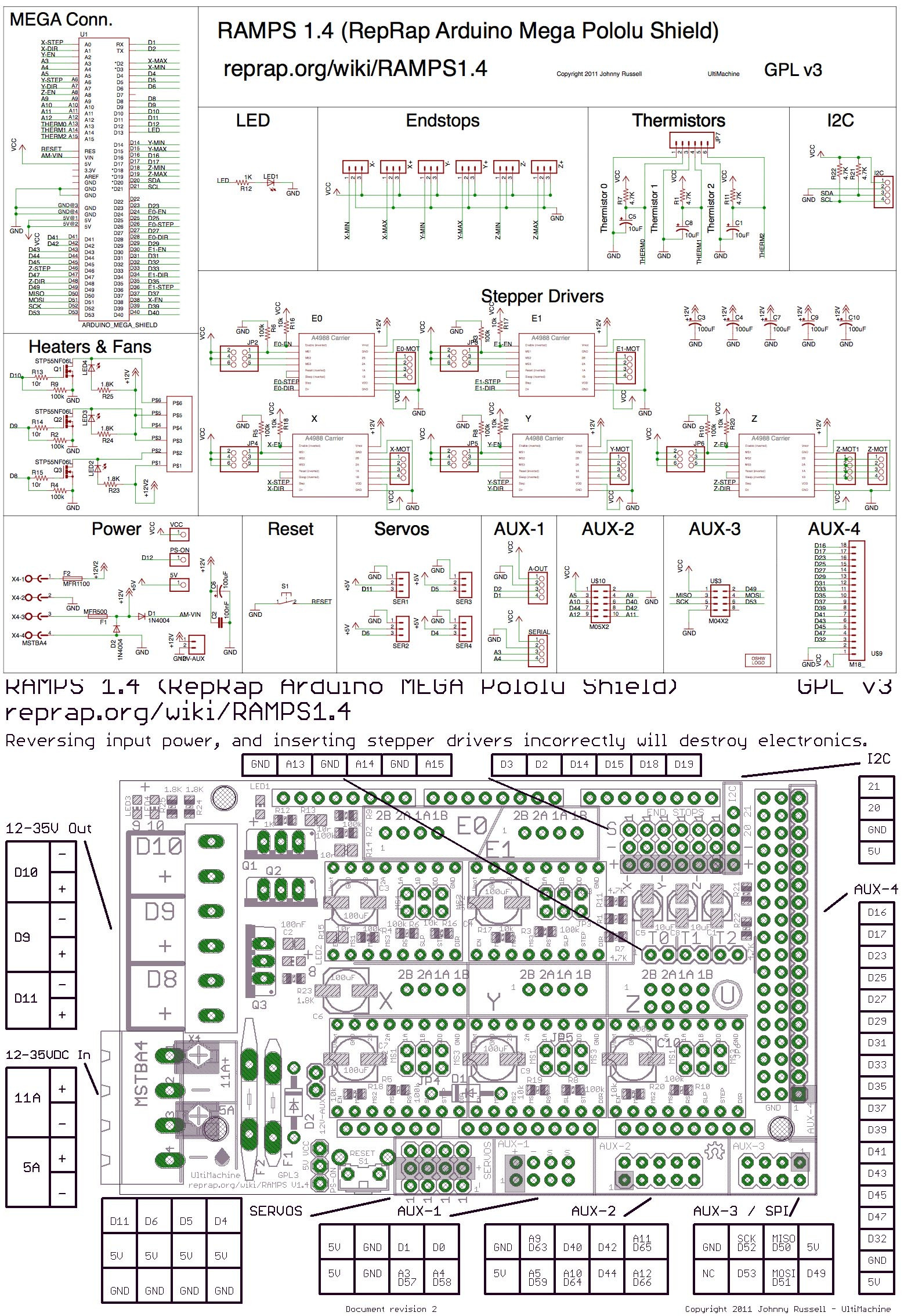 For the 2nd Ashtar K 3D Printer I used (2018/11) RAMPS 1.4 combo with Arduino Mega, which was easy to upload new firmware. RAMPS 1.4 is Open Hardware,
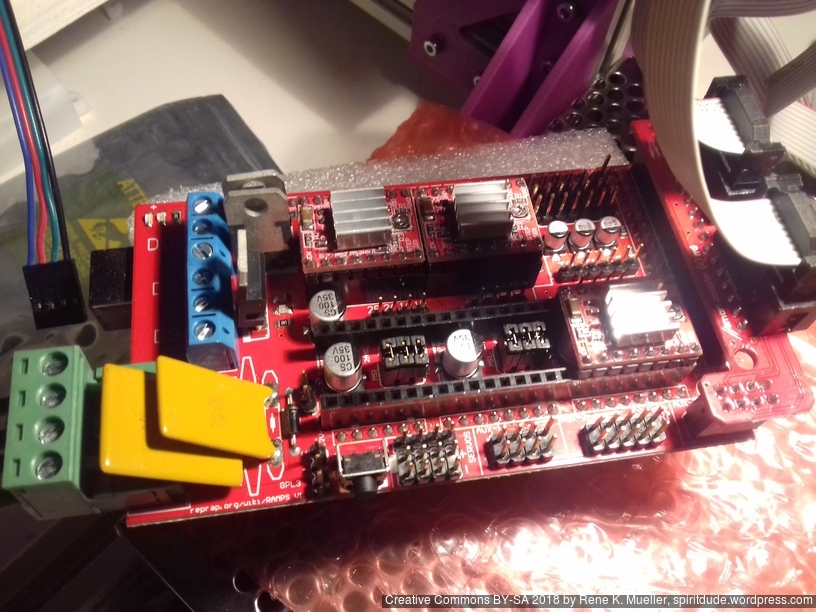

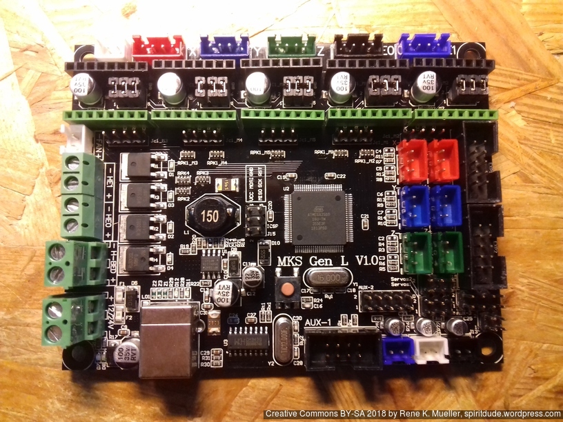


 Commercially manufactured, apprx. cost EUR 2.50 per piece, sold in 10 pieces bag.