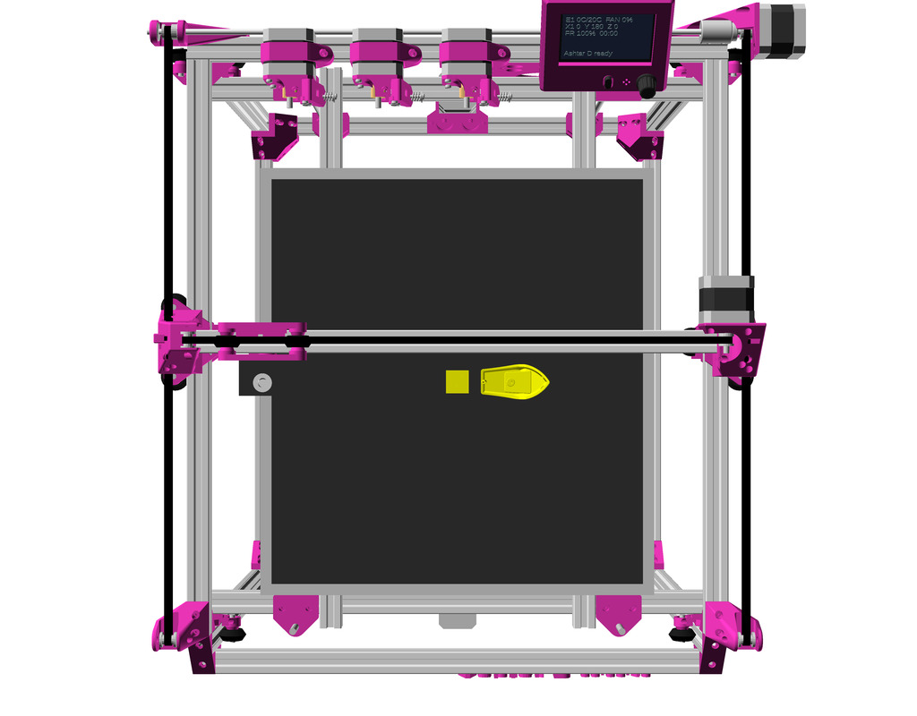
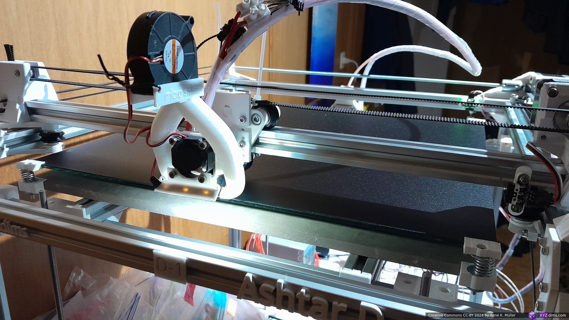
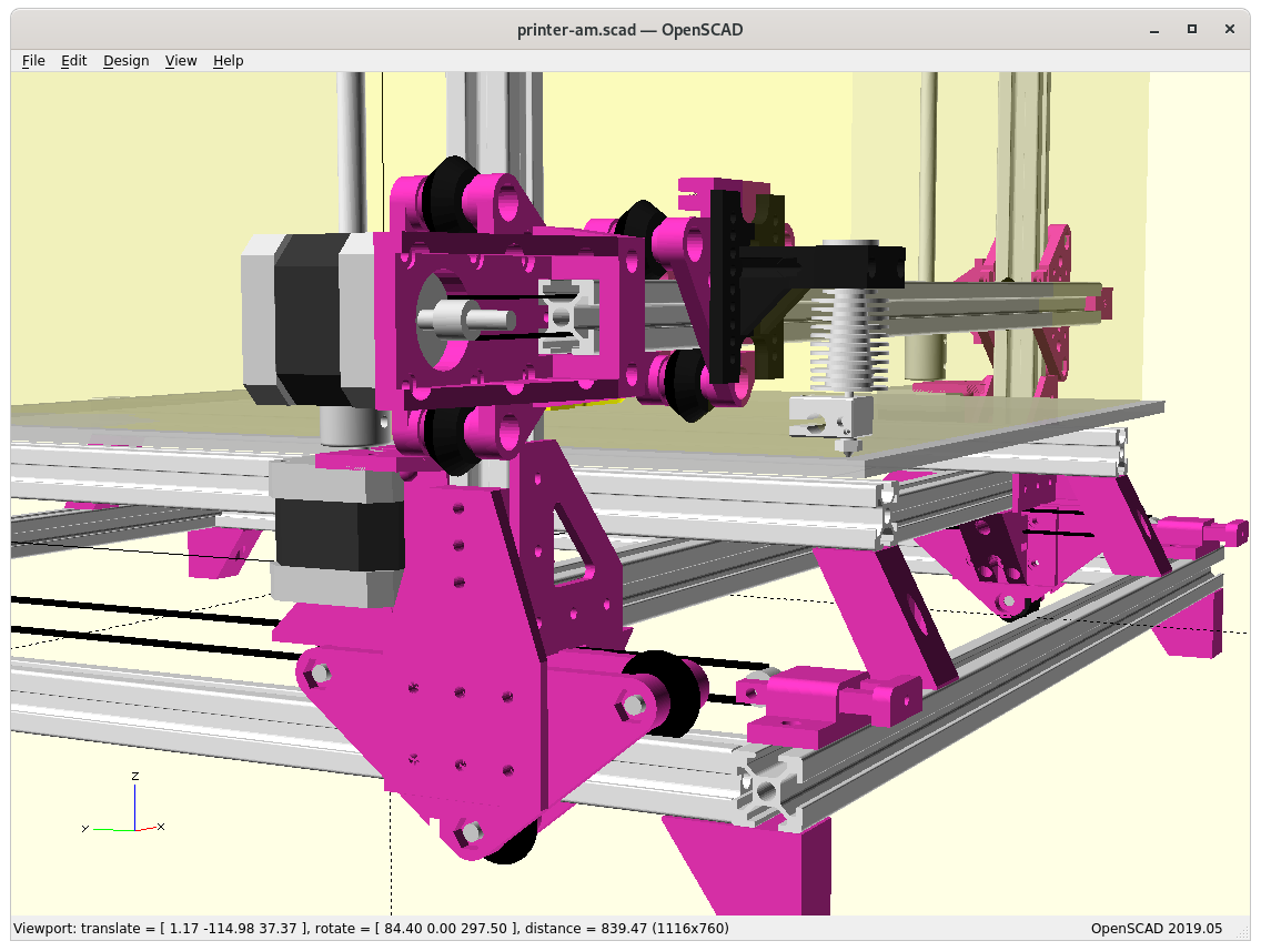
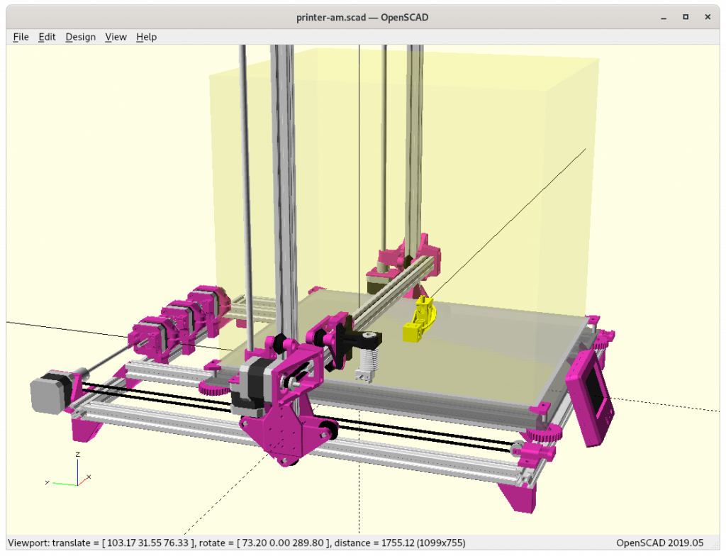
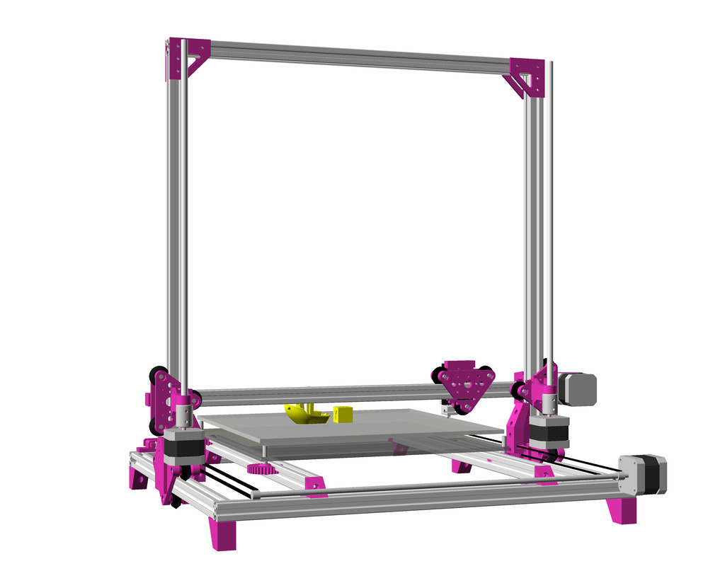
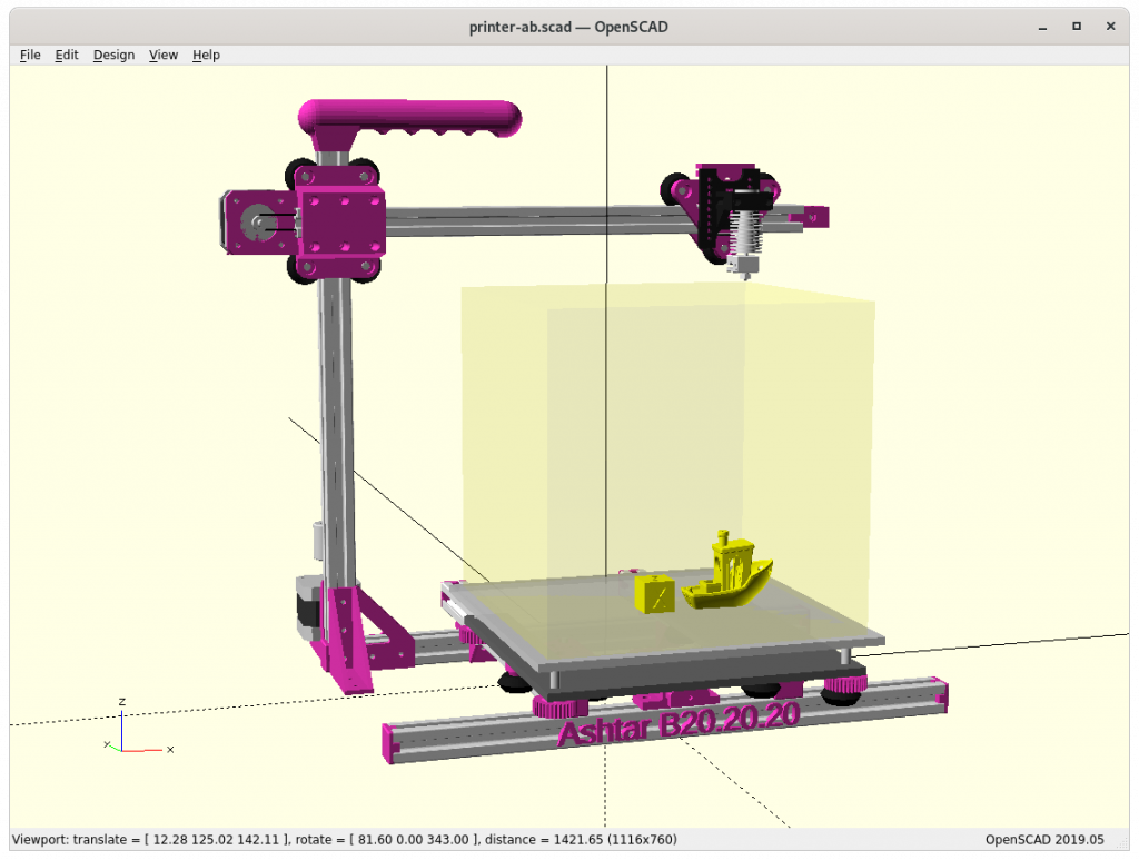
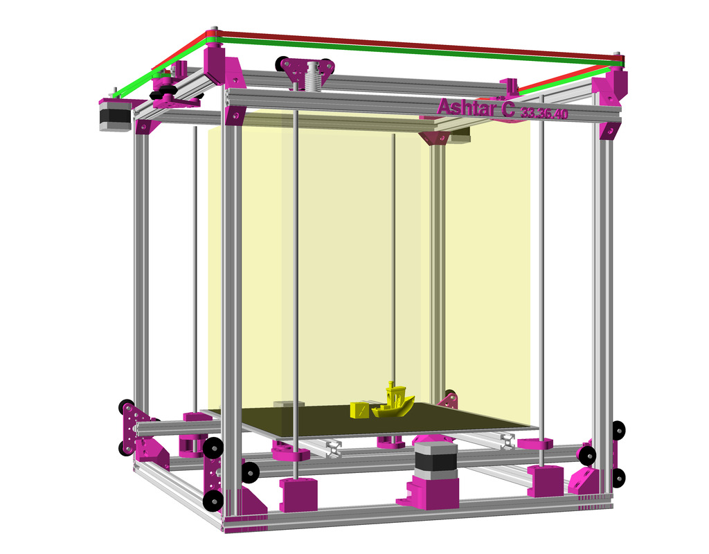
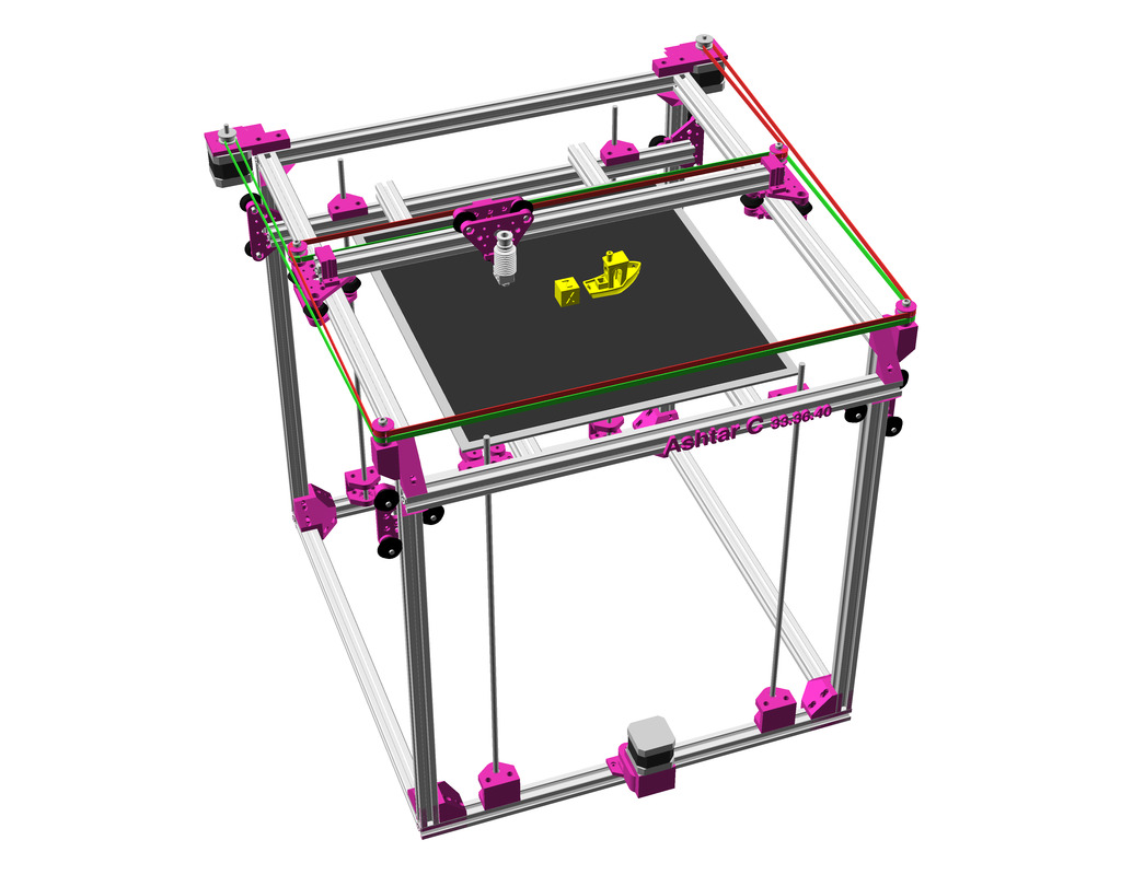
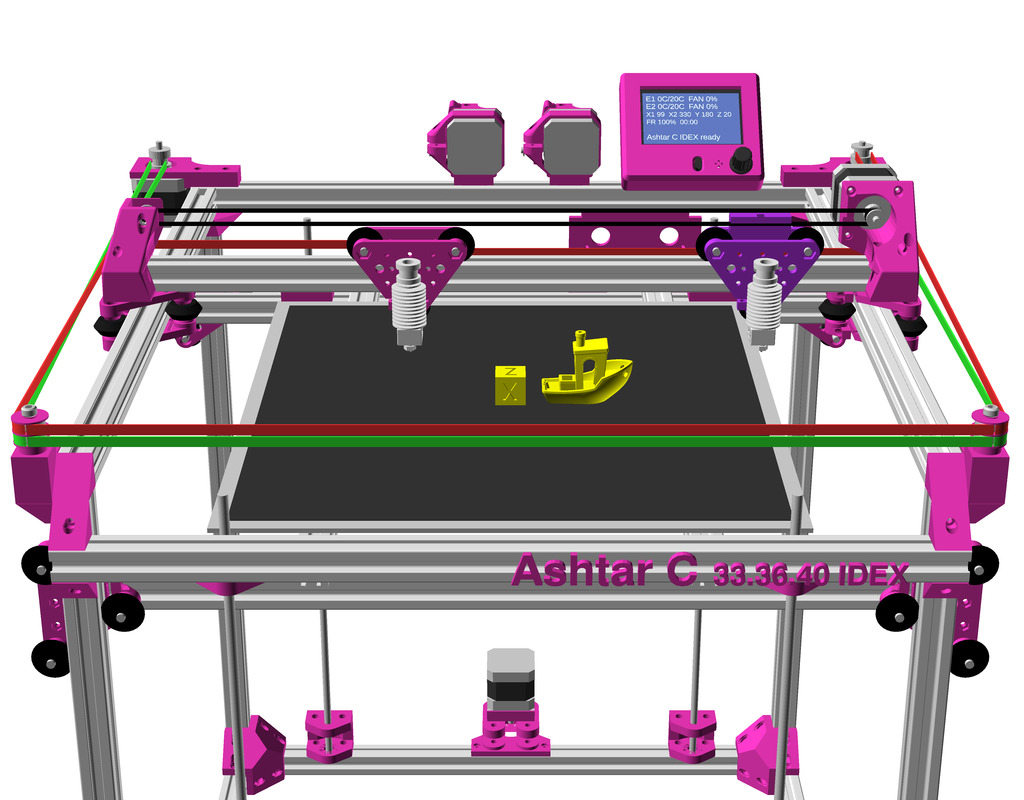
After the Core XY implementation of Ashtar C I pondered on changing the kinematic to a more classic approach to separate X and Y axis motors, but otherwise keep the setup and frame, hence Ashtar D:
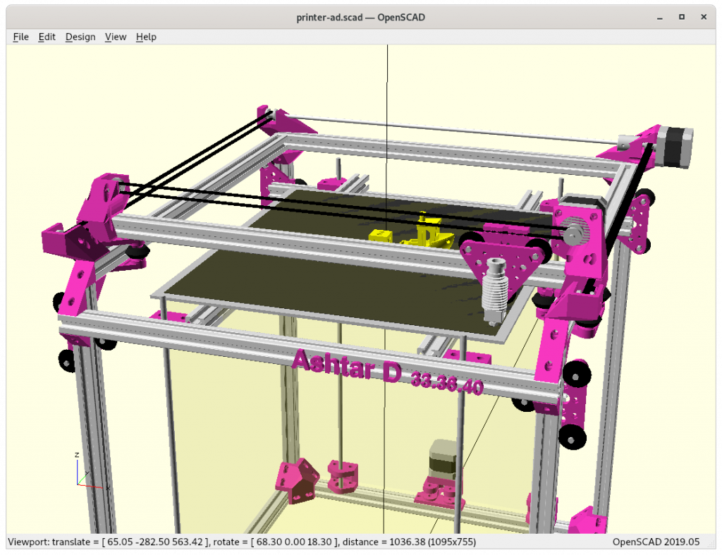
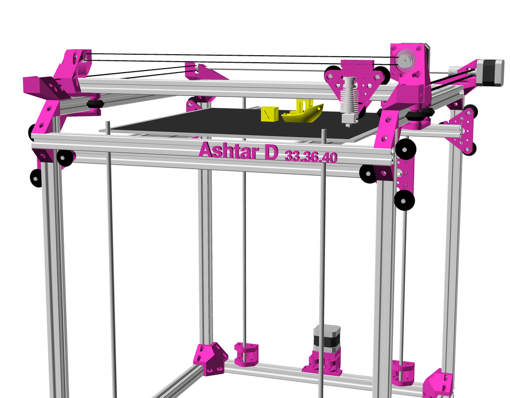
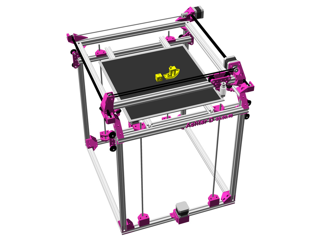
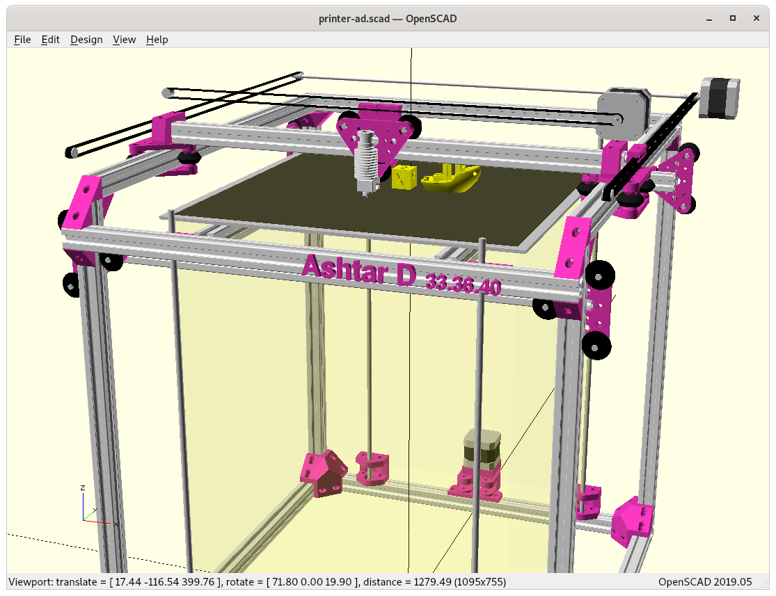
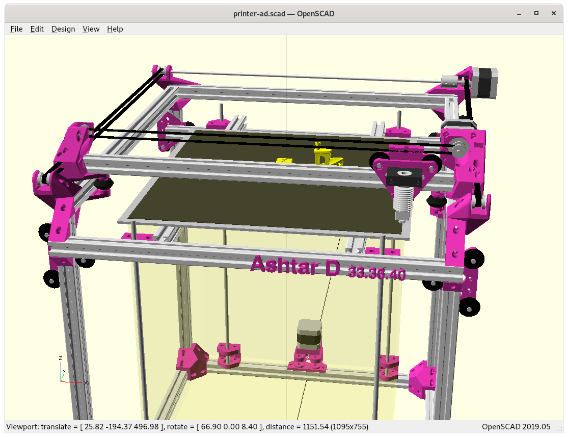
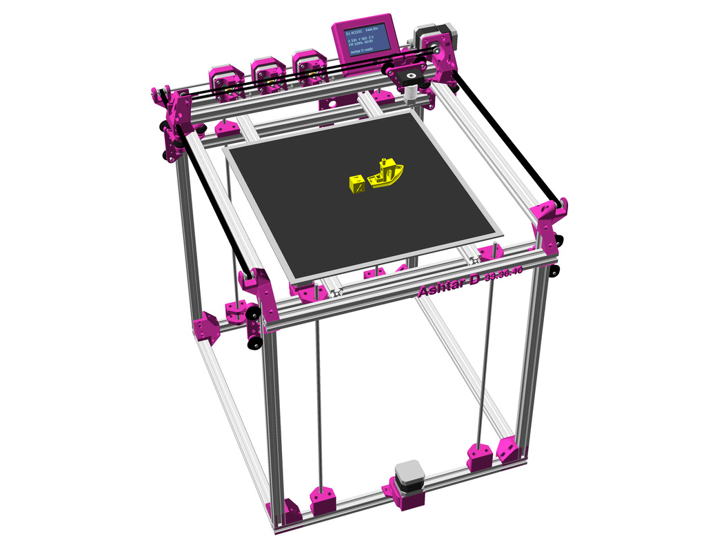
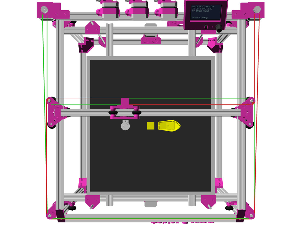
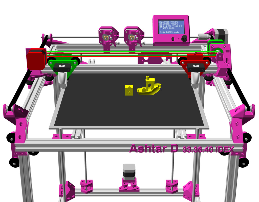
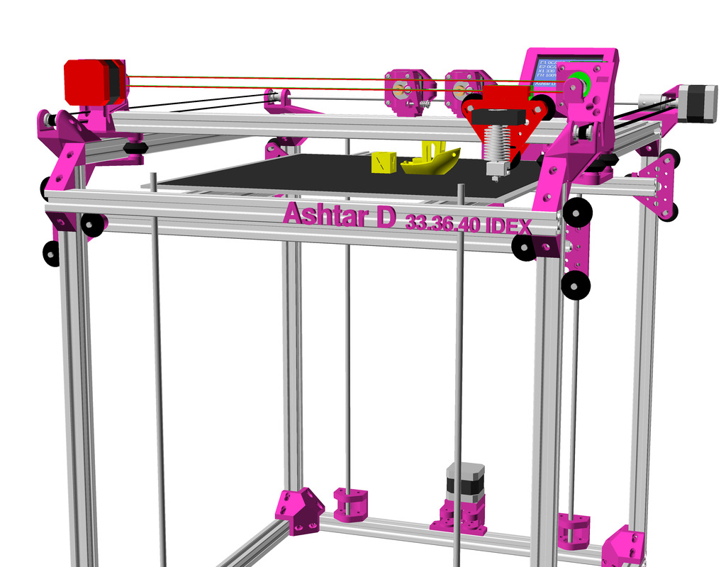
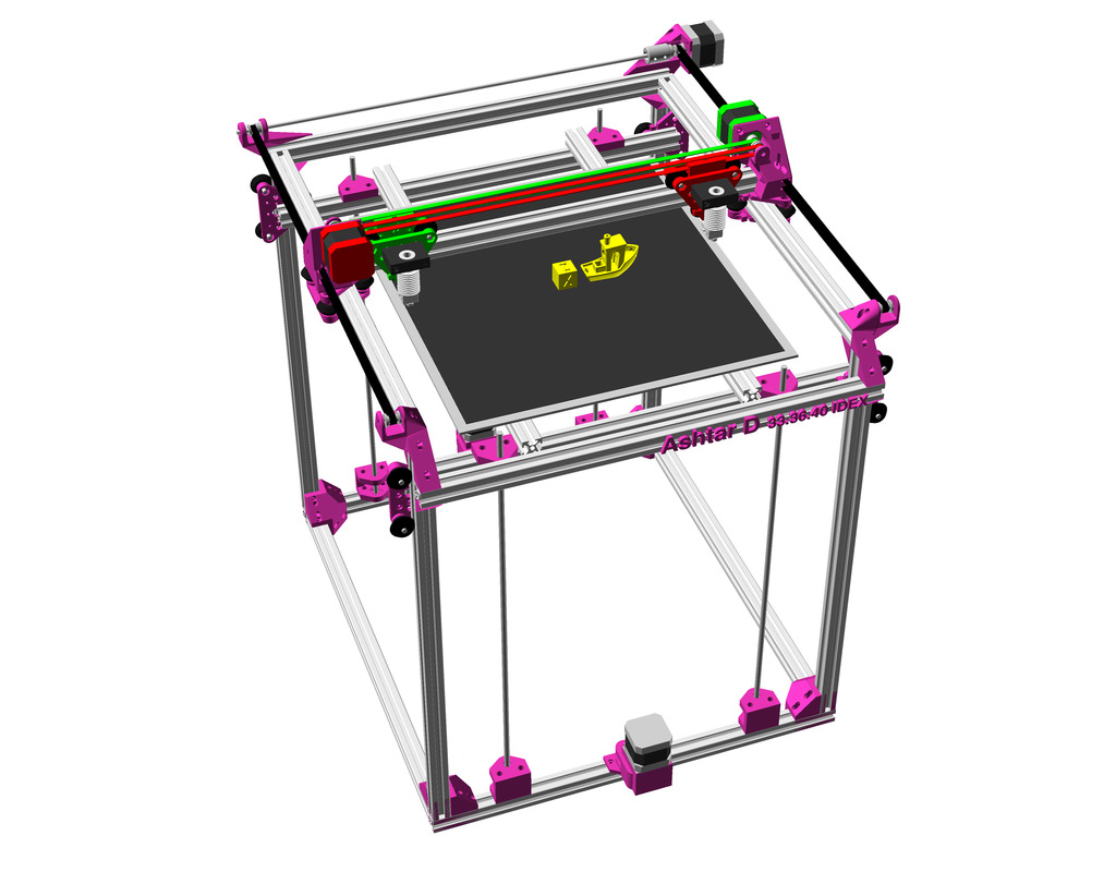
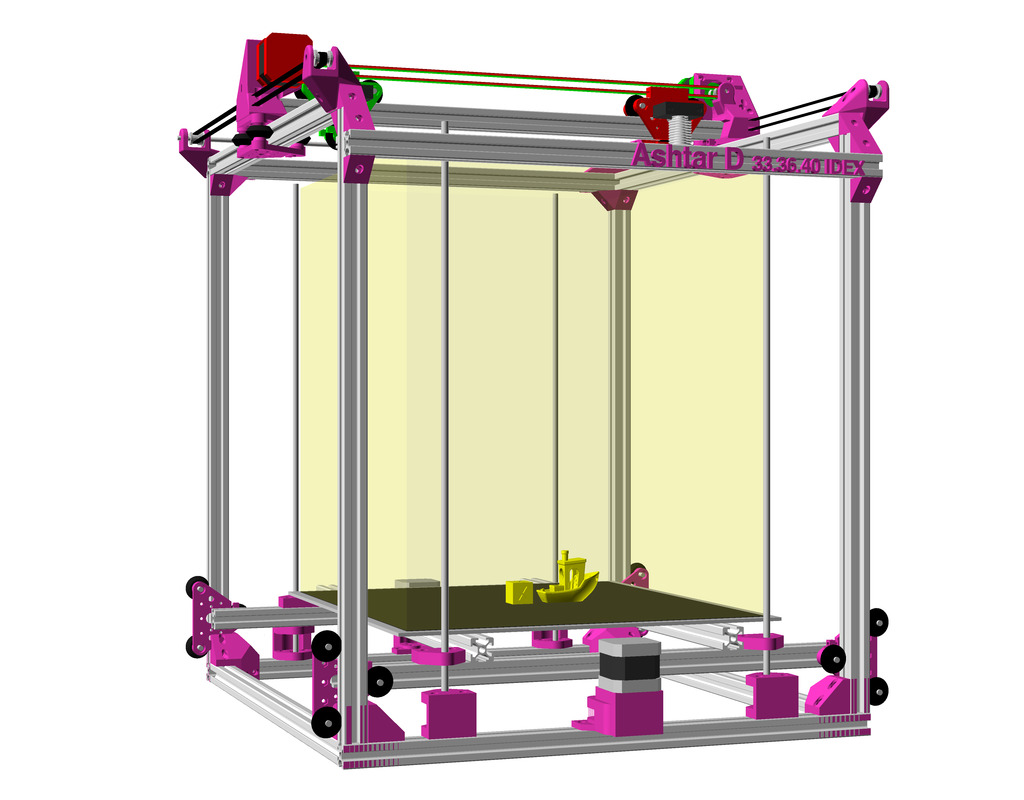
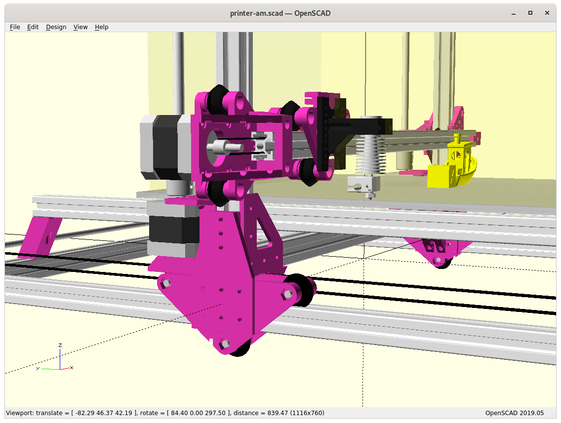
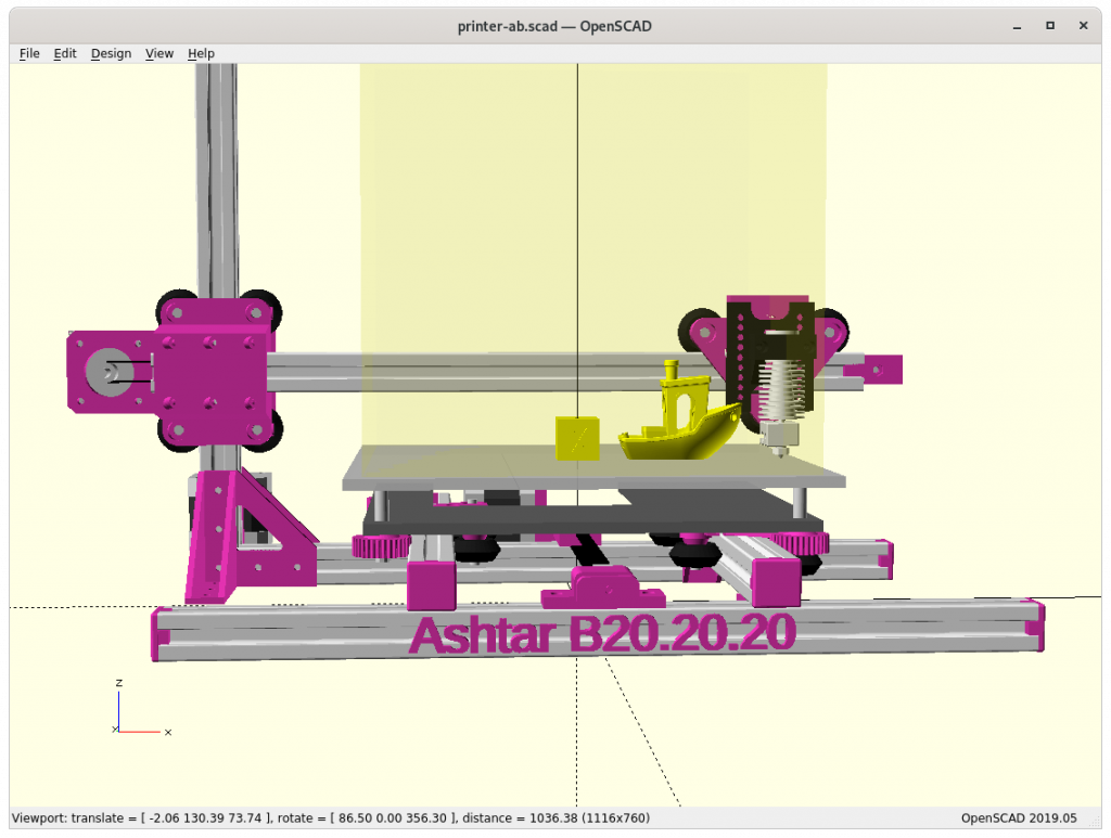
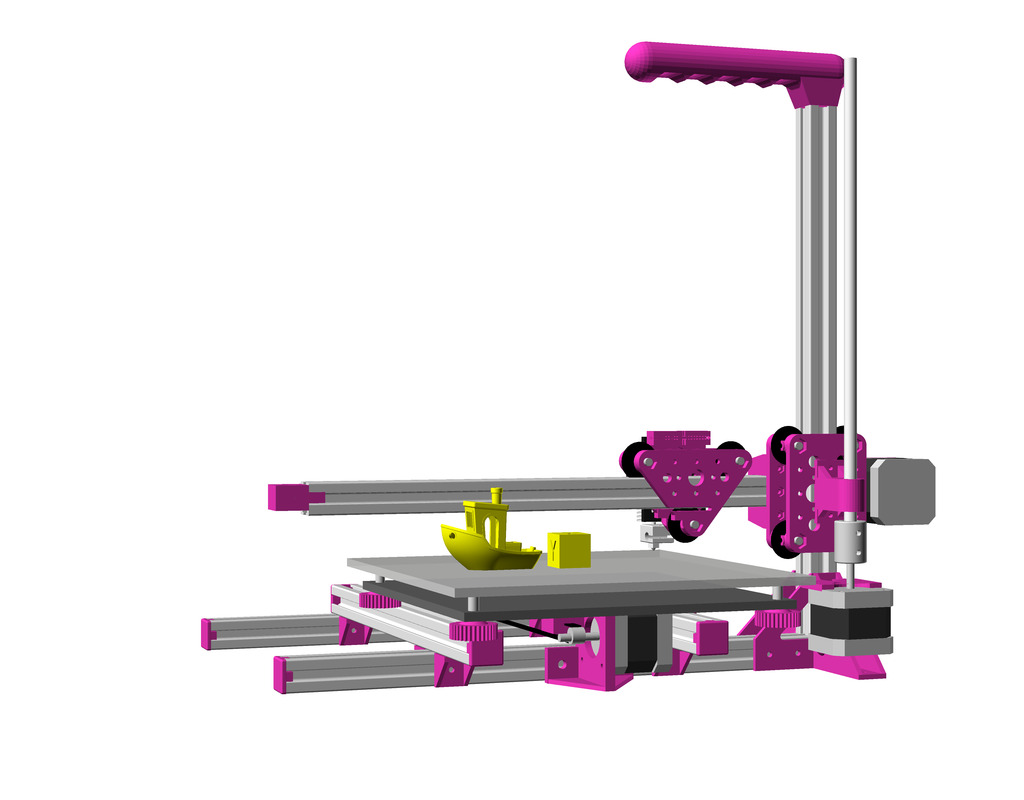
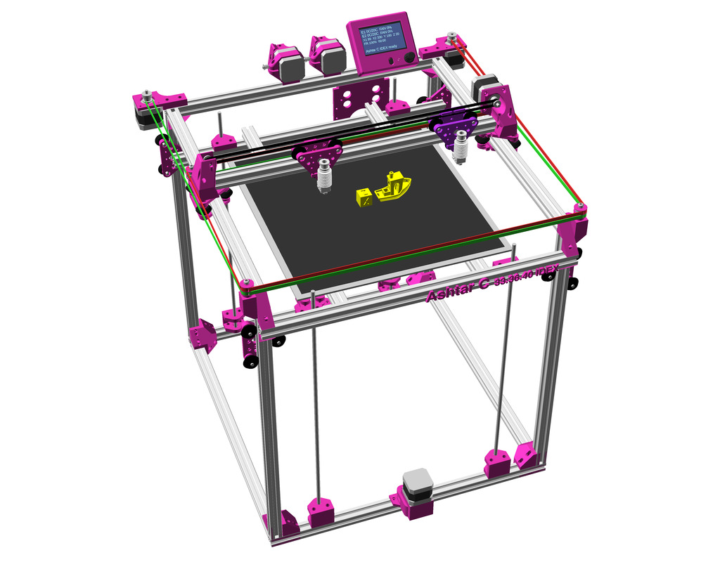
Ashtar D: classic independent XY kinematic: head XY, bed Z setup, with 500mm 2020 alu profiles
Draft
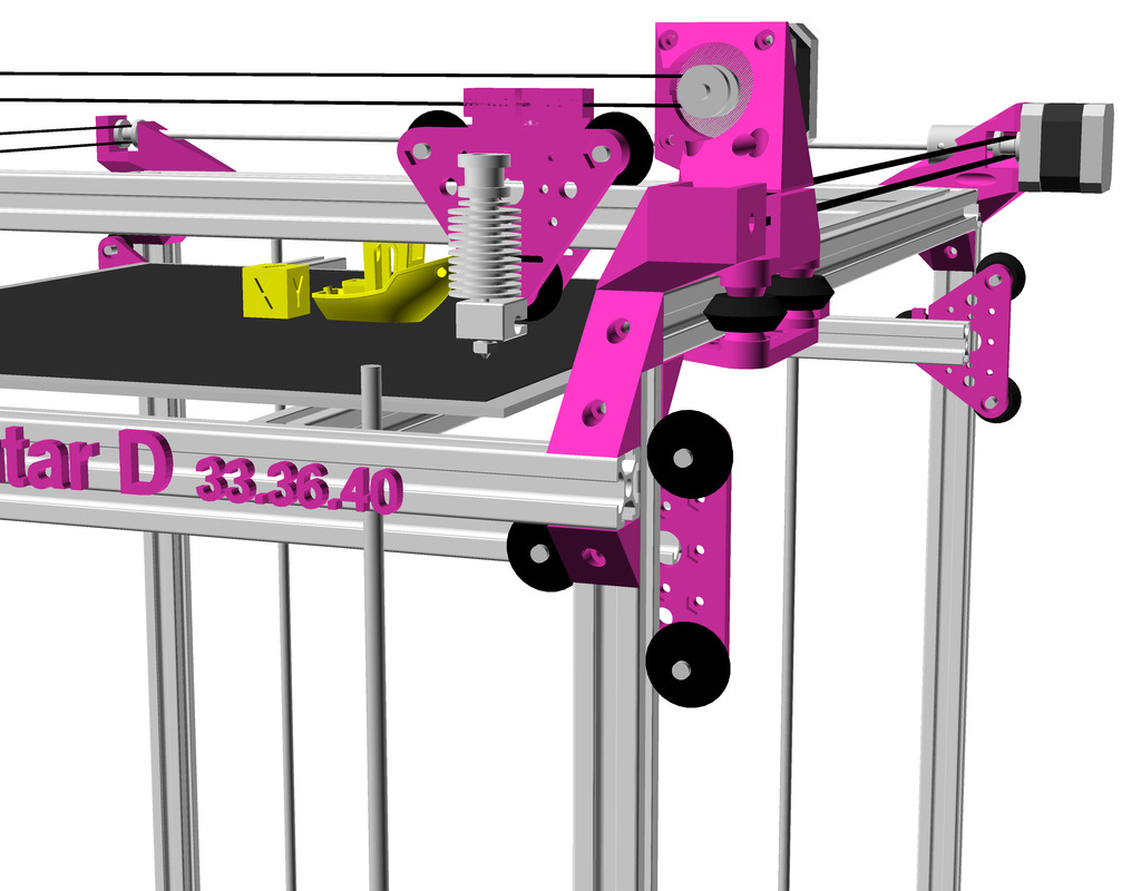
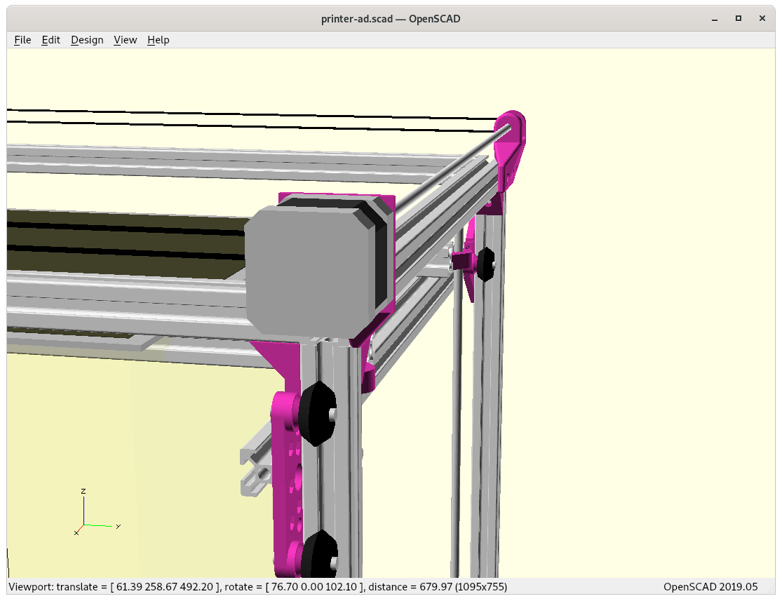
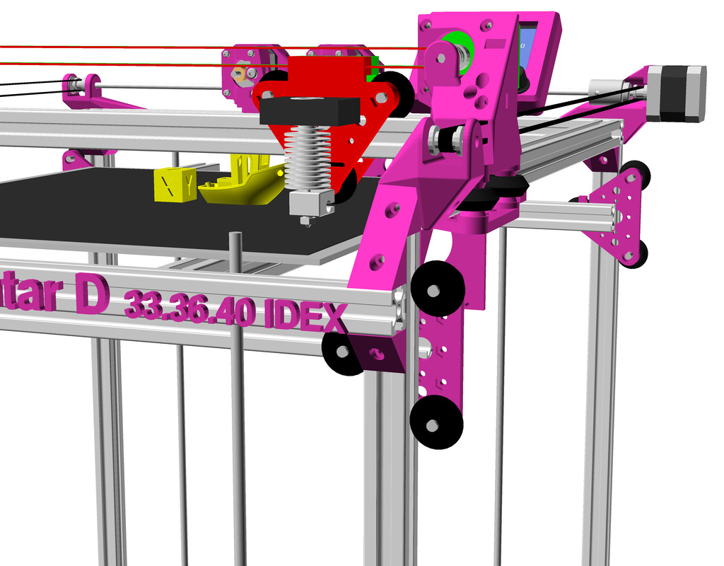
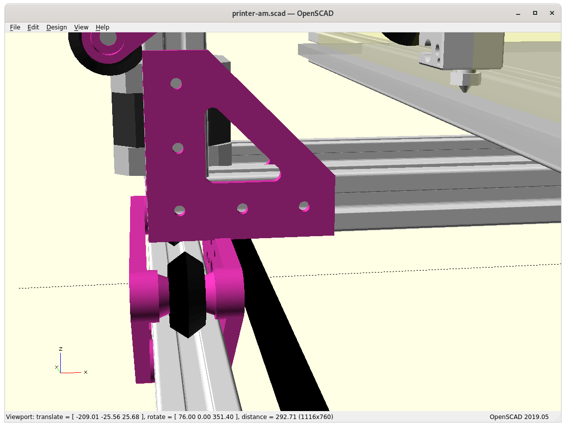
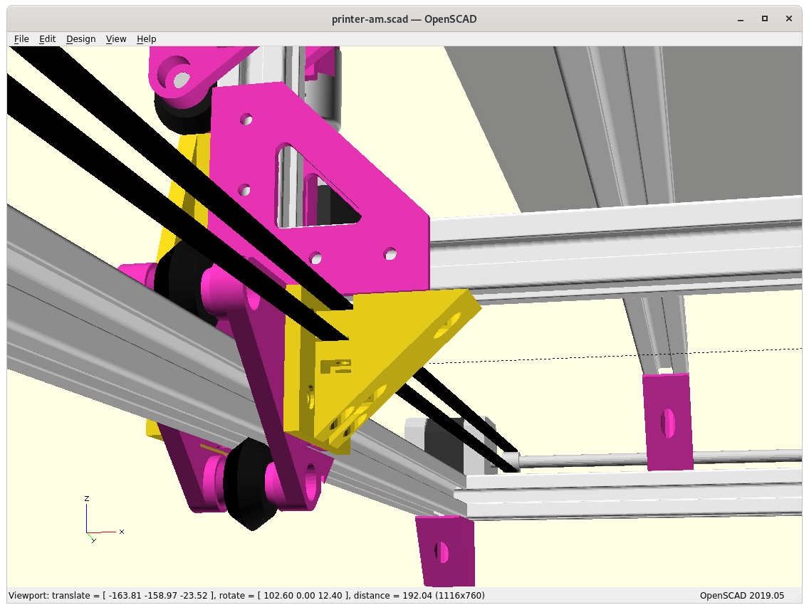
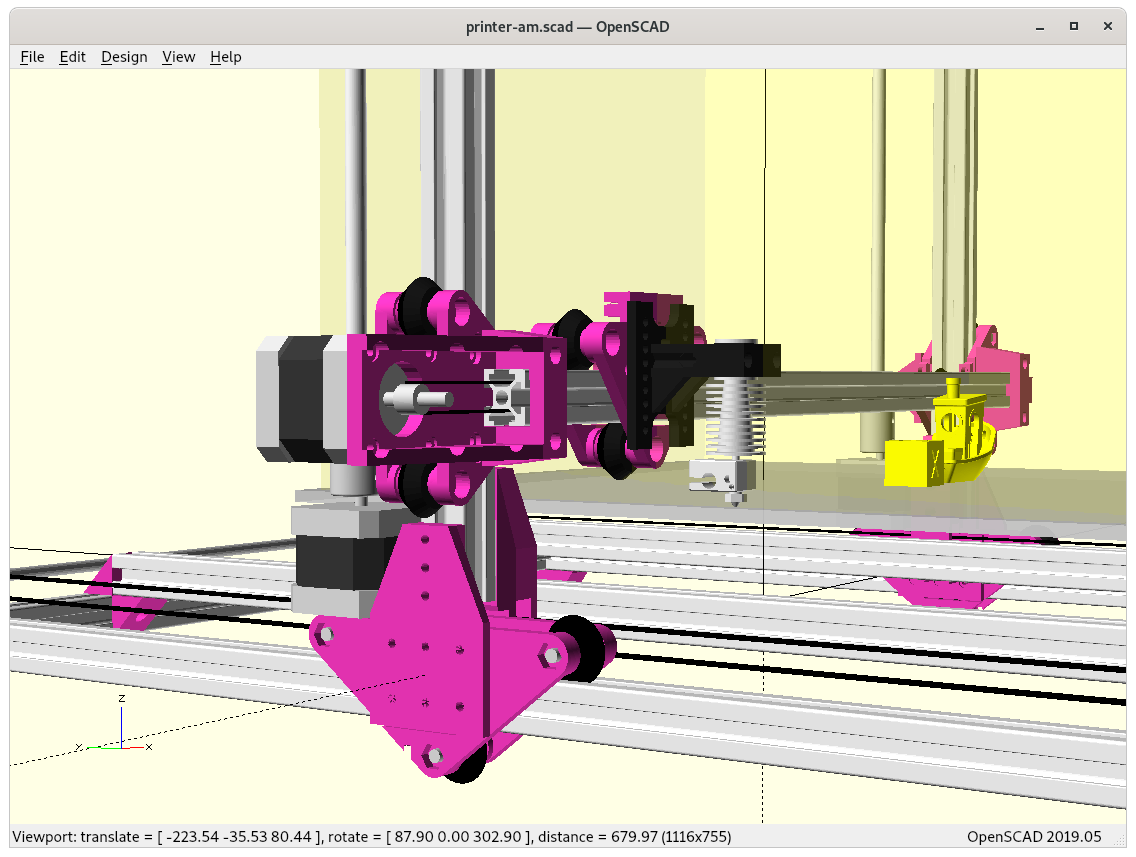
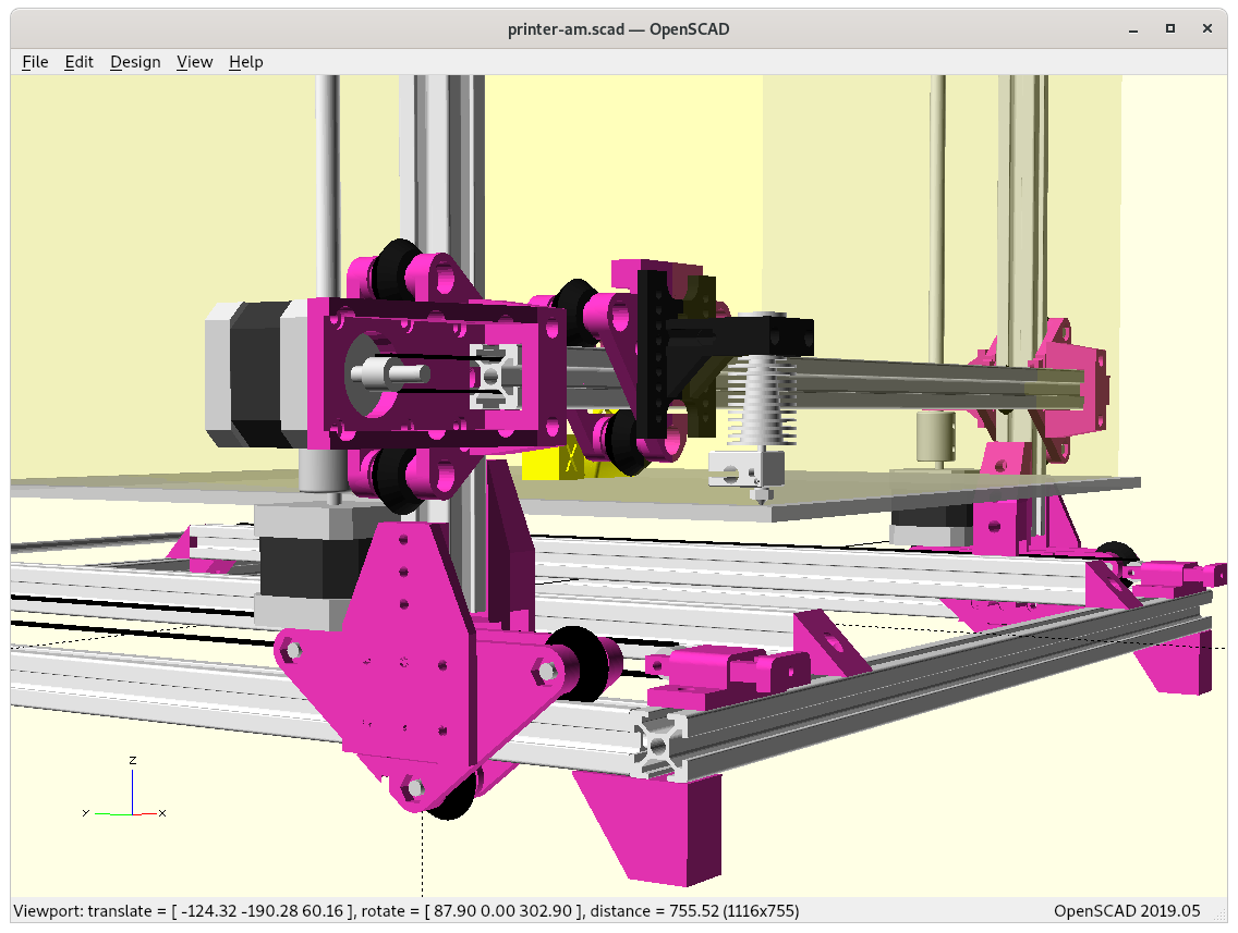
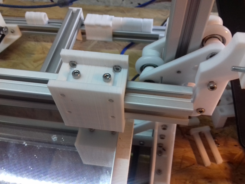
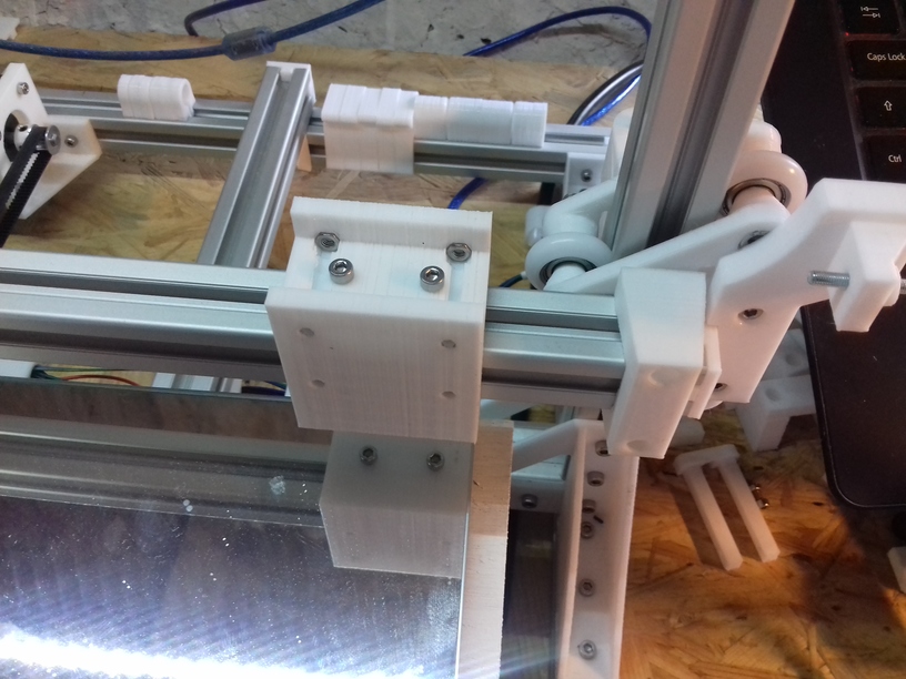
X motor mount with Y carriageX carriage with hotend and X motor mountX carriage with hotend and X motor mountY motor mountY carriage and Y motor with shaft extenderY motor with shaft extender
Again using 500mm alu profiles, utilizing the frame itself as rails:
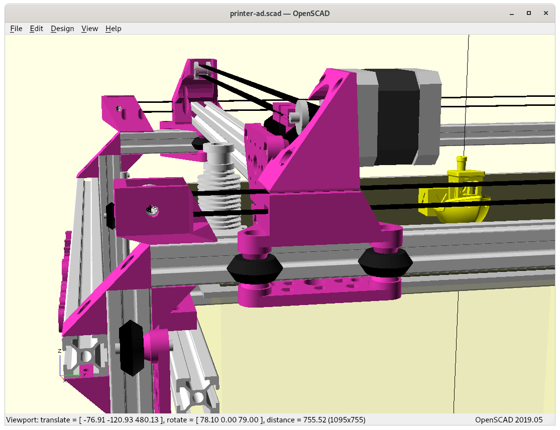
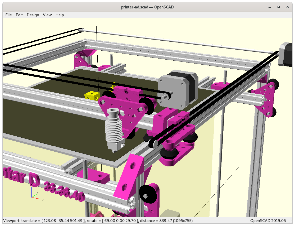
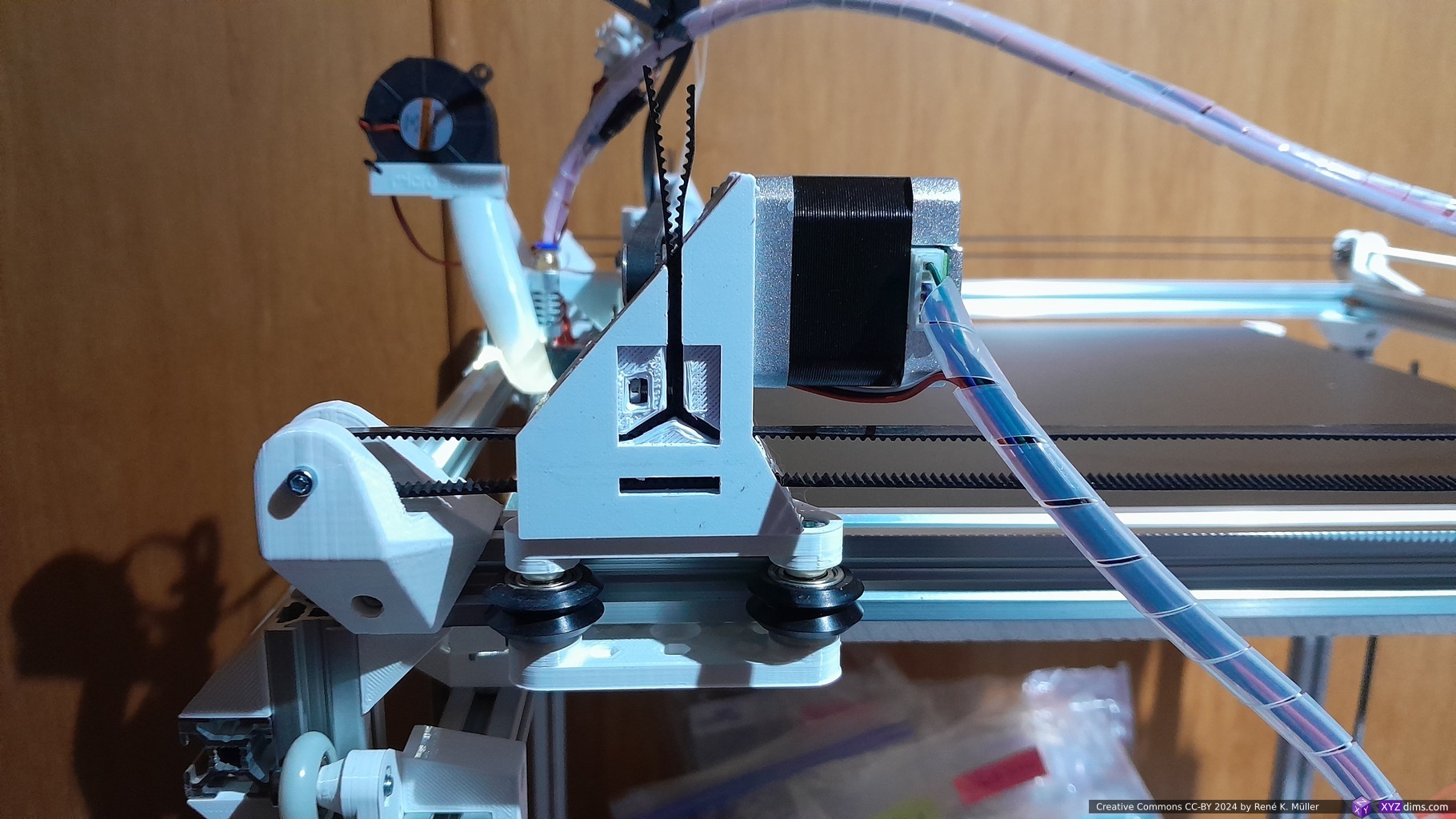
1 V-slot beam for X axis with V-carriage/module (triangle shaped carriage) as X carriage with hotend
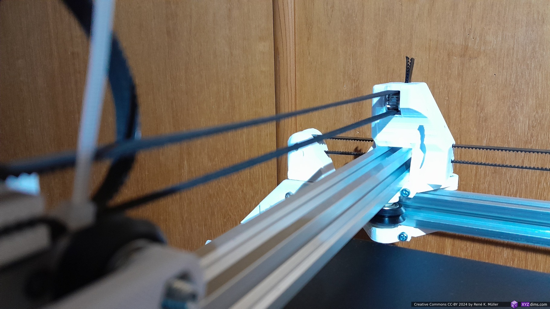
2 V-slot beams for Y axis, 2 V-carriages/modules with the X beams on it
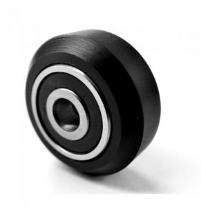
using classic V wheels
14 T-slot beams for the rest of the frame
Z bed: white 7.3mm thick Delrin wheels on T-slots
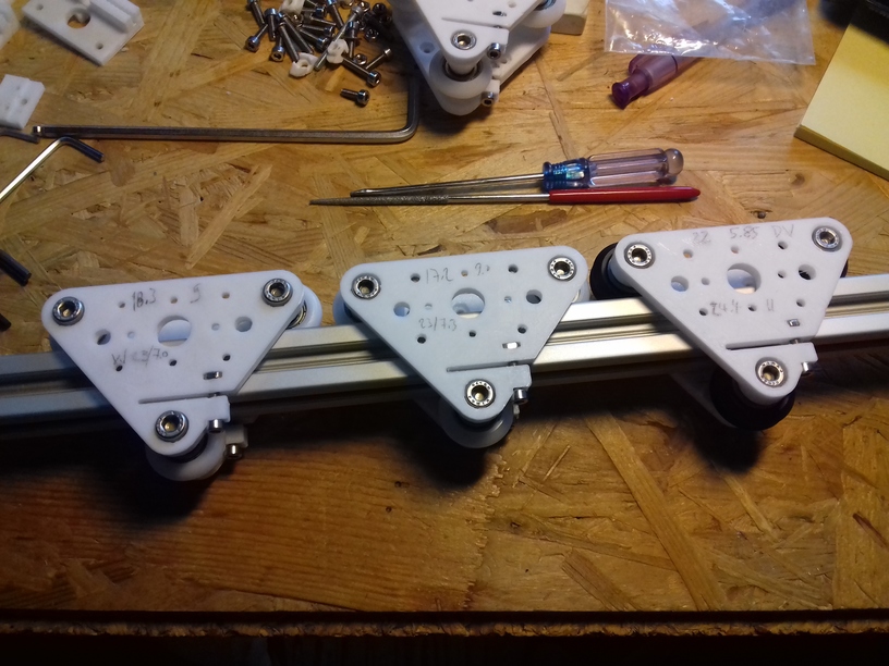
T-Slot 2020V-Slot 2020V wheelV modules with different kind of wheels.
The target is again a 400x400mm printbed, probably 380x400x380mm build volume alike with Ashtar C (Core XY), perhaps a bit less X-wise due the more complex pieces to mount the X motor and pulleys.
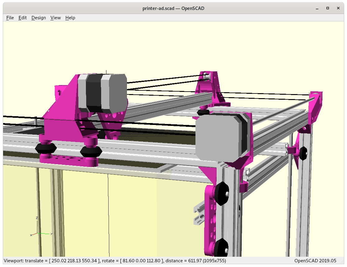
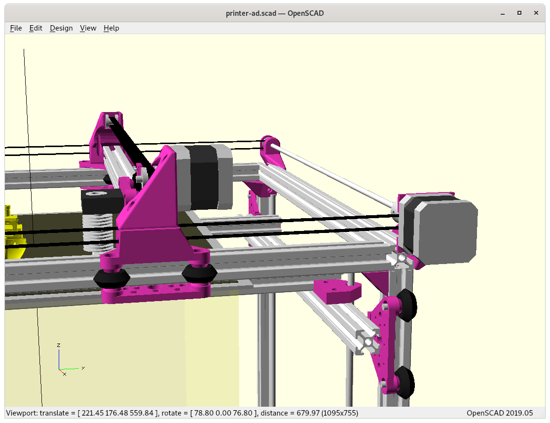
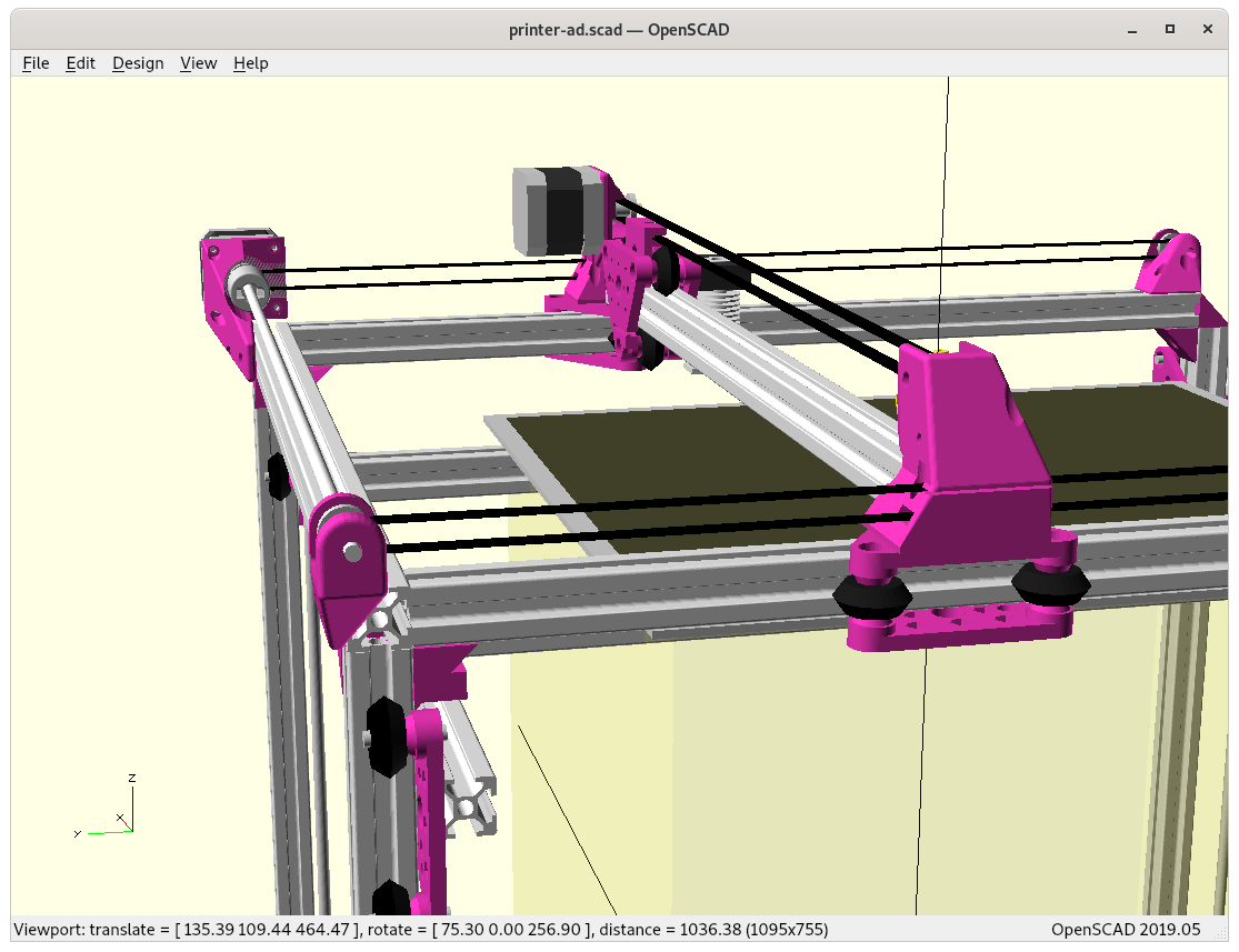
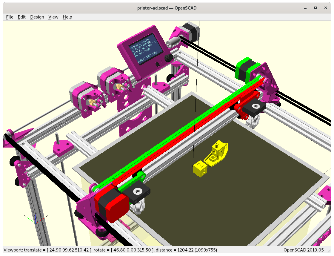
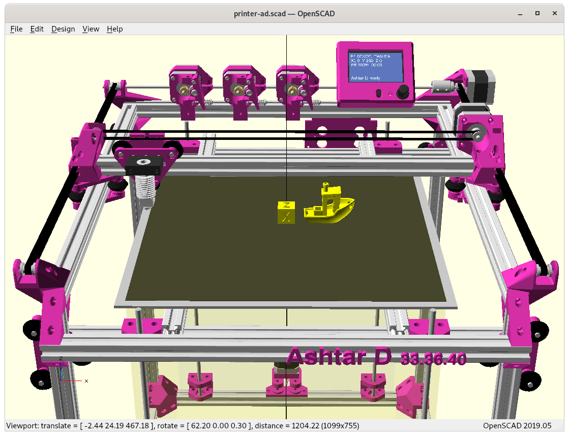
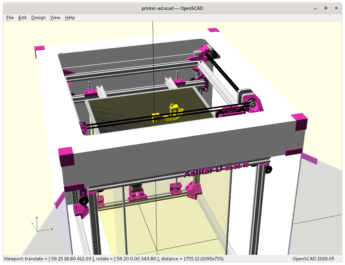
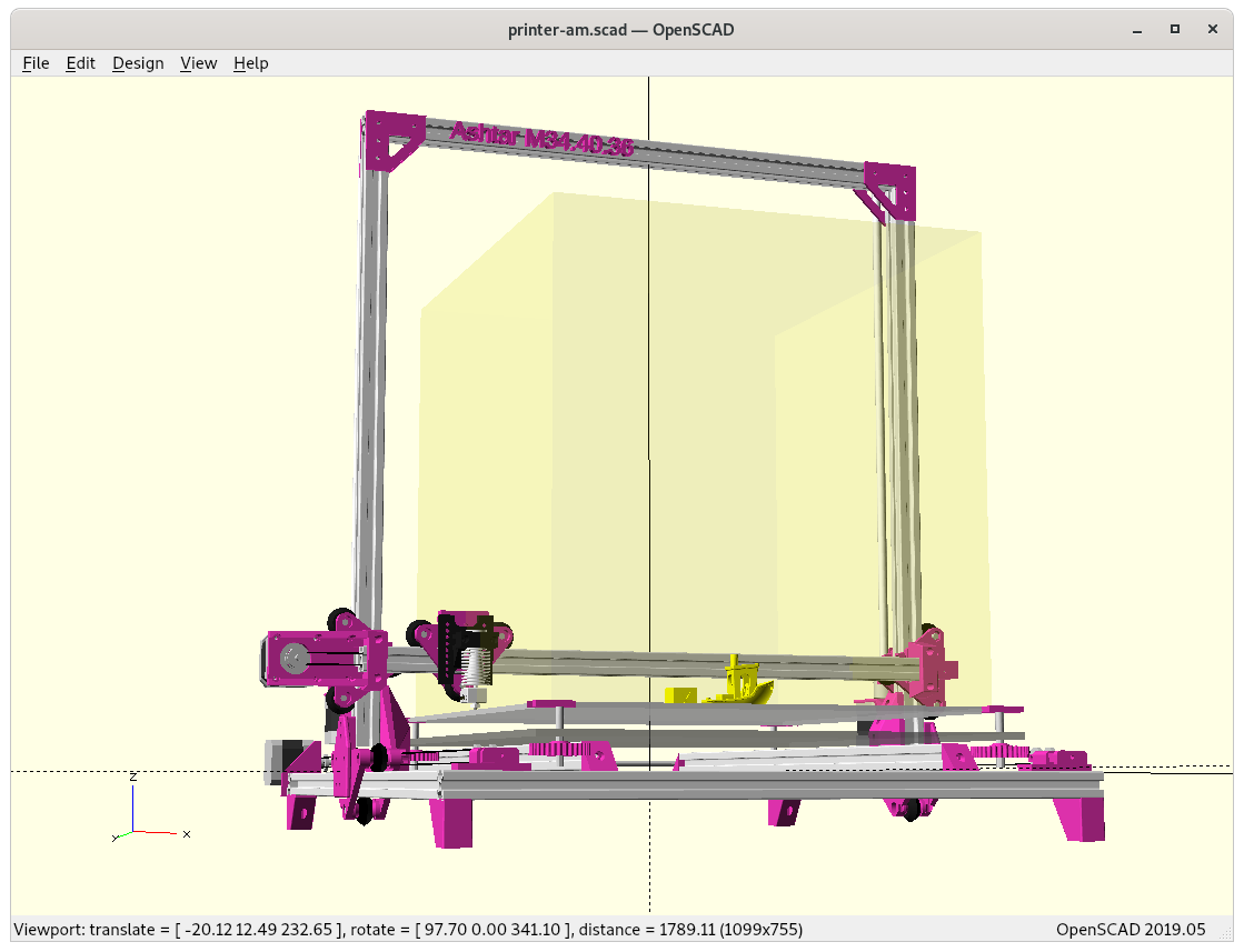
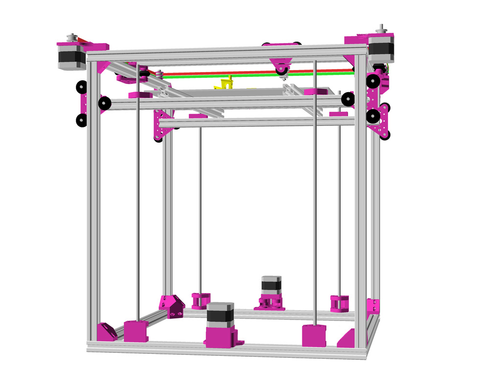
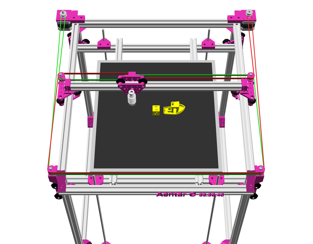
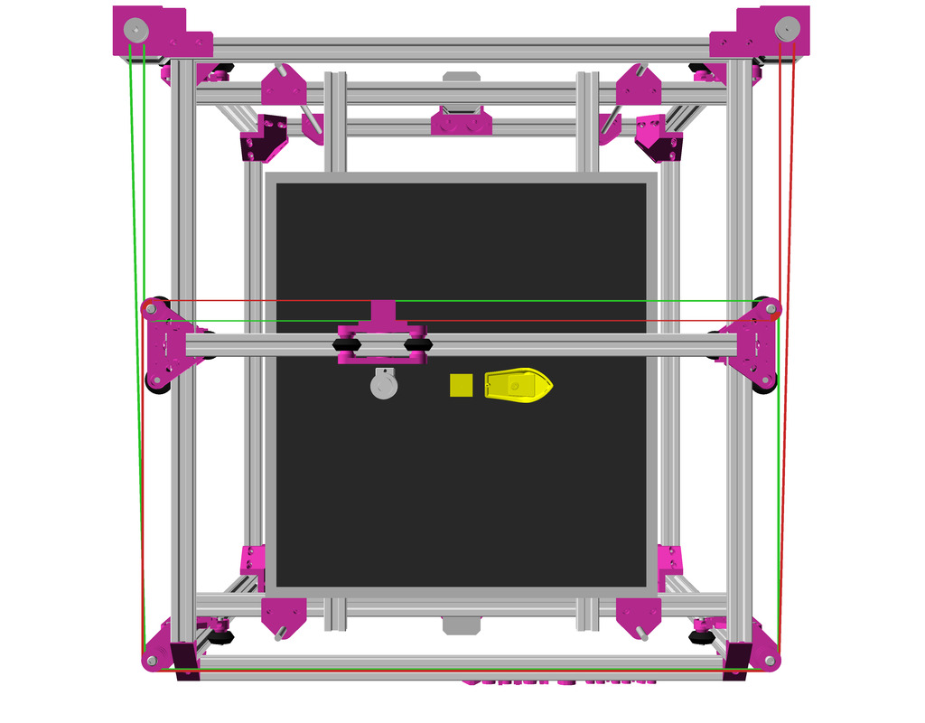
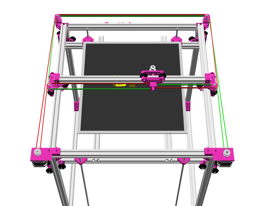
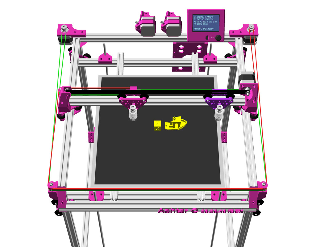
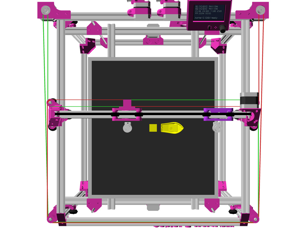
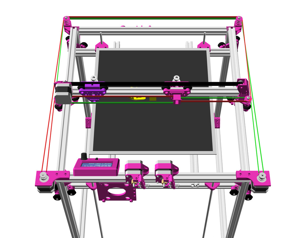
More high resolution renderings:
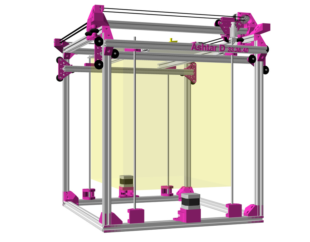
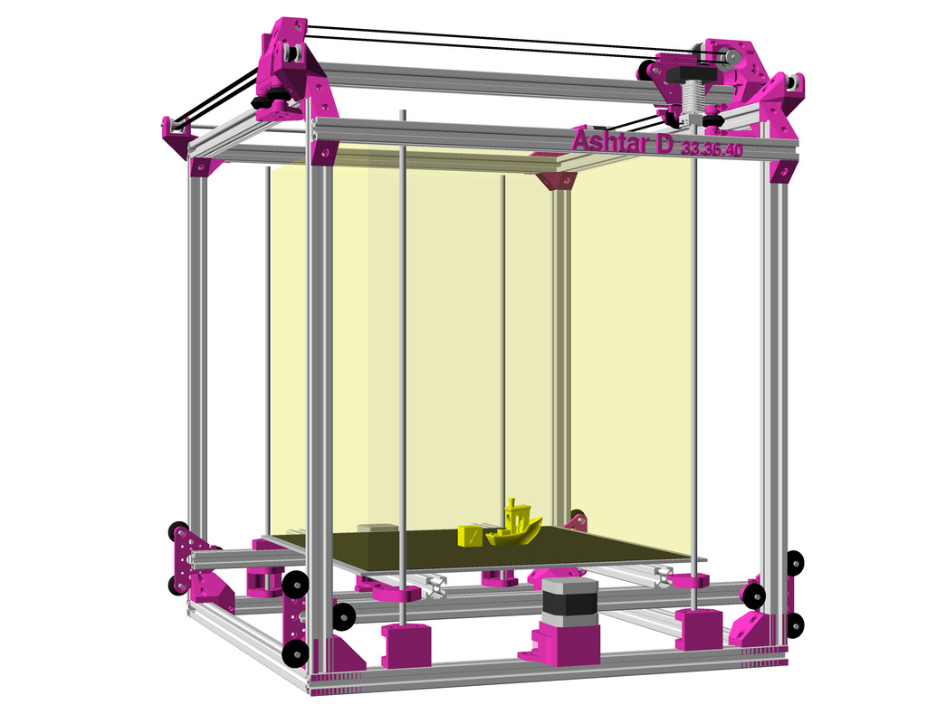
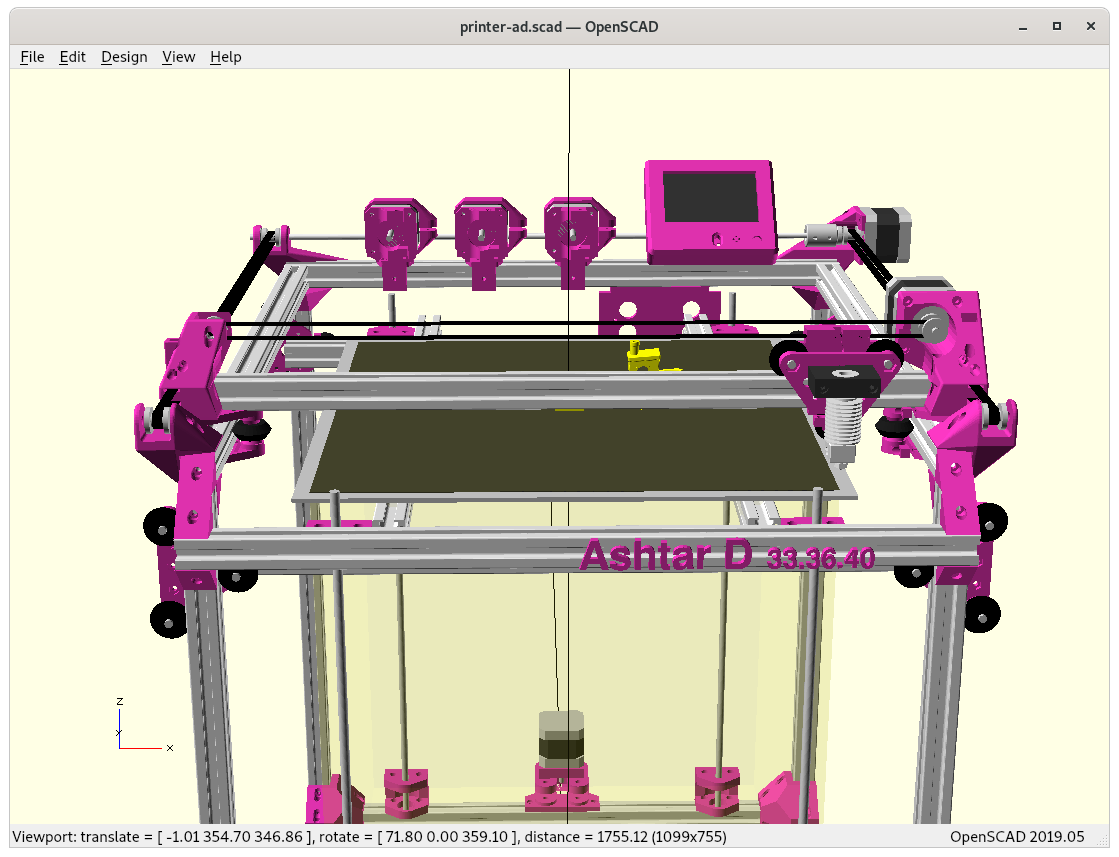
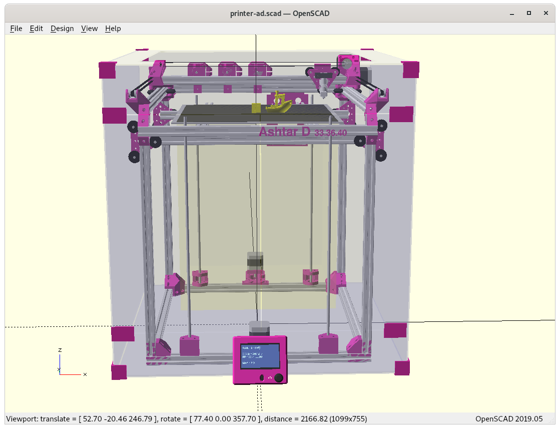
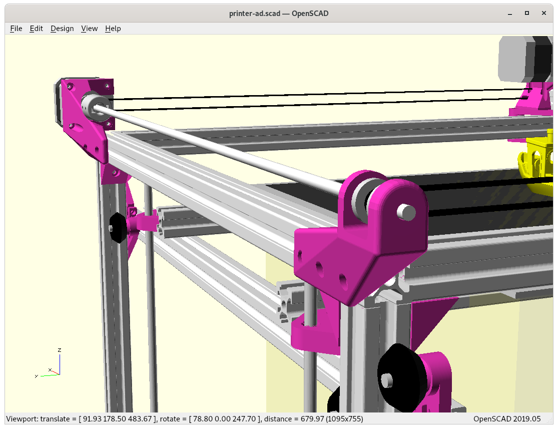
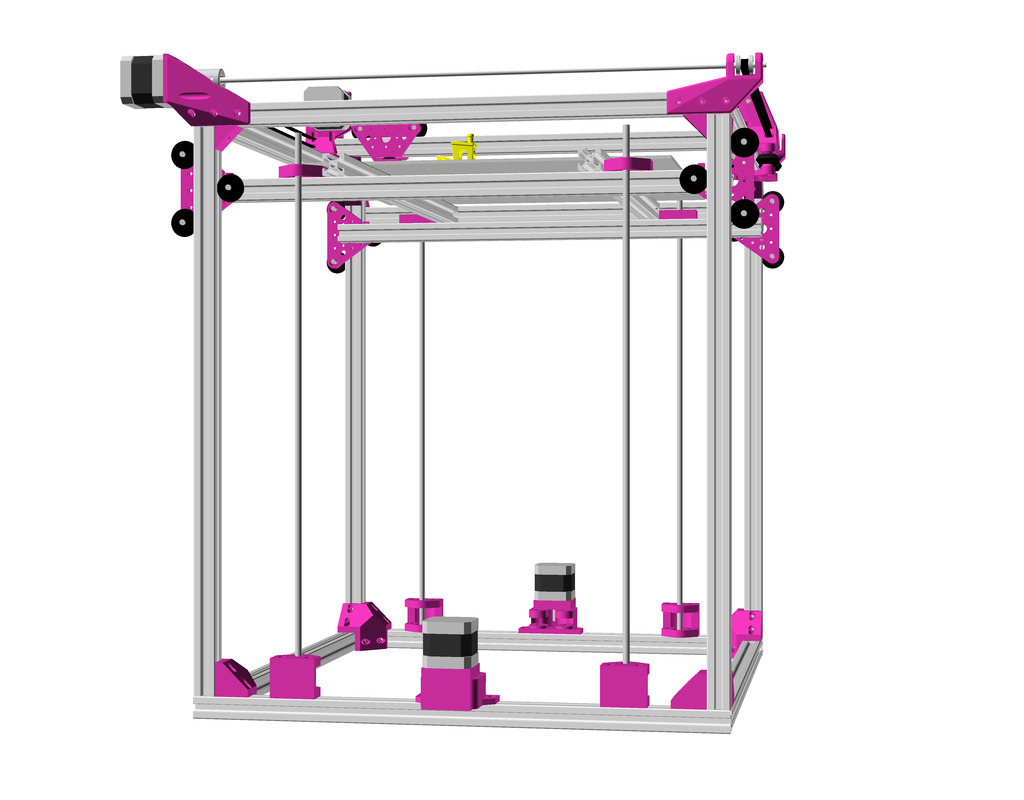
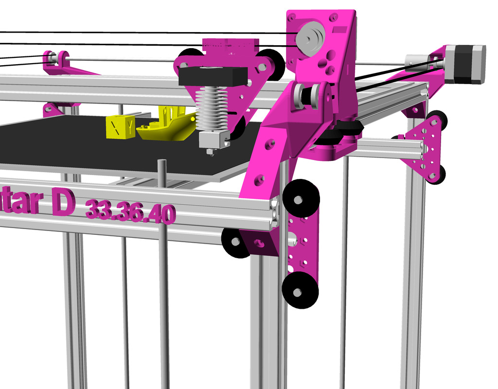
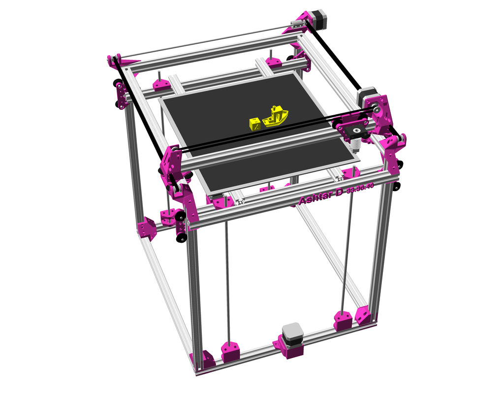
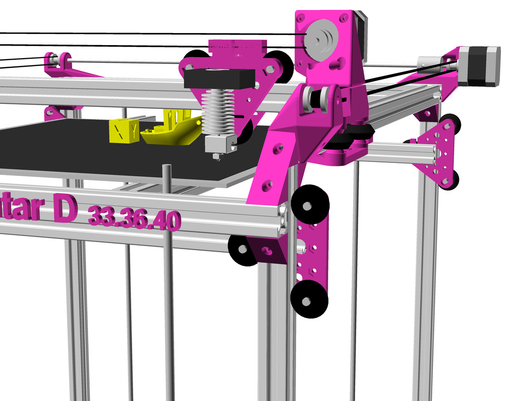
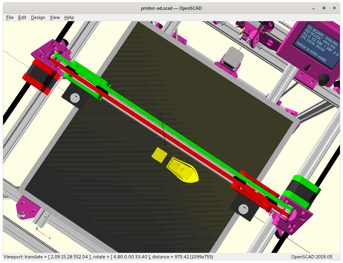
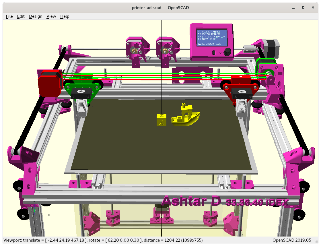
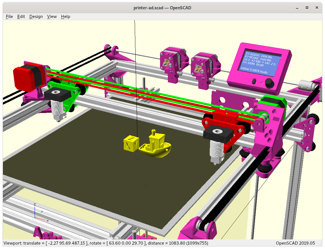
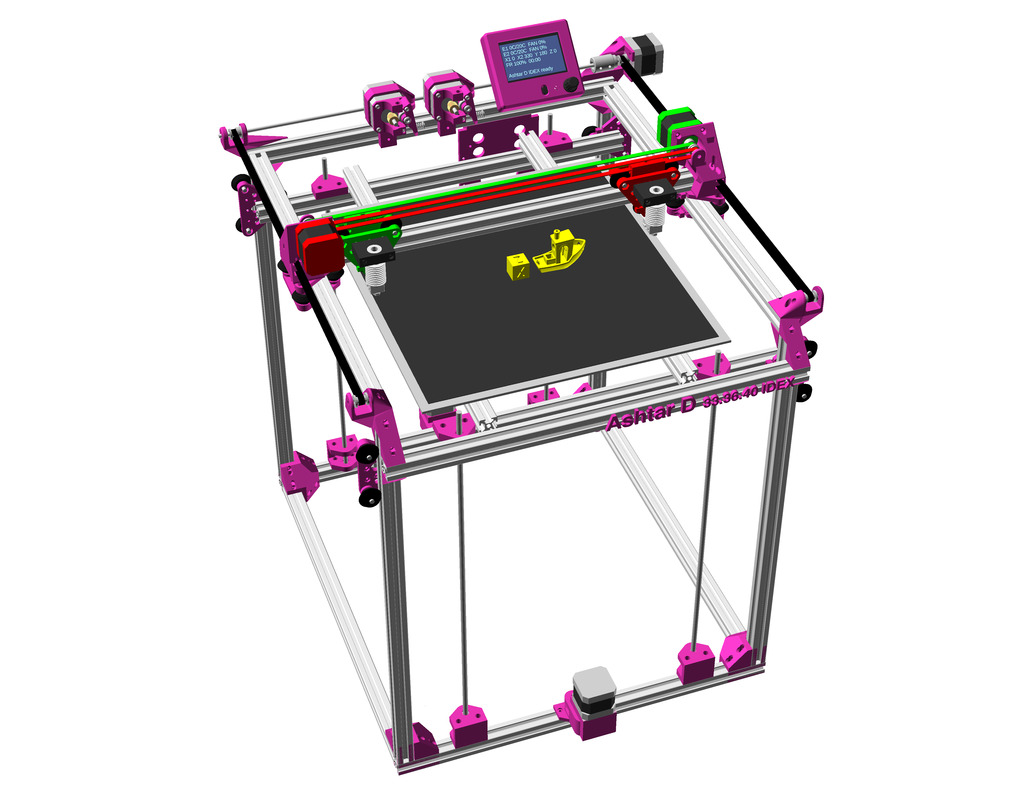
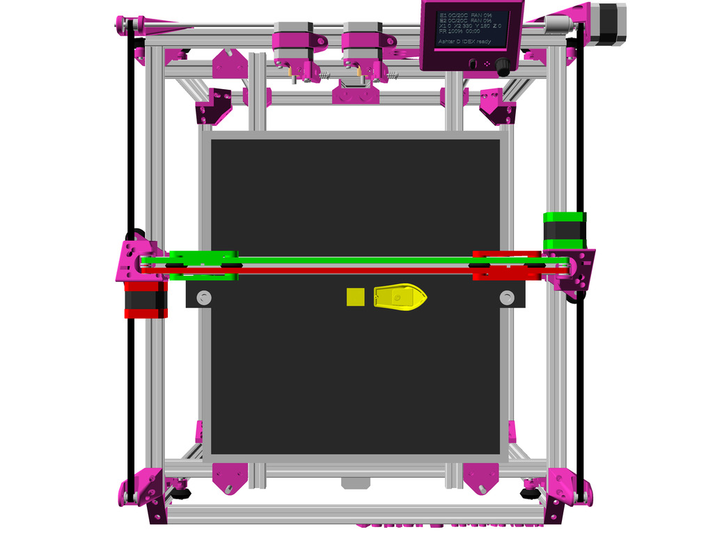
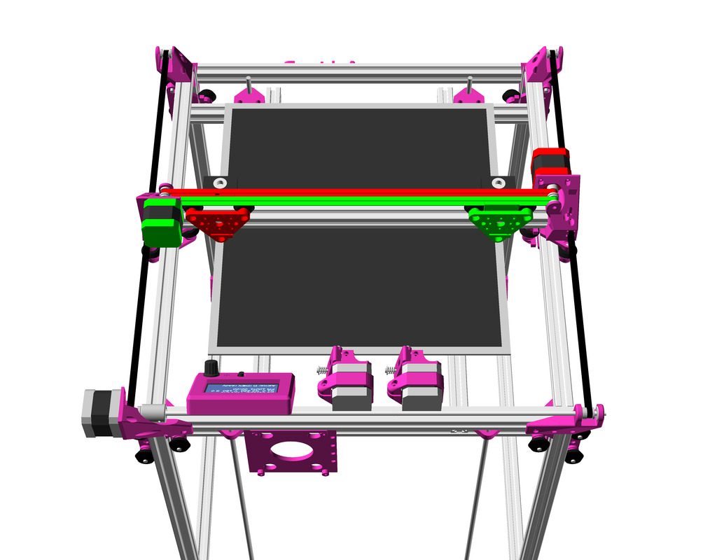
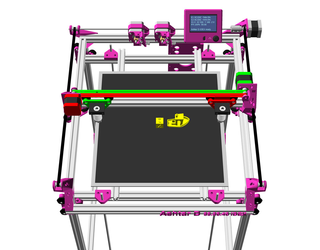
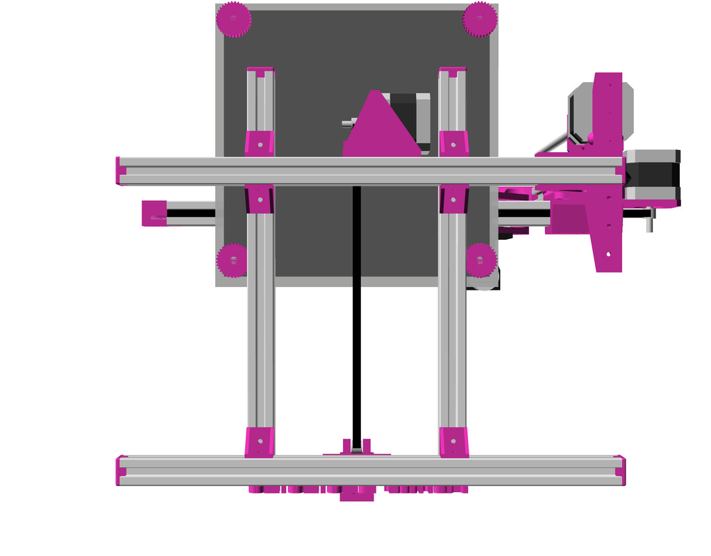
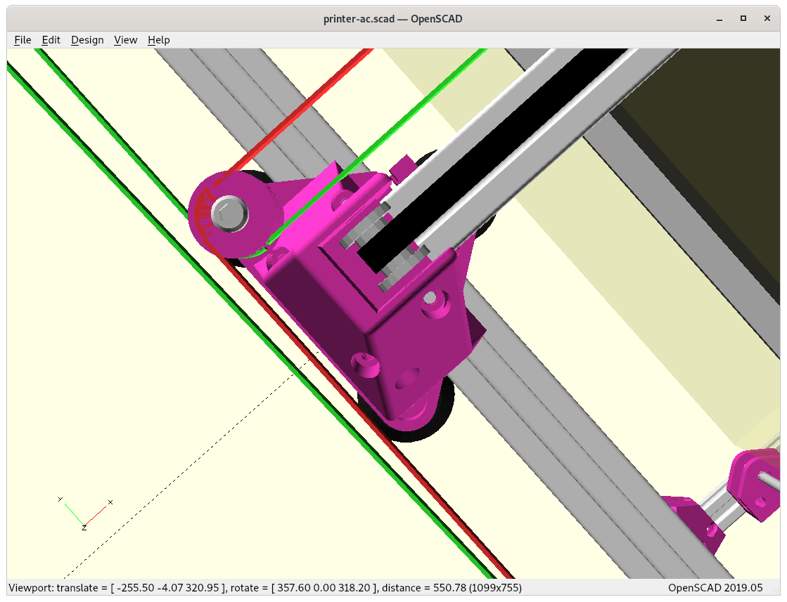
Ashtar D: top viewAshtar D: Closeup X carriage with hotend and Y carriageAshtar D: tilted top vewAshtar D: Cubic Frame, Head XY, Bed Z
The project page on Ashtar D summarizes the current state of the project.
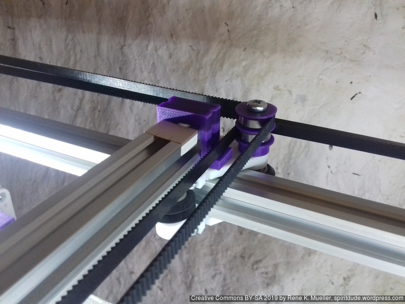
2021/01/08: starting with details of Y belt/pulley (non-)printable parts
2020/12/28: beautifying X & Y motor and pulley mounts with rcube(), rcylinder() and chainhull()
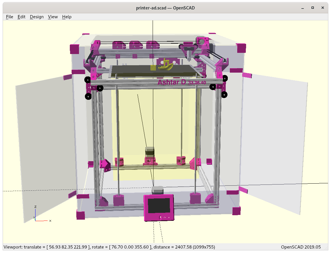
2020/12/25: starting with some basic parametric enclosure, refining some details
2020/12/24: X & Y motor mounts as well X & Y pulley mounts done
2020/12/23: starting with Ashtar C frame and transforming it to classic X/Y head, X/Y motor mounts and pulleys mounts missing
Introduction
After the Core XY of Ashtar C I thought to convert it to a more classic kinematic X/Y head with two dedicated NEMA17 motors for each axis – independent XY. Mostly using the same frame setup with 500mm alu extrusions, same V-carriages/modules as before, but reposition both motors to dedicate for X and Y axis now. The main goal is to achieve 400x400mm print area with 500mm alu extrusions.
Ashtar D (Classic XY)
X motor & Y motor
no XY frame tension
shorter belts
one moving motor (Y-wise)
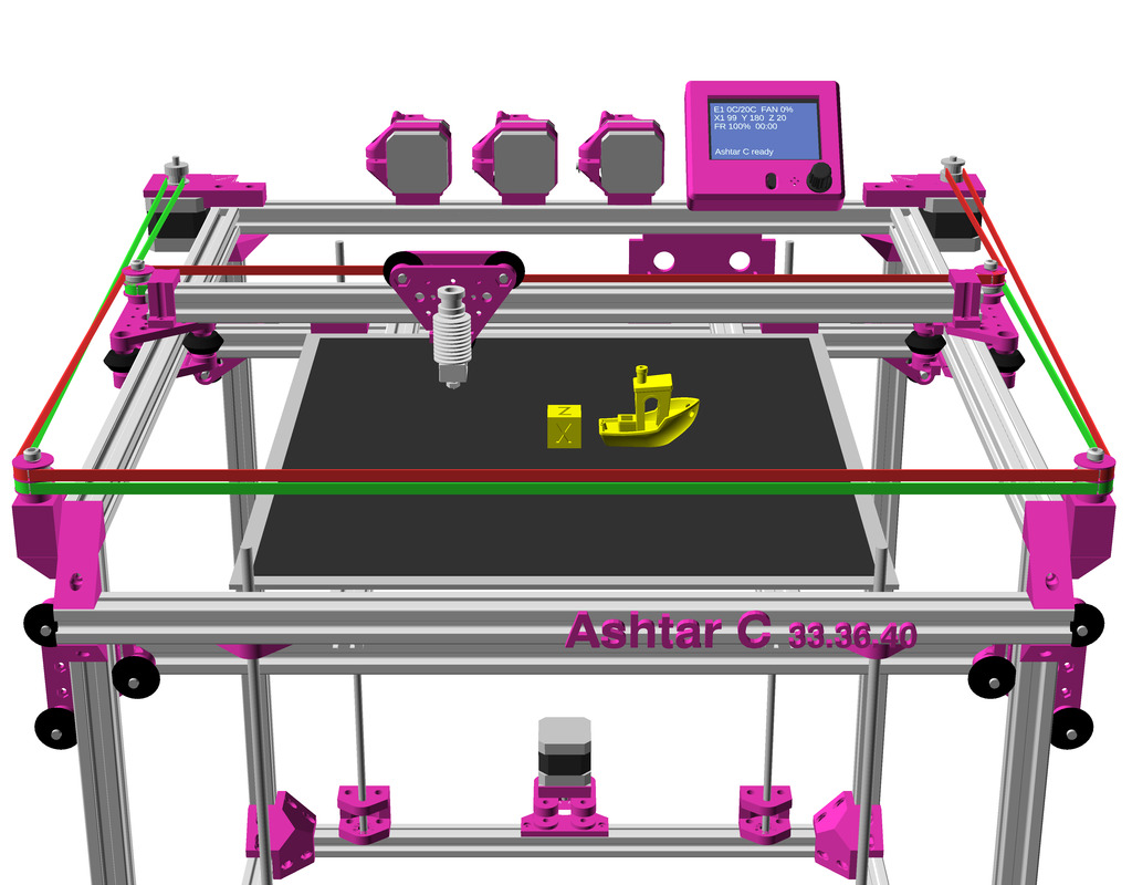
Ashtar C (Core XY)
Core XY with motor A & B
XY frame tension
long belts
no moving motors
Draft
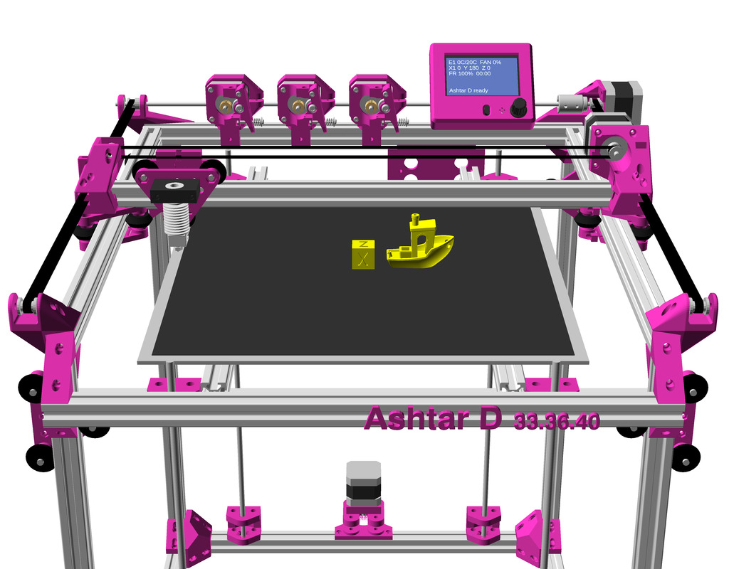
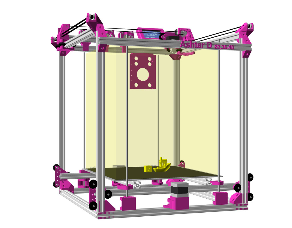
Bare without mountsX = max, Y = 0X = max, Y = maxWith X & Y motor mounts and X & Y pulley mountsIncluding 3 Bowden extruders and LCD controller3 Bowden extruders and LCD controllerParametric enclosure for Ashtar D, moving LCD controller in front bottom
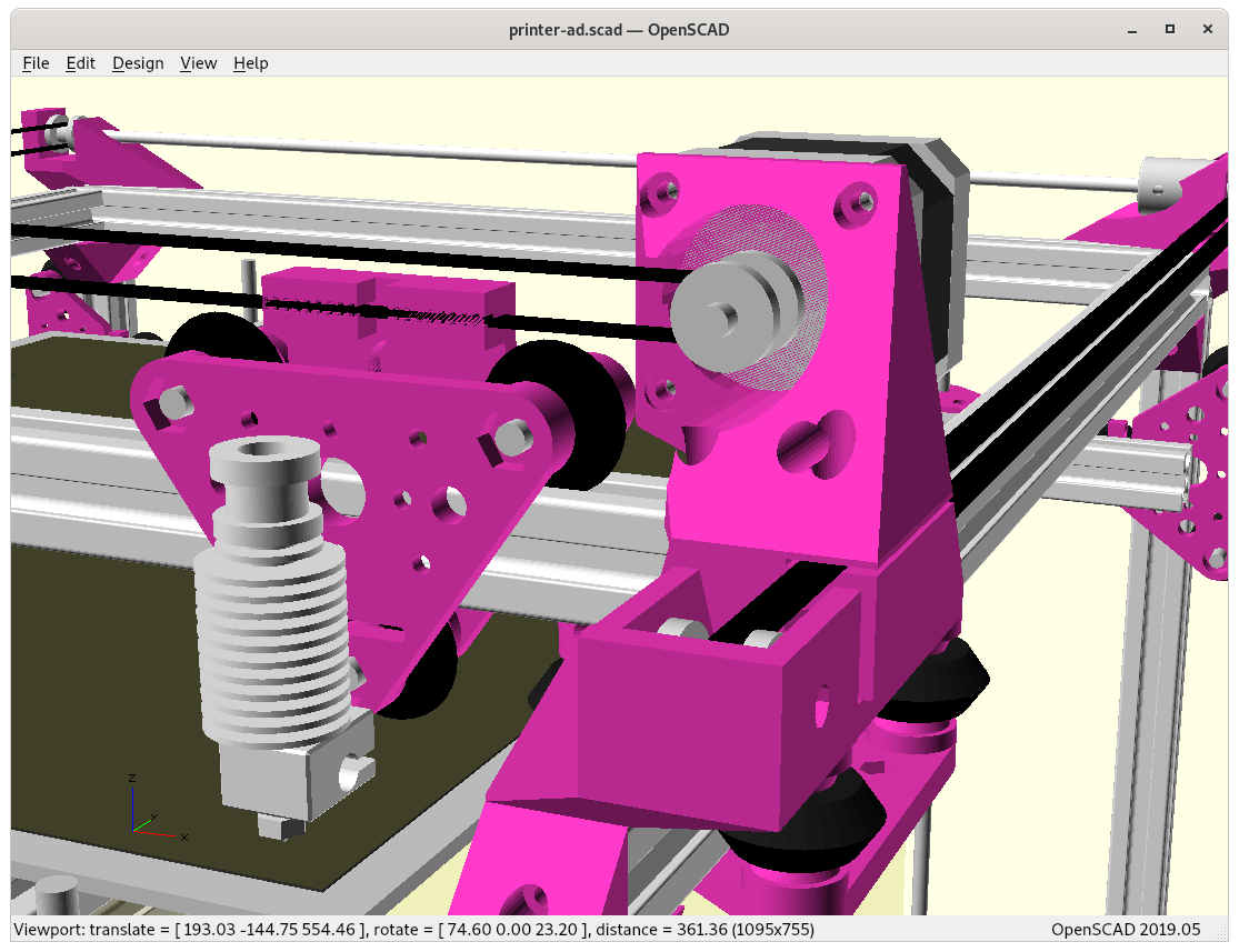
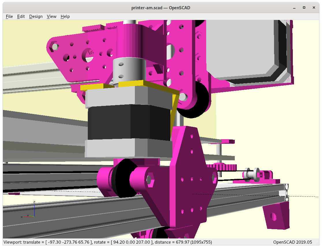
After the rough design was OK, with X = 0 .. max and Y = 0 .. max and maintaining max of printable area, I went ahead and did basic Y motor mount and X motor mount, and I was designing the pieces in OpenSCAD, the ad_[xy]mount(type="motor" or "pulley") and I changed the 42×42 interface for NEMA17 to pulley holder which made it quite a fast design – so motor-side and pulley-side are very similar made with the same OpenSCAD module:
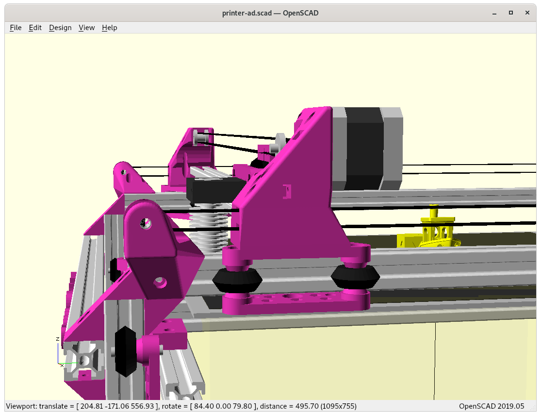
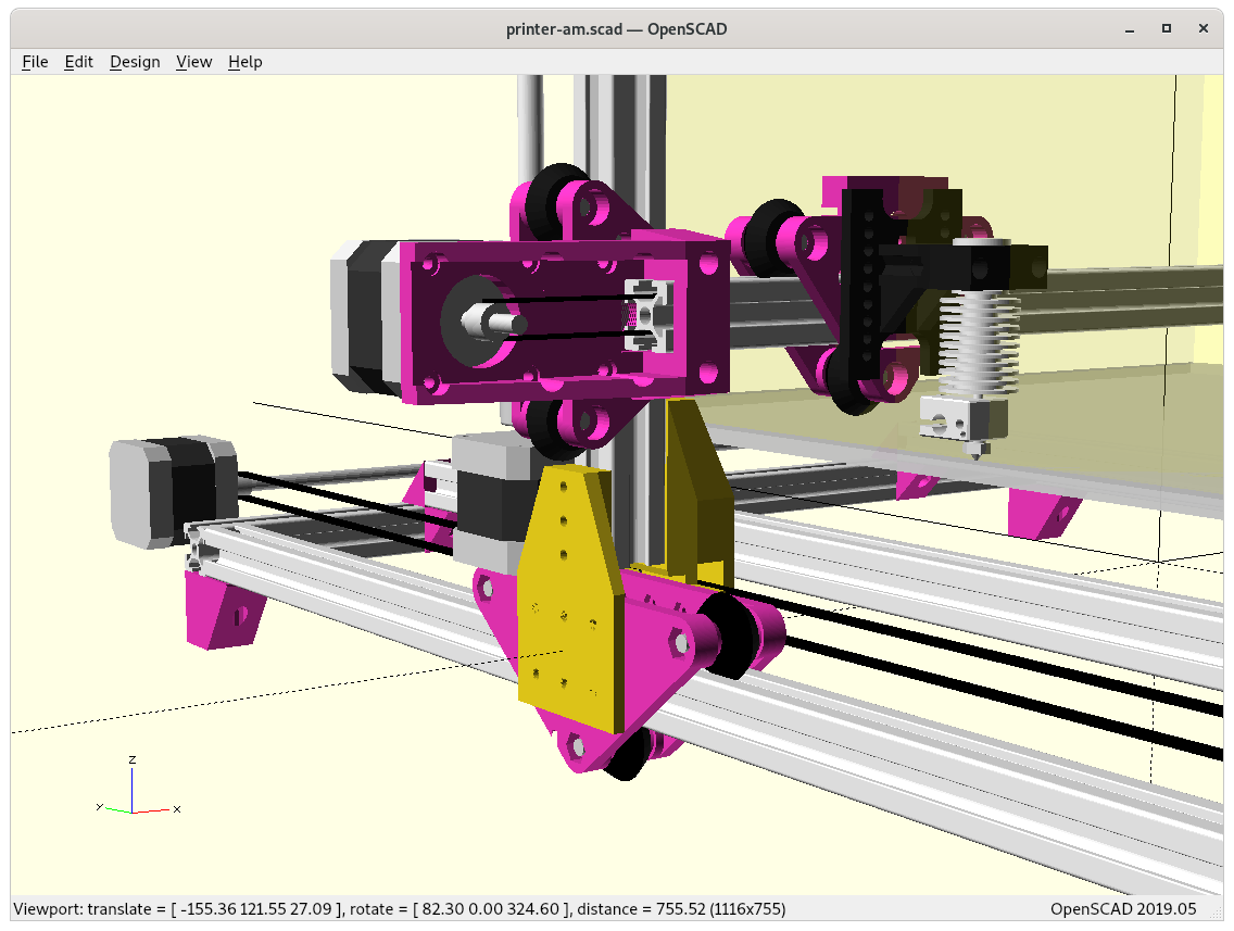
Y Motor Mount
ad_ymount(type=”pulley”) in the front, and ad_ymount(type=”motor”) in the back
At Y = max + Y margin (beyond print bed, but not yet touching anything else):
At Y = max+ Y marginBack viewTop view
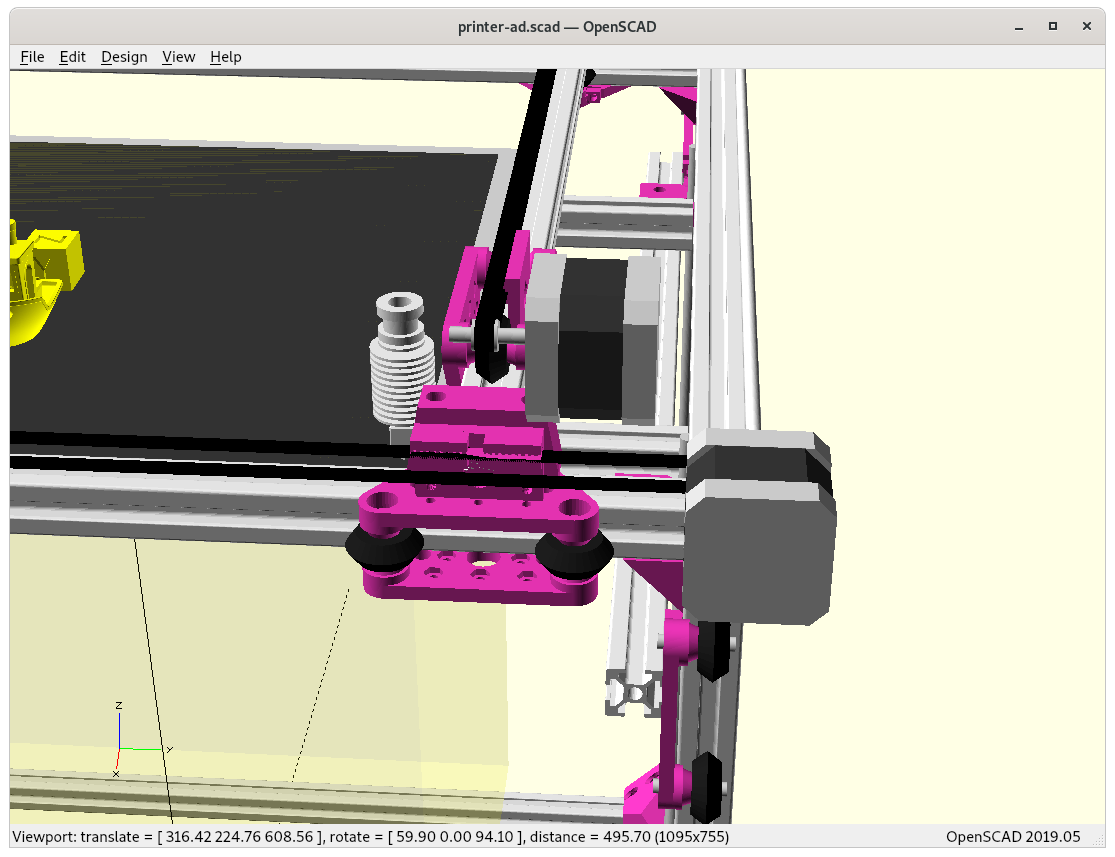
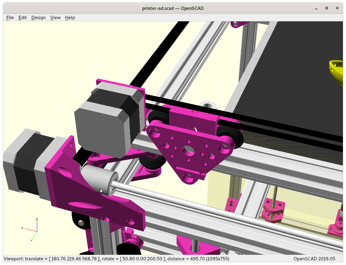
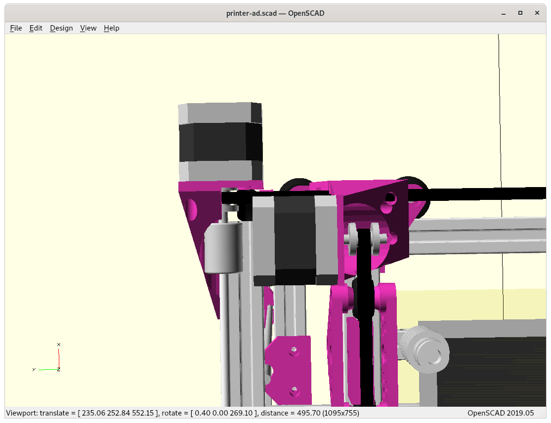
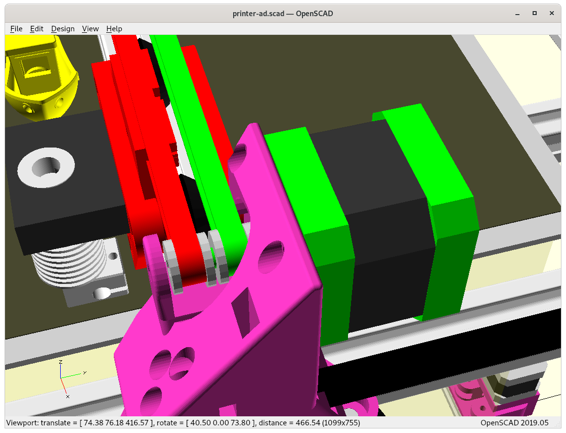
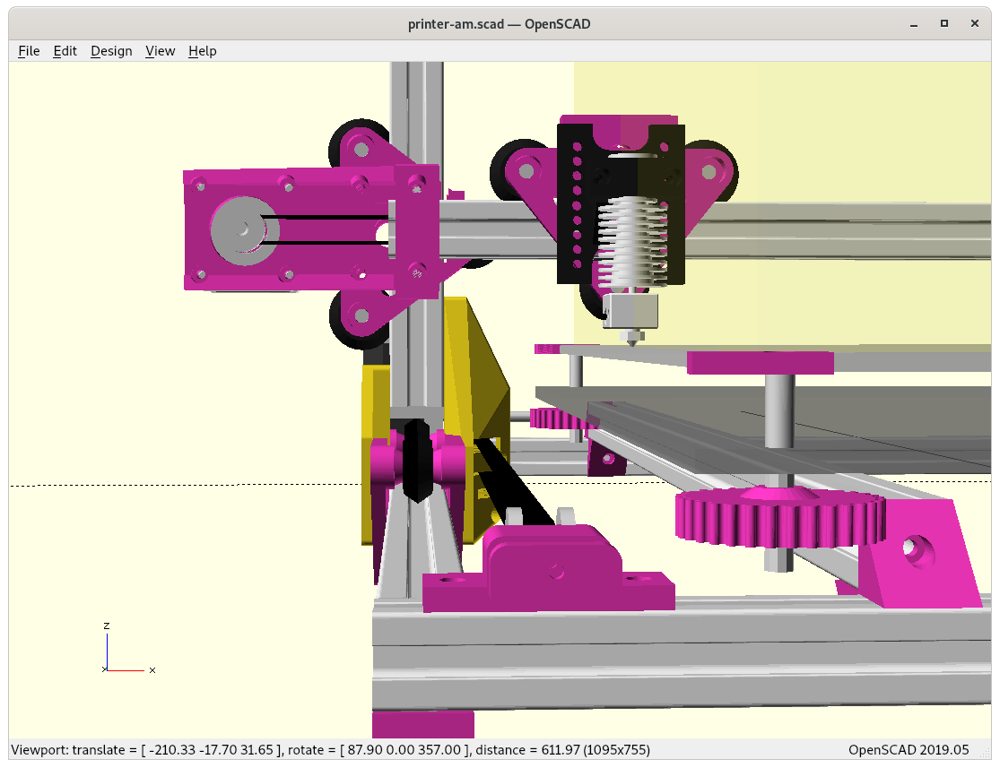
X Motor Mount
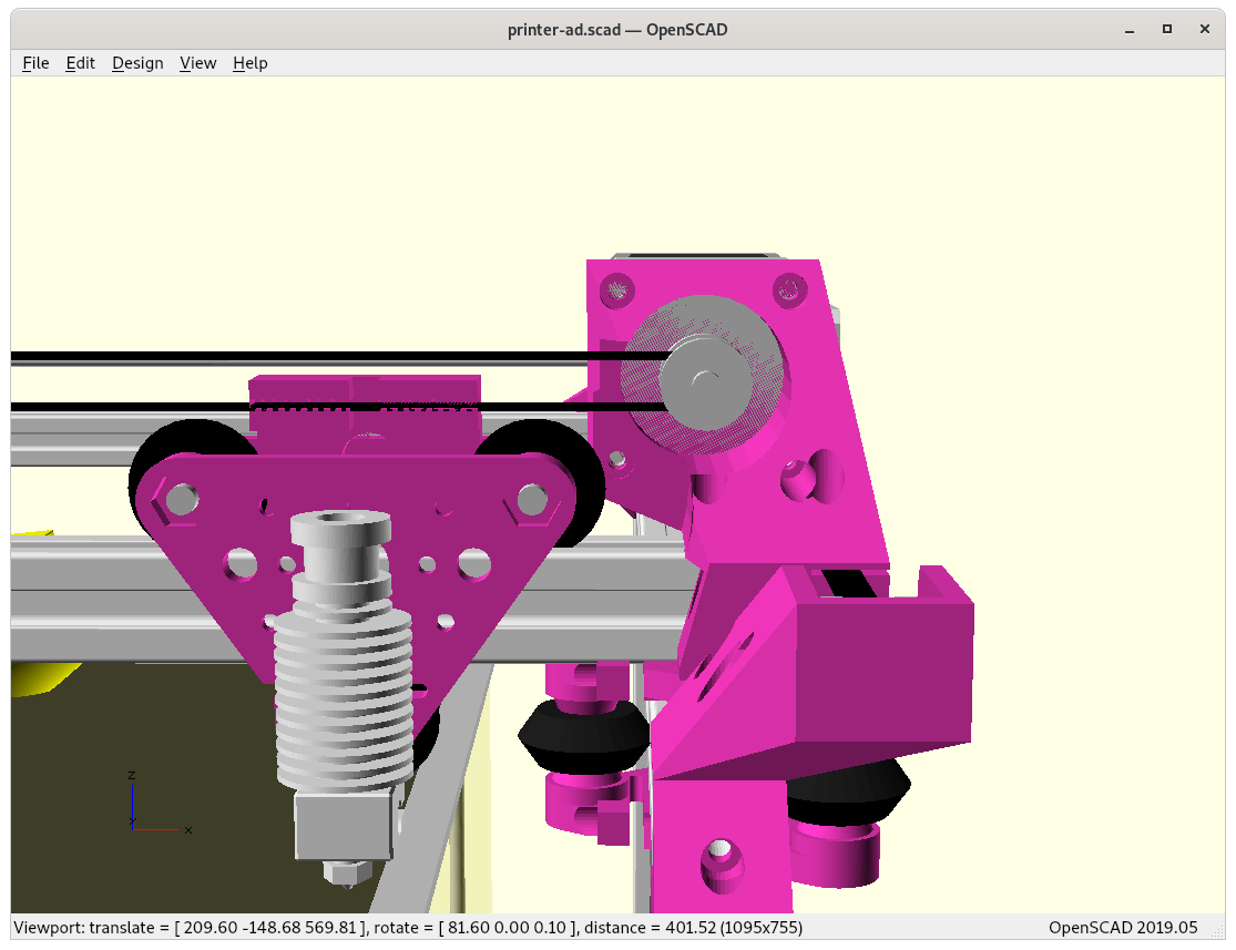
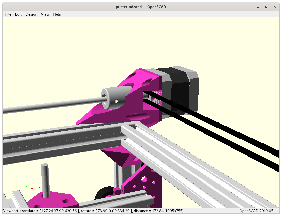
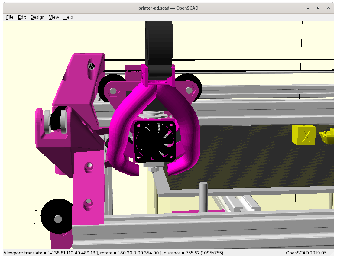
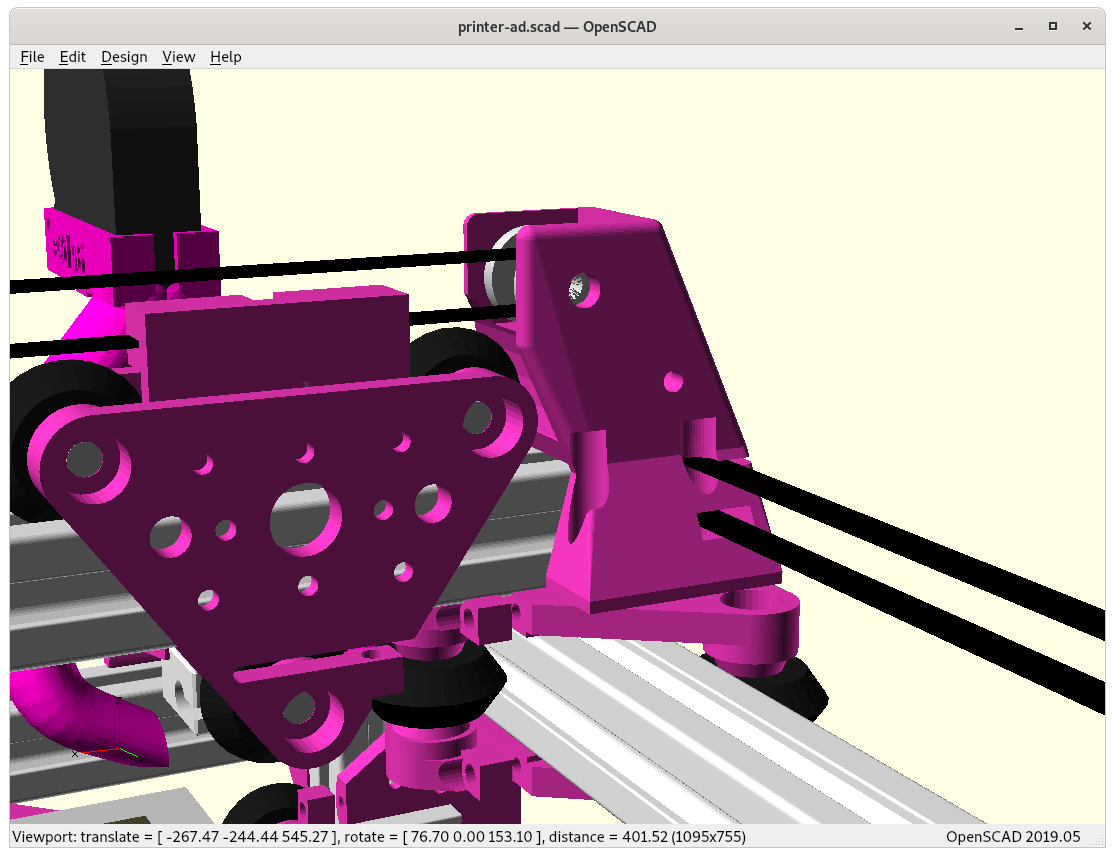
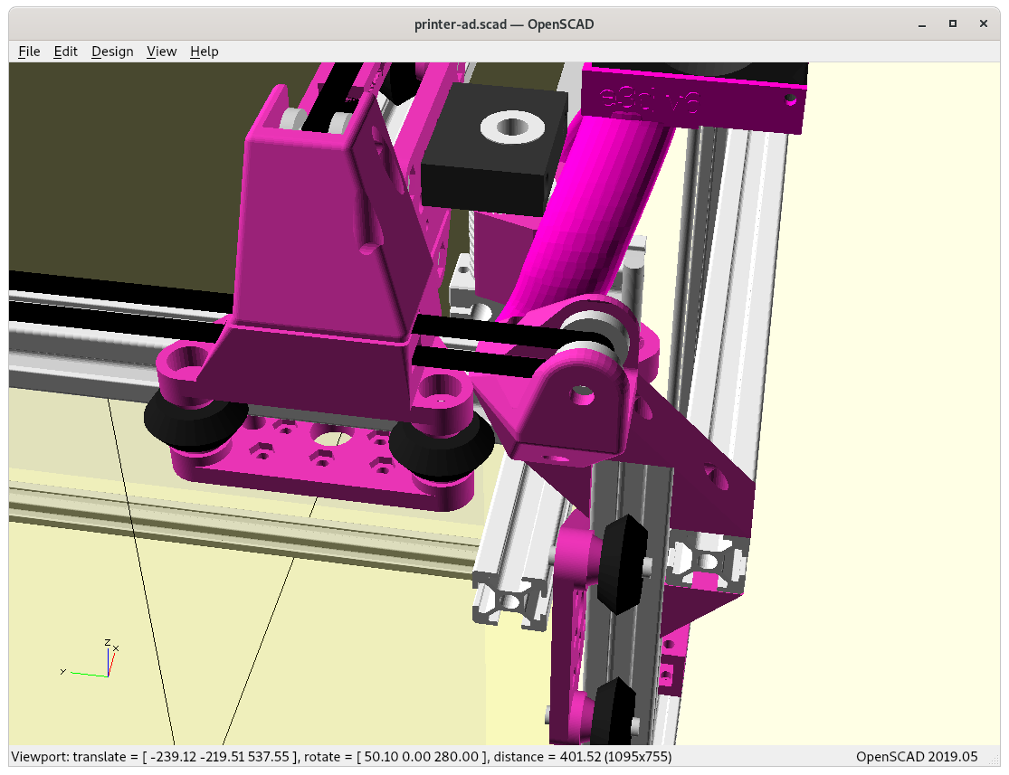
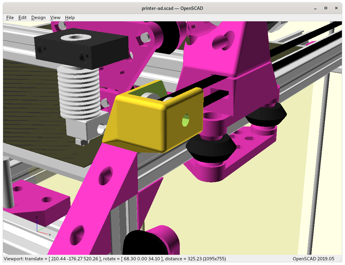
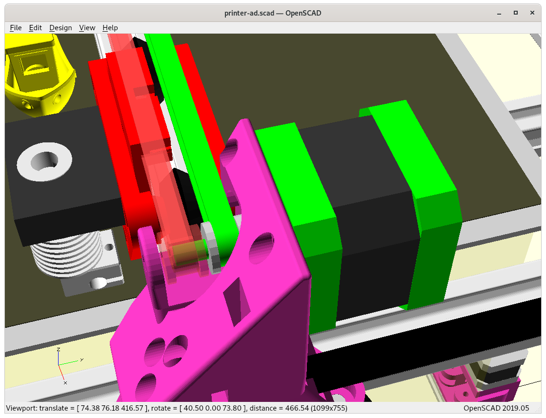
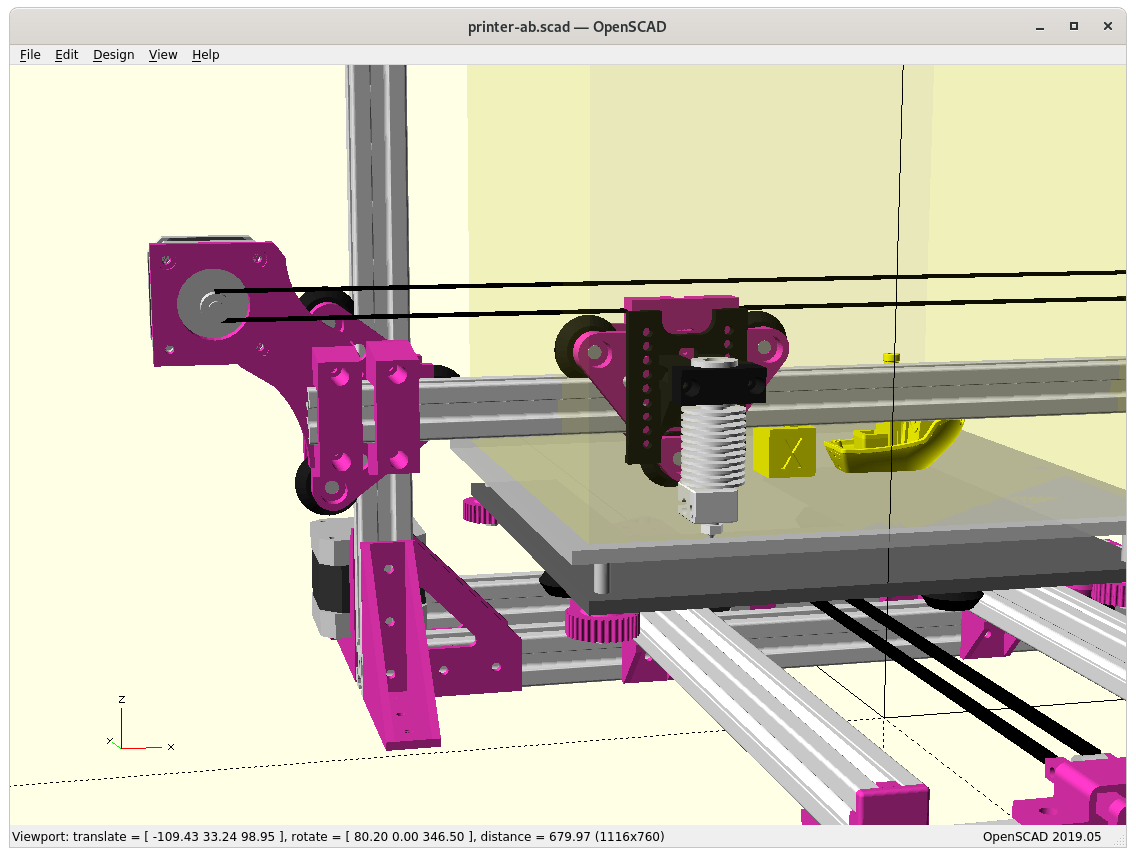
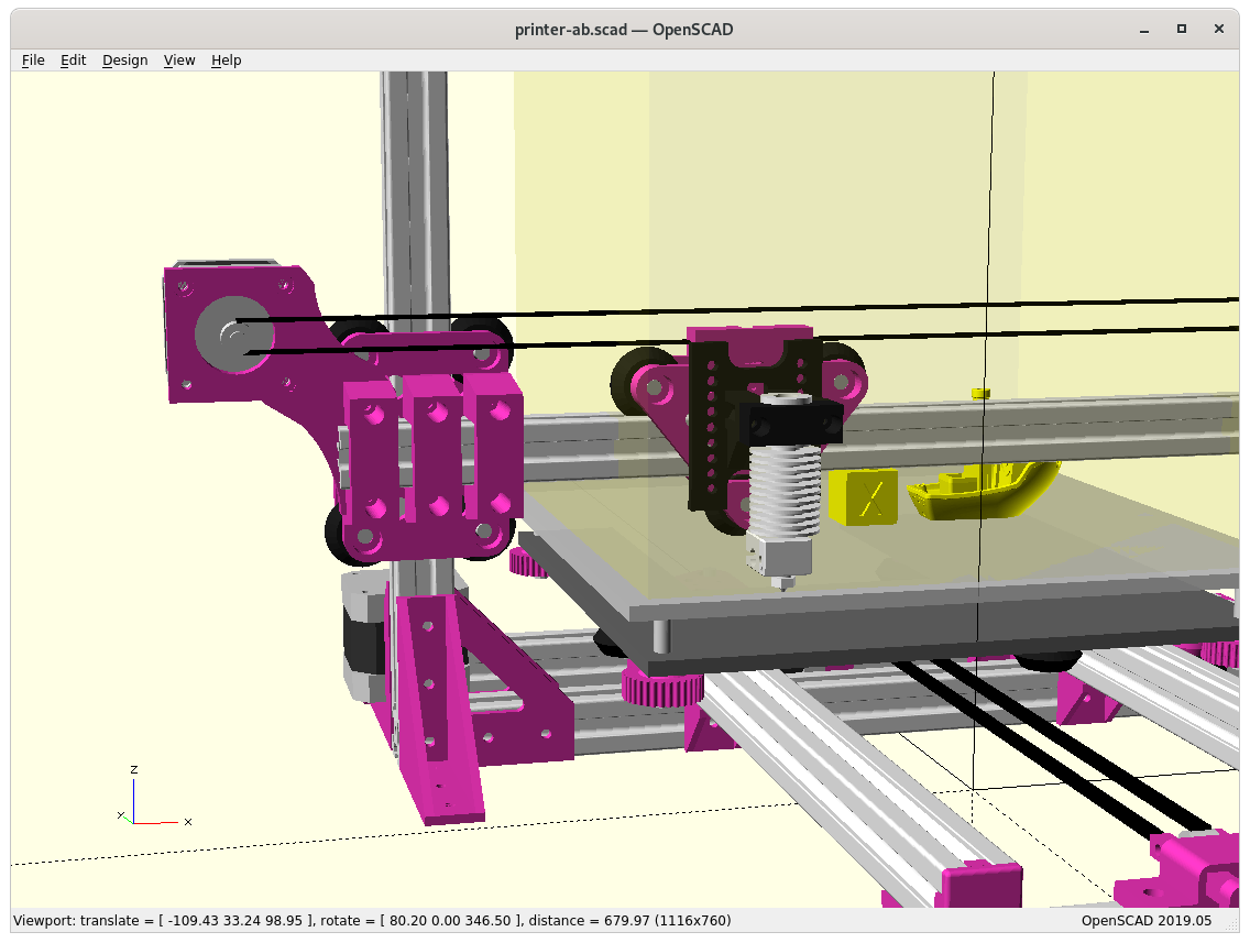
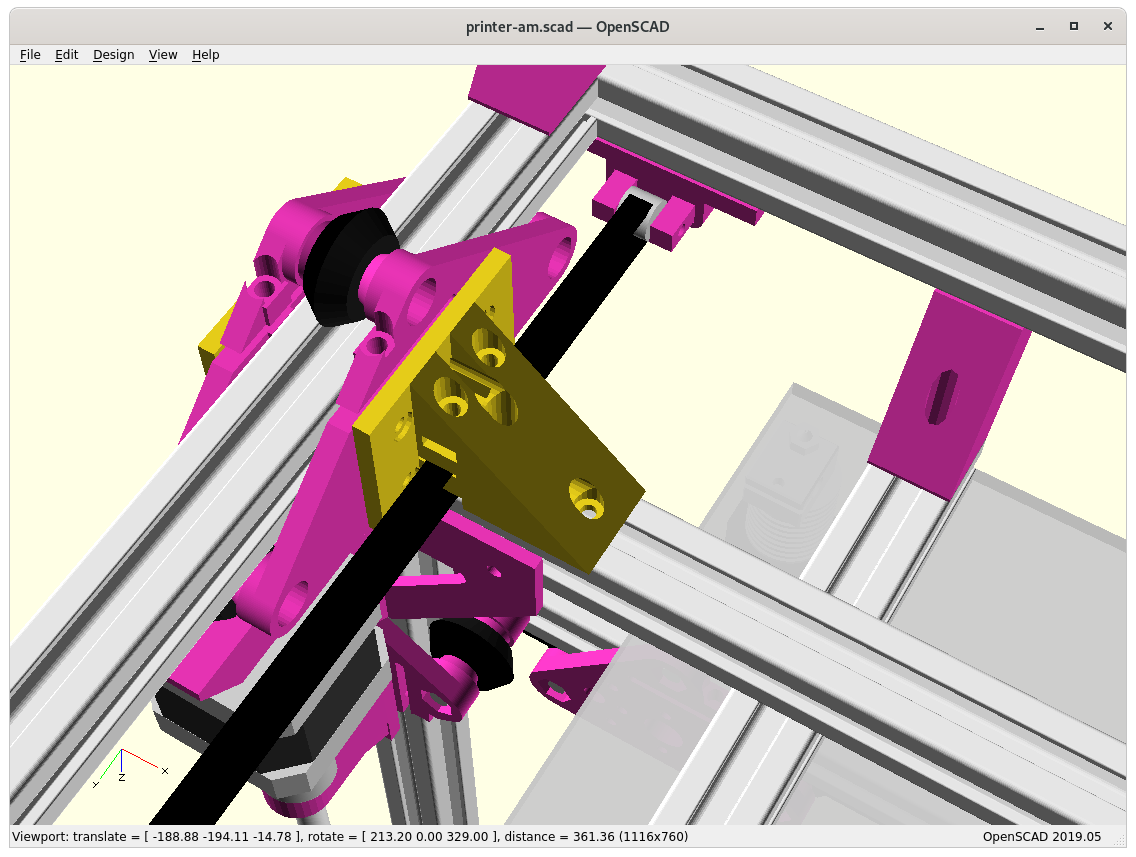
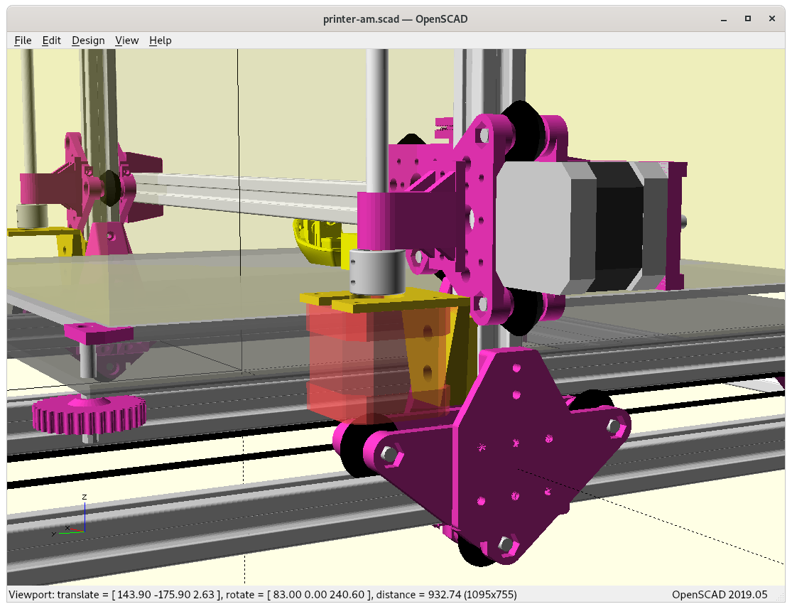
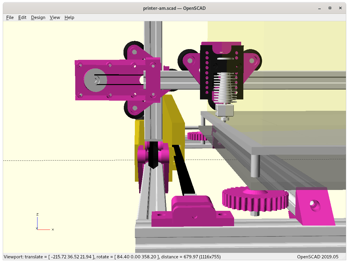
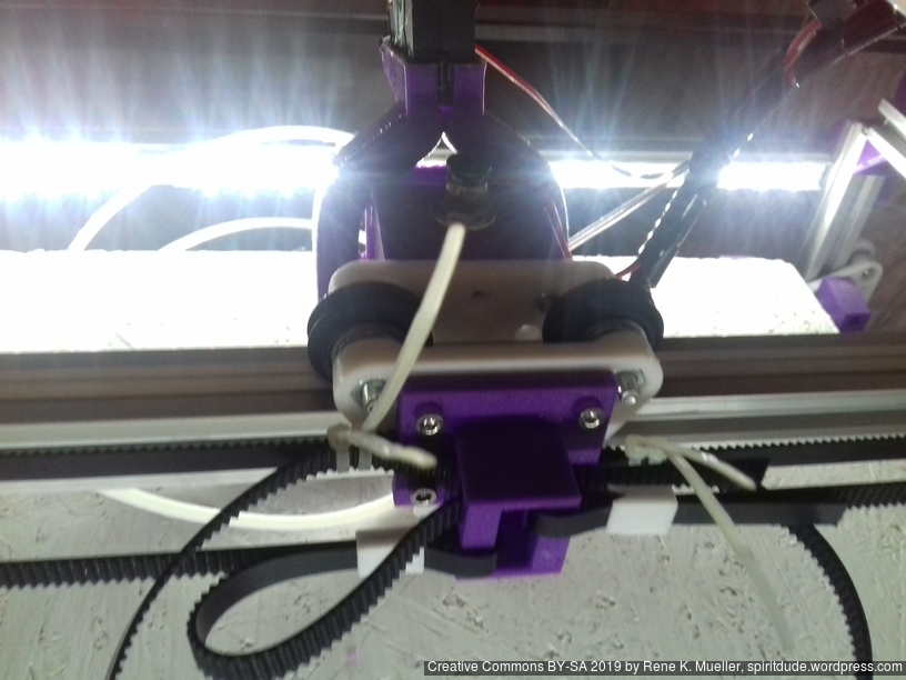
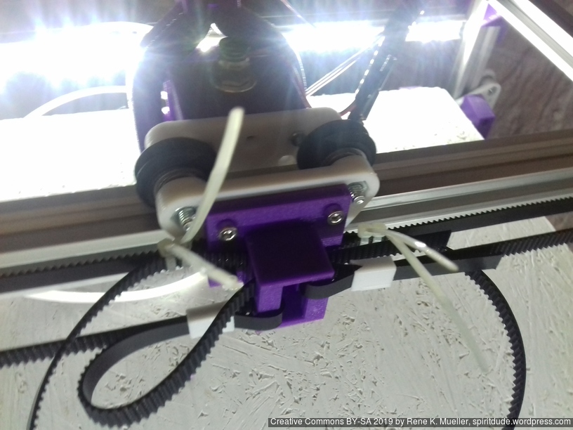
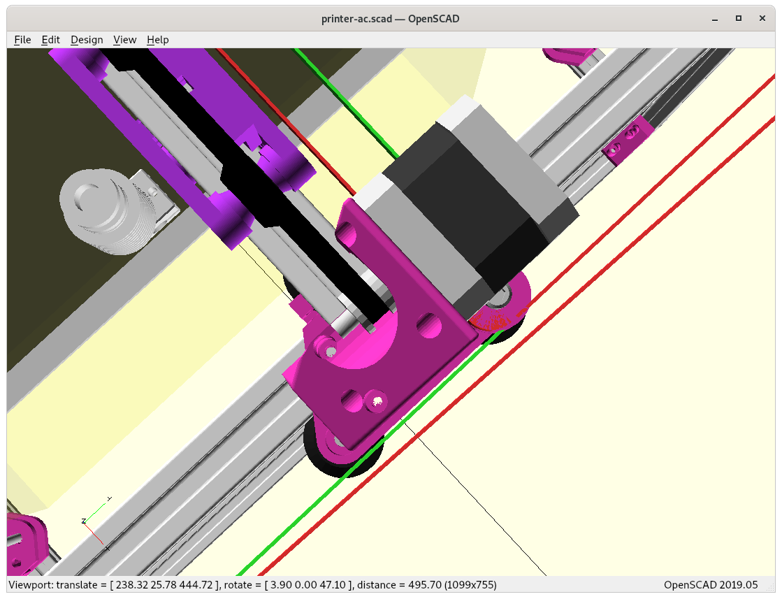
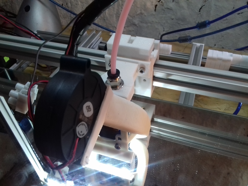
Exploring the X & Y minimum, how X carriage can as close as possible with the part cooler attached:
At X = -12, Y = 0At X = -12, Y = 0At X = -12, Y = -10
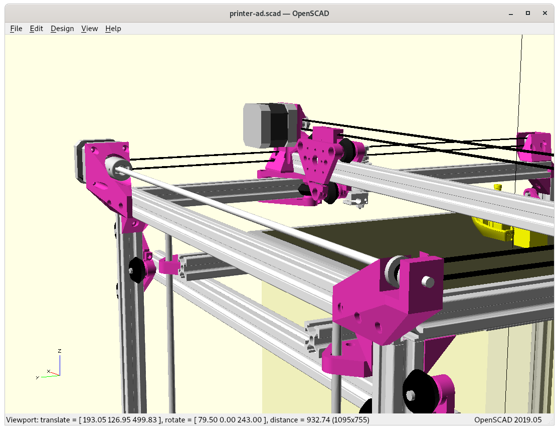
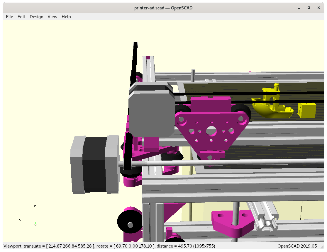
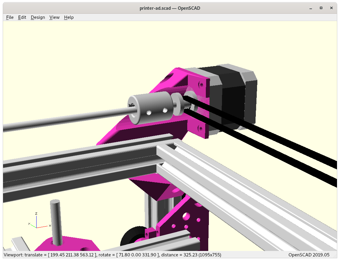
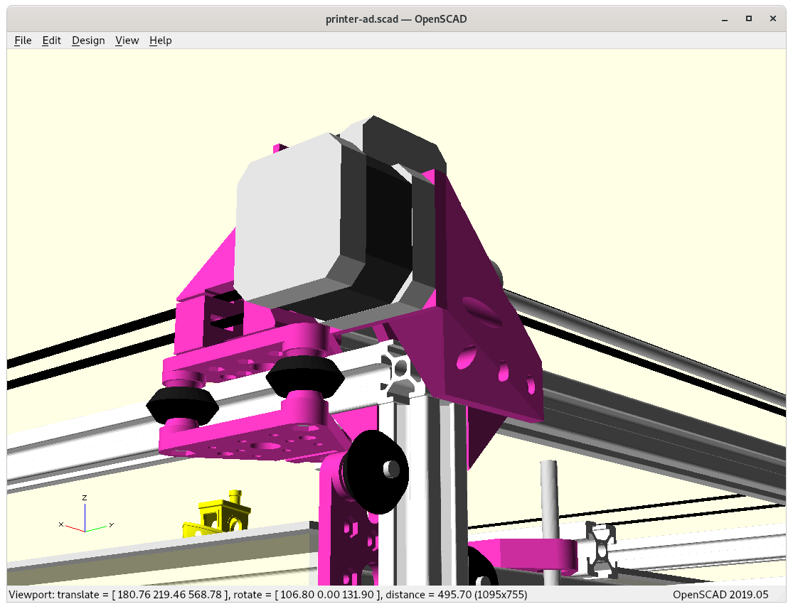
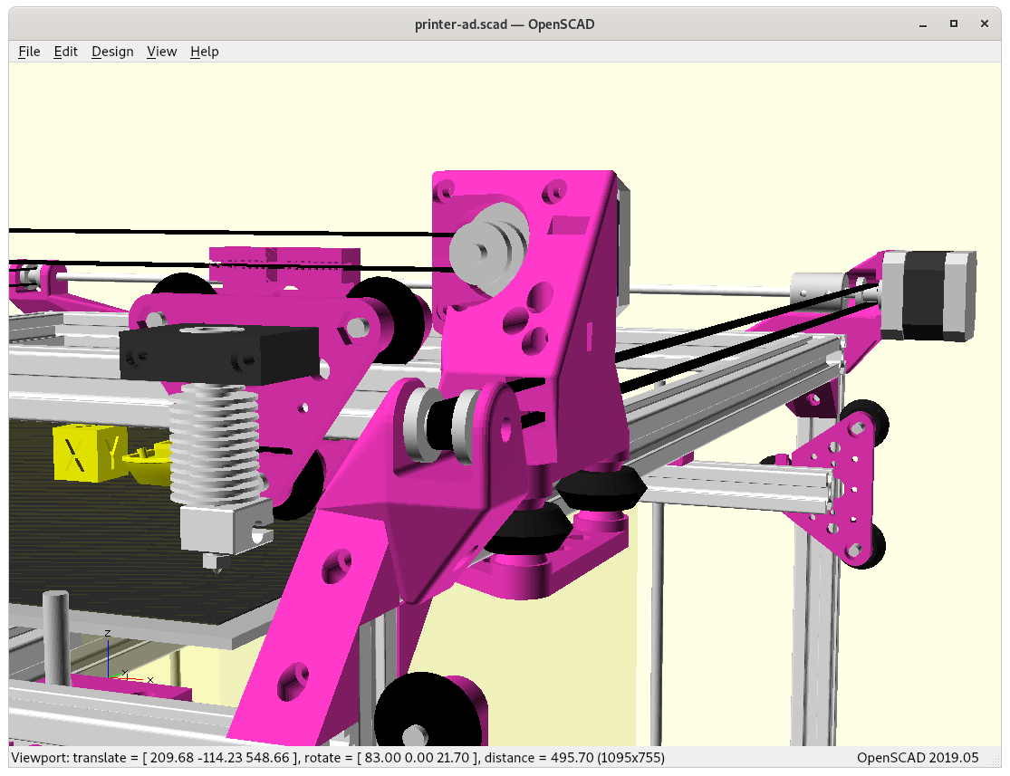
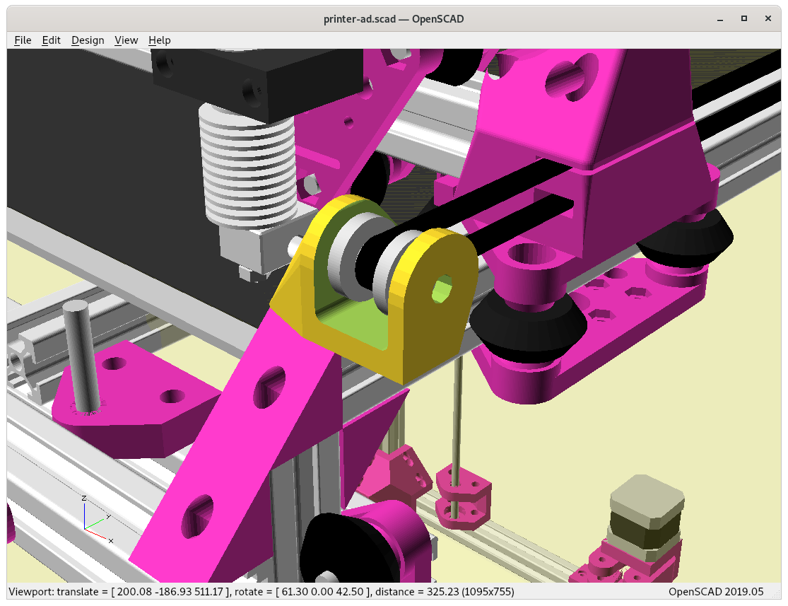
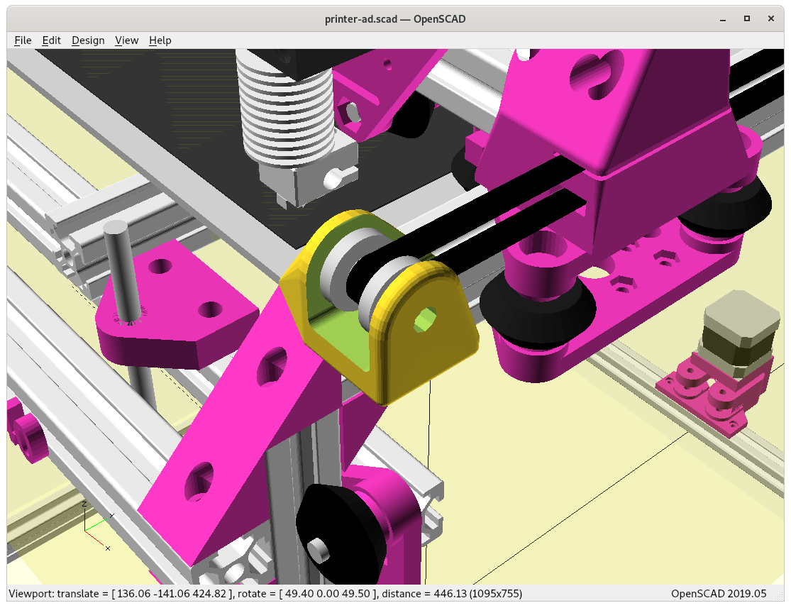
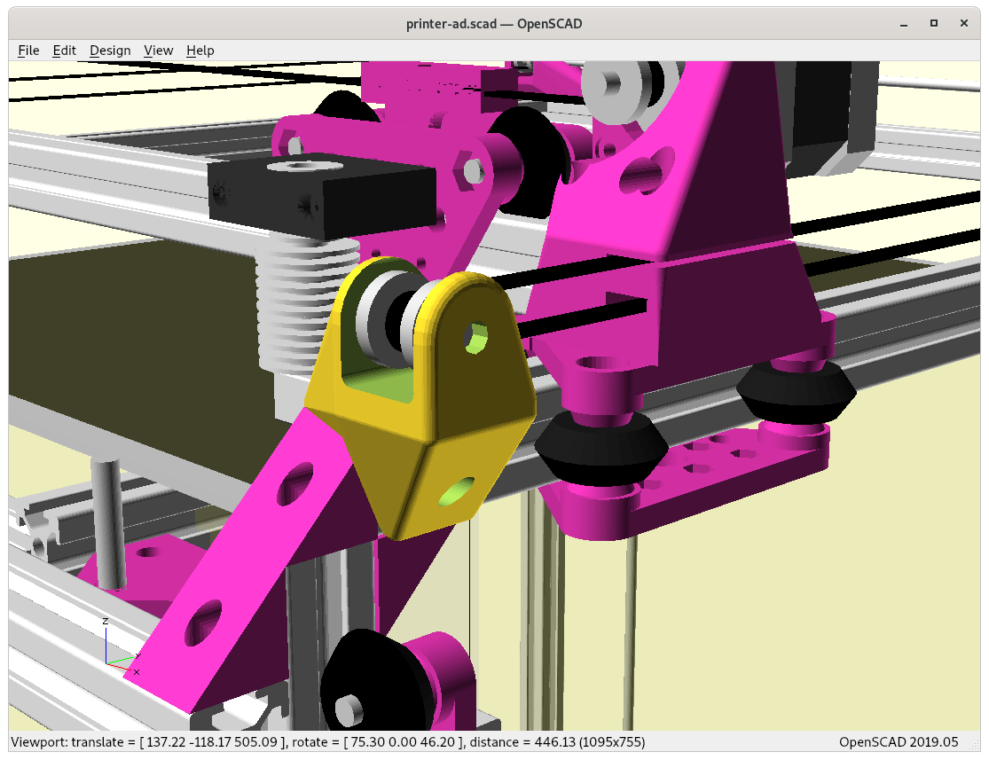
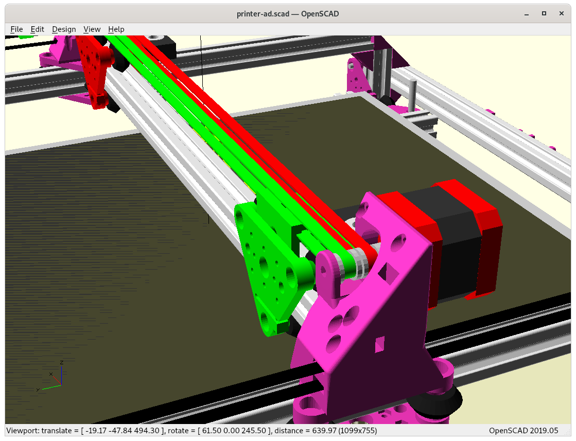
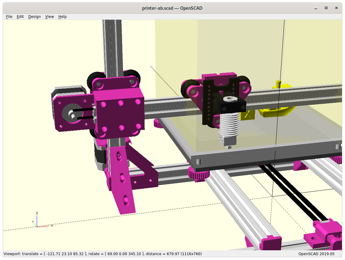
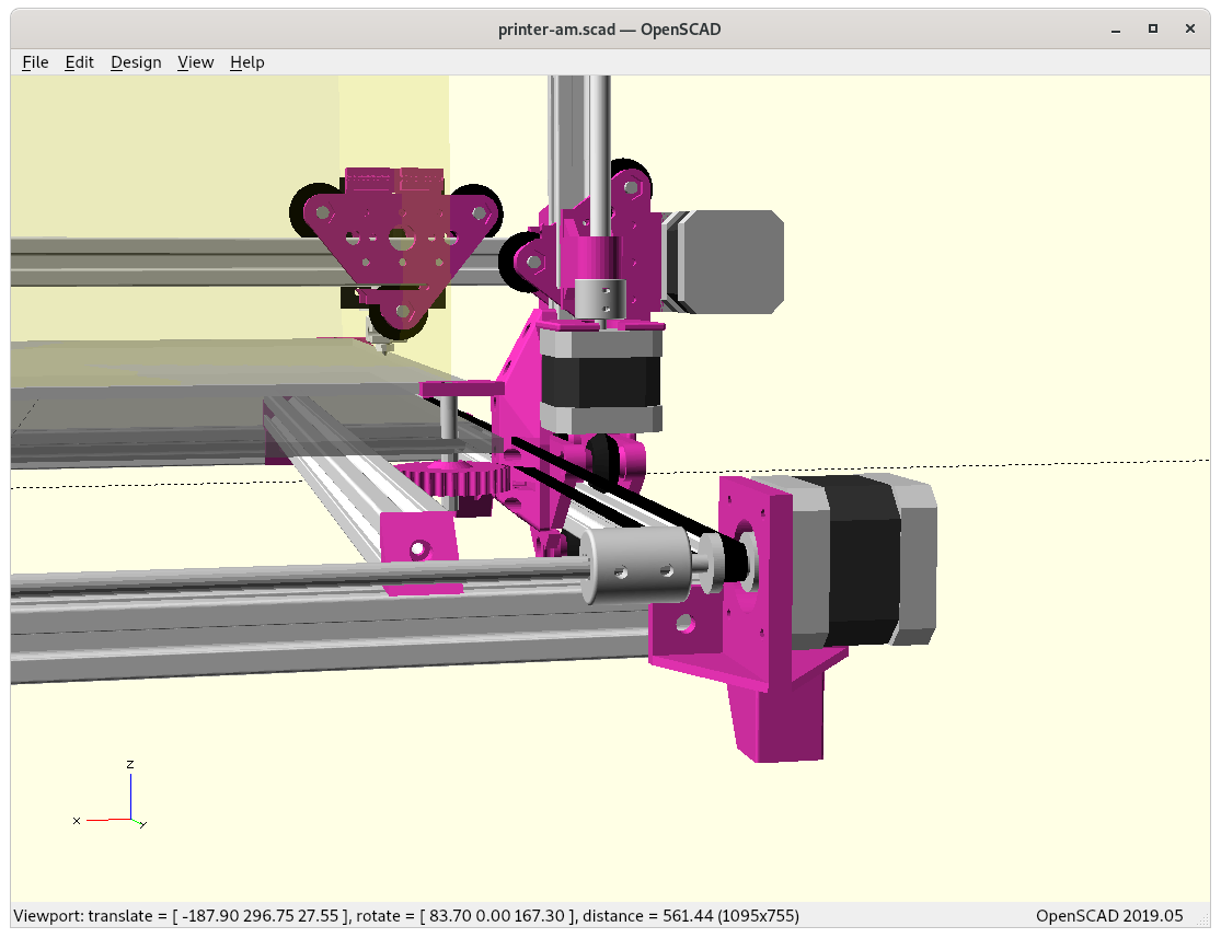
X & Y Motors / Axis
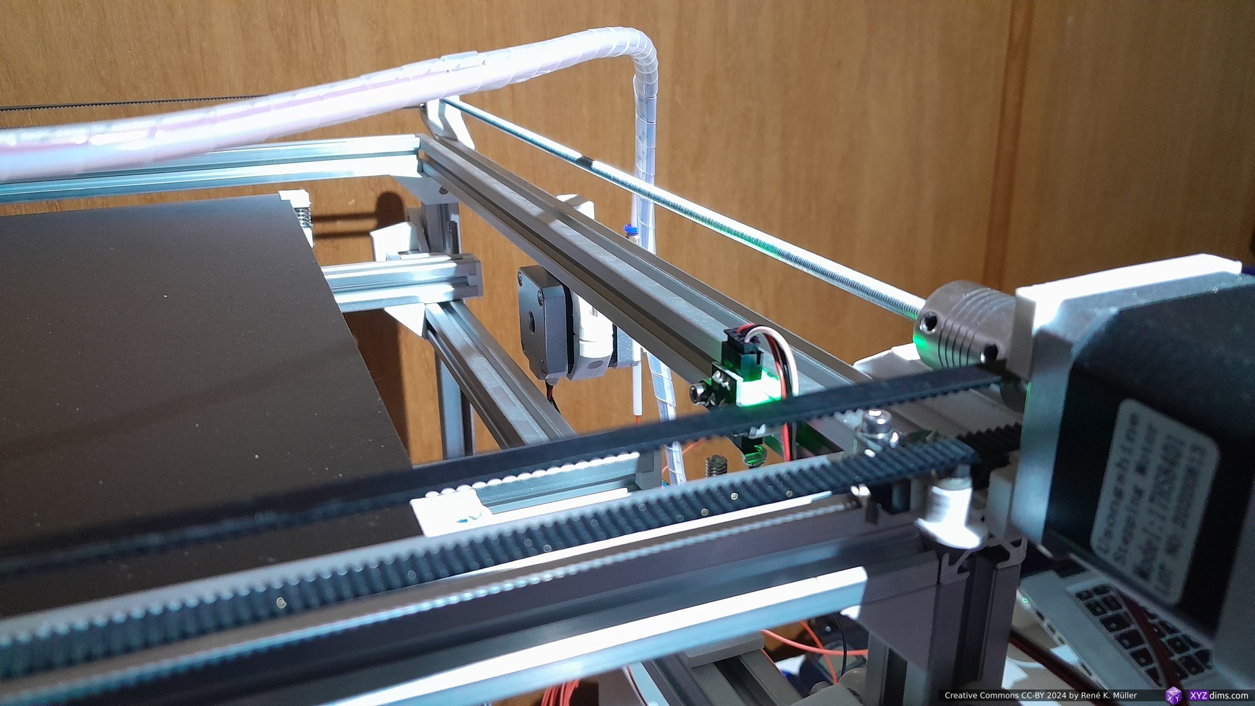
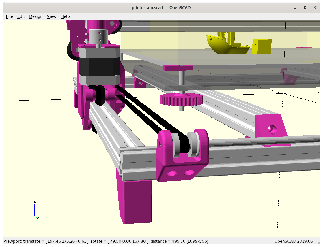
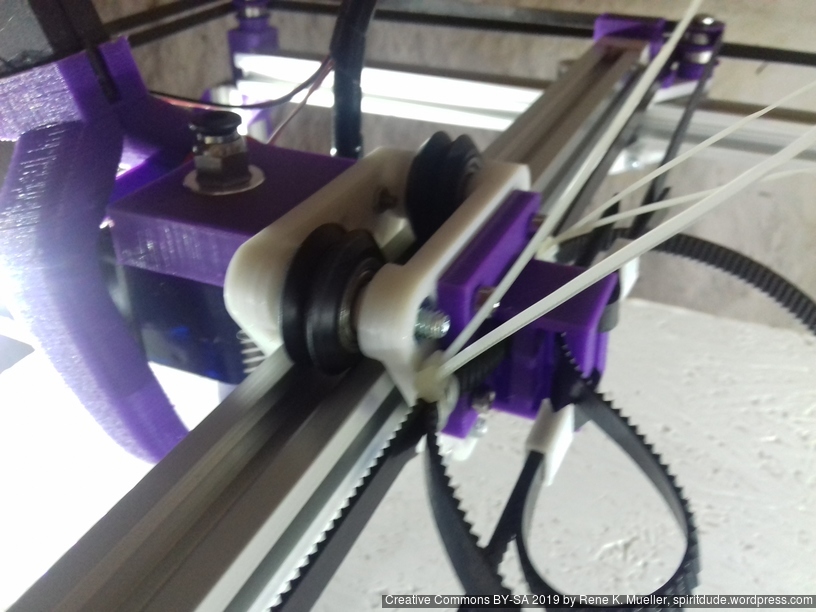
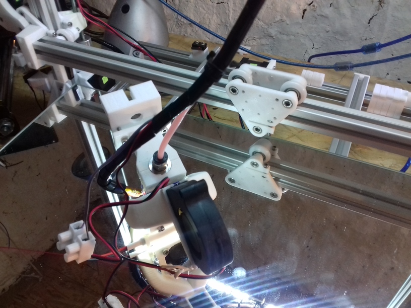
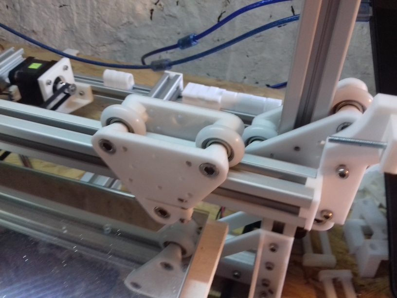
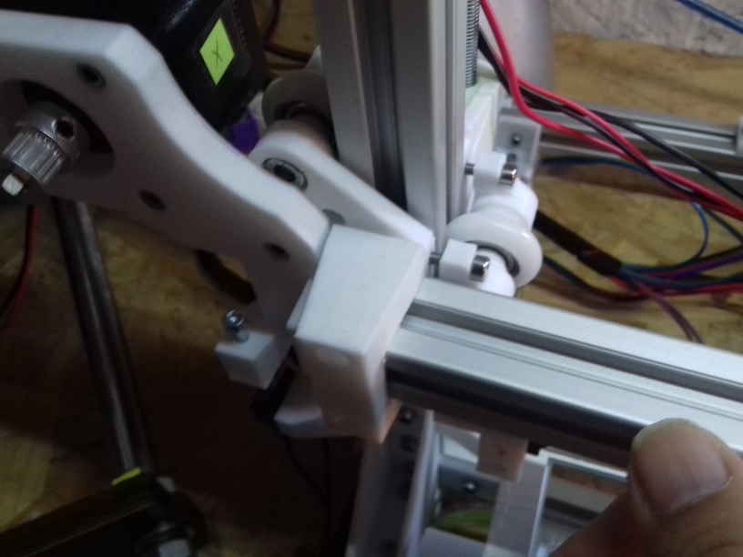
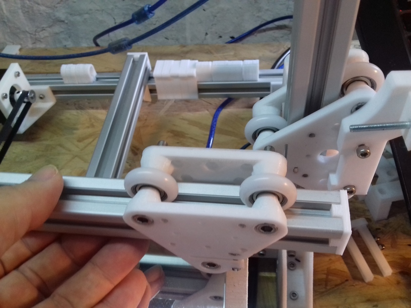
Ashtar D: Y carriage with X motor mount and X pulley (on the other side) Y motor mount and shaft extender and Y pulleyAshtar D: Y pulley mount and X pulley mount on Y carriage (in the front)
Specifications
Build Volume: ~380 x 400 x 380mm (not yet finalized)
Frame: 17x 500mm 2020 alu profiles
14x 500mm 2020 T-slot alu profiles
3x 500mm 2020 V-slot alu profiles
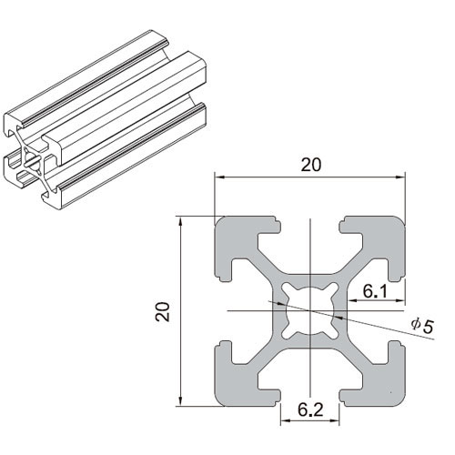
T-Slot 2020
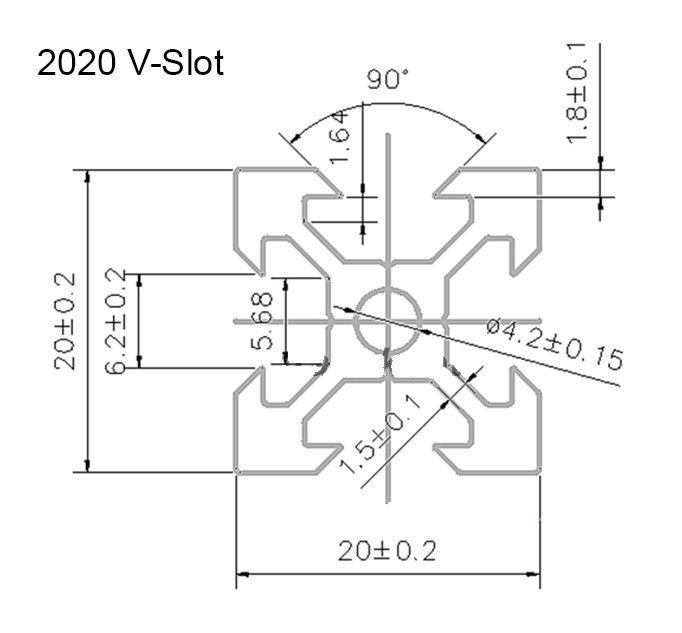
V-Slot 2020
V wheel
Issues to Resolve
mounting X motor, resolved
mounting X pulleys, done
mounting Y motor, resolved
mounting Y pulleys, done
using M6 or M5 smooth or threaded rod to extend Y motor shaft
Y belt mount to carriage, done
positioning: extruders, controller, power-supply (like Ashtar C)
positioning: X, Y and Z end-switches
tuning toward 400x400x400mm build volume with 500mm 2020 alu profiles
build printer
print tests
release parts
release code
Gallery
Classic XY vs Core XY
Compared to Ashtar C Core XY the Ashtar D is less elegant, more complex parts but better setup using the rather thin 2020 alu profiles for such a big build volume.
Just cube()Using rcube()Using cylinder() & cube()Using rcylinder() & rcube()Final version, using rcylinder() and rcube()
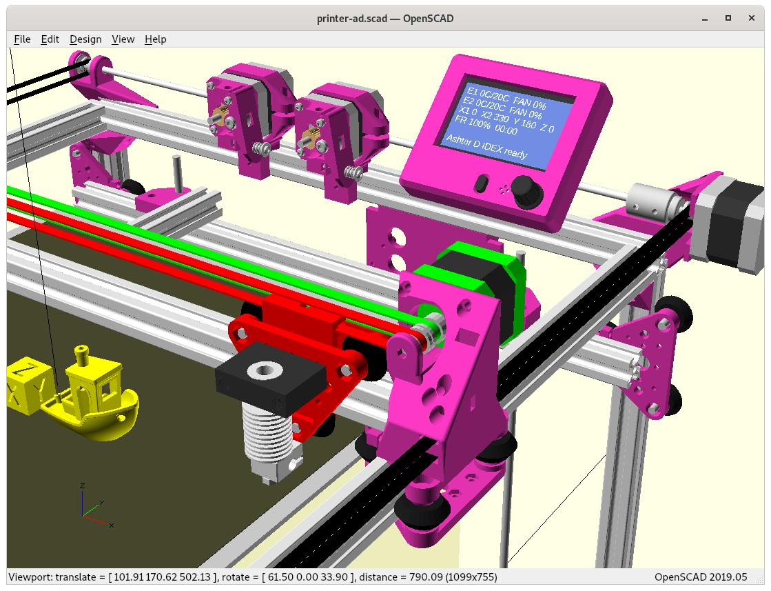
IDEX Option
In order to provide Dual Independent Extrusion (IDEX) a 2nd belt and motor is required, yet, the Y carriage is quite delicate in this current setup but after some pondering I think I came up with an elegant solution: the main idea is to utilize the NEMA 17 shaft as axis for 2nd belt idler:
Reusing NEMA 17 shaft as axis for idlerReusing NEMA 17 shaft as axis for idler (see through)
and then rotate the same Y carriage on the other side:
Since the entire Ashtar D design is still just a draft, this IDEX setup is also very experimental in nature and only actual build will tell if it’s feasible.
Ashtar DAshtar D IDEXAshtar DAshtar D IDEX
Gallery
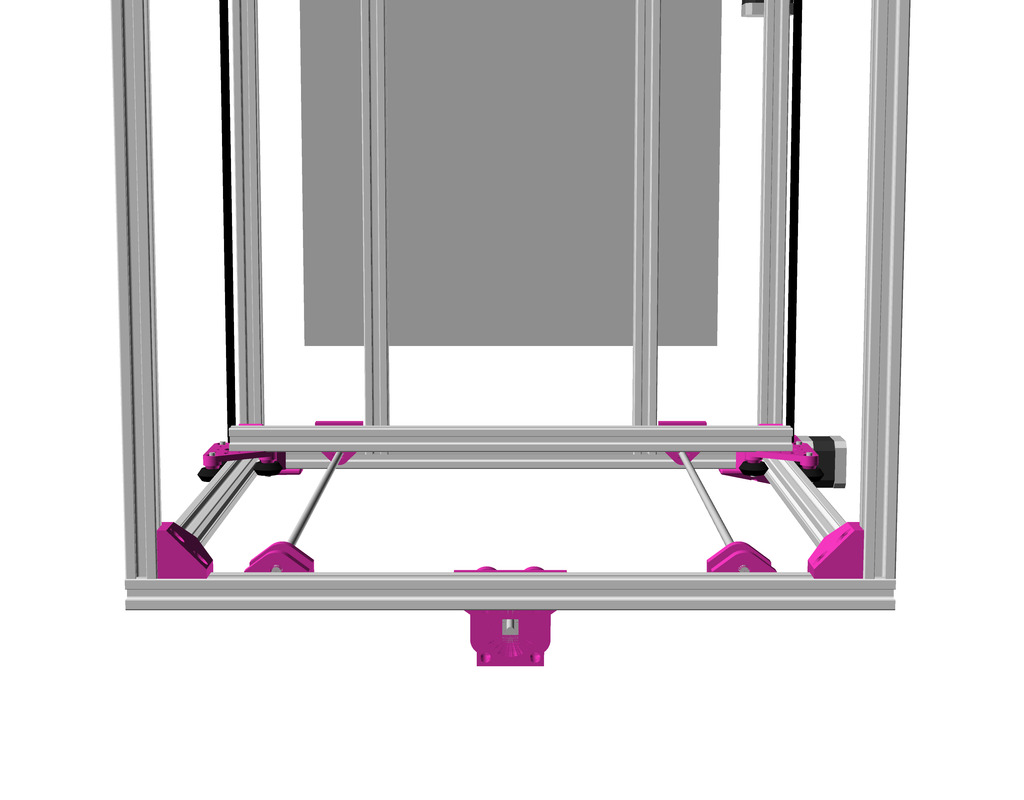
Z Axis & Motors
It has been tested successfully with Ashtar C, so I use the same setup again:
Ashtar C/D: Z Axis / Motor
Ashtar C/D: Z motor mountAshtar C/D: Z motor and Z axis
Parts
Printable Parts
1x ad_xmount-type=motor
1x ad_xmount-type=pulley
1x ad_ymount-type=motor
1x ad_ymount-type=pulley
1x ad_ypulley-left
1x ad_ypulley-right
Note: the new parts aren’t released yet until I used them in a test setup.
Non-Printable Parts
2x 625ZZ bearings ID=5mm
2x for 1x ad_ymount-type=pulley
12x 629ZZ bearings ID=6mm
8x for 4x Z thread holder (2x bottom)
4x for 4x Z thread holder (top)
nx pulleys (dimension not yet determined)
2x (5mm hole) for 2x Z motors
1x (5mm hole) for 1x X motor
2x (5mm hole) for 1x Y motor, 1x ad_ymount-type=pulley
4x (6mm hole) for Z threaded rods
nx idlers (with 3 or 5mm hole)
2x (3mm hole) for 1x ad_ypulley-left, 1x ad_ypulley-right
~520 mm M5 smooth or threaded rod (Y shaft extension)
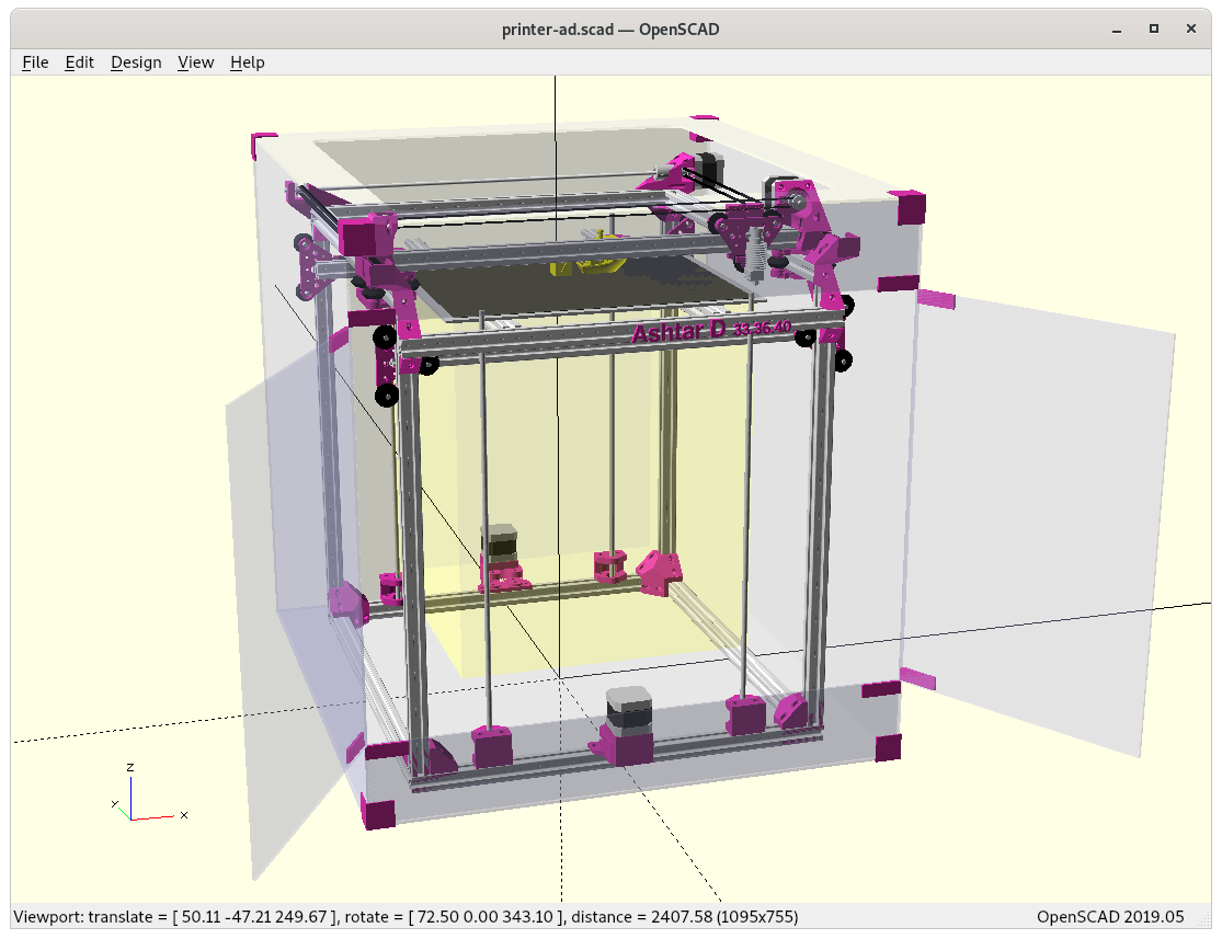
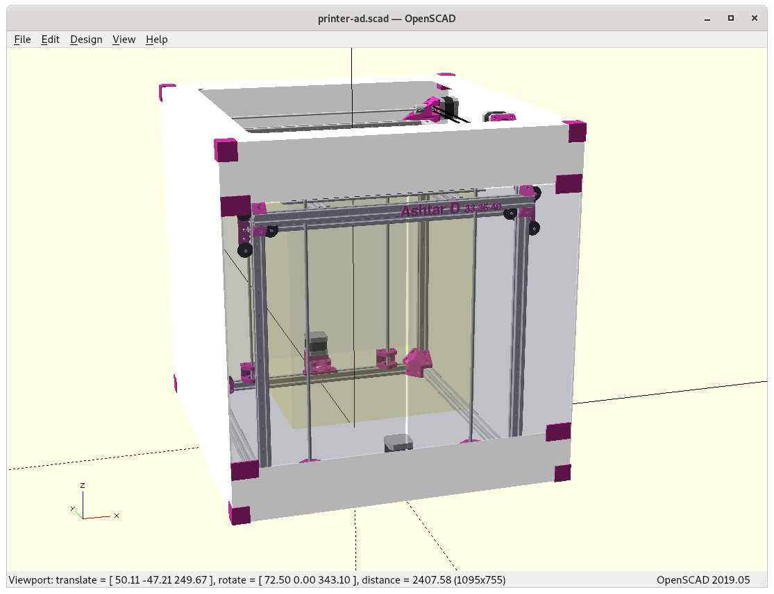
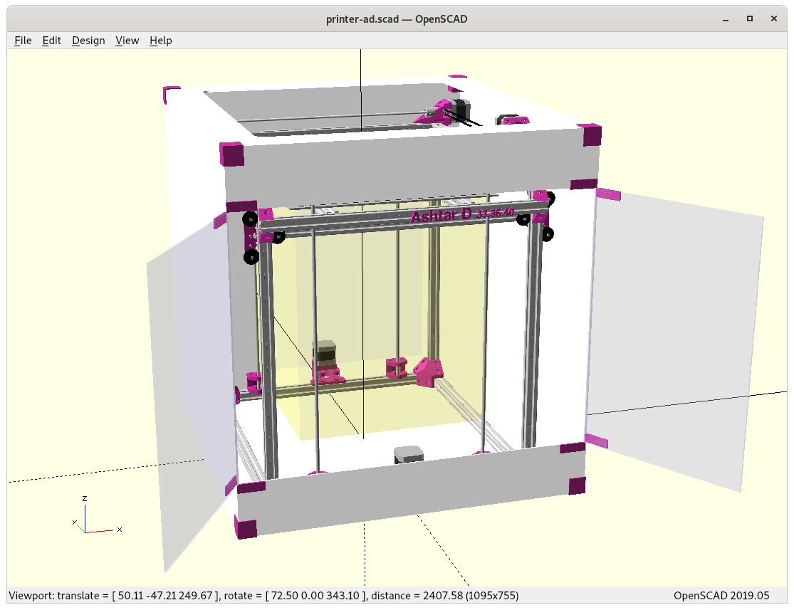
Enclosure
Developing some enclosure, either attach to the Z beams – as one side is free to fasten pieces and use acrylic sheets – or enclose entire frame, like with
With the enclosure the display must be reachable, and therefore likely be on the front and longer wires from the controller board, which most likely resides on the back right side as with Ashtar C.
Build Volume: 380 x 400 x 380mm (57.7Kcm3 / 57.7L) = 100%
Device Dimension: 590 x 650 x 620mm (237Kcm3 / 237L)
Build vs Device Volume: 4.11
Creality CR5
Build Volume: 300 x 225 x 380mm (25.6Kcm3 / 25.6L) = 44%
Device Dimension: 530 x 487 x 621mm (160Kcm3 / 160L)
Build vs Device Volume: 6.25
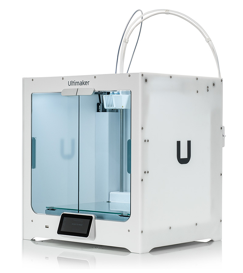
Ultimaker S5
Build Volume: 320 x 240 x 300mm (23.0Kcm3 / 23L) = 40%
Device Dimension: 495 x 585 x 780mm (225Kcm3 / 225L)
Build vs Device Volume: 9.78
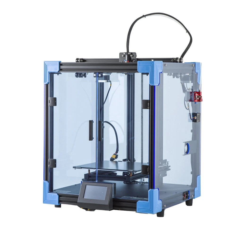
Creality Ender 6
Build Volume: 250 x 250 x 400mm (25.0kcm3 / 25L) = 43%
Device Dimension: 495 x 495 x 650mm (159Kcm3 / 159L)
Build vs Device Volume: 6.36
Ashtar D and Ultimaker S5 device volumes are nearly the same, 237Kcm3 vs 225Kcm3, but Ashtar D would print more than the double of the volume – so it would be volume-wise more efficient. Creality CR5 and Creality Ender 6 are more volume efficient than the Ultimaker S5, but not as good Ashtar D. Let’s see if I can keep this advantage for the final implementation.
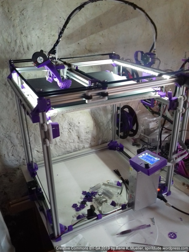
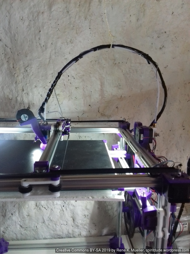
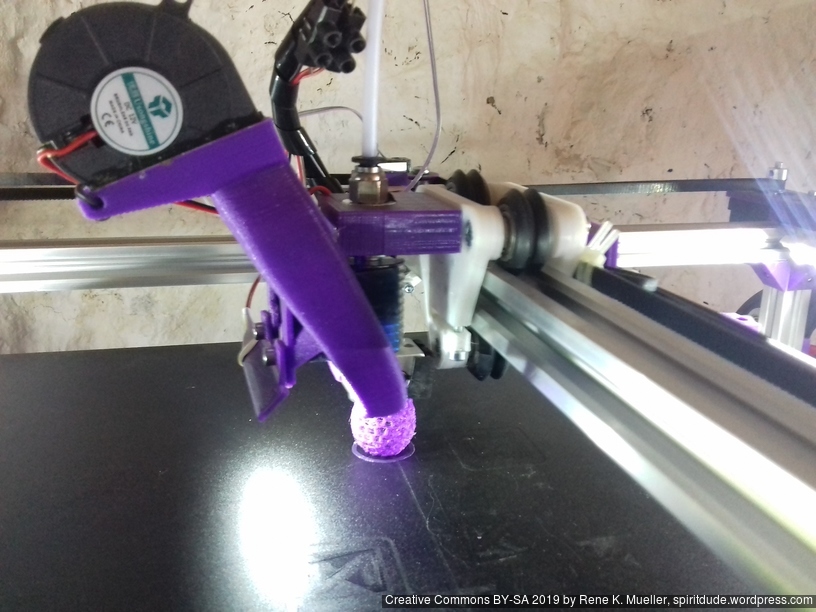
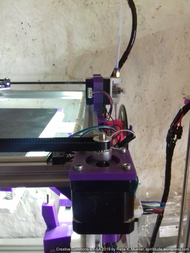
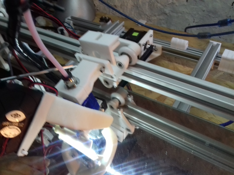
Building Ashtar D
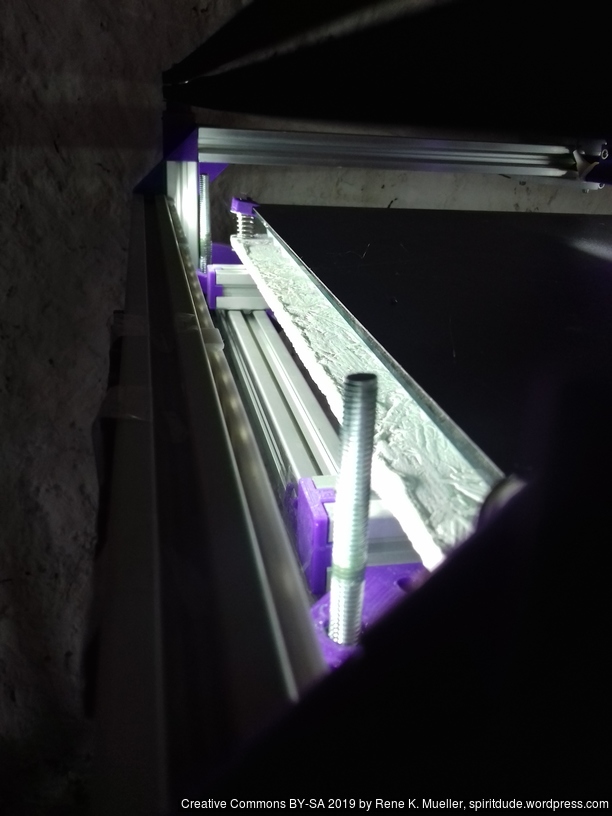
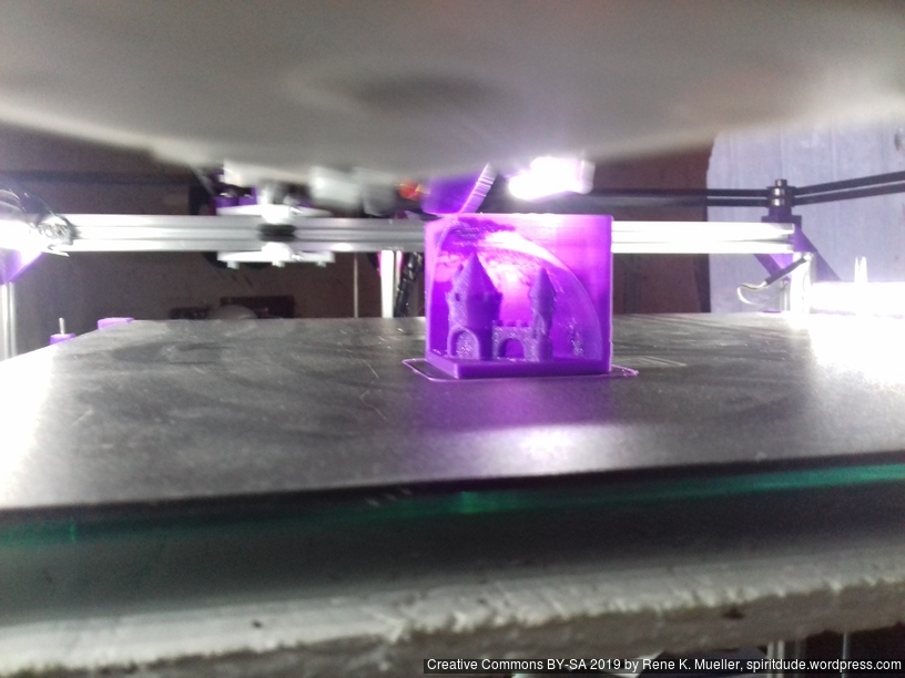
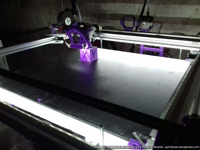
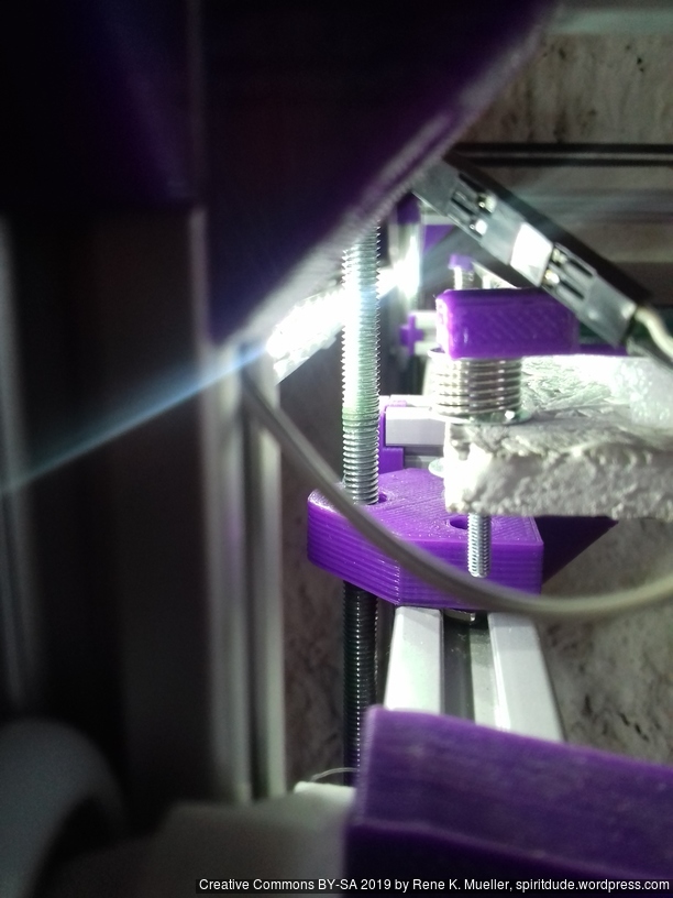
It took a while to build the Ashtar D #1 as the other variants like Ashtar K and Ashtar C worked so well – here some of the early tests in 2022/12/09:
References
Ultimaker S5: different XY head design using smooth rods, head: XY, bed: Z, build volume: 330 x 240 x 300mm, swapable hotends/printcores; priced at EUR/USD 6,500+ (2020/12)
Makerbot Replicator: head: XY, bed: Z, build volume: 295 x 195 x 165mm, priced EUR/USD 2,400 (2020/12)
Creality CR5: blatant copy of Ultimaker 2, S3 & S5 case design, head: XY, bed: Z, build volume: 300 x 225 x 380mm, priced EUR/USD 1,500 (2020/12)
It has been on my mind for quite a while to do a 2020 alu extrusion based Cantilever 3D printer, and so I started in December 2020 with a rough design, starting from the existing Ashtar K design and cut away parts:
using Head XZ and Bed Y
aiming common build volume (e.g. easy to source print bed)
140mm to 190mm each axis
tried 6, 7 and 9 beams options, settling with 6 beams for now
aiming for uni-length 2020 alu extrusions, T-slot and V-slot where a carriage rides (X & Z axis) with V wheels.
trying to keep as simple as possible
20×20 aka 2020 Alu Extrusion T-Slot Profile
2020 V-Slot Profile
V wheel
Frame: 6 vs 7 vs 9 beams
6 beams
7 beams (+1 back)
9 beams (+2 left + right)
The 9 beams give an overall better sturdiness, but not sure how essential at small building volume (less than 220mm each axis). I might be able to remove beam, the last beam at the back at the bottom reducing to only 6 beams, in that case the Y motor is mounted on the remaining beam in the back.
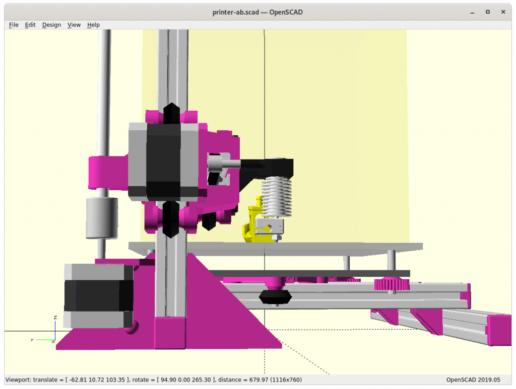
Z Carriage: 3 vs 4 wheels module
3 Wheels / 2 Mounts
4 Wheels / 3 Mounts
4 Wheels / 3-wide Mount
4 Wheels / 3-wide Mount, Routing Inside
The 4 wheels looks best but it also sacrifices some of the X range by apprx. 10mm, the obvious choice is 3-wide mount – actual tests will tell if the X & Z axis are solid enough.
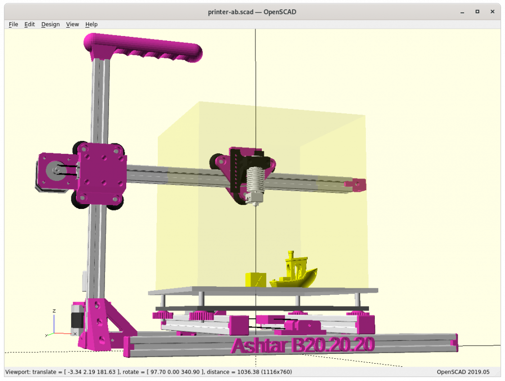
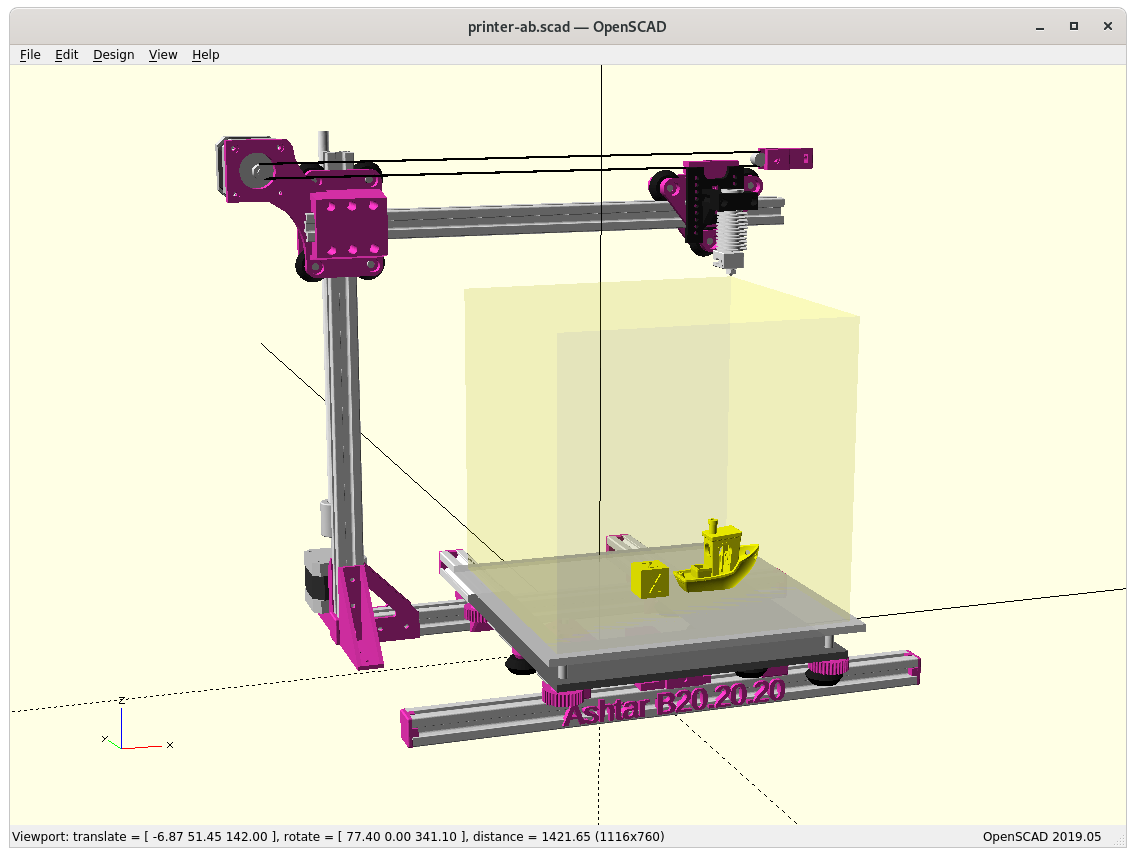
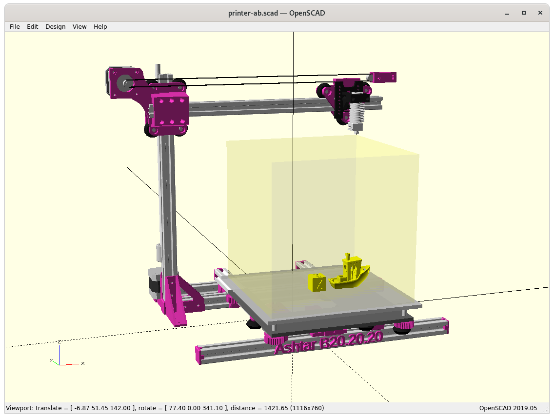
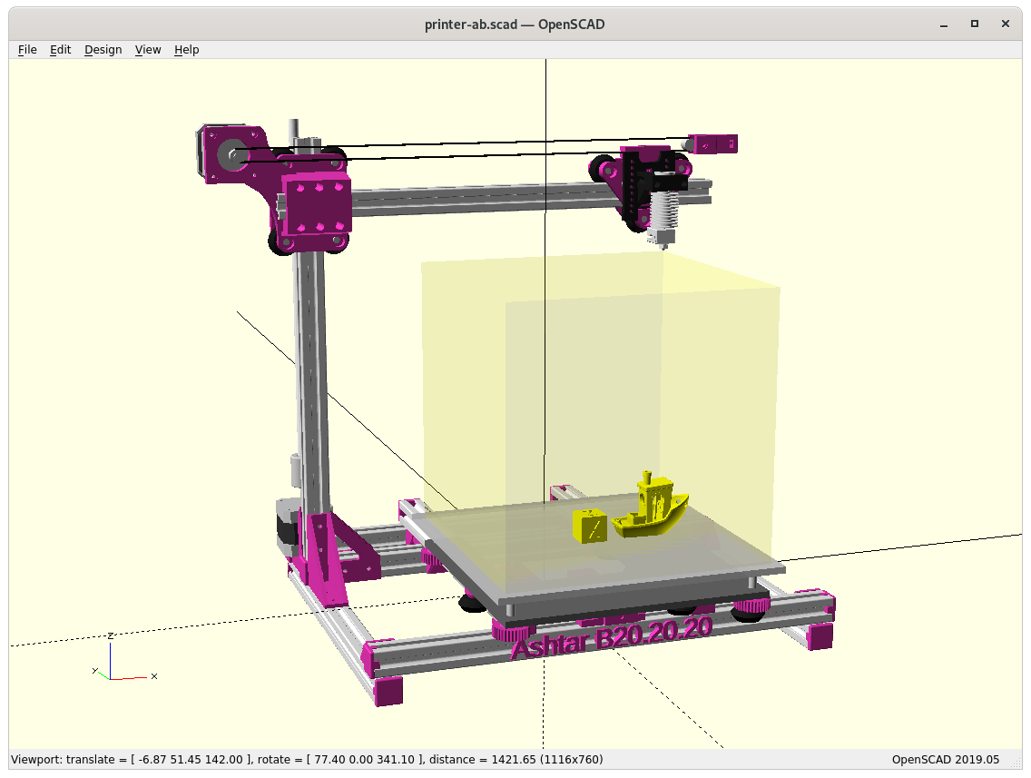
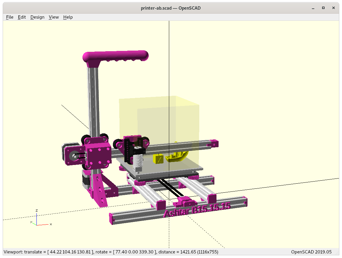
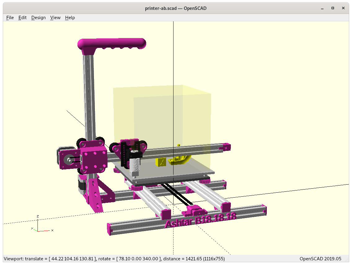
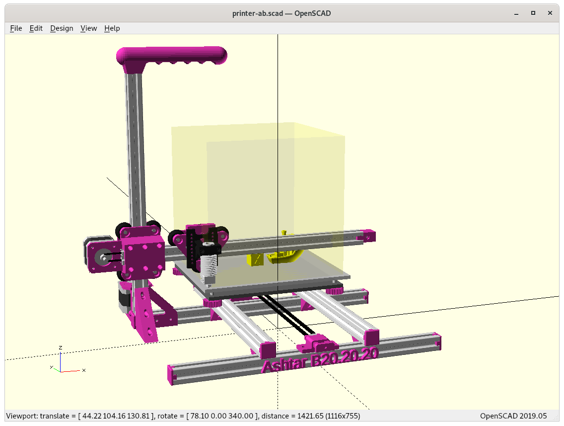
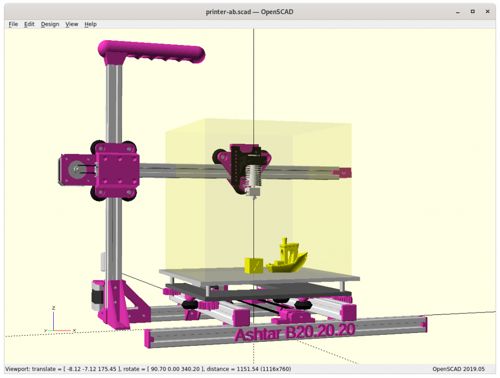
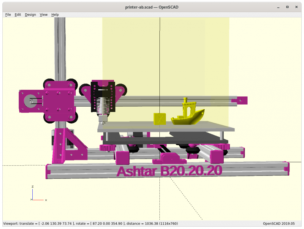
Different Sizes
Ashtar B 150x150x150
Ashtar B 180x180x180
Ashtar B 200x200x200
The 200mm build axis length would be good, but I’m not sure if the XZ carriage will allow it as the max margin or tolerance would be half of a layer-height, e.g. 1mm layer height ⇒ 0.05mm tolerance, at X = 0 .. max the head should not flex more than 0.05mm. At this this early draft stage I don’t know which size is most suitable, I focus on 180mm build axis.
The project page on Ashtar B summarizes the current state.
2021/01/07: Y motor and shaft extension with Y pulley holder added
2021/01/03: Z motor mounts added, Y carriage to XZ frame/arch pieces refined using rcube()
2020/12/19: new “XZ Arch” option (removing lower X beam from XZ frame)
2020/12/17: change X carriage, routing X belt inside 2020 alu extrusion
2020/12/12: first drafts, just a skeleton, details still to be worked out
Introduction
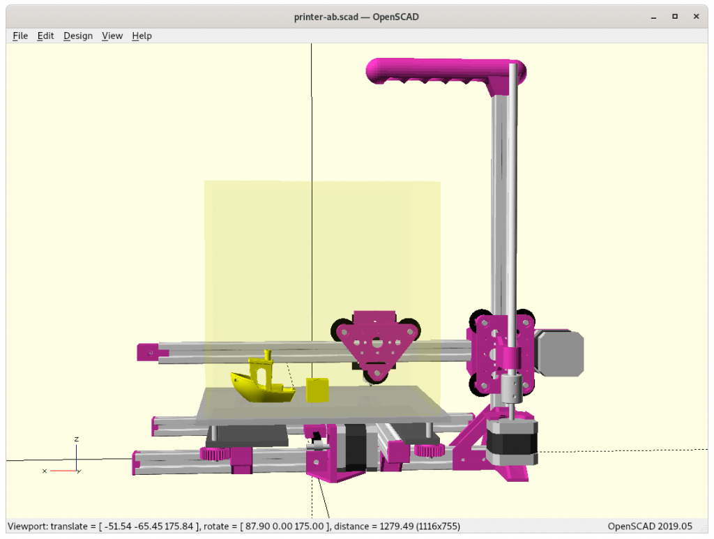
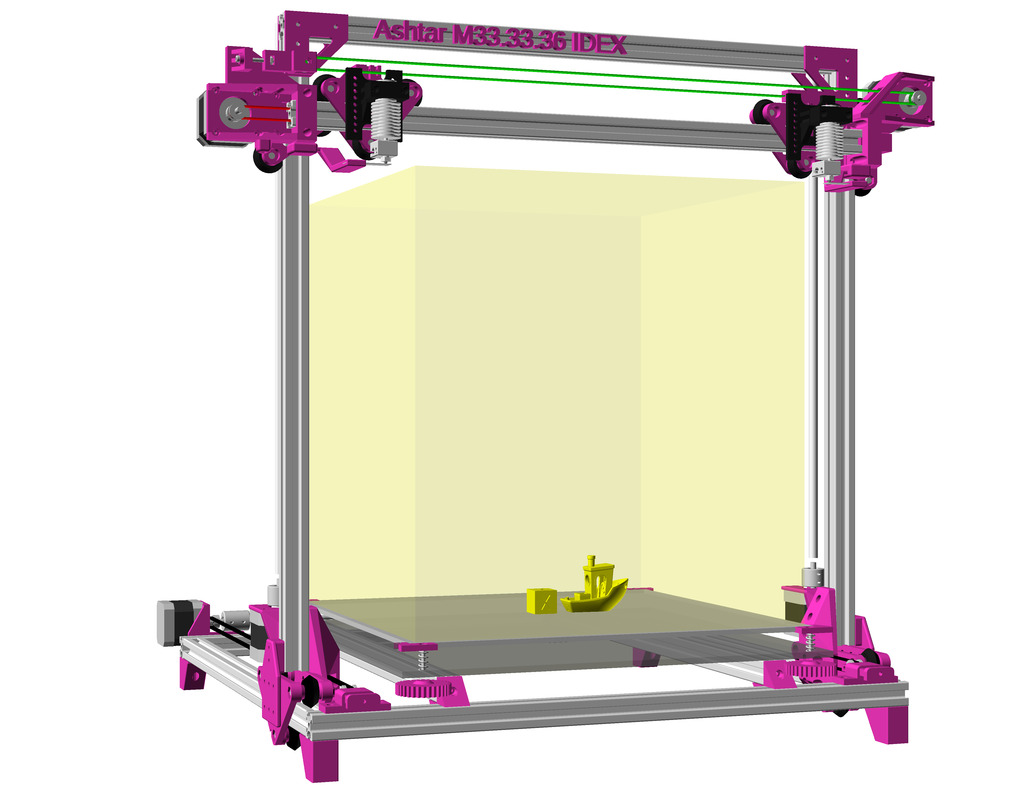
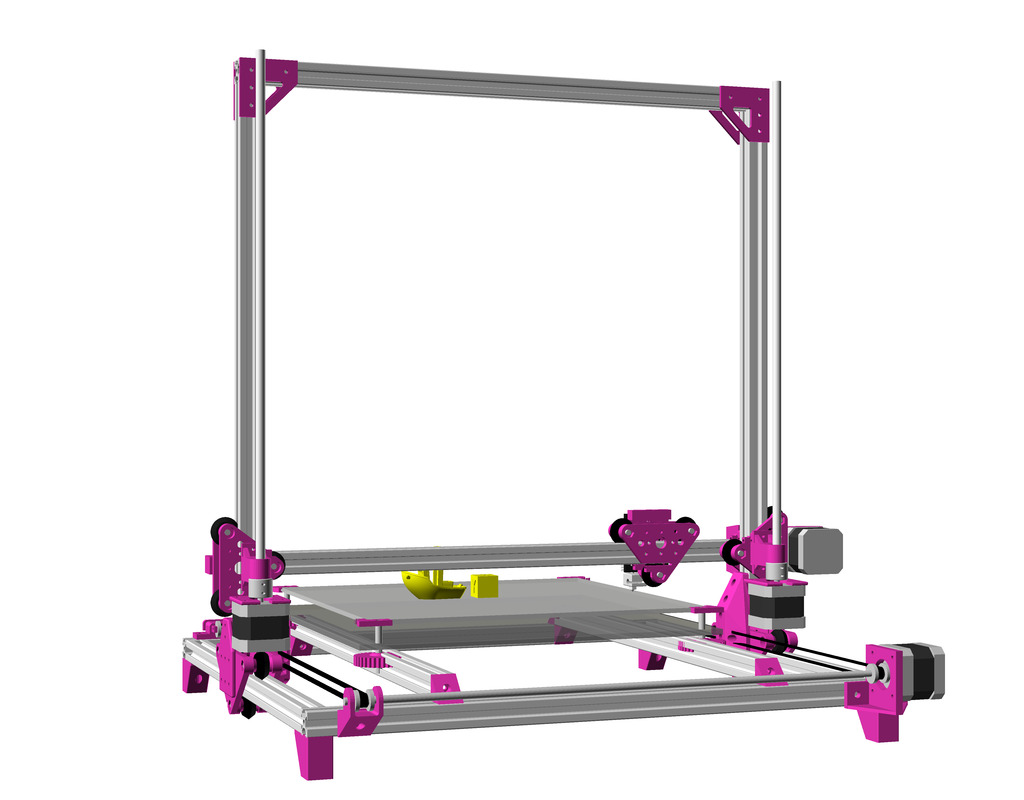
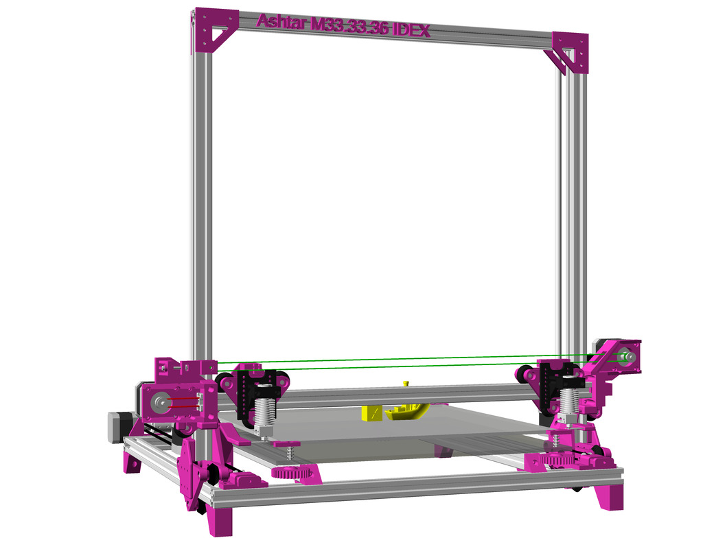
Jon Schone (@properprinting) did a “Moving Portal” (MP) mod for his CR-10 in April 2020, and I thought to adapt his approach as “Ashtar M” as Moving Gantry (MG) using CNC terminology.
Instead to move the bed in Y axis to move the entire XZ frame or gantry – the rest of the Prusa i3 style printer remains the same.
Reducing Moving Weight
Ashtar M with Moving XZ frame using modular & parametric V-carriage
This variant only makes sense when the weight of the bed exceeds the weight of the XZ frame + X carriage, in order to reduce the moving weight as of inertia – so only for large(r) build volume this makes sense:
weight(XZ frame + X carriage) < weight(bed)
and as I compose my Ashtar 3D printer series with alu extrusions (beams) I can say:
weight(XZ frame) = beam X * 2 + beam Z * 2 + NEMA17 * 2 weight(bed) = X * Y
and it becomes here clear, the bed weight grows X * Y whereas XZ frame only (X + Z) * 2, but also 2* NEMA17 motors of the Z axis are part of the XZ frame.
XZ frame is static (can hold filament, extruders etc)
T-Slot 2020
V-Slot 2020
V wheel
Draft
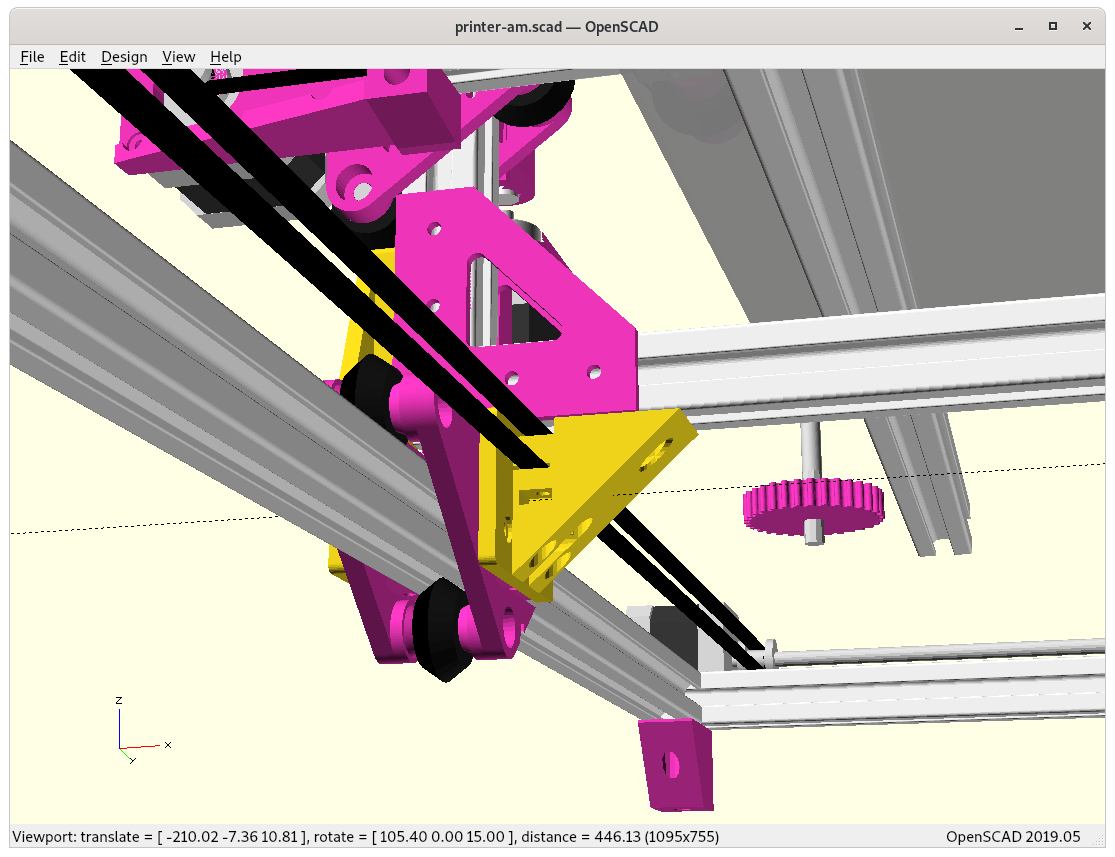
At position 0,0,0
Bare view of Y carriage to XZ frame
Adding side pieces “A” & “B”
Side piece “A” Y carriage to XZ frame
Side piece “B” Y carriage to XZ frame
Side piece “B” bottom view
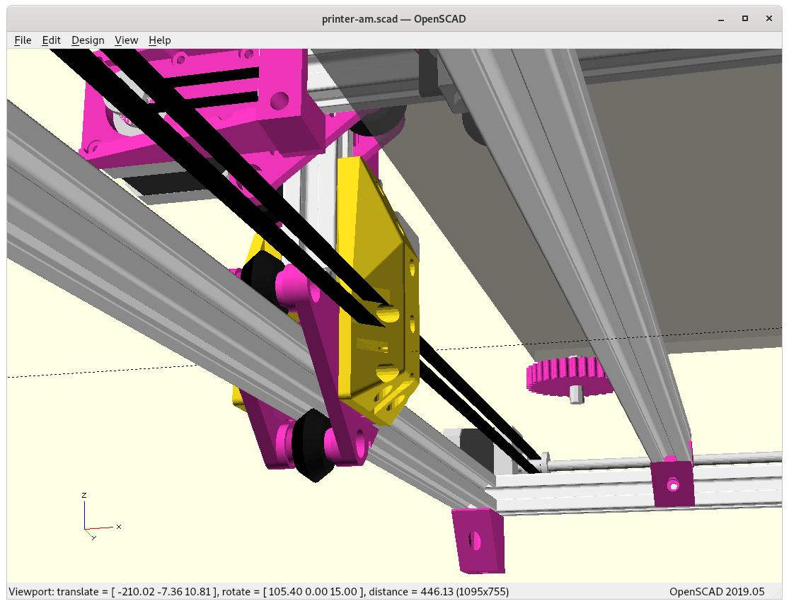
At position 0,0,0
Z motor mount
Y belts & Y motor
Y pulley holder
Y motor mount
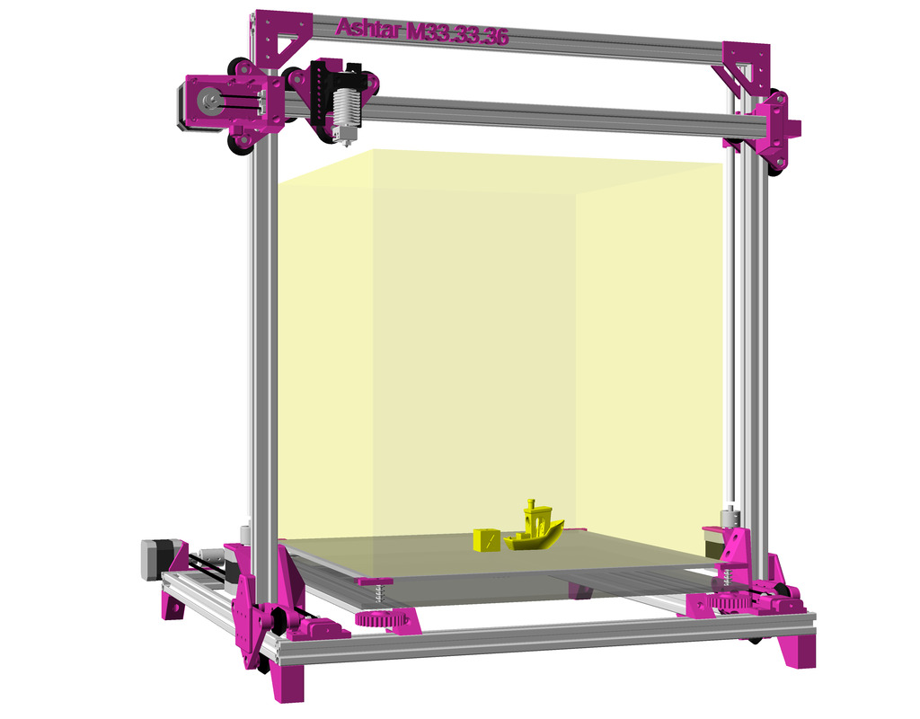
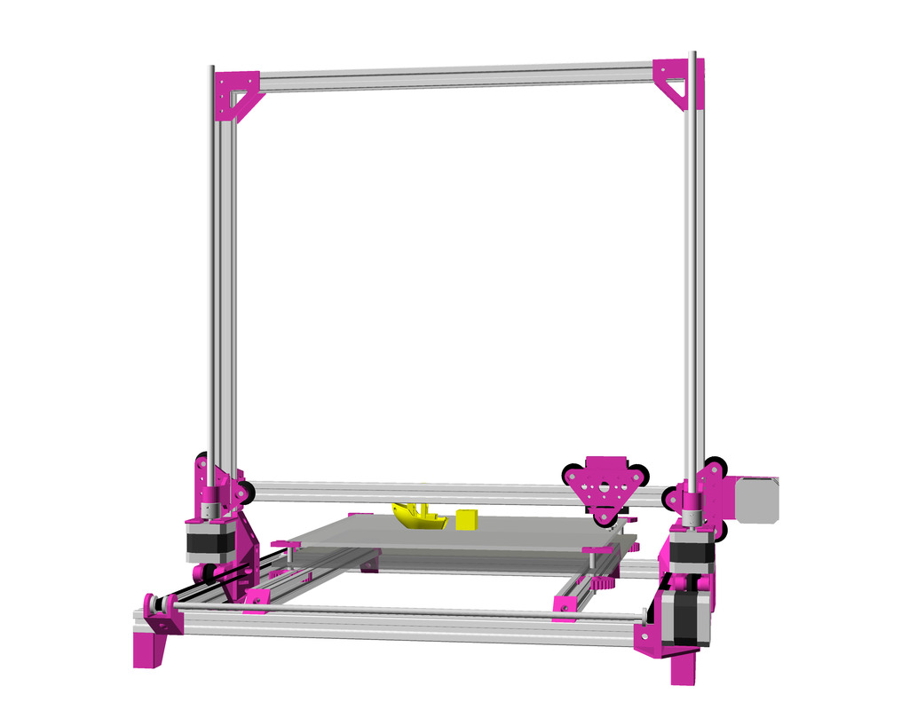
For now I decided to use my V modules as Y carriages with width of 100mm vcarriage2(width=100) but actual tests are required how stable the moving XZ frame will be.
As you can see on the draft, I lose some build volume because I stack on top of the Y carriage instead within, but if I put the gantry / XZ frame between the Y carriage I need extra long X beams for the outer frame, and make it impossible to achieve uni-length design (same beam length for all); it’s all about balancing a compromise.
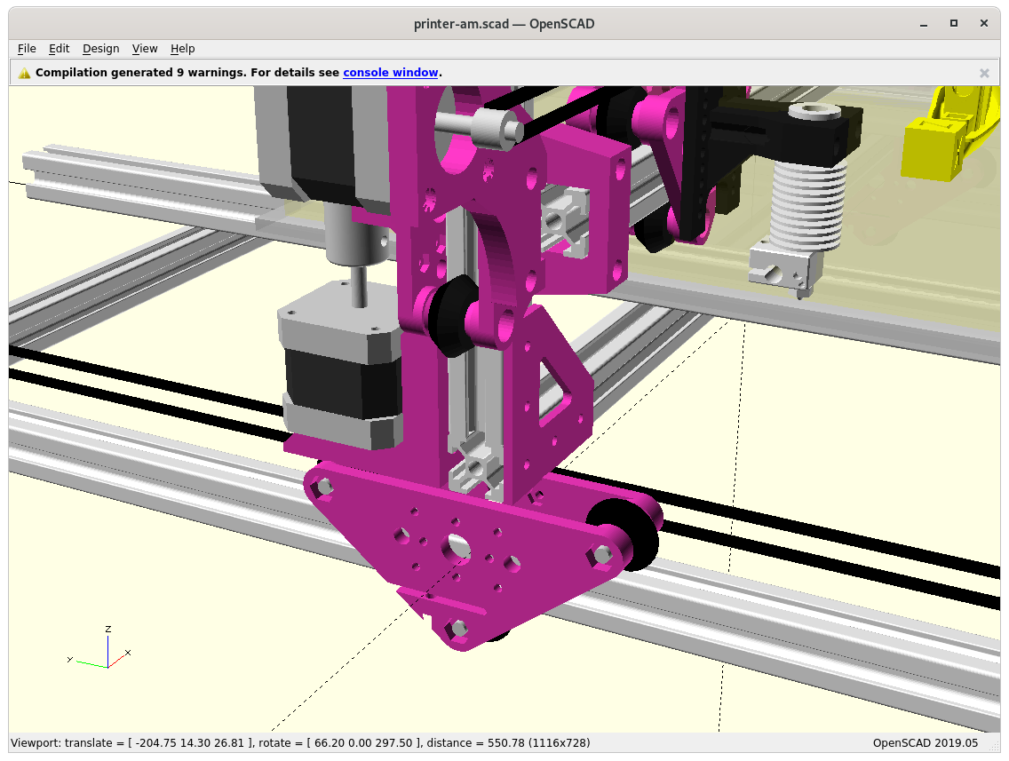
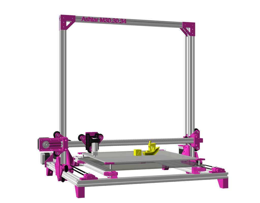
XZ Arch Option
The “XZ Arch” option is removing the lower X beam from the XZ frame, hence, extends Z build space as the print bed also goes lower – for now I moved the Y beams supporting the print bed on the lower framework, details how the print bed will be mounted not yet determined. The side piece “A” is a bit shorter, and side piece “B” is a bit more solid – the way the Y belt is fastened remains the same: Y belt ends come out downward, and are fastened with M3 screws & M3 nuts inserts.
Side pieces “A” & “B” with Arch (lower X-beam removed)
Side piece “A”
At position 0,0,0
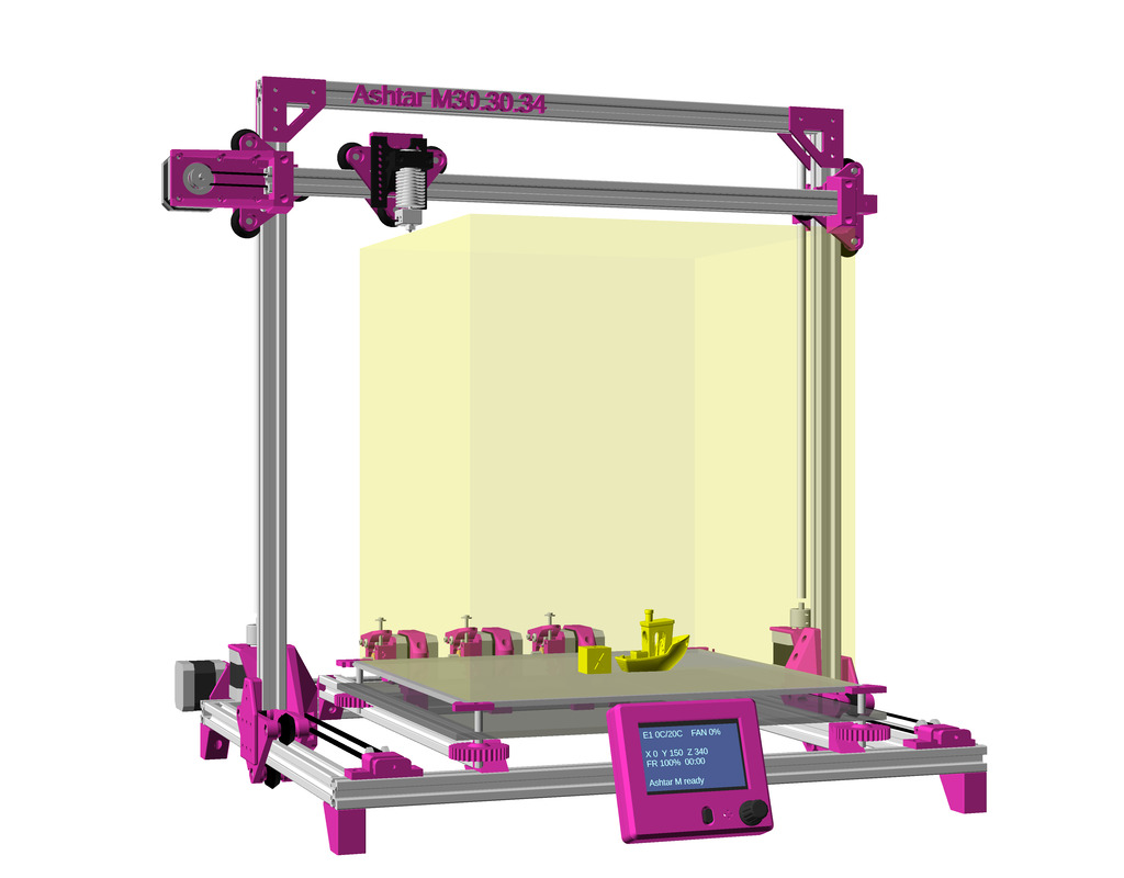
Specifications
Build Volume: ~380x400x380mm
Frame: 10x 500mm 2020 alu profiles (XZ arch option)
3x or 5x V-Slot 2020 (X, Y and optional Z axis)
7x or 5x T-Slot 2020
Issues to Resolve
Y motor & Y pulley holder, likely using 6mm smooth or threaded rod as extender, resolved, details defined with 625ZZ bearings
print bed mounting with adjusting nobs to level bed
optional remove lower beam of the XZ frame and make it just a gantry, would allow to lower supporting bed beams (space for springs and nobs etc) – but might introduce weaker XZ gantry geometry
Y Carriage to XZ Frame mount: either combine the L shape of XZ frame, or have a separate piece to attach – that part likely is the most challenging to get right, using two pieces “A” and “B” to connect to XZ frame with Y carriage
resolved in theory, but in actual implementation it will be tricky, as the piece “A” aka ycarriage_xzframe_mount_a() will be printed flat, and quantized by layer height, but the thickness has to be very precise as +/- 0.05mm not to introduce any tilt on the Y carriage (it would damage the V module and/or V wheels and introduce wobble Y-wise), hence 0.1mm layer height required for piece ycarriage_xzframe_mount_a() mounted outside, and ycarriage_xzframe_mount_b() (◤-like piece) mounted inside:
Side pieces “A” & “B” with full XZ Frame
Side pieces “A” & “B” with XZ Arch
Z motor mounts, resolved: how stable it is needs to be tested
cabels & bowden tube routing
XZ frame moves as well – lot of motion involved – likely not put bowden extruder motor on it and avoid to add additional weight again
cable chain to ensure it bends in a controlled manner
Preliminary position of multiple extruders: X back beam, hence, very long Bowden tubes
none of them can be put on the moving XZ frame anymore
tuning to common to build-volume with uni-length beams
likely 400x400mm build plate achievable, but perhaps 380×400 printable, losing 10-15mm on left- and right-hand side.
XZ frame vs XZ arch: to be determined if it’s essential with actual tests
XZ frame (back view)
XZ arch (back view)
build printer
print tests
release parts
release code
Bed
Ashtar K & M bed mounting
The bed is stationary, so it’s relatively simple, a bed carriage it still required so the fine level adjustment is possible with some knobs – using the same setup as for Ashtar K.
Gallery
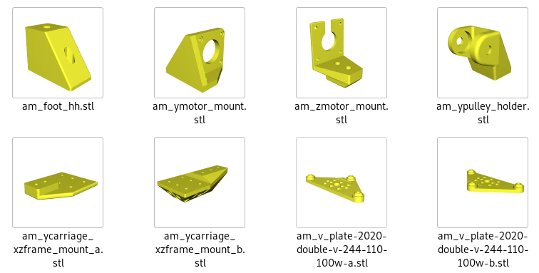
Parts
Printable Parts
Y carriage:
2x am_v_plate-2020-double-v-244-110-100w-a
2x am_v_plate-2020-double-v-244-110-100w-b
2x am_zmotor_mount
2x am_ycarriage_xzframe_mount_a
2x am_ycarriage_xzframe_mount_b
1x am_ypulley_holder
1x am_ymotor_mount or 2020_Y_motor_mount
4x am_foot_hh
Non-Printable Parts
2x 625ZZ bearings
2x for 1x am_pulley_holder
nx pulleys (dimension not yet determined)
2x (5mm hole) for 1x Y motor, 1x am_ypulley_holder
1x (5mm hole) for 1x X motor
nx idlers (with 3 or 5mm hole)
1x (3mm hole) for 1x X belt
2x (3mm hole) for 2x Y belts
~490-500 mm M5 smooth or threaded rod (Y shaft extension)
See the on-going blog-posts on Ashtar M development, with some more details than the overall page here.
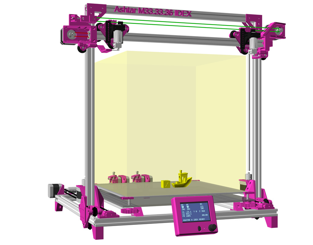
IDEX Option
As Ashtar M shares much of Ashtar K design, the IDEX option comes easily – yet, adding a 2nd motor on the moveable XZ frame/gantry definitely pushes the limits of Ashtar M, significant forces will be applied at high Z positions while moving Y axis.
In order to run two independent printheads (Independent Dual Extrusion) following changes are needed:
2020/12/23: added more details on Y bed, and size comparison, blog post published.
2020/12/17: X motor mount done, X belt pulley holder, XZ cantilever x-offset 10mm.
2020/12/12: just the basic idea, an early draft with a few options (extra foot, 3/4 wheels for Z carriage), 6 vs 7 vs 9 beams.
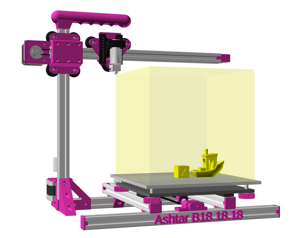
Introduction
Ashtar K was the first design with 2020 T-slot alu extrusions, and I used 11 beams of 500mm length to make up the entire frame. In the back of my mind I thought also doing a Cantilever 3D printer with 2020 T- or V-slot, like the Prusa Mini or Printrbot Simple Metal, and as before I like to reuse the frame as rails directly and not use any smooth rods or alike, which means X beam as V-slot, and optionally Z beam as well as V-slot, Ashtar B:
T-Slot 2020
V-Slot 2020
V wheel
Draft
At position X = 0
At position X = max
At position Y = 0
At position Y = max
A build-volume of 140mm to 190mm each axis is targeted in order to keep the X axis short – also, likely using a Bowden extruder setup where just a hotend resides on the X carriage.
Specifications
Build Volume: ~180x180x180mm
Frame: 6x 340mm 2020 alu profiles
2x V-Slot (X and Z axis)
4x T-Slot (Y axis with simple sliders where T-Slot are sufficient)
Issues to Resolve
X belt routing: outside of 2020 extrusion or inside
X motor mount: rather simple, perhaps combine with xcarriage_short_hmount_2020(), done
Y motor mount position: will determine overall build volume
3 vs 4 wheels on Z carriage, 4 wheels (see below why)
positioning: extruder, controller, display, power supply, optional filament holder
positions of X, Y and Z endswitches
tune to a common build volume while having uni-length beams/extrusions
150mm, 200mm, 215mm for X & Y build axis length
Frame: 6 vs 7 vs 9 beams
6 beams
7 beams (+1 back)
9 beams (+2 left/right)
The 9 beams give an overall better sturdiness, but not sure how essential at small building volume (less than 220mm each axis). I might be able to remove beam, the last beam at the back at the bottom reducing to only 6 beams, in that case the Y motor is mounted on the remaining beam in the back.
Z Carriage: 3 vs 4 wheels module
3 Wheels / 2 Mounts
4 Wheels / 3 Mounts
4 Wheels / 3-wide Mount
4 Wheels / 3-wide Mount, Routing Inside
The 4 wheels looks better also because it allows to add another 2020 horizontal mount or wider mount, some X range is sacrificed (10-20mm).
Different Sizes
Ashtar B 150x150x150
Ashtar B 180x180x180
Ashtar B 200x200x200
The build volume from 150mm to 200mm for each axis, I like to have 200mm but not sure if the X axis can maintain linearity fully (e.g. half of a layer-height such as 0.1mm ⇒ 0.05mm linearity for head X = 0 .. max), I might to have to settle for 180mm or even 150mm. Actual tests and fine tuning of the Z axis (4 wheels V carriage) and X axis (3 wheels V carriage) will tell.
Common quadratic bed-sizes are 150mm, 200mm, 214mm, 220mm and 235mm e.g. for magnetic beds. A 200mm bed can be used but only 180mm be printed, as I have sufficient margin on the XZ cantilever side.
Y Bed
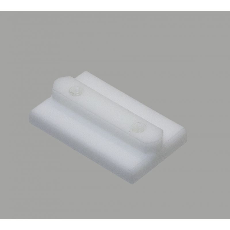
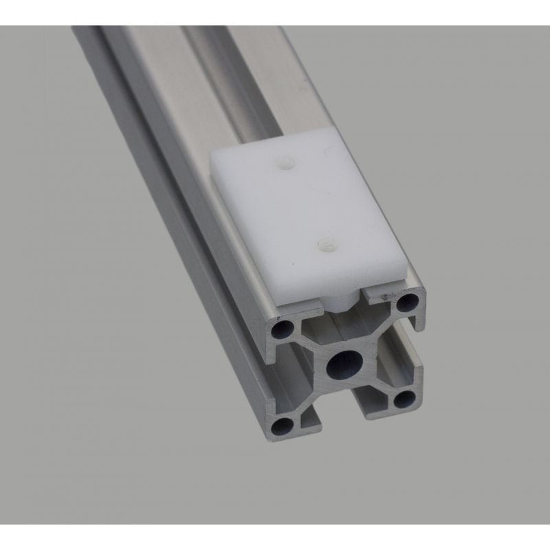
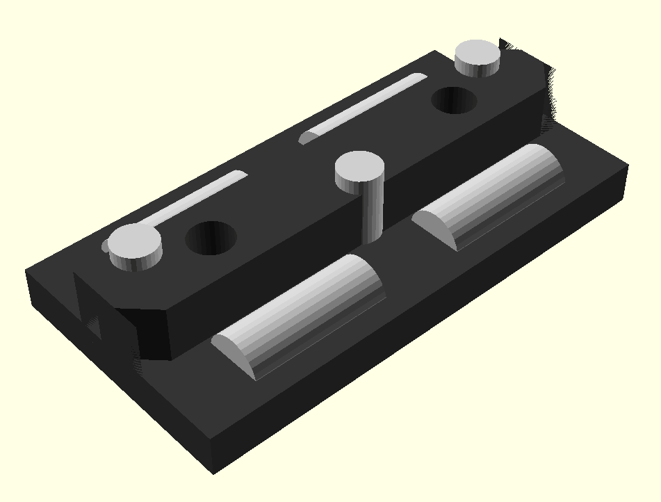
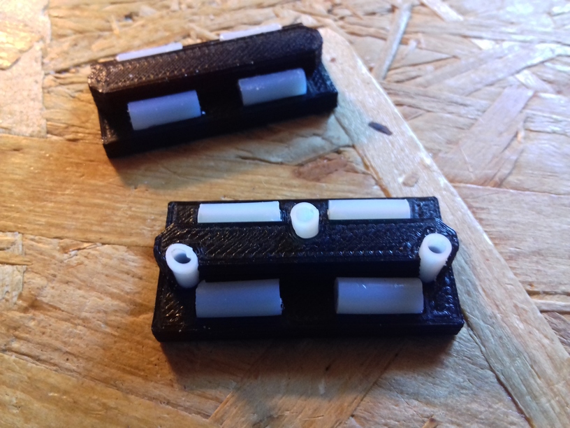
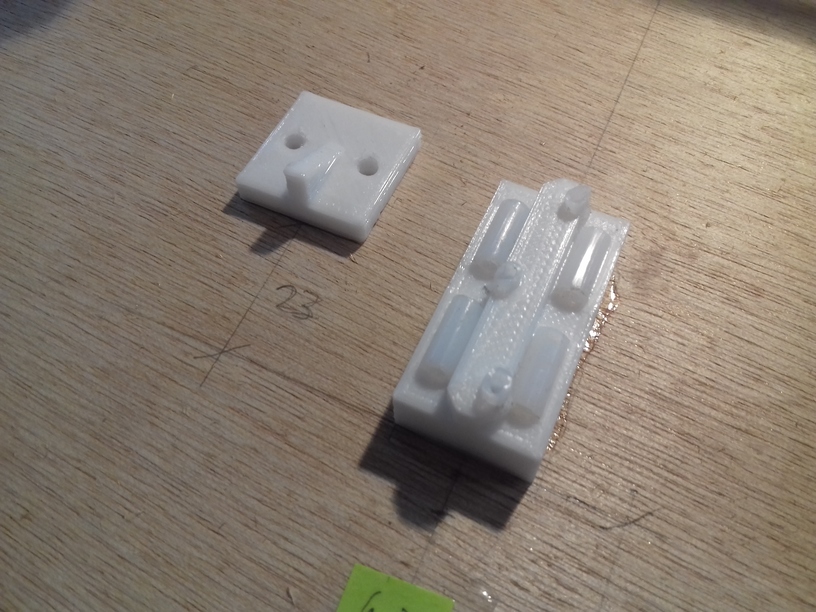
I gonna use the simple slider riding on T-slot (derived from an existing nylon slider) for the Y bed, 3 sliders in total:
Nylon Slider for T-Slot
Slider on T-Slot
Slider model with PTFE tubes
3D printed slider with PTFE tubes
The sliders are glued beneath the Y carriage, then the Y bed snaps into the T-slots easily. I have printed on these sliders with two Ashtar K‘s (K1 = 380×400, K2 = 300×300) for about 1+ years successful. This simple approach requires gravity, and the bed needs its own weight to stay in place (cannot be up-side-down or in no-gravity environment like International Space Station ISS).
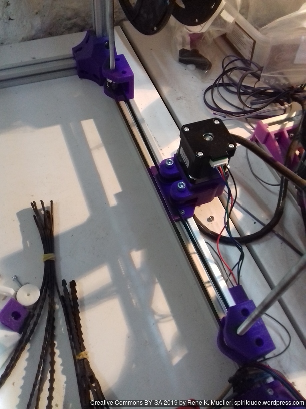
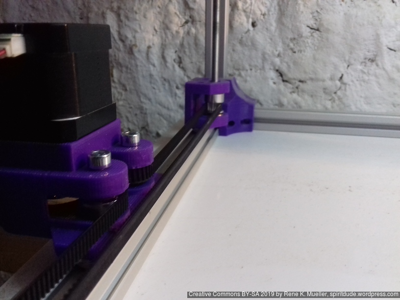
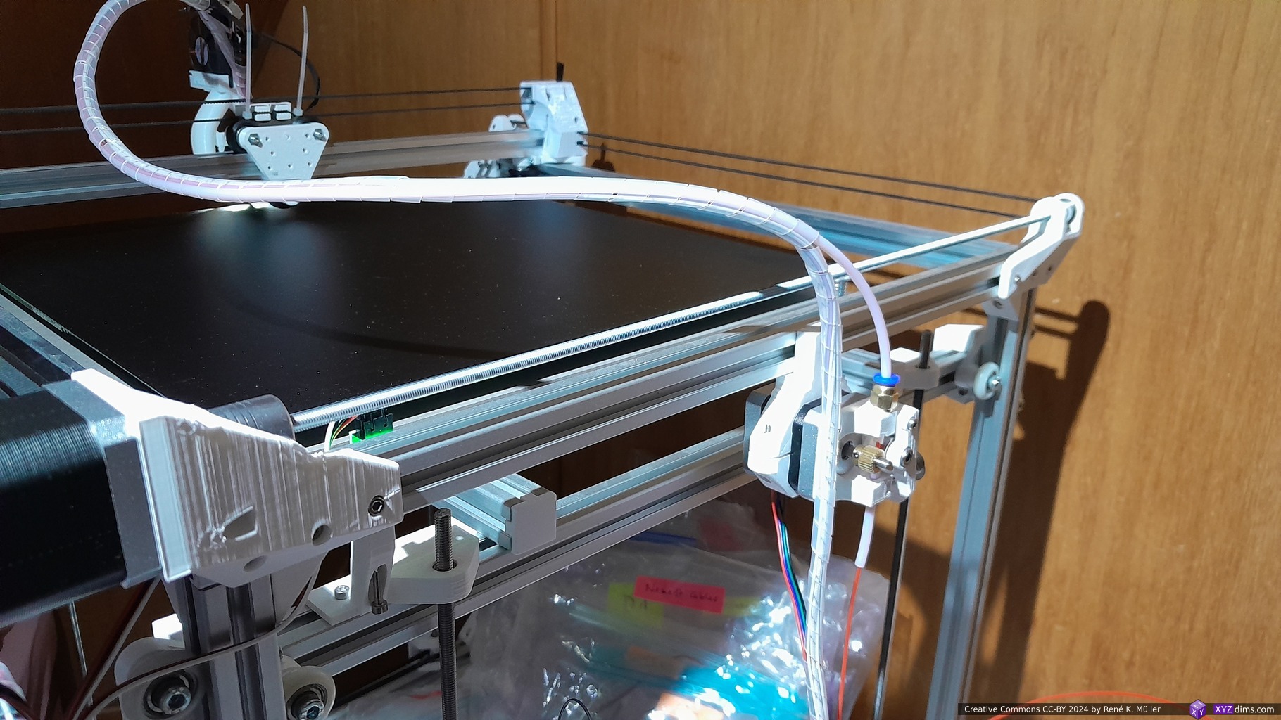
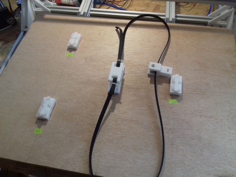
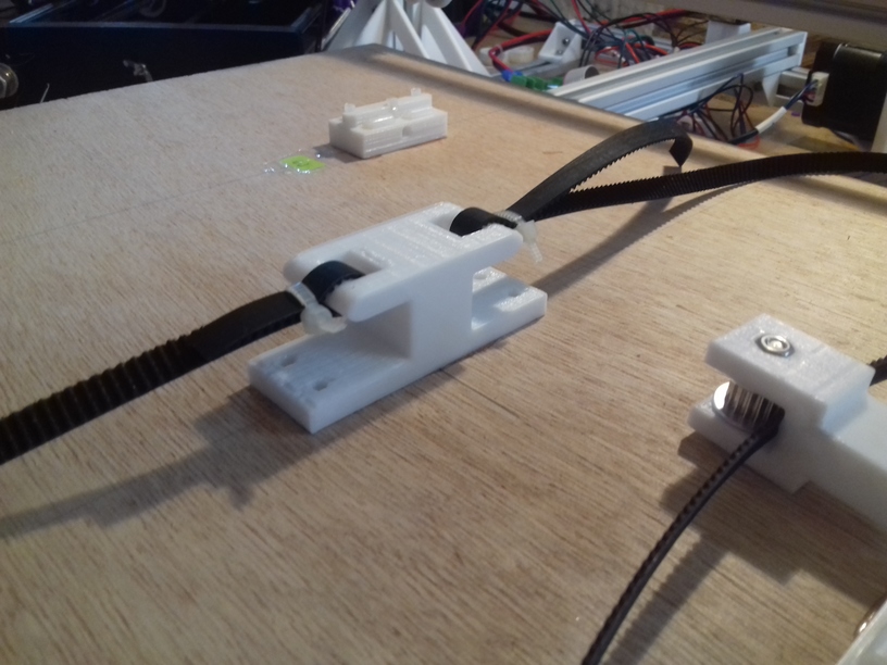
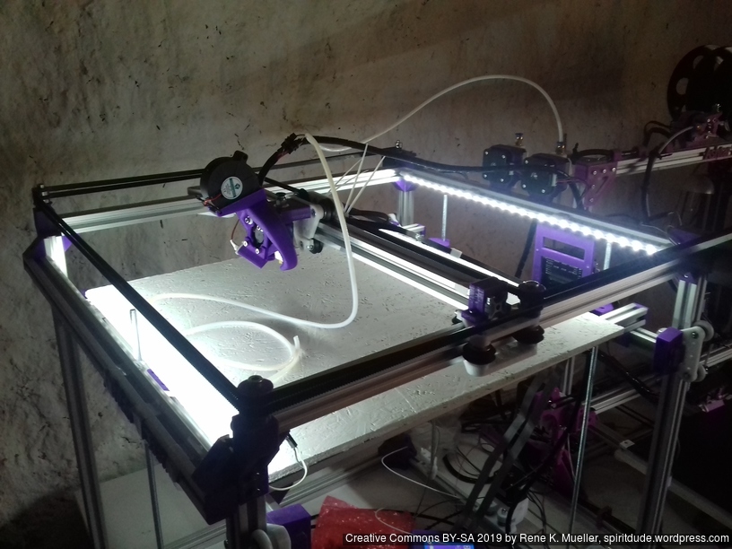
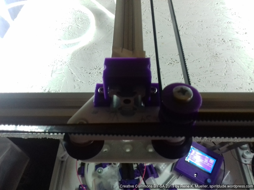
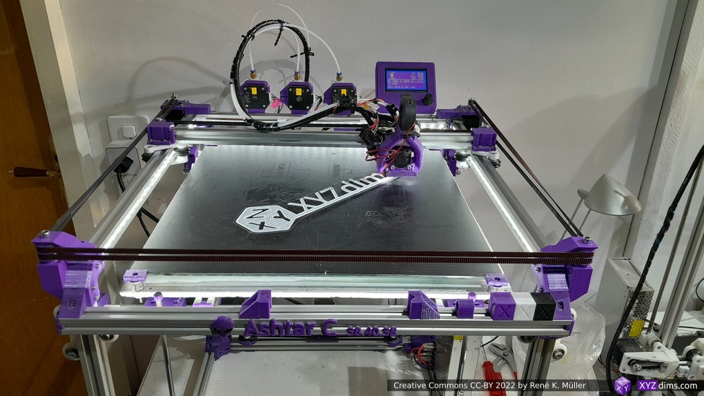
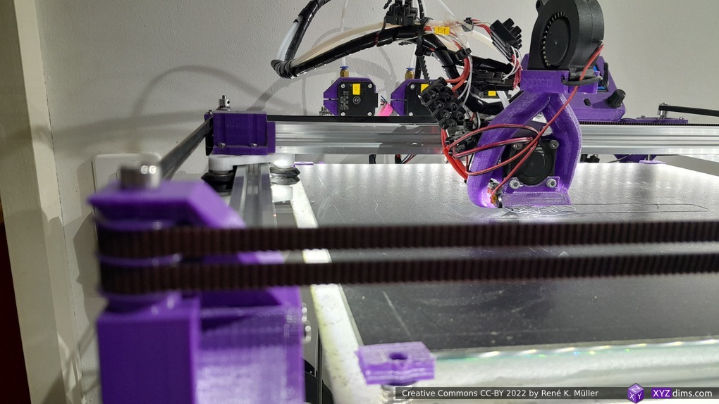
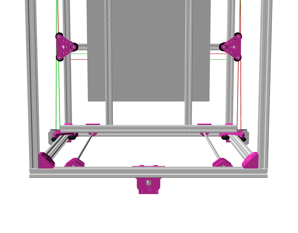
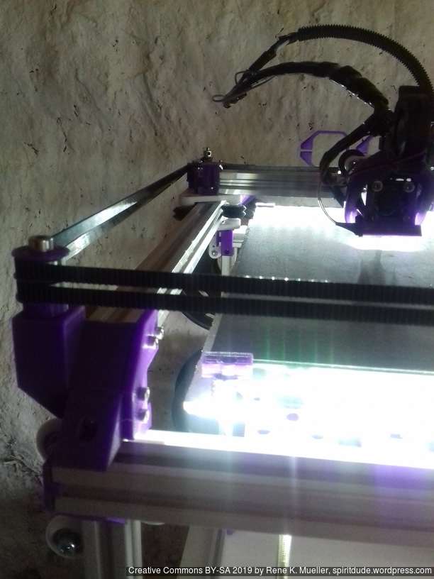
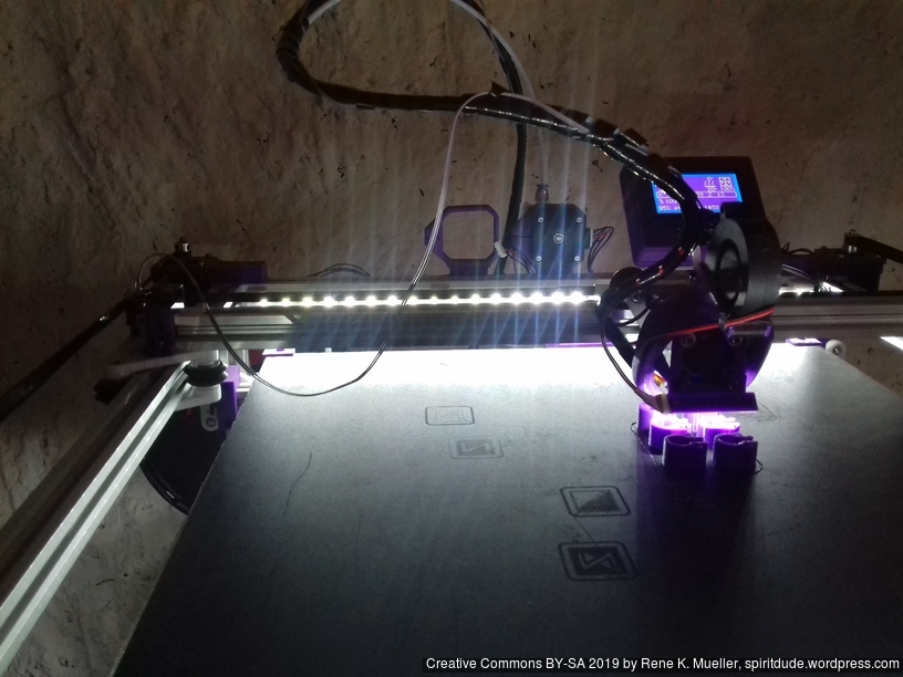
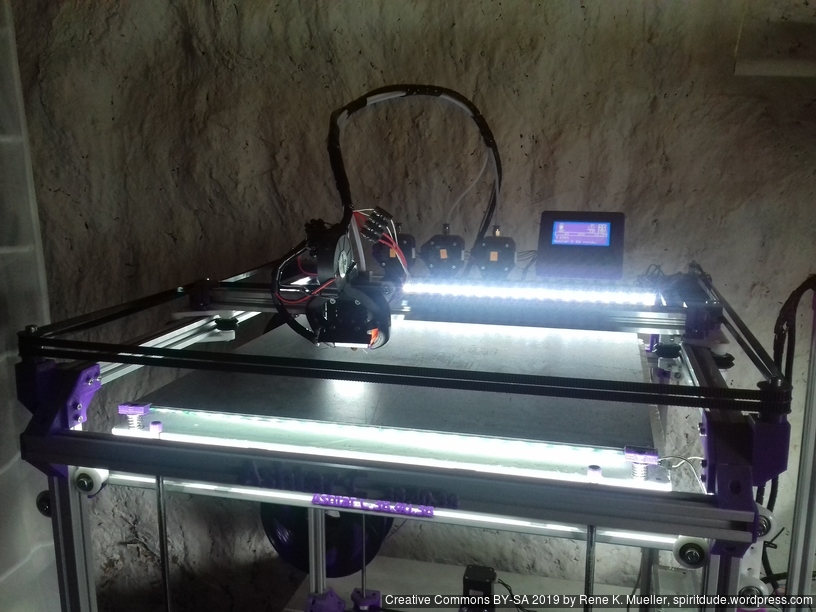
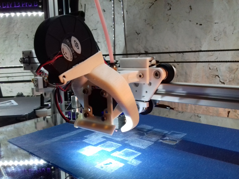
After some delay of parts, I finally was able to finalize the belt routing and configure the firmware for Ashtar C #1:
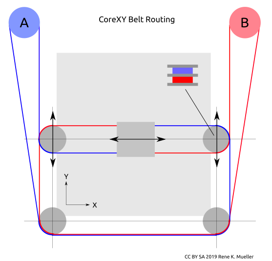
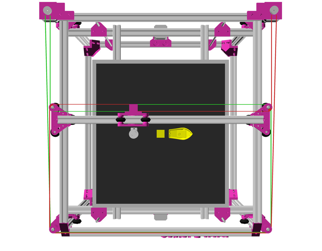
Belt Routing
CoreXY belt routing of Ashtar C
Early on I decided to separate belts of motors A and B in the Z axis, so they would not cross as such, and also hoped one axis of the carriage holding the X beam would allow some idlers to redirect the belts – to save space and keep frame dimension and build (or printable space) dimension close.
The Bowden tube and the wires of the hotend are preliminary arranged:
Firmware
To configure the Marlin firmware turned out not that simple, as CoreXY has its own interdependencies of A & B motors: first X axis was reversed, whereas Y axis worked correctly, the INVERT_X_DIR setting on Configuration.h of Marlin did not help, it reversed the stepper motor direction, but not the actual X axis direction. After many attempts to use COREYX instead of COREXY I ended up
swap cables of A & B stepper motors
keep #define COREXY
#define INVERT_X_DIR = true and #define INVERT_Y_DIR = true
and X and Y direction worked correctly.
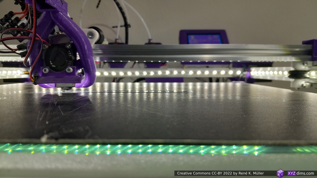
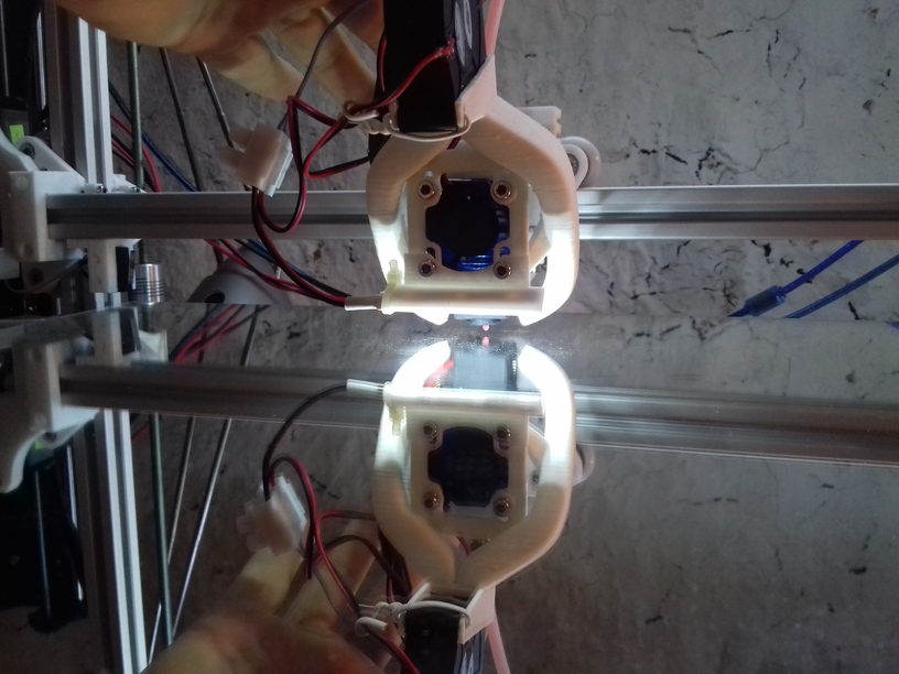
Preflight (no extrusion, just X & Y axis movement testing):
The stepper drivers still need some tuning, as I saw or rather heard a few missed steps at fast movement.
X & Y Endstops
The preliminary positions of the endstop are:
X endstop resides on the X beam left-hand side (USE_XMIN_PLUG)
Y endstop resides on the right-hand backside, (USE_YMAX_PLUG and HOME_DIR_Y 1)
X endstop
Y endstop
Z Axis
I postponed the actual details of the Z axis, as my main concern of the design was to have a good CoreXY setup and then see how I would achieve the Z axis.
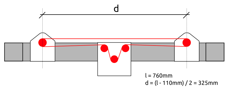
In order to use 625ZZ bearings I started to use them as idlers directly (after cleaning the grease off their surfaces) and also use them to increase contact surface when driving a closed belt which drives 3 or 4 threaded rods M6 x 500mm:
Since the surface of the threaded rods is rough, I realized I need dedicated bearings to hold the rods at the bottom, otherwise the friction would wear on the mounts and increase its diameter. So, the Z axis isn’t finalized yet, but close.
2022/09/19: new board MKS Monster8 with Marlin 2.0.x, 8 drivers
2022/08/01: Refining pieces, belts replaced with GATES LL 2GT
2021/01/14: Adding IDEX option as a draft, untested
2021/01/10: Finally more detailed and complete renderings with routed belts
2019/05/04: Dual Z + Dual Extruder for MKS Gen L for Chimera/Cyclops hotend
2019/02/08: Added “Maintenance” with first few points what’s important on this Core XY setup, up-to-date OpenSCAD model renderings
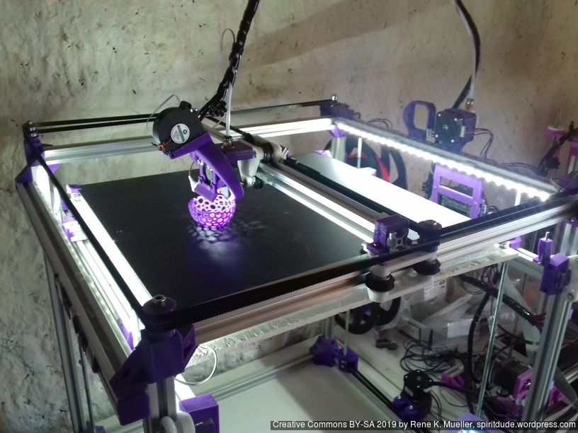
2019/01/31: First prints successful, Z axis redone with 2x Z motors with 2x 760 mm closed loop GT2 belts
2019/01/01: CoreXY mechanism complete: belt routing finalized and Marlin firmware configured, brief “preflight” video (no extrusion yet)
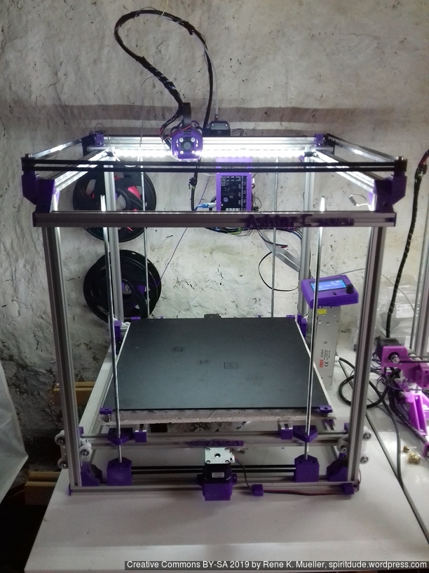
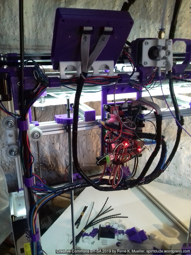
2018/12/08: Parts delayed, so development delayed as well, A/B motors installed and Bowden extruder, “Current State” photos uploaded
2018/11/09: Main frame setup with basic belt routing with mockup stepper motor.
2018/10/03: Dedicated corner bracket cci_2020() OpenSCAD module, first scaffolding the frame with printed parts
2018/09/10: First draft, fully parametric approach, detailed routing of belts not yet done (most important)
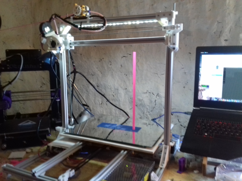
Current State
2022/08/01: corner pieces redone, high quality belts
Introduction
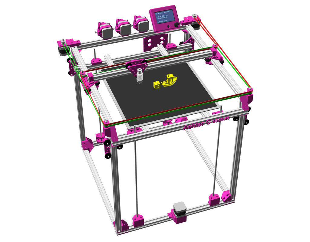
After Ashtar K(Prusa i3-like), I thought to still use single size 2020 T slot 6 (B-Type) alu extrusions to compose CoreXY styled 3d printer, fully parametric designed:
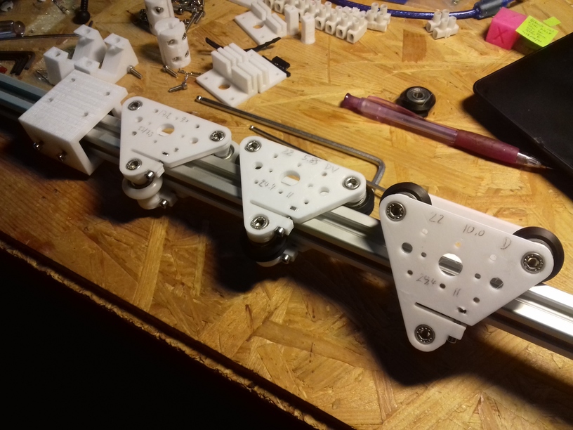
As first study shows, while trying to develop a single sized beam design: 16x beams make up the main geometry including bed mount, plus the X gantry which has to be shorter to lie between the top Y beams (if it sits above the belts also have to be routed above, and Y axis V modules and X axis V module not being on the same plane) and I used the same beam for the X beam where the X carriage rides the same length, using the Z offset to my advantage (instead to shorten it and fit it between the Y carriages): 17x 500mm alu extrusions (14x T slot and 3x V slot for X and 2x Y).
V modules with different kind of wheels.
So far I like to reuse the V modules to ride on the alu extrusions directly, that is X, Y and Z axis.
The Z axis details aren’t defined yet, I tend toward belt implementation, which is a bit more overhead than thread or lead screw implementation. The Z axis is done with 2 stepper motor driving each 2x threaded M6 rods (or lead screws optionally).
Specifications
CoreXY style
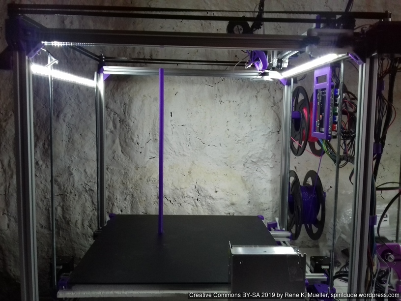
~385 x 400 x 380mm build volume (300×300 or 300×400 or 400×400 build plate)
500 x 520 x 520mm frame size with
14x 500mm 2020 T slot alu extrusion
3x 500mm 2020 V (or T slot as well) alu extrusion
Bowden setup for fast X/Y movement and fast printing therefore
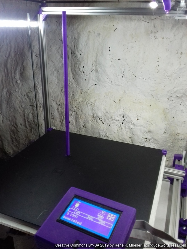
MKS Gen L main board + Smart Full Graphic display (with dialer)
Reprap style with many parts to be printed
M3: assemble most parts
M5: idlers of A/B belts
M6: Z axis threaded rods
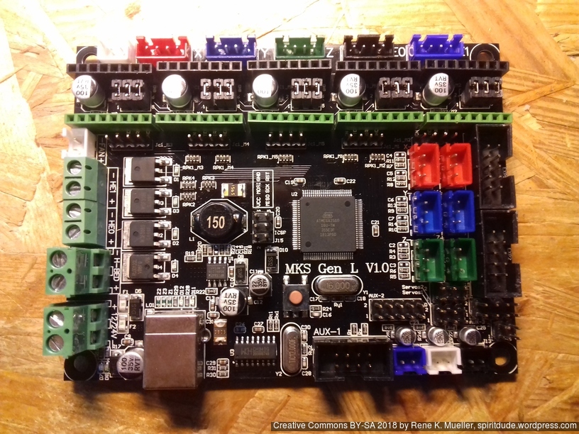
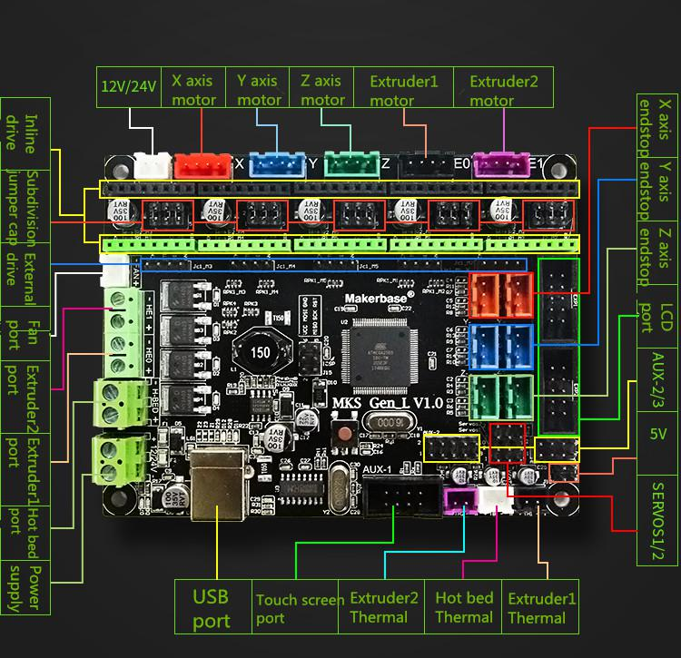
Electronics
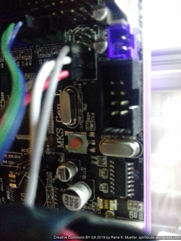
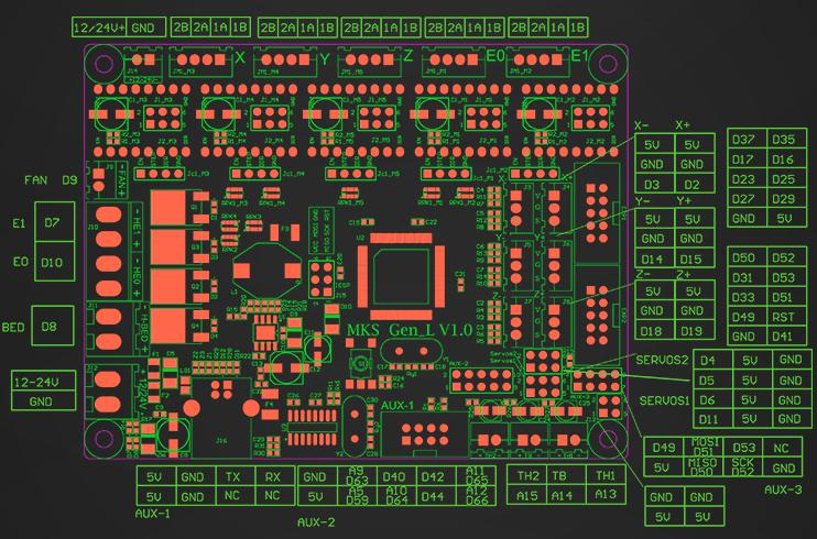
For Ashtar C #1 I use the MKS Gen L V1.0 board:
MKS Gen L V1.0 Controller BoardMKS Gen L V1.0 Controller Board Connectors
In order to add the RepRap Discount Full Graphics Controller I had to remove the notches and rotate EXP1 and EXP2 by 180 degrees so the display would work. I gonna use 5x A4988 as stepper motor drivers.
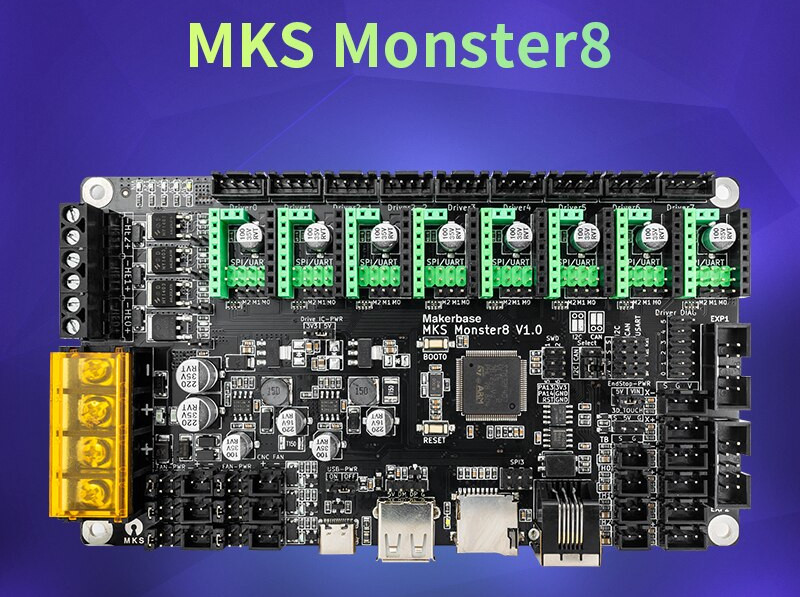
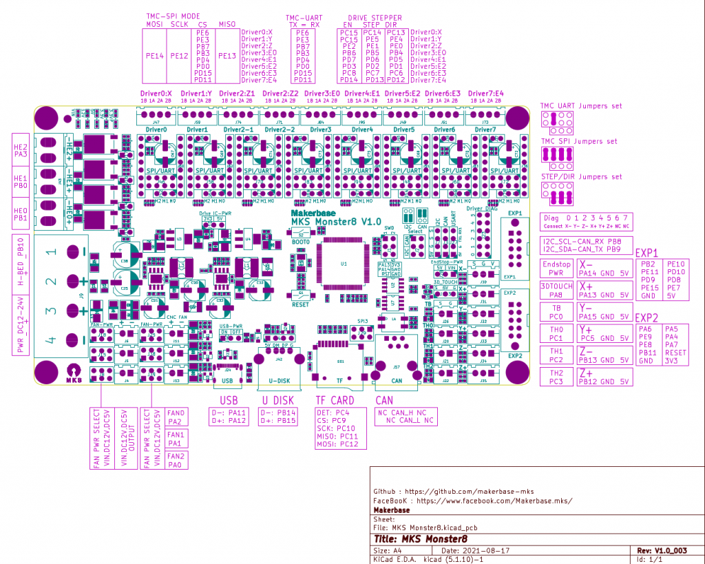
Update 2022/09 using MKS Monster8 V1.0 running Marlin 2.0x (requires PlatformIO to compile) with 8x TMC2209 motor drivers, MKS Mini 12864 V3 display (EUR 58):
MKS Monster8 (2022)MKS Monster8 Pinout
One has to use SDcard to put firmware on and reboot the board in order to install the firmware, there are firmware uploaders available just not for Linux.
With 8 motor drivers there are plenty extensions possible, especially the Z motor driver has two connectors (e.g. usually 2x Z motors, also in my case with CoreXY I use Z motors):
X, Y and Z(2): 3 drivers occupied
max 5 extruders
The board supports 3 independent hotends, so IDEX or even a 3x tool-changer possible with this board.
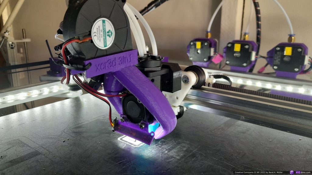
BigTreeTech ZSYong 3-in-1 with 3 materials/colors mounted on Ashtar C #1
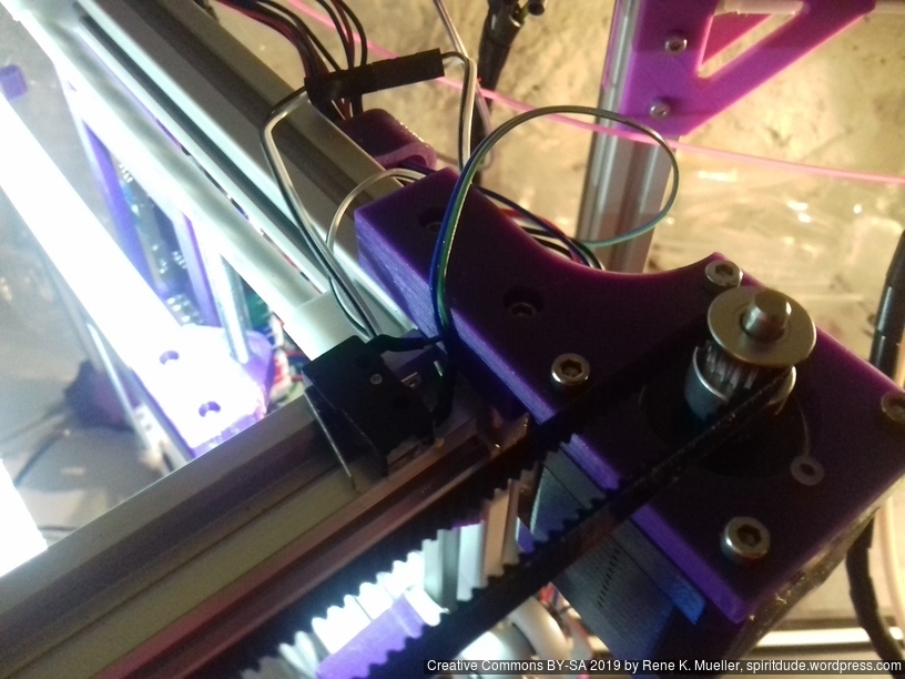
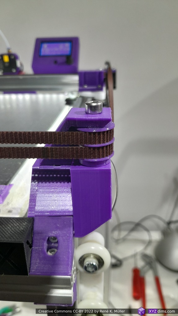
XY Belt Routing
The XY belt routing of CoreXY is more complex than usual, I decided to separate A and B motor belts on the Z axis with two levels, and twist the belts once so the notches would not roll over the redirectional idlers (more detailed photos follow):
CoreXY belt routing of Ashtar C
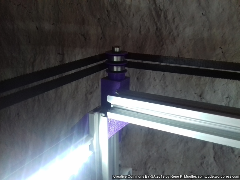
V1.0 corner (simple)V1.1 corner (stronger)
Key features:
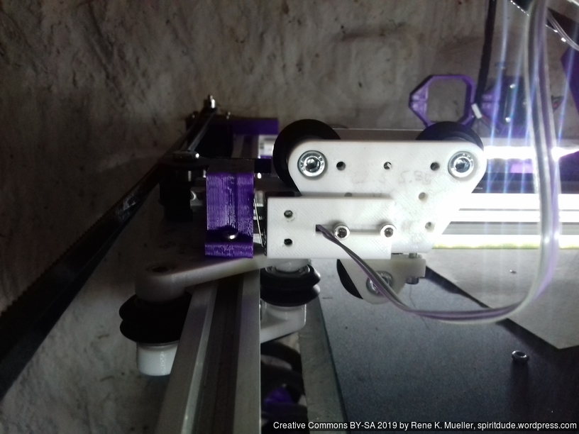
V (3 wheels) shaped 2x Y carriages: v_plate(width=54), width=48 was too narrow as the belt would touch the X beam, to ride on 2x “Y” V slot extrusions
using one roller axis to extend for belt routing with 2 idlers made with 625ZZ bearings and a couple of printed washers
attaching belts on the back of the X carriage, very little space wasted
V (3 wheels) shaped X carriage: v_plate(width=48) narrow enough to achieve in X ~385mm range
stepper motors A & B at the back
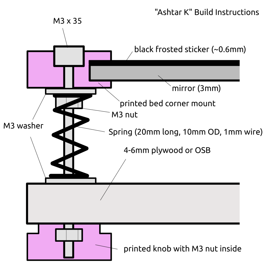
Bed
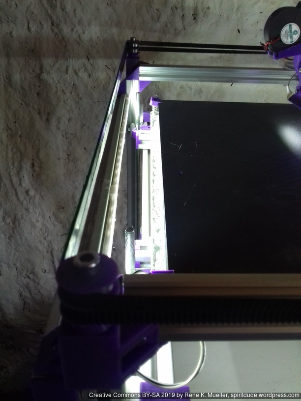
Alike with Ashtar K I used a mirror as main bed structure for Ashtar C:
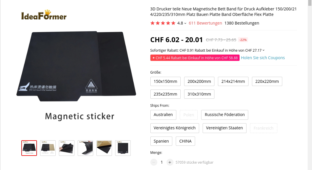
400 x 400mm black bed sticker (~0.7mm thick)
400 x 400 x 4mm mirror (custom order)
4x bed corner mounts (printed), with M3 x 30 and spring and 4x washers each
420 x 420 x 4mm OSB
residing on 2020 T-slot alu extrusions.
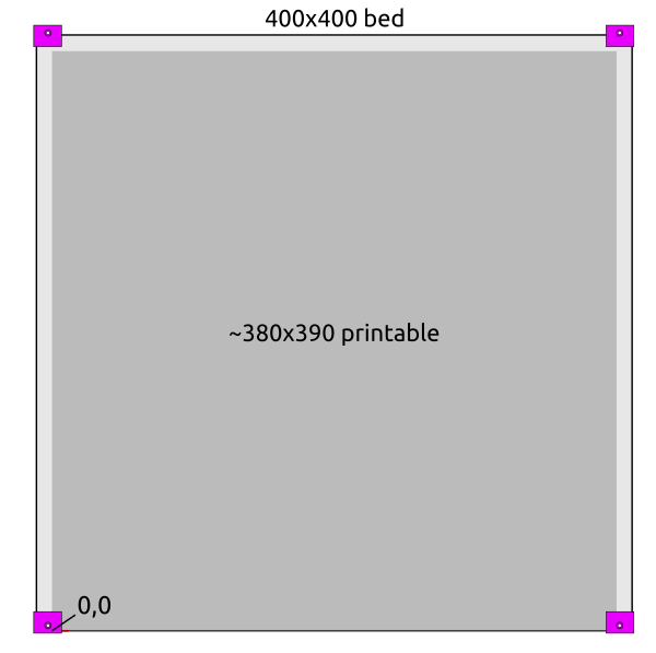
There are few millimeters in front in the left and right corner which cannot be printed on because of the bed mounts; at the back the nozzle won’t touch the bed mounts, but fan shrouds might – so one has to be aware of:
the X stop is at the left (X=0)
the Y stop is at the back (Y=390)
start of print at X = W/2 (e.g. 190), Y = -3, so the oozing of filament will be chopped when moving to the print position.
Z Axis
It took me some research and trial-and-error to determine Z axis in its details:
Option A
2x Nema17 (45Nm) stepper motor with 18 teeth GT2 pulley 5mm bore
2x 760mm closed belt
Option B
Using 3 or higher : 1 gear box (e.g. 3:1 gearbox could be used, but external shaft isn’t strong enough stabilized versus tilt) or alike to increase torque and still drive 4 threaded rods
Option C (not recommended)
1x Nema 17 (45Nm) stepper motor driving 4x M6 threaded rods with 1524mm long closed GT2 belt – even when well greased rods and well aligned, I still experienced occasional skipped steps, which made this option not reliable – so I switched to 2x closed loop belts Option A.
4x M6 x 490mm threaded rods
4x M6 nuts with bed mounts (printed)
4x bottom Z rod mount (printed)
8x 606ZZ bearings (each rod has 2 bearings)
4x 18 teeth GT2 pulley 6mm bore
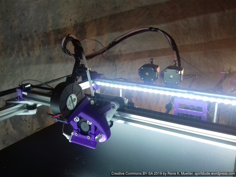
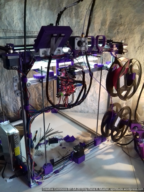
Electrical Wiring
I positioned the main controller board near the A/B stepper motors and the extruder motors at the back of the cubic framework:
advantage: most cables remain short and can be well put together
disadvantage: controller box with display cable too short to mount it in front, so remains on the back as well
Firmware
I’m using Marlin 1.1.8 (for MKS Gen L1), following changes were required
stepper motors A & B reside on the back, left-front will be 0,0
X direction was reversed
Y direction was correct
It was quite complicate to reverse X, as #define INVERT_X_DIR true was not doing it, but just reverse the motor direction, which in CoreXY also affects Y. Solution was, after some back and forth trying #define COREYX as well and failing, was to swap cables of A/B motors and
Configuration.h
#define COREXY
#define INVERT_X_DIR true
#define INVERT_Y_DIR true
Further, Z axis is driven by 2x Z motors, as driven 3 or 4 threaded rods with a single motors lead to various missing steps, so 2x Z motors with MKS Gen L controller board:
First I had the X stopper at the left-hand side of the X beam (Photo 3), but the cable entangled with other parts, so I moved the X stopper on the X carriage (Photo 1 & 2)
X stopper on the X carriageMounting X stopper on X carriageX stopper on X beam (not recommended)
X stopper: on the X carriage
Y stopper: right-hand back side of the main frame
Z stopper: right-hand back side of the main frame
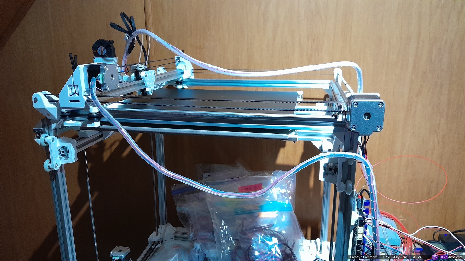
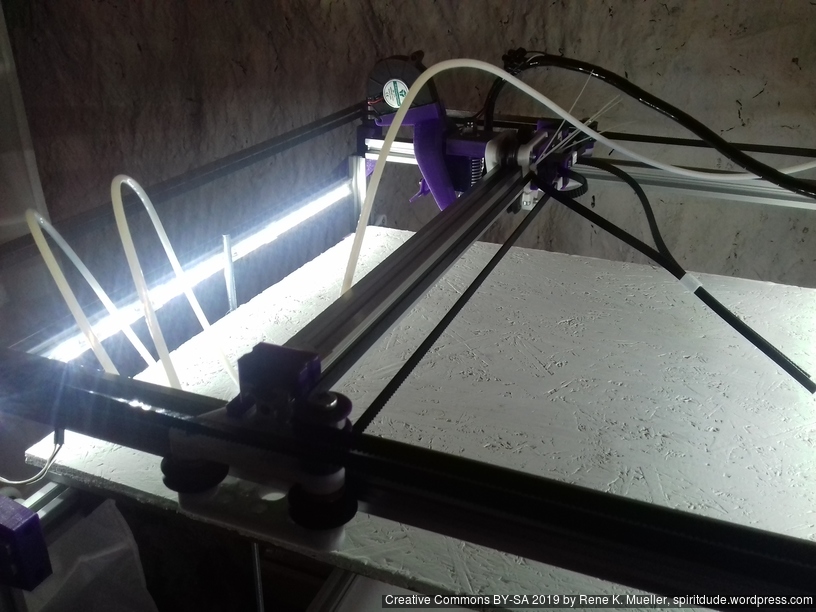
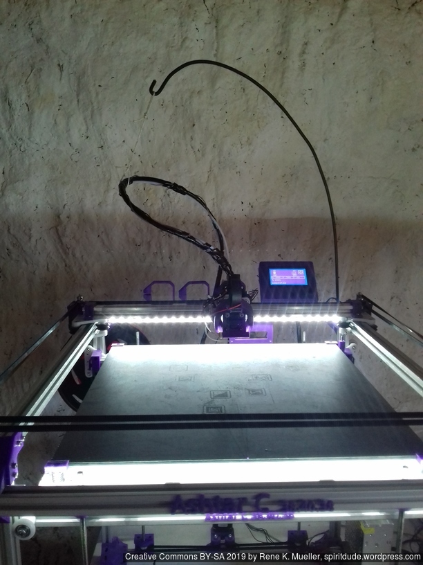
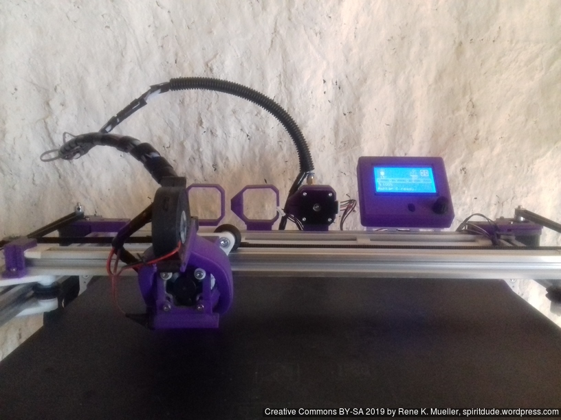
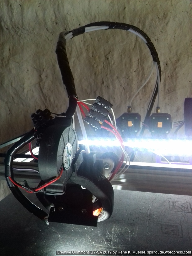
The PTFE 4mm OD / 2mm ID with the cables aren’t stiff enough to support themselves, so I added
Option A: 4mm insulated copper wire as a gantry to keep the cables from falling on the print bed.
Option B: strong plastic bundler near extruder to stiffen part of the cables/tubes.
Option A: thick wire as gantryOption B: stiffen with additional cable bundler
Maintenance
Belt Tension of Core XY
The Core XY mechanism takes some further care:
Parallelism: with the stepper motors off I move the carriage to the front and make sure both carriages of Y axis have the same distance to the end – if not, I tensioned the longer belt so both distances are the same = parallel to front beam.
Missing Steps: I noticed once I tensioned belts to achieve parallelism that the belts got harder to run, and eventually at larger prints with fast and longer positioning movements near 120mm/s I was missing steps in X and/or Y and caused failed prints quickly – so I loosened A/B belts equally to maintain parallelism.
So, there is some learning and experiences required to determine the best equal tension of belt A and B.
Update 2022: I’ve used GATES-LL-2GT belts which resolved all the previous problems with parallelism, as slightly stretching belts caused all kinds of geometrical inaccuracies.
Stiffness of Frame
At first the frame wasn’t as sturdy as possible as the details were not yet determined, but with maturing and defining the details the edges of the frames became more sturdy and the noise of the operational printer increased; yet, the print quality increased significantly. Further, since many parts are printed in PLA, they require re-fastening after few days as PLA gives in under tension, in particular all the edge fastening parts, which as well improved print quality.
Update 2022: I made the corner pieces stronger, to avoid any bending there:
I use M6 x 500mm threaded rods for the Z axis, because they give 1.0mm way per revolution, given 1.8 degree per motor step or 200 steps per revolution, with 16 microsteps there are 3200 microsteps per revolution which gives 0.3um per microstep or 5um per step. Using M8 or M6 for Z axis has a bad reputation in Prusa i3 setup, something I only partially agree with, gives in my setup of Ashtar C no little Z wobble, but it may have introduced some slight non-linearity within the 1mm way which isn’t observable for me. Lead screws would provide excellent linearity but less resolution due higher pitch, often 8mm per revolution, or 40um per step.
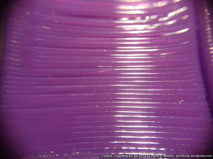
25um (0.025mm) layer height with 0.4mm nozzle50um (0.050mm) layer height with 0.4mm nozzle250um (0.25mm) layer height with 0.4mm nozzle350um (0.35mm) layer height with 0.4mm nozzle450um (0.450mm) layer height with 0.4mm nozzle500um (0.500mm) layer height with 0.4mm nozzle
In my early test, when I ran one stepper motor driving 4 well greased rods for the Z axis, I experienced eventual missing steps due the distributed friction at multiple spots (nut/threaded-rod, threaded-rod/pulley/bearing, etc), and few days in, even more. As a result I used two stepper motors each driving two threaded rods for the Z axis.
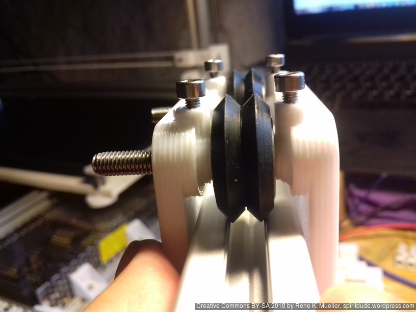
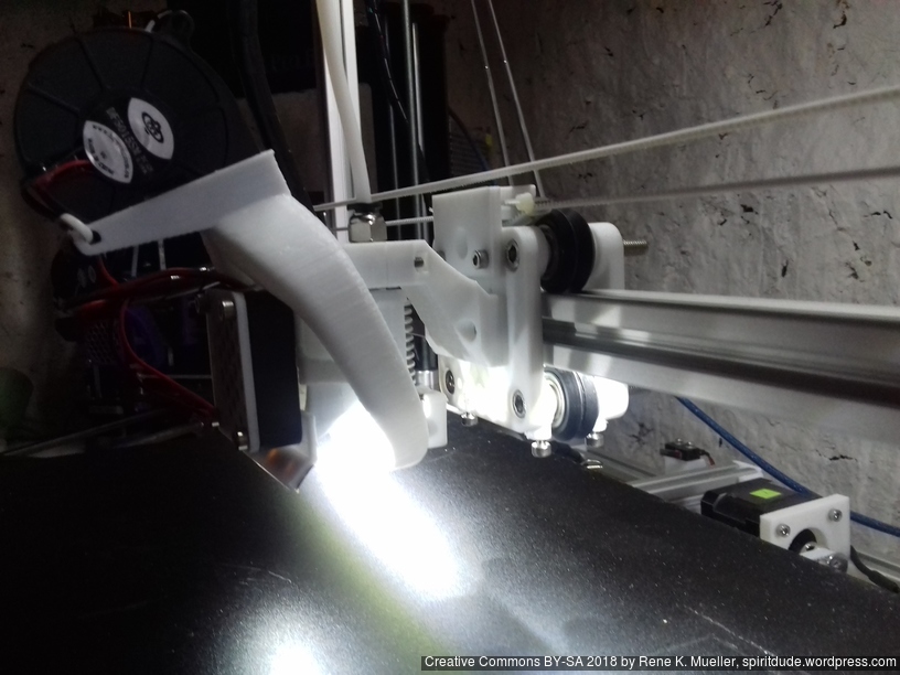
Fixing Z Wobble
Left: 1 out of 4 Z rods tilted; Right: 4 Z rods mostly aligned
While replacing the M6 x 500mm threaded zinc rods with stainless steel ones I noticed that I introduced severe Z wobble, which wasn’t there with lower quality M6 threaded rods – odd enough – and I moved the bed to Z=380 and noticed one rod swinging around due slightly titled rod, and reopen the GT2 pulley on the bottom with that rod, and turned the rod slightly and refasten the GT2 pulley again, the difference is significant: the wobble is nearly gone.
Update 2022: one of the key to resolve wobble is to keep the closed loop belts not too tight, otherwise their un-eveneness translates to the bed – keeping it a bit soft resolves it.
I may use 4x 8mm lead screws as a test as well and see how it performs regarding wobble but also resolution.
Todo
Z axis details (belt vs lead screw vs threaded rod)
1 Z motor with closed loop belt: 1, 2, 3 or 4 threaded rods/leadscrews
2 Z motors with/out closed loop belt: 2 or 4 threaded rods/leadscrews
details of belt redirection idler mounts
moving X endstop to X carriage itself (avoid cable entanglements)
stiffen or stabilize X carriage cables and Bowden tube
controller box positioning
release sources
complete instructions
list all parts properly
Parts
Printed Parts
Not yet defined, reusing most of Ashtar K 2020 parts plus some Ashtar C specifics.
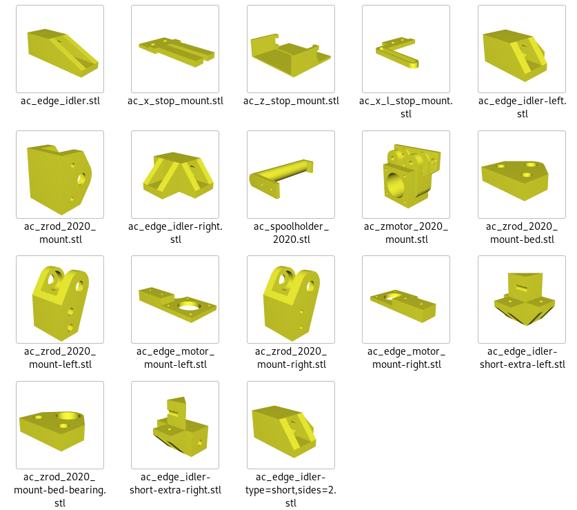
Frame
4x cci_2020 (bottom corner brackets)
2x cci_2020-type=idler2 (top front corner brackets)
2x cci_2020-type=motor (top back corner brackets)
X/Y
1x ac_edge_motor_mount-left
1x ac_edge_motor_mount-right
Z
2x ac_motor_2020_mount
2x ac_zrod_2020_mount-left
2x ac_zrod_2020_mount-right
4x ac_zrod_2020_mount-bed
Axis Modules
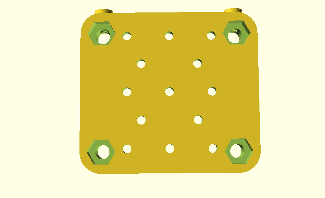
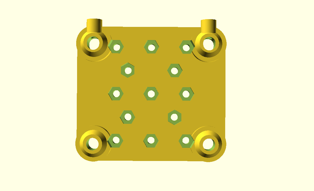
1x X Module with black 3 x OpenWheels 24.4/11 on T slot 6 or V slot 6
1x v_plate-2020-double-v-244-110-54w-a
1x v_plate-2020-double-v-244-110-54w-b
1x ac_x_l_stop_mount
1x ac_x_stop_mount
2x Y Modules each with black 3 x OpenWheels 24.4/11 on T slot 6 or V slot 6
1x v_plate-2020-double-v-244-110-48w-a
1x v_plate-2020-double-v-244-110-48w-b
4x Z Modules each with white 3 x Delrin wheels 23.0/7.3 on T slot 6
1x v_plate-2020-delrin-230-73-48w-a
1x v_plate-2020-delrin-230-73-48w-b
Misc
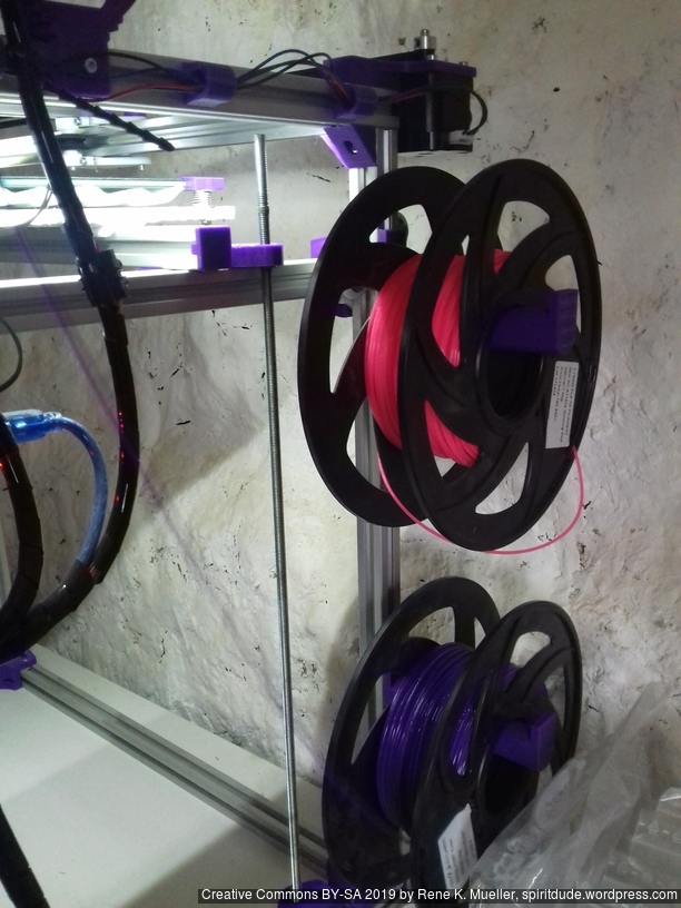
2-3x ac_spoolholder_2020
Non-Printed Parts (aka Vitamins)
Two Frame Options:
A: 16x 500mm T slot 6 (B-Type) 2020 alu extrusions + 1 x 440mm T slot 6 (B-Type) 2020 alu extrusion or
B: 14x 500mm T slot 6 2020 alu extrusion + 3 x 500mm V slot 6 2020 alu extrusions
Example Prints
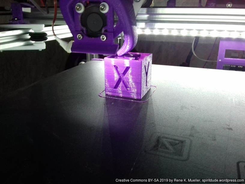
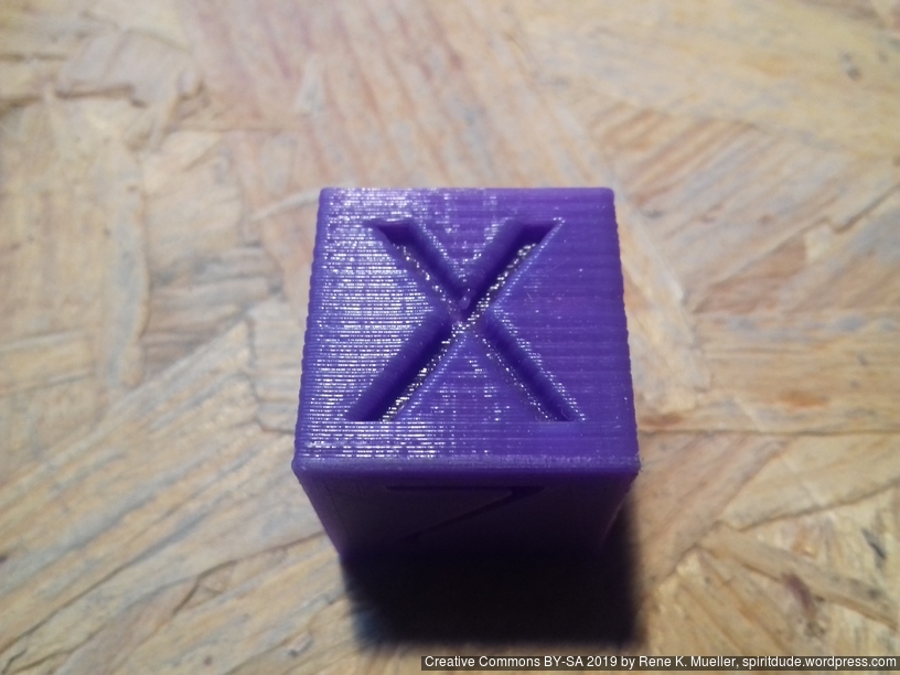
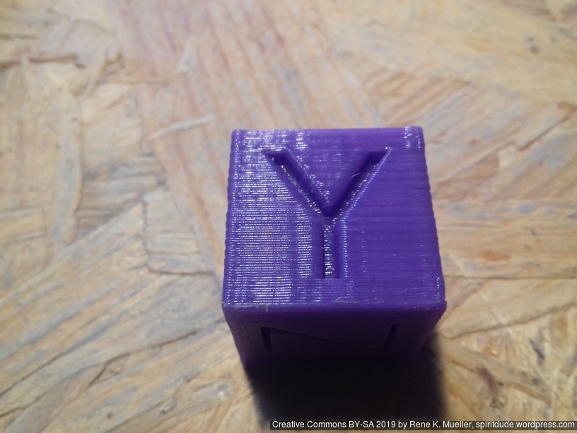
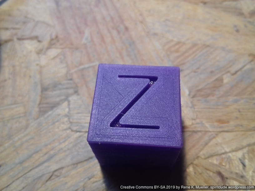
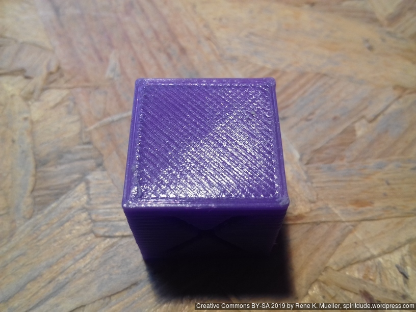
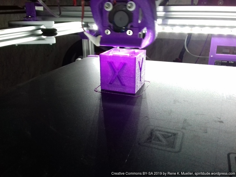
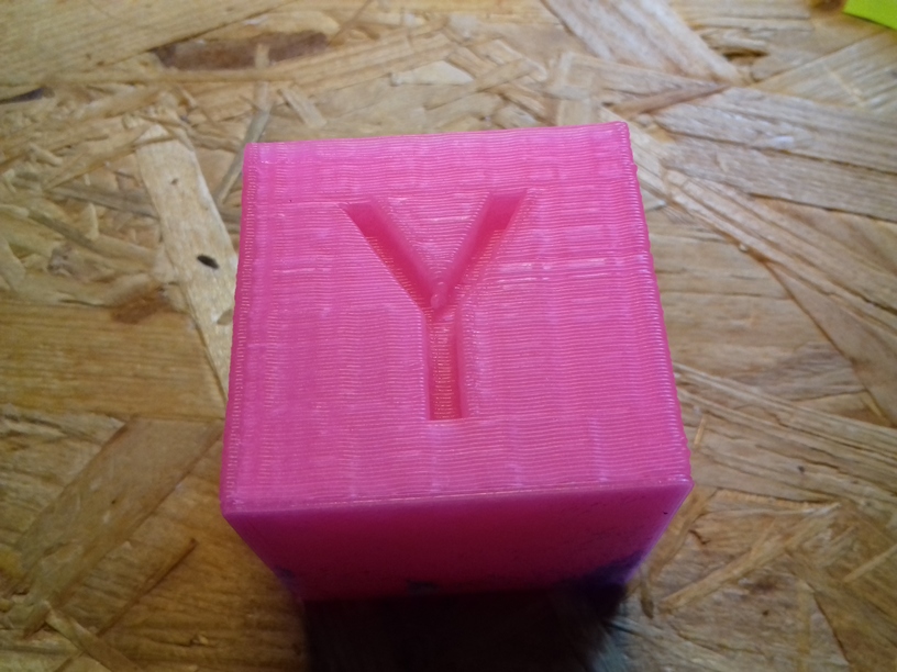
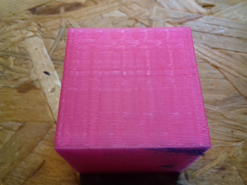
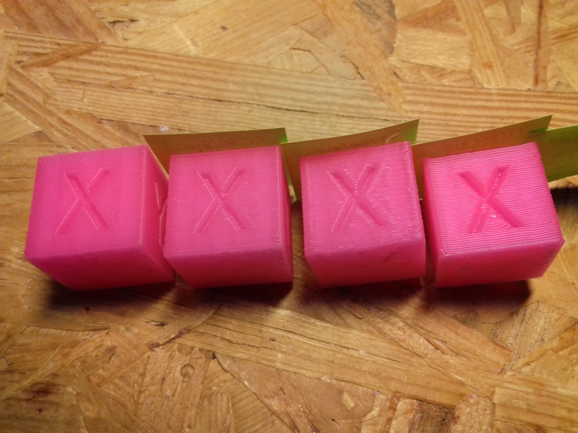
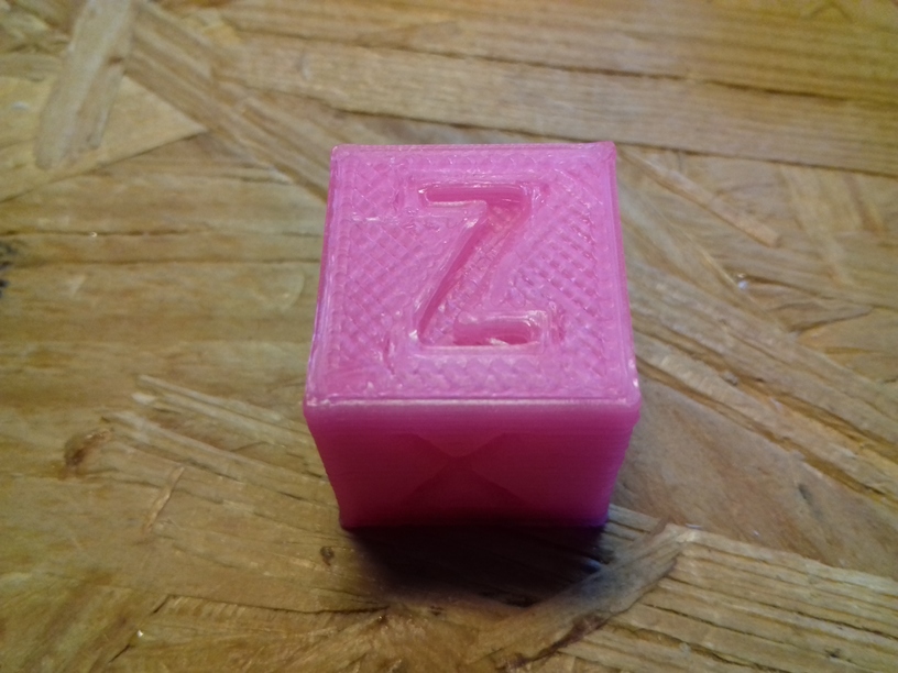
20mm Hollow Calibration Cube
Printed with 0.4mm nozzle at 0.25mm layer height, the “Z” at the bottom, first layer too thin a bit:
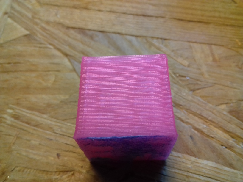
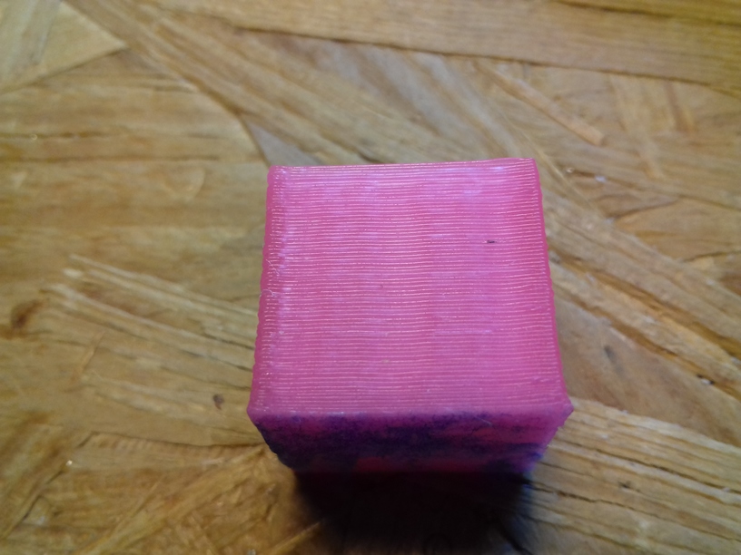
Castle 20mm Cube
200% scaled Castle 20mm Cube:
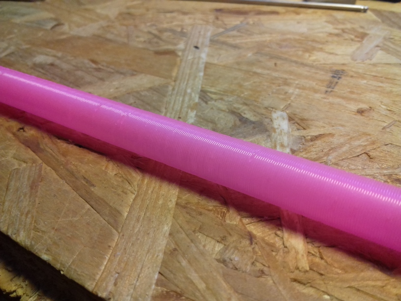
Tall Cylinder
380mm x 10mm hollow cylinder using full height of the printer:
Upgrades
Dual Z & Dual Extruder with MKS Gen L
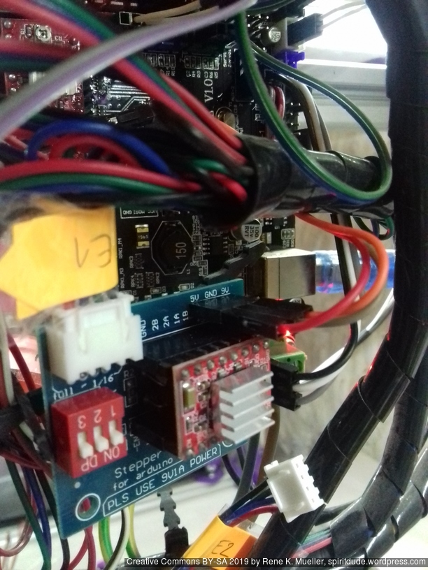
For the Chimera/Cyclops hotend with two filament but single heater and single or double nozzle, I added a stepper expander on AUX 2:
AUX2 / D64 – E1 STEP
AUX2 / D59 – E1 DIR
AUX2 / D63 – E1 ENABLE
and wired 5V, GND, 12V as well.
Additionally made following changes to Marlin 1.1.8:
Configuration.h
#define EXTRUDERS 2

#define SINGLENOZZLE
Configuration_adv.h
#define Z_DUAL_STEPPER_DRIVERS
pins_RAMPS.h
Comment out first E1_* and add Z2_* newly, and new E1_* below:
/*
#define E1_STEP_PIN 36 // this is E1
#define E1_DIR_PIN 34
#define E1_ENABLE_PIN 30
#define E1_CS_PIN 44
*/
#define Z2_STEP_PIN 36 // this is Z2
#define Z2_DIR_PIN 34
#define Z2_ENABLE_PIN 30
#define Z2_CS_PIN 44

#define E1_STEP_PIN 64 // E1 (2nd extruder) via stepper expander
#define E1_DIR_PIN 59
#define E1_ENABLE_PIN 63
The “Z_DUAL_STEPPER_DRIVERS” by default will use “E1_*” and interfere with 2nd extruder, hence the Z2_* definition helps to keep 2nd Z motor at “E1” motor on the MKS Gen L board, and in Marlin E1 is newly defined separately at AUX2 at D64/D59/D63.
To summarize:
MKS Gen L “Z” => Marlin “Z1”
MKS Gen L “E0” => Marlin “E0” (1st extruder)
MKS Gen L “E1” => Marlin “Z2”
MKS Gen L “AUX2”:D64/D59/D63 => Marlin “E1” (2nd extruder)
which then in Gcode the 2 extruders (E0 & E1) are referenced as T0 and T1.
Update 2022/09 I replaced MKS Gen L 1 with MKS Monster8 with 8 drivers, still running Marlin but its 2.0.x series, and since I have 8 drivers, and I possible can attach 5 extruders.
IDEX Option
The independent dual extrusion (IDEX) is an upgrade in draft state – means, it’s untested for now. It provides a 2nd extruder on the same X axis. As of 2021/01 there is only Duet RepRap firmware able to provide support for it as CoreXYU, whereas Marlin 2.x doesn’t provide support yet.
Right now I keep the up-to-date information on Ashtar C IDEX in this blog-post, once things actually are tested all the details will be documented in this document.
Printing new X motor mount on CTC DIY I3, and replacing it on the new Ashtar K: CTC DIY I3 prints quite reliably – there is nothing to clean up – the piece I attach it right away:
Ashtar K lacked a proper print surface (before I received the black sticker surface), otherwise I would have printed the piece on itself.
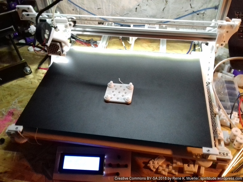
Black Sticker as Bed Surface
The 400×400 black sticker arrived, and I cut it into 400x300mm and put it on the mirror – which worked well, and so far I can tell the surface is very very flat, much better than on alu heat bed.
Current bed setup (top to bottom):
400x300mm black sticker (“frosted sticker”), apprx. 0.6mm thick
400x300mm 3mm thick mirror
210x210mm 12V alu heat bed
various cork patches under heat bed
10mm light black foam material
420x320mm 6mm plywood (white painted) as Y carriage
Now that I have a good print surface I finally printed pieces for itself.
Mounting the 400×300 bed (OSB 6mm, white painted) with 200×200 heat bed (which I hardly use, as I started to print on cold bed):
I currently use the white PU steel enhanced GT2 belts, and it produces hard edges, some ghosting, but more precise prints than the black rubber GT2 belts which just stretch too much – I have to research this more closely – about the type of reinforcement and the use with more heavy beds (Y carriage).
Just for the record regarding Y carriage (2018/09):
420×320 carriage:
4mm plywood flexes, but has been quite flat – not recommended
6mm plywood hardly flexes, but has been hard to buy truly flat – and so far my attempt to flatten it did not work well – not recommend unless it’s flat
6mm OSB quite flat, does not flex much (3 or 4 sliders) – recommended
320×320 carriage (for 300×300 bed):
4mm plywood works (3 sliders, 4 sliders recommended)
6mm plywood works (3 sliders, 4 sliders possible if plywood is truly flat <0.2mm difference)
6mm OSB quite flat, doesn’t flex (not yet tested)
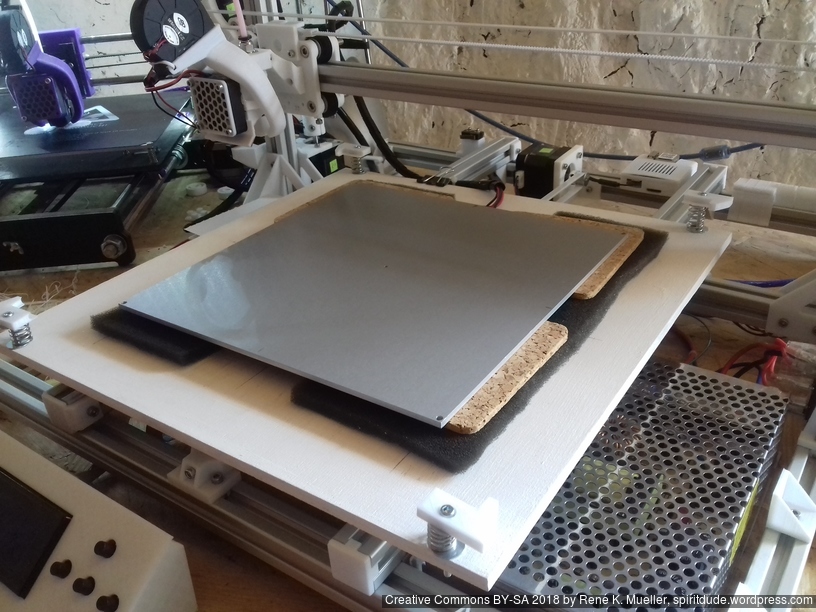
Just to explain my thought or decision process for my setup:
the mirror should not be bend (of course)
the support structure should not be the edge mounts, but the foam in between
the carriage can be bent, but not flex
revelation: already bent means the springs with screws might extend the bent further with a flexing carriage, and not counter act – as the mirror should stay flat
so, even though the springs/screws and edge mount can adjust, the carriage should be fairly flat, and not flex at all – this way the edge mounts holding the glass/mirror only stabilize position. Main force to hold the glass/mirror, for my setup, is the foam in between. So, there is no “spring” induced vibration back/forth introduced, but the foam neutralizes such vibrations – and hardly adds weight/inertia.
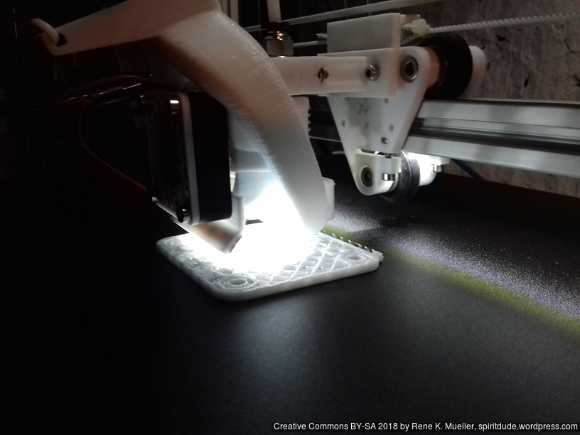
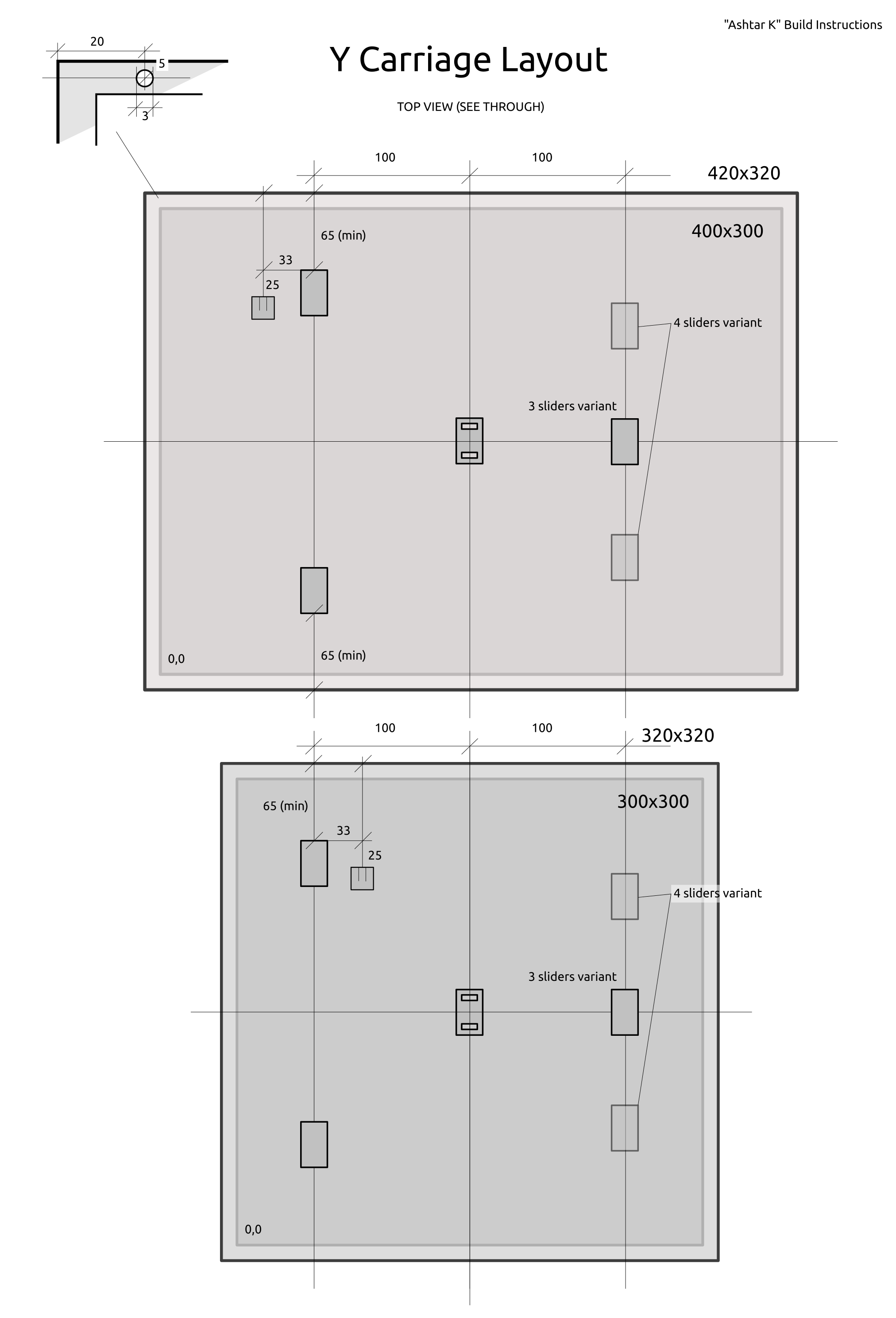
Sliders & Belt Mount Positions
Top view with see-through (best mark “0,0” on both sides to keep reference).
400×300 vs 300×300 Bed
Originally I focused on 300×300 bed at least, with some tweaking and narrow X carriage I was able to reach 380×300 printable bed, so it was suitable to use 400×300 plate as well.
It takes me about 5min to mount new bed, downgrade from 400×300 to 300×300:
Changes needed:
move Y endstop switch from left to Y carriage extrusion to the right side
Y stopper mounted on the bed needs to placed accordingly
With 300×300 bed the 0,0 is now plenty outside of the bed, with 400×300 the 0,0 is near the printed bed mount.
Setting Offsets for 300×300 bed
With 300×300 bed the 0,0 is now +32mm to right and +25mm deeper, hence the Gcode M206 is set like this:
M206 X-32 Y-25
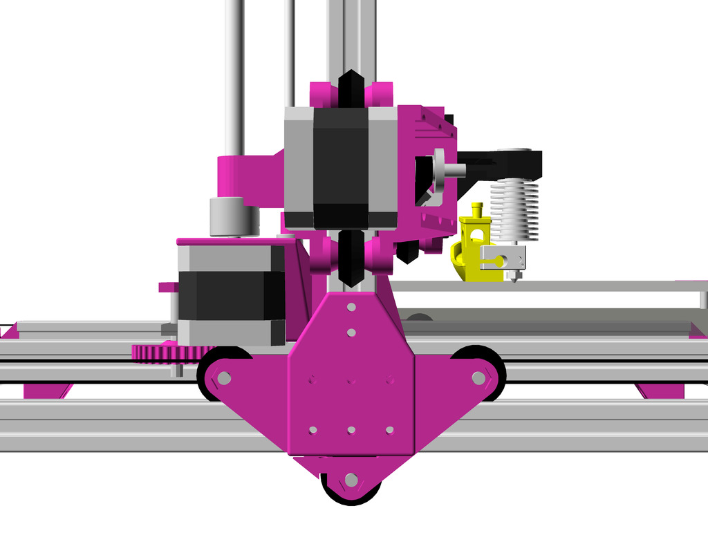
H Plate/Module as X Carriage
The 3 wheels module riding on the 2020 alu extrusion I named “V plate” due the shape, the 4 wheels module “H plate” providing more stability or rigidity for use as X axis carriage, when the nozzle runs over slightly unclean extrusion and tilts upside. For the X carriage I choose a narrow (48mm wide hole-to-hole) version:
Belt mount and hotend holder using same mounting holes
It’s the first/early version, the adjustment screws (M3x10) are very or too close to the bed for my taste, next version will use M3x8 and give more spacing. I like to keep the hotend close to the X carriage so not to waste Z space.
Additionally I made a new hotend mount so it would use another mounting holes than belt mount:
Belt mount and hotend holder using same mounting holes
Belt mount and hotend holder separate
But now it’s harder to reach the hotend mount holes due the part cooler – oh well.
After few days, I noticed one wheel stopped to turn, no longer touching the alu extrusion – I guess the carriage slowly balanced itself and triangulized, no longer use the 4th wheel. I re-tighten the 4th wheel gently so it would roll again.
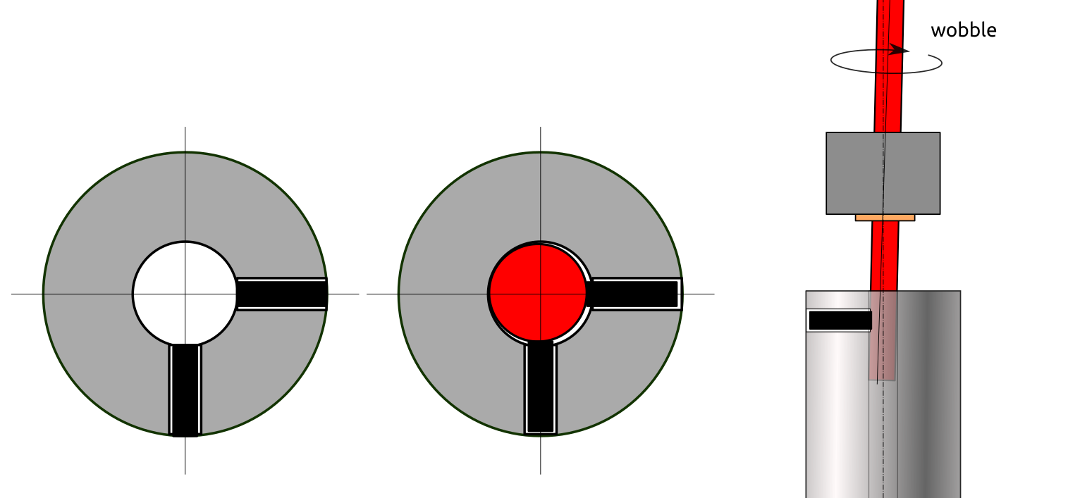
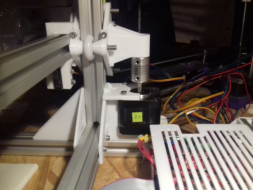
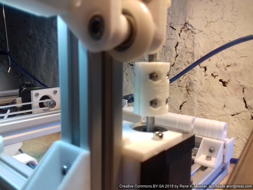
Z Couplers: To Wobble or Not To Wobble
As I posted before, I suspect the Z couplers to be the main source for Z wobbles, as the threaded rods may look and are cheap but they are mostly straight – the wobble actually is caused, after close observation, from the misalignment which happens when you screw the metal couplers on, in particular if you attached the lead screw or threaded rod with uneven surface – the thightening screws may or may not attach cleanly – and thereby push the Z rods out of the center of the Z stepper motor – when the Z thread holding the X axis is fixed, the resulting wobble is worse at low Z heights; and if you fasten the Z rods at the top, the wobble gets even worse.
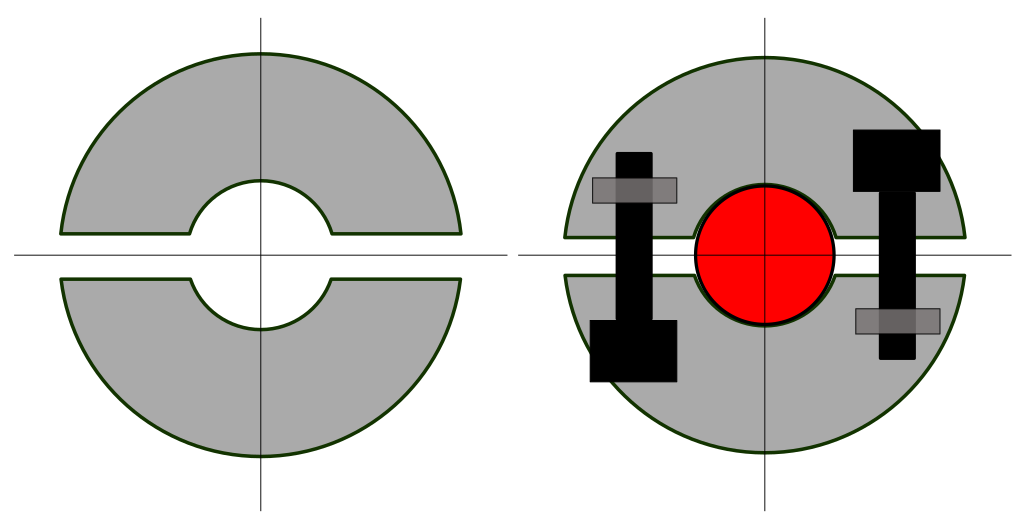
A simple remedy I found is to use printed couplers, two pieces which are screwed together with 4x M3 screws and nuts, a bit of an overkill, and a bit time consuming to fasten: incrementally tighten each screw over and over until all are tight – but I think it’s worth it: the two halves attach evenly and the PLA or ABS or whatever you printed the couplers, is soft enough so the threads of the Z rods carve themselves evenly into the coupler, and self center themselves this way – result is better centric attachment of the Z rods, not perfect but acceptable and better than poorly manufactured metal couplers.
Alu 5mm to 6mm coupler
PLA printed 5mm to 6mm coupler
As mentioned before, I switched from M8 to M6 for the Z axis the M6 provides 1mm movement per full turn, and is more flexible to even out out-of-center wobbles, better than the stiffer M8 threaded rod. If using couplers at all, and likely introduce out-of-center mounting, rather use a more flexible lead-screw or threaded rod than a stiffer one.
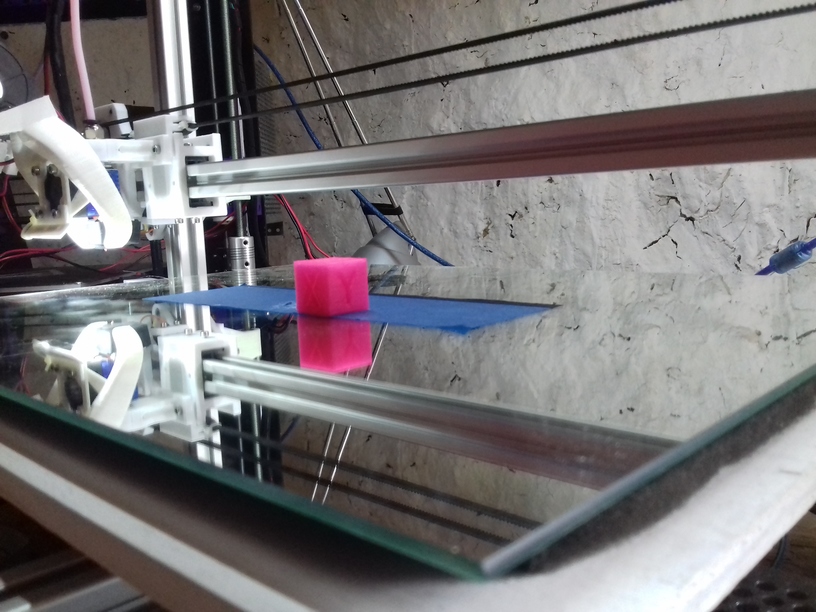
It has been a few days (2018/09/04), since Ashtar K happen to be able to print, the heat bed still unfinished, some prints illustrated below are done with no leveling screws, the mirror just taped on the Y carriage – don’t laugh – later prints I had proper carriage and leveling screws included; a proper build surface I still wait for in the mail (400×400 black sticker to be cut in shape) – anyway, here some of the early prints:
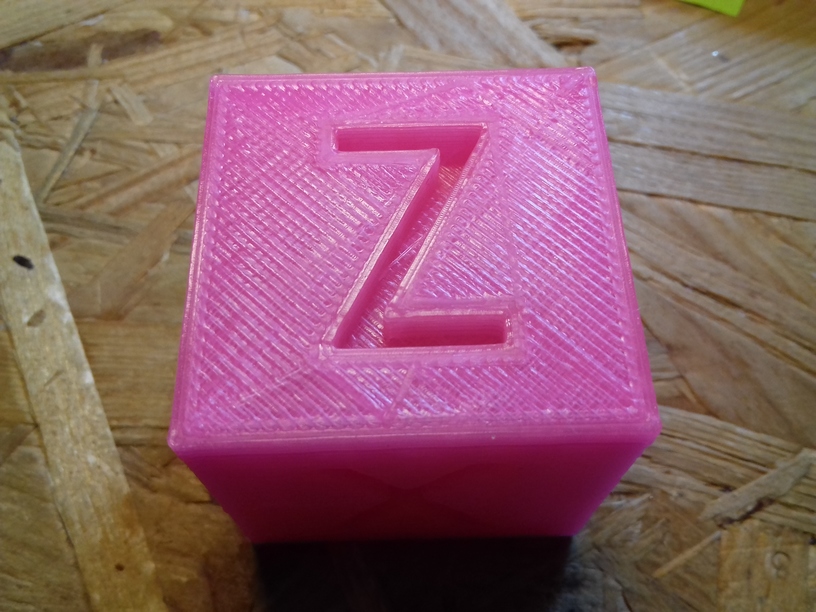
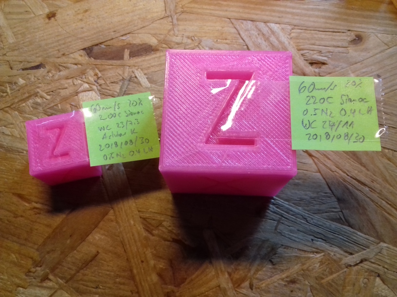
40mm XYZ Calibration Cube
The original 20mm XYZ Calibration Cube is printed in 8 mins with 0.5mm nozzle at 0.4mm layer height, and so I thought, let’s print it 2x the size with 0.4mm layer height, merely 40 mins later this:
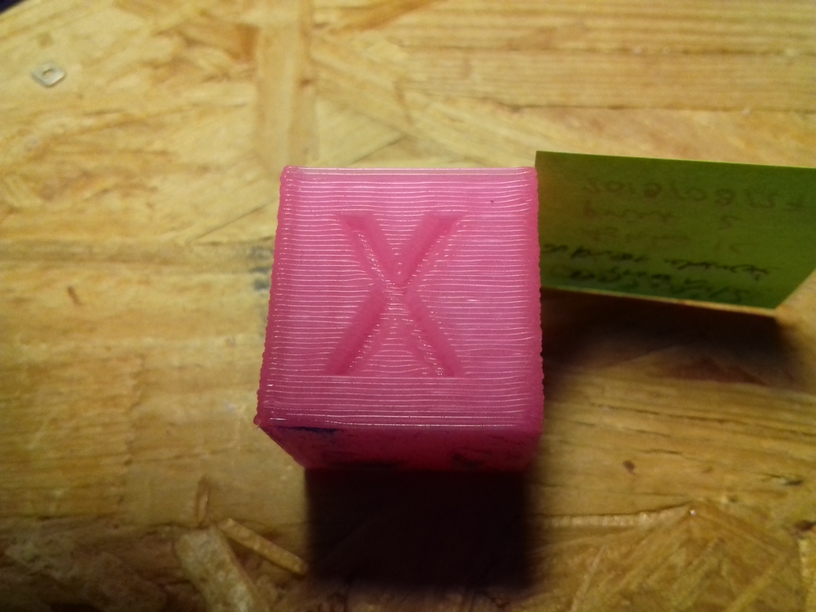
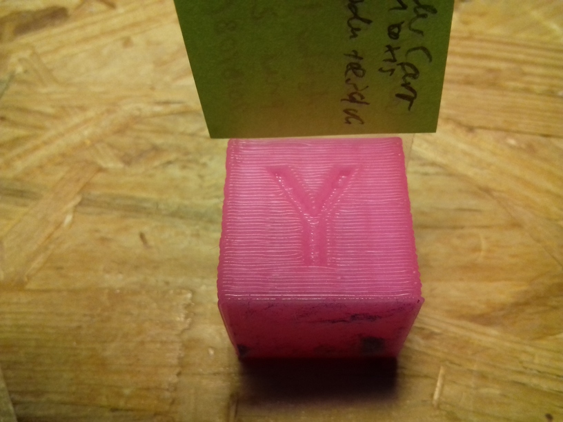
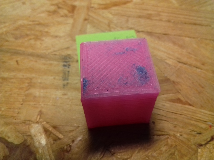
The quality is . . . impressive, this is just tuning a single day – mostly on the extrusion factor and print temperature – and this is what I hoped for: XYZ positioning almost flawless: there is slight ghosting on X axis (which could be resolved) shown on “Y”, and Y axis shown on the “X” which is fine, given the size of the bed and its weight and inertia this is OK.
I had to increase print temperature +20C from 200C to 220C for 80mm/s infill while printing with the 0.5mm nozzle, I otherwise would hear clicking from the extrusion stepper motor missing steps. I still use the classic E3D V6 (clone) heat block, not the Volcano heat block.
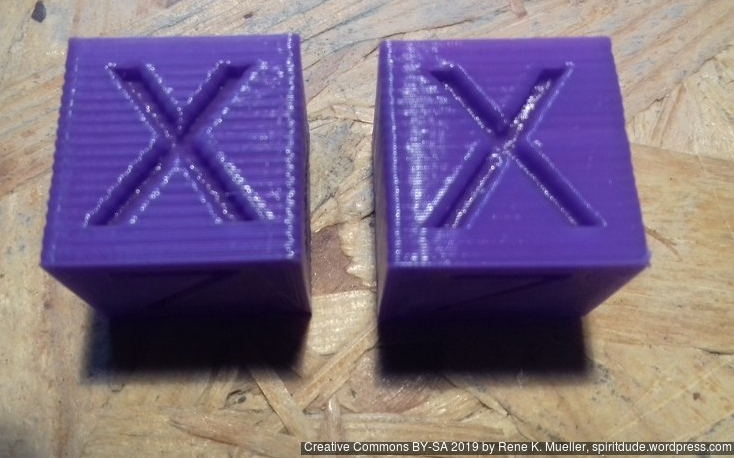
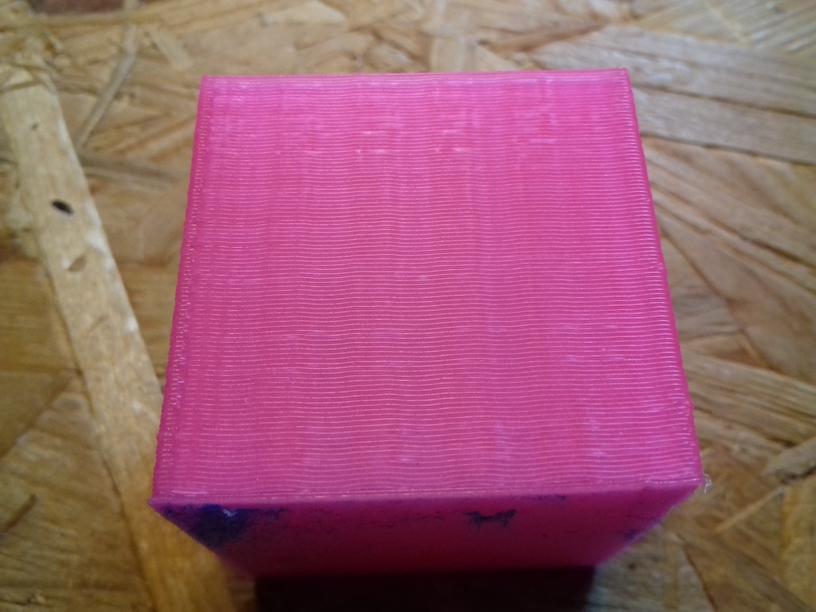
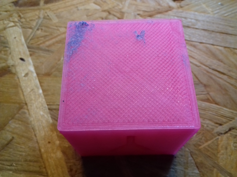
20mm Calibration Cube: Different Layer Heights
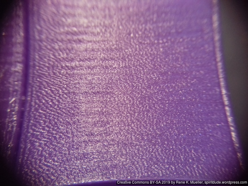
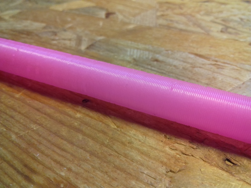
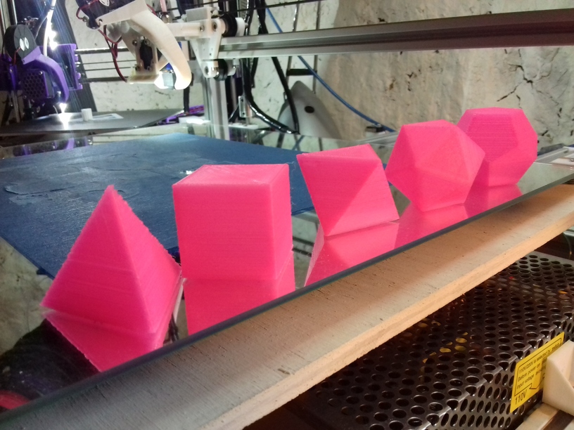
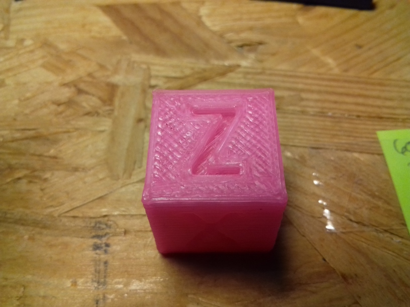
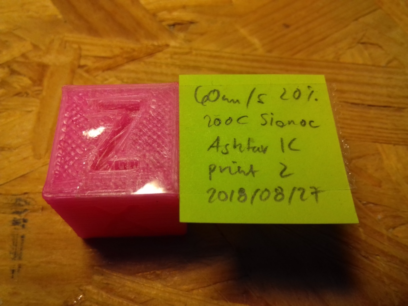
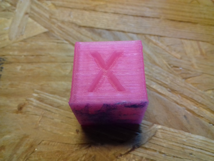
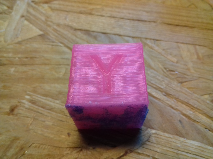
Printed with 0.5mm nozzle, left-to-right: 0.1mm, 0.2mm, 0.3mm and 0.4mm layer height, 60mm/s (80mm/s infill), 200C first layer, rest with 210C, pink glowing PLA by Sienoc.
X Carriage: Sliders vs Wheels
While printing with slider carriage on the X axis, I noticed increased stuttering, and regardless if I thighten or loosen the grip, the stuttering remained, and slight horizontal tilt occured when changing direction on the X axis resulting in too narrow prints in X dimension.
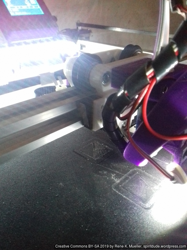
X carriage with white nylon wheels (23.mm OD / 7.3mm width)
So, I changed back to wheel-based carriage, first again 23/7.3 white nylon wheels (right photo), but when I printed “L” shape with 200mm length in X and Y and 1mm height in Z, I noticed slight Z sinus form as I saw before – while it rolled nicely, there was a wobble . . . and so I printed a new carriage which holds the black OpenRail Double V (clone) 24.4mm OD / 11mm width, and put it on the X carriage:
X carriage with double V black wheels 24.4mm OD / 11mm width
A brief overview of the carriages riding on 2020 T slot (B-Type) alu extrusion:
Sliders: on the X axis it did not last, the stuttering was not avoidable; the issue is that the X carriage is one of the hardest axis of the Prusa i3 style geometry to handle: it isn’t just X directional rail, but also pressure on the Z with the weight of the print head, and running over overextruded filament – and it’s hard to pull the X carriage perfectly without the carriage have some vertical tilt as well – anyway, I still use the slider option on the Y carriage – and works fine so far.
White nylon 23/7.3mm wheel: rolls nicely, but gives wobble to the Z height when used on X carriage, apprx. 1mm, also doesn’t stay vertical upright, but tilts a bit with pressure – when the print head moves over overextruded print it doesn’t level it, but jumps over it. I currently use white nylon wheels on the Z carriage successfully.
Black double V delrin 24.4/11mm wheel
groove use: rolls very nicely, gives no wobble, and stays vertical. The next days and weeks will tell if the double V wheels do last on the T slot alu profiles – they are meant on proper V slot alu extrusions.
diagonal/edge use: rolls very nicely too, but surprisingly gives less tilt rigidity than groove use – the T slot 6 (B-Type) gives less surface at supposed 90deg edge, but is rather 85deg
Z Axis Linearity
As you may have read in the other post(s), I use M6 threaded rods, it’s flexible and rather aligns with the Z axis itself, whereas M8 is stiffer and misalignment – which by the way doesn’t come from the rod itself, but the mounting with the couplers – won’t impose on the X carriage – this is my own view and it happens to come true again with Ashtar K, after I changed my cheap CTC DIY I3 also to M6.
Now, the 1m long M6 threaded rod, enough for two Z axis each 500mm long, did just cost EUR 0.70, made in China but purchased locally in Germany, and the nylon wheel-based Z carriage happen to work perfectly so far – I expected some slight sinus wobble imposed by the nylon wheels as I encountered on the X carriage, but it seems when there is little force applied on the wheel the carriage works good enough.
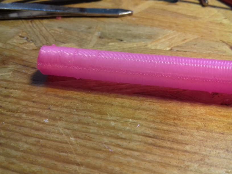
Printing 330mm high 10mm diameter cylinder (with slider-based X carriage):
There was some slight extrusion inconsistencies, this is likely due the material, an broken vacuum seal of a newly purchased glowing pink PLA roll, actually, after watching the 2nd print closely, either GCode errors or USB transmission errors, as some segments of the circle (layer of a cylinder) is repeated for some unknown reason and so overextrusion occurs there (needs proper investigation) – but the linearity is very good, and no Z wobble whatsoever.
The “loopy egg” is a good benchmark for retraction settings, and stressing the extruder motor as the short segments making up the loops require a lot of push / pull on the filament. There was still some slight stringing, which I knew will happen, as the retraction is just set to 2mm at 35mm/s giving very good results. More prints will tell if I can stay with these retraction numbers.
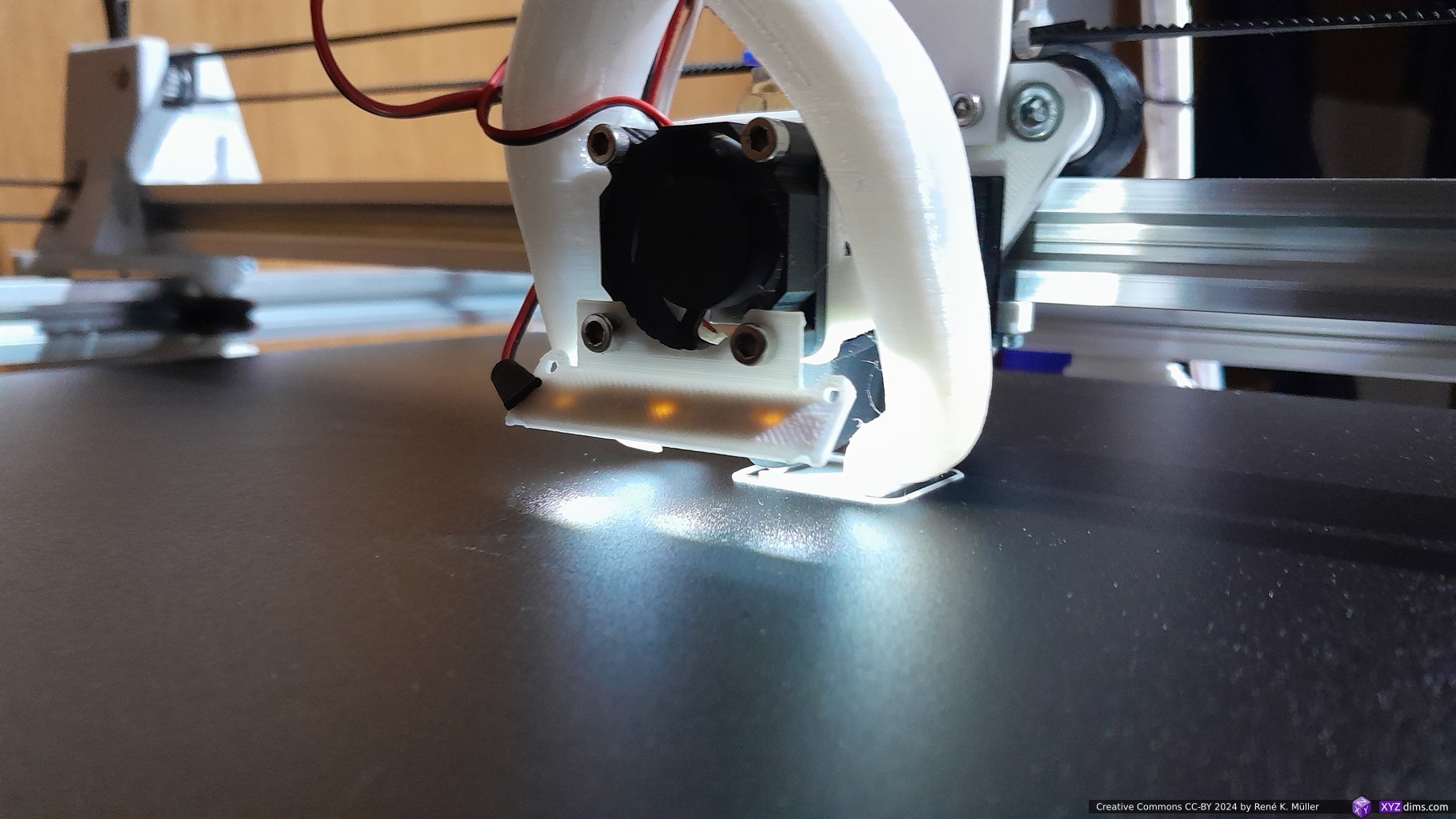
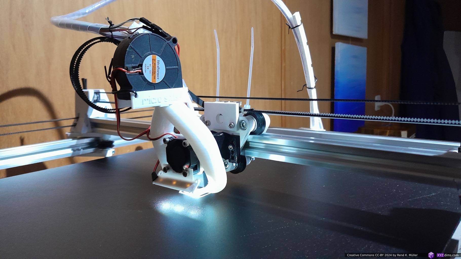
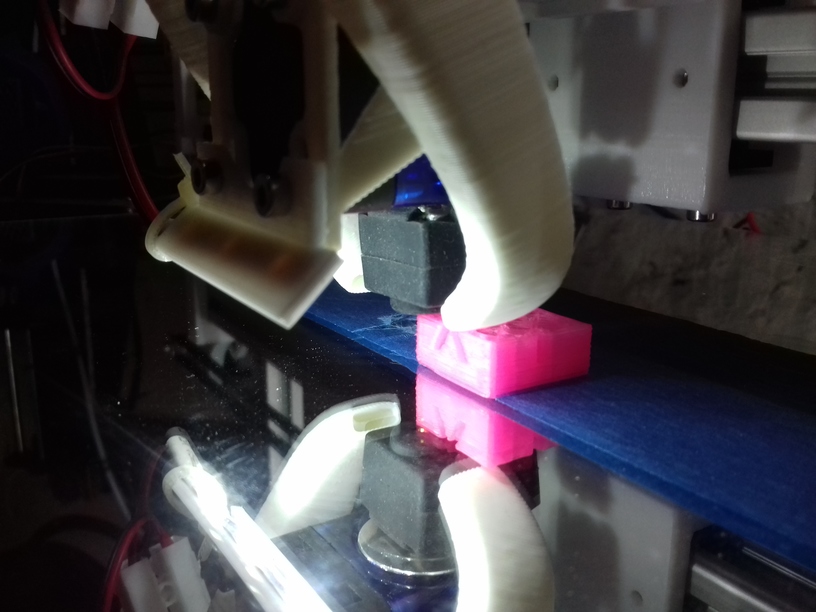
Fighting Heat Creep
I currently use E3D V6 clones as hotends, one with 30mm “original” fan, and one with 40mm fan. And with the “original” smaller 30mm fan I experienced frequent clogging up within the hotend: some of the filament melted above the heat break and expanded and blocked any further extrusion – that happened now several times.
I tried to reduce the extrusion temperature but which caused decline of print quality. After trying to determine the root cause of the problem, I concluded that it was heat creep and insufficient cooling above the heat break, hence, the hotend fan, and I switched to 40mm fan – and the clogging disappeared, not quite yet . . . update follows.
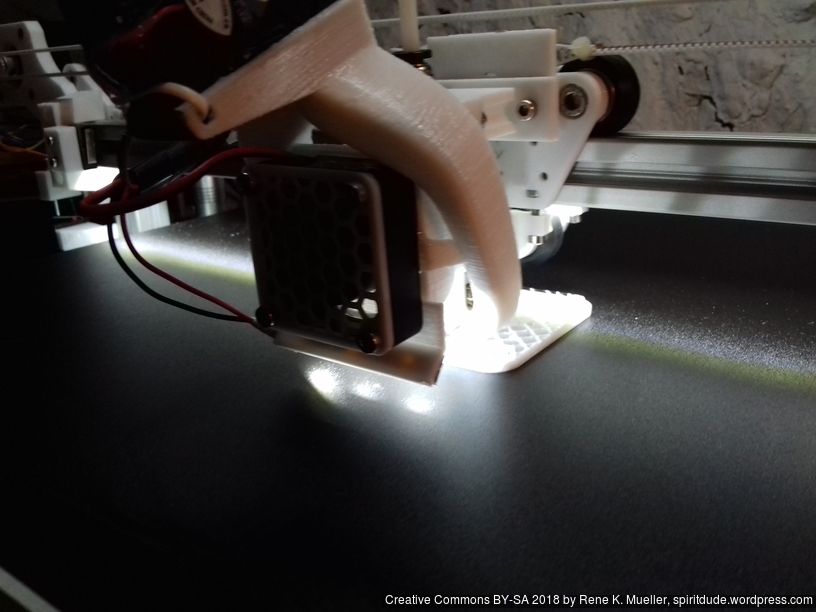
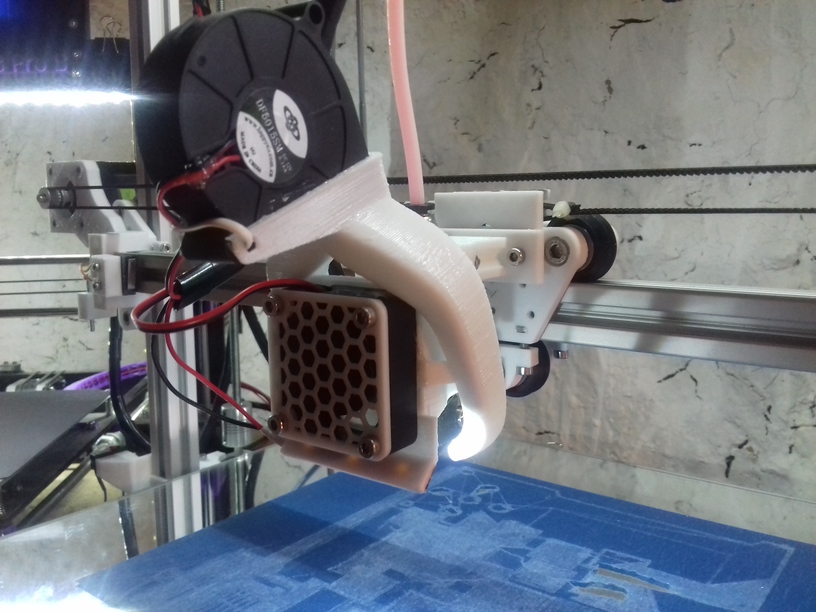
30mm Fan (front facing) with 5015 Fan Fang (top)
40mm Fan (front facing) with 5015 Fan Fang (top)
Although both setups look very alike, I had to print out another fan fang which can contain 40mm fan.
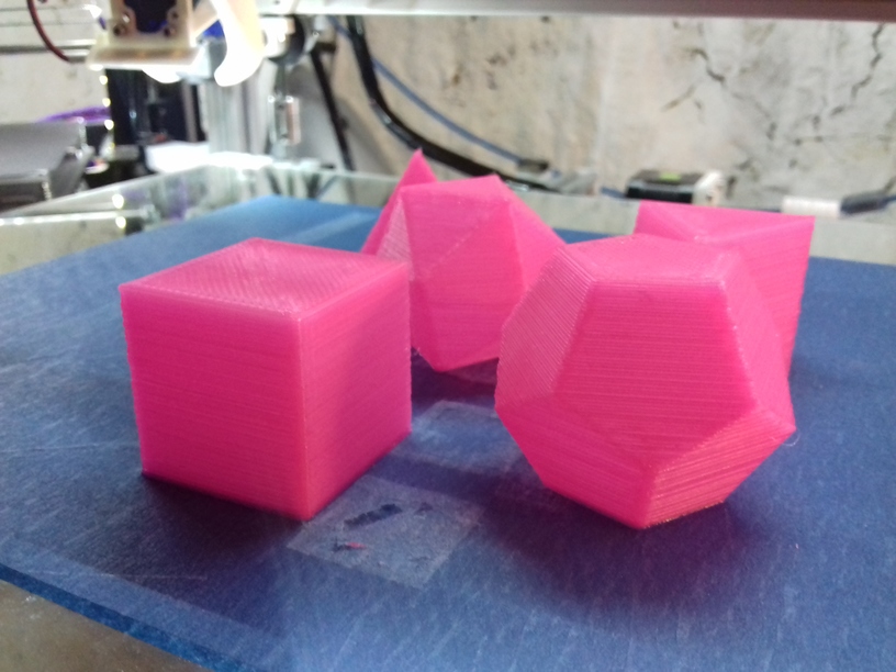
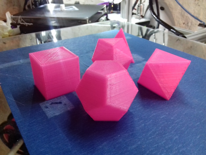
Five Platonics
My favorite geometrical forms – aside the sphere – the sacred set:
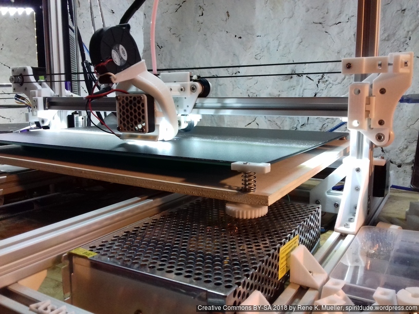
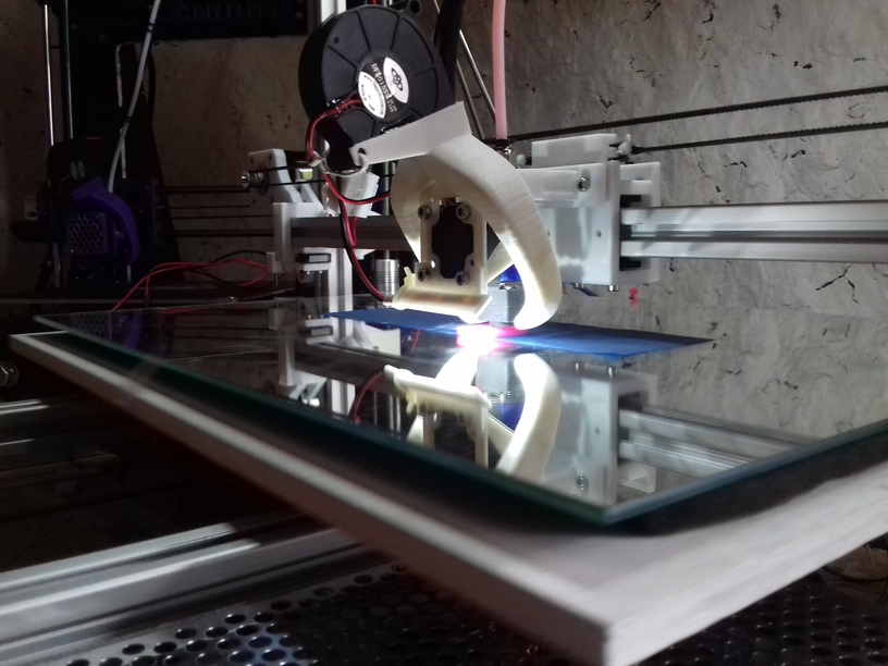
Mirror as Bed
I’ve got 40cm x 30cm mirror which became my bed base, underneath with some tight springs some 6mm multilayered plywood, which was warped 2-3mm on the edge – but it didn’t matter (much). The mirror was the reference, and the Y carriage had to hold the mirror. That turned out to work very well: the mirror is truly flat, I leveled the bed once for tilting, after a week, I only had to tweak the Z endstop screw slightly, but I didn’t touch the screws mounting the mirrors to re-level the bed anymore.
So, using the mirror as bed worked well so far due the flatness – but the glass didn’t turn out to print good on it, the printed parts often detached before finishing the print, and ruin the print – so I used blue tape sheet as temporary solution until the black sticker arrives which I already use on the other 3d printer.
Reflection
As I designed Ashtar K with larger build volume, I choose 0.5mm nozzle at least, and the max 0.4mm layer really pays off in regards of print speed, while still maintain some details – I’m quite pleased so far.
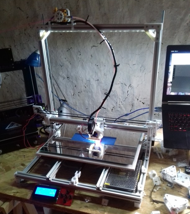
Well, after merely 3 months (2018/06/06) when I started to code the first lines of OpenSCAD to develop a series of parametric Prusa i3-like designs, and few weeks ago decided to go with the “K” series with 2020 alu profiles: simple 11x 500mm beam T slot (B-Type) alu profiles – the 1st prototype happen to print the 20mm XYZ Calibration Cube as of 2018/08/27:
Ashtar K 38.30.33
The bed is very temporarly fasten with tape, as I haven’t decided on the actual details of the bed mounting yet and leveling details – but I wanted to see how well the mechanics already works – and it performed quite well so far.
1st print came out mediocre, when I realized I had to tighten X and Y belts more, 2nd print came out much better; 0.5mm nozzle with 0.4mm layer height, merely printed in 8mins with 60mm/s print speed and 80mm/s 20% infill:
And just for the fun of it, 0.2mm layer height with 0.5mm nozzle, at 70mm/s:
Incredible quality: X and Y surface very good, some inconsistency at “X”, on the “Y” side some slight ghosting; but most surprising is the edges on the Z axis – I operate with a simple M6 threaded rod and M6 nut – that’s all – moving nylon wheel-based carriage up and down – sure, I require to print more tests, in particular larger prints to really see how well all axis print up to 300mm.
I had to use blue tape on the mirror otherwise PLA would not stick – eventually I will use the black sticker as I used for the CTC DIY printer which worked quite well.
Nylon Wheels vs Sliders
The past 2-3 weeks, while waiting the nylon wheels to arrive, I decided to check alternatives such as sliders with PTFE tubes – and this paid off: the nylon wheels 23.0mm OD with 7.3mm width sit quite nicely into the T slot (B-type) but when used in real life, like with X carriage, I had some sinus wobble in the vertical – apprx. 0.5mm to 1mm – way too much. So, I exchanged the wheel-based X carriage with the slider-based carriage, remounted the hotend with Bowden setup, and after 5mins the exchange was done:
X carriage with white nylon wheels (23.mm OD / 7.3mm width)
Current setup:
X axis: slider-based carriage, holding on top and bottom side with 2 tightening screws
Y axis: simple sliders (just sitting on the groove)
Z axis: nylon wheel (23.0/7.3mm) based carriage
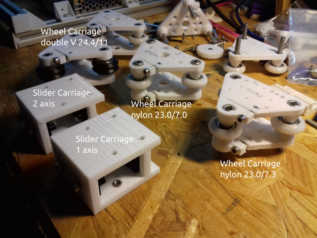
The next days and weeks I will review my options:
slider-based carriage with
1 axis support or
2 axis support
wheel-based carriage with
nylon wheels 23.0/7.3 and 23.0/7.0
double V wheels
both on T slot alu extrusion – I know ideally would be proper V slot alu extrusions, but I like to find out how good it works with the easily available T slot extrusions. Worst case is, I have to use on X and perhaps Z axis proper V slot alu extrusions, on the Y axis it seems the simple sliders (just a block) work fine.
0.5mm Nozzle
Since I deal with nearly 3x the bed surface compared to 200×200 I thought I have to use a bigger nozzle as well, as a bigger build volume would imply larger objects to be printed. The increase from 0.4mm to 0.5mm diameter also implies 1.5x or +50% more material being extruded and I still desire to print with 60mm/s average with 80mm/s infill – this means I have to test well the hotend performs with that speed and higher throughput of material.
Specifications
Current specifications of Ashtar K 3d printer:
380 x 300 x 320 mm build volume (400 x 300 bed)
E3D V6 clone hotend
0.5mm nozzle
Anet 1.0 controller board
210 x 210mm 12V heatbed
TODO
bed mounting & leveling
300×300 or 400×300 220V heatbed
proper print surface (likely black sticker 300×300 or 400×300)