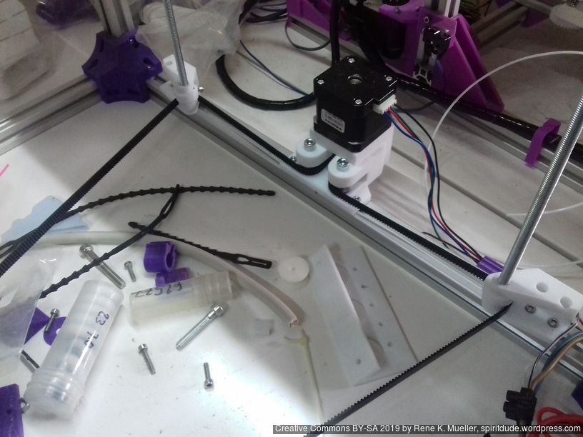
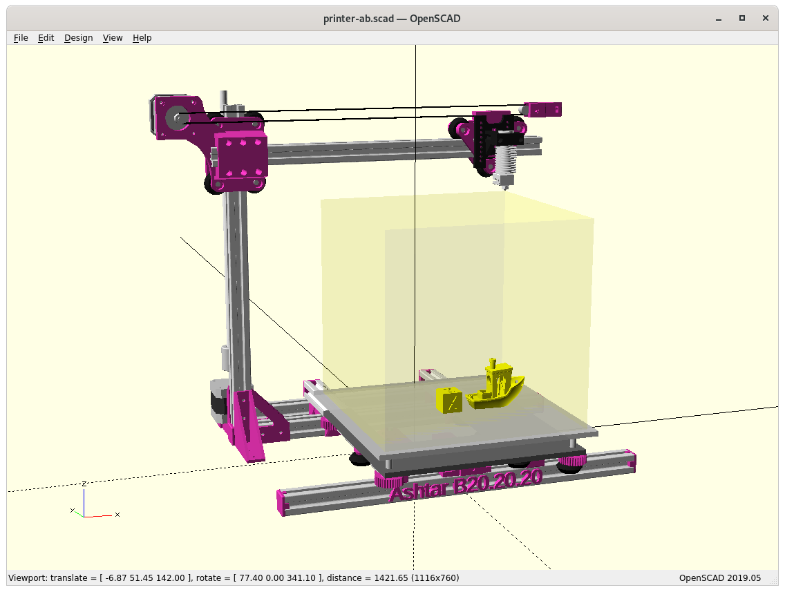
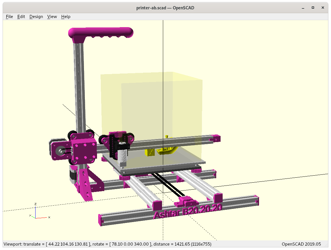
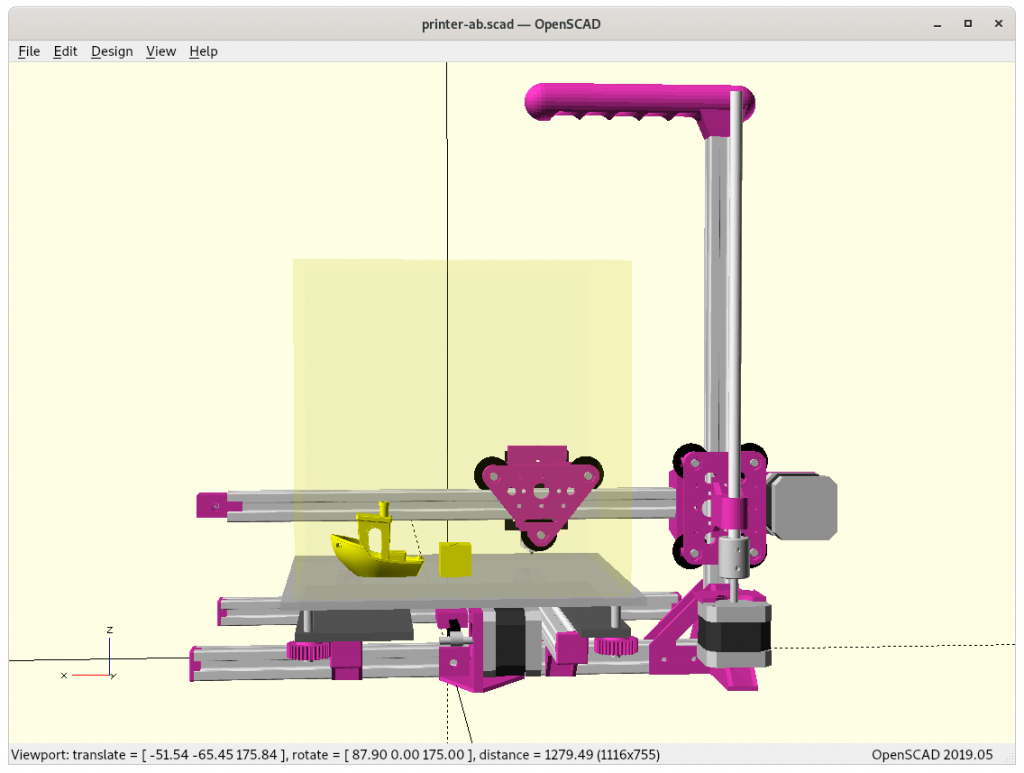
It has been on my mind for quite a while to do a 2020 alu extrusion based Cantilever 3D printer, and so I started in December 2020 with a rough design, starting from the existing Ashtar K design and cut away parts:
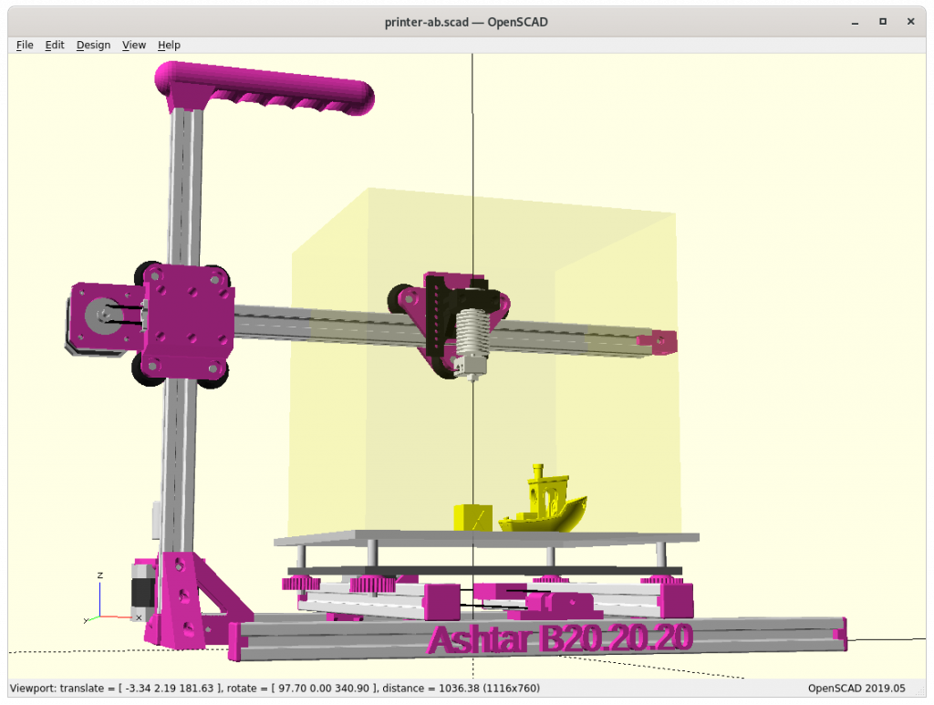
using Head XZ and Bed Y
aiming common build volume (e.g. easy to source print bed)
140mm to 190mm each axis
tried 6, 7 and 9 beams options, settling with 6 beams for now
aiming for uni-length 2020 alu extrusions, T-slot and V-slot where a carriage rides (X & Z axis) with V wheels.
trying to keep as simple as possible
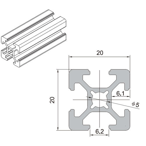
20×20 aka 2020 Alu Extrusion T-Slot Profile
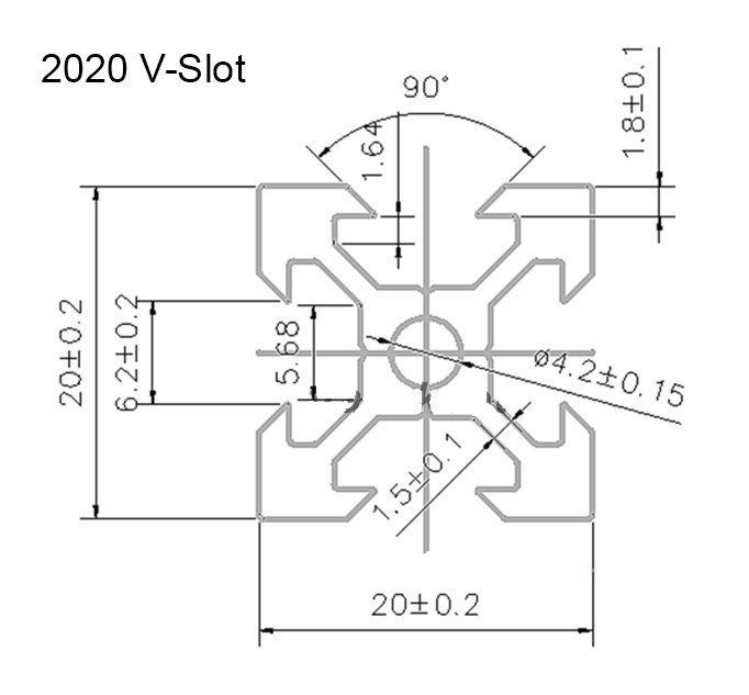
2020 V-Slot Profile
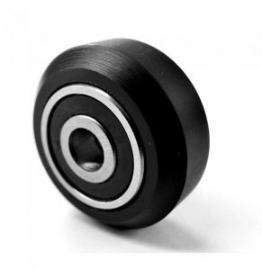
V wheel
Frame: 6 vs 7 vs 9 beams
6 beams
7 beams (+1 back)
9 beams (+2 left + right)
The 9 beams give an overall better sturdiness, but not sure how essential at small building volume (less than 220mm each axis). I might be able to remove beam, the last beam at the back at the bottom reducing to only 6 beams, in that case the Y motor is mounted on the remaining beam in the back.
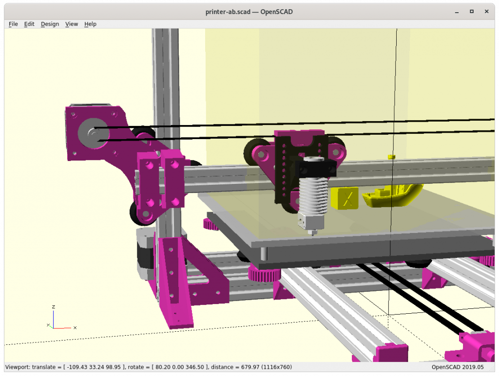
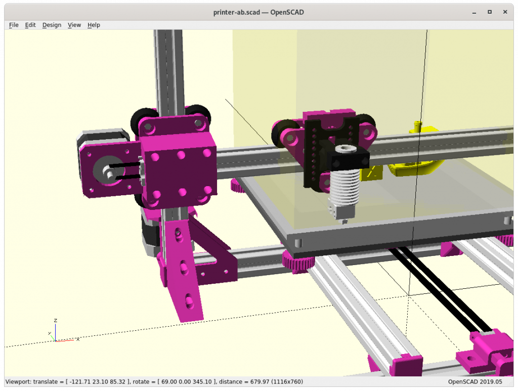
Z Carriage: 3 vs 4 wheels module
3 Wheels / 2 Mounts
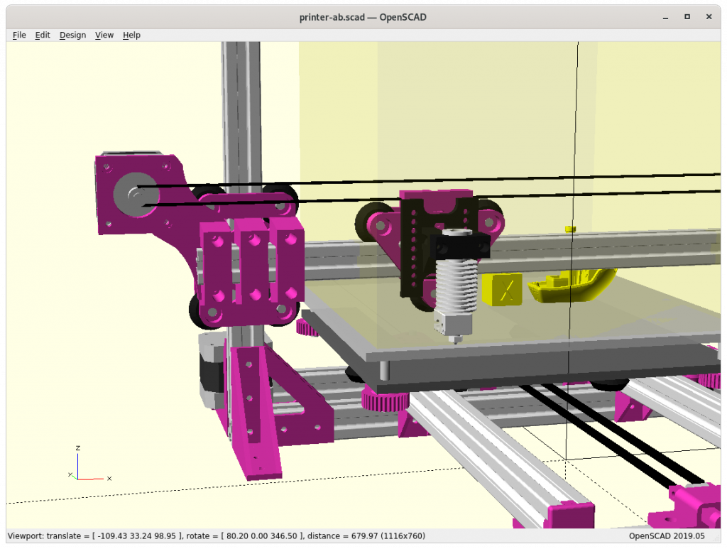
4 Wheels / 3 Mounts
4 Wheels / 3-wide Mount
4 Wheels / 3-wide Mount, Routing Inside
The 4 wheels looks best but it also sacrifices some of the X range by apprx. 10mm, the obvious choice is 3-wide mount – actual tests will tell if the X & Z axis are solid enough.
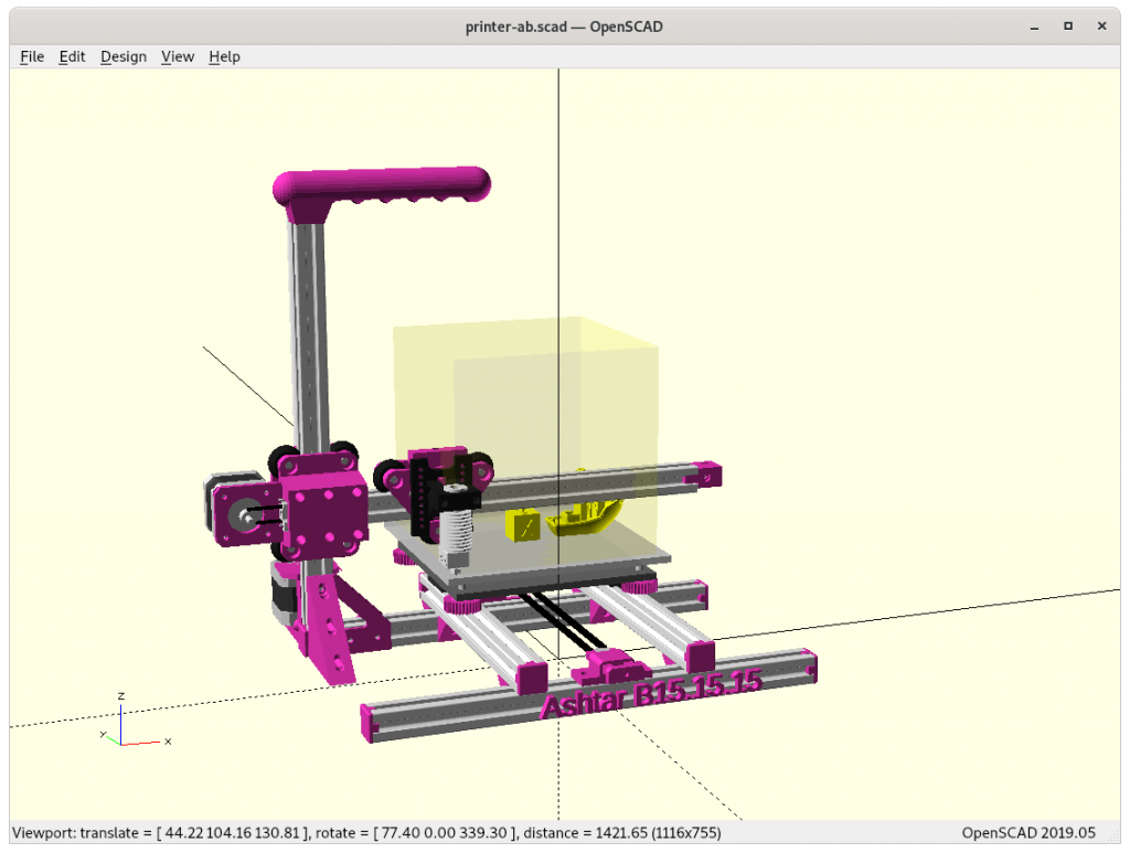
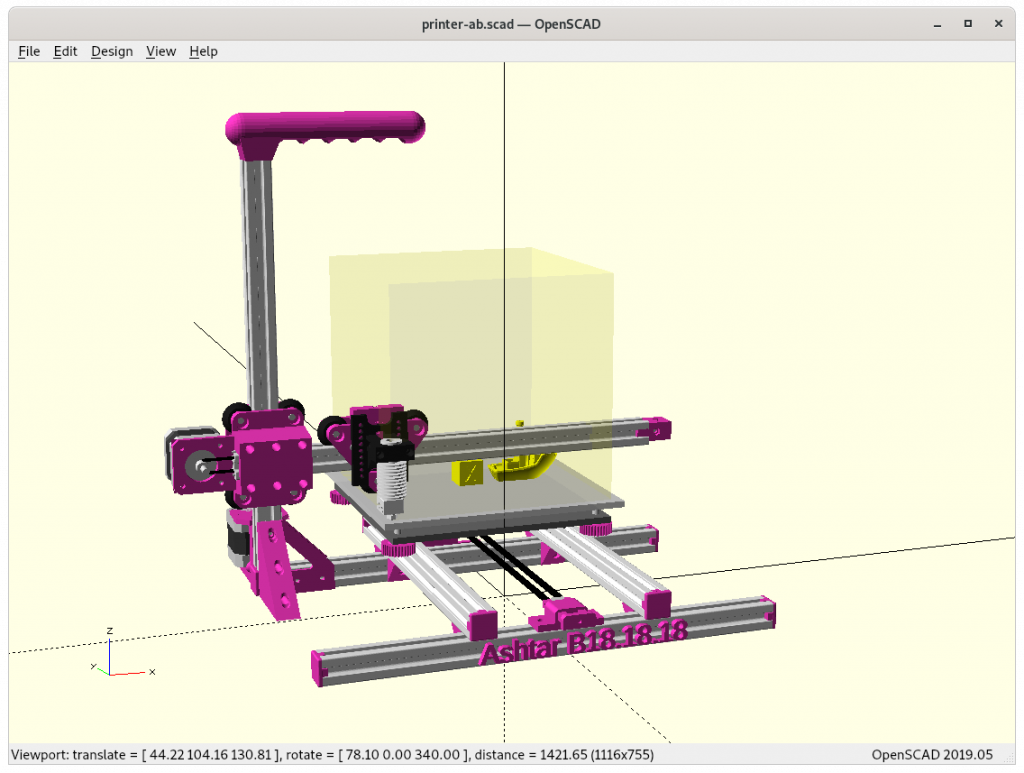
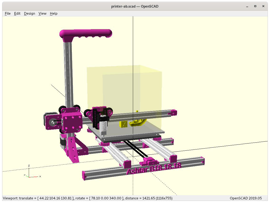
Different Sizes
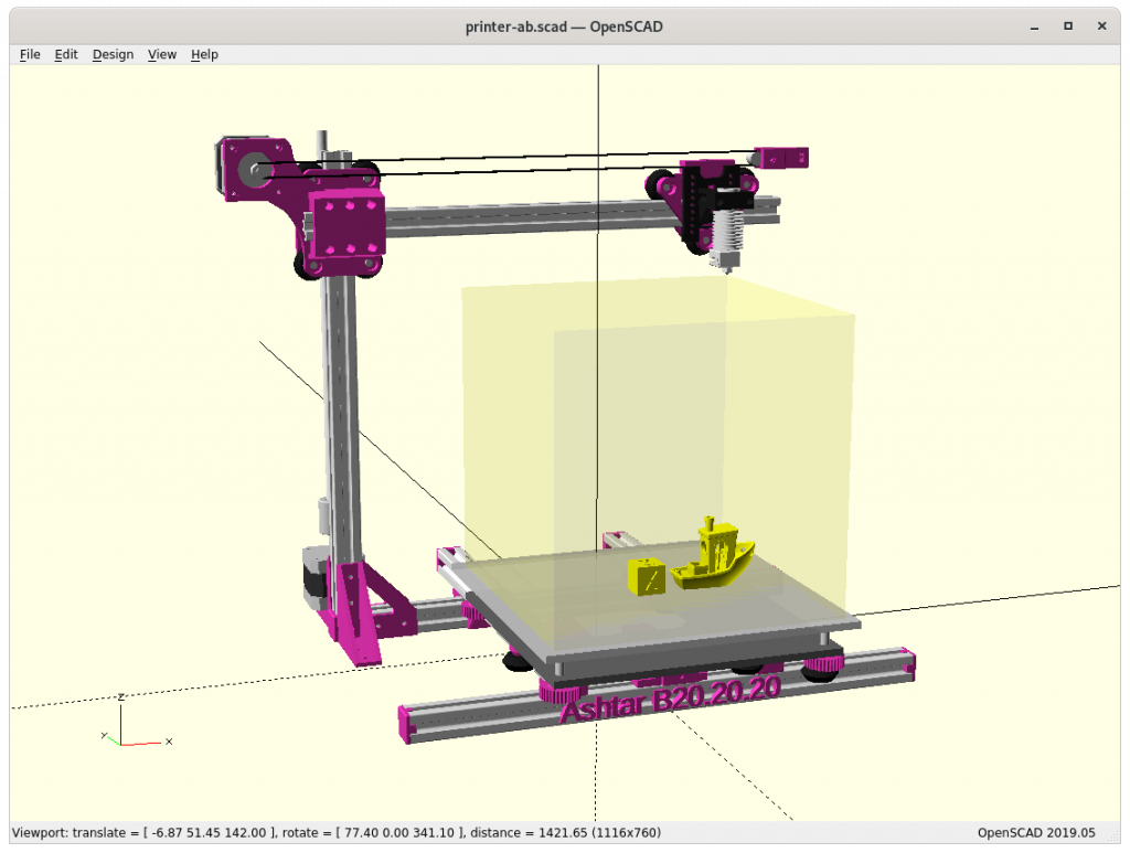
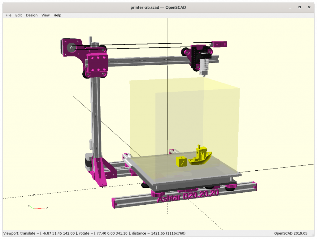
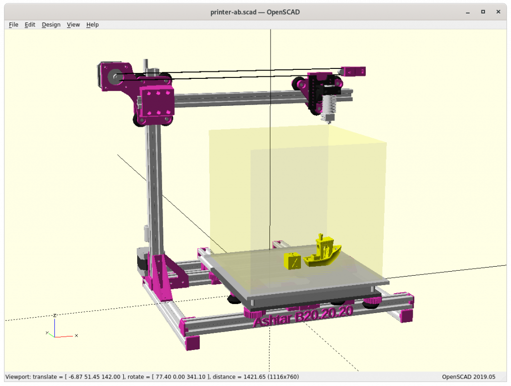
Ashtar B 150x150x150
Ashtar B 180x180x180
Ashtar B 200x200x200
The 200mm build axis length would be good, but I’m not sure if the XZ carriage will allow it as the max margin or tolerance would be half of a layer-height, e.g. 1mm layer height ⇒ 0.05mm tolerance, at X = 0 .. max the head should not flex more than 0.05mm. At this this early draft stage I don’t know which size is most suitable, I focus on 180mm build axis.
The project page on Ashtar B summarizes the current state.
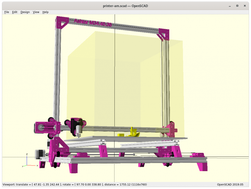
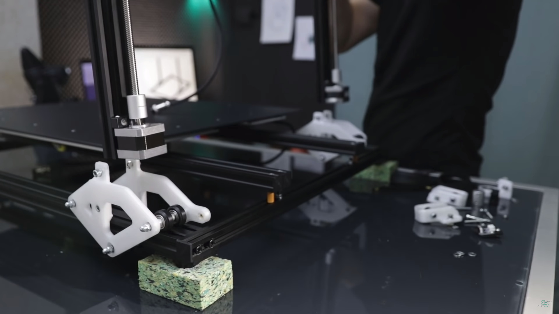
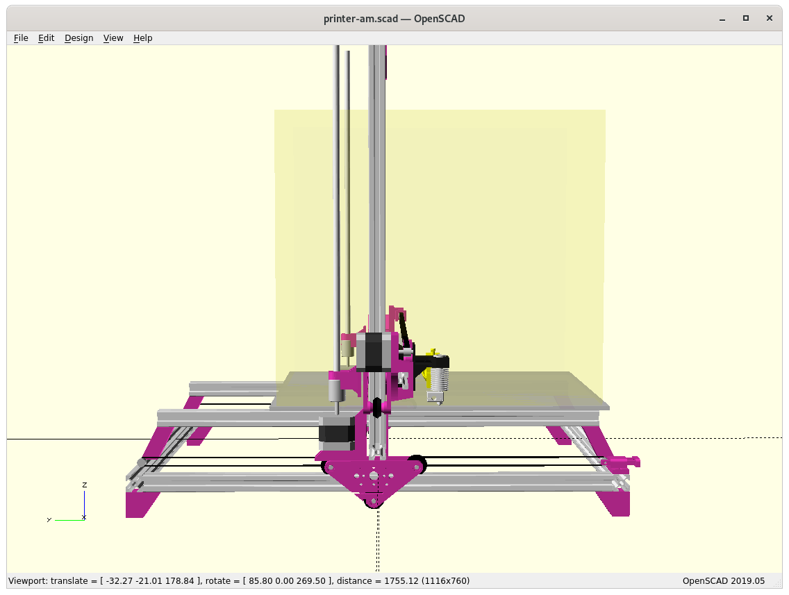
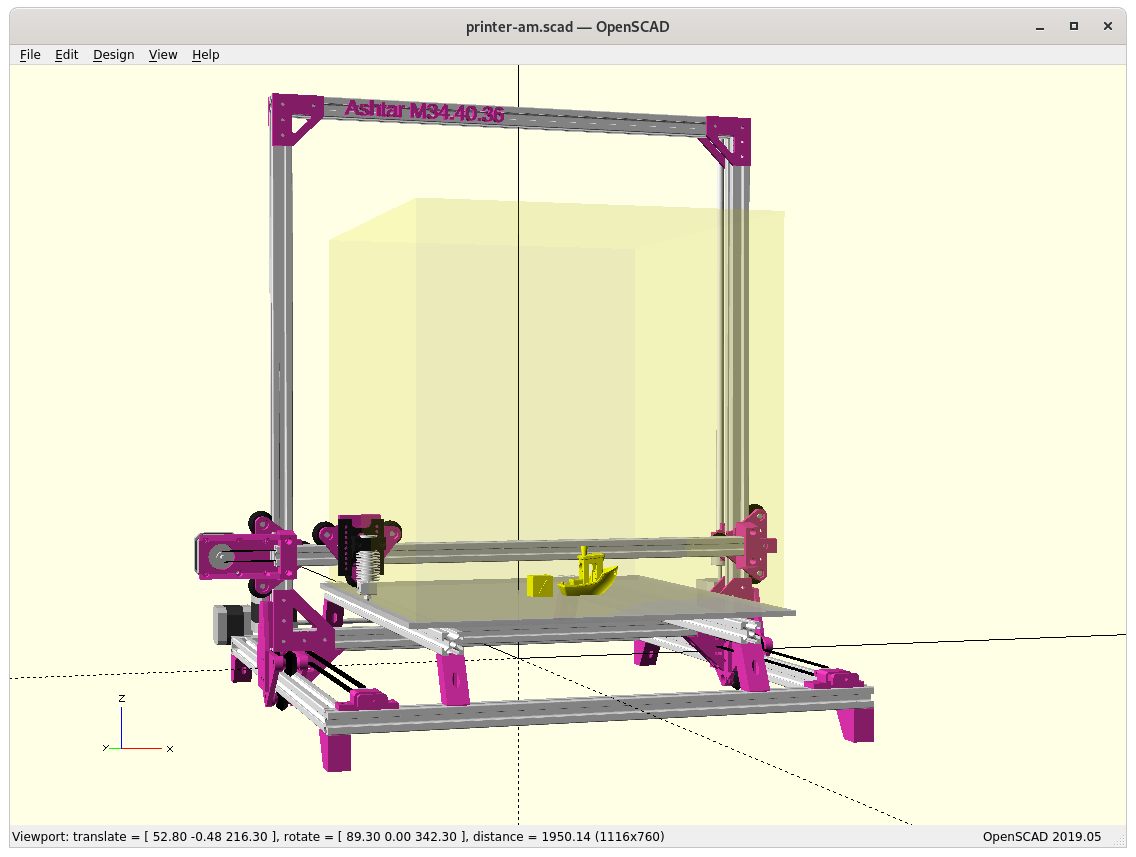
In April 2020 Jon Schone (@properprinting) showed a “Moving Portal” mod for his CR-10 – a Prusa i3 derivative – and I thought to adapt his approach as “Ashtar M” as moving XZ frame or moving gantry in CNC terms.
On a second thought, this approach makes only sense with larger beds, as the bed weight should exceed the weight of XZ frame and X carriage:
weight(XZ frame + X carriage) < weight(bed)
and as I compose my Ashtar 3D printer series with alu extrusions (beams) I can say:
weight(XZ frame) = beam X * 2 + beam Z * 2 + NEMA17 * 2 weight(bed) = X * Y
and it becomes here clear, the bed weight grows X * Y whereas XZ frame only (X + Z) * 2, but also 2* NEMA17 motors of the Z axis are part of the XZ frame.
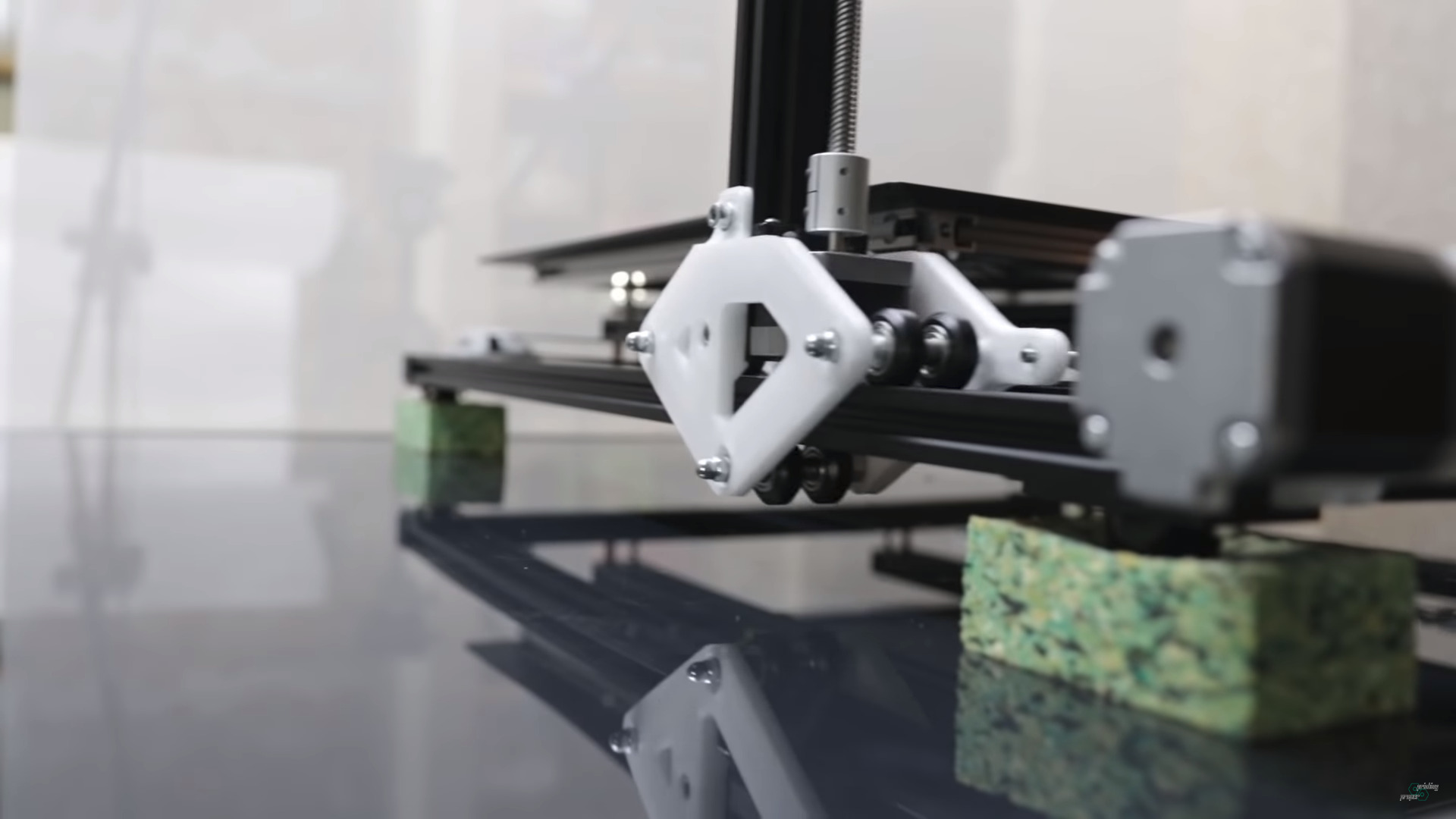
Moving Portal / Gantry
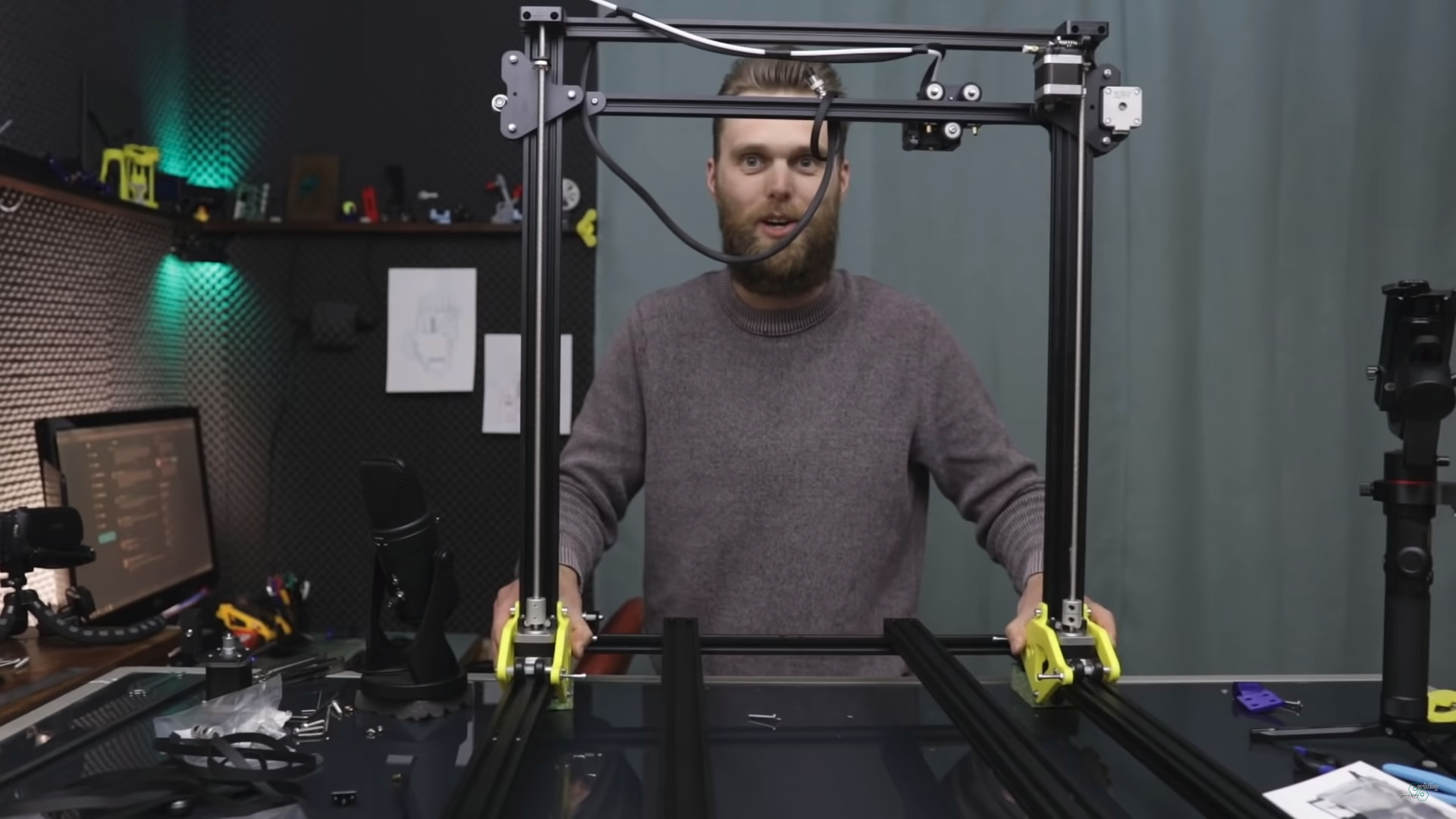
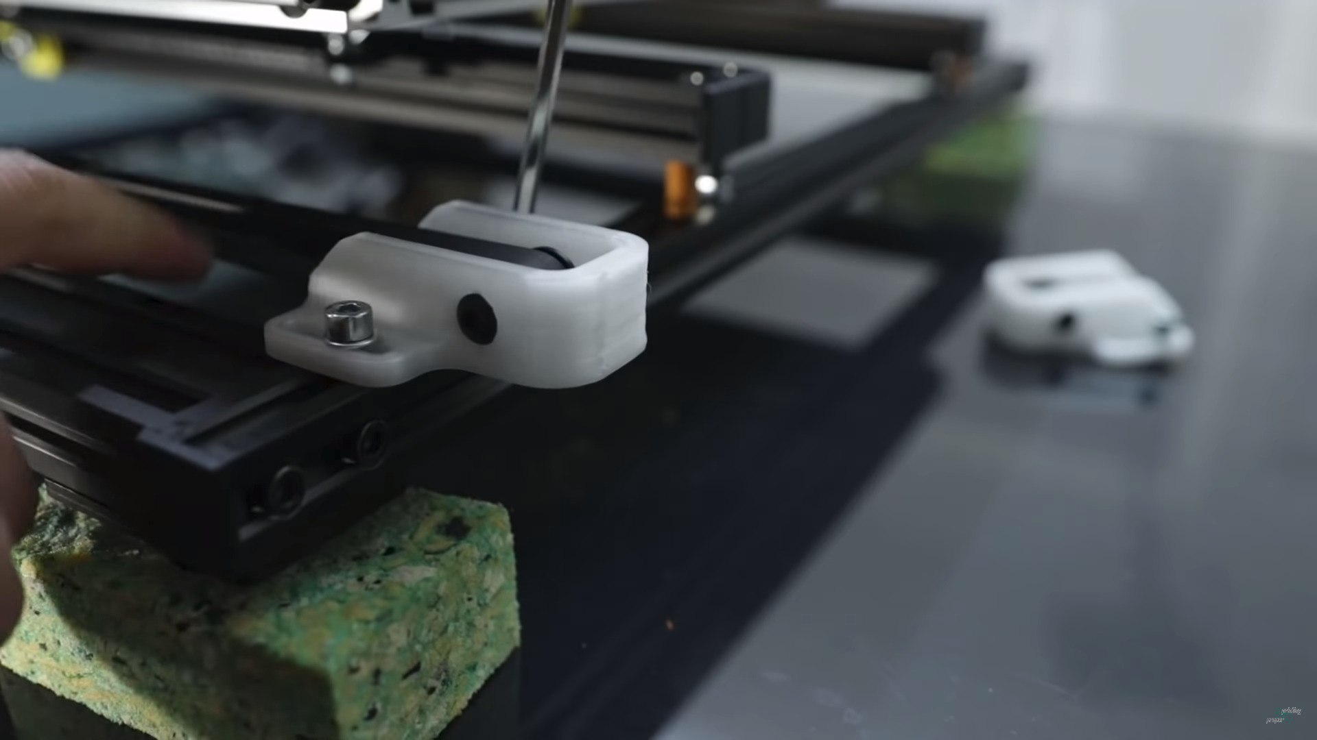
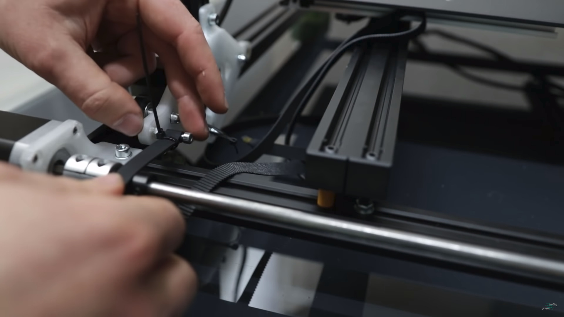
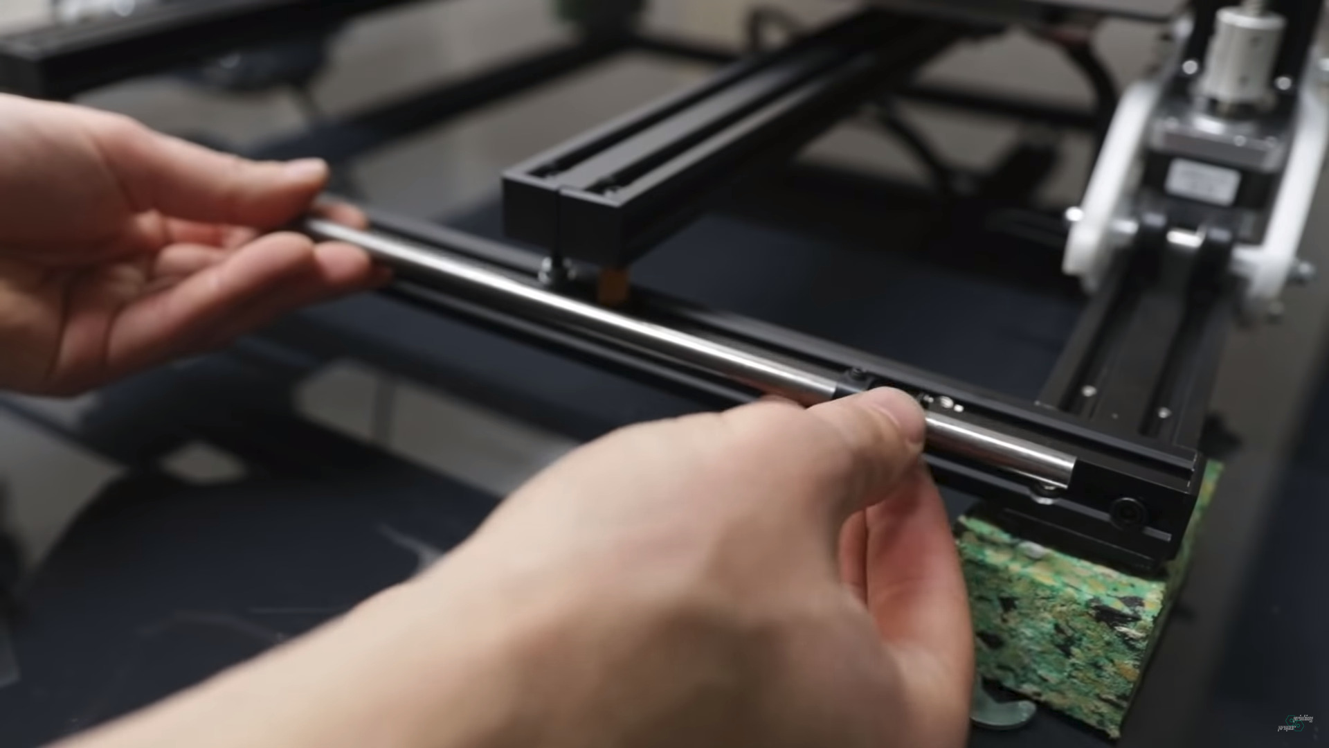
A few still images of Jon’s YT video to look at some details of his approach:
Jon Schone: Moving Portal Mod
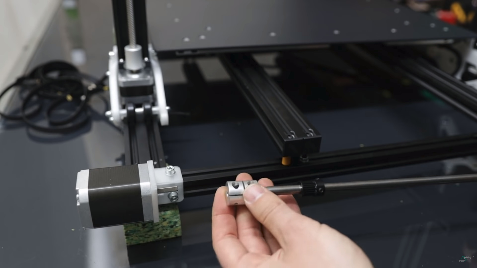
Z motor sits inside the Y carriage (40×20 V alu extrusion)
Y belt end
Single Y motor, 8mm rod to drive two Y belts
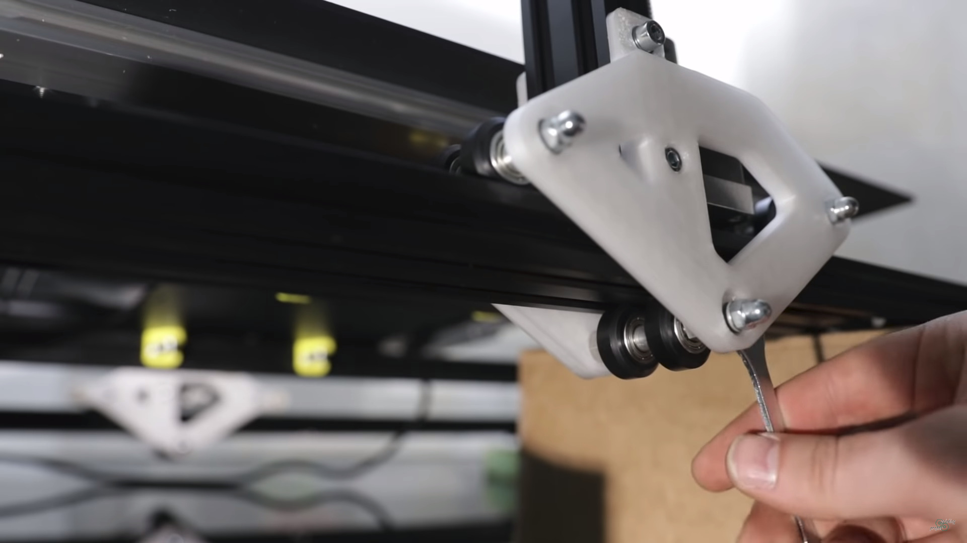
XZ frame Y Mount
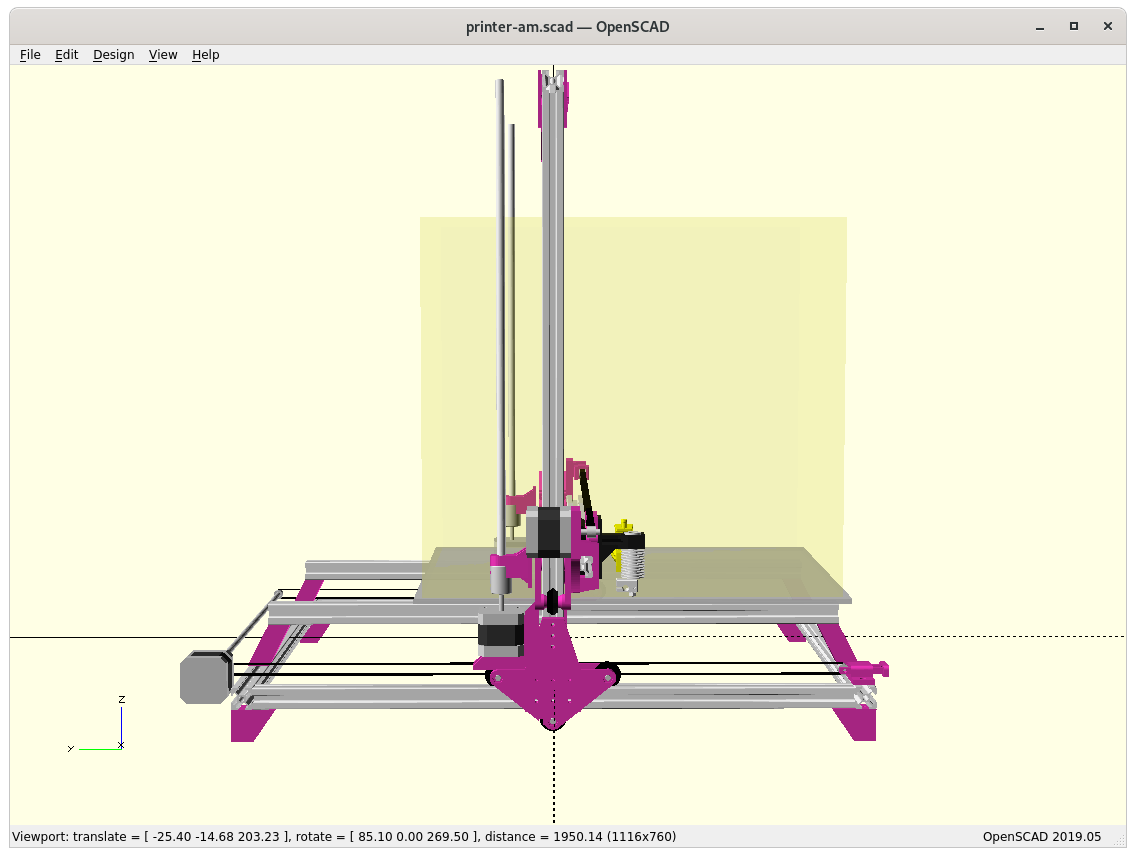
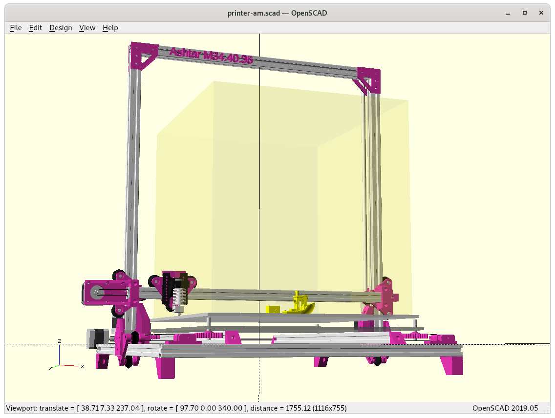
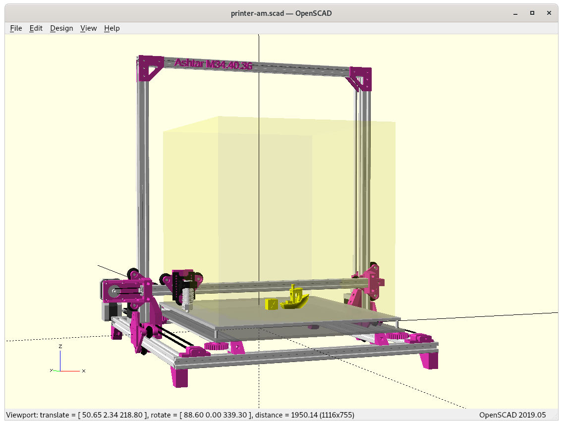
Moving Portal / XZ Frame
First Draft
using solely 500mm 2020 alu extrusions (T-slot for general frame and XZ frame, V-slot for carriages: X beam, 2x Y beams)
trying to achieve 400x400x400mm build volume as close as possible, alike Ashtar C 38.40.36
T-Slot 2020
V-Slot 2020
V wheel
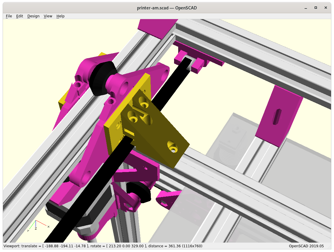
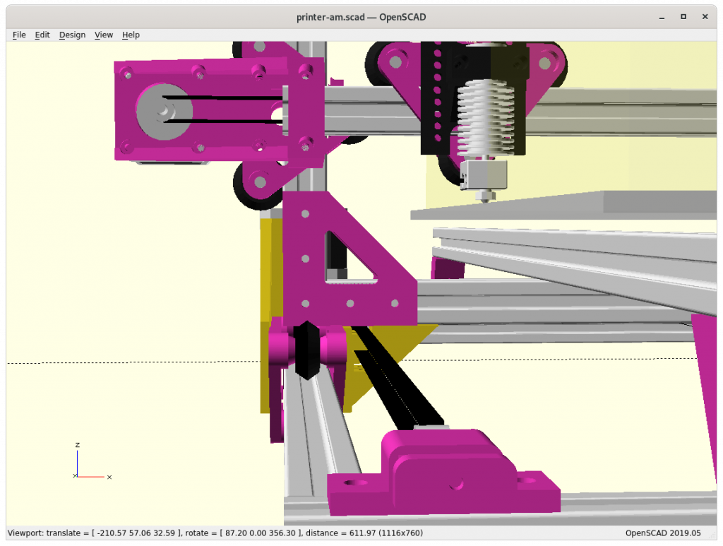
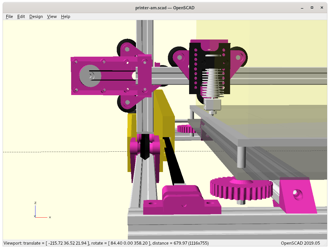
Using for Y carriages existing vcarriage2 module with vcarriage2(width=100) to have it wide enough:
Bare view on Y carriage with XZ frame
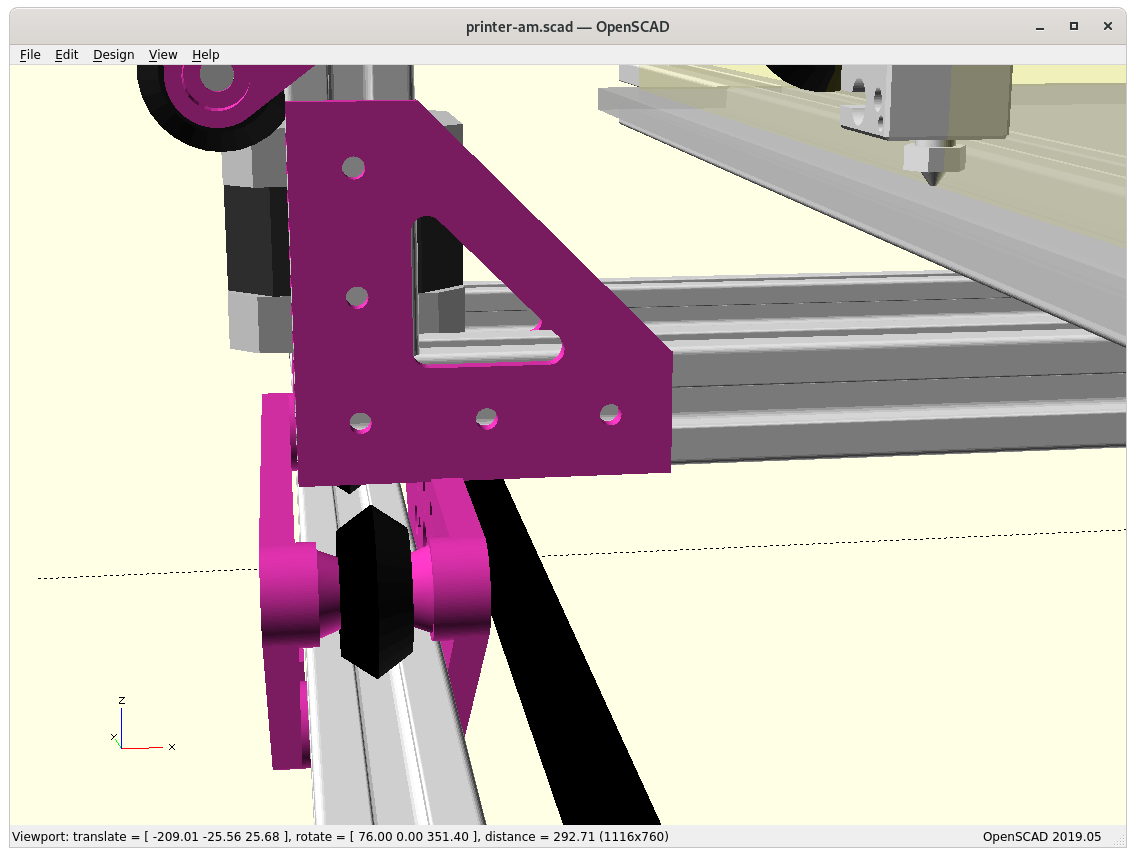
Adding side pieces “A” & “B”
Piece “A” connecting Y carriage with XZ frame
Piece “B” connecting Y carriage with XZ frame
Piece “B” bottom view
At position 0,0,0
The two main new pieces required were connecting the Y carriage with the XZ frame:
Piece “A” outside ycarriage_xzframe_mount_a(): has to be printed with 0.1mm layer height in order to stay within the +/- 0.05mm tolerance, otherwise it will introduce tilt and stress on the Y carriage and cause long term damage – tricky part to print.
Adding side pieces “A” & “B”
Piece “B” inside ycarriage_xzframe_mount_b(): is quite elaborate already and should be functional, with the Y belt ends fastening with M3 screws and M3 nuts inserts, the belt endings will come out downward:
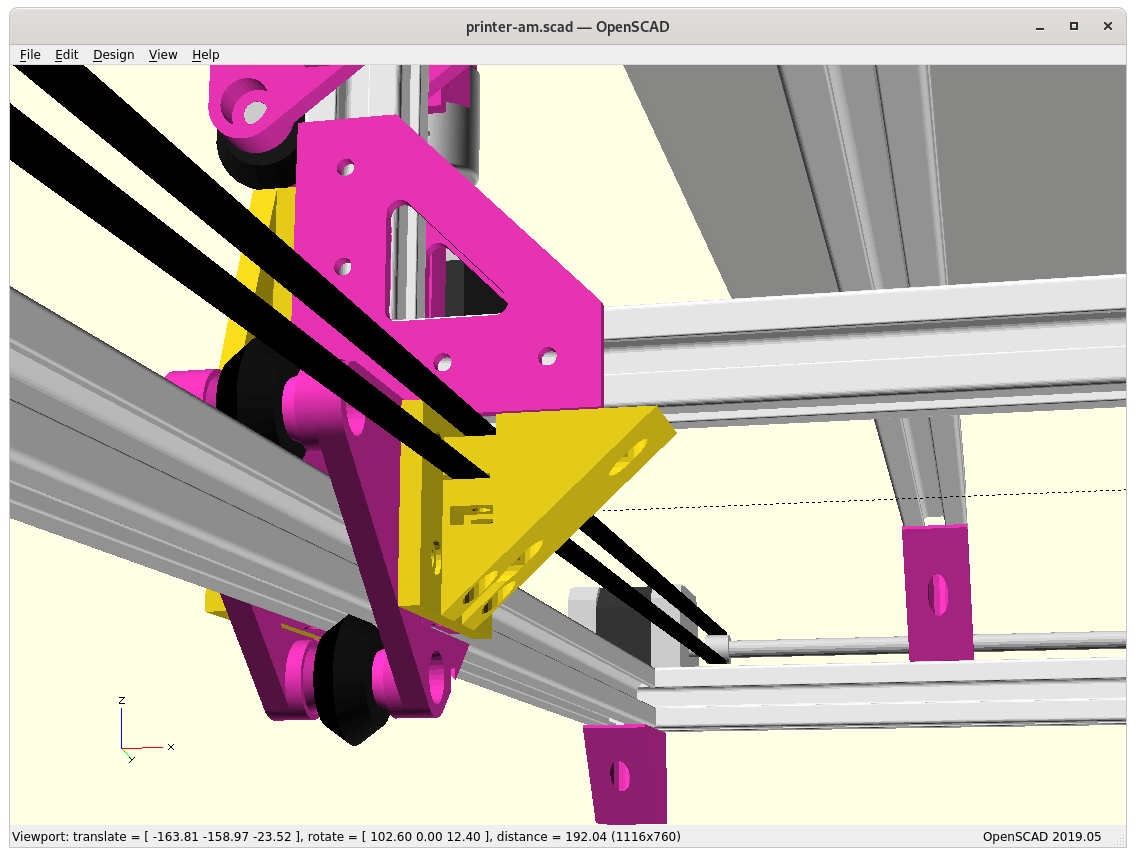
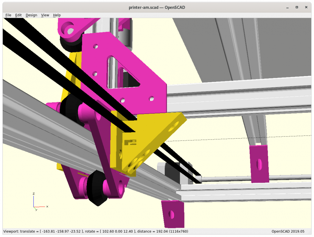
XZ Arch Option – Removing Lower X Beam
In order to gain some Z build space by lowering the print bed, I may reduce the XZ frame to an XZ arch:
Side pieces “A” & “B” with Arch (lower X-beam removed)
Side piece “B”
Actual physical tests may reveal if it’s suitable to maintain overall geometrical integrity. Removing the lower X beam also reduces moving mass of the XZ arch/frame/gantry.
Pros
gain Z build space
reduce XZ gantry weight / inertia
Cons
decrease XZ gantry stability
Further Development
As I develop Ashtar M further, I will post updates on the blog here, and also keep documenting the current state at Ashtar M page.
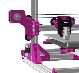
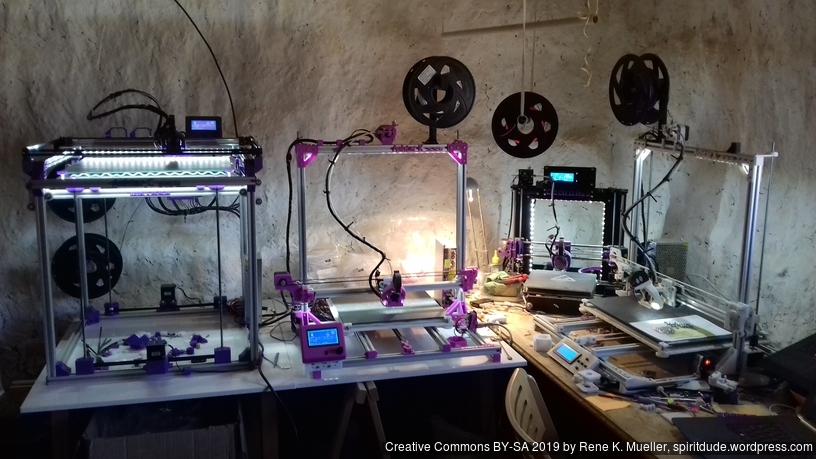
For the past 9 months (2019/08) I printed with two Ashtar K printers, where the X belt was routed above the 2020 extrusion:
Routing Above (Old)
Routing Within (New)
Pro:
easy access (X motor & X carriage belt mount)
stabilizes the X carriage vertically
Cons:
bending of the mount
And the bending of the mount became an issue more and more, as I kept tighten the belt and bend the mount more; time to redesign the part.
Update 2021/01/19: I resurrected the piece for the Ashtar K/M IDEX and improved the strength for its use-case.
Old “routed above” X motor mount
Improved “routed above” X motor mount
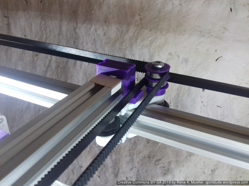
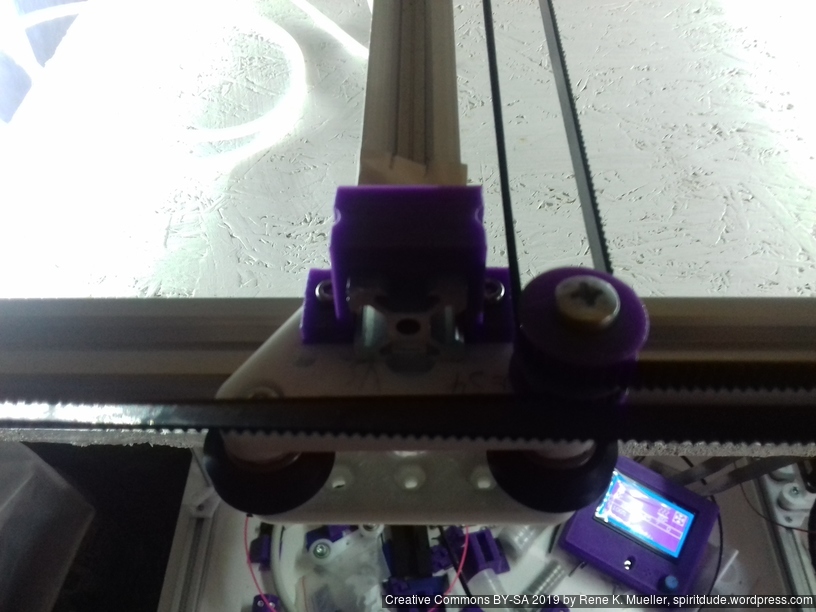
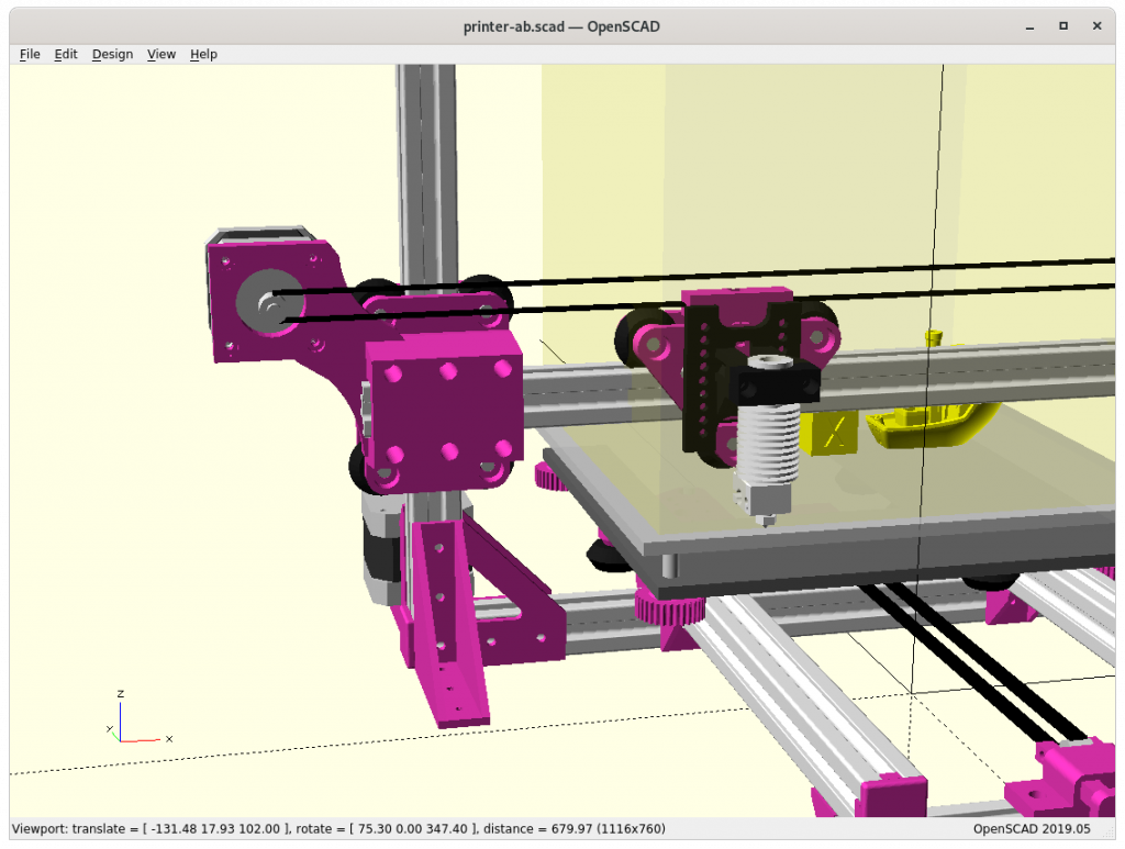
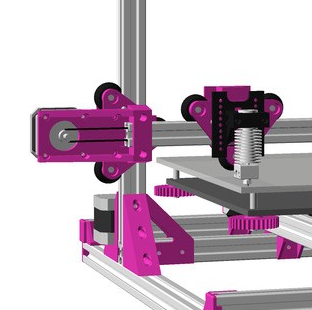
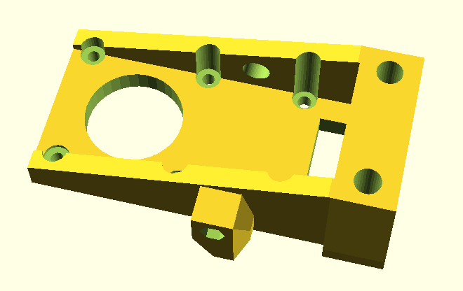
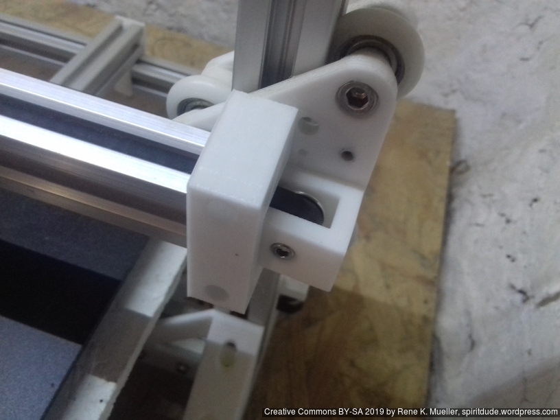
New Option: Routing Belt inside groove of 2020 Profile
First I used T shaped 2020 aluminium profiles and the nylon wheels did have little surface to ride, hence, I wanted the belt also function as vertical stabilizing. Once I replaced the X beam with V shaped 2020 profile, and V shaped wheel in the V modules riding on the profiles, I thought to reposition the belt into the groove of the V 2020 profile, and so reposition the X motor mount. So I merged the horizontal 2020 mount with the motor mount in one, plus adjustable Z stopper:
which gave the desired stiffness of the part I sought.
Pro:
remains stiff
easy to mount & accessible (belt, Z stop screw)
Cons:
larger part, 2020 mount and motor mount combined
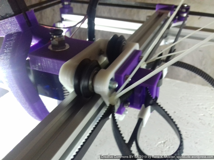
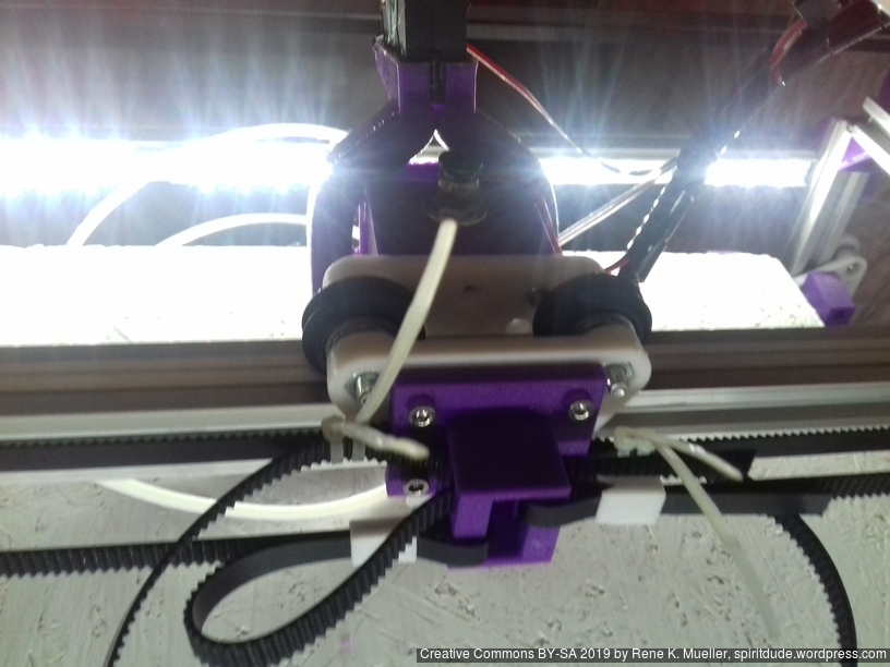
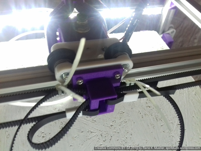
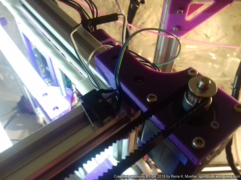
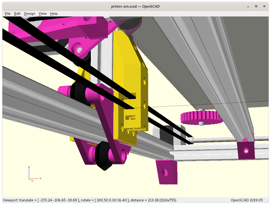
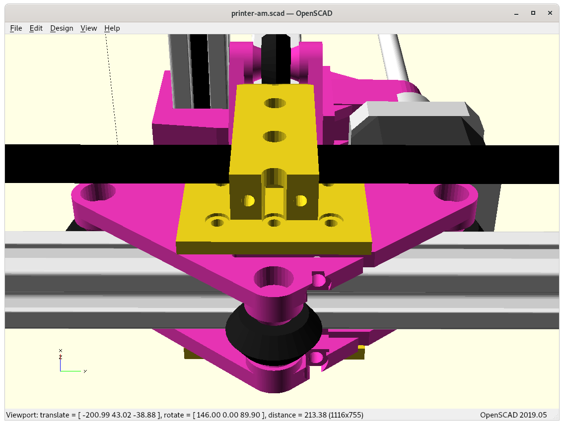
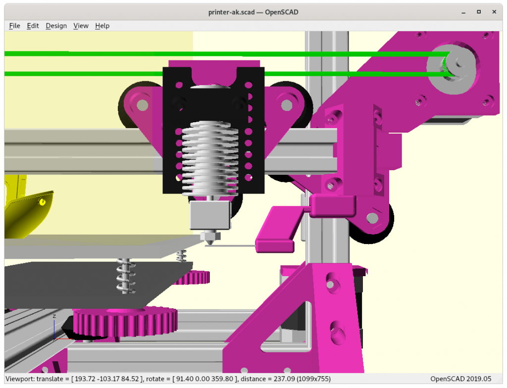
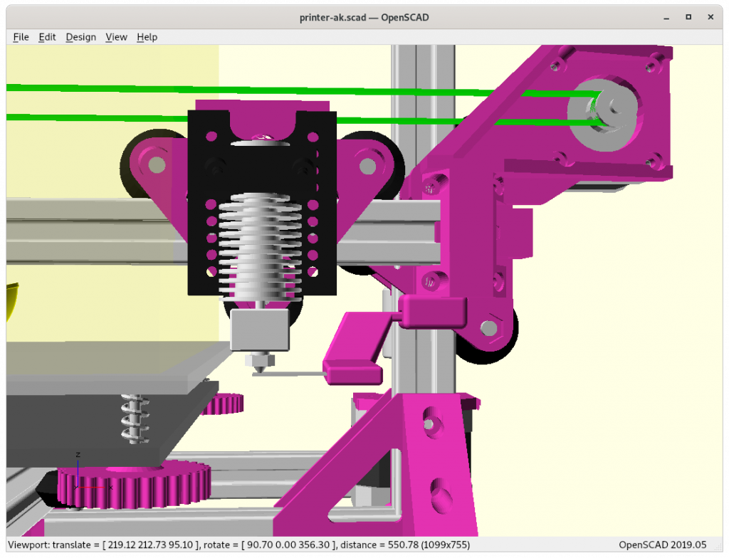
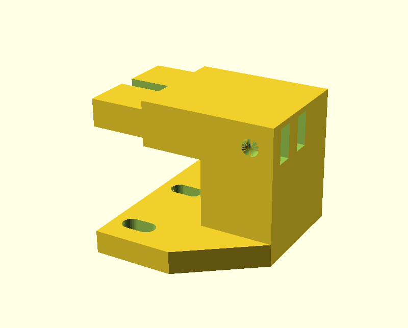
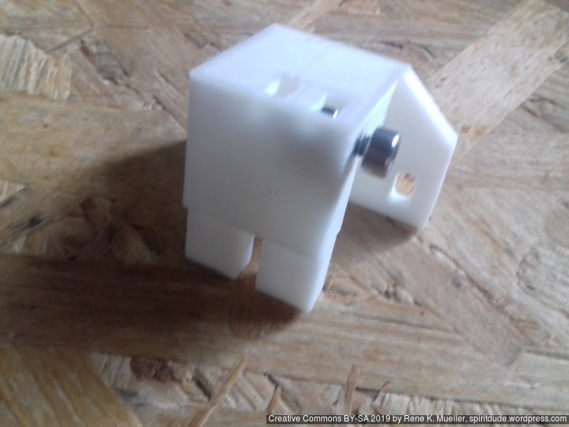
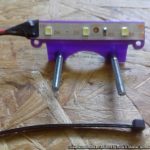
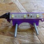
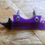
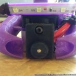
X Carriage Beltmount
In order to route the belt in the groove of the 2020 profile for the X carriage itself, a rather delicate piece was required, mounted at the backside of the X carriage V-module; I use a M3 to fasten the belts:
Assembled
Part names with variables:
xcarriage_short_hmount_motor_2020(zstop=true): main motor mount with 2020 profile mount combined
xcarriage_beltmount_2020(th=32.7): new belt mount on the X carriage, th default at 32.7mm, but one needs to measure the total thickness of the V modules acting as X carriage
pulley_holder_2020(): right side of the belt routing
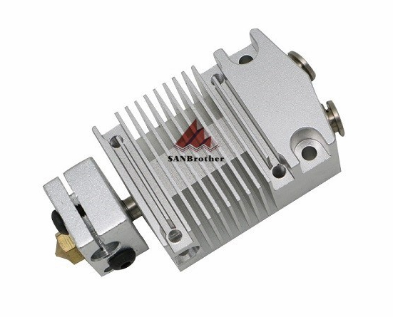
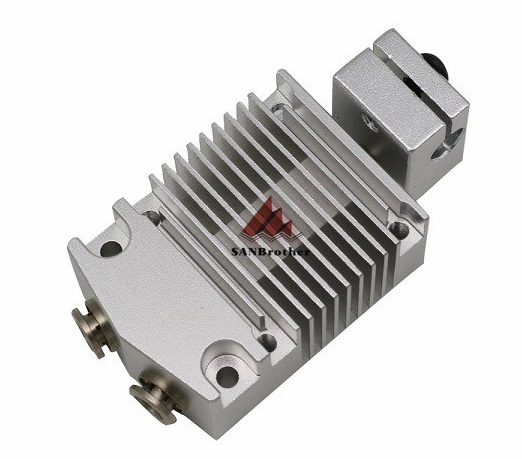
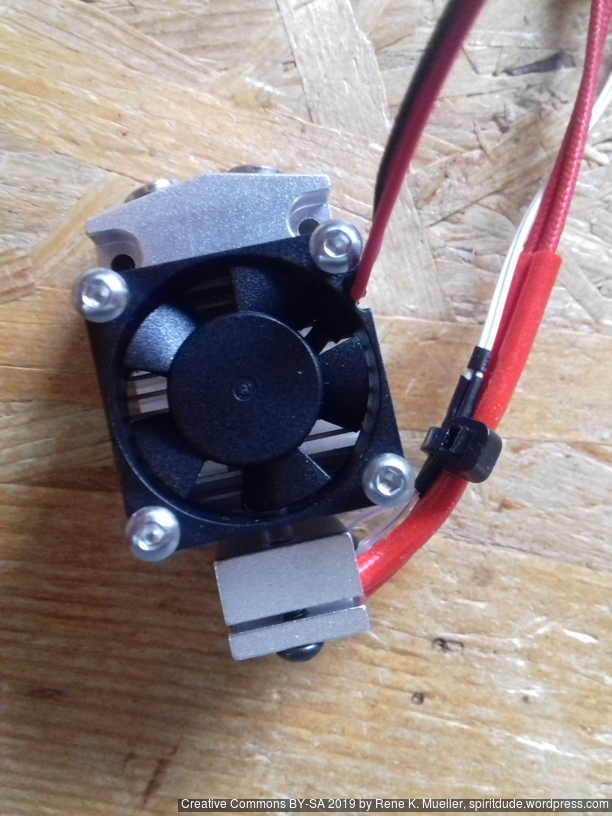
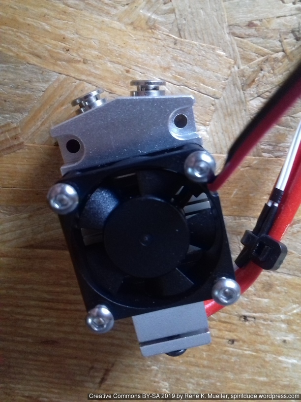
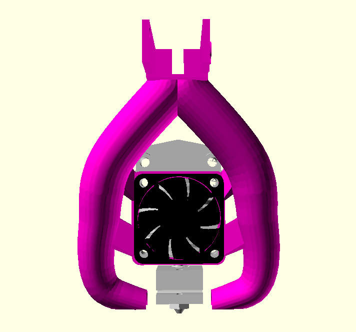
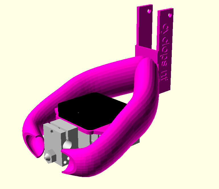
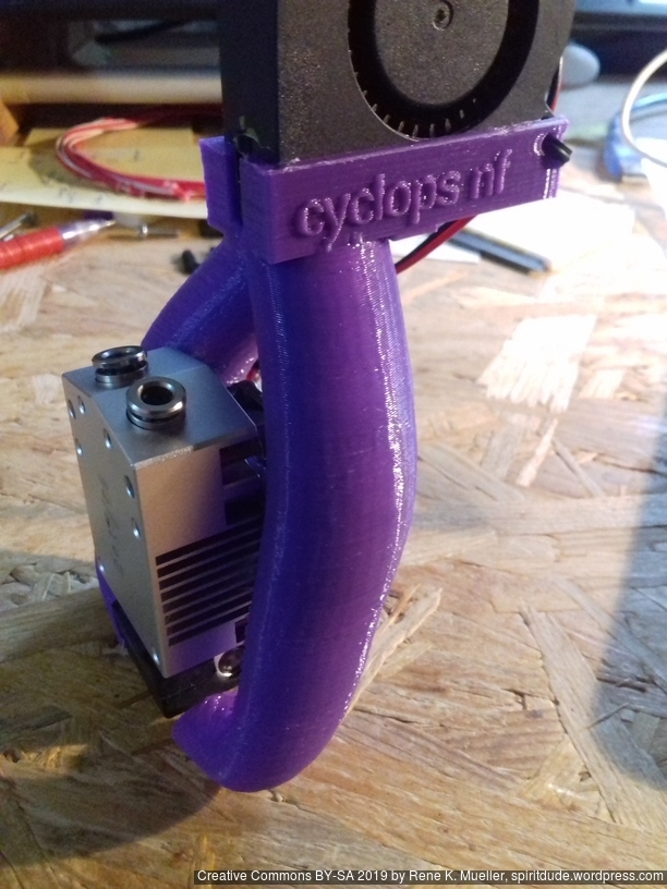
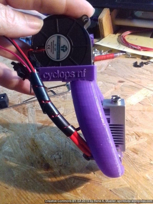
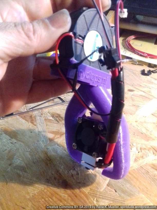
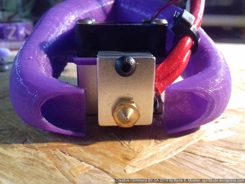
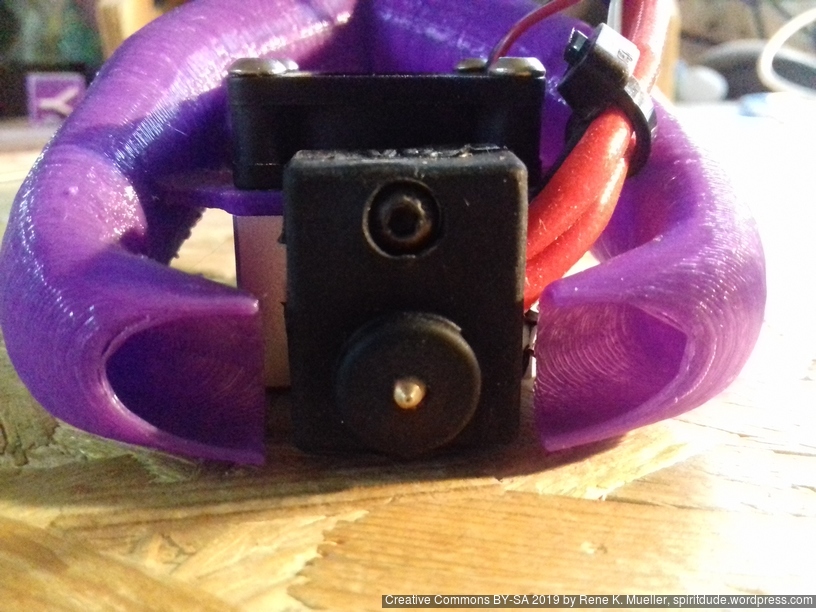
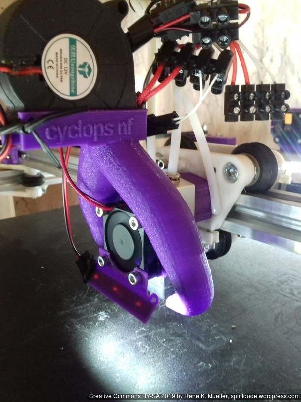
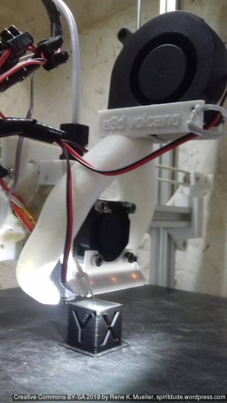
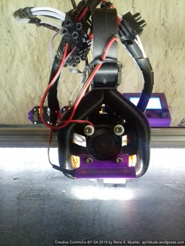
After my bad experience with the “Cyclops/Chimera” clone (2-in-1 with mixing capability), I purchased (June 2019) the improved “Cyclops” which resembles the “Cyclops NF 2-in-1” or “LERDGE 2-in-1 V2” , so I name this variant “Cyclops NF 2-in-1“:
which can be ordered at AliExpress (affiliate links):
LERDGE 2-IN-1 V2 (slightly different screws holes to fasten heatbreak),
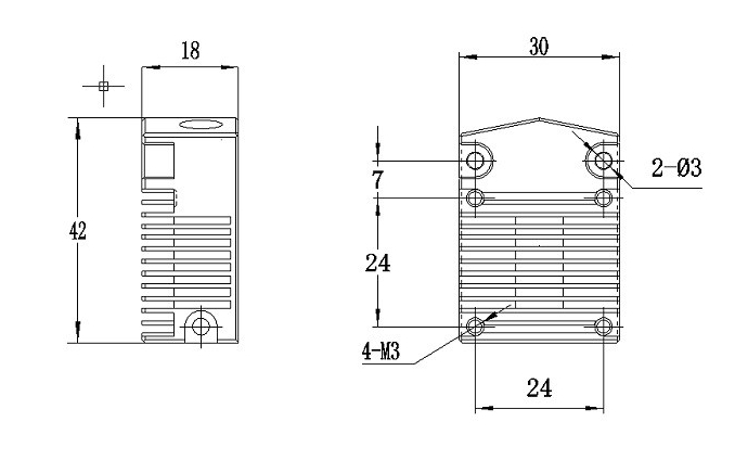
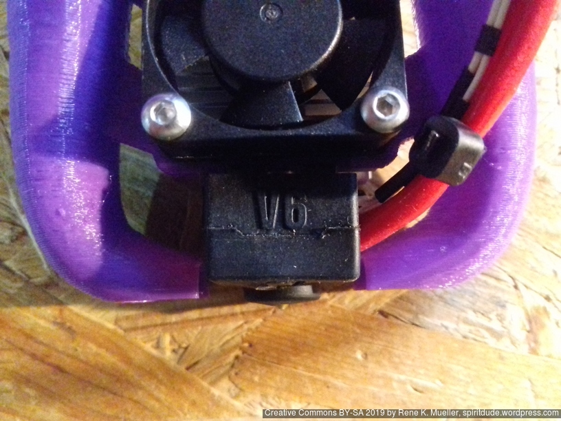
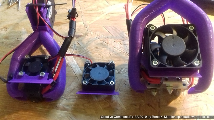
and uses E3D V6 nozzle (clone) and 30x10mm fan on top. The two mounting holes are 24mm apart and fit the Prusa i3 X-carriage.
Further, the two filaments cannot be mixed like the original Cyclops but either filament A or B can be fed into the nozzle, but not both at the same time. Also, one can print with one filament solely, a 2nd filament must not be present.
Pros:
affordable
simple setup
single filament printing possible without 2nd filament being present
Cons:
cannot mix colors
long retraction required for tool change (>34mm)
long transition purge (~55mm)
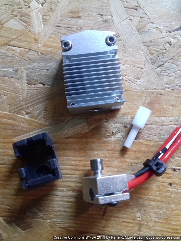
custom PTFE or nylon piece in the heatbreak (not easy to source)
uncoordinated retraction can cause one filament blocking another
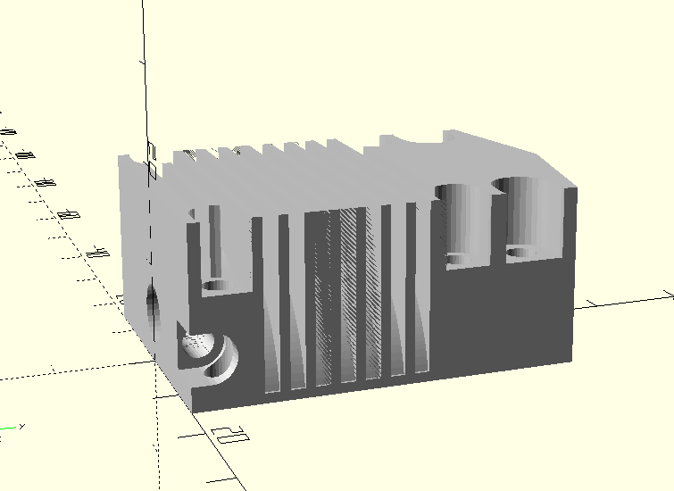
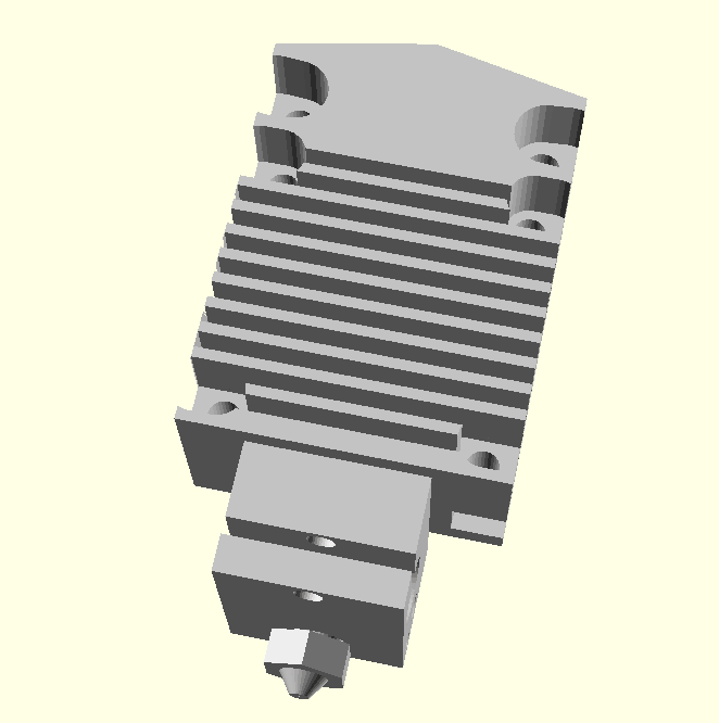
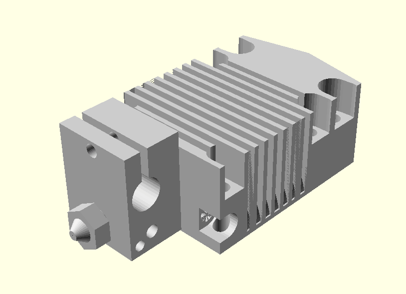
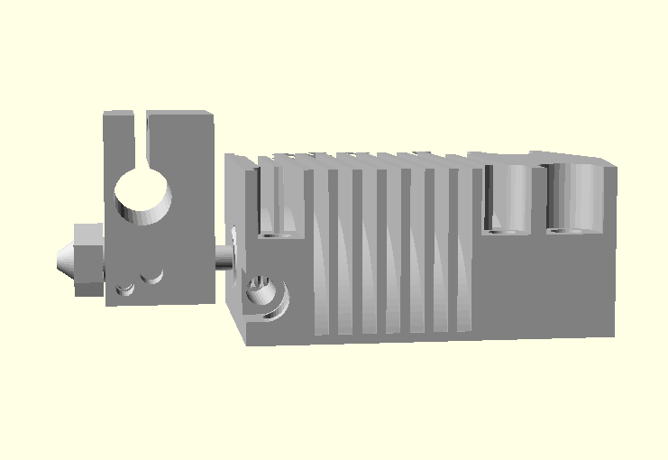
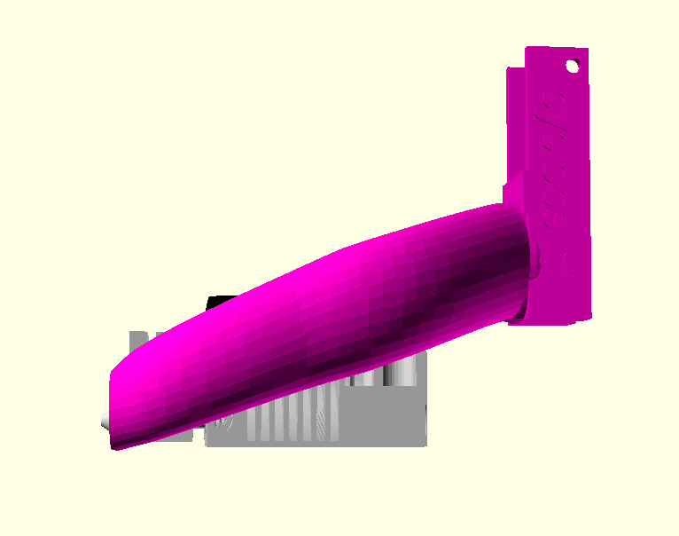
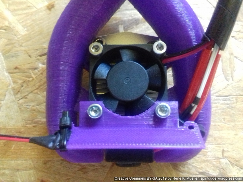
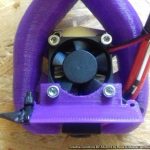
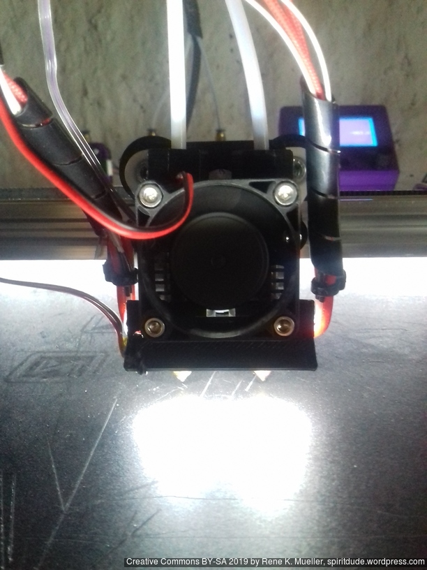
Model & Part Cooler
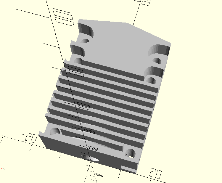
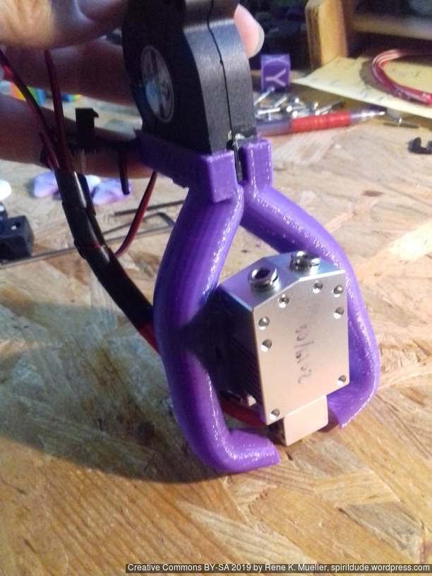
I quickly modeled the heatsink in OpenSCAD:
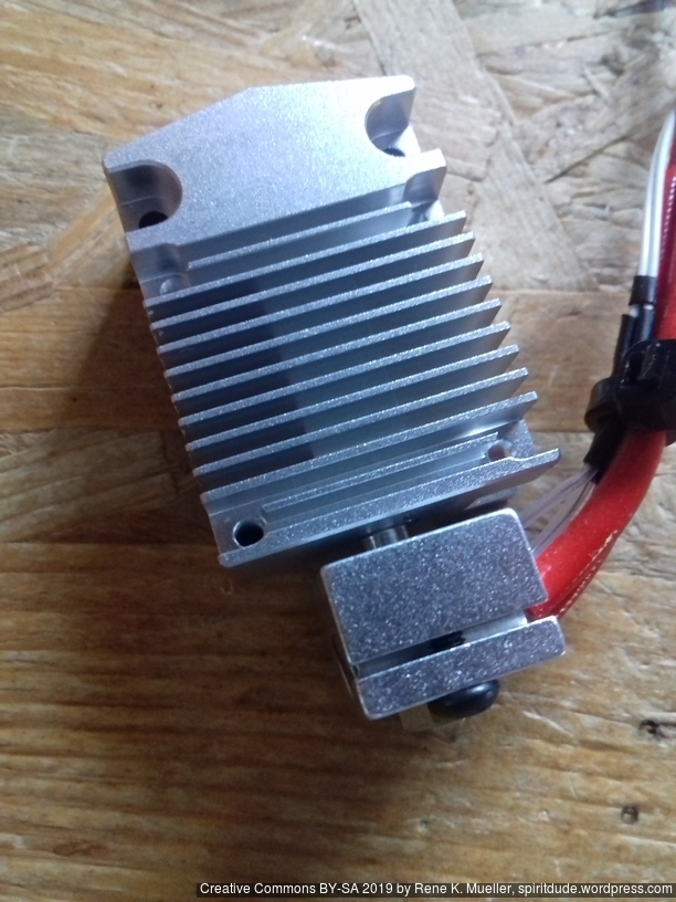
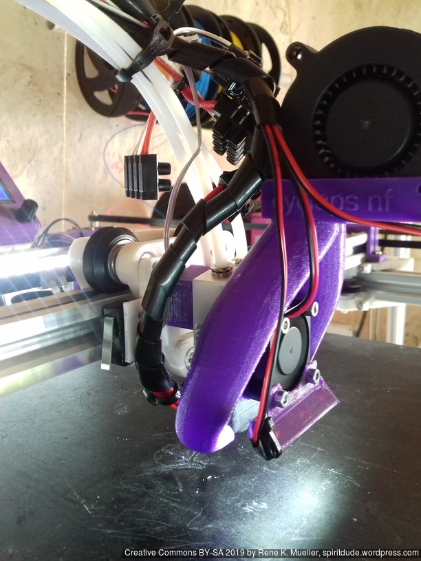
so I was able to adapt my Parametric Part Cooler with following settings part_cooler(name="cyclops nf",m=30,wx=25,yoff=10):
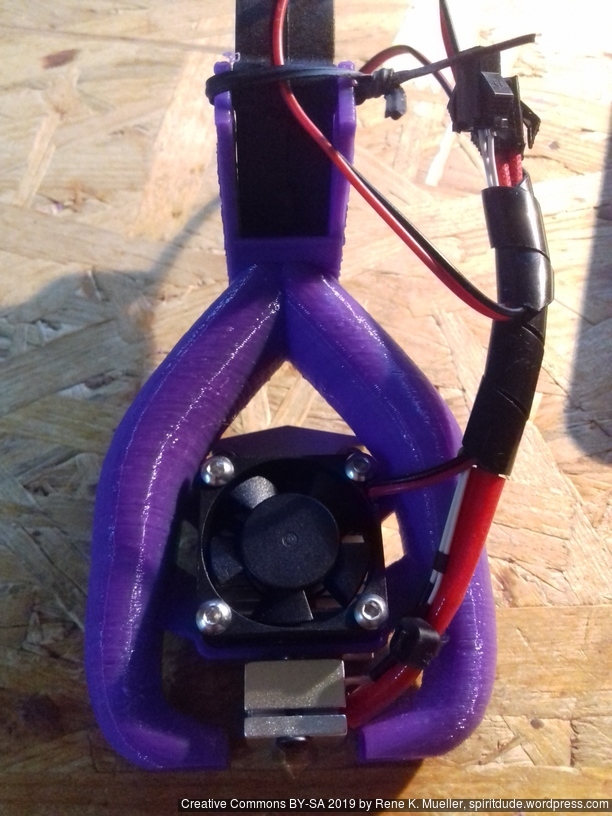
I finally turned the heatblock around (from the default orientation), so I could see the nozzle better and the LED strip shining more direct on the nozzle and bed.
Operation
The long tool switching retraction of > 34mm imposes quite additional risk of jamming combined with temperature sensitivity: depending on the temperature the pulled back of end of filament changes shape, and may not able to re-enter at next tool switch – so I’m a bit skeptical on the reliability – time will tell.
As I use print3r solely (without GUI), I set following in the printer profile:
# -- slicer=slic3r, slic3r-pe and prusa only:
retract_length_toolchange = 36
which I use as print3r @e2-nf-t1 ... in case I like to print with 2nd filament only:
start:
T0: purge 20mm
T0: retract -36mm
T1: forward 36mm
T1: purge 60mm
reset E meter and go back to absolute positioning/extruding
end:
go back to Y380 (absolute)
T1: retract extrusion -2mm
T1: retract -36mm quick
T0: forward 36mm quick
switch off heating and motors
This way I keep T0 as default, and on-demand switch to T1 only with @e2-nf-t1 macro in operations. One case is not covered: if I abort a print then T1 is still active in the printhead and manually needs to be retracted (future print3r version will resolve this).
in theory no purge block, but if ooze shields are shared among switching extrusions (more than 2 extrusions) there may be cross-contamination between colors/materials
the printheads individually are proven to be reliable
Hints:
single heatblock = same print temperature
dual heatblock = different print temperatures possible
The final step you can decide to put the mount above or below the fan, which gives some flexibility. The mount is just 1mm thick so it won’t matter so much on the existing setup.
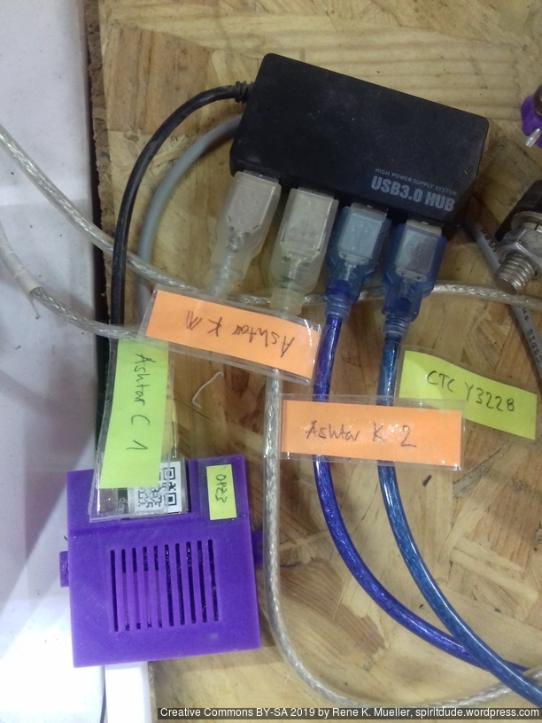
The workstation from which I print from (design and slice) is also connected via Ethernet. The printed violet PLA case I published a while ago on Thingiverse: Orange Pi Zero Case.
Preparation
On printhub (Orange Pi Zero) starting all the network clients processes:
The CTC I3 Pro B Y3228 low cost printer still runs Marlin 1.0 and 250,000 baudrate which won’t work with ser2net which print3r uses internally to print in network environment, so it needs to be flashed first with newer firmware, so it can be networked as well with common baudrate like 230,400. I upgraded the ~1 year old “CTC DIY I3 Pro B” 3d printer to Marlin 1.1.8 finally, first burning a bootloader with an Arduino Uno, and then properly configured Marlin, and now runs with 115,000 baudrate as well, so it can be networked as well.
Otherwise I stopped using Cura GUI or Slic3r GUI completely, and solely use print3r to first preview the Gcode, sliced with CuraEngine or Slic3r, and then print the parts, and because it runs on the command line, all the previous calls in the terminal are stored as history therefore I can scroll back (cursor-up/down) and repeat a job with slightly changed settings by editing the command line – something which GUI doesn’t offer, unless you save a printjob as .3mf and reload it and click around and change settings and save again as .3mf etc.
Command Inline OpenSCAD
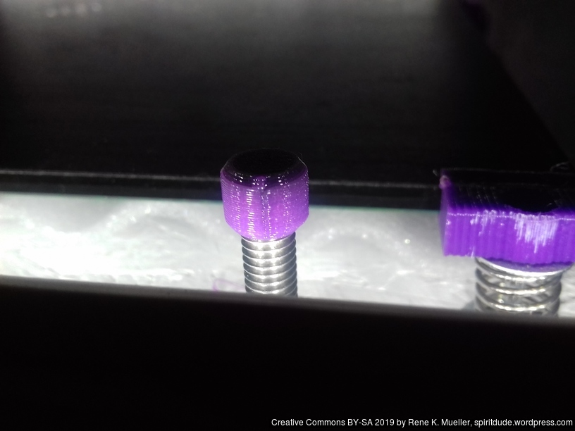
Further, I often code OpenSCAD code directly with print3r for simple parts, e.g. caps for M6 threaded rods, something like:
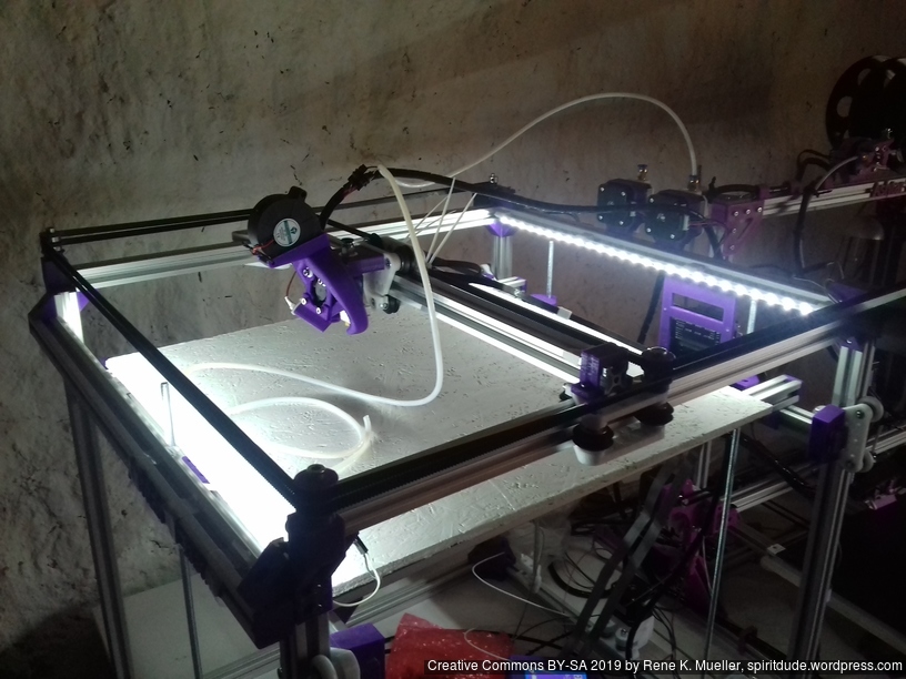
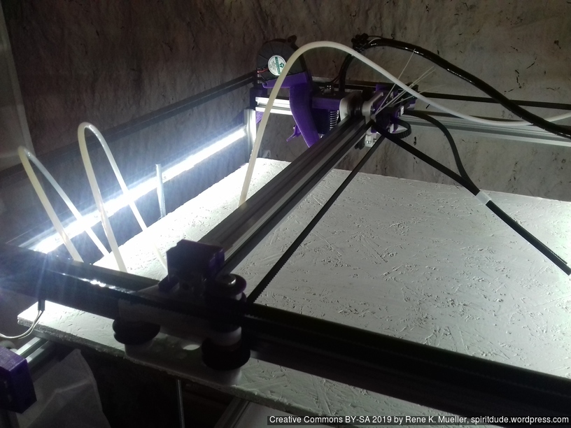
After some delay of parts, I finally was able to finalize the belt routing and configure the firmware for Ashtar C #1:
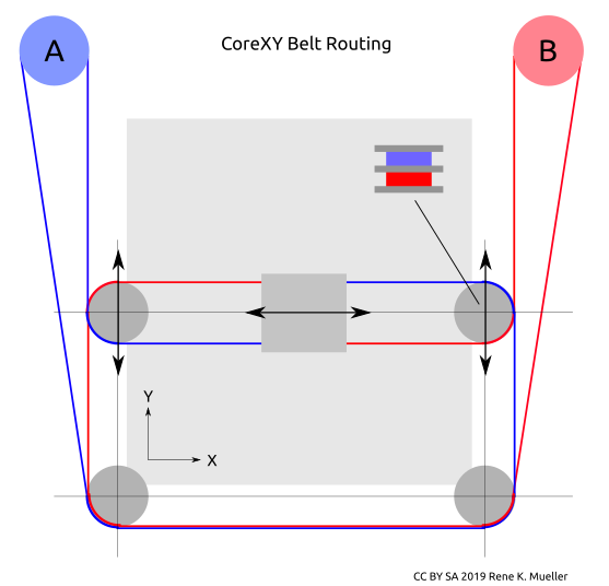
Belt Routing
CoreXY belt routing of Ashtar C
Early on I decided to separate belts of motors A and B in the Z axis, so they would not cross as such, and also hoped one axis of the carriage holding the X beam would allow some idlers to redirect the belts – to save space and keep frame dimension and build (or printable space) dimension close.
The Bowden tube and the wires of the hotend are preliminary arranged:
Firmware
To configure the Marlin firmware turned out not that simple, as CoreXY has its own interdependencies of A & B motors: first X axis was reversed, whereas Y axis worked correctly, the INVERT_X_DIR setting on Configuration.h of Marlin did not help, it reversed the stepper motor direction, but not the actual X axis direction. After many attempts to use COREYX instead of COREXY I ended up
swap cables of A & B stepper motors
keep #define COREXY
#define INVERT_X_DIR = true and #define INVERT_Y_DIR = true
and X and Y direction worked correctly.
Preflight (no extrusion, just X & Y axis movement testing):
The stepper drivers still need some tuning, as I saw or rather heard a few missed steps at fast movement.
X & Y Endstops
The preliminary positions of the endstop are:
X endstop resides on the X beam left-hand side (USE_XMIN_PLUG)
Y endstop resides on the right-hand backside, (USE_YMAX_PLUG and HOME_DIR_Y 1)
X endstop
Y endstop
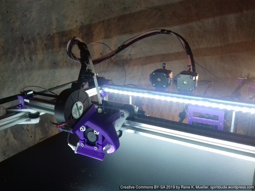
Z Axis
I postponed the actual details of the Z axis, as my main concern of the design was to have a good CoreXY setup and then see how I would achieve the Z axis.
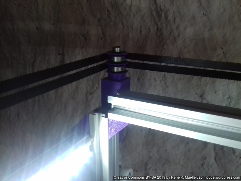
In order to use 625ZZ bearings I started to use them as idlers directly (after cleaning the grease off their surfaces) and also use them to increase contact surface when driving a closed belt which drives 3 or 4 threaded rods M6 x 500mm:
Since the surface of the threaded rods is rough, I realized I need dedicated bearings to hold the rods at the bottom, otherwise the friction would wear on the mounts and increase its diameter. So, the Z axis isn’t finalized yet, but close.


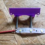
 Early on I used this setup and extended the options further – a 50mm long LED Strip Fan Mount – which mounts directly on
 Orange Pi Zero