Brief update of motors, belts, threaded rods and end stops mounted:
X Axis
I switched from slider based carriage to the nylon wheel (23.0mm OD, 7.3mm width) based carriage (X and Z axis), apprx. 120cm belt length.
Y Axis Belt
Apprx. 90cm belt length – with some considered cutting X + Y ~ 2m belt length.
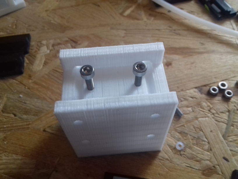
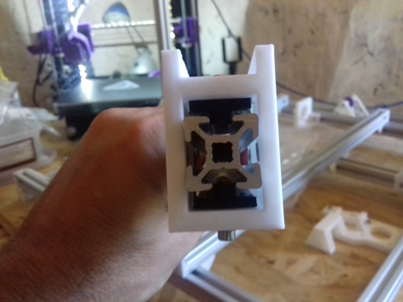
This part was tricky – the parts are glued to bottom of the wooden carriage:
mark the positions of the sliders (left: 65mm distance from top and bottom, left: center of top/bottom)
glue 2x sliders on the left (where the Y motor is mounted)
glue 1 slider on the right side
put carriage on the rails, avoid any horizontal movement, push it slightly down (a slight snapping you sense from the sliders)
let it rest (don’t touch or move it) for 30min – glue must dry
move Y carriage gently forward & backward; if there is slight resistance then
loosen all screws of the right 2020 beam so you can move it sideways
then move carriage forward and backward and let the beam slightly find its new position
when the carriage moves gently without resistance
fasten the screws gently
retest and if it’s still resitance, repeat procedure
this is a bit tedious work, but worth it
This part is to do next (once I concluded those PTFE pipe chunk based sliders do their job well):
drill holes and use Zip ties to fasten sliders
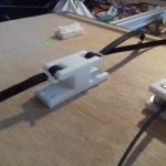
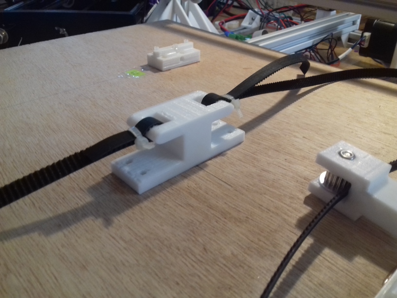
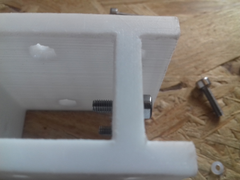
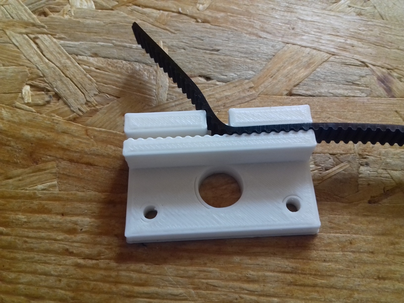
glue Y carriage belt mount, let it dry
mount GT2 belt to carriage belt mount
fasten Y carriage belt mount with screws: drill holes from the bottom side
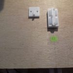
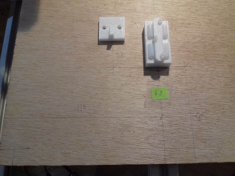
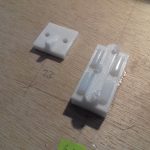
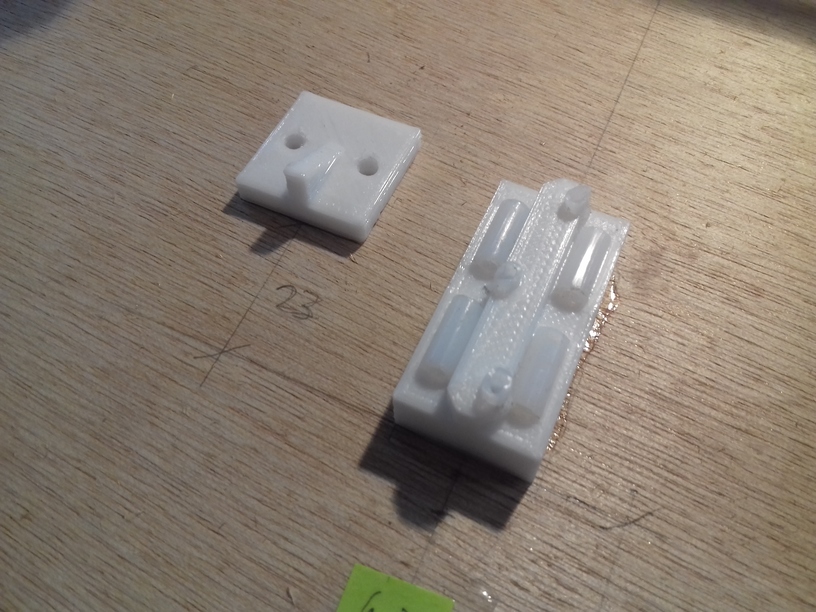
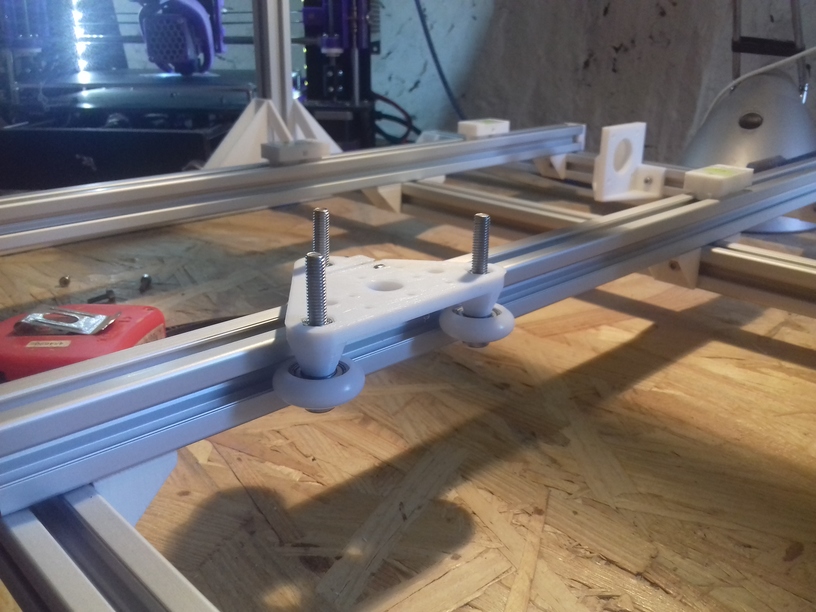
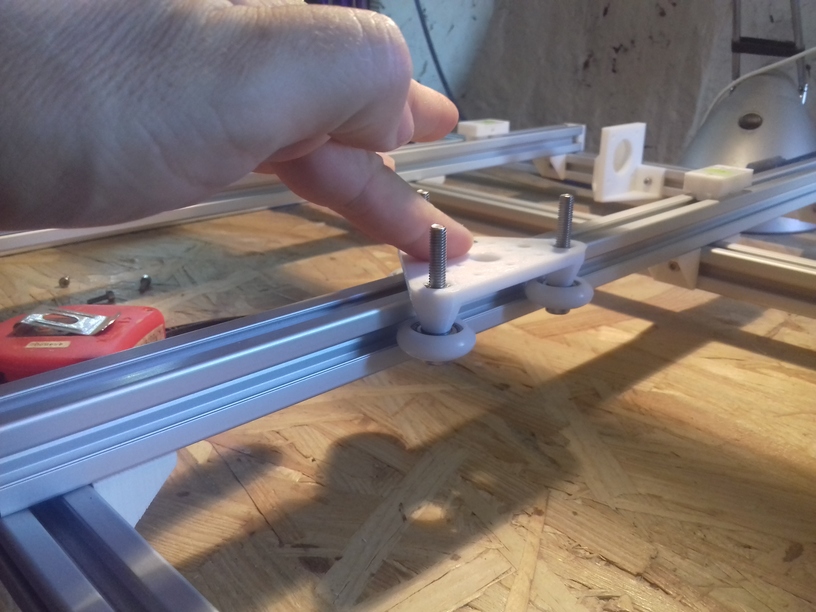
Ashtar K: 3 slider based Y bed
Y bed mount
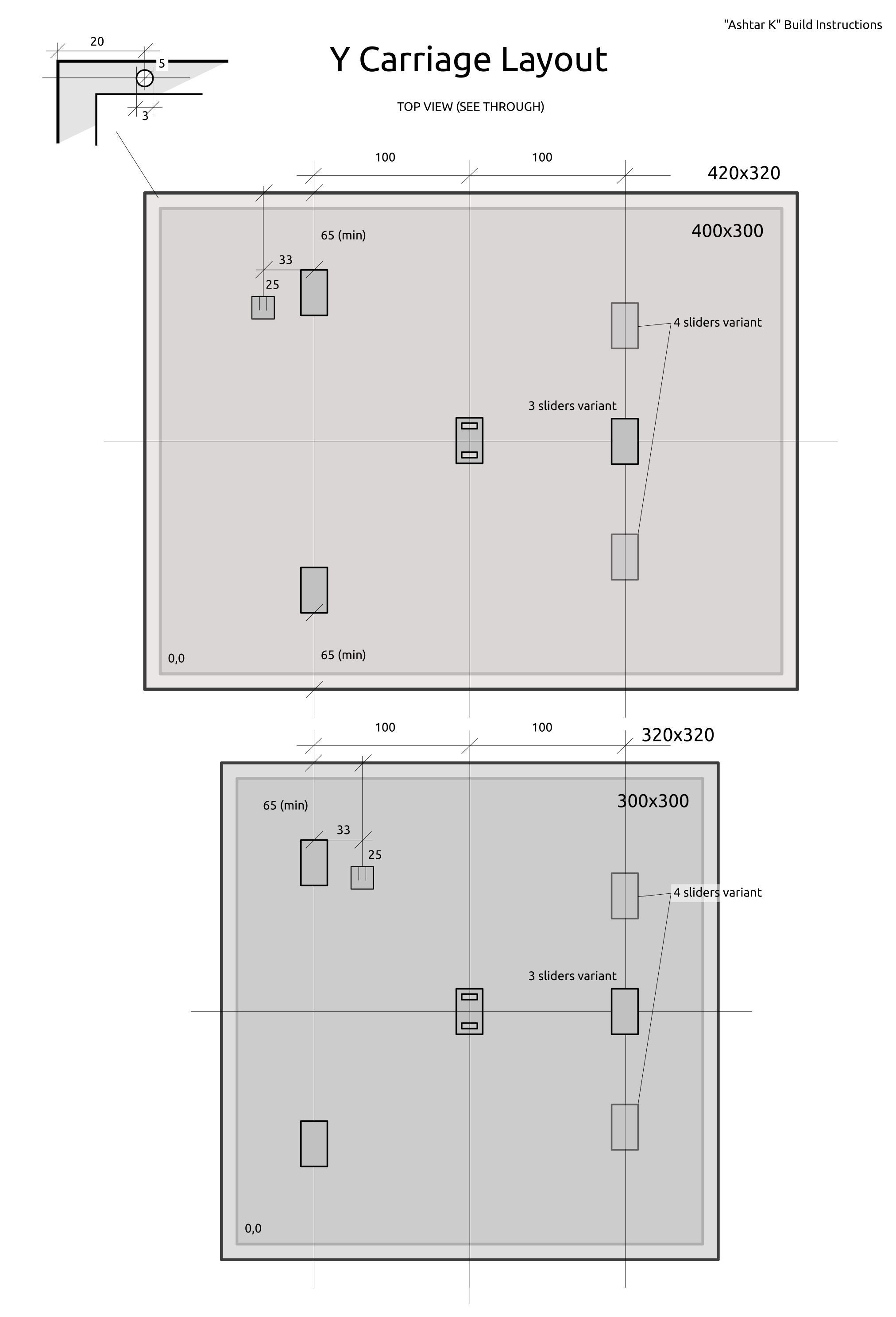
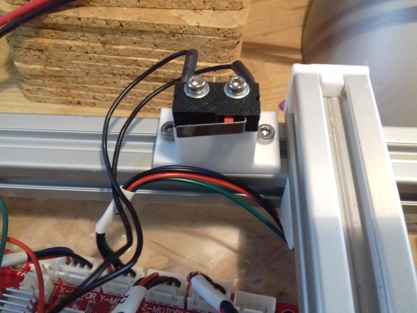
Detail measurements: 110mm from left to slider, 65mm from bottom; stopper, 23mm further, apprx. 20mm aside of slider.
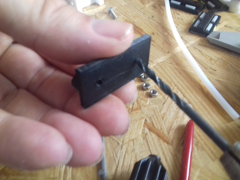
Slider closeup with trigger for Y endswitch
I will make some short videos of putting the carriage together and mounting it – it’s quite fast to attach and detach with those sliders (no screws to unfasten).
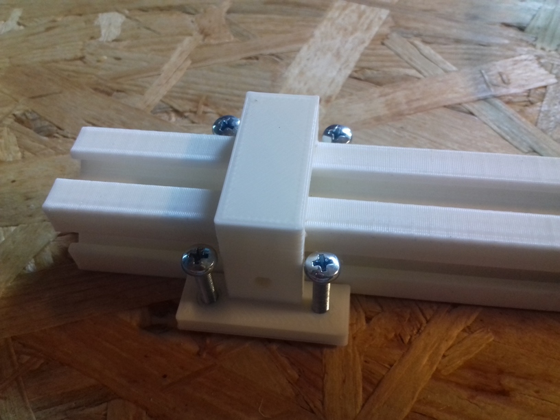
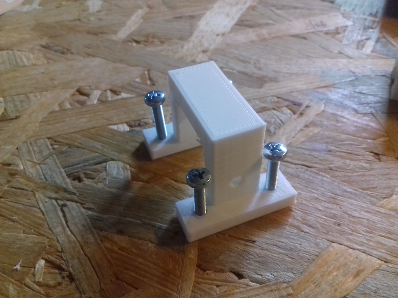
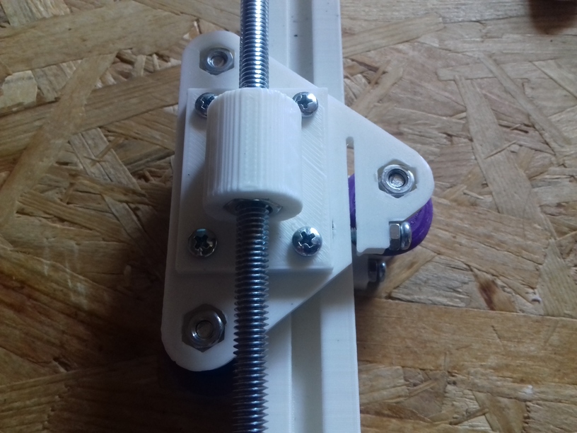
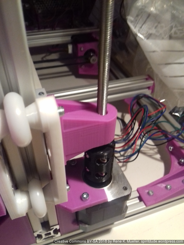
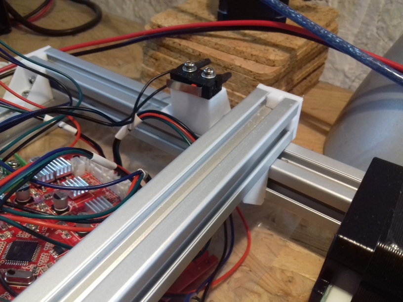
Z Axis
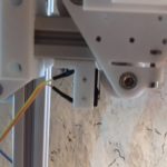
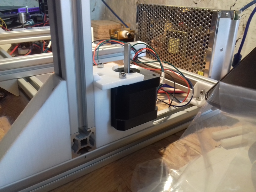
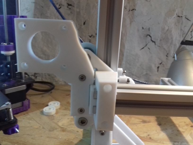
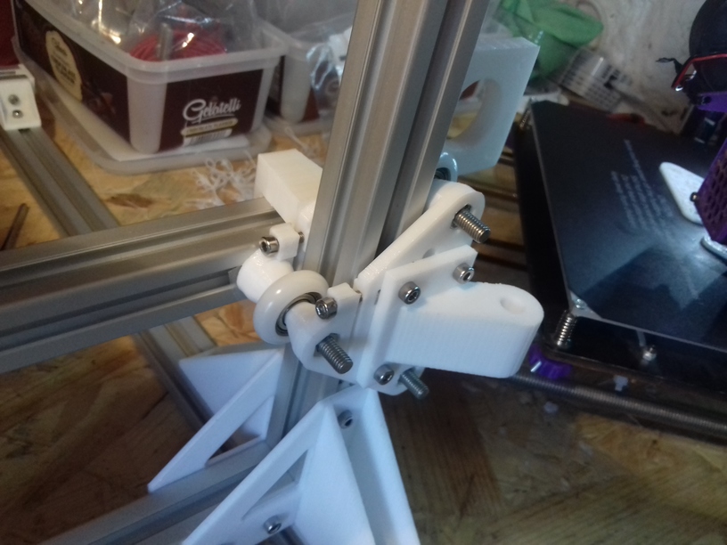
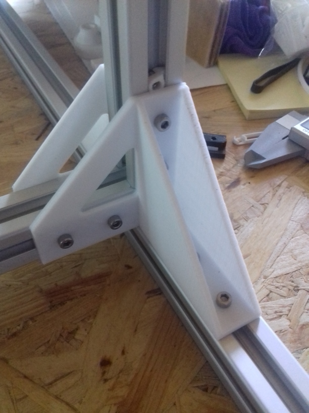
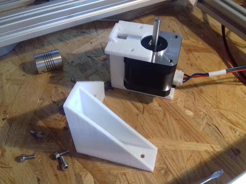
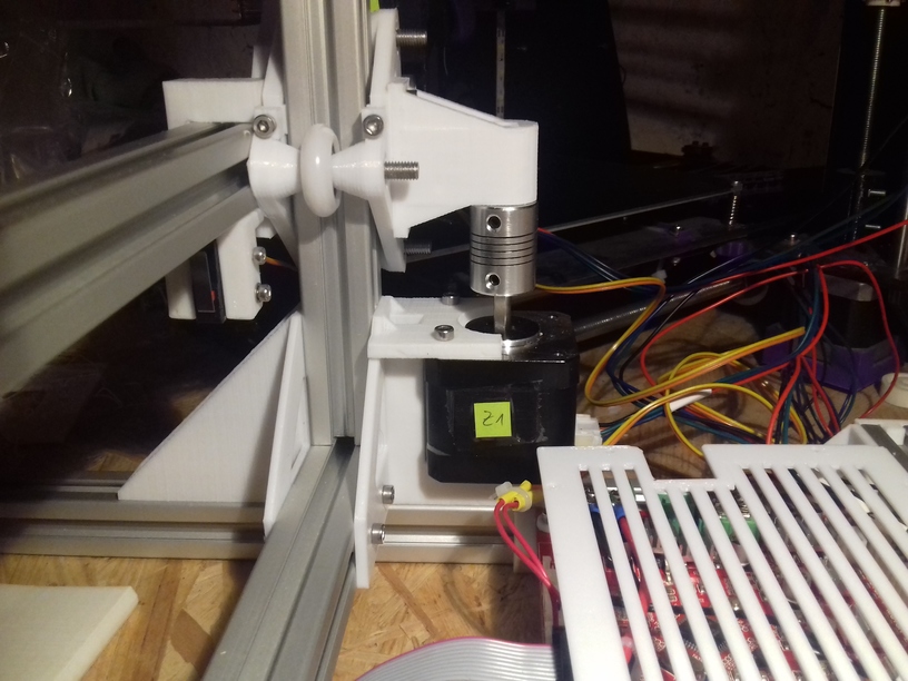
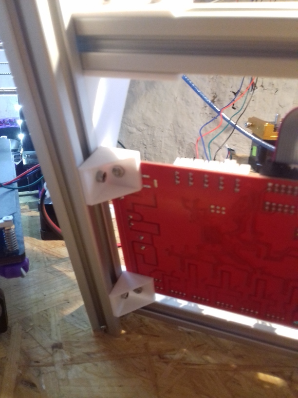
I extended the corner brackets so the Z stepper motors can be inserted, this weakens the part but saves quite a lot of space and hides the threaded rods nicely behind the 2020 Z beams. I might work on those brackets later to increase rigidity again.
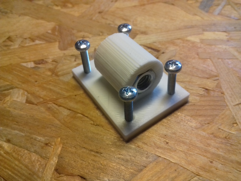
Alu 5mm to 6mm coupler
Currently I use M6 threaded rods for the Z axis, one cycle gives 1mm height change.
X, Y, Z Motion & Homing
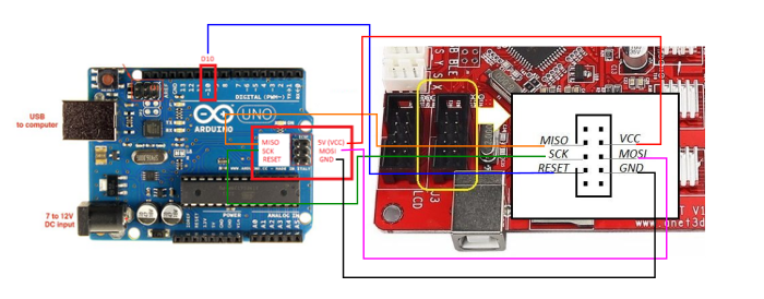
Flashing the Anet 1.0 board (which I currently use) with latest Marlin, this was required:
using Arduino Uno R3 (clone), installing Arduino ISP on it
cabling Uno R3 with Anet board (Uno powers Anet board with 5V, all stepper motors or power detached)
installing Bootloader (“Burning Bootloader”) with “Arduino as ISP” as writer
downloading latest Marlin, copying Anet Configuration.h and starting to change it
Finally, after hours fiddling around (bad install of Arduino failed to compile and/or upload anything to my Uno R3) the LCD display greeted with “Marlin 1.1.8” 🙂
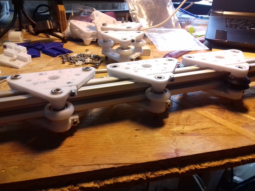
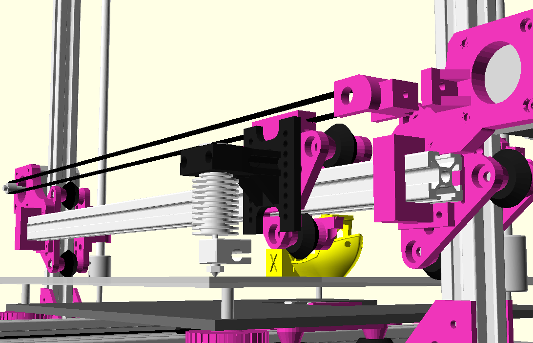
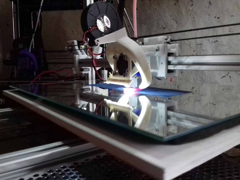
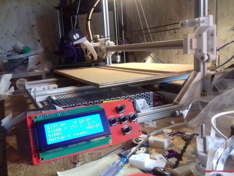
Moving X, Y and Z axis briefly, 380 x 300 x 320 build volume with the current V carriage with 23mm OD, 7.3mm width nylon wheels – no extruder and no bed heating and leveling yet.
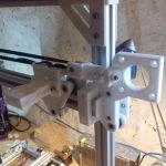
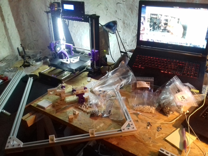
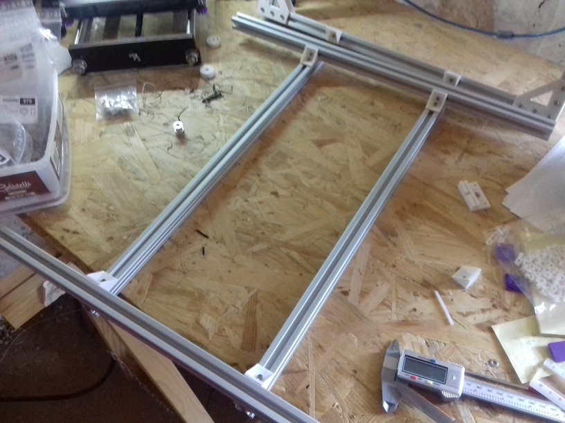
As I finished the frame, I focused on the carriages:
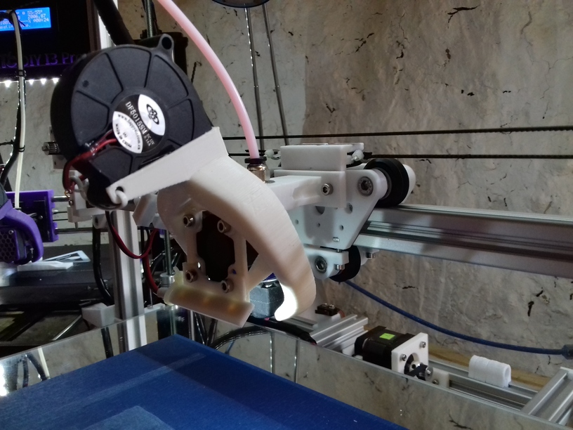
X carriage: moving left to right with the hotend with Bowden setup to keep it light: Wheel-based Carriage
Y carriage: moving bed forward and backward, relatively heavy with 400×300 bed with a mirror to ensure flatness: leaning toward Sliding Carriage
Z carriage: moving up and down with X carriage: Wheel-based Carriage
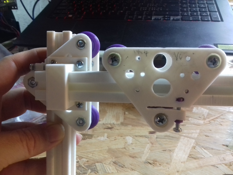
XZ Frame with X- and Z-Carriages
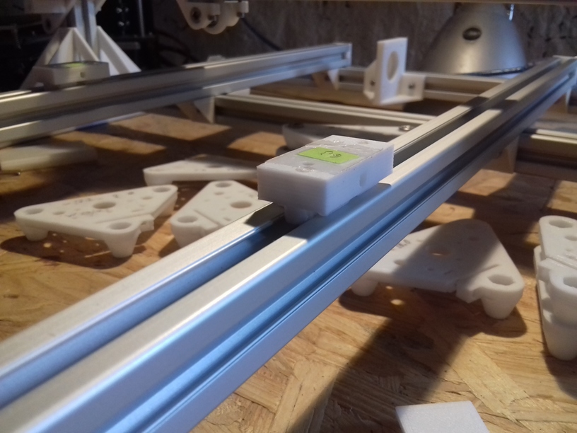
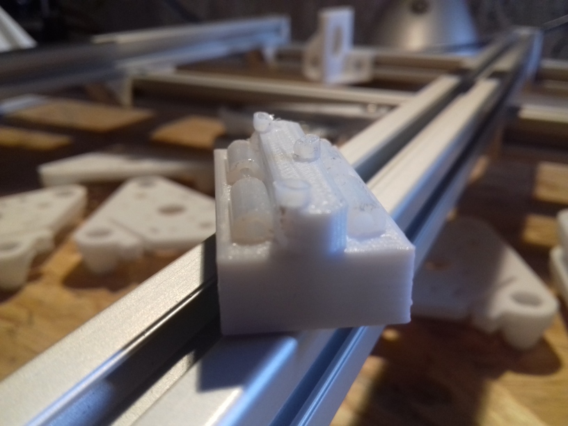
I made some tests with sliding carriage (composed with PTFE tubes), and finally the Nylon wheels arrived and I began to review two kinds of wheels:
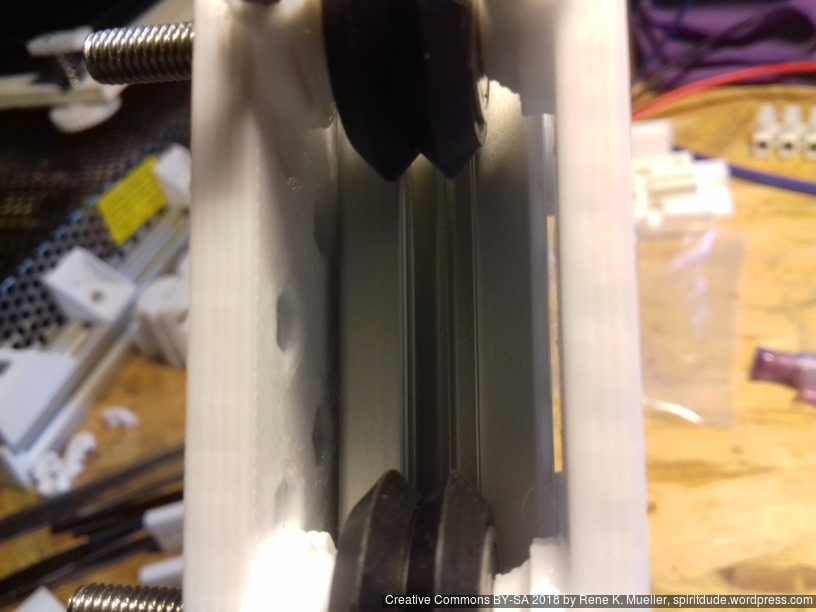
23mm OD, 7.3mm width: even it’s wider it sits better in the T slot 2020 alu extrusion
23mm OD, 7.0mm width: is bit more narrow, but doesn’t sit well on the extrusion
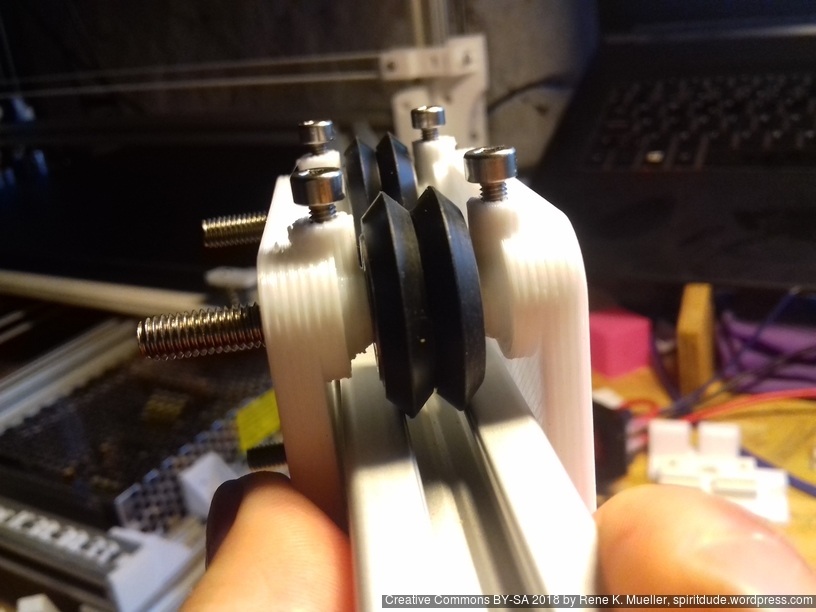
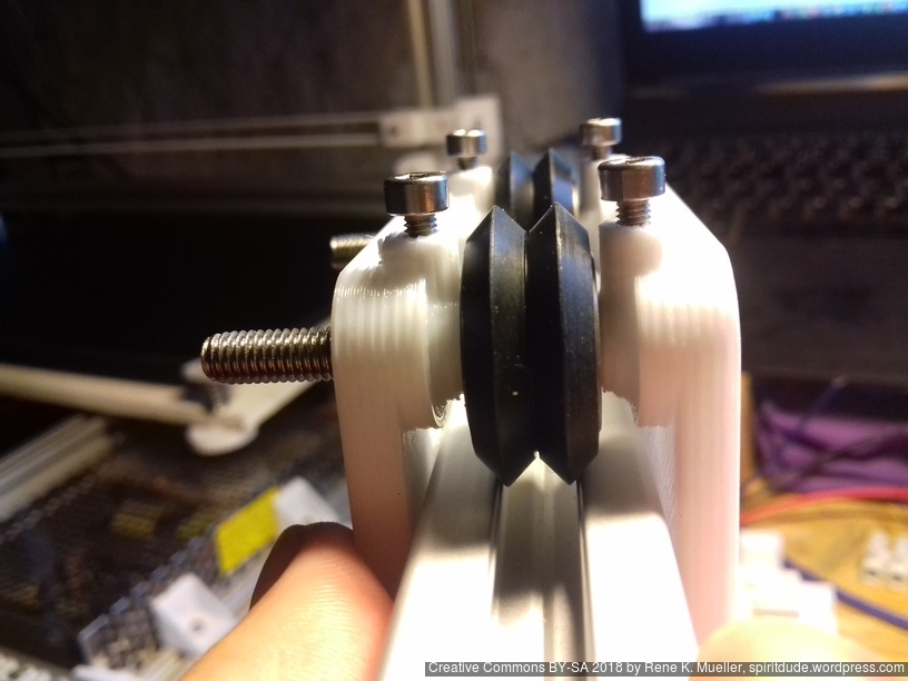
So, I put the 23/7.3 nylon wheel on the V plate to compose a V carriage, and applied to X and Z axis:
Y Carriage
The nylon wheels work very well, given the fine-tuning capability, whereas the sliding approach with 2 axis support (PTFE tubes in sliding direction plus vertical to stay in line) doesn’t give tuning capability.
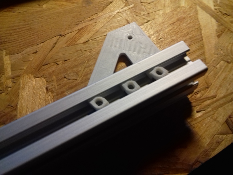
3D printed slider with PTFE tubes
Currently I lean toward the more simple slider (white PLA) with 2 axis stabilization, as with the wheel-based carriage too much vertical force will be applied to the wheel in a perpendicular manner and wear the wheels rather fast.
One of the challenges is to mount three such sliders on the bed – two can mounted quite freely (with margin of 1-2mm) whereas the 3rd slider needs to be mounted very precise.
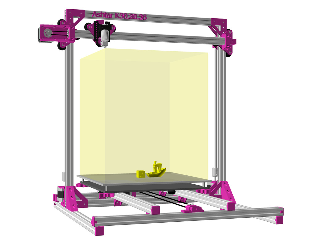
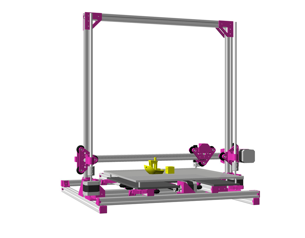
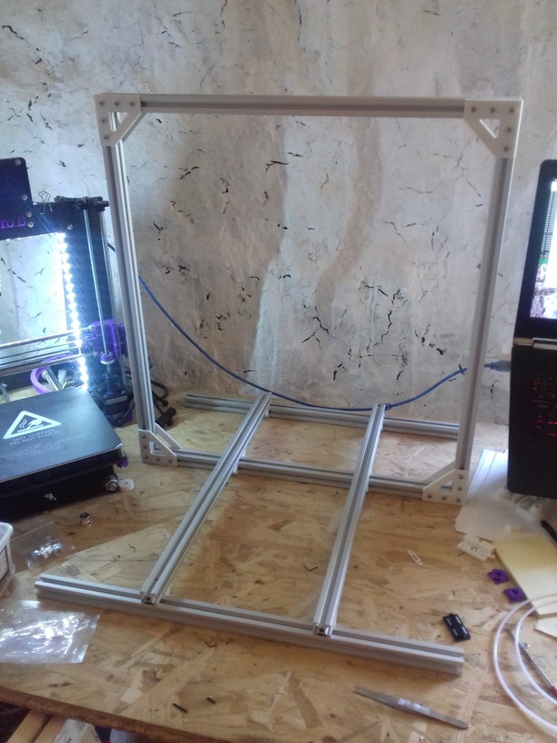
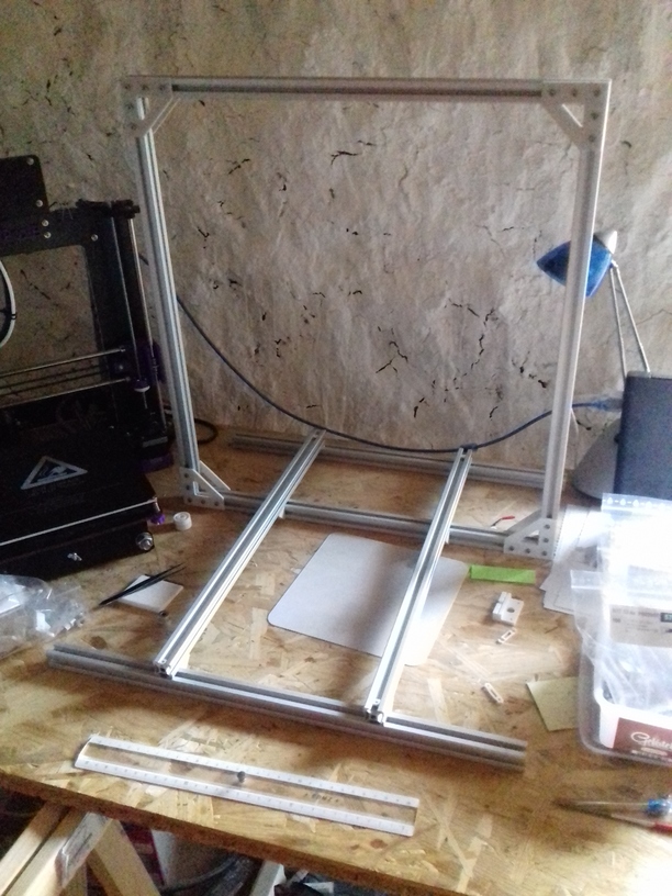
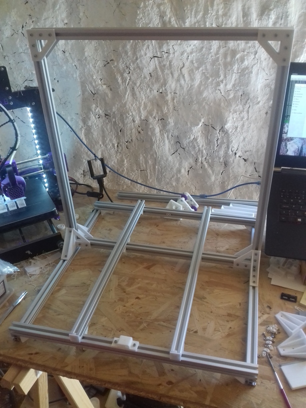
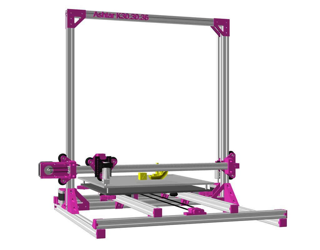
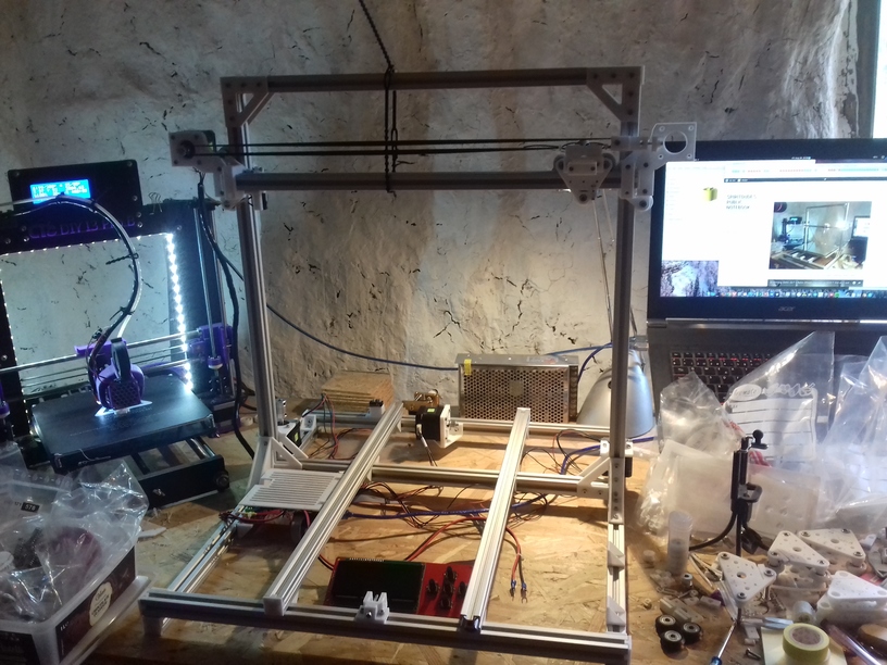
Building 3D Printer Ashtar K starting with the frame using 2020 T slot 6 alu extrusions, changing design slightly from 9x 500mm to 11x 500mm as early tests showed the XZ frame wasn’t stable enough toward Y bed – so two additional beams (later photos in the series) to make XZ frame sturdy toward the bed.
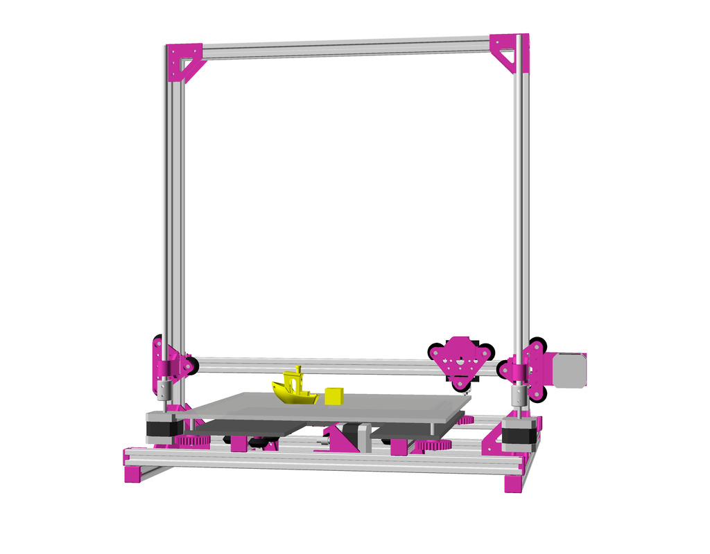
and the current state more or less:
While waiting for wheels to arrive I thought to make some tests with sliders composed with PTFE tubes (4mm and 3mm in diameter) – I might actually use them in the X axis and Y axis:
The building volume with the 500mm beams can be stretched to 380 x 300 x 360mm, if the X carriage is short(er) – this means, the bed can be 400 x 300.
State: Early draft, work in progress and likely will receive updates.
Updates
2018/08/15: Added Slider with PTFE tube inlets with 1 and 2 axis support with photos and brief test video
2018/08/05: First overview with a 3 approaches
While waiting for the shipment to arrive, I thought to study some of the alternatives to wheels on alu extrusions, such as sliders.
Nylon 2020 Slider
Commercially manufactured, apprx. cost EUR 2.50 per piece, sold in 10 pieces bag.
3D Printed Sliders
Simple Slider
A simple replicate of one of the simple 2020 sliders:
Slider on T-Slot
Nylon Slider for T-Slot
The sliding nose is 5.8mm wide. Ideally this would be printed in nylon; PLA might work as well but tends to stick more and grease or oil is required therefore.
TODO
print samples and measure friction with PLA
publish model
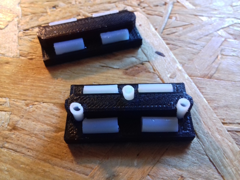
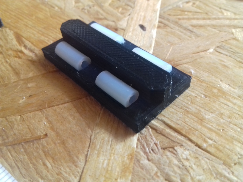
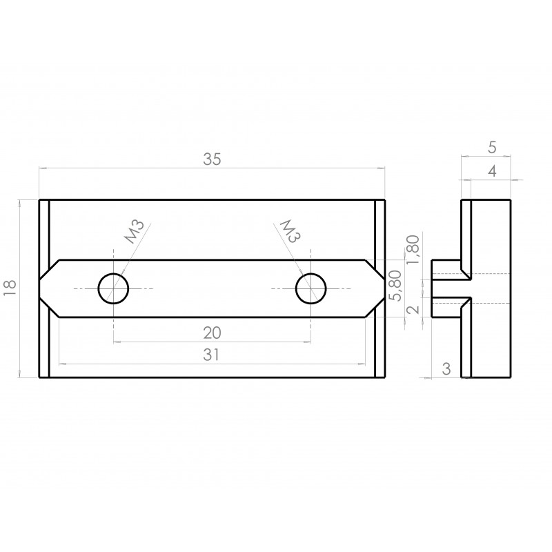
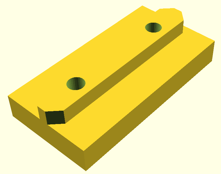
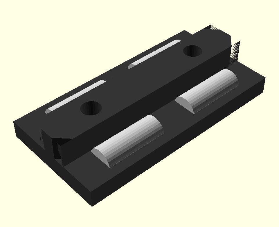
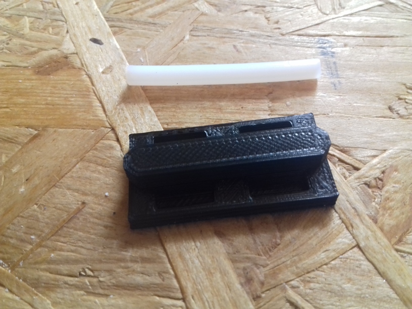
Slider (2 Sides) with PTFE tubes
Improving the simple slider with 10mm long 4mm PTFE chunks to decrease surface and use proper material for sliding:
and in use for the Y axis of a Prusa i3 like style:
and a small improvement to take care of the 2nd axis as well (reducing 2nd axis wiggle):
and then mounting them with a carriage together with M3 screws to control tightness:
and a brief test:
Slider (4 Sides) Carriage with PTFE tubes
A bit more complex using PTFE tubes on all 4 sides:
each inner side has 8 tube chunk insets, which gives you the variable option:
4 chunks (a 10mm) x 4 sides = 160mm total
8 chunks (a 10mm) x 4 sides = 320mm total
12 chunks (a 10mm) x 4 sides = 480mm total
16 chunks (a 10mm) x 4 sides = 640mm total
The OpenSCAD module takes parameters such as length of the carriage and the diameter of the PTFE tube (e.g. 3mm or 4mm), default length 60mm.
And the adjustable version with 75mm width looks like this:
which breaks the one surface apart with the mounting hole; if a plate would use all 4 holes that side would become non-adjustable that way – so this isn’t ideal, but perhaps work for single side use.
A possible application as X carriage and two Z carriages in a Prusa i3 use case:
TODO
print model and make actual physical tests, measure friction of the possible options
2018/08/26: Partial functional, X, Y and Z motors and belts and threaded rods mounted with end stopper, board been flashed with Marlin 1.1.8
2018/08/24: More photos about XZ frame bracket with integrated Z motor mount, Y belt mount and sliders
2018/08/20: Short video testing X and Z axis with nylon wheel based carriages
2018/08/15: Added photos of composing the frame (XZ + Y) and changing design slightly to add 2 more beams so XZ frame is more sturdy, early tests with sliders, as alternative with wheel based carriages
2018/08/01: More details, extruder motor on the right side with belt idler mount, short video showing some details.
2018/07/30: Updated images, more examples of prototyping V modules
2018/07/21: Published with few drawings, short part list.
Introduction
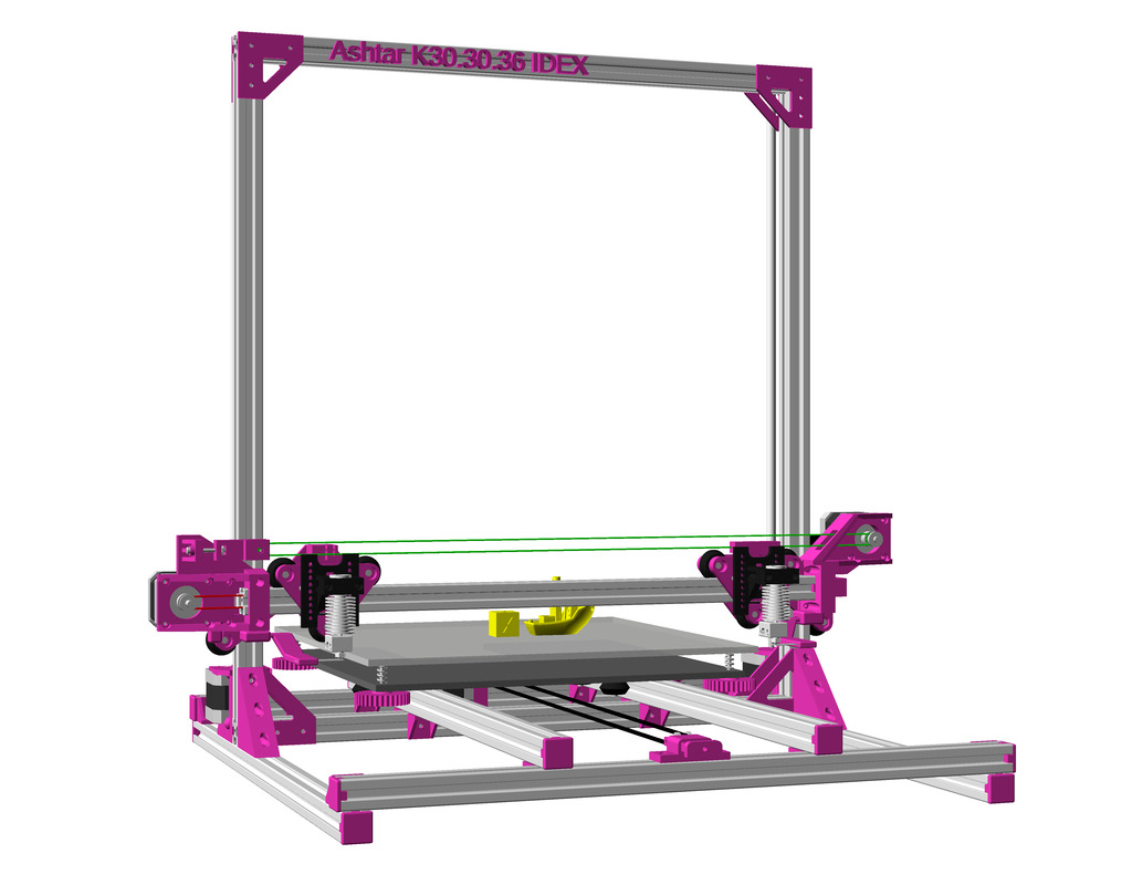
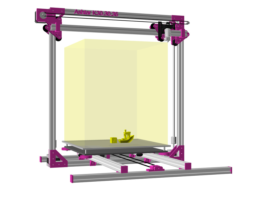
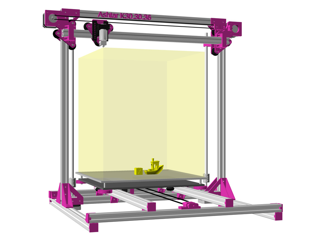
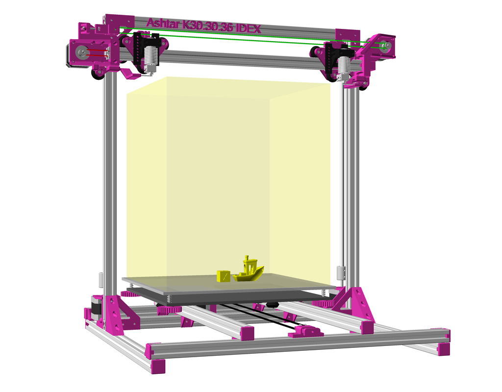
In summer 2018 I pondered on a parametric Prusa i3 3d printer designs, composed with 2020, 2040 aluminium extrusions / profile, hereby I document the development here.
The Ashtar W Series and Ashtar T Series are fully parametric, from 200mm^3 to 500mm^3 build volume, whereas this Ashtar K Series focuses on single beam length construction with 2020 alu extrusions.
Ashtar K #1 (right, white) and #2 (left, pink), both 380x300x330 build volune, but having different build plates
Parametric Designing
Unlike traditional CAD (Computed Aided Design) sketched constructions, a coded parametric design is actually textual coded a design, defining which parts depend on which, and align according some variables, which can be changed. In this case, the input is the building volume X, Y and Z, and all parts are calculated accordingly, using OpenSCAD as programming language.
Following notion has been introduced:
X,Y and Z are the starting point, the printable volume
IX, IY, and IZ are the inner dimension of the construction needed to make X, Y and Z build volume work, hence, IX, IY and IZ are greater than X, Y and Z
all constructions depends on IX, IY and IZ
XE, YE and ZE are the position of hotend ranging between 0..X, 0..Y and 0..Z
XP, YP and ZP is the calculated position of the hotend in physical space
These notions, in retrospect, allowed me to code all the different printer types: Ashtar K (Prusa i3), Ashtar C (CoreXY), Ashtar M (Prusa i3 MG), Ashtar D (Classic XY) coherently.
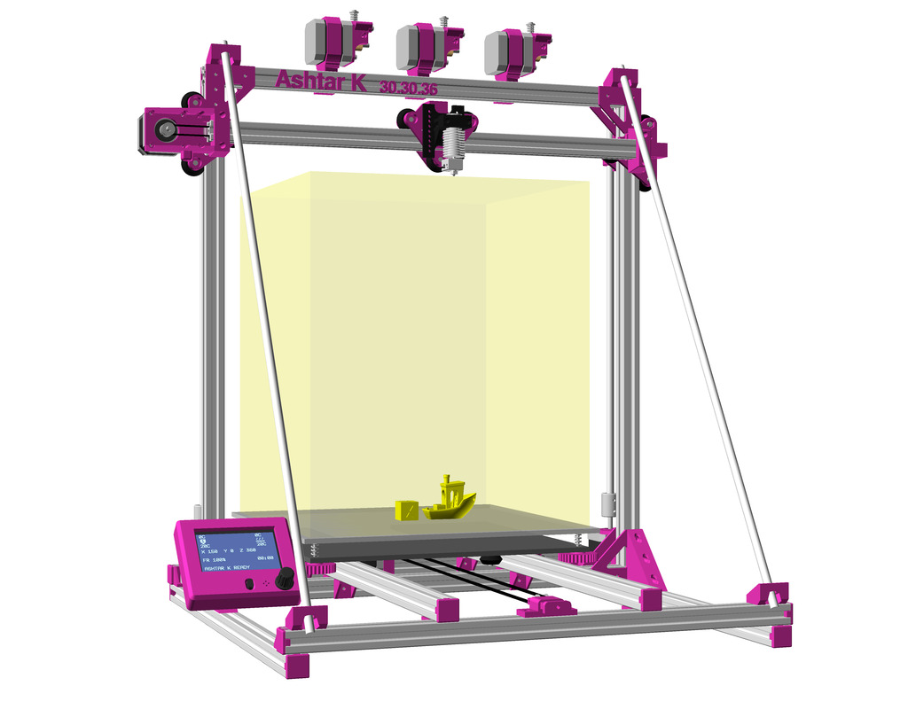
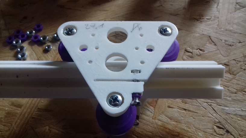
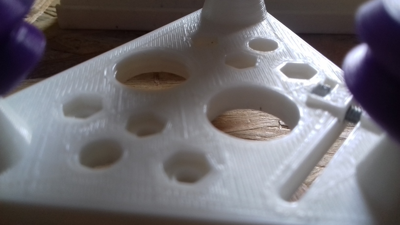
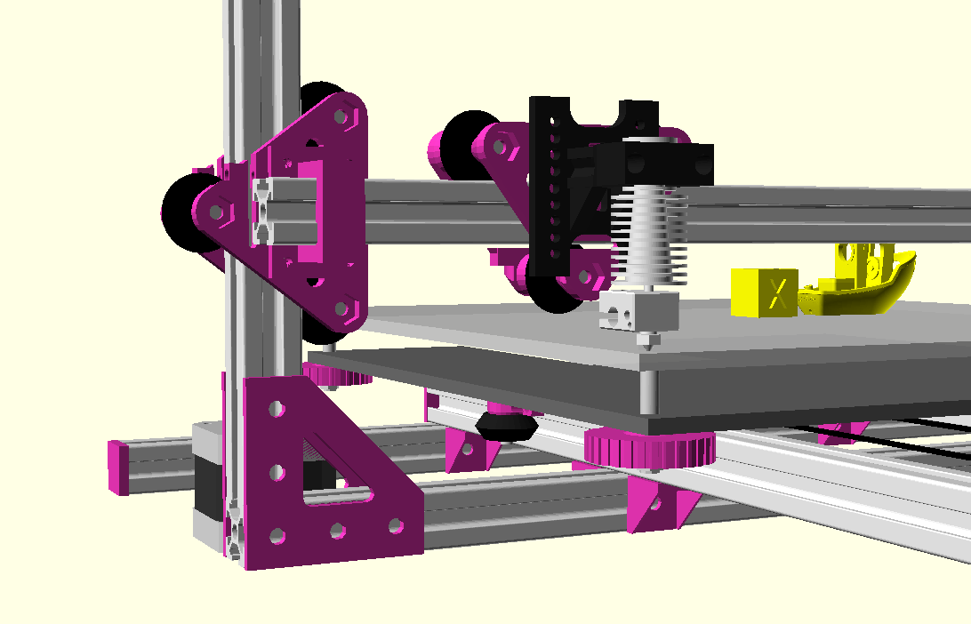
Ashtar K: 500mm 2020 Extrusions as Rails
This is a single size design optimized: 300(-380) x 300 x 360mm build volume, composed by 11x 2020 500mm B-type or V-slot beams:
Backside:
Bottom view:
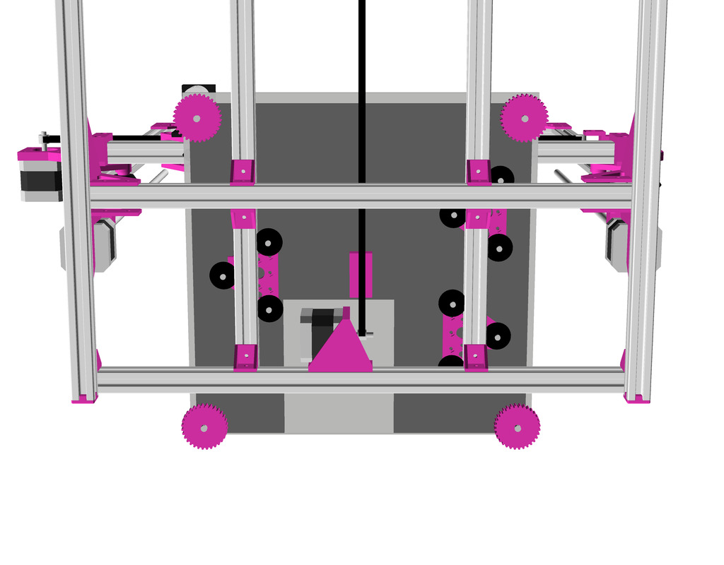
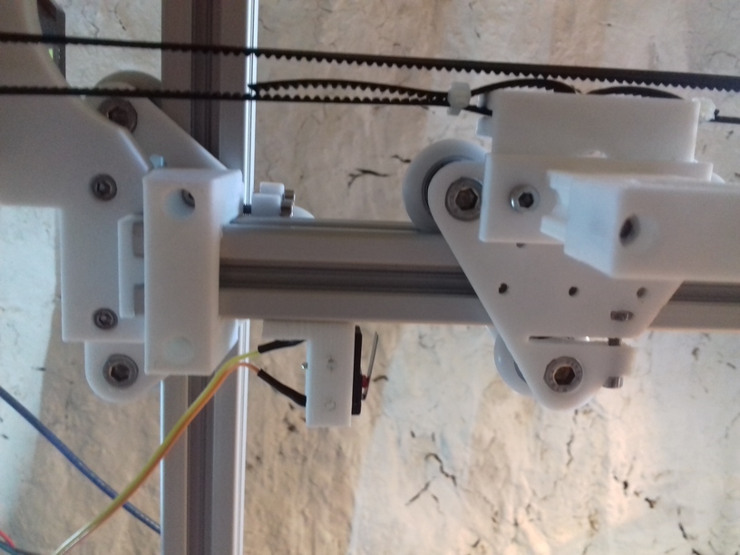
The rollers on the Y axis can be likely reduced to minimum of 3 total, instead of 9 (3×3), it really depends how well the rollers have a grip on the extrusions. Majority of the printed parts are custom. I settled with DIY sliders with small PTFE tubes instead, they were simpler and turned out reliable enough for my use case, see below “Y Carriage Slider”.
The Y axis is quite short to match 500mm beam length, and the Y bed fits barely as you can see in this bottom view, but it should work:
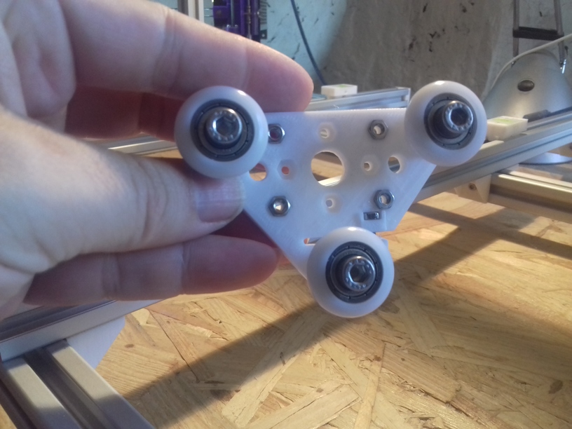
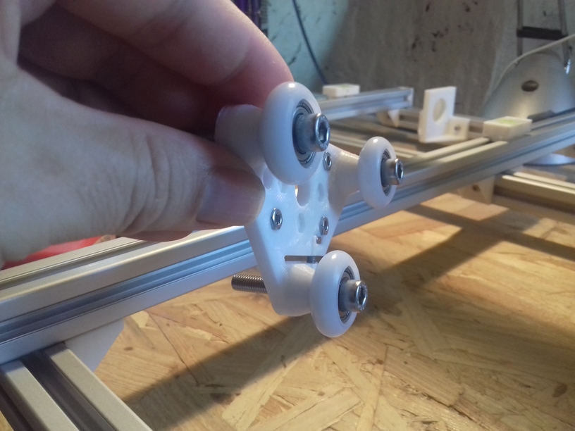
Moveable V Modules
The V modules, composed by 2x V plates, which holds the wheels running on the alu extrusion, I document separately at 3D Printing: Wheels on Alu Extrusions and is used:
2x Z axis motion
1x X axis motion
3x Y axis motion (perhaps a dedicated module to reduce amount of wheels) or
3x or 4x Y axis sliders
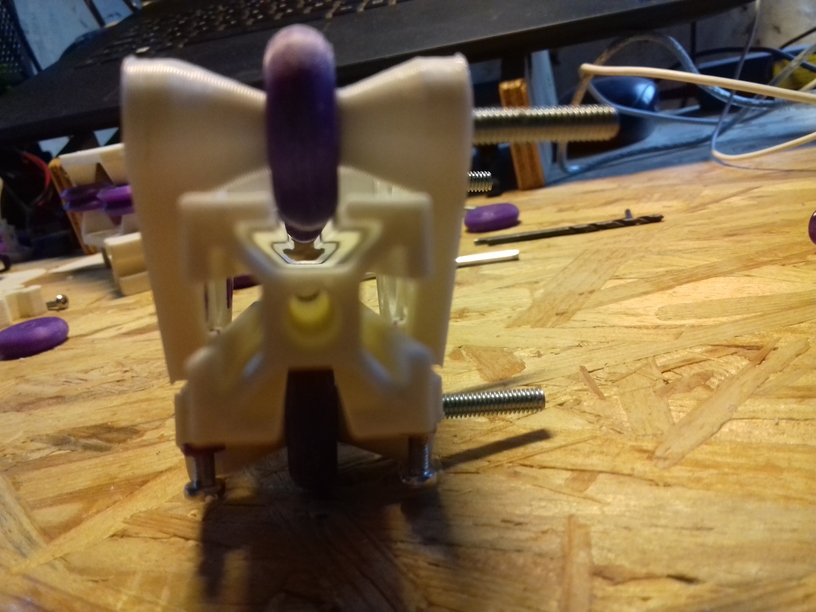
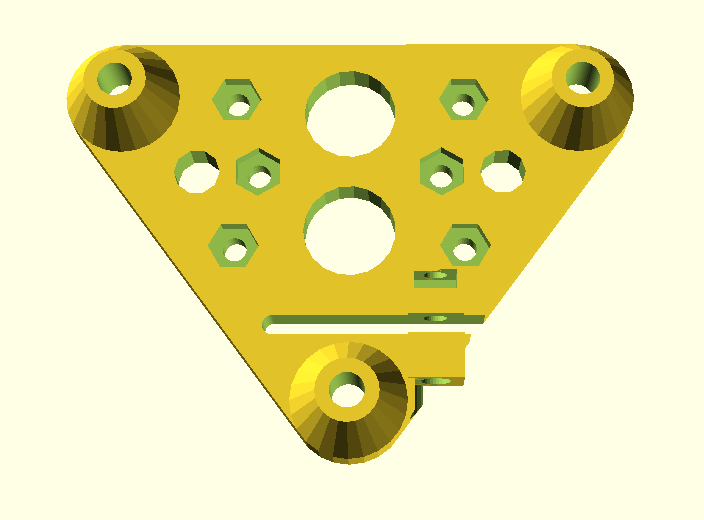
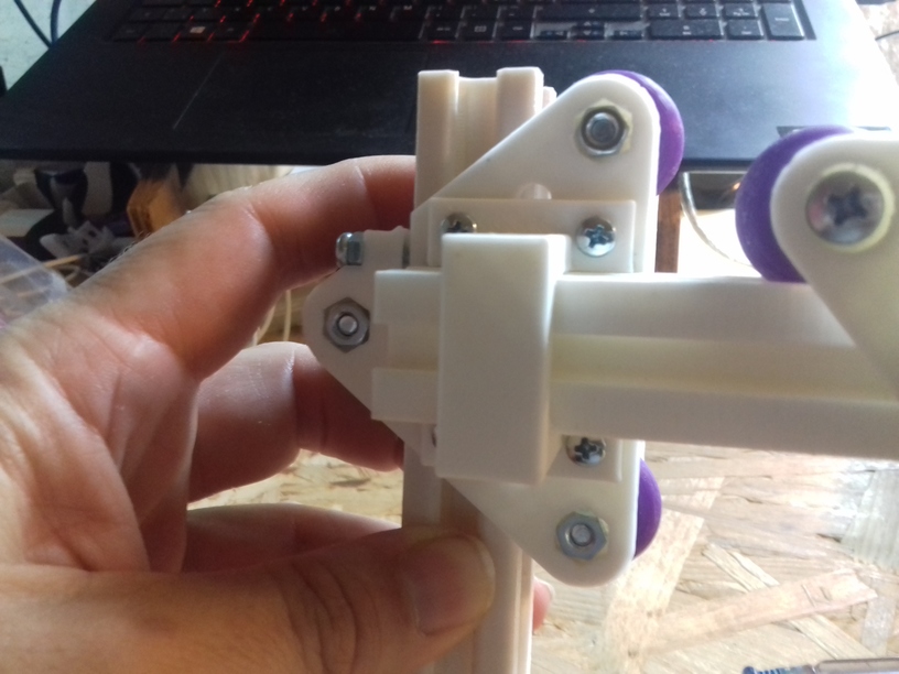
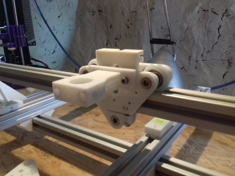
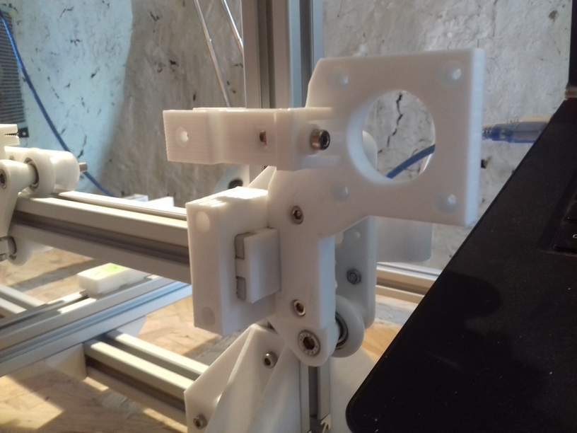
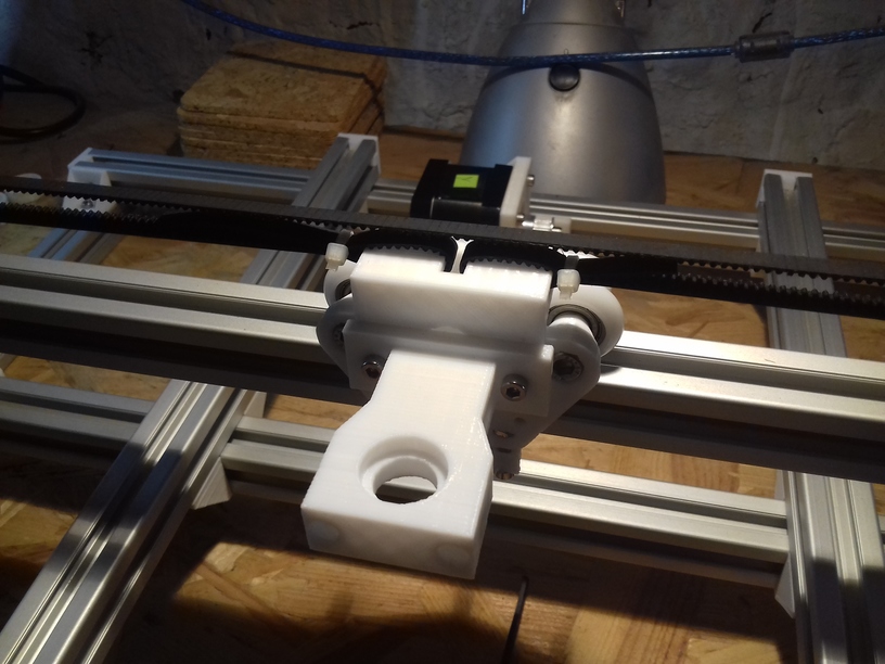
V Module X Axis
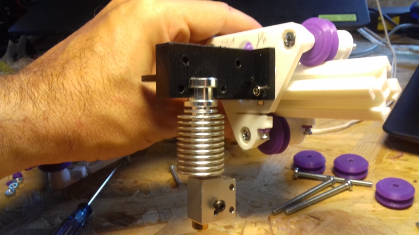
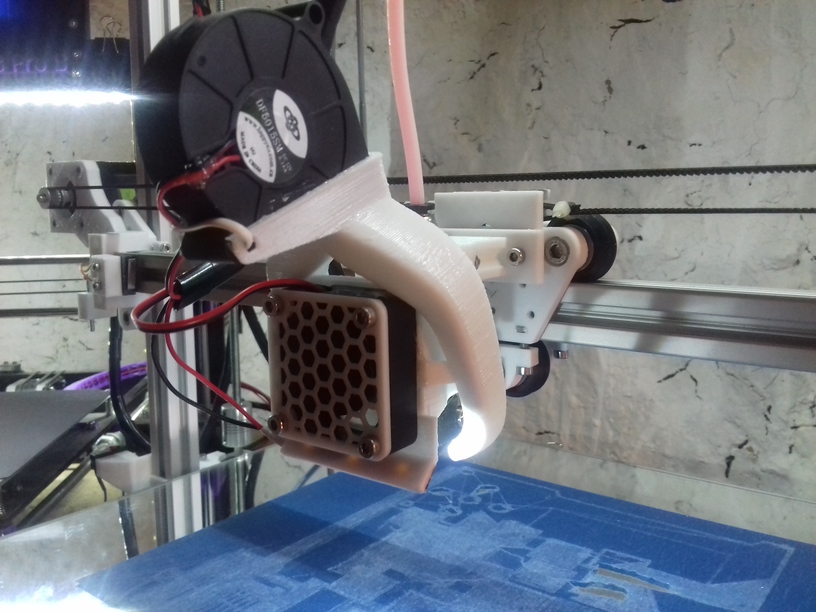
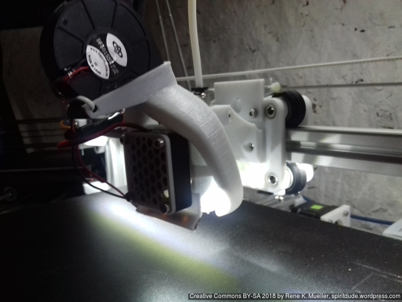
As first I mounted existing direct drive extruder piece to the module, although due the thin 2020 profile I likely have to run it with Bowden setup to make sure the moving extruder is light enough.
40mm fan with 5015 fan fang on top, X carriage with 3 wheels (V module)
40mm fan with 515 fan fan on top, X carriage with 4 wheels (H module)
Small belt mount, 1st version is one sided, 2nd version goes both ways to be more flexible:
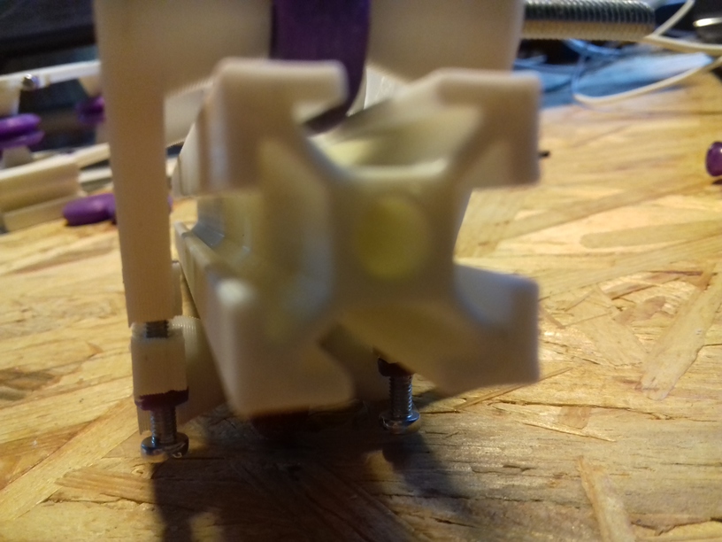
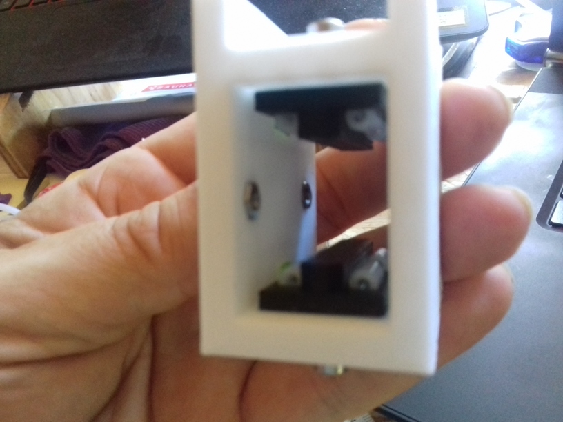
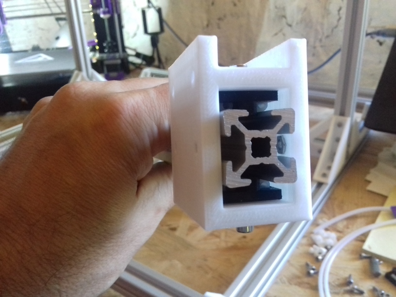
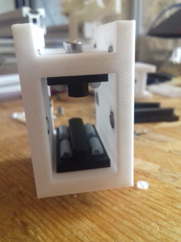
V Module Z Axis
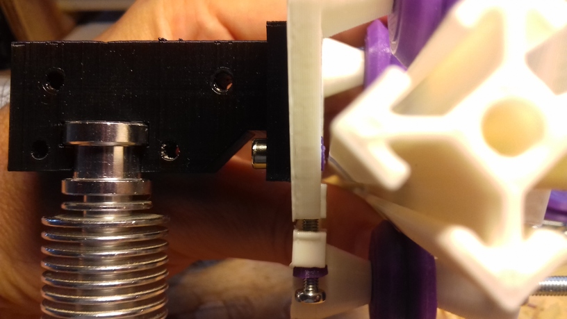
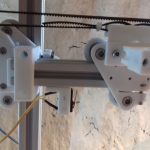
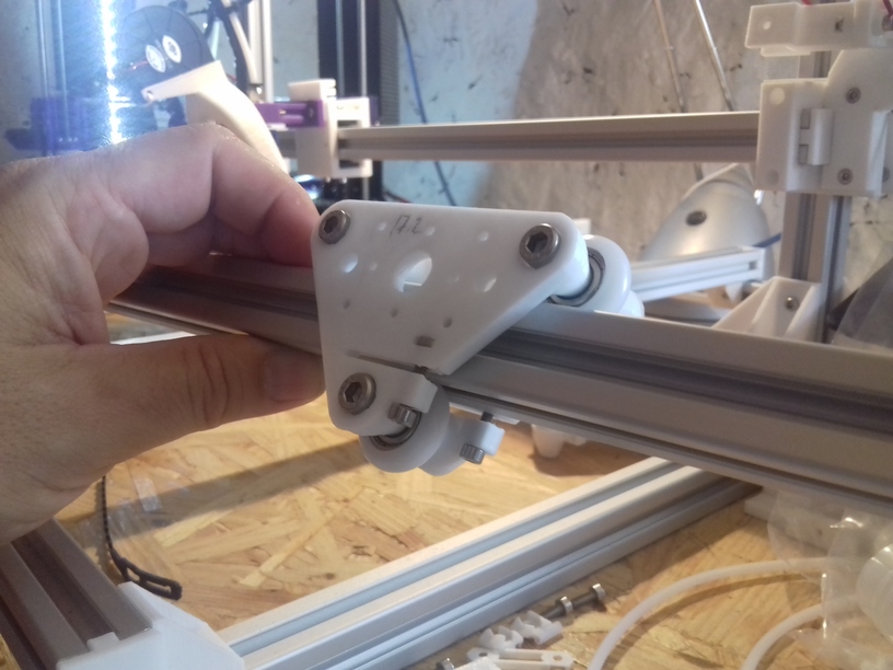
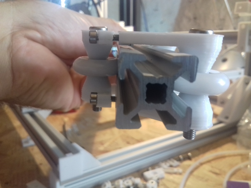
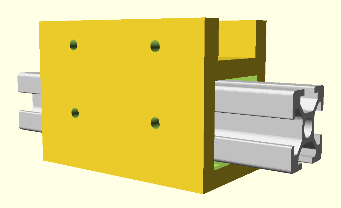
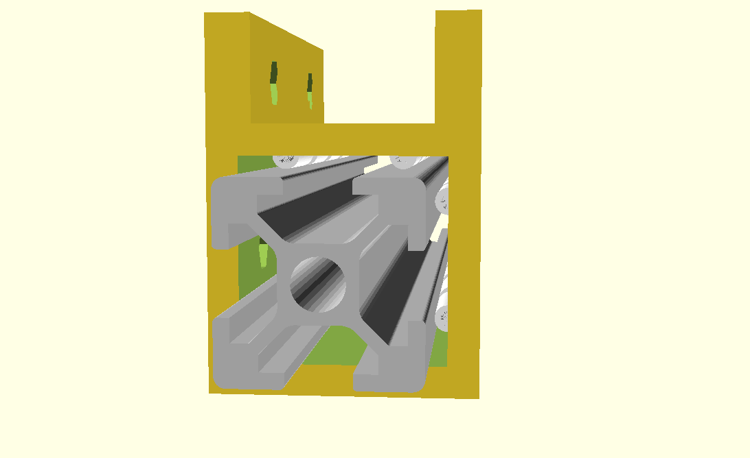
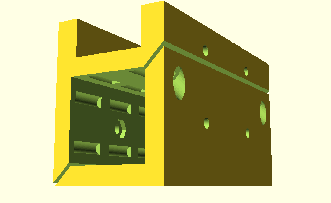
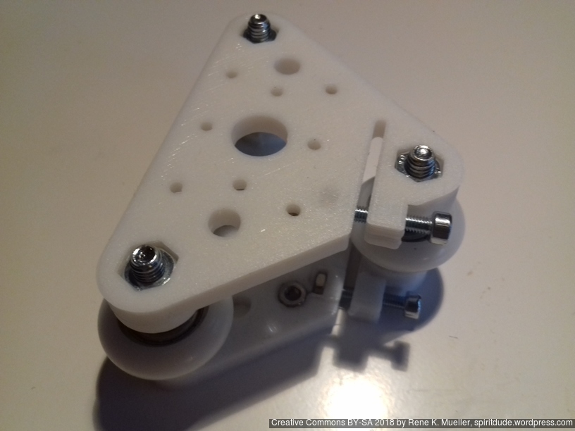
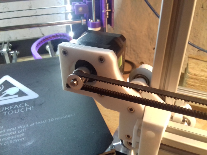
Z Axis V module is a bit more complex, it takes the X axis beam and the Z axis leadscrew or threaded rod, and the X motor mount:
Slider-based Carriages
Aside of wheel-based carriage, I thought of trying and playing with some slider-based carriages as well:
for more details see my blog post on 3D Printing: Sliding on Alu Extrusions. It eventually didn’t work that well, with time it became wobbling, and the friction increased – so I switched to wheel-based V modules.
Frame
Some photos of early tests with building the frame. I changed the frame design an add two more beams to stabilize the XZ frame with the Y bed more; using 11x 500mm beams now – and some strong bracket at the bottom:
X Axis Module
Two options are available:
2020 T-Slot 6 (B-Type): using 3x Nylon wheels 23.0 OD / 7.3 wide
2020 V-Slot 6: using 3 or 4x OpenBuild 24.4 OD / 11 wide V wheels
The V-Slot beam is more suitable as the X carriage will be more stable and sturdy when printing – yet, V-Slot 2020 beams aren’t easily available or with high shipment costs.
Four options I tried: the 1st with a slider worked only briefly, then 2nd I switched to white Nylon wheels which wasn’t stable enough but wobbled in Z a bit on T-Slot beam, the 3rd was 3x wheel V module, or the 4x wheel H module on V-Slot which worked best.
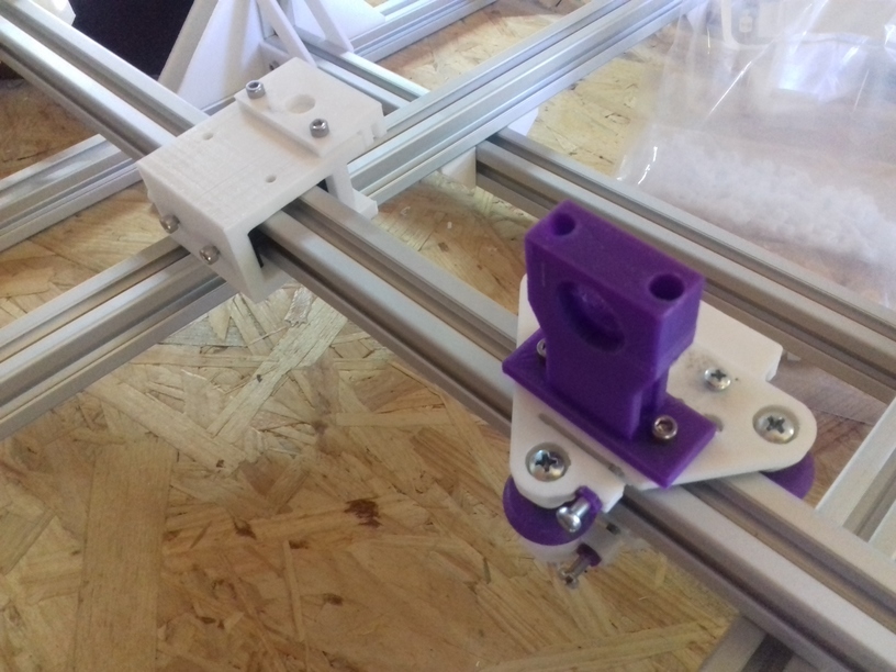
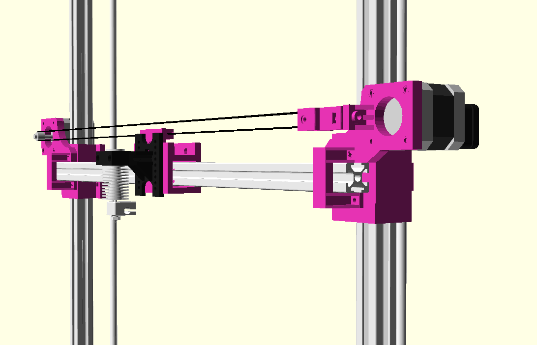
Belt mount and hotend holder using same mounting holes
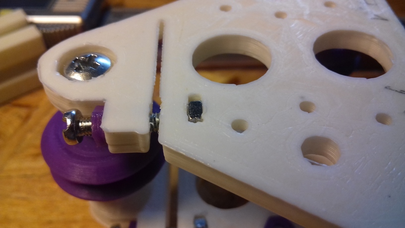
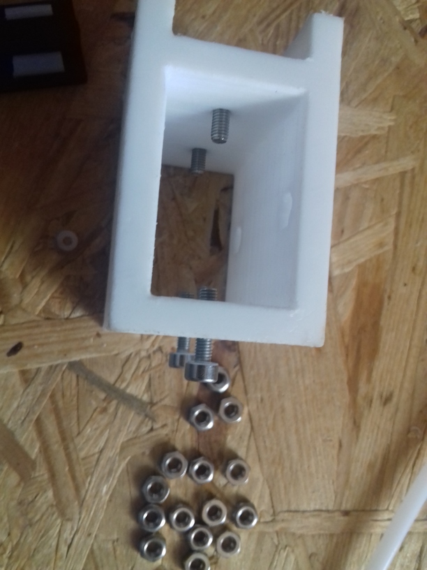
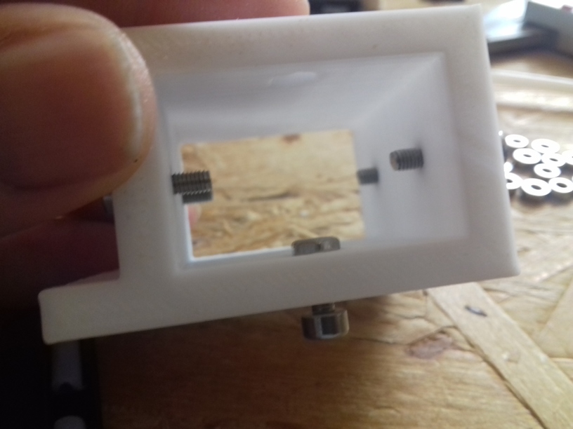
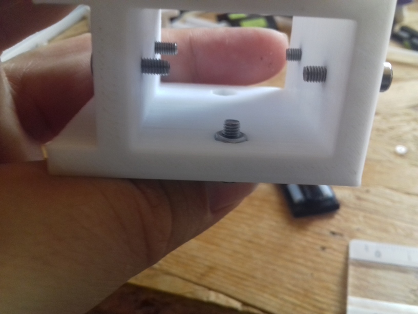
Z Axis Modules
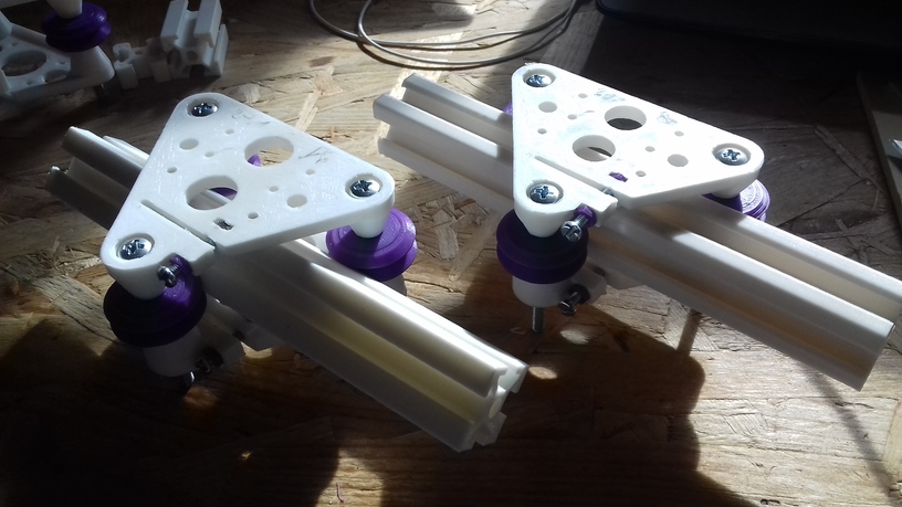
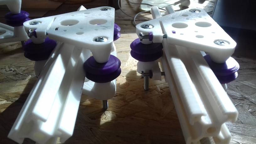
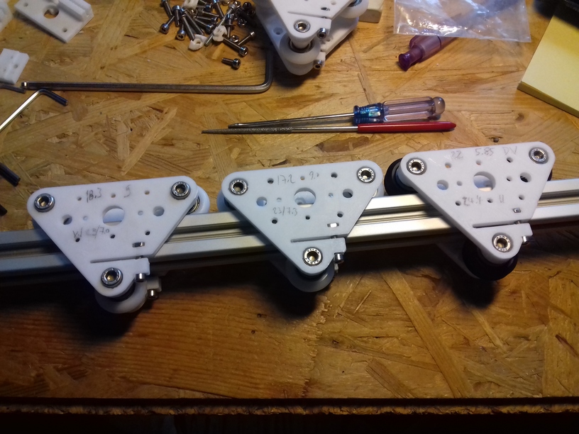
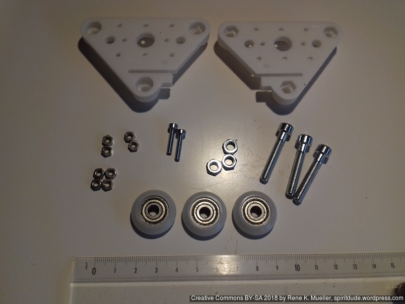
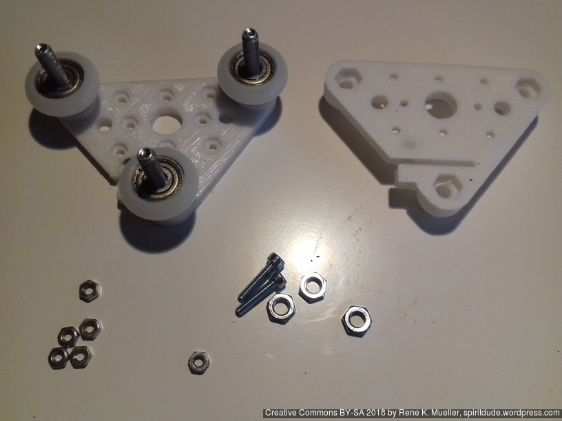
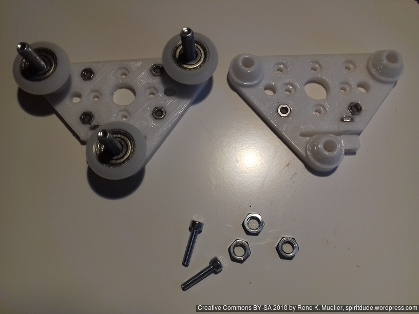
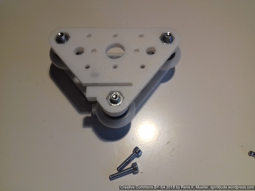
Two V modules (each with 2 plates) assembly for 2020 T slot 6 B-Type beams, per module:
3 x M5 x 30
3 x M5 nuts
4 + 2 + 2 M3 nuts (4 front insets, 2 back insets, and 2 for adjustment screws)
2 x M3 x 14 or x 16 (adjustment screws)
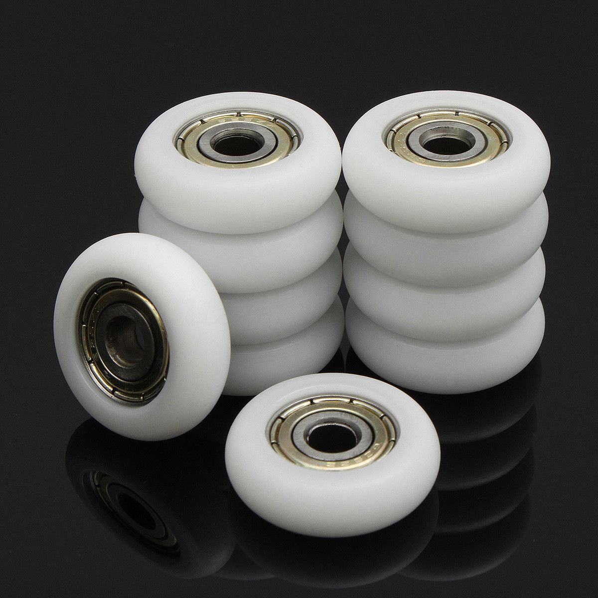
3 x Nylon wheels 23.0 OD / 7.3 wide (do not use 23.0/7.0 wheels, but 23.0/7.3)
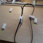
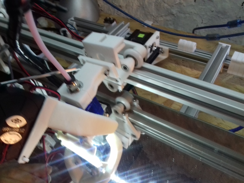
X, Y and Z Axis Motors
All motors mounted with belts and threaded rods:
and all 3 axis in motion (without extruder and without bed heating/leveling):
and early tests show with the nylon wheel (23.0mm OD, 7.3mm width) based carriage a build volume of 380 x 300 (+10mm outside of bed) x 320mm.
Other carriage, e.g. the slider based, might result in smaller or bigger build volume.
Controller Board
For now I use an Anet 1.0 controller board (as part of a “CTC DIY Kit”), and it required some preparation:
using Arduino Uno R3 (clone) and upload “Arduino ISP”
attach Anet 1.0 board (detach all other cables) to Uno R3
run “Burning Bootloader” with “Arduino as ISP” as writer
downloading Marlin and edit main Configuration.h to match my specifications
upload new firmware Marlin to Anet 1.0 via USB upload
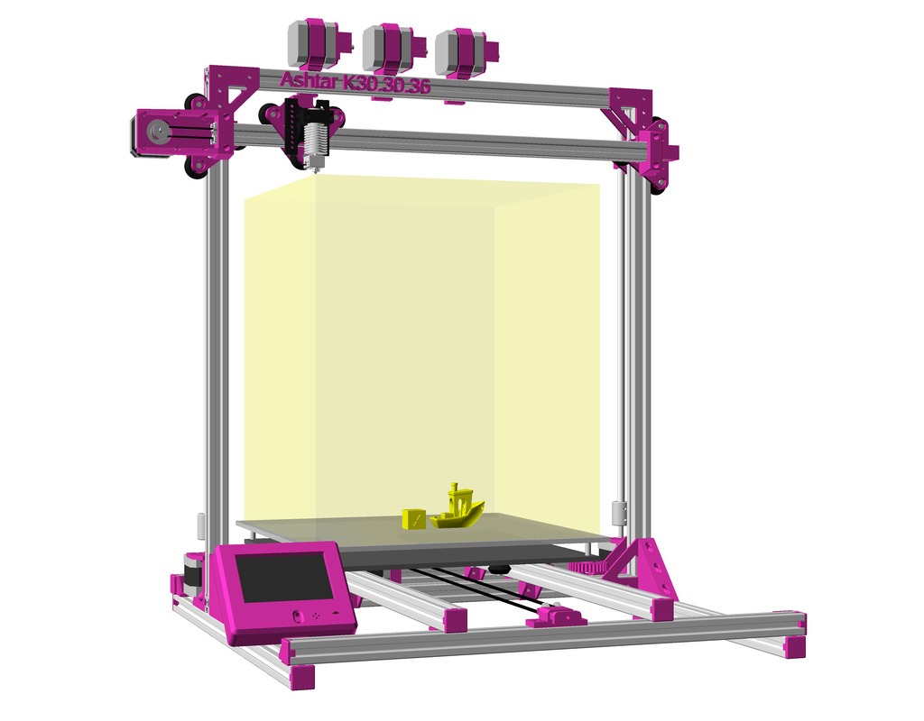
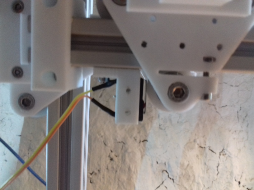
I mounted the board first in the farther left corner (in the photo), but the Z stepper motor new mount required to move the board in front of the XZ frame on the left side. The position and casing for the LCD display I haven’t decided yet.
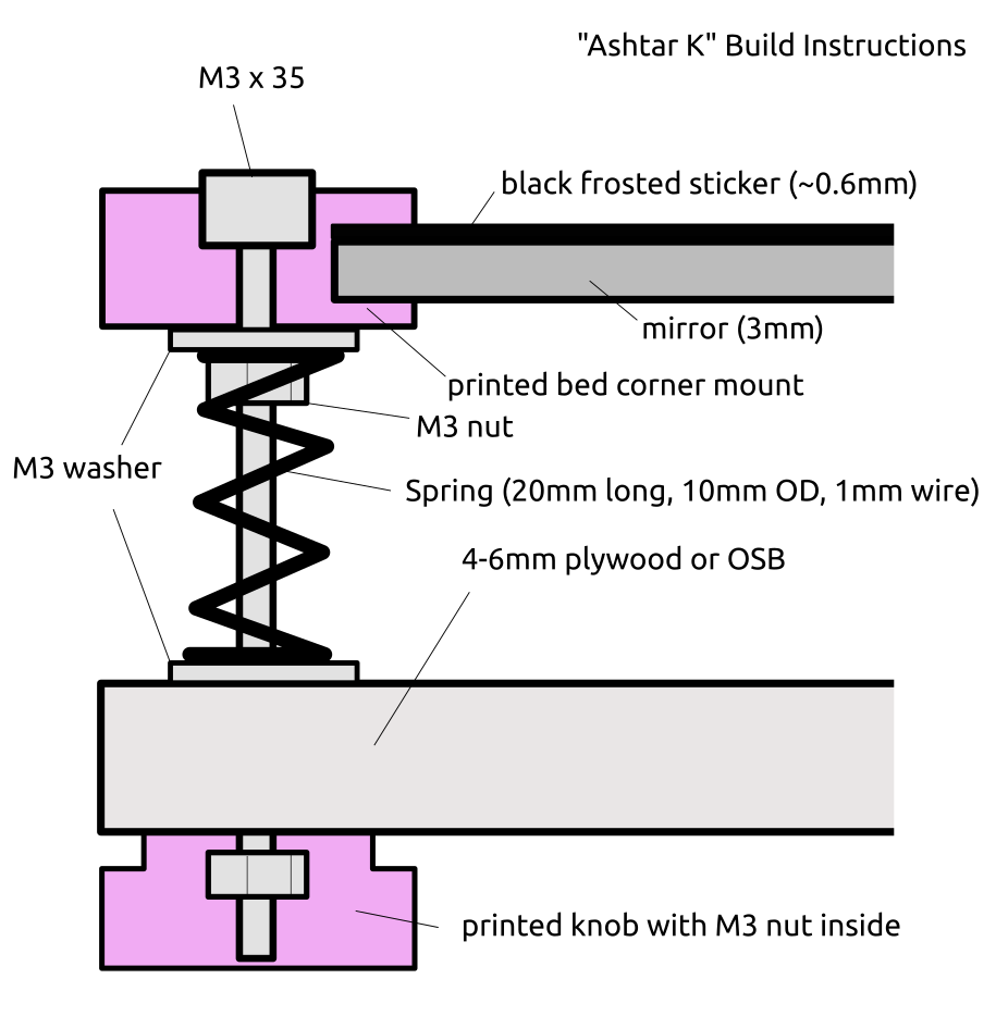
Y Carriage
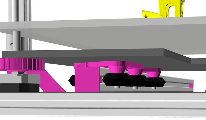
Current bed setup (top to bottom):
400x300mm black sticker (“frosted sticker”), apprx. 0.6mm thick
I currently use the white PU steel enhanced GT2 belts, and it produces hard edges, some ghosting, but more precise prints than the black rubber GT2 belts which just stretch too much – I have to research this more closely – about the type of reinforcement and the use with more heavy beds (Y carriage).
420×320 carriage:
4mm plywood flexes, but has been quite flat – not recommended
6mm plywood hardly flexes, but has been hard to buy truly flat – and so far my attempt to flatten it did not work well – not recommend unless it’s flat
6mm OSB quite flat, does not flex much (3 or 4 sliders) – recommended
320×320 carriage (for 300×300 bed):
4mm plywood works (3 sliders, 4 sliders recommended)
6mm plywood works (3 sliders, 4 sliders possible if plywood is truly flat <0.2mm difference)
6mm OSB quite flat, doesn’t flex (not yet tested)
Just to explain my thought or decision process for my setup:
the mirror should not be bend (of course)
the support structure should not be the edge mounts, but the foam in between
the carriage can be bent, but not flex
revelation: already bent means the springs with screws might extend the bent further with a flexing carriage, and not counter act – as the mirror should stay flat
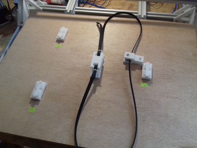
Sliders & Belt Mount Positions
Top view with see-through (best mark “0,0” on both sides so you keep proper reference) – if your carriage is truly flat, choose 4 sliders, otherwise 3 sliders.
Bowden Extruder
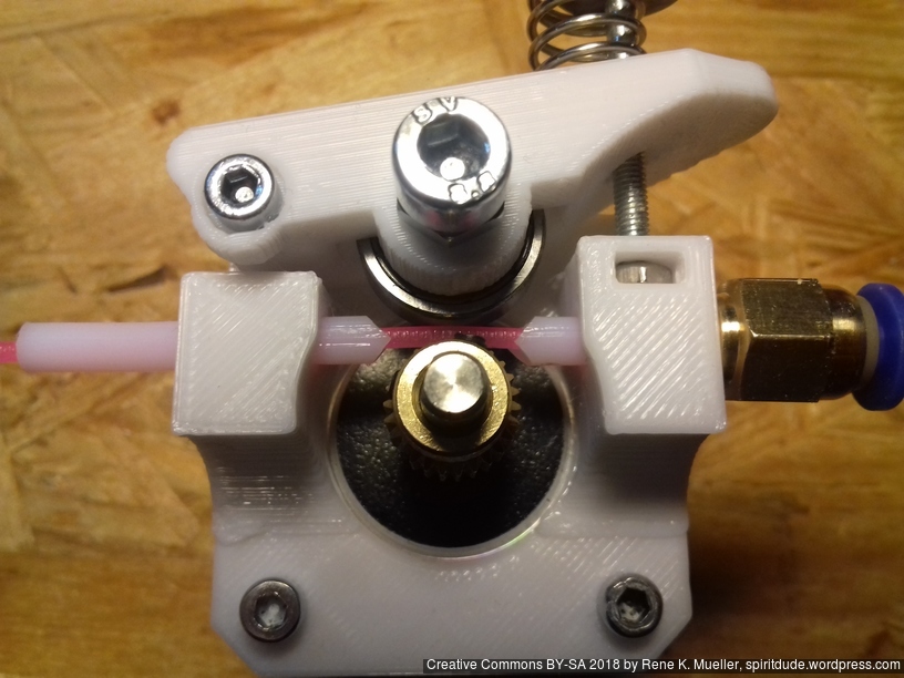
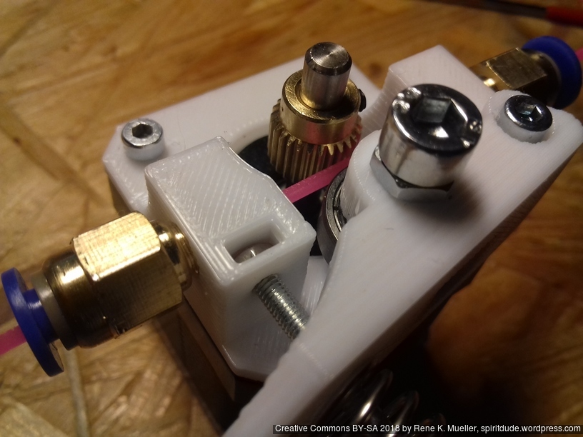
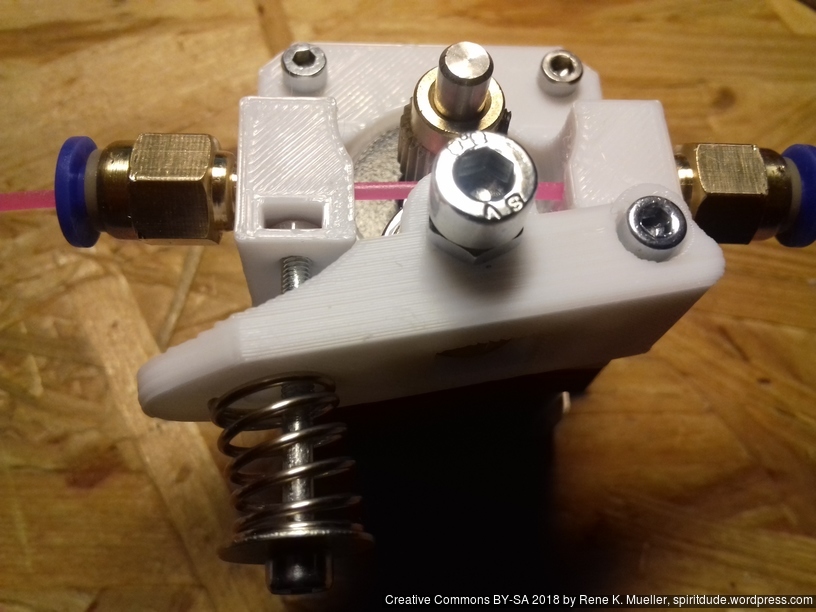
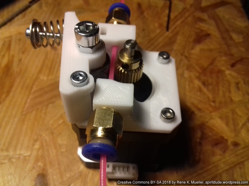
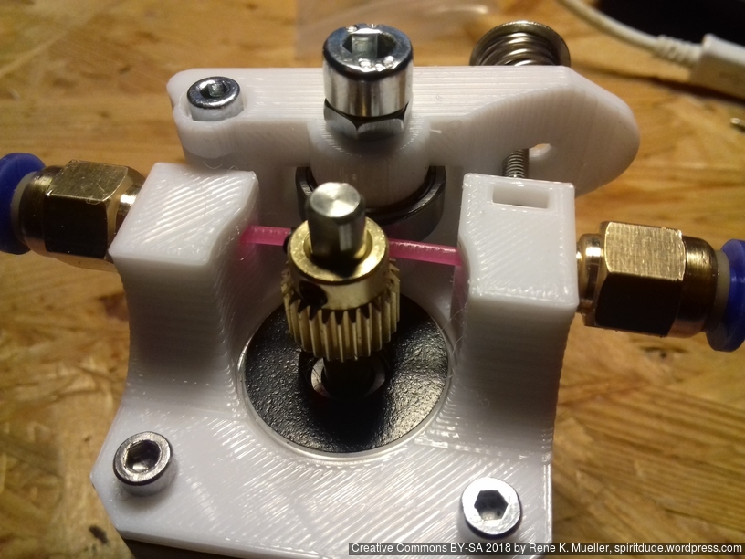
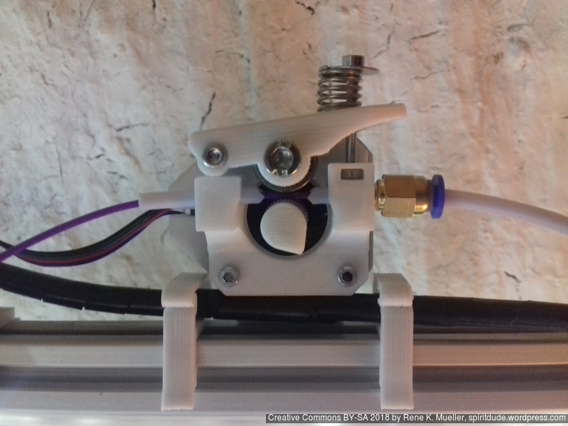
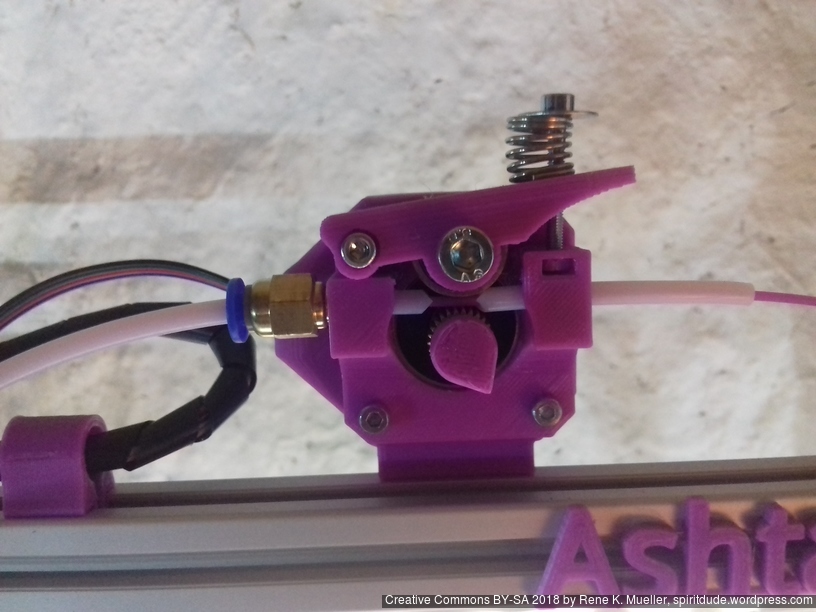
After few weeks I decided to do my own extruder, adapting the design of the “Compact Extruder” which has low complexity and low amount of parts to achieve simple extruder functionality; here my redesign:
and in a functional state:
Assembled Simple Extruder
Assembled Simple Extruder on Ashtar K #1
Assembled Simple Extruder on Ashtar K #2
It’s published at thing:3265864, it’s based on 625ZZ bearing:
625ZZ bearing (16mm OD, 5mm ID)
M5x14: mounting bearing
2x M3x25: one to attach handle, another to hold spring
2x M3x8: mounting to stepper motor
M3 nut: insert into slot
M3 washer: to hold spring
3-8mm OD 20mm long spring
hobbed gear OD 11mm
4mm OD / 2mm ID PTFE for filament guides
PC4-M6 for outgoing Bowden tube
Gallery
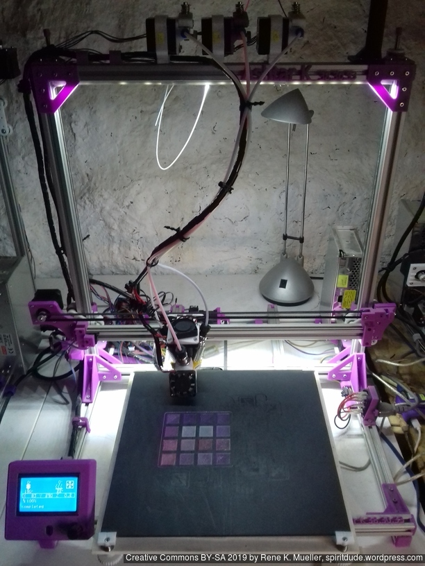
Ashtar K with 3 extruders and LCD controller
Ashtar K with stabilizing rods
Ashtar K with parametric clear enclosure
In Action
After 3 months (2018/06 – 2018/08), since I started to code the first OpenSCAD lines, the “K” prototype happen to print the 20mm XYZ Calibration Cube:
And roughly 2 months later Ashtar K #2 (with RAMPS 1.4 board) was printing as well, on a smaller 300x300mm unheated bed:
TODO
proper bed mounting and leveling: done
bed heating: running without heat bed
better cable management (in particular heatbed / Y carriage)
release sources
complete instructions
complete part list (printed / non-printed)
Parts
This is a preliminary part list (no files yet published):
Printed
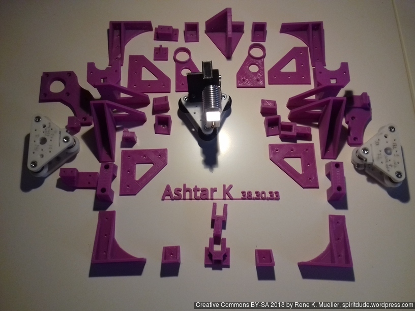
Most of the printed parts
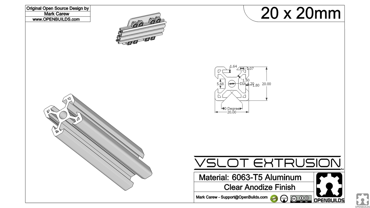
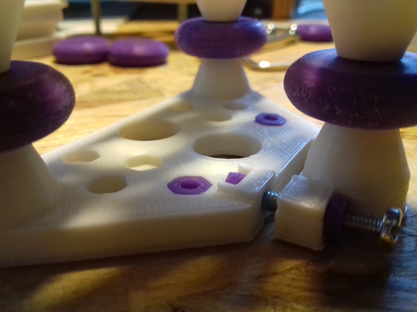
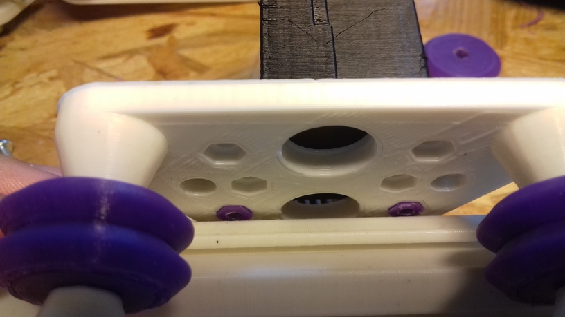
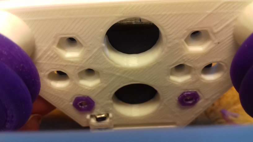
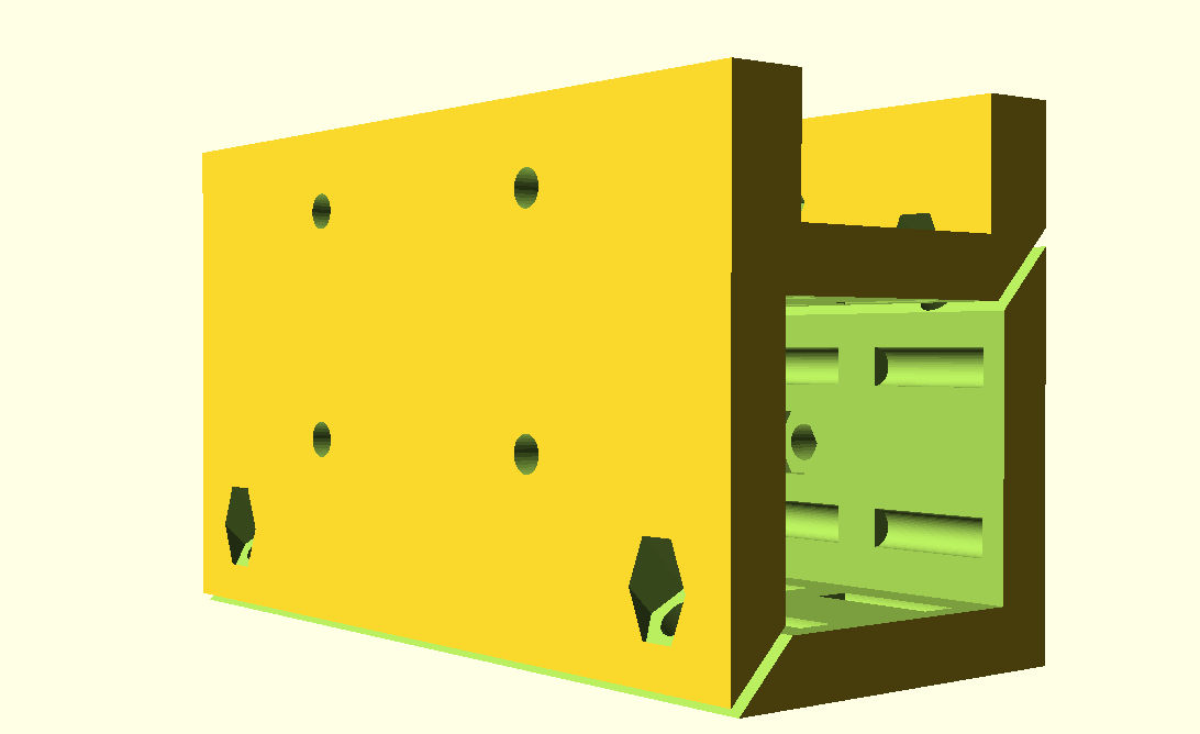
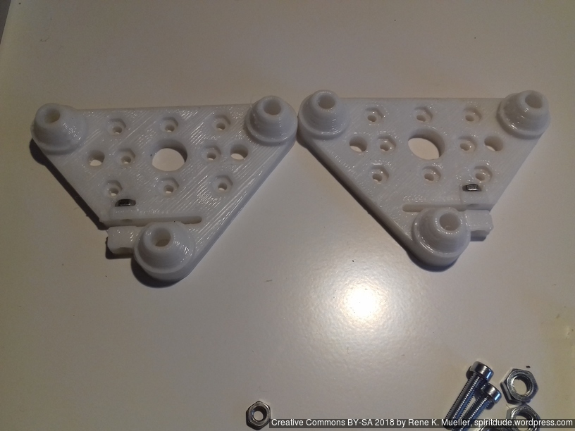
V plates (2 plates = 1 module) with 3 x or 4 x M5 x 30: Note: for each axis the plates must be printed with the same print settings to be symmetric when assembled, recommended setting: 1.5mm top and bottom thickness and wall thickness, layer height ~60% or less of nozzle diameter
X module (with 3 or 4 x black OpenWheels 24.4/11):
short 3 wheel carriage:
1x v_plate-2020-double-v-244-110-48w-a
1x v_plate-2020-double-v-244-110-48w-b
short 4 wheel carriage:
1x h_plate-2020-double-v-244-110-48w-a
1x h_plate-2020-double-v-244-110-48w-b
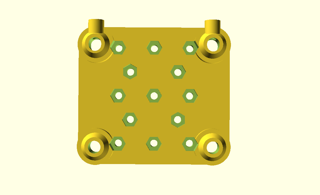
2 x Z modules (with 3 x white Nylon 23/7.3 wheels) each
3 wheel carriage:
1x v_plate-2020-delrin-230-73-10-a
1x v_plate-2020-delrin-230-73-10-b
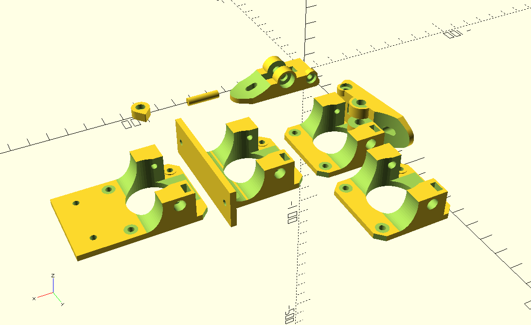
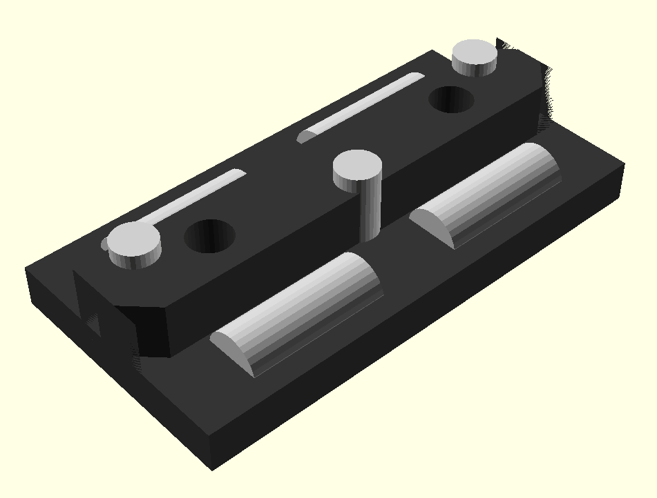
3 or 4 x Y modules (1 module = 1 slider, per slider 4 x 10mm long x 4mm PTFE + 3x 8mm long x 3mm PTFE)
3 or 4 x slider_2020-ptfe=true,td=4,td2=3,axis=2,closed=true,hplus=5,hole=true
X carriage:
1x xcarriage_short_hmount_motor-endstop-left Note: minimum 1.5mm top and bottom thickness, and 1.5mm wall thickness, 30% infill, layer height ~60% or less of nozzle diameter
1x xcarriage_short_hmount_motor-right Note: minimum 1.5mm top and bottom thickness, and 1.5mm wall thickness, 30% infill, layer height ~60% or less of nozzle diameter
2x xcarriage_short_hmount
1x xcarriage_beltmount-y=7,w=25
1x pulley_holder
1x endstop_mount
Printhead/Hotend:
1x e3d_mount
2x M3x12 (mounting to x carriage), 2x M3 nuts for insets for clamp (use M3x12 to draw nuts into inset)
1x e3d_mount-type=clamp
2x M3x16 (clamp E3D v6)
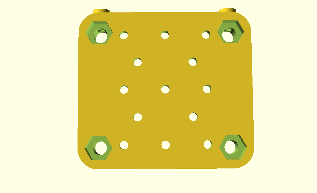
Y carriage:
4x knob_30,8,6 (bed level wheels)
1x ymotor_mount
1x ycarriage_mount-h=15
1x yendstop_bumper
1x yendstop_mount
1x pulley_holder
1x ybelt_mount
Z carriage:
2x zcarriage_short_mount-6,30 (for M6 threaded Z rods)
1x ztop_bracket-left
1x ztop_bracket-right
1x zendstop_mount
Frame
8x c_2020 (simple 2020 corners)
2x l_2020-a (short L bracket)
2x l_2020-b
1x ll_2020-a, 3 perimeters/wall line count
1x ll_2020-b, 3 perimeters/wall line count
1x ll_2020-type=nema17-a (X/Z bracket + Z motor mount) Note: 3 perimeters/wall line count with layer height ~60% of nozzle diameter (e.g. 0.25mm @ 0.4mm nozzle or 0.3mm @0.5mm nozzle)
1x ll_2020-type=nema17-b (same notes as above)
2x c2_2020-a (strong L for bottom frame)
2x c2_2020-b
12x e_2020 (end caps)
Non-Printed (Vitamins)
11x 500mm 2020 alu extrusions (T slot 6 B-type or V-slot 6)
Double or single V slot wheels (OpenWheel 24.4/11) and/or 18x (6 x 3) x Delrin R nylon (23/7.3) wheels (see printed parts above which are needed)
Screws & Nuts:
200x M3 nuts
100x M3 8mm
20x M3 10mm
20x M3 15mm
150x M3 Hammer Nuts for T slot/V slot 6
20x M5 x 30
20x M5 nuts
Y carriage / bed:
420 x 320 or 320 x 320 OSB 6mm as Y carriage
400 x 300 or 300 x 300 3mm thick mirror
400 x 300 or 300 x 300 frosted bed sticker
4 x springs 20mm long, compressed 10mm
Belts:
2x GT2 pulleys (ID 3, OD 16, 6 wide with teeths)
~220cm GT2 6mm belt (200cm might be sufficient but without any cutting margins)
Printhead:
E3D V6 original / clone with 0.4mm or 0.5mm (recommended) nozzle
100cm PTFE 4mm OD / 2mm ID (60cm for Bowden tube, reuse rest for sliders)
1x Pneumatic Connector PC4-01
1x Pneumatic Fittings PC4-M6 Bore 4.3mm for 4mm PTFE
Electronics:
5x stepper motors Nema17 42-45NM (40mm height) with 1m wires
1x control board (with Marlin support), e.g. Anet V1.0 or Makerbase MKS Gen L board
2 x endstops with 1m wires
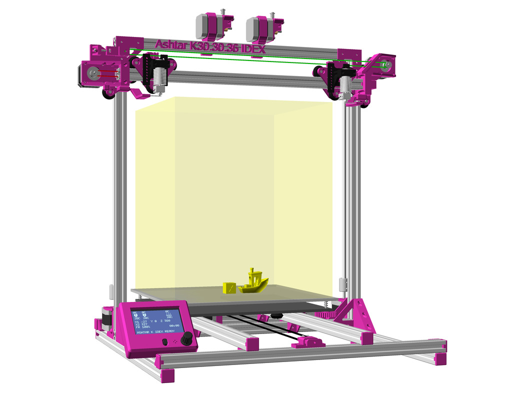
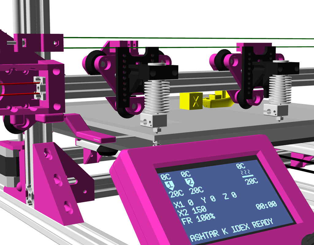
IDEX Option
In order to run two independent printheads aka IDEX (Independent Dual Extrusion) see this blog-post on Ashtar K IDEX with the details and those new pieces are needed:
Status: This is a work in progress – and will likely will receive more updates, files not yet released.
Updates
2018/09/14: Added H Plate (4 wheels) and h_plate() reference.
2018/09/01: Added v_plate() variables and numbers for common wheels
2018/07/28: Adding another example with Z axis X gantry adapter & X gantry horizontal beam mount.
2018/07/21: Supporting Delrin R 21.5 or 23mm/7mm wheel as well.
2018/07/20: Version 0.6 added, with ordered mounting holes and nut insets, screw which controls distance inside the plate to reduce overhead
2018/07/19: New version 0.2 with M3 has controlling distance of the 3rd wheel
2018/07/17: First basic design (Version 0.1), few tests made
Introduction
As part of developing various designs around Aluminium extrusions, a few tests. Early tests I printed the wheels in PLA just for sake of testing the dynamics, once the wheels arrived real applications were sought:
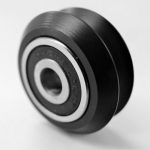
The possible parts are 2020 alu extrusions and Dual V wheel by OpenRail:
V Wheel
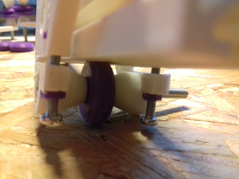
and the “Delrin R” V type nylon wheel (21.5/23mm diameter, 7/7.3mm thickness and 5mm hole):
Later in the research the difference between 7.0mm and 7.3mm thickness nylon wheels were significantly, as the shape of the wheel differ, and the ticker one (7.3mm) actually sat better in the T slot groove.
2020 V-Slot with Double V Wheels
The V-Slot alu extrusions usage test.
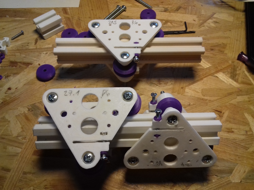
V Plate (Version 0.6)
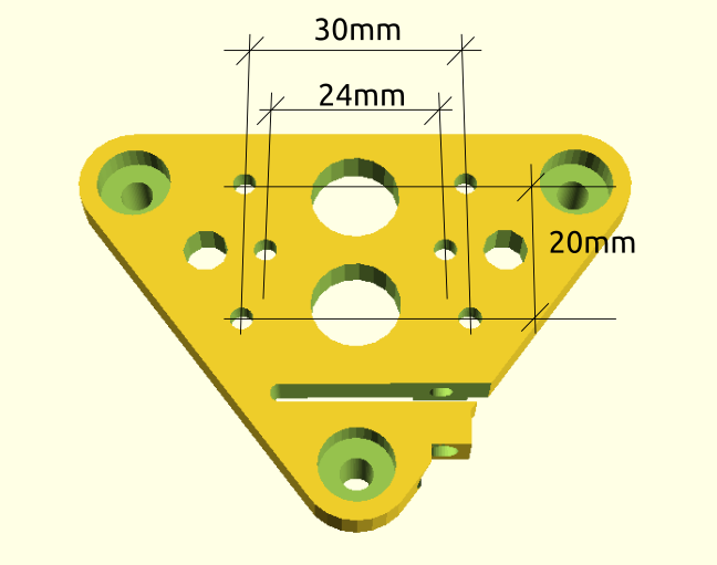
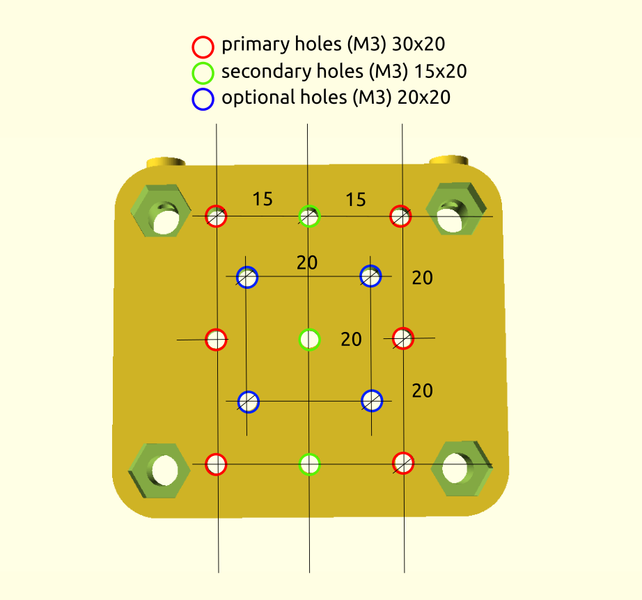
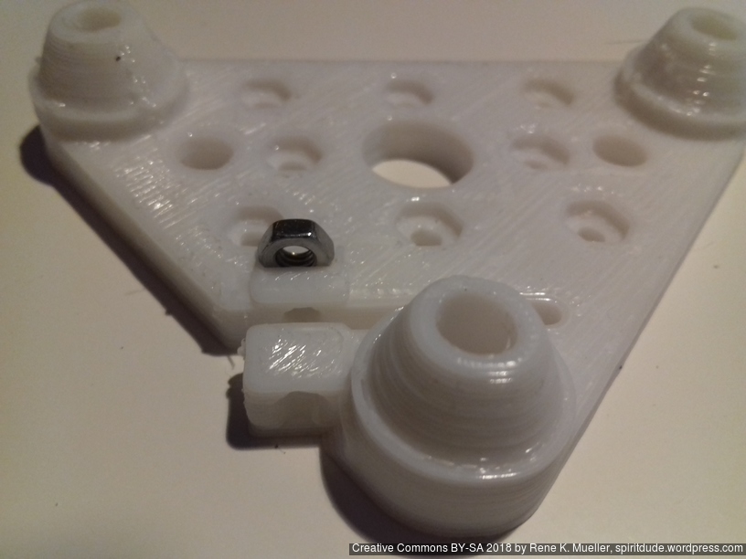
Ordered mounting holes (2x 30mm apart horizontally x 2 20mm vertically apart) plus 24mm apart near center, all with M3 nut insets so both surfaces (inside and outside) are nearly flat and mounts easily attached.
Hole-to-hole distance: 40.5mm (20.5 + 20)
2020 T-Slot Diagonal with Double V Wheel
Using the traditional T-slot Aluminium extrusion without proper wheel groove but rotating so the edges are used as rail and the 90 degree inner groove of the Dual V wheel.
Version 0.6
Moving the adjuster into the plate to save some space, and adding some insets for the M3 mount holes (2x 30mm apart and 20mm height distance, 2x 24mm apart (Prusa i3 extruder).
Hole-to-hole distance: 47.1mm (27.1 + 20)
2020 T-Slot with Delrin R Wheels
Since the V plate is parametric designed (controlling thickness, distances etc) I thought to support also the “Delrin R” nylon wheels:
V Plate (Version 0.6)
Hole-to-hole distance:
21.5mm diameter wheel: 37.4mm (17.4 + 20)
23.0mm diameter wheel: 38.9mm (18.9 + 20)
V-Slot vs Diagonal
Mounting Holes
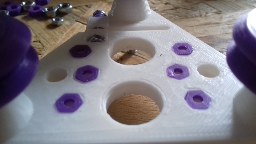
Since the V plate, either used with V Slot alu profile or diagonal, has 6 fixed holes with nut insets to attach adapters:
2x 24mm apart horizontally centered vertically on the plate
An adapter plate or area of 40 x 35mm is guaranteed to be flat, and 5mm thick, with the given mounting holes as mentioned.
Usage
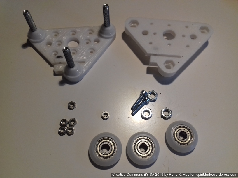
2x V plates (top/bottom) with its 3x wheels each are made so I can use it as a “V module”:
Prusa i3 Style
X extruder: 1x V module with extruder adapter
X gantry: 2x V module with Z axis threaded rod adapter
Y gantry: 3x V module without adapter, but mounting top V plates direct to Y carriage
OpenSCAD v_plate()
v_plate() takes multiple arguments:
d: distance of holes (-20mm)
h: height/distance of the wheel to plate
orientation: -1 or 1 (back / front)
f: multiplier horizontal distance gap (default: 1)
g: multiplier vertical distance gap (default: 1)
Here for 2020 T Slot B-Type in groove usage:
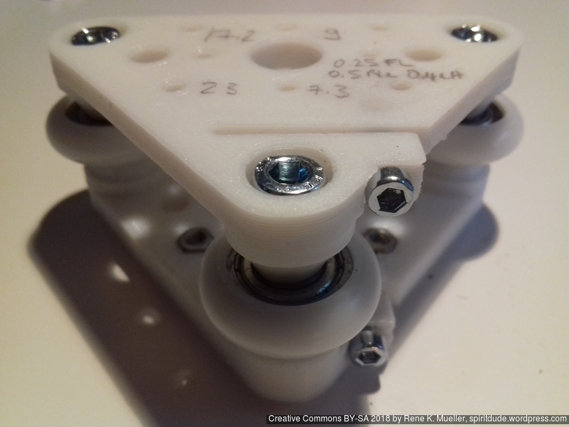
Nylon wheel 23.0mm OD / 7.3mm width: d=17.2, h=9.0
Nylon wheel 23.00mm OD / 7.0mm width: d=18.3, h=9.0
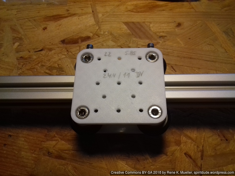
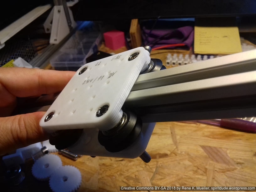
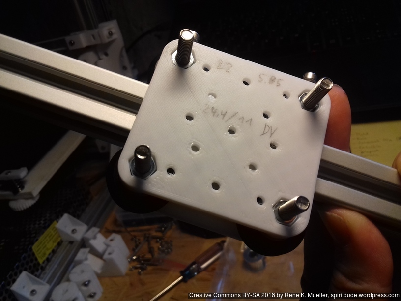
OpenRail Double V 24.4mm OD / 11mm width: d=22.0, h=5.85
Use
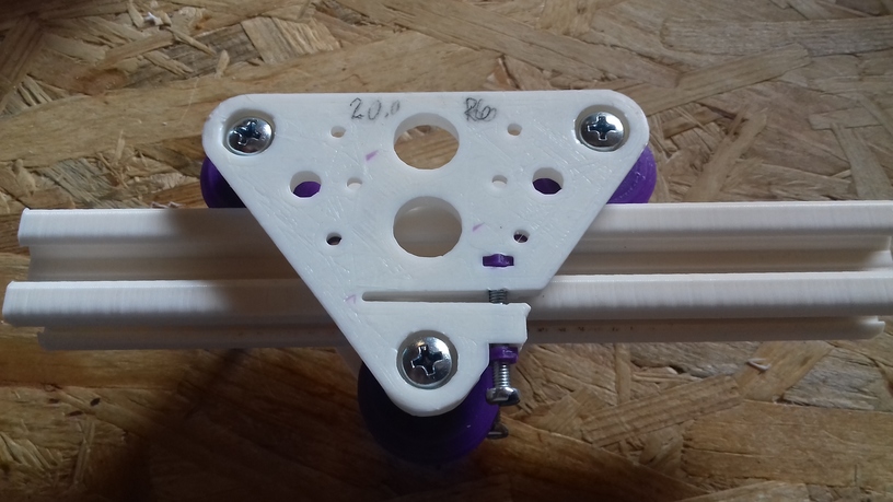
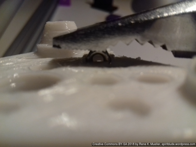
1x screw M3 x 16 with M3 nut (push it carefully yet forcefully so it aligns top/bottom flat) for distance control, put a drop of oil on the tip of the M3 screw before you screw the first time.
3x screw M5 x 30mm with cylinder head with hex inset, and 3 M5 nuts to mount the wheels per double V plate to make up a V module
Four Wheels: H Plate
For the X carriage with the hotend I thought to add another wheel to improve tilt rigidity (e.g. when overruning bumpy unclean or over-extrusions) – ideally triangle like with V plate/module it’s easy to adjust, four wheels means two wheels need to be adjustable, and those are harder to align properly.
H Plate (Version 0.1)
First version I decided to use a simple solution, have some larger vertical extended 5mm holes and M3 screw which carves its own thread to control the distance – this means the H plate should be used in double to make up a H module, this is the short/narrow 48mm wide H plate:
The plate contains a set of 30mm and 20mm spaced mounting holes, all M3 – requires support from bed only (not “everywhere”) so the M5 nut and screw heads insets are printed nicely for the wheels:
h_plate() settings – same as for v_plate():
Nylon wheel 23.0mm OD / 7.3mm width: d=17.2, h=9.0
Nylon wheel 23.00mm OD / 7.0mm width: d=18.3, h=9.0
OpenRail Double V 24.4mm OD / 11mm width: d=22, h=5.85
For the short version, width=48 (less won’t work).
Examples
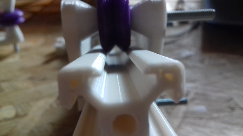
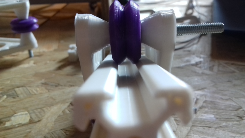
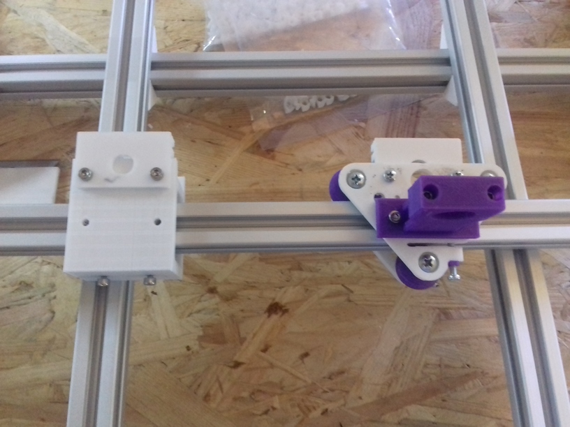
Extruder/Hotend Adapter
Attaching E3D V6 hotend on a pair of 30mm holes with M3x8 (M3x10 might work as well) with M3 nuts (in this example printed in purple PLA):
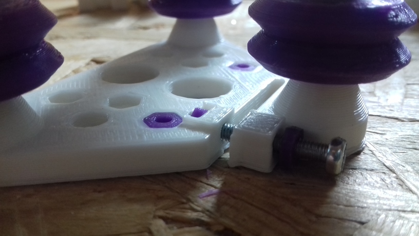
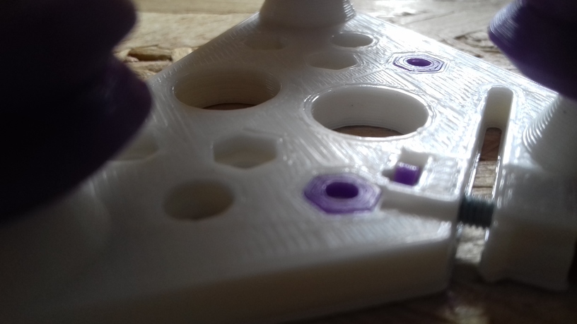
Z Axis Adapter
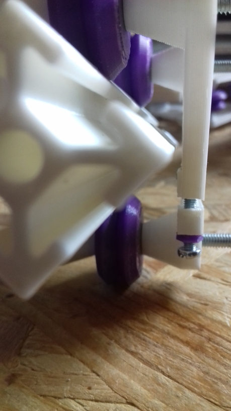
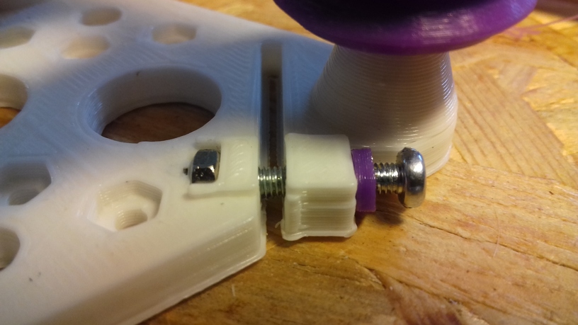
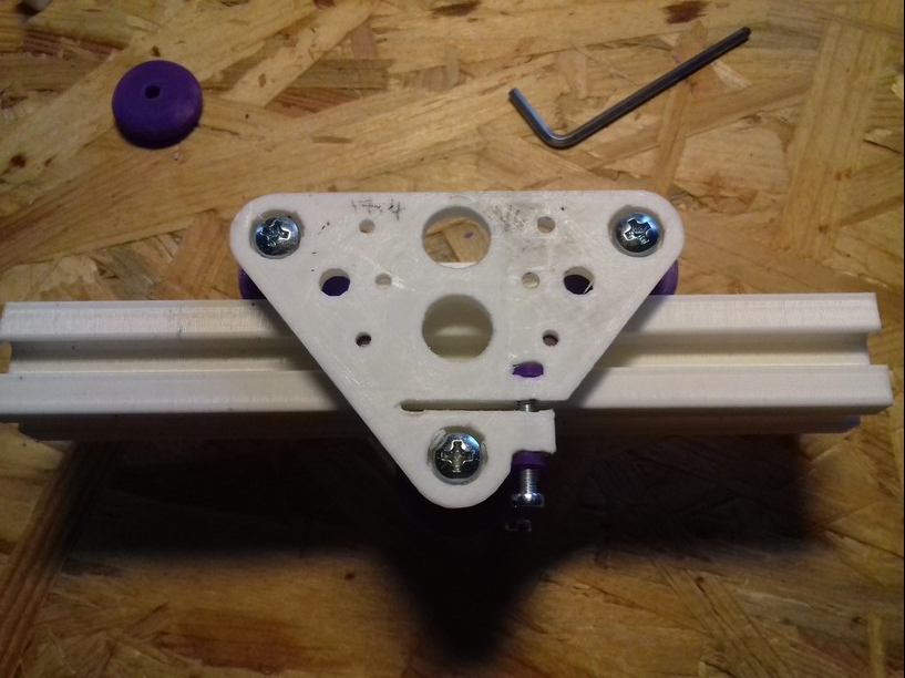
A simple Z axis adapter, here with M6 threaded rod with M6 nut:
The adapter is 4mm thick, and M3 x 10 should work (in this example I used M3 x 16 which are too long, but still work).
X Gantry Horizontal Beam Mount
A small simple piece to mount the 2020 horizontal X axis on Z axis V module:
Additional holes to fasten beam with T nuts as well (top and bottom of the bridge).


 Commercially manufactured, apprx. cost EUR 2.50 per piece, sold in 10 pieces bag.


 420x320mm 6mm OSB (white painted) as Y carriage