Updates:
- 2018/12/05: added MKS Gen L as alternative, for Ashtar C #1
- 2018/11/25: added RAMPS 1.4 as alternative, for Ashtar K #2
- 2018/08/28: initial version with CTC DIY I3 Kit
Sourcing Parts
The past months (2018/08) I began to use Aliexpress for ordering electronics – even prior going into 3d printing – and the past weeks my development cycles pretty much were depending on the 20-25 days delay until items arrived from China to Switzerland – and one develops some skill to anticipate what one would require as next – but some things only become known once you really tested parts thoroughly.
Anyway, the CTC DIY I3 Pro B (Geeetech DIY I3 Pro B clone) was still sold via Ebay (2018/08), at a price as low as EUR 80 incl. shipment, which is a true bargain.
Aliexpress (2018/08):
- MKS Gen L mainboard (incl. drivers) with LCD (with dialer), 200×200 heatbed, end stops, cables: EUR 50
- PSU 12V 240W: EUR 20
- 5x Nema 17 45Nm stepper motors: EUR 35
- Total: EUR 105 (without endstops and various cables to connect all together)
CTC DIY I3 Pro B Kit (2018/08):
- Anet 1.0 mainboard, with 2 Lines LCD (4 buttons), 200×200 heatbed, end stop, cables, PSU 12V 240W, 5x Nema 17 45Nm stepper motors
- Total EUR 80 (all cables included)
So I decided to get another CTC DIY to source the parts in one go, and likely upgrade later with individually sourced parts to have dual extruder motors (two color or material printing).
In 2018/11, when I started to build a second Ashtar K 38x30x33 #2 I checked Ebay with following prices:
Ebay (2018/11):
- MKS Gen L: EUR 28
- MKS Gen L mainboard: EUR 16
- 5x A4988 drivers: EUR 6
- RepRap Full Graphic LCD: EUR 11
- RAMPS 1.4 with Arduino Mega, 5x A4988 drivers, Full Graphic LCD: EUR 28
- 5x Nema 17 40-50Nm stepper motors with cables: EUR 26-35
- PSU 12V 240W: EUR 20
- Total EUR 74 – 83 (missing: endstops and various cables to connect all)
Burning Bootloader on Anet 1.0 Board
For now I use an “Anet V1.0” controller board (Atmel 1284P), as part of a “CTC DIY Kit” as mentioned, and it required some preparation:
- using Arduino Uno R3 (clone) and upload “Arduino ISP”
- attach Anet V1.0 board (detach all other cables) to Uno R3
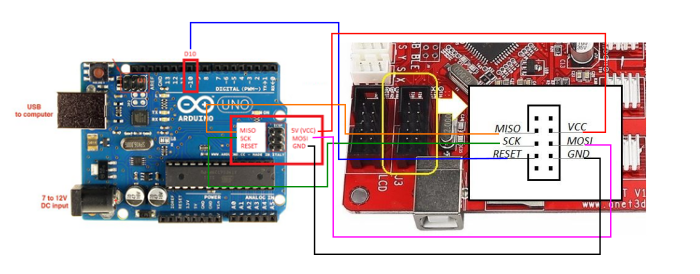
- run “Burning Bootloader” with “Arduino as ISP” as writer
- downloading Marlin and edit main Configuration.h (not yet published) to match my specifications
- upload new firmware Marlin to “Anet V1.0” via USB upload

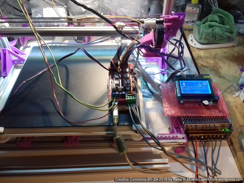
RAMPS 1.4 with RepRap Discount Full Graphic LCD
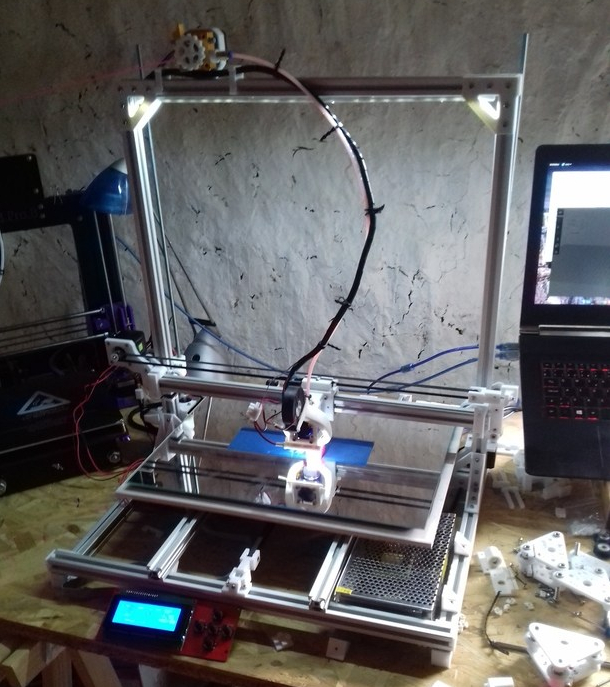
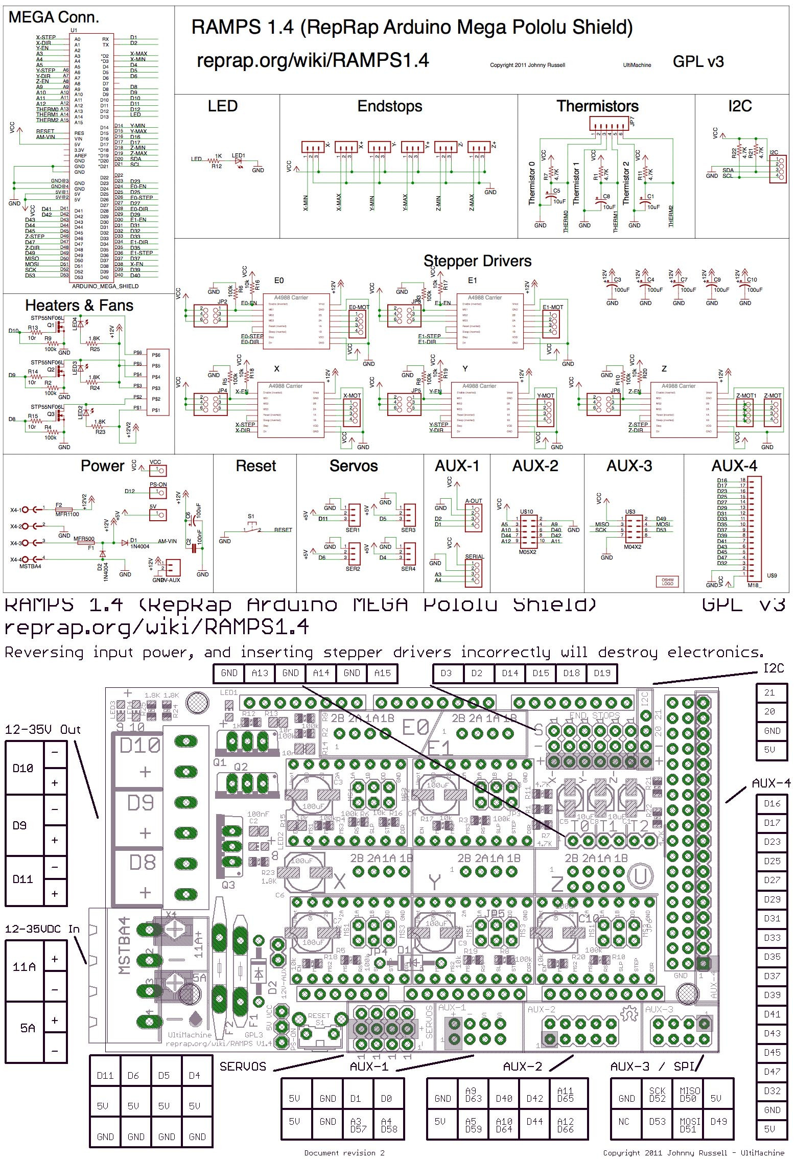 For the 2nd Ashtar K 3D Printer I used (2018/11) RAMPS 1.4 combo with Arduino Mega, which was easy to upload new firmware. RAMPS 1.4 is Open Hardware, the entire schematic and pinout is available or download diagram with pinout as one image (same as on the side) – but it’s also a hassle to plug correctly as the board plug descriptions are tiny or covered by parts so one has to consult documentation in details, and there many ways to do wrong (reverse or misalign plugs) and most of these can and do damage either the RAMPS 1.4 shield and/or the Arduino Mega beneath, including misaligning the endstops.
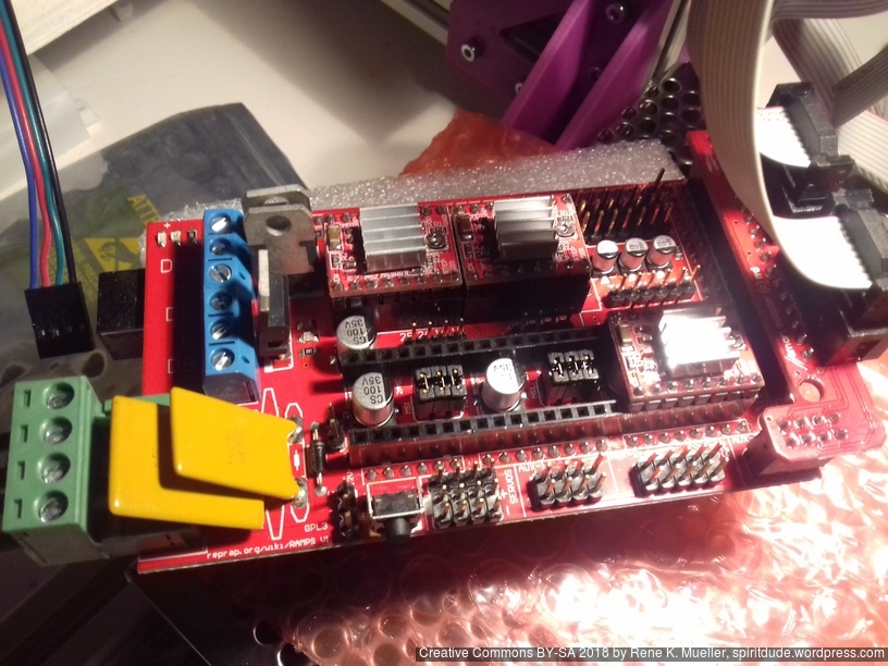

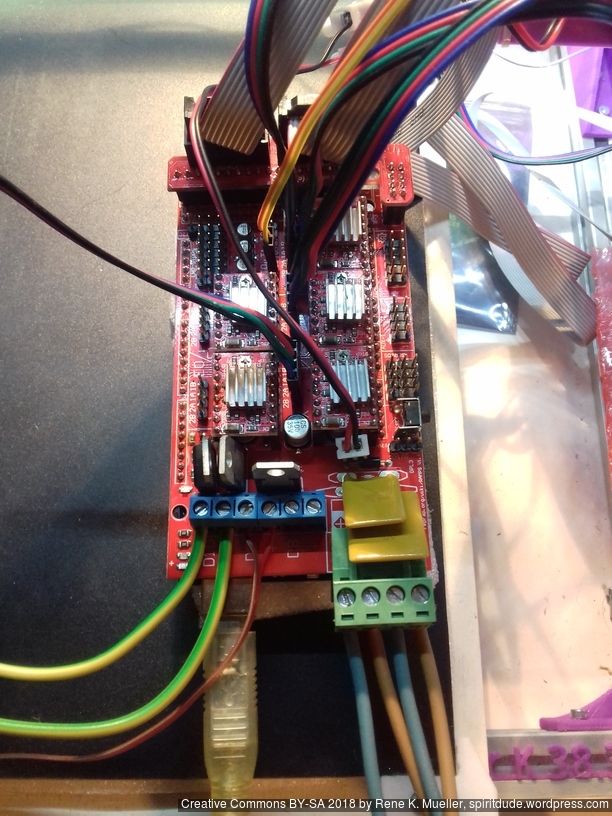
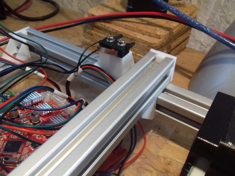
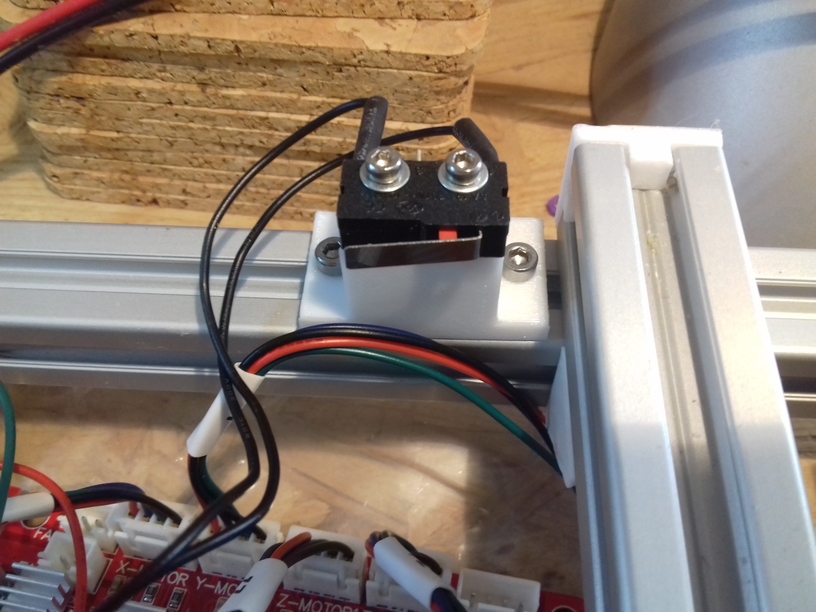
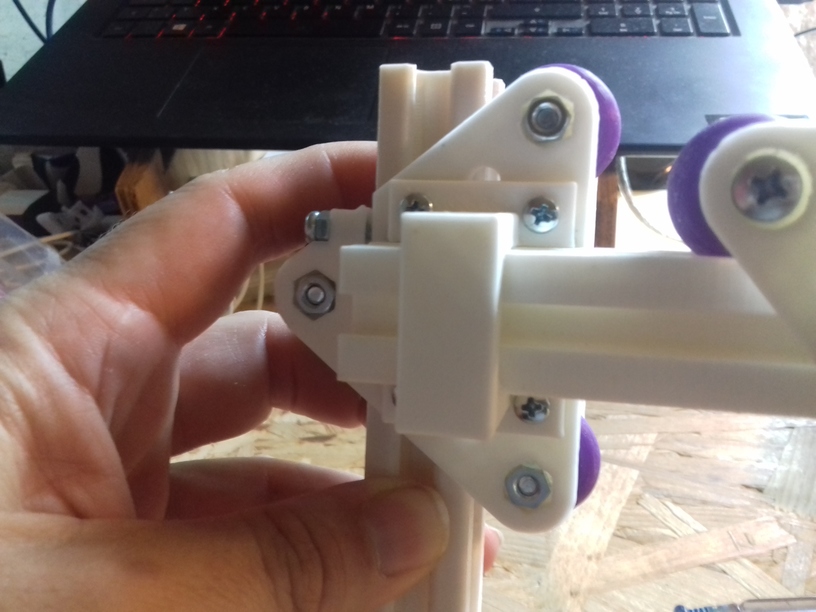
Endstops
- using C and NC on the endstop and the board (power connector on the left) above the 2x Z motor connectors: XMIN, XMAX, YMIN, XMAX, ZMIN, XMAX, each:
- top (Signal) -> C
- middle (Ground) -> NC
- bottom (5V) -> empty
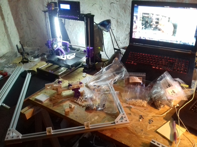
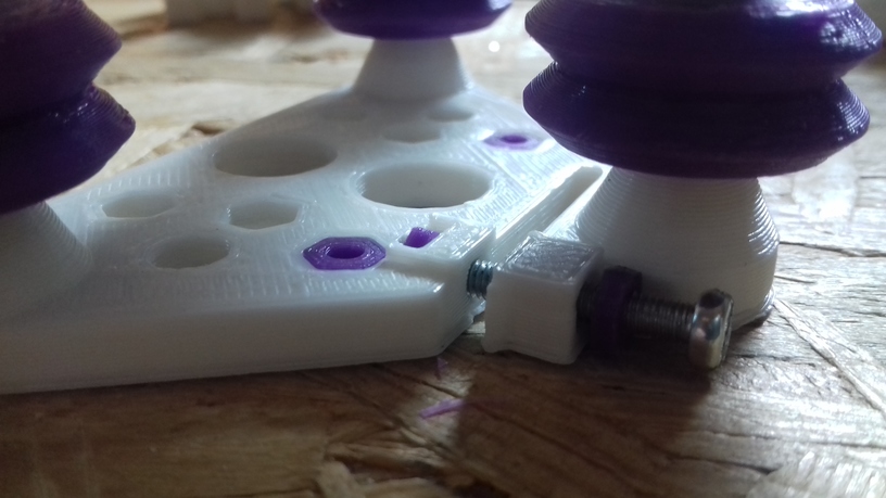
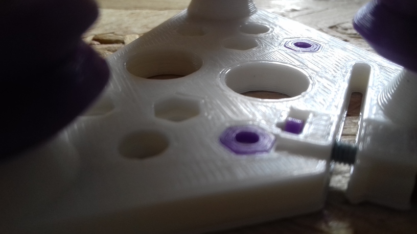
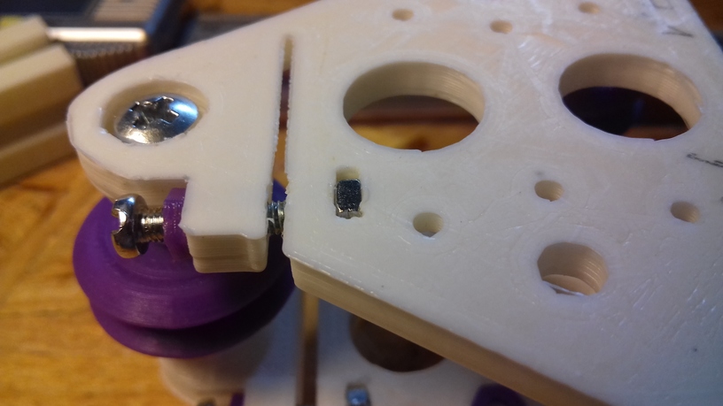
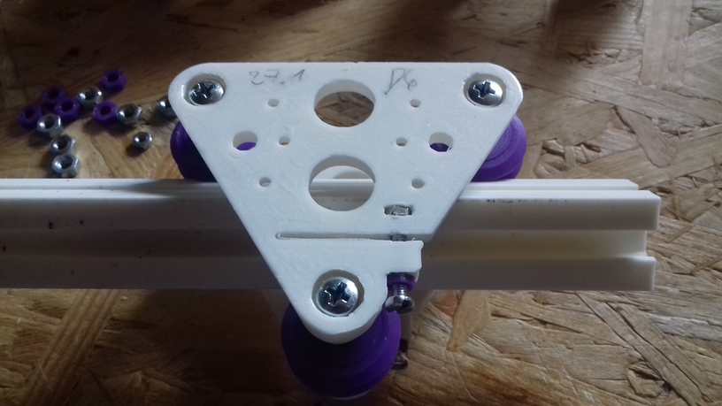
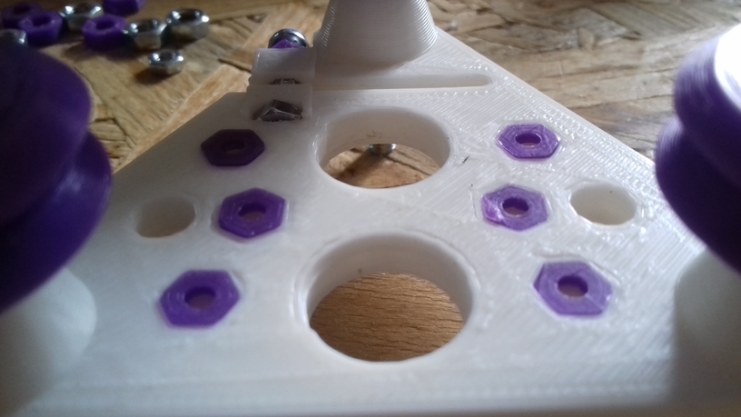
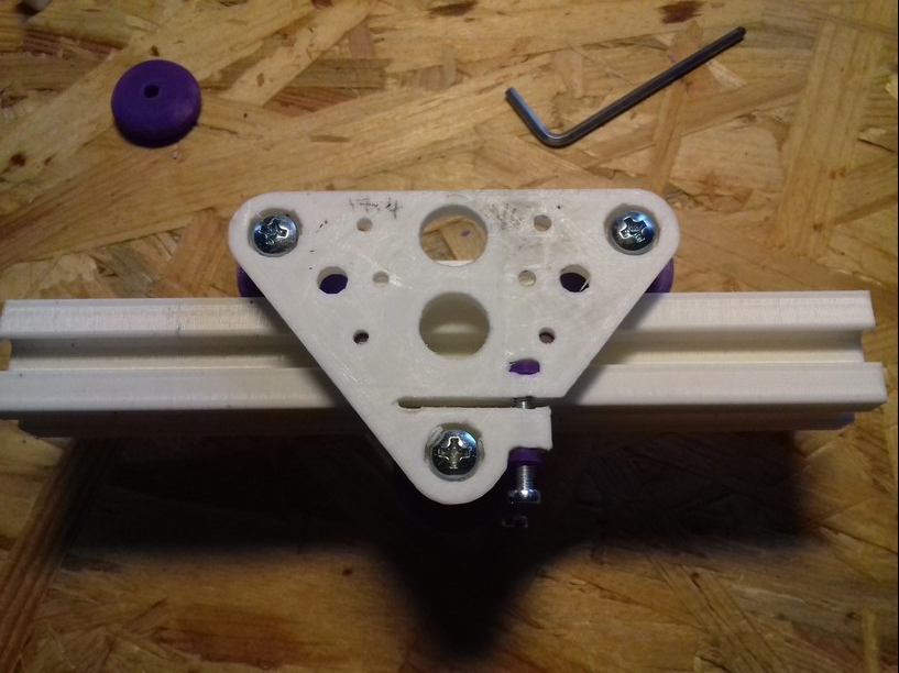
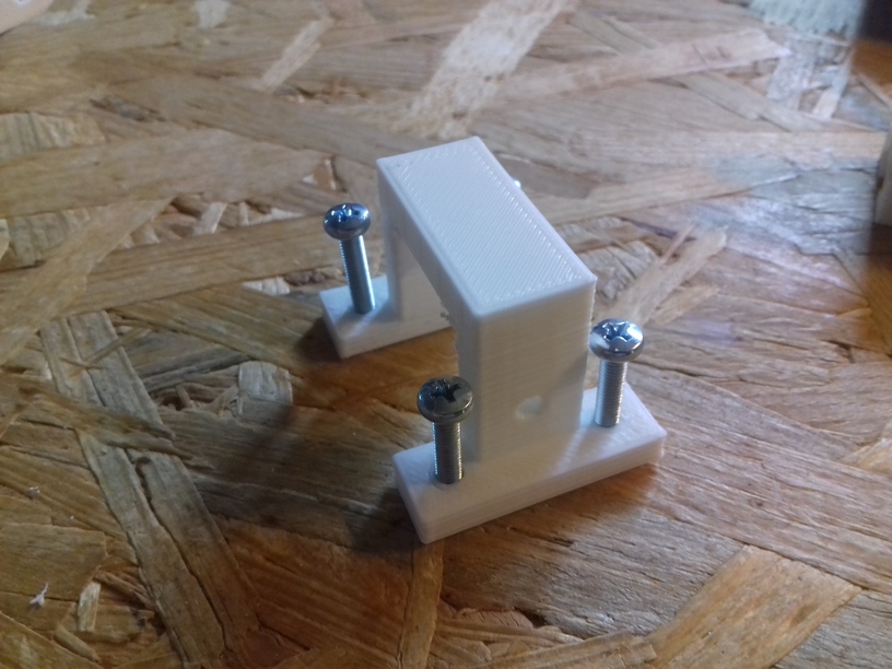
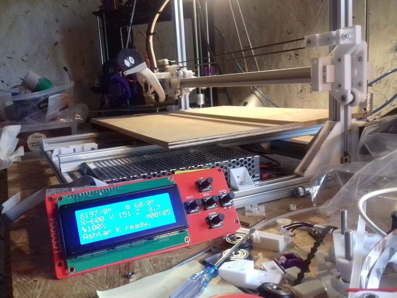
while waiting for proper endstops to arrive, I salvaged microswitches from a faulty computer mouse to work as endstops
Marlin Firmware Changes
Configuration.h:#define MOTHERBOARD BOARD_RAMPS_14_EFB#define REPRAP_DISCOUNT_FULL_GRAPHIC_SMART_CONTROLLER
Configuration_adv.h:- commented out
#define MENU_HOLLOW_FRAMEso selected item is inversed
- commented out
pin_RAMPS.h:- see
#if ENABLED(REPRAP_DISCOUNT_SMART_CONTROLLER)and the following#if ENABLED(CR10_STOCKDISPLAY)after the#elsecheckBTN_EN1andBTN_EN2and reverse the pins (31 <-> 33) so clockwise dialing goes down (and not up).
- see
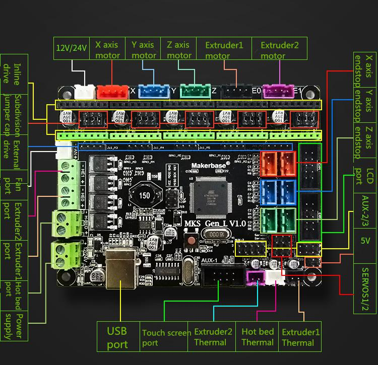
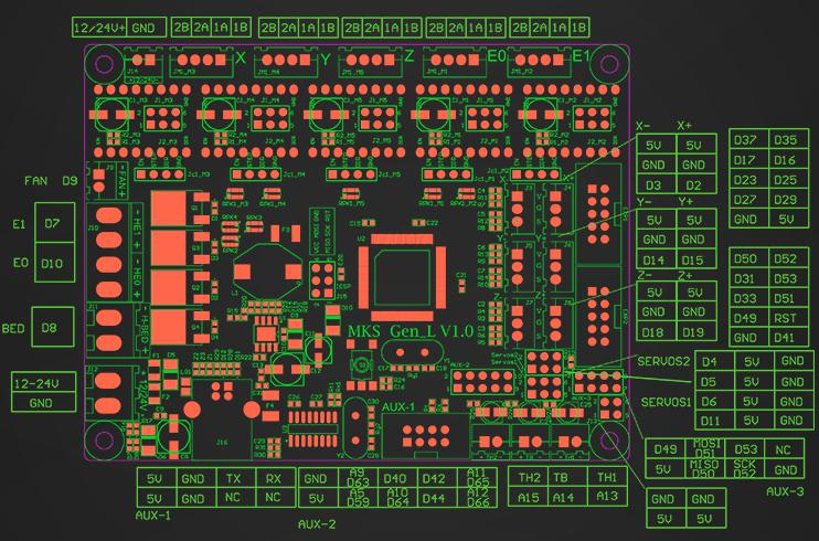
MKS Gen L
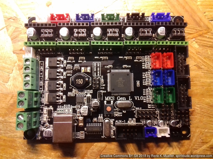
Configuration.h:#define MOTHERBOARD BOARD_MKS_GEN_L
As far I can tell the end-stops take DuPont females and pin order is the same as with RAMPS 1.4, but orientation is crucial – otherwise the GND and VCC is shorted.
The plan is to use this board for Ashtar C #1.
I update this post as I go along.


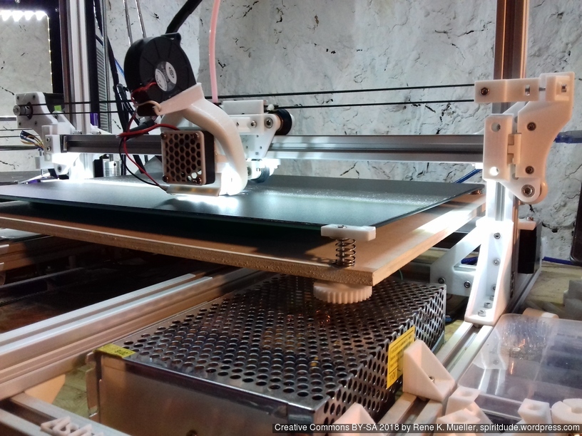

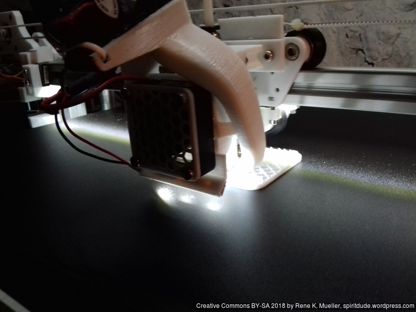
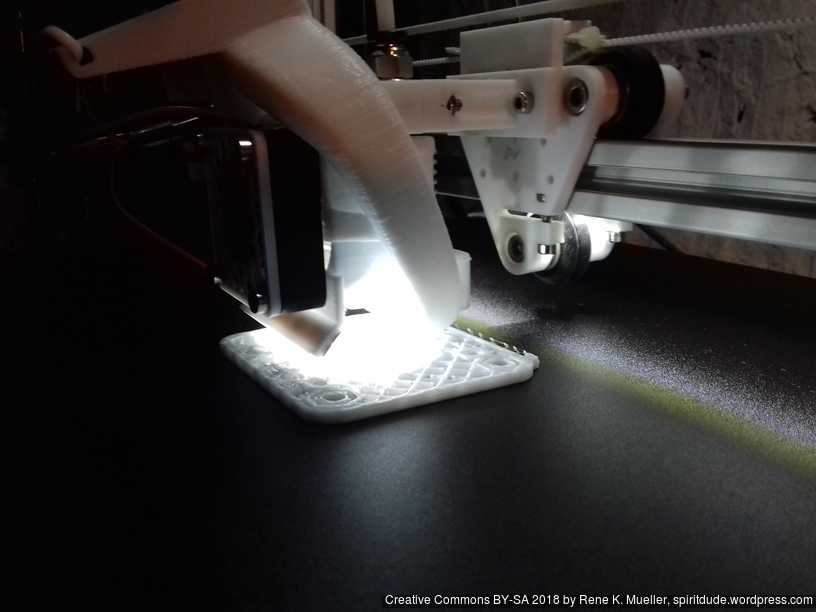
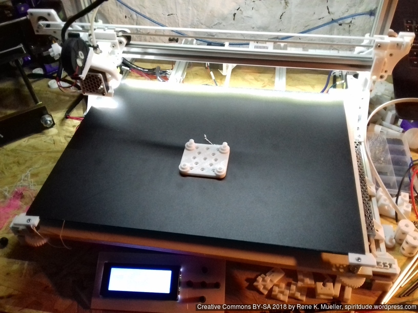
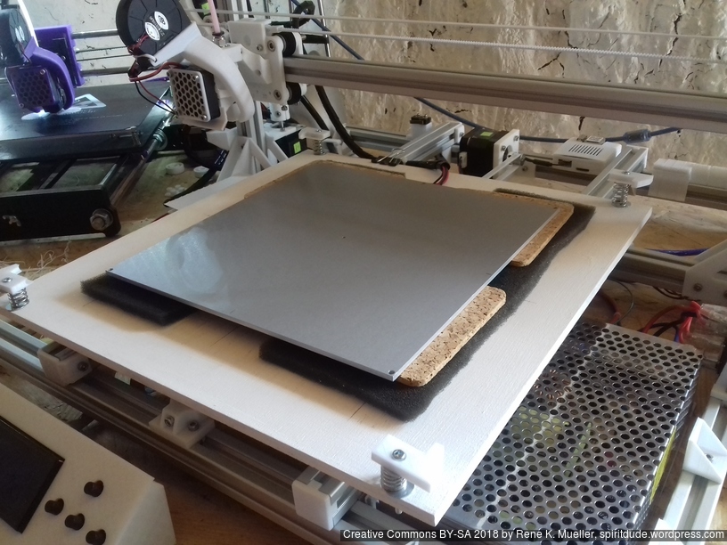
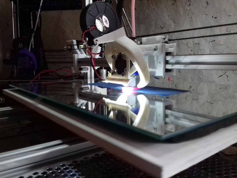
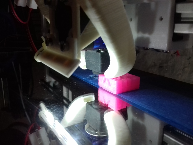
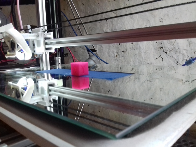
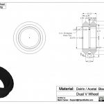
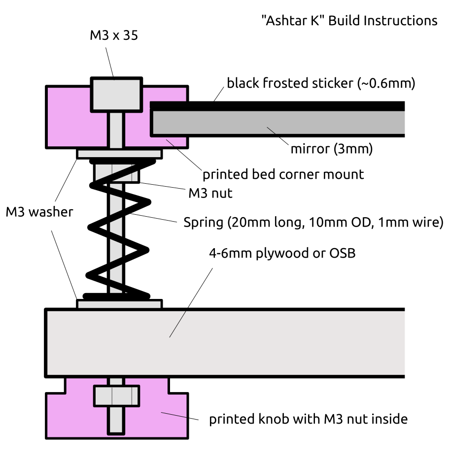 Current bed setup (top to bottom):