Updates:
- 2020/12/20: adding XZ arch option
- 2020/12/14: initial post

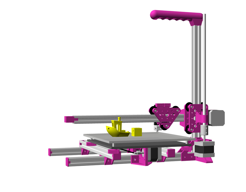
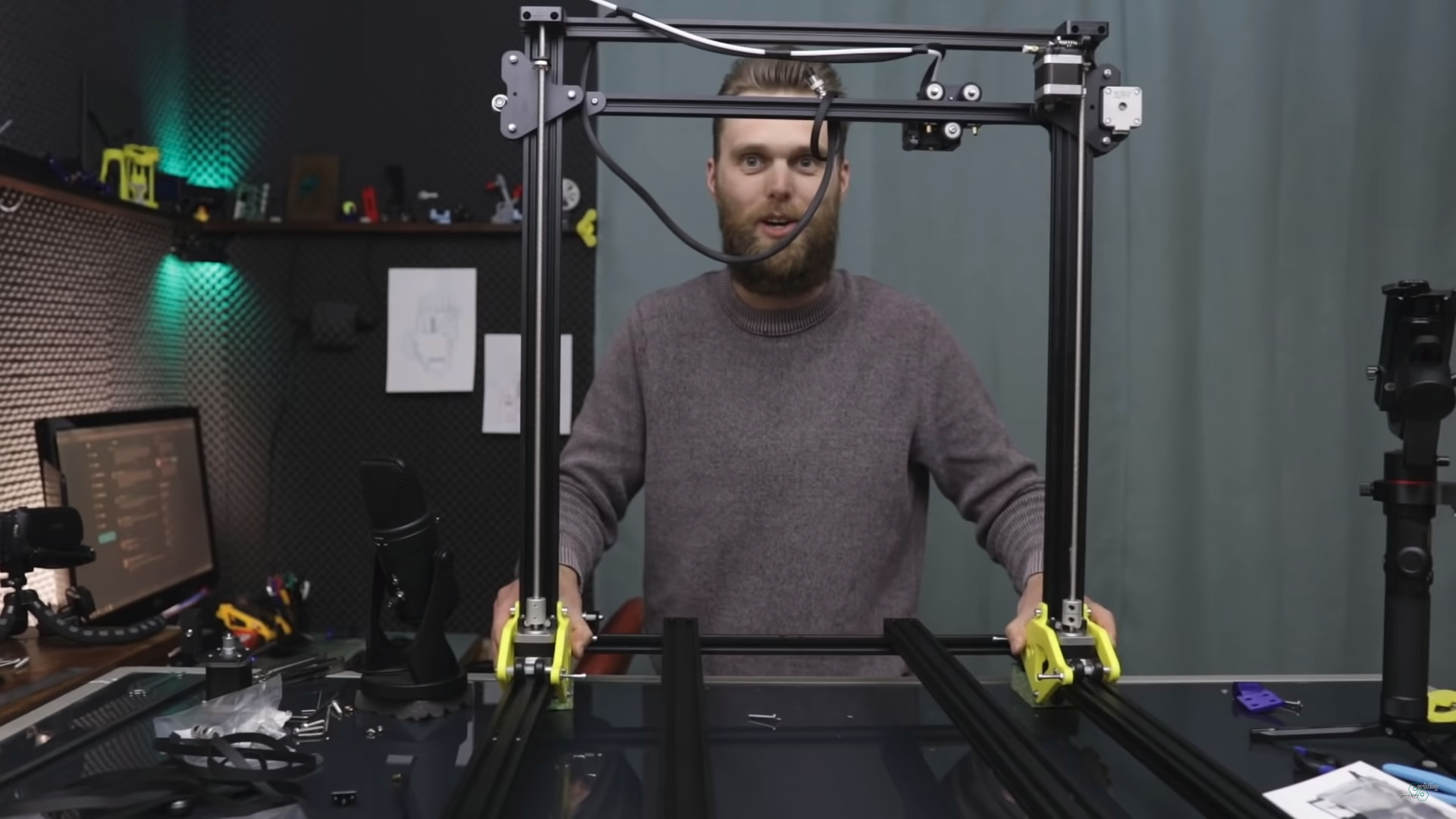
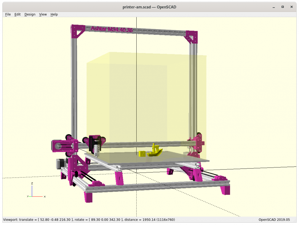
In April 2020 Jon Schone (@properprinting) showed a “Moving Portal” mod for his CR-10 – a Prusa i3 derivative – and I thought to adapt his approach as “Ashtar M” as moving XZ frame or moving gantry in CNC terms.
On a second thought, this approach makes only sense with larger beds, as the bed weight should exceed the weight of XZ frame and X carriage:
weight(XZ frame + X carriage) < weight(bed)
and as I compose my Ashtar 3D printer series with alu extrusions (beams) I can say:
weight(XZ frame) = beam X * 2 + beam Z * 2 + NEMA17 * 2
weight(bed) = X * Y
and it becomes here clear, the bed weight grows X * Y whereas XZ frame only (X + Z) * 2, but also 2* NEMA17 motors of the Z axis are part of the XZ frame.
Moving Portal / Gantry
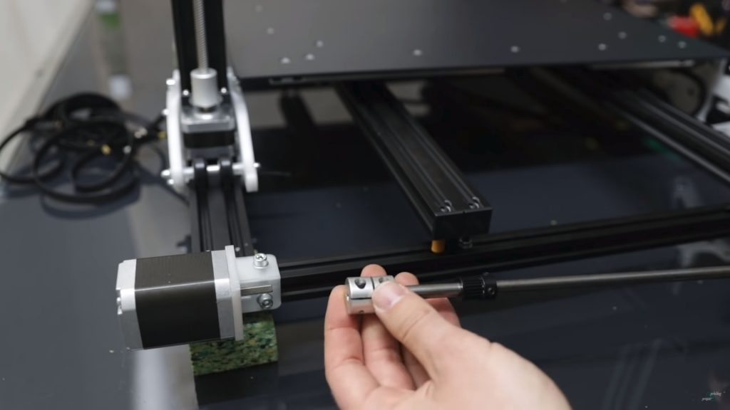
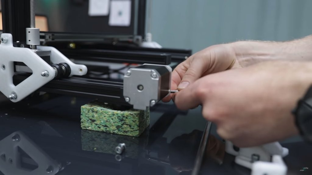
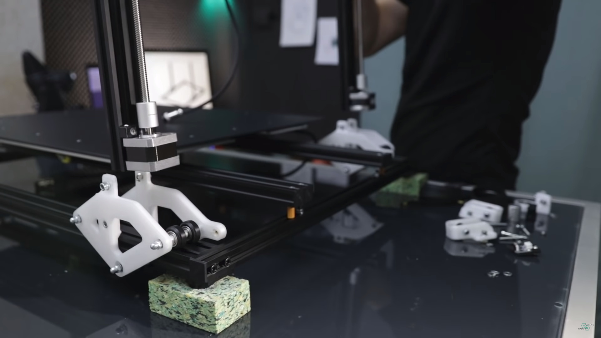
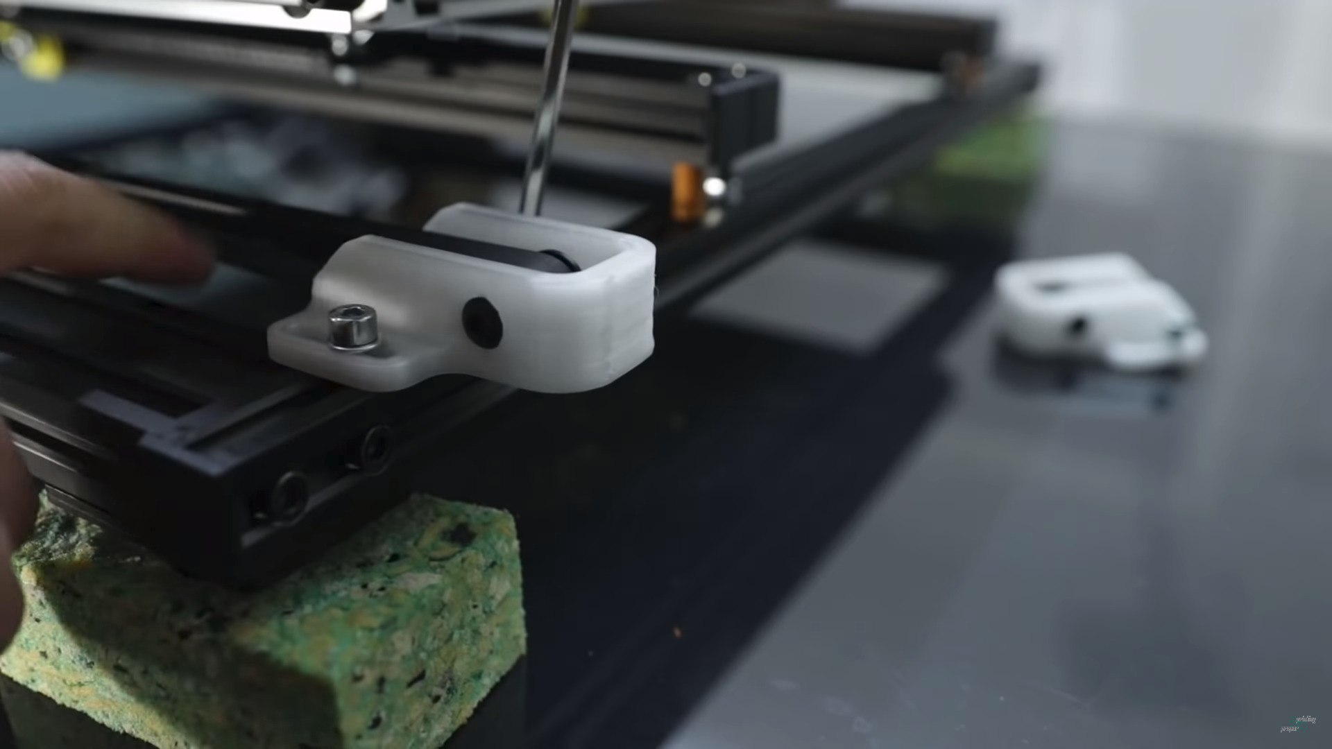
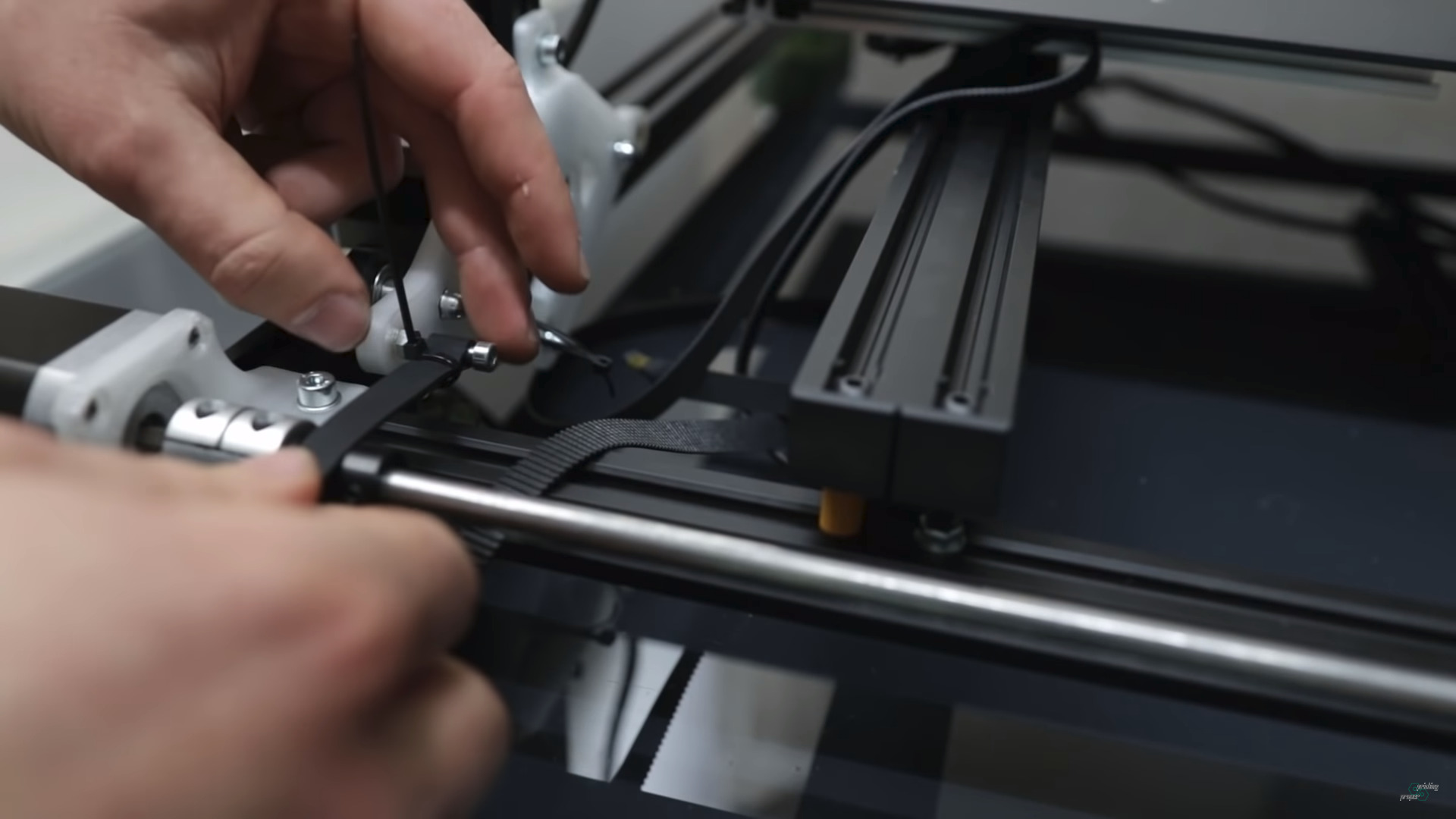
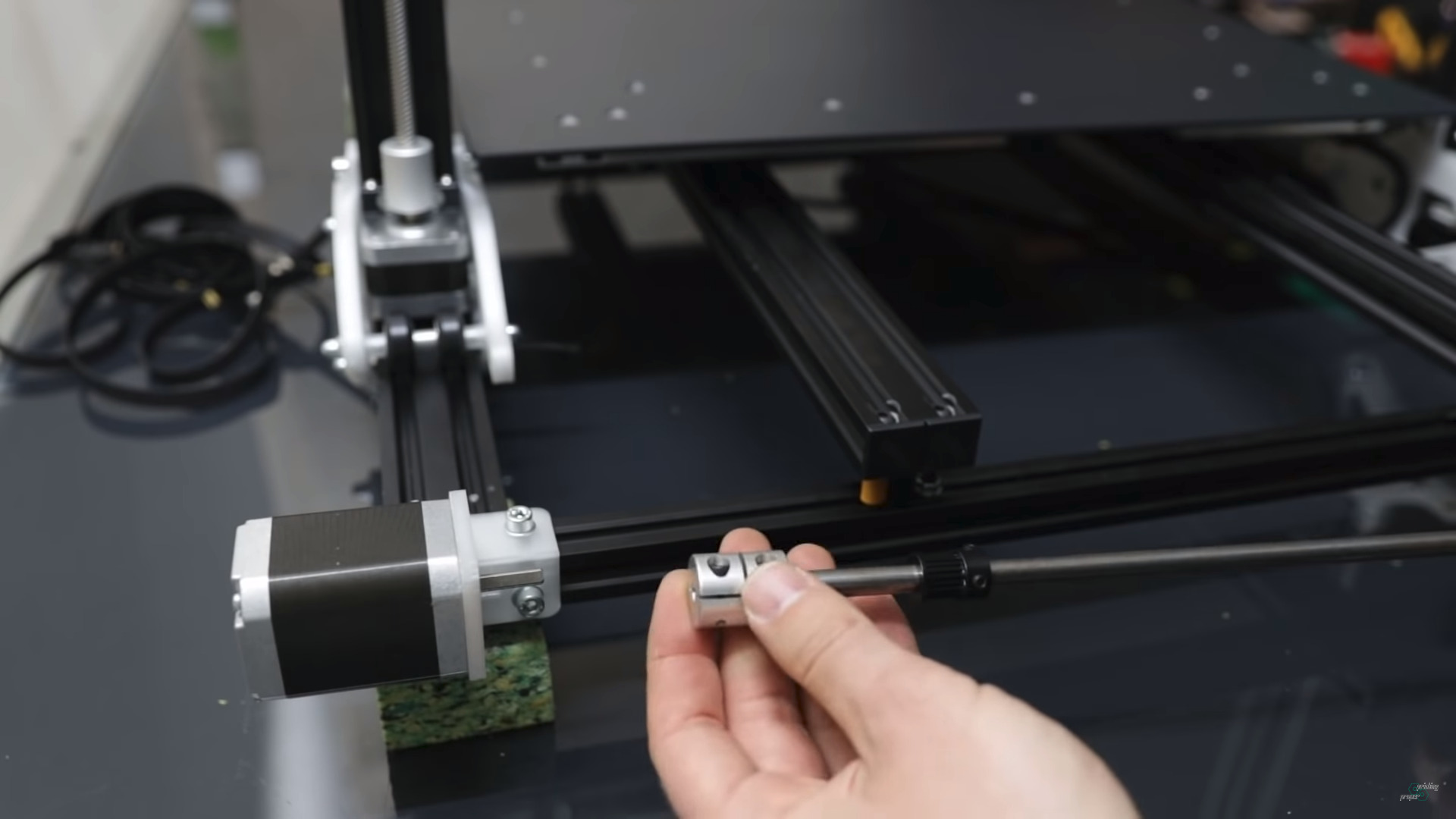
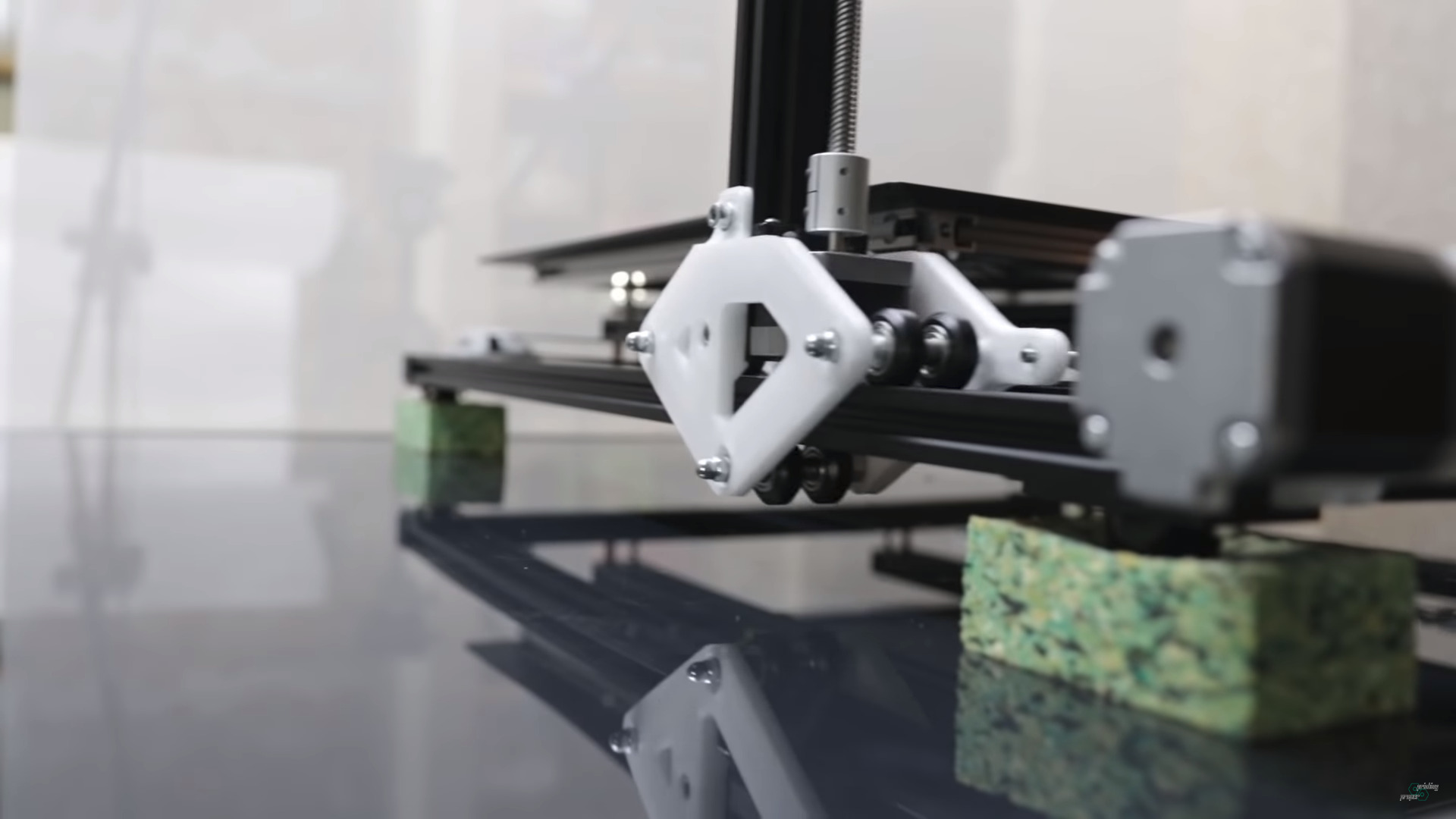
A few still images of Jon’s YT video to look at some details of his approach:
Jon Schone: Moving Portal Mod 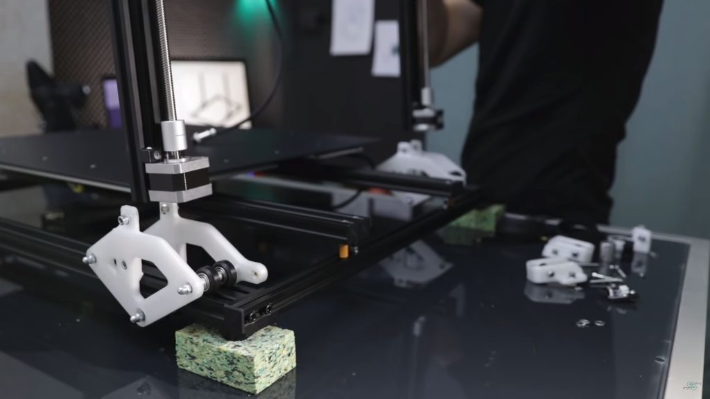
Z motor sits inside the Y carriage (40×20 V alu extrusion) 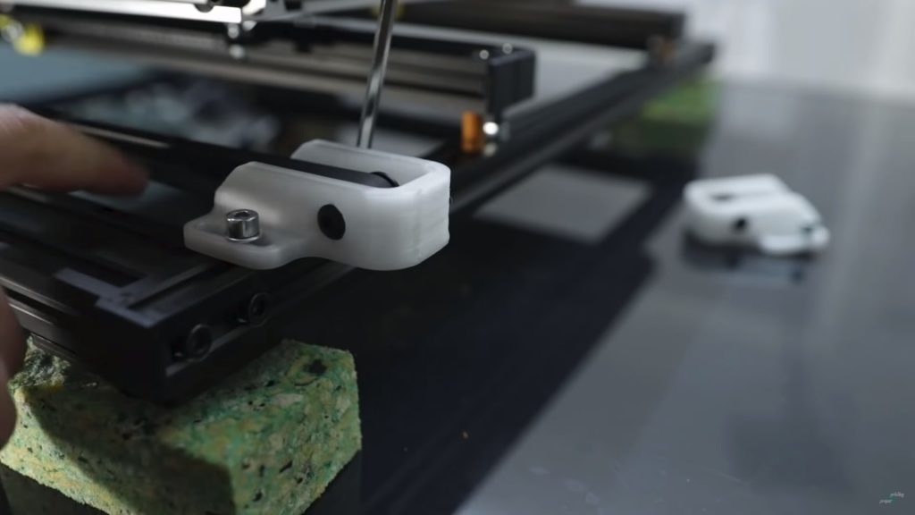
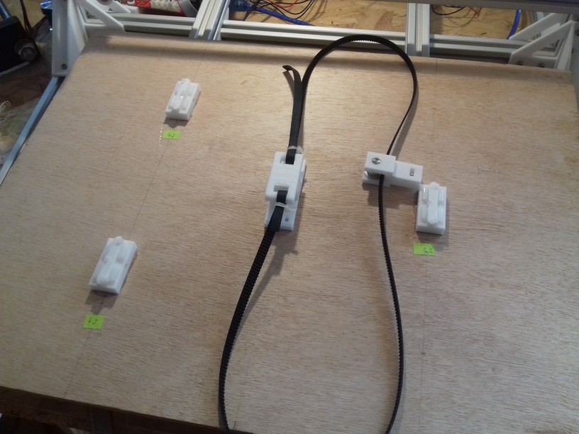
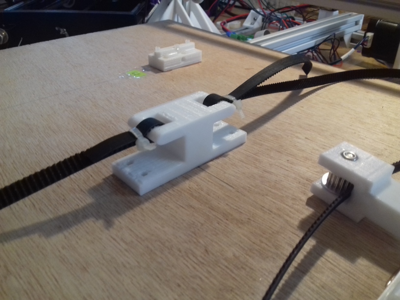
Y belt end 
Single Y motor, 8mm rod to drive two Y belts 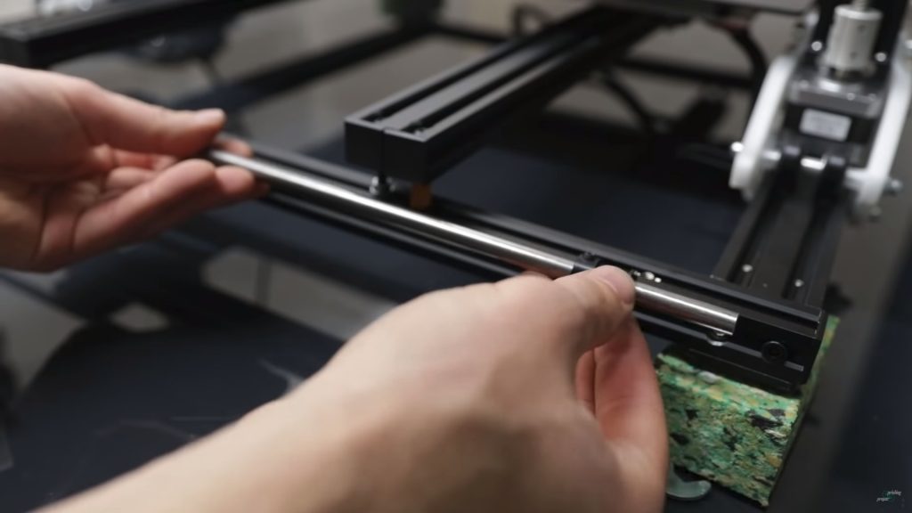
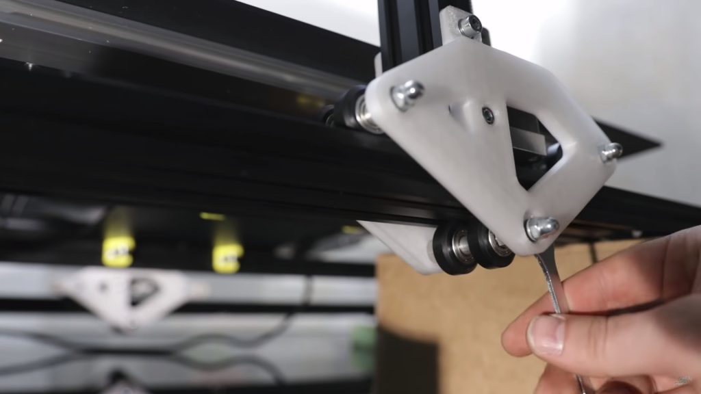
XZ frame Y Mount 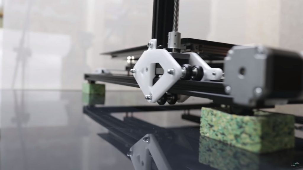
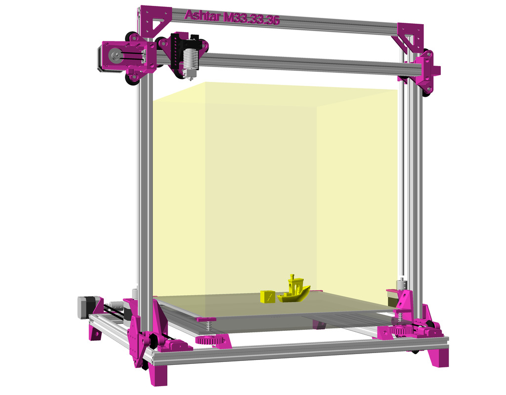
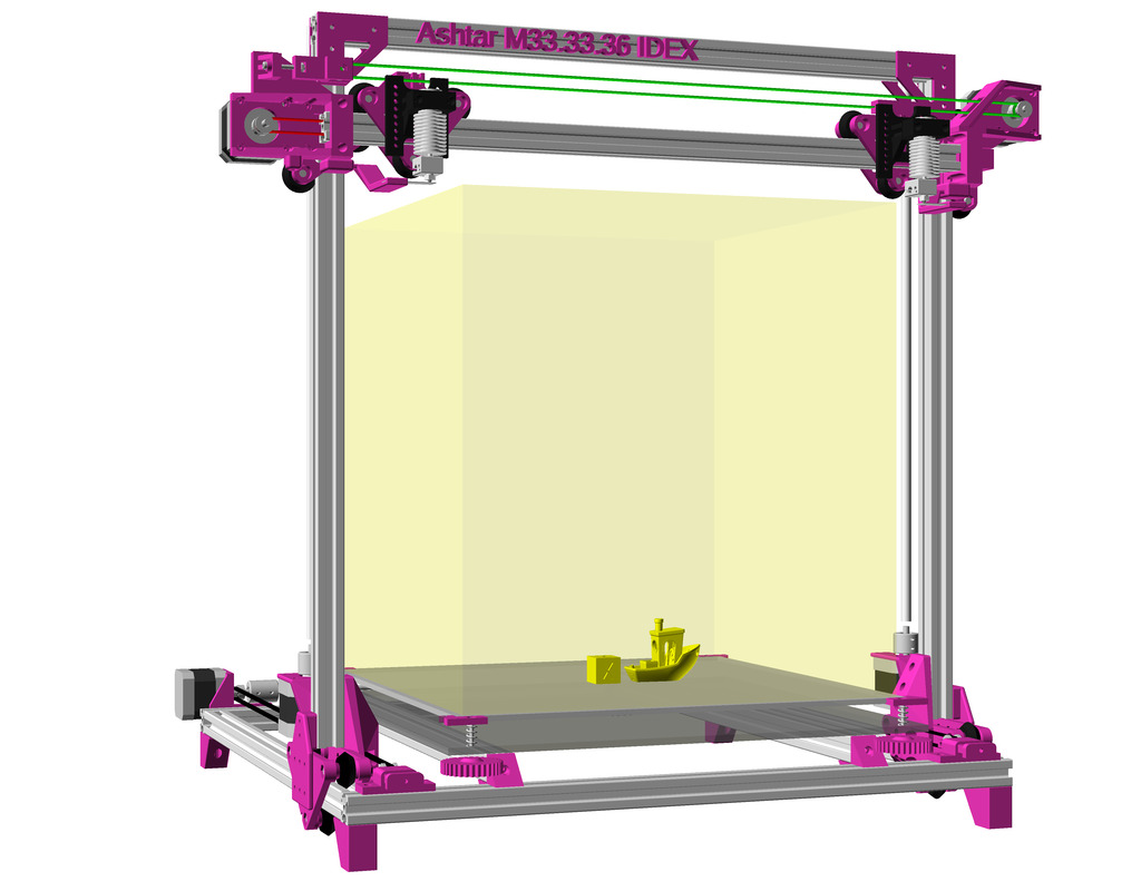
Moving Portal / XZ Frame


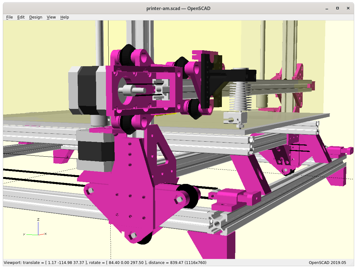
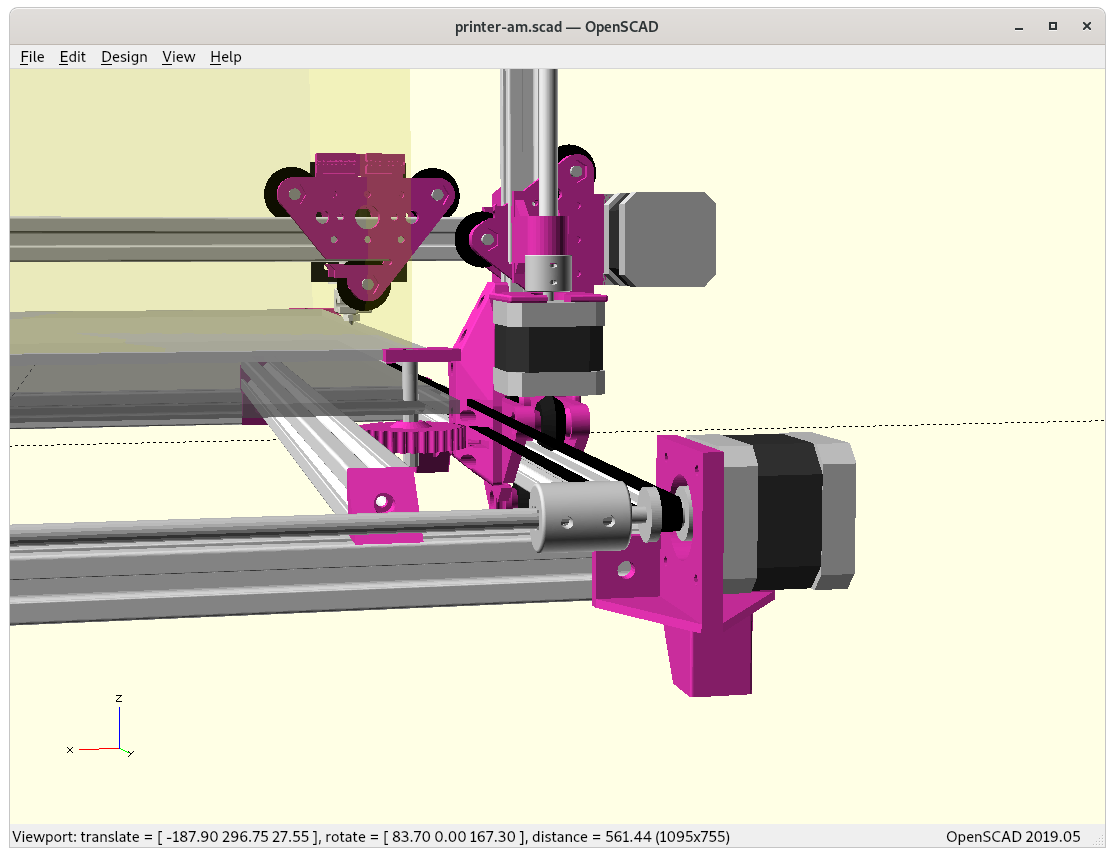
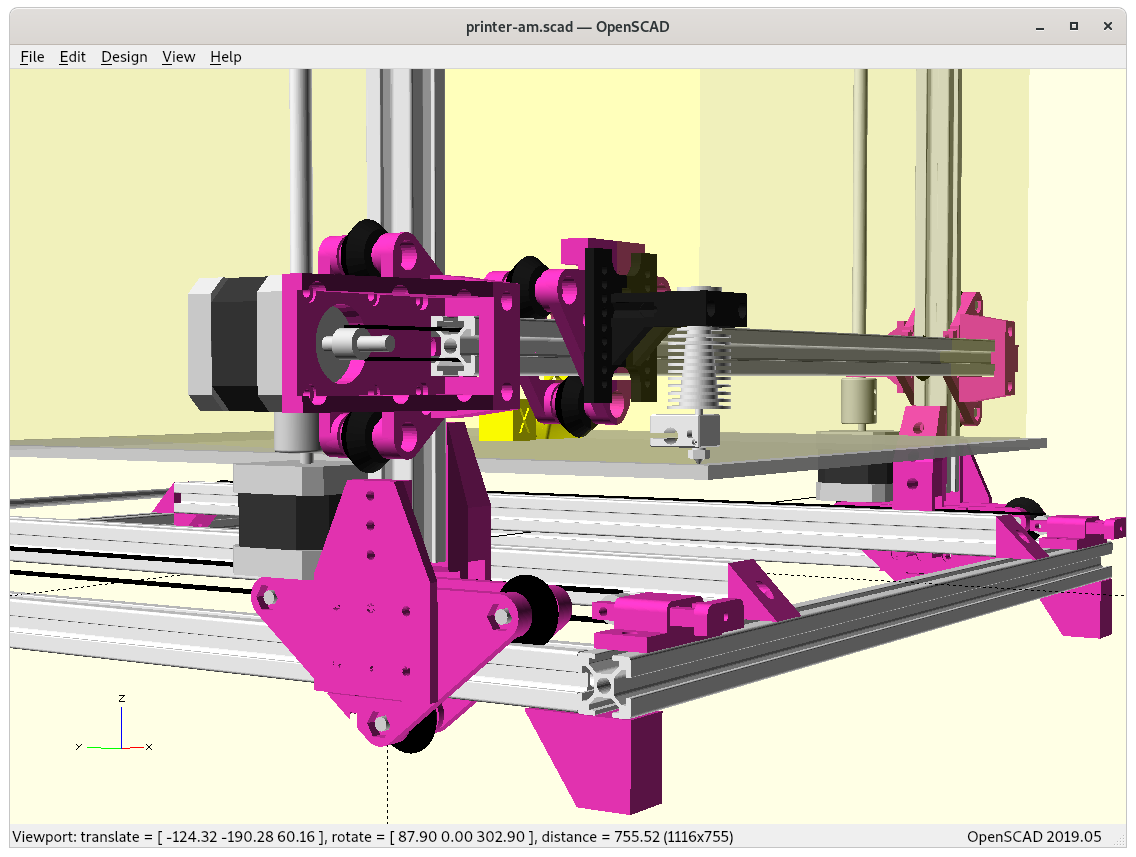
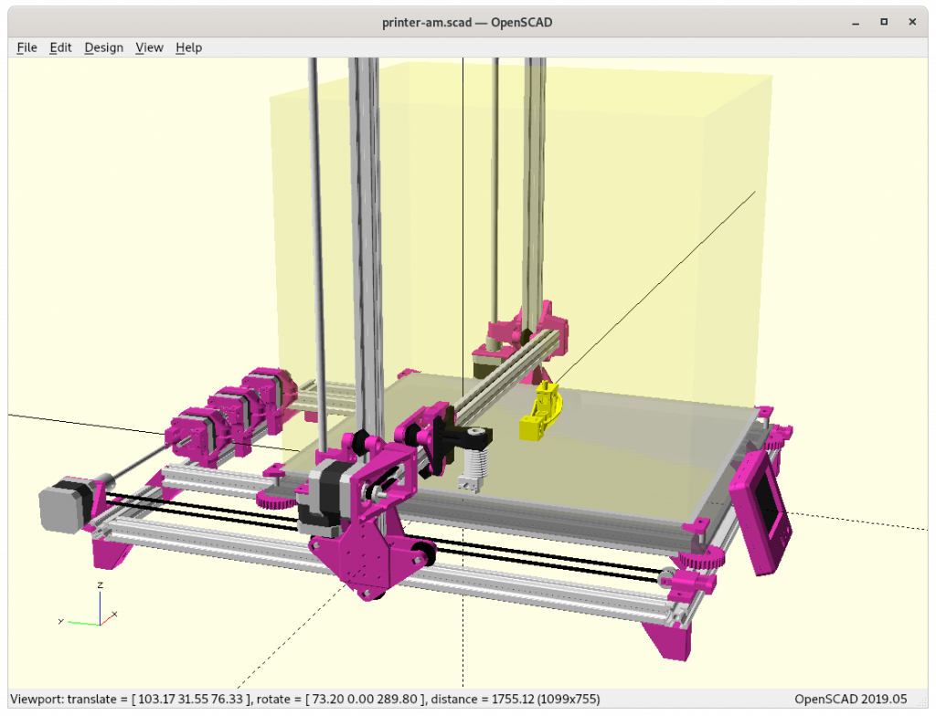
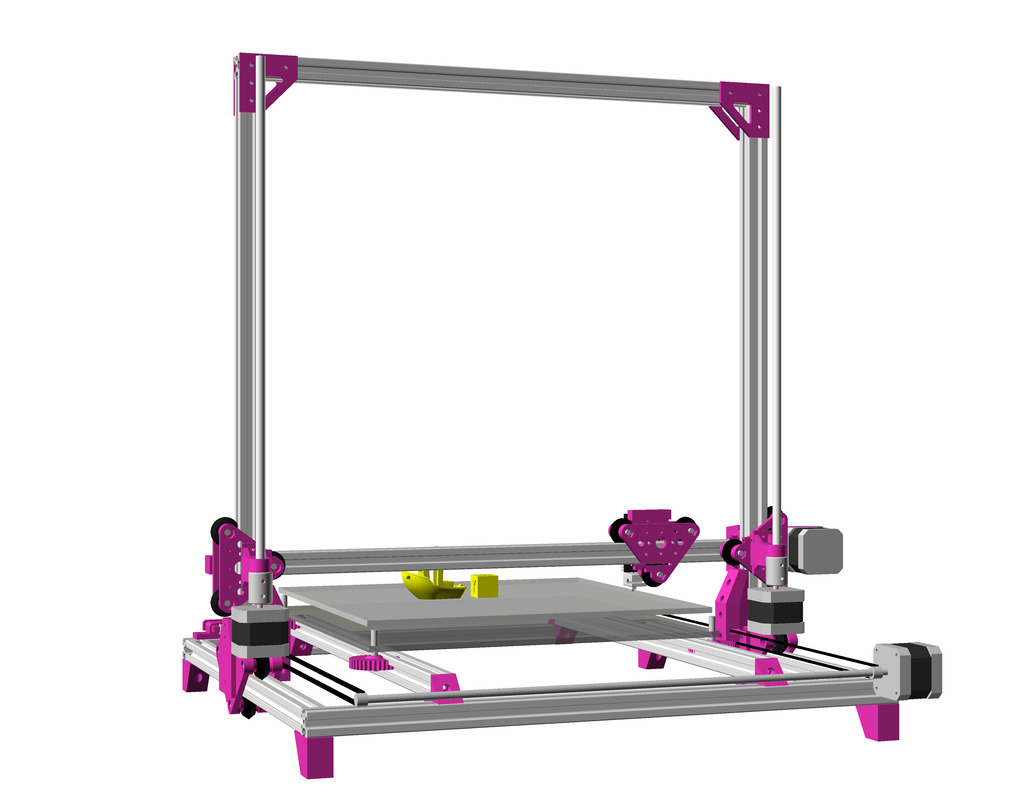
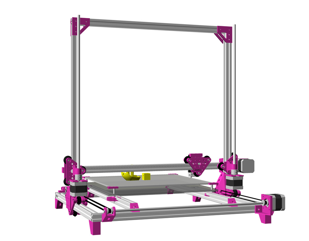
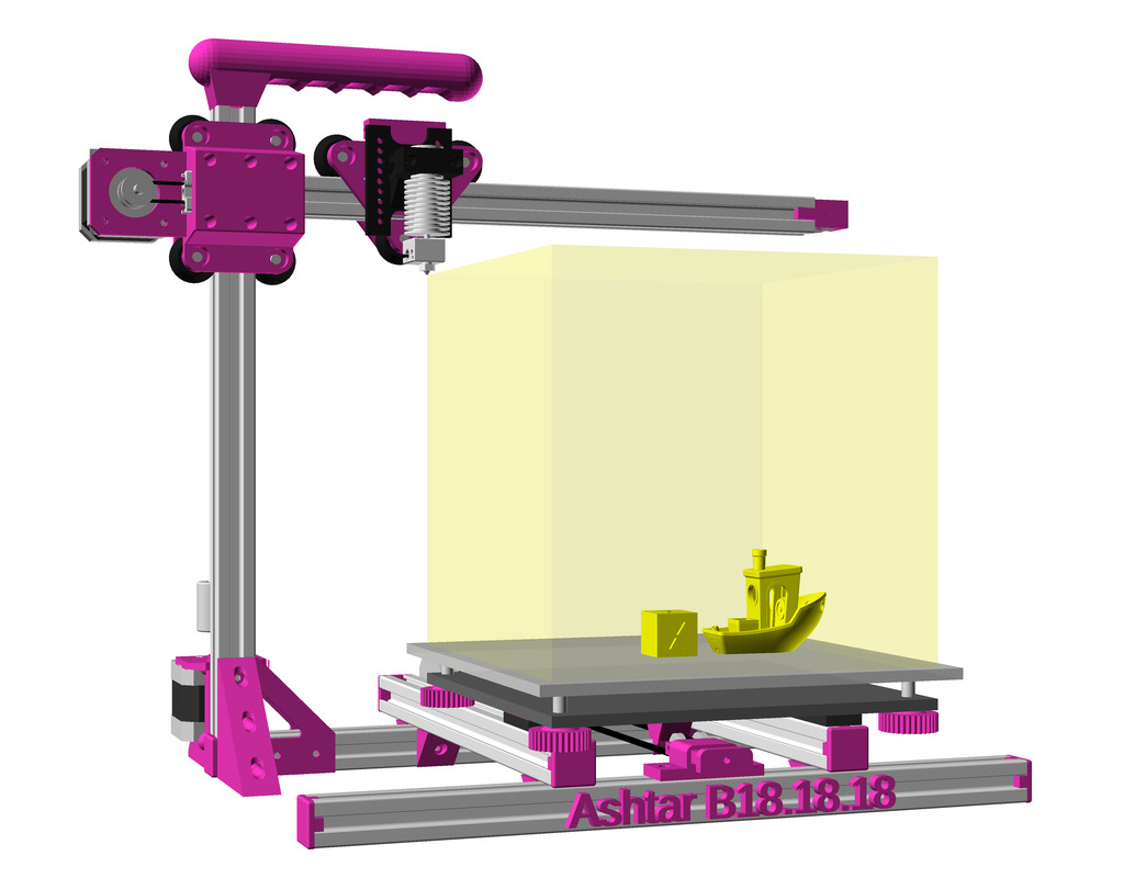
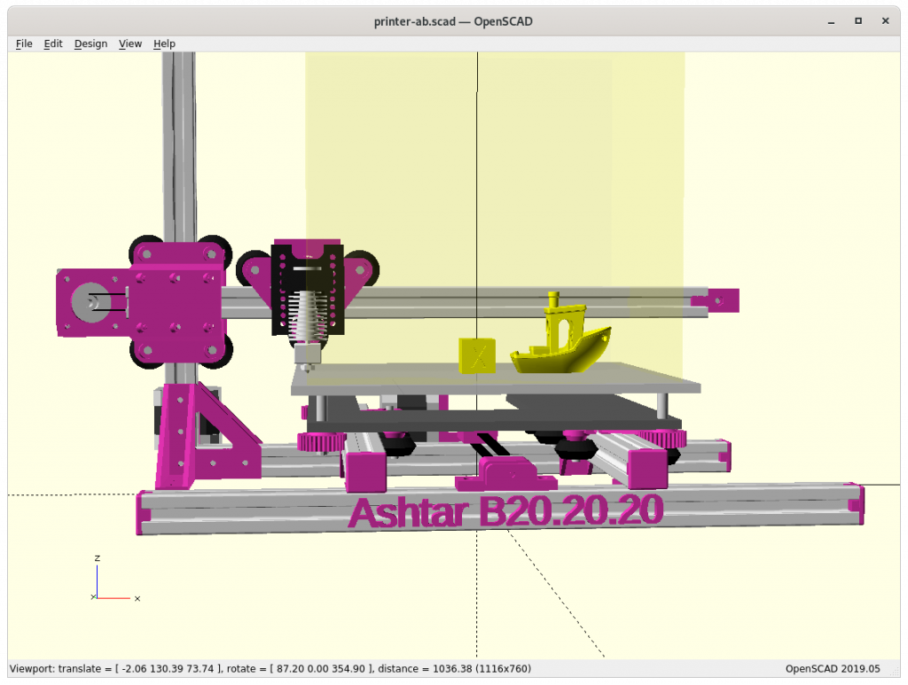
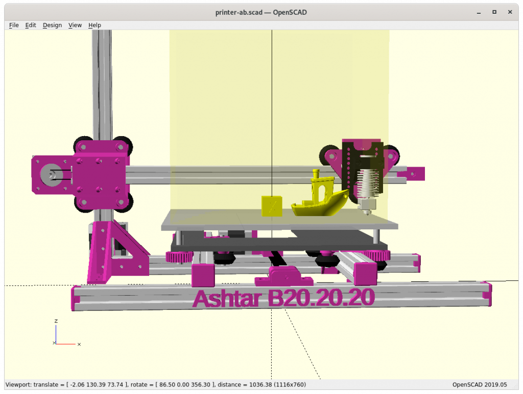
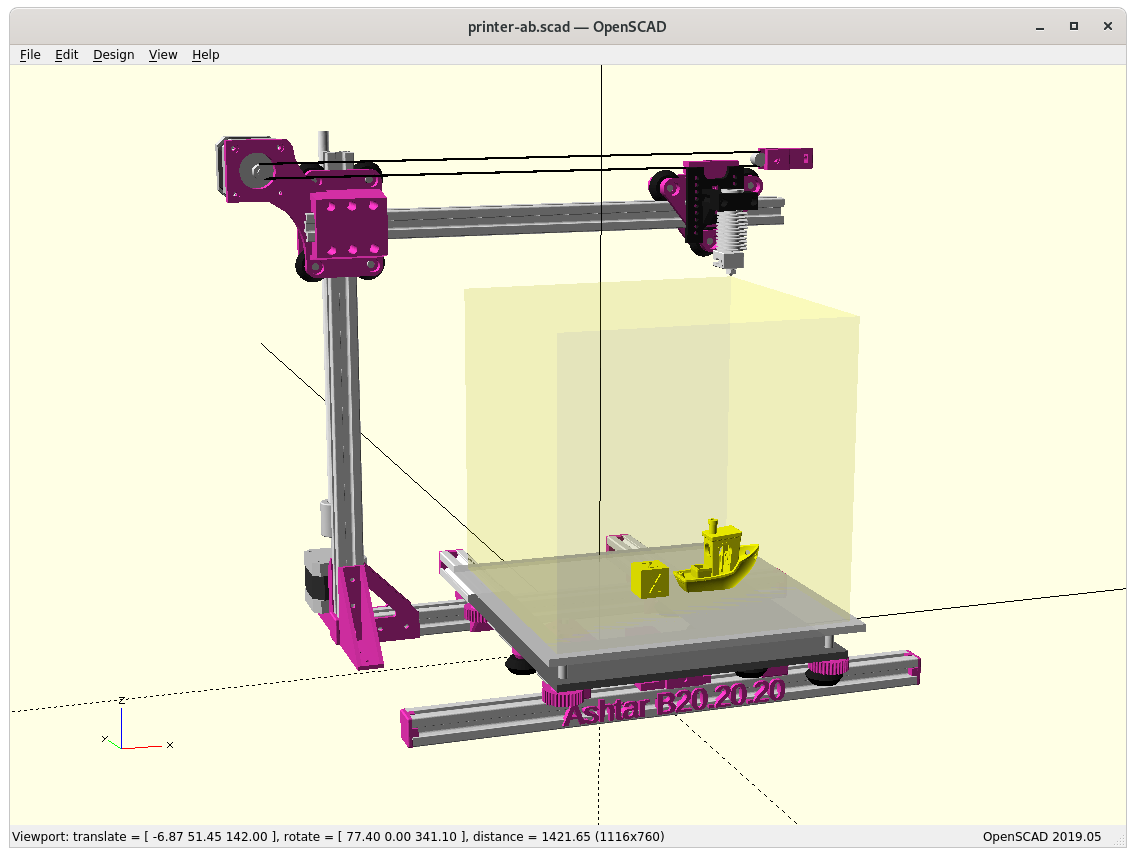
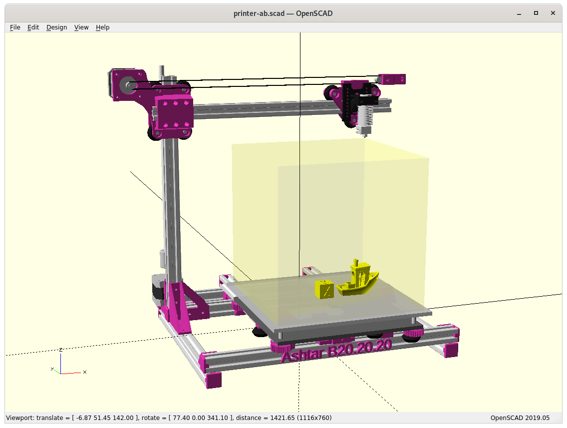
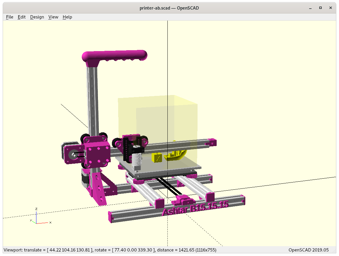
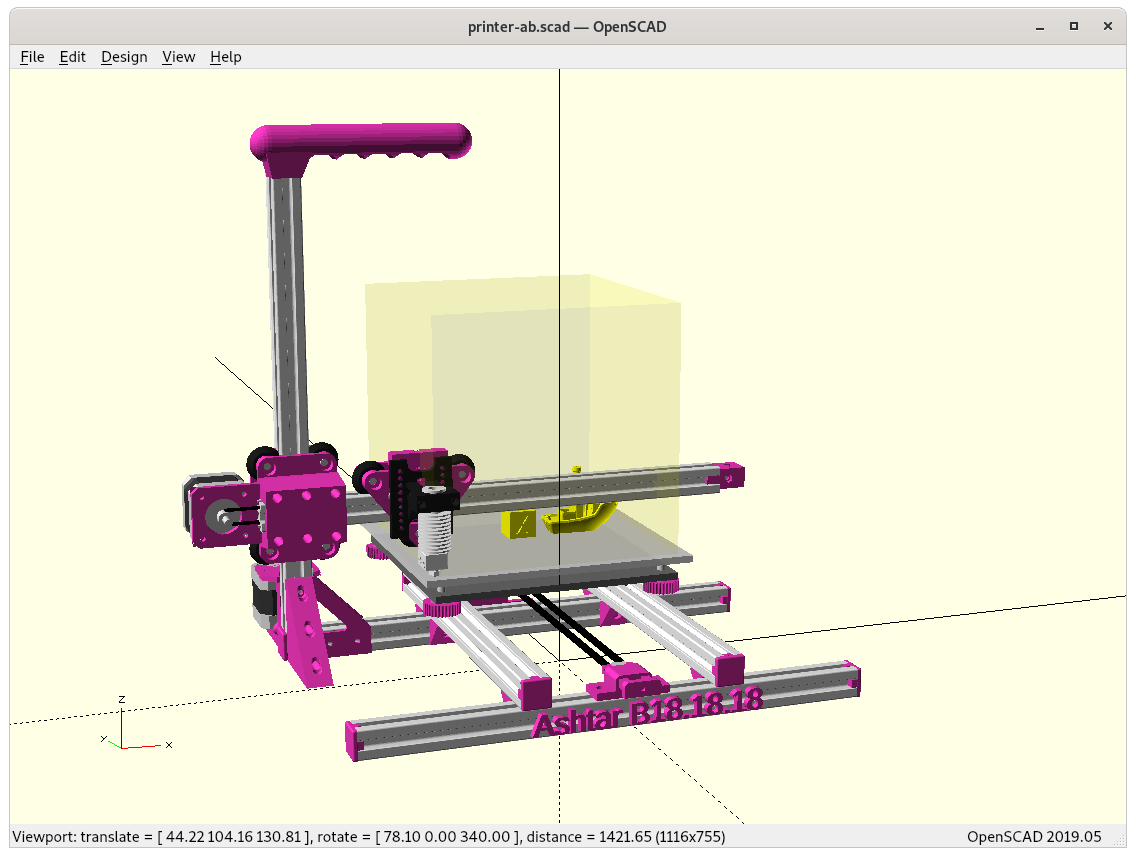
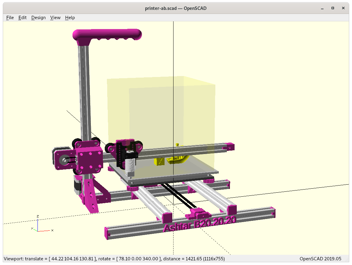
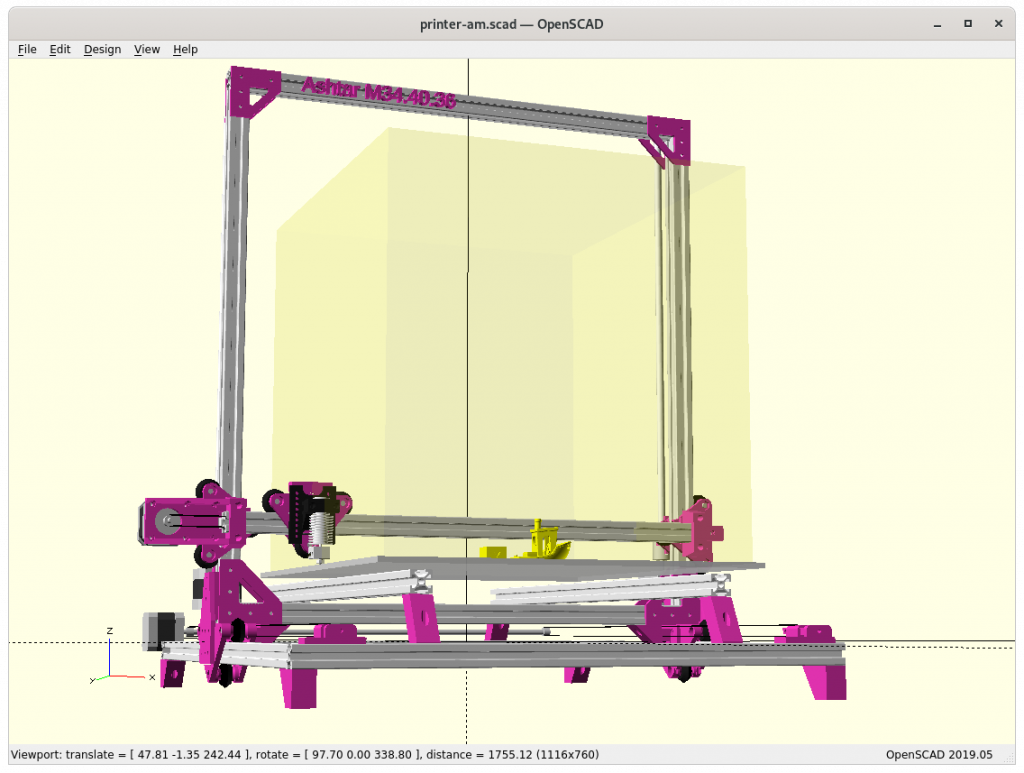
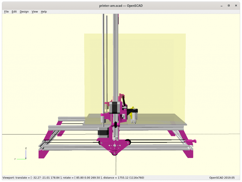
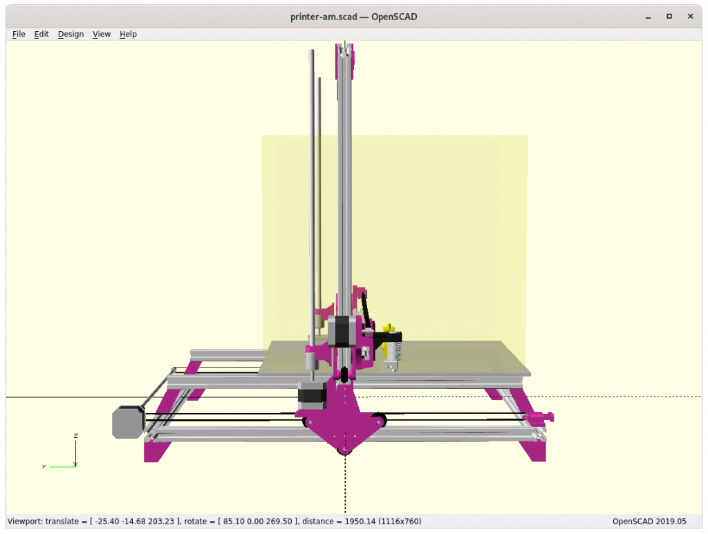
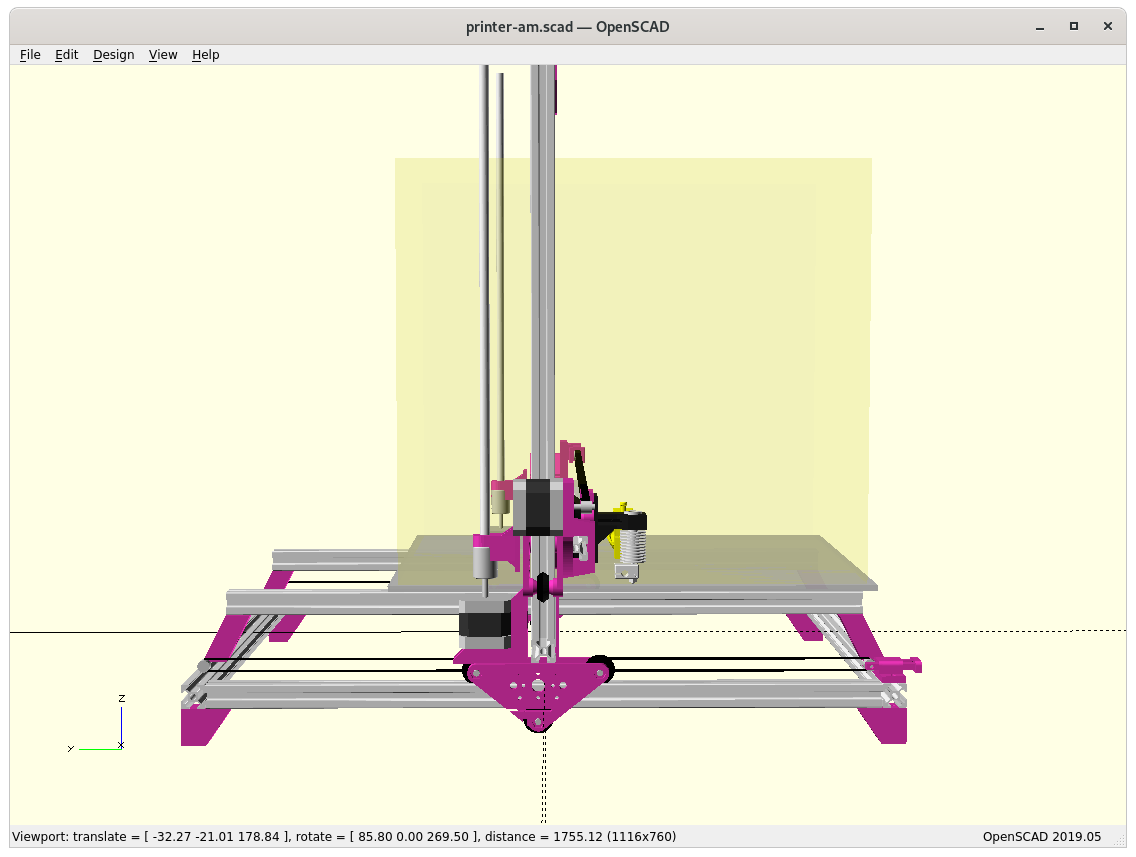
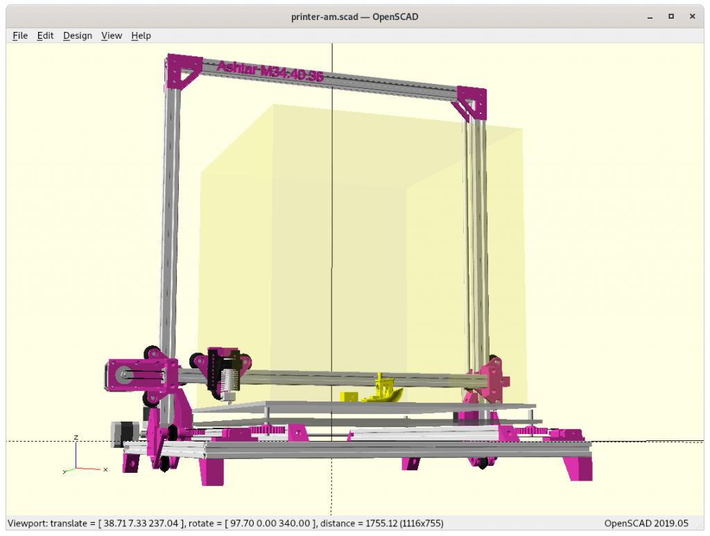
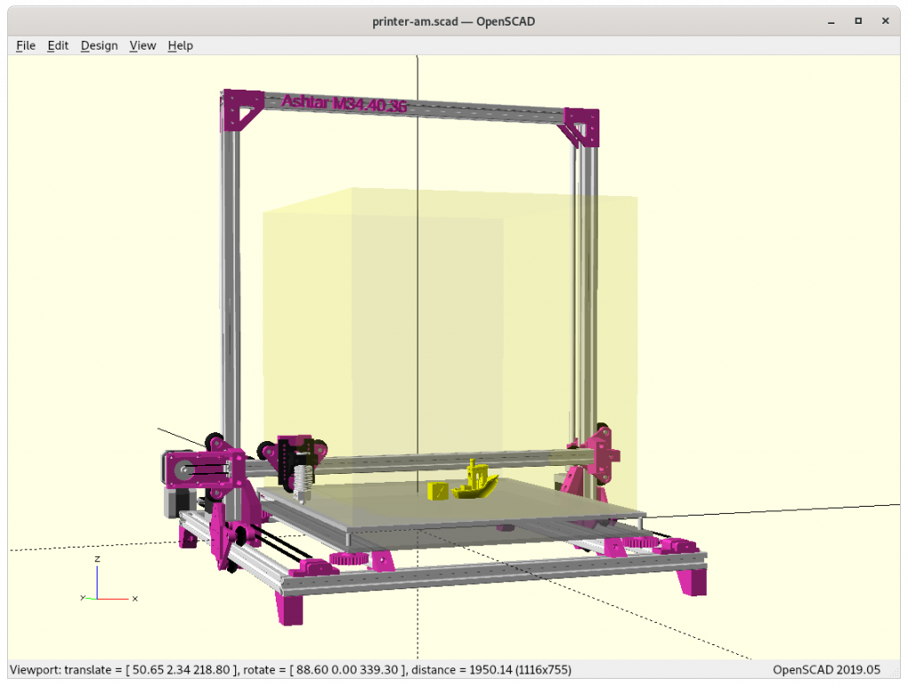
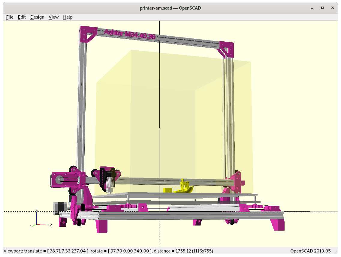
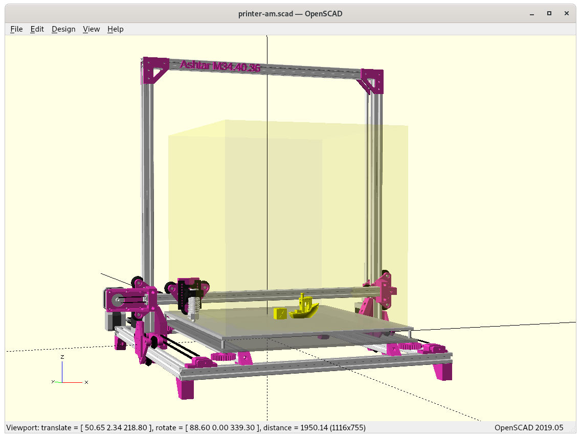
First Draft
- using solely 500mm 2020 alu extrusions (T-slot for general frame and XZ frame, V-slot for carriages: X beam, 2x Y beams)
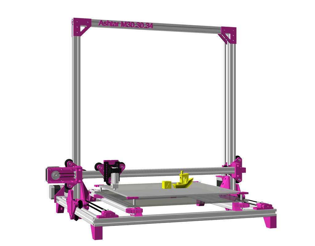
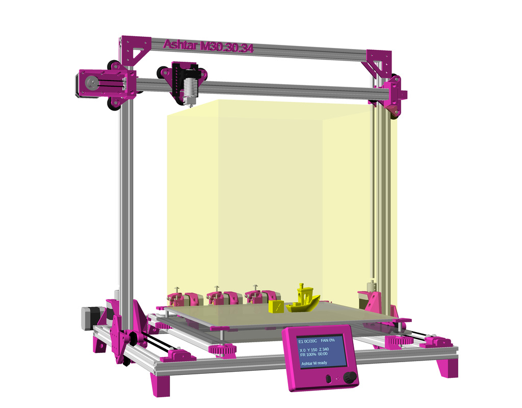
- trying to achieve 400x400x400mm build volume as close as possible, alike Ashtar C 38.40.36
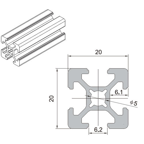
T-Slot 2020 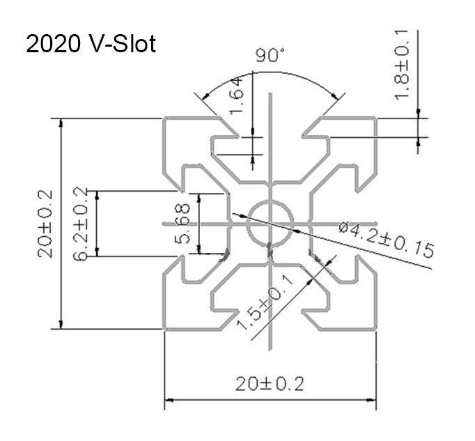
V-Slot 2020 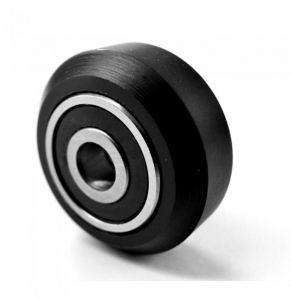
V wheel
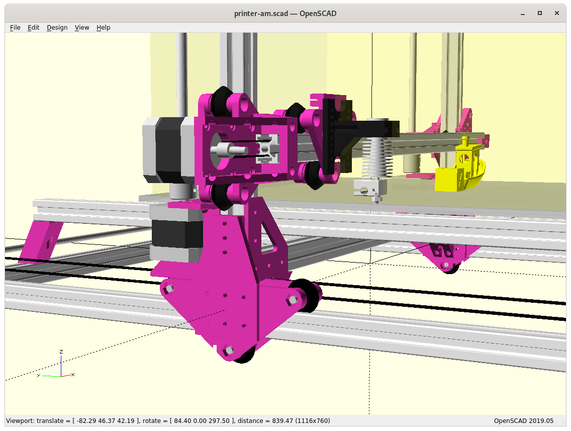
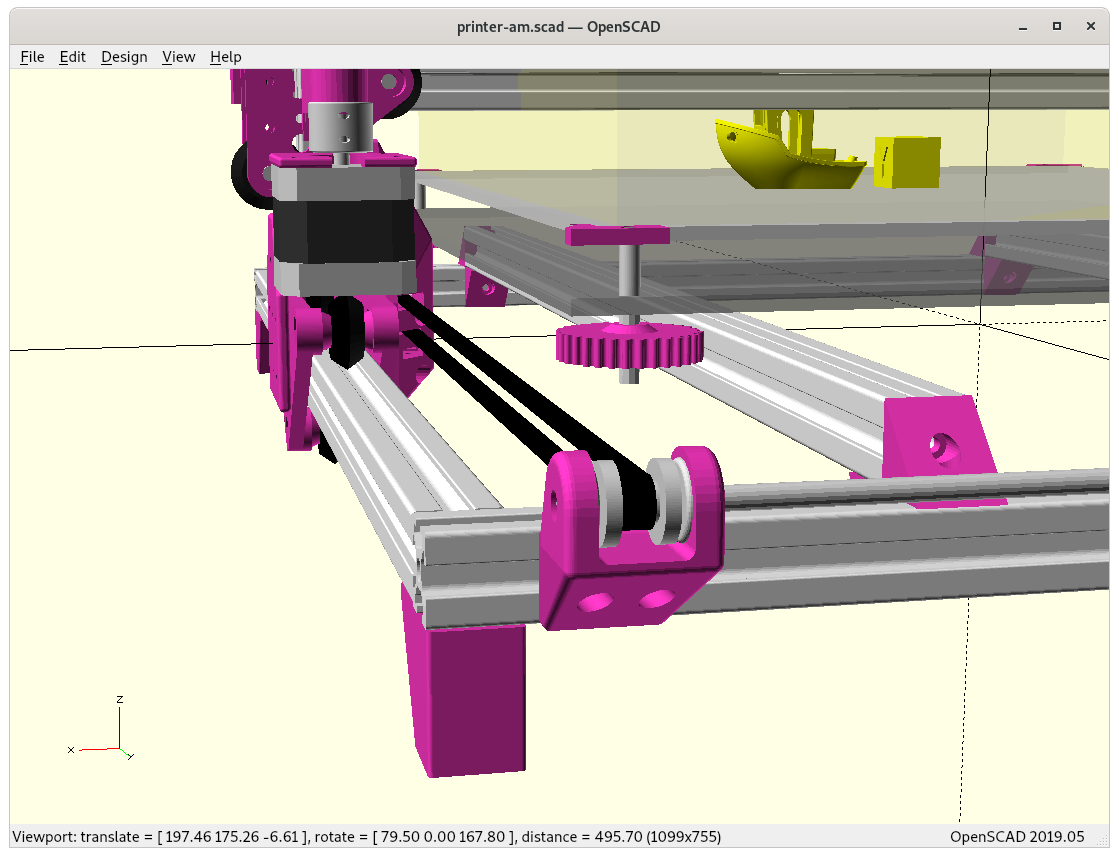
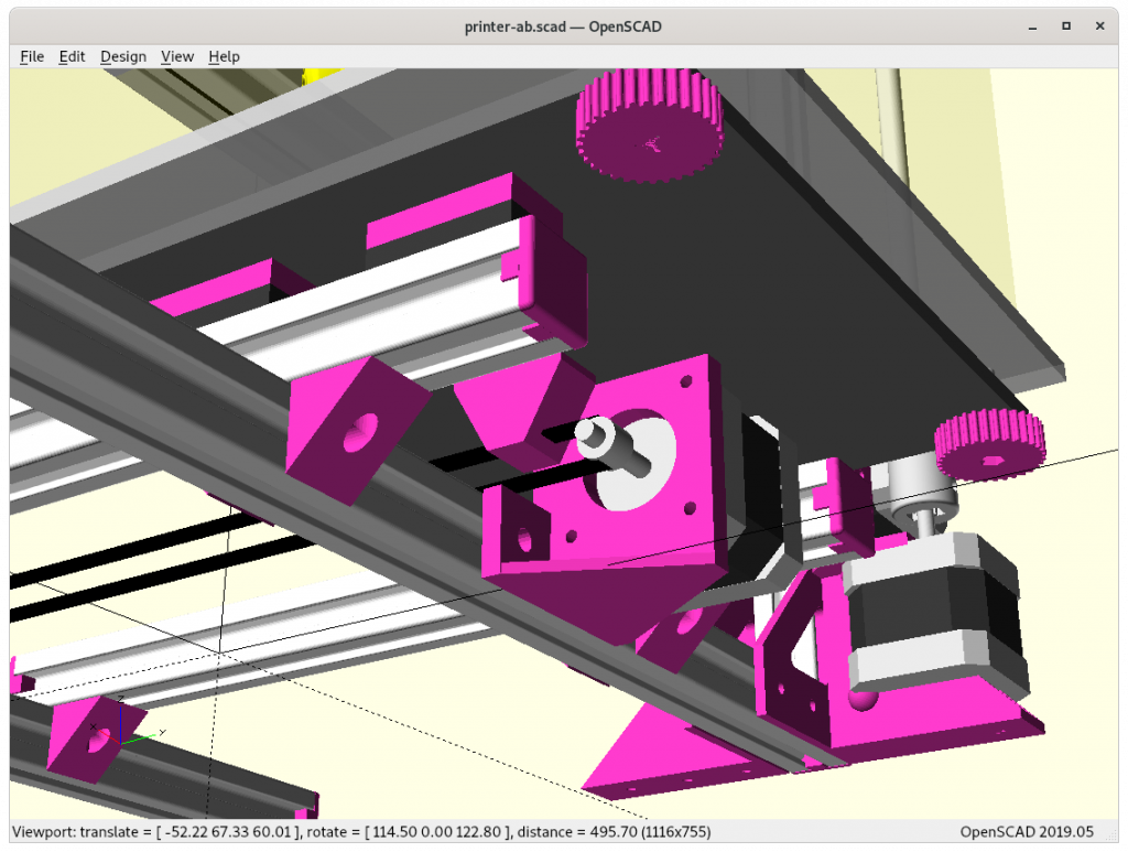
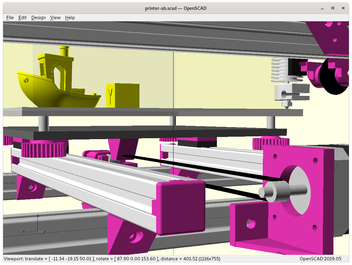
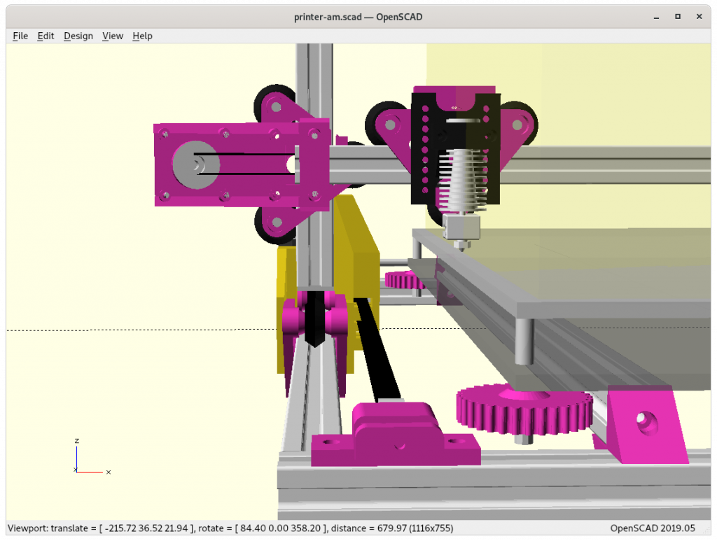
Using for Y carriages existing vcarriage2 module with vcarriage2(width=100) to have it wide enough:

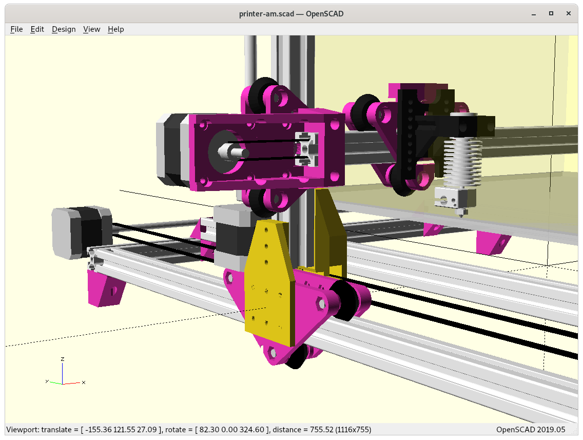
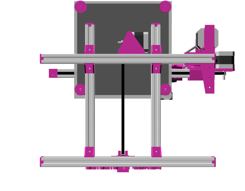
Bare view on Y carriage with XZ frame 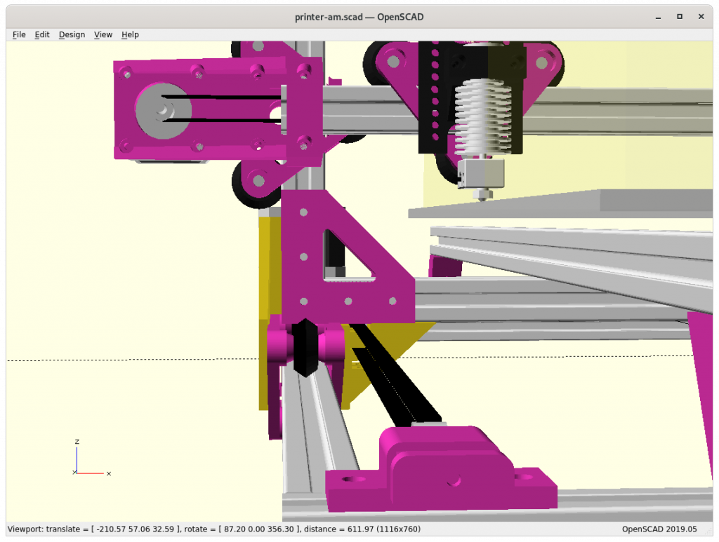
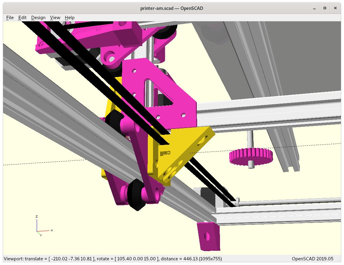
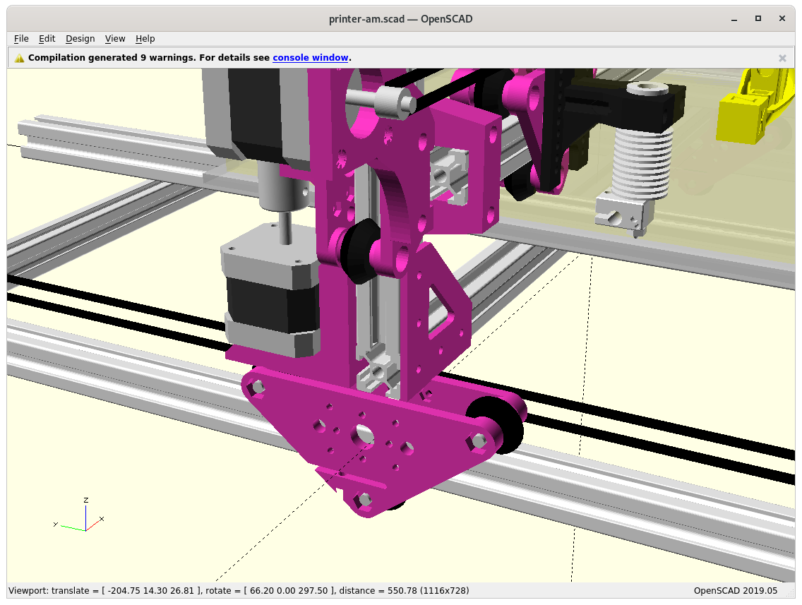
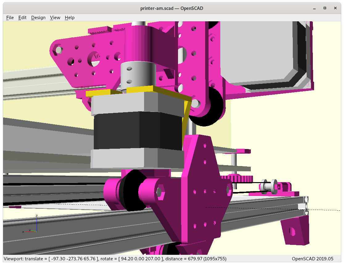
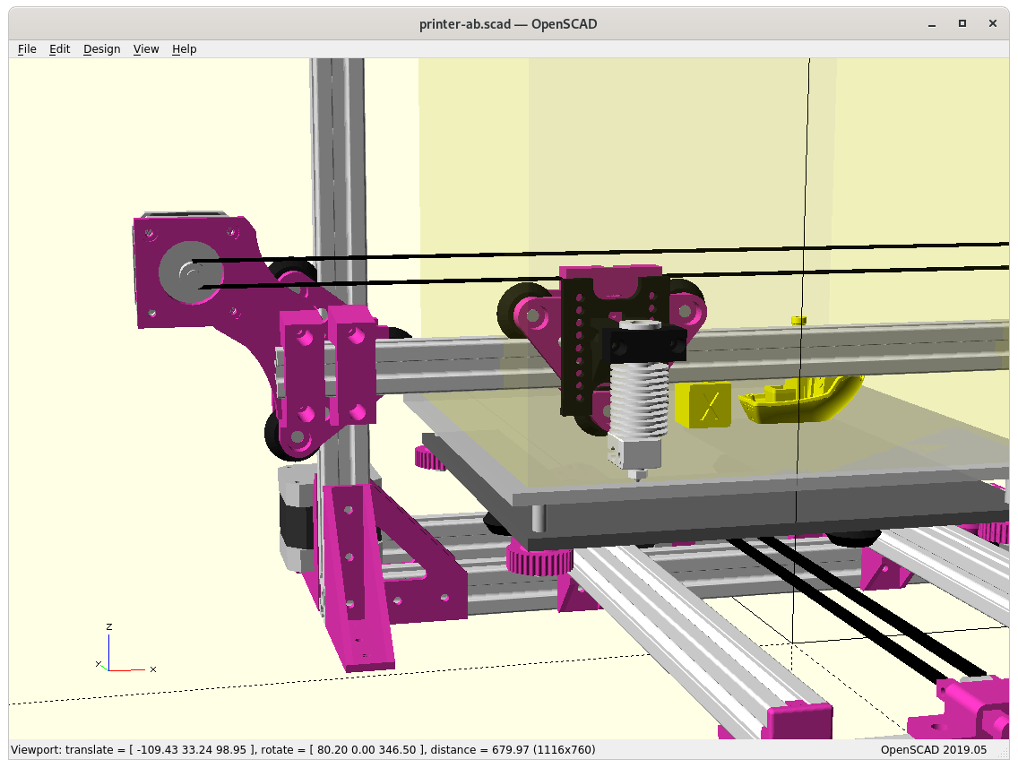
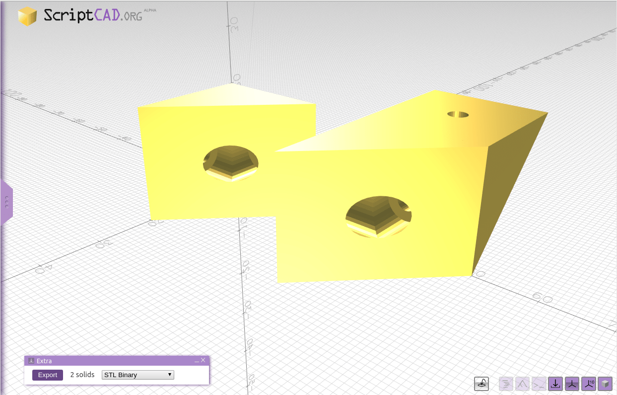
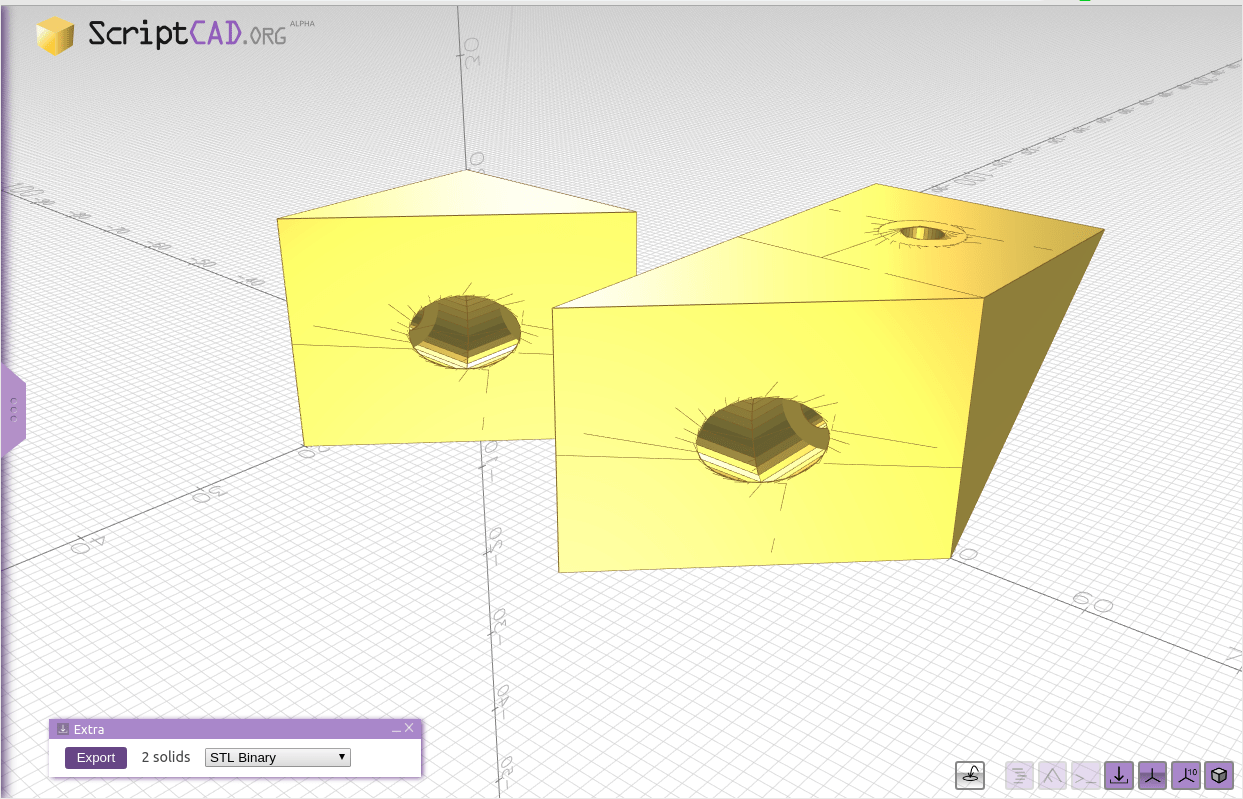
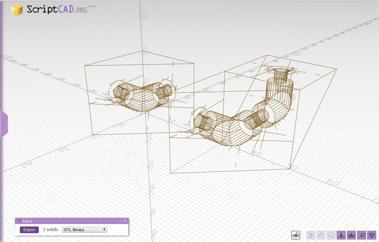
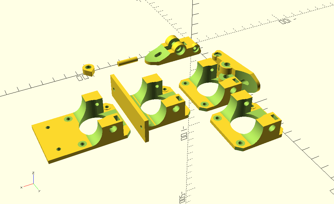
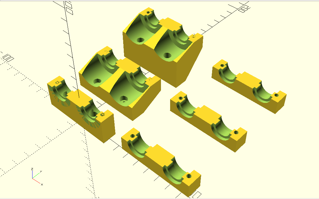
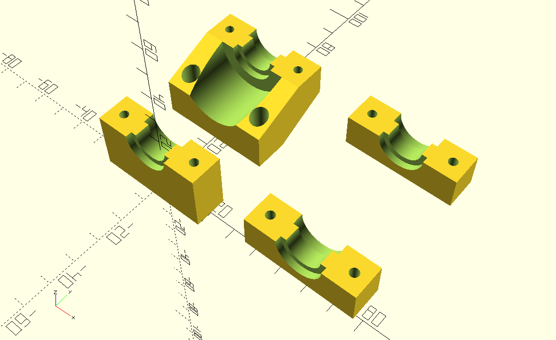
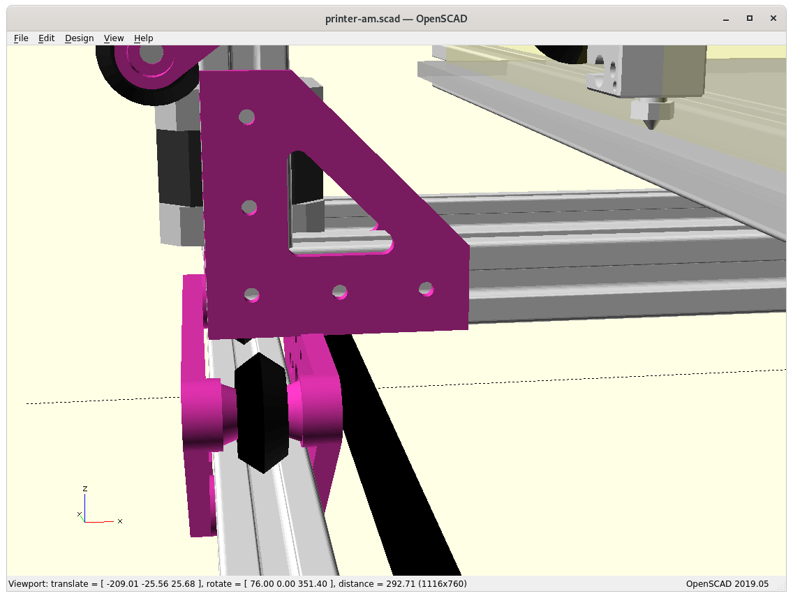
Adding side pieces “A” & “B” 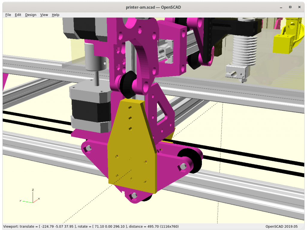
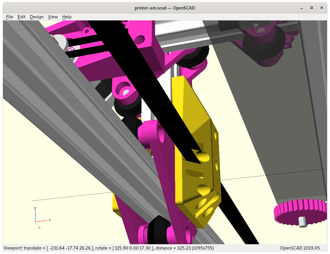
Piece “A” connecting Y carriage with XZ frame 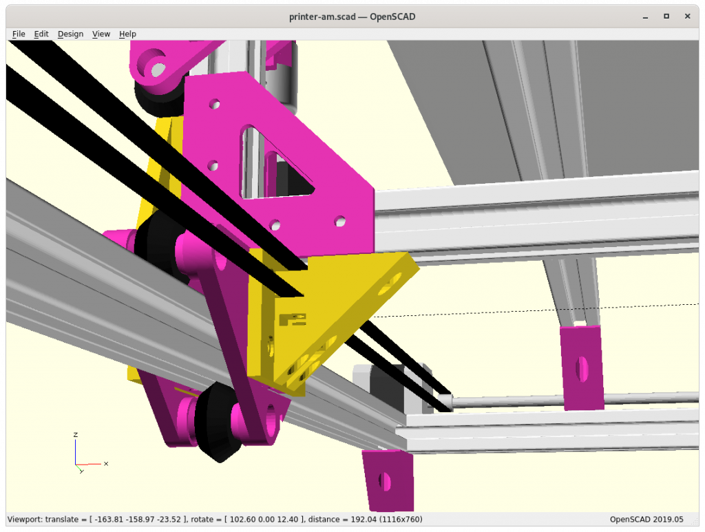
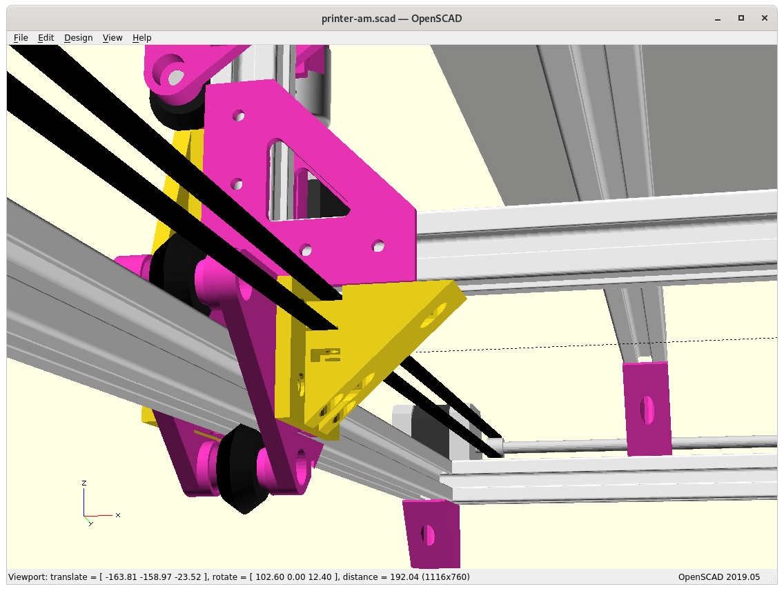
Piece “B” connecting Y carriage with XZ frame 
Piece “B” bottom view 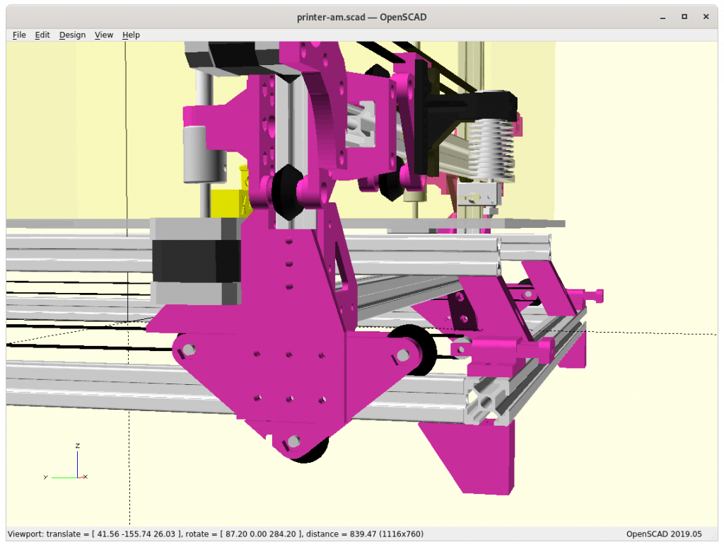
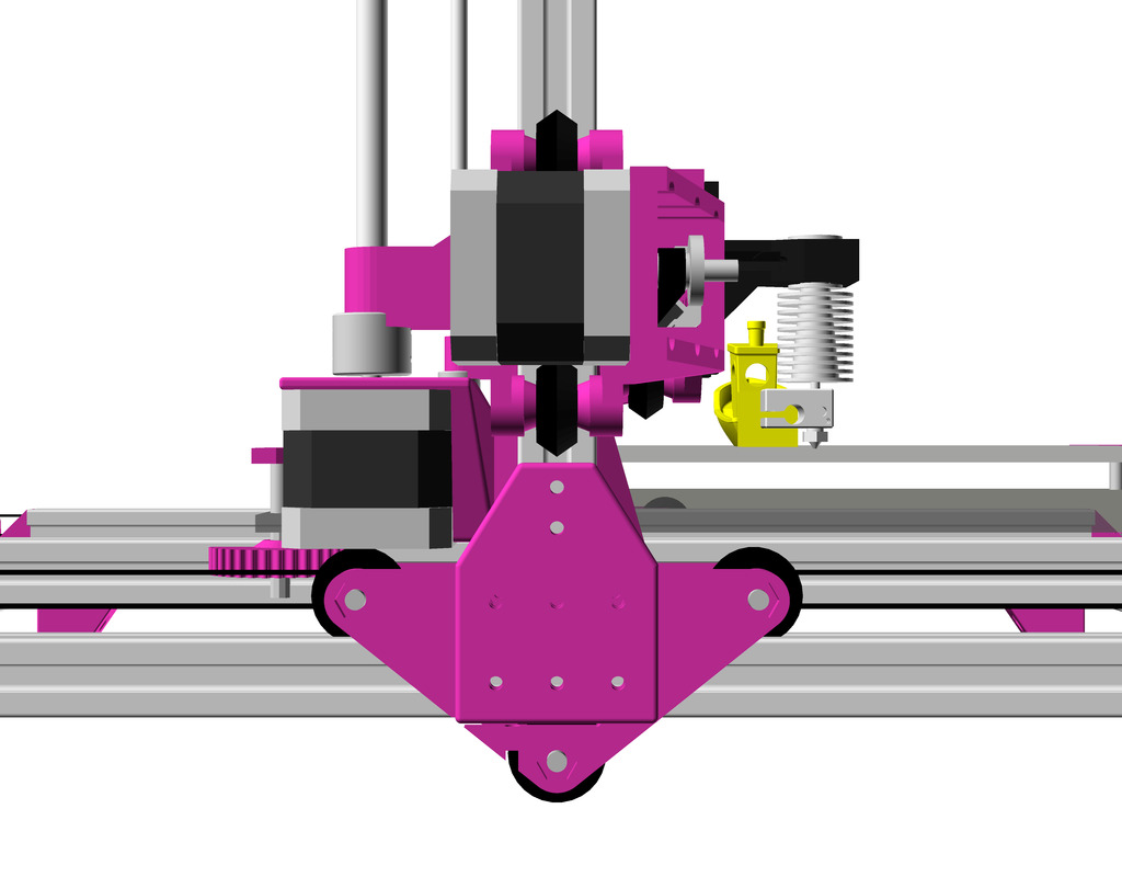
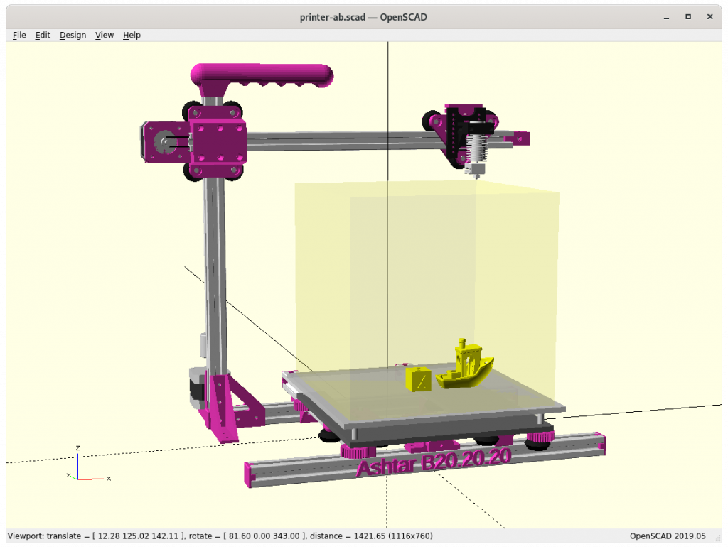
At position 0,0,0 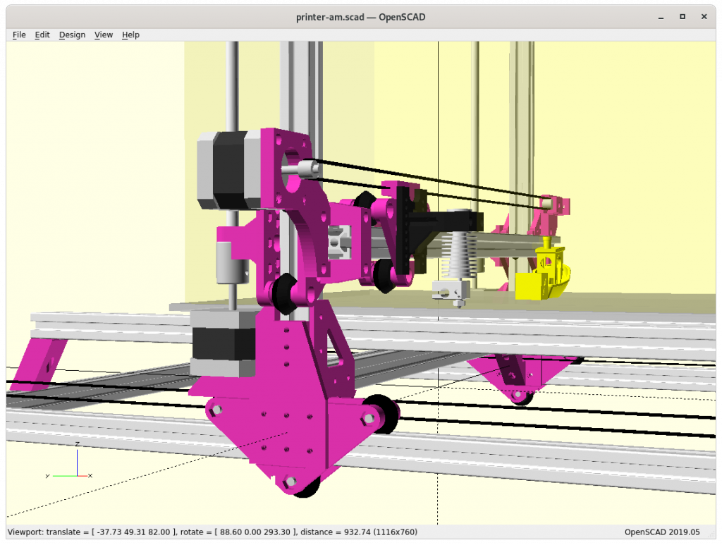


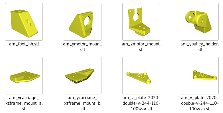
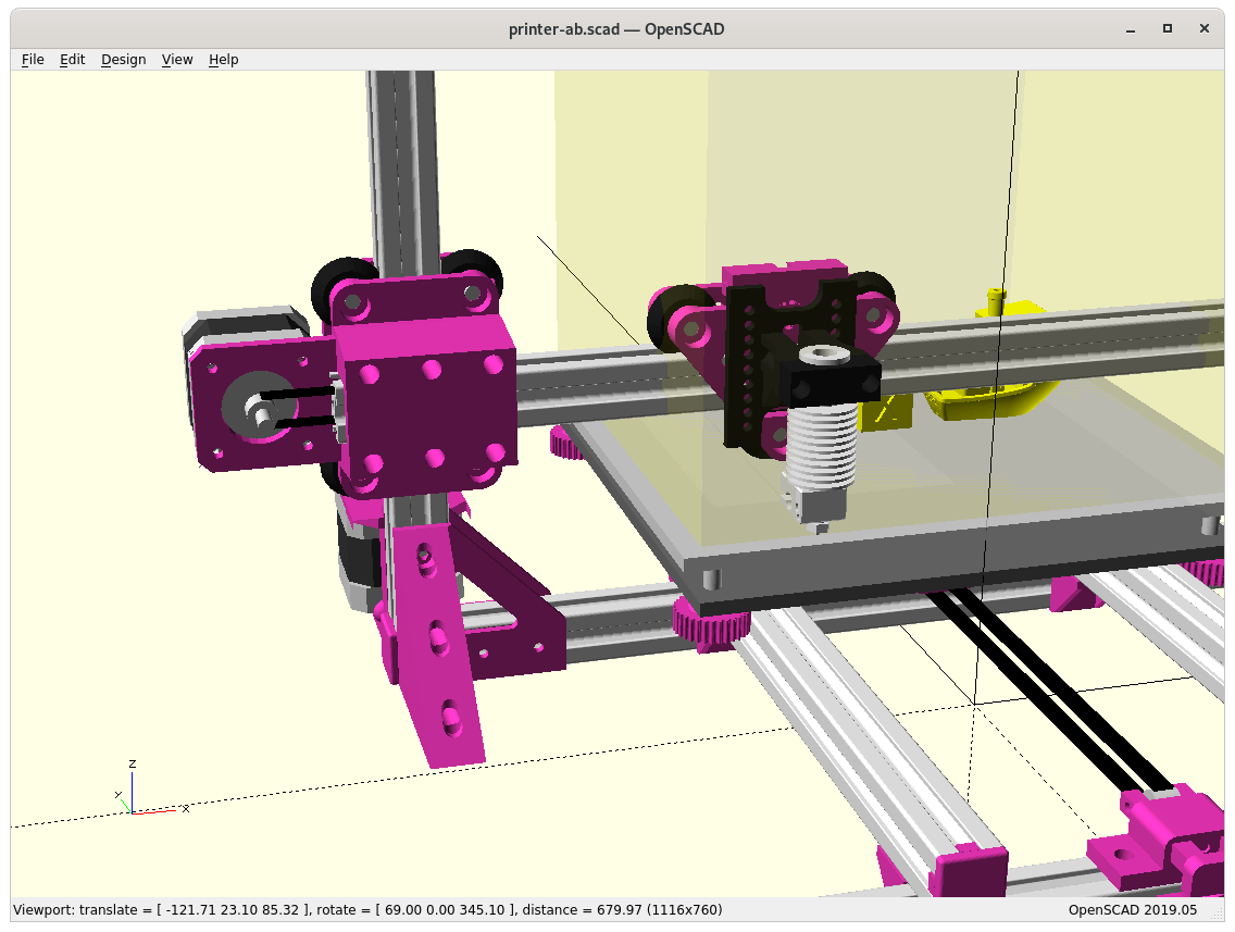
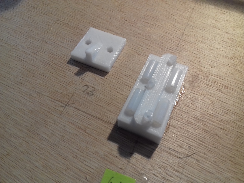
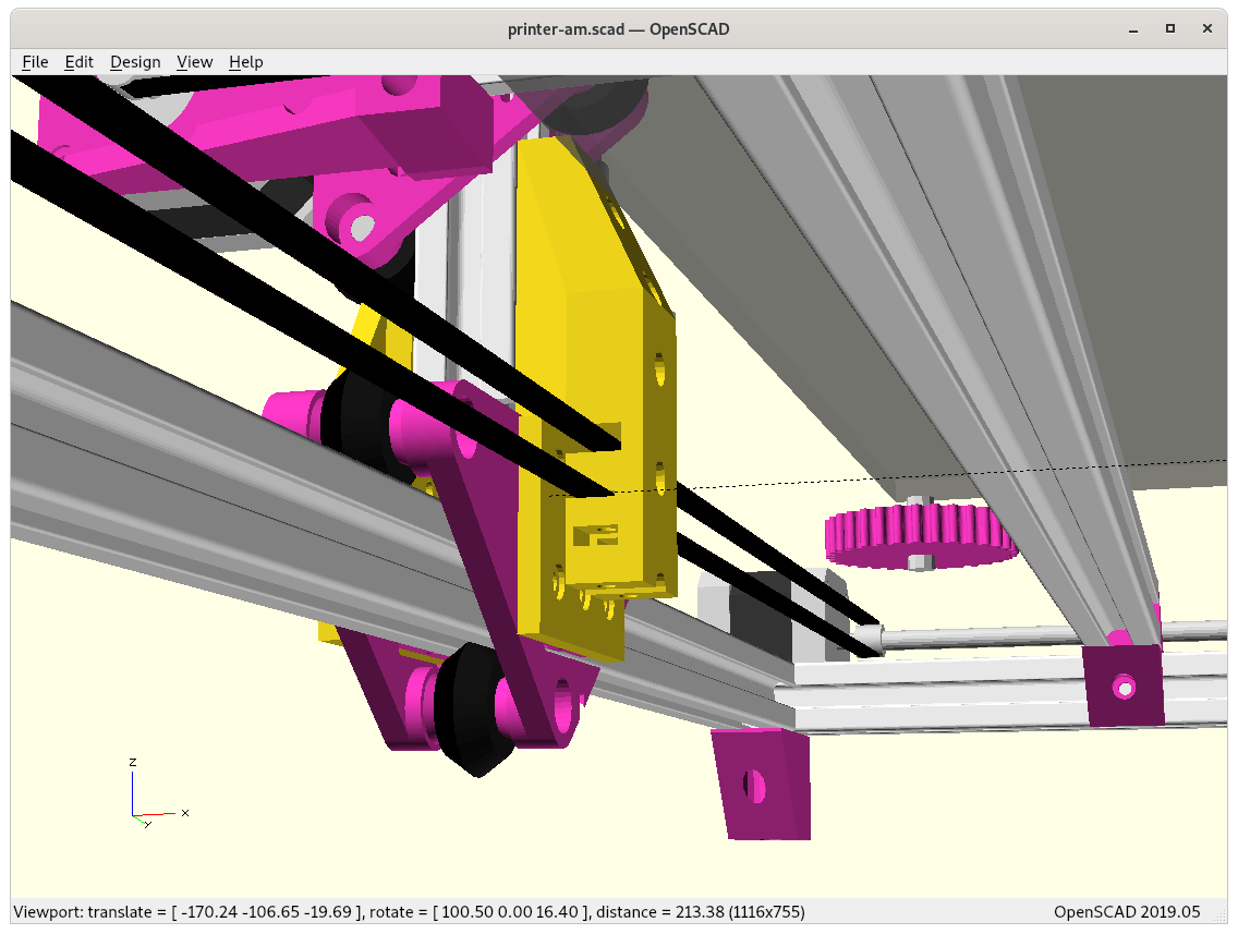
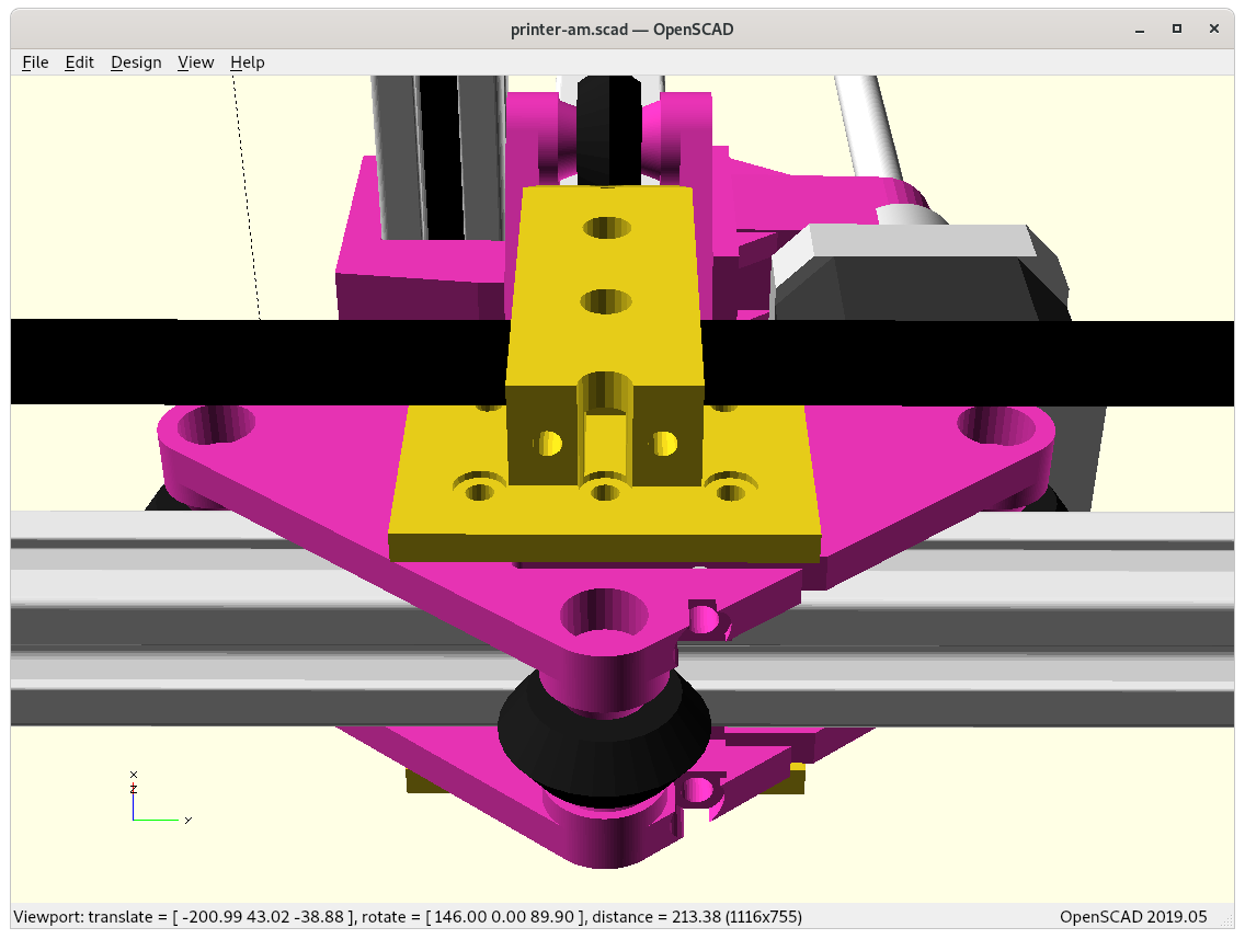
The two main new pieces required were connecting the Y carriage with the XZ frame:
- Piece “A” outside
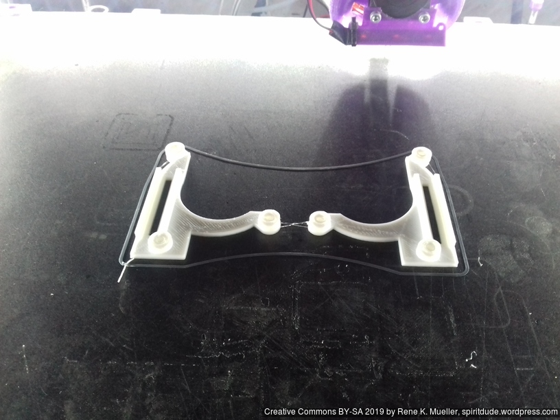
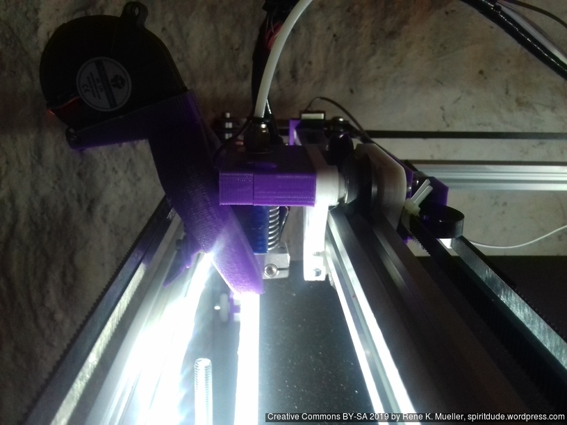
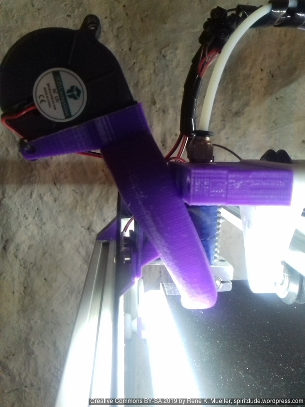
ycarriage_xzframe_mount_a(): has to be printed with 0.1mm layer height in order to stay within the +/- 0.05mm tolerance, otherwise it will introduce tilt and stress on the Y carriage and cause long term damage – tricky part to print.
- Piece “B” inside
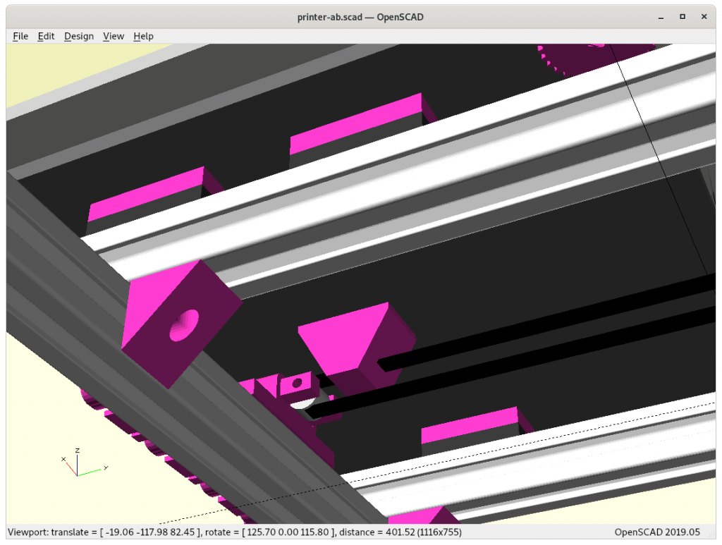
ycarriage_xzframe_mount_b(): is quite elaborate already and should be functional, with the Y belt ends fastening with M3 screws and M3 nuts inserts, the belt endings will come out downward:
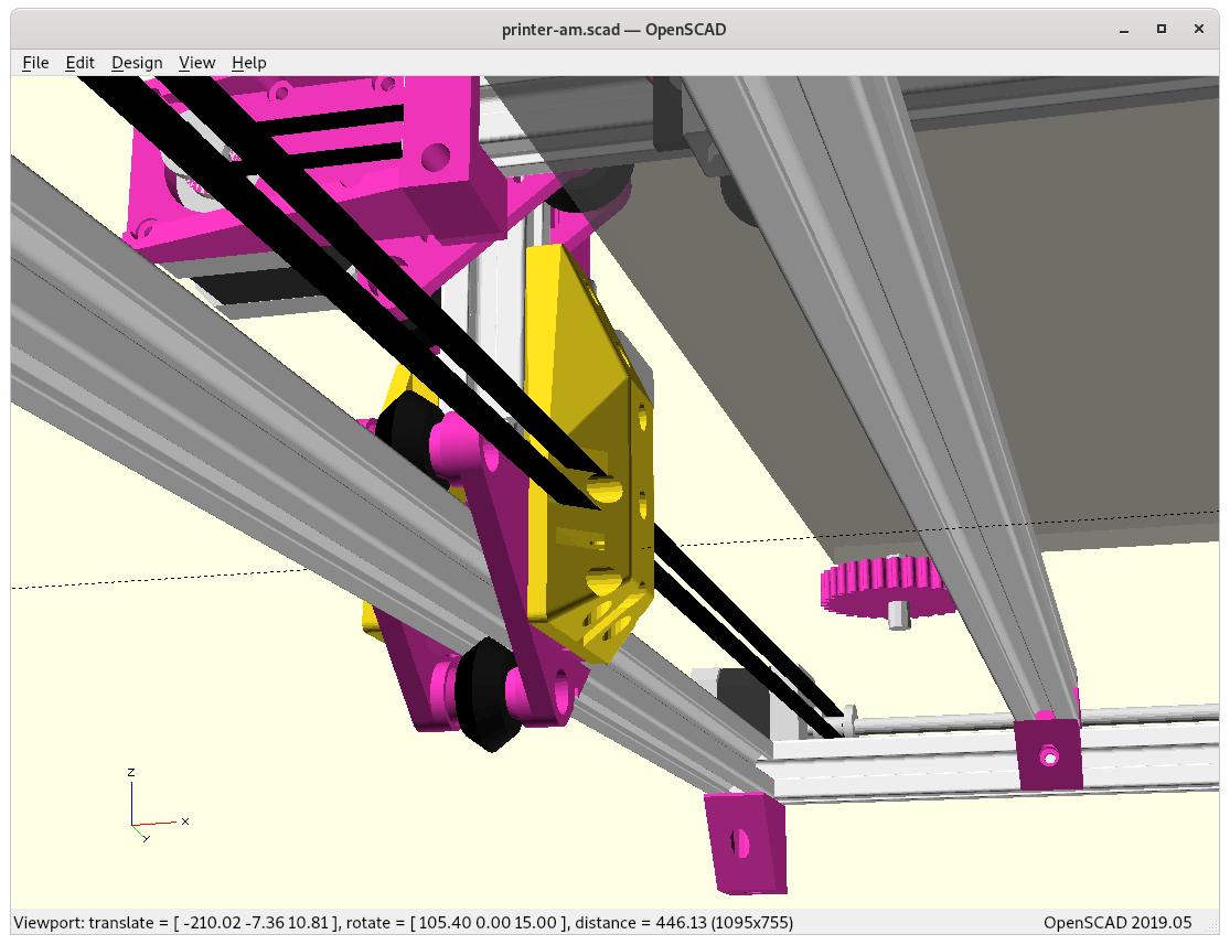
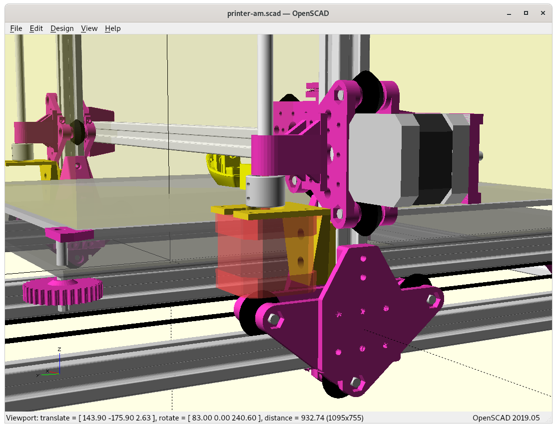
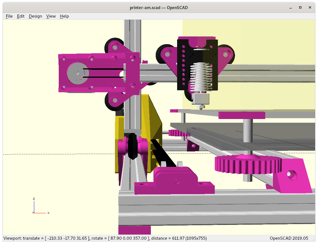
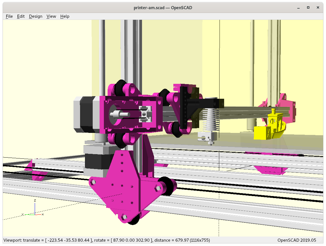
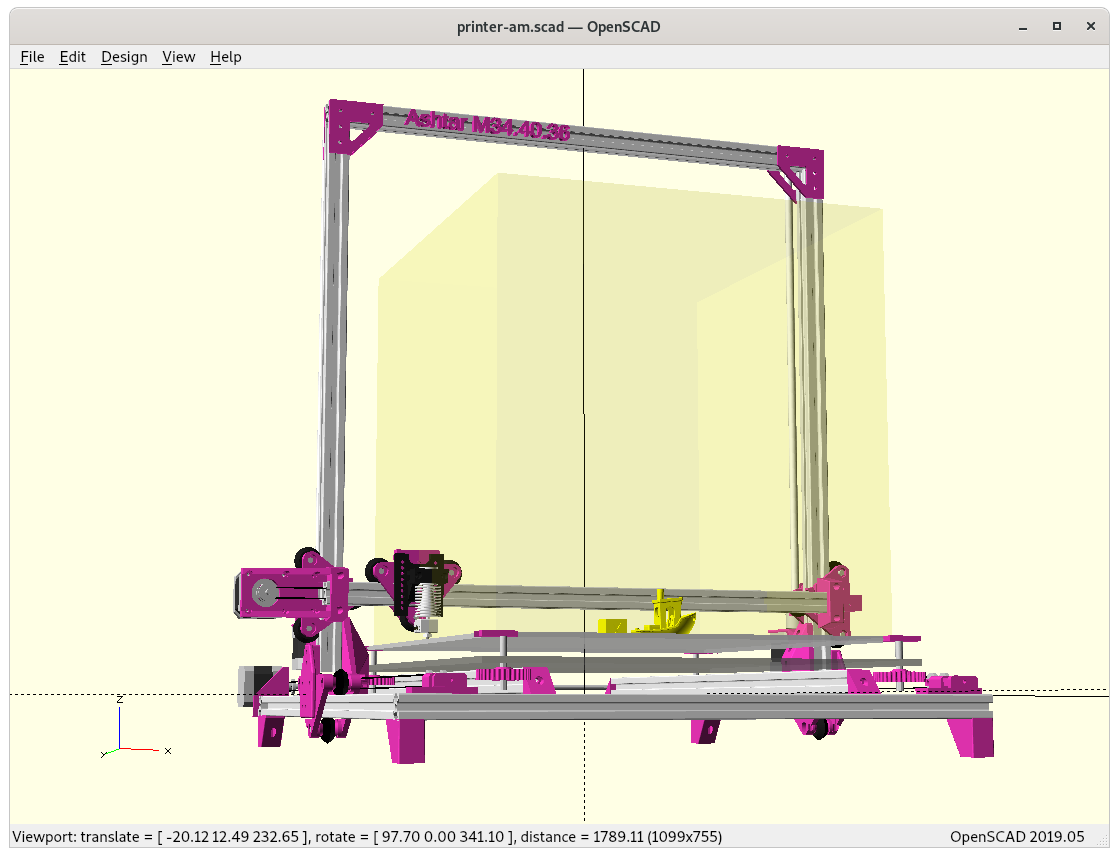
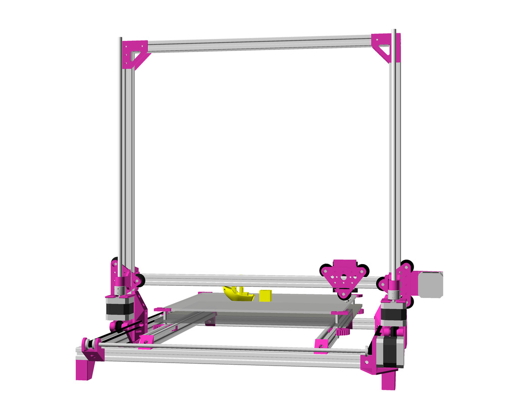
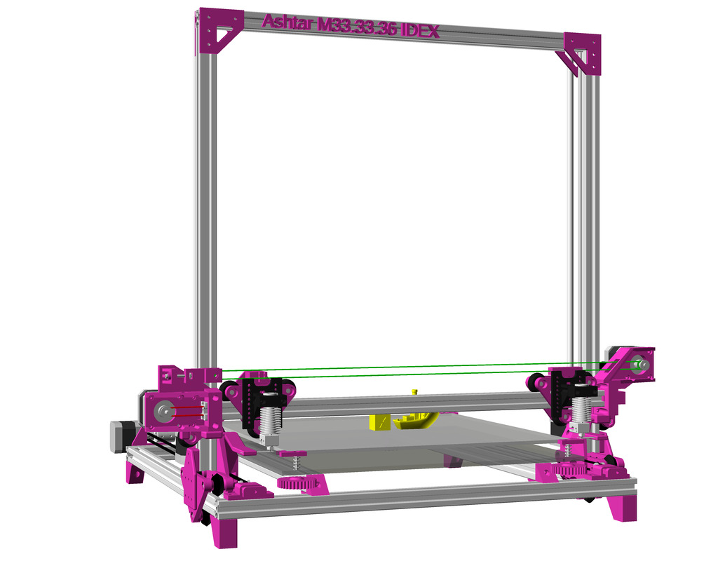
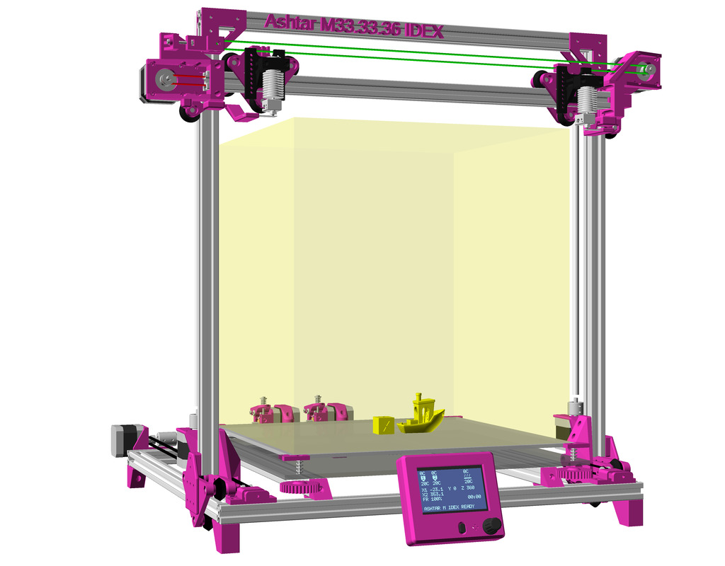
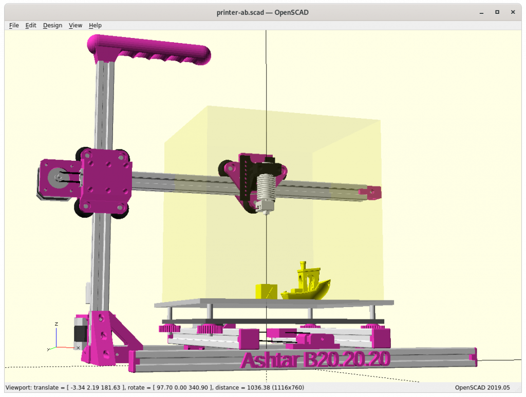
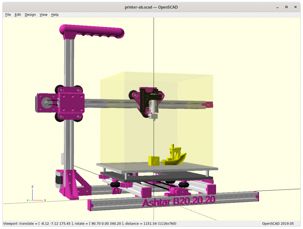
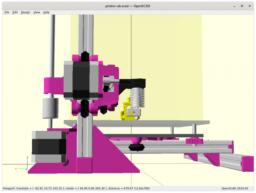
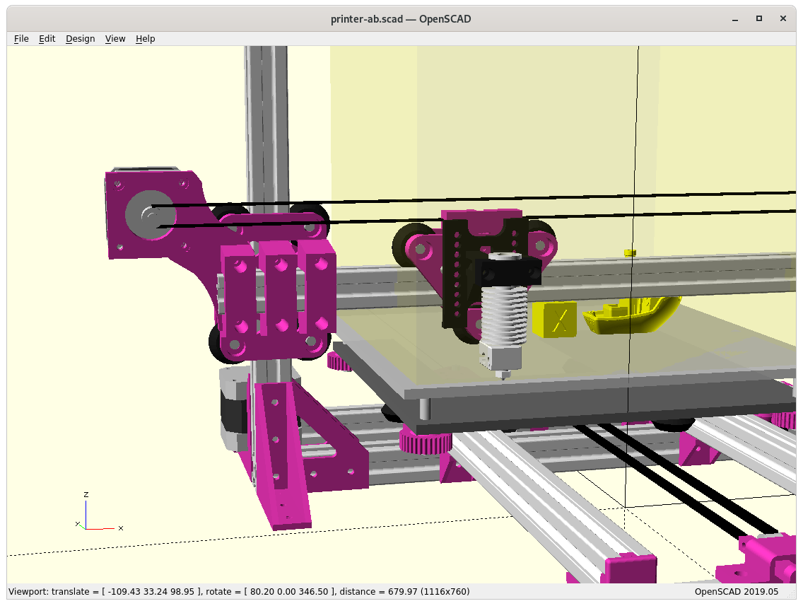
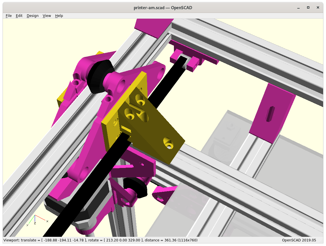
XZ Arch Option – Removing Lower X Beam
In order to gain some Z build space by lowering the print bed, I may reduce the XZ frame to an XZ arch:
Side pieces “A” & “B” with Arch (lower X-beam removed) 
Side piece “B” 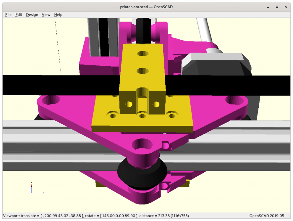

Actual physical tests may reveal if it’s suitable to maintain overall geometrical integrity. Removing the lower X beam also reduces moving mass of the XZ arch/frame/gantry.
Pros
- gain Z build space
- reduce XZ gantry weight / inertia
Cons
- decrease XZ gantry stability
Further Development
As I develop Ashtar M further, I will post updates on the blog here, and also keep documenting the current state at Ashtar M page.
That’s it.