Status: fully functional, it prints successfully
Updates:
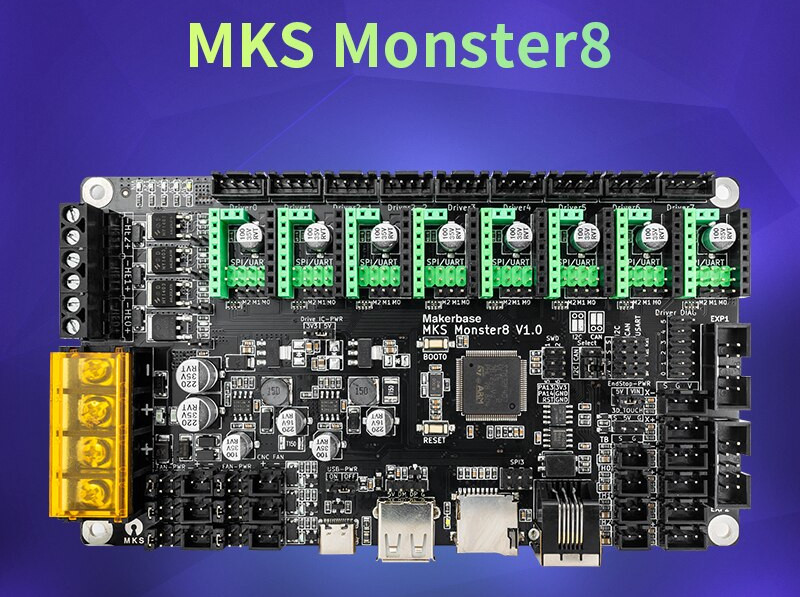
- 2022/09/19: new board MKS Monster8 with Marlin 2.0.x, 8 drivers
- 2022/08/01: Refining pieces, belts replaced with GATES LL 2GT
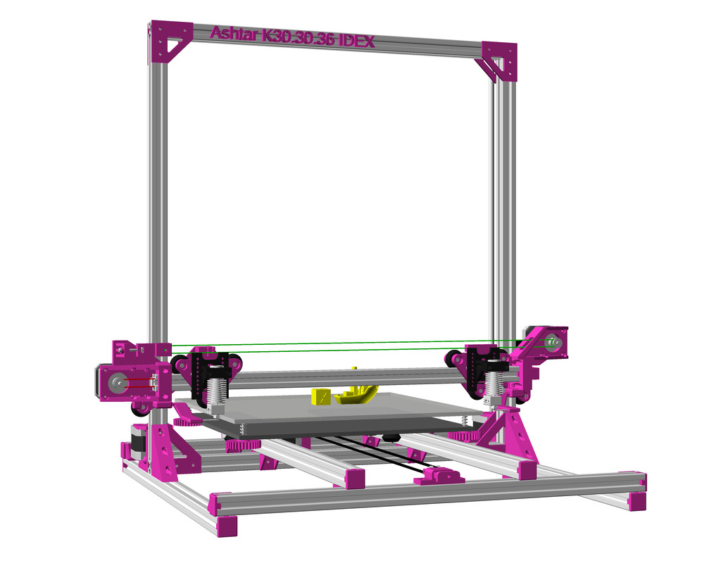
- 2021/01/14: Adding IDEX option as a draft, untested
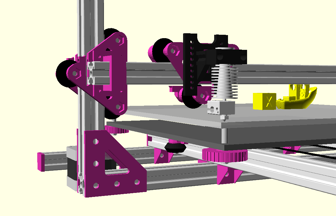
- 2021/01/10: Finally more detailed and complete renderings with routed belts
- 2019/05/04: Dual Z + Dual Extruder for MKS Gen L for Chimera/Cyclops hotend
- 2019/02/08: Added “Maintenance” with first few points what’s important on this Core XY setup, up-to-date OpenSCAD model renderings
- 2019/01/31: First prints successful, Z axis redone with 2x Z motors with 2x 760 mm closed loop GT2 belts
- 2019/01/01: CoreXY mechanism complete: belt routing finalized and Marlin firmware configured, brief “preflight” video (no extrusion yet)
- 2018/12/08: Parts delayed, so development delayed as well, A/B motors installed and Bowden extruder, “Current State” photos uploaded
- 2018/11/09: Main frame setup with basic belt routing with mockup stepper motor.
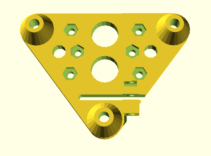
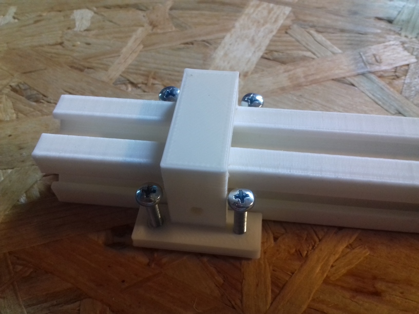
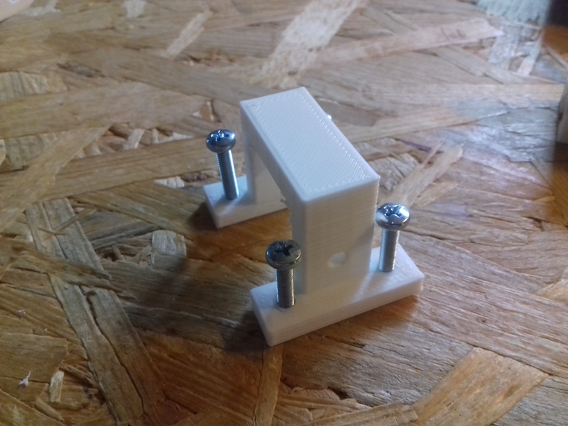
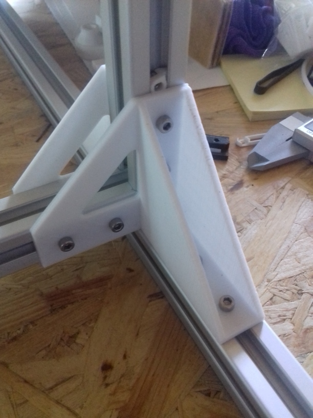
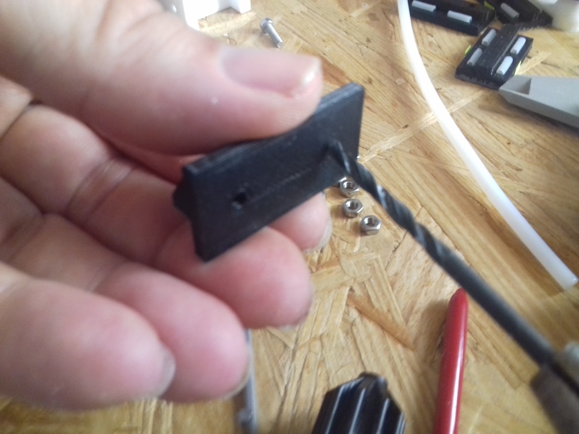
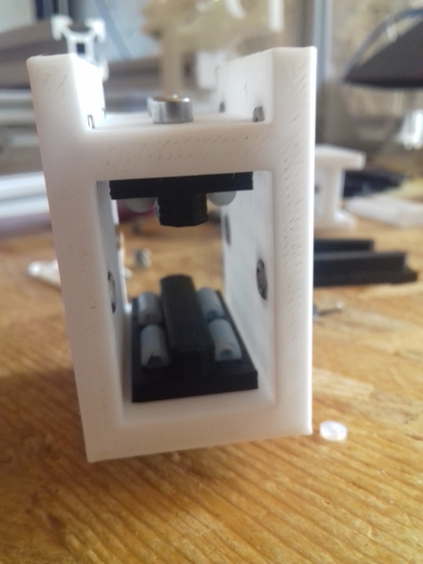
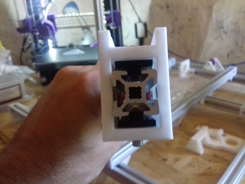
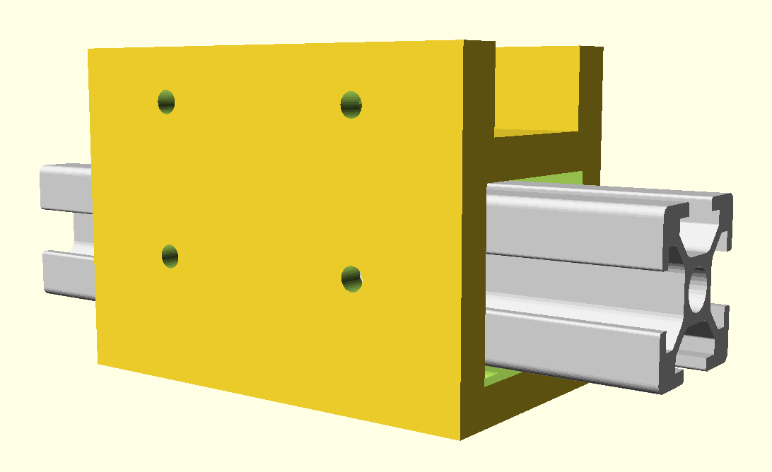
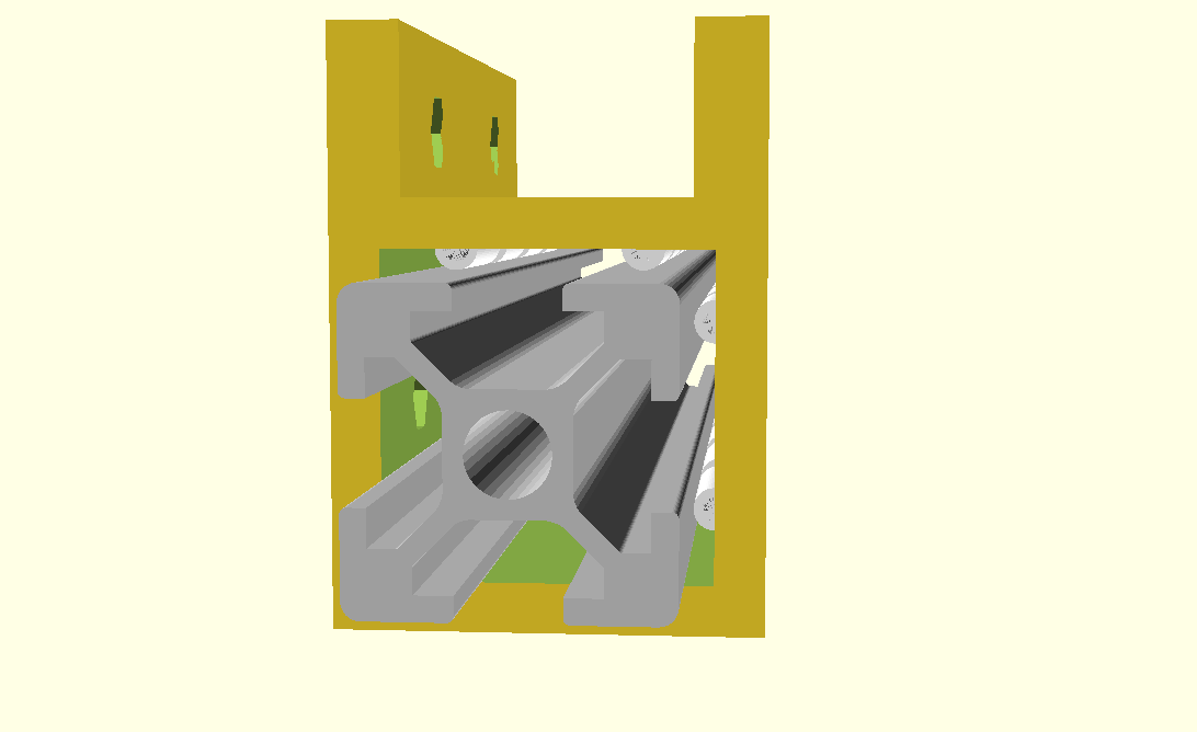
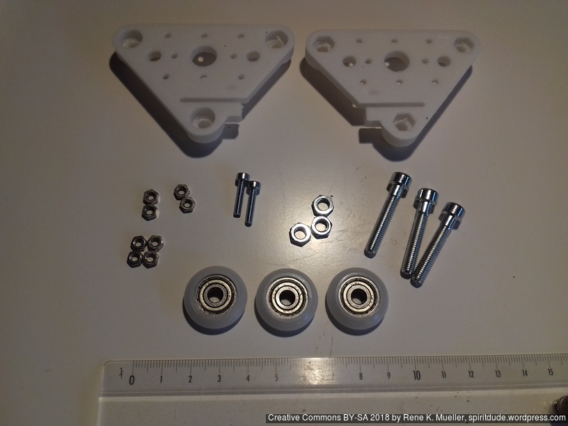
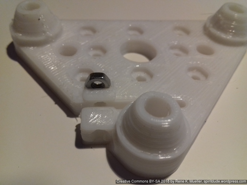
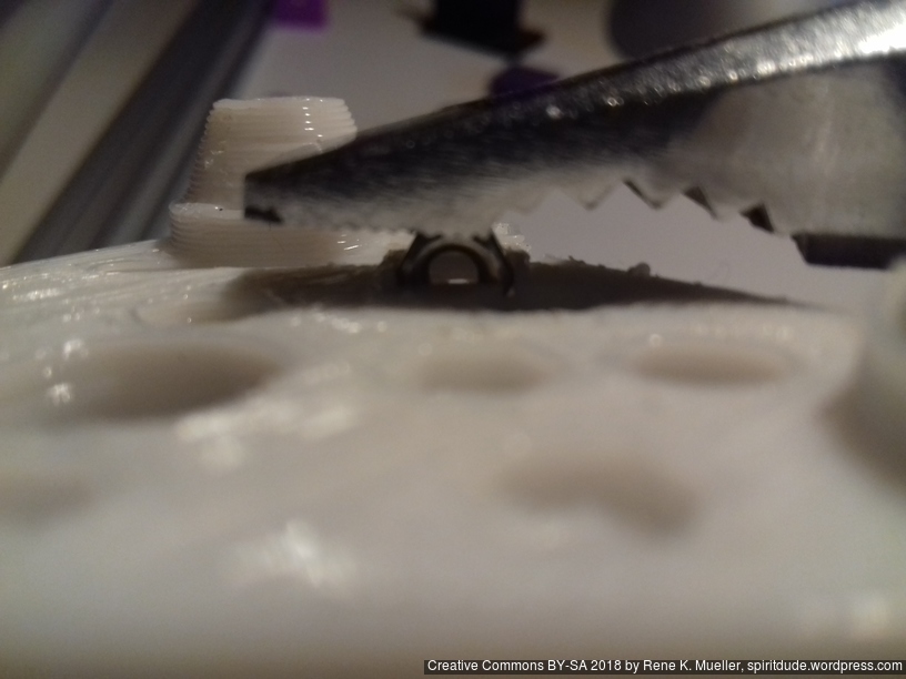
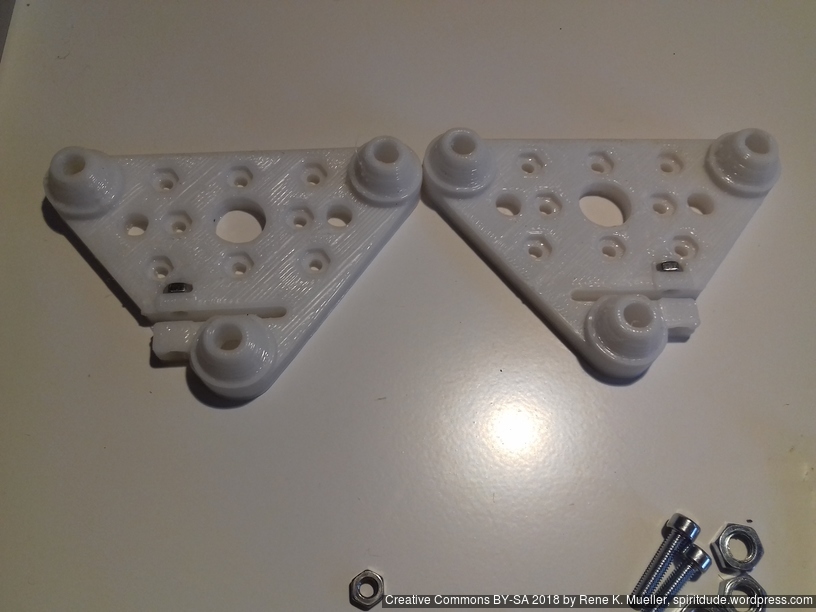
- 2018/10/03: Dedicated corner bracket
cci_2020()OpenSCAD module, first scaffolding the frame with printed parts - 2018/09/10: First draft, fully parametric approach, detailed routing of belts not yet done (most important)
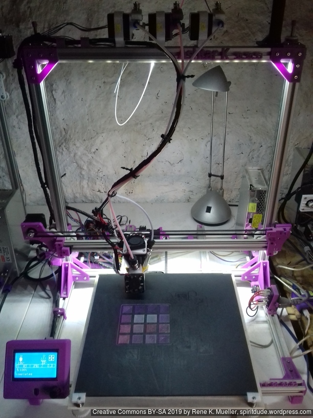
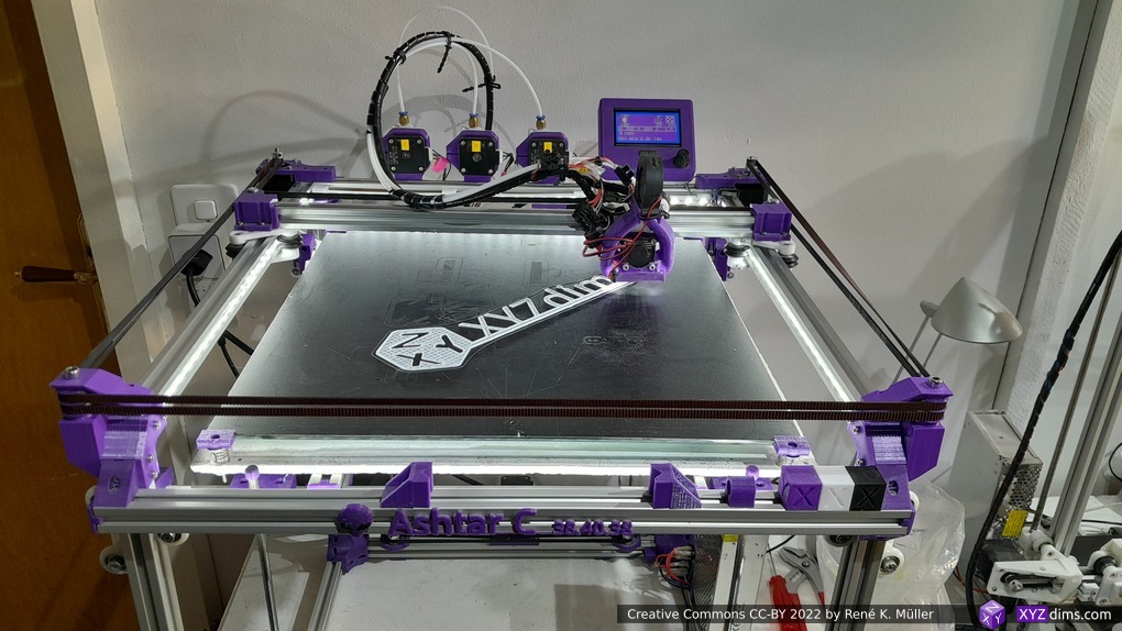
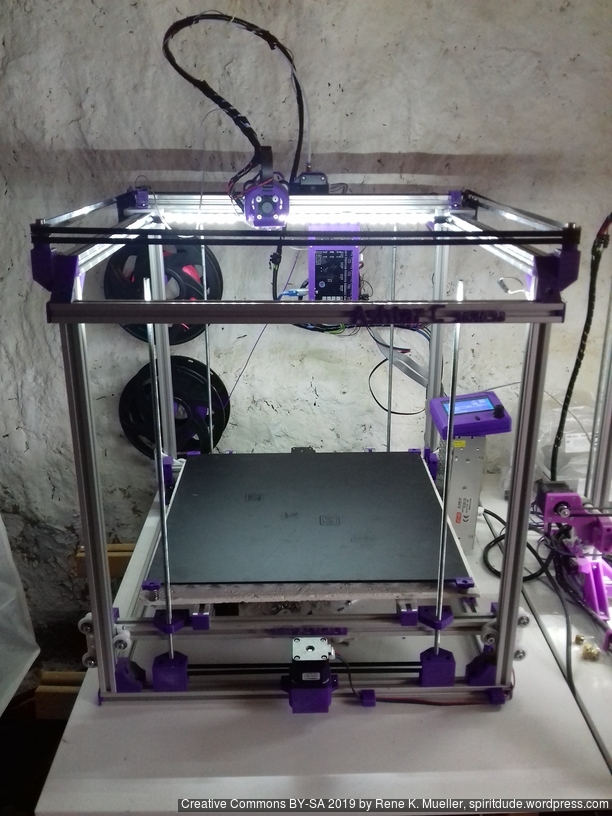
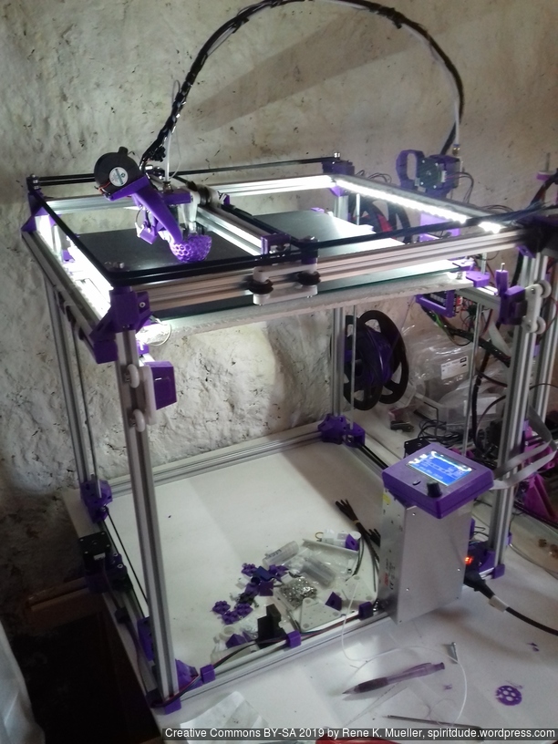
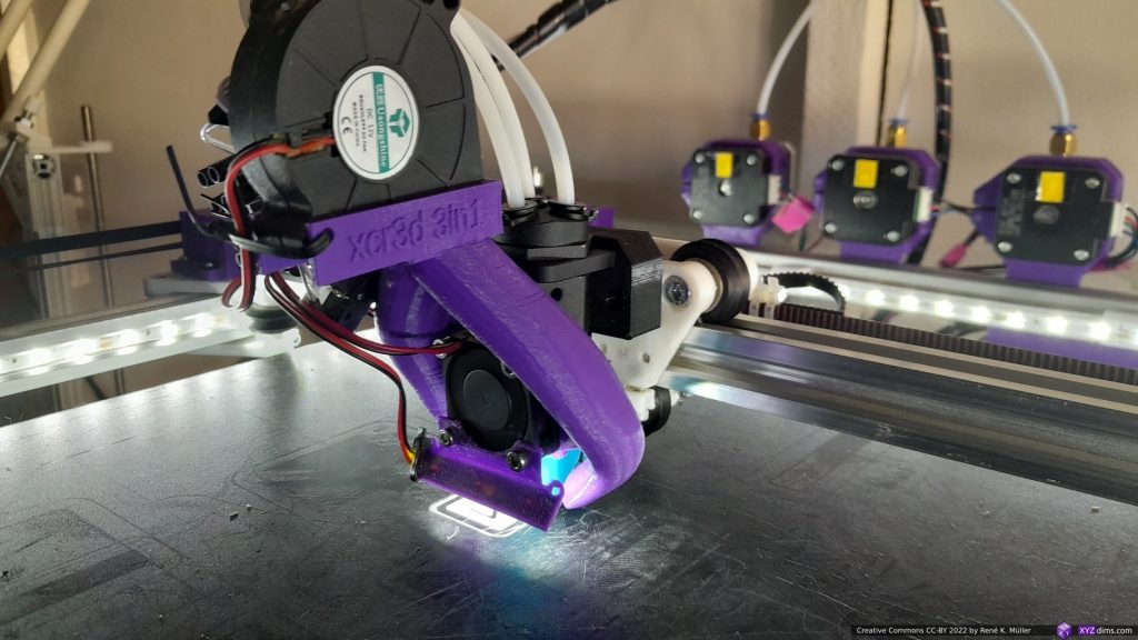
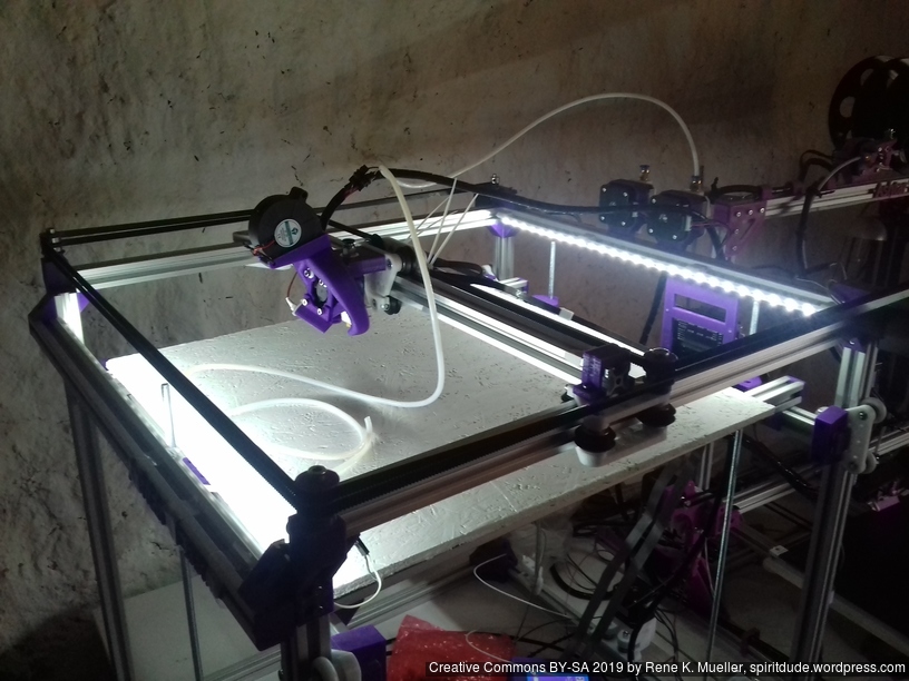
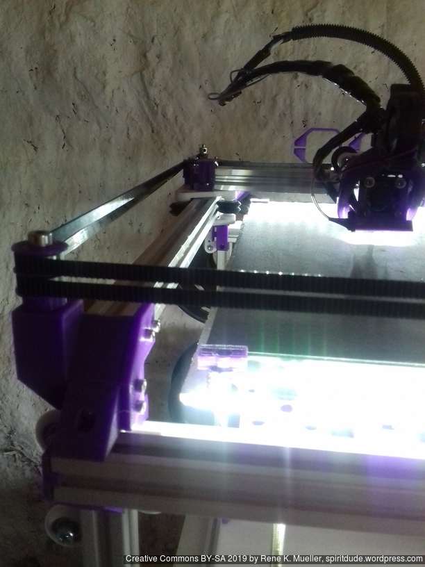
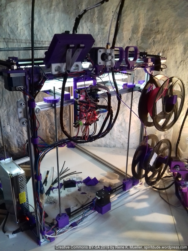
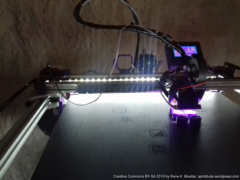
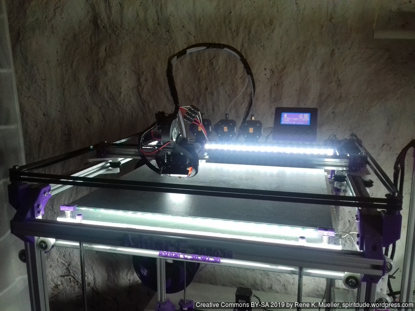
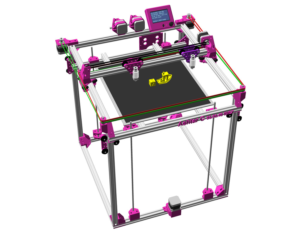
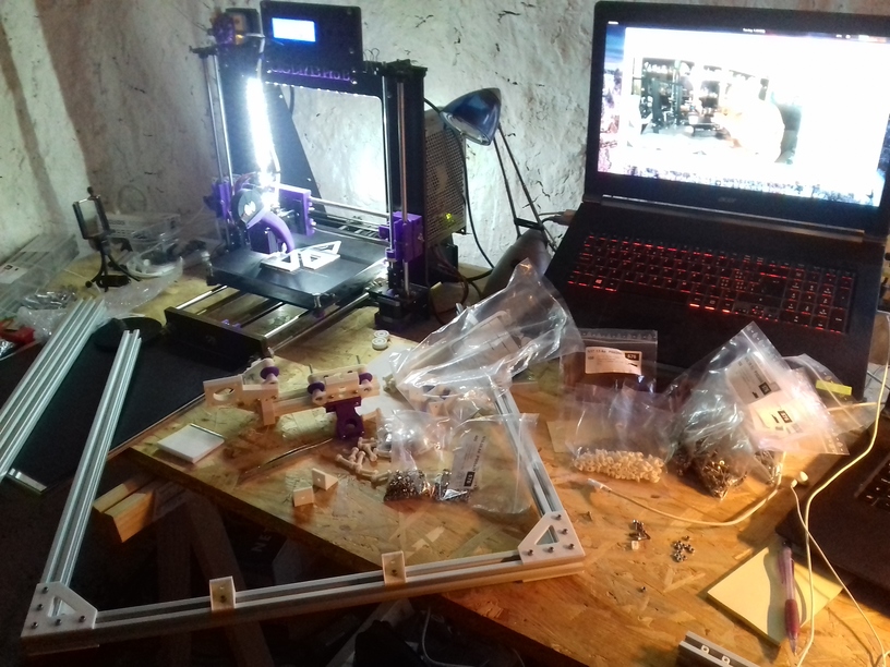
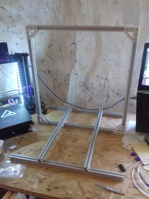
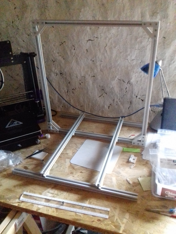
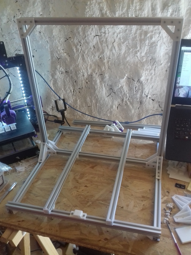
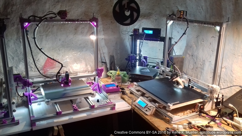
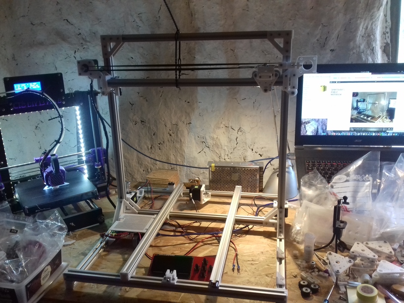
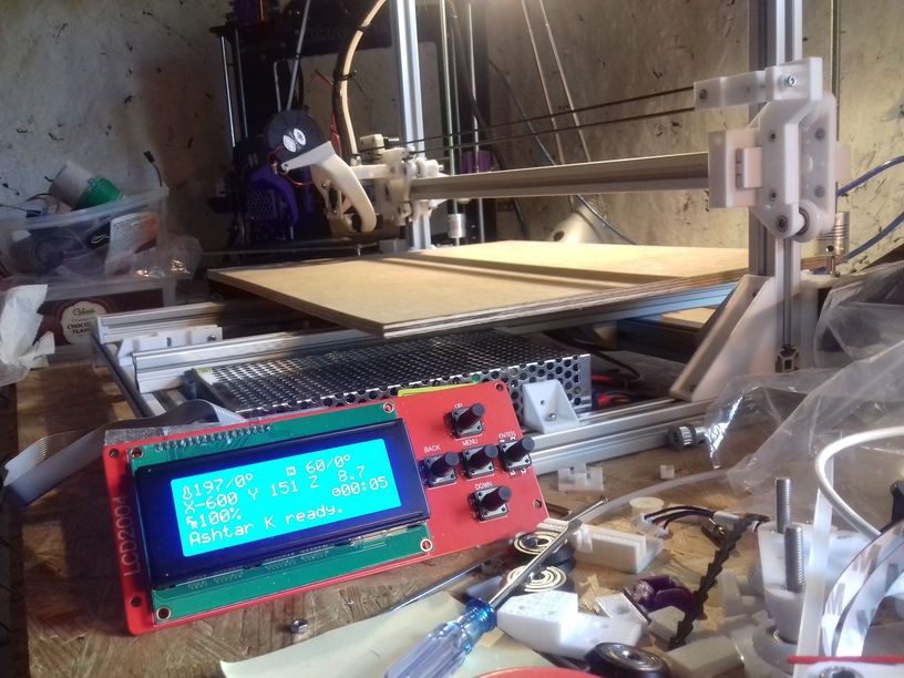
Current State
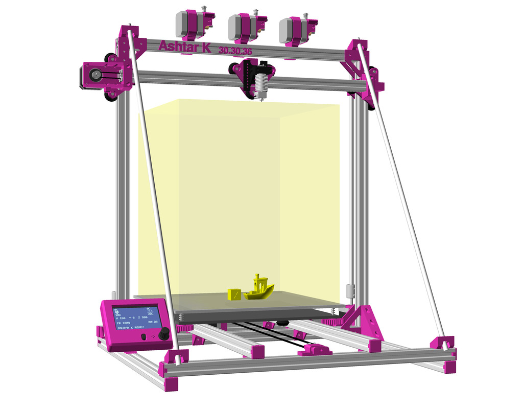
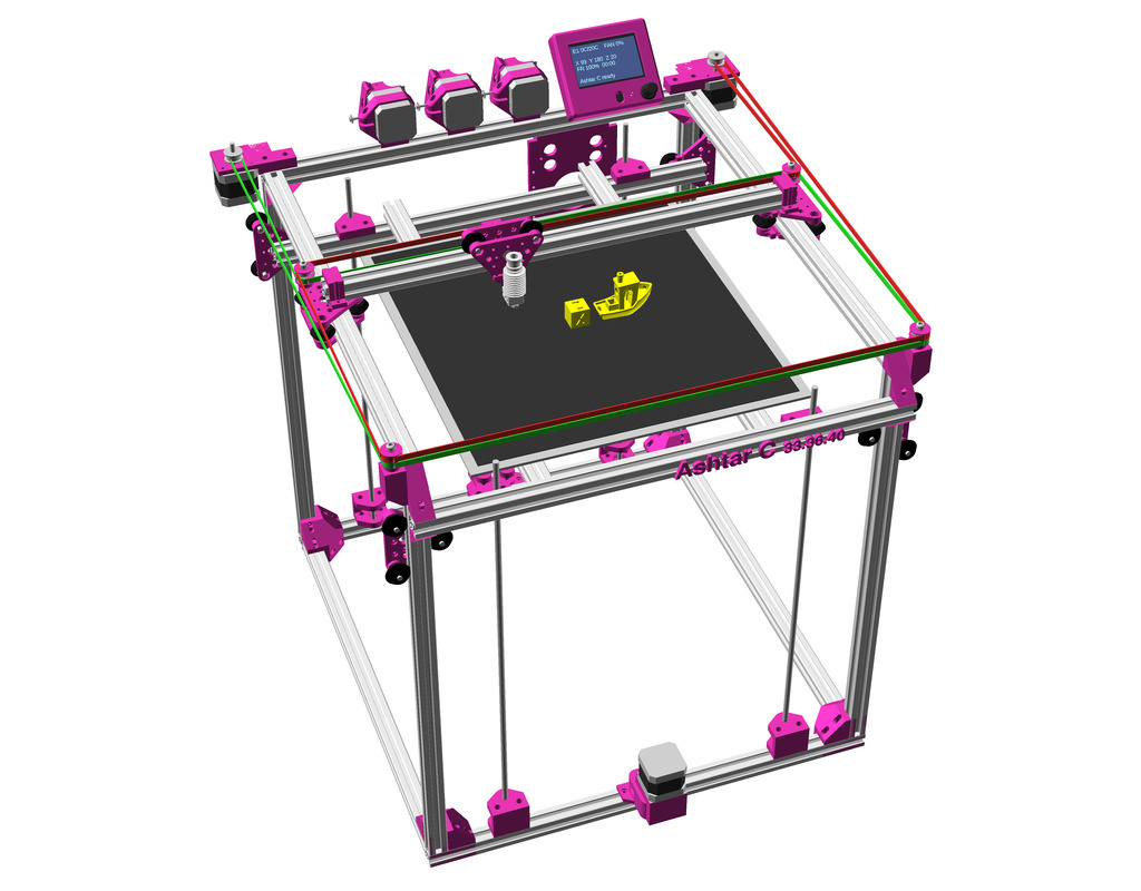
Introduction
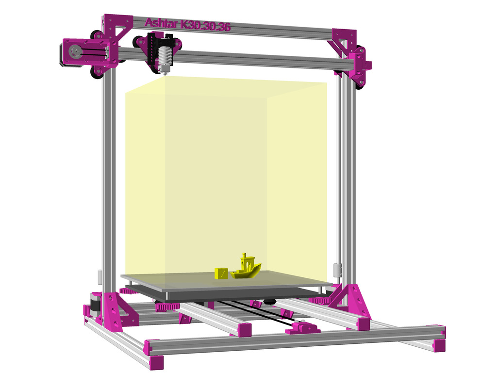
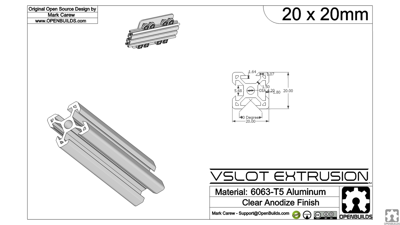
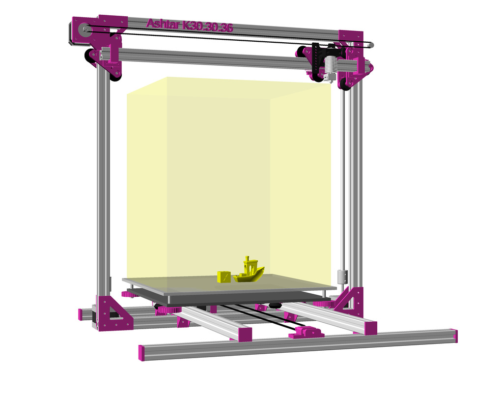
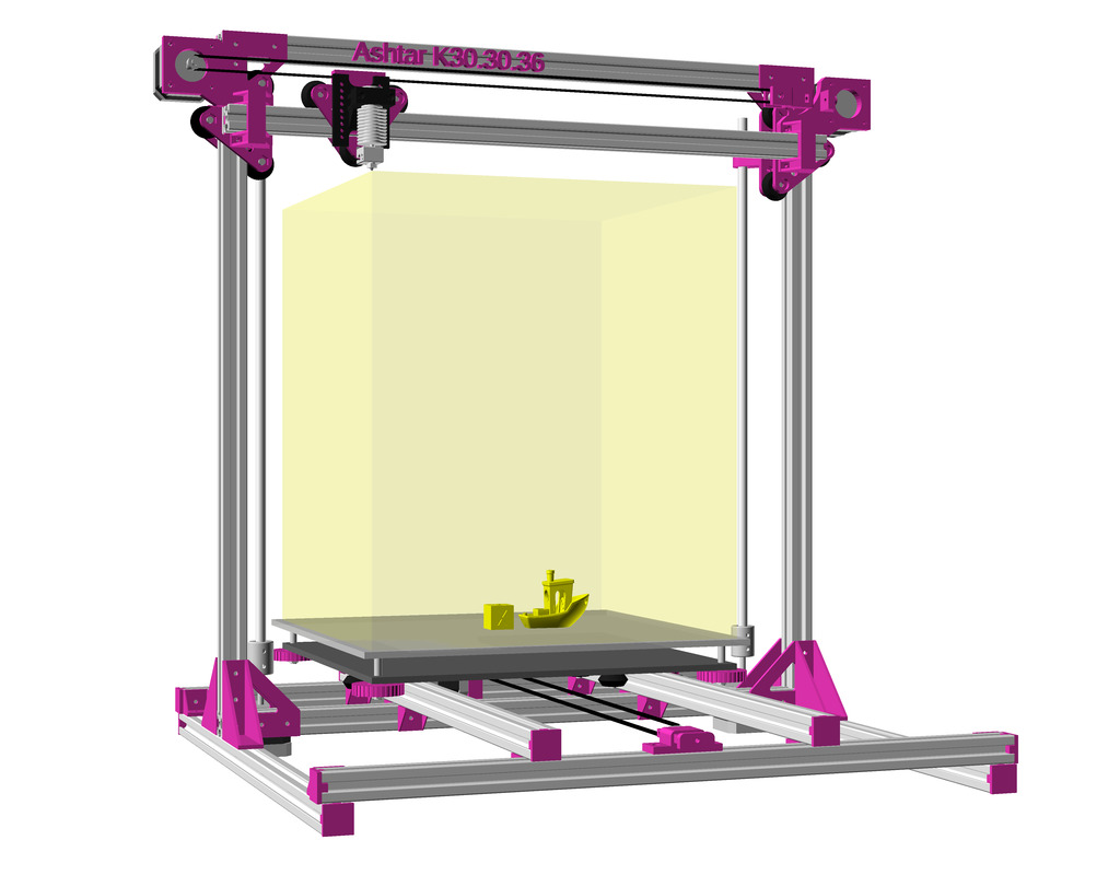
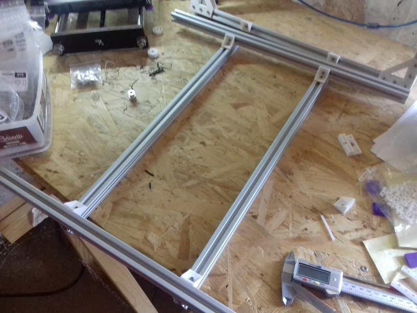
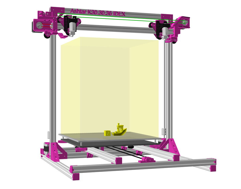
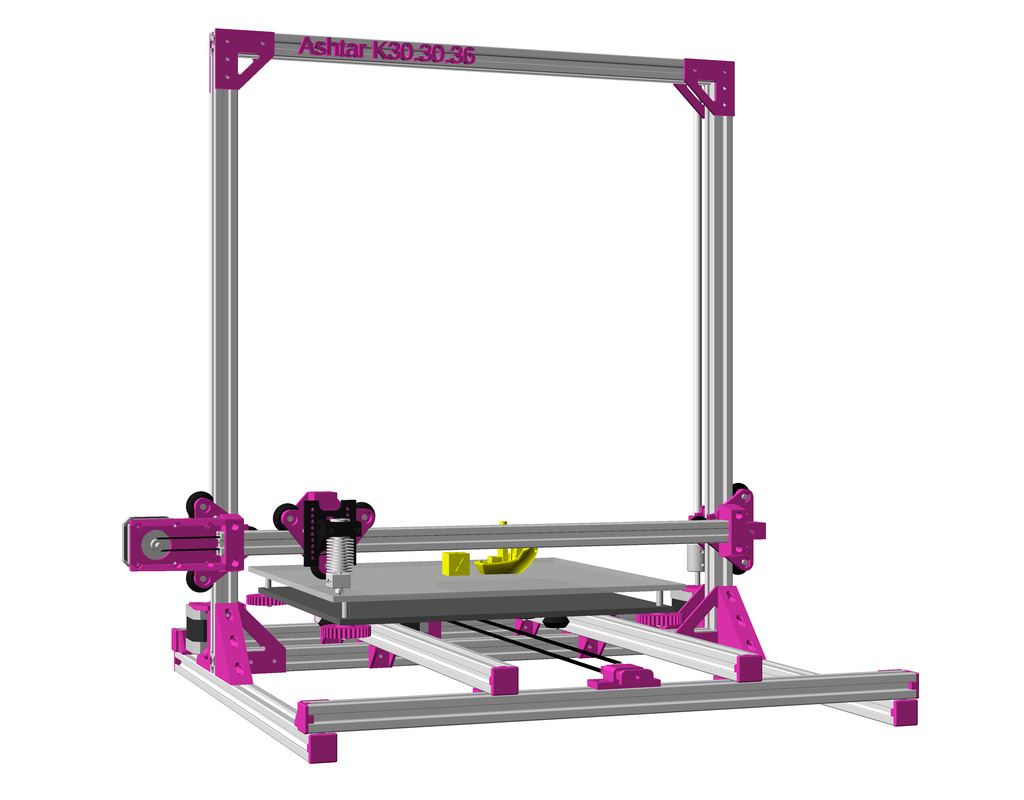
After Ashtar K (Prusa i3-like), I thought to still use single size 2020 T slot 6 (B-Type) alu extrusions to compose CoreXY styled 3d printer, fully parametric designed:
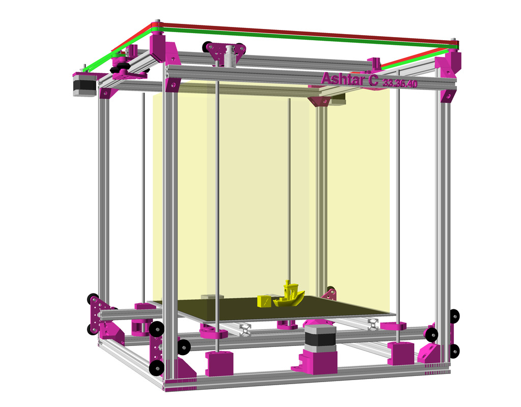
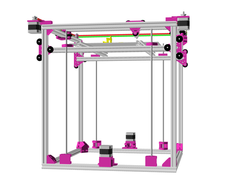
As first study shows, while trying to develop a single sized beam design: 16x beams make up the main geometry including bed mount, plus the X gantry which has to be shorter to lie between the top Y beams (if it sits above the belts also have to be routed above, and Y axis V modules and X axis V module not being on the same plane) and I used the same beam for the X beam where the X carriage rides the same length, using the Z offset to my advantage (instead to shorten it and fit it between the Y carriages): 17x 500mm alu extrusions (14x T slot and 3x V slot for X and 2x Y).

So far I like to reuse the V modules to ride on the alu extrusions directly, that is X, Y and Z axis.
The Z axis details aren’t defined yet, I tend toward belt implementation, which is a bit more overhead than thread or lead screw implementation. The Z axis is done with 2 stepper motor driving each 2x threaded M6 rods (or lead screws optionally).
Specifications
- CoreXY style
- ~385 x 400 x 380mm build volume (300×300 or 300×400 or 400×400 build plate)
- 500 x 520 x 520mm frame size with
- 14x 500mm 2020 T slot alu extrusion
- 3x 500mm 2020 V (or T slot as well) alu extrusion
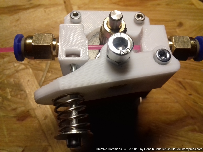
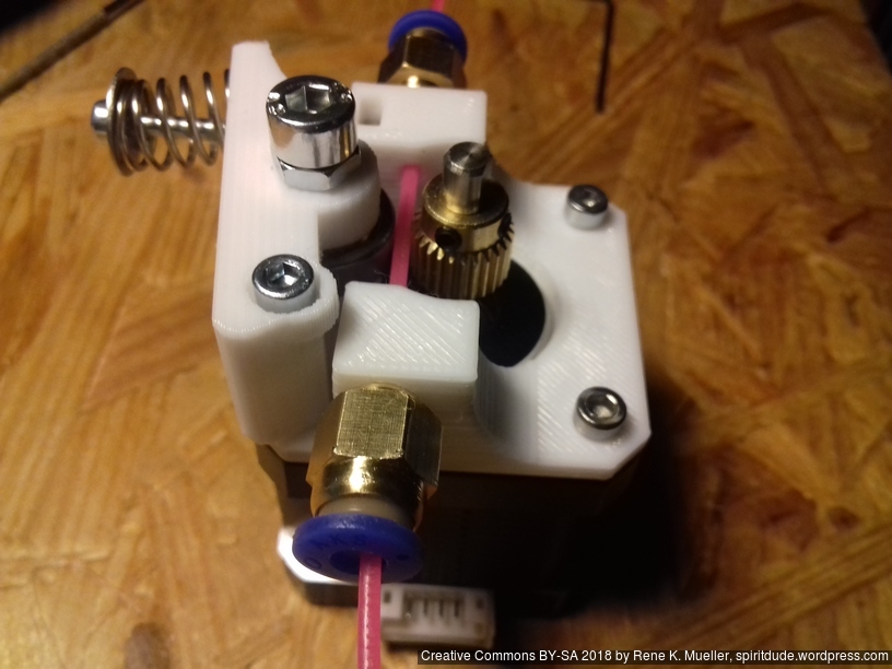
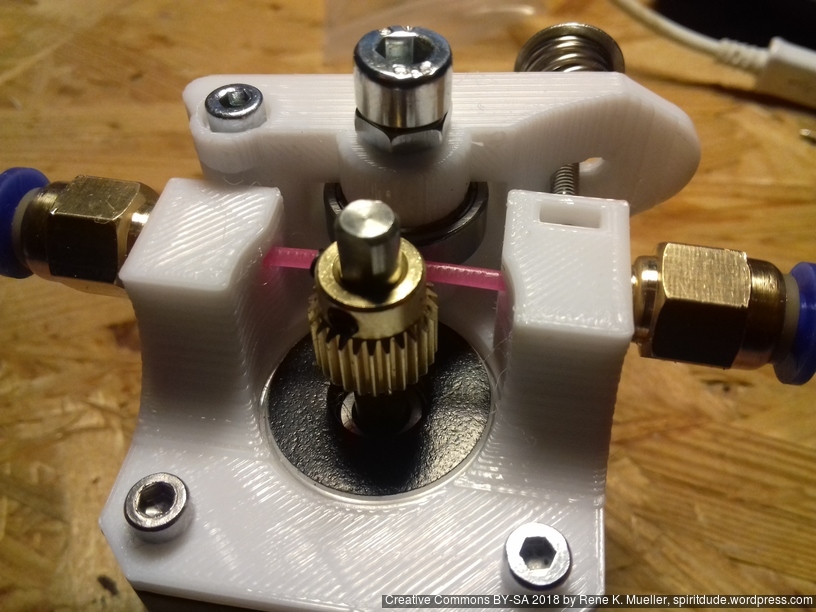
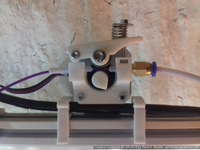
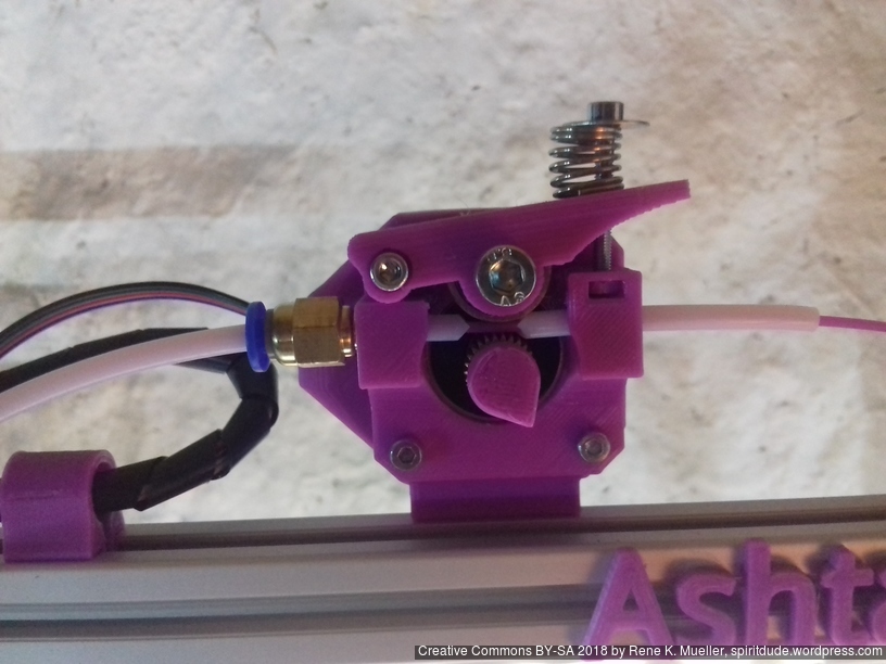
- Bowden setup for fast X/Y movement and fast printing therefore
- MKS Gen L main board + Smart Full Graphic display (with dialer)
- Reprap style with many parts to be printed
- M3: assemble most parts
- M5: idlers of A/B belts
- M6: Z axis threaded rods
Electronics
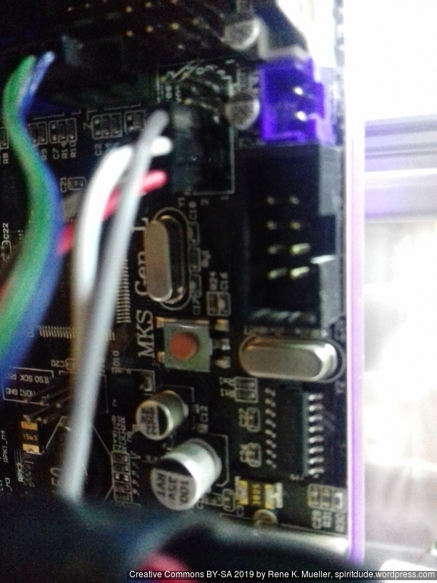
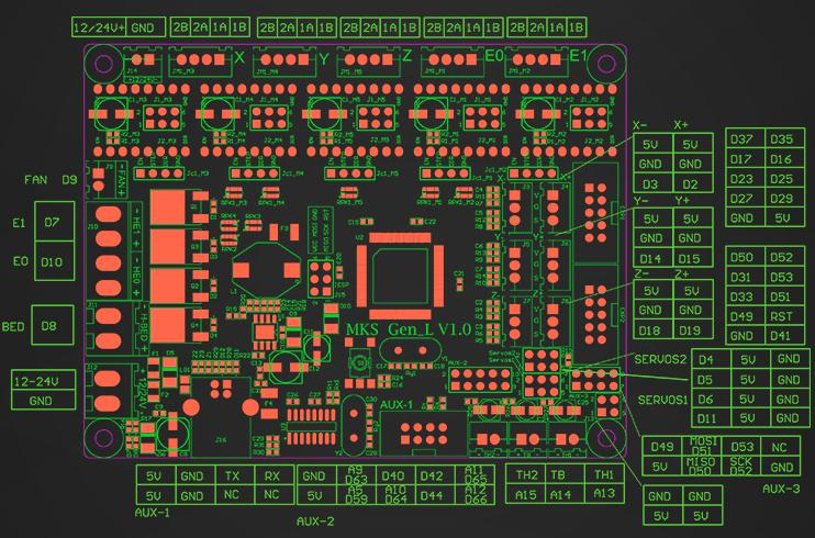
For Ashtar C #1 I use the MKS Gen L V1.0 board:
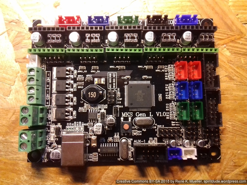
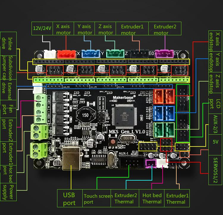
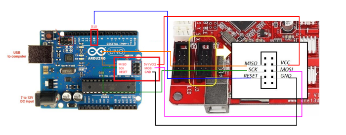
In order to add the RepRap Discount Full Graphics Controller I had to remove the notches and rotate EXP1 and EXP2 by 180 degrees so the display would work. I gonna use 5x A4988 as stepper motor drivers.
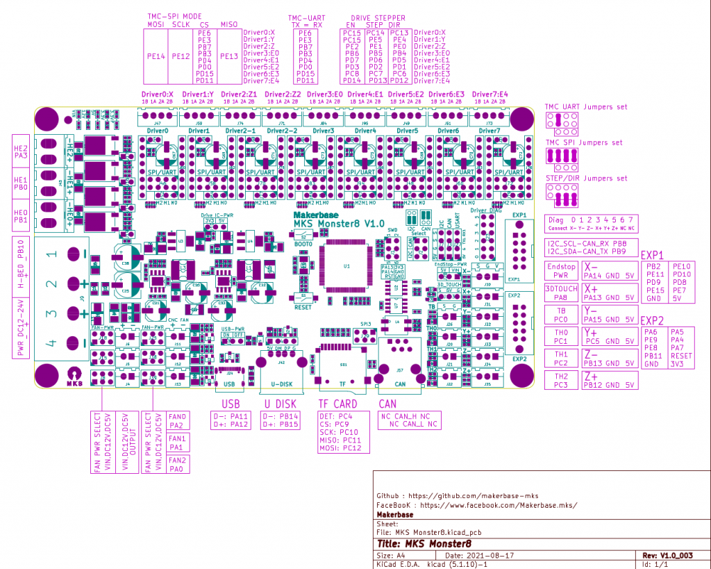
Update 2022/09 using MKS Monster8 V1.0 running Marlin 2.0x (requires PlatformIO to compile) with 8x TMC2209 motor drivers, MKS Mini 12864 V3 display (EUR 58):
One has to use SDcard to put firmware on and reboot the board in order to install the firmware, there are firmware uploaders available just not for Linux.
With 8 motor drivers there are plenty extensions possible, especially the Z motor driver has two connectors (e.g. usually 2x Z motors, also in my case with CoreXY I use Z motors):
- X, Y and Z(2): 3 drivers occupied
- max 5 extruders
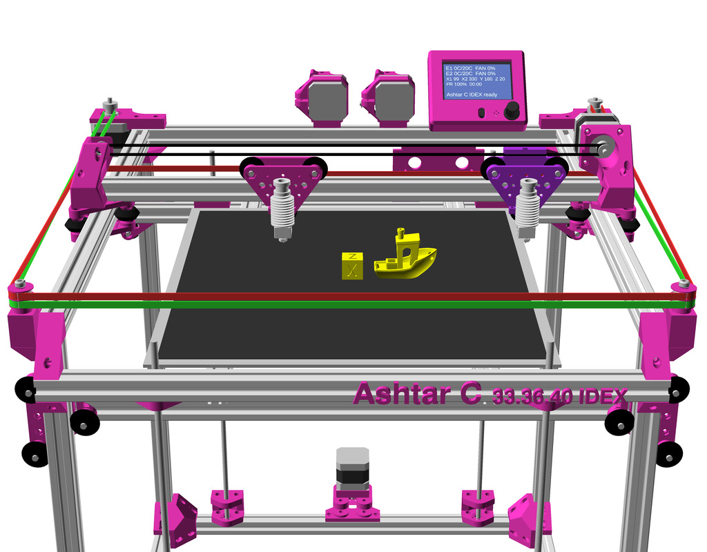
The board supports 3 independent hotends, so IDEX or even a 3x tool-changer possible with this board.
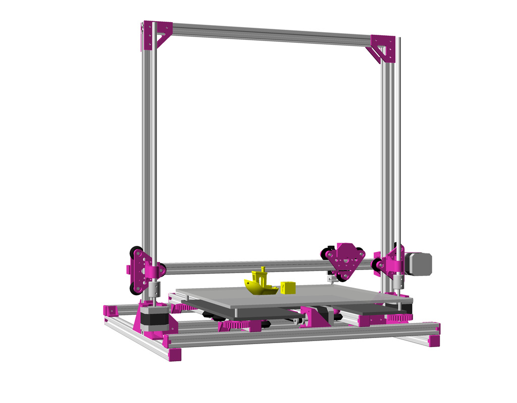
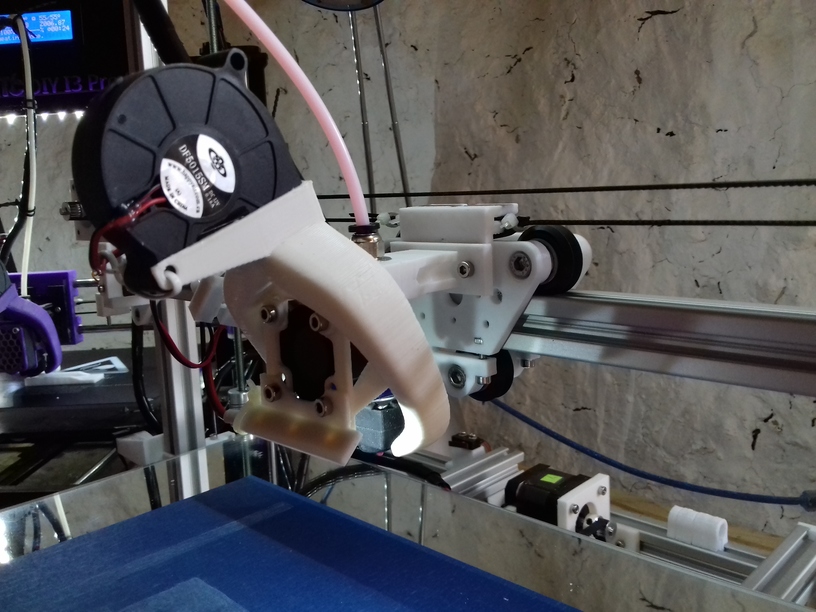
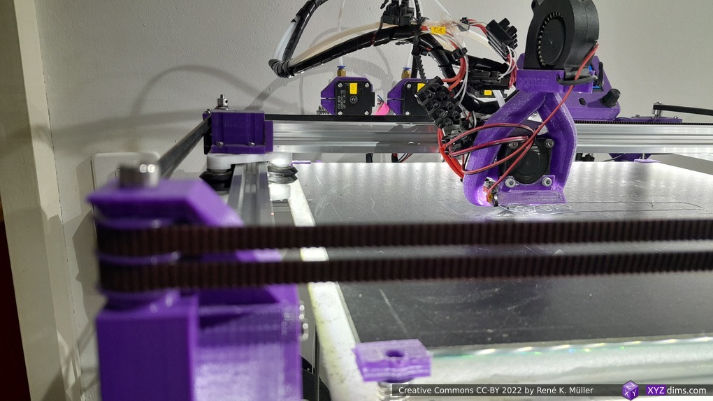
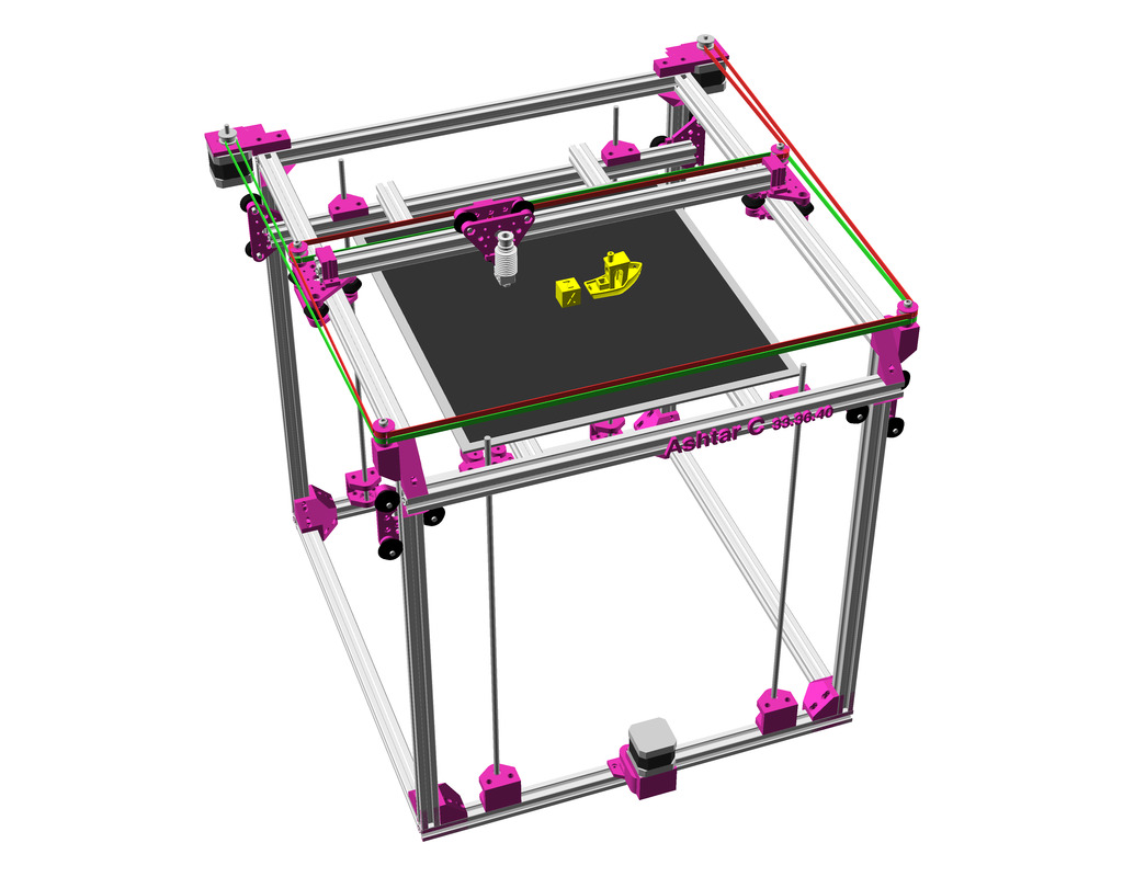
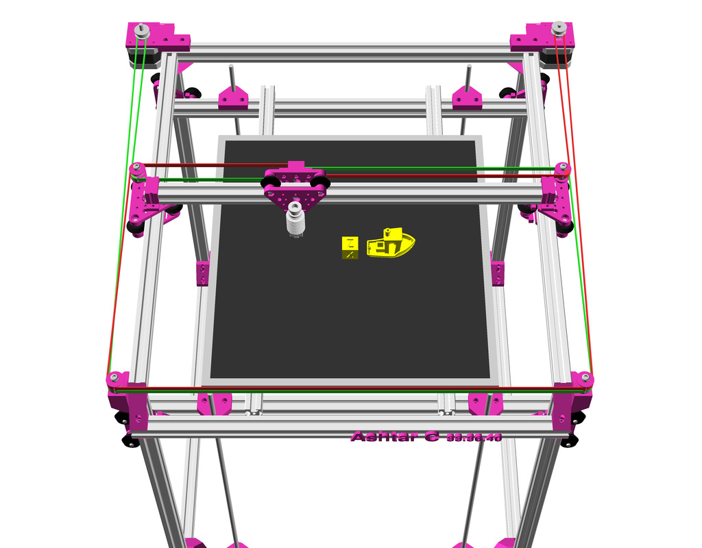
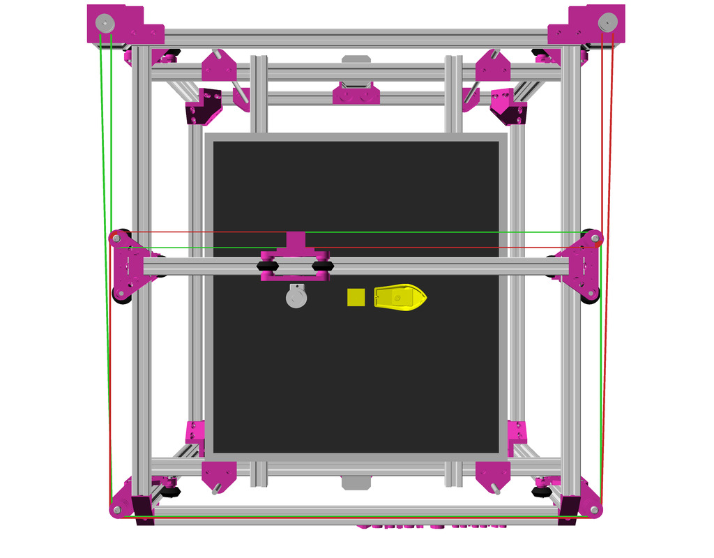
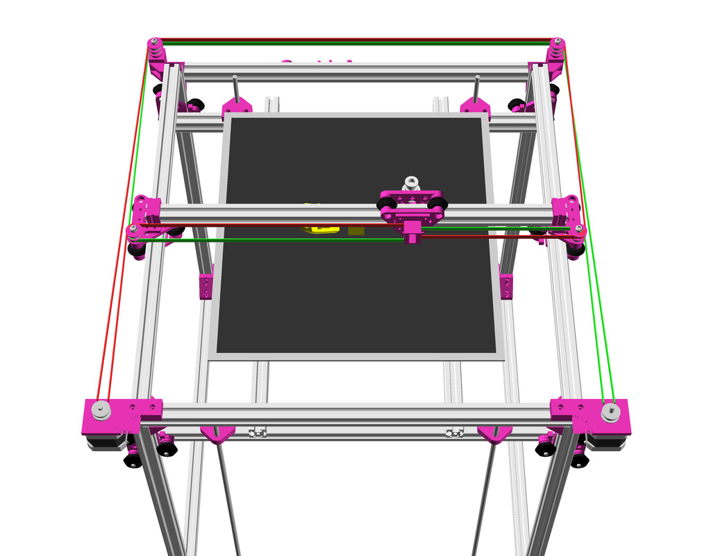
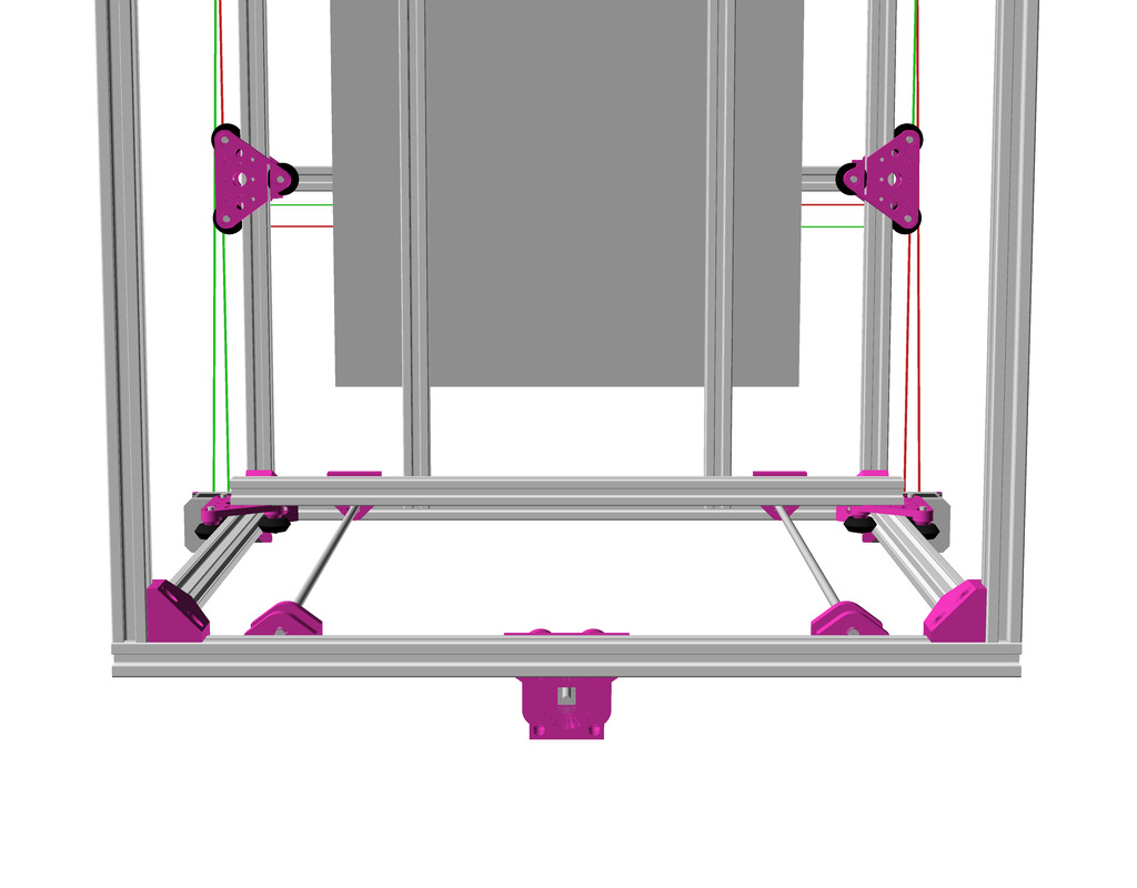
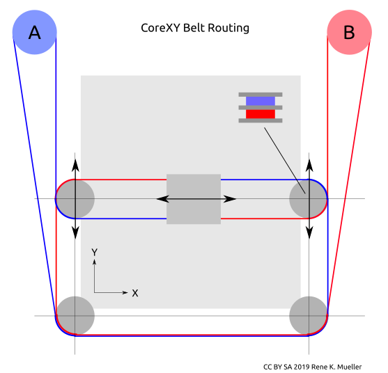
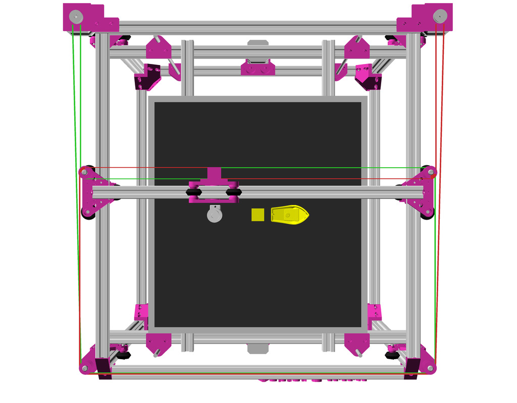
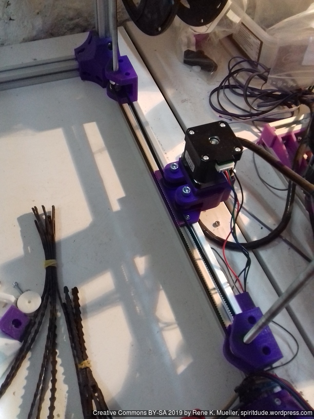
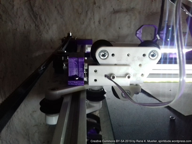
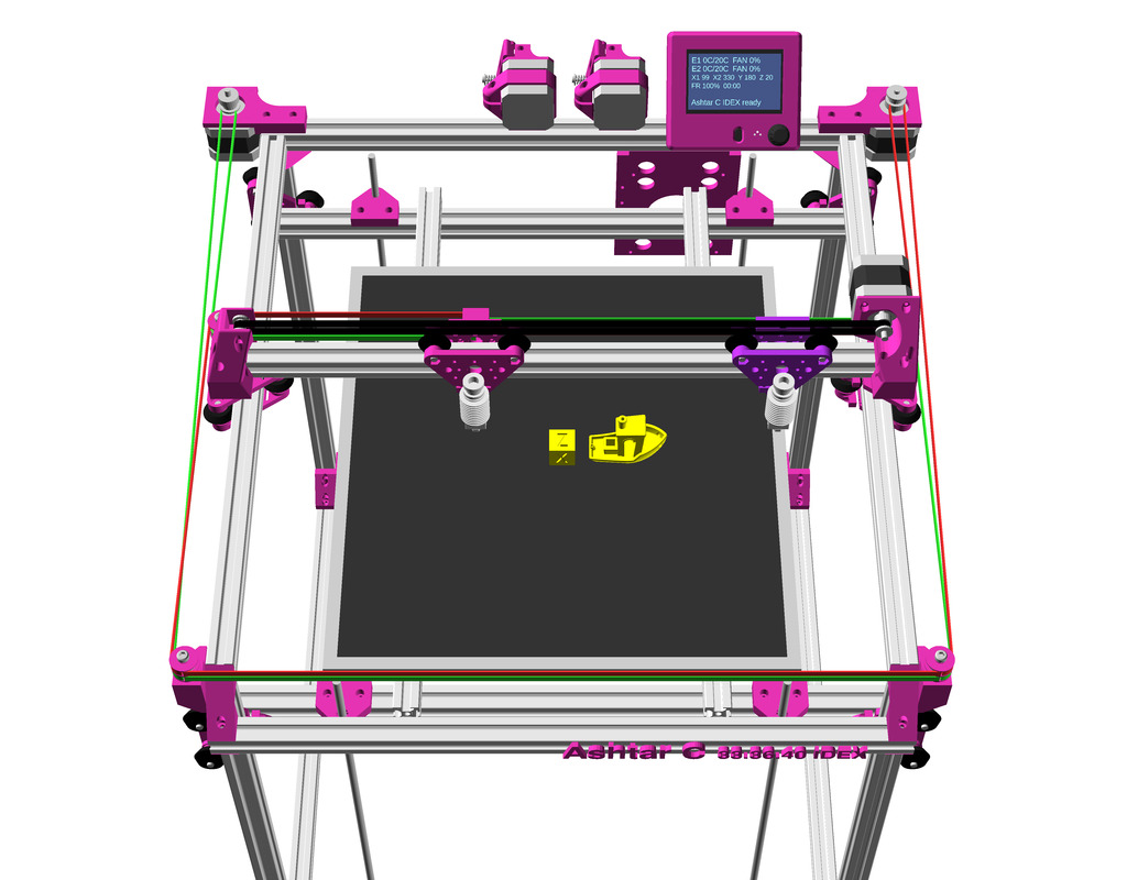
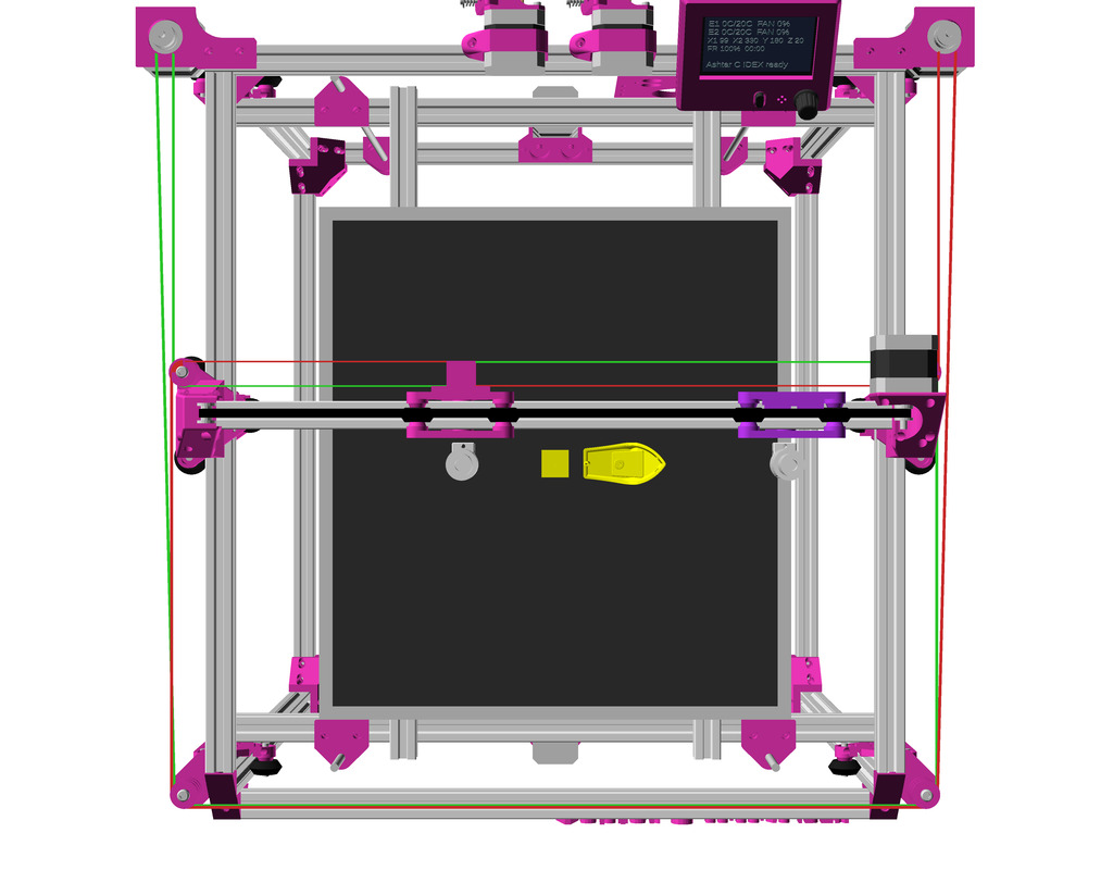
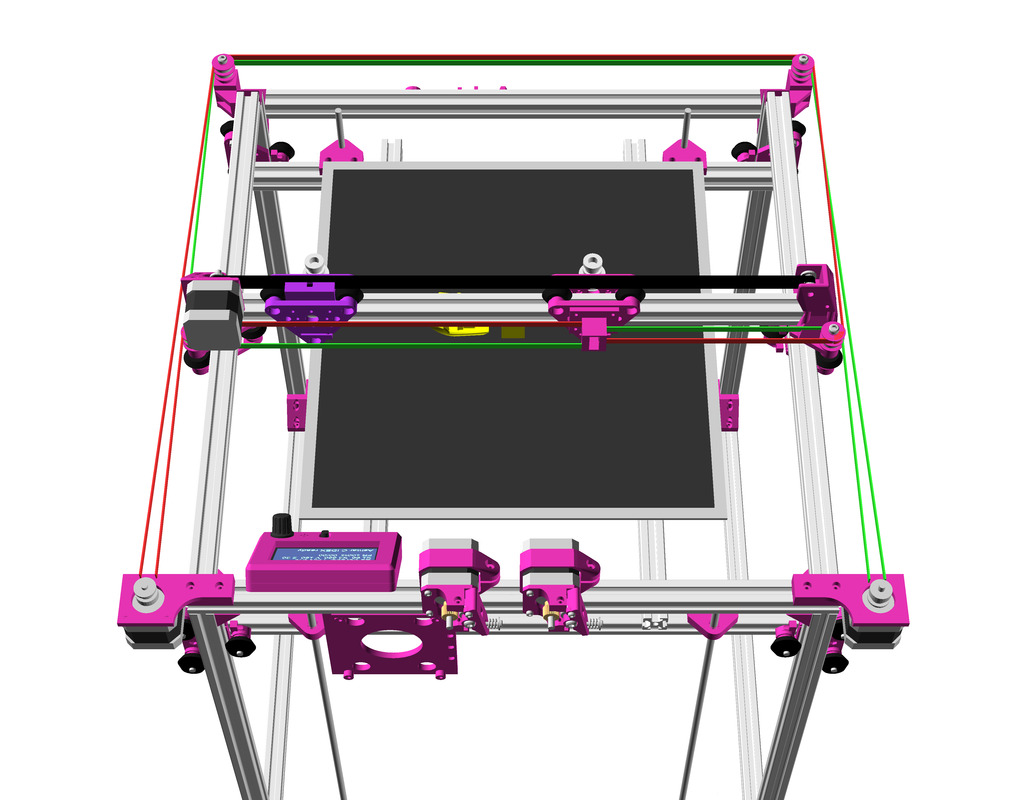
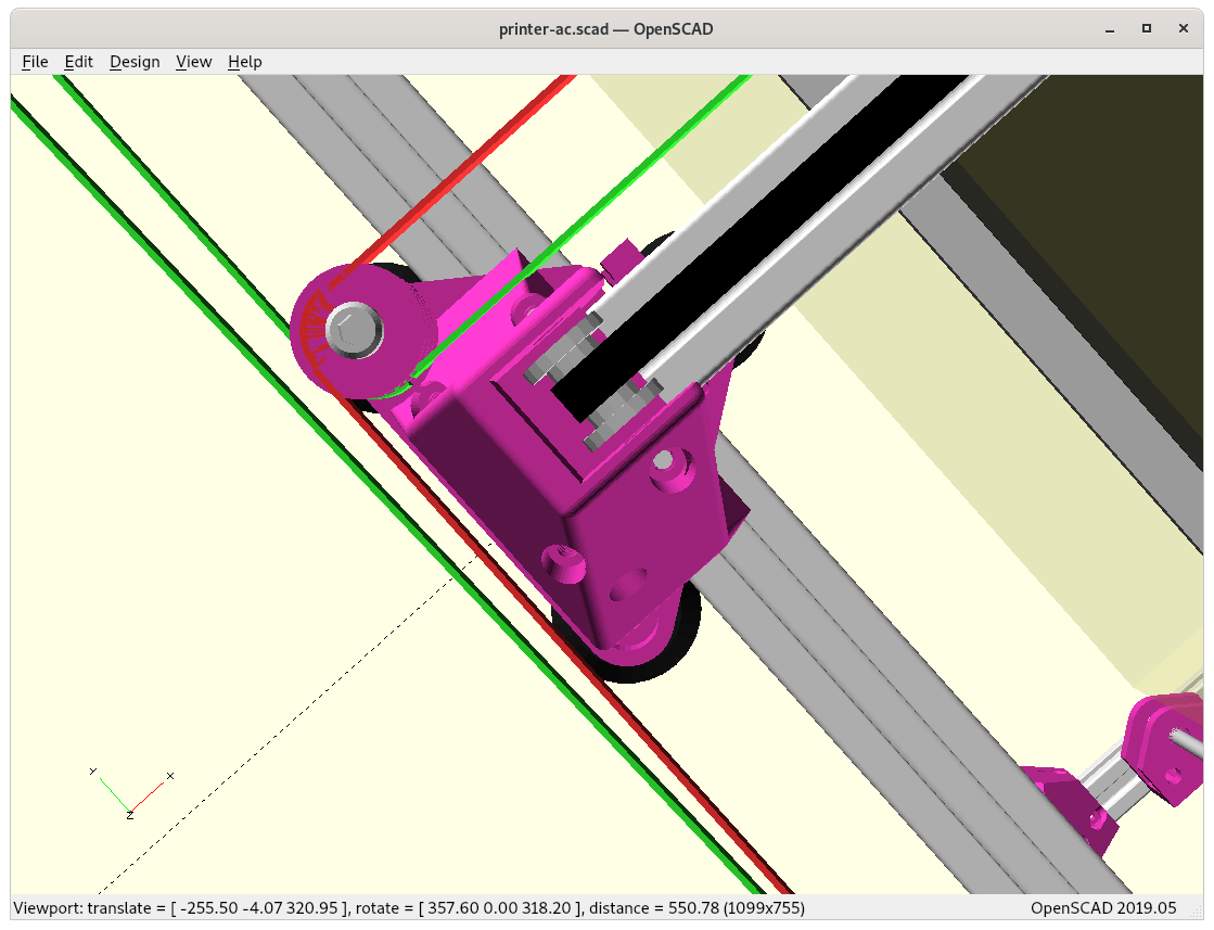
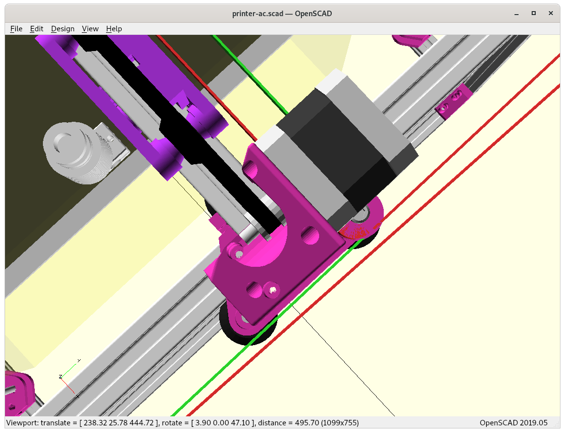
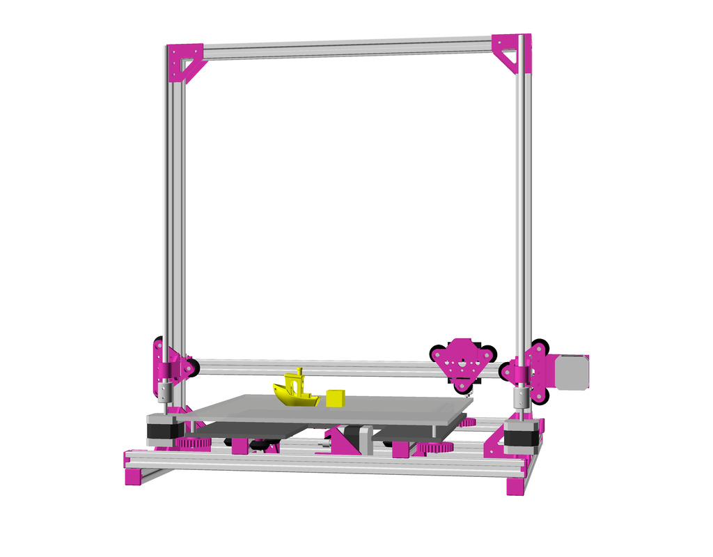
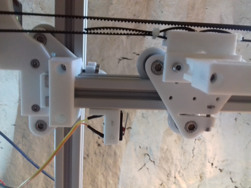
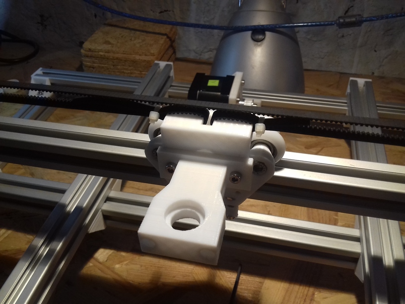
XY Belt Routing
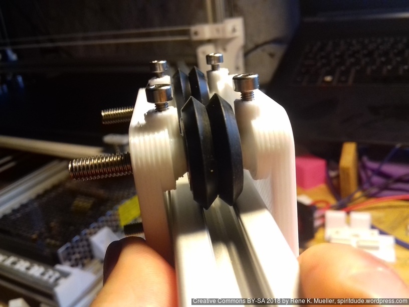
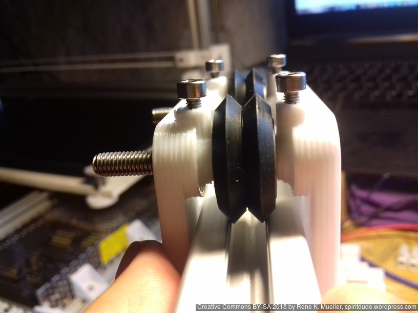
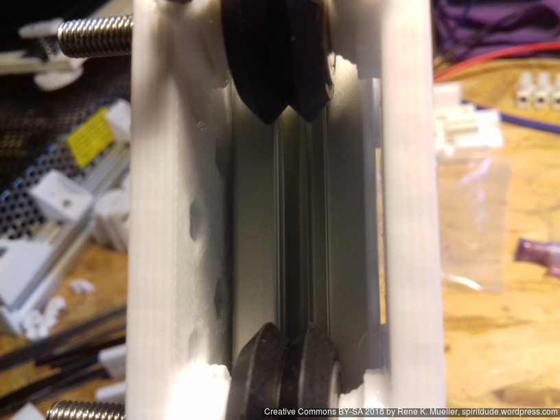
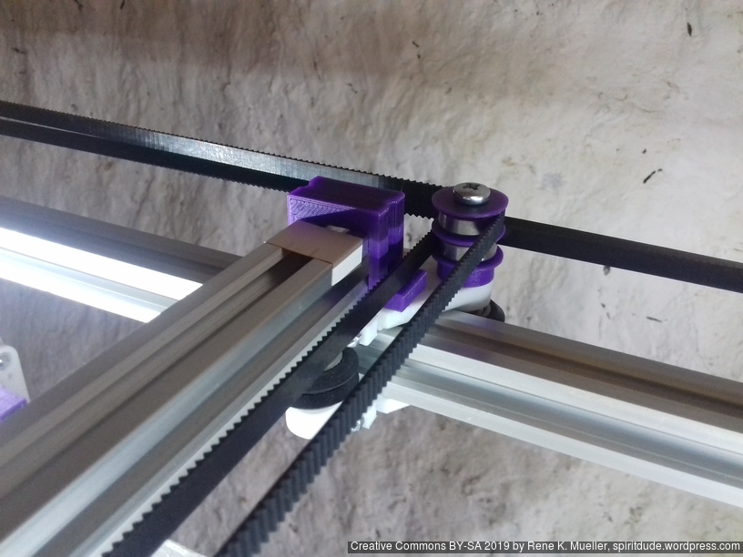
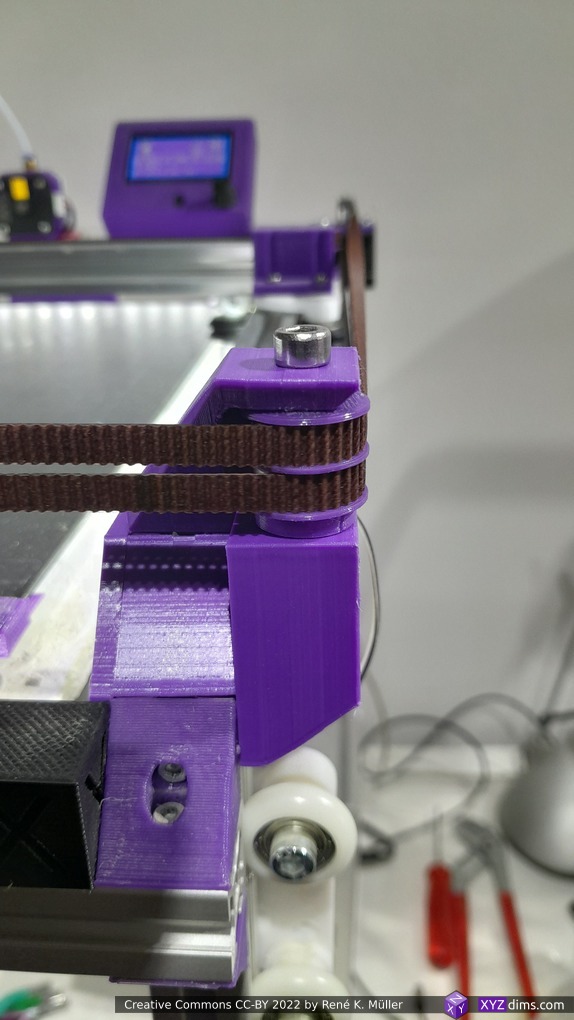
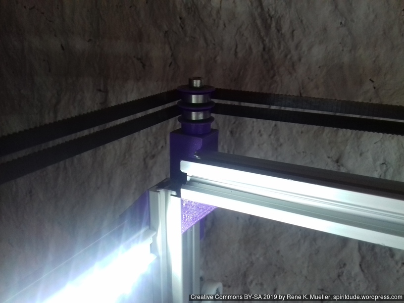
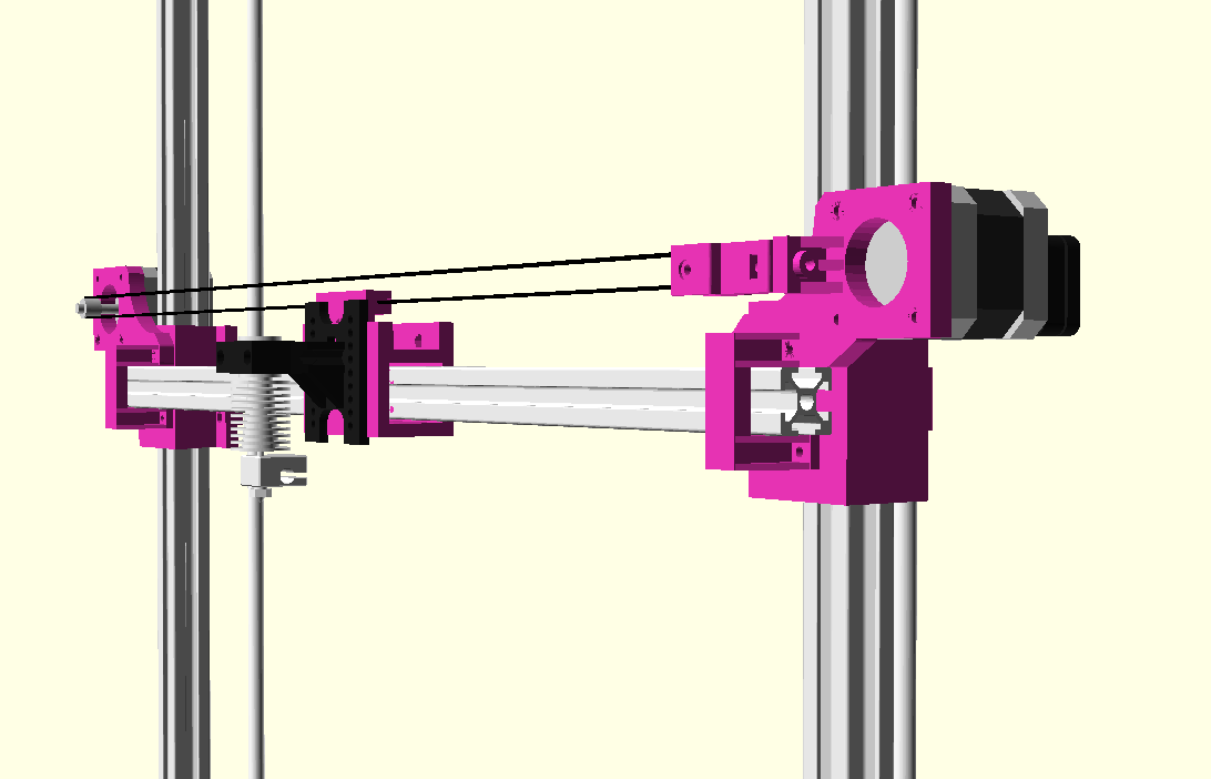
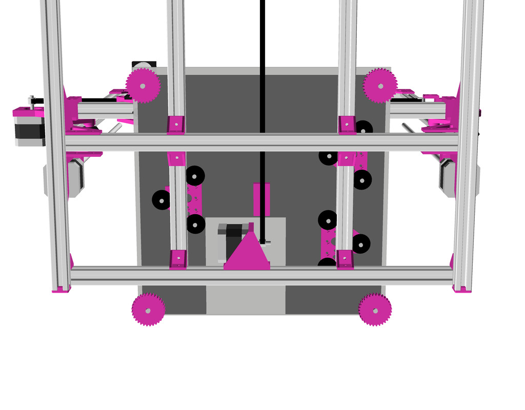
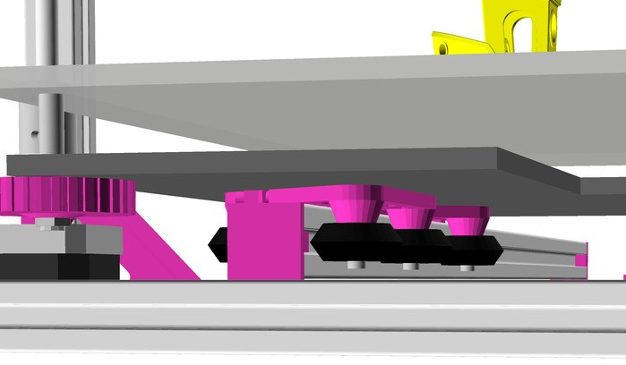
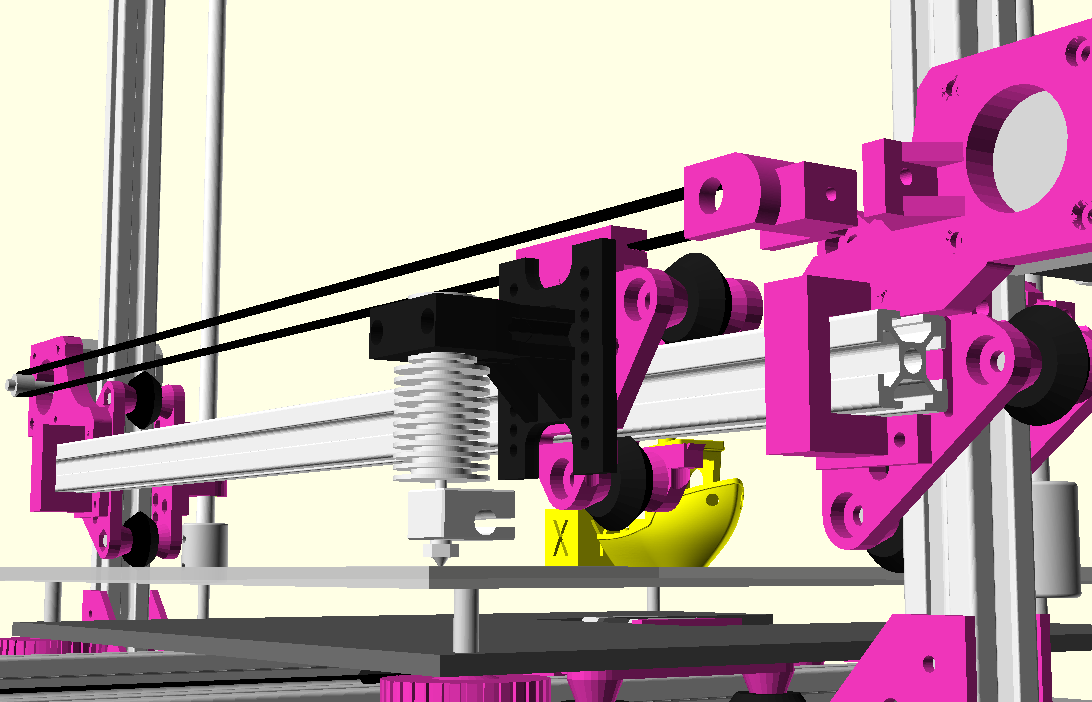
The XY belt routing of CoreXY is more complex than usual, I decided to separate A and B motor belts on the Z axis with two levels, and twist the belts once so the notches would not roll over the redirectional idlers (more detailed photos follow):

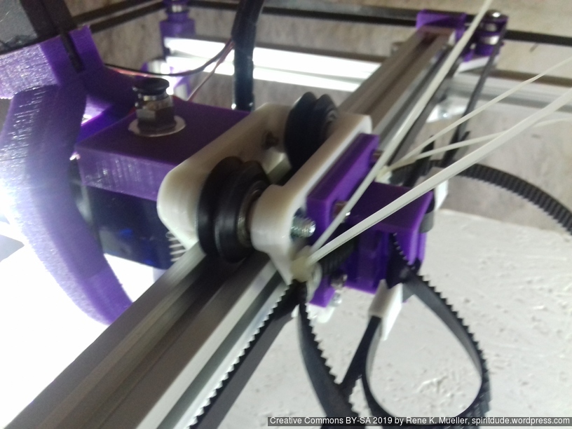
Key features:
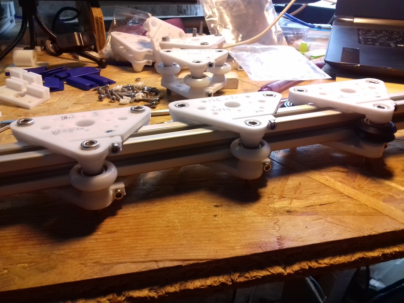
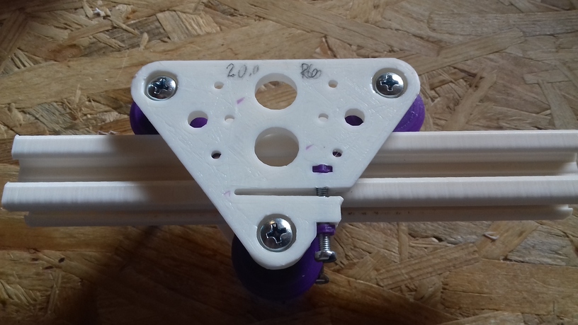
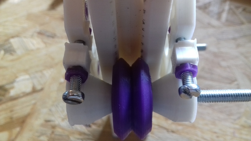
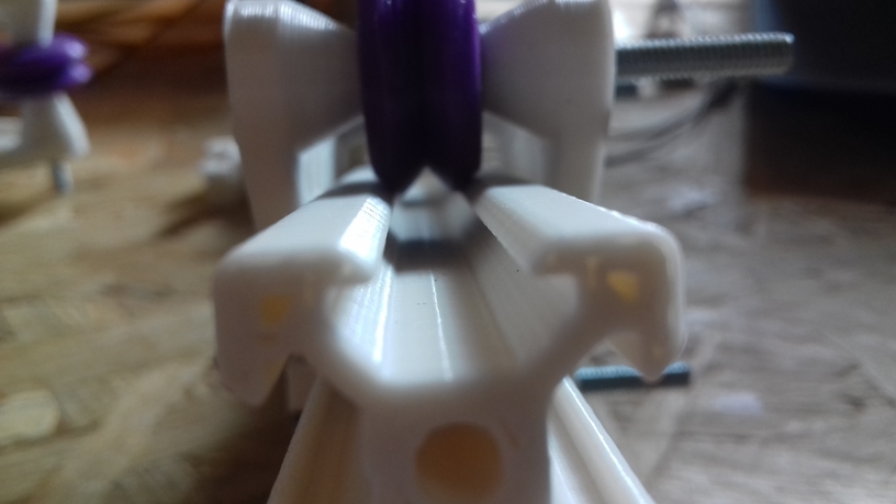
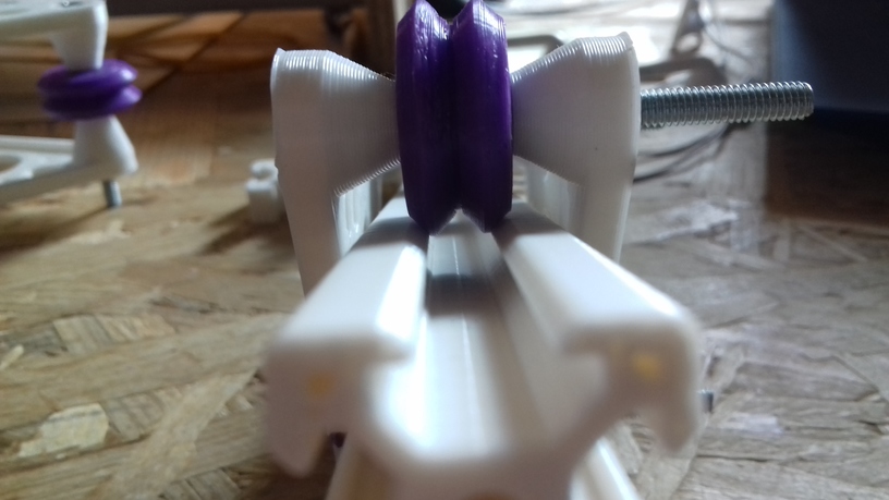
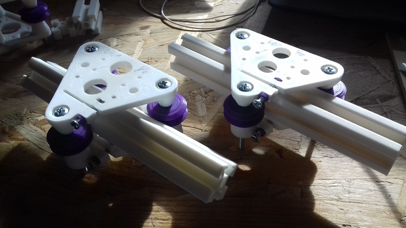
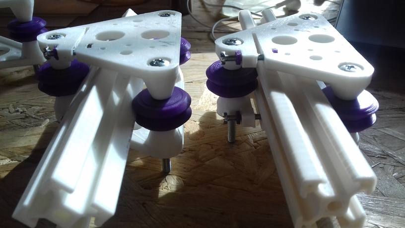
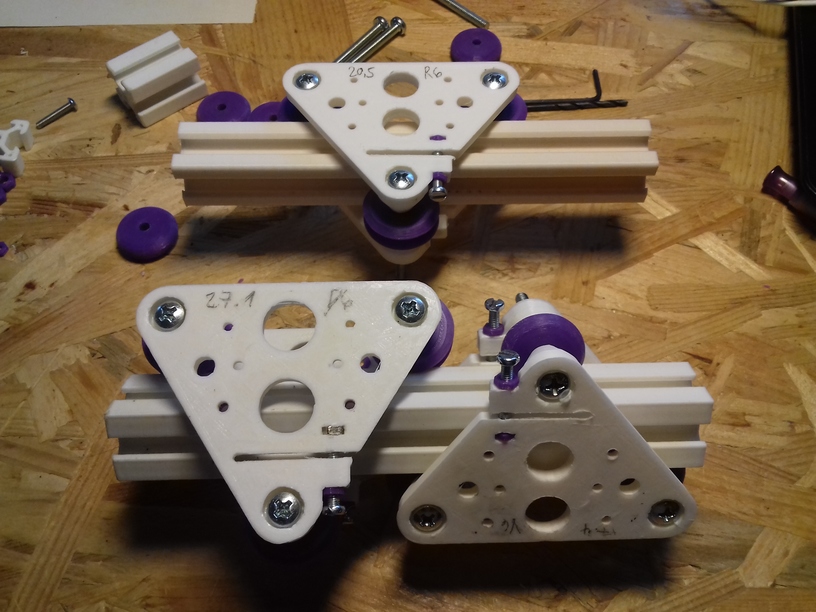
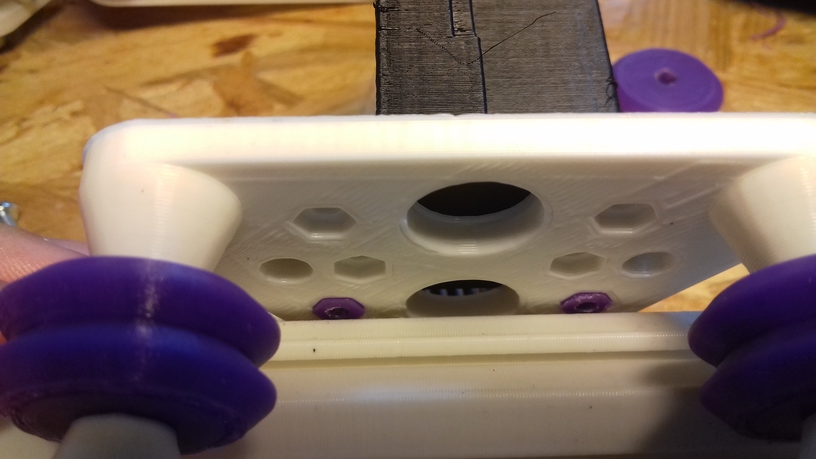
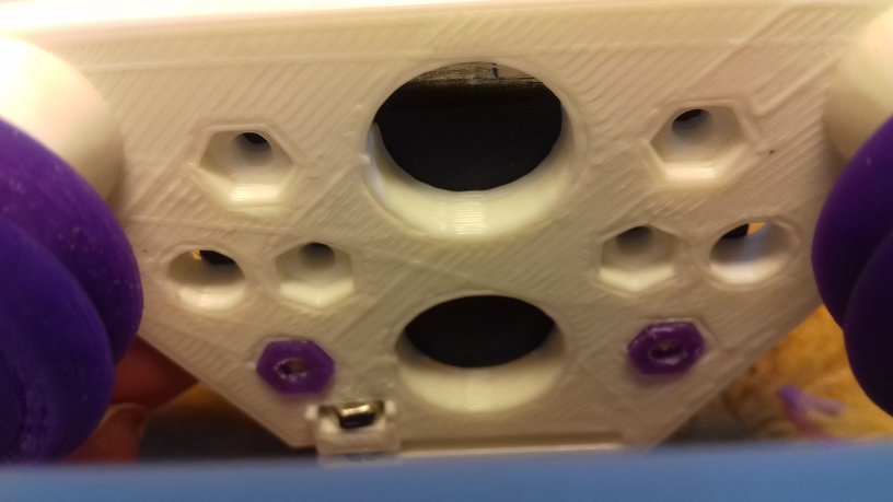
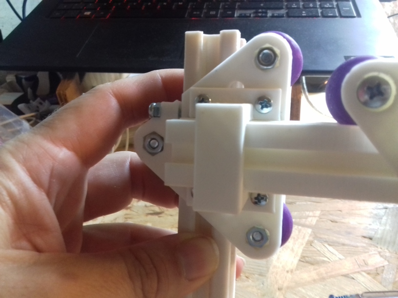
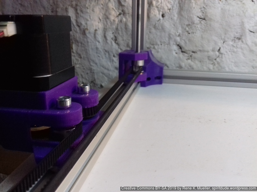
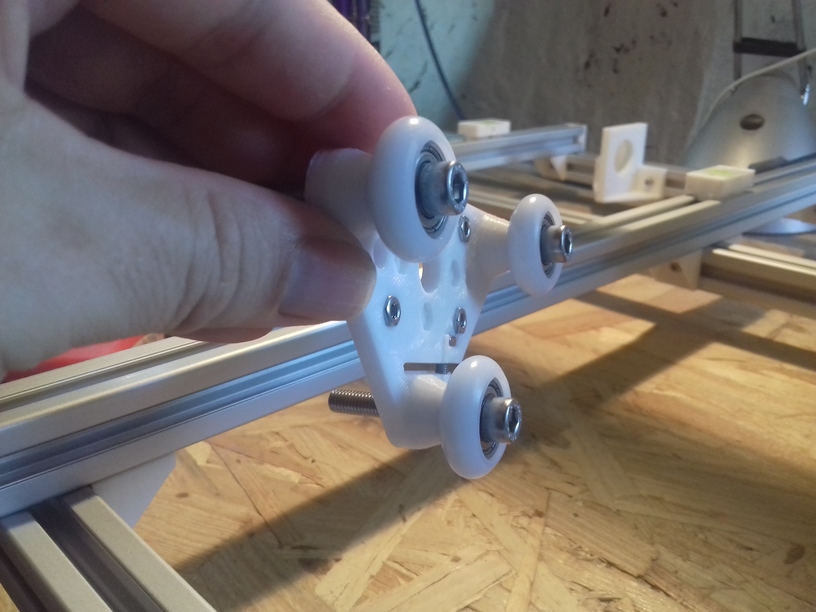
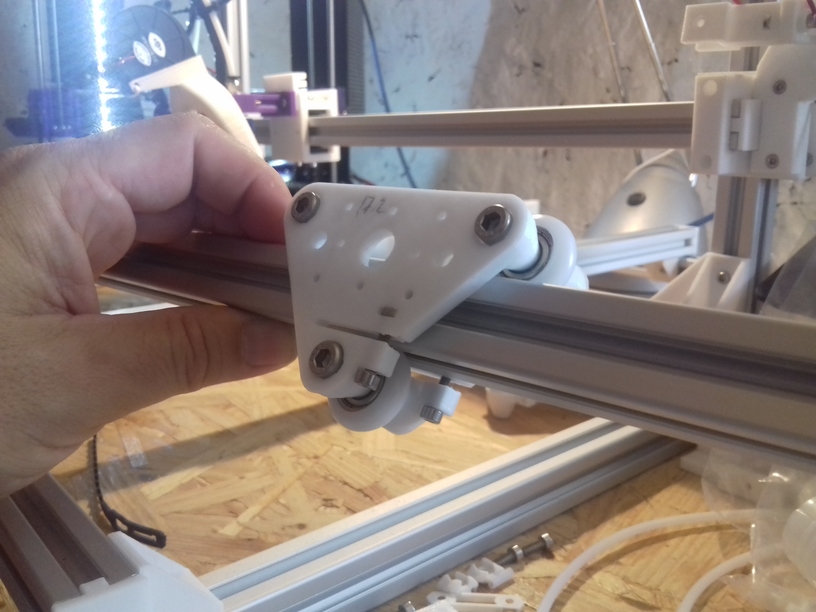
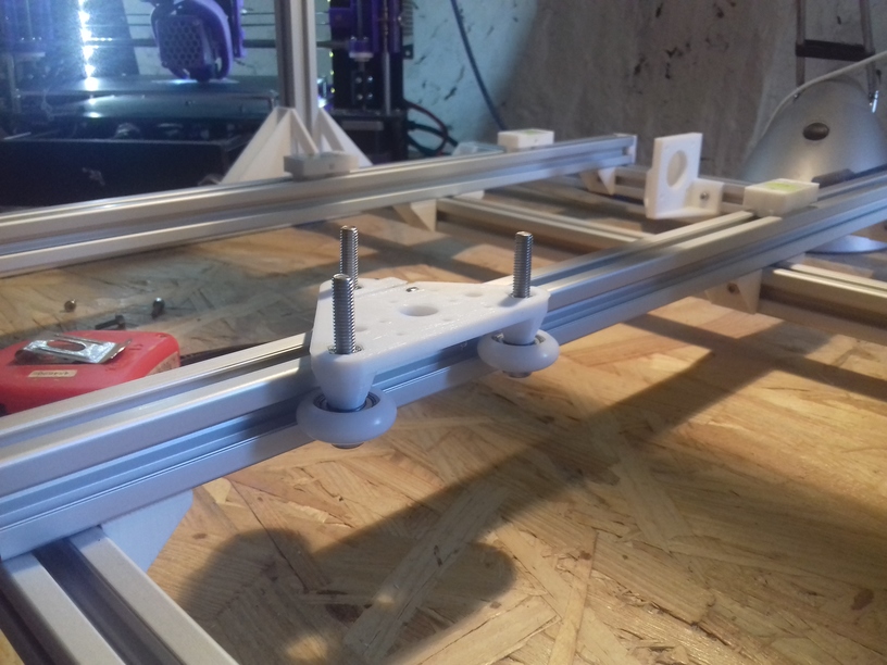
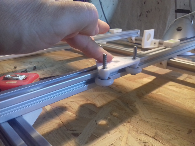
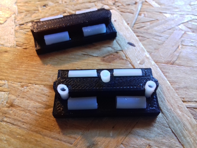
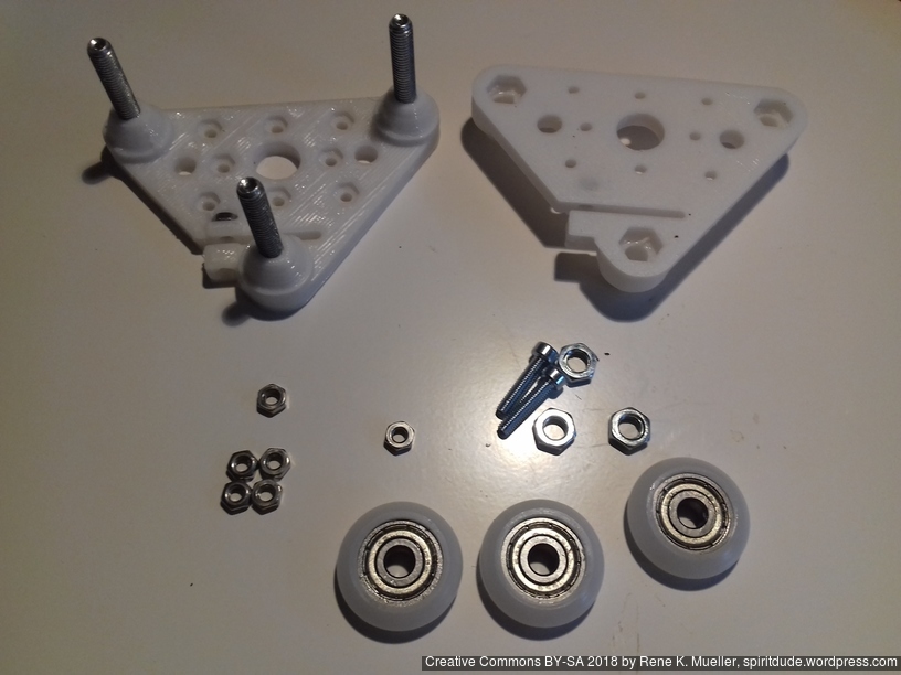
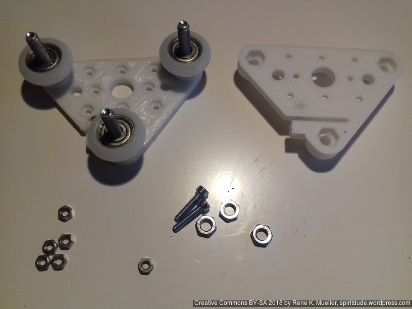
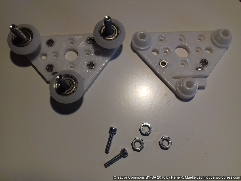
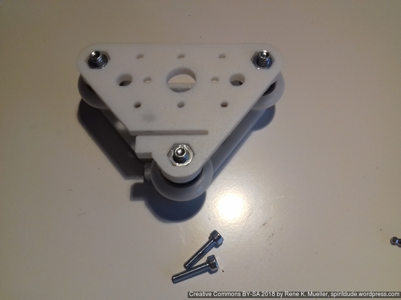
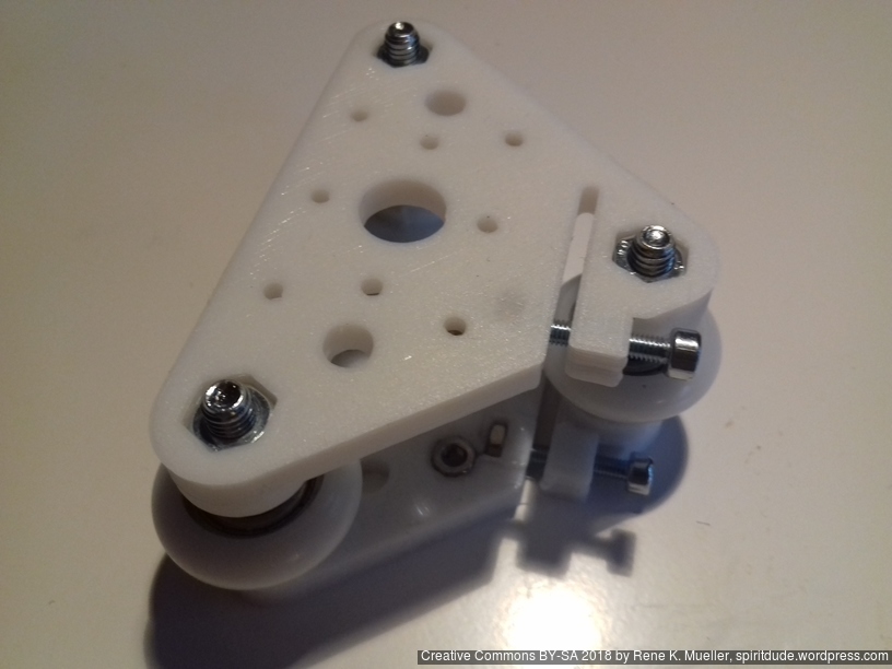
- V (3 wheels) shaped 2x Y carriages:
v_plate(width=54), width=48 was too narrow as the belt would touch the X beam, to ride on 2x “Y” V slot extrusions- using one roller axis to extend for belt routing with 2 idlers made with 625ZZ bearings and a couple of printed washers
- attaching belts on the back of the X carriage, very little space wasted
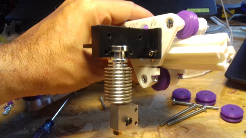
- V (3 wheels) shaped X carriage:
v_plate(width=48)narrow enough to achieve in X ~385mm range - stepper motors A & B at the back
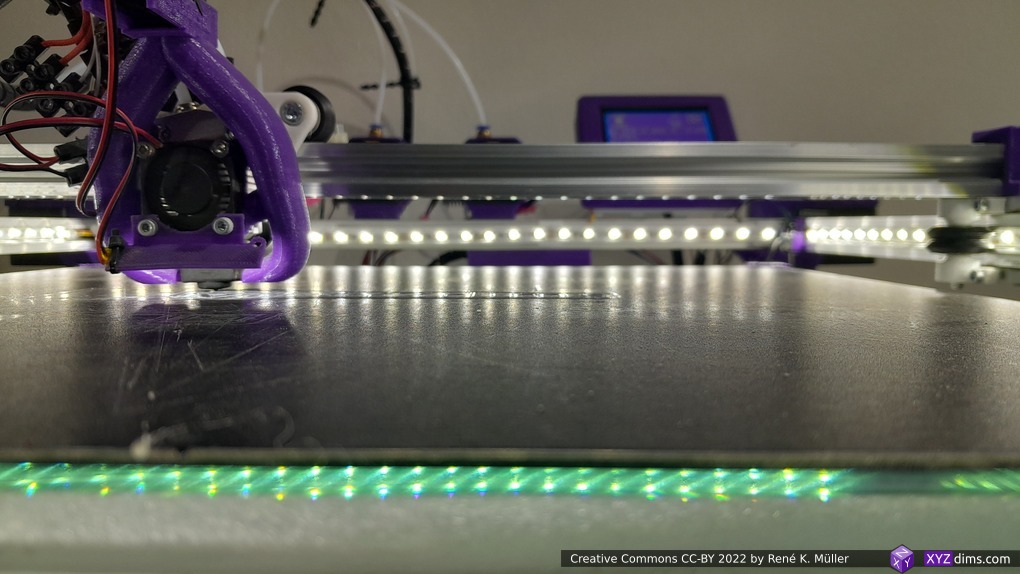
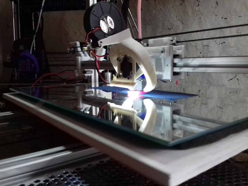
Bed
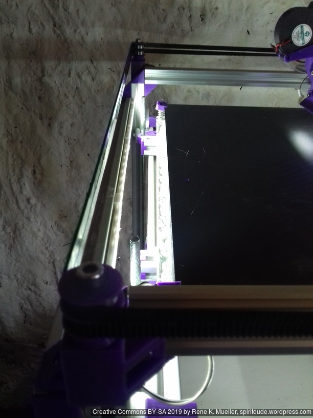
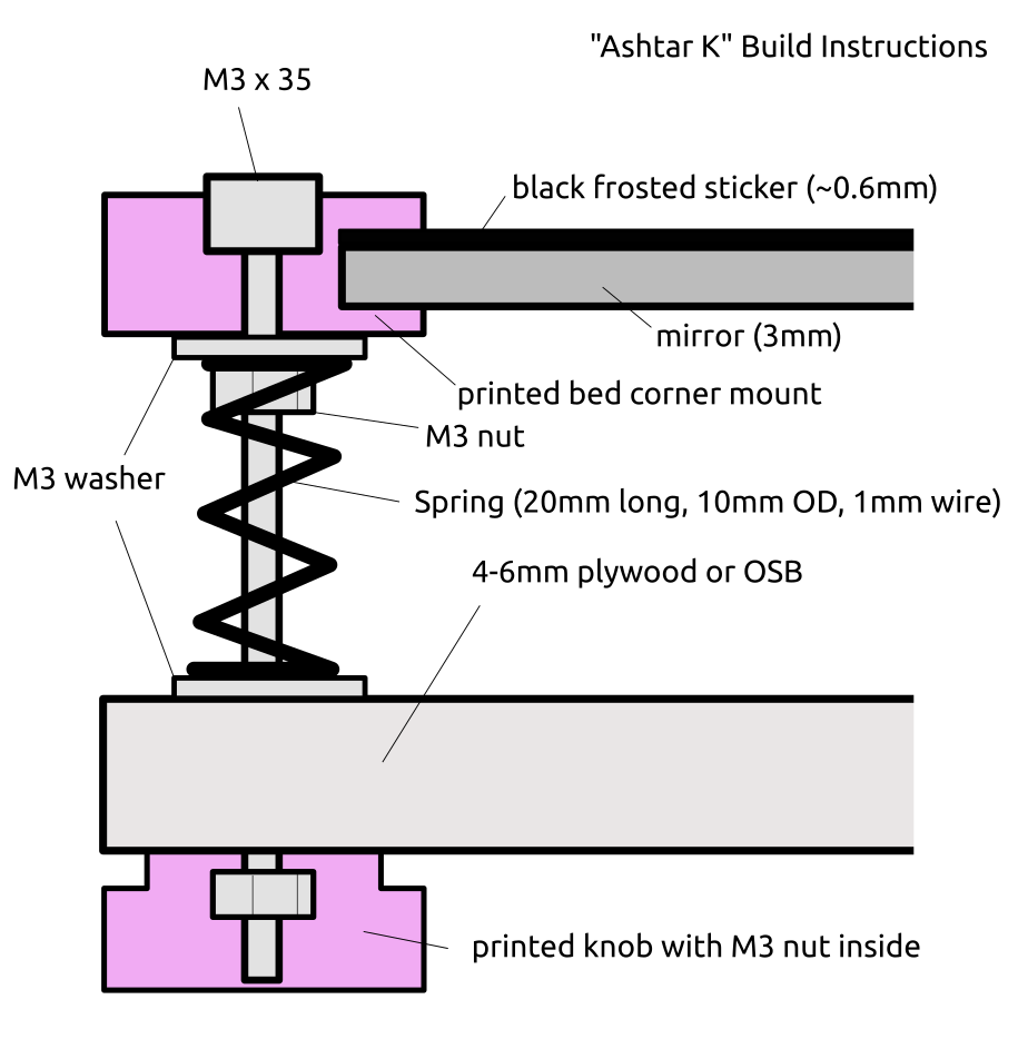
Alike with Ashtar K I used a mirror as main bed structure for Ashtar C:
- 400 x 400mm black bed sticker (~0.7mm thick)
- 400 x 400 x 4mm mirror (custom order)
- 4x bed corner mounts (printed), with M3 x 30 and spring and 4x washers each
- 420 x 420 x 4mm OSB
residing on 2020 T-slot alu extrusions.
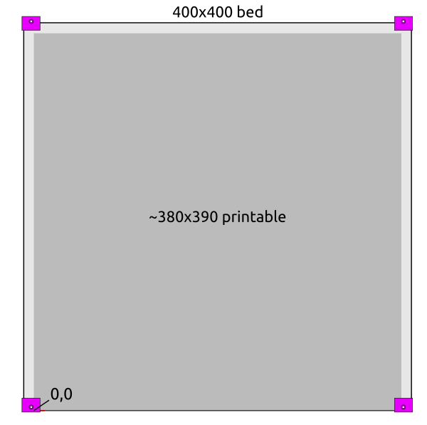
There are few millimeters in front in the left and right corner which cannot be printed on because of the bed mounts; at the back the nozzle won’t touch the bed mounts, but fan shrouds might – so one has to be aware of:
- the X stop is at the left (X=0)
- the Y stop is at the back (Y=390)
- start of print at X = W/2 (e.g. 190), Y = -3, so the oozing of filament will be chopped when moving to the print position.
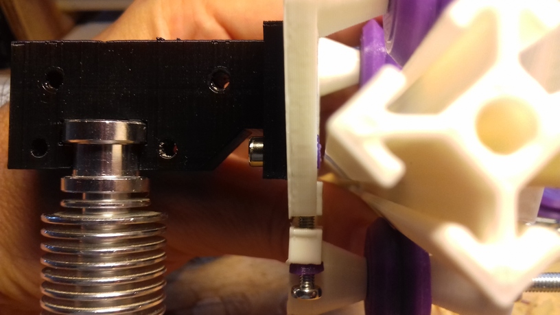
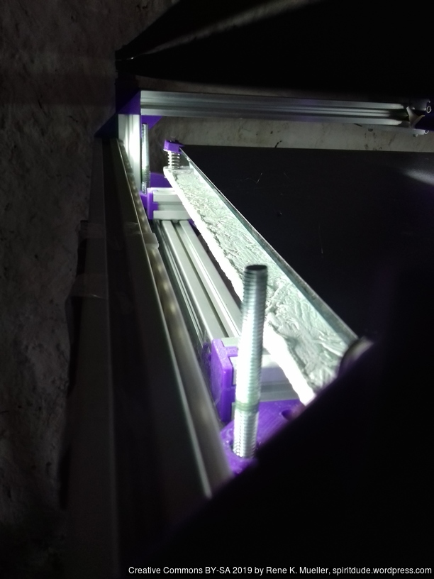
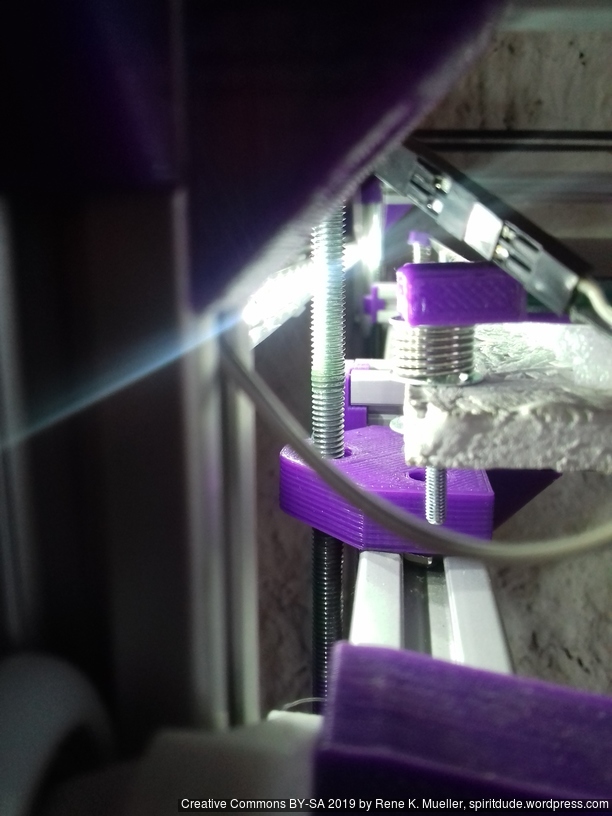
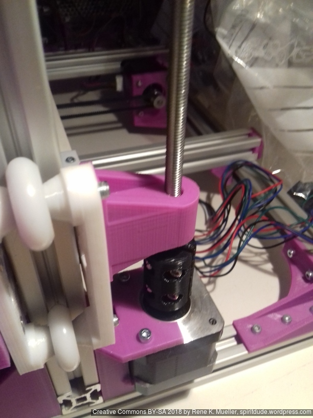
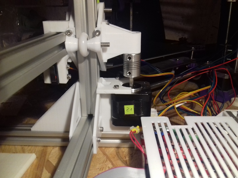
Z Axis
It took me some research and trial-and-error to determine Z axis in its details:
- Option A
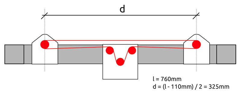
- 2x Nema17 (45Nm) stepper motor with 18 teeth GT2 pulley 5mm bore
- 2x 760mm closed belt
- Option B
- Using 3 or higher : 1 gear box (e.g. 3:1 gearbox could be used, but external shaft isn’t strong enough stabilized versus tilt) or alike to increase torque and still drive 4 threaded rods
- Option C (not recommended)
- 1x Nema 17 (45Nm) stepper motor driving 4x M6 threaded rods with 1524mm long closed GT2 belt – even when well greased rods and well aligned, I still experienced occasional skipped steps, which made this option not reliable – so I switched to 2x closed loop belts Option A.
- 4x M6 x 490mm threaded rods
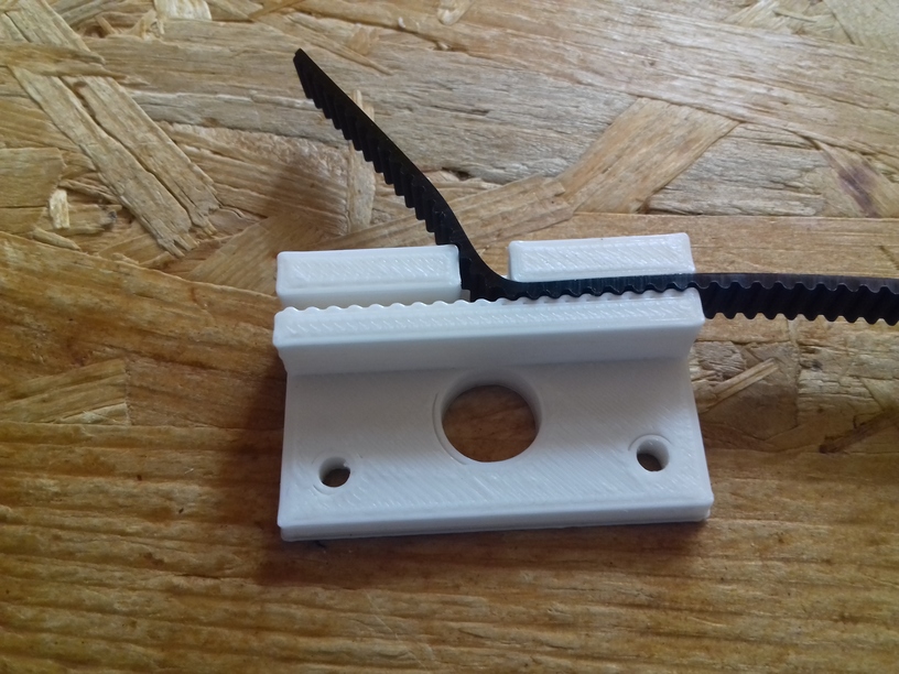
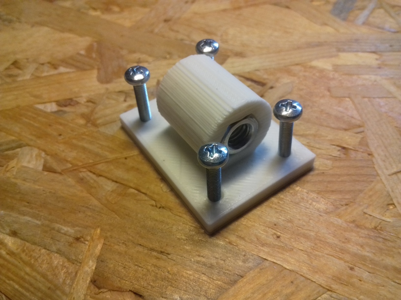
- 4x M6 nuts with bed mounts (printed)
- 4x bottom Z rod mount (printed)
- 8x 606ZZ bearings (each rod has 2 bearings)
- 4x 18 teeth GT2 pulley 6mm bore
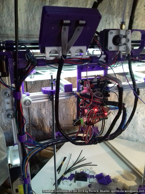
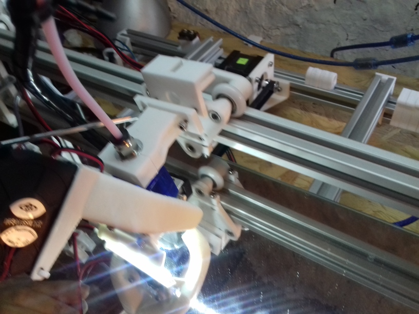
Electrical Wiring
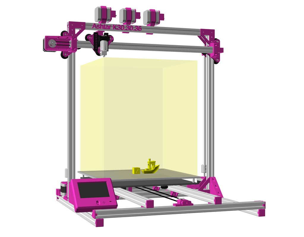
I positioned the main controller board near the A/B stepper motors and the extruder motors at the back of the cubic framework:
- advantage: most cables remain short and can be well put together
- disadvantage: controller box with display cable too short to mount it in front, so remains on the back as well
Firmware
I’m using Marlin 1.1.8 (for MKS Gen L1), following changes were required
- stepper motors A & B reside on the back, left-front will be 0,0
- X direction was reversed
- Y direction was correct
It was quite complicate to reverse X, as #define INVERT_X_DIR true was not doing it, but just reverse the motor direction, which in CoreXY also affects Y. Solution was, after some back and forth trying #define COREYX as well and failing, was to swap cables of A/B motors and
Configuration.h#define COREXY#define INVERT_X_DIR true#define INVERT_Y_DIR true
Further, Z axis is driven by 2x Z motors, as driven 3 or 4 threaded rods with a single motors lead to various missing steps, so 2x Z motors with MKS Gen L controller board:
- Z motor #1: Z motor
- Z motor #2: E1 motor
-
Configuration_adv.h:#define Z_DUAL_STEPPER_DRIVERSenabled
> M503
-----
echo:  G21    ; Units in mm
echo:  M149 C ; Units in Celsius

echo:Filament settings: Disabled
echo:  M200 D1.75
echo:  M200 T1 D1.75
echo:  M200 T2 D1.75
echo:  M200 D0
echo:Steps per unit:
echo:  M92 X100.00 Y100.00 Z3200.00 E102.00
echo:Maximum feedrates (units/s):
echo:  M203 X400.00 Y400.00 Z2.00 E45.00
echo:Maximum Acceleration (units/s2):
echo:  M201 X1400 Y1400 Z50 E80000
echo:Acceleration (units/s2): P<print_accel> R<retract_accel> T<travel_accel>
echo:  M204 P1400.00 R5000.00 T1000.00
echo:Advanced: S<min_feedrate> T<min_travel_feedrate> B<min_segment_time_us> X<max_xy_jerk> Z<max_z_jerk> E<max_e_jerk>
echo:  M205 S0.00 T0.00 B20000 X13.00 Y13.00 Z0.30 E5.00
echo:Home offset:
echo:  M206 X0.00 Y0.00 Z0.00
echo:Material heatup parameters:
echo:  M145 S0 H180 B55 F255
echo:  M145 S1 H240 B100 F255
echo:PID settings:
echo:  M301 P19.86 I1.00 D98.93
ok
Update 2022/09: I replaced the aged MKS-Gen L1 (Marlin 1.1) with MKS Monster8 V1.0 (Marlin 2.0.x):
> M503
-----
echo:  G21    ; Units in mm (mm)
echo:  M149 C ; Units in Celsius

echo:; Filament settings: Disabled
echo:  M200 T0 D1.75
echo:  M200 T1 D1.75
echo:  M200 T2 D1.75
echo:  M200 S0
echo:; Steps per unit:
echo: M92 X100.00 Y100.00 Z3200.00 E102.00
echo:; Maximum feedrates (units/s):
echo:  M203 X500.00 Y500.00 Z2.00 E120.00
echo:; Maximum Acceleration (units/s2):
echo:  M201 X9000.00 Y9000.00 Z50.00 E10000.00
echo:; Acceleration (units/s2): P<print_accel> R<retract_accel> T<travel_accel>
echo:  M204 P1500.00 R1500.00 T1500.00
echo:; Advanced: B<min_segment_time_us> S<min_feedrate> T<min_travel_feedrate> X<max_x_jerk> Y<max_y_jerk> Z<max_z_jerk> E<max_e_jerk>
echo:  M205 B20000.00 S0.00 T0.00 X10.00 Y10.00 Z0.20 E2.50
echo:; Home offset:
echo:  M206 X0.00 Y-5.00 Z0.15
echo:; Material heatup parameters:
echo:  M145 S0 H180.00 B70.00 F0
echo:  M145 S1 H240.00 B110.00 F0
echo:; PID settings:
echo:  M301 P22.20 I1.08 D114.00
echo:; LCD Contrast:
echo:  M250 C255
echo:; Power-Loss Recovery:
echo:  M413 S1
echo:; Stepper driver current:
echo:  M906 X700 Y700 Z1000
echo:  M906 T0 E700
echo:  M906 T1 E700
echo:  M906 T2 E700

echo:; Driver stepping mode:
echo:  M569 S1 X Y Z
echo:  M569 S1 T0 E
echo:  M569 S1 T1 E
echo:  M569 S1 T2 E
echo:; Tool-changing:
echo: Z2.00
ok
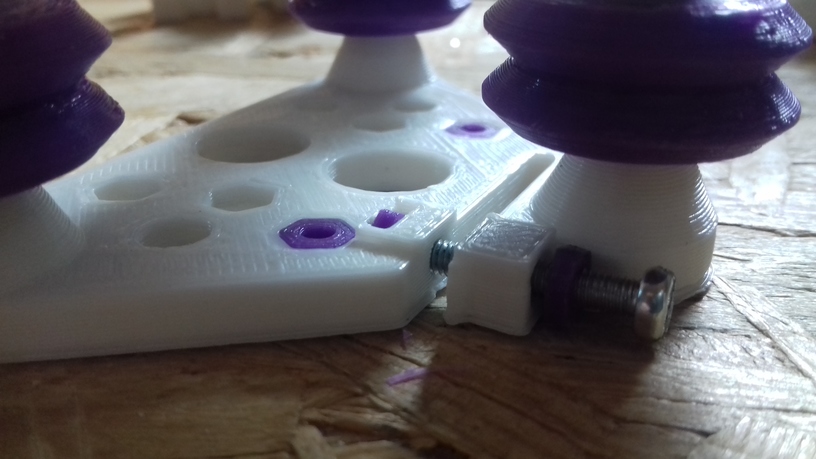
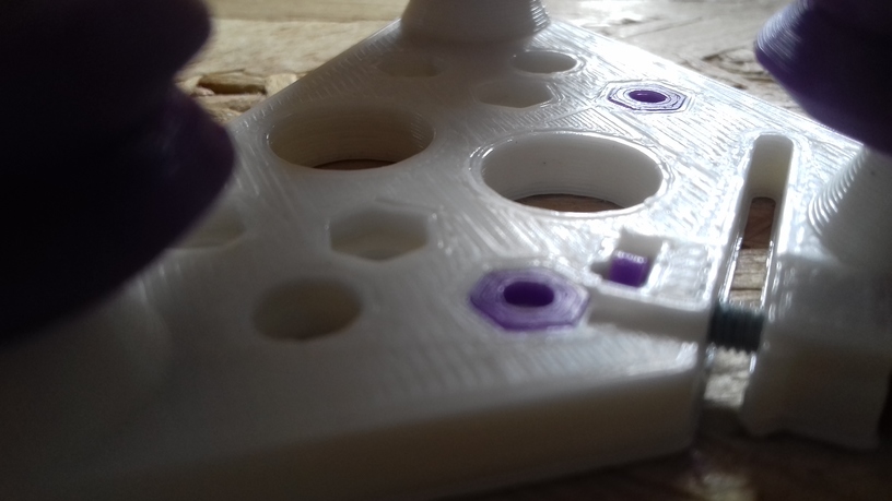
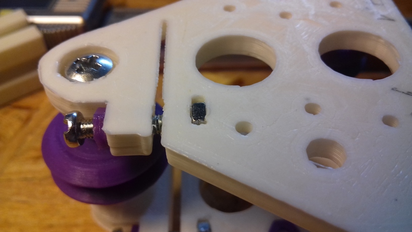
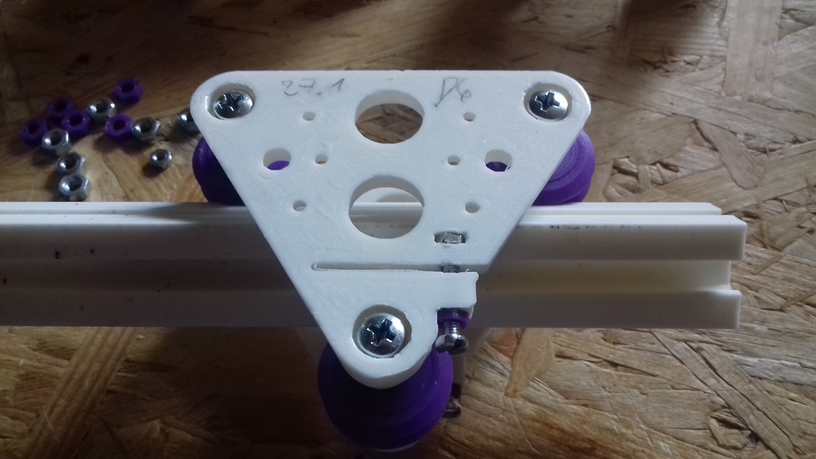
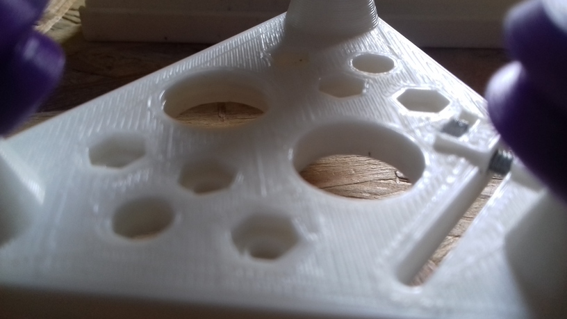
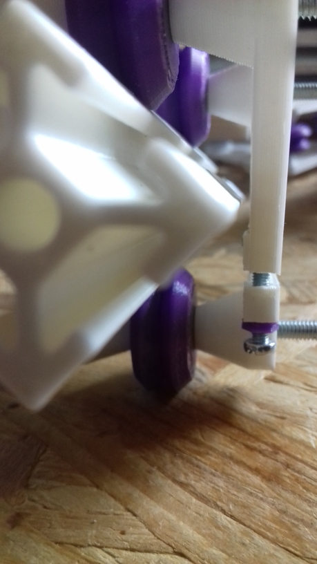
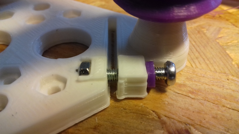
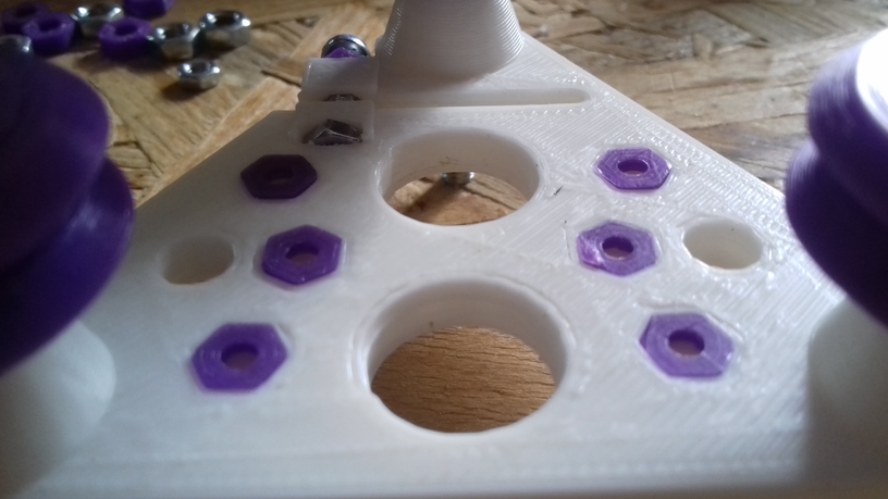
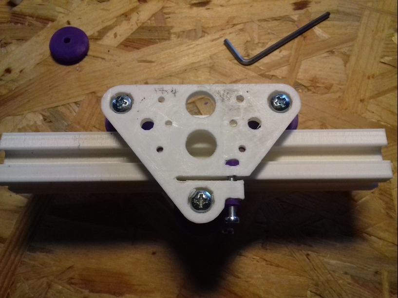
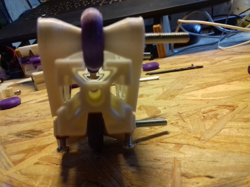
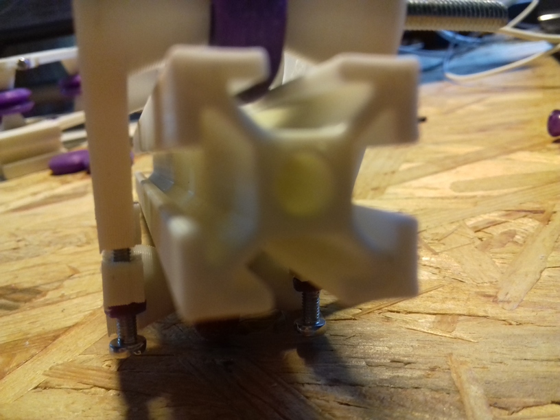
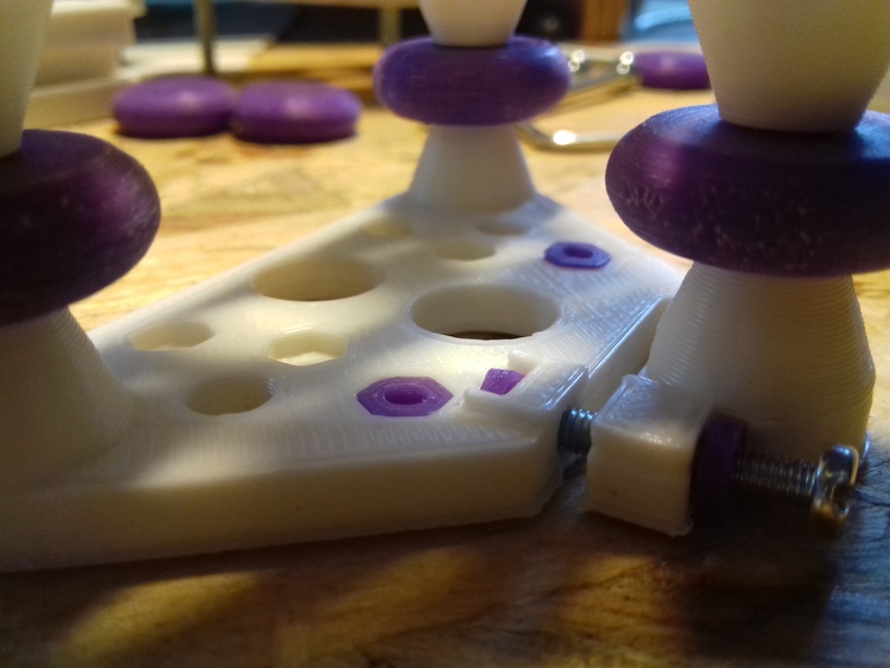
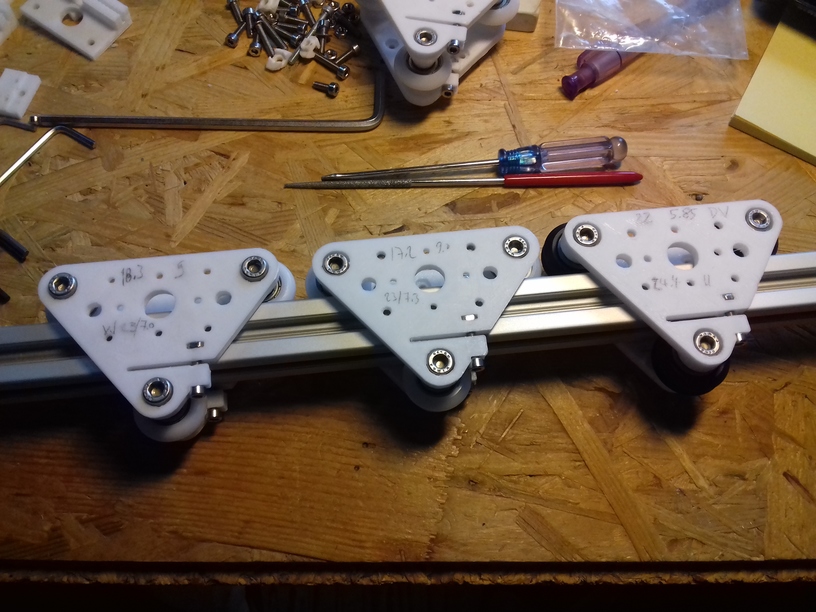
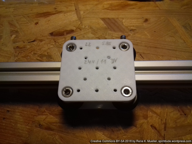
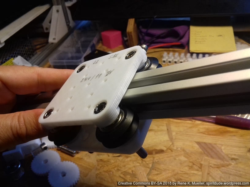
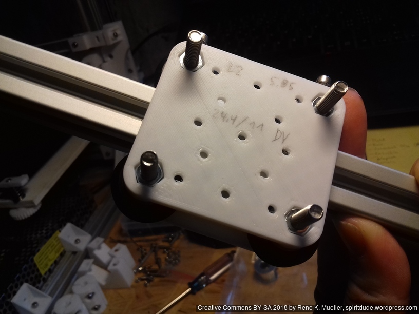
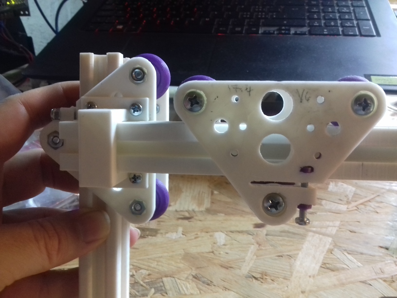
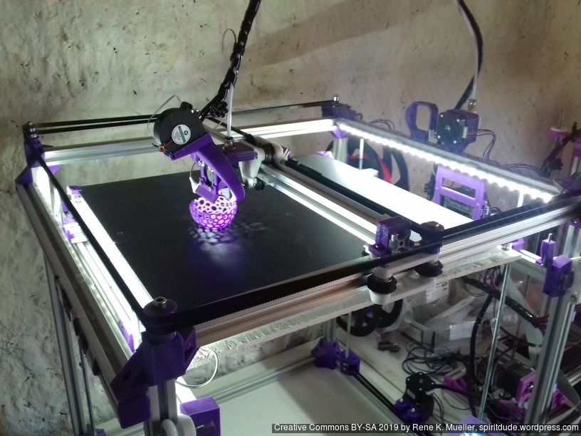
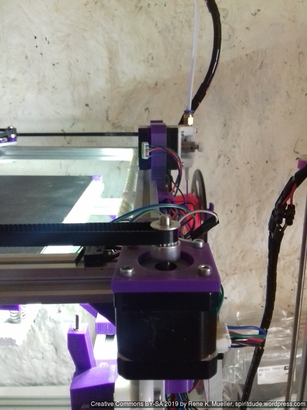
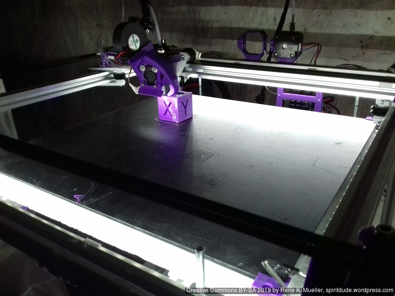
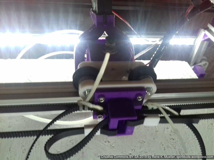
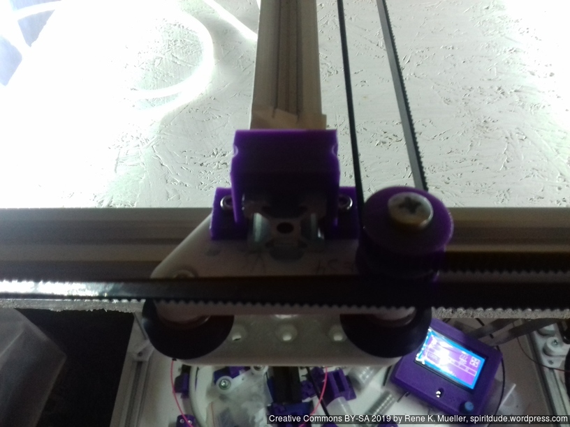
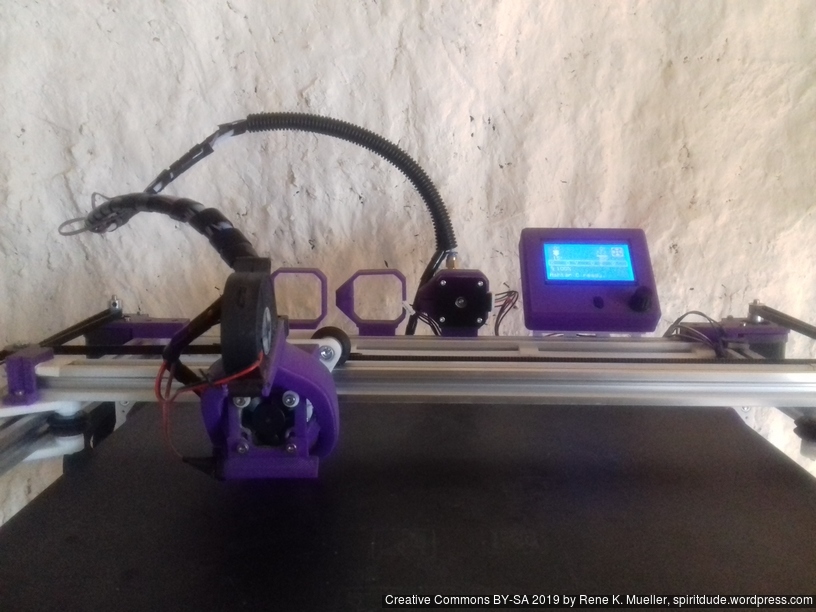
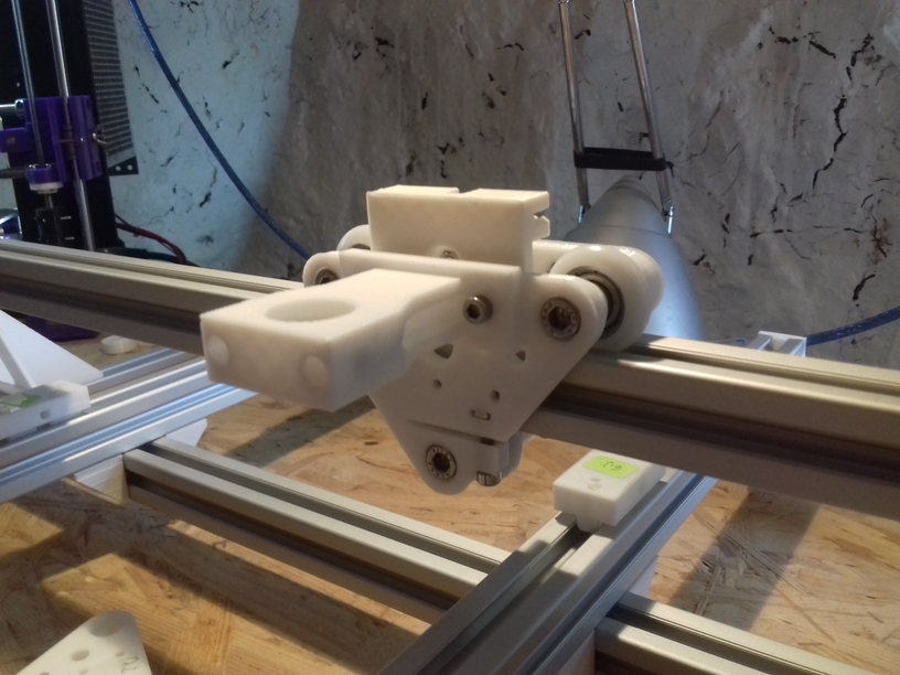
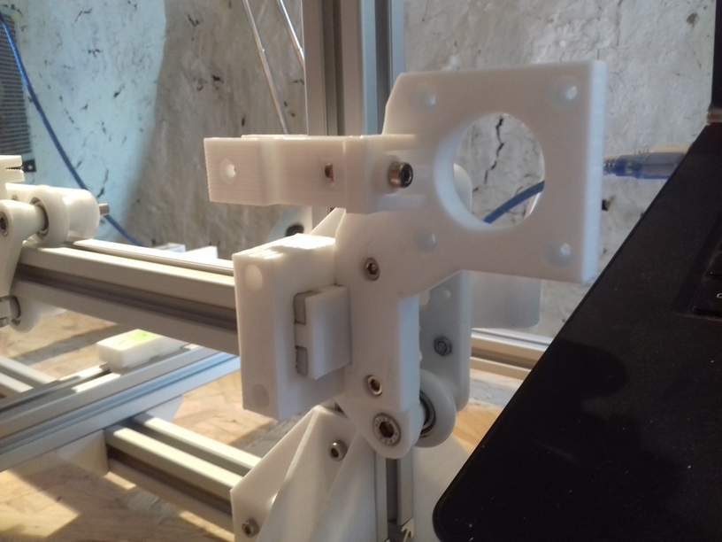
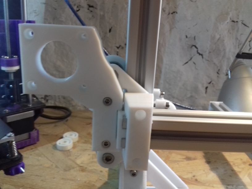
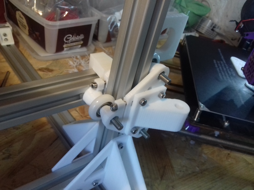
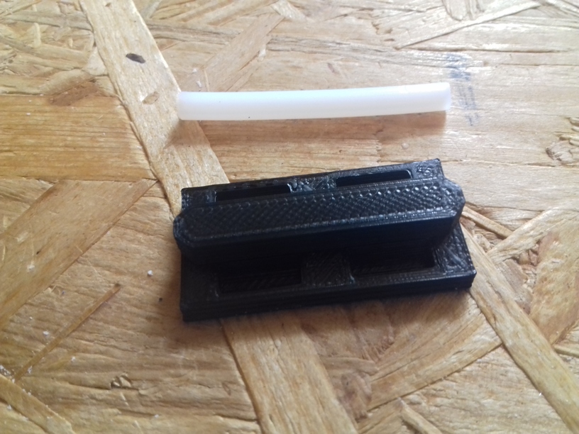
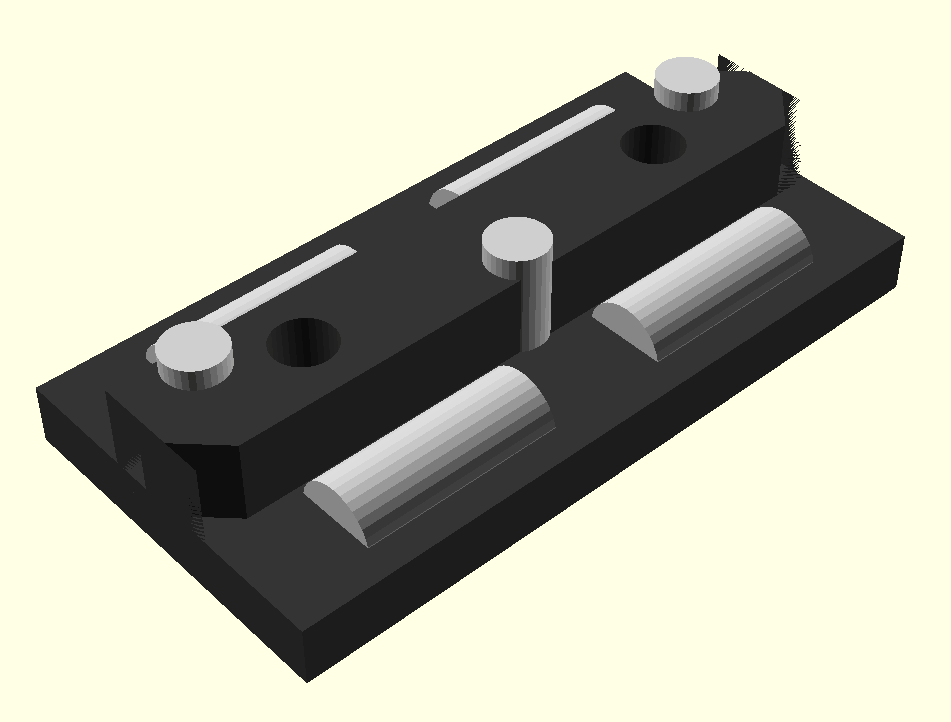
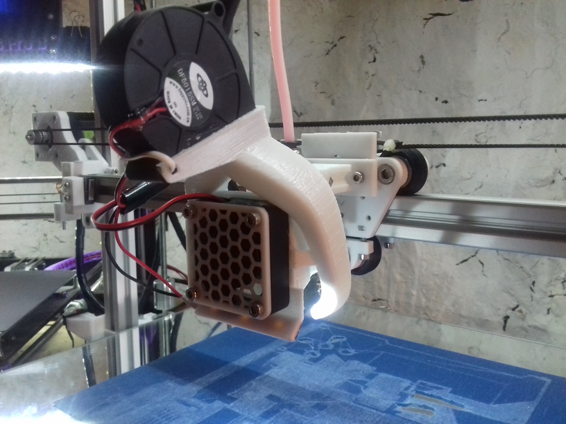
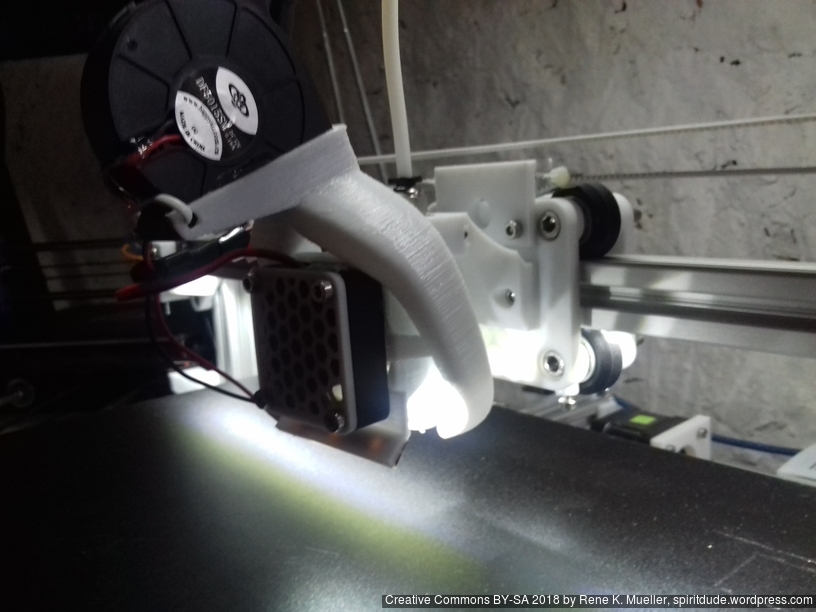
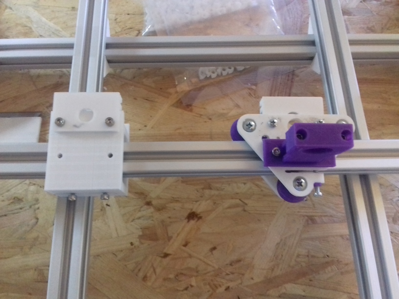
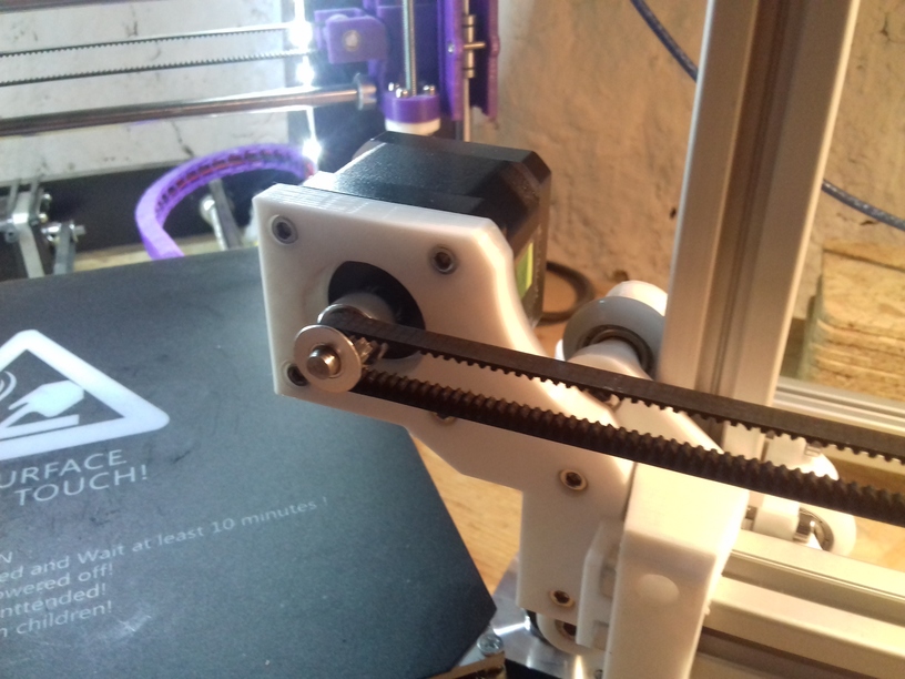
X Carriage
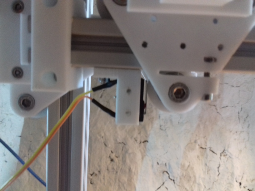
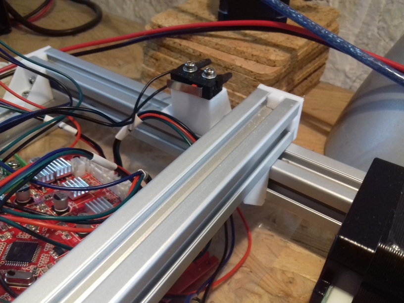
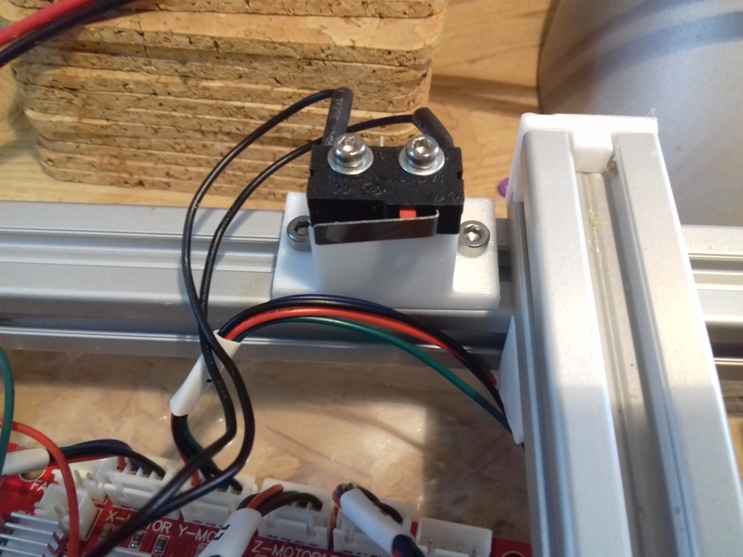
First I had the X stopper at the left-hand side of the X beam (Photo 3), but the cable entangled with other parts, so I moved the X stopper on the X carriage (Photo 1 & 2)
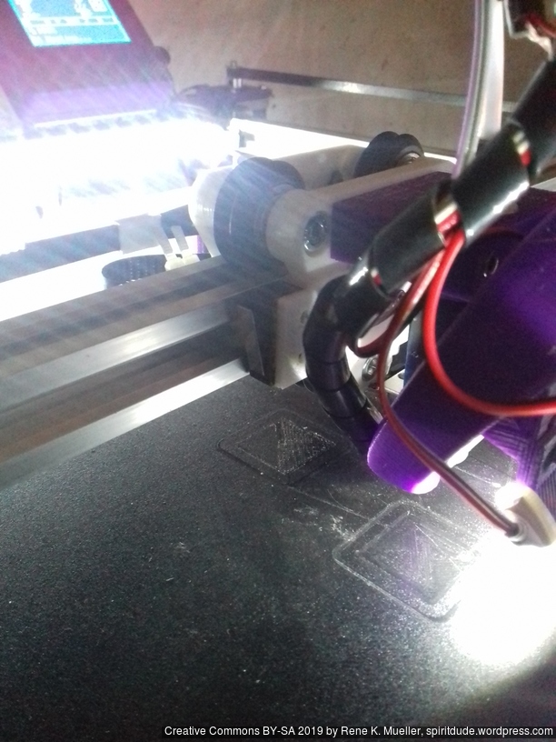
- X stopper: on the X carriage
- Y stopper: right-hand back side of the main frame
- Z stopper: right-hand back side of the main frame
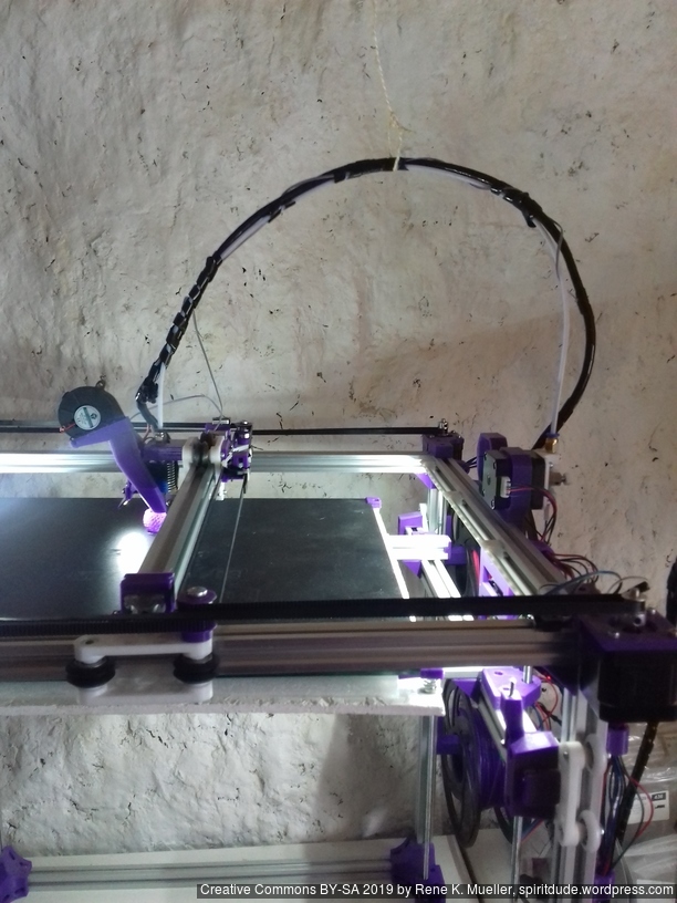
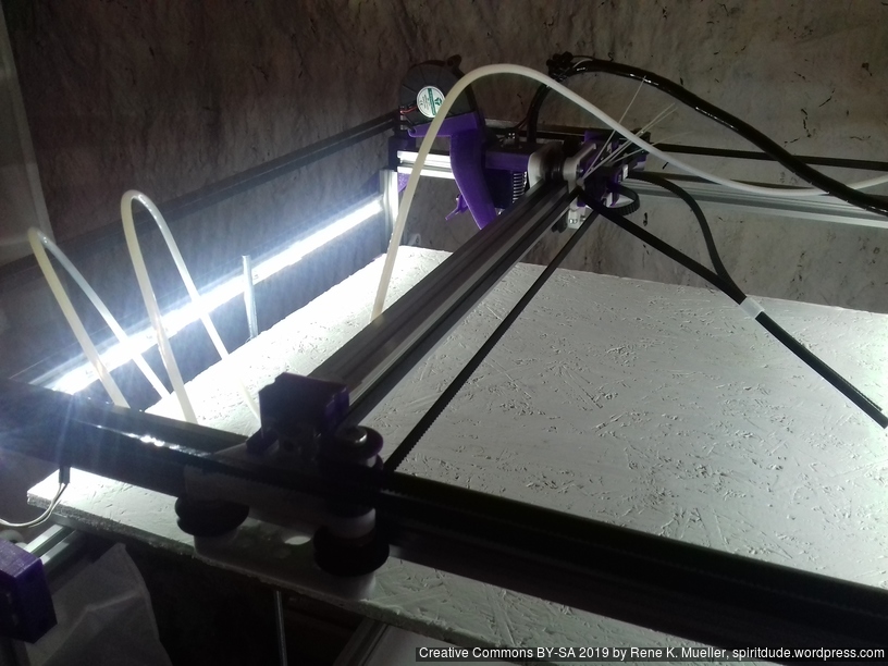
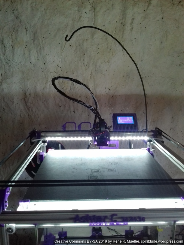
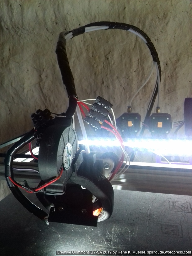
The PTFE 4mm OD / 2mm ID with the cables aren’t stiff enough to support themselves, so I added
- Option A: 4mm insulated copper wire as a gantry to keep the cables from falling on the print bed.
- Option B: strong plastic bundler near extruder to stiffen part of the cables/tubes.
Maintenance
Belt Tension of Core XY
The Core XY mechanism takes some further care:
- Parallelism: with the stepper motors off I move the carriage to the front and make sure both carriages of Y axis have the same distance to the end – if not, I tensioned the longer belt so both distances are the same = parallel to front beam.
- Missing Steps: I noticed once I tensioned belts to achieve parallelism that the belts got harder to run, and eventually at larger prints with fast and longer positioning movements near 120mm/s I was missing steps in X and/or Y and caused failed prints quickly – so I loosened A/B belts equally to maintain parallelism.
So, there is some learning and experiences required to determine the best equal tension of belt A and B.
Update 2022: I’ve used GATES-LL-2GT belts which resolved all the previous problems with parallelism, as slightly stretching belts caused all kinds of geometrical inaccuracies.
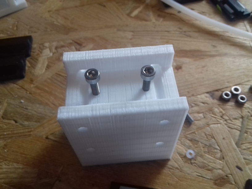
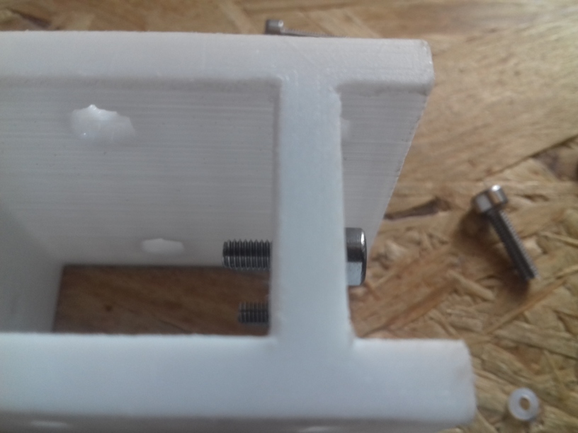
Stiffness of Frame
At first the frame wasn’t as sturdy as possible as the details were not yet determined, but with maturing and defining the details the edges of the frames became more sturdy and the noise of the operational printer increased; yet, the print quality increased significantly. Further, since many parts are printed in PLA, they require re-fastening after few days as PLA gives in under tension, in particular all the edge fastening parts, which as well improved print quality.
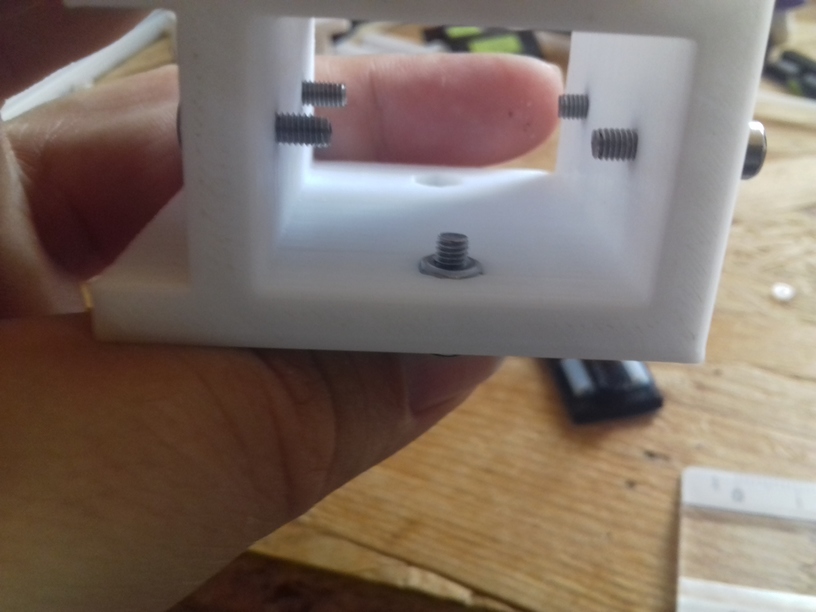
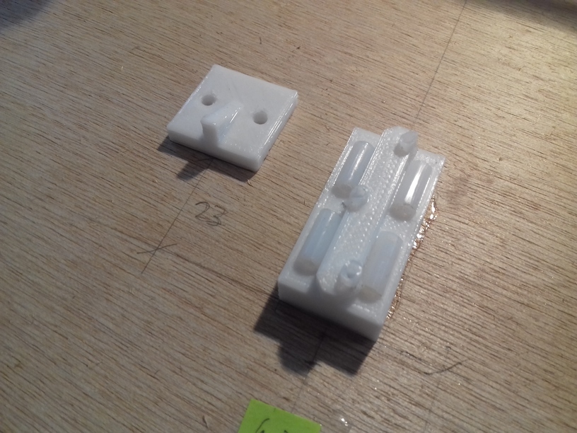
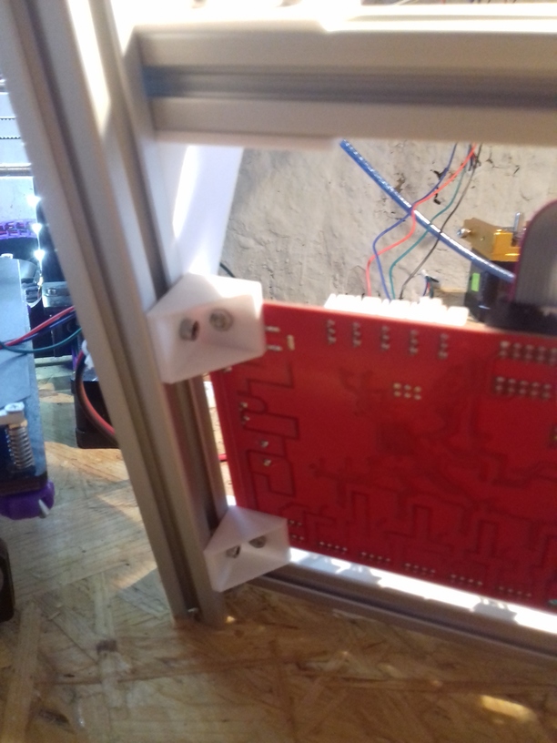
Update 2022: I made the corner pieces stronger, to avoid any bending there:
Z Axis
I use M6 x 500mm threaded rods for the Z axis, because they give 1.0mm way per revolution, given 1.8 degree per motor step or 200 steps per revolution, with 16 microsteps there are 3200 microsteps per revolution which gives 0.3um per microstep or 5um per step. Using M8 or M6 for Z axis has a bad reputation in Prusa i3 setup, something I only partially agree with, gives in my setup of Ashtar C no little Z wobble, but it may have introduced some slight non-linearity within the 1mm way which isn’t observable for me. Lead screws would provide excellent linearity but less resolution due higher pitch, often 8mm per revolution, or 40um per step.
In my early test, when I ran one stepper motor driving 4 well greased rods for the Z axis, I experienced eventual missing steps due the distributed friction at multiple spots (nut/threaded-rod, threaded-rod/pulley/bearing, etc), and few days in, even more. As a result I used two stepper motors each driving two threaded rods for the Z axis.
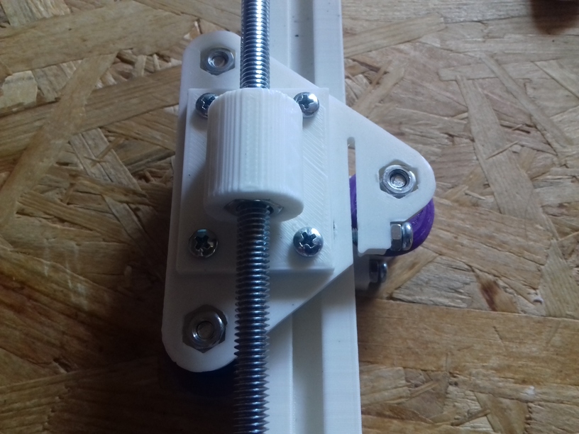
Fixing Z Wobble
While replacing the M6 x 500mm threaded zinc rods with stainless steel ones I noticed that I introduced severe Z wobble, which wasn’t there with lower quality M6 threaded rods – odd enough – and I moved the bed to Z=380 and noticed one rod swinging around due slightly titled rod, and reopen the GT2 pulley on the bottom with that rod, and turned the rod slightly and refasten the GT2 pulley again, the difference is significant: the wobble is nearly gone.
Update 2022: one of the key to resolve wobble is to keep the closed loop belts not too tight, otherwise their un-eveneness translates to the bed – keeping it a bit soft resolves it.
I may use 4x 8mm lead screws as a test as well and see how it performs regarding wobble but also resolution.
Todo
Z axis details (belt vs lead screw vs threaded rod)1 Z motor with closed loop belt: 1, 2, 3 or 4 threaded rods/leadscrews2 Z motors with/out closed loop belt: 2 or 4 threaded rods/leadscrews
details of belt redirection idler mountsmoving X endstop to X carriage itself (avoid cable entanglements)- stiffen or stabilize X carriage cables and Bowden tube
controller box positioning- release sources
- complete instructions
- list all parts properly
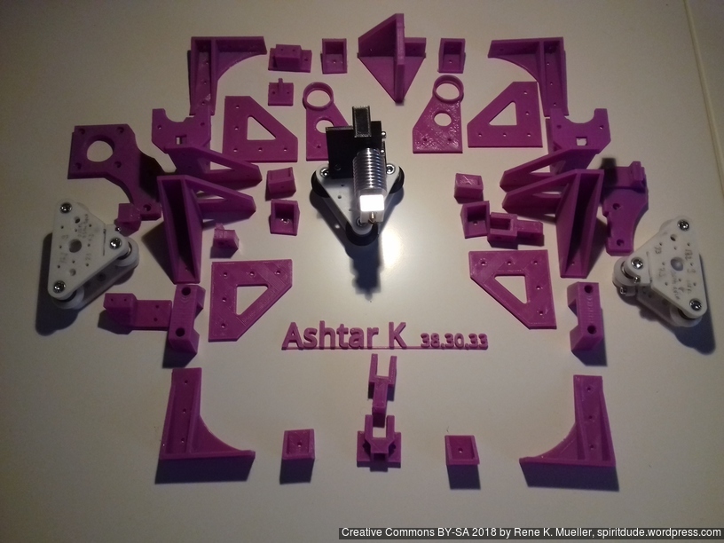
Parts
Printed Parts
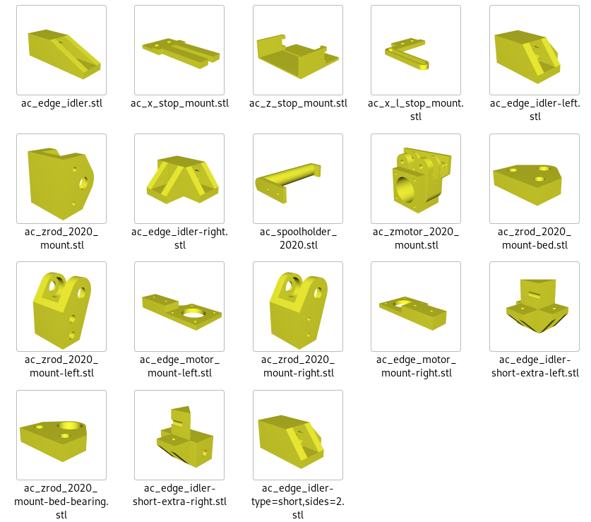
Not yet defined, reusing most of Ashtar K 2020 parts plus some Ashtar C specifics.
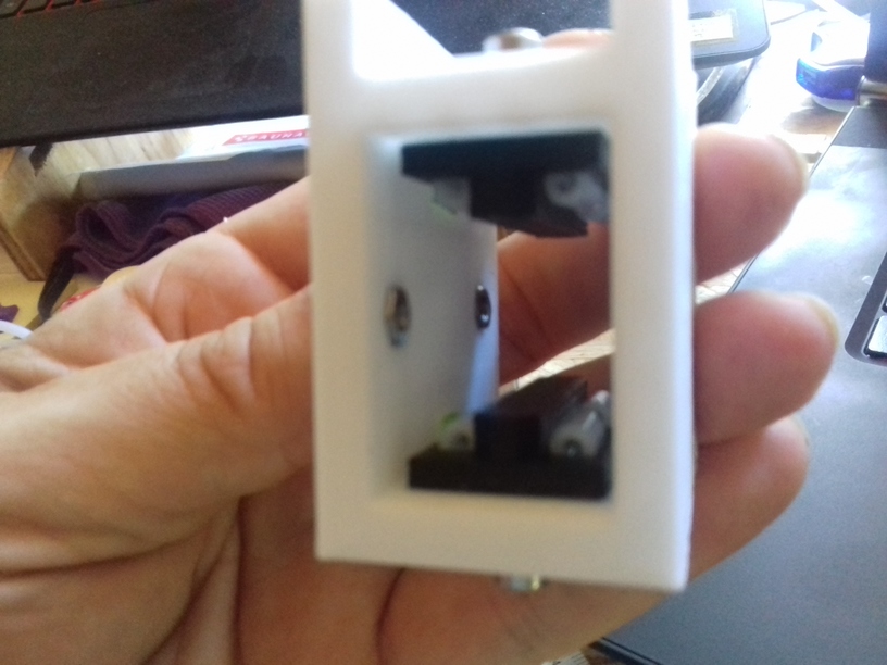
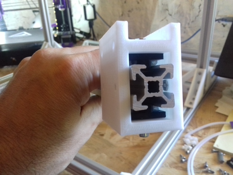
- Frame
- 4x cci_2020 (bottom corner brackets)
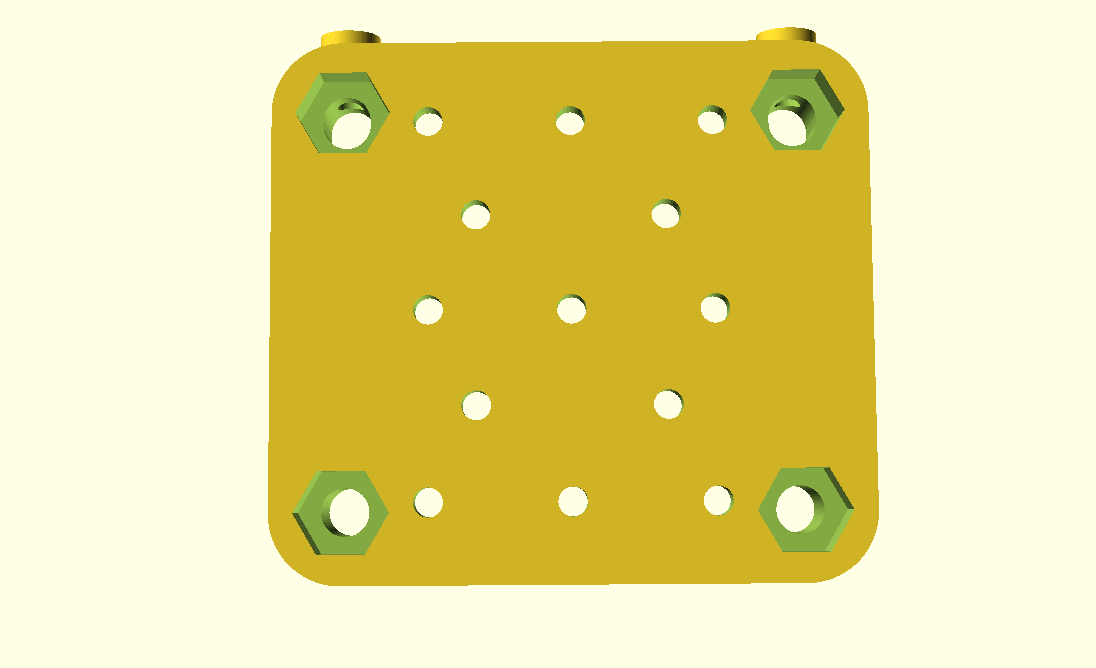
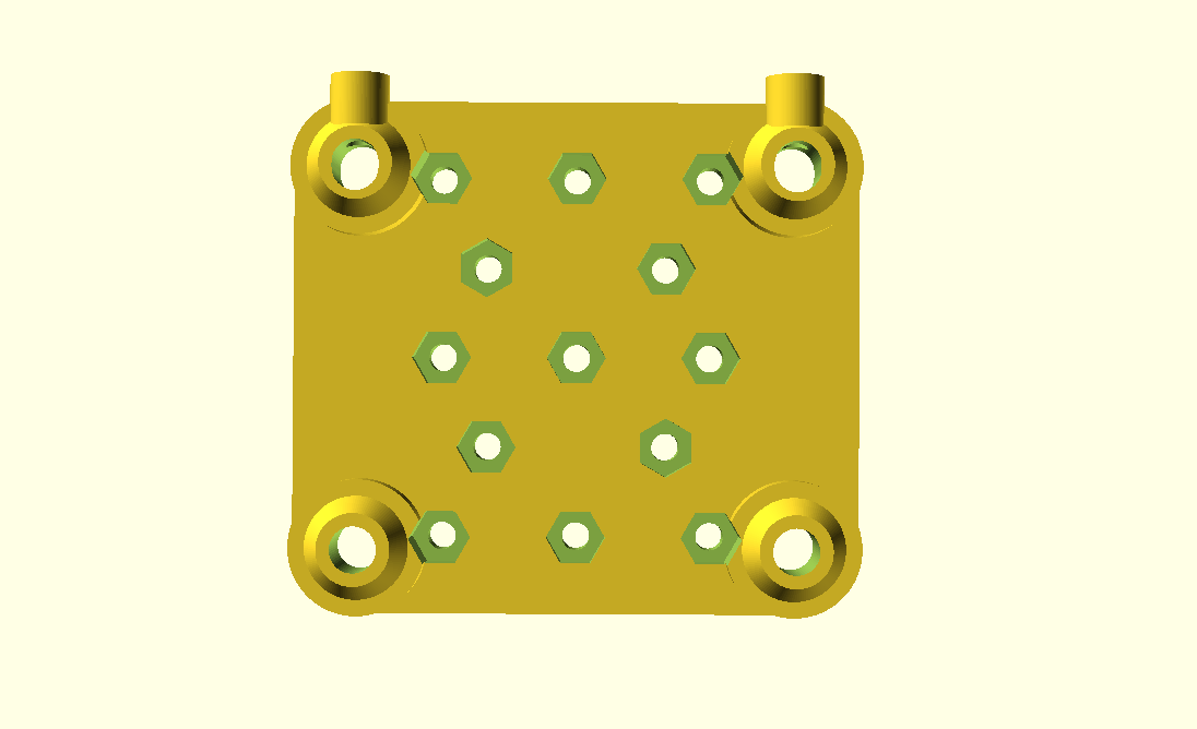
- 2x cci_2020-type=idler2 (top front corner brackets)
- 2x cci_2020-type=motor (top back corner brackets)
- X/Y
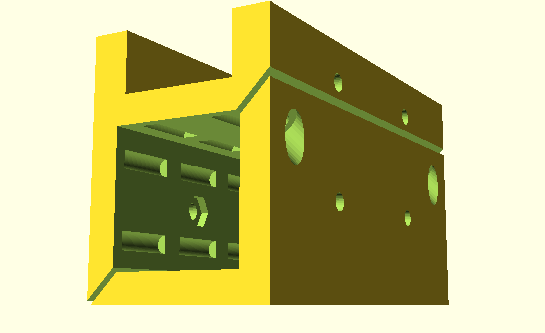
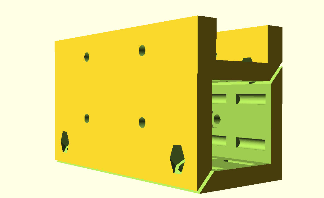
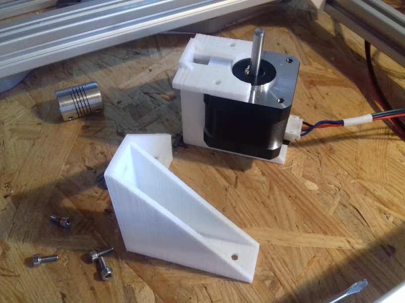
- 1x ac_edge_motor_mount-left
- 1x ac_edge_motor_mount-right
- Z
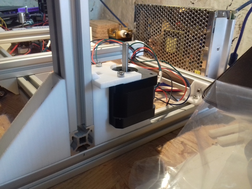
- 2x ac_motor_2020_mount
- 2x ac_zrod_2020_mount-left
- 2x ac_zrod_2020_mount-right
- 4x ac_zrod_2020_mount-bed
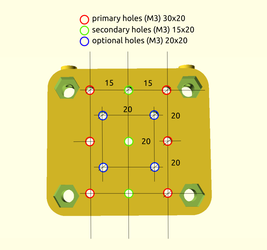
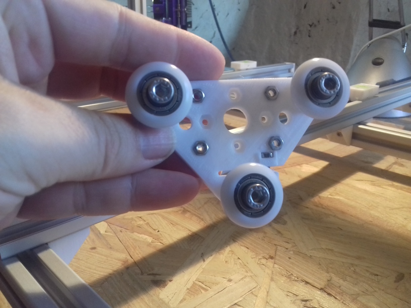
- Axis Modules
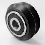
- 1x X Module with black 3 x OpenWheels 24.4/11 on T slot 6 or V slot 6
- 1x v_plate-2020-double-v-244-110-54w-a
- 1x v_plate-2020-double-v-244-110-54w-b
- 1x ac_x_l_stop_mount
- 1x ac_x_stop_mount
- 2x Y Modules each with black 3 x OpenWheels 24.4/11 on T slot 6 or V slot 6
- 1x v_plate-2020-double-v-244-110-48w-a
- 1x v_plate-2020-double-v-244-110-48w-b
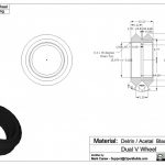
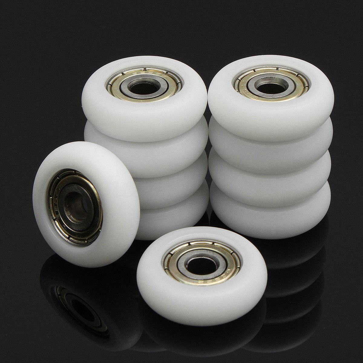
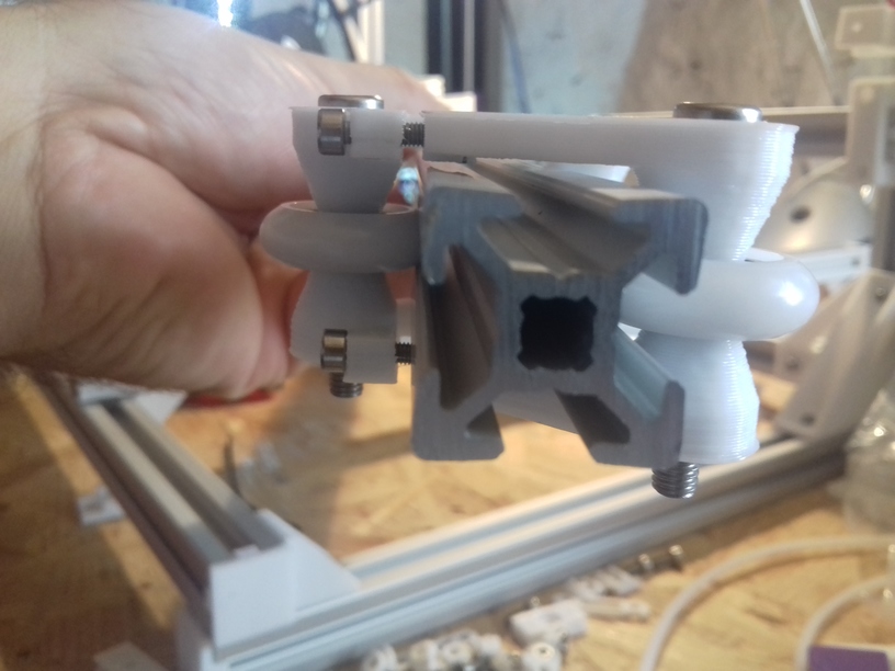
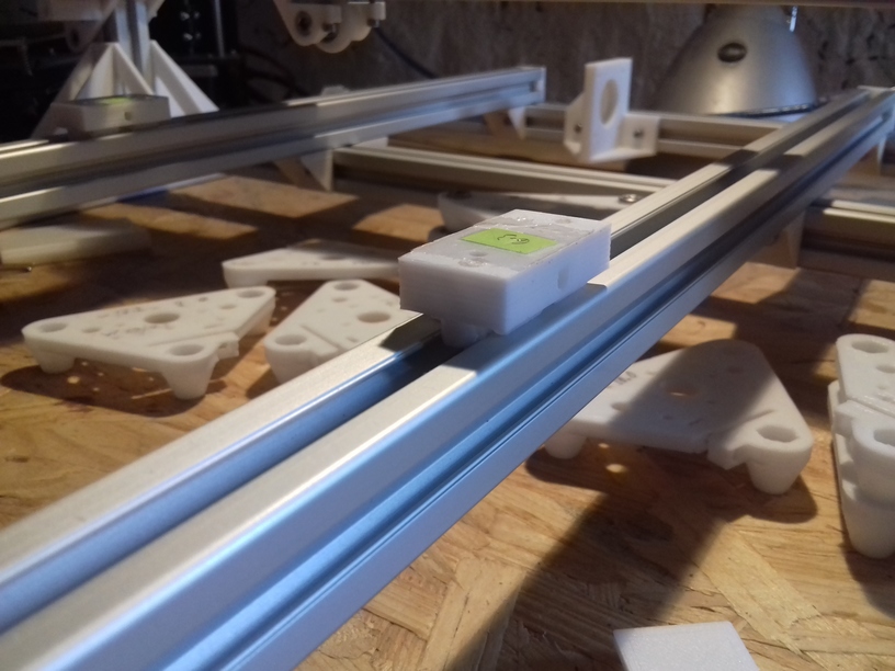
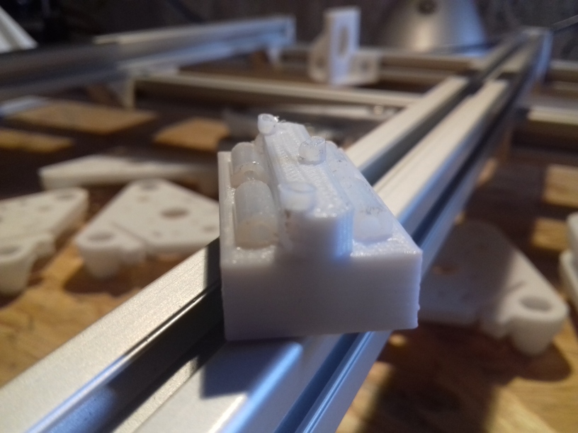
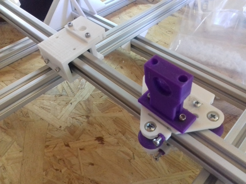
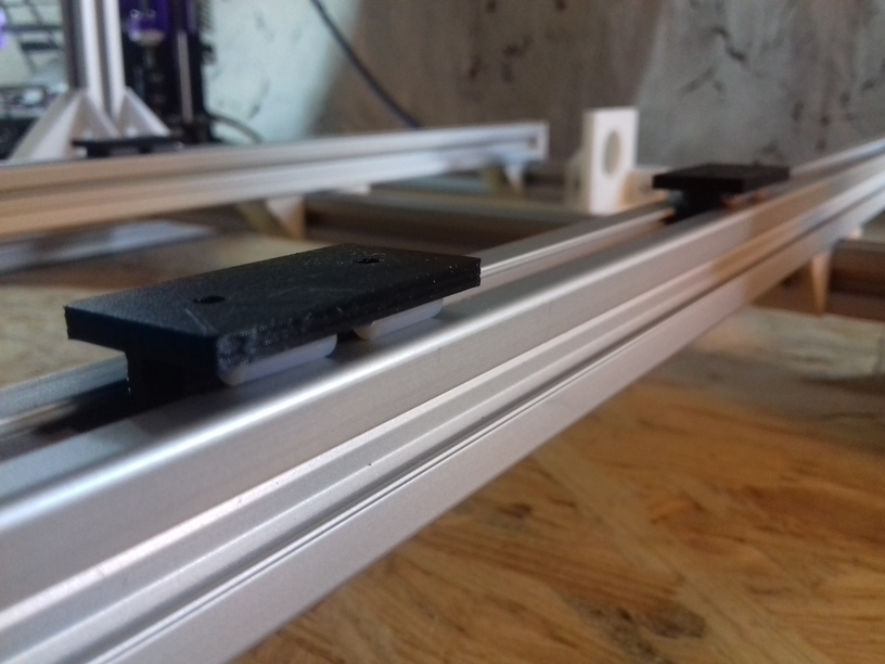
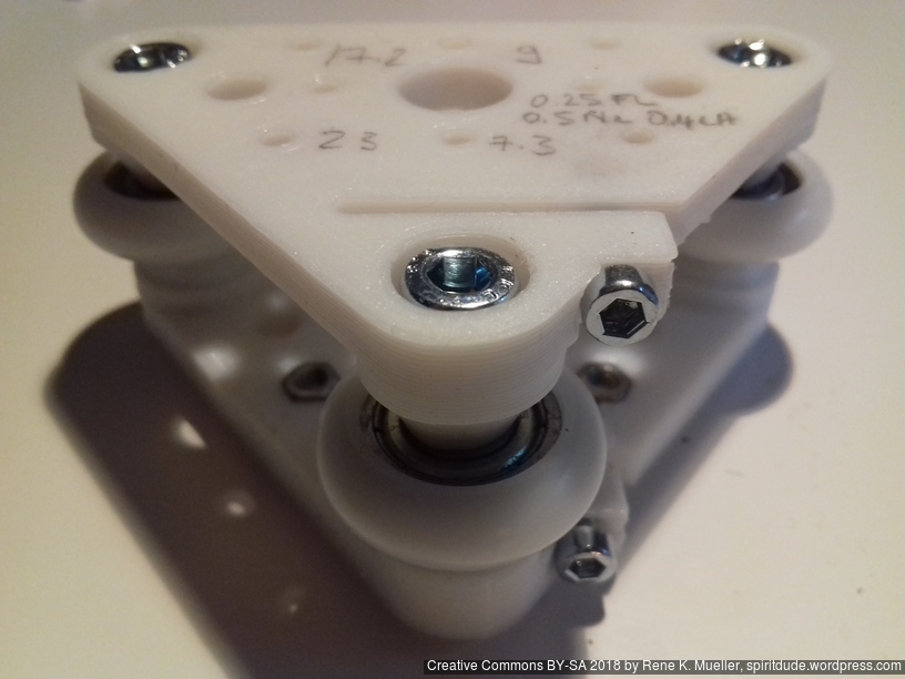
- 4x Z Modules each with white 3 x Delrin wheels 23.0/7.3 on T slot 6
- 1x v_plate-2020-delrin-230-73-48w-a
- 1x v_plate-2020-delrin-230-73-48w-b
- 1x X Module with black 3 x OpenWheels 24.4/11 on T slot 6 or V slot 6
- Misc
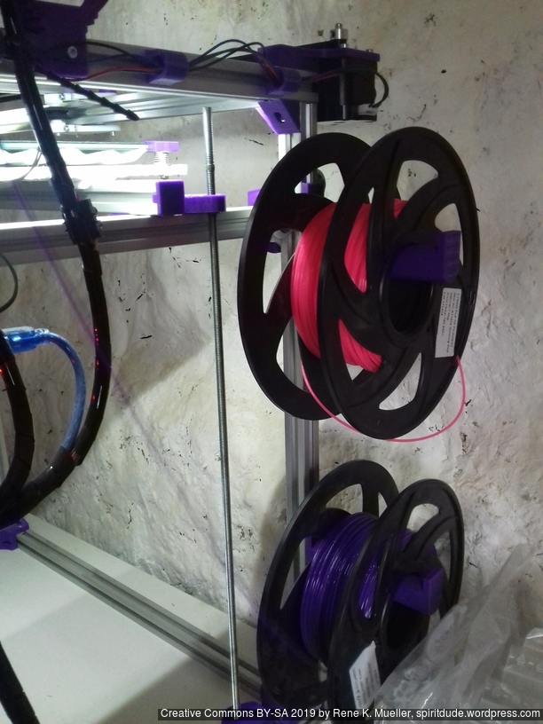
- 2-3x ac_spoolholder_2020
Non-Printed Parts (aka Vitamins)
- Two Frame Options:
- A: 16x 500mm T slot 6 (B-Type) 2020 alu extrusions + 1 x 440mm T slot 6 (B-Type) 2020 alu extrusion or
- B: 14x 500mm T slot 6 2020 alu extrusion + 3 x 500mm V slot 6 2020 alu extrusions
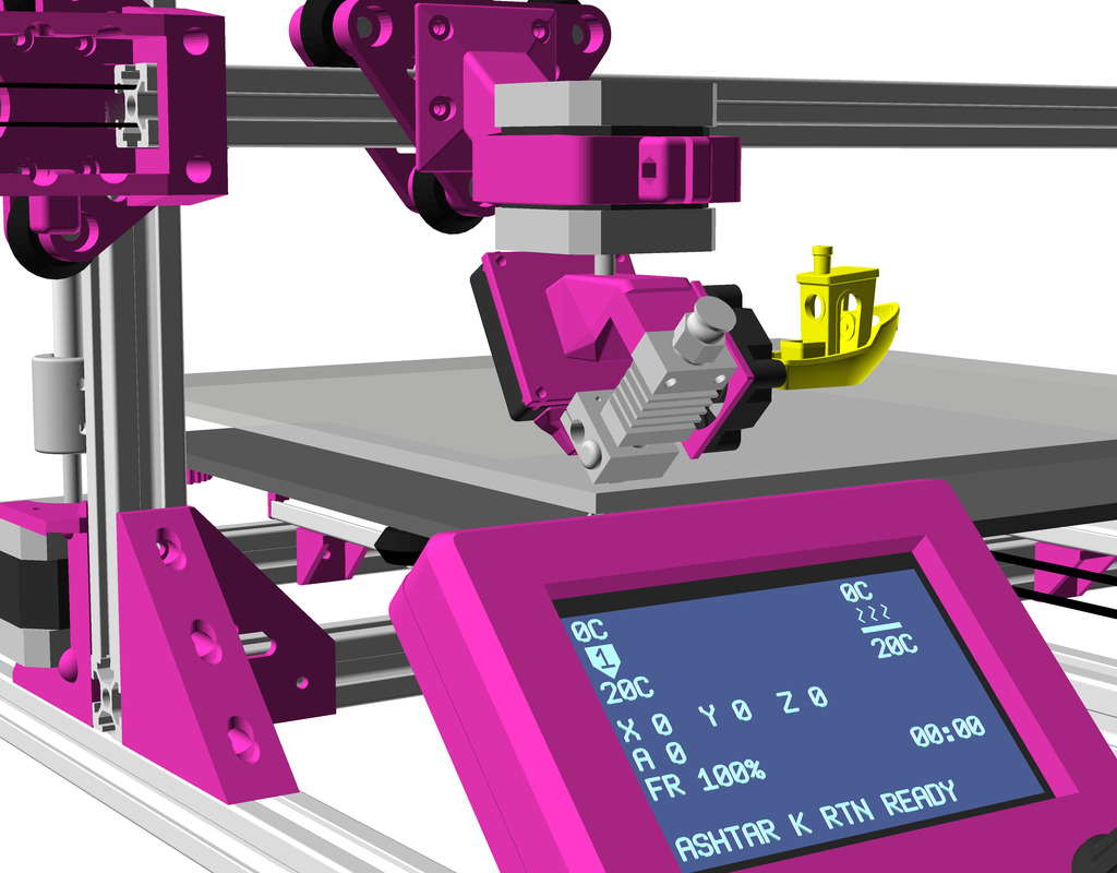
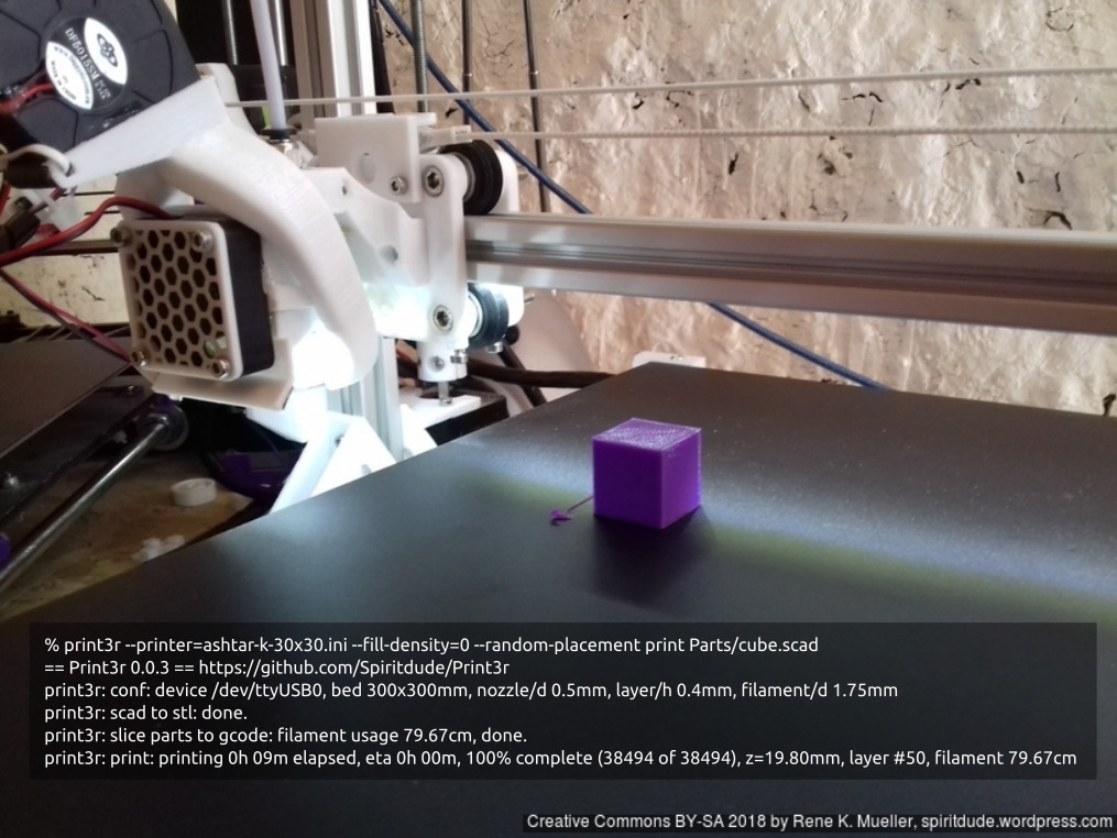
Example Prints
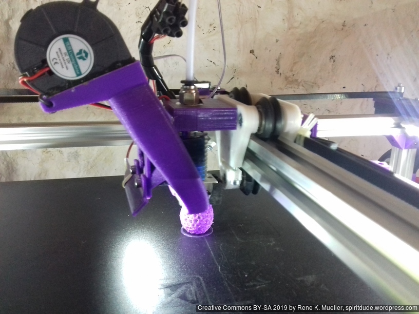
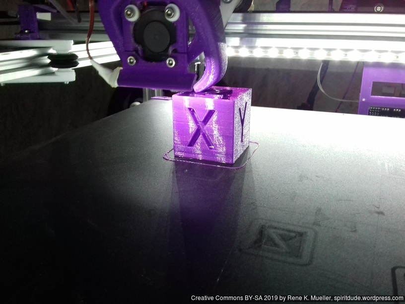
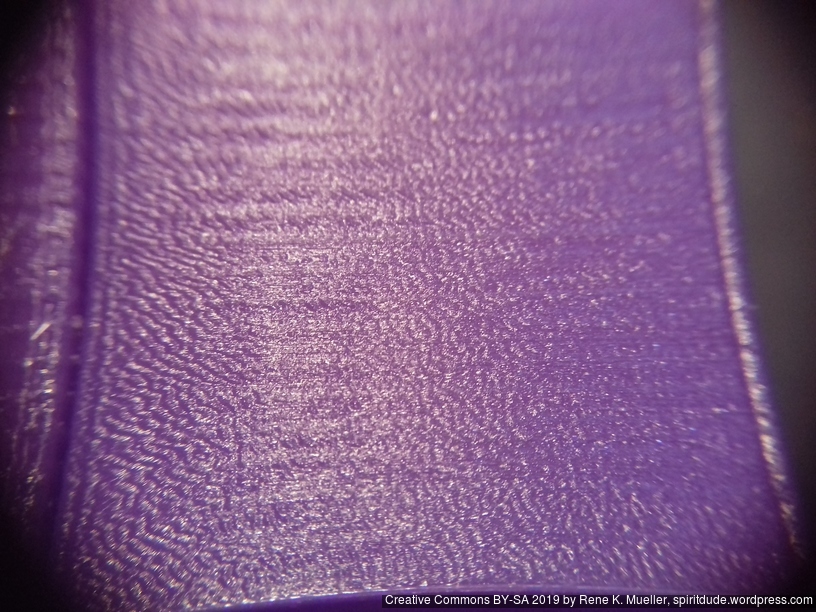
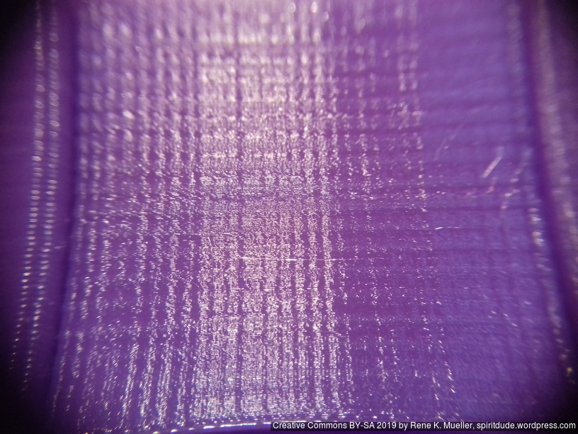
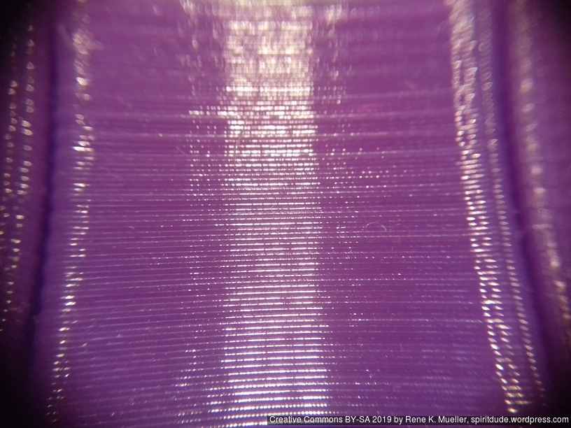
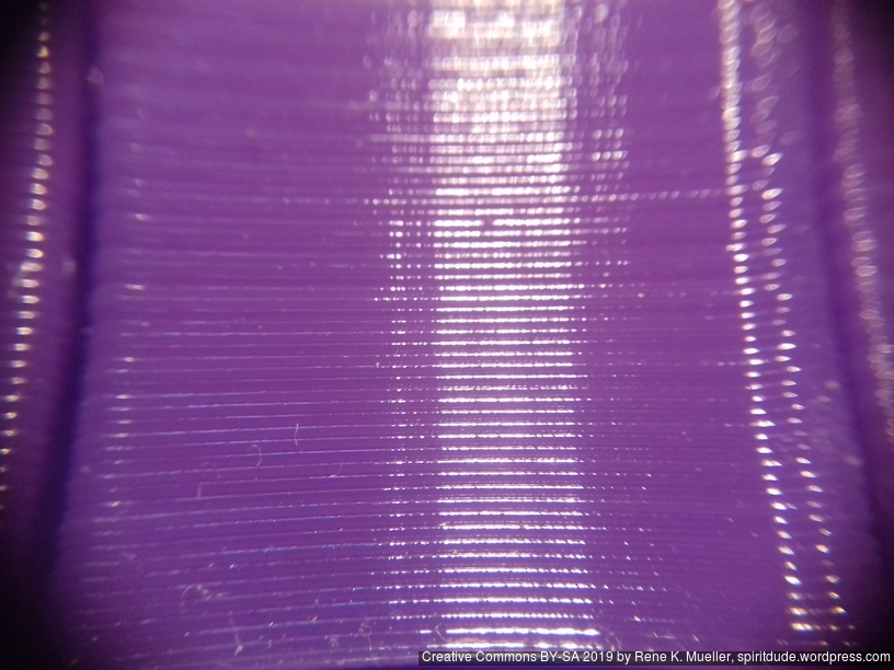
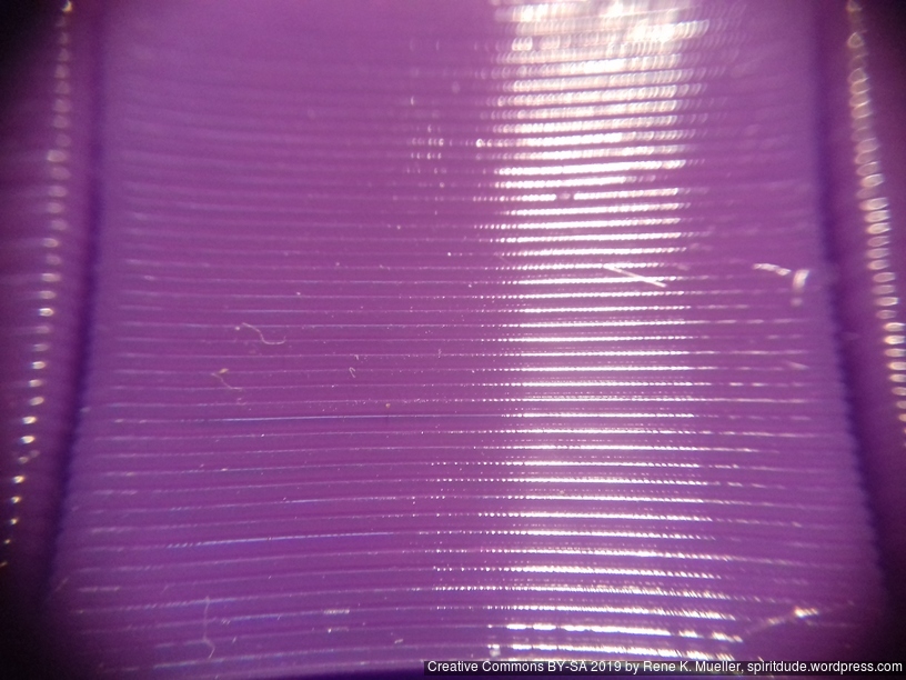
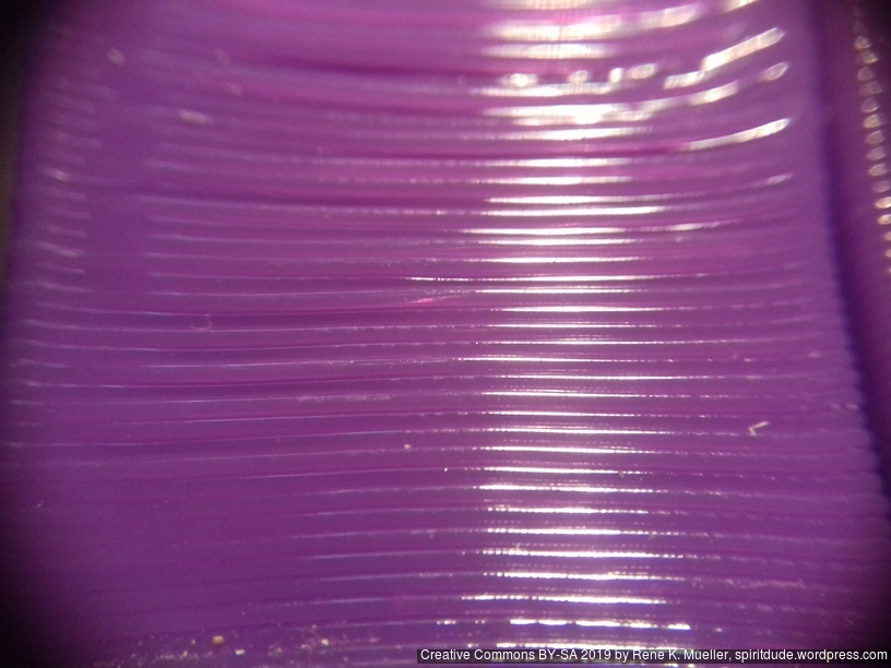
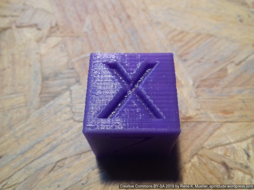
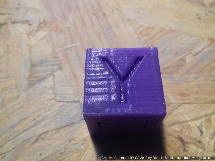
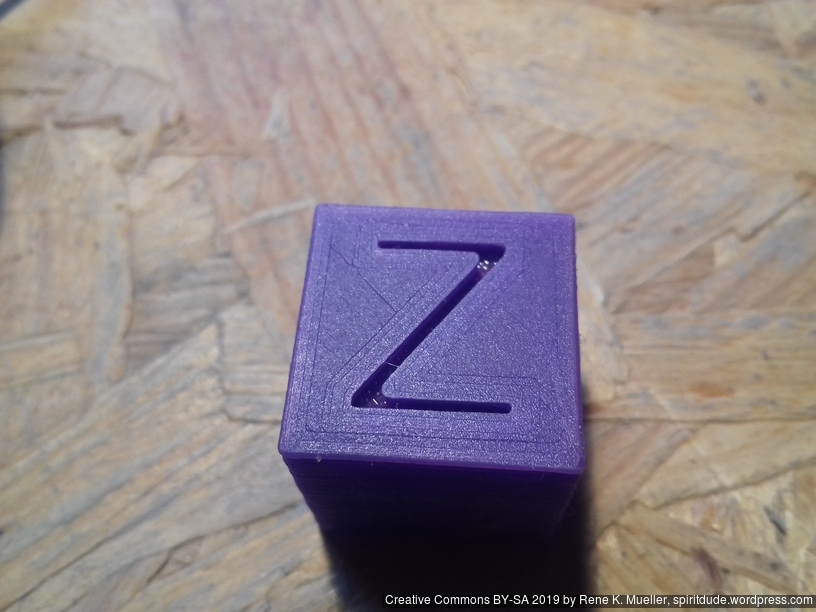
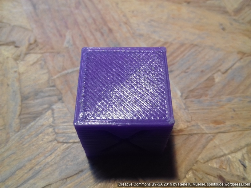
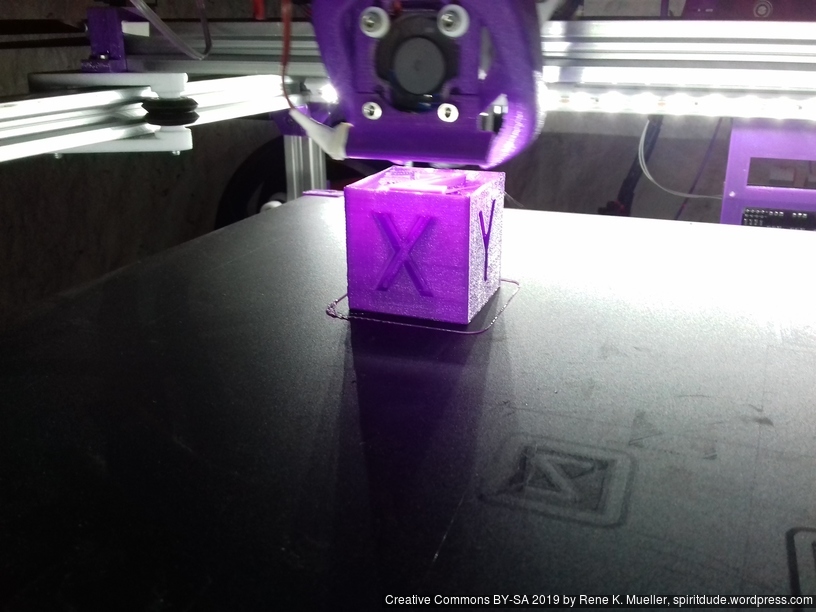
20mm Hollow Calibration Cube
Printed with 0.4mm nozzle at 0.25mm layer height, the “Z” at the bottom, first layer too thin a bit:
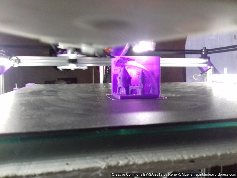
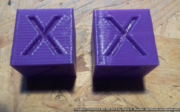
Castle 20mm Cube
200% scaled Castle 20mm Cube:
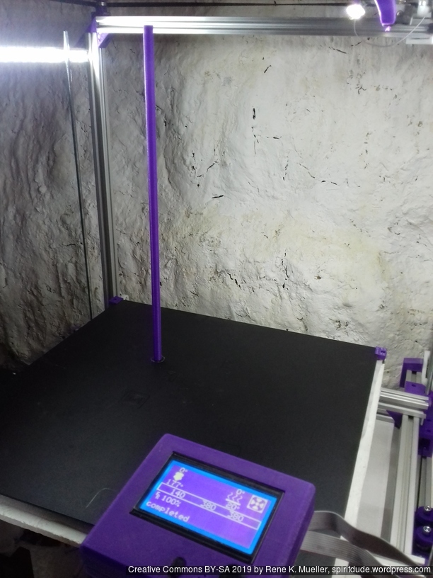
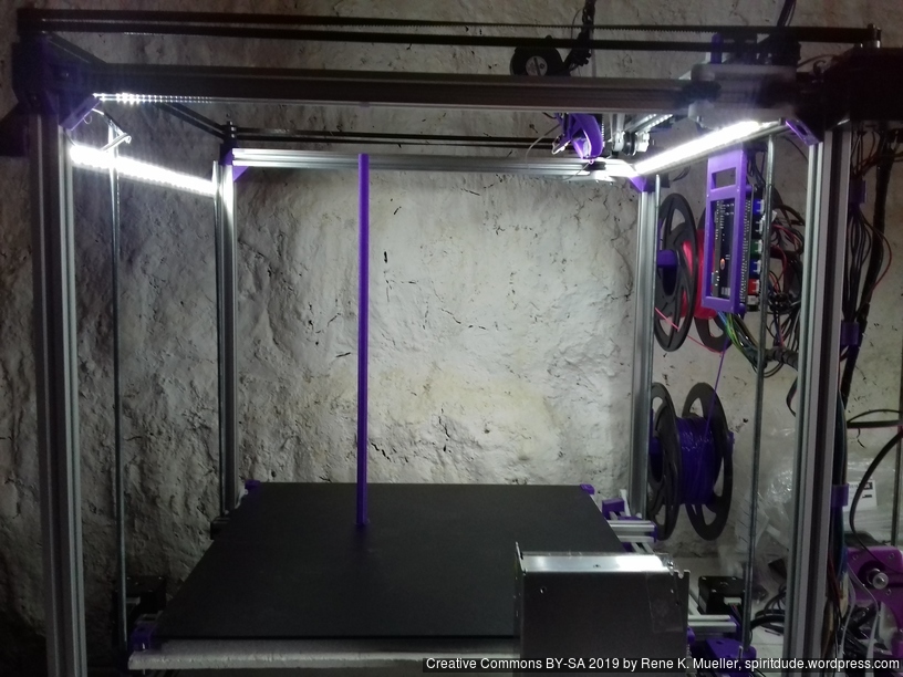
Tall Cylinder
380mm x 10mm hollow cylinder using full height of the printer:
Upgrades
Dual Z & Dual Extruder with MKS Gen L
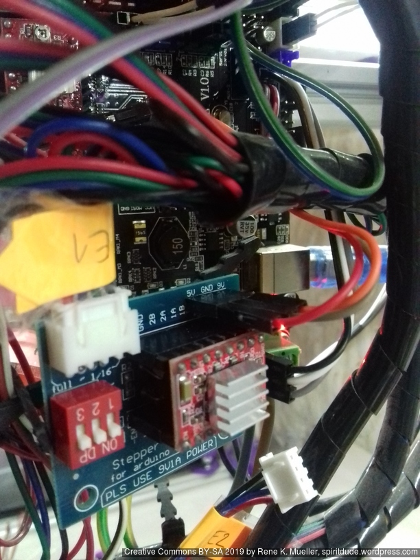
For the Chimera/Cyclops hotend with two filament but single heater and single or double nozzle, I added a stepper expander on AUX 2:
- AUX2 / D64 – E1 STEP
- AUX2 / D59 – E1 DIR
- AUX2 / D63 – E1 ENABLE
and wired 5V, GND, 12V as well.
Additionally made following changes to Marlin 1.1.8:
Configuration.h
#define EXTRUDERS 2

#define SINGLENOZZLE
Configuration_adv.h
#define Z_DUAL_STEPPER_DRIVERS
pins_RAMPS.h
Comment out first E1_* and add Z2_* newly, and new E1_* below:
/*
#define E1_STEP_PIN 36 // this is E1
#define E1_DIR_PIN 34
#define E1_ENABLE_PIN 30
#define E1_CS_PIN 44
*/
#define Z2_STEP_PIN 36 // this is Z2
#define Z2_DIR_PIN 34
#define Z2_ENABLE_PIN 30
#define Z2_CS_PIN 44

#define E1_STEP_PIN 64 // E1 (2nd extruder) via stepper expander
#define E1_DIR_PIN 59
#define E1_ENABLE_PIN 63
The “Z_DUAL_STEPPER_DRIVERS” by default will use “E1_*” and interfere with 2nd extruder, hence the Z2_* definition helps to keep 2nd Z motor at “E1” motor on the MKS Gen L board, and in Marlin E1 is newly defined separately at AUX2 at D64/D59/D63.
To summarize:
- MKS Gen L “Z” => Marlin “Z1”
- MKS Gen L “E0” => Marlin “E0” (1st extruder)
- MKS Gen L “E1” => Marlin “Z2”
- MKS Gen L “AUX2”:D64/D59/D63 => Marlin “E1” (2nd extruder)
which then in Gcode the 2 extruders (E0 & E1) are referenced as T0 and T1.
Start Gcode:
G91          ; relative positioning
T0
G1 E30 F100  ; purge E0/T0
T1
G1 E30 F100  ; purge E1/T1
G90          ; absolute positioning
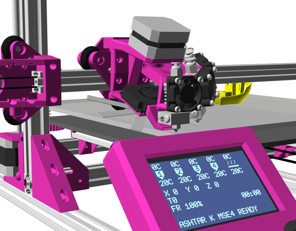
Update 2022/09 I replaced MKS Gen L 1 with MKS Monster8 with 8 drivers, still running Marlin but its 2.0.x series, and since I have 8 drivers, and I possible can attach 5 extruders.
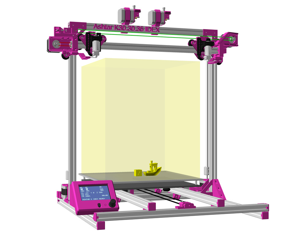
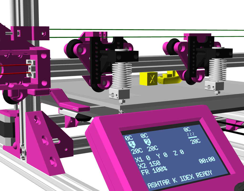
IDEX Option
The independent dual extrusion (IDEX) is an upgrade in draft state – means, it’s untested for now. It provides a 2nd extruder on the same X axis. As of 2021/01 there is only Duet RepRap firmware able to provide support for it as CoreXYU, whereas Marlin 2.x doesn’t provide support yet.
Right now I keep the up-to-date information on Ashtar C IDEX in this blog-post, once things actually are tested all the details will be documented in this document.
Gallery
Related Projects
- CoreXY Belt Routing, recommended reading
- V-King CoreXY Printer, very elegant implementation, belt Z axis
- Rat Rig V-Core Printer, professional implementation, dual lead screws Z axis
- SDavi: V Slot CoreXY 3D Printer, well documented, complete OpenSCAD sources on Github
- Thingiverse: Tag:CoreXY


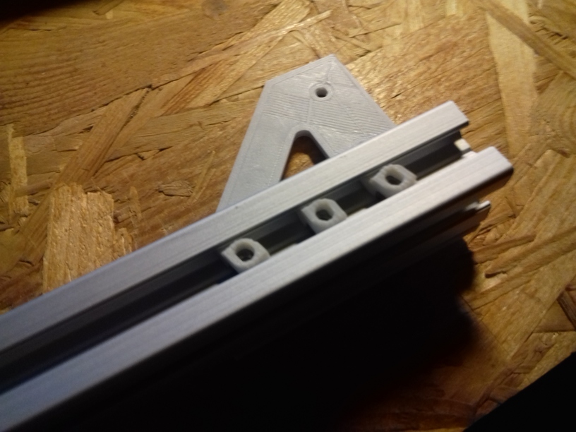


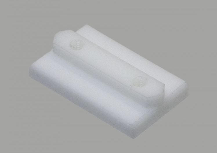
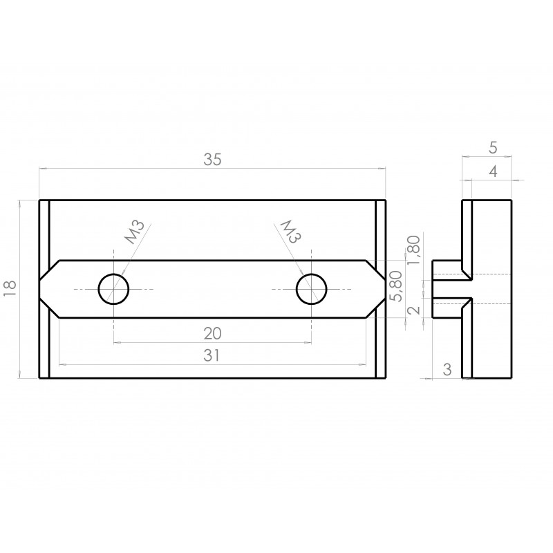
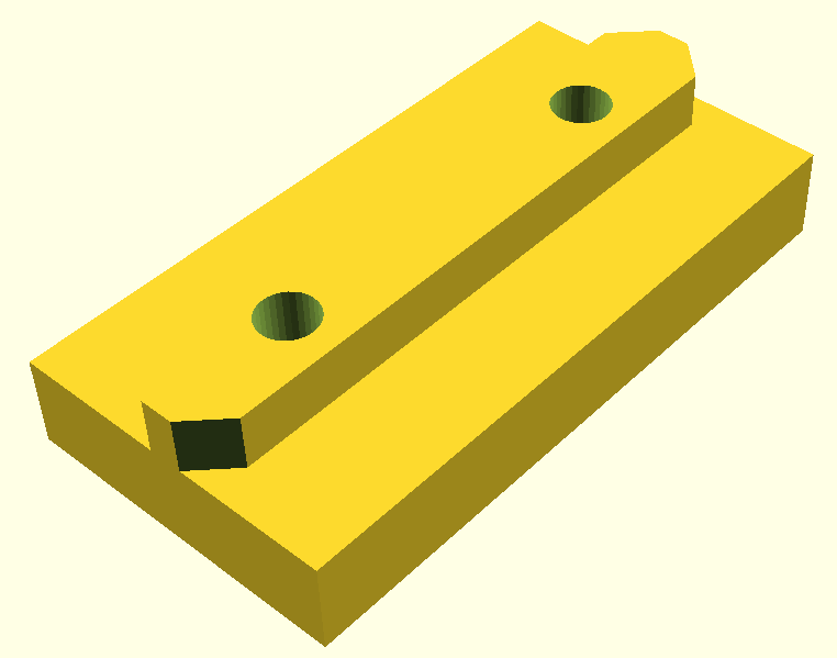
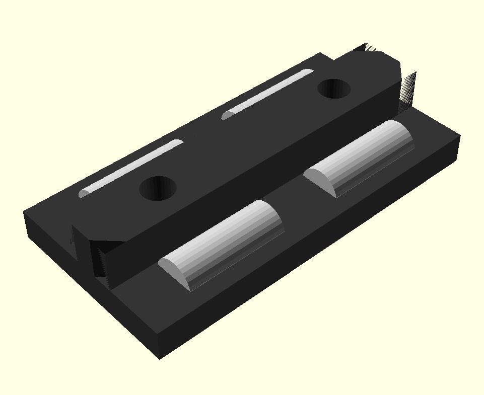
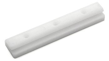 Commercially manufactured, apprx. cost EUR 2.50 per piece, sold in 10 pieces bag.
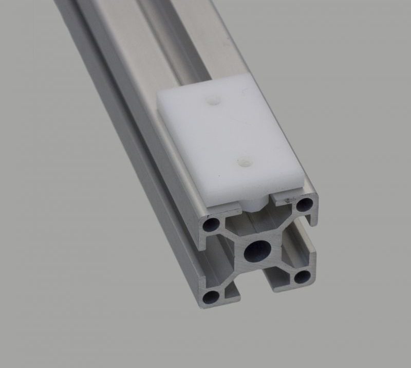


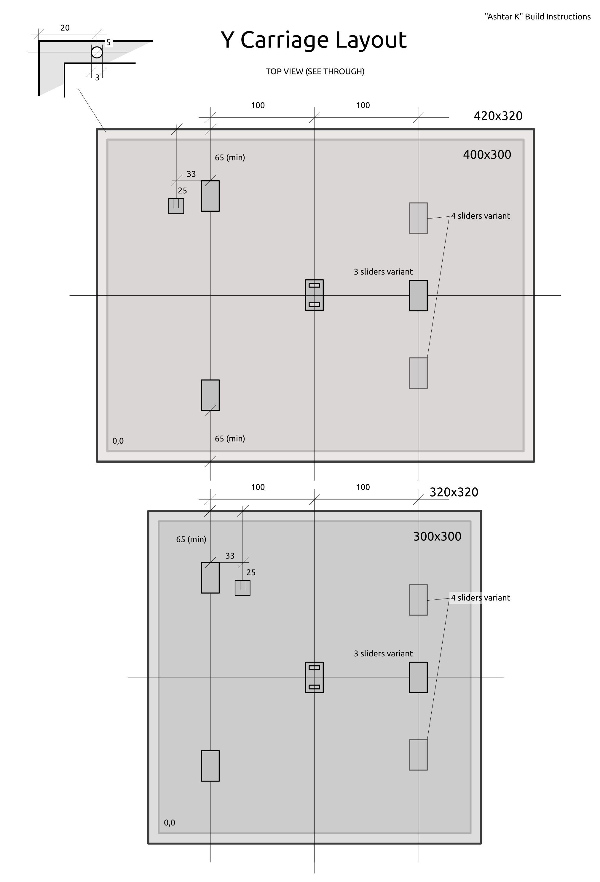
 420x320mm 6mm OSB (white painted) as Y carriage