Video ID not provided: Please check your shortcode.Video ID not provided: Please check your shortcode.
 Updates
2018/03/26: Initial post with description, assembling and first test print.
2018/03/27: Board identified as “Anet A1284-Base-Control Board V1.0”. More details on adding a printer to Cura and included brief video of the first print.
2018/03/28: fan duct added, replaced broken extruder fan (see section “Fixes & Upgrades”)
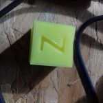
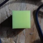
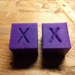
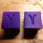
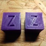
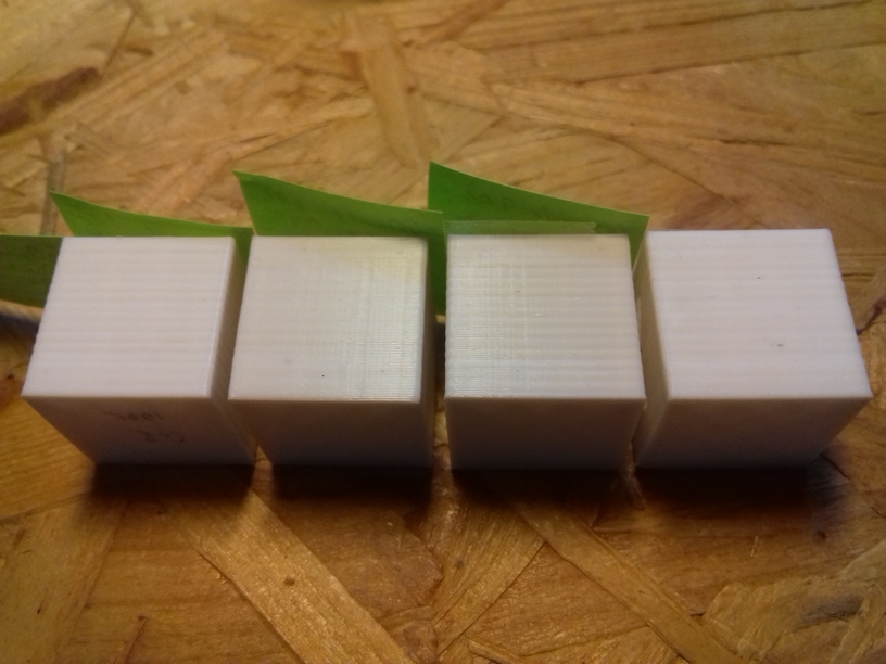
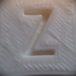
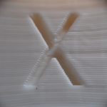
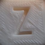
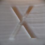
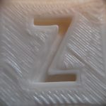
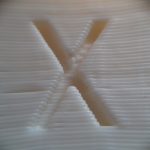
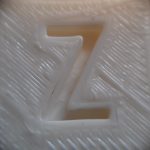
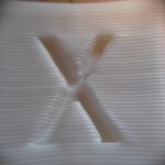
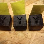
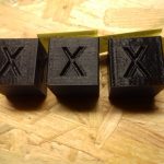
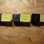
2018/03/29: added white LED near nozzle, XYZ calibration cube fan vs fanless printing.
2018/03/30: added serial plate and label plate, calibrating X and Y axis properly.
2018/04/19: cables sorting
2018/04/23: printed X gantry/axis parts and replaced them
2018/04/25: refasten screws & cable binders of Y carriage
Introduction
Back in 2013 I’ve got pulled into 3D Printing and did some work on
- theoretical issues (2013) and
- software (coauthor of OpenJSCAD.org, 2013-2016)
- and briefly cooperated with a small 3d printer company, where I printed my first pieces as part of testing 3d printers
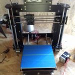
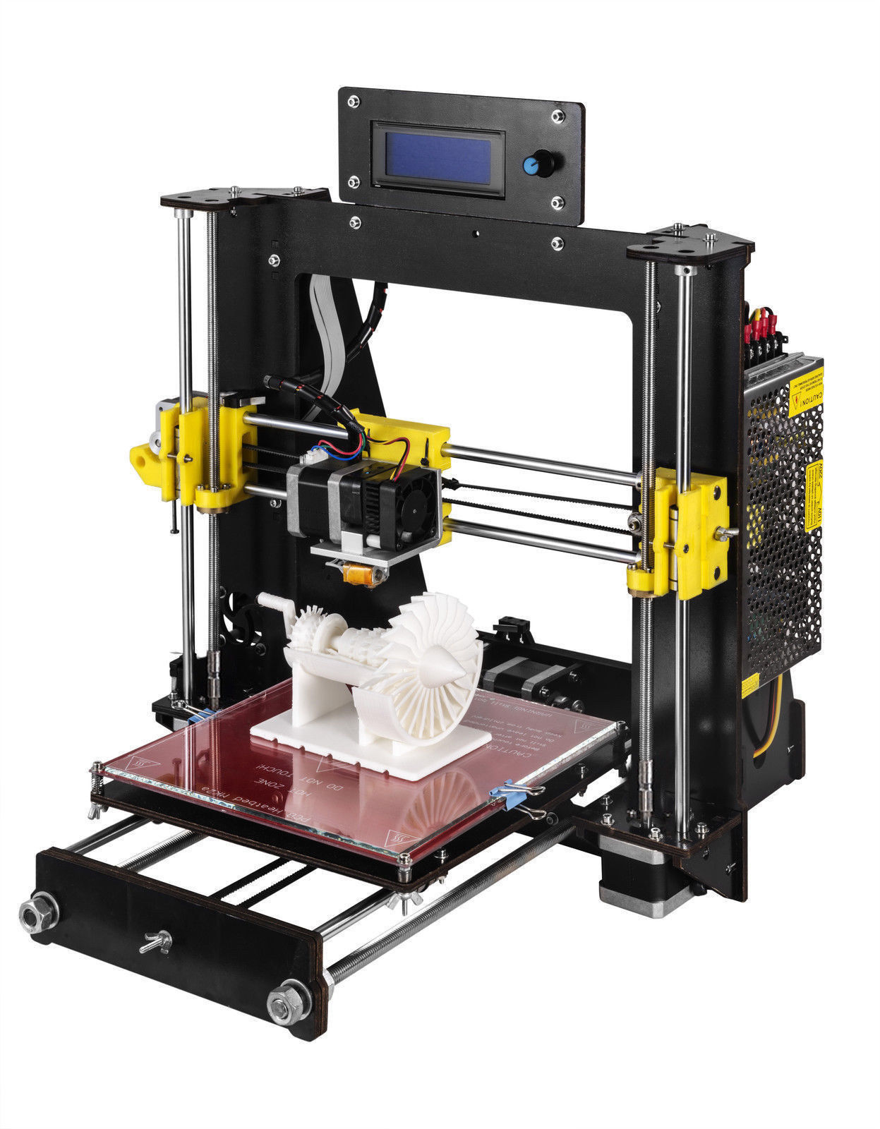
but I didn’t own a 3d printer myself until 2018/03/21 – roughly 5 years later – when I ordered an “DE A8 3D Printer DIY i3 Upgradest High Precision Reprap Prusa 3d Drucker” for EUR 99.00 (apprx. USD 120) shipment from and to Germany included – that is by far the most affordable 3d printer I ever saw (2018/03).
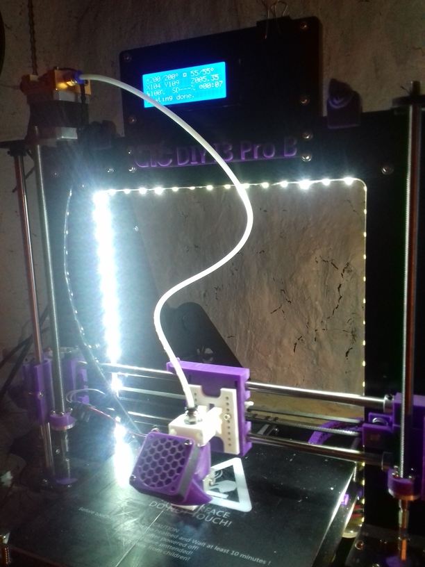
 As the product image shows – it is hastly translated from english to german, and doesn’t make a very serious impression. After some research I realized it’s an CTC DIY Prusa i3 aka CTC DIY i3 Pro B (product link valid 2018/03/22) sold for USD 140, produced by Zhuhai CTC Electronic Ltd located at Zhuhai City, Guangdong, China – located at another peninsula west of Shenzen and Hong Kong. On further investigation I found out that the CTC DIY I3 Pro B is a clone of Geeetech DIY I3 Pro B, which is advertised as “Geeetech I3 pro is based on the Reprap open source project. Geeetech I3 is highly recommended for students and beginners who want to start journey in 3d printing technology.”
Technical Specifications
- Method: FDM (Fused Deposition Method)
- Volume: 200mm x 200mm x 180mm (X Y Z)
- Printing Resolution: 100um
- Layer Precision: 50-100um
- Filament Diameter: 1.75mm
- Material: PLA (platform 50-60C), ABS (platform 110C)
- Nozzle Diameter: 0.4mm
- Mechanical Positioning:
- Speed Positioning: 300mm/s, 100mm/s
- Recommended Nozzle Speed: 35-40mm/s
- Power: 220V / 80W
- Connectivity: USB & SD Card
- Product Size: 36cm x 38cm x 43cm
- Transport Package: 50cm x 42cm x 23cm, 9.13kg
(Numbers taken from the flyer 2018/03/24)
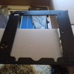
Unpacking
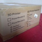
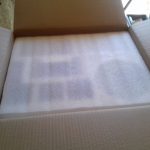
After 2 days, after ordering on Ebay.de, it arrived with DHL, a 9kg (20lbs) package.
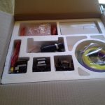
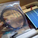
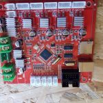
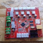
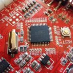
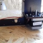
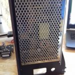
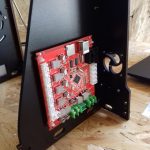
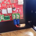
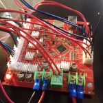
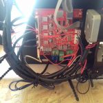
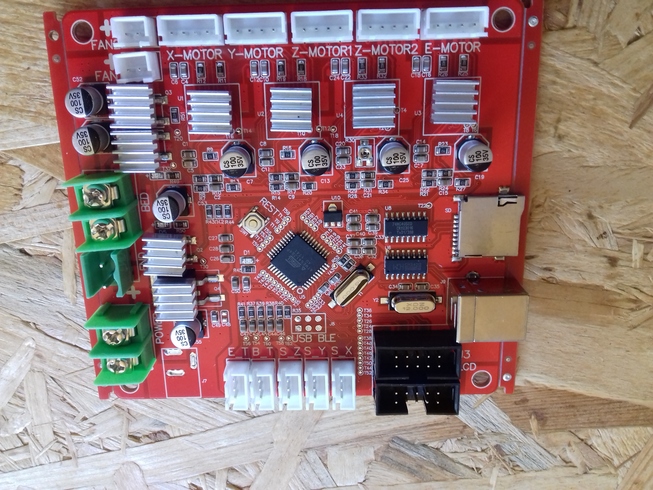
The package is well composed, most parts are marked, some of the labels didn’t stick to the parts though. The controller board is orange with an ATMEGA 1284P in the center, with all connectors well labeled – it seems it’s loosely identified as “Anet A1284-Base-Control Board V1.0”. Gcode M115, which identifies the firmware, responds as
Marlin V1; Sprinter/grbl mashup for gen6 FIRMWARE_URL:https://github.com/ErikZalm/Marlin/ PROTOCOL_VERSION:1.0 MACHINE_TYPE:I3 Pro B EXTRUDER_COUNT:1 UUID:00000000-0000-0000-0000-000000000000
The shipped 3d printer does not match the photos in the Ebay posting, therefore the product link to the CTC manufacturer is also not correct. It turns out it’s either another version of the “CTC DIY I3 Pro B” or a remix of another line, the included manual states it’s a “CTC DIY Printer” by “Zhuhai CTC Electronic Co., Ltd”.
Here the main differences:
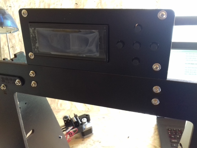
- LCD has 5 buttons – advertising shows a dialer with integrated push button
- controller board is orange with green power connectors, stepper motors drivers are soldered on (cannot be replaced) – advertising shows board with replaceable stepper motor drivers
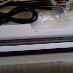
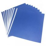
- heating bed is aluminium with blue tape already on – advertising shows orange/red heating bed with a glass plate
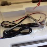
The only things I thought was missing was
- the small fan near the controller board, the screws and distance tubes were included (stepper motors drivers have passive coolers attached), perhaps they meant the fan attached to the extruder (which is included) . . .
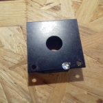
- on/off switch for the main power, a small hole (~4.8cm x ~2.6cm) is prepared, but none was included
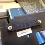
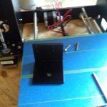
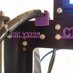
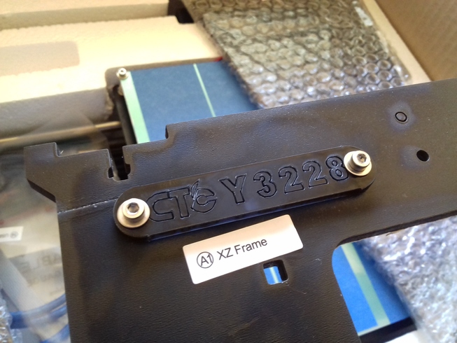 The XZ frame comes with a small plate “CTC Y 3228”, which likely is the serial number of this frame/printer.
Assembling
The included manual (diy-manual) on the CD is cumbersome to read – so here the assembling procedure which worked for me and for my own future reference:
Mechanical Assembling
I realized to first assemble mechanically and then electrical (wires) is the best procedure; also re-fasten all screws of the preassembled pieces to ensure the stability.
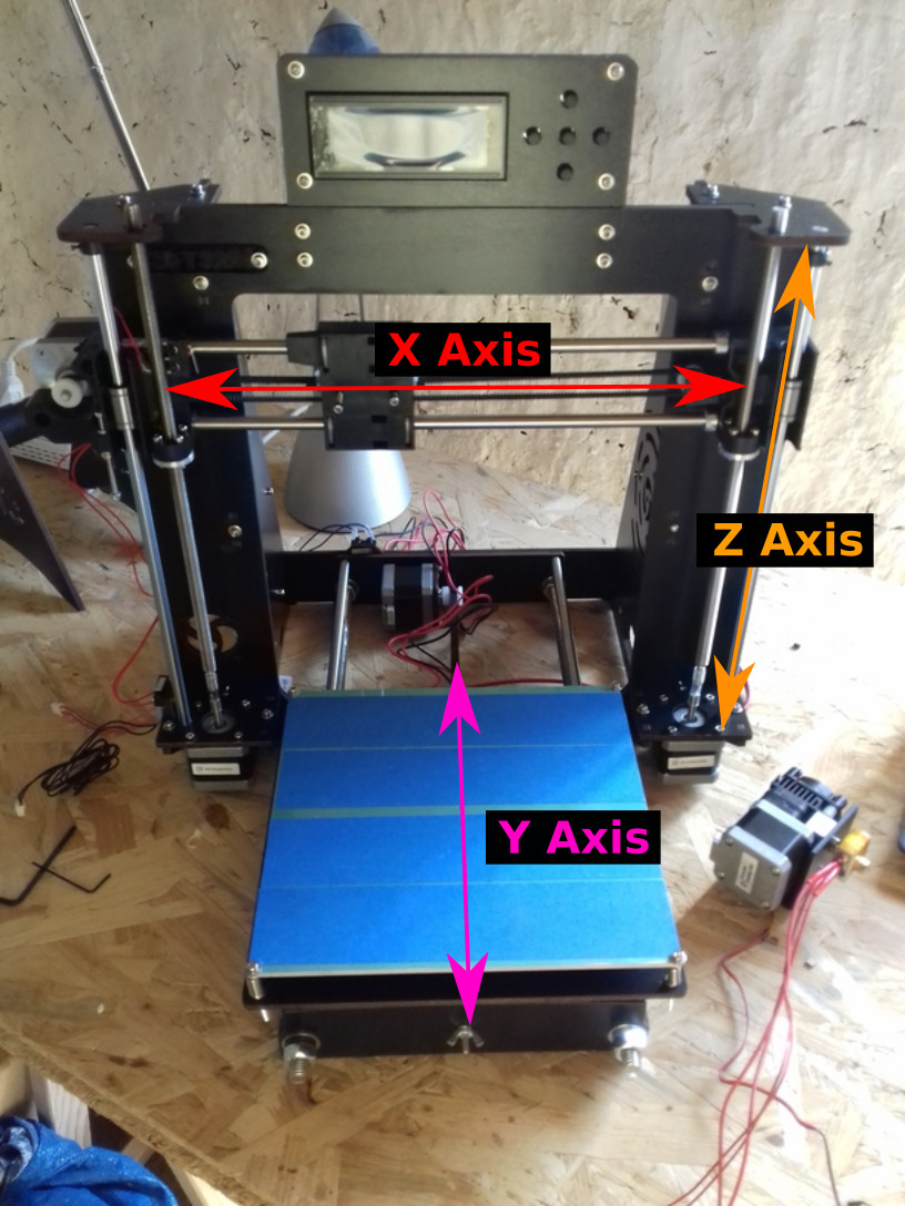
Here as reference the 3 axis as mentioned further below:
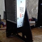
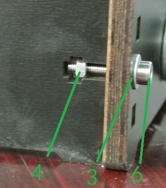 use the two sheets/feets so the XZ frame stands upward, the larger ventilation grill comes to the right-hand side when looking to the front; use M3 with washer on the front, and the nut within the sheets/feet; don’t tighten it too much otherwise you will crush the wood.
-
-
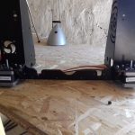
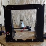
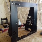
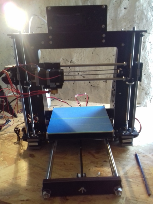
XZ Frame
-
-
XZ Frame with two sheets attached
- the right-hand middle screw at the XZ frame has to be flat without a washer this screw otherwise crashes later with the X axis moving up/down the Z axis.
- add the two Z axis stepper motors, the one with the end stopper switch comes at the left-hand side, again M3 with washers and nuts.
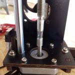
- add the X axis:
- the X axis stepper motor goes on the left-hand side
- insert the threaded rods, the flexible tubes looking downside (thread them from bottom to top) – a bit time consuming
- the X axis with the threaded rods push unto the flexible couplers on the stepper motors, at least 1cm or 1/2″ on the stepper motor, leave 0.5-1.0cm or 1/4″-1/2″ spacing between stepper motor shaft and threaded rods (I have seen others leaving little space, but larger distance worked for me so far)
- twist threaded rods so X axis is visually horizontal (fine tuning comes later)
- insert the smooth rods (no threads), the holes at the stepper motors require some filing (use the included grater), the smooth rods get pushed apprx. 5mm in
- insert the top ends which fixates the smooth rods but not the threaded rods (those have to stay floating)
- add Y axis, since it’s mostly prepared already you just lay it into the XZ frame, with the stepper motor behind, two additional (unfastened) sheets to attach the Y axis with its larger threaded rods to the XZ frame
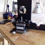
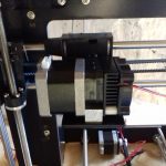
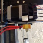
- add printer head: take it apart (first the nozzle and then L shaped support), use prepared M3 to attach the L and then add the printer head (without nozzle) to it, and then add the nozzle again (screw it with the cable looking left-hand side, once fully screwed on they look on the left-hand side again).
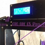
- add LCD screen on the top of the XZ frame
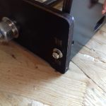
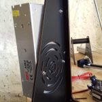
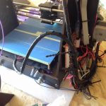
- add power supply on the right-hand side (looking from the front), just three M3 (one corner of the power supply is in the air), the electrical connectors are looking downward
- add controller board on the left-hand side
this finishes the mechanical assembling.
Electrical Assembling
Attaching all the cables to the controller board is easy since all connectors are labeled:
- add main 12V power from the power supply to the controller board
- attach the 2 long stepper motor cables (one end fits stepper motor, other connector to board – not interchangeable) to
- the right Z axis stepper motor (not moving)
- the extruder stepper motor (moving)
- attach the shorter stepper motor cables to
- the left Z axis stepper motor (not moving)
- the X axis stepper motor (moving)
- the Y axis stepper motor (not moving)
- attach the thermistors
- E/T: extruder thermistor
- B/T: bed thermistor
- attach the stopper switches:
- S/X: stop X axis
- S/Y: stop Y axis
- S/Z: stop Z axis
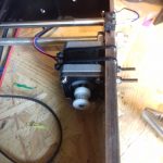
- attach extruder fan to “FAN2” on the controller (always on, but anoying but if you print larger pieces, the extrude fan must be running at first layer already)
- attach heating bed power to “BED” (polarity doesn’t matter here)
- attach extruder heating power
- attach LCD display with marked “LCD” on the controller (one connector aside remains empty)
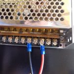
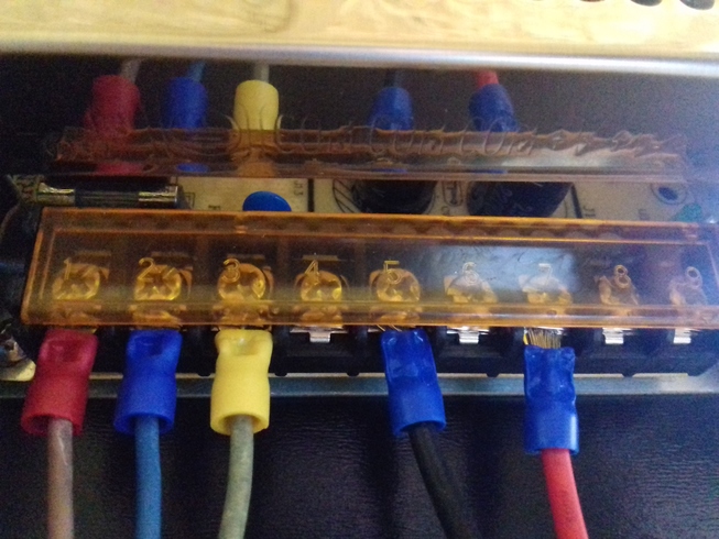
- attach main power cable 110V / 220V to the power supply (don’t plug power yet): european standard: green/yellow = GROUND(3), blue = NEUTRAL(2), brown = LIVE(1)
before you bundle the cables, control all connections again – missing or mixing up just one connector can damage the 3d printer once powered on.
Make sure the correct voltage 110V or 220V is chosen at the power supply (default 220V).
As next bundle
- all wires from the print head, with the black plastic wire bundler, these wires move the most
- all wires from the heating bed (heating and thermistor) with zip ties, and slightly lift them up so they don’t lay on the Y axis frame near the bottom otherwise the zip ties will eventually hang themselves there and block Y movement
- bundle the other wires neatly with isolated wires or
zip ties spiral cable wrappers (only one is included, so get 2m extra) – on a 2nd thought avoid zip ties as they tend to hang somewhere when on moving parts
Adjusting X axis Height
This part is crucial for the geometric accuracy of all your prints:
- use any kind of item with a certain length, a pencil, a stick, or a ruler – whatever, long and short enough to match the height of your X axis (moving up/down the Z axis)
- put the item on the bottom of the left Z axis stepper motor and adjust the height manually by twisting the Z axis manually until the item touches the X axis; you might have to adjust the right side as well to stay somewhat horizonally
- now move the item to the right side of the X axis, and measure the same distance and adjust the height of the right side
- now both sides have the same distance to the bottom (the stepper motors at the bottom) – which means, the X axis is now perfectly horizontal
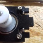
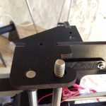
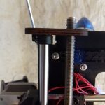
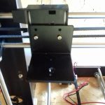
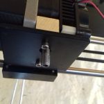
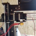
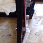
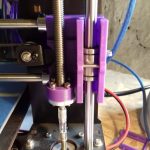
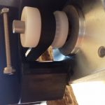
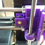
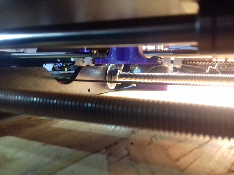
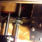
As next make sure the Z axis stopper on the left-hand side near the bottom, that screw coming down on the X axis is fully extended: move the nuts up so the screws extends down and reaches the stopper early.
-
-
Left-hand side long screw adjusted to early tip the Z axis stopper
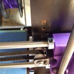
-

-
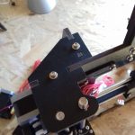
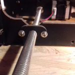
Notice left-hand side Z axis stopper
Adjusting Printing Bed aka Bed Leveling
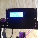
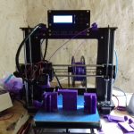
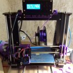
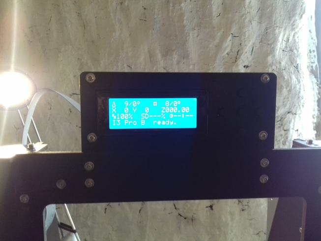 When all is assembled mechanically and electrically, you turn on the machine; the LCD display should light up in blue with white letters.
Note: when the printer is powered on, the stepper motors become active and hold their position, you can’t or shouldn’t move the X or Y axis manually anymore, unless you choose in the menu “Prepare -> Disable Stepper Motors”
- choose “Prepare -> Auto Home”; and carefully watch the printing head moving left to X axis home, moving backward with Y axis to home and Z axis downward:
- if the screw hitting the Z axis end stopper missed, push the stopper before with your fingers, you otherwise damage your printer
- if the screw hits the stopper, good
- you likely have too much space between the nozzle and the printing bed
- adjust the screw hitting the stopper to minimize the distance of the nozzle to the end, hit “Prepare -> Auto Home” until the nozzle is within 0-3mm distance of the bed
- hit “Prepare -> Disable Stepper Motors”,
- adjust the bed with the manual fly nuts, put a piece of paper on the bed, and adjust distance so the nozzle barely touches the paper (left/front side of the bed), then
- move the printer head on the X axis manually to the right side, and adjust right/front side alike , then
- move the Y axis forward manually so you reach the end of bed (right/end side), adjust height, and
- move the printer head on the X axis so you reach (left/end side) and adjust the height as well,
- and repeat it once more to make sure the nozzle is 0.1mm distance from the bed (that’s the thickness of a piece of paper)
You have now adjusted the printing bed, you are ready to print now.
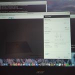
Installing Cura
The included Cura slicer and front-end on the CD (as in my case) is of version 14.07 (roughly 5 years old) and has no Linux version, as of 2018 I can’t even find a binary anymore for Linux – so I installed the latest on my Linux laptop; you download Cura-3.2.1.AppImage or something newer, once downloaded you execute it direct (it does no install) with right mouse click and “Execute”; under Windows or Mac it may install differently.
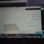
Once Cura started up:
- add a new printer
- choose “Other” -> “Prusa i3 Mk2” as type
- name it “CTC DIY i3 Pro B” or something like this
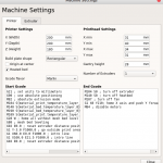
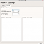
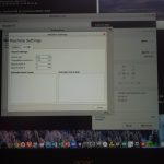
- Printer Setting:
- enter as printing volume: X = 200mm, Y = 200mm, Z = 180mm
- select “Reprap” or “Marlin” as GCode flavor
- select “[x] Heated Bed”
- you don’t have to edit the Start or End Gcode
- Extruder Setting:
- define the nozzle 0.4mm and filament 1.75mm diameter
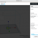
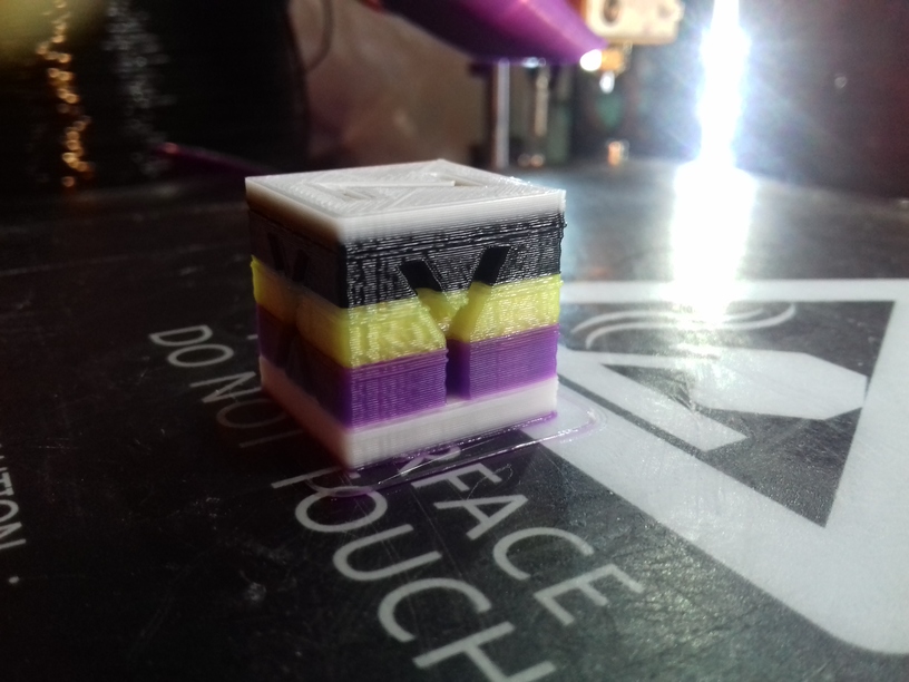
- open xyzCalibrationcube.stl (download .zip and unpack it)
- it will slice right away once it appears on the virtual printing bed
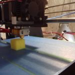
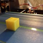
First Test Print
Best choose PLA in Cura as a first test print, it’s easier to print.
- Connect the controller board with your computer with the USB cable.
- Go into the menu of LCD display (with 5 buttons, “up/down/left/right” and “select” at the center), and choose “Prepare -> Preheat -> Preheat PLA 1”, and wait 60 seconds, then
- cut the filament so you get a sharp pointy end
- push the filament into the printing head (the 2nd hole closer to you)
- start the print of the “XYZ Calibration Cube” on your computer:
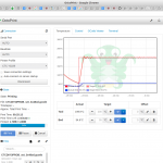
- choose triangle near right-side bottom of the CURA window, deselect “save to …” but change to “print to USB”
- then press that button
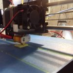
- the printer will now start to heat the bed to 55C (takes longer) and the printer head (faster heating because it’s a smaller heating mass) to 210C
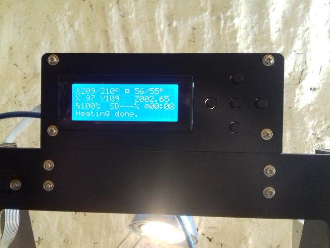
- after 60-90 seconds when those temperatures are reached your print will start
- it first auto home (X=Y=Z= 0) and then will try to push out some PLA just to clear the nozzle, at your first print this might not happen right away, because the filament isn’t far enough through the nozzle yet
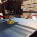
- it will try to print a circumference of the test print, wait and see if any PLA comes out of the nozzle, if you see the actual cube or test print you chose is about to be printed, and still no PLA comes out, try to push the filament into the printer head or abort the print and when the printer head is stopped, push the filament into the printer head (perhaps try to pull and push again to see where the filament is blocked)
- start the test print again, eventually the PLA comes out of the nozzle
- if no PLA comes out, repeat 5.1
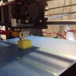
- if PLA comes out, and attaches to the bed, you likely have a successful first print ahead
- if PLA comes out and doesn’t attach to the bed but creates a mess, abort the print and check “Adjusting Printing Bed” again
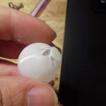
In my case the bed was too close to the bed, so the test cube was too firmly attached to the tape that I ripped the tape off the bed when removing the test cube.
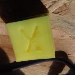
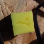
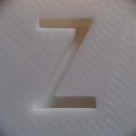
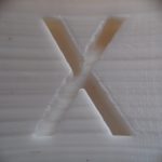
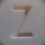
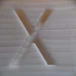
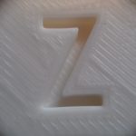
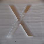
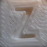
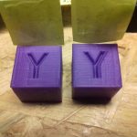
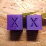
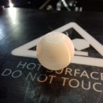
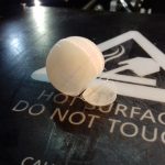
The very first test print worked extremely well, beyond my expectations – no Z wobble at all, some stringing at “X” and “Y” though.
Fixes & Upgrades
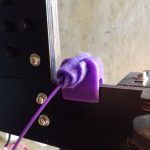
Filament Guide & Cleaner
- filament guide and cleaner:
- 2nd filament guide for holding the wires of the printer head
Extruder & Part Fan
I had attached the extruder fan to “FAN2” which is an always on 12V source (surely can be turned off), the fan ran for few minutes and died; I replaced it and attached it to “FAN1” which turns on after 2nd layer of printing which is sufficient and kept it there, as I printed once a large piece which caused the extruder heat up so much that filament got stuck – so it’s remained on “FAN2” (always on).
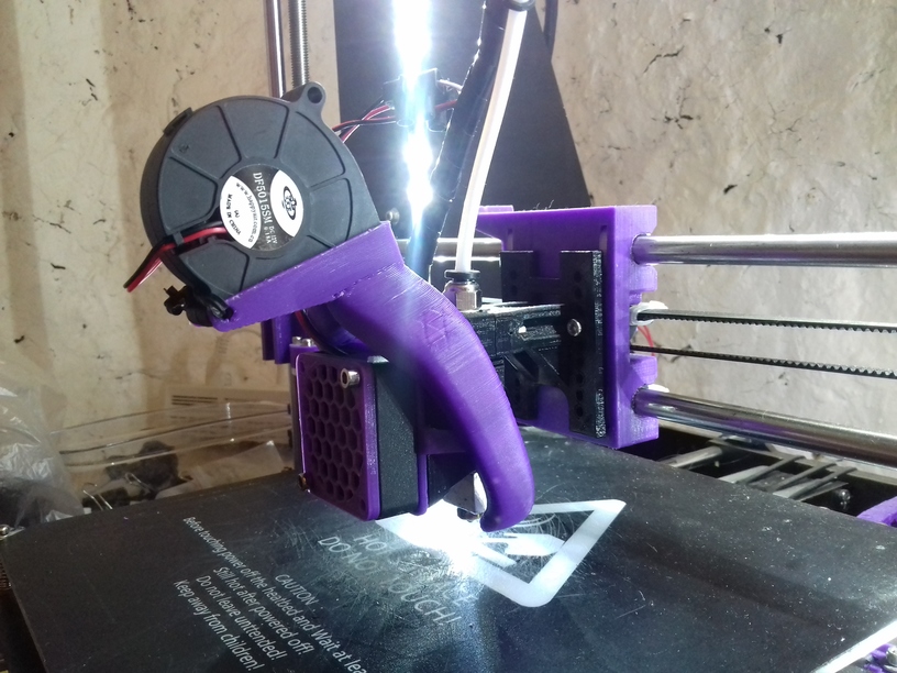
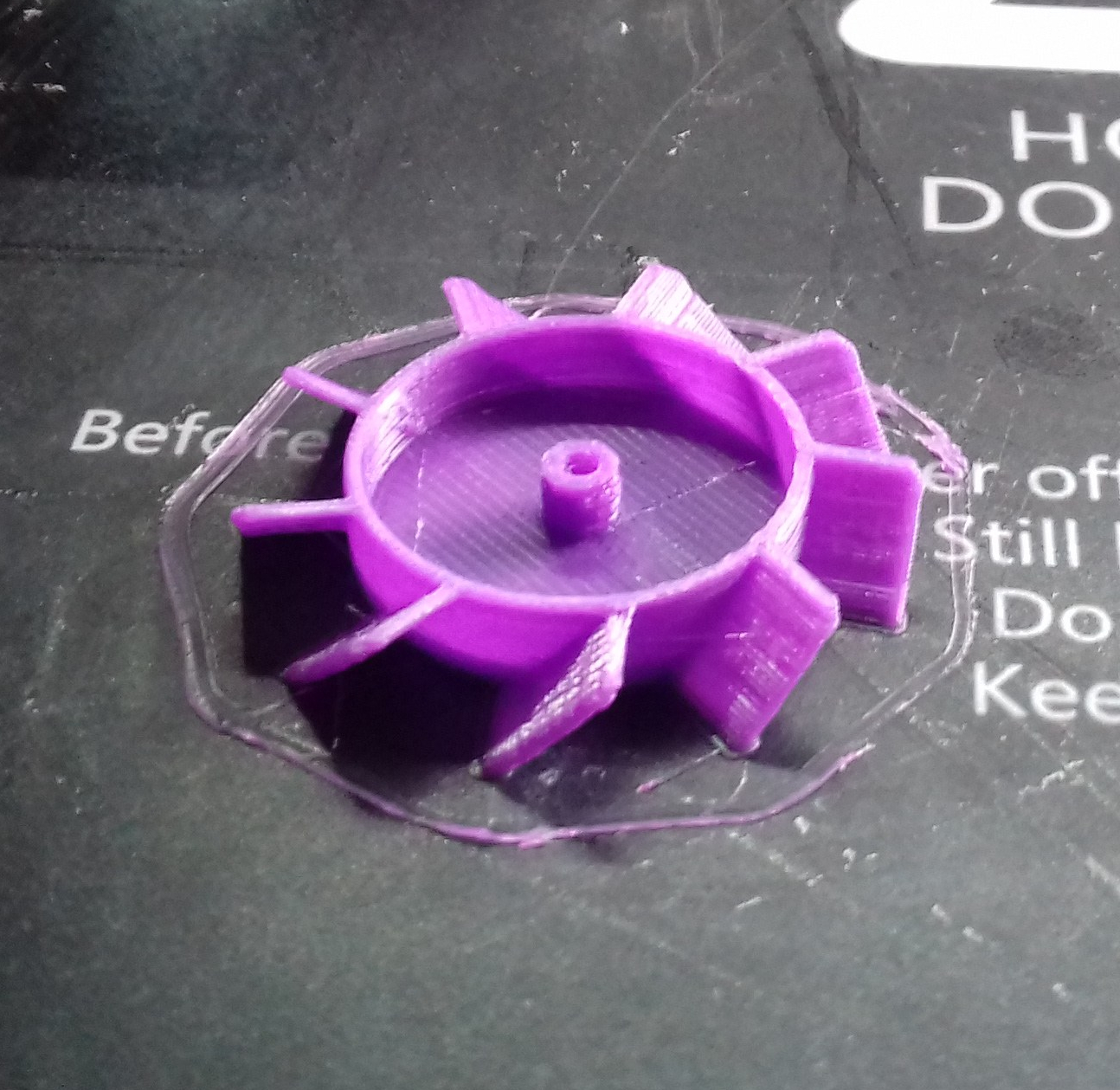
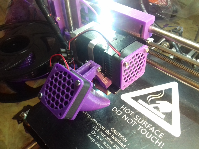
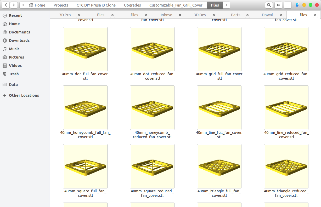
- 40mm fan duct for CTC Prusa (printed with “support” enabled) as part fan attached electrically to extruder fan which is connected to “FAN1” on the controller, which turns on at 2nd layer printing
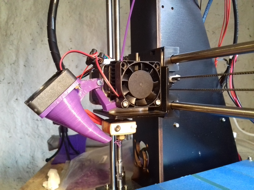
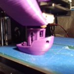
- after the 40mm fan duct “part fan” attached the prints significantly improved, for example #3dbenchy I would have dared to print without fan, still a bit stringing but overall a very good print:
-
-
Printing #3dbenchy (challenging)
-
-
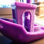
Finished #3dbenchy with some “stringing”
-
-
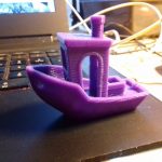
Manually cleaned up #3dbenchy
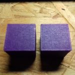
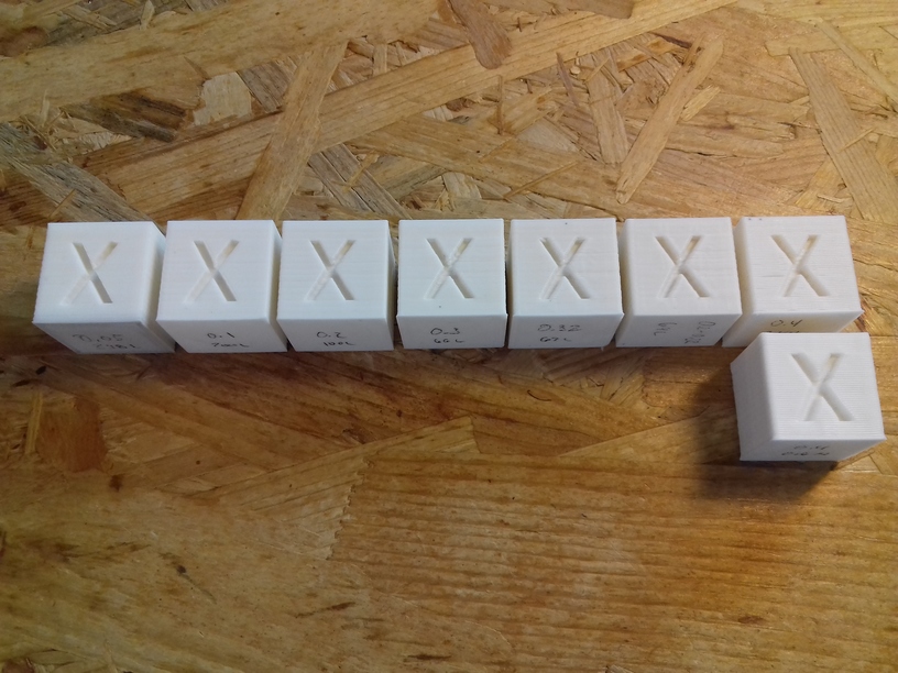
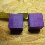
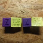
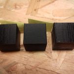
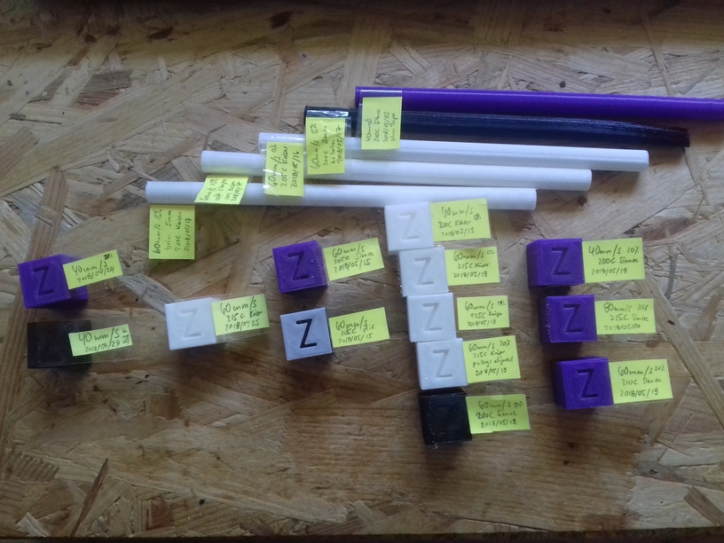
- fan vs fanless printing side-by-side:
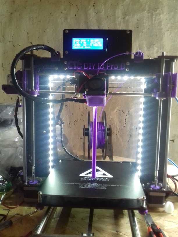
White LED
Adding white LED near the nozzle for better viewing, attached to “FAN2” on the controller board (always on), 1K resistor in series with LED on 12V.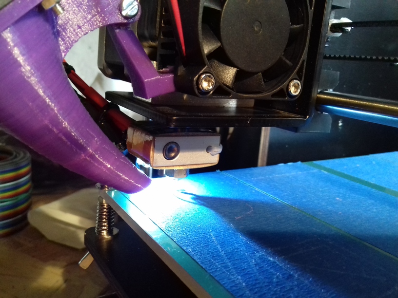
Labels
I thought the printer lacks proper labels, also one of the reasons it’s sold in so many variants and you don’t know what kind of “CTC DIY I3” you get.
- label plate “CTC DIY I3 Pro B” (just press “Generate STL” -> “Download”) or download STL
Hint: your printer must be calibrated, even 1% margin will make the label not fit – best print 2-3 layers first, then abort print and measure hole-to-hole (centers), and then rescale piece (100%/your-length*157.5) in Cura so the distance of the holes fit 157.5mm distance finally – see next section “X & Y Axis Calibration”.
- serial plate “CTC A9999” and check Description, edit your serial number & press “Update”, then press “Generate STL” -> “Download”
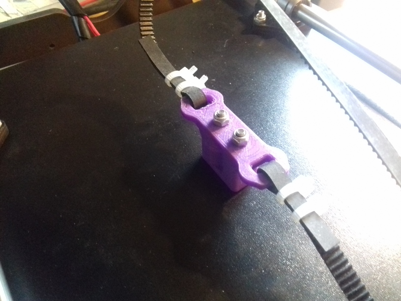
X & Y Axis Calibration
When I printed the labels I realized my X and Y axis were off by 1.49% each, which made more than 2mm on 150mm distance (way too much); I printed out an “L shape” of 150mm length 10mm wide X and Y axis, and measured the length, apprx, 147.8mm. I went into the LCD menu “Control -> Motion -> XSteps/mm & YSteps/mm”:
Current settings:
- XSteps/mm: 78.74
- YSteps/mm: 78.74
and calculated 78.74 / 147.8 (measured) * 150 (should be) = 79.91
New settings:
- XSteps/mm: 79.91
- YSteps/mm: 79.91
I printed out the “L 150mm” again, and remeasured: 147.8mm – it made no difference, checking back the settings they were reset back to 78.74. So, I could edit it, but it had no effect whatsoever . . .
Using Repetier helped as I was able to manually send Gcode without actually printing anything and checking back with the LCD menu, and so reconfigured it to enter “M92 X79.91″ which was set as “XSteps/mm 79.9” when reading back in the LCD menu – when I printed with Repetier the L shape again I ended up with 149.5mm instead of 150mm, still a bit off.
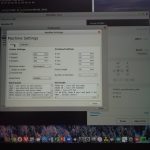
I decided to stay for now with Cura – as I’m used to it right now – and after some additional test prints I ended up adding following “Start Code” in Cura at the bottom of the existing code:
M92 X80.27 ; change xsteps to 80.27 per mm
M92 Y80.27 ; change ysteps to 80.27 per mm
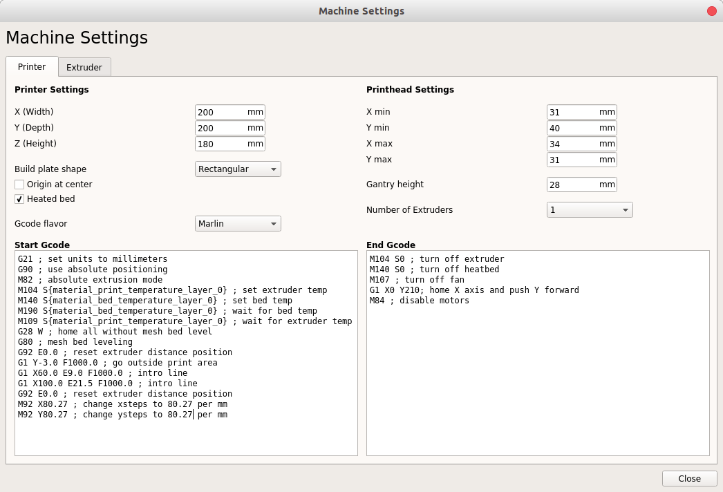
That finally worked, the L shape of 150mm ended up with 150.0mm (+/- 0.2mm) as measured with a ruler.
Even though I printed out the 20mm calibration cube, the 1% or 0.2mm I could hardly see with the simple ruler (right, require analog or digital caliper) – the Z axis seems fine but needs verification as well.
Update 2018/04/25
After a lot of tuning, I ended up with this single line
M92 X80 Y80 E96
which sets X & Y Steps per second as well the extrusion flow (instead using 105 steps as the default and reduce by 95% you define E96 and stay with 100% extrusion flow).
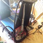
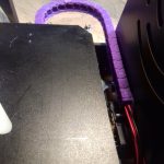
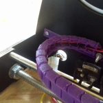
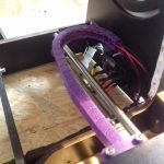
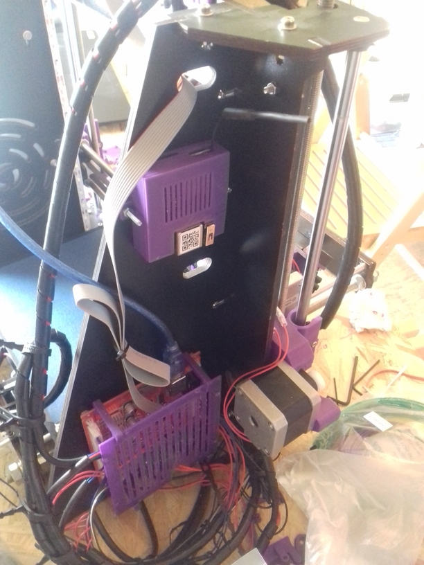
Cables
I used some more cable spirals to sort the cables better and give them some kind of stiffness while still being flexible, e.g. the Y axis cable I lifted up so it stays flexible and won’t catch on anything while moving:
What’s left to do it is a cover over the controller board.
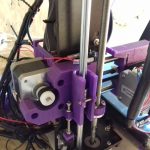
Replacing X Gantry/Axis Parts
I finally dared to print the X gantry/axis parts as enclosed on the CD I received, and replaced the black parts:
I had to remove the XZ Frame flatter screw as it touched the X pulley on the right side slighly at the same Z height – and I didn’t want X position errors at that particular Z height. Also, the Z Stopper seemed now too far on the right, and the screw pushing on the stopper too far on the right, so I printed a 10mm wide 5mm height cylinder with 2.8mm hole inside, which I screwed on the bottom of the M3 Z Stopper screw which extends the area and now reliably pushes the X Stopper switch.
Loose Screws & Cablebinders: Y carriage
After roughly a month of usage, the printed started to make noises, more so the bed leveling was almost impossible to perform, after each print the level was misaligned and I wondered. Finally I removed the heatbed and retighten all screws and nuts and refastened the cable binders which held the linear bearings of the Y carriage.
That made a huge difference . . . I was finally to print again 60mm/s and most of the stringing went away due the higher speed; I even printed at 80mm/s at still acceptable quality. The entire printer sounded now differently, it mad an immense impact to retightend those screws, it did not just affect Y axis, but also the X axis – and the overall prints are cleaner, more precise and I’m able to print at higher speeds without loss but actual gain of printing quality.
Conclusion
This 3D Printer is the low cost hobbyist or entry-level “maker” approach to 3D printing – and even when you end up with a broken printer, the parts are worth it as you likely are unable to source the parts yourself for less than EUR 100 with shipment.
Expect to invest heavily in regards of time to educate yourself and fine-tune your printer and extend it so it becomes easy to use.
It is worth it – but what you order might not what you get . . .
Notes
Material
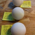
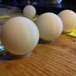
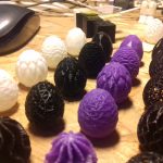
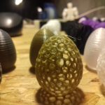
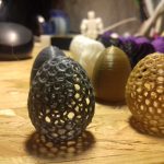
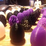
- 1kg PLA “Sienoc” purple (2018/03): nice color, bed adhesion ok, printed at 200C, good flow
- 1kg PLA “Sienoc” black (2018/04): very good bed adhesion, fully opaque at 0.15mm layer already, very glossy, printed at 200C, very good flow
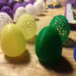
- 1kg PLA “Kaisertech” white (2018/04): adhesion ok, layers quite opaque (0.15mm partially transparent, 0.25mm already quite opaque), printed at 200C, flow not ideal
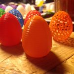
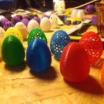
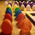
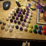
- 20 pieces/colors a 10m colored (incl. transparent, glowing, gold, silver) PLA of unknown brand (2018/04): 210-215C required, at 200C possible of non extruded filament (missing extruder steps) and therefore missing regions of material
Note: I will update this post with new discoveries and experiences, and see also additional blog posts with CTC DIY i3 Pro B tag.


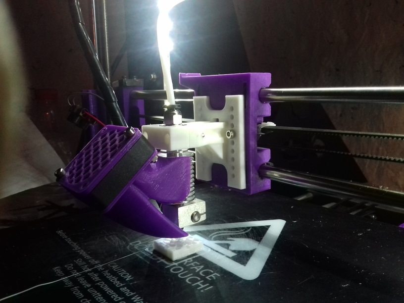
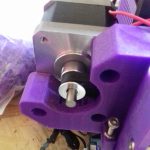
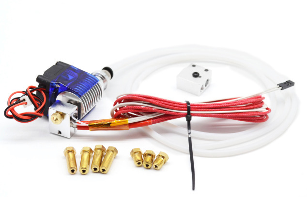 The CTC DIY I3 Pro B, a Geeetech I3 Pro clone, is the very low-end of 3d printers – quality and pricewise, and uses a direct drive to feed the filament aka “MK8 Extruder”. I ordered an E3D V6 clone with 0.2mm-0.4mm short nozzles with optional Volcano hotend for larger diameter nozzles (0.6mm – 1.0mm) from China, at EUR 9 price, as I wanted to
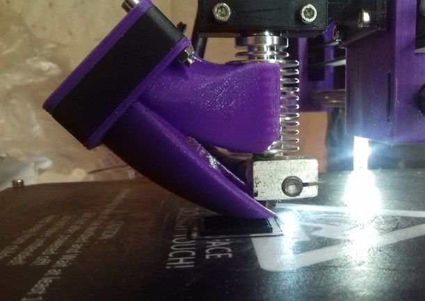
 After some time I switched to
 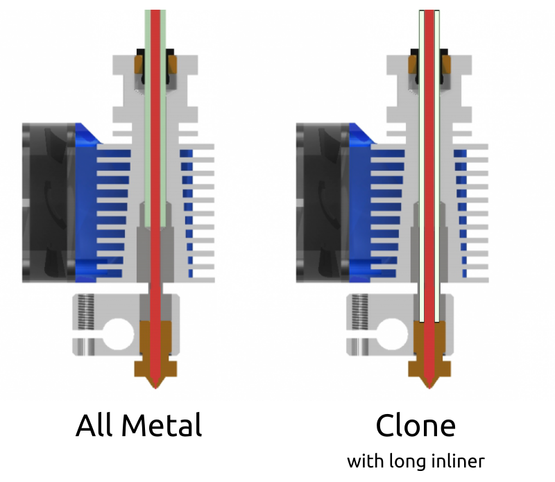 Before I go into the details, let me comment of the overall building quality of those E3D V6 clones: you get what you pay for, a compromise. My hotend leaked like crazy, at the junction of heatblock & nozzle, and heatblock & heatbreak – which is most annoying, and that did not happen with the original MK8 Extruder.
 Update 2: the real problem of leaking was the PTFE/teflon inliner, the end toward the nozzle wasn’t perpendicular sufficiently and likely a bit too short (by less than 1mm) and it was too narrow tube with 3mm OD instead of 4mm and be more tight – so the PLA leaked between the inliner and the threads of the heatbreak and nozzle – so the real remedy is to pay close attention of the length of the inliner (in case the E3D V6 clone comes without it as in my case), and give it 0.5mm to 1mm extend with a clean cut and preferably a conic end which presses then toward the nozzle.
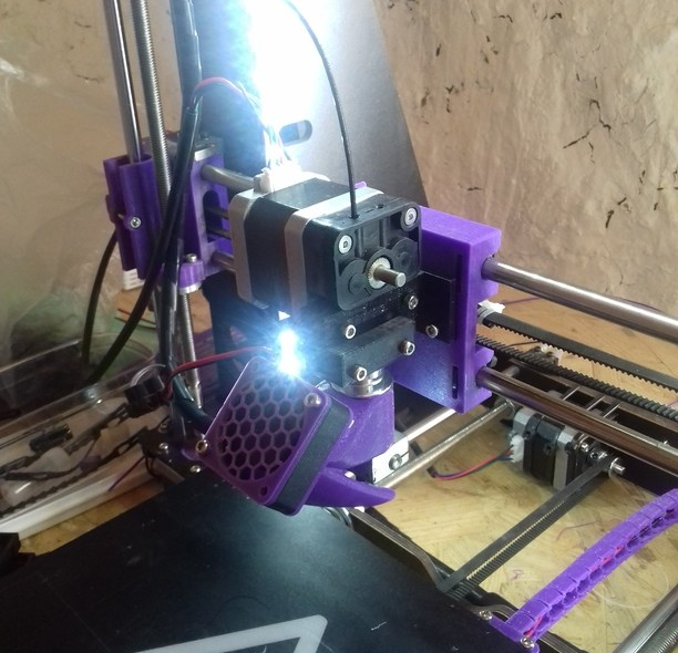
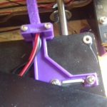
 The two E3D V6 bowden adapters I first printed and used required quite some change in Z height, bringing my Z stopper screw to its limits and also were off in the Y axis – so I designed a more suitable adapter with multiple mounting holes:
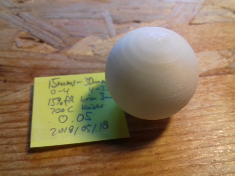
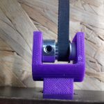
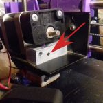
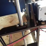
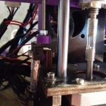
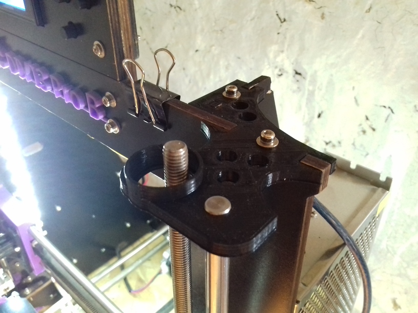
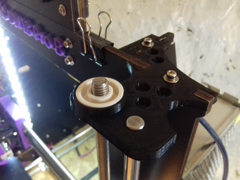
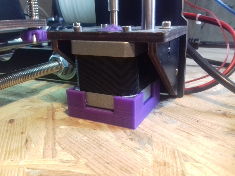 It bothered me at the very beginning, and finally resolved it: the Z Motors are lifted 8mm in air with a bracket, the force from the XZ frame and the smooth rods is distributed between just three screws, whereas the most tear is just on one screw – it’s fairly simple to make some stand so the entire Z motor takes some weight as well and adds stability.
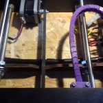


 I used this