
Using a low-cost 3D printer like CTC DIY I3 Pro B (Geeetech I3 Pro B clone) with M8 threaded rods as Z axis with loose or floating ends is what you get – and so also some wobble or banding on the X axis due slightly bent M8 threaded rods – they barely come straight. I hesitated to use lead screws due decrease of resolution (M8: 1 cycle = 1.25mm height, lead screw like TR8x8 (8mm dia, 4 starts, 2mm pitch, 8mm lead => 1 cycle = 8mm height) but otherwise gaining pretty straight lead.
Anyway, I searched Thingiverse for Z mounts for the CTC DIY and found a few, and adapted one design and made a remix Geeetech / CTC Prusa i3 DIY – Z Axis Bracket Remix with printable Bearing:
- changed structural holes (larger hole -> smaller holes)
- bearing hole widened to have more floating
- printable bearing added to restrict end (optional)
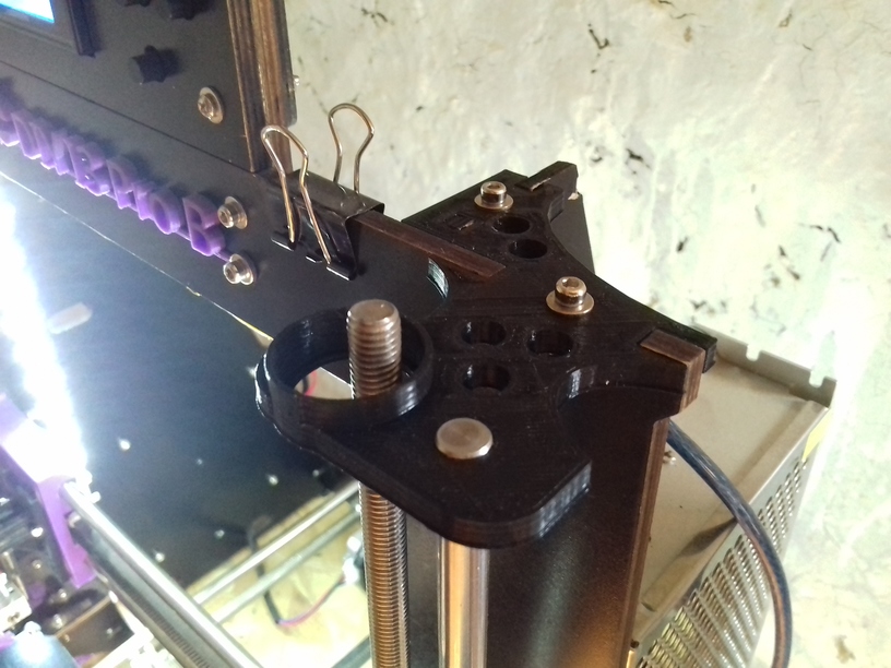
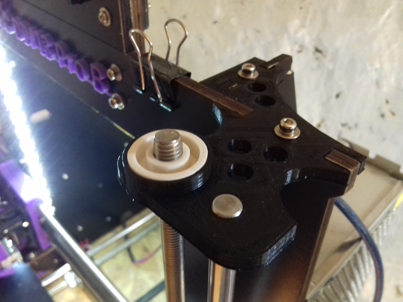
New Z bracket mounts (black), without/with printed bearing (white):
And I did a few tests:
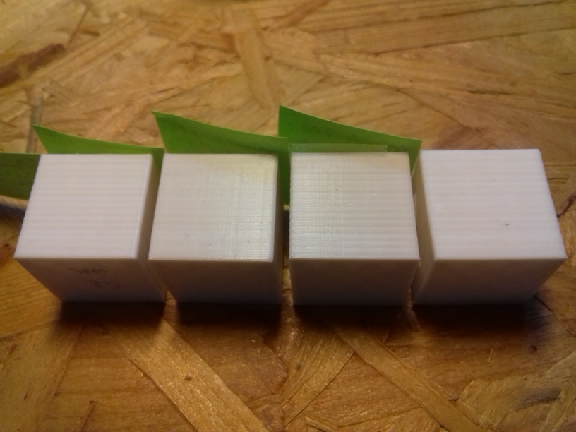
Left to right (close-ups photos below):
- original Z bracket (wood) apprx. 4mm play
- new Z bracket without printed bearing, apprx. 10mm play
- new Z bracket with printed bearings (with loose tolerance)
- new Z bracket with printed bearings (tight tolerance)
-
- Original Z Bracket (wood) ~ 4mm play
-
- New Z Bracket, Without Bearing
-
- New Z Bracket w/ Loose Bearing
-
- New Z Bracket w/ Tight Bearing
Now comes the surprise, the best surface (best to worst):
- no bearings / open floating: gives the smoothest surface, most straight Z edge
- tight bearings: gives very good surface, slightly worse than with no bearings
- loose bearings: noticeable artifacts / wobble, Z edge wobbly
- original bracket: worst wobble of all, Z edge wobbly
Which means, either give it a lot of space so the upper end of the Z threaded rods can float, and thereby the X gantry can stay fixed (and not wobble) – or – fix the threaded rods and suppress wobble (there is still wobble but restricted). Giving it some space on the top means the inherent wobble of the rod is distributed between top and X gantry – giving wobble artifacts on the print . . .
The issue isn’t simple: with or without fixation gives good results, some fixation gives more bad print results.
Open Ends / Floating
The new Z bracket provides more space for the threaded M8 rods than the original wooden bracket:
Printed Bearings
You may print two bearings (OD 22mm, ID 8mm), make sure to test inner diameter, so the threaded rod slides smoothly – if required use a 8mm drill to widen the inner hole.
Conclusion
Worst Z wobble was with original Z mount with ~4mm play or the loose bearing with apprx. 1-2mm play.
Best results I achieved with floating ends or with tight bearing – in other words, either leave it open or make it stay close, but worst is to give it a little play and threaded rods will show their unevenness on the prints.
I would also guess, the unevenness of the threaded rods and their position to each other also matters, e.g. whether left and right go the same way or cancel each other wobble out. What I noticed was, once I used the printable bearings for a print, and removed it, the threaded rods wobble already less – but as said, best results I achieved with no bearing and wide floating ends or with the tight bearings.
Recommendation: print the mounts, print the two bearings, and print the XYZ Calibration Cube or whatever reference item, and see yourself which option works better for you.
Addendum: M6 Z Axis Conversion
I made a small package Geeetech / CTC DIY I3 Pro B M6 Z Axis Conversion to use M6 threaded rods instead of M8. It made little difference:
- less wobble, but still wobble despite of “straight” M6 threaded rods
- wobble seems mostly introduced by the couplers (either printed or PVC pipe):
- out of center alignment = wobble
- tilted mounted rods = wobble
It is hard to mount the rods perfectly with the couplers, a little misalignment and one introduces wobble (X/Y wiggle).
Anyway, M6 gives slightly higher resolution in Z axis with 0.005mm per motor step.
