Updates:
- 2022/04/01: changing wording of “non-planar” vs “planar” slicing but describe actual slicing vector and geometry
- 2022/03/26: published finally
- 2022/03/24: added “Tensile & Shearing Force” illustration
- 2022/03/10: added “Scale & Functional Qualities”
- 2022/02/27: added Class 2 example
- 2022/02/18: removed MetatronSlicer example and move to new page, keeping page focused on general and theoretical aspect of Universal Slicing
- 2022/02/12: adding MetatronSlicer example as first attempt of an Universal Slicer
- 2022/01/28: separating from another blog-post, solely focusing on Universal Slicing
- 2022/01/16: starting write-up
Table of Contents
Introduction
While conceptualizing the in-house LabSlicer (2021/2022) and the two subsequent slicers afterwards (Vox3lSlicer & VoxGLSlicer), I realized it would be useful to formulate a general or universal description of slicing, hence I propose an universal definition of slicing as such:
Universal slicing means free slicing geometry along a free path.
“free (definable) slicing geometry”: any kind of geometry, may it be a solid or just a surface defining the slicing geometry.
“free (definable) path”: the slicing procedure can go in any direction, curvature and steps.
To put this in context:
- “planar slicing” is plane or quasi box geometry with layer height thickness, sliced along a static 3D path vector of
[ 0, 0, 1 ], aka “planar” or “Z-planar” with vector steps of[ 0, 0, layer height ], whereas layer height can change in that case it’s “variable” or “adaptive layer height” - “conic slicing” is a cone geometry with layer height thickness, sliced along a static path vector of
[ 0, 0, 1 ]with vector steps of[ 0, 0, cos( layer height )] or scaling a stationary conic to match layer height - “cylindrical slicing” is a cylinder which stays positioned static at
[ 0, 0, 0 ]and variable scaled to match layer height with[ s, s, 1 ], slicing pipe-like layers - “spherical slicing” is a sphere geometry with scales in size to match layer height, the position stays
[ 0, 0, 0 ], whereas the geometry is scaled by[ s, s, s ], slicing thin sphere layers
| Slicing | Slicing Geometry | Slicing Vector | Vector Steps | Geometry Scale |
| planar | plane | [ 0, 0, 1 ] | [ 0, 0, t ] | [ 1, 1, 1 ] |
| conic | cone | [ 0, 0, 1 ] | [ 0, 0, t ] | [ 1, 1, 1 ] |
| cone | [ 0, 0, 0 ] | [ 0, 0, 0 ] | [ s, s, s ] | |
| cylindrical | cylinder | [ 0, 0, 0 ] | [ 0, 0, 0 ] | [ s, s, 1 ] |
| spherical | sphere | [ 0, 0, 0 ] | [ 0, 0, 0 ] | [ s, s, s ] |
The actual implementation, how slices are routed and then G-code is created, is up to the slicer; an Universal Slicer is a slicer which implements Universal Slicing paradigm.
Class 1: Static Slicing Vector, Static Slicing Geometry
There are two distinct cases of class 1 slicing:
- slicing with planar geometry, a plane – also known as “planar slicing”
- slicing with non-planar geometry, like a wave, a hemisphere, a cone, etc.
Static slicing vector means here, there is an equal distance among all points of a slice to the next or previous slice at the same [ x, y ] position according the slicing vector:
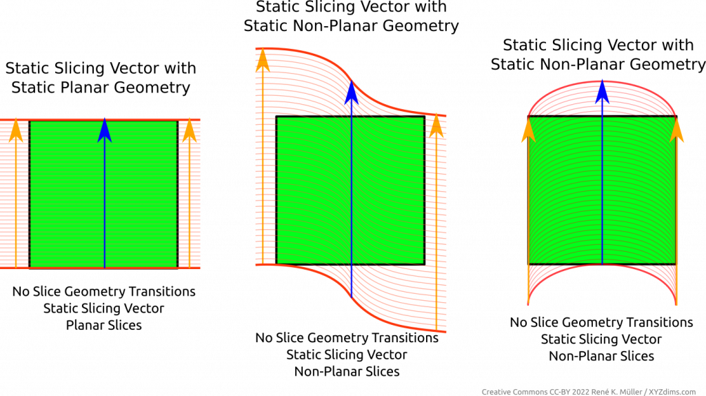
Regardless of the slicing geometry, the layer height or thickness remains the same along the slice or layer itself.
The layer height or thickness may vary from layer to layer, this is known as “variable layer height” or “adaptive layer height” but only means among layers or slices, but not within a single layer or slice.
Class 1 Examples
Examples of Class 1 Universal Slicing with planar and non-planar geometries and the respective G-code outputs (produced by MetatronSlicer and EnochSlicer):
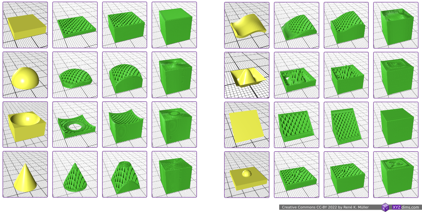
- using a block as planar blueprint
- hemisphere, convex
- hemisphere reverse, concave
- cone, slicing conical like for Rotating Tilted Nozzle
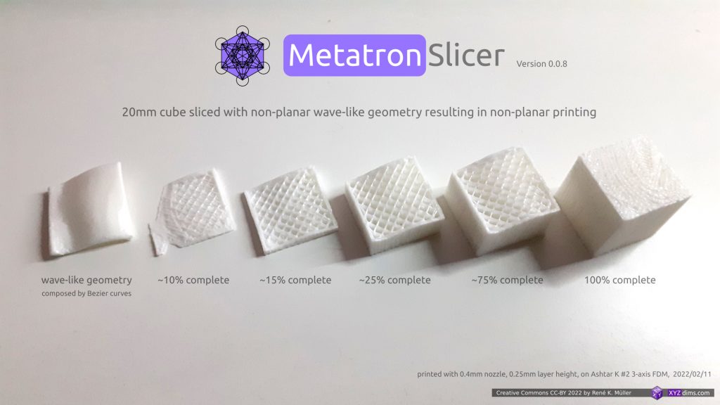
- wave-like defined via Bezier curves
- wave-like defined via NURBS (Non-Uniform Rational B-Splines) curves
- tilted plane, slicing for belt printer with 45° tilted XY frame toward Z belt
- pimple-like
Class 2: Variable Slicing Vector or Variable Slicing Geometry
Variable slicing vector or changing slicing geometry (often refered as “non-planar slicing” without the specifics) means the slice itself has variable layer height or thickness – to be more precise:
- change of slicing geometry, e.g. transitioning from one slicing geometry to another
- change of slicing vector, e.g. change in steps, or curvature
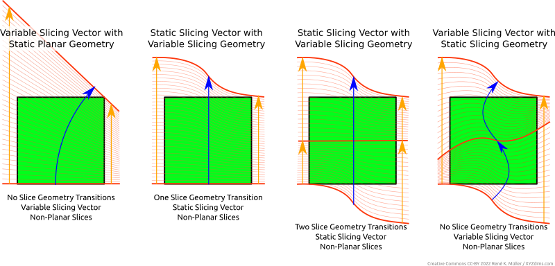
It may not be always clear at first sight whether there is a transition of a slicing geometry or a change of slicing vector, as the changed slicing vector can also be looked as another slicing geometry – yet I think it makes more sense to differentiate between a slicing vector and slicing geometry when laying out a slicing procedure.
Class 2 Examples
Example of Class 2 of Universal Slicing (produced by EnochSlicer):
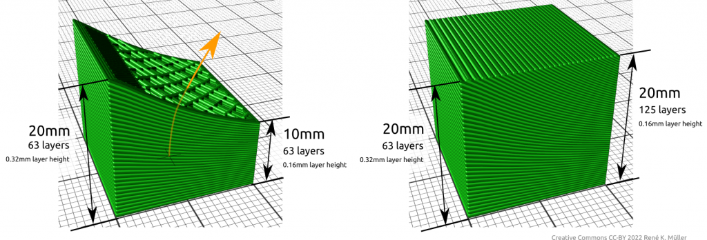
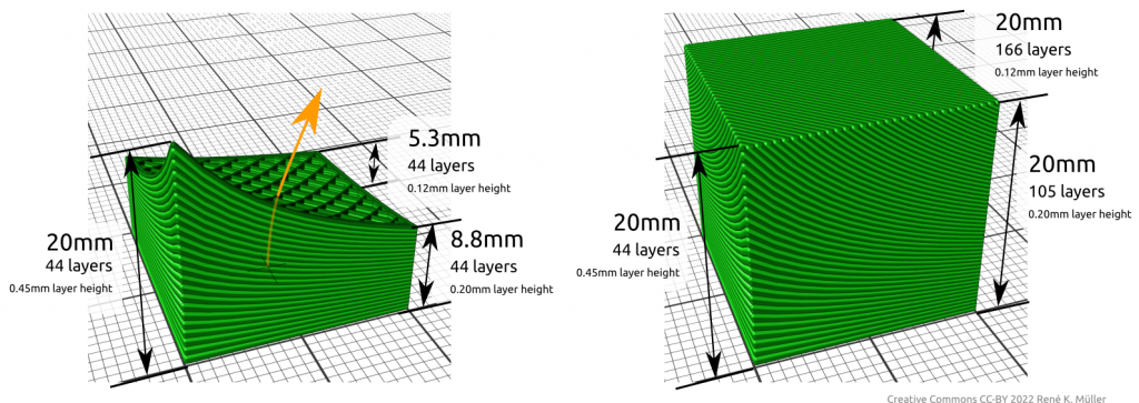
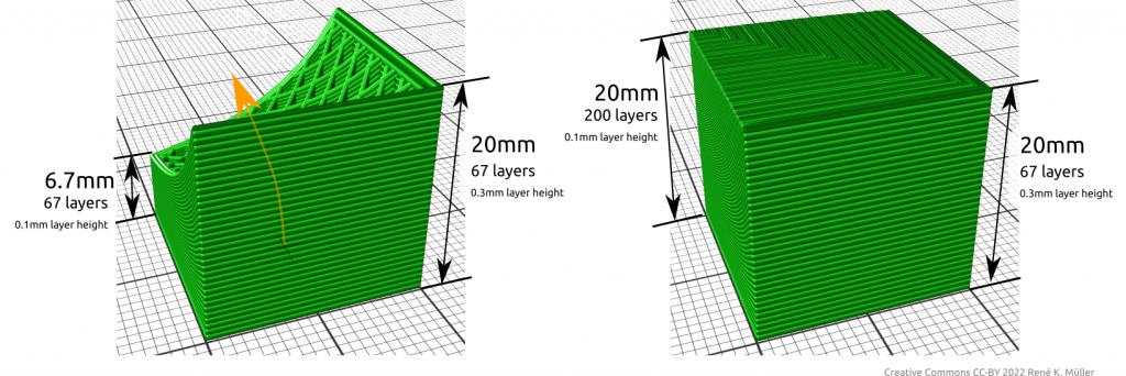
It is important to realize, that change of slicing geometry and/or slicing vector implies the slice or layer has variable thickness, hence, might have to comply with physical limits like maximum layer height printable with FDM and a given nozzle diameter – the actual implementation of an Universal Slicer has to adhere this.
Slicing Vector vs Slicing Geometry
| Slicing Vector | Slicing Geometry | Slices / 3D Printing | Slice Thickness |
| static | planar | planar | static |
| non-planar | non-planar | static | |
| variable | planar | non-planar | variable |
| non-planar | non-planar | variable |
Implementing Universal Slicing
The implementation of such Universal Slicing can be achieved in many ways and procedures. It is important to name features and describe what it they mean, such as:
- Universal Slicing: is the ability to choose slice geometry and slice path freely
- Universal Slicer: slicer which implements Universal Slicing in parts or fully – if it only implements part it shall be declared so
- Class 1 Universal Slicing: static slicing path of
[ 0, 0, 1 ], but with any kind of slicing geometry, static planar or static non-planar - Class 2 Universal Slicing: flexible slicing path, ability to change slicing geometry while slicing
| Class | Slicing Path | Slicing Geometry |
| Class 1 | static | static (planar or non-planar) |
| Class 2 | flexible | flexible (planar or non-planar) |
Universal Slicers
- MetatronSlicer (in-house XYZdims, status 2022/03):
- slicing with (non-)planar geometries (Class 1)
- partial support for slicing with change of slicing geometry (Class 2)
- EnochSlicer (in-house XYZdims, status 2022/03):
- slicing with (non-)planar geometries (Class 1)
- partial support for slicing with change of slicing path & geometry (Class 2)
- DotXControl 5-Axis Slicer (status 2022/03): supposedly supports Class 1 + 2 based on illustrations on the web-site
- AI-Build (AI Build): requires NDA to even see a demo (!!) therefore difficult to conclude capabilities, might supports Class 1 + 2 based on illustrations and brief videos
Benefits of Non-Planar 3D Printing FDM
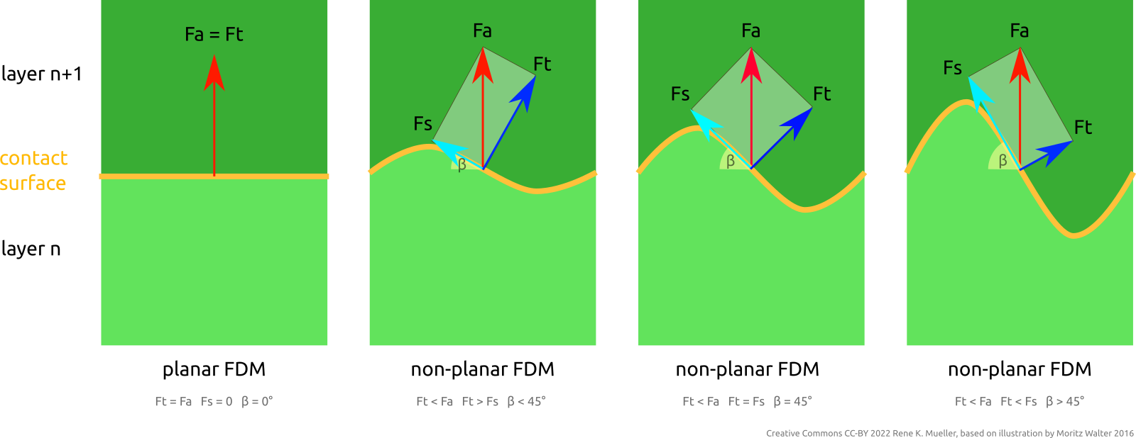
Fa = attacking force; Ft = tensile component of Fa; Fs = shearing component of Fa; β = tangent angle
One advantage resides in the ability to address FDM Z-layer adhesion issues by distributing force or stress vectors along any kind of trajectory and optimize material vs strength of the overall printed piece, e.g. when using continuous fiber filament and lay it along most stressed locations.
Further, the ability to have top layers align to object’s surface directly, no more layer lines. Essentially being able to define and manufacture a piece based on inner structure requirements and its outer form requirements.
References
- 3D Printing: Slicing with Non-Planar Geometries
- Video: Mastering Non-Planar Printing: Slicing with Non-Planar Geometries
- MetatronSlicer (Class 1+2 Universal Slicer)
- EnochSlicer (Class 1+2 Universal Slicer)
- LabSlicer (planar slicer)
- Slicer4RTN: conic slicer for Rotating Tilted Nozzle
- HackaDay: 3D Printering: Non-Planar Layer FDM (2016), brief overview
- Inner Structure Approaches
- Hyperganic: software designing parts based on actual function and strength properties, voxel-based, output for SLS, SLA, FDM – very little information available on the net (2022/02), secretively operating company
- nTopology: generative design using implicit modeling, more open company, they even have a Github presence
- Papers:
- [Coupek, Friedrich, Battran, Riedel] Reduction of support structures and building time by optimized path planning algorithms in multi-axis additive manufacturing (2018) – free PDF
- [Wuethrich, Elspass, Bos, Holdener] Novel 4-axis 3D printing process to print overhangs without support material (2020) – non-free PDF

