
Updates:
- 2025/06/17: new & advanced features with “inline multi-tool” G-code support with MAF 0.2.0
- 2025/06/05: publishing article
- 2025/05/30: updating
maf.cfgand more documentation - 2025/05/23: first write-up with MAF
maf.cfg
Introduction
As of May 2025 Klipper supports multi-axis support on G-code level. It was possible to define “manual stepper“ motors, but those needed to be handled via “Extended G-code” of Klipper. Now those “manual steppers” can be tied to a G-code axis, and thereby multi-axis system can be composed and becomes available in traditional G-code context.
MANUAL_STEPPER STEPPER=stepper_x1 GCODE_AXIS=Aand after that
G0 A100can be used.
As of 2025/05 only G0/G1 is supported, but not G92, M82 (absolute extrusion), M83 (relative extrusion) in case “manual stepper” is used as additional extruder motors – so I coded a Multi-Axis Framework for Klipper, just a bunch of Klipper macros which provide a better multi-axis & multi-extruder support:
G0,G1supports relative extrusion if enabled withM83(I prefer)G28homing the new axes as wellG92supports the new axes tooM82,M83switches absolute/relative extrusionT0,T1, … switch extrudersM104,M109support of multiple extruders usingT<n> notion
Klipper natively supports:
G90,G91for new axes also
Setup
Create a dedicated file, or add following into printer.cfg, for example:
[include maf.cfg]

[gcode_macro MY_MAF]
variable_maf = {
      "X": { "motor": "stepper_x", "dir": -1, "end_pos": 0 },
      "Y": { "motor": "stepper_y", "dir": -1, "end_pos": 0 },
      "Z": { "motor": "stepper_z", "dir": -1, "end_pos": 0, "bounce": 2 },
      "E": { "motor": "extruder" },
      "U": { "motor": "stepper_x1", "dir": -1, "end_pos": 0 },
      "V": { "motor": "stepper_x2" "dir": 1, "end_pos": 380 },
      "W": { "motor": "stepper_x3" "dir": -1, "end_pos": 0 },
      "A": { "motor": "extruder1" },
      "B": { "motor": "extruder2" },
      "C": { "motor": "extruder3" }
   }
gcode:
This defines all axes, the additional 3 X carriages, and additional 3 extruders. If you declare X, Y, Z as well, it will home the same way as the new axes. By default after sensor is hit for homing, it bounces back 10mm (recommended for sensorless homing), you can override it with “bounce” value.
The maf.cfg once included, the MAF will be automatically executed at boot/restart.
M82 / M83: Absolute / Relative Extrusion
This applies to all extruders, M82 (absolute extrusion) is the default. I prefer relative extrusion (M83) as it makes it easier to insert or remove G-code without affecting existing G-code with extrusion.
G92: Set Position
Any new axis can be set now, including the extruders.
G92 W0 A0 B90 C110M104 / M109: Set Temperatures
One can set temperature per extruder/tool:
T0
M104 S200
T1
M104 S200
or more compact
M104 T0 S200
M104 T1 S200
M104 set the temperature but doesn’t wait, and M109 waits until temperature is reached.
G28: Homing
The new axes can be homed as well:
G28 X Y U V W
G28 Z
Note: if you declared the axis in MY_MAF it will use the new G28 procedure, otherwise uses the native Klipper one. See also “Advanced Features” below to define tool axes.
In case you want to specify the default homing of G28 without any arguments, then add this in MY_MAF as well:
...
variable_misc = {
   ...
   "home_all": "XUYAIBZ"
   ...
}
this way you define the order exactly, otherwise the tool order (and the related axes) is used, and if no tools are defined, the order is according the map of axes to motor definition – it nicely falls back to what’s known to perform the homing. See also “Advanced Features” where you can define the order how axes are homed when you to define tool to axis mapping as well.
A multi-tool / multi-axis with multiple gantries can be quite complex to home, so this is why there is sufficient flexibility to define it and not hard-code in G-code or create another macro.
G0 / G1: Move & Extrude
The G0 / G1 is overridden in order to support relative extrusion.
M83                      ; relative extrusion
G0 X100 U300 Y100        ; move two X carriages on common Y gantry
G1 X150 U350 Y150 E5 W5 ; extrude with both extruders on the X carriagesNote: given we work in cartesian kinematics, This is taken care of since V0.2.0 which recalculates the internal speeds.X Y Z dictates the total distance as dist = sqrt (X^2+Y^2+Z^2) and the feedrate F (mm/min), any additional axis is given time t = dist (mm) / feedrate (mm/min) to reach its destination, and therefore has its own feedrate or speed – so, when operating new axes in this context, it’s up to you to be aware of the other axes speeds and keep them below operation limits.
MAF: Current State
One can send MAF command, and an output like this is received:
echo: == MAF: Multi-Axis Framework 0.2.0 ==
echo: debug: 0
echo: duplication:
echo: speed: 40 mm/s
echo: tool T0: X:X Y:Y Z:Z E:E home:XY
echo: tool T1: X:U E:W
echo: tool T2: X:A Y:B E:C
echo: tool T3: X:I E:K
echo: motion mode: absolute
echo: extrude mode: absolute
echo: axis X: stepper_x, pos: 0.0000
echo: axis Y: stepper_y, pos: 0.0000
echo: axis Z: stepper_z, pos: 0.0000
echo: axis E: extruder / T0, pos: 0.0000
echo:    temperature: 31.1C / 0.0C
echo: axis U: stepper_x1, pos: 0.0000
echo: axis A: stepper_x2, pos: 0.0000
echo: axis I: stepper_x3, pos: 0.0000
echo: axis B: stepper_y1, pos: 0.0000
echo: axis W: extruder1 / T1, pos: 0.0000
echo:    temperature: 31.49C / 0.0C
echo: axis C: extruder2 / T2, pos: 0.0000
echo:    temperature: 31.03C / 0.0C
echo: axis K: extruder3 / T3, pos: 0.0000
echo:    temperature: 31.26C / 0.0C
ok
Download
This is a very experimental set of macros – the code has grown more complex since V0.2.0 – you can still use V0.1.0 when checking earlier version:
- maf.cfg V0.2.2 (Github GIST)
I plan to keep the code updated and backward compatible.
Advanced Features
Tool Axis Mapping
[ Since V0.2.0 ]
Additionally you can define tools and which axes they use, like:
[gcode_macro MY_MAF]
...
variable_tools = {
   "T0": { "X":"X", "Y":"Y", "Z":"Z", "E":"E" },
   "T1": { "X":"U", "E":"W" },
   "T2": { "X":"A", "Y":"B", "E":"C" },
   "T3": { "X":"I", "E":"K" }
   }
...
once you added it in your MY_MAF section, you can use it like this, I call this format “inline multi-tool” G-code:
G1 T0 X100 Y10 E1 T1 X200 E1 T2 X100 Y200 E1 T3 X200 E1performing all 4 tools at once via internal tool axis mapping.
You can also do “traditional” aka sequential tool switching and keep using XY and E for each tool and it will be mapped to the internal axes – but all operations are sequentially performed, tool by tool:
T0
G1 X100 Y10 E1
T1
G1 X200 E1
T2
G1 X100 Y200 E1
T3
G1 X200 E1
perhaps only useful for debugging.
Switch to T0 again to use multi-axis support, e.g. naming the axes with A, B, C or whatever additional axes you have.
Homing Tools
Further, also homing G28 can take T<n> notion such as:
G28 T0 T1 T2 T3and it will home all respective axes associated with the tool, in the order as defined in the mapping. If you want to define your order or skip a certain axis in a tool for homing, you define:
...
   "T0": { "X":"X", "Y":"Y", "Z":"Z", "E":"E", "home": "XY" },
   ...
   "T4": { "X":"I", "Y":"J", "E": "K", "home": "YX" }
...
so even T0 has XYZ axes defined, it only homes X and Y, or in case of T4 it homes in different order like Y and then X.
Multi-Tool Duplication (Experimental)
[ Since V0.2.0 ]
It allows to define duplication on the Klipper level – in order to support this you define an additional variable:
[gcode_macro MY_MAF]
...
variable_duplication = {
   "T0": { "offset": [0,0], "size": [200,200], "row": 0 },
   "T1": { "offset": [200,0], "size": [200,200], "row": 0 },
   "T2": { "offset": [0,200], "size": [200,200], "row": 1 },
   "T3": { "offset": [200,200], "size": [200,200], "row": 1 }
   }
...
this defines for each tool at XY offset position and size in XY where the tool operates, the row gives a hint how to mirror like with gantries. In the example above a 400×400 bed with 4 extruders/tools each 200×200 printable, two rows/gantries.
You enable duplication with:
MAF DUPLICATION=copy   ; or 'mirror'
; or
MAF duplication=copy   ; or 'mirror'
once activated, you send G-code for a single tool and it will be expanded using inline multi-tool, hence, in order to have duplication working, you need to define the tool axes also.
> MAF DUPLICATION=mirror DEBUG=1
> G0 X10 Y10
echo: [duplication] G0 T0 X10.0000 Y10.0000 T1 X390.0000 Y10.0000 T2 X10.0000 Y210.0000 T3 X390.0000 Y210.0000
echo: [inline multi-tool] {'G': '0', 'X': '10.0000', 'Y': '10.0000', 'U': '390.0000', 'A': '10.0000', 'B': '210.0000', 'I': '390.0000'}
echo: [final] G0 X10.0000 Y10.0000 U390.0000 A10.0000 B210.0000 I390.0000
With DEBUG=1 or 2 you can see the steps taken to compose the final multi-axis G-code.
Using following “basic” G-code:
G21
G90
G28

MAF DUPLICATION=copy
G0 X10 Y10 F4800
G0 X100 Y100
G0 X50 Y50

MAF DUPLICATION=mirror
G4 P2000
G0 X10 Y10
G0 X100 Y100
G0 X50 Y50
which looks like this:
and when moving to X10 Y10 after homing with G28, some tools (and their axes) have more distance to cover like T2 and T3, and their travel distance is used to comply with F4800 – right now (2025/06) Klipper does not enforce speed limits to manual steppers, MAF does it for you.
Use Case
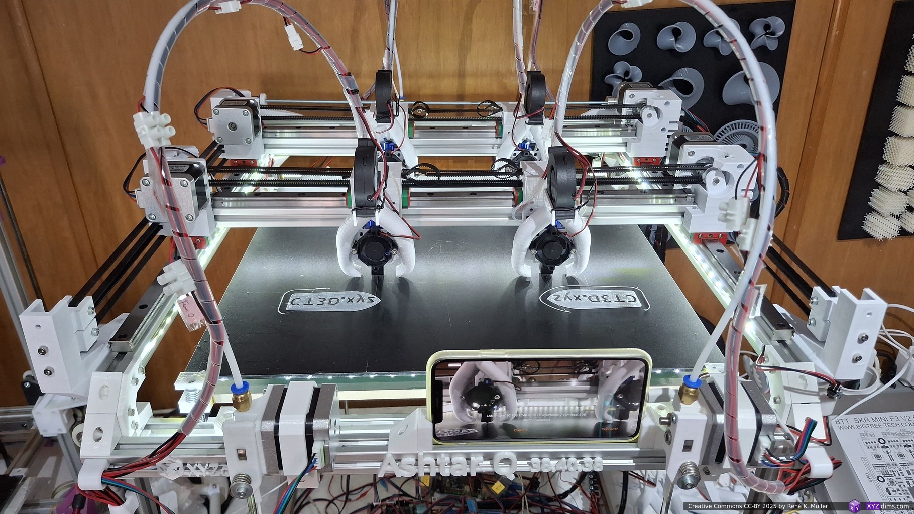
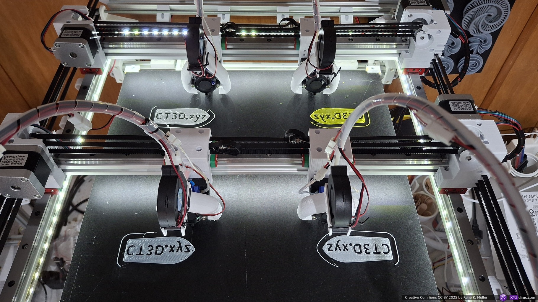
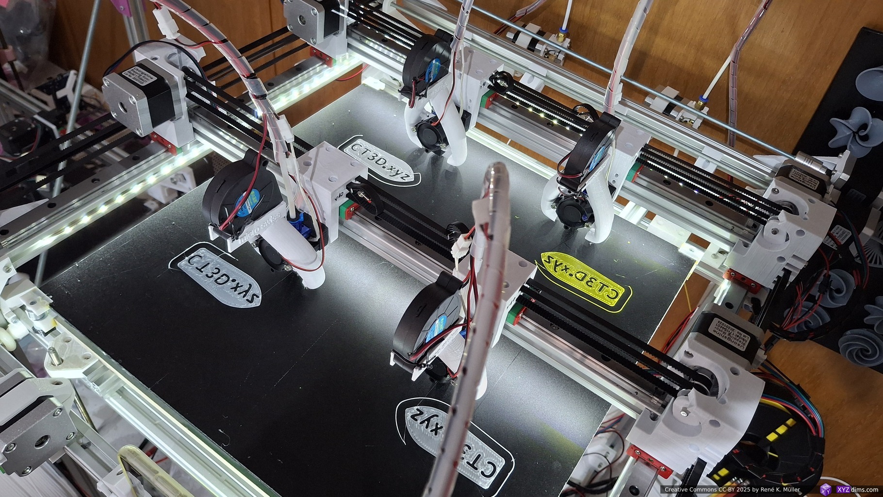
I used “MAF” for early prototyping a Multi Gantry with Multi Extruder (IDEX) setup – Ashtar Q (MG2 IDEX) – printing in duplication mode (horizontal & vertical mirrored) on G-code level:
Operating in two different modes:
- 1x Klipper instance (with 4x MCUs): 2x Y gantries, 4x X carriages, 4x extruders = 11 axis (XYZE+XE+XYE+XE) – all motors fully synced
- 2x Klipper instances (with 2x MCUs each): Dual of 1x Y gantry, 2x X carriages, 2x extruders = 6 axis (XYZE+XE) + 5 axis (XYE+XE) – two gantries loosely synced
Here some brief video of Ashtar Q (MG2 IDEX) actually printing duplicating:
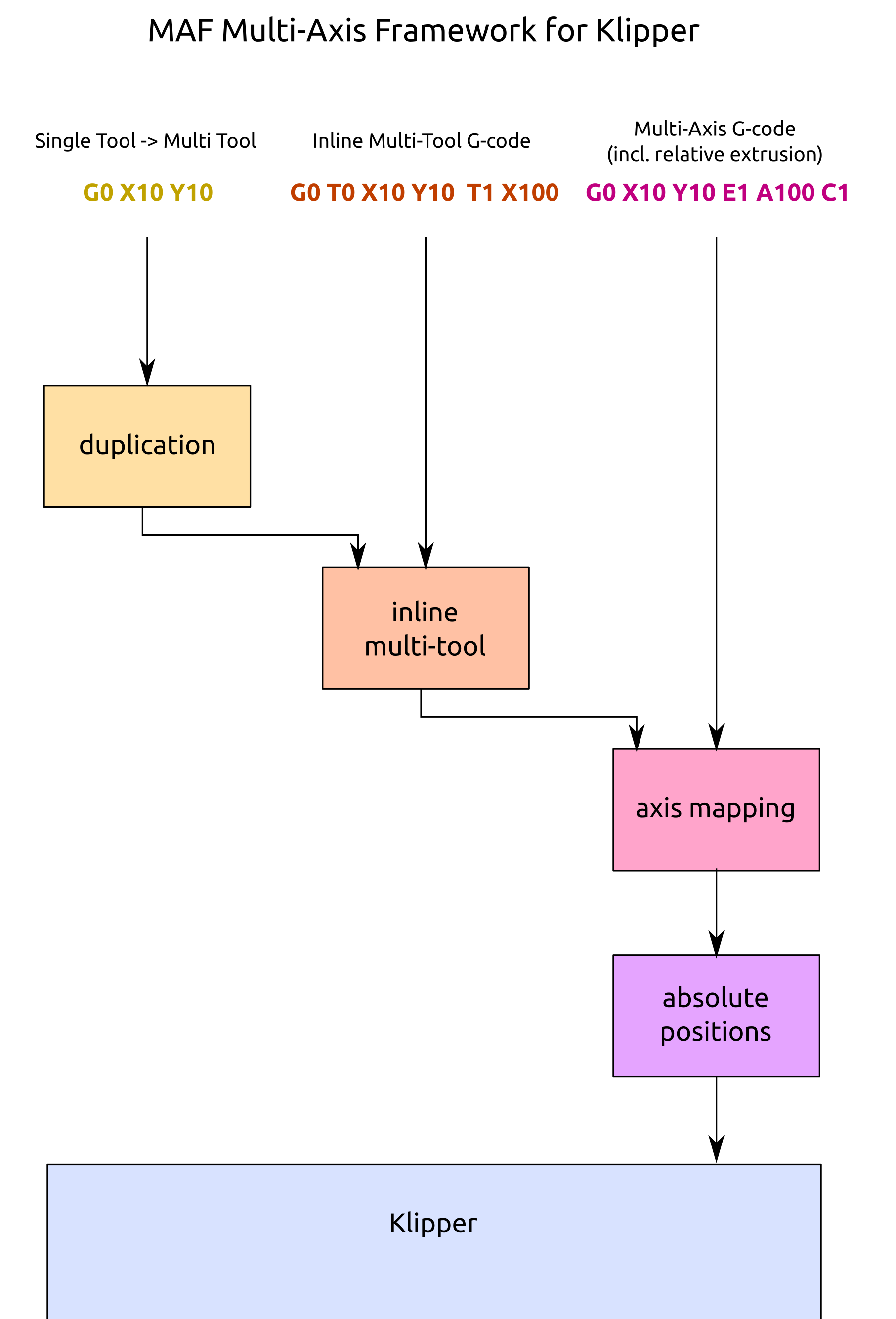
The example above is “multi-axis” G-code, where all axes are individually delivered – whereas the duplication feature of MAF is available since V0.2.0 (2025/06) and uses “inline multi-tool” G-code internally. The “inline” is important here, otherwise it might be confused with traditional multi-line spread T0 G0 T1 G0 commands.
References
- Github PR #6888: Support for additional G1 axes (merged in May 2025)
- Klipper Forum: Macros
- Ashtar Q (MG2 IDEX) – coming soon
