Updates:
- 2024/12/09: ready for publication
- 2024/12/04: completing first table on printheads & nozzles
- 2024/07/30: starting write up
Introduction
When depositing material through a nozzle, the variables to compose a workpiece depends on the amount of nozzles and their operational spaces – let’s lay out the different methods which gives us the foundation to tackle then parallel procedures in the next part in the series.
Printheads, Nozzles & Operational Space
| Printheads | Nozzles per Printhead | Nozzle Size [mm] | Layer Height [mm] | Material | Operational Space | |
|---|---|---|---|---|---|---|
| Single nozzle FDM/FFF | 1 | 1 | 0.1-1.0 | 0.1-0.6 | Polymer (PLA, PETG, ABS) | 100% |
| Dual nozzle FDM/FFF aka IDEX | 2 | 1 | 0.1-1.0 | 0.1-0.6 | Polymer (PLA, PETG, ABS) | 2x 50%; horizontally separated |
| Duplex F2 | 2 | 1 | 0.1-1.0 | 0.1-0.6 | Polymer (PLA, PETG, ABS) | 2x 50%; vertical separated |
| CM3P Dual Conical | 2 | 1 | 0.1-1.0 | 0.1-0.6 | Polymer (PLA, PETG, ABS) | 2x 50% of negative cone |
| Resin SLA (UV Laser) | 1 | 1 | 0.150 | 0.050-0.150 | Resins | 100% |
| Resin MSLA (UV & LCD) | 1 | 50M-100M | 0.020-0.040 | 0.050-0.150 | Resins | 100% |
| Quantica NovoJet | 1 | 96 | 0.050 | Resins | 100% | |
| Stratasys J55 PolyJet | 1 | 192*) | 0.2*) | 0.18 | Resins | 100% |
| Selective Laser Sintering/Melting | 1+ | 1 | 0.1 | 0.05-0.10 | Polymer or Metal Powder | 100% |
- Stratasys J55: nozzles & nozzle size based on J850 specs, J55 details specs seem not publicized (2024/12)
Print Base
A print base is where the nozzle can extrude on. For the first layer, there is the print bed, after the first layer the workpiece or support structure can be build upon. One can alternatively use a stabilizing medium like silicon and extrude in such liquid medium which operates as bed or foundation like Rapid Liquid Printing (RLP) does:
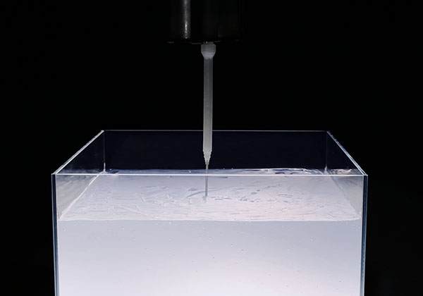
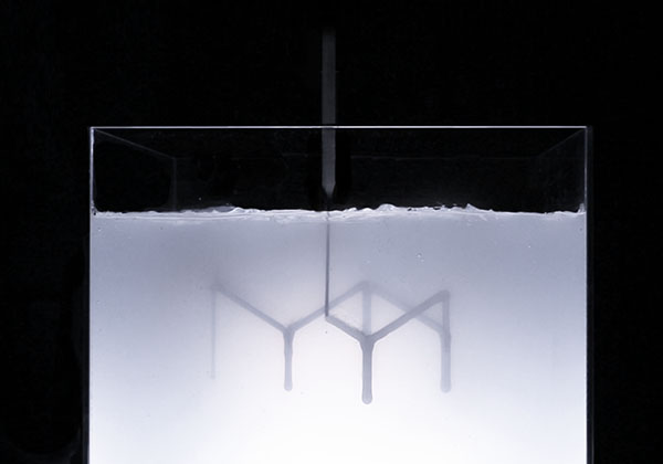
The extruded material just has to stay where it was put, either a solid bed or a medium which prevents it to float out of position, or as traditionally printed on a print bed or base, very similar does Xolography where the solidified resin stays put as well.
Massive Parallel Nozzles Printhead
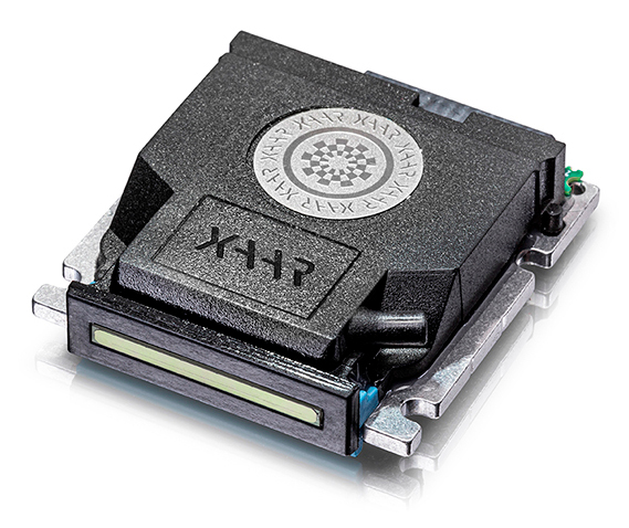
Resin printing with a printhead may have hundreds or even thousands of nozzles, yet, they share the same operational space, but due the parallel setup the print speed multiplies direct with the amount of parallel nozzles on the same printhead.
Massive Parallel Nozzles: MSLA
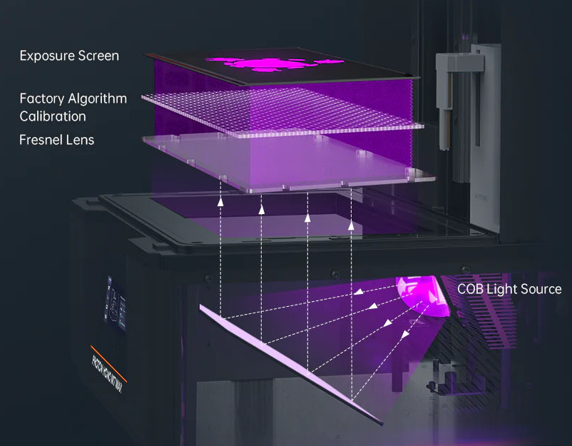
As mentioned above, we can also view Masked Stereolithography (MSLA) resin printing as a massive parallel nozzle setup, where each pixel is either an active or inactive nozzle depositing a voxel.
Separated vs Shared Operational Space
Disclosure: I have been contracted to work on the Duplex F2 software stack (2022-2024).
Let’s take a look at the Duplex F2 printer where space is separated vertically, or the CM3P dual conical printer where the cone space is separated horizontally, or the Multi Gantry 3D printer by Proper Printing (Jon Schone). We have two printheads which never collide due their separated operational space, the firmware is simple and path planning is simple, both heads pretty much can operate independently.
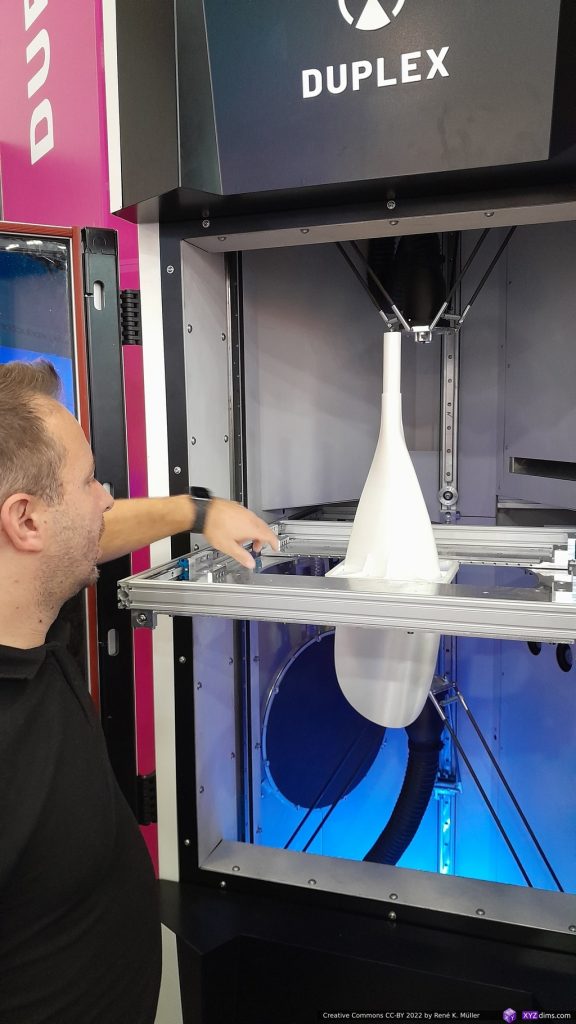
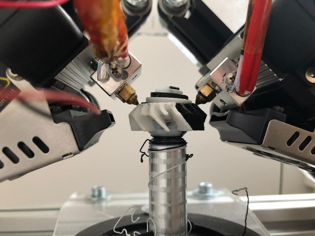
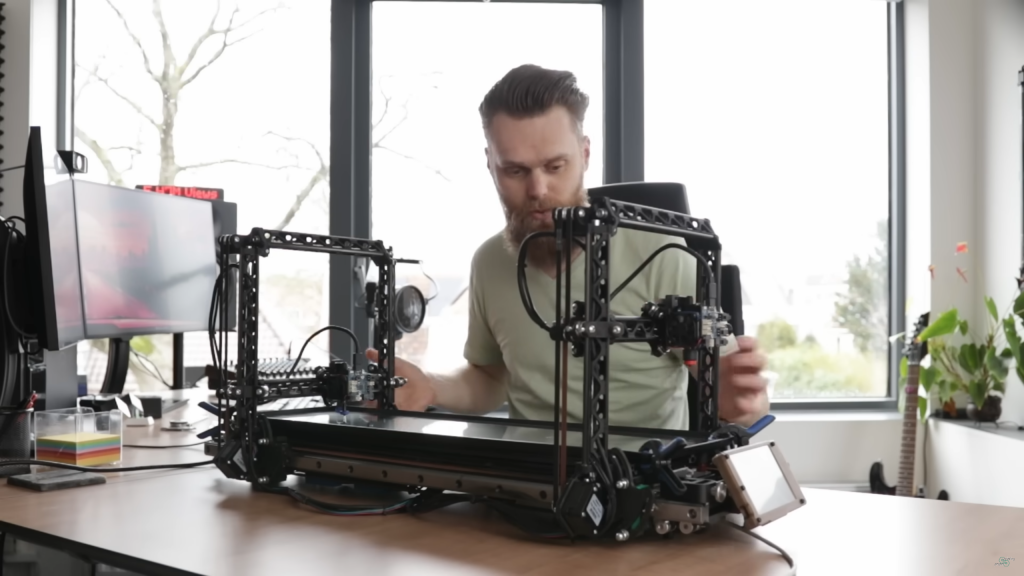
When using more than two printheads it is beneficial to share the operational space, yet assume 6 or 8 printheads, each printhead needs rods to keep the printhead and position and orient the nozzle(s), so overlapping operational space requires extreme well planned tool paths avoiding any collision of the printheads.
Regular Operation Space Separation
We can segment or separate the space evenly or according the reach of the printheads, and each separated space can be printed without colliding. Yet, in reality the printheads mounts limit that operational space into slightly smaller spaces, but ideally:
nvolumes = volumetotal / volumeprinthead
If the individual printhead volumes aren’t regular, then we end up with arbitrary amount of printheads to cover a given print volume:
volumetotal = sum( volume1..n )
In reality, we require (slightly) overlapping operation to get seamless operation, so the “regular operation space separation” is only theoretically, but not practically.
Overlapping Operational Spaces
When the printheads can reach each other operational space, they become overlapping and controlling tool path generation needs to take care no collision is occurring (same place at the same time).
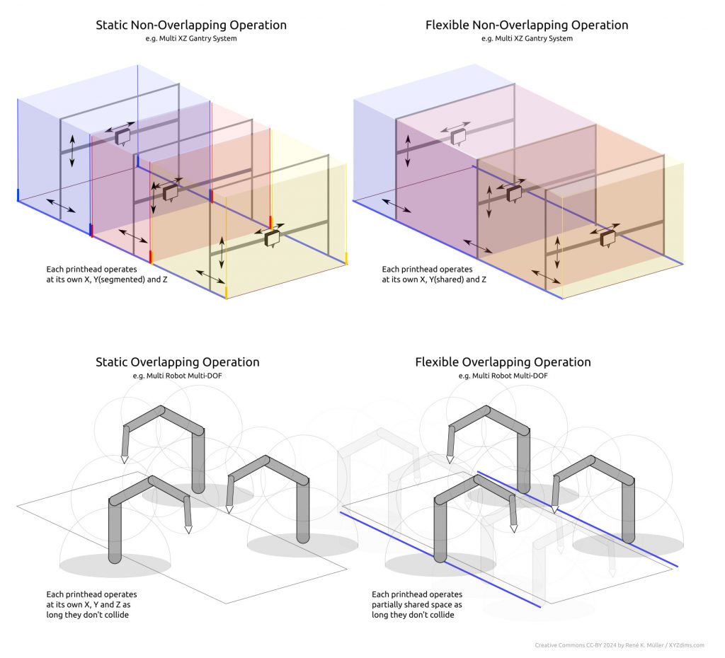
The Static Non-Overlapping Operation has static defined operational spaces where the operators can function – it’s quite obvious such solution is impractical, as in real life there would be space which cannot be reached, a kind of blind seam not reachable by either operator.
The Flexible Non-Overlapping Operation is flexible defined operational spaces, in the illustration above those spaces are co-dependent.
The Static Overlapping Operation is when those operational spaces are overlapping, yet, prefixed or static operational spaces.
The Flexible Overlapping Operation is flexible operational spaces, yet due the nature of the setup these operators cannot occupy the same space at the same time which would result in physical collisions.
Now, the last part of the last sentence may sound obvious to even mention, but bear in mind you can have two projectors shining light into a resin bath, and expose and solidify a 3D model, then these two lights acting as operators indeed occupy the same space at the same time as part of their function. So, the operators functioning with light can occupy the same space at the same time, whereas solid operators, such as robotic arms, cannot.
Print Speed in Parallel Setups
total print speed [mm3/s] = nprintheads * nnozzles * vextrusion [mm3/s] * parallelfactor
whereas parallelfactor is 1.0 if printheads can print parallel, or is less if the operational space is overlapping and preventing printheads to operate parallel thereby.
~ * ~
“Parallel 3D Printing / Additive Manufacturing” Part 2 follows later (will be linked when published)
