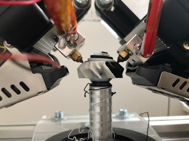
State: first prototype with dual gantry each with IDEX
Updates:
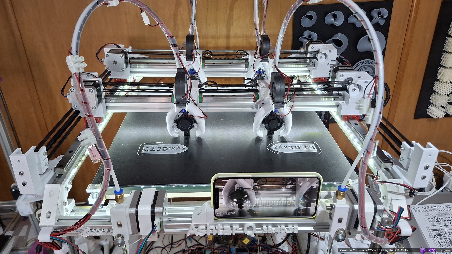
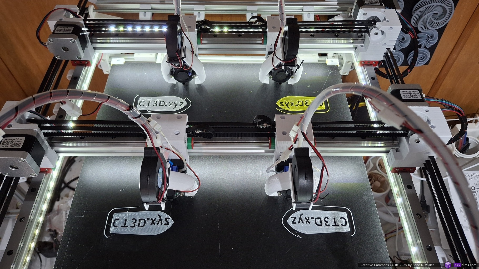
- 2025/06/03: adding first photos of Ashtar Q (MG2 IDEX)
- 2024/12/22: adding Ashtar D (Classic XY) MG3 IDEX, comparing Y-XZ vs XY gantries in regards of inertia and slicing approaches thereof
- 2024/12/20: early idea to add tool changer as well
- 2024/12/16: adding more details with multiple extruders on same X gantry
- 2024/12/06: early ideas about single layer segmenting
- 2024/12/05: starting write-up
Introduction
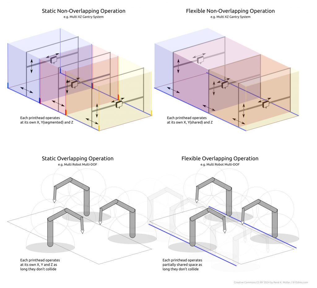
While working on theoretical side of parallel 3D printing, I used the example of multi-gantry or Multi Gantry (MG) setup where a single bed is shared in Y – here a few rough sketches using Y-XZ gantries:
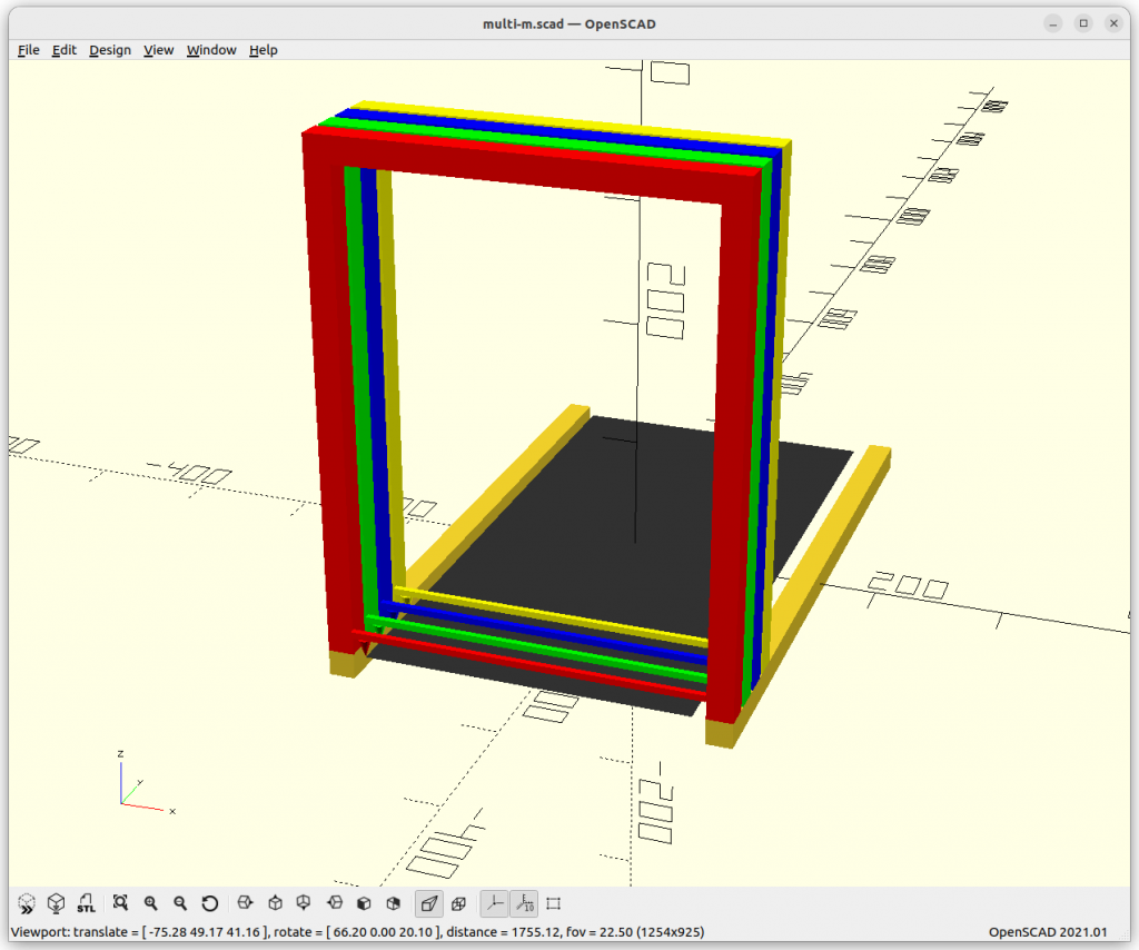
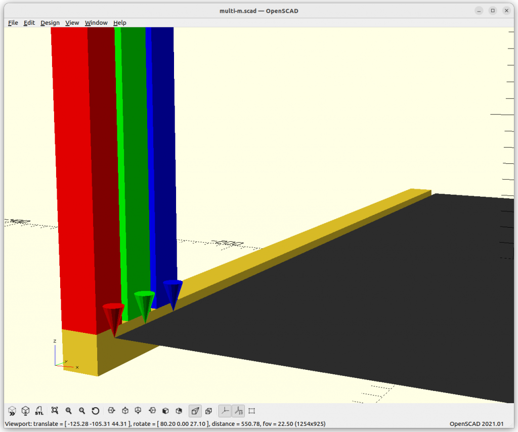
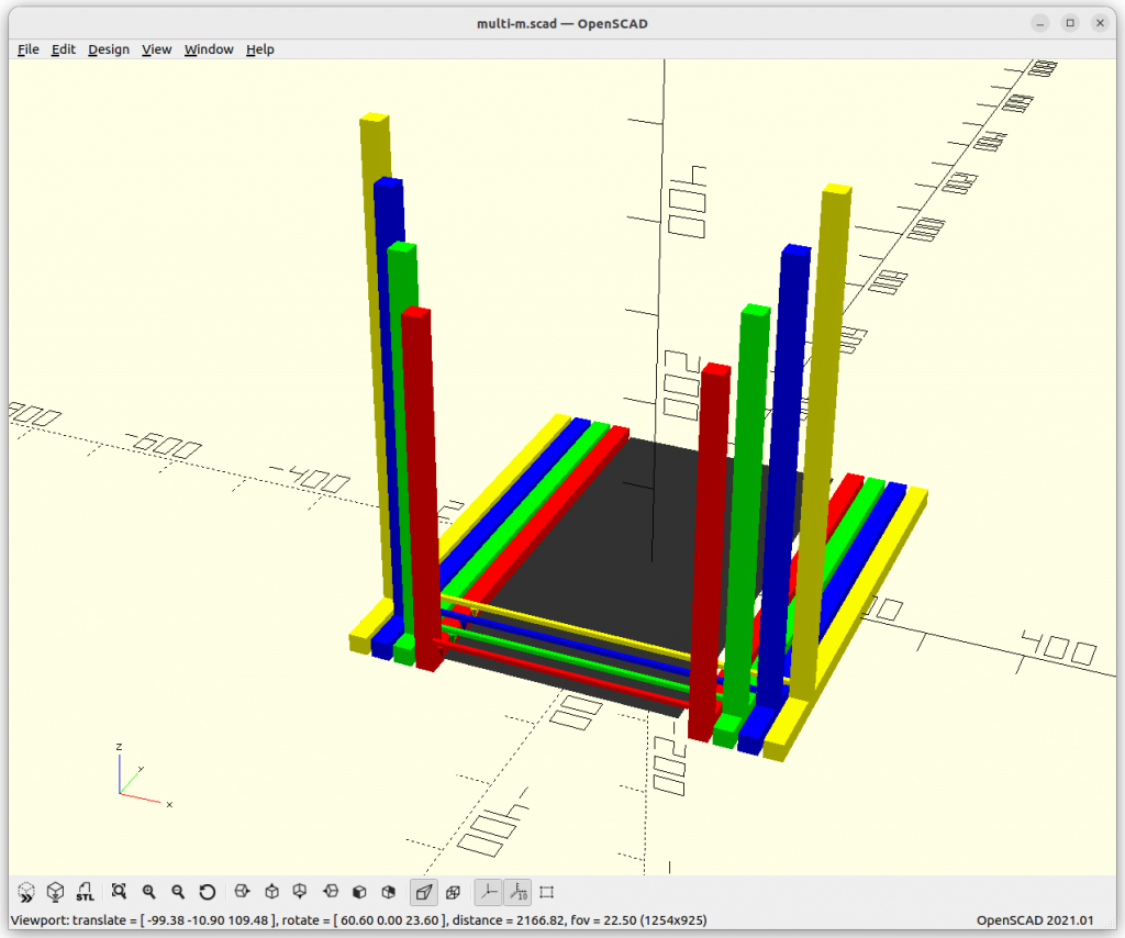
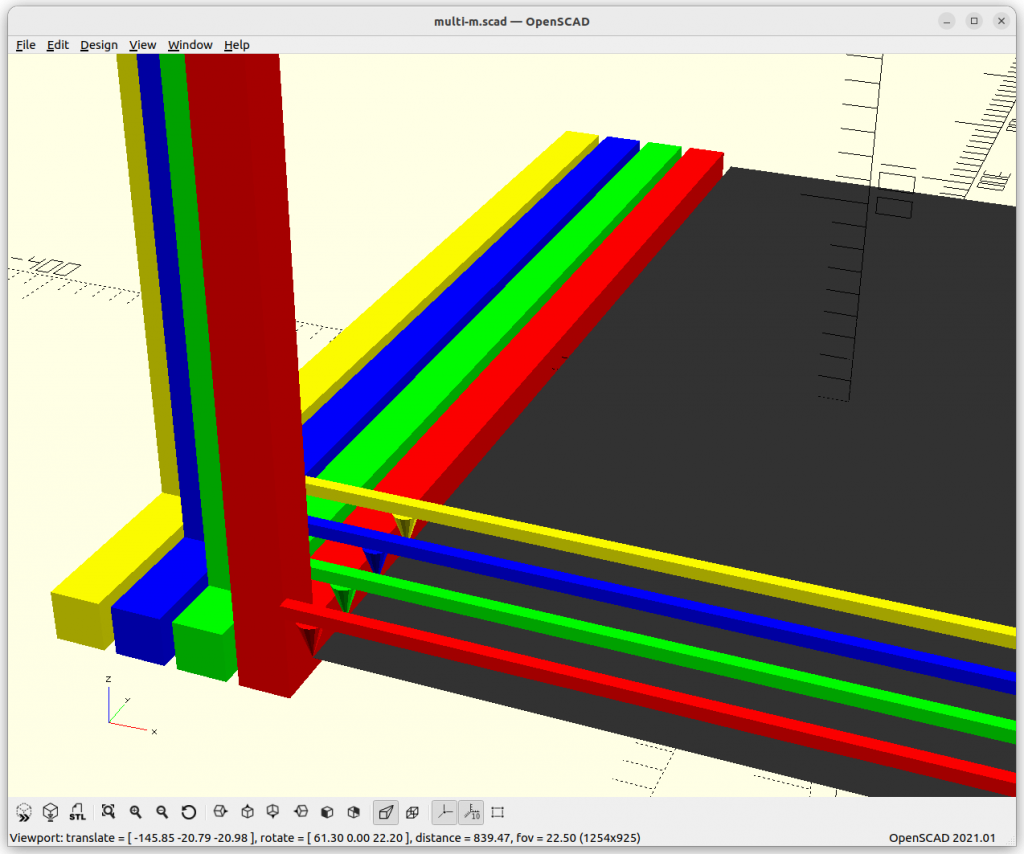
Y-XZ Gantry Approach
When having moving gantry implementing Y + XZ motion, there are several challenges, such as the Y- and the XZ motion system and making the thickness of each gantry as thin as possible to have as little “dead” or “unusable” space as it adds up and also limits the printable XY space.
Y motion system
We can share a single rail where each gantry rides hence Common Y rails, then they can’t change the order, in that case the belt routing becomes the main issue of concern – whereas when each gantry has its own rail hence Dedicated Y rails, and each gantry has a distinct height they can change the order (lift Z to the top and move over the lower one – hence each gantry has a different Z height, but with the filament and cabling the entanglement needs to be closely observed).


XZ motion system
We require to have two positioning axes to integrate here, the X and Z:
- two independent motion systems (X axis = 1 motor, Z axis = 1 motor)
- Core XZ system also using two motors, but having XZ motion combined
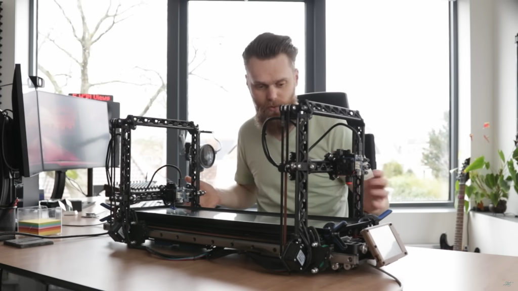
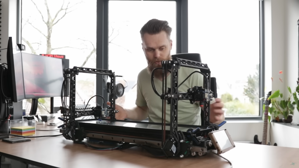
Jon’s approach is clever to use CoreXZ and position both X/Z motors near the bed, so they don’t swing higher in Z, and only have the E motors ride on the X beam, yet, his setup is a single printhead on the X-beam.
XY Gantry Approach: Less Inertia
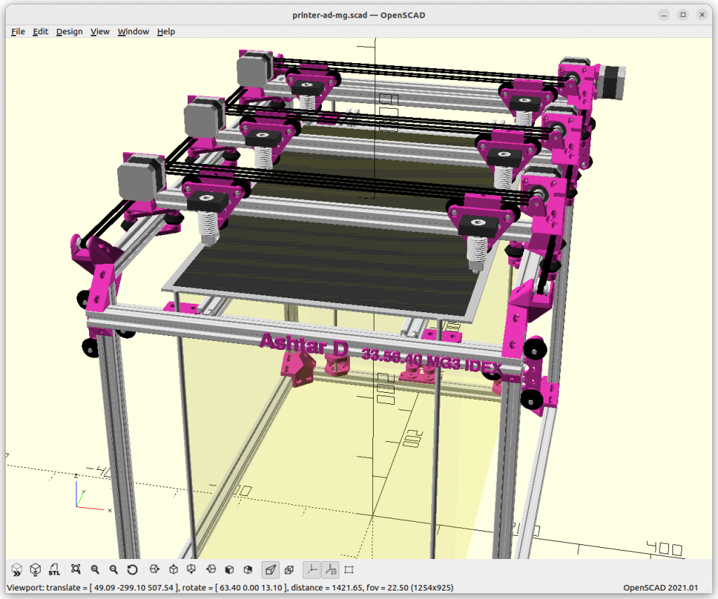
Classic XY (non-CoreXY) where X and Y motion is separated – like the Ashtar D – the moving gantry only has a X beam, where printhead and X motor resides – whereas with CoreXY only the printhead resides on the X beam, and XY motors are stationary/non-moving. As we separate in Y, we can use this Classic XY setup to add also multiple gantries, something like this:

Comparison
| Gantry KInematics | Moving Motors per GANTRY | Moving Motors in MG3 IDEX per Gantry | independeNt AXES per Gantry |
|---|---|---|---|
| Y-XZ | n*X, Y, Z, n*E | 6 (2+1+1+2) | YZ |
| XY | n*X, n*E | 4 (2 + 2) | Y |
- n-amount of printheads (IDEX: n=2) per gantry
The Y-XZ gantry setup has more moving parts, especially the heavier stepper motors, whereas XY gantry, as its name indicates, has the Z kinematics in common for all gantries and therefore only X motors moving – plus printhead (E) motors for both options.
So, if we aim to reduce the inertia like heavier stepper motors, we also lose that independence in the kinematics: with Classic XY gantries they all share the same Z height.
Slicing for Multi Gantry System
As I realized earlier, it makes no sense to statically segment Y-space for each gantry (e.g. Y-size/n) although it would make coding easier, but seamless printing would be impossible – in reality, we need slightly overlapping spaces to achieve zero space seams where the gantries print for the same piece, so we naturally choose flexible non-overlapping operations.
Layer Segmenting
Obviously one of the simple optimization is when we are looking at a single layer, and segment it area-wise to n-amount of gantries. For sake of consistency, a wall is assigned to a single gantry to have a seamless wall/perimeter.
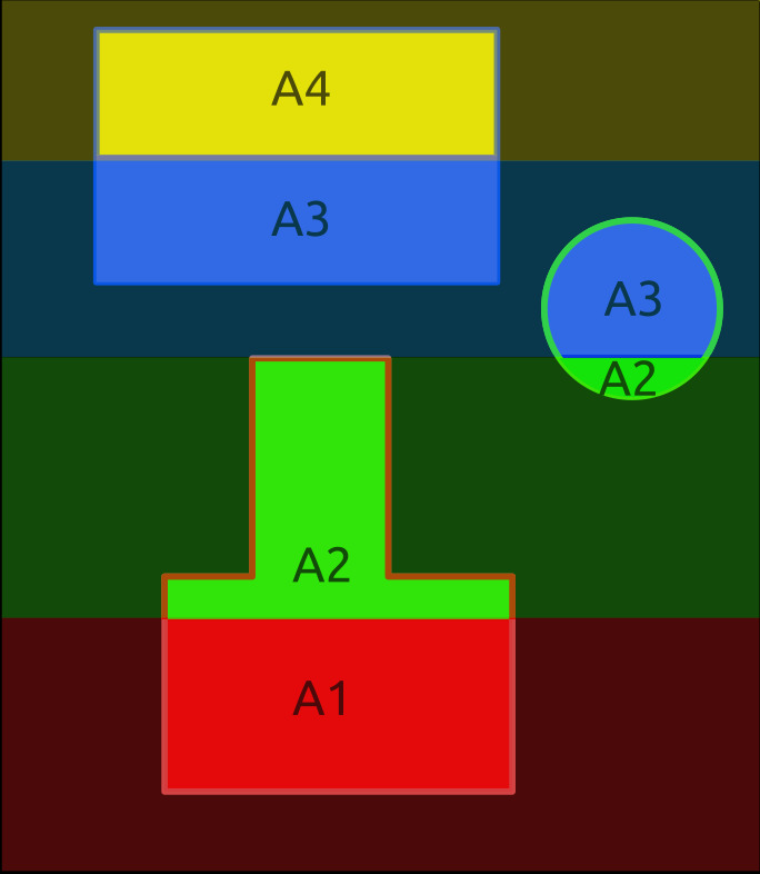
- Infill areas are Y segmented
- each area (e.g. A1-A4) is the same to distribute work equally
- Walls/perimeters are assigned to a single gantry
- if walls intersect each other in Y, those are printed sequentially not in parallel to avoid Y collision
The layer segmenting approach makes it rather easy so all nozzles have the same Z, thereby segmenting print jobs becomes easy as well.
Mixing Multi Gantry (MG) with IMEX (IDEX & ITEX etc)
We can also mix Multi Gantry (MG) with IDEX (Dual) or ITEX (Triple), or in general Independent Multi Extruders (IMEX), something like this:
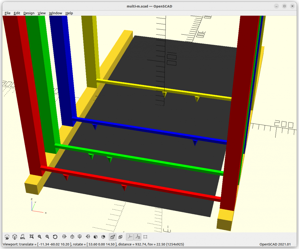
per single XZ gantry
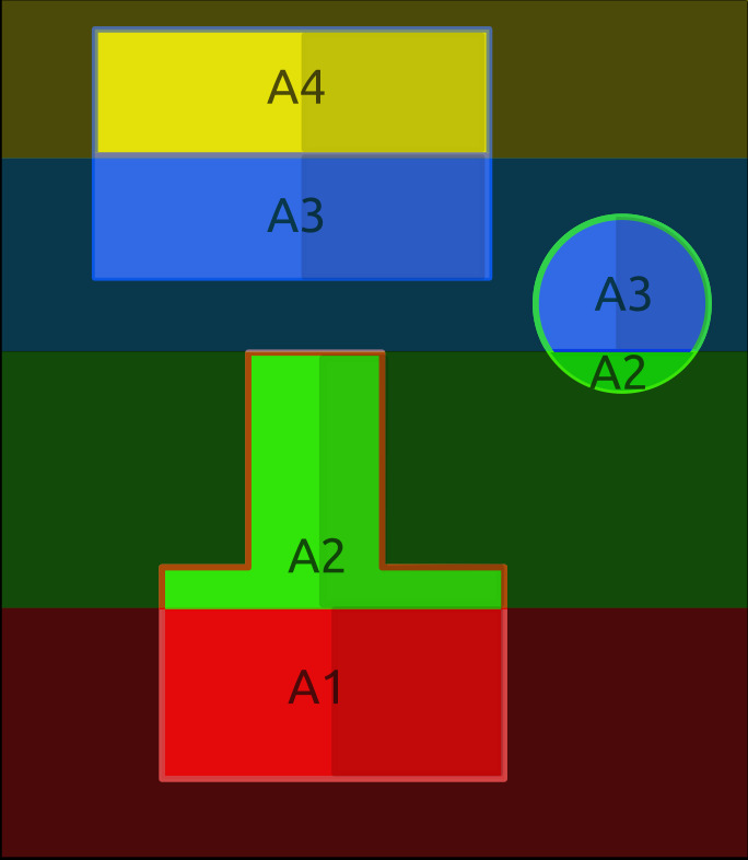
And like-wise segmenting layer areas in Y as before, and additionally segment in X for each printhead on Independent Multi Extruders (IMEX), in this example it’s IDEX (Dual).
As IMEX looks like scaling print parallelism further, one has to be aware of the spatial overhead for each printhead, e.g. a single printhead occupy ~40mm width in X, and similar in Y.
IDEX-MG3: Ashtar M vs Ashtar D
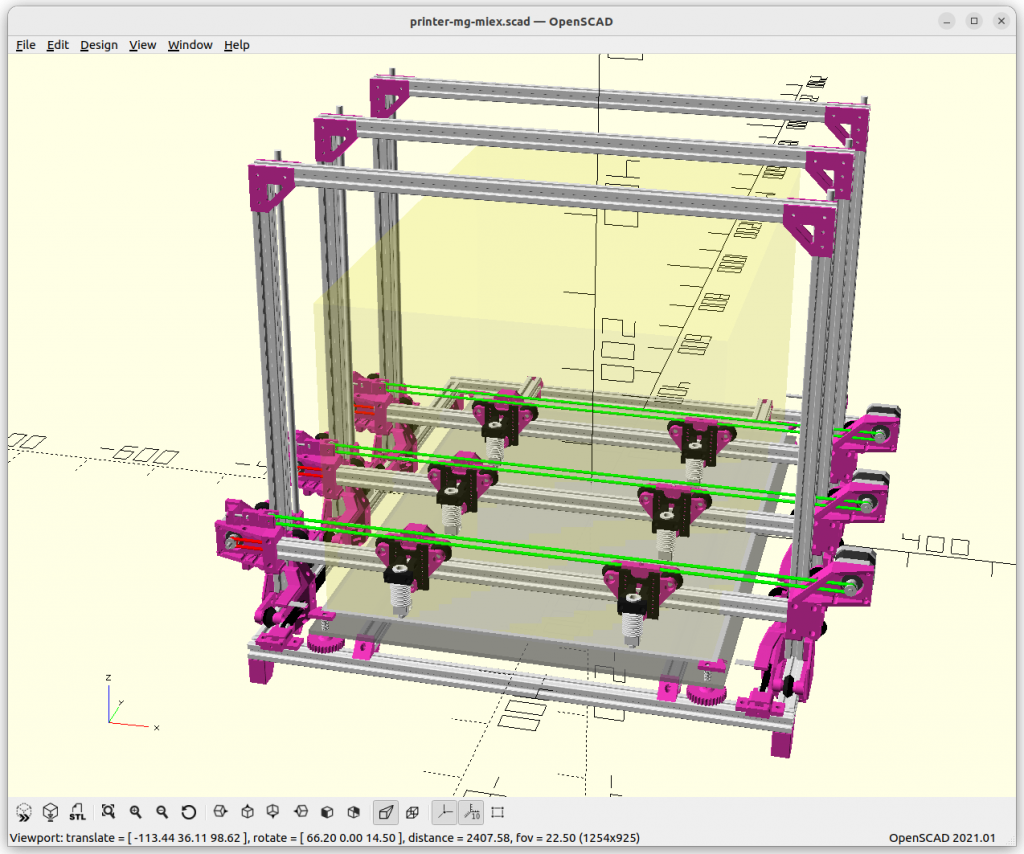
Early draft with more details based on Ashtar M (Y-XZ gantry), extended to MG, with Common Y rails with IDEX; and for comparison Ashtar D (XY gantry) with MG and IDEX:

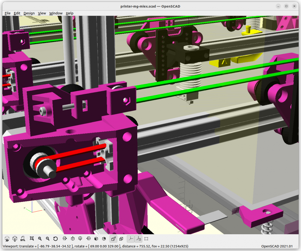

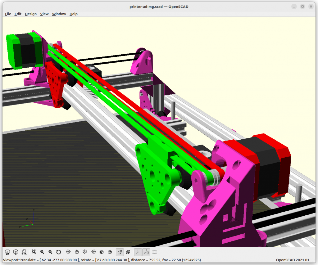
Challenges
- 1a) When doing a Y-XZ gantry IMEX2-MG3 (2 extruders/IDEX on each 3 gantry):
- X: 2*3 motors = 6 motors
- Y: 3 motors
- Z: 3 motors
- E: 2*3 = 6 motors
we end up 6+3+3+6 = 18 motors to coordinate & control.
- 1b) for XY gantry approach:
- X: 2*3 = 6 motors
- Y: 3 motors
- Z: 1 motor (or more, but all synchronous)
- E: 2*3 = 6 motors
we end up with 6+3+1+6 = 16 motors to coordinate & control.
- 2) Slim design of the gantry to reduce dead-space in Y.
- 3) Slim printhead design to reduce dead-space in X.
- 4) Slicer requires to coordinate 6 printheads (e.g. T0-T5) in non-colliding and efficient way.
Solutions
Slicer
A dedicated slicer is required which segments each layer into printable areas A1 to An whereas n is the amount of gantries, and those areas might be further segmented by m-amount of printheads on the same gantry, so they share the same Y position but can have distinct X position but not switch order or collide.
As proposed above, a single printhead of a gantry is then assigned to print within the same Y-segment the walls/perimeters to have a clean wall, hence, the infills are distributed among all the printheads.
For segmenting entire sub-volume and not just layers, the Y-XZ would allow distinct Z, e.g. one gantry printing higher and another lower – the XY gantries share the same Z, therefore there only the layer segmenting is possible.
Firmware & Controller
The controller with its firmware we have a few options:
- Duet3D/RRF: Multiple motion systems
- G-code Features
M400: wait for current moves to finish (when usingT<n>withG1s together, applies toX,Y,Z, and alsoE)M596 P<n>selects motion queue, prior eachG0orG1M597: collision avoidance (at firmware level)M598: sync up multiple motions (faster waits for the slower)
- G-code Features
- Klipper
- flexible in regards of MCUs – some early prototype (2025/05) showed promising results using new multi-axis capability to coordinate two truly independent X & Y carriages
- requires SBC and host and MCU firmware, most things are software defined (MCU firmware compiled once only)
- Marlin
- one controller per gantry or extruder, orchestrating/sync between controller needed, hence a meta controller required (SBC)
- using
M400to sync each controller by meta controller
- using
- simple setup, reliable
- one controller per gantry or extruder, orchestrating/sync between controller needed, hence a meta controller required (SBC)
To keep this in mind, the Y-XZ approach allows distinct Z for each gantry, whereas the XY approach all Z of the gantries are the same.
Adding Tool Changer (TC)
In order to support a tool changer, the printheads need to reach a common position in order to deposit and pick up tools. In case of a single/common Y-rail setup this seems at first sight challenging, only a dedicated tool change per gantry, at a particular a YZ position for example. The multi/dedicated Y-rail setup allows any gantry to reach a common region in YZ, and so any printhead could deposit and pickup a tool from the common toolset.
| MG MIEX Gantry Style | Toolset position |
|---|---|
| Y-XZ Common Y rails | ends of Y rail, unique Z positions per gantry |
| Y-XZ Dedicated Y rails | ends of Y rail, common or unique Z positions |
| XY | first & last gantry at ends of Y rail, Z fixed |
XY gantry setup still can have a tool changer but only the most front gantry, and the most farthest gantry in regards of Y, the gantries in between – if more than total of 2 gantries used – cannot reach a toolset; unless the toolset itself – aka Dockslide – moves close enough to hand over tools.
Commercial Collaboration
Currently I work on a MVP implementing the actual details (software & hardware), if you are interested in a commercial collaboration, contact me to discuss opportunities.


References
- Parallel 3D Printing / Additive Manufacturing – Part 1
- Jon Schone’s Multi Gantry Setup (YouTube)
- Ashtar M (Y-XZ Gantry)
- Ashtar D (XY Gantry)

