2025/06/17: new & advanced features with “inline multi-tool” G-code support with MAF 0.2.0
2025/06/05: publishing article
2025/05/30: updating maf.cfg and more documentation
2025/05/23: first write-up with MAF maf.cfg
Table of Contents
Introduction
As of May 2025 Klipper supports multi-axis support on G-code level. It was possible to define “manual stepper“ motors, but those needed to be handled via “Extended G-code” of Klipper. Now those “manual steppers” can be tied to a G-code axis, and thereby multi-axis system can be composed and becomes available in traditional G-code context.
MANUAL_STEPPER STEPPER=stepper_x1 GCODE_AXIS=A
and after that
G0 A100
can be used.
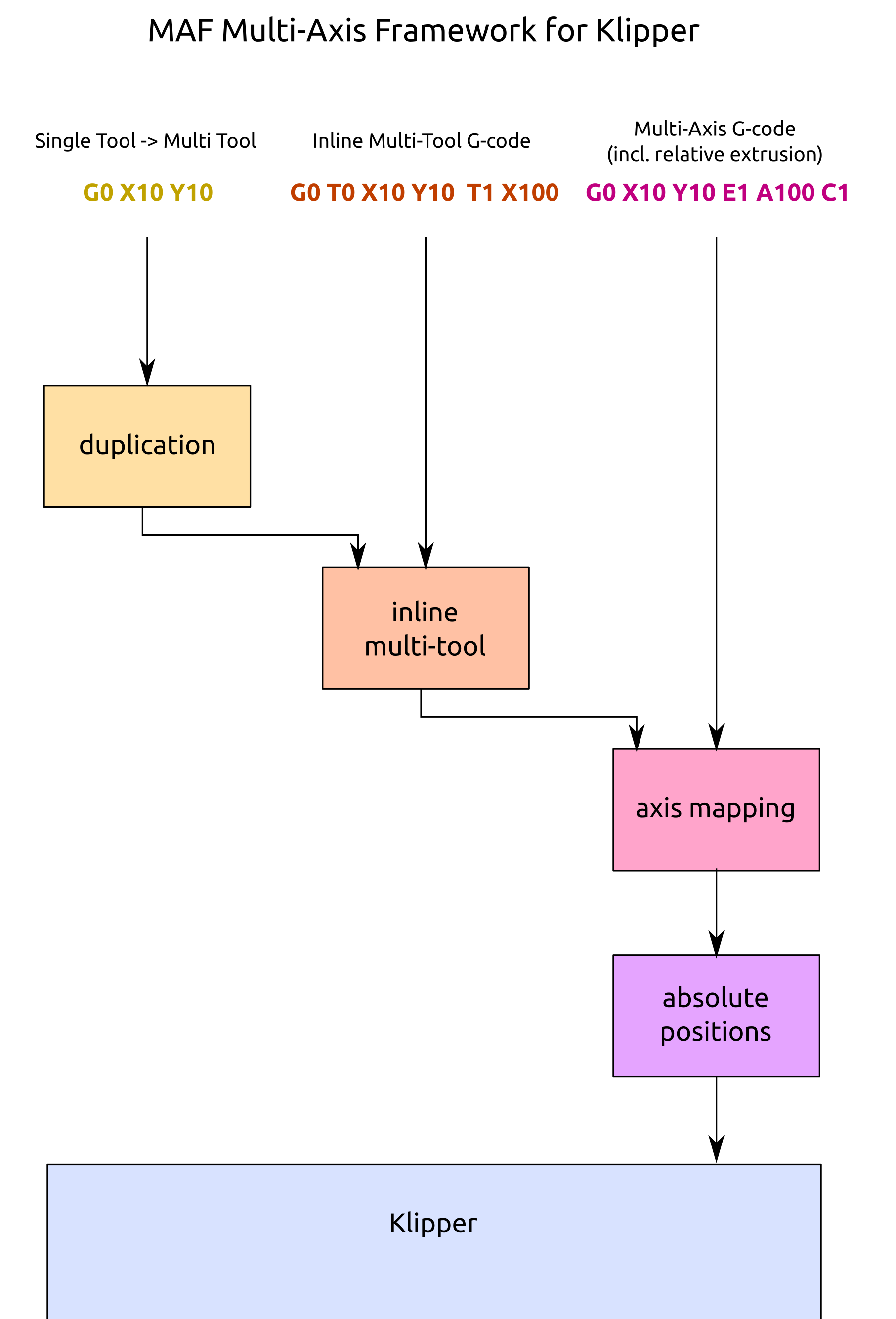
As of 2025/05 only G0/G1 is supported, but not G92, M82 (absolute extrusion), M83 (relative extrusion) in case “manual stepper” is used as additional extruder motors – so I coded a Multi-Axis Framework for Klipper, just a bunch of Klipper macros which provide a better multi-axis & multi-extruder support:
G0, G1 supports relative extrusion if enabled with M83 (I prefer)
G28 homing the new axes as well
G92 supports the new axes too
M82, M83 switches absolute/relative extrusion
T0, T1, … switch extruders
M104, M109 support of multiple extruders using T<n> notion
Klipper natively supports:
G90, G91 for new axes also
Setup
Create a dedicated file, or add following into printer.cfg, for example:
This defines all axes, the additional 3 X carriages, and additional 3 extruders. If you declare X, Y, Z as well, it will home the same way as the new axes. By default after sensor is hit for homing, it bounces back 10mm (recommended for sensorless homing), you can override it with “bounce” value.
The maf.cfg once included, the MAF will be automatically executed at boot/restart.
M82 / M83: Absolute / Relative Extrusion
This applies to all extruders, M82 (absolute extrusion) is the default. I prefer relative extrusion (M83) as it makes it easier to insert or remove G-code without affecting existing G-code with extrusion.
G92: Set Position
Any new axis can be set now, including the extruders.
G92 W0 A0 B90 C110
M104 / M109: Set Temperatures
One can set temperature per extruder/tool:
T0
M104 S200
T1
M104 S200
or more compact
M104 T0 S200
M104 T1 S200
M104 set the temperature but doesn’t wait, and M109 waits until temperature is reached.
G28: Homing
The new axes can be homed as well:
G28 X Y U V W
G28 Z
Note: if you declared the axis in MY_MAF it will use the new G28 procedure, otherwise uses the native Klipper one. See also “Advanced Features” below to define tool axes.
In case you want to specify the default homing of G28 without any arguments, then add this in MY_MAF as well:
this way you define the order exactly, otherwise the tool order (and the related axes) is used, and if no tools are defined, the order is according the map of axes to motor definition – it nicely falls back to what’s known to perform the homing. See also “Advanced Features” where you can define the order how axes are homed when you to define tool to axis mapping as well.
A multi-tool / multi-axis with multiple gantries can be quite complex to home, so this is why there is sufficient flexibility to define it and not hard-code in G-code or create another macro.
G0 / G1: Move & Extrude
The G0 / G1 is overridden in order to support relative extrusion.
M83                      ; relative extrusion
G0 X100 U300 Y100        ; move two X carriages on common Y gantry
G1 X150 U350 Y150 E5 W5  ; extrude with both extruders on the X carriages
Note: given we work in cartesian kinematics, XYZ dictates the total distance as dist = sqrt (X^2+Y^2+Z^2) and the feedrate F (mm/min), any additional axis is given time t = dist (mm) / feedrate (mm/min) to reach its destination, and therefore has its own feedrate or speed – so, when operating new axes in this context, it’s up to you to be aware of the other axes speeds and keep them below operation limits. This is taken care of since V0.2.0 which recalculates the internal speeds.
MAF: Current State
One can send MAF command, and an output like this is received:
performing all 4 tools at once via internal tool axis mapping.
You can also do “traditional” aka sequential tool switching and keep using XY and E for each tool and it will be mapped to the internal axes – but all operations are sequentially performed, tool by tool:
Switch to T0 again to use multi-axis support, e.g. naming the axes with A, B, C or whatever additional axes you have.
Homing Tools
Further, also homing G28 can take T<n> notion such as:
G28 T0 T1 T2 T3
and it will home all respective axes associated with the tool, in the order as defined in the mapping. If you want to define your order or skip a certain axis in a tool for homing, you define:
this defines for each tool at XY offset position and size in XY where the tool operates, the row gives a hint how to mirror like with gantries. In the example above a 400×400 bed with 4 extruders/tools each 200×200 printable, two rows/gantries.
You enable duplication with:
MAF DUPLICATION=copy   ; or 'mirror'
; or
MAF duplication=copy   ; or 'mirror'
once activated, you send G-code for a single tool and it will be expanded using inline multi-tool, hence, in order to have duplication working, you need to define the tool axes also.
and when moving to X10 Y10 after homing with G28, some tools (and their axes) have more distance to cover like T2 and T3, and their travel distance is used to comply with F4800 – right now (2025/06) Klipper does not enforce speed limits to manual steppers, MAF does it for you.
Use Case
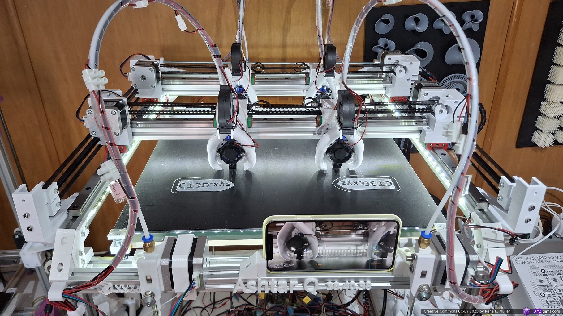
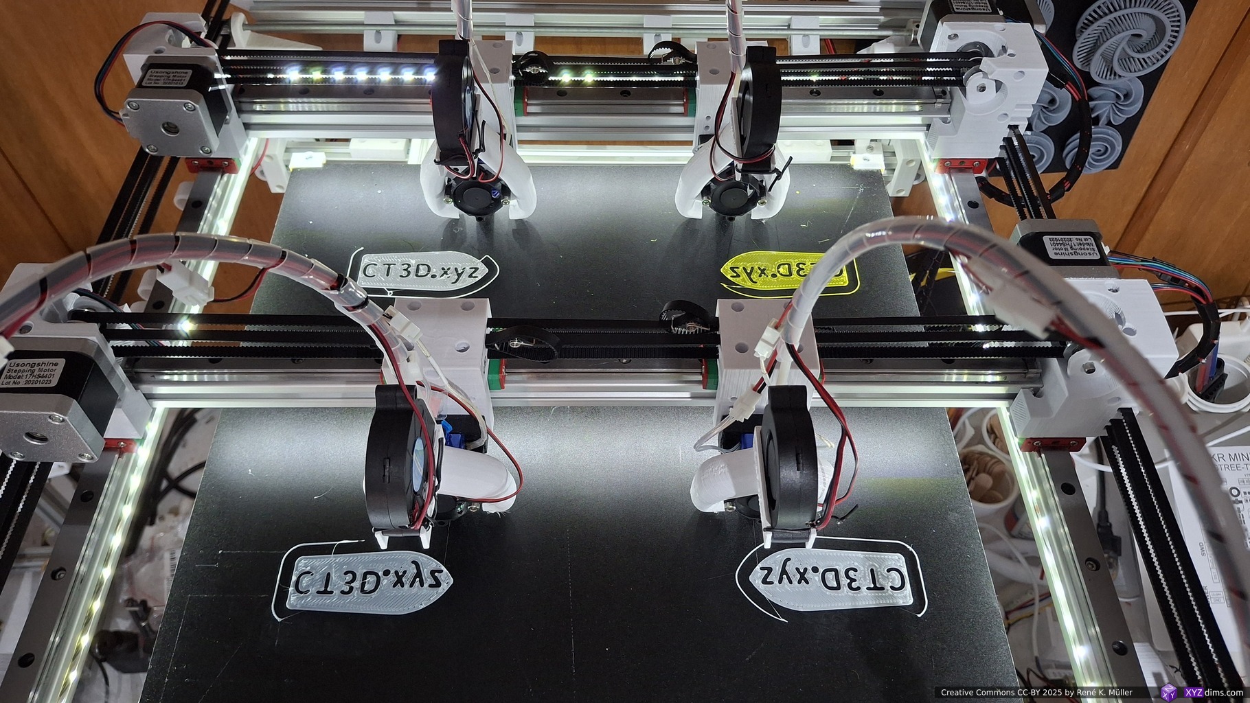
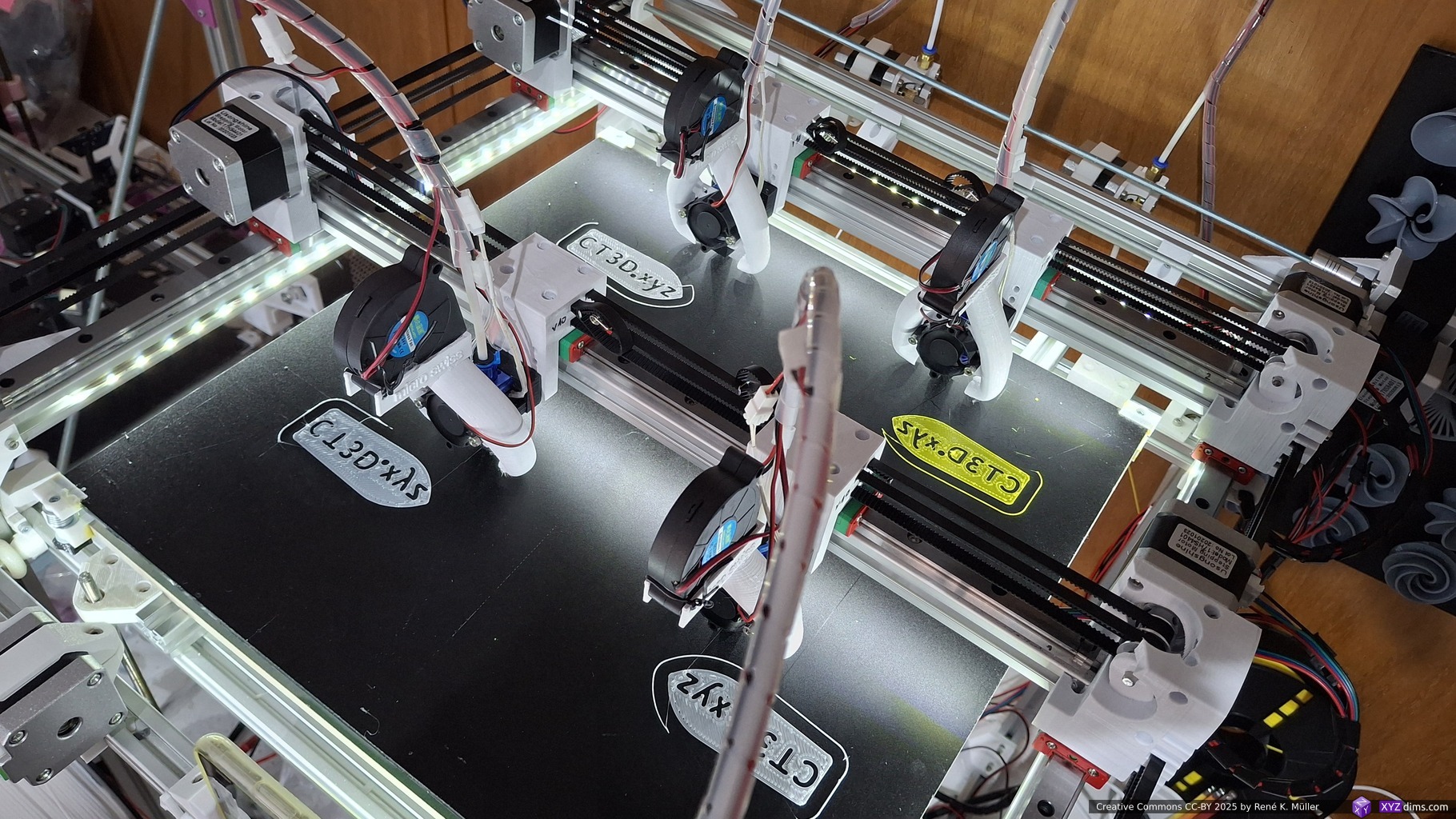
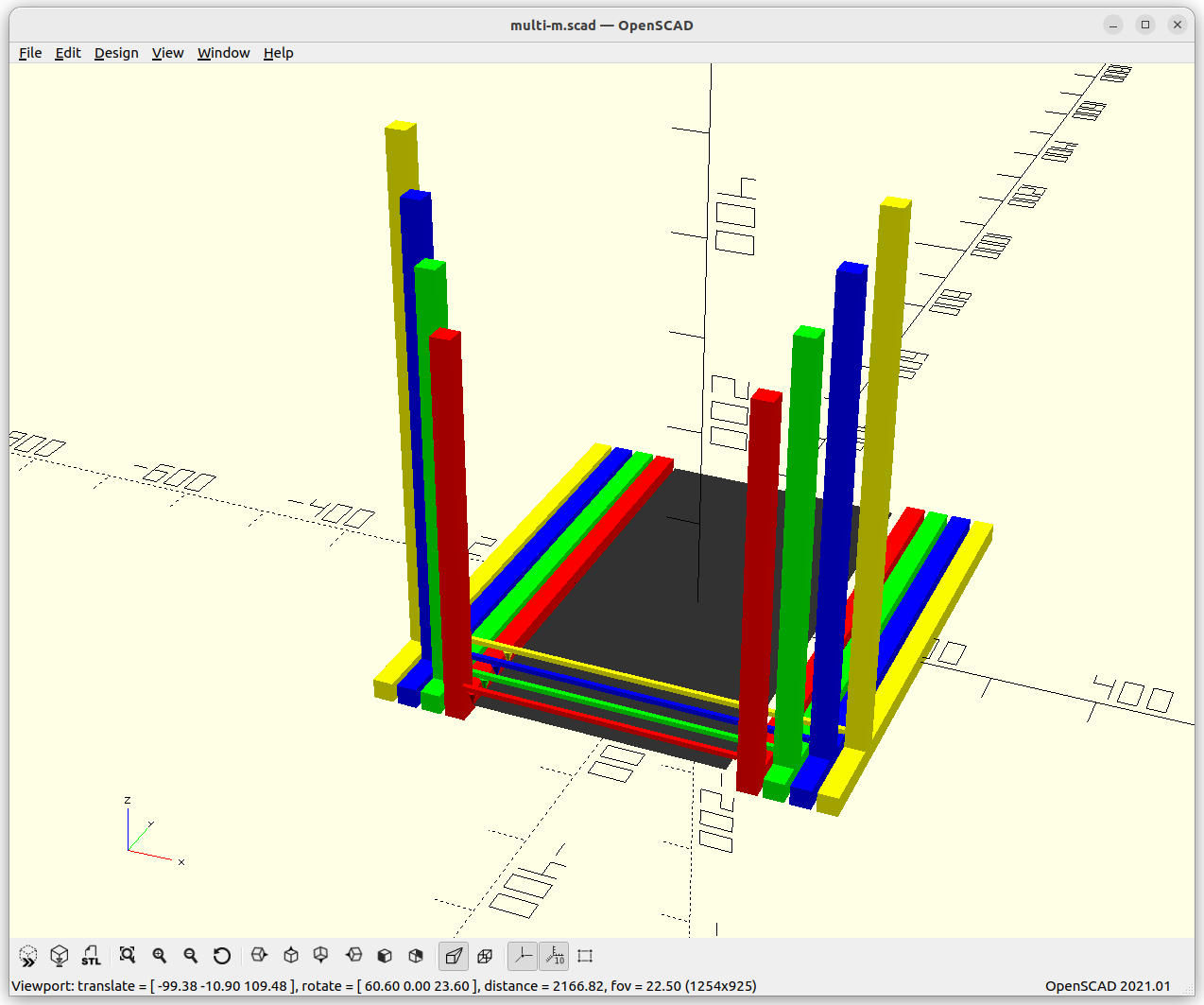
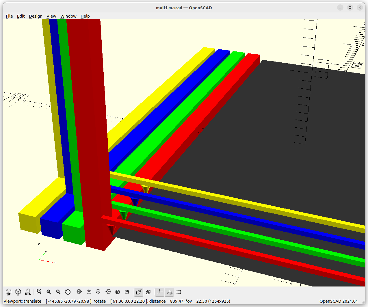
I used “MAF” for early prototyping a Multi Gantry with Multi Extruder (IDEX) setup – Ashtar Q (MG2 IDEX) – printing in duplication mode (horizontal & vertical mirrored) on G-code level:
Ashtar Q (MG2 IDEX): 11 Axis Setup – early prototypeAshtar Q (MG2 IDEX): 11 Axis Setup – early prototypeAshtar Q (MG2 IDEX): 11 Axis Setup – early prototype
Operating in two different modes:
1x Klipper instance (with 4x MCUs): 2x Y gantries, 4x X carriages, 4x extruders = 11 axis (XYZE+XE+XYE+XE) – all motors fully synced
2x Klipper instances (with 2x MCUs each): Dual of 1x Y gantry, 2x X carriages, 2x extruders = 6 axis (XYZE+XE) + 5 axis (XYE+XE) – two gantries loosely synced
Here some brief video of Ashtar Q (MG2 IDEX) actually printing duplicating:
The example above is “multi-axis” G-code, where all axes are individually delivered – whereas the duplication feature of MAF is available since V0.2.0 (2025/06) and uses “inline multi-tool” G-code internally. The “inline” is important here, otherwise it might be confused with traditional multi-line spread T0 G0 T1 G0 commands.
2025/05/31: adding MAF reference to support multi-axis functionality better
2025/05/14: starting write-up
Table of Contents
Introduction
Klipper is a host software running usually on a dedicated Single Board Computer (SBC) like Raspberry Pi or alike, and sends compact binary to MCUs for low-level to control stepper motors, and various sensors.
The kinematics and the resulting motion (acceleration, speed, deceleration) is planned on the host, therefore it’s very good to prototype experimental setups such as my Ashtar Q with multiple gantries and multiple extruders on each gantry.
In the past I was skeptic about introducing another part like an SBC for operating a 3D printer, as one introduces another point-of-failure, yet, the Klipper developers in particular Kevin O’Connor, managed to find the right balance to separate the planning from the realtime sensitive aspects from the “host” vs the “microcontroller” (aka MCU).
I still like RepRapFirmware running on a more powerful MCU without the need of a separate SBC – but I wanted to experiment with Klipper and so far I really liked its capabilities.
Hardware Declaration
What I really like is that Klipper allows to describe the MCUs at the low-level:
pins are named which control the stepper motor
simply add “!” in front, and the logic is inverted (e.g. change direction of the motor)
multiple MCUs can control different aspect of the printer, each MCU is named, and the pins are referenced <mcu_name>:<pin_name> and so (re)use older MCUs to build quite capable kinematic systems (not just 3D printers)
So a multitude of MCUs are available, from cheap ~10 EUR board up to Duet3D boards at 200+ EUR price – all capable running Klipper MCU firmware.
Extended G-code
Klipper provides vast features, and therefore requires more powerful way to distinct settings from the limited way G-code does it, so it introduces a powerful macro system based on Jinja2, and an additional set of new G-code commands, such as:
RESTART starts host software
FIRMWARE_RESTART restarts the MCU software/firmware
and SOMETHING A=100 BC=100,200 can be processed like this:
[gcode_macro SOMETHING]
gcode:
   {% set A = params['A'] %}
   {% set B,C = params['BC'].split(',') %}
   MANUAL_STEPPER STEPPER=my_stepper MOVE={A}
   MANUAL_STEPPER STEPPER=my_stepper_2 MOVE={B}
   {% set C2 = (A|int + B|int)/2 %}
   MANUAL_STEPPER STEPPER=my_stepper_3 MOVE={C}
and a bare/subset of Python is available within the macro coding – one has to refrain (like me) to code complex code there as one will reach its limits quickly.
Software & Hardware Modularity
By having multiple microcontrollers (MCUs) attached via USB and addressable within Klipper printer configuration, and declaring so called multiple “manual steppers“ outside of the common kinematics system, together with its macro-system one can do more than just move an extruder in XYZ, but create a robotic system with a lot of functionality, but it misses multiple motions queues limiting some applications.
Multi-Axis Capability
As of May 2025, Klipper is able to handle multi-axis G-code:
declare MANUAL_STEPPER with connection with a driver, such as TMC2209 (move driver declaration before MANUAL_STEPPER in case you use virtual_endstop)
home that axis with Extended G-code of Klipper (or use the “MAF” macro collection I wrote using G28)
register MANUAL_STEPPER into “G-gcode space” by assigning an axis, e.g. A, B, C, D, U, V, W, or I, J, K, P, Q, R (be aware I and J is used for G2/G3 arc motions); MAF does handle this as well
Example of 2nd X carriage, in my case I have a dedicated MCU for the 2nd extruder named mcu2, this is for a BTT SKR MINI E3 V2.0 board:
[tmc2209 manual_stepper stepper_x1]    # -- must come before [manual_stepper] https://github.com/Klipper3d/klipper/issues/2563
uart_pin: mcu2:PC11
diag_pin: ^mcu2:PC0
uart_address: 0
run_current: 0.580
stealthchop_threshold: 999999
driver_SGTHRS: 100  # 255 is most sensitive value, 0 is least sensitive

[manual_stepper stepper_x1]
step_pin: mcu2:PB13
dir_pin: mcu2:PB12
enable_pin: !mcu2:PB14
microsteps: 16
rotation_distance: 40
#endstop_pin: ^PC0
endstop_pin: tmc2209_stepper_x1:virtual_endstop
at point writing this, homing a “manual stepper” with G28 wasn’t yet supported – so I wrote a “Multi-Axis For Klipper” aka “MAF” macros which implements some of the missing functionalities:
G28 X U
G0 X200 Y200 U300 F3000
moving two X-carriages independently but together or atomic, whereas using something like:
T0
G0 X200 Y200 F3000
T1
G0 X300 F3000
would not guarantee the exact atomicity, given both carriages mounted on the same Y gantry, but introduce slight drift as introduced from the motion planner and stepper motor control – having it done as a new “axis”, we have it guaranteed at the same time.
Note: T<number> (tool selection) notion requires macros to define the behavior, like changing extruder and such – regardless, G-code line-wise only guarantees atomicity at line-level, not beyond.
So, treating the 2nd (or 3rd) X carriage as separate axis allows to implement True IDEX, independent motion of multiple extruders, but fully coordinated. Usually firmware handles mirror or copy of IDEX systems at low-level, now one controls the carriages at G-code level fully giving great freedom for multiple extruders printing at the same time.
Limitations
No Multiple Motion Queues (Yet)
As of writing (2025/06) Klipper does not yet support multiple motion queues like RepRapFirmware (RRF) provides. In essence it means, one cannot issue two concurrent running G0 or G1 commands but they run in sequence always, even if those G0/G1 commands might address different axes or gantries altogether.
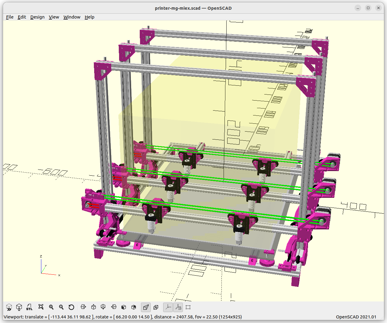
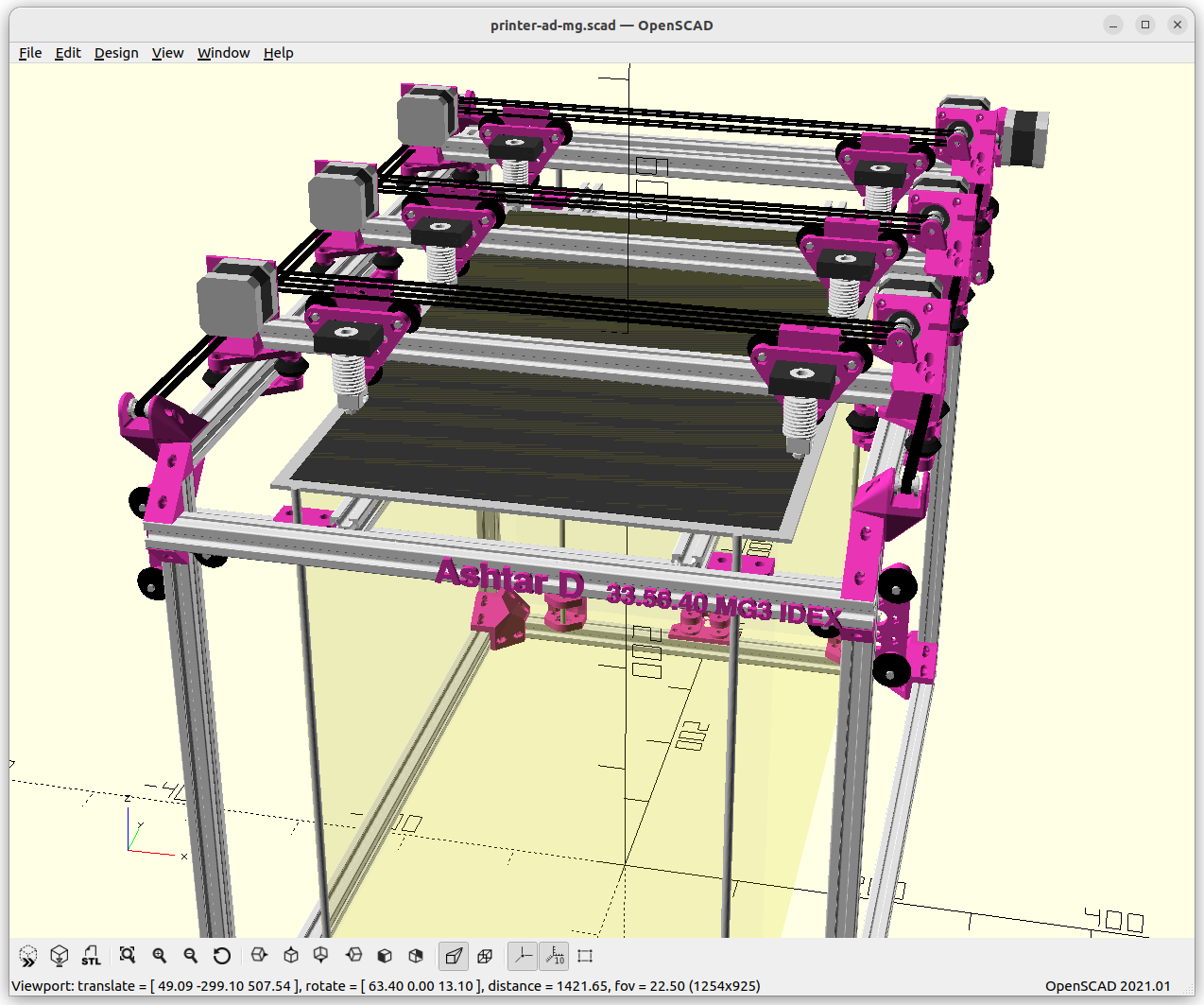
State: first prototype with dual gantry each with IDEX
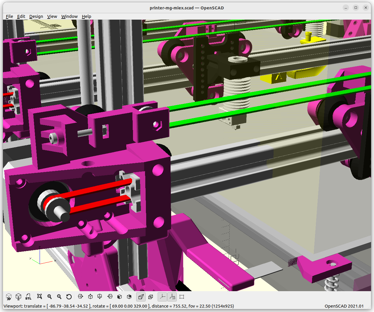
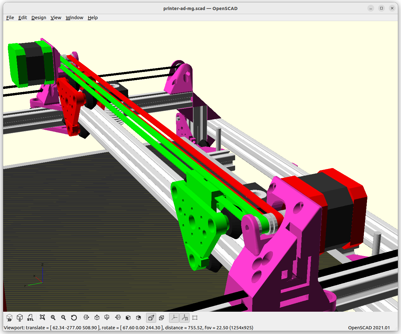
Y-XZ Gantries: Ashtar M MG-MIEX (Multi Gantry & Multiple Independent Extruders) [early draft]XY Gantries: Ashtar D MG-MIEX (Multi Gantry & Multiple Independent Extruders) [early draft] – becoming Ashtar Q seriesAshtar Q (MG2 IDEX): quad extruder in multi-grantry dual IDEX setup – early prototypeAshtar Q (MG2 IDEX): quad extruder in multi-grantry dual IDEX setup – early prototype
Updates:
2025/06/03: adding first photos of Ashtar Q (MG2 IDEX)
2024/12/22: adding Ashtar D (Classic XY) MG3 IDEX, comparing Y-XZ vs XY gantries in regards of inertia and slicing approaches thereof
2024/12/20: early idea to add tool changer as well
2024/12/16: adding more details with multiple extruders on same X gantry
2024/12/06: early ideas about single layer segmenting
2024/12/05: starting write-up
Table of Contents
Introduction
While working on theoretical side of parallel 3D printing, I used the example of multi-gantry or Multi Gantry (MG) setup where a single bed is shared in Y – here a few rough sketches using Y-XZ gantries:
Multi Gantry with same order, Common Y railsMulti Gantry with same order (closeup), Common Y railsMulti Gantry with ability to change order, Dedicated Y railsMulti Gantry with ability to change order (closeup), Dedicated Y rails
Y-XZ Gantry Approach
When having moving gantry implementing Y + XZ motion, there are several challenges, such as the Y- and the XZ motion system and making the thickness of each gantry as thin as possible to have as little “dead” or “unusable” space as it adds up and also limits the printable XY space.
Y motion system
We can share a single rail where each gantry rides hence Common Y rails, then they can’t change the order, in that case the belt routing becomes the main issue of concern – whereas when each gantry has its own rail hence Dedicated Y rails, and each gantry has a distinct height they can change the order (lift Z to the top and move over the lower one – hence each gantry has a different Z height, but with the filament and cabling the entanglement needs to be closely observed).
Single Rail, Multiple or Common GantriesDedicated Rails per Gantry
XZ motion system
We require to have two positioning axes to integrate here, the X and Z:
two independent motion systems (X axis = 1 motor, Z axis = 1 motor)
Core XZ system also using two motors, but having XZ motion combined
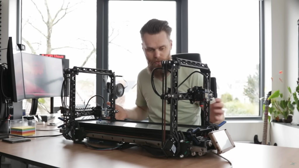
Jon Schone’s (ProperPrinting) 2 Gantry System: X & Z axes with each their own motor, sharing a single Y rail
Jon’s approach is clever to use CoreXZ and position both X/Z motors near the bed, so they don’t swing higher in Z, and only have the E motors ride on the X beam, yet, his setup is a single printhead on the X-beam.
XY Gantry Approach: Less Inertia
Classic XY (non-CoreXY) where X and Y motion is separated – like the Ashtar D – the moving gantry only has a X beam, where printhead and X motor resides – whereas with CoreXY only the printhead resides on the X beam, and XY motors are stationary/non-moving. As we separate in Y, we can use this Classic XY setup to add also multiple gantries, something like this:
Ashtar D MG3 IDEX [draft: Y motion not yet separated]
Comparison
Gantry KInematics
Moving Motors per GANTRY
Moving Motors in MG3 IDEX per Gantry
independeNt AXES per Gantry
Y-XZ
n*X, Y, Z, n*E
6 (2+1+1+2)
YZ
XY
n*X, n*E
4 (2 + 2)
Y
n-amount of printheads (IDEX: n=2) per gantry
The Y-XZ gantry setup has more moving parts, especially the heavier stepper motors, whereas XY gantry, as its name indicates, has the Z kinematics in common for all gantries and therefore only X motors moving – plus printhead (E) motors for both options.
So, if we aim to reduce the inertia like heavier stepper motors, we also lose that independence in the kinematics: with Classic XY gantries they all share the same Z height.
Slicing for Multi Gantry System
As I realized earlier, it makes no sense to statically segment Y-space for each gantry (e.g. Y-size/n) although it would make coding easier, but seamless printing would be impossible – in reality, we need slightly overlapping spaces to achieve zero space seams where the gantries print for the same piece, so we naturally choose flexible non-overlapping operations.
Layer Segmenting
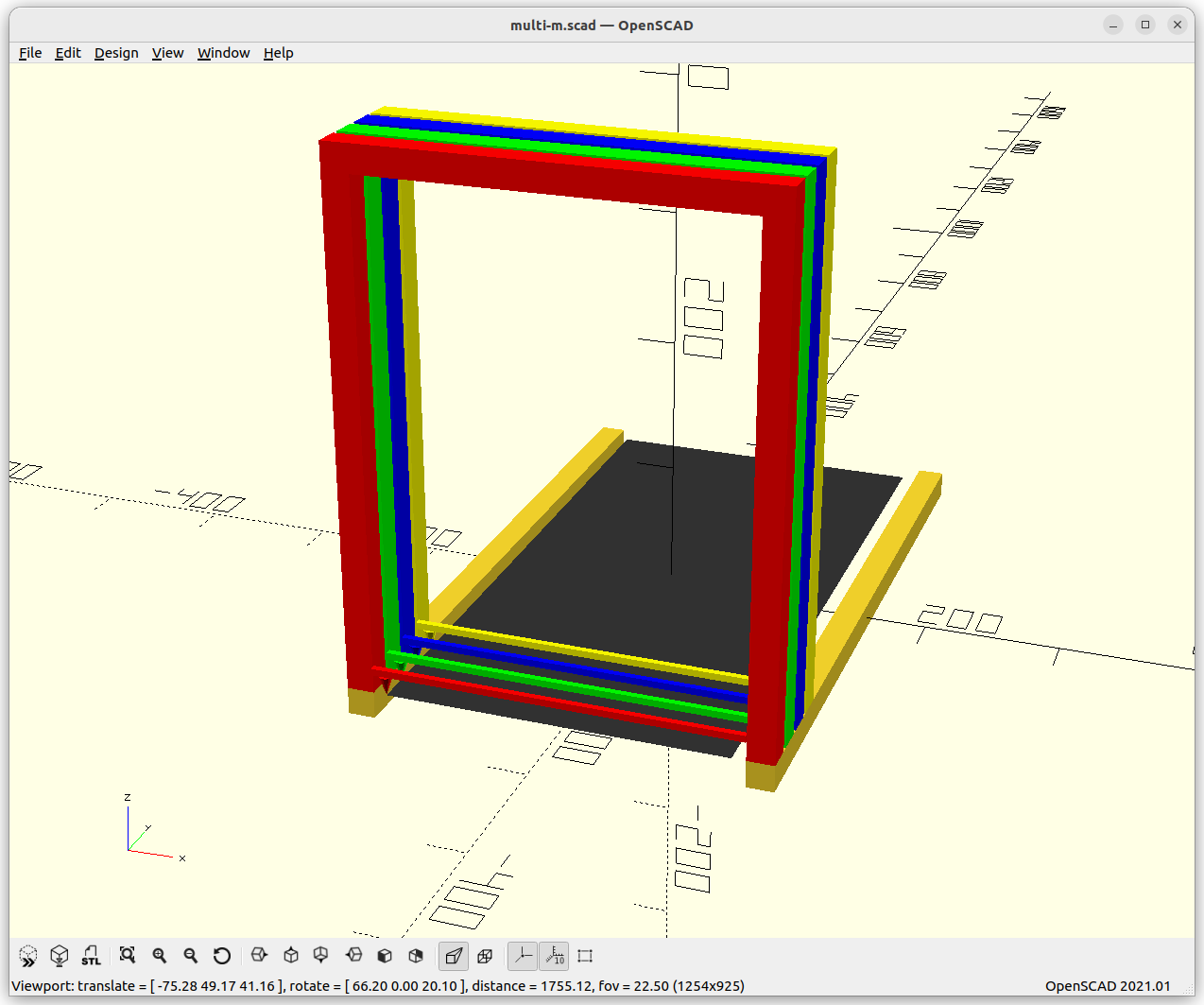
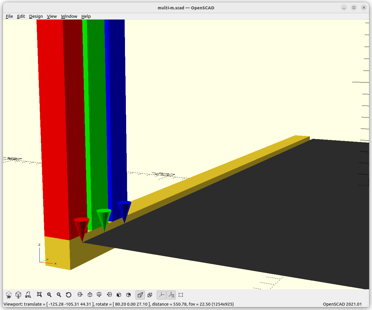
Obviously one of the simple optimization is when we are looking at a single layer, and segment it area-wise to n-amount of gantries. For sake of consistency, a wall is assigned to a single gantry to have a seamless wall/perimeter.
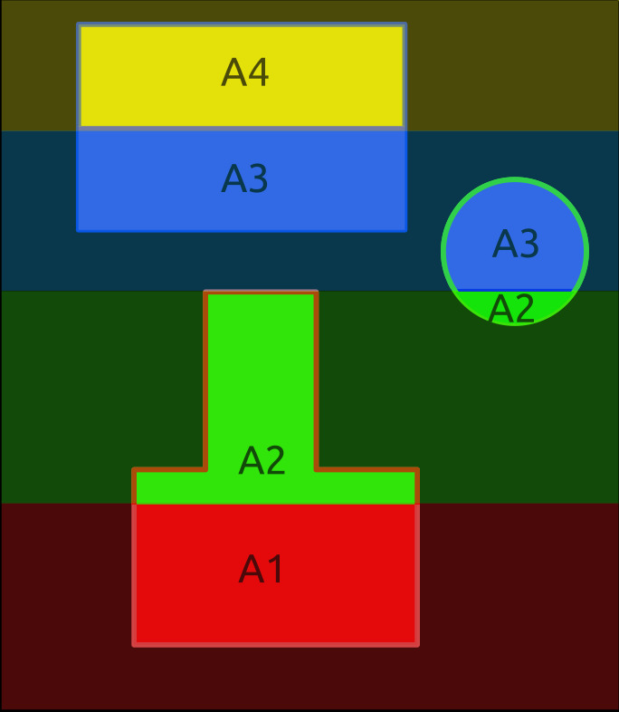
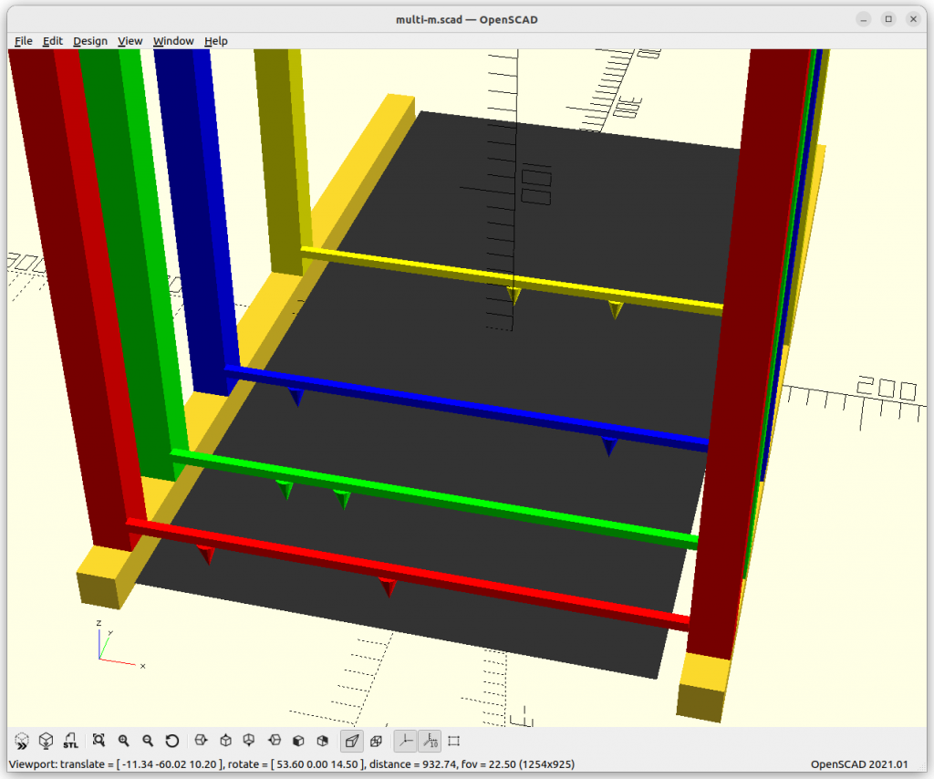
Y Segmenting Single Layer for 4 gantries & nozzles (red, green, blue & yellow)
Infill areas are Y segmented
each area (e.g. A1-A4) is the same to distribute work equally
Walls/perimeters are assigned to a single gantry
if walls intersect each other in Y, those are printed sequentially not in parallel to avoid Y collision
The layer segmenting approach makes it rather easy so all nozzles have the same Z, thereby segmenting print jobs becomes easy as well.
Mixing Multi Gantry (MG) with IMEX (IDEX & ITEX etc)
We can also mix Multi Gantry (MG) with IDEX (Dual) or ITEX (Triple), or in general Independent Multi Extruders (IMEX), something like this:
Y-XZ Multi Gantry with IDEX: Independent Dual Extruders per single XZ gantry
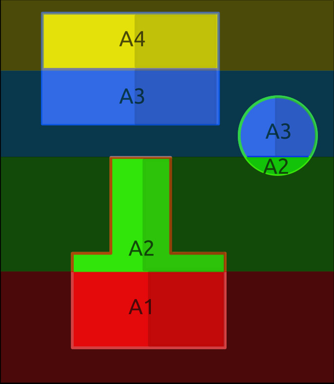
Layer Segmenting of Multi Gantry (4: red, green, blue, yellow) with IDEX (2) per Gantry
And like-wise segmenting layer areas in Y as before, and additionally segment in X for each printhead on Independent Multi Extruders (IMEX), in this example it’s IDEX (Dual).
As IMEX looks like scaling print parallelism further, one has to be aware of the spatial overhead for each printhead, e.g. a single printhead occupy ~40mm width in X, and similar in Y.
IDEX-MG3: Ashtar M vs Ashtar D
Early draft with more details based on Ashtar M (Y-XZ gantry), extended to MG, with Common Y rails with IDEX; and for comparison Ashtar D (XY gantry) with MG and IDEX:
Ashtar M MG3-MIEX2 [draft: Y motion system missing]IDEX DetailAshtar D MG3-MIEX2 [draft: Y motion system missing]IDEX Detail
Challenges
1a) When doing a Y-XZ gantry IMEX2-MG3 (2 extruders/IDEX on each 3 gantry):
X: 2*3 motors = 6 motors
Y: 3 motors
Z: 3 motors
E: 2*3 = 6 motors we end up 6+3+3+6 = 18 motors to coordinate & control.
1b) for XY gantry approach:
X: 2*3 = 6 motors
Y: 3 motors
Z: 1 motor (or more, but all synchronous)
E: 2*3 = 6 motors we end up with 6+3+1+6 = 16 motors to coordinate & control.
2) Slim design of the gantry to reduce dead-space in Y.
3) Slim printhead design to reduce dead-space in X.
4) Slicer requires to coordinate 6 printheads (e.g. T0-T5) in non-colliding and efficient way.
Solutions
Slicer
A dedicated slicer is required which segments each layer into printable areas A1 to An whereas n is the amount of gantries, and those areas might be further segmented by m-amount of printheads on the same gantry, so they share the same Y position but can have distinct X position but not switch order or collide.
As proposed above, a single printhead of a gantry is then assigned to print within the same Y-segment the walls/perimeters to have a clean wall, hence, the infills are distributed among all the printheads.
For segmenting entire sub-volume and not just layers, the Y-XZ would allow distinct Z, e.g. one gantry printing higher and another lower – the XY gantries share the same Z, therefore there only the layer segmenting is possible.
Firmware & Controller
The controller with its firmware we have a few options:
M400: wait for current moves to finish (when using T<n> with G1s together, applies to X, Y, Z, and also E)
M596 P<n> selects motion queue, prior each G0 or G1
M597: collision avoidance (at firmware level)
M598: sync up multiple motions (faster waits for the slower)
Klipper
flexible in regards of MCUs – some early prototype (2025/05) showed promising results using new multi-axis capability to coordinate two truly independent X & Y carriages
requires SBC and host and MCU firmware, most things are software defined (MCU firmware compiled once only)
Marlin
one controller per gantry or extruder, orchestrating/sync between controller needed, hence a meta controller required (SBC)
using M400 to sync each controller by meta controller
simple setup, reliable
To keep this in mind, the Y-XZ approach allows distinct Z for each gantry, whereas the XY approach all Z of the gantries are the same.
Adding Tool Changer (TC)
In order to support a tool changer, the printheads need to reach a common position in order to deposit and pick up tools. In case of a single/common Y-rail setup this seems at first sight challenging, only a dedicated tool change per gantry, at a particular a YZ position for example. The multi/dedicated Y-rail setup allows any gantry to reach a common region in YZ, and so any printhead could deposit and pickup a tool from the common toolset.
MG MIEX Gantry Style
Toolset position
Y-XZ Common Y rails
ends of Y rail, unique Z positions per gantry
Y-XZ Dedicated Y rails
ends of Y rail, common or unique Z positions
XY
first & last gantry at ends of Y rail, Z fixed
XY gantry setup still can have a tool changer but only the most front gantry, and the most farthest gantry in regards of Y, the gantries in between – if more than total of 2 gantries used – cannot reach a toolset; unless the toolset itself – aka Dockslide – moves close enough to hand over tools.
Commercial Collaboration
Currently I work on a MVP implementing the actual details (software & hardware), if you are interested in a commercial collaboration, contact me to discuss opportunities.
Ashtar Q (MG2 IDEX): quad extruder in multi-grantry dual IDEX setup – early prototype (2025/05)Ashtar Q (MG2 IDEX): quad extruder in multi-grantry dual IDEX setup – early prototype (2025/05)
2024/12/04: completing first table on printheads & nozzles
2024/07/30: starting write up
Table of Contents
Introduction
When depositing material through a nozzle, the variables to compose a workpiece depends on the amount of nozzles and their operational spaces – let’s lay out the different methods which gives us the foundation to tackle then parallel procedures in the next part in the series.
Printheads, Nozzles & Operational Space
Printheads
Nozzles per Printhead
Nozzle Size [mm]
Layer Height [mm]
Material
Operational Space
Single nozzle FDM/FFF
1
1
0.1-1.0
0.1-0.6
Polymer (PLA, PETG, ABS)
100%
Dual nozzle FDM/FFF aka IDEX
2
1
0.1-1.0
0.1-0.6
Polymer (PLA, PETG, ABS)
2x 50%; horizontally separated
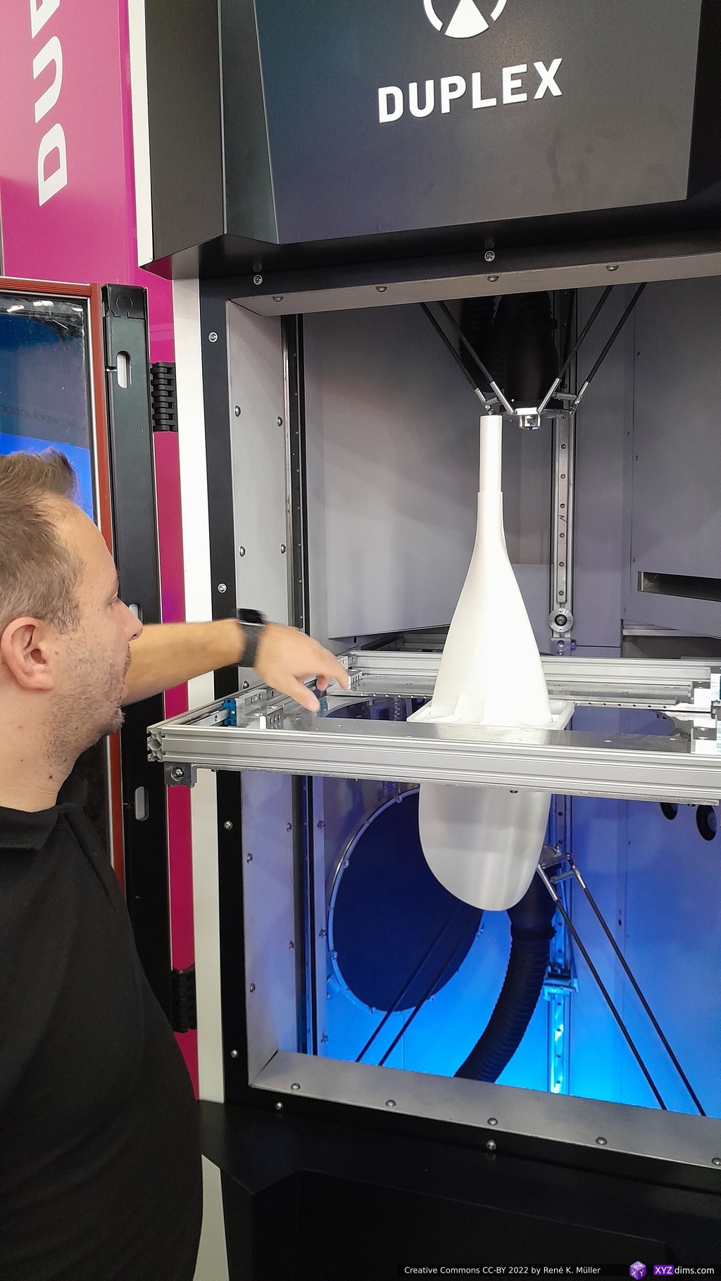
Duplex F2
2
1
0.1-1.0
0.1-0.6
Polymer (PLA, PETG, ABS)
2x 50%; vertical separated
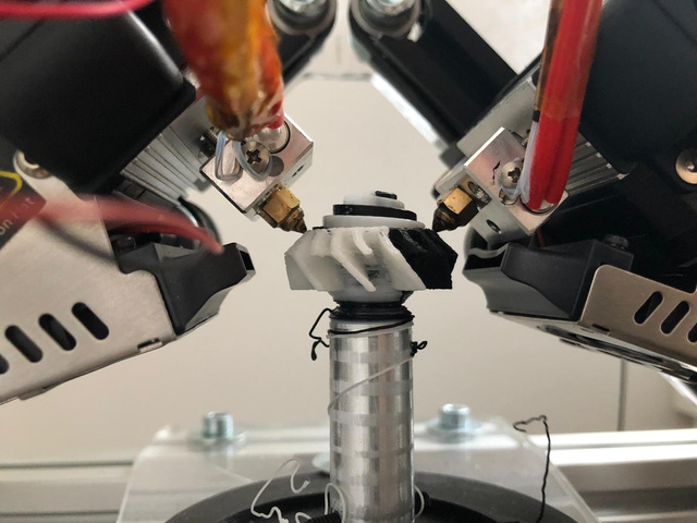
CM3P Dual Conical
2
1
0.1-1.0
0.1-0.6
Polymer (PLA, PETG, ABS)
2x 50% of negative cone
Resin SLA (UV Laser)
1
1
0.150
0.050-0.150
Resins
100%
Resin MSLA (UV & LCD)
1
50M-100M
0.020-0.040
0.050-0.150
Resins
100%
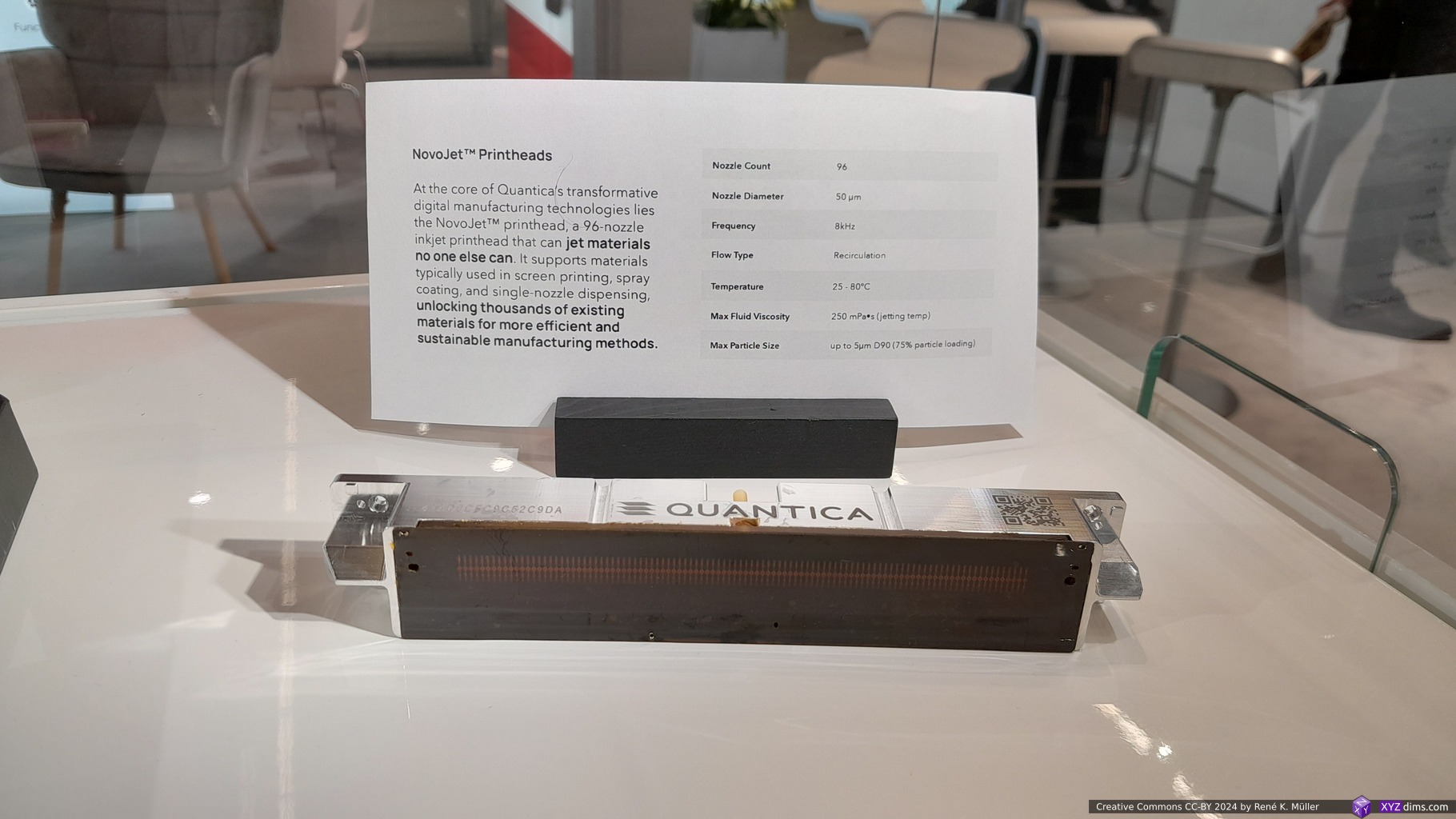
Quantica NovoJet
1
96
0.050
Resins
100%
Stratasys J55 PolyJet
1
192*)
0.2*)
0.18
Resins
100%
Selective Laser Sintering/Melting
1+
1
0.1
0.05-0.10
Polymer or Metal Powder
100%
Stratasys J55: nozzles & nozzle size based on J850 specs, J55 details specs seem not publicized (2024/12)
Print Base
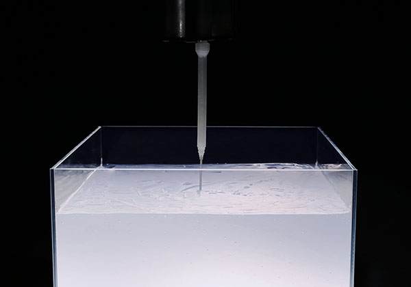
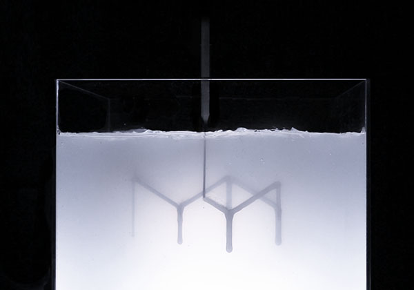
A print base is where the nozzle can extrude on. For the first layer, there is the print bed, after the first layer the workpiece or support structure can be build upon. One can alternatively use a stabilizing medium like silicon and extrude in such liquid medium which operates as bed or foundation like Rapid Liquid Printing (RLP) does:
Extruding into supporting materialExtruding into supporting material
The extruded material just has to stay where it was put, either a solid bed or a medium which prevents it to float out of position, or as traditionally printed on a print bed or base, very similar does Xolography where the solidified resin stays put as well.
Massive Parallel Nozzles Printhead
Resin printing with a printhead may have hundreds or even thousands of nozzles, yet, they share the same operational space, but due the parallel setup the print speed multiplies direct with the amount of parallel nozzles on the same printhead.
As mentioned above, we can also view Masked Stereolithography (MSLA) resin printing as a massive parallel nozzle setup, where each pixel is either an active or inactive nozzle depositing a voxel.
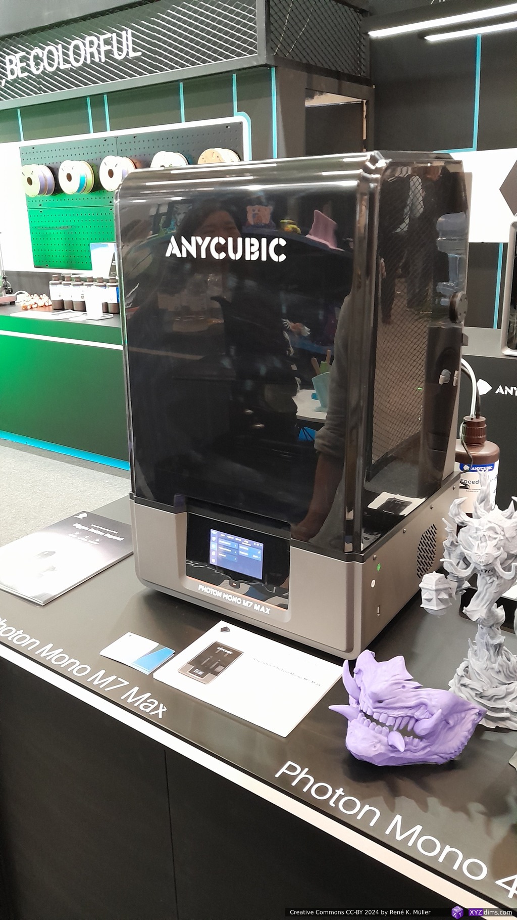
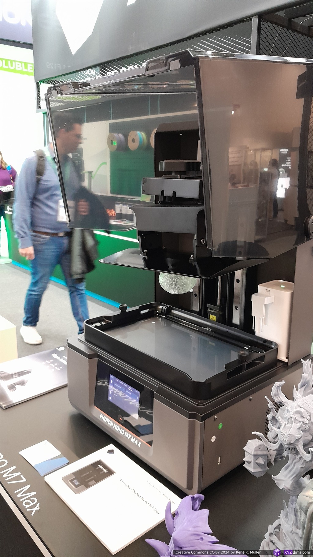
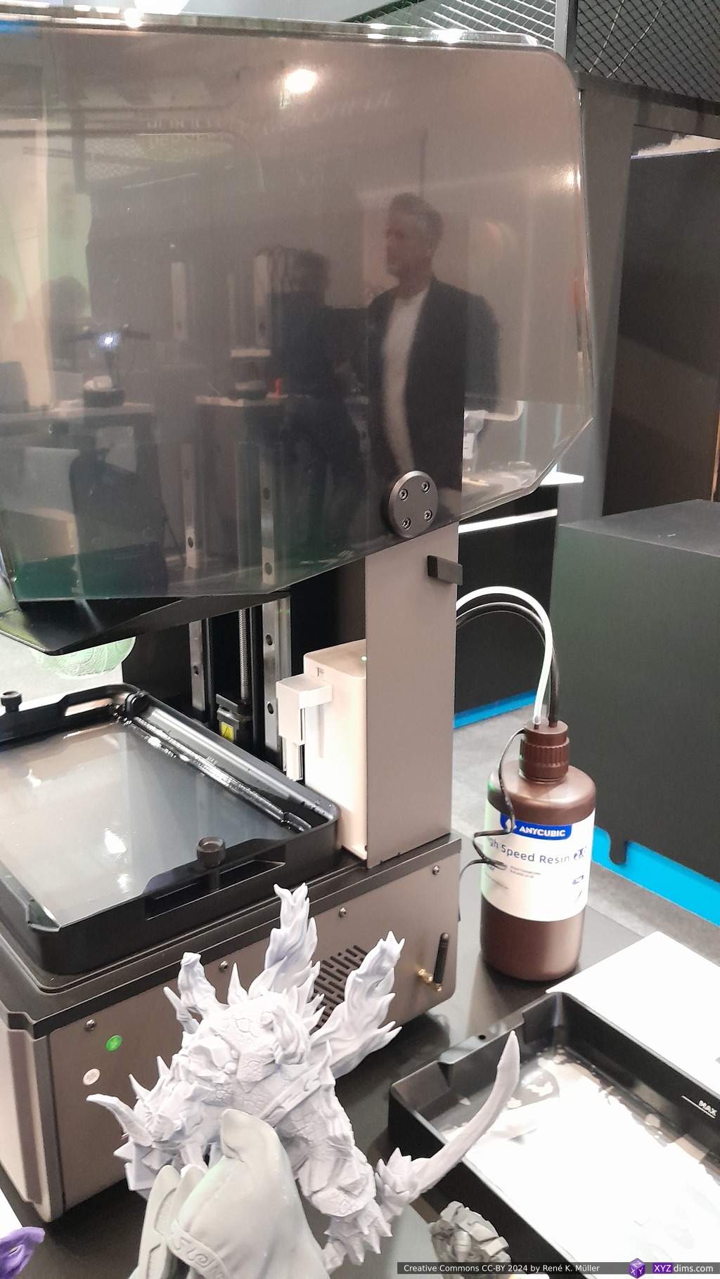
Anycubic Mono M7 Max MSLA Setup
Separated vs Shared Operational Space
Disclosure: I have been contracted to work on the Duplex F2 software stack (2022-2024).
Let’s take a look at the Duplex F2 printer where space is separated vertically, or the CM3P dual conical printer where the cone space is separated horizontally, or the Multi Gantry 3D printer by Proper Printing (Jon Schone). We have two printheads which never collide due their separated operational space, the firmware is simple and path planning is simple, both heads pretty much can operate independently.
When using more than two printheads it is beneficial to share the operational space, yet assume 6 or 8 printheads, each printhead needs rods to keep the printhead and position and orient the nozzle(s), so overlapping operational space requires extreme well planned tool paths avoiding any collision of the printheads.
Regular Operation Space Separation
We can segment or separate the space evenly or according the reach of the printheads, and each separated space can be printed without colliding. Yet, in reality the printheads mounts limit that operational space into slightly smaller spaces, but ideally:
nvolumes = volumetotal / volumeprinthead
If the individual printhead volumes aren’t regular, then we end up with arbitrary amount of printheads to cover a given print volume:
volumetotal = sum( volume1..n )
In reality, we require (slightly) overlapping operation to get seamless operation, so the “regular operation space separation” is only theoretically, but not practically.
Overlapping Operational Spaces
When the printheads can reach each other operational space, they become overlapping and controlling tool path generation needs to take care no collision is occurring (same place at the same time).
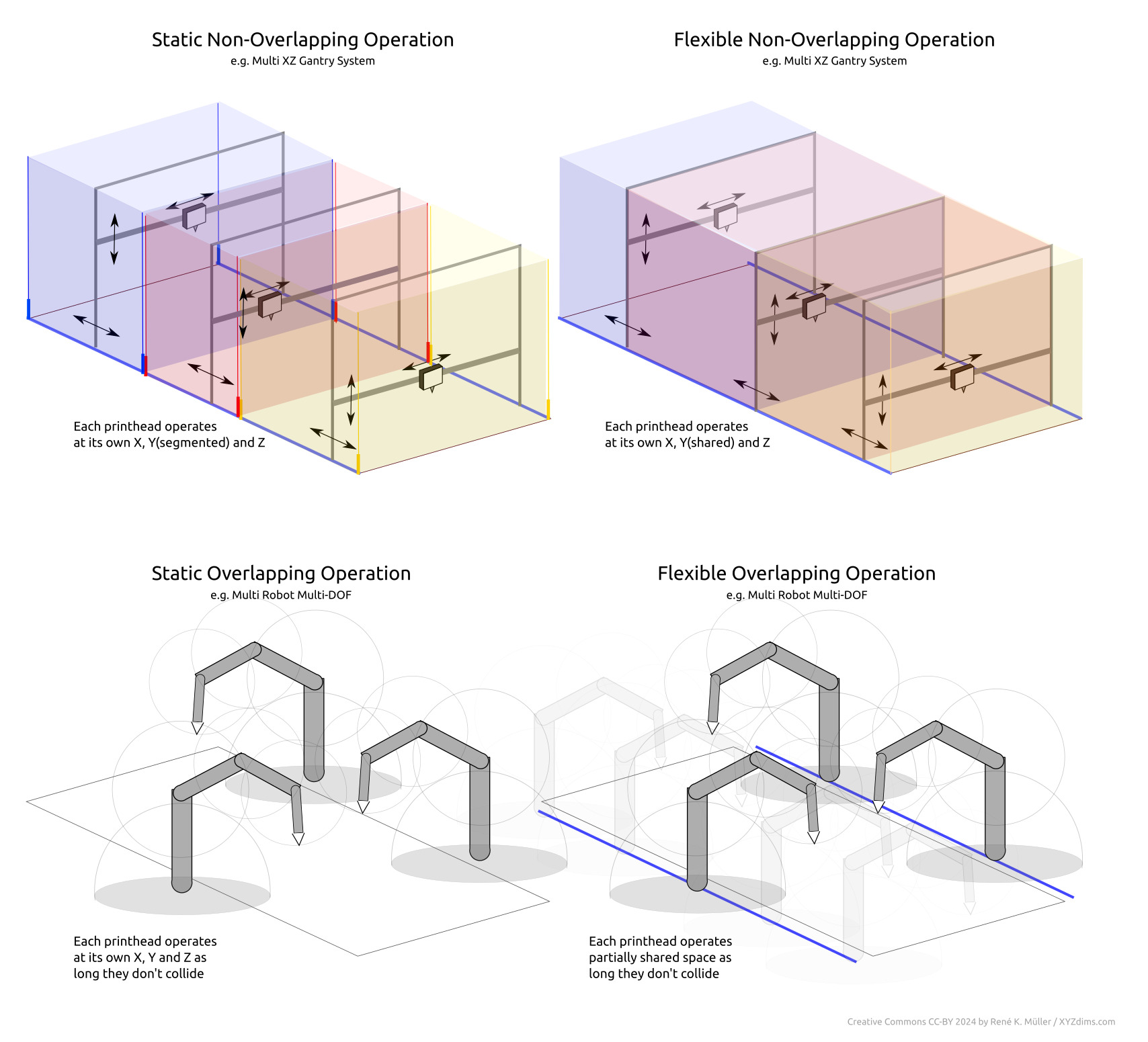
The Static Non-Overlapping Operation has static defined operational spaces where the operators can function – it’s quite obvious such solution is impractical, as in real life there would be space which cannot be reached, a kind of blind seam not reachable by either operator.
The Flexible Non-Overlapping Operation is flexible defined operational spaces, in the illustration above those spaces are co-dependent.
The Static Overlapping Operation is when those operational spaces are overlapping, yet, prefixed or static operational spaces.
The Flexible Overlapping Operation is flexible operational spaces, yet due the nature of the setup these operators cannot occupy the same space at the same time which would result in physical collisions.
Now, the last part of the last sentence may sound obvious to even mention, but bear in mind you can have two projectors shining light into a resin bath, and expose and solidify a 3D model, then these two lights acting as operators indeed occupy the same space at the same time as part of their function. So, the operators functioning with light can occupy the same space at the same time, whereas solid operators, such as robotic arms, cannot.
whereas parallelfactor is 1.0 if printheads can print parallel, or is less if the operational space is overlapping and preventing printheads to operate parallel thereby.
~ * ~
“Parallel 3D Printing / Additive Manufacturing” Part 2 follows later (will be linked when published)
2025/04/21: added 2nd slicer link to new S4 Slicer (reimplementing S^3 slicer)
2025/03/11: added link to github repo of the radial slicer
2024/12/03: starting write-up, and published it
Introduction
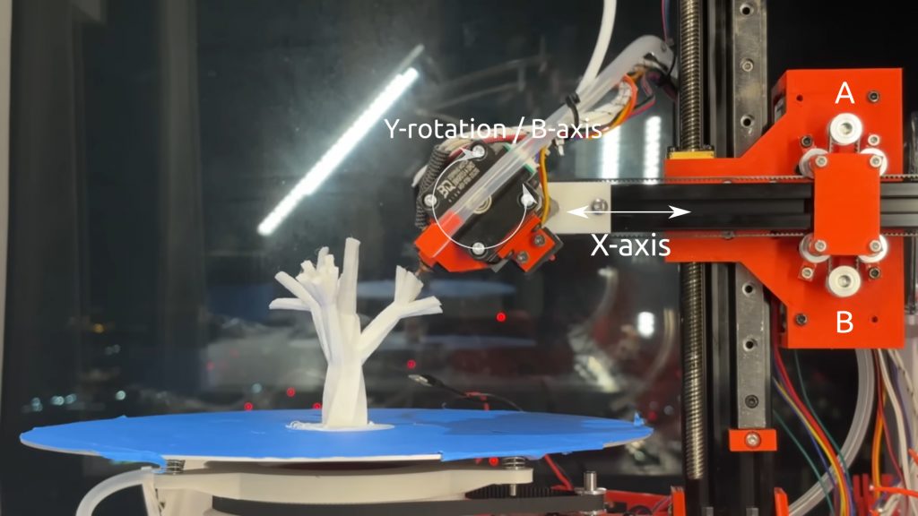
Joshua Bird announced his 4-axis Polar CoreXB Printer December 1st 2024 on Reddit and YouTube:
Beside the hardware, he also implemented the required software and released it on github as “Radial Non-Planar Slicer” – an impressive undertake and success in one go.
4-Axis Linear Head(XZ), Rotational Head(Y)Bed(Z)
Even though I was impressed by the 4-axis RTN by ZHAW I wrote about, I abandoned the idea of 4-axis setup, as I considered it too limiting. Joshua’s approach to use a Z rotating bed, and the nozzle rotating ~180° or -90°.. +90° in Y-axis implements a polar (coordinate) printer.
He has a fixed Z-rotational center on the bed, and variable head Y-rotation in X. By keeping the Y-rotation (B) at 0° (vertical), the printer can print Z-planar cylindrical as well.
It can print XY Z-planar like a 3-axis 3D printer by mapping the XY coordinates into radial/cylindrical coordinates as well, so let’s summarize quickly what can be done:
polar coordinates, spherical slices
cylindrical coordinates, Z-planar cylindrical slices (fixed Y/B axis at 0°/vertical)
cartesian coordinates, mapping XY into radial/circular coordinates and fixed Y/B axis at 0°/vertical as well
So, this setup is quite powerful – and much better than the 4-axis RTN and also my 5-axis PAX setup, where the cabling and PTFE pipe for the filament prevent 360° Z-rotation / C-axis. Because Joshua’s has the Z/C-rotation on the bed, it’s fully continuous (or use a slip-ring to deliver power for a heated bed).
Dual Z Fixed X-Axis: Bad Idea?
Joshua’s original design is a cantilever, a single XZ beam with the Y/B rotation on the head. For a more large scale setup we require the X-rail to be attached on two Z rails, like the traditional Prusa-Mendel setup. In order to keep the -90°..+90° Y/B rotation of the head/nozzle, we need to position the rotation center a bit below the X-axis – but . . . this will prevent the nozzle to rotate Y/B to -90° or +90° as the gantry likely will crash with the already printed piece. So, it’s rather a bad idea to do so. As a result, we end up with a limited build volume, as the cantilever will tilt with further extending the X-axis.
Core XB: Combining Linear X with Rotational B (Y-Axis)
That is a very clever setup Joshua did, by having the linear X-axis combined with the rotational B-axis (Y-rotation) which he calls “Core XΘ” (Core X-Theta).
There are two motors (A & B) which control in “Core” manner the X-axis and the Y-rotation B-Axis or Θ
Non-Planar Polar Slicer
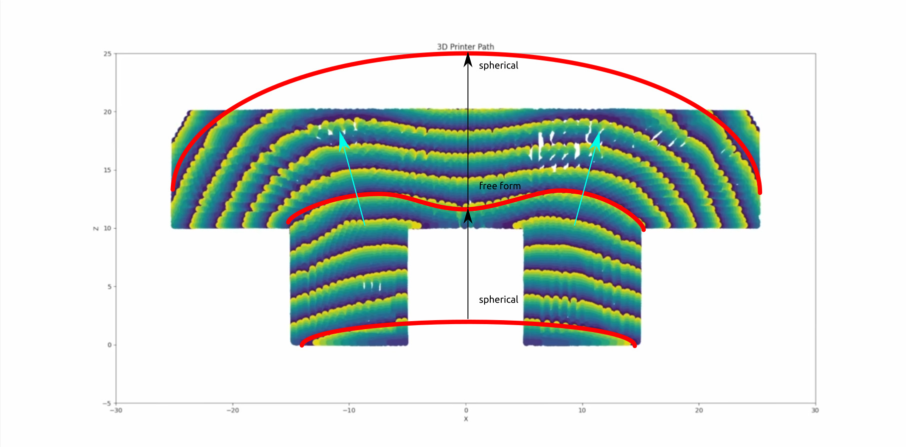
Joshua did also code a mixed non-planar slicer which combines multiple schemas as shown in the video:
Mixing spherical with free form slicing depending on the requirements of continuous printing without overhangs
That is the most tricky part, as polar (flexible tilt) and conical (fixed tilt) slicing may appear sophisticated, but it has its even more expanding challenges as Joshua mentions in his video, and obviously he developed a mixing strategy/schema slicing procedure to slice according the given requirements of printing continuous without supports – as when slicing non-planar, pieces otherwise easy to slice & print, suddenly have overhangs or are non-continuous or not connected anymore.
The S^3 DeformFDM Slicer from Manchester Uni (Tianyu Zhang, Tao Liu, Charlie C.L. Wang) has provided a solution to combine Support Free (SF), Strength Reinforcement (SR) and Surface Quality (SQ) under one umbrella of consideration and optimize all three requirements using quaterions per sample. I tried to adapt that solution but struggled to even build the solution from the sources back in 2022.
Update 2025/04/20: Joshua released his reimplementation of S^3 DeformFDM Slicer as S4 Slicer:
Joshua Bird has “single-handedly pushing the 3DP community forward.” according a YT-comment, and I whole-heartly agree, not only did he thought out of the box with the Core XB setup, but resolved multiple hardware and software challenges – impressive.
References
Polar Core XB 3D Printer (original YouTube video aka “I Built a 4 Axis 3D Printer Unlike Anything You’ve Seen”)
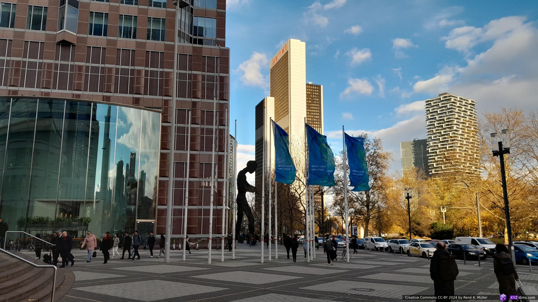
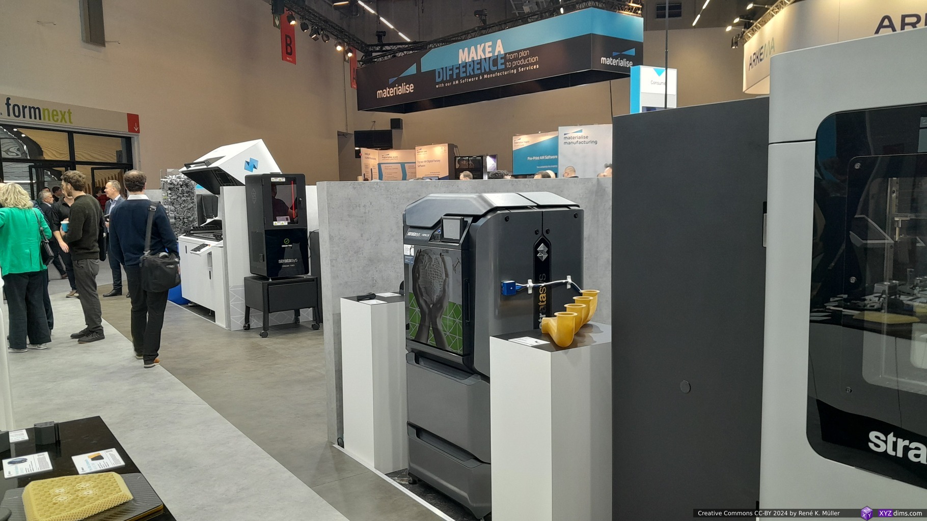
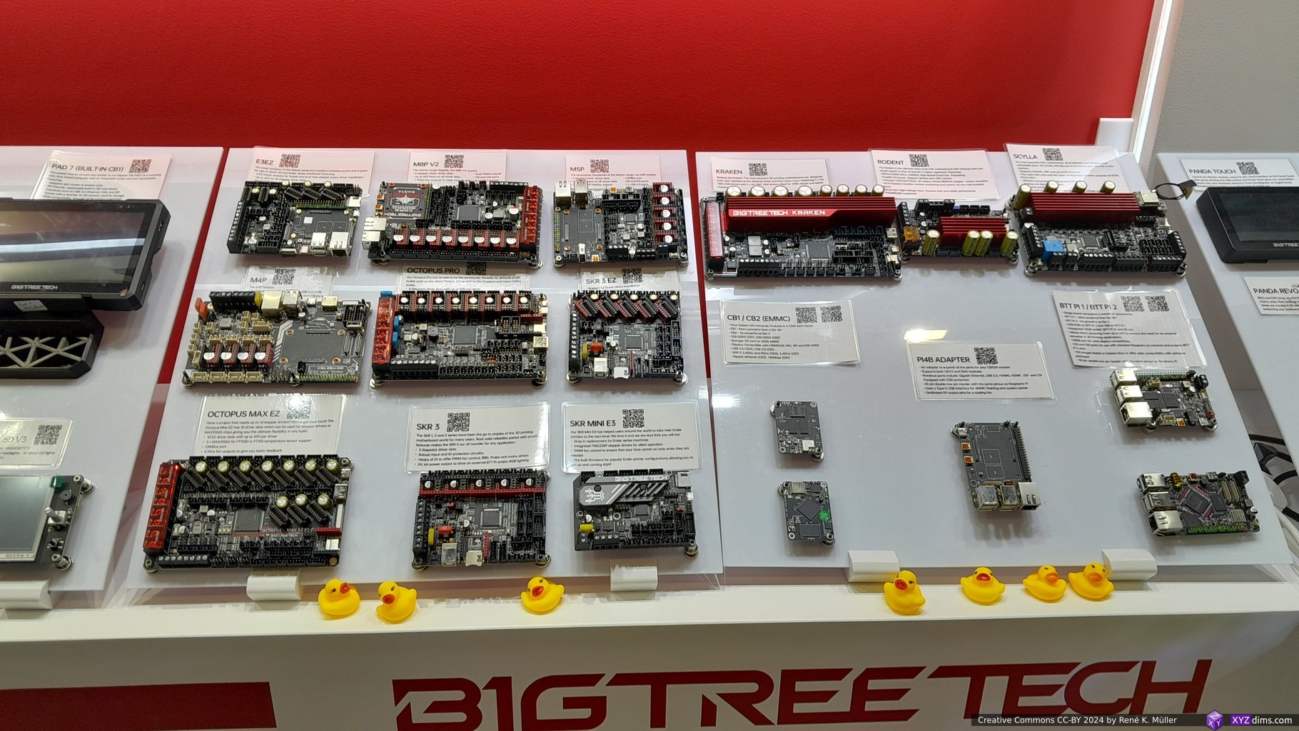
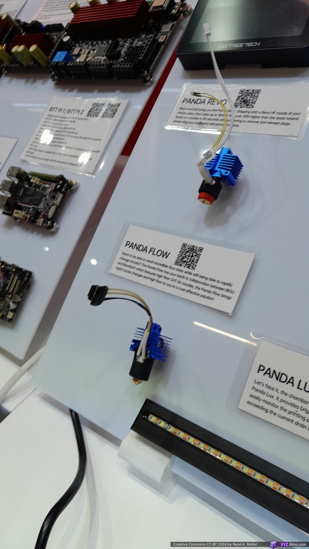
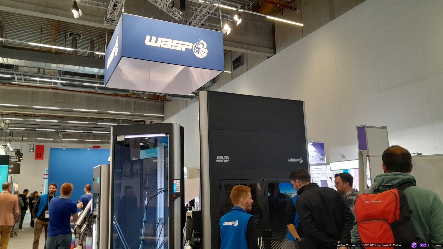
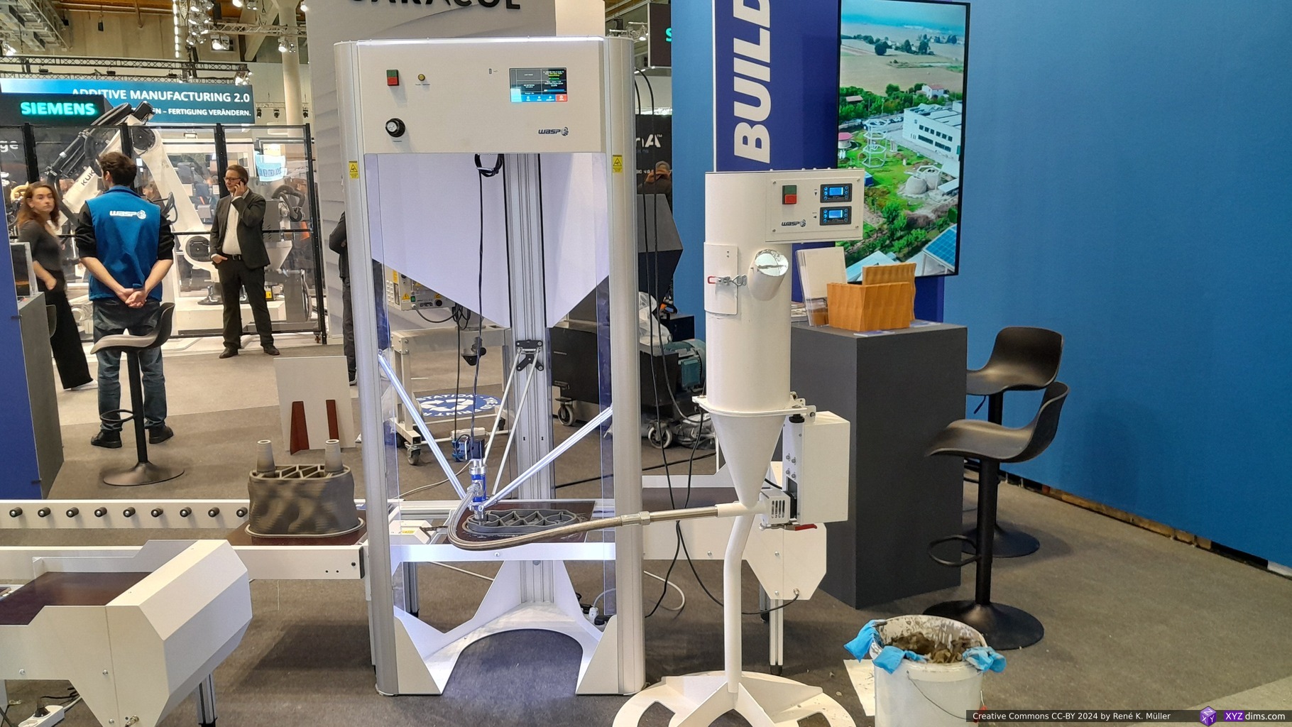
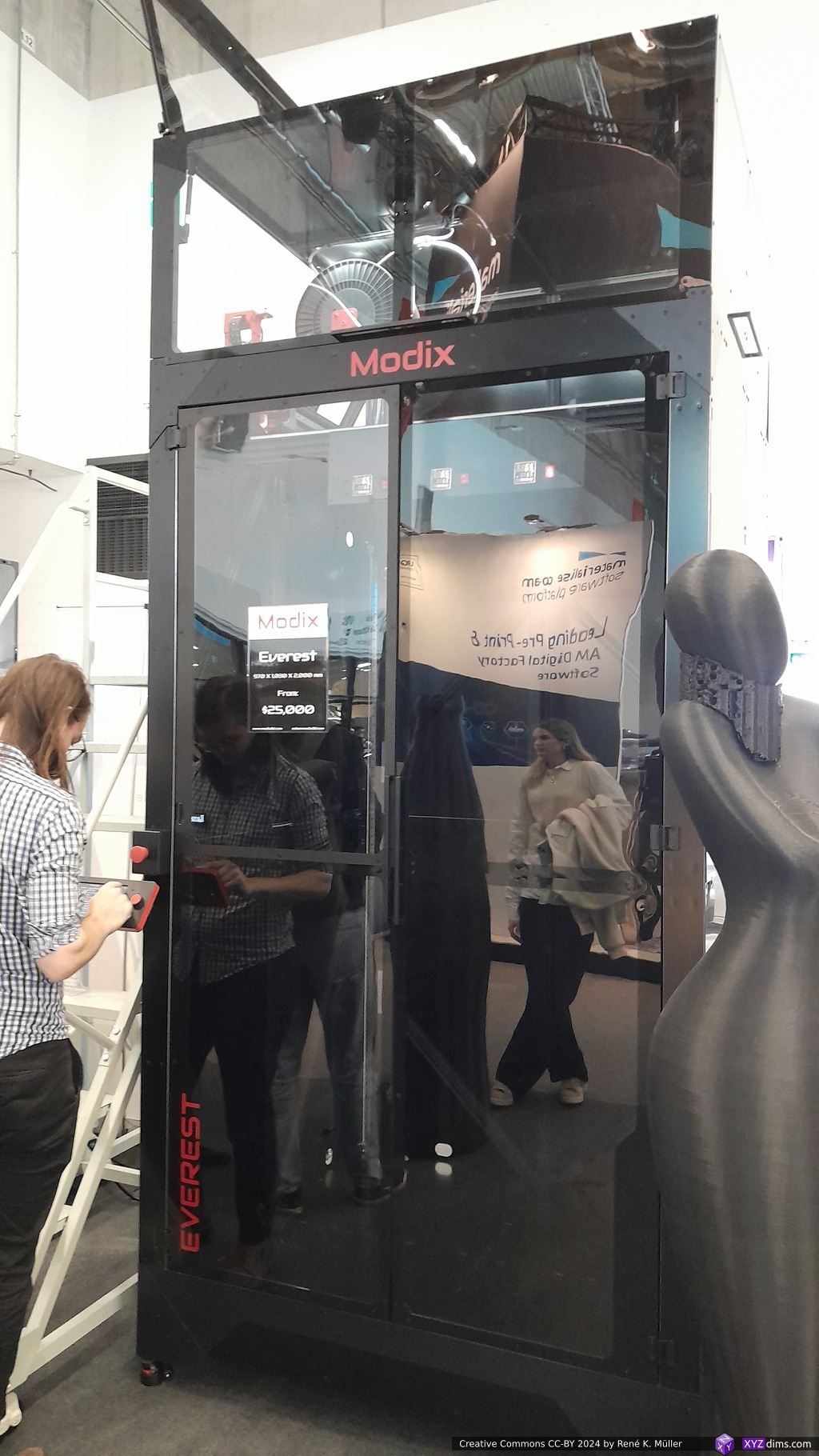
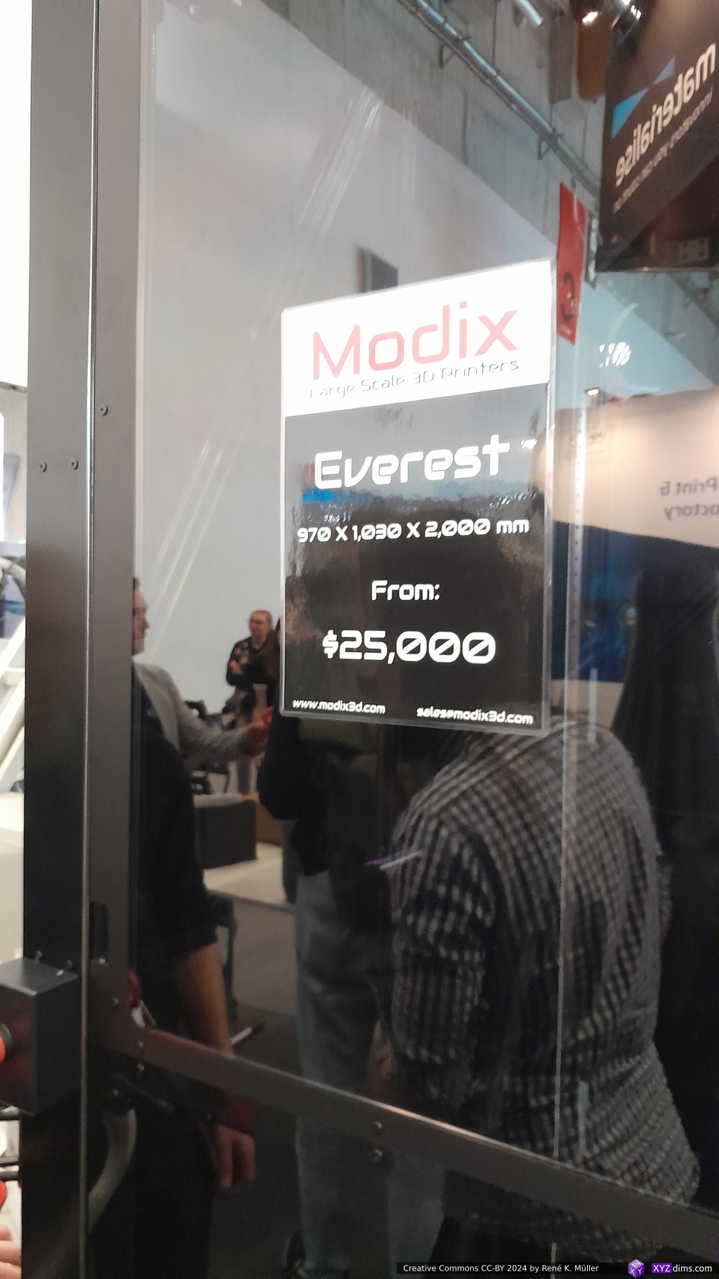
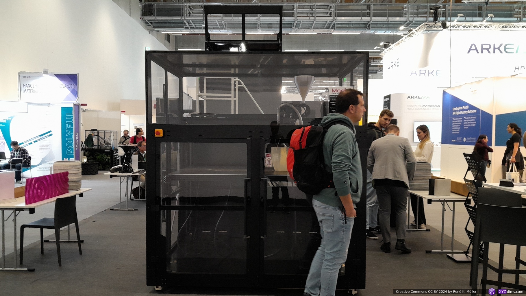
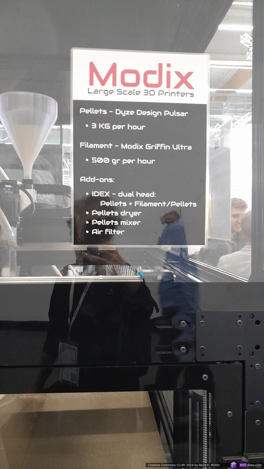
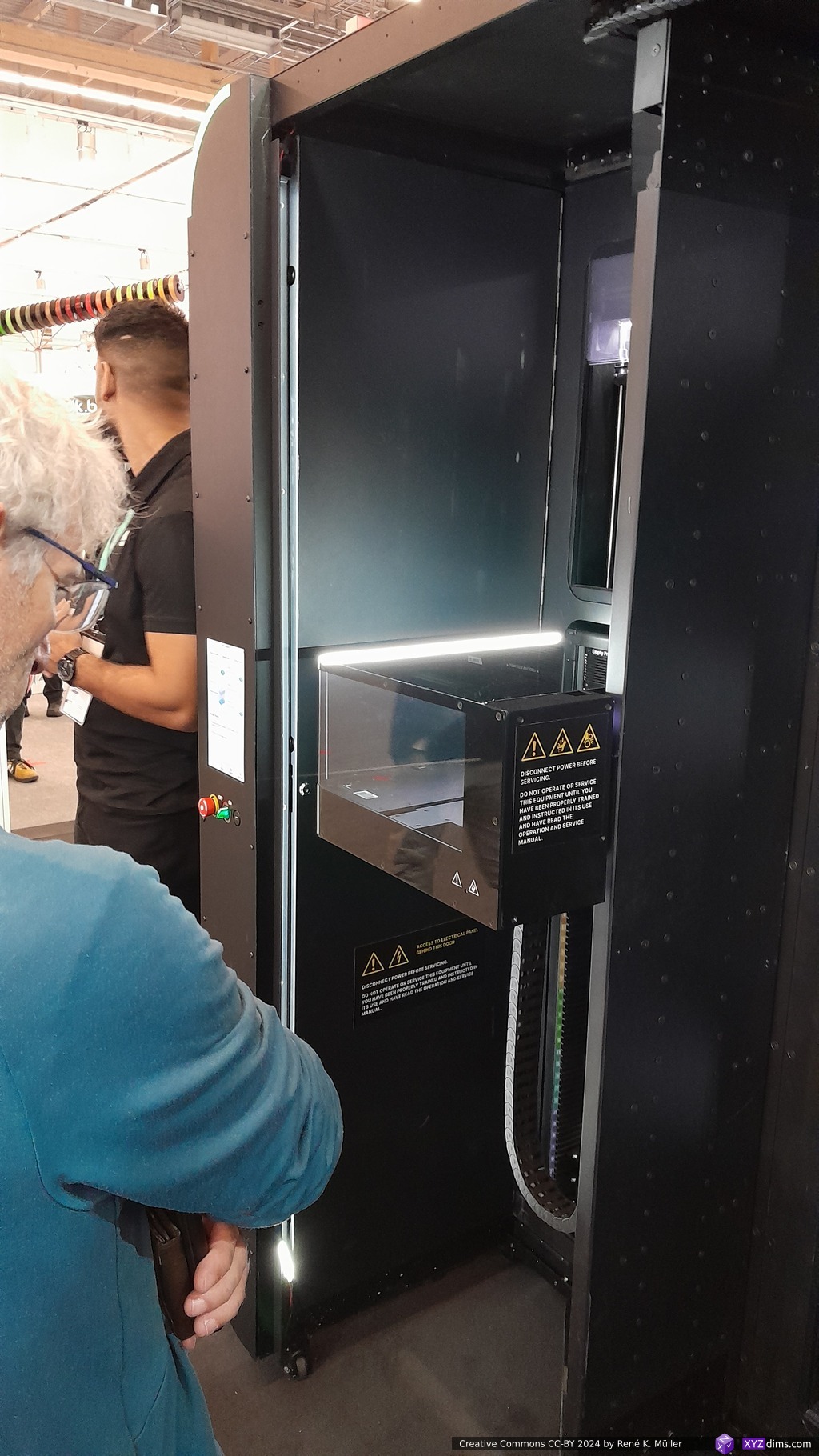
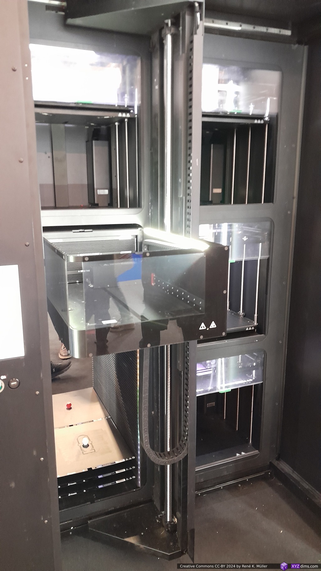
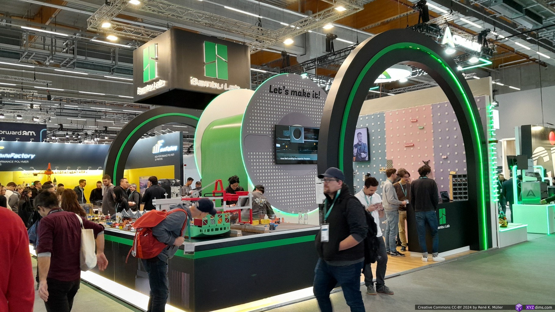
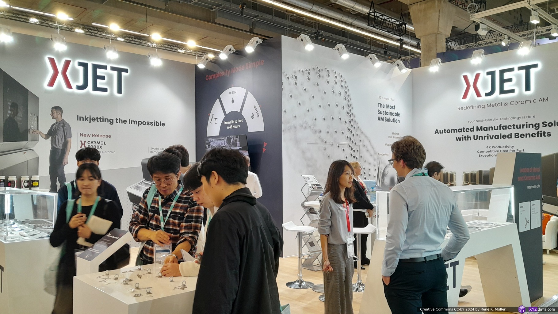
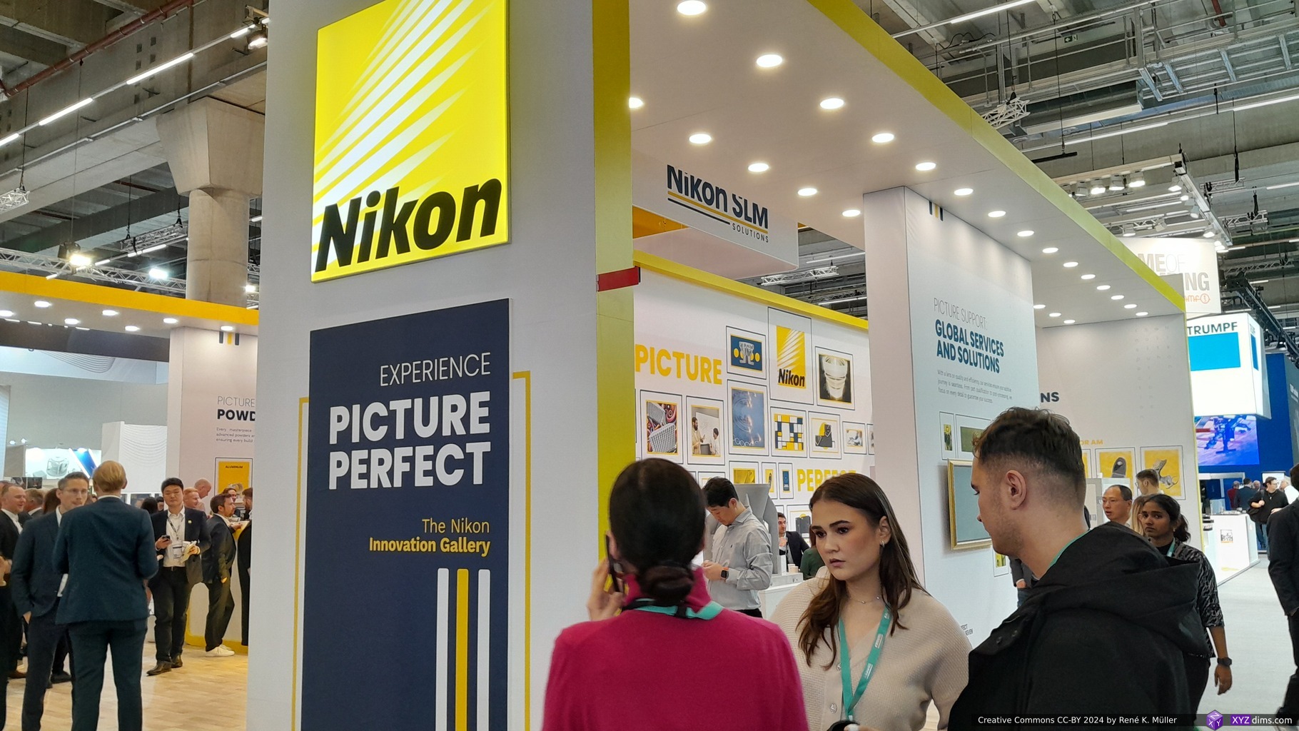
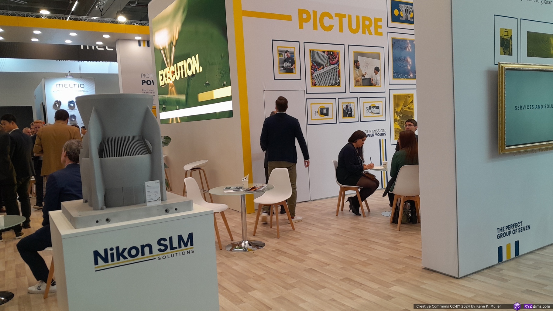
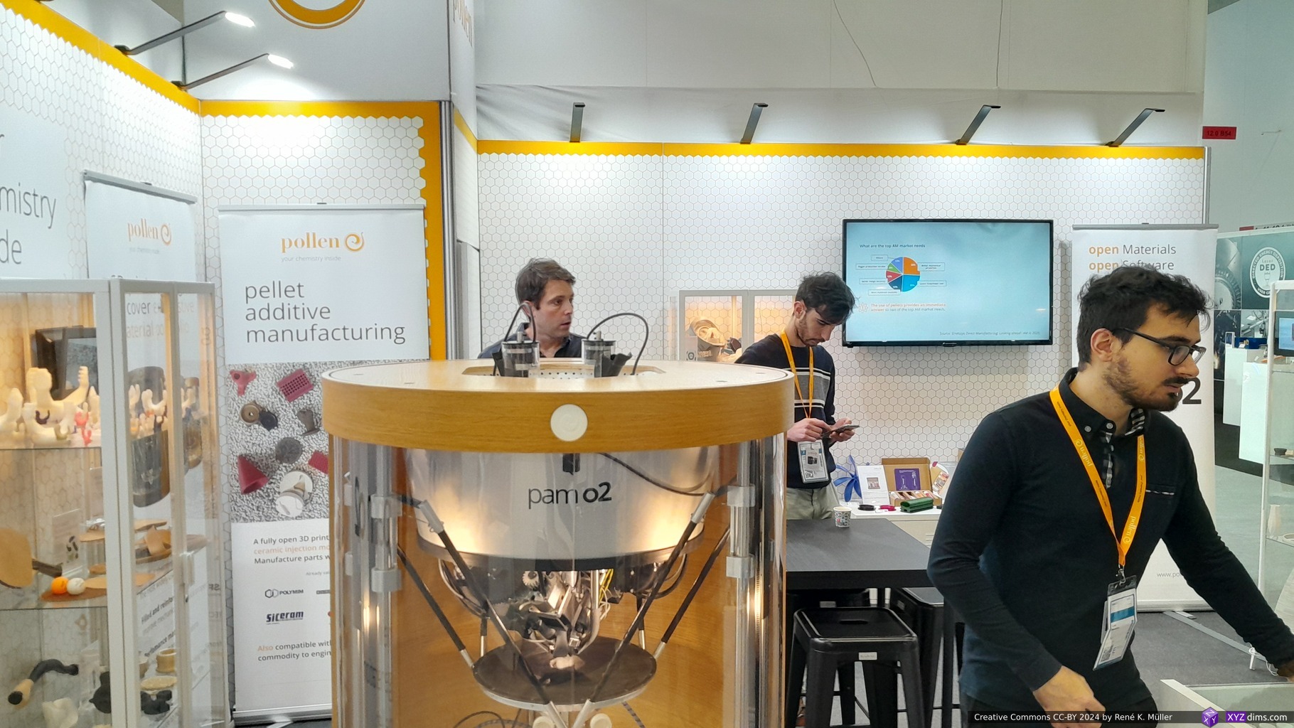
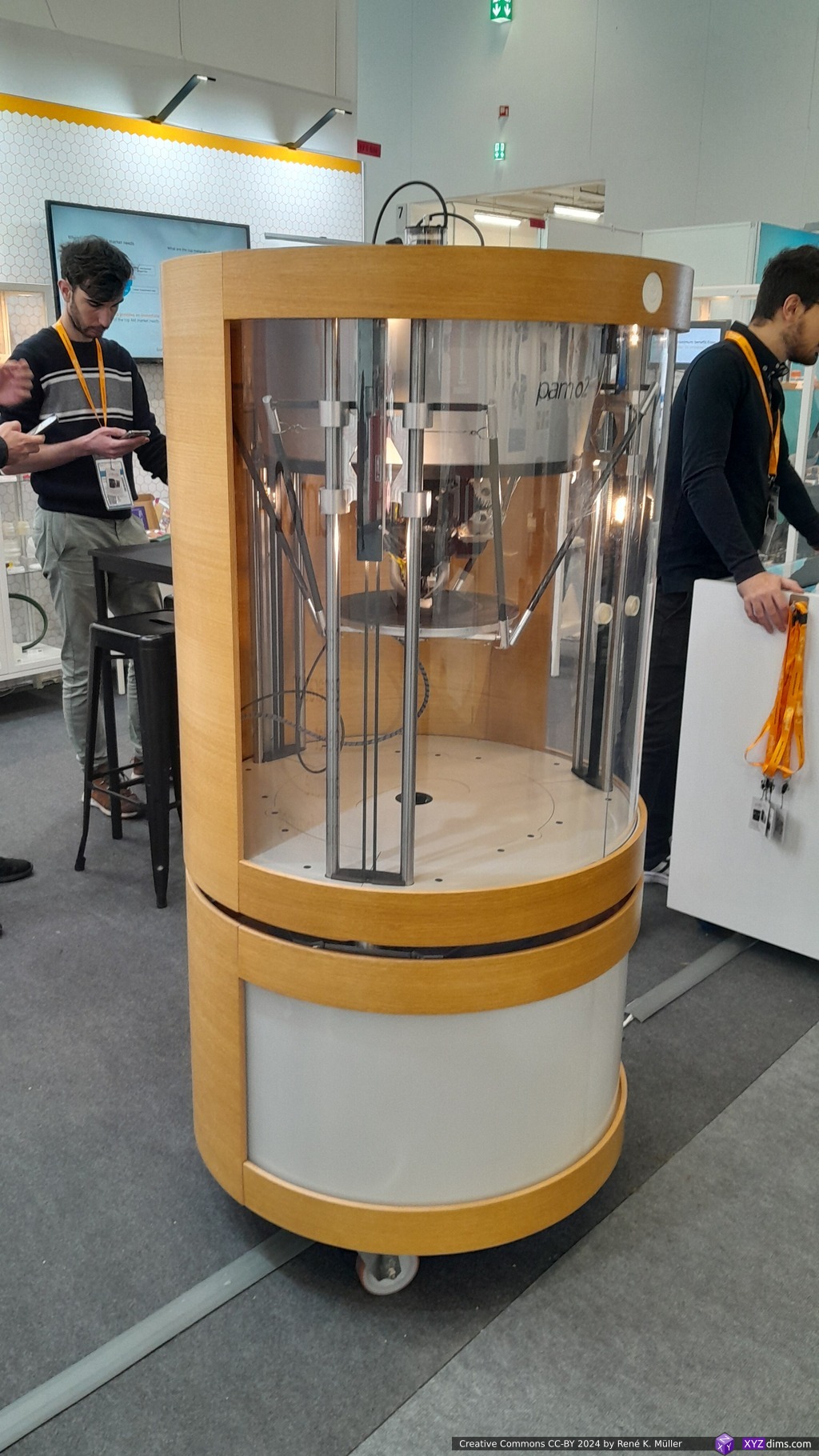
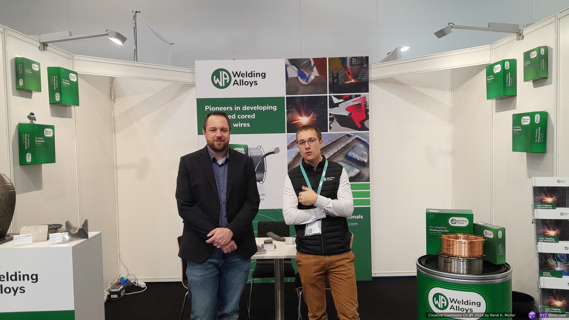
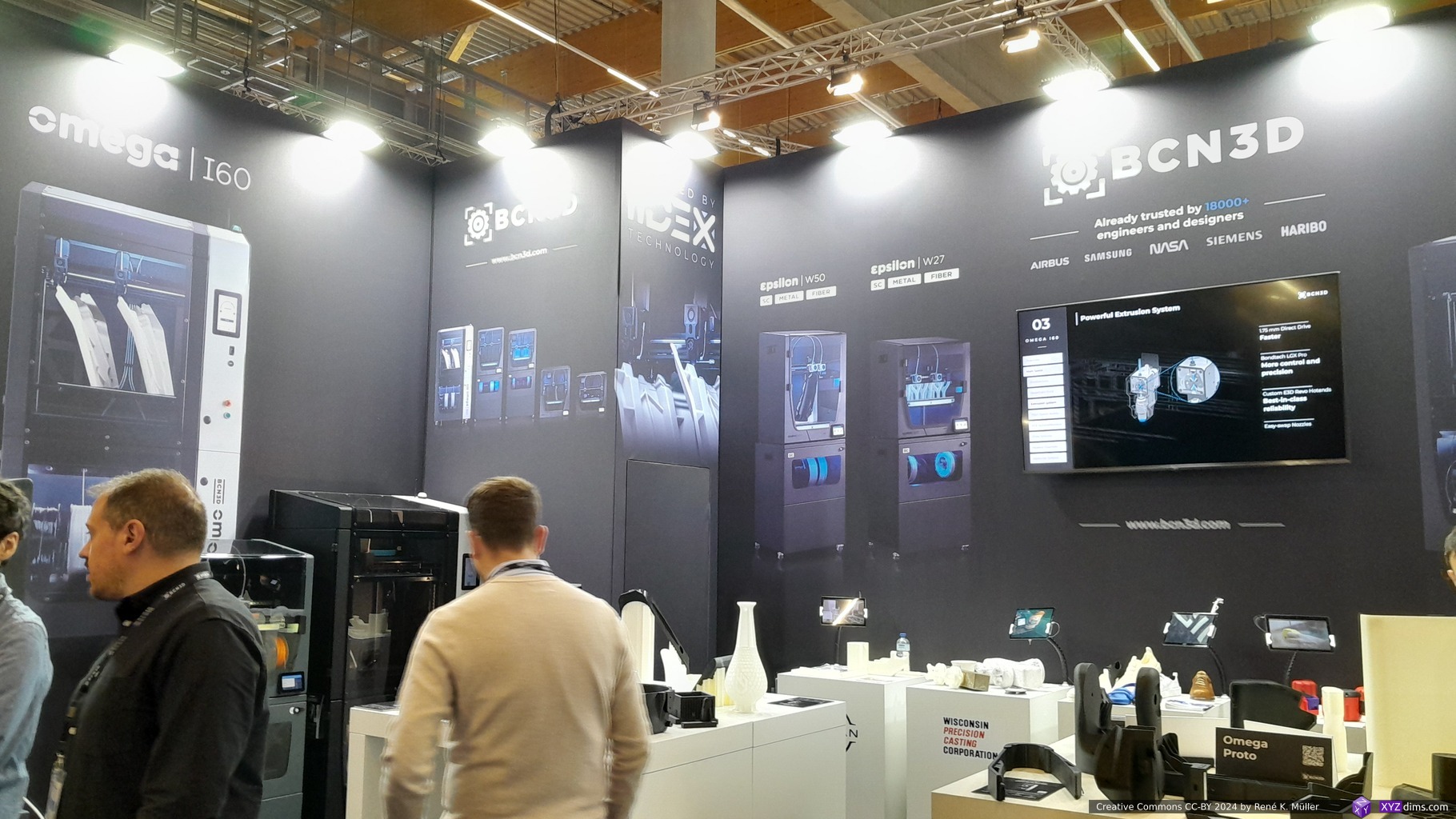
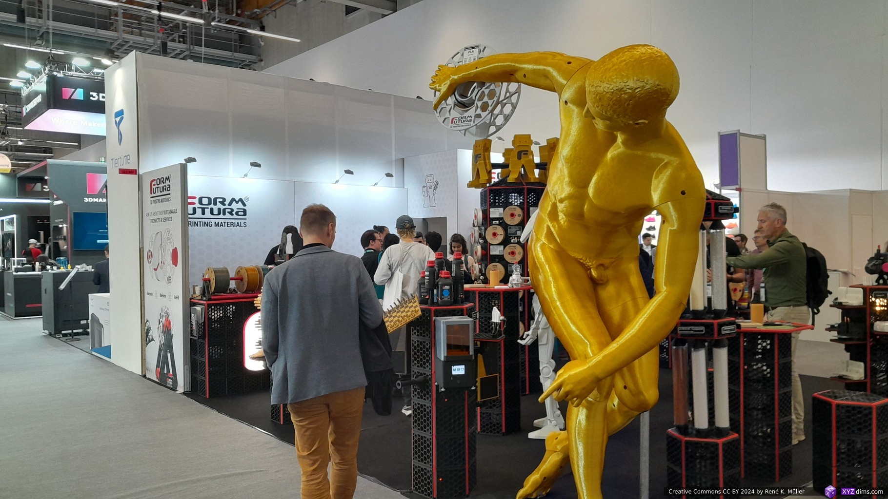
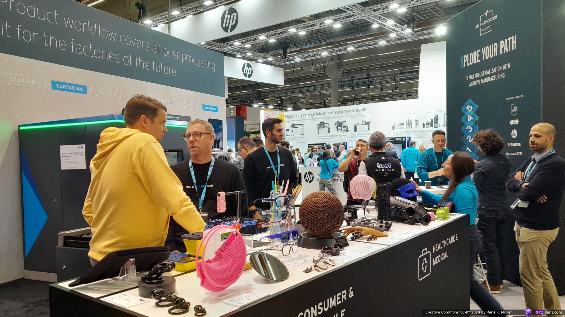
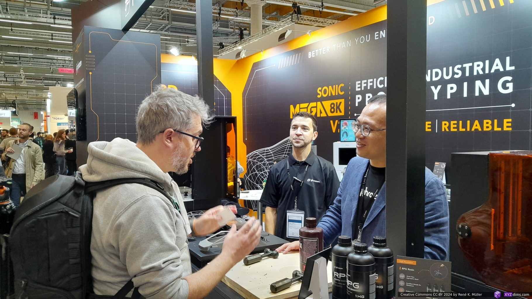
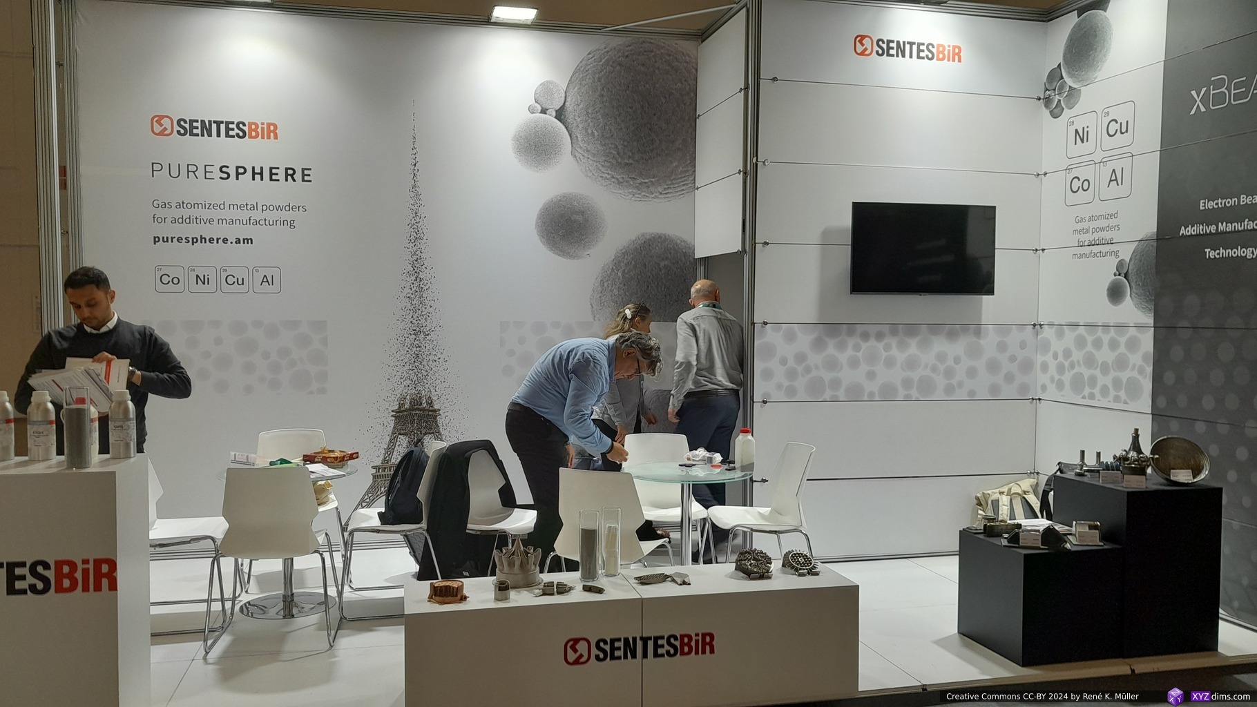
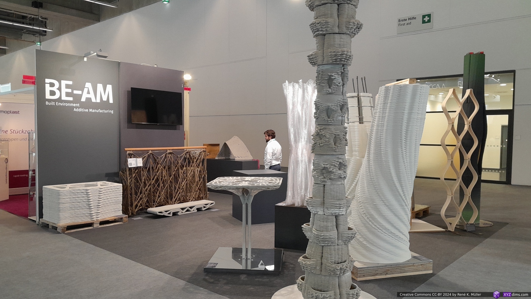
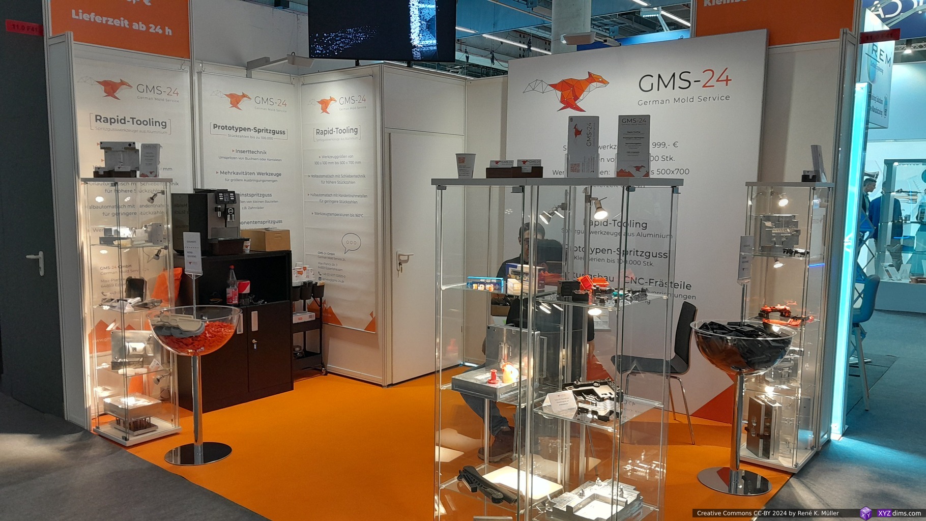
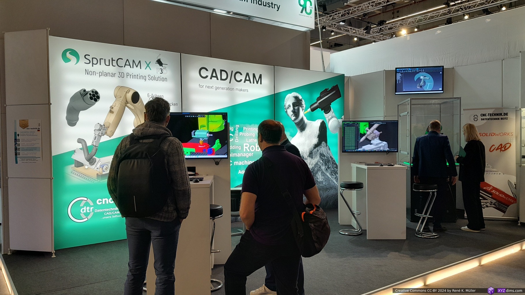
Formnext 2024 in Frankfurt/Main (Germany)Formnext 2024: Hammer ManFormnext 2024
Once again in fall (November 19-22, 2024) Formnext expo opened its doors, and I attended for 2 1/2 days – here my brief write-up and reflection of my experience.
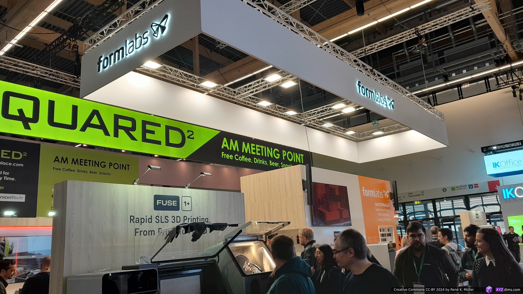
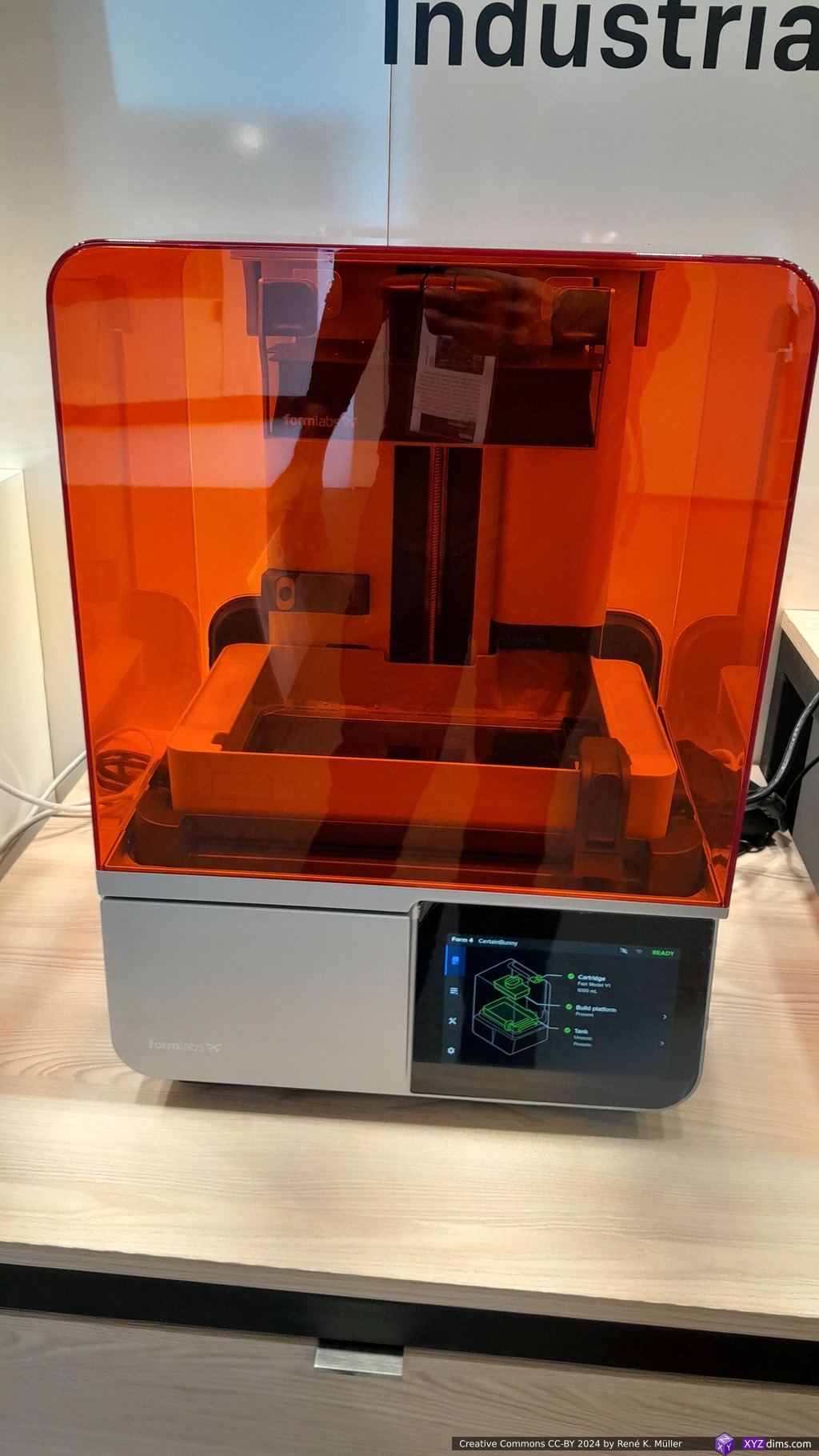
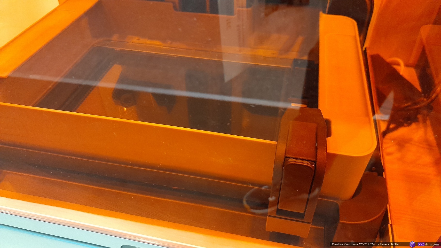
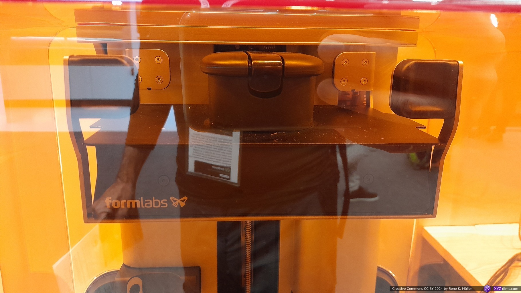
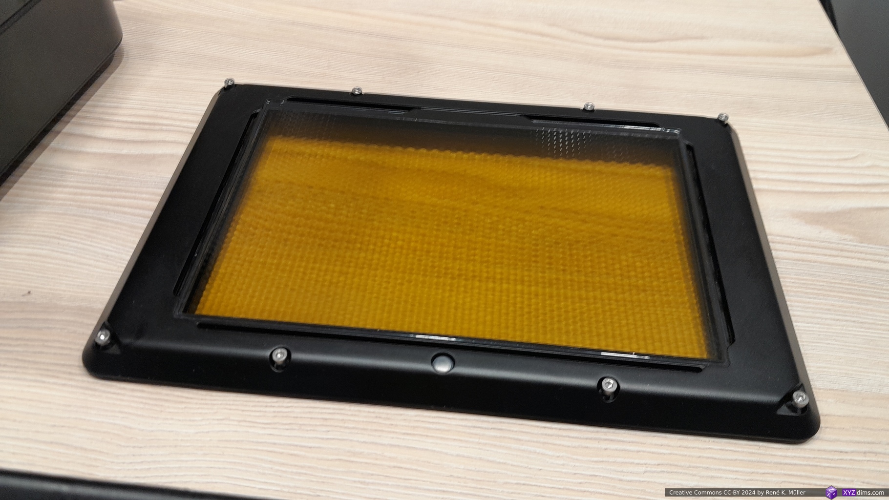
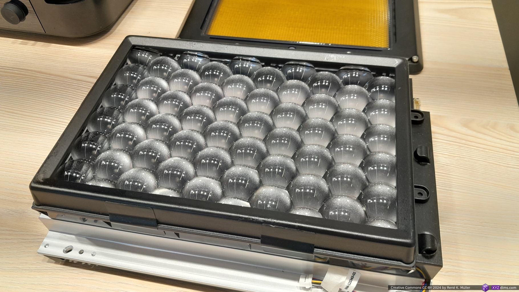
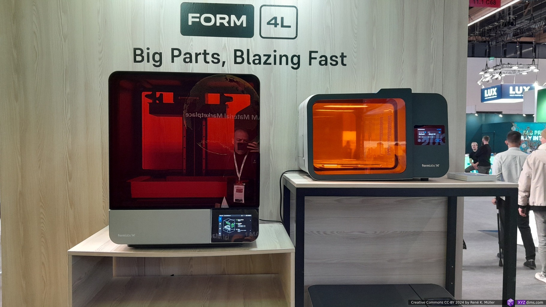
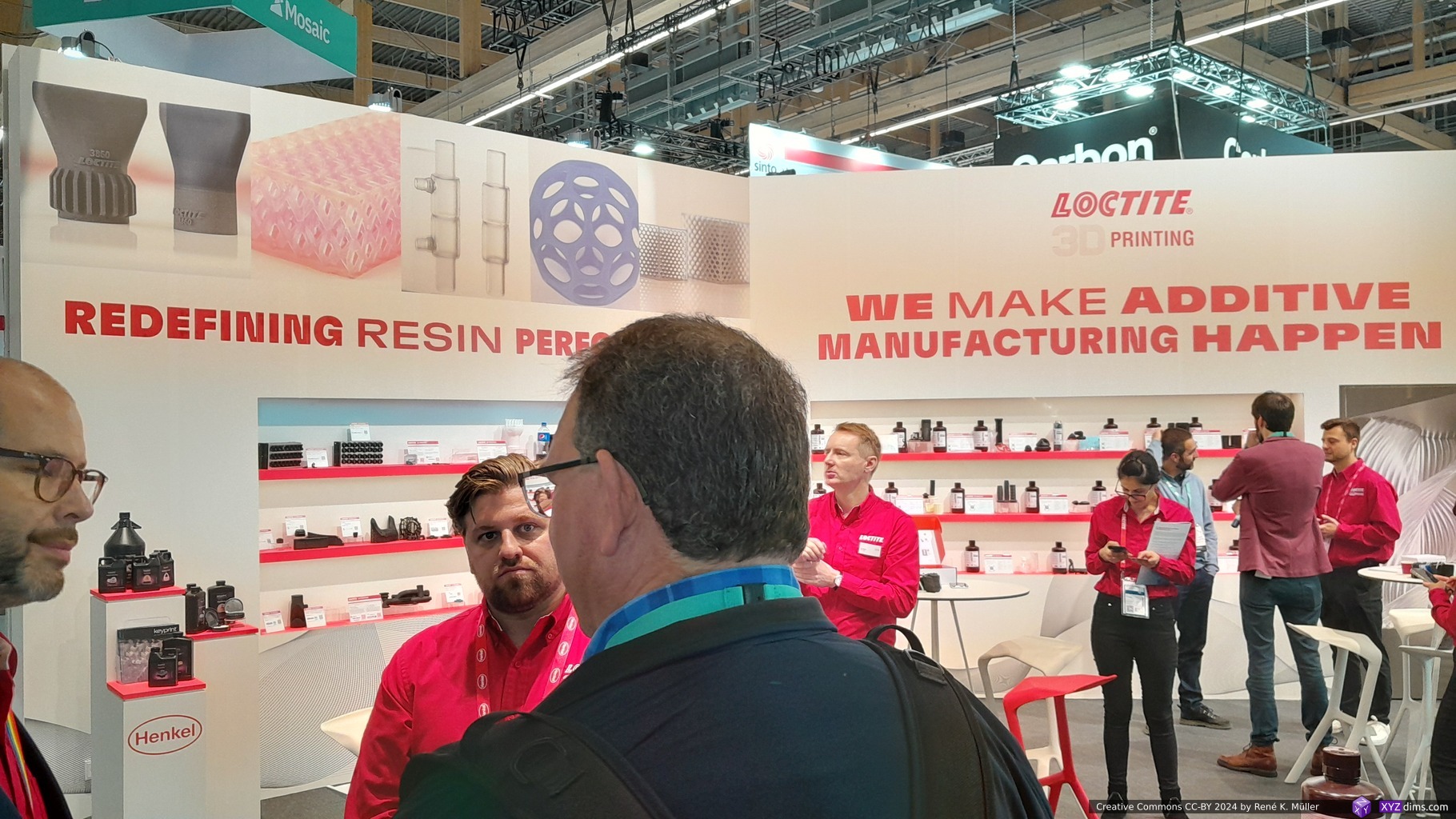
Formlabs
Formlabs made an interesting move: it abandoned the SLA (laser-based) to MSLA (UV light & LCD masking) resin printing with their Form 4 series (Form 4 & Form 4L), so I briefly visited their booth:
FormlabsFormlabs: Form 4Formlabs: Form 4Formlabs: Form 4Formlabs: Form 4Formlabs: Form 4Formlabs: Form 4L
I highly recommend the taking apart of the Form 4 by Shane Wighton / Stuff Made Here to get to know all the engineering work which went into the new series.
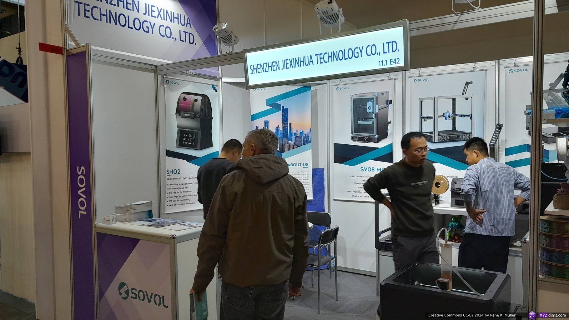
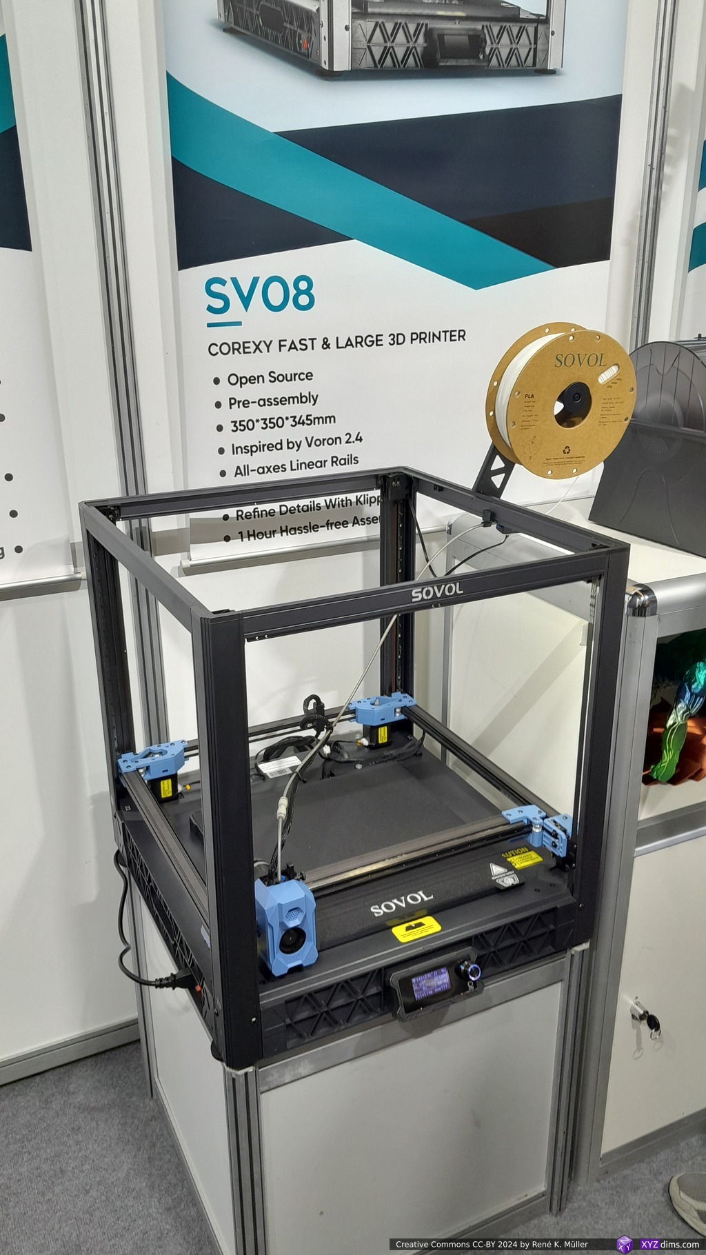
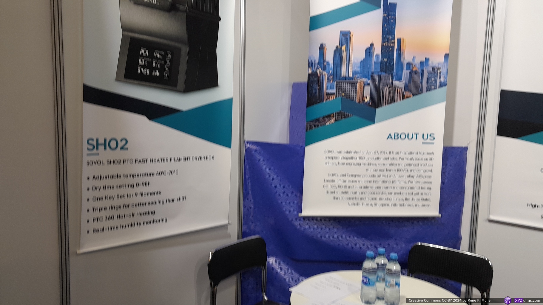
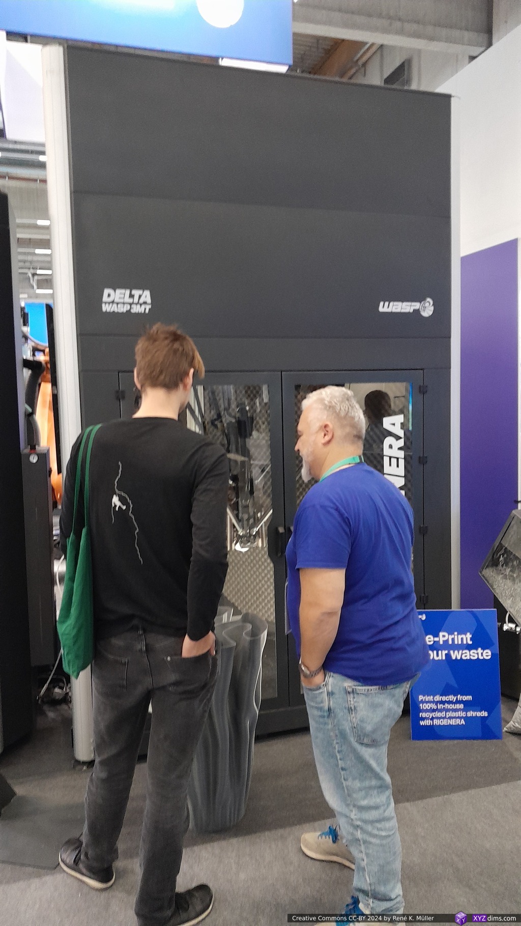
The company behind the commercialization of the VORON series with their SOVOL printers, SOVOL 08 or SV08, a Core XY 350x350x450mm build volume, priced at 550 EUR.
So far only Genera‘s G3 does something similar where washing & curing is done in the same case/apparatus.
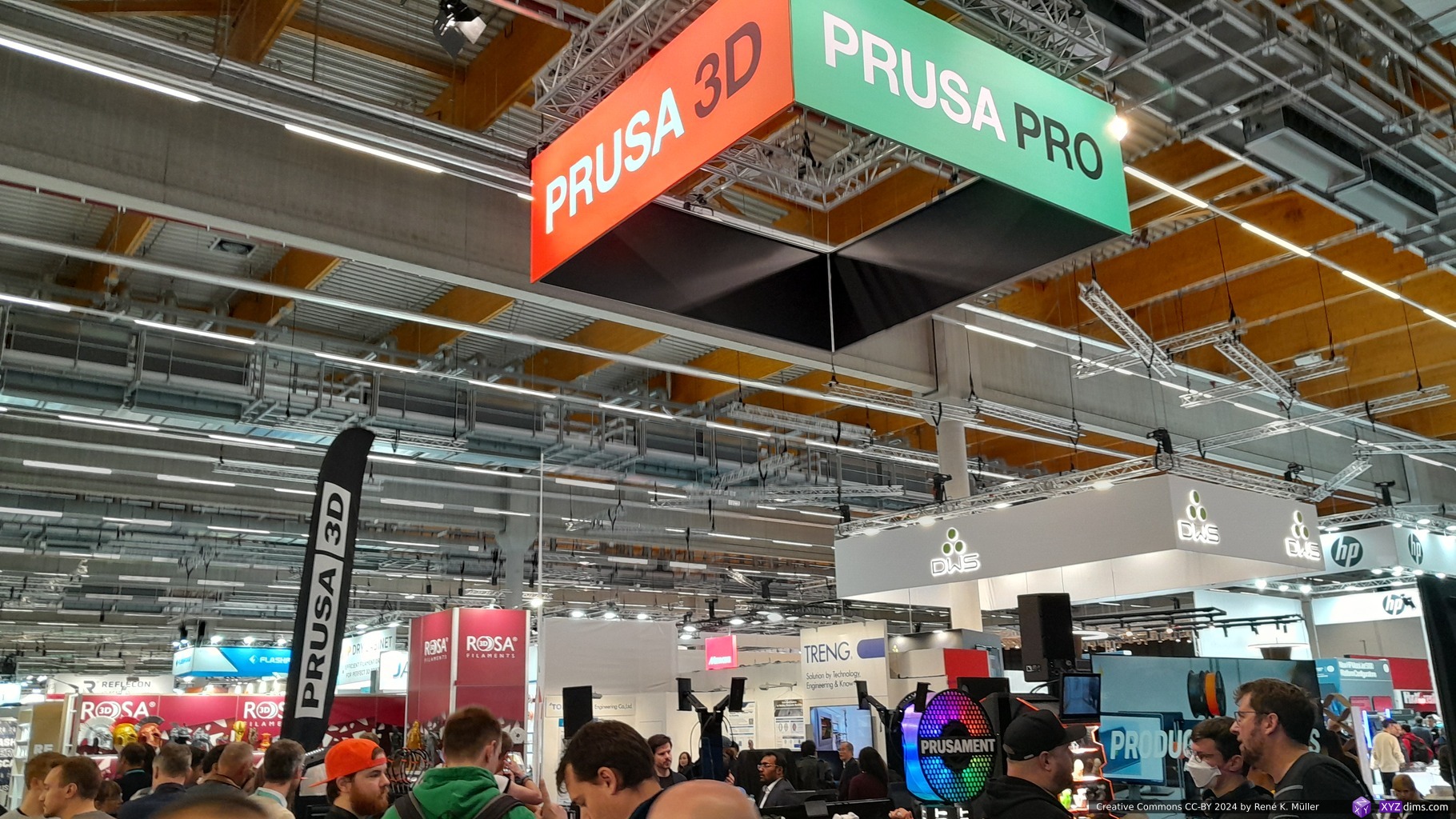
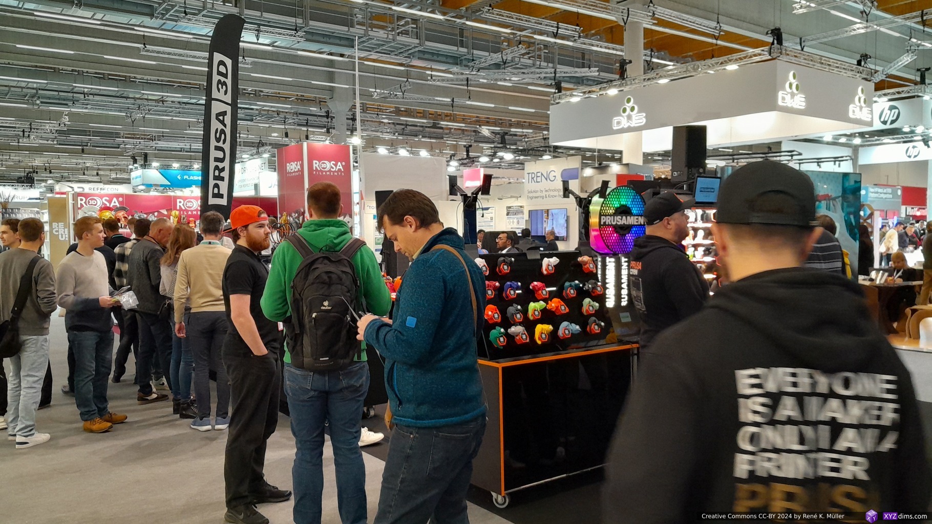
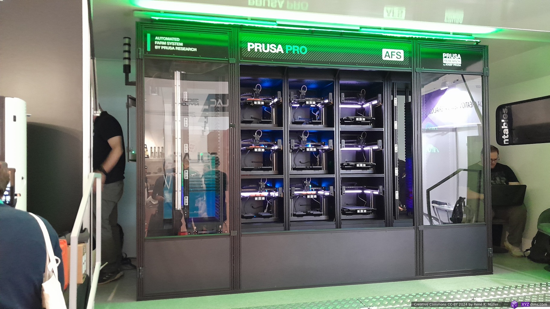
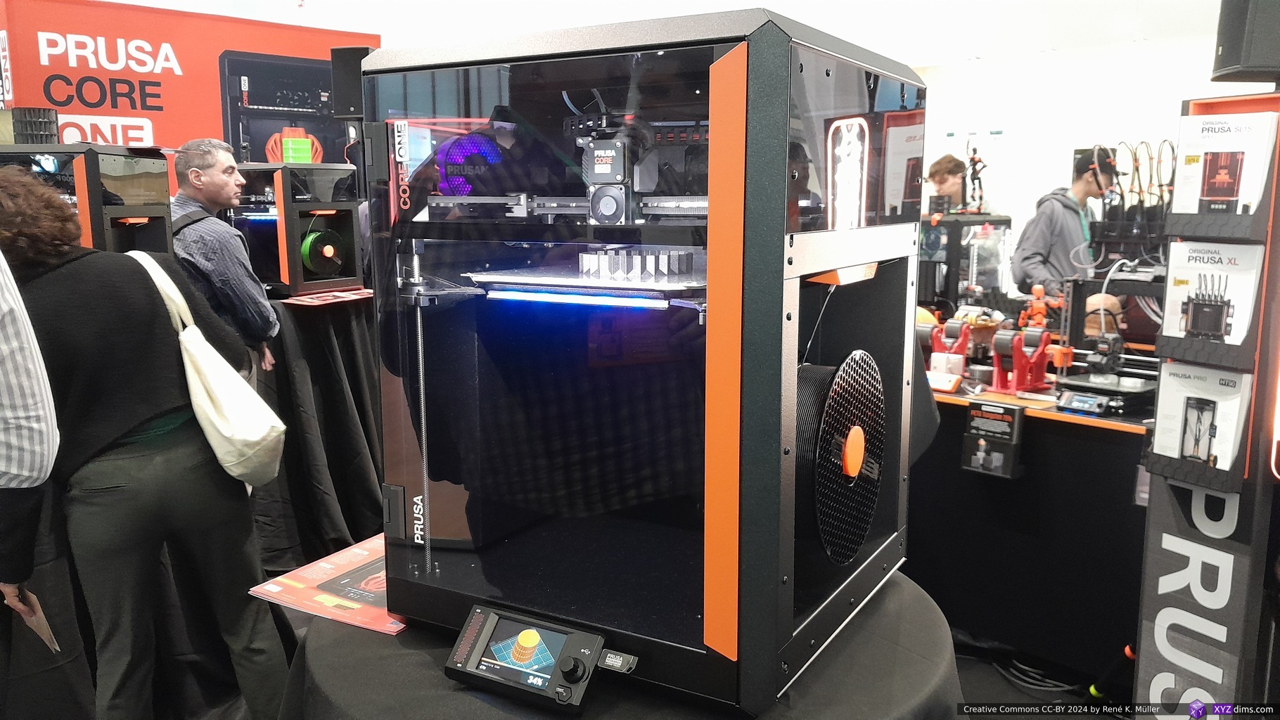
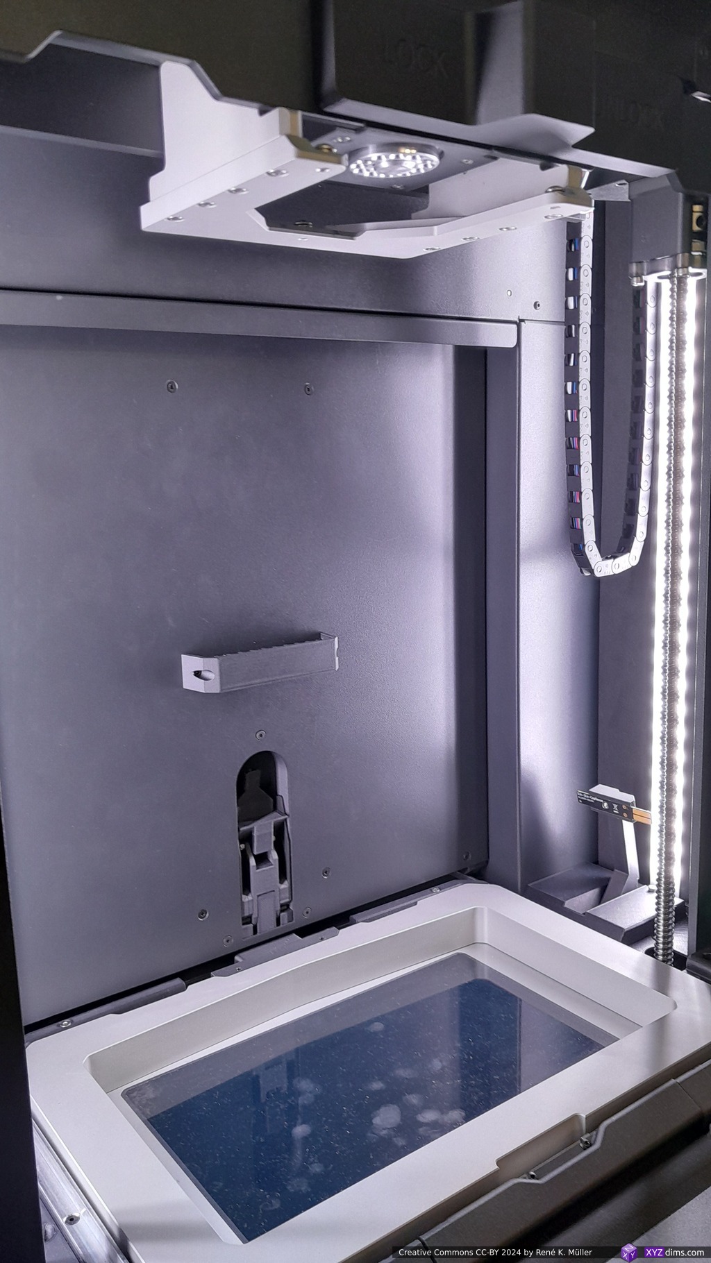
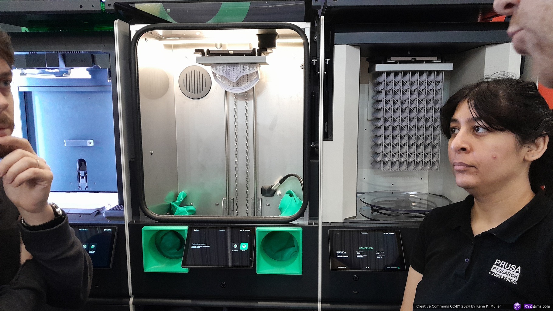
Prusa Research
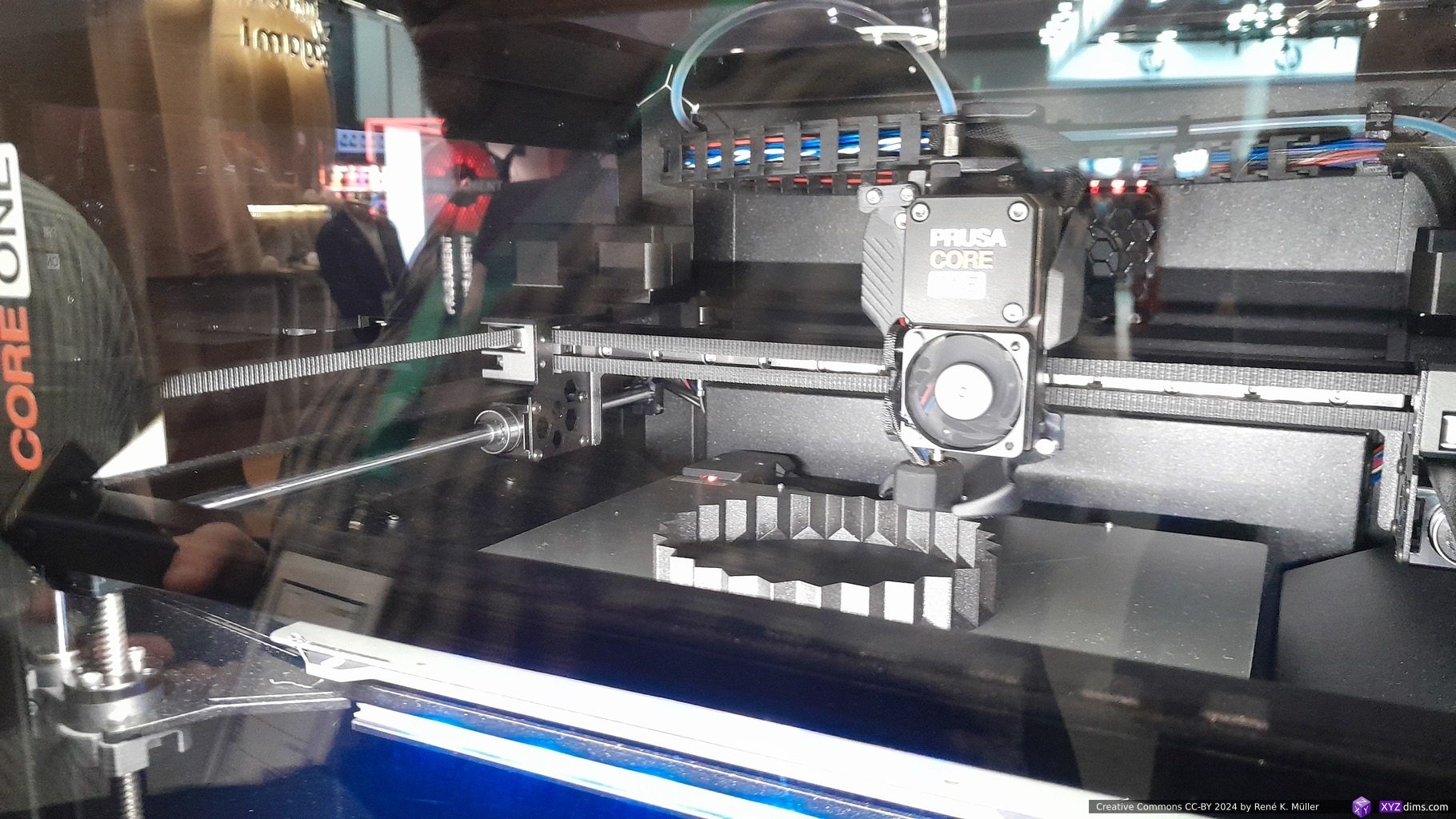
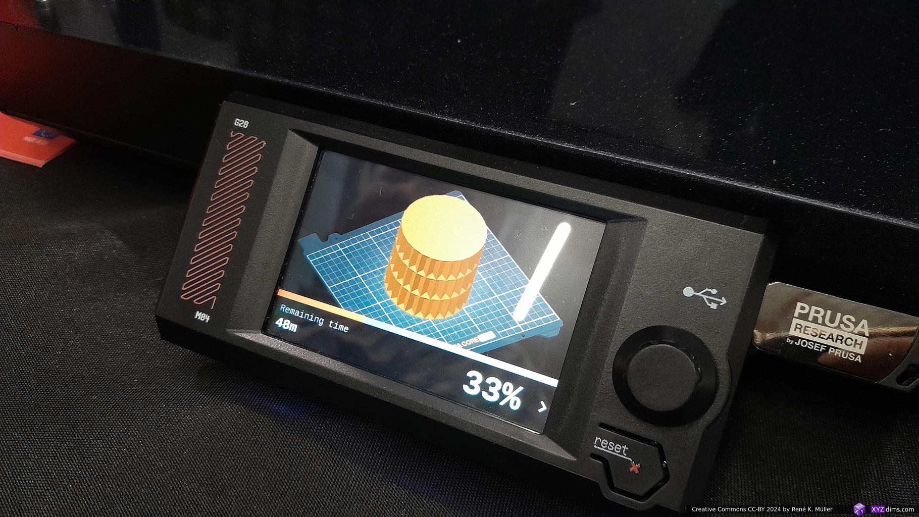
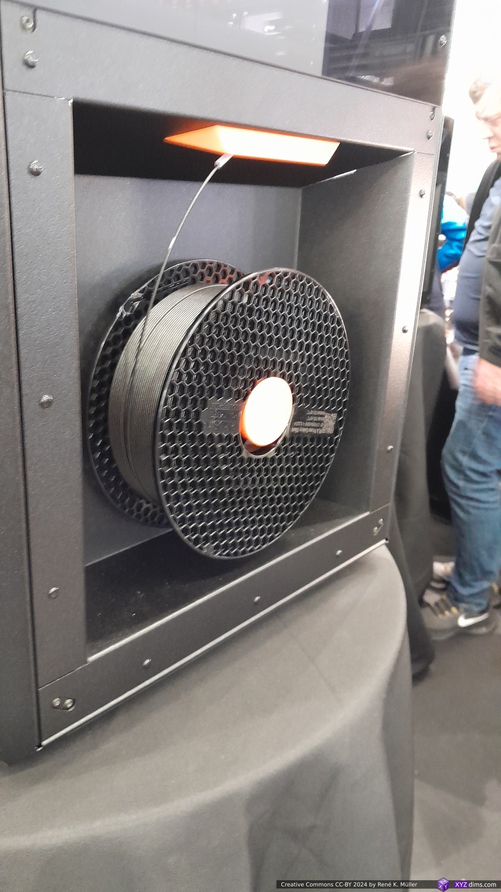
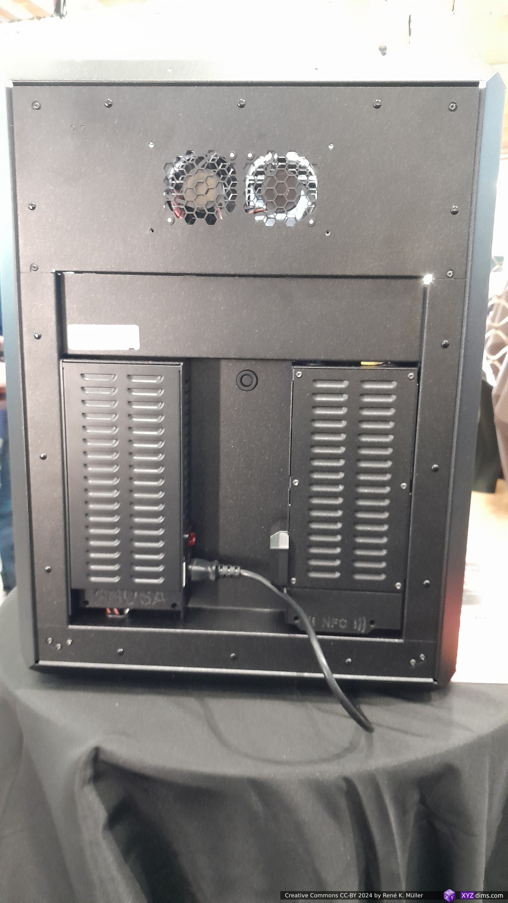
Prusa Research announced at the Formnext their new Prusa Core One, a Core XY with 250x220x270mm build volume, nozzle temp. max 300°C, chamber temp. max 55°C, priced at EUR 1,350, with the ability to uprade from MK4S, available later in 2025.
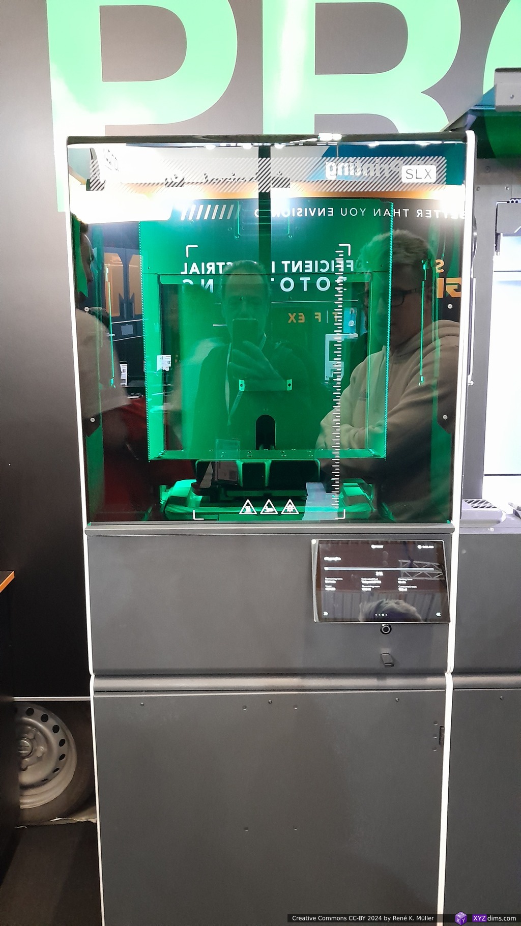
Prusa ResearchPrusa ResearchPrusa Research: Prusa Pro Print FarmPrusa Research: Silver / White Iron ManPrusa Core OnePrusa Core OnePrusa Core One: DisplayPrusa Core One: Side with spool, nicely donePrusa Core One: BackPrusa Pro SLXPrusa Pro SLXPrusa Pro SLX
One may argue, Prusa reached a state of commercial success, that it can’t afford to support low-cost chinese replicas of their invention, exactly as it happened to Makerbot and Ultimaker – and both stopped innovate, and recently merged – let’s see if Prusa will thrive in hardware innovation the coming years or lay back as well.
Open Source Software seems more tolerable to commercial pressure: Prusa Slicer still actively developed and forked many times, and so the Cura Slicer by UltiMaker; both slicers enable countless university labs and commercial engineering offices to develop new hardware and having an Open Source implementation of reliable slicers with a ton of detail knowledge embedded when one studies the source code.
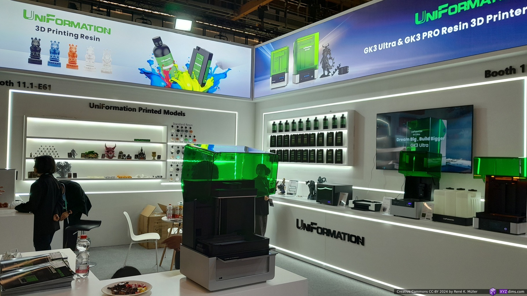
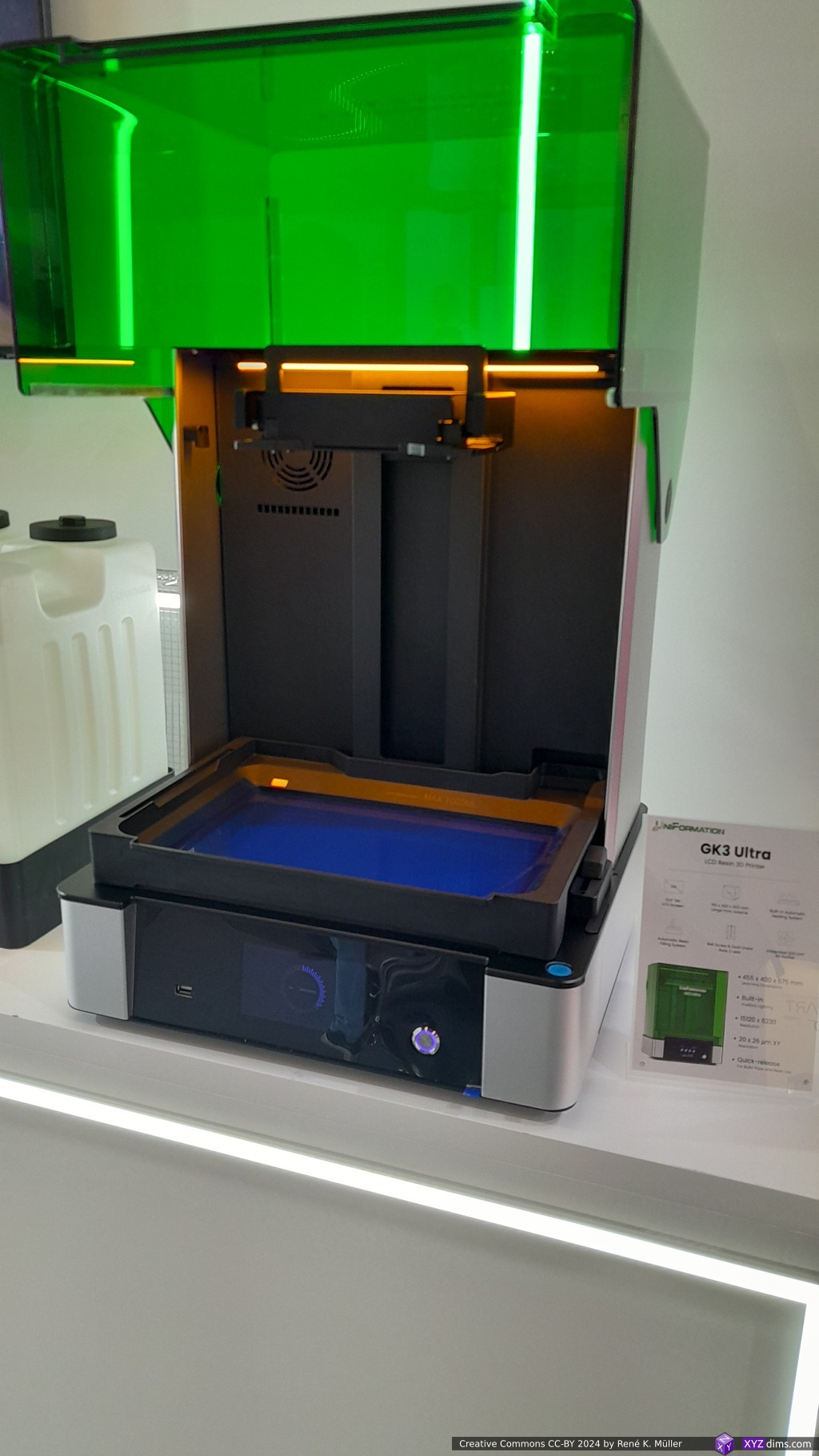
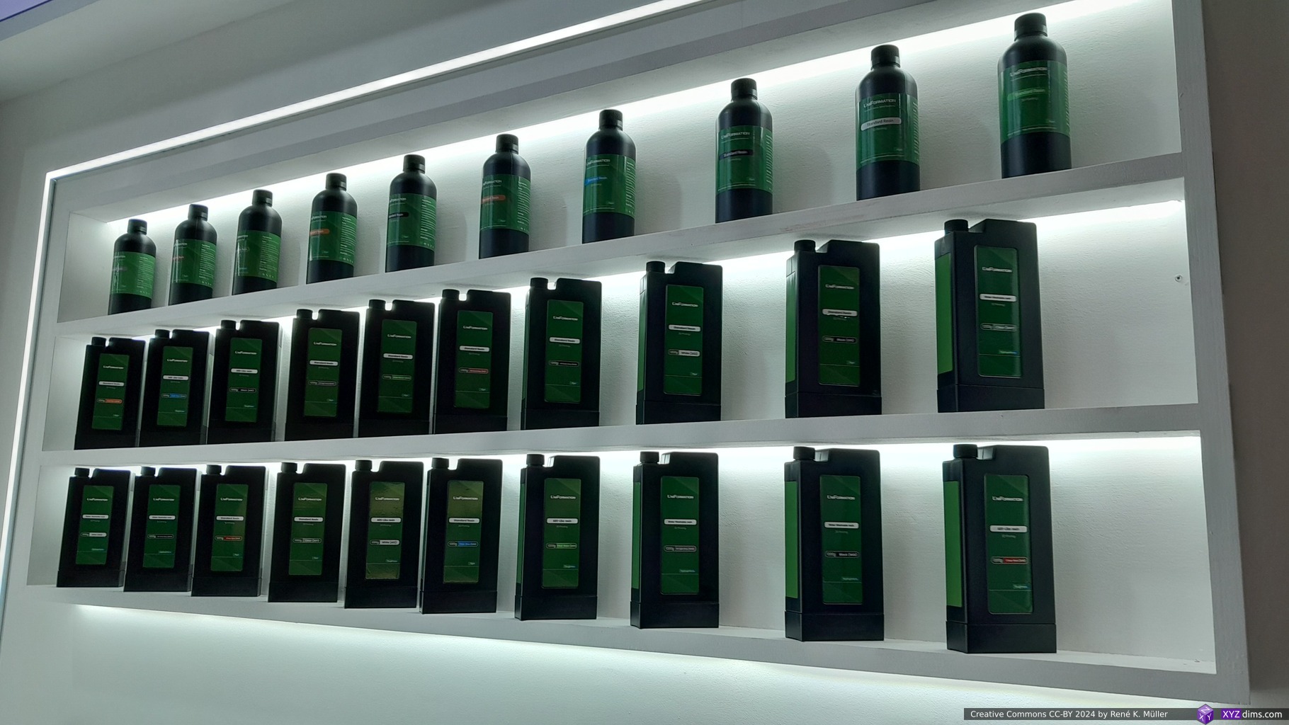
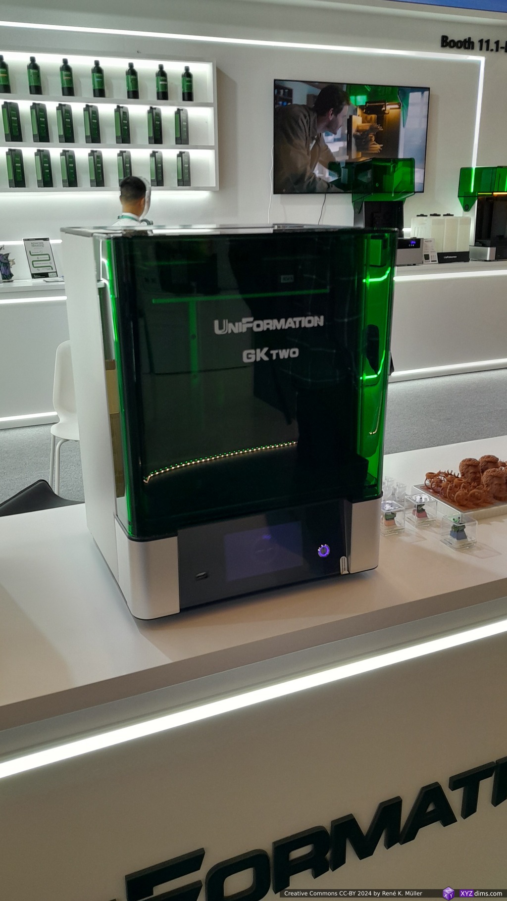
Rather unknown brand to me caught my attention the past year due to high praise from various YouTube reviewers: the older GKTwo (228x128x245mm @30um) ~670 EUR and the new GK3 Ultra (300x160x300mm @20x26um) ~1,200 EUR.
integrated heating system at 35°C
resin feeding system & resin weight measuring
built-in air filter
Industrial-level features while maintaining consumer pricing.
The booth featured Pengji (LCD maker) and Apex Maker (MSLA printers) together, so I assumed they are the same business with different brands with LCD making as core business – a representative at the booth confirmed my guess – so aside making UV LCDs they started to produce their own series of MSLA 3D printers:
Plus their own branded resins, curing and washing stations, see more at Apex-Maker.com
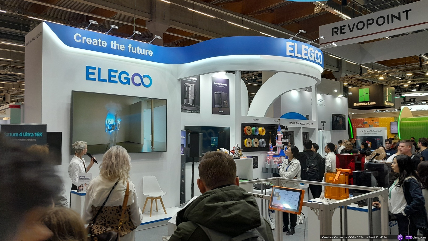
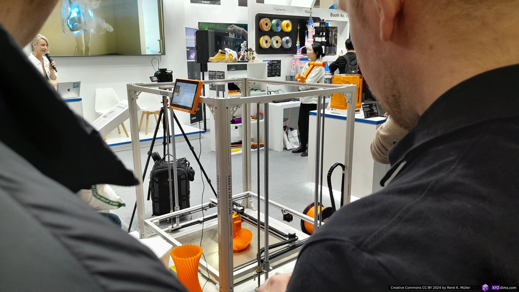
Elegoo
This year Elegoo released Mars 5 Ultra and the Saturn 4 Ultra which have tilting vat alike the Prusa SL1S which decreases layer print time (curing + detaching from film) down to apprx. 5 secs; so I was eyeing to get a Saturn 4 Ultra.
Thursday morning I revisited the booth and asked about whether Saturn 4 Ultra would permit to put a magnet flex plate on it – which would change the Z offset for homing, and two representatives explained to me it would be a bad idea as the home aka zero Z-position would fail, and one would require the change the “G-code” in the firmware (which is closed-source) . . . in other words, the Z offset or home position is somehow hard coded and doesn’t use pressure sensor to calibrate home (this Reddit thread shows Chitubox Slicer allows to alter the homing G-code, LycheeSlicer doesn’t have this option) – the usual rabbit hole.
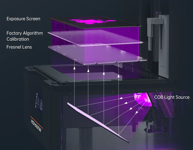
My resin printing farm is composed by Anycubic printers (Mono 4K, X2 and 6Ks), mainly due the diverse third party market for replacement and add-ons, so I was checking out their new Photon Mono M7 Max (298x164x300mm @46um) priced at EUR 900 (2024/11).
I was hoping Anycubic would also implementing tilting vat to decrease the print time and allow more delicate prints due more gentle / gradual detaching from the film with the tilting motion – so far not yet.
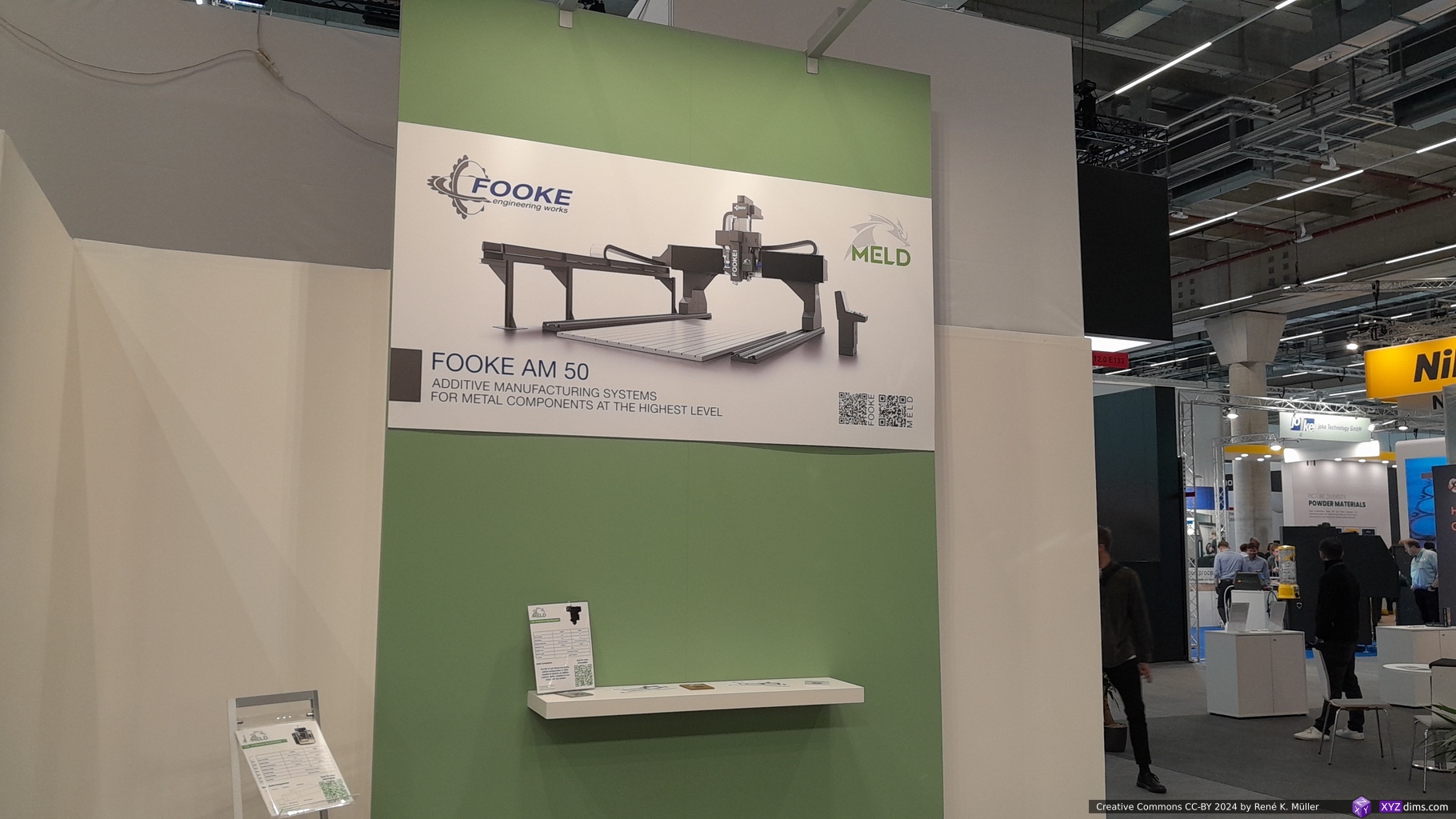
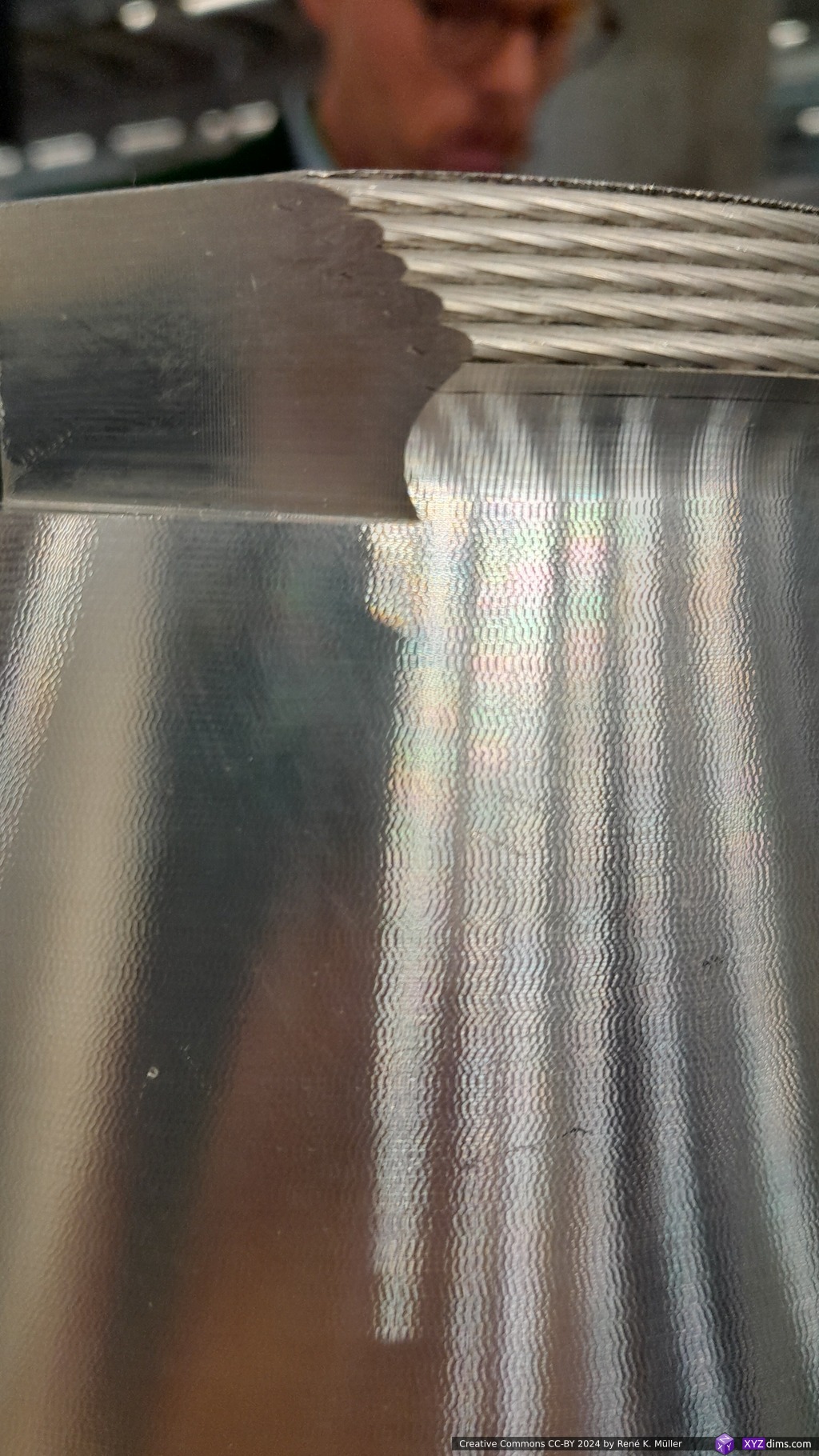
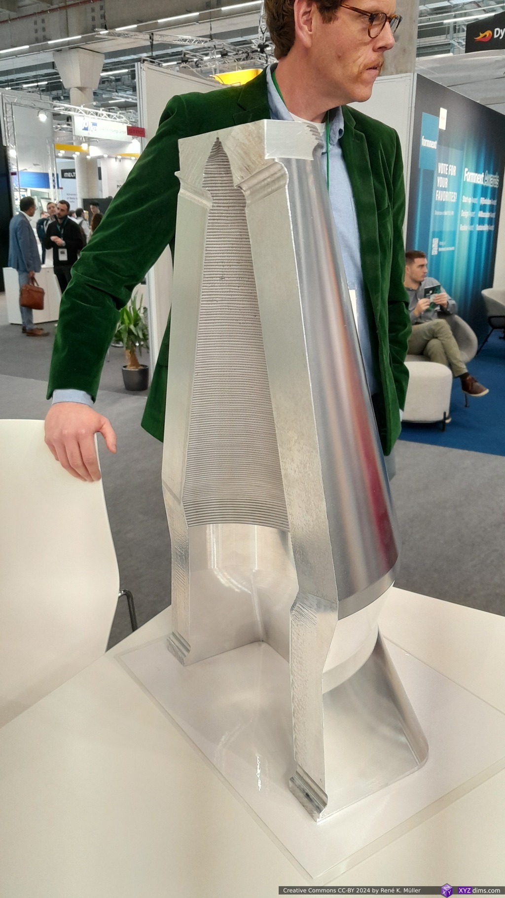
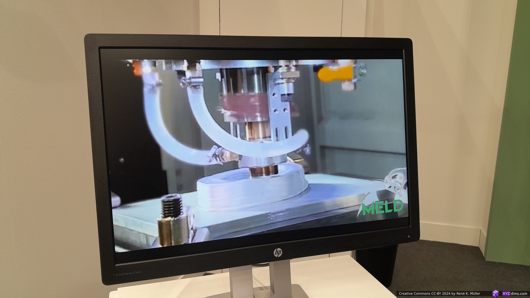
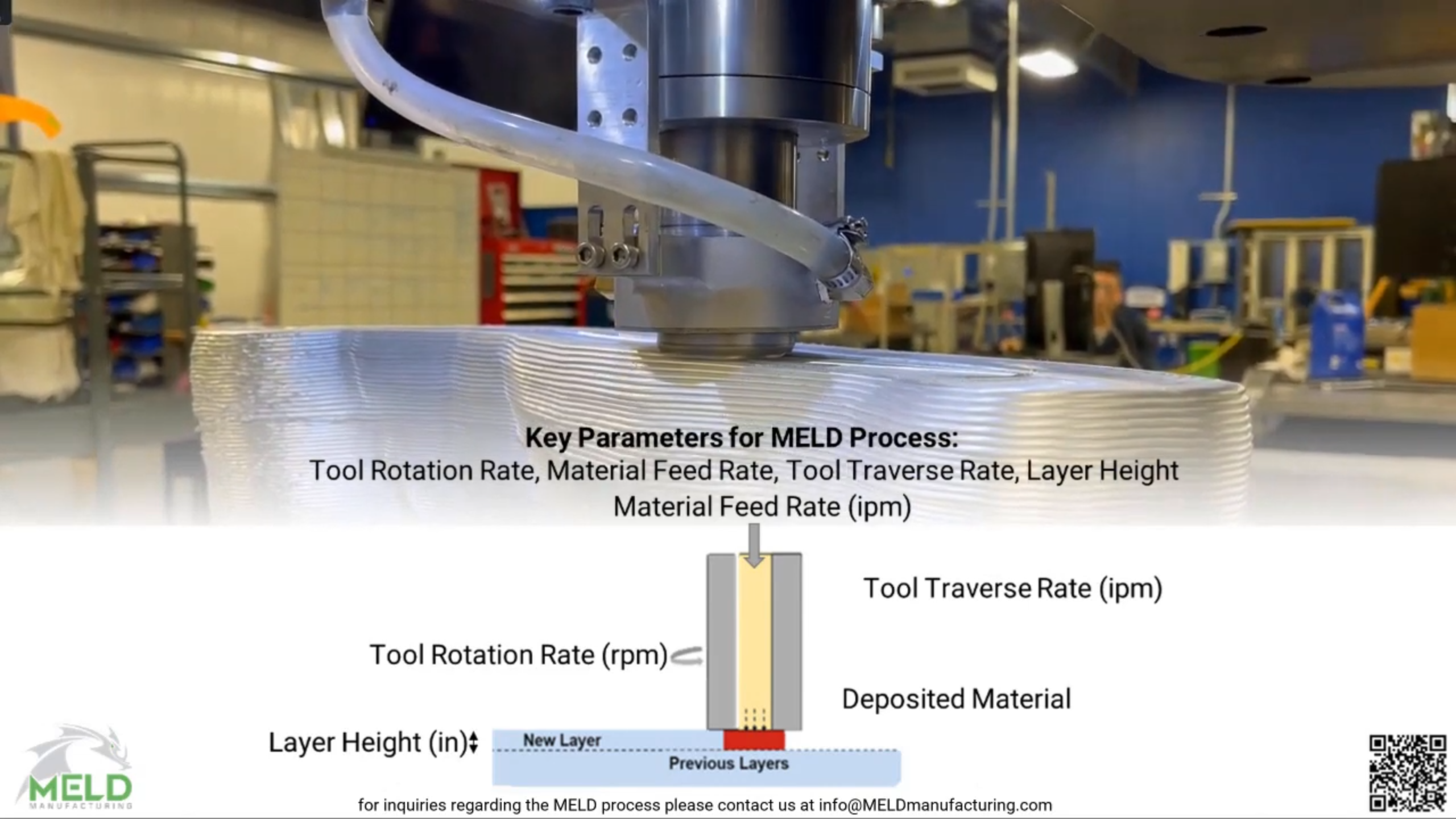
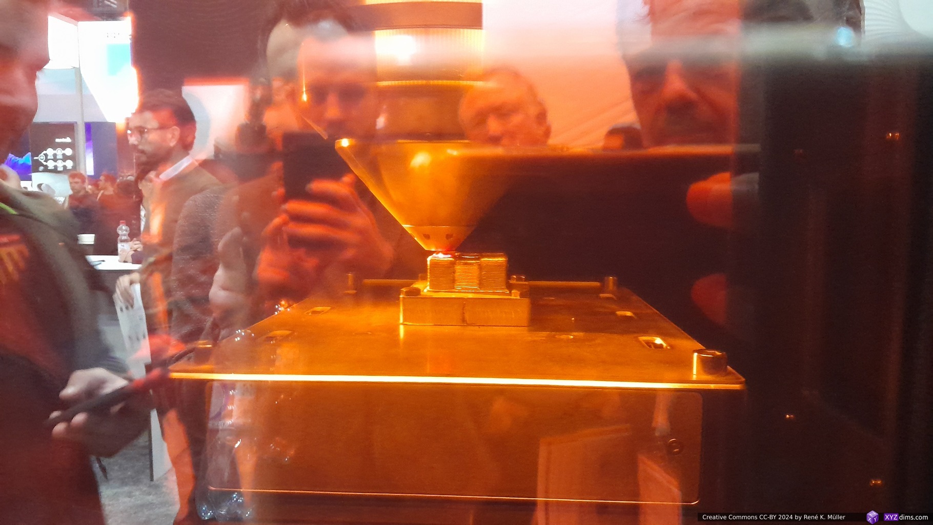
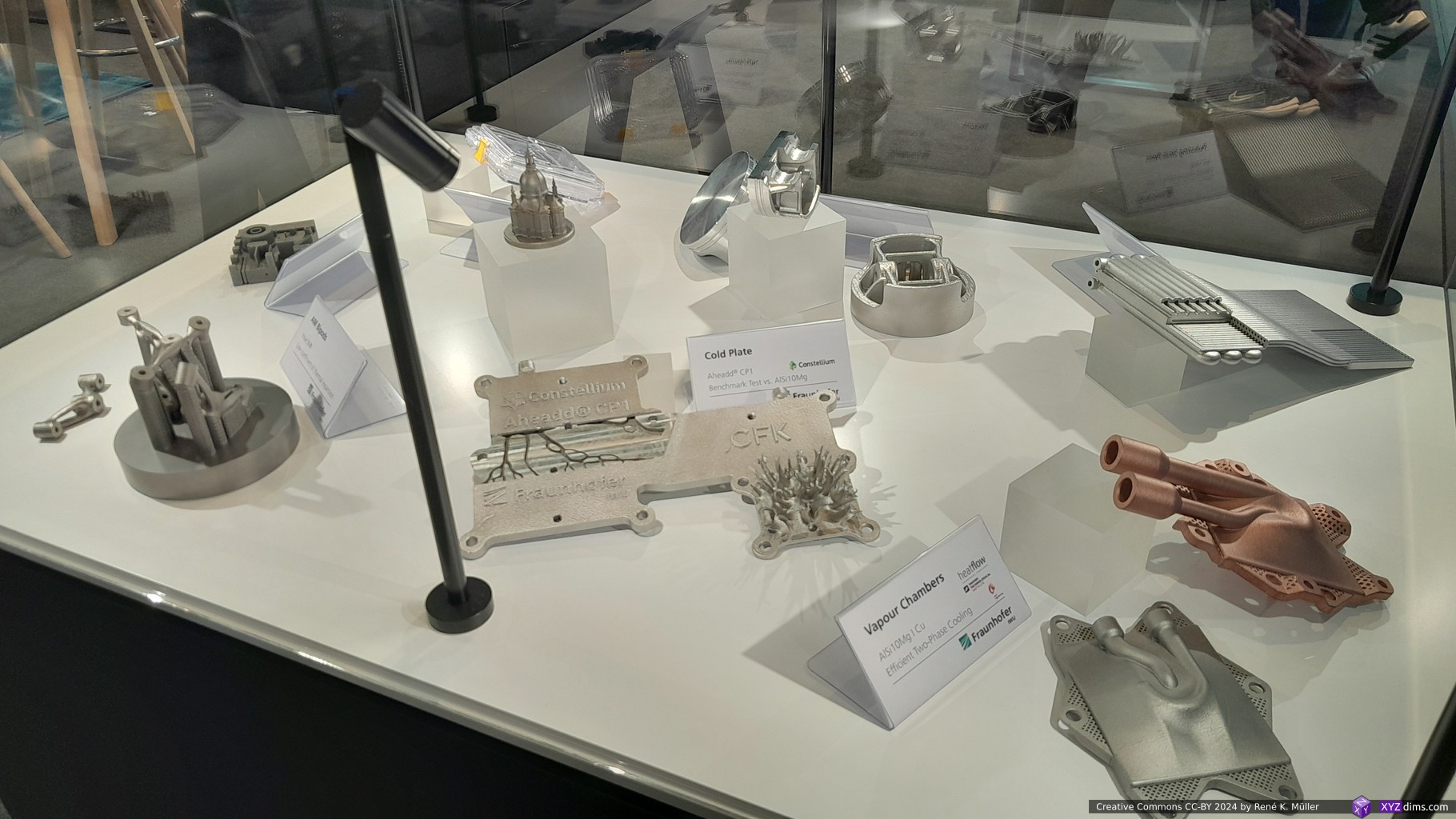
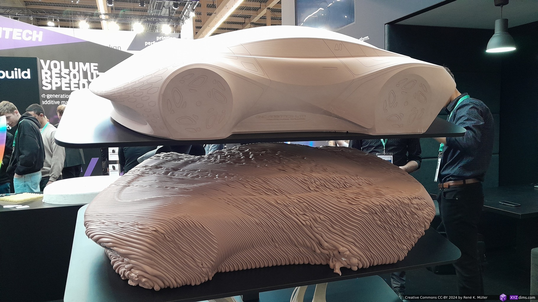
This basic looking booth I consider a gem among a few others at Formnext 2024, a sample of massive piece which was extruded with aluminium below the melting point using Additive Friction Stir Deposition (AFSD) procedure and yet creating a fully solid piece where layers fully bond – their main photo (1st photo below) or illustration at the booth was deceptive small at first sight, but after looking twice, I realized the entire machine “Fooke AM50” is over ~6m long with a huge build volume of 6 x 3.5 x 1.5m, and aluminium, magnesium, copper, steel and titanium as possible materials, with build rates up to 15kg/h – and all extruded in normal room atmosphere and temperature.
Following video gives an impression of AFSD & FSW based extrusion by MELD (unfortunately the audio is quite silent in most parts):
grumpy, because of the patent collection which caused the 20 year delay for others to be able to adapt major extrusion technologies, once they expired the “3D printing era” actually started with affordable 3d printers (MakerBot, Ultimaker, Prusa, and all the chinese replicates) and many prosumer derivates
grandfather, because it’s truly the beginning of extrusion-based 3D printing / additive manufacturing
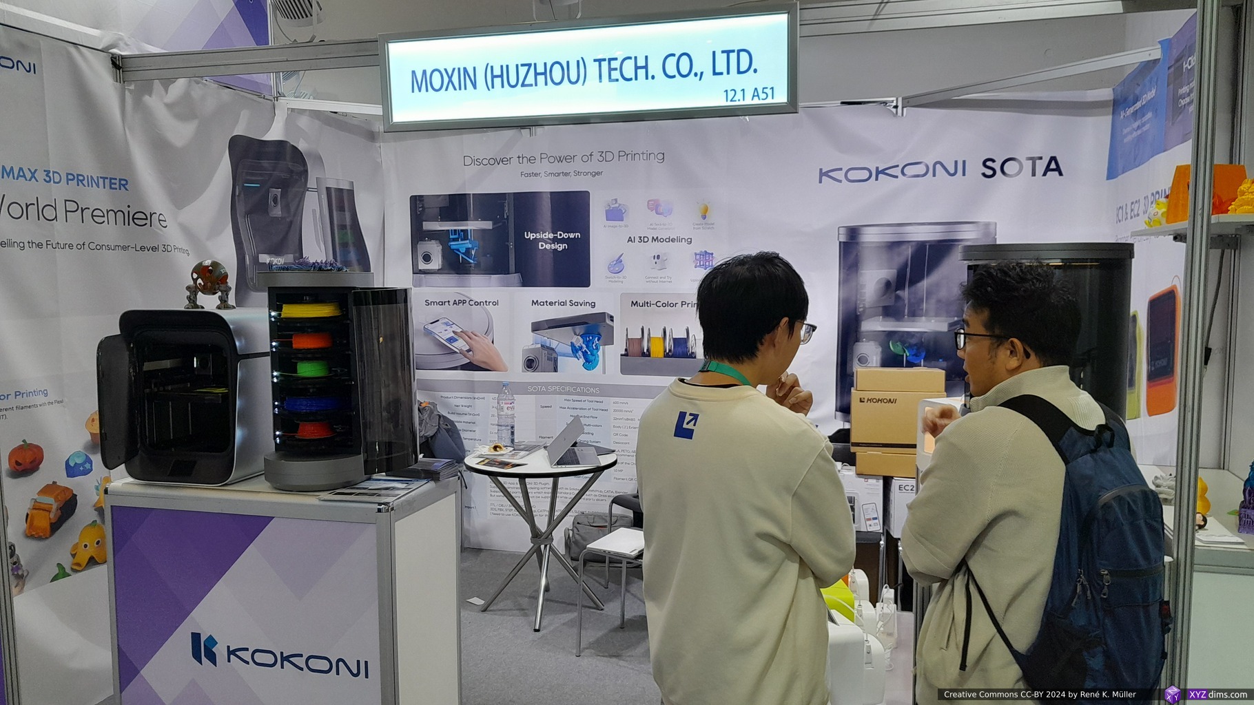
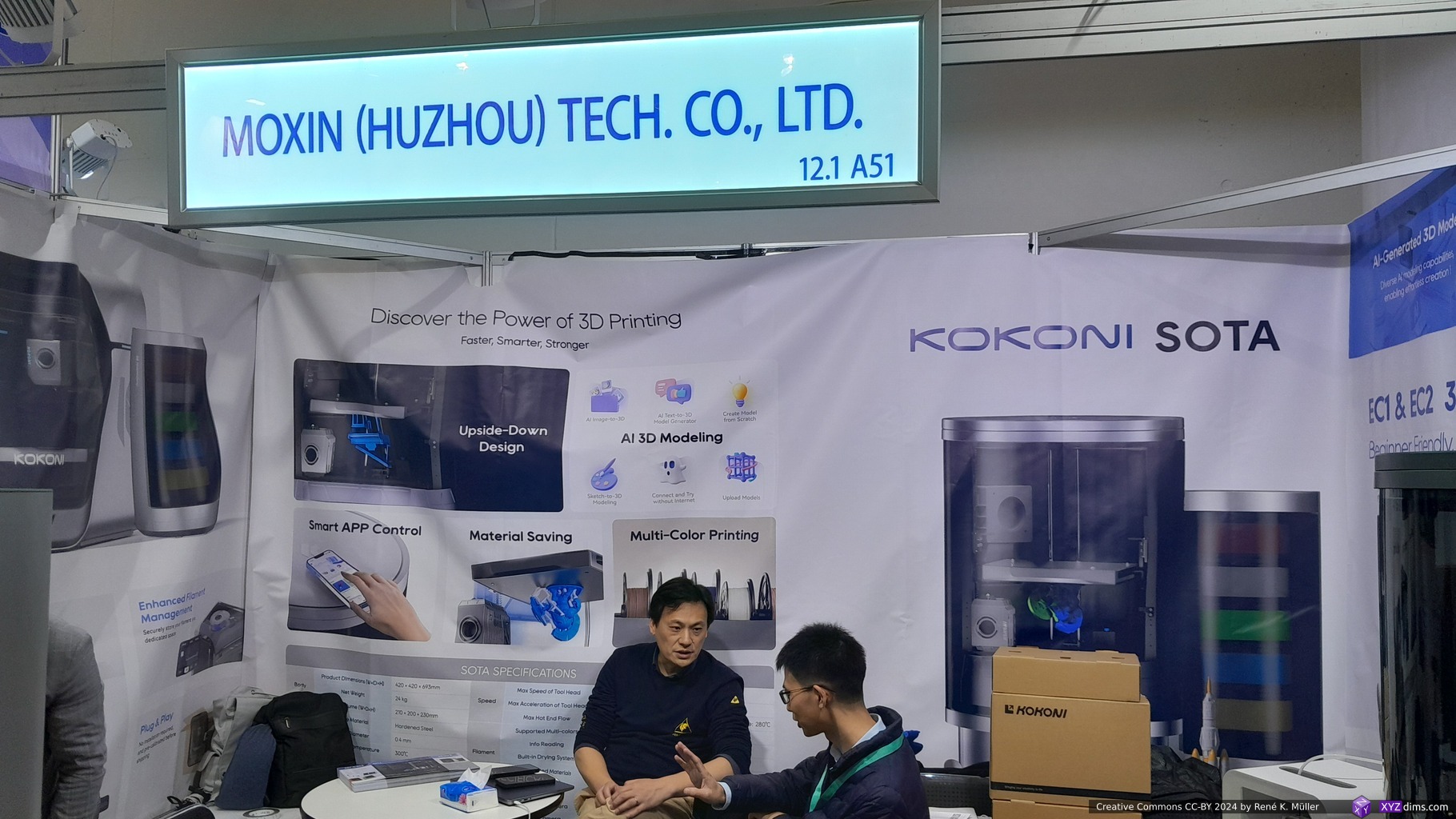
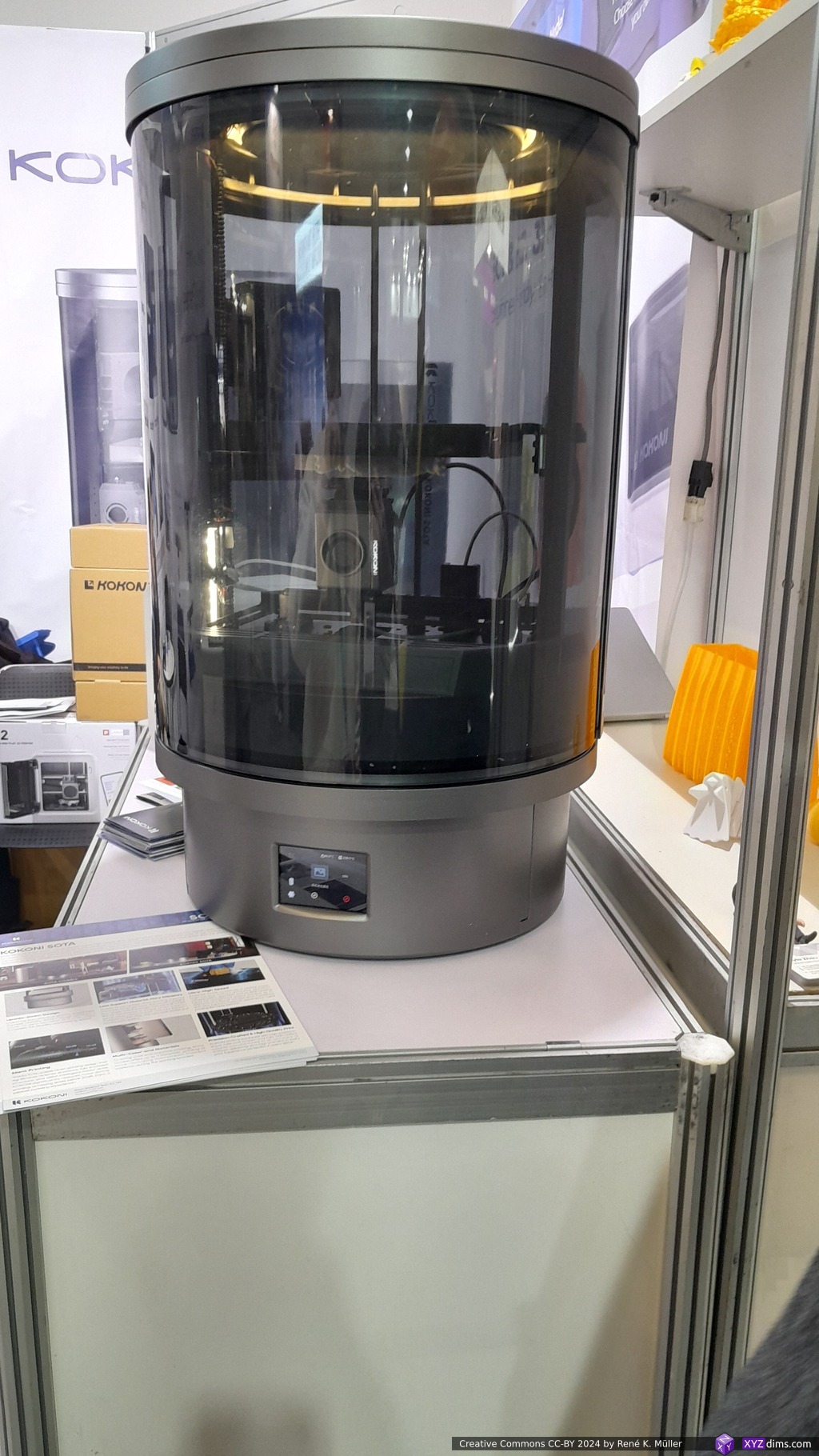
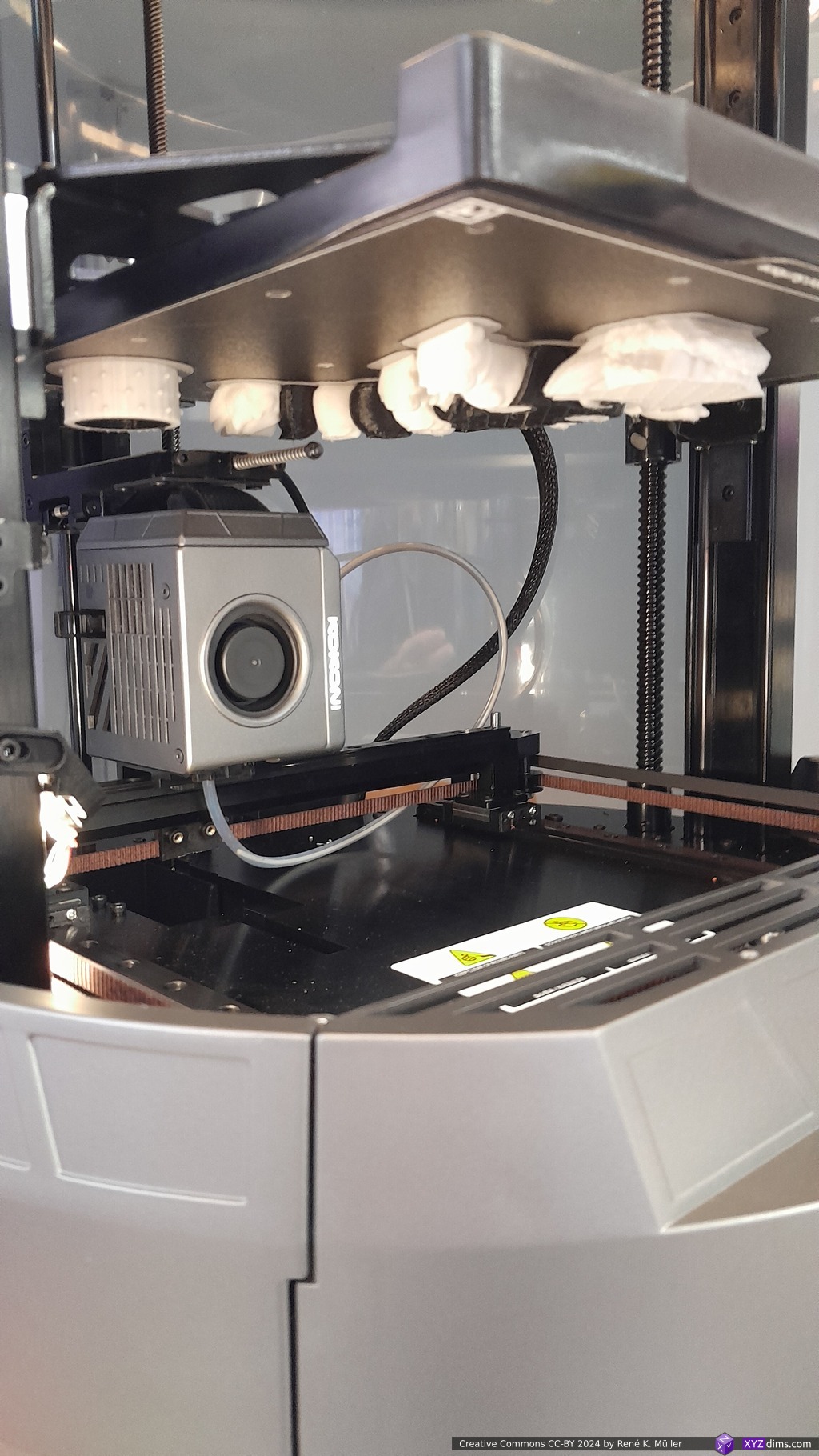
The cylindrical shape of a 3D printer caught my attention, and on the 2nd sight I saw it was a Positron-like setup of printing upside down, the Kokoni Sota printer:
I briefly spoke with Tianrun Chen and he explained when printing upside down, less support material required, and therefore developed their own support generation method which reduces material by 20-50%.
210x200x230mm build volume
up to 300°C nozzle temperature
optional multi material systems (also in cyndrical case)
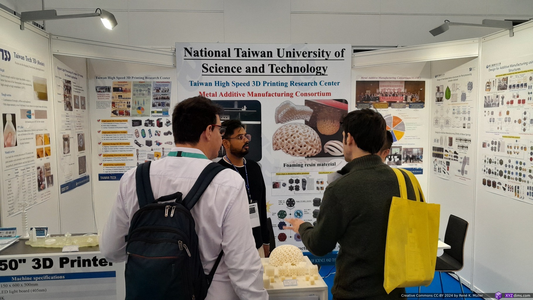
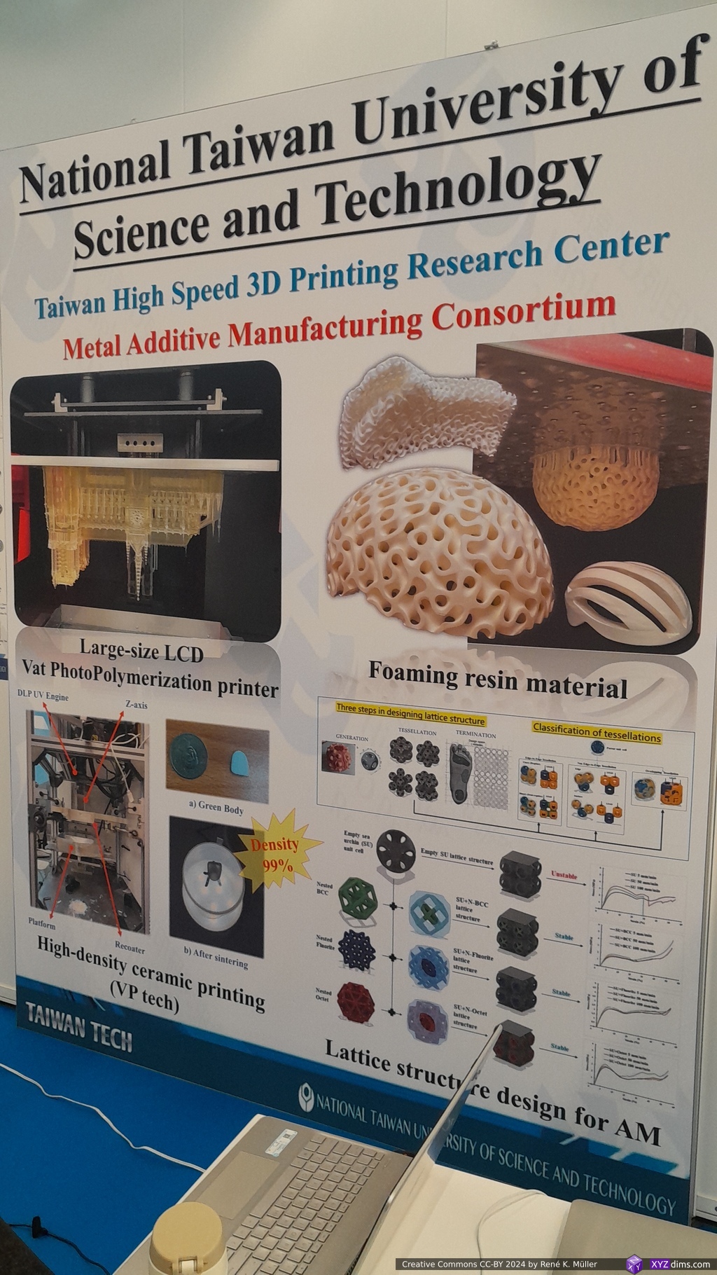
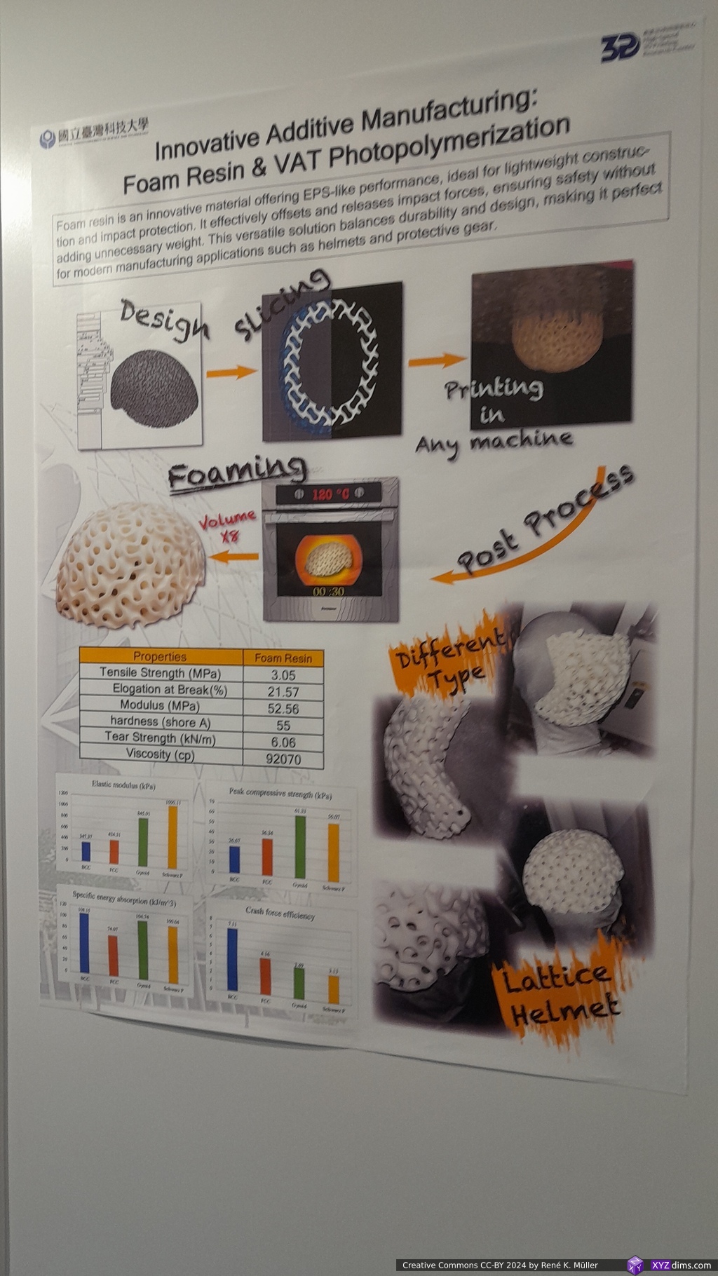
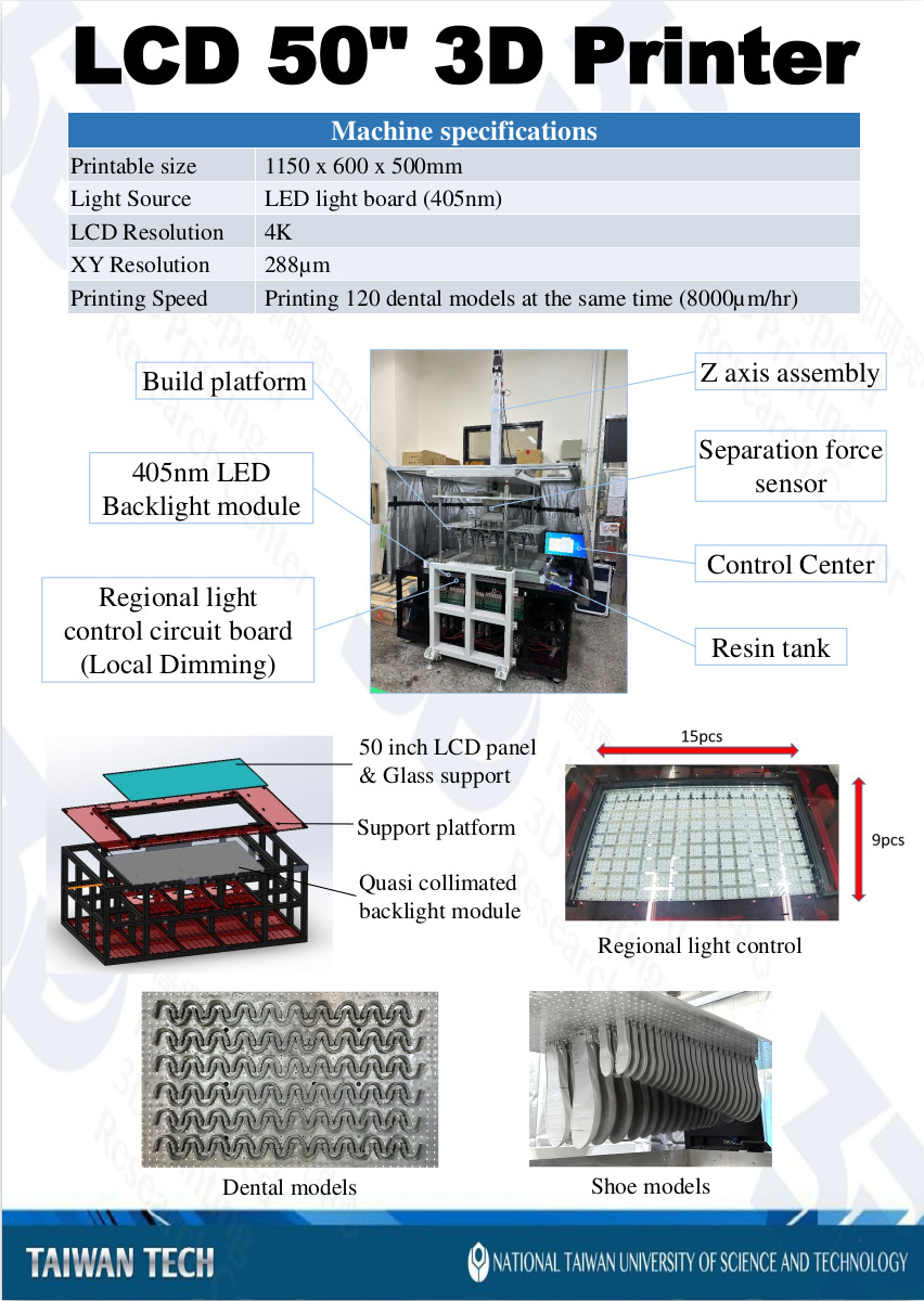
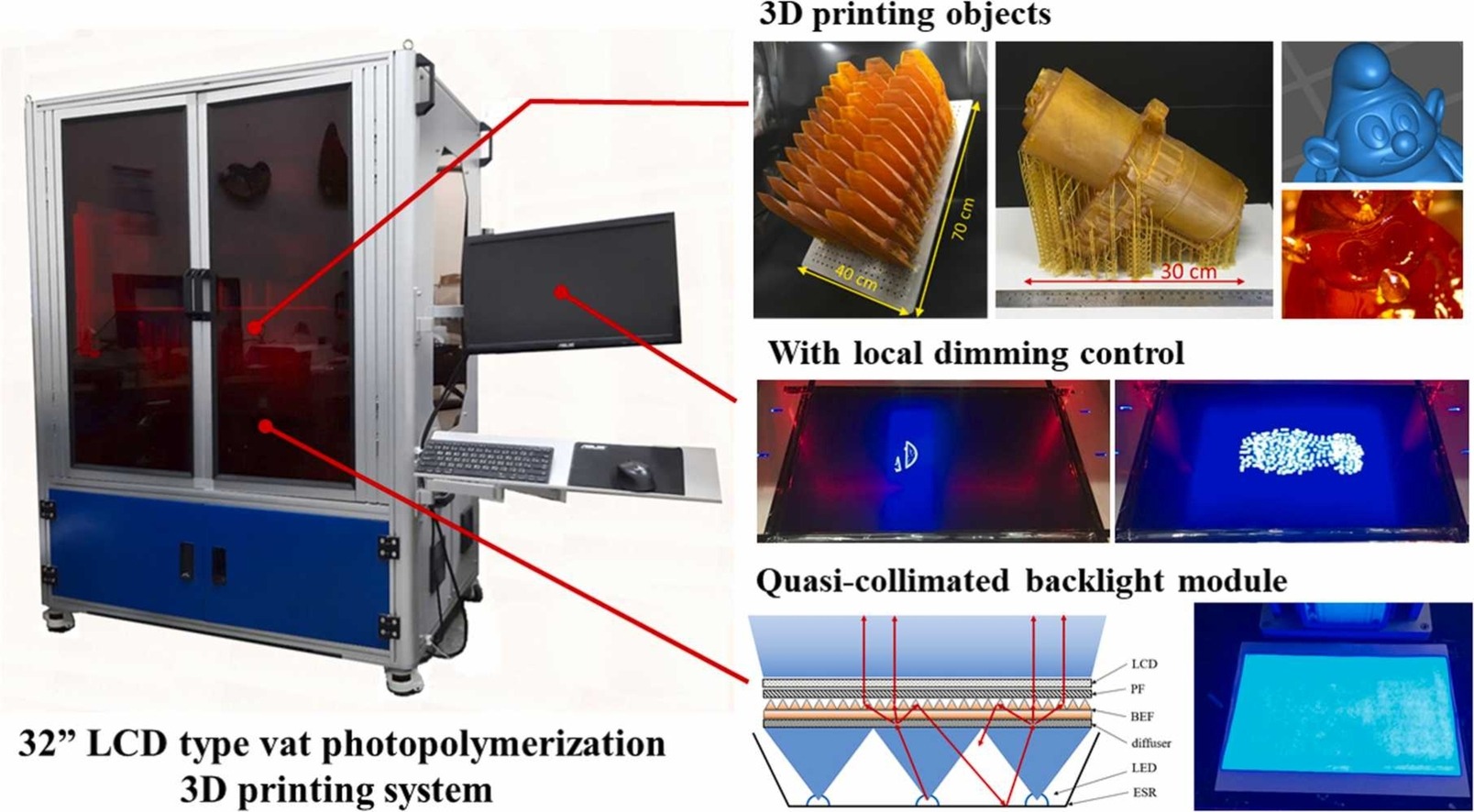
National Taiwan University of Science & Technology (NTUST)
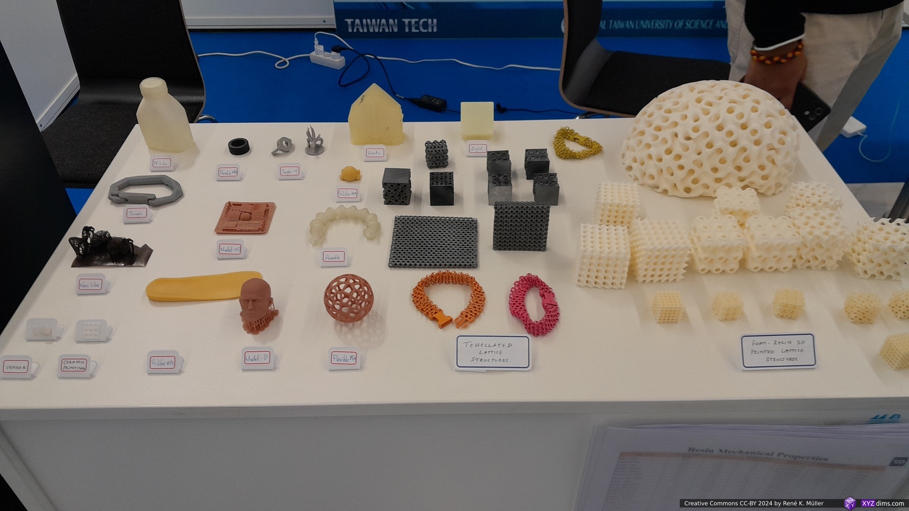
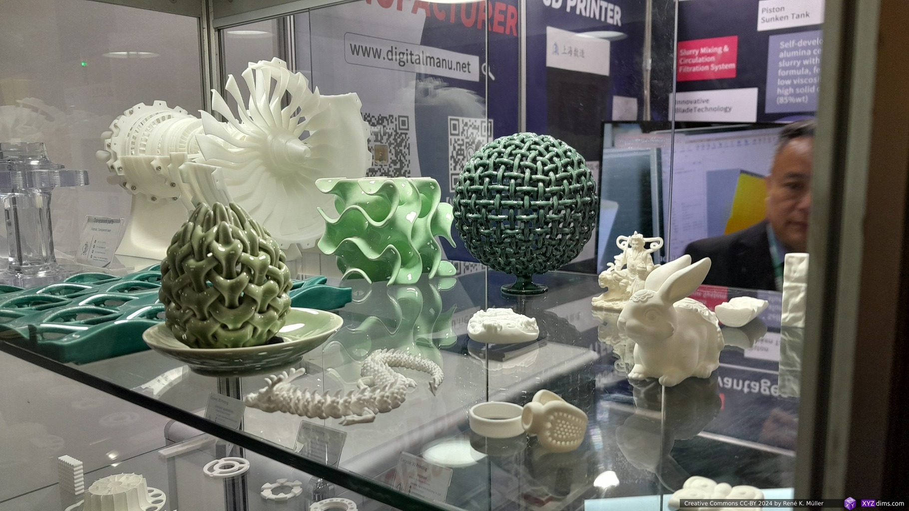
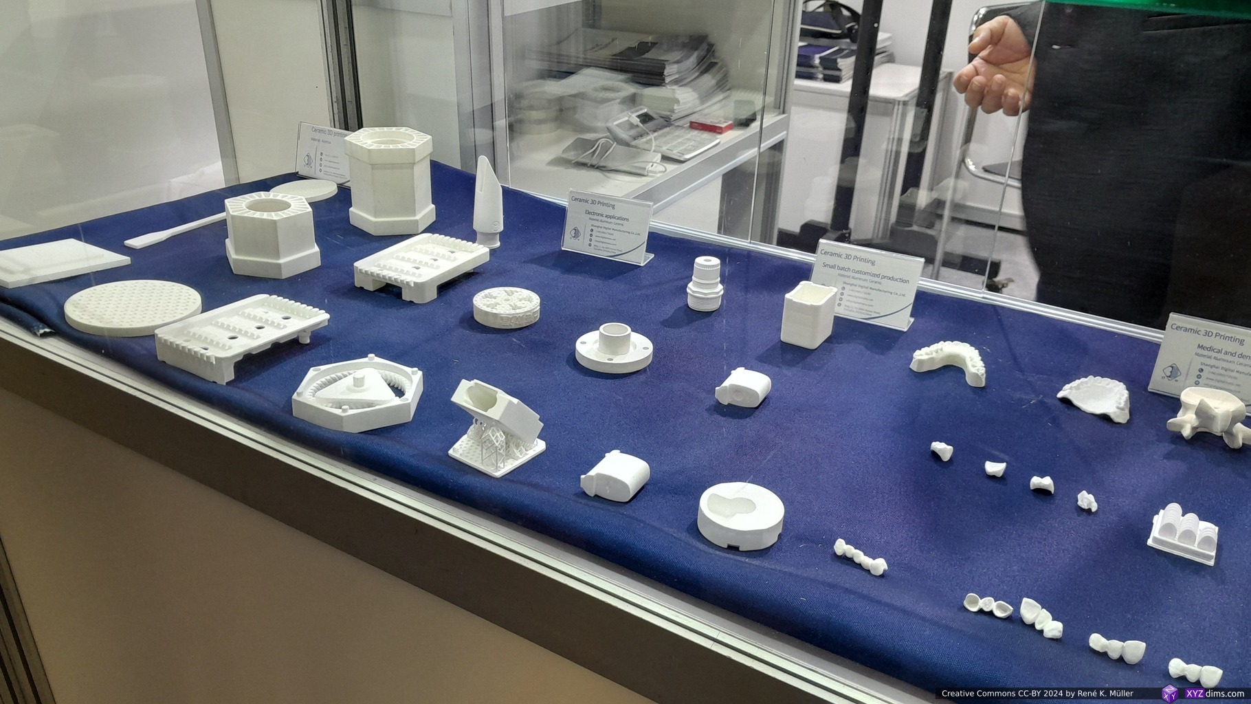
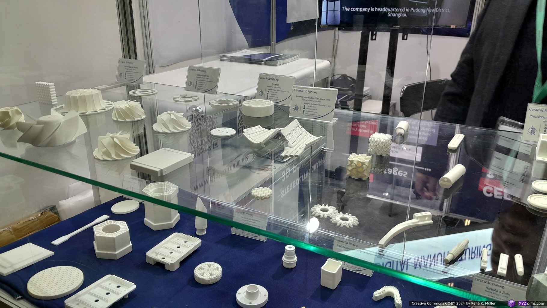
The little booth, and the walls where full of large scale posters with a lot of information, so I stopped and began to absorb the information – in particular the mention of TPMS caught my attention.
32″ LCD Resin Printer50″ LCD Resin PrinterResin 3D printed, heat activated foaming 2x in XYZ
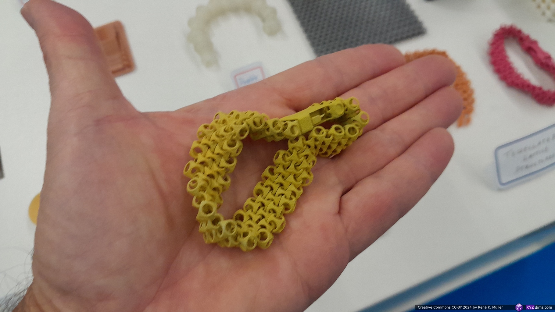
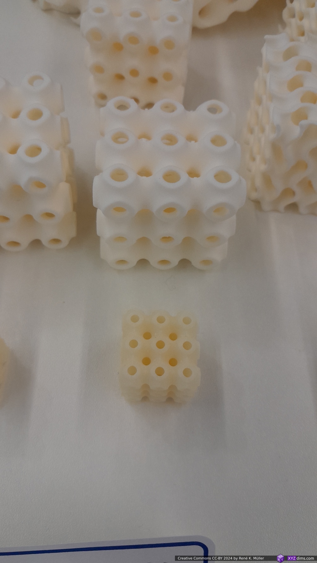
So, one of their invention is a resin which when it is baked at 120°C it increases in size XYZ 2x – therefore in volume 8x – which they named “Foaming Resin Printing“, the sample prints like the bike helmet or even the small TPMS Schwarz P cube was incredible light compared to its size.
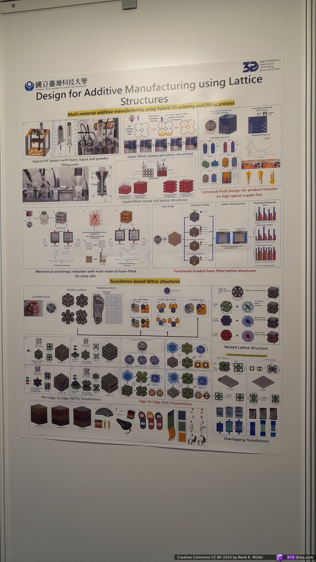
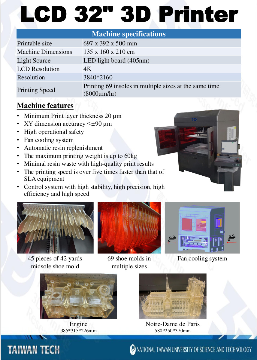
Another invention is printing TPMS like Schwarz P and then fill the partial closed P cells with a foaming agent, they call this process “Multi-Material Additive Manufacturing using Hybrid 3D Printing and Filling Process” (see non-free paper) – in case of the Schwarz P TPMS the cells are interconnected and spherical, so the agent flows into all captivities quickly as “Liquid Filled Closed Cell Lattice Structures” – and reduces print time while increase stiffness / strength – kind of combining Additive Manufacturing with Mold Injection method.
3D printing closed cells with injection of secondary material
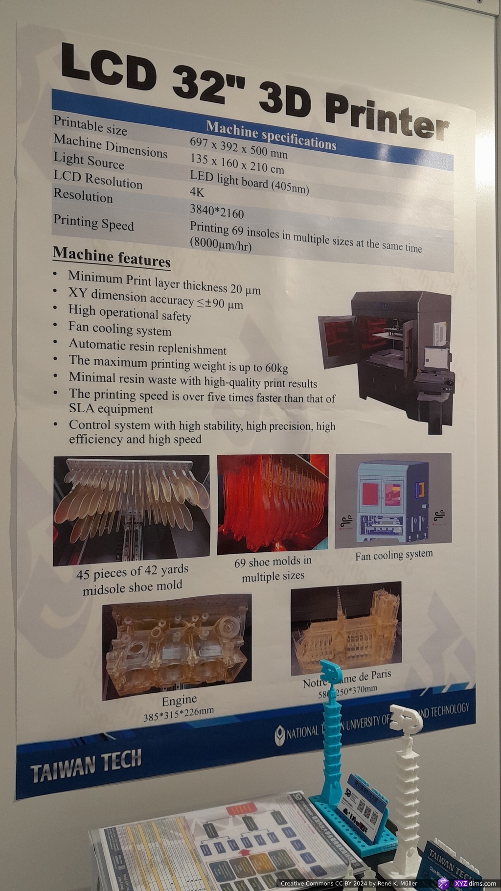
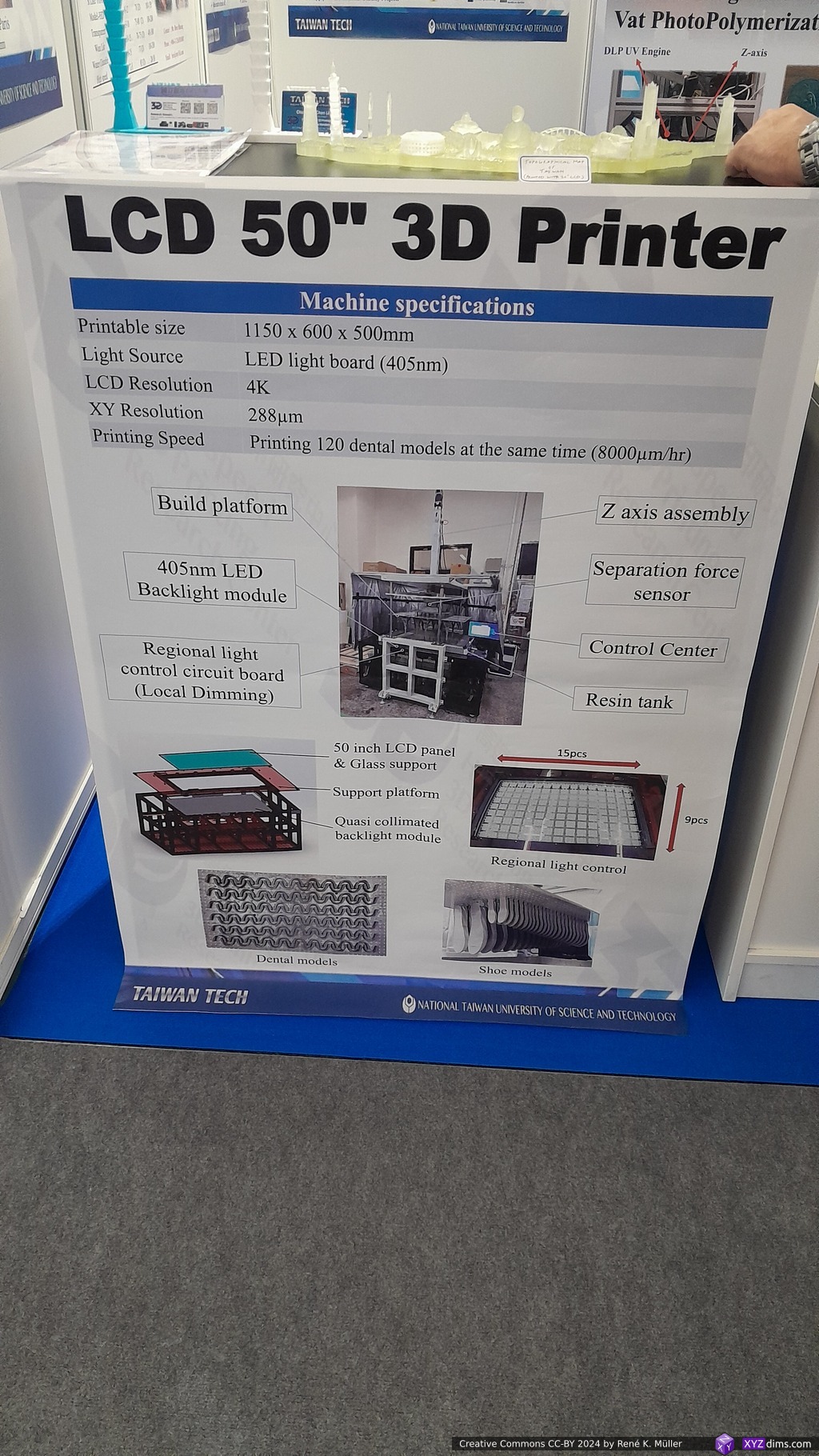
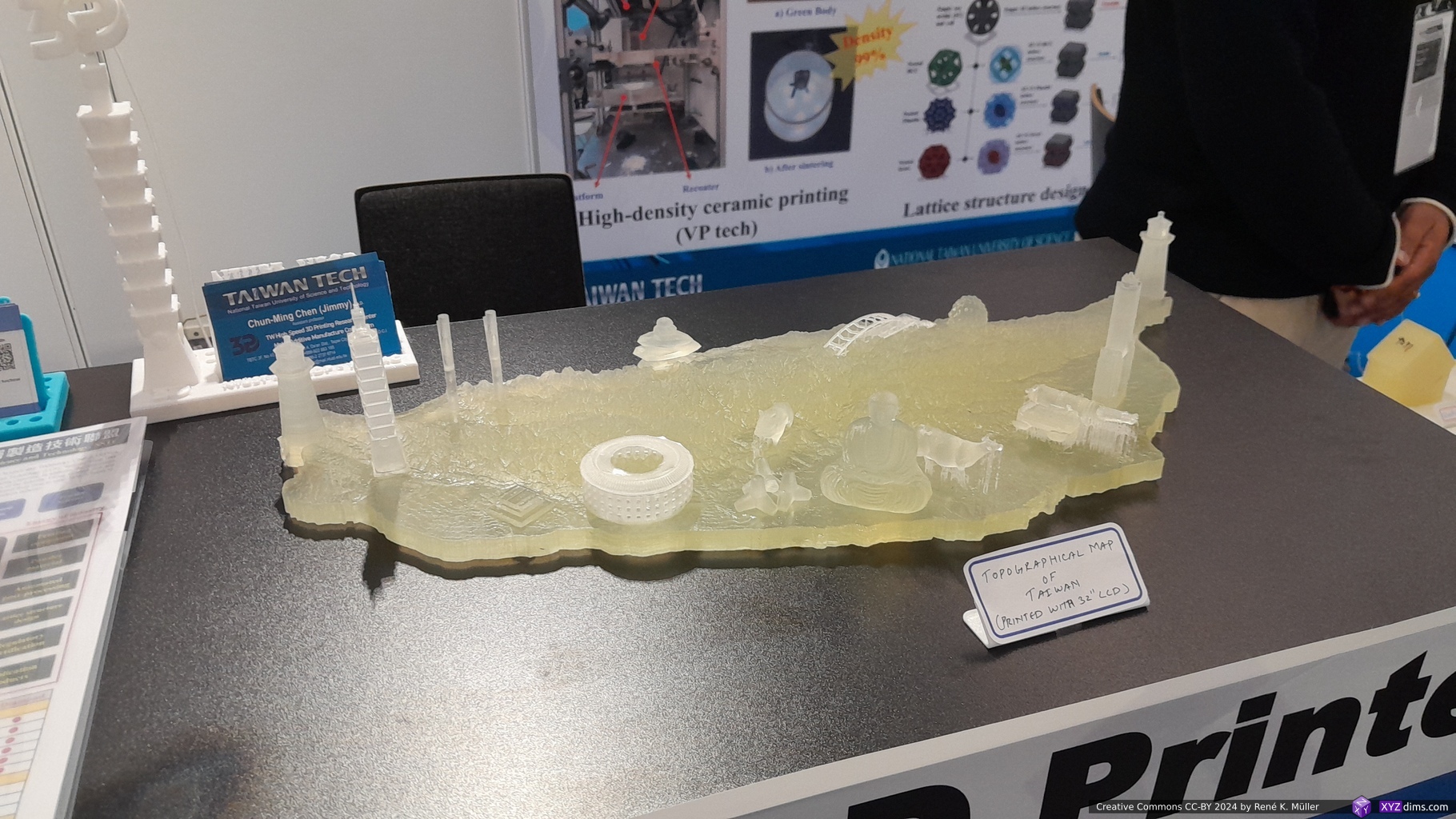
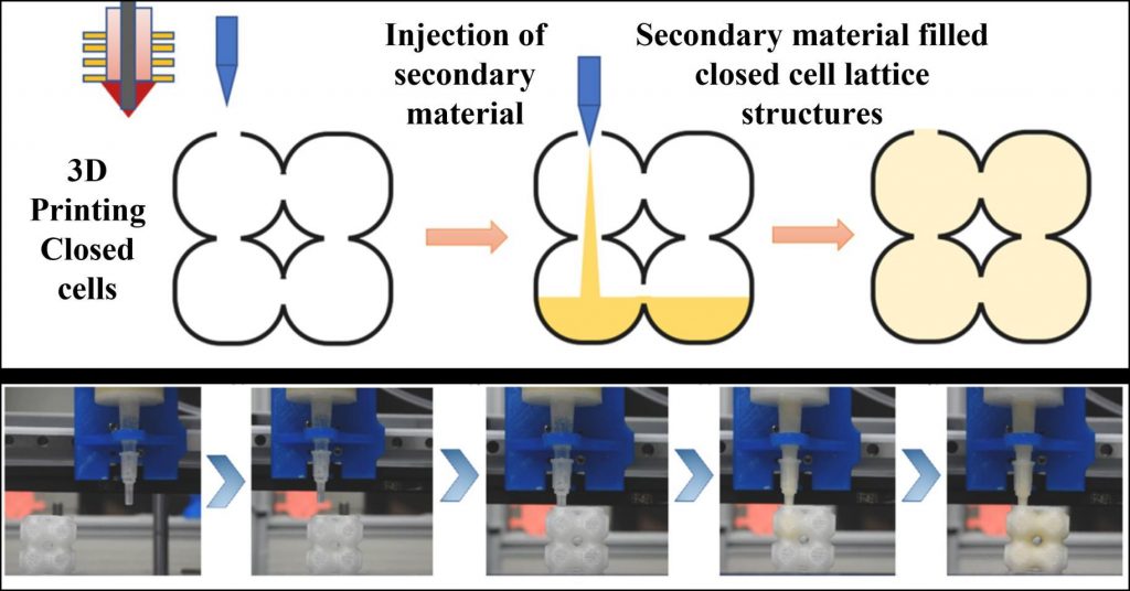
Another achievement is their 32″ (697x392x500mm build volume) and 50″ (1,150x600x500mm build volume) large LCD/MSLA resin printers, with new film coating of better release of the cured layers, although we couldn’t get into the deep details of it. See this non-free paper and this paper for details about the 32″ resin printer.
LCD 32″ 3D PrinterLCD 50″ 3D Printer32″ LCD type vat photopolymerization 3D printing system
I could easily spent an hour to explore their different projects and the benefits of those 3 distinct inventions alone. See more at NTUST.edu.tw and its High Speed Printing research center, in particular follow Mayur Prajapati.
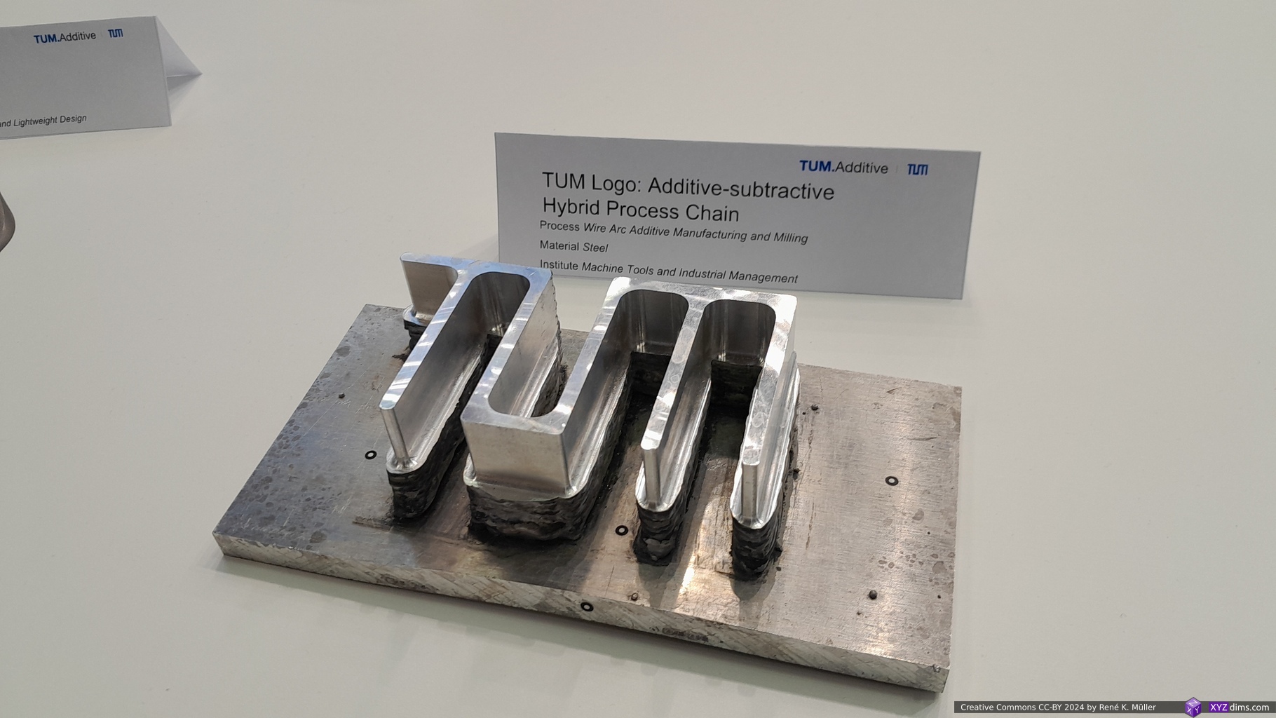
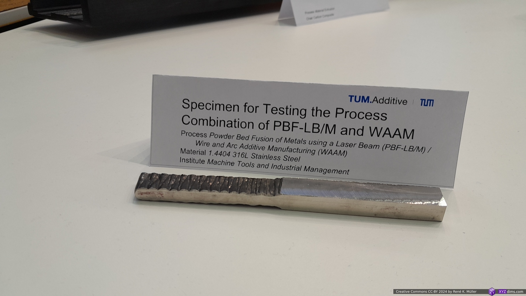
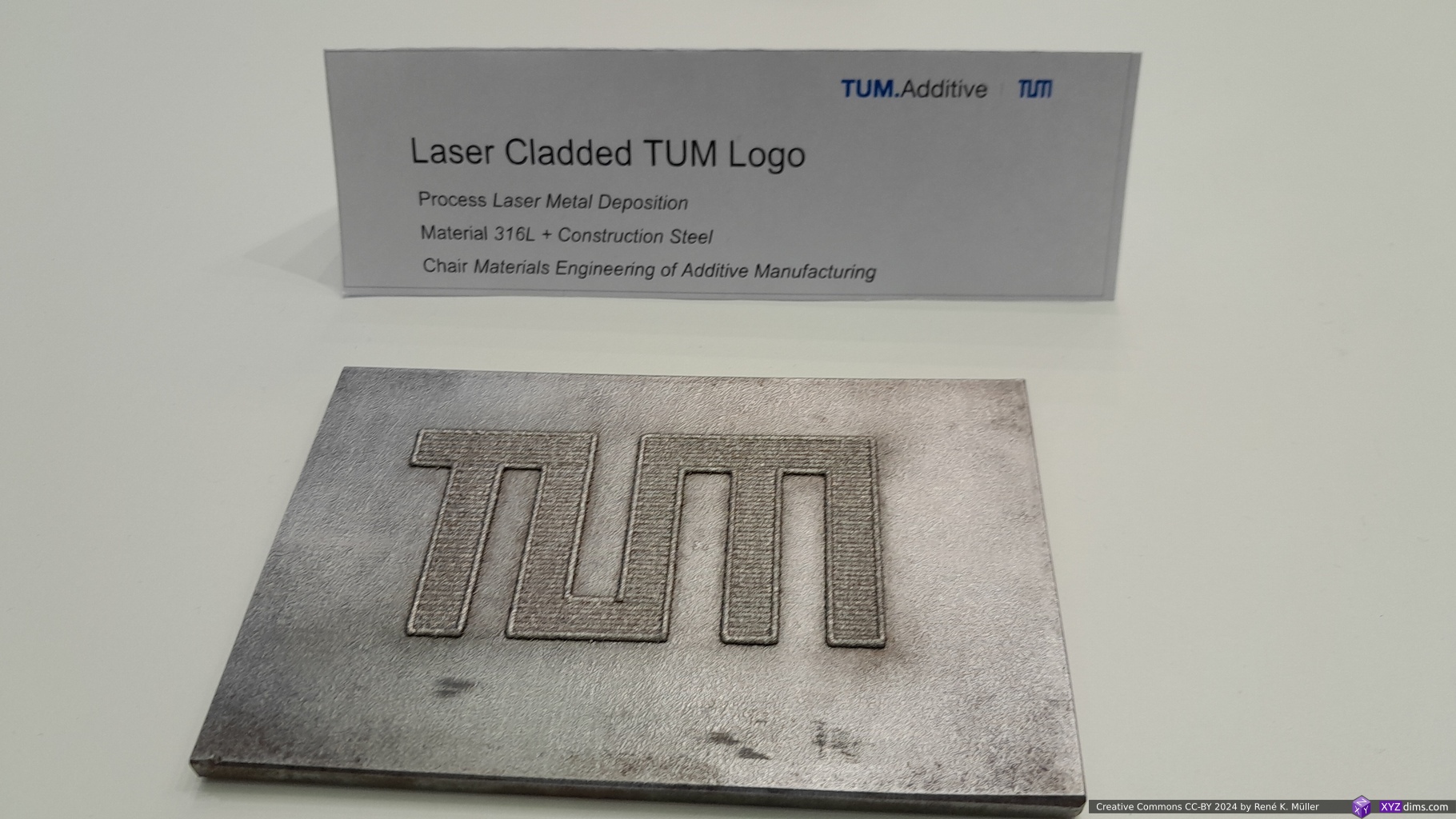
TUM (Technical University of Munich)
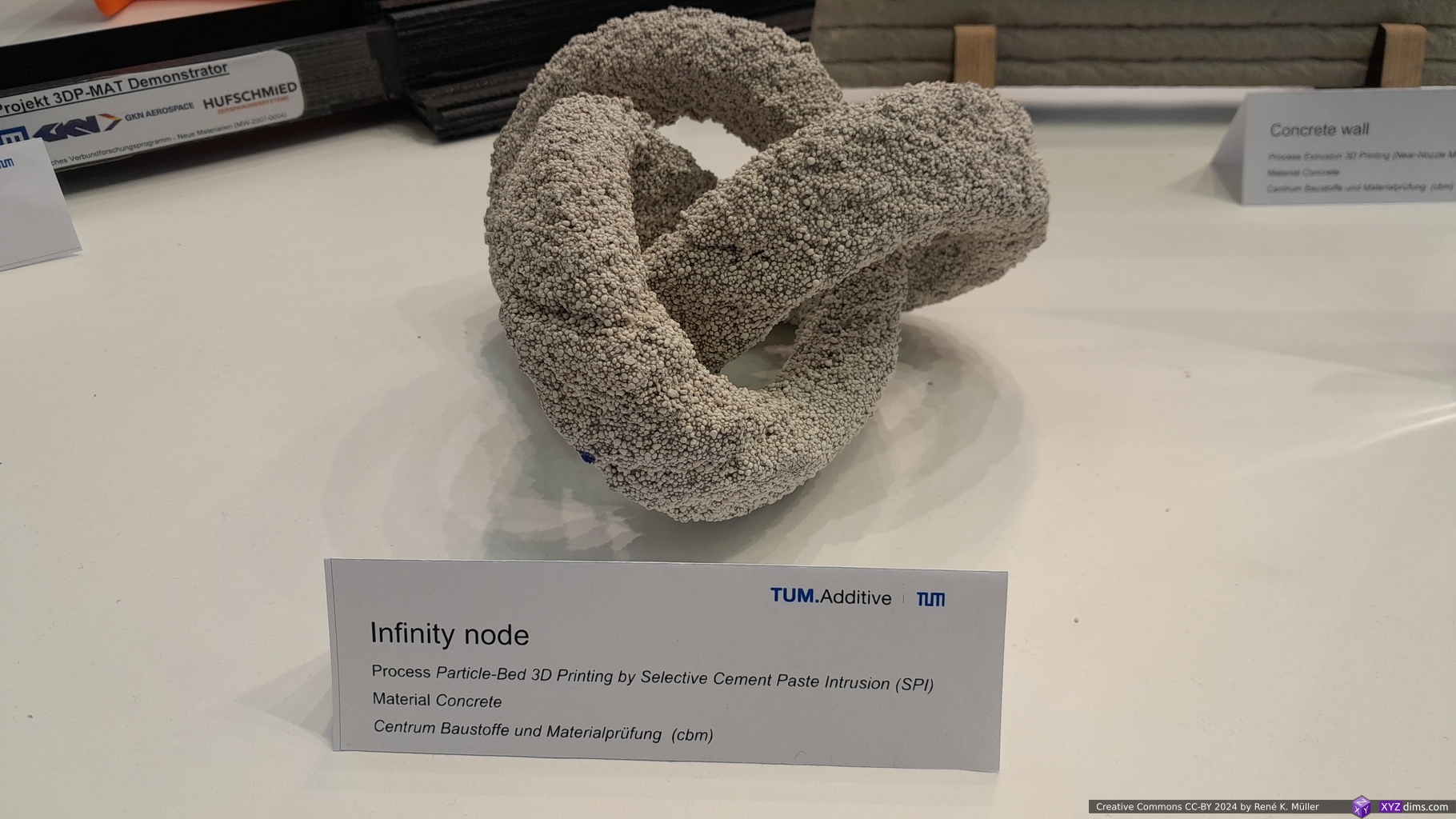
The TUM had a very prominent and large booth with many departments and many samples shown:
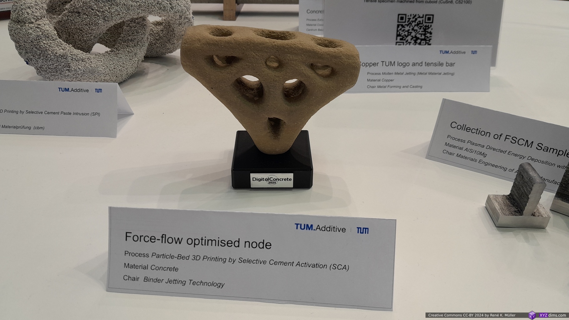
What caught my attention was the “Infinity Node” made from ~1mm gravel, it was printed using SLS-like printing: Particle-Bed 3D Printing by Selective Cement Paste Intrusion (SPI), using concrete as a binder to connect the small gravel together. The “Force-flow Optimized Node” (brown triangular truss shape) was done using Particle-Bed 3D printing by Selective Cement Activation (SCA).
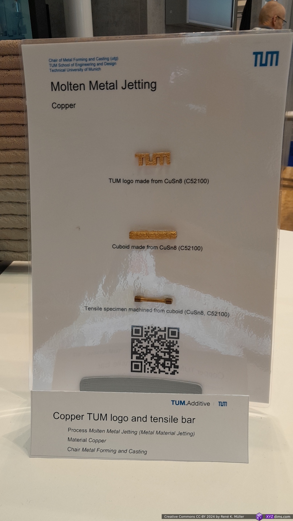
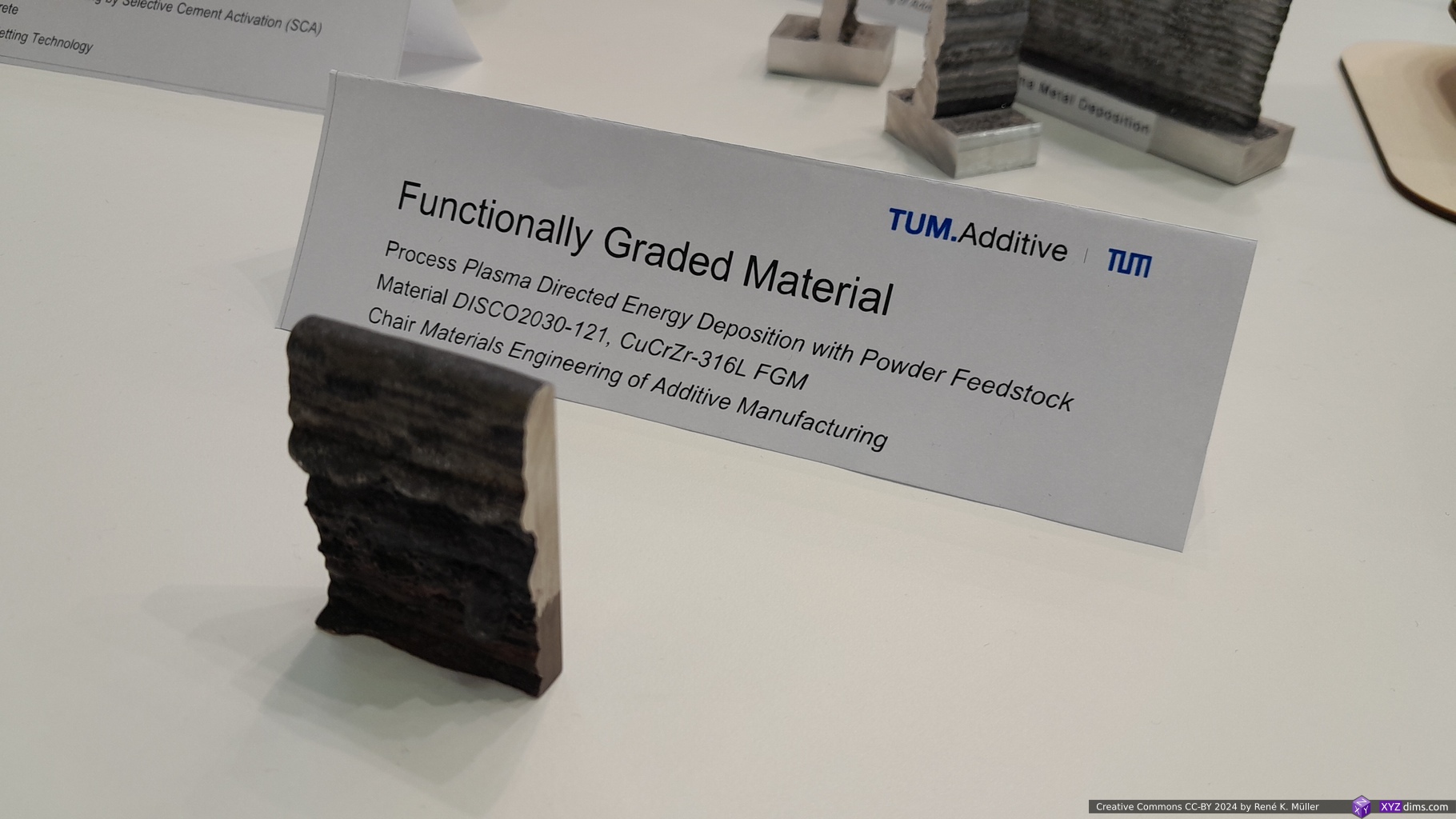
The other samples were “Molten Metal Jetting” (Copper), “Functional Graded Material” using Plasma Directed Energy Deposition with Powder Feedstock, and “Laser Cladded TUM Logo” using Laser Metal Deposition (316L + Construction Steel).
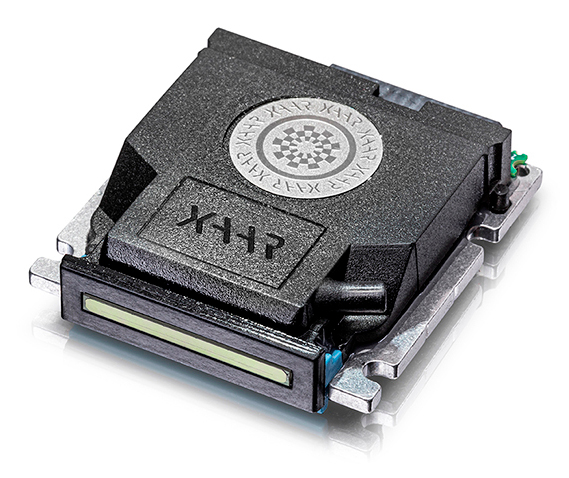
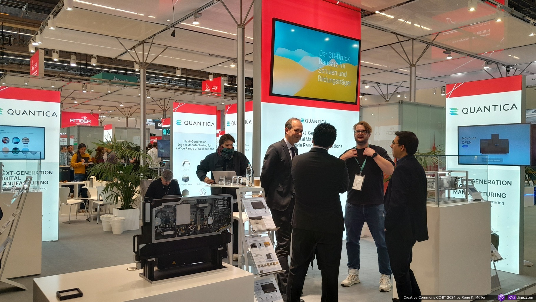
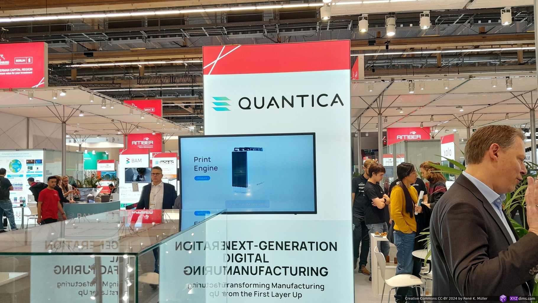
Quantica caught my attention 2-3 years ago, also at the Formnext, as I saw the modular fully voxel-exact jetting of material. Their core business was their printhead “NovoJetTM” able to print high viscous materials, something other jetting printheads would not able to do.
This year I talked to Sven, and he explained to me that they broaden their application areas like exact glue jetting and other high viscous materials, as some industries saw their printheads as high precision material deposition, outside of the “3D printing / Additive Manufacturing” use cases – quite interesting how their core expertise found other applications.
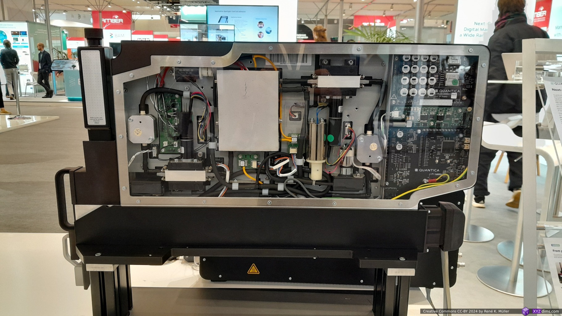
Quantica Print Engine: circular motion of material kept under pressureNovoJet Printhead: 96 nozzles, 50um diameter each, 8kHz max frequency
Again I asked for some 3D printed samples, and again I was denied any like the past 2 years (!!) – they said they don’t have any (or very few) but just for internal use; my main interest is to observe the actual blend or non-blend and then 3D dithering of materials and colors on drop level in order to explore new applications.
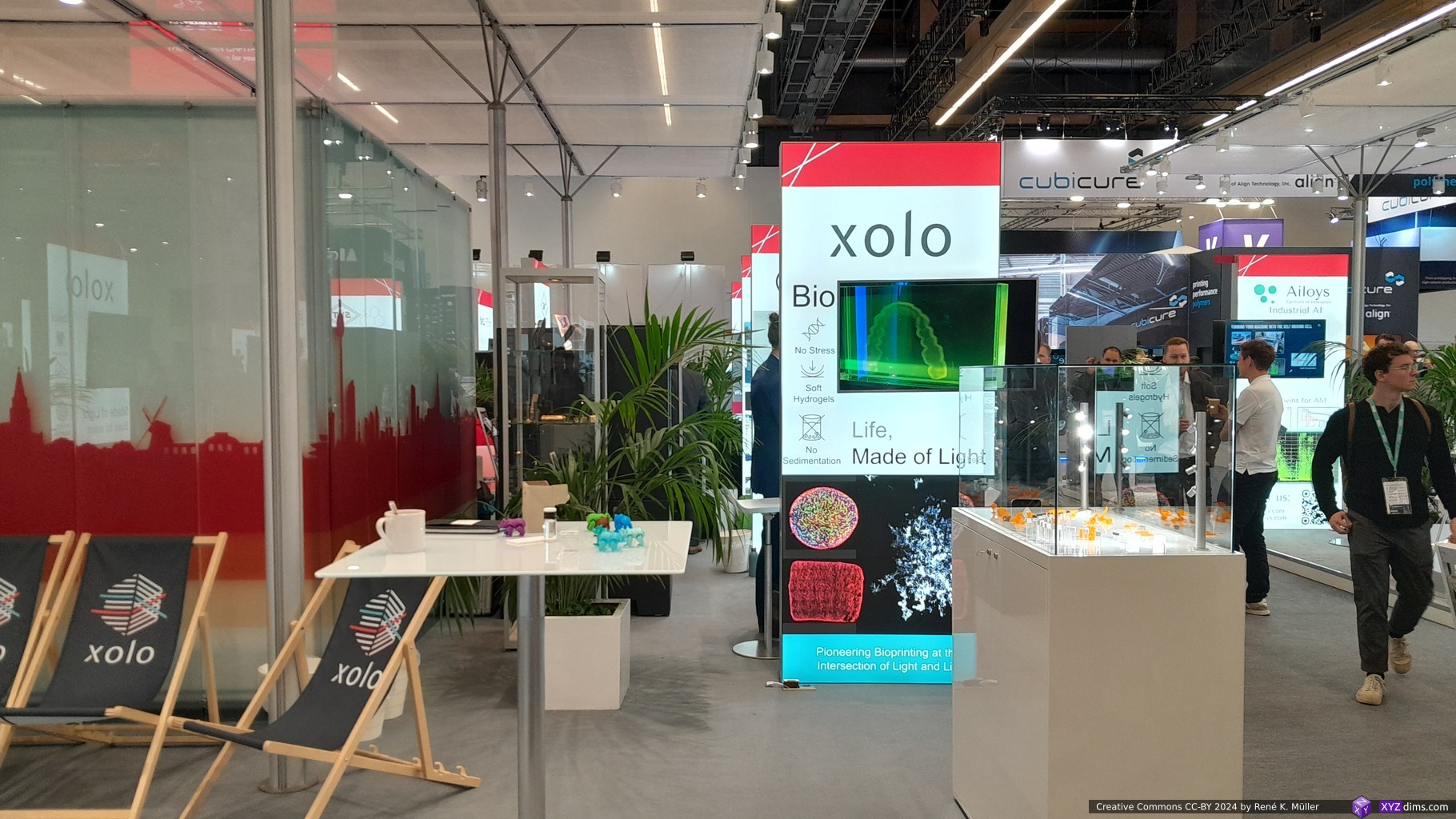
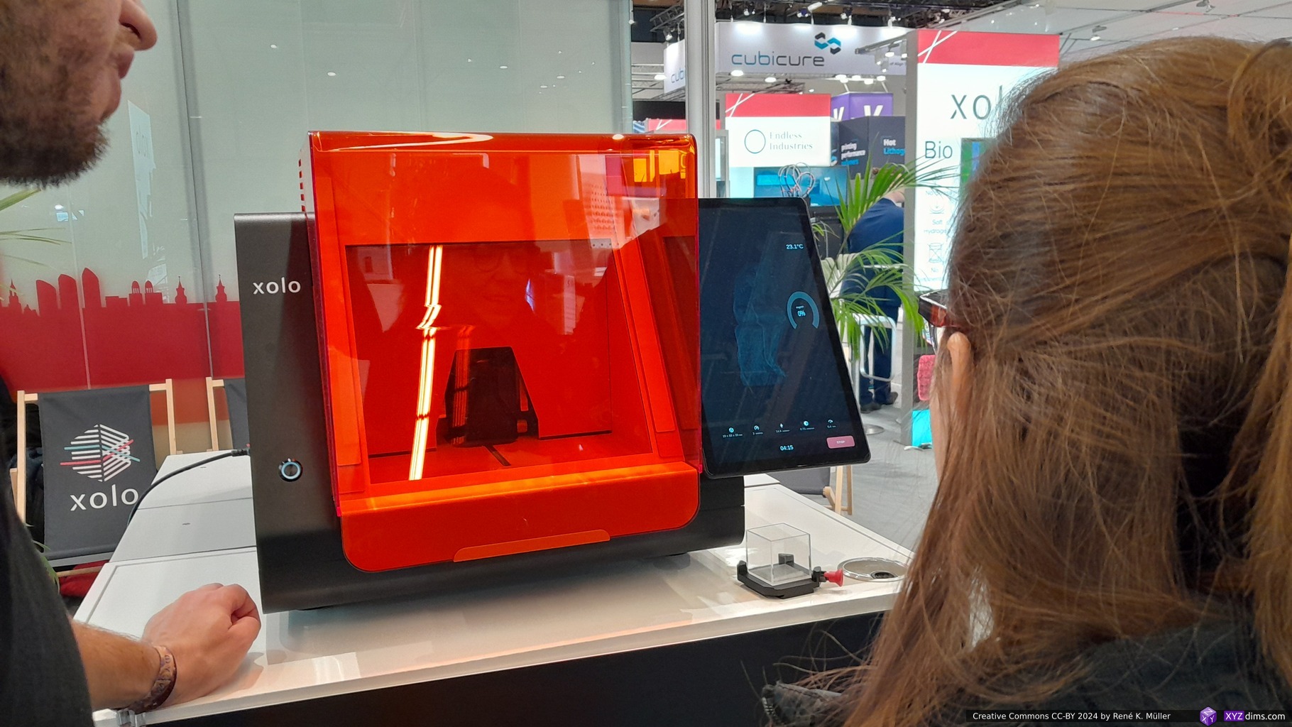
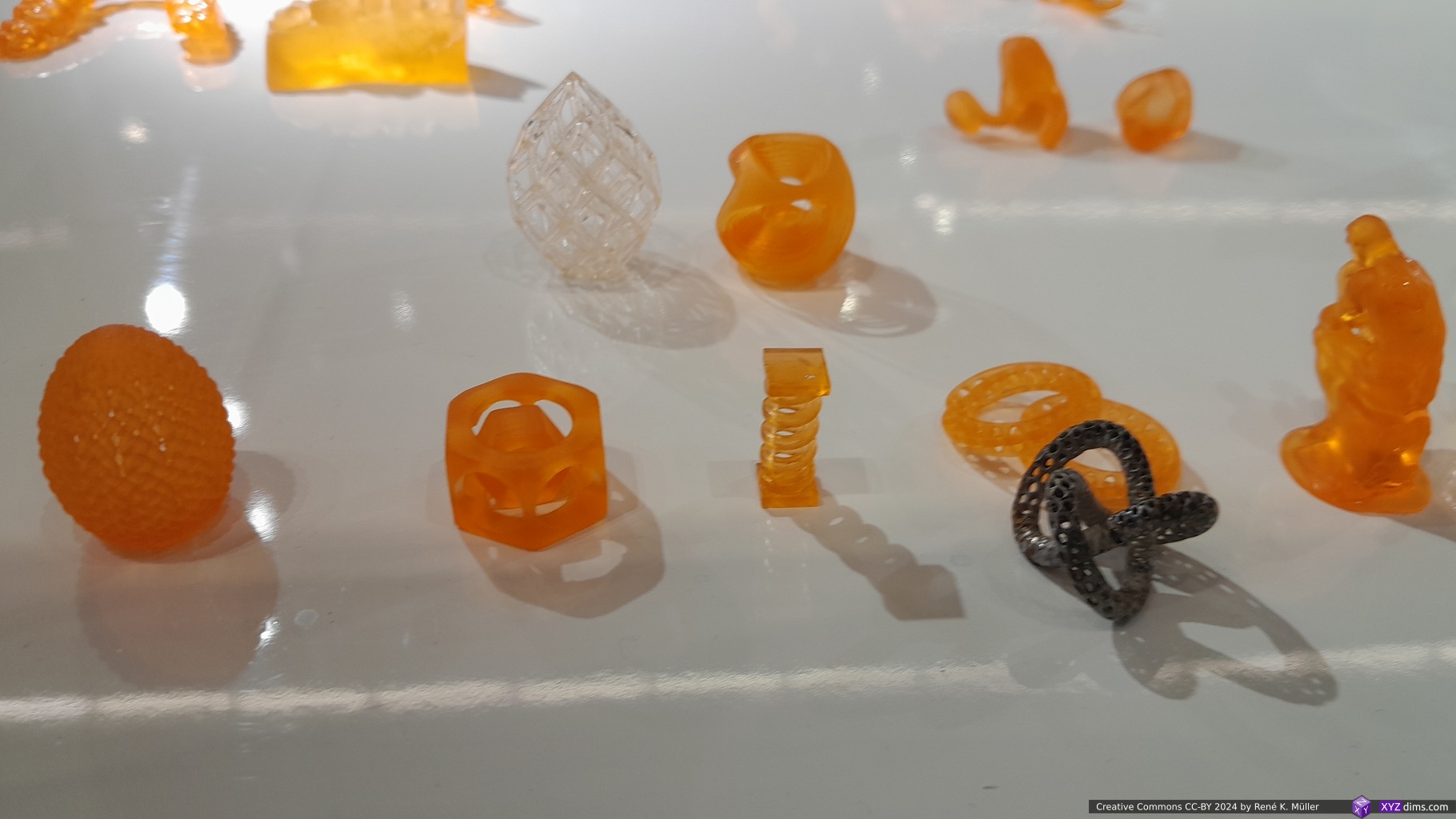
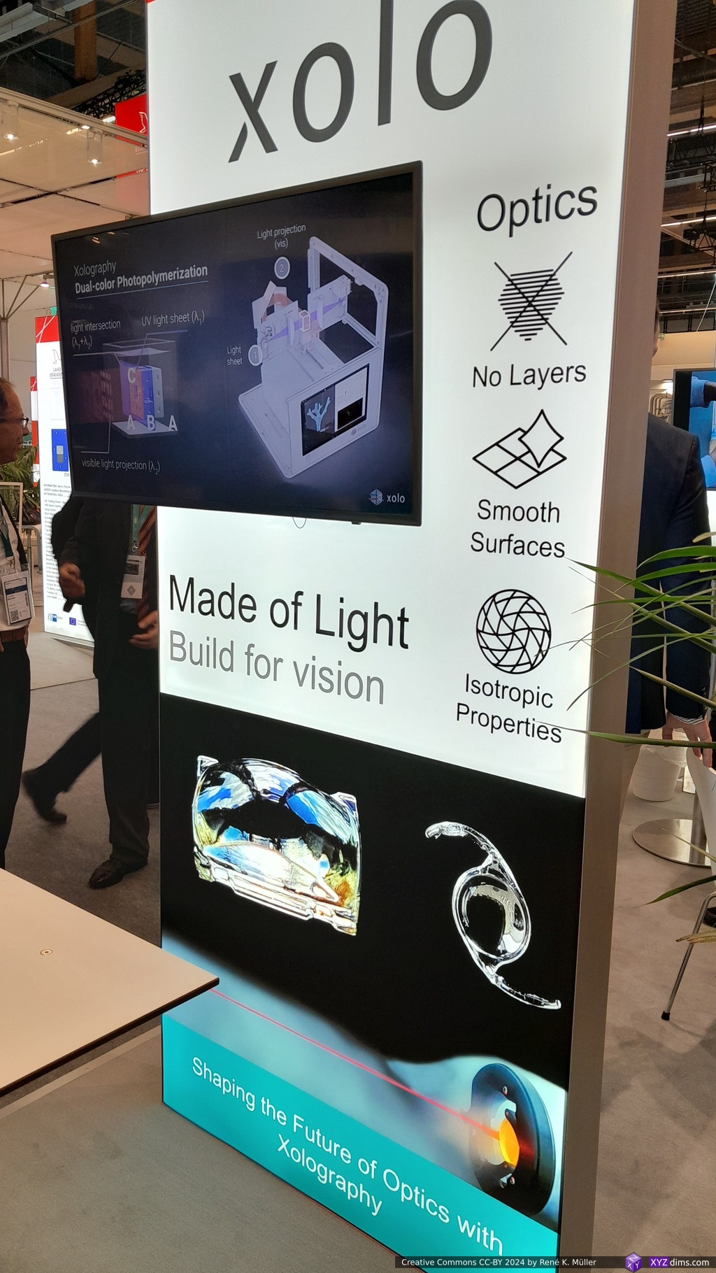
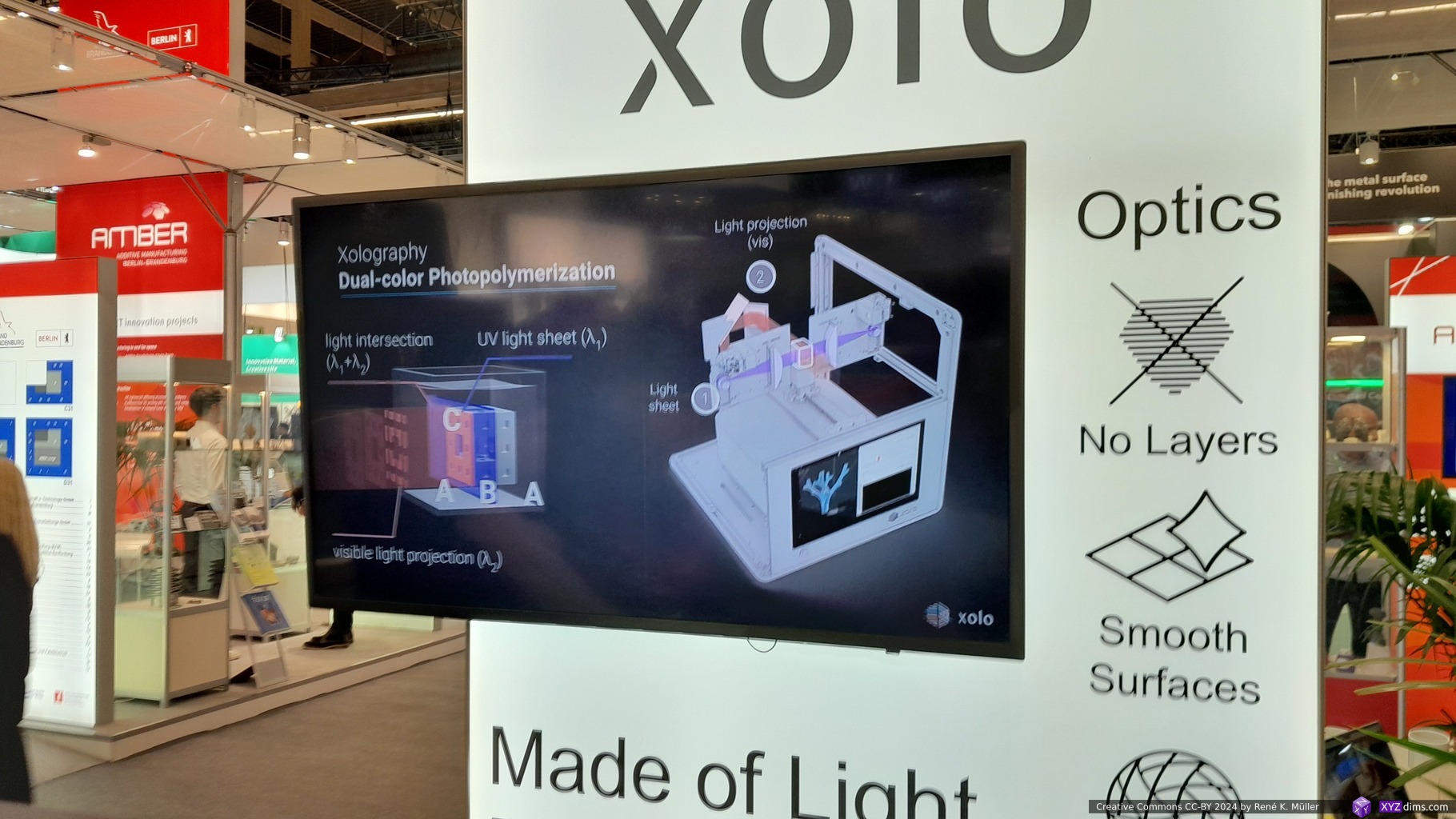
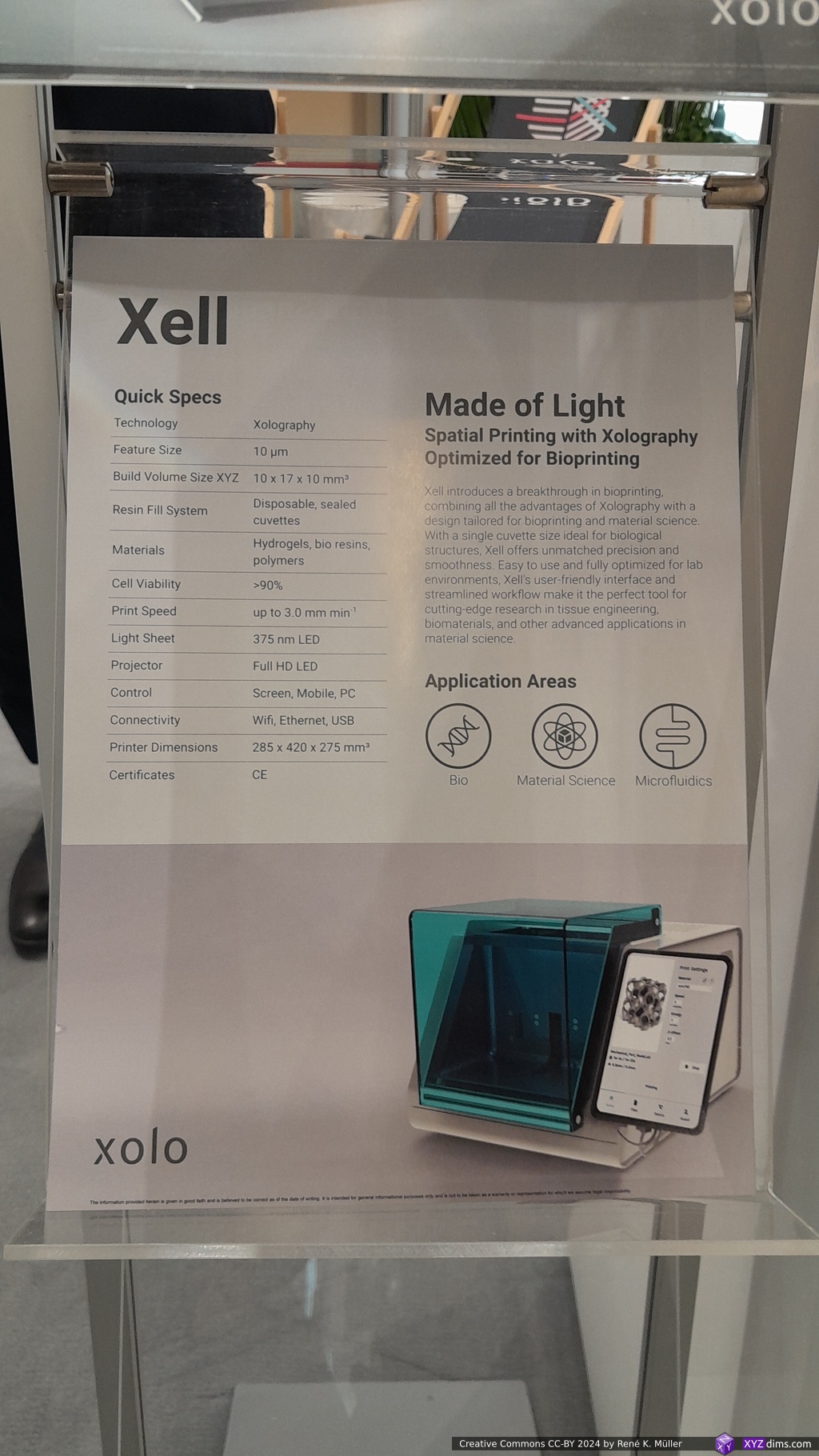
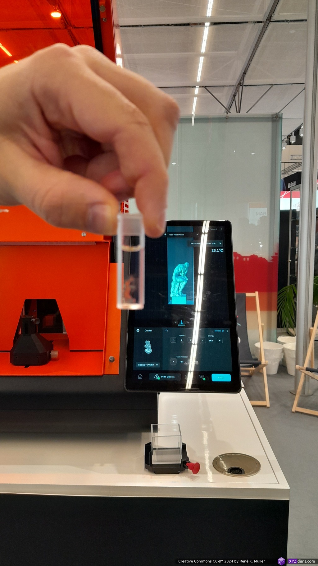
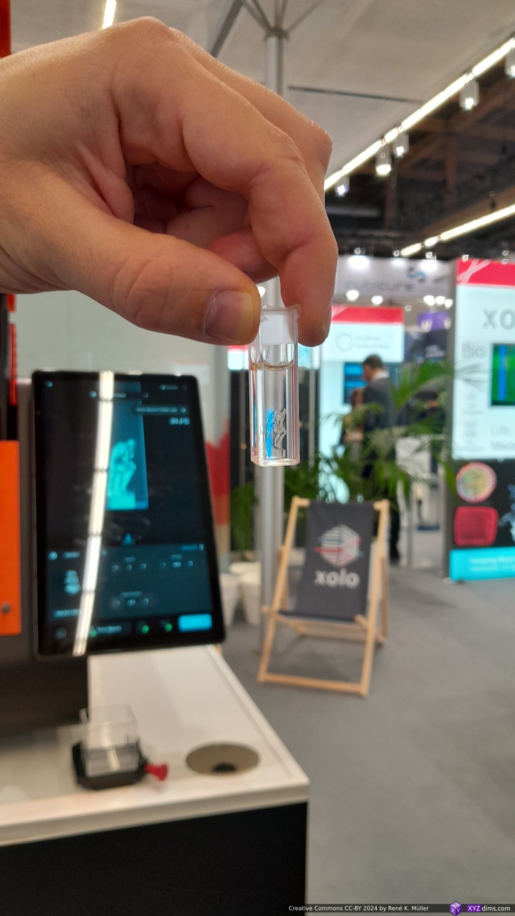
An interesting approach, new to me, is Xolography, spatial printing in a resin – first a light sheet is established in the Z plane of 50um thickness, and then XY image is projected into the volume, different color/wavelength for each, and where the Z plane and the XY image light meet, there the photopolymerization takes place; it only works with highly transparent resins, more precisely dual-color photoinitiator (DCPIs), as otherwise the Z plane won’t reach all XY 2D image.
Xolography: UV light Z plane intersecting with XY plane with visible light
first wavelength (375 or 405 nm, UV light) activates the dormant initiator by triggering a spiropyran photoswitch (Z plane)
second visible wavelength (450-700 nm, visible light) excites the benzophenone component to initiate polymerization (XY plane)
So far they reached 50x89mm XY size, yet any size in Z including continuous Z printing.
They claim “no layer lines”, and told me they project a “video”, yet, a video has also n-amount of images e.g. a certain frame rate. What they rather mean is a continuous Z motion while they project their Z sliced XY images, and because the Z motion is continuous, the “layers” rather blend together and get smoothed out. They also don’t need any support structures, as the cured/solidified structure stays in-place and doesn’t sink.
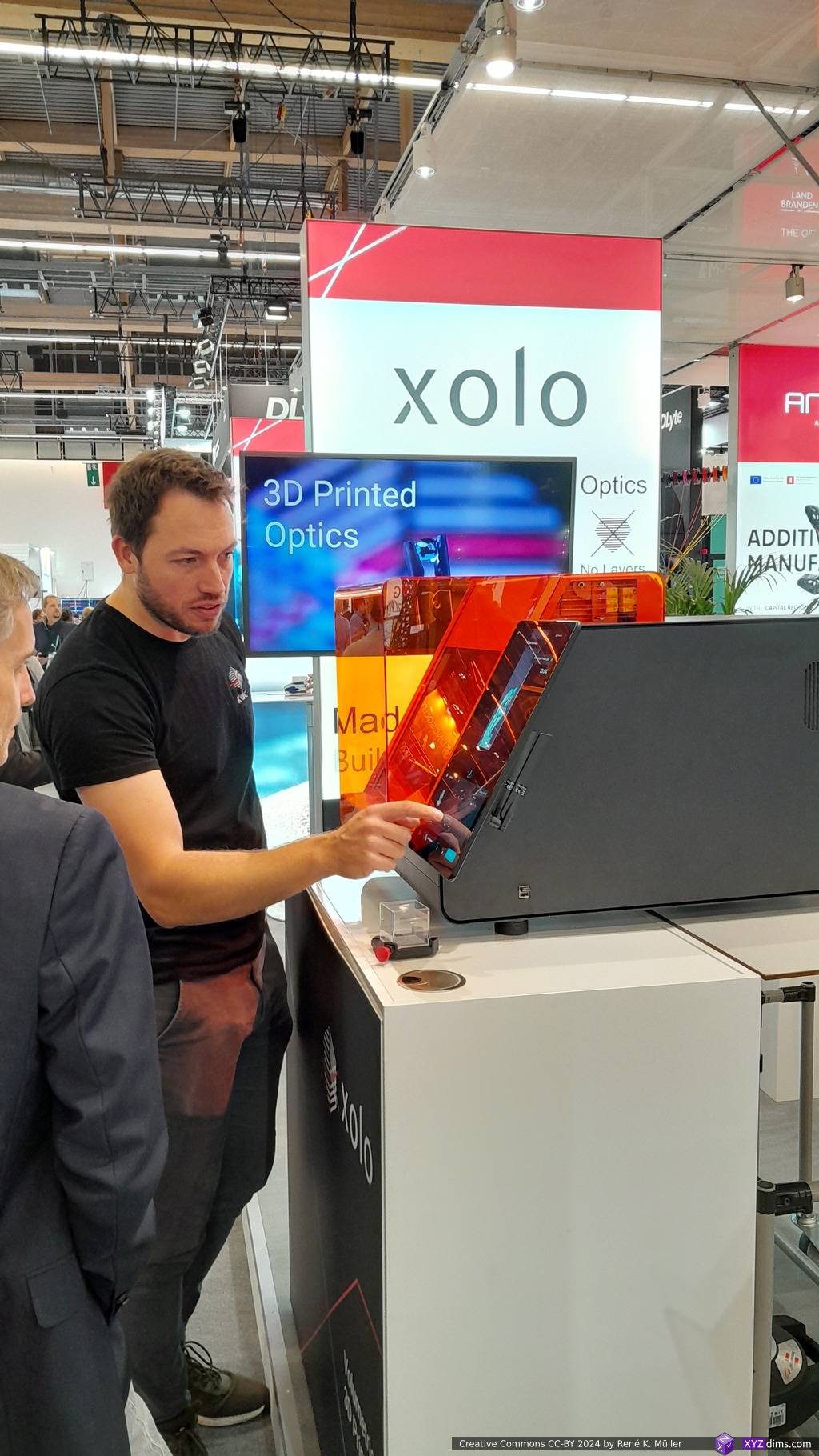
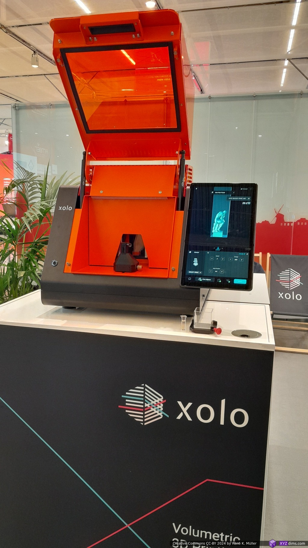
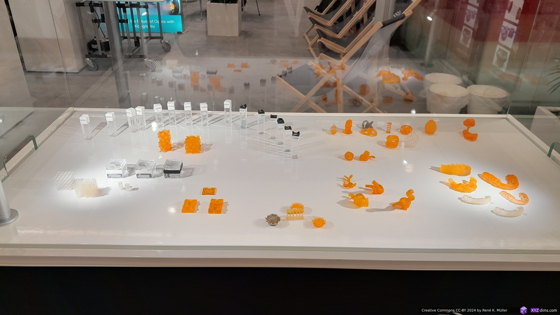
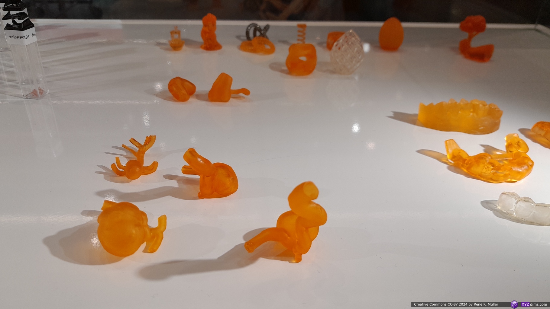
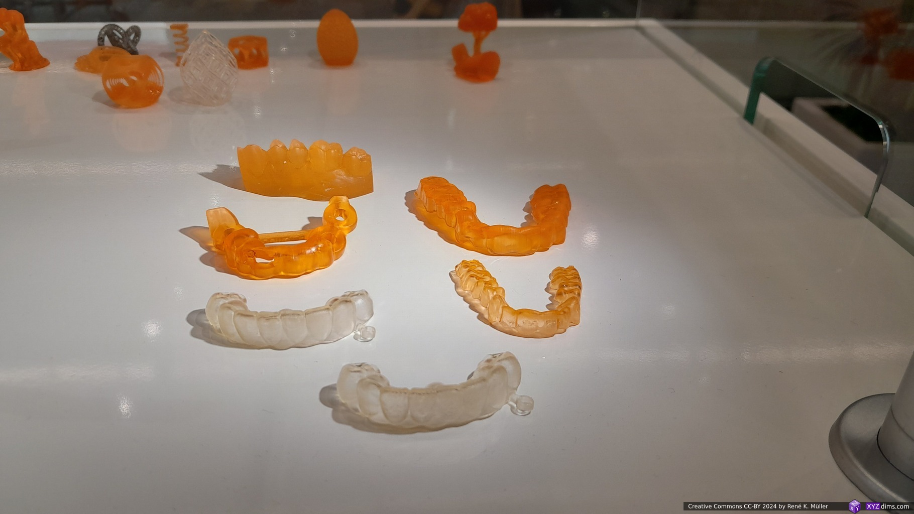
Their requirement of highly transparent resin they derive one of their main use cases: 3D printed optics, and isotropic properties (angle independent strength, no deliminations), other resins they developed are bio-compatible and even soft and gel-like – quite an impressive achievement.
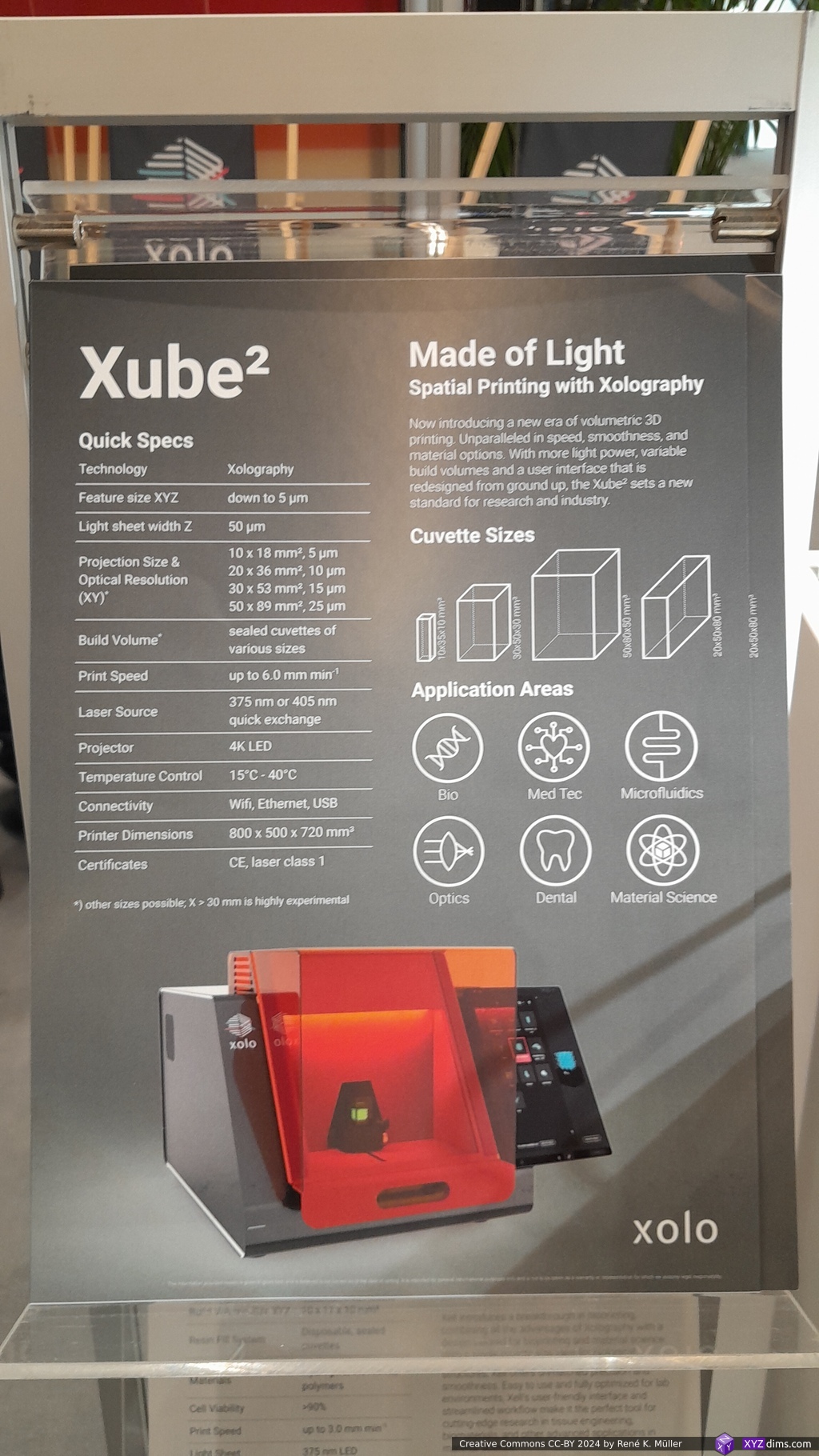
Currently they have two machines available:
Xube2: 10x18mm (@5um feature resolution) up to 50x89mm (@25um feature resolution) x80mm, apprx. 6mm/min in Z, feature size 5-25um as mentioned, although 50um lightsheet width/thickness, so the “feature size” more applies to XY than Z
Xell: 10x17x10mm build volume, @10um feature size
This process has been new to me as mentioned, but while researching I realized it has been around since 2020 or so, when this paper was published.
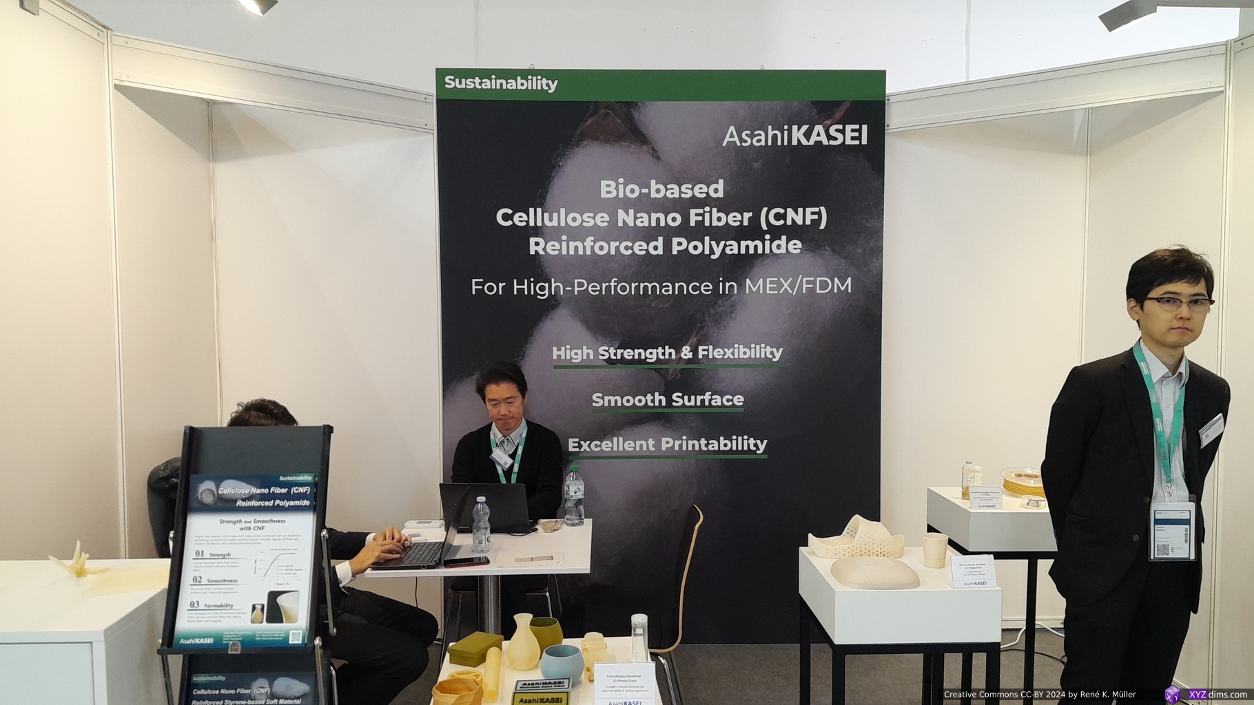
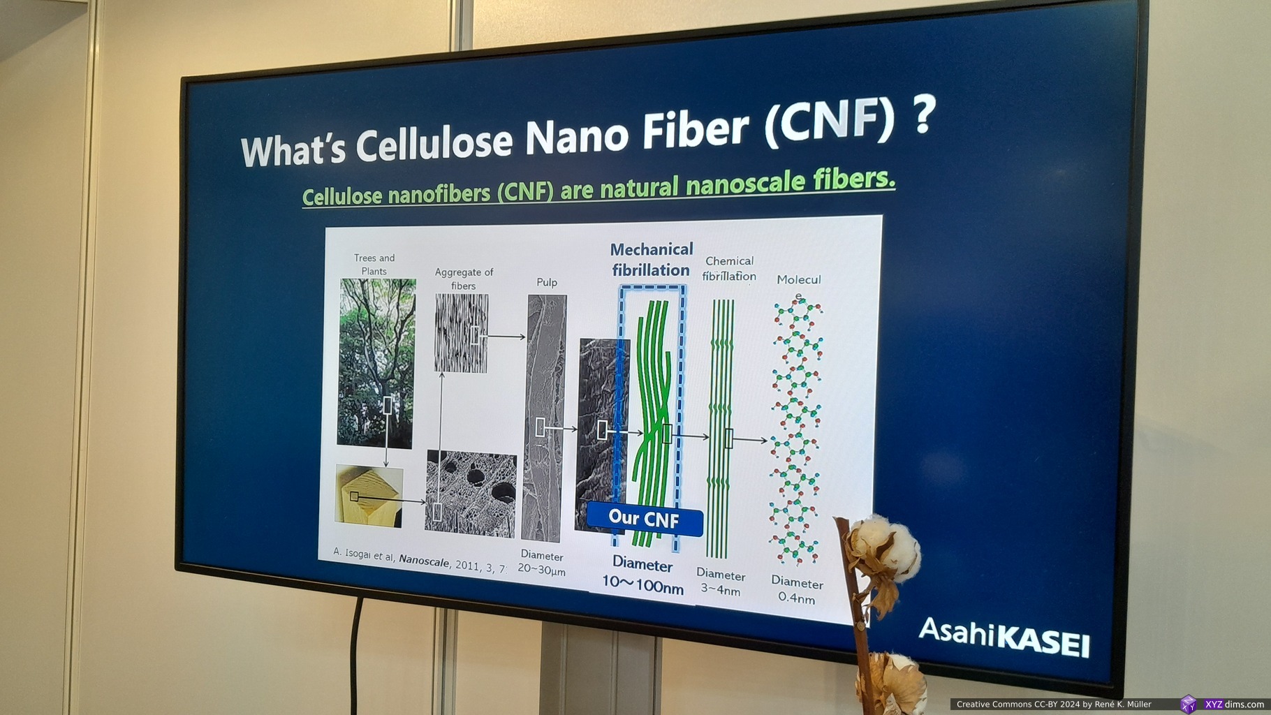
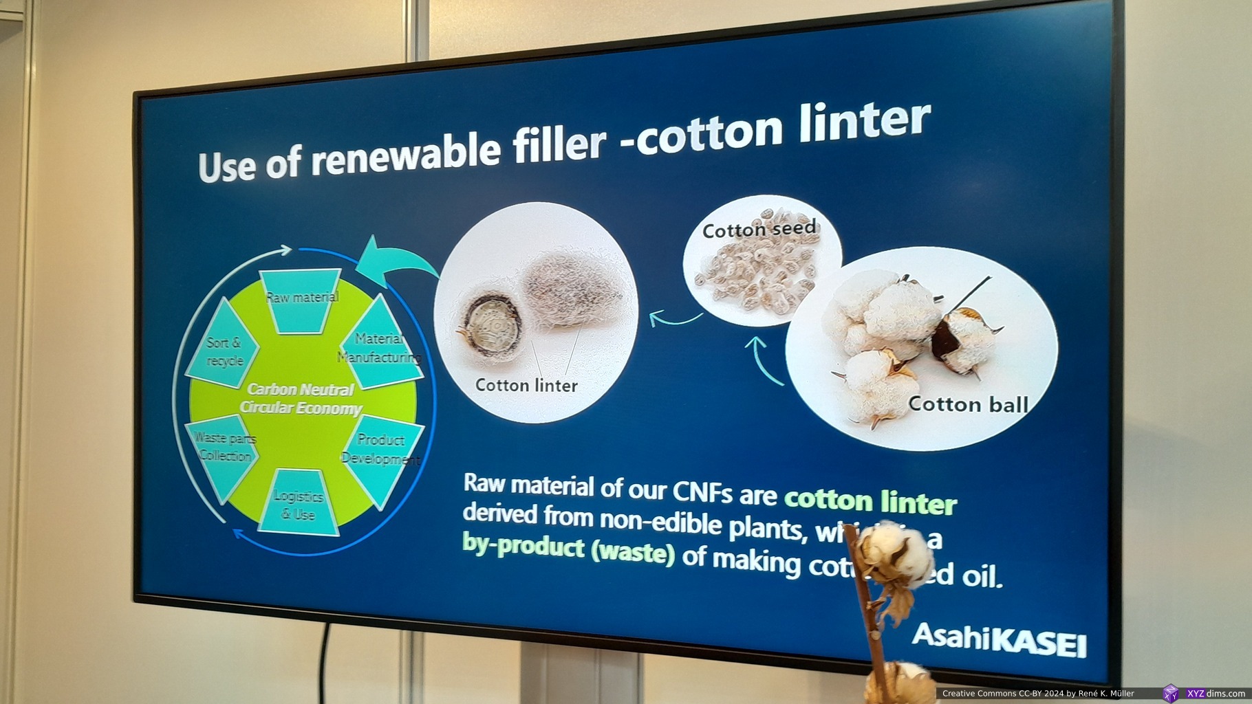
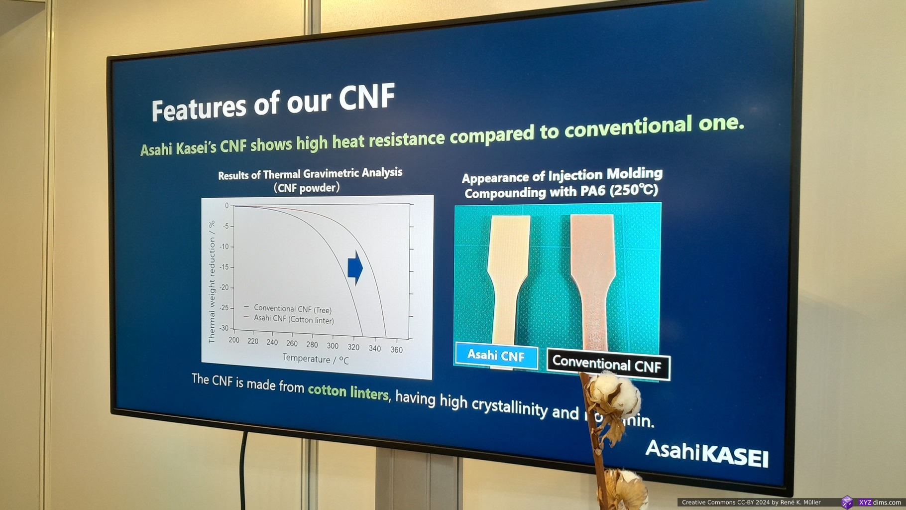
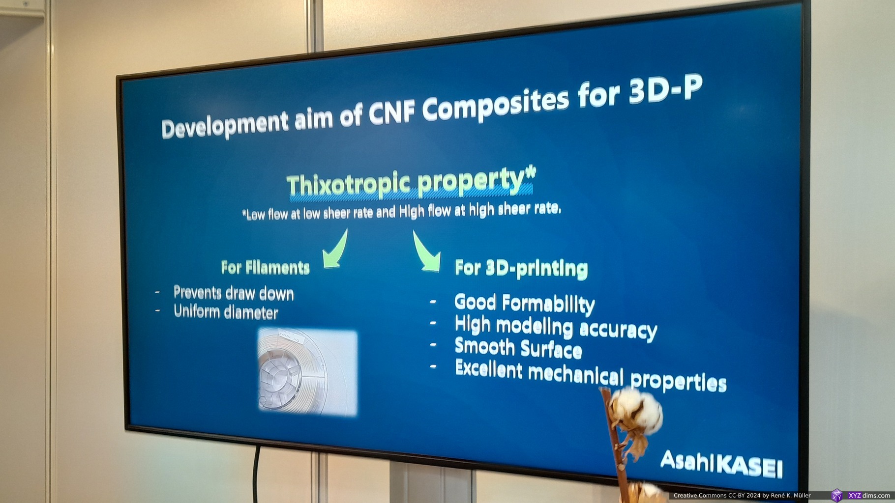
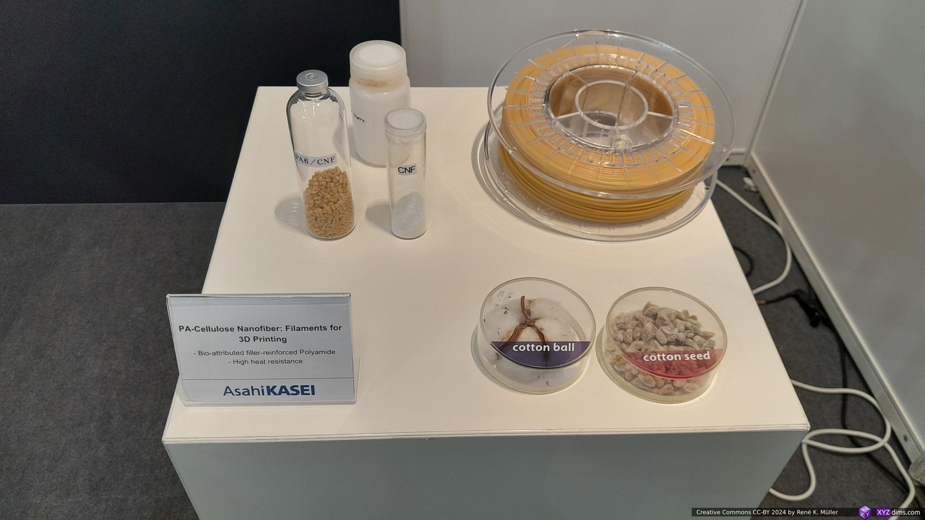
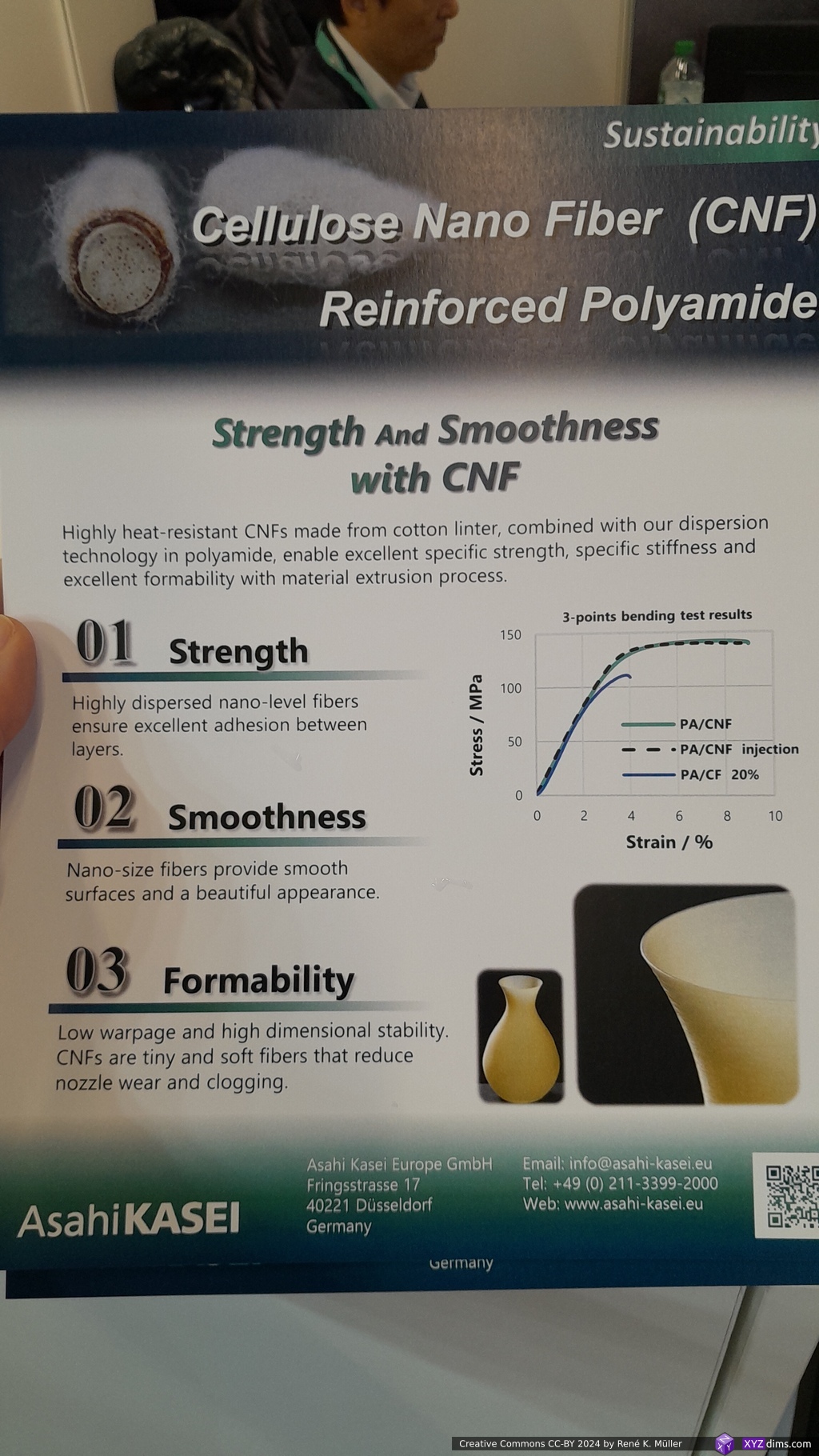
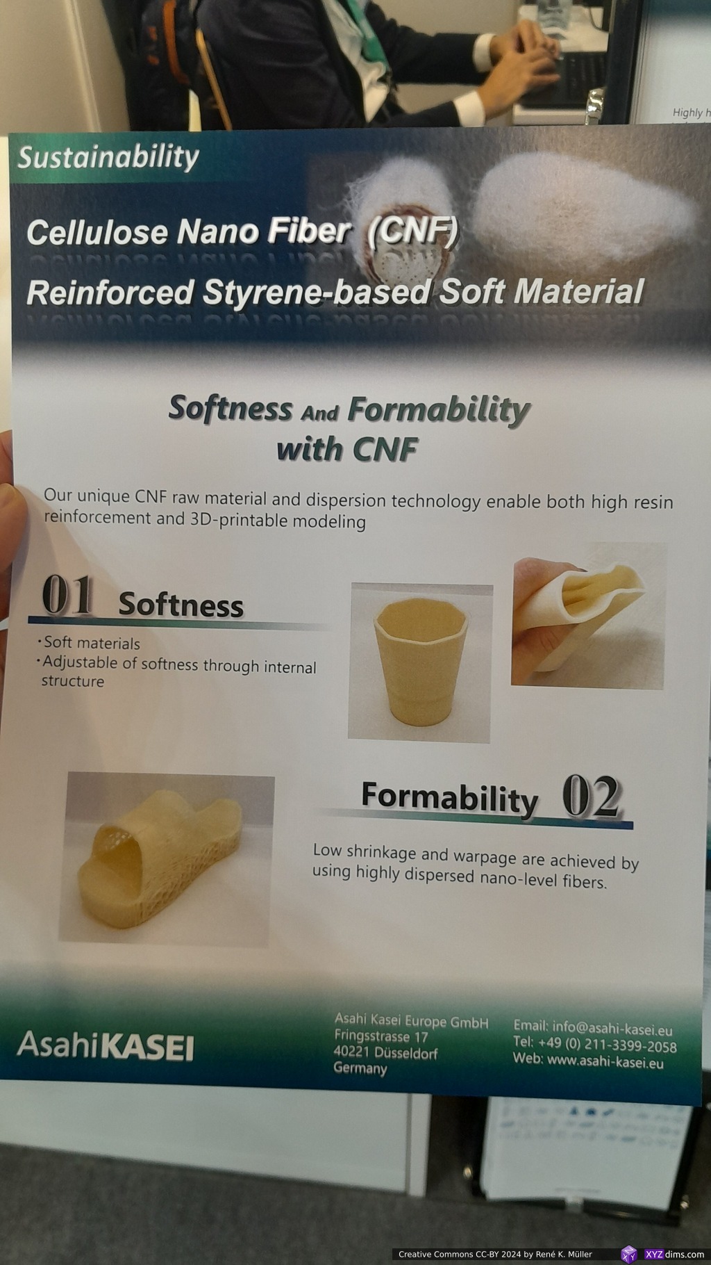
They showed a bio-attributed Cellulose Nano Fiber (CNF) made from cotton fibres, and then reinforced polyamide PA66 into a filament named CNF/ECONYL® Polymer with extended heat resistance, strength (performing better than carbon fiber), smoothness and formability – actual details of measurements are missing to backup those claims – according their announcement the material becomes available in Q3 2025.
While their booth has been very small and unassuming, the company has nearly 50,000 employees world-wide.
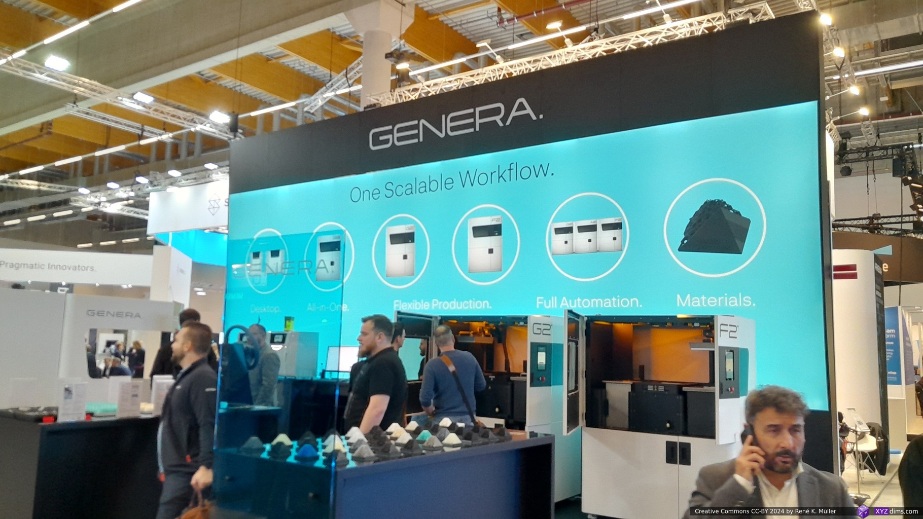
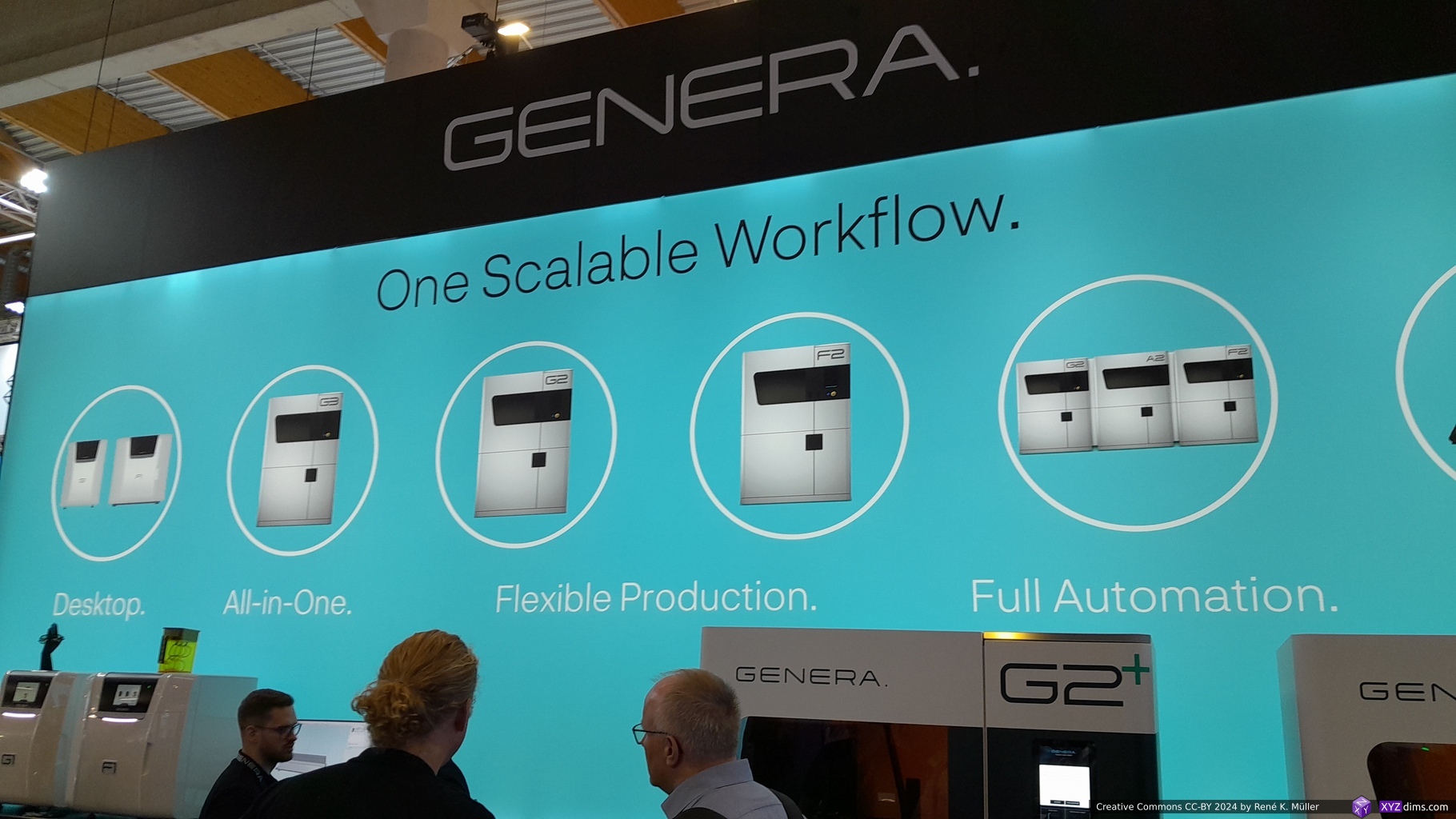
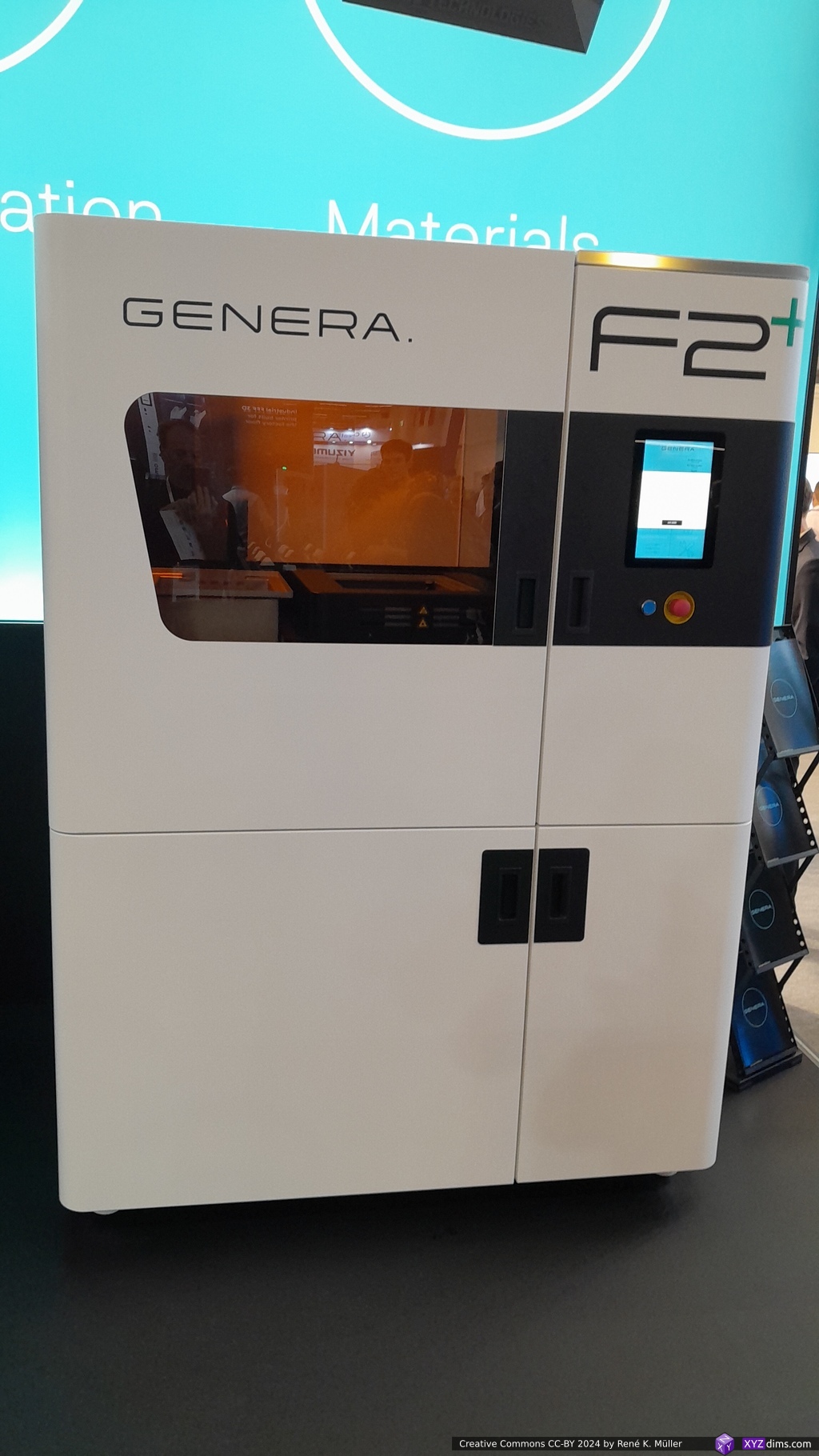
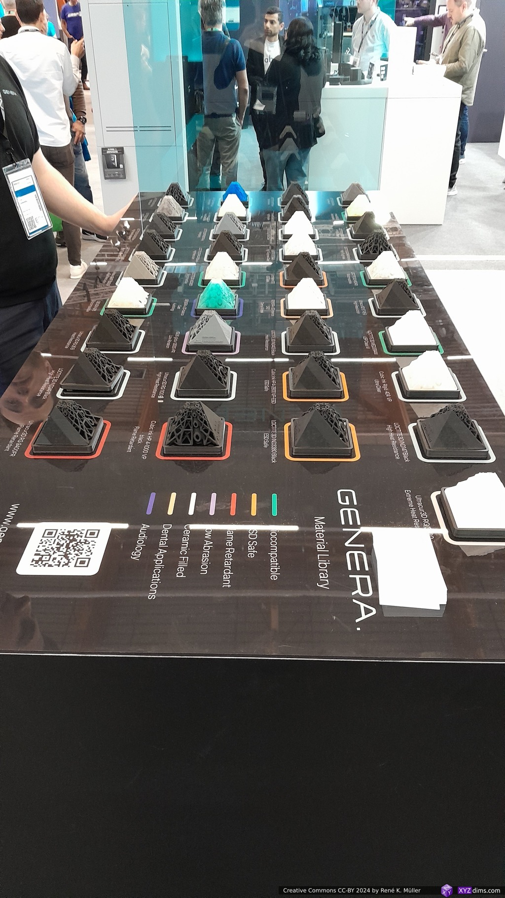
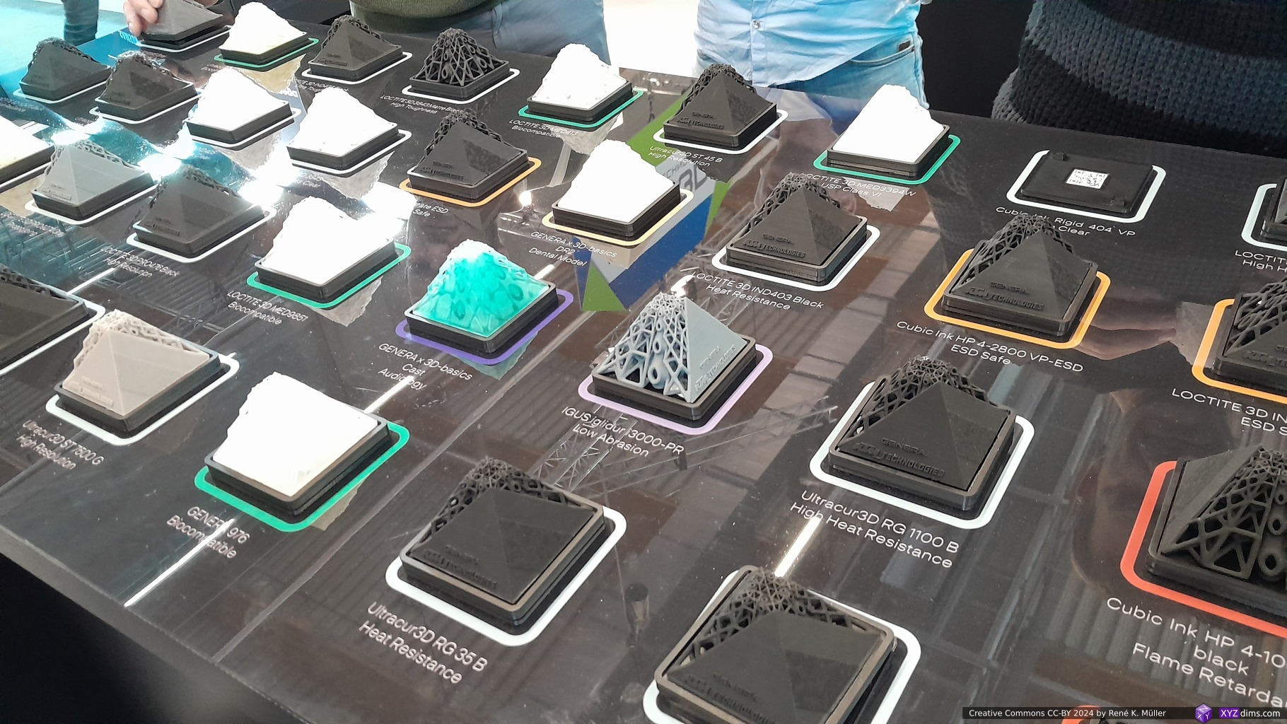
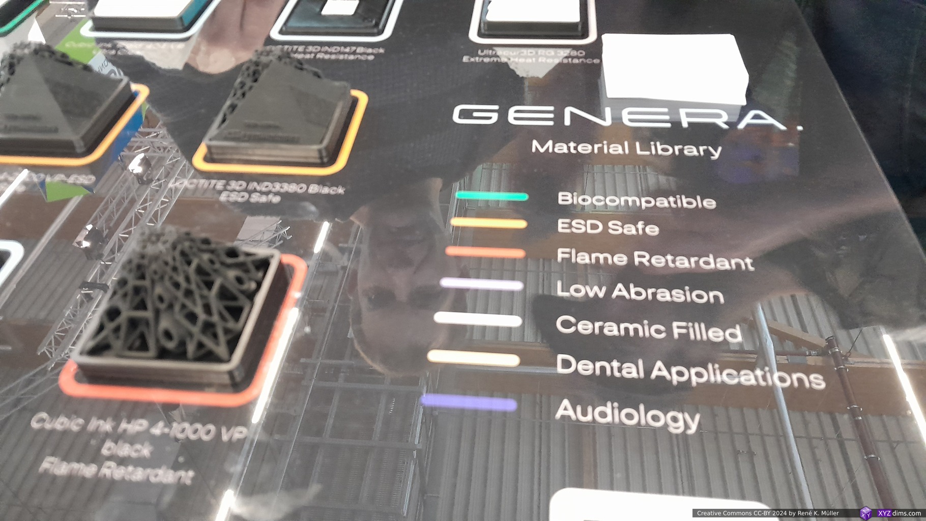
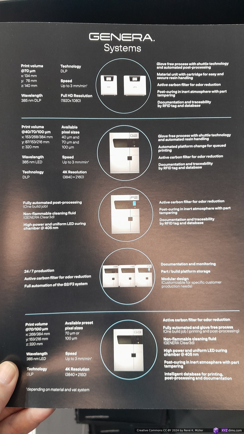
As far I saw they are one of few which makes resin printers which print, wash and cure in the same machine (Genera G3), where as their G1+F1 and G2+F2 they call “glove free process with shuttle technology and automated post-processing”, where the build plate is carried over in an encasing “glove free” to wash and cure station (F1 respectively F2).
Genera G1 + F1: 134 x 76 x 140mm build volume @70um pixel resolution
Genera G2 + F2: same as G1 plus automatic platform change for queued printing
153-384 x 87-216 x 320mm build volume (@40, 70 or 100um pixel resolution)
Genera G3: same as G2 but has F2 integrated, print, wash & cure in one machine
268-384 x 153-216 x 320mm build volume (@70, 100um pixel resolution)
Genera G3 (3D Model): (left-to-right) resin vat, washing vat, and curing vat
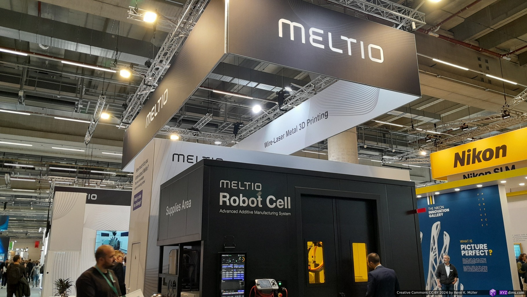
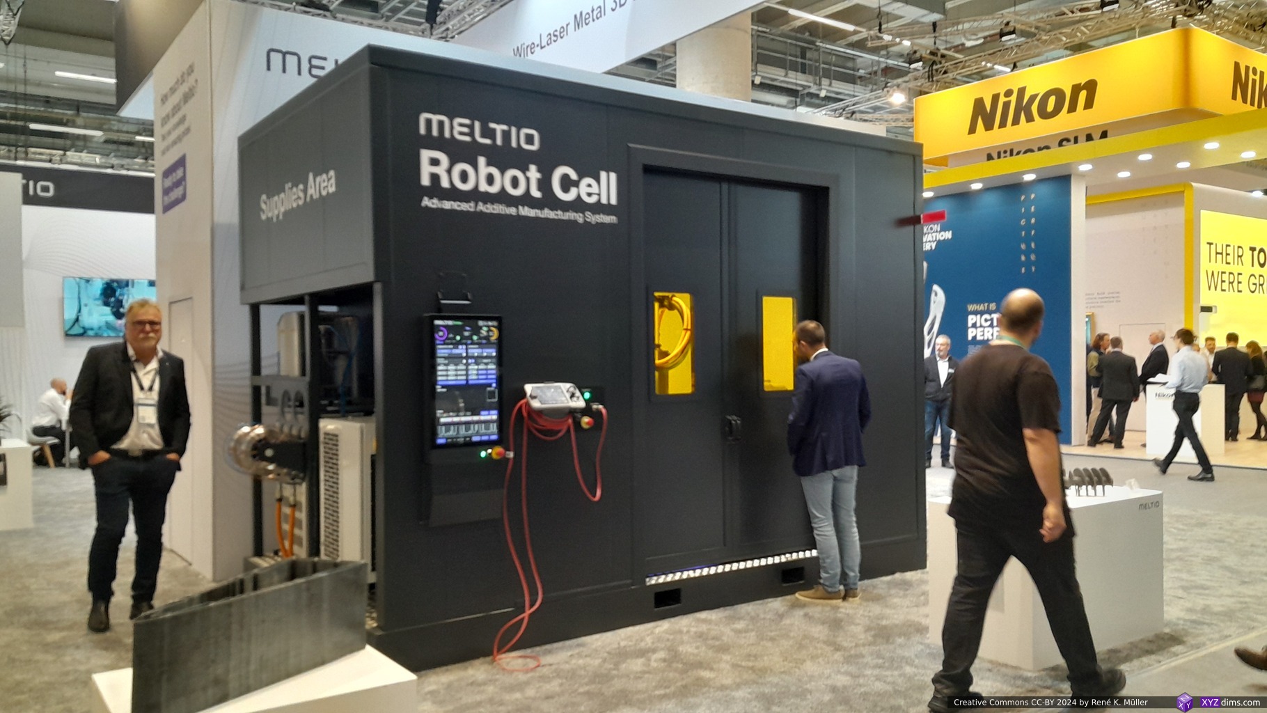
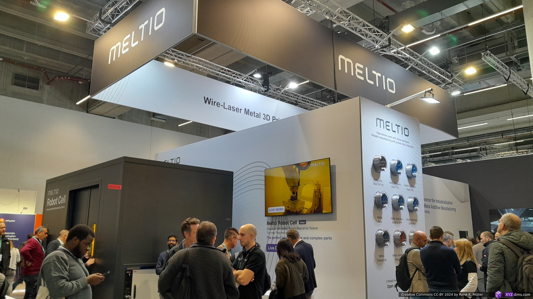
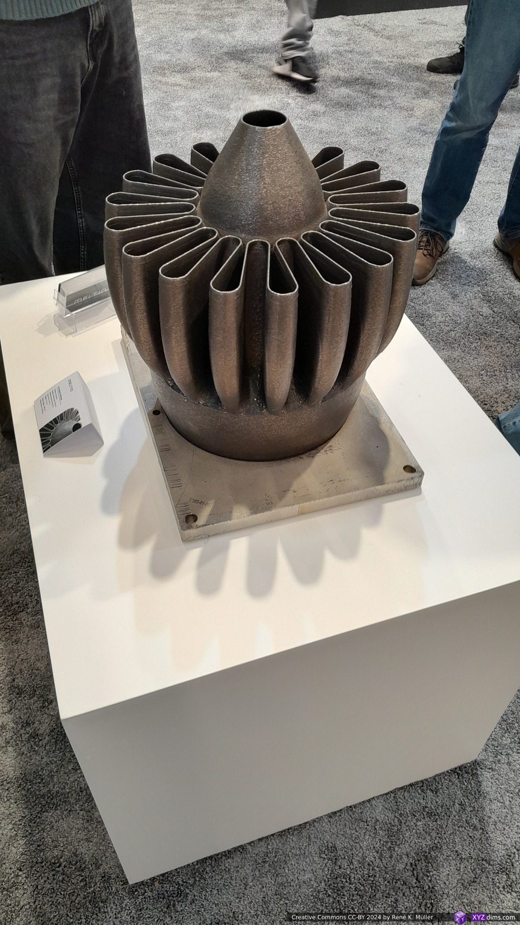
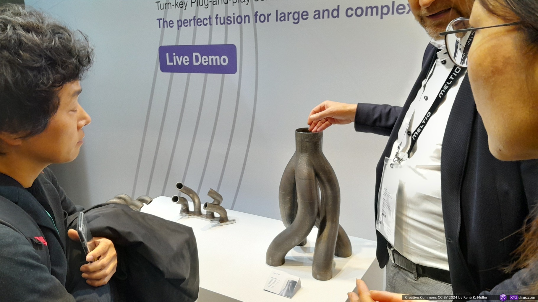
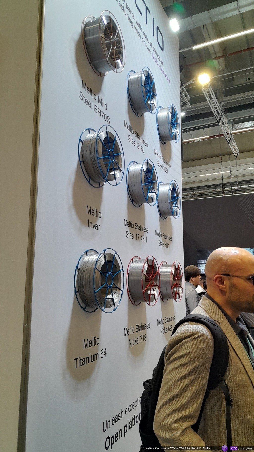
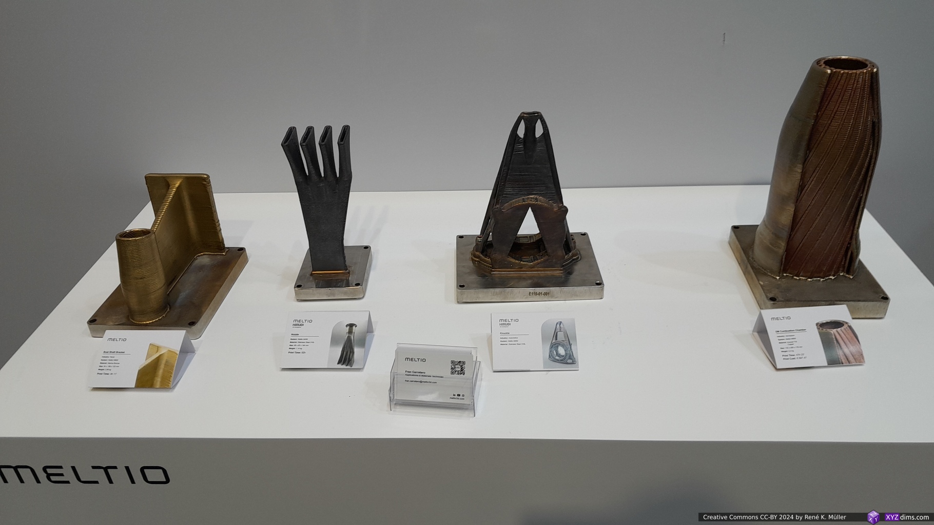
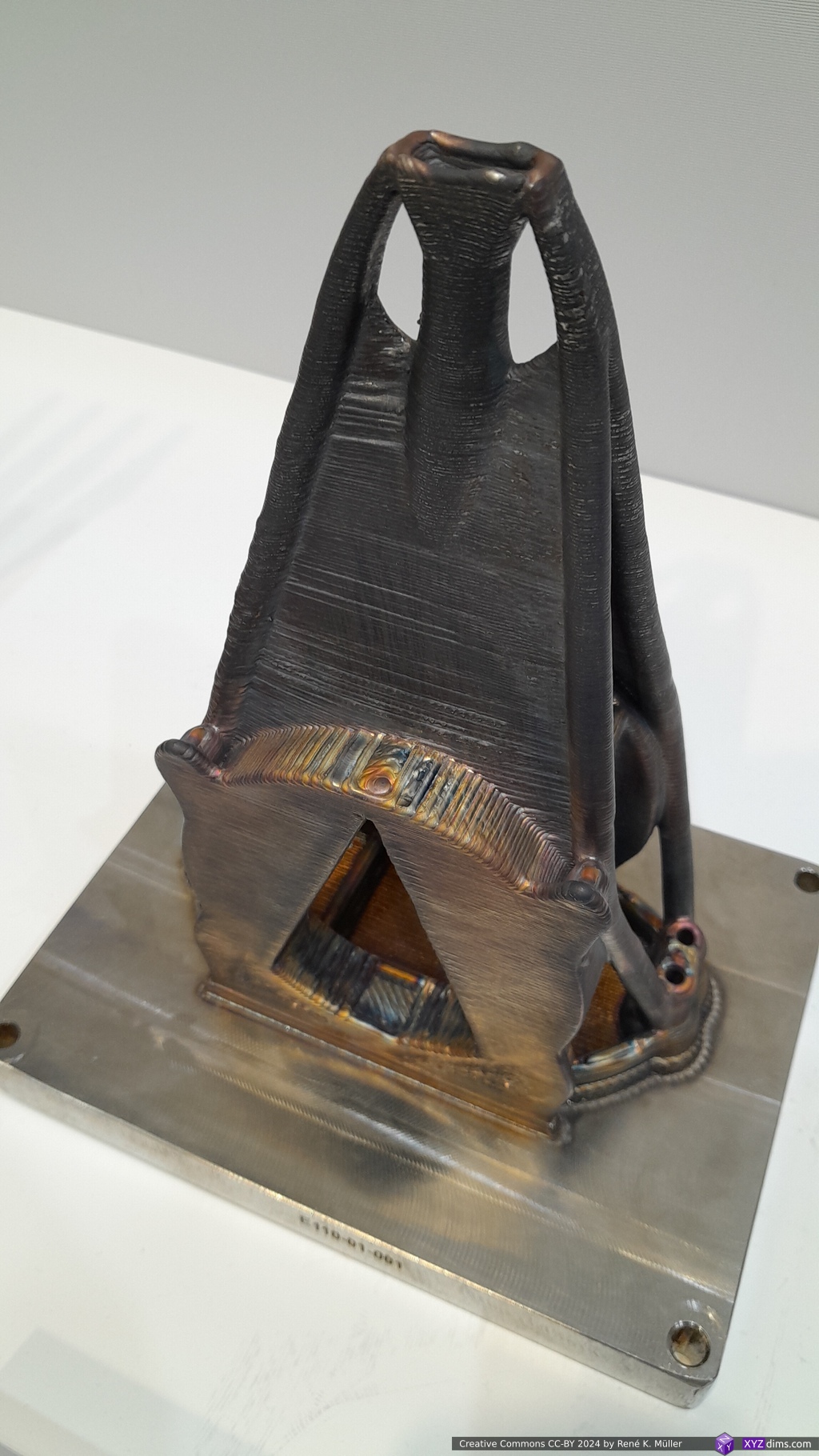
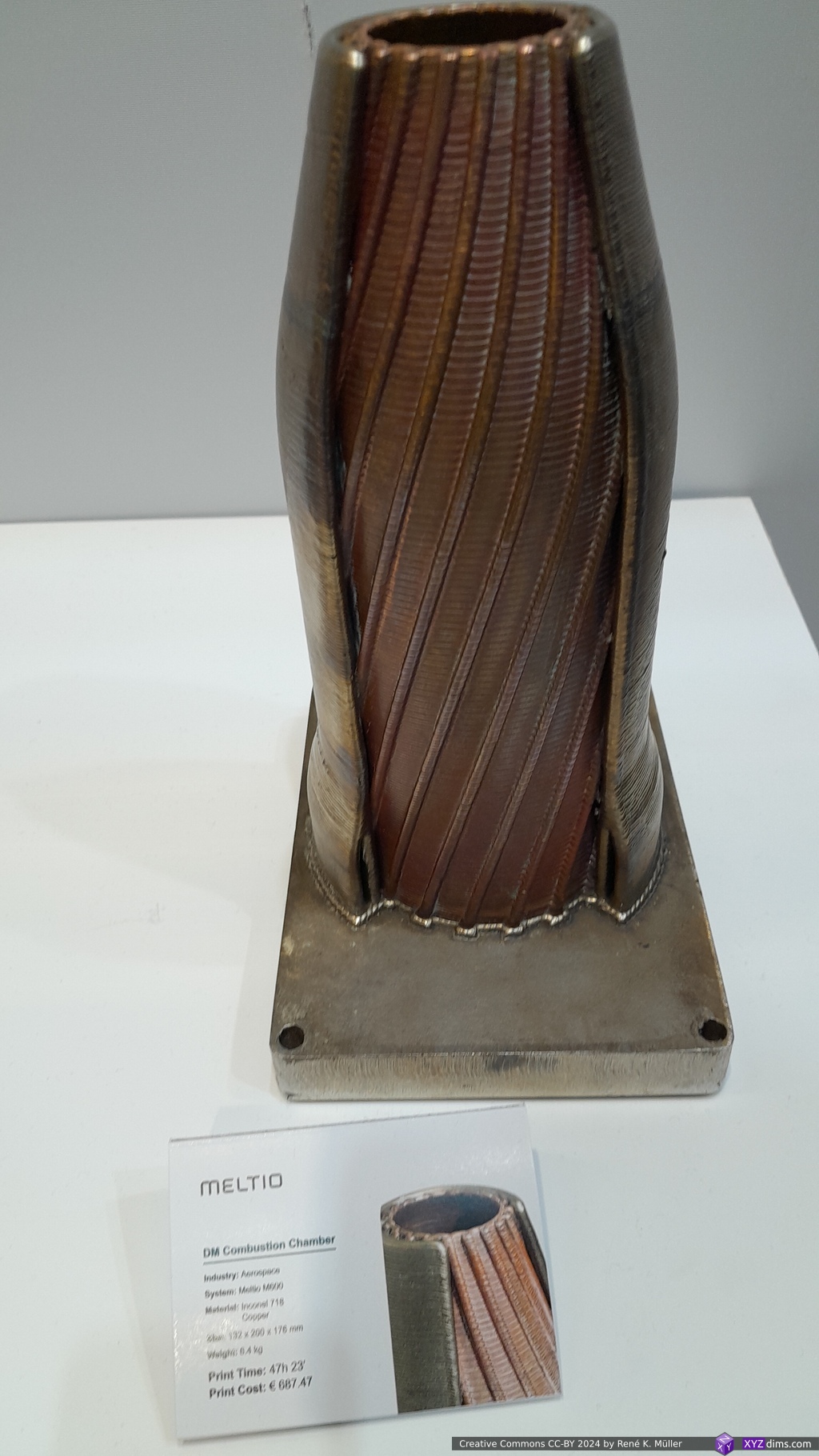
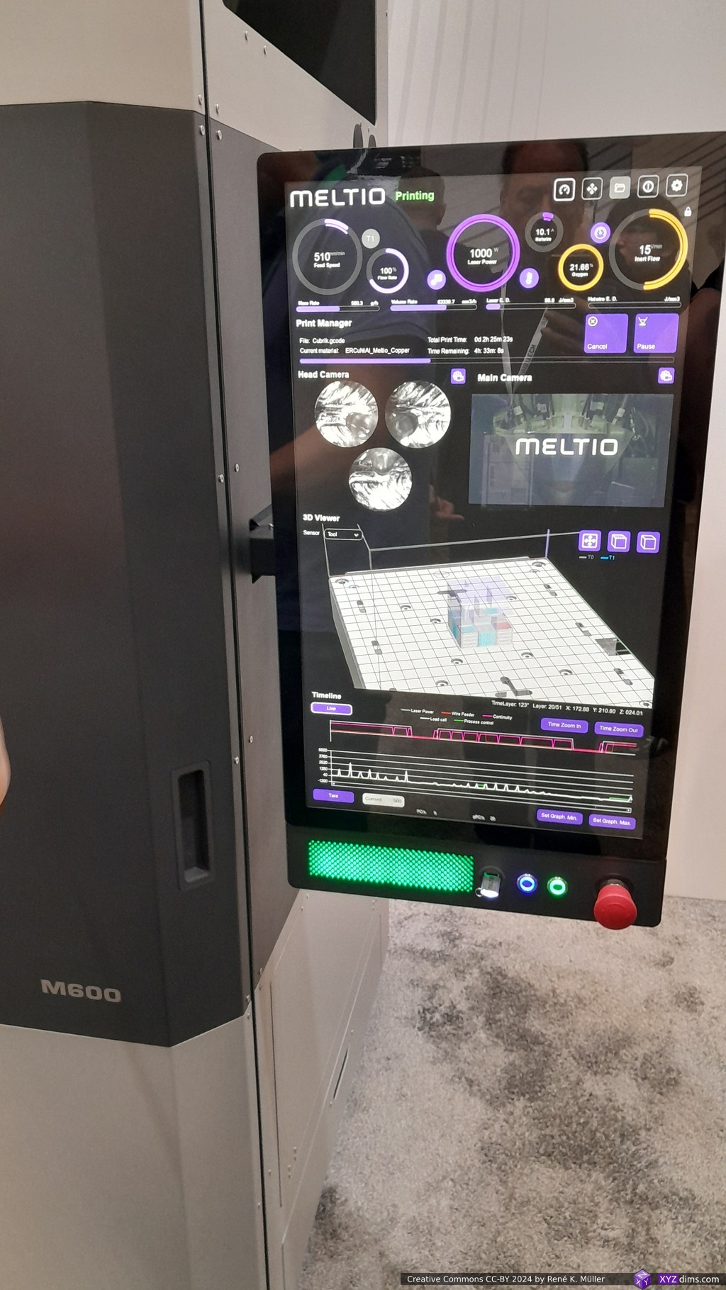
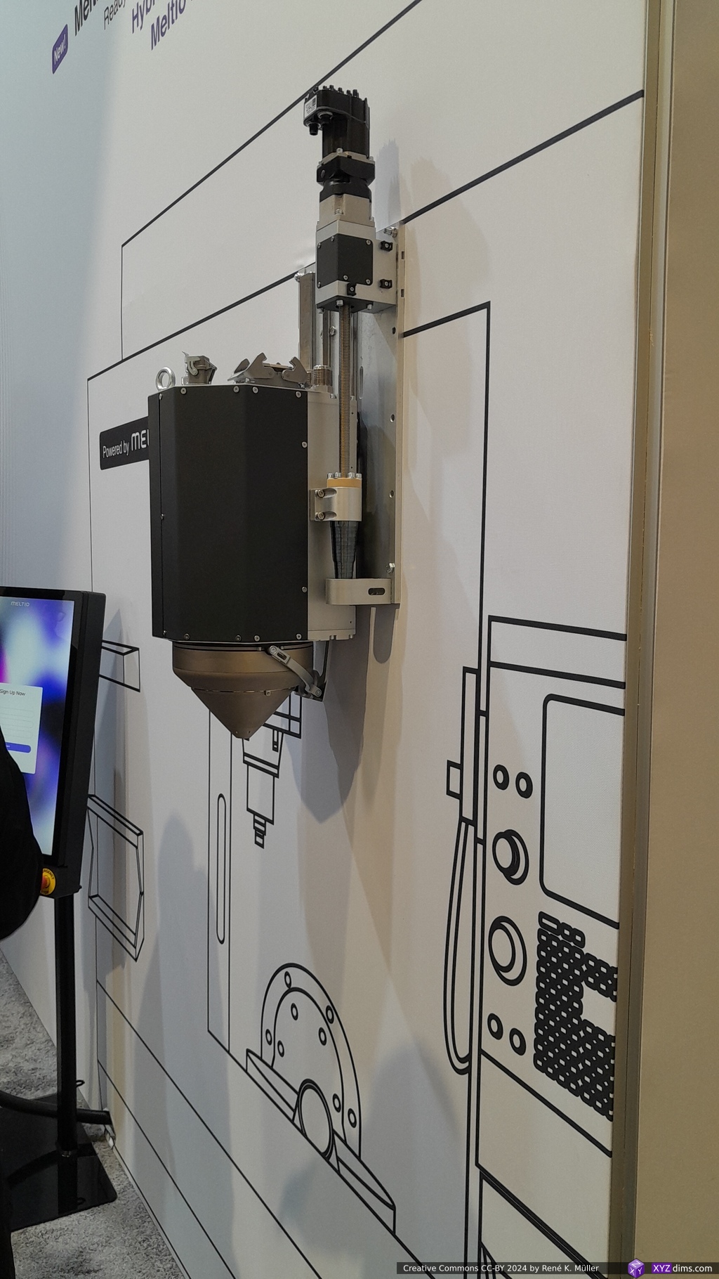
Printing metal poses the biggest challenge in my eyes as you have to put immense amount of energy to deform metal, while maintain or desire high degree of precision. So Meltio focuses on Directed Energy Deposition (DED) and Wire-Laser Metal Deposition (W-LMD): stainless steel, carbon steel, titanium alloys, nickel alloys, copper and aluminium:
Their sample prints are massive, and quite rough compared (0.8-1.2mm wire diameter) to Selective Laser Melting (SLM, powder-based) models where we get 50um feature size.
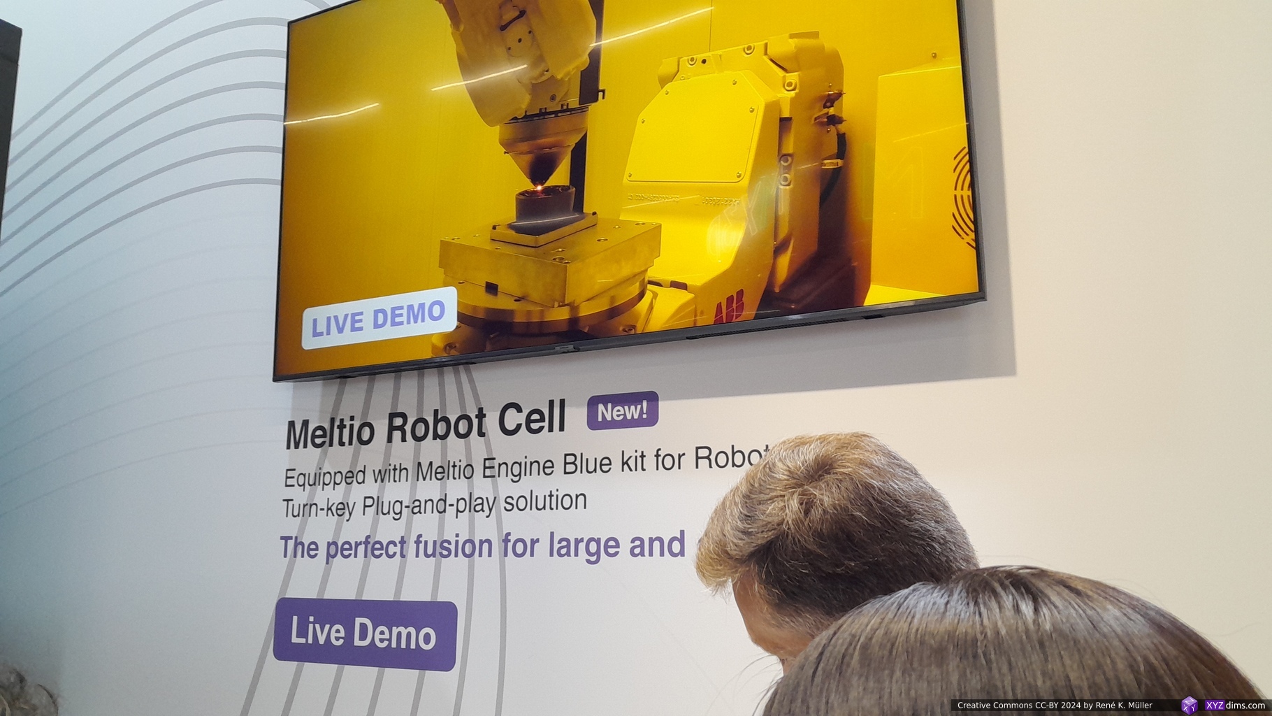
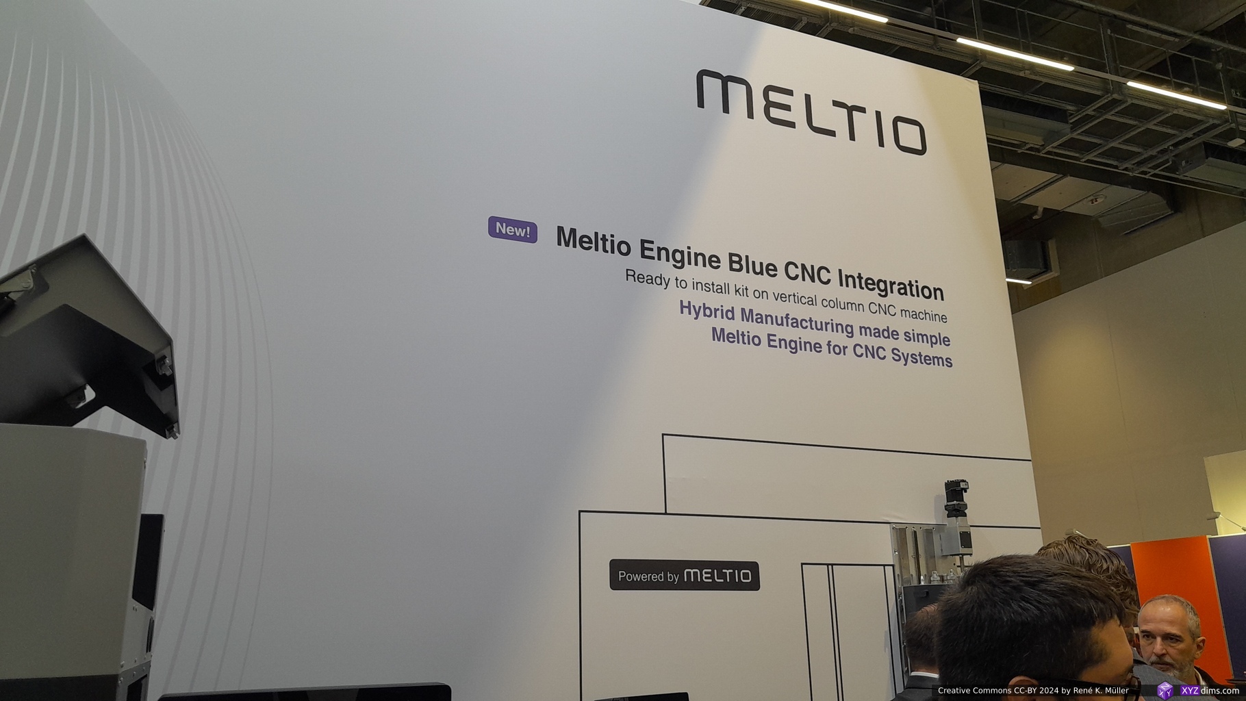
Their “Engine Blue Integration Kit” integrates into existing CNC machines making it hybrid operation and achieve traditional CNC tolerances and feature size – one of the many examples where Additive & Subtractive Manufacturing are put together with their respective strengths.
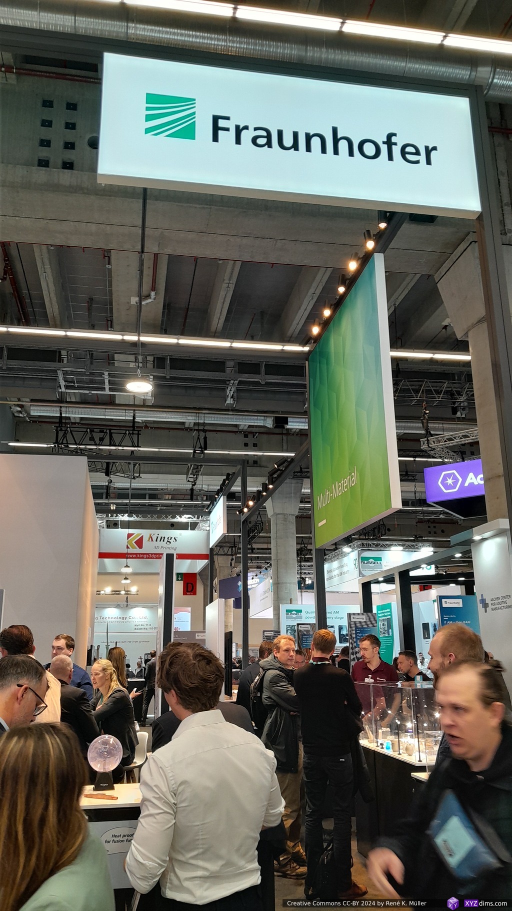
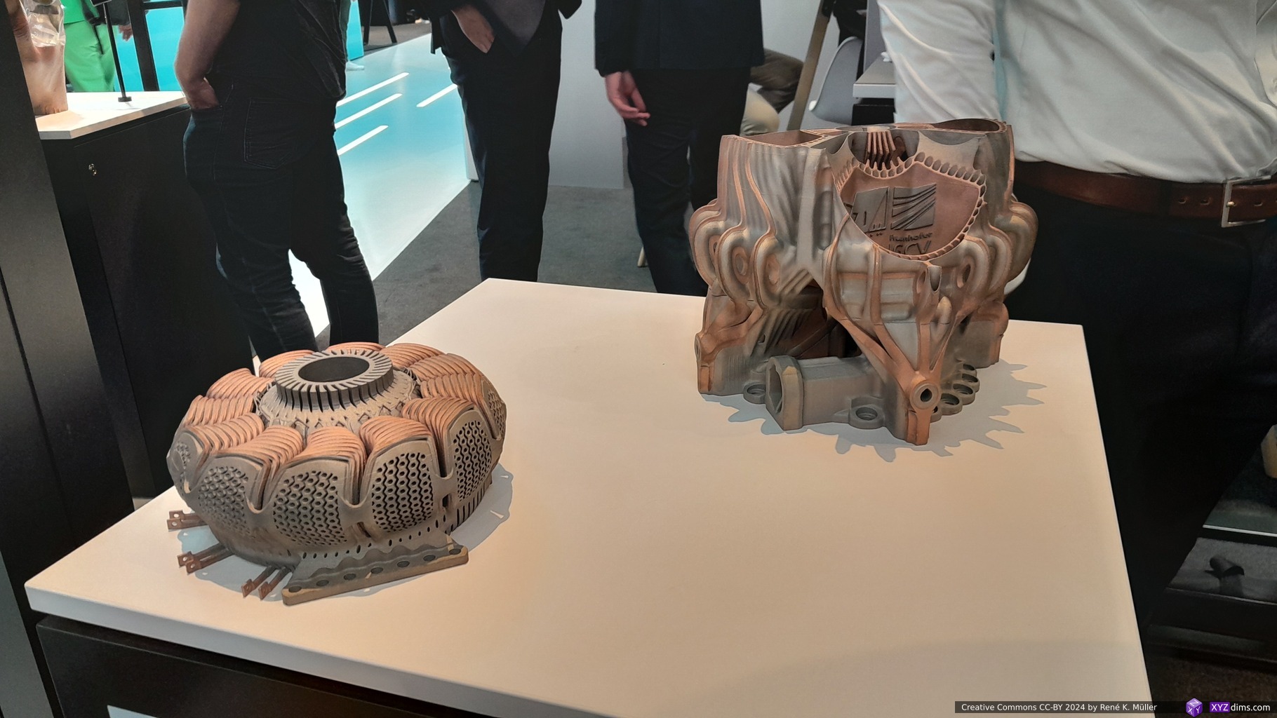
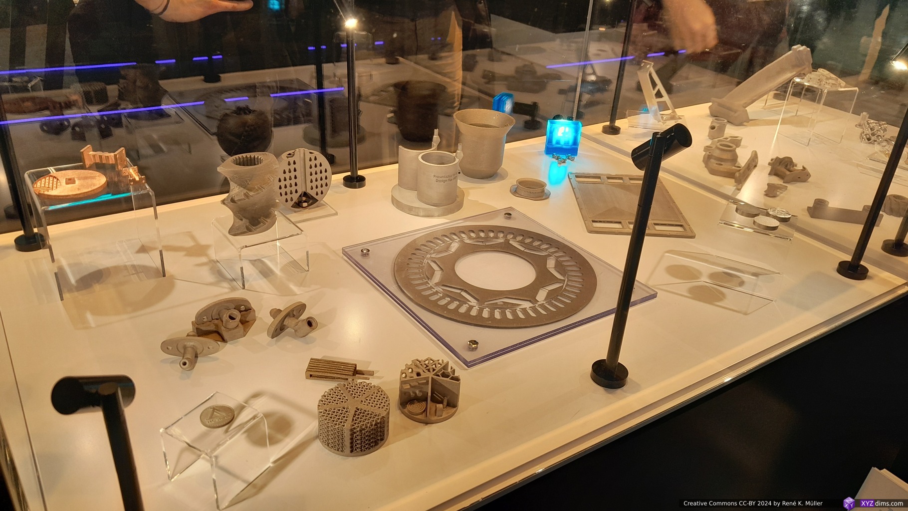
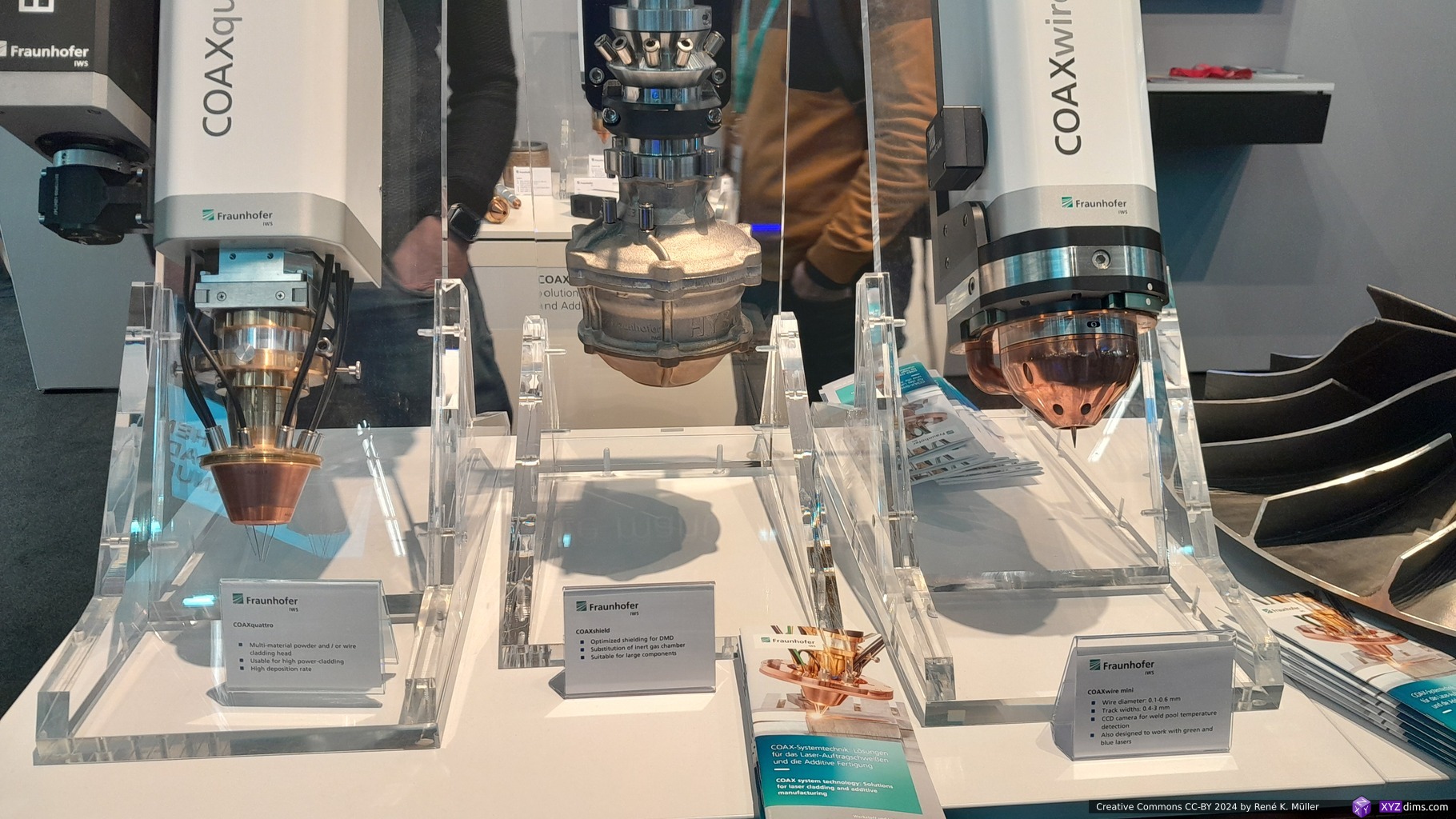
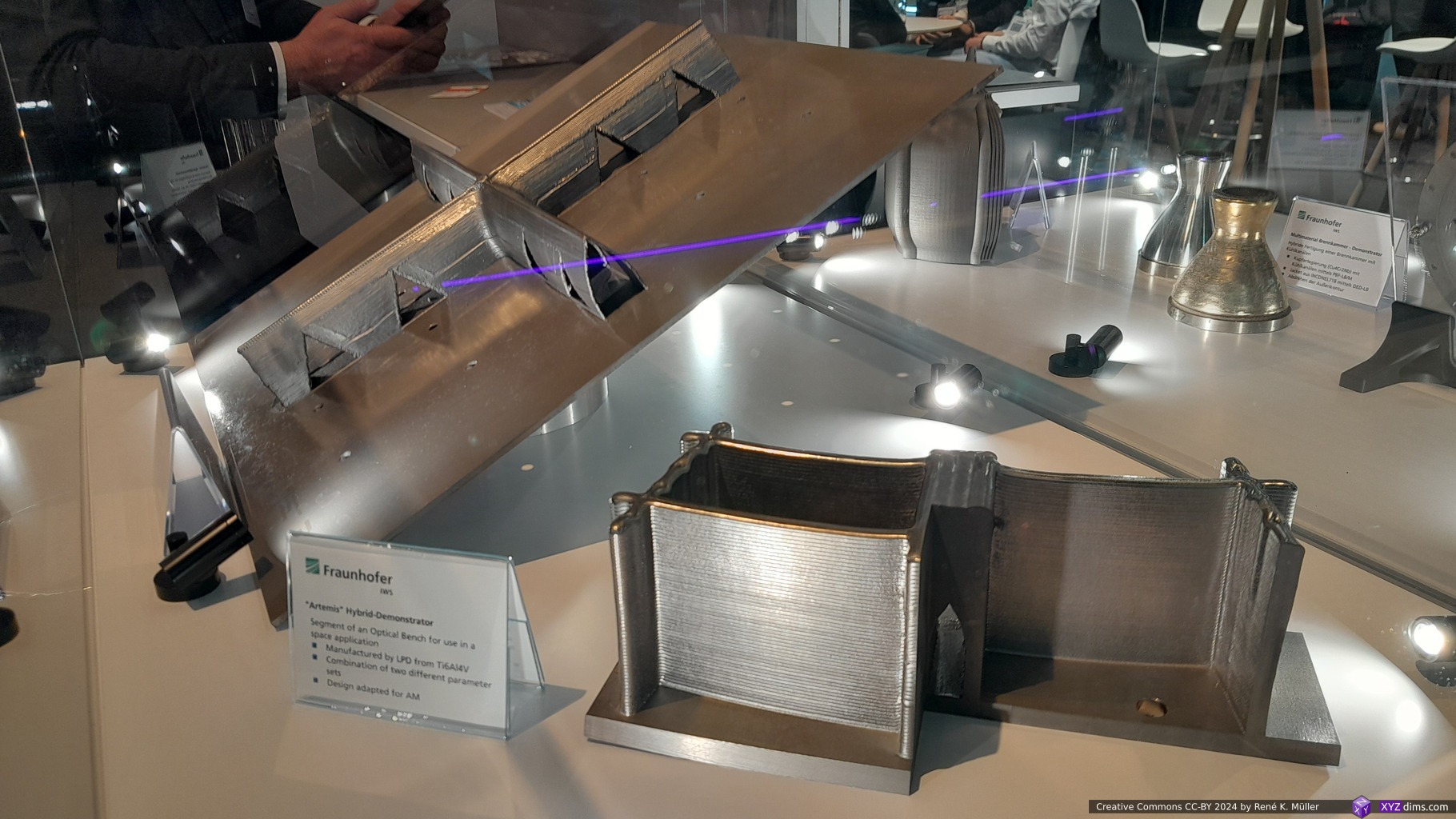
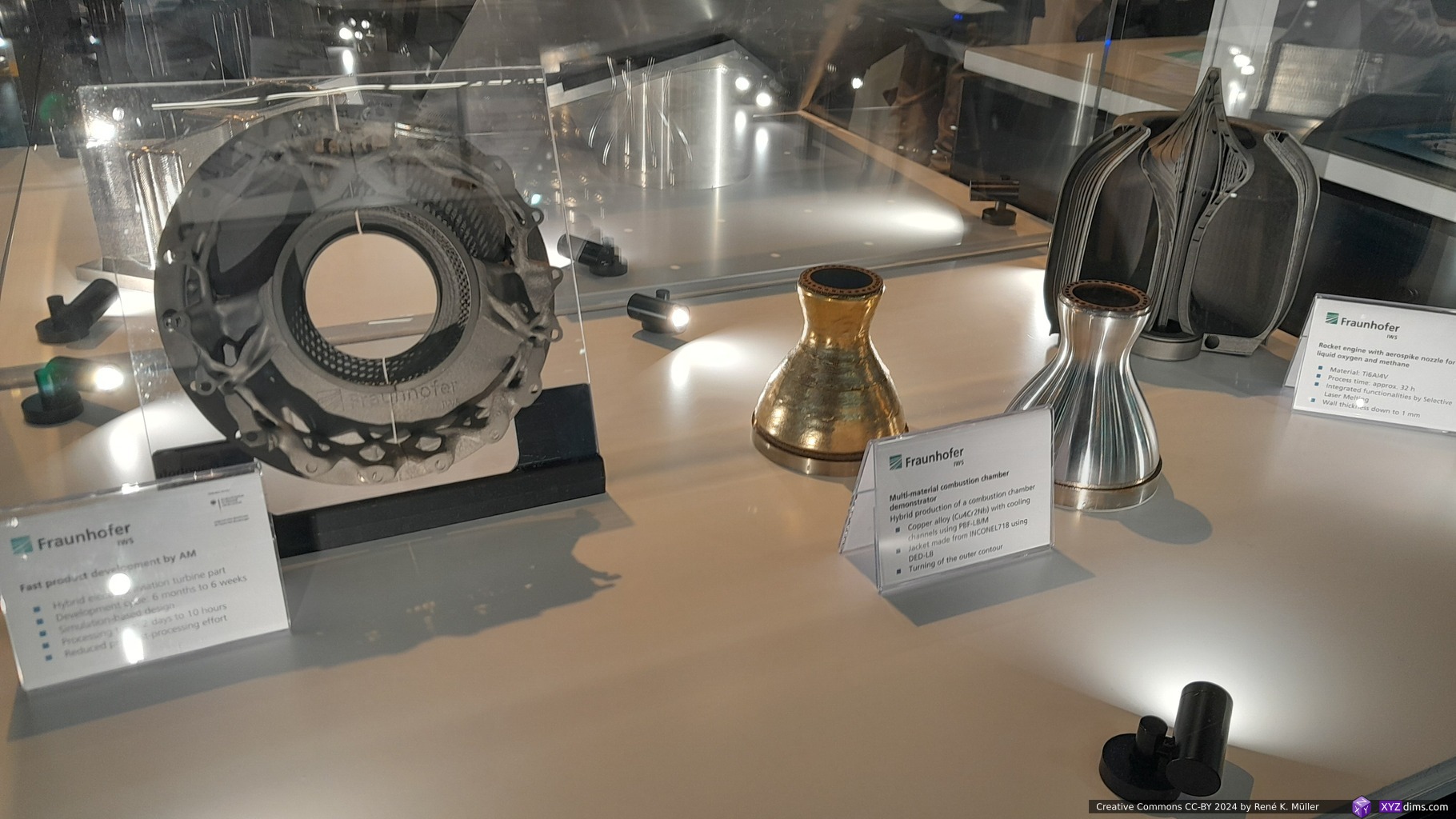
Fraunhofer is a prominent research institute in Germany, with multiple booths displaying cutting edge AM methods – I didn’t have the time to dig deeper into their samples, somehow nothing stood out prominently, or it was vaguely explained at first sight unlike at other booths.
Whenever I pass by their booth, the only thing I think is “car-sized 3D printers costing millions of EUR/USD”, it’s a different use-case from where I operate – as simple as that, and yet, still impressive what they achieved.
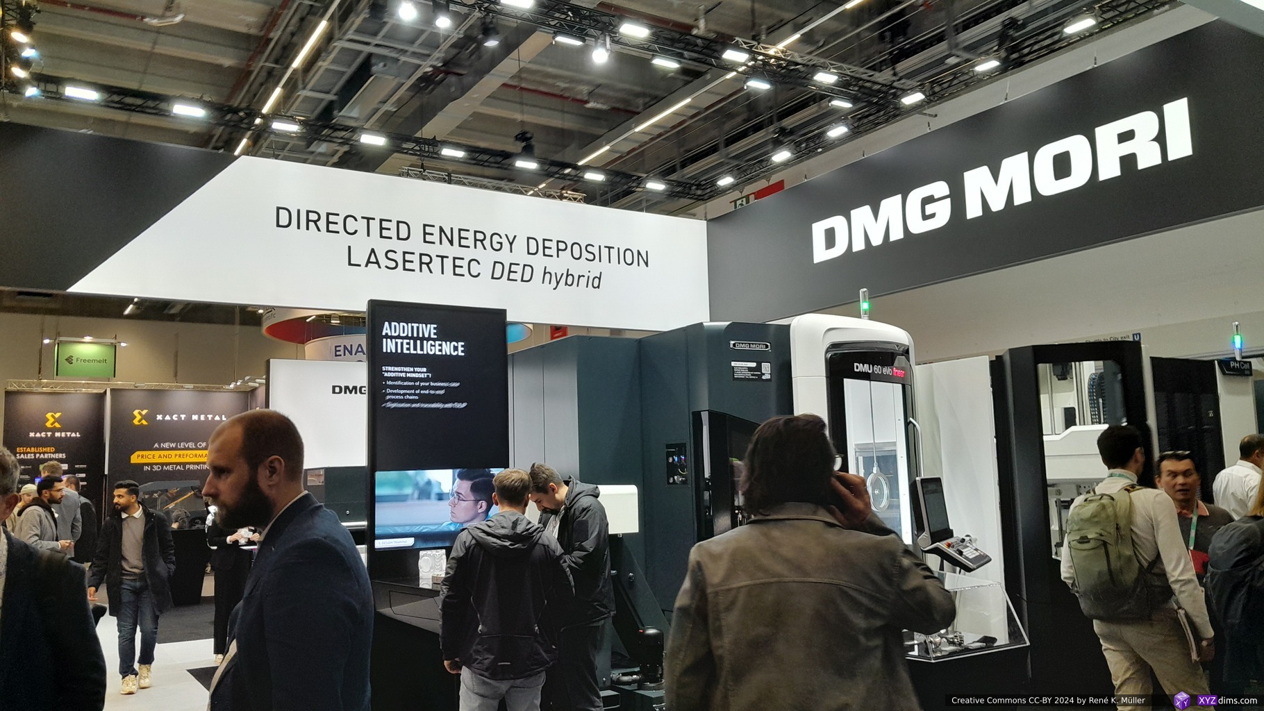
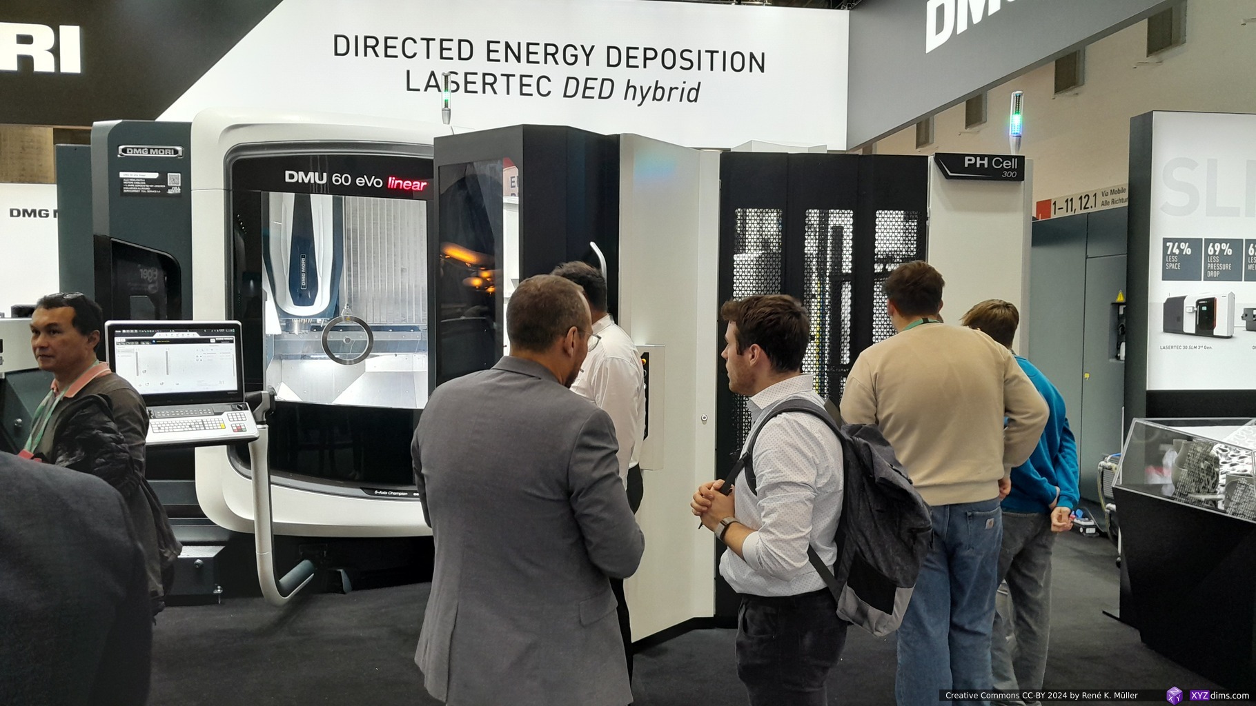
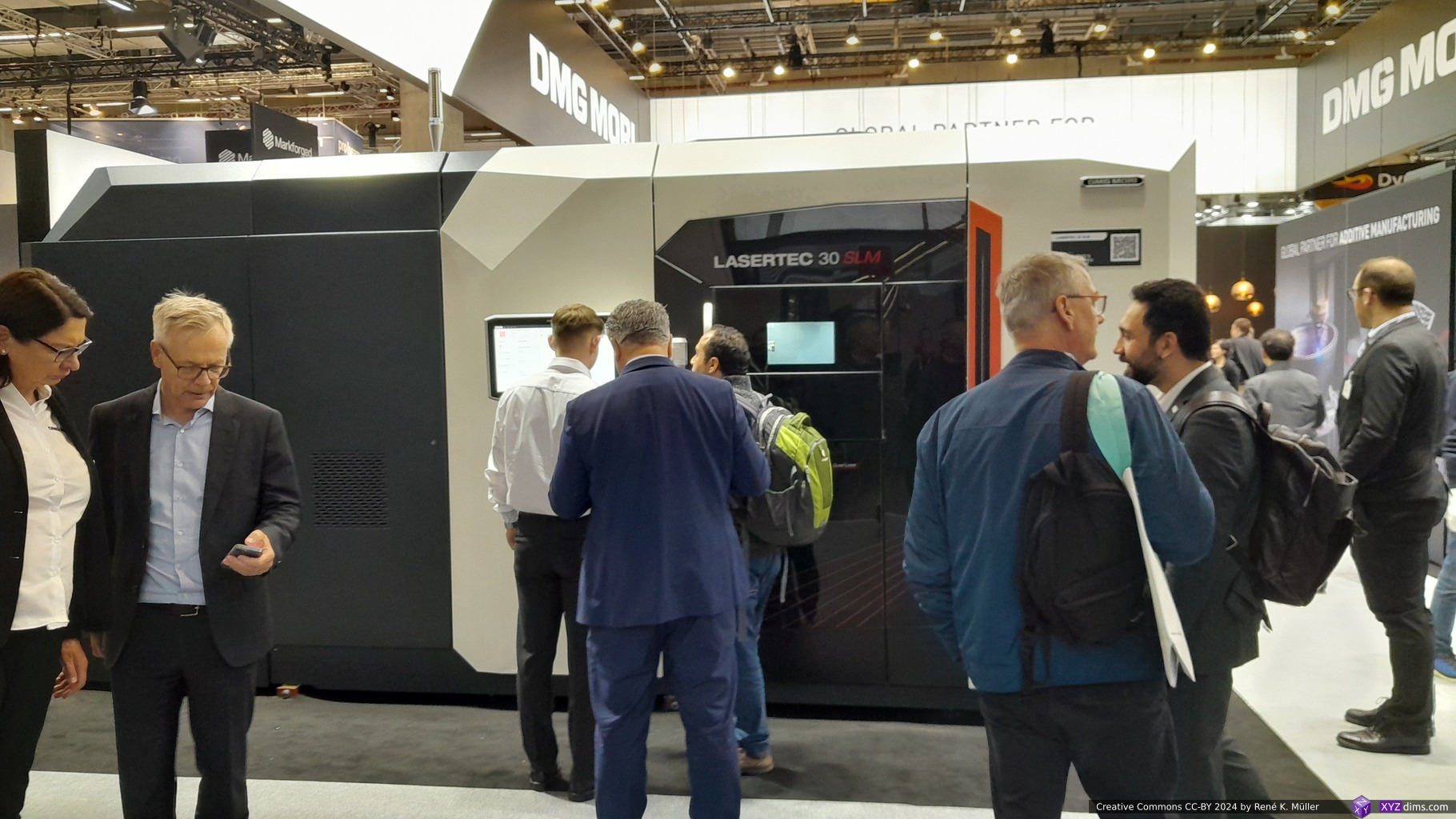
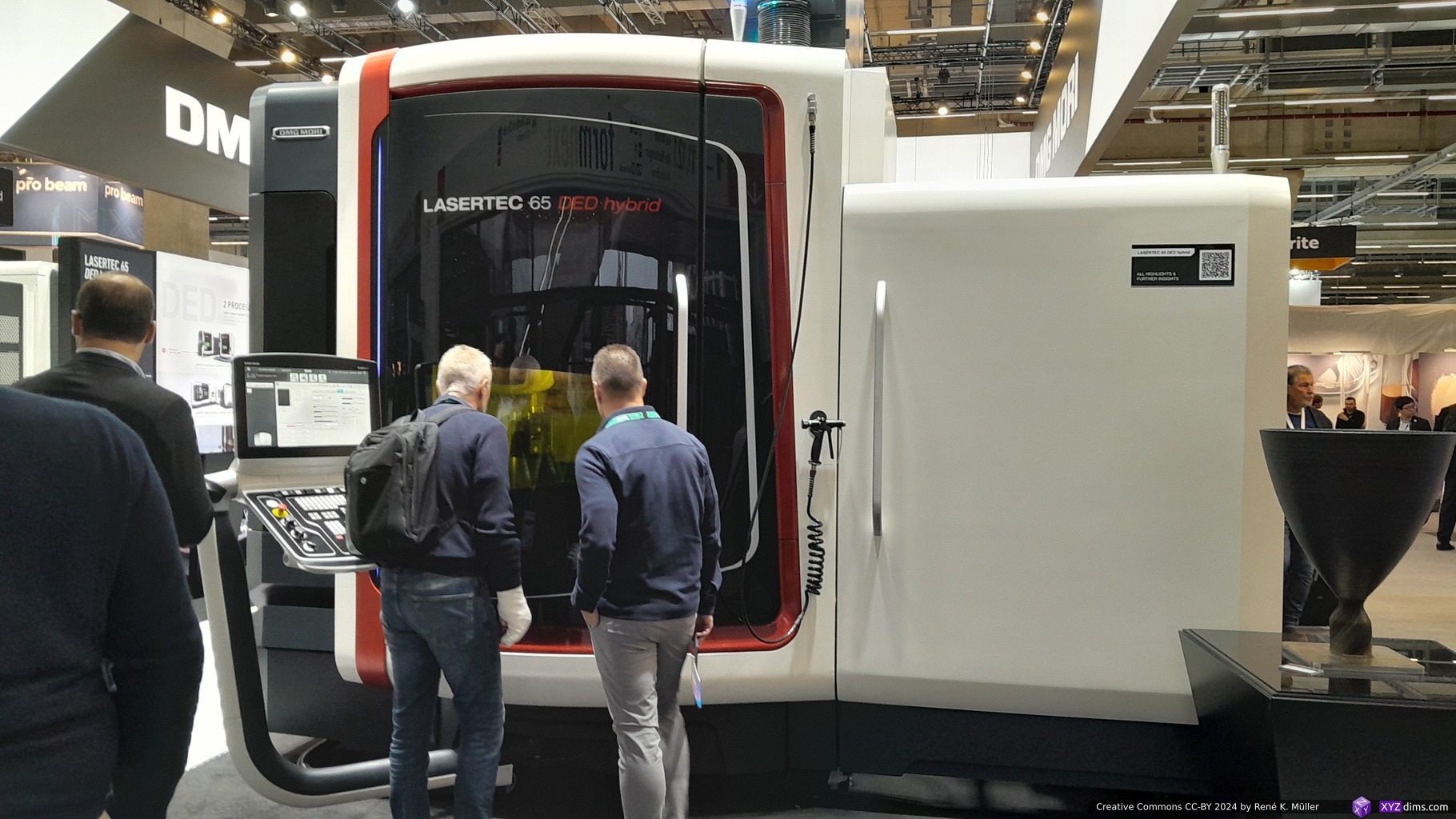
Lasertec 65 DED Hybrid: DED with CNC capability, with just 735x650x560mm build volume
Btw, its name comes from multiple mergers: DMG (Deckel, Maho, Gildemeister) and Japan’s Mori Seiki – a blend of german and japanese workmanship.
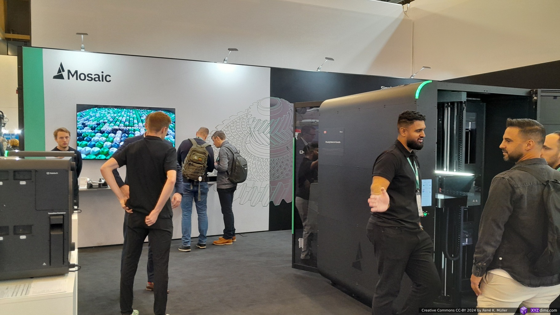
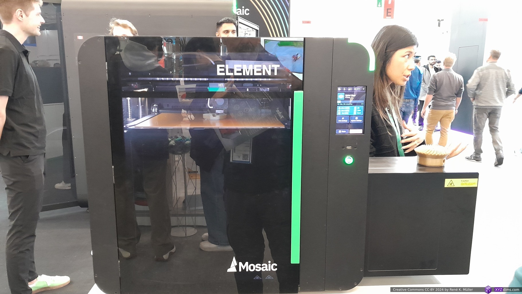
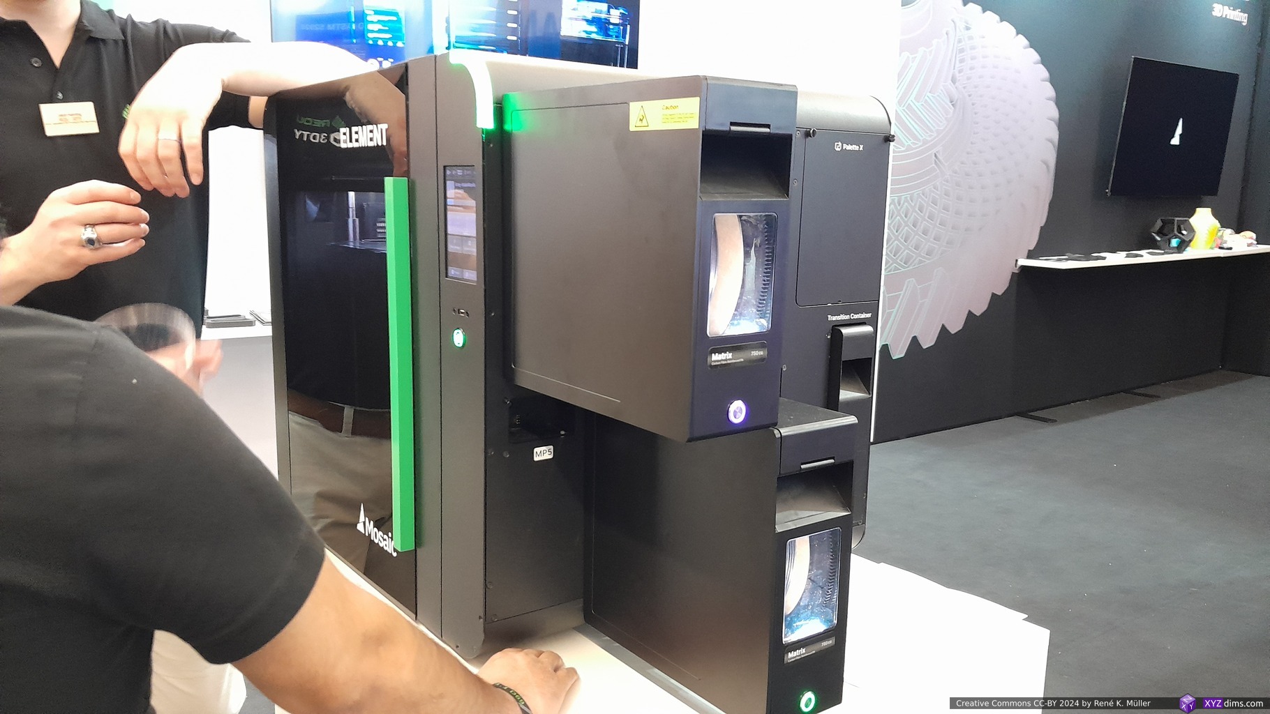
A few years back in 2017 they released their Mosaic Palette, splicing (cutting and melding together) filaments ahead for a single filament yet achieving multi-color with a single nozzle without material waste. Meanwhile they massively scaled up their expertise and developed their own printers called Mosaic Element and print farm called Mosaic Array – and I admired the overall case design in simplicity how the filament cartridges are attached.
Element HT2 specs:
nozzle up to 500°C
build plate up to 120°C
build chamber up to 80°C
350x350x350mm build volume
up to 8 materials via filament cartridges
price starting at EUR 9,500
Their print farm is built on stacked printers, and a robot arm removing the built-plate with the printed piece and stack it below and refill the printers with empty build plates again.
While roaming in the halls, I recognized a few YouTubers like Ross Graham (FauxHammer), Jon Schone (Proper Printing) and also Joel Telling (3D Printing Nerd):
Here his marathon live-stream at Formnext 2024:
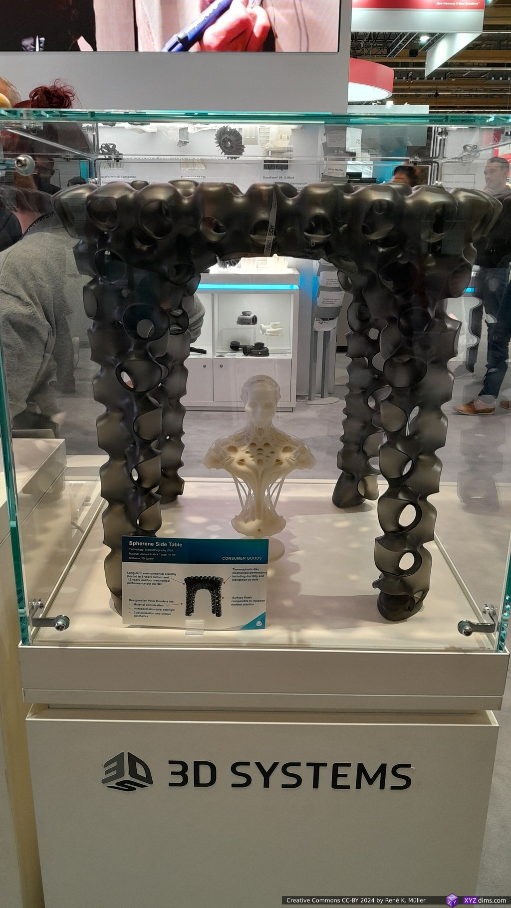
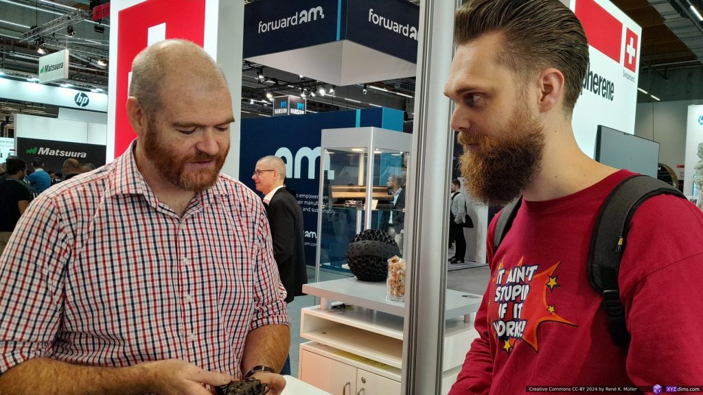
Among others were also Xolo with the Xolography light printers, Spherene with Daniel Bachmann, Josef Prusa showing the Prusa Core One, and Stratasys representative featuring SAF H350 able to process used powder with High-Energy Absorption Fluid (HAF) with Selective Absorption Fusion (SAF).
Tony Lock (Duet) & Jon Schone (Proper Printing)
As I was visiting the booth of OST (Eastern Switzerland University of Applied Sciences) & Spherene I met Jon Schone (Proper Printing) and Tony Lock (Duet3D) and we had a brief talk on multi-axis firmware & slicing and parallel printing as Jon showed in his video with a multi-gantry setup – I’m currently composing/writing on a blog-post about parallel/concurrent printing with multiple nozzles so I was keen to briefly exchange thoughts on this topic.
Tony Lock (Duet3D) & Jon Schone (Proper Printing) – Formnext 2024
Reflection
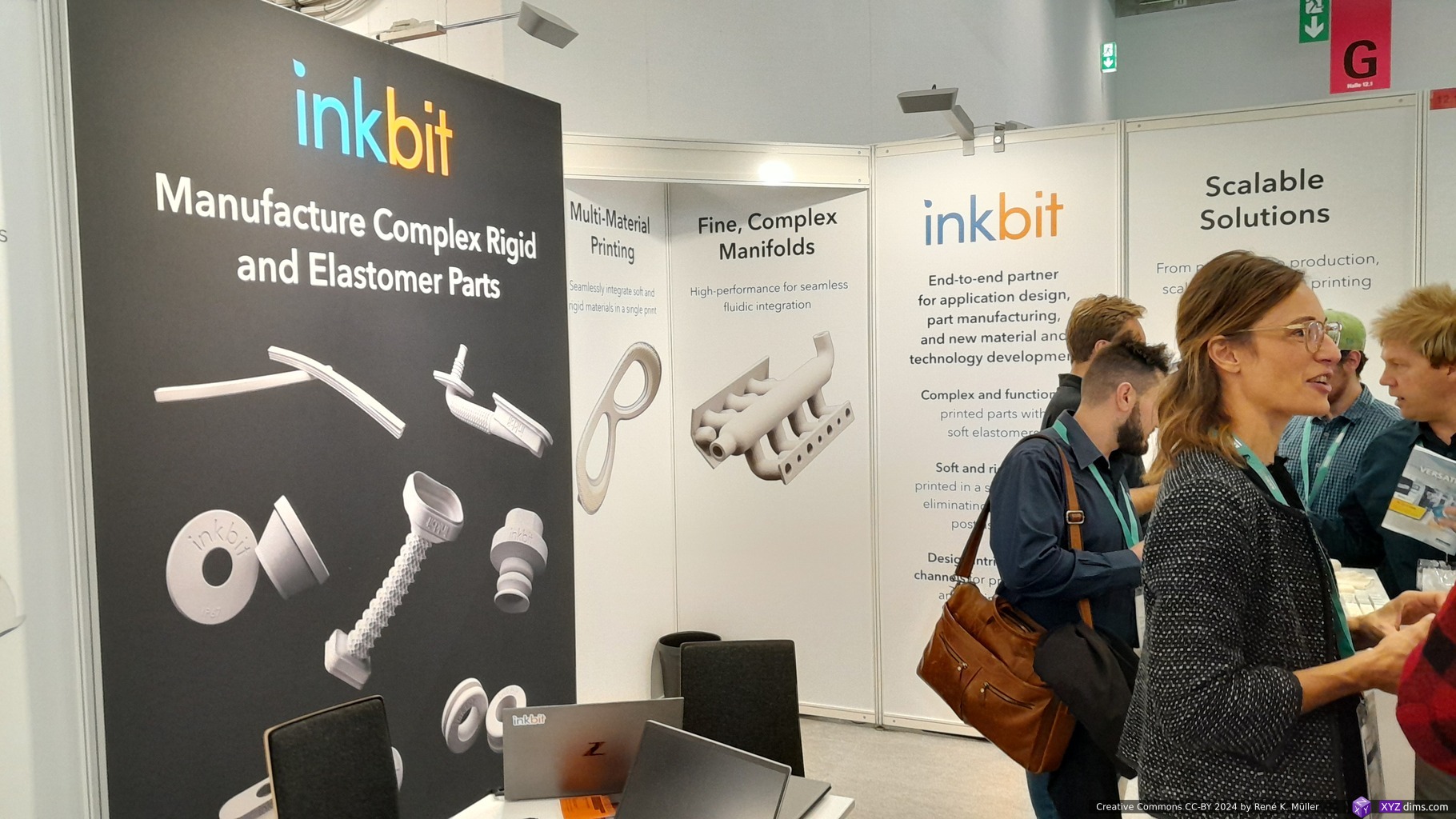
Formnext is an overwhelming expo on all things on Additive Manufacturing, and this year less people and less exhibitors than last year. Also a few startups with big booths last year either had a small one (nTop, Inkbit, etc) or were no longer present. A couple of newcomers and startups, and some companies I have been following pushing their innovation further and exploring new applications, like Quantica.
I only stayed for 2 1/2 days (Tue-Thu) instead the full 4 days, as from last year I knew I wouldn’t be able to absorb more things with more time, there was only so much to take in. For me it was worth it, to reconnect with companies and individuals I know only online and via video calls.
The “3D Printing Hype” has peaked, the stock prices (state 2024/11/22) of Stratasys (8% or -92% of max), 3D Systems (8% or -92% of max), Desktop Metal (1.6% or -98.4% of max) or Nano Dimension (15% or -75% of max) have shown how much air and speculation was there, and now the sobering realism and use case are established. The same time MakerBot & Ultimaker merged, two exhausted 3D printer manufacturer without hardware innovation in the past years – yet Prusa, Creality, Elegoo, Anycubic still thrive on the pro- and consumer level with both FDM/FFF and MSLA resin printers, and BambuLab so successful that it caught Stratasys’s attention to sue them about patent infringements.
It’s clear to me, that Additive Manufacturing (AM) has its unique use-cases, whereas injection molds still dominate mass production due the high volume capacities and cost effective production. Additive Manufacturing may be a bland term (I like “3d printing” better), but there are still many possibilities to be explored, as Xolo or diverse university booths have shown – any kind of granular or liquid material is melted, extruded, jetted, cured or bound with an agent.
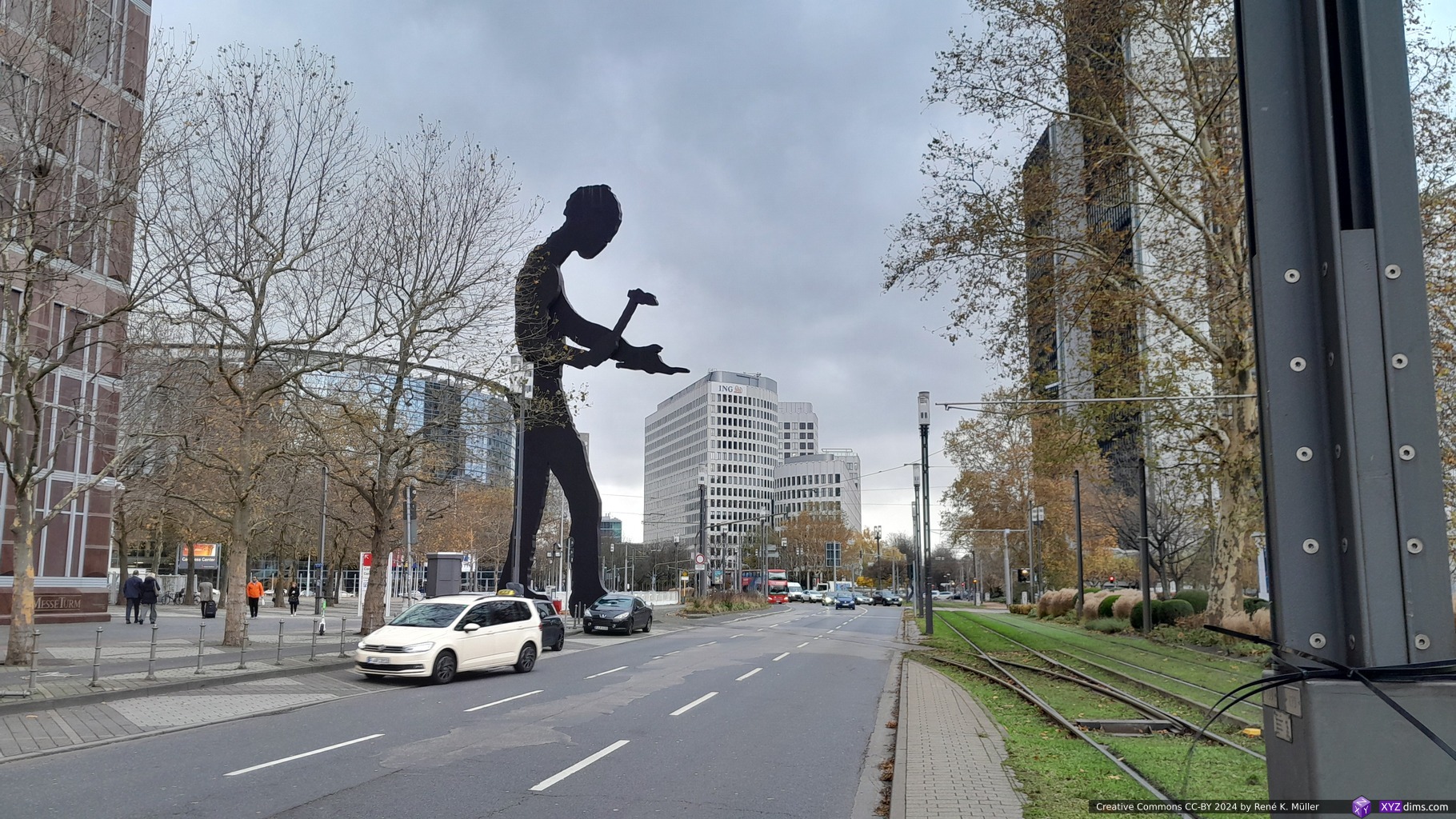
Hammer Man in Frankfurt/Main (Germany) – Symbol of a Maker
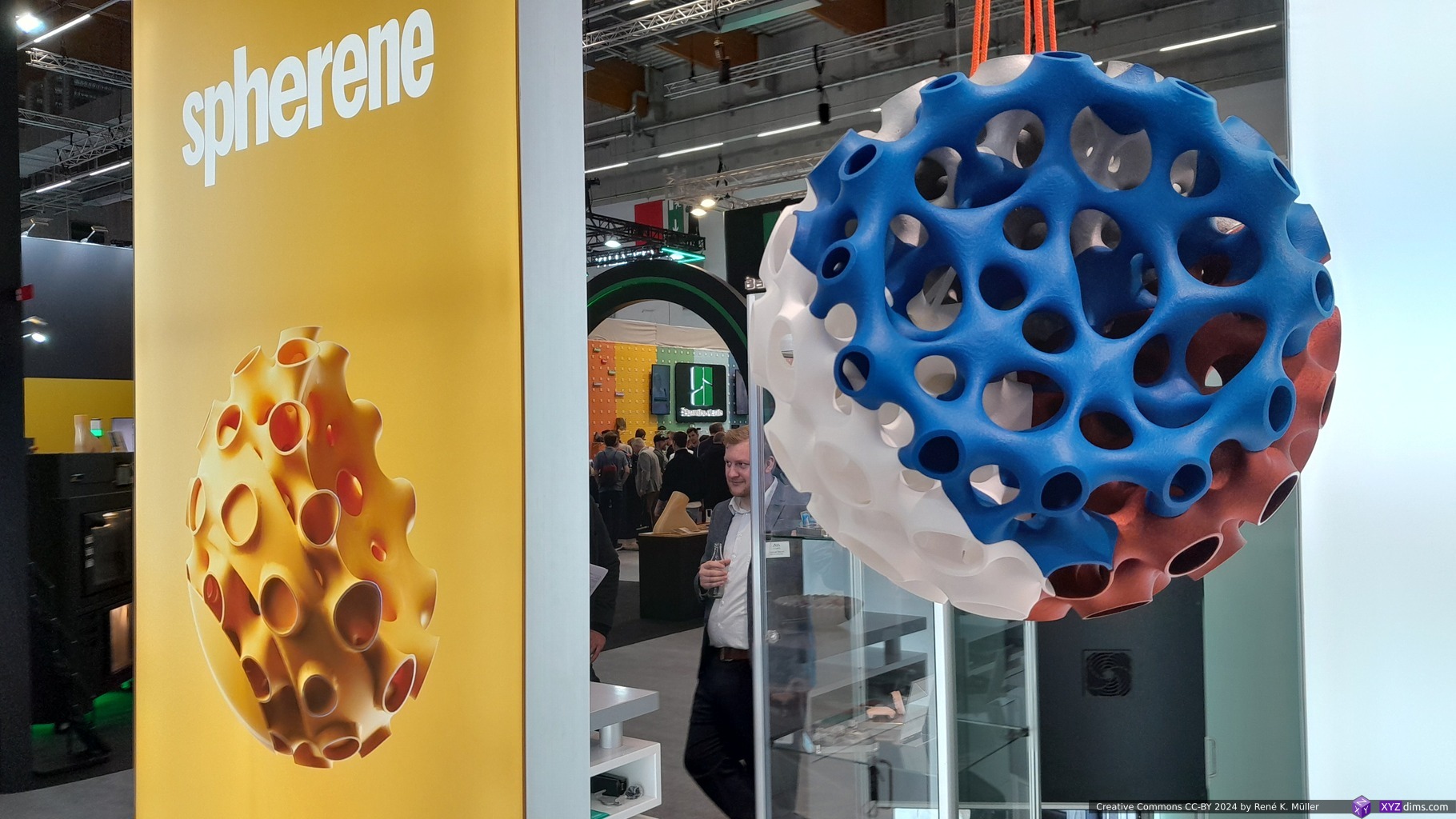
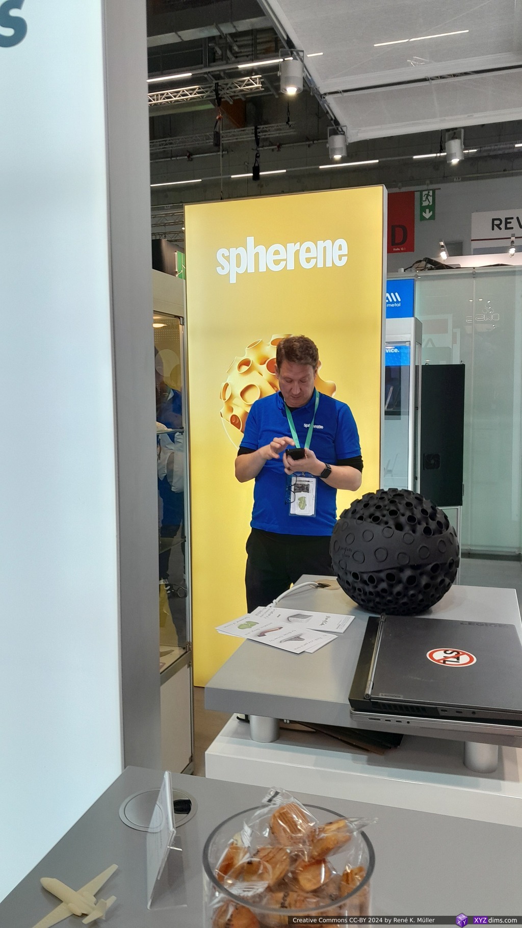
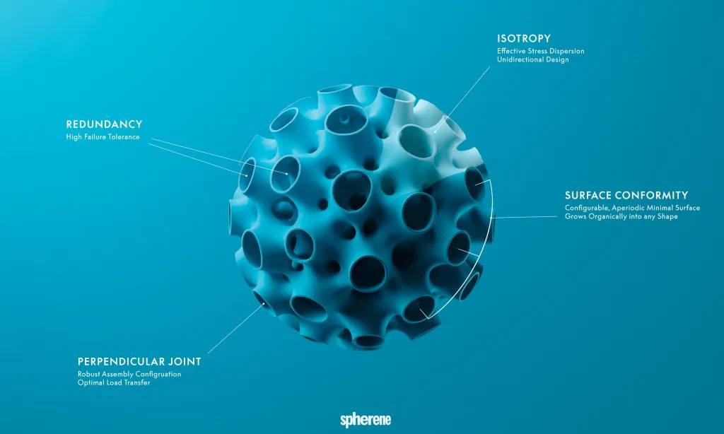
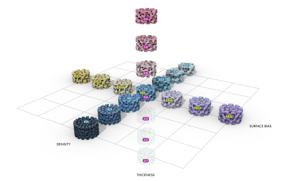
At Formnext 2023 I spent some unexpected time to discover a new class of procedural structure called “Spherene” (“sphere” + “graphene”), it’s a name as introduced by a company with the same name.
It’s main feature is isotropic (“all directions”) distribution of forces. Their service provides the creation of this structure based on:
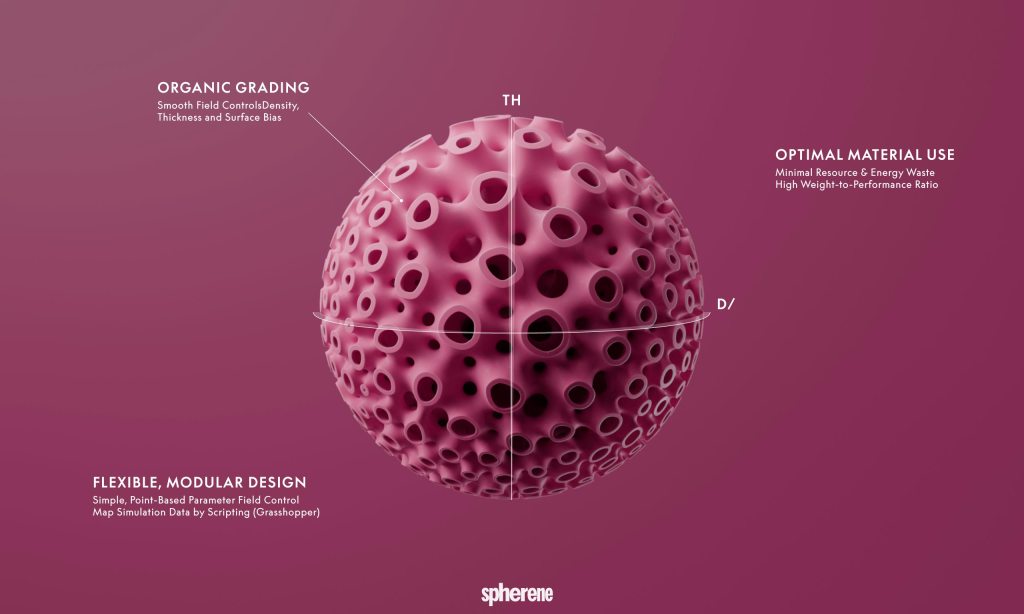
density (ratio of material vs empty space), hence their term of Adaptive Density Minimal Surface (ADMS)
form
wall thickness
where all of them are freely definable in 3D space contained within an overall boundary. Their service “renders” a mesh which complies with such, like defining at some point a lower or higher density, and transits in 3D space from one to another.
Spherene Metamaterial in Simulation-Based DFAM: CDFAM NYC 2024 (Video Presentation)
Patent
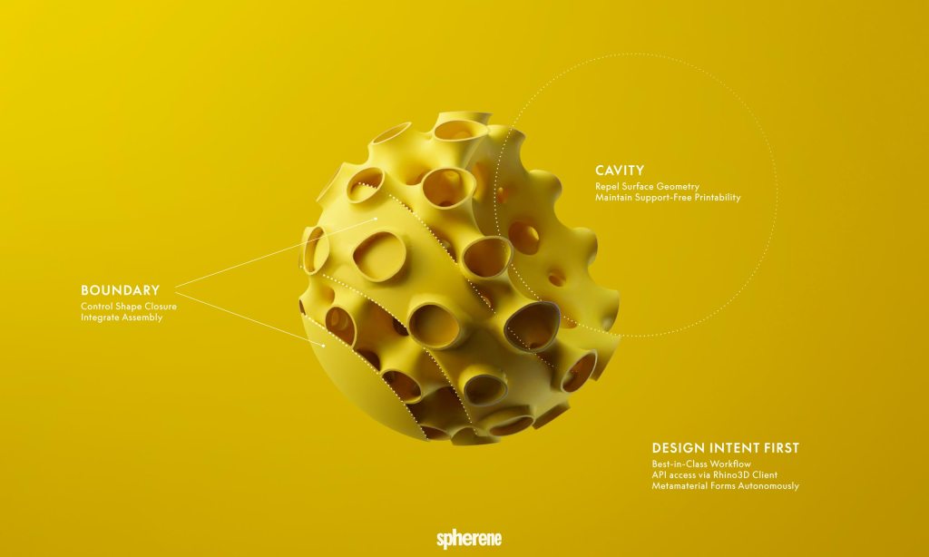
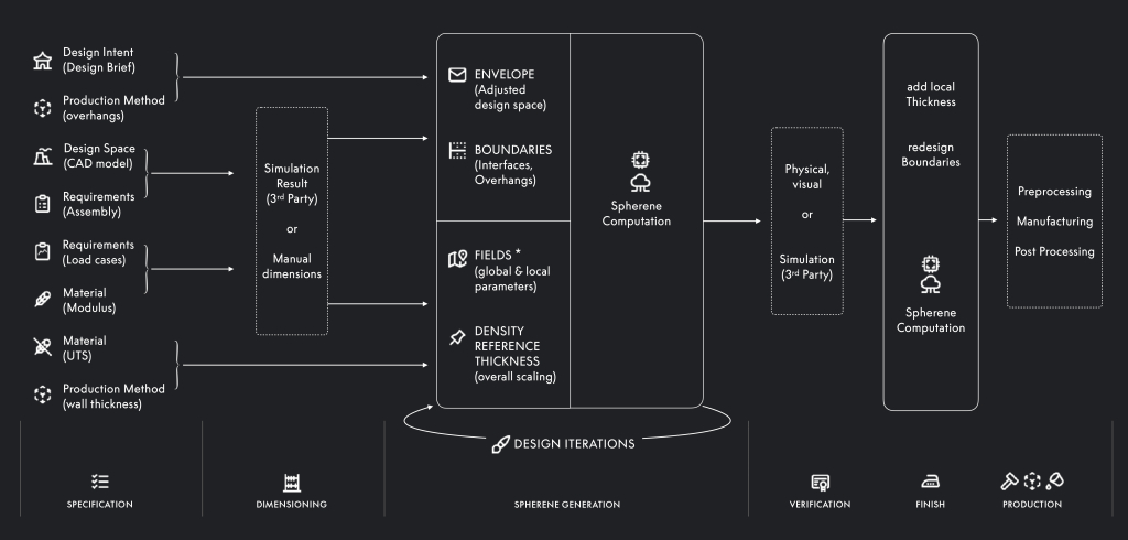
My immediate impulse was to code the Spherene aside of the existing TPMS’s, but I realized their business core is the service of creating meshes based on their procedure as described in a patent:
at its core it describes 6 steps (abbreviations added for clarity)
creating envelope
creating density field
adaptive Voronoi tesselation (AVT),
1st skeleton graph (SG) associated to AVT (SG-AVT1)
generated from the edges of the Voronoi cells
2nd skeleton graph associated to SG-AVT1 (SG-AVT2)
generated using Delaunay tetrahedralization
minimal surface from SG-AVT1 and SG-AVT2, using equidistant from both skeleton graphs, with minimal wall thickness requirements
Abstract: A method of additively manufacturing a minimal surface structure of a three-dimensional article includes a computer executing the steps of recording, in the computer,
an envelope of the three-dimensional article; generating a density field across a volume enclosed by the envelope with densities of the density field corresponding to local requirement values of at least one physical parameter at respective positions of the three-dimensional article;
generating an adaptive Voronoi tessellation of the volume using the density field;
generating a first skeleton graph associated with the adaptive Voronoi tessellation;
generating a second skeleton graph associated with the first skeleton graph; and
generating a digital minimal surface model from the first and second skeleton graphs.
The method may further include a 3D printer additively manufacturing the minimal surface structure according to the digital minimal surface model.
I think if Spherene is truly as significant for Additive Manufacturing, and an essential invention, it has to move beyond the grip of a single company and its patents – time will tell.
Samples
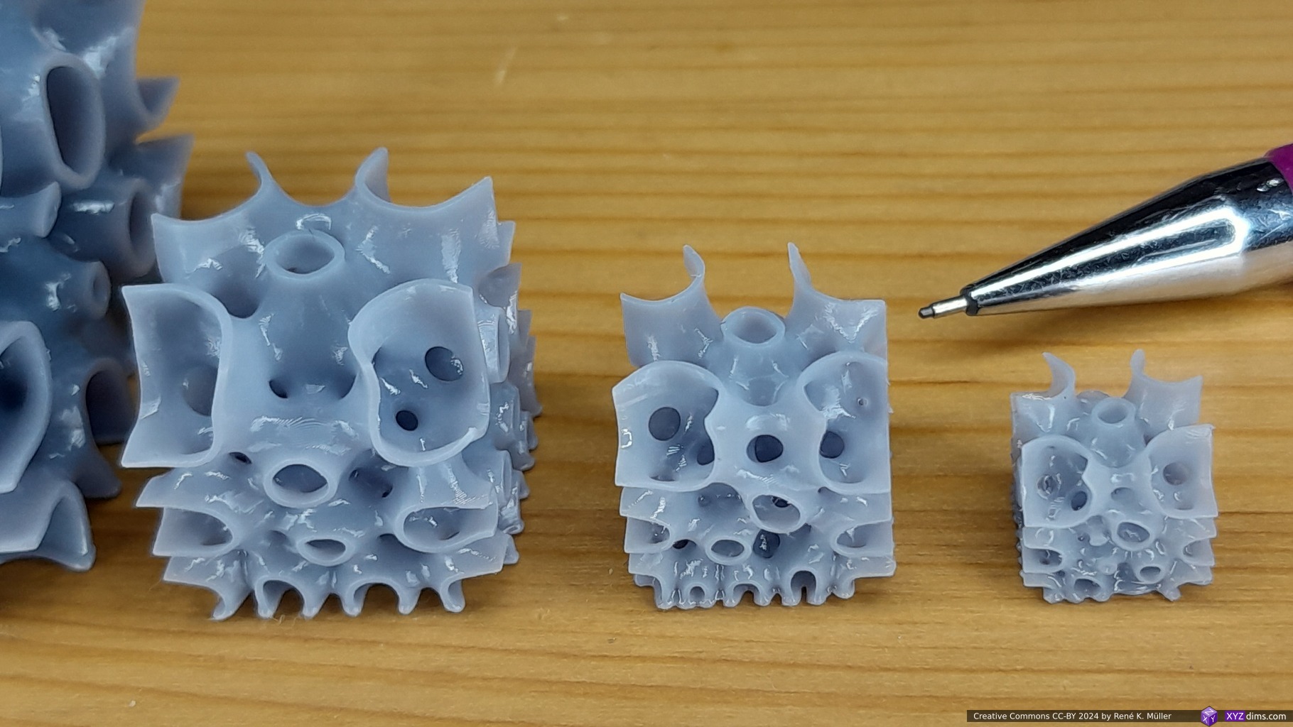
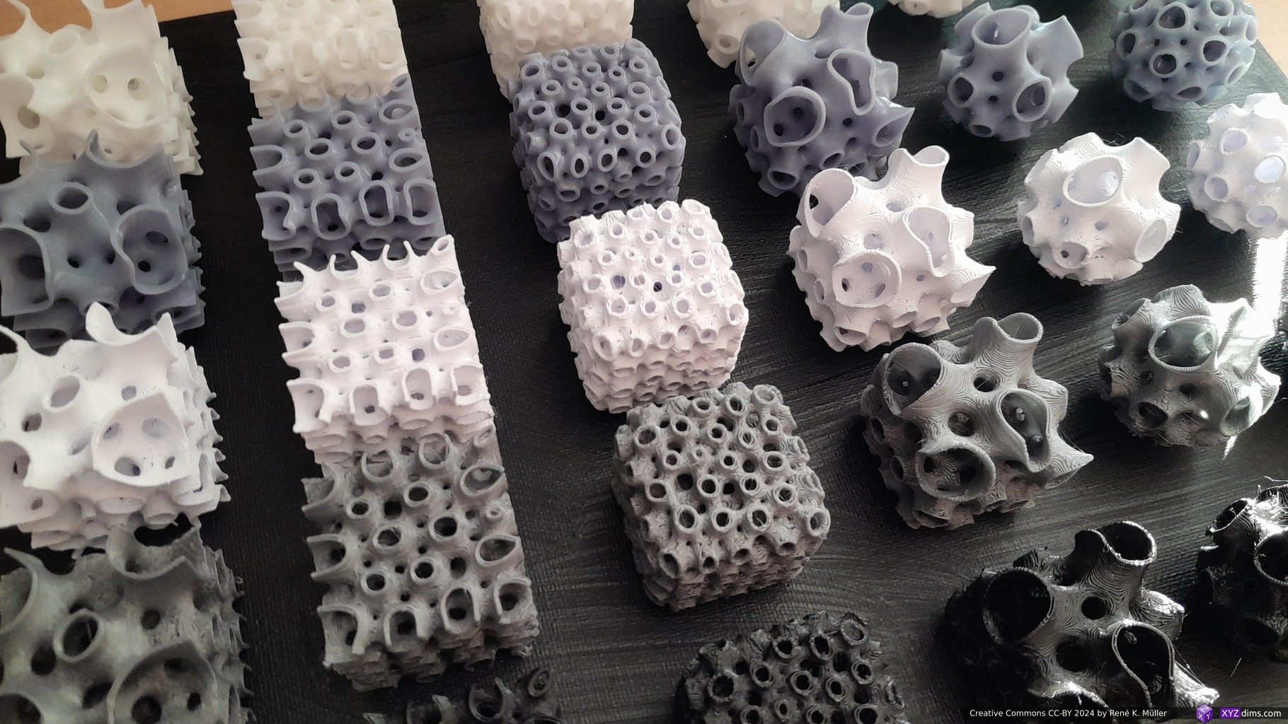
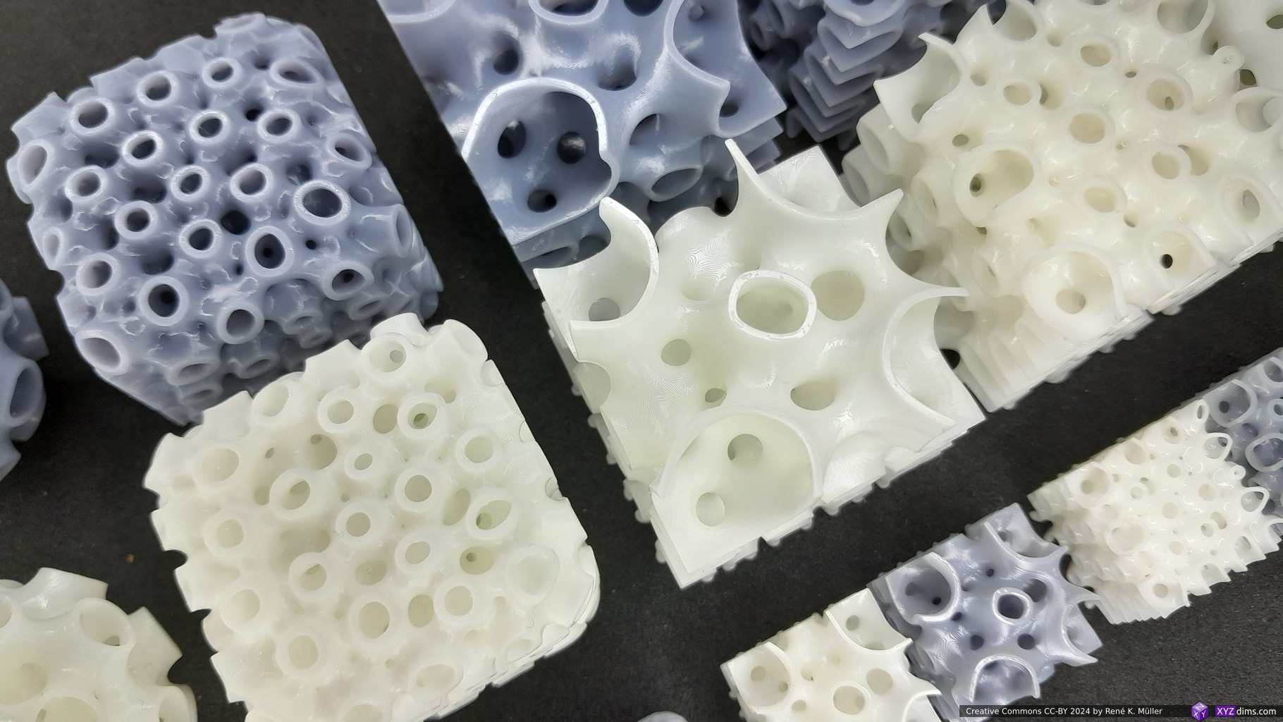
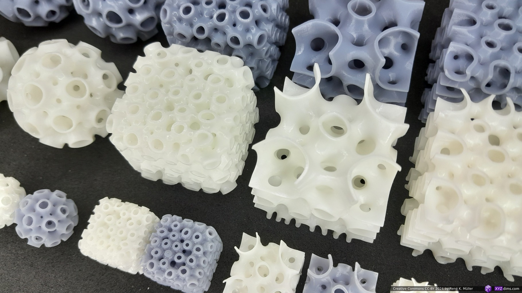
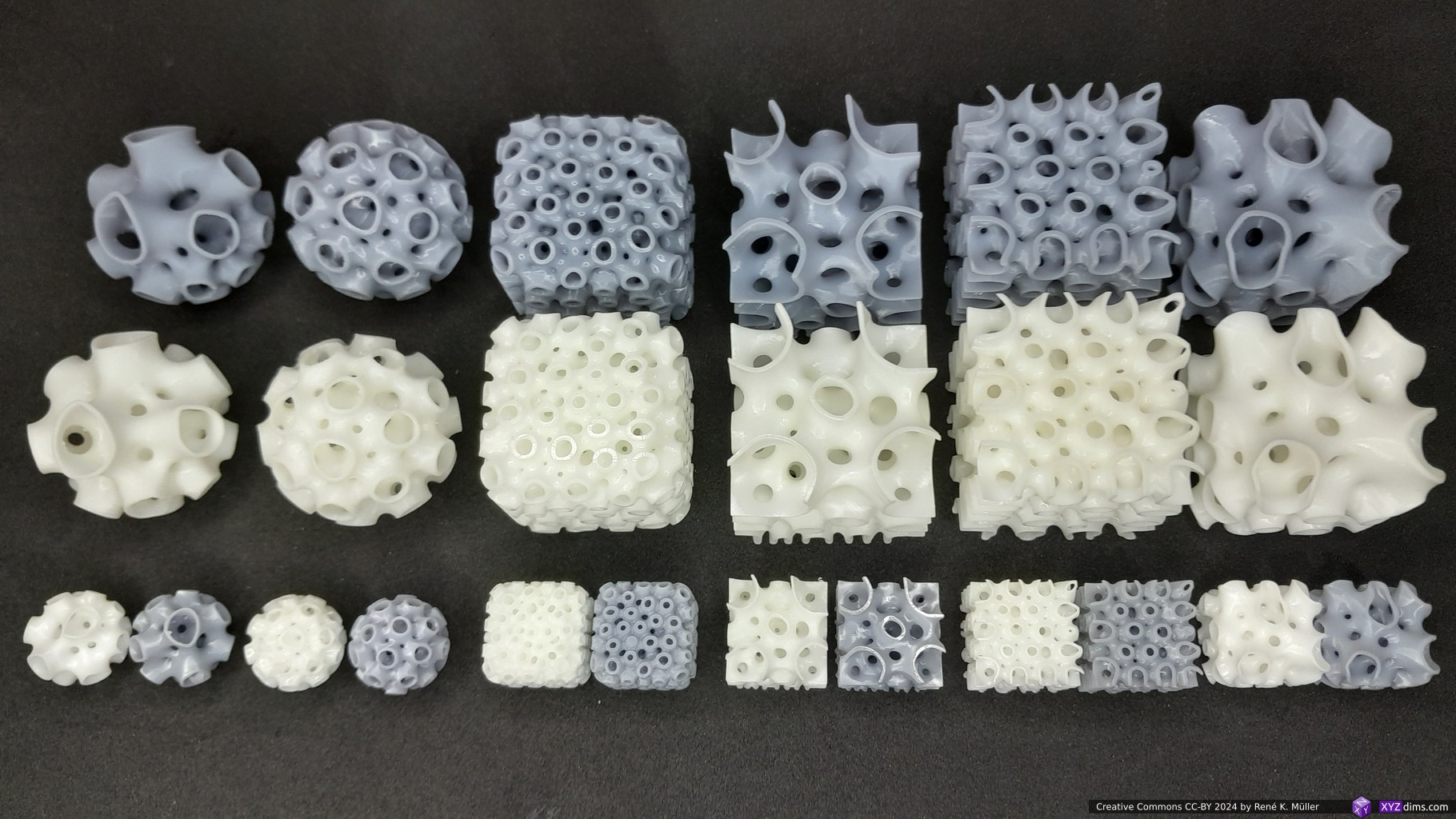
Daniel Bachmann from Spherene Inc. kindly shared with me a few samples, 20x20x20mm cubes, and 20mm diameter spheres with Spherene infills, illustrating their properties:
Spherene 20mm, 15mm and 10mm sampleSpherene 40mm in white & grey resin (top row) and white, grey and black PLA/PLA+Spherene resin samplesSpherene resin samplesSpherene resin samples
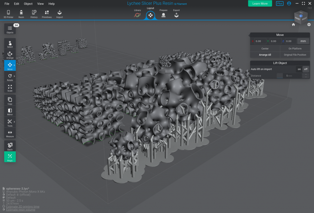
A few support structures were required for the spherical samples, the cubic samples did not require such:
Lychee Slicer: spherical spherenes required support structure due overhangs
Additionally I printed a few cubic samples with FDM on my CoreXY Ashtar C without supports at 40x40x40mm scale.
Subtractive Manufacturing & Molding Usage
The structure cannot very well machined with subtractive manufacturing processes – or only if the piece is sub-divided so all indentations can be milled, and sequentially fused or welded again.
Another approach comes to my mind is to form dedicated bricks, e.g. for large scale application like a building, and have a limited kinds of bricks depending on their position and use case, and have molds to form those limited kinds in larger quantities.
In order to produce a mold one would inverse the original model, the negative volume, that would be produced using additive manufacturing and then produce lost-form casting molds, or highly simplify the form so one can remove the positive without destroying the mold.
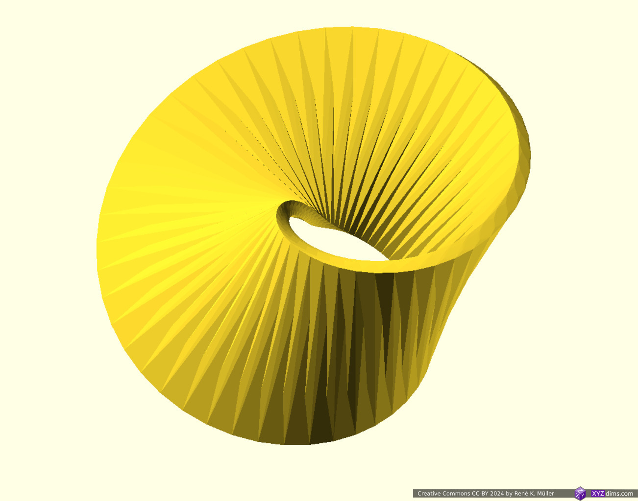
Mathematician August Ferdinand Möbius described in his paper 1858 a shape, which later became known as “Moebius Strip”: a surface with only one side or surface and one edge:
In the physical one can take a strip and twist it once and tape both ends – when creating a 3D representation, one rotates a strip by 180° to a closing circle.
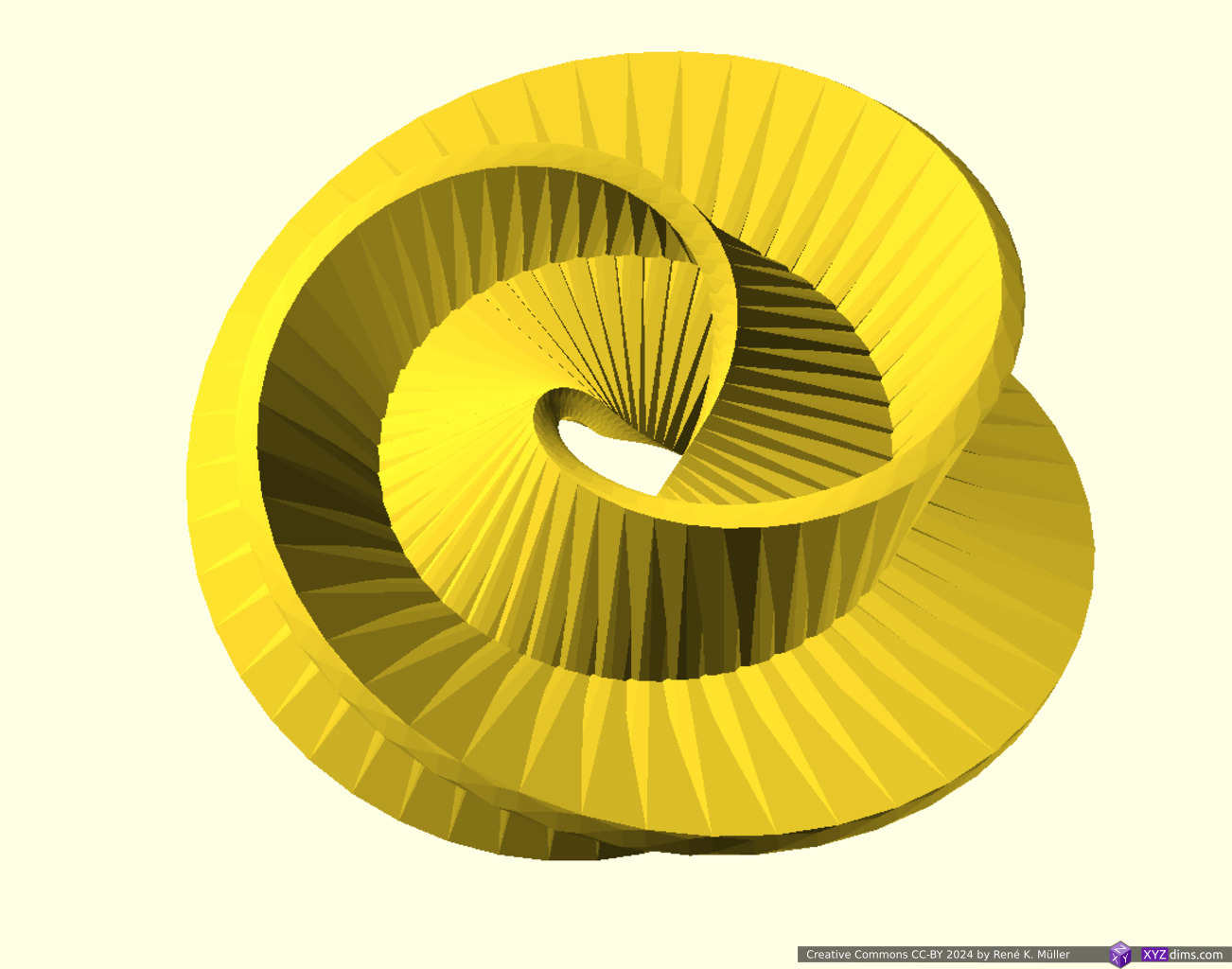
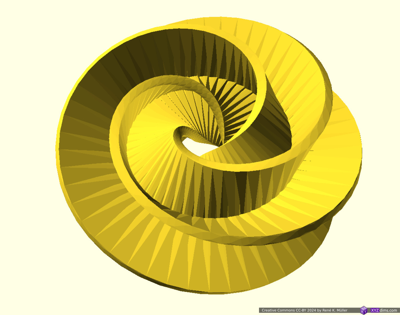
Examples
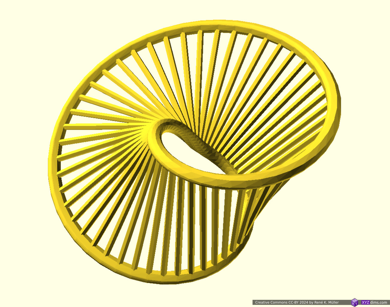
Original Moebius StripMoebius Strip with 2 stripsMoebius Strip with 3 stripsMoebius Strip with spokesMoebius Strip with 2 strips & spokesMoebius Strip with 3 stripts & spokes
3D Prints
I printed some of the models on MSLA resin printers with plenty of supports, one more flat and another series more vertical oriented which required more support structure and harder to remove.
Moebius Strip Meditation: multiple turns: 1, 2, 3, 4, 5, 12Moebius Strip Meditation: multiple stripsMoebius Strip Meditation: single turn, double turnMoebius Strip Meditation: single turn, single turn with multiple strips, both with spokes
2024/01/20: adding more examples and mounting tool/ruler
2024/01/15: starting write-up
Table of Contents
Introduction
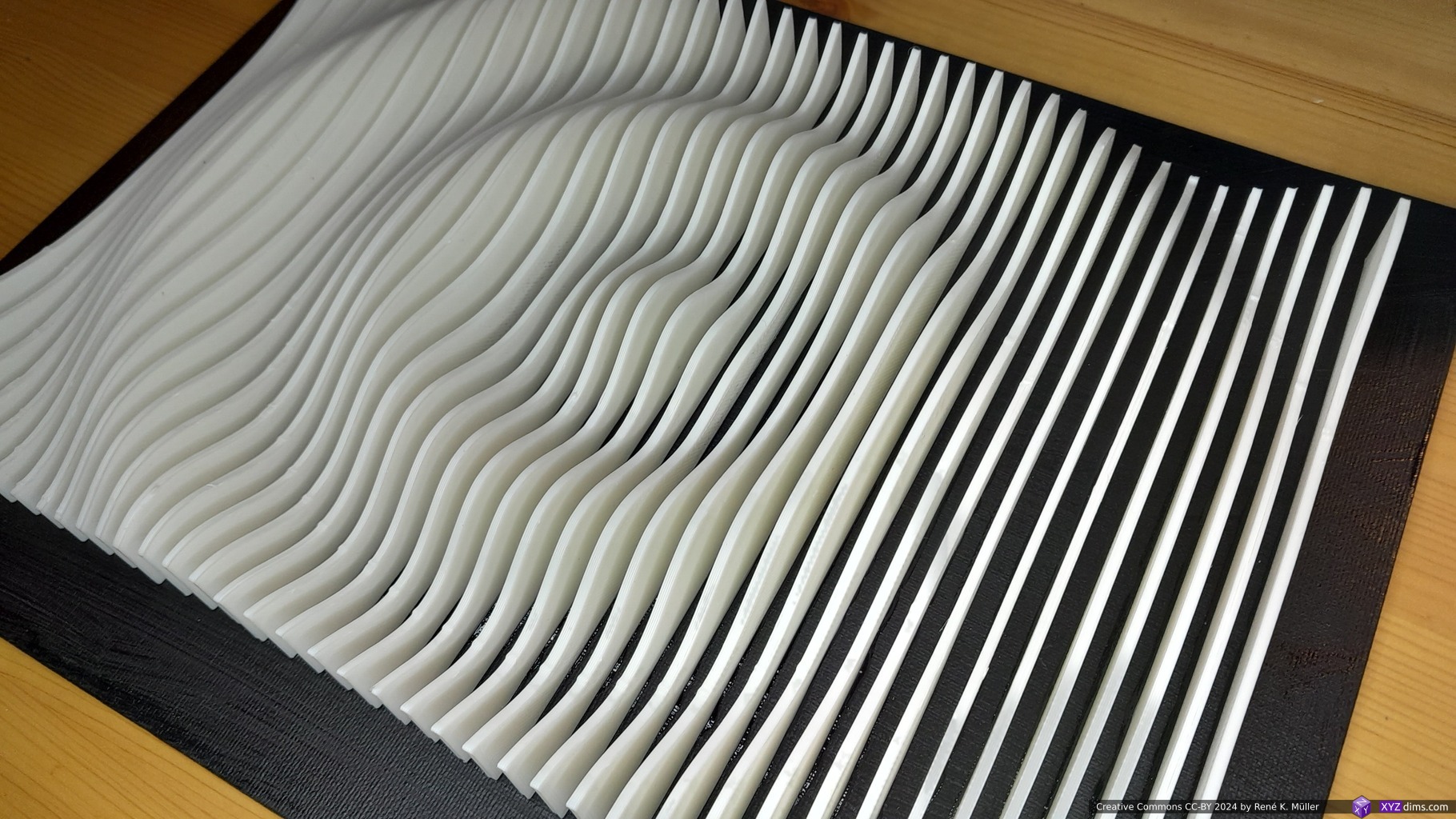
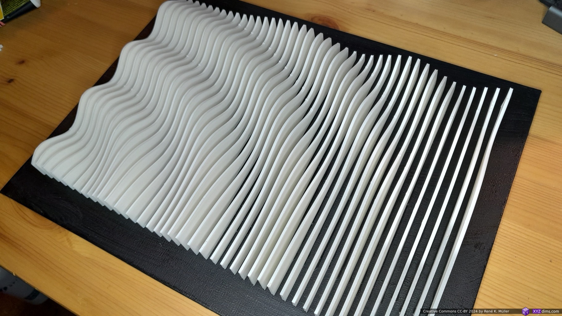
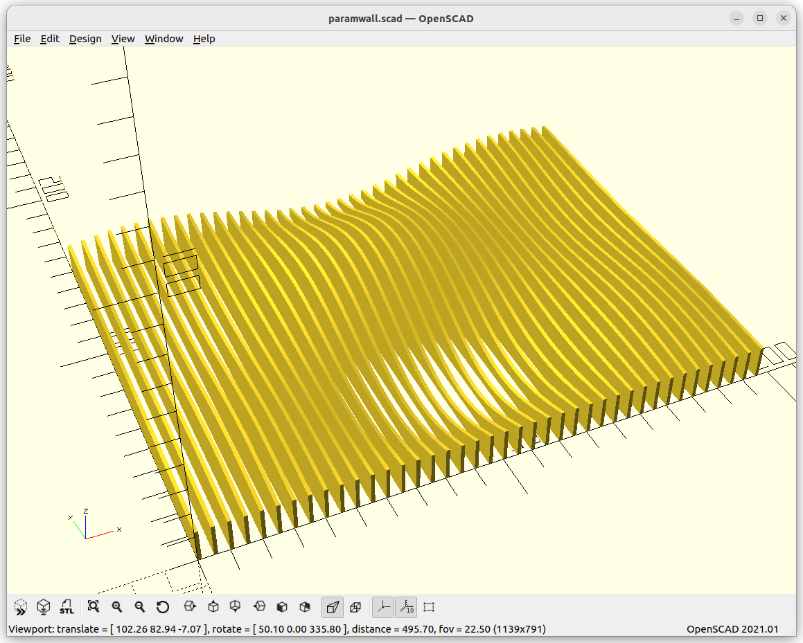
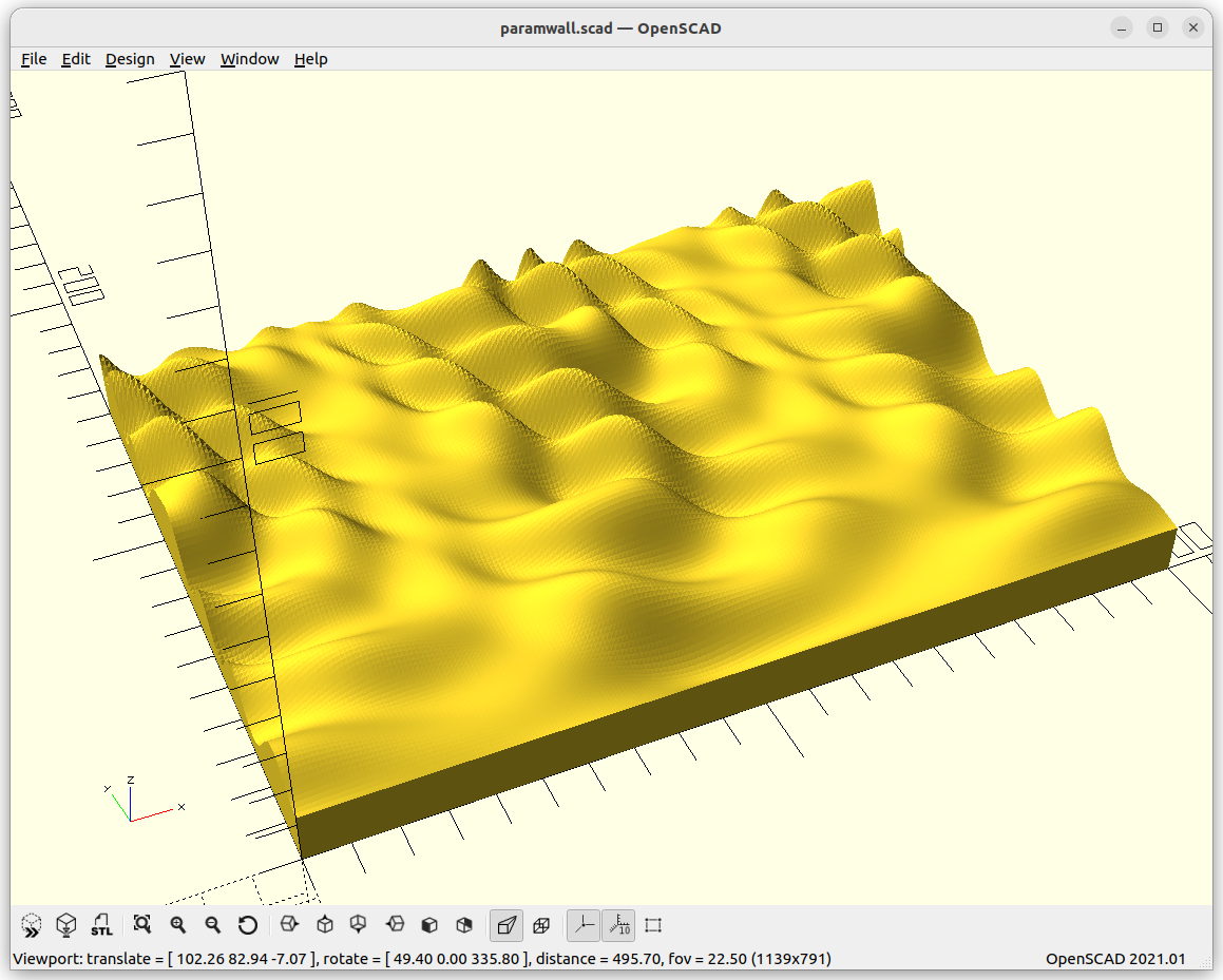
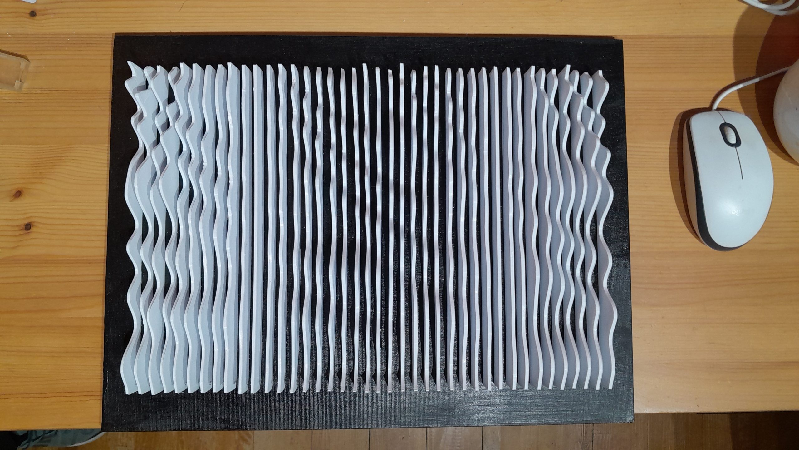
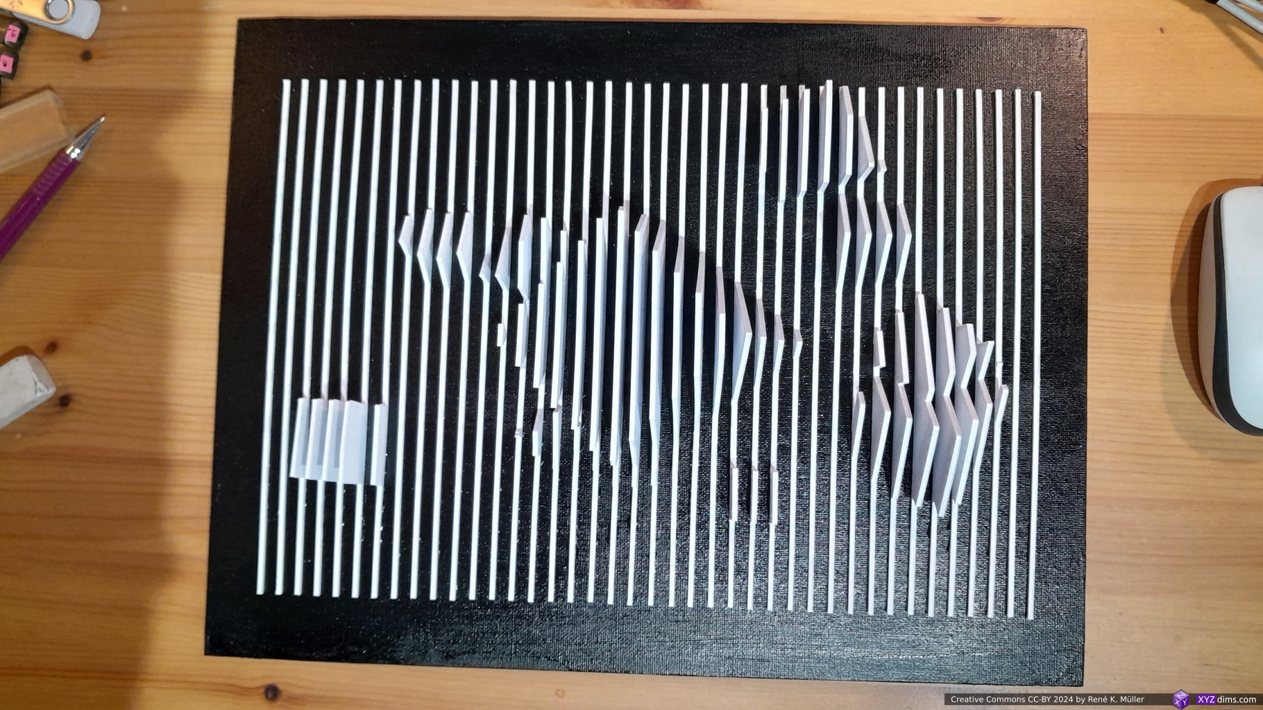
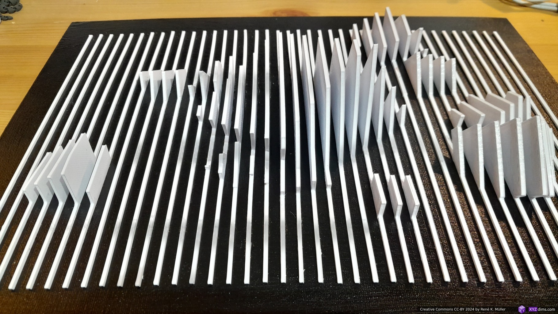
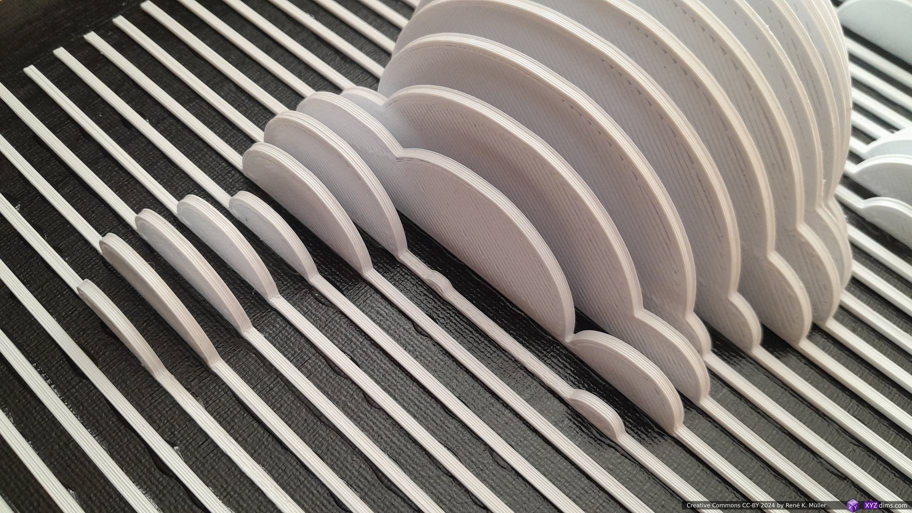
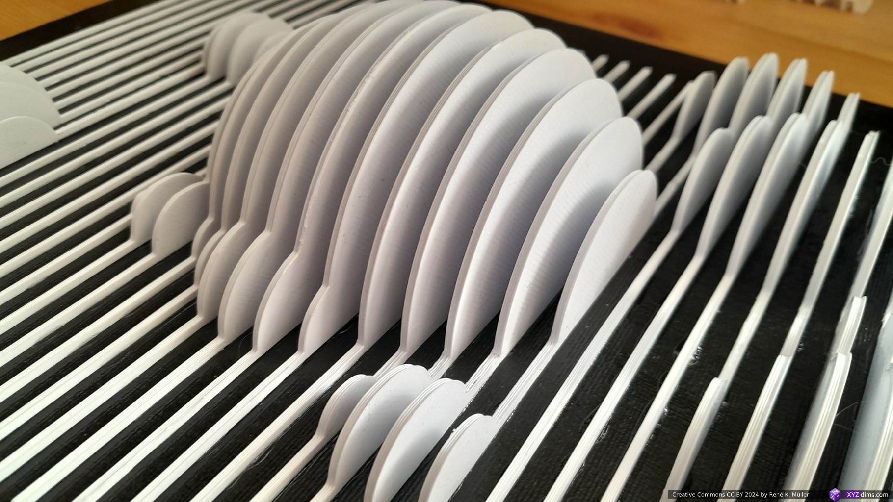
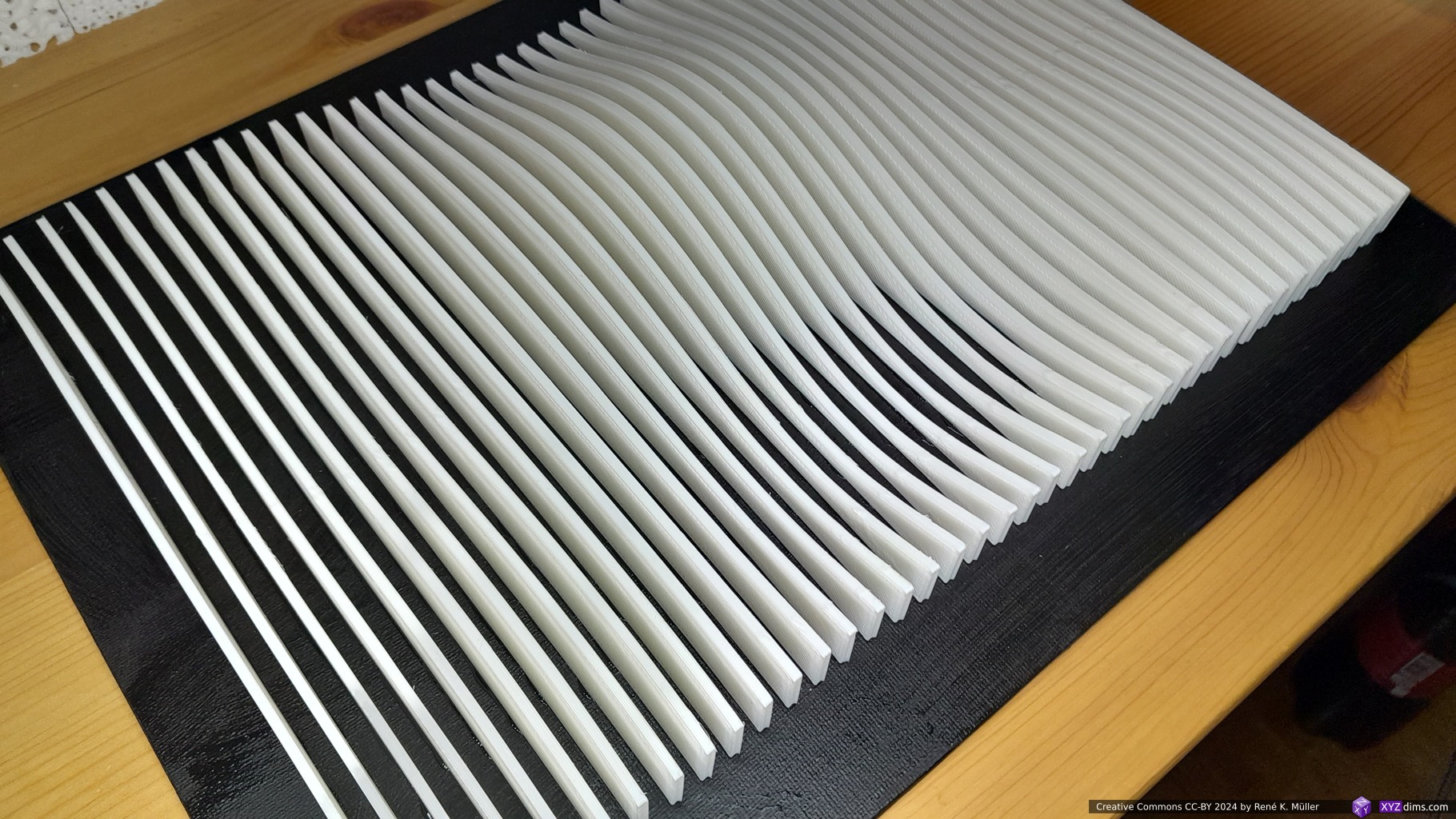
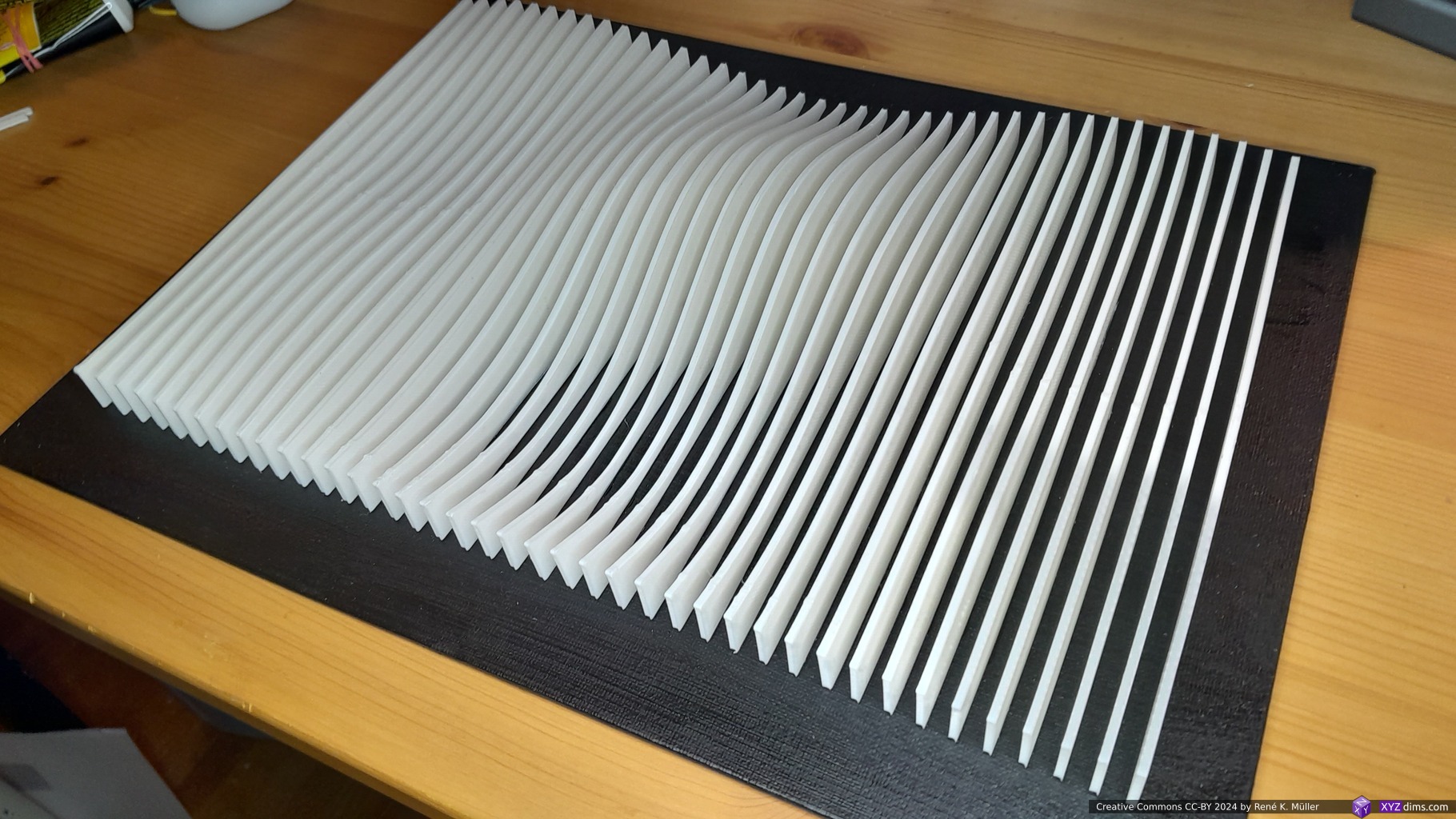
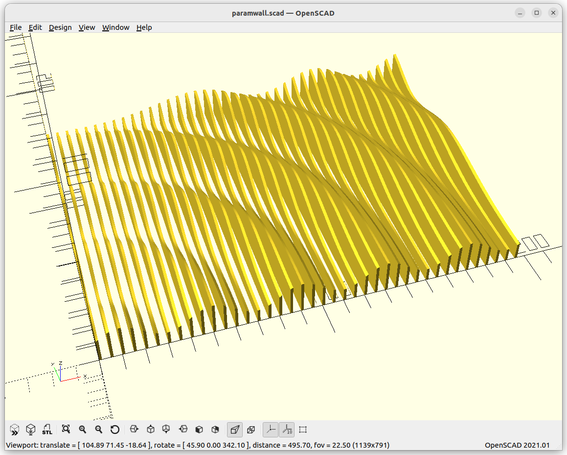
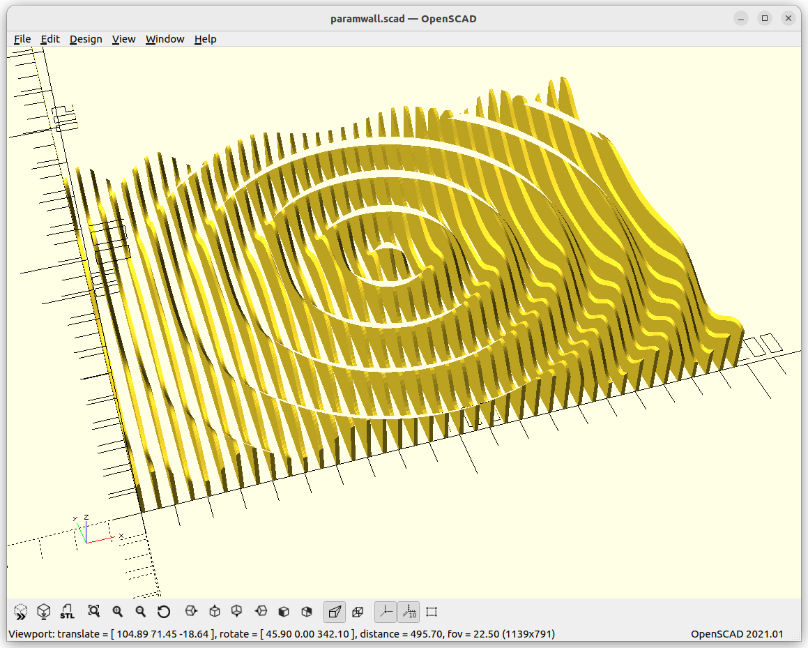
Since a while I was wondering how to create large(r) scale 3D prints like 1m / 1000mm or more, and I thought to use wood planks as slices and make “parametric wall” like sculptures. In order to get an idea of the procedure, I started with “parametric canvas” or Slices on Canvas.
Models
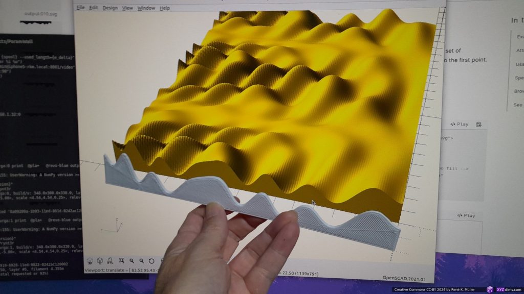
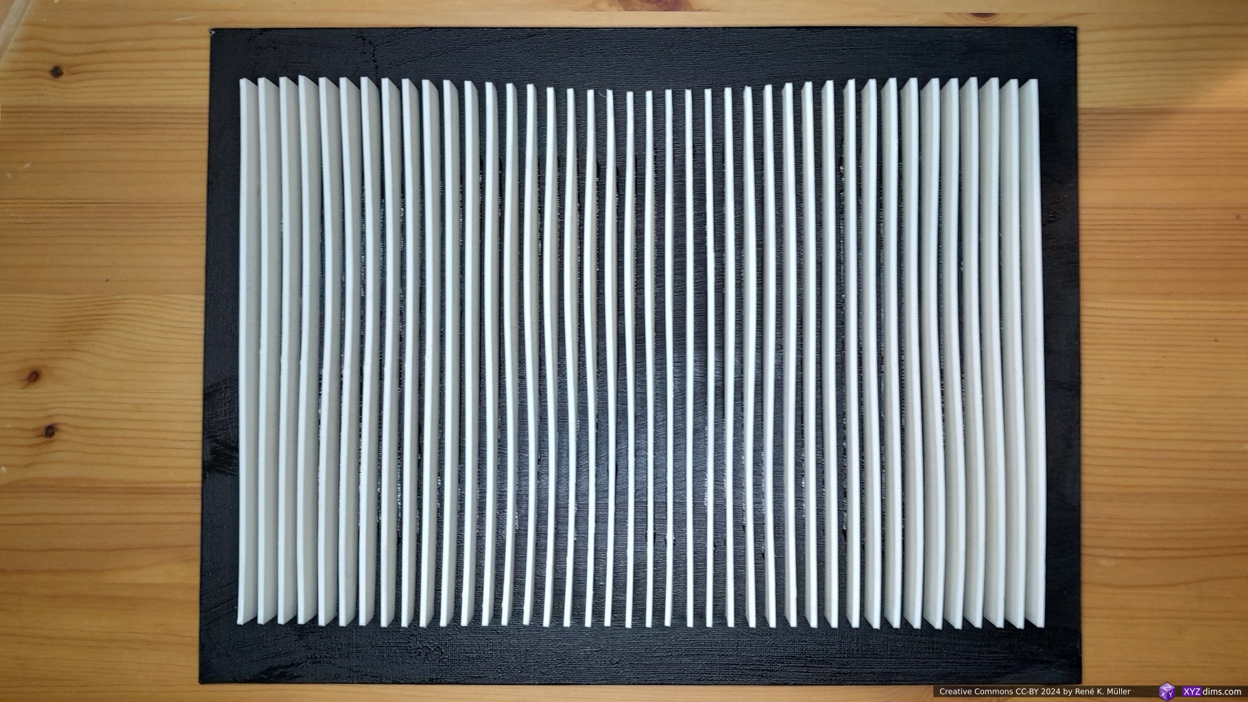
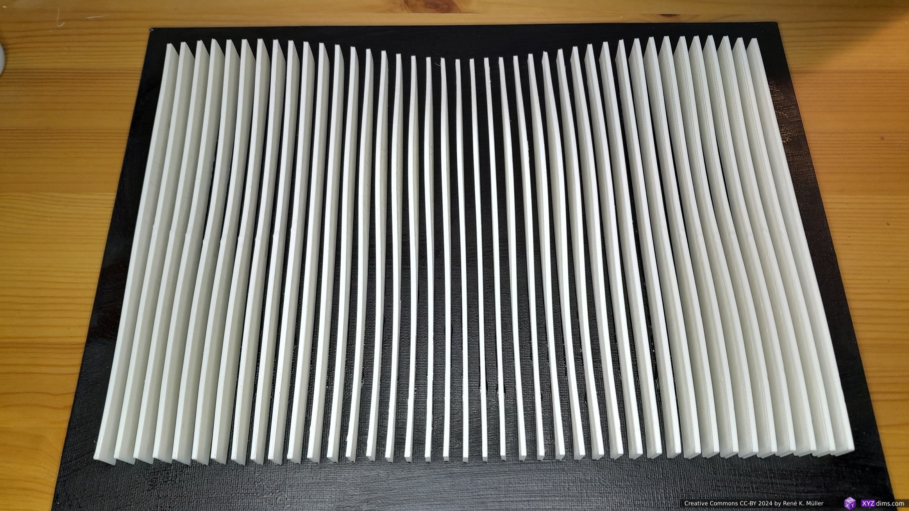
I used OpenSCAD to put together a few examples with 200×150 in size, and settled for 40 slices, which are then scaled up for 400x300mm canvas, the actual size is 340x240mm giving on each side 30mm margin to the edge of the canvas.
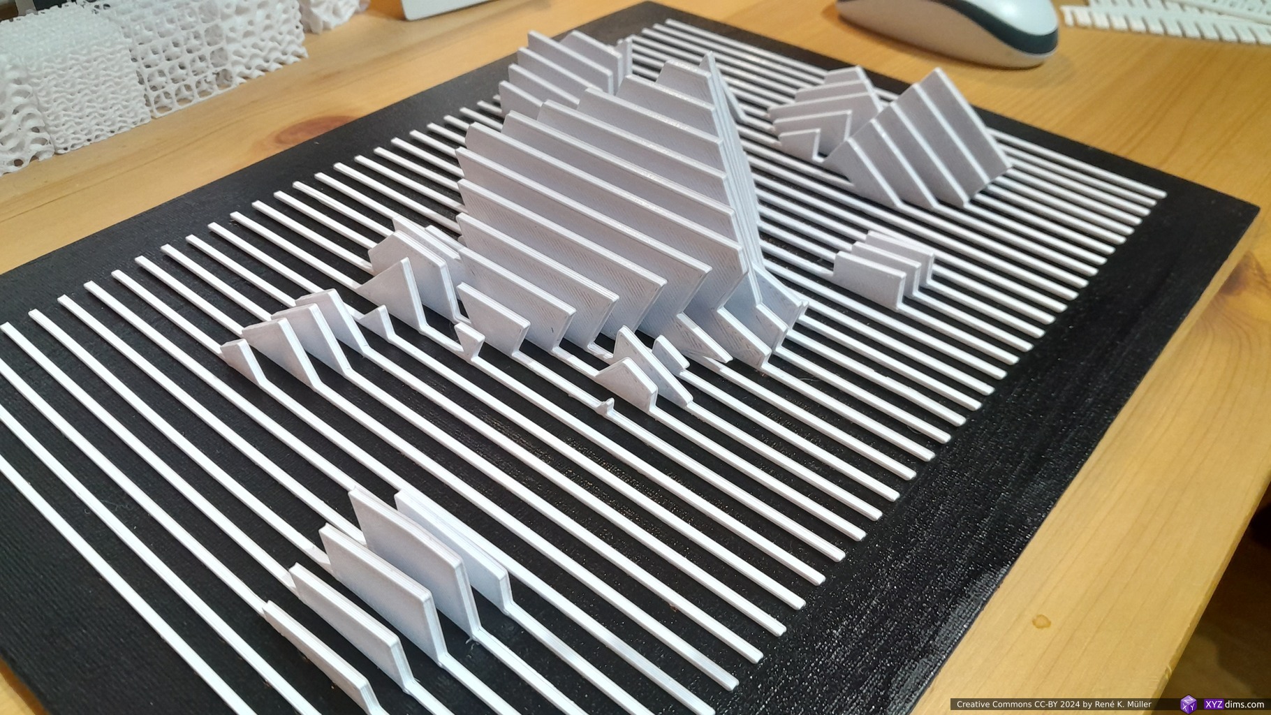
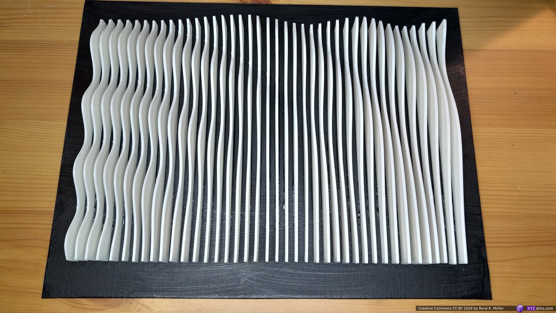
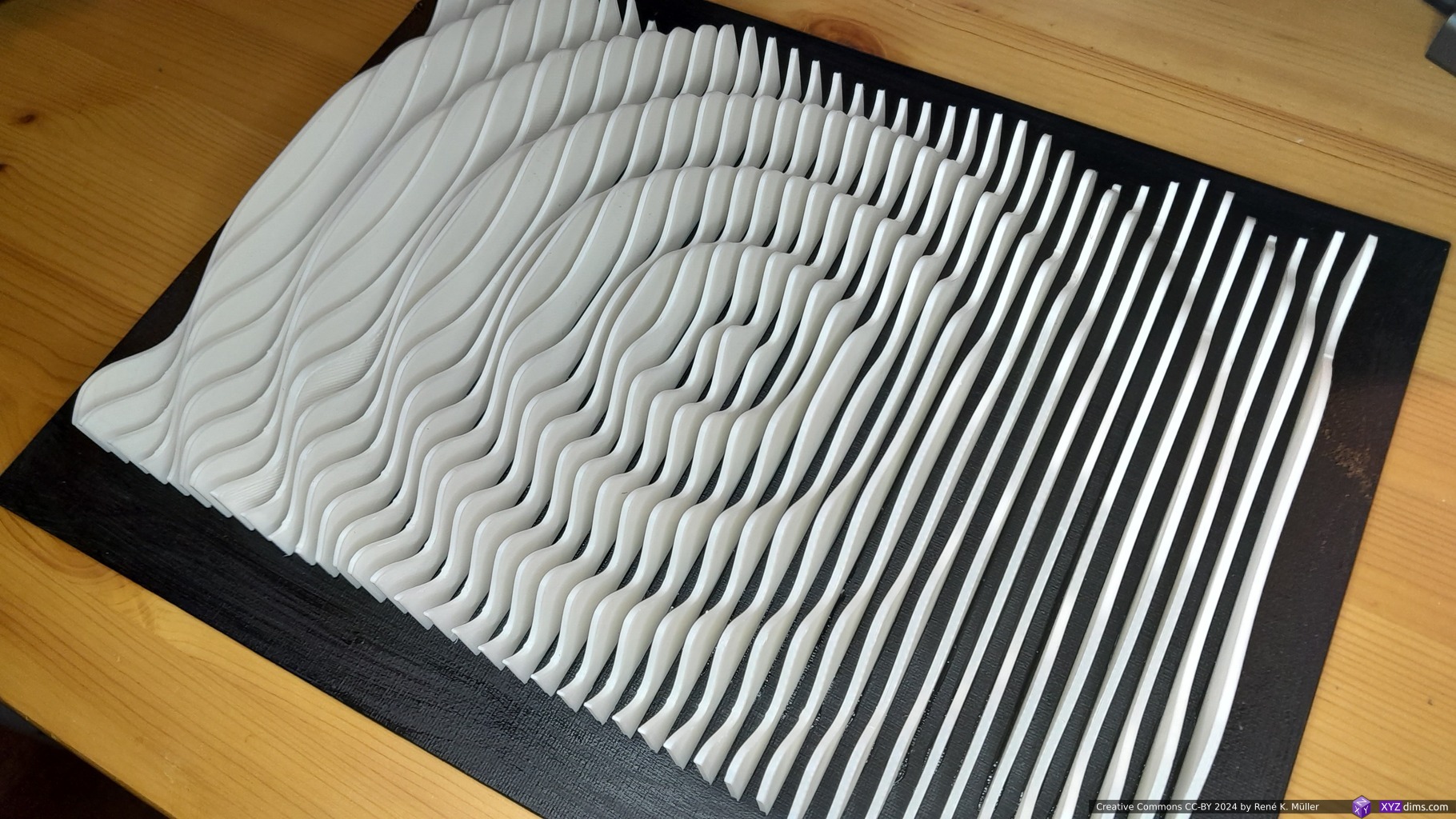
In order to test the concept, I used 3D printed slices printed with cold-white PLA+ in order to get a strong contrasts to the black canvas:
First 3D printed slice (240mm wide, 2.5mm thick) of “Sinus Mountain Range”
Each slice is 240mm wide, and 2.5mm thick and various height depending on the model.
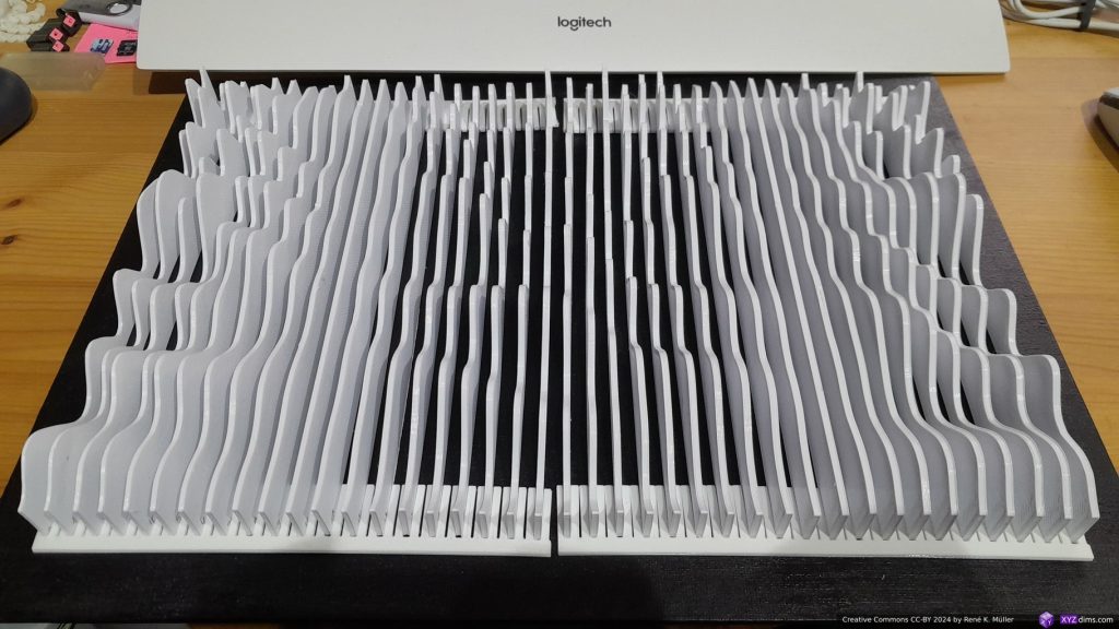
After printing 40 slices finished, I mounted them on the canvas:
Mounting slices on canvas with a mounting tool / ruler at bottom & top for exact spacing
As shown on the photo, I used a mounting tool / rulers, also 3D printed, which helped me to keep the slices well aligned and spaced to each other – then glued each slice on the canvas.
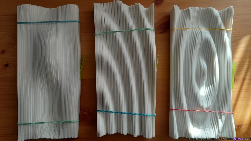
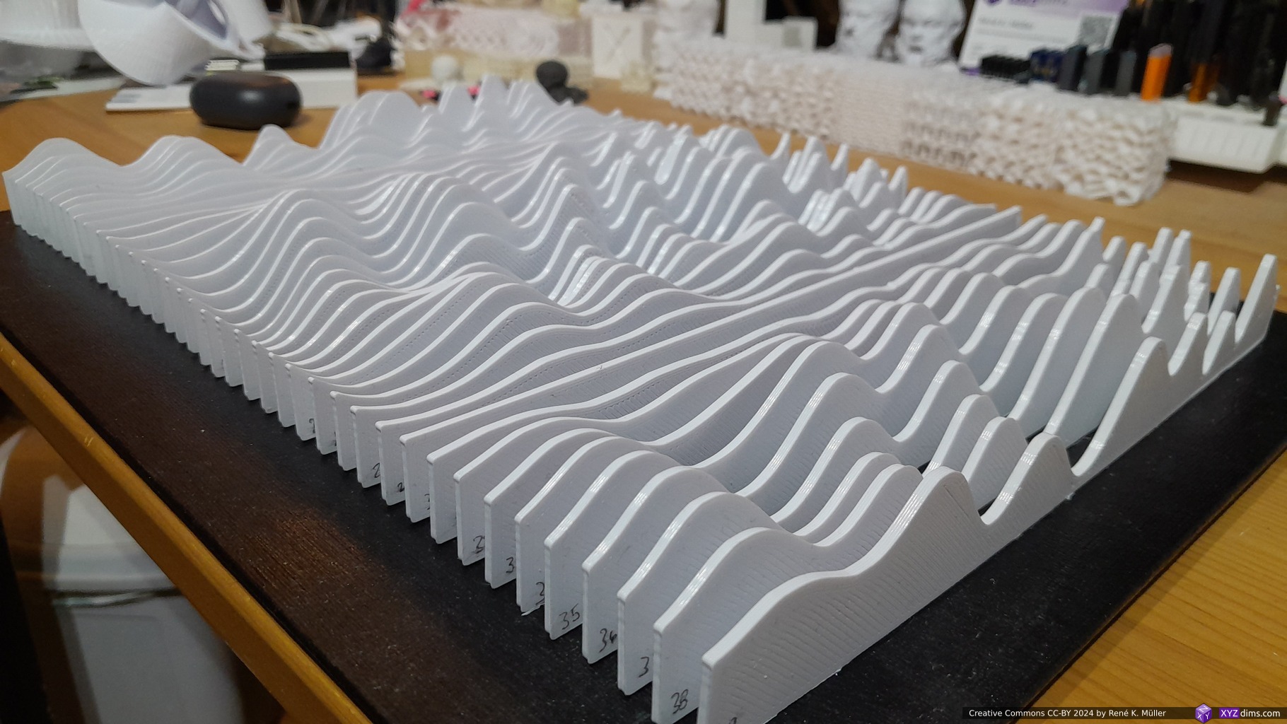
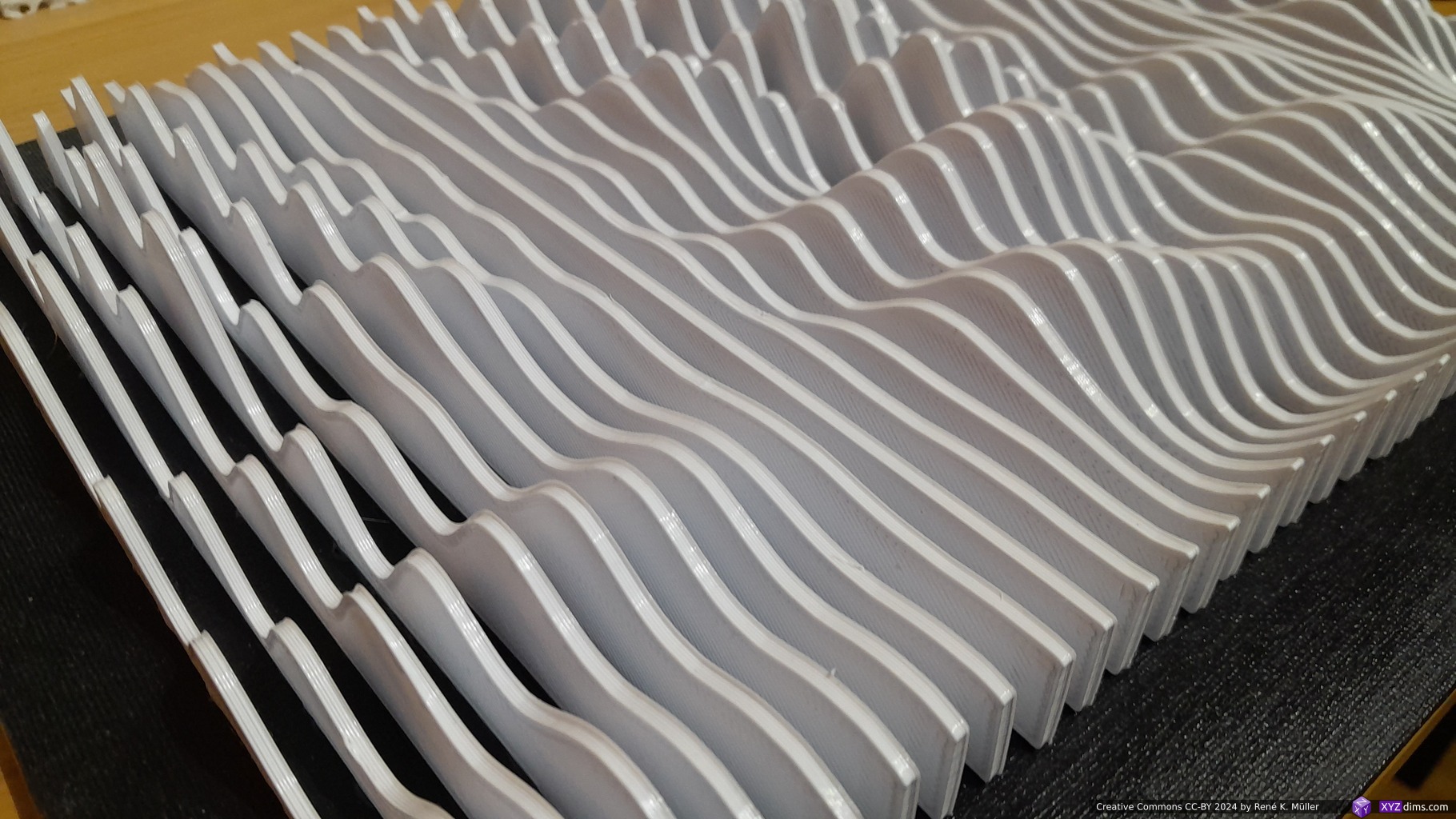
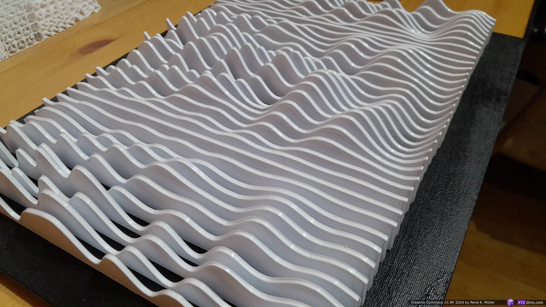
40 slices with 240mm width and 2.5mm thickness takes about 20hrs to print (4 slices ~ 2hrs print time) and ~520g of filament like for the Sinus themed sculptures.
Raw slice bundles: Smooth Sinus Meadow, Quarter Drop, Drop each bundle apprx. 520g PLA+
With 2.5mm thickness x 40 and 340mm canvas width, it’s about ~25% or 1/4 of actual volume of the model, and the rest is empty space in between.
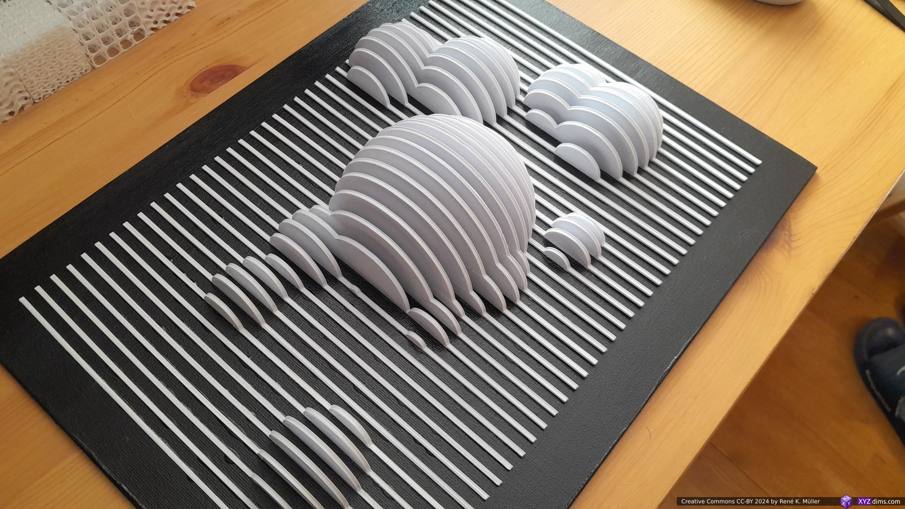
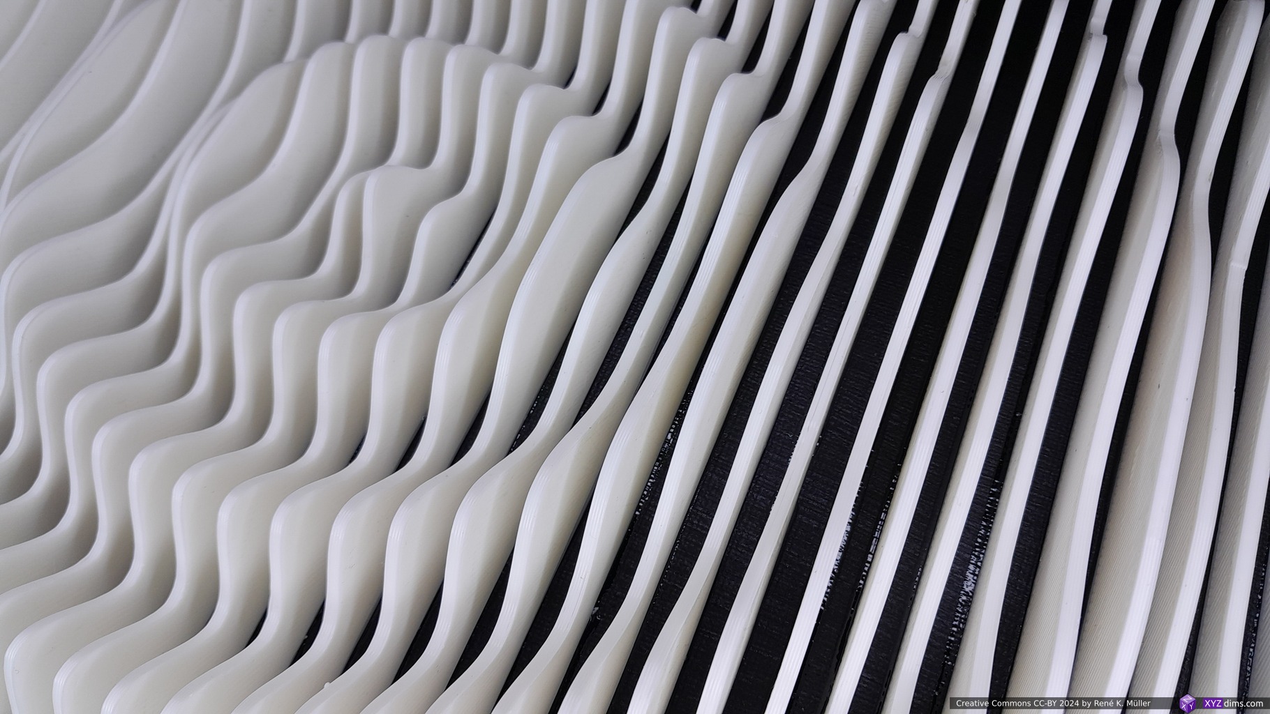
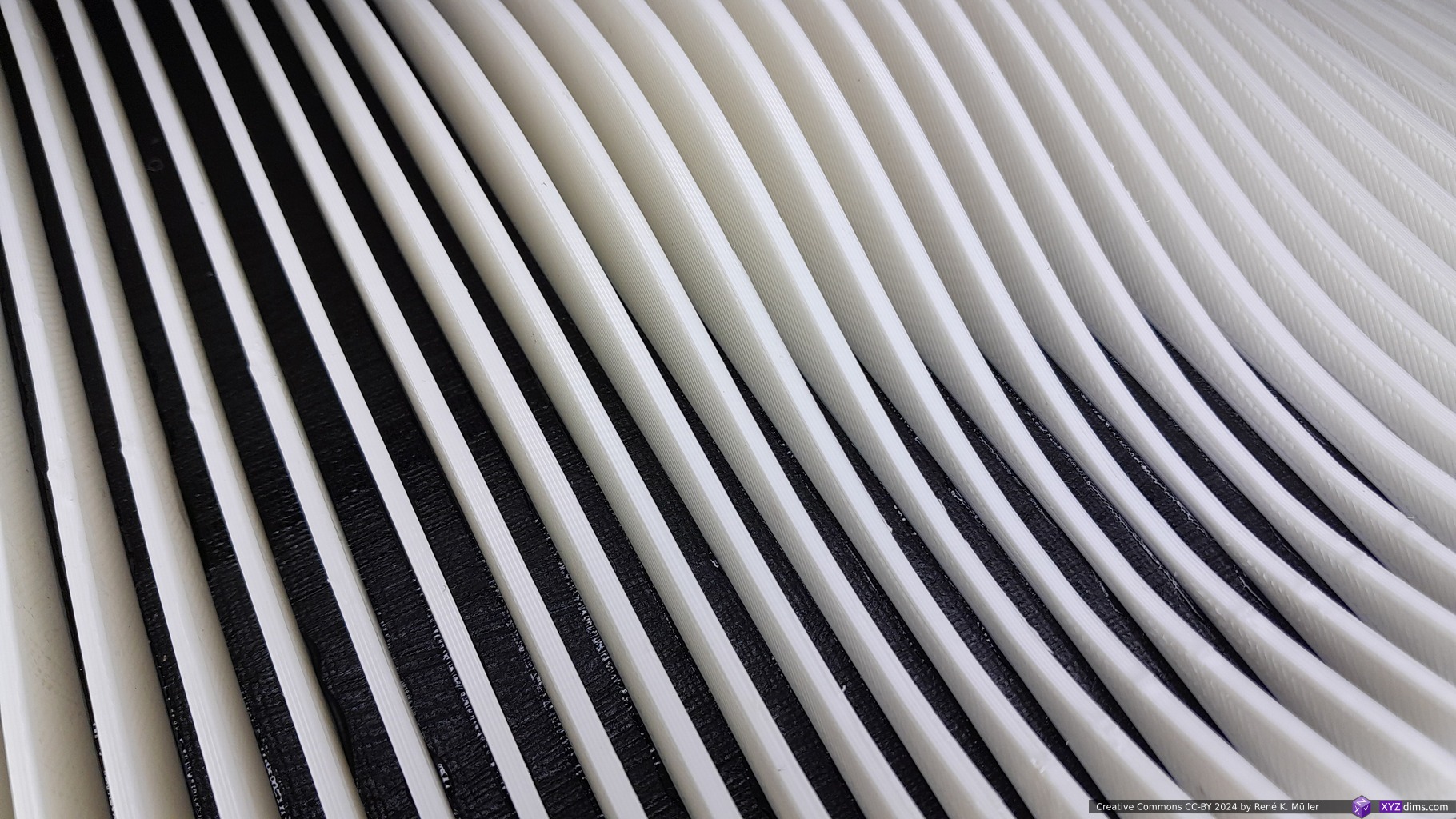
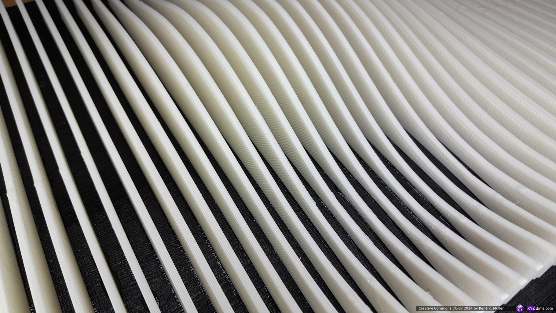
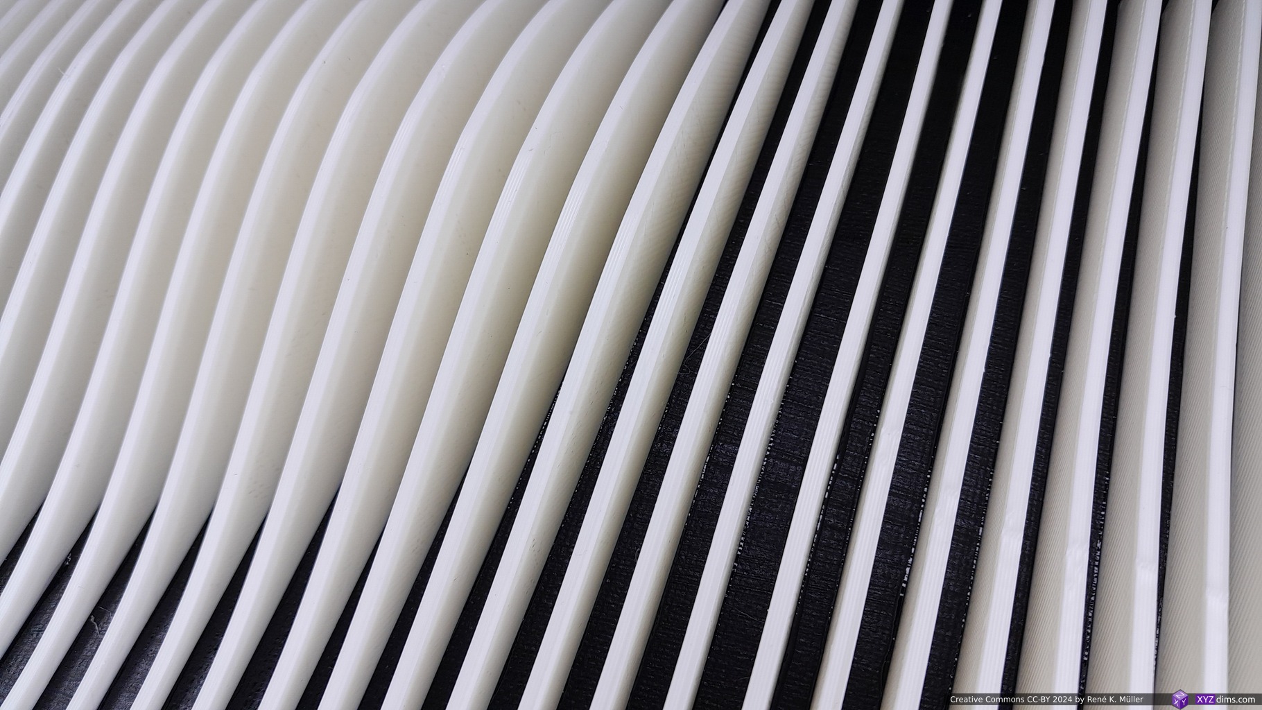
Sinus Mountain Range
Sinus Mountain Range on canvasSinus Mountain Range on canvasSinus Mountain Range on canvasSinus Mountain Range on canvas
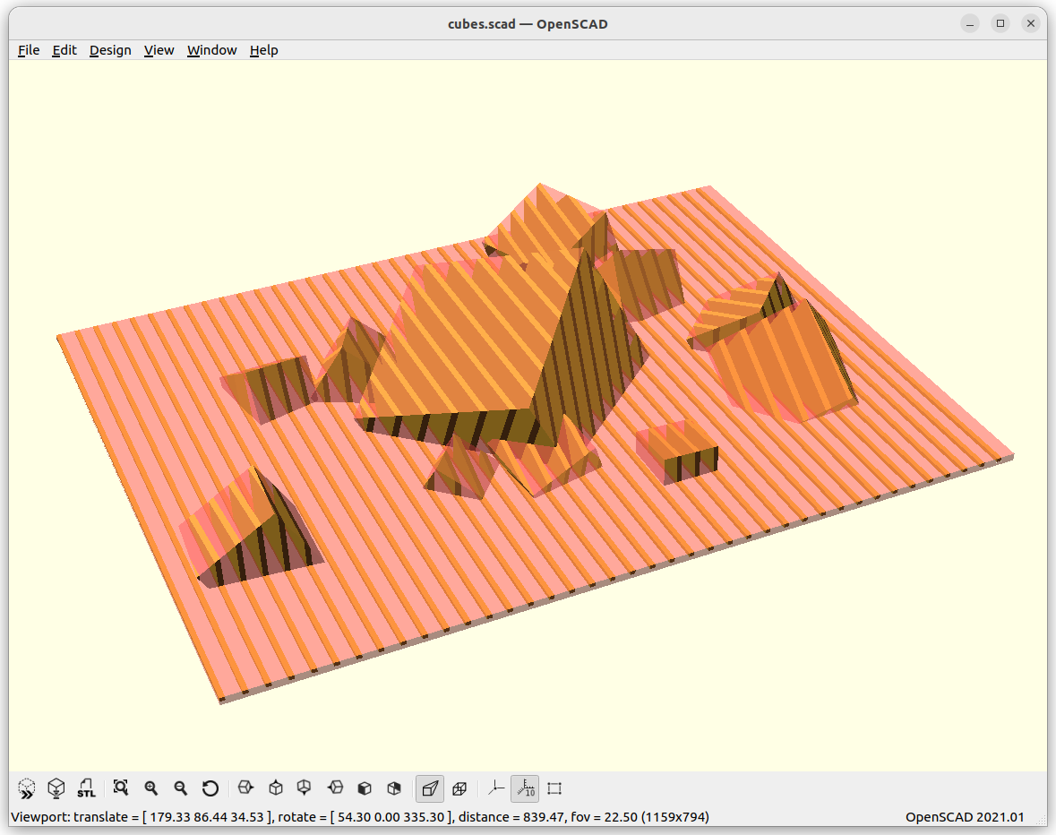
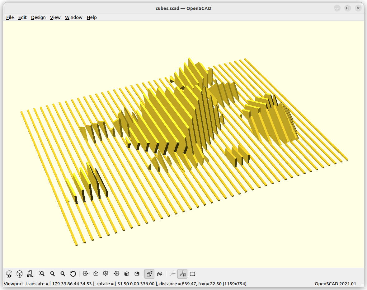
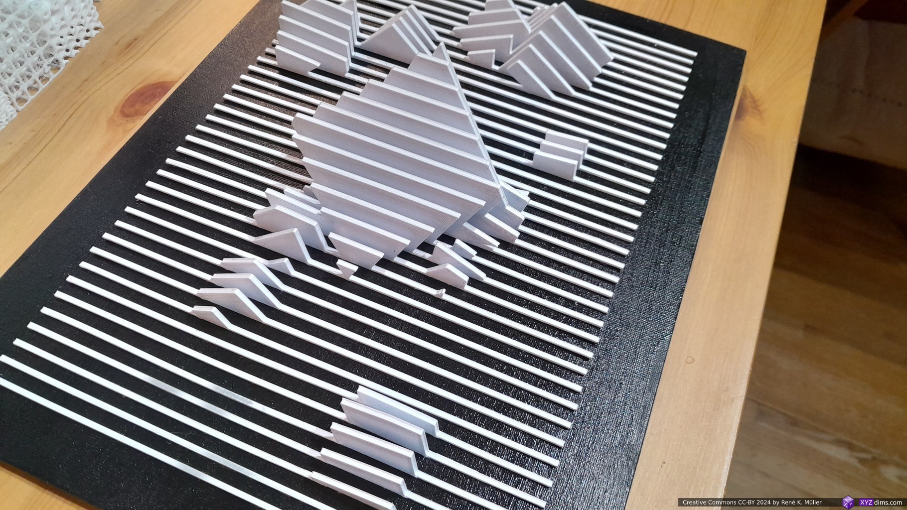
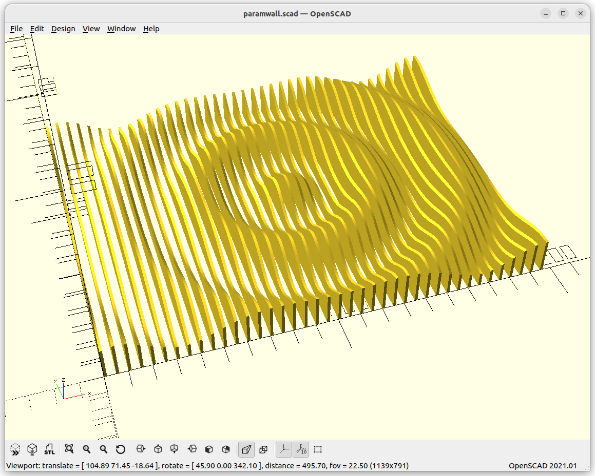
Cubes
Cubic landscape on canvasCubic landscape on canvasCubic landscape on canvasCubic landscape on canvas
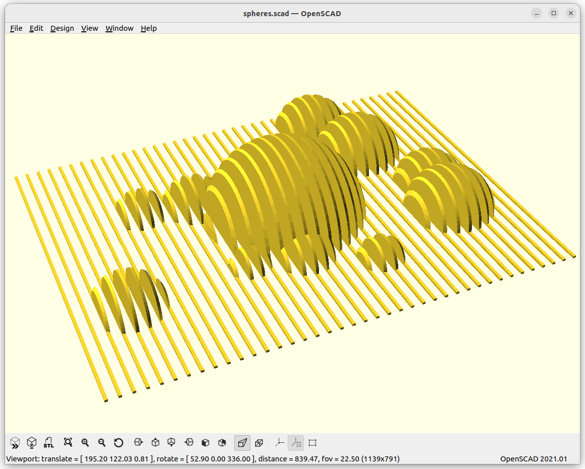
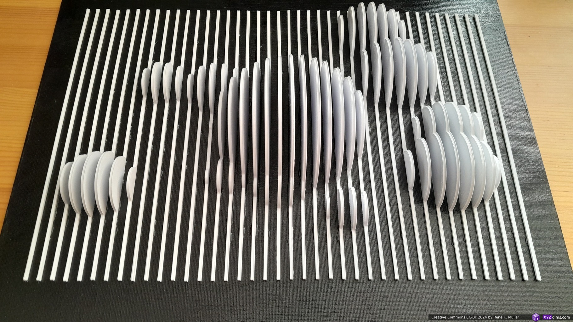
Spheres
Smooth Sinus Meadow
Various Examples
Quarter Drop (#6)Drop (#7)Fast Drop (#8)
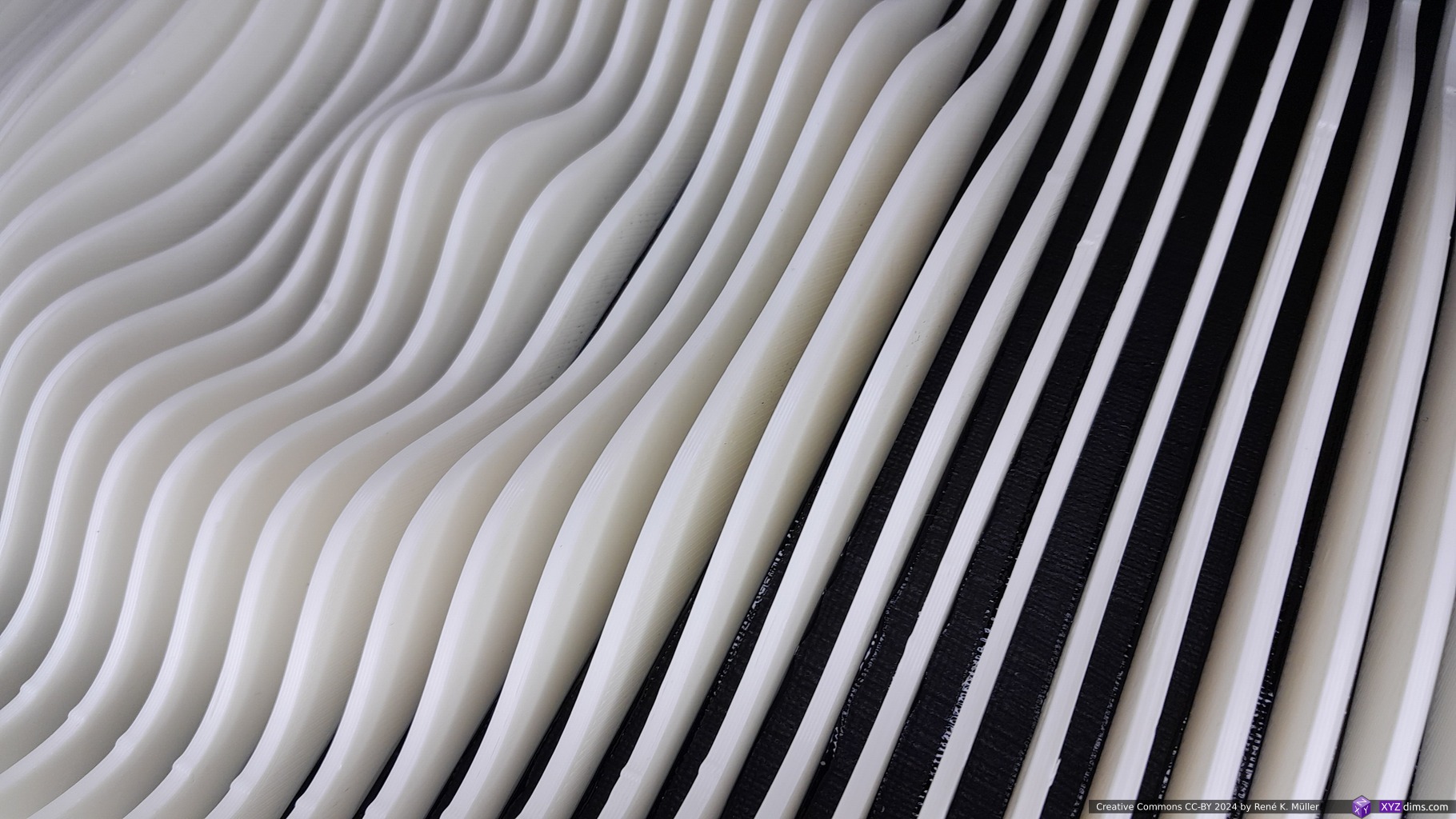
Conclusion
It’s relatively easy to create a Slices on Canvas (parametric canvas) but it takes its time to print and assemble – due the thin slices the sculpture changes its appearance drastically depending on viewing angle, and so is an eye catcher.
It certainly is a viable approach for larger scale sculptures, the saving in material is compensated with additional manual work like aligning and fastening the slices.
References
LabSlicer: used to slice the model into SVG slices (PrusaSlicer also supports this functionality)
Prynt3r: for printing the individual SVG slices directly
2024/01/22: published without much reflection & conclusion as research is ongoing
2023/12/02: adding more examples and refining details
2023/10/22: start writeup
Table of Contents
Introduction
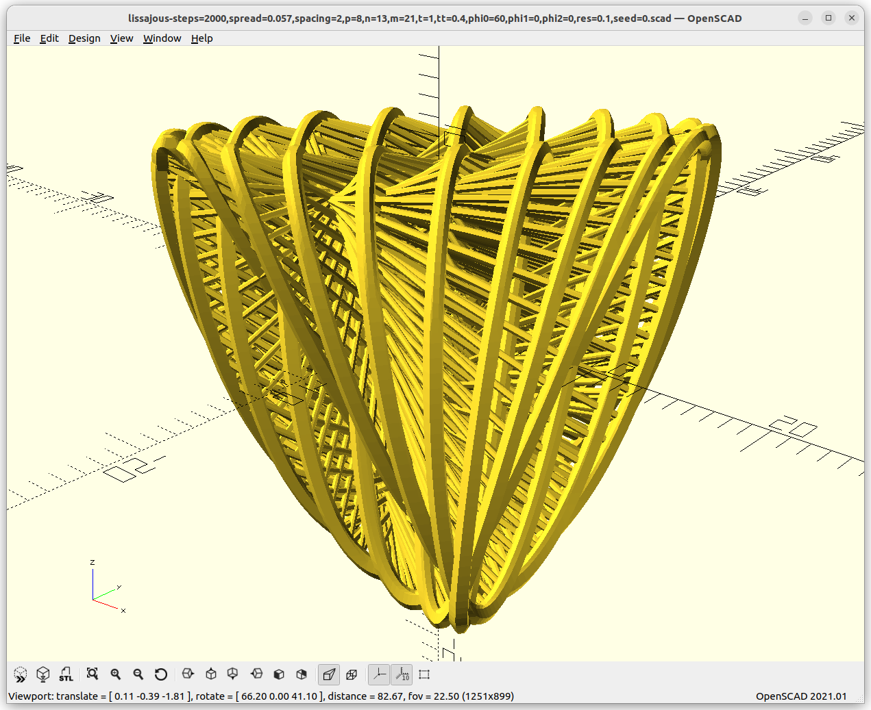
While studying continuous fiber 3D printing and its main nature is to find ways to lay fiber without interruption. In order to refresh my memory I revisited the Lissajous forms, which until recently only knew in their 2D form, the swirling strings or lines – and now extending it into 3D as well.
The main idea is to realize how a line, string or fiber can be used to fill non-planar and circumvent a 3D structure and how angular shifting in Lissajous context affects such form.
3D Lissajous
angle: 0 .. 2pi or 0 .. 360°
p, n, m: 0 .. 1000, the amount of loops
phi0, phi1, phi2: the angular offsets 0 … 2pi or 0 .. 360°
X = sin(angle*p+phi0)*r
Y = sin(angle*n+phi1)*r
Z = sin(angle*m+phi2)*r
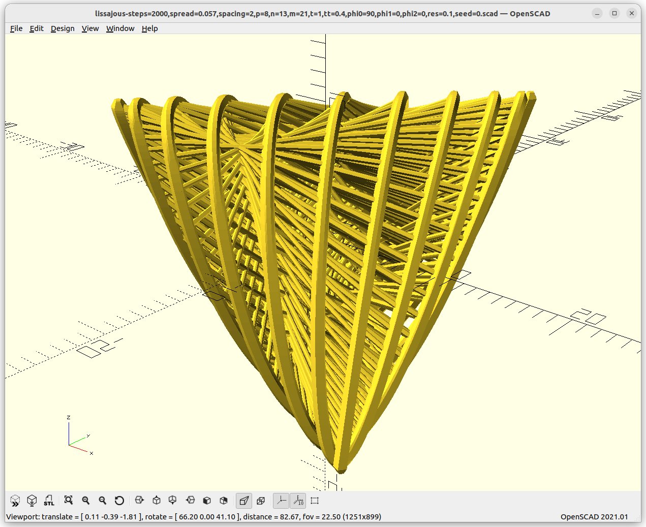
I did a lot of experimenting – I could post hundreds of forms – but let me focus on one a bit closer, which got my attention:
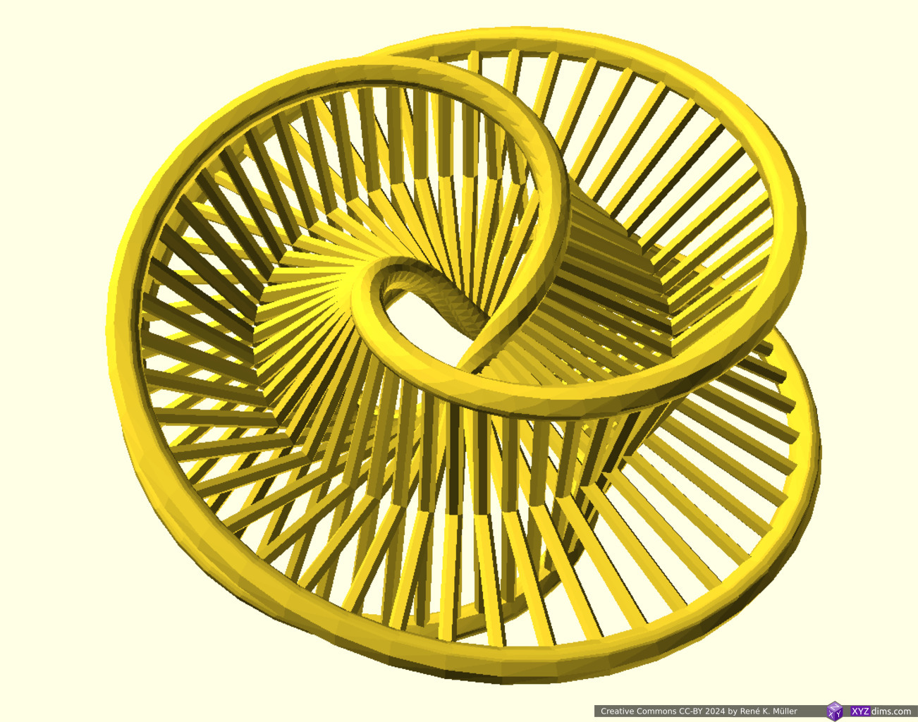
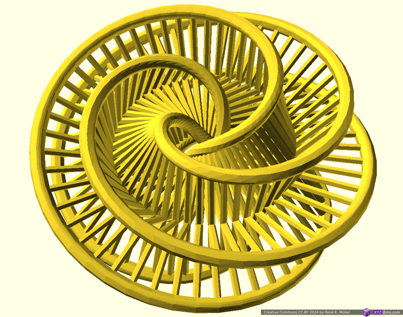
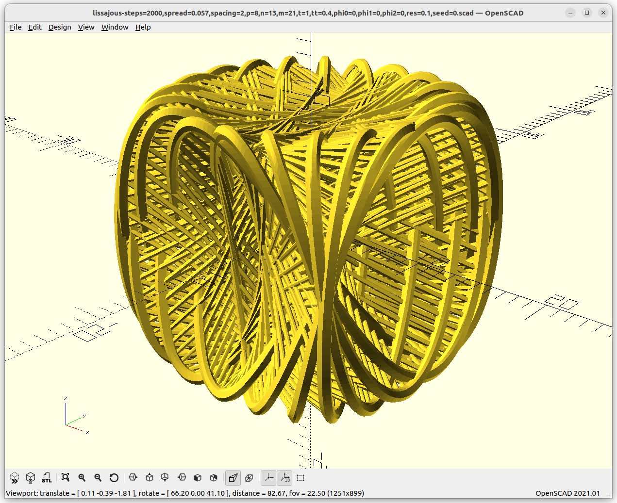
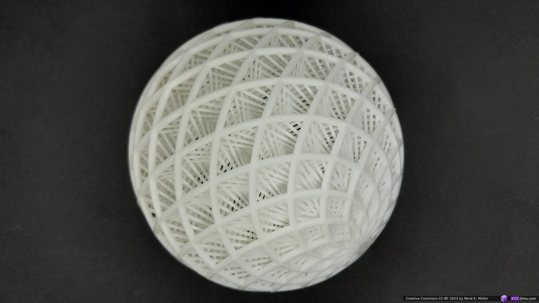
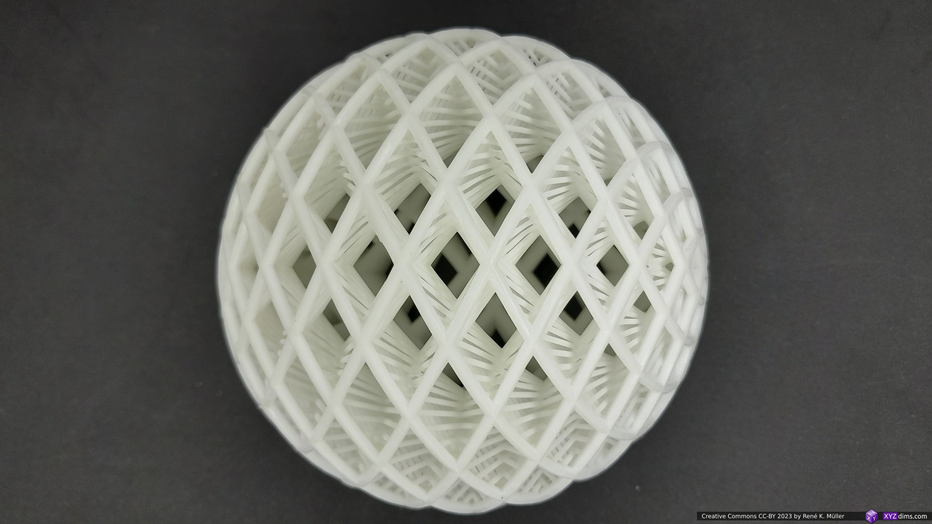
While playing with 3D Lissajous, I thought to adapt the cyclic nature, but apply it to a circle laying in the XY plane and then rotate in X axis, and Y axis as well, and optionally cyclic translation as well:
d: diameter
angle: 0 .. 2pi or 0 .. 360°
p: amount of loops as in X=sin(angle*p)*d/2, Y=cos(angle*p)*d/2
q: amount of X rotations: rotateX(angle*q)
r: amount of Y rotations: rotateY(angle*r)
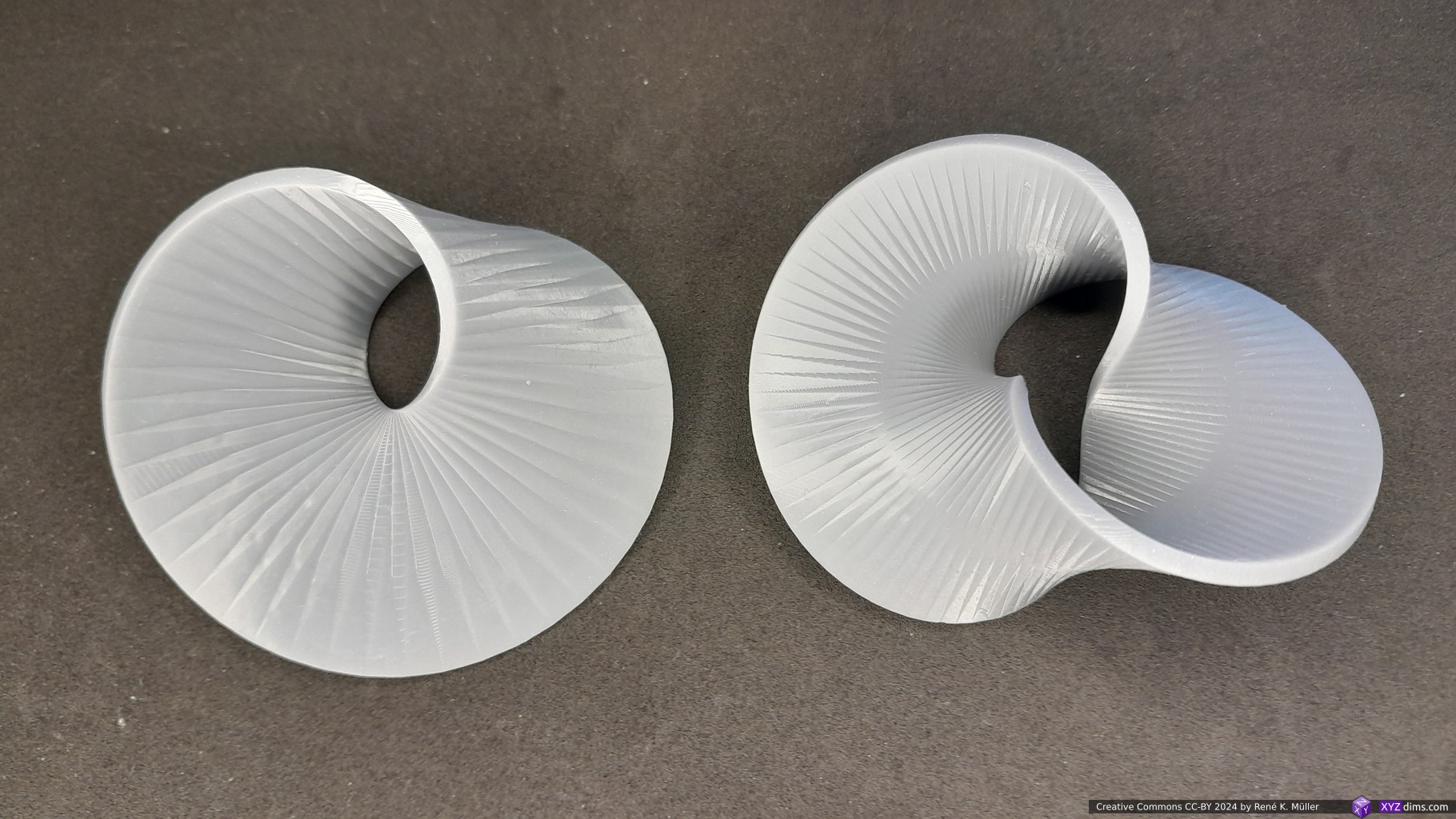
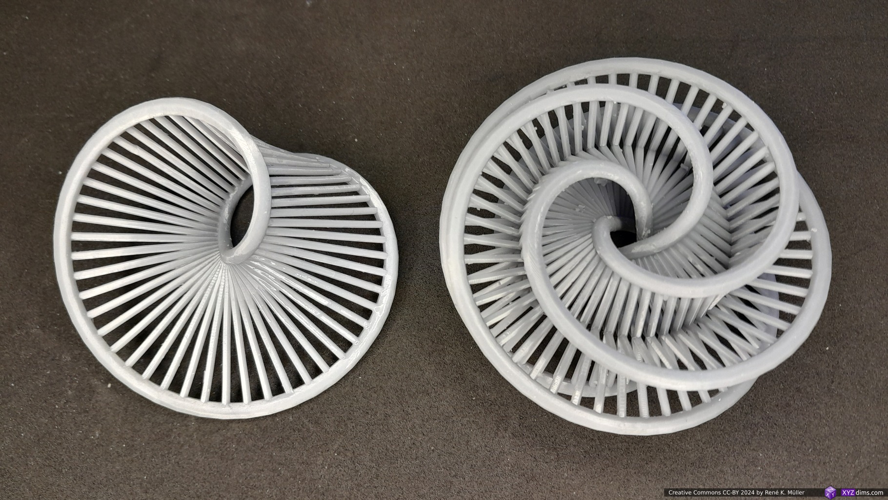
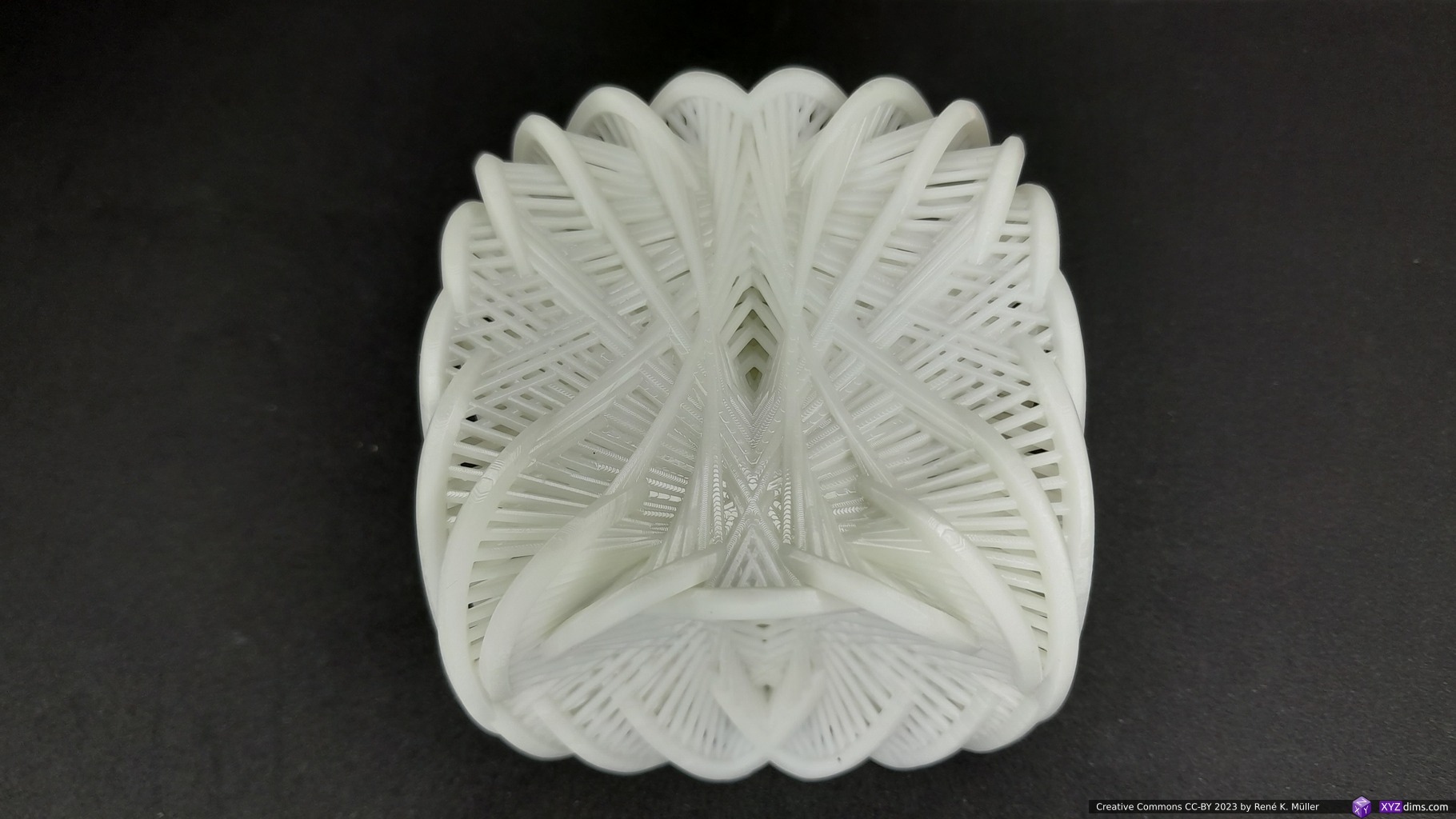
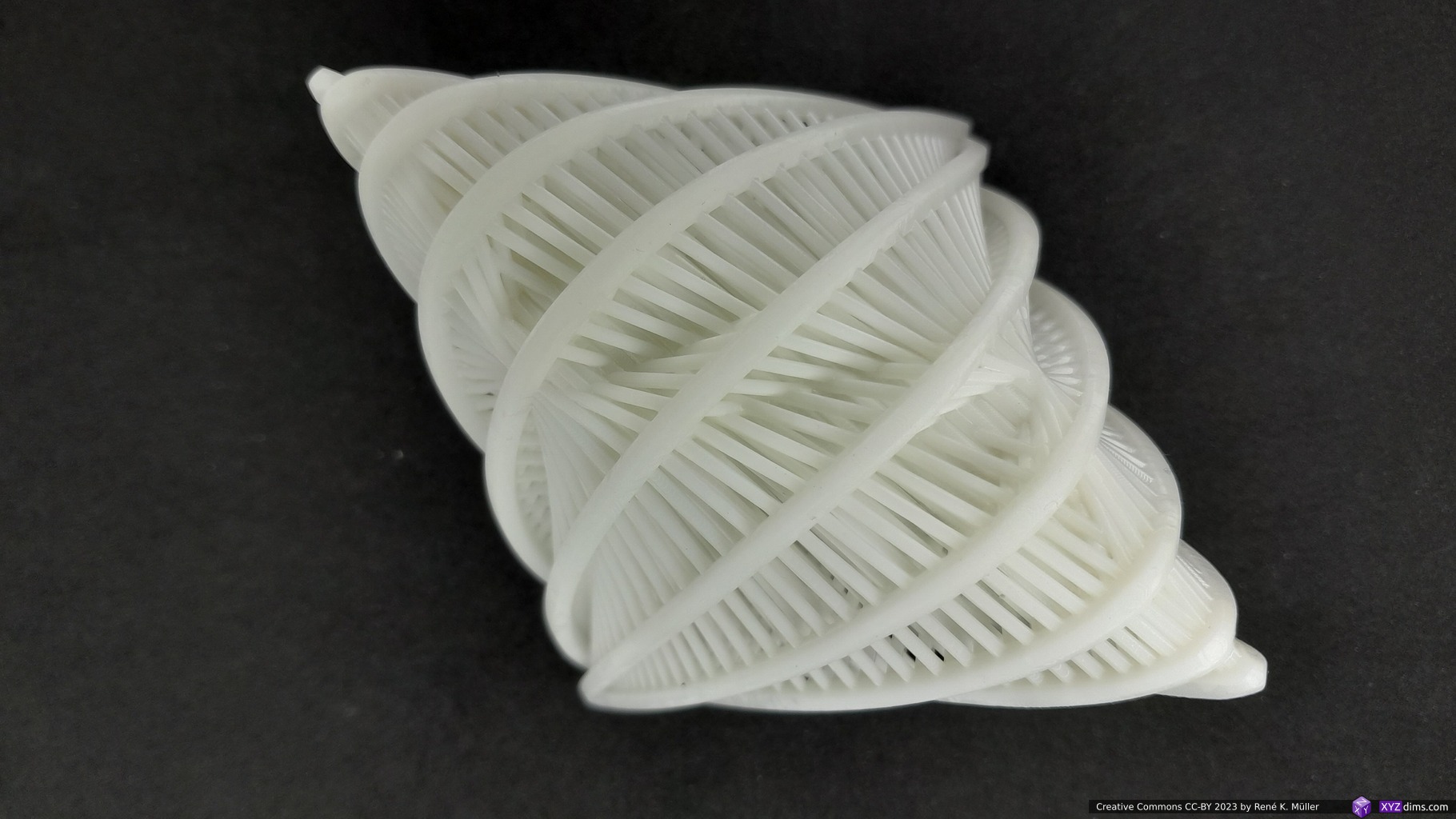
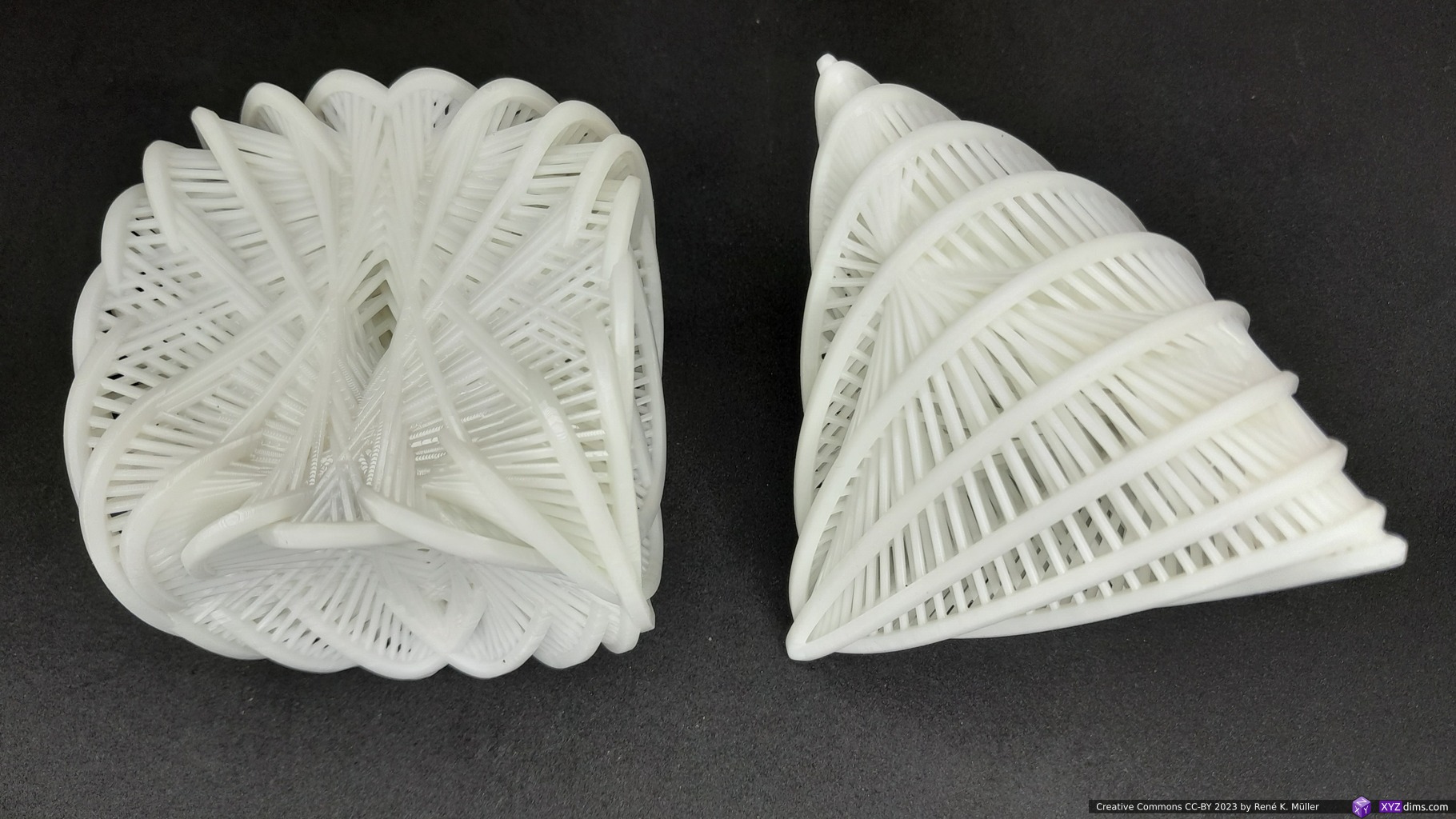
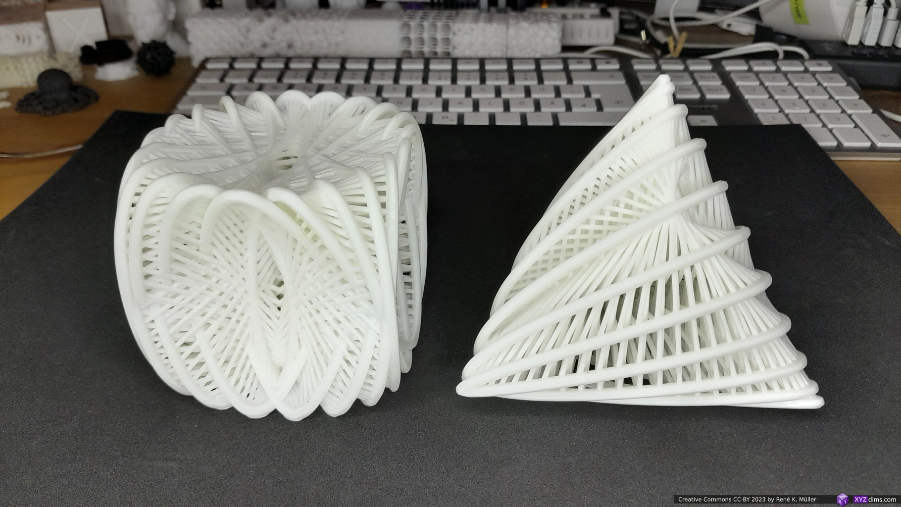
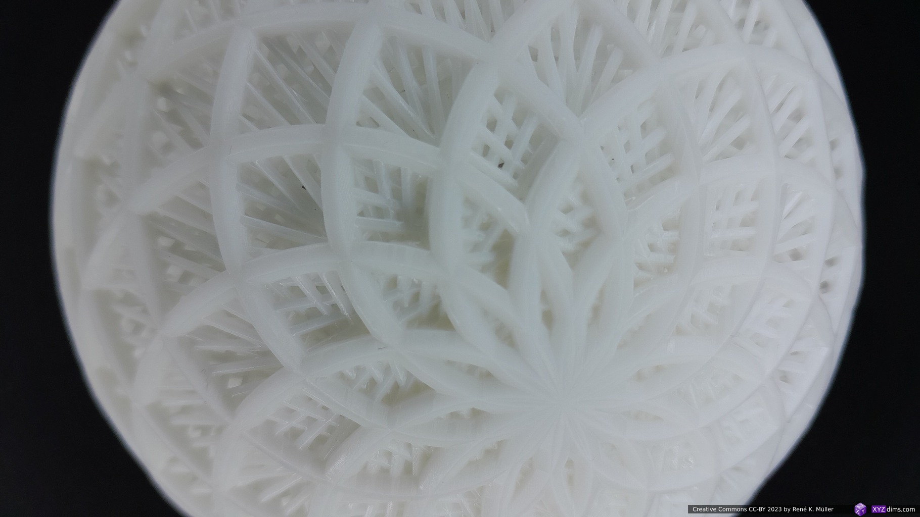
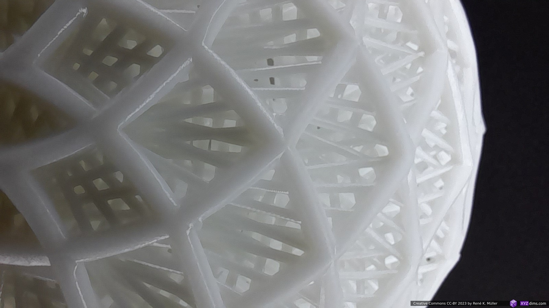
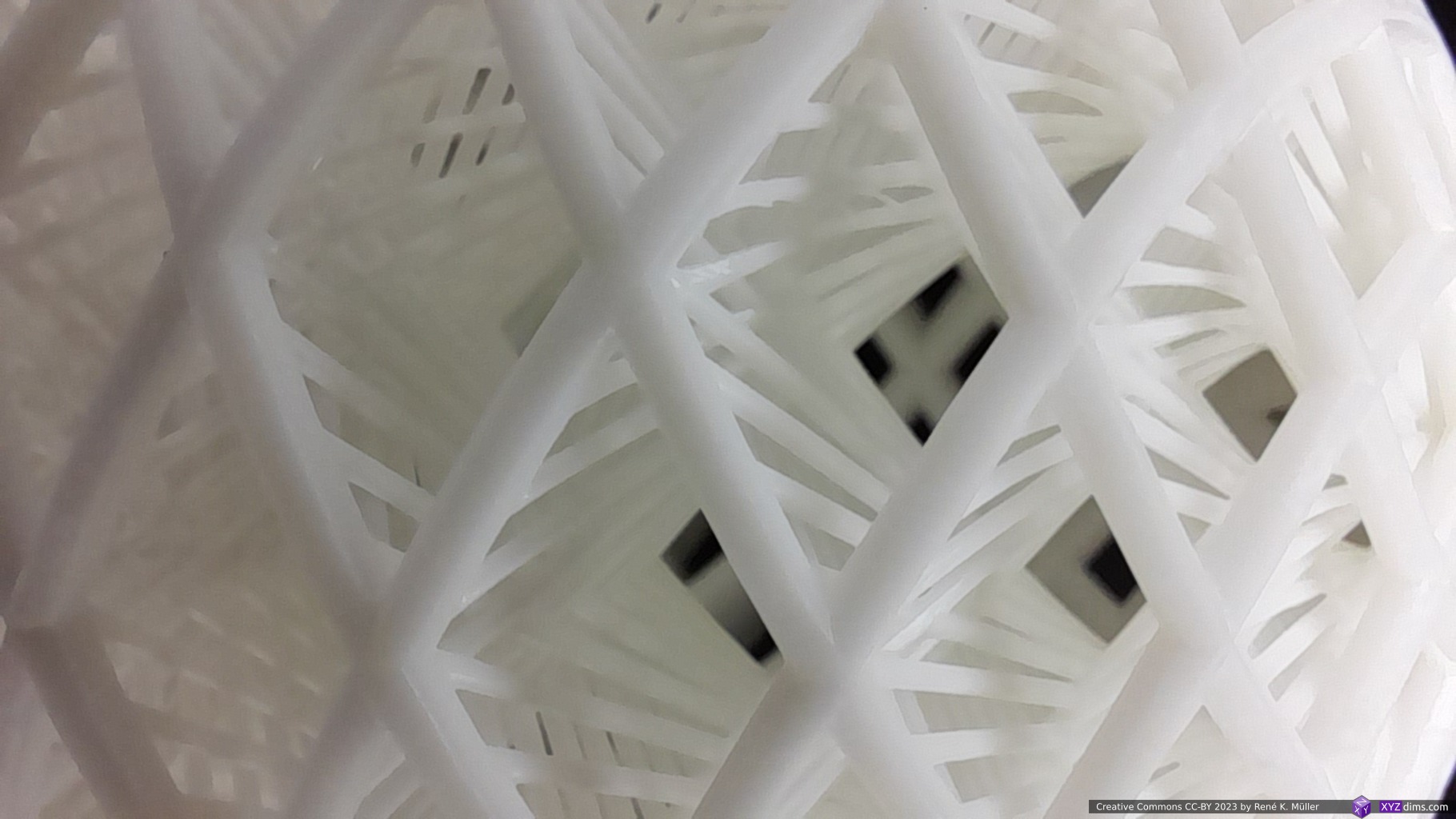
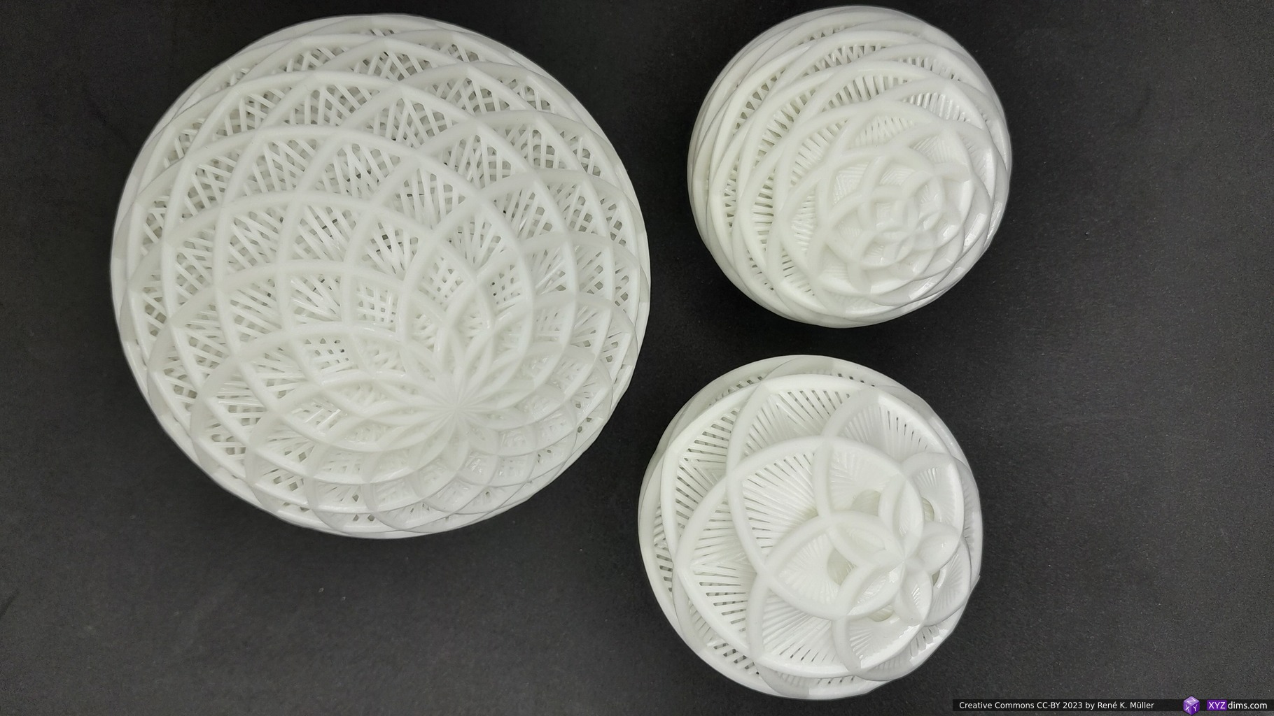
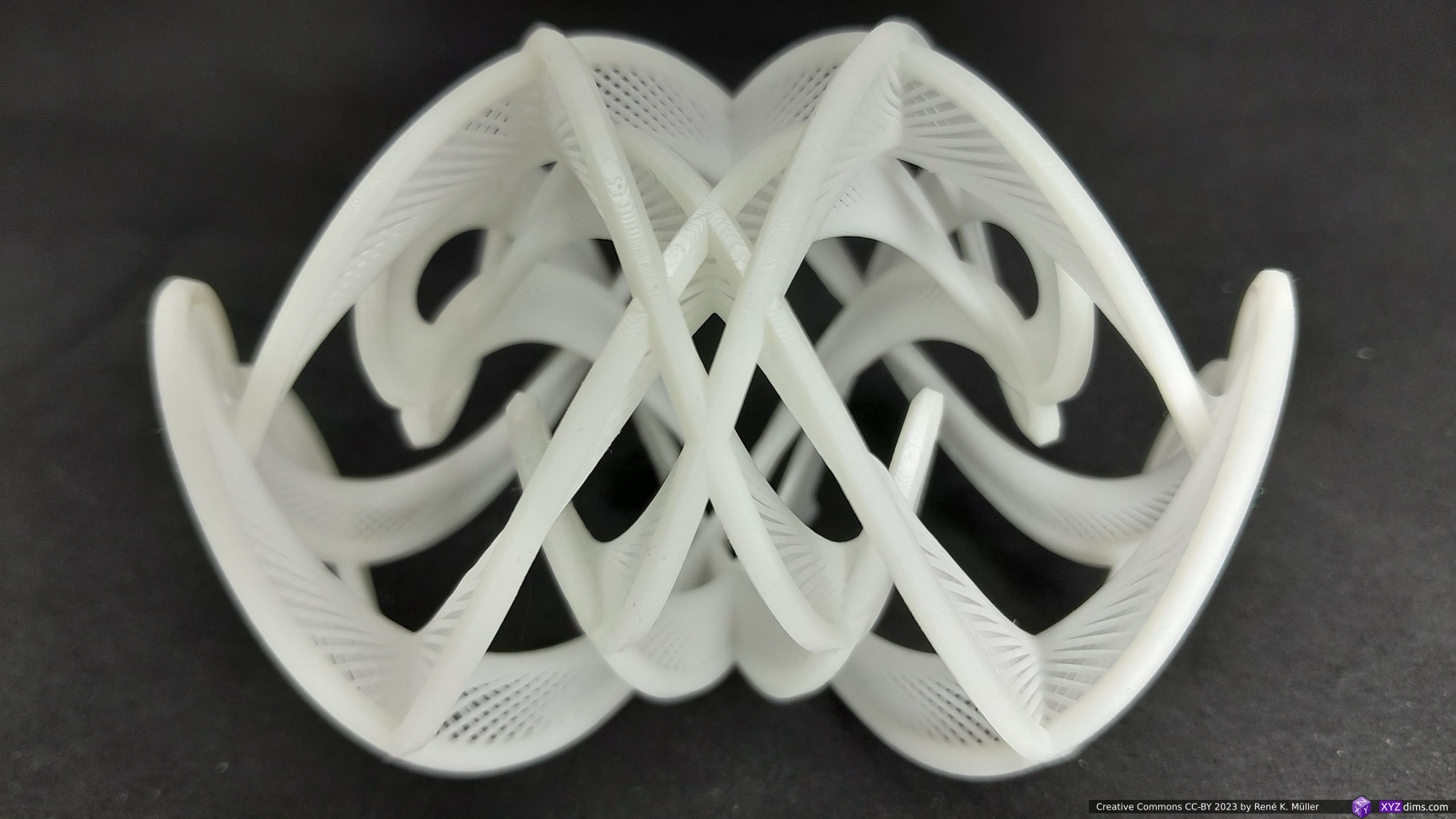
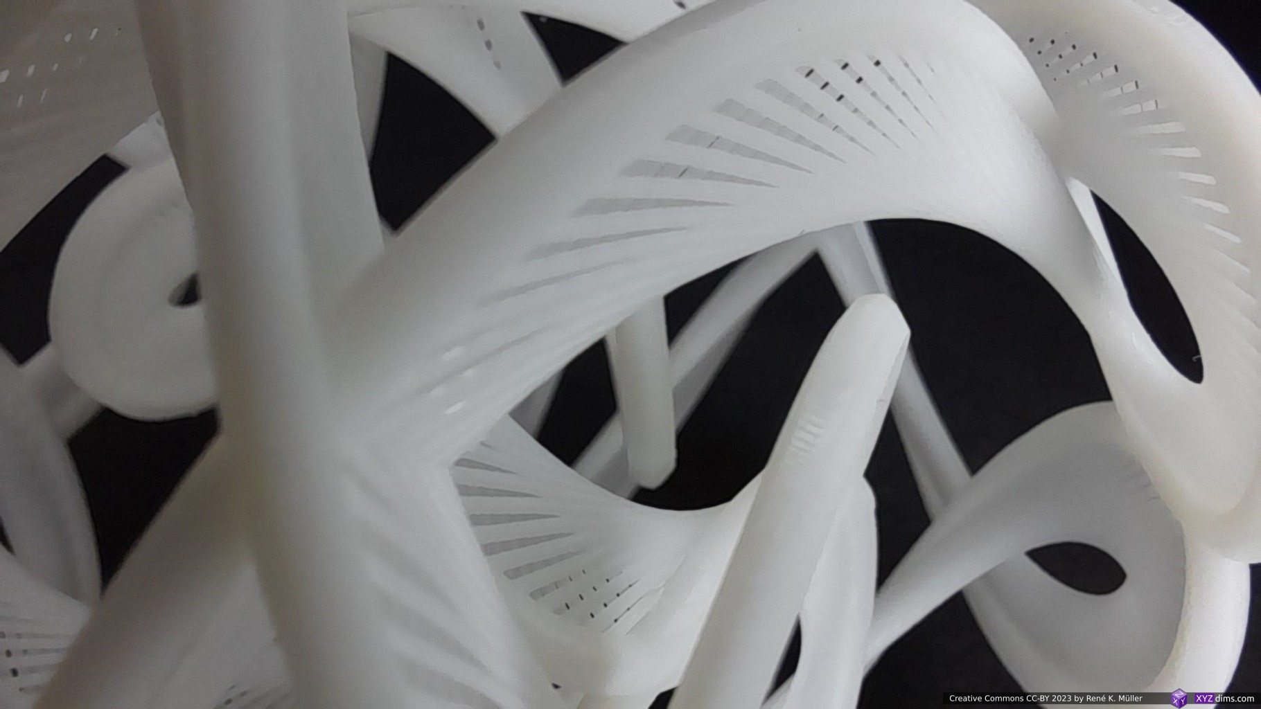
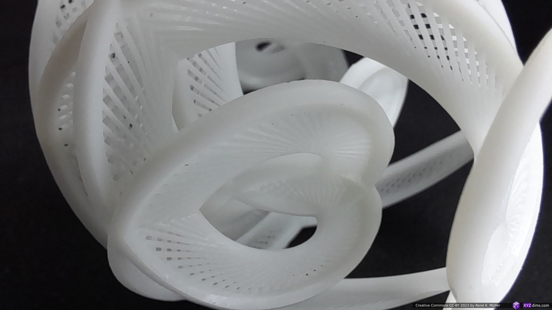
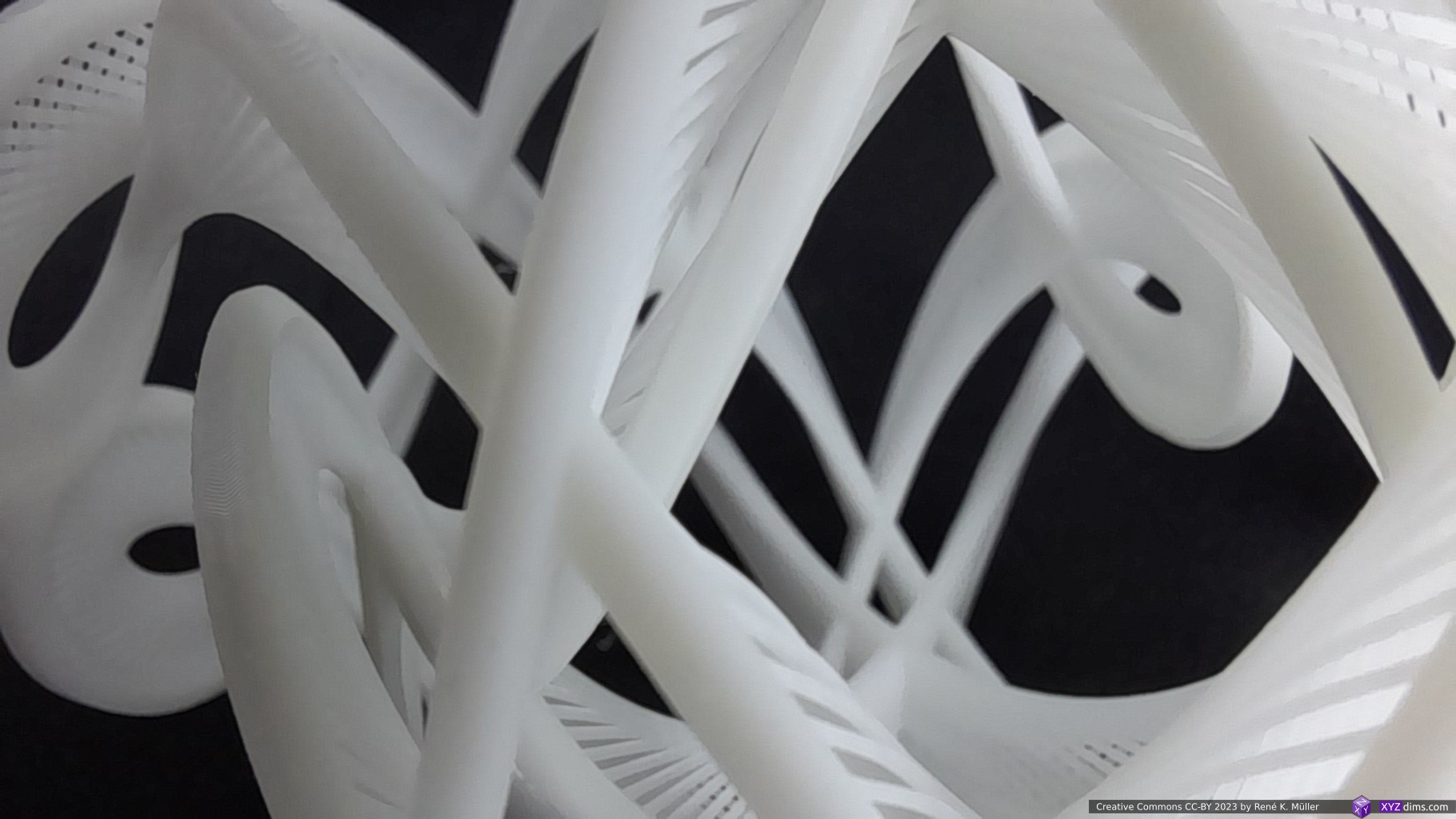
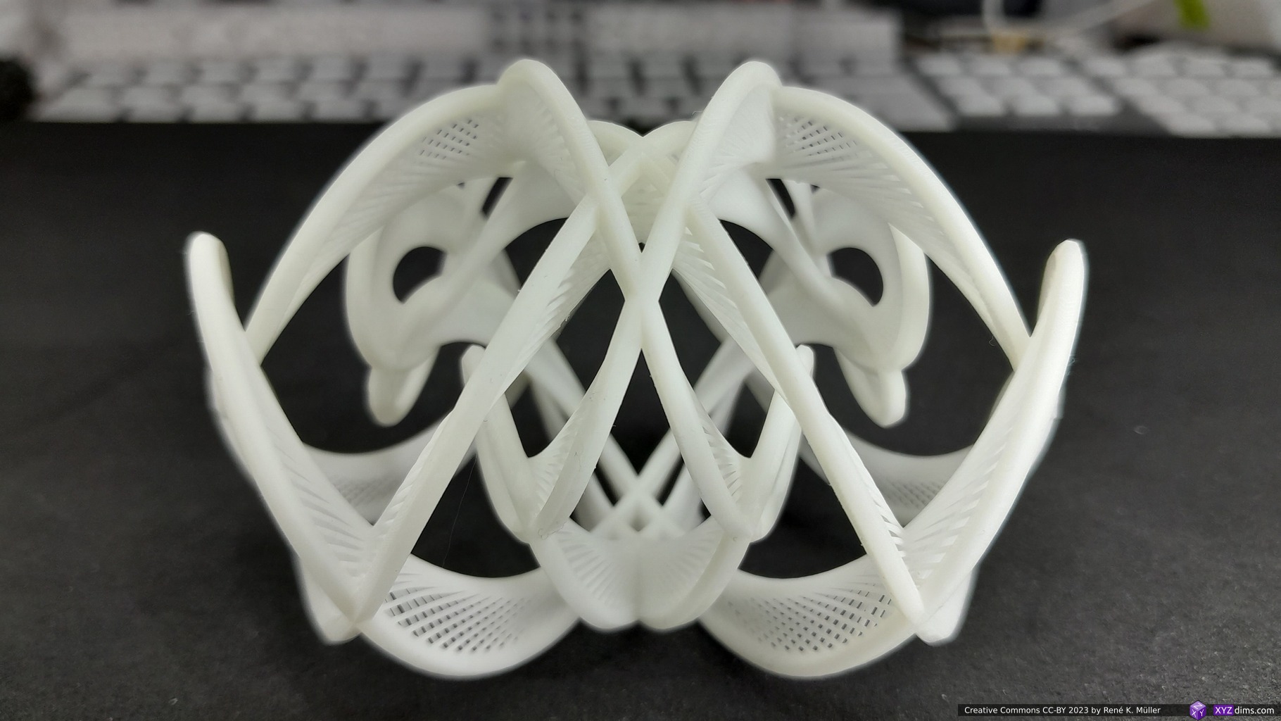
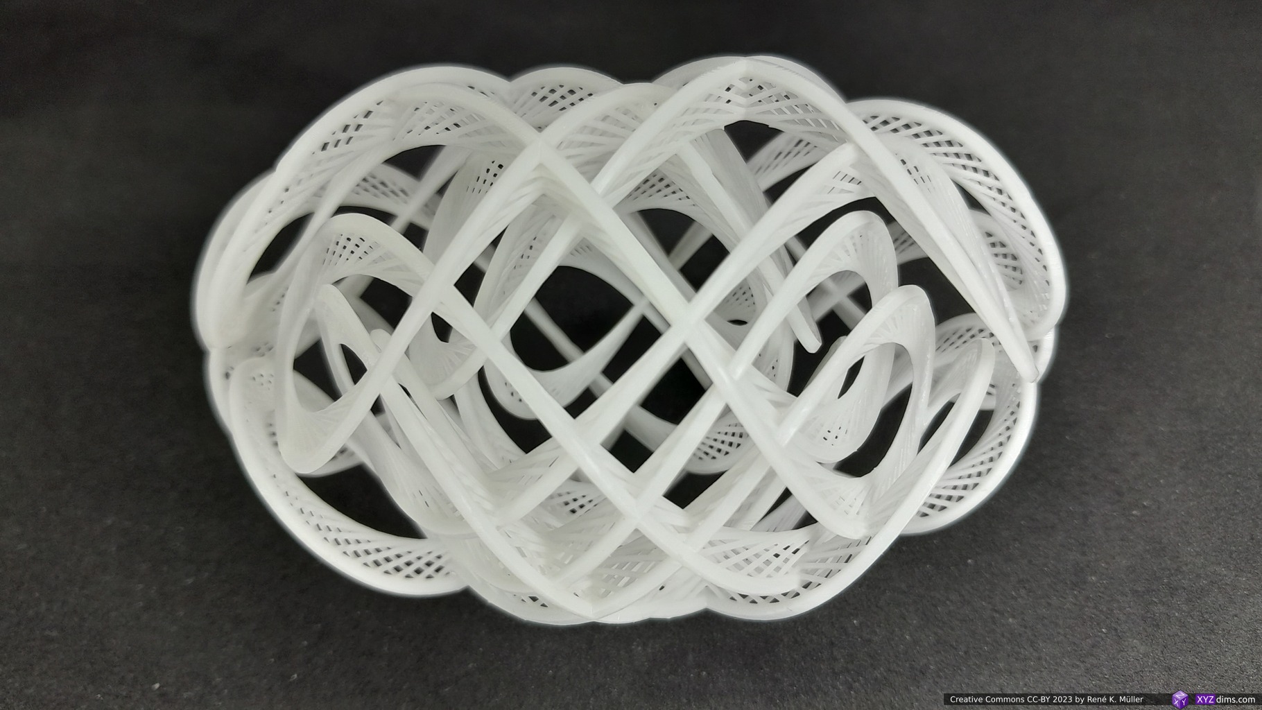
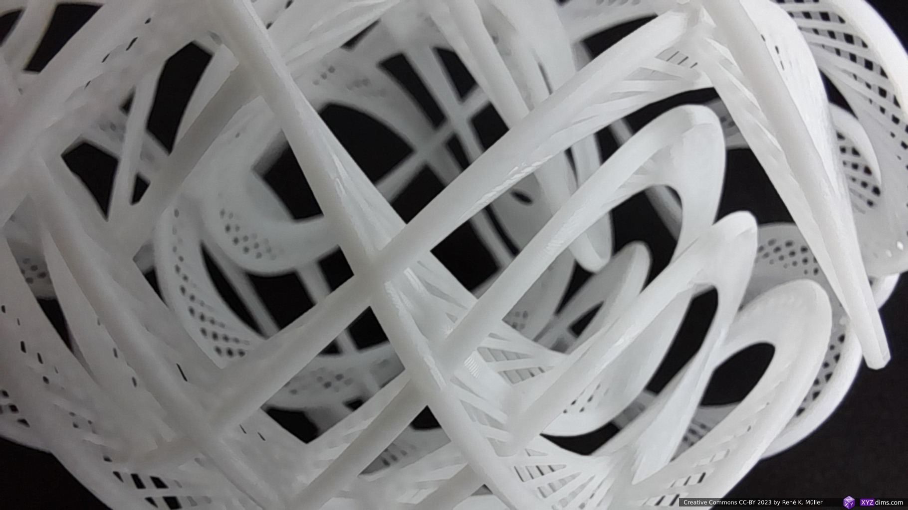
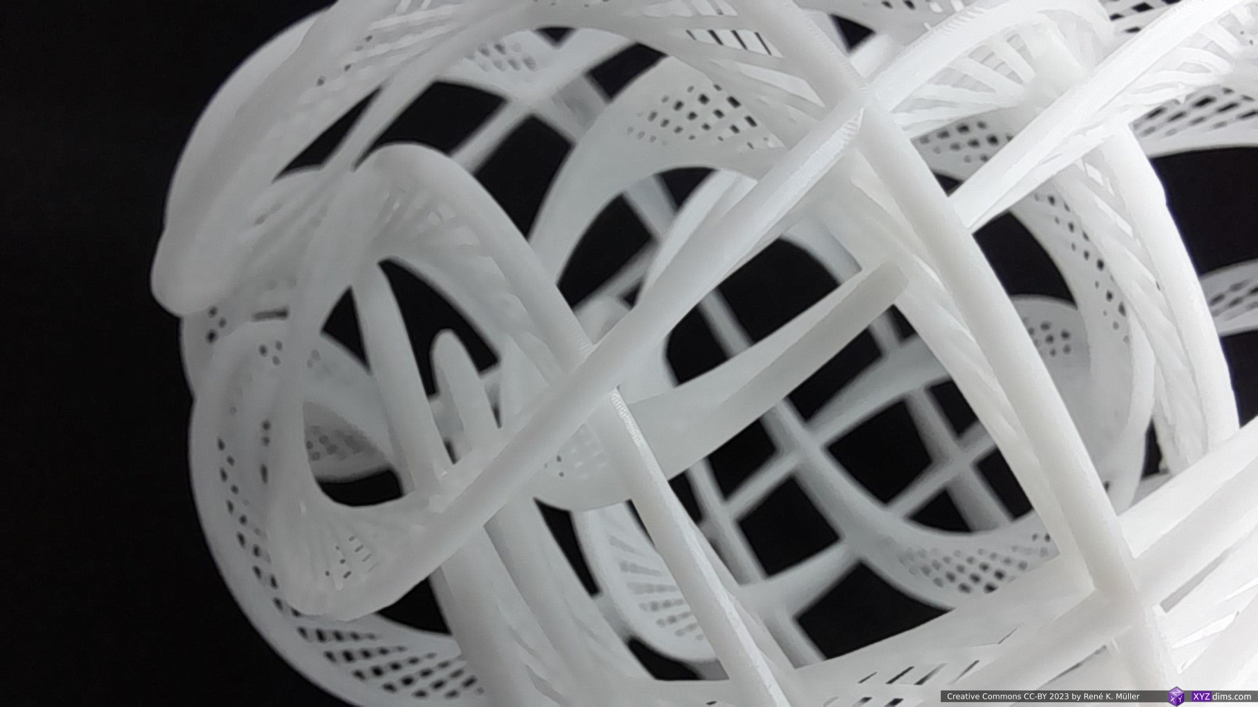
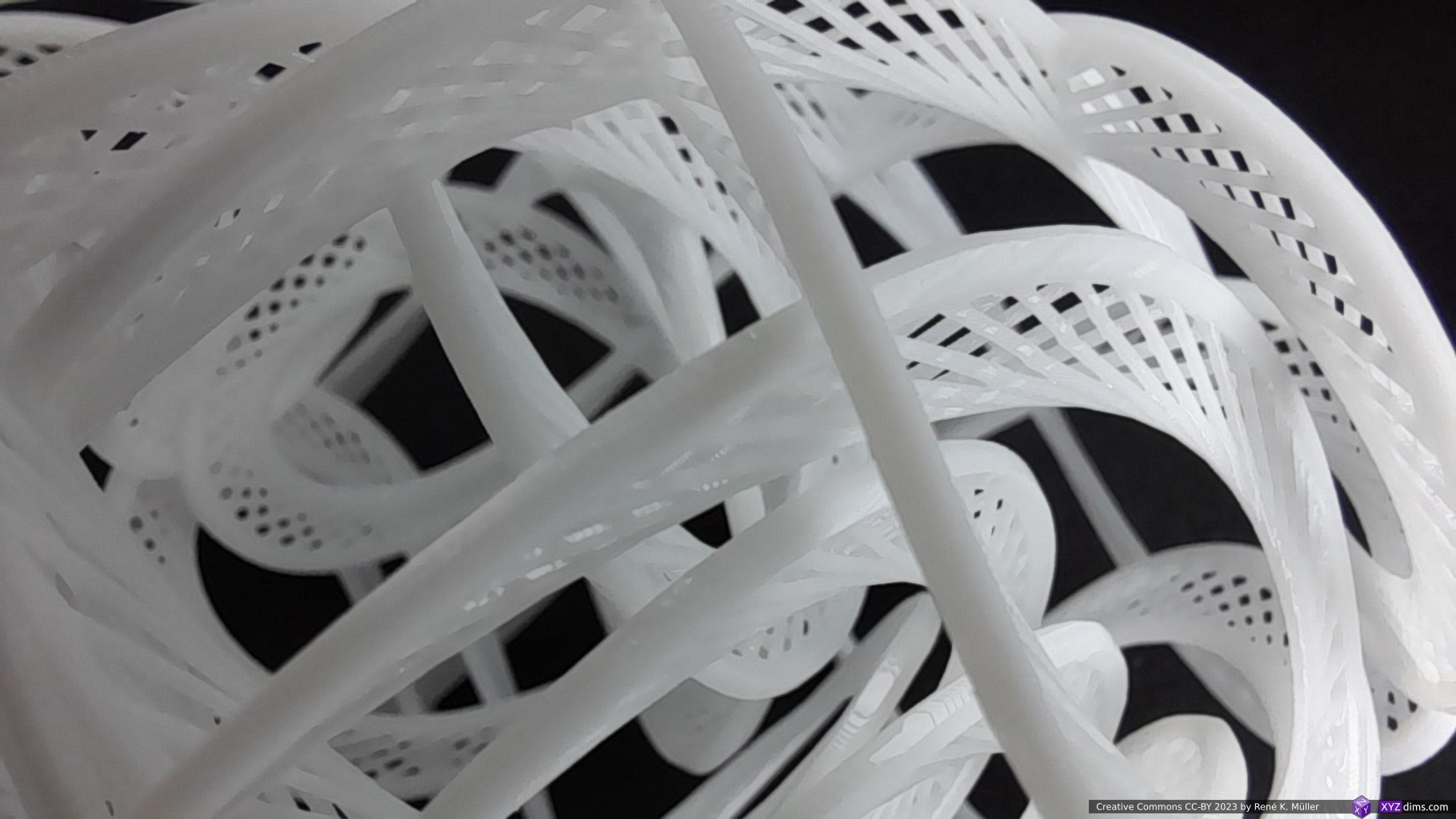
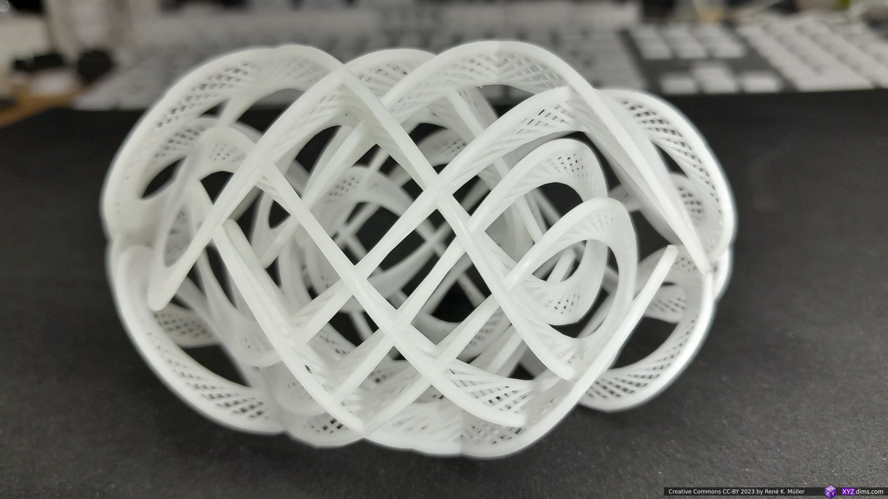
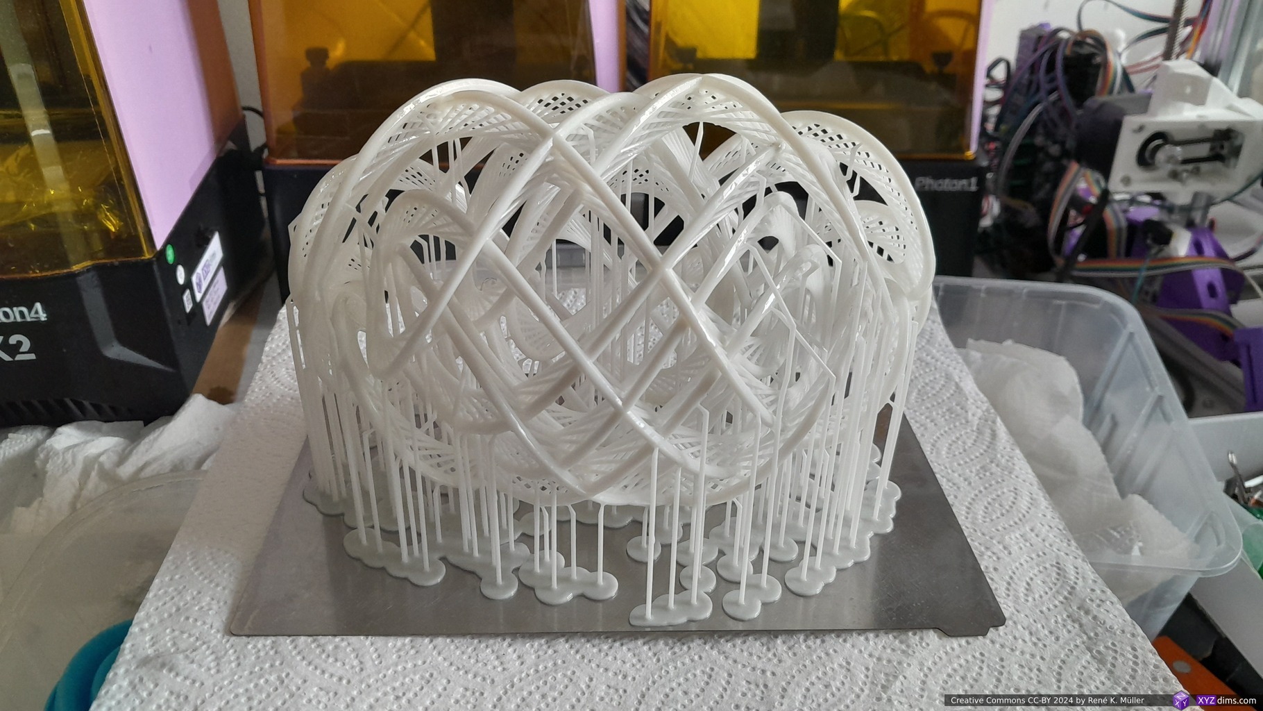
Spherical Lissajous 12.23 with spreading struts
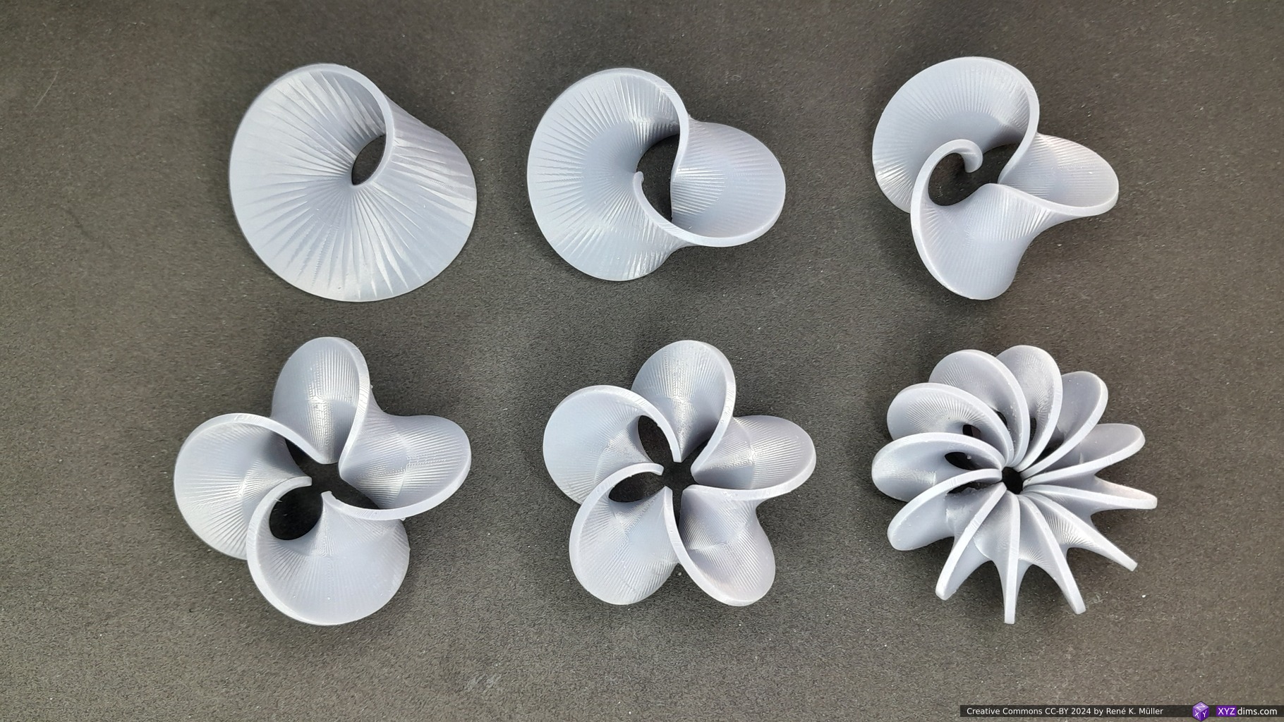
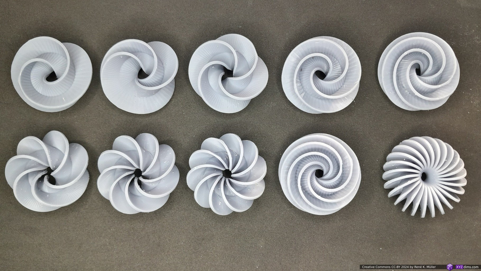
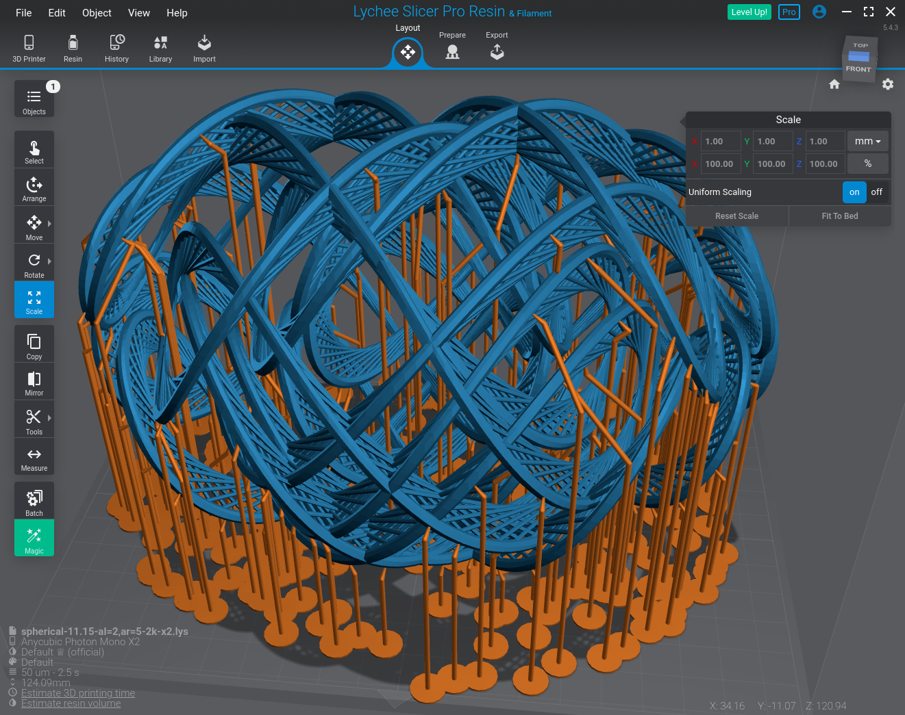
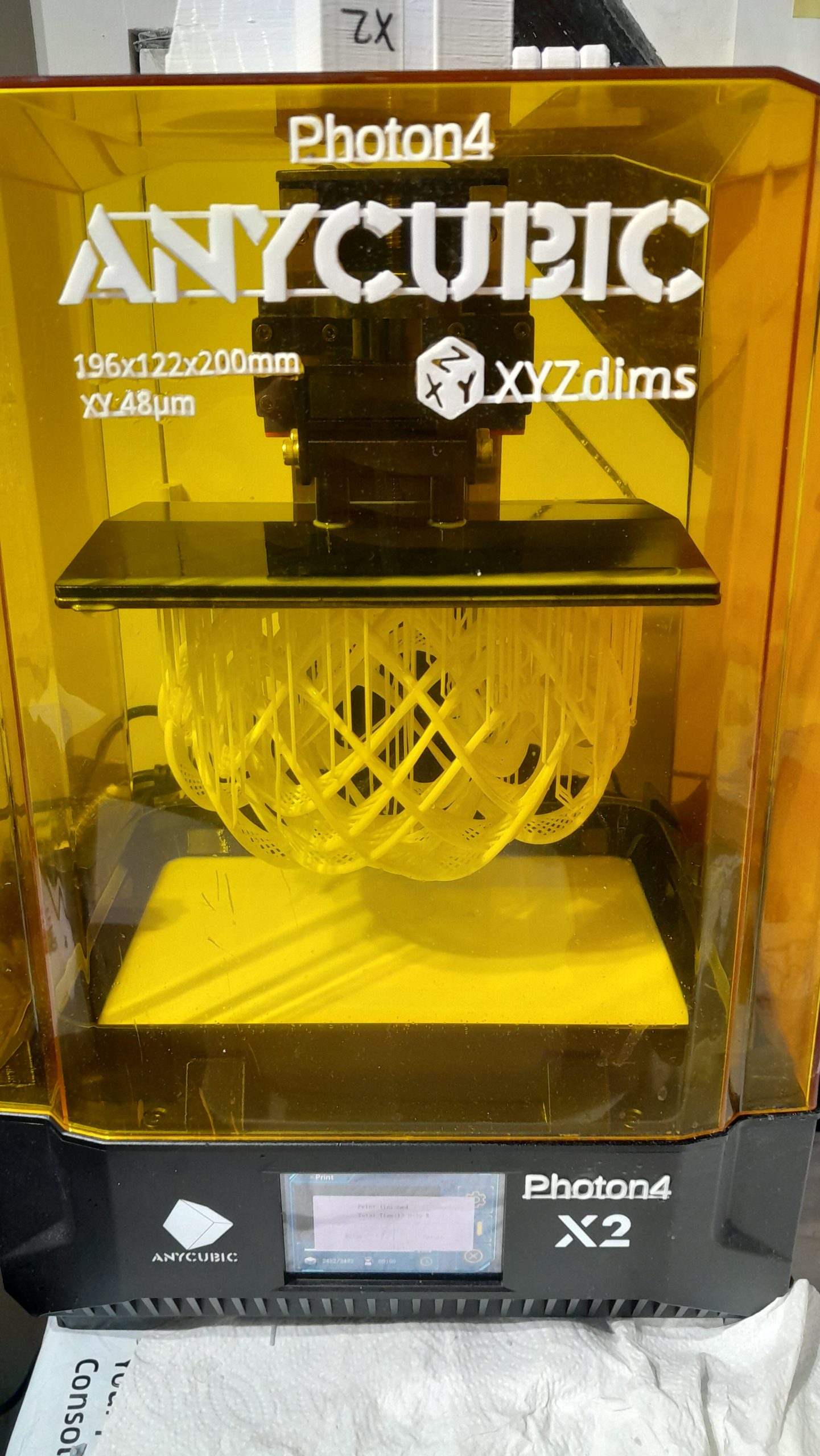
The model was printed with MSLA white resin at XYZ 50um resolution with 120mm diameter, with a few support structures near the bottom:
Spherical Lissajous 12.23 with spreading struts MSLA printed at 120mm diameterSpherical Lissajous 12.23 with spreading strutsSpherical Lissajous 12.23 with spreading struts closeup 1Spherical Lissajous 12.23 with spreading struts closeup 2Spherical Lissajous 12.23 with spreading struts closeup 3Various spherical Lissajous
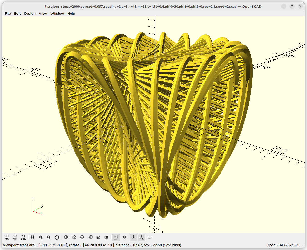
Spherical Lissajous with Translations
Using the Spherical Lissajous and extend it slightly: