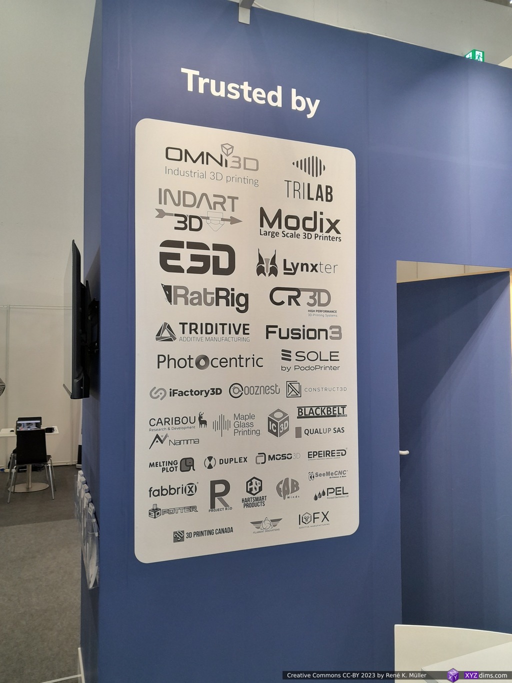
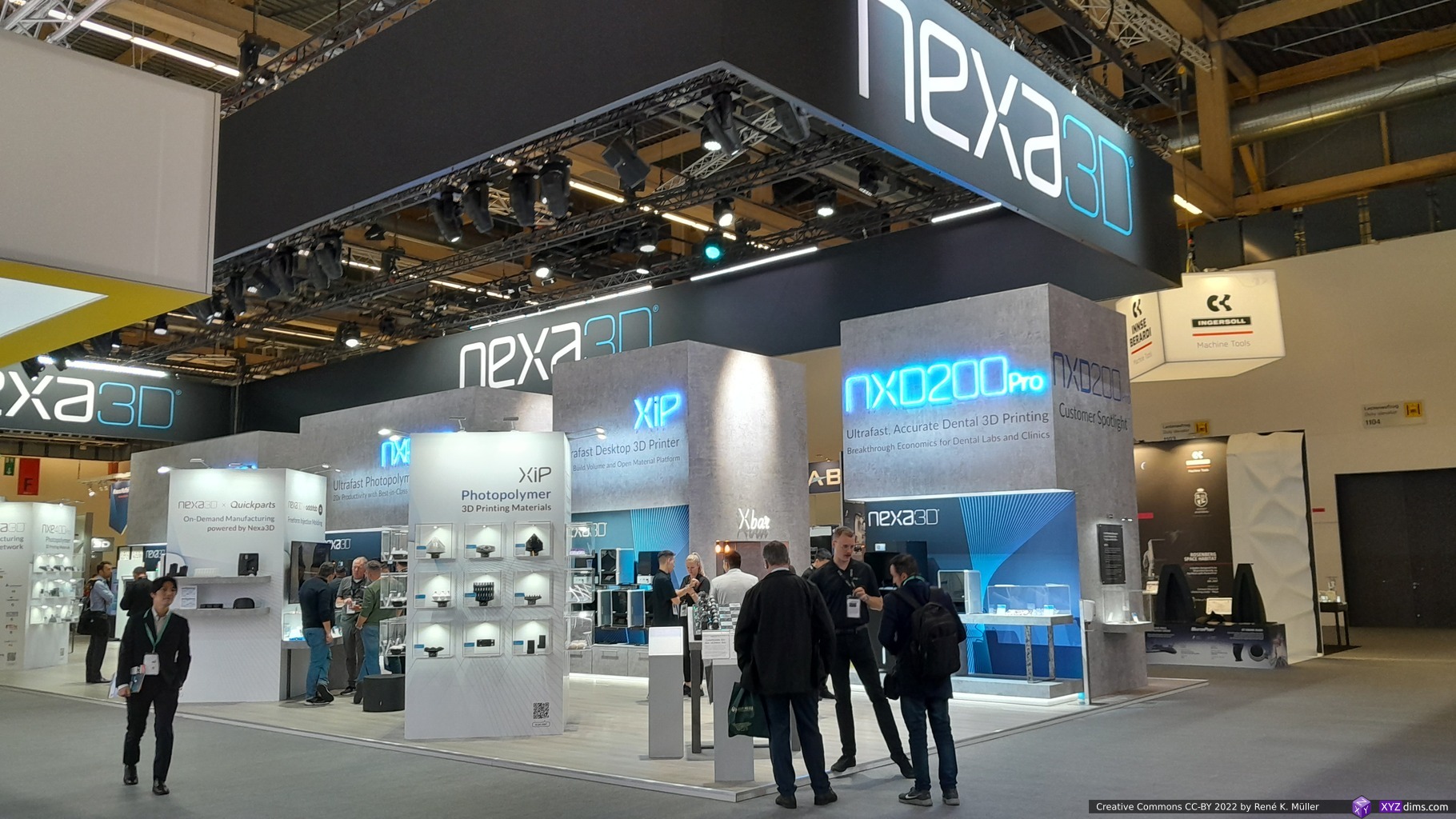
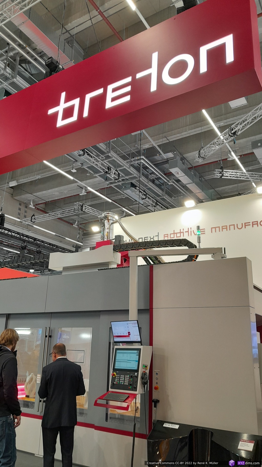
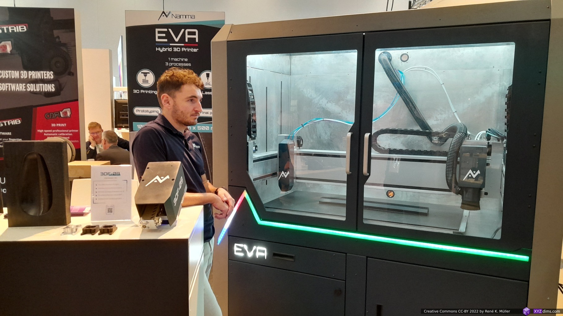
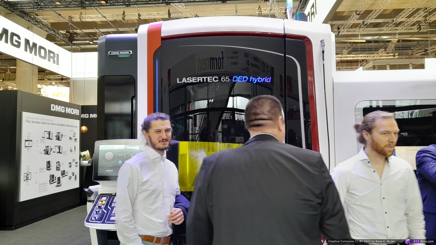
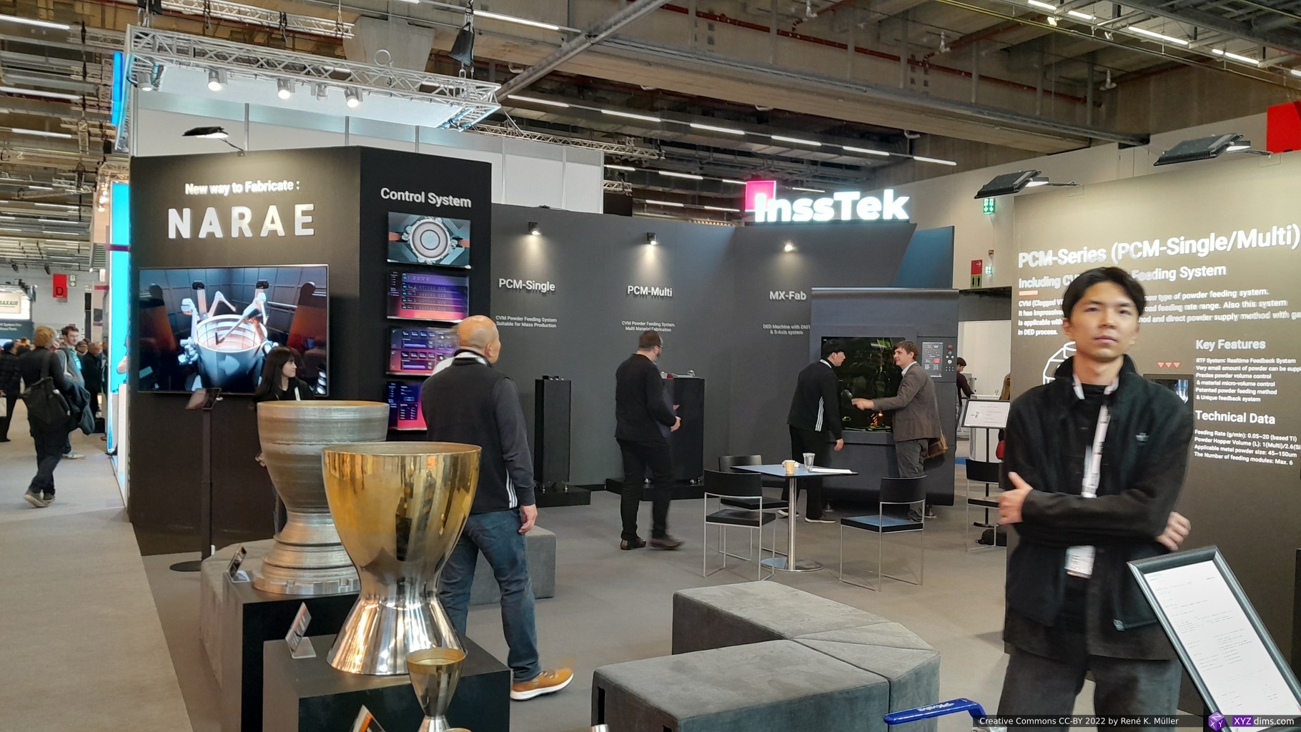
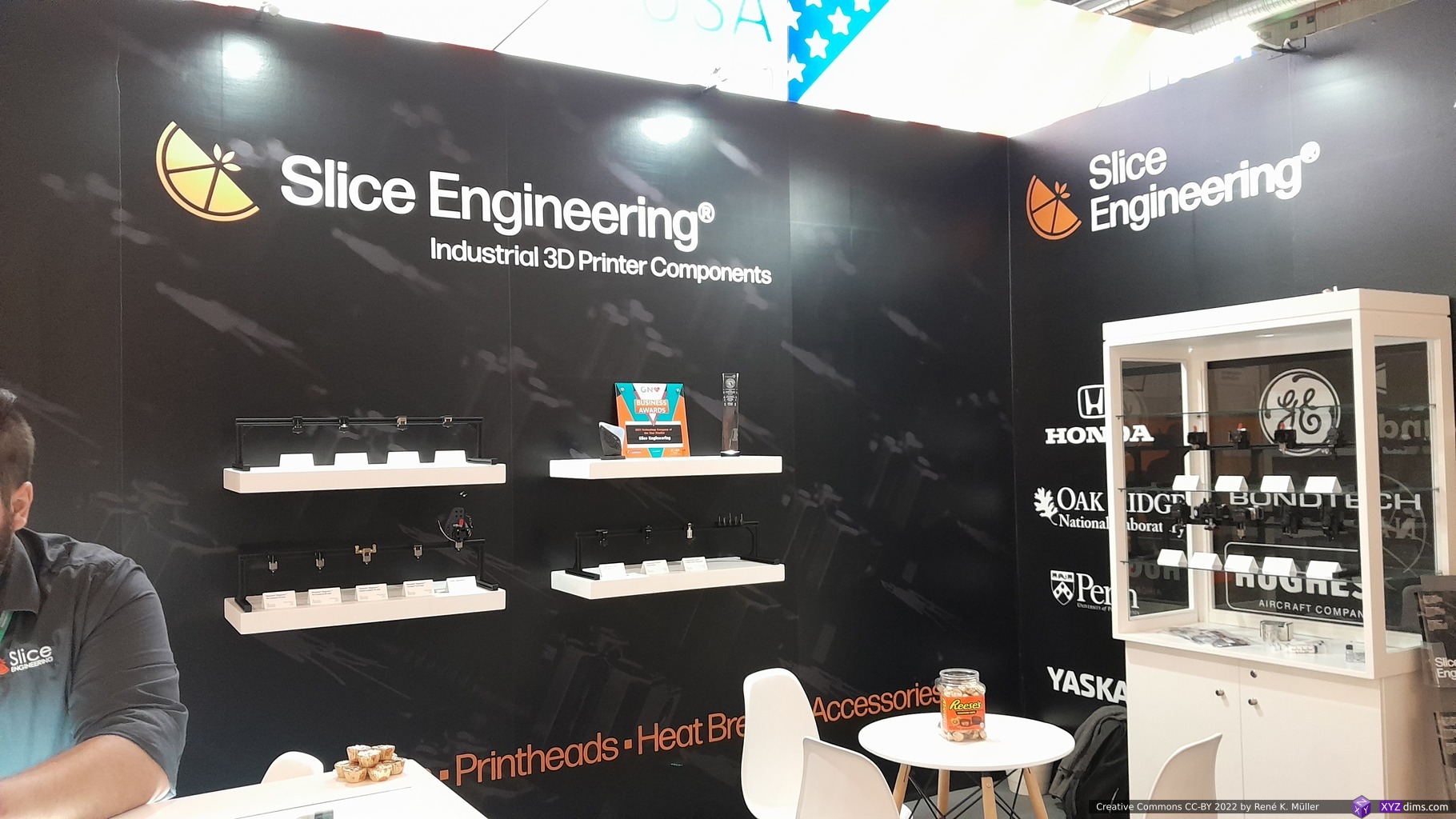
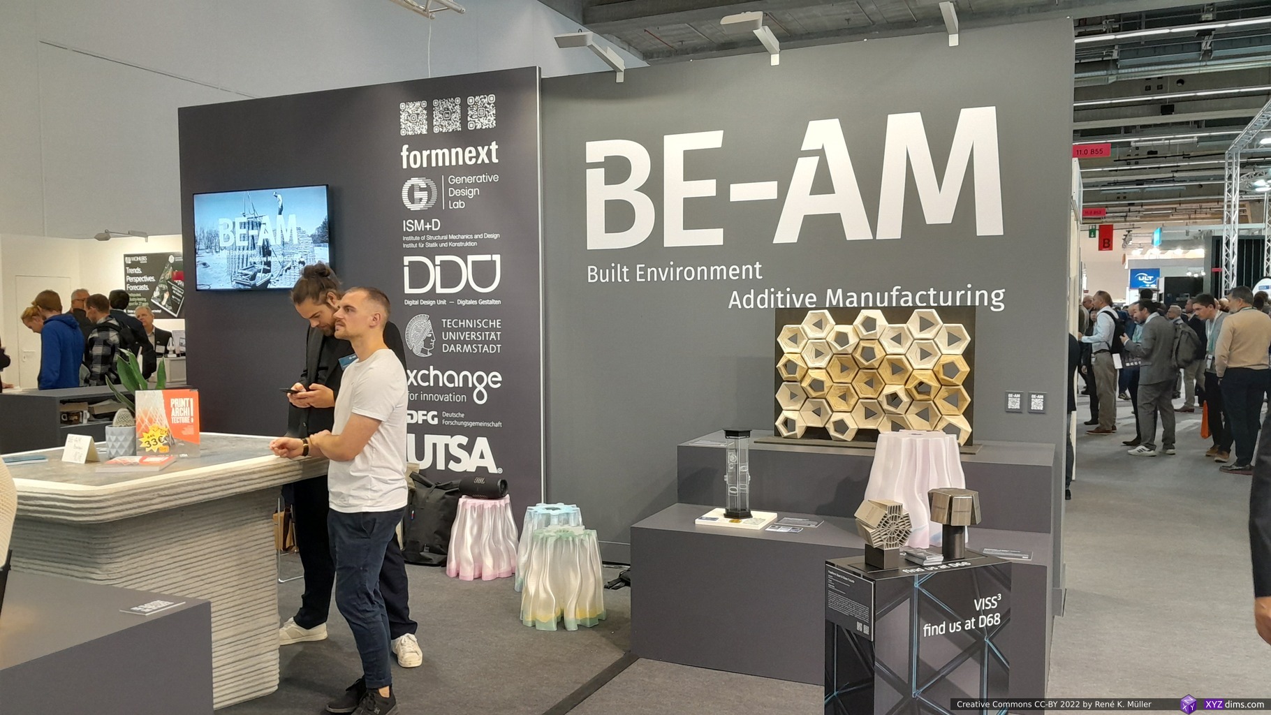
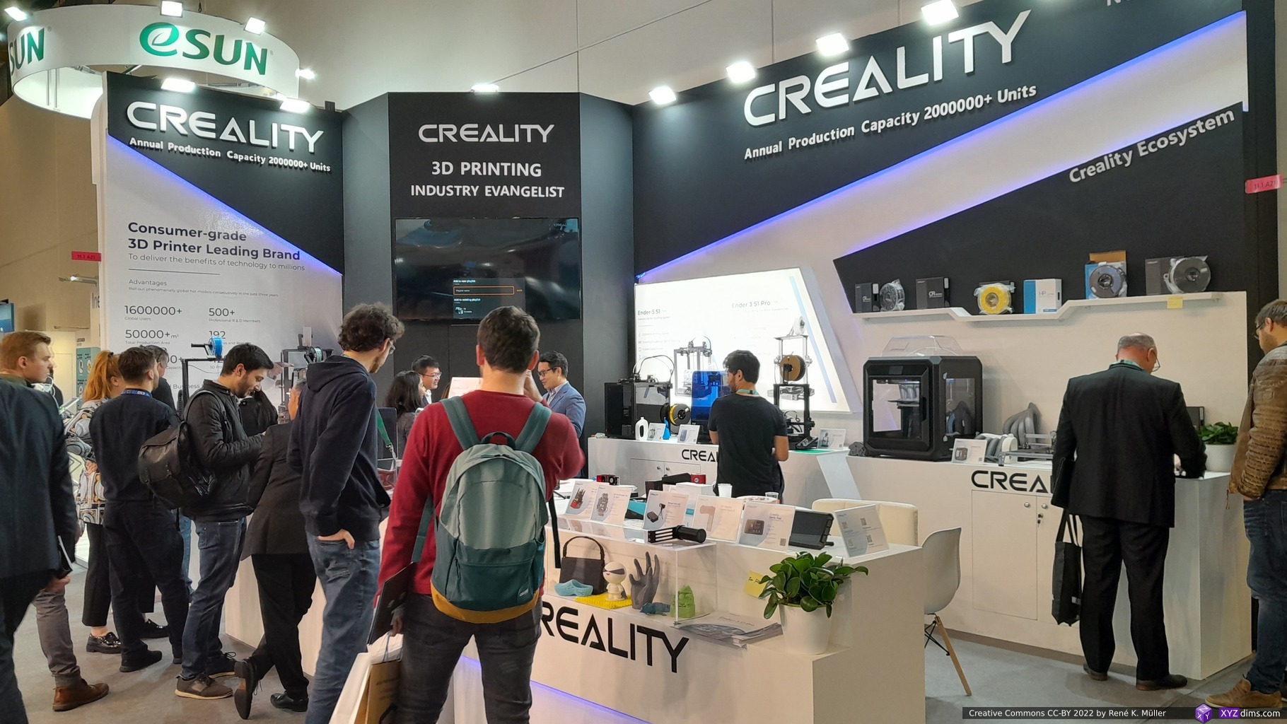
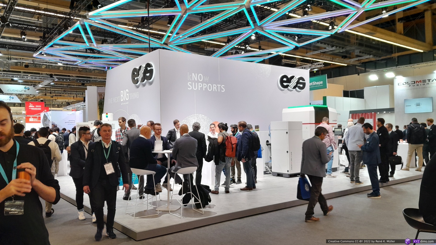
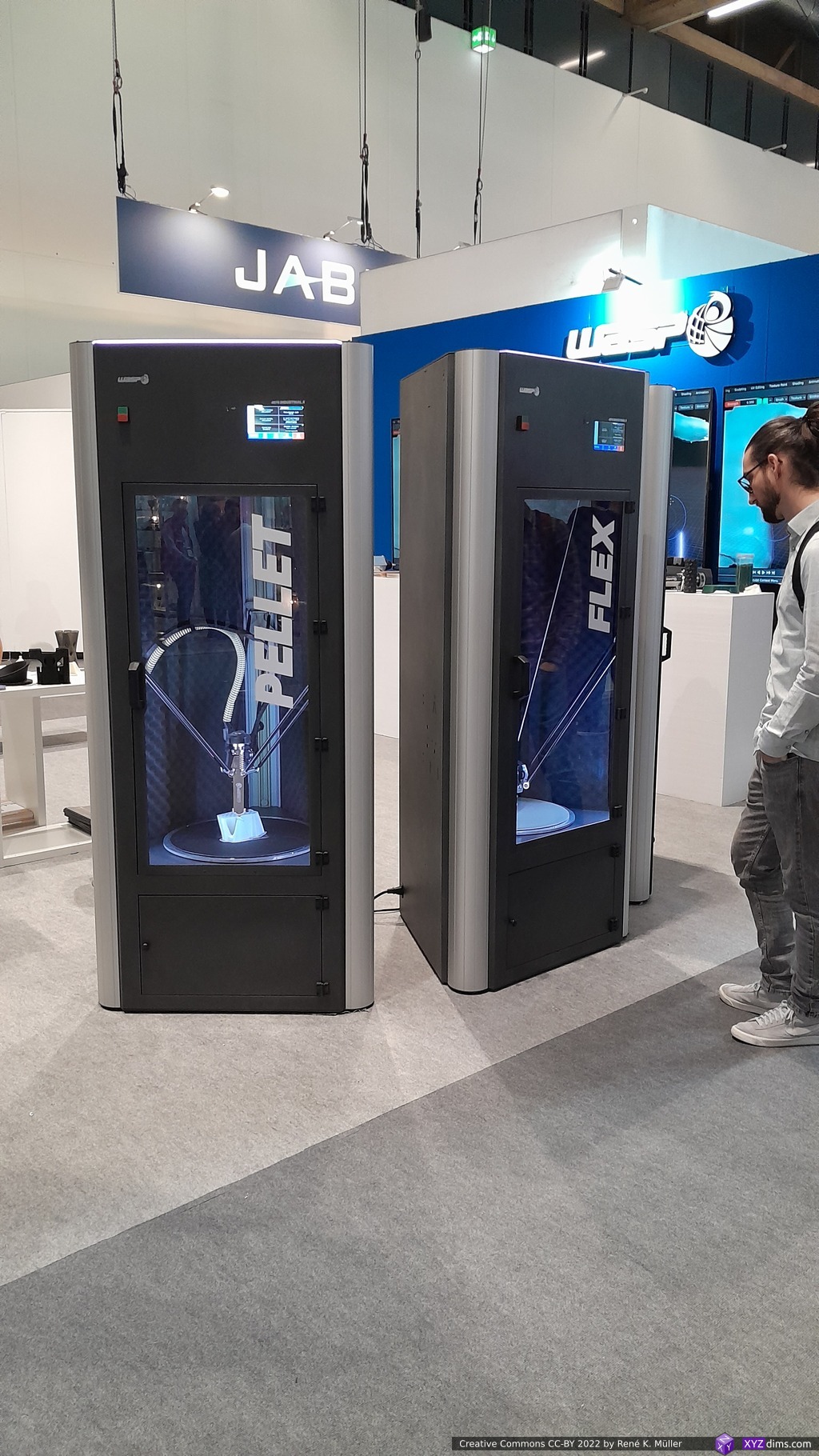
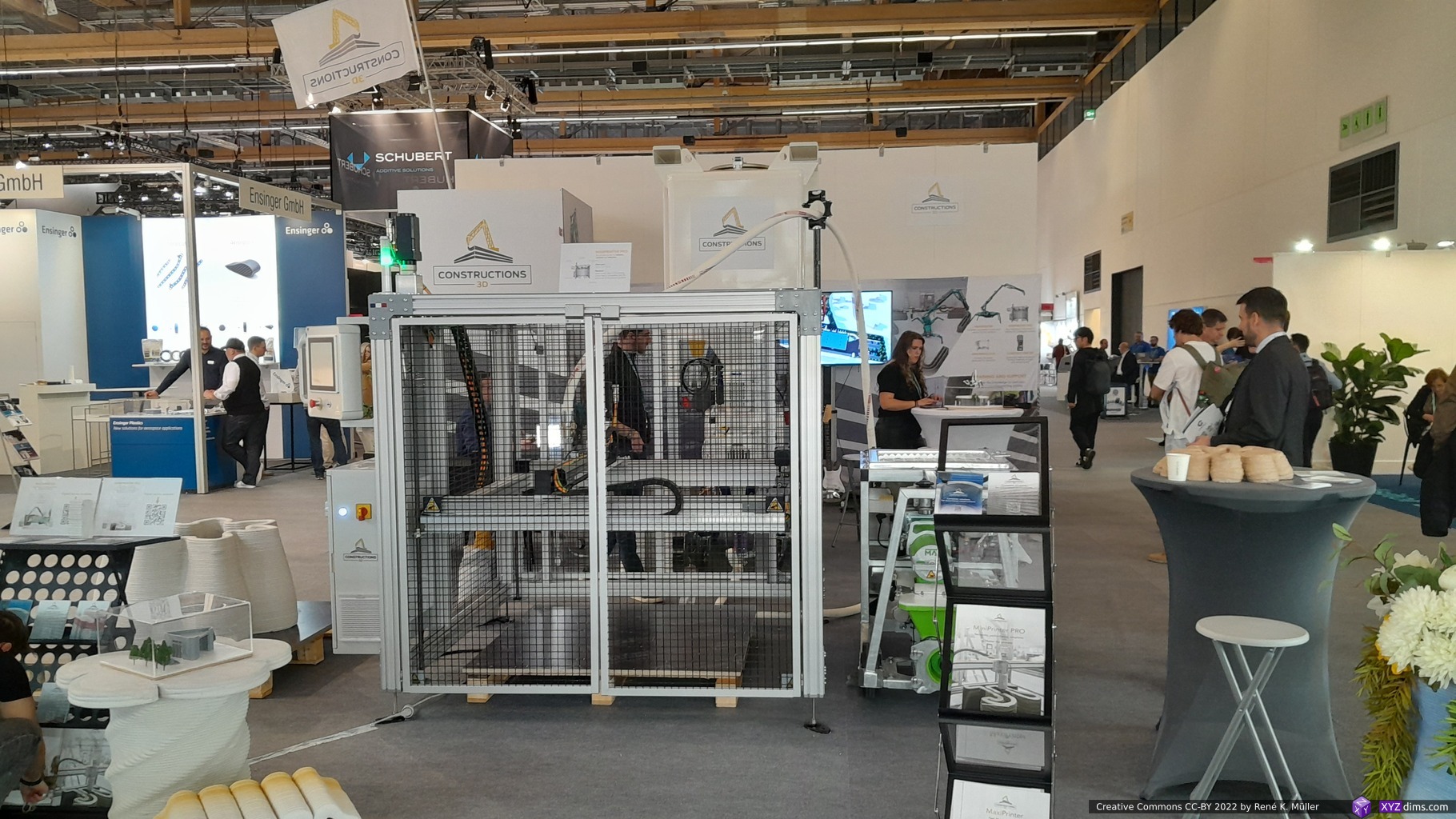
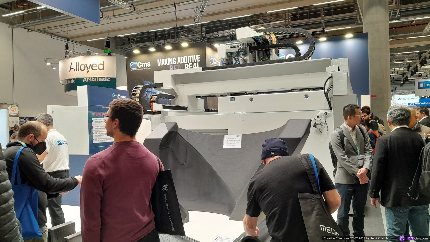
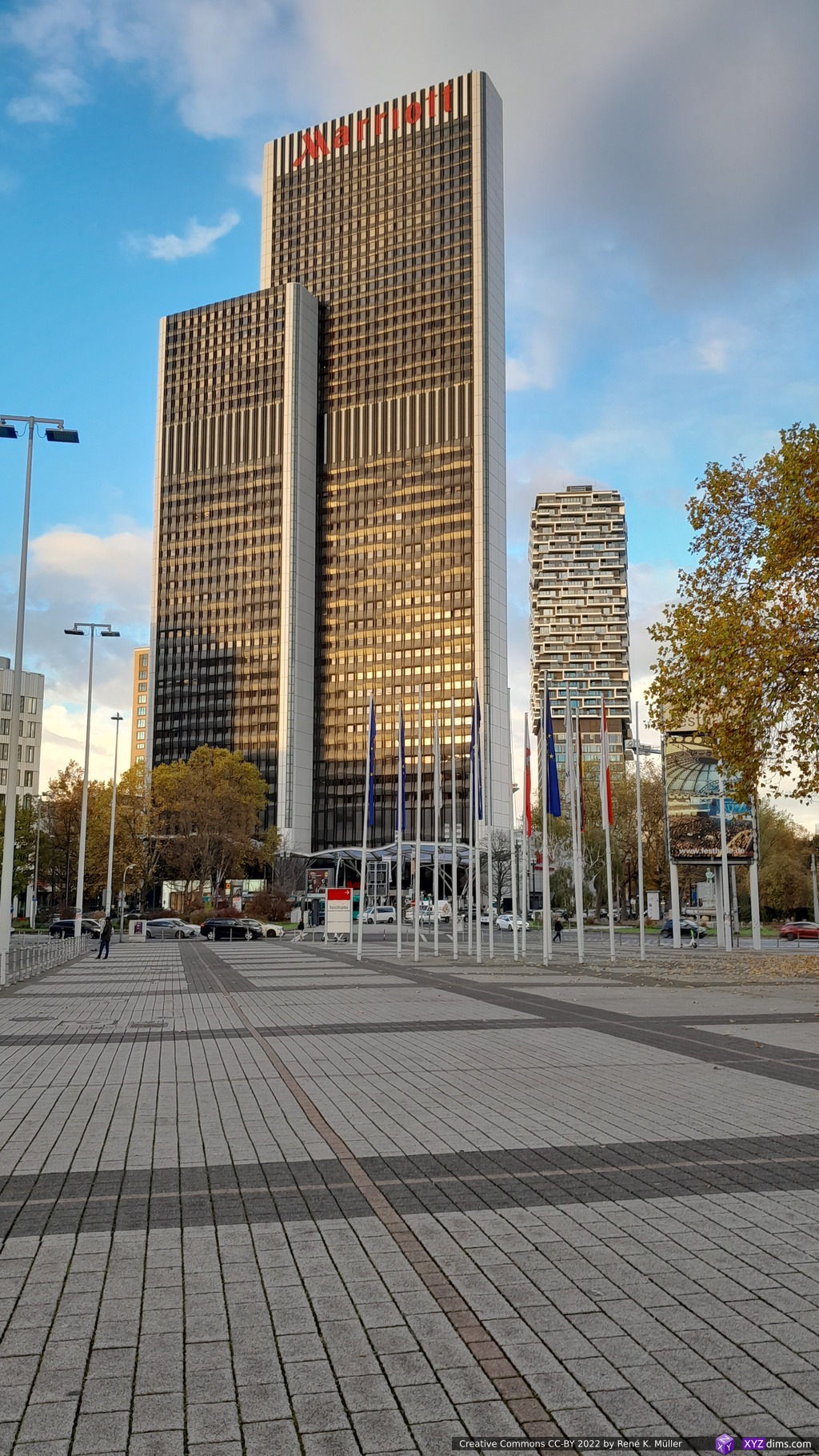
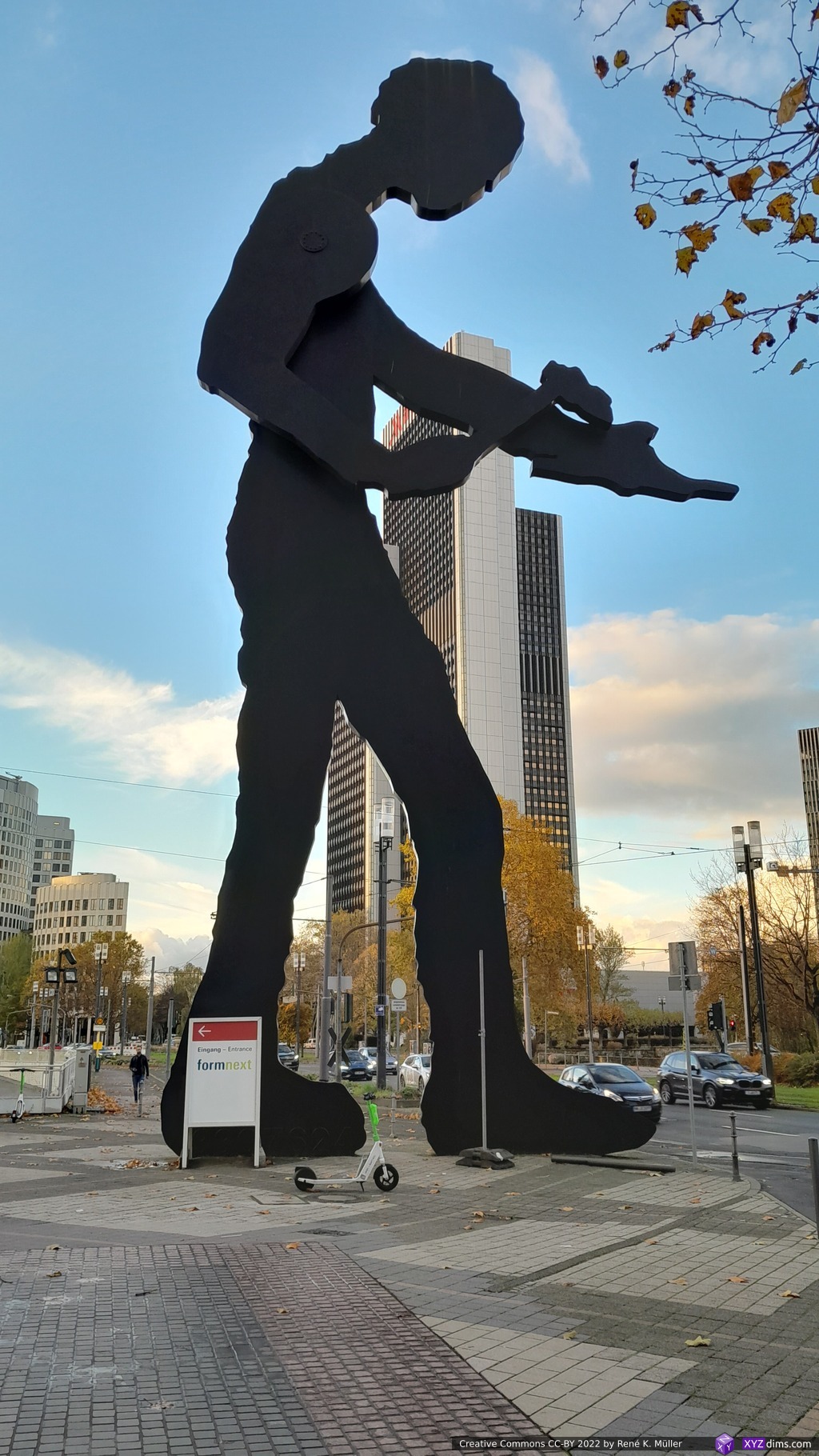
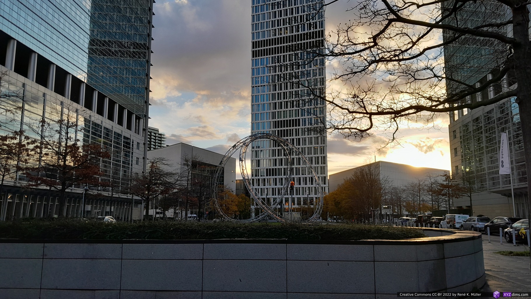
Another year, another November in Frankfurt (Germany) and Formnext – this is the main event of the year professionally for me. As I reside in Switzerland the travel is fairly easy and short and the 770 exhibitors in two halls (11 & 12) with two floors each is so overwhelming that even 4 days attending is not sufficient.
Day 1 (Tue, Nov 7): I spent an entire day to explore hall 12.1 alone, which turns out a good choice as it was a dense populated hall with many smaller companies
Day 2 (Wed, Nov 8): visiting with a client half of the day to review some of their possible competition, and then explore 12.0
Day 3 (Thu, Nov 9): some schedules meetings and then explore 11.0 and 11.1
Day 4 (Fri, Nov 10): revisiting 12.1 and 11.1 briefly, visiting with another client some selected booths to check products on display
I surely missed a few booths in 11.1 and 12.1 still; whereas 12.0 and 11.0 were more large scale industrial AM solutions, mixed with university and regional focused booths which I didn’t have time to explore in detail.
Personal Selection
I feature some companies according my personal professional interests:
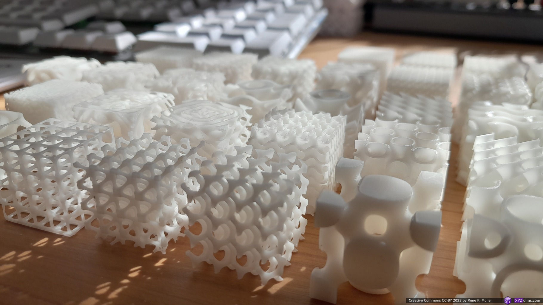
Spherene (Math)
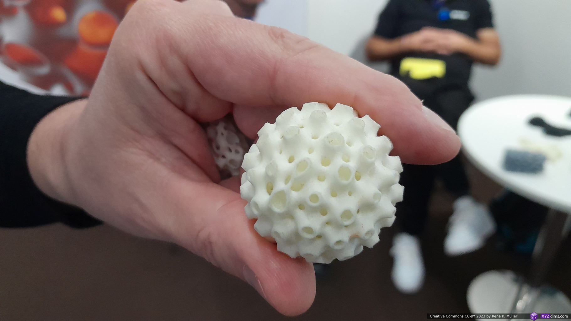
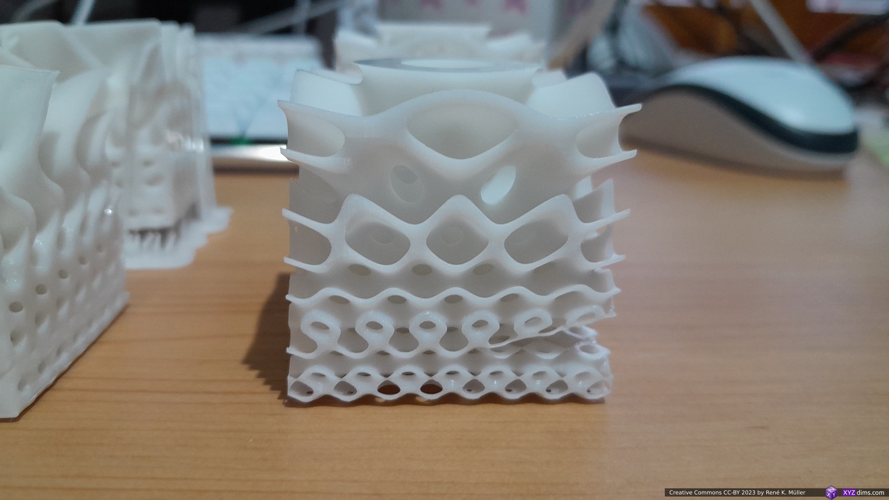
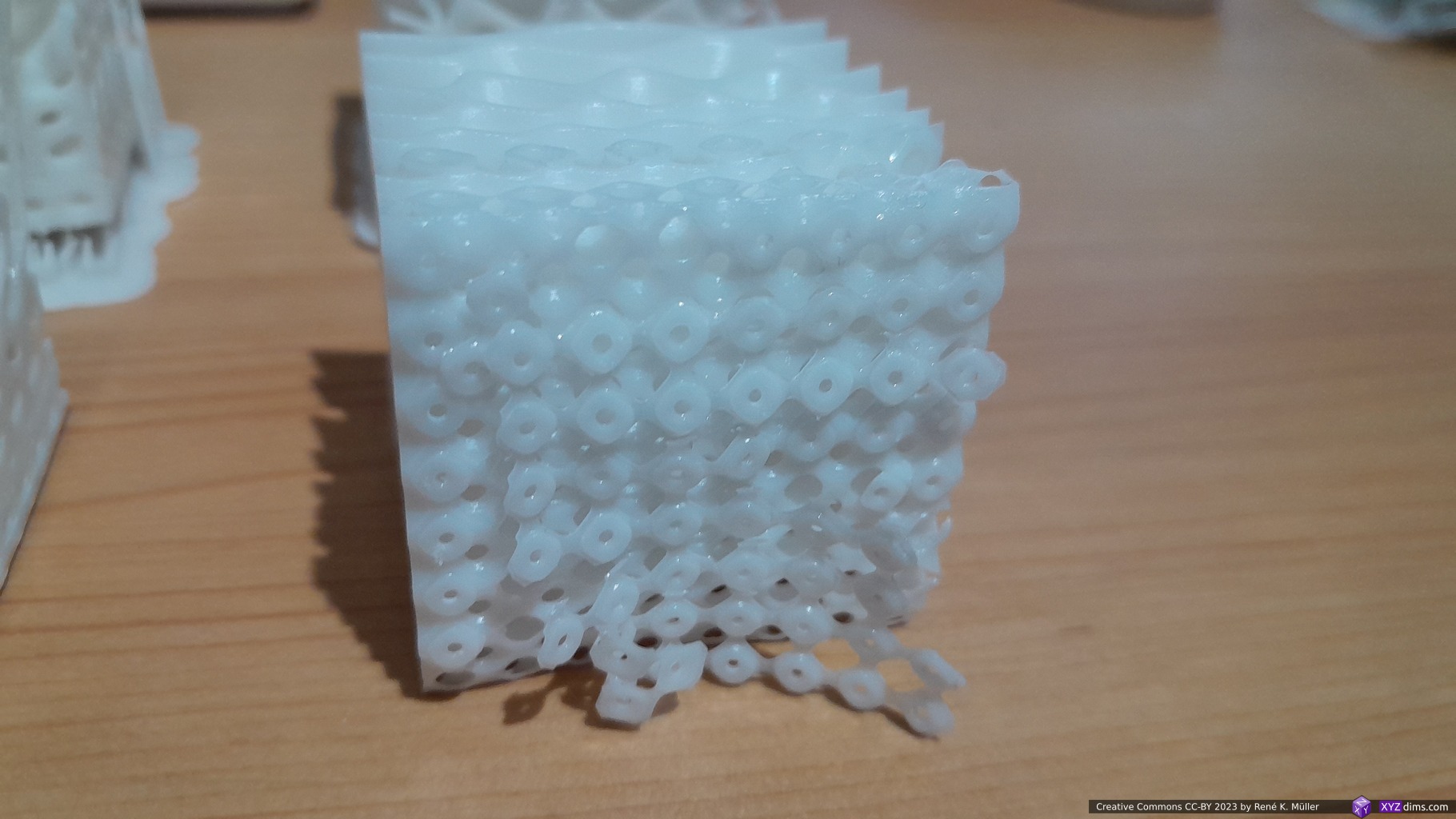
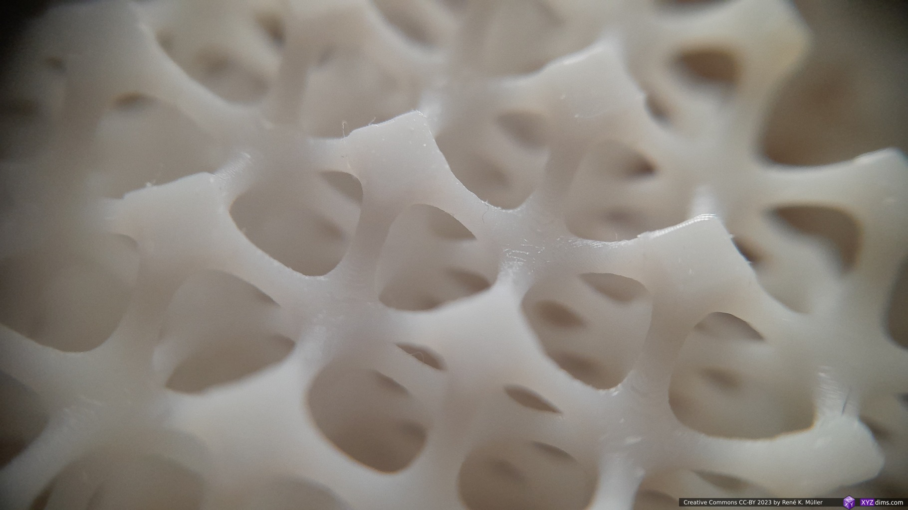
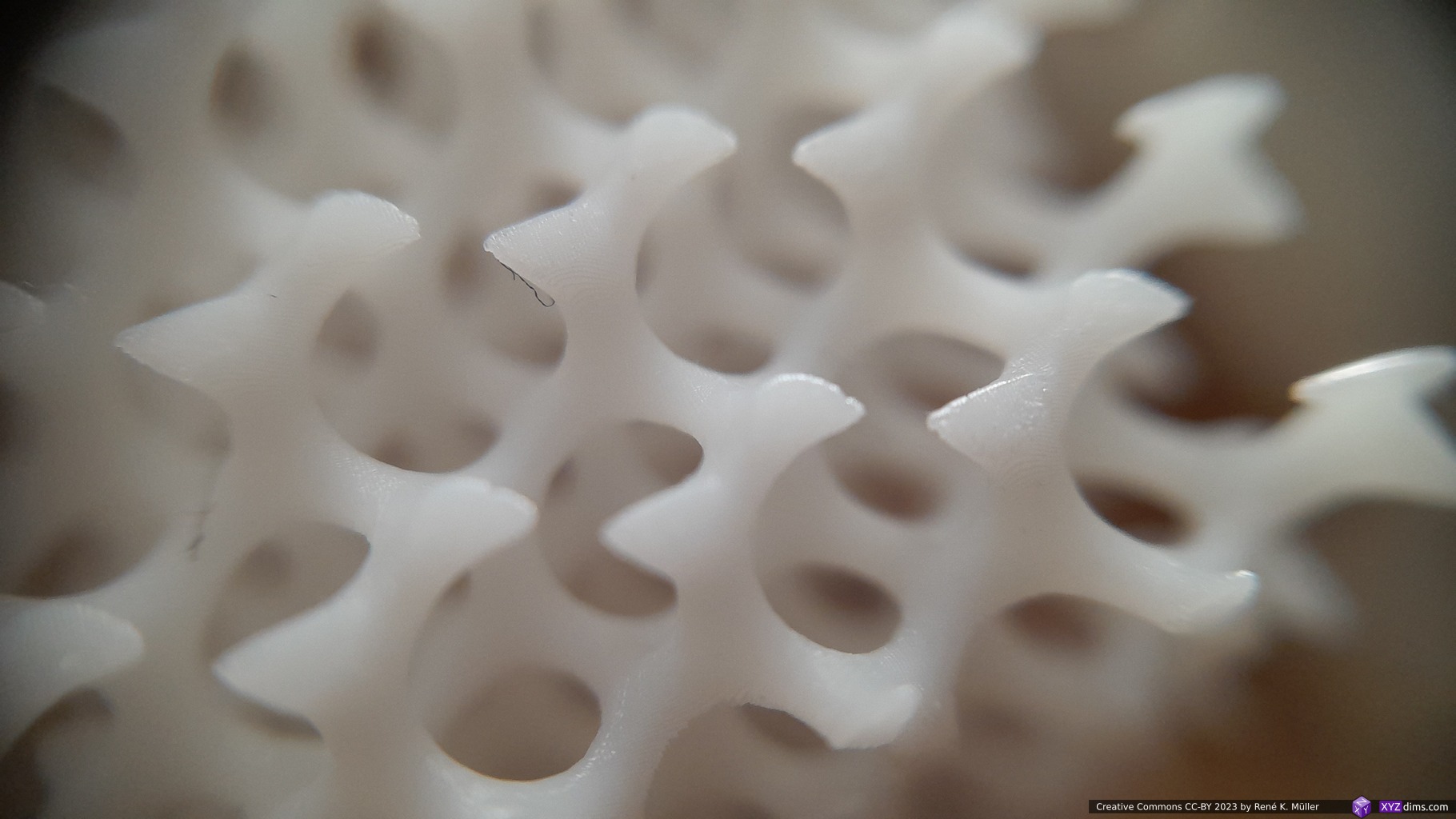
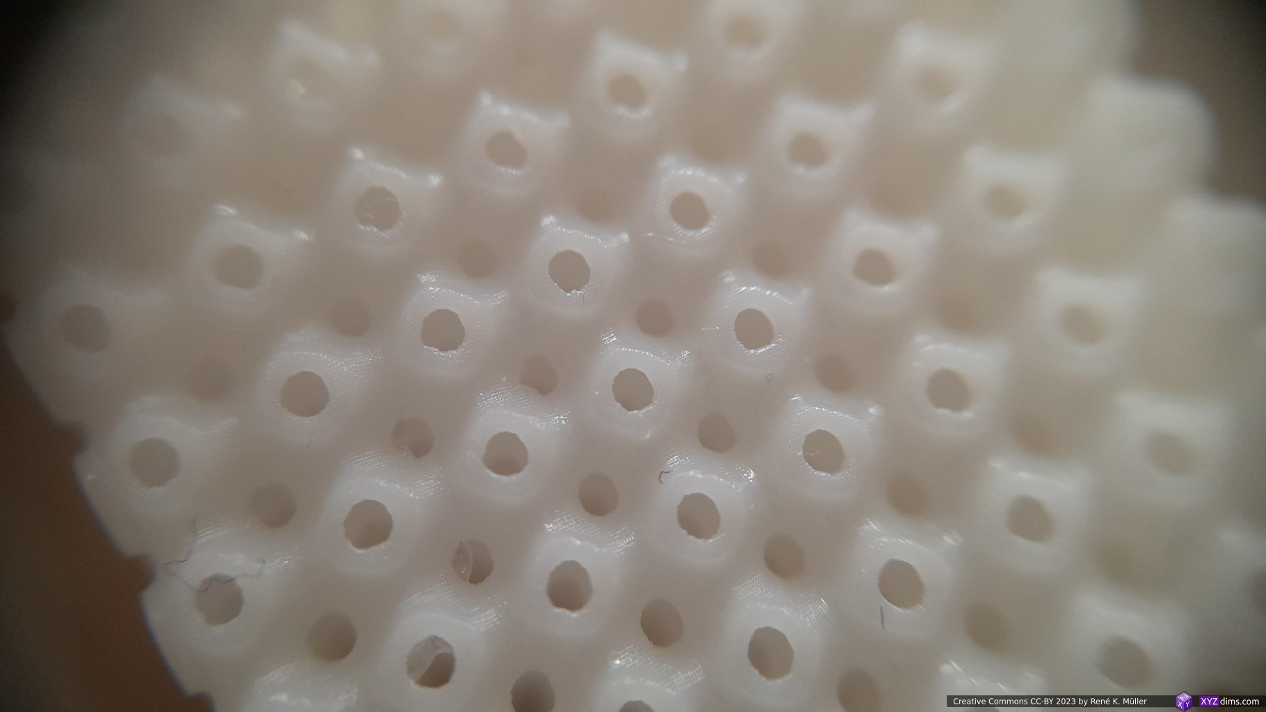
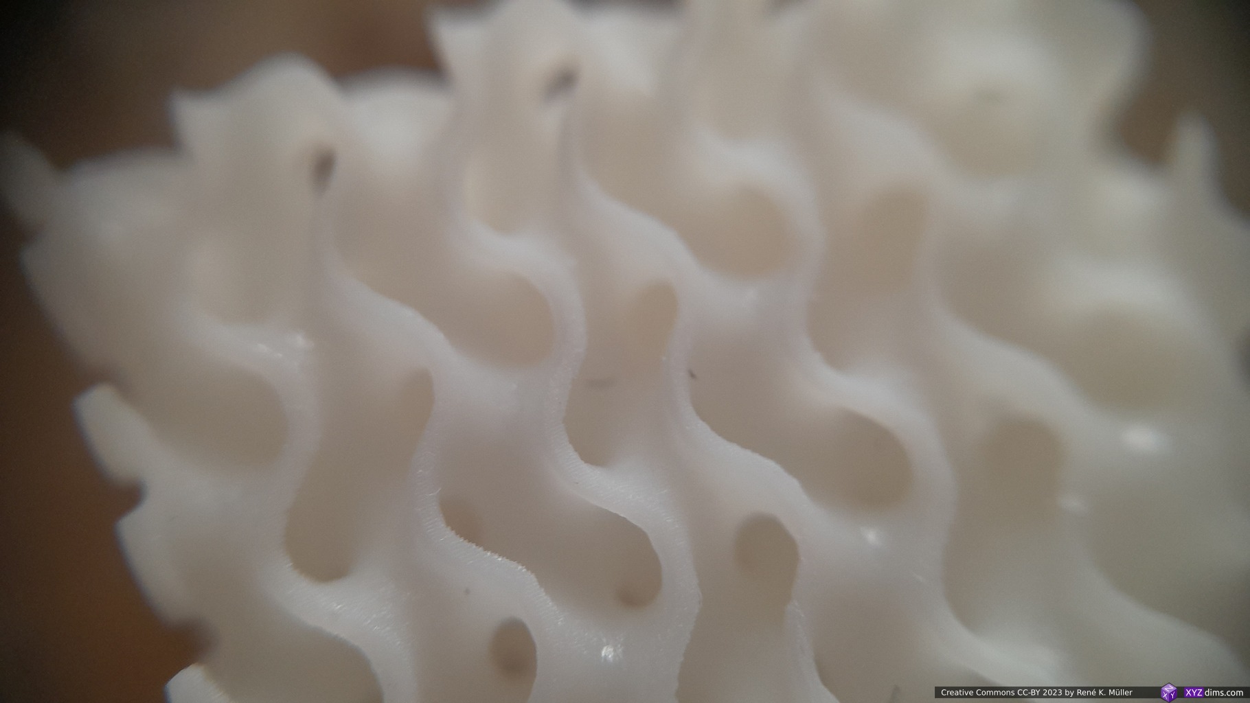
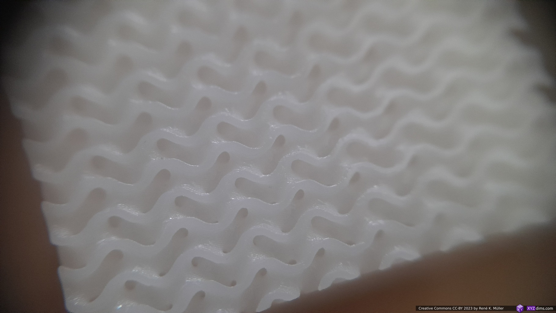
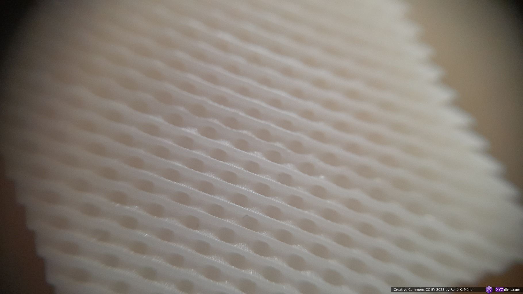
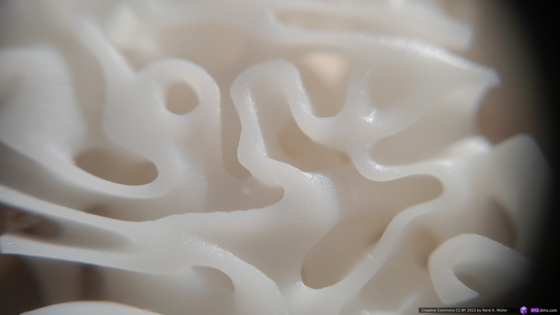
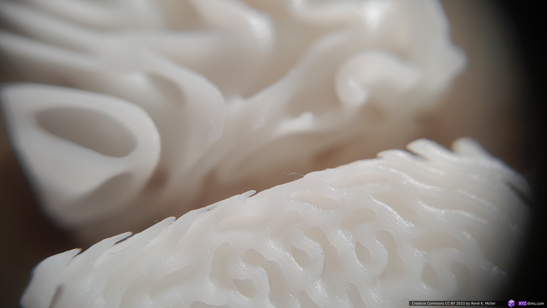
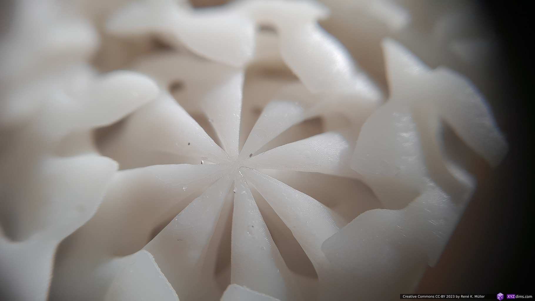
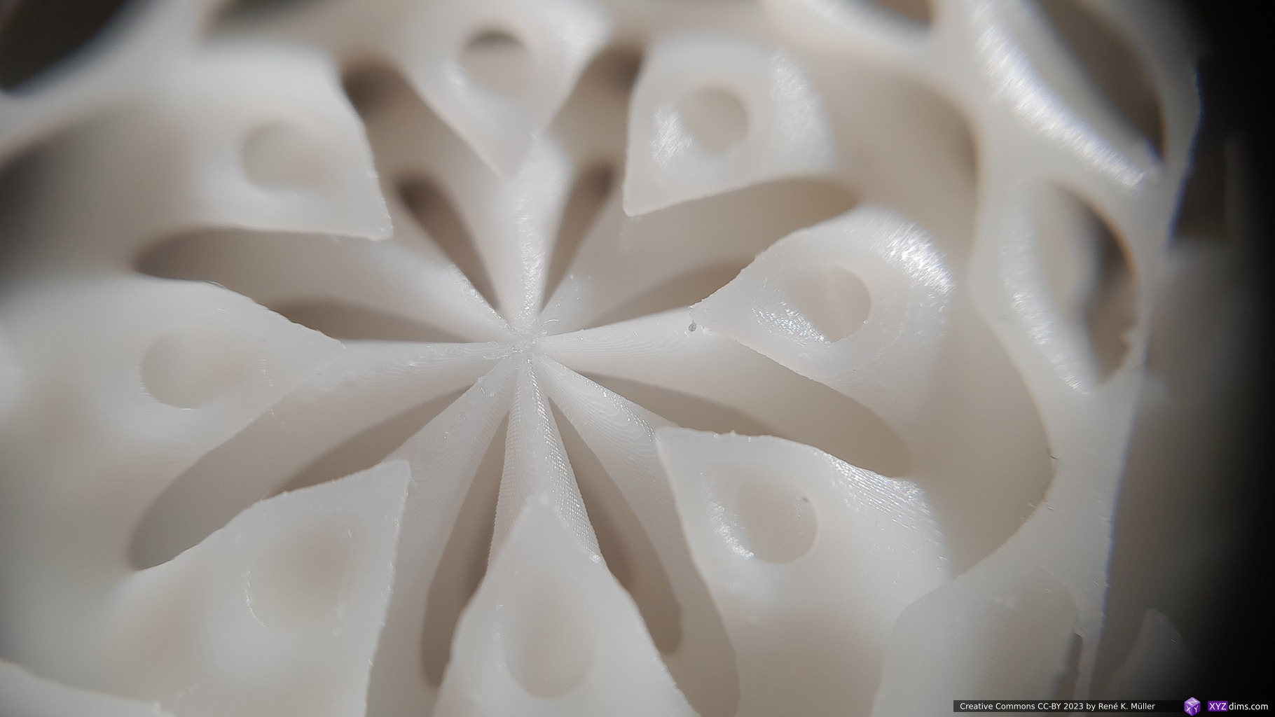
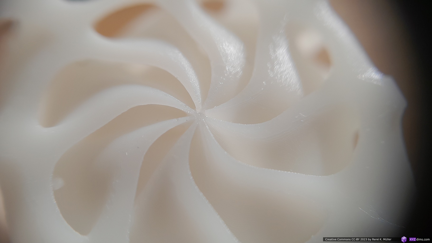
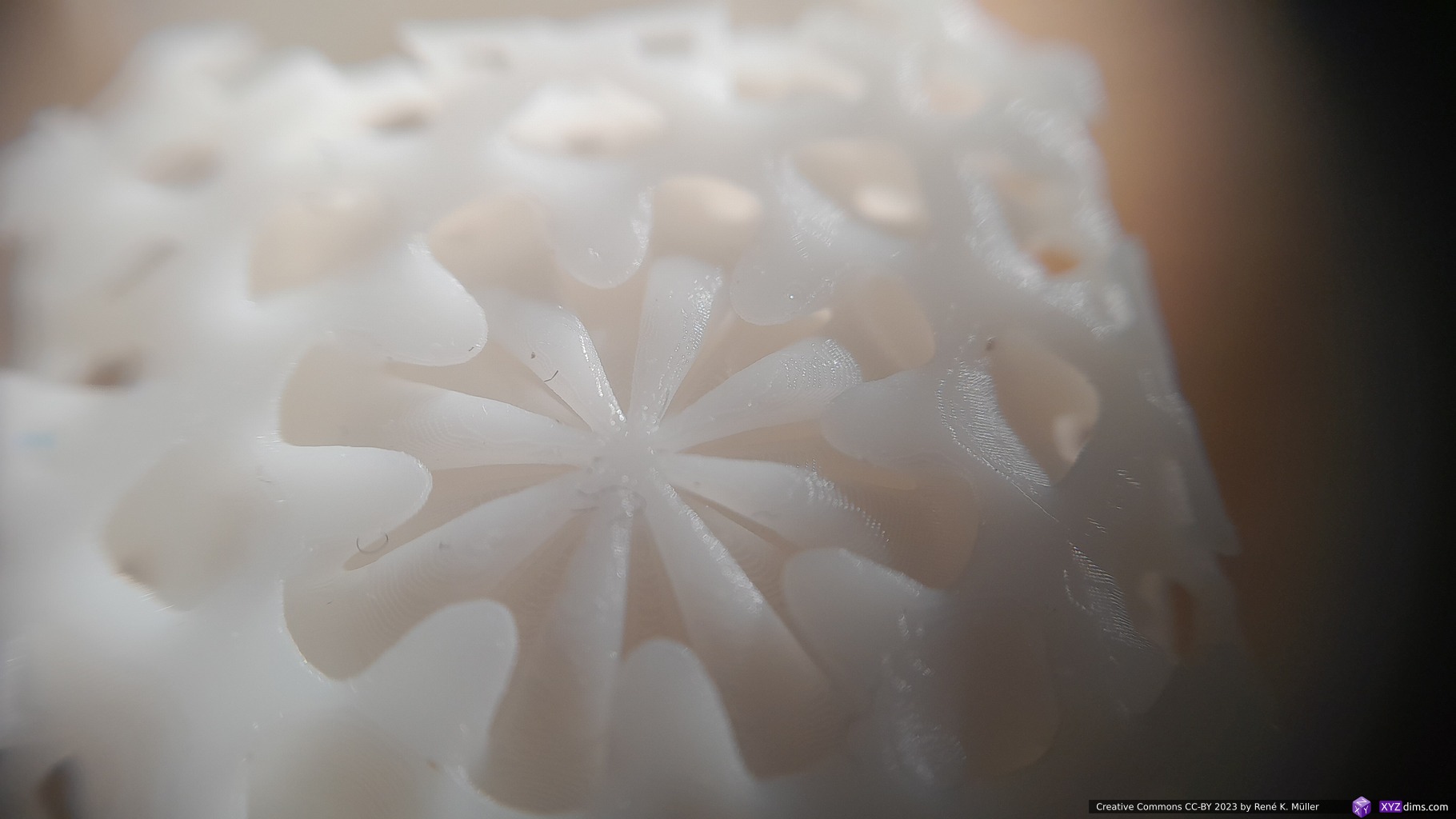
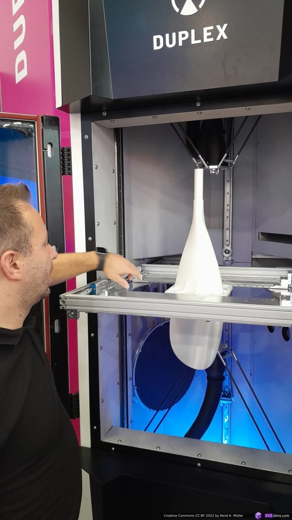
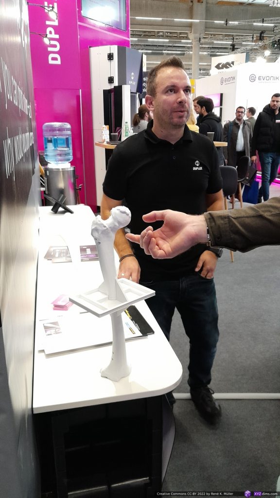
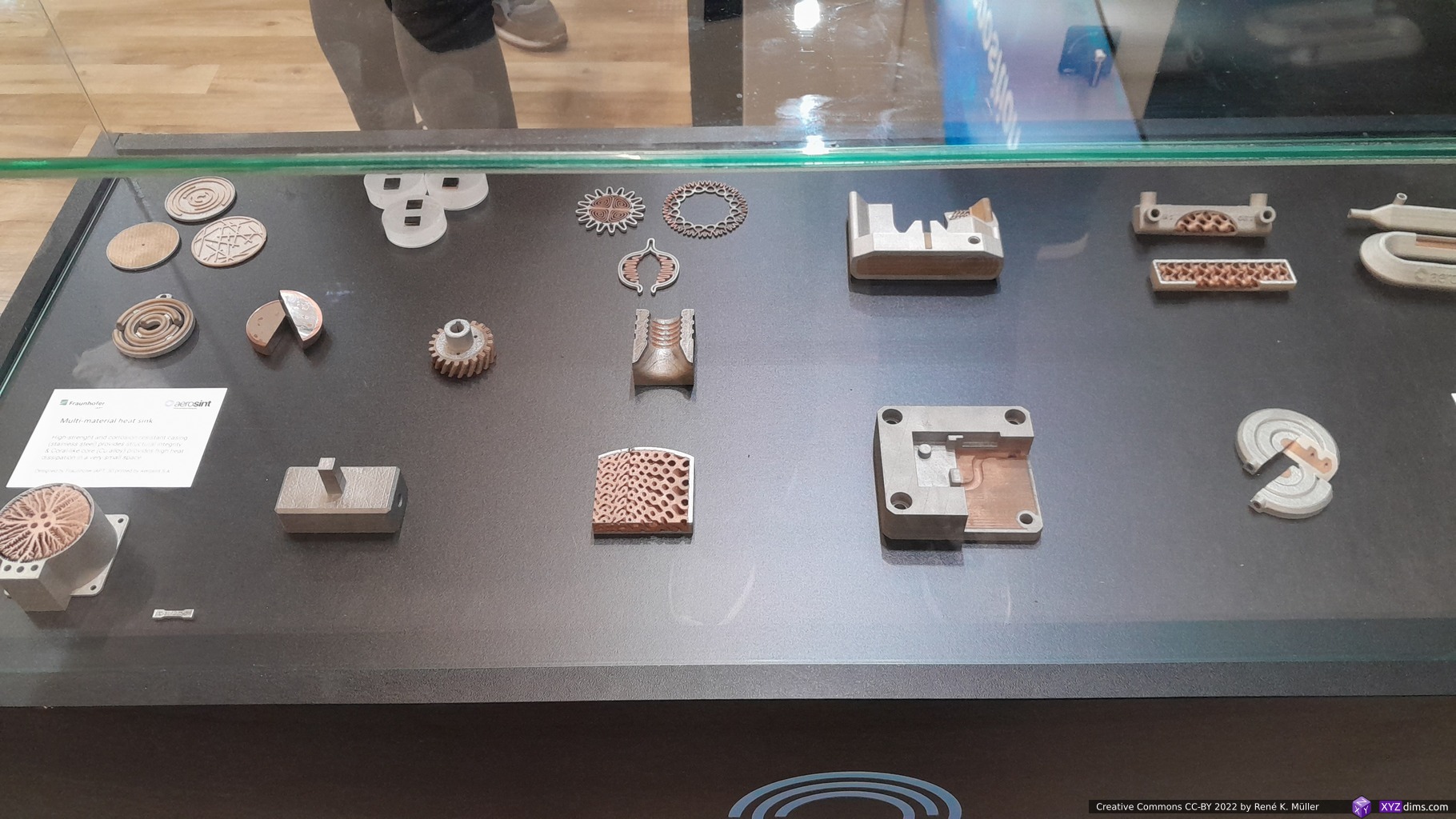
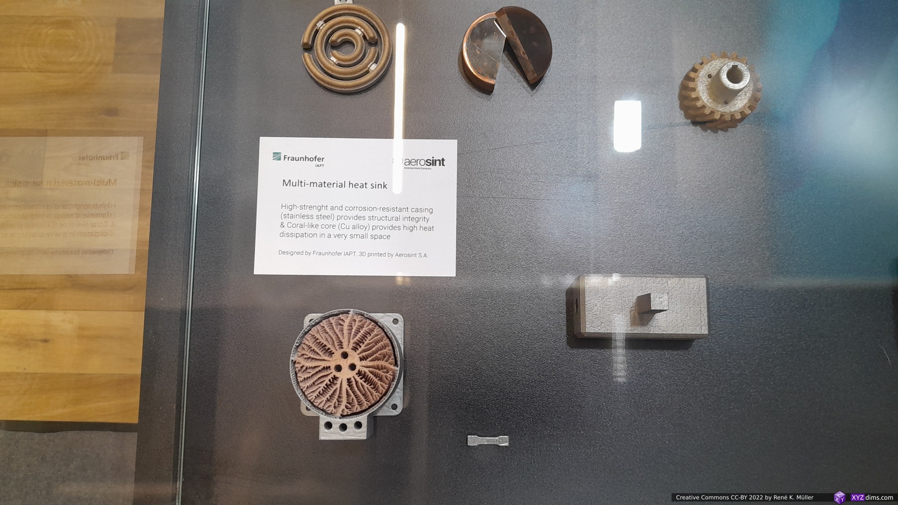
I made contact with Spherene before via LinkedIn but I realized I missed the point of what Spherene actually “invented”, at their booth Daniel Bachmann took the time to show me the features of their new class of minimal surface model and it was challenging for me to follow him despite of my own experience with Triply Periodic Minimal Surfaces (TPMS) – after apprx. 20 mins I realized the scope and some of their depth of their “invention”.
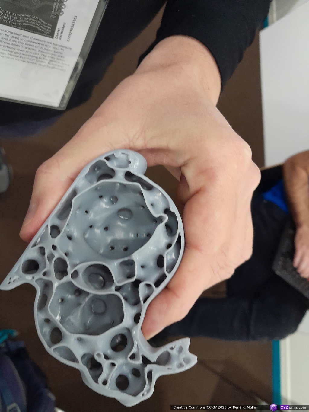
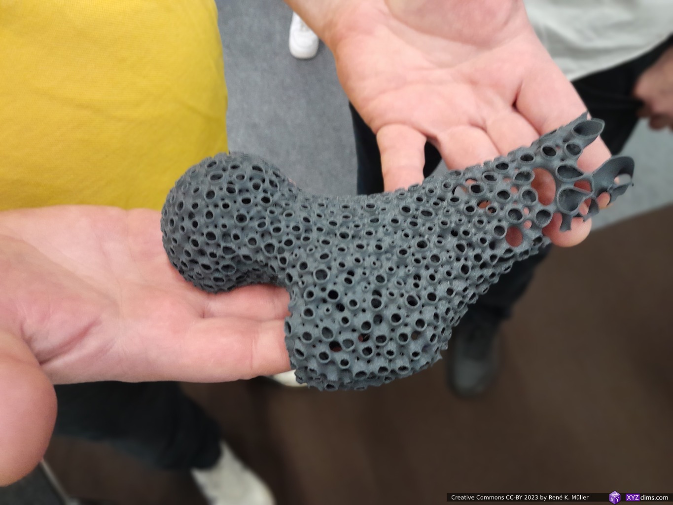
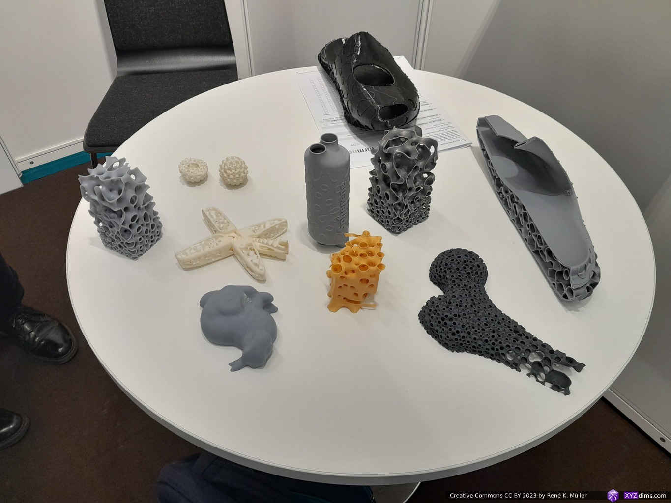
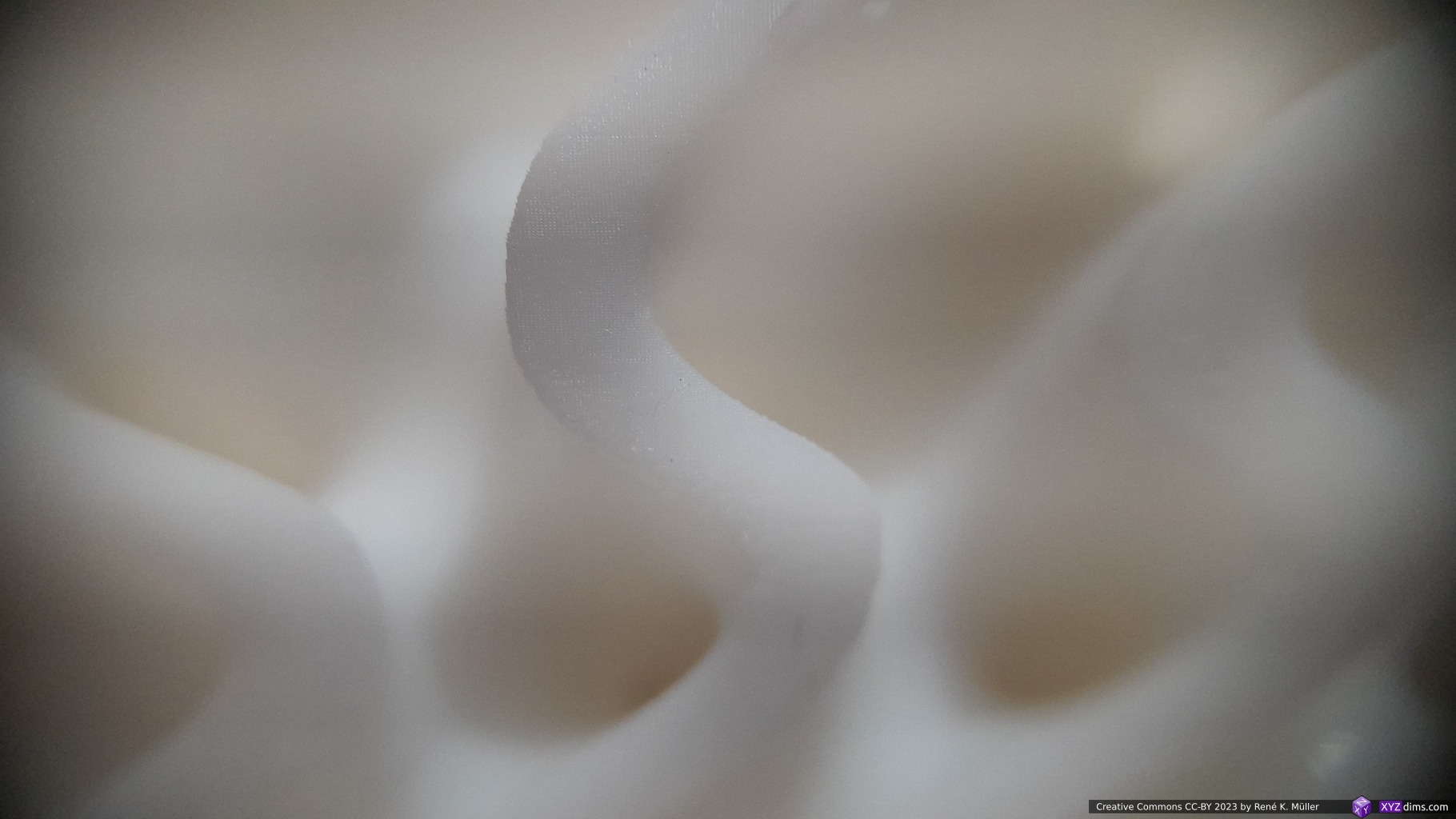
Spherene: sphere sample with variable porousitySpherene: resin printed rabbit with spherene infillSpherene: FFF/FDM printed bone replace with spherene infillSpherene: print samples (MSLA, FFF/FDM, SLM)
In essence, the sphere is used as a base form, and density, wall thickness and other features are processed in a localized manner, filling the space. The main result doing is optimizing a form to distribute inner/outer forces, e.g. the ends of the spheres are perpendicular to the surface providing ideal way to distribute them into a network of thin walled interconnected spheres providing isotropic (“all directions”) property.
The samples on display were printed with MSLA, SLA, FFF/FDM or SLM were indeed very strong in relation to the printed volume, e.g. the hallow rabbit printed with resin barely gave in when pushing on the thin outer perimeter – impressive.
Their approach is available as cloud-based GUI or as Grasshopper/Rhino plugin. The actual details of their procedure isn’t easily found but a patent (WO2020229692A1) by CEO Christian Waldvogel gives some idea.
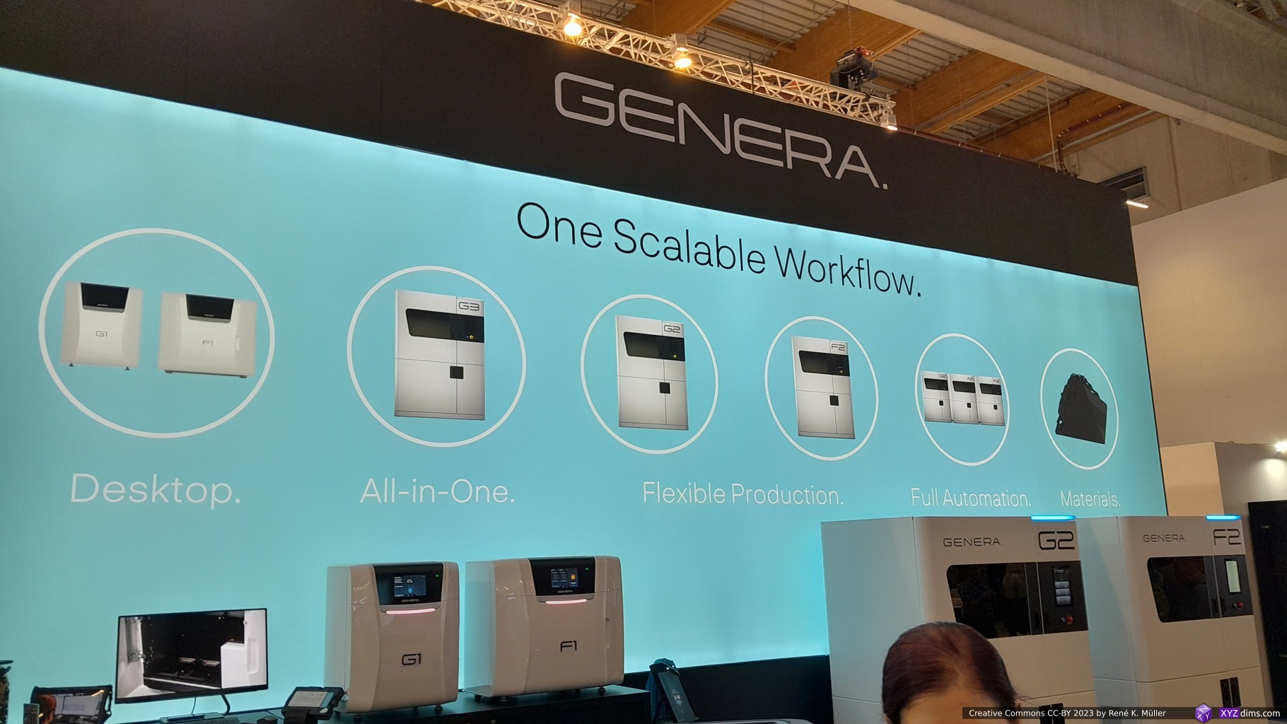
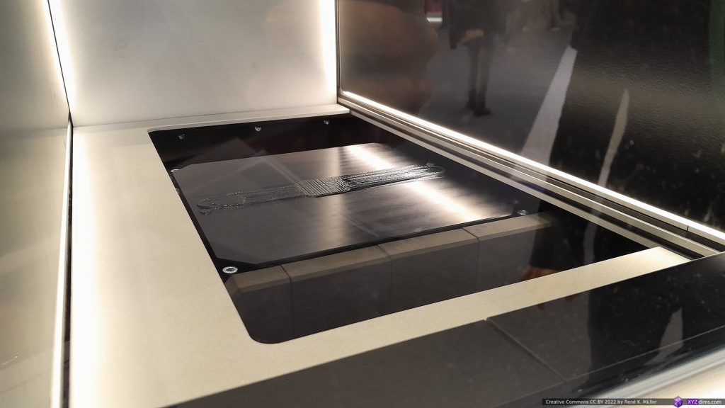
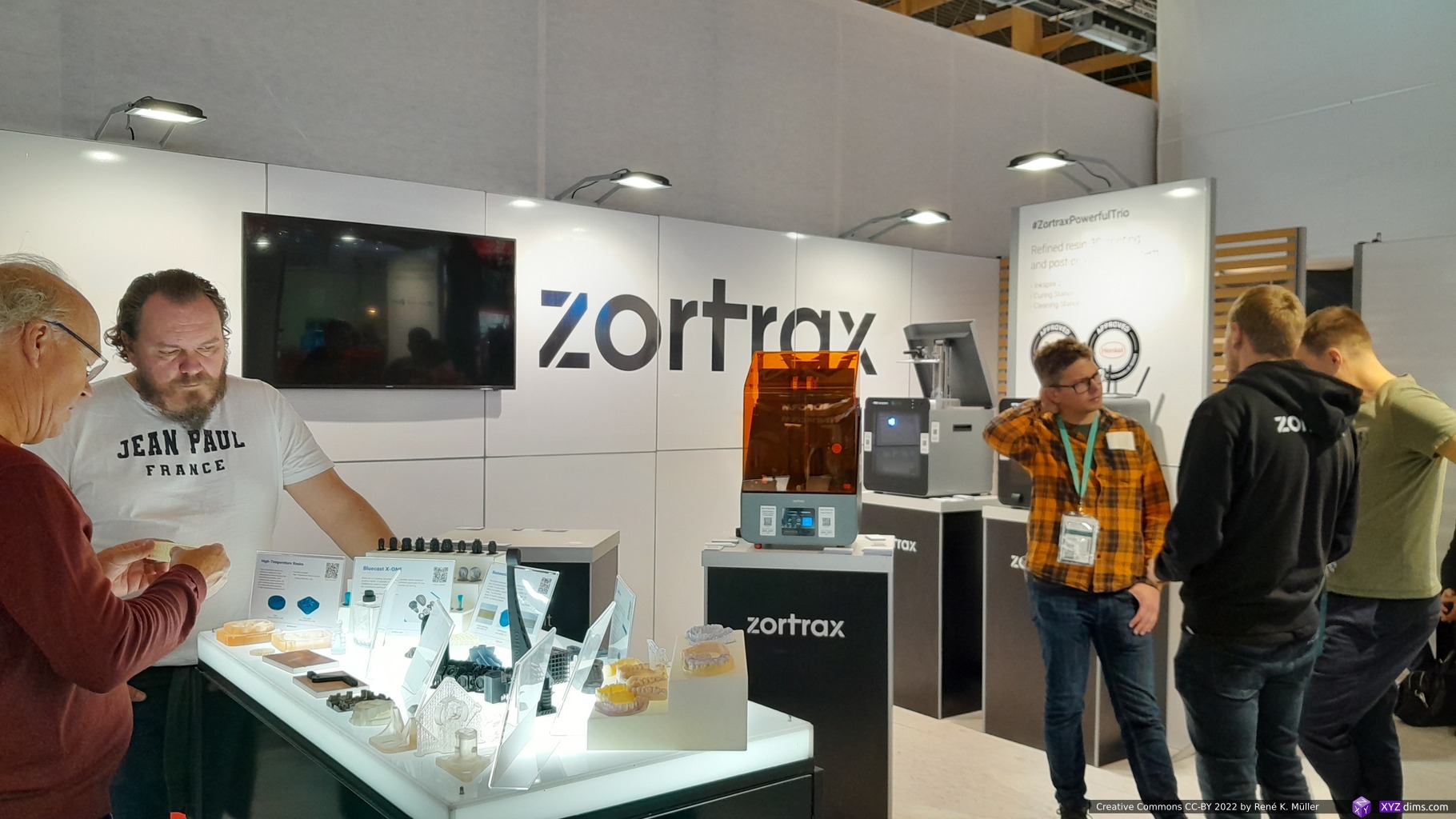
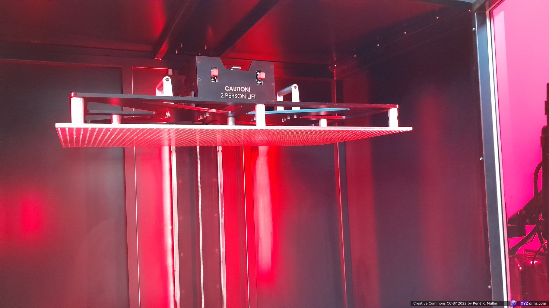
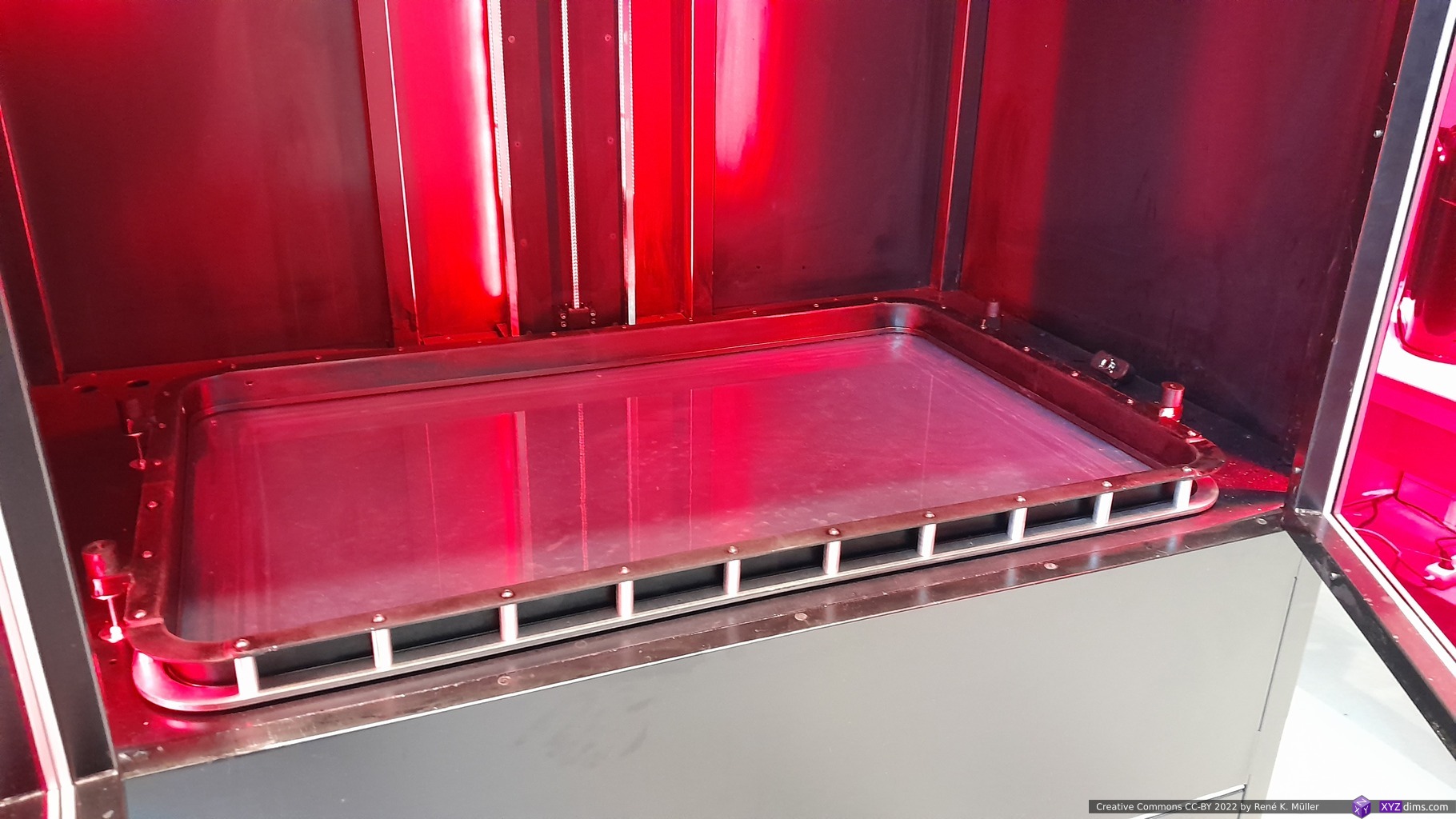
Genera (DLP Resin)
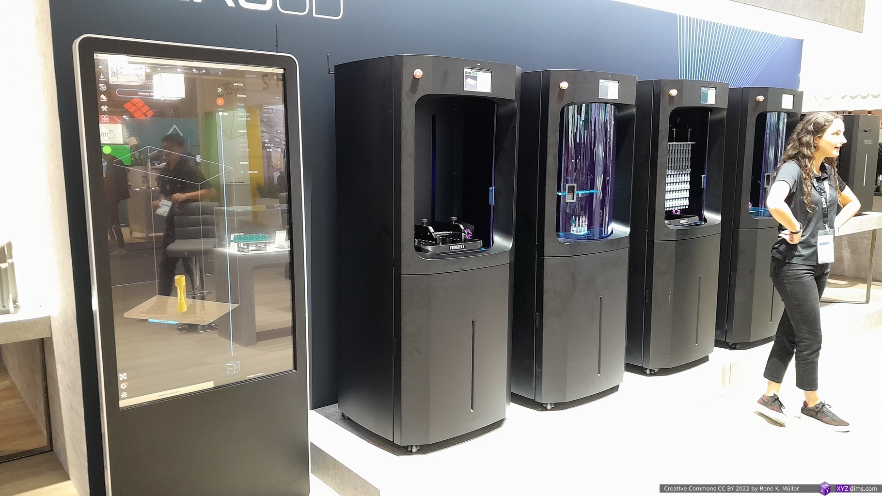
There are many MSLA/SLA/DLP printer manufacturers, yet, I wasn’t aware of Genera and I was shown their system, an integrated workflow:
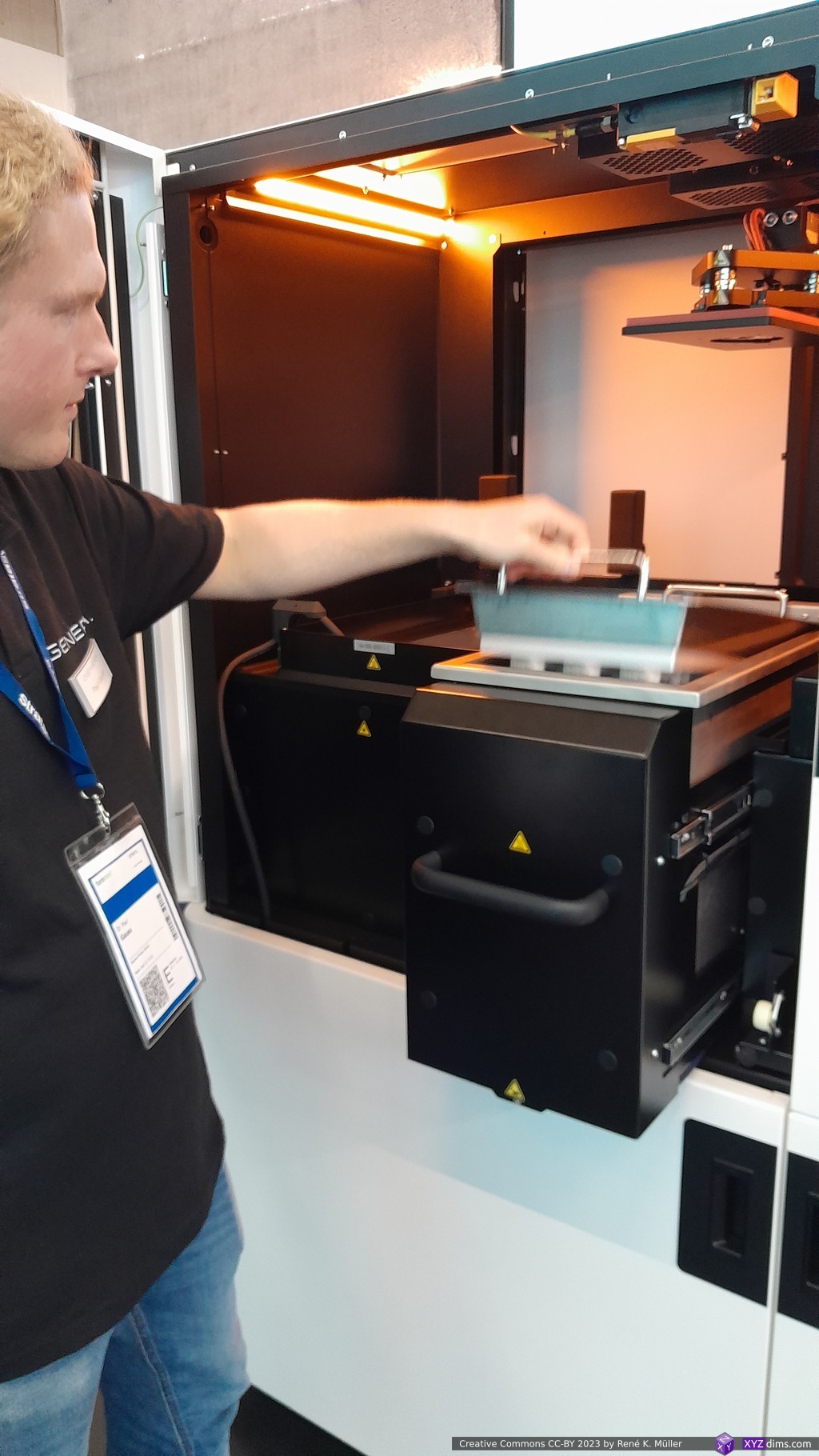
all resin vatshave a lid (only applies for G1/F1 combo but not their bigger machines), which are opened only within the machine
the finished prints (still on the plate) are moved in a box into the washing machine (without any person touching resin or the resin coated prints)
once automatically cleaned and post-cured, the prints are removed from the build plate manually
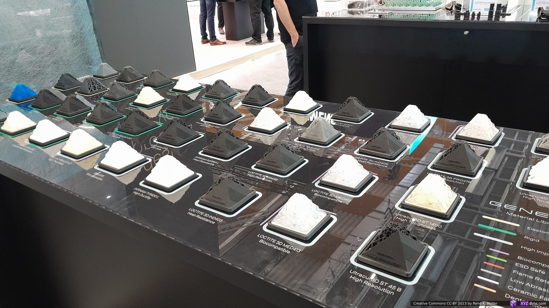
In essence one does not interact with resin directly, it’s all contained within the workflow – which I like a lot. They also provide wide selection of resins: hard, soft, rubbery, opaque, transparent/clear.
My idea has been to adapt some of their approach to make my own resin printing with Photon series (4K, X2 and X 6Ks); right now I also have multiple vats, and flex-plate, but moving the printed parts and washing them are still messy.
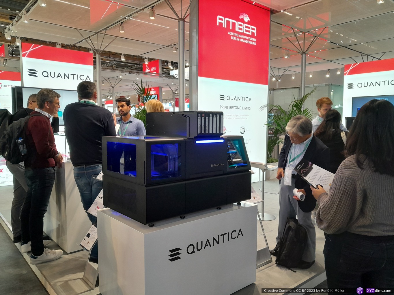
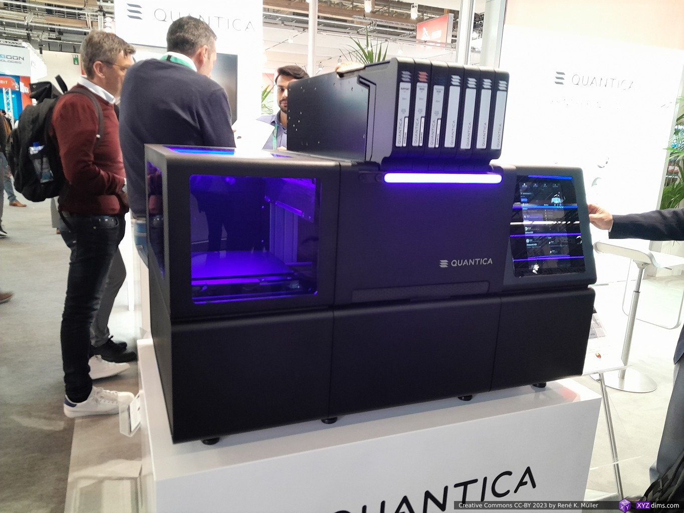
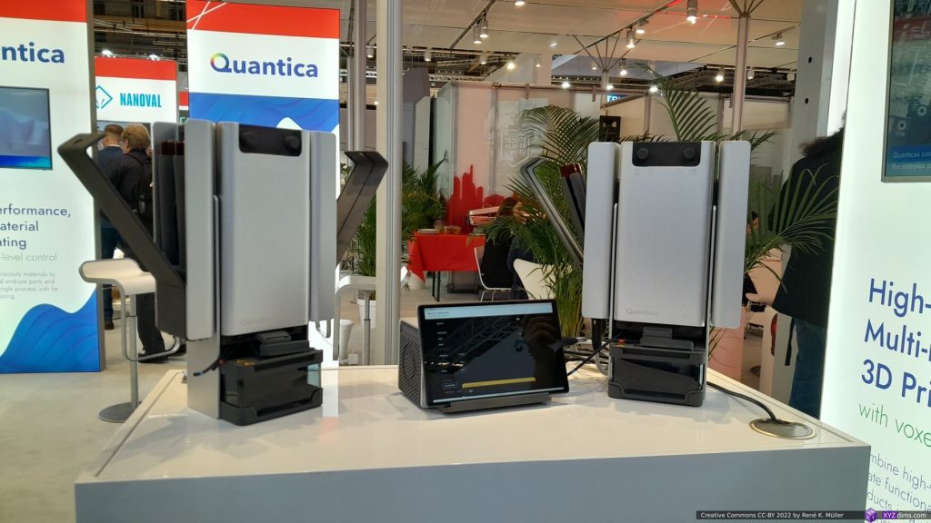
Quantica (Resin Jetting)
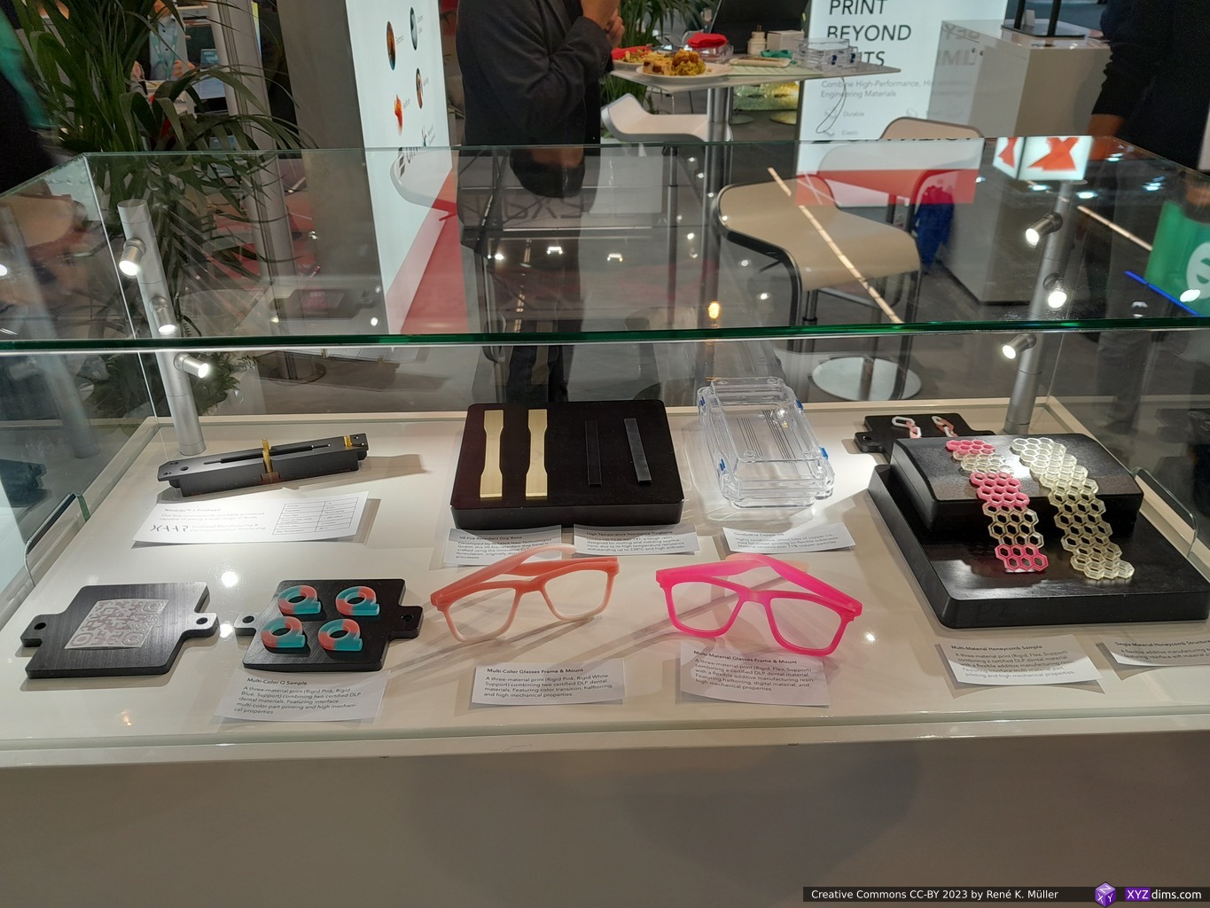
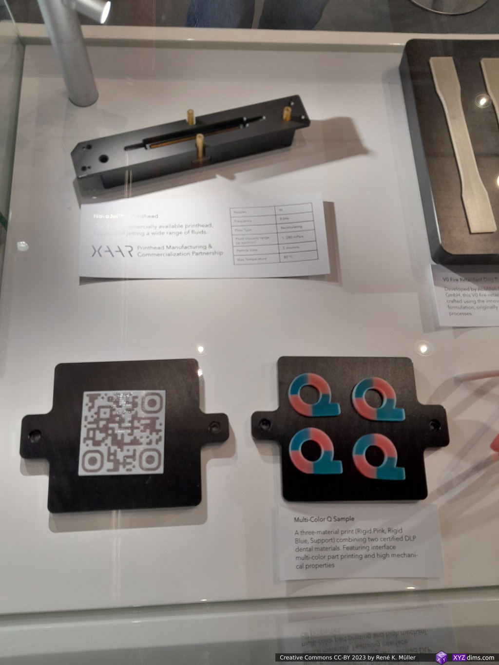
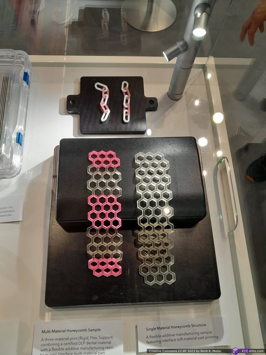
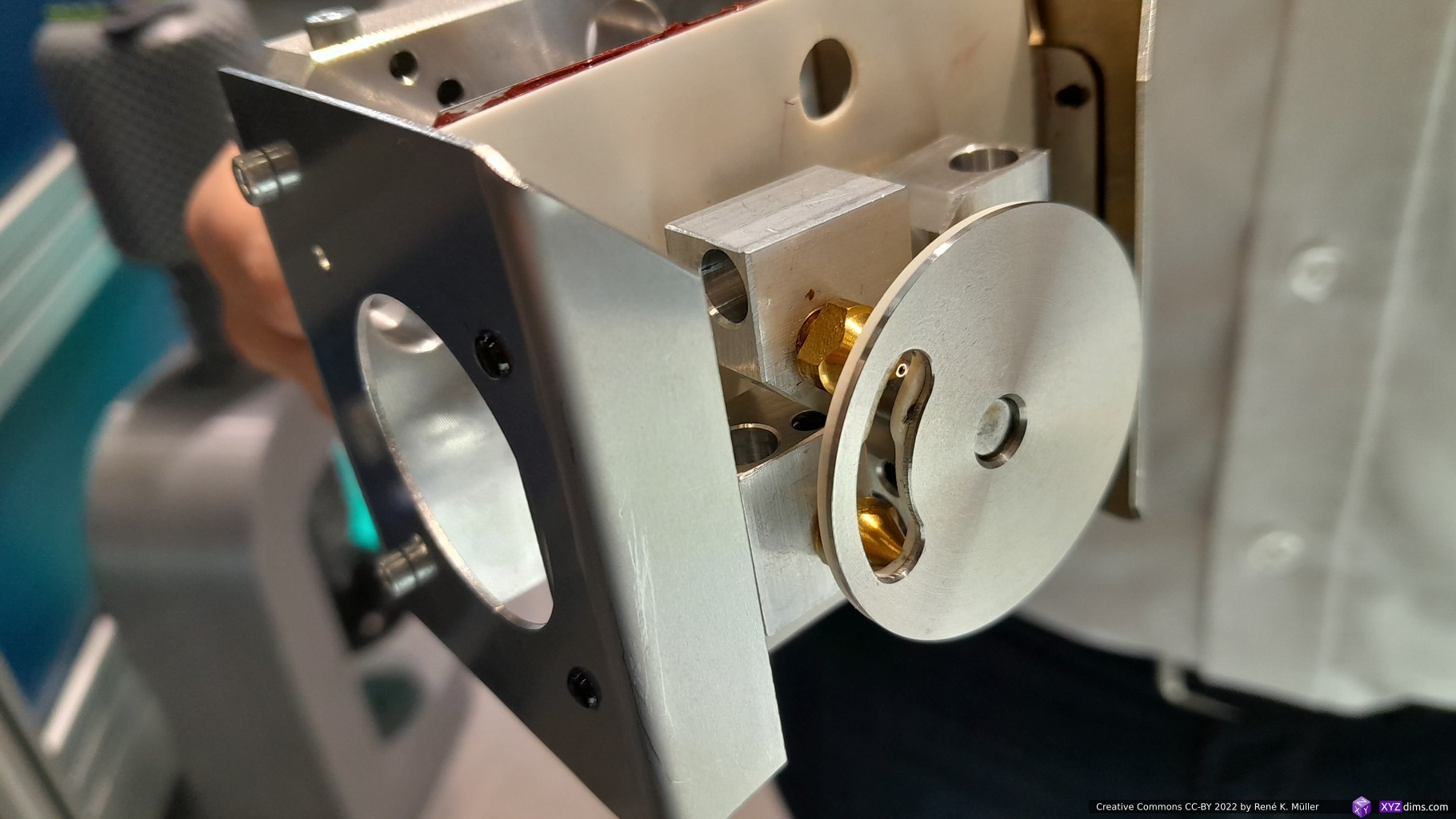
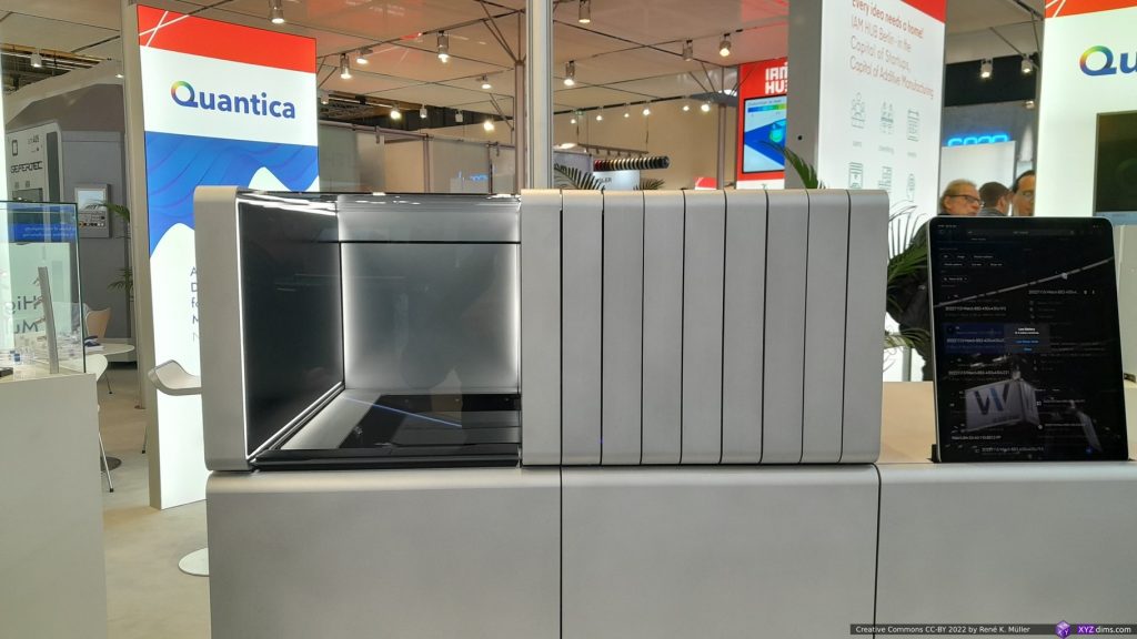
Last year I already visited the booth of Quantica, and so this year again. I asked earlier for printed samples, but they declined, and again this time . . . it is bizarre to see a machine actually able to print, and they don’t hand out samples, but I was told by January 2024 I might get some. This tells me a few things, the printed pieces are very sparse or not yet at the quality they want others to experience – some samples were on display, but sealed behind a glass box unable to have in my hand. So I guess now, they are expecting or already have better and more reliable printing results where the printed pieces match other similar printing processes.
QuanticaQuantica: NovoJet OpenQuantica: multi material samplesQuantica: multi material samplesQuantica: multi material samplesQuantica: multi material samples
I follow their development closely since ~2 years as I consider it very innovative to print with 7 different resin-based materials at the same time and able to fine-tune material properties on the voxel-level.
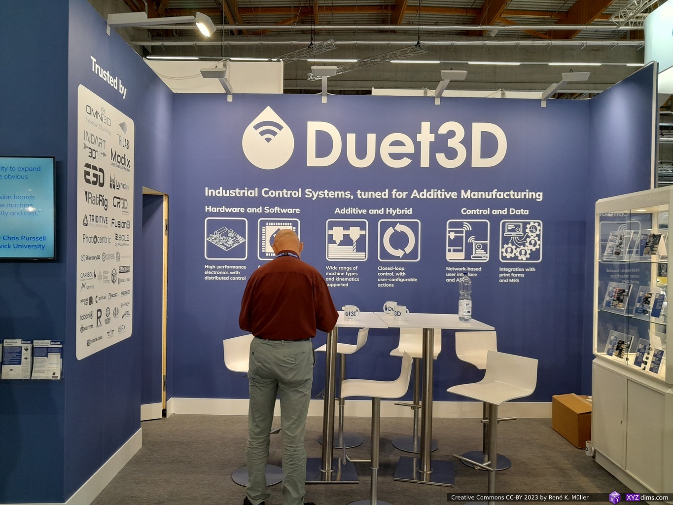
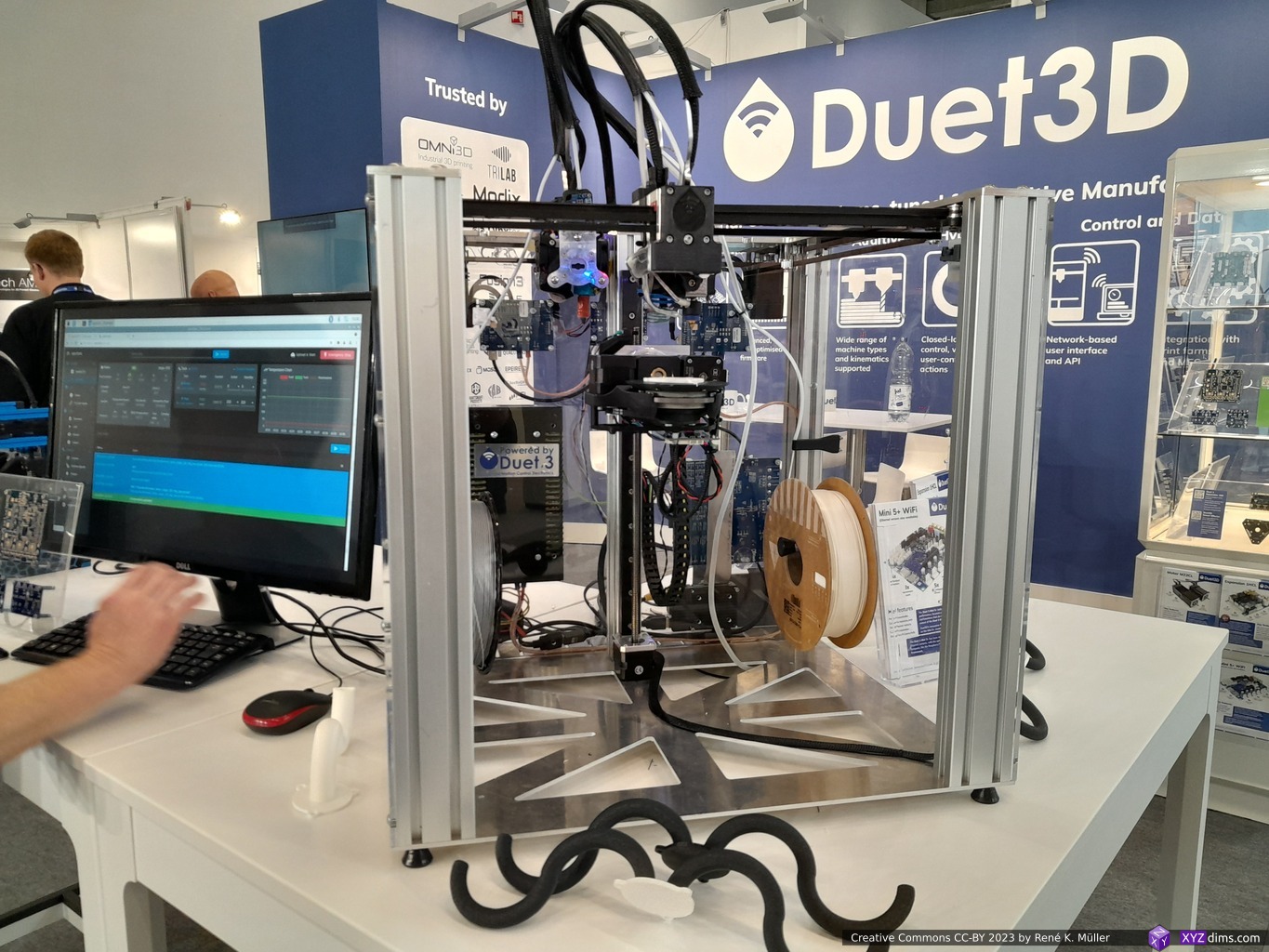
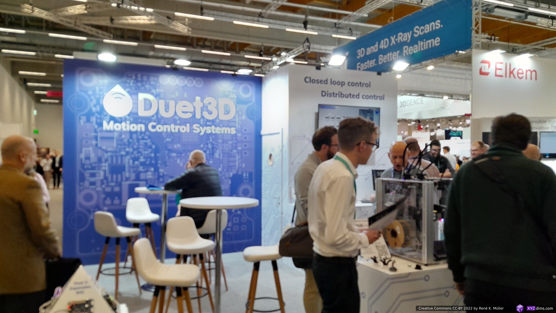
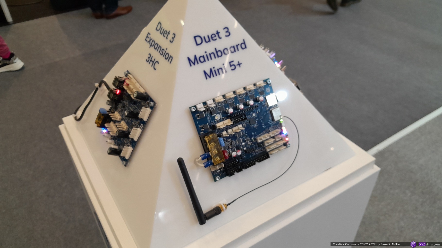
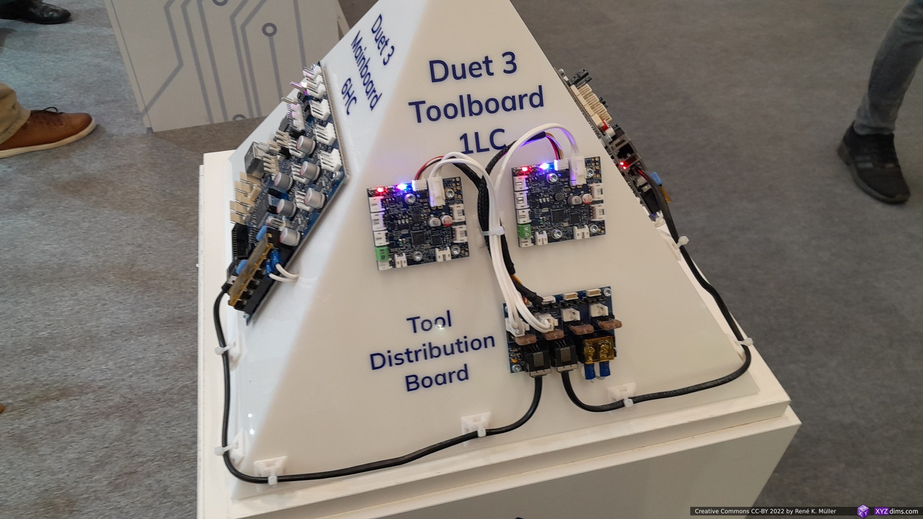
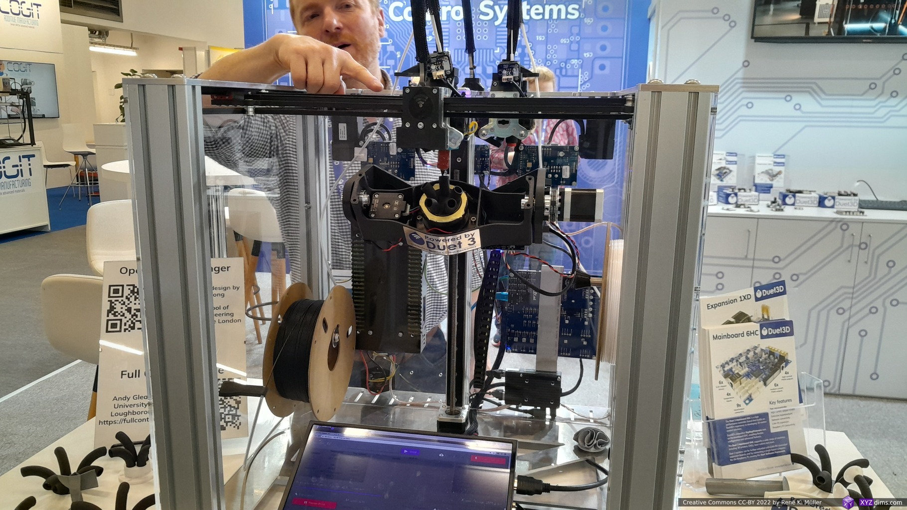
Duet3D (Open Source Hardware & Community Building)
UK-based Duet3D with its Duet boards and RepRapFirmware (RRF) is, as I wrote before, a beacon within the Open Source Hardware community – it isn’t just an example for other companies, and but also a great synergy provider, aiming to bring different individuals, groups and companies together.
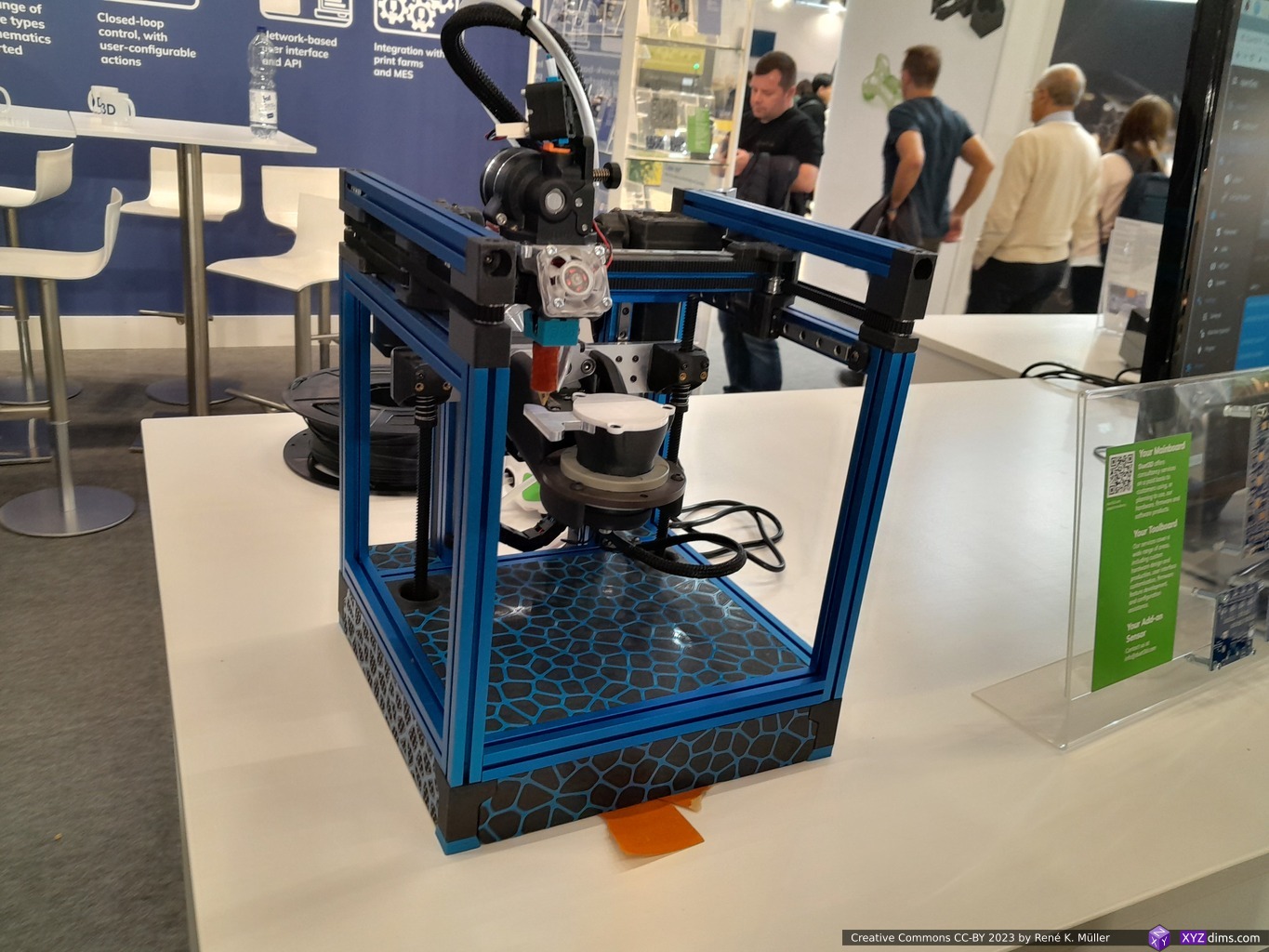
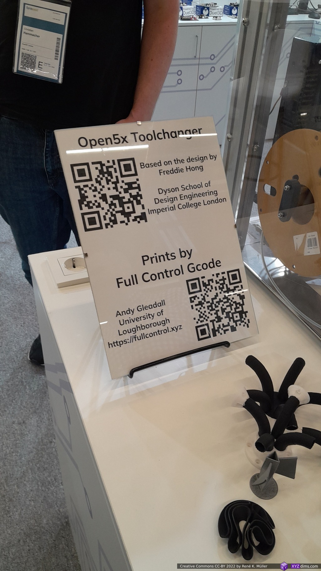
Duet3D: with David’s backDuet3D: Voron 0 with Brandon Build’s variant of Open5X Duet3D 5-axis Open5X with tool changerThe many companies using Duet boardsDuet3D booth: Josef Prusa & Tony Lock – legends of 3D printing community
Brandon Builds’ Open 5X version was featured on a Voron 0, and a second machine also 5-axis setup with a tool changer.
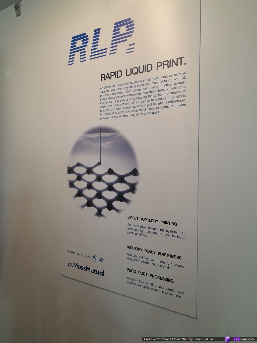
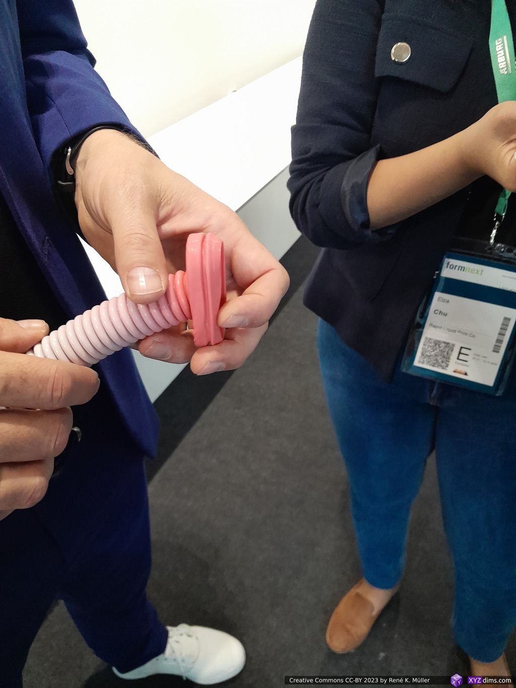
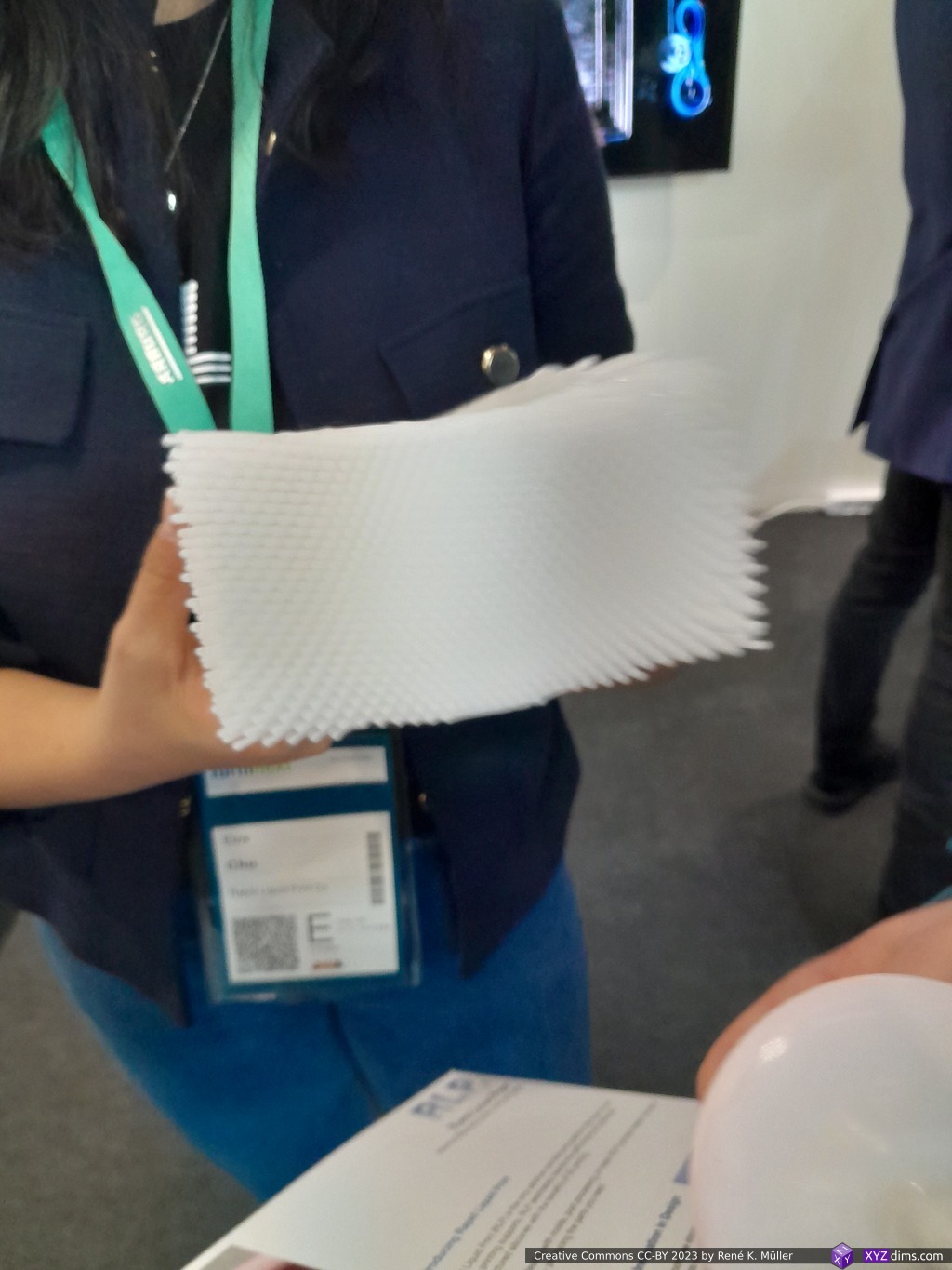
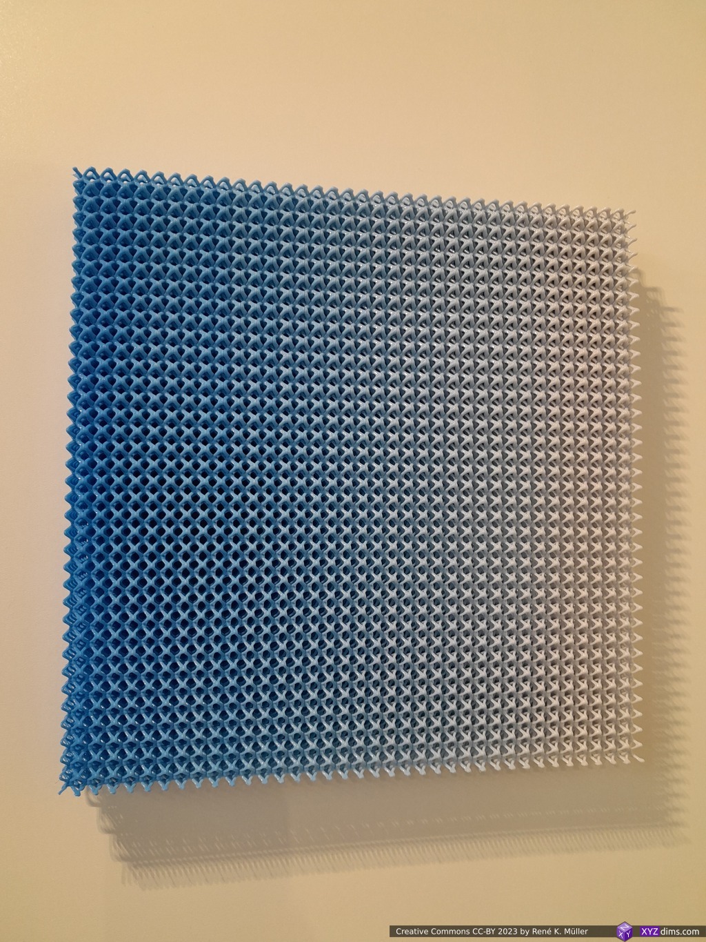
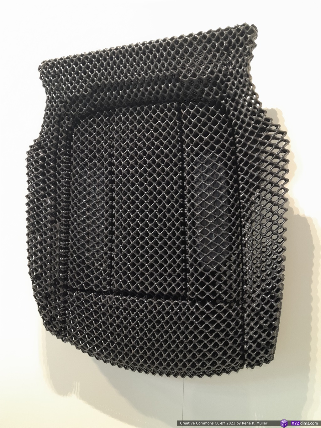
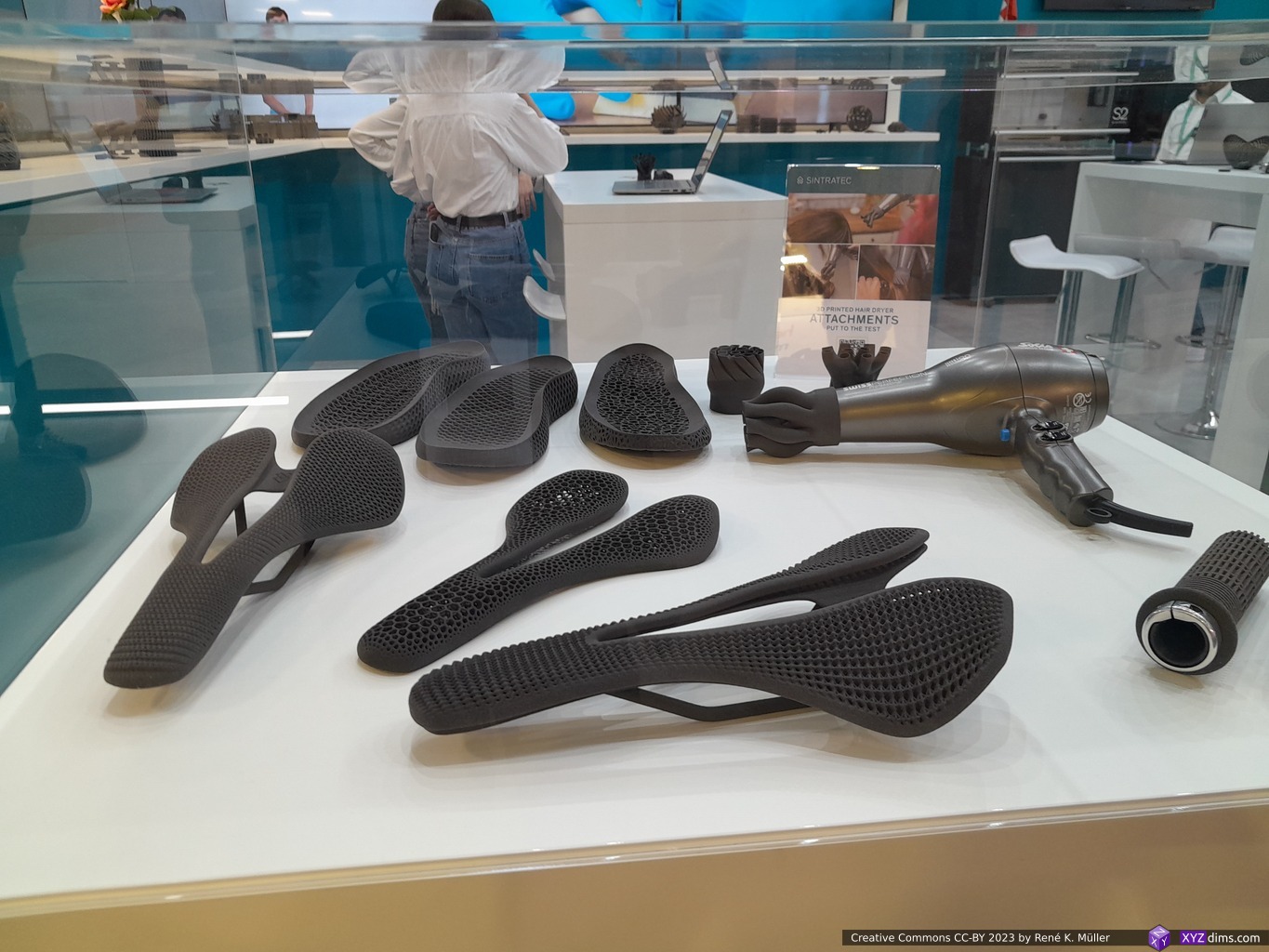
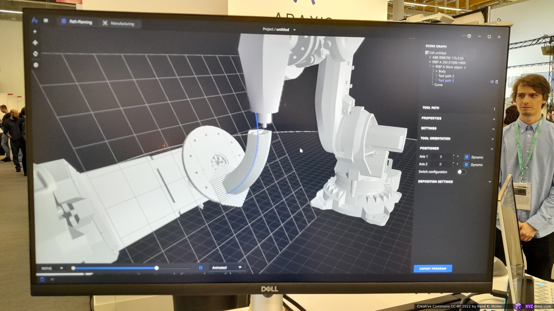
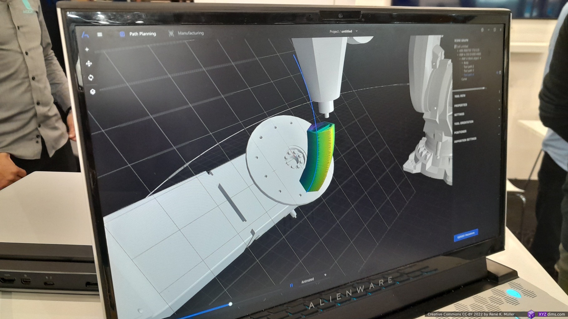
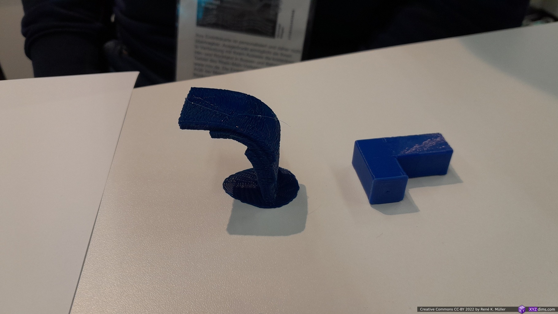
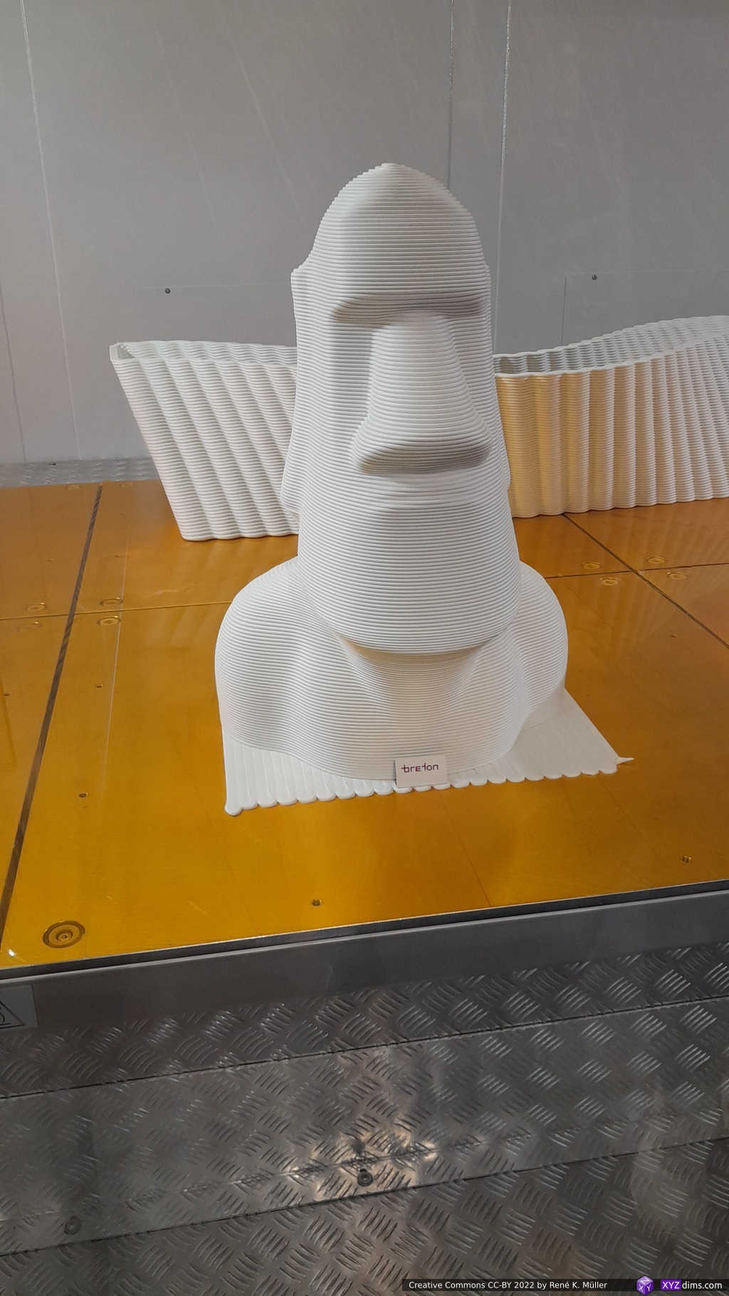
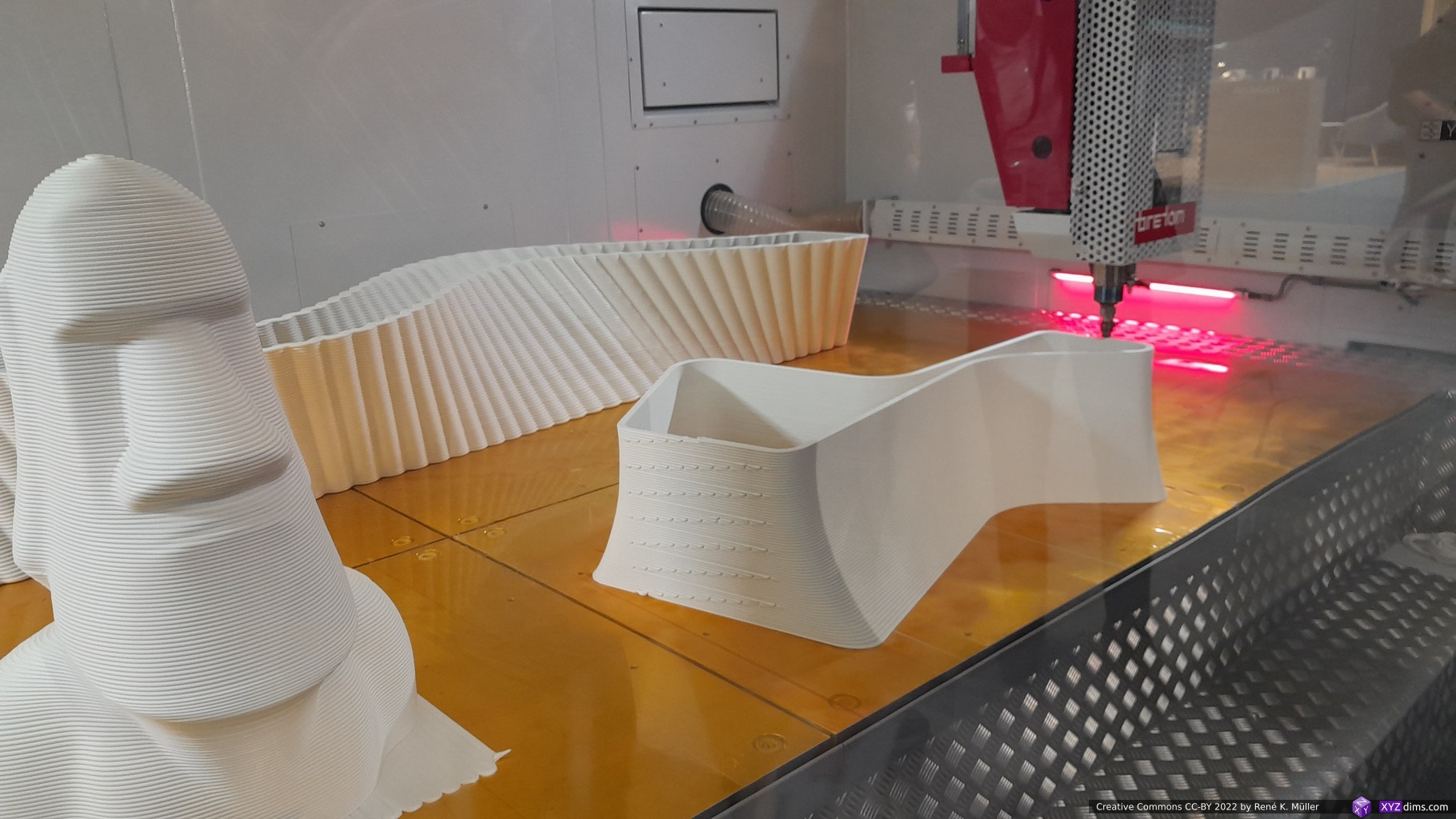
Rapid Liquid Printing / RLP (Flexible Structures)
While roaming around a small booth of RLP caught also my attention, where a video was featured of a nozzle moving in a bed filled with silicon printing rubber, and other flexible material:
Rapid Liquid Print (RLP)RLP: multi color samplesRLP: white “finger” sampleRLP: area with flexible “fingers” and color gradientRLP: Flexible seat print with inflatable cushions
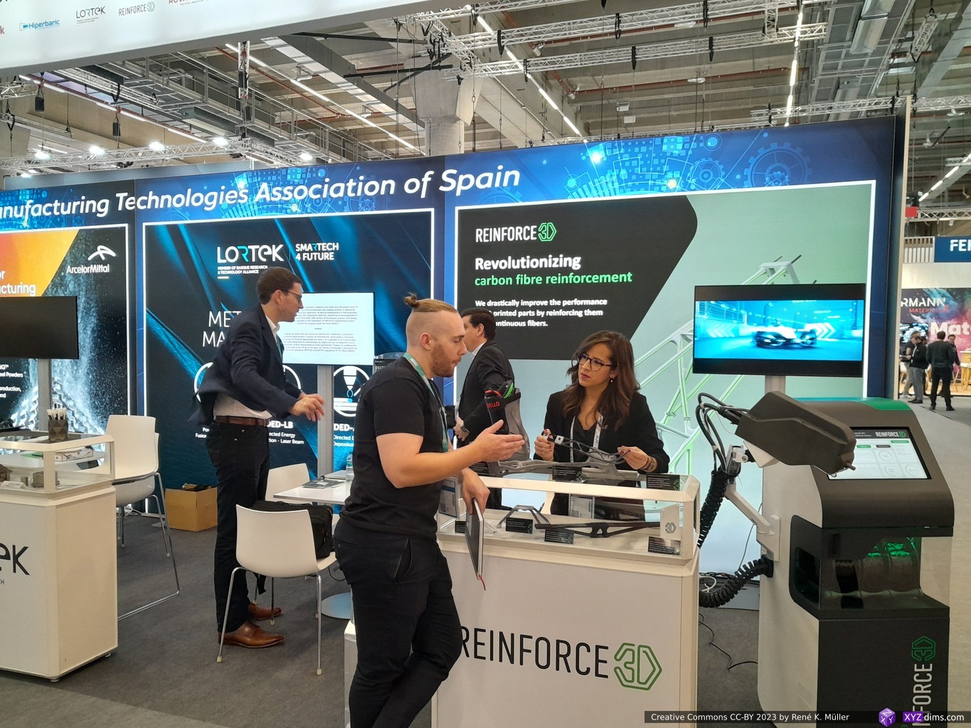
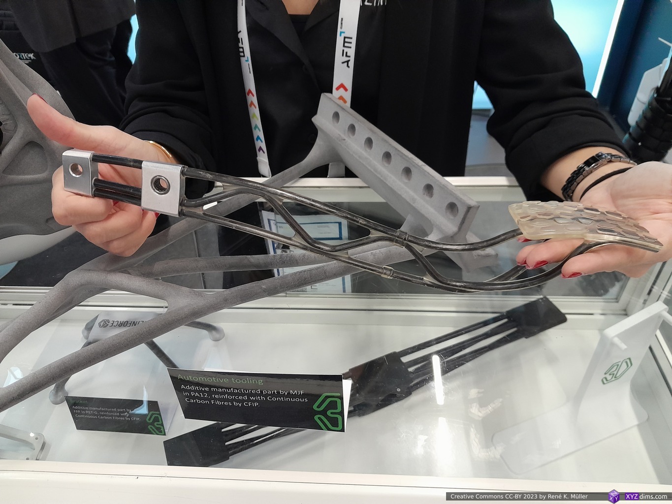
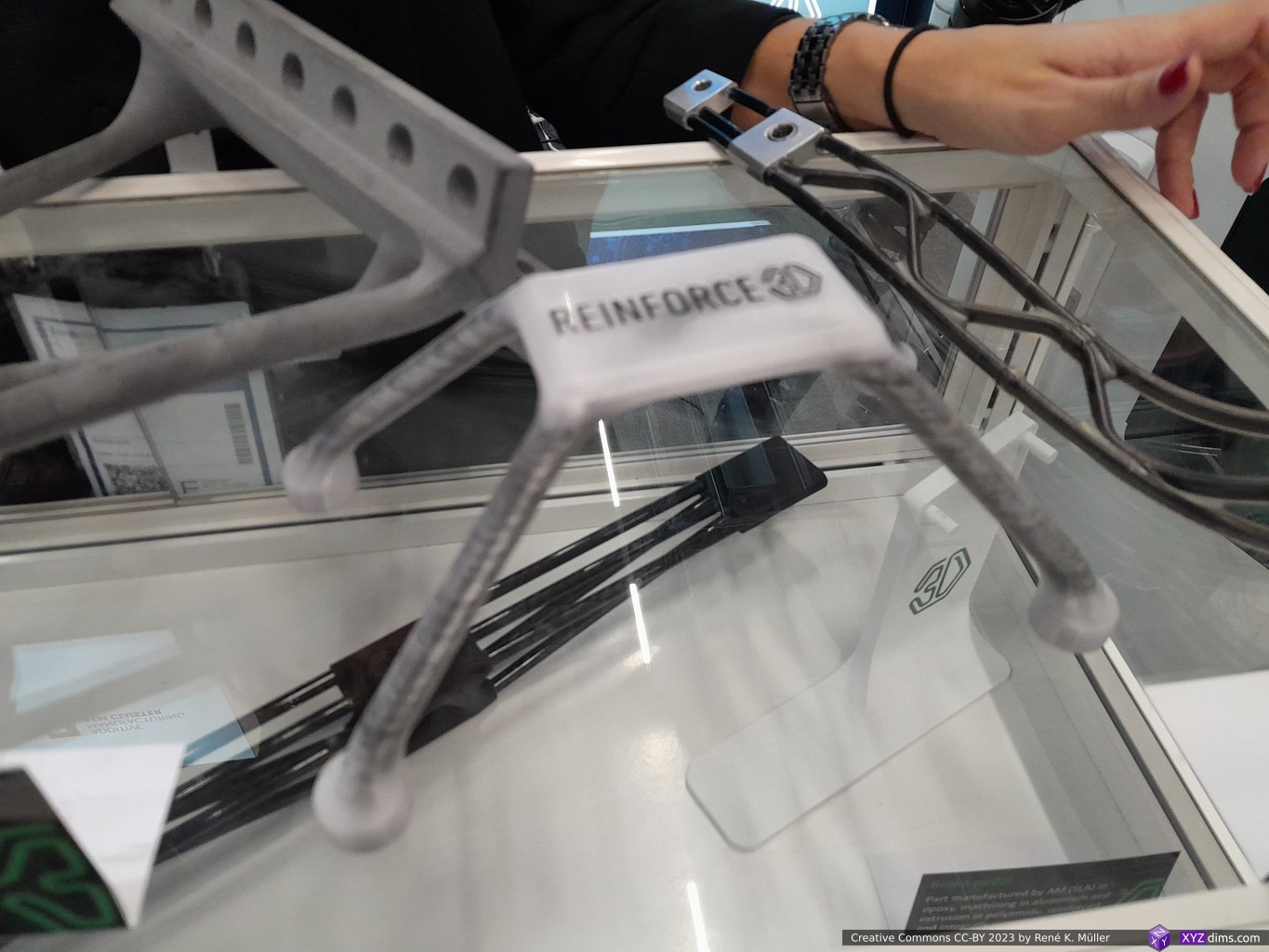
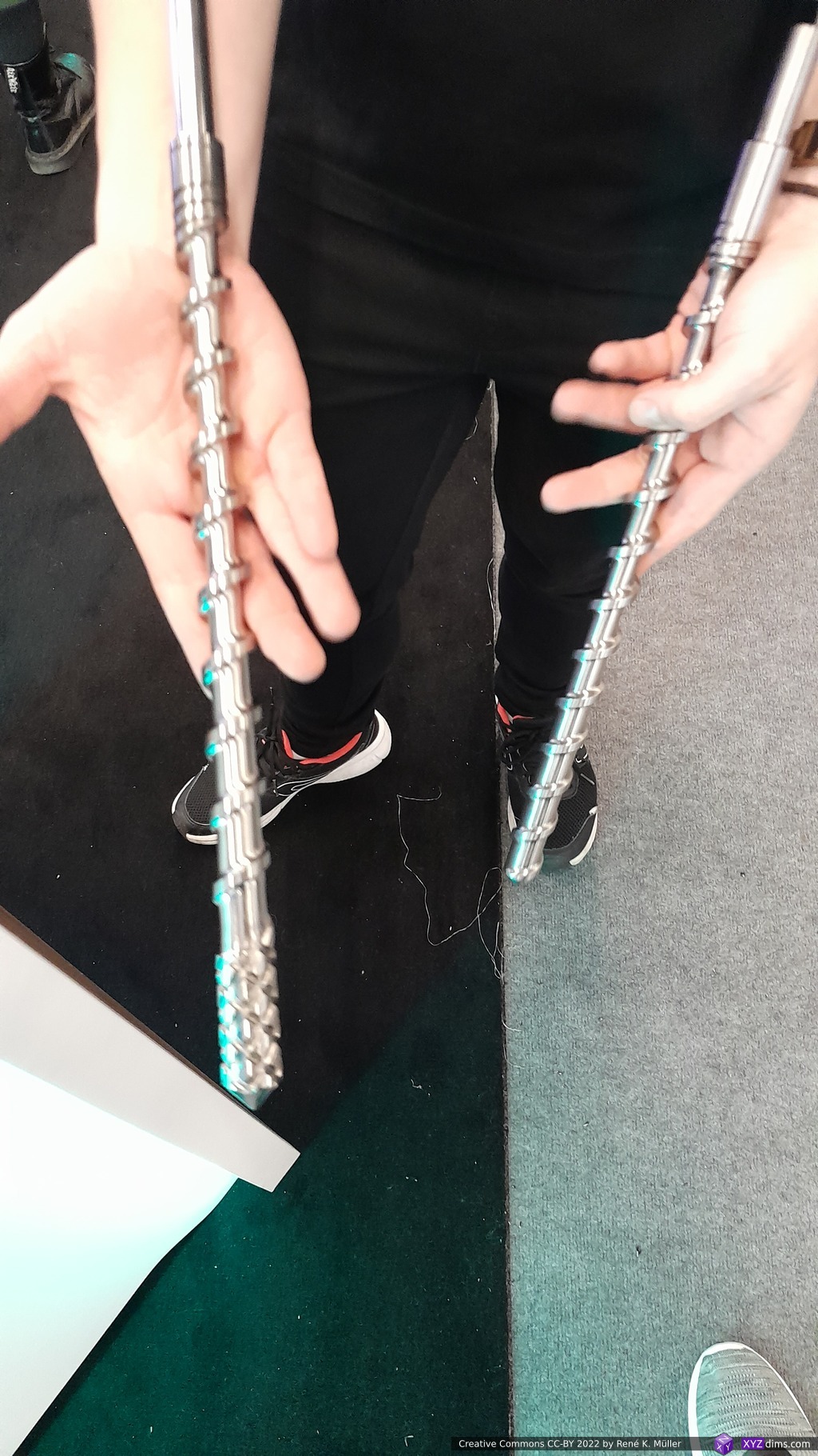
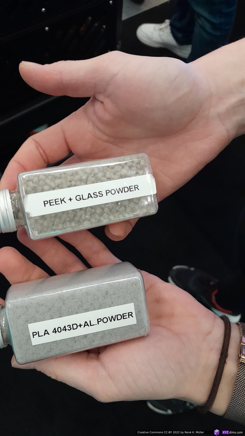
Reinforce 3D (Enhancement)
Another truly innovative approach combining and enhancing existing additive manufacturing processes was shown by Reinforce 3D:
using existing AM methods such as SLM, SLA, MSLA and even FFF/FDM to make models with thin walled tunnels and then
filling or rather pushing them with strains of carbon fibres along with resin into the tunnels
and thereby reinforcing free forms by keeping the result lightweight but incredible strong due the embedded carbon fibres
Reinforce 3D boothReinforce 3D: SLM and resin (MSLA) printed pieces carbon fiber reinforcedReinforce 3D: FDM printed and carbon fiber reinforcedReinforce 3D: FDM printed and carbon fiber reinforced
A very small but significant detail is, that you can print multiple parts on a smaller printer, but once you start to insert the bundles of carbon fiber those segments of pieces get combined in a strong assembly, as the aluminium skeleton shown above.
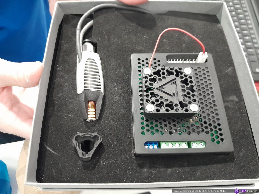
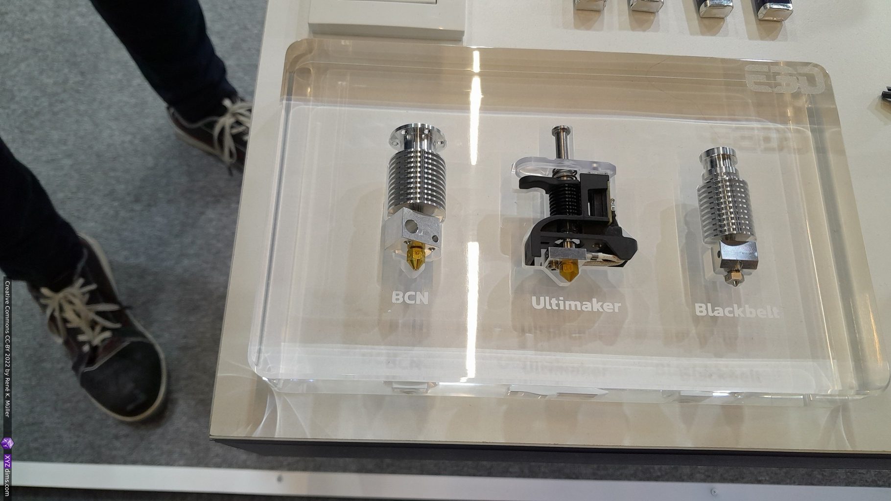
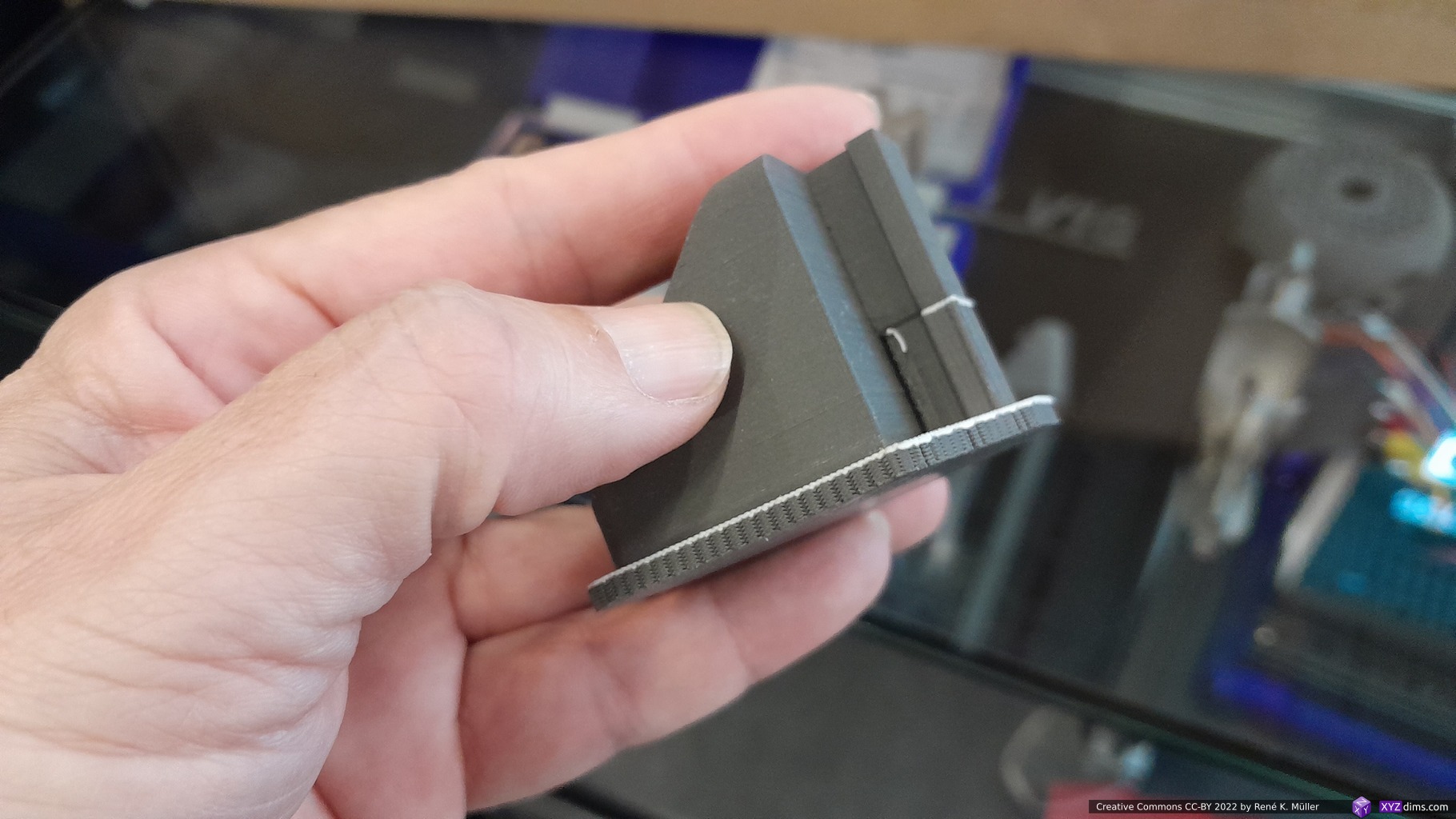
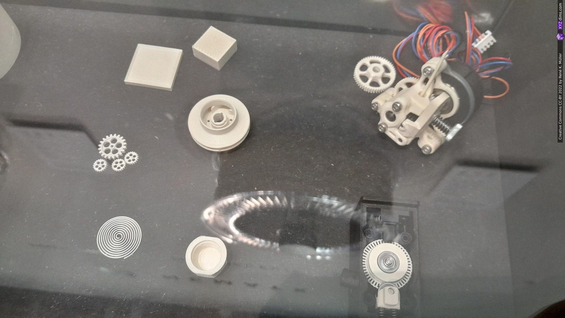
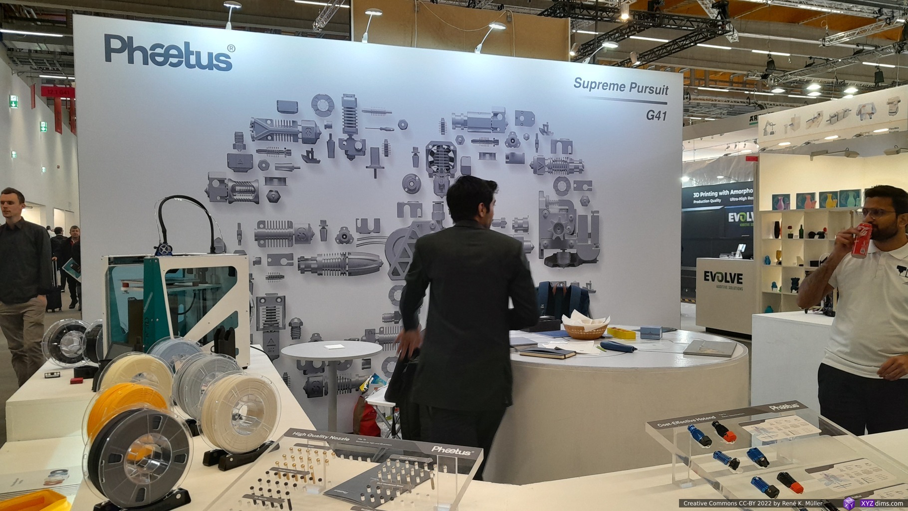
INo Trident – inductive hotend by Plasmics: fast heatup and cooldown / 3s from 20C to 220C, 10s from 220C to 150C
At the booth of Plasmics I looked at the inductive hotend and saw the heating up in a few seconds from 20C to 220C and cool-off in a small demo first hand.
The hot part of the nozzle looks like a needle, with little thermal mass, hence the fast heat and cooling-off time, and then surrounded by ceramics with the inductive coil on it.
The hotend incl. the controller board priced at EUR 400 is high for DIY enthusiasts but low for an industrial setup.
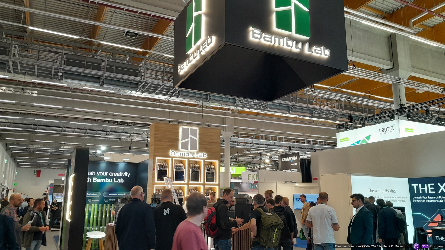
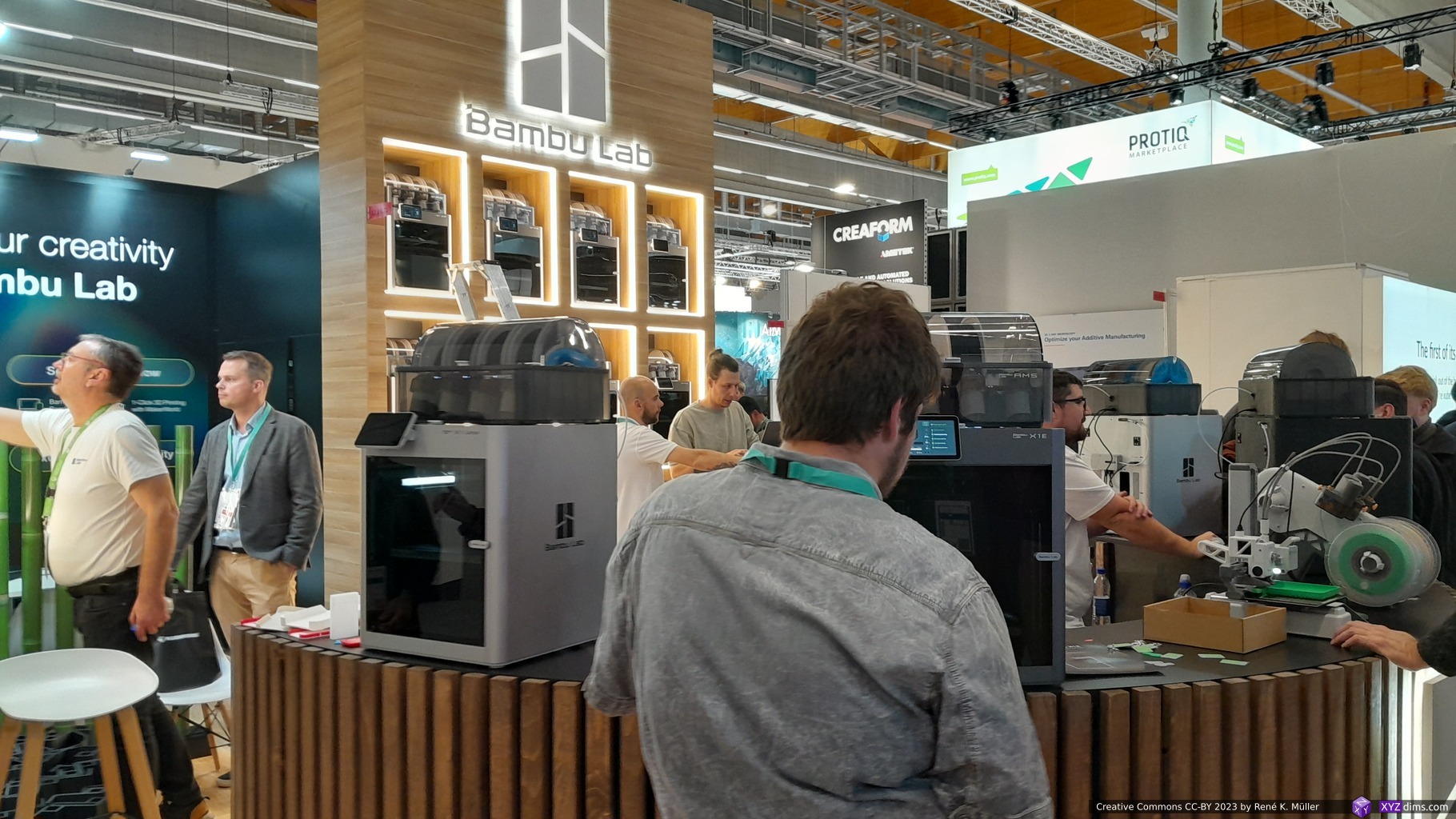
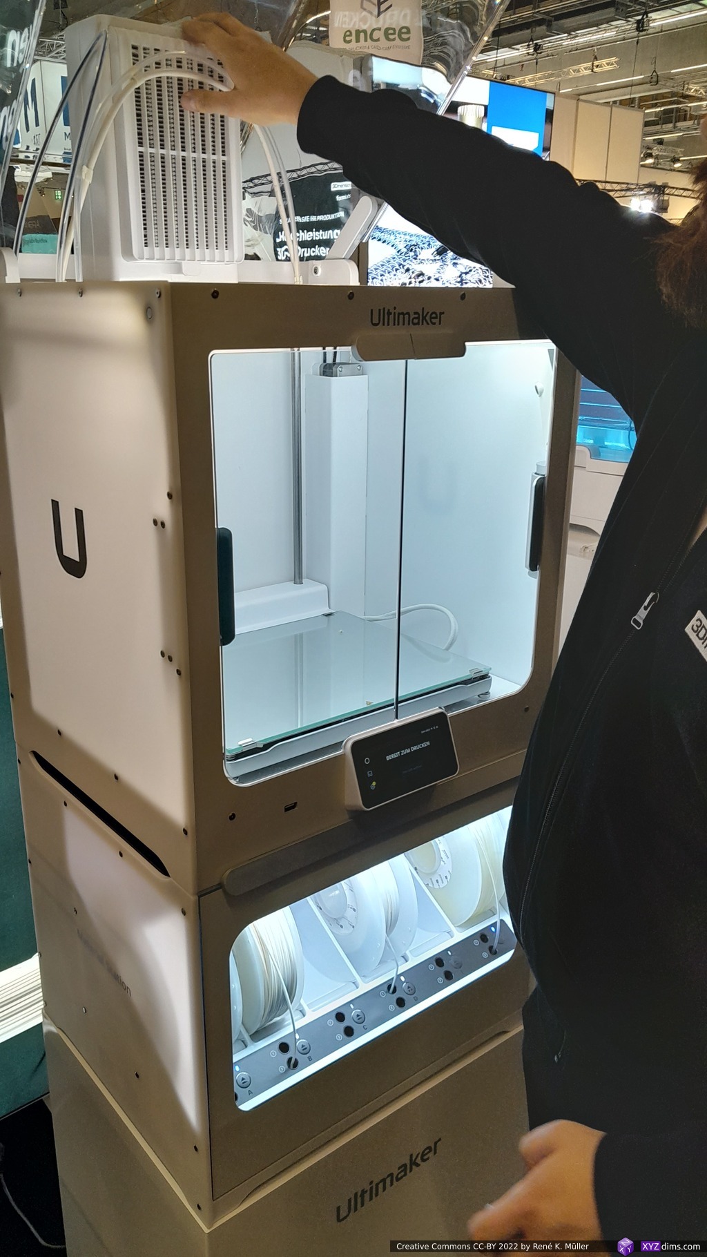
And UltiMaker (after Ultimaker & MakerBot merger) wasn’t present again; the consensus has been that BambuLab‘s printers have taken the higher quality consumer FFF/FDM printers market segment, and the air getting thinner for UltiMaker – at the same time they are doing a great service with the Open Source Cura slicer.
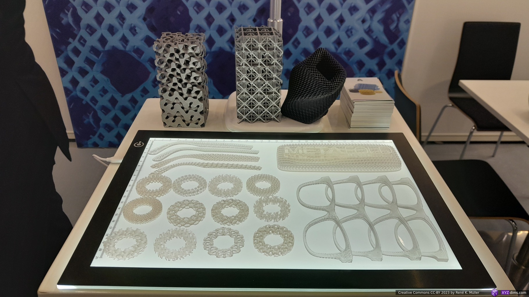
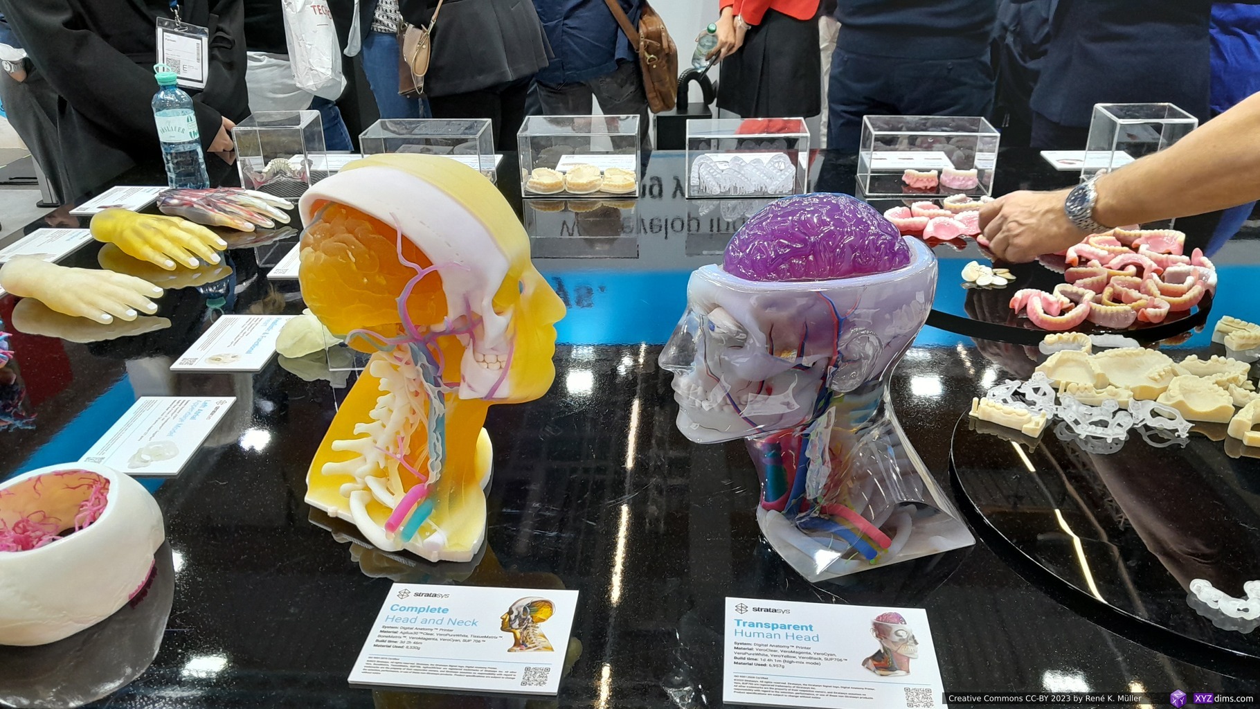
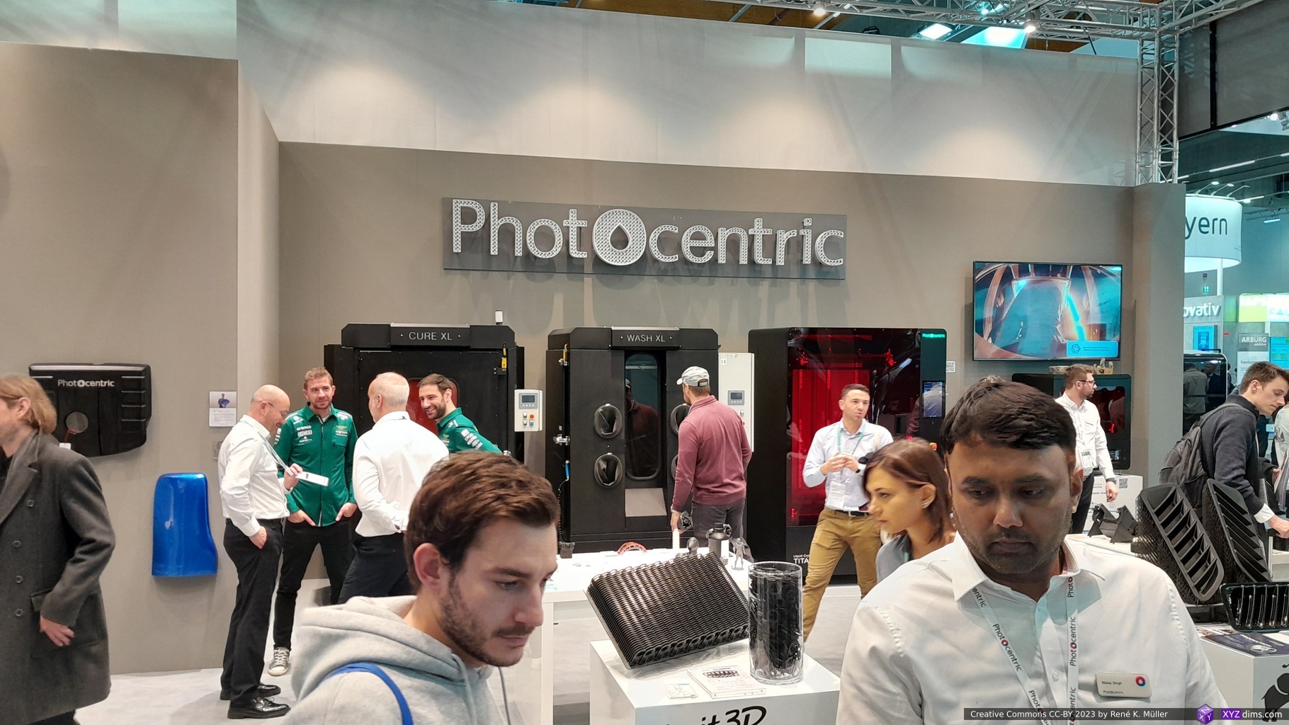
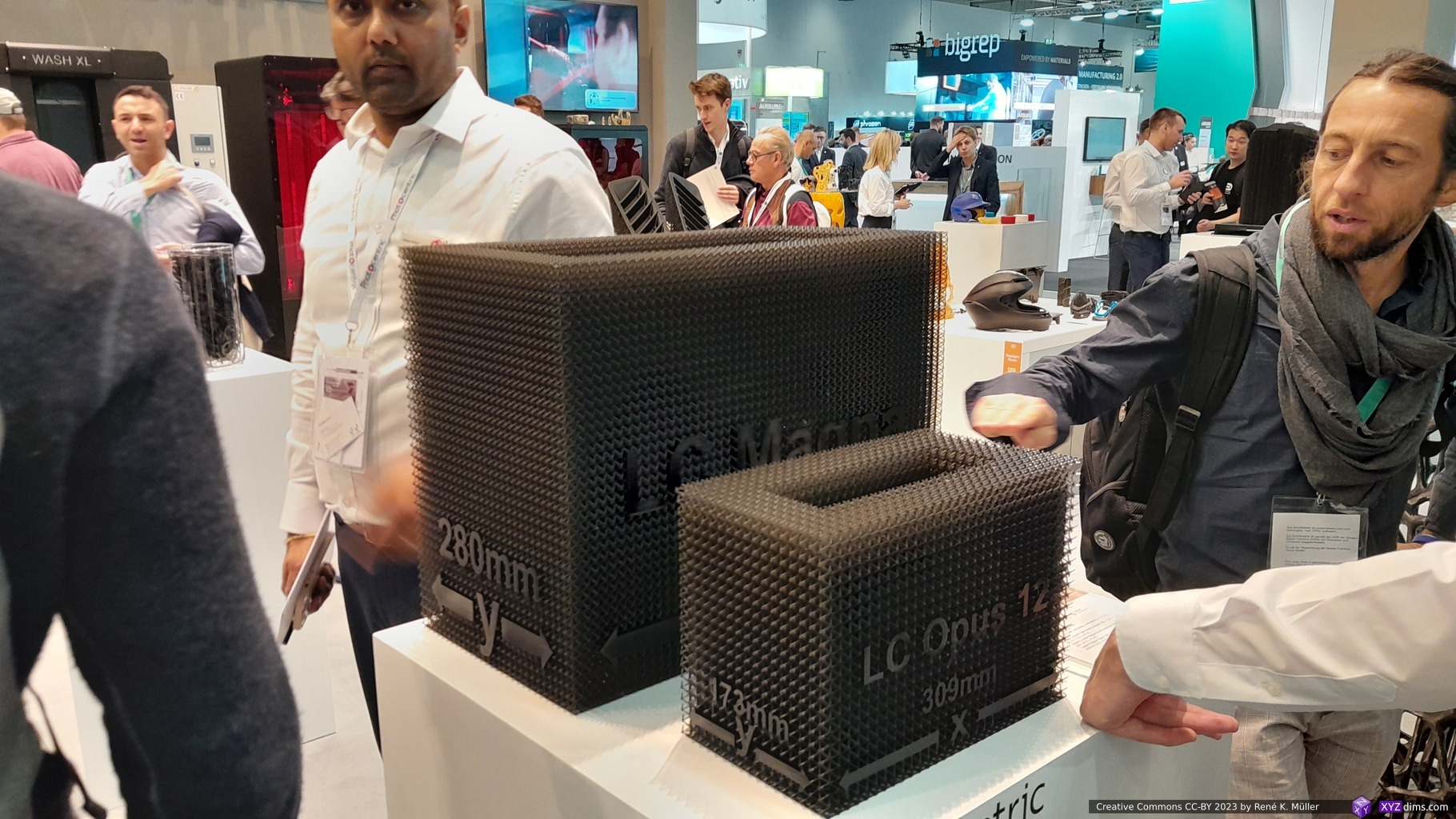
Random Impressions
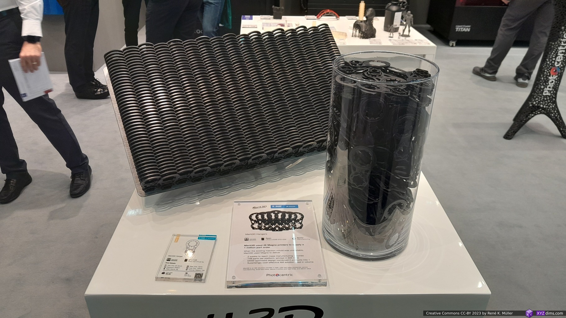
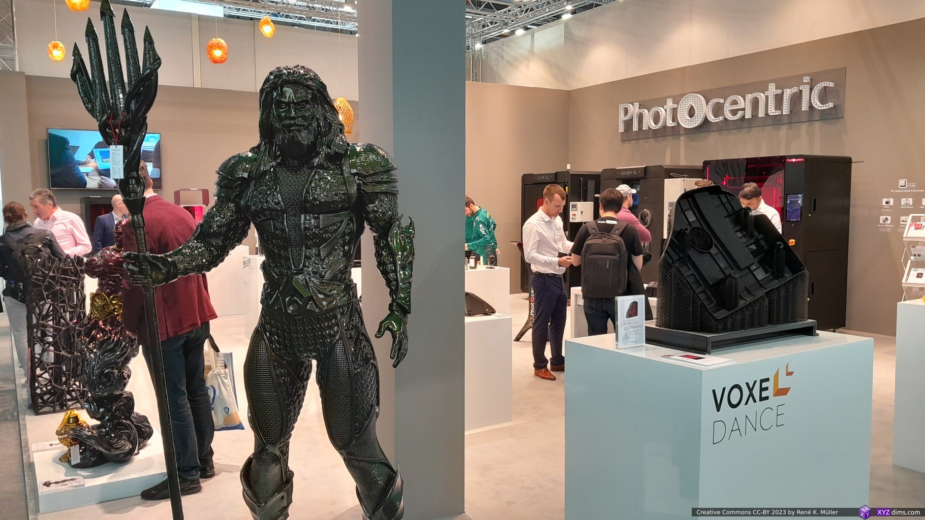
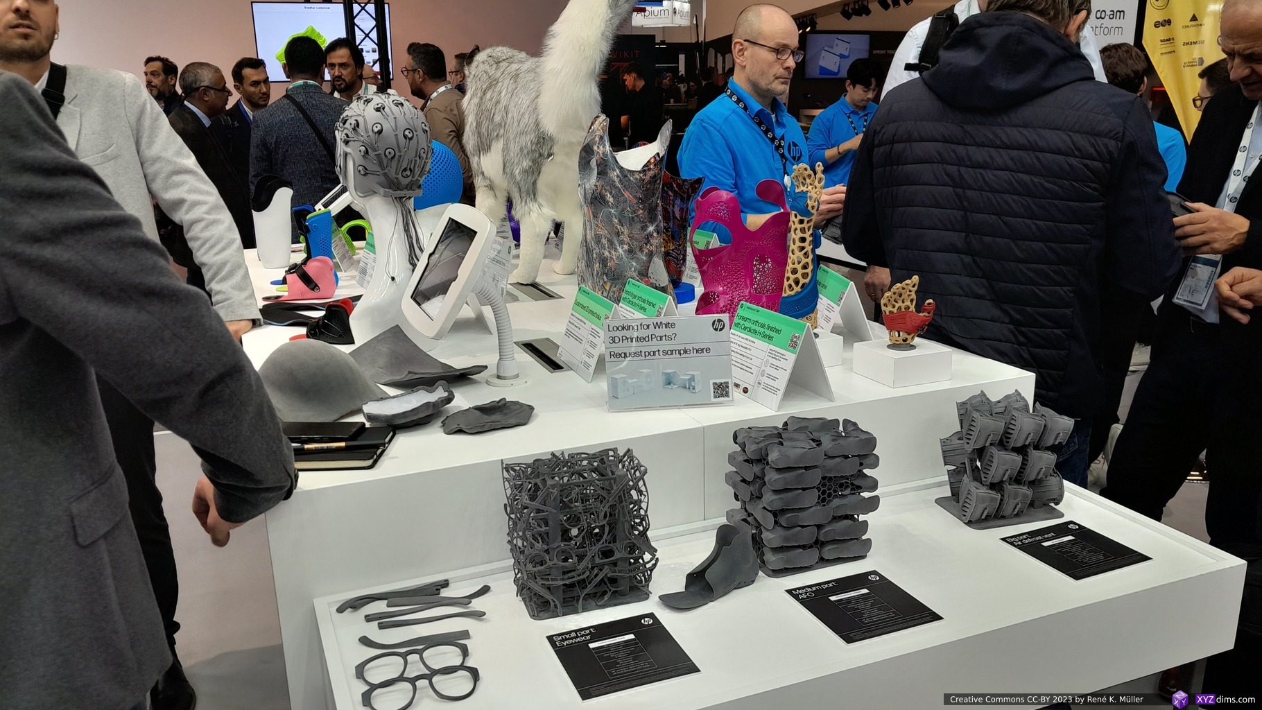
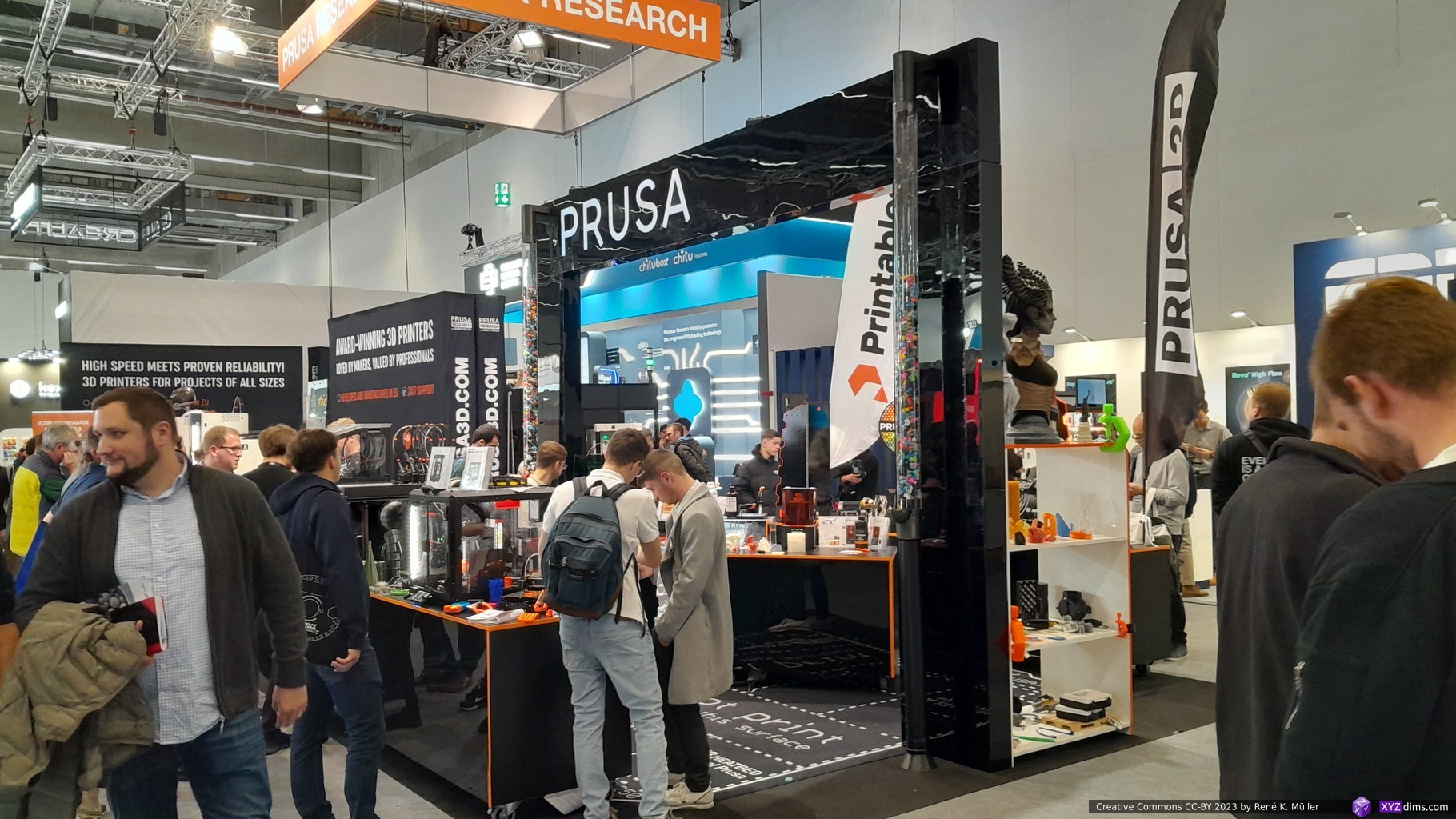
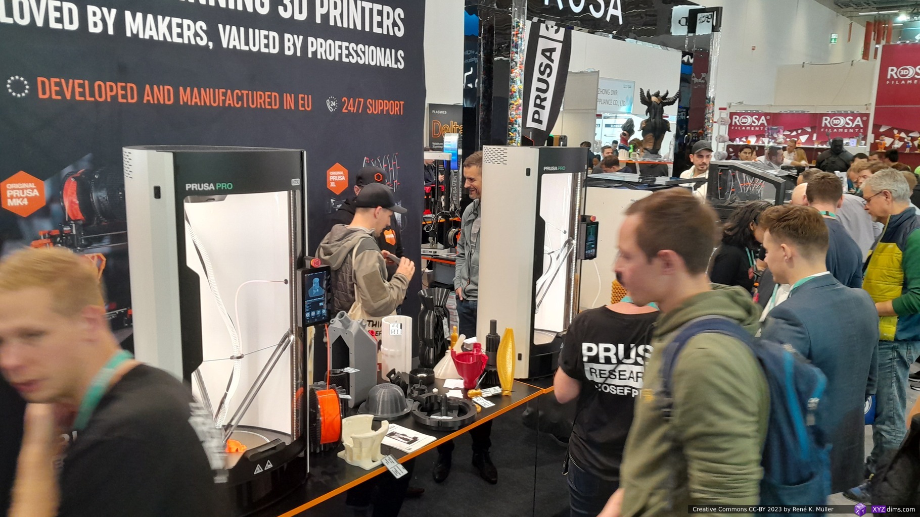
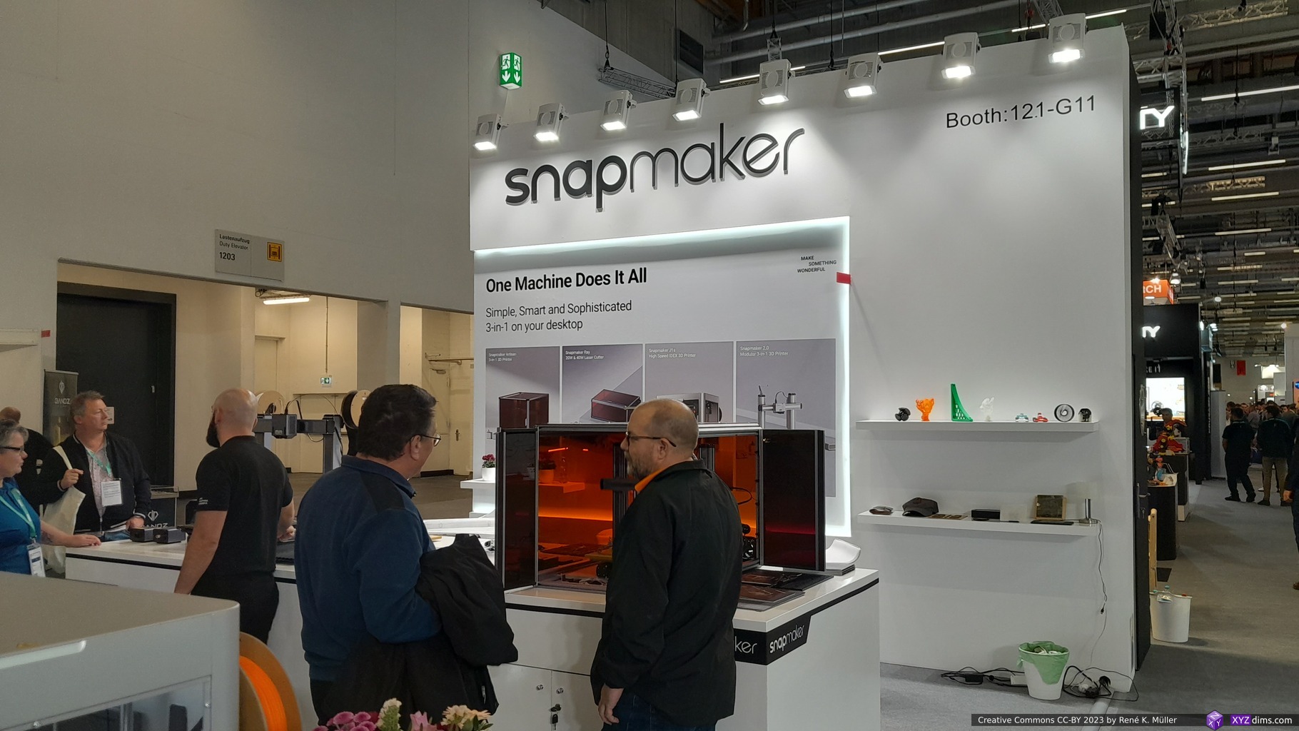
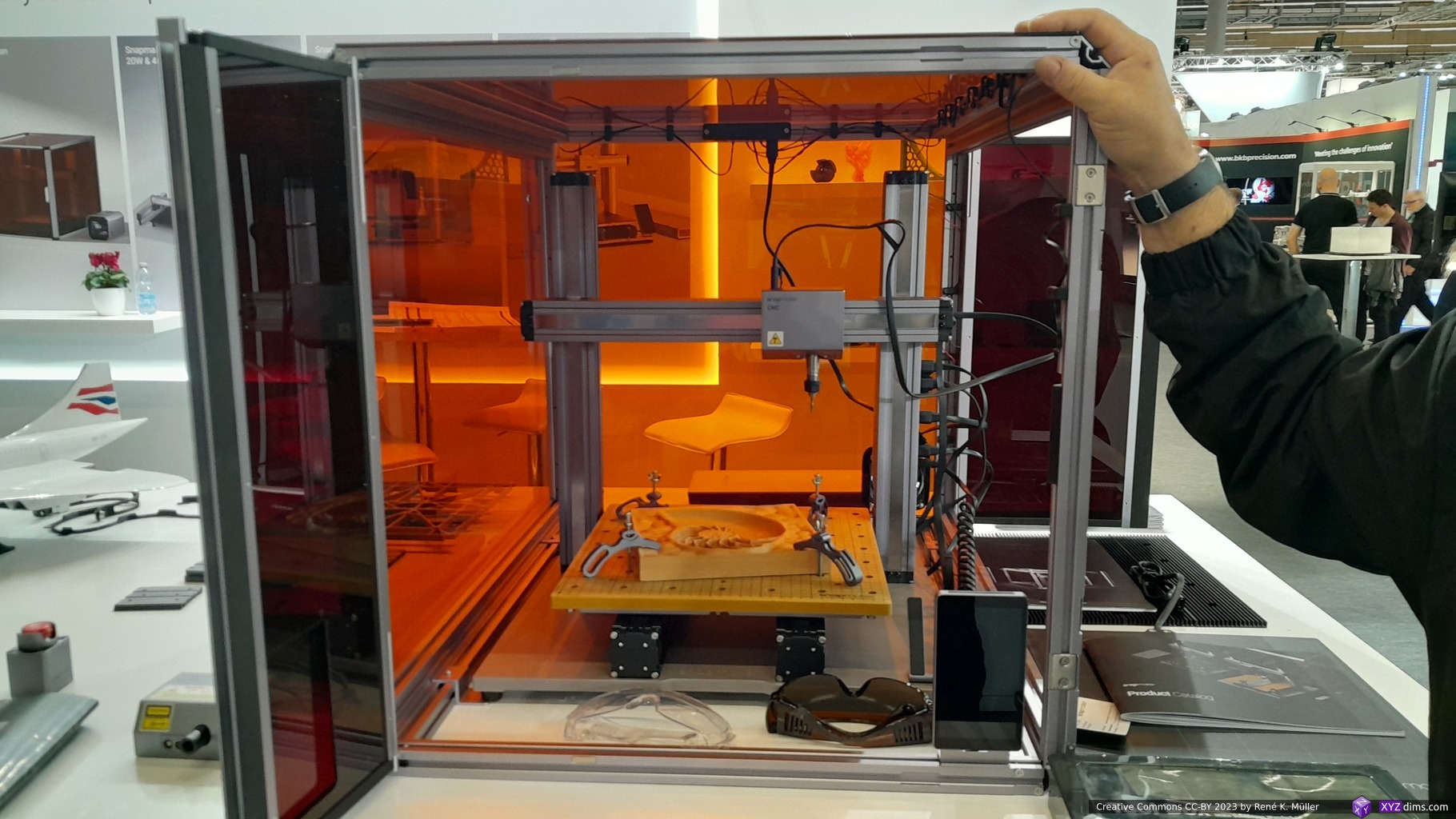
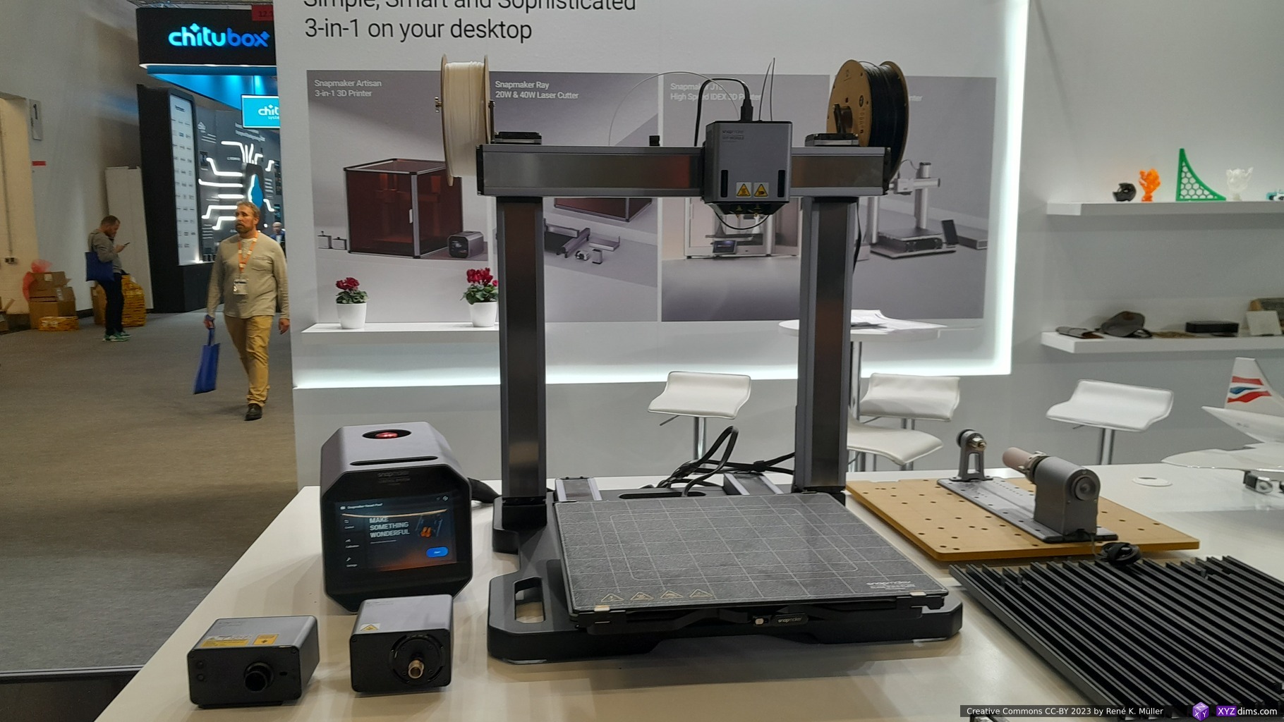
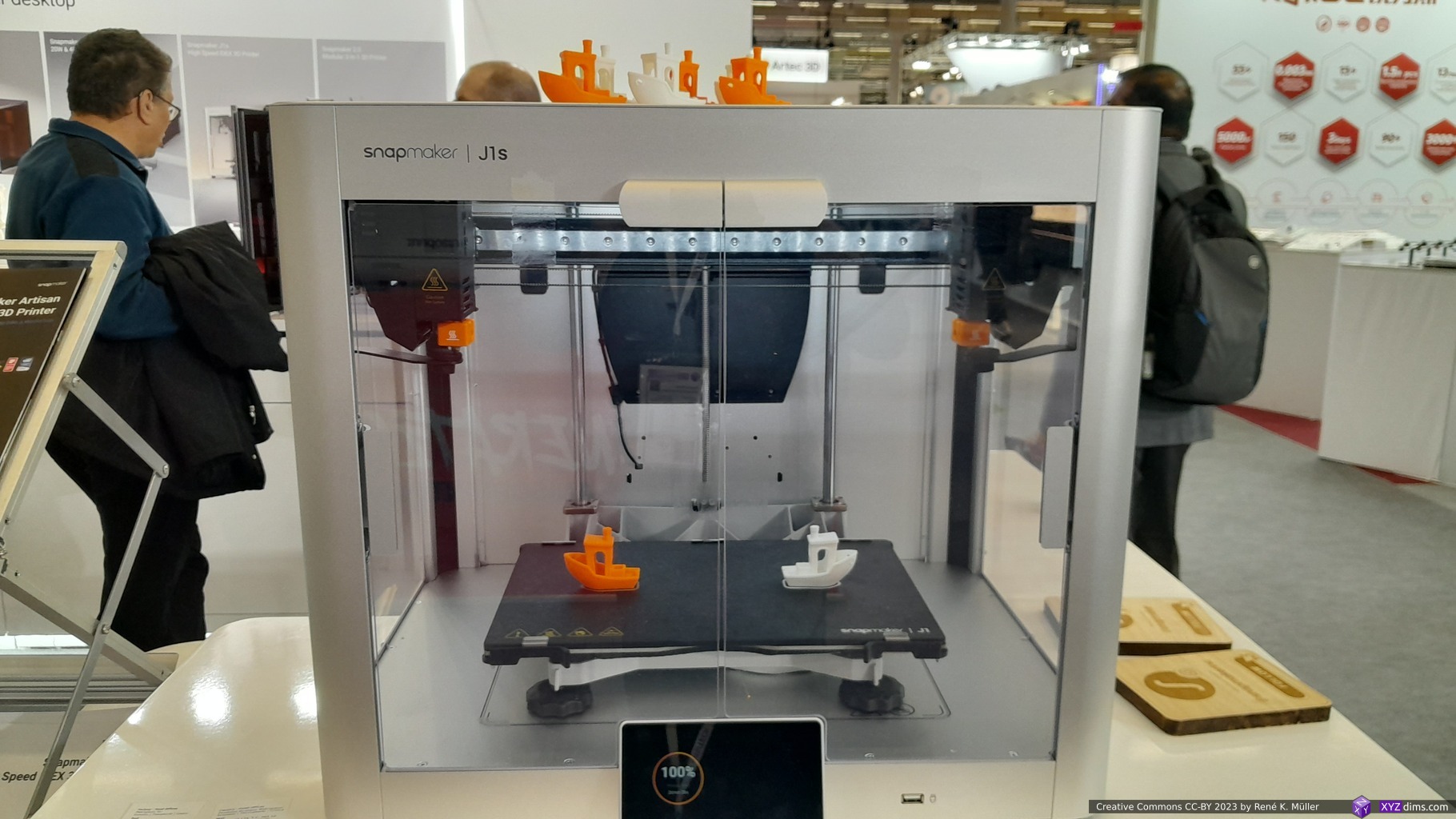
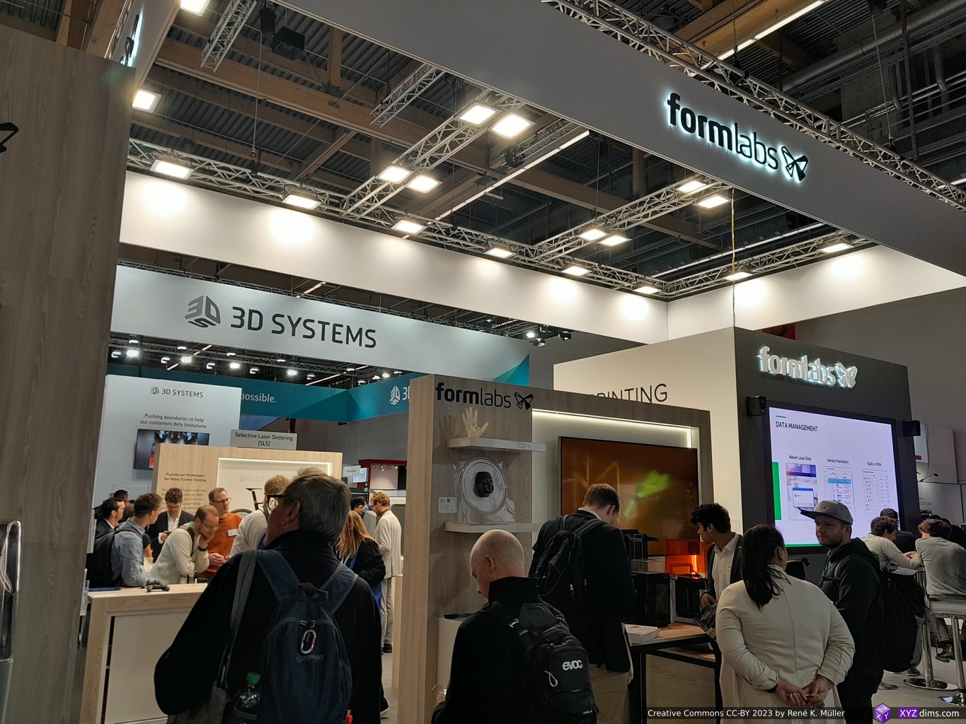
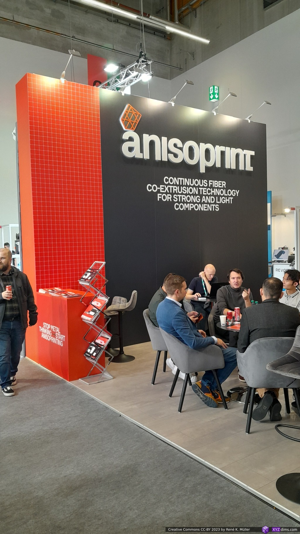
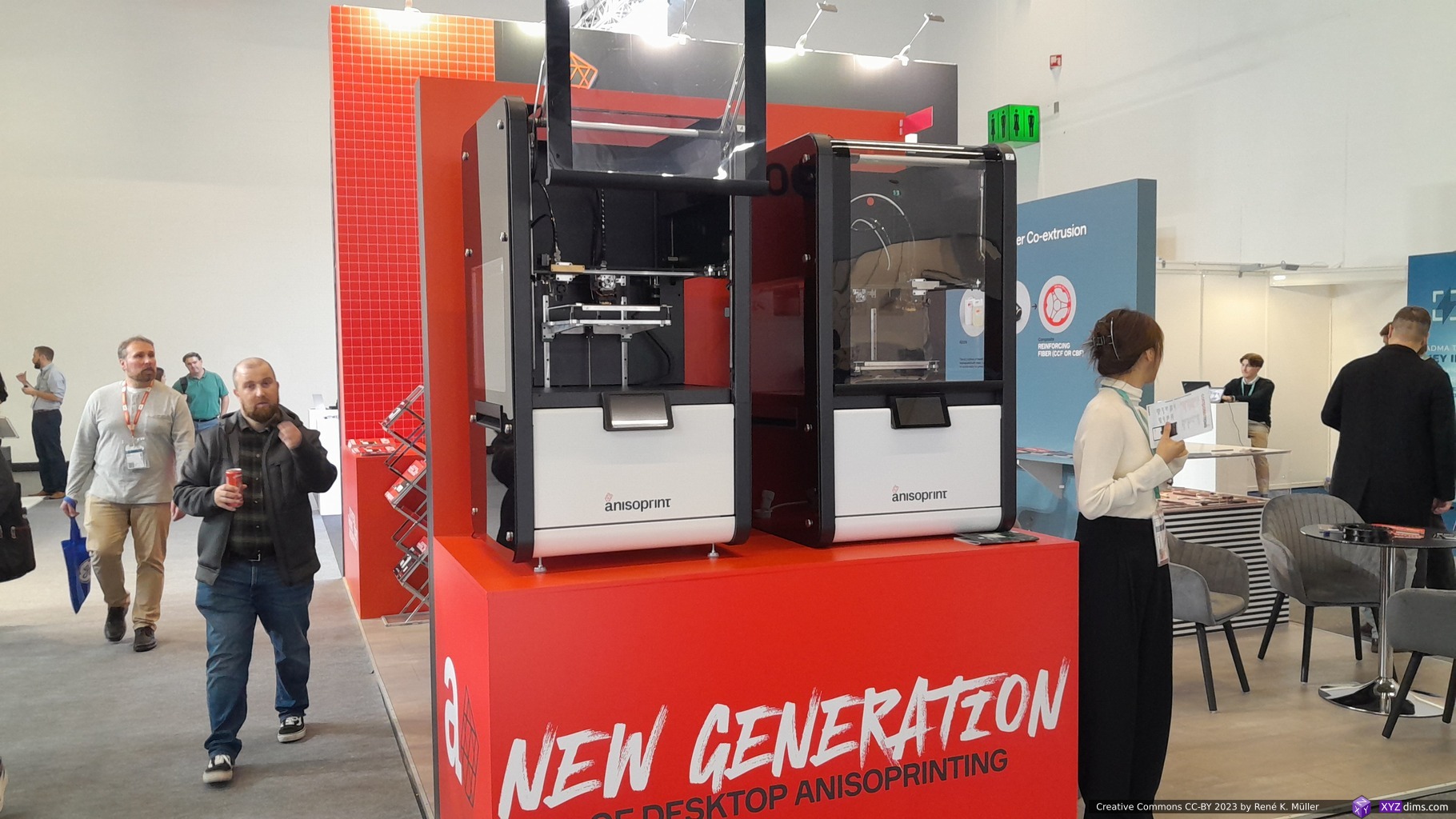
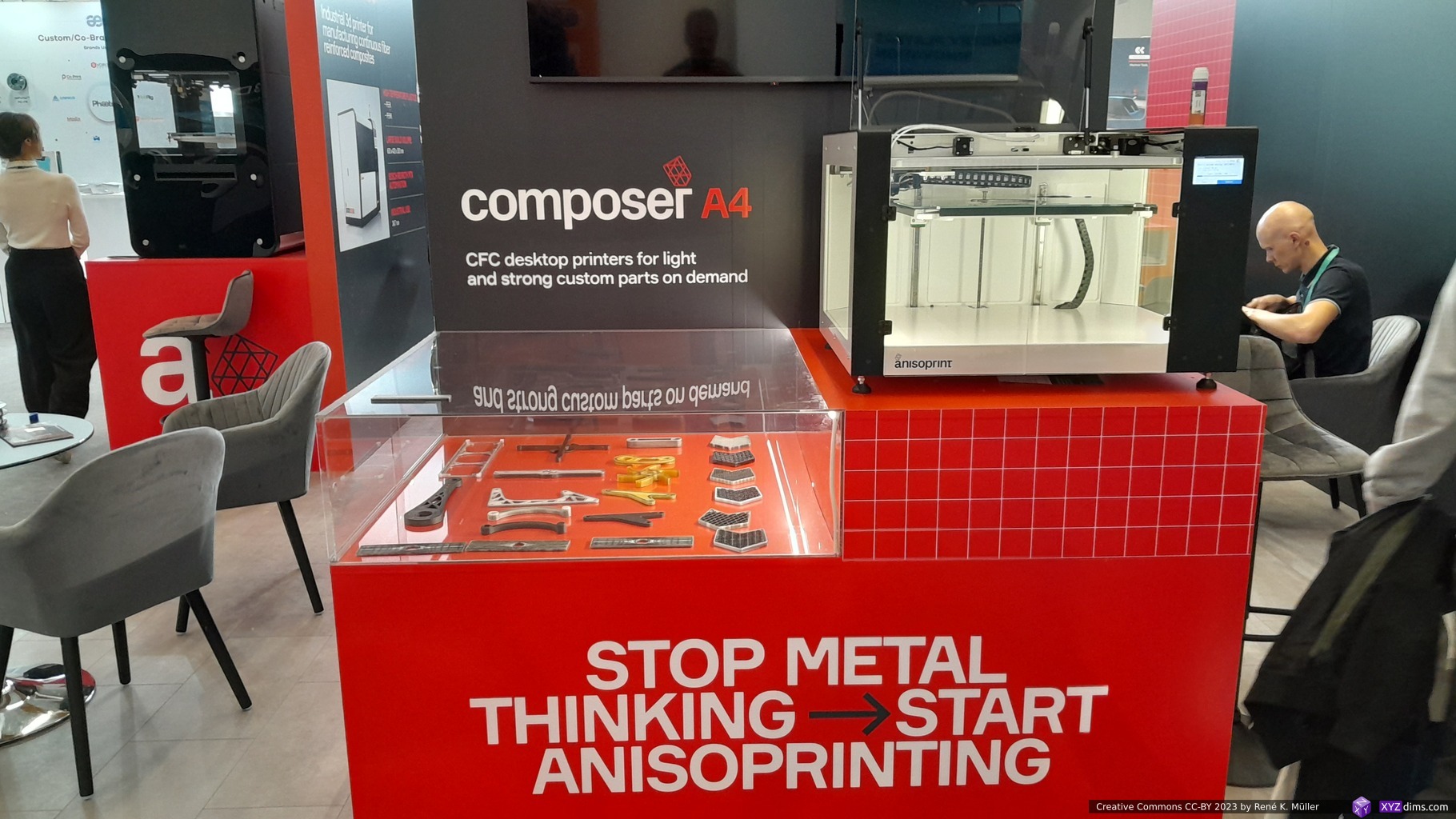
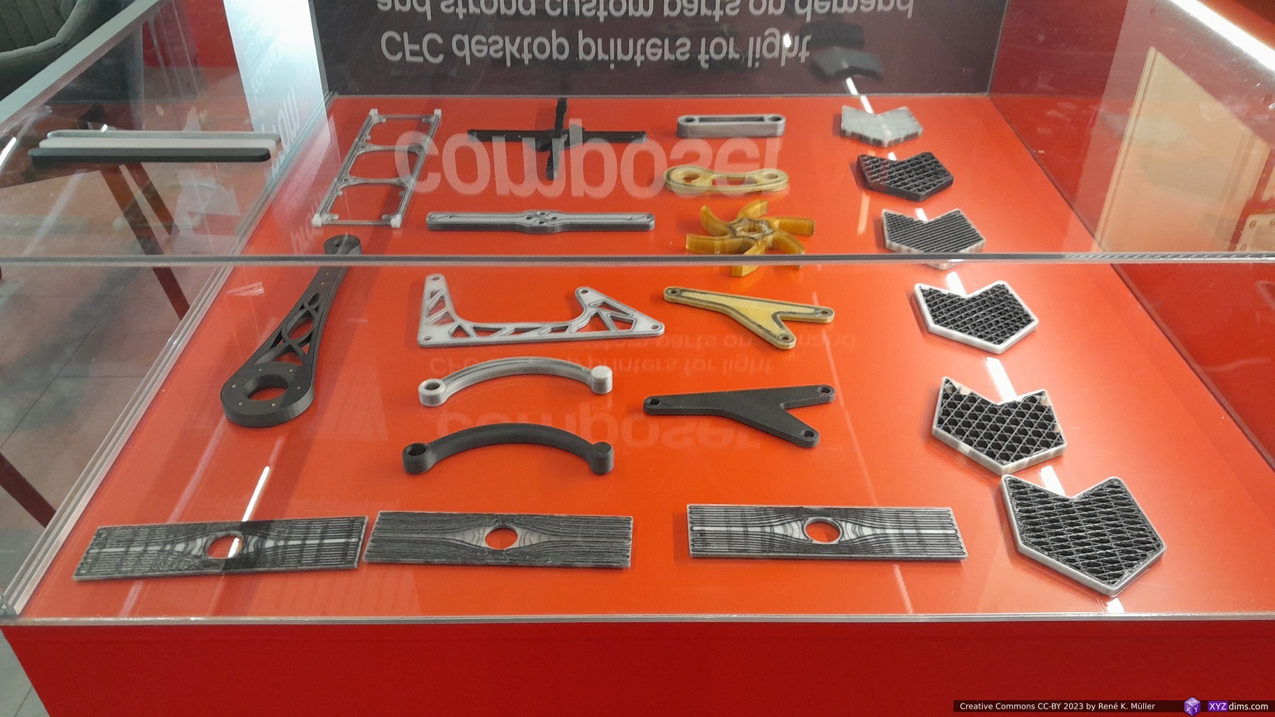
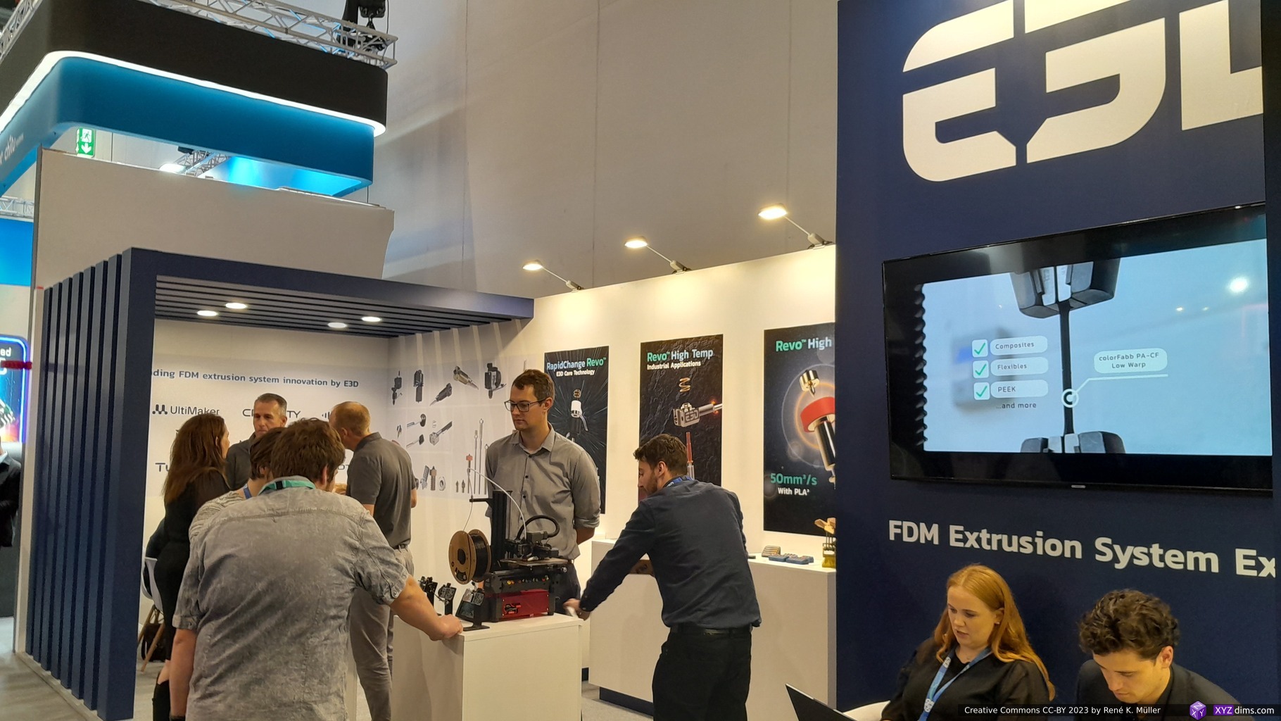
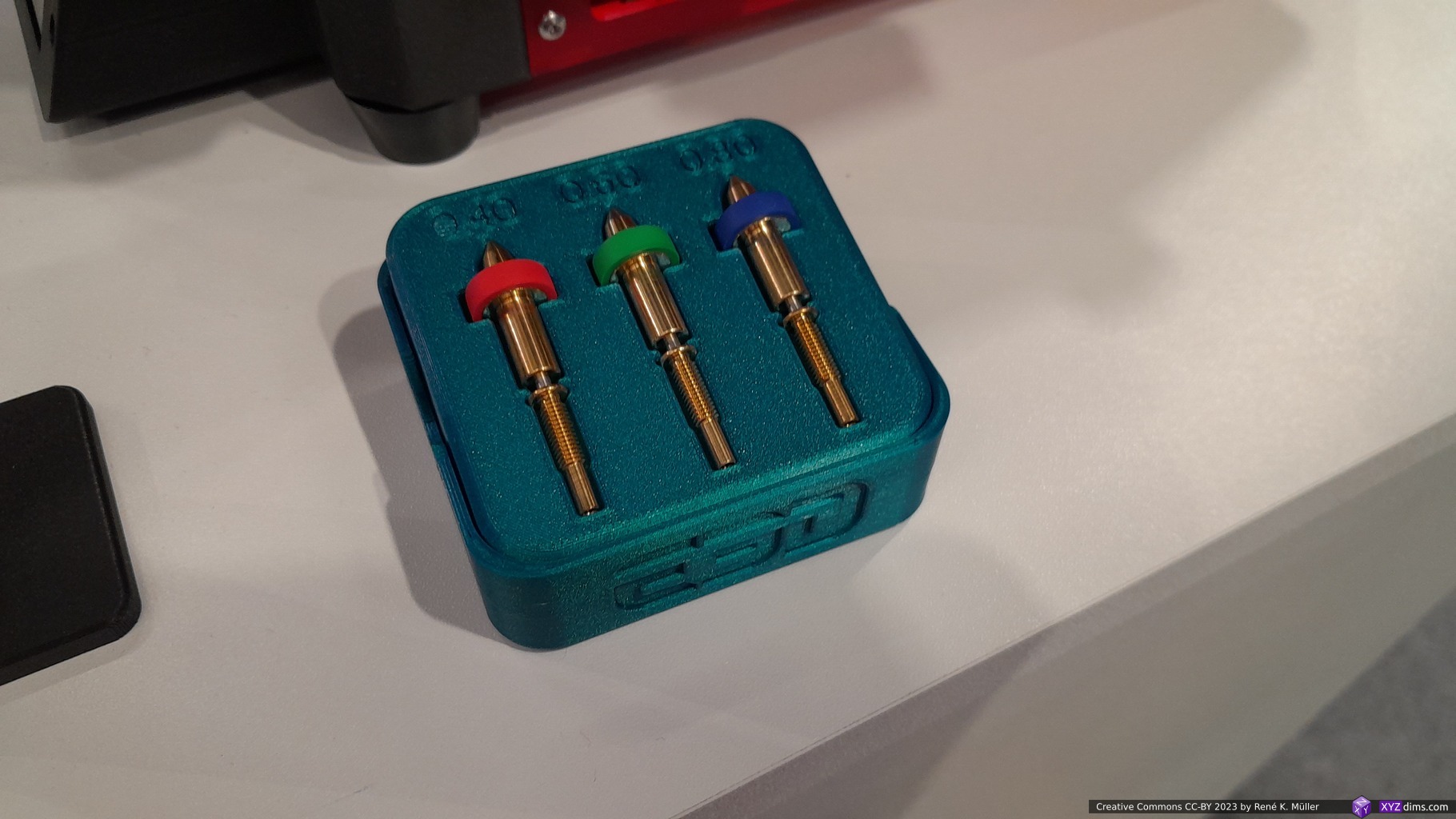
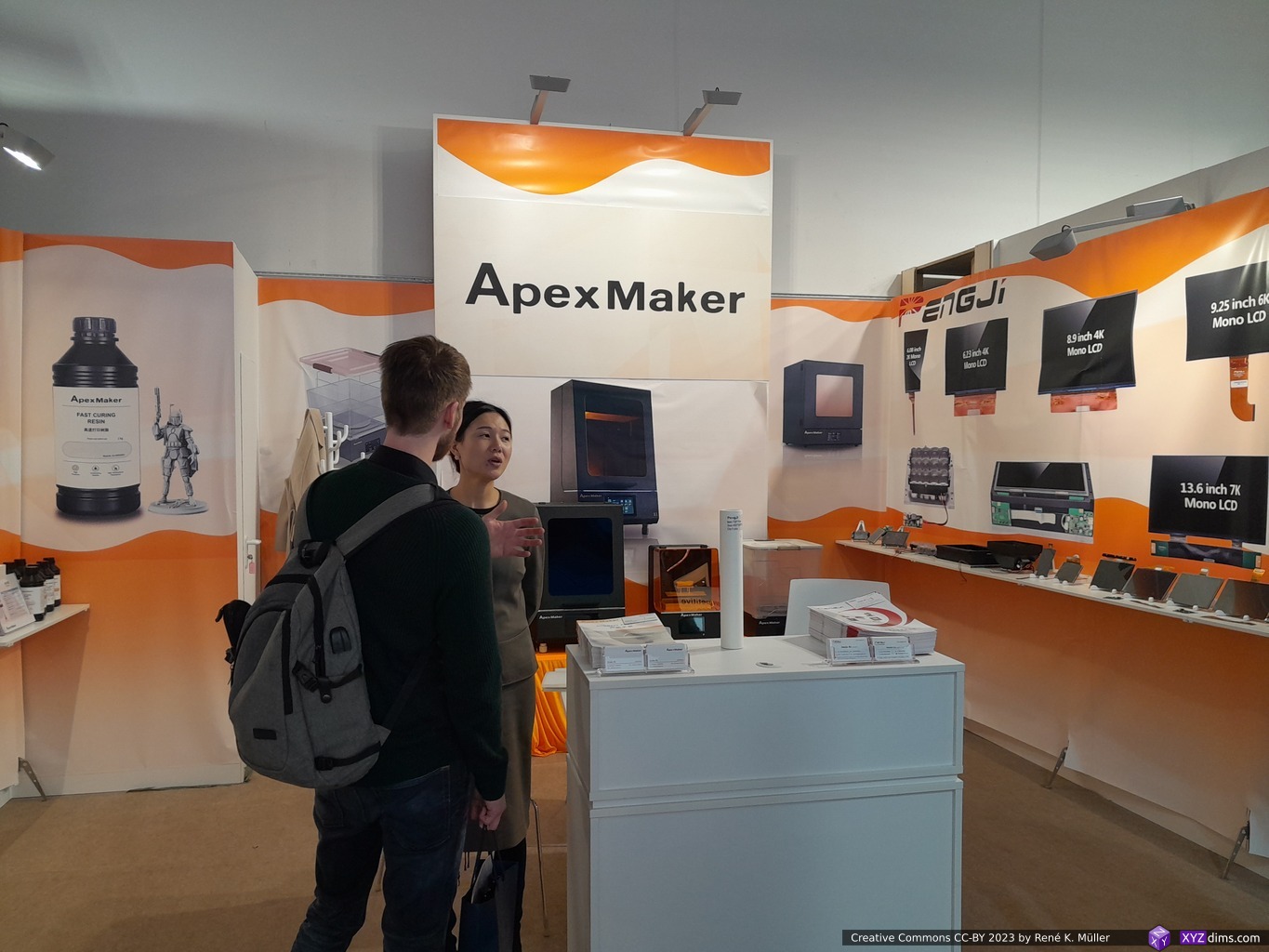
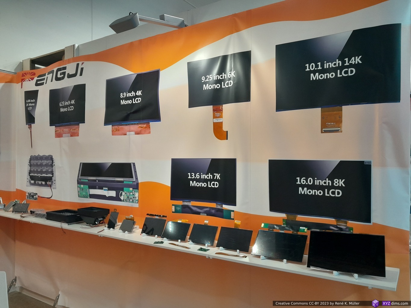
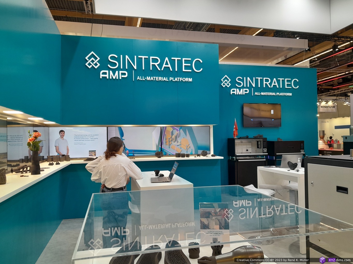
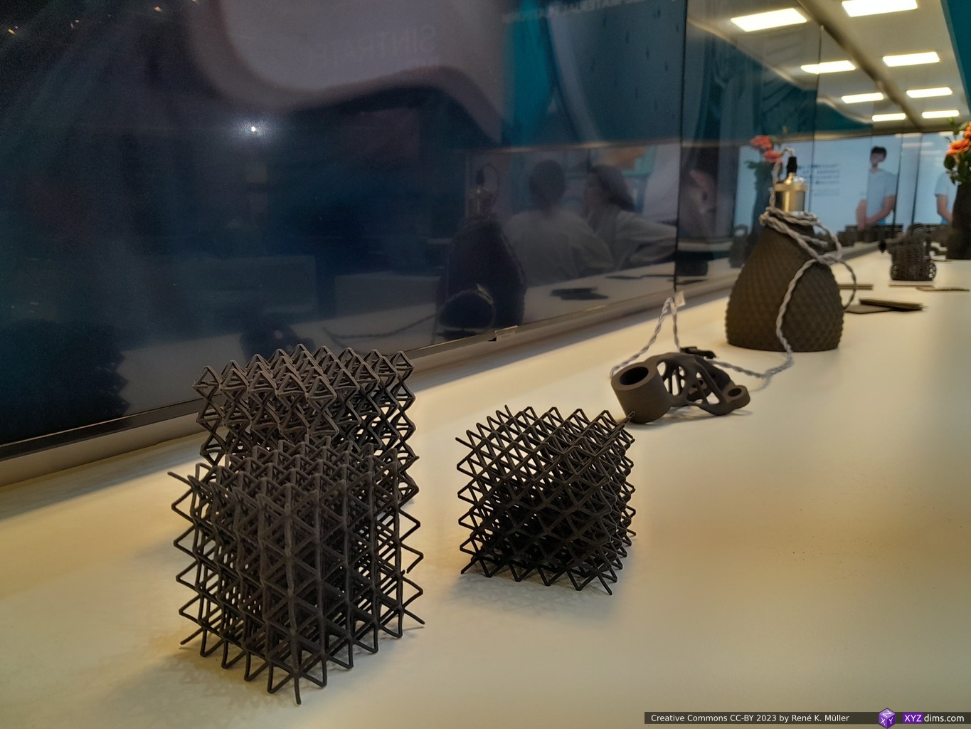
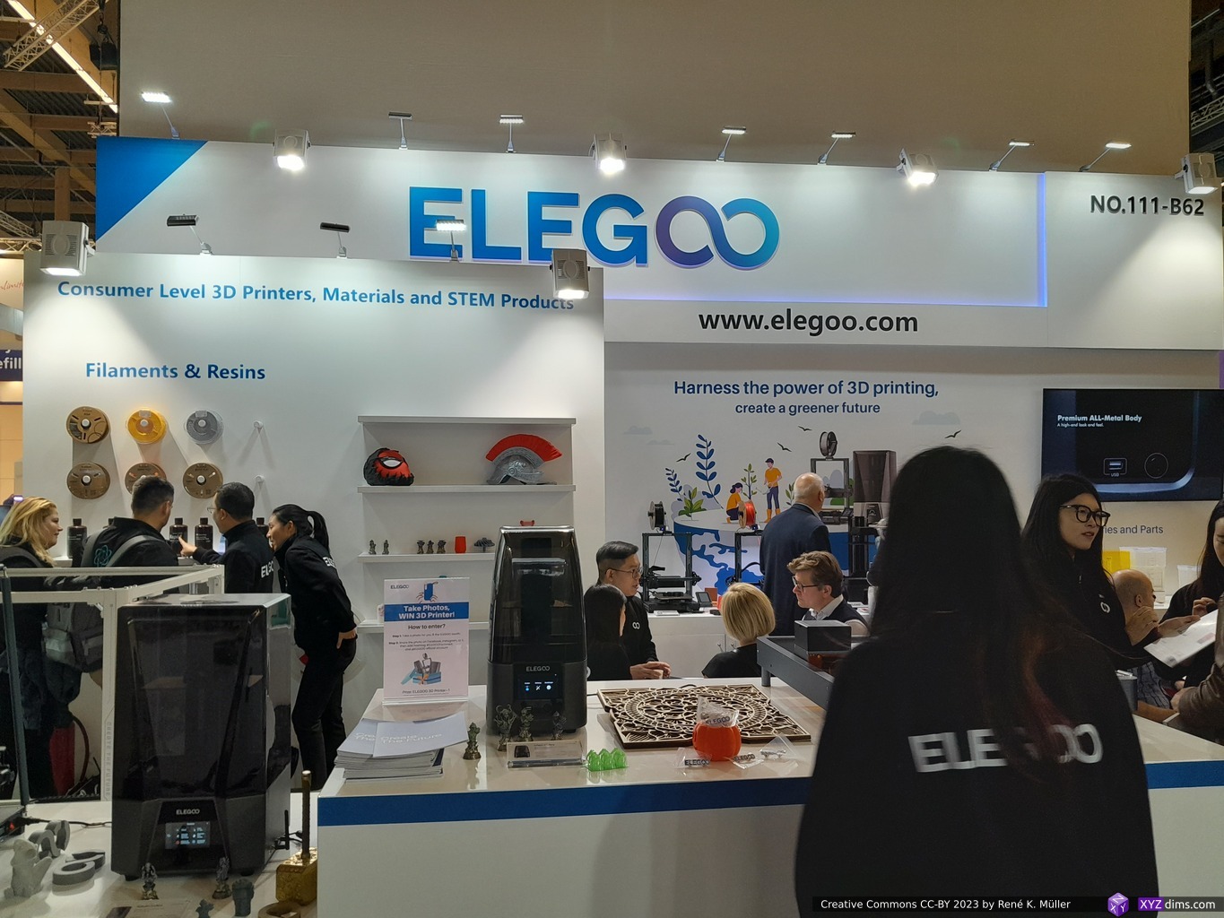
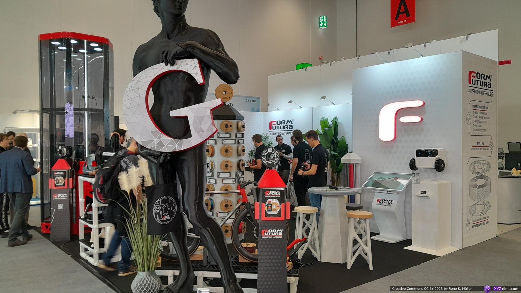
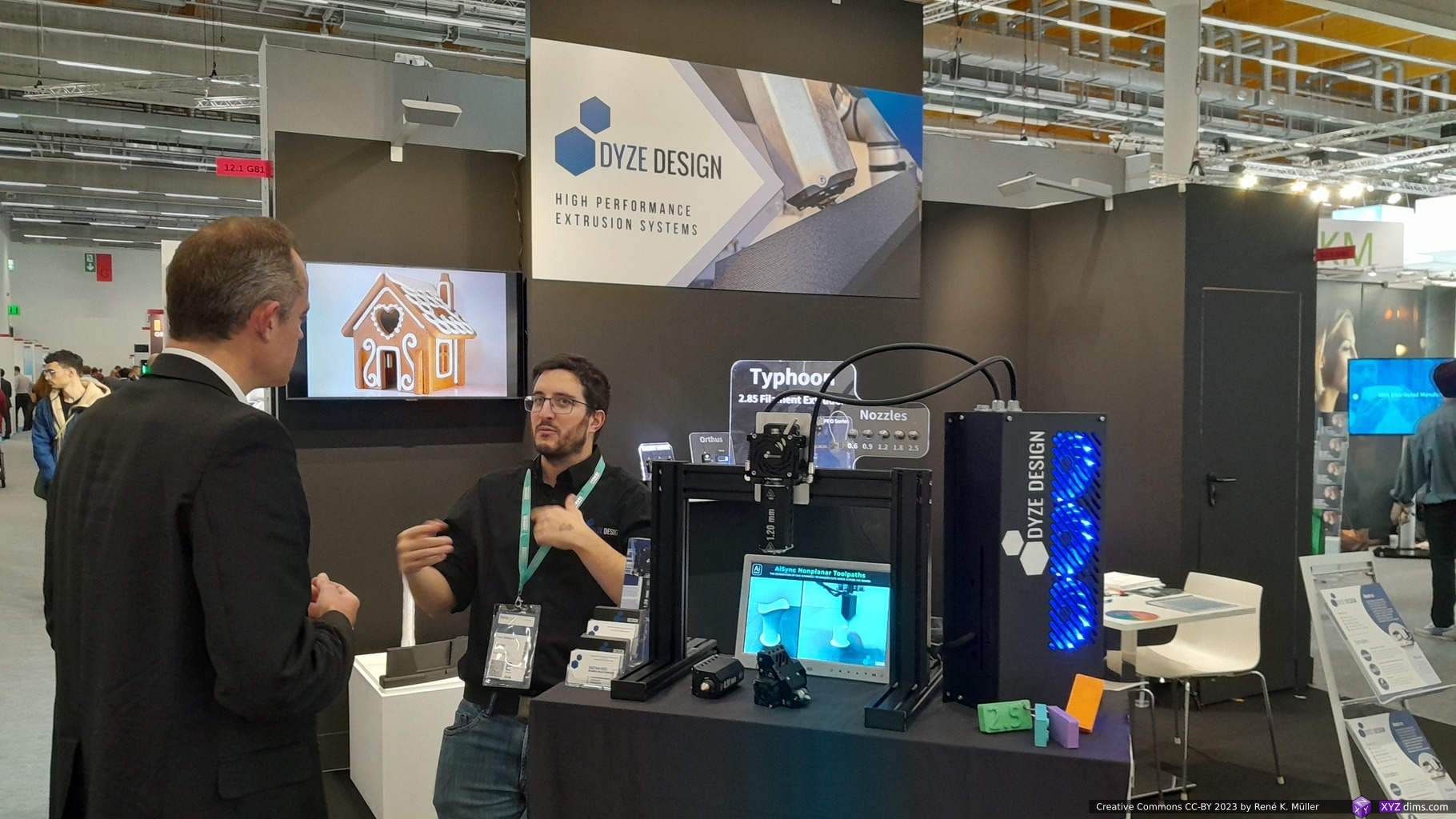
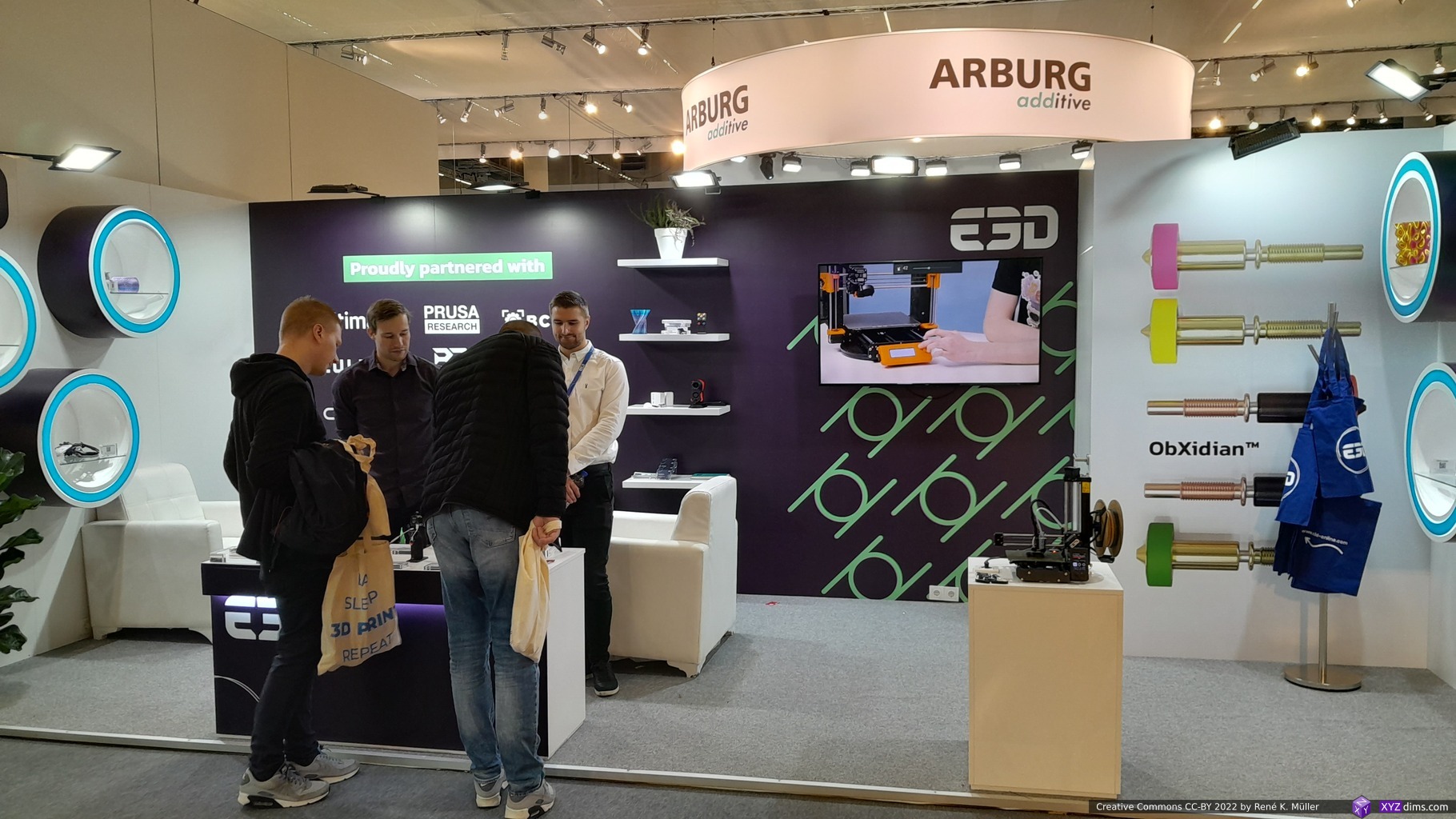
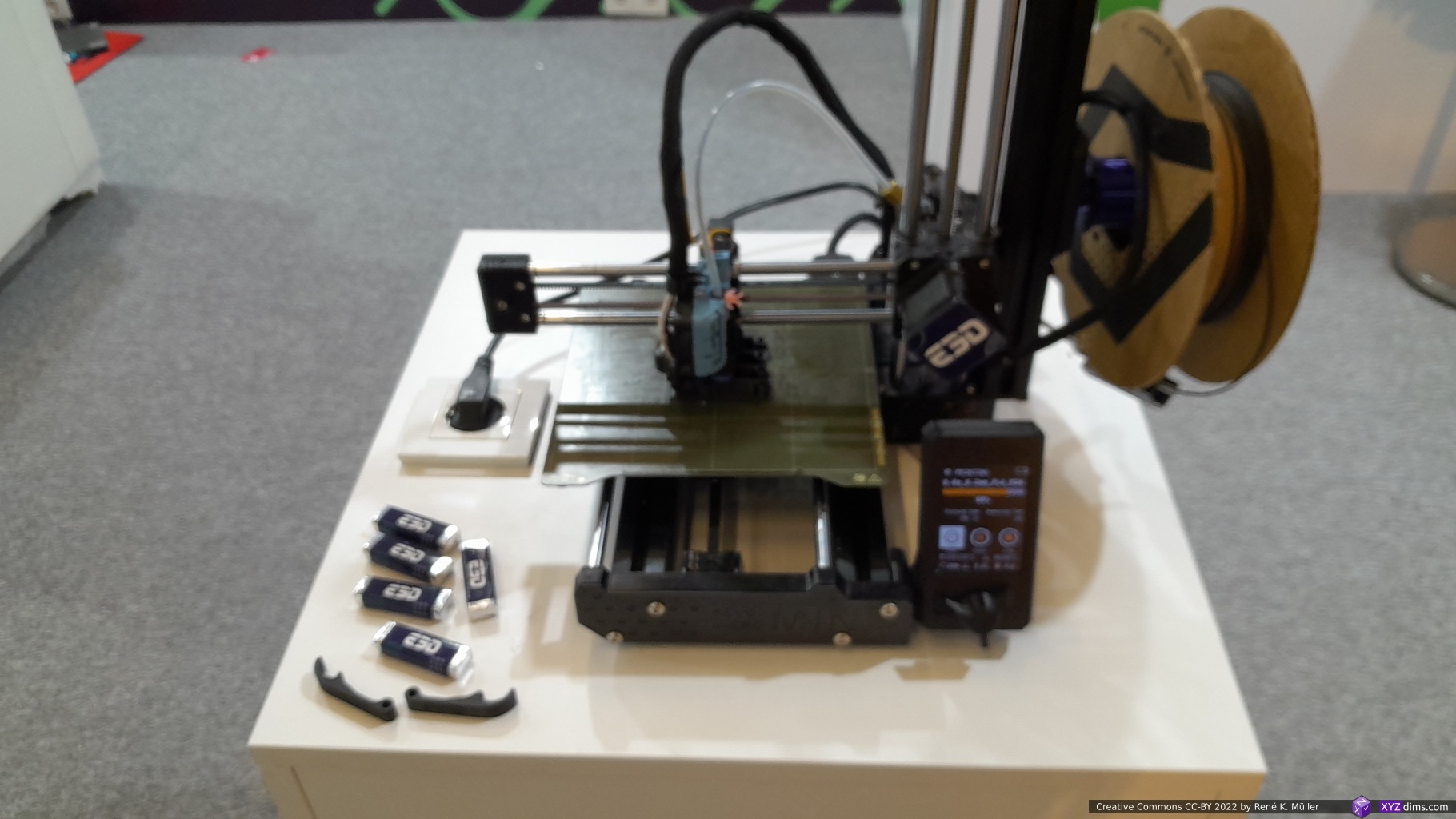
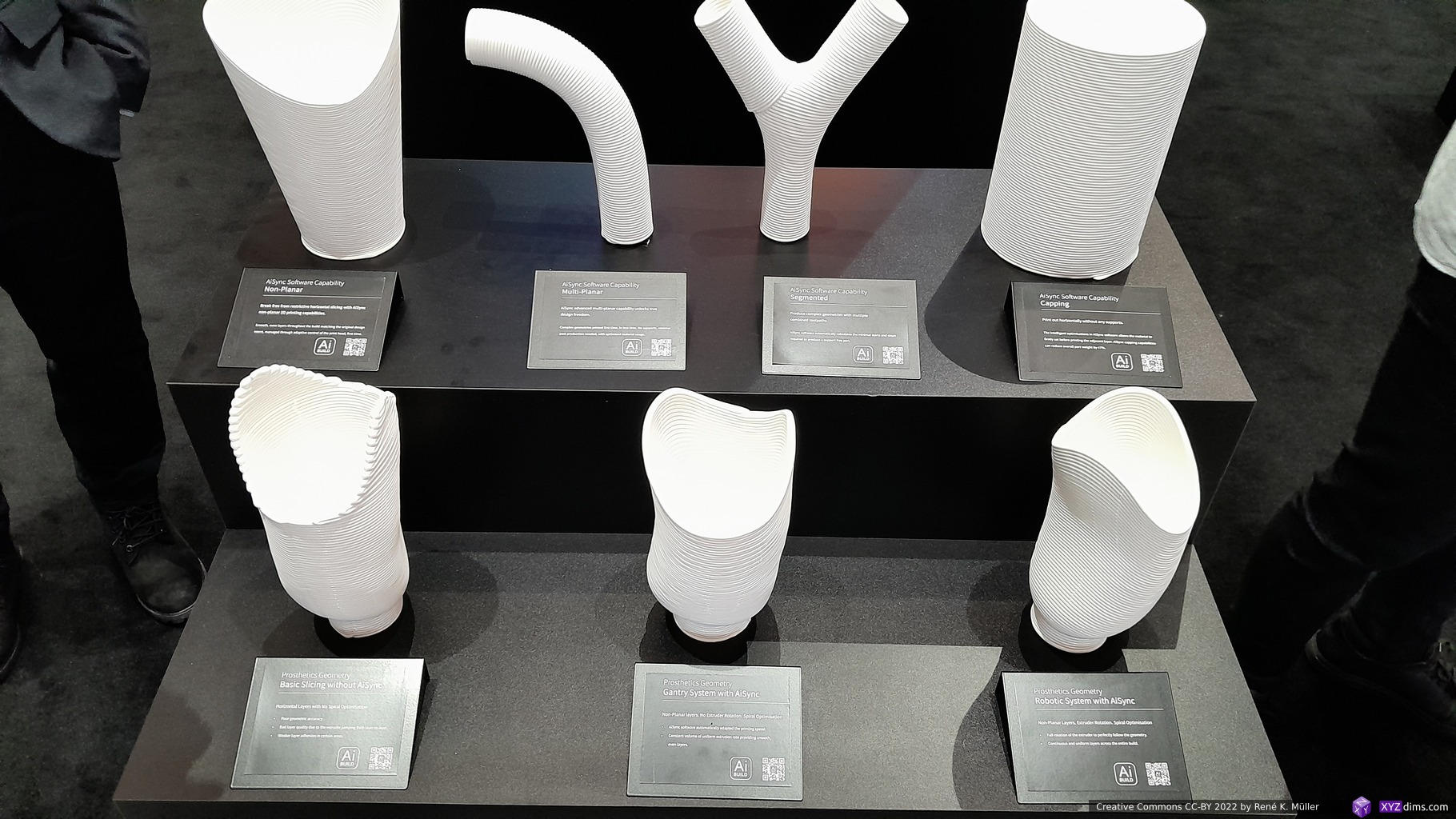
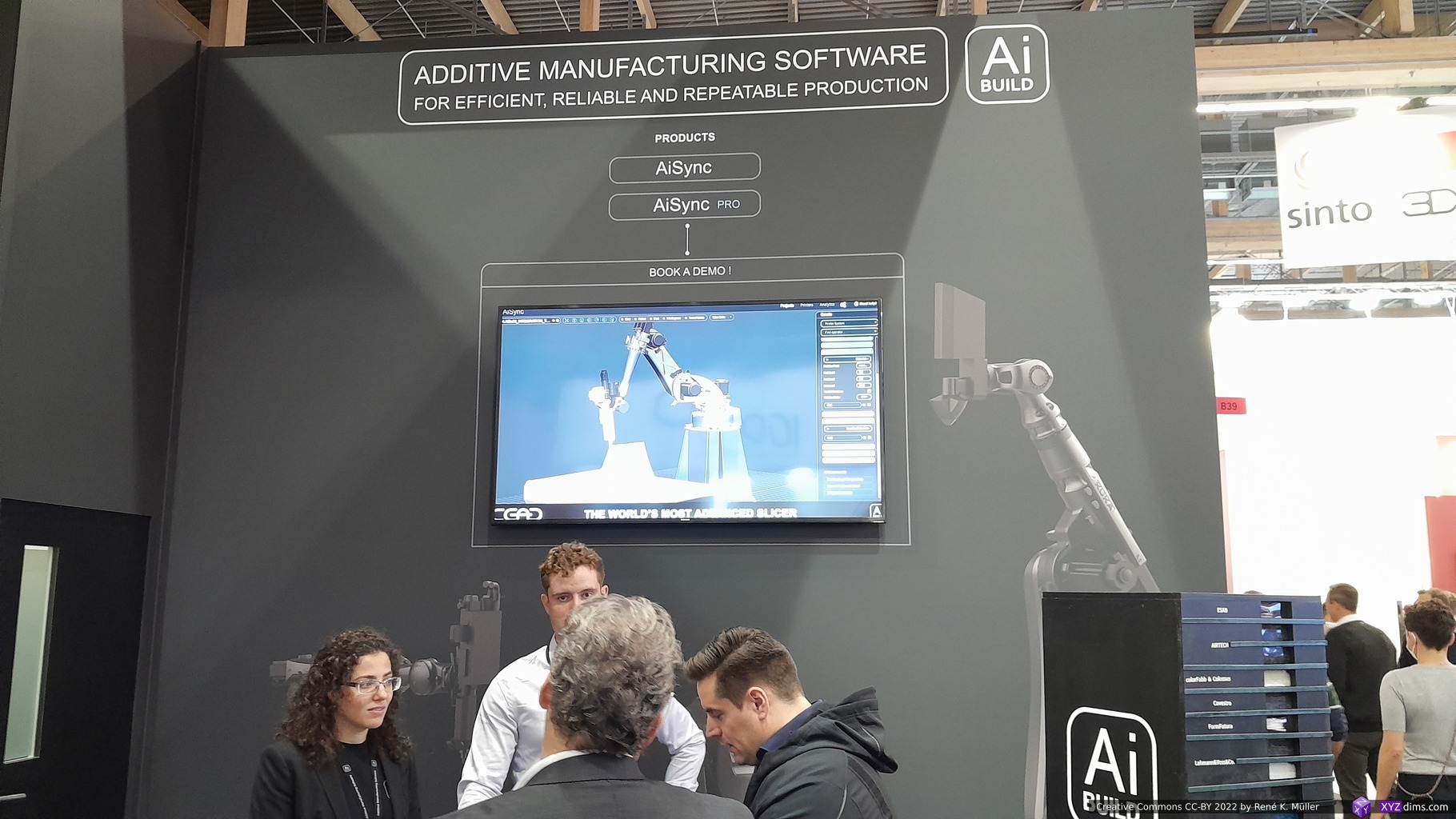
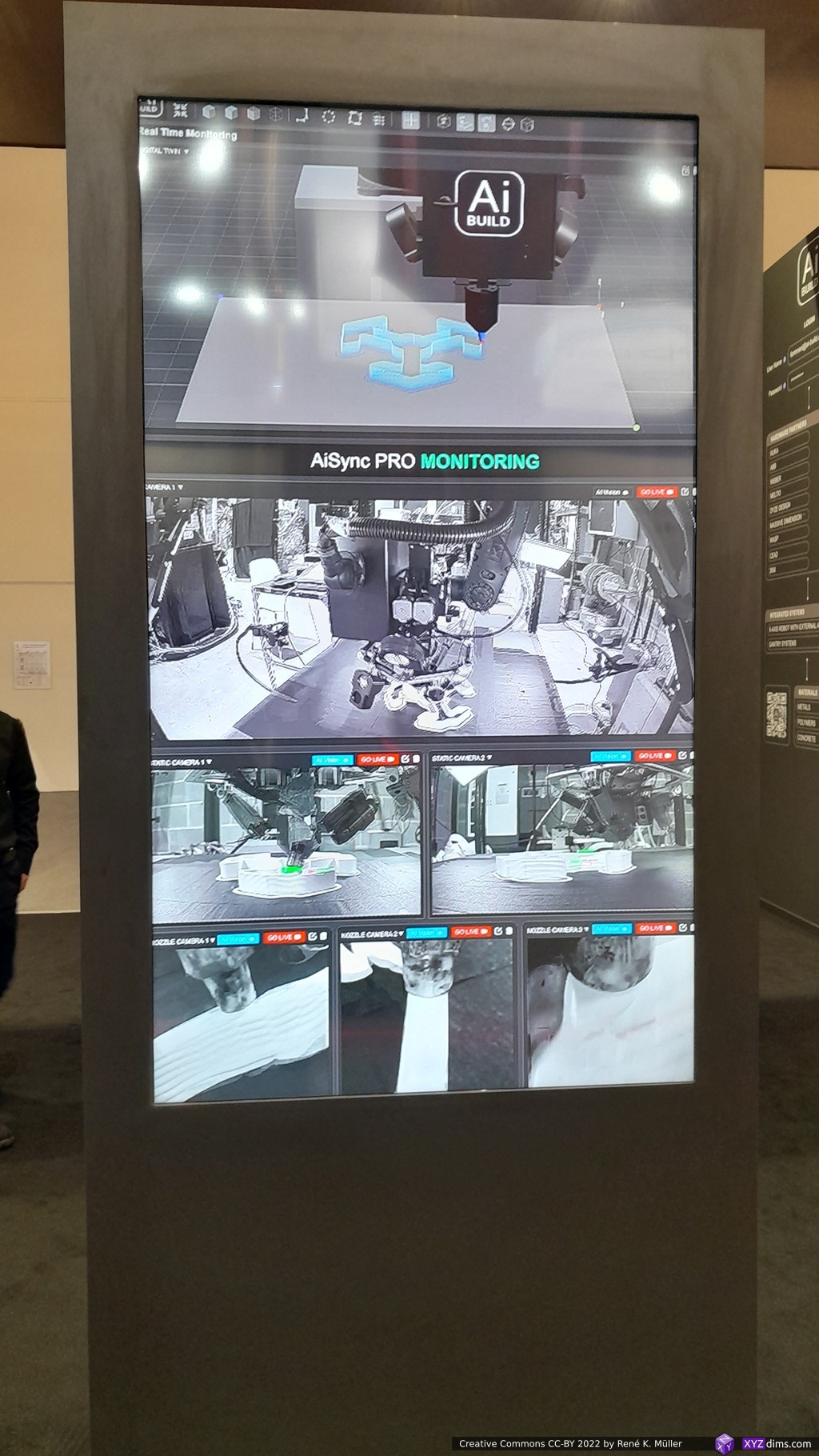
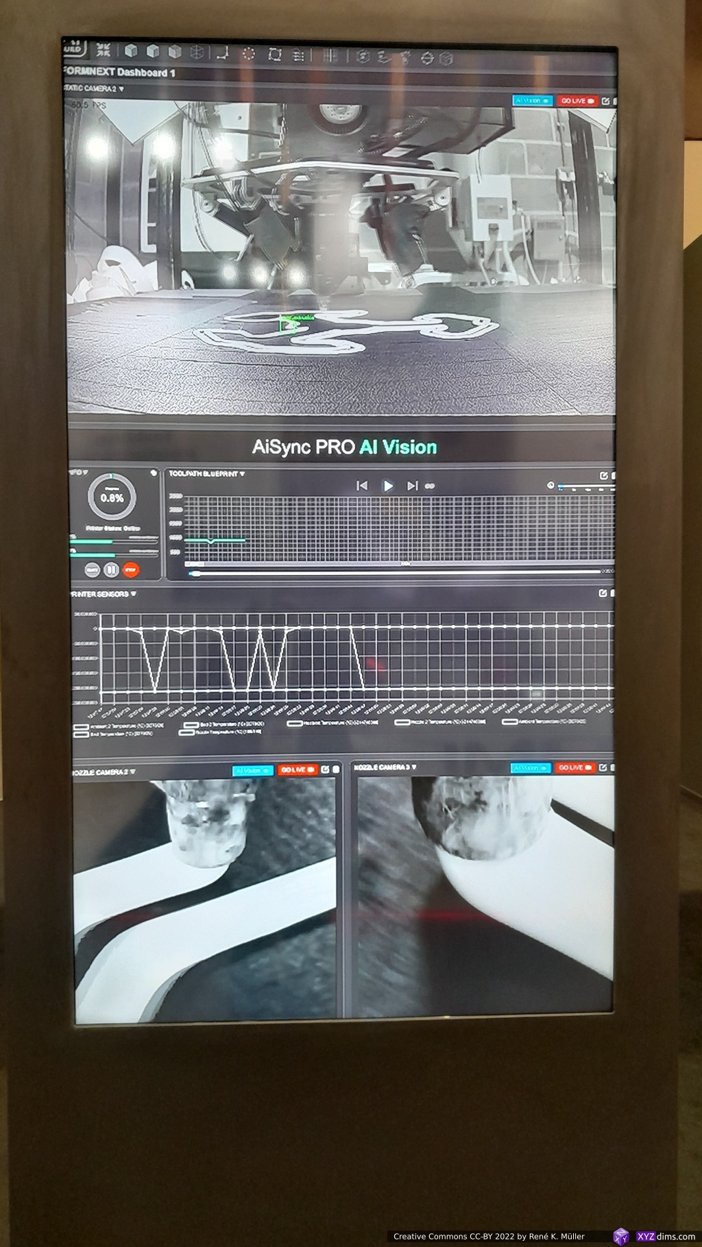
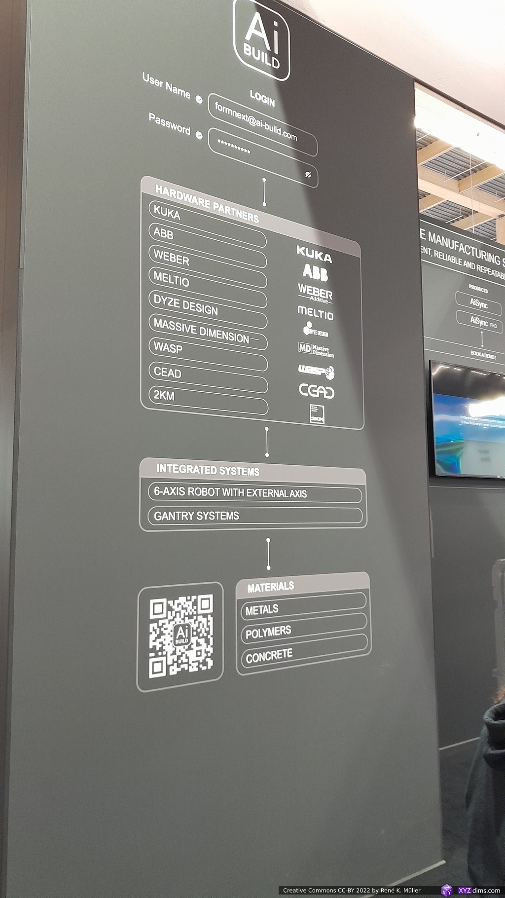
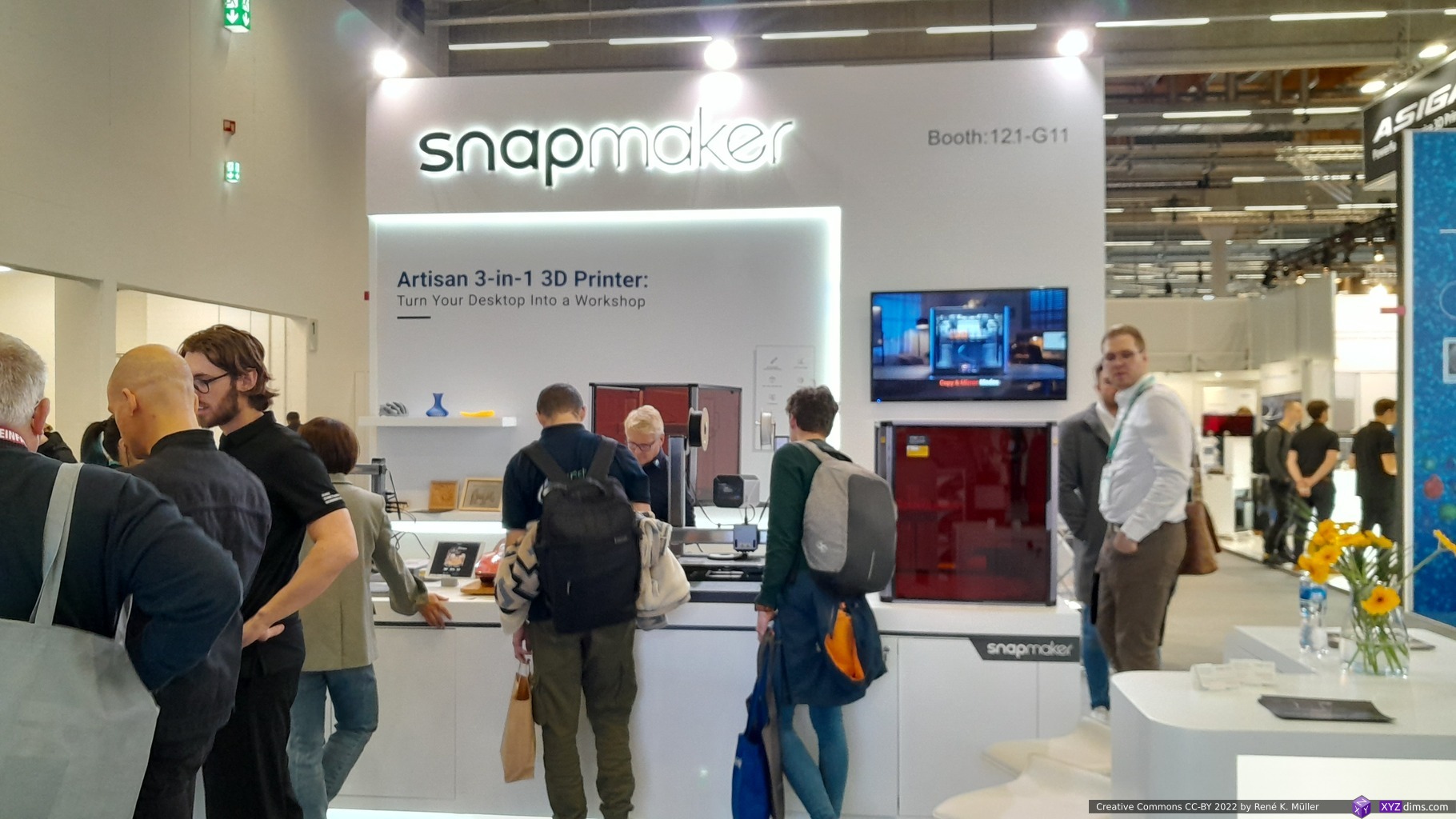
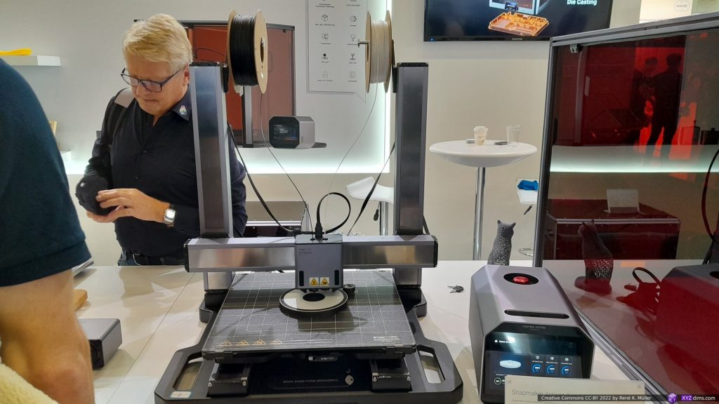
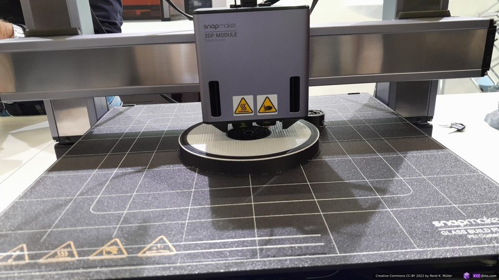
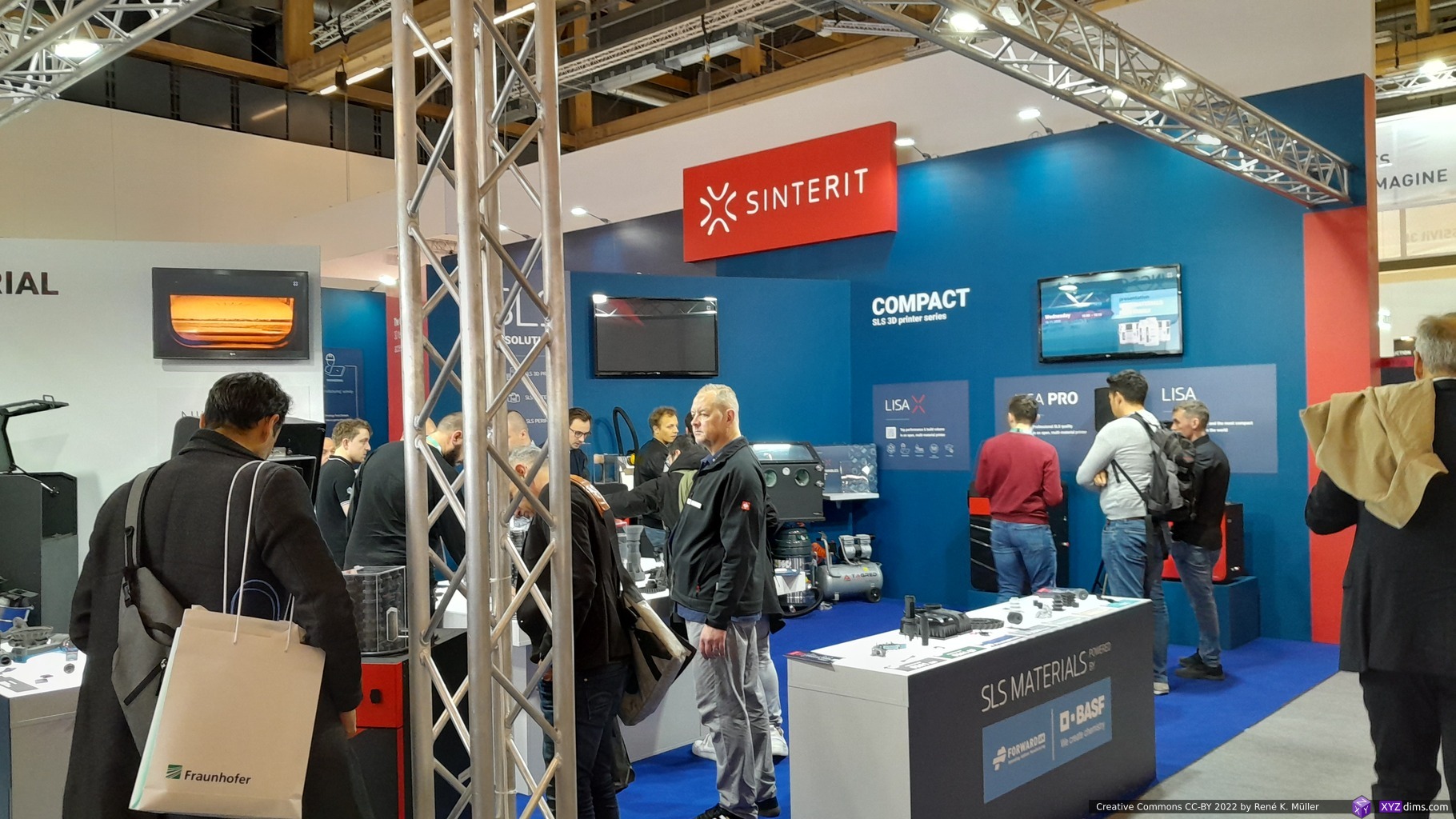
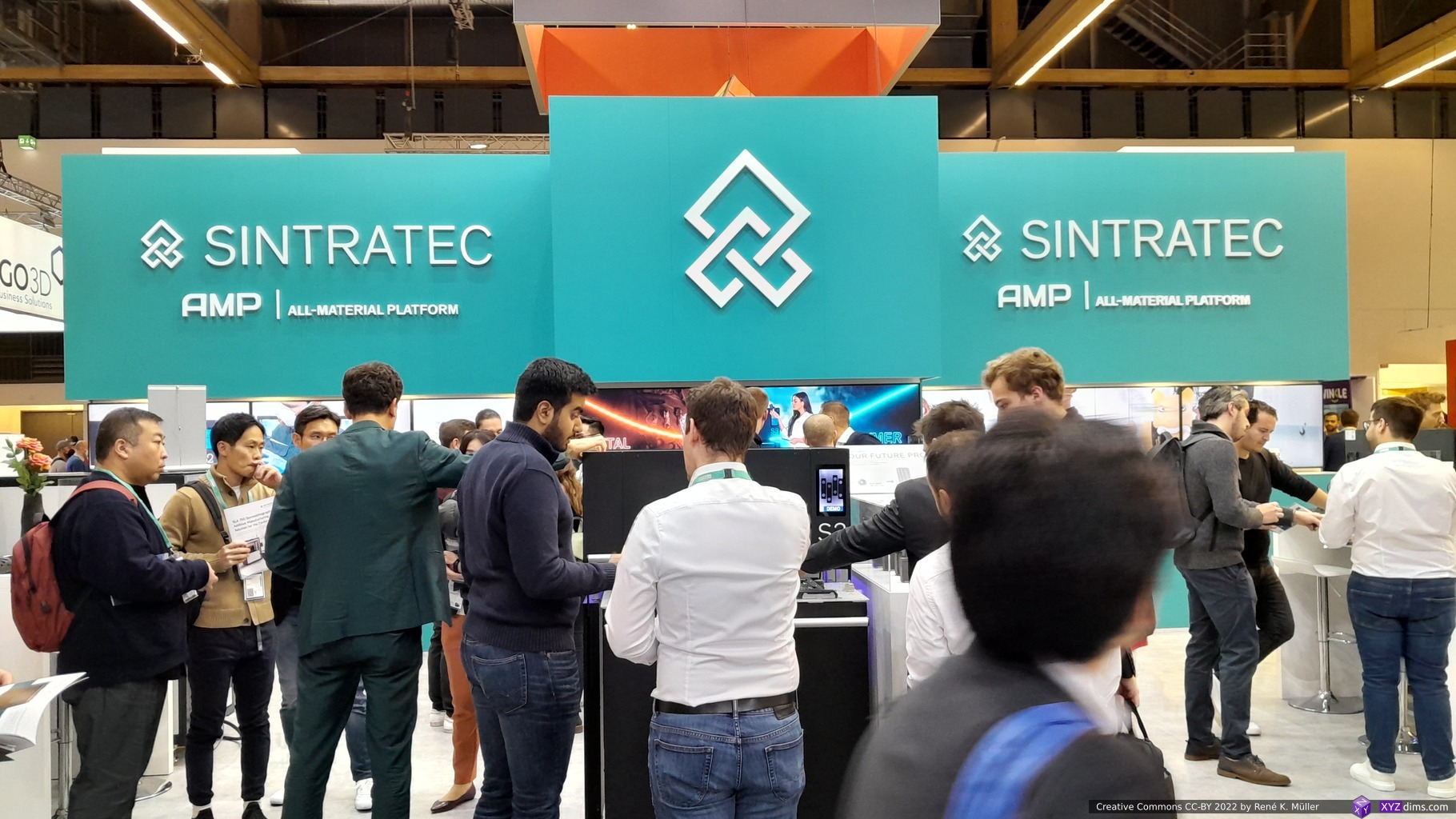
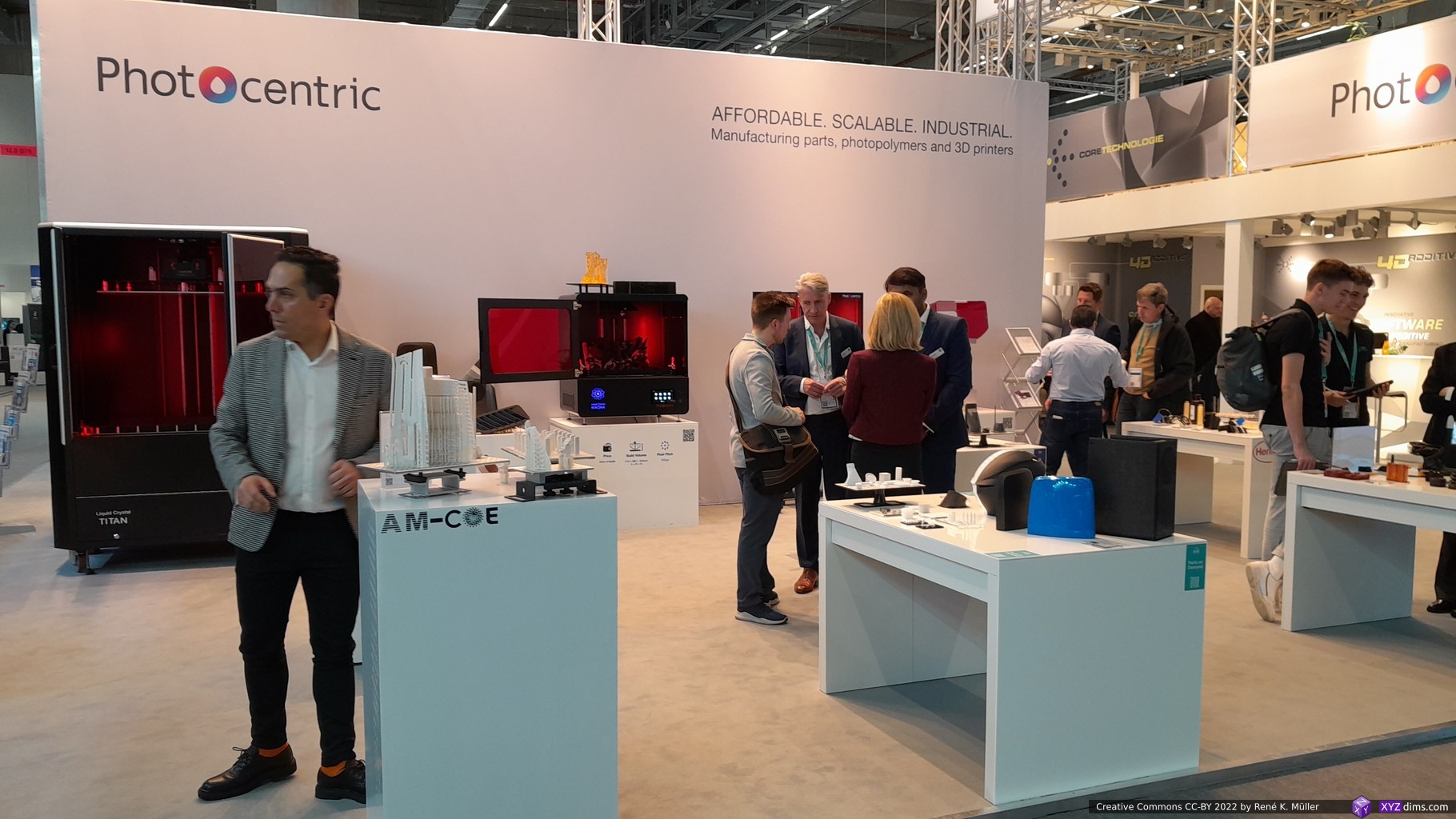
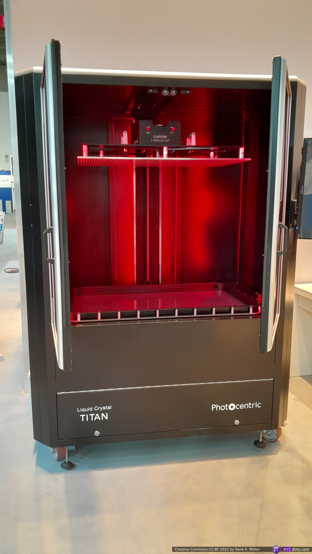
Metafold: samplesStratasys: samplesPhotocentricPhotocentric: samplesPhotocentric: samplesPhotocentric: large scale statueHP: samplesPrusa ResearchPrusa Research Pro seriesSnapmakerSnapmaker with CNC drillSnapmakerSnapmaker: IDEXFormlabsAnisoprintAnisoprintAnisoprintAnisoprintE3DE3D: non-planar / belt printer nozzlesApexMakerApexMaker & PangJi resin printer LCDsSintratec: SLS printersSintratecSintratecNexa3D: SLA & SLS machinesNexa3DAiBuild: multi-axis slicingElegoo: printers, filaments, resinsFormFuturaBambu LabBambu LabDyze Design: water cooled large hotends
running Klipper on it, likely requires expansion board with additional USB ports, not yet tested; ArchLinux repo provides it though
any kind of quick experimental setup when Linux is a requirement, and Raspberry Pi perhaps overkill already, and ESP32 not powerful enough to run Linux*)
*) as of 2023/09 a few people working on Linux for ESP32-S3
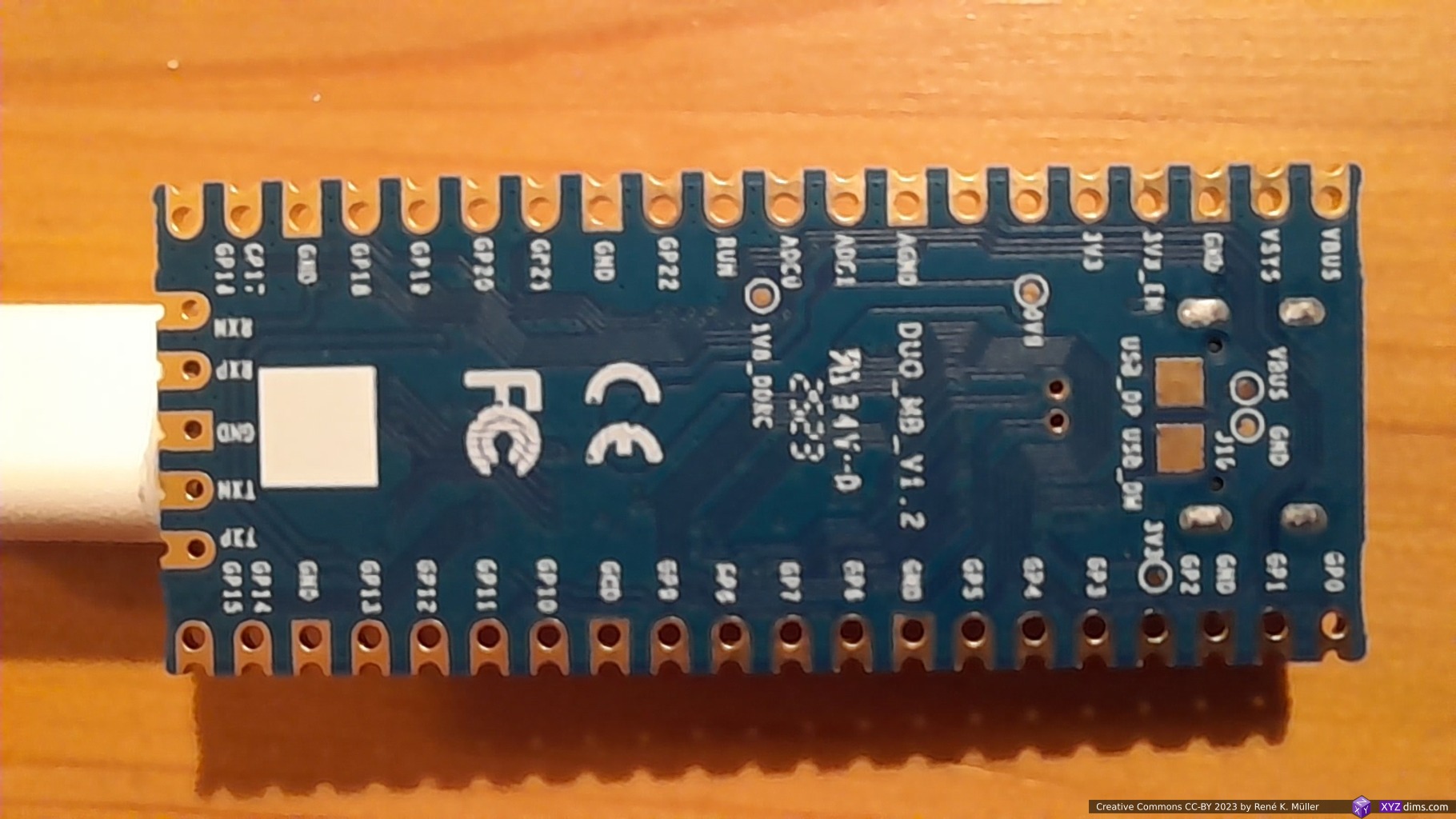
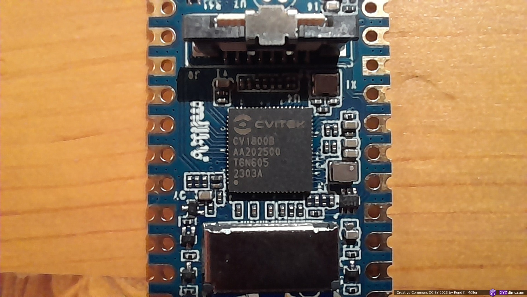
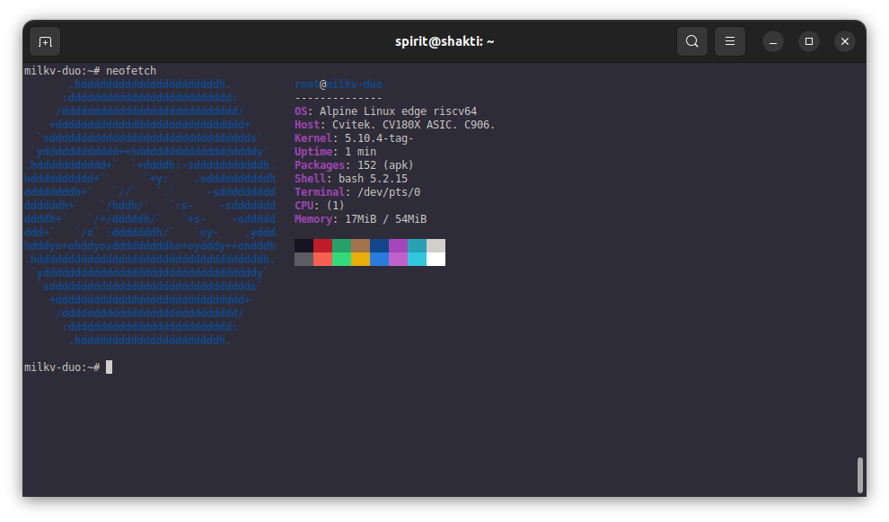
A couple of years ago I used ESP8266 with Lua, and ESP32 with Lua and MicroPython, but the functionality was very limited, although it had WiFi built-in, but barely ran anything more complex or serious – the Milk-V Duo changes this, at the same pricing of USD 5.00-9.00; and I really looking forward to have just a small device running Linux, and competing with Raspberry Pi’s which either hardly were available or sold at 2-3x the announced price.
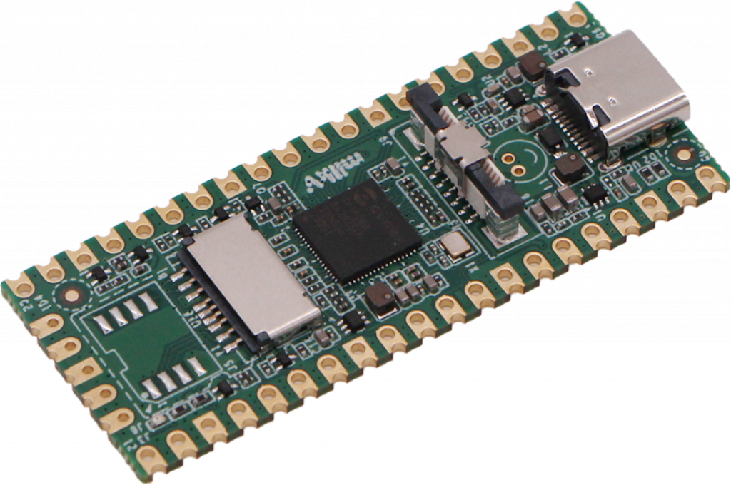
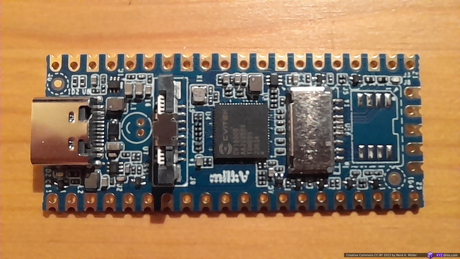
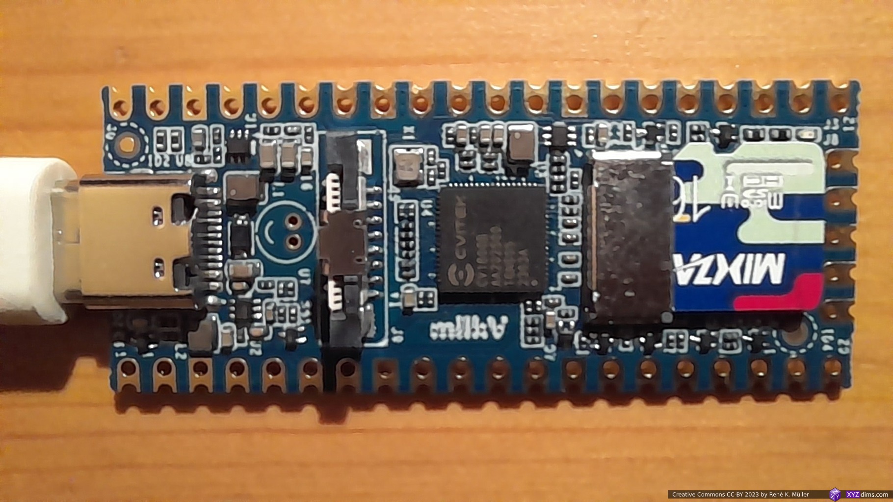
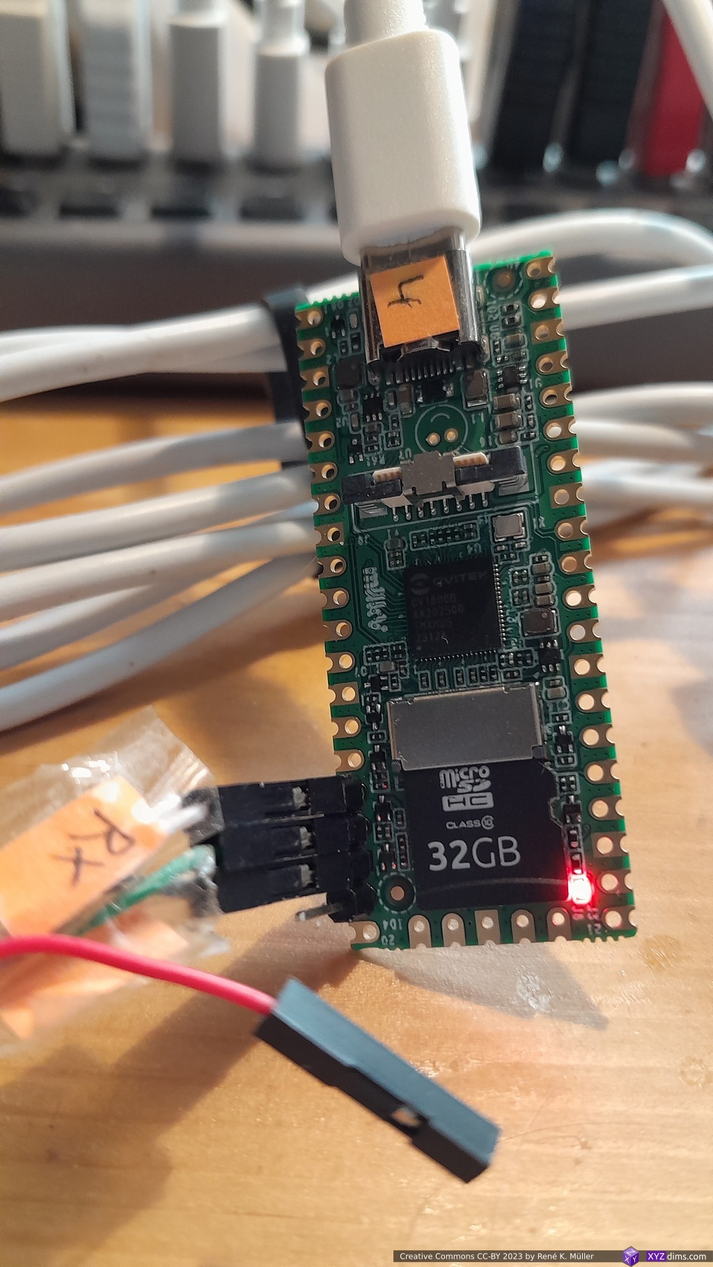
Milk-V Duo 64MB RAM (bare)Milk-V Duo 64MB RAM with USB-C connected and SD cardMilk-V Duo 64MB RAM (backside)Milk-V Duo 64MB RAM, CPI ID: “CVITEK CV1800B AA202500 T6N605 2303A”
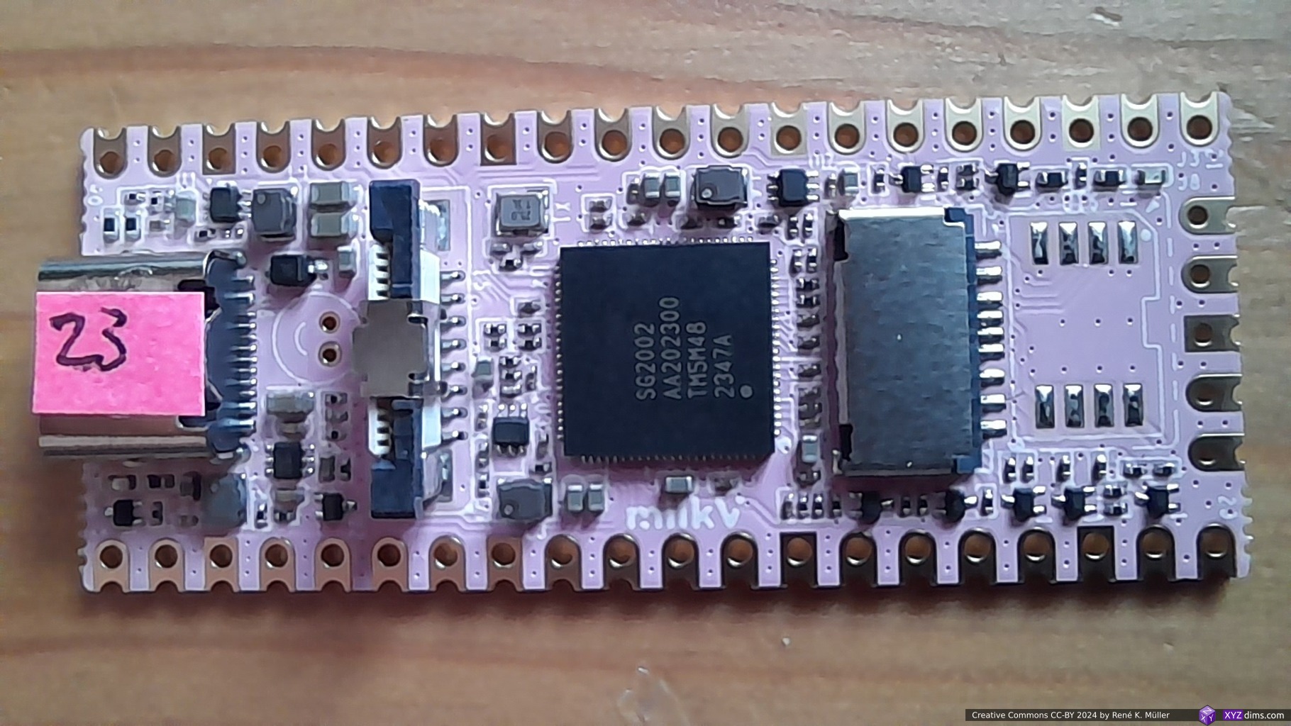
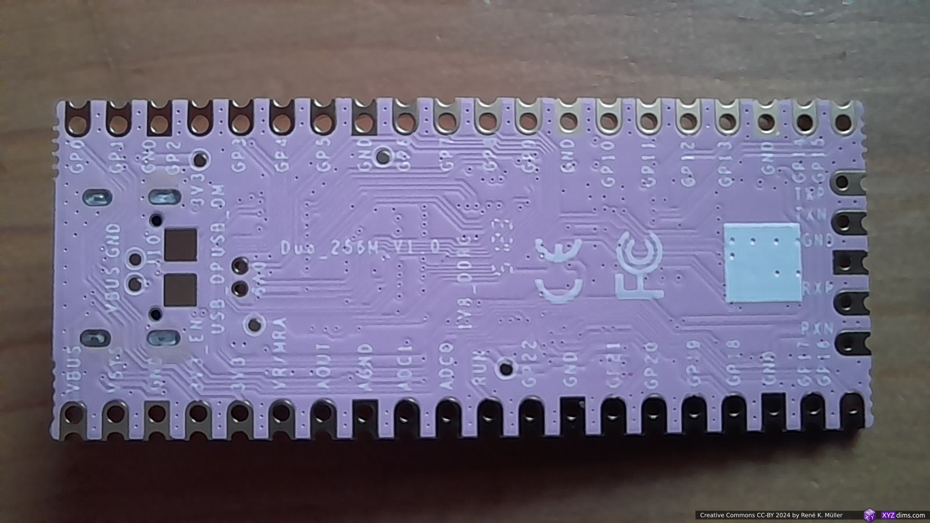
and the newer 256MB RAM variant (released 2023/12):
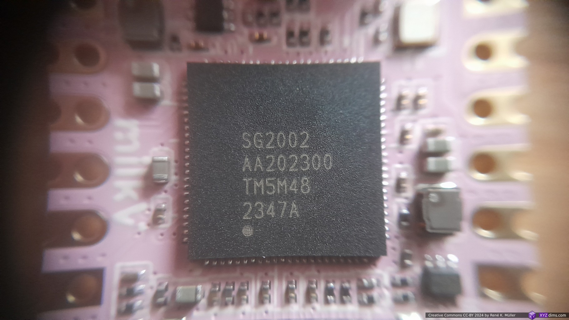
Milk-V Duo 256MB RAM (frontside)Milk-V Duo 256MB RAM (backside)Milk-V Duo 256MB RAM, CPU ID: “SG2002 AA202300 TM5M48 2357A”
Specification & Features have been partially copied from Milkv.io (2023/09 & 2024/02):
– boots, but then fails with systemd (coredump) – no login possible
Linux BuildRoot Disk Image
The BuildRoot is a minimal custom Linux release which is meant for IoT developers who know what they want and need and select the features at building time and then get a disk image which contains then a set of features and applications. It’s not very user friendly, e.g. there is no package manager which allows to add new packages afterwards once the system is running.
Attach a SD card to your host, find out which device it became (Linux):
% lsblk
CAUTION: make sure /dev/sdX (replace X with proper letter) is the SD card and not your other disk(s) as copying the disk image will erase and replace the content of the device you choose with the following command:
then remove SD card from the host*), and insert it to the MilkV-Duo board, and power it on via USB-C.
*) in case you have the wrong /dev/sdX, or write to it if it’s not plugged in, you might struggle to write there again, simply do sudo rm /dev/sdX and then pull out and plugin the SD card again, and you should be able to write again to it.
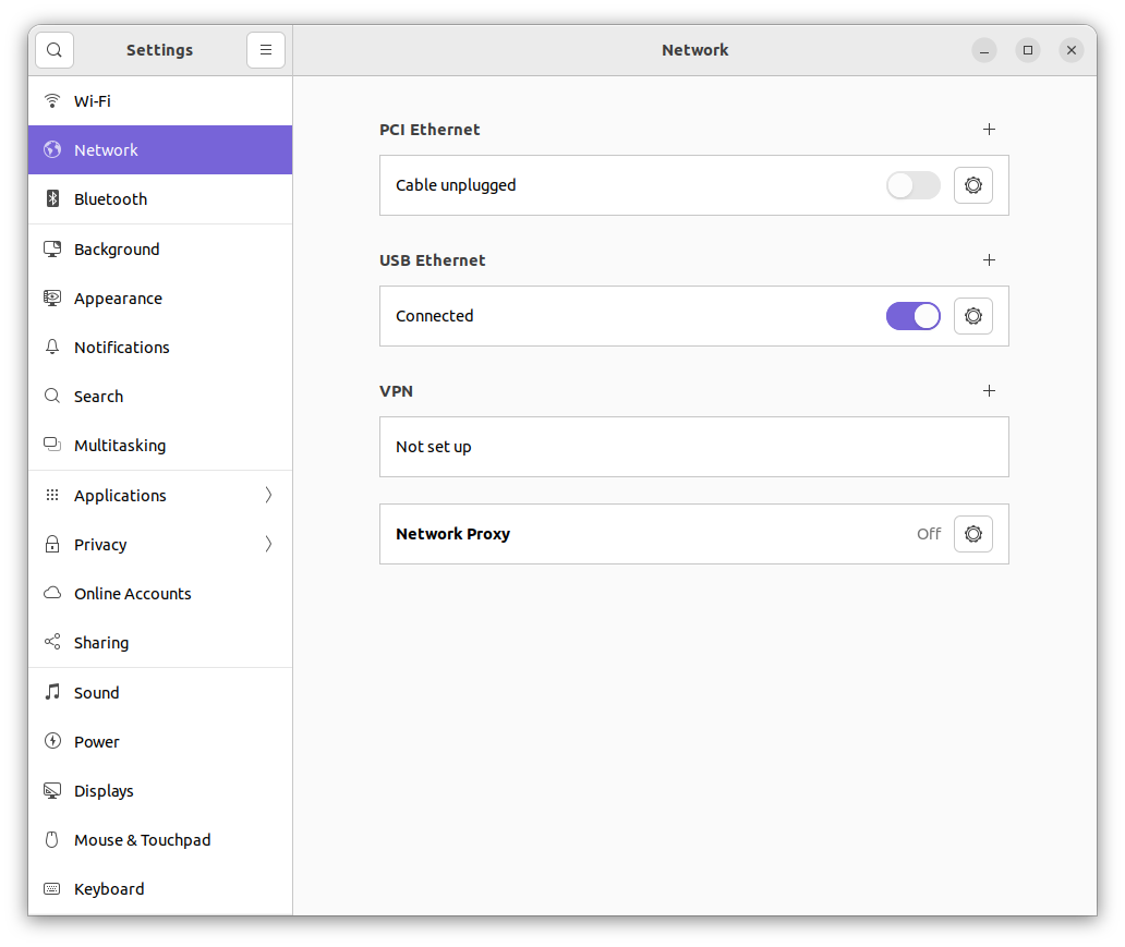
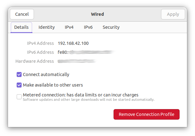
Ubuntu 22.04 LTS Network: automatically starts it USB EthernetThe client sets the network: 192.168.42.0 and the “host” chooses 192.168.42.100 its own IP.
After ~15 seconds you should be able to login with ssh root@192.168.42.1 into your MilkV-Duo with passwd: milkv or you attach a UART to USB bridge like that:
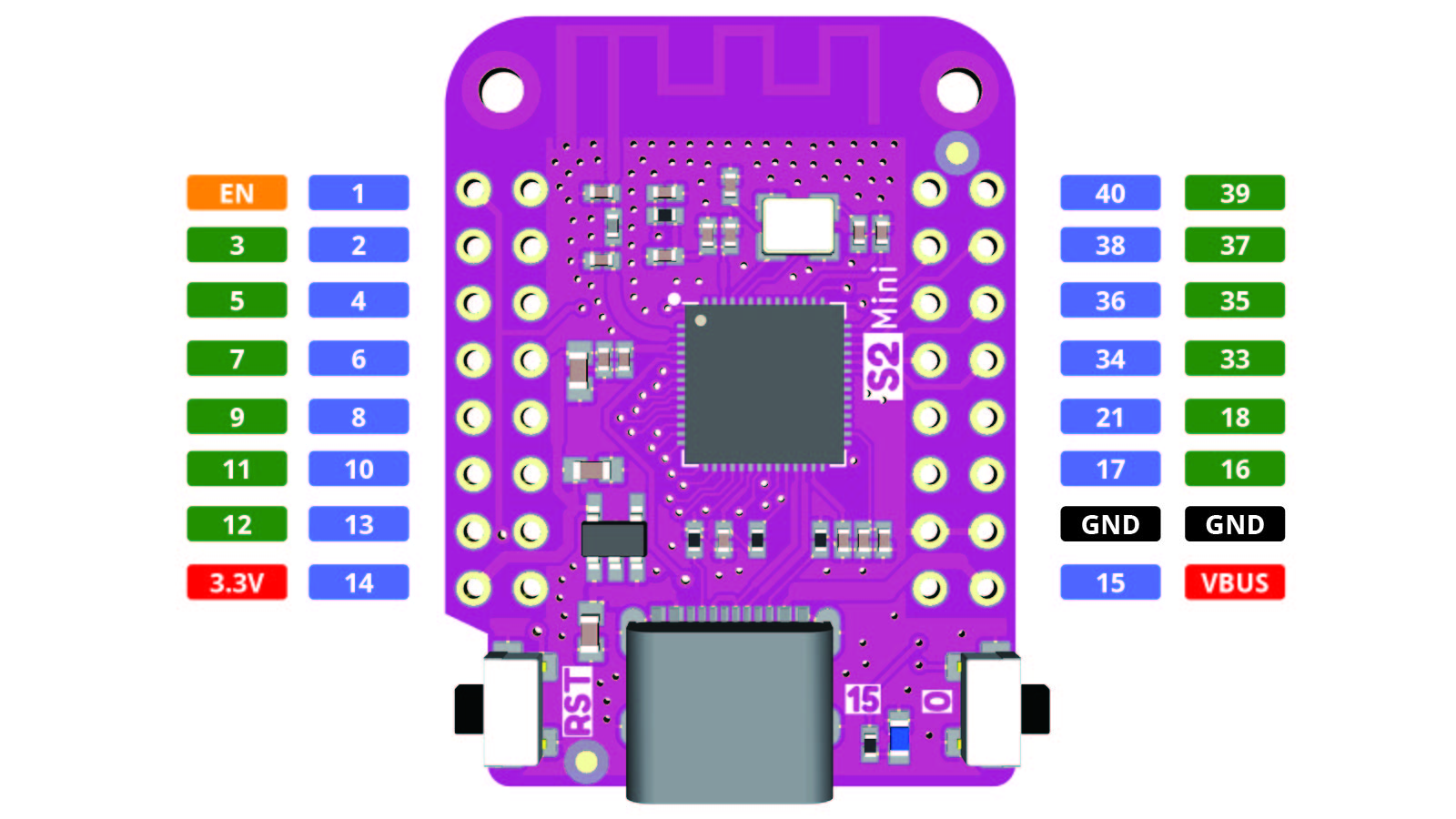
Pin 16/TX: RX/white UART-USB
Pin 17/RX: TX/green UART-USB
Pin 18/GND: GND/black UART-USB
don’t connect 5V/red UART-USB
and use tio /dev/ttyUSB0 (or another number) under Linux to connect via serial port; also useful in case bootup is stuck after doing changes, and ssh isn’t possible anymore.
Note: you won’t need to solder the male connectors, I usually just insert them loosely and the cable bending gives sufficient connectivity for a brief login to fix things and then remove UART-USB cable again.
[root@milkv-duo]~# ls /bin
arch           dmesg          linux64        nuke           sleep
ash            dnsdomainname  ln             pidof          stty
base32         dumpkmap       login          ping           su
base64         echo           ls             pipe_progress  sync
busybox        egrep          lsattr         printenv       tar
cat            false          mk_cmds        ps             touch
chattr         fdflush        mkdir          pwd            true
chgrp          fgrep          mknod          resume         umount
chmod          getopt         mktemp         rm             uname
chown          grep           more           rmdir          usleep
compile_et     gunzip         mount          run-parts      vi
cp             gzip           mountpoint     sed            watch
cpio           hostname       mt             setarch        zcat
date           kill           mv             setpriv
dd             link           netstat        setserial
df             linux32        nice           sh
/usr/bin
[root@milkv-duo]~# ls /usr/bin/
[                  fold               od                 tee
[[                 free               openvt             telnet
ar                 fuser              passwd             test
ascii              gcore              paste              tftp
awk                gdb                patch              time
basename           gdb-add-index      pip                top
bc                 head               pip3               tr
bunzip2            hexdump            pip3.9             traceroute
bzcat              hexedit            printf             truncate
chrt               hostid             pyserial-miniterm  ts
chvt               htop               pyserial-ports     tty
cksum              id                 python             uniq
clear              install            python3            unix2dos
cmp                ipcrm              python3.9          unlink
crc32              ipcs               readlink           unlzma
crontab            killall            realpath           unlzop
cut                last               renice             unxz
cvi_pinmux         less               reset              unzip
dbclient           logger             resize             uptime
dc                 logname            scp                uudecode
deallocvt          lsof               seq                uuencode
diff               lspci              setfattr           vlock
dirname            lsscsi             setkeycodes        w
dos2unix           lsusb              setsid             wc
dropbearconvert    lzcat              sha1sum            wget
dropbearkey        lzma               sha256sum          which
du                 lzopcat            sha3sum            who
easy_install       md5sum             sha512sum          whoami
easy_install-3.9   mesg               shred              xargs
eject              microcom           smtpd.py.9         xmlcatalog
env                mkfifo             sort               xmllint
event_rpcgen.py    mkpasswd           ssh                xmlwf
evtest             nl                 strace             xsltproc
expr               nohup              strace-log-merge   xxd
factor             nproc              strings            xz
fallocate          nslookup           svc                xzcat
find               ntpdate            svok               yes
flock              ntptime            tail

[root@milkv-duo]~# ls -1 /usr/bin/ | wc -l
151
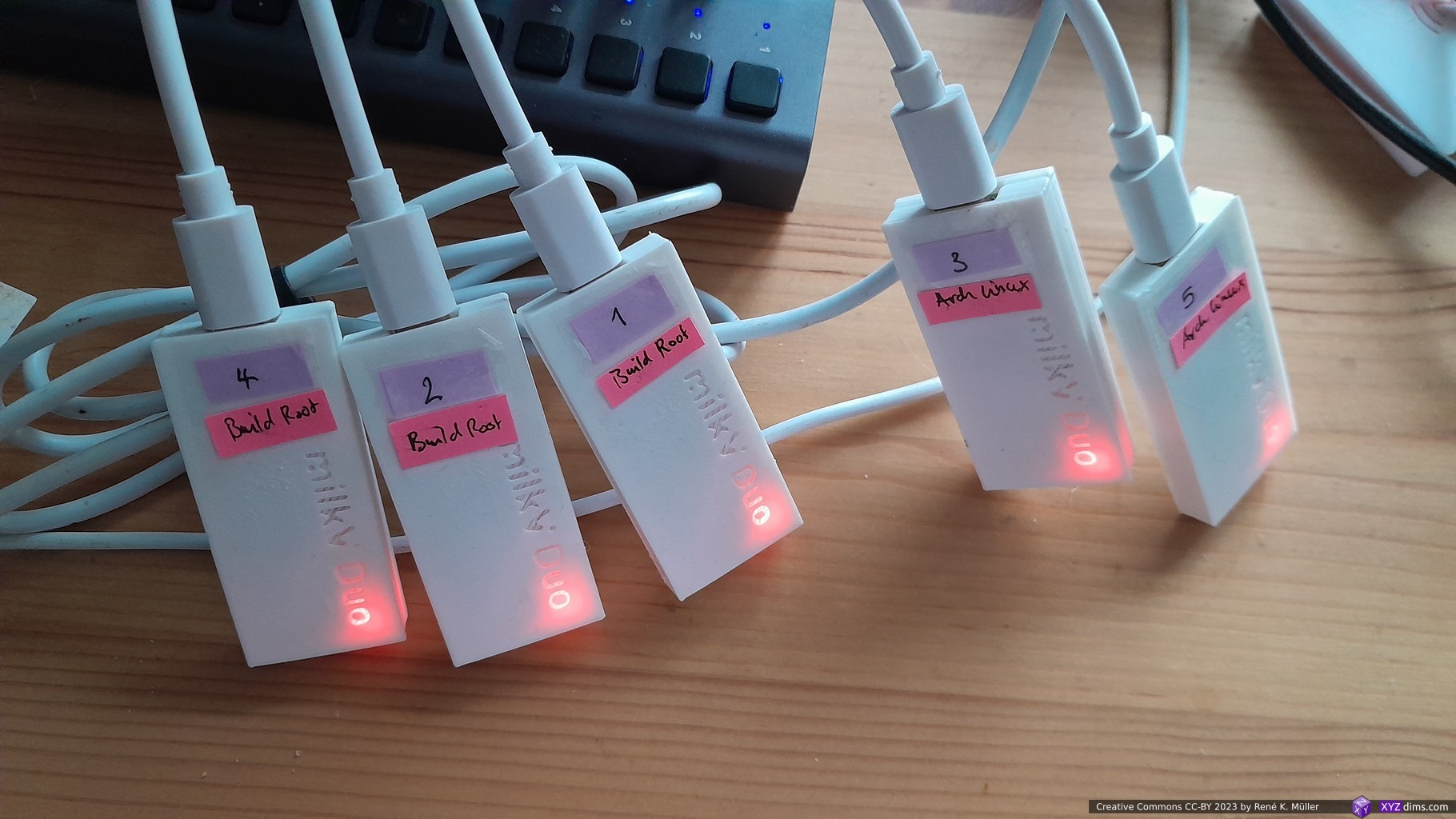
Multiple Milk-V Duos / Alternative IPs
In order to support multiple Milk-V Duos on the same host via USB-C, you assign for each board its own network:
board 1: 192.168.51.0
board 2: 192.168.52.0
board 3: 192.168.53.0
Edit on each board two files:
/mnt/system/usb-rndis.sh (buildroot-based) or /etc/usb-rndis.sh (other systems):
ifconfig usb0 192.168.51.1
/etc/dnsmasq.conf:
dhcp-range=192.168.51.2,192.168.51.242,1h
In order to add a new board, you login into 192.168.42.1 as usual, and change it to the 192.168.52.1 and so on.
Resizing Disk
By default the entire available space of the SD card is only 1GB (or 2GB in case you use another distro), but you can make the rest of the SD card available to /data for example – part of the guide was taken from a post in the forum but updated it:
% mkdir /data
% fdisk /dev/mmcblk0
n (new partition)
p (primary partition)
4
<RETURN> (confirm start selection)
<RETURN> (confirm end selection)
w
q

% reboot
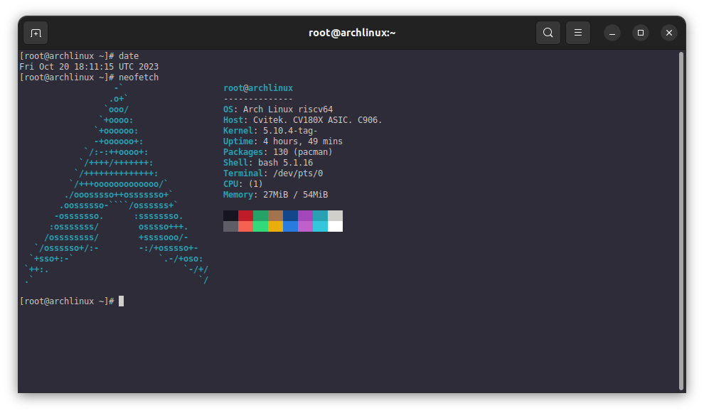
I followed this guide to get ArchLinux working – thanks to Judehahh doing the main work – and added RNDIS support (Virtual Ethernet over USB) and made a disk image to use, the date e.g. “2023-10-09” references the riscv64 rootfs date which was unpacked as a base, the “x.xgb” describes the size of disk or rootfs and “vX.X.X” the actual release version. Unzip downloaded image first before writing on the SD card.
– 240MB RAM (no camera support) – 250MB swap enabled – RNDIS (connect via usb virtual ether) – minimum 8GB SD card – 5.7GBfree in rootfs – persistent MAC addresses for RNDIS (internet routing ready)
For the 256m-version disk image I downloaded the kernel from this thread and just copied boot.sd and fip.bin into the first partition, otherwise no changes toward the milkv-duo disk-image (below) was made
– 55MB RAM (no camera support) – 250MB swap enabled – RNDIS (connect via usb virtual ether) – minimum 8GB SD card – 5.7GBfree in rootfs – persistent MAC addresses for RNDIS (internet routing ready)
– 55MB RAM (no camera support) – 250MB swap enabled – RNDIS (connect via usb virtual ether) – minimum 2GB SD card – 960 apps in /usr/bin/ – only 40MB free in rootfs (!!)
– package management (apk) – rndis / usb network (but random MAC addresses) – rootfs 1GB, 150MB used
– dropbear v2022.83
– use apk [add|update] –no-check-certificate
For the 256m-version disk image I downloaded the kernel from this thread and just copied boot.sd and fip.bin into the first partition, otherwise no changes toward the milkv-duo disk-image (below) was made.
– package management (apk) – rndis / usb network (but random MAC addresses) – rootfs 1GB, 150MB used
– dropbear v2022.83
– use apk [add|update] –no-check-certificate
Notes:
use apk [add|update] --no-check-certificate to install new packages, otherwise installs or update fail
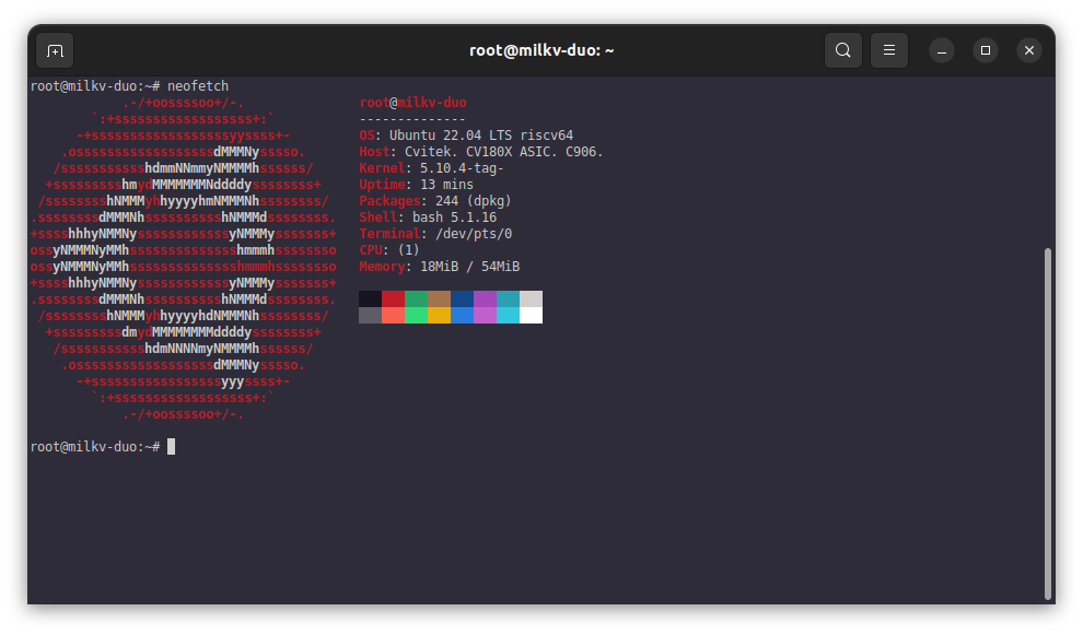
Ubuntu Disk Image
I followed this guide (see discussion thread as well) – thanks to Bassusteur – and added RNDIS related services so you can login with ssh root@192.168.42.1 (passwd milkv) via virtual Ethernet over USB; unzip disk image before you write on the SD card.
Notes:
apt / apt-get are awfully slow on Milk-V Duo at step “Building dependency tree...“, takes 4+mins for each apt install call as apt requires 50+MB RAM to build that dependency tree, which goes hard on all available RAM + swap
these are very experimental disk images
Note: milkv-duo (64MB RAM) vs milkv-duo-256m (256MB RAM)
– 240MB RAM (no camera support) – RNDIS (connect via usb virtual ether) – persistent MAC addresses for RNDIS (internet routing ready) – apt works now smoothly – minimum 8GB SD card – 6.0GBfree in rootfs
– dropbear (v2020.81) – python 3.10.12
For the 256m-version disk image I downloaded the kernel from this thread and just copied boot.sd and fip.bin into the first partition, otherwise no changes toward the milkv-duo disk-image (below) was made.
– 55MB RAM (no camera support) – 250MB swap enabled – RNDIS (connect via usb virtual ether) – persistent MAC addresses for RNDIS (internet routing ready) – minimum 8GB SD card – 6.0GBfree in rootfs
– dropbear (v2020.81) – python 3.10.12 – zram enabled in kernel, and works now, but apt still very slow
– 55MB RAM (no camera support) – 250MB swap enabled – RNDIS (connect via usb virtual ether) – persistent MAC addresses for RNDIS (internet routing ready) – minimum 8GB SD card – 6.0GBfree in rootfs
– dropbear (v2020.81) – python 3.10.12 – zram not enabled in kernel yet
– 55MB RAM (no camera support) – 250MB swap enabled – RNDIS (connect via usb virtual ether) – persistent MAC addresses for RNDIS (internet routing ready) – minimum 8GB SD card – 6.0GBfree in rootfs
disabled systemd-resolved service due clash with dnsmasq
added /etc/resolv.conf.tail with default DNS servers
installed dropbear (lightweight sshd), removed the auto generated keys, added in /etc/default/dropbear the -R switch so new keys are generated at first boot
Tips & Examples
Most of the examples relate to the Duo BuildRoot SDK setup, but should be easily adaptable to ArchLinux or other distros.
blink.py with sysfs GPIO
There is a way to control GPIO via sysfs with Python:
import time

import gpio as GPIO

pin = 440
GPIO.setup(pin, GPIO.OUT)

while True:
    GPIO.output(pin, GPIO.HIGH)
    time.sleep(1.0)
    GPIO.output(pin, GPIO.LOW)
    time.sleep(1.0)
and run it:
% python blink.py
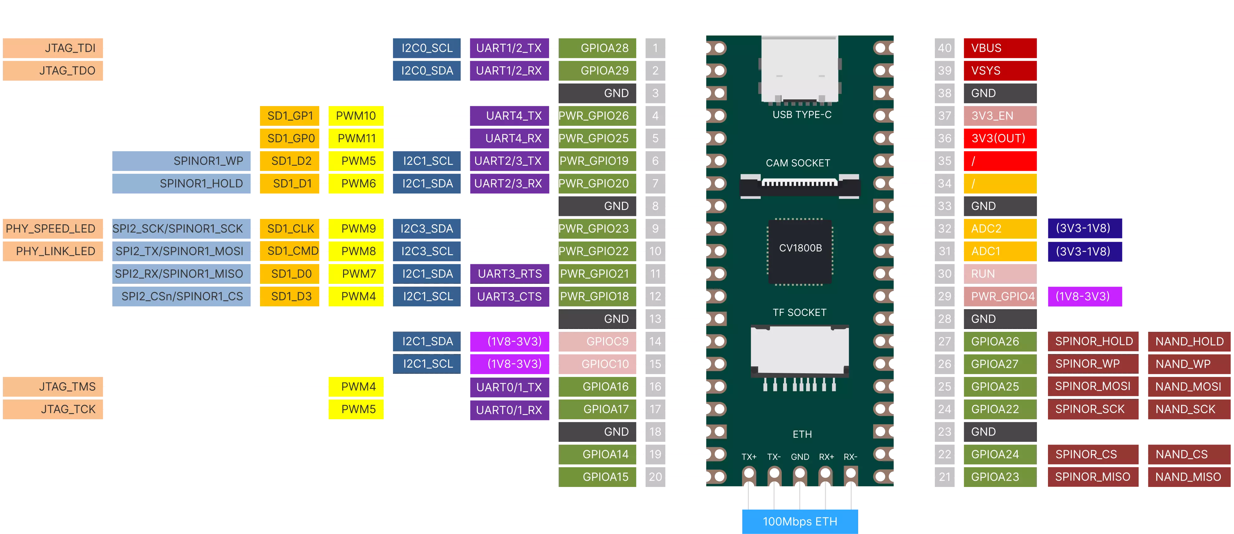
See this table for GPIO names, pins and numbers, a copy (2023/10/10):
GPIO NAME
GPIO PIN
GPIO Number
Notes
GPIOA14
19
494
GPIOA15
20
495
GPIOA16
16
496
GPIOA17
17
497
GPIOA22
24
502
GPIOA23
21
503
GPIOA24
22
504
GPIOA25
25
505
GPIOA26
27
506
GPIOA27
26
507
GPIOA28
1
508
GPIOA29
2
509
GPIOC9
14
425
1.8V
GPIOC10
15
426
1.8V
PWR_GPIO4
29
356
1.8V
PWR_GPIO18
12
370
PWR_GPIO19
6
371
PWR_GPIO20
7
372
PWR_GPIO21
11
373
PWR_GPIO22
10
374
PWR_GPIO23
9
375
PWR_GPIO25
5
377
PWR_GPIO26
4
378
Pinpong
Follow the guide to install pinpong.zip (my mirror), only for V1.0.4 system image, and then:
blink2.py
import time
from pinpong.board import Board,Pin

Board("MILKV-DUO").begin()

led = Pin(Pin.D0, Pin.OUT)

while True:
  led.value(1)
  time.sleep(1)
  led.value(0)
  time.sleep(1)
The pinpong library covers quite a lot of functionality, and useful examples:
According this post, tinycc has been ported as well – C compiler and C interpreter in one – download the .zip (my mirror) and run its install.sh, and then fix missing executable bit:
lua (5.4.6): segmentation fault, luac (5.4.6): seems to work (both compiled with tinycc)
lua & luac (5.3.6) works
lua & luac (5.4.6) works
extras
quickjs/qjs, micropython, nano, screen, git, make (no gcc/cc, use tinycc), thttpd, nginx, lighttpd, php-cgi, file, which, sudo
pacman (package mgr), lighttpd, file, which, sudo, make
Internet Access for Milk-V Duo
RNDIS (Virtual Ethernet over USB)
The host has to run Ethernet over USB and also operate as transparent router and let the connected board(s) reach the internet, see this guide (use google translate to english), here the brief description:
On The Host
The outgoing_if is the outgoing interface, either eth0 or wpl0s0 or something, check with ifconfig of the proper name, and then as root perform:
Also, find out which IP your host got (ip_of_host) from the connected board, e.g. 192.168.42.120, also check with ifconfig.
On The Board
% ip r add default viaip_of_host
% echo "nameserver 8.8.8.8" >> /etc/resolv.conf
Static IP for Host with RNDIS
What may look simple actually isn’t that easy as RNDIS itself is the culprit:
one can limit the IP range in dnsmasq.conf to from/to be the same IP, but
as RNDIS assigns random MAC addresses to the RNDIS host (the board) and the RNDIS client (the host the board is connected to) treat it as new device at every boot – if you force it to have the same IP again, the host will not get a new IP via DHCP as it has the IP remembered for another MAC address . . .
it’s a mess
So, a working solution is:
/etc/rndis-macs.sh which generates two random MAC addresses but keeps them persistent then:
#!/bin/bash

RNDIS_USB="/tmp/usb/usb_gadget/cvitek/functions/rndis.usb0"
MAC_FILE="/etc/rndis-macs.conf"

generate_random_mac() {
    printf "02:%02x:%02x:%02x:%02x:%02x\n" $((RANDOM%256)) $((RANDOM%256)) $((RANDOM%256)) $((RANDOM%256)) $((RANDOM%256))
}

# check if the MAC address file exists and has exactly two lines
if [[ -f "$MAC_FILE" ]] && [[ $(wc -l < "$MAC_FILE") -eq 2 ]]; then
    # read the two MAC addresses from the file
    IFS=$'\n' read -d '' -r -a macs < "$MAC_FILE"
    dev="${macs[0]}"
    host="${macs[1]}"
    echo "using existing MAC addresses:"
else
    # generate two new MAC addresses and store them in the file
    echo "generating new MAC addresses:"
    dev=$(generate_random_mac)
    host=$(generate_random_mac)
    echo "$dev" > "$MAC_FILE"
    echo "$host" >> "$MAC_FILE"
fi
echo "dev_addr: $dev"
echo "host_addr: $host"
echo "$dev" > "$RNDIS_USB"/dev_addr
echo "$host" > "$RNDIS_USB"/host_addr
/etc/usb-rndis.sh:
/etc/uhubon.sh device >> /tmp/rndis.log 2>&1
/etc/run_usb.sh probe rndis >> /tmp/rndis.log 2>&1
/etc/rndis-macs.sh >> /tmp/rndis.log 2>&1
/etc/run_usb.sh start rndis >> /tmp/rndis.log 2>&1
sleep 0.5
ip link set dev usb0 up
ip a add 192.168.42.1/24 dev usb0
ip r add default via 192.168.42.2
sleep 0.5
systemctl start dnsmasq
Note: if you had 192.168.42.2 once assigned to the host, choose another “static” IP in your range, as your host has remembered the IP to a particular MAC address and won’t accept it again, e.g. 192.168.42.200 or so.
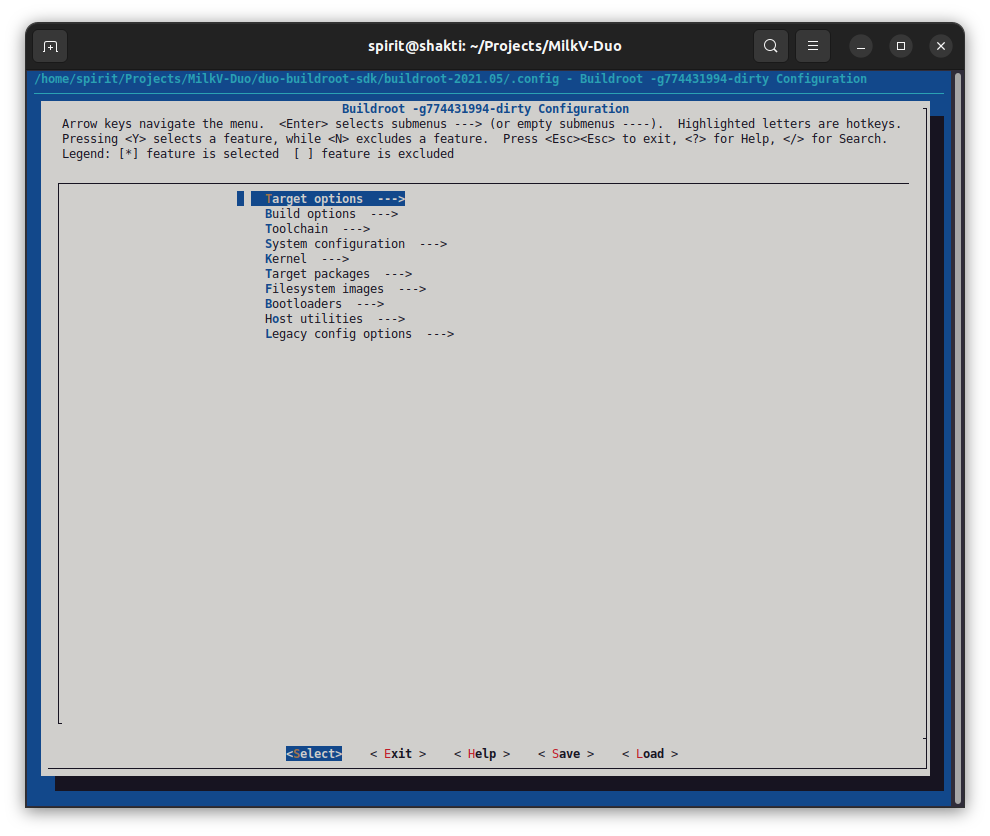
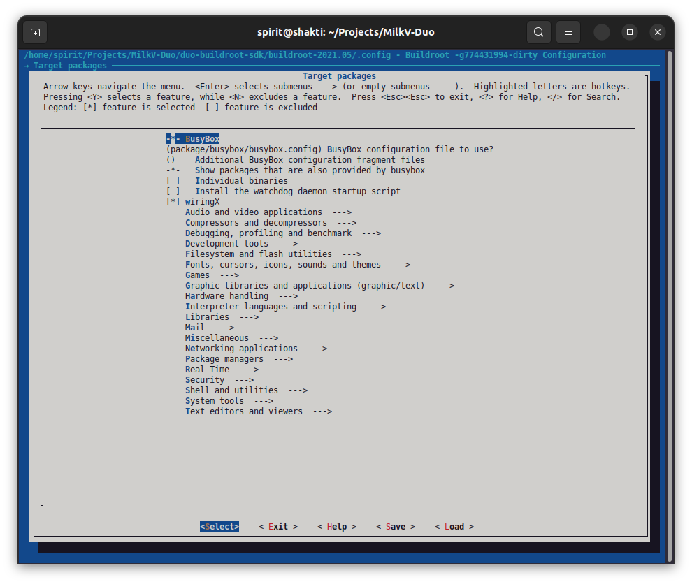
Here my brief guide – see also this guide (use google translate) – how to customize packages included in the base distribution of the image for the SD card:
% cd duo-buildroot-sdk/buildroot-2021.05% make menuconfig
then go into the “Target packages”, and then walk through:
Audio and video applications
Compressors and decompressors
Debugging, profiling and benchmark
Development tools
Filesystem and flash utilities
Fonts, cursors, icons, sounds and themes
Games
Graphic libraries and applications (graphic/text)
Hardware handling
Interpreter languages and scripting
Libraries
Mail
Miscellaneous
Networking applications
Package managers
Real-Time
Security
Shell and utilities
System tools
Text editors and viewers
once you selected the packages you like to have included, choose “Save” and confirm as ‘.config’ and then “Exit”.
% cp .configconfigs/milkv_duo_musl_riscv64_defconfig
% cd ..
% ./build_milkv.sh
and after while, depending on how many packages you selected, you find in out/ folder your new disk image you can copy on the SD card.
Note: buildroot is quite a quirky package, e.g. when you select a package and make a build, later deselect a package, it will still be included – worse, if you commit a clean slate in output/, some packages might not fully build anymore – you have to go back to an earlier state of fewer packages, remake the build, and restart re-selecting new packages.
Postfixing missing .so file
As of 2023/10 v1.0.4 buildroot-2021.05 environment, there seems a problem regarding a missing shared library for some of the compiled apps (like qjs), you can fix this:
% cd /lib
% ln -s ld-musl-riscv64v0p7_xthead.so.1 ld-musl-riscv64.so.1
– lua, quickjs/qjs, micropython, nano, screen, git, make (no gcc/cc, use tinycc), thttpd2), nginx, lighttpd, php-cgi – 55MB RAM1) available – “fixed” image has .so lib-fix included
– lua, quickjs/qjs, micropython, nano, screen, git, make (no gcc/cc, use tinycc), lighttpd (doesn’t work yet out of the box) – 55MB RAM1) available
apprx. 55MB actual available RAM, no camera support, INO_SIZE=0
thttpd, nginx and lighttpd are all http-server, only use one, see /etc/init.d/ where those are started.
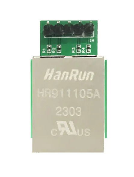
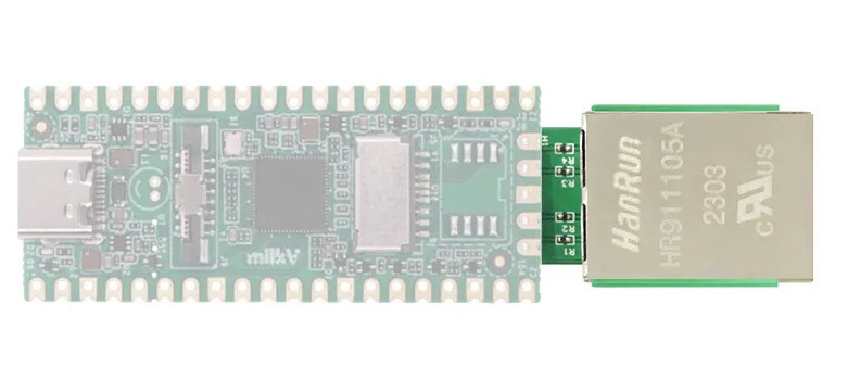
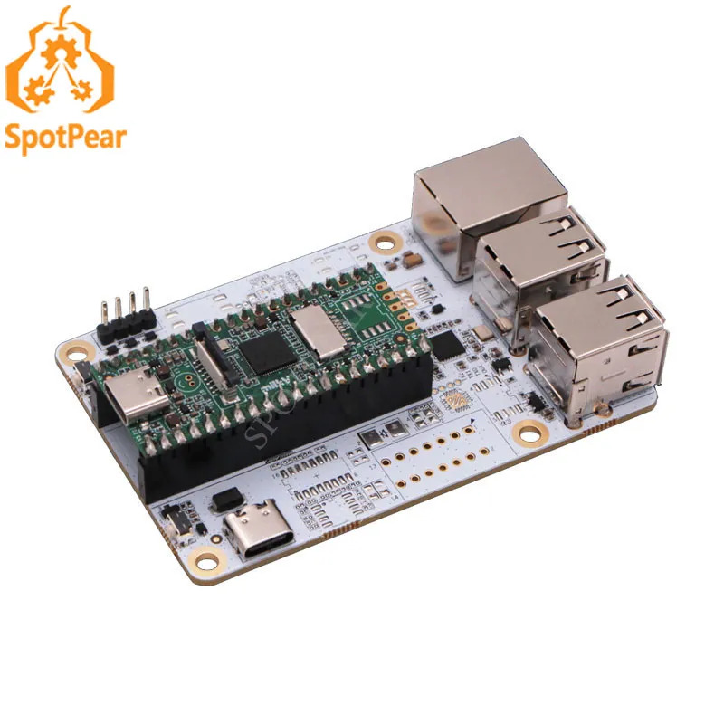
Ethernet Add-On
The easier way is to get proper networking is to add a real ethernet port and properly wire it to the ethernet router. There are several options & sources (2023/09):
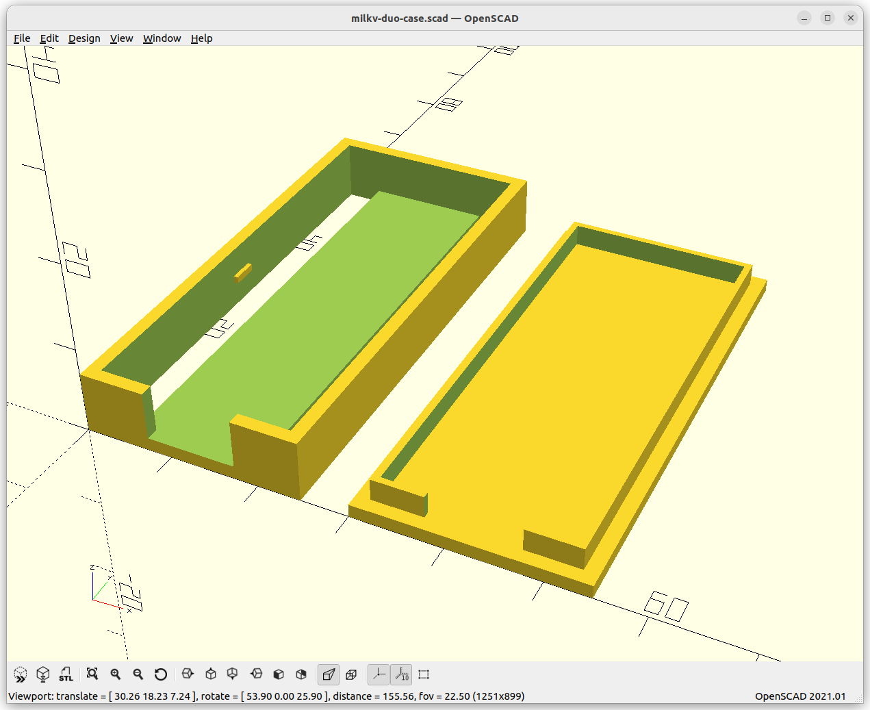
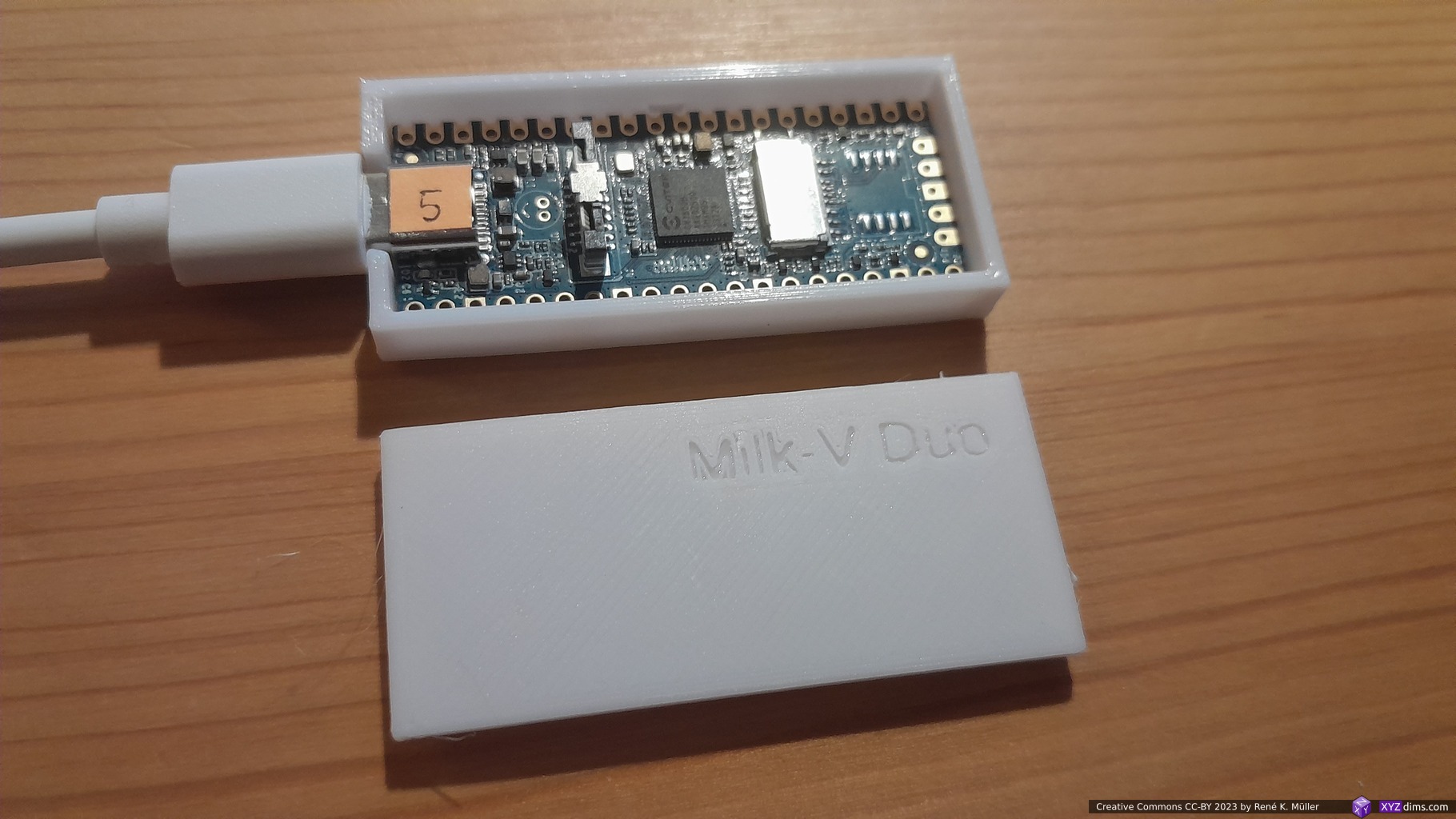
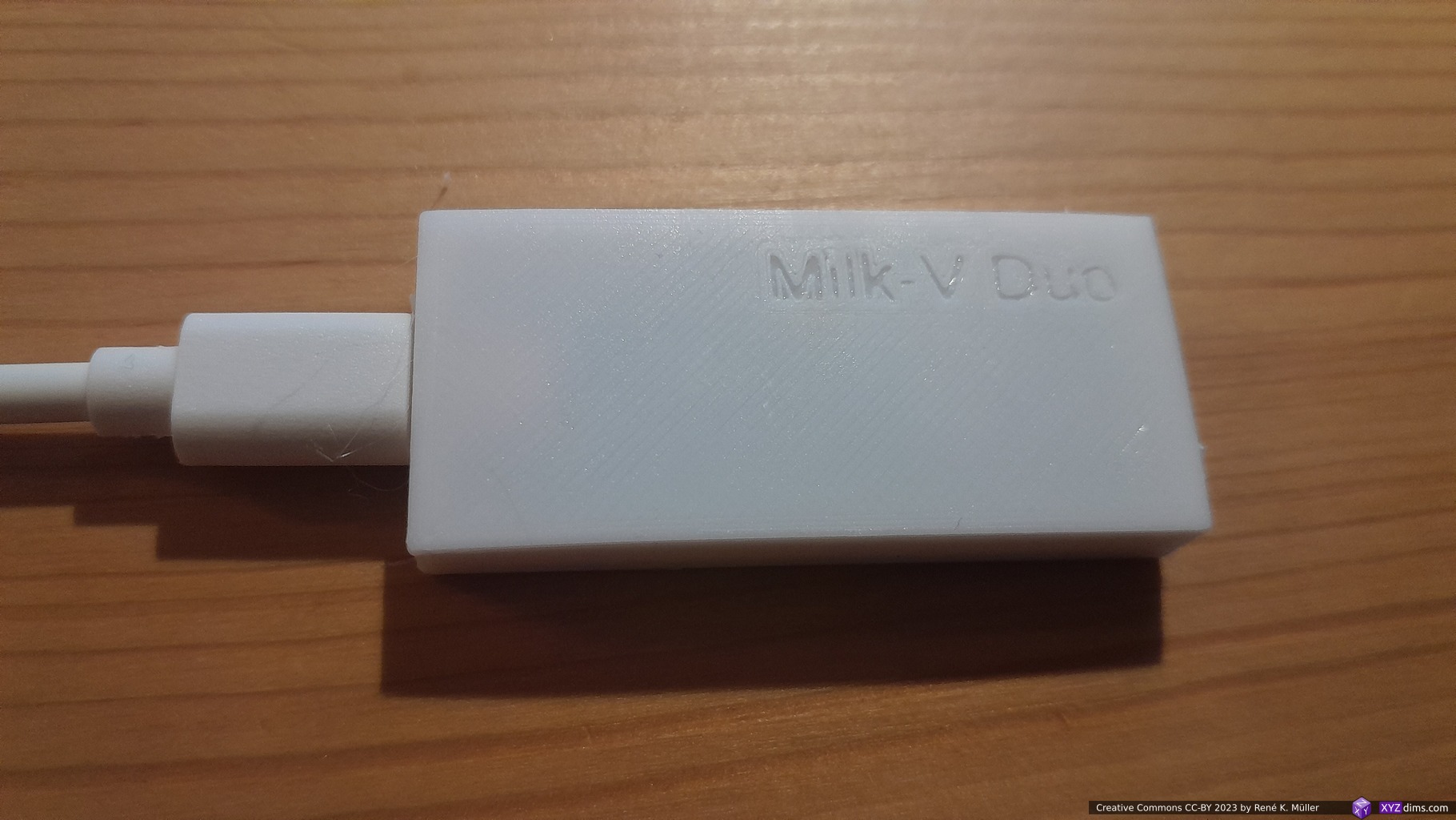
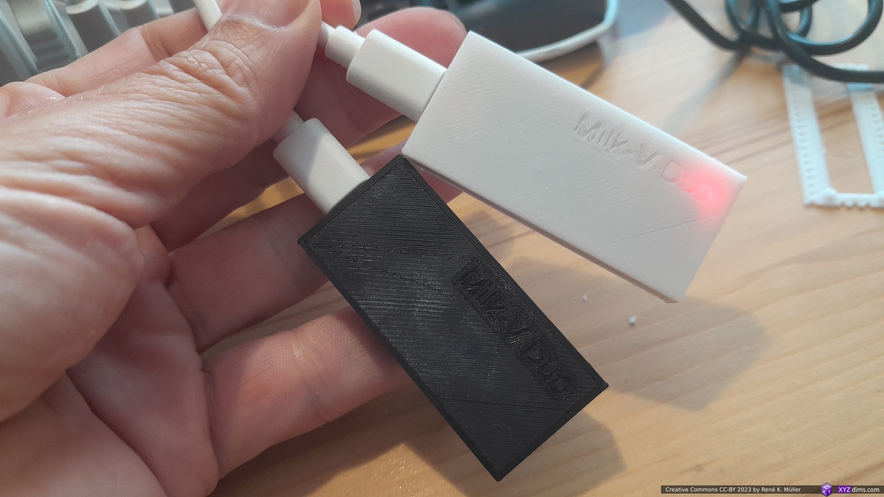
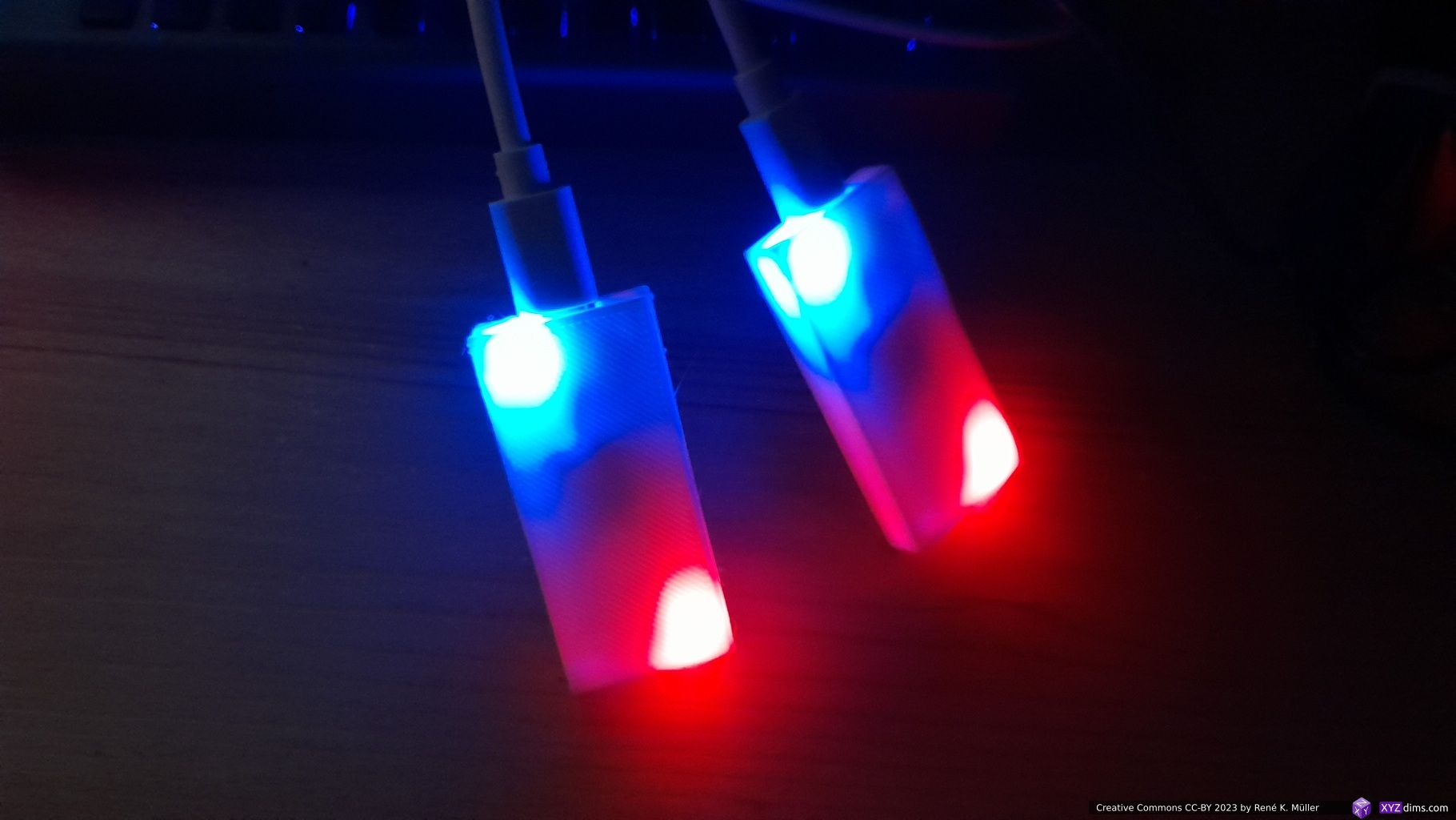
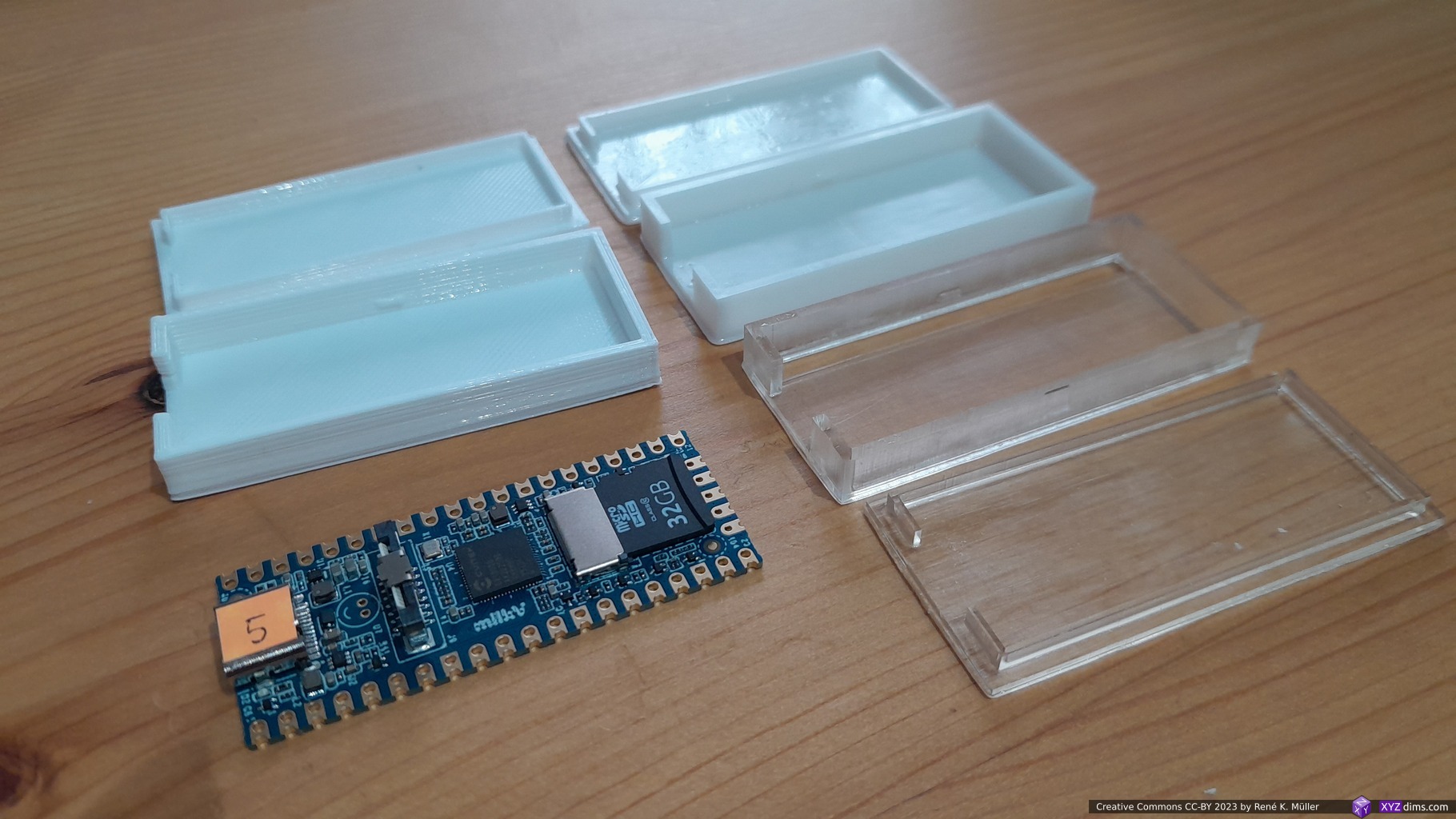
I did a small case for the bare board without Ethernet or Extension board to be 3D printed:
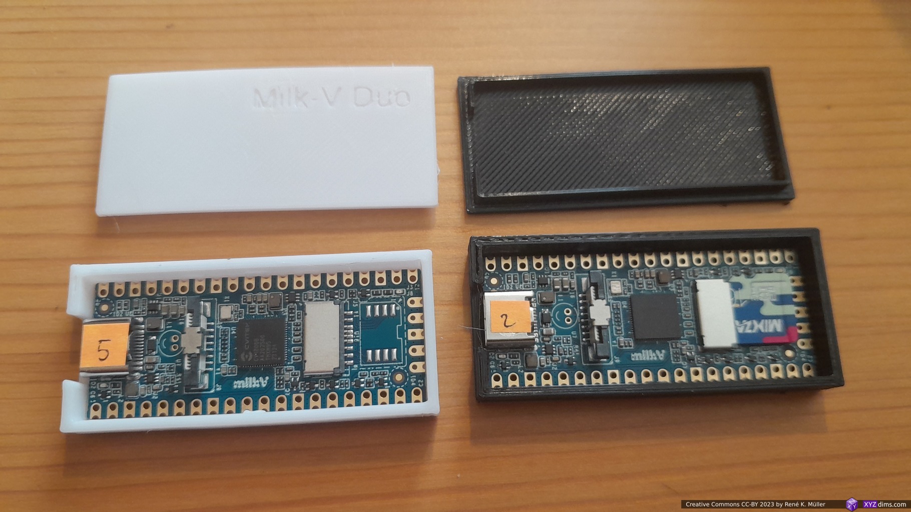
Milk-V Duo (bare): bottom case & lidMilk-V Duo (bare): bottom caseMilk-V Duo case closedPrinted in white & black PLAwhite vs black case blue & red LEDs see-throughwhite PLA cases allow LEDs see throughwhite PLA (FFF/FDM), white & clear resin (MSLA)MilkV Duo’s running BuildRoot & ArchLinux
As the Milk-V Duo has the same width and depth (X/Y) as the Raspberry Pico but it’s a bit thicker so the some of the existing cases work only partially:
Raspberry Pi Pico Case by Botvinnik works perfectly, recommended, bottom/lid with 2 options: closed or with holes
Raspberry Pi Pico Case w Slider 3D Print Model by AndysTechGarage bottom part works, but lid doesn’t fit due the camera connector; you need to disconnect board from power in order to put in or out from the case
Raspberry Pi Pico Case by Kuma0055: has pins for holes which Milk-V Duo PCB doesn’t have, not recommended
As soon my Ethernet connectors and Extension boards arrived I will provide case variants (2023/10/05).
2023/10/04: finally published, added CircuitPython which should work better than MicroPython
2023/09/25: retesting WiFi, still fails with latest firmware
2023/02/03: starting writeup
Introduction
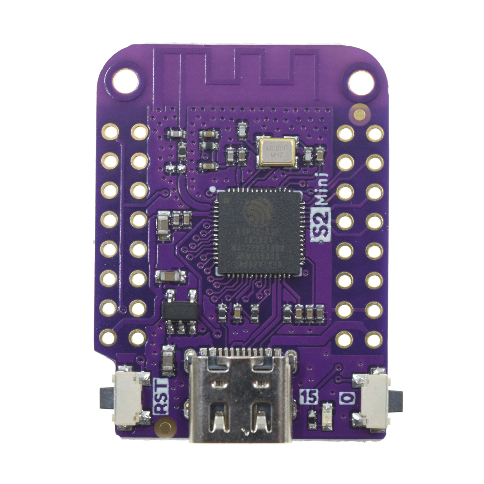
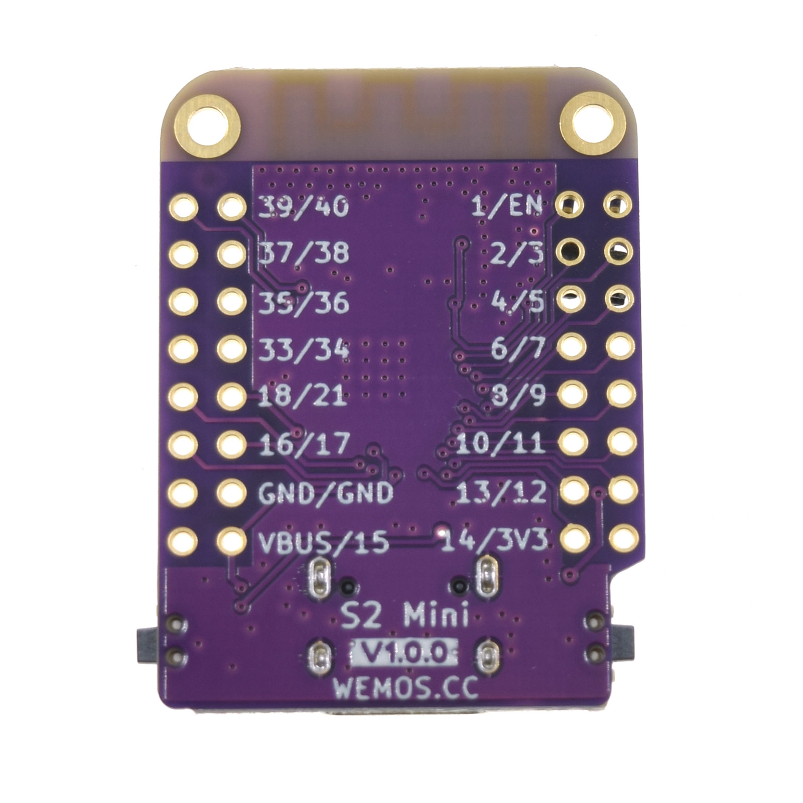
Wemos S2-Mini is a ESP32-S2FN4R2 chip on a small module, supporting to run MicroPython and connecting to existing WiFi or operating as WiFi Access Point – it’s ideal as IoT device, or easy add-on to 3D printing infrastructure to probe sensors and make them WiFi compatible.
Compatible with MicroPython, Arduino, CircuitPython and ESP-IDF
At the price of barely EUR 2.00 on Aliexpress (2023/02) this is a very affordable IoT device.
Note: MicroPython on ESP32-S2 seem not able to connect to an WiFi AP, and also not operate as WiFi AP itself. Before you follow any steps below, read it first through entirely and decide whether MicroPython or CircuitPython is more suitable – for me both approaches fail to provide WiFi connectivity.
Installing MicroPython (no WiFi)
My modules came without MicroPython unlike advertised, I had to upload the latest MicroPython firmware myself:
attach module with USB-C cable to the computer (e.g. running Linux as in my case)
press Button “0” and hold down, press Button “RST” briefly, wait 2 secs, release Button “0”
use ./esptool.py --port /dev/ttyACM0 --baud 1000000 write_flash -z 0x1000 firmware-LOLIN_S2_MINI-v1.19.1-669-gd4b9df176.bin
Adadfruit ampy
In order to use the modules, one requires ampy which is installed via
% pip3 install adafruit-ampy
and provides ampy command line interface:
Usage: ampy [OPTIONS] COMMAND [ARGS]...

  ampy - Adafruit MicroPython Tool

  Ampy is a tool to control MicroPython boards over a serial connection.
  Using ampy you can manipulate files on the board's internal filesystem and
  even run scripts.

Options:
  -p, --port PORT    Name of serial port for connected board.  Can optionally
                     specify with AMPY_PORT environment variable.  [required]
  -b, --baud BAUD    Baud rate for the serial connection (default 115200).
                     Can optionally specify with AMPY_BAUD environment
                     variable.
  -d, --delay DELAY  Delay in seconds before entering RAW MODE (default 0).
                     Can optionally specify with AMPY_DELAY environment
                     variable.
  --version          Show the version and exit.
  --help             Show this message and exit.

Commands:
  get    Retrieve a file from the board.
  ls     List contents of a directory on the board.
  mkdir  Create a directory on the board.
  put    Put a file or folder and its contents on the board.
  reset  Perform soft reset/reboot of the board.
  rm     Remove a file from the board.
  rmdir  Forcefully remove a folder and all its children from the board.
  run    Run a script and print its output.
so you can put (upload), run, delete files – essentially you have a small filesystem where files reside, to run/execute or read from or write to.
Booting Module
By default /boot.py is executed, where some default behavior can be defined.
No WiFi (Yet)
As first I uploaded wifimgr.py and webserver.py (see main.py), along with default wifi.dat:
myssid;password
which contains the SSID / Password of the WiFi AP I wanted the module to connect to. All 3 files I uploaded ampy -p /dev/ttyACM0 put wifimgr.py and so on, one can only upload one file at a time with ampy.
Finally one can ampy -p /dev/ttyACM0 run webserver.py
As of 2023/09 with MicroPython V1.20.0 I was not able connect the module to an existing WiFi neither have it operate as Access Point (AP) itself – both cases failed; quite disappointing.
Firmware
Boot
REPL
WiFi Client
AP
LOLIN_S2_MINI-v1.19.1-669
ok
ok
failed
failed
LOLIN_S2_MINI-20230228-unstable-v1.19.1-910
ok
ok
failed
failed
LOLIN_S2_MINI-20230426-v1.20.0
ok
ok
failed
failed
LOLIN_S2_MINI-20230914-unstable-v1.20.0-475
ok
ok
failed
failed
Installing CircuitPython (no WiFi)
Alternatively you can install CircuitPython, for such you
then press button “RST” again, after few seconds the board appears like a USB disk, and then you copy the adafruit-circuitpython-....bin into the USB disk – once done, it does reboot itself again (or press button “RST” again).
It will again appear as USB disk named “CIRCUITPY”, that means CircuitPython has been successfully installed and is active running.
Running Code on CircuitPython
Well, you create on that USB disk a new file called code.py which is executed as default when its content changes – so you can edit it directly. Any other files which that code.py needs resides in the same root folder.
The lib/ folder contains all libraries, which you can copy from CircuitPython Libraries, you download a .zip file with all libraries and unzip it and then individually copy libraries you need into the lib/ which become then active right away.
The console is viewable if you start
% tio /dev/ttyACM0
I tried to run a web-server example, but it failed with ConnectionError: Unknown failure 2 – so neither MicroPython or CircuitPython are providing working WiFi connectivity.
No WiFi Yet
I’m quite surprised to see my Wemis S2-Mini fail to connect to my WiFi network, regardless of MicroPython or CircuitPython – it seems to me the libraries involved as faulty for both approaches, I cannot believe that this is a hardware problem, but is a software problem.
Orange Pi Zero: I use a couple of them as Print3r/Prynt3r printhub: I connect multiple USB-based printers, and used Print3r/Prynt3r network-based remote printing capabilities
Embedded Single Board Computer (eSBC)
Milk-V Duo (EUR 5.00-9.50) Ethernet over USB, Linux, Python
2024/11/04: update with long-term usage of flex-plate
2023/07/25: published
2023/06/13: adding my print settings to increase reliability
2023/03/31: first prints performed
2023/03/29: adding Formlabs 3/3L and Prusa SL1S as comparison
2023/03/23: starting write-up
Introduction
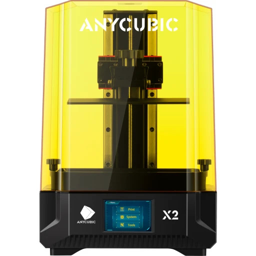
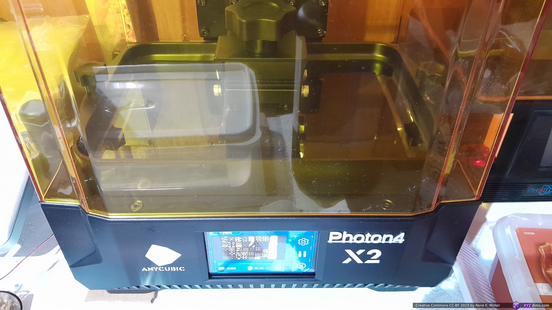
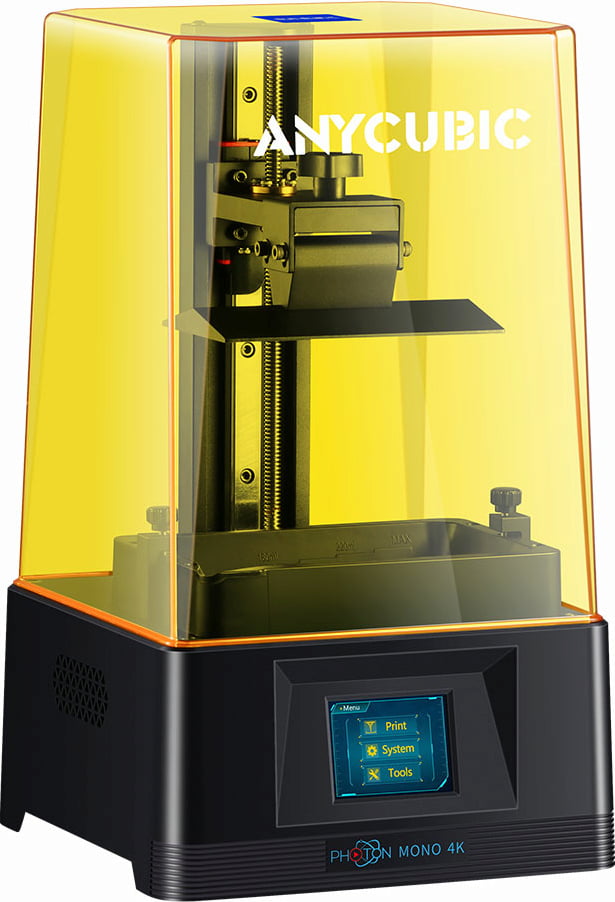
After my first steps with Anycubic Photon Mono 4K, an entry-level MSLA I also got a slightly larger Anycubic Photon Mono X2:
build volume: 196 x 122 x 200 mm (WxDxH)
resolution: XY 48μm, Z 50μm
9.1″ display with 4K+ resolution (4096×2560) display
monochromatic LCD (hence “Mono”), faster printer due shorter exposure
affordable with EUR 300-350 (2023/03)
no network, only USB drive printing
I ordered at Anycubic.com directly (EUR 350) 2023/03/24, and got it a week later.
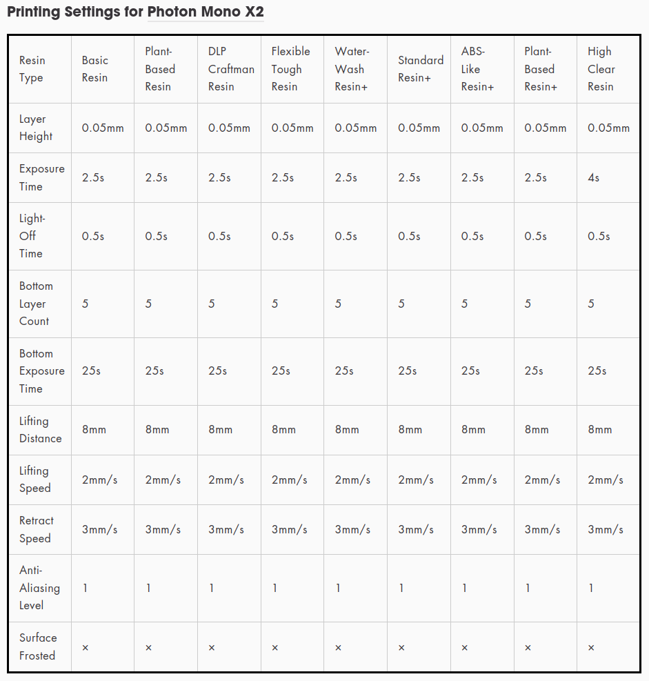
Default Settings
Defaults Firmware V0.2.3
My Settings 2023/07
My Settings 2023/11
Bottom Layers
6
5
1 .. 62)
Exposure Off [s]
1.0
Bottom Exposure [s]
30.0
25.0
25.0
Normal Exposure [s]
2.0
2.5
2.5
Transition Layers
4
10
10
Bottom Region
Bottom Layer [0] Rising Height [mm]
3.0
4.0
Bottom Layer [0] Rising Speed [mm/s]
1.0
Bottom Layer [0] Retract Speed [mm/s]
1.0
Bottom Layer [1] Rising Height [mm]
4.0
4.0 1)
Bottom Layer [1] Rising Speed [mm/s]
3.0
1.5
1.5
Bottom Layer [1] Retract Speed [mm/s]
3.0
Normal Region
Normal Layer [0] Rising Height [mm]
3.0
4.0
Normal Layer [0] Rising Speed [mm/s]
1.0
Normal Layer [0] Retract Speed [mm/s]
1.0
Normal Layer [1] Rising Height [mm]
4.0
4.0 1)
Normal Layer [1] Rising Speed [mm/s]
3.0
1.5
1.5
Normal Layer [1] Retract Speed [mm/s]
3.0
UV Light (not available)
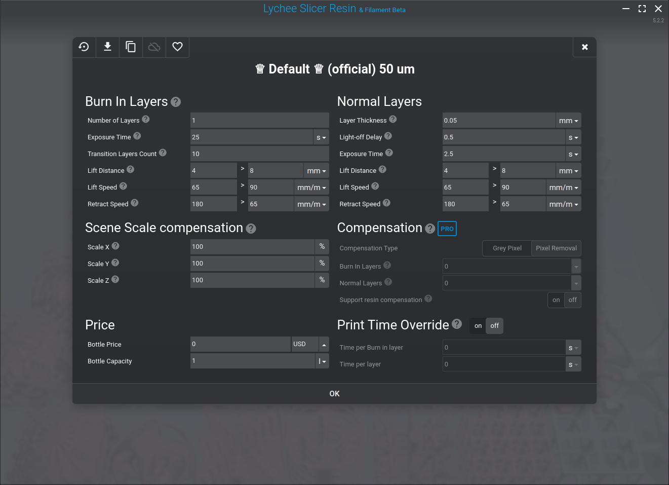
in Lychee Slicer the 2nd lift distance is the sum of [0] Rising Height 4.0mm + [1] Rising Height 4mm = “4.0mm > 8.0mm”:
depending on the size of the pieces, if they are small (e.g. 20x20mm foot print) then I use 1 bottom layer, for larger pieces I increase up to 6 bottom layers
After some prints I realized the 3mm/s or 180mm/min 2nd rising speed really decreased the reliability of prints I did, usually after bottom layers some models, especially fine structures, deliminated and I realized the transitioning needed to be longer and also reduce the 2nd rising speed, the retraction speed could stay as is. The slowed down the overall print time, but reliability is getting near to Mono 4K.
Various Resins
from Anycubic Web-Site (2023/04/02)
Mono 4K vs Mono X2 vs Mono M3 Max
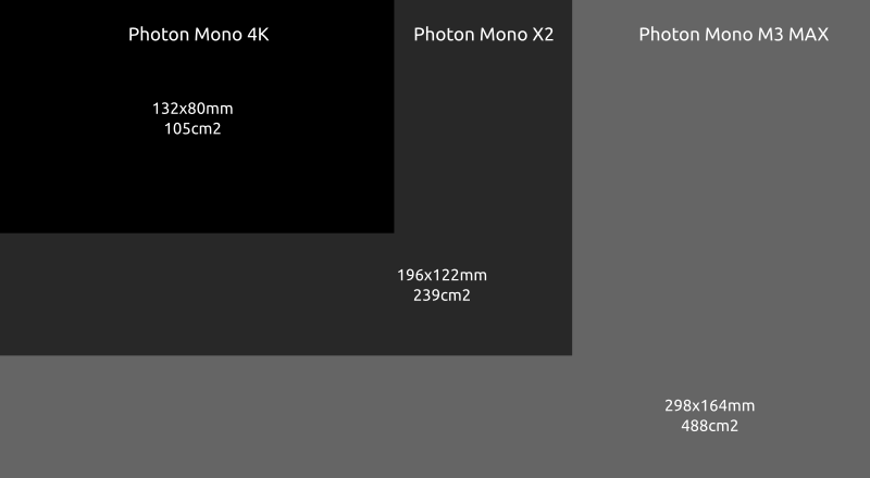
The print area Mono 4K doubles nearly with Mono X2, and the Mono M3 Max (EUR 1000) additionally doubles the print area:
As pointed out previously, the print area with MSLA directly affects the print speed, the larger the build plate, the faster the print: more parts can be printed at the same time.
The Mono X2 is relatively new as of writing this blog-post, just released in late 2022, so the third party market has not yet taken off regarding spare vats, spring steel magnetic build plate, protective films and alike.
Update 2023/07: The Mono X2 already discontinued as M5 and M5S has been released.
Photon Mono X2 vs Creality LD-006: Details Matter
The main reason I prefered the Photon Mono X2 (EUR 350) over the Creality LD-006 (EUR 250) with the nearly same build-volume is that the LD-006 has a bad build-plate mount where resin is trapped near the screws – which makes cleaning and switching resins much harder:
Anycubic Photon Mono X2 build plate: all resins flows away from the build plate, good designCreality LD-006 build plate: mounting screws trap resin, bad designCreality LD-006 build plate: mounting screws trap resin, bad design
Eventually either cured, dried or semi liquid resin trapped in there will contaminate your next prints – so a bad build plate design can ruin your prints eventually.
Slicer Support
Lychee Slicer 5.x and upward also supports the Mono X2 out of the box, whereas Prusa Slicer SLA slicer, as of 2.x series, does not slice to any but .sl1, and so requires a custom setting to add support for it indirectly then requires a tool like UVtools to convert to .pmx2 (Note: as of 2023/03 the output format is not working properly).
The native Photon Workshop slicer coming with the printer has no Linux support and only works via Wine “Windows” emulator, and is barely usable.
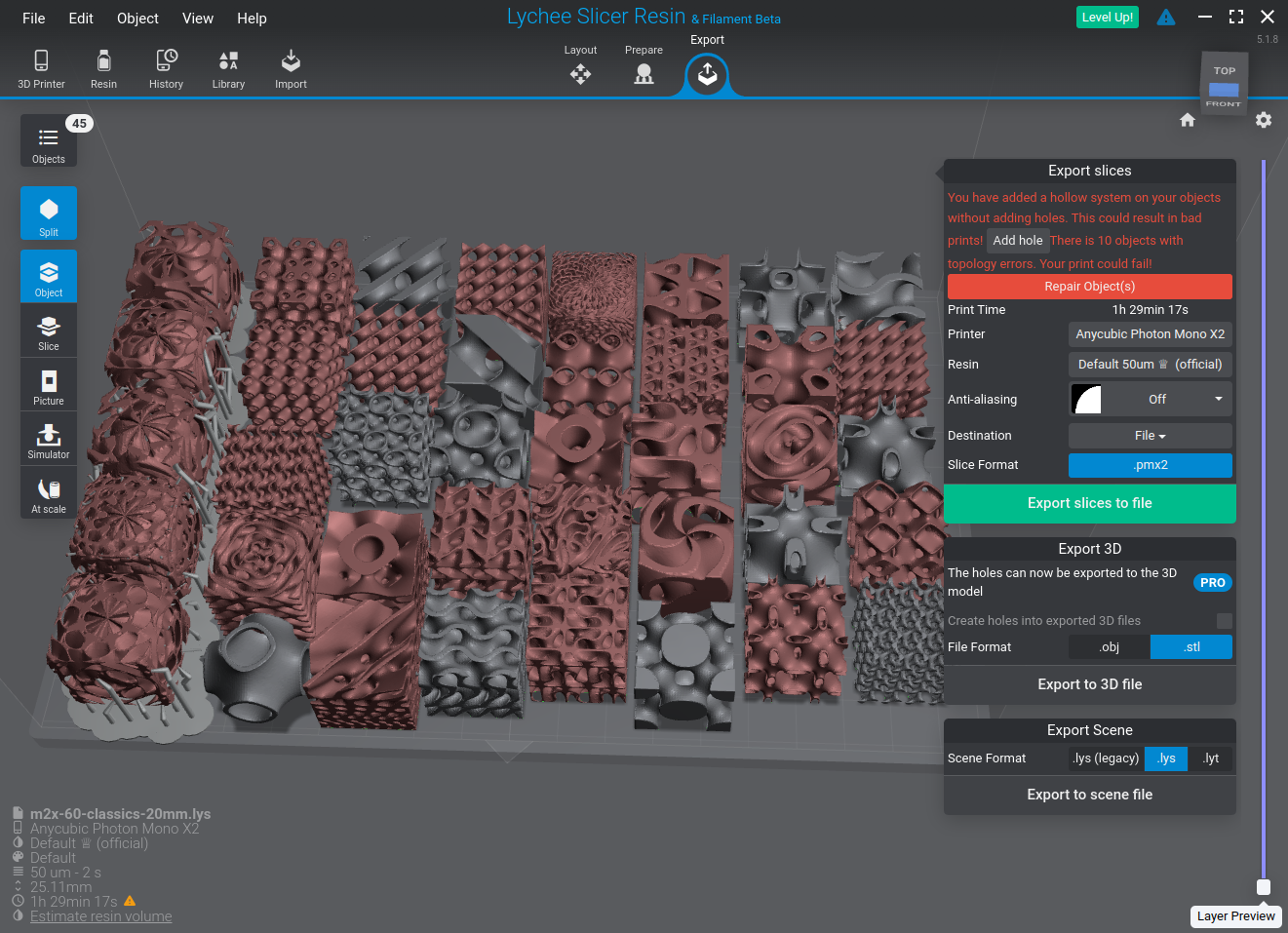
Lychee Slicer, positioning 40x cubes, left column requires support, all others directly on the bedLychee Slicer slicing 40x cubes
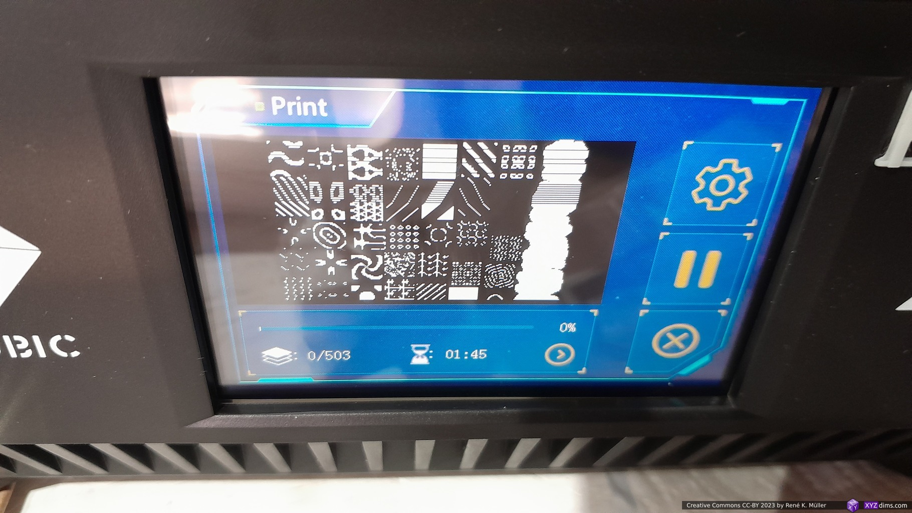
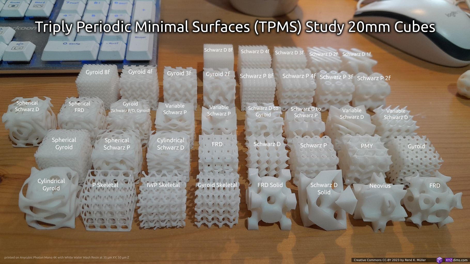
Printing 40x Triply Periodic Minimal Surfaces 20mm cubes samples at once, and it took 1h45m (with default settings) with apprx. 30mm height, as some required support.
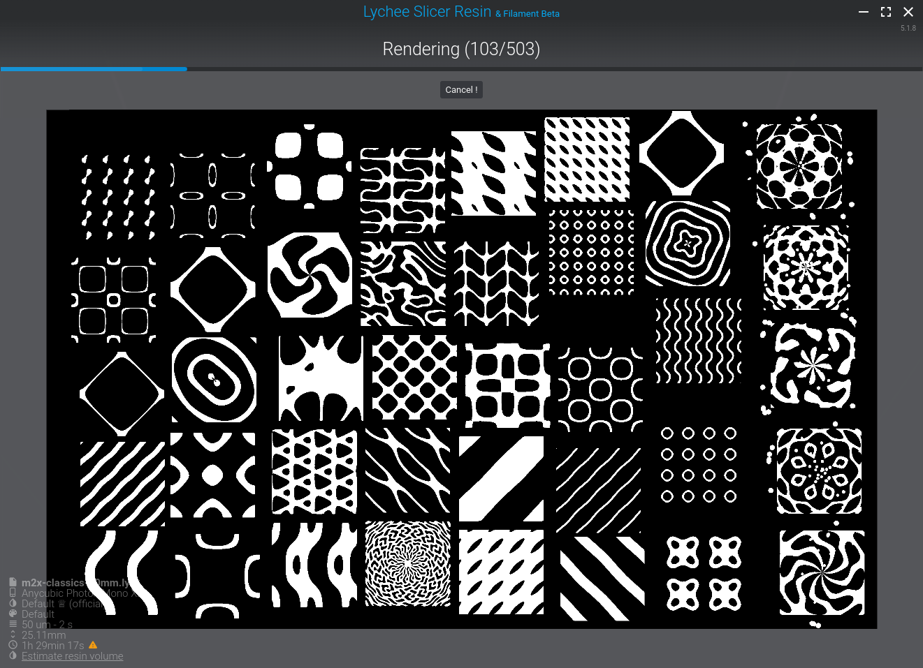
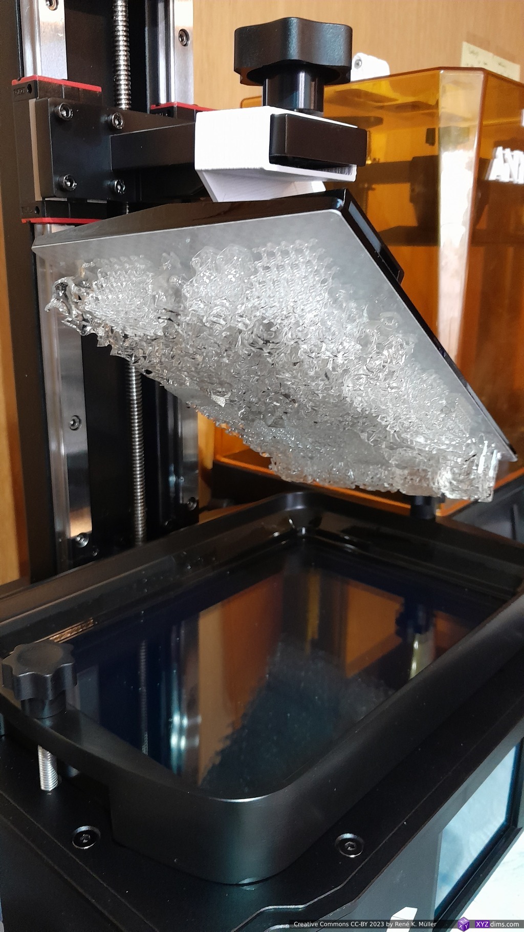
Mono X2 printing 40x Triply Periodic Minimal Surface 20mm cubesdisplay shows current layer exposureafter 1h45m the print was finished, using drip hook to tilt platform
The pieces were overexposed, the bottom layers were significantly overexposed, the clear resin as well the white resin which came as 2nd batch – the defaults as recommended by Anycubic and consequently by Lychee Slicer 5.1.8 were not as good as Photon Mono 4K.
The default settings with 3mm/s or 180mm/min for 2nd lift speed caused multiple failed prints for me such as delimination, and I reduced it to 1.5mm/s or 90mm/min and increased transitioning layers from 4 to 10 – after that fine structures like those 40mm cube lattice prints came out quite well.
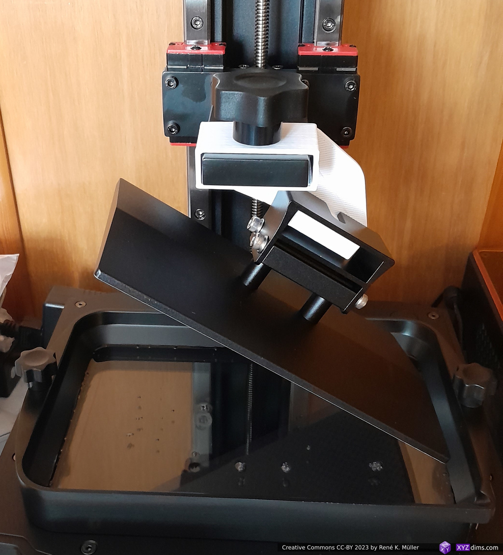
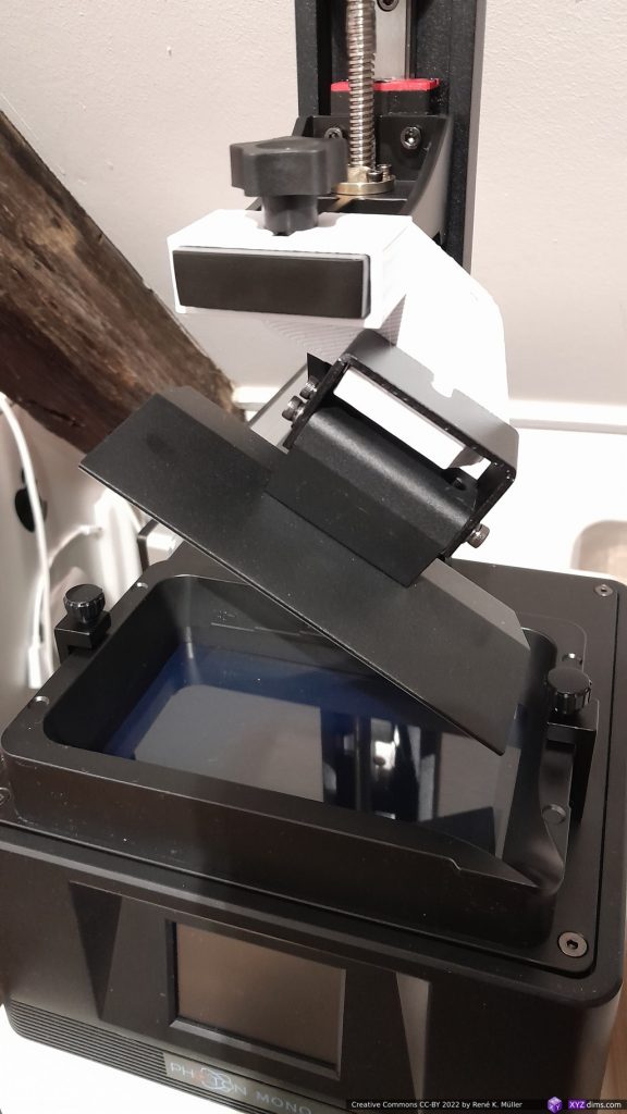
Photon Mono X2 Drip Hook
I highly recommend a drip hook, you want uncured resin easily drip over a period of 5-10min back into the vat, before you wash it off in water (when using water wash resin) or isopropyl alcohol (IPA).
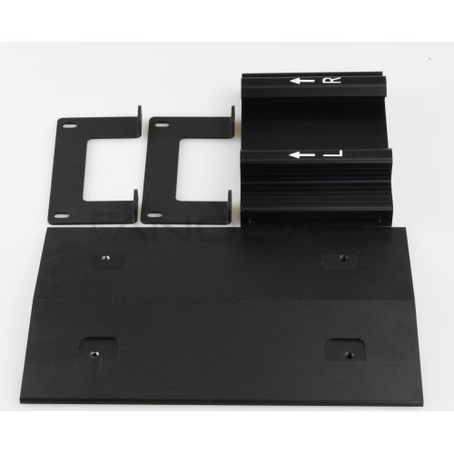
263 x 169 x 30 mm (outside max) 238 x 162 mm (inside)
steel build plate
Elegoo Saturn S (same LCD size)
202 x 129 mm (min. 196 x 122mm)
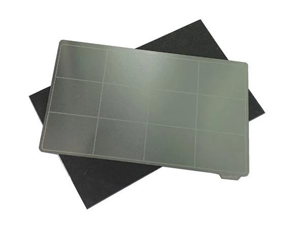
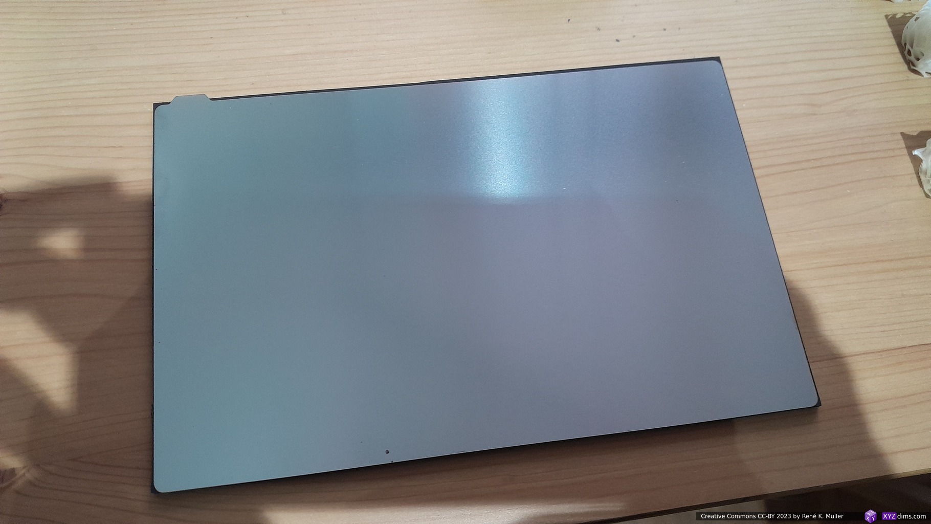
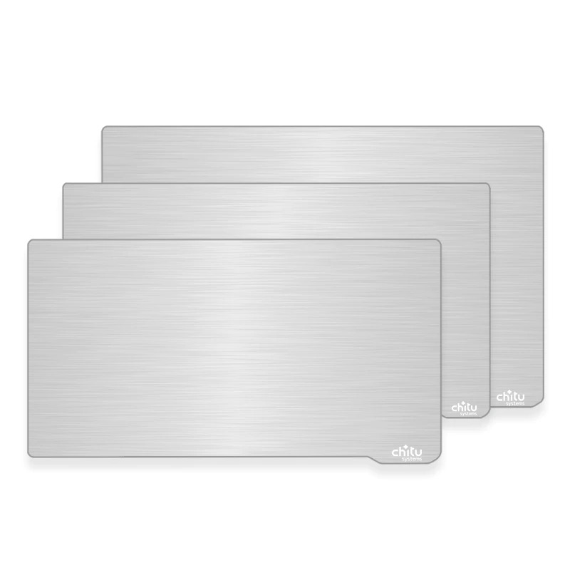
Spring Steel Plate
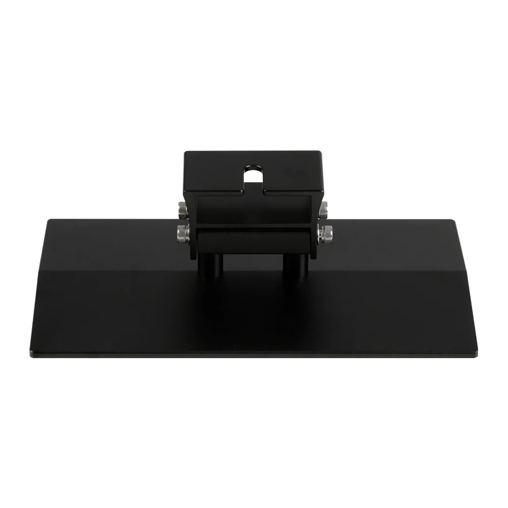
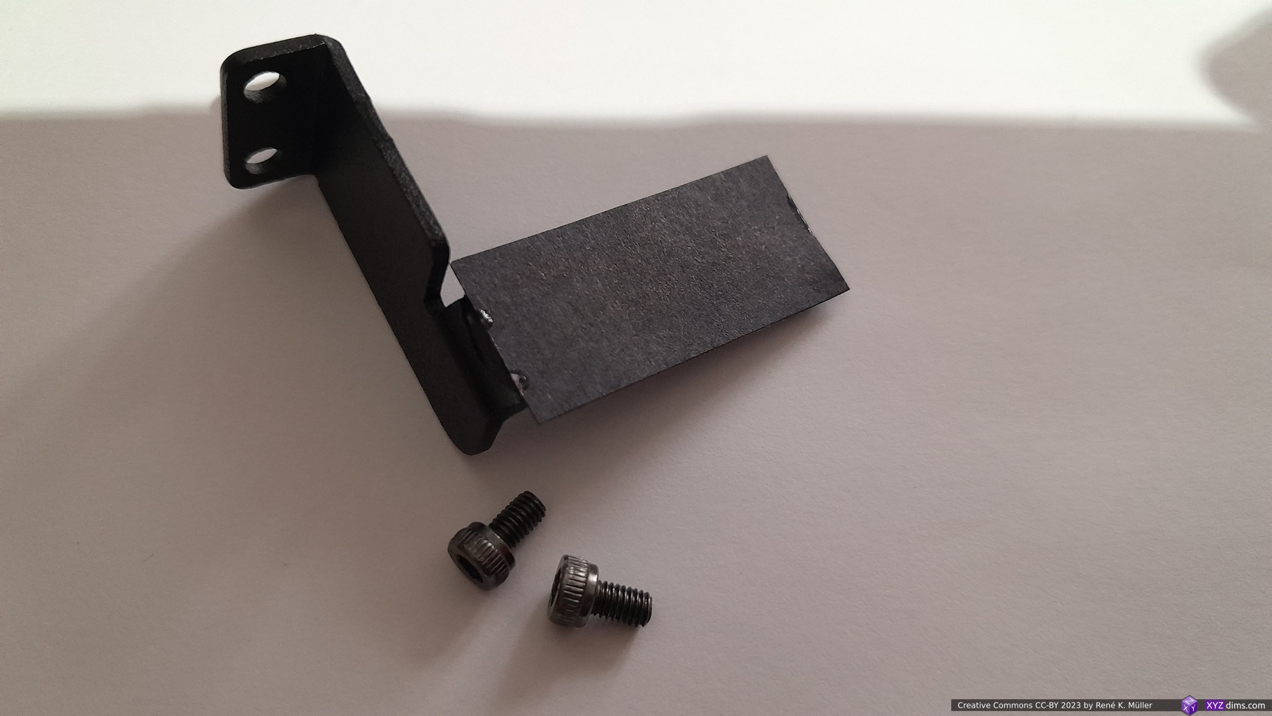
I made two prints with the original build plate, and it was difficult to remove the prints without flexing and scratched the plate right away – the adhesion is good, too good actually. So it became clear, I also want a spring steel plate for it.
Magnetic spring steel plate: 202x128mm for Photon Mono X2Photon Mono X2 202x128mm spring steel plate
magnetic base: 2.2mm thick, slightly extends, 203x129mm
steel plate: 0.5mm thick, exact 202x128mm
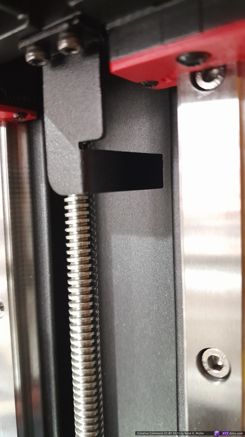
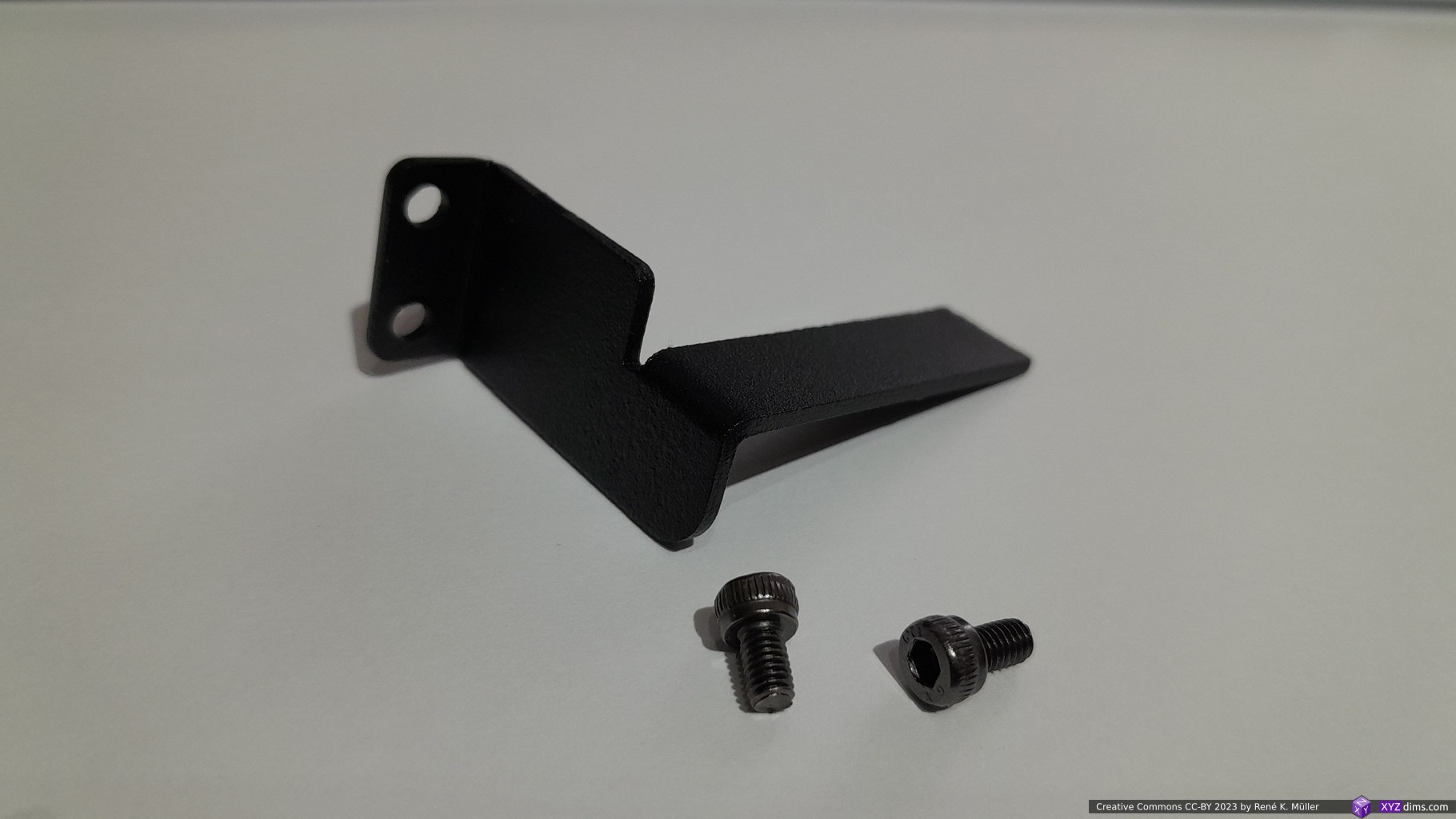
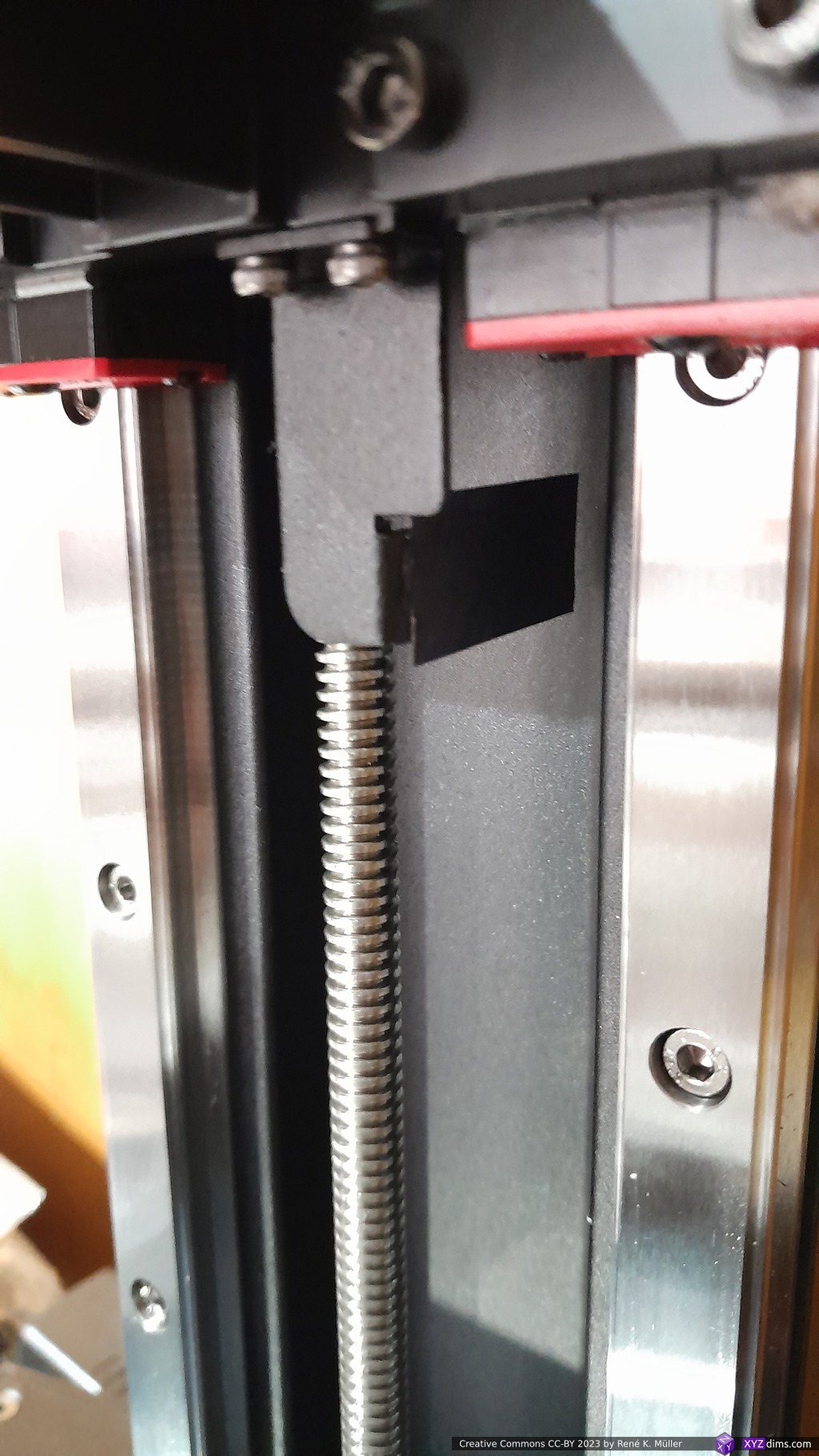
so one has to compensate 2.5 – 3mm in Z height and adjust, speak extend, the Z-level probe. I just glued a black strip of paper, and then of course re-level the bed again afterwards.
Mono X2 Z probeZ probe removedZ probe extended with strip of black paper (or any opaque tape), apprx. 3mm to the bottomZ probe with extension mounted back
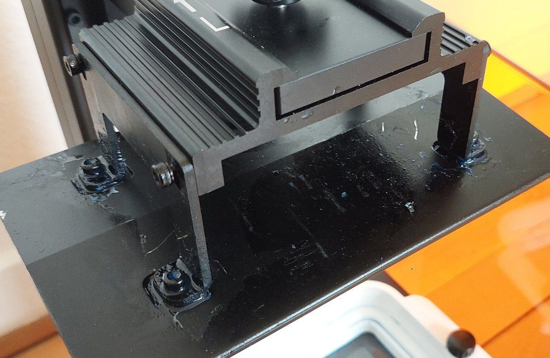
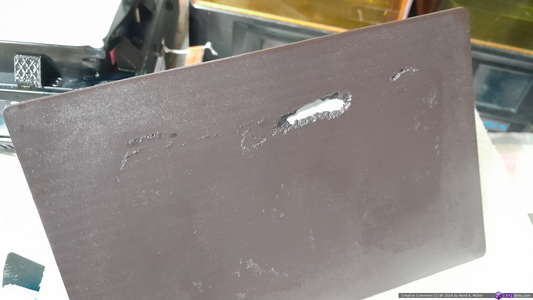
Update 2024/11: well, let me add here after 20 months usage, where the built-plate rested for apprx. 5 months without use, the steel plate fused with the magnetic rubber counter part, and while trying to separate, the rubber base tore a hole, but as it turned out, also the adhesive of the rubber base detaching from the actual build-plate:
While detaching steel from rubber base, the rubber base tore multiple tears and even a holeAdditionally rubber base detached from the actual build plate as wellManually detached rubber base, revealing adhesive no longer attaching, and also thin transparent layer also detaching
This is bad . . . I’m not sure if it came to be of the long stand-still / resting without detaching the steel plate, or a rather short lifetime of the flex-plate, I suspect a combination of both. I clean(ed) the steel plate and rubber counter part after every print session (one or multiple consecutive prints), but still some resin residue could have remained, sufficient to fuse the flex steel plate with the rubber counter part.
Either way, I gonna replace it and keep using the flex steel plate as it makes it easier to detach smaller or delicate pieces. I can conclude this flex steel plate likely will last 15-20 months only, and if I won’t use the printer for longer then I detach the flex steel plate from the rubber magnetic base.
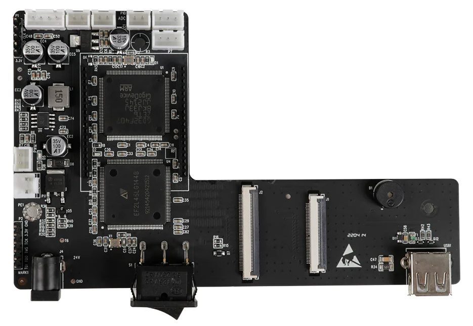
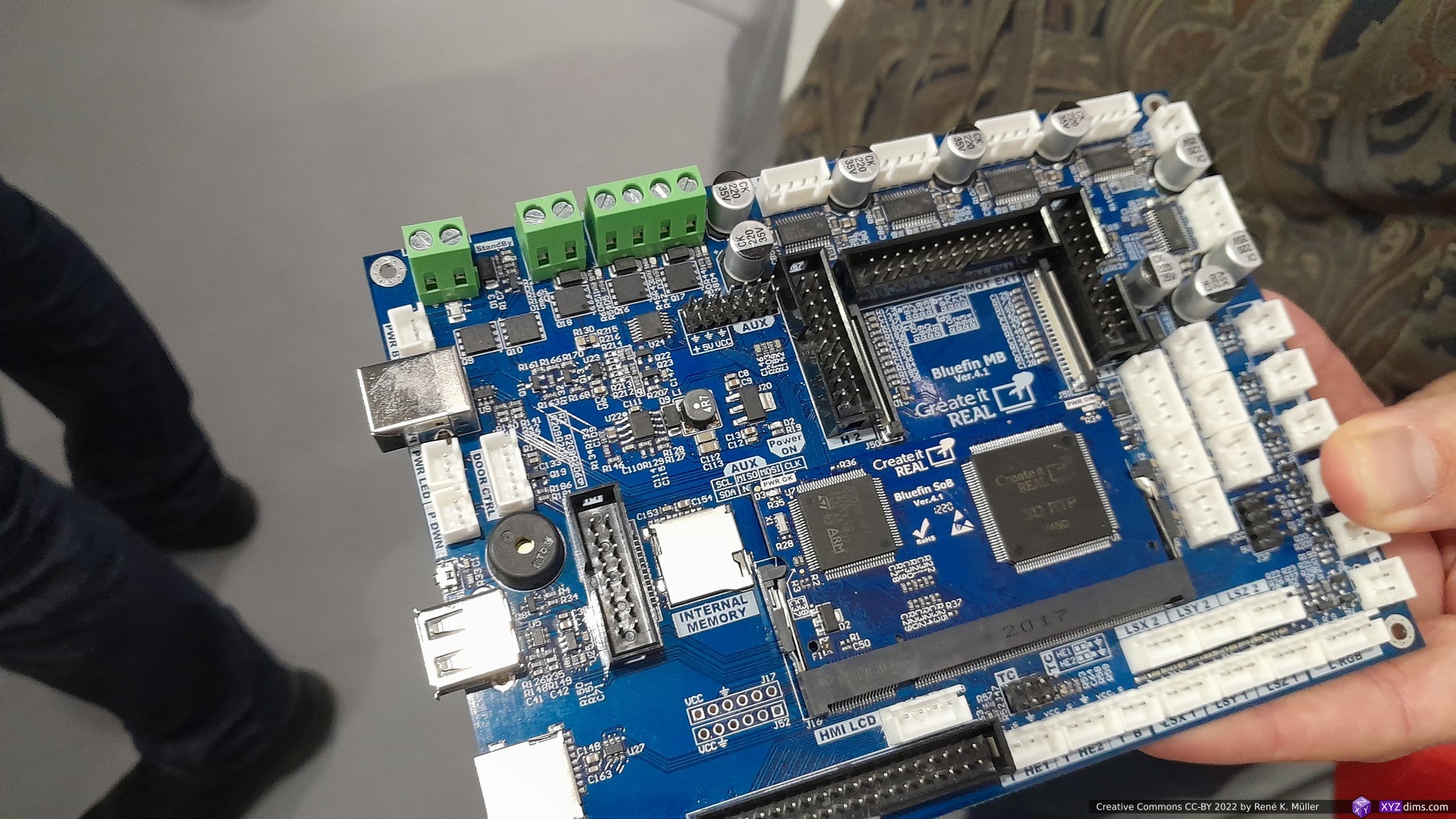
Motherboard
The motherboard has two main chips:
ARM GD32F407
driving Z stepper motor with endstop (Z=0)
driving USB port
driving both LCDs via ASIC
EF2L 45L G1444B (ASIC)
driving monochrome LCD via MIPI DSI (not sure where the image buffer resides)
driving UI color LCD with touchscreen
Mono X2 motherboard
Preliminary Review Mono X2
Pros:
good value for build size, but not features
mid-size build volume with 196 x 122 x 200 mm (WxDxH)
no cover sensor (can be on or off and still prints)
available replacement of parts (LCD, vat, build-plate)
Cons:
no Wi-Fi (only USB Stick)
surprisingly noisy with fans while printing
firmware doesn’t allow to change UV light intensity
default settings are not giving reliable prints1)
very simple firmware & UI
no flex build plate
no upper endstop (you can ramm the build-plate into the plate on top)
no sensor for running plate against cured remains in vat2), that would require more advanced firmware
cheap USB memory stick (breaks after a few days, data corruption)
using original Anycubic Water Washable Resin +
newer printers (2023) have load cell to measure counter force, and prevent build-plate to run with force against vat and LCD underneath. Update 2023/05: Anycubic released Mono M5S (2023/05) which has a load-cell sensor, but reviews are mixed.
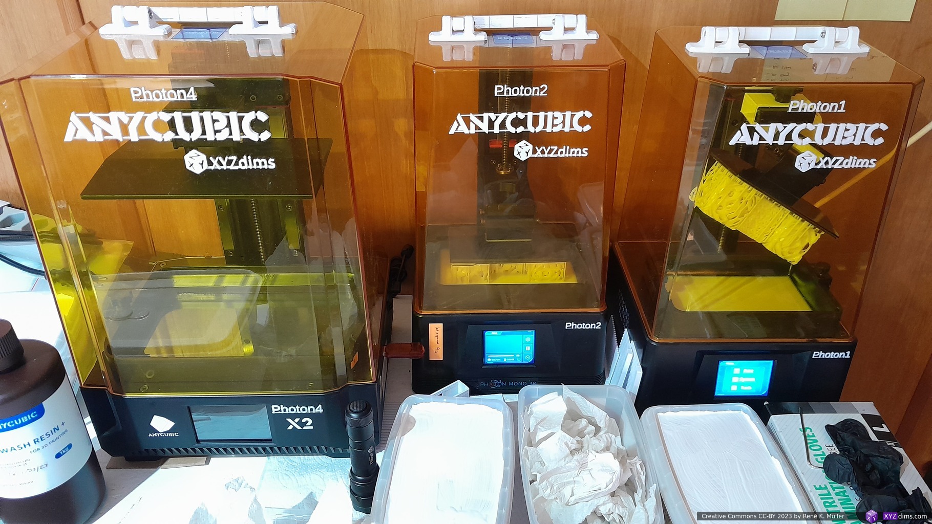
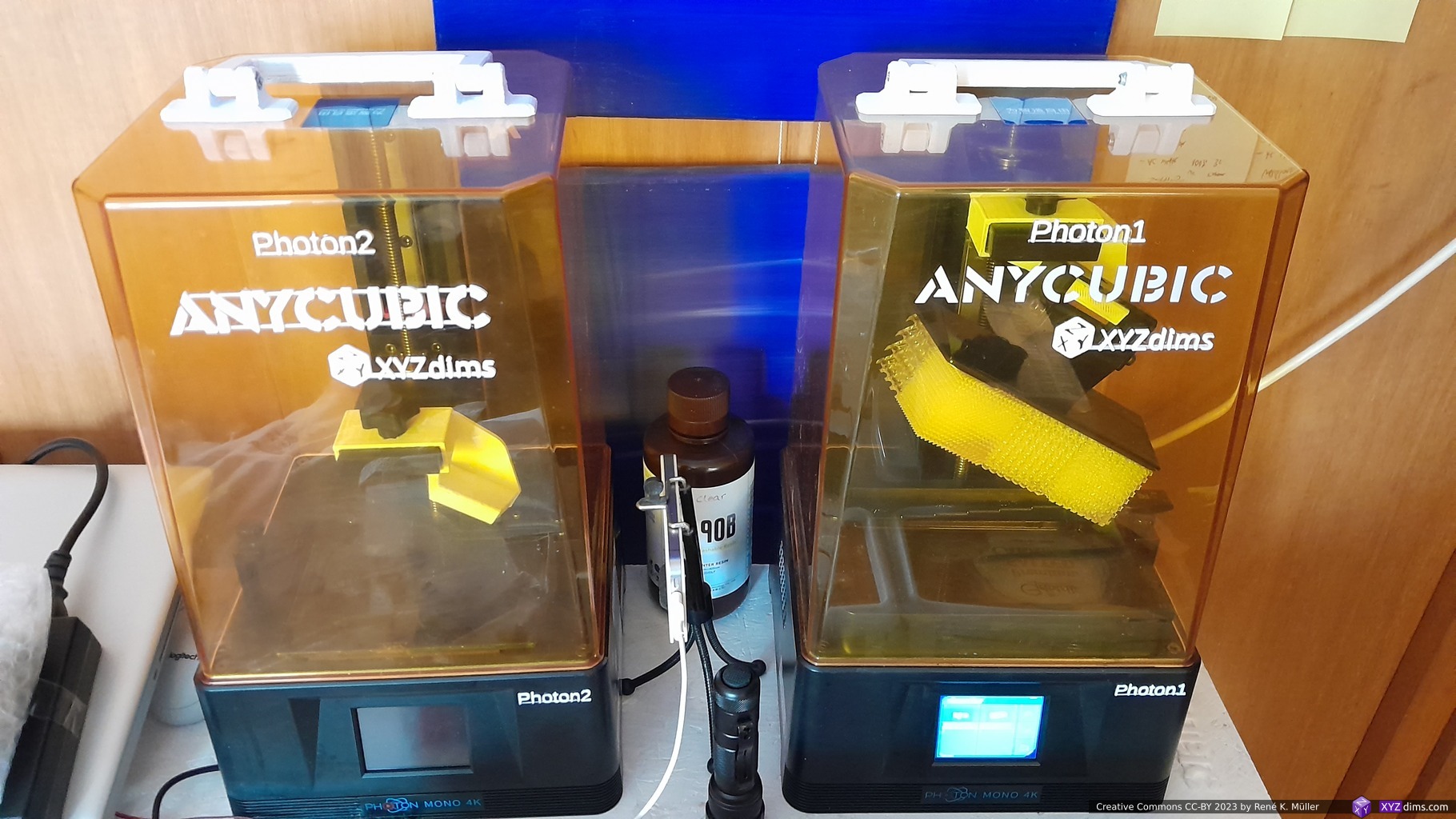
Photon #4 (Mono X2) & Photon #1 & #2 (Mono 4K): additional handle on top, and labels on cover and body
Addendum
Printing Procedure
Let me take the chance to describe my MSLA resin printing procedure – if you are newcomer you might like to read it in a concise way.
resin printing (as in 2023) is still a messyprocedure at the consumer and prosumer level as well
the moment the print is finished, you need to remove the build-plate or flex steel plate, no matter which, the piece(s) still have resin on it, which likely will drip on the printer and especially around the vat is the most critical area:
by any means prevent any resin to come under the vat
don’t touch the underside of the vat with hands or gloves, unless you have a fresh piece of sheet of paper towel or equivalent
if you must clean the underside of the vat – and if you do you already screwed up when this happens – clean it first thoroughly, and after that the side of the vat and other part of the printer
prevent any resin to get on the LCD or protective layers on the LCD, wipe it away right away
cured resin is difficult to remove, especially from softer surfaces like plastic – so I have the habit to remove all resin outside of the vat right away
clean your gloves with pieces of paper towel, to prevent to further spoil your equipment you grab as next:
clean gloves when handling the build plate
I keep the same gloves for multiply prints or a 1-2 weeks as I clean them with paper towels right away (2-3 times per print: whenever I touch the 3d printer, the gloves are clean)
when removing the pieces from the build plate, things will become messy, no matter what
washing the piece(s) off in a water container as I use only water wash resin
1st wash container: I dip the pieces with the build plate into the container, my gloves don’t get wet or touch resin
2nd wash container: I remove the flex build plate, and dip it with the pieces still on the plate into the 2nd container – dipping in and out several times
then I remove the pieces from the flex build plate, by flexing the build plate or use a metal scrapper, and they drop into a small container with layers of paper towels where they dry a bit (10-30min) – I don’t touch the pieces with my gloves, I only touch the build plate
cleaning the build plate with paper towels dry, mount it back on the printer
cleaning the flex build plate with paper towels and attach it to the build plate
no cured remains in vat: using the plastic scrapper to push on the vat’s bottom softly, and move through the vat slowly to see if there are remains attached to the vat bottom, those needs to be removed otherwise at next print the build plate will push it unto the LCD and potentially damage it – high risk to damage the MSLA printer severely, such as puncture FEP of the vat and leak resin all over
if there are cured remains on the bottom FEP which I can’t remove with the plastic scrapper (large enough to pick out), then
either I expose the entire plate for 10-20s, and remove then a full cured layer of the entire area, this removes all small remains
if there are small floating pieces, then I empty the vat off the resin by pouring through a metal or paper filter (keeps back remove all cured remains) back into the bottle – this is time consuming and messy as you need to clean funnel and metal filter again
if I have printed pieces with small holes where water might still be captured, I take a piece of paper towel and wrap it and shake it fast in my hands – I have seen people blowing compressed air on the cured pieces, this makes sense if you produce many pieces in series frequently
2nd stage curing of the pieces in UV chamber:
white/black/grey resin 1-3 mins
clear resin 2 mins max
further resting the piece(s) for 1-2 hours to dry further
And I leave the resin in the vat, and let the vat stay on the printer for weeks and even months – no refilling back and forth to and from bottles, unless I know I have cured fragments in the vat, then I empty the vat with metal or paper filter back into the bottle and clean it with paper towels thoroughly as mentioned above already.
Keep everything around resin printer as clean as possible.
Consumer MSLA vs Professional SLA/MSLA
When trying to compare consumer MSLA and professional SLA & MSLA like from Formlabs, notable they switched from SLA 2024/04 to MSLA with their Form 4 series as well, one might just look at the print size or build volume (state 2024/11):
★★☆☆☆ depends on layer cross section & print height
★★★★☆ depends only on print height
Hardware Maintainability
★★★☆☆
★★★☆☆
★★★★☆
★★★☆☆
★★★☆☆
Original Online Resources
★☆☆☆☆
★☆☆☆☆
★★★★★
★★★★★
★★★★☆
Community Resources
★★★★☆
★★★☆☆
★★★★☆
★★★☆☆
★★★☆☆
After Sales Support
★★☆☆☆
★★☆☆☆
★★★★☆
★★★★☆
★★★★☆
Third Party Market
★★★☆☆
★★☆☆☆
★★☆☆☆
★☆☆☆☆
★☆☆☆☆
Reliability
★★☆☆☆1)
★★★★☆
★★★☆☆
Value
★★★☆☆2)
★★★★☆2)
★★★☆☆2)
★★★☆☆2)
★★★☆☆2)
based on overall build and firmware, which can’t even properly calculate remaining print time while printing, I have a low expectation
value for most are nearly the same, because the low price for Anycubic Photon Mono series also give you moderately good solution, whereas Formlabs printers are very pricey but also giving you good value, and Prusa SL1S rather high priced for the gaining reliability and print speed, Elegoo Mars & Saturn Ultra value is higher due lower price
Form Wash station for Form 3, Form Wash L for Form 3L, you move the build plate direct into the washing station, and before curing remove them from the build plate
Prusa SL1S & Elegoo Mars/Saturn Ultra prints a layer in 2 seconds in total, whereas traditional MSLA takes 7-10s (exposure time + lifting/retraction)
Impressive selection of resins, incl. bio compatible, strong and durable options
As a follow-up, while reviewing another resin printer, I realized the “value” for me I could actually determined by the XY area which translate into parallel printing capability, which is more relevant than the height (Z), combined with the precision or voxel size – as of 2023 Anycubic doesn’t even mention the XY resolution anymore – a bad marketing move.
Resin Printer Value Comparison
A numeric value summarization for features I care about, the rough & simple formula:
XY Area [mm2] / Price [EUR] / XY Resolution [μm]
The bigger the XY area, the smaller the price and the smaller the resolution, the higher the value:
Formlabs 3’s & EMake SLA printers use a laser beam which has 100μm in diameter, but it can be positioned 25μm exact, the latter was used to calculate the value
The UV pixels are non-square, the longer side was used to calculate the value
Elegoo Jupiter 2 advertised the Z build volume as 300mm, it can print but you can’t remove it afterward, so it’s rather 275mm.
The XY area in SLA scales not as good as with MSLA, as the laser beam takes longer the more XY area (e.g. more pieces) need to be rendered per layer – so, MSLA is recommended for aiming fast parallel printing. Interestingly Formlabs 4 is now a MSLA as well (2024/04), they seem to have abandoned the SLA laser-based approach.
2023/07/25: moved content from blog into regular pages
2023/03/15: adding more Settings for different resins, different default for different firmware version, added preliminary Review
2023/03/09: finally published
2023/03/05: first prints made, more info on Lychee Slicer, Prusa Slicer SLA, more on magnetic steel plate use, prints with or without support, closeup photos added
2022/11/29: added Drip Hook, still preparing the utilities to make first print
2022/11/26: Mono 4K arrived, preparing software pipeline (slicer, converters) and working place
2022/11/07: starting write-up
Introduction
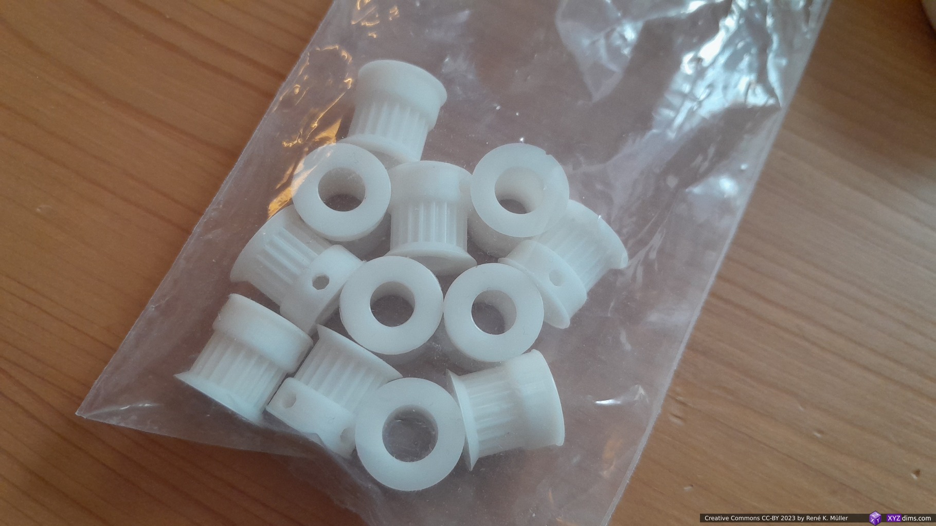
The past years I focused on Filament Deposition Manufacturing (FDM) / extrusion based 3D printing, and the time came to focus on MSLA resin based process as well.
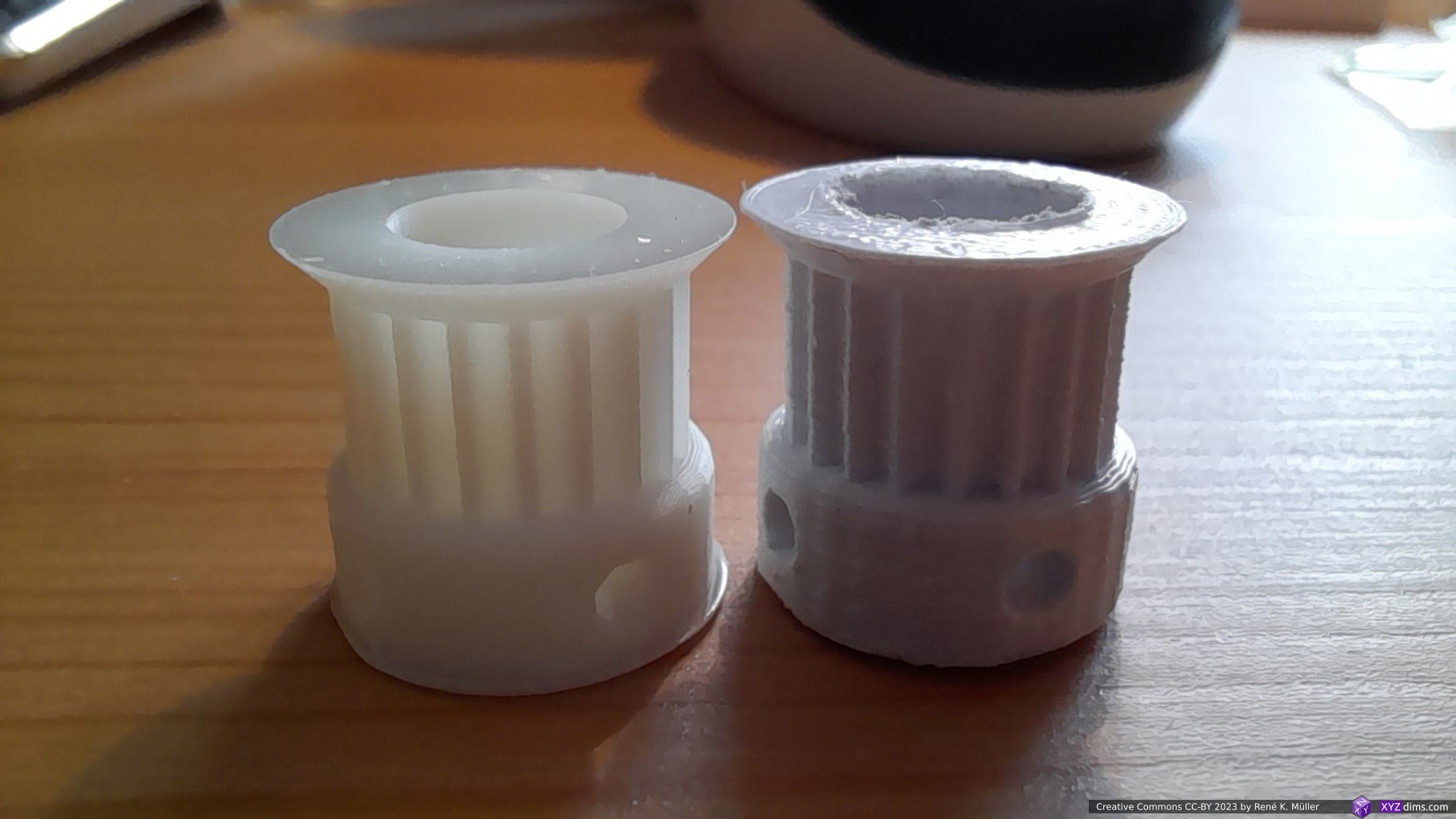
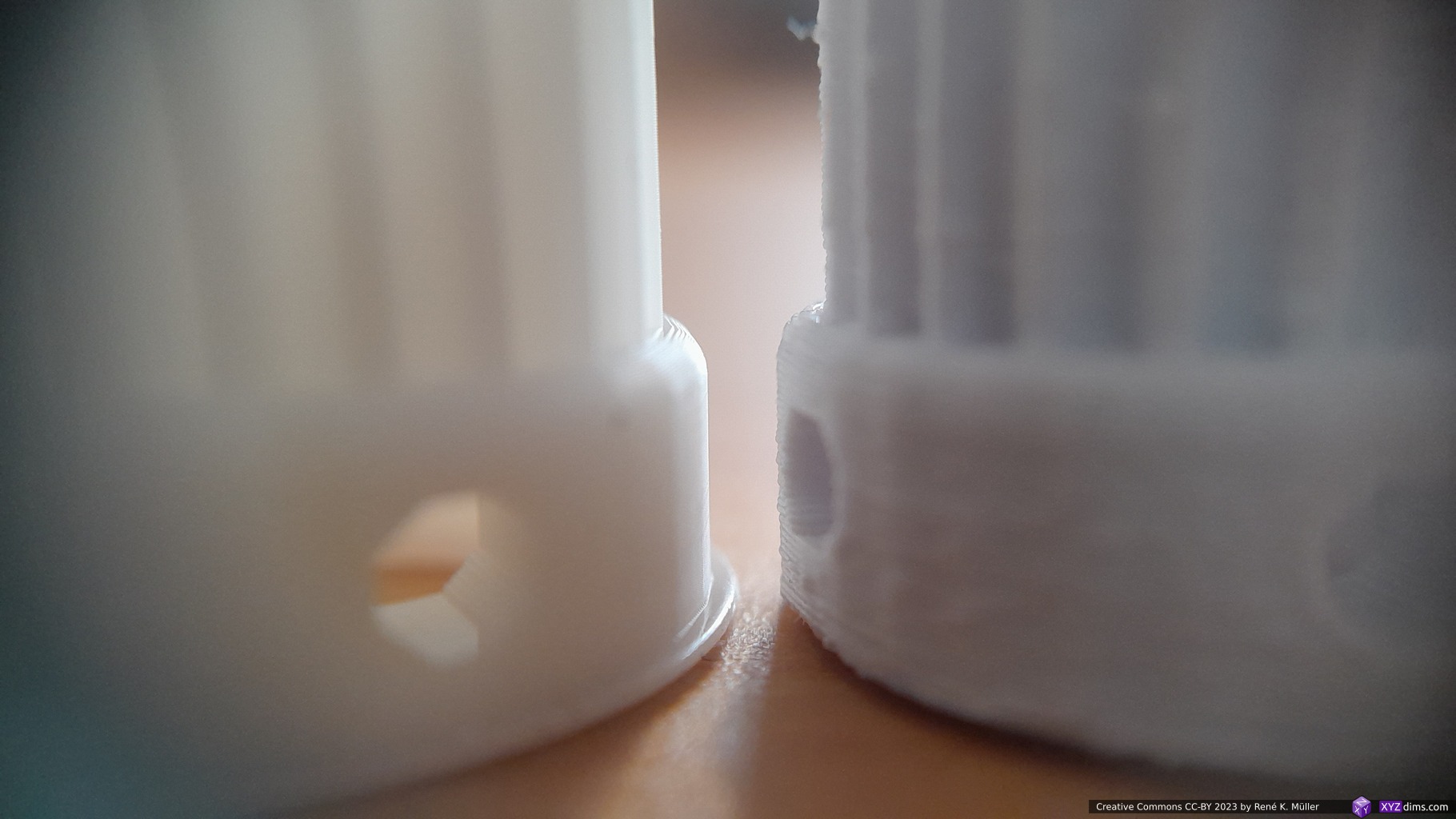
My main use case a small pieces, like custom pulleys and idlers – precise parts, such as:
Custom pulley ID8 20T: MSLA @35μm XY, 50μm Z vs FFF @400μm nozzle, 100μm ZCustom pulley ID8 20T: MSLA @35μm XY, 50μm Z vs FFF @400μm nozzle, 100μm Z
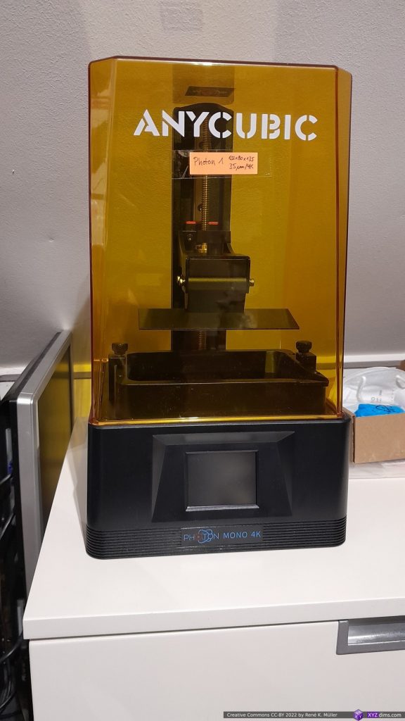
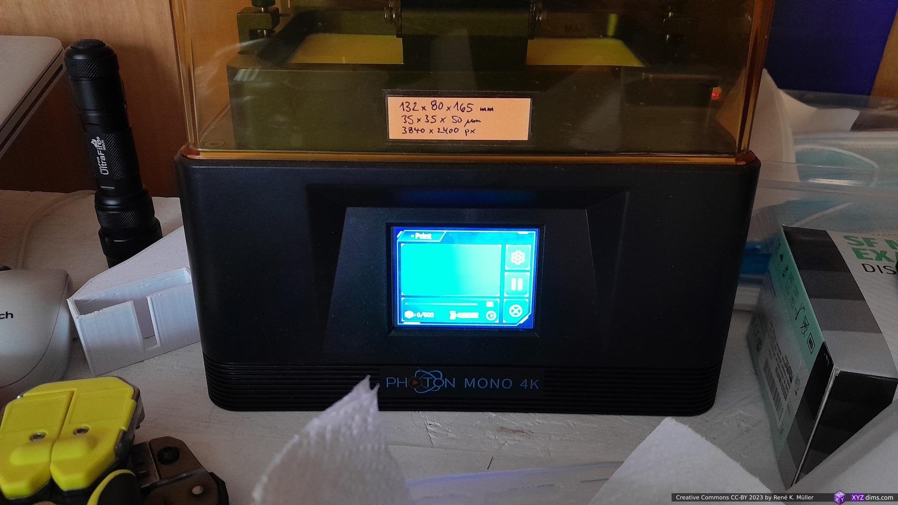
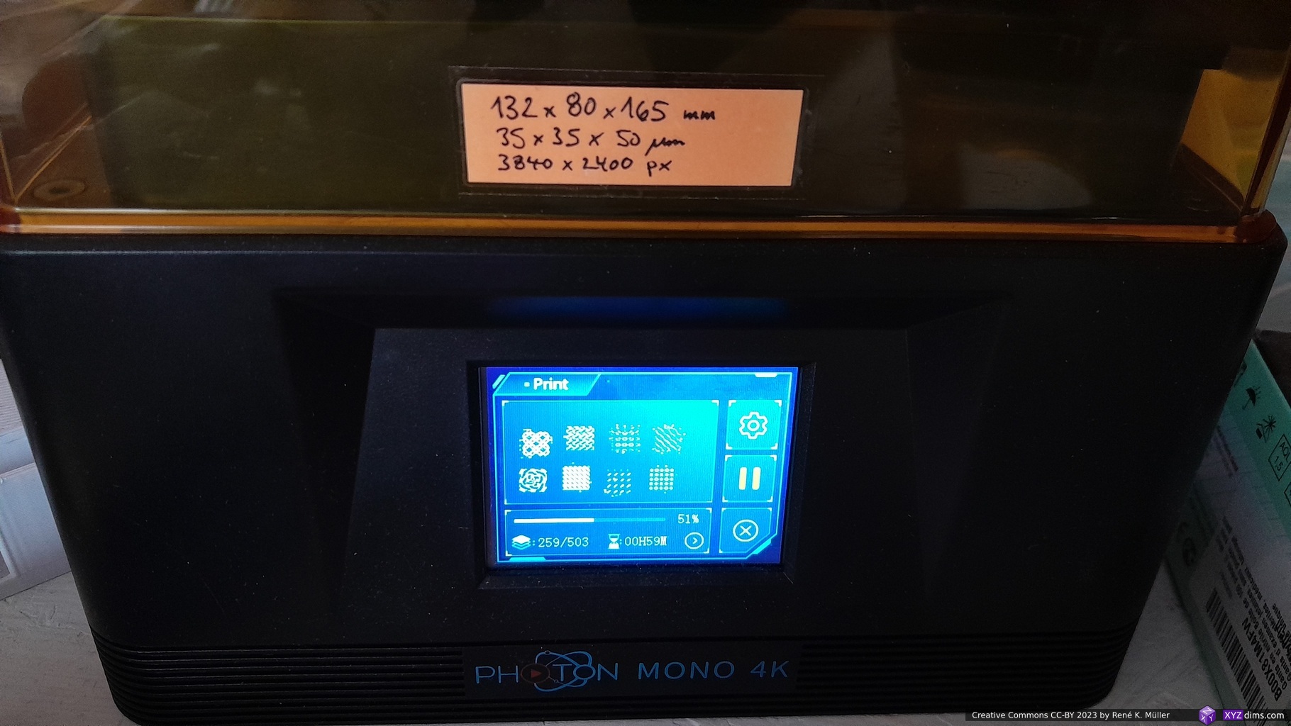
Anycubic Photon Mono 4K
The Anycubic Photon Mono 4K seemed like a good choice to start with:
build volume: 132 x 80 x 165 mm (WxDxH)
resolution: XY 35μm, Z 50μm
6.1″ display with 4K resolution (3840×2400) display
monochromatic LCD (hence “Mono”), faster printer due shorter exposure
affordable with EUR 170-220 (2022/11)
no network, only USB drive printing
SLA Stereolithography Apparatus – one beam/point light source
MSLA Mask Stereolithography Apparatus – one light source, masking what does not need to be printed
DLP Digital Light Processing – one image, each pixel controlled by micro mirror
I ordered 2022/11/22 for EUR 170 and received it 4 days later via Anycubic Store within Amazon, along with a few utilities like water wash resins, gloves, etc – ready to MSLA print.
Update 2023/05: the Mono 4K has been discontinued, and replaced with Mono 2 with slightly larger print volume of 143 (+11mm) x 89 (+9mm) x 165 (+33mm).
FDM/FFF vs Resin
FDM/FFF
Resin MSLA
X, Y precision: 100μm Z precision: 50μm minimal structure: 200-600μm1) minimal post-processing minimal toxicity of filament print duration based on printed volume large scale prints affordable 1kg filament EUR 15-30 mixed materials2)
X, Y precision: 35-75μm Z precision: 30-50μm minimal structure: 30-50μm extensive post-processing severe toxicity of resin print duration based on print Z height only large scale prints require expensive printers 1kg resin EUR 30-803) single material
depends on nozzle diameter
multiple printheads/hotends required, e.g. IDEX, tool changer, material changer
Anycubic sold water wash resins at 22-27 EUR/kg 2023/03 (black, white, clear, grey and waterblue)
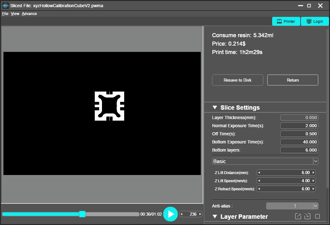
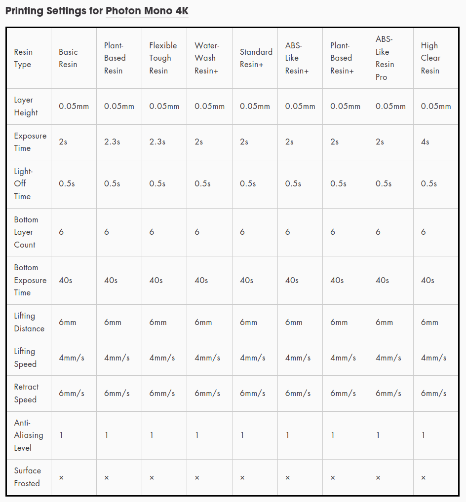
Print Settings
layer height: 0.05mm / 50μm
exposure time: 2s
light-off time: 0.5s
bottom layer count: 6
bottom exposure time: 40s
lifting distance: 6mm
lifting speed: 4mm/s
retract speed: 6mm/s
anti-aliasing level: 1
file formats: pwma (proprietary)
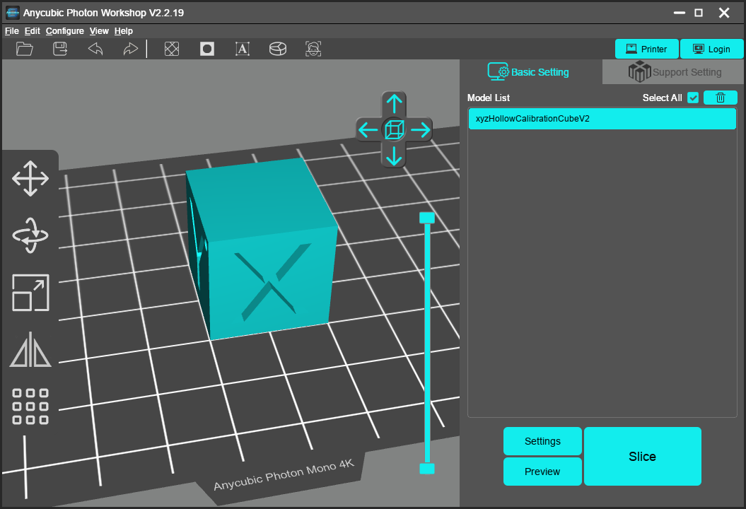
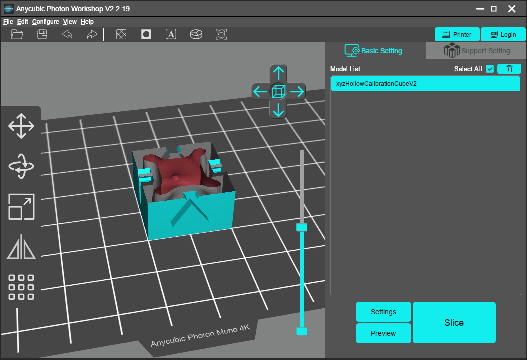
Photon Workshop on Linux
My development environment is Linux, and as of 2022/11 there is no Linux Photon Workshop, the name of the slicer needed to slice for Mono 4K; but you can run it via Wine (a Windows compatibility wrapper):
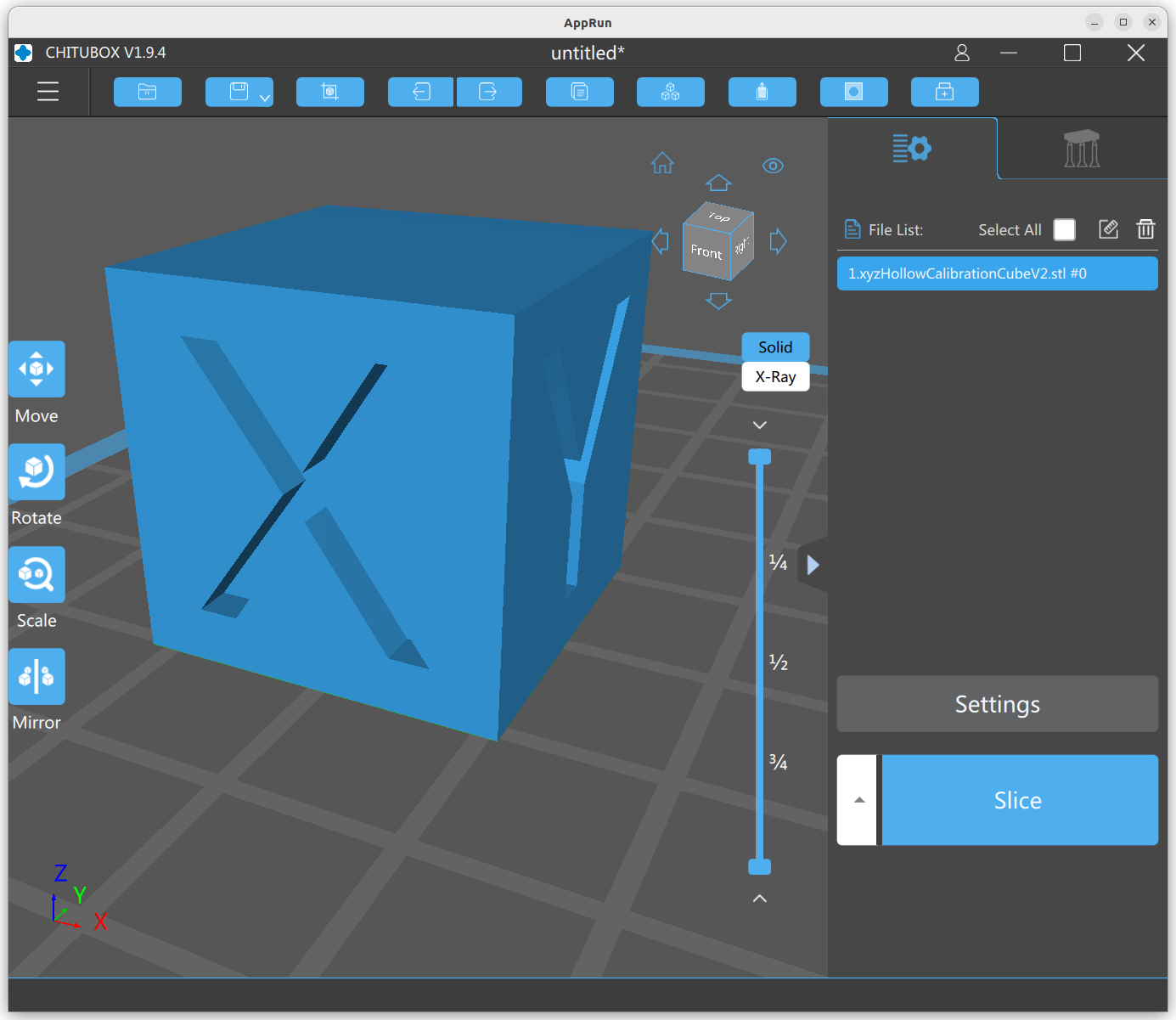
I tried my xyzHollowCalibrationCubeV2 and used auto hollow feature which defaults to 2mm thickness:
This seems to work but is not ideal. The Photon Workshop reveals that Photon Mono 4K supports only .pmwa format, which as it turns out, is PWS format just with the extension .pmwa to avoid mixing up different PWS files for different machines, as the pixel-based slices are hardware dependent now as resolution of the display is set.
Chitubox for Linux
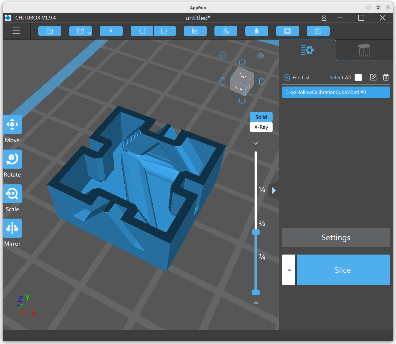
Chitubox Slicer is available for Linux natively and supports a variety of SLA printers, also the Mono 4K:
I also used the auto hollow feature, which defaulted to 1.2mm wall thickness.
Lychee Slicer for Linux
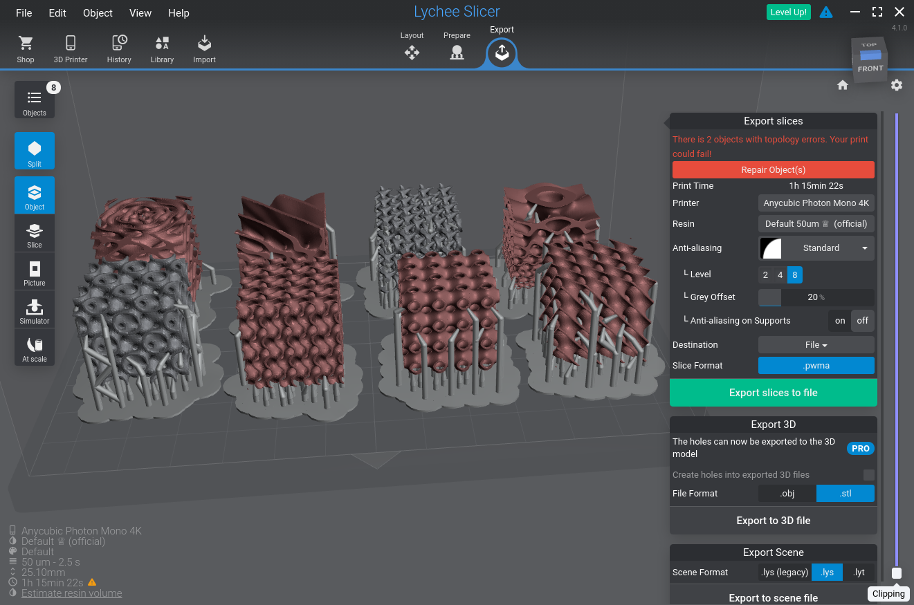
I ended up with the Lychee Slicer which is available for Linux as well, which contains some annoying advertising to wait for when slicing or exporting various formats, but functionality-wise it it is more intuitive than Chitubox Slicer.
Lychee Slicer 4.1.0 for Linux (AppImage)
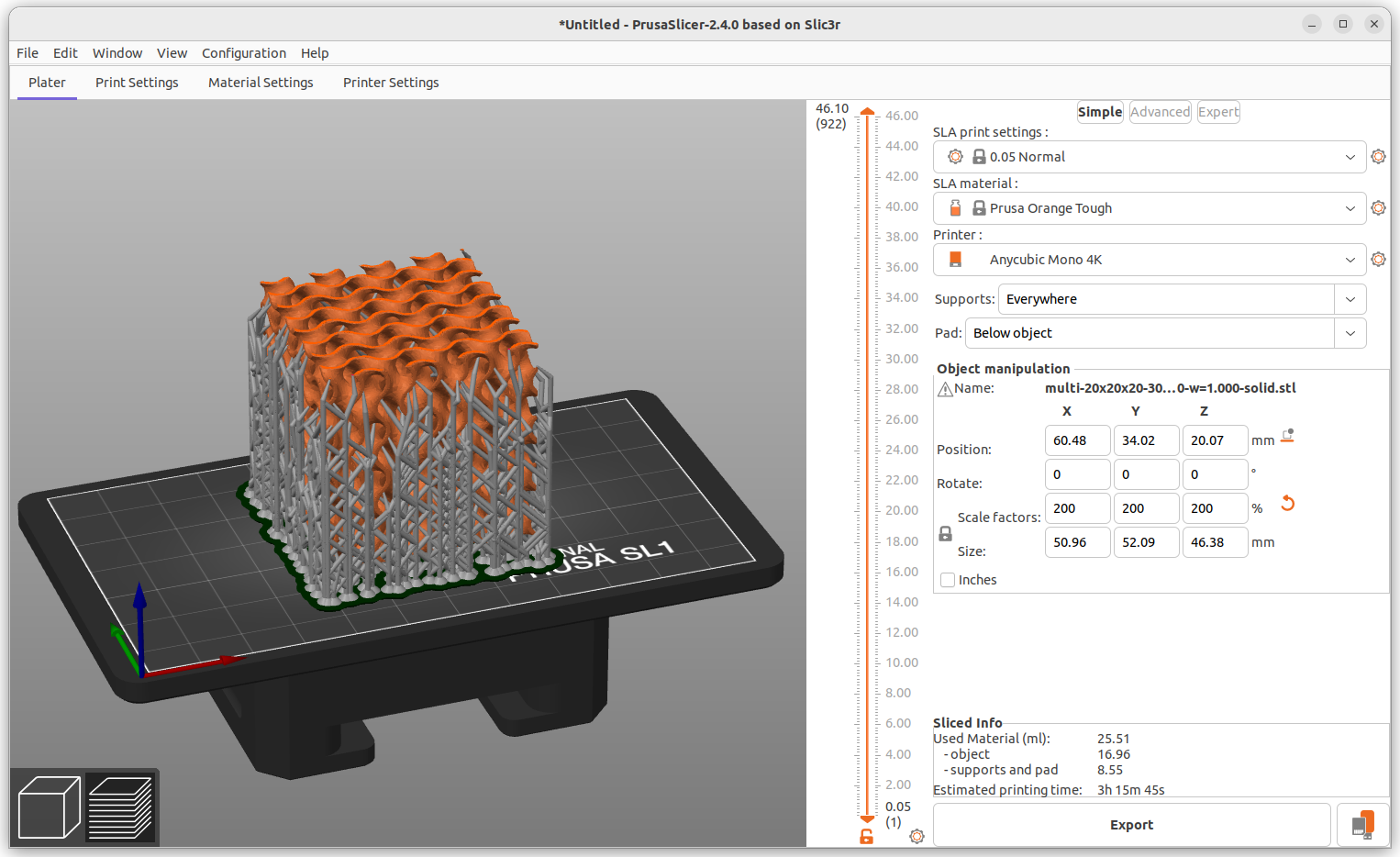
Prusa SLA Slicer
Prusa Slicer 2.4.0 using SLA subsystem and custom build-volumeRedefining Printer Settings to fit Anycubic Photon Mono 4K: 132x80mm / 3840×2400 px
As mentioned, the Photon Mono 4K has its own proprietary file-format PWS file to print with, with a particular file extension to indicate which Anycubic MSLA device it is sliced for:
Machine
File Extension
Layer Image Encoding
Mono
PWNO
PWS
Mono SE
PWMS
PWS
Mono X
PWMX
PWS
Mono X2
PMX2
PWS
Mono 4K
PWMA
PWS
S
PWS
PWS
Zero
PW0
PW0
X
PWX
PWS
Ultra
DLP
PWS
D2
DLP2
PWS
Prusa Slicer slices also for MSLA, it’s own .sl1 format, just a ZIP file with a list of PNG files per slice, in order to convert .sl1 to PWS/.pwma another tool is required:
UVtools, it can read and write many SLA image formats, incl. PhotonWorkshop (.pw*) file-formats
another approach could be (as of 2022/12 not yet) to just convert sl1 to .photon with SL1toPhoton command line tool, and extend functionality to support PWS/.pwma as well
alternatively uv3dp supports pw0 and pws files, but struggles with new(er) PWS files like .pwma
.photon/ctb/cbddlp vs .pw*
.photon (and ctb/cbddlp) is an older file format, whereas newer Photon Workshop (PW) has PWS and PW0 encoded images as layers – so far the format seems reverse engineered and somewhat documented via UVTools: PhotonWorkshopFormat.cs
does not report layer counts, but be determined from the amount of enclosed .png files
does not support multi-exposure printing
PWS
SL1
x_resolution [px]
display_pixels_x [px]
y_resolution [px]
display_pixels_y [px]
xy_pixel [μm]
display_pixels_x / bedshape[x] * 1000 [μm]
layers_count
len(<*.png>)
Replacing Firmware
MSLA resin printers are quite closed systems without much information of the hardware, firmware, and additional having their own proprietary file formats which contain the layer images.
For the Anycubic Photon Mono 4K is an open source firmware available, Turbo Resin – which gave me a good reason to get this 3D printer (2023/07: the firmware isn’t complete yet). Along with it, the hardware has been pretty much reversed engineered.
Anycubic Firmware
Turbo Resin (2022/12)
– PW0/PWMA format
– PW0/PWMA & CTB format
Custom MSLA Slicer
Pondering on a custom MSLA slicer:
automatic hollowing of solids at certain wall thickness
automatic support generation, outside and inside (after hollowing)
drain hole generation
command line interface (CLI)
external preview of sliced part
supporting sl1 and pws/pw0 as a start
Feature
Prusa Slicer
Lychee Slicer
ChituBox Slicer
command line interface (CLI)
Y
–
–
automatic hollowing
Y
Y
Y
drain holes
Y
Y
Y
automatic support
Y
Y
Y
Linux support
Y
–
–
PWS support
–
Y
Y
Open MSLA Format
Unfortunately there is no open (M)SLA format, each manufacturer kind of does its own, whereas G-code .gcode has some conformity, although G-code in general is also machine specific has it has absolute positioning, which differ from machine to machine, but at least G-code is easy to compose unlike proprietary (M)SLA file formats.
SL1 format by Prusa Engineering is a simple ZIP file which contains:
config.ini: irrelevant info
prusaslicer.ini: info about printer (bed size), pixel density, and many slicer settings
*.png: enumerated image files per slice in PNG format
and thereby is open enough for my taste.
Requirements of Open MSLA Format
simple format for controller to decode
simple pixel data1)
simple preview image format1)
this is why PWS/PW0 or CTB fileformat use some simple RLE algorithm to compress pixel data
First Print
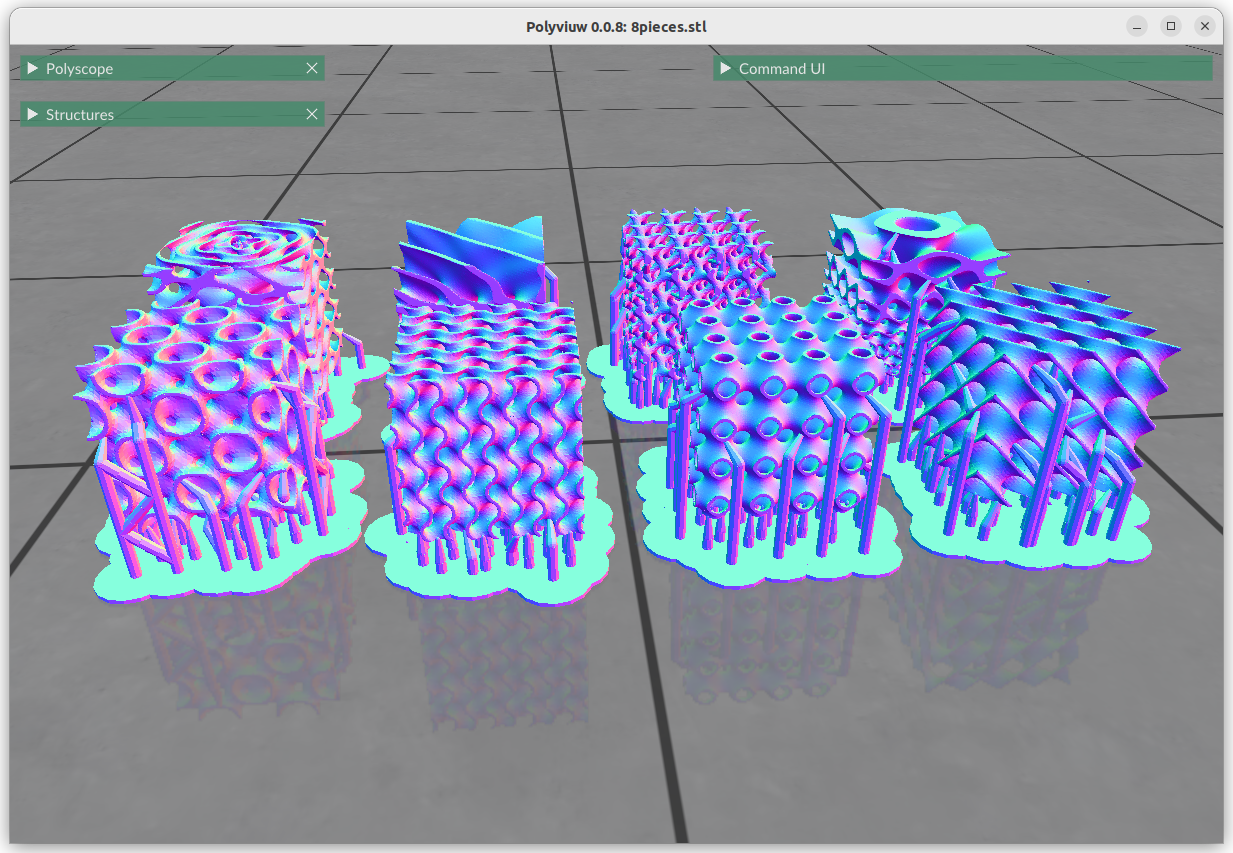
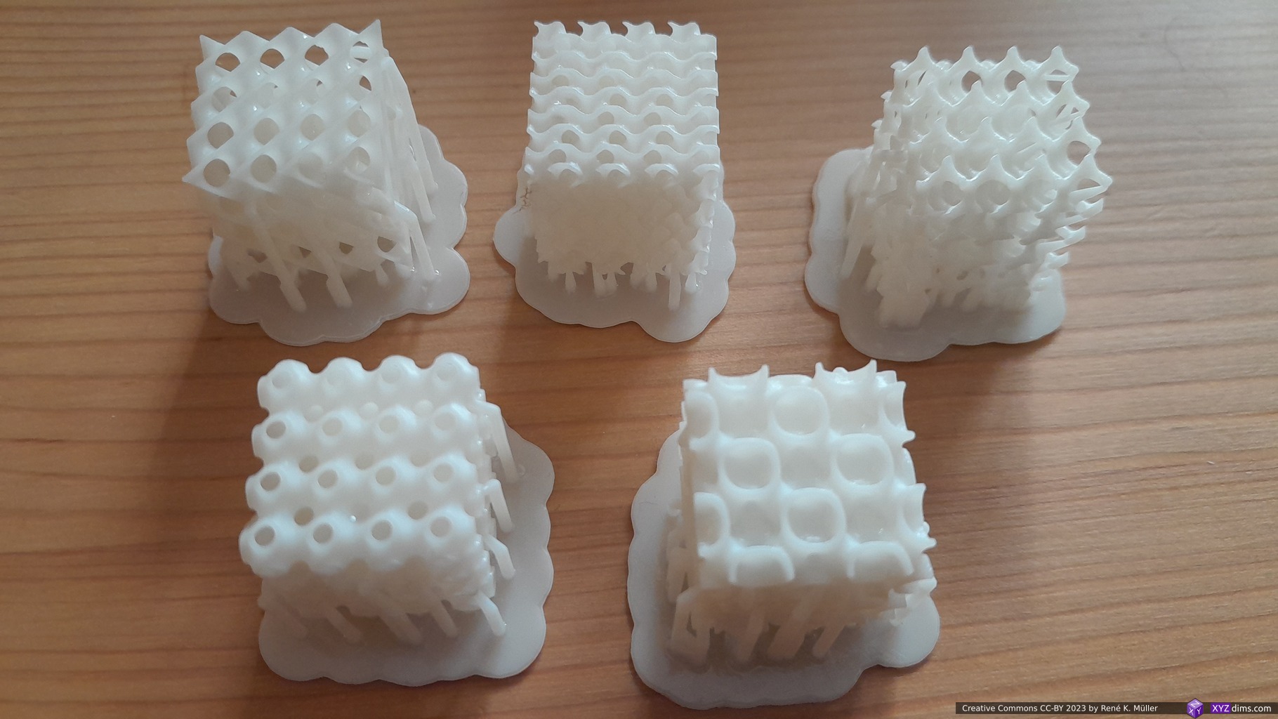
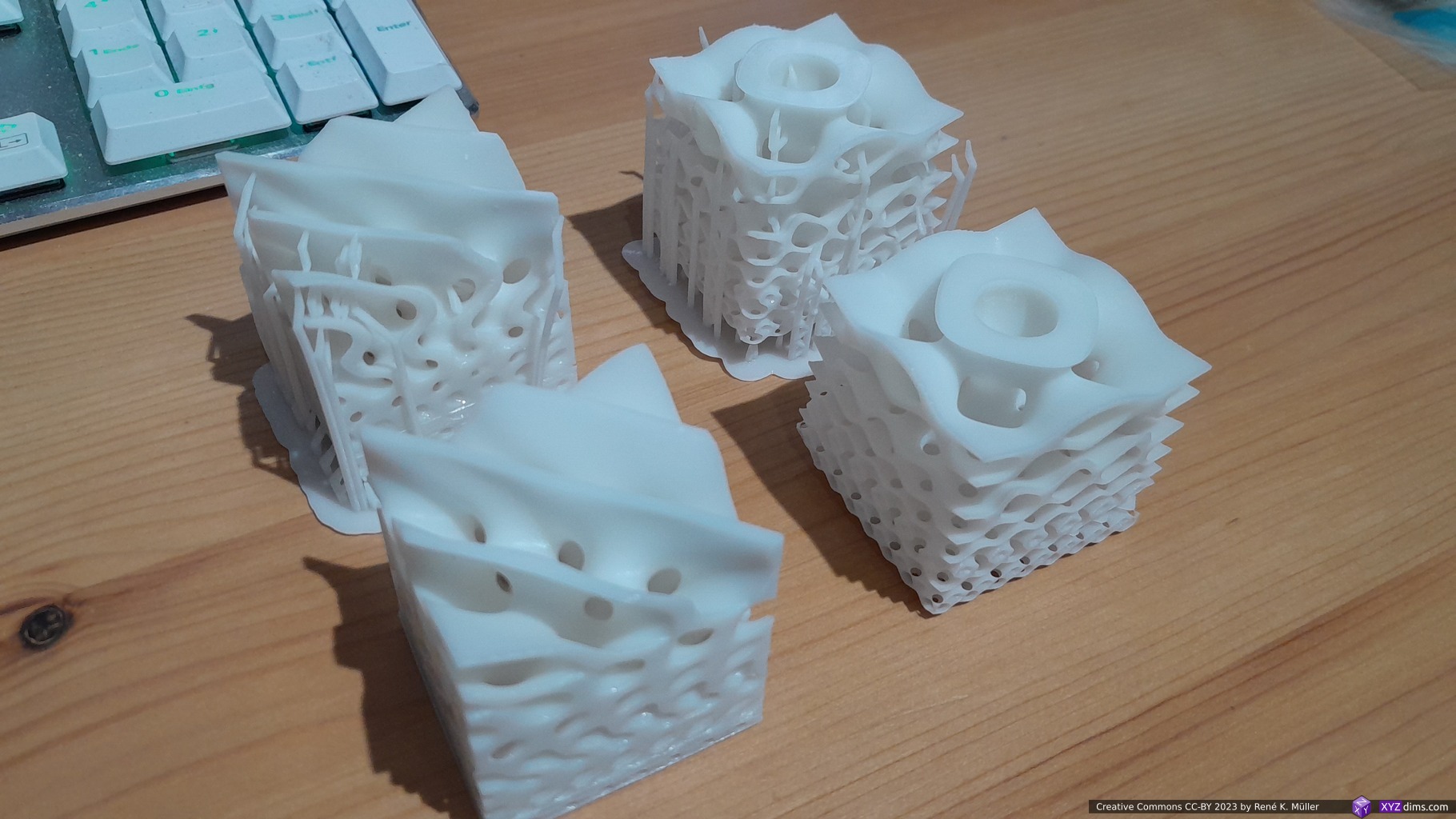
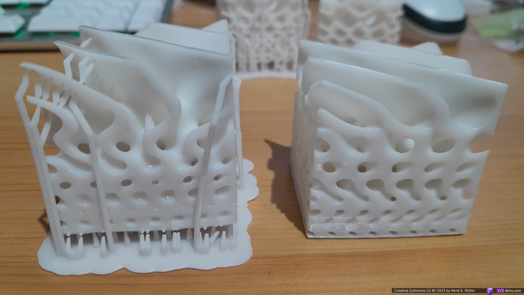
After many weeks postponing, as I wasn’t eager deal with the inherent messiness of resin printing, I gave it a shot with some of the Triply Periodic Minimal Surfaces (TPMS) (2023/03/05):
Lychee Slicer: 8 TPMSScene exported as STL with supportAnycubic Mono 4K: starting print 2h 15mAnycubic Mono 4K: mid print
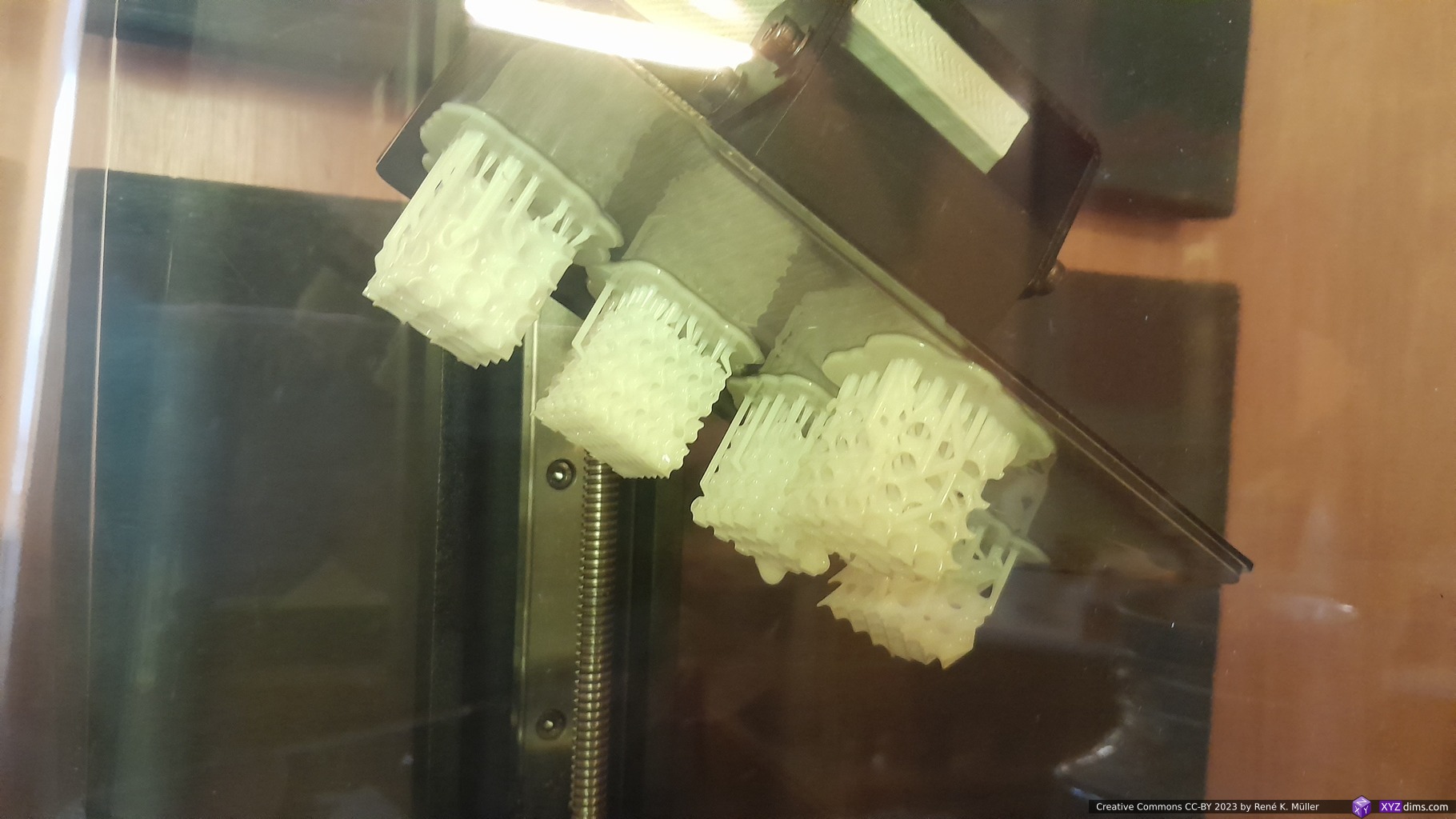
The Lychee Slicer gave 1h 15m print time, the printer itself showed 2h 15m; I used Anycubic White Water Wash Resin. I used automatic supports, and it printed 5 pieces successful, 3 pieces failed and only apprx. 4mm Z height were printed, interestingly all 3 failed pieces failed at the same Z height and broke off and stuck at the print plate.
Batch 1: 5 pieces printed successful, 3 failedWashed & cured: 5 TPMS 20mm: (front) Schwarz P, FRD, (background): Schwarz D, Gyroid, Gyroid Skeletal Washed & cured: 5 TPMS 20mm: (front) Schwarz P, FRD, (background): Schwarz D, Gyroid, Gyroid SkeletalBatch 2: reprinting previously 3 failed prints again, this time successful at the same position, same settings
I reprinted the 3 failed pieces at the same place, and this time they succeeded – which is strange as I suspected perhaps uneven light or some other positional inconsistency, but obviously the position did not matter, which is bad as I don’t know what caused the first failed print.
The curved bottoms (not directly printed but with diverse support pipes) already showing severe distortion while printing.
Update: It seems my office rooms aren’t warm enough, so the bed adhesion isn’t optimal as I read up in some forum posts. I tried to print a few other pieces, all failed the next day in the room with 15-19C° – the prints detached after 2-3mm height from the build plate. I moved it to another warmer room, warmed the resin on the radiator which helped.
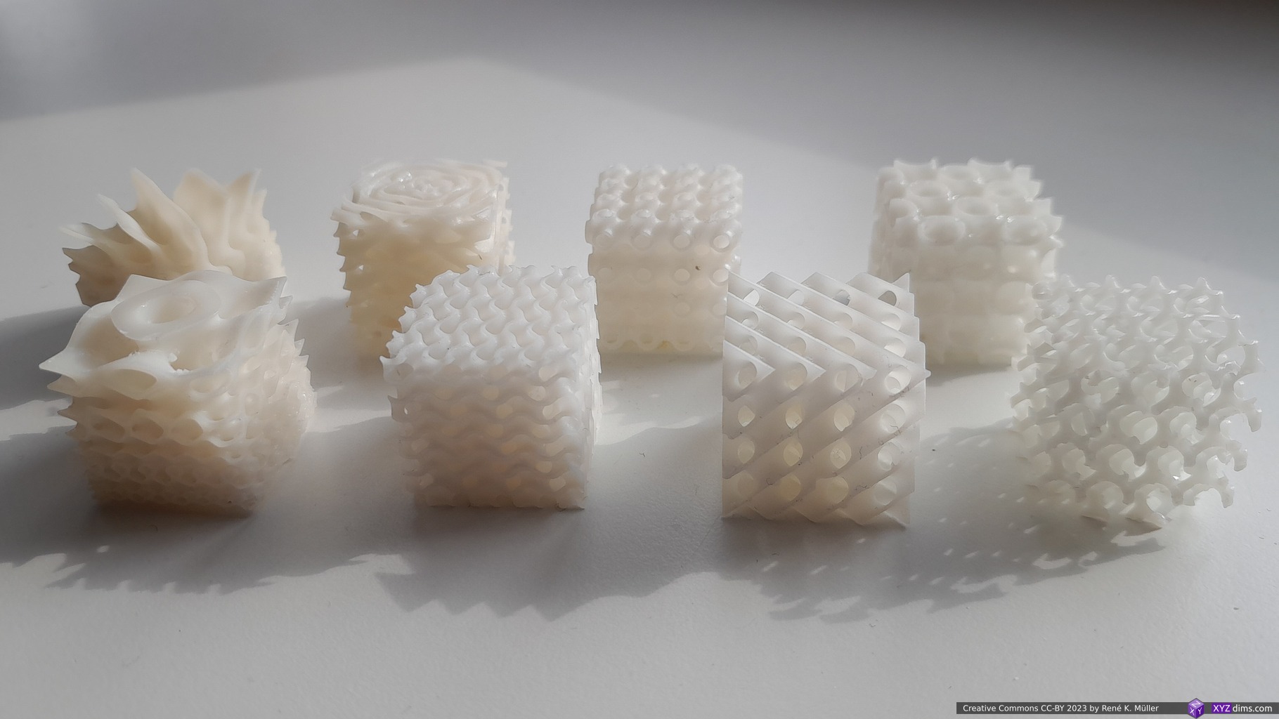
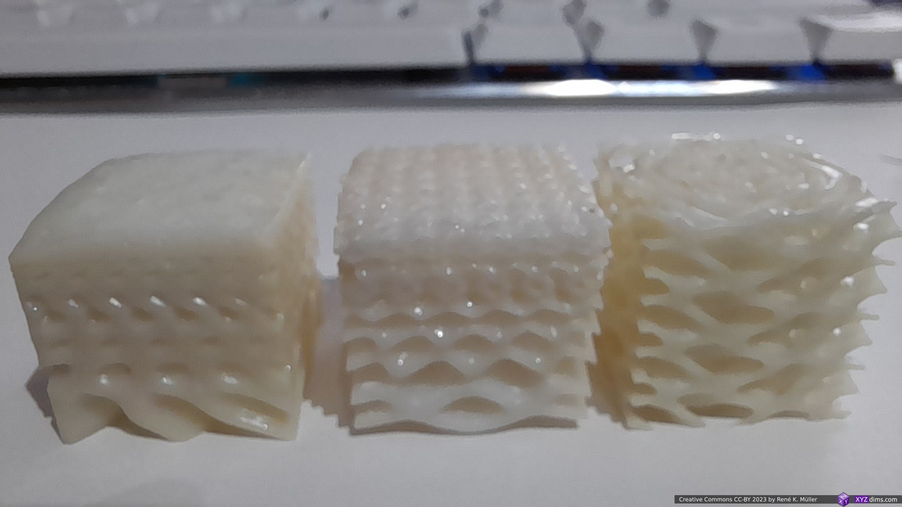
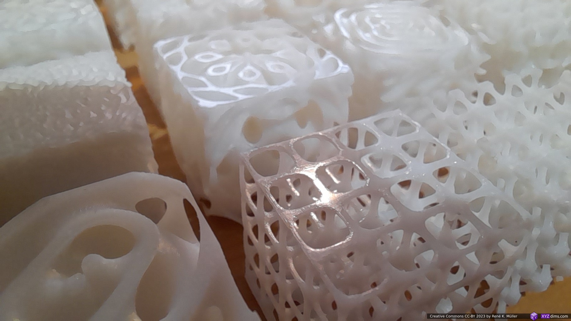
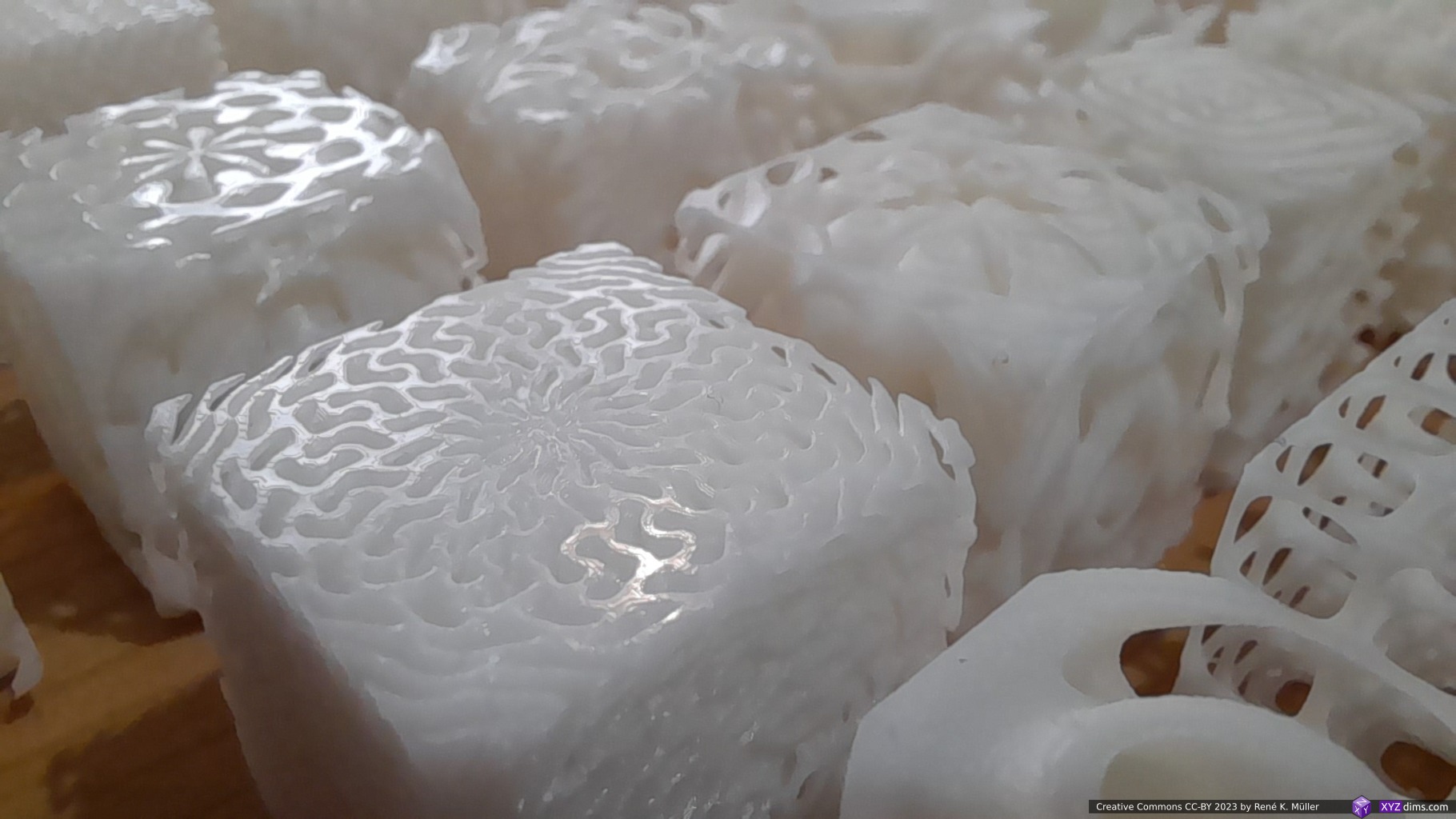
The overall quality of the pieces is astonishing, no visible voxels or layers are seen, incredible quality for those prints which didn’t fail.
Yet the failure rate is still significant for my taste, so I need to pay close attention to room temperature, and other aspects:
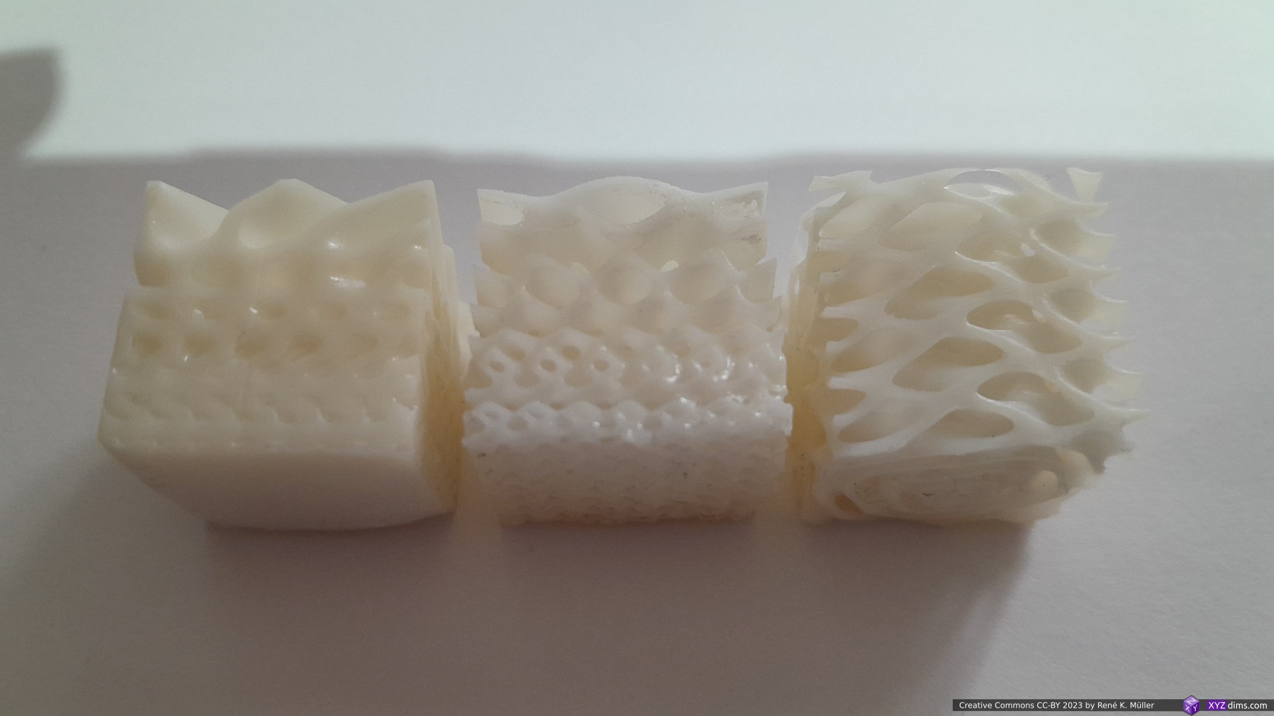
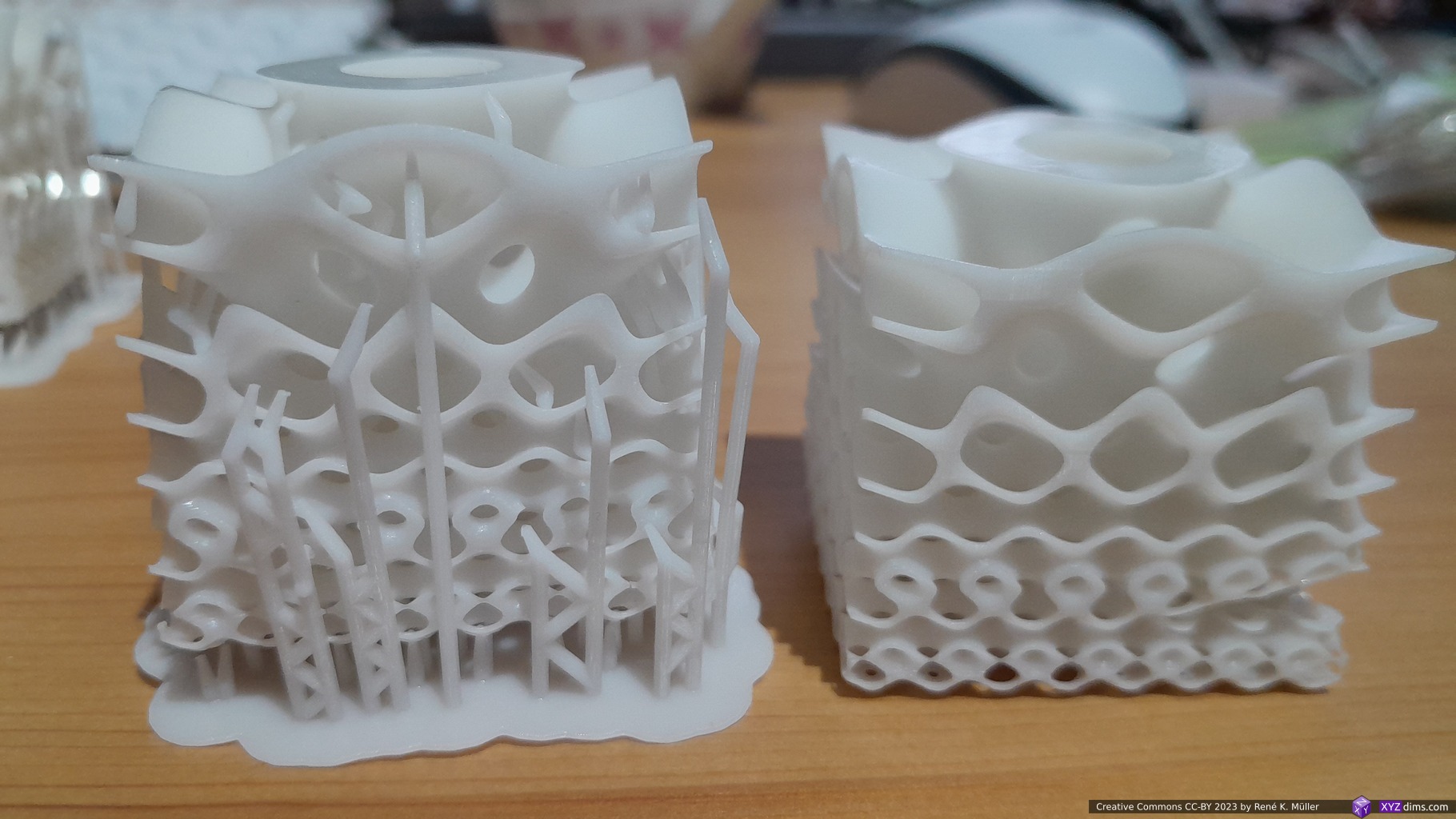
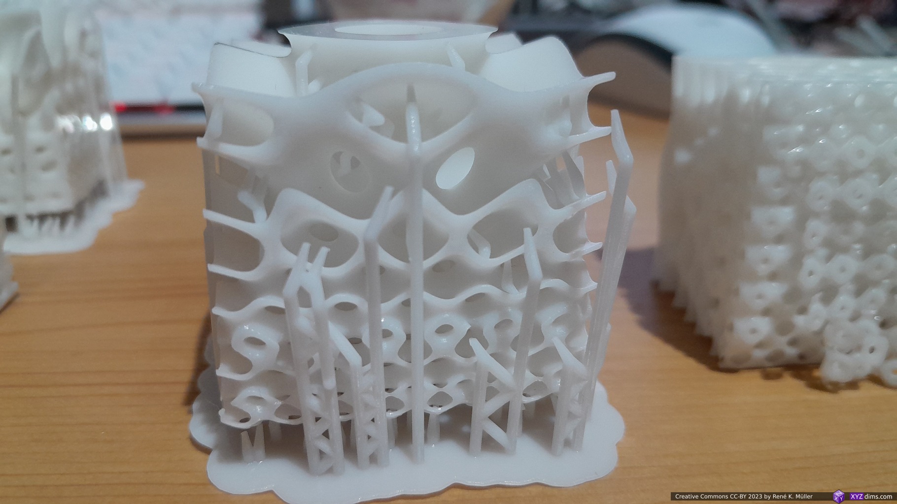
Variable frequency of Schwarz P & D TPMS (40mm cube): with support and withoutSchwarz D variable frequency TPMS: with and without support (both successful prints)Schwarz P variable frequency TPMS: with and without support (mixed success)Schwarz P variable frequency TPMS with support (successful print)Schwarz P variable frequency TPMS without support: deliminated near bottom (failed print)Schwarz P variable frequency TPMS without support: deliminated near bottom (failed print)Schwarz D: 35μm XY, 50μm Z, seeing the voxels in the closeup
The cause of the “delimination” isn’t clear yet to me, it seems the prints with proper support and elevated bottom printed better, but I need to confirm with more prints.
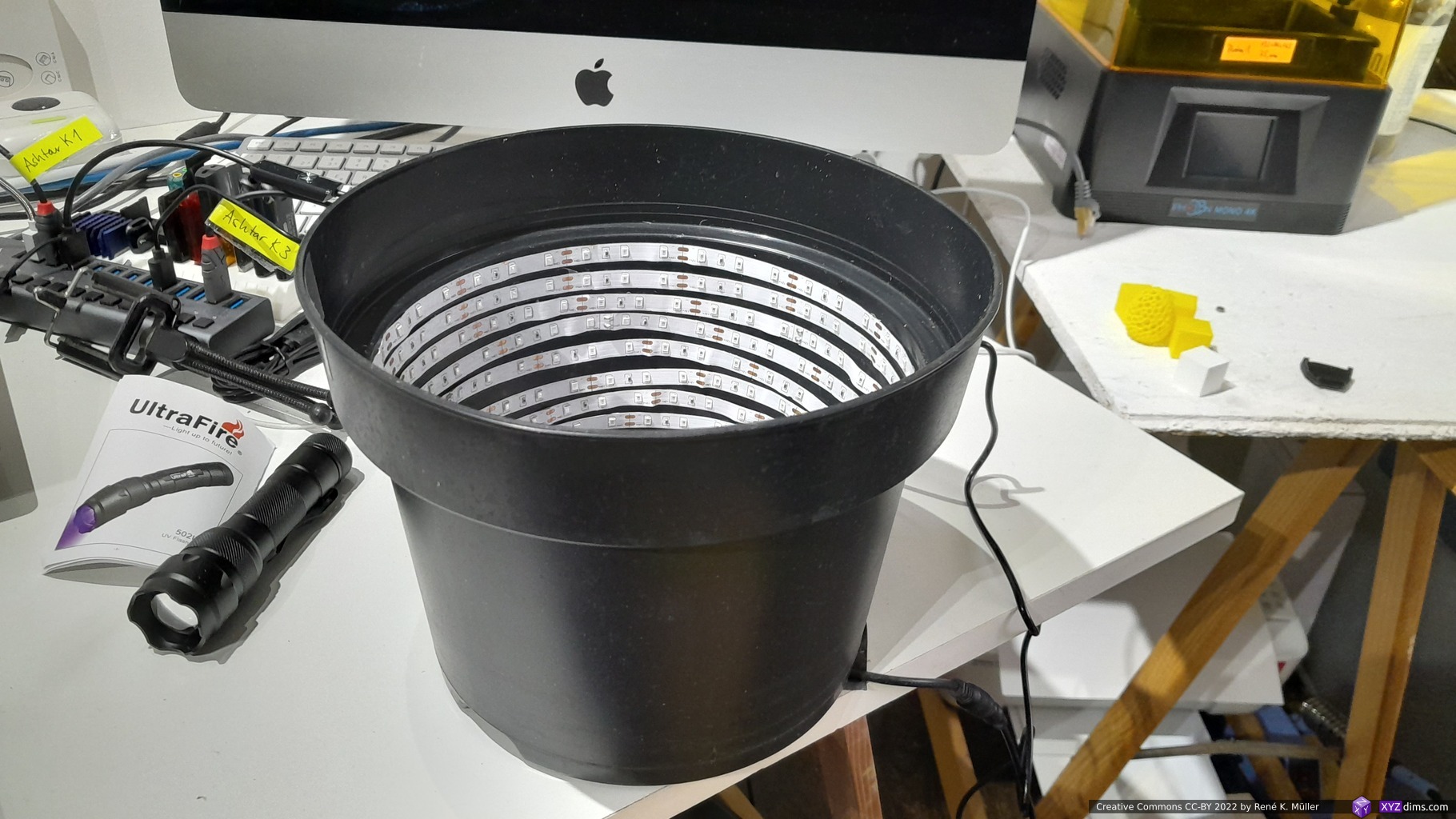
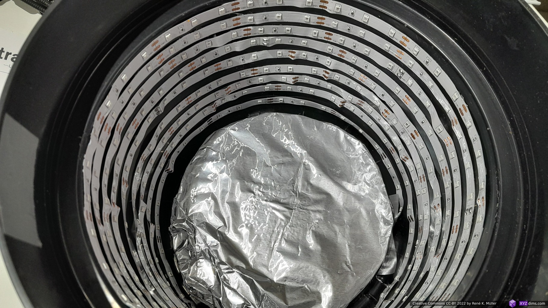
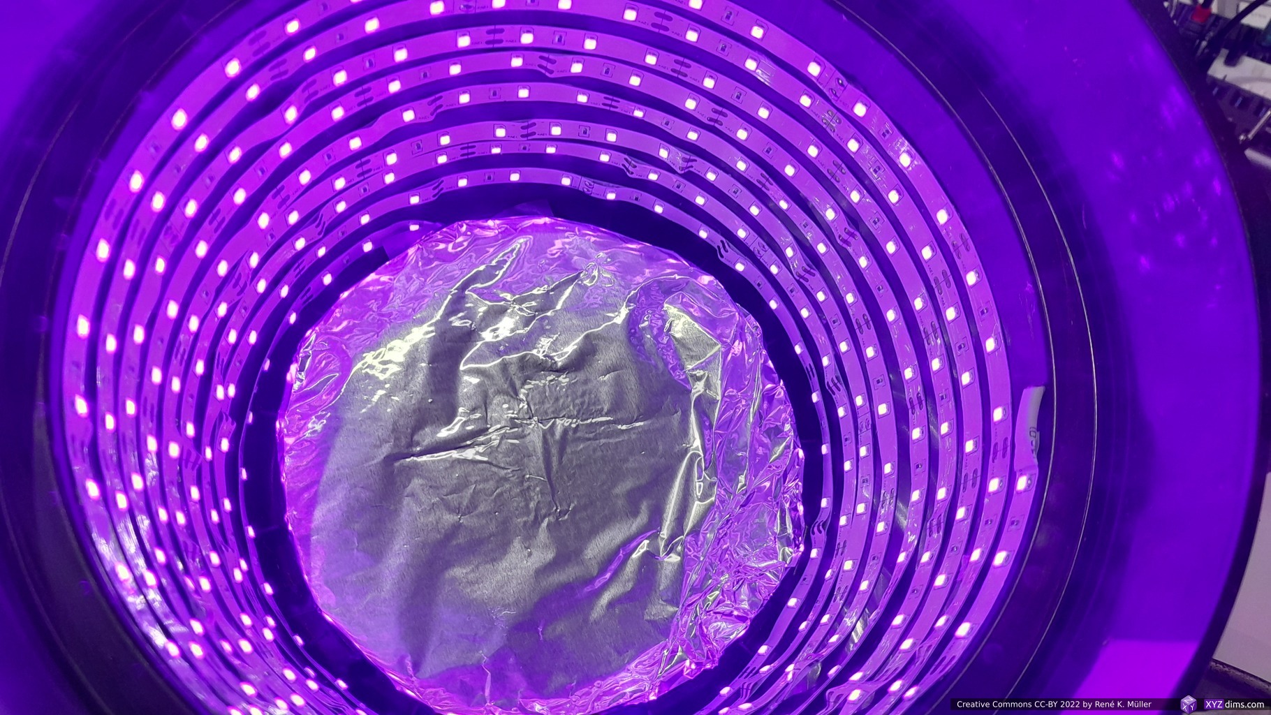
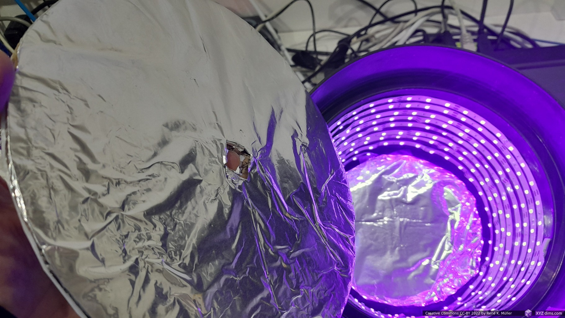
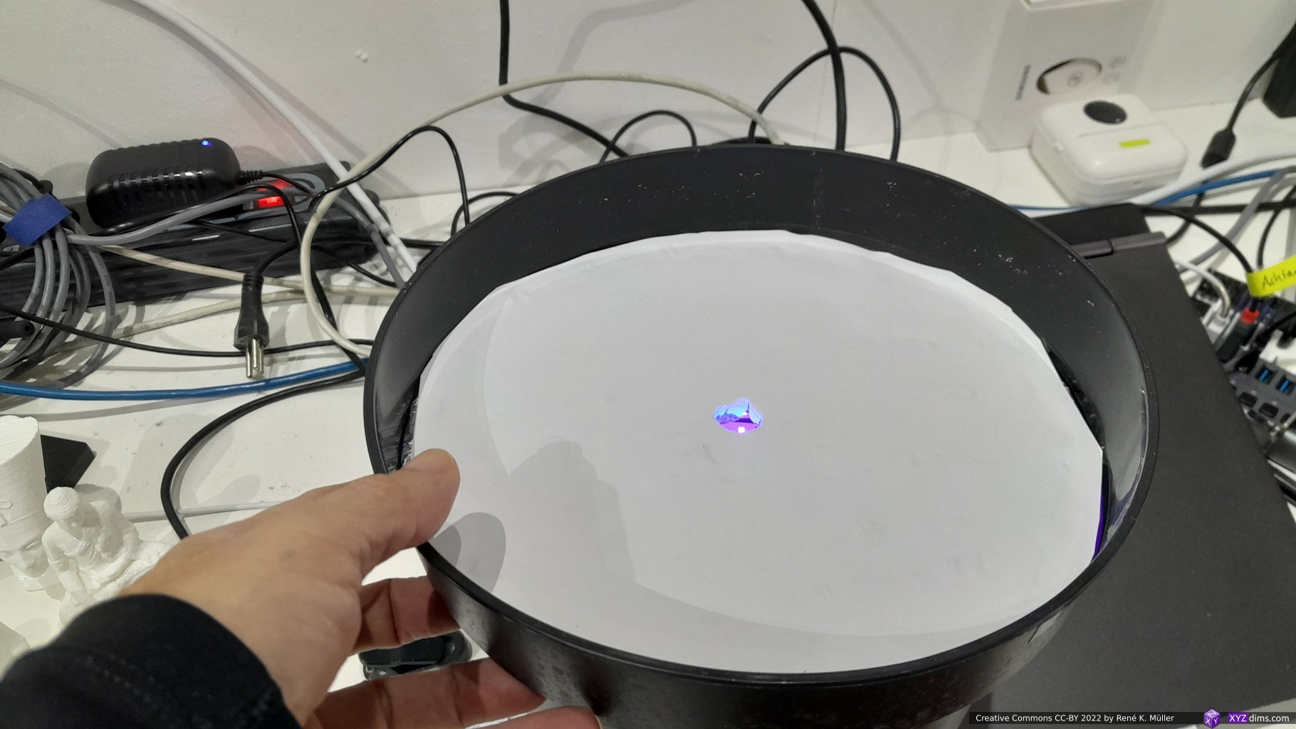
As a start I assembled a simple DIY curing station with a 5m UV LED strip and placed it inside a plastic cup, with some aluminium foil at the bottom and top lid:
I only cure for 4-5mins, longer exposure changes the white resin into yellowish tint, and indicates over curing.
Keeping Resin in the Vat
After a print, the resins needs to be filtered for impurities, such as partial cured pieces not attached to the part, with a funnel and filter into a cup or bottle, and then it can be poured back into the vat ready to print again.
One can leave the resin in the vat for weeks, if you stir the resin short before you print again – stirring the resin within the vat is not ideal, as one has to avoid to scratch or FEP film; yet there is no need to pour resin back into the bottle unless one changes the resin, like the brand or color.
Drip Hook
I remixed an existing drip hook for Photon Mono to fit Photon Mono 4K, and make it easier to slide the bed on and off.
Additionally I’ve got a spring steel build plate 135x80mm with a magnetic base for EUR 10 (2022/12).
This turned out to be a good choice, the removal of the pieces is easy without additional tool.
Caution:
the thickness of the adhesive magnet holding the plate required the optical Z endswitch to recalibrate, instead to move the sensor, I extended the light breaking piece with just a small piece of paper with a drop of glue – it was easier than 3d printing an extender for the entire sensor.
in my case the small handle of the plate scratches on the original vat at the last 3-4mm height, therefore the entire plate needs to be slightly misaligned (just pushing one side while fastening the build plate) so the handle doesn’t touch the vat.
third party Anycubic Mono 4K vat like from Mega/Kingroon have a larger space, and don’t need any fiddling around therefore
the spring steel is sharp, it happened several times the single-use gloves being torn/cut while handling the plate
(One of) My Use Case
After a few days I aimed for the main use case of mine: printing custom pulleys.
MSLA @ 35μm XY, 50μm Z vs FFF @ 400μm nozzle, 100μm Z
As I printed them with Anycubic Water Wash White Resin without support, the “elephant foot” comes from the first 6 layers being cured for 40s as in my case, and the UV light refracting and curing more than meant to be, but I can neglect this.
16 custom pulleys ID8 20T printed with Anycubic Photon Mono 4K in 1h 30m or 5m30s per piece
MSLA
FDM/FFF
geometrical accuracy
★★★★☆1)
★★★☆☆
surface quality
★★★★☆
★★☆☆☆
mechanical sturdiness
(not yet tested)
★★★☆☆ (PLA)
print time per piece
5m 30s2)
15m
print time for 1 piece
1h 30m
15m
print time for 16 pieces
1h 30m
4h
due the “elephant foot” the Z accuracy was off by 0.8mm, instead of 15.0mm it’s 14.2mm
when printing 16 pieces, it took 1h 30m for printing 15mm in Z, I could have printed ~28 pulleys on 132 x 80mm build plate, bringing print time for a piece down to 3m 10s
Settings
from Anycubic Web-Site (2023/03/12)
My own experience with different resins (to be extended):
Defaults V0.0.11 Firmware V0.11
Defaults V2.0.2 Firmware V0.16
White WATER WASH RESIN (Anycubic)
Clear Water Wash Resin (Resione)
Layer Thickness [μm]
50
50
50
50
Exposure Time [s]
3
2.5
3
2 .. 3
Exposure Off Time [s]
2.5
1
0.5
0.5
Bottom Exposure [s]
50
30
40
40
Bottom Layers
6
6
6
6
Anti-alias
1
1
1
1
Z Lift Distance [mm]
3.0
4.0
6.0
6.0
Z Lift Speed [mm/s]
1.0
1.0
2.0
1.0
Z Retract Speed [mm/s]
1.0
1.0
4.0
1.0
UV Power [%]
100
100
100
50 .. 100
Notes
Distance, Speed & Retract Speed for – [BL] Bottom Layers – [NL] Normal Layers individually definable
– geometrical precise
– soft with 3s exposure – stiffer & brittle with 5s exposure – geometrical not precise (+0.2 .. 0.8mm in XYZ)
Preliminary Review
Pros:
good prints for the price
cost effective
power loss recovery actually works
lot’s of third party replacements (vat, FEP, etc)1)
alternatively Open Source firmware
nearly full reverse engineered hardware
this actually is quite important: popular machine raise a secondary market for replacements: future replacement of parts even when Anycubic ends support
Cons:
newly bought machine had outdated firmware
updated firmware calculates wrong total print time, this is just sloppy
touchscreen unreliable (wrong position) ‘print’ vs ‘delete’, use a soft pencil
slow prints with default settings (1mm/s Z motion), not nearly at 50mm/h height as advertised
Confusing:
slicer print settings are ignored, only settings on the machine matter
advantage: once sliced the .pwma can be printed with different resins and settings changed on the machine only
disadvantage: one has to memorize or document settings for different resins, as it not stored in the .pwma file
Verdict
It’s a low-cost entry level MSLA machine, Anycubic seems to care little about the software (2023/03) as the slicer as well the firmware are Minimal Viable Product (MVP) level, but aren’t mature or reliable at all. Given they sell 500K+ machines per year at least, investing to improve in the firmware would help 500,000 users.
Small anecdote: I bought a pre-owned Mono 4K, becoming “Photon 2”, from official Anycubic store at Ebay directly – the listing said the machine likely would miss some parts – but I felt to get some more in-depth experience, and I’ve got what I asked for: the machine came dirty with resin all over, no power-supply, no build-plate, no vat, and cured resin between LCD and underlying (acryl-)glass, spent EUR 120+ for replacement parts, and 10+ hrs cleaning it to get it in working condition again. From a cost saving point of view not worth it, but experience wise it was good to get to know the machine more thoroughly.
Resin Printer Value Comparison
A numeric value summarization for features I care about, the rough & simple formula:
XY Area [mm2] / Price [EUR] / XY Resolution [μm]
The bigger the XY area, the smaller the price and the smaller the resolution, the higher the value:
Formlabs 3’s & EMake SLA printers use a laser beam which has 100μm in diameter, but it can be positioned 25μm exact, the latter was used to calculate the value
The UV pixels are non-square, the longer side was used to calculate the value
Elegoo Jupiter 2 advertised the Z build volume as 300mm, it can print but you can’t remove it afterward, so it’s rather 275mm.
The XY area in SLA scales not as good as with MSLA, as the laser beam takes longer the more XY area (e.g. more pieces) need to be rendered per layer – so, MSLA is recommended for aiming fast parallel printing. Interestingly Formlabs 4 is now a MSLA as well (2024/04), they seem to have abandoned the SLA laser-based approach.
2023/02/08: worked on text and illustrations a lot, many sample prints, multiple visualization approaches, details on f1 + f2 vs f1 * f2 and cylindrical and spherical transformation of TMPS
2023/01/05: adding mesh/voxel renderings, slicing geometry to generate G-code
2022/12/11: first FDM G-code generated using 2D / contour approach
2022/12/07: included many suitable periodic minimal surfaces
2022/12/02: start with implicit surface focus
As I progress I will update this blog-post.
Introduction
Infill geometries are geometries which are continuous, repetitive or periodic; they fill a boundary defined geometry aka outer form often defined via meshs. Let’s dive into some of the simple geometries and then looking at some more complex structures:
The Implicit Geometries
Implicit geometries are geometries defined via f(x,y,z) = 0 defining their surface, the boundary between inside and outside and they are ideal to define repetitive or periodic 3D infill geometries.
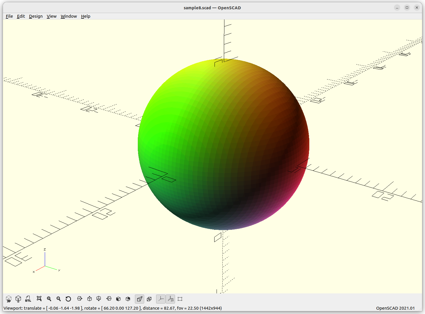
Sphere
Sphere: x2 + y2 + z2 – r2 = 0
When you ever tried to compose a sphere as a mesh, you know there are many ways to do so, and all are more complex than this simple description, and as you realize, the formula is perfect, it’s not an approximation – this is the nature of implicit formula. When you try to visualize an implicit formula, then you need to discretize and there the approximation takes place, as a mesh or as voxels.
Another nifty property of the sphere, it is the minimal surface to circumvent a volume, and through this blog-post, the minimal surface will become a common theme.
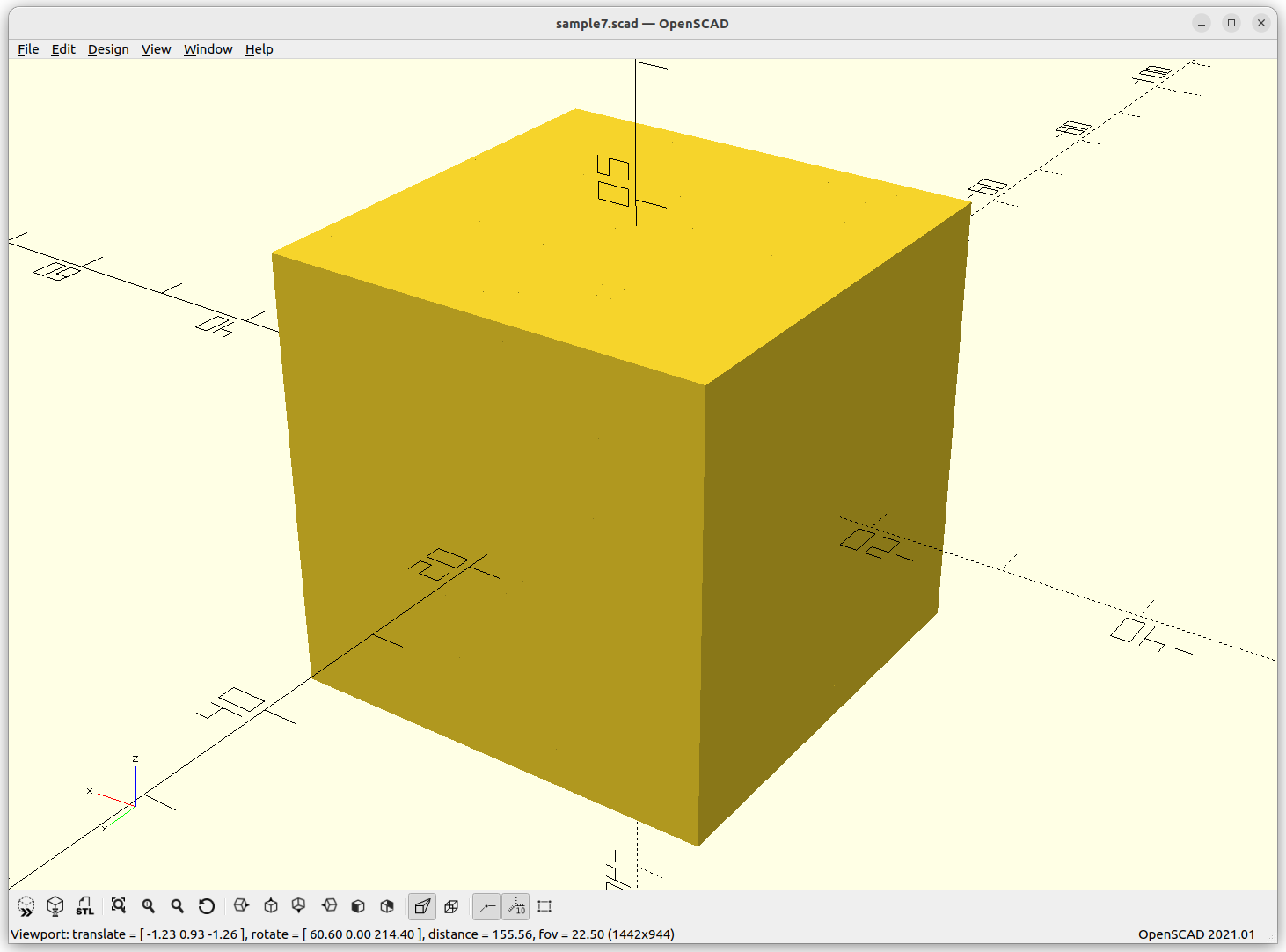
Cube
Cube: max(abs(x),abs(y),abs(z)) – w/2 = 0
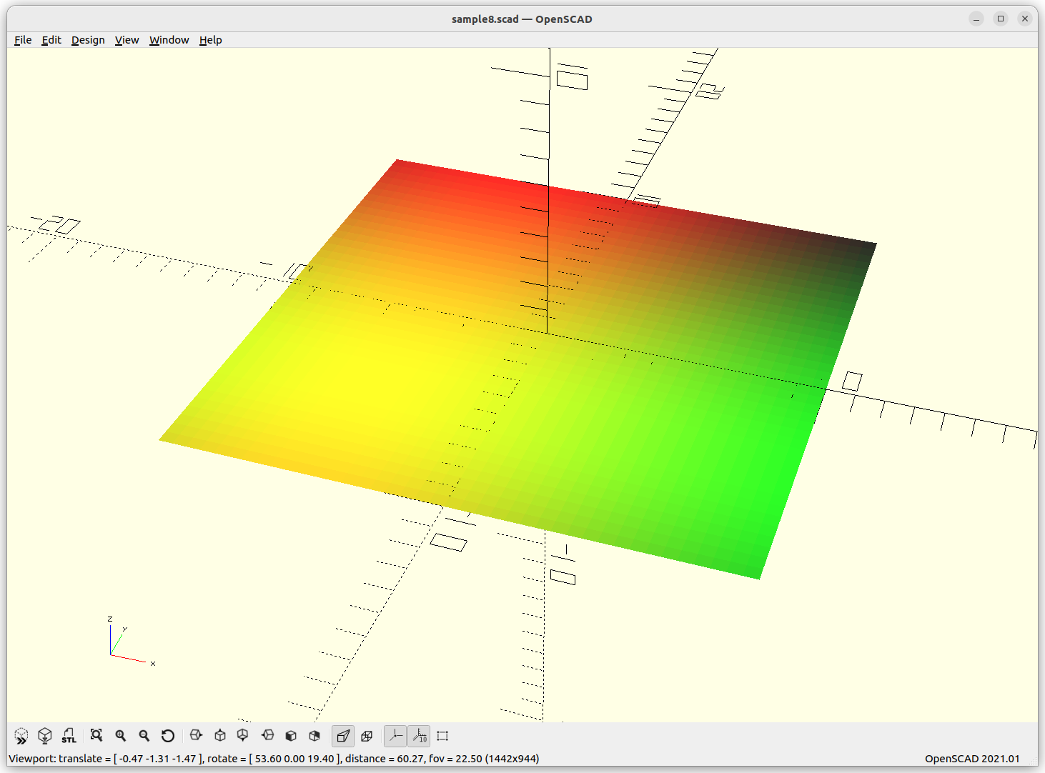
Plane
Plane: z = 0
As I render only -10 to 10 to each axis, it creates a small plate:
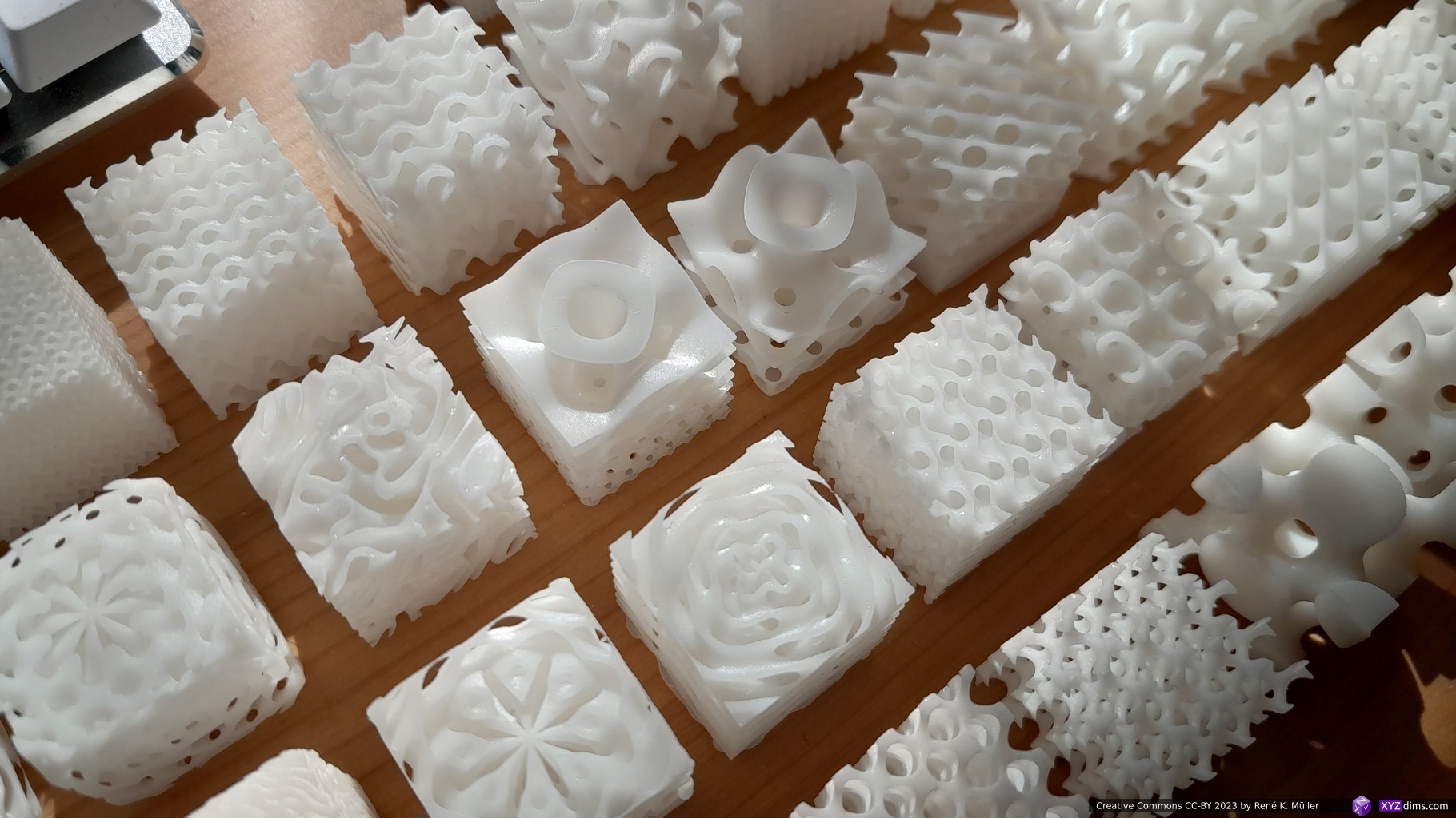
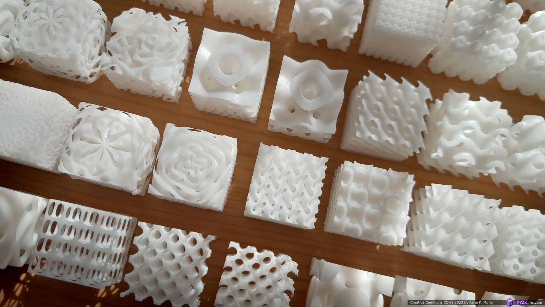
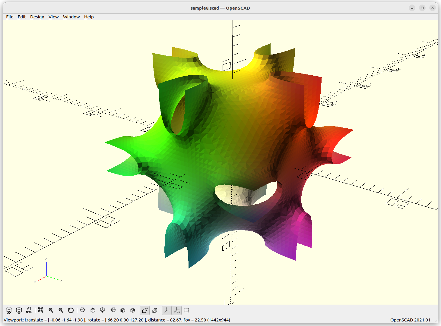
Triply Periodic Minimal Surface (TPMS)
Let’s move to the world of minimal surfaces, so called Triply Periodic Minimal Surfaces (TPMS), those can be expressed in implicit form and have some properties as sought for infill geometries.
In differential geometry, a triply periodic minimal surface (TPMS) is a minimal surface in ℝ3 that is invariant under a rank-3 lattice of translations. These surfaces have the symmetries of a crystallographic group. Numerous examples are known with cubic, tetragonal, rhombohedral, and orthorhombic symmetries. Monoclinic and triclinic examples are certain to exist, but have proven hard to parametrise.
Let’s explore this form more thoroughly, we animate a, b, c, d, and e and see what it does, essentially we animate -1 to 1 in sinus, 0 eliminates of the chunk of the formula:
animating a (-1..-1)animating b (-1..1)animating c (-1..1)animating d (-1..1)animating e (-1..1)
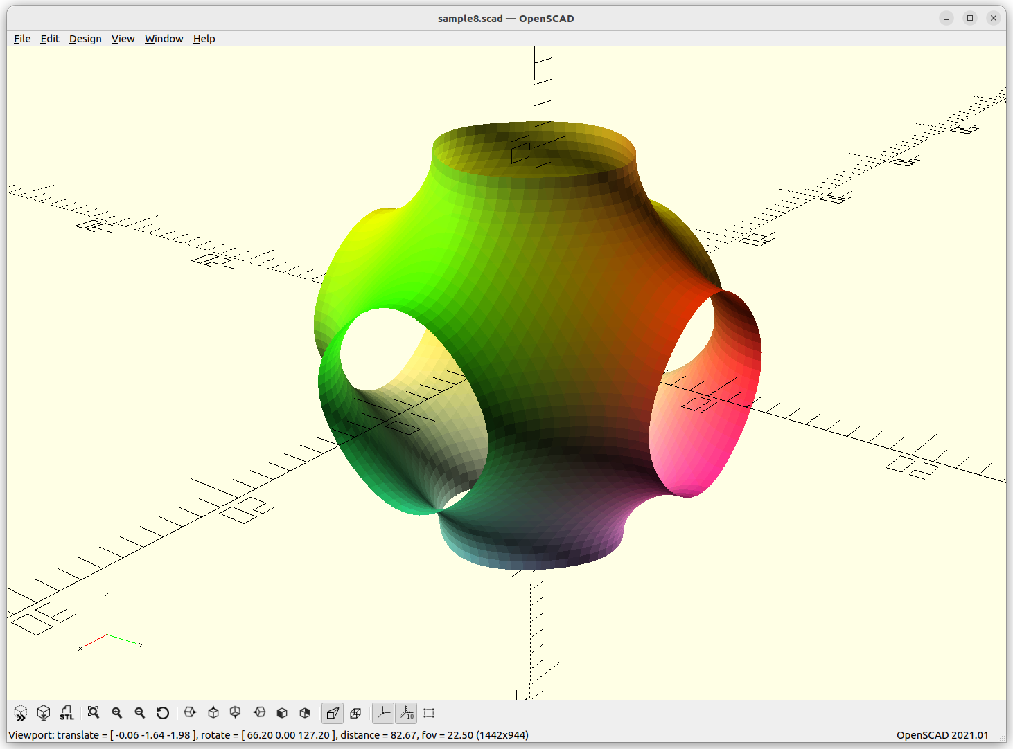
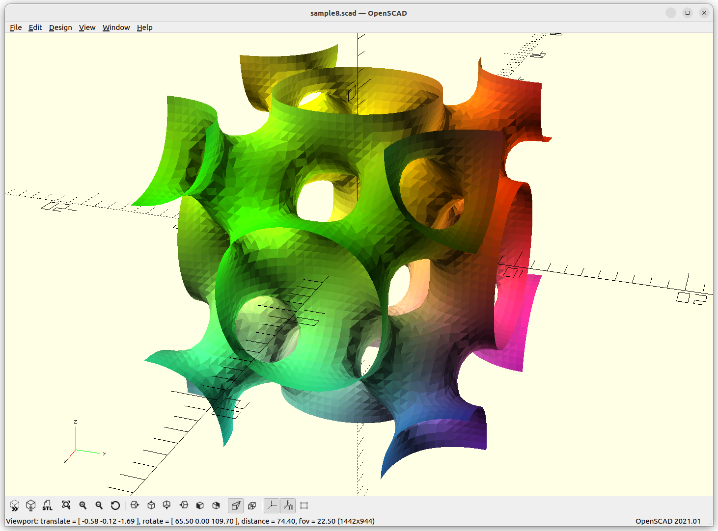
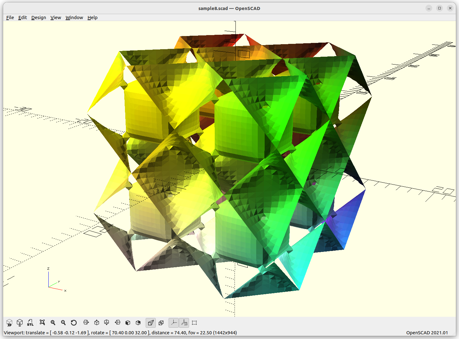
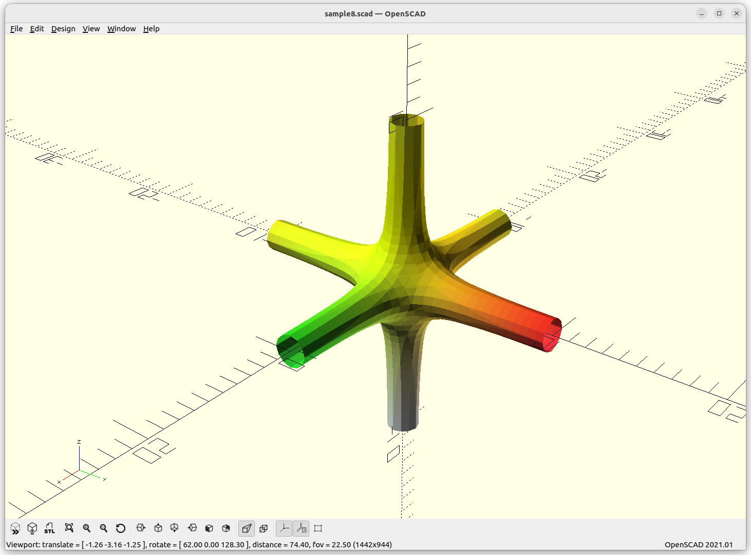
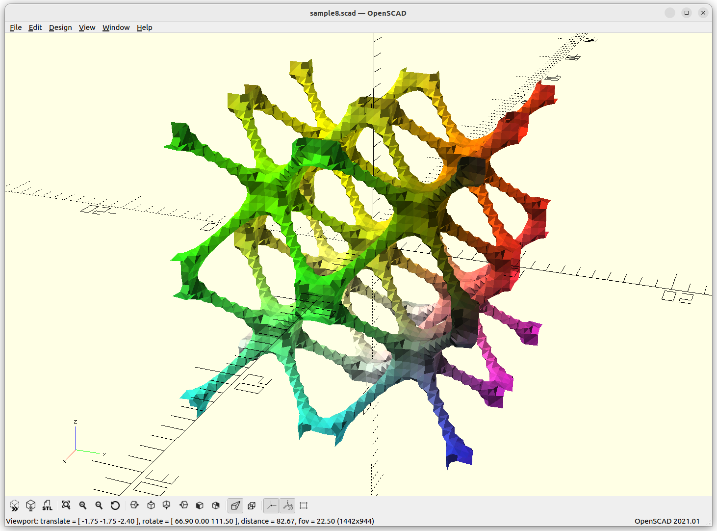
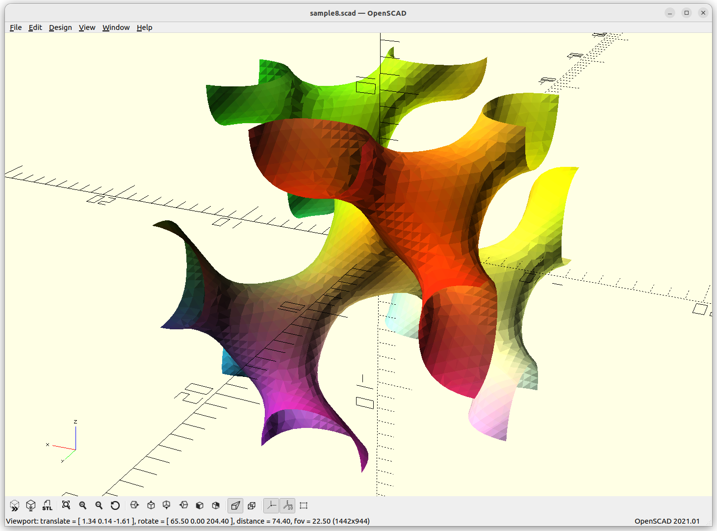
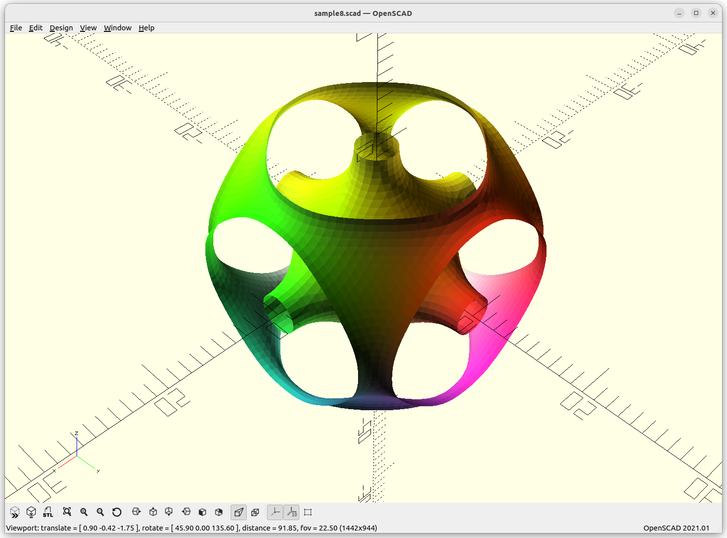
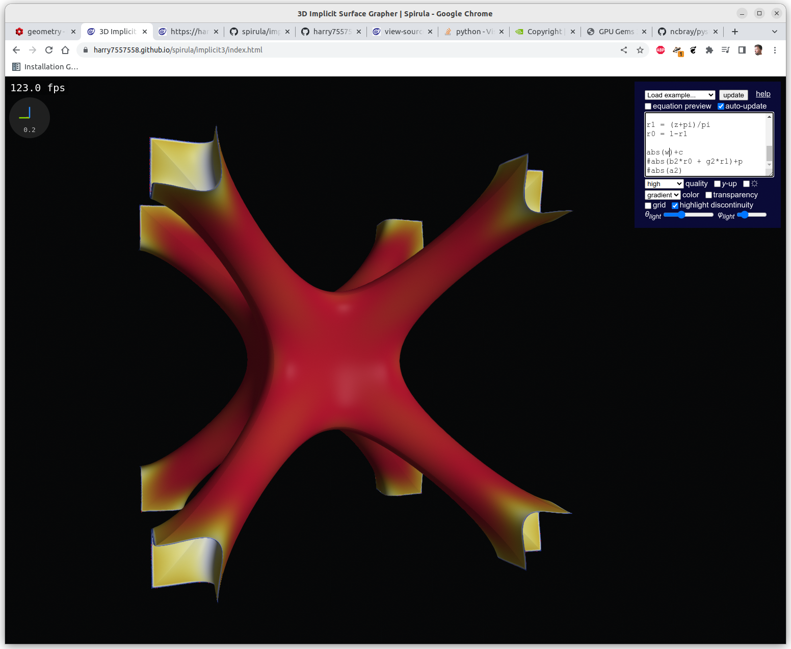
P Skeletal: 10*(cos(x)+cos(y)+cos(z) – 5.1*(cos(x)*cos(y)+cos(y)*cos(z)+cos(z)*cos(x)) – 14.6
By changing the last substraction of 14.6 to 10 or 8, the structure get more dense – ideal to use.
P Skeletal, animating main subtraction -14.6(thin)..5.4(disconnected)
The P Skeletal connects 6 arms to each other.
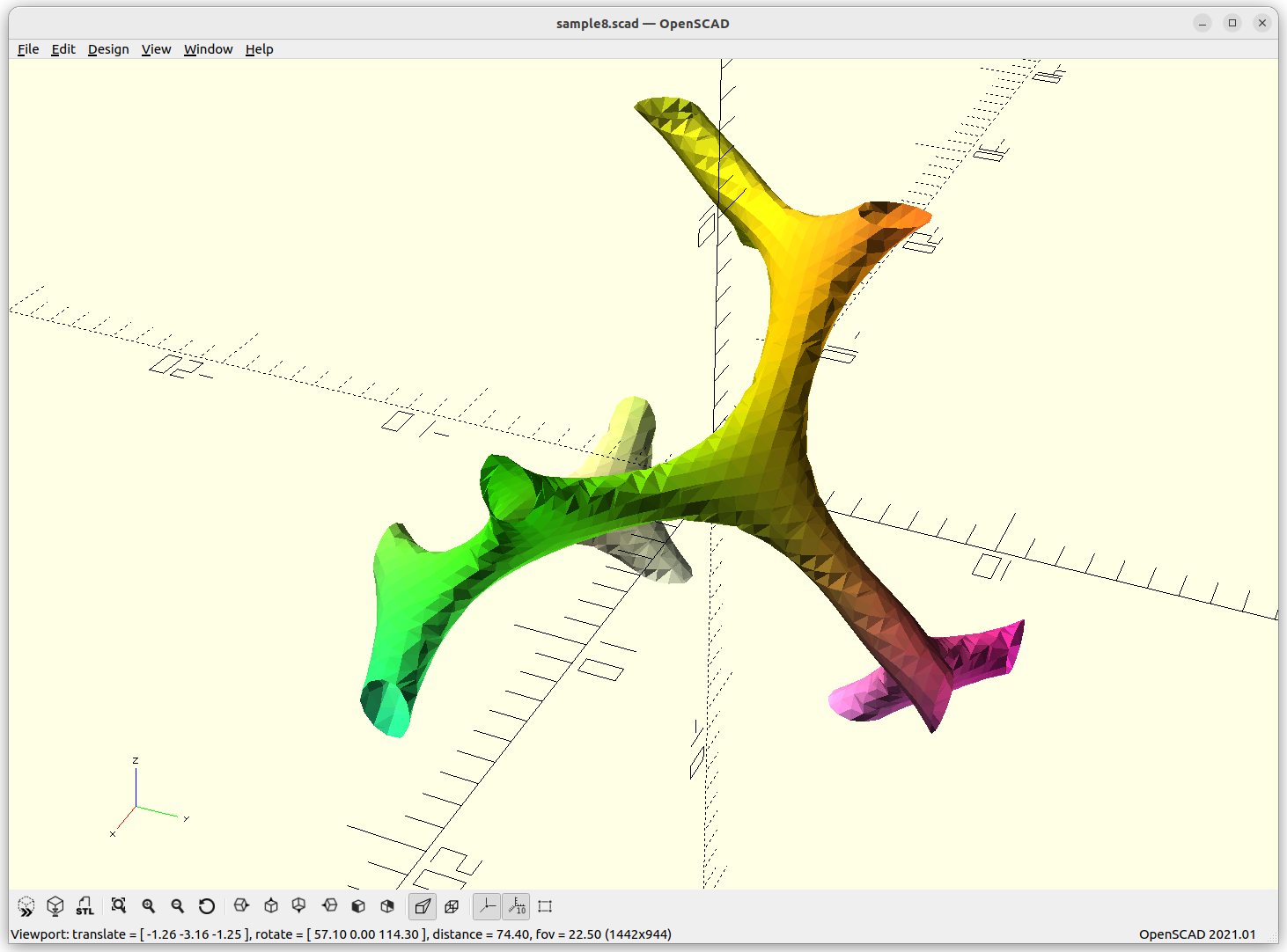
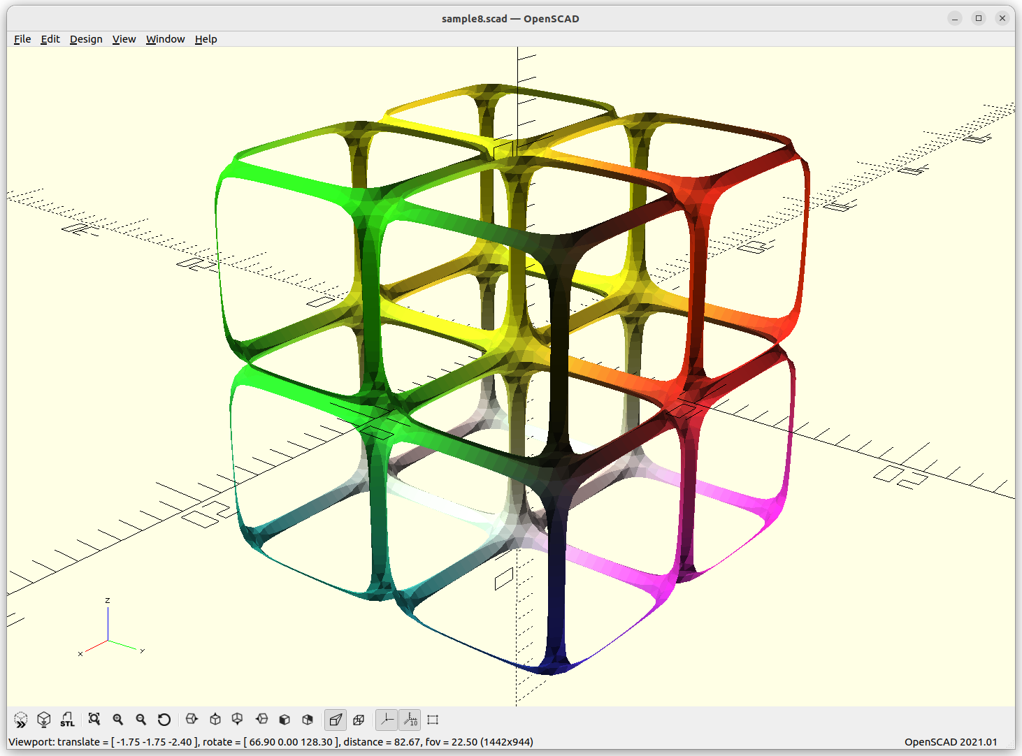
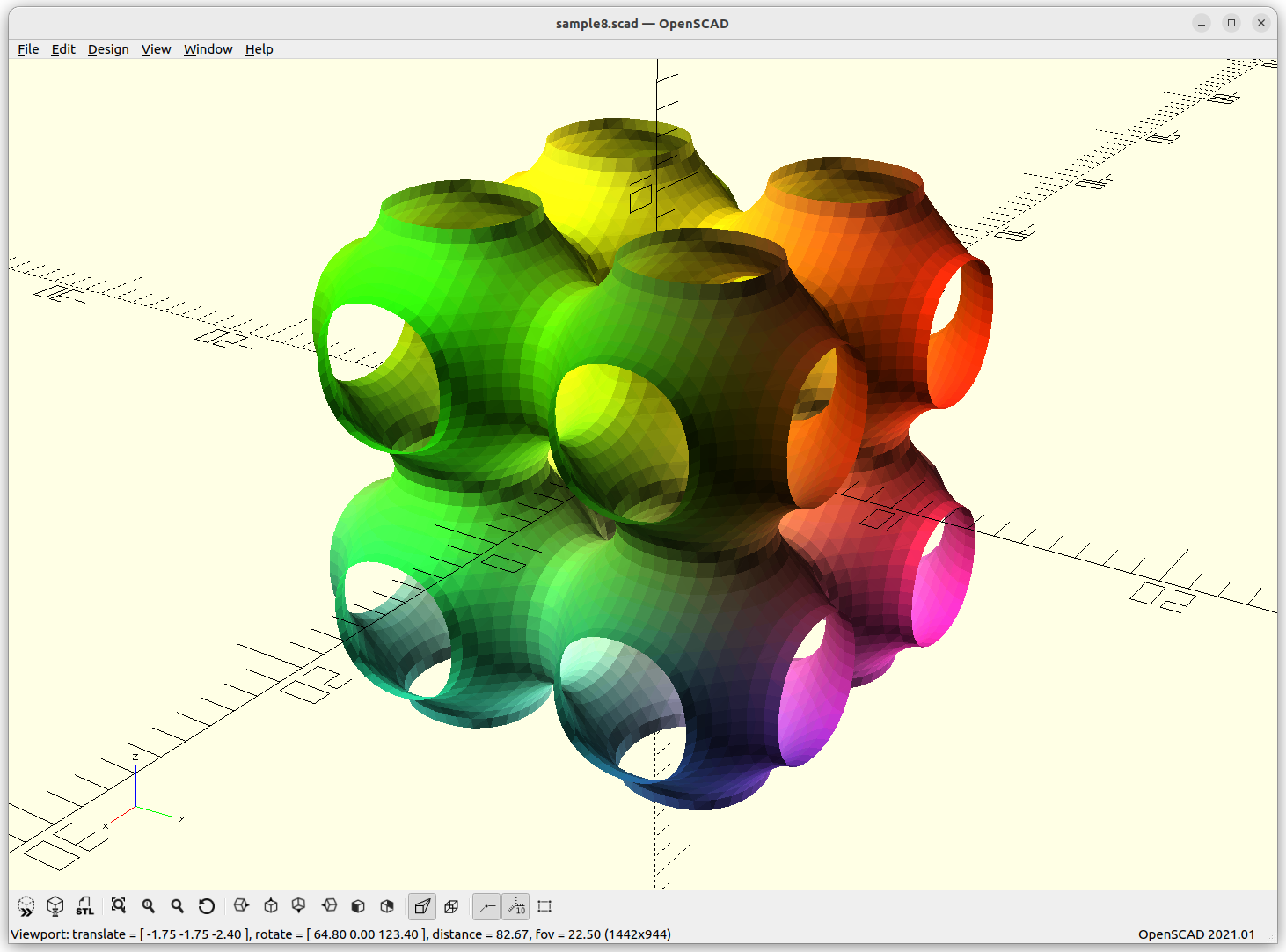
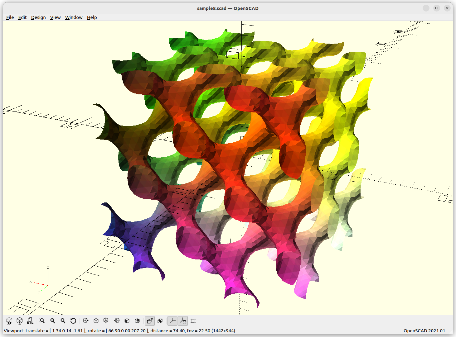
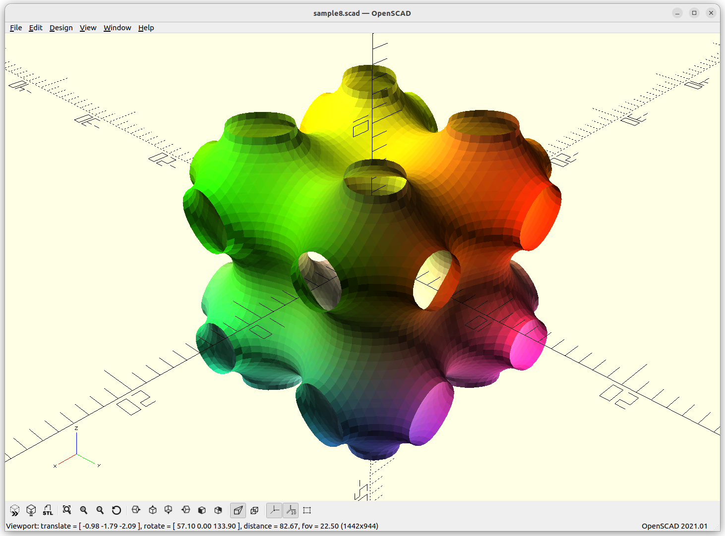
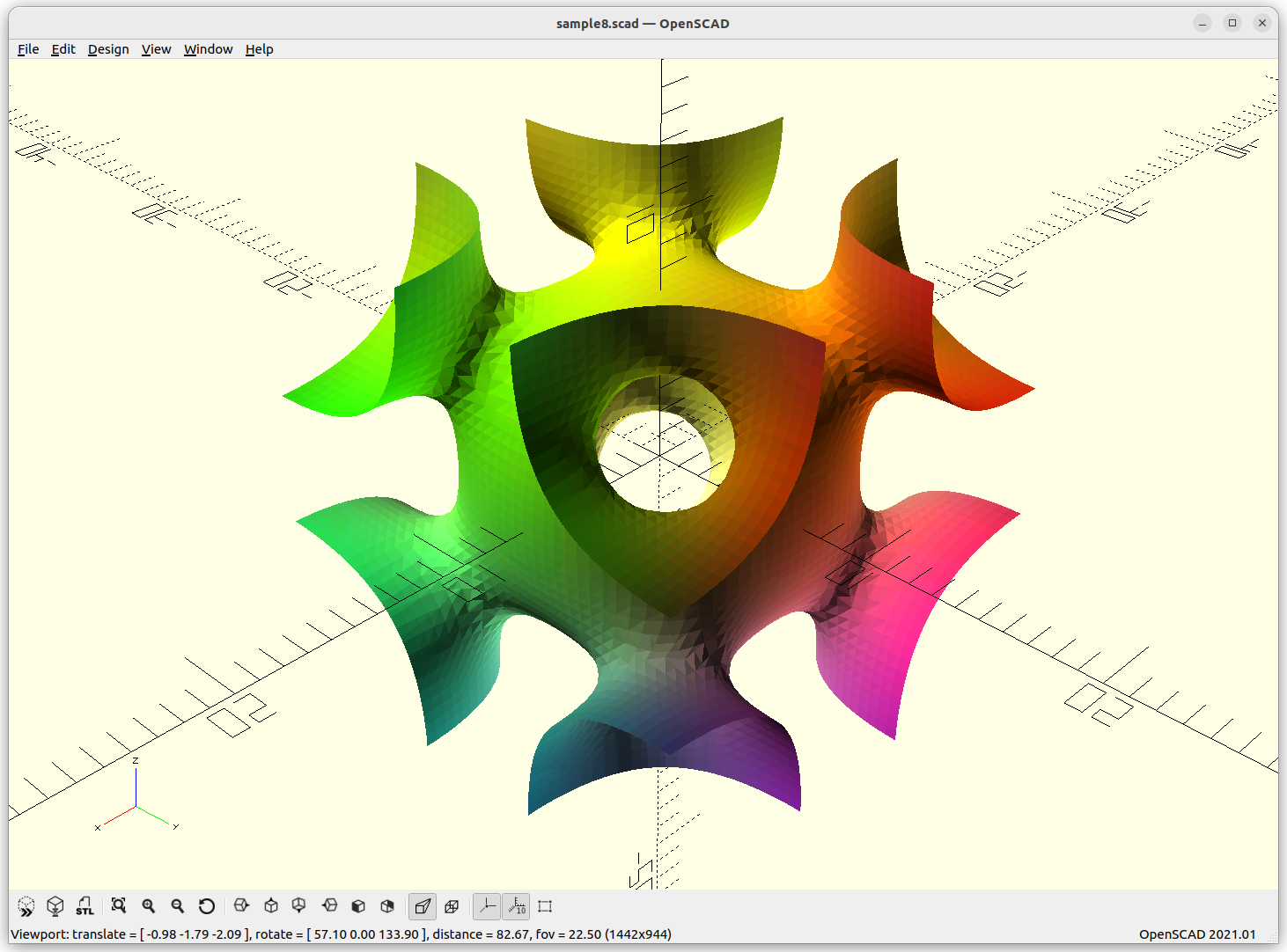
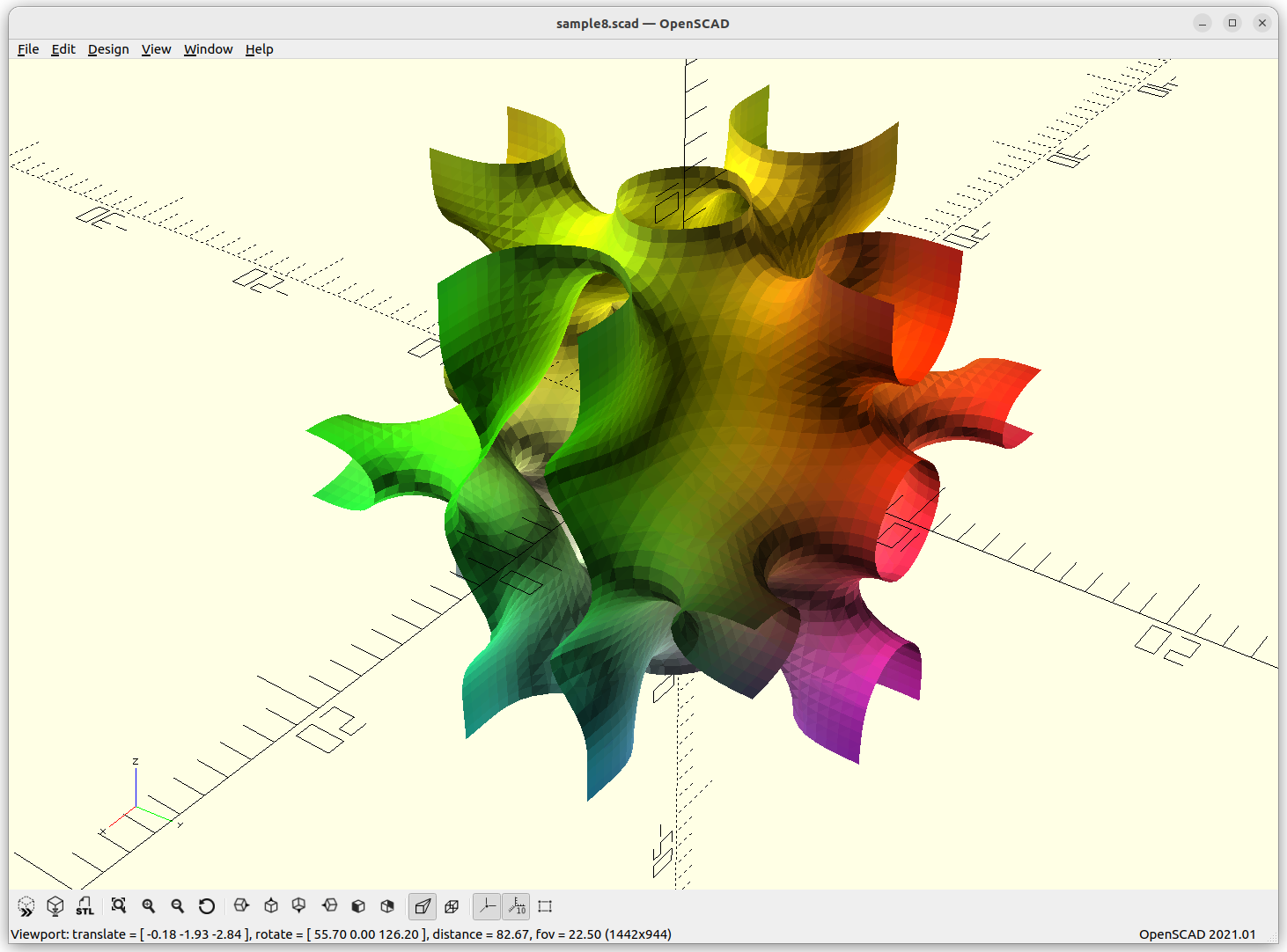
IWP Skeletal
IWP Skeletal connects 8 arms to each other.
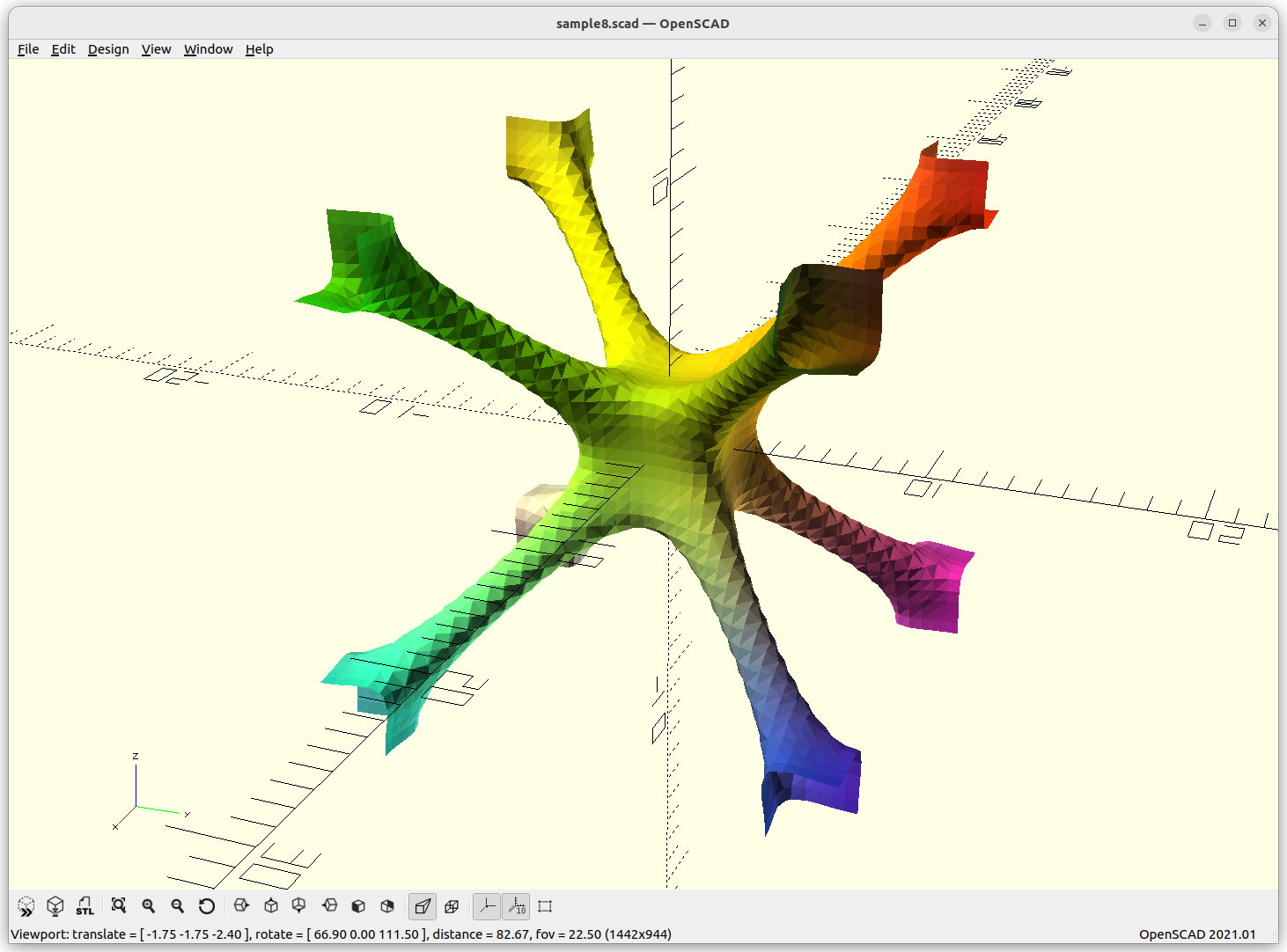
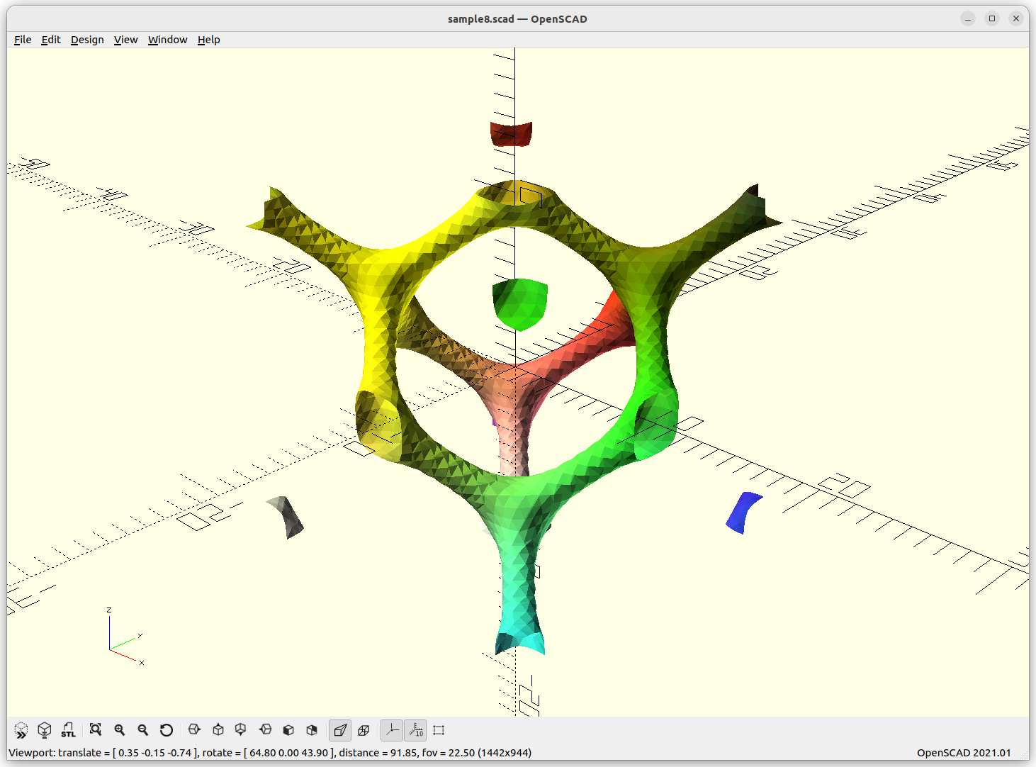
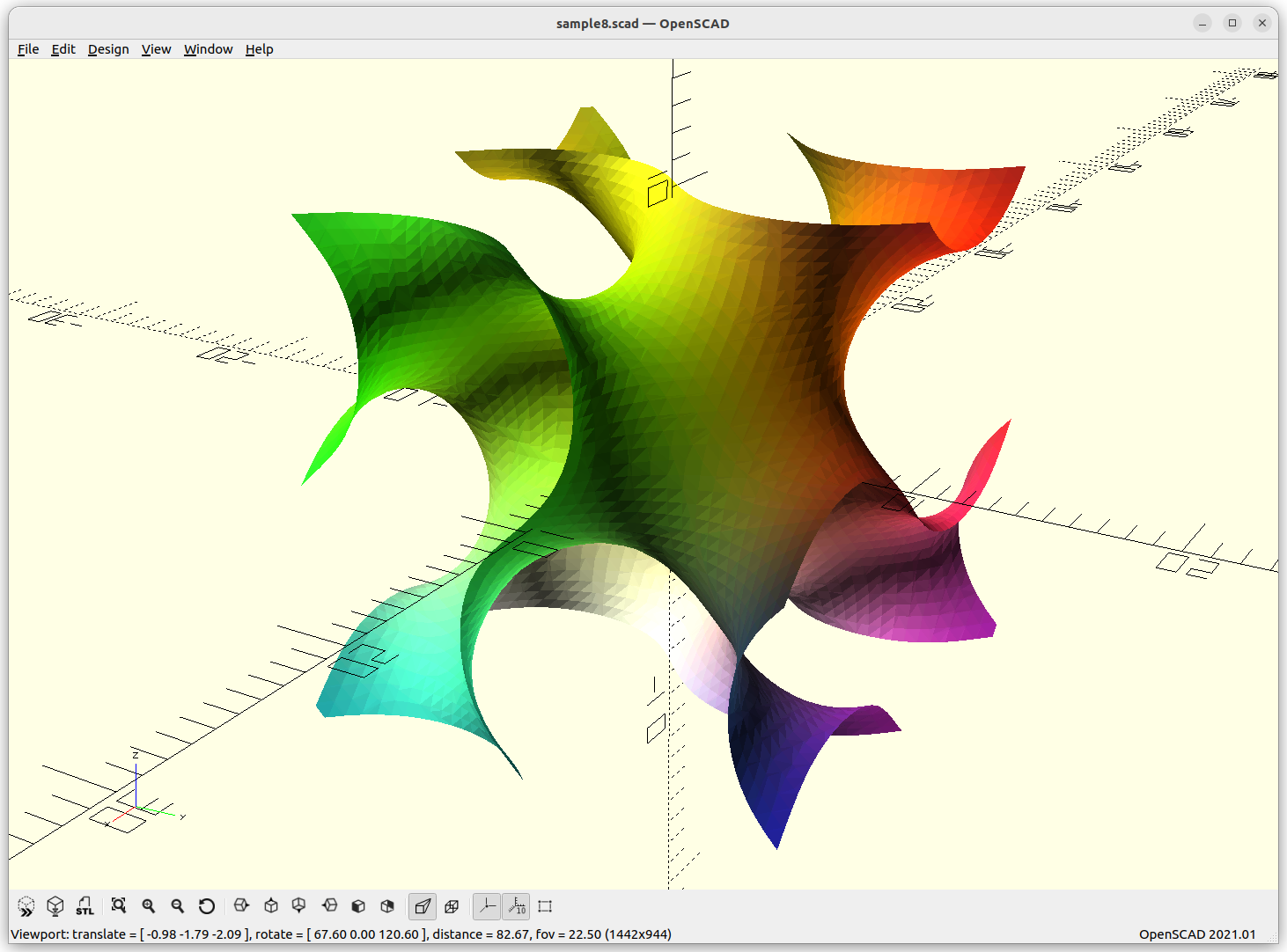
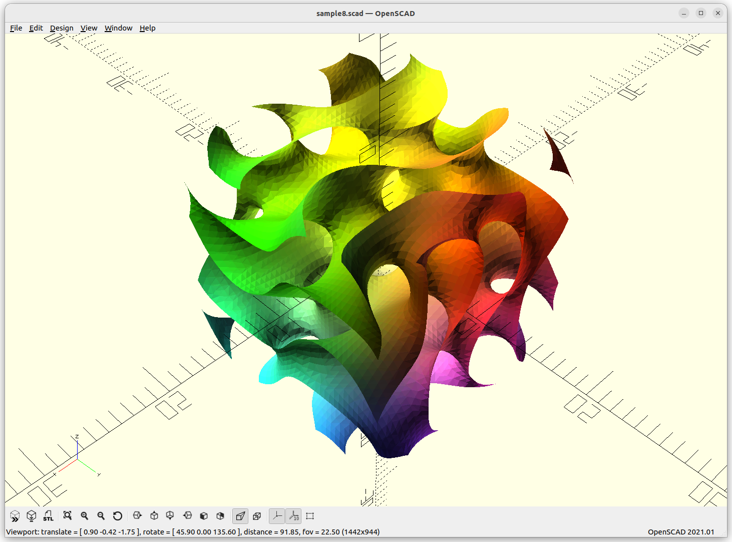
Schwarz D Skeletal
Schwarz D Skeletal connects with 4 arms to each other.
The above “skeletal” minimal surfaces are ideal for lattice structures, likely most usable in context of voxel-based 3D printing approaches, such as SLA, SLS, SLM and so forth, but less ideal for traditional FDM where the lattice is sliced Z-planar again kind of defeating the overall purpose of lattice structures.
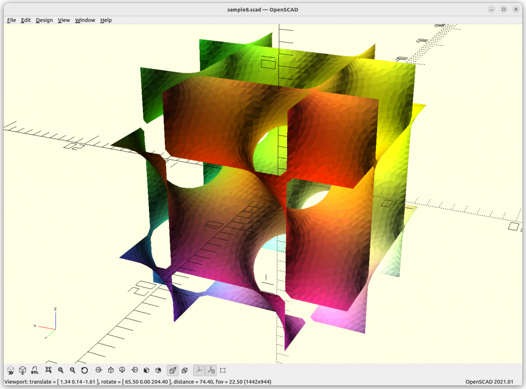
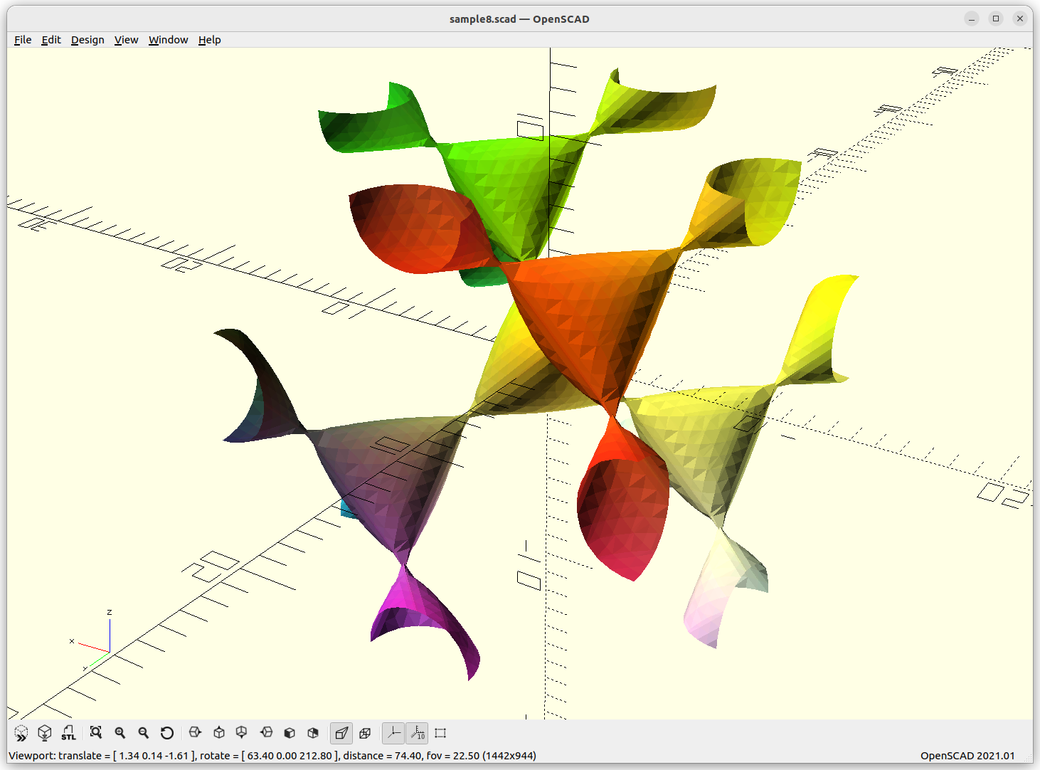
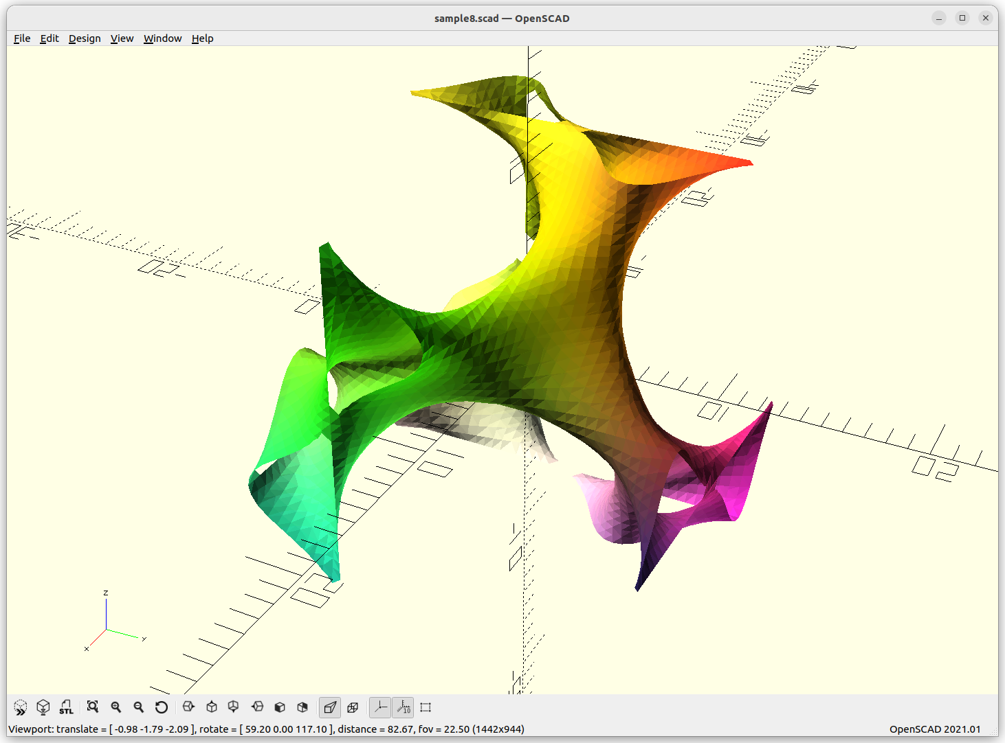
D Surface
D Surface: cos(x)*cos(y)*cos(z) – sin(x)*sin(y)*sin(z)
As Juergen Meier created a variant, adding a, which gives these variants:
a=-0.5a=-sqrt(2)/2a=0.5a=0.5 (double density)
providing a structure using 4 arms to connect each other.
Miscellaneous
Bionic BoneBionic Bone 2Split PDKPIWPDouble GyroidDiamond Double 1Diamond Double 2Octo 1Octo 2Double PG Prime 1G Prime 2PN
Using Implicit Geometries as Infill Structures
Slic3r and Prusa Slicer are providing gyroid infill pattern since early version, but beyond that it seems no to little development happened since (2022/12).
Let’s see how implicit geometry can be transformed into slices (FDM) or voxels/pixels (SLA, SLS etc)
Algorithm A: 3D Cache
create point cloud of surface of implicit geometry
create surface of implicit geometry using marching cube
(optional) determine x, y, z size where it repeats itself
slice surface for infills at certain scale
clip inner surface with outer perimeter of slice
Pros
with caching: fast lookup of infill geometry
Cons
many steps
x, y, z repeatability must be given, hard to determine programmatically from outside
clipping to perimeter can be computational expensive depending
Algorithm B: 2D Cache
create 2D point cloud of a slice of implicit geometry based on clipped 2D area / slice
convert 2D point cloud to polylines (FDM) or pixels (SLA)
Pros
reduction to 2D problem at first stage
fast 2D point cloud creation as only one z-level is used
Cons
create 2D point cloud at arbitrary resolution, loss of curves unless refitted
caching without knowing repeatability of the geometry makes little sense
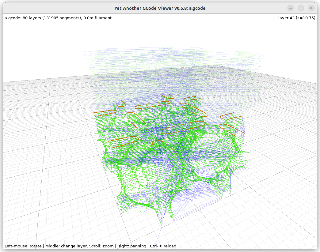
FDM G-code
Here some early G-code for FDM 3D printer using PyImplicit tool tracking the implicit surface as 2D contour:
The implicit surfaces only define the surface, either:
inside vs outside – a solid; or
certain thickness of such surface
In order to create watertight meshs the volume needs to be limited with a boundary box, and Marching Cube is performed from outside to get proper mesh to post-process afterwards.
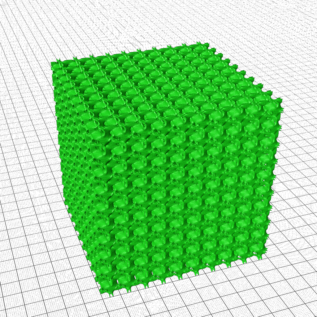
Now you may wonder, what’s the fuss with all those forms, why doing this complicate implicit form, why not just create a few forms as meshs right away and repeat them orderly – well, here it comes why:
Frequency or Scale Gradients
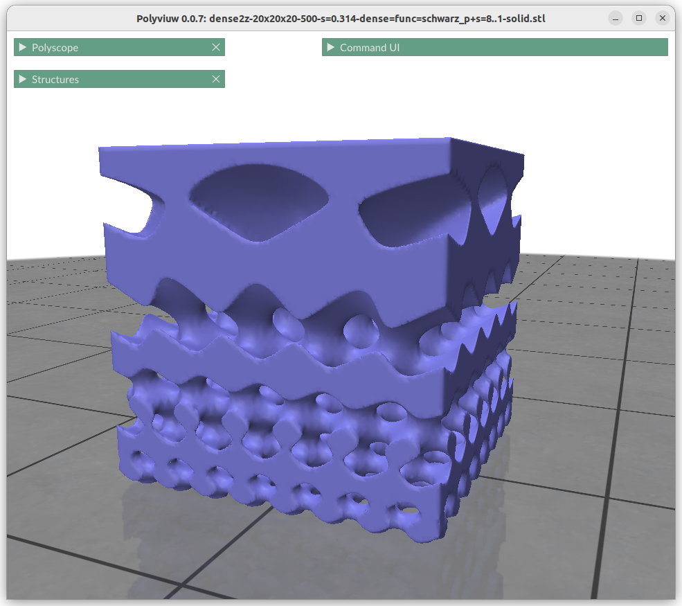
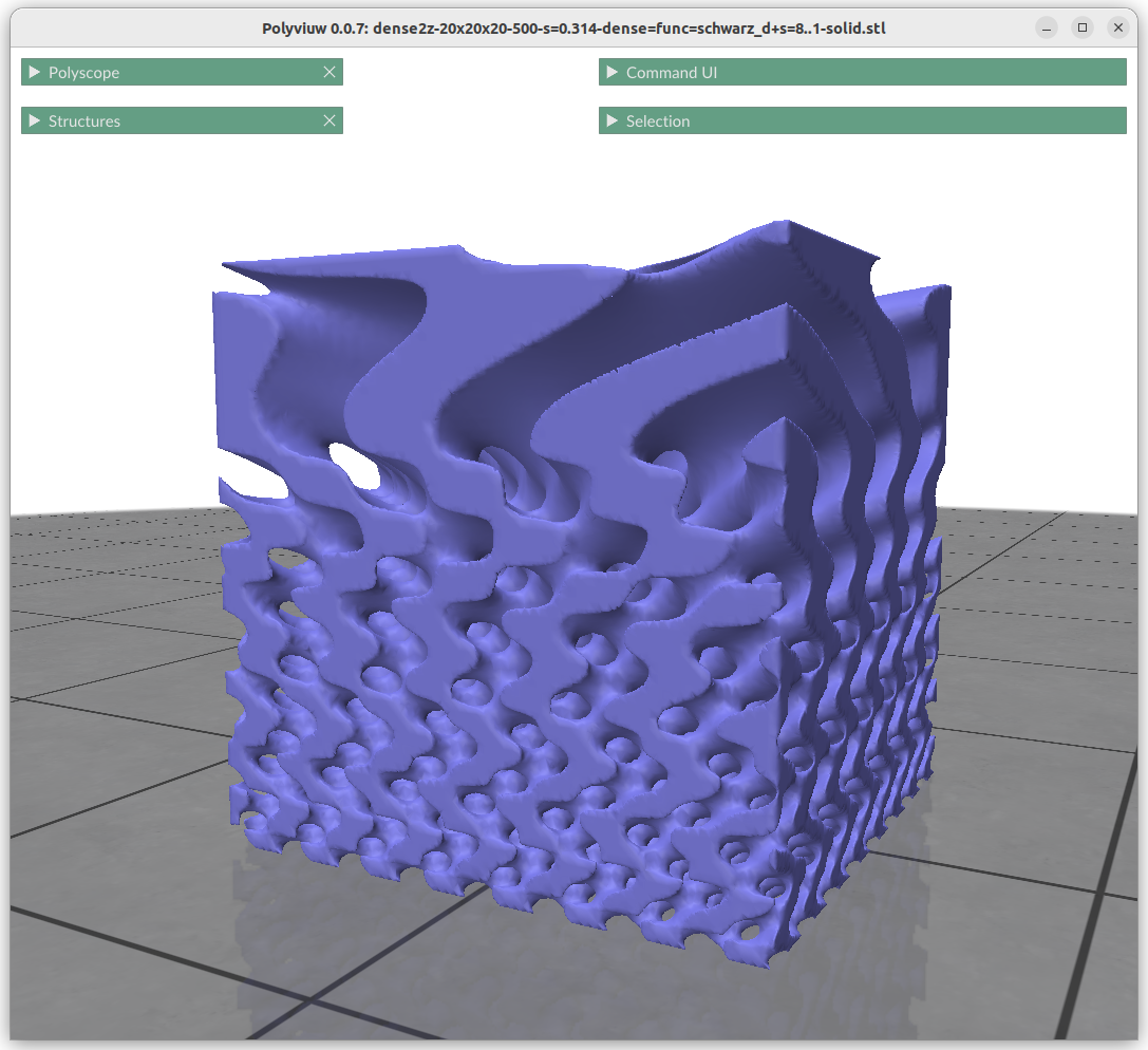
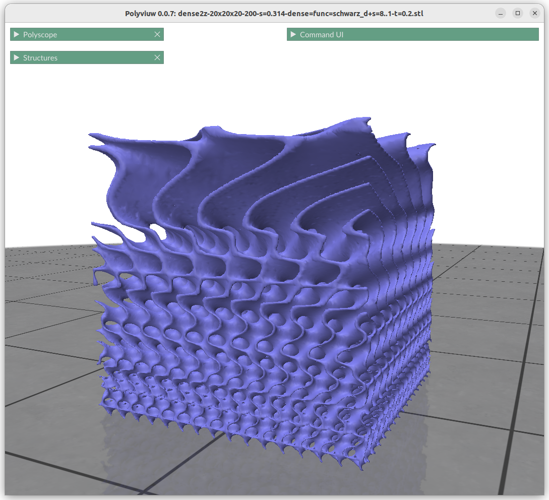
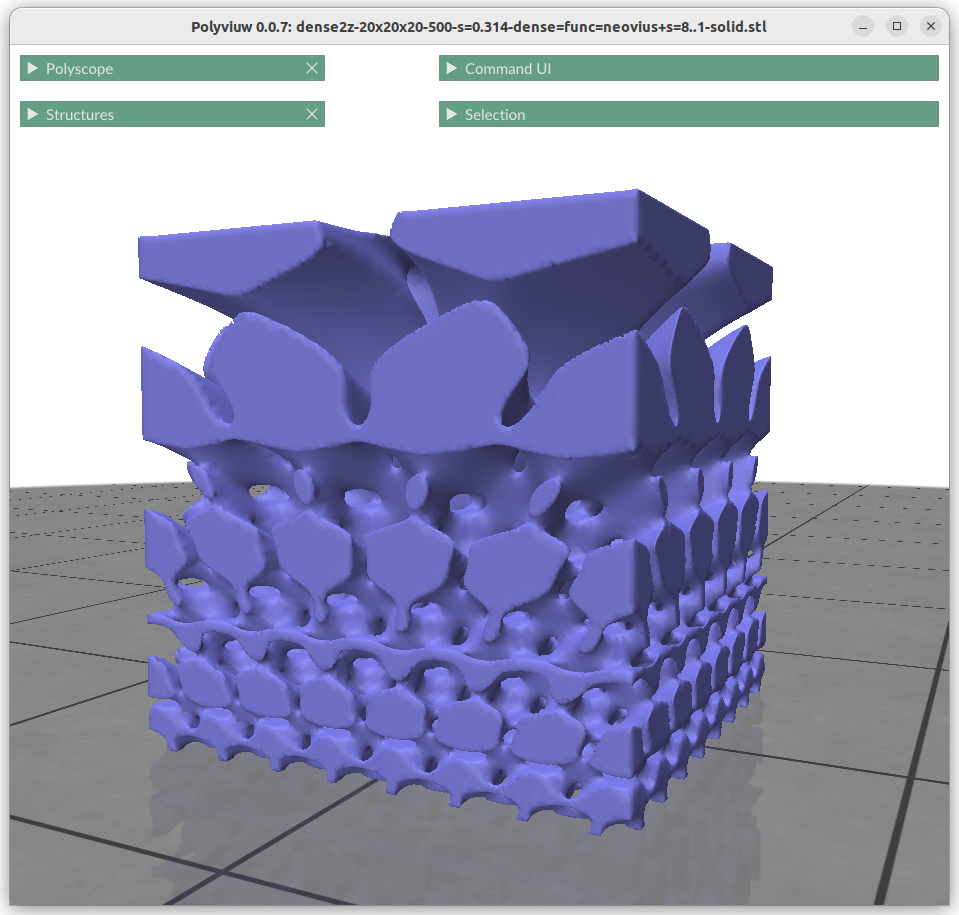
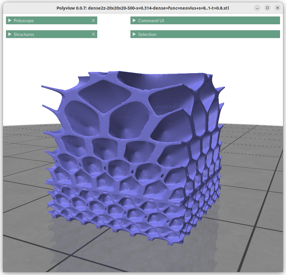
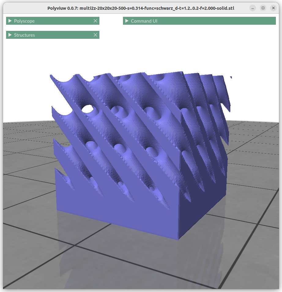
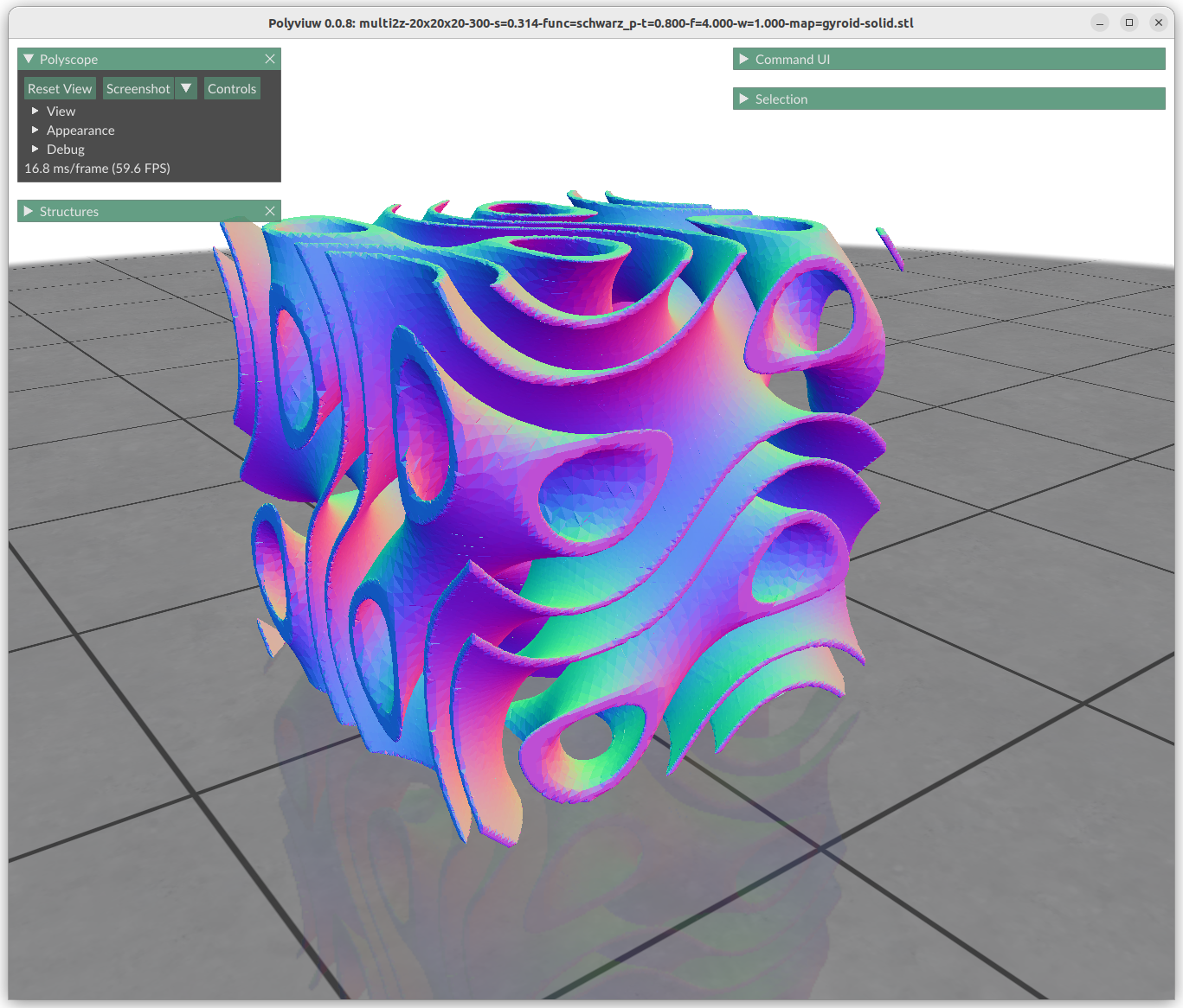
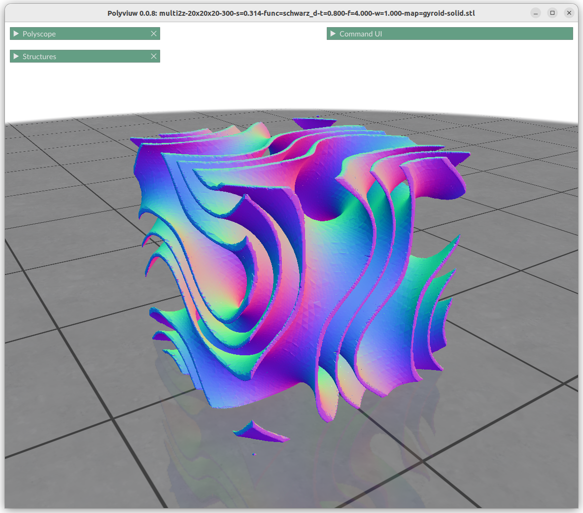
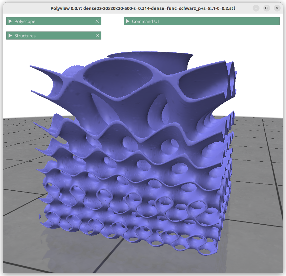
Schwarz P scale=8..1 solidSchwarz P scale=8..1 thickness=0.2Schwarz D scale=8..1 solidSchwarz D scale=8..1 thickness=0.2Neovius scale=8..1 solidNeovius scale=8..1 thickness=0.8
Changing the frequency or scale s0 and s1 can be achieved by:
znorm = (z-zmin) / (zmax-zmin) s =(1-znorm)*s0 + znorm*s1 or s = lerp(s0, s1, znorm) f = surface(x*s, y*s, z*s)
This shows the power of generative geometries, we simply can define the scale or frequency of a geometry at any point, given we transit within reason and not too sharply to cause discontinuty.
Thickness Gardients
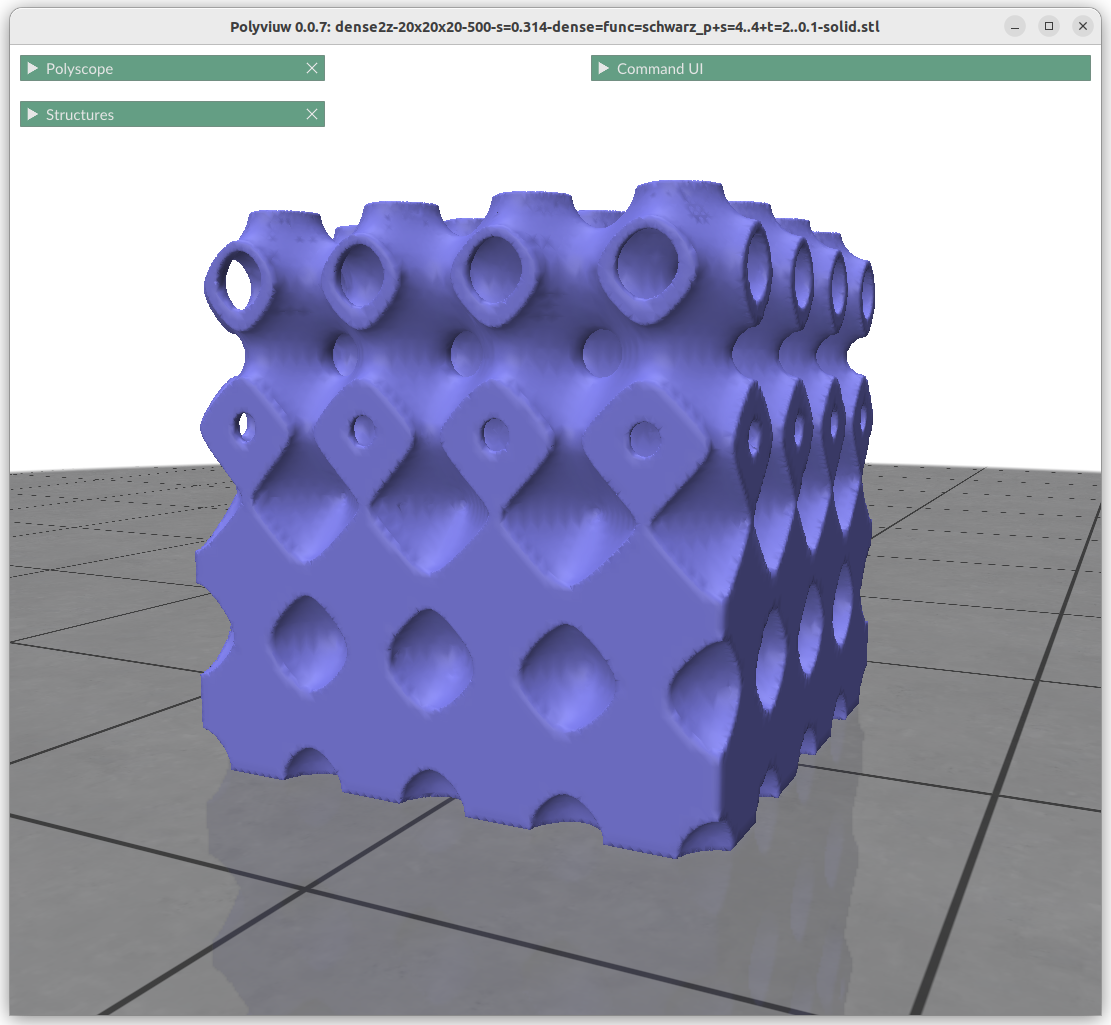
Schwarz P thickness: 2 .. 0.1Schwarz D thickness: 1.2 .. 0.2
Alike changing thickness:
znorm = (z-zmin) / (zmax-zmin) t = lerp(t0, t1, znorm) f = abs(surface(x,y,z)) – t
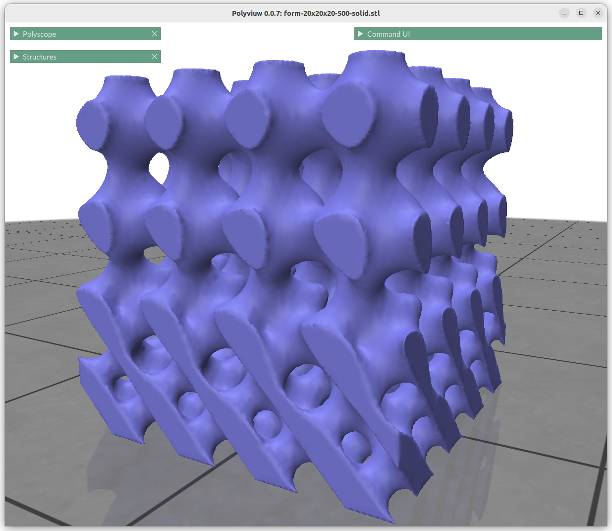
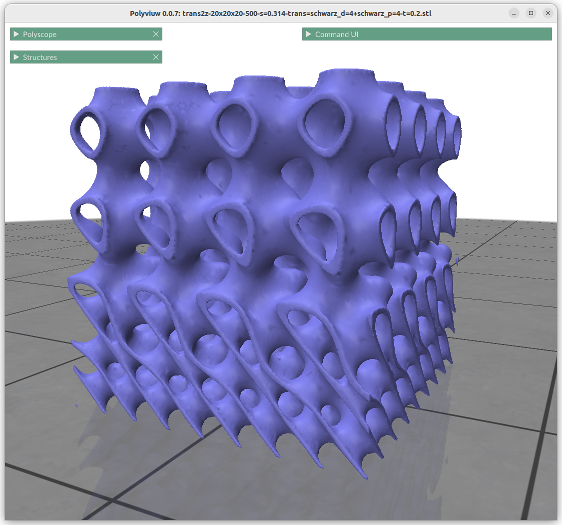
Form Gradients
Transit vertically from Schwarz D to Schwarz P (solid)Transit vertically from Schwarz D to Schwarz P (thickness=0.2)
What looks very complex is done quite simply with:
This is quite powerful property, to be able to morph from one implicit form to another with such a simple formula.
Contineous Transitions:
Schwarz D – Schwarz P
Schwarz D – Neovius
Schwarz P – Neovius
thickness: IWP Skeletal – Schwarz P
thickness: IWP Skeletal – Schwarz D
Discontinueous Transitions:
IWP Skeletal – P Skeletal
IWP Skeletal – Neovius
solid: IWP Skeletal – Schwarz P
solid: IWP Skeletal – Schwarz D
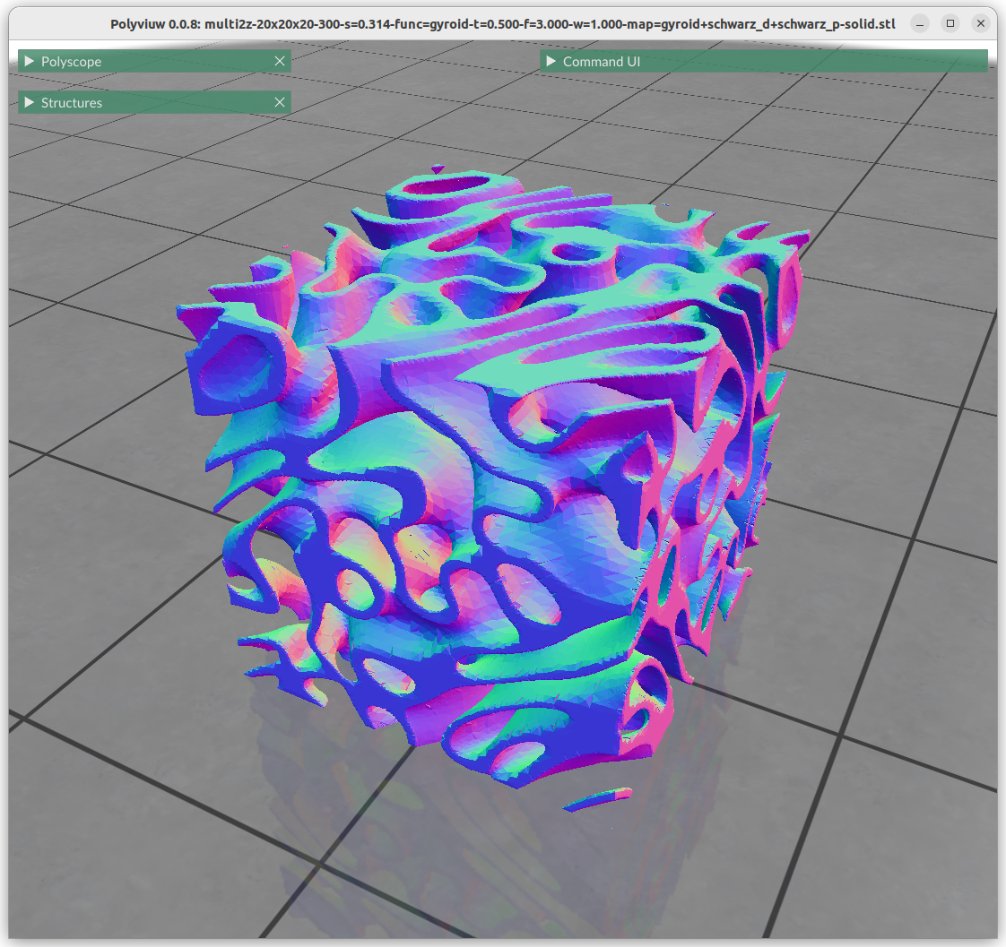
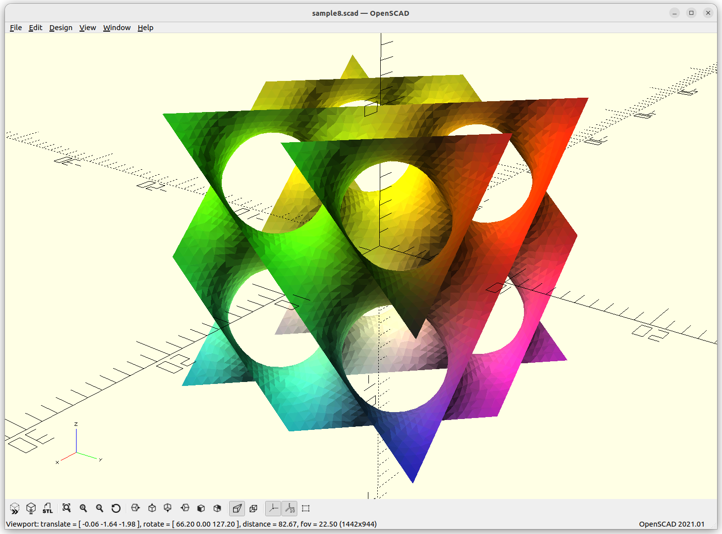
Combining Implicit Surfaces
Additions
Algebraic addition has the effect of apply one geometry within another, alike recursion:
Schwarz P 4f + Schwarz D 4fSchwarz P 1f + Schwarz D 4f
Multiplications
Algebraic multiplication has the effect of clipping, or geometrical intersection:
Schwarz P 4f x Schwarz D 4fSchwarz P 4f x Schwarz D 1f
Mapping Implicit Surfaces
One can map the coordinates, and create a cylindrical gyroid, where former X & Y become distance and rotation angle, and Z remains as is, and so spherical projection is possible as well, or even feed coordinates through implicit formula itself:
Next blog-post(s) I will go into further details utilizing TPMS in Additive Manufacturing (AM) like FDM/FFF, SLA, MSLA, SLS, MJF or SLM – each one of them have unique features and limitation for using those Parametric Generative Infill Geometries.
Appendix: Visualization
In case you wondered of the different styled visualization through this blog-post, let me show you the different approaches to discretize implicit defined surfaces.
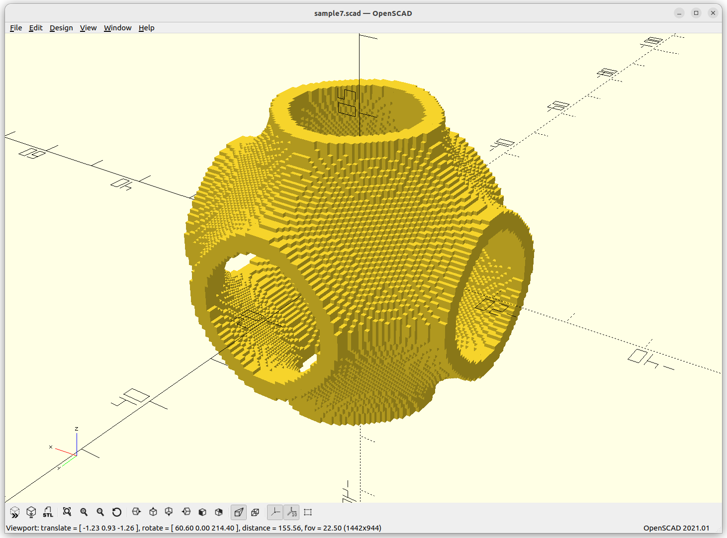
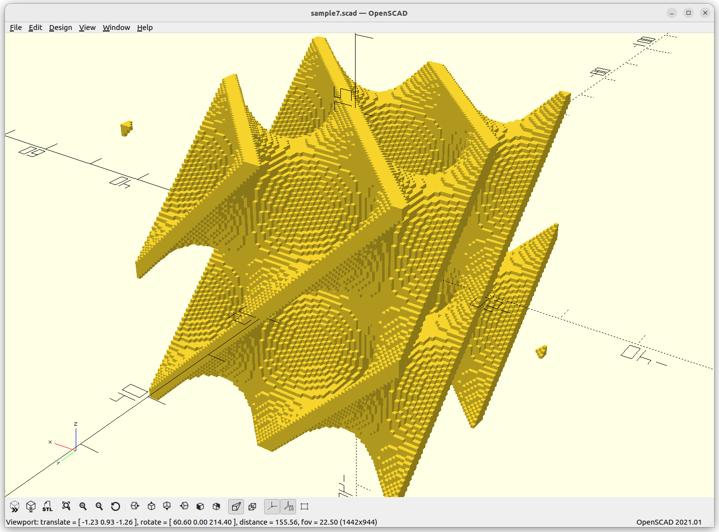
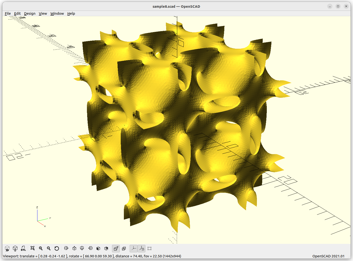
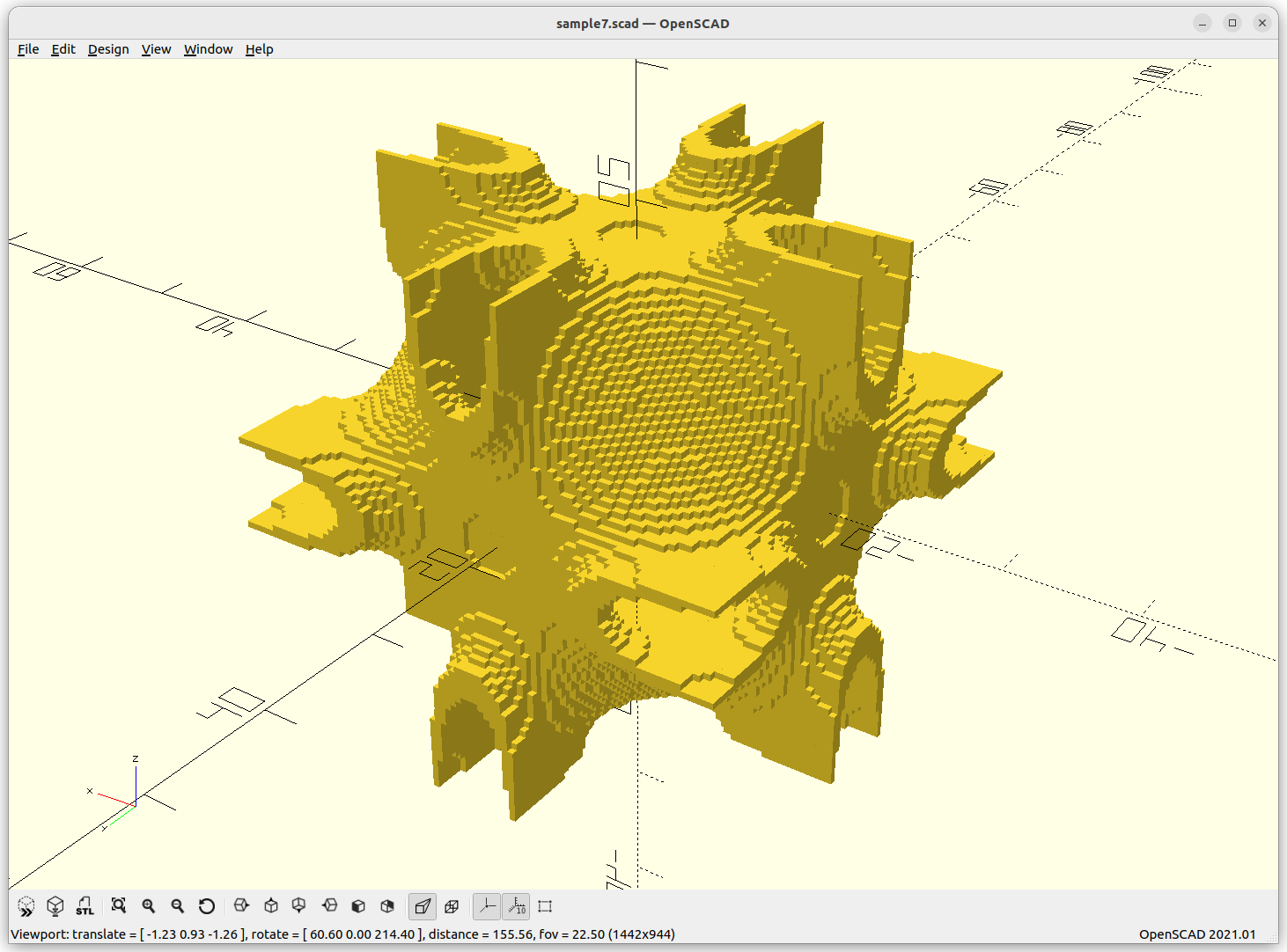
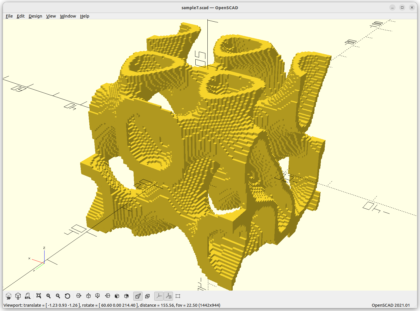
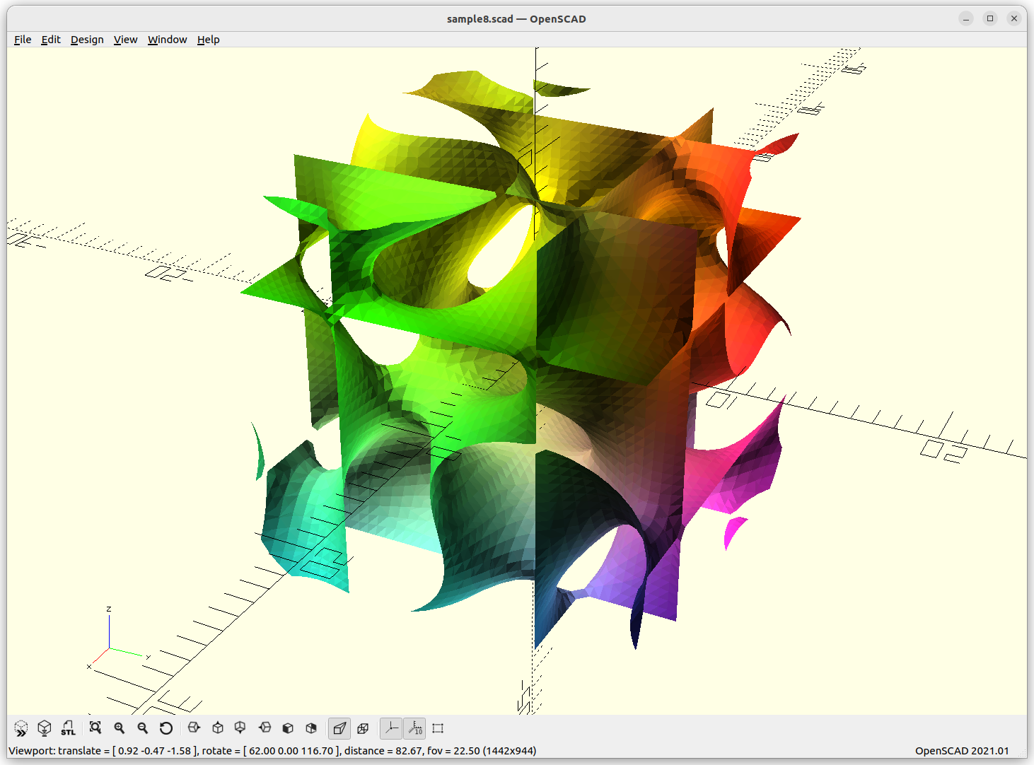
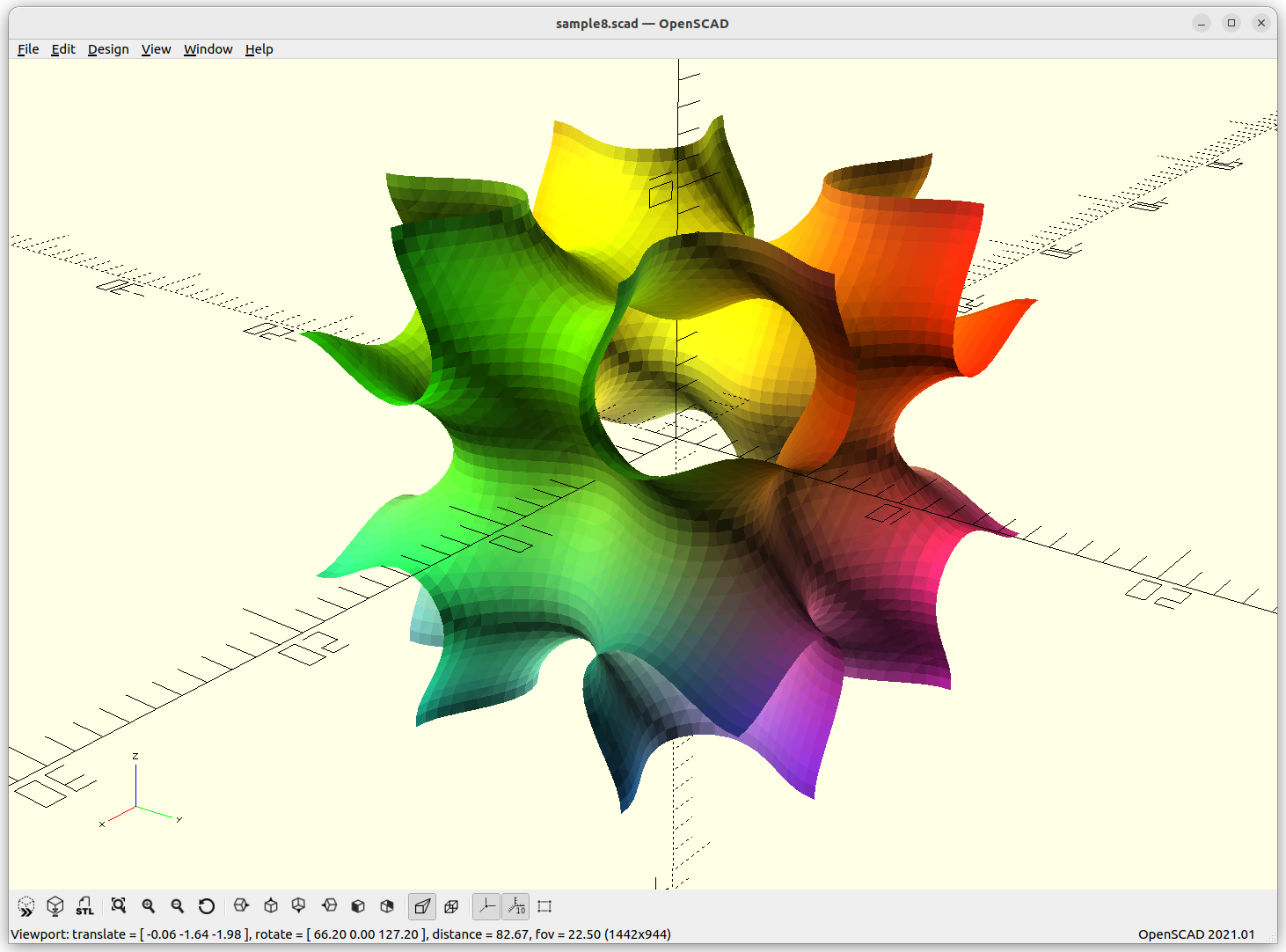
Voxels
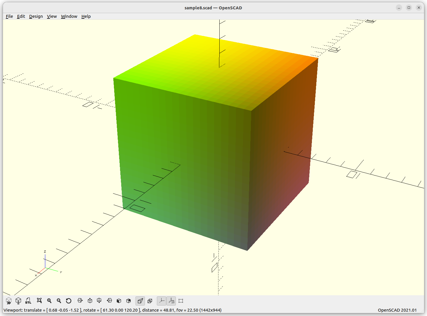
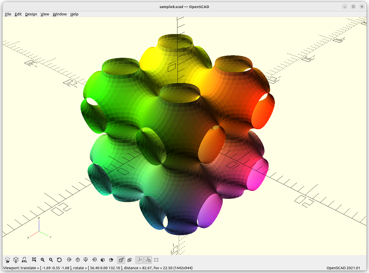
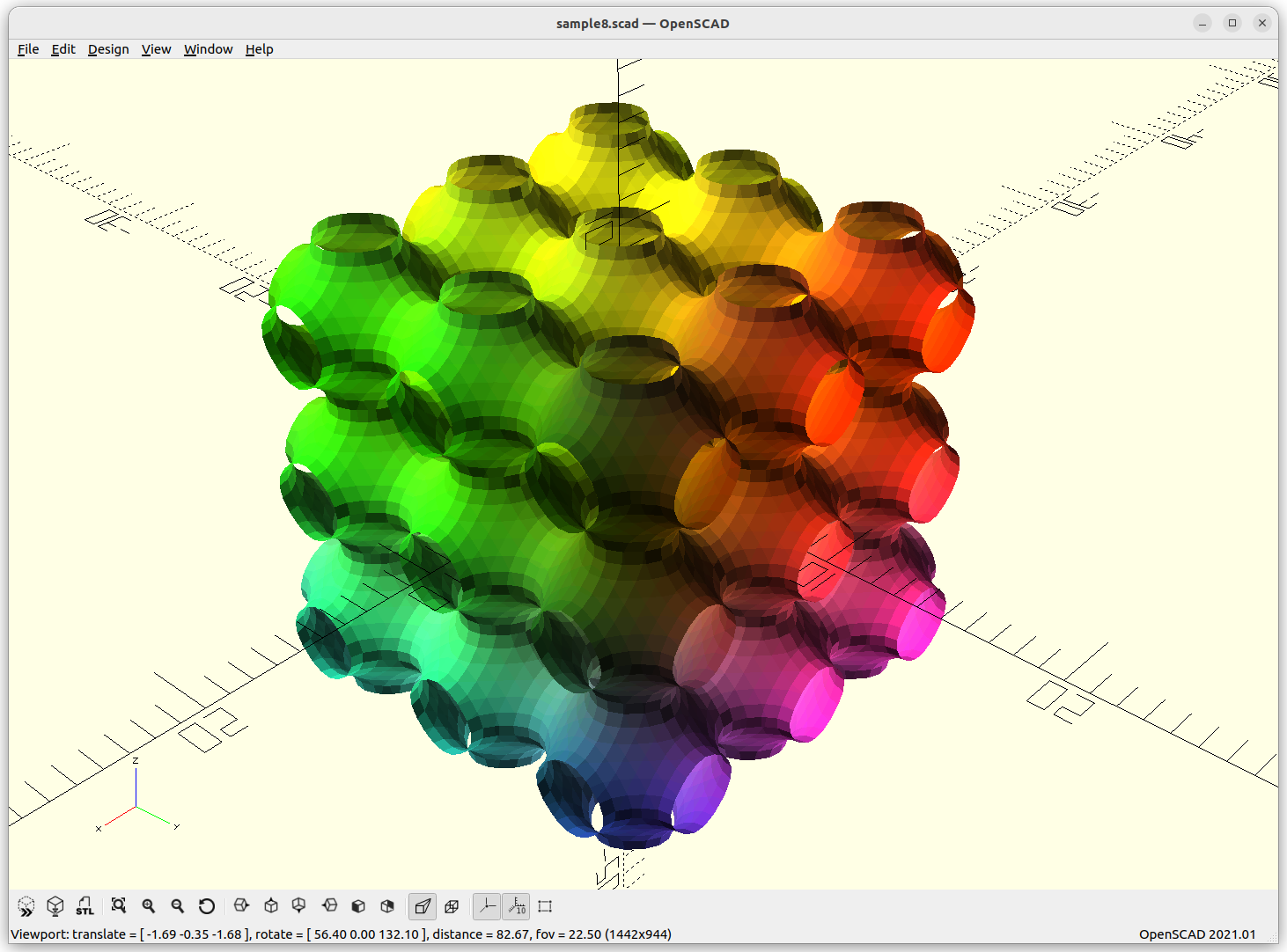
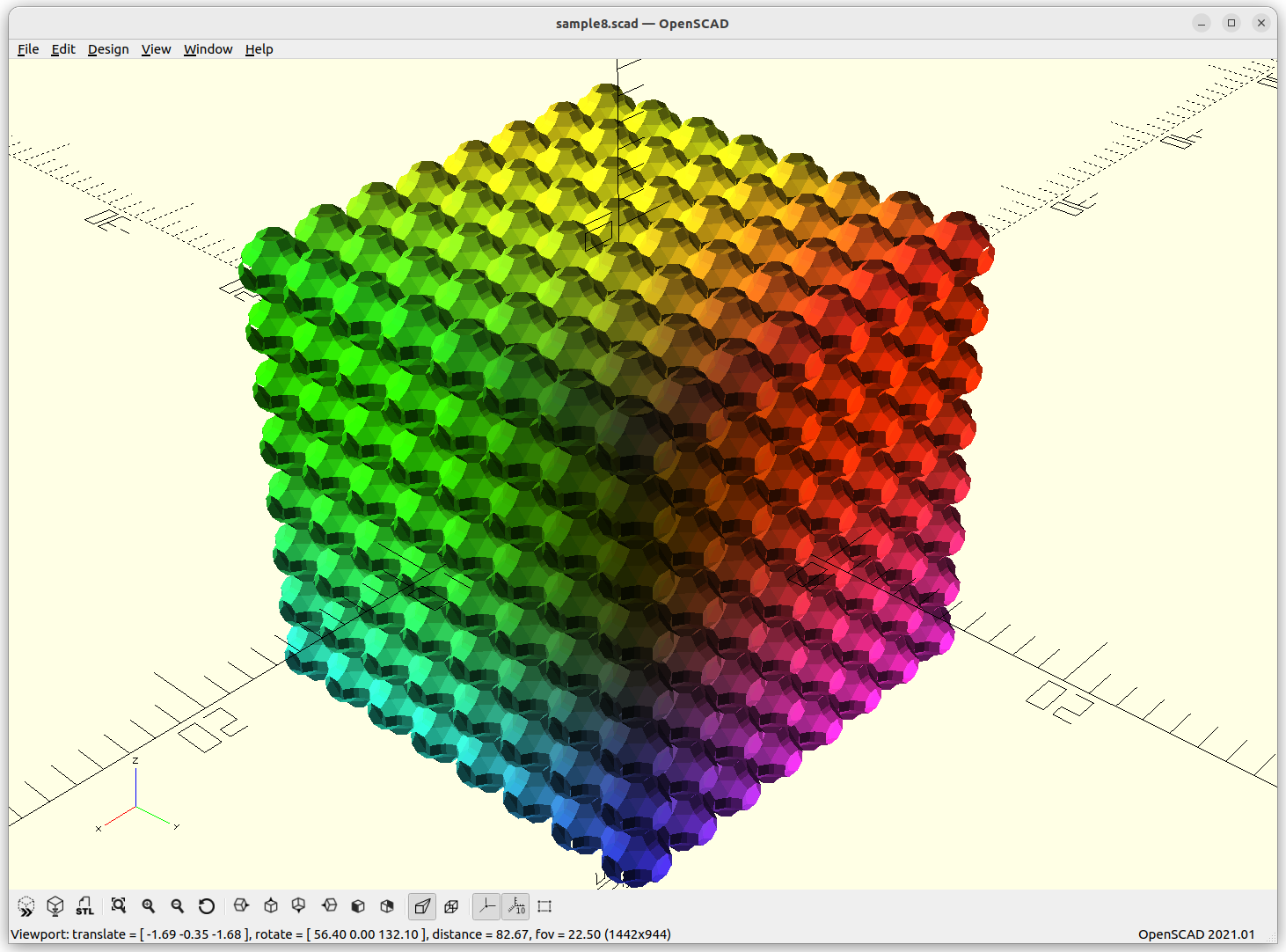
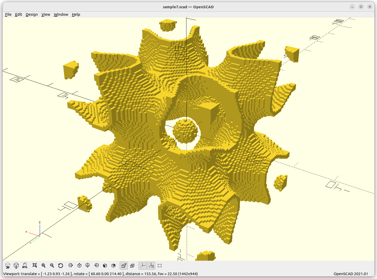
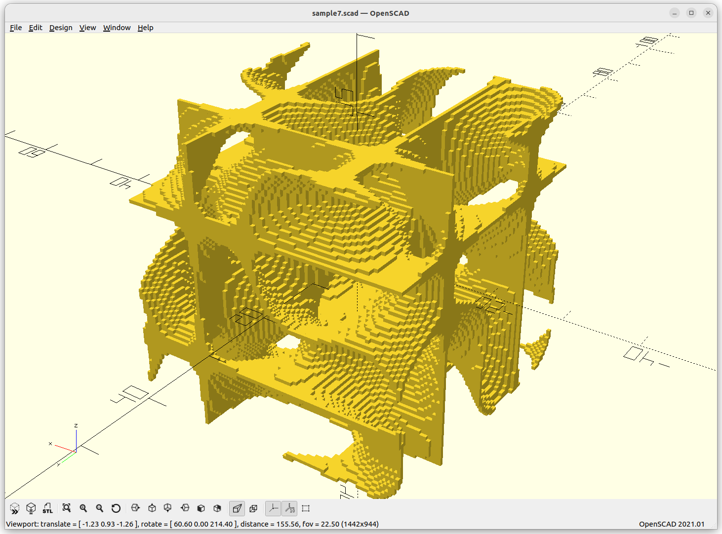
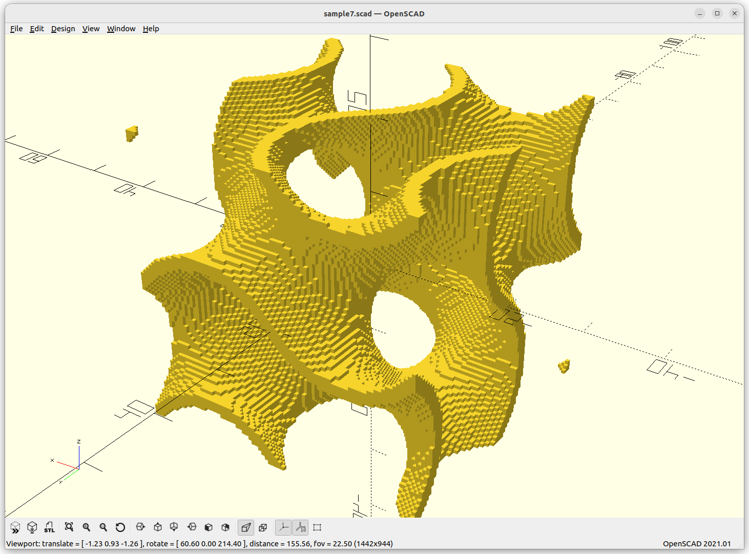
The code is rather simple with OpenSCAD yet rather slow: either skin is true or false, and delta determines the thickness of the skin if enable:
t = 1;
r = 20*t;
st = 1/2;
delta = 0.2;

function schwarz_p(x,y,z,s=1) = cos(x*s) + cos(y*s) + cos(z*s);

skin = true;

for(x=[-r:st:r])
   for(y=[-r:st:r])
      for(z=[-r:st:r]) {
         f = schwarz_p(x,y,z,360/20/2);
         if(skin && abs(f)<delta)           // -- skin only
            translate([x,y,z]) cube(st);
         else if(!skin && f<delta)          // -- inside/outside
            translate([x,y,z]) cube(st);
      }
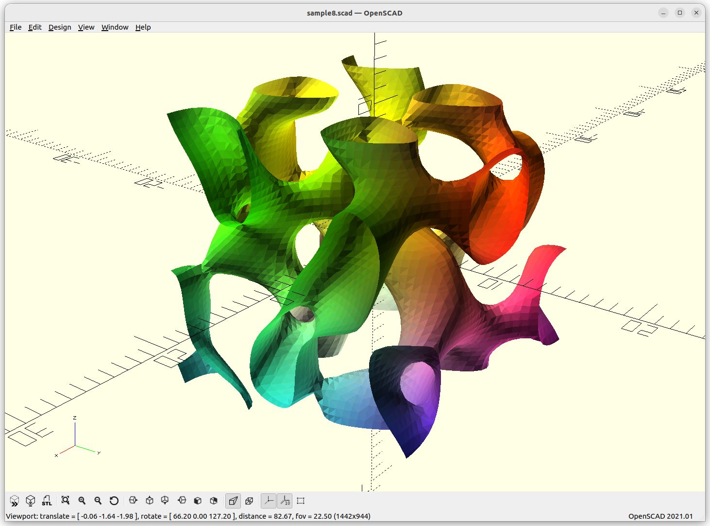
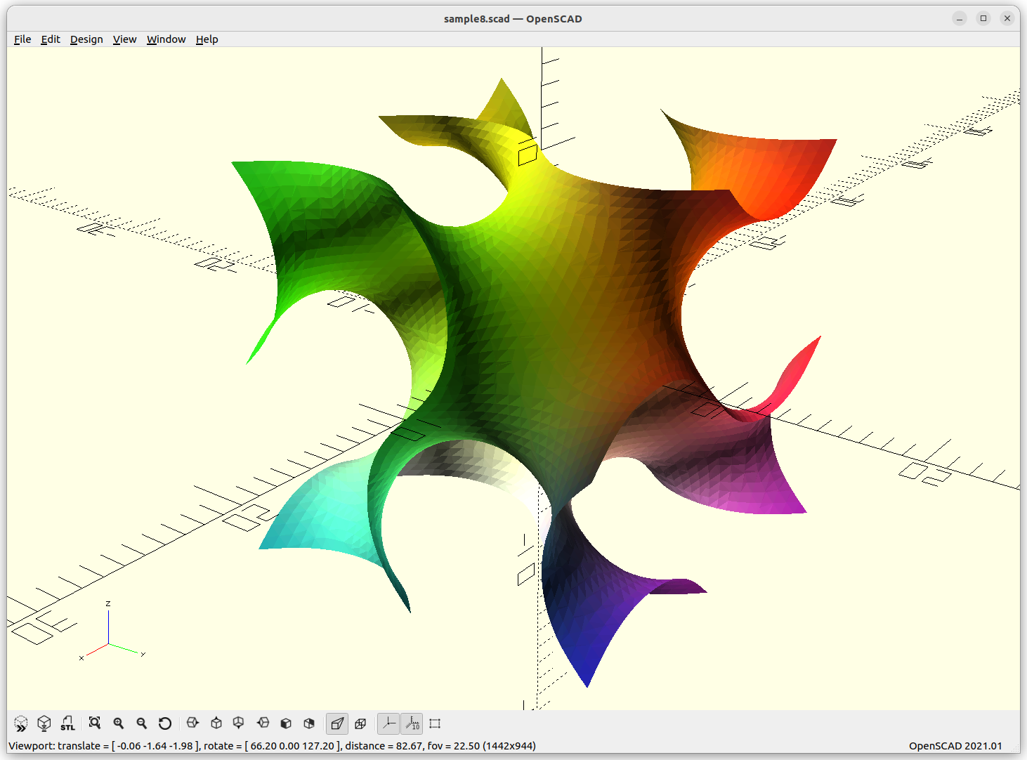
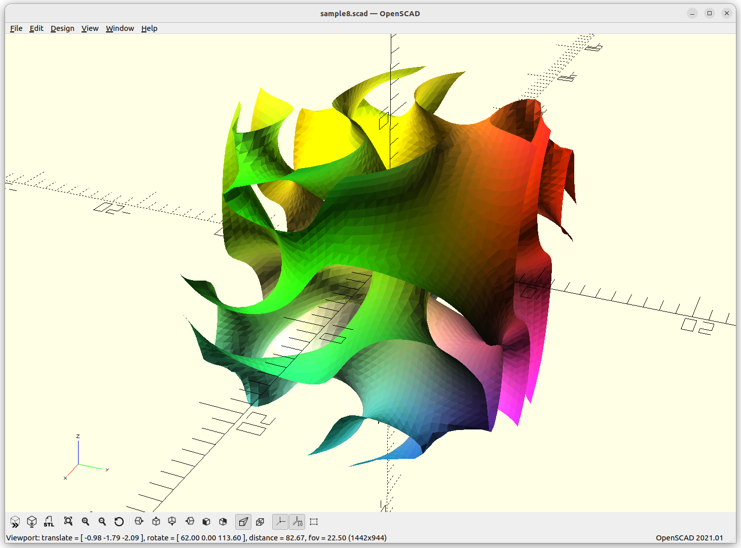
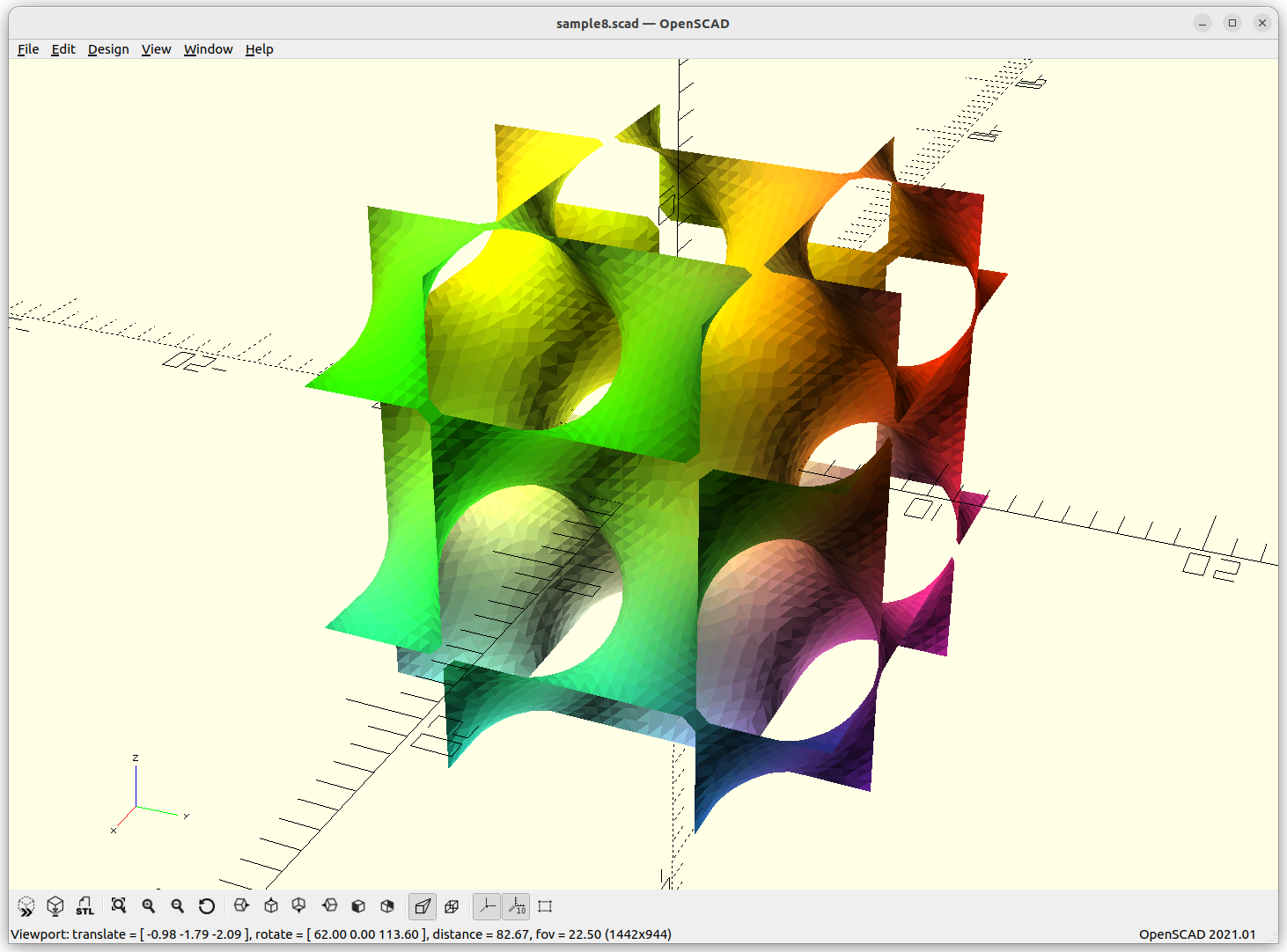
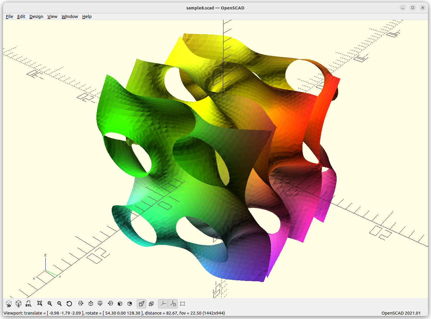
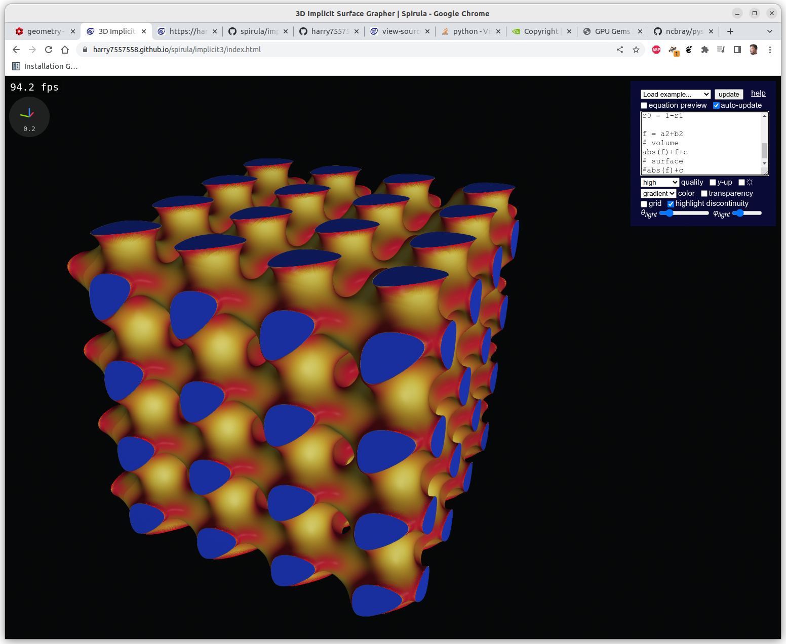
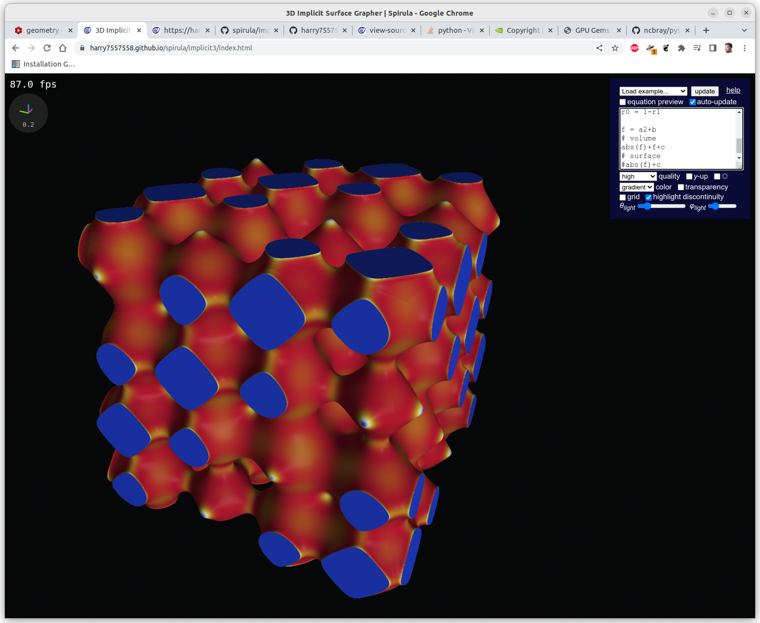
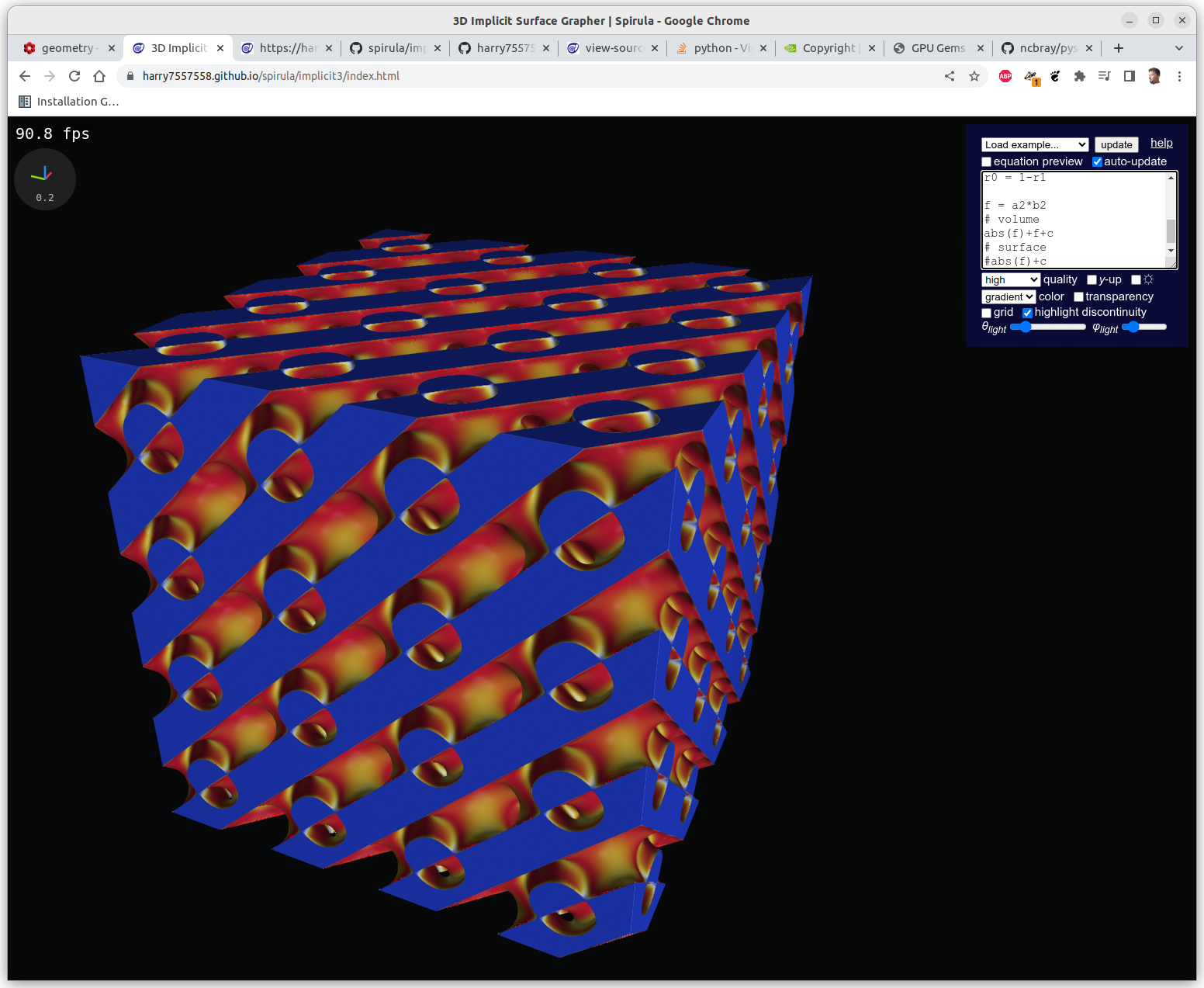
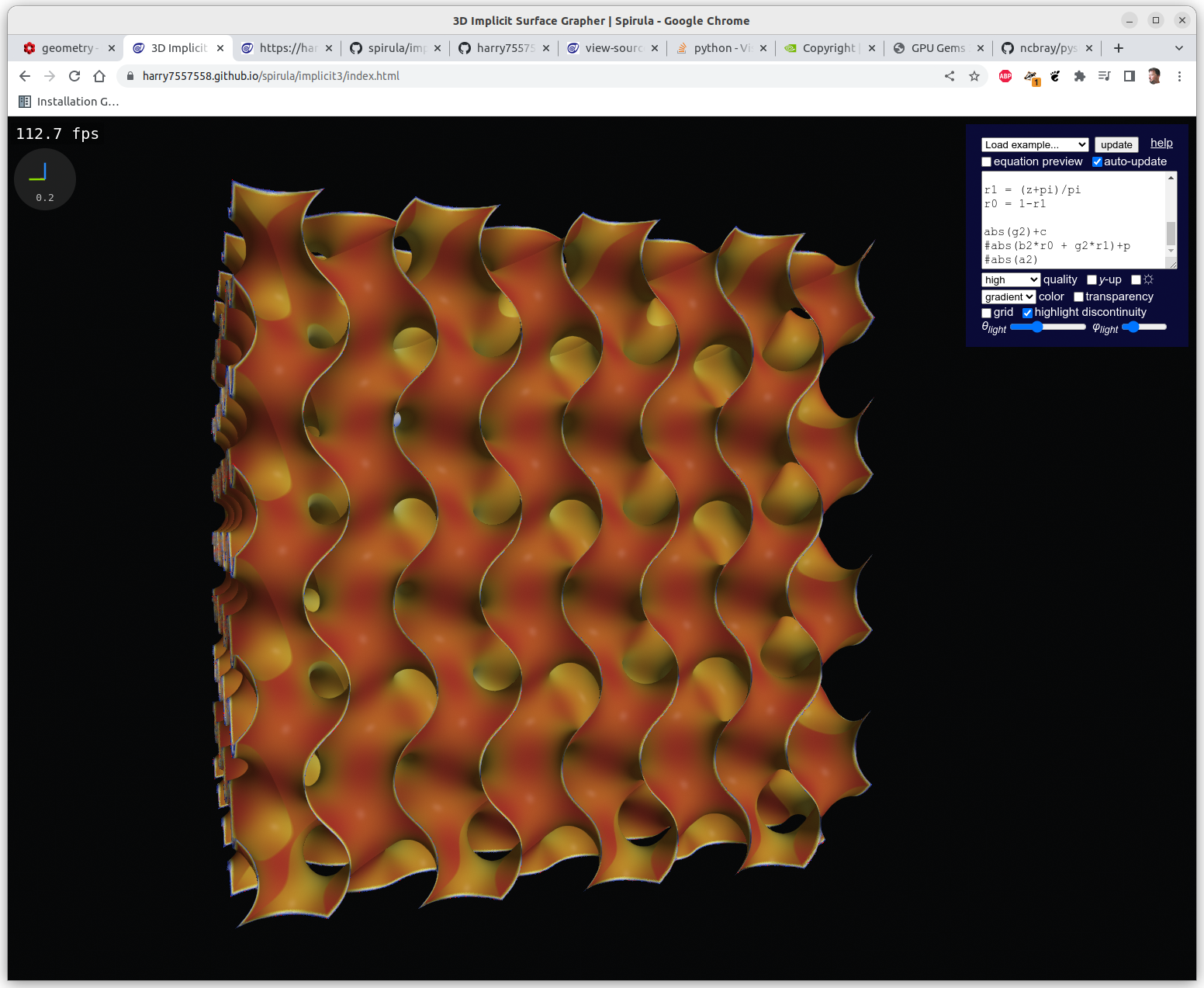
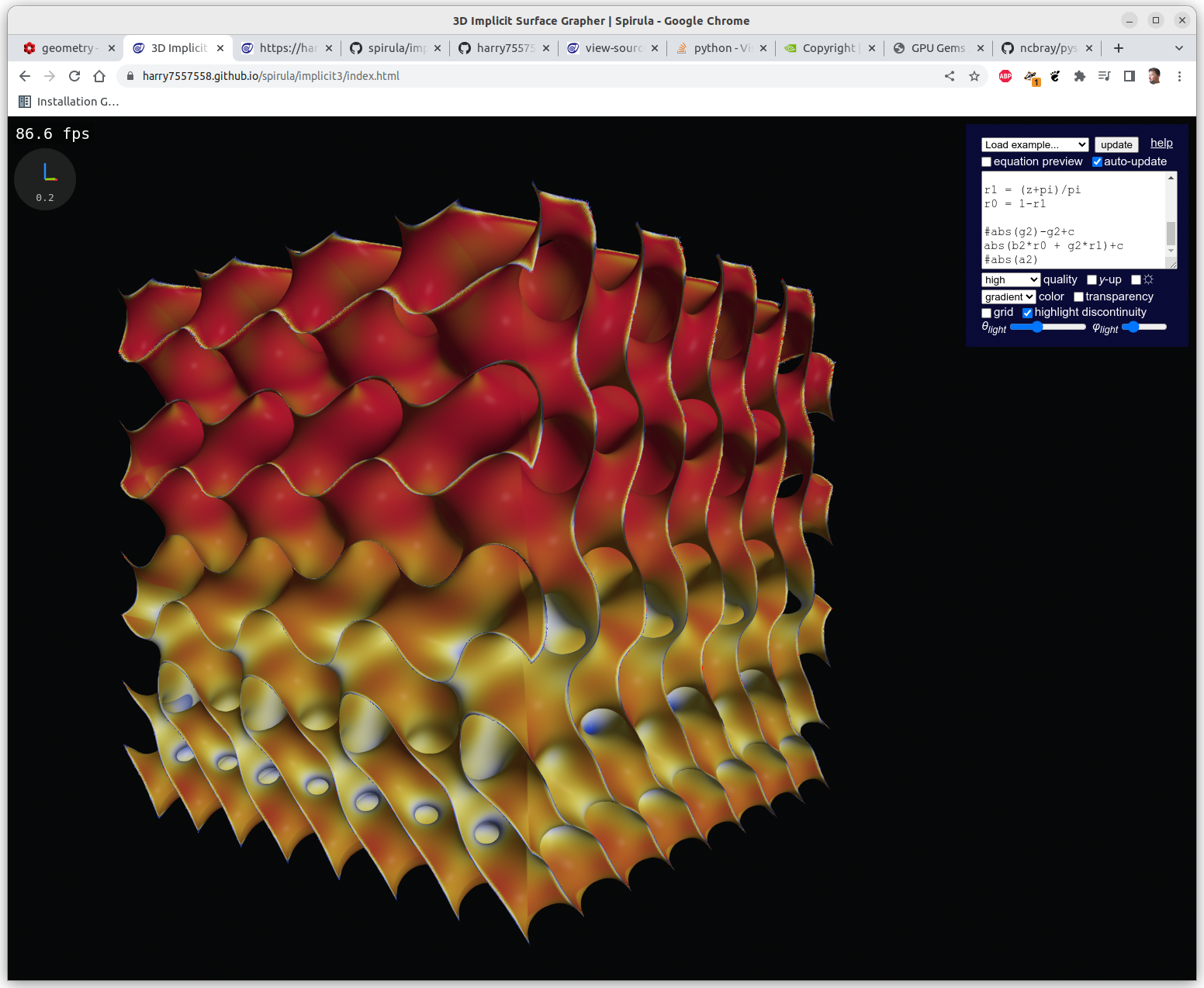
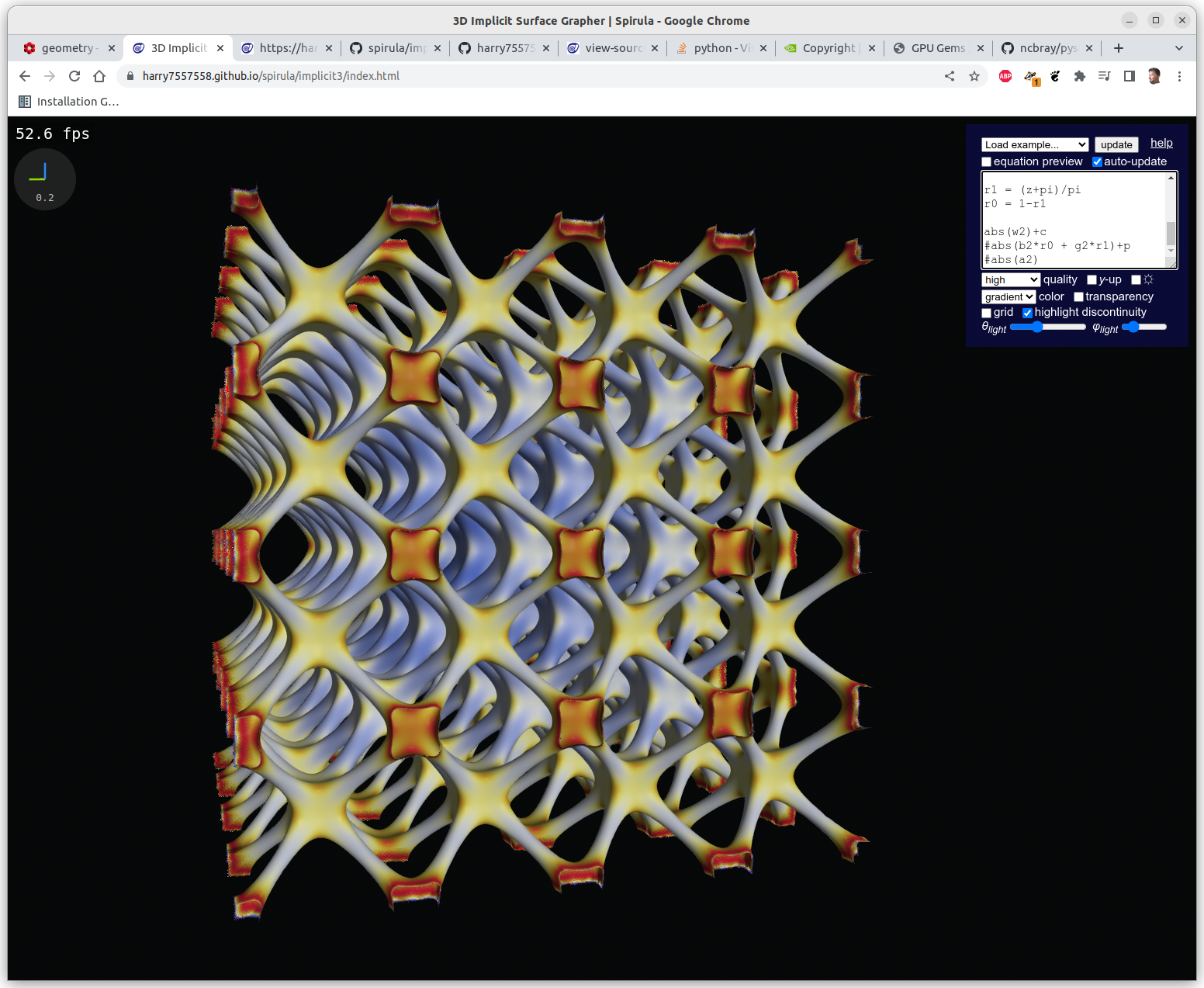
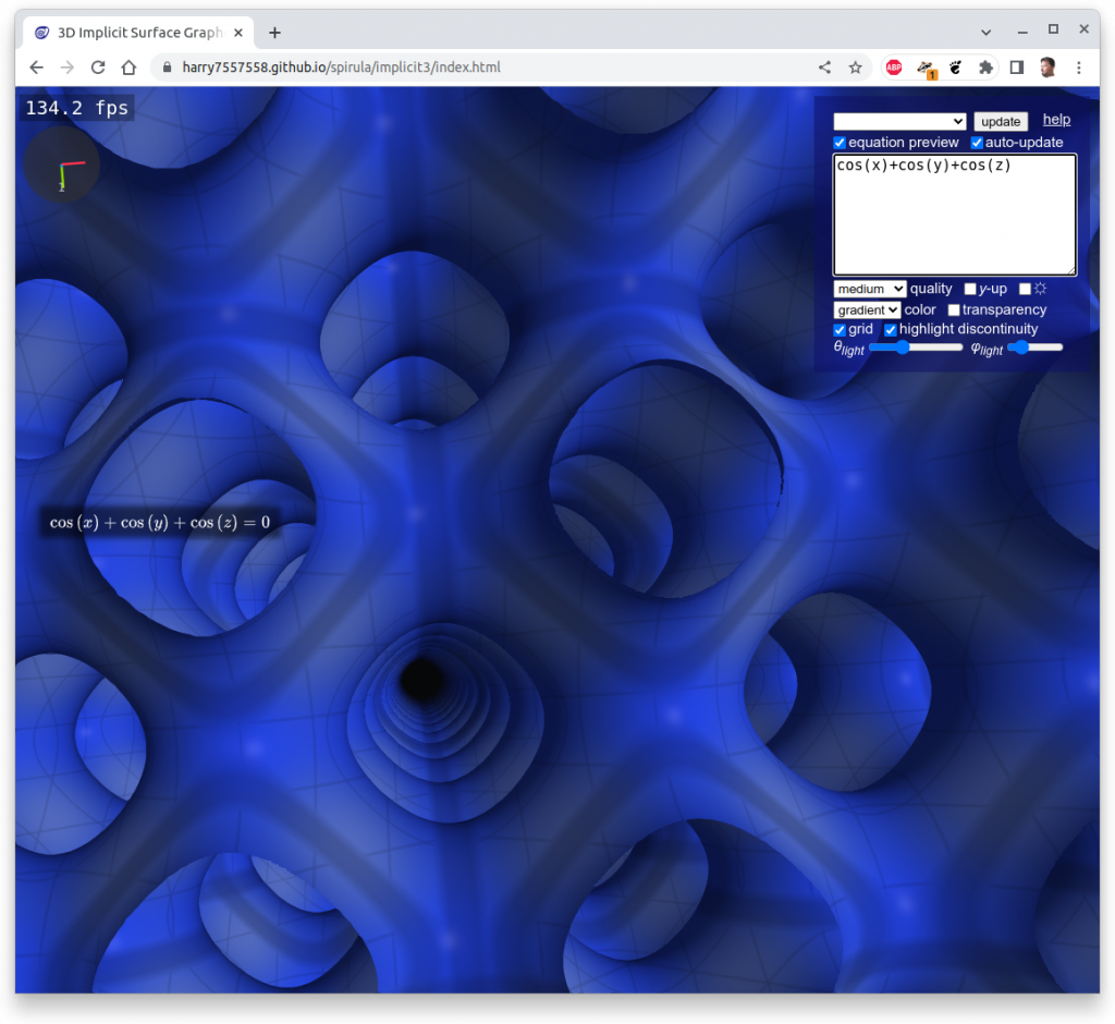
Following experiments were done with Spirula/Implicit3 within the browser, the implicit formulas are rendered in realtime at 100-500 fps using OpenGL’s GLSL (GL Shader Language):
One has to clip the formulas with a cube in order to have a limited set, otherwise you get a full screen looking at infinite X, Y & Z, here Schwarz P:
Spirula/Implict3 realtime rendered Schwarz P TPMS in the browser
Meshs with Marching Cube
In order to create a mesh, I developed PyImplicit which utilizes Numpy library to calculate the implicit formula fast, and then run a Marching Cube algorithm over the result in order to get a discrete mesh like STL, OBJ, or 3MF to process further for 3D printing.
Foreground: 1st row: 90mm cube clipped of frequency gradients on Schwarz D, Schwarz P*, surface gradient between Schwarz D to Schwarz P (top) at certain thickness or solid, 2nd row: 2x IWP skeletal 90mm cubes at different frequency; Background: various 30/40mm cube clipped Triply Periodic Minimal Surfaces
*) some of my larger prints I attach RFID tags, e.g. as on top of the variable frequency Schwarz P print, which I store the print UID from my Prynt3r job which logs all my prints with all settings and webcam snapshots. In future blog-post I will illustrate my NFC/RFID setup.
And Polyviuw is a small mesh viewer using Polyscope Python as backend to display it as mesh:
Polyviuw (0.0.8)Polyviuw (0.0.7)
It is easy to create huge files when exporting an implicit generative infill geometry and one ends up with a 700MB binary STL file, which becomes hard to view at least on my system. To handle complex outer forms, with complex inner geometries I estimate reaching multiple gigabytes large files – let’s see.
References
3D-Meier.de: Juergen Meier’s excellent write-up on Triply Periodic Minimal Surfaces (german only) with formulas & references
Commercial Software:
nTopology.com: outer and inner geometry incl. simulation
GeoDict.com: digital material development, deep dive into designing interior geometries
Spherene.ch: Adaptive Density Minimal Surfaces (ADMS) software framework, startup
After download and installation, you can start to configure and use it:
Usage
          ____    .              __ _____         .
     *   / __ \_______* ______  / /|__  /_____                 *
        / /_/ / ___/ / / / __ \/ __//_ </ ___/  .         |             *
   .   / ____/ /  / /_/ / / / / /____/ / /              -=*=-      .
      /_/   /_/   \__, /_/ /_/\__/____/_/        *   .    |
                 /____/                     V0.0.8           *          .
      https://github.com/Spiritdude/Prynt3r

Prynt3r 0.0.8 USAGE: [<opts>] <cmd> <arg1> ...

   commands:
      slice <file1> ...    slice file(s) into single gcode, e.g. use -o <fn> or --output=<fn>
      print <file1> ...    slice and send gcode to printer local or remote, e.g. define -d <dev> or --device=<dev>
      preview <file1> ...  slice file(s) into single gcode and launch gcode viewer
      gconsole             starts interactive g-code console
      log [<s>] [#<n>]     list log, query term <s> or list log entry '#<n>', with --output or -o you can list only particul
ars
      client               start client process, so remote prynt3r can access it

   file-formats:
      stl, obj, off, 3mf, ply, scad, jscad, zcad, vdb, svg

   options:
      --help               print this message
      --version            print version and exit

      --device=<dev>       set device (default: /dev/ttyUSB0)
        -d <dev>

      --printer=<name>     set printer name (default: default)
        -p <name>

      --slicer=<slicer>    set slicer: cura, cura-legacy, cura4, cura5, curax, prusa, slic3r, slic3r-pe, slicer4rtn, cura-slicer, super, mandoline, 5dmaker, kirimoto, zplus, lab, vox3l, voxgl, metatron, enoch, goslice, (default: slic3r)
        -s <slicer>

      --gcode-viewer=<cmd> set gcode previewer (default: yagv)

      --verbose=<n>        increase verbosity
         -vvv
      --extended or -x     extended output, e.g. for 'log' command
      --quiet or -q        stay quiet, only output warnings or errors

      --output=<fn>        slice: slicing into a particular file 'prynt3r slice cube.stl -o test.gcode' or
         -o <fn>              log: 'prynt3r log -o uid,files,args' to list particular fields of the log file

      --placement=<loc>    set location: 'none', 'center', 'random' (default: none)

      --rotate=<x>,<y>,<z> rotate model(s)
      --scale=<f>          scale model(s) uniformly
      --scale=<x>,<y>,<z>  scale model(s), if value has 'mm' appended, then axis is set absolute
                              e.g. "0,0,20mm" scales model(s) to 20mm Z height, all axes with 0 scales
                              proportionally

      --multiply-part=<n>  multiply model(s)

      --recenter=<s>       recenter models (default: 1), recommended when rotating
      --relevel=<s>        relevel models (default: 1), recommended when rotating

      --uid=<uid>          set uid for print process (otherwise unique will be generated)
      --keep               keep all temporary files (for debugging)

      --scad               treat arguments as OpenSCAD code, e.g. --scad 'cube(20)'
         --scadlib=<lib>[,<lib2>]   consider libraries as well, e.g. --scadlib=parts.scad
      --zcad               treat arguments as OpenZCAD code
      --jscad              treat arguments as OpenJSCAD code

  slicing options (slicer independent):
      --machine-name=<v>         set machine name (default: "Unknown")
      --machine-uuid=<v>         set machine uuid (default: "")
      --machine-width=<v>        set machine width (default: 200.0)
      --machine-depth=<v>        set machine depth (default: 200.0)
      --machine-height=<v>       set machine height (default: 180.0)
      --nozzle-diameter=<v>      set nozzle diameter (default: "0.4")
      --line-width=<v>           set line width (default: 0.4)
      --layer-height=<v>         set layer height (default: "0.3")
      --filament-diameter=<v>    set filament diameter (default: "1.75")
      --fill-density=<v>         set fill density (default: "20")
      --temperature=<v>          set temperature (default: "200")
      --first-layer-temperature=<v> set first layer temperature (default: "210")
      --bed-temperature=<v>      set bed temperature (default: "45")
      --first-layer-height=<v>   set first layer height (default: "0.25")
      --first-layer-speed=<v>    set first layer speed (default: "20")
      --skirts=<v>               set skirts (default: "2")
      --brims=<v>                set brims (default: "0")
      --rafts=<v>                set rafts (default: "0")
      --support=<v>              set support (default: "none")
      --support-angle=<v>        set support angle (default: "60")
      --seam=<v>                 set seam (default: "aligned")
      --top-thickness=<v>        set top thickness (default: "0")
      --bottom-thickness=<v>     set bottom thickness (default: "0")
      --wall-thickness=<v>       set wall thickness (default: "0")
      --perimeters=<v>           set perimeters (default: "2")
      --top-layers=<v>           set top layers (default: "2")
      --bottom-layers=<v>        set bottom layers (default: "2")
      --start-gcode=<v>          set start gcode (default: "G28 X0 Y0\\nG1 X100 F6000\\nG28 Z0\\nM206 X0 Y-25 Z0.15\\n\n")
      --end-gcode=<v>            set end gcode (default: "G1 Y290 F6000\\nM104 S0\\nM140 S0\\nM84\\n")
      --abort-gcode=<v>          set abort gcode (default: "M104 S0 ; extruder heater off\\nM140 S0 ; heated bed heater off (if you have it)\\nG1 X10 F9000 ; go way to the left\\nM84     ; motors off\\n")
      --prepend-gcode=<v>        set prepend gcode (default: "")
      --retraction-length=<v>    set retraction length (default: "2")
      --retraction-speed=<v>     set retraction speed (default: "70")
      --print-speed=<v>          set print speed (default: "60")
      --travel-speed=<v>         set travel speed (default: "130")
      --perimeter-speed=<v>      set perimeter speed (default: "60")
      --small-perimeter-speed=<v> set small perimeter speed (default: "15")
      --infill-speed=<v>         set infill speed (default: "80")
      --bridge-speed=<v>         set bridge speed (default: "60")
      --extruders-count=<v>      set extruders count (default: "1")
      --cool-fan-speed=<v>       set cool fan speed (default: "100")
      --cool-fan-speed-min=<v>   set cool fan speed min (default: "30")
      --cool-fan-speed-max=<v>   set cool fan speed max (default: "100")

   examples:
      prynt3r print cube.stl
      prynt3r print cube.scad
      prynt3r -p prusa-i3 print --scad 'cube(20)'
      prynt3r -p ashtar-k-1 -s cura5 slice cube.3mf
      prynt3r -p ashtar-k-1 -s cura5 print structure.vdb -d tcp:192.168.1.32:0
      prynt3r -s prusa slice cube.stl -o a.gcode
      prynt3r preview cube.stl
      prynt3r log
      prynt3r log cube.stl -v
      prynt3r log '#100' -xv
      prynt3r log -o uid,args,files
      prynt3r -d /dev/ttyACM0 client &
      prynt3r -d /dev/ttyACM1 gconsole
      > M115
Setup
First you need to adjust the profile for your 3D printer(s):
% cd ~/.config/prynt3r/printer
% cp /usr/share/prynt3r/printer/default.ini myprinter.ini
as next edit myprinter.ini according the specifications of your printer, after that your profile is available as -p myprinter or --printer=myprinter when calling prynt3r:
Optionally, if you run a bunch of 3D printers, define machine_uuid in your .ini file, which references the Marlin’s UUID or RepRapFirmware’s Board ID or as fallback the MAC of the Wi-Fi – this is what the machine_uuid is verified with on serial or remote connection.
RepRapFirmware for Duet 3 Mini 5+ version 3.4.0alpha (2021-07-09 08:59:45) running on Duet 3 Mini5plus Ethernet (standalone mode)
Board ID: ABR3A-KA67A-J03J0-40TFS-21D0Z-RTDXU
Used output buffers: 1 of 40 (2 max)
=== RTOS ===
Static ram: 102768
Dynamic ram: 105632 of which 0 recycled
Never used RAM 35304, free system stack 155 words
Tasks: NETWORK(ready,25.8%,546) ETHERNET(notifyWait,0.0%,662) HEAT(notifyWait,0.0%,361) Move(notifyWait,0.1%,302) CanReceiv(notifyWait,0.0%,939) CanSender(notifyWait,0.0%,371) CanClock(delaying,0.0%,340) TMC(notifyWait,1.1%,112) MAIN(running,72.1%,438) IDLE(ready,0.1%,29) AIN(delaying,0.8%,262), total 100.0%
Owned mutexes: USB(MAIN)
...
without Board ID, checking the WiFi MAC:
- WiFi -
Network state is active
WiFi module is connected to access point
Failed messages: pending 0, notready 0, noresp 0
Bad header: 0/0
WiFi firmware version 1.26-08S32-D
WiFi MAC address ad:15:a3:15:6c:95
WiFi Vcc 0.00, reset reason Power up
WiFi flash size 0, free heap 151828
A printer is identified with:
CLI: printer nickname with --printer=<nick> or -p <nick>
<nick>.ini: machine_name=“Full Name” where you write it out exactly, e.g. “Ashtar K #3 PAX”, which means it’s Ashtar K number 3 with PAX extension
<nick>.ini: machine_uuid=<uid> where you ensure the actual identity with the hardware at time of connecting
Networked Printing
You can print to a computer which has 3D printers connected to, if you run
it will upload the .gcode and run it, yet, prynt3r will wait until the print is finished.
Prynt3r vs Print3r
So far the slicer independent settings of Print3r are the same as for Prynt3r, so you can migrate the ~./config/print3r/printer/* into ~/.config/prynt3r/printer/* simply, the same with the macros.
Migrate from Print3r to Prynt3r
cd ~
mkdir .config/prynt3r
cp -rp .config/print3r/* .config/prynt3r/
The same as print3r:
printer profiles
slicer profiles incl. mapping
macro profiles
protocol for remote printing
The differences as print3r:
new: better usage output with actual list of slicer independent settings
new: written in Python
new: smaller code-base (Py ~1.2K lines vs Perl 4.1K lines)
one main reason is using trimesh doing import/export/manipulation of meshs incl. diverse mesh formats
Formnext 2022 was a 4 days Additive Manufacturing (AM) event in Frankfurt (Germany) November 15-18 2022, and it had ~750 exhibitors, two huge halls numbered 11 and 12 each with two floors. I attended the 4 days and it was pretty overwhelming. I try to give an overview, for myself to process what I saw, and perhaps for you who couldn’t attend.
E3D Online
E3D is an old timer among 3D printing enthusiasts, so I start with their booth:
Revo nozzlesTheir nozzles integrated into various printheads of known desktop FDM printersBCN, Ultimaker and Blackbelt hotends setup manufactured by E3D
I was surprised to get to know E3D manufactures for UltiMaker their CC printcore.
Duet3D
Duet3D is a small UK-based company, but very influential due their excellent and often praised customer support and support forum aside of their slowly expanding board selection:
I met Tony Lock, and we discussed current state of multi-axis support in Duet/RepRapFirmware, and he showed me the Open5X by Freddie Hong printing non-planar as crafted by FullControl.xyz
White parts sliced by Prusa Slicer, the black parts constructed with FullControl.xyz
I briefly pitched my new tool VirtualGcodeController (vgcodectl) which sits between printing program and the device, and able to change G-code on the fly, transparently bi-directional – as I was told Duet has an alike infrastructure called Duet Software Framework (DSF) which I wasn’t aware of.
Also check this brief interview by Mihai Design:
Multec
At german-based Multec booth I saw a multi-printhead setup with a rotating seal to prevent the inactive printheads leak filament – and a precise mechanism to lift the inactive printheads (patented):
3devo
Dutch-based company providing infrastructure to mix and extrude your own filament, not just for mixing different colors, but also different materials and achieve custom material properties – the only downside is the price-tag of those desktop filament extruders starting at 10K EUR – which is too high for its functionality for prosumers, and seems to aim for R&D departments of larger companies.
3devo: wide-range of pellets to mix from to extrude your own filament
Commercial Slicers
As I have been entering slicing development more seriously, and closely paid attention to possible competitors or collaborators – and interestingly, the majority responded positively when I approached them:
CreateItREAL
A small danish company, who recently patented interlocking (Z-offsetted layers) printing patterns.
CreateItREALCreateItREAL: their own microcontroller boards
I had a brief chat with Folmer Gringer Brem about industrial slicer capabilities and customer needs, and what I have researched the past year.
Adaxis
A new french company is providing non-planar 5-axis slicer with a nice GUI, and were open enough to give an actual demo and I was impressed by the responsiveness of the GUI but were tight-lipped to reveal anything about the internals – 5-axis slicer with infill patterns:
FreeD Printing
A small 2 person german company, a spin-off from the university Bochum, also coding 5-axis non-planar slicer, showing a small desktop 6-axis robot to print an overhang model, their own logo, and it has infill – which means, they actually did properly slice 5-axis G-code. They were reluctant to go into the details, as their IP represent their core asset as a company:
AiBuild
AiBuild has a huge booth, lots of advertising, has been very secretive last year as they didn’t want to demo their software without NDA to anyone – but while attending Formnext 2022 I was able to get to talk to people who purchased the software, and all of them have been giving me strange feedback: a sort of underwhelming sensation – the software is costly and not deliver what is advertised: you need to know a lot of slicing in order to use the software – there is nothing “Ai” (Artificial Intelligence) as the company name implies, at least not with their slicing software.
On their booth they had the usual non-planar printed pieces, but none of them had infill, so they all are printed in vase-mode or single wall.
One feature I saw though impressed me, it was the live quality control they implemented, having a nozzle camera and machine learning / AI to determine over- and under-extrusion – something which I would say one should have under control, but perhaps it was to illustrate the detection mechanism.
AiBuild: AiSync live monitoringAiBuild: AiSync live monitoring
VShaper
Poland-based 5-axis printer manufacturer has progressed in hardware and software, and developed their own 5-axis slicer – the simulation shown as the actual printer prints – overall well designed.
I had a brief chat with Adam Wajda about the state of their hardware/software stack, very open and friendly exchange.
Duplex3D
Hungary-based startup with a dual delta setup printing upside and downside at the same time. They were present last year Formnext 2021 already but with an inactive printer, and this time showing the printer in action:
Beside reducing print-time the printer also is able to print pieces which otherwise are hard or impossible print when layer orientation is given and surface quality is of high priority.
UltiMaker
The newly merge Ultimaker + MakerBot = UltiMaker had no booth again, hardly any presence – the marketing / sales department seems in hybernation to skip such as event without their own booth, no hardware innovation on display, perhaps there is nothing (new) to show.
I visited the 3dimensional booth and someone showed me how to print “metal” (just steel as it turned out) with BASF metal filament on a Ultimaker S5, and having everything needed in a nice box and then send off to wash & sinter.
Single ceramic layer in between
Snapmaker
Snapmaker announced a new machine called Snapmaker Artisan: single head operation, yet changeable heads: FDM head, CNC head, laser head – very sturdy desktop machine, using linear motors:
NematX
Bleeding edge high temperature resisting materials, and to show the applications they built a most precise FDM printer I have seen so far – Chiara Mascolo briefly showed me the machine and samples:
NematxNematx: Nema HSP massive granite base and granite XZ beam with linear motors: pricey 100K EUR machine, but the best of the bestVery small and precise pieces like from moldsVery small and precise samplesNema HSB Filament: +/- 0.01mm diameter tolerance, withstands > 230C°
Nexa3D
Massive SLA and SLS machines shown:
Well designed booth of Nexa3DNexa3D SLA Dyed SLA printed piecesNexa3D: SLSNexa3D: QLS 850 SLSLarge scale GUI . . .
Formlabs
The Formlabs booth was well visited, and it was hard to take photos until the last day of the expo – so just a brief video of the Form 3+ printing below:
Formlabs Fuse 1+ (SLS)
Quantica
German-based startup printing with 7 different light curable materials at the same time, drop size / resolution at 60um with the NovoJet C-7 – quite impressive, with the ability to blend drops or let them cure side-by-side giving new possibilities of material gradients in 3D space:
They also provide a station for fluid testing & development, so you can engineer your own material to print with. Even though this was a small both it was for me from a technical point of view most innovative I have seen so far.
Nanodimension
As I was looking at resin printheads, I was approaching Global Inkjet Systems (GIS) – a subdivision of Nanodimension:
Fabrica 2.0: impressive 2um resolution, but as consequence 1mm height / hr print speed, SLA/DLP
Admaflex 300: 35-88um XY resolution, 10-200um layer height, up to 60mm/hr height print speed, resin combined with ceramic/metal printing
Inkbit
A massive industrial resin jetting 3D printer, build-volume at 500 x 250 x 200 mm printing with wax as support material. It is a closed-loop system, it prints, cures and measures the actual layers and adjusts live for the next layer – achieving 100um precision, yet only for industrial application due the cost of 1M USD per machine.
They developed their own packing algorithm in order to achieve high density packing ratio.
Breton
Italian-based “Betron Genesi” 4000 x 1900 x 1300mm build volume along with high volume extrusion (~20mm nozzle, layer height ~4-5mm based on my own photos) having excellent extrusion precision, along their real time temperature control:
Additionally is is a hybrid able to run also CNC milling on the same machine for post-processing.
Phaetus & DropEffect
Visited Phaetus expecting to just meet sales people instead I ran into Maximilian Arnold, owner of DropEffect which designs hotends under his own brand but also for chinese-based Phaetus as R&D director. I showed him photos of my early prototype of a Multi-In Mixing Hotend supposed to be printed in Aluminium and he immediately commented on my design and gave me useful input – unexpected interesting and fruitful exchange.
A brief interview with Max conducted by MihaiDesigns:
France-based company combining FDM and CNC together:
Namma: 1000x500x500 build volume
What you achieve with this is incredible precise plastic pieces at 20um precision, while maintaining 500 x 500 x 500mm respectively 1000 x 500 x 500mm build-volume. They are milling with a round drill bit – CNC toolpath is calculated by Autodesk’s Fusion 360 though.
Metalworm
Turkish-based company wire arc welding with 6-axis robot:
Bloom Robotics
Massive ABB 6-axis robot FDM printing on a rotating 2-axis bed . . . with shiny cyan/pink/violet lights, a bit of an overkill with the lights, but the setup was impressive:
Miscellaneous
Picco’s 3D World: CF1200Recycling Fabrik: making a business by recycling failed printsCogitCogitCogit: live temperature scanBigRepDMG MORIDMG MORI: Lasertec 65 DED hybridRapidiaRapidiaRapidiaAerosintAerosintAerosintInssTek: NARAEInssTek: NARAEInssTek: NARAESlice EngineeringBE-AMBE-AMHIWINHIWIN: Linear RailsHIWIN: Harmonic GearsAnima / ZRapid TechAnima / ZRapid TechCrealityCrealityeSUNXYZprintingXYZprintingMassivIT 3DZotraxSinteritSintratecCubicureEOSVisitecWASP Pellet DeltaWASP Pellet DeltaWASP Pellet DeltaConstructions 3DConstructions 3D: concrete PiMagforms SLAMagforms SLADotXControl 5-axis SlicerPhotocentricPhotocentric: Titan, massive resin printerPhotocentricPhotocentric: massive resin bedCms: Massive 3D FDM Printer
Aftermath
It has been overwhelming expo for me, 4 days in noisy halls, constant audible and visual stimuli grown tiresome for me as I was eager to absorb all; I can say I looked at every single booth, and decided within few seconds if something caught my attention, and I knew to lookout for things I did not know or a company I did not recognize – for new companies in the arena of Additive Manufacturing. It took me a single day to roam both floors of a single hall, so at least it takes 2 days to explore two halls of the expo – and if you happen to explore a booth for more than a few mins, you end up with 3-4 days attending easily.
So, the overall impression of mine has been:
3D printing / Additive Manufacturing (AM) specializes into niches more and more
resins printed as drops at high resolution & precision
paste-like materials get printed in high extrusion quality
metal printing showing incredible wide-variety in regards of materials
industrial machines are still pricey but seem to me become more affordable, instead of 10M’s they are becoming 100K – 1M while maintaining same functionality
multi-axis FDM with robots become more established to print large scale parts
in-process/live quality control and logging/documentation for FDM and powder-based processes
many startups still coming up with new or refined existing processes
gap between prosumer and affordable industrial machines is closing
quite open atmosphere, people are willing to share and discuss their technology, collaboration seems more important than eyeing on each as competitors