Status: early prototype, metal printed model, temperature testing, no extruding yet

Updates:
- 2023/01/09: iteration 2 testing results
- 2022/11/22: early heating tests, no extruding yet
- 2022/11/21: iteration 1: SLM AlSi10Mg metal printed photos added
- 2022/11/19: published finally
- 2022/09/10: adding photos of PLA+ prototype
- 2022/09/02: starting writeup
This blog-post will be updated as I progress.
Introduction
I experimented with the Diamond Hotend in the past, but I was limited with the setup given – and adding another color or otherwise change the design seemed impossible, but it has changed now.
Metal 3D printing has been a niche and high priced application the past years, but in 2022 many 3D printing services support:
- stainless steel: low heat conductivity 15W/mK
- aluminium: good heat conductivity 210W/mK, yet low melting point 660C°
- inconel: low heat conductivity 15W/mK
- titanium: low heat conductivity 17W/mK
at relatively low price and all of the sudden designing a FDM mixing hotend, where multiple filaments are mixed together before exiting the nozzle – like with the Diamond Hotend – can be printed in metal, like with aluminium – so, I started to design a Parametric Mixing Hotend.
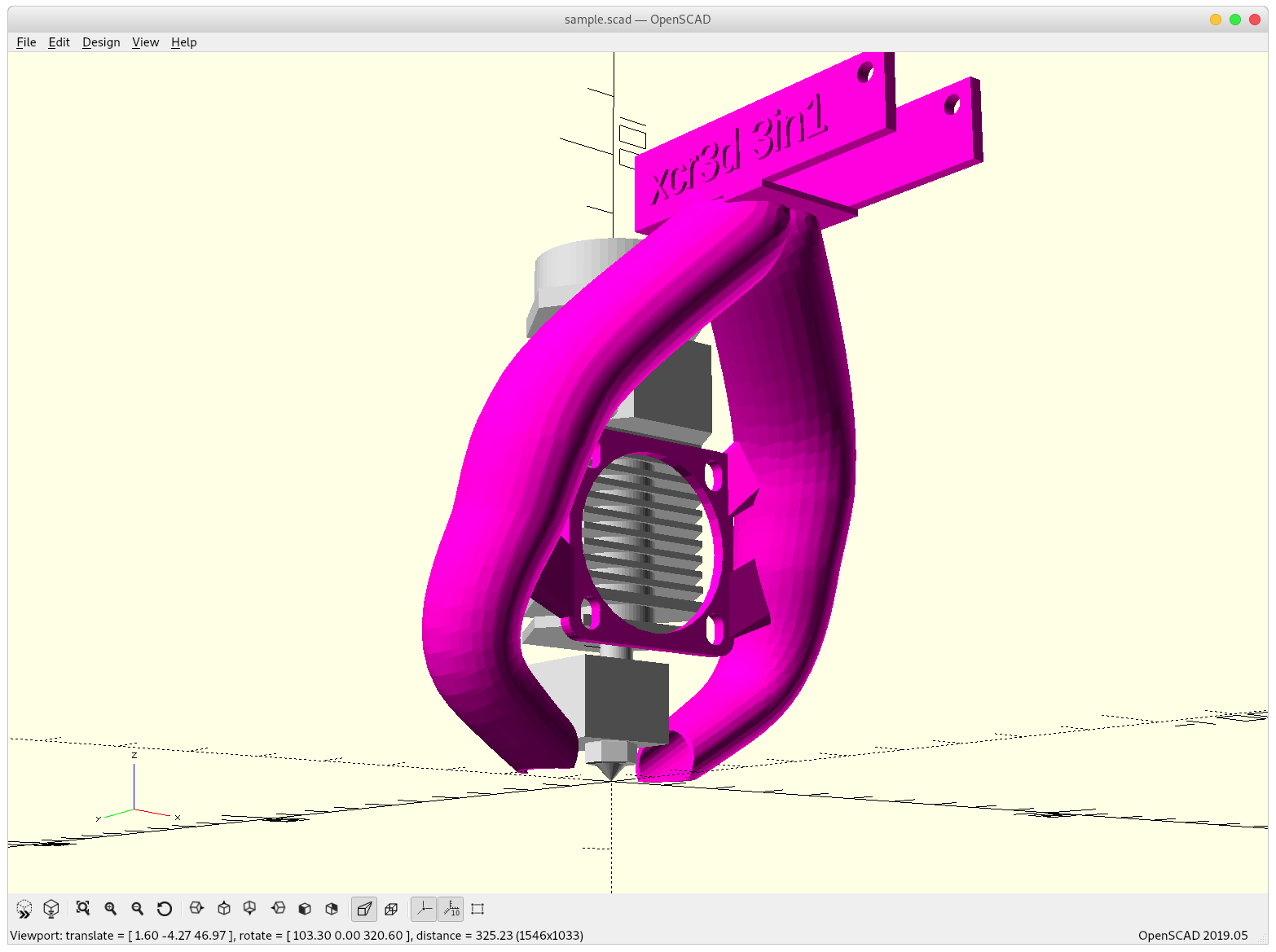
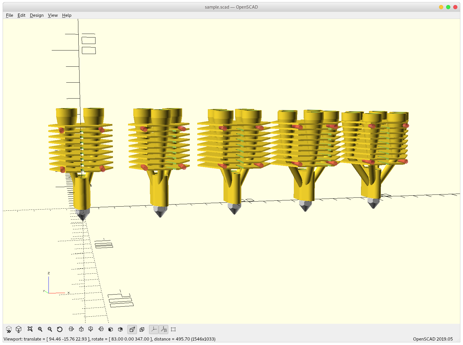
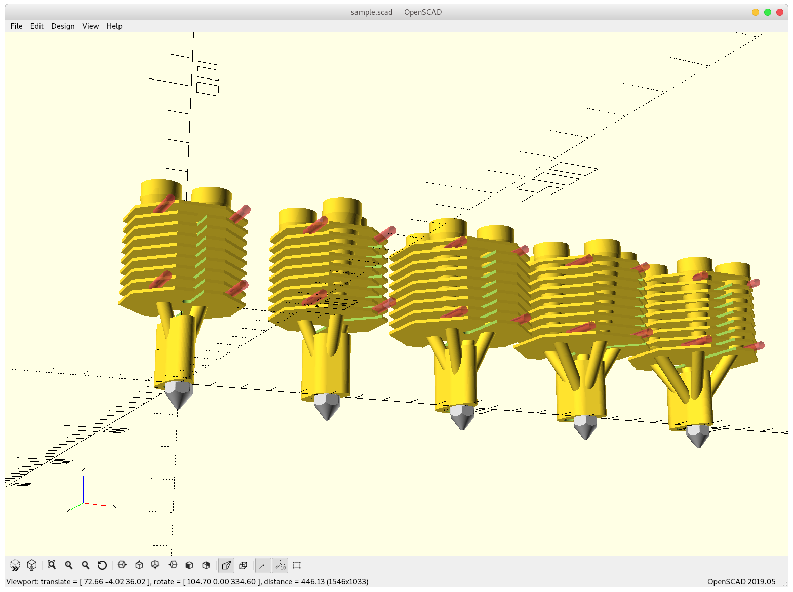
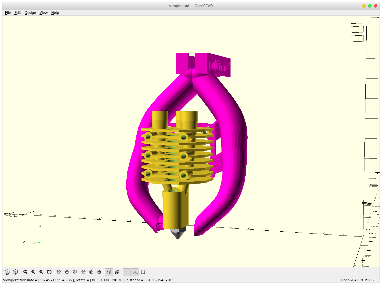
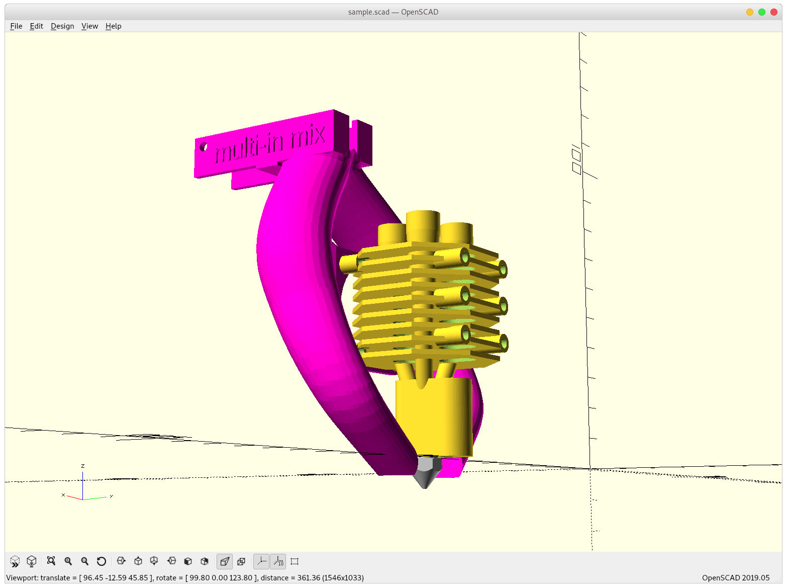
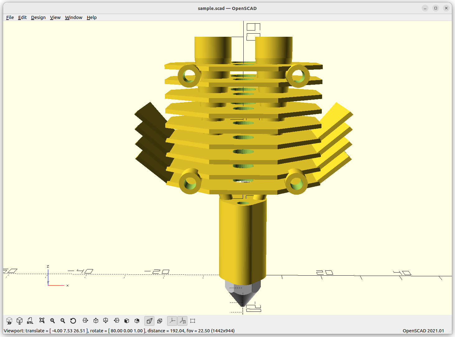
Concept
- parametric design with 2 up to 6 filaments inputs
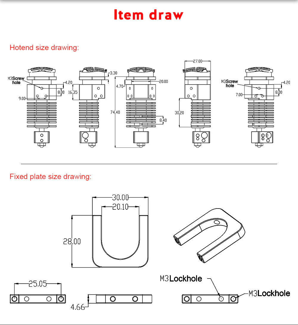
- combine heatblock, heatbreak and heatsink, make it compact
- permit ordinary nozzles (MK8/E3D V6), using M7 thread
- orient heat cartridge vertically (like a E3D Volcano) to support up to 0.8mm nozzles
- single 30mm fan for heatsink
- using PC4 M10 or M4 pneumatic couplers as intakes
Pros:
- mixing colors: 2 to 6 colors, CMY(KW), actual true color printing
- fast switching of materials, given they have similar extrusion temperature
Cons:
- filaments must be present in order to withstand backpressure even if not printed
- filaments must be printed eventually, otherwise ‘bake’ in the hotend
Challenges:
- controlling actual mixing in the chamber, e.g. creating turbulence to mix properly
- creating turbulences may limit retraction, which is anyway not easy with mixing hotends
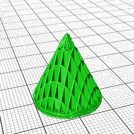
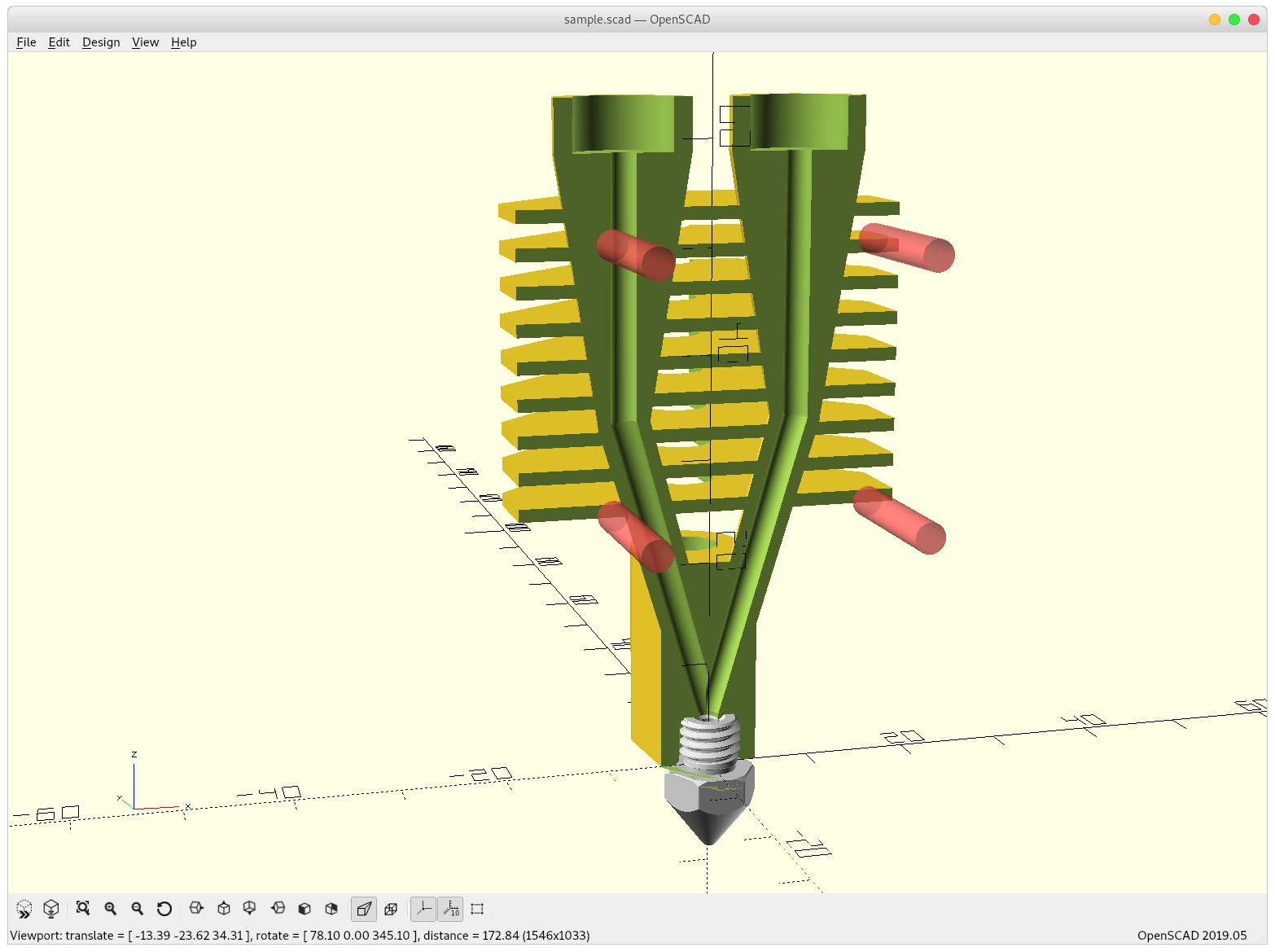
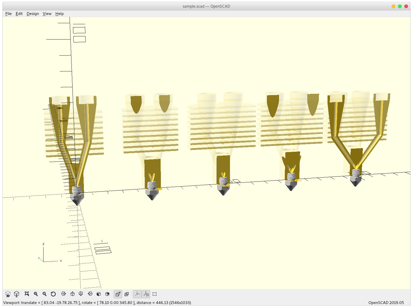
Gallery

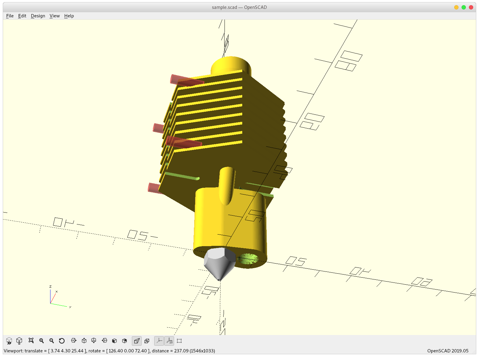
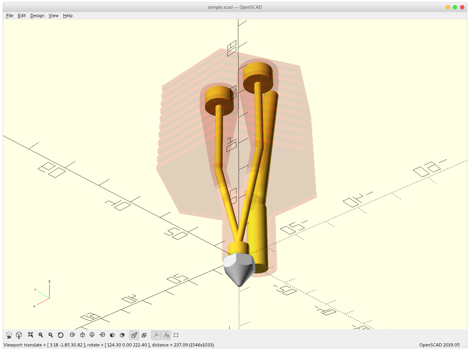
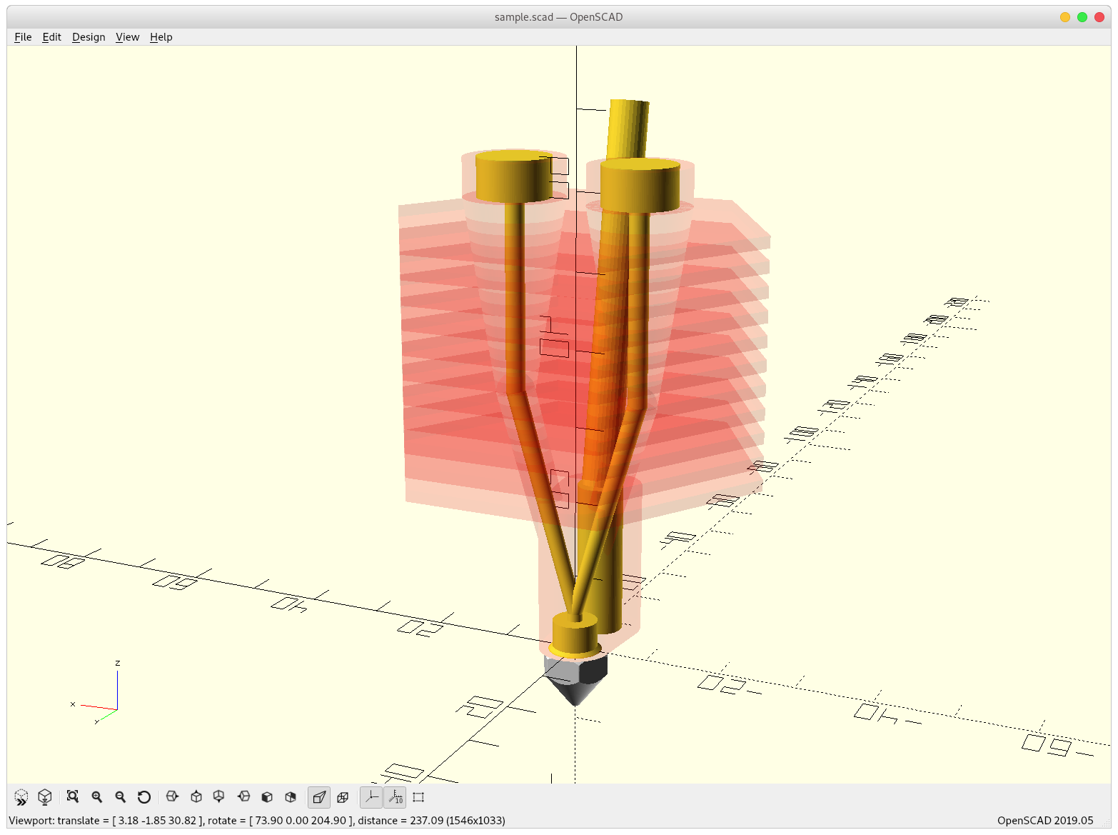
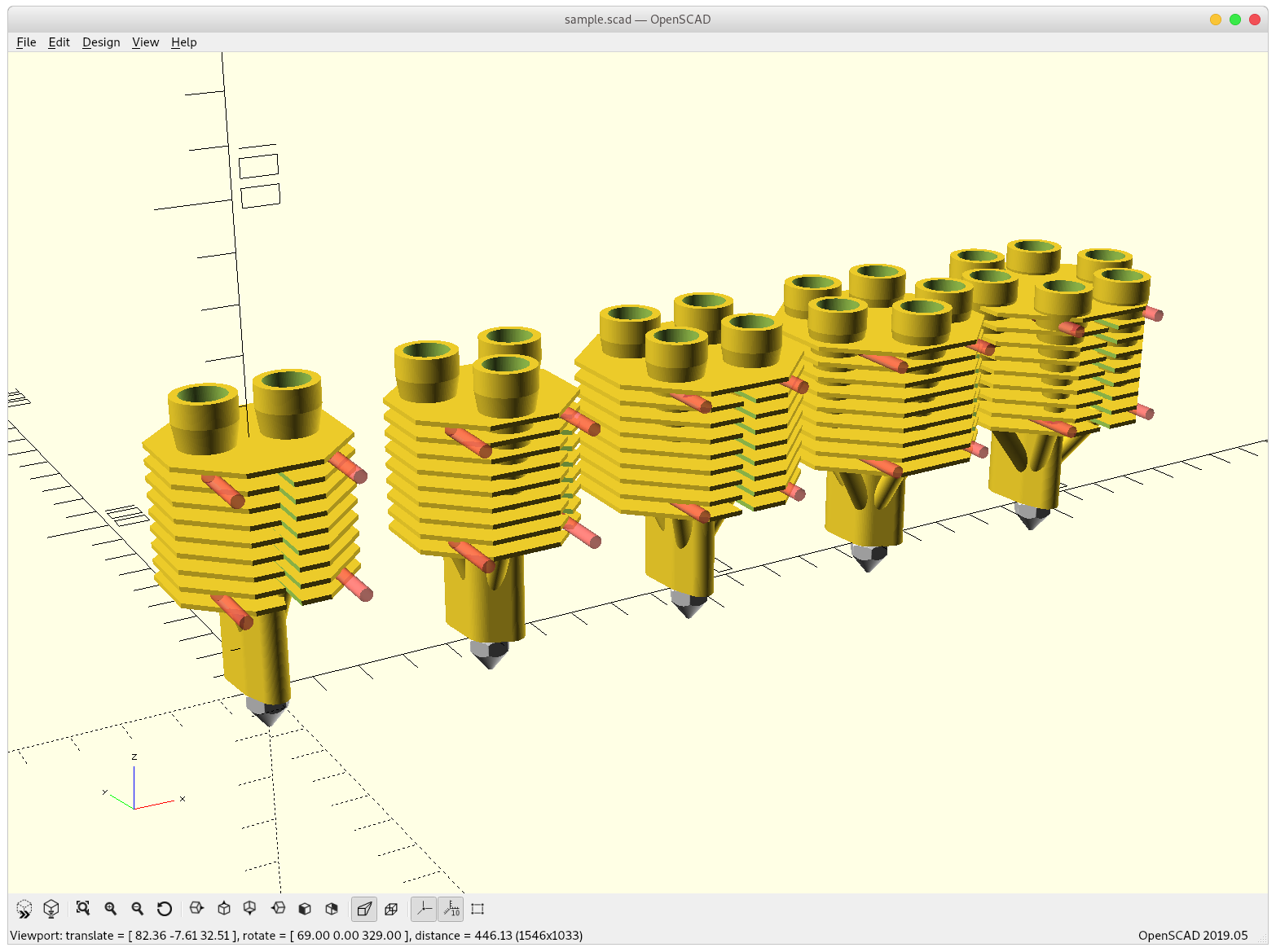
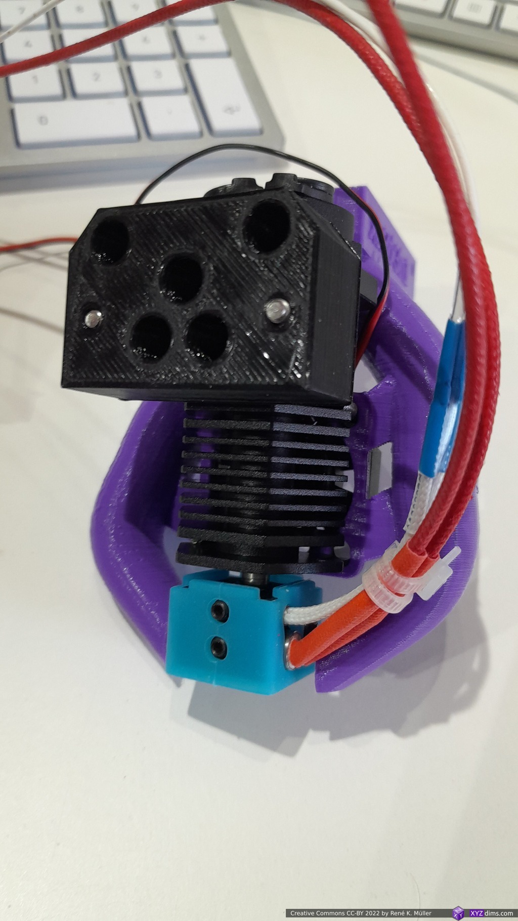
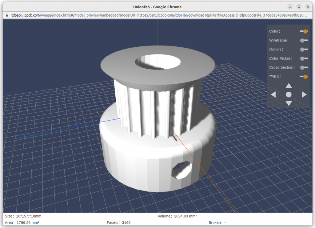
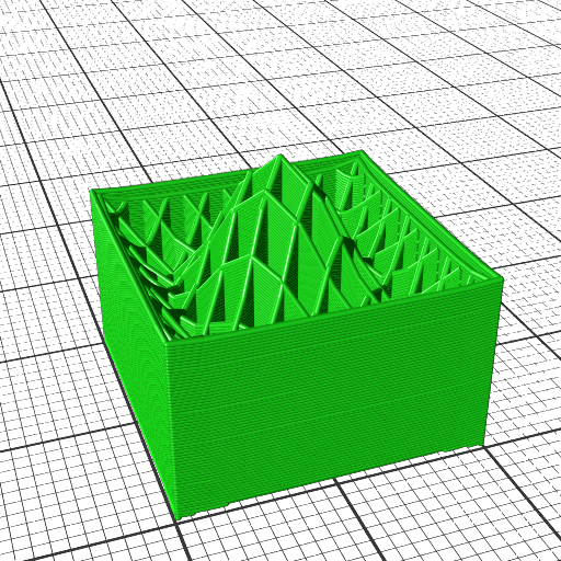
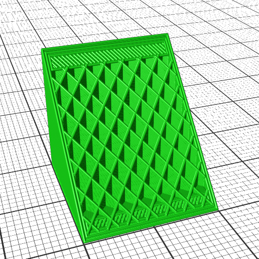
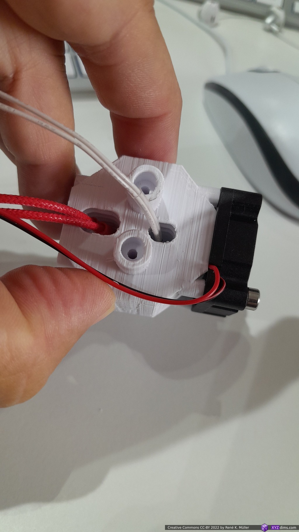
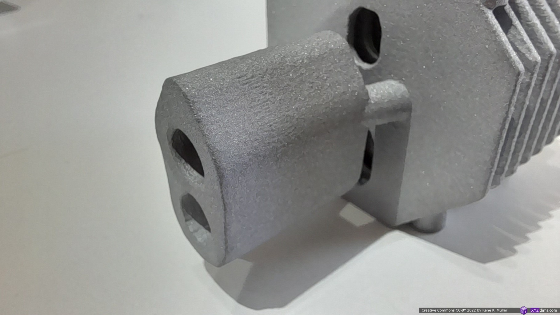
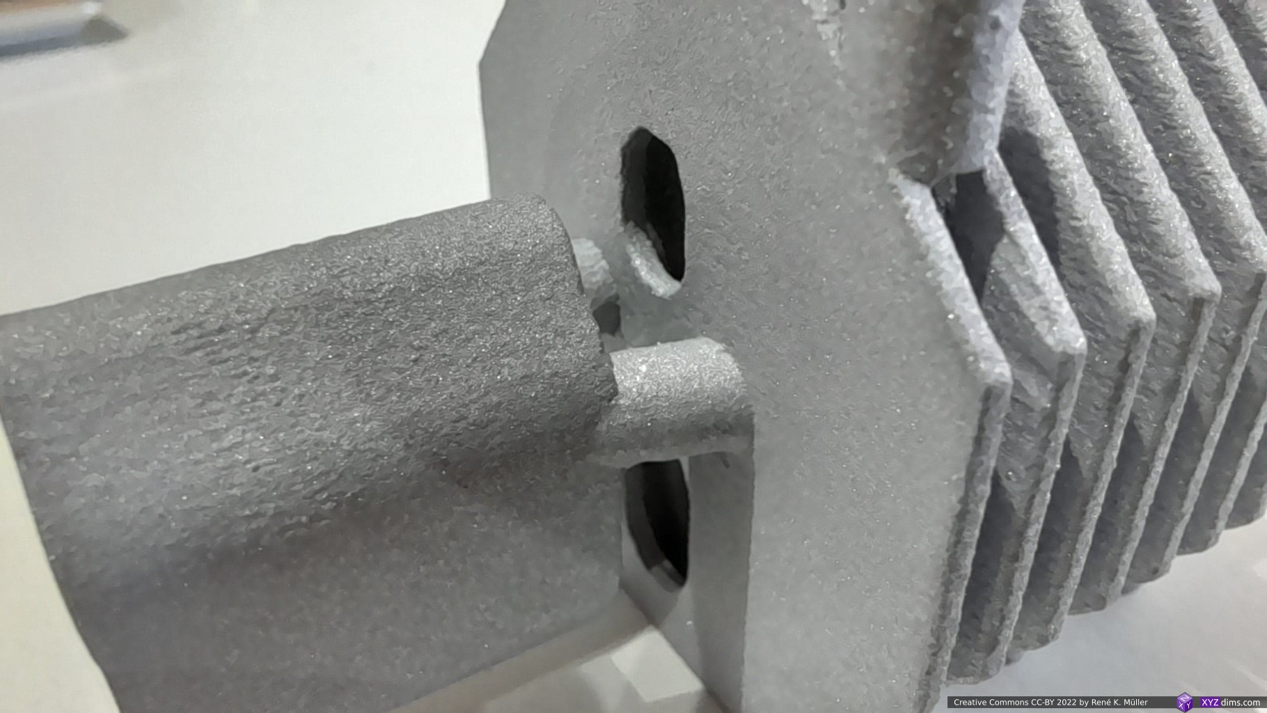
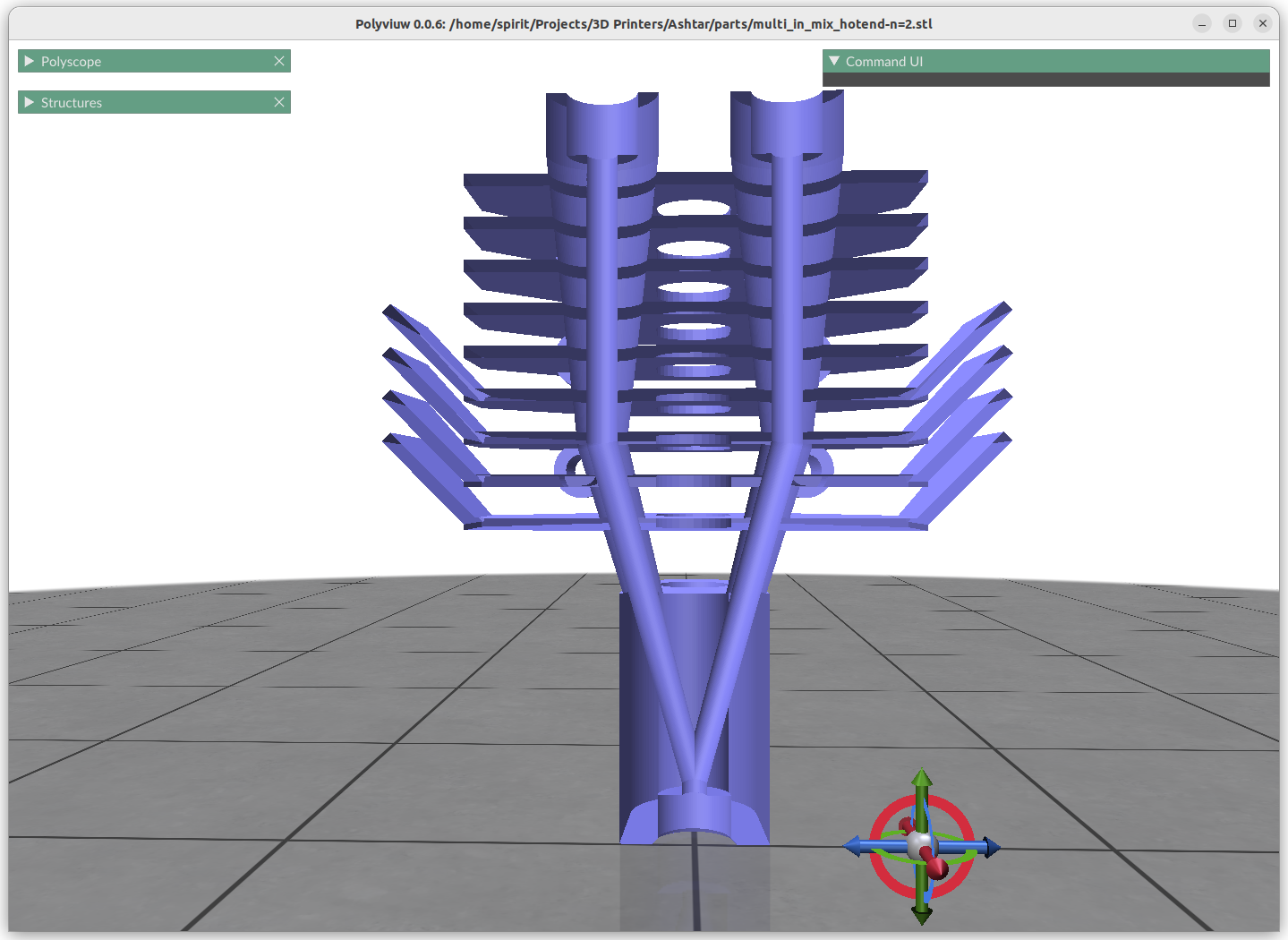
The filament channels:
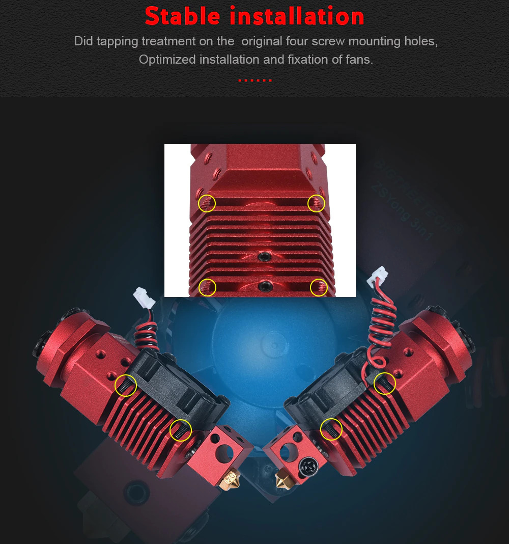
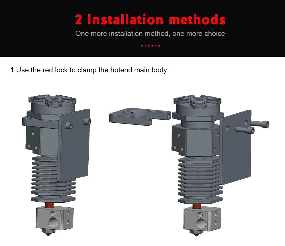
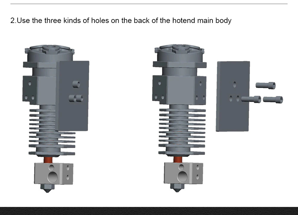
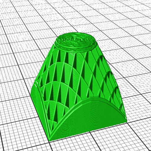
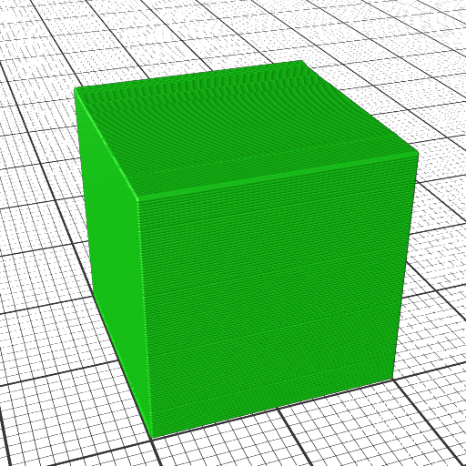
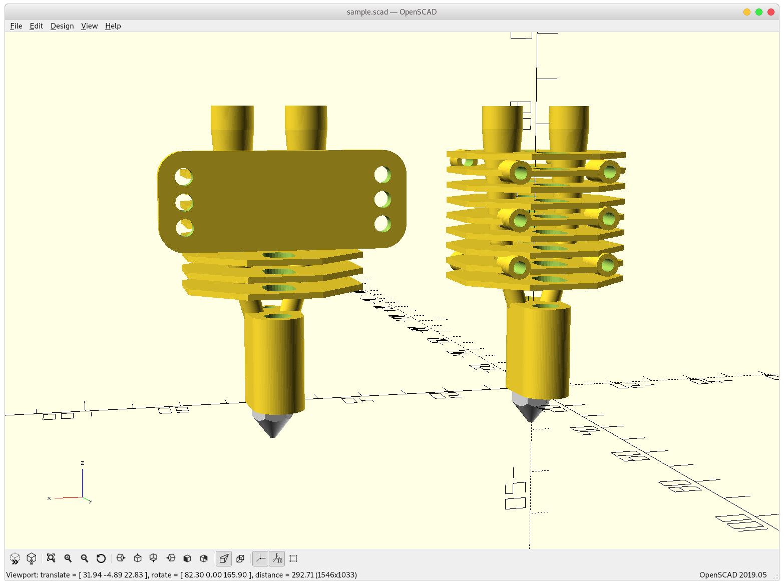
Mounting options, plain mounting holes 3x 20mm, or plate with 3x 40mm holes:


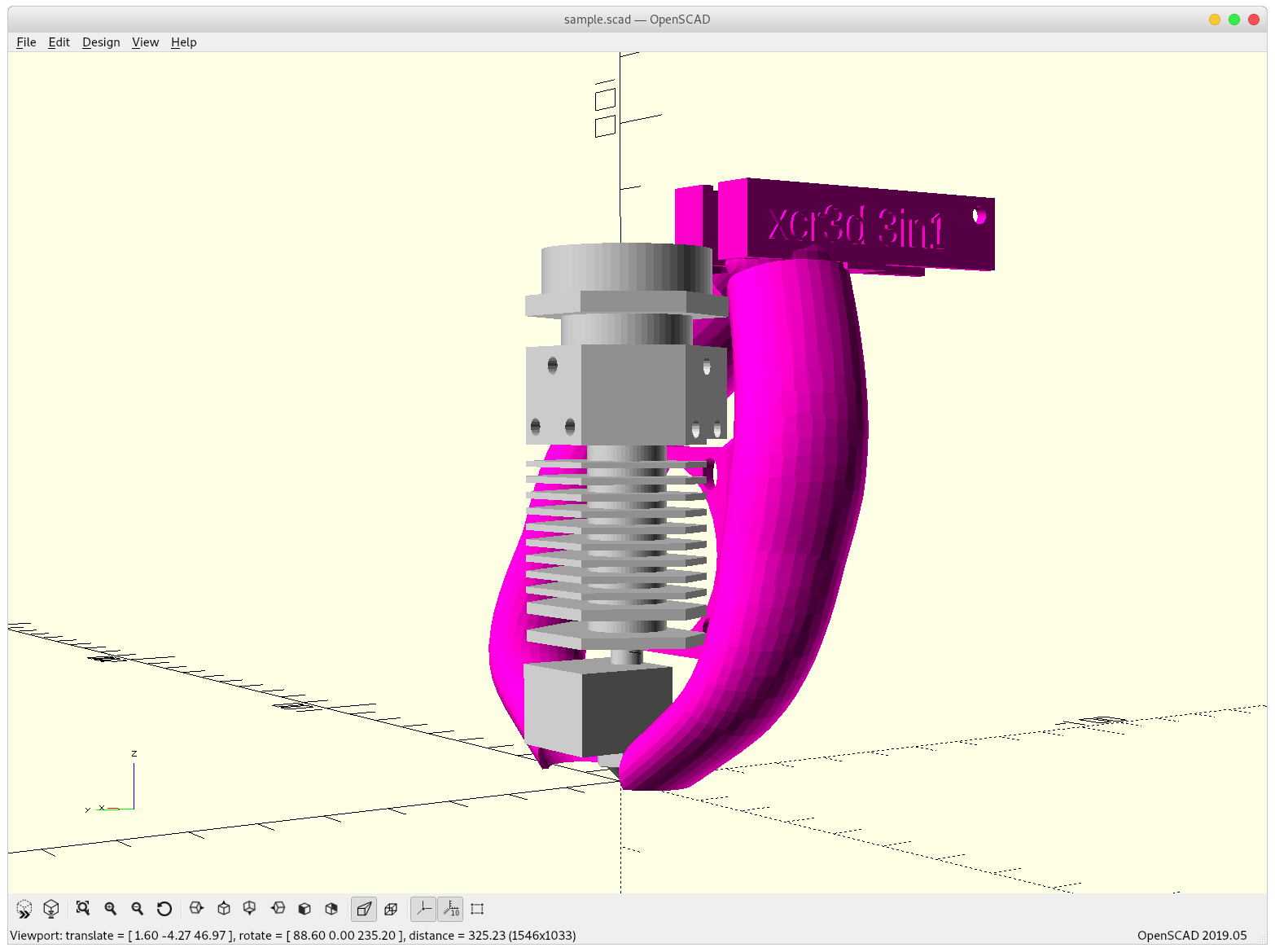
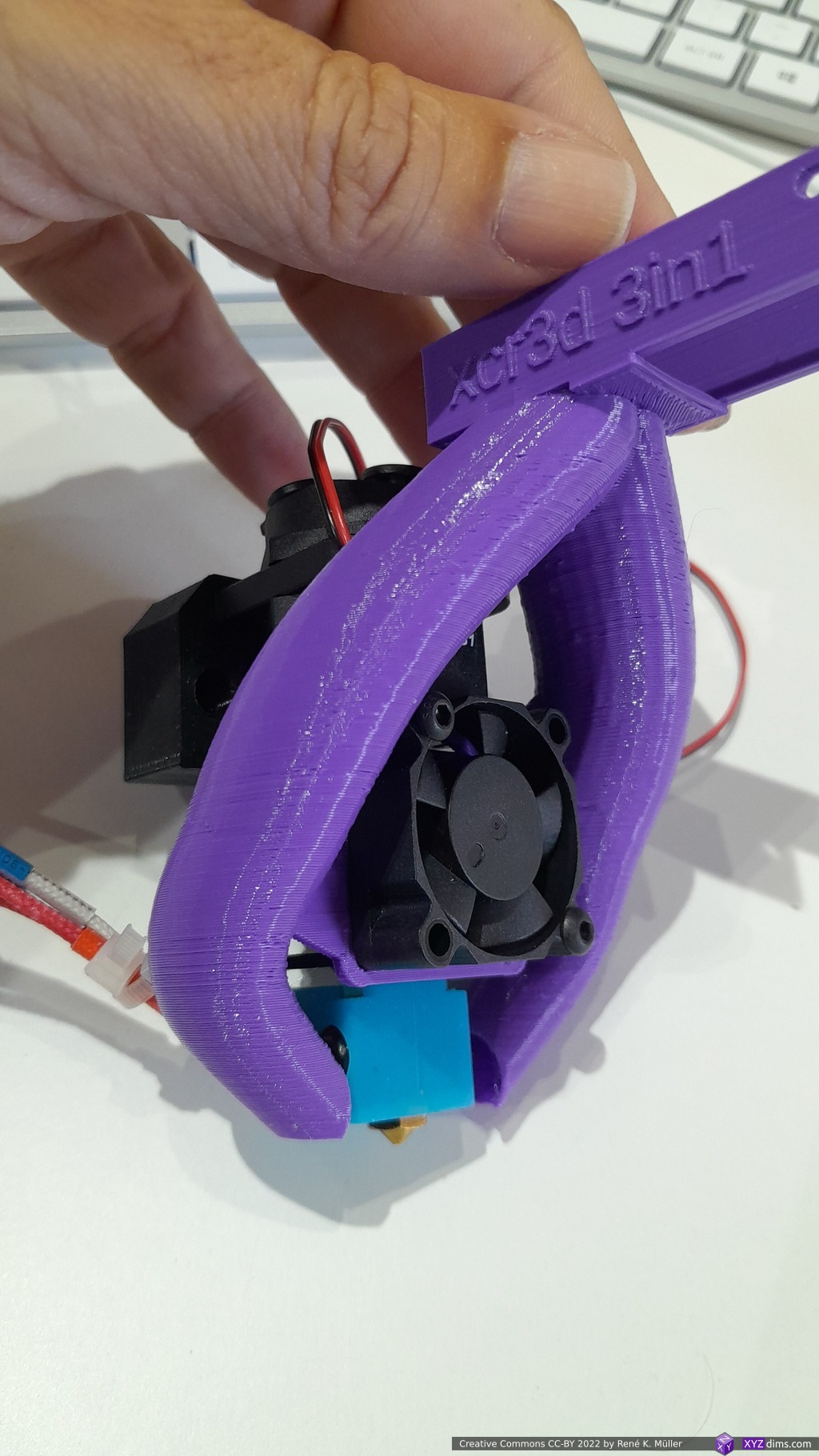
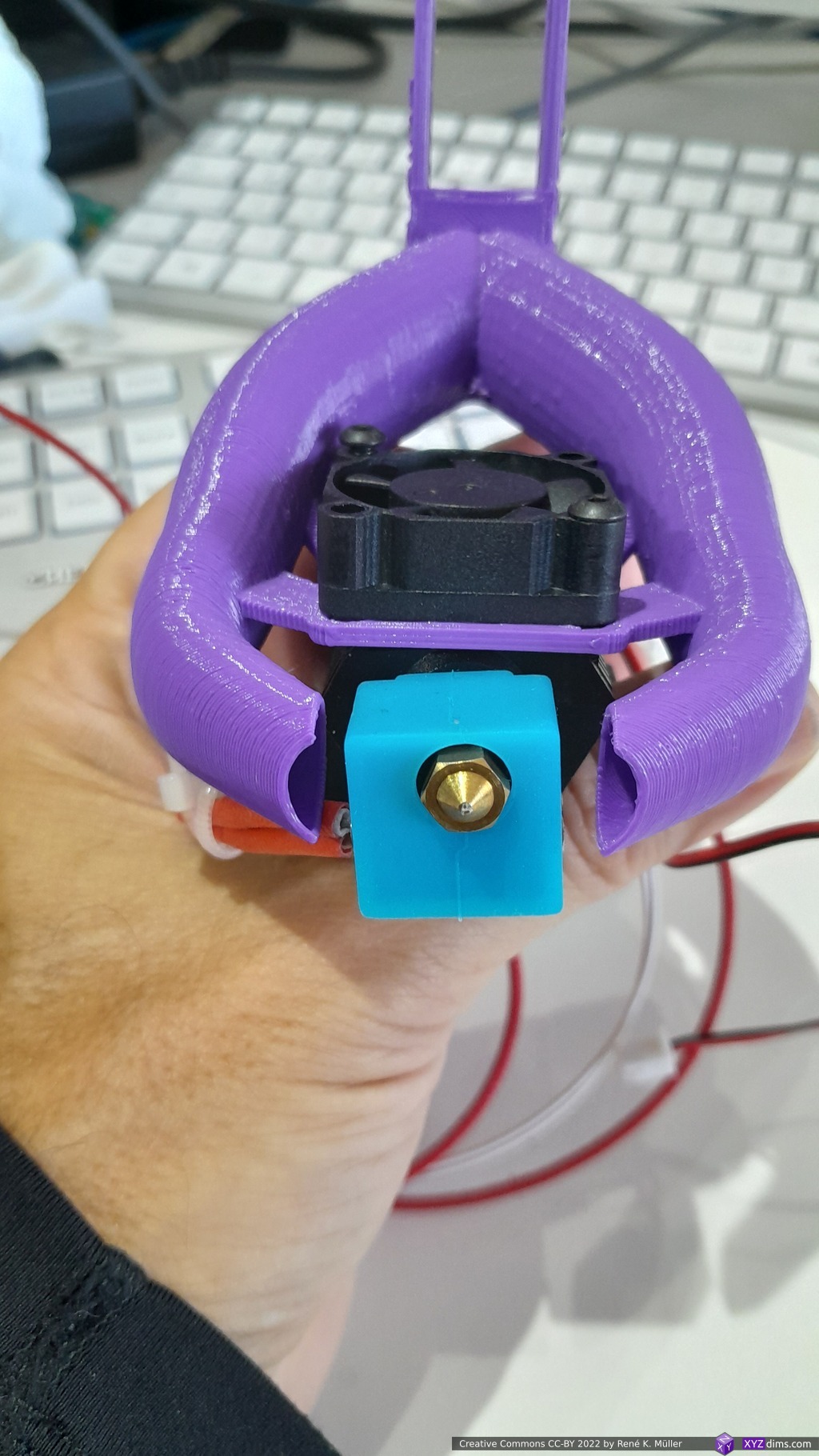
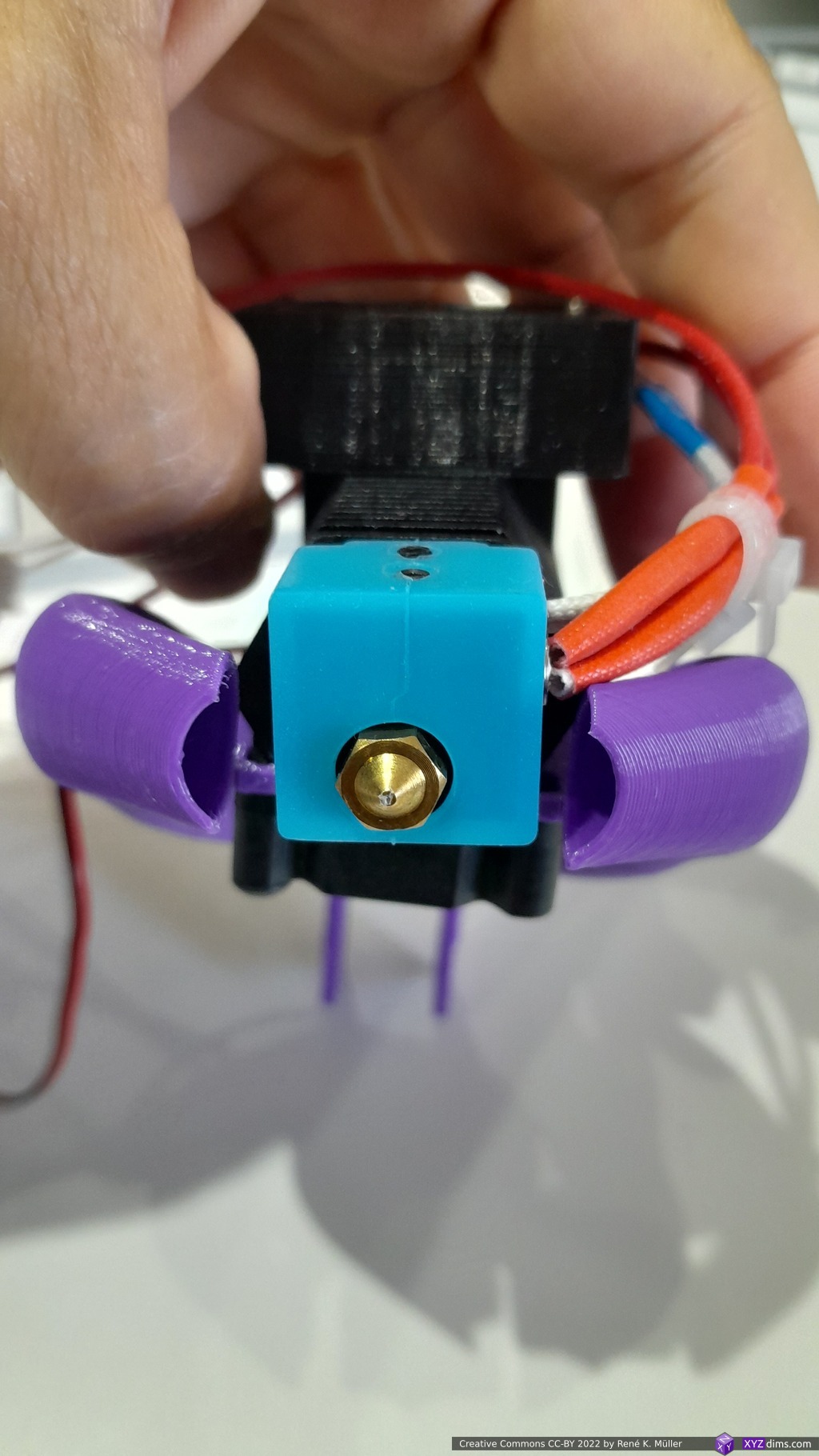
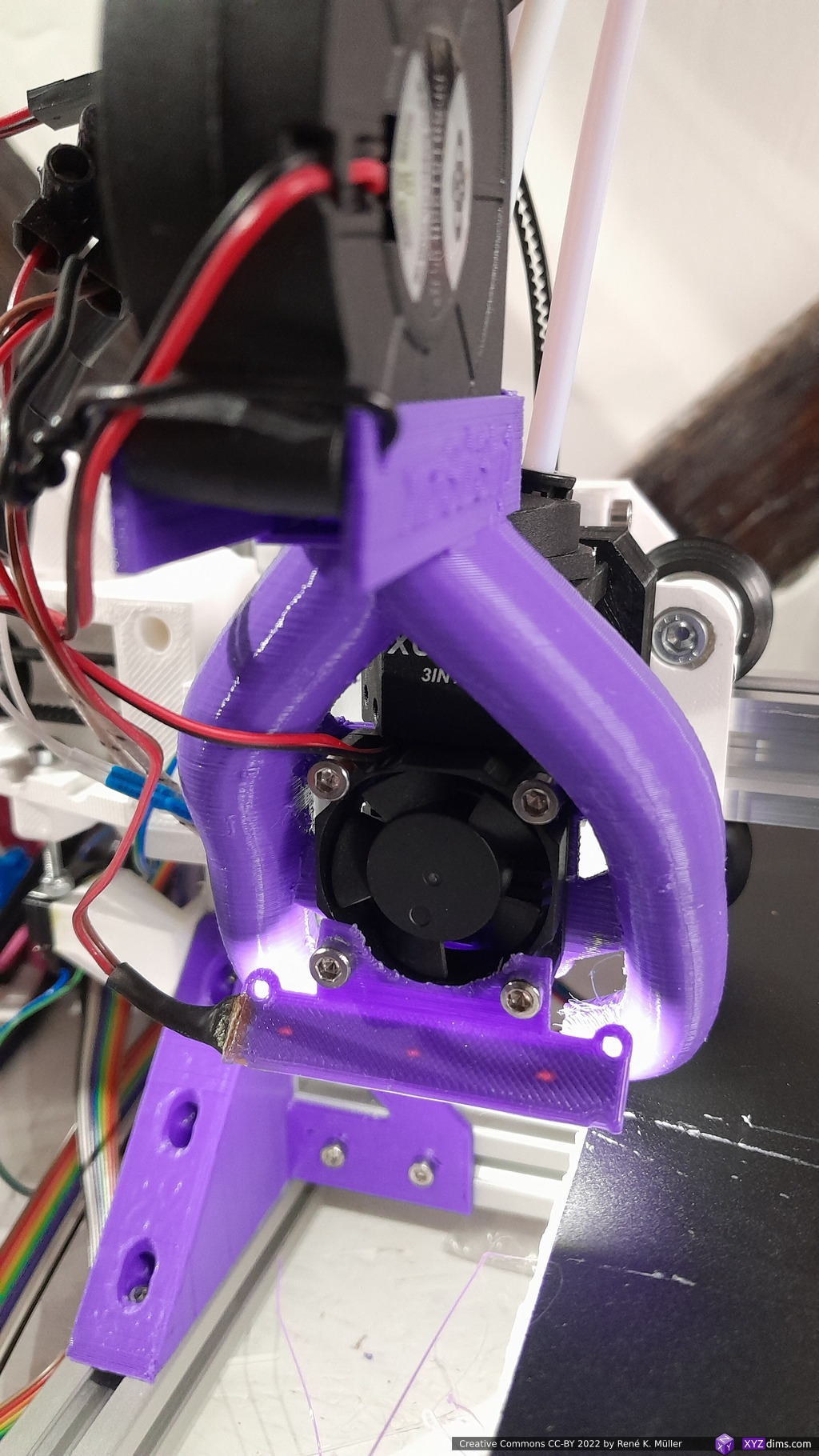
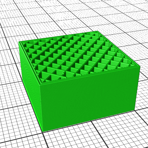
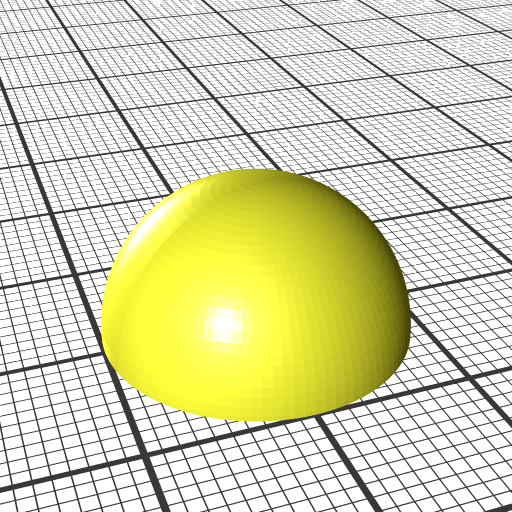
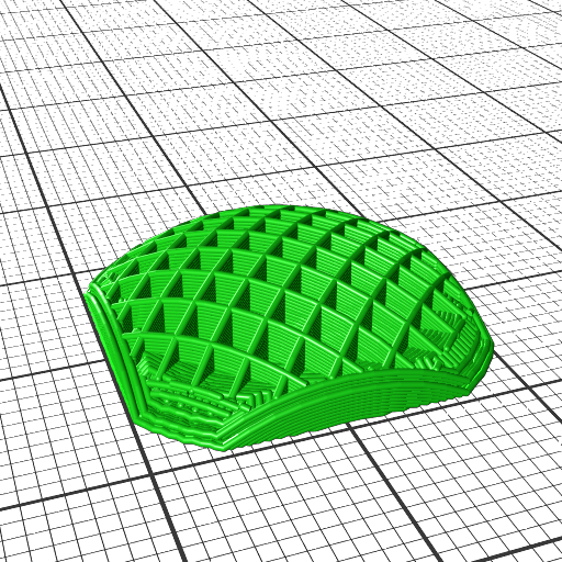
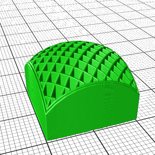
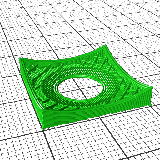
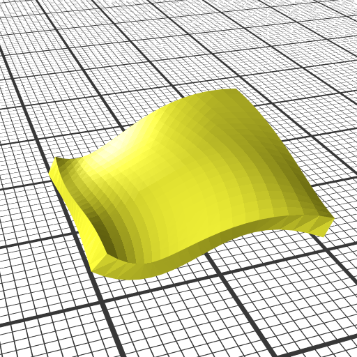
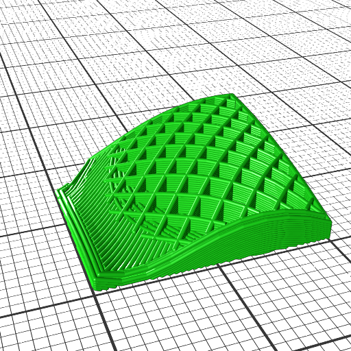
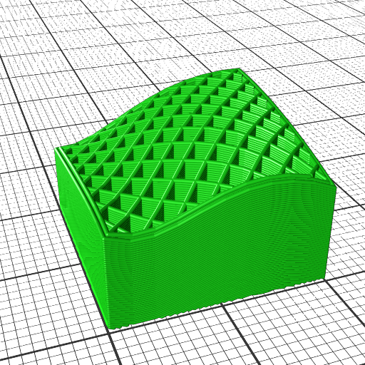
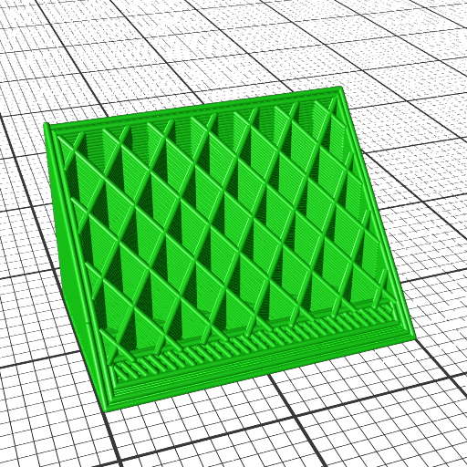
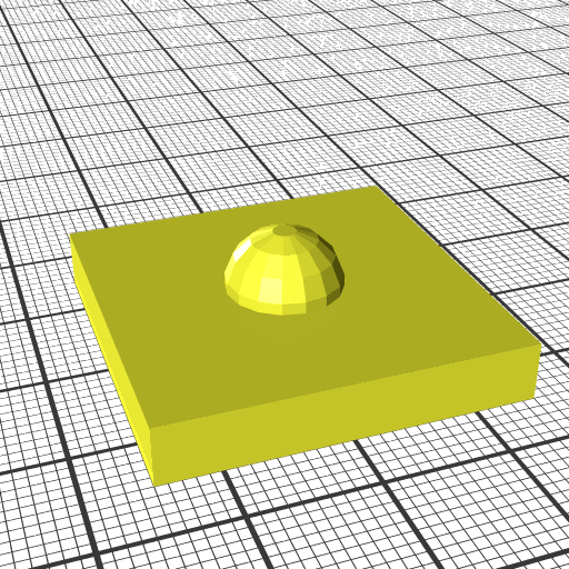
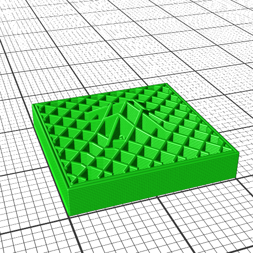
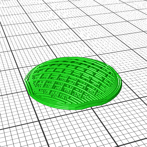
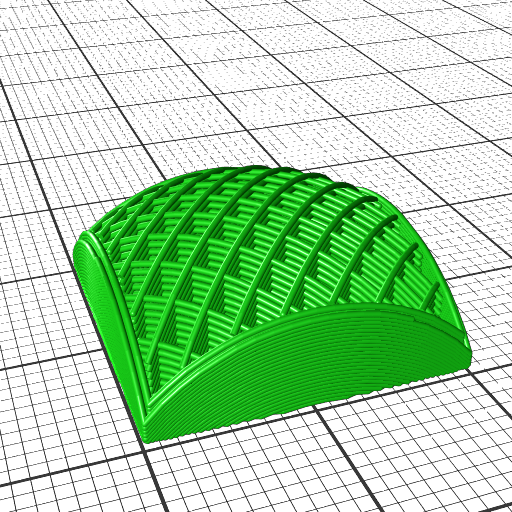
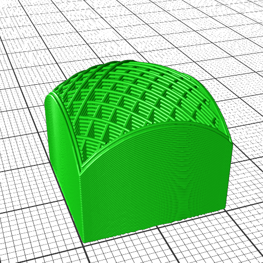
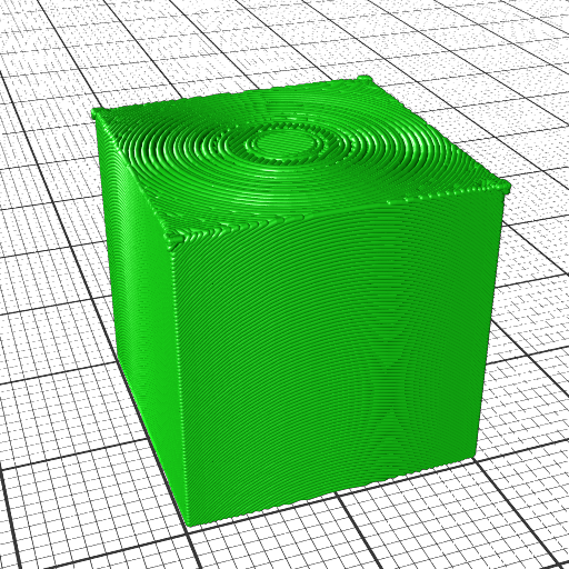
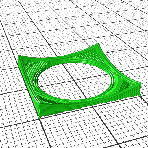
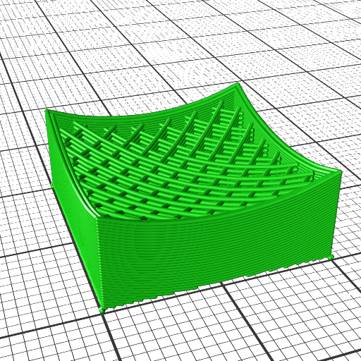
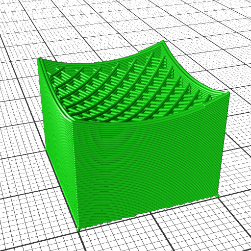
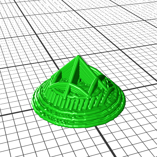
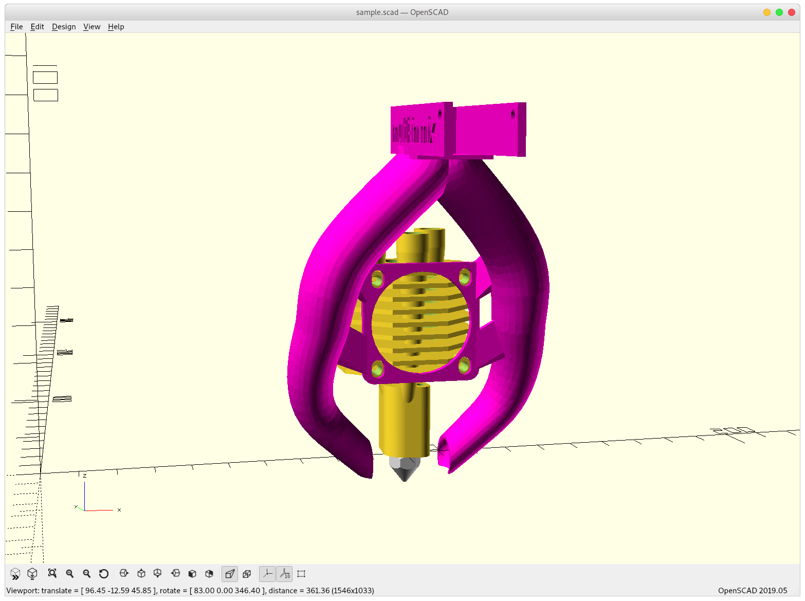
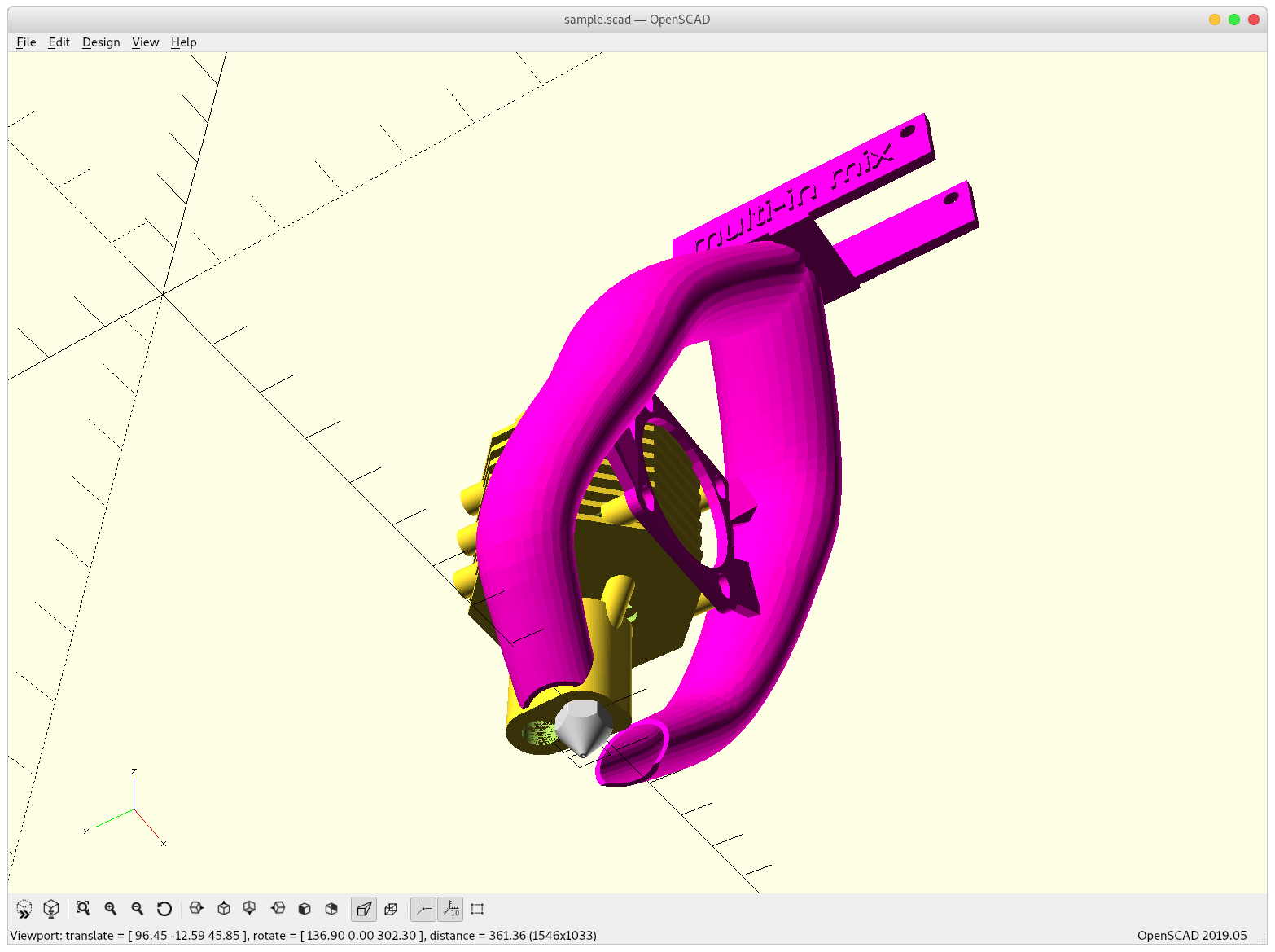
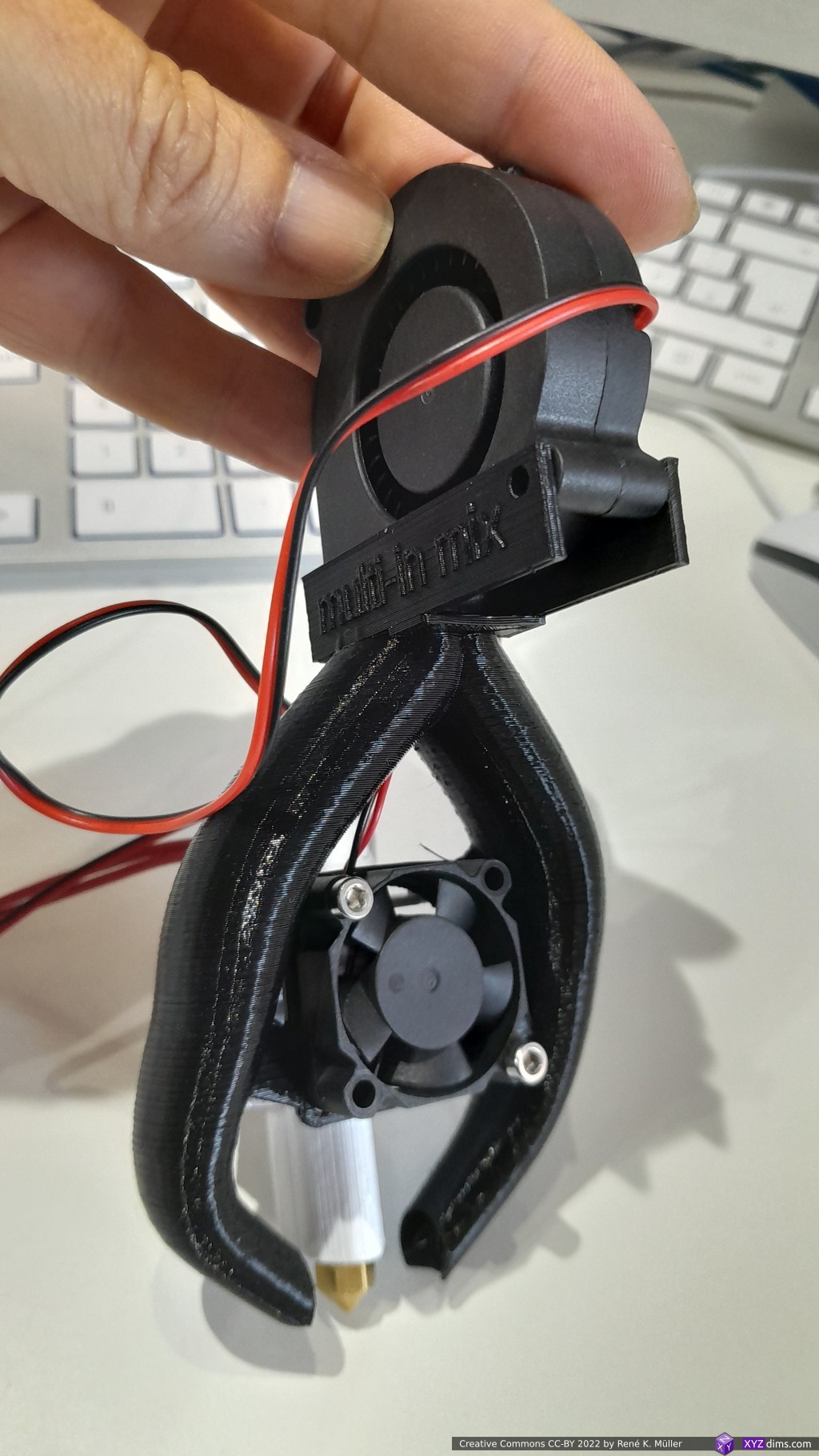
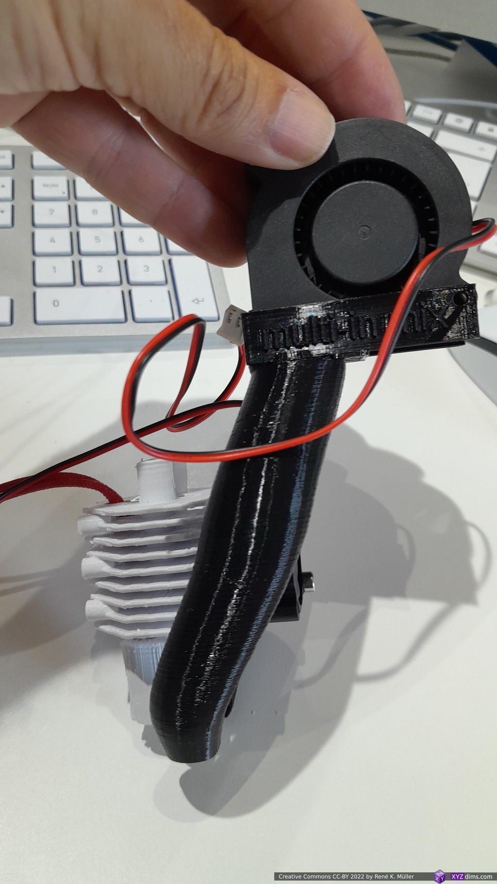
and adding my Parametric Part Cooler:


Gallery
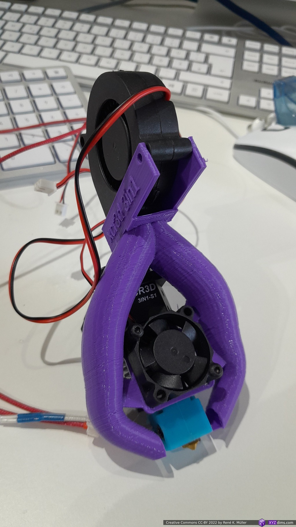
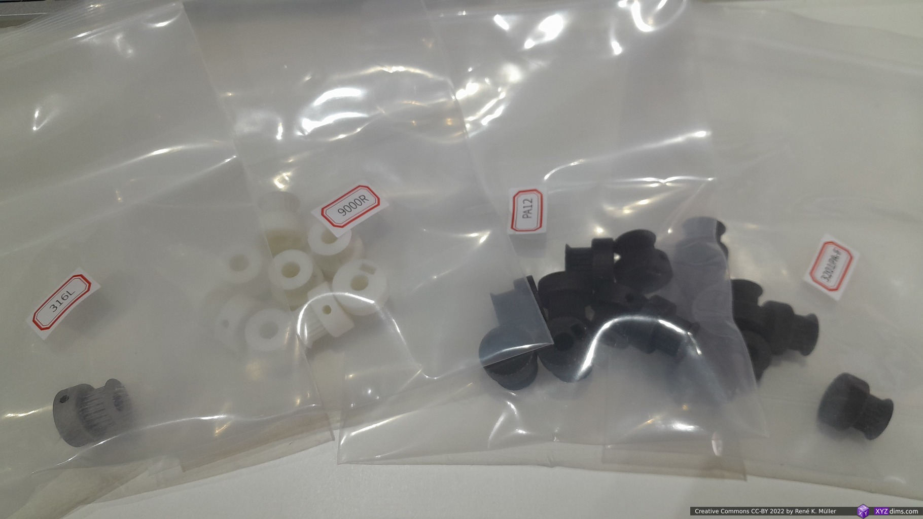
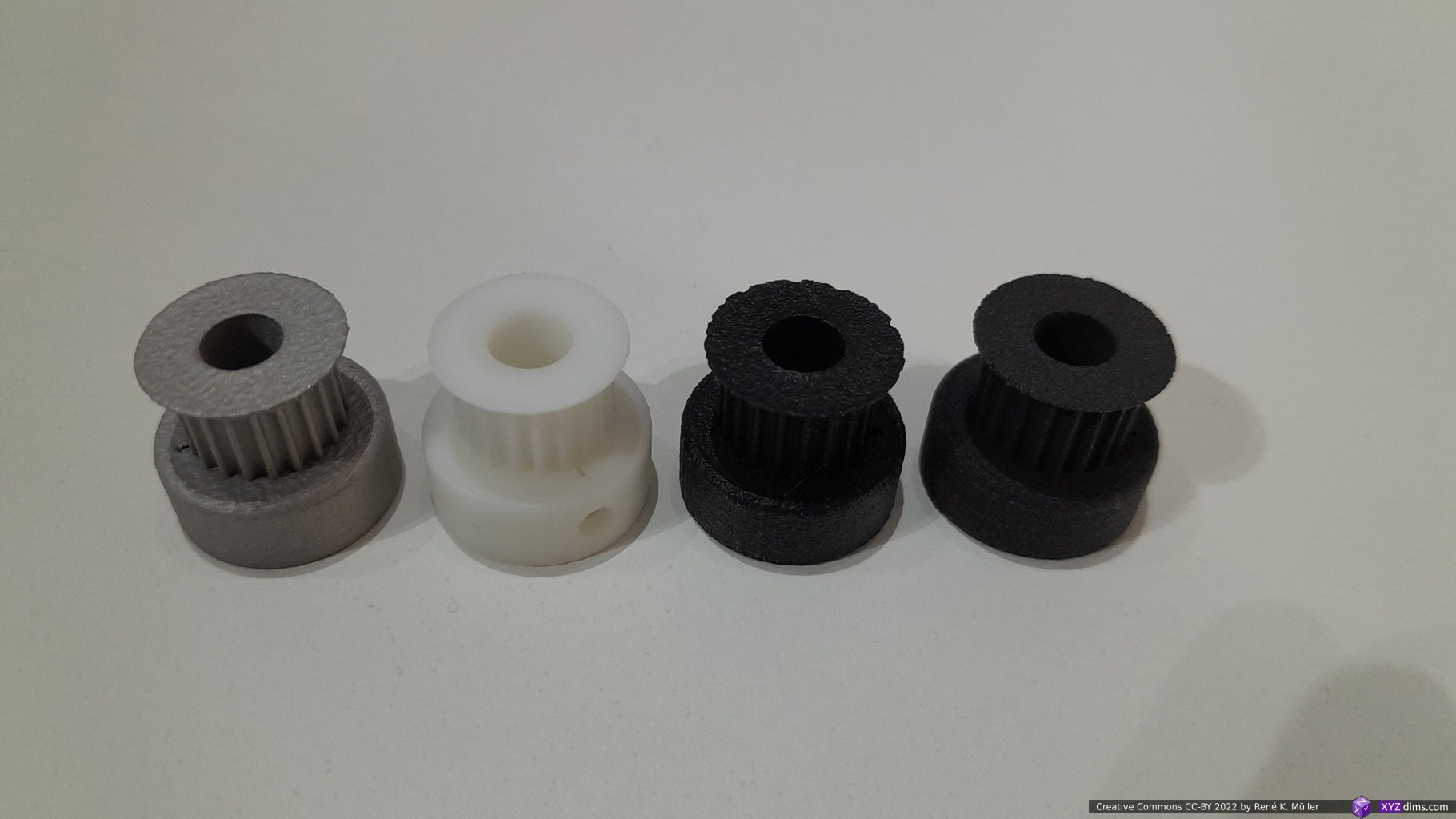
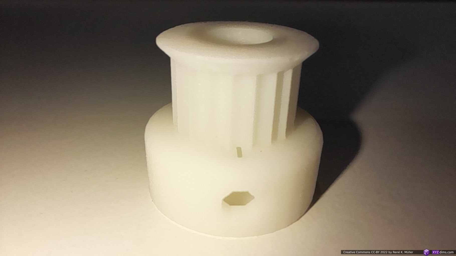
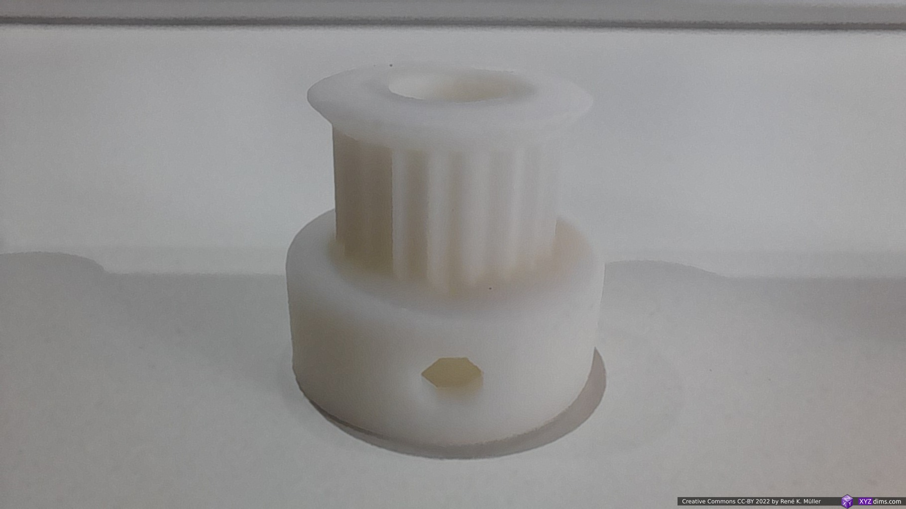
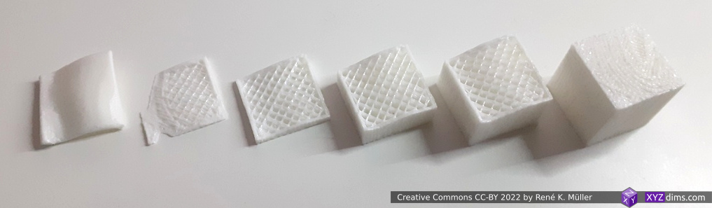
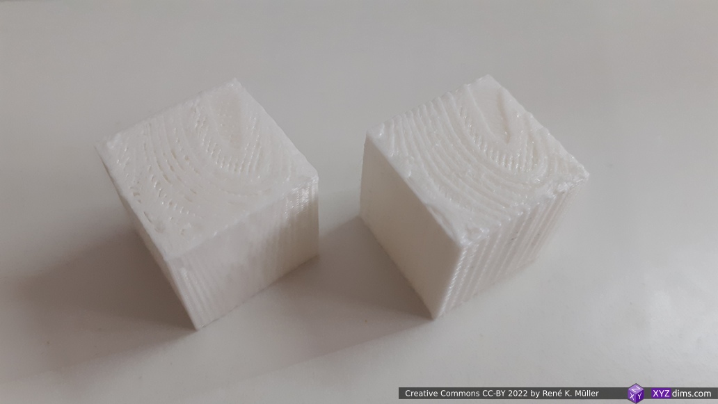
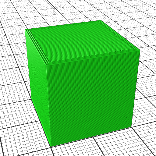
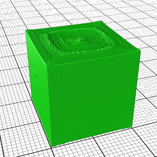
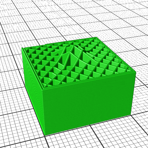
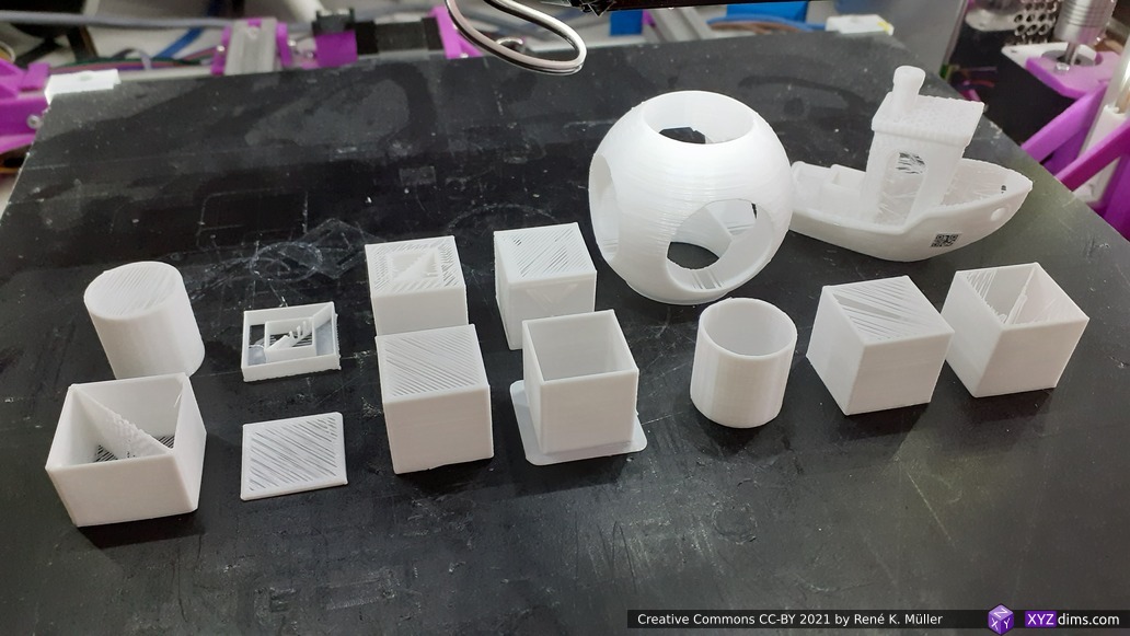
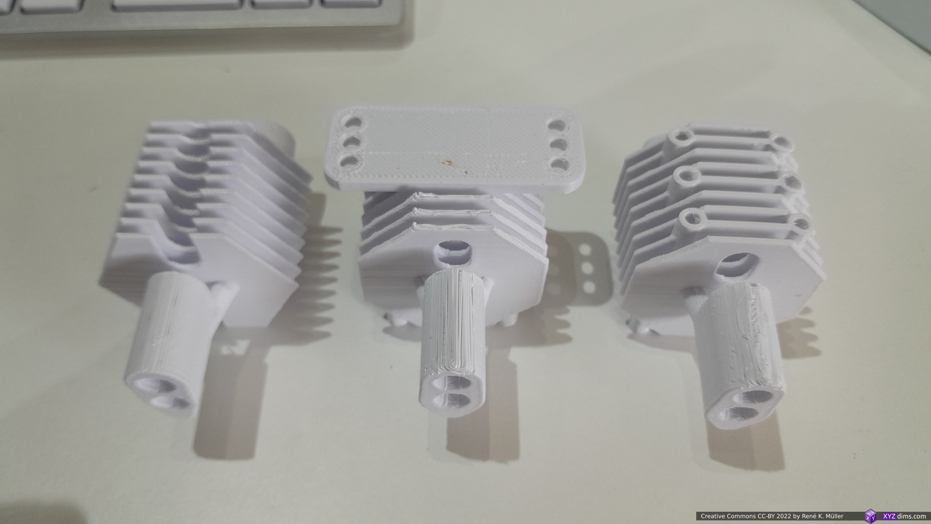
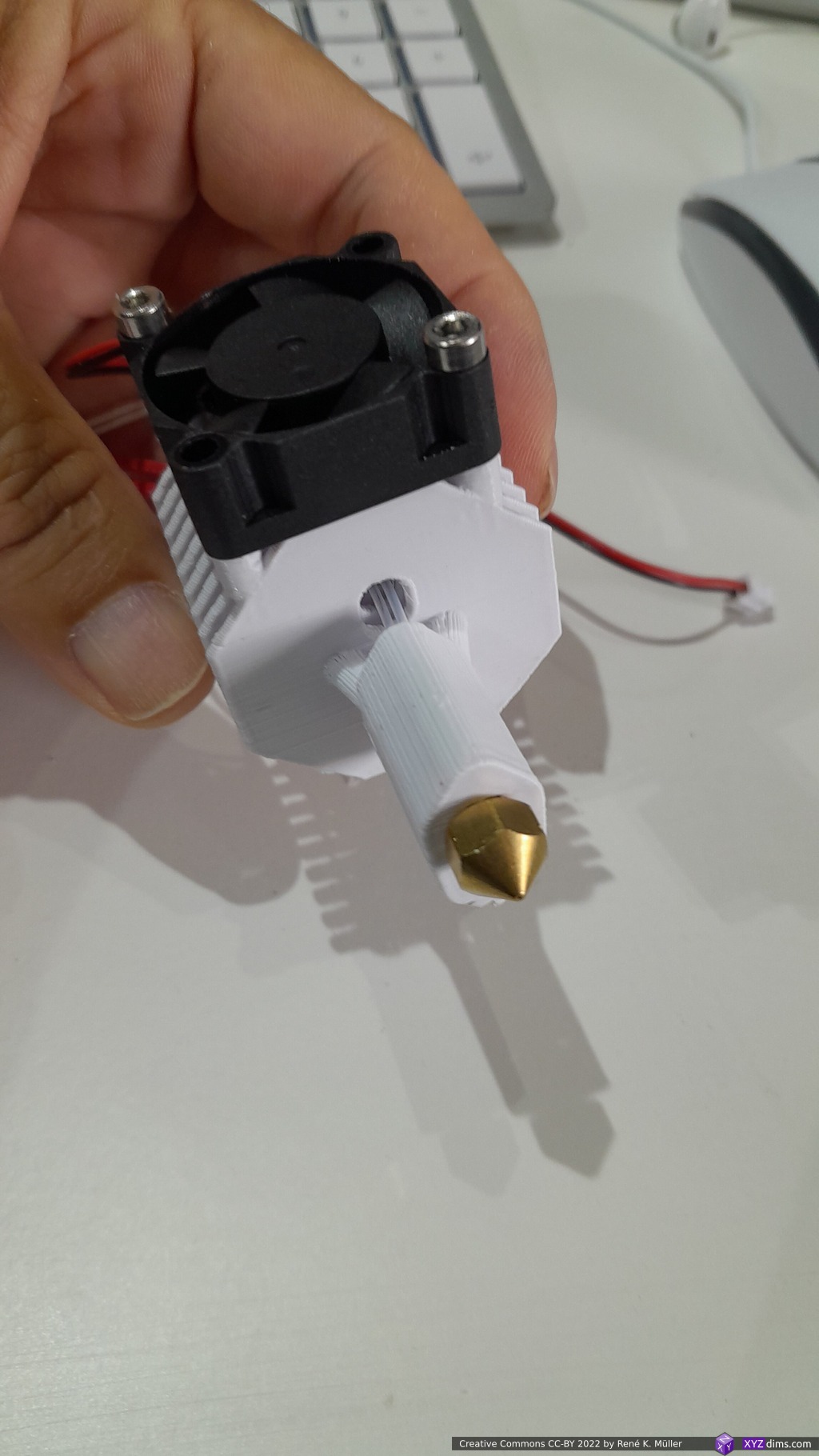
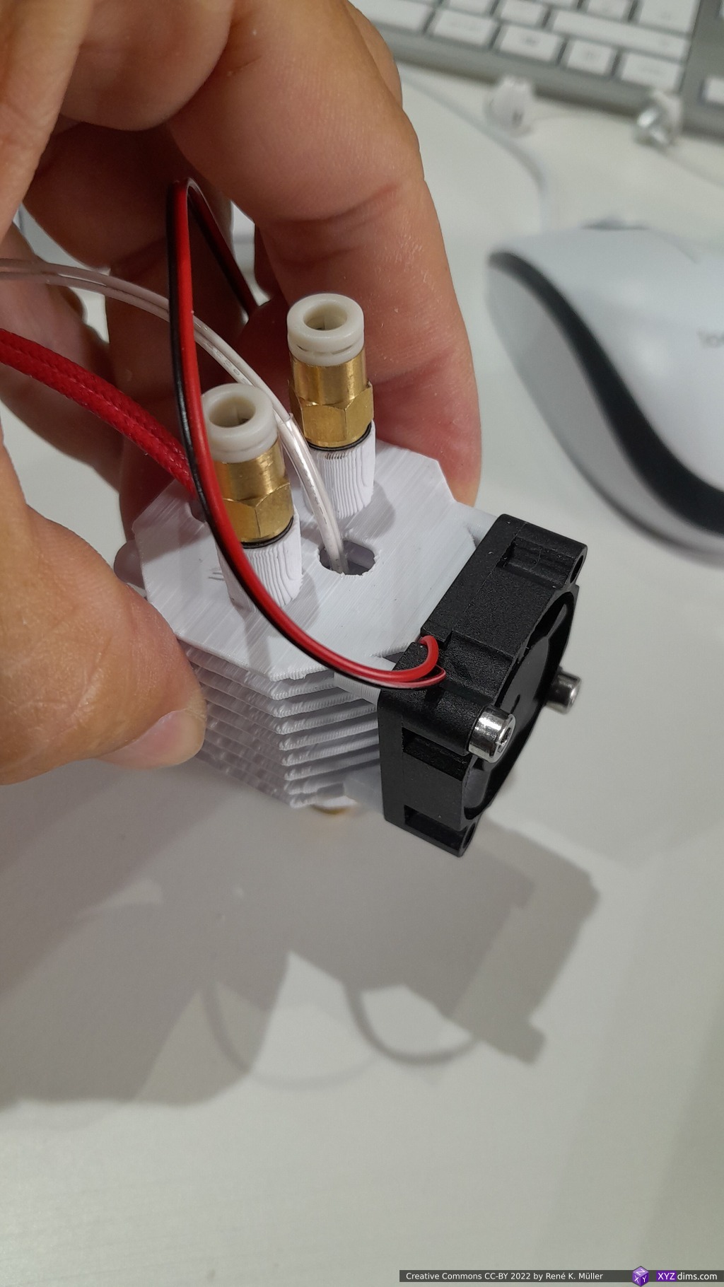
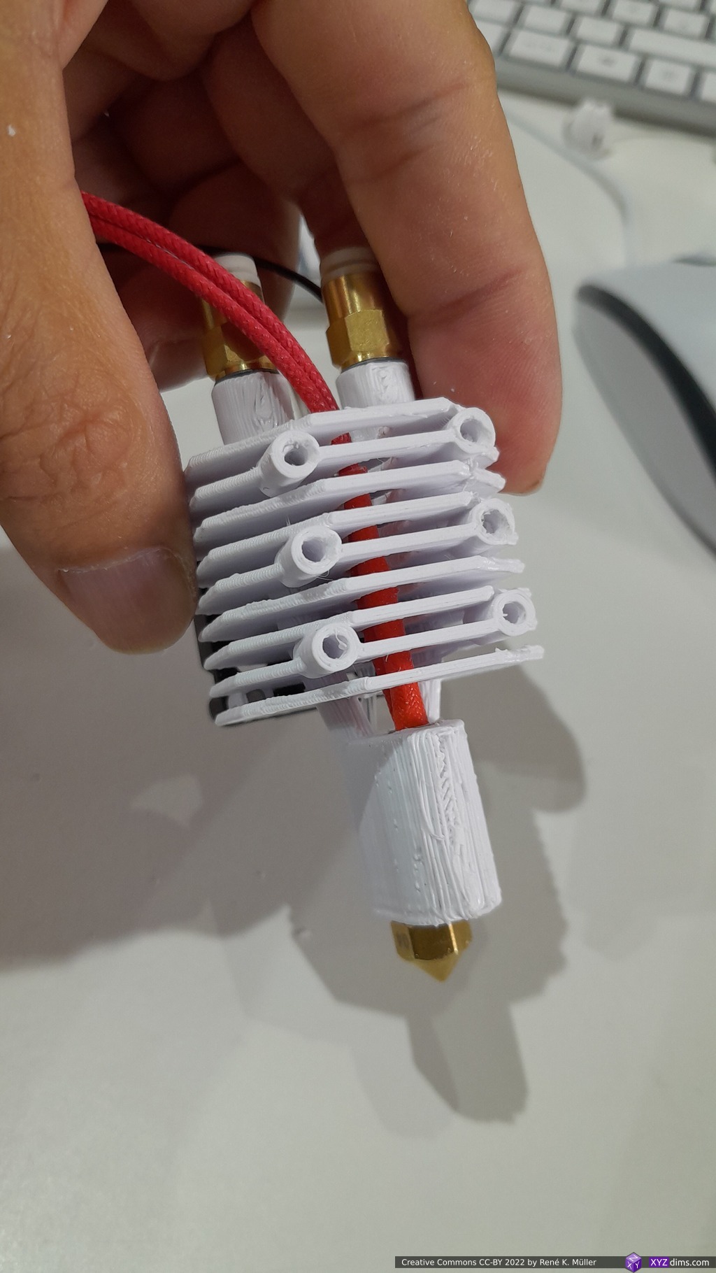
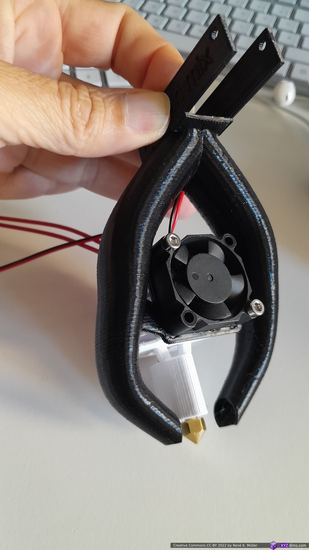
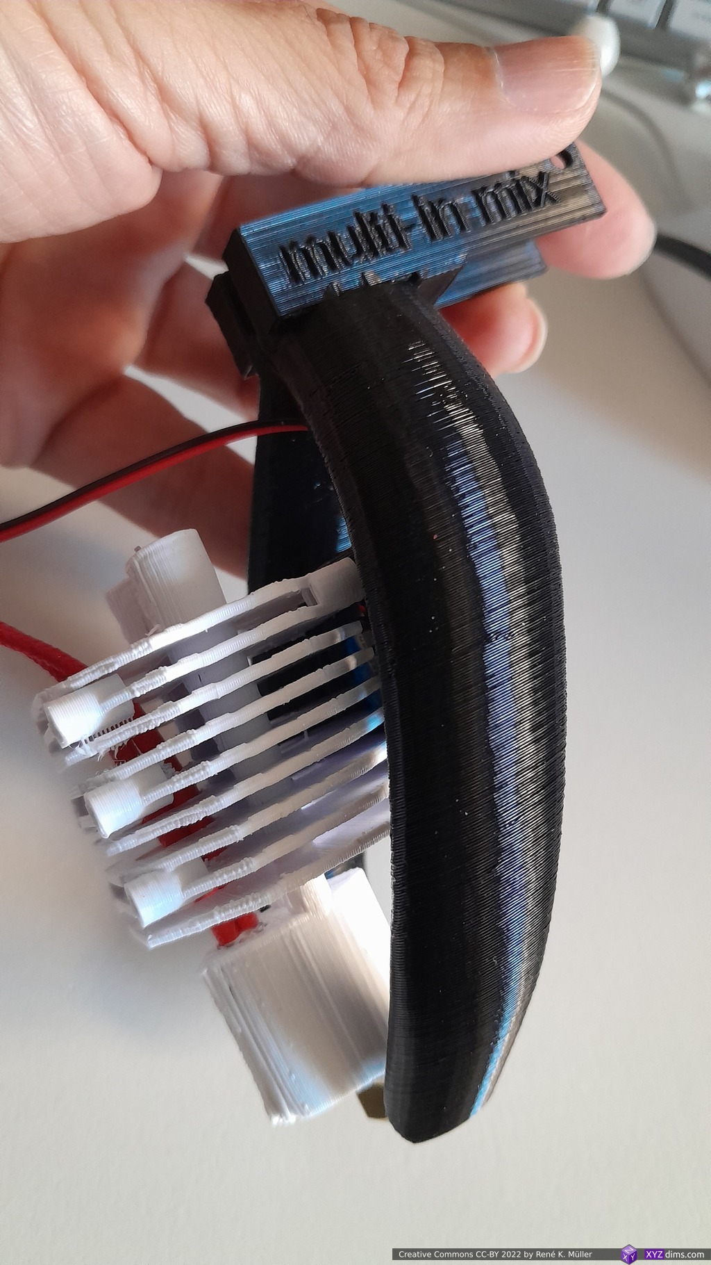
Early prototype printed in cold white eSun PLA+ 0.25mm layer height (~1h 20m print time):

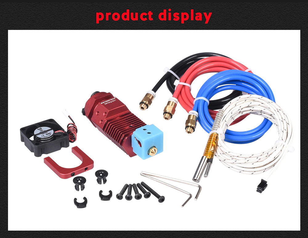
Adding nozzle, heat cartridge, heat thermistor, heatsink fan and pneumatic couplers PC4 M6:
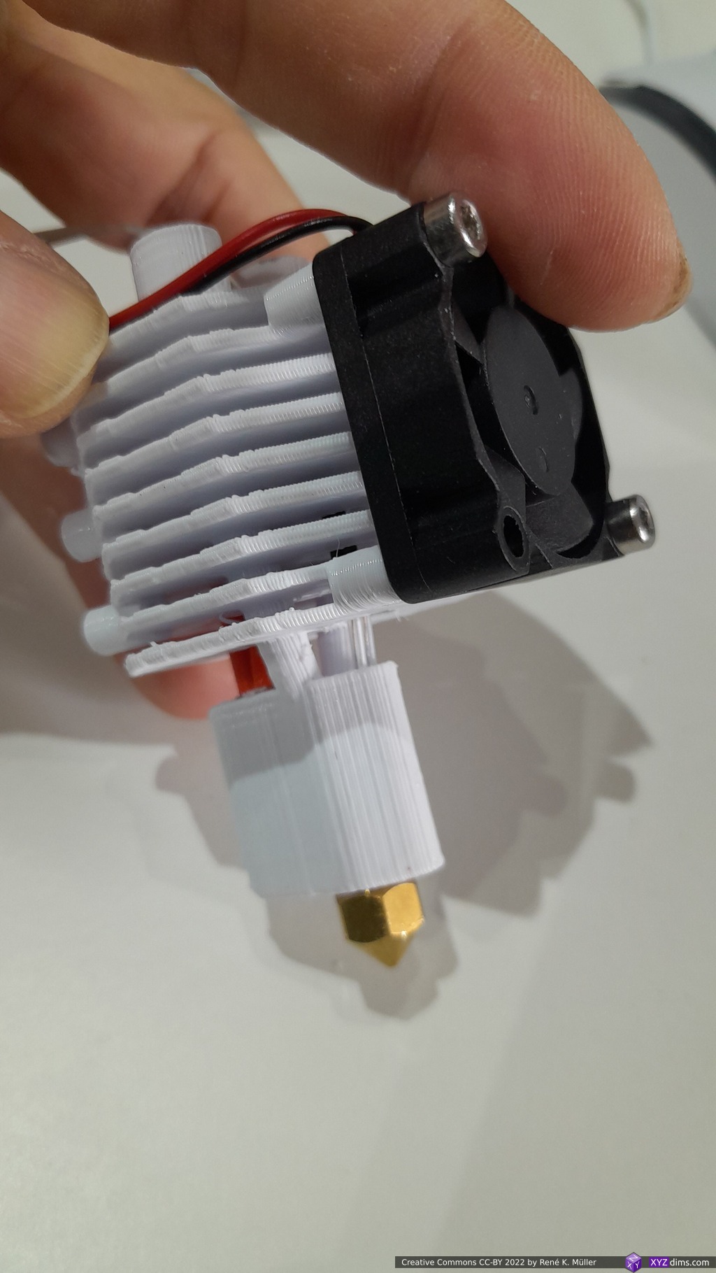
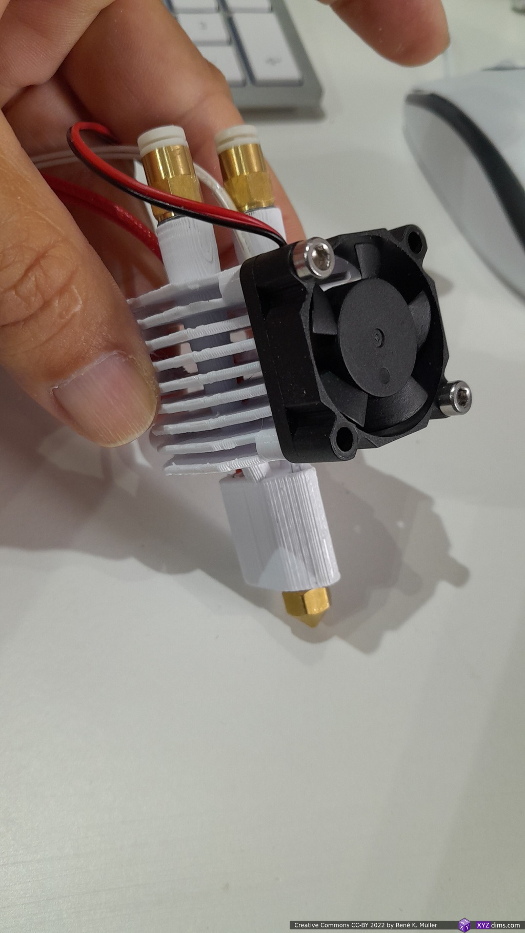
and just testing my Parametric Part Cooler using 50×15 blower fan:
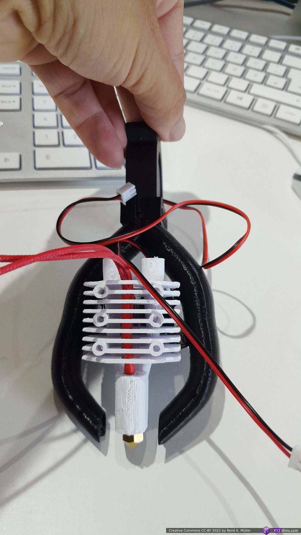
which very likely leads to have a some sort of thermal insulator aka silicon sock for lower part of the heat chamber and nozzle.
Metal Printing
The first attempt to order with WeNext using SLM failed, they were not able to find a way to print it without support, which was surprising as powder-based metal printing1) – the removal of support was not guaranteed, so I canceled the order.
- SLM powder-based printing requires support structure to counter act geometric distortion when sintering, when the piece shrinks.
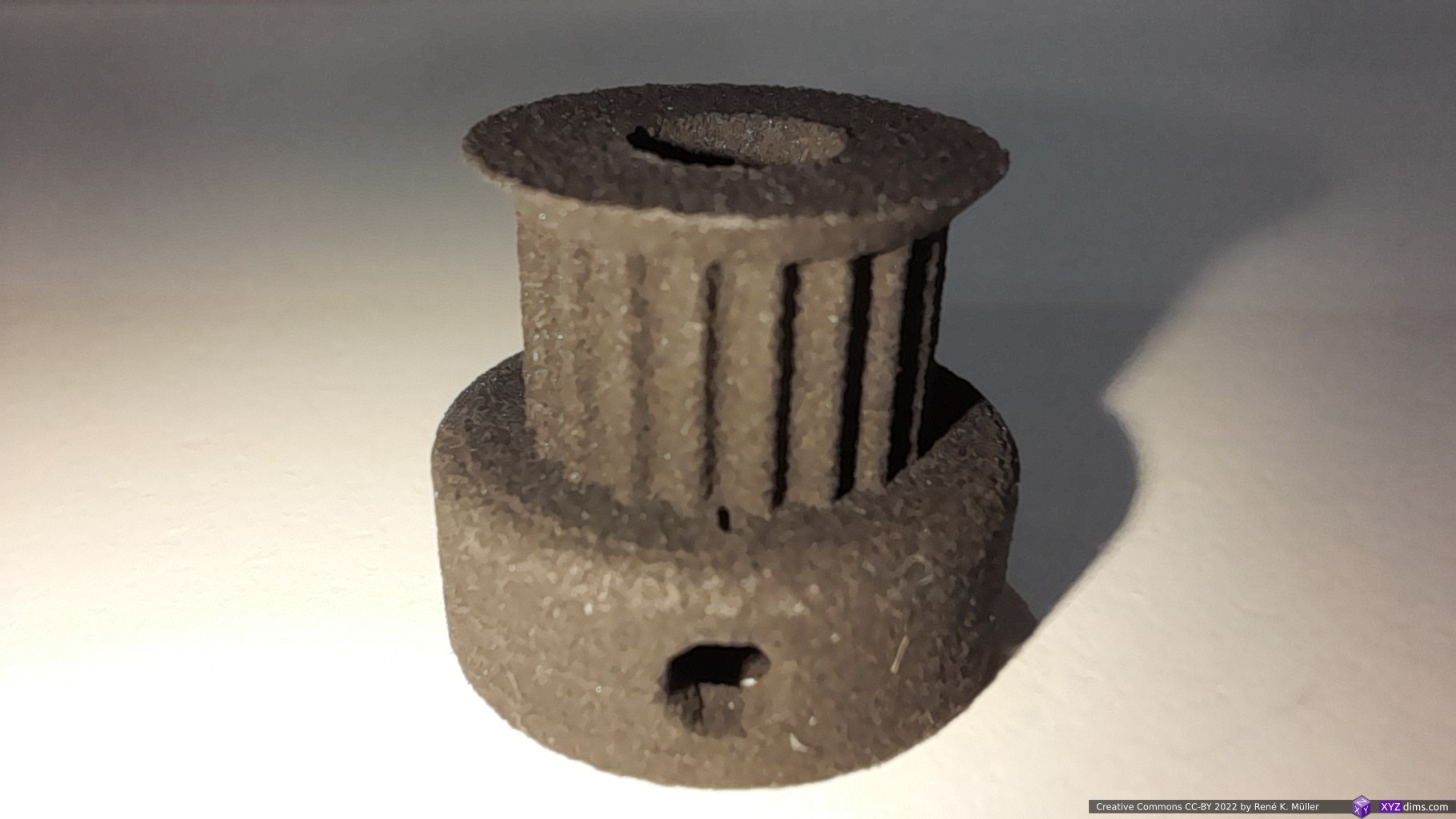
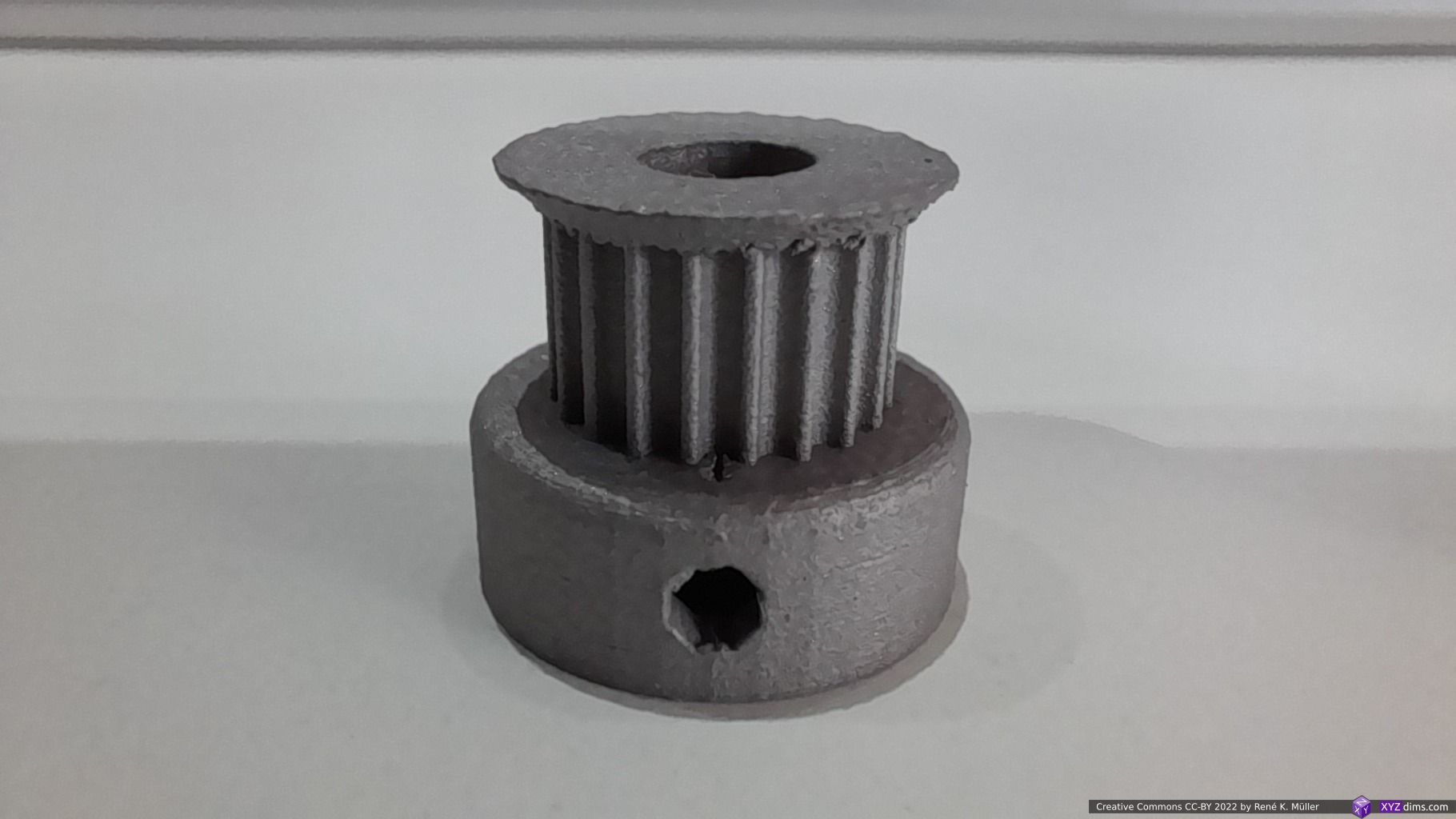
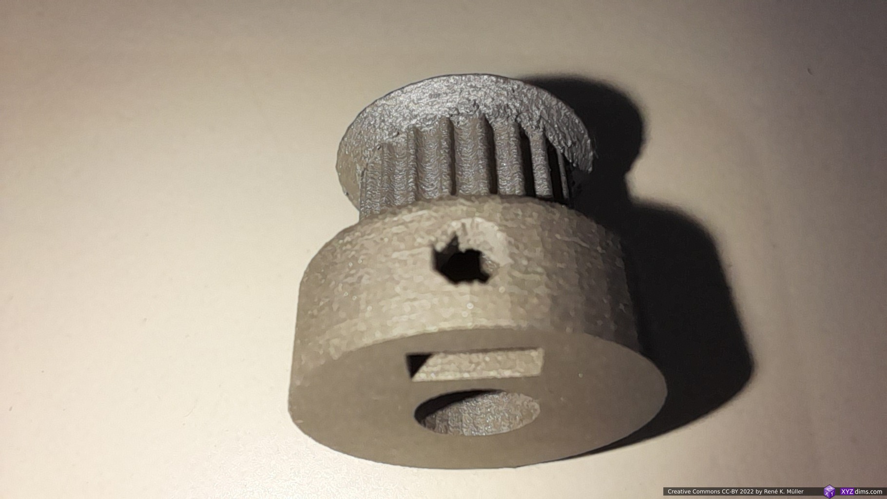
The 2nd attempt with PCBWay – disclosure: they approached me a couple of weeks later to sponsor metal printing process, which I agreed on – also using SLM AlSi10Mg at first looked good at first, but then they also needed to add supports once the production step came close, and then I followed up and approved the production. The order was submitted November 5, and 14 days later the piece was at my door.
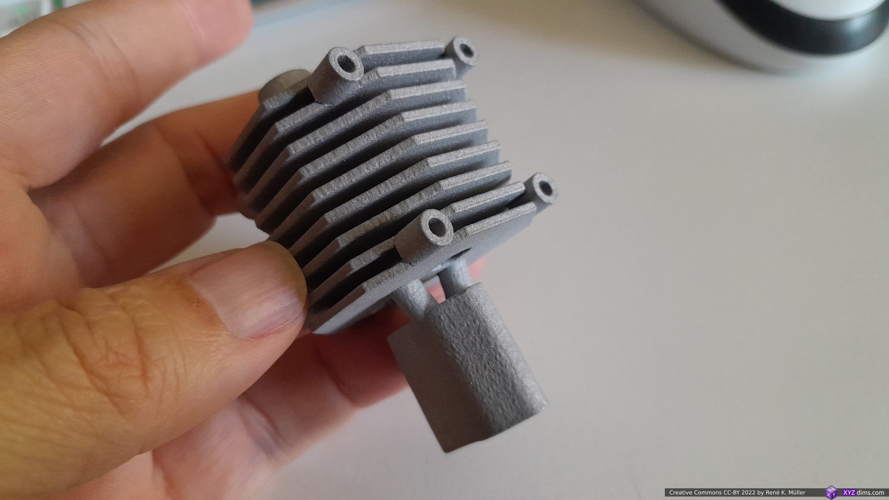

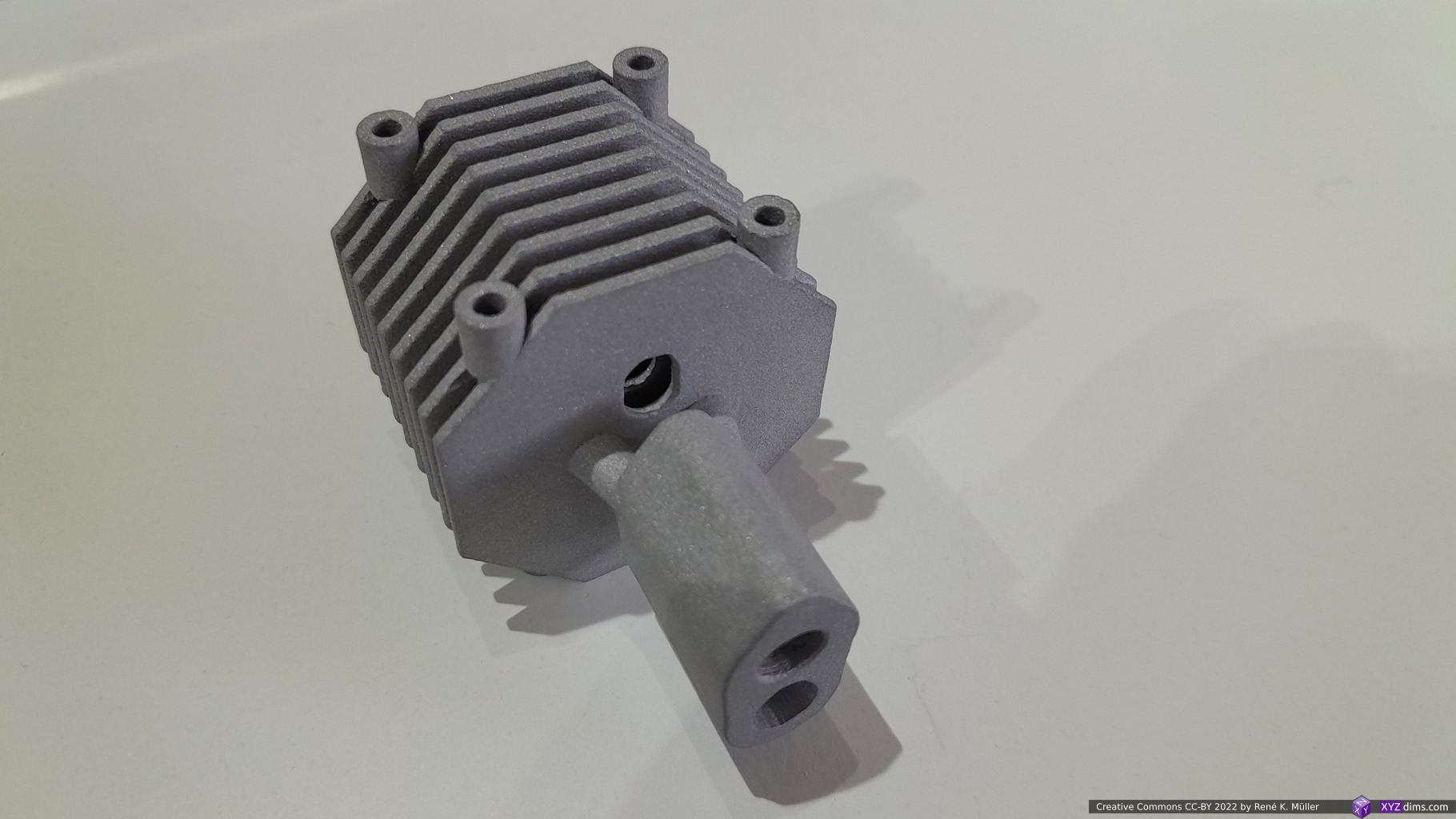

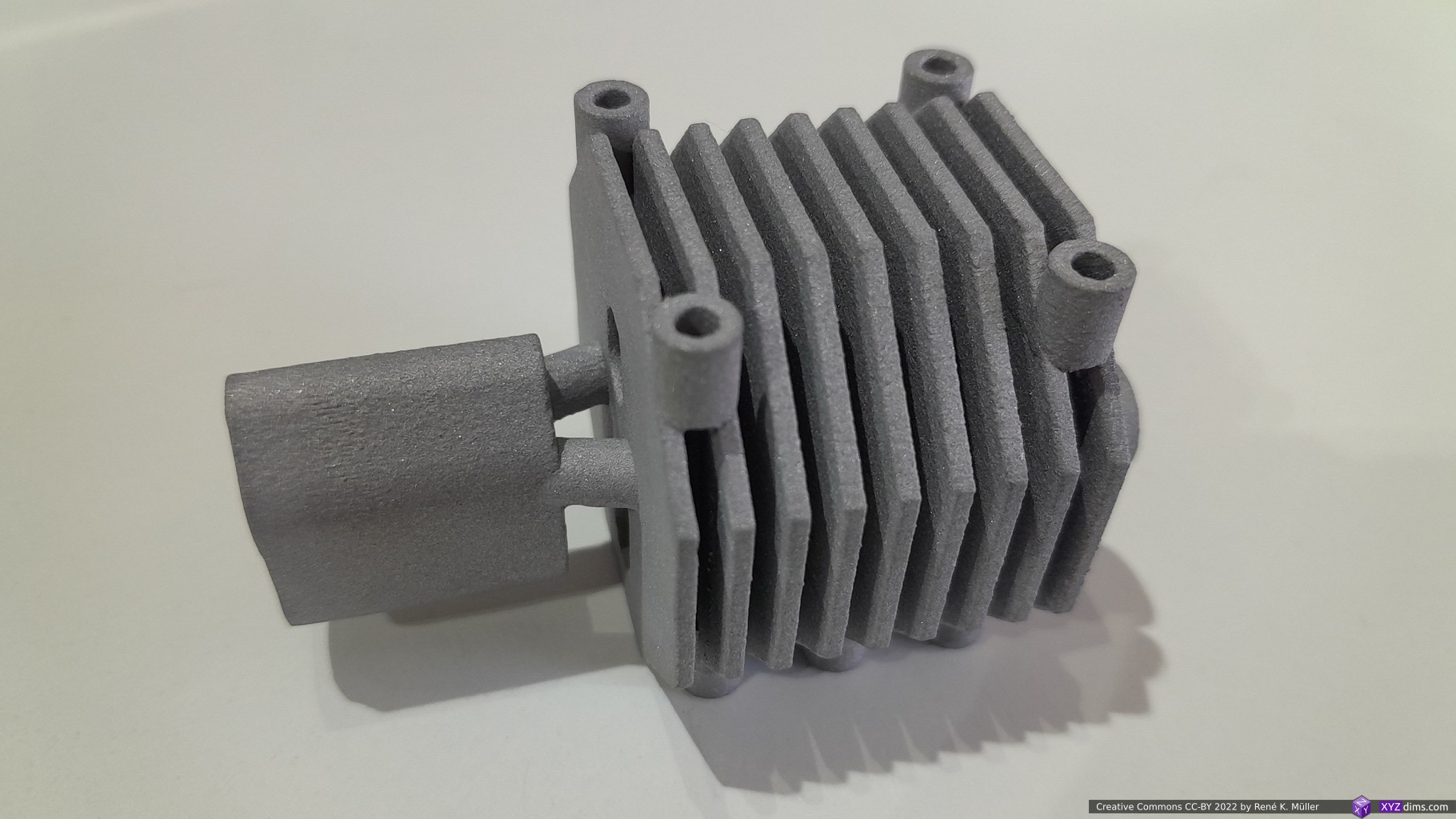
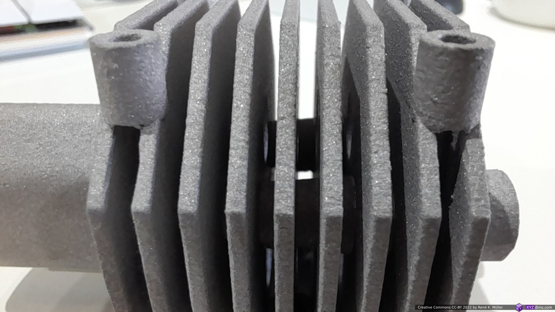
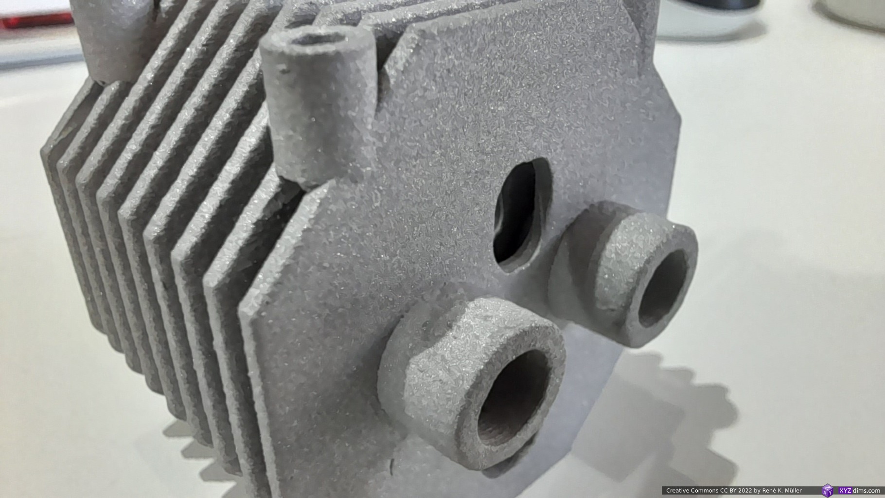
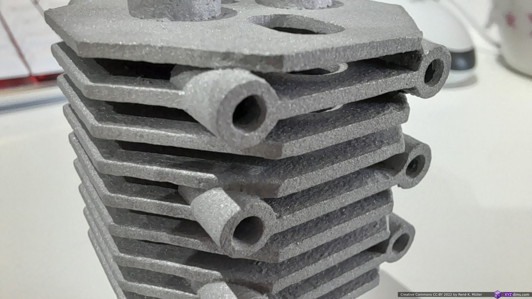
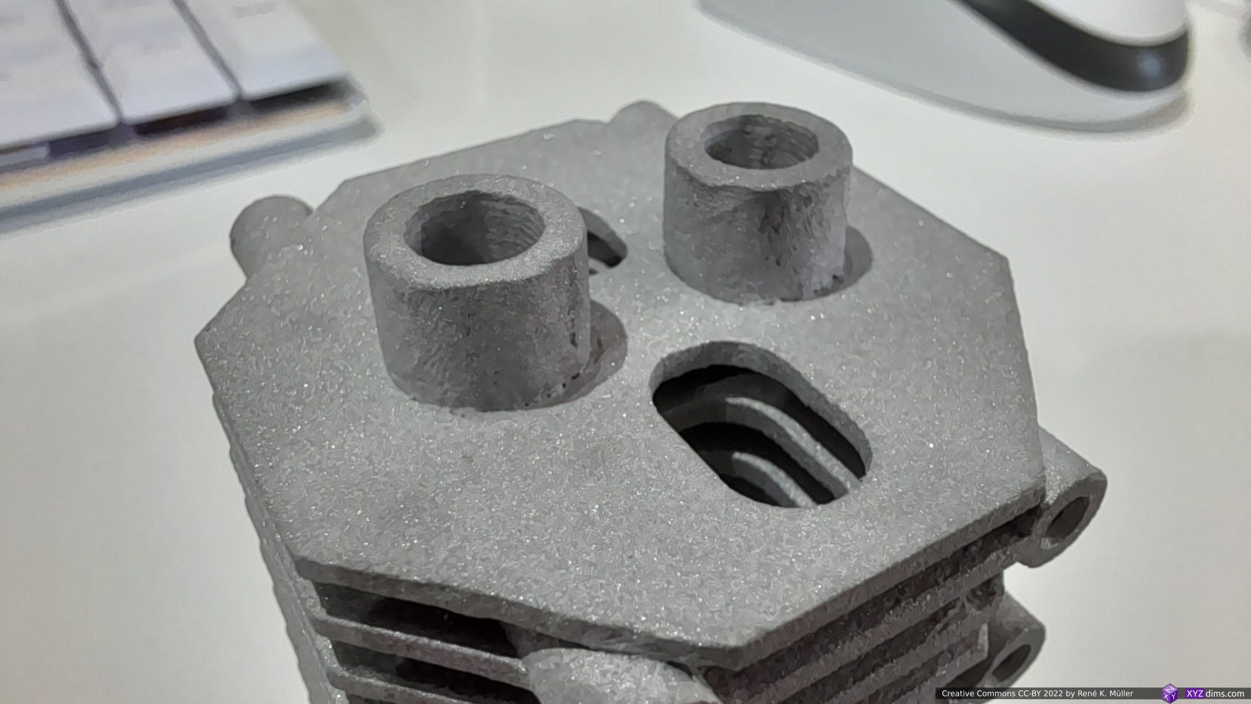
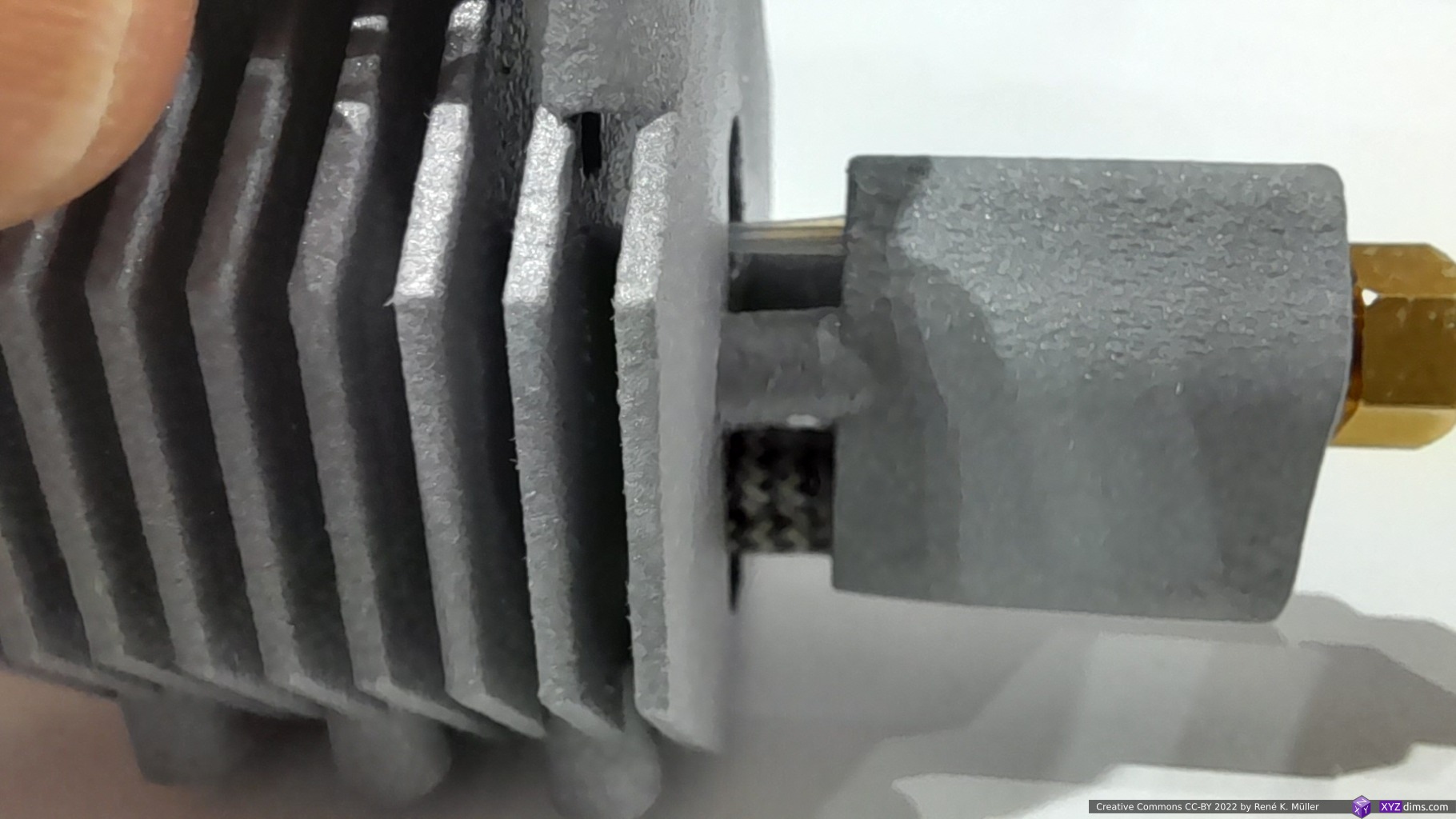
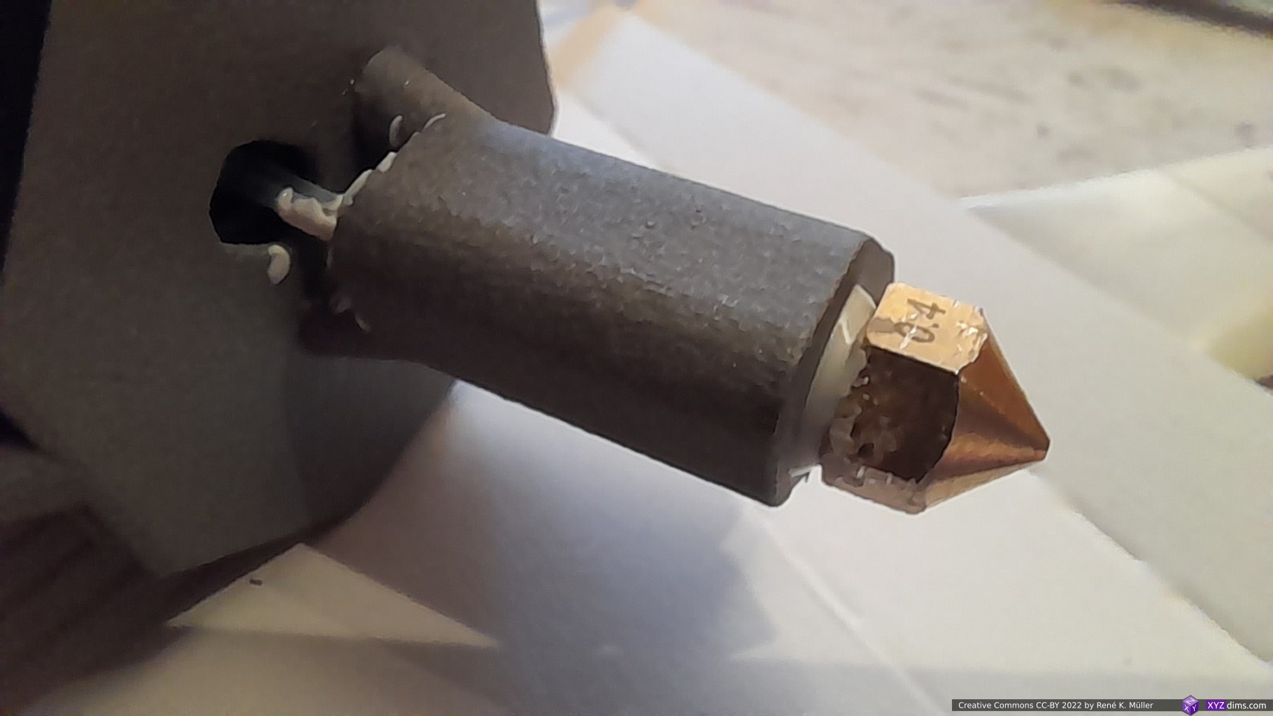
- the print quality is excellent, the supports have been removed pretty much with little remains (between the cooling plates a few spikes remained but they have no functional influence)
- a bit rough surface overall, more than I expected; which means, the inner holes are also rough and likely add friction to the motion of the filament
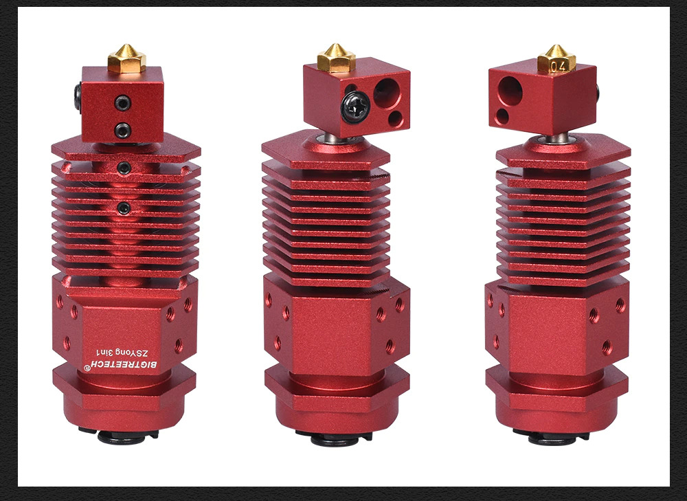
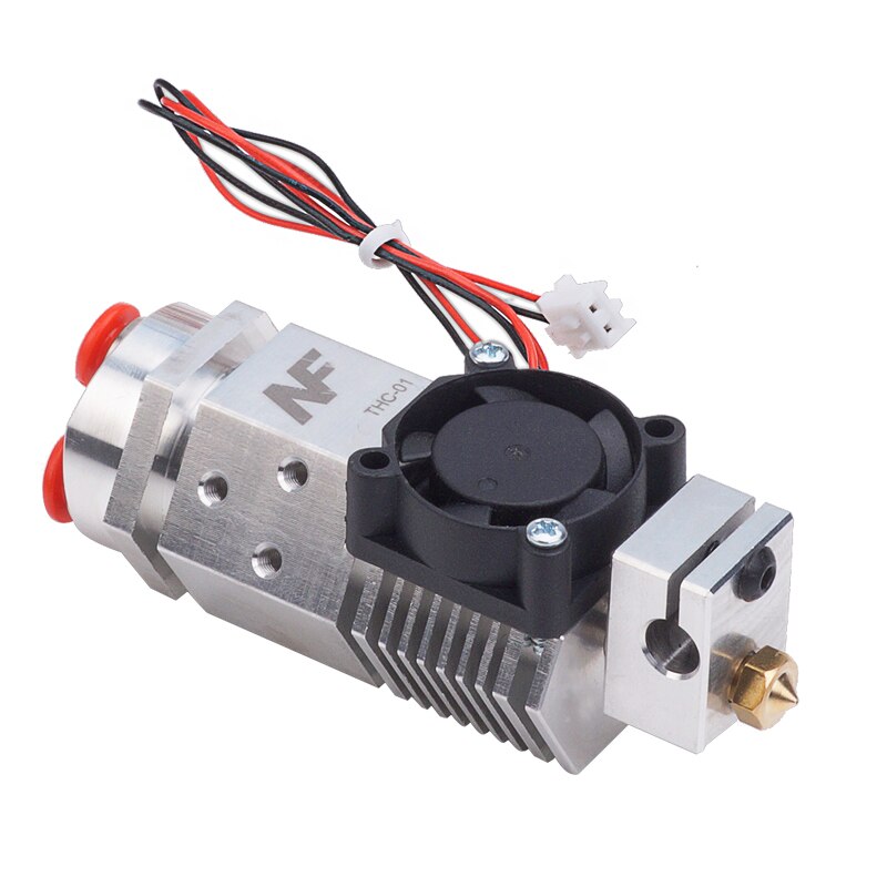
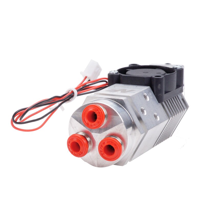
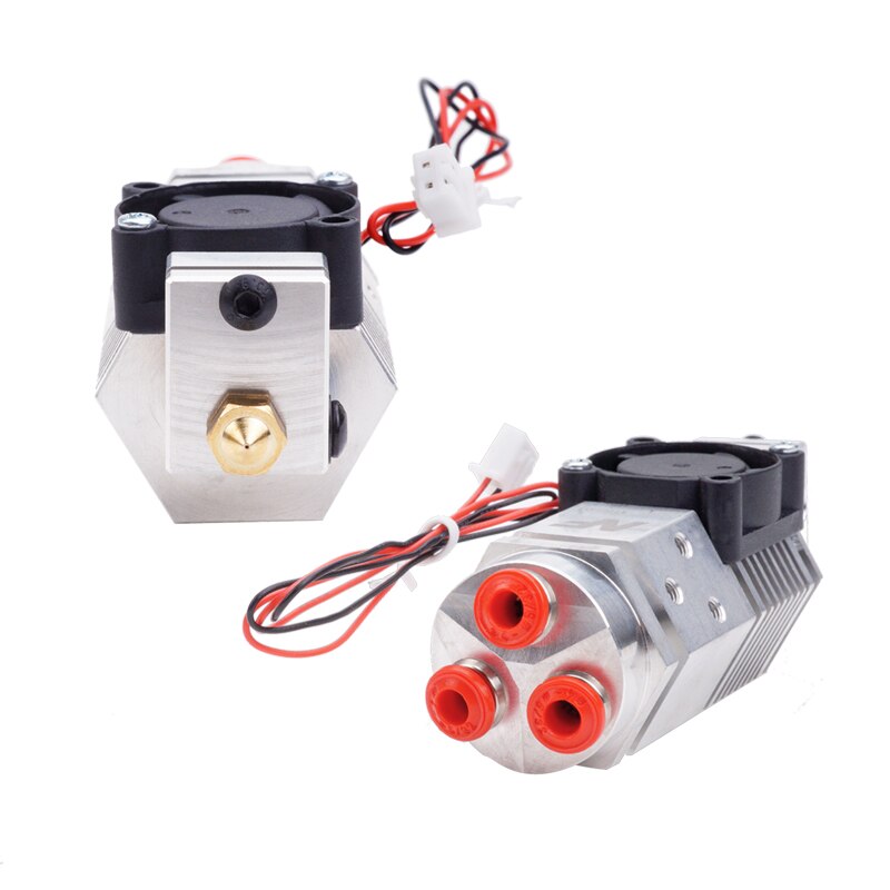
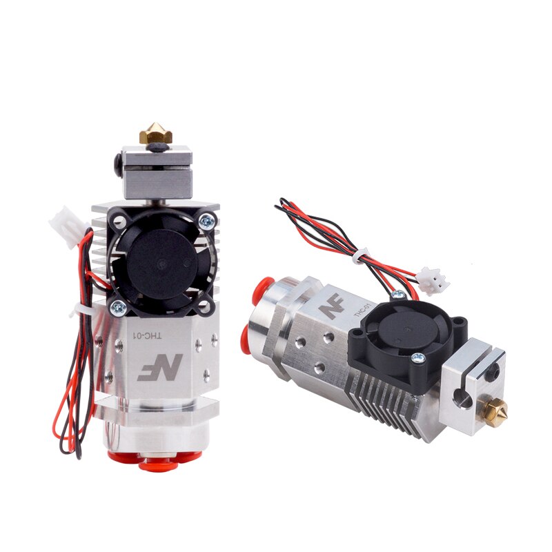
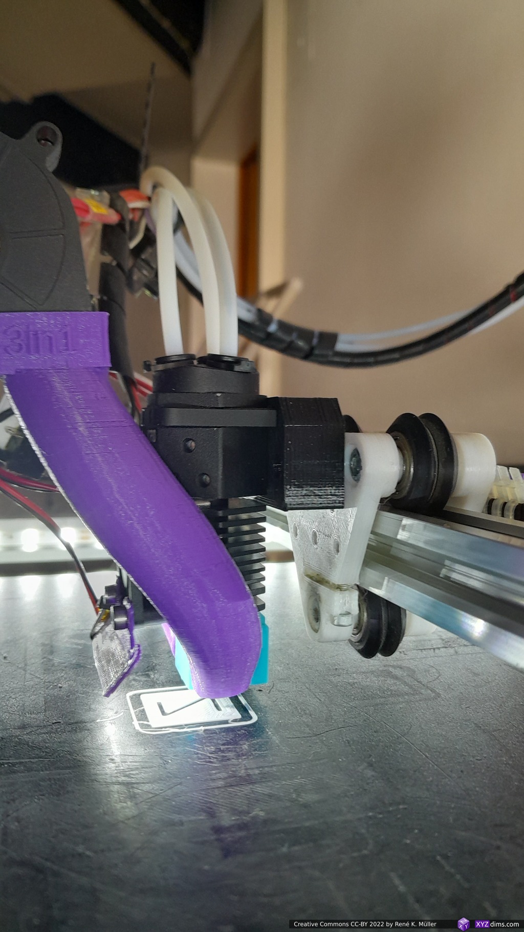
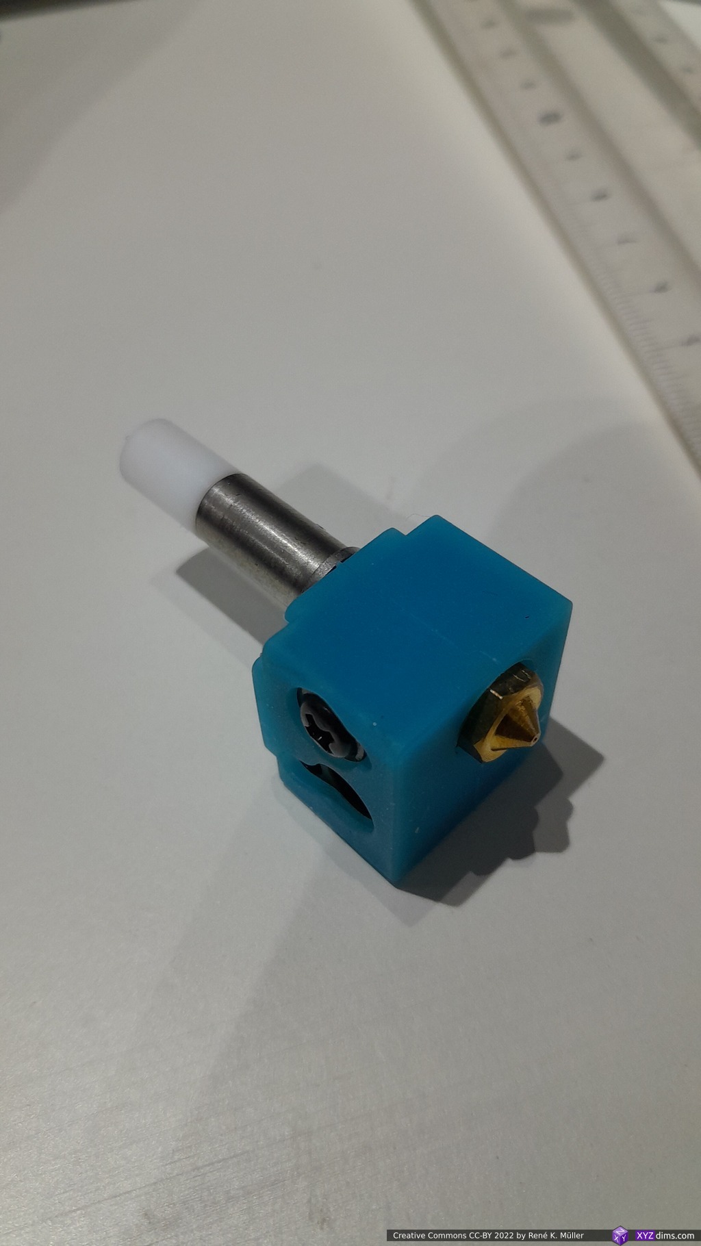
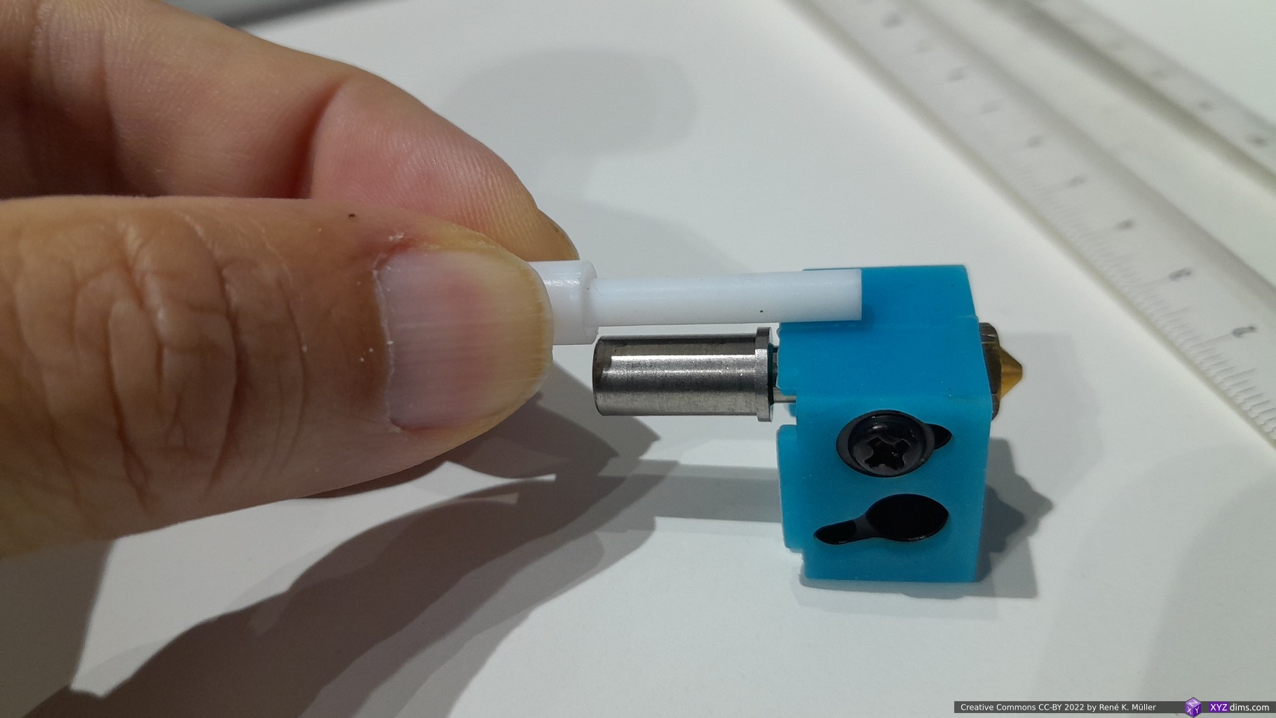
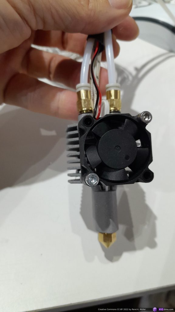
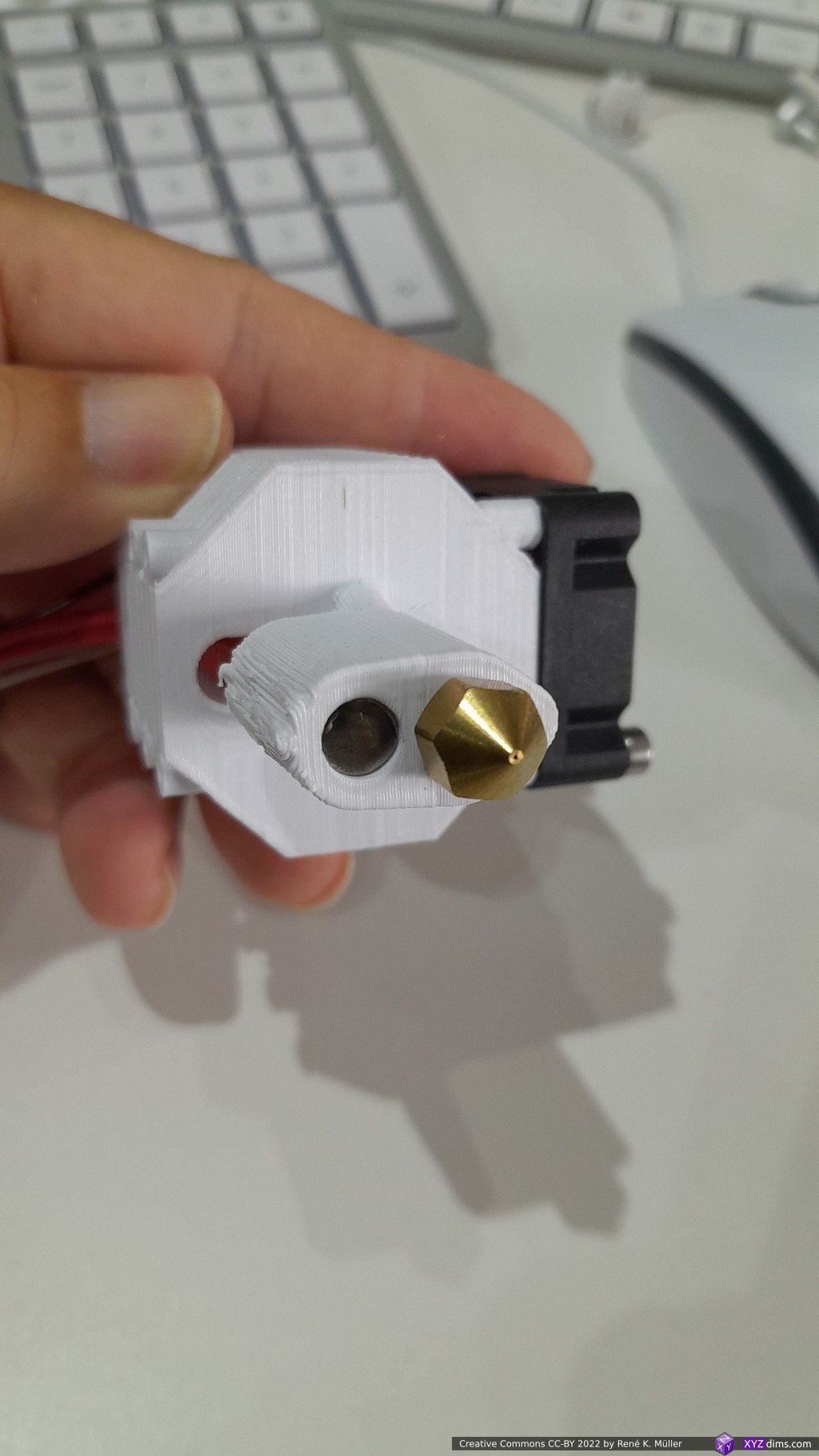
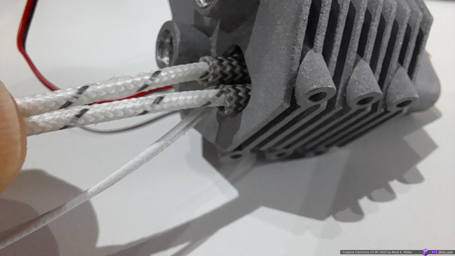
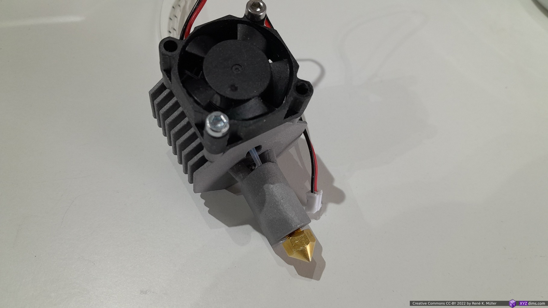
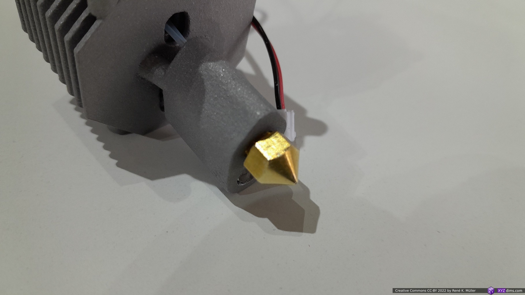
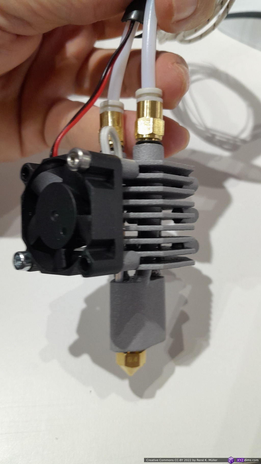
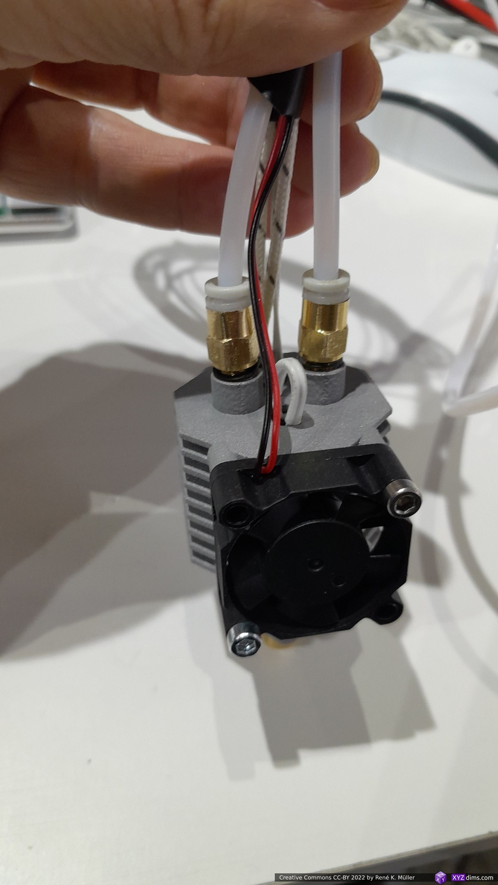
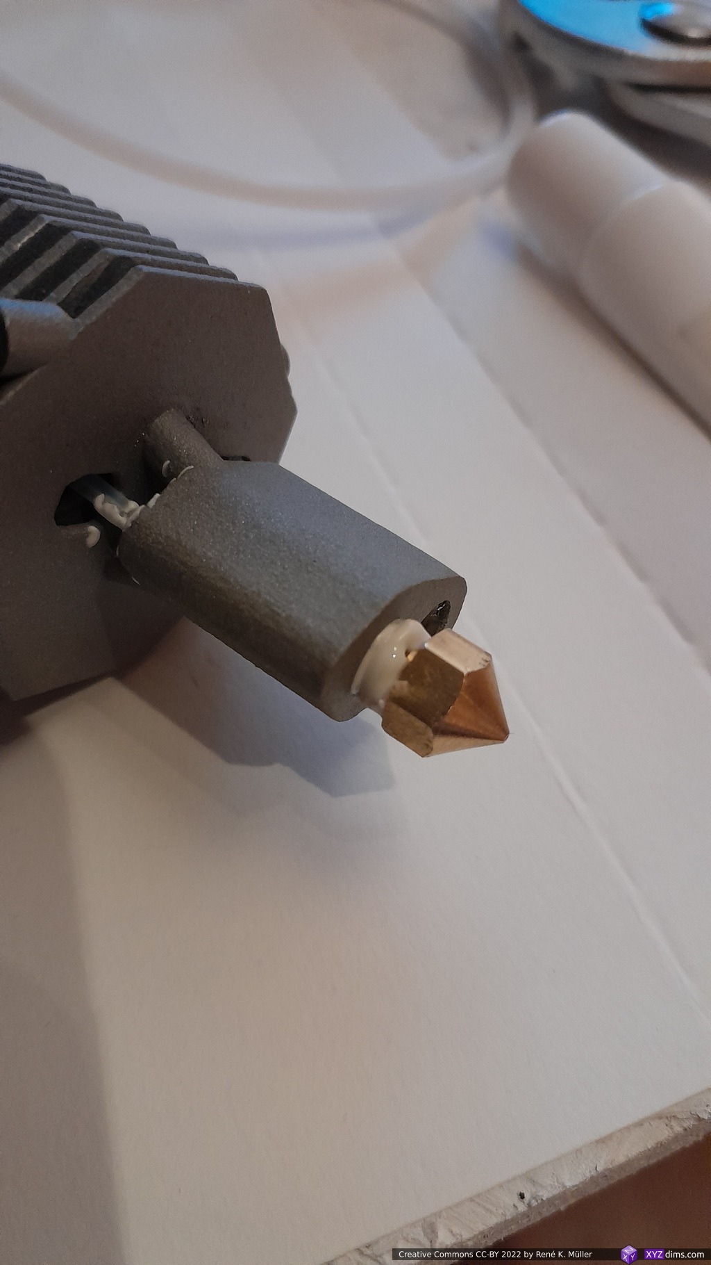
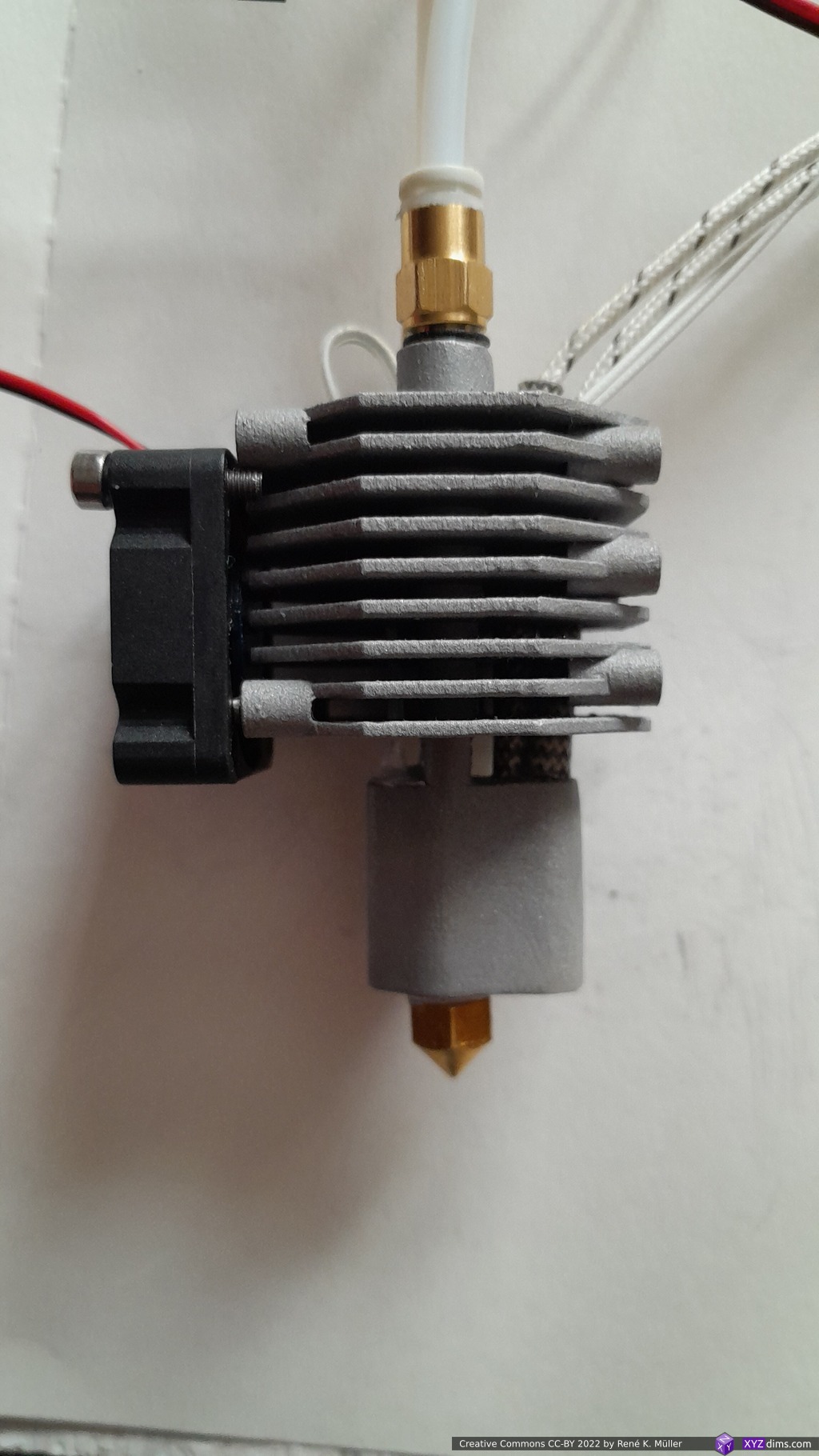
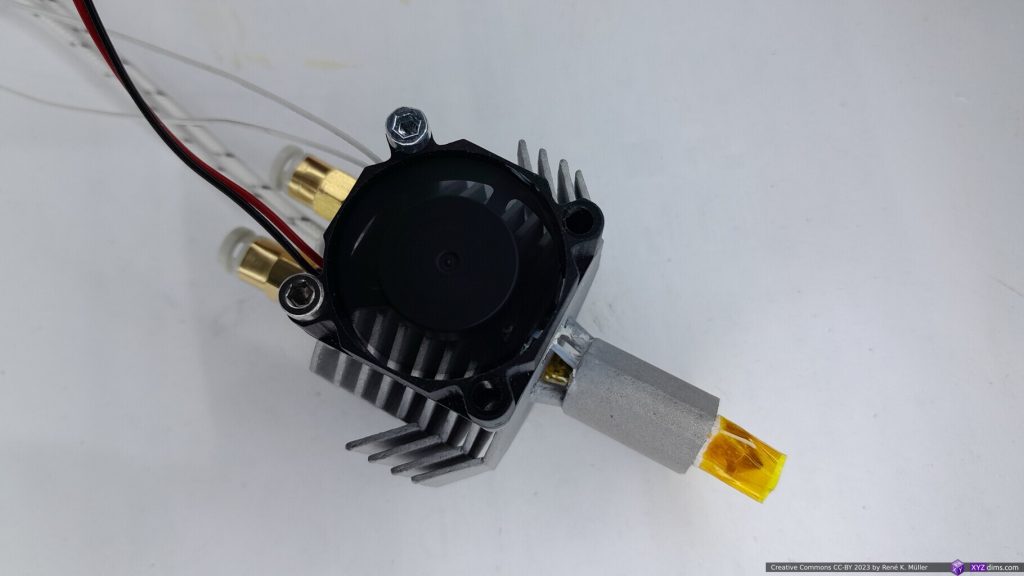
Preassembled with MK8 0.4mm nozzle, 30mm fan, heat cartridge and thermistor:

and 2x PC4-M6 threaded, with PTFE tubes:

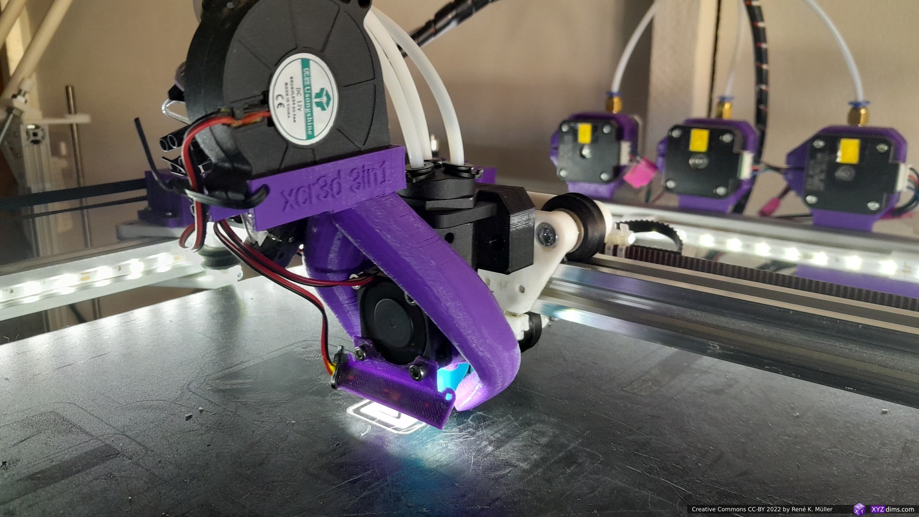
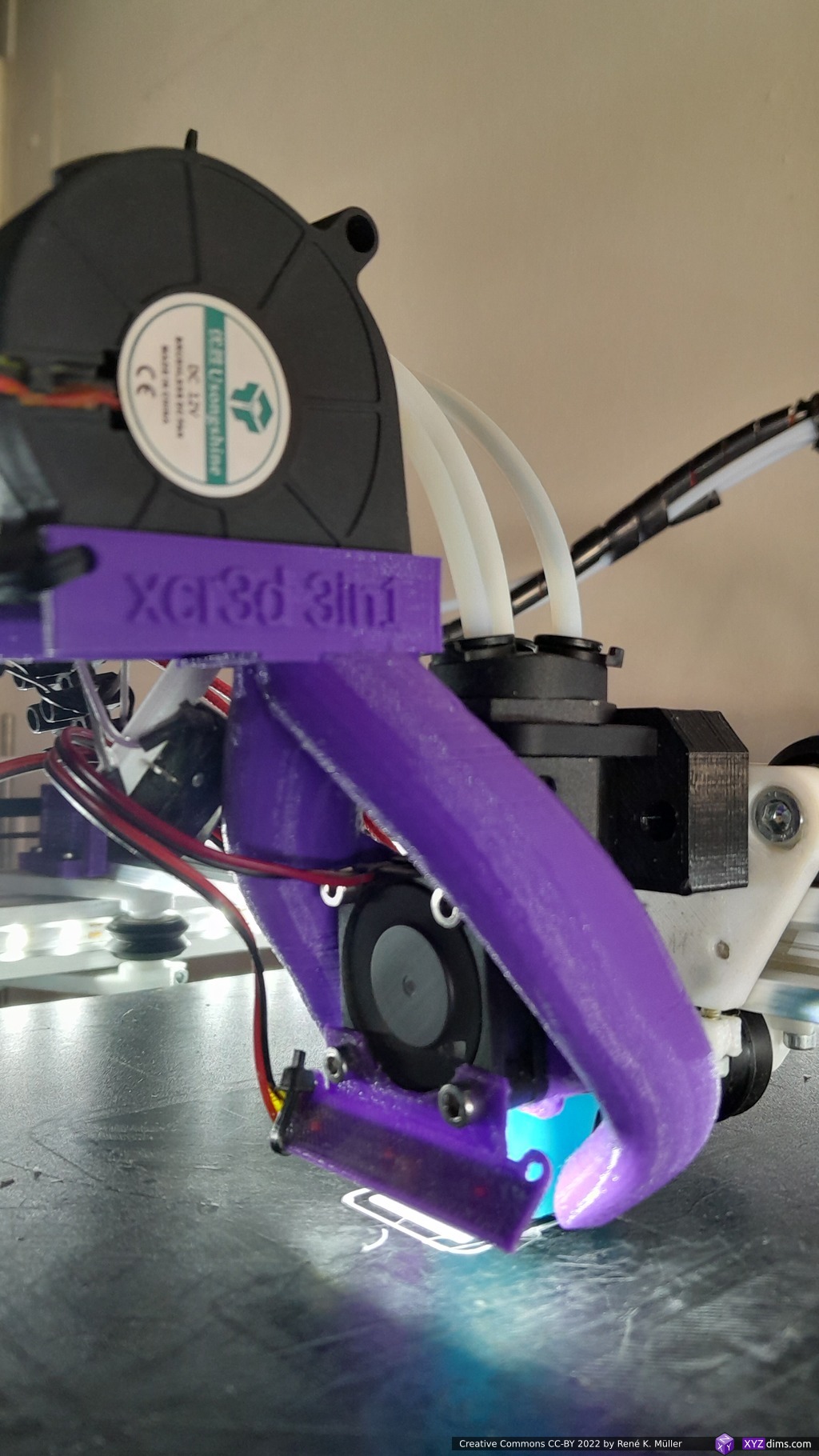
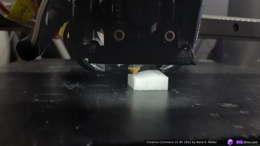
Heating
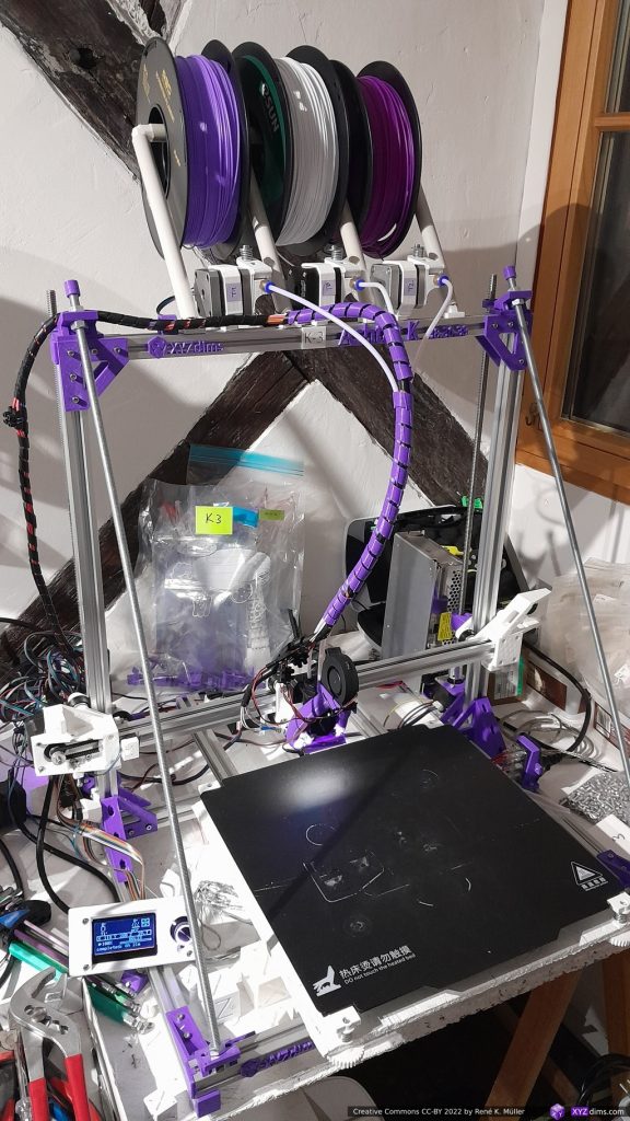
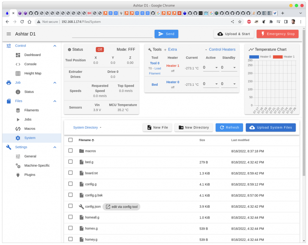
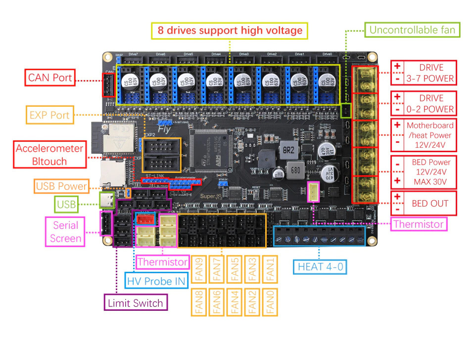
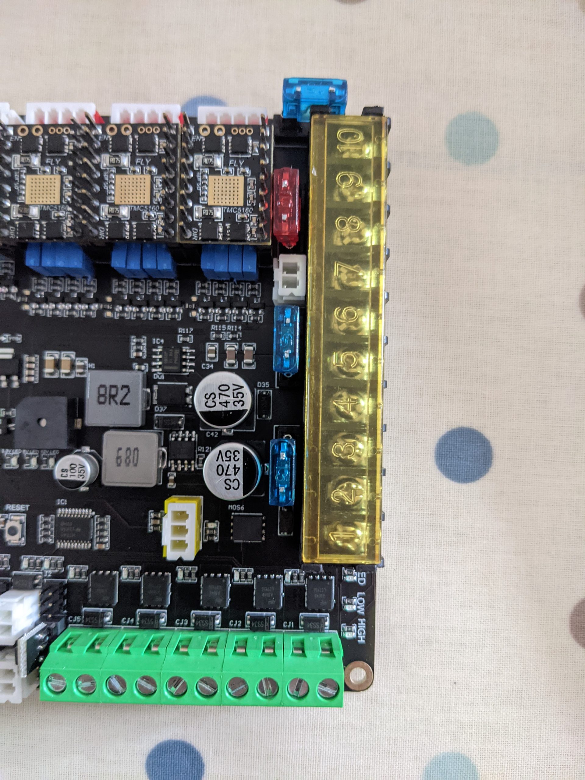
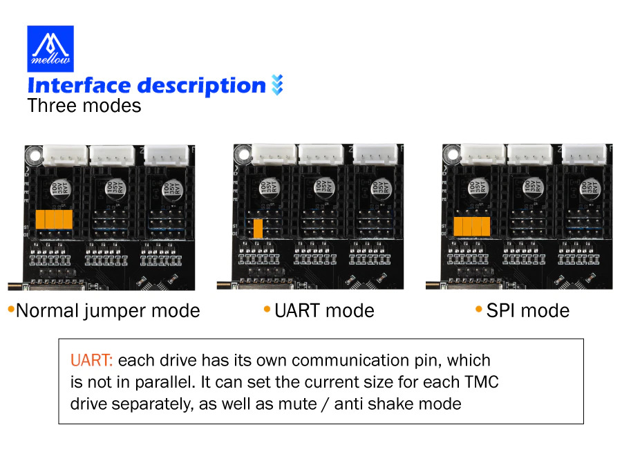
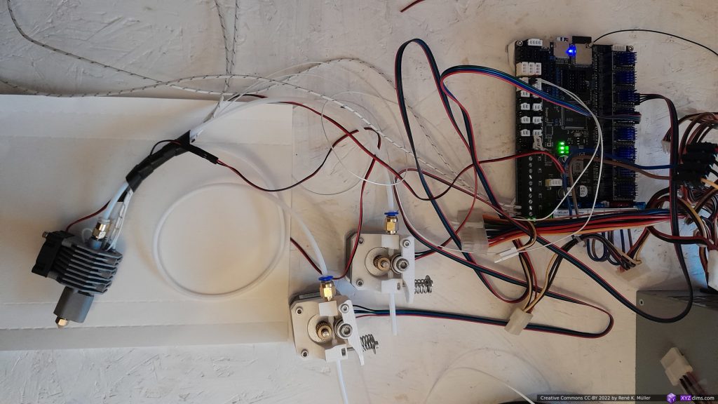
My test rig:
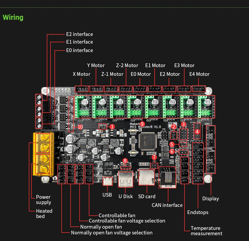
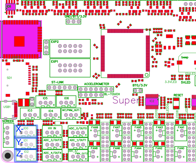
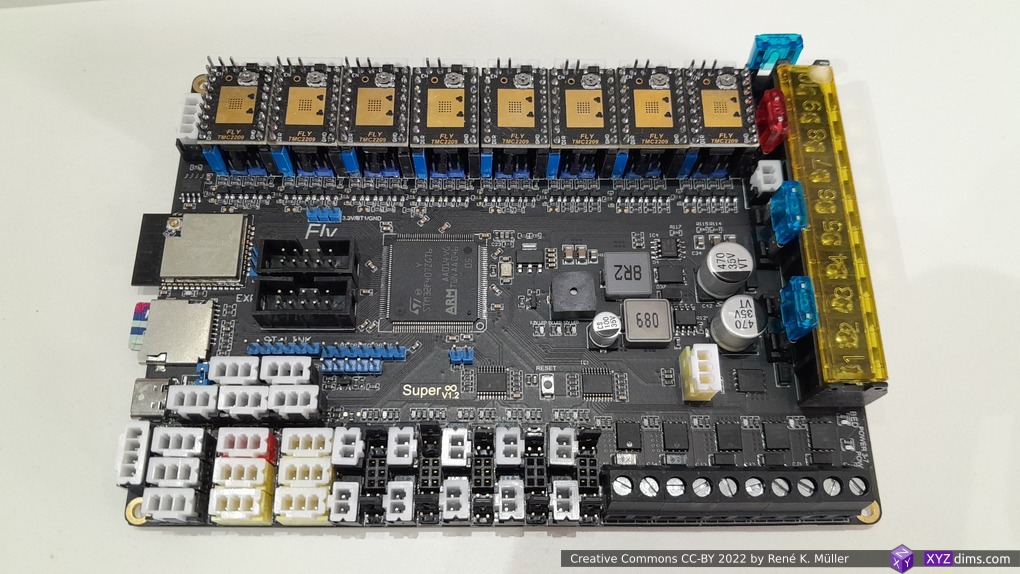
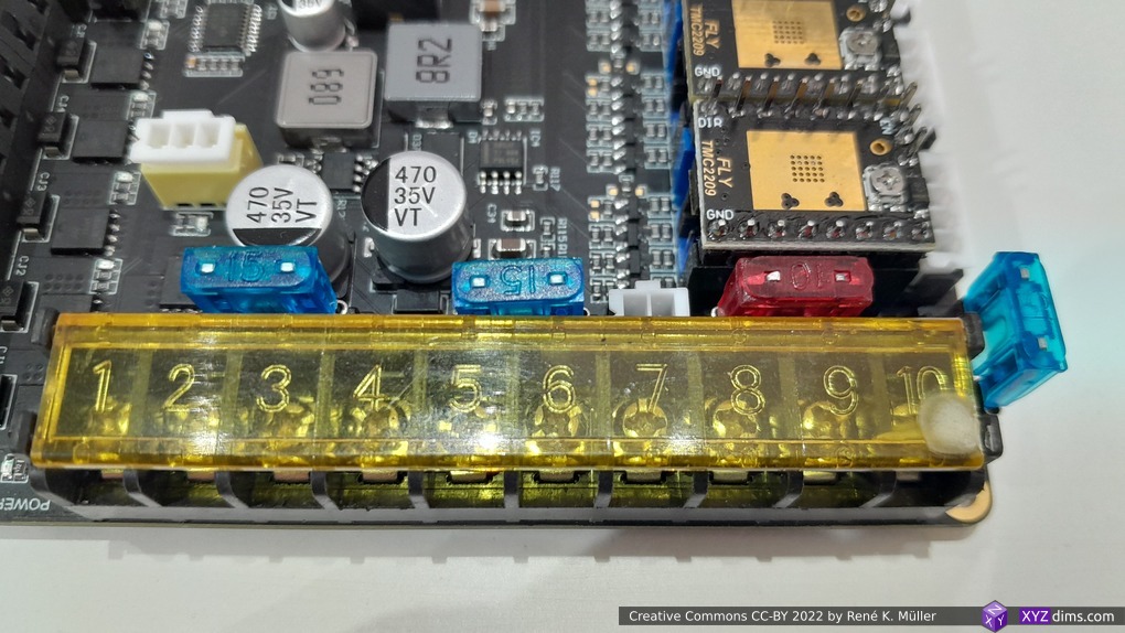
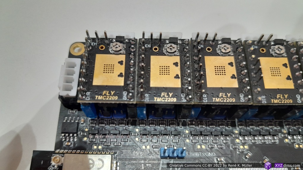
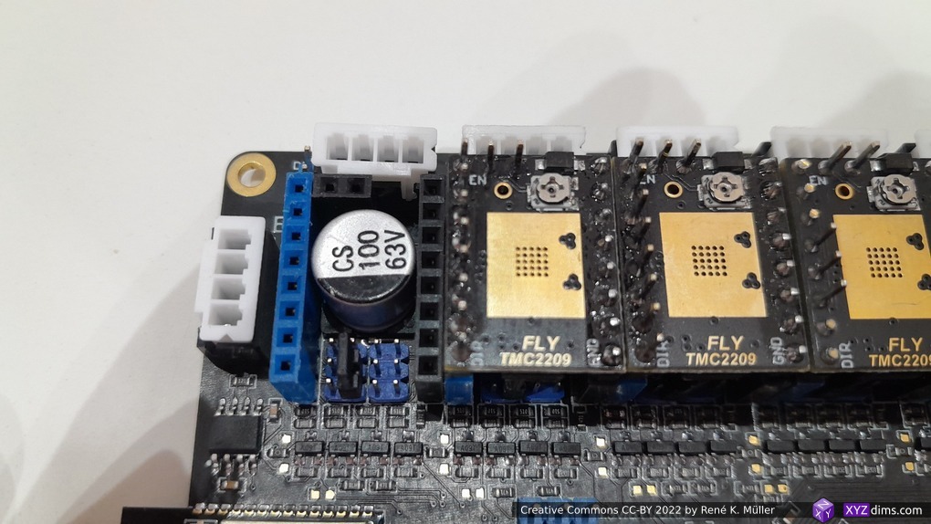
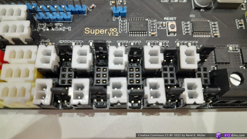
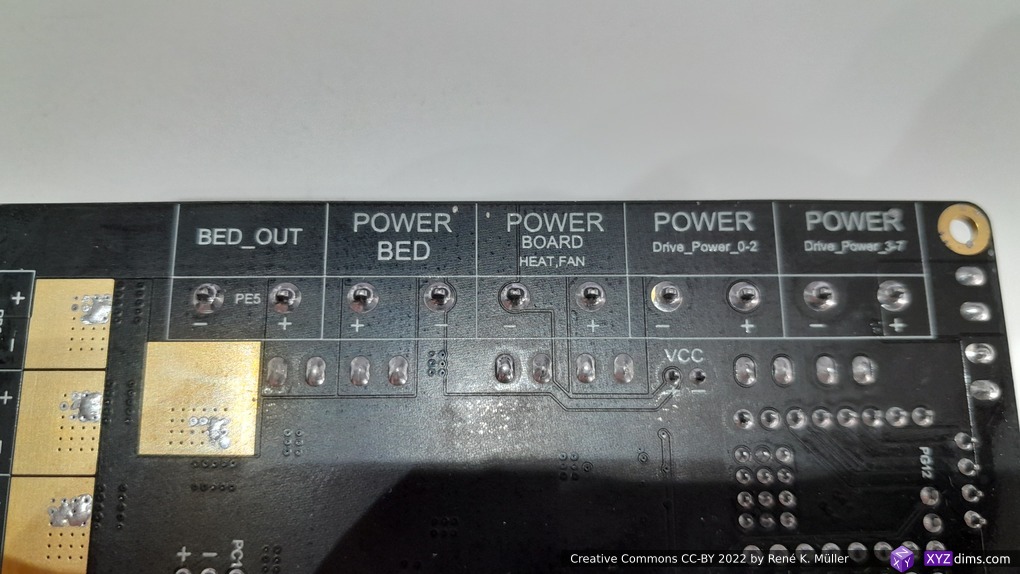
- Mellow Fly Super8 V1.2 running RepRapFirmware with two stepper motors attached driving two extruders in Bowden style
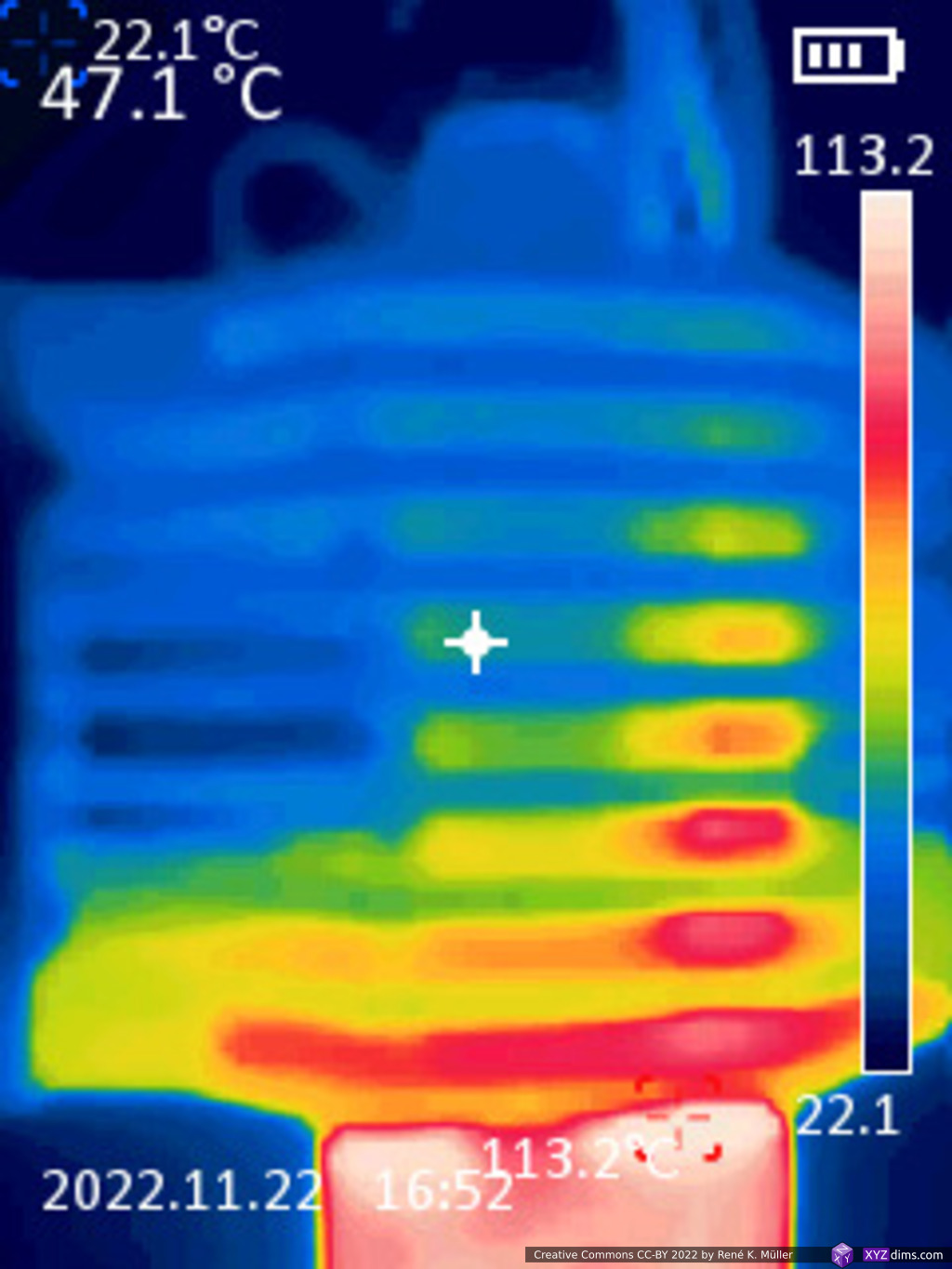
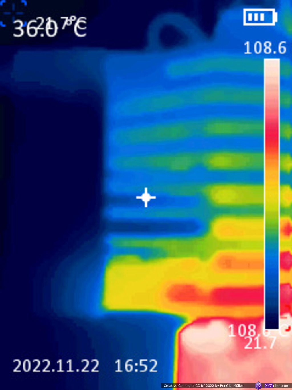
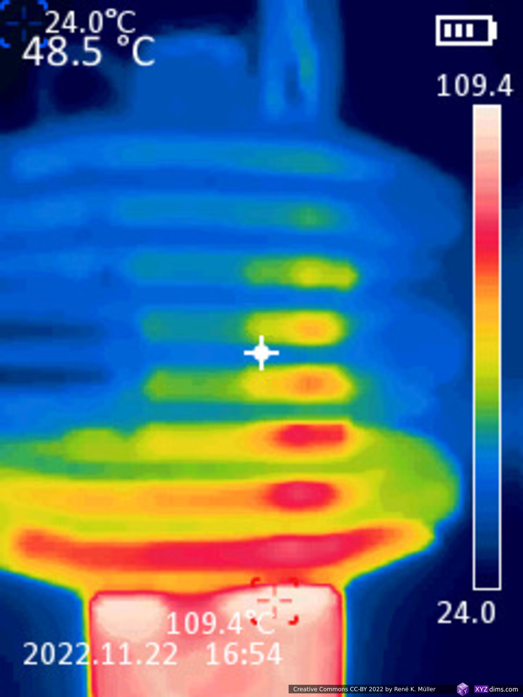
Pass 1: First results
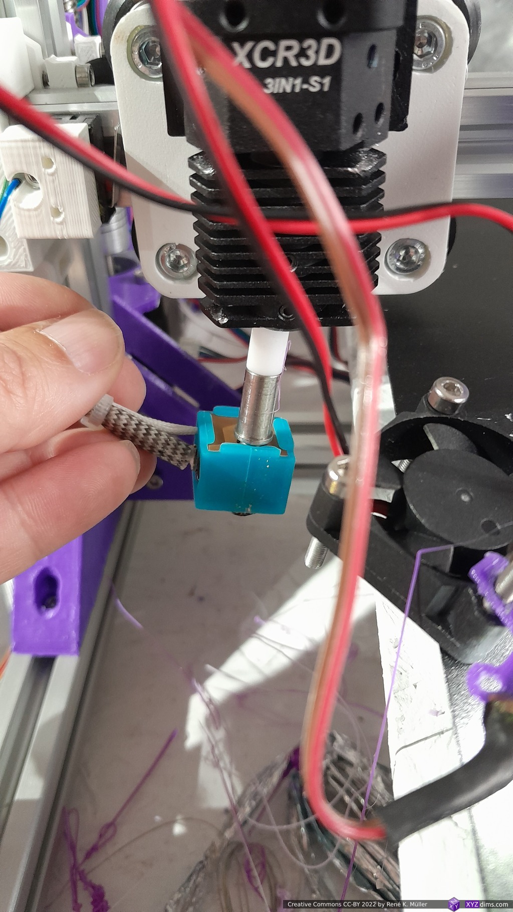
I heated to 50C°, 80C° and 100C°:
- thermistor does poor job to measure actual temperature at the heatblock ~20C° off
- heat conductivity to nozzle is very poor, barely heat up at all (when thermister reports 100C°) – very surprising
- heat piles up from the heart cartridge cables
- the fan cools barely, could be better
Pass 2: Adding thermal paste
- adding thermal paste for the thermistor and nozzle thread
- running
M303for 100C° and keeping it at 100C° for 10mins


- lowest heatsink fin reaches 50C° – also connects to heatsink fan
- nozzle looks cold (but when touching it it is hot), filament will definitely melt above
- heat block has consistent heat distribution
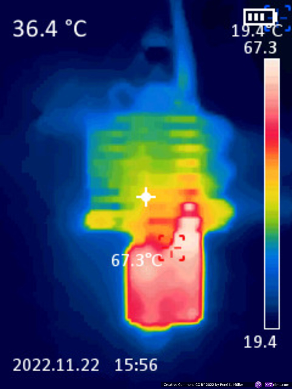
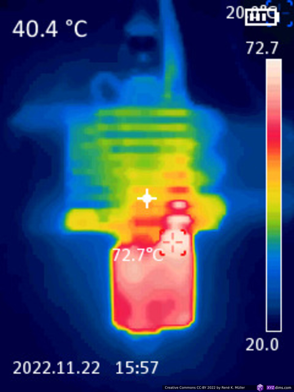
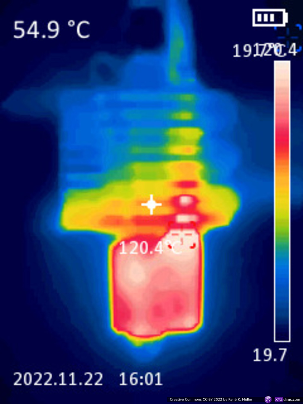
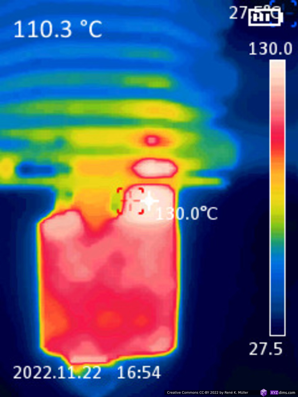
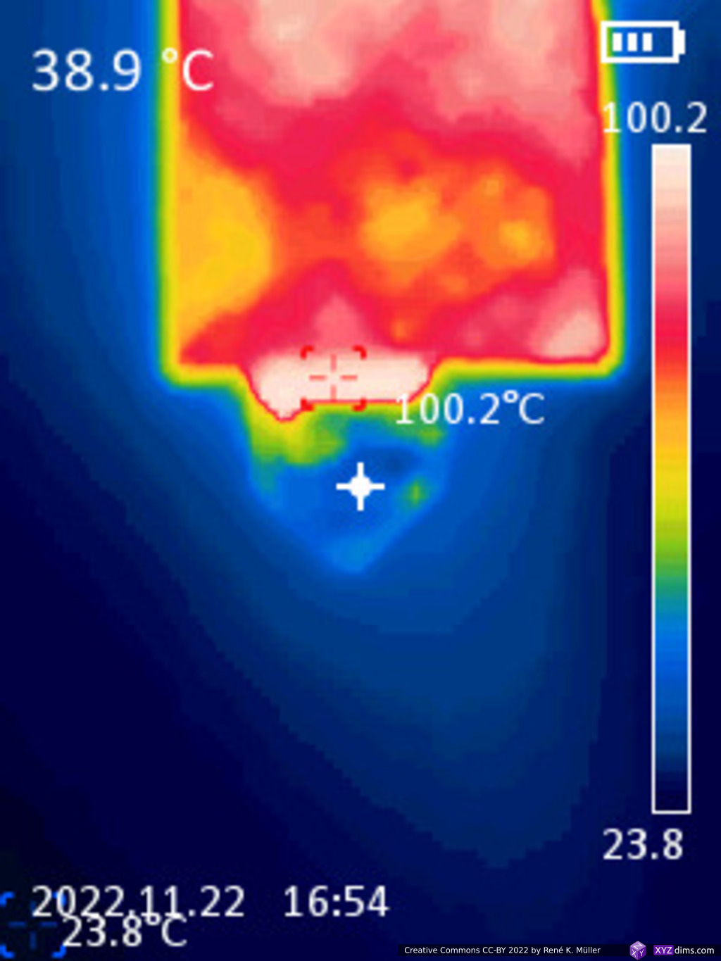
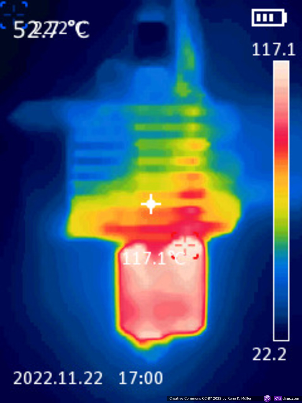
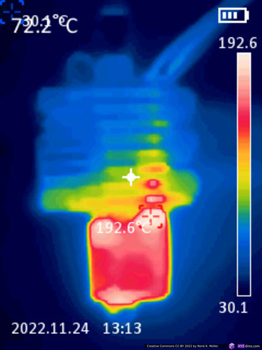
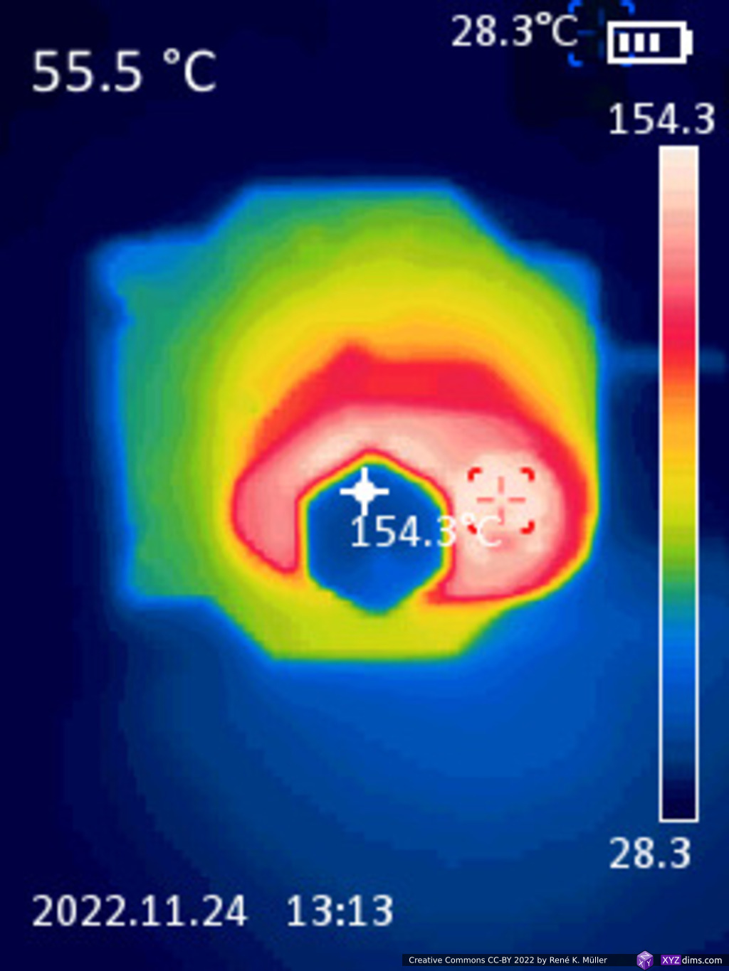
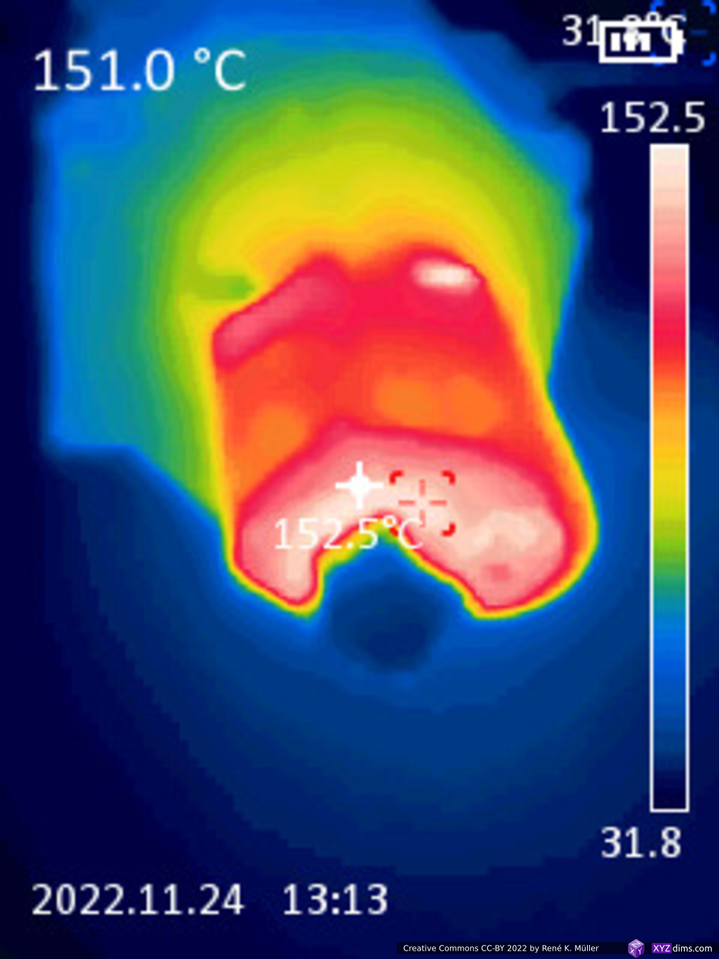
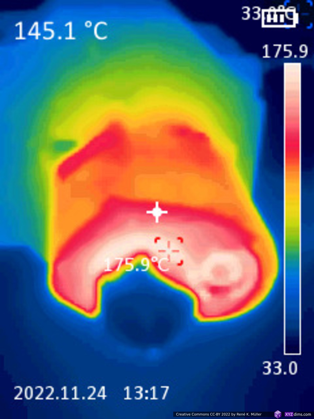
Pass 3: Setting 150C°


- heatblock is at ~120C° while thermistor reports 150C°
- the filament pipe above the heatblock is at 100C°
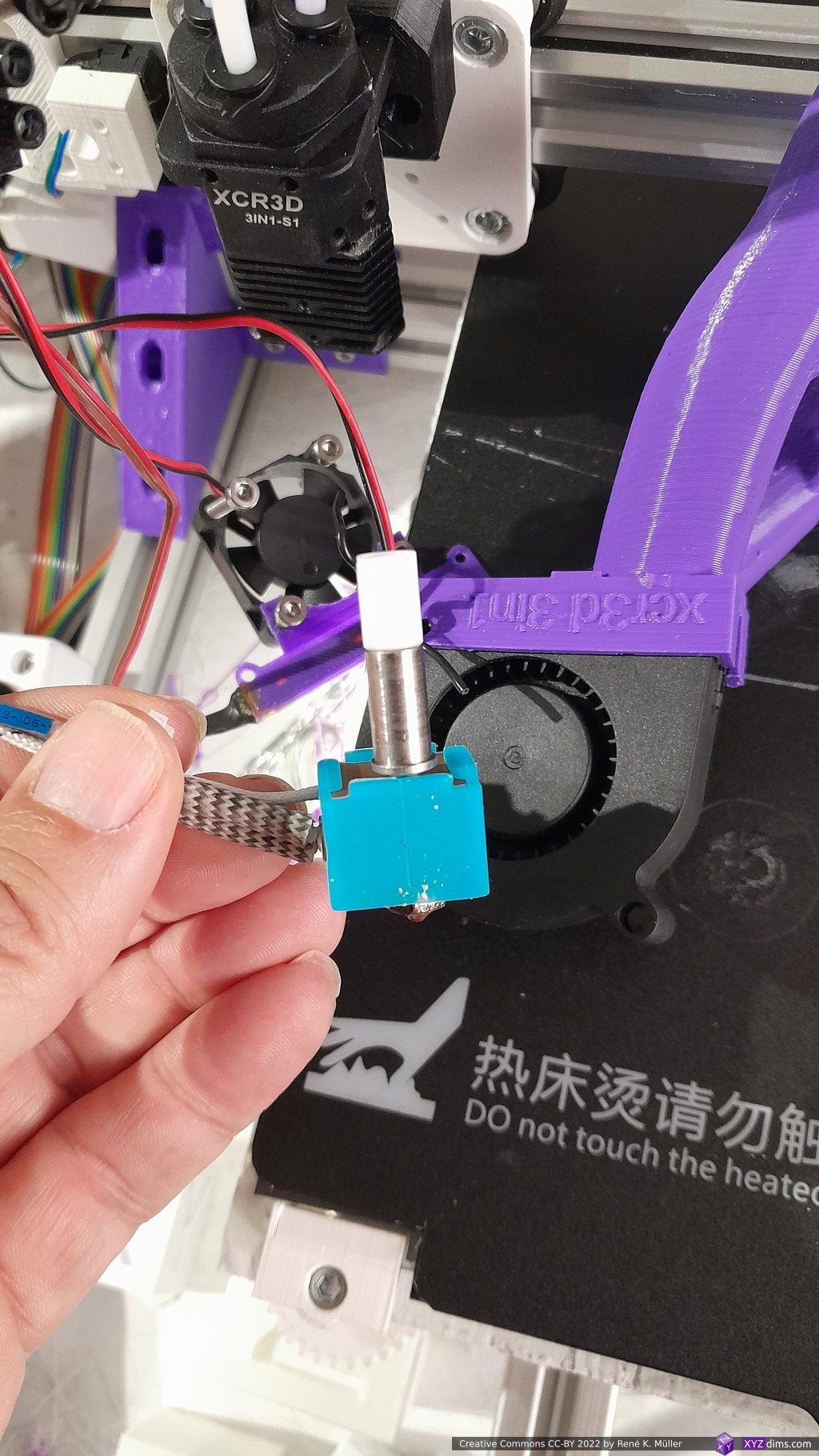
- the nozzle looks cold, but is hot at 105C° when touching with 2nd thermistor, an issue with reflective brass not properly showing proper thermal reading
Pass 4: Lowering Fan
As the lowest fin heats up significantly, as a first remedy I lowered the heatsink fan a bit:

- lowest fin is cooler, also overall better air flow; the fins seems a bit too thick, thinner would be better
- lower end of heat block has near set temperature, delta of just ~5C°
Conclusion Pass 1-4
- make heatbreak section of pipes thinner
- optionally have PTFE tubes until lower end of heatsink for smooth motion of filament
- make fins thinner
- lower heatsink fan by one fin


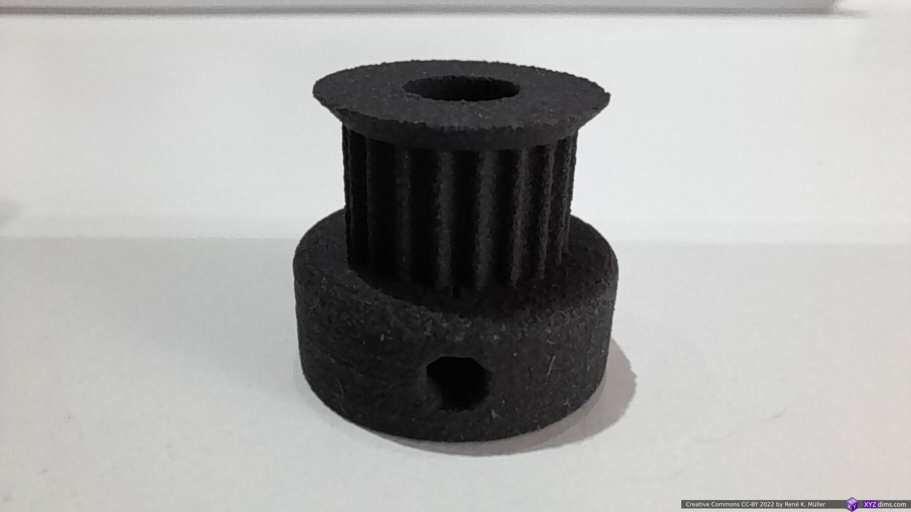
Iteration 2
After the tests, I changed the design slightly:
- thinner pipes to lessen heat transfer to the heatsink
- a few wings on the fins to increase heat dissepation
- thinner fins so the air flows better


Submitted to PCBWay 2022/11/29 for manufacturing review, a day later I was informed of thin walls of the pipes near the heatbreak (<1mm) and I gave OK to manufacture.
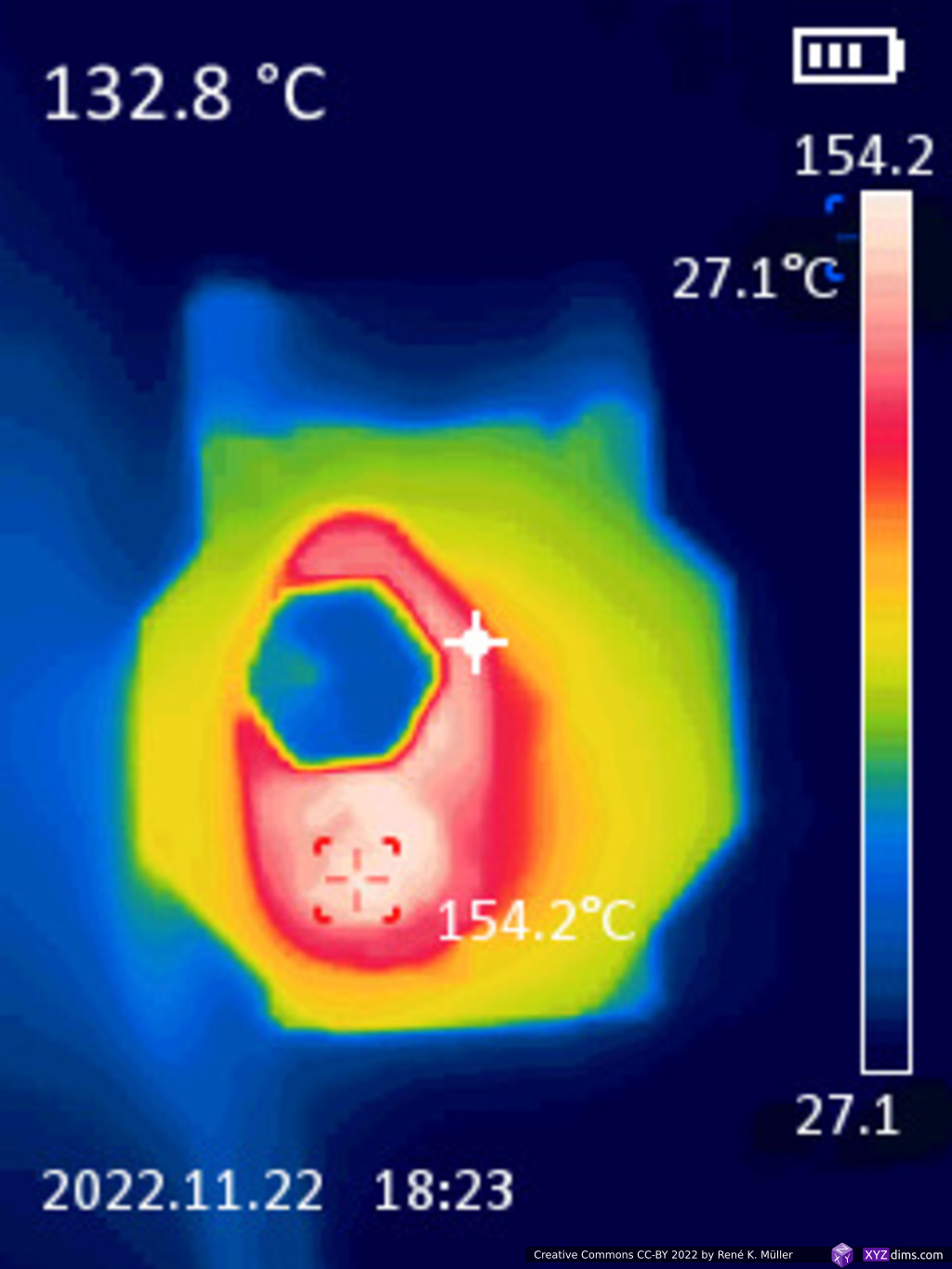
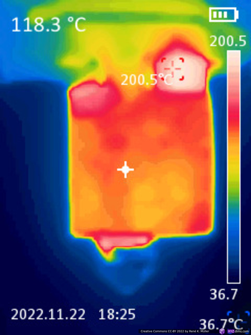
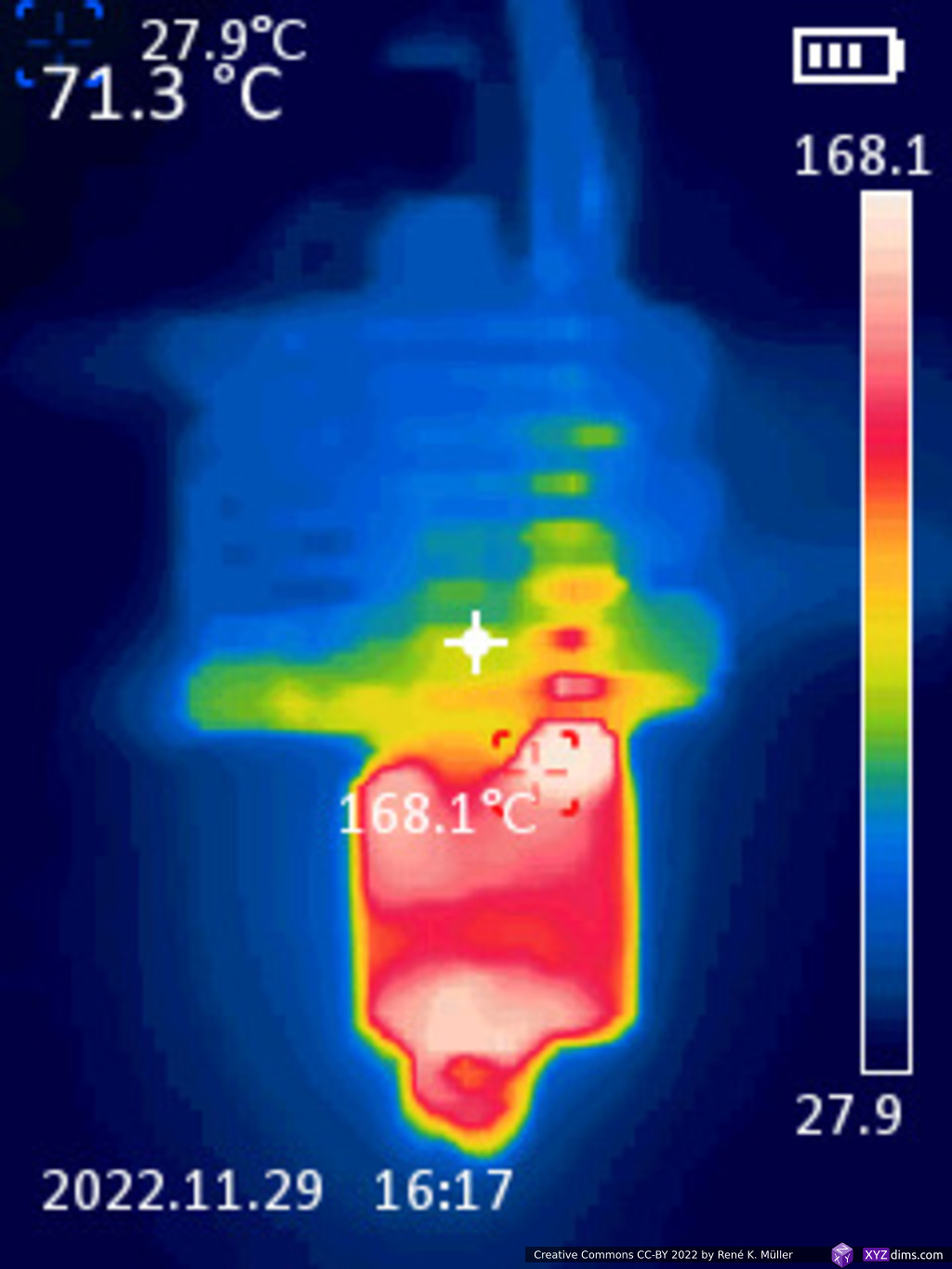
The thin heatbreak walls seemed to help:
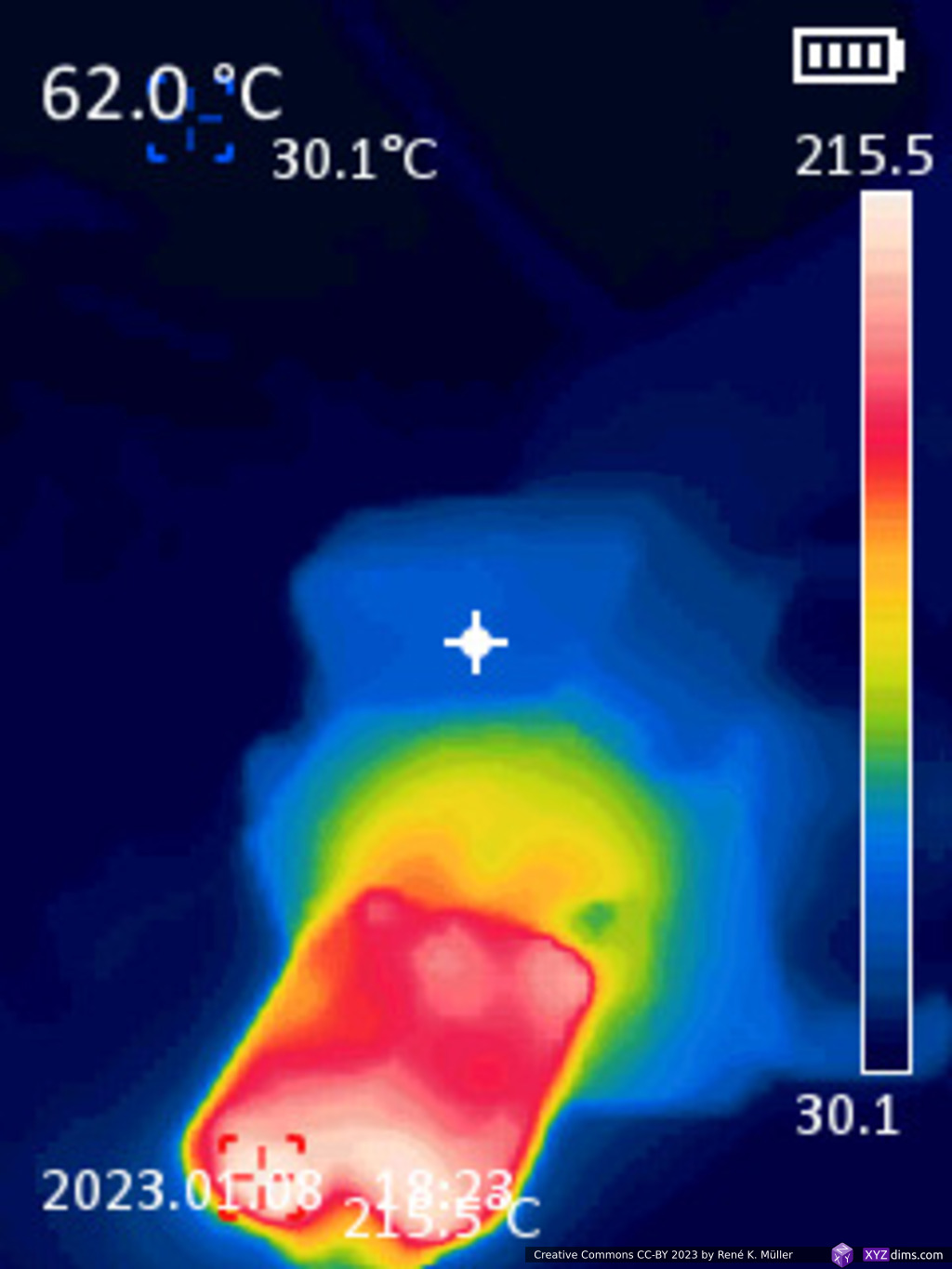
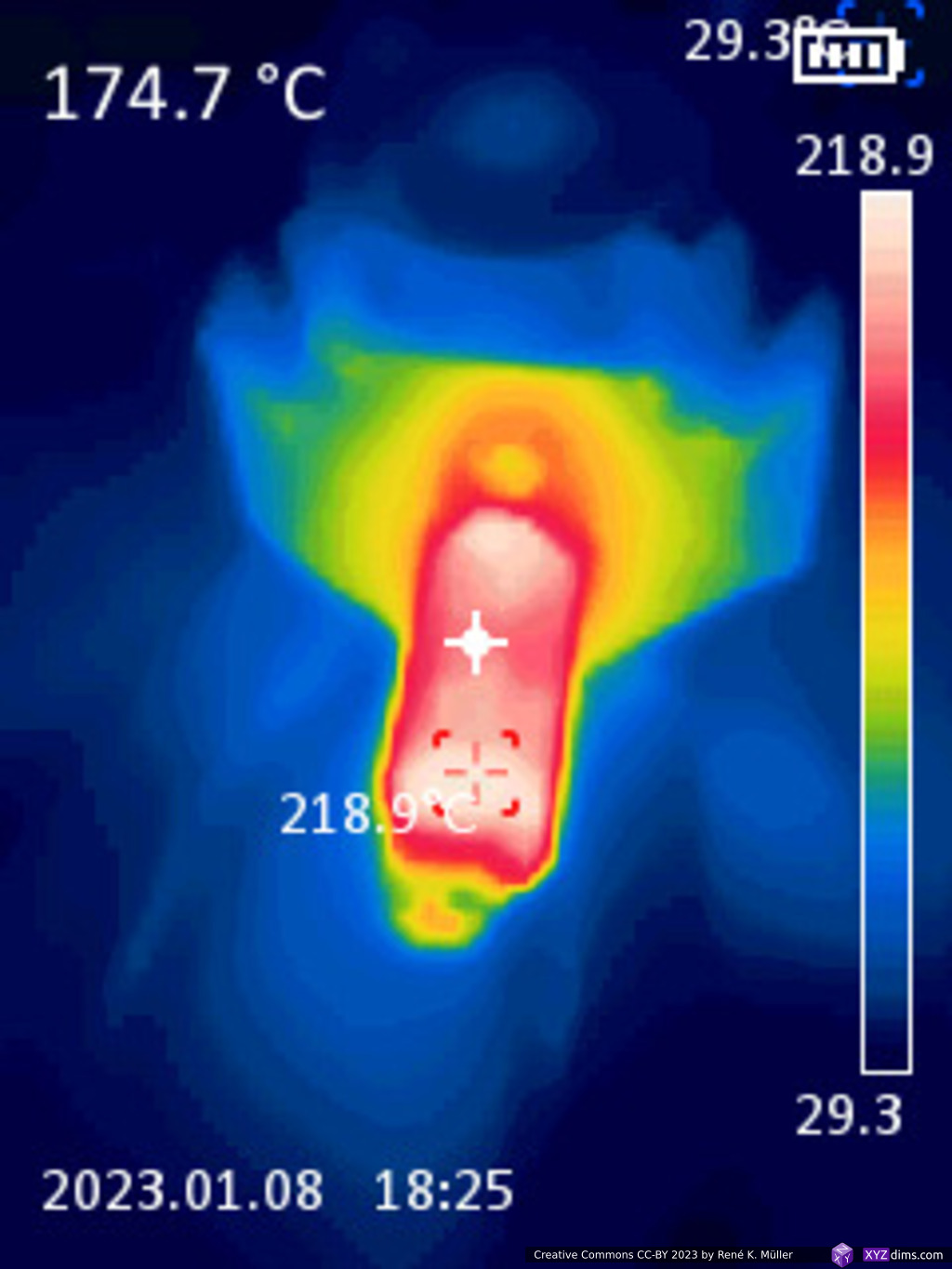
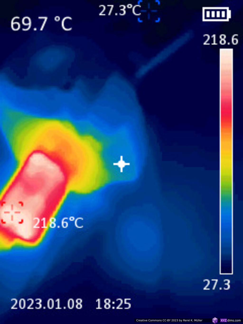
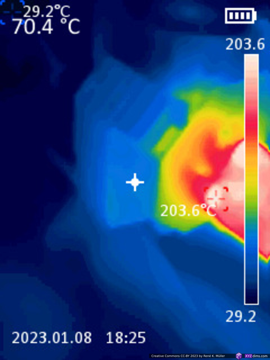
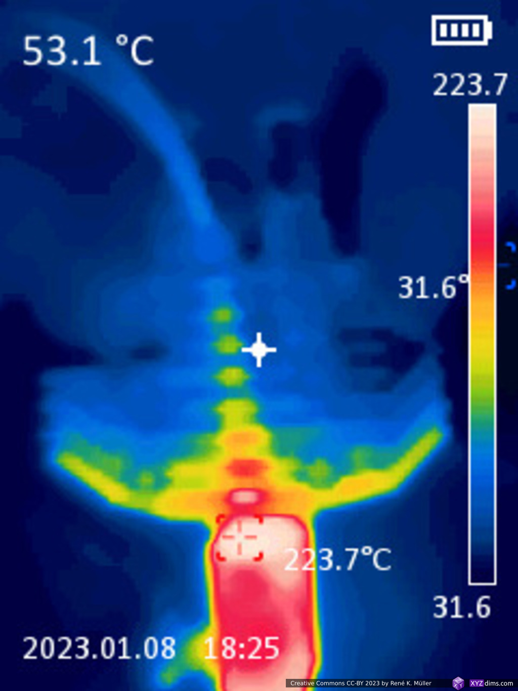
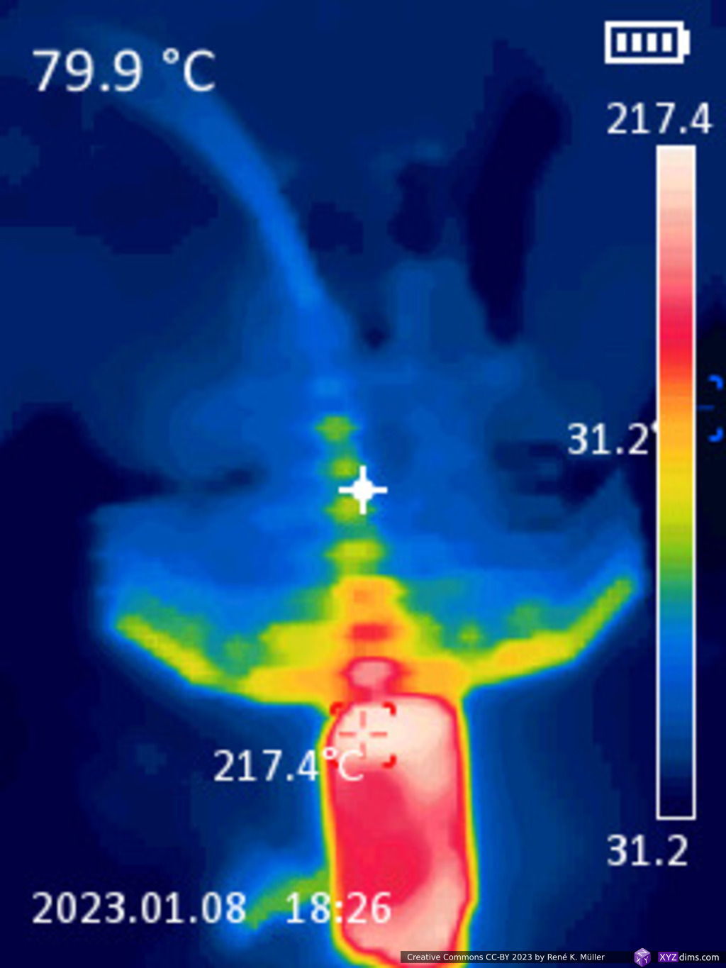
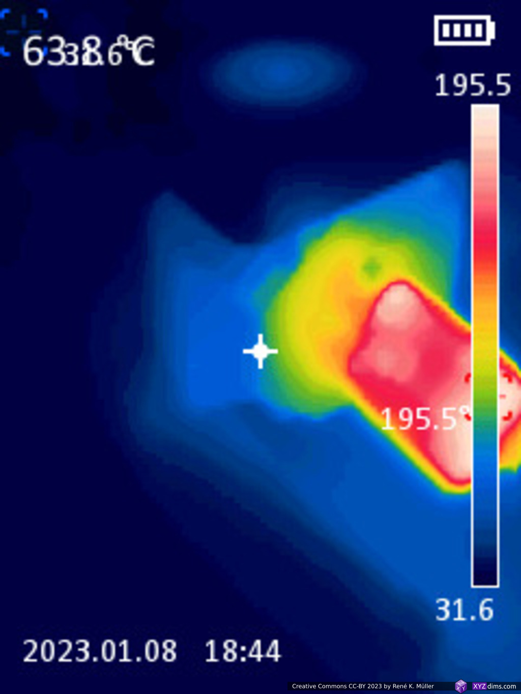

- ability to heat up to 210°C nominal, some parts reach 220°C, but nozzle is around 210°C
- 30mm fan performs well
- 40mm fan removes too much heat, no possible to reach 210°C anymore
- heatbreak pipes are still too thick, too much heat flows away (hence 30mm vs 40mm fan)
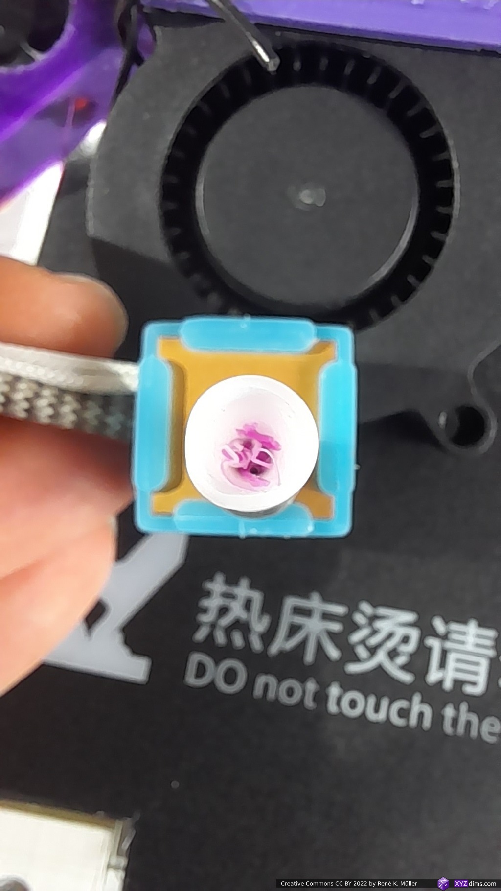
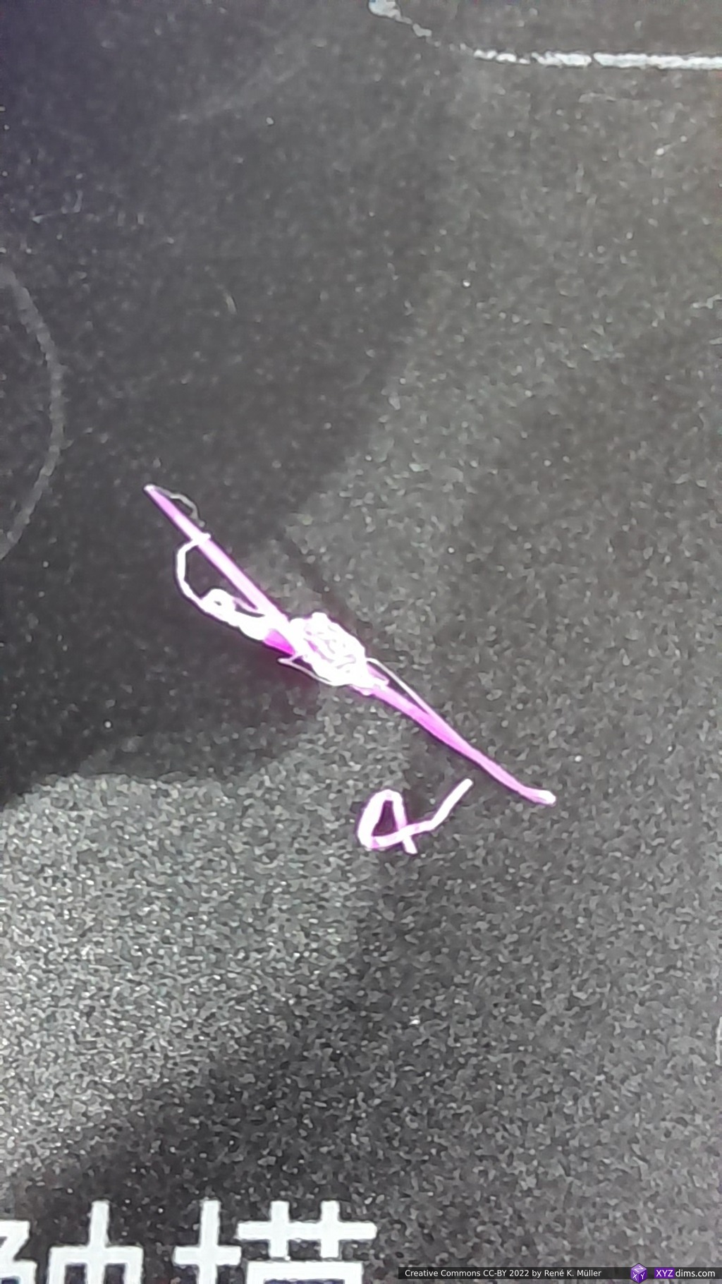
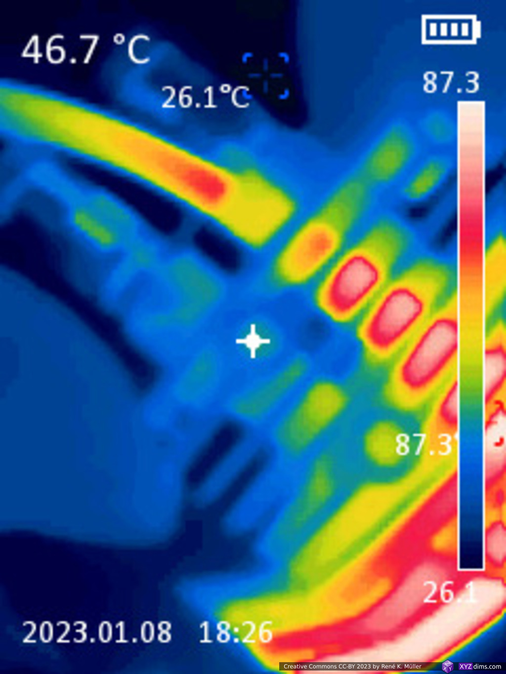
- first extrusion worked, but after 1-2min both channels are blocked, near lowest fin of the heatbreak, to clear the blockage, I removed the fan and heated to 180°C and allow entire hotend to reach ~90°C, then with 0.4mm needle and 1.8mm copper wire was able to clear the blocked section
Conclusion
Heatbreak is most critical, and has to be short and has to be a hard cut temperature gradient-wise – and 0.5mm wall thickness is still too much. So, regardless of cooling fan on the heatsink, if the heatbreak is too thick, too much heat creeps up or away – it’s not a matter of cooling capacity, but conductivity.
Todo
metal printed version (aluminium), done 2022/11/21- heating tests (on-going)
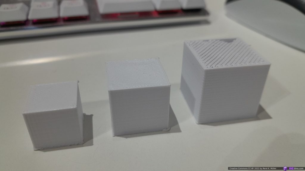
- test prints with multiple filaments
- 2 inputs, e.g. complementary colors (Black/White: Grey Shades, Yellow/Violet: Red Shades)
- 3 inputs, e.g. CYM: saturated colors only
- 5 inputs, e.g. CYMKW: full spectrum colors
- silicon socks for all variants, as part cooler will introduce otherwise heating instabilities
References
- Diamond Hotend: 3 color mixing hotend experiments
- PCBWay 3D Printing: metal printing service used
- WeNext: another metal printing service considered