Updates:
- 2023/11/13: published
- 2023/11/11: starting writeup
Introduction
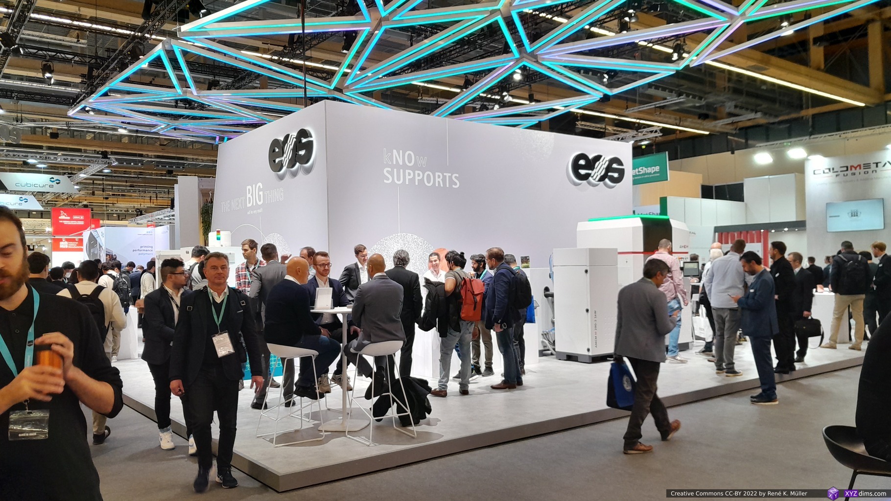
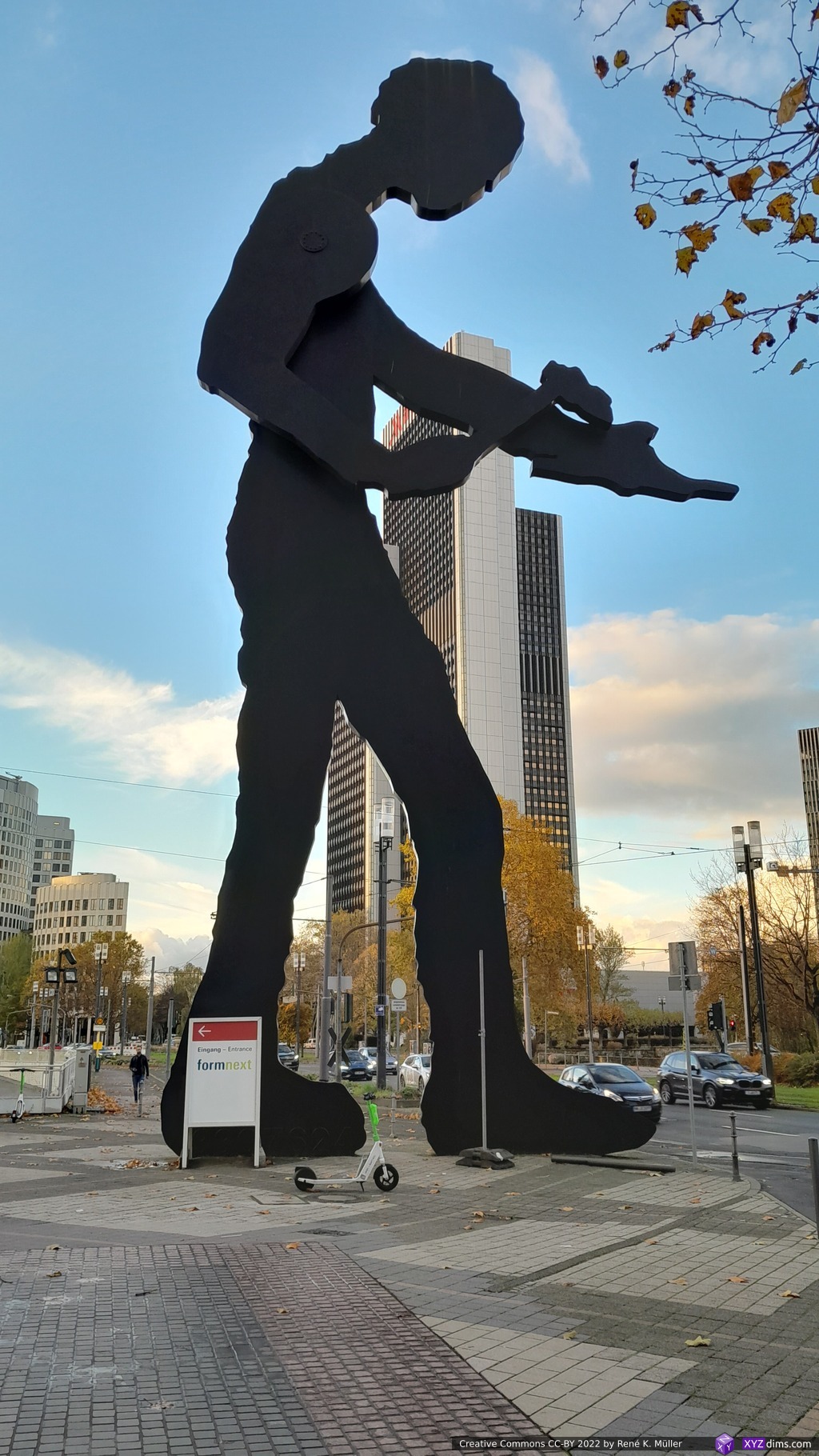
Another year, another November in Frankfurt (Germany) and Formnext – this is the main event of the year professionally for me. As I reside in Switzerland the travel is fairly easy and short and the 770 exhibitors in two halls (11 & 12) with two floors each is so overwhelming that even 4 days attending is not sufficient.
- Day 1 (Tue, Nov 7): I spent an entire day to explore hall 12.1 alone, which turns out a good choice as it was a dense populated hall with many smaller companies
- Day 2 (Wed, Nov 8): visiting with a client half of the day to review some of their possible competition, and then explore 12.0
- Day 3 (Thu, Nov 9): some schedules meetings and then explore 11.0 and 11.1
- Day 4 (Fri, Nov 10): revisiting 12.1 and 11.1 briefly, visiting with another client some selected booths to check products on display
I surely missed a few booths in 11.1 and 12.1 still; whereas 12.0 and 11.0 were more large scale industrial AM solutions, mixed with university and regional focused booths which I didn’t have time to explore in detail.
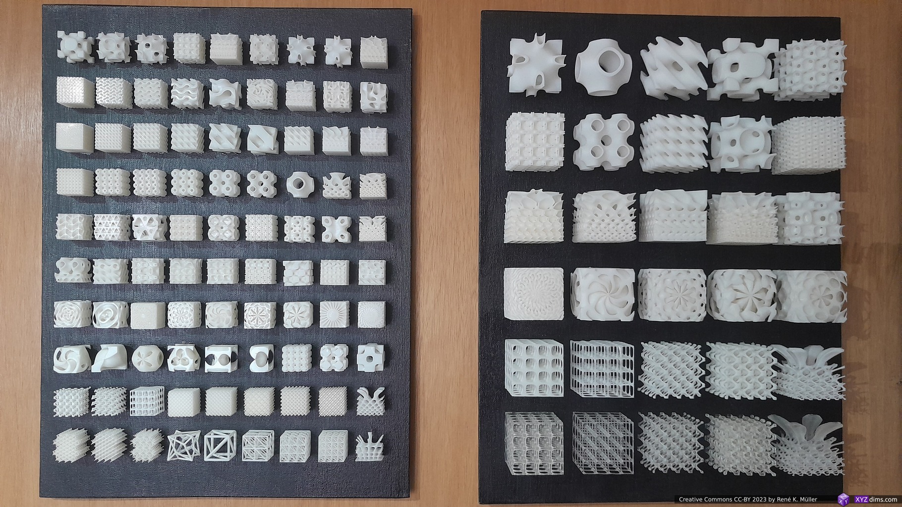
Personal Selection
I feature some companies according my personal professional interests:
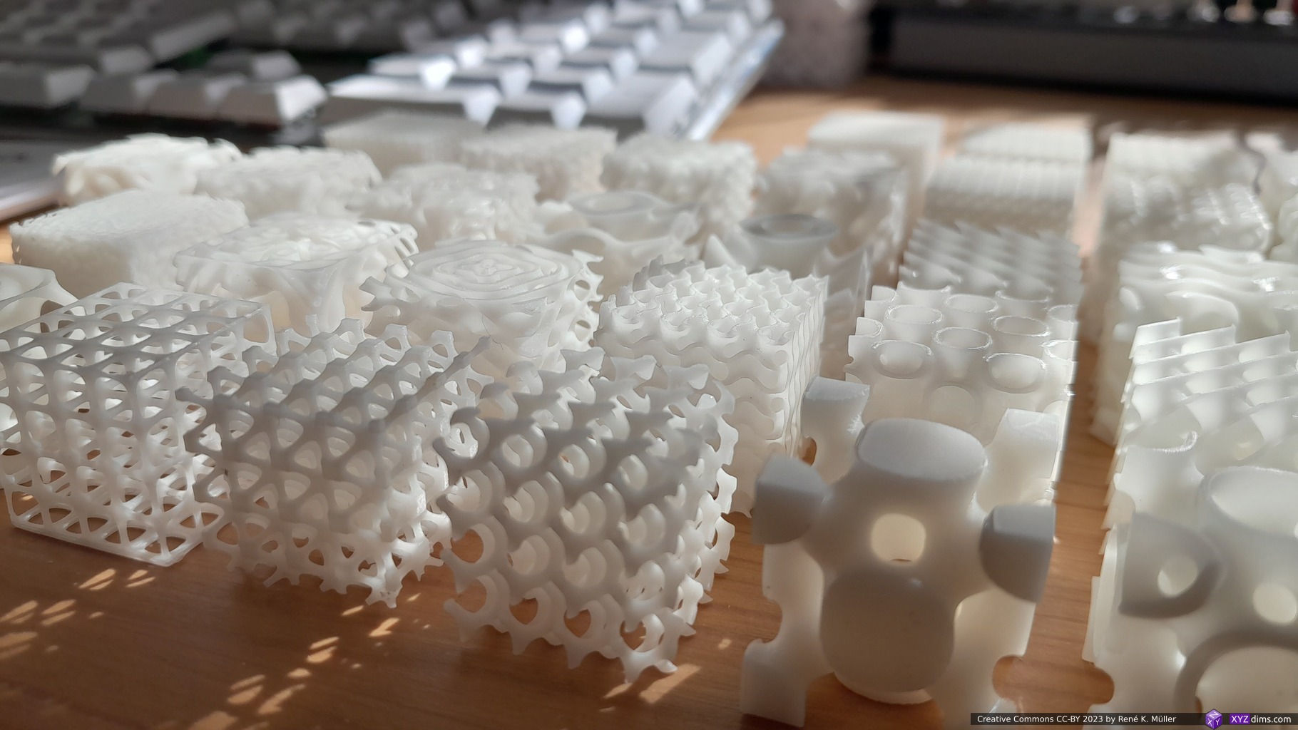
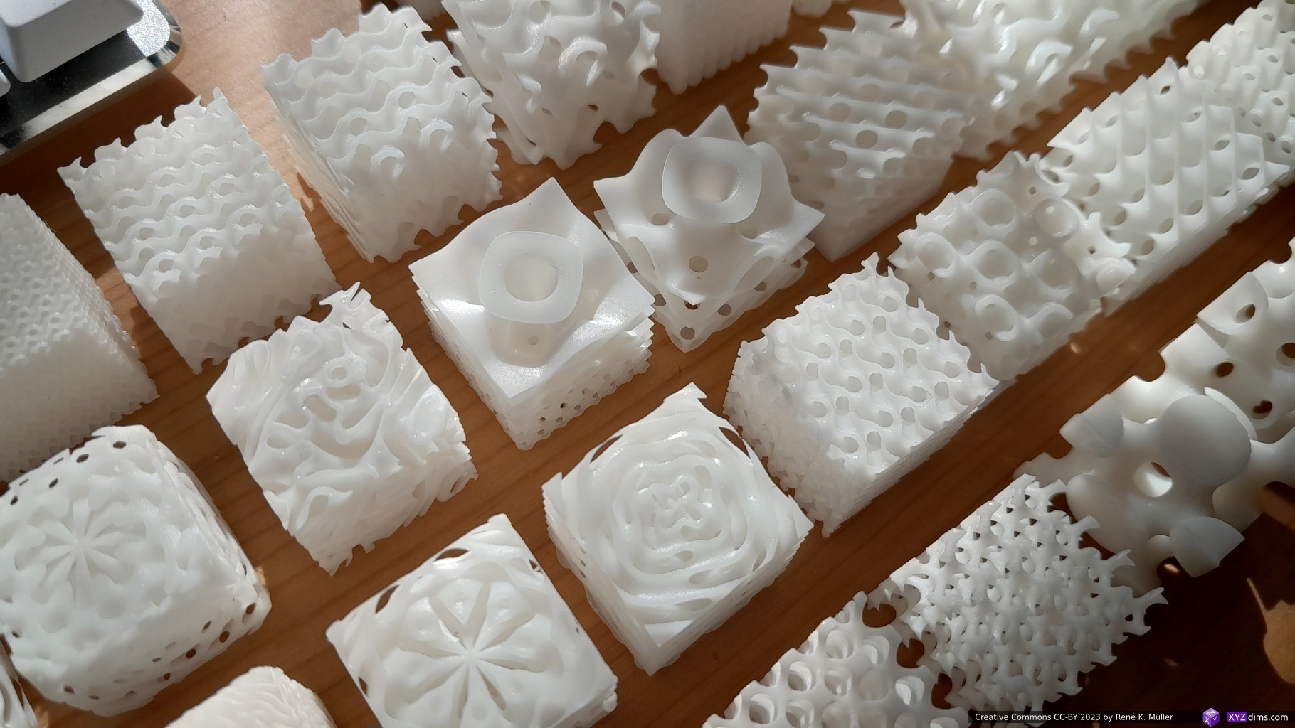
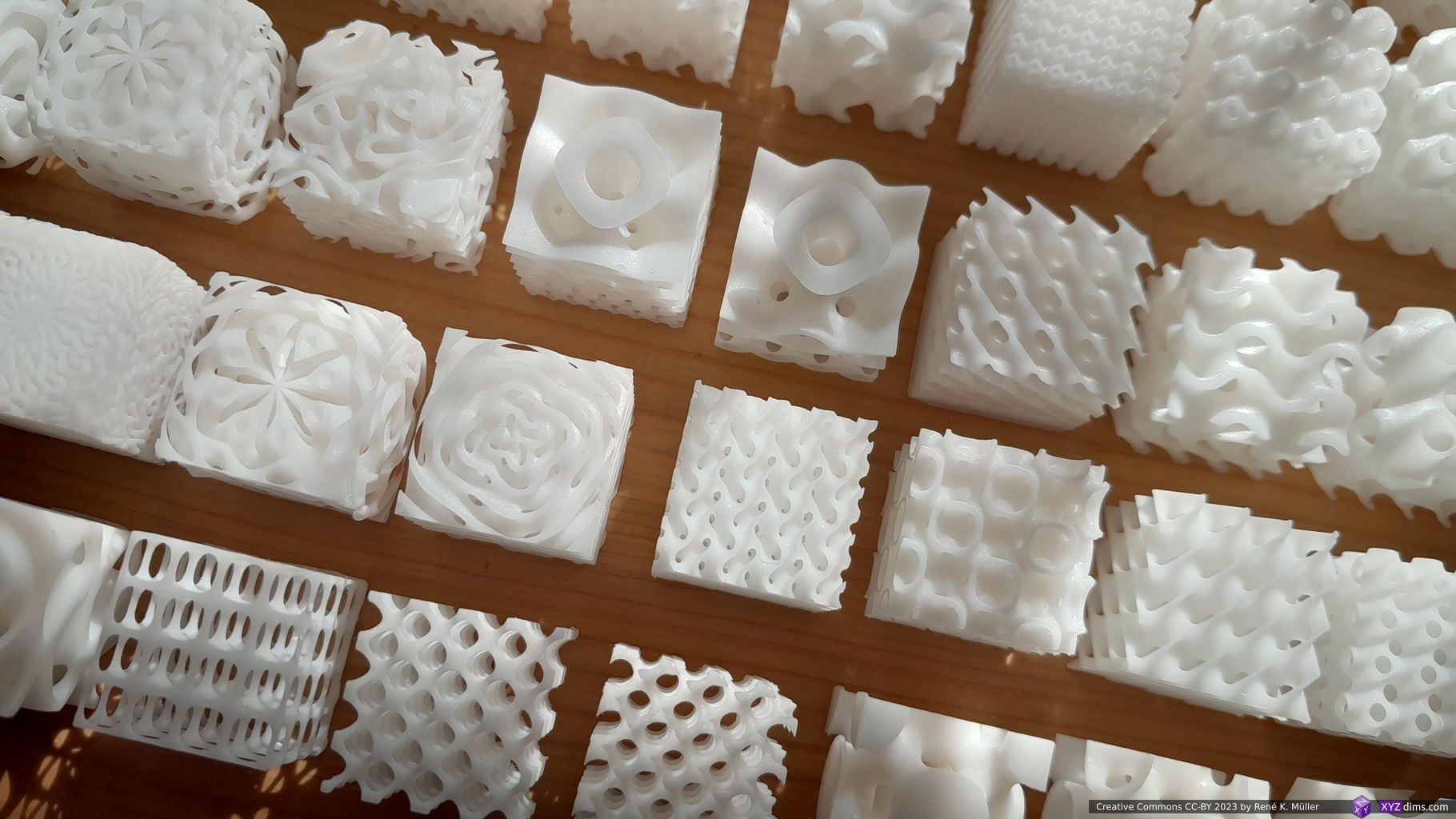
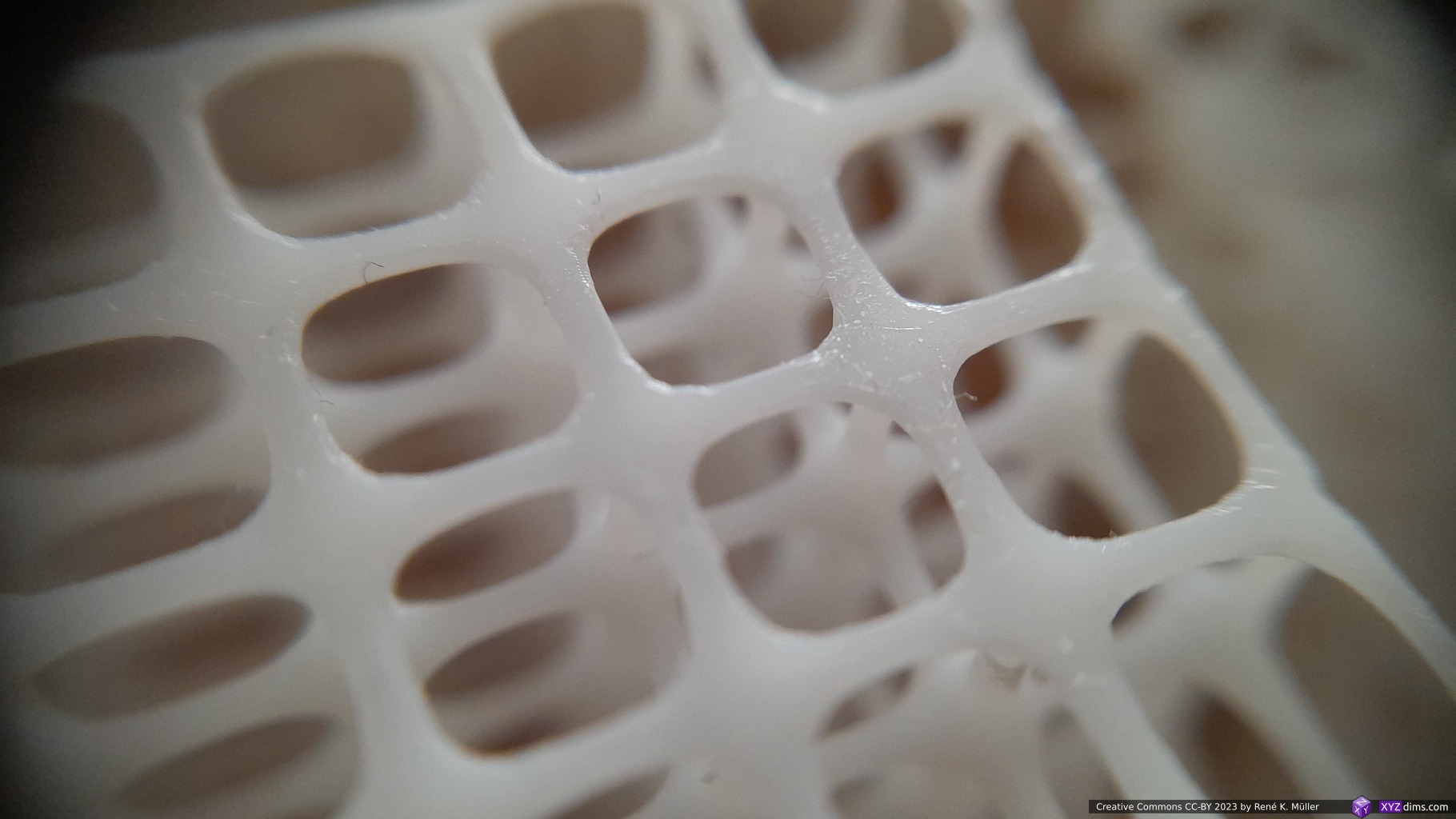
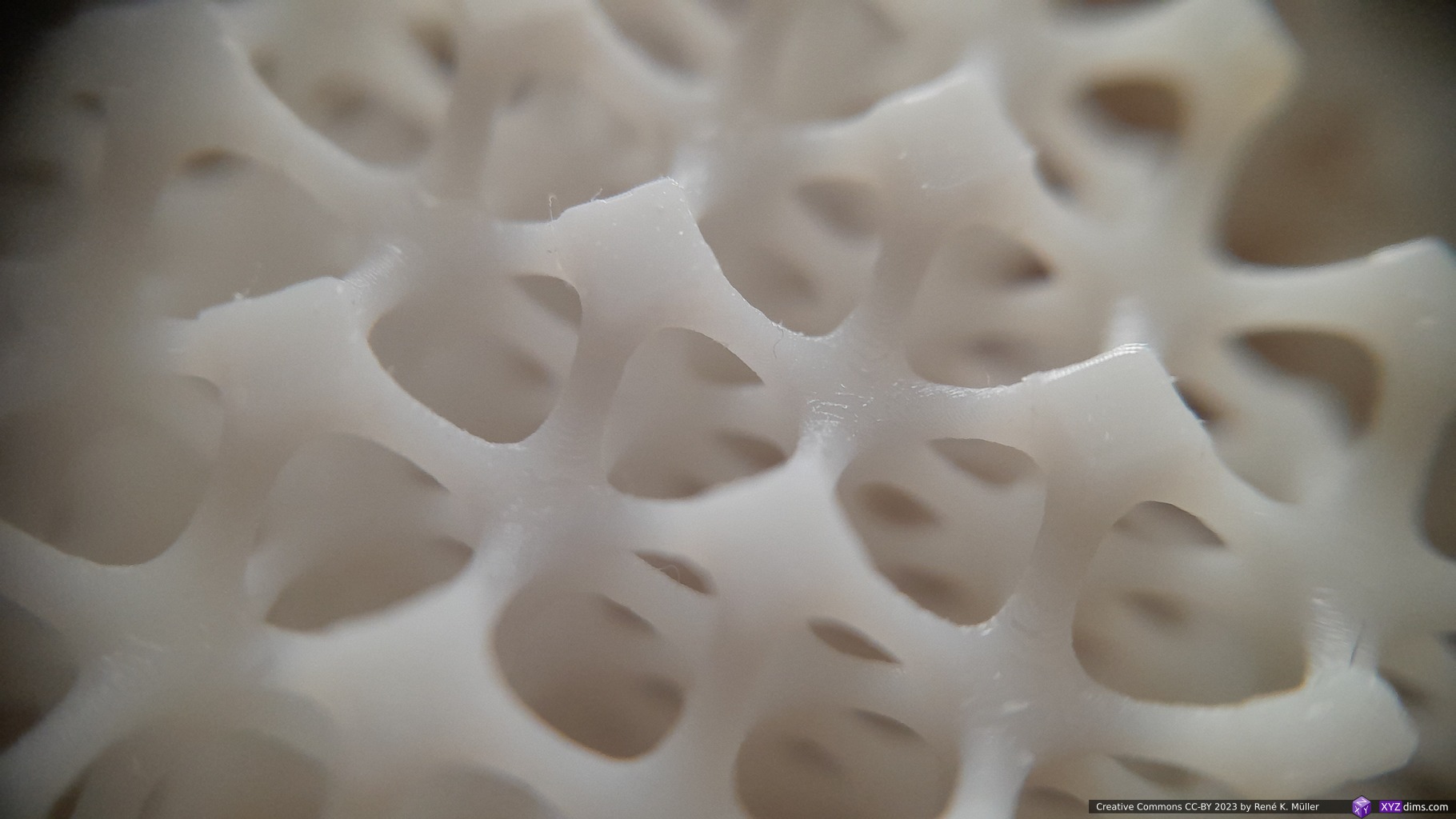
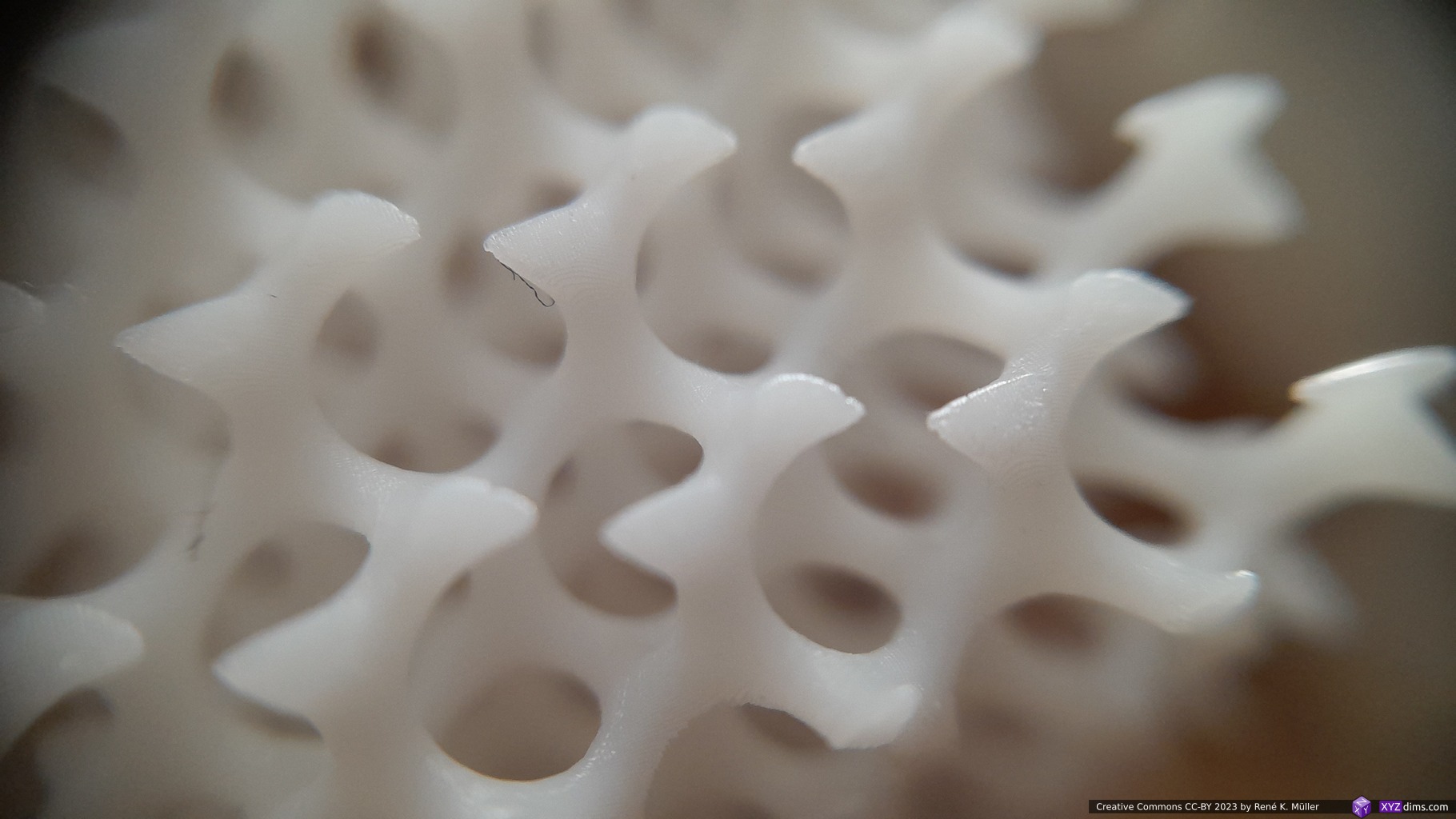
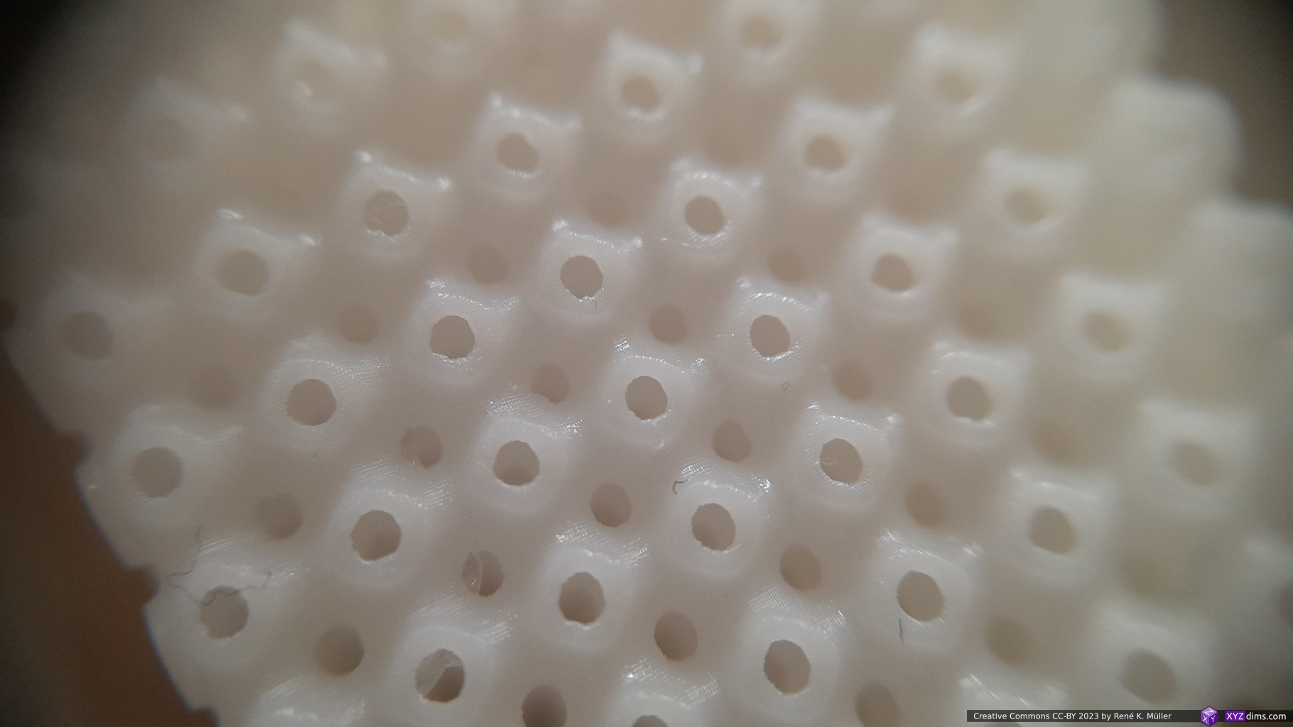
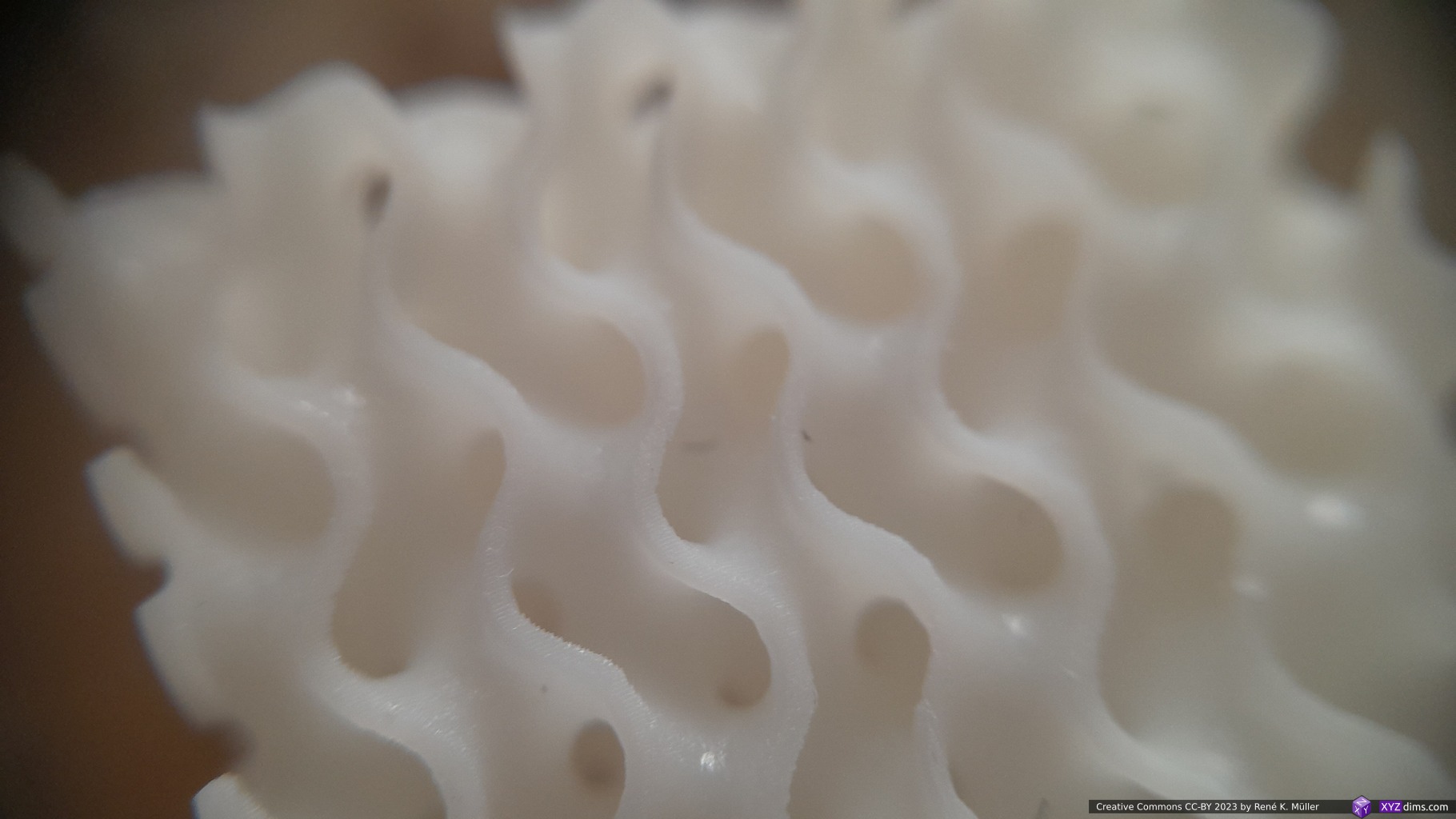
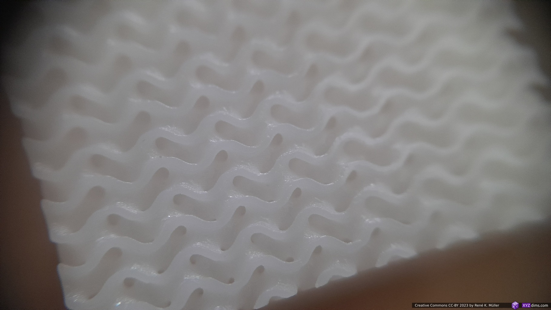
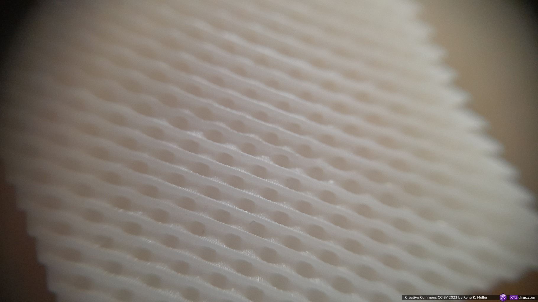
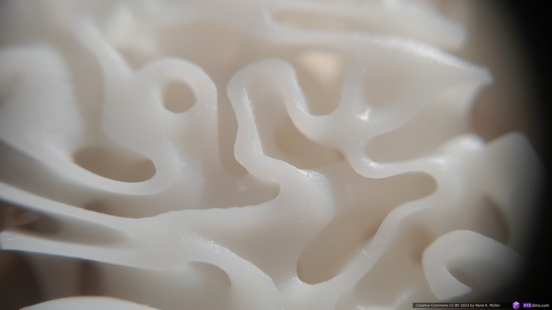
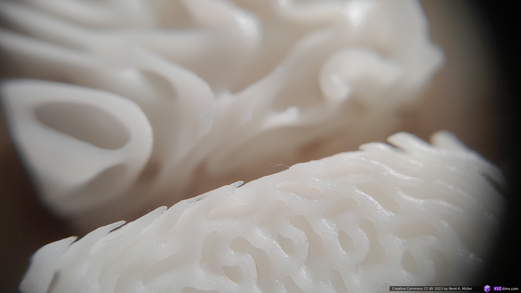
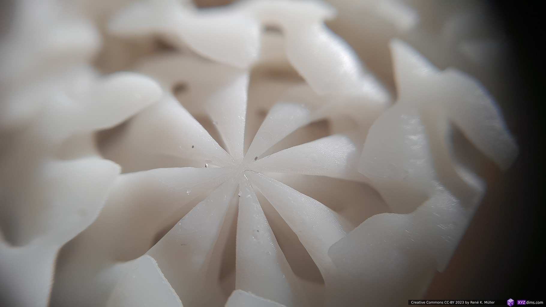
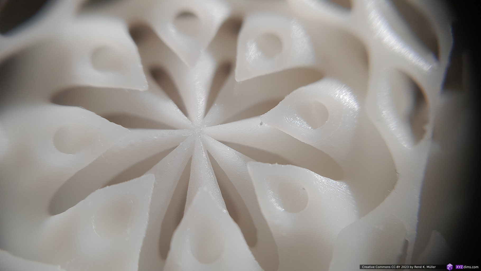
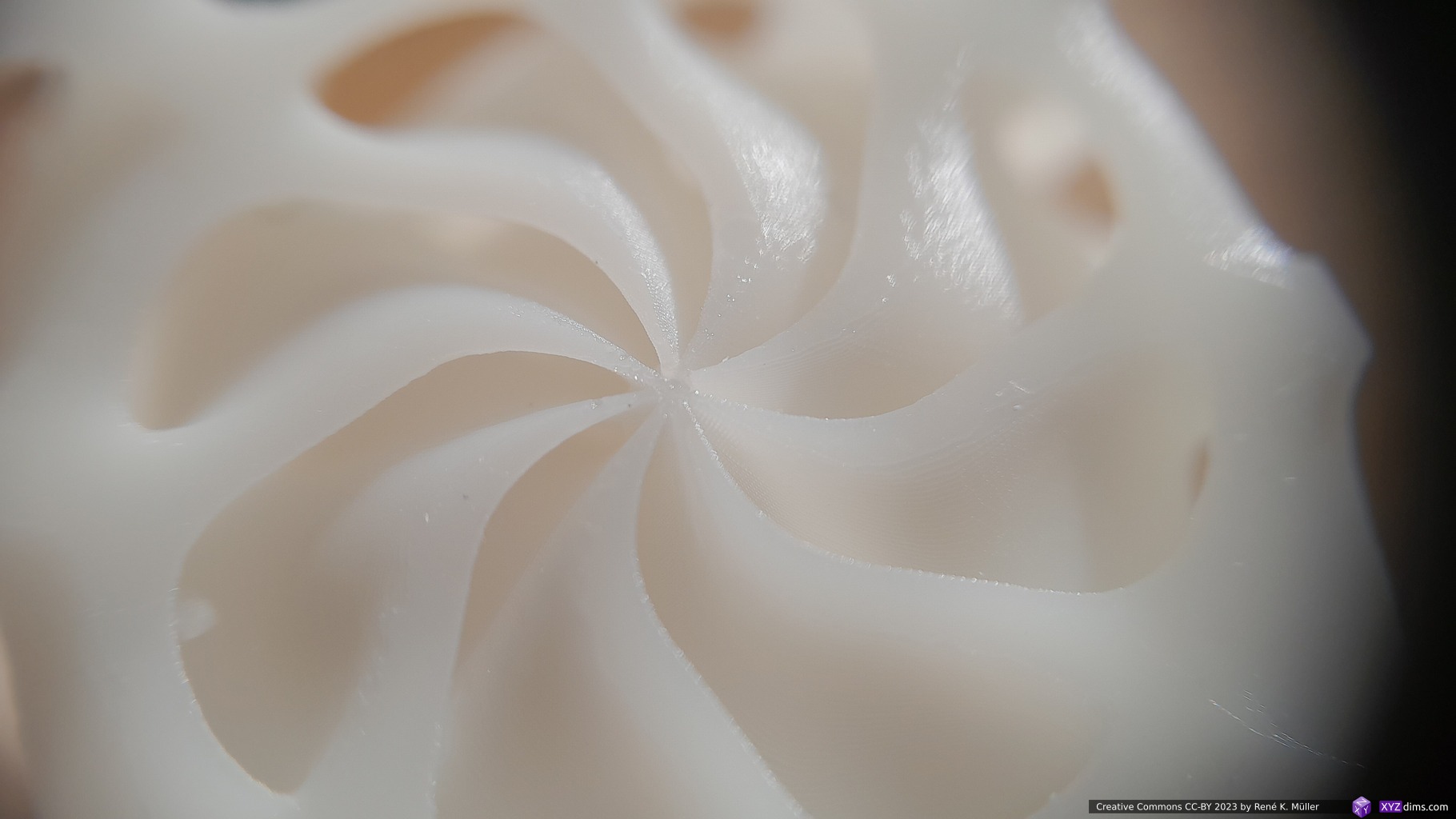
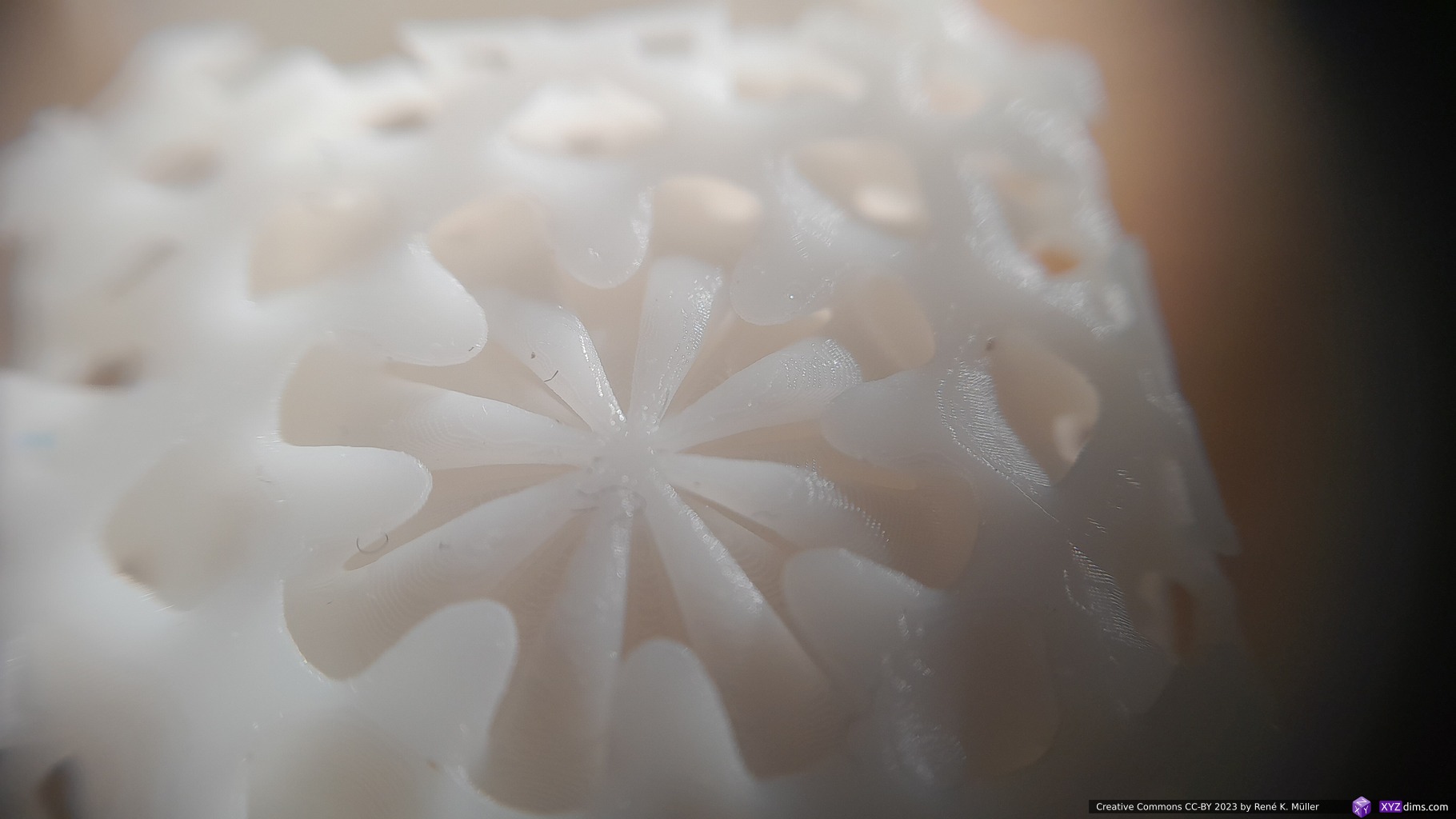
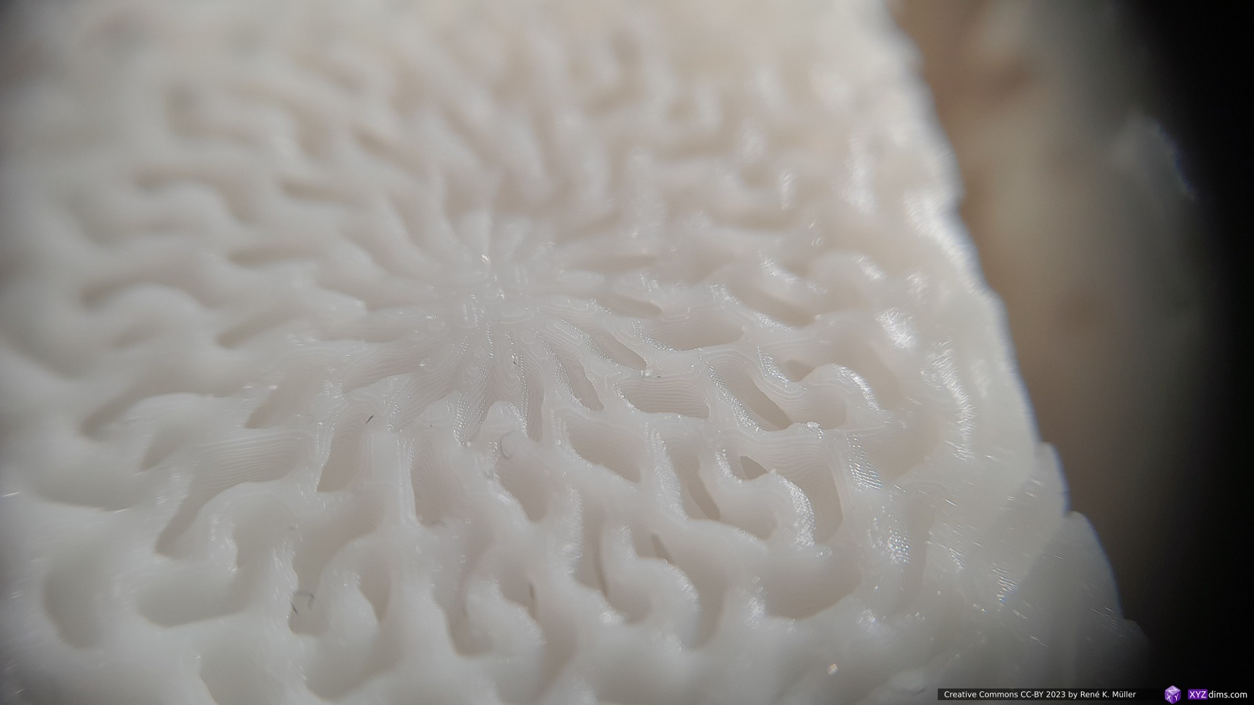
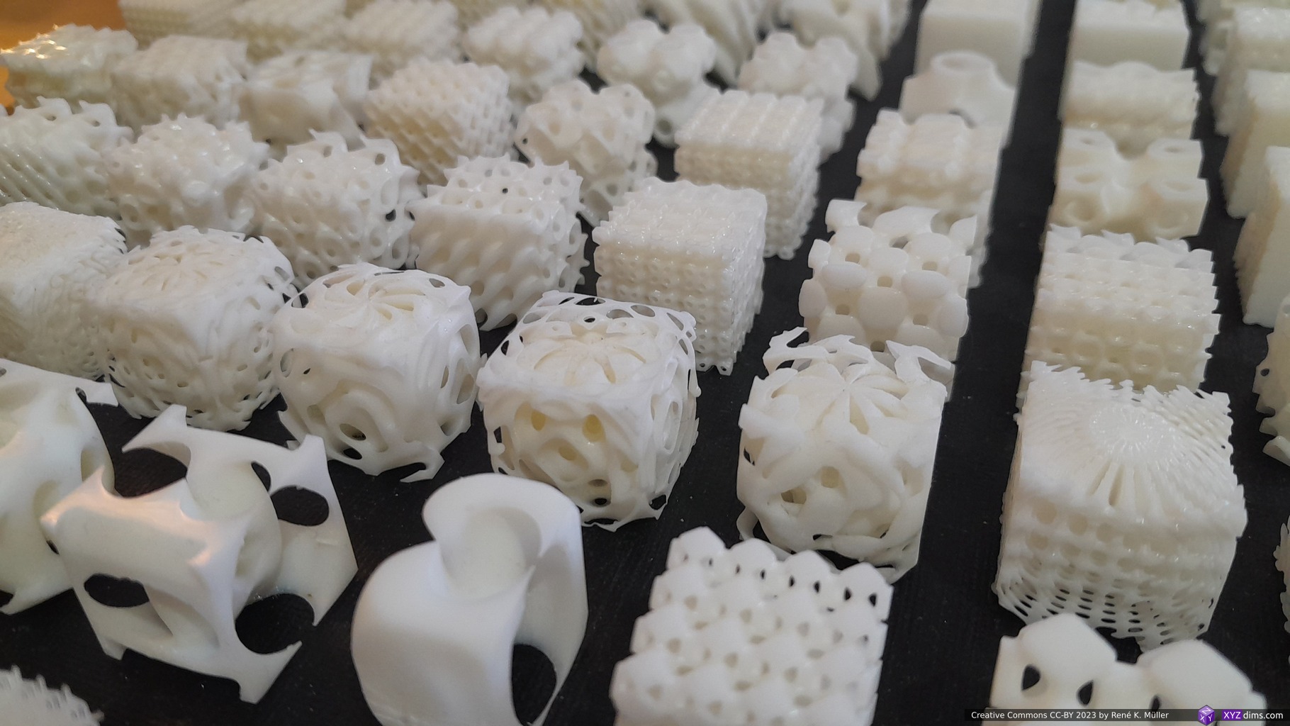
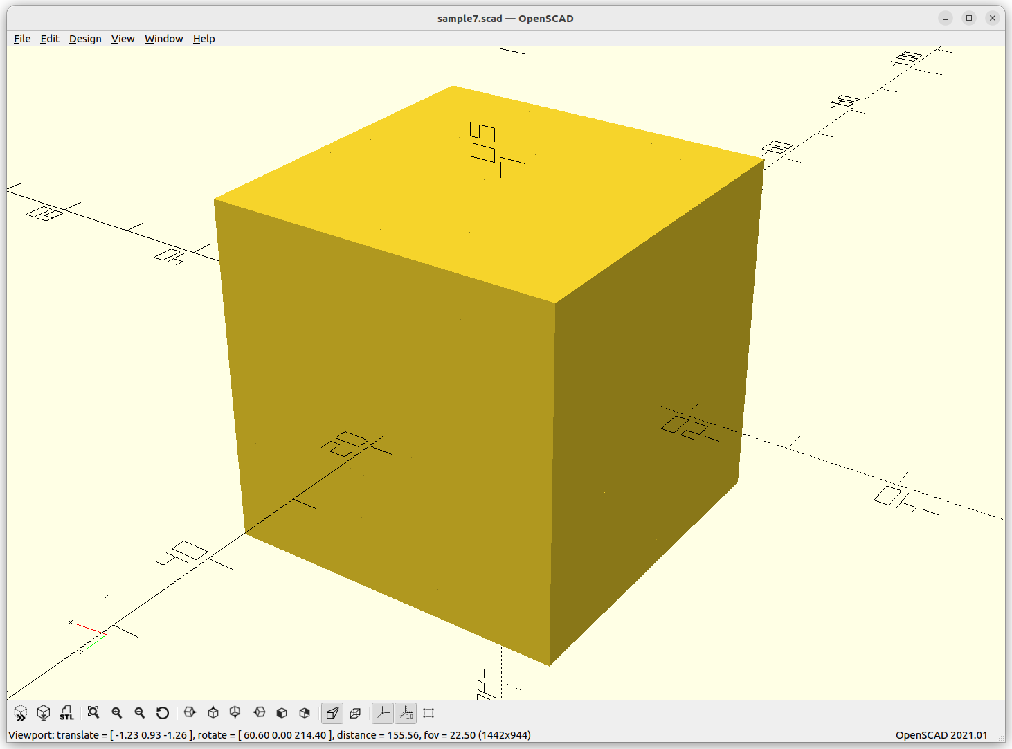
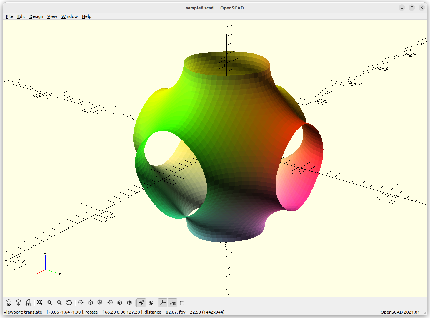
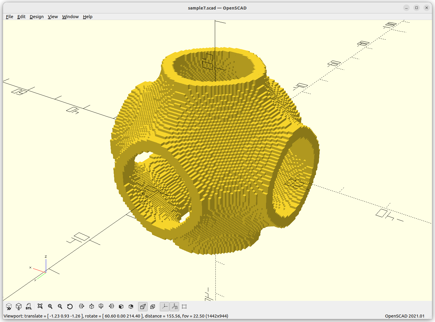
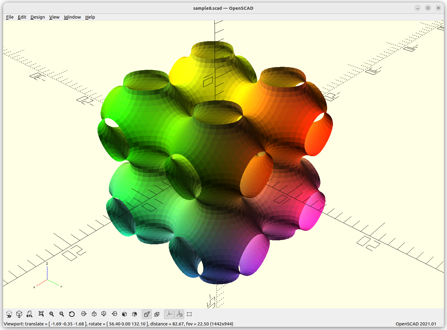
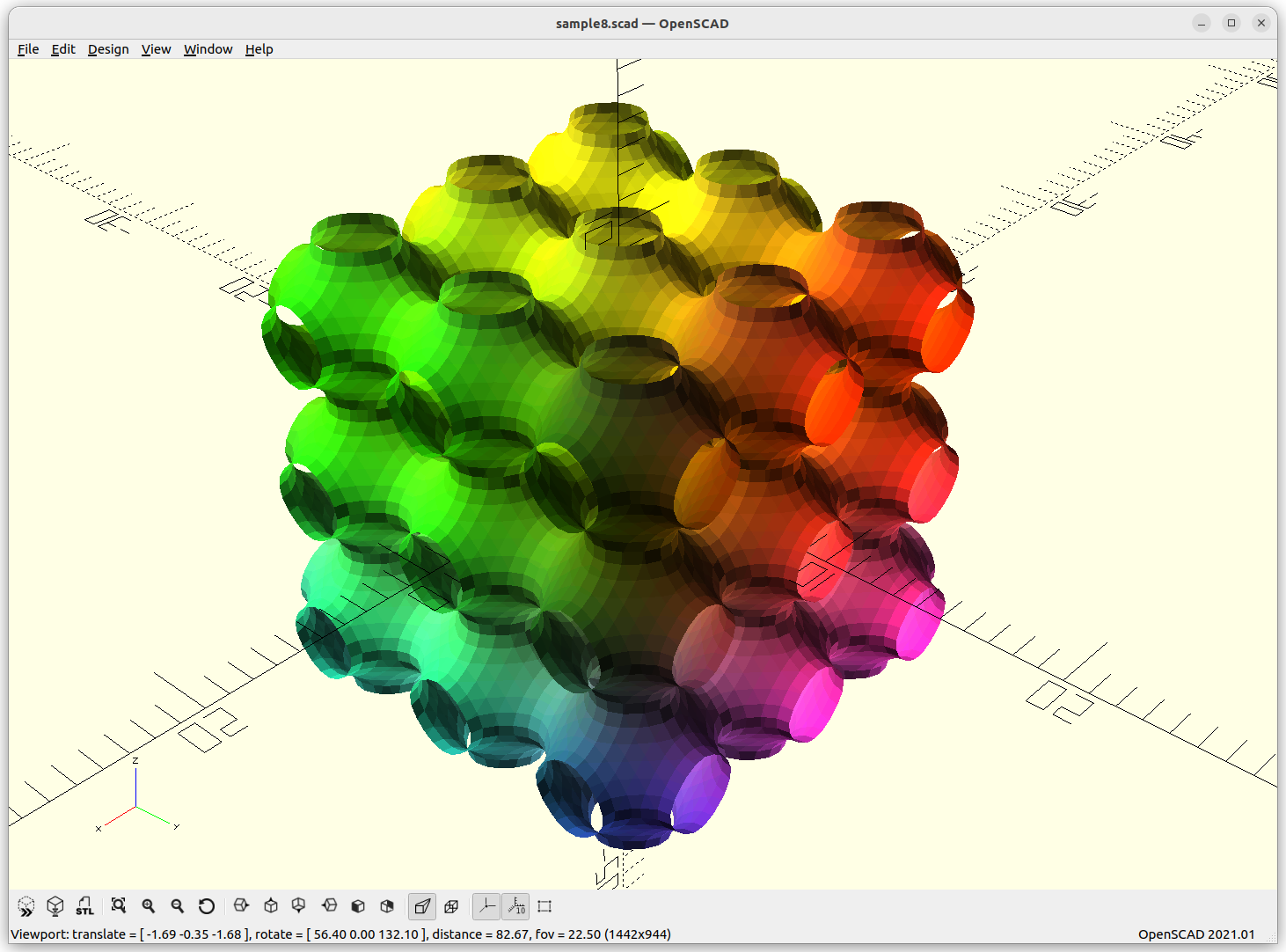
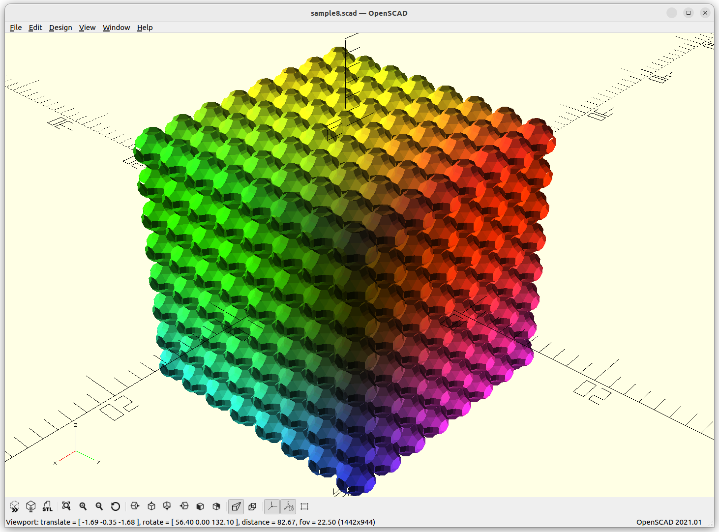
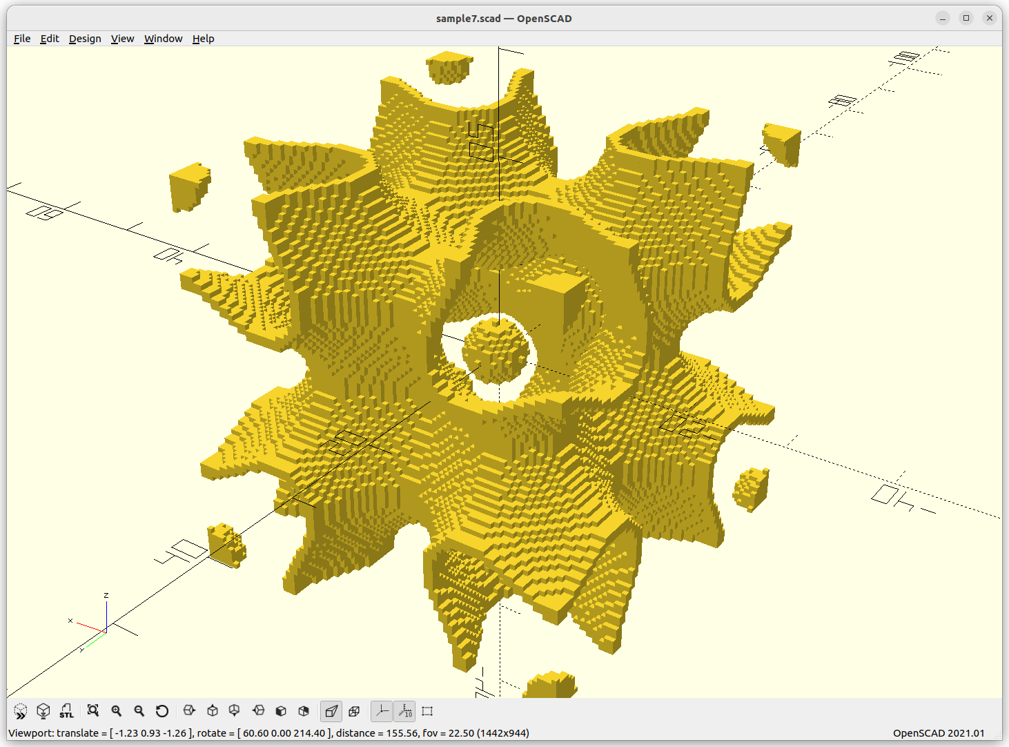
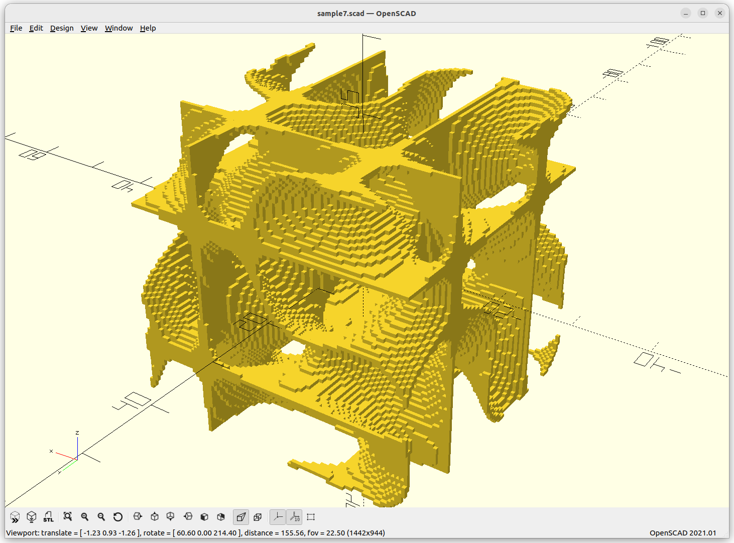
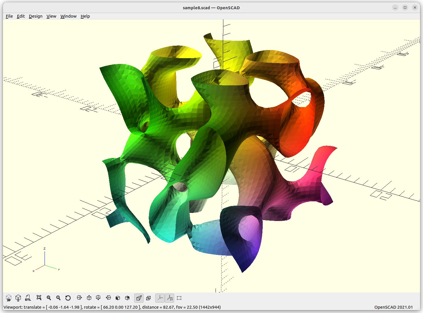
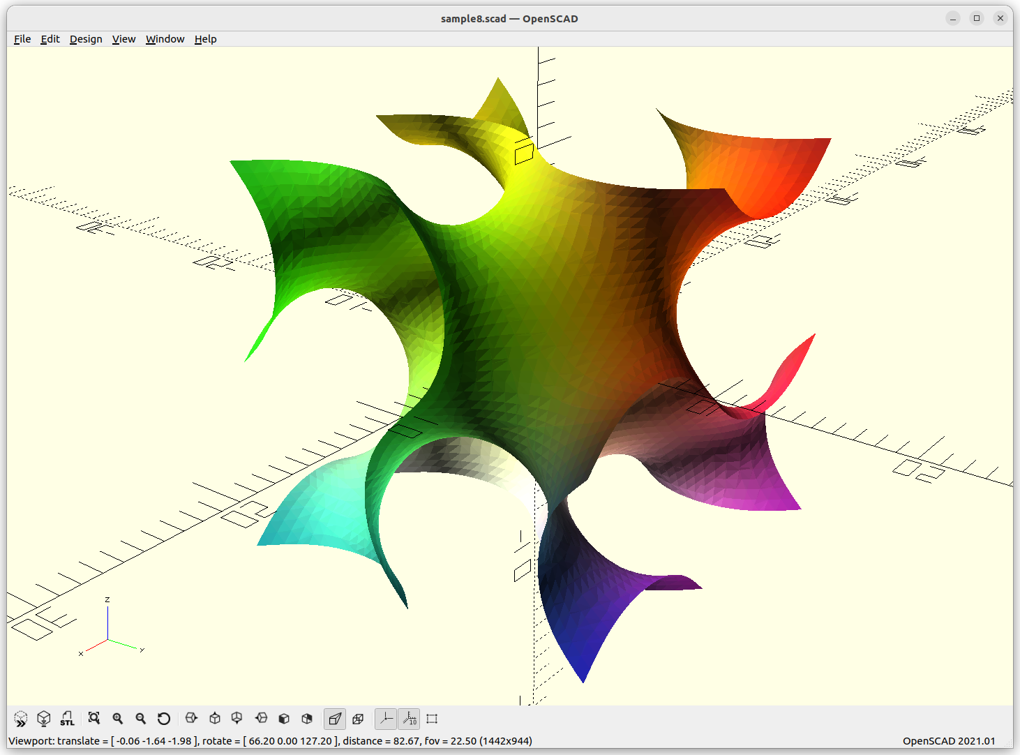
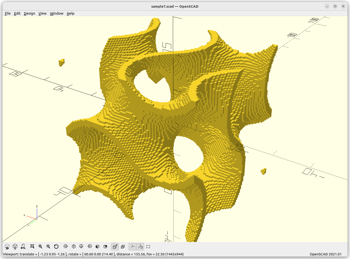
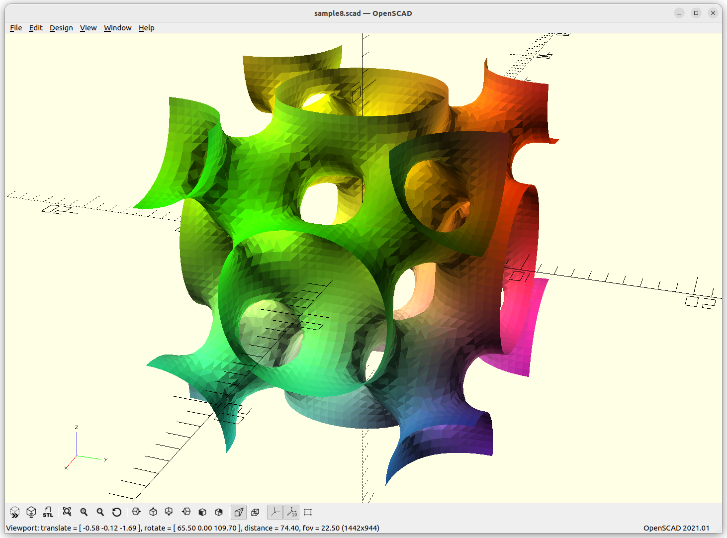
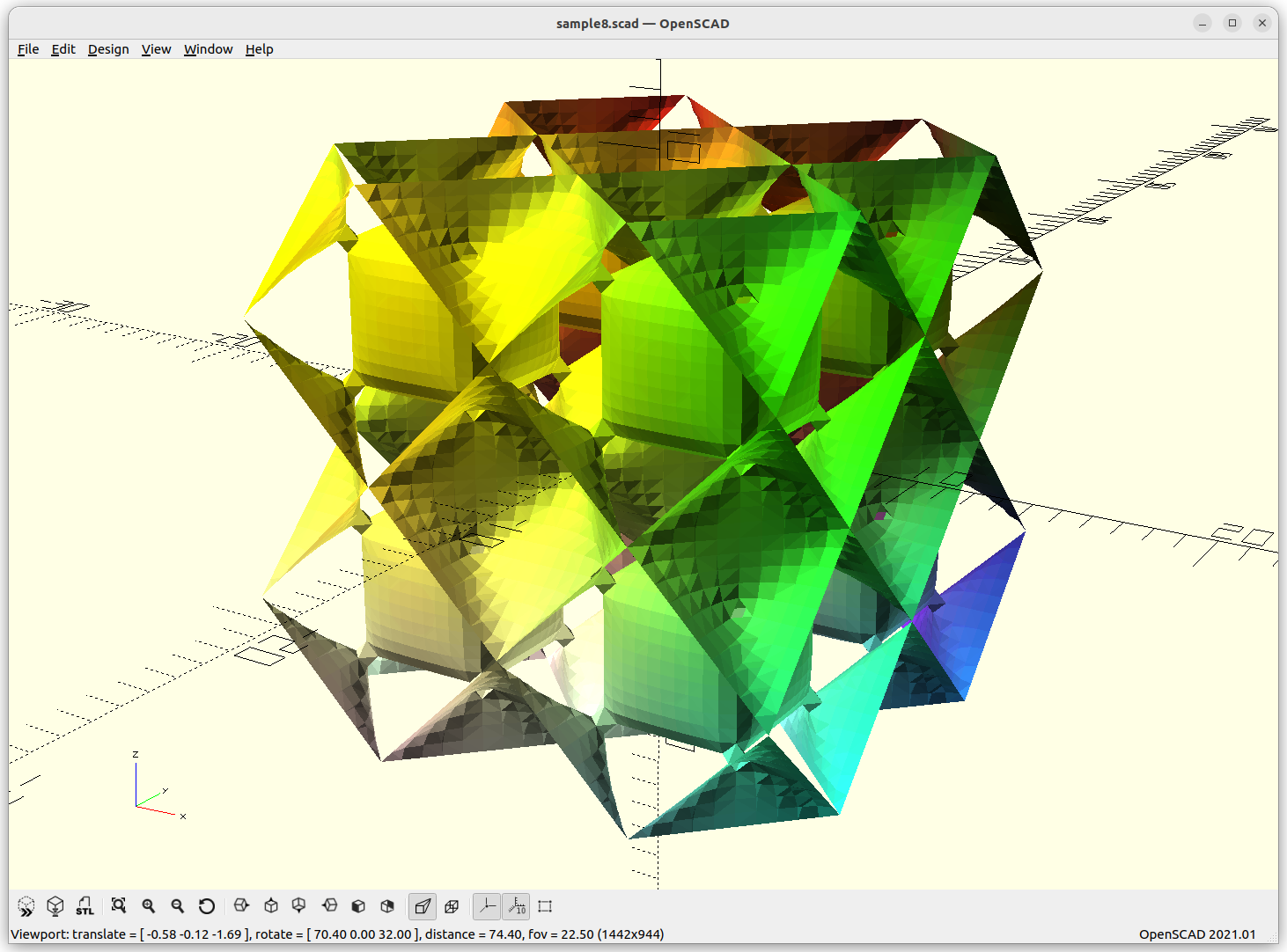
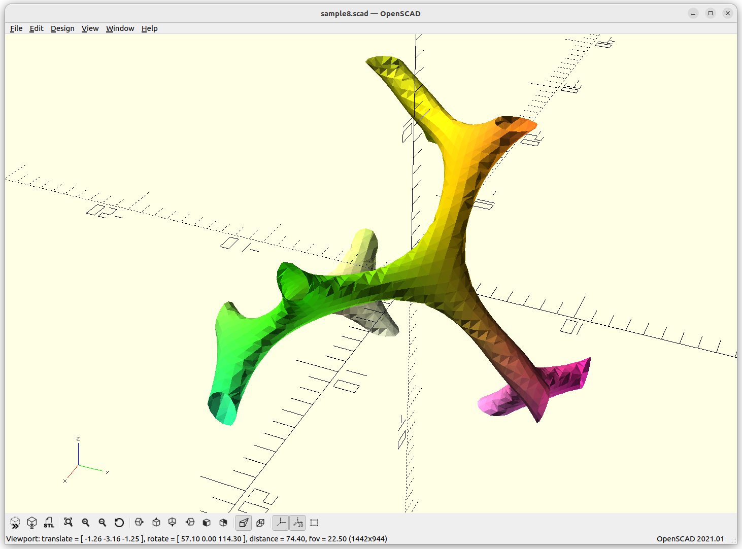
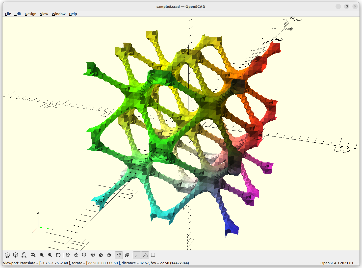
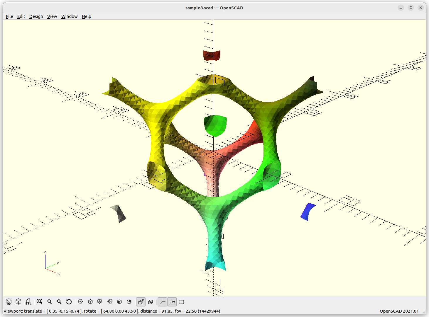
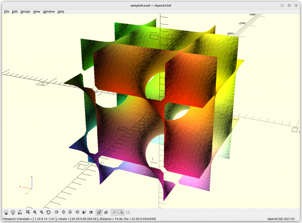
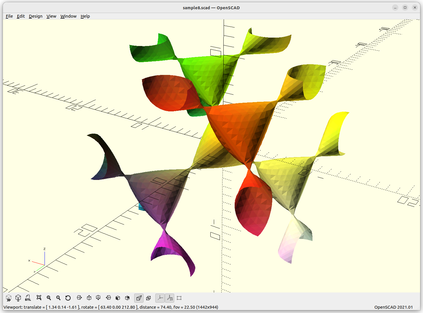
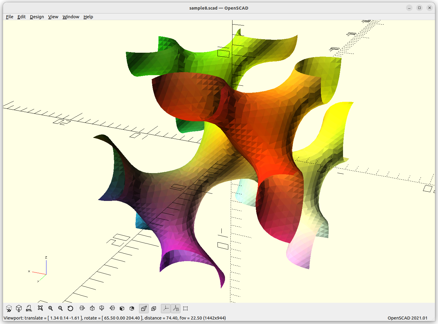
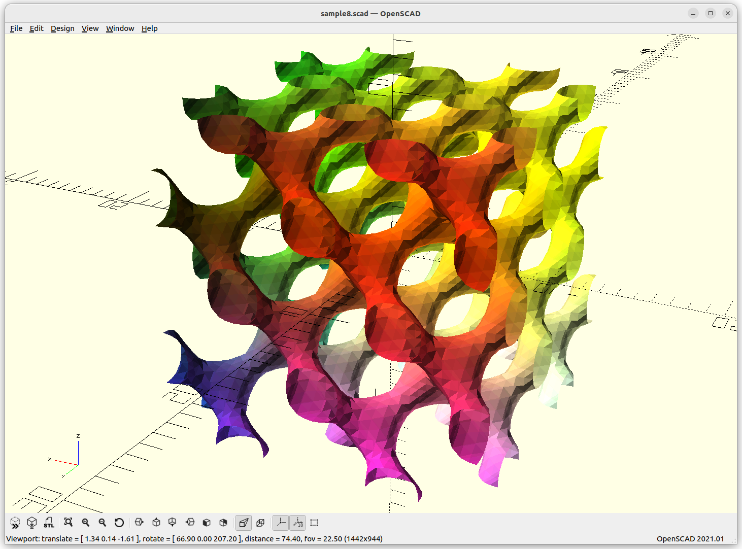
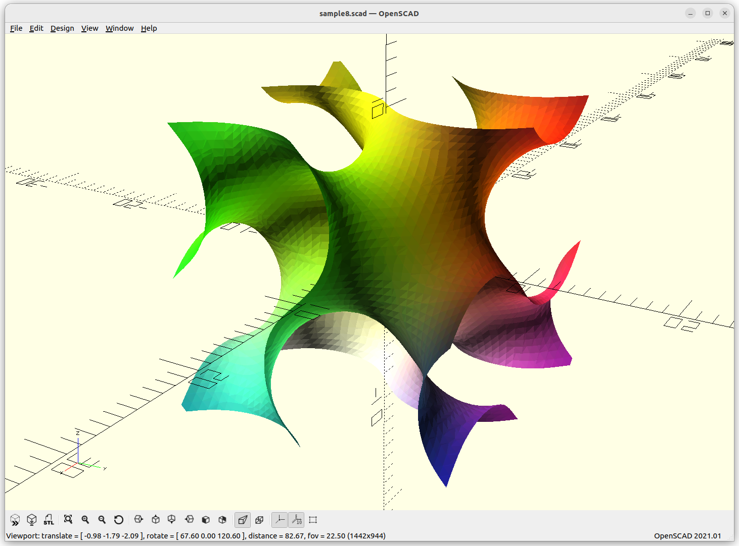
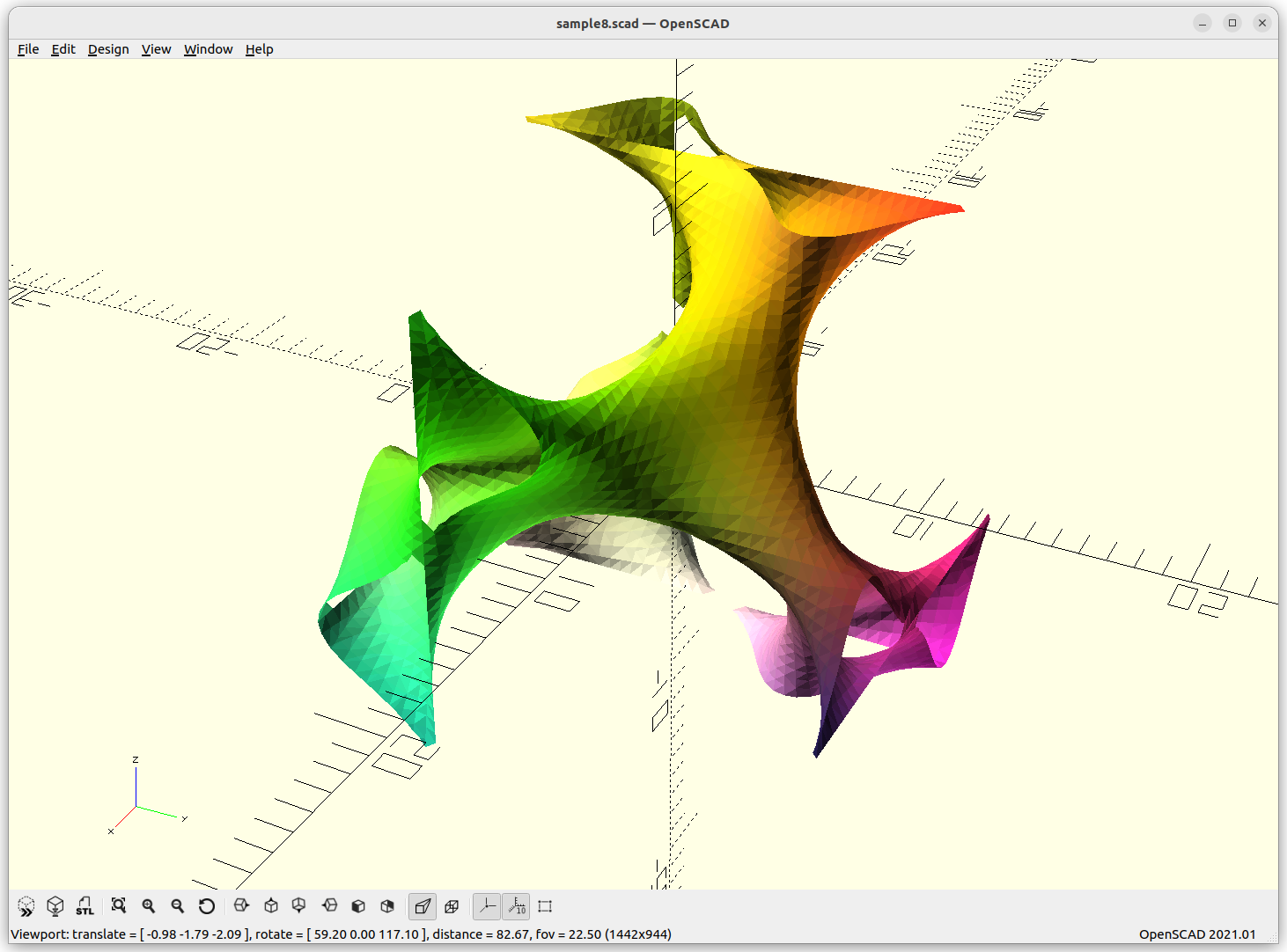
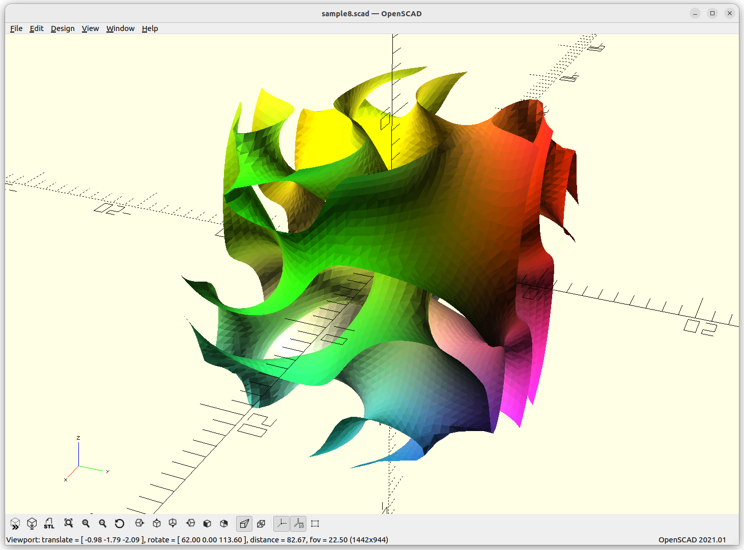
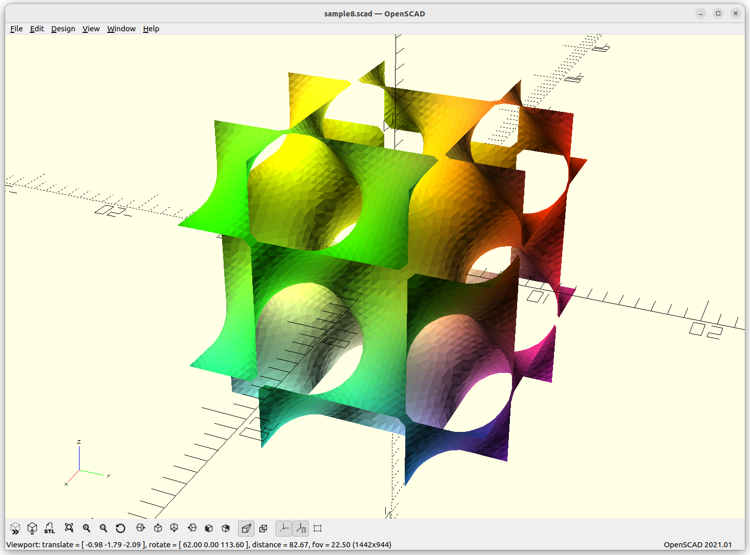
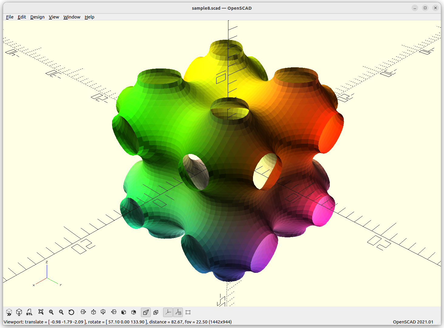
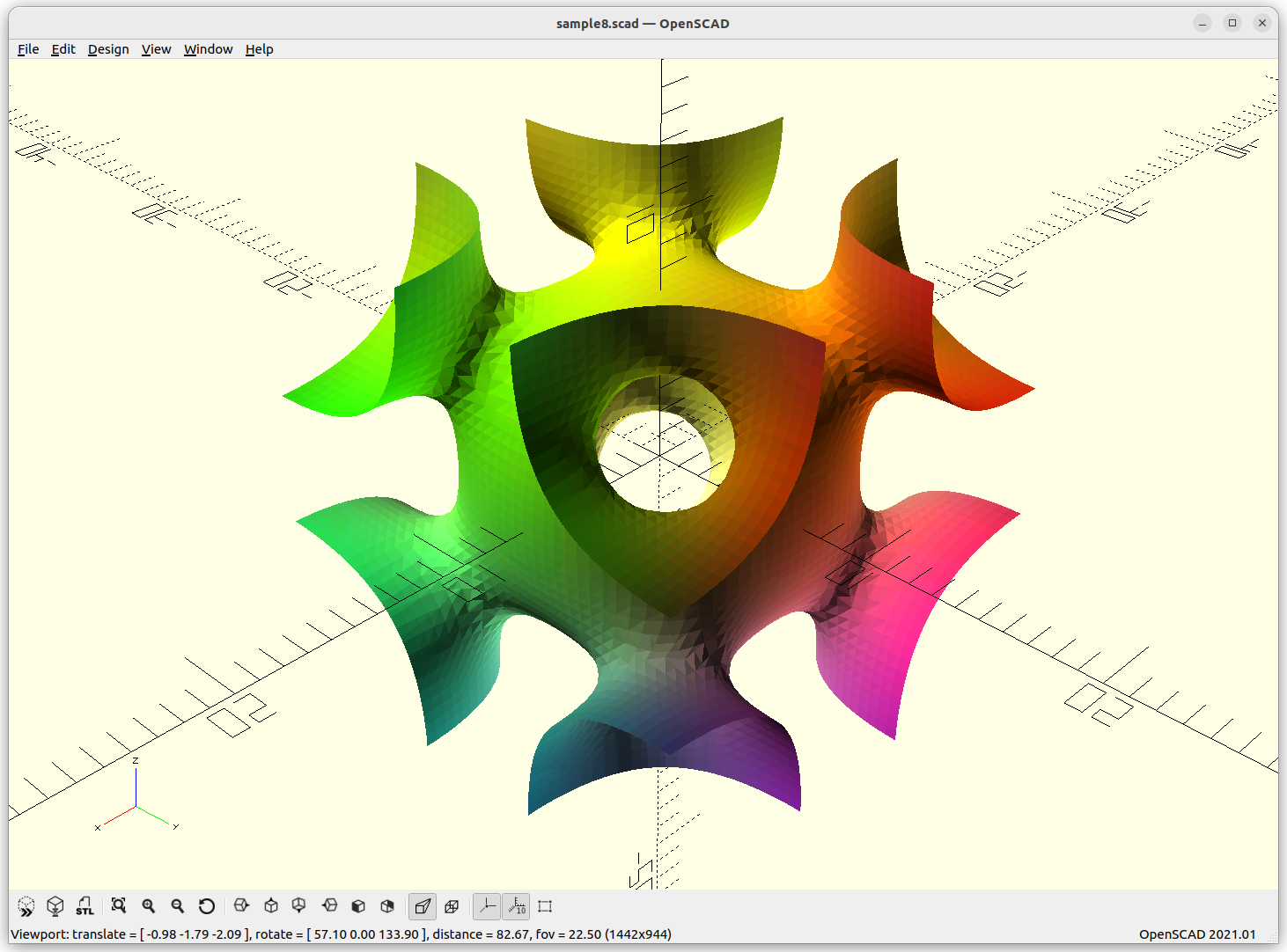
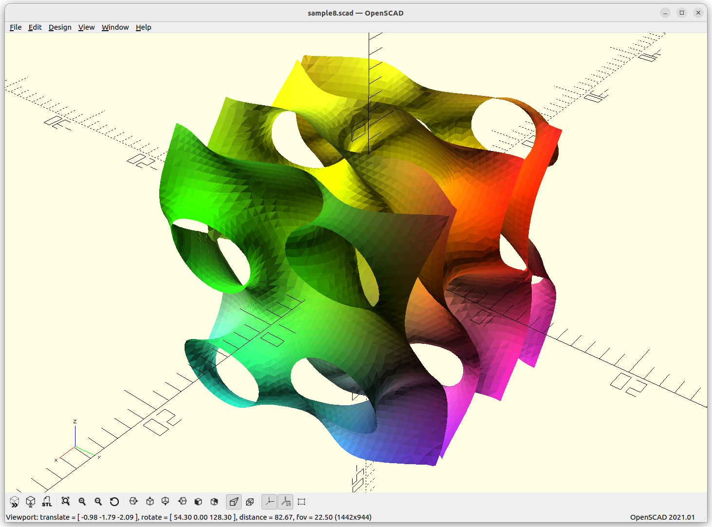
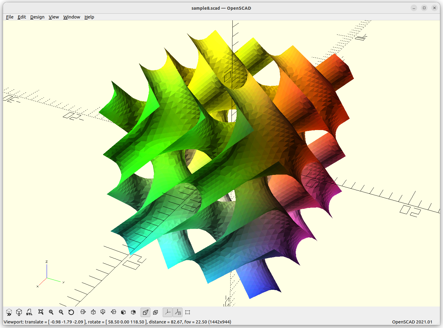
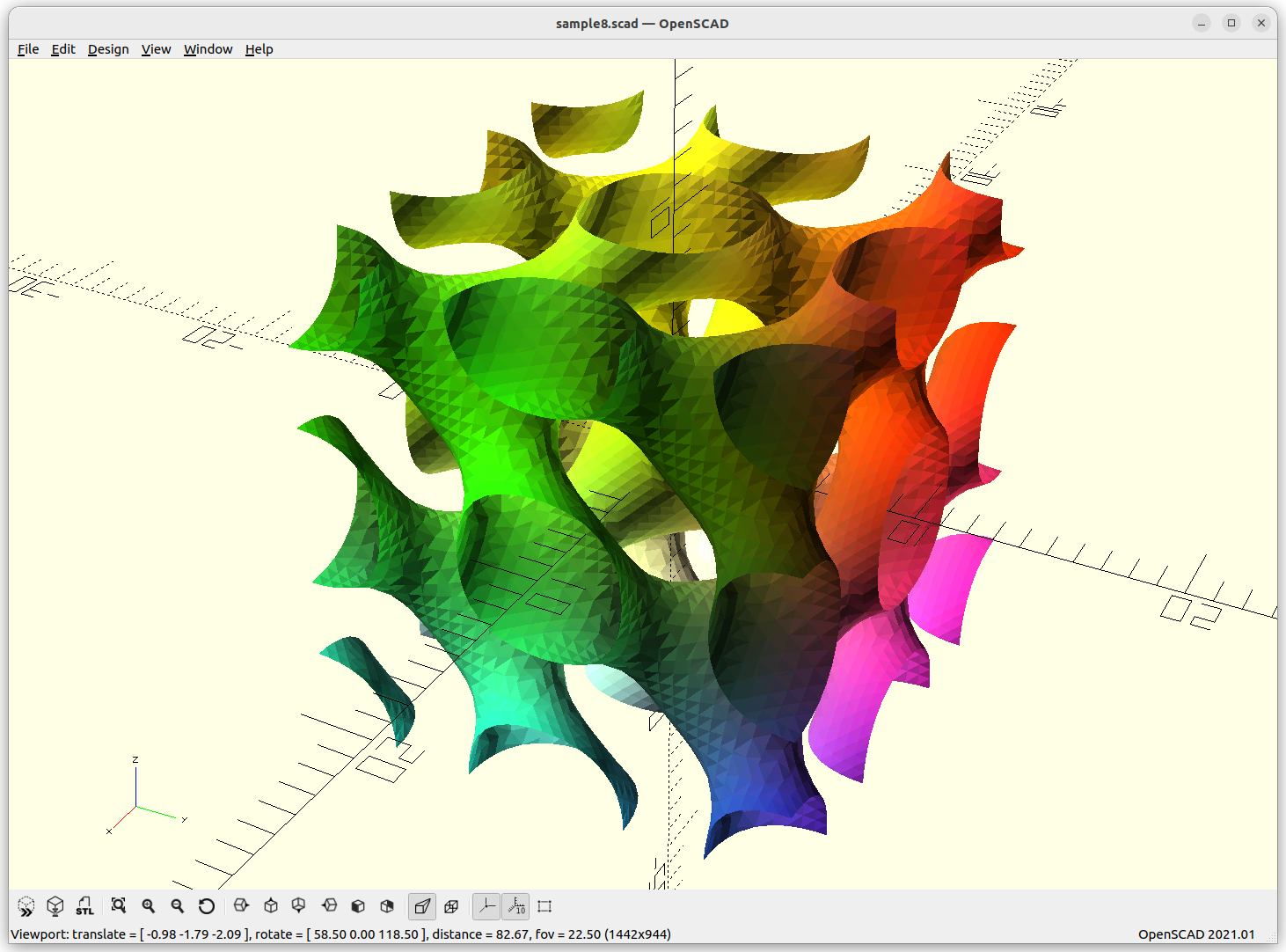
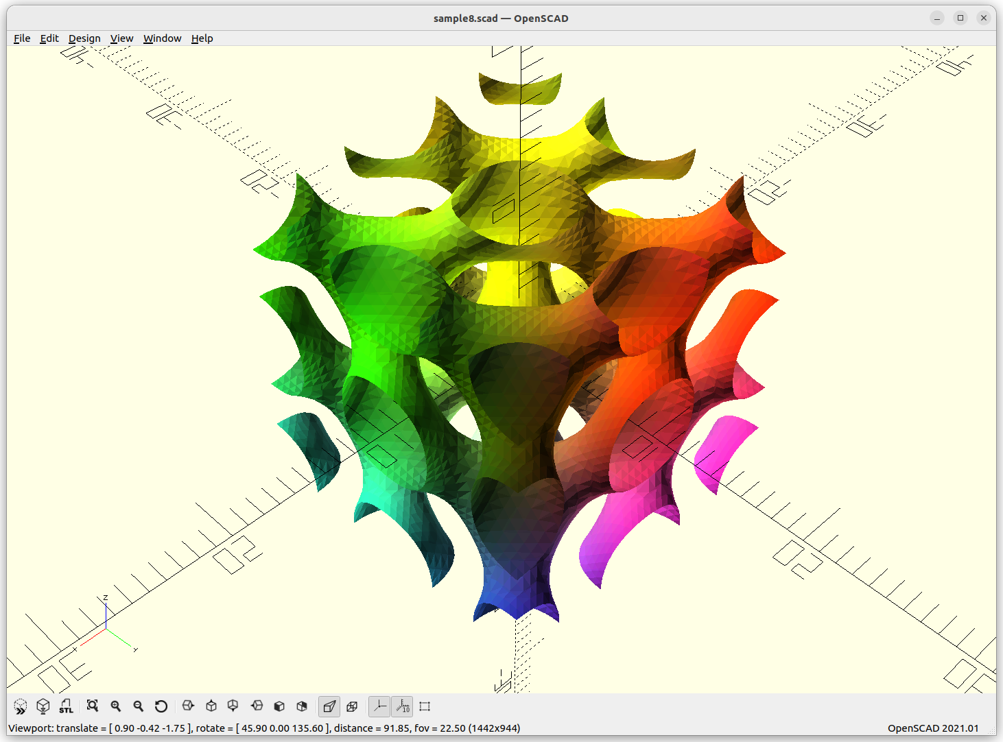
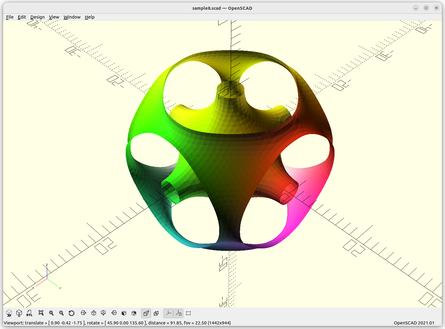
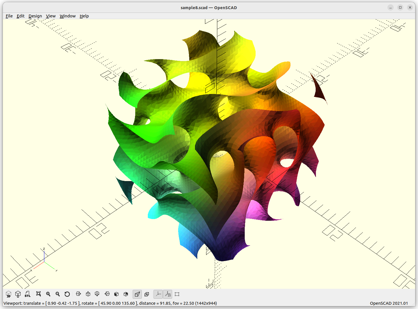
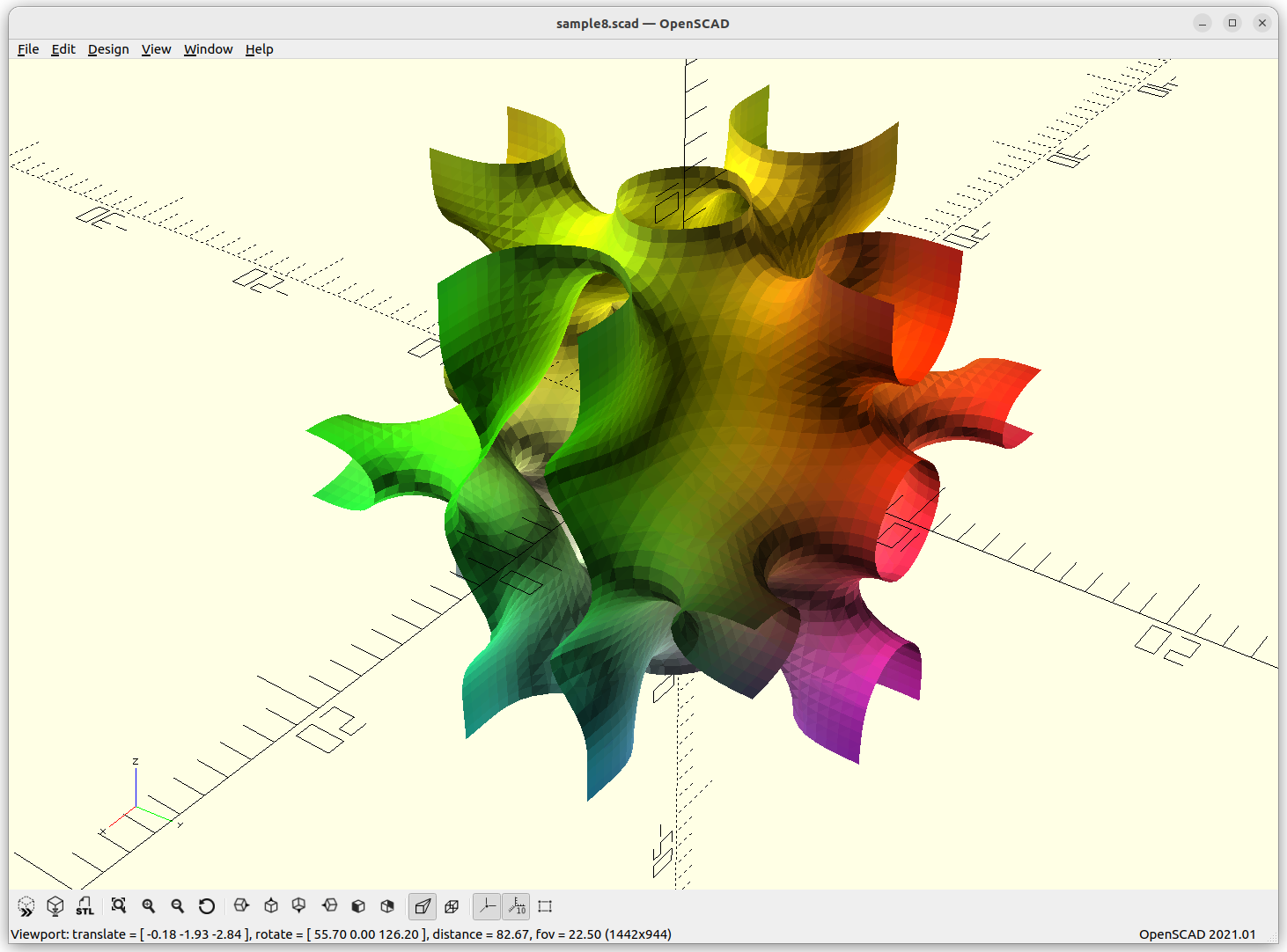
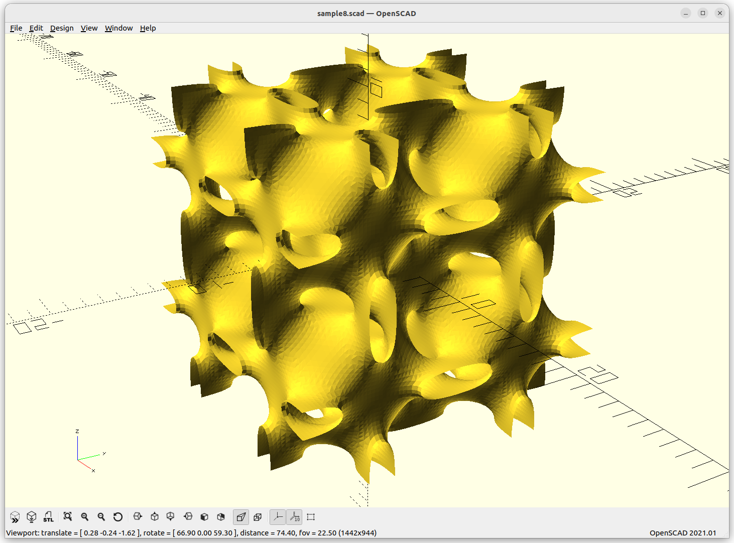
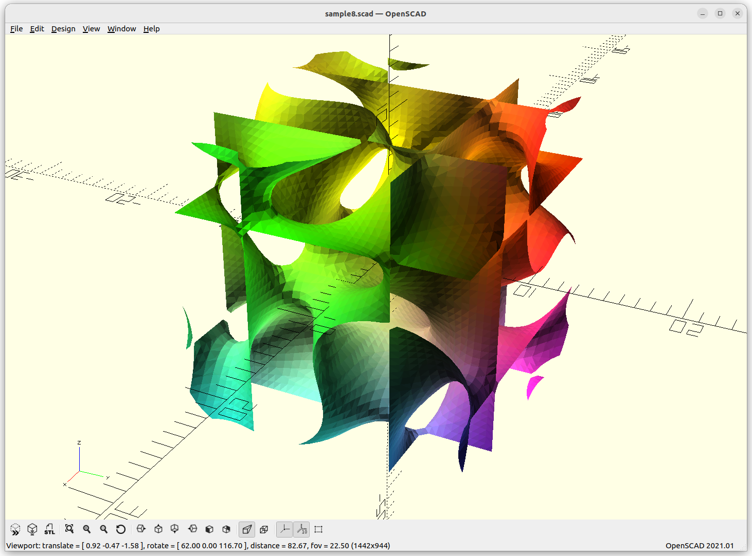
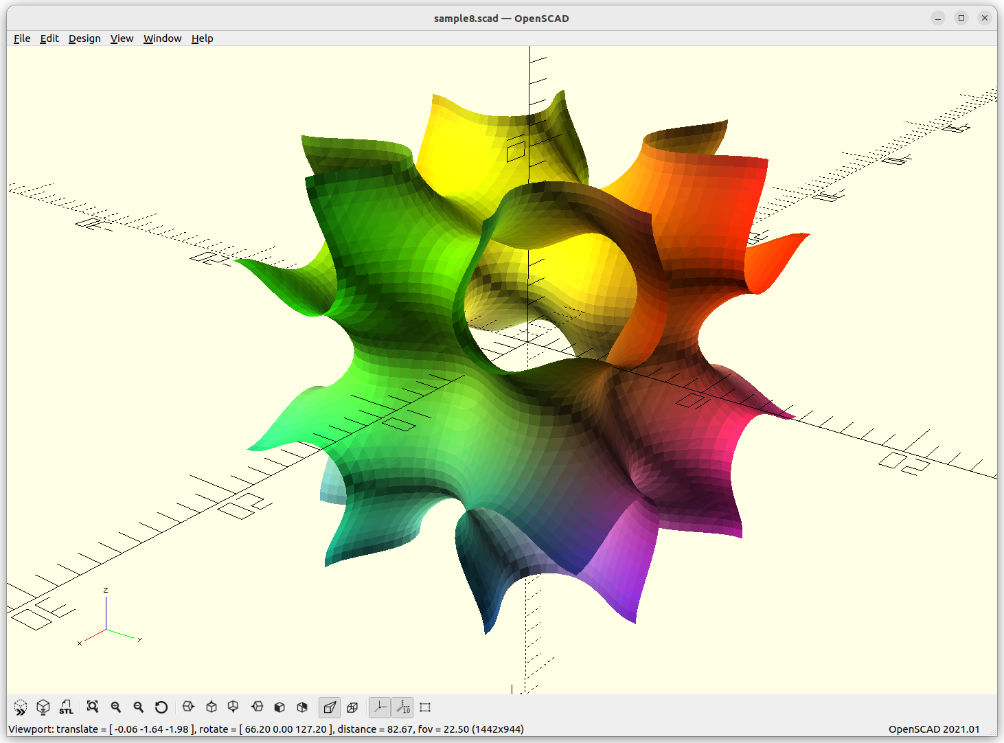
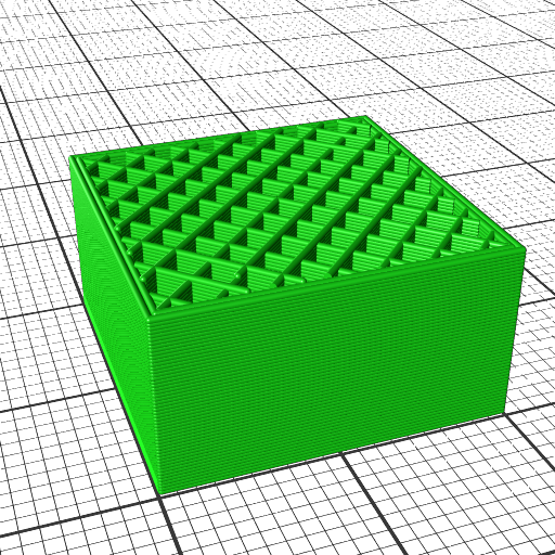
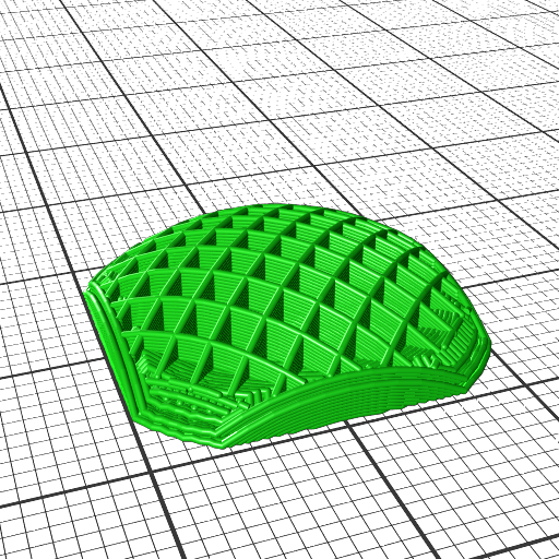
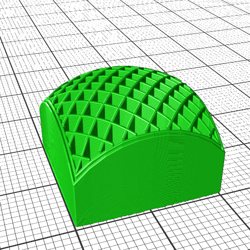
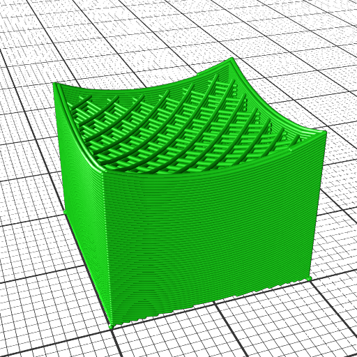
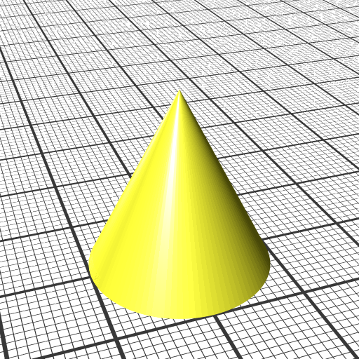
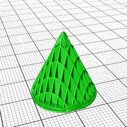
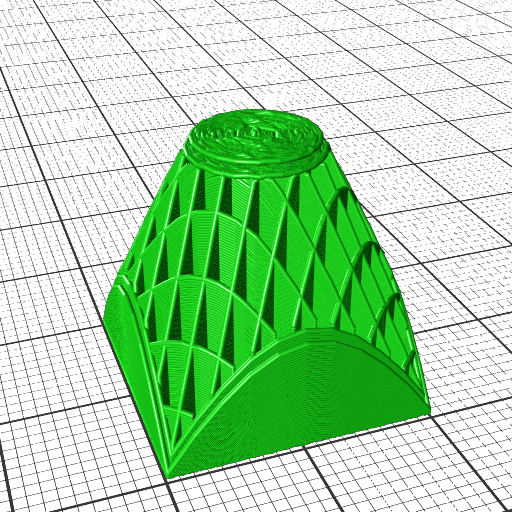
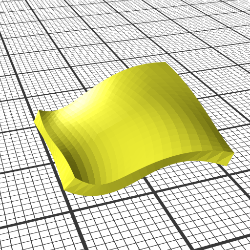
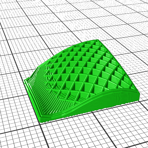
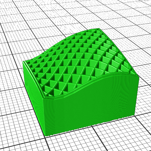
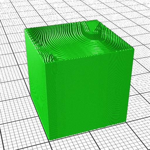
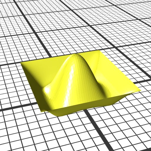
Spherene (Math)
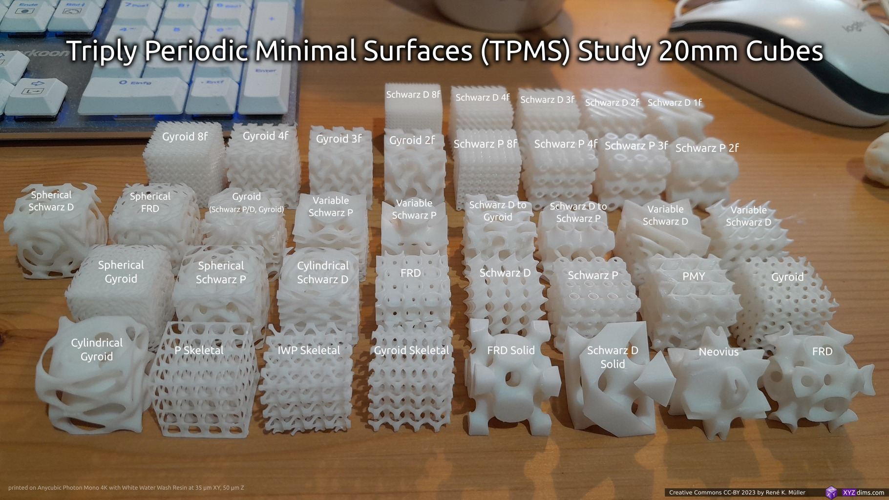
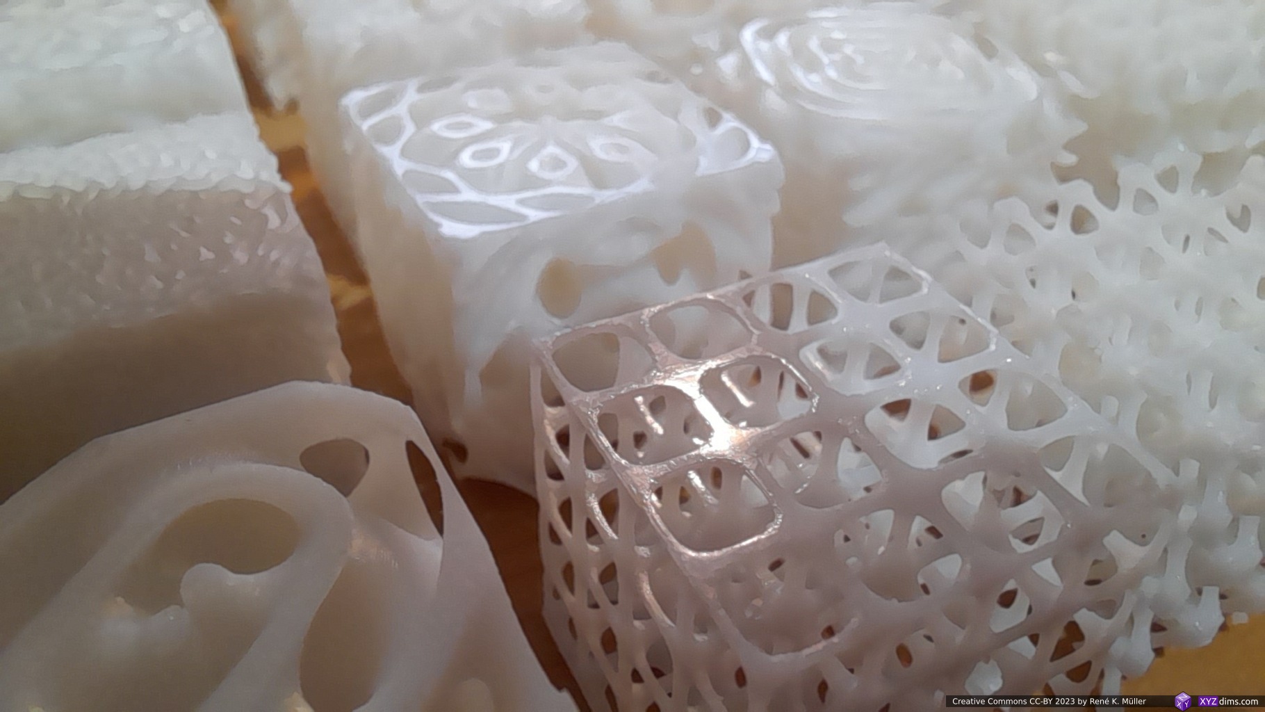
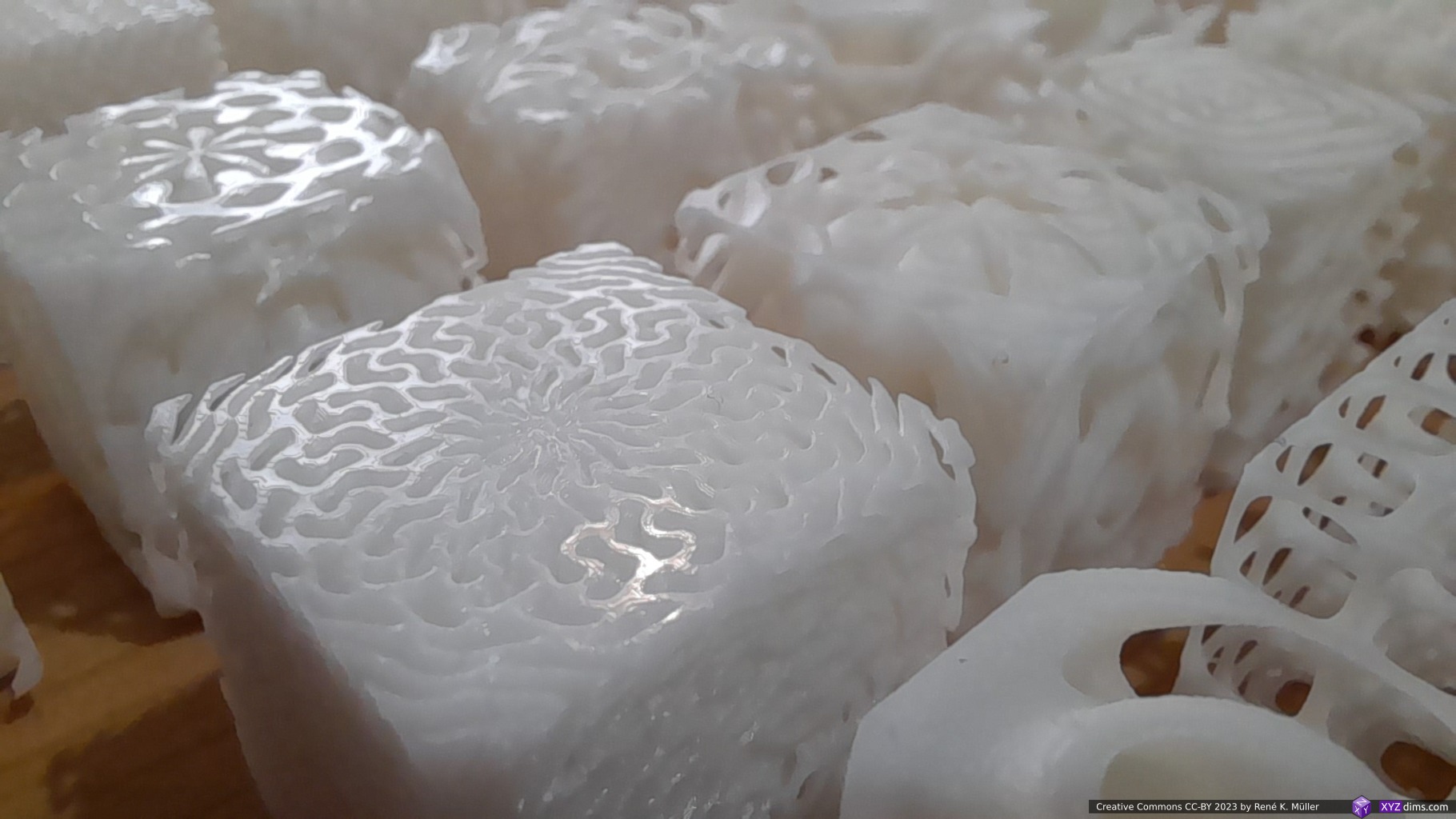
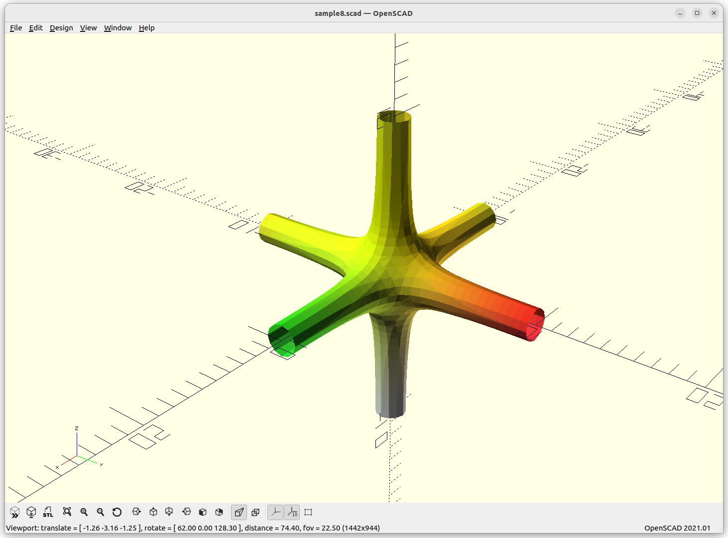
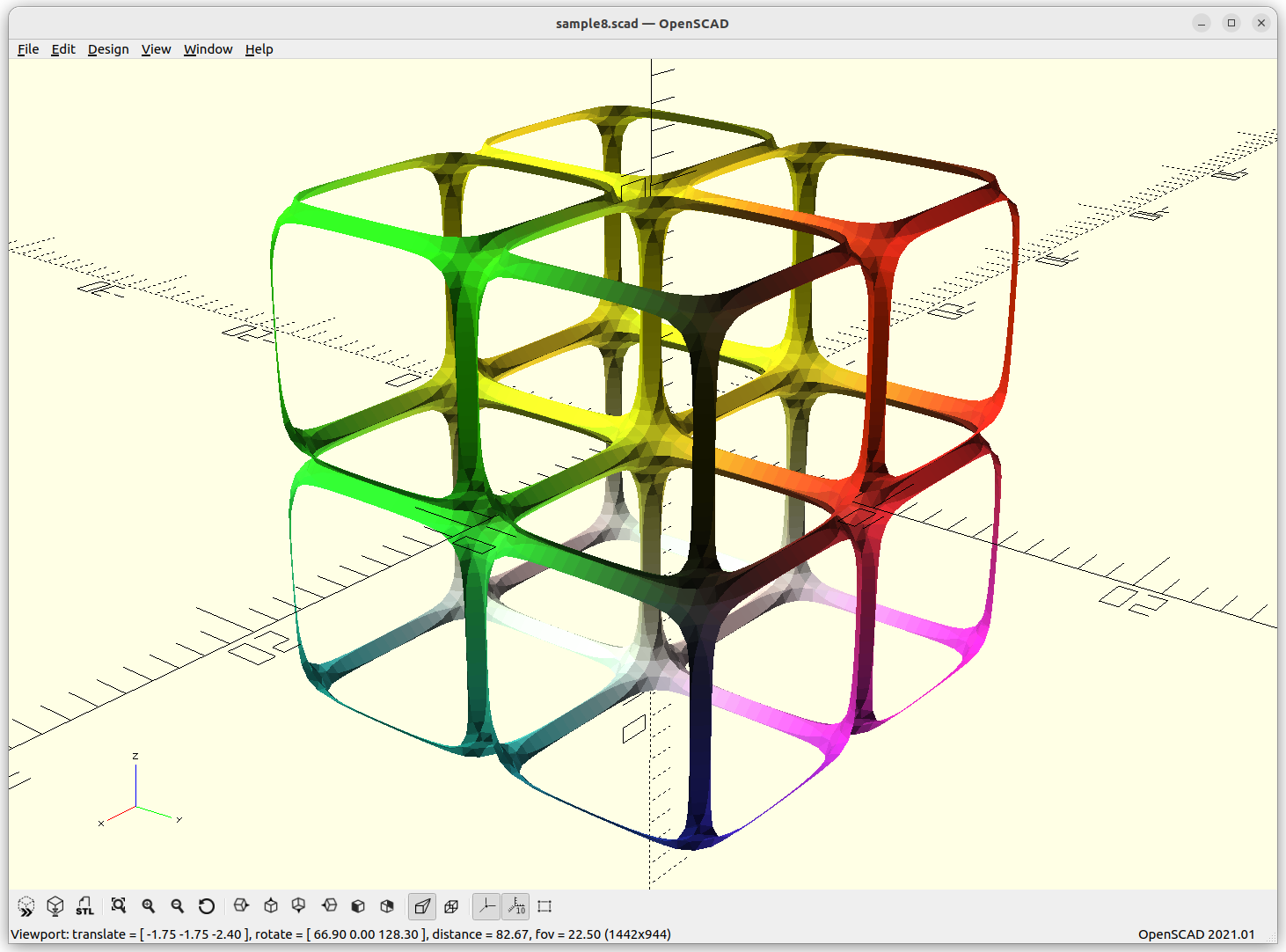
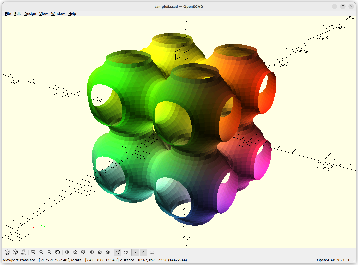
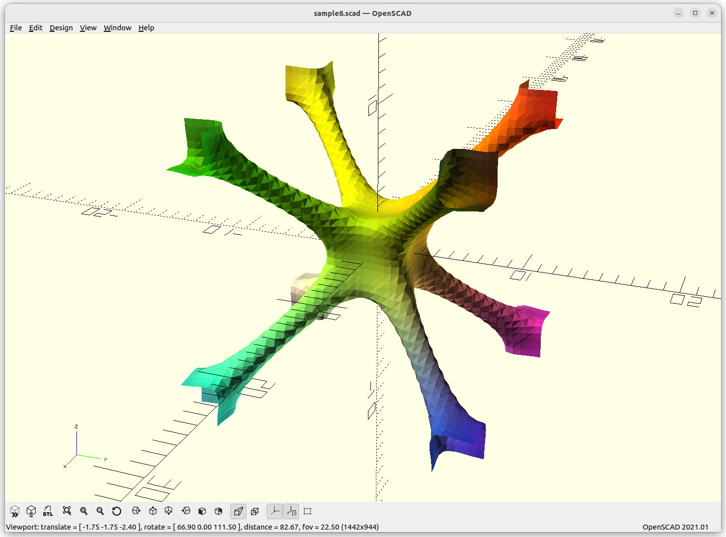
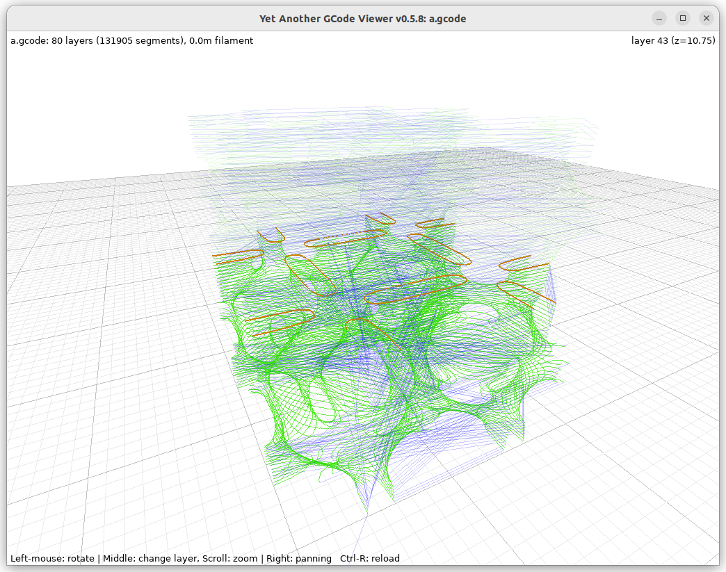
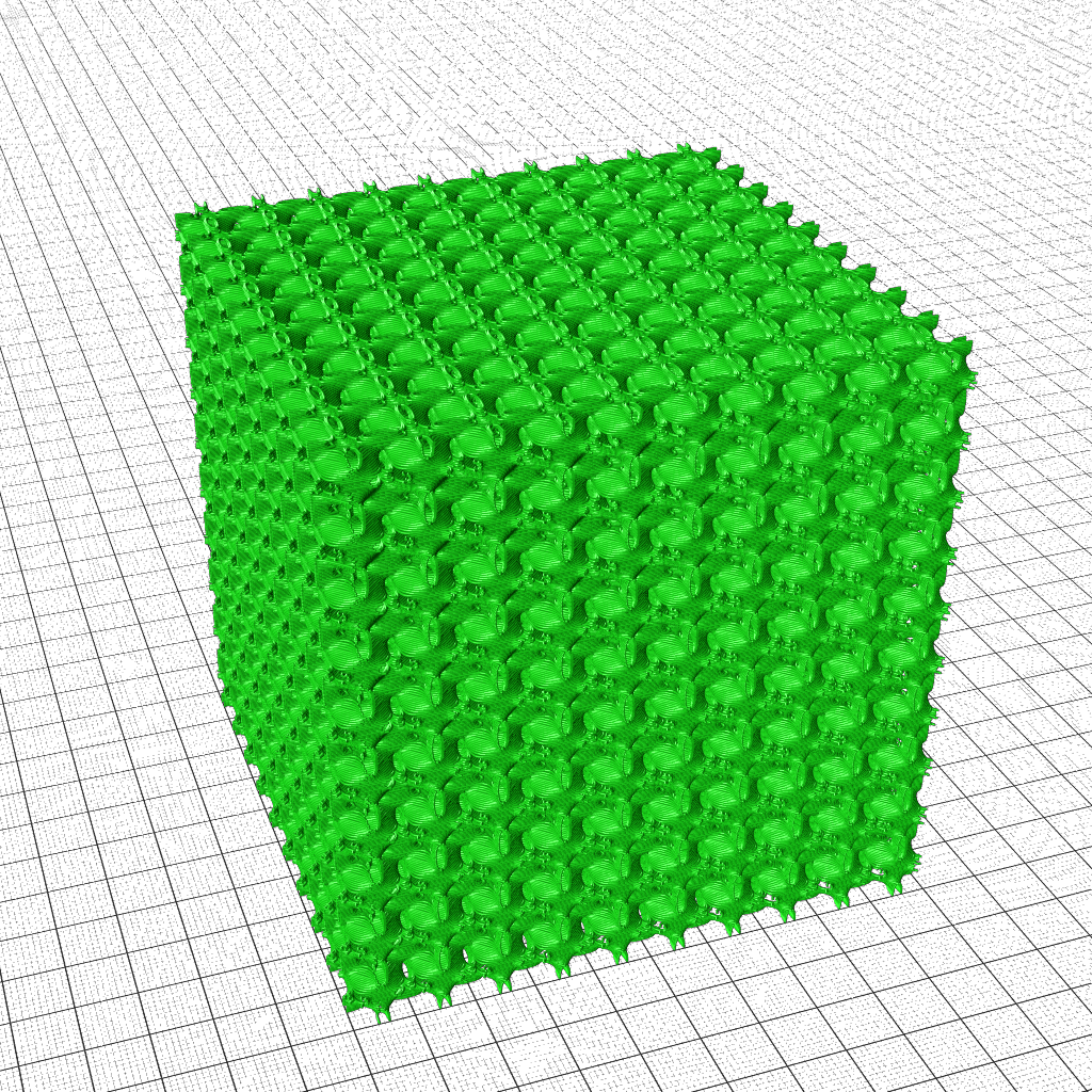
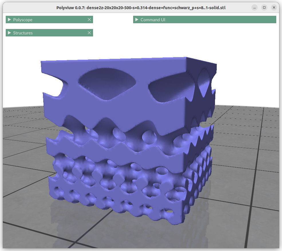
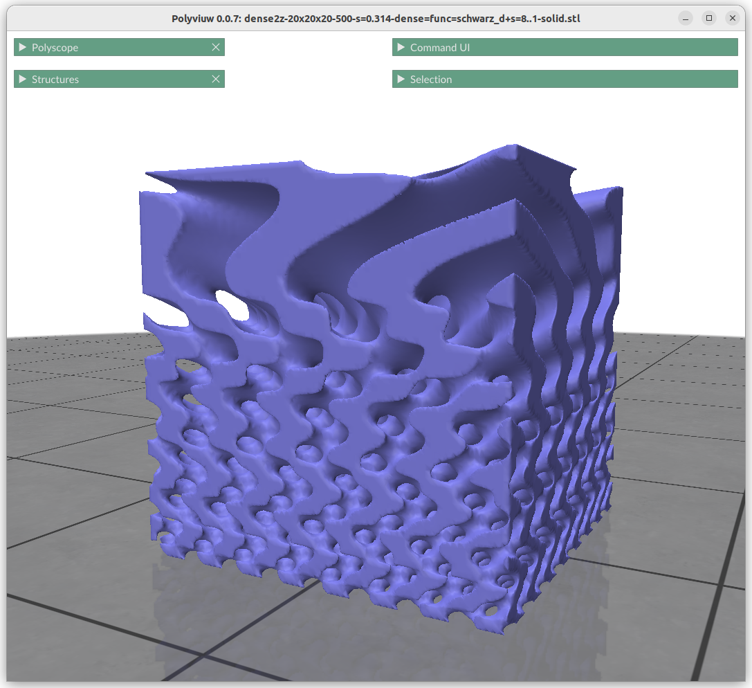
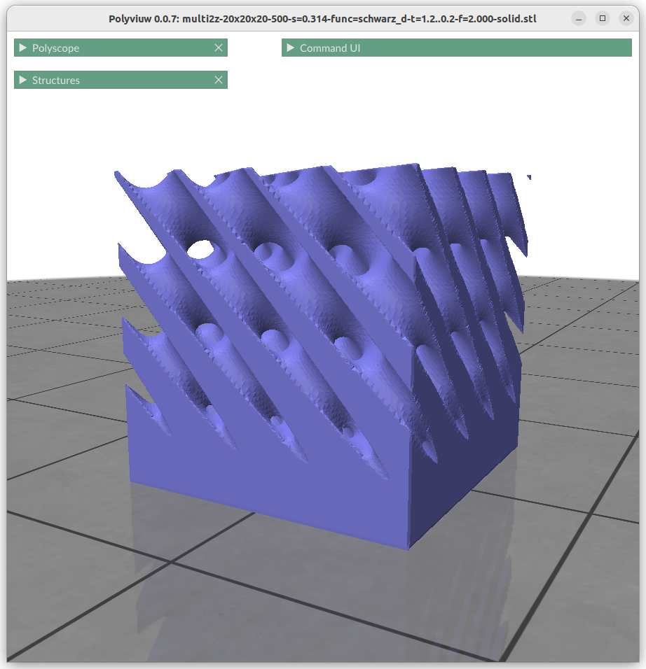
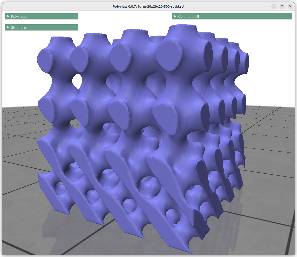
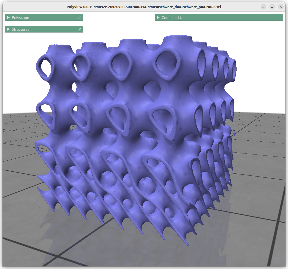
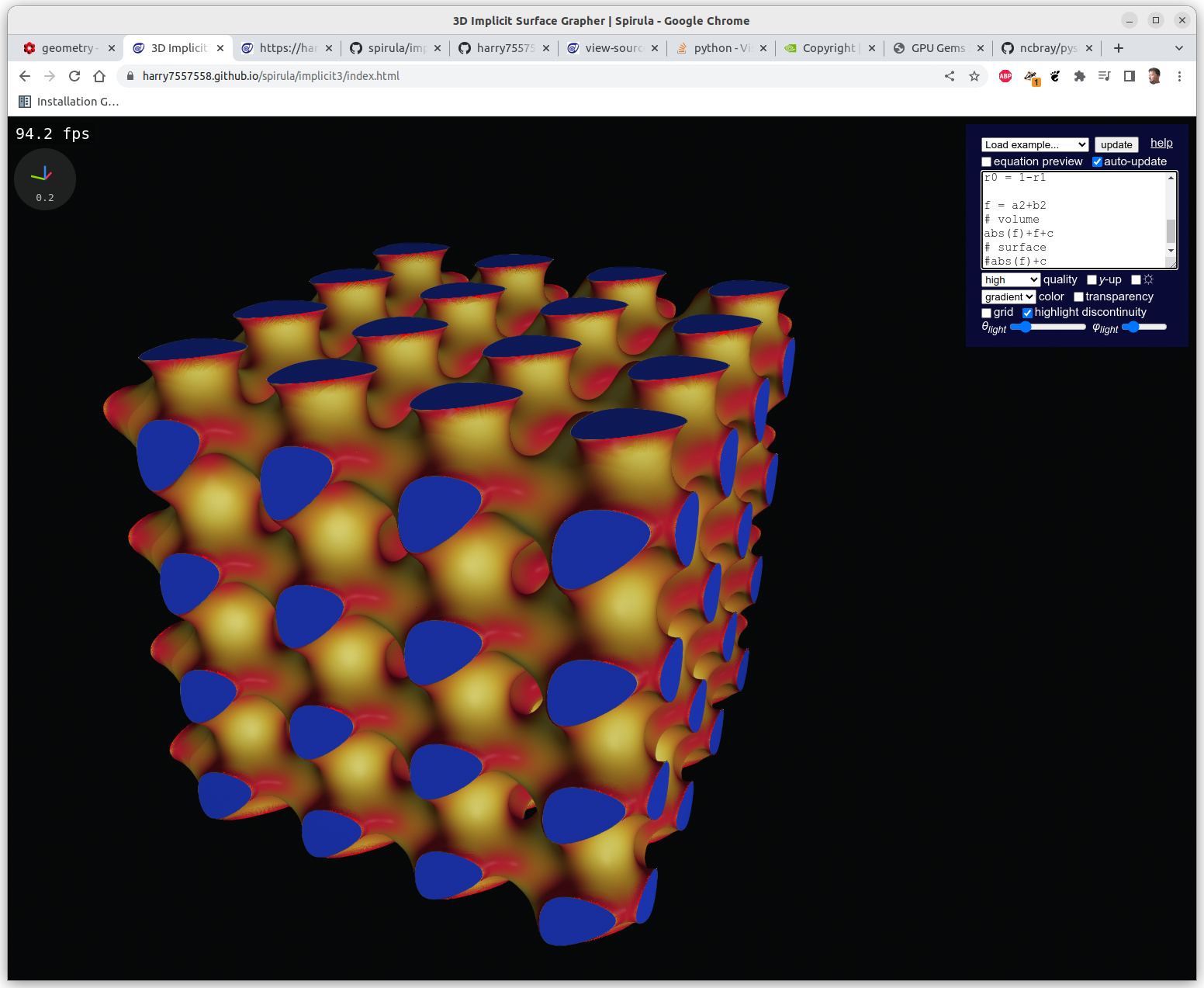
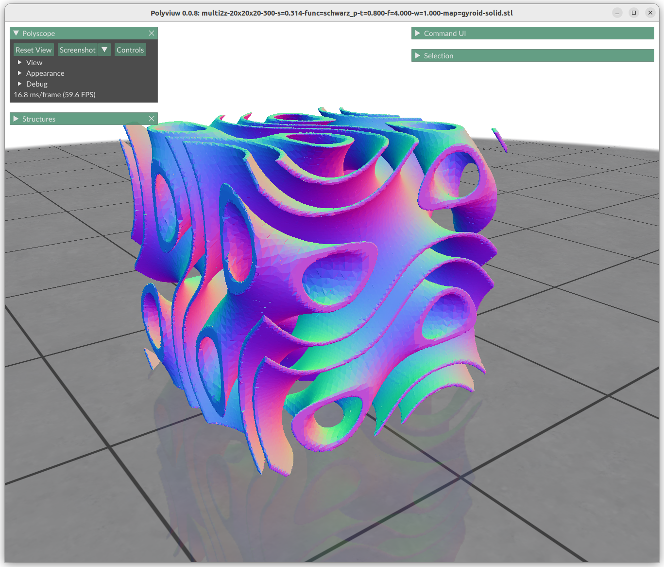
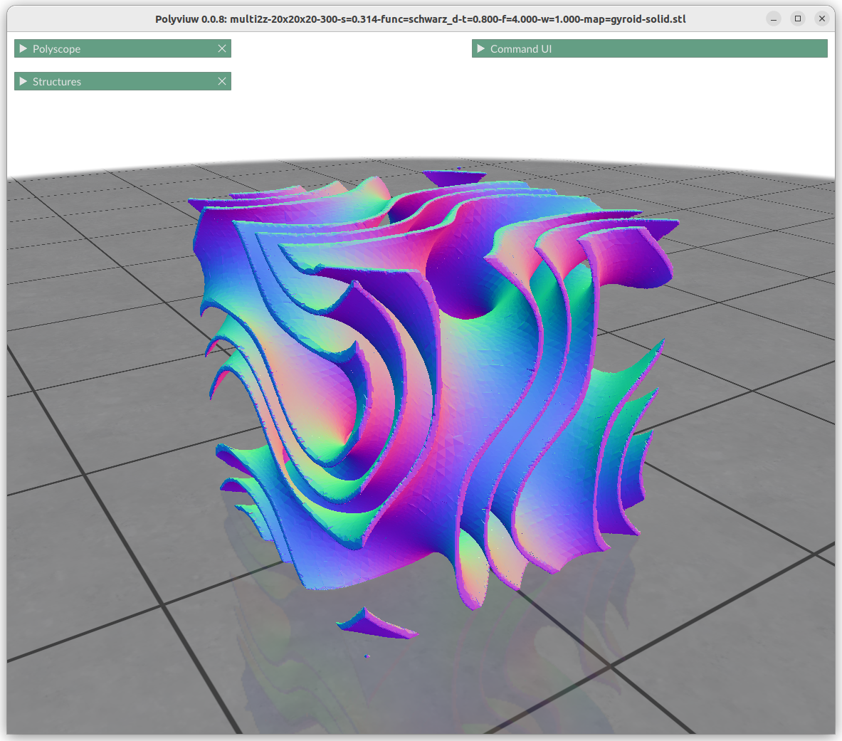
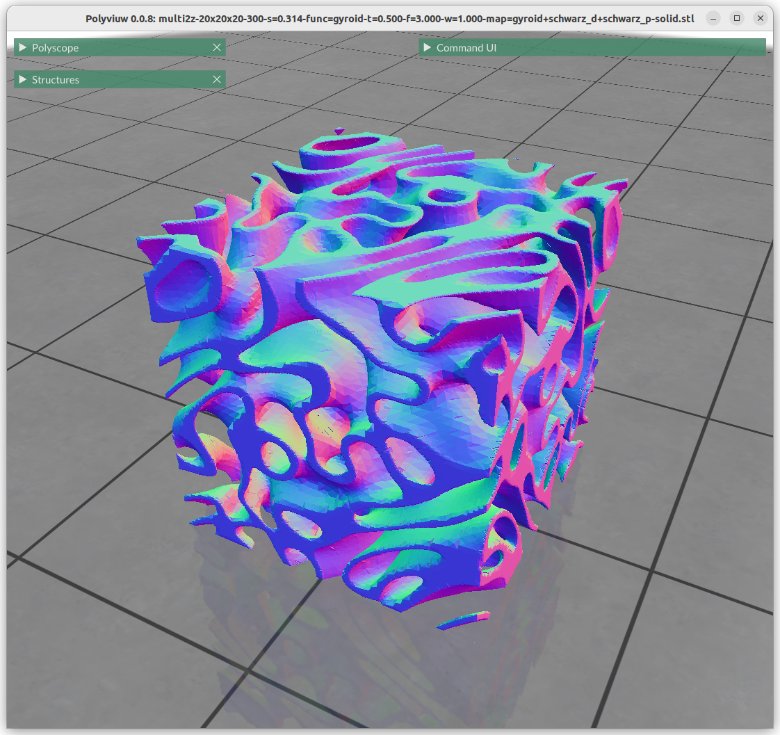
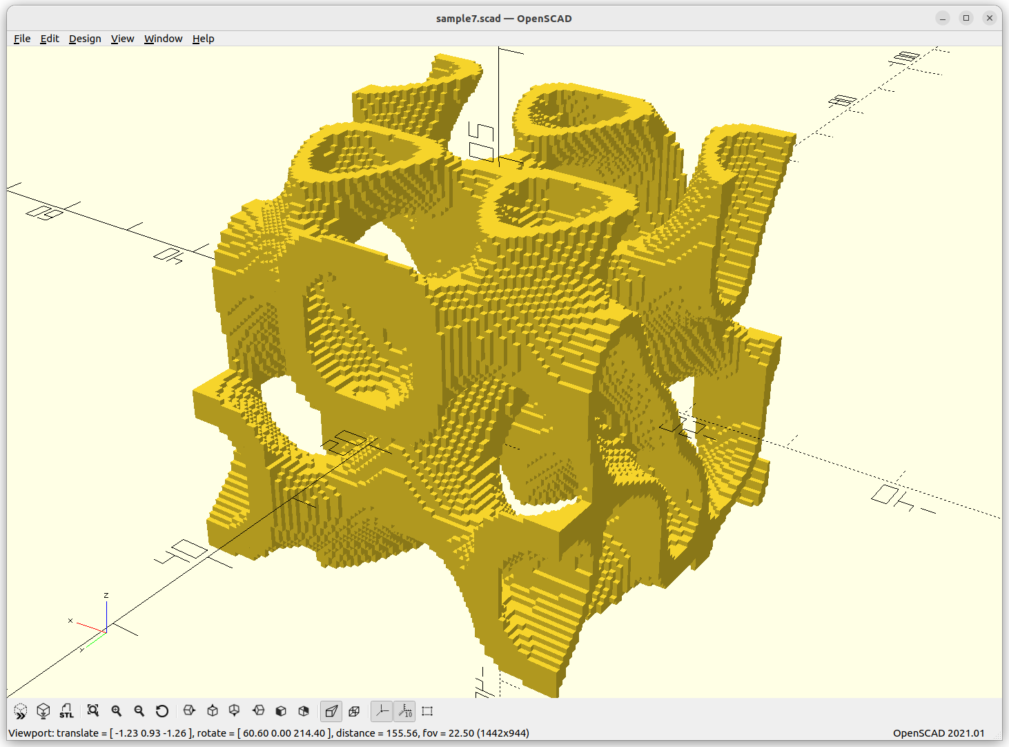
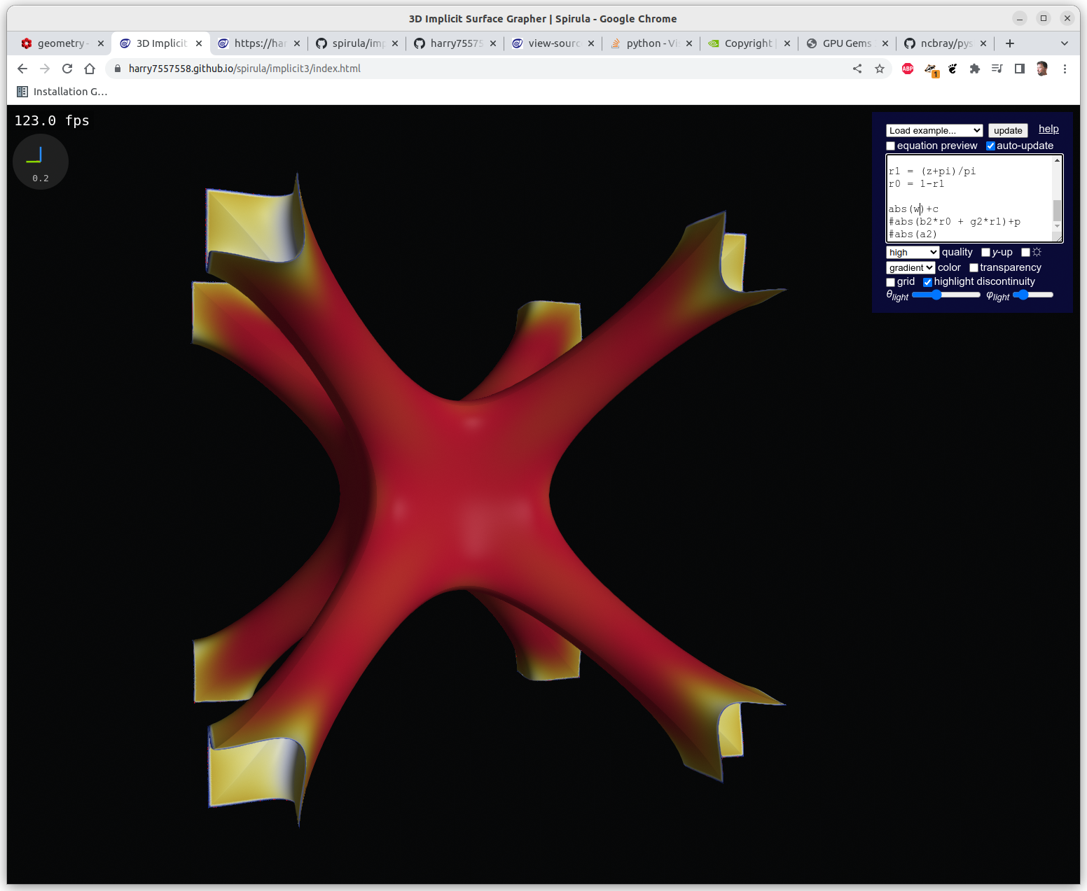
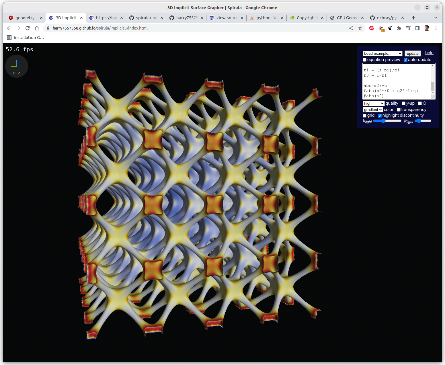
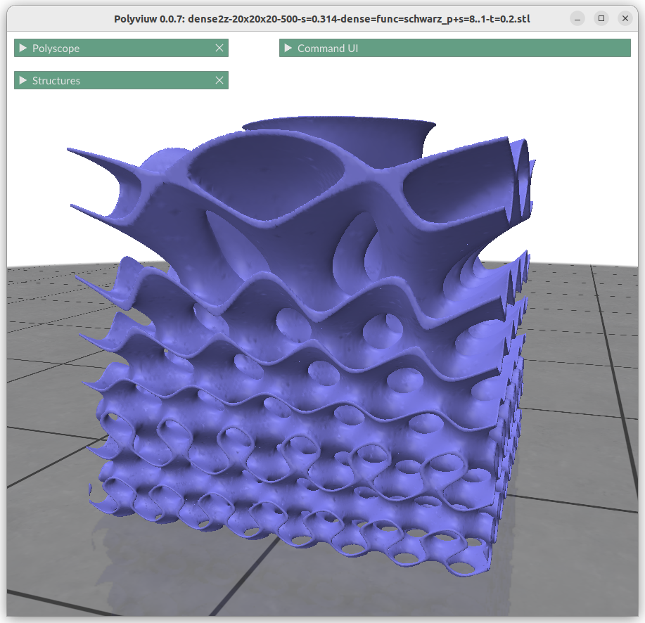
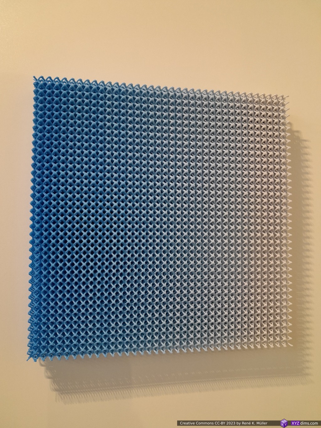
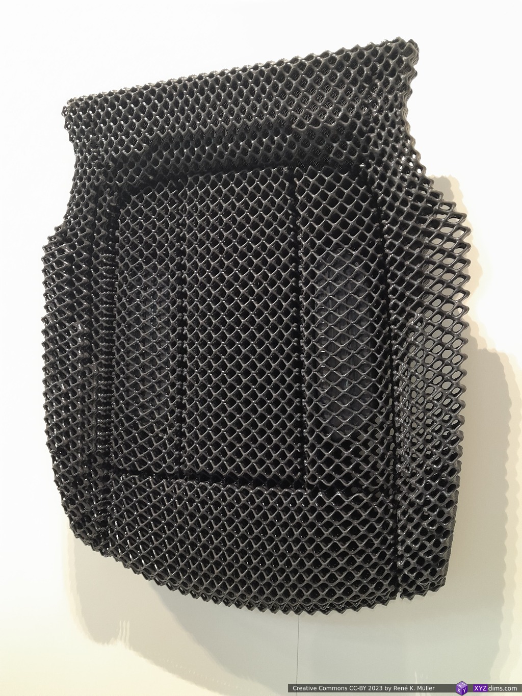
I made contact with Spherene before via LinkedIn but I realized I missed the point of what Spherene actually “invented”, at their booth Daniel Bachmann took the time to show me the features of their new class of minimal surface model and it was challenging for me to follow him despite of my own experience with Triply Periodic Minimal Surfaces (TPMS) – after apprx. 20 mins I realized the scope and some of their depth of their “invention”.
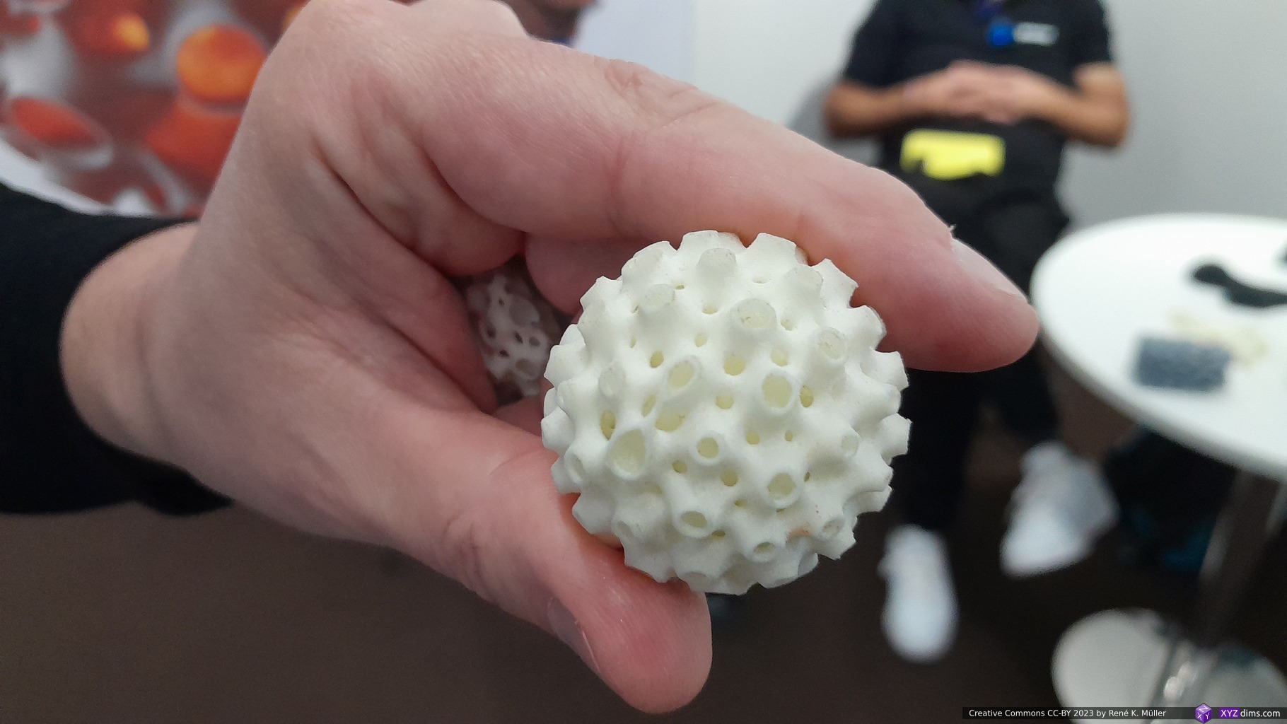
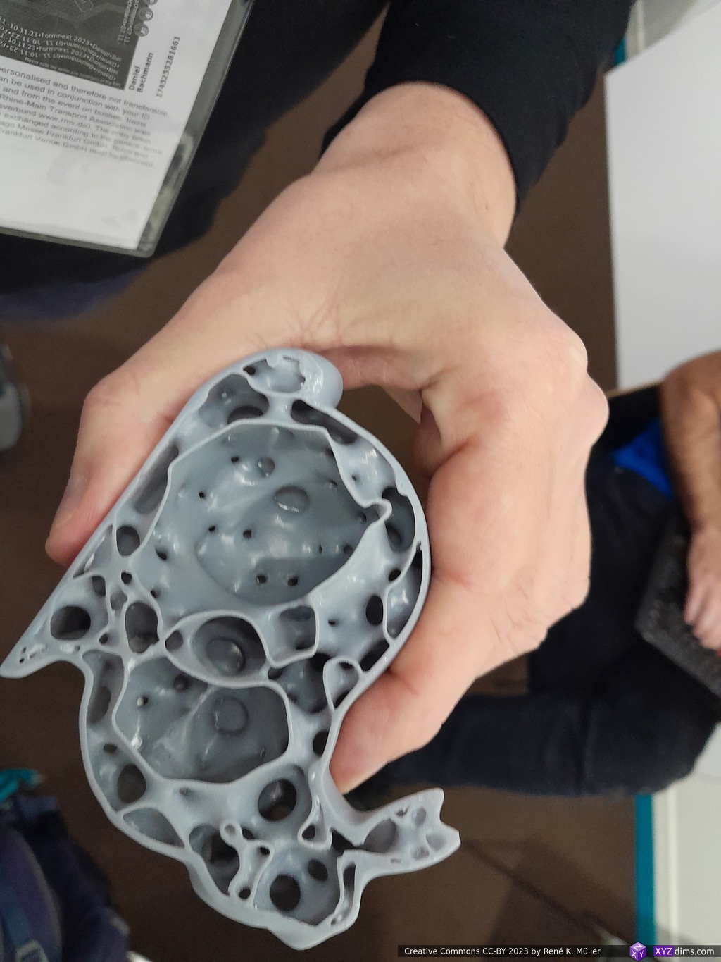
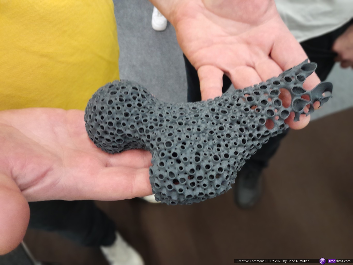
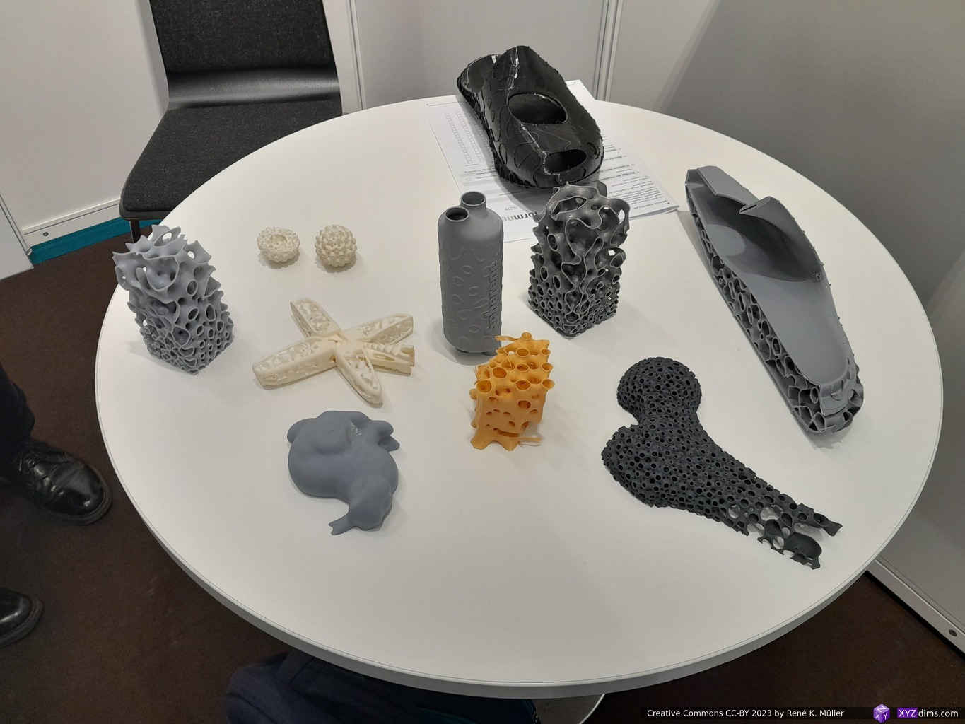
In essence, the sphere is used as a base form, and density, wall thickness and other features are processed in a localized manner, filling the space. The main result doing is optimizing a form to distribute inner/outer forces, e.g. the ends of the spheres are perpendicular to the surface providing ideal way to distribute them into a network of thin walled interconnected spheres providing isotropic (“all directions”) property.
The samples on display were printed with MSLA, SLA, FFF/FDM or SLM were indeed very strong in relation to the printed volume, e.g. the hallow rabbit printed with resin barely gave in when pushing on the thin outer perimeter – impressive.
Their approach is available as cloud-based GUI or as Grasshopper/Rhino plugin. The actual details of their procedure isn’t easily found but a patent (WO2020229692A1) by CEO Christian Waldvogel gives some idea.
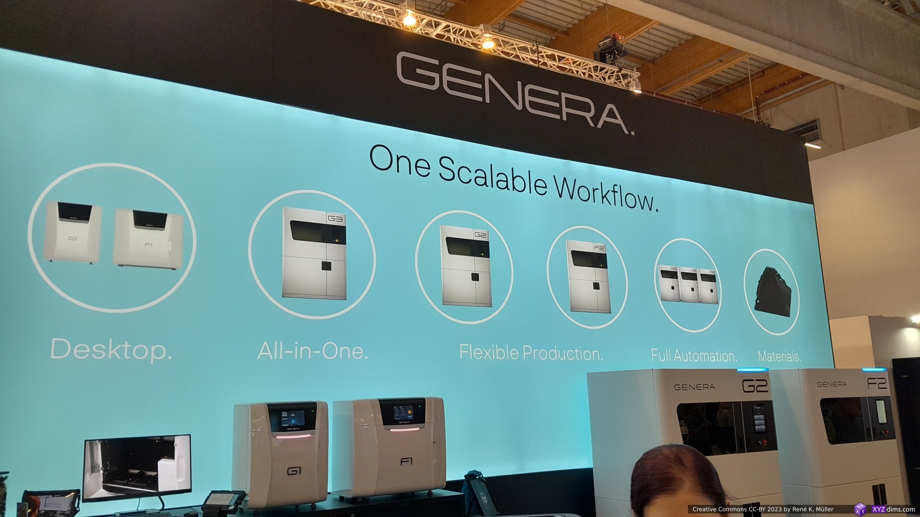
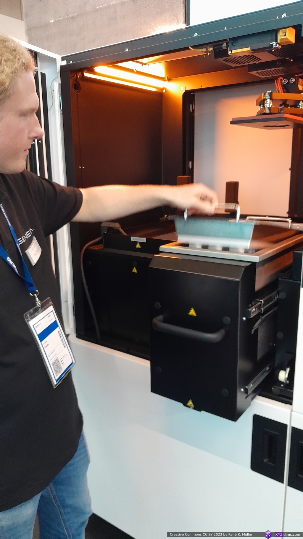
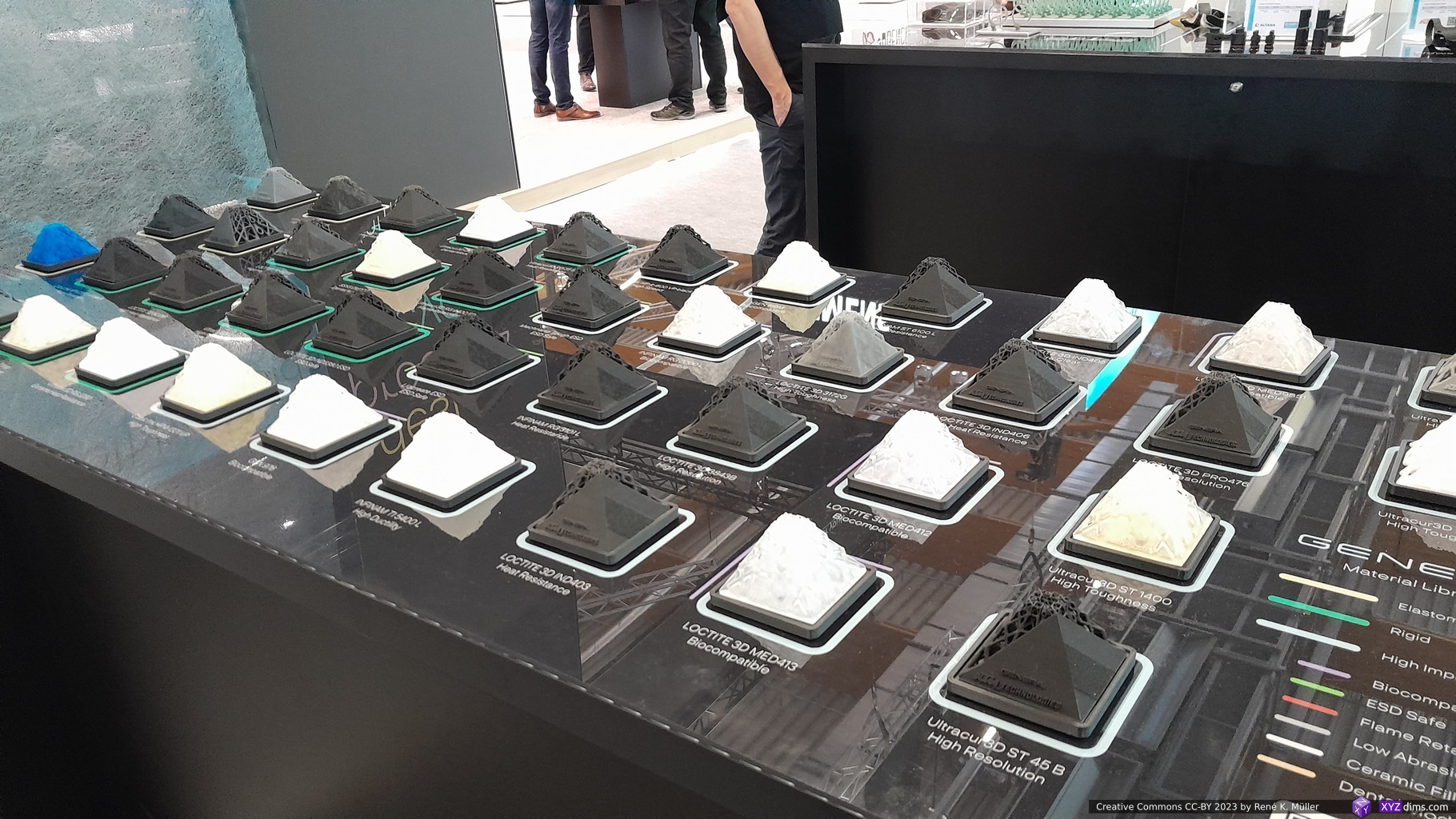
Genera (DLP Resin)
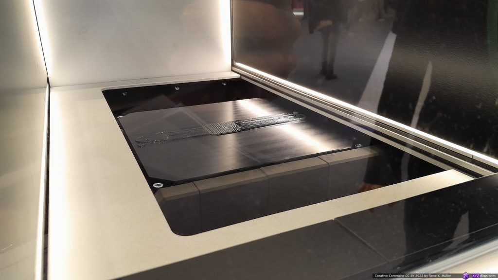
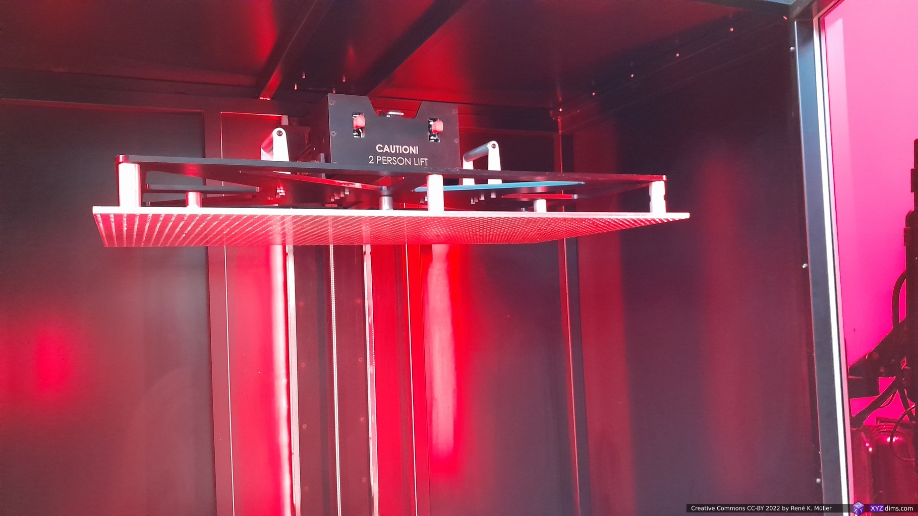
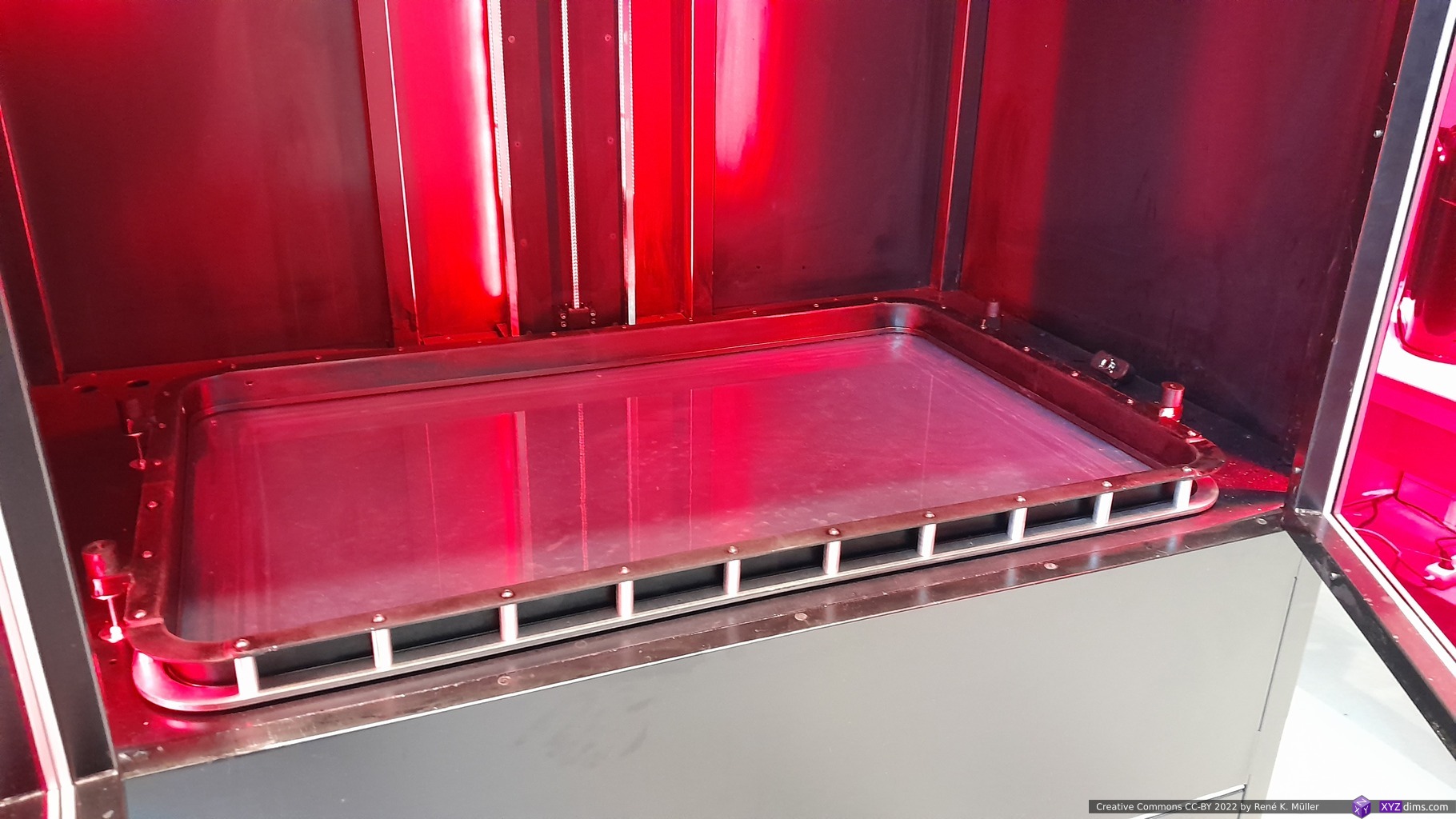
There are many MSLA/SLA/DLP printer manufacturers, yet, I wasn’t aware of Genera and I was shown their system, an integrated workflow:
- all resin vats have a lid (only applies for G1/F1 combo but not their bigger machines), which are opened only within the machine
- the finished prints (still on the plate) are moved in a box into the washing machine (without any person touching resin or the resin coated prints)
- once automatically cleaned and post-cured, the prints are removed from the build plate manually
In essence one does not interact with resin directly, it’s all contained within the workflow – which I like a lot. They also provide wide selection of resins: hard, soft, rubbery, opaque, transparent/clear.
My idea has been to adapt some of their approach to make my own resin printing with Photon series (4K, X2 and X 6Ks); right now I also have multiple vats, and flex-plate, but moving the printed parts and washing them are still messy.
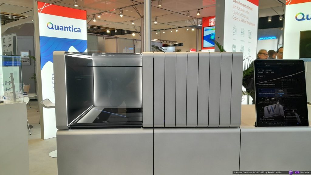
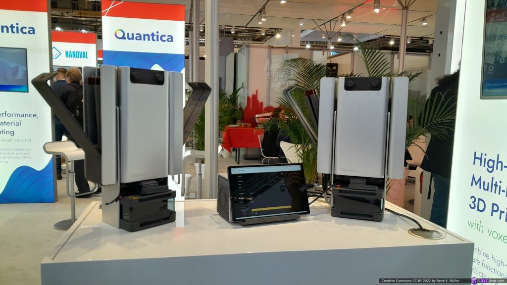
Quantica (Resin Jetting)
Last year I already visited the booth of Quantica, and so this year again. I asked earlier for printed samples, but they declined, and again this time . . . it is bizarre to see a machine actually able to print, and they don’t hand out samples, but I was told by January 2024 I might get some. This tells me a few things, the printed pieces are very sparse or not yet at the quality they want others to experience – some samples were on display, but sealed behind a glass box unable to have in my hand. So I guess now, they are expecting or already have better and more reliable printing results where the printed pieces match other similar printing processes.
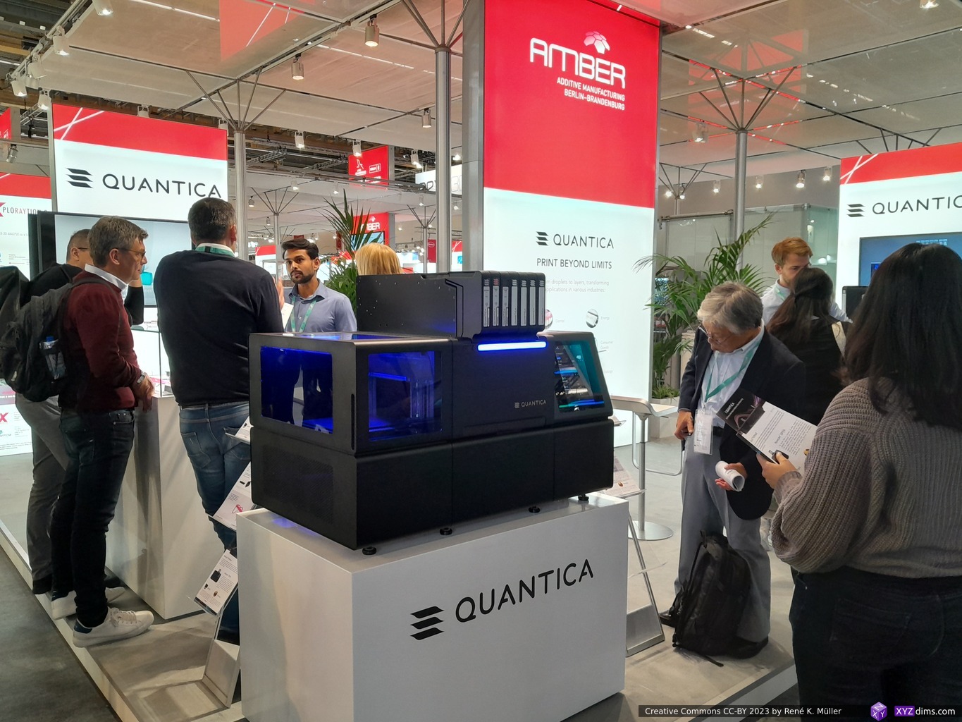
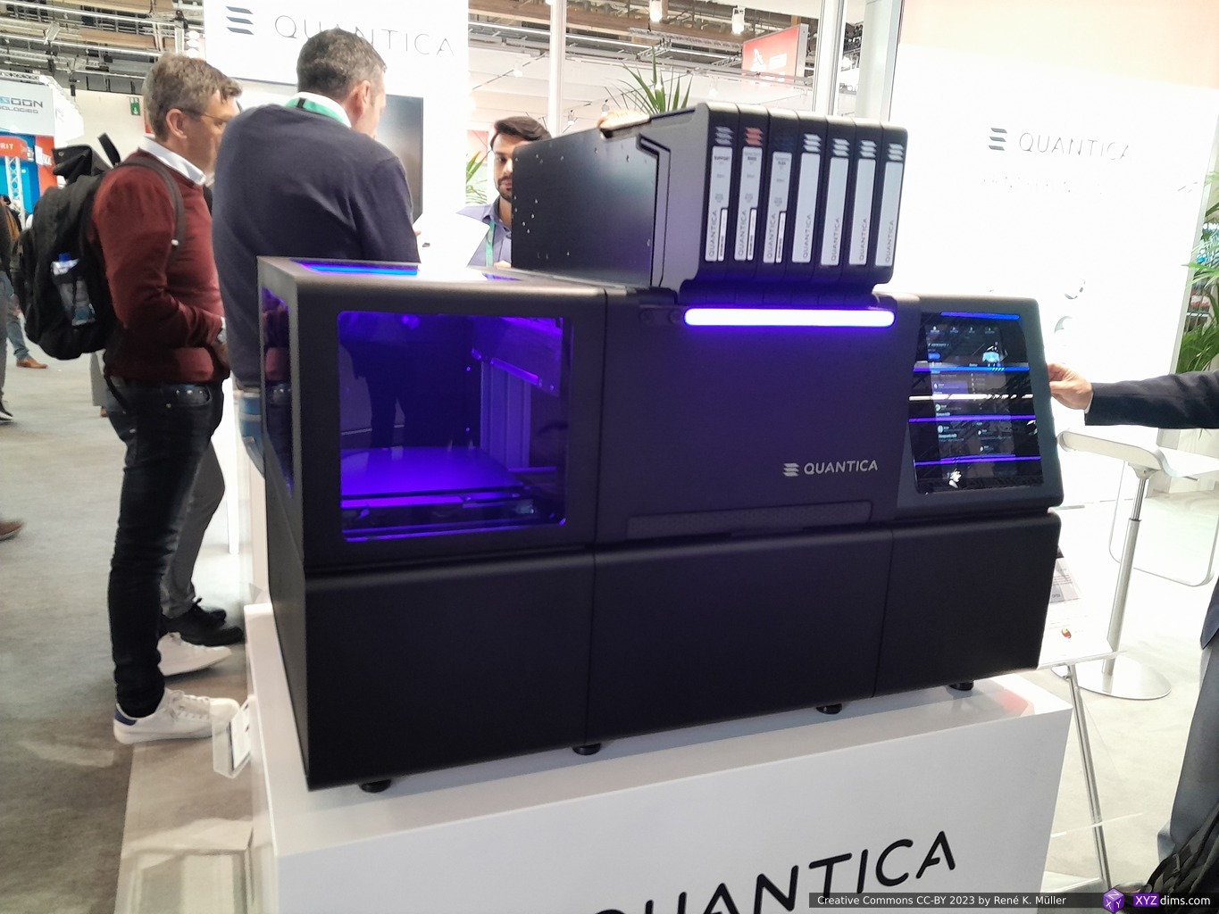
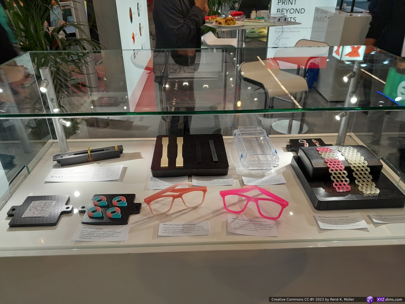
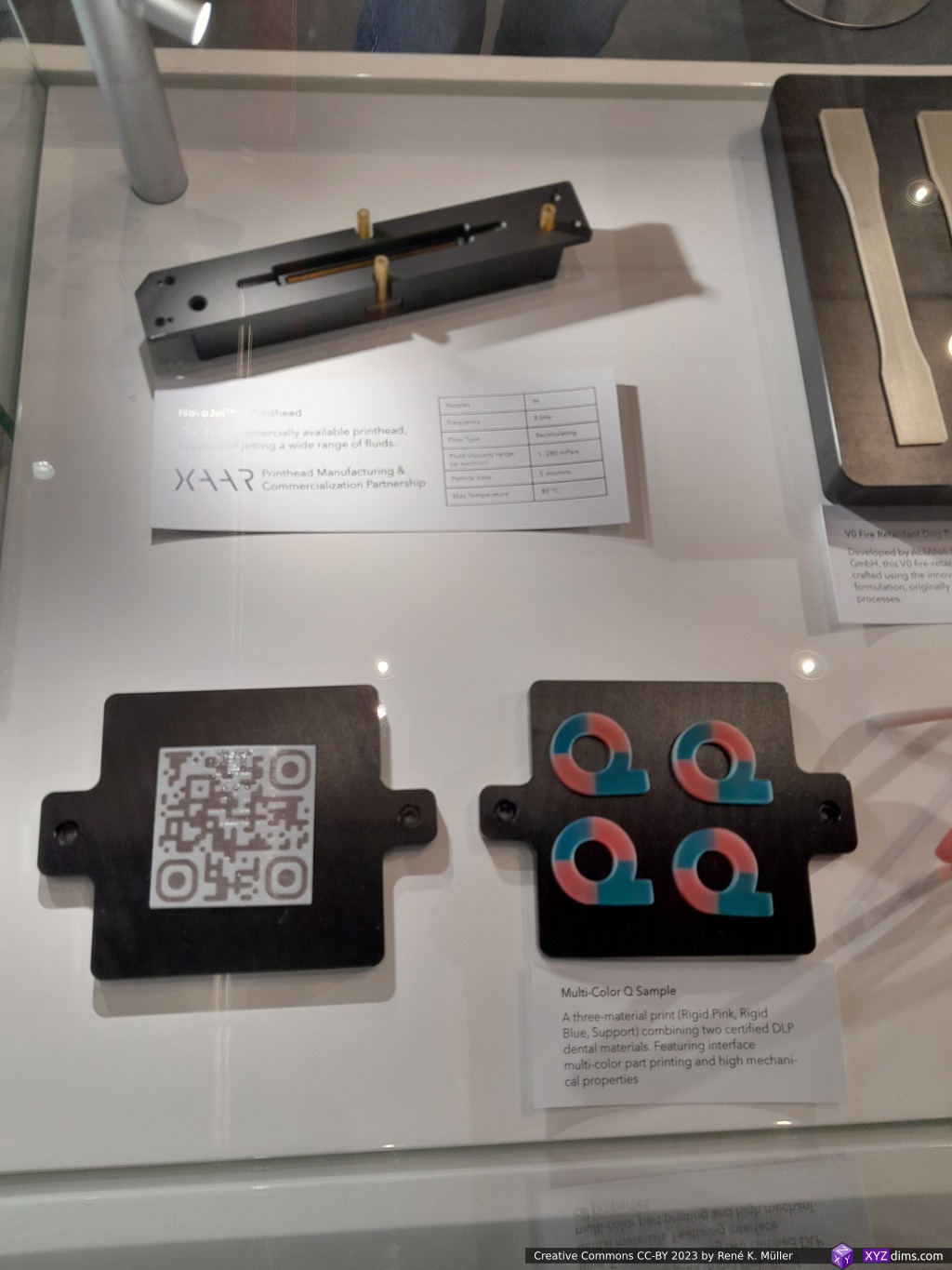
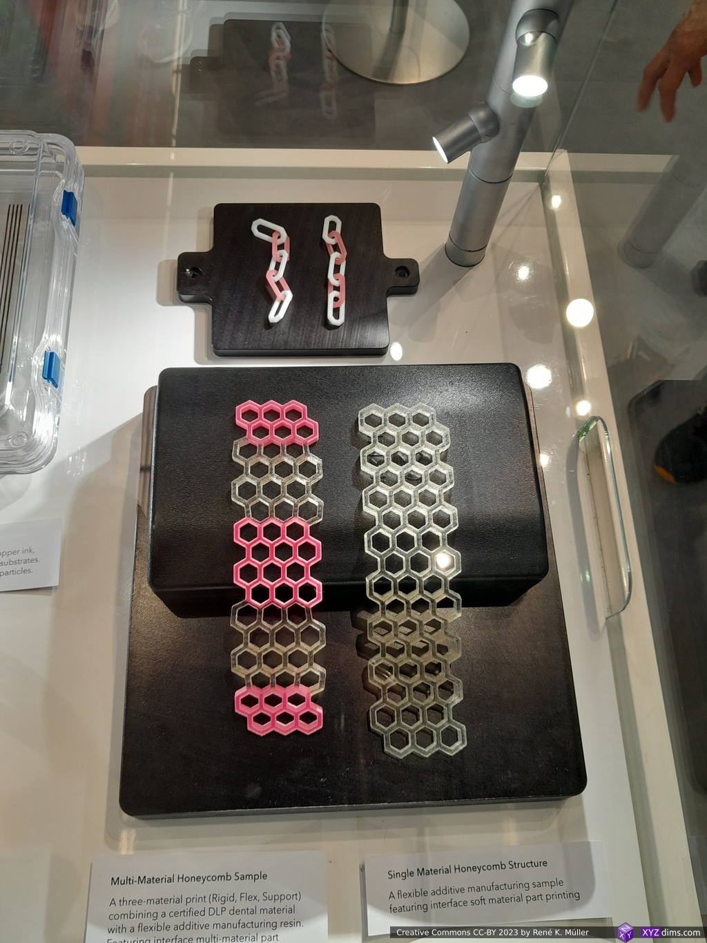
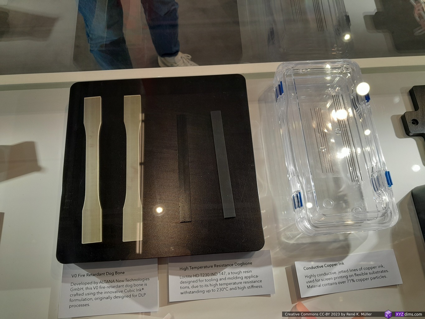
I follow their development closely since ~2 years as I consider it very innovative to print with 7 different resin-based materials at the same time and able to fine-tune material properties on the voxel-level.
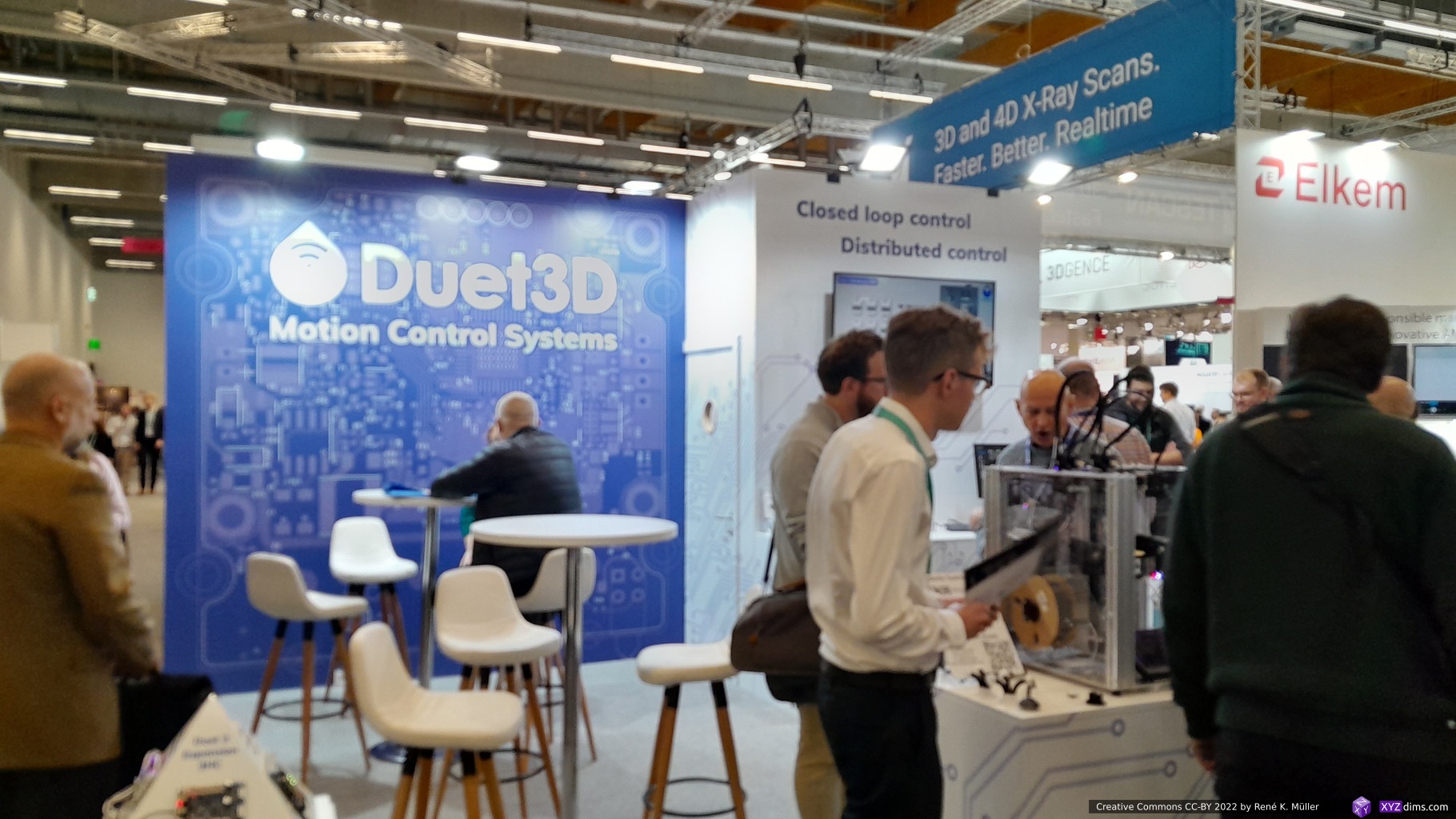
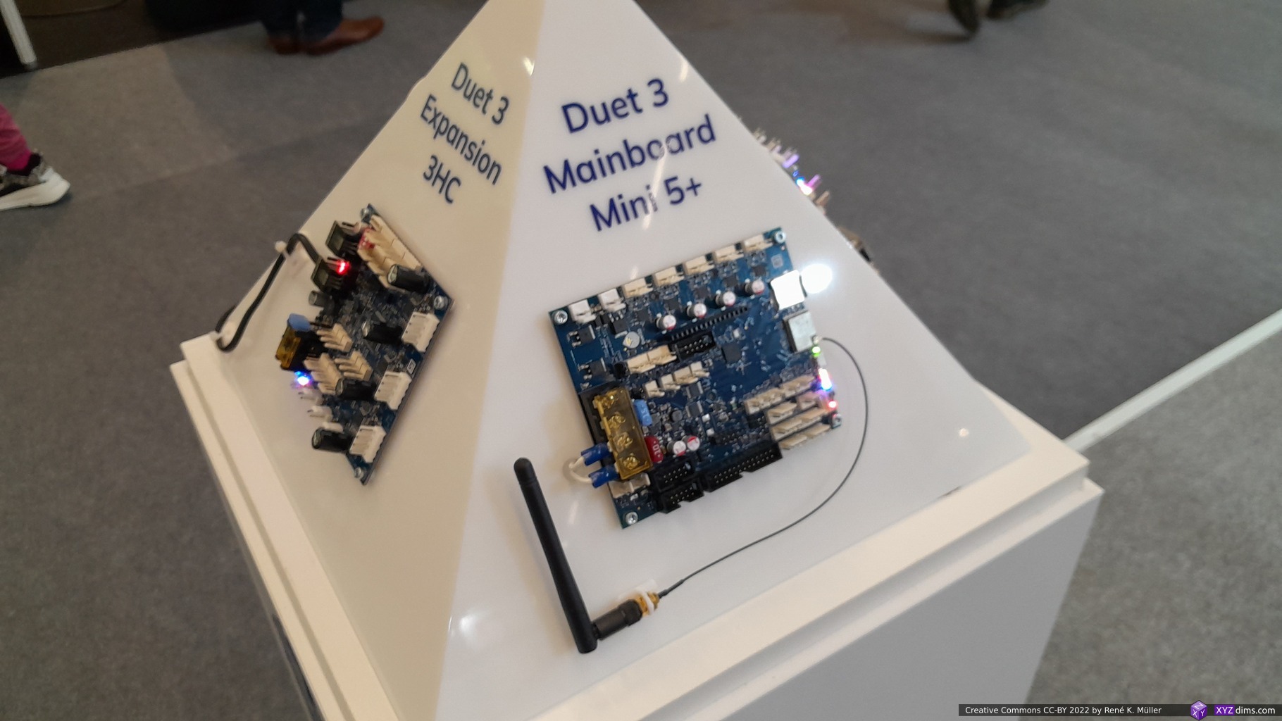
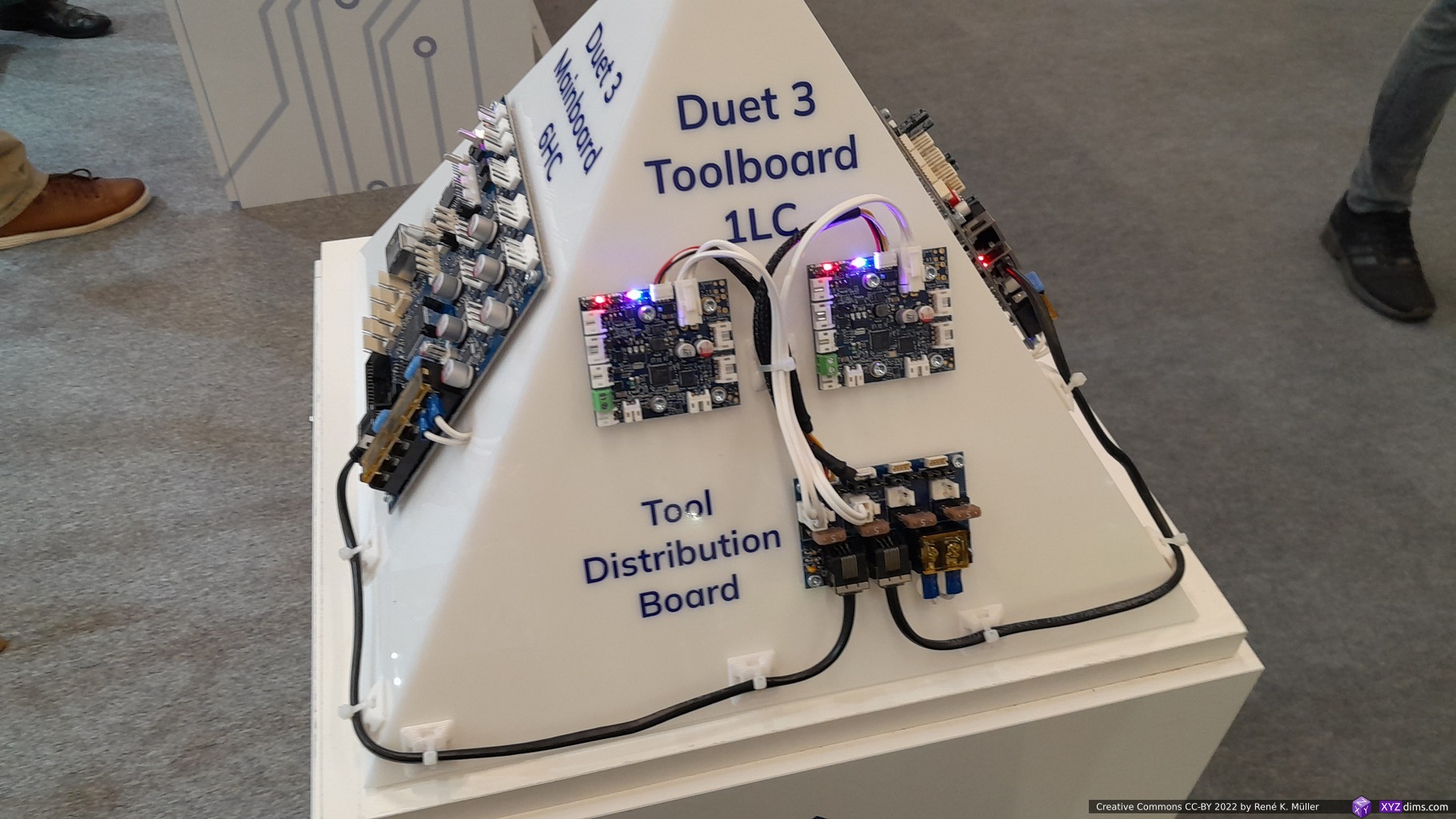
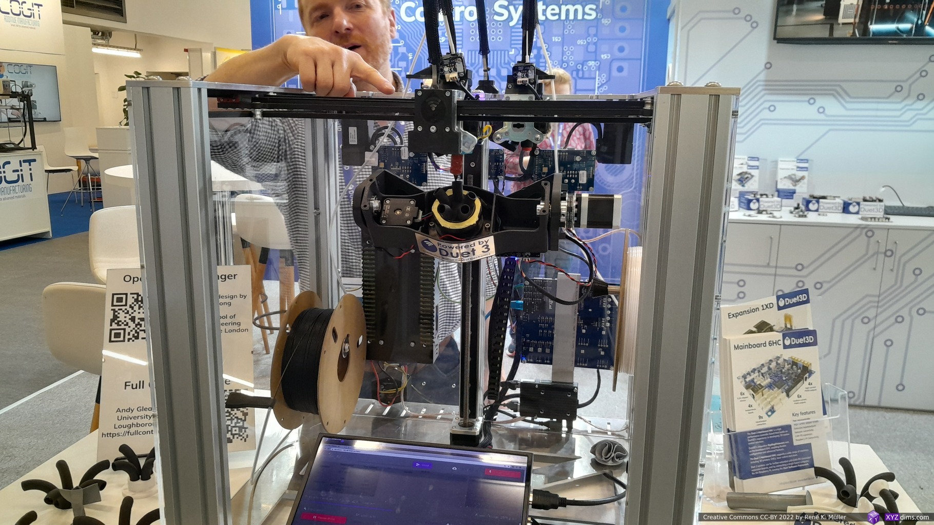
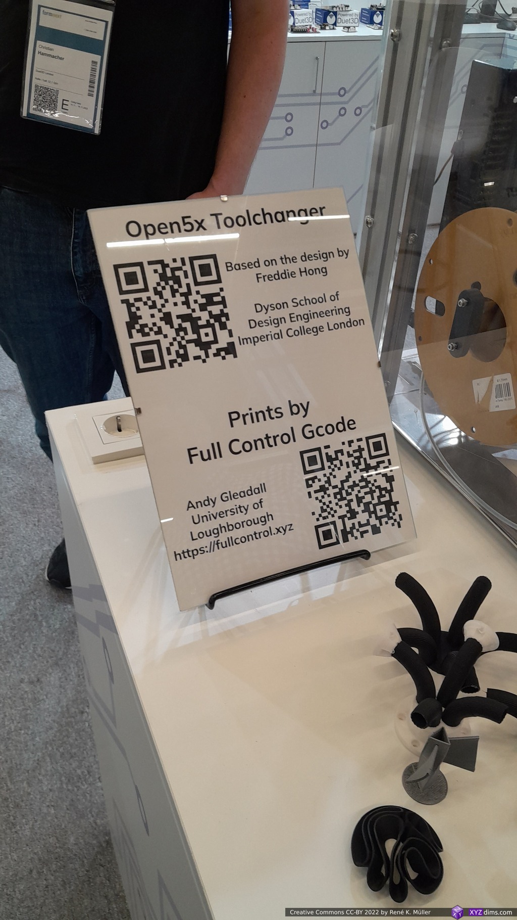
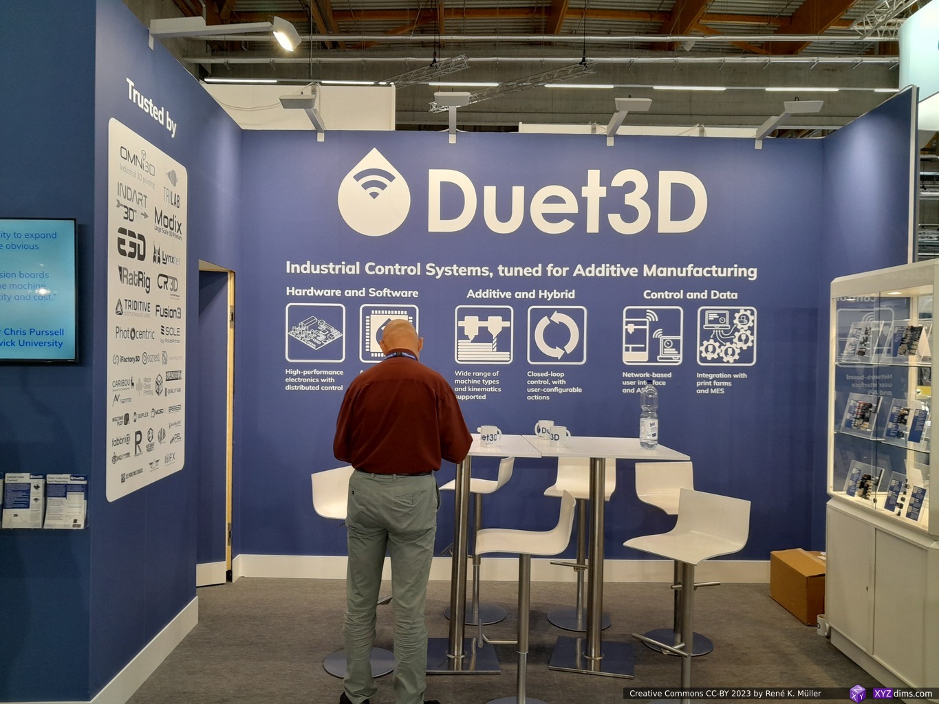
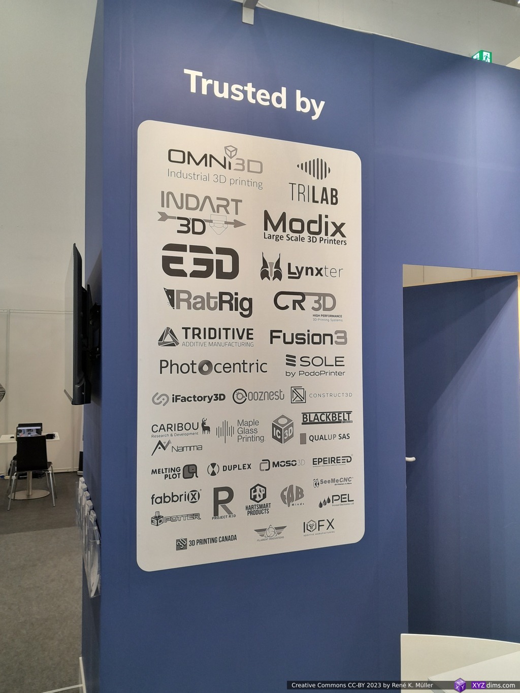
Duet3D (Open Source Hardware & Community Building)
UK-based Duet3D with its Duet boards and RepRapFirmware (RRF) is, as I wrote before, a beacon within the Open Source Hardware community – it isn’t just an example for other companies, and but also a great synergy provider, aiming to bring different individuals, groups and companies together.
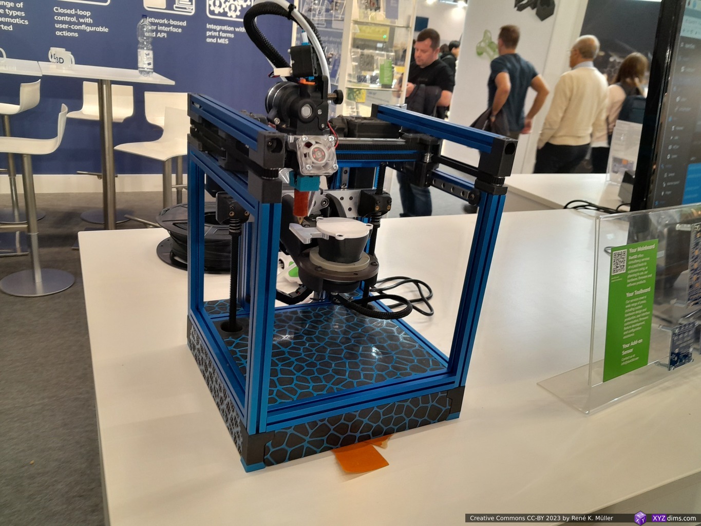
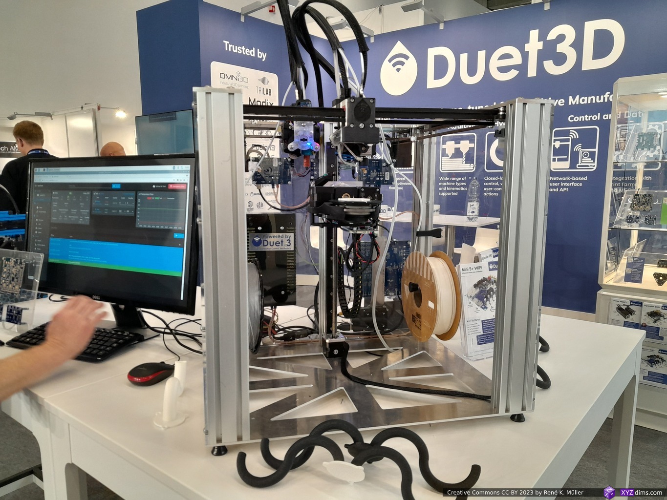
Brandon Builds’ Open 5X version was featured on a Voron 0, and a second machine also 5-axis setup with a tool changer.
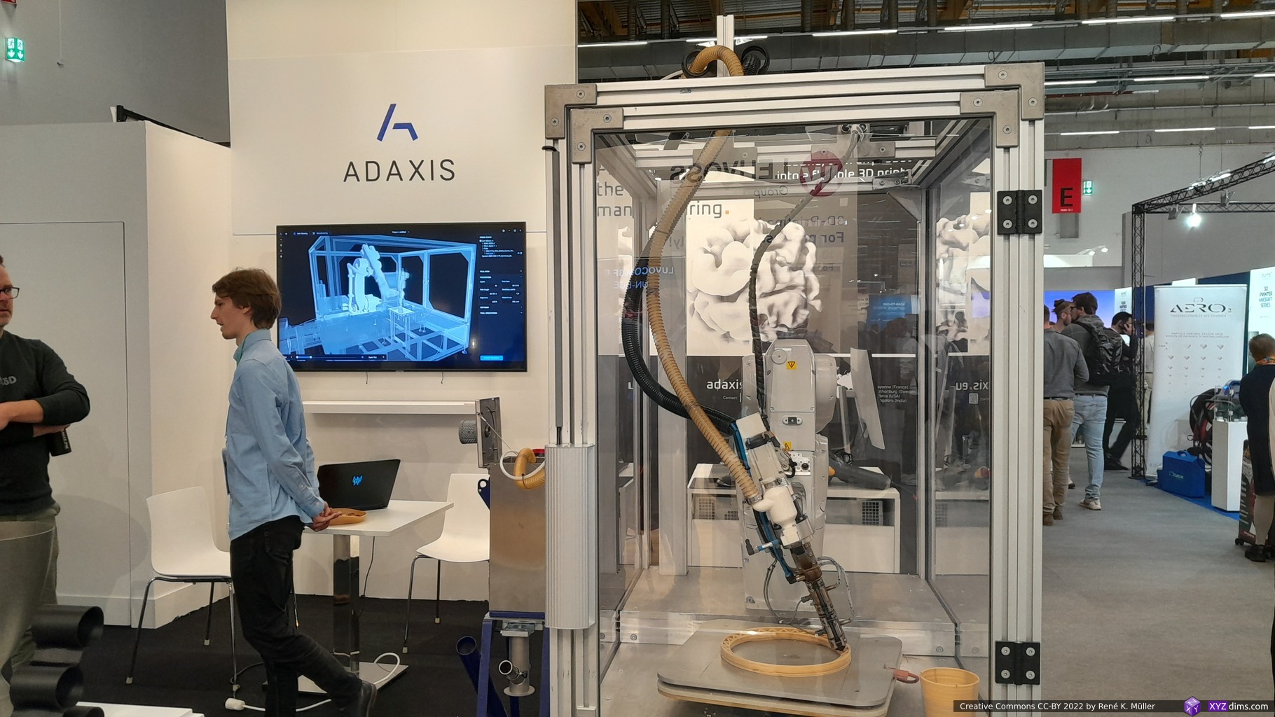
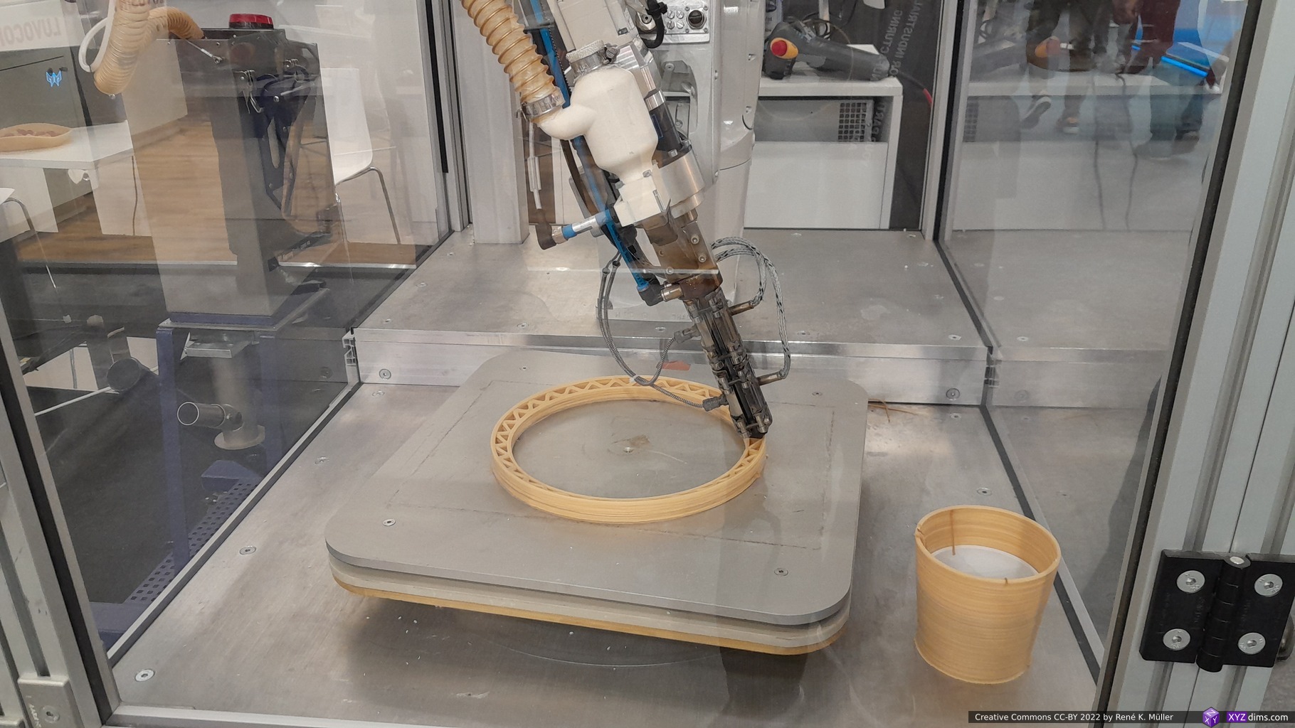
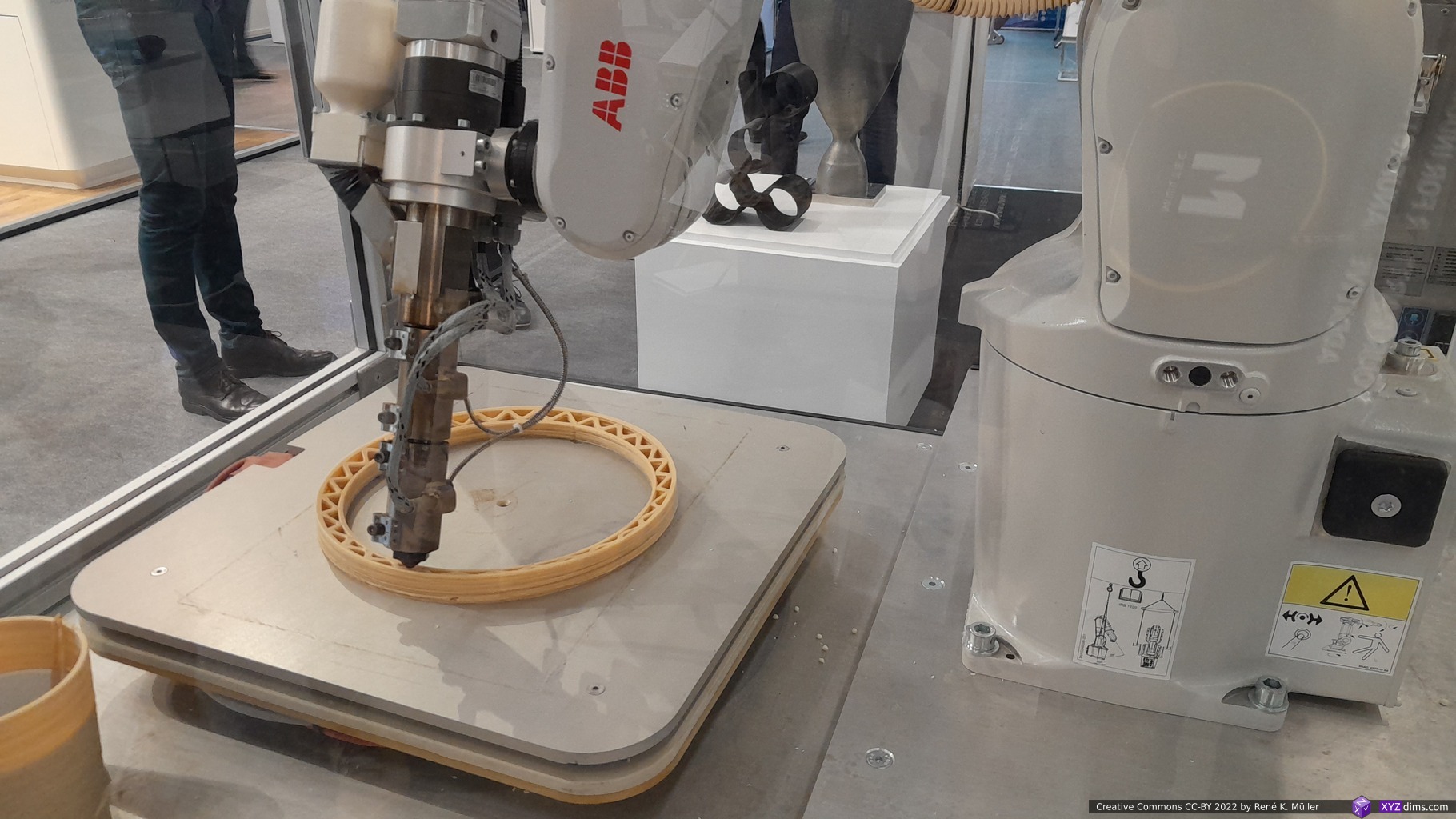
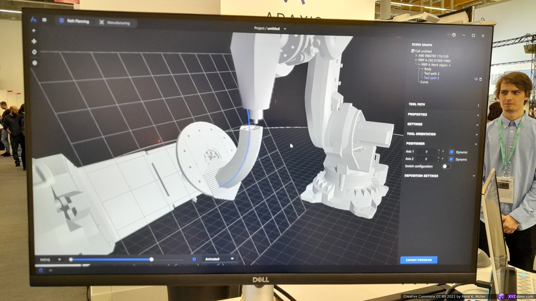
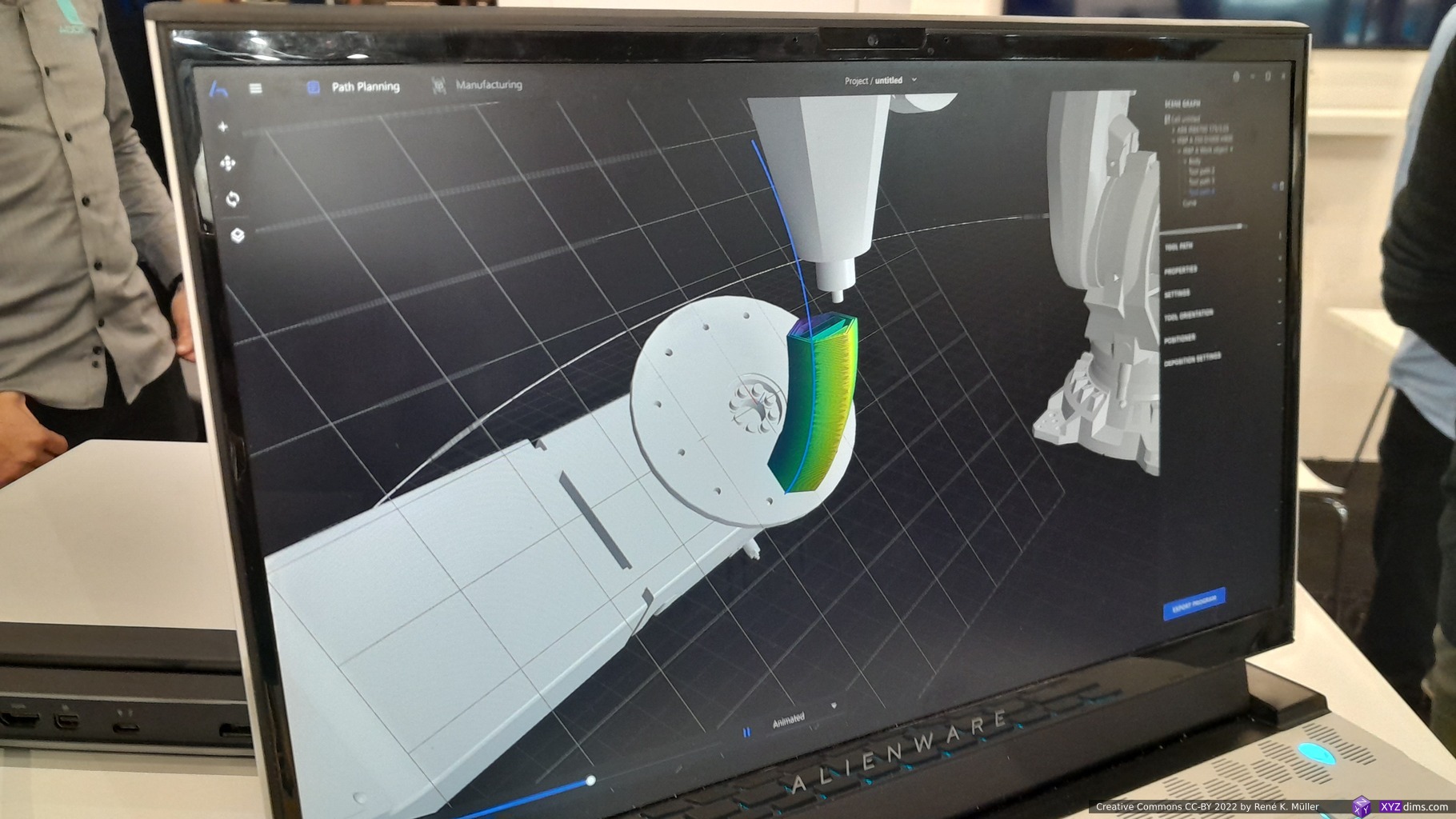
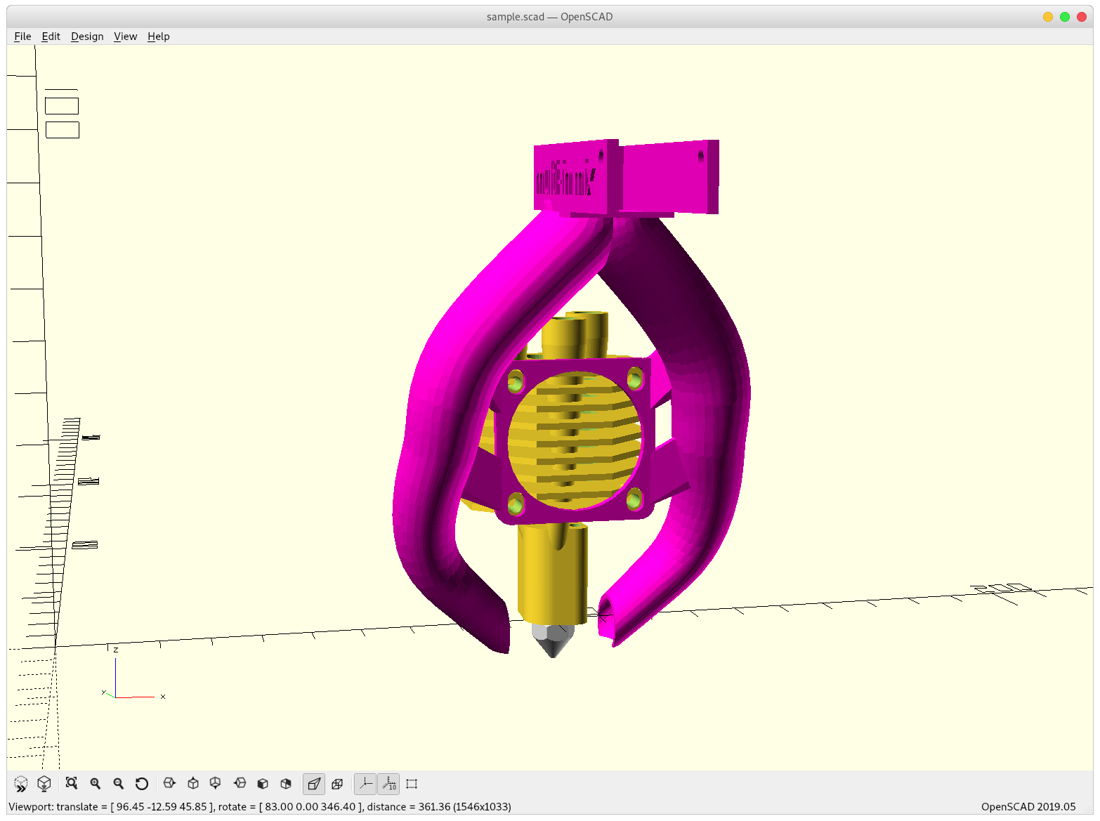
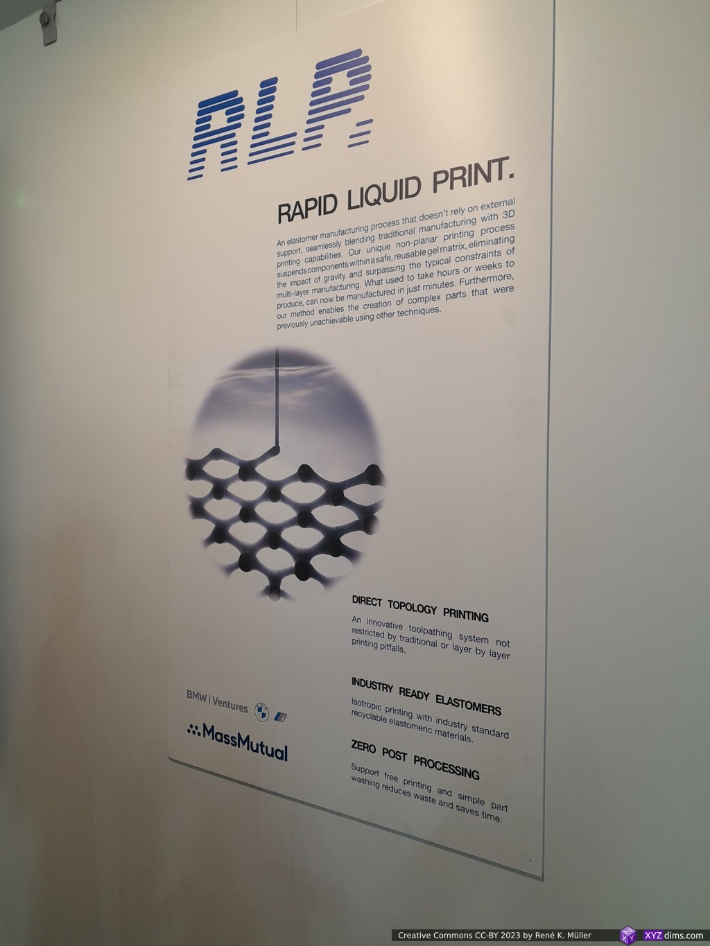
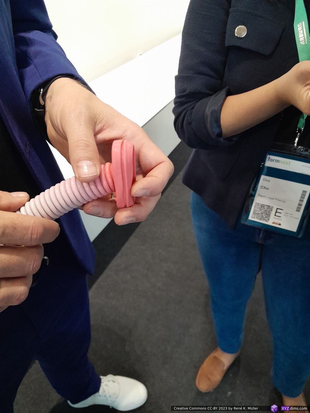
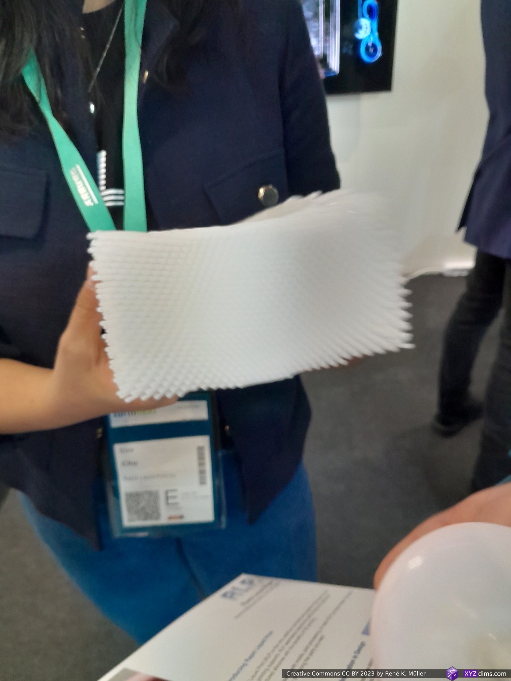
Rapid Liquid Printing / RLP (Flexible Structures)
While roaming around a small booth of RLP caught also my attention, where a video was featured of a nozzle moving in a bed filled with silicon printing rubber, and other flexible material:
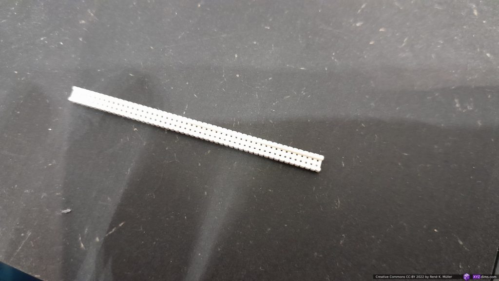
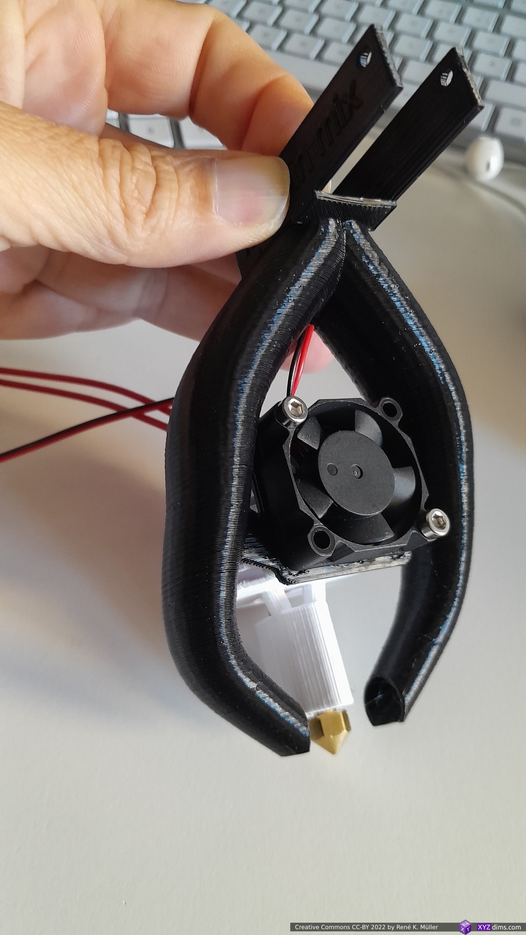
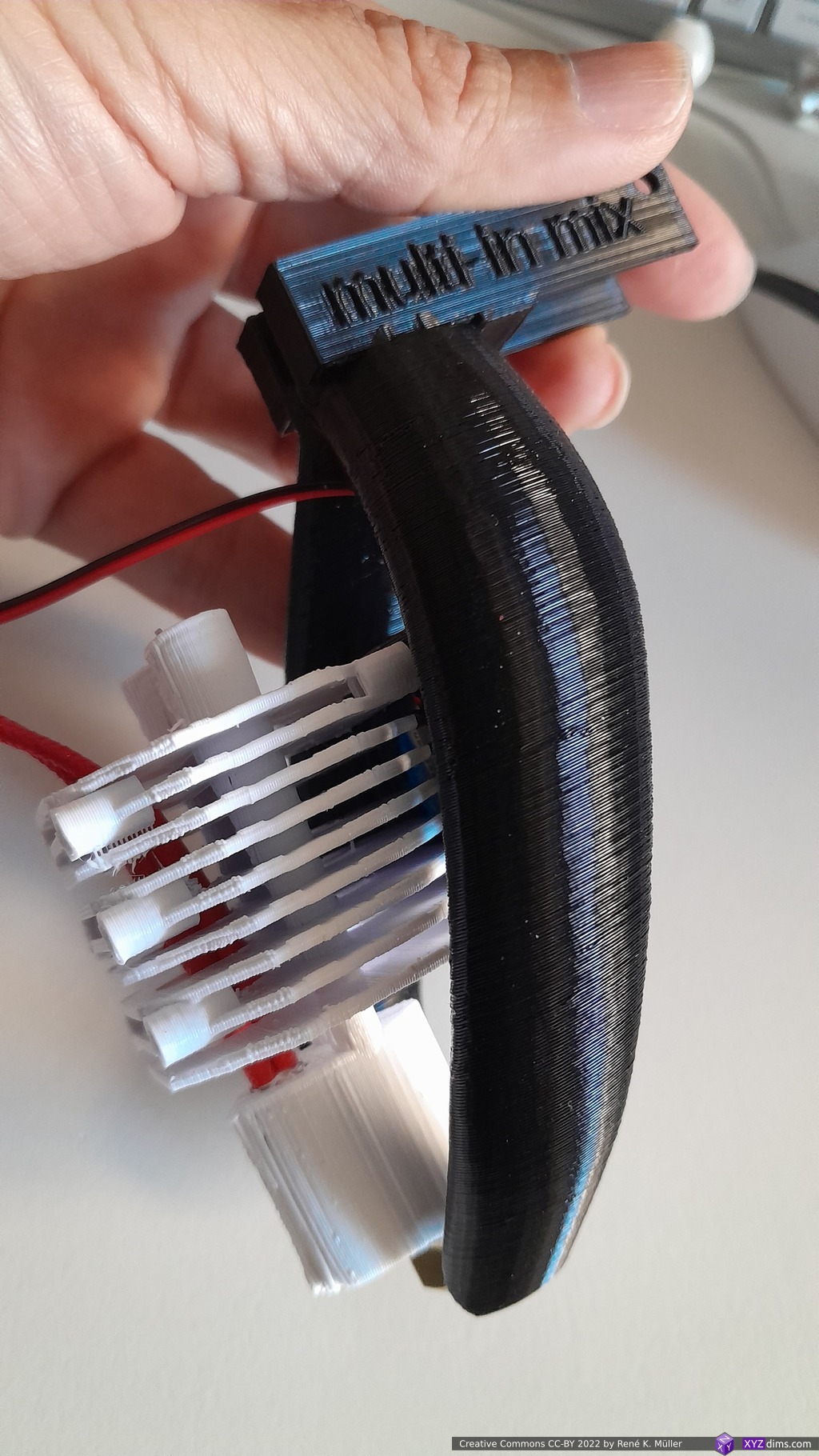
Reinforce 3D (Enhancement)
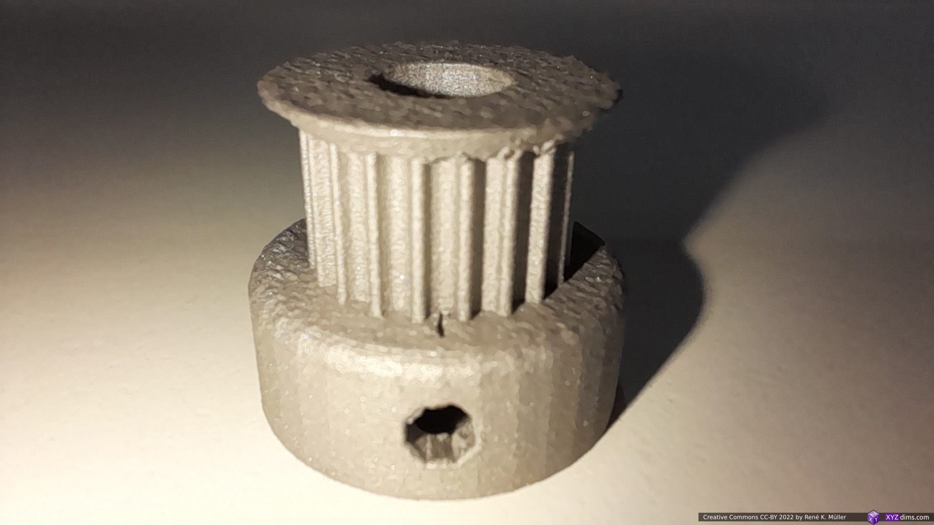
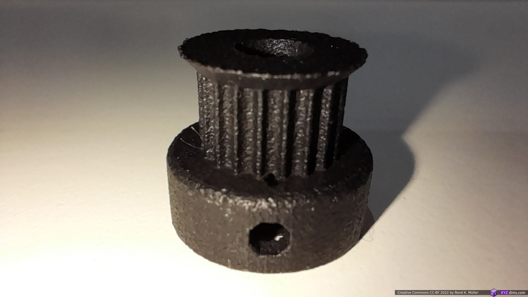
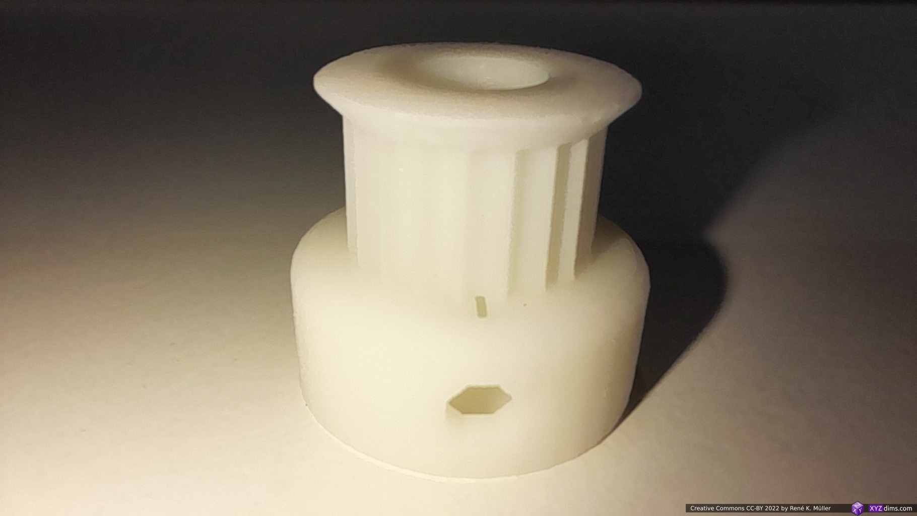
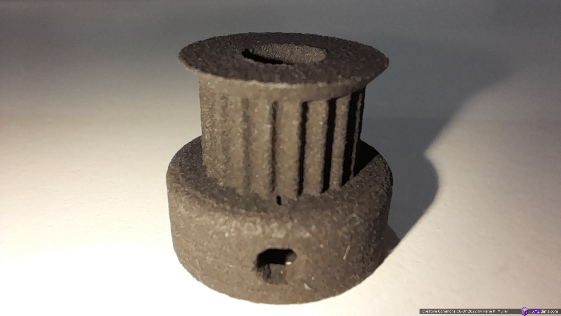
Another truly innovative approach combining and enhancing existing additive manufacturing processes was shown by Reinforce 3D:
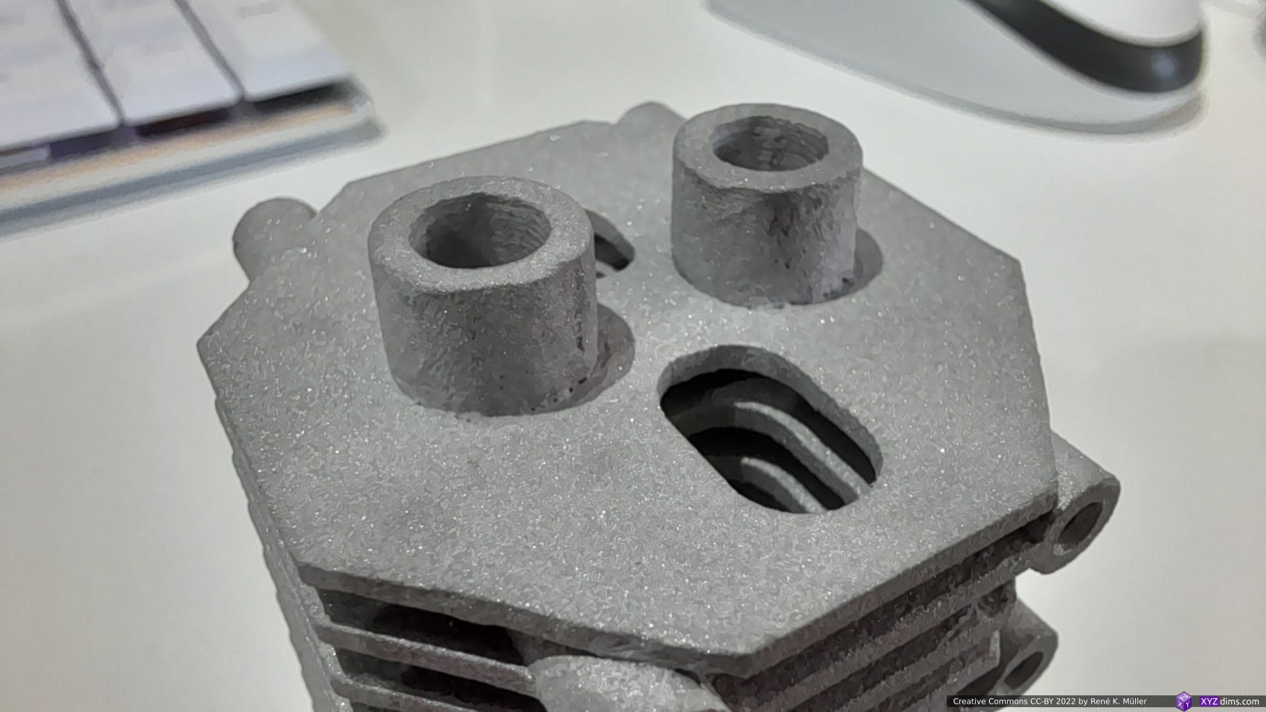
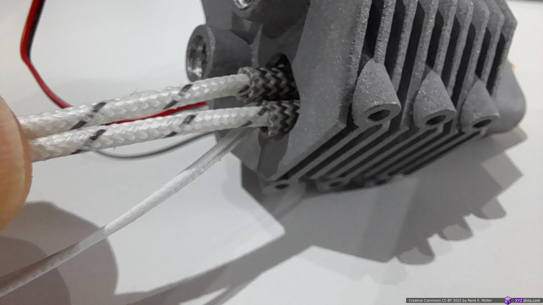
- using existing AM methods such as SLM, SLA, MSLA and even FFF/FDM to make models with thin walled tunnels and then
- filling or rather pushing them with strains of carbon fibres along with resin into the tunnels
- and thereby reinforcing free forms by keeping the result lightweight but incredible strong due the embedded carbon fibres
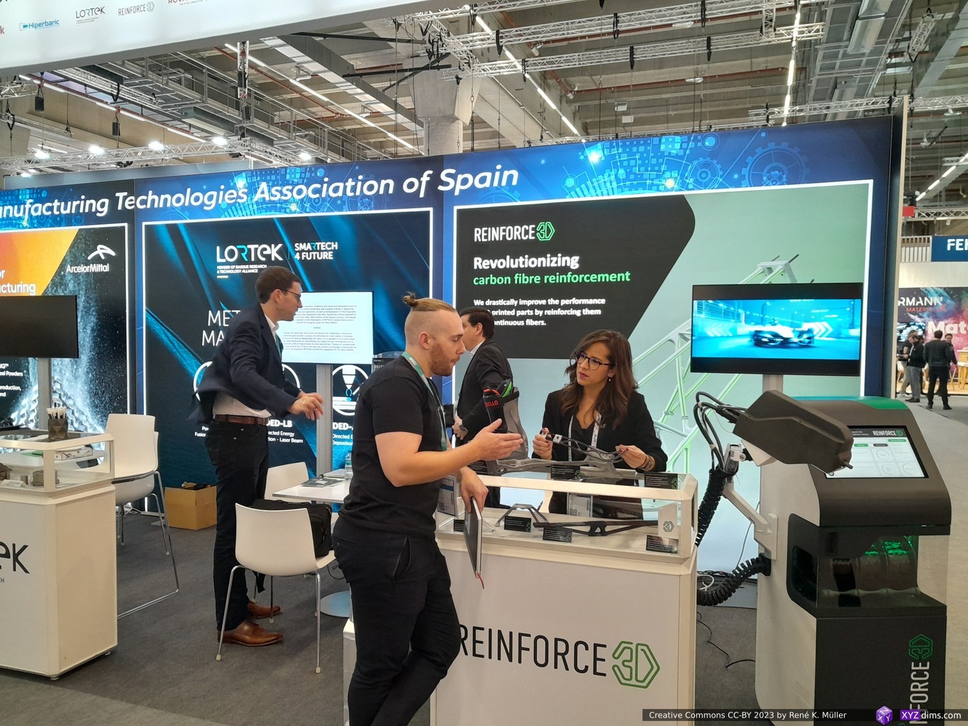
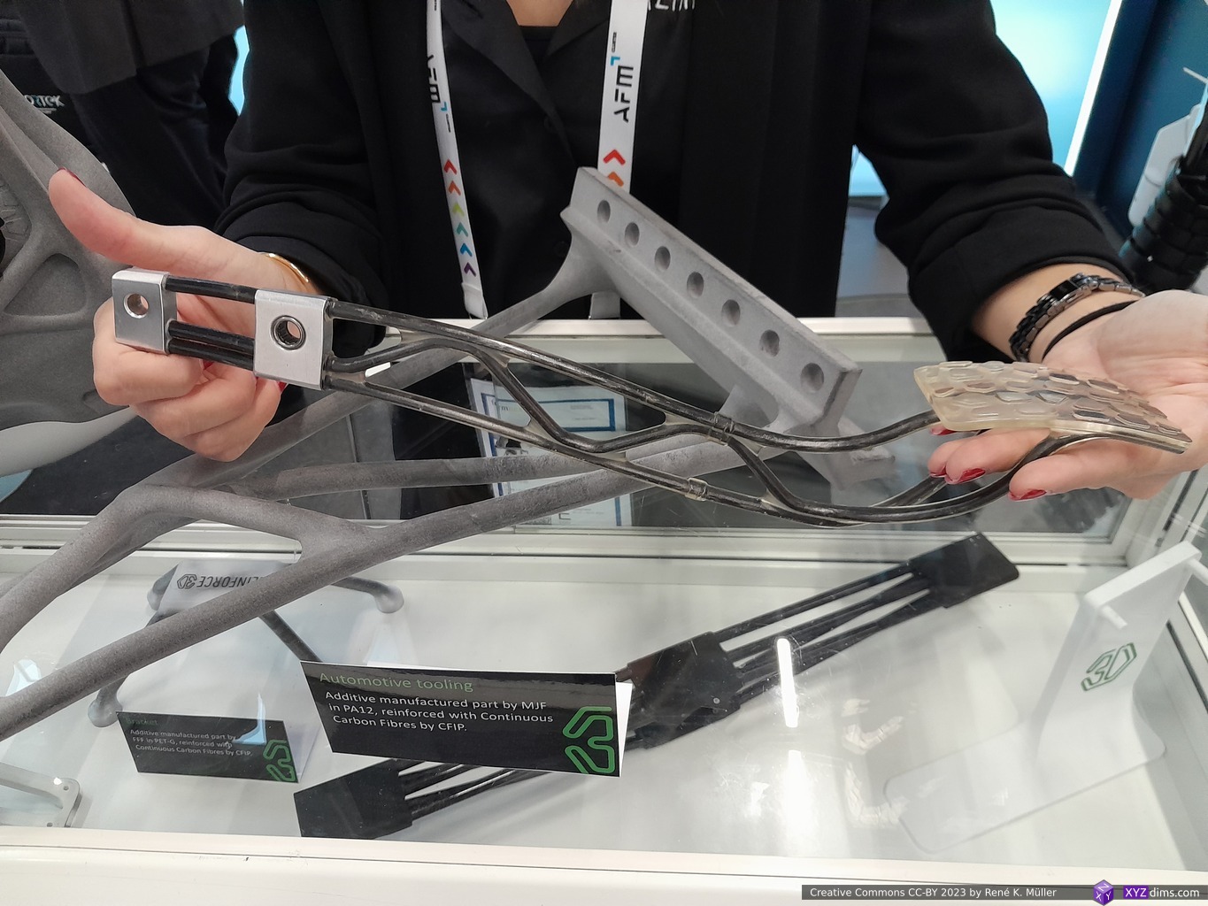
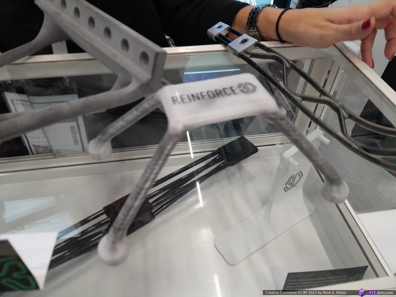
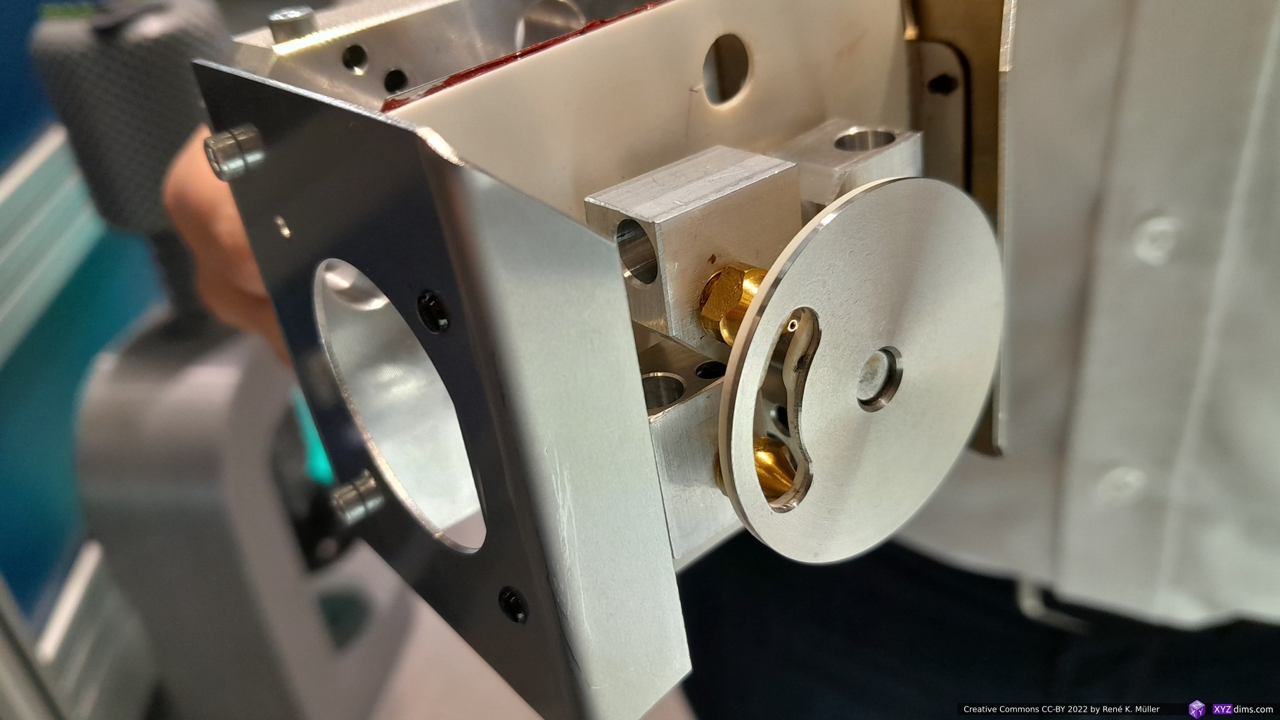
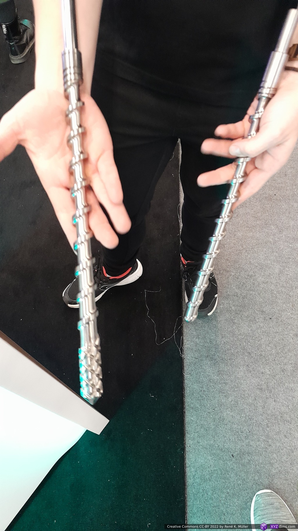
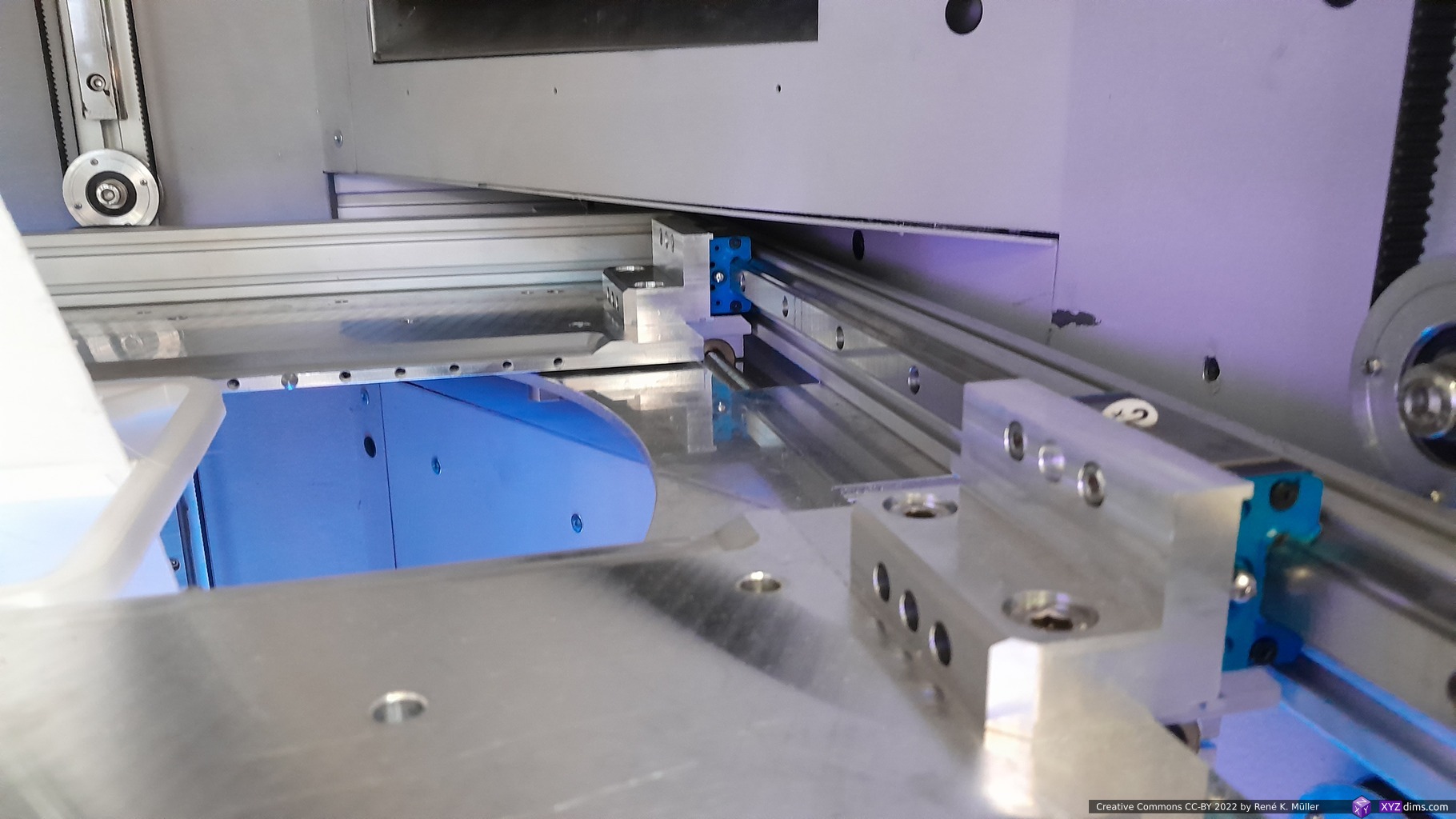
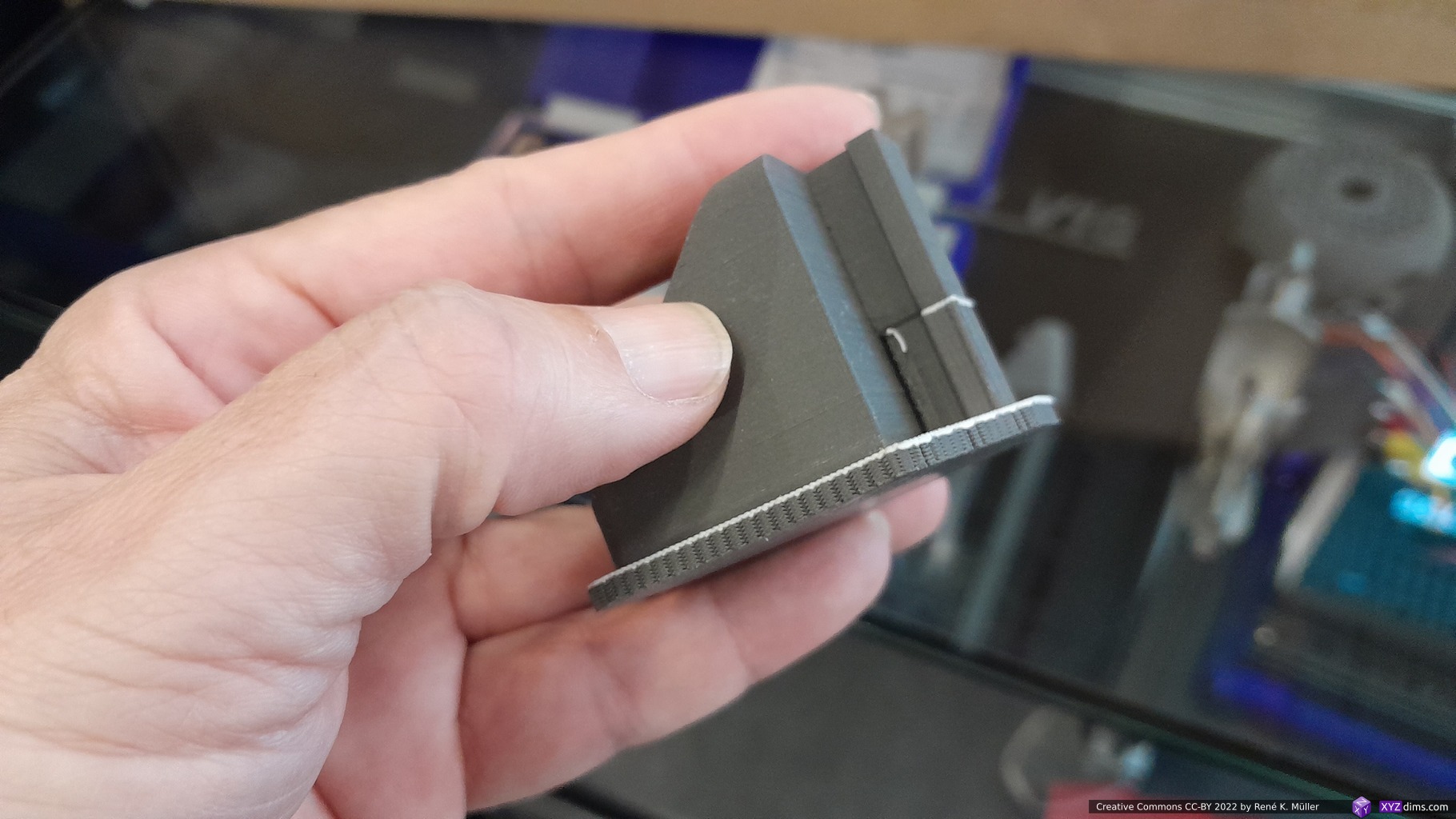
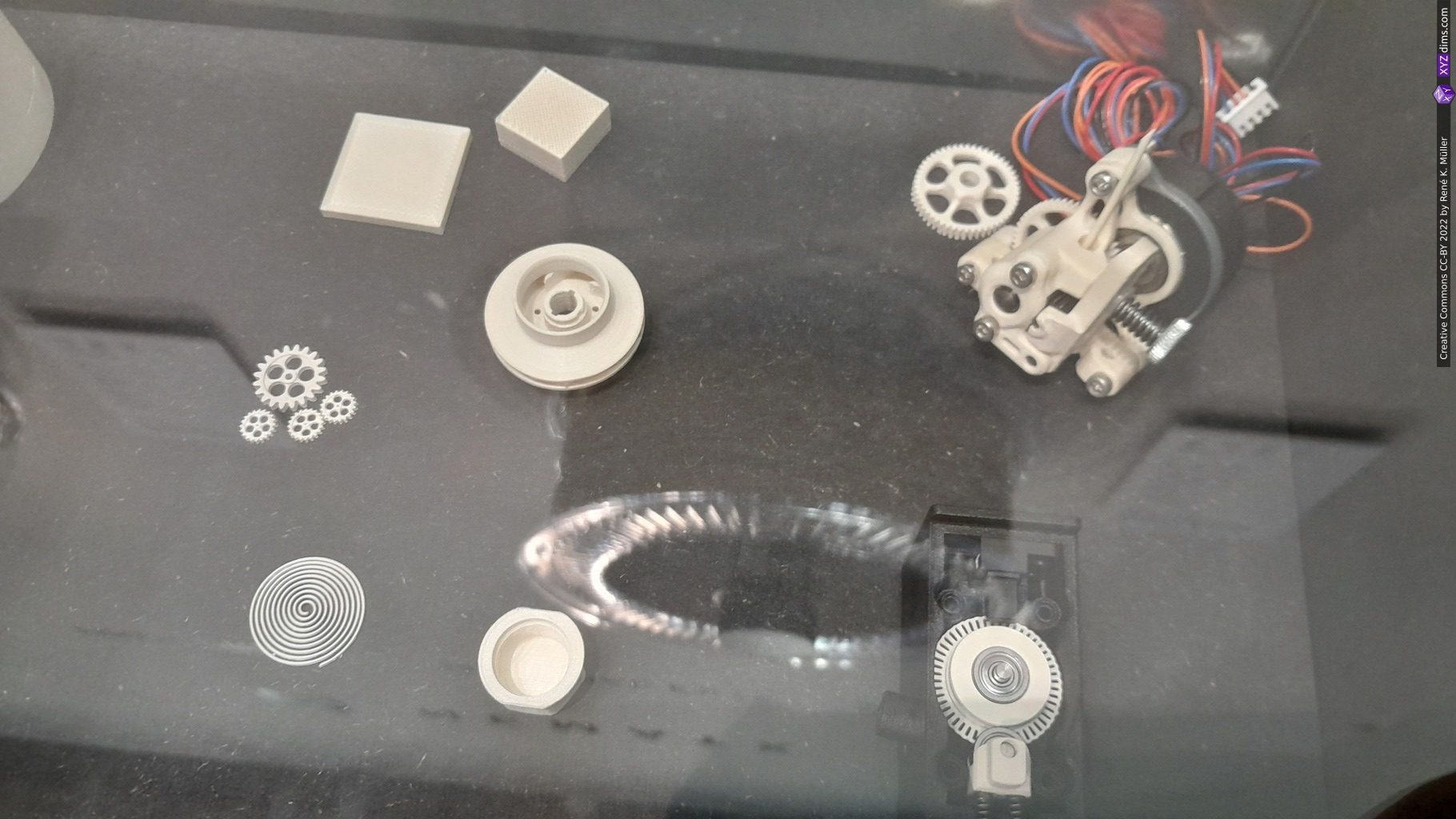
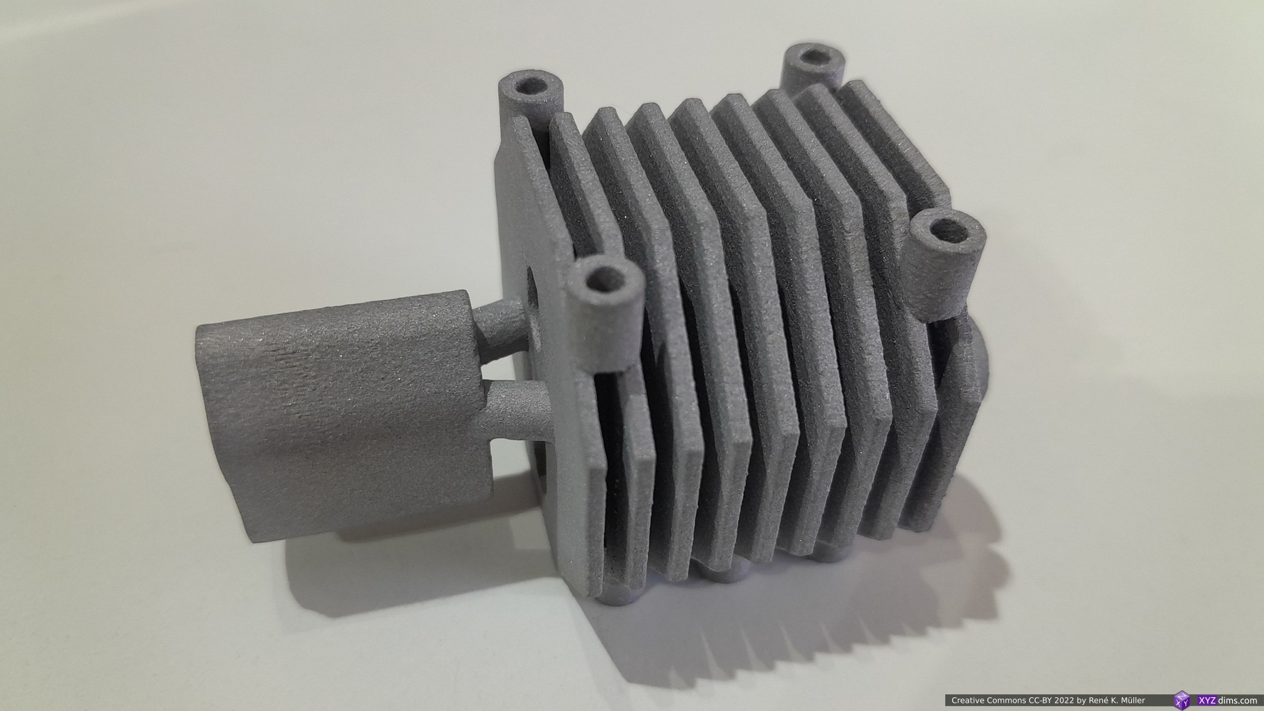
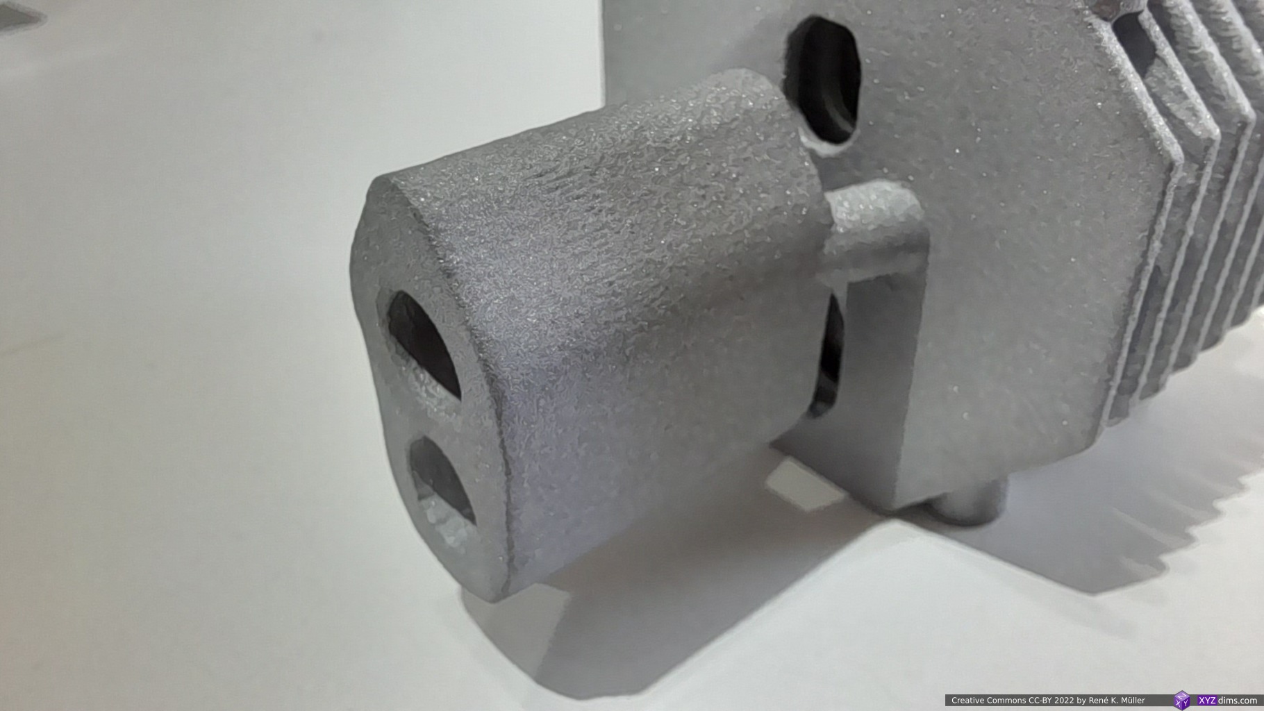
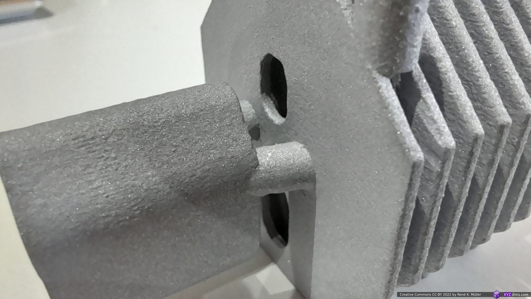
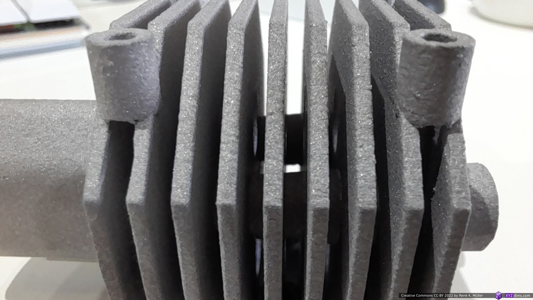
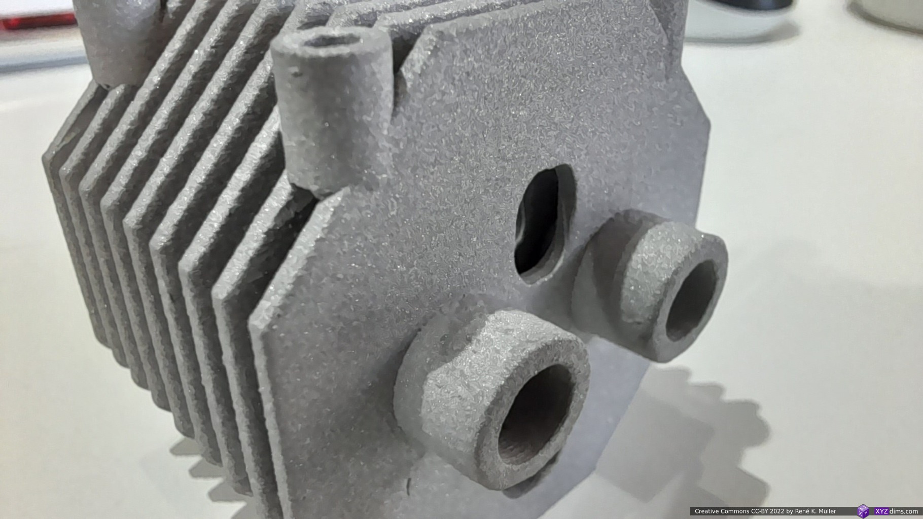
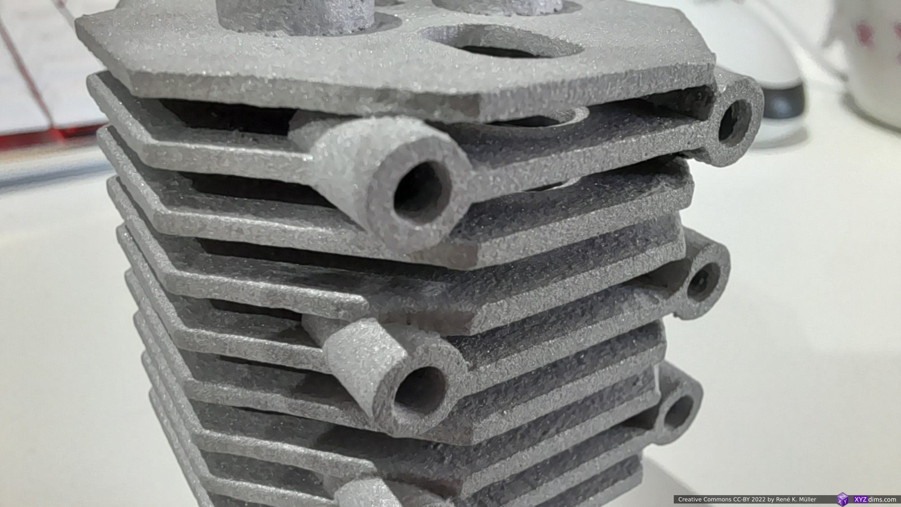
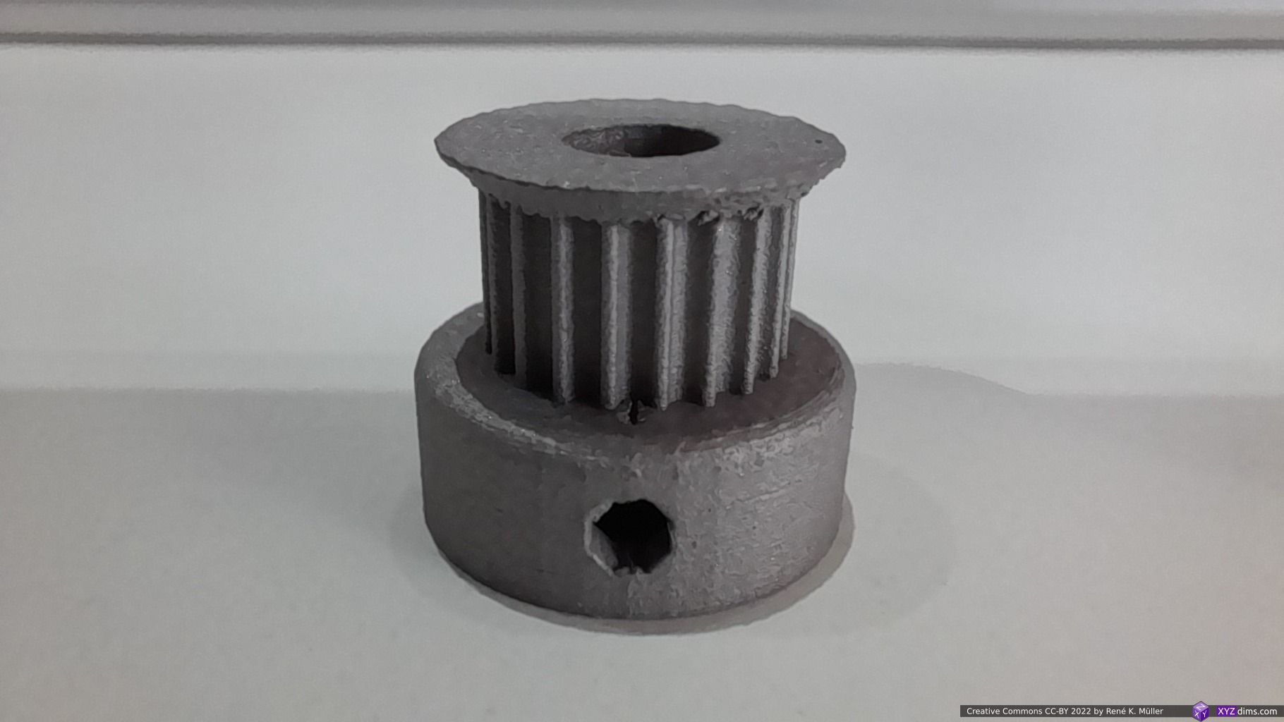
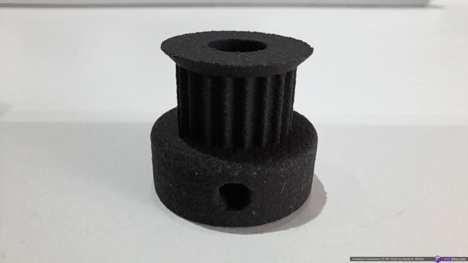
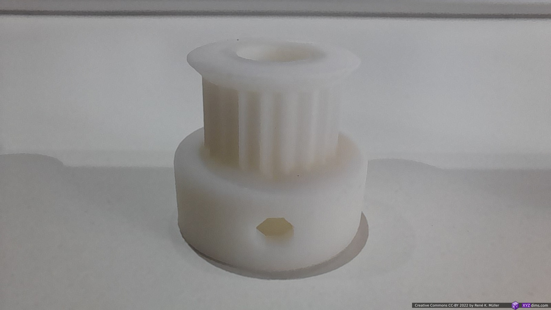
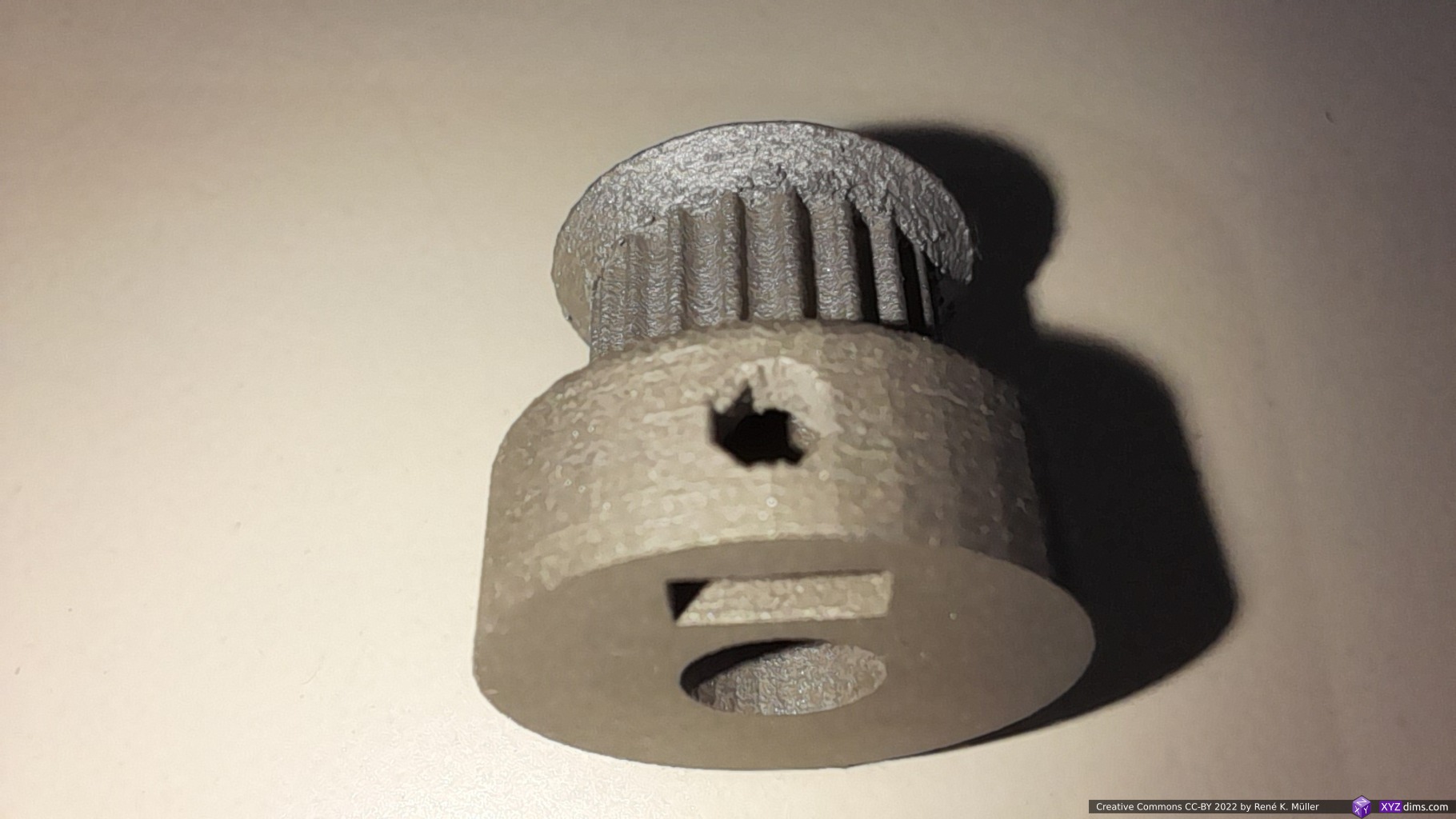
A very small but significant detail is, that you can print multiple parts on a smaller printer, but once you start to insert the bundles of carbon fiber those segments of pieces get combined in a strong assembly, as the aluminium skeleton shown above.
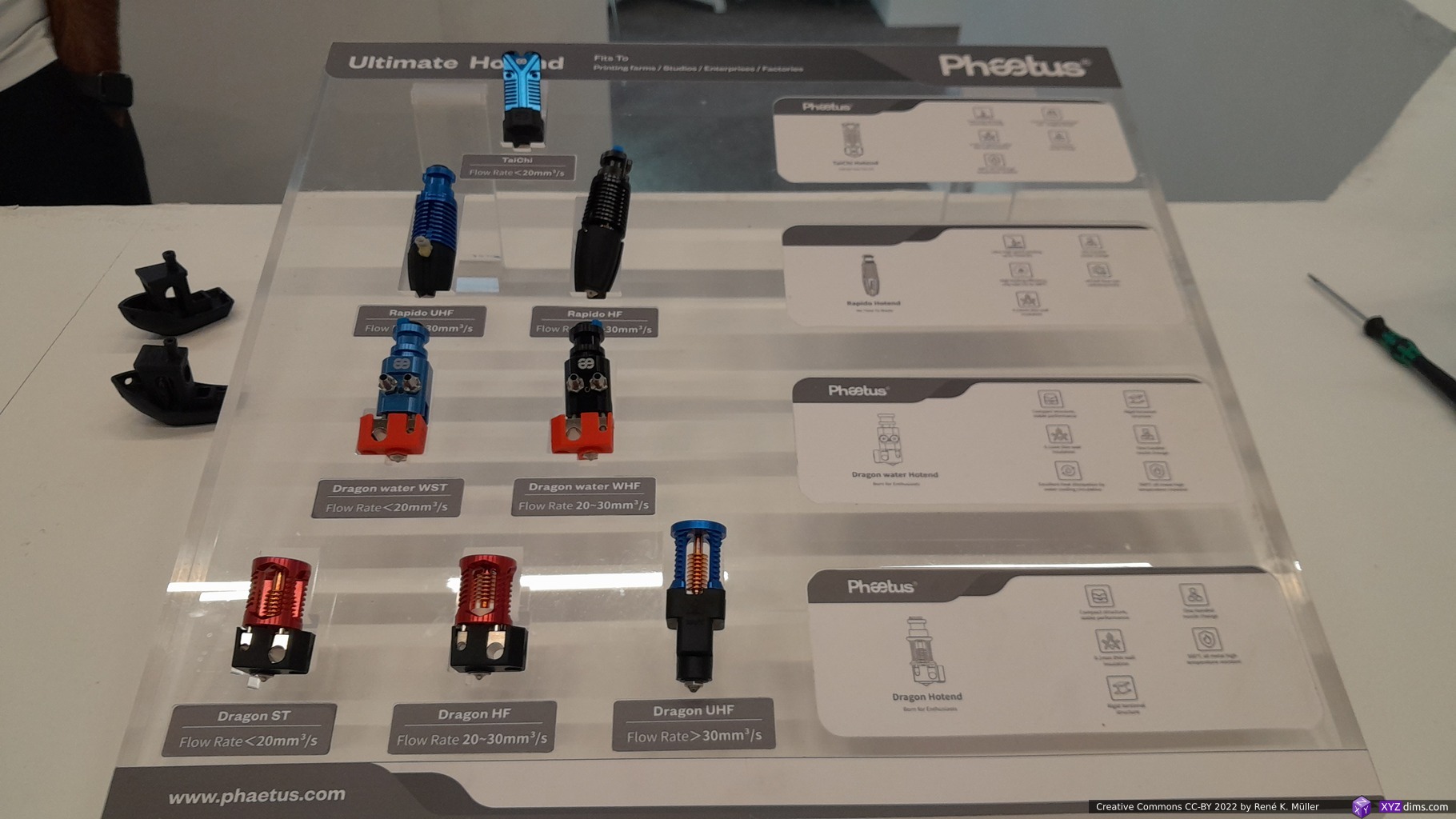
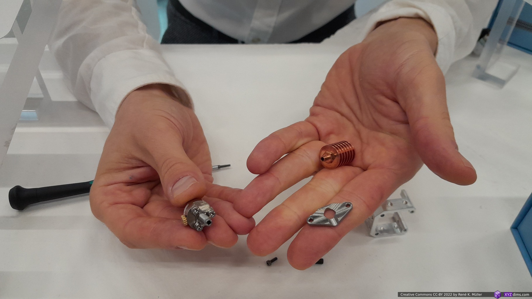
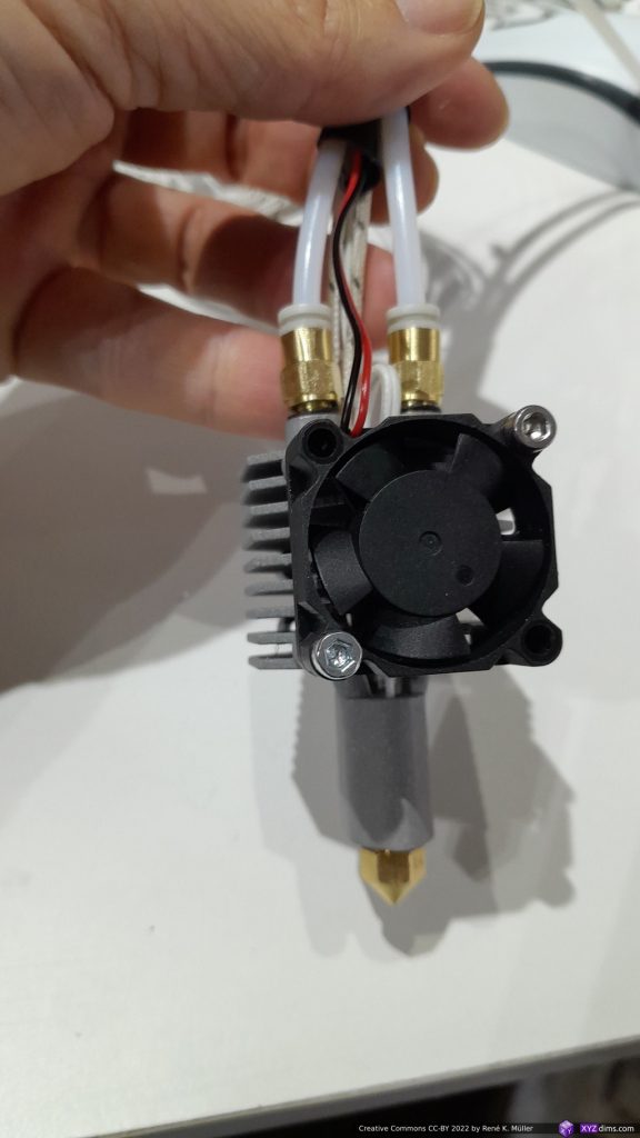
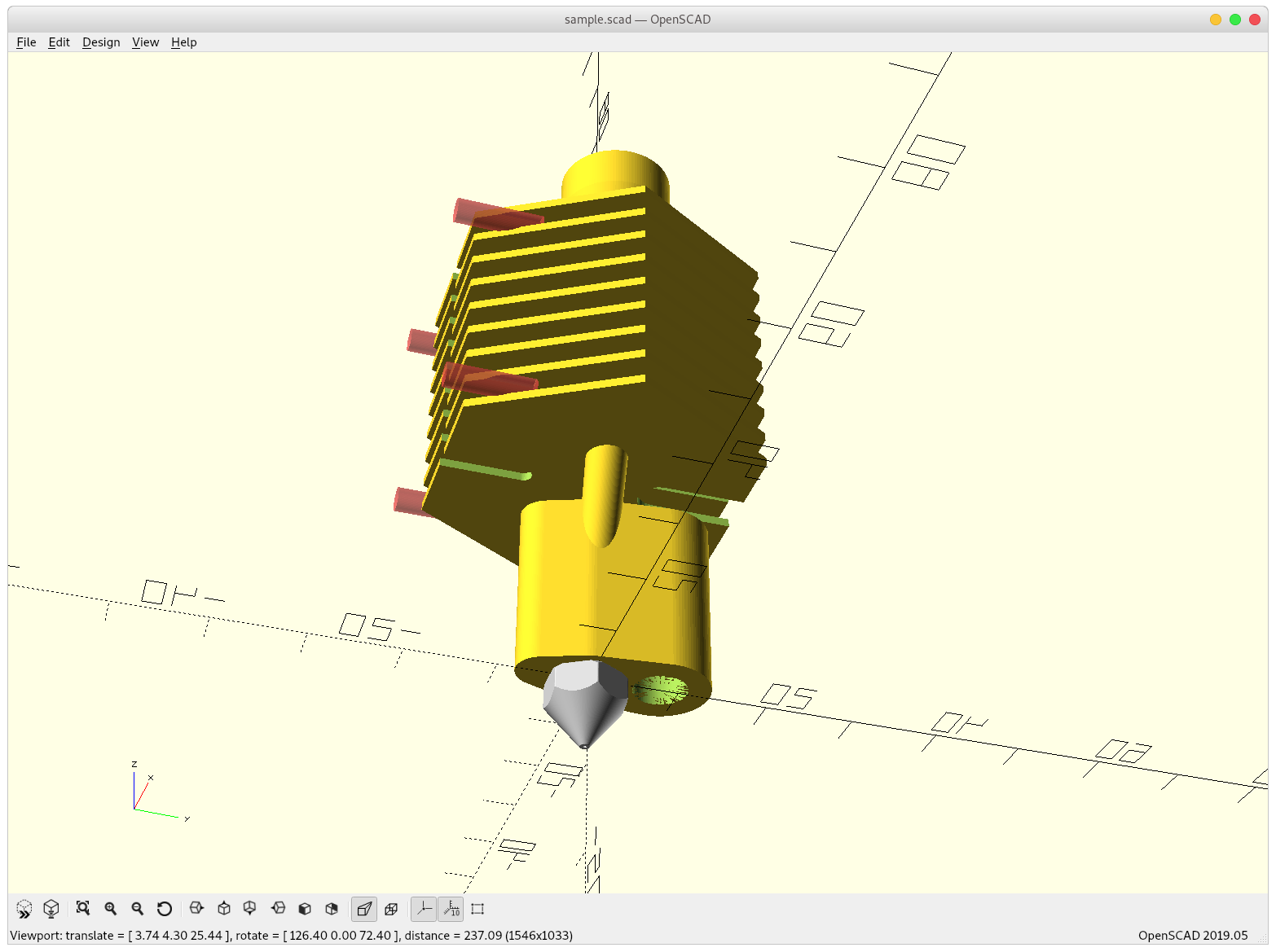
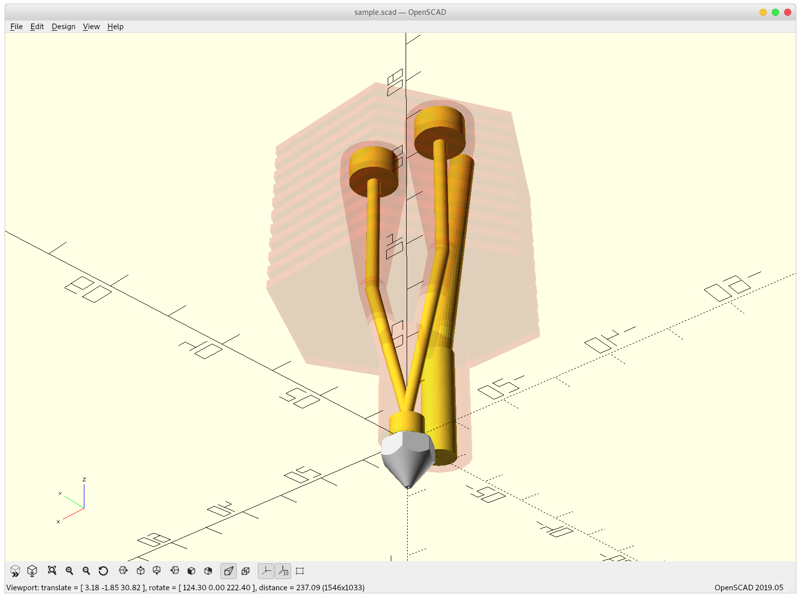
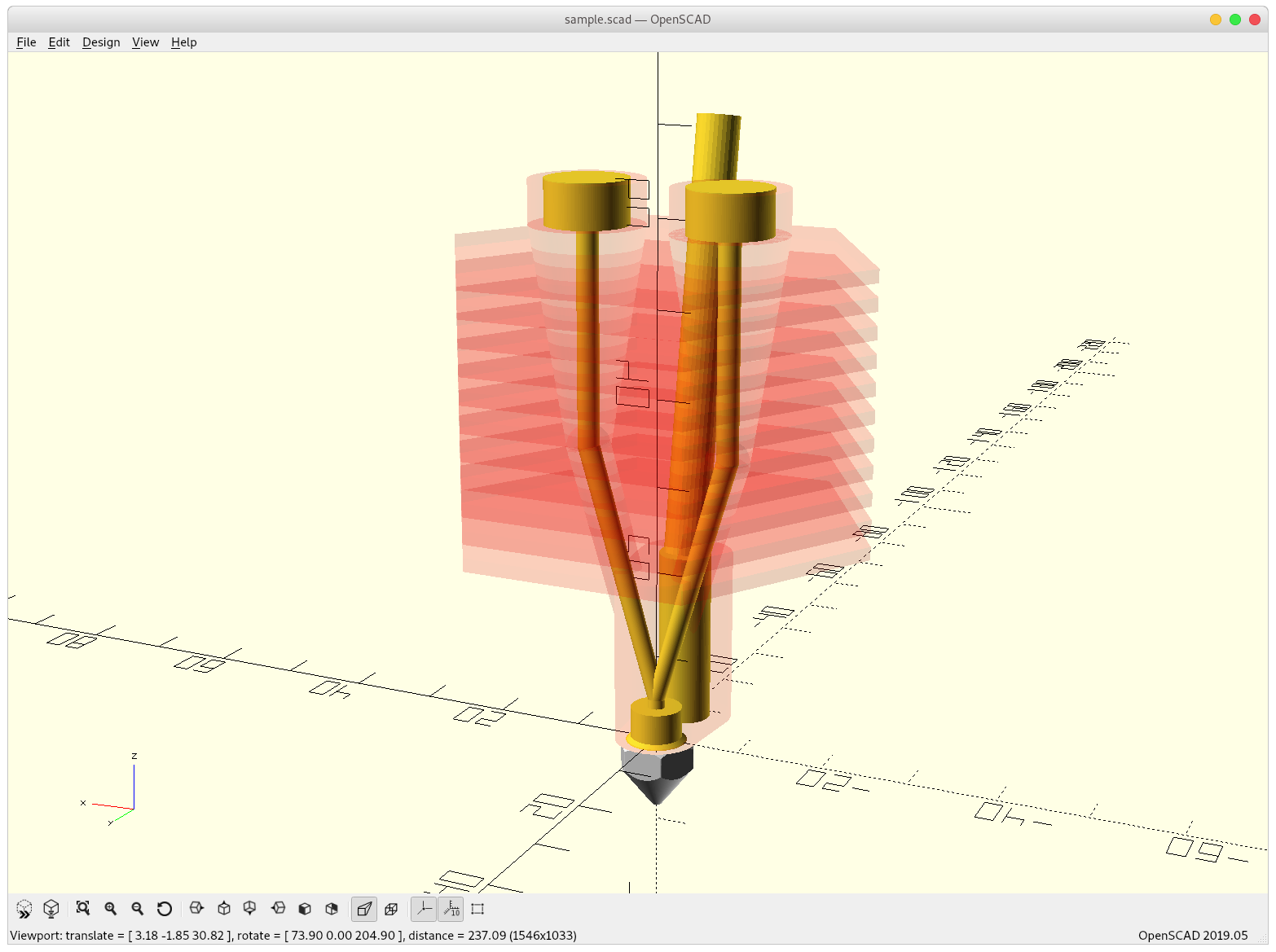
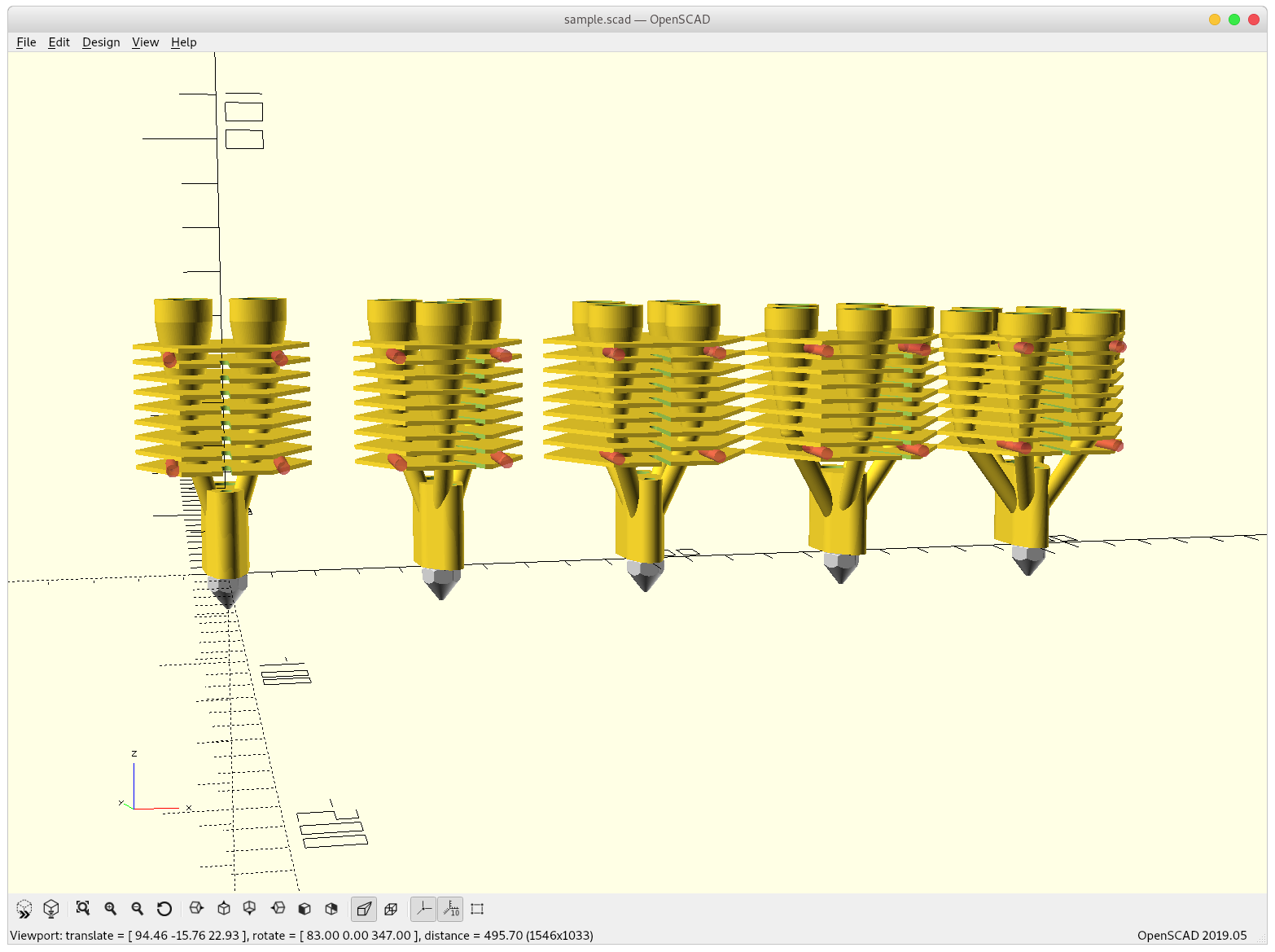
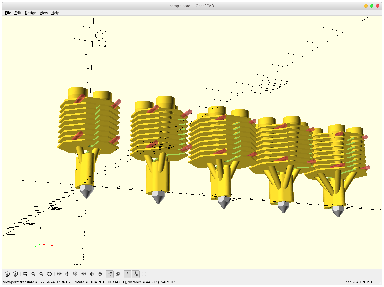
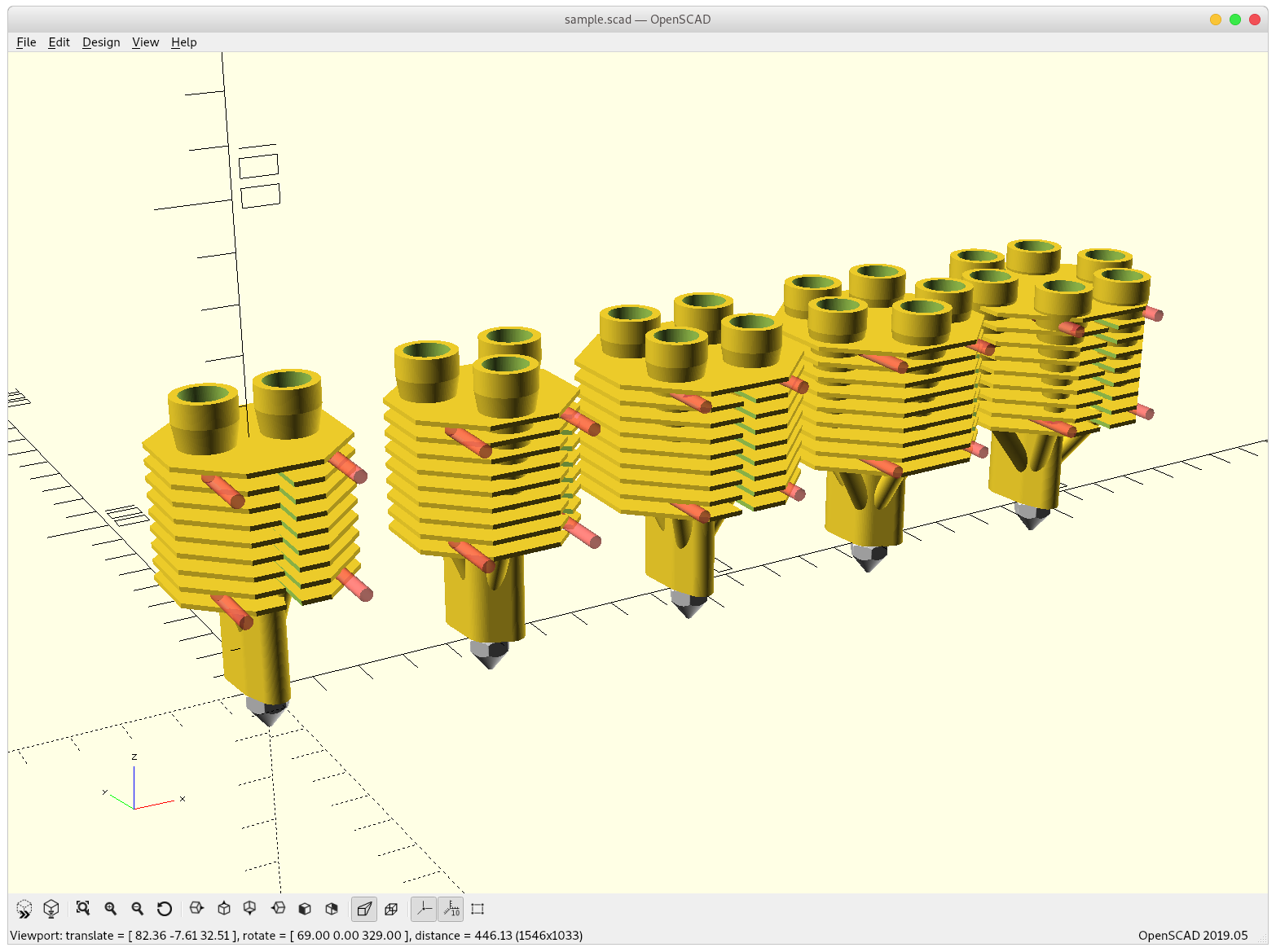
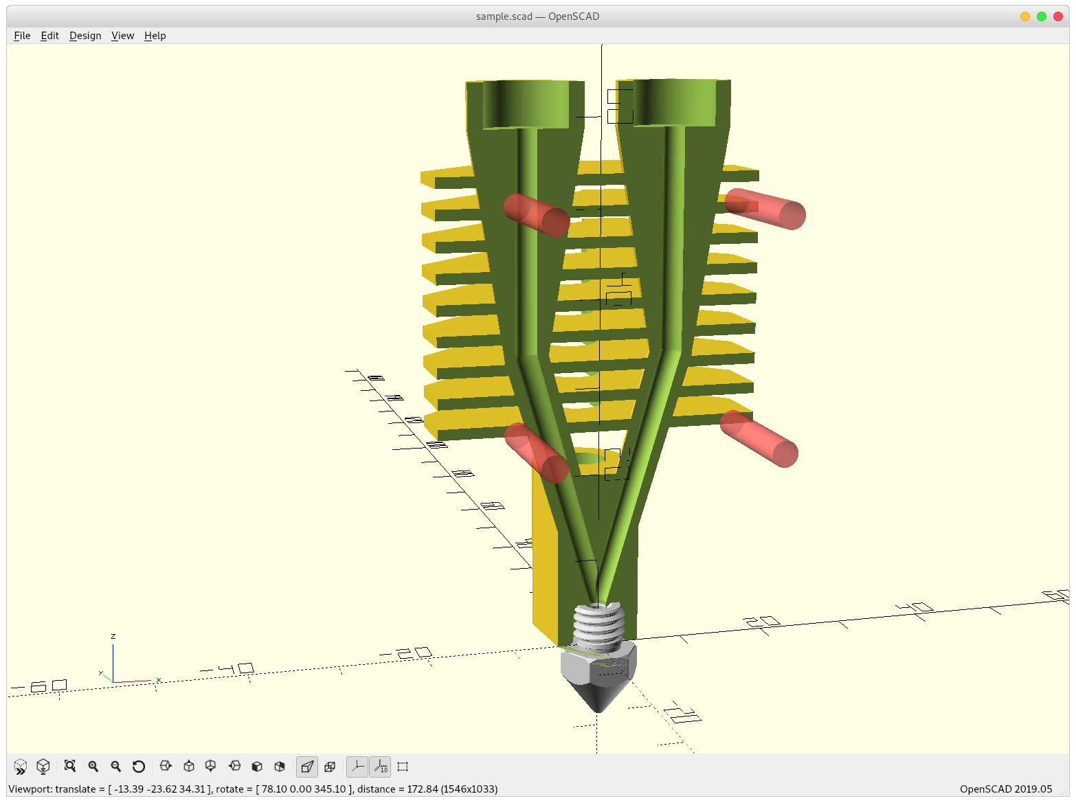
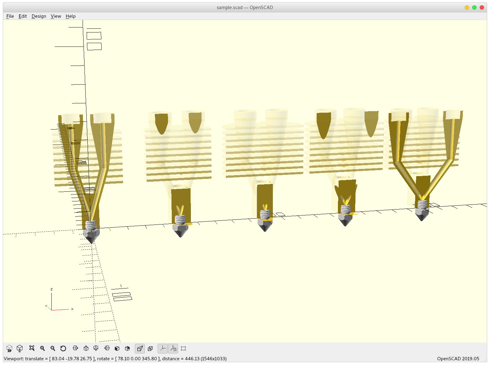
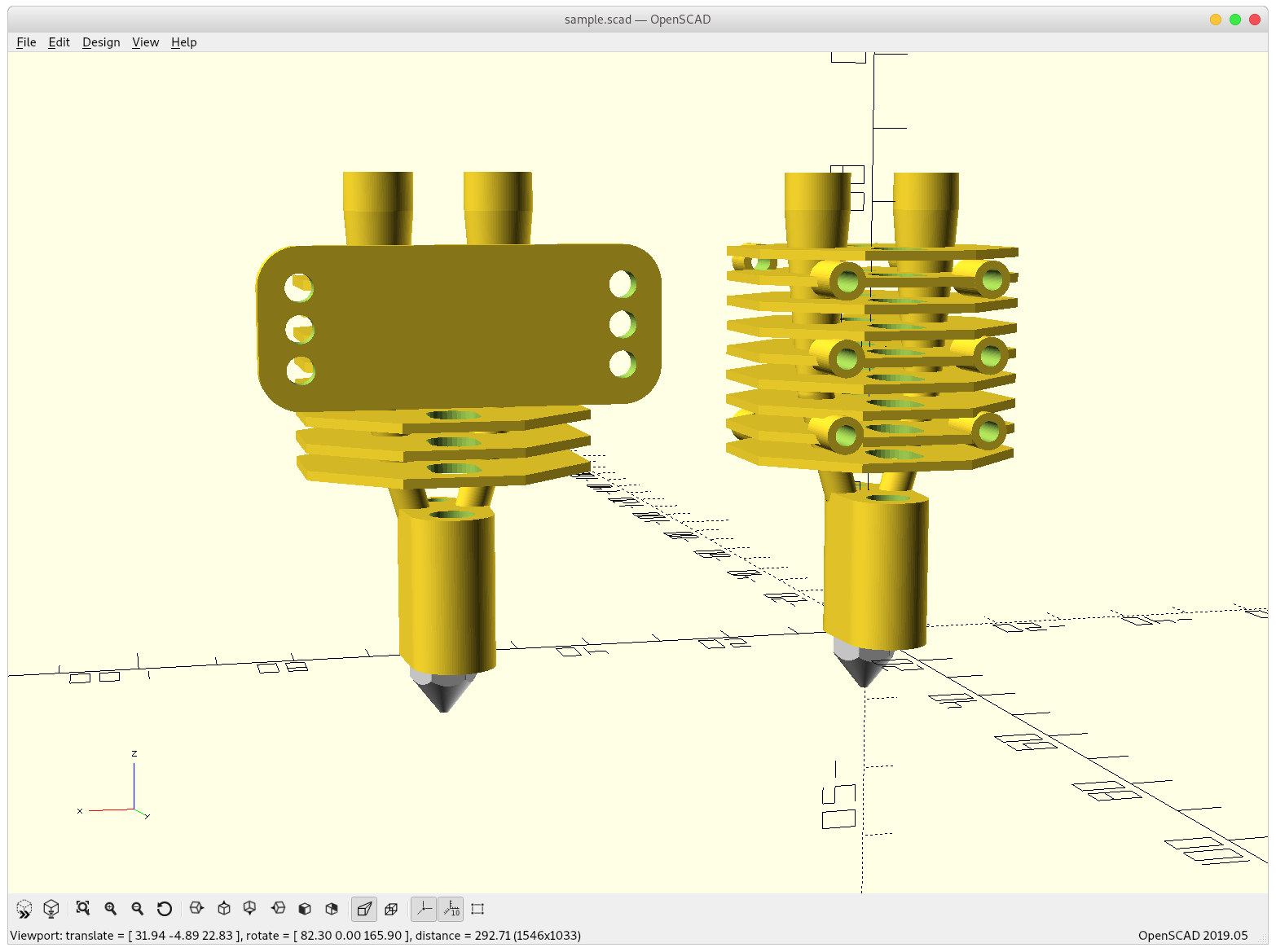
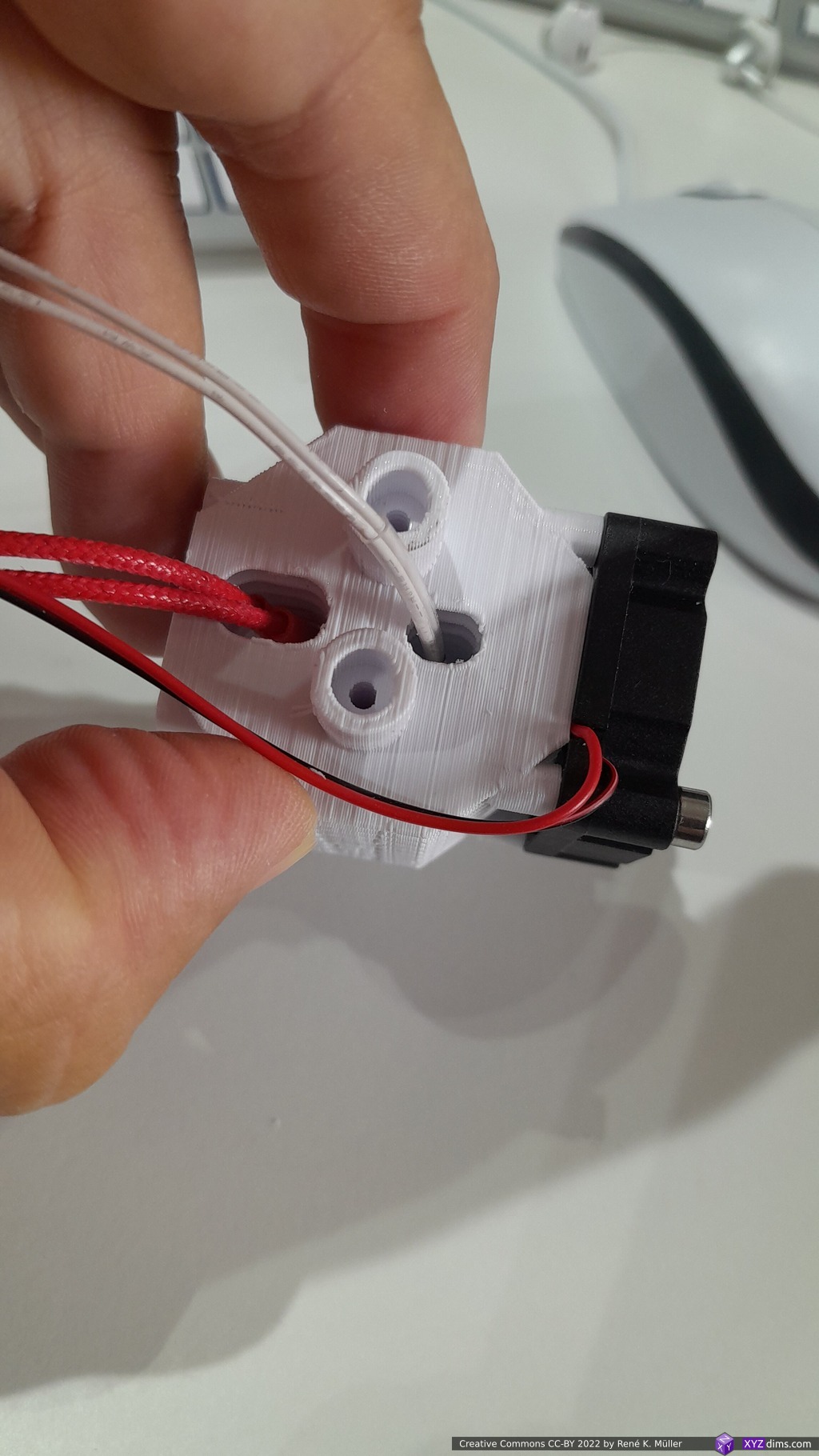
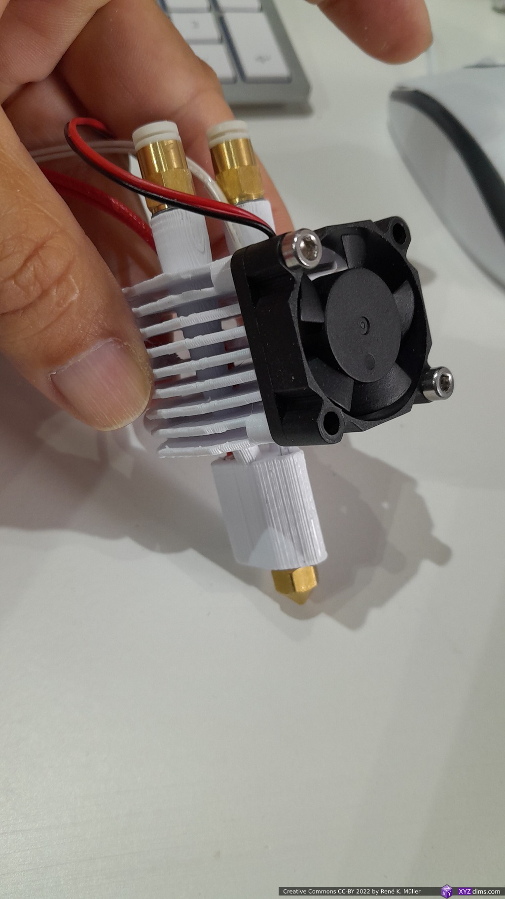
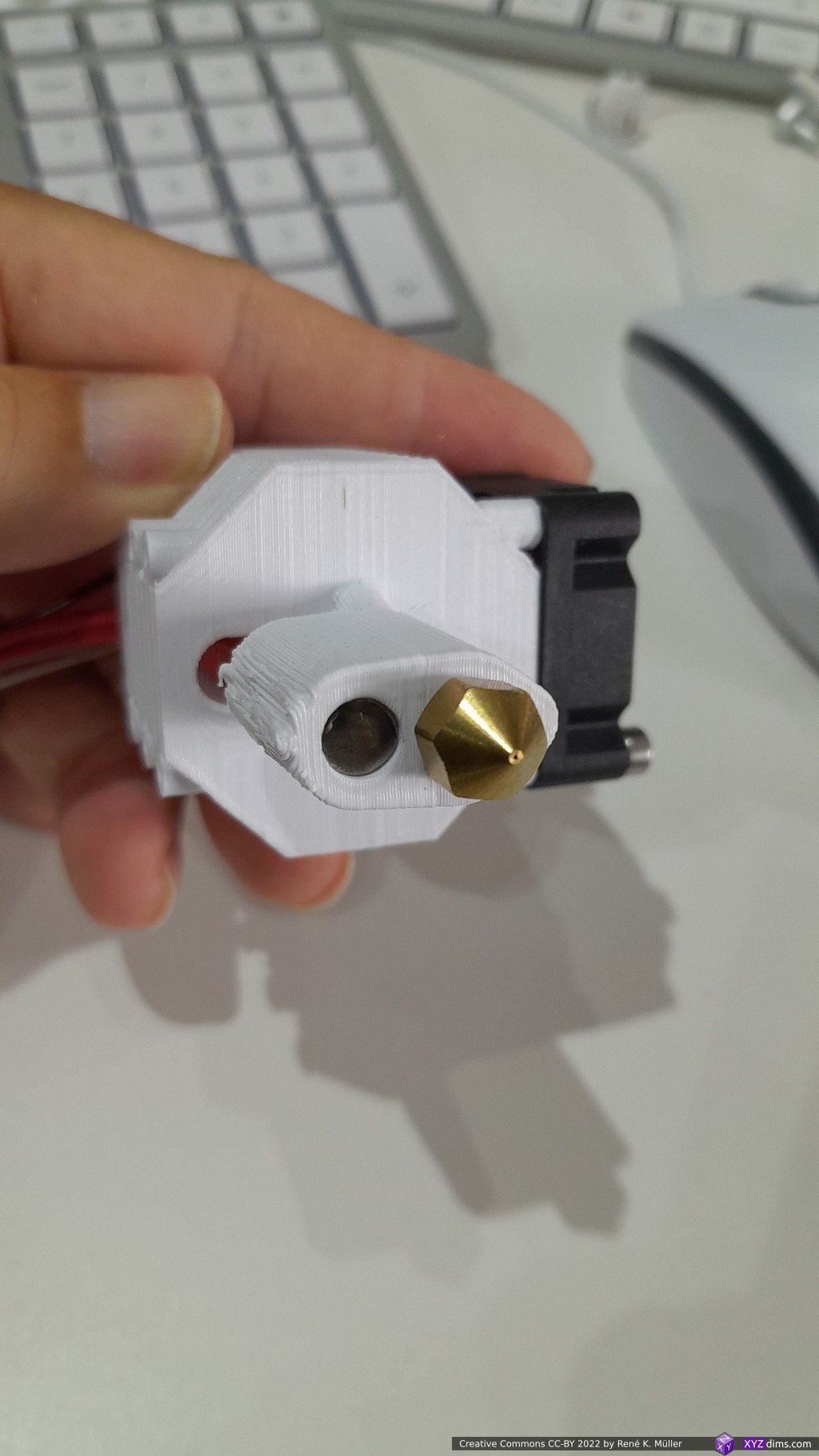
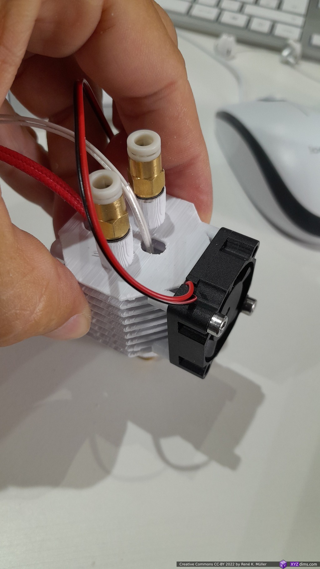
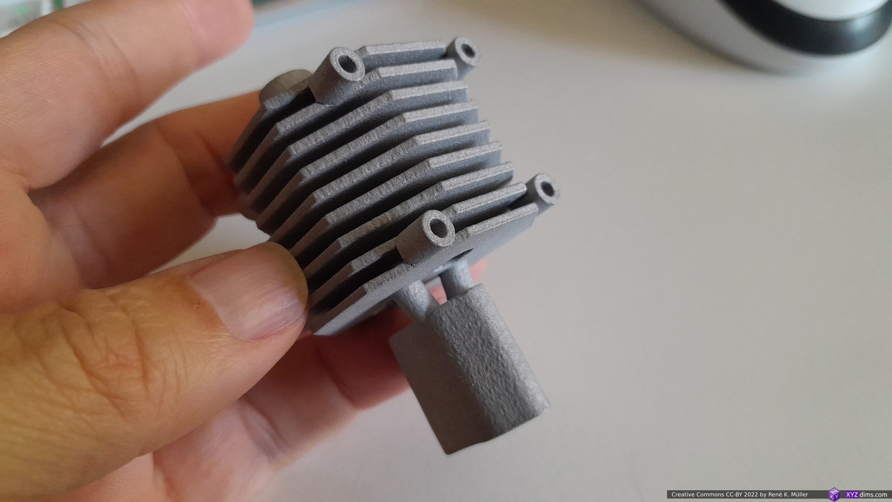
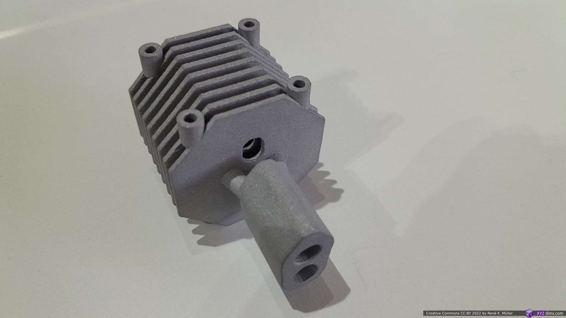
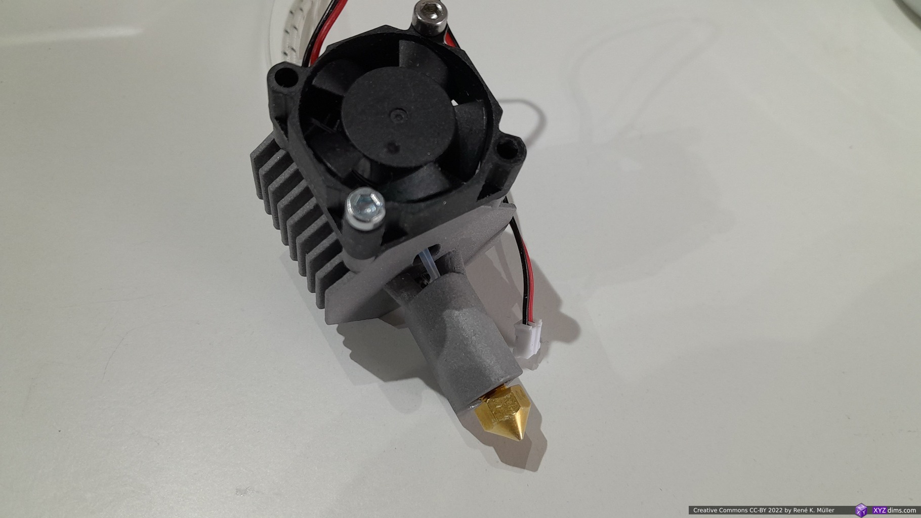
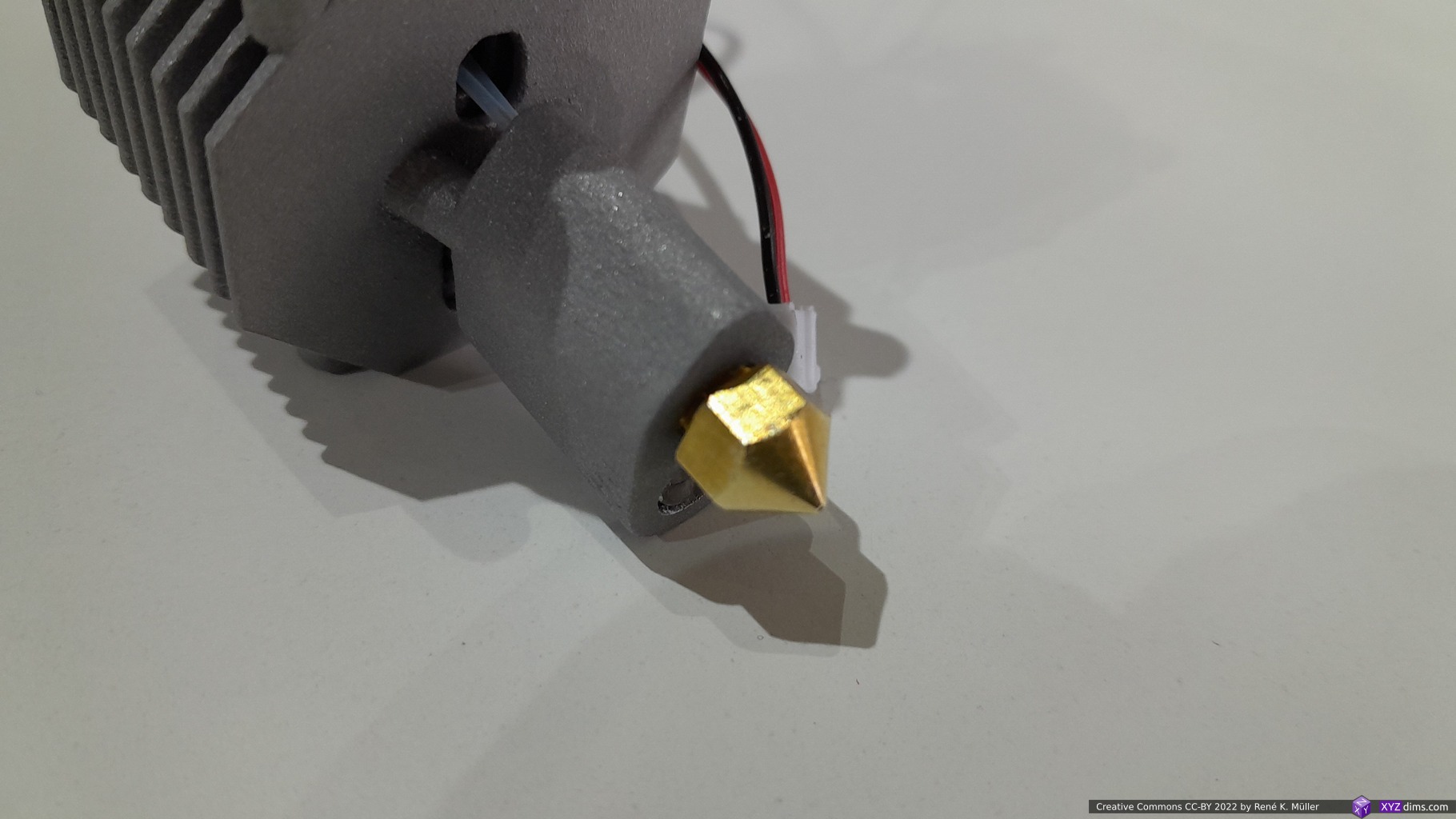
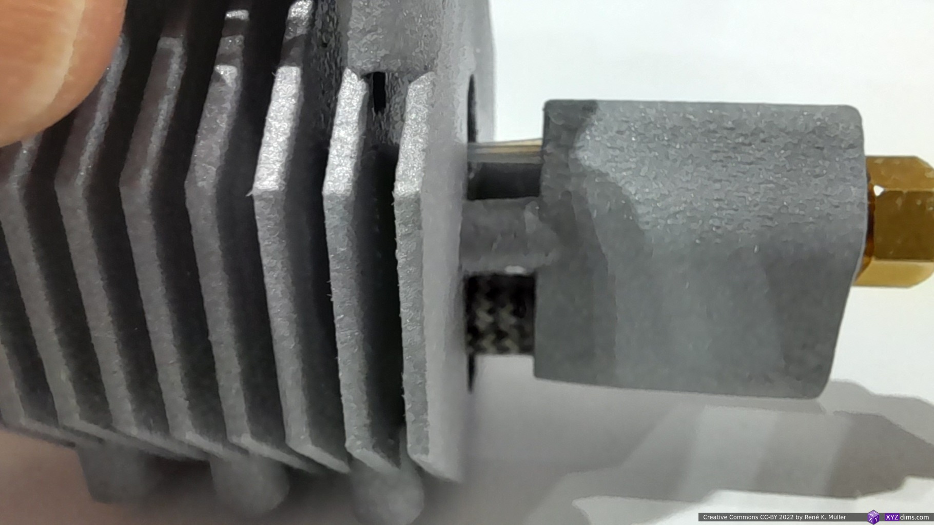
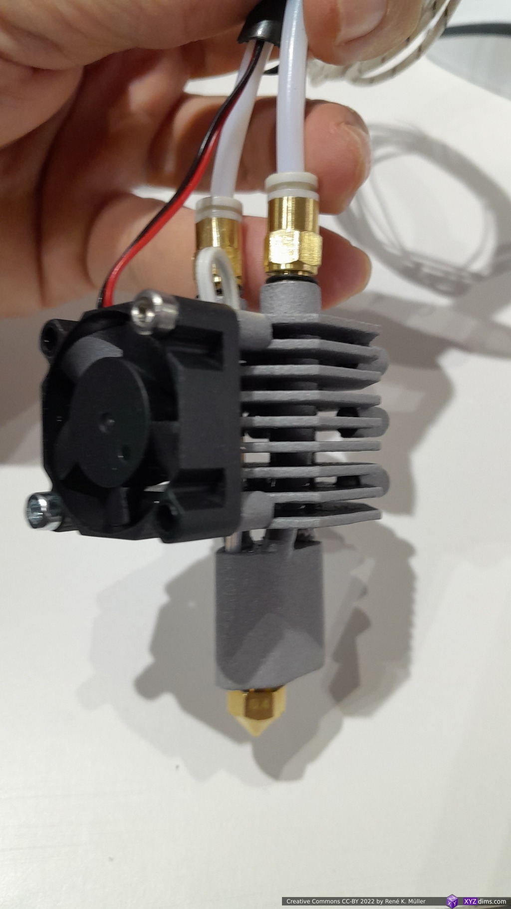
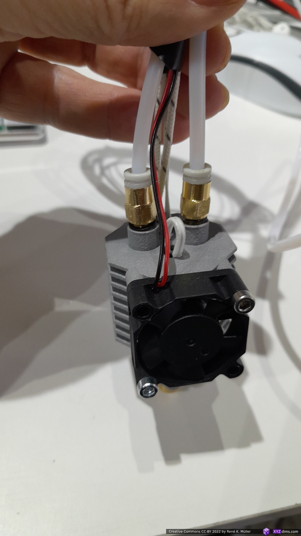
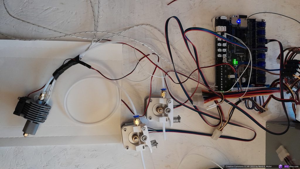
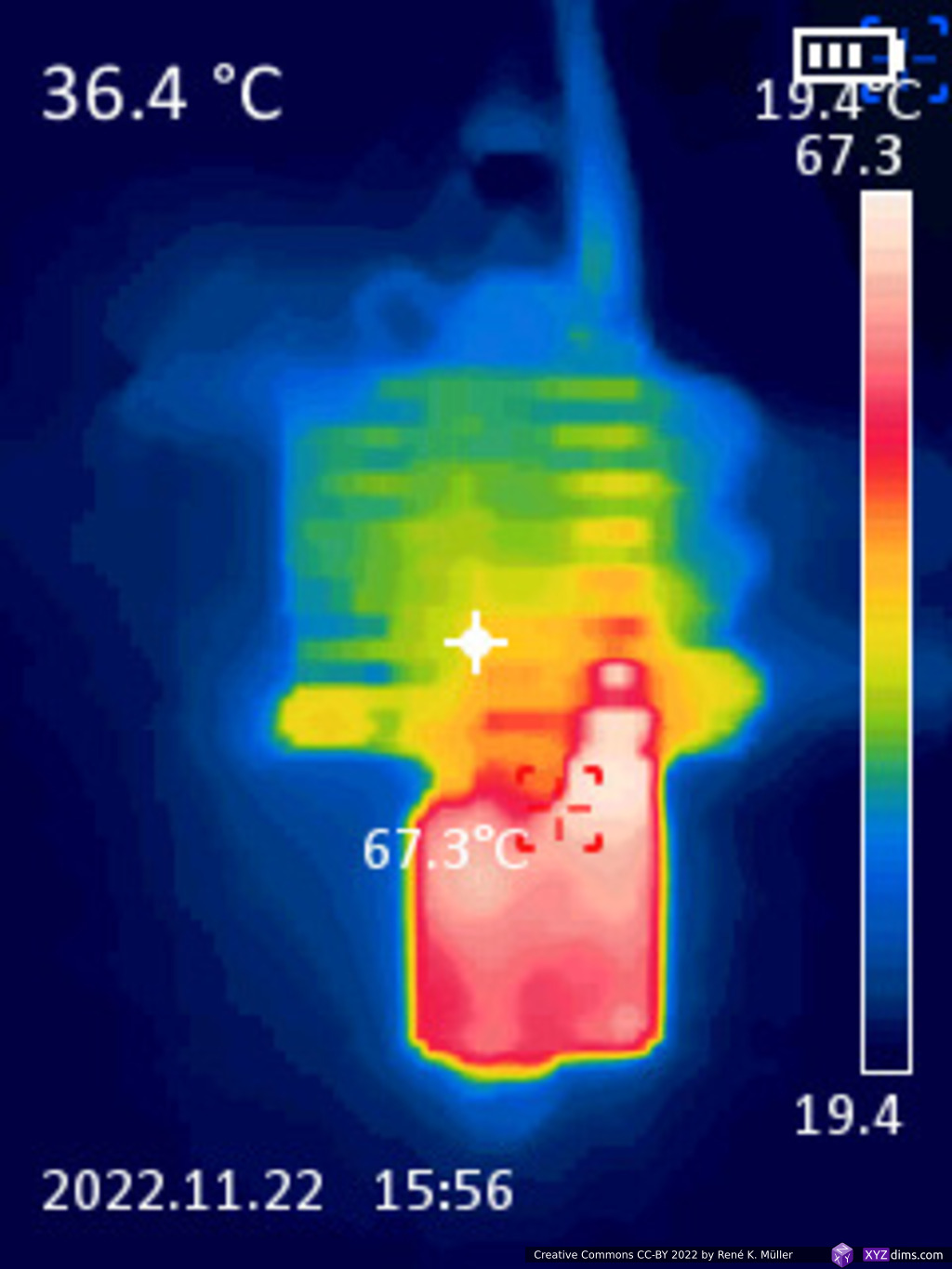
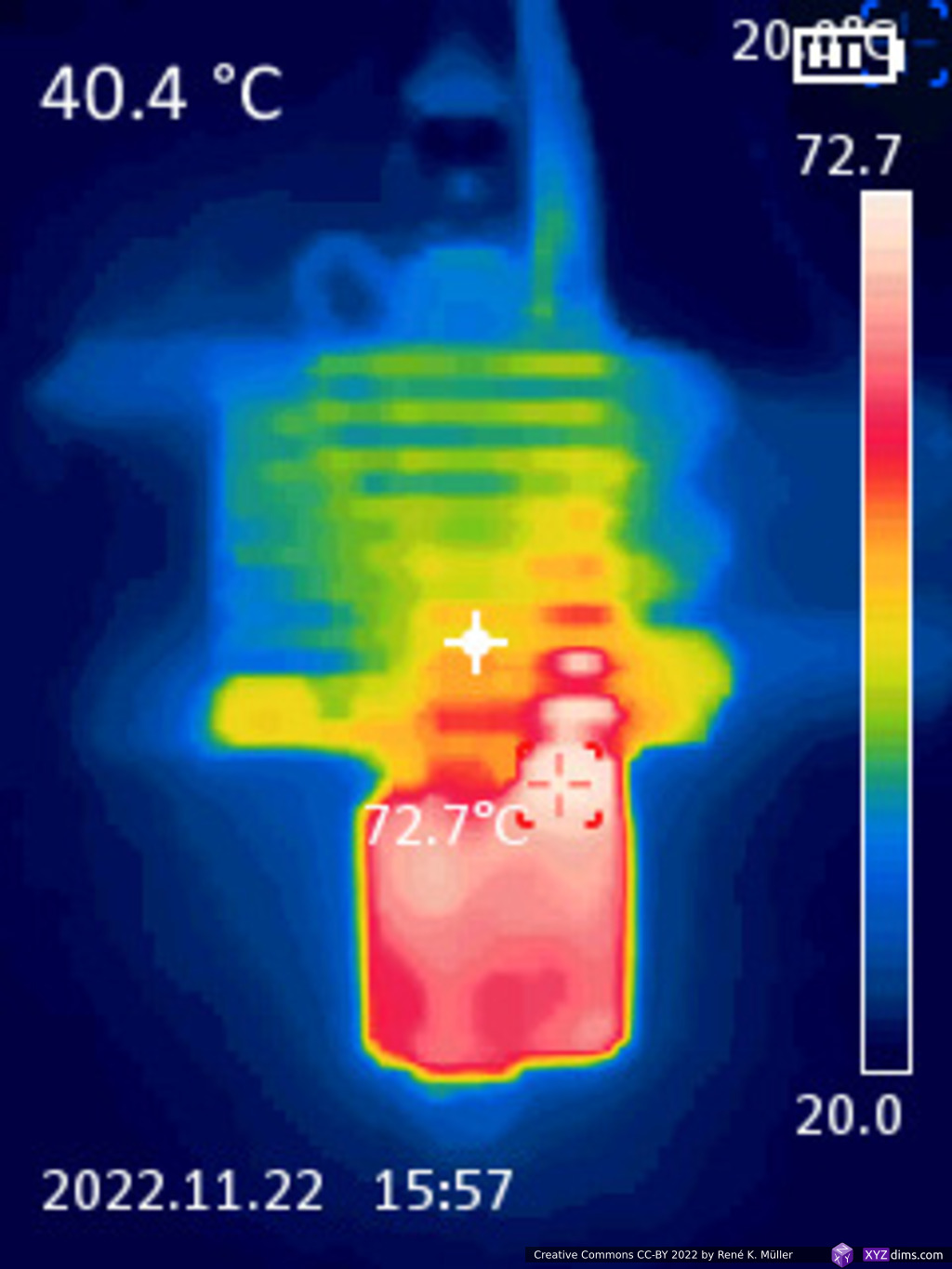
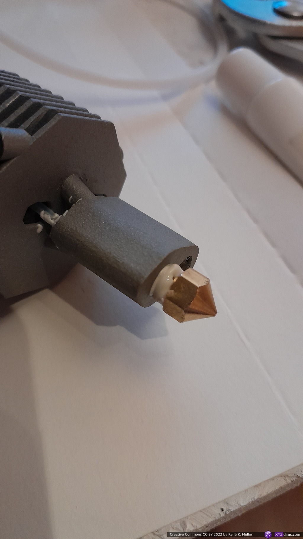
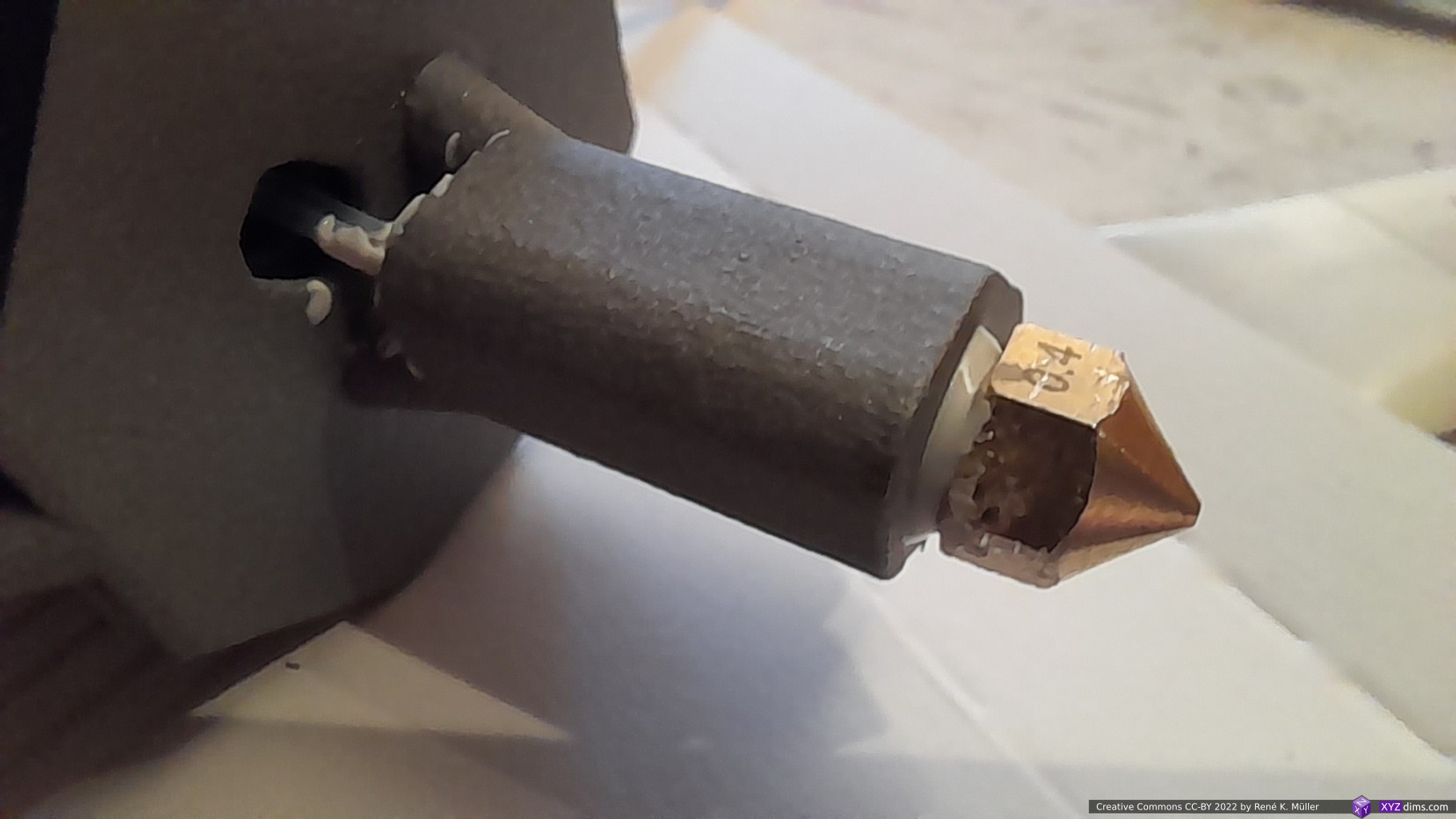
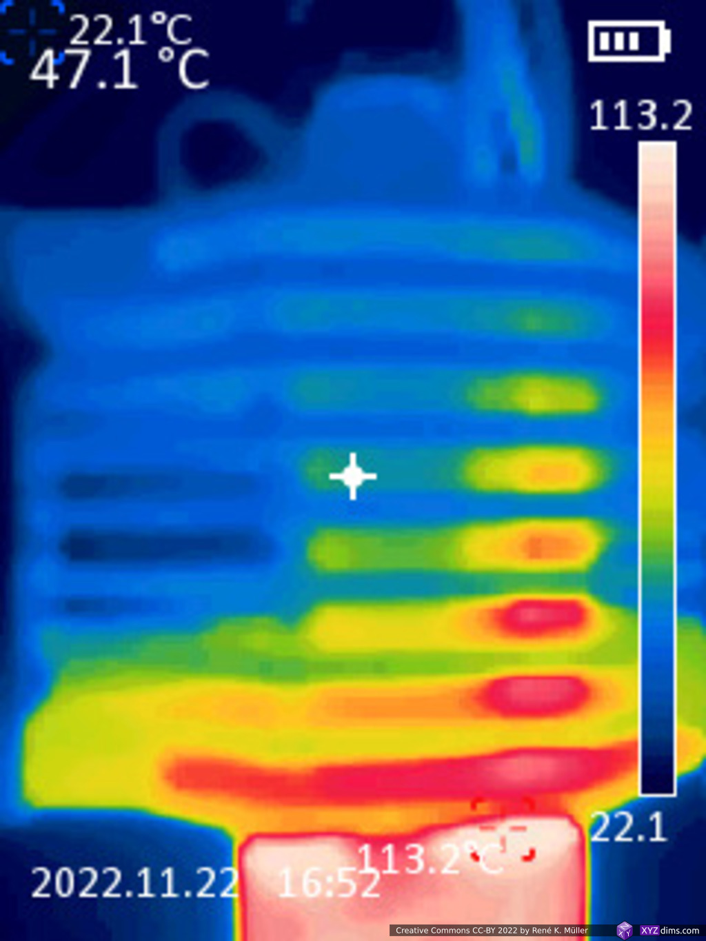
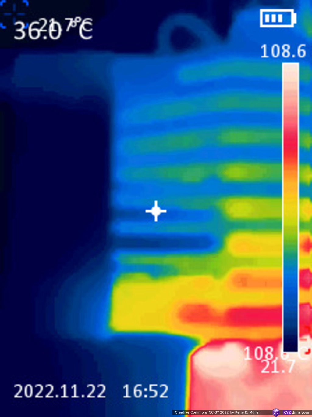
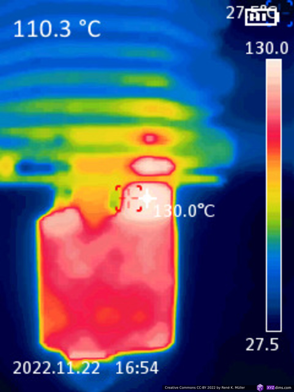
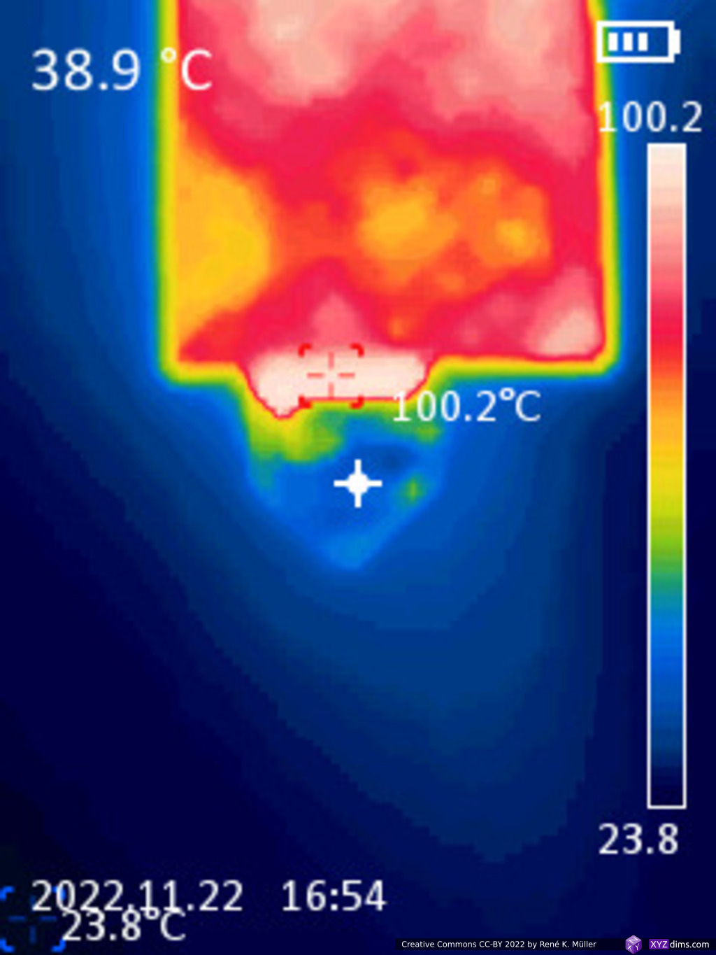
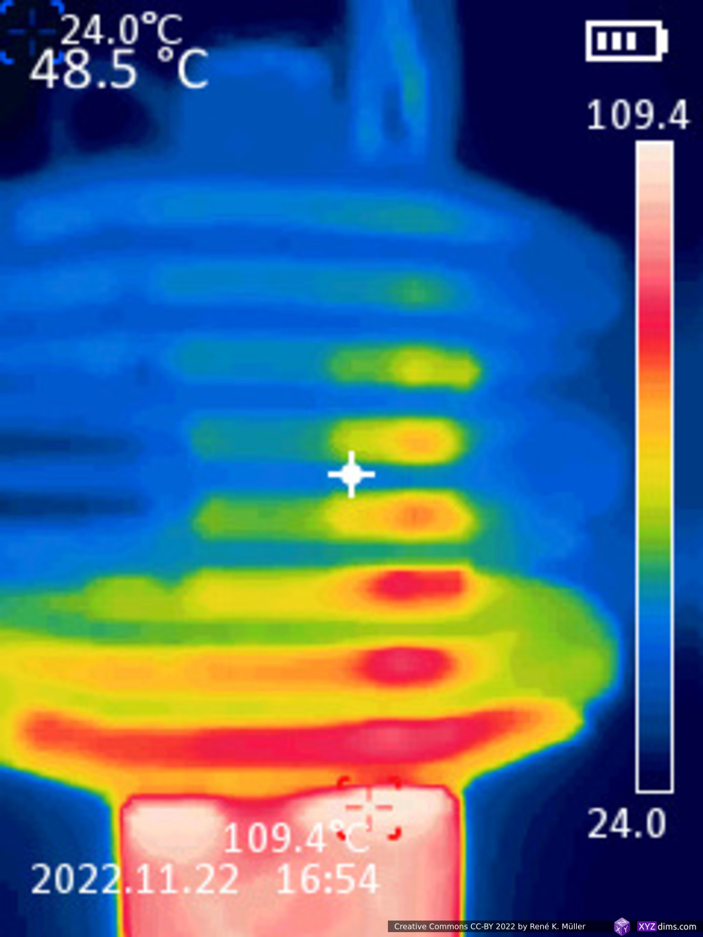
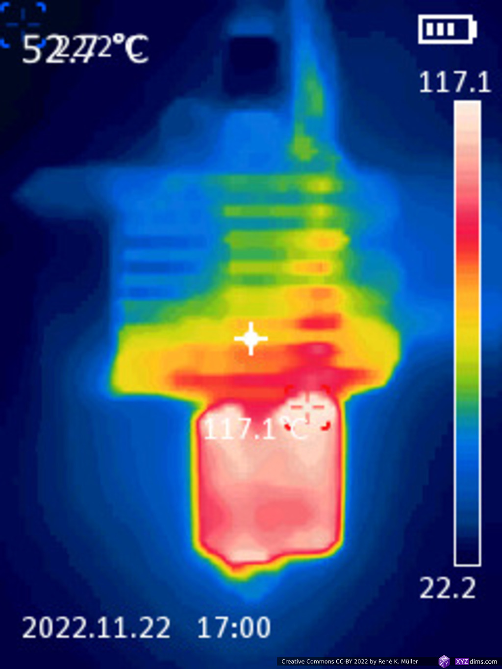
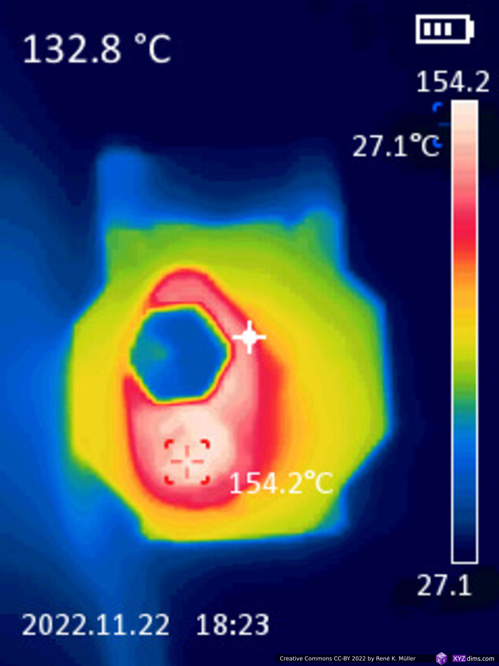
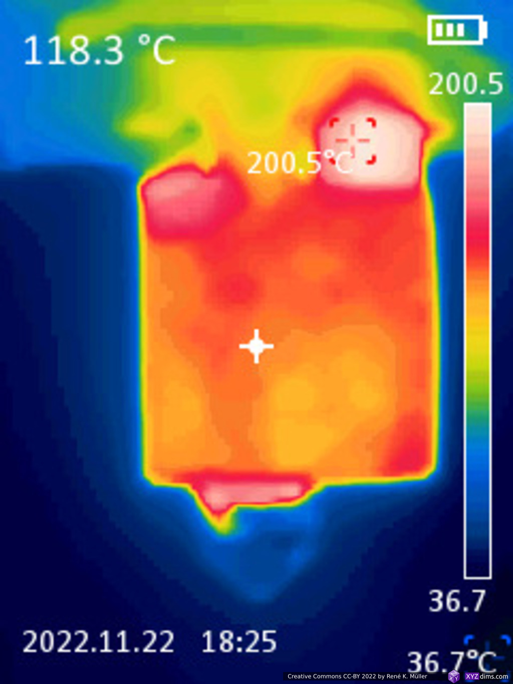
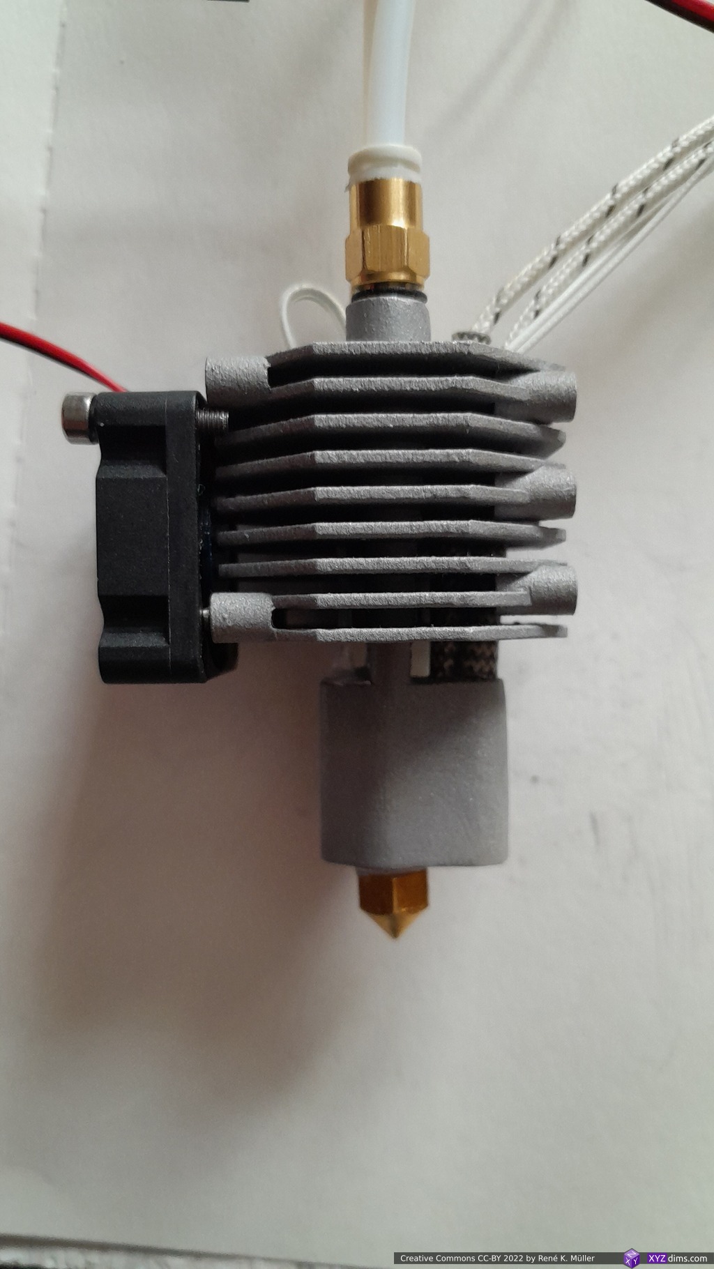
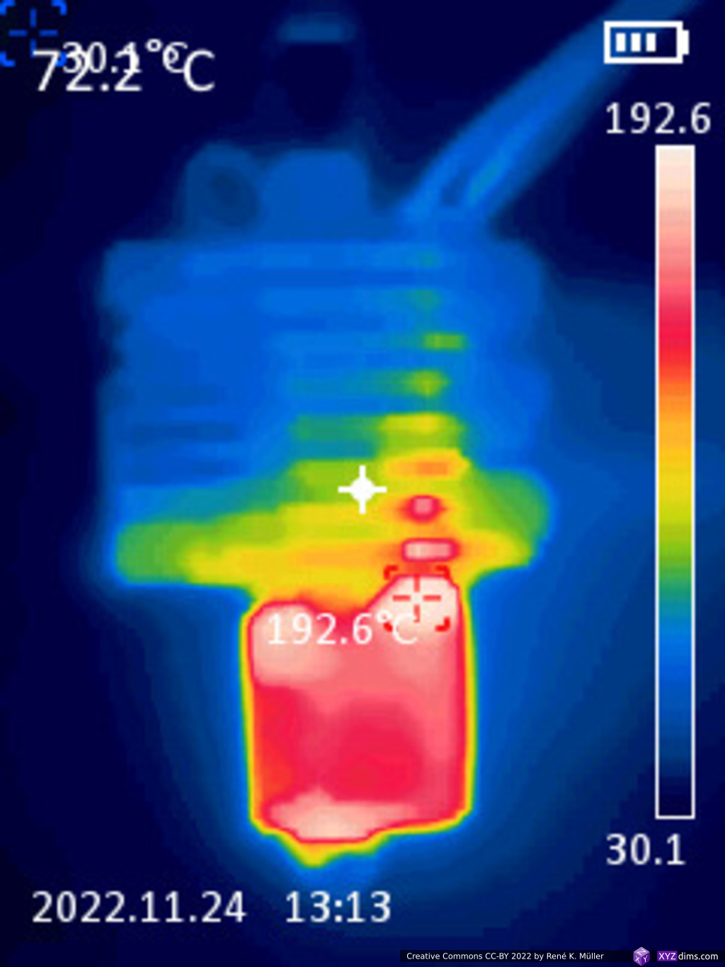
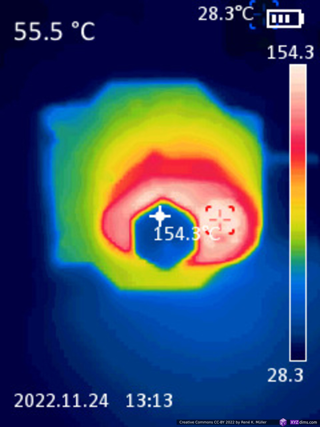
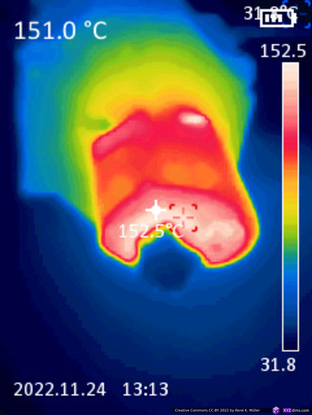
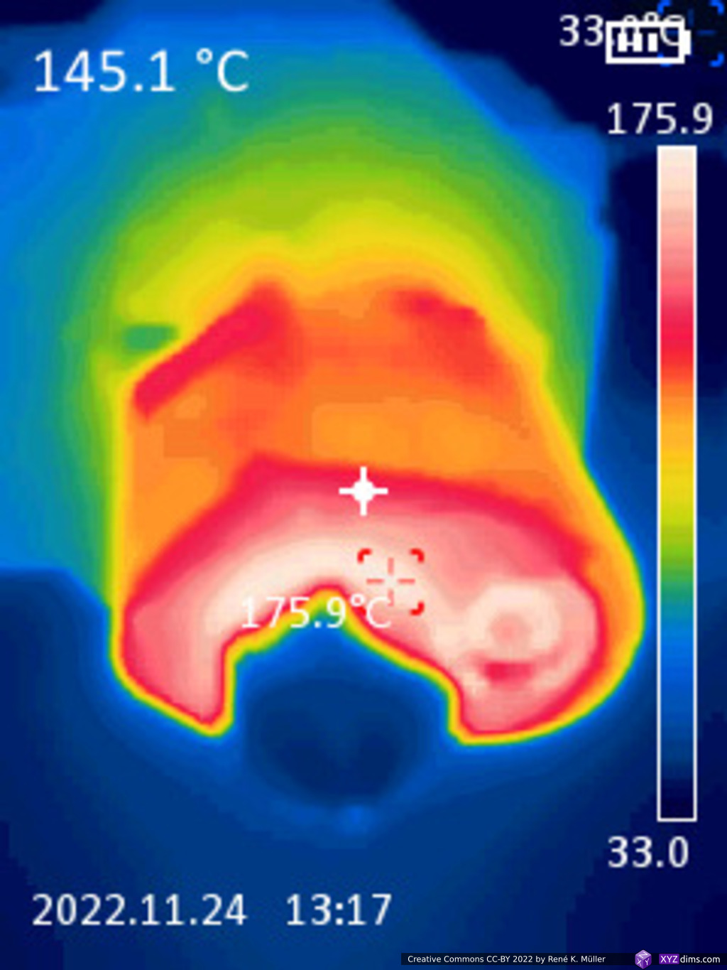
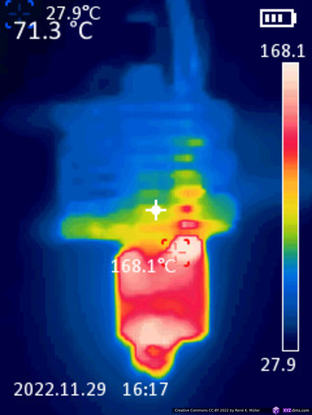
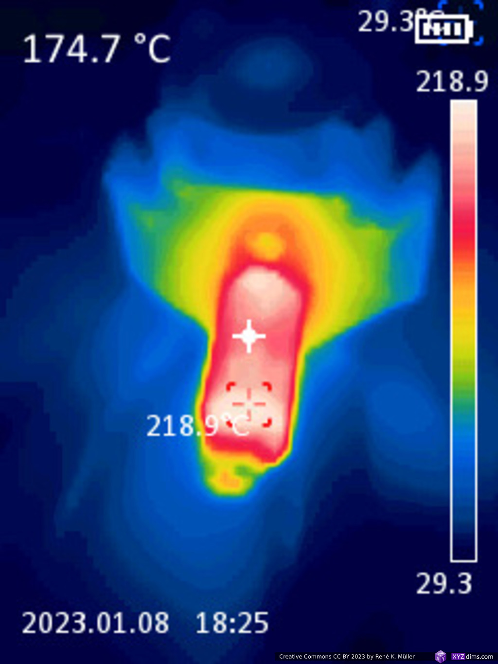
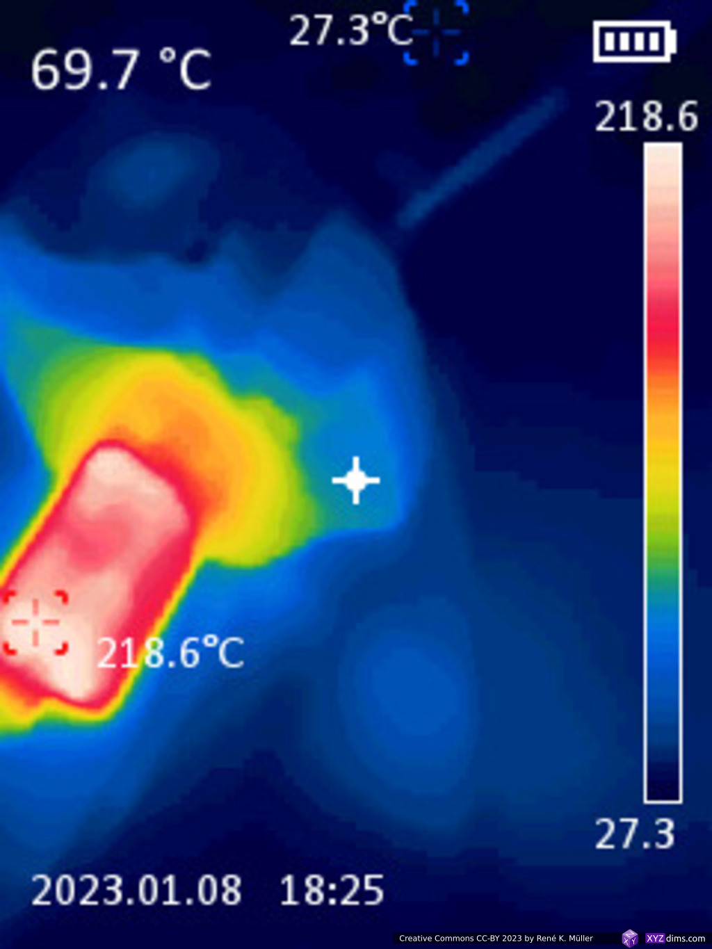
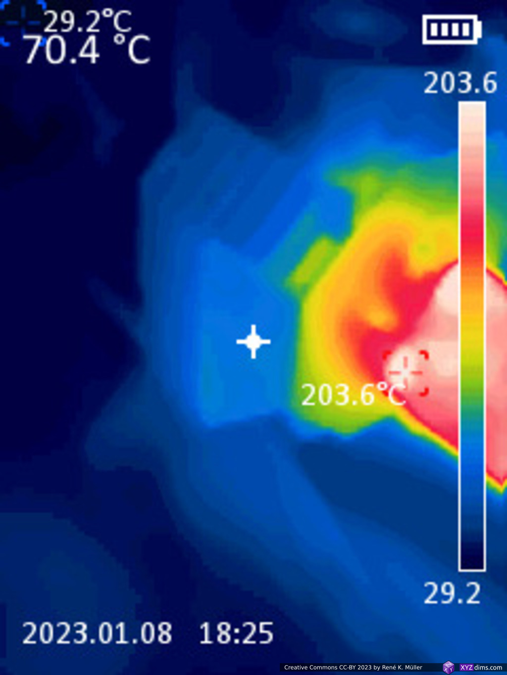
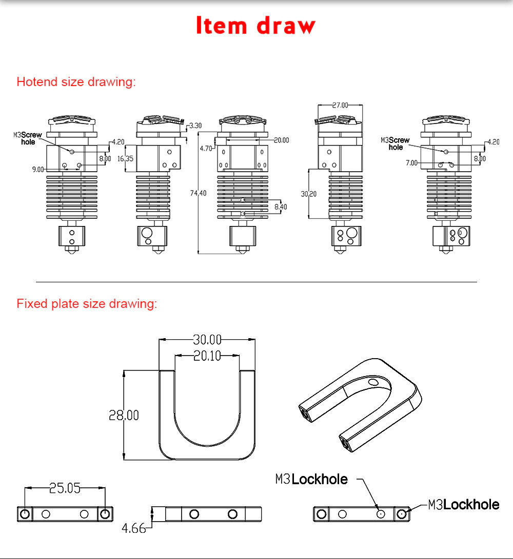
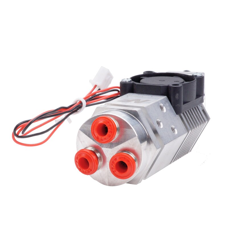
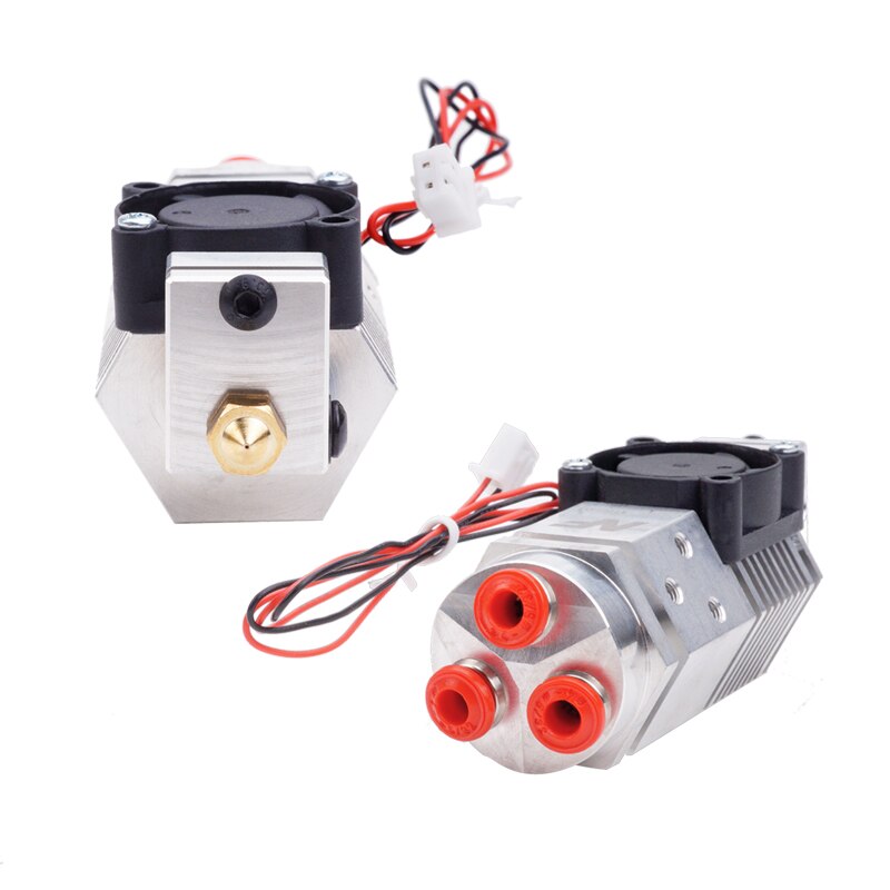
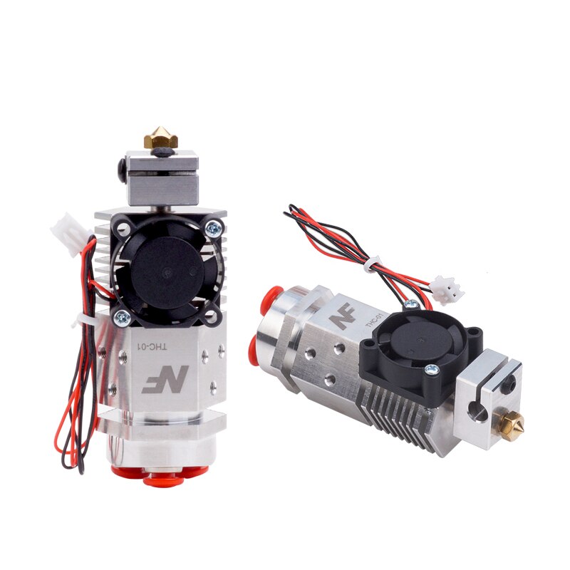
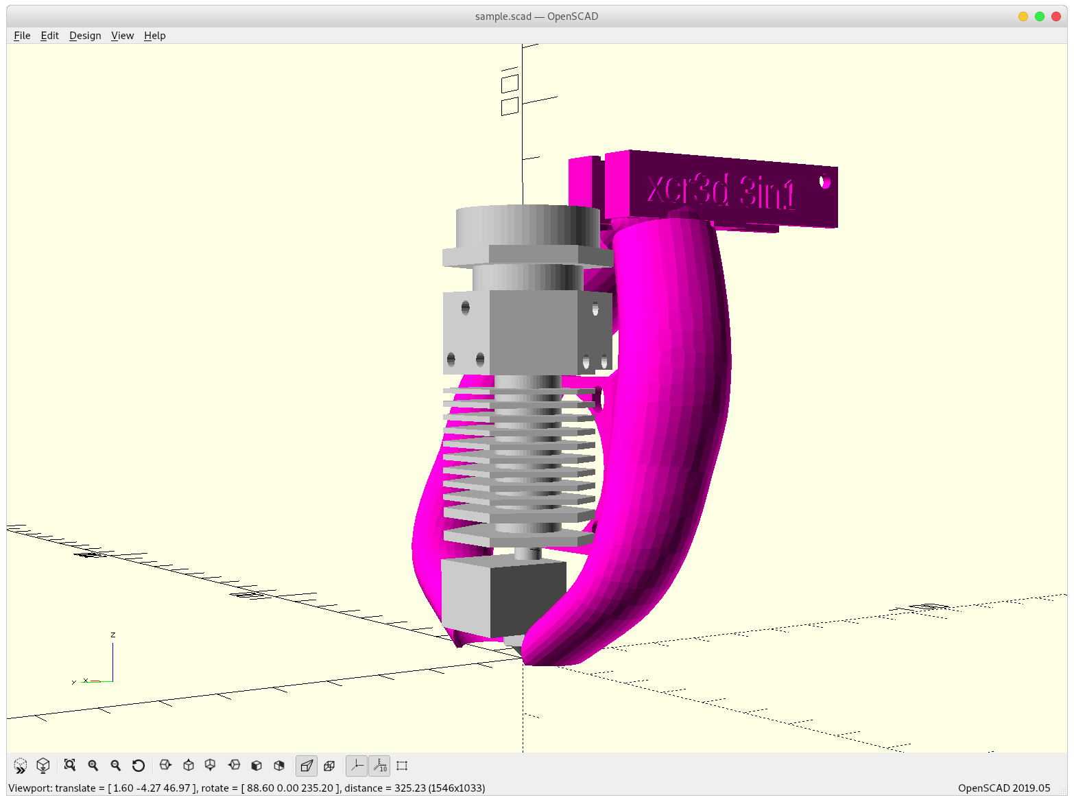
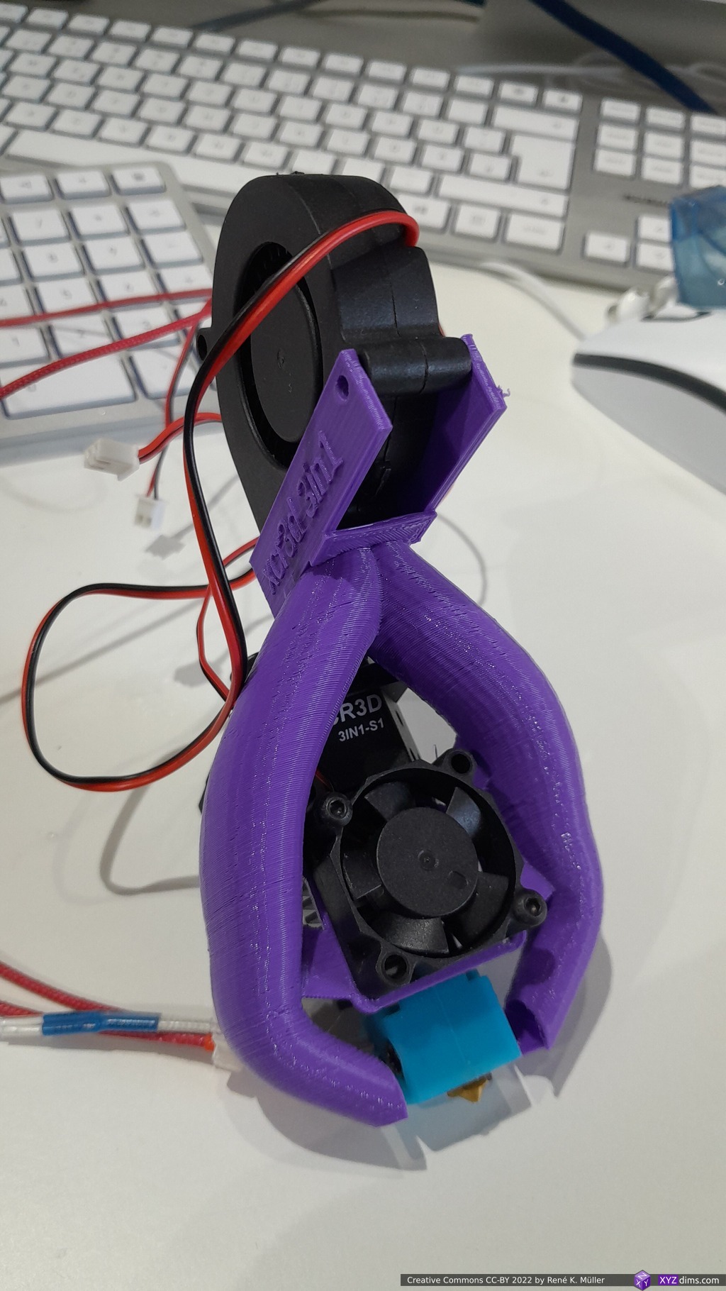
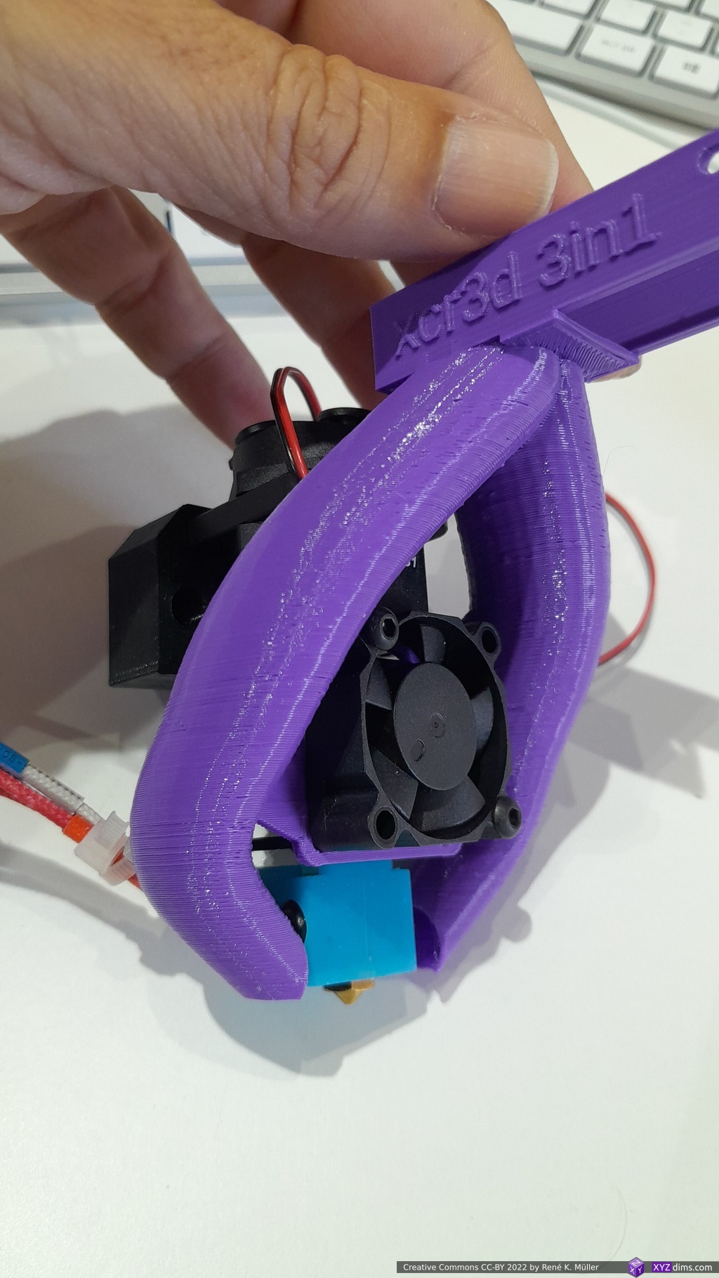
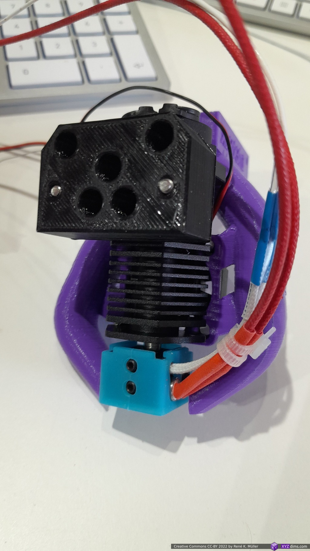
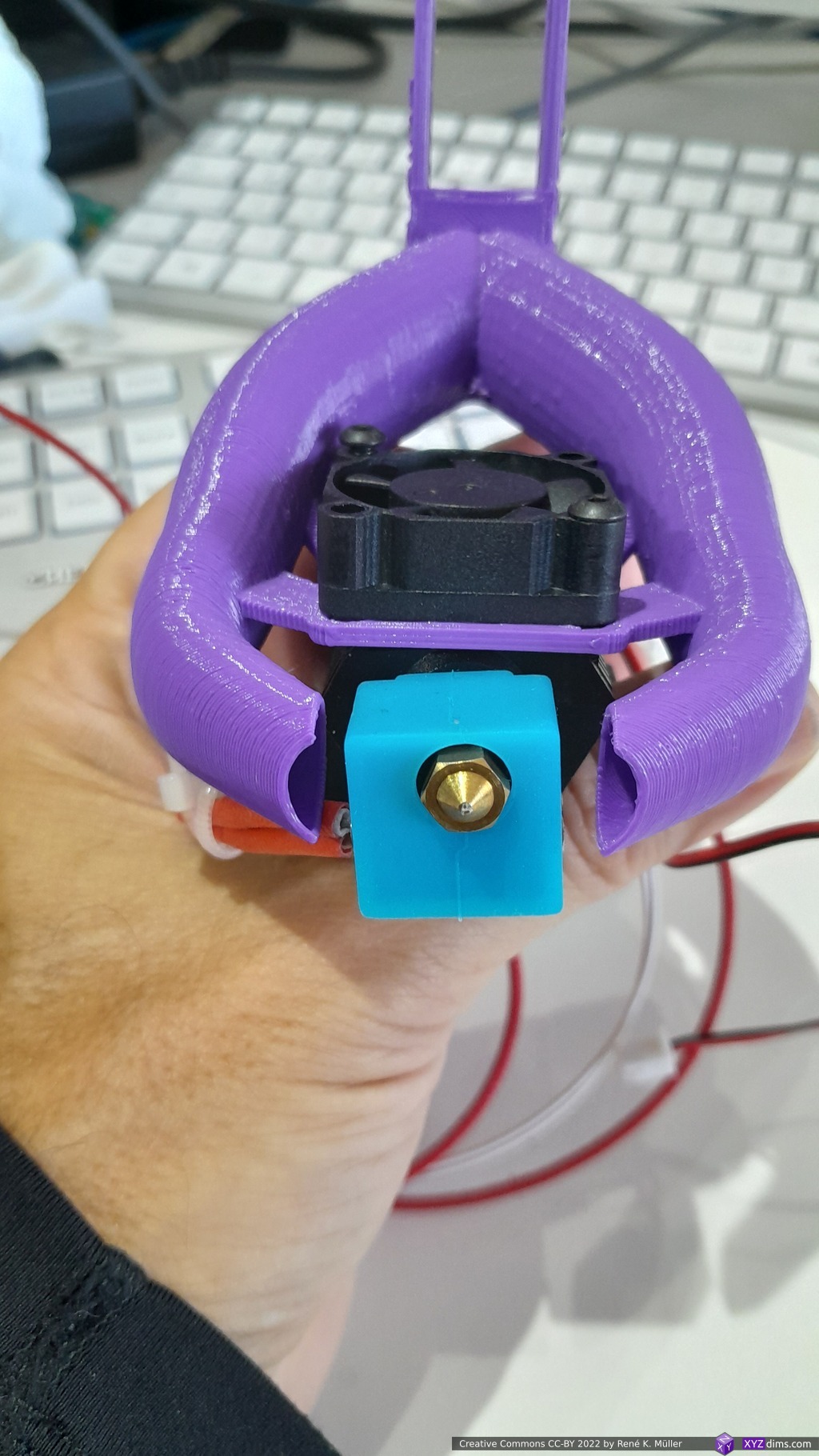
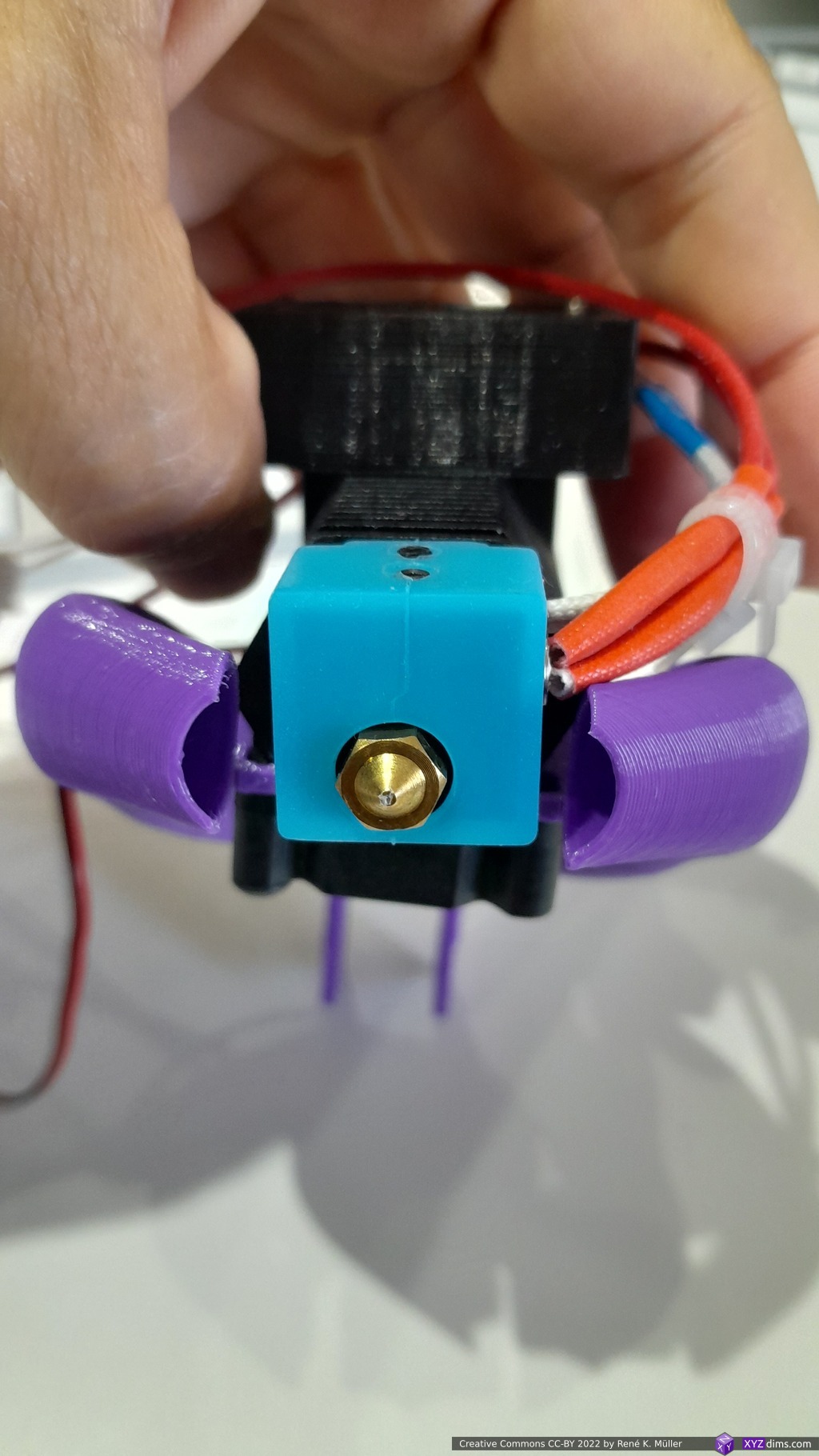
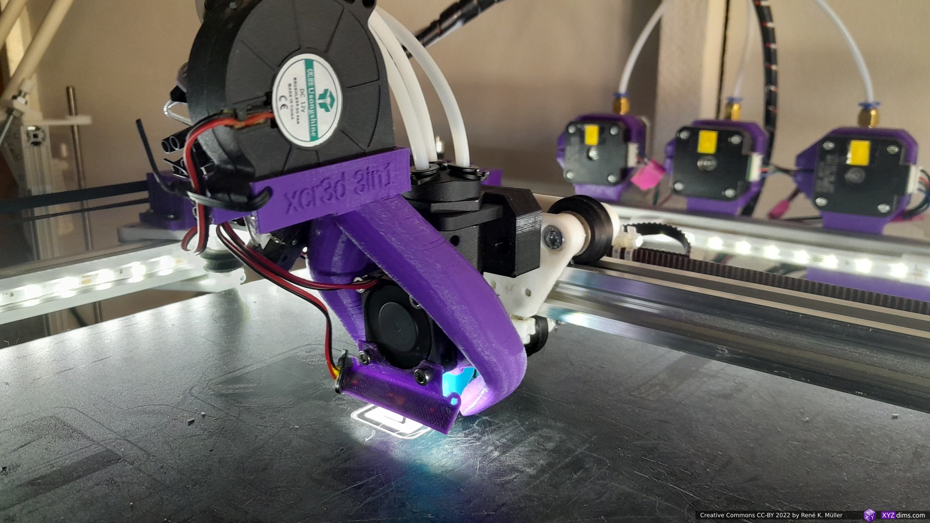
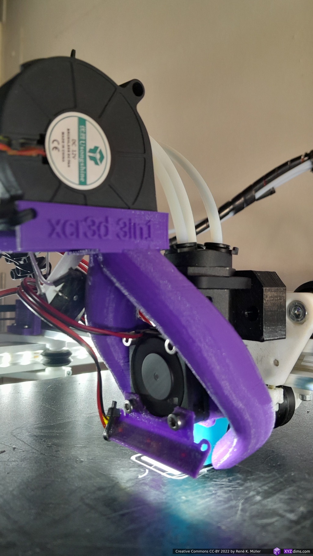
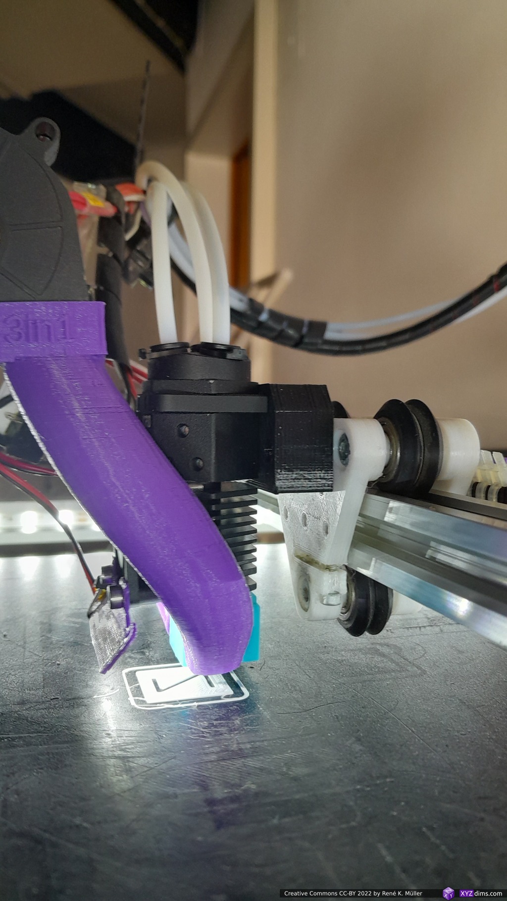
Plasmics (Inductive Heated Hotend)
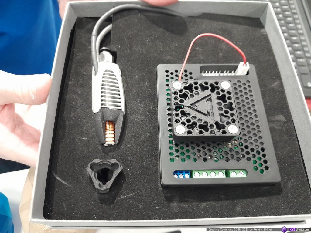

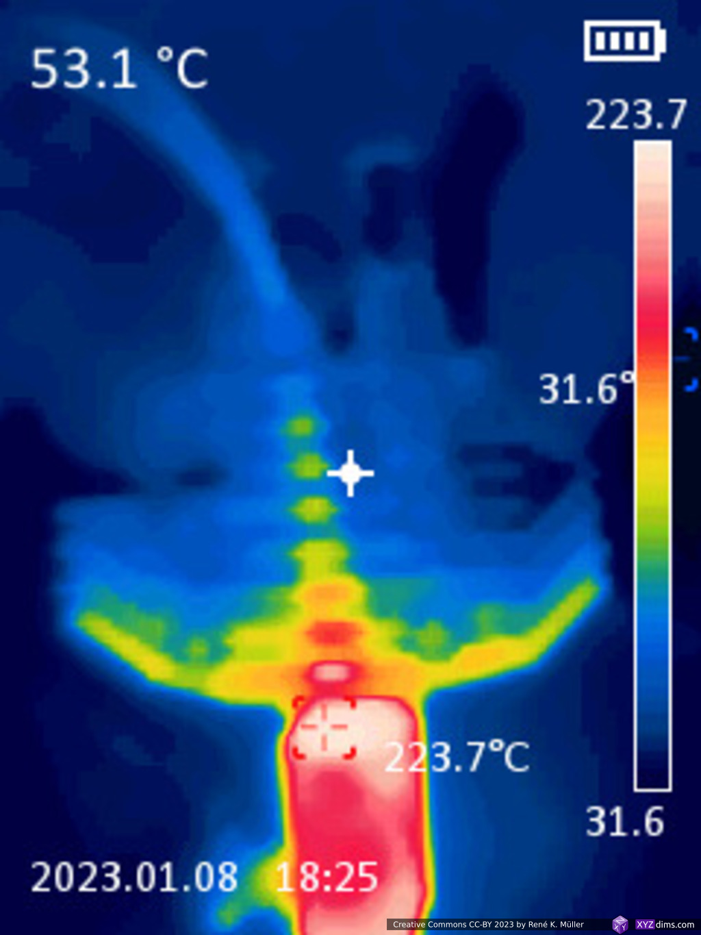
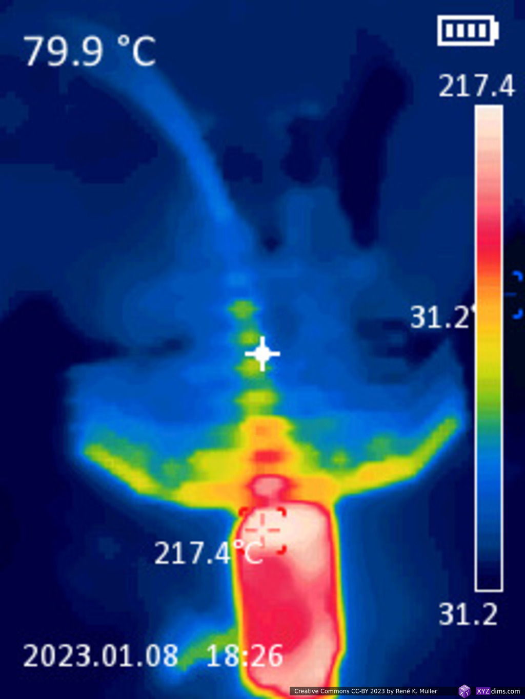
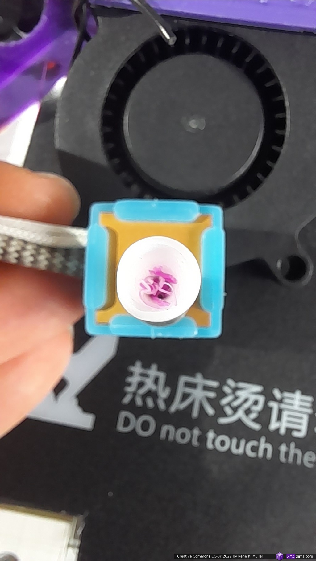
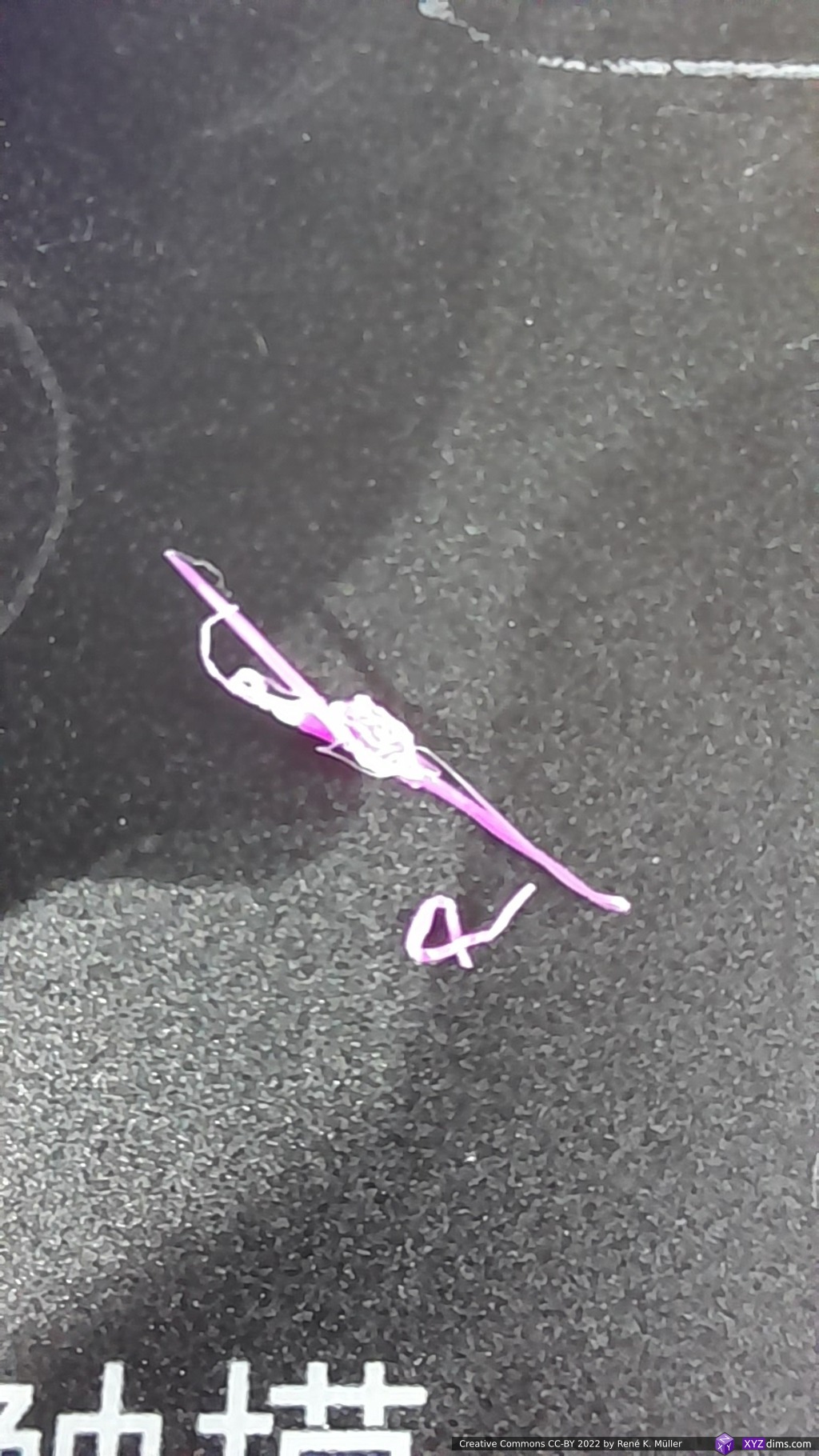
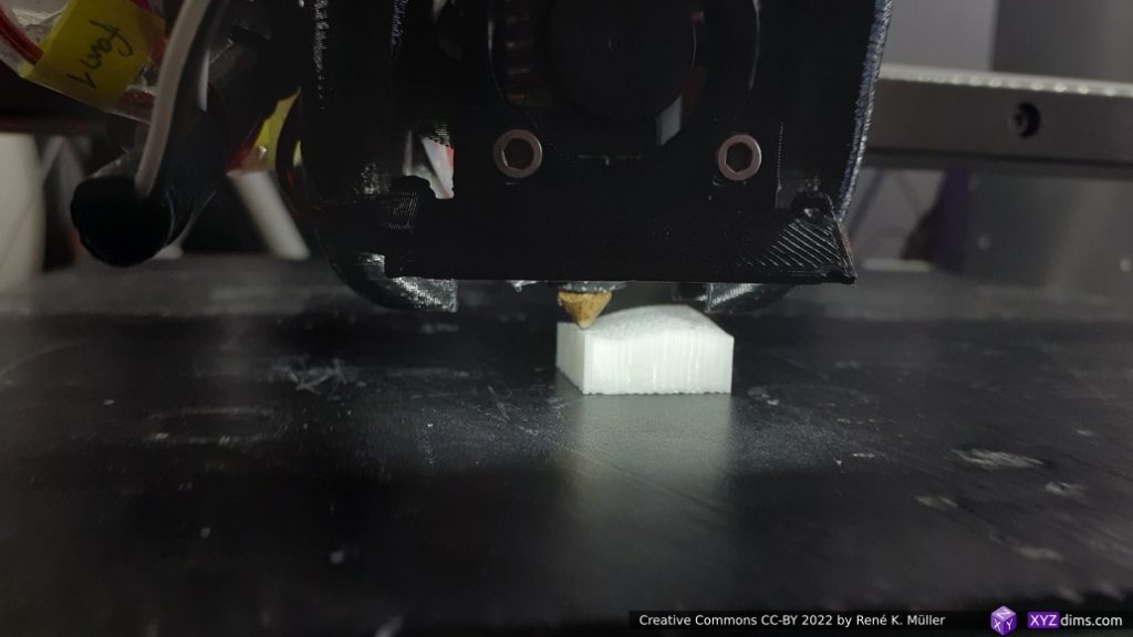
At the booth of Plasmics I looked at the inductive hotend and saw the heating up in a few seconds from 20C to 220C and cool-off in a small demo first hand.
The hot part of the nozzle looks like a needle, with little thermal mass, hence the fast heat and cooling-off time, and then surrounded by ceramics with the inductive coil on it.
The hotend incl. the controller board priced at EUR 400 is high for DIY enthusiasts but low for an industrial setup.
Miscellaneous
Major AM players were present:
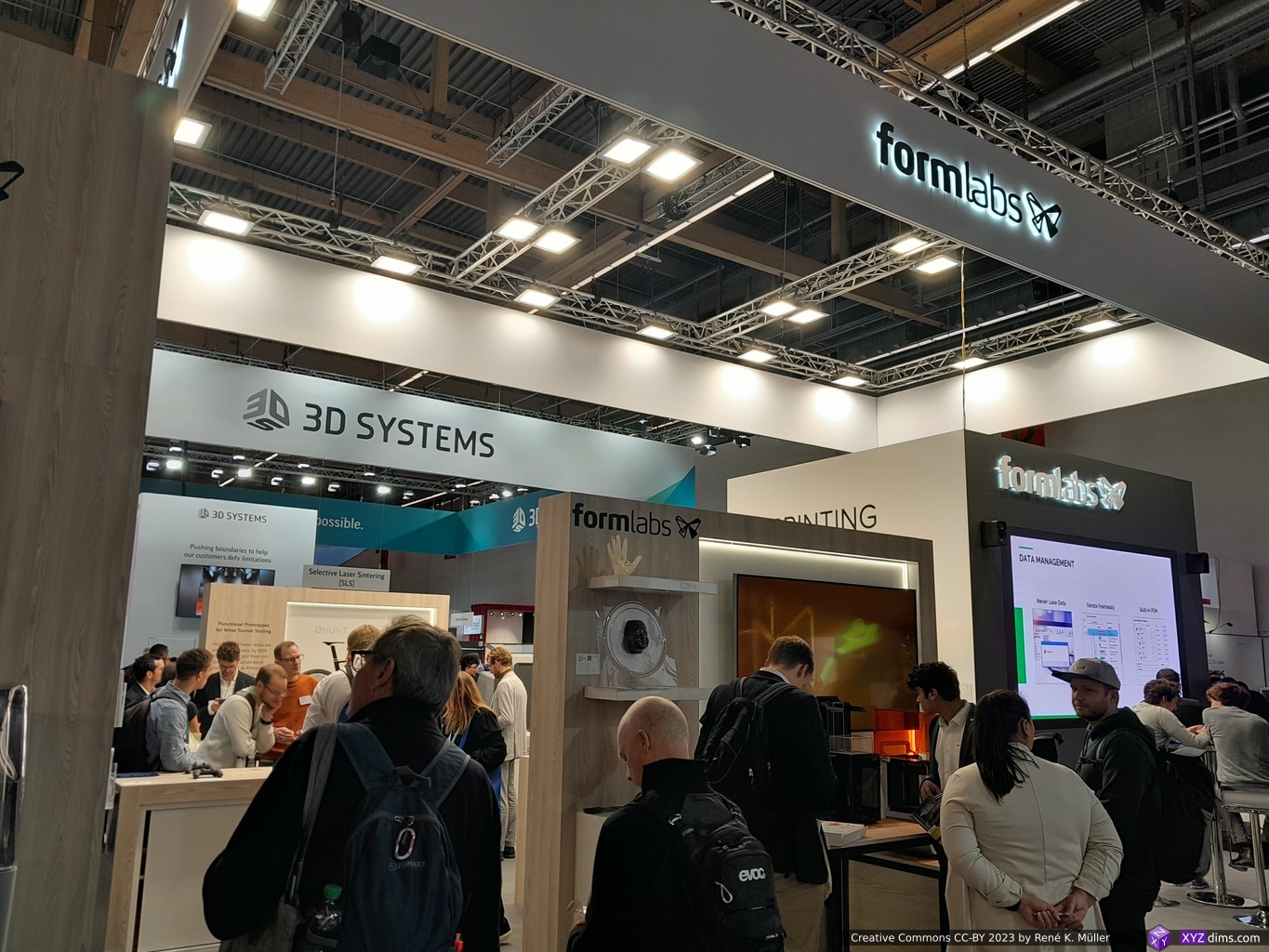
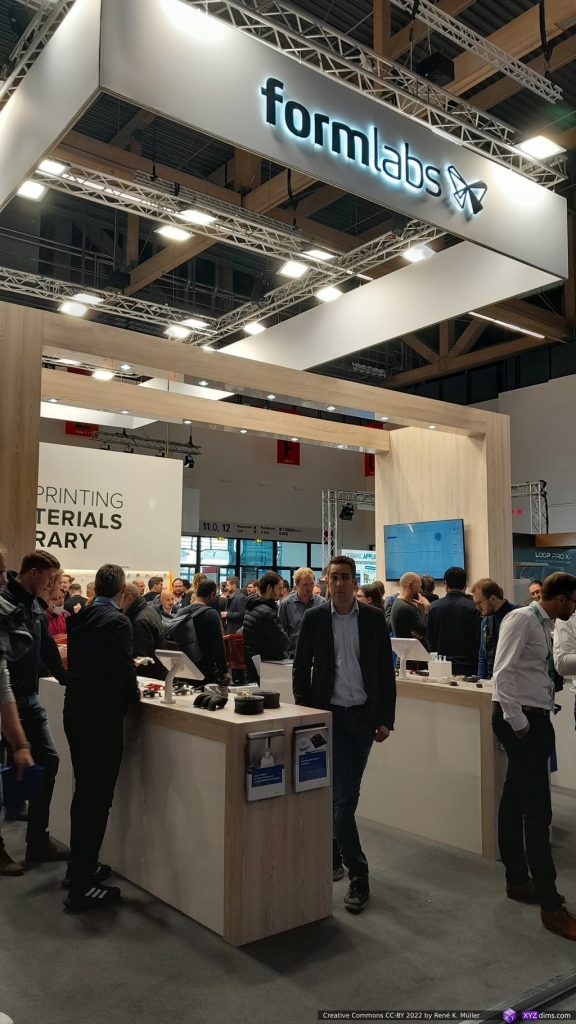
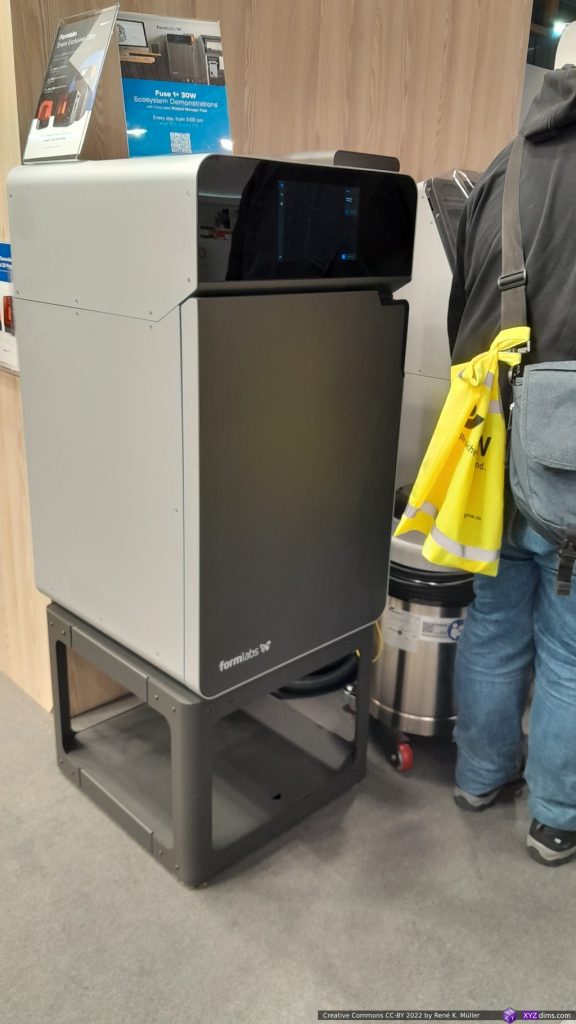
- Formlabs: industrial SLA & SLS
- Markforged: 3-axis Continueous Carbon Fiber (CFF)
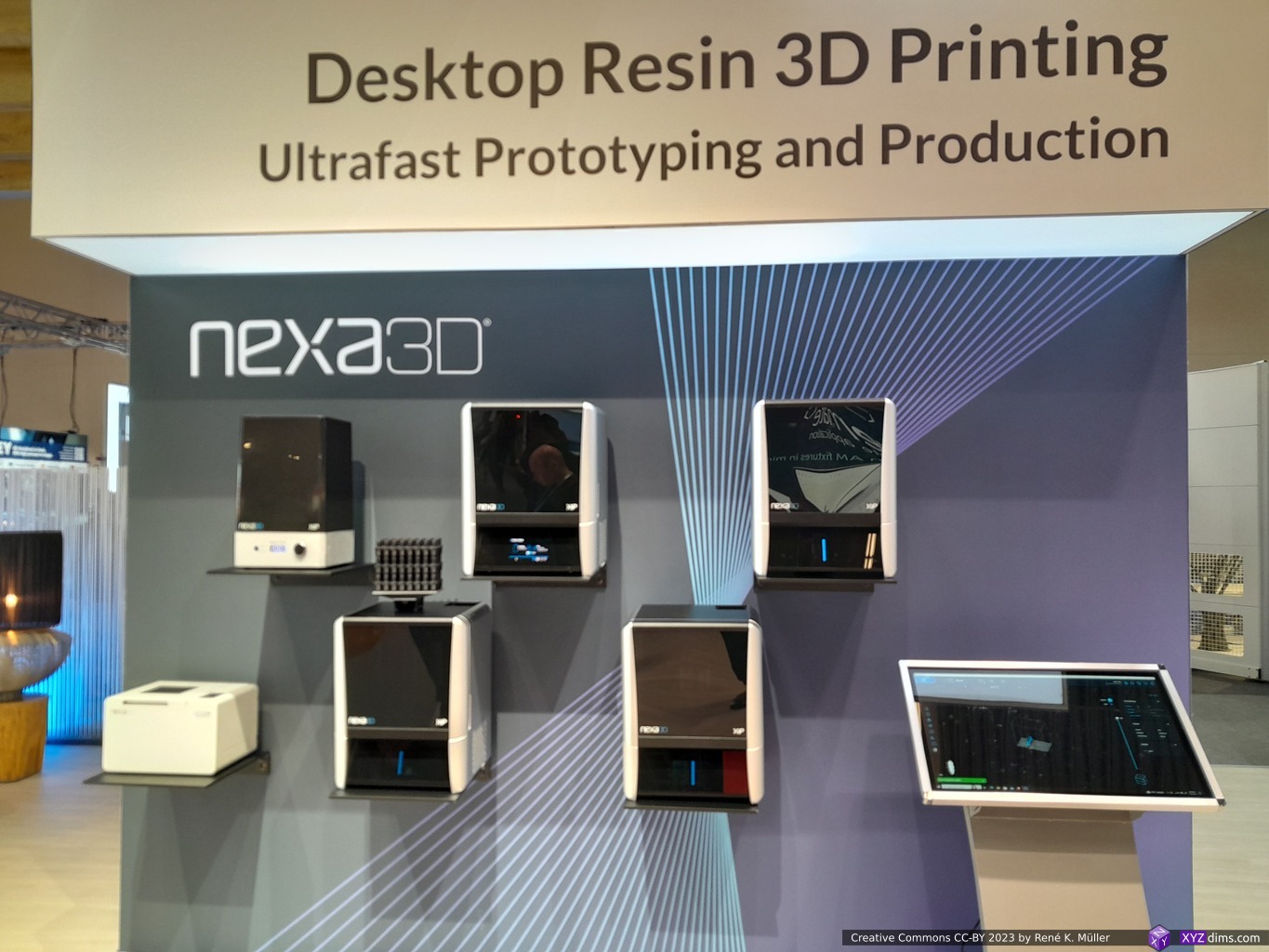
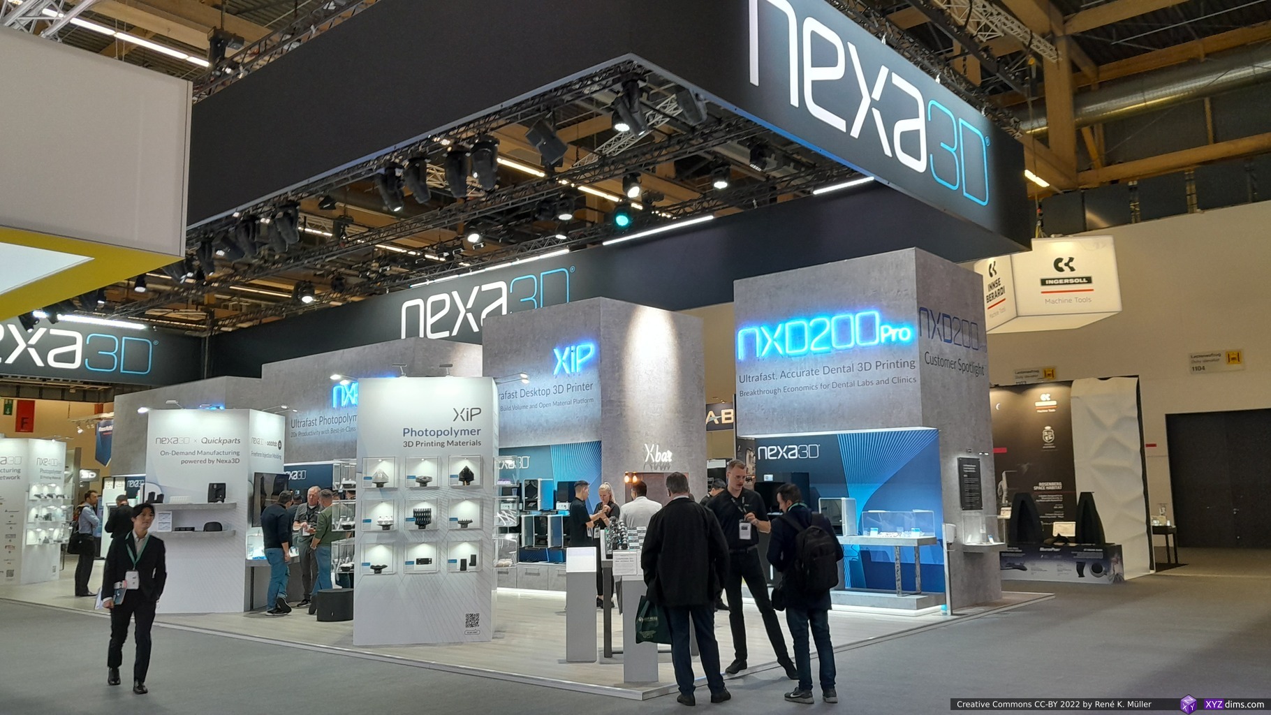
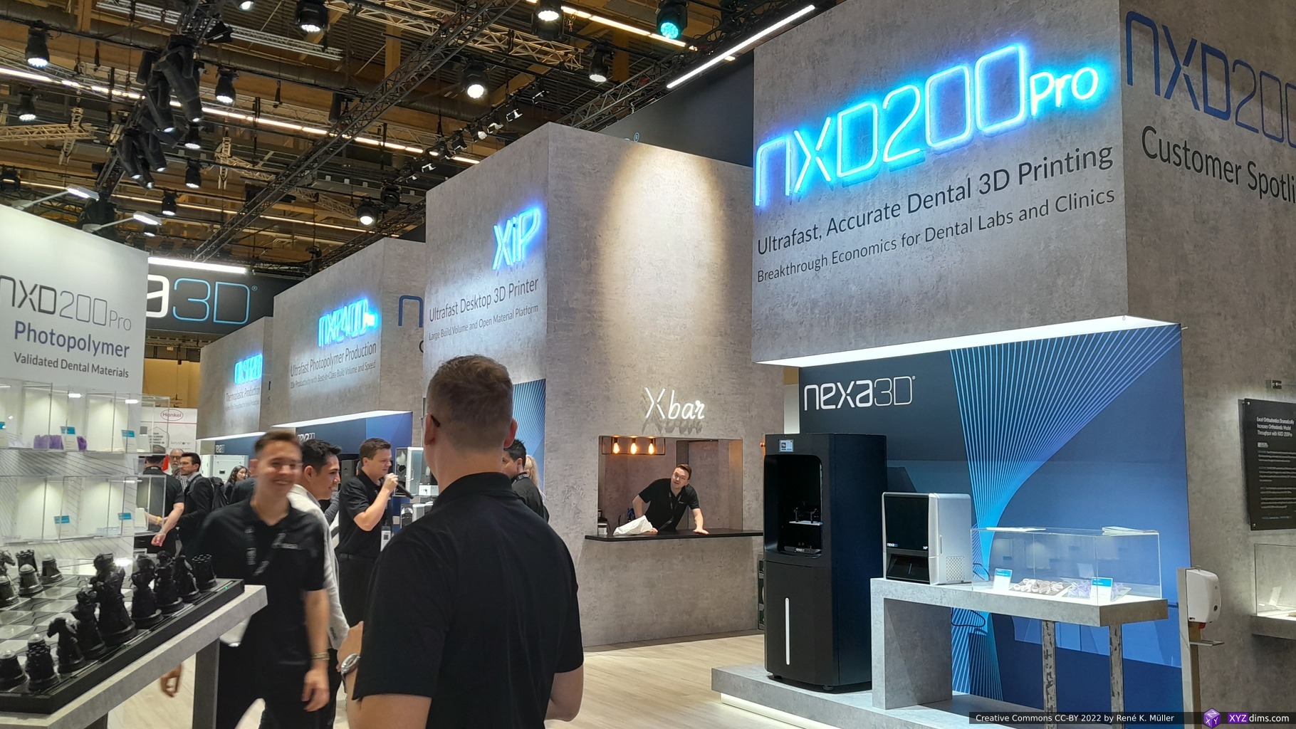
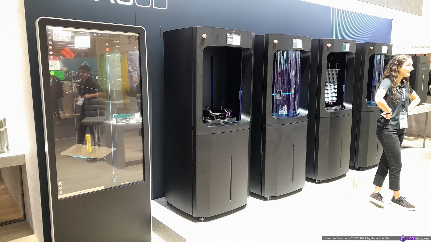
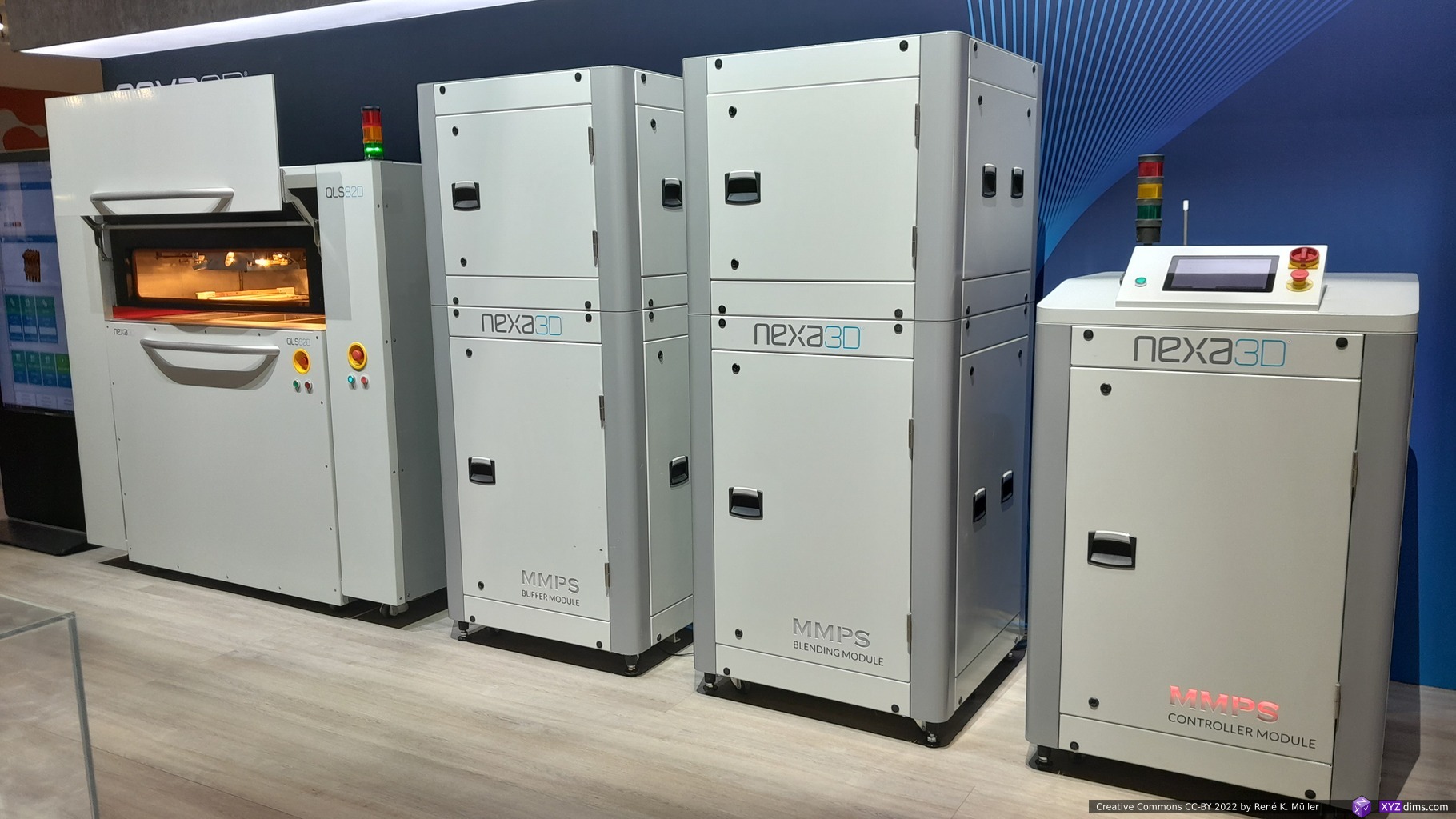
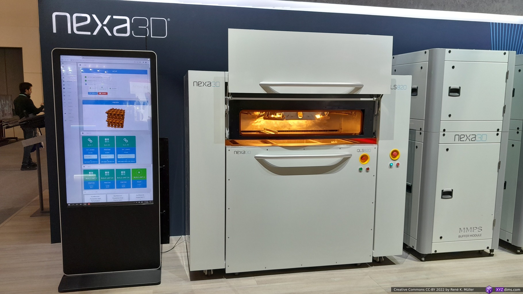
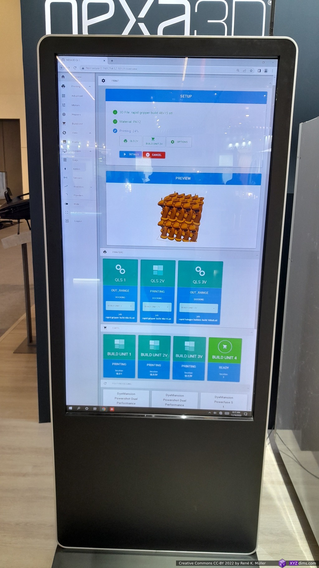
- Nexa3D: industrial SLA & SLS
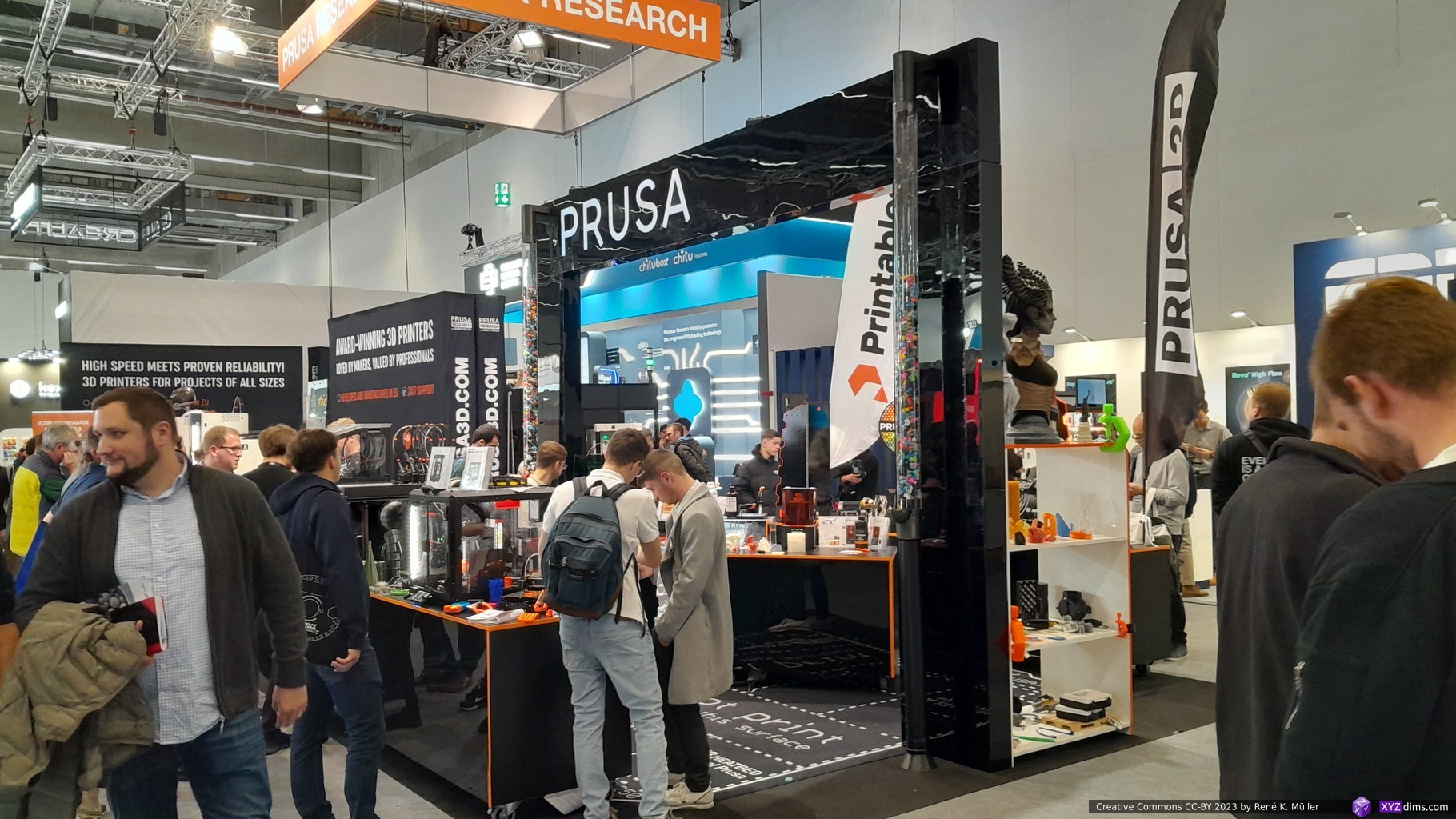
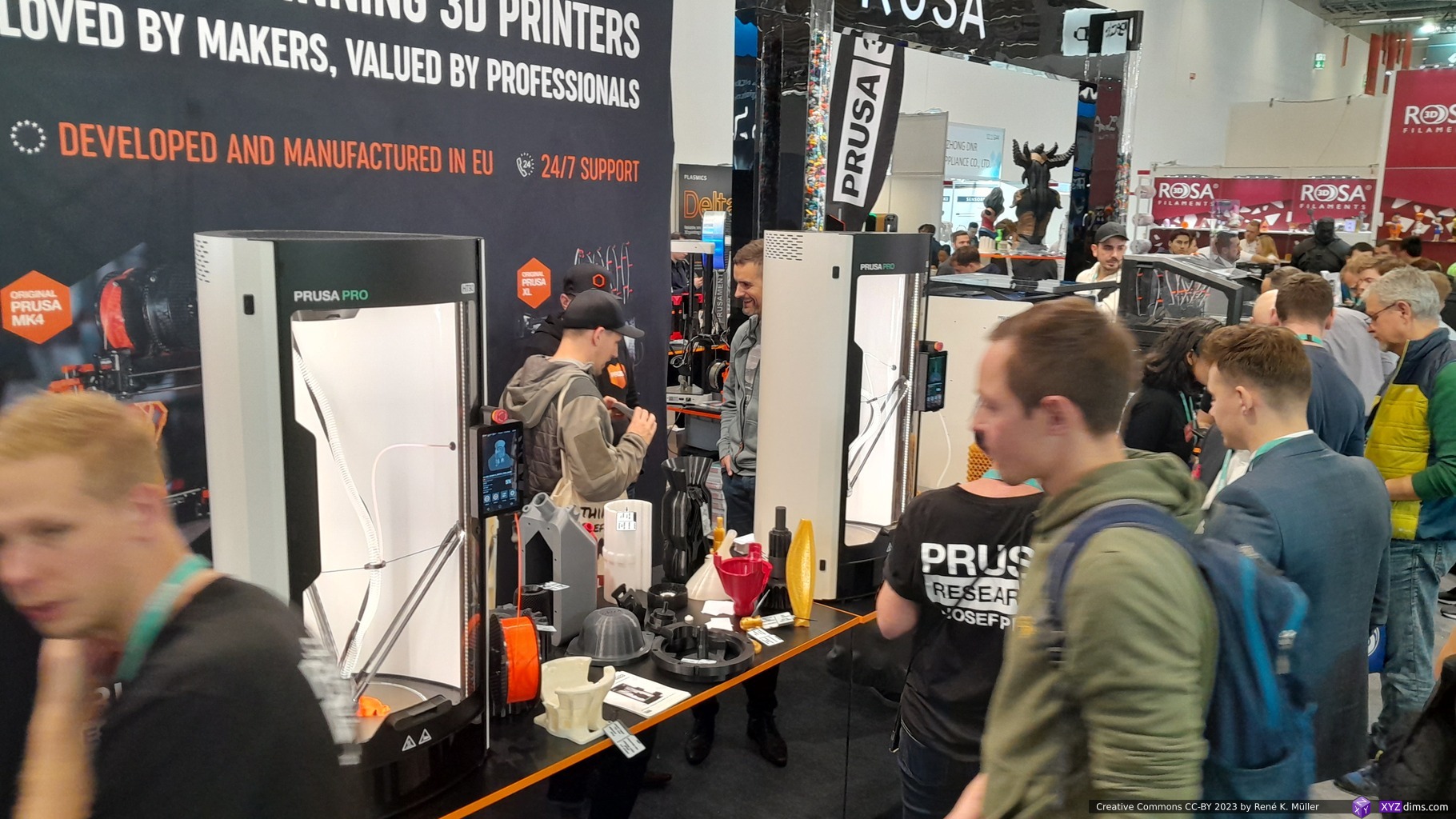
- Prusa Research: the usual lower-end/lower cost printer and their industrial aimed printers of the “Pro” series
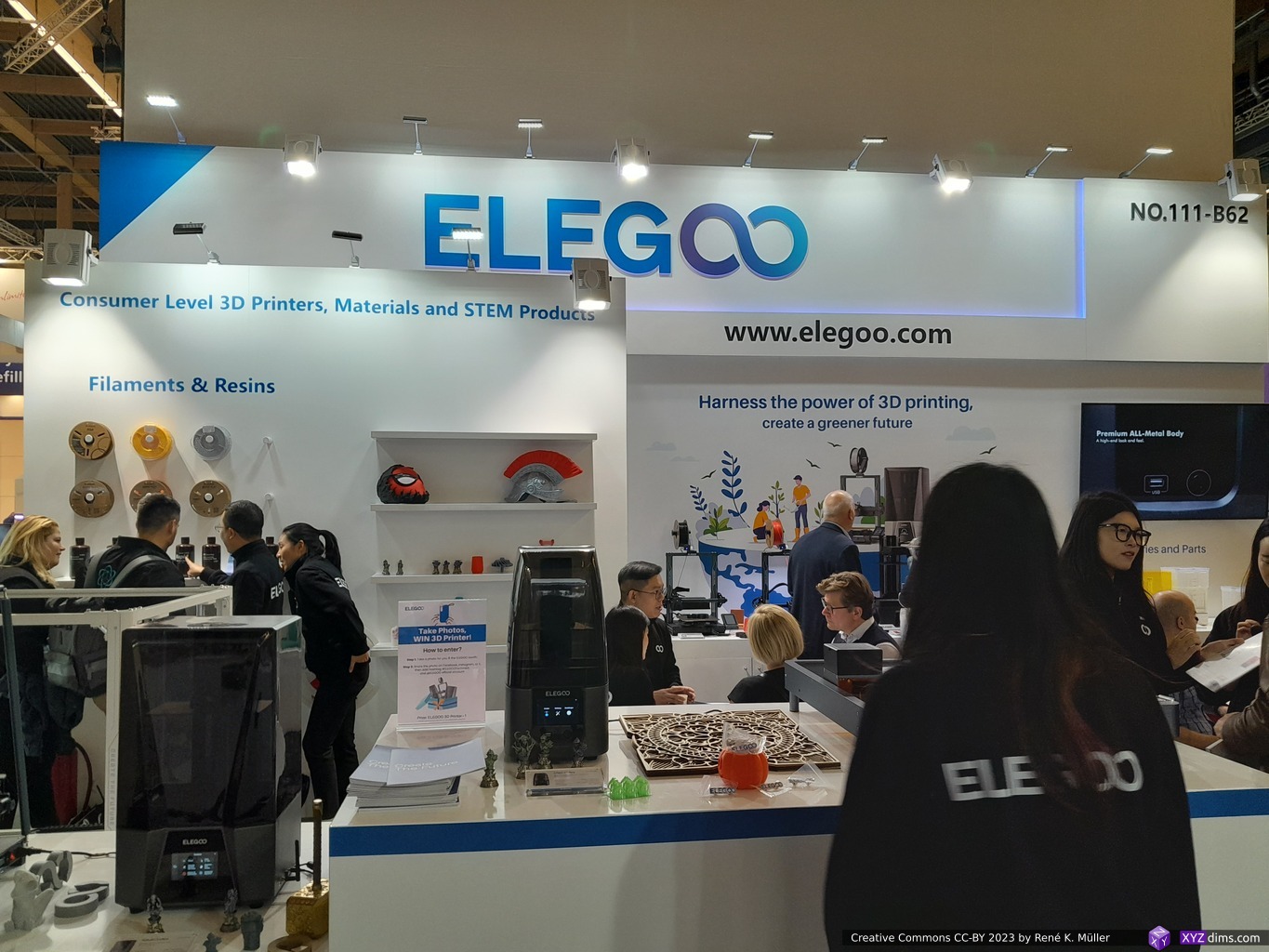
- Elegoo: low-cost resin & FFF/FDM printers, resins & filaments
- Anycubic: low-cost resin & FFF/FDM printers, resins & filaments
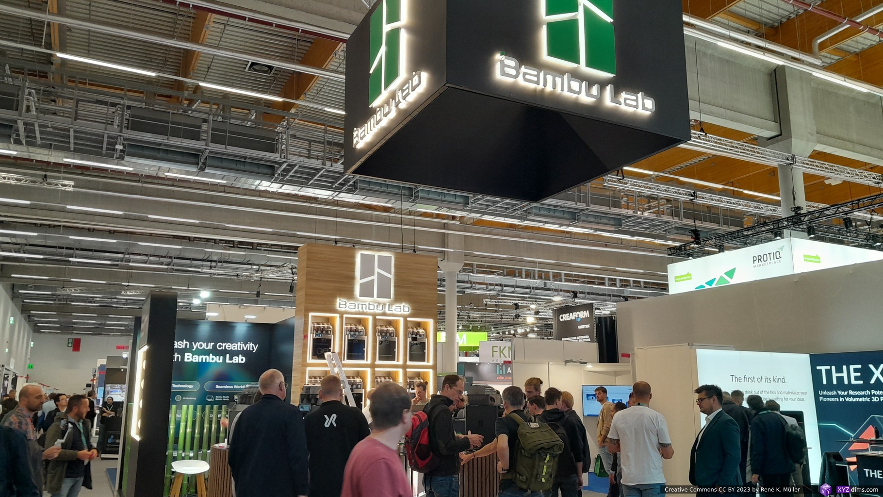
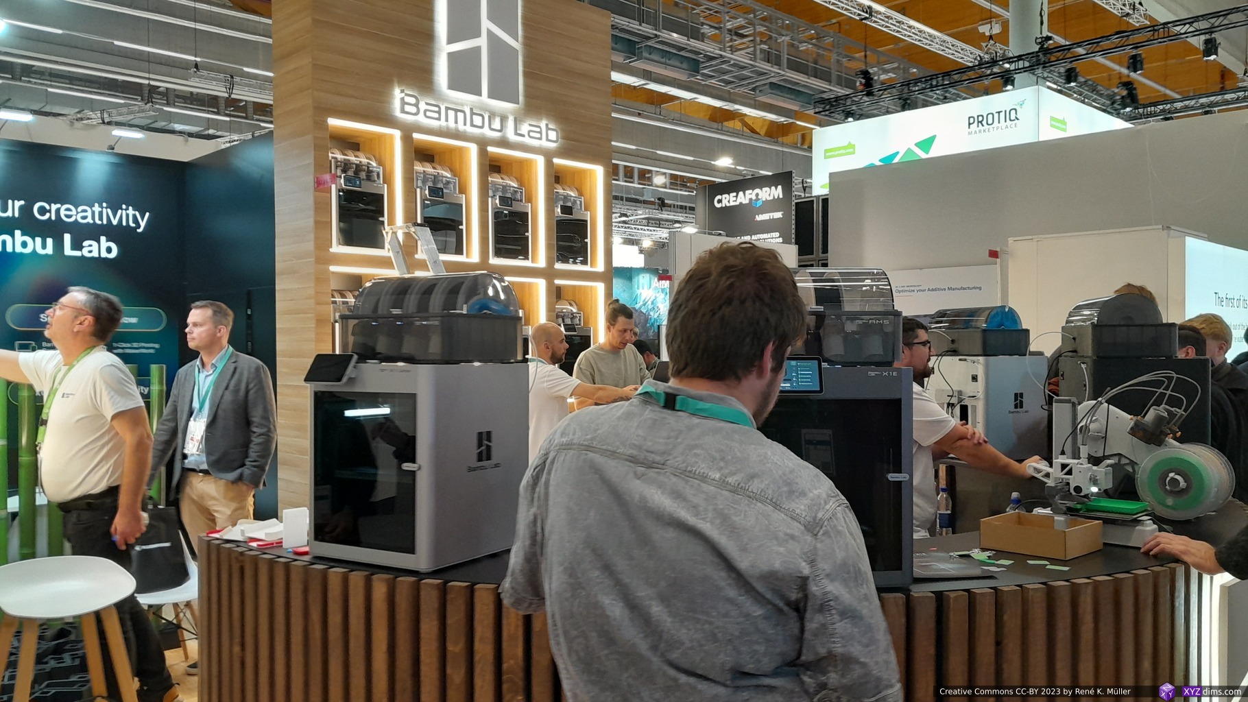
- BambuLab: cost-effective quality high-speed FFF/FDM printers
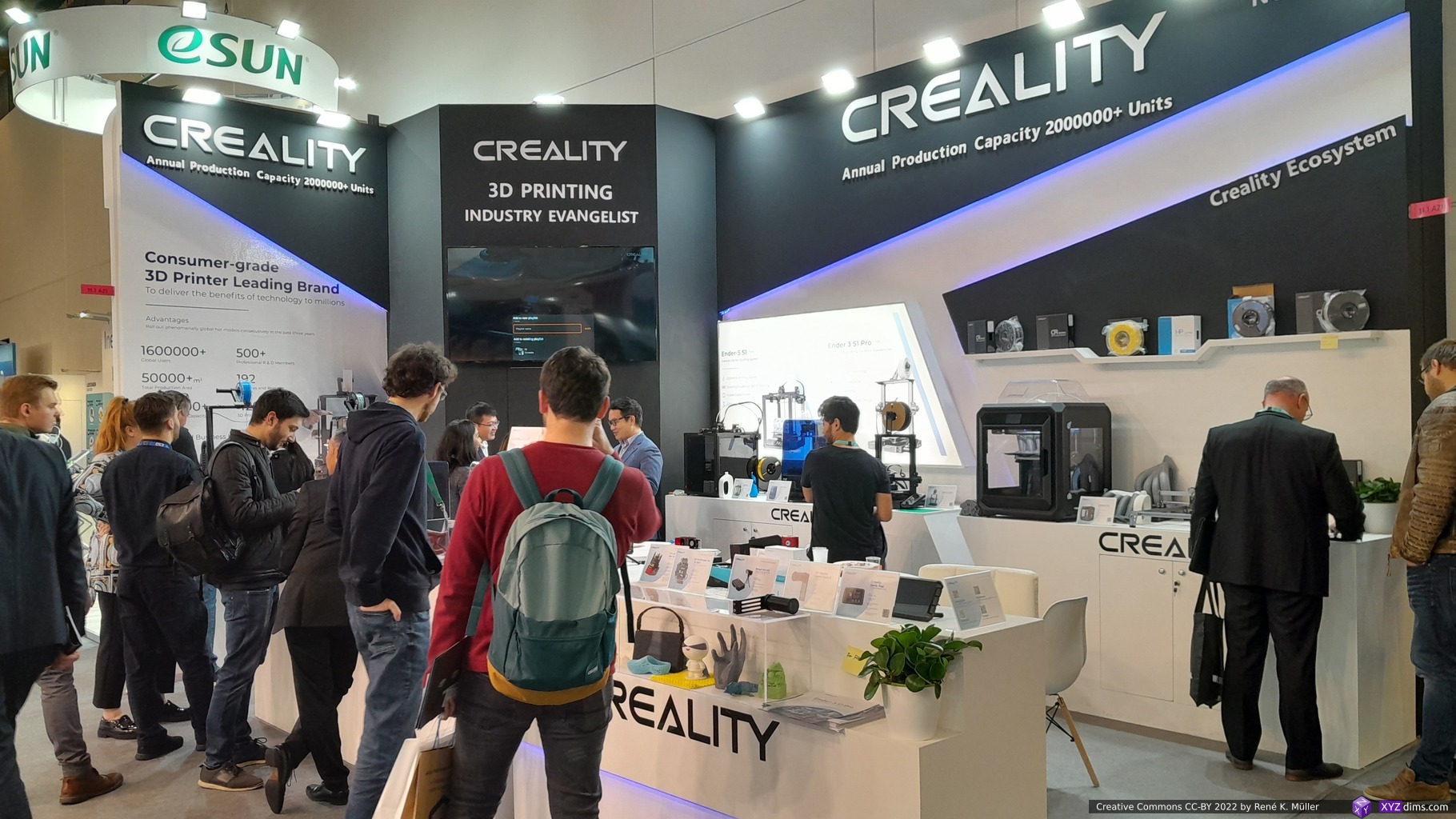
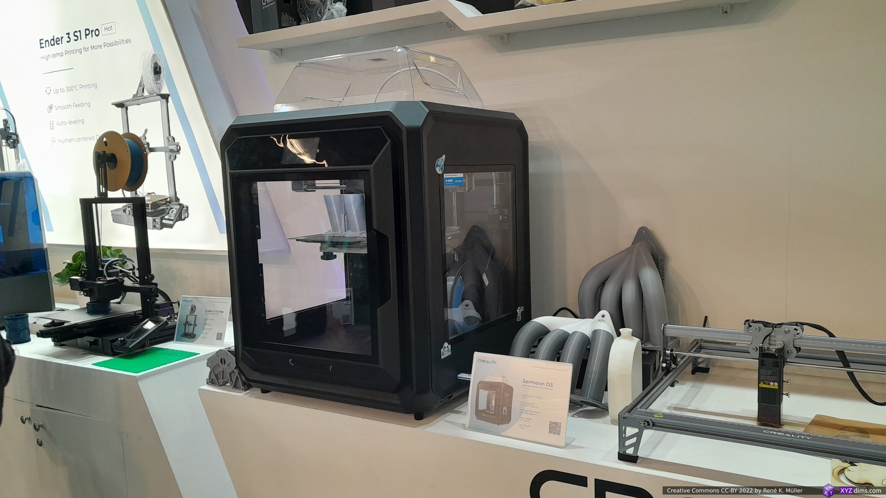
- Creality: low-cost FFF/FDM & resin printers
- Modix: low-cost but large scale FFF/FDM printers
- Polymaker: filaments
- eSun: filaments & resins
- many smaller filament seller
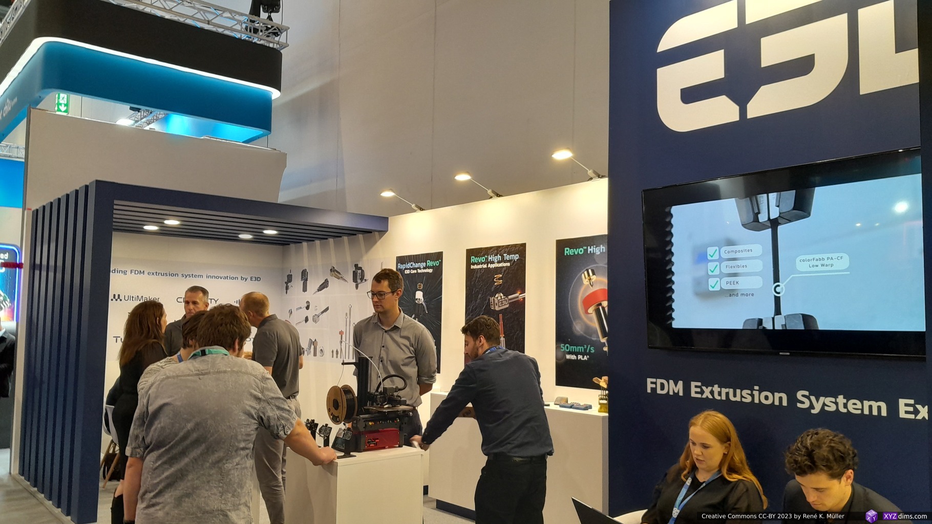
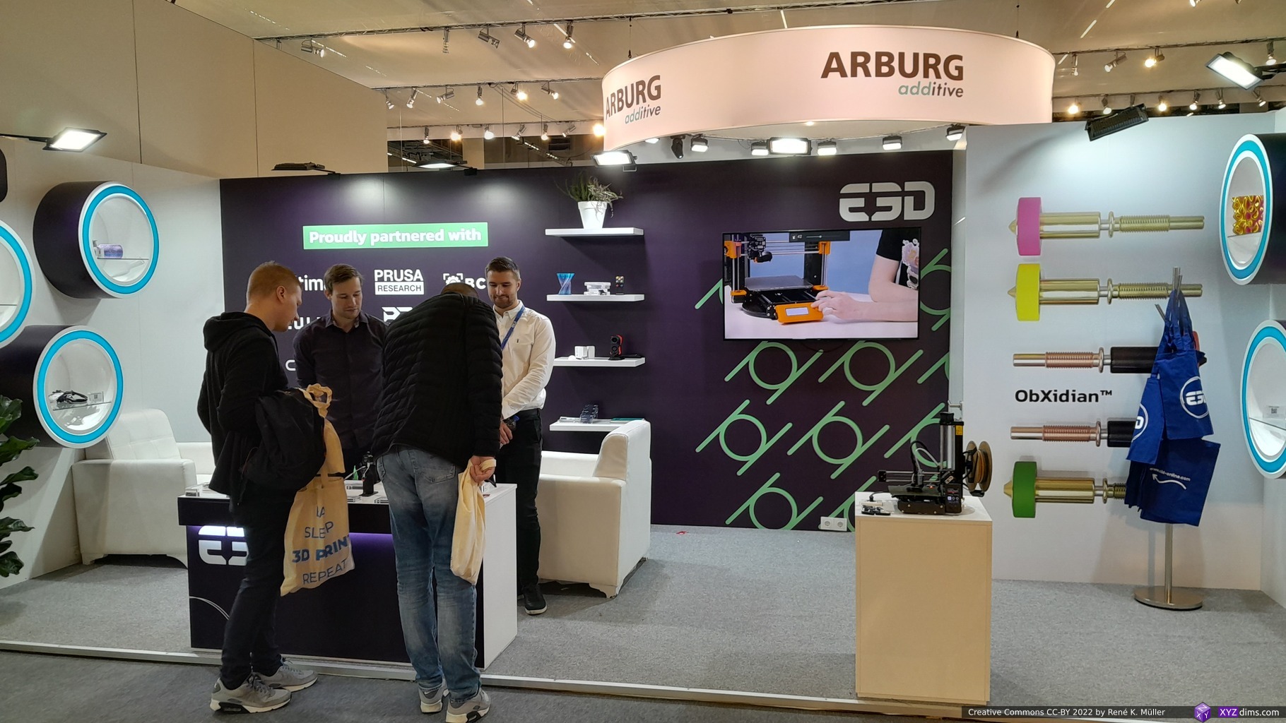
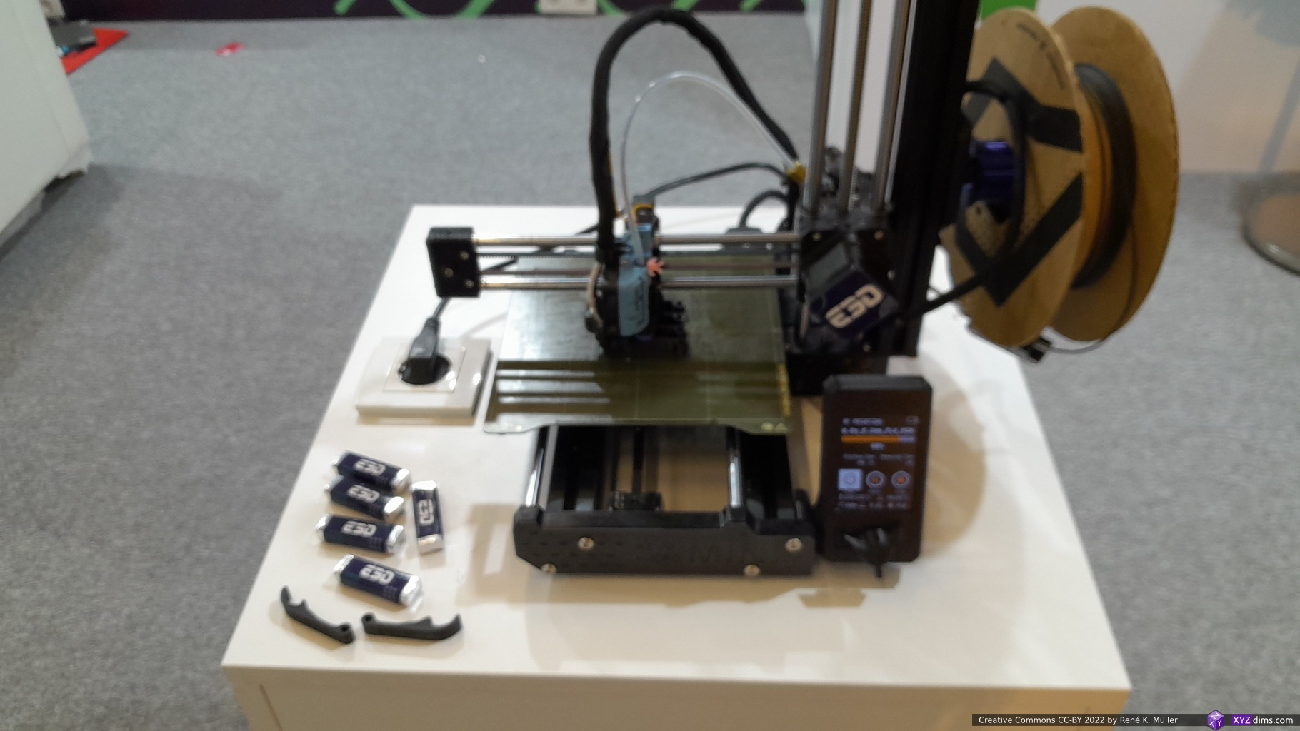
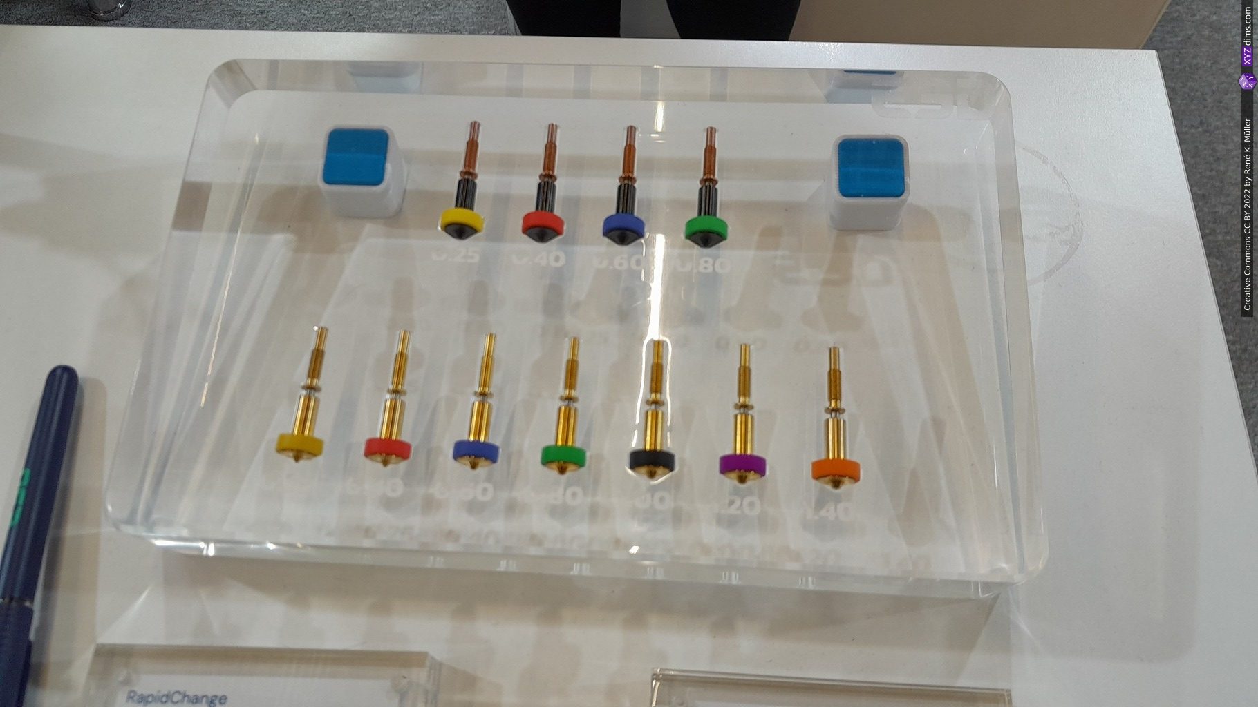
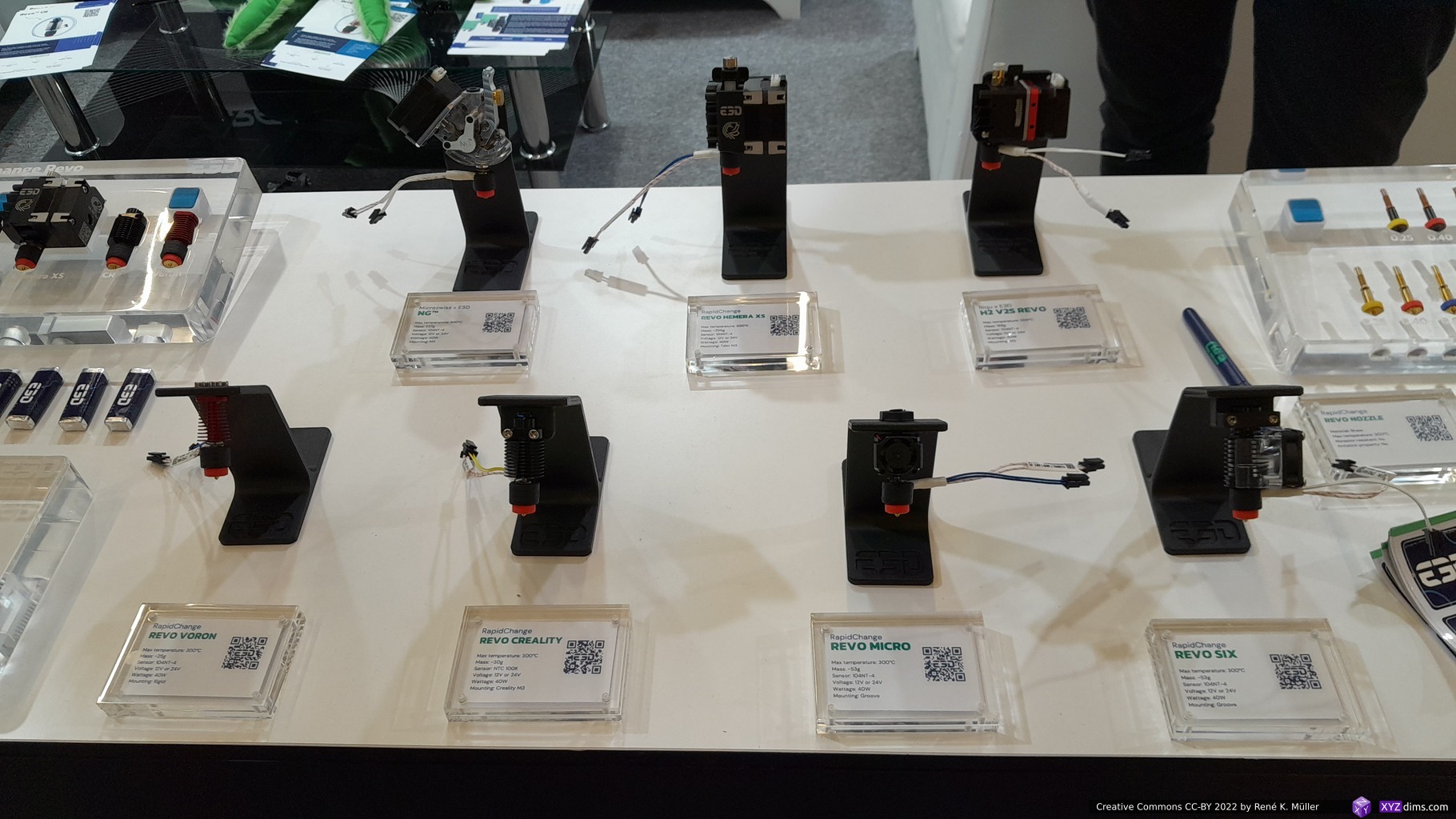
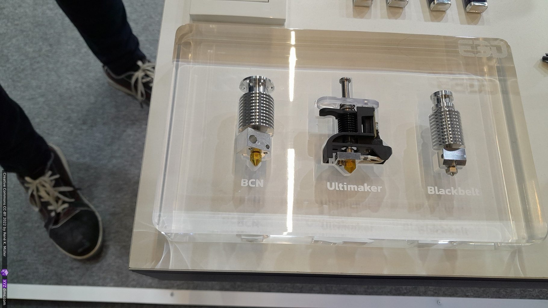
- E3D: hotends, extruders
And UltiMaker (after Ultimaker & MakerBot merger) wasn’t present again; the consensus has been that BambuLab‘s printers have taken the higher quality consumer FFF/FDM printers market segment, and the air getting thinner for UltiMaker – at the same time they are doing a great service with the Open Source Cura slicer.
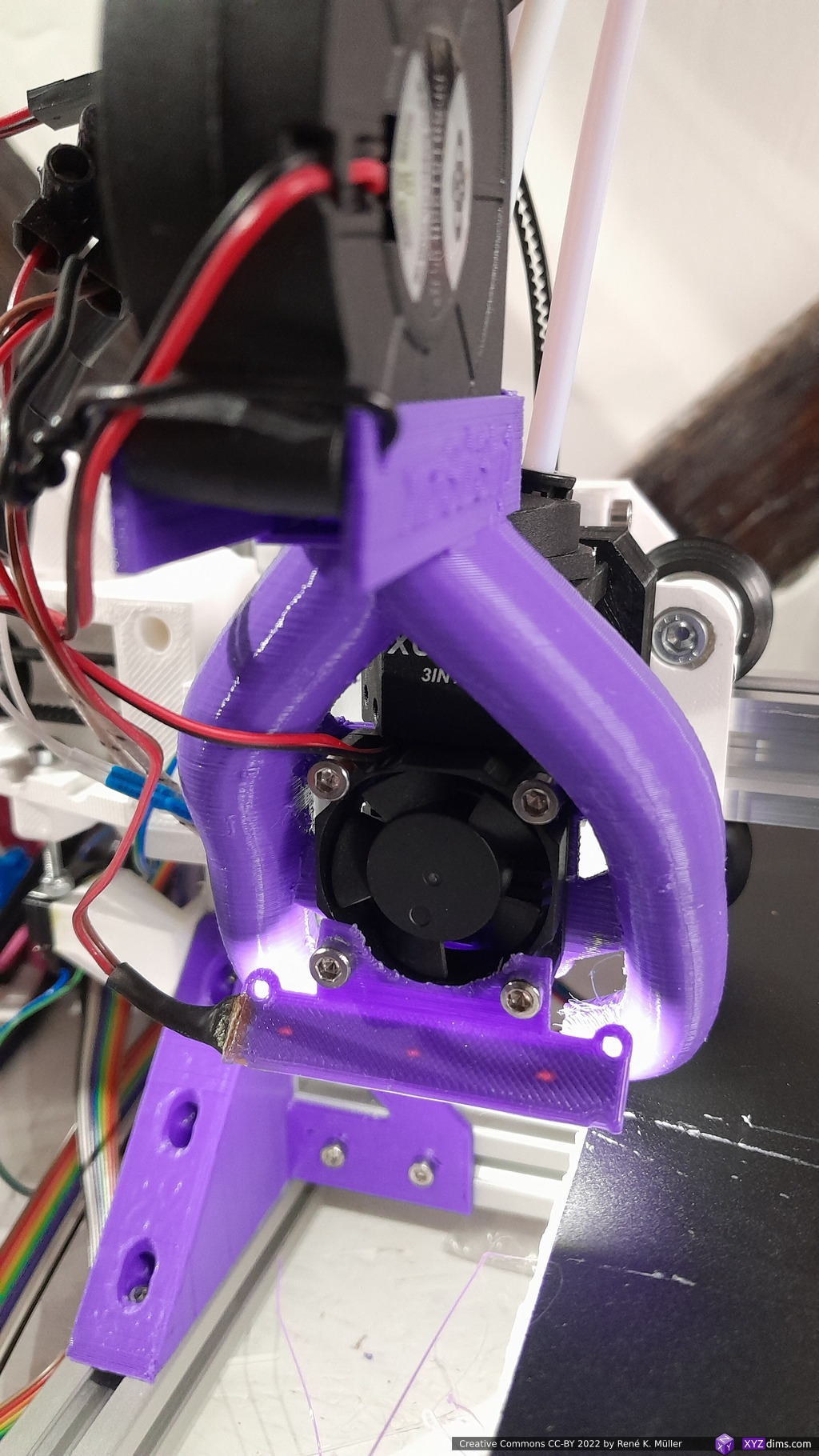
Random Impressions