3D Printing: Ashtar K Printer: Printing #1

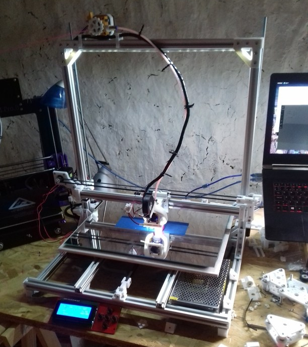
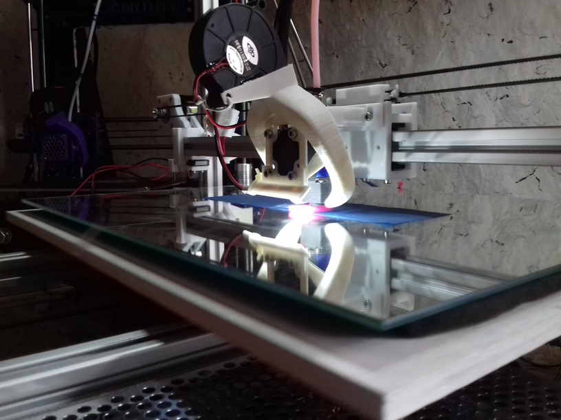
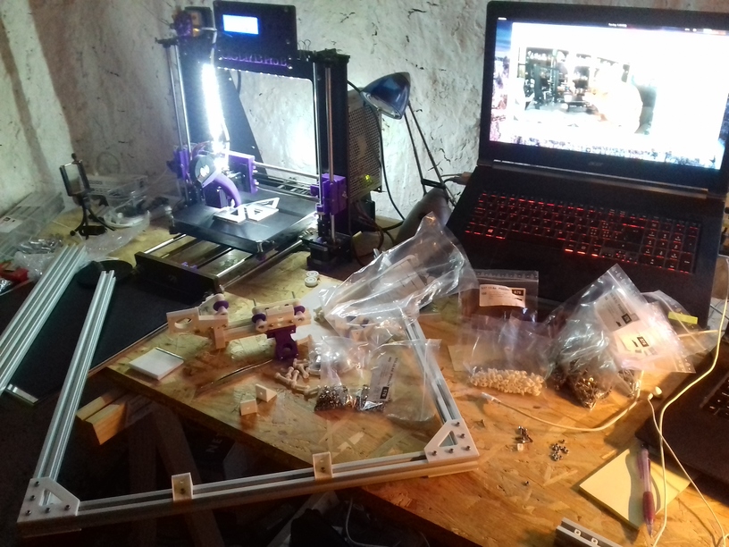
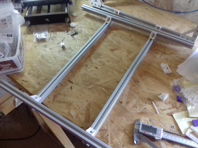
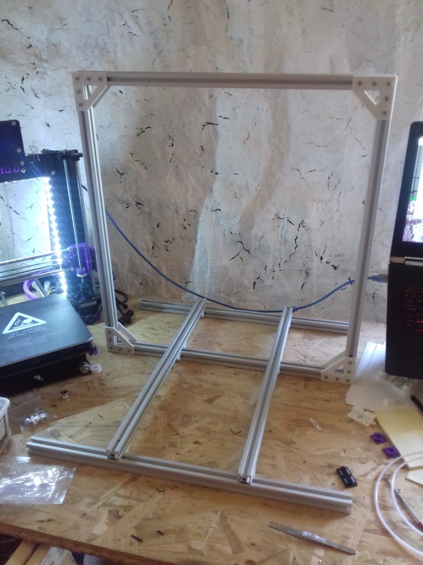
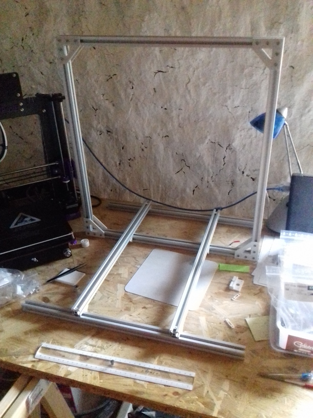
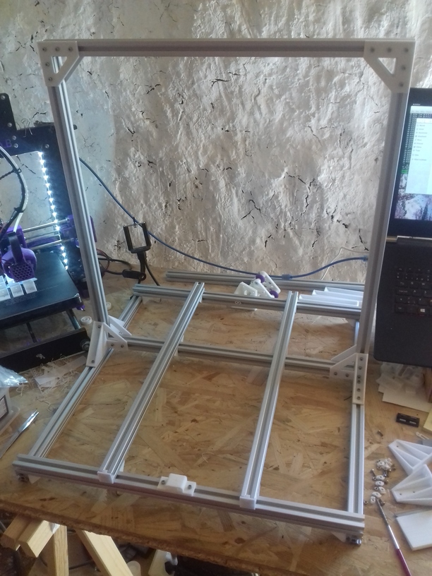
It has been a few days (2018/09/04), since Ashtar K happen to be able to print, the heat bed still unfinished, some prints illustrated below are done with no leveling screws, the mirror just taped on the Y carriage – don’t laugh – later prints I had proper carriage and leveling screws included; a proper build surface I still wait for in the mail (400×400 black sticker to be cut in shape) – anyway, here some of the early prints:

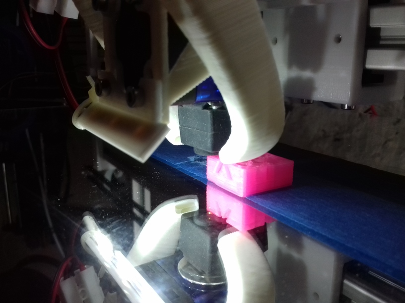
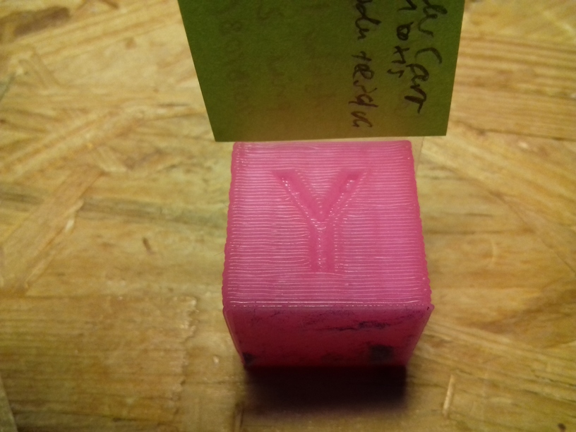
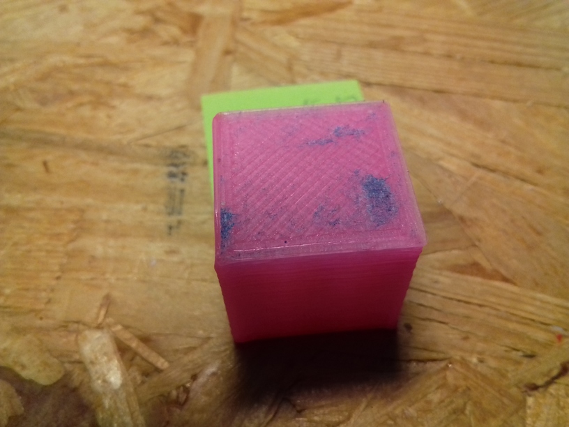
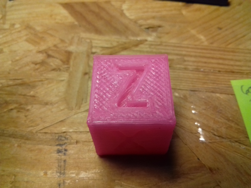
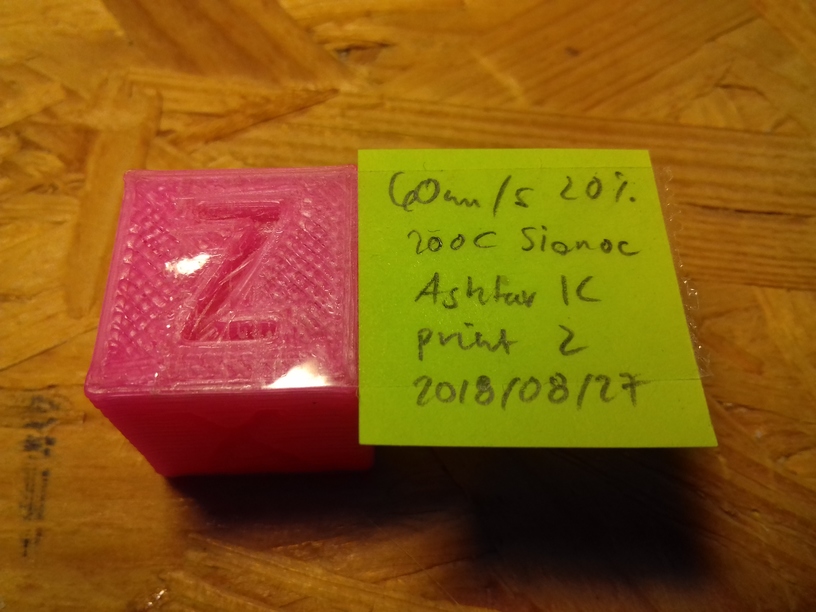
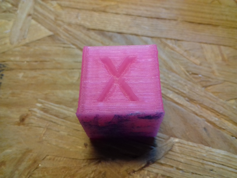
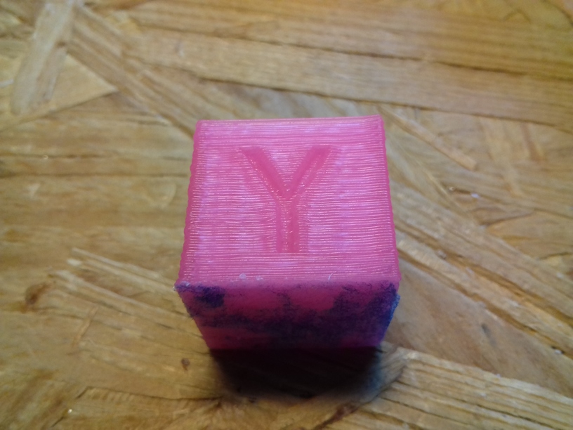
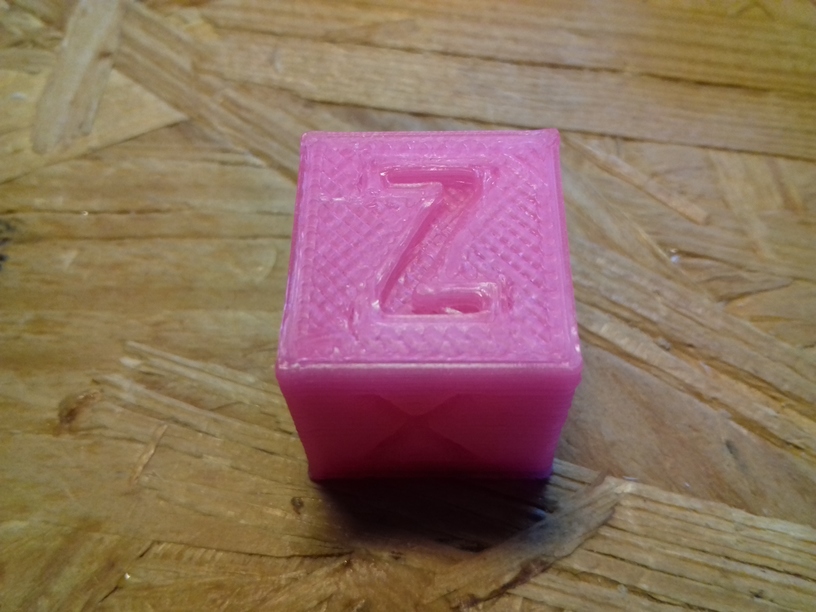
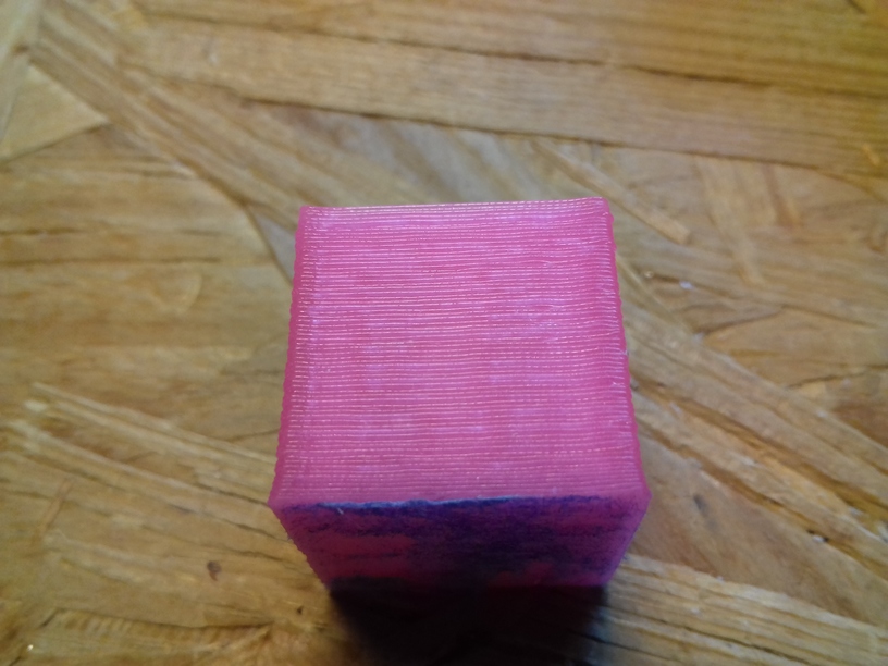
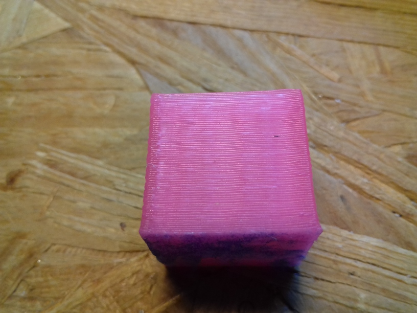
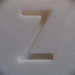
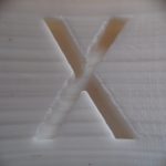
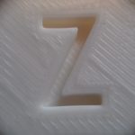
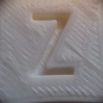
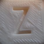
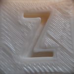
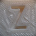
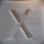
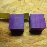
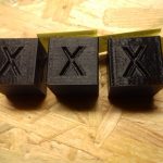
40mm XYZ Calibration Cube

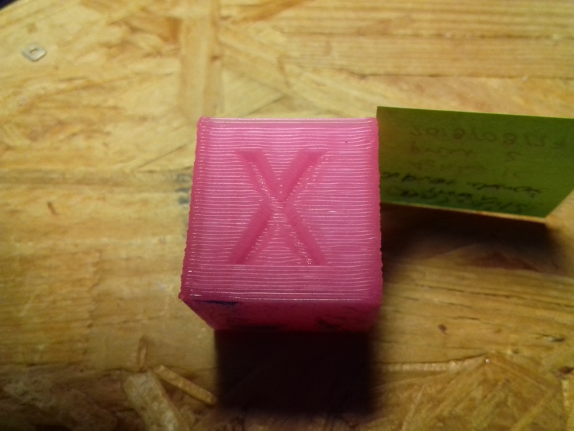
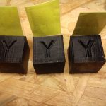
The original 20mm XYZ Calibration Cube is printed in 8 mins with 0.5mm nozzle at 0.4mm layer height, and so I thought, let’s print it 2x the size with 0.4mm layer height, merely 40 mins later this:

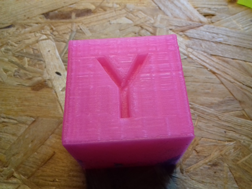
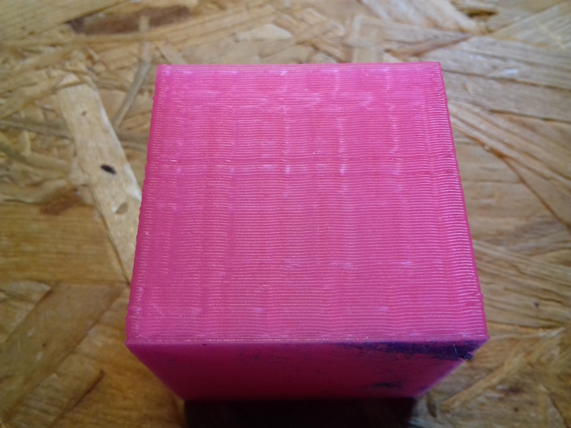
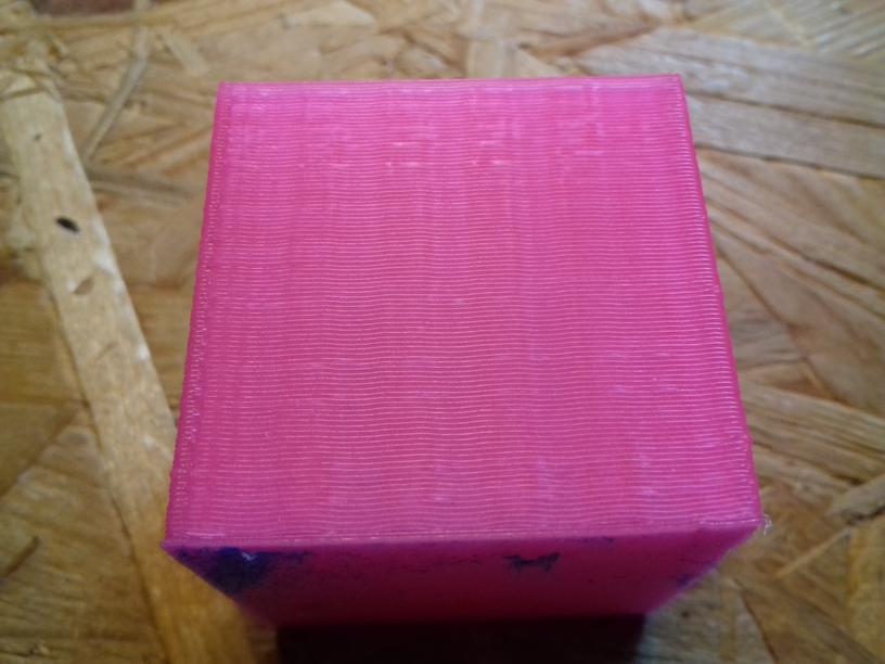
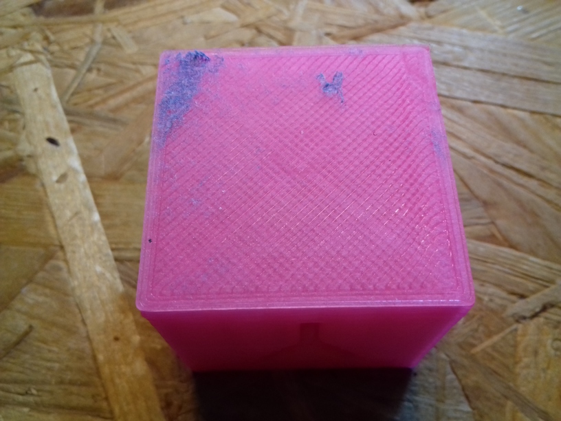
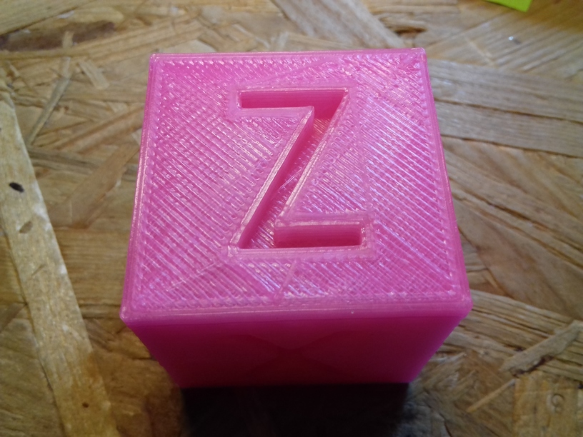
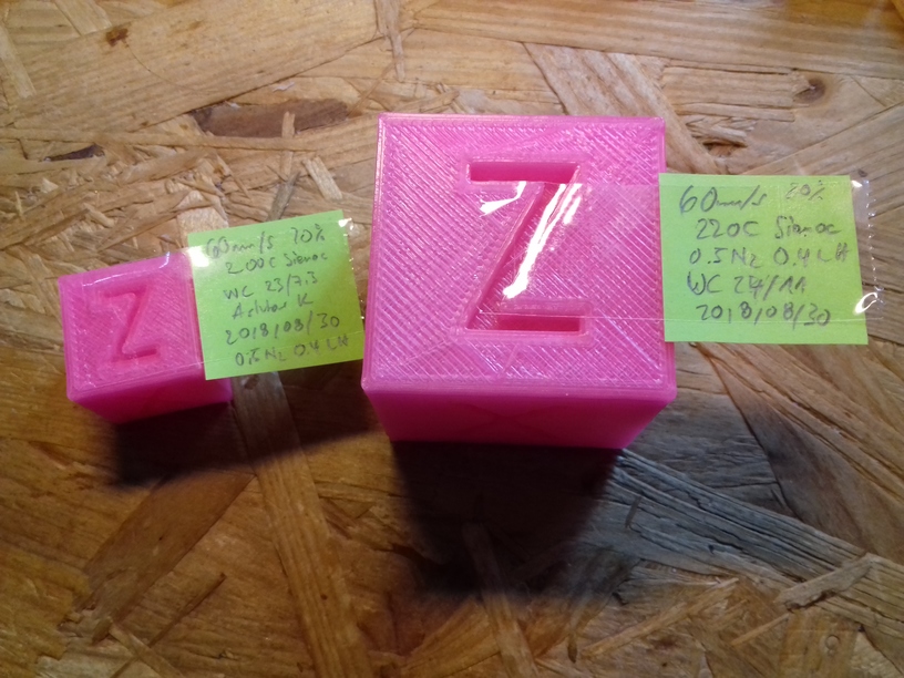
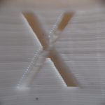
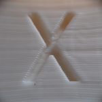
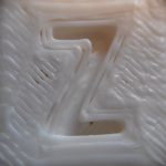
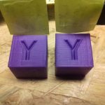
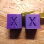
The quality is . . . impressive, this is just tuning a single day – mostly on the extrusion factor and print temperature – and this is what I hoped for: XYZ positioning almost flawless: there is slight ghosting on X axis (which could be resolved) shown on “Y”, and Y axis shown on the “X” which is fine, given the size of the bed and its weight and inertia this is OK.

I had to increase print temperature +20C from 200C to 220C for 80mm/s infill while printing with the 0.5mm nozzle, I otherwise would hear clicking from the extrusion stepper motor missing steps. I still use the classic E3D V6 (clone) heat block, not the Volcano heat block.

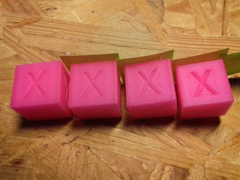
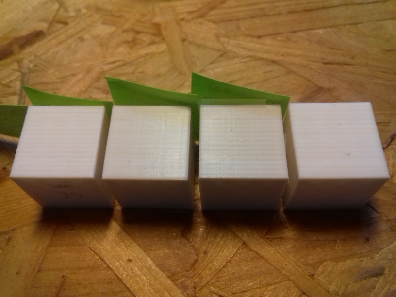
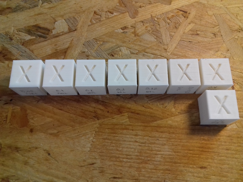
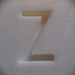
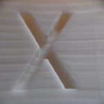
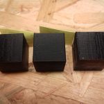
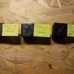
20mm Calibration Cube: Different Layer Heights

Printed with 0.5mm nozzle, left-to-right: 0.1mm, 0.2mm, 0.3mm and 0.4mm layer height, 60mm/s (80mm/s infill), 200C first layer, rest with 210C, pink glowing PLA by Sienoc.

20180831_070853

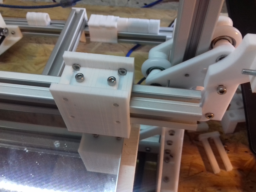
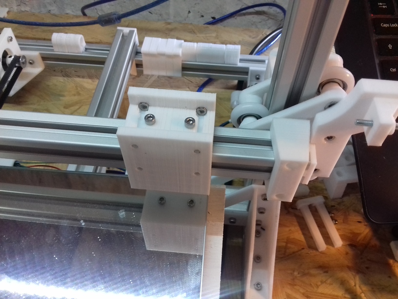
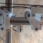
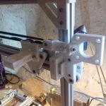
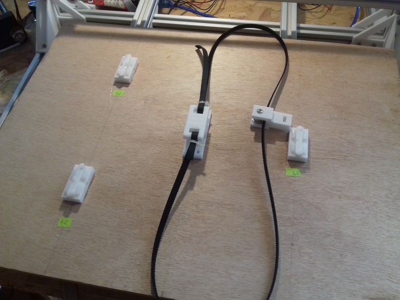
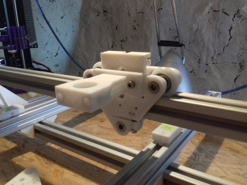
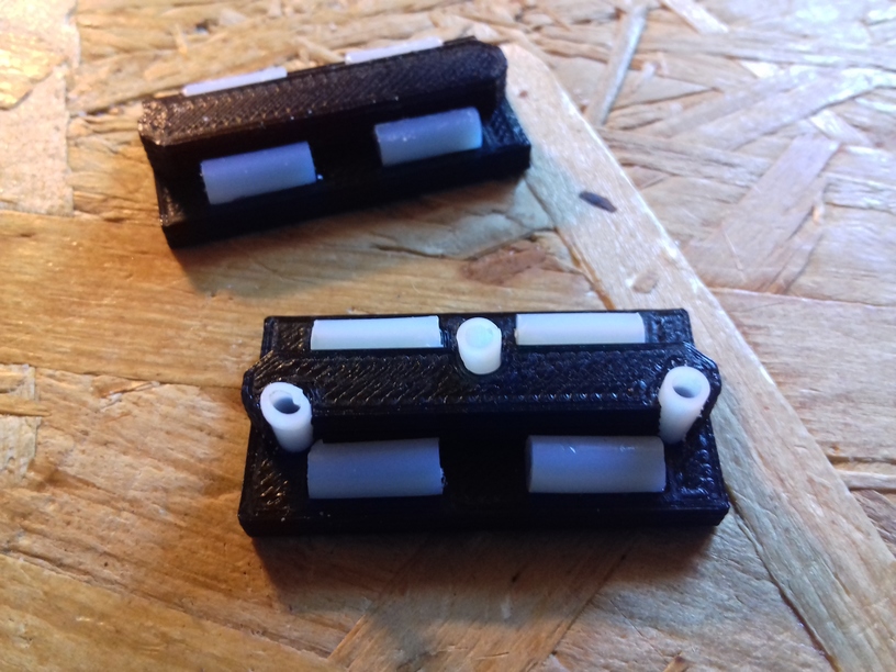
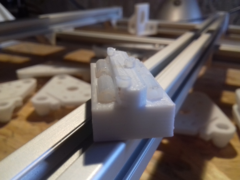
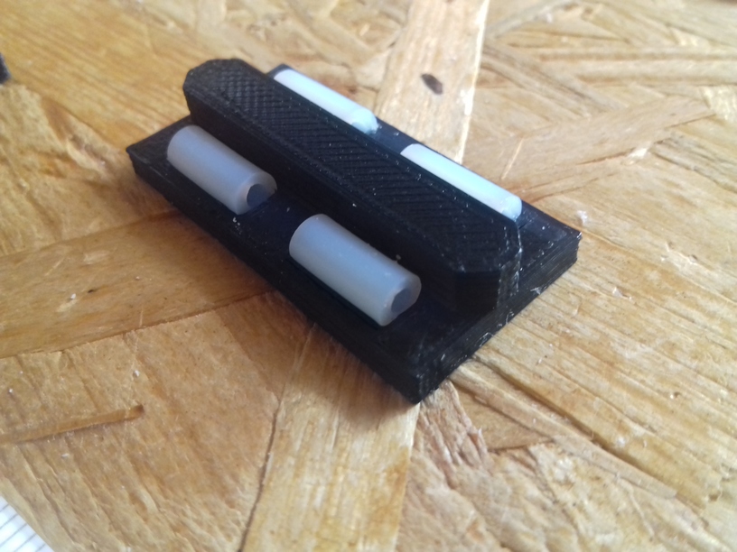
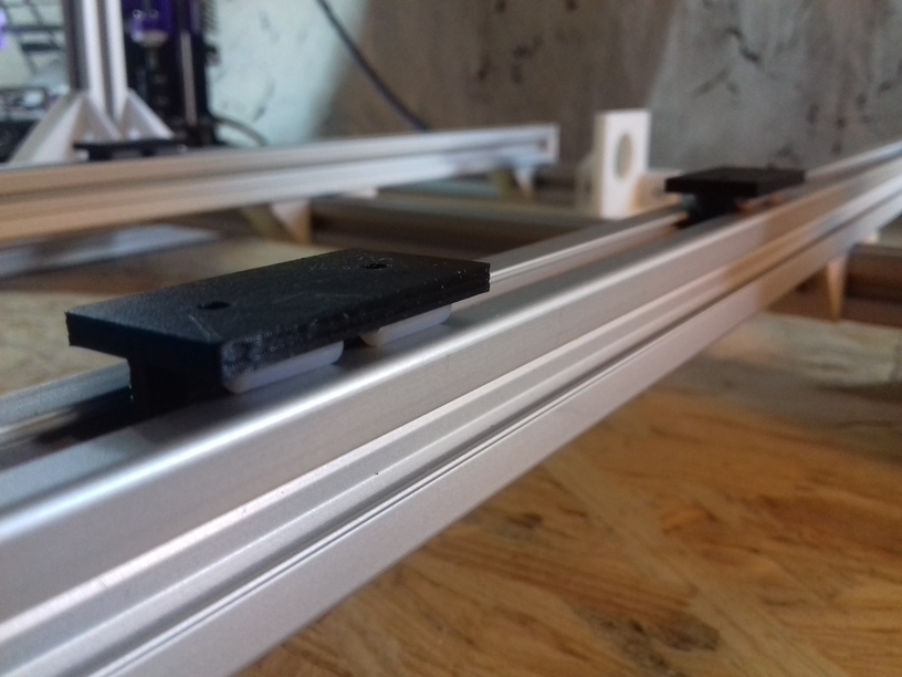
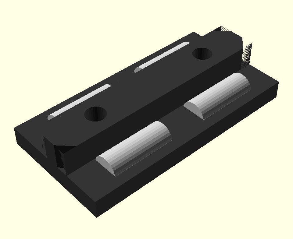
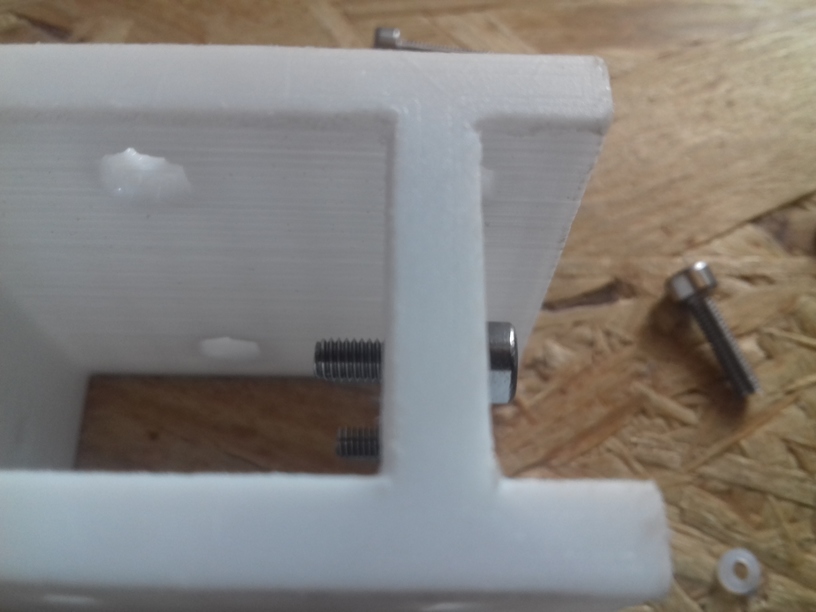
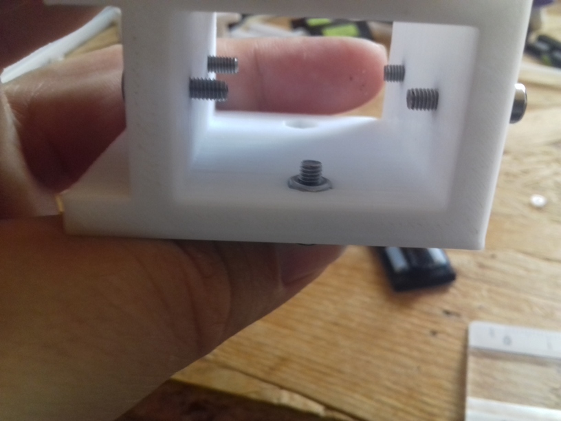
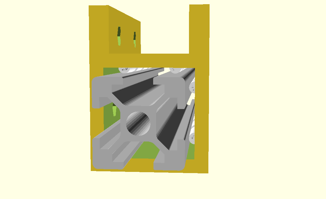
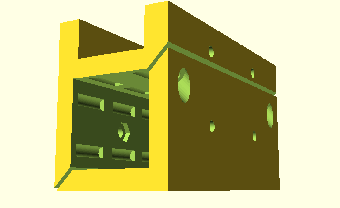
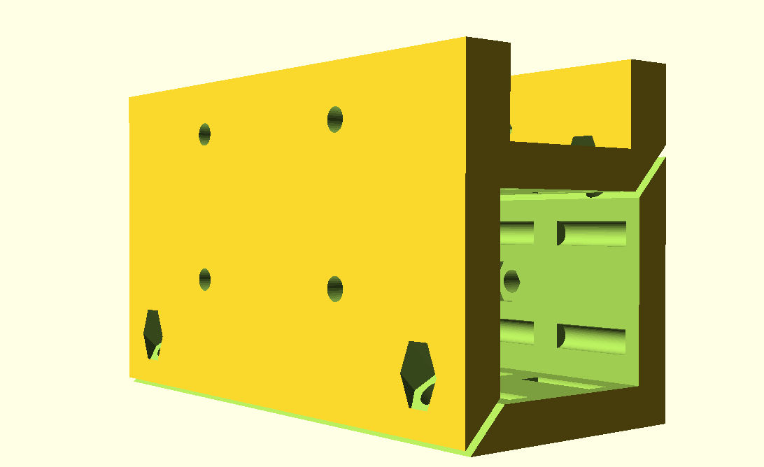
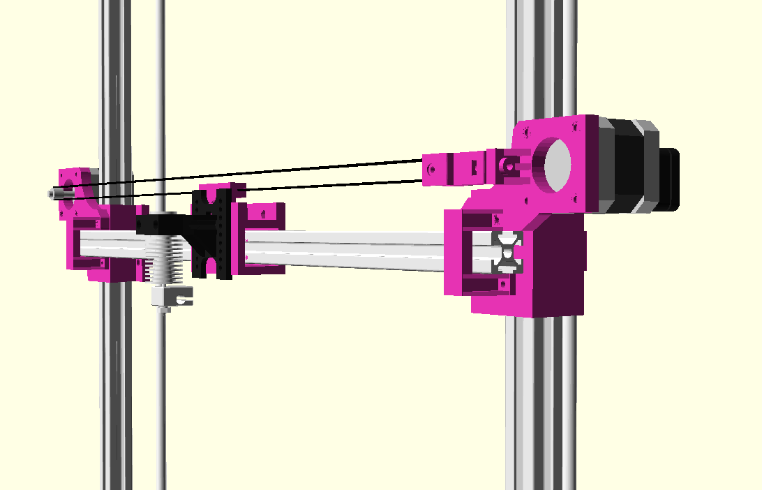
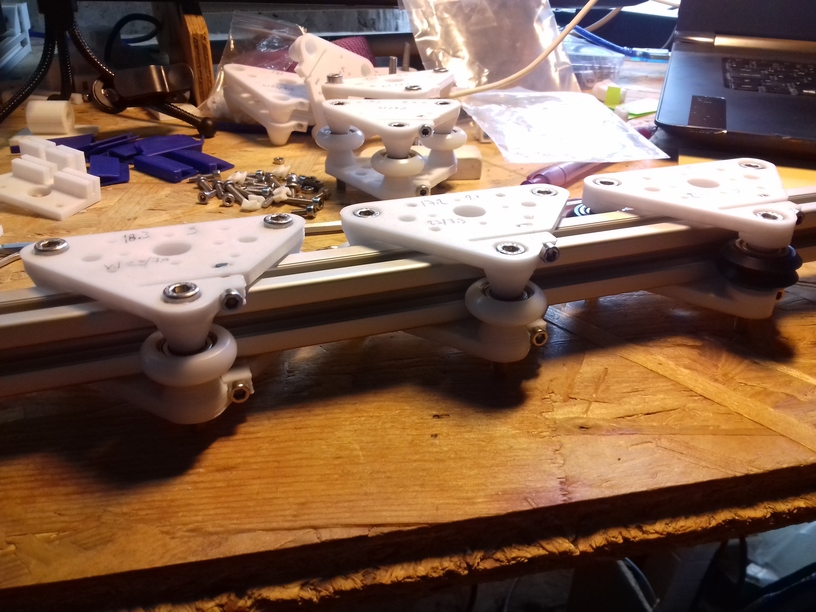
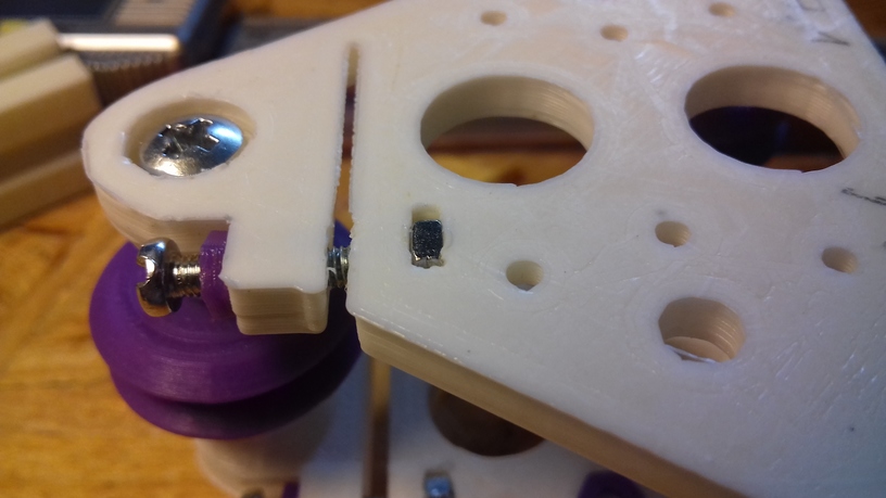
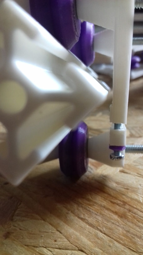
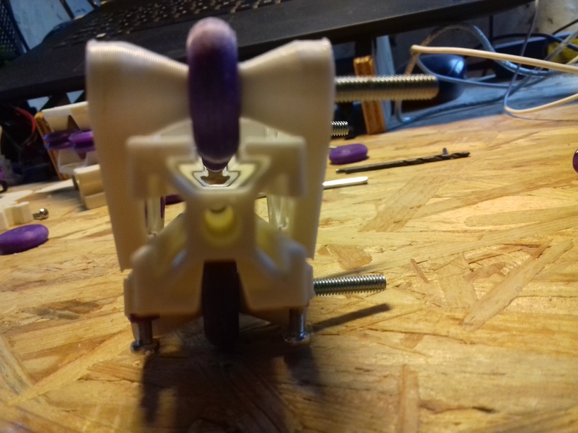
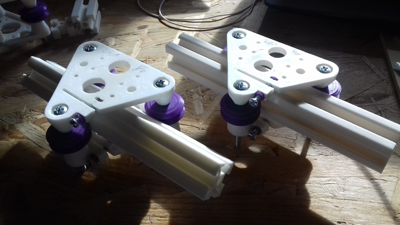
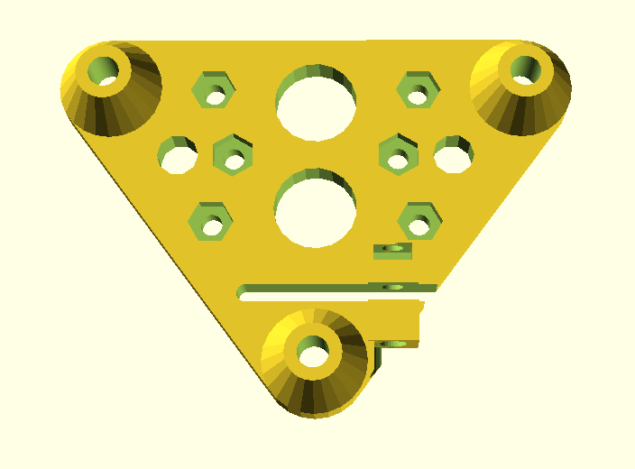
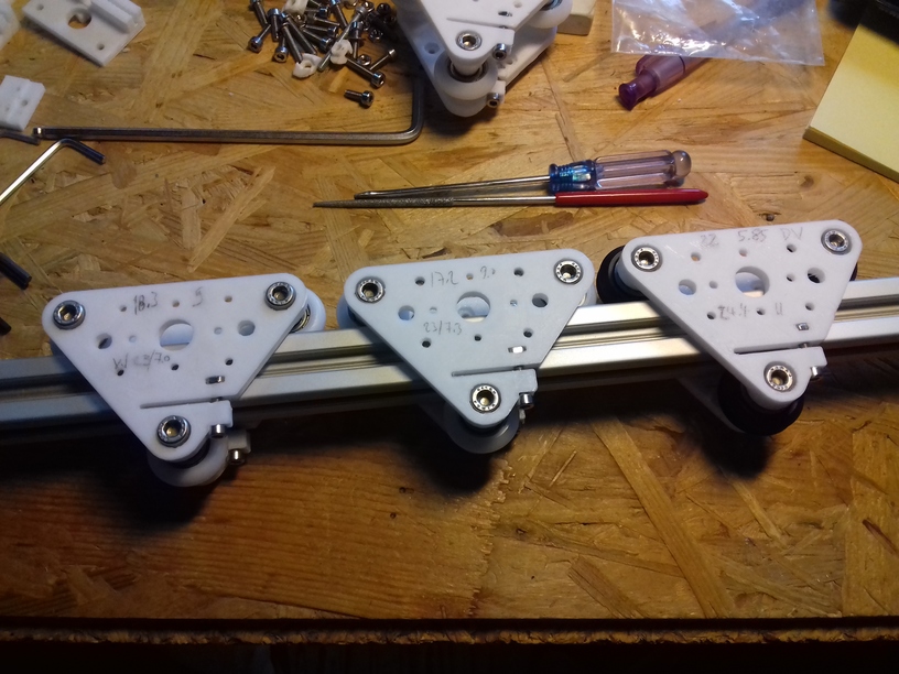
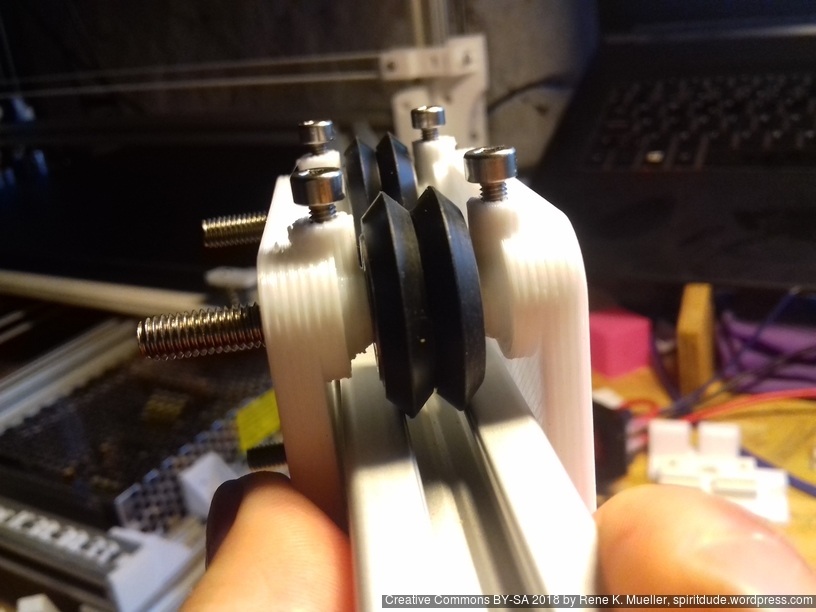
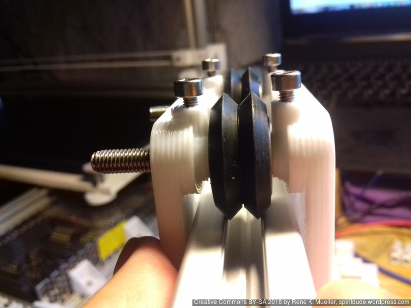
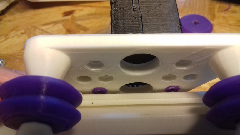
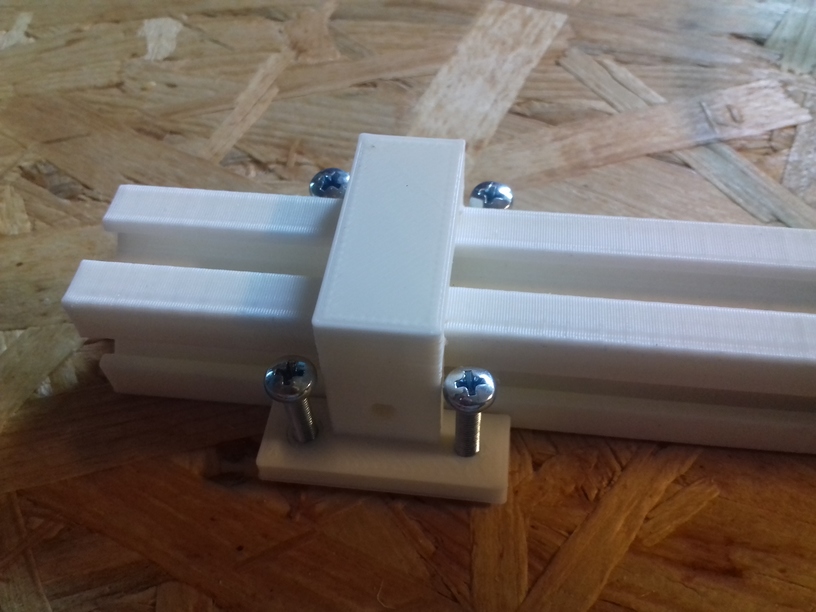
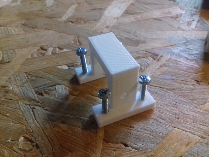
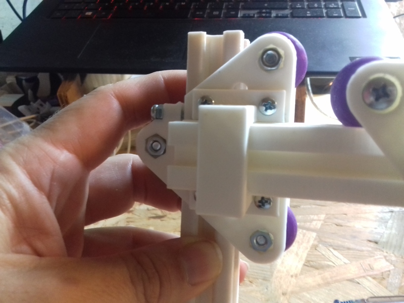
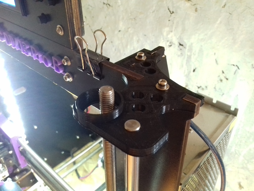
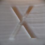
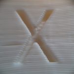
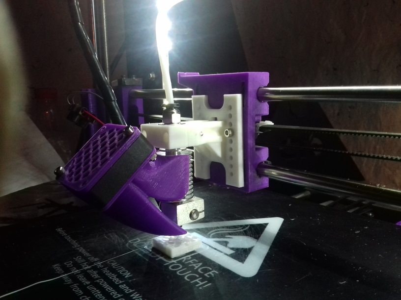
X Carriage: Sliders vs Wheels

While printing with slider carriage on the X axis, I noticed increased stuttering, and regardless if I thighten or loosen the grip, the stuttering remained, and slight horizontal tilt occured when changing direction on the X axis resulting in too narrow prints in X dimension.

20180827_093753

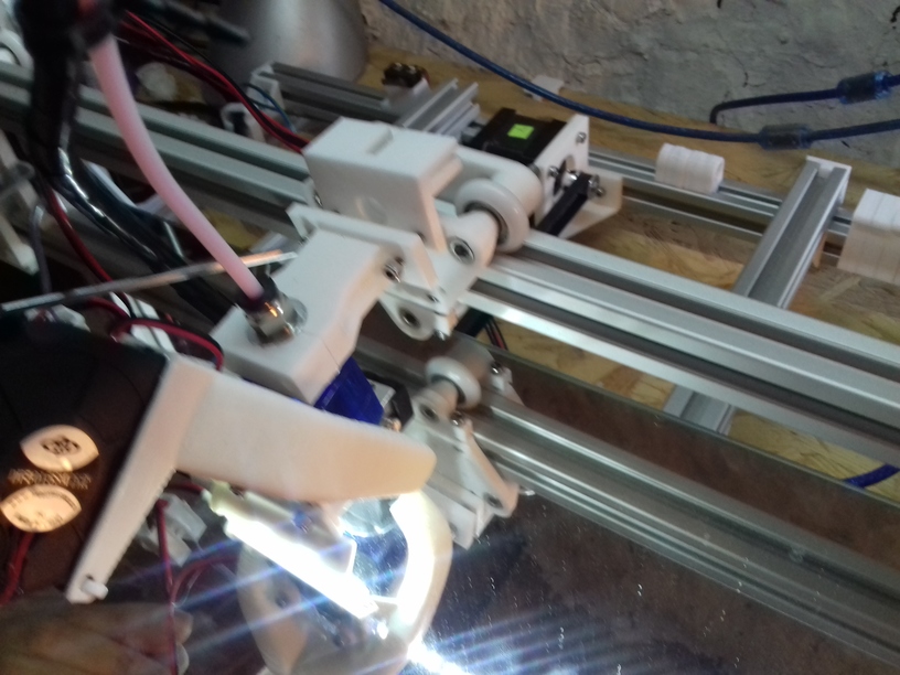
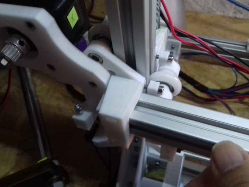
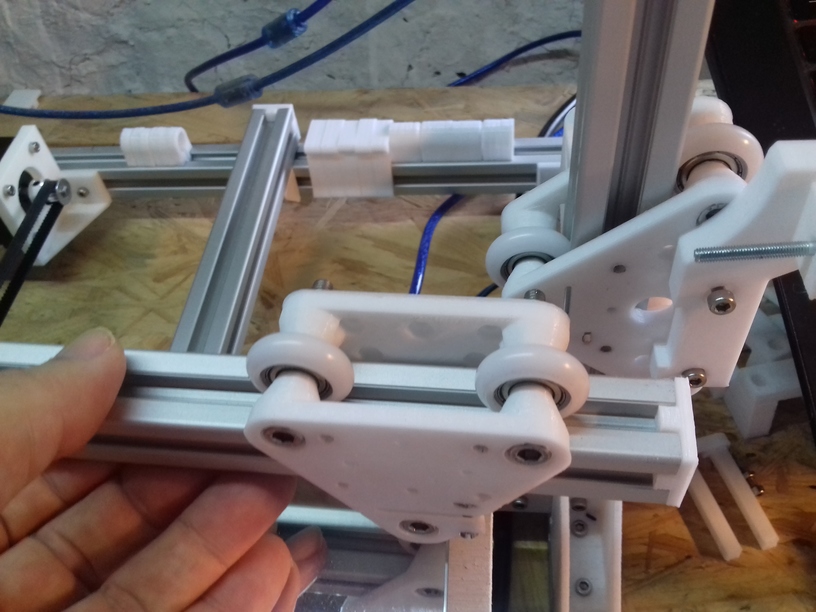
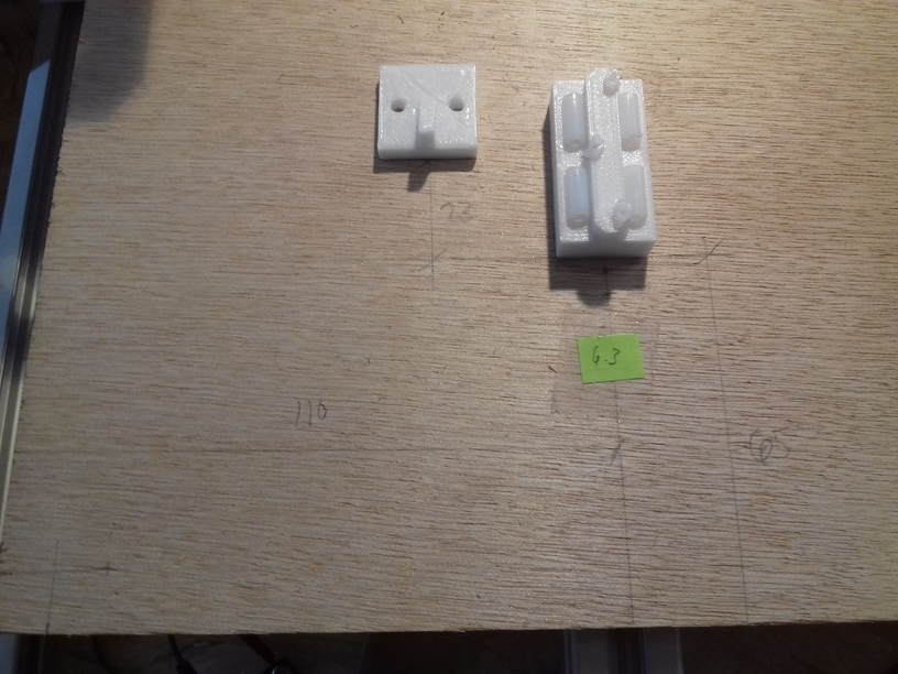
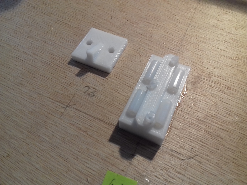
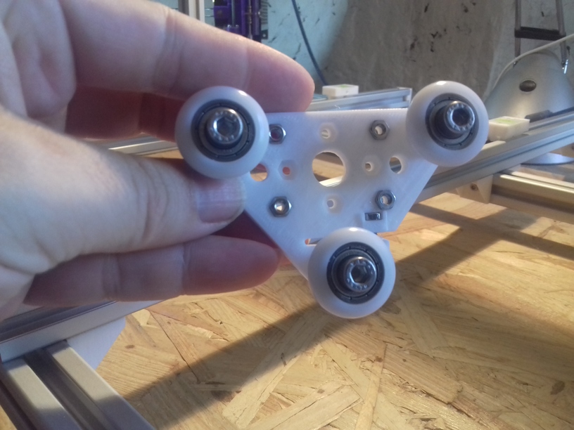
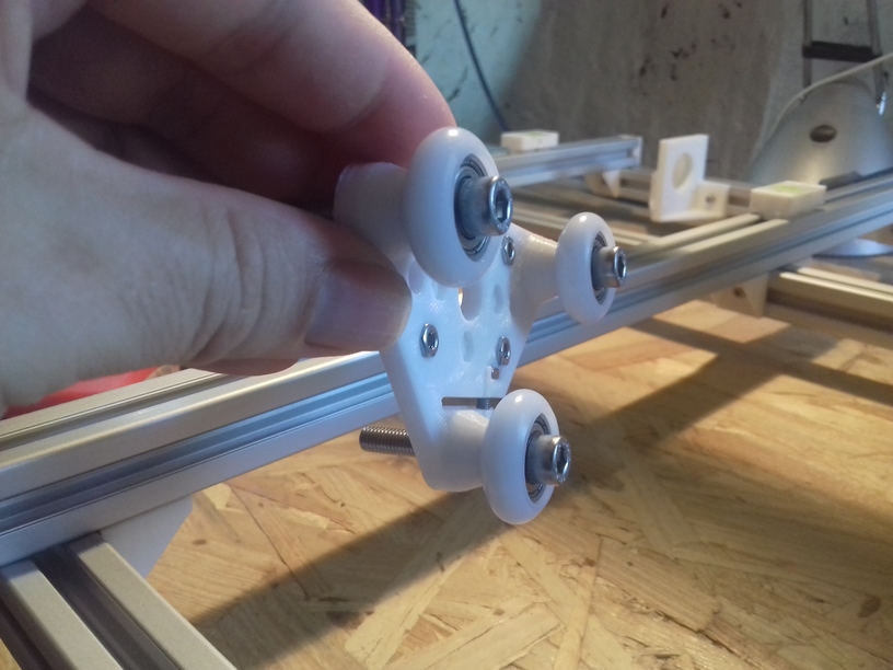
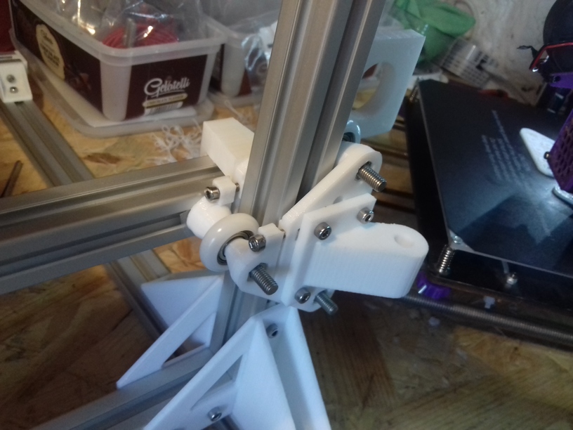
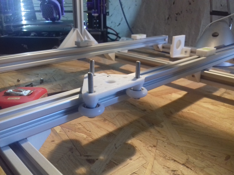
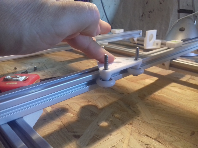
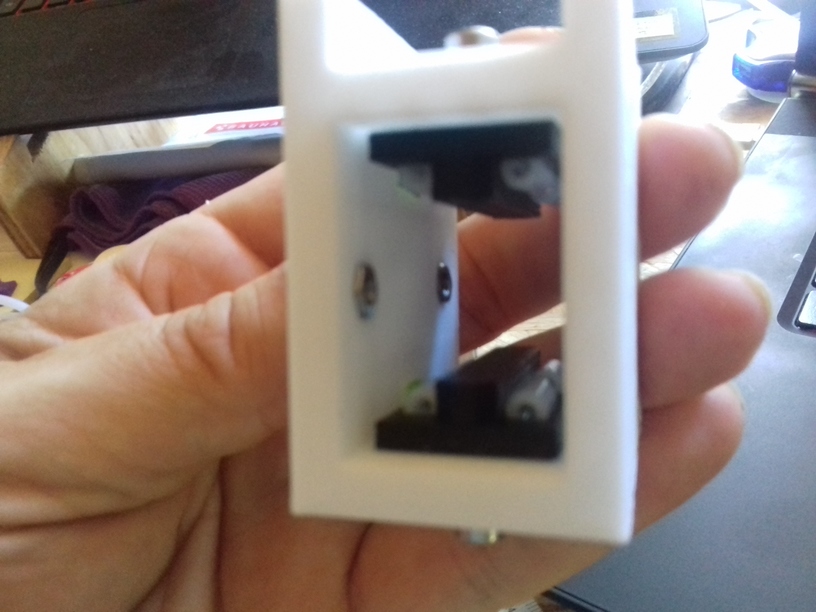
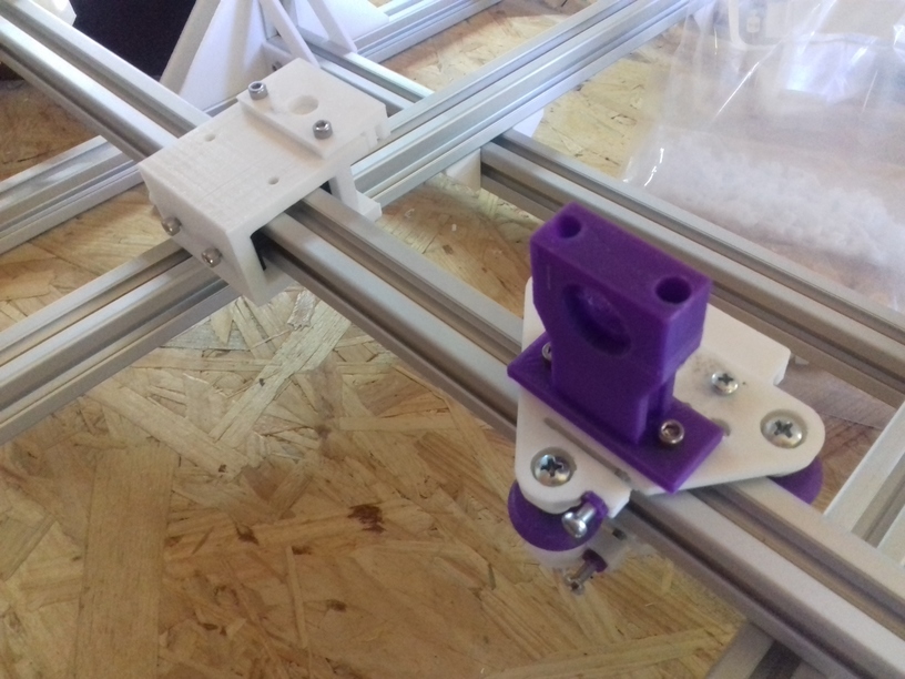
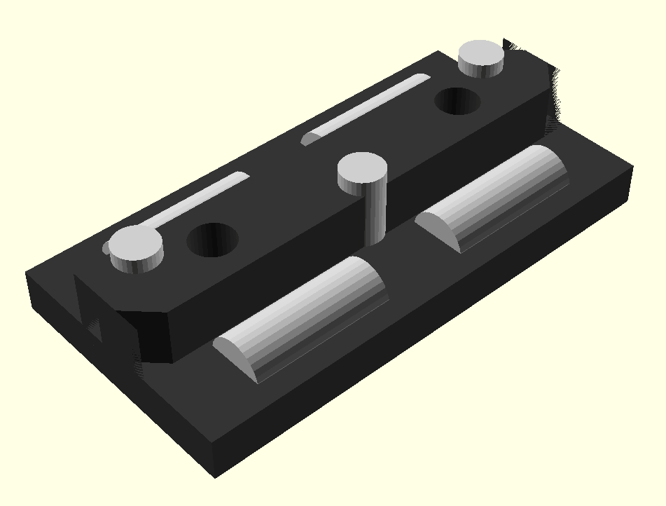
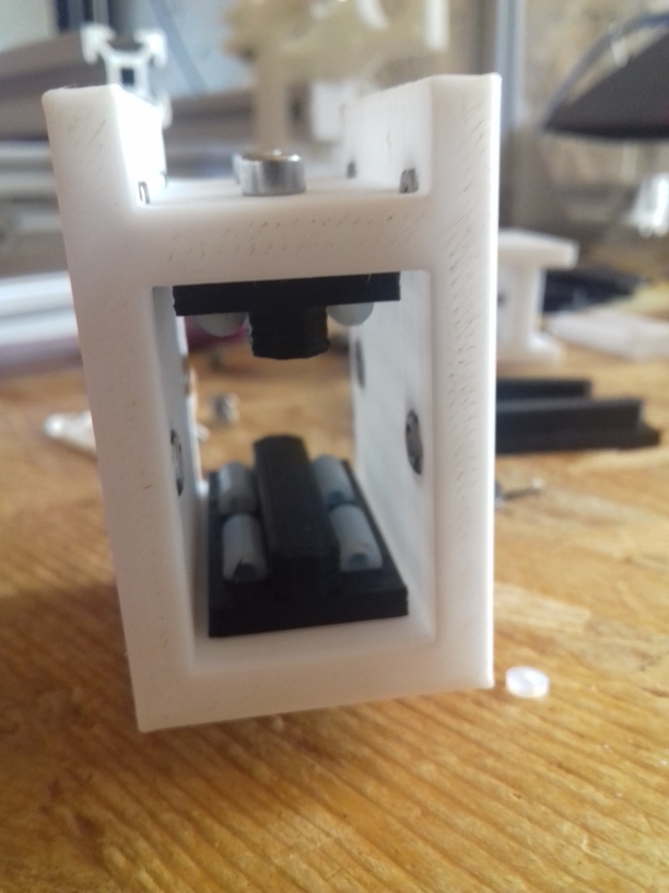
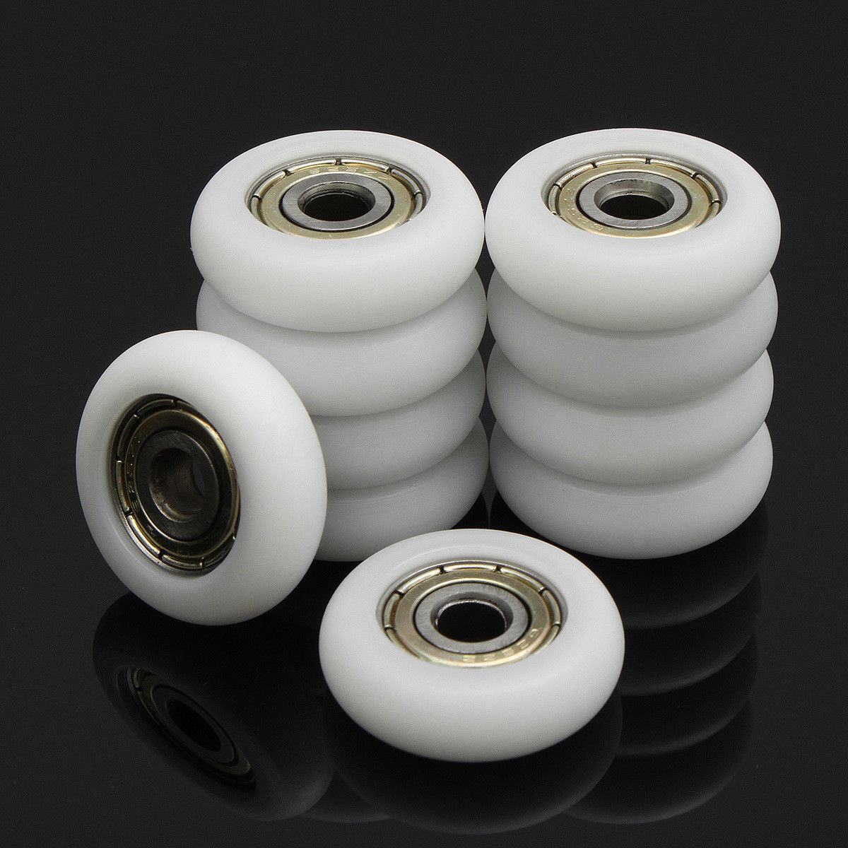
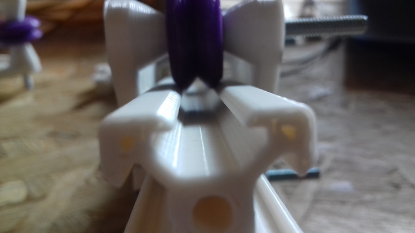
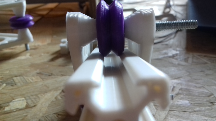
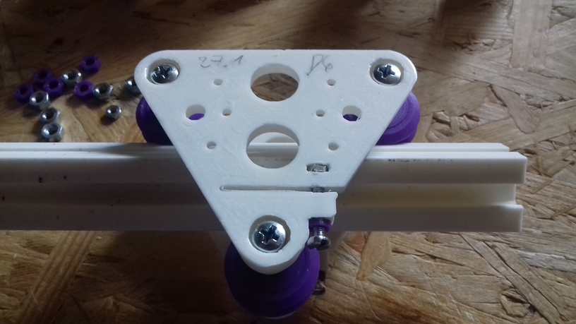
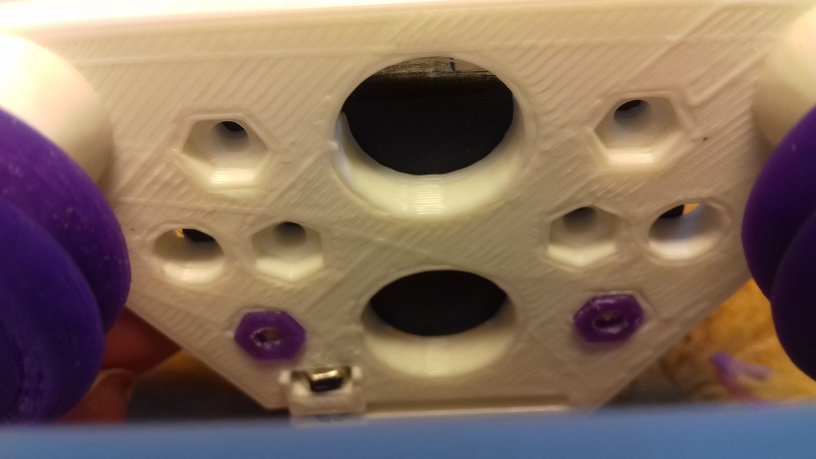
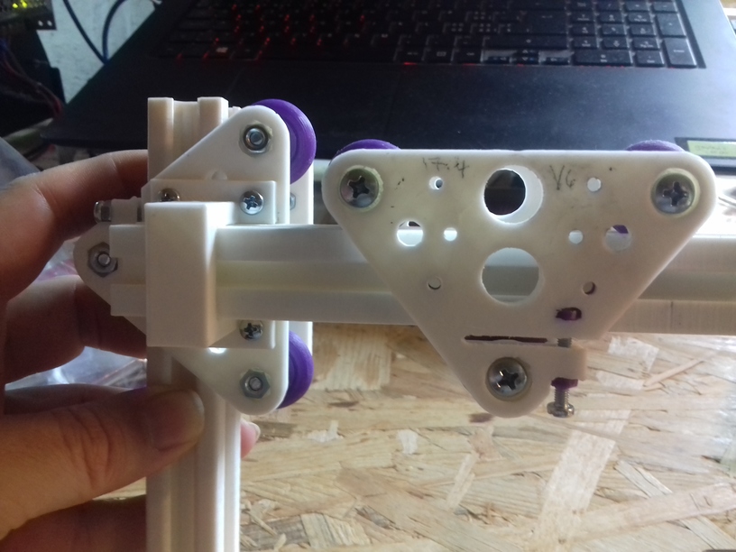
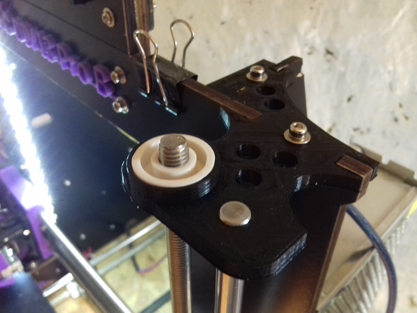
X carriage with white nylon wheels (23.mm OD / 7.3mm width)

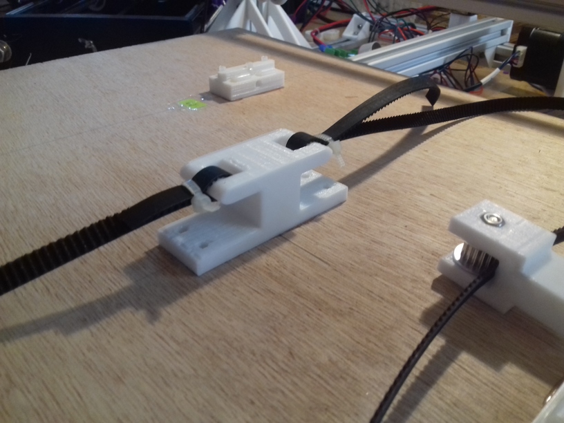
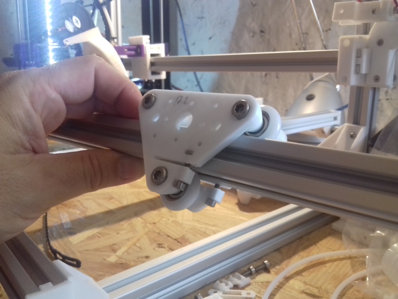
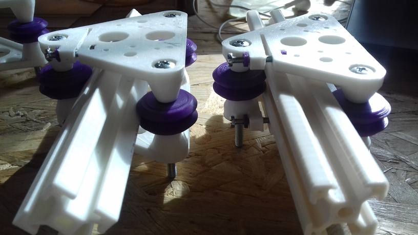
So, I changed back to wheel-based carriage, first again 23/7.3 white nylon wheels (right photo), but when I printed “L” shape with 200mm length in X and Y and 1mm height in Z, I noticed slight Z sinus form as I saw before – while it rolled nicely, there was a wobble . . . and so I printed a new carriage which holds the black OpenRail Double V (clone) 24.4mm OD / 11mm width, and put it on the X carriage:

20180831_071941

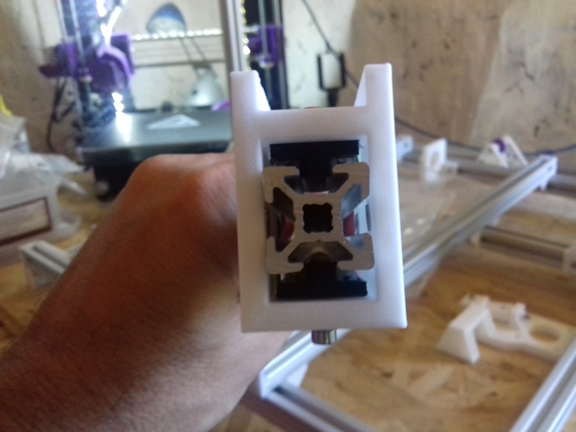
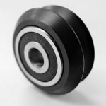
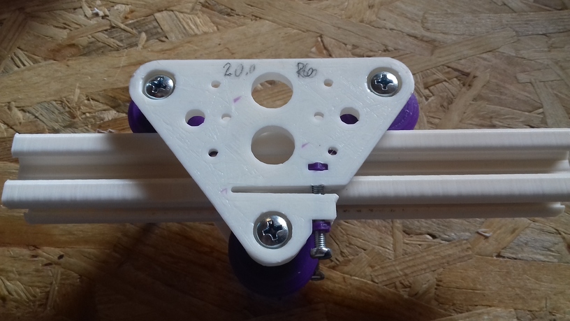
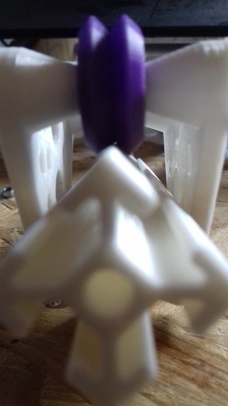
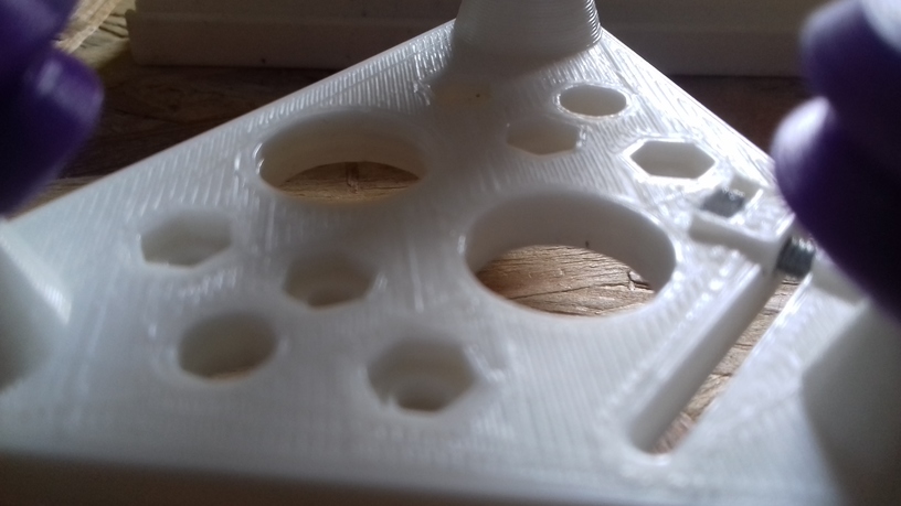
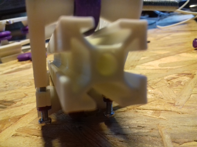
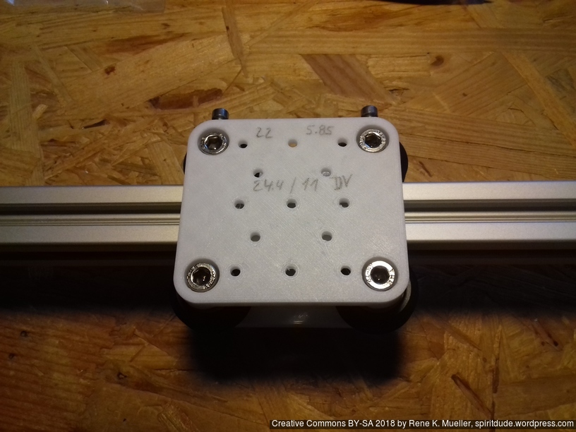
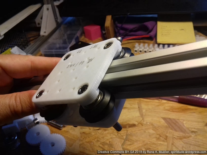
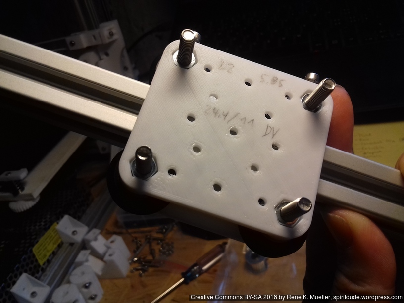
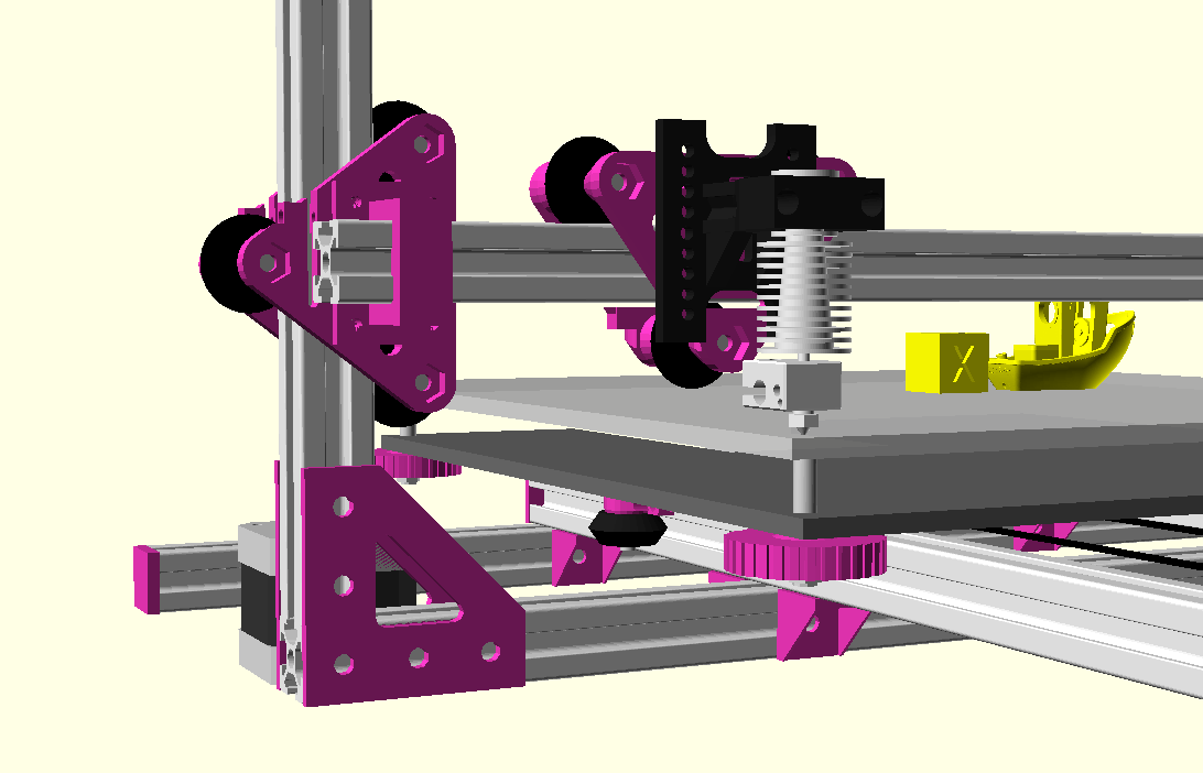
X carriage with double V black wheels 24.4mm OD / 11mm width

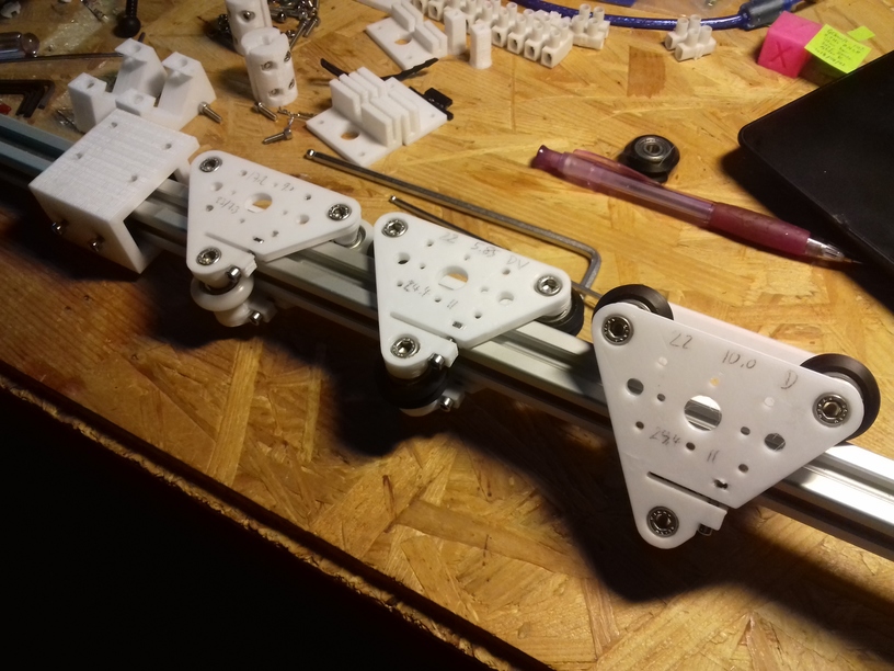
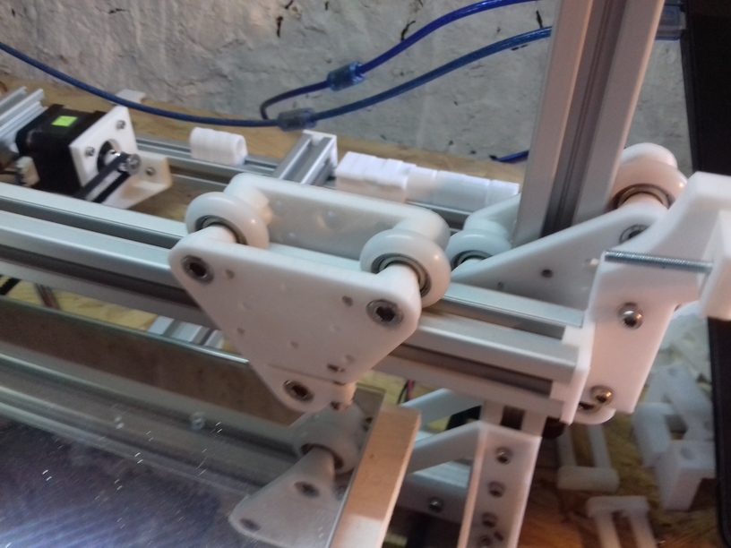
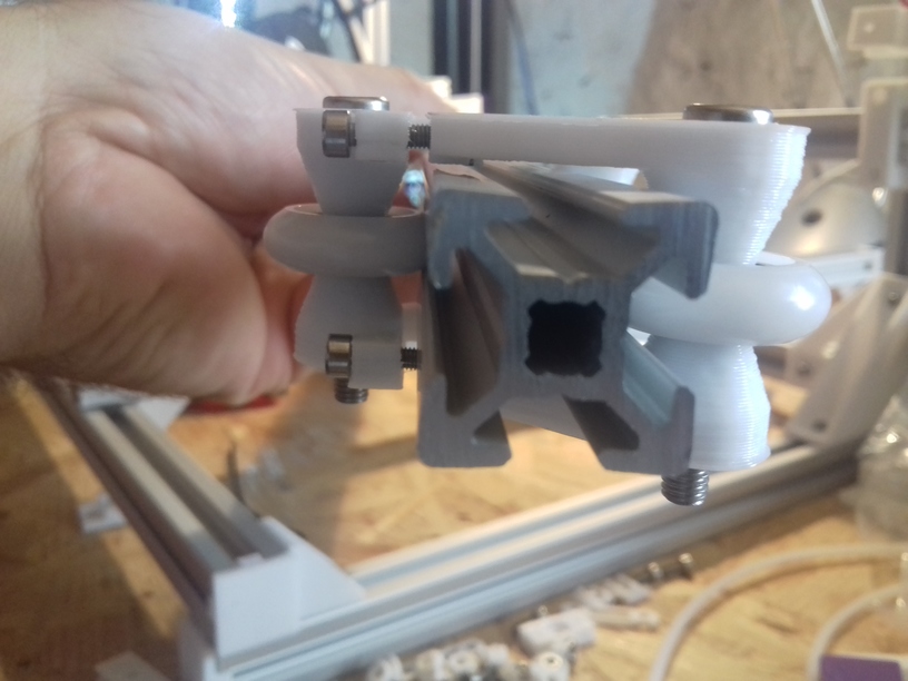
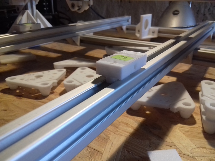
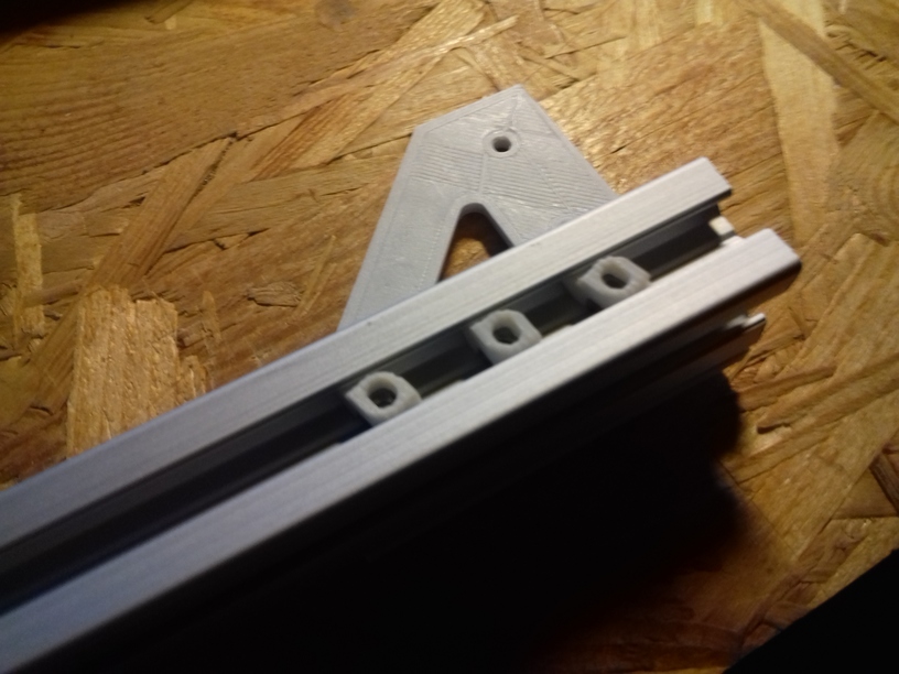
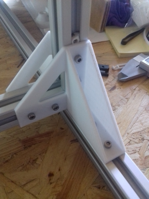
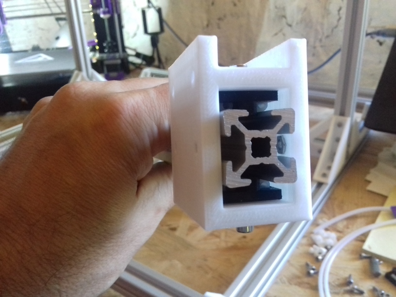
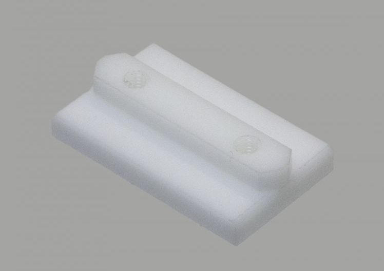
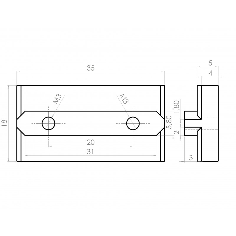
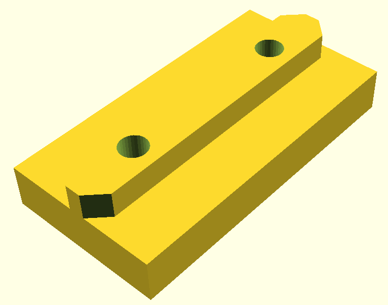
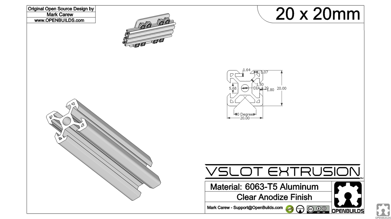
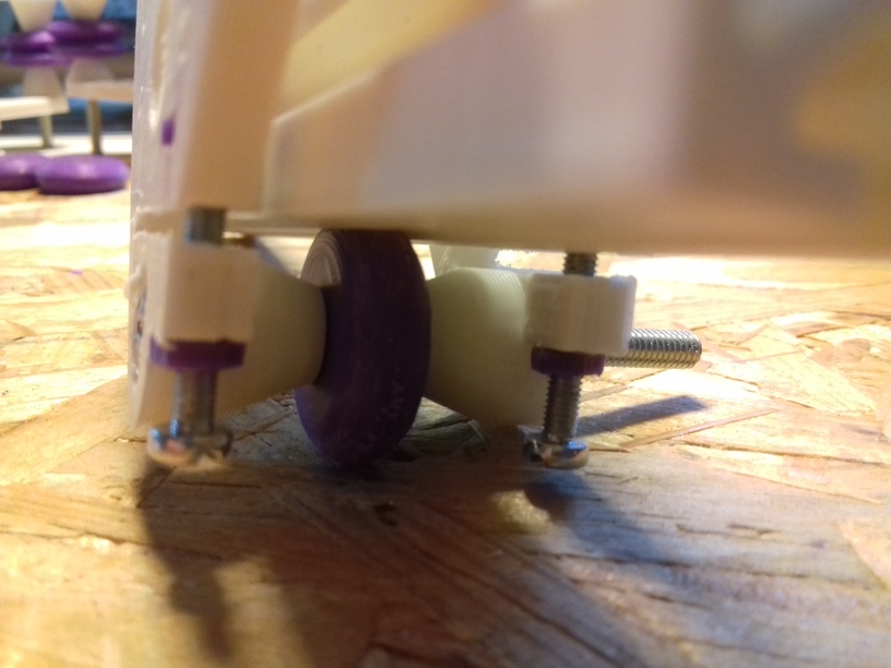
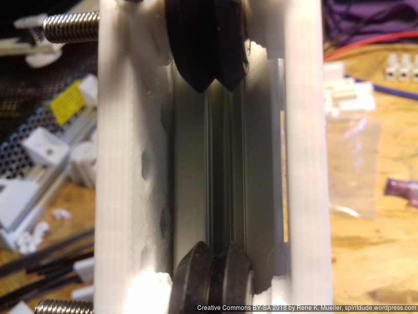
A brief overview of the carriages riding on 2020 T slot (B-Type) alu extrusion:

carriages-selection

20180905_055421

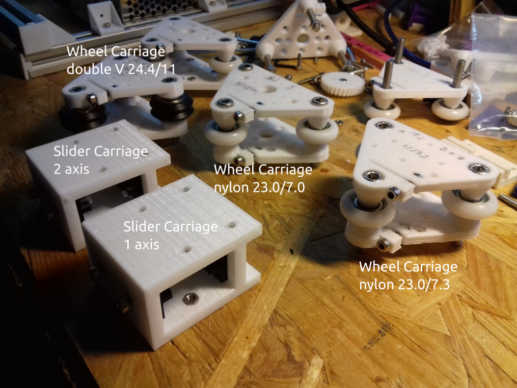
Sliders: on the X axis it did not last, the stuttering was not avoidable; the issue is that the X carriage is one of the hardest axis of the Prusa i3 style geometry to handle: it isn’t just X directional rail, but also pressure on the Z with the weight of the print head, and running over overextruded filament – and it’s hard to pull the X carriage perfectly without the carriage have some vertical tilt as well – anyway, I still use the slider option on the Y carriage – and works fine so far.

White nylon 23/7.3mm wheel: rolls nicely, but gives wobble to the Z height when used on X carriage, apprx. 1mm, also doesn’t stay vertical upright, but tilts a bit with pressure – when the print head moves over overextruded print it doesn’t level it, but jumps over it. I currently use white nylon wheels on the Z carriage successfully.

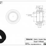
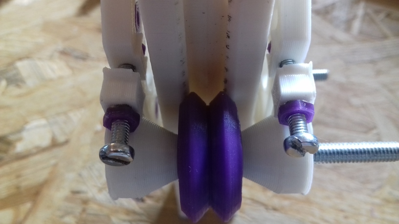
Black double V delrin 24.4/11mm wheel

  • groove use: rolls very nicely, gives no wobble, and stays vertical. The next days and weeks will tell if the double V wheels do last on the T slot alu profiles – they are meant on proper V slot alu extrusions.
  • diagonal/edge use: rolls very nicely too, but surprisingly gives less tilt rigidity than groove use – the T slot 6 (B-Type) gives less surface at supposed 90deg edge, but is rather 85deg
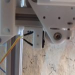
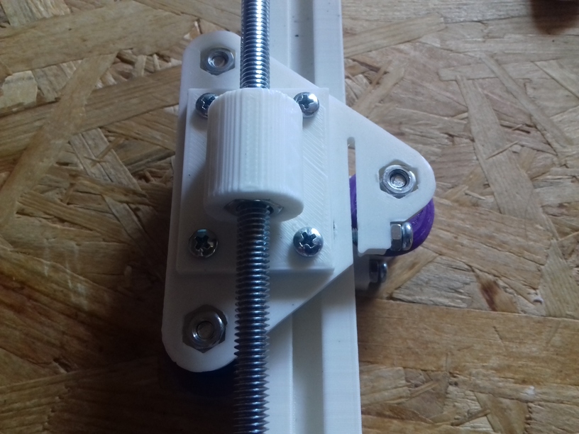
Z Axis Linearity

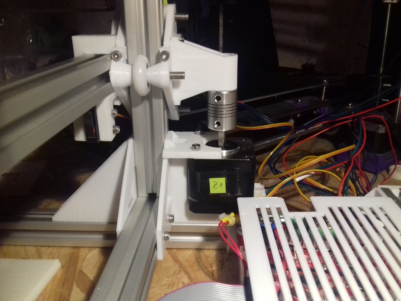
As you may have read in the other post(s), I use M6 threaded rods, it’s flexible and rather aligns with the Z axis itself, whereas M8 is stiffer and misalignment – which by the way doesn’t come from the rod itself, but the mounting with the couplers – won’t impose on the X carriage – this is my own view and it happens to come true again with Ashtar K, after I changed my cheap CTC DIY I3 also to M6.

Now, the 1m long M6 threaded rod, enough for two Z axis each 500mm long, did just cost EUR 0.70, made in China but purchased locally in Germany, and the nylon wheel-based Z carriage happen to work perfectly so far – I expected some slight sinus wobble imposed by the nylon wheels as I encountered on the X carriage, but it seems when there is little force applied on the wheel the carriage works good enough.

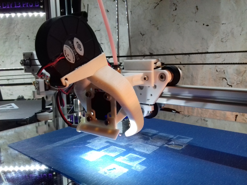
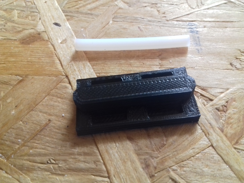
Printing 330mm high 10mm diameter cylinder (with slider-based X carriage):

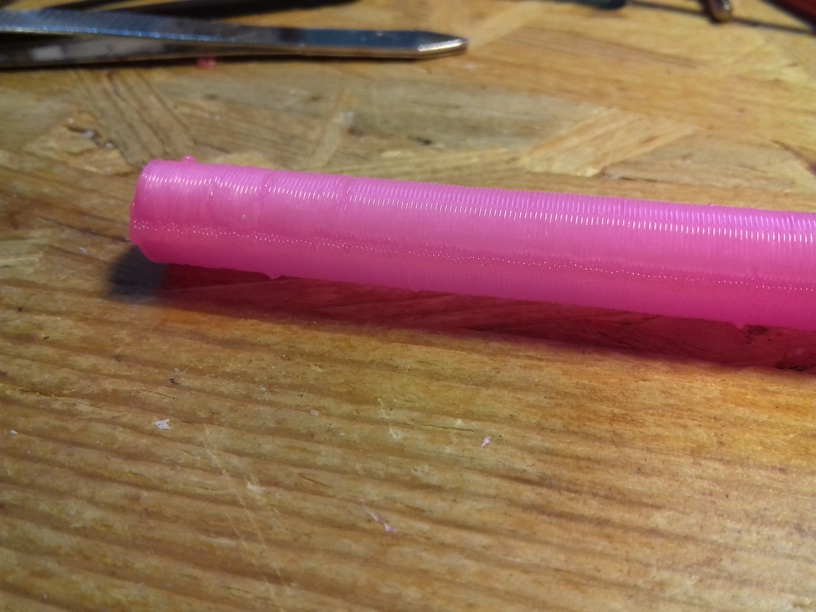
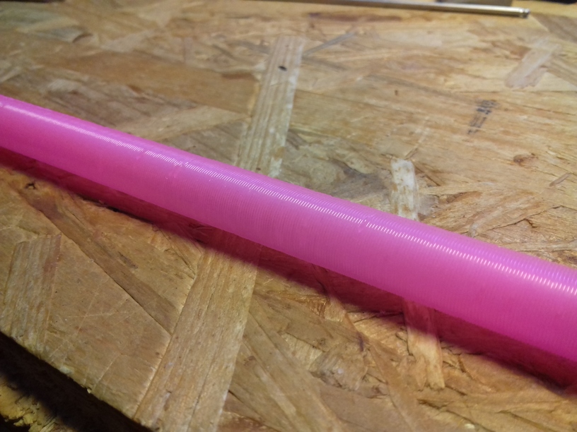
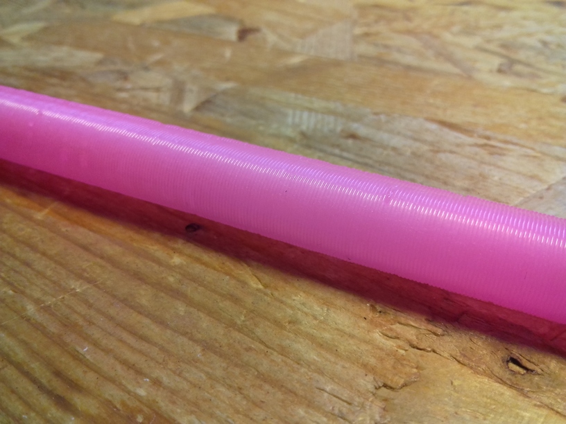
There was some slight extrusion inconsistencies, this is likely due the material, an broken vacuum seal of a newly purchased glowing pink PLA roll, actually, after watching the 2nd print closely, either GCode errors or USB transmission errors, as some segments of the circle (layer of a cylinder) is repeated for some unknown reason and so overextrusion occurs there (needs proper investigation)  – but the linearity is very good, and no Z wobble whatsoever.
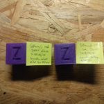
Loopy Egg

60mm height “loopy egg”, printed with 0.5mm nozzle, 0.4mm layer height:

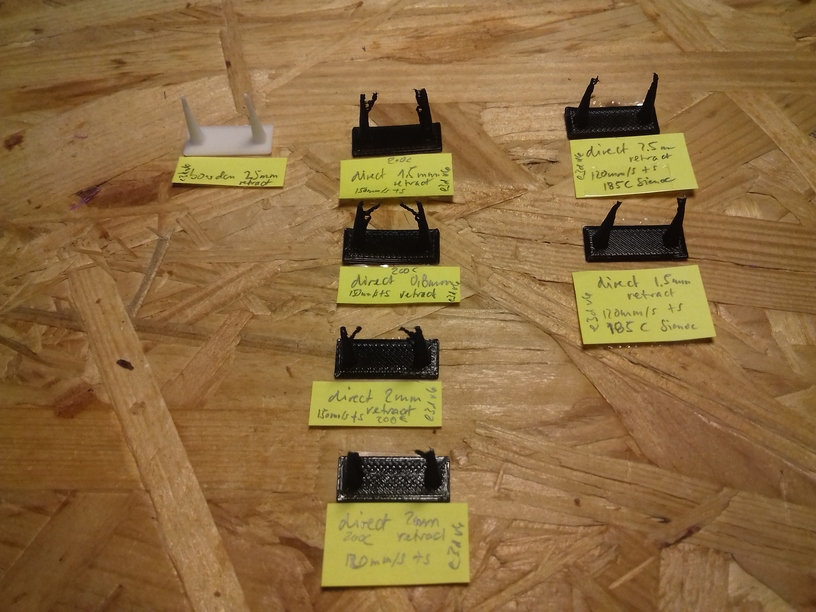
The “loopy egg” is a good benchmark for retraction settings, and stressing the extruder motor as the short segments making up the loops require a lot of push / pull on the filament. There was still some slight stringing, which I knew will happen, as the retraction is just set to 2mm at 35mm/s giving very good results. More prints will tell if I can stay with these retraction numbers.

Fighting Heat Creep

I currently use E3D V6 clones as hotends, one with 30mm “original” fan, and one with 40mm fan. And with the “original” smaller 30mm fan I experienced frequent clogging up within the hotend: some of the filament melted above the heat break and expanded and blocked any further extrusion – that happened now several times.

I tried to reduce the extrusion temperature but which caused decline of print quality. After trying to determine the root cause of the problem, I concluded that it was heat creep and insufficient cooling above the heat break, hence, the hotend fan, and I switched to 40mm fan – and the clogging disappeared, not quite yet . . . update follows.

20180831_071941

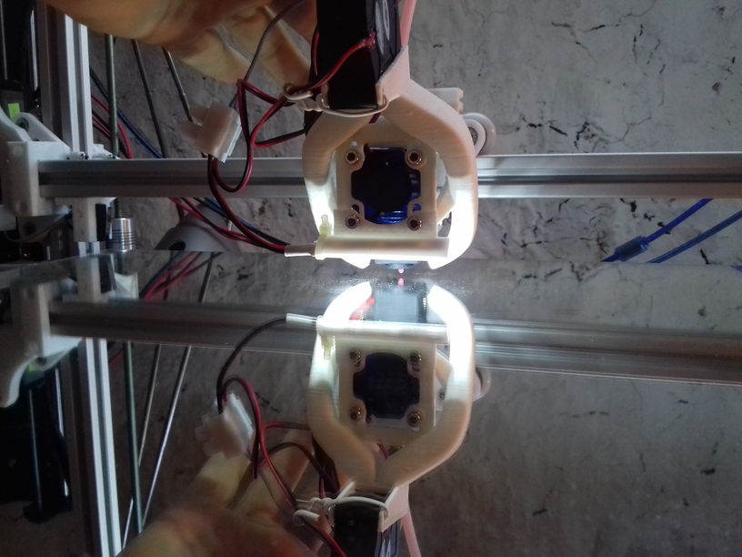
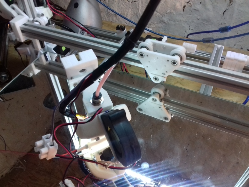
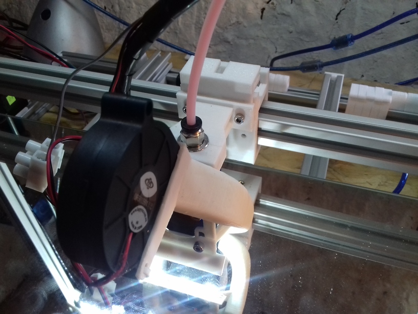
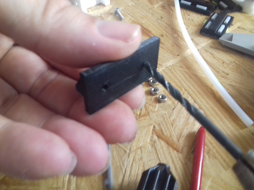
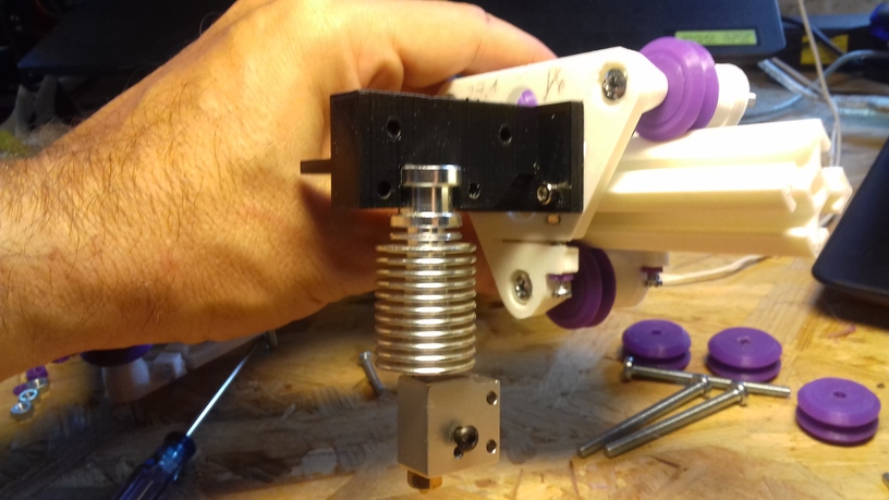
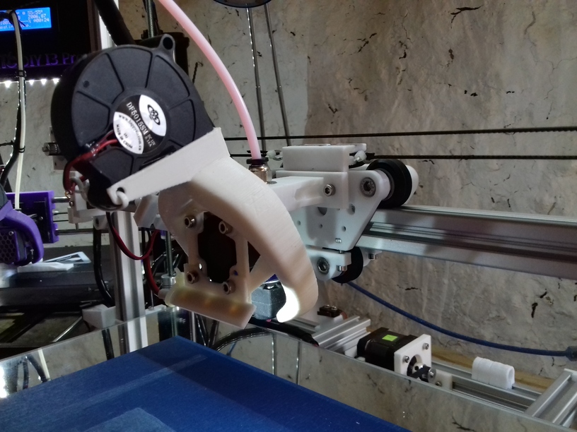
30mm Fan (front facing) with 5015 Fan Fang (top)

20180903_085124

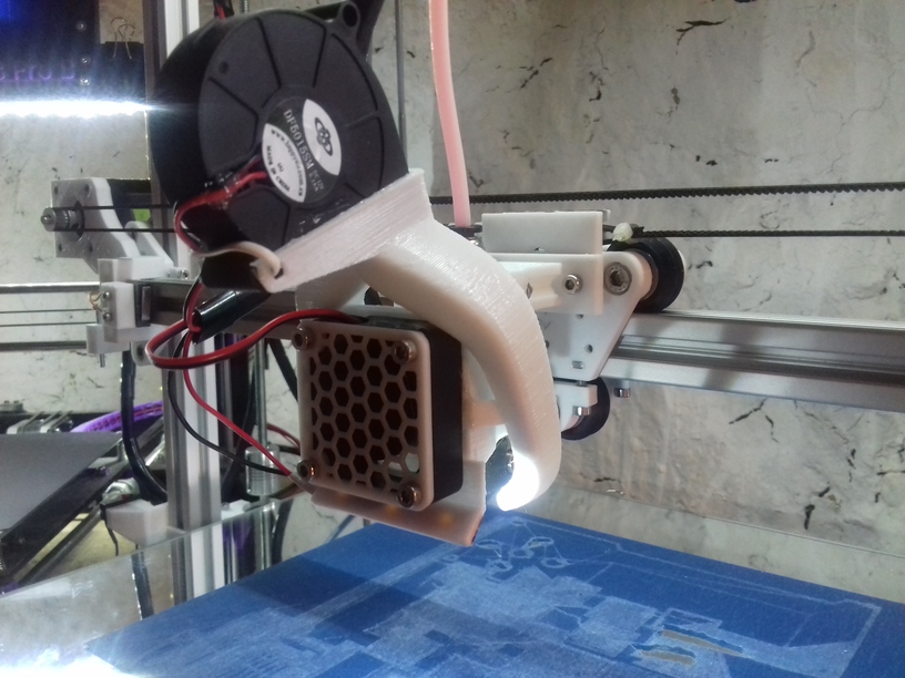
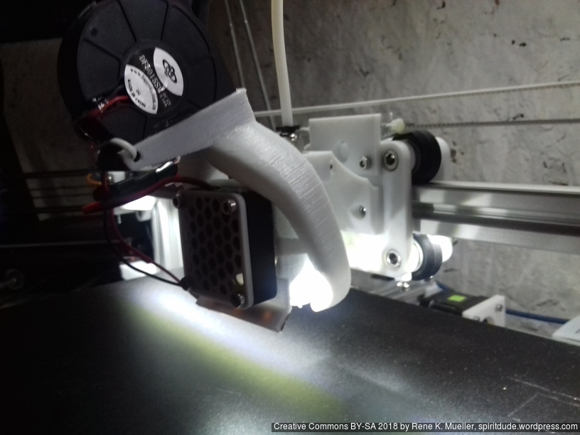
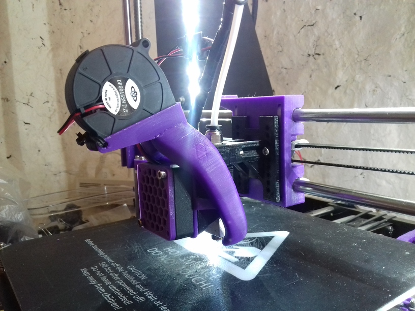
40mm Fan (front facing) with 5015 Fan Fang (top)

Although both setups look very alike, I had to print out another fan fang which can contain 40mm fan.
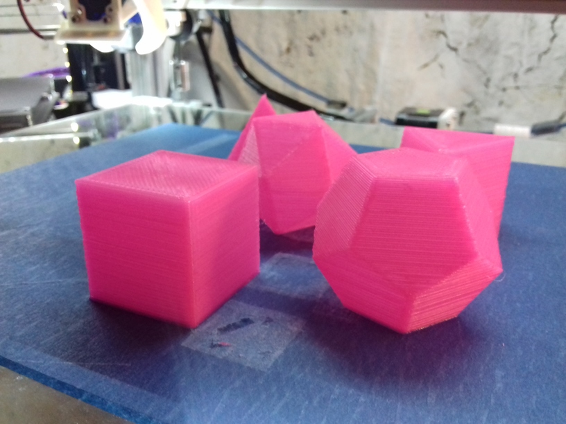
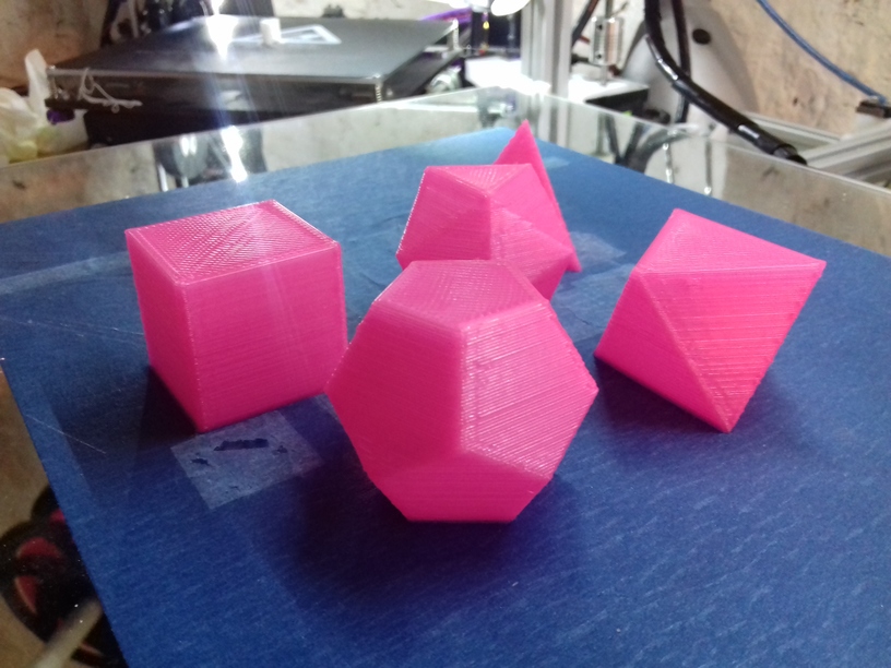
Five Platonics

My favorite geometrical forms – aside the sphere – the sacred set:
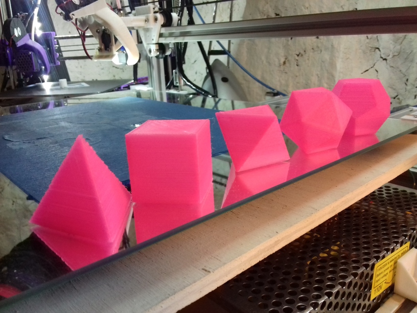
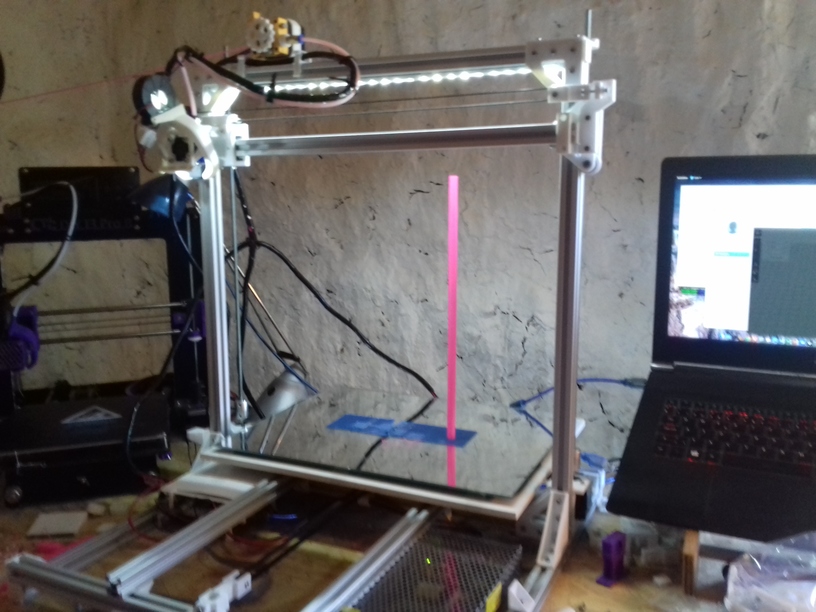
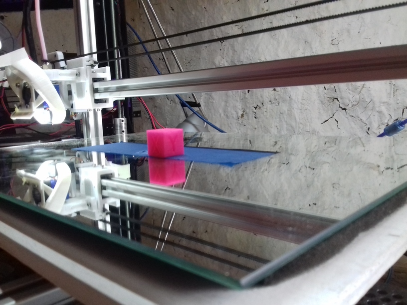
Mirror as Bed

I’ve got 40cm x 30cm mirror which became my bed base, underneath with some tight springs some 6mm multilayered plywood, which was warped 2-3mm on the edge – but it didn’t matter (much). The mirror was the reference, and the Y carriage had to hold the mirror. That turned out to work very well: the mirror is truly flat, I leveled the bed once for tilting, after a week, I only had to tweak the Z endstop screw slightly, but I didn’t touch the screws mounting the mirrors to re-level the bed anymore.

So, using the mirror as bed worked well so far due the flatness – but the glass didn’t turn out to print good on it, the printed parts often detached before finishing the print, and ruin the print – so I used blue tape sheet as temporary solution until the black sticker arrives which I already use on the other 3d printer.

Reflection

As I designed Ashtar K with larger build volume, I choose 0.5mm nozzle at least, and the max 0.4mm layer really pays off in regards of print speed, while still maintain some details – I’m quite pleased so far.

3D Printing: Ashtar K: It’s Alive ;-)

Well, after merely 3 months (2018/06/06) when I started to code the first lines of OpenSCAD to develop a series of parametric Prusa i3-like designs, and few weeks ago decided to go with the “K” series with 2020 alu profiles: simple 11x 500mm beam T slot (B-Type) alu profiles – the 1st prototype happen to print the 20mm XYZ Calibration Cube as of 2018/08/27:

The bed is very temporarly fasten with tape, as I haven’t decided on the actual details of the bed mounting yet and leveling details – but I wanted to see how well the mechanics already works – and it performed quite well so far.

1st print came out mediocre, when I realized I had to tighten X and Y belts more, 2nd print came out much better; 0.5mm nozzle with 0.4mm layer height, merely printed in 8mins with 60mm/s print speed and 80mm/s 20% infill:

And just for the fun of it, 0.2mm layer height with 0.5mm nozzle, at 70mm/s:

Incredible quality: X and Y surface very good, some inconsistency at “X”, on the “Y” side some slight ghosting; but most surprising is the edges on the Z axis – I operate with a simple M6 threaded rod and M6 nut – that’s all – moving nylon wheel-based carriage up and down – sure, I require to print more tests, in particular larger prints to really see how well all axis print up to 300mm.

I had to use blue tape on the mirror otherwise PLA would not stick – eventually I will use the black sticker as I used for the CTC DIY printer which worked quite well.

Nylon Wheels vs Sliders

The past 2-3 weeks, while waiting the nylon wheels to arrive, I decided to check alternatives such as sliders with PTFE tubes – and this paid off: the nylon wheels 23.0mm OD with 7.3mm width sit quite nicely into the T slot (B-type) but when used in real life, like with X carriage, I had some sinus wobble in the vertical – apprx. 0.5mm to 1mm – way too much. So, I exchanged the wheel-based X carriage with the slider-based carriage, remounted the hotend with Bowden setup, and after 5mins the exchange was done:

Current setup:

  • X axis: slider-based carriage, holding on top and bottom side with 2 tightening screws
  • Y axis: simple sliders (just sitting on the groove)
  • Z axis: nylon wheel (23.0/7.3mm) based carriage

The next days and weeks I will review my options:

  • slider-based carriage with
    • 1 axis support or
    • 2 axis support
  • wheel-based carriage with
    • nylon wheels 23.0/7.3 and 23.0/7.0
    • double V wheels

both on T slot alu extrusion – I know ideally would be proper V slot alu extrusions, but I like to find out how good it works with the easily available T slot extrusions. Worst case is, I have to use on X and perhaps Z axis proper V slot alu extrusions, on the Y axis it seems the simple sliders (just a block) work fine.

0.5mm Nozzle

Since I deal with nearly 3x the bed surface compared to 200×200 I thought I have to use a bigger nozzle as well, as a bigger build volume would imply larger objects to be printed. The increase from 0.4mm to 0.5mm diameter also implies 1.5x or +50% more material being extruded and I still desire to print with 60mm/s average with 80mm/s infill – this means I have to test well the hotend performs with that speed and higher throughput of material.

Specifications

Current specifications of Ashtar K 3d printer:

  • 380 x 300 x 320 mm build volume (400 x 300 bed)
  • E3D V6 clone hotend
  • 0.5mm nozzle
  • Anet 1.0 controller board
  • 210 x 210mm 12V heatbed

TODO

  • bed mounting & leveling
  • 300×300 or 400×300 220V heatbed
  • proper print surface (likely black sticker 300×300 or 400×300)
  • improving cable management:
    • Y carriage and heatbed with proper cable chain
    • deciding on position of LCD display

3D Printing: Ashtar K Printer: Motor & Belts

Brief update of motors, belts, threaded rods and end stops mounted:

X Axis

I switched from slider based carriage to the nylon wheel (23.0mm OD, 7.3mm width) based carriage (X and Z axis), apprx. 120cm belt length.


Y Axis Belt

Apprx. 90cm belt length – with some considered cutting X + Y ~ 2m belt length.

This part was tricky – the parts are glued to bottom of the wooden carriage:

  1. mark the positions of the sliders (left: 65mm distance from top and bottom, left: center of top/bottom)
  2. glue 2x sliders on the left (where the Y motor is mounted)
  3. glue 1 slider on the right side
  4. put carriage on the rails, avoid any horizontal movement, push it slightly down (a slight snapping you sense from the sliders)
  5. let it rest (don’t touch or move it) for 30min – glue must dry
  6. move Y carriage gently forward & backward; if there is slight resistance then
    1. loosen all screws of the right 2020 beam so you can move it sideways
    2. then move carriage forward and backward and let the beam slightly find its new position
    3. when the carriage moves gently without resistance
    4. fasten the screws gently
    5. retest and if it’s still resitance, repeat procedure
    6. this is a bit tedious work, but worth it

This part is to do next (once I concluded those PTFE pipe chunk based sliders do their job well):

  1. drill holes and use Zip ties to fasten sliders
  2. glue Y carriage belt mount, let it dry
  3. mount GT2 belt to carriage belt mount
  4. fasten Y carriage belt mount with screws: drill holes from the bottom side


I will make some short videos of putting the carriage together and mounting it – it’s quite fast to attach and detach with those sliders (no screws to unfasten).

Z Axis

I extended the corner brackets so the Z stepper motors can be inserted, this weakens the part but saves quite a lot of space and hides the threaded rods nicely behind the 2020 Z beams. I might work on those brackets later to increase rigidity again.

Currently I use M6 threaded rods for the Z axis, one cycle gives 1mm height change.

X, Y, Z Motion & Homing

Flashing the Anet 1.0 board (which I currently use) with latest Marlin, this was required:

  • using Arduino Uno R3 (clone), installing Arduino ISP on it
  • cabling Uno R3 with Anet board (Uno powers Anet board with 5V, all stepper motors or power detached)
  • installing Bootloader (“Burning Bootloader”) with “Arduino as ISP” as writer
  • downloading latest Marlin, copying Anet Configuration.h and starting to change it

Finally, after hours fiddling around (bad install of Arduino failed to compile and/or upload anything to my Uno R3) the LCD display greeted with “Marlin 1.1.8” 🙂

Moving X, Y and Z axis briefly, 380 x 300 x 320 build volume with the current V carriage with 23mm OD, 7.3mm width nylon wheels – no extruder and no bed heating and leveling yet.

3D Printing: Ashtar K Printer: Carriages (X, Y, Z)

State: Work in progress

As I finished the frame, I focused on the carriages:

  • X carriage: moving left to right with the hotend with Bowden setup to keep it light: Wheel-based Carriage
  • Y carriage: moving bed forward and backward, relatively heavy with 400×300 bed with a mirror to ensure flatness: leaning toward Sliding Carriage
  • Z carriage: moving up and down with X carriage: Wheel-based Carriage

XZ Frame with X- and Z-Carriages

I made some tests with sliding carriage (composed with PTFE tubes), and finally the Nylon wheels arrived and I began to review two kinds of wheels:

  • 23mm OD, 7.3mm width: even it’s wider it sits better in the T slot 2020 alu extrusion
  • 23mm OD, 7.0mm width: is bit more narrow, but doesn’t sit well on the extrusion

So, I put the 23/7.3 nylon wheel on the V plate to compose a V carriage, and applied to X and Z axis:

Y Carriage

The nylon wheels work very well, given the fine-tuning capability, whereas the sliding approach with 2 axis support (PTFE tubes in sliding direction plus vertical to stay in line) doesn’t give tuning capability.

Currently I lean toward the more simple slider (white PLA) with 2 axis stabilization, as with the wheel-based carriage too much vertical force will be applied to the wheel in a perpendicular manner and wear the wheels rather fast.

One of the challenges is to mount three such sliders on the bed – two can mounted quite freely (with margin of 1-2mm) whereas the 3rd slider needs to be mounted very precise.

I update this post as I progress.

3D Printing: Ashtar K Printer: Frame

State: Work in progress

Building 3D Printer Ashtar K starting with the frame using 2020 T slot 6 alu extrusions, changing design slightly from 9x 500mm to 11x 500mm as early tests showed the XZ frame wasn’t stable enough toward Y bed – so two additional beams (later photos in the series) to make XZ frame sturdy toward the bed.

and the current state more or less:

20180811_152129

While waiting for wheels to arrive I thought to make some tests with sliders composed with PTFE tubes (4mm and 3mm in diameter) – I might actually use them in the X axis and Y axis:

The building volume with the 500mm beams can be stretched to 380 x 300 x 360mm, if the X carriage is short(er) – this means, the bed can be 400 x 300.

3D Printing: Sliding on Alu Extrusions

State: Early draft, work in progress and likely will receive updates.

Updates

  • 2018/08/15: Added Slider with PTFE tube inlets with 1 and 2 axis support with photos and brief test video
  • 2018/08/05: First overview with a 3 approaches

While waiting for the shipment to arrive, I thought to study some of the alternatives to wheels on alu extrusions, such as sliders.

2020 Nut 6 B - 999991_1

Nylon 2020 Slider

gleiter-glatt-b-typ-nut-6_3
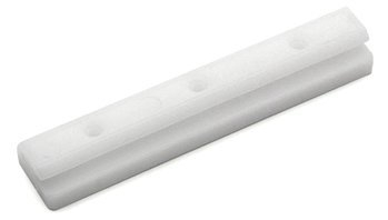
Commercially manufactured, apprx. cost EUR 2.50 per piece, sold in 10 pieces bag.


3D Printed Sliders

Simple Slider

A simple replicate of one of the simple 2020 sliders:

The sliding nose is 5.8mm wide. Ideally this would be printed in nylon; PLA might work as well but tends to stick more and grease or oil is required therefore.

TODO

  • print samples and measure friction with PLA
  • publish model

Slider (2 Sides) with PTFE tubes

Improving the simple slider with 10mm long 4mm PTFE chunks to decrease surface and use proper material for sliding:

screenshot-from-2018-08-15-06-21-23.png

and in use for the Y axis of a Prusa i3 like style:

20180813_084627

and a small improvement to take care of the 2nd axis as well (reducing 2nd axis wiggle):

Screenshot from 2018-08-15 06-21-15

20180817_102329

and then mounting them with a carriage together with M3 screws to control tightness:

and a brief test:

Slider (4 Sides) Carriage with PTFE tubes

A bit more complex using PTFE tubes on all 4 sides:

each inner side has 8 tube chunk insets, which gives you the variable option:

  • 4 chunks (a 10mm) x 4 sides = 160mm total
  • 8 chunks (a 10mm) x 4 sides = 320mm total
  • 12 chunks (a 10mm) x 4 sides = 480mm total
  • 16 chunks (a 10mm) x 4 sides = 640mm total

The OpenSCAD module takes parameters such as length of the carriage and the diameter of the PTFE tube (e.g. 3mm or 4mm), default length 60mm.

And the adjustable version with 75mm width looks like this:

which breaks the one surface apart with the mounting hole; if a plate would use all 4 holes that side would become non-adjustable that way – so this isn’t ideal, but perhaps work for single side use.

A possible application as X carriage and two Z carriages in a Prusa i3 use case:

printer-ak-with-sliders

TODO

  • print model and make actual physical tests, measure friction of the possible options
  • publish model


End of Page

3D Printing: Wheels on Alu Extrusions

Status: This is a work in progress – and will likely will receive more updates, files not yet released.

Updates

  • 2018/09/14: Added H Plate (4 wheels) and h_plate() reference.
  • 2018/09/01: Added v_plate() variables and numbers for common wheels
  • 2018/07/28: Adding another example with Z axis X gantry adapter & X gantry horizontal beam mount.
  • 2018/07/21: Supporting Delrin R 21.5 or 23mm/7mm wheel as well.
  • 2018/07/20: Version 0.6 added, with ordered mounting holes and nut insets, screw which controls distance inside the plate to reduce overhead
  • 2018/07/19: New version 0.2 with M3 has controlling distance of the 3rd wheel
  • 2018/07/17: First basic design (Version 0.1), few tests made

Introduction

As part of developing various designs around Aluminium extrusions, a few tests. Early tests I printed the wheels in PLA just for sake of testing the dynamics, once the wheels arrived real applications were sought:

20180831_134539

The possible parts are 2020 alu extrusions and Dual V wheel by OpenRail:

and the “Delrin R” V type nylon wheel (21.5/23mm diameter, 7/7.3mm thickness and 5mm hole):

nylon-weels-s-l1600

Later in the research the difference between 7.0mm and 7.3mm thickness nylon wheels were significantly, as the shape of the wheel differ, and the ticker one (7.3mm) actually sat better in the T slot groove.

2020 V-Slot with Double V Wheels

The V-Slot alu extrusions usage test.

VS_20x20

V Plate (Version 0.6)

Ordered mounting holes (2x 30mm apart horizontally x 2 20mm vertically apart) plus 24mm apart near center, all with M3 nut insets so both surfaces (inside and outside) are nearly flat and mounts easily attached.

Hole-to-hole distance: 40.5mm (20.5 + 20)

2020 T-Slot Diagonal with Double V Wheel

Using the traditional T-slot Aluminium extrusion without proper wheel groove but rotating so the edges are used as rail and the 90 degree inner groove of the Dual V wheel.

2020 Nut 6 B - 999991_1

Version 0.6

Moving the adjuster into the plate to save some space, and adding some insets for the M3 mount holes (2x 30mm apart and 20mm height distance, 2x 24mm apart (Prusa i3 extruder).

Hole-to-hole distance: 47.1mm (27.1 + 20)

2020 T-Slot with Delrin R Wheels

Since the V plate is parametric designed (controlling thickness, distances etc) I thought to support also the “Delrin R” nylon wheels:

V Plate (Version 0.6)

Hole-to-hole distance:

  • 21.5mm diameter wheel: 37.4mm (17.4 + 20)
  • 23.0mm diameter wheel: 38.9mm (18.9 + 20)

V-Slot vs Diagonal

20180720_175909

20180720_175933

20180721_194709

Mounting Holes

Since the V plate, either used with V Slot alu profile or diagonal, has 6 fixed holes with nut insets to attach adapters:

  • 2x 30mm apart horizontally, 2nd row 20mm apart vertically
  • 2x 24mm apart horizontally centered vertically on the plate

An adapter plate or area of 40 x 35mm is guaranteed to be flat, and 5mm thick, with the given mounting holes as mentioned.

v-plate-holes

v-plate-inside

Usage

2x V plates (top/bottom) with its 3x wheels each are made so I can use it as a “V module”:

Prusa i3 Style

  • X extruder: 1x V module with extruder adapter
  • X gantry: 2x V module with Z axis threaded rod adapter
  • Y gantry: 3x V module without adapter, but mounting top V plates direct to Y carriage

OpenSCAD v_plate()

v_plate() takes multiple arguments:

  1. d: distance of holes (-20mm)
  2. h: height/distance of the wheel to plate
  3. orientation: -1 or 1 (back / front)
  4. f: multiplier horizontal distance gap (default: 1)
  5. g: multiplier vertical distance gap  (default: 1)

Here for 2020 T Slot B-Type in groove usage:

  • Nylon wheel 23.0mm OD / 7.3mm width: d=17.2, h=9.0
  • Nylon wheel 23.00mm OD / 7.0mm width: d=18.3, h=9.0
  • OpenRail Double V 24.4mm OD / 11mm width: d=22.0, h=5.85

Use

  • 1x screw M3 x 16 with M3 nut (push it carefully yet forcefully so it aligns top/bottom flat) for distance control, put a drop of oil on the tip of the M3 screw before you screw the first time.
  • 3x screw M5 x 30mm with cylinder head with hex inset, and 3 M5 nuts to mount the wheels per double V plate to make up a V module

20180831_134523

Four Wheels: H Plate

For the X carriage with the hotend I thought to add another wheel to improve tilt rigidity (e.g. when overruning bumpy unclean or over-extrusions) – ideally triangle like with V plate/module it’s easy to adjust, four wheels means two wheels need to be adjustable, and those are harder to align properly.

H Plate (Version 0.1)

First version I decided to use a simple solution, have some larger vertical extended 5mm holes and M3 screw which carves its own thread to control the distance – this means the H plate should be used in double to make up a H module, this is the short/narrow 48mm wide H plate:

The plate contains a set of 30mm and 20mm spaced mounting holes, all M3 – requires support from bed only (not “everywhere”) so the M5 nut and screw heads insets are printed nicely for the wheels:

h_plate() settings – same as for v_plate():

  • Nylon wheel 23.0mm OD / 7.3mm width: d=17.2, h=9.0
  • Nylon wheel 23.00mm OD / 7.0mm width: d=18.3, h=9.0
  • OpenRail Double V 24.4mm OD / 11mm width: d=22, h=5.85

For the short version, width=48 (less won’t work).

Examples

Extruder/Hotend Adapter

Attaching E3D V6 hotend on a pair of 30mm holes with M3x8 (M3x10 might work as well) with M3 nuts (in this example printed in purple PLA):

Z Axis Adapter

A simple Z axis adapter, here with M6 threaded rod with M6 nut:

The adapter is 4mm thick, and M3 x 10 should work (in this example I used M3 x 16 which are too long, but still work).

X Gantry Horizontal Beam Mount

A small simple piece to mount the 2020 horizontal X axis on Z axis V module:

Additional holes to fasten beam with T nuts as well (top and bottom of the bridge).

V and H modules used as part of the Ashtar K 3D Printer:

printer-ak-vplate-closeup

20180830_174653

20180915_191015

Related Projects

End of Page

3D Printing: Fixing Z Banding

Using a low-cost 3D printer like CTC DIY I3 Pro B (Geeetech I3 Pro B clone) with M8 threaded rods as Z axis with loose or floating ends is what you get – and so also some wobble or banding on the X axis due slightly bent M8 threaded rods – they barely come straight. I hesitated to use lead screws due decrease of resolution (M8: 1 cycle = 1.25mm height, lead screw like TR8x8 (8mm dia, 4 starts, 2mm pitch, 8mm lead => 1 cycle = 8mm height) but otherwise gaining pretty straight lead.

Anyway, I searched Thingiverse for Z mounts for the CTC DIY and found a few, and adapted one design and made a remix Geeetech / CTC Prusa i3 DIY – Z Axis Bracket Remix with printable Bearing:

  • changed structural holes (larger hole -> smaller holes)
  • bearing hole widened to have more floating
  • printable bearing added to restrict end (optional)

New Z bracket mounts (black), without/with printed bearing (white):

20180712_13470020180712_150437

And I did a few tests:

20180712_200705

Left to right (close-ups photos below):

  1. original Z bracket (wood) apprx. 4mm play
  2. new Z bracket without printed bearing, apprx. 10mm play
  3. new Z bracket with printed bearings (with loose tolerance)
  4. new Z bracket with printed bearings (tight tolerance)

Now comes the surprise, the best surface (best to worst):

  1. no bearings / open floating: gives the smoothest surface, most straight Z edge
  2. tight bearings: gives very good surface, slightly worse than with no bearings
  3. loose bearings: noticeable artifacts / wobble, Z edge wobbly
  4. original bracket: worst wobble of all, Z edge wobbly

Which means, either give it a lot of space so the upper end of the Z threaded rods can float, and thereby the X gantry can stay fixed (and not wobble) – or – fix the threaded rods and suppress wobble (there is still wobble but restricted).  Giving it some space on the top means the inherent wobble of the rod is distributed between top and X gantry – giving wobble artifacts on the print . . .

The issue isn’t simple: with or without fixation gives good results, some fixation gives more bad print results.

Open Ends / Floating

The new Z bracket provides more space for the threaded M8 rods than the original wooden bracket:

20180712_134700

Printed Bearings

You may print two bearings (OD 22mm, ID 8mm), make sure to test inner diameter, so the threaded rod slides smoothly – if required use a 8mm drill to widen the inner hole.

20180712_150437

Conclusion

Worst Z wobble was with original Z mount with ~4mm play or the loose bearing with apprx. 1-2mm play.

Best results I achieved with floating ends or with tight bearing – in other words, either leave it open or make it stay close, but worst is to give it a little play and threaded rods will show their unevenness on the prints.

I would also guess, the unevenness of the threaded rods and their position to each other also matters, e.g. whether left and right go the same way or cancel each other wobble out. What I noticed was, once I used the printable bearings for a print, and removed it, the threaded rods wobble already less – but as said, best results I achieved with no bearing and wide floating ends or with the tight bearings.

Recommendation: print the mounts, print the two bearings, and print the XYZ Calibration Cube or whatever reference item, and see yourself which option works better for you.

Addendum: M6 Z Axis Conversion

I made a small package Geeetech / CTC DIY I3 Pro B M6 Z Axis Conversion to use M6 threaded rods instead of M8. It made little difference:

  • less wobble, but still wobble despite of “straight” M6 threaded rods
  • wobble seems mostly introduced by the couplers (either printed or PVC pipe):
    • out of center alignment = wobble
    • tilted mounted rods = wobble

It is hard to mount the rods perfectly with the couplers, a little misalignment and one introduces wobble (X/Y wiggle).

Anyway, M6 gives slightly higher resolution in Z axis with 0.005mm per motor step.

3D Printing: Layer Height

Printing with different layer heights with the same nozzle diameter (e.g. 0.4mm) gives quite a range of printing quality and printing time – the higher the quality or lower the layer height the more printing time it takes, the 20mm height XYZ Calibration Cube as an example:

20180711_193114

0.05mm layer height / 398 layers / 1.38 hrs

0.1mm lh / 200 layers / 0.73 hrs

0.2mm lh / 100 layers / 0.37 hrs

0.3mm lh / 66 layers / 0.25 hrs

0.32mm lh / 62 layers / 0.23 hrs

0.32mm layer height is 80% of the nozzle diameter, and supposed to be the maximum of layer height.

0.14mm – 0.39mm lh / 64 layers / 0.21 hrs

using the Adaptive Layer Height feature of Cura.

0.4mm lh / 50 layers / 0.18 hrs

obviously too high layer height with 0.4mm on a 0.4mm nozzle, some layers have gaps.

0.4mm w/ 0.6mm nozzle / 50 layers / 0.11 hrs


using 0.6mm nozzle on E3D Volcano clone – not quite tuned with under extrusion on the top (90% flow, with 100% flow the X/Y surfaces were terribly over extruded).

All printed with

  • 60mm/s print @ 190C
  • 80mm/s infill
  • 150mm/s travel
  • 1st layer: 20mm/s print @ 200C

on

  • a heavily improved CTC DIY I3 Pro B (Geeetech DIY I3 Pro B clone) with
  • Bowden setup and E3D V6 clone hotend,
  • sliced with Cura 3.4,
  • printed with white PLA-R (recycled PLA) by Fabru – it was a custom extrusion based on recycled white PLA, they usually sell only black recycled PLA as of 2018.

While reviewing all the samples, I noticed I could improve the Z banding issue, which still showed a bit – addressed in 3D Printing: Fixing Z Banding; done after all my layer tests.

Conclusion

Layer height 0.05mm and 0.1mm look very alike with this XYZ Calibration Cube – so it’s not really worth 0.05mm but 0.1mm would be sufficient. The Adaptive Layer Height turned out quite well, near the same speed as 0.32mm layer height.

The top surfaces of 0.05mm and 0.1mm are very nice, whereas 0.2mm already shows significant artifacts – best choice would be to print the last layer at 0.1mm layer height.

If one prints large volume, it’s worth to consider a larger nozzle, e.g. 0.6mm nozzle diameter, which outputs 2.25x more material already yet direct drive recommended – I struggled with complex prints with retractions with the Bowden setup.

I usually print at 0.2mm layer height, and if a larger piece is required I increase to 0.3mm – for the future I might switch the Adaptive Layer Height feature in Cura in that case.

3D Printing: CTC DIY I3 with E3D V6 Clone Hotend

E3D-V6-J-edited
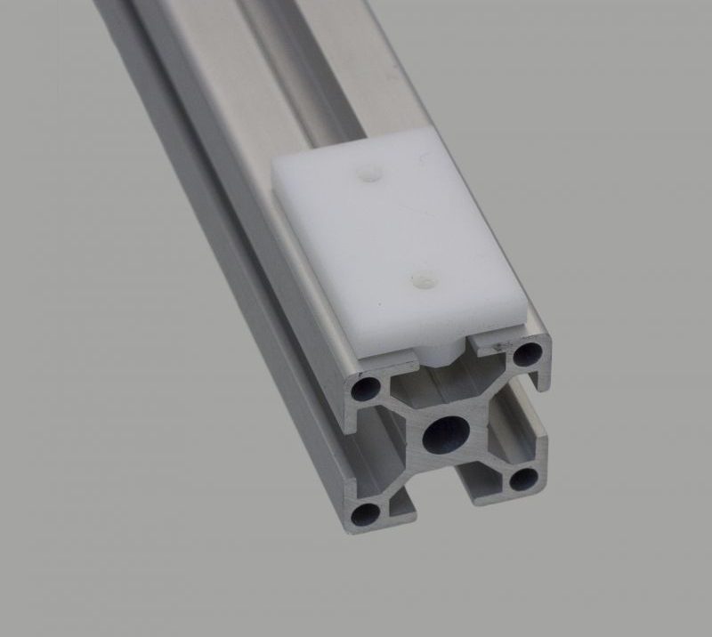
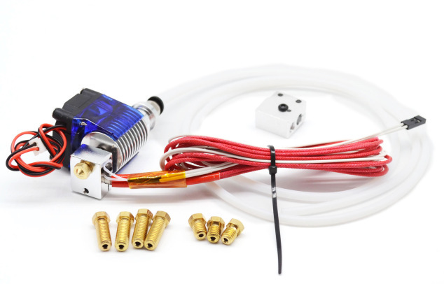
The CTC DIY I3 Pro B, a Geeetech I3 Pro clone, is the very low-end of 3d printers – quality and pricewise, and uses a direct drive to feed the filament aka “MK8 Extruder”.  I ordered an E3D V6 clone with 0.2mm-0.4mm short nozzles with optional Volcano hotend for larger diameter nozzles (0.6mm – 1.0mm) from China, at EUR 9 price, as I wanted to

  • print faster, above 100mm/s if possible
  • print thicker or larger layer height to reduce print time for larger volume prints, e.g. 0.6mm – 1.0mm nozzles

and E3D V6 hotend seemed to be the remedy.

First I tried the Bowden setup, then printed an adapter so E3D V6 works with original extruder as well, e.g. direct drive is recommended when printing with flexible filament.

2-in-1 Fan Setup for E3D V6

20180604_172725

I used the 2-in-1 fan duct: extruder and filament cooler for E3D V6, it’s low complexity and low mass makes it quite suitable, yet, since only one fan is used, it cools at the first layer already and likely reduce adhesion – not optimal but for now an acceptable compromise. The cooling otherwise is excellent, as good as my “duck beak” fan I had with original setup.

To secure the fan better, I used some rubbery-like glue (when dried) and put it on the end of the clamp of the fan adapter (let it dry first before using), to increase the grip on the hotend – as the fan once fell off while printing when it ran off failed printed filament which was cool and hard already – which would have caused quite a chain of dangerous events (hotend no longer cooled, melting the mounts, falling on the heatbed and heat whatever lies on the bed if the print(er) would have let be unattended).

E3D V6 Radial Fan Fang

20180721_143402
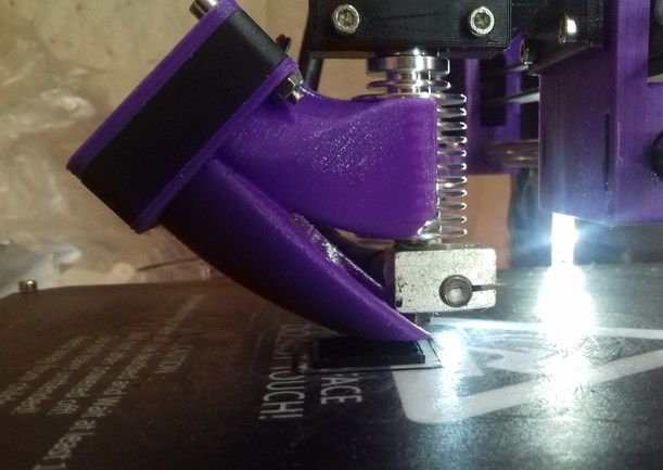
After some time I switched to E3D V6 Radial Fan Fang, which uses 5015 radial fan, which turns on at 2nd layer – I used a remix which uses 40x40x10mm fan for the heatsink and replaces the small E3D V6 fan.

If you choose this, file the grip a bit so it attached smoother to the heatsink – my first print broke while attaching.


Quality of E3D V6 Clone

e3dv6-clone
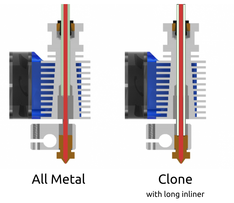
Before I go into the details, let me comment of the overall building quality of those E3D V6 clones: you get what you pay for, a compromise. My hotend leaked like crazy, at the junction of heatblock & nozzle, and heatblock & heatbreak – which is most annoying, and that did not happen with the original MK8 Extruder.

Remedy: I used teflon thread tape used to seal threads of the heatbreak, on both nozzle and heatbreak thread – this is really suboptimal. The teflon thread melted over time (not right away but after days/weeks), so I didn’t keep it.

hotend-problem
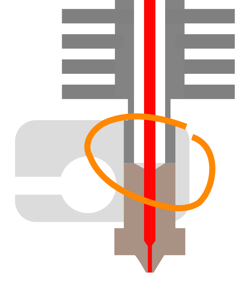
Update 2: the real problem of leaking was the PTFE/teflon inliner, the end toward the nozzle wasn’t perpendicular sufficiently and likely a bit too short (by less than 1mm) and it was too narrow tube with 3mm OD instead of 4mm and be more tight – so the PLA leaked between the inliner and the threads of the heatbreak and nozzle – so the real remedy is to pay close attention of the length of the inliner (in case the E3D V6 clone comes without it as in my case), and give it 0.5mm to 1mm extend with a clean cut and preferably a conic end which presses then toward the nozzle.

Further, I had to use again a teflon inliner/tube – this wasn’t an all metal hotend, means, I am still limited with limited material choices, staying below 240C to preserve the teflon tube.

But on the upside, the quality of the extrusion was excellent, there was an significant improvement of print quality compared to the old “MK8 Extruder” setup, and I seemed to increase printing speed as I desired:

E3D V6 with Original Extruder

20180604_171258

I used an adapter but altered it so it prints without support Simplified E3D V6 mount for CTC Prusa i3 Pro B with original extruder, fortunately it maintains the similar Z and Y distance to the bed as the original hotend, so there is little to change.

And the usual XYZ calibration cube at 60mm/s and 120mm/s:

Since I didn’t upgrade or customize my firmware yet, my thermistor likely reported wrong temperature, as the possibly new type wasn’t properly assigned in the firmware – and I had to reduce print temperature, too much stringing otherwise occured:

20180604_200117

The tests reveals that stringing is mainly a problem of nozzle temperature, and much less of retraction length.

XYZ Calibration Cube

Left to right: 60mm/s, 120mm/s and 150mm/s:

Surprisingly it still performed quite well with 120mm/s and 150mm/s, although I doubt 150mm/s were really achieved at this small print.

E3D V6 MK 7 Extruder Settings

  • Printing speed: 60mm/s – 150mm/s
  • Infill speed: 100mm/s – 150mm/s
  • Motion speed: 120mm/s – 150mm/s
  • Retraction distance: 1.5mm

E3D V6 with Bowden Setup

With the Bowden setup one uses a teflon/PTFE tube to put the extruder motor stationary aside and push from there, reducing the moving mass on the X axis and so faster printing speed is possible – but as I found out, with faster printing speed more pressure in the hotend and if the hotend isn’t properly sealed, it will leak quickly.

20180603_061944

The first run with Bowden setup, the extruder stepper motor not yet mounted but sitting aside:

With the direct drive I printed at 60mm/s as default, now printing at 80mm/s the XYZ Calibration Cube:

and the results are impressive, left 60mm/s, right 120mm/s:

20180603_061929
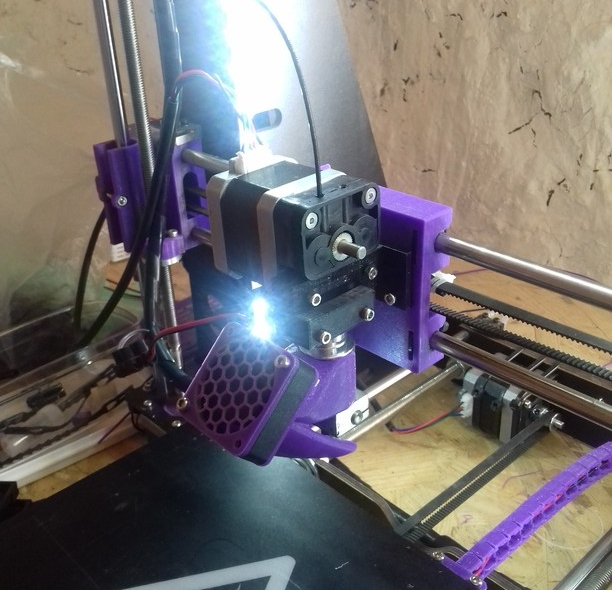
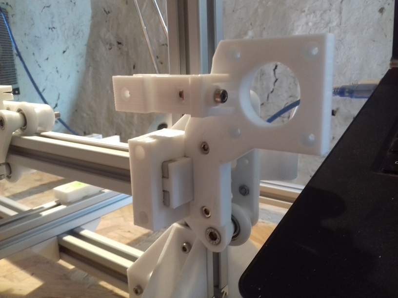
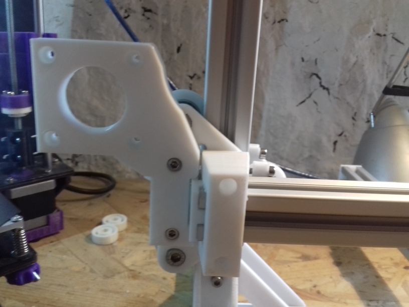
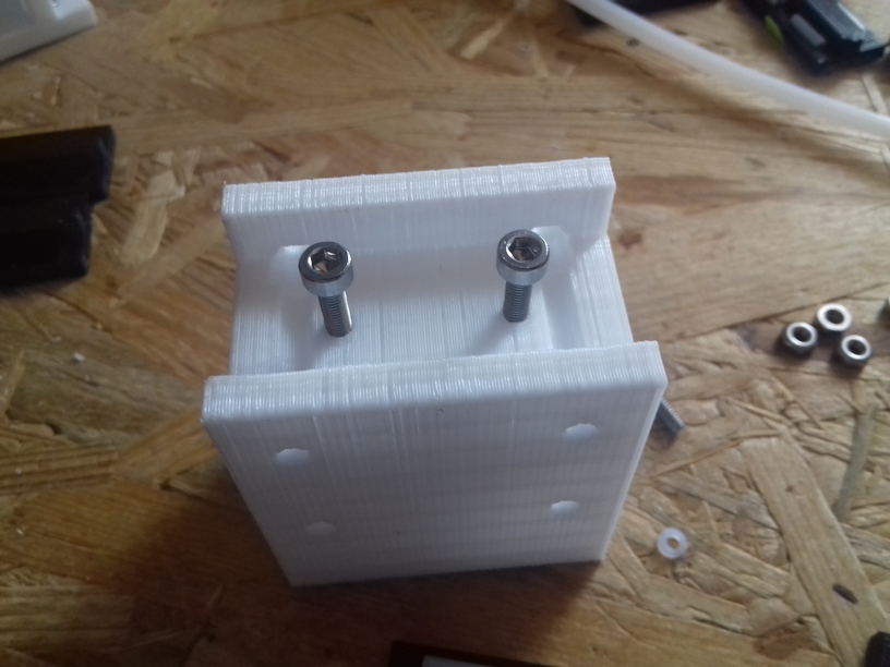
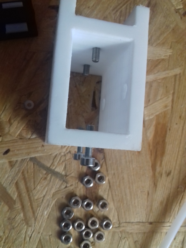
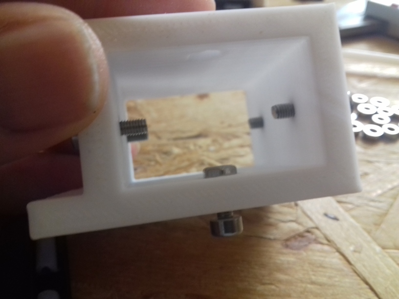
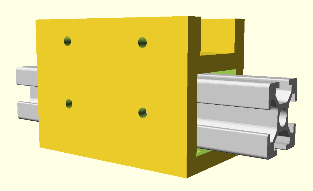
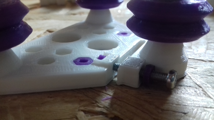
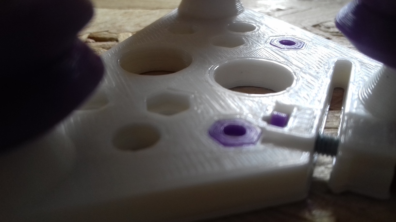
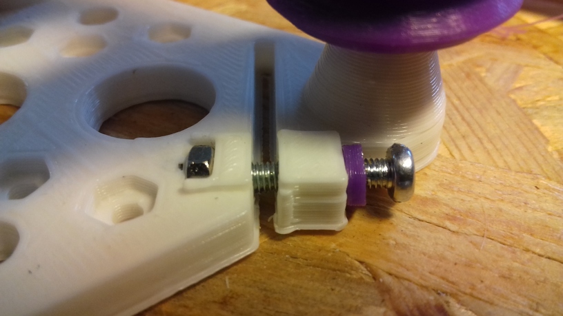
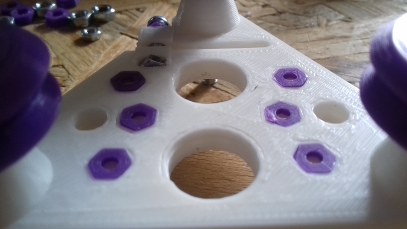
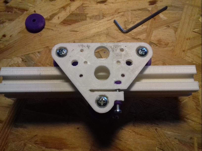
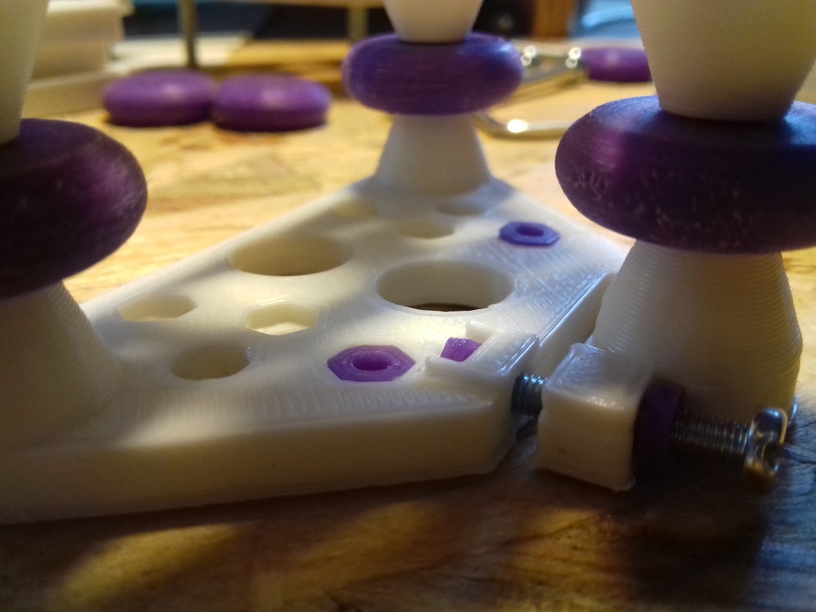
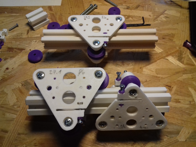
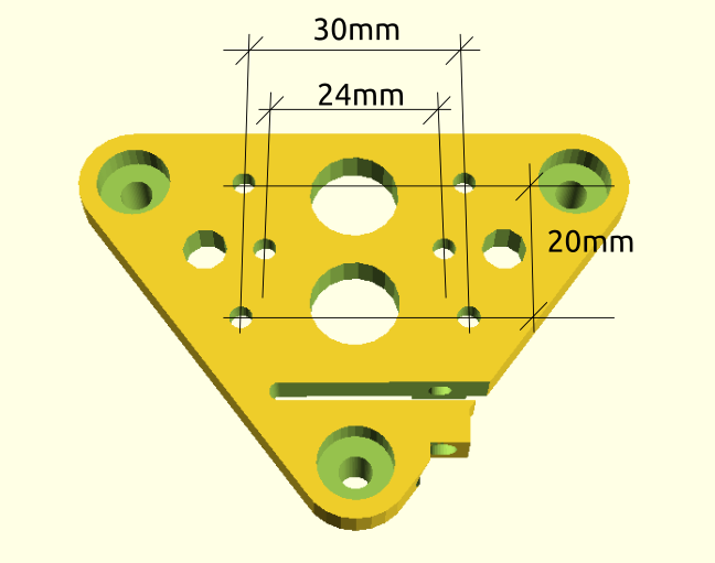
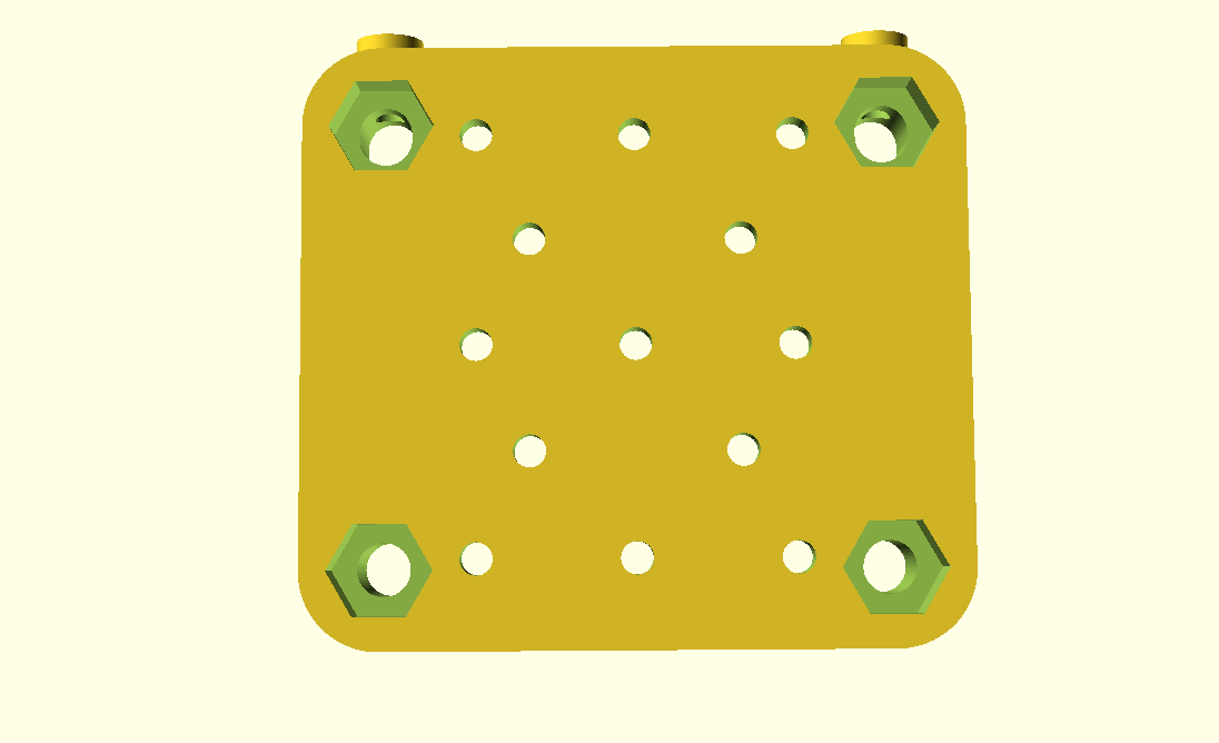
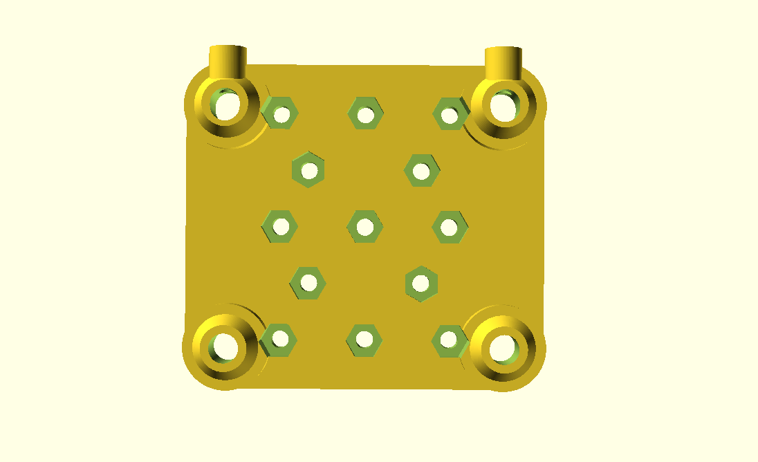
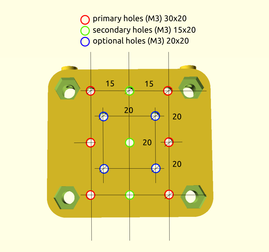
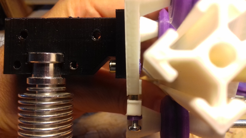
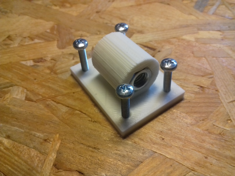
The two E3D V6 bowden adapters I first printed and used required quite some change in Z height, bringing my Z stopper screw to its limits and also were off in the Y axis – so I designed a more suitable adapter with multiple mounting holes: CTC Prusa I3 Pro B E3D V6 Extruder Adapter V2.2 with a simple extruder motor mount at the top left-hand side of the XZ frame.

E3D V6 Bowden Settings

  • Printing speed: 60mm/s – 150mm/s
  • Infill speed: 100mm/s – 150mm/s
  • Motion speed: 120mm/s – 150mm/s
  • Retraction distance: 2.5mm – 4mm (really depends on the length of the Bowden tube)

Conclusion

Using E3D V6 with a low cost and low quality 3d printer:

Faster printing with improved overall print quality.

Aside of the leaking, which was fixed with teflon thread tape, the E3D V6 clone is a great addition to the CTC DIY I3 Pro B – true added value, but comes with more cumbersome handling with sealing threads when exchanging nozzles.

Btw, in this setup I still use M8 threaded rods in the Z axis, and you see no Z wobble artifacts, the linear threads for the Z axis are overrated – it works with simple M8 threads, if you let the couplers flexible enough, like with this “cheap” clear PVC tube, and not fasten the threads on the top, they have to stay floating.