Category Archives: Technology

Universal Slicing

Updates:

  • 2022/04/01: changing wording of “non-planar” vs “planar” slicing but describe actual slicing vector and geometry
  • 2022/03/26: published finally
  • 2022/03/24: added “Tensile & Shearing Force” illustration
  • 2022/03/10: added “Scale & Functional Qualities”
  • 2022/02/27: added Class 2 example
  • 2022/02/18: removed MetatronSlicer example and move to new page, keeping page focused on general and theoretical aspect of Universal Slicing
  • 2022/02/12: adding MetatronSlicer example as first attempt of an Universal Slicer
  • 2022/01/28: separating from another blog-post, solely focusing on Universal Slicing
  • 2022/01/16: starting write-up

Introduction

While conceptualizing the in-house LabSlicer (2021/2022) and the two subsequent slicers afterwards (Vox3lSlicer & VoxGLSlicer), I realized it would be useful to formulate a general or universal description of slicing, hence I propose an universal definition of slicing as such:

Universal slicing means free slicing geometry along a free path.

“free (definable) slicing geometry”: any kind of geometry, may it be a solid or just a surface defining the slicing geometry.

“free (definable) path”: the slicing procedure can go in any direction, curvature and steps.

To put this in context:

  • “planar slicing” is plane or quasi box geometry with layer height thickness, sliced along a static 3D path vector of [ 0, 0, 1 ], aka “planar” or “Z-planar” with vector steps of [ 0, 0, layer height ], whereas layer height can change in that case it’s “variable” or “adaptive layer height”
  • “conic slicing” is a cone geometry with layer height thickness, sliced along a static path vector of [ 0, 0, 1 ] with vector steps of [ 0, 0, cos( layer height )] or scaling a stationary conic to match layer height
  • “cylindrical slicing” is a cylinder which stays positioned static at [ 0, 0, 0 ] and variable scaled to match layer height with [ s, s, 1 ], slicing pipe-like layers
  • “spherical slicing” is a sphere geometry with scales in size to match layer height, the position stays [ 0, 0, 0 ], whereas the geometry is scaled by [ s, s, s ], slicing thin sphere layers
SlicingSlicing GeometrySlicing VectorVector StepsGeometry Scale
planarplane[ 0, 0, 1 ][ 0, 0, t ][ 1, 1, 1 ]
coniccone[ 0, 0, 1 ][ 0, 0, t ][ 1, 1, 1 ]
cone[ 0, 0, 0 ][ 0, 0, 0 ][ s, s, s ]
cylindricalcylinder[ 0, 0, 0 ][ 0, 0, 0 ][ s, s, 1 ]
sphericalsphere[ 0, 0, 0 ][ 0, 0, 0 ][ s, s, s ]

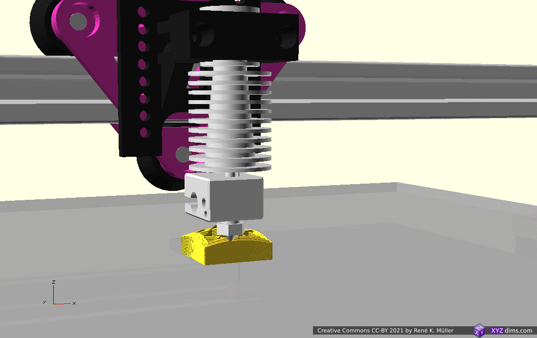
The actual implementation, how slices are routed and then G-code is created, is up to the slicer; an Universal Slicer is a slicer which implements Universal Slicing paradigm.

Class 1: Static Slicing Vector, Static Slicing Geometry

There are two distinct cases of class 1 slicing:

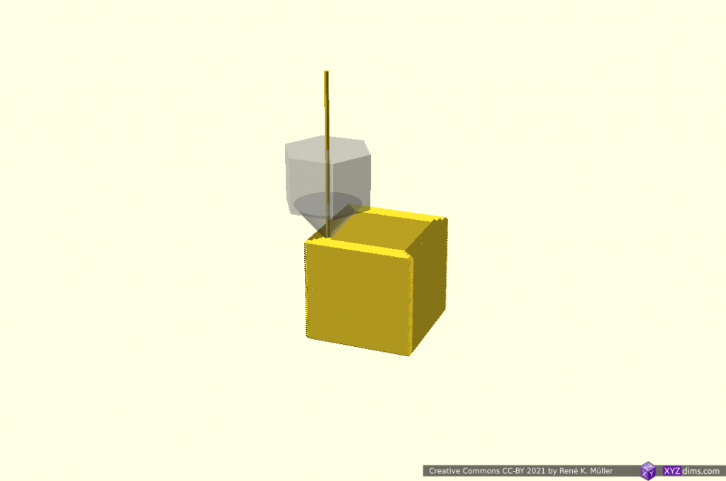
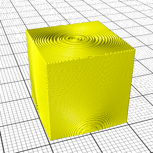
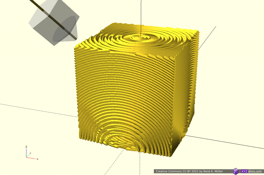
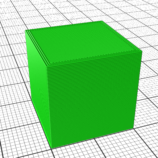
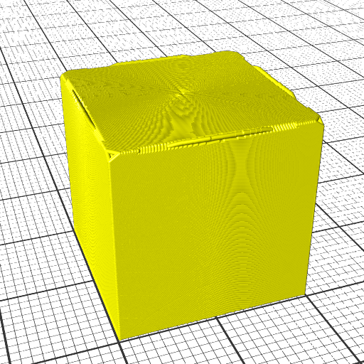
  • slicing with planar geometry, a plane – also known as “planar slicing”
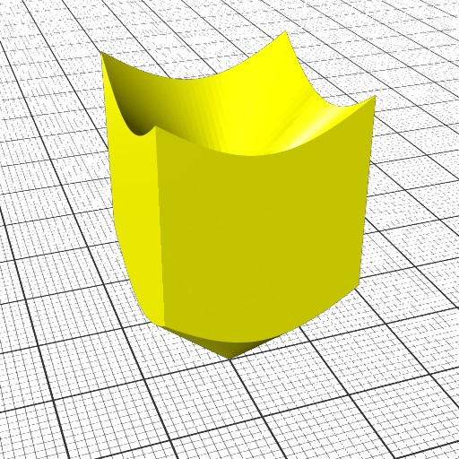
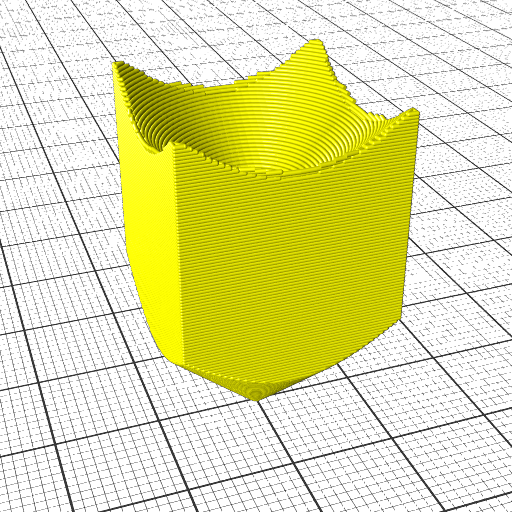
  • slicing with non-planar geometry, like a wave, a hemisphere, a cone, etc.

Static slicing vector means here, there is an equal distance among all points of a slice to the next or previous slice at the same [ x, y ] position according the slicing vector:

Class 1 Universal Slicing: Static Slicing Vector with Planar and Non-Planar Geometries

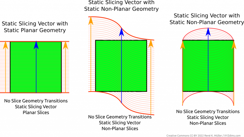
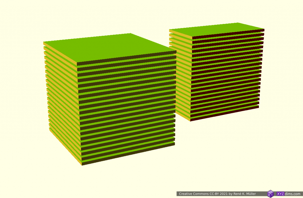
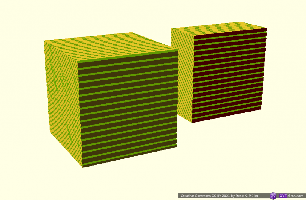
Regardless of the slicing geometry, the layer height or thickness remains the same along the slice or layer itself.

The layer height or thickness may vary from layer to layer, this is known as “variable layer height” or “adaptive layer height” but only means among layers or slices, but not within a single layer or slice.
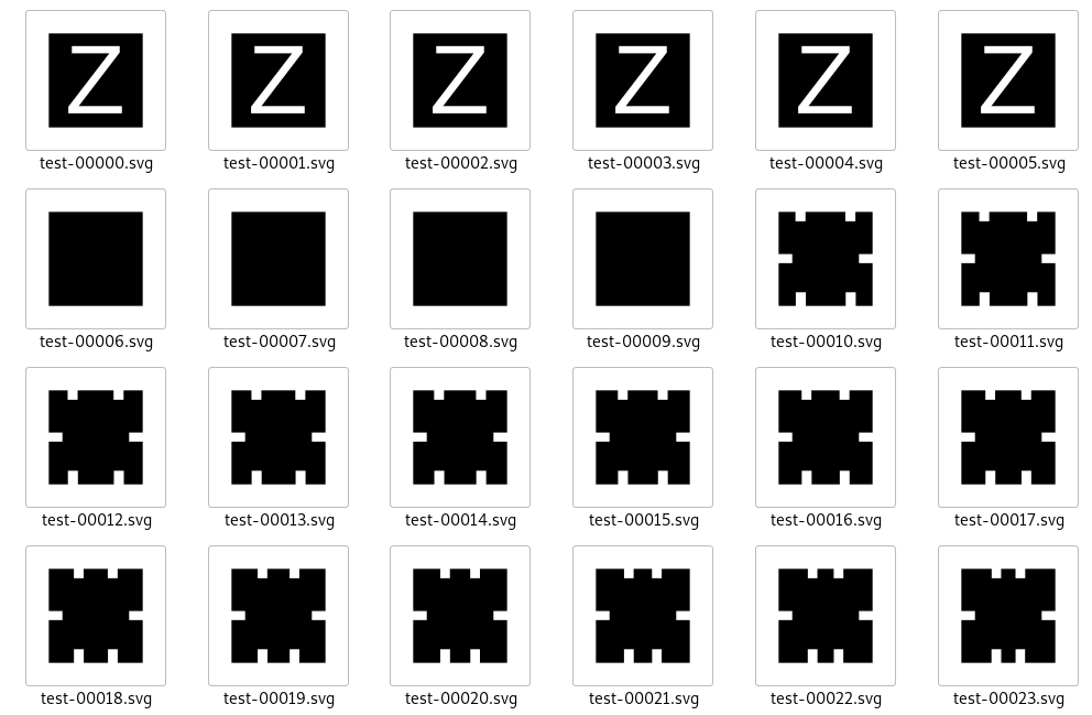
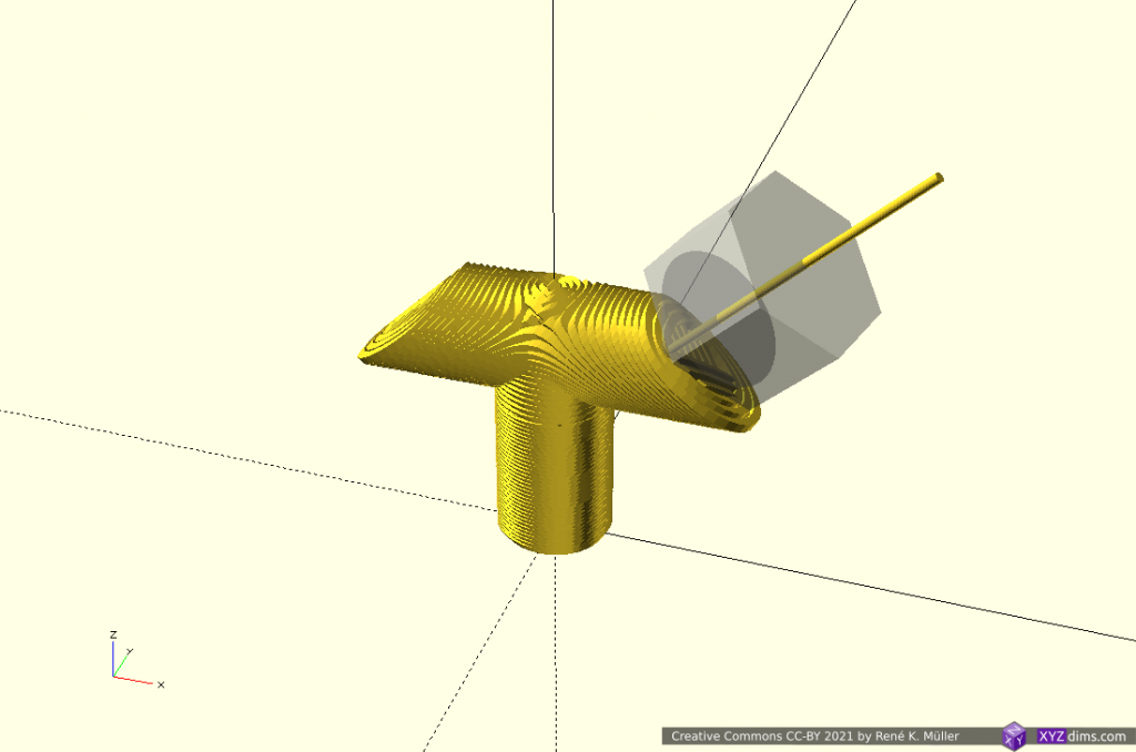
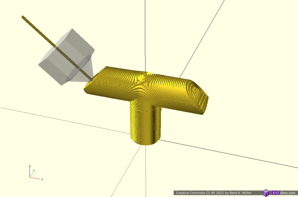
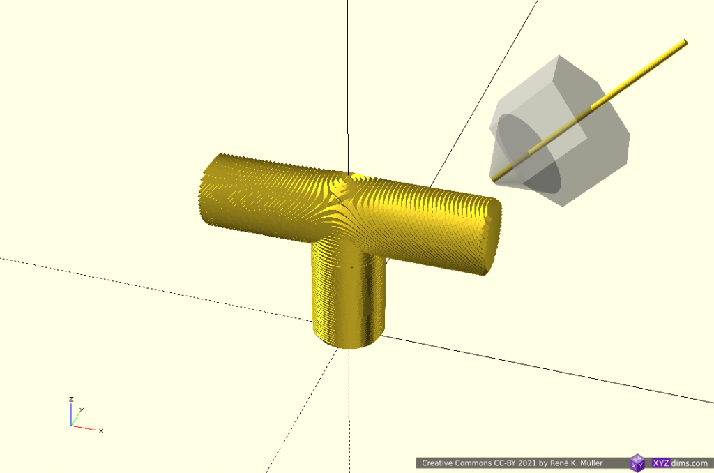
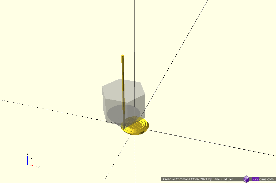
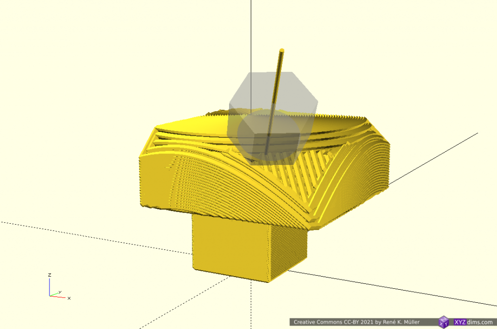
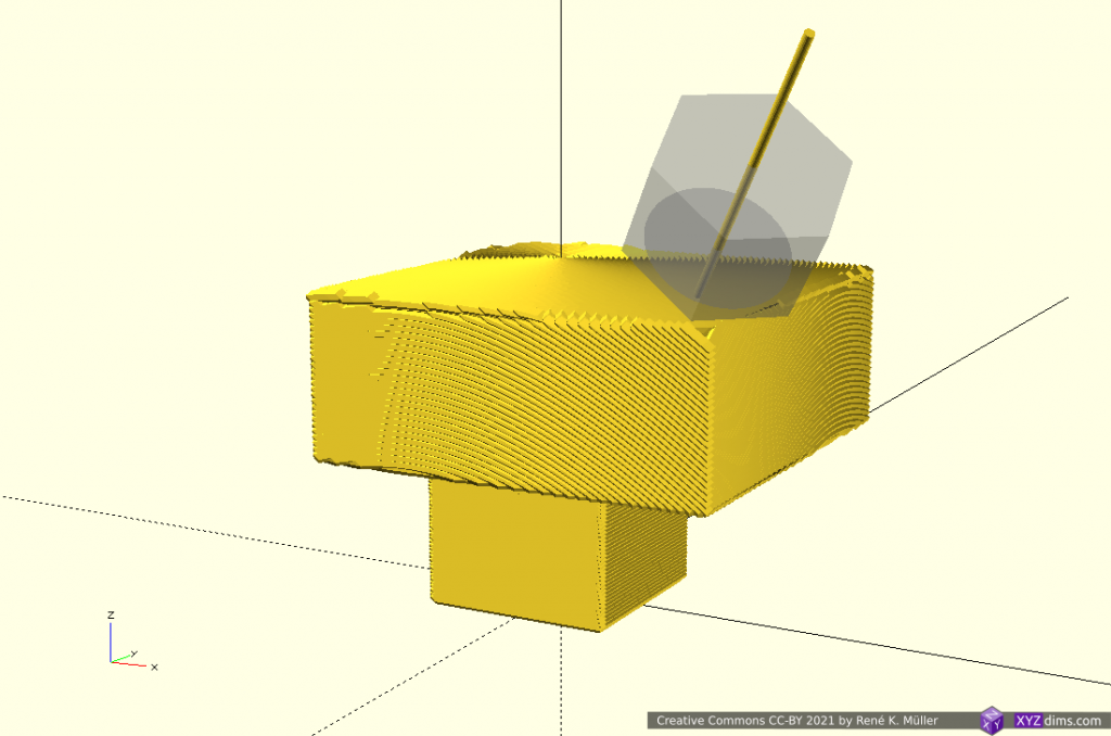
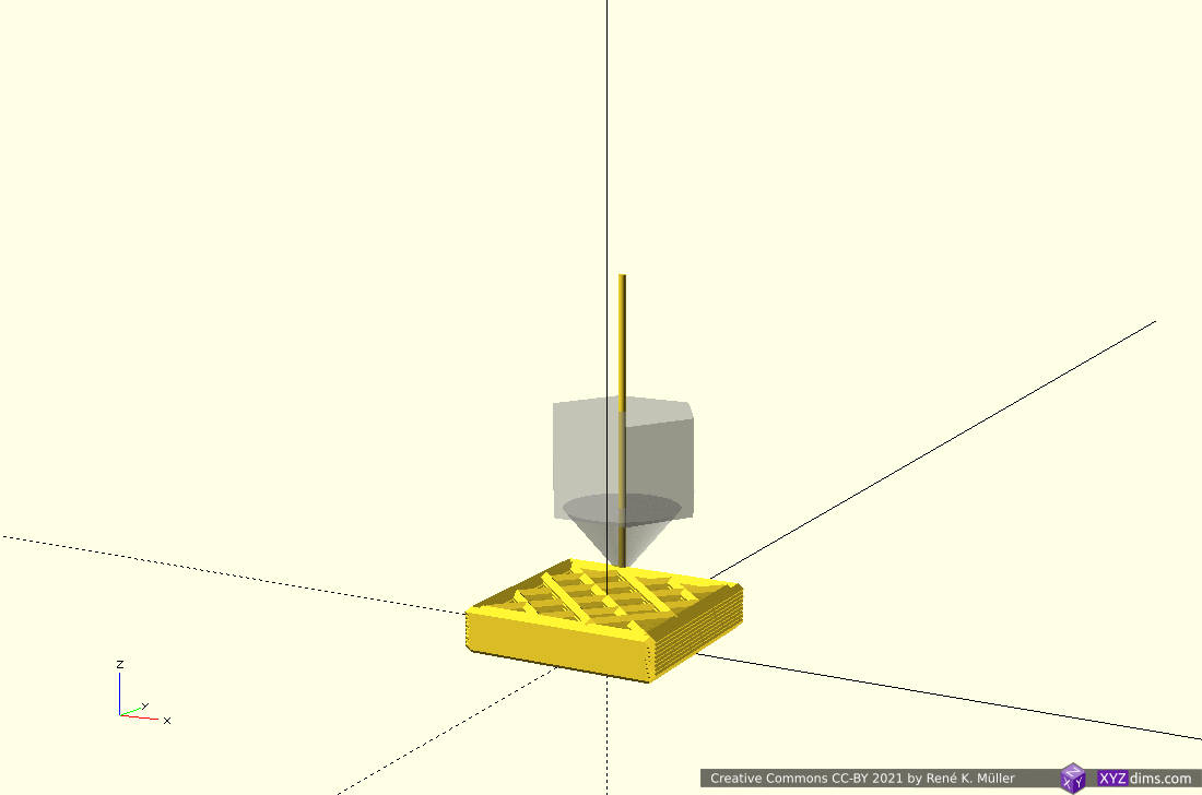
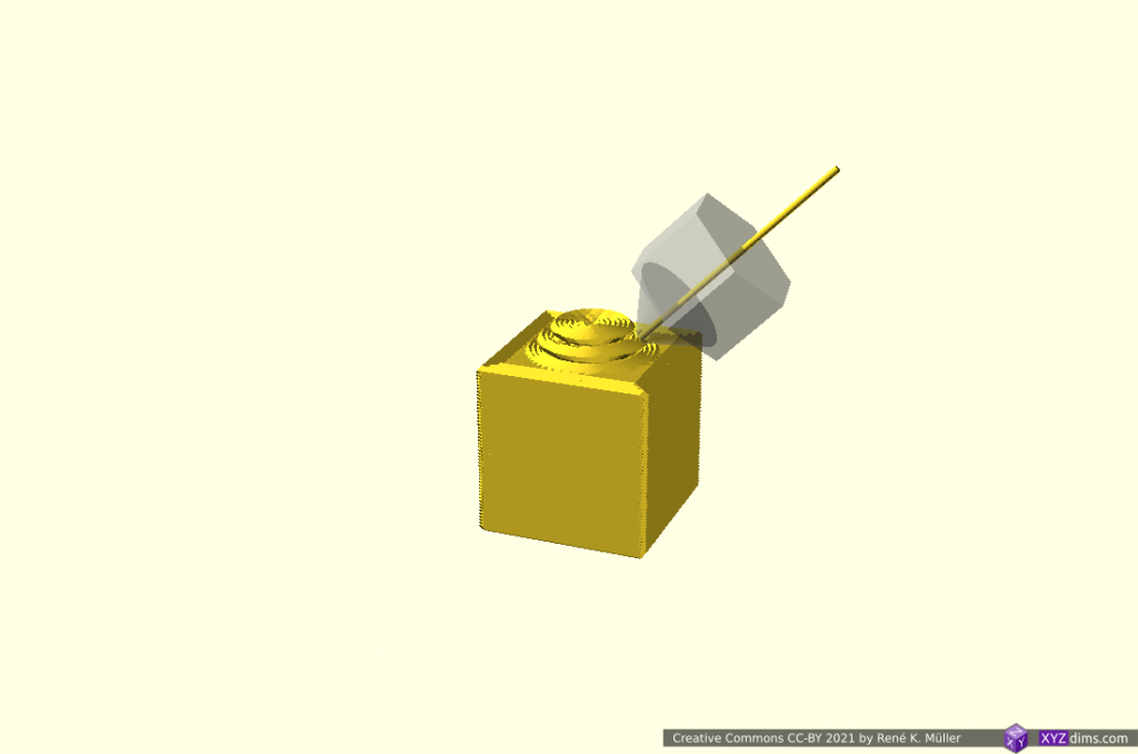
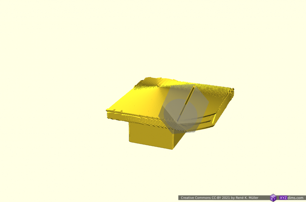
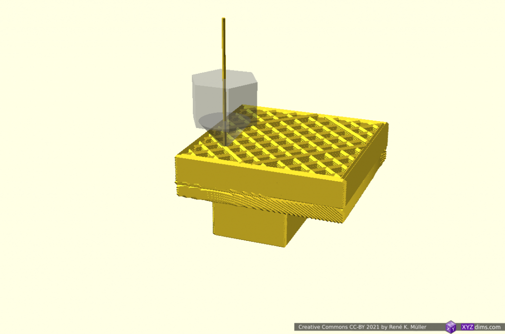
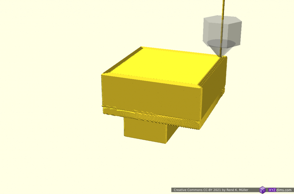
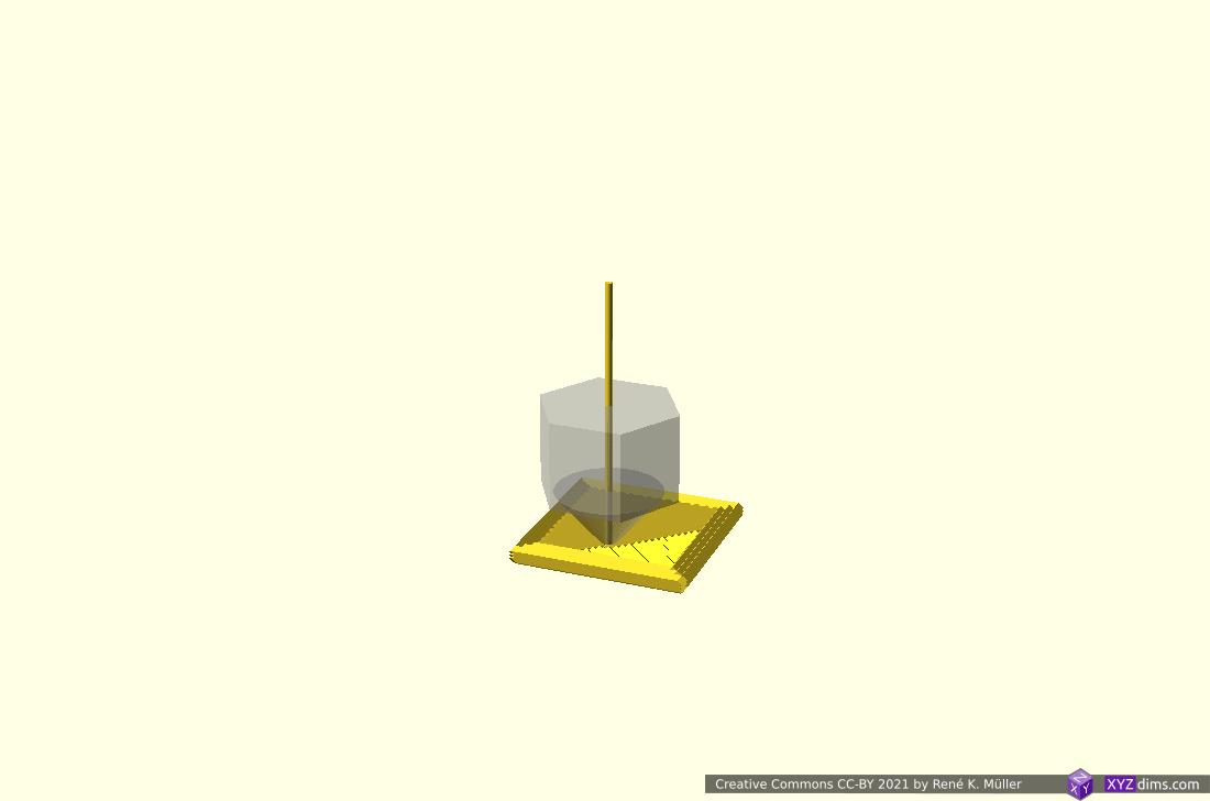
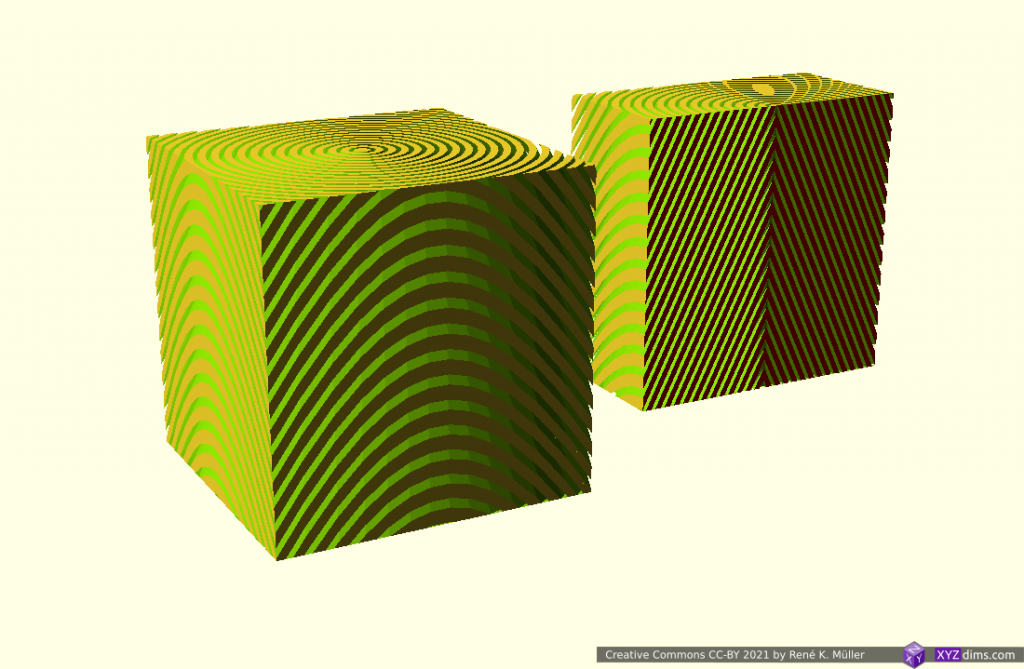
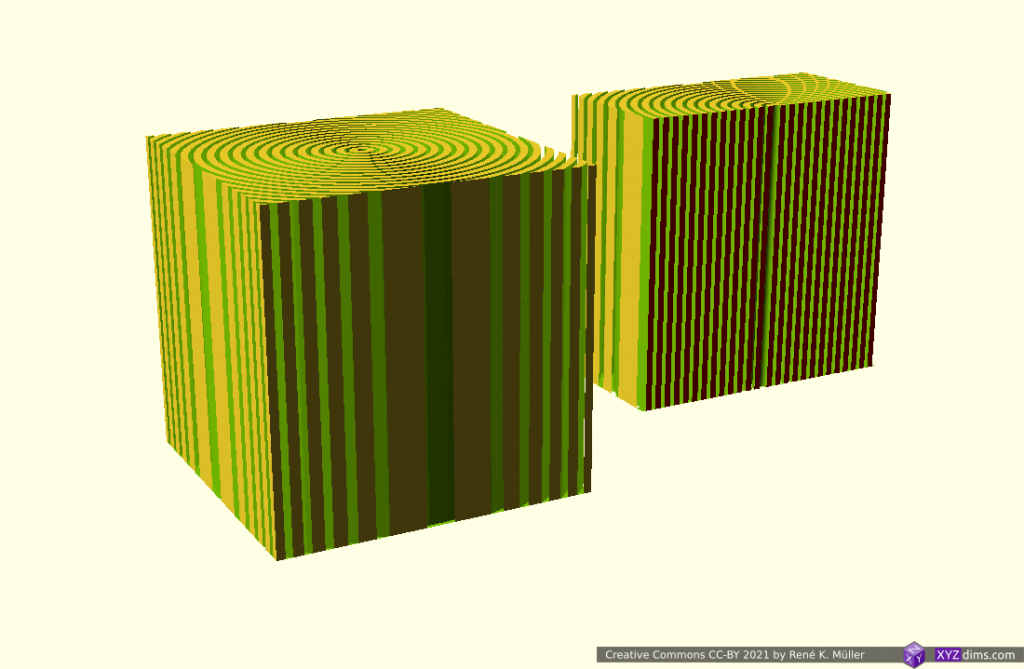
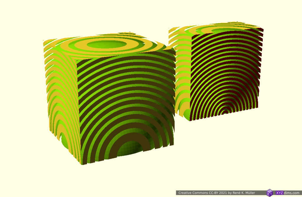
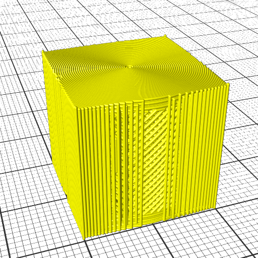
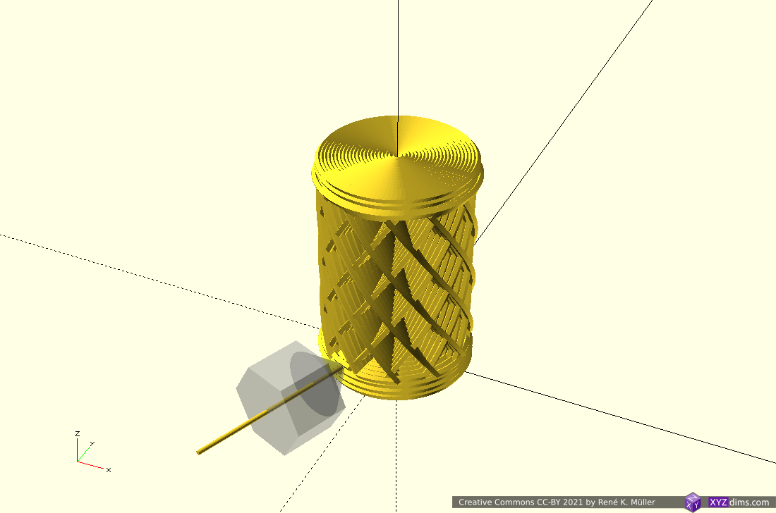
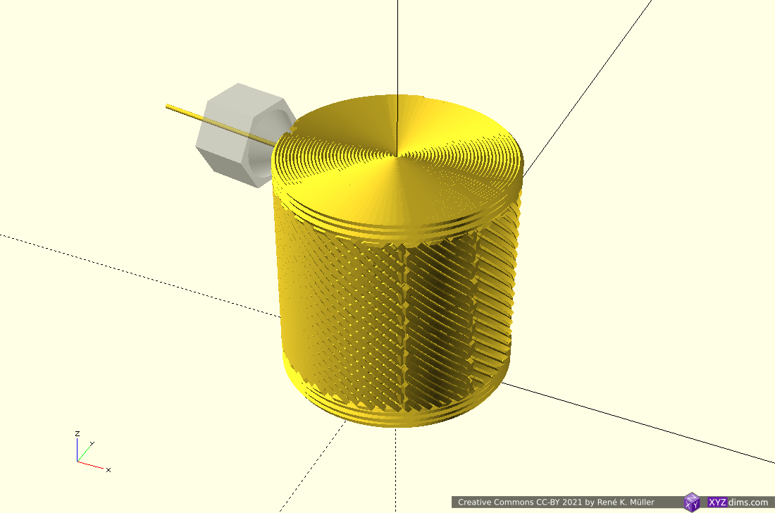
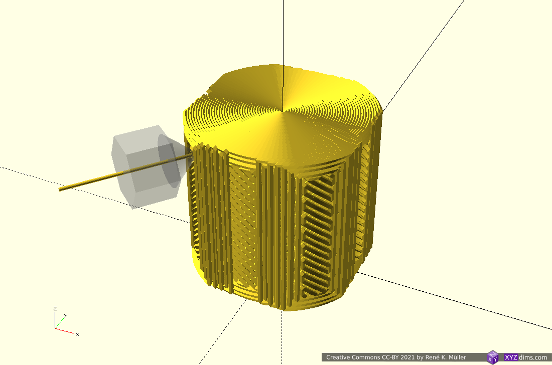
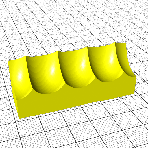
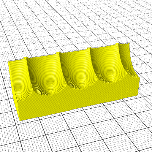
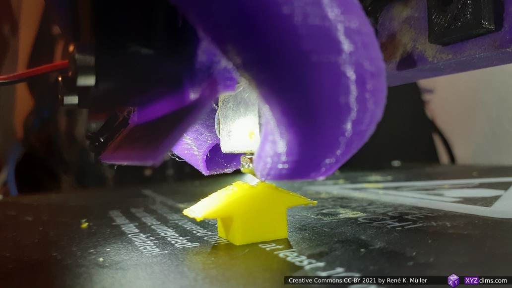
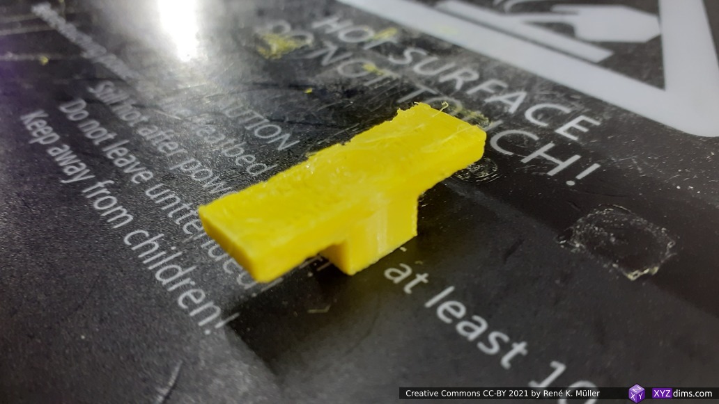
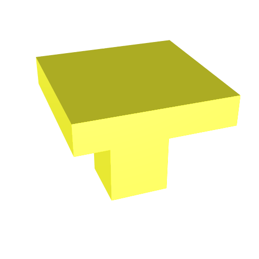
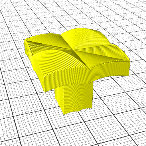
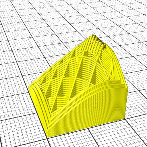
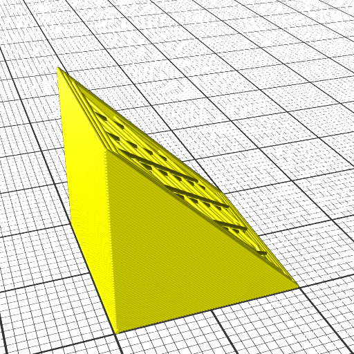
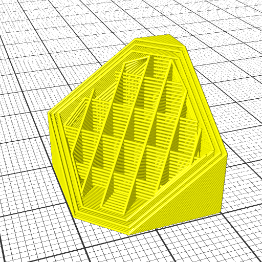
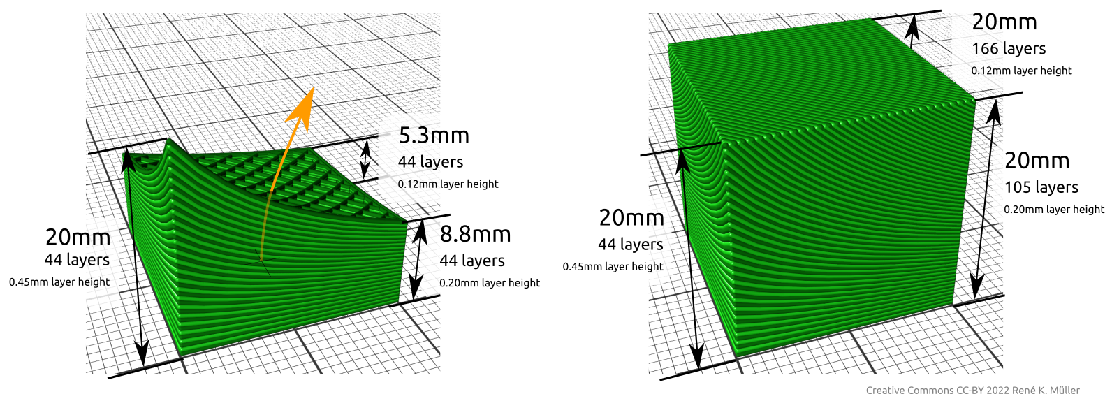
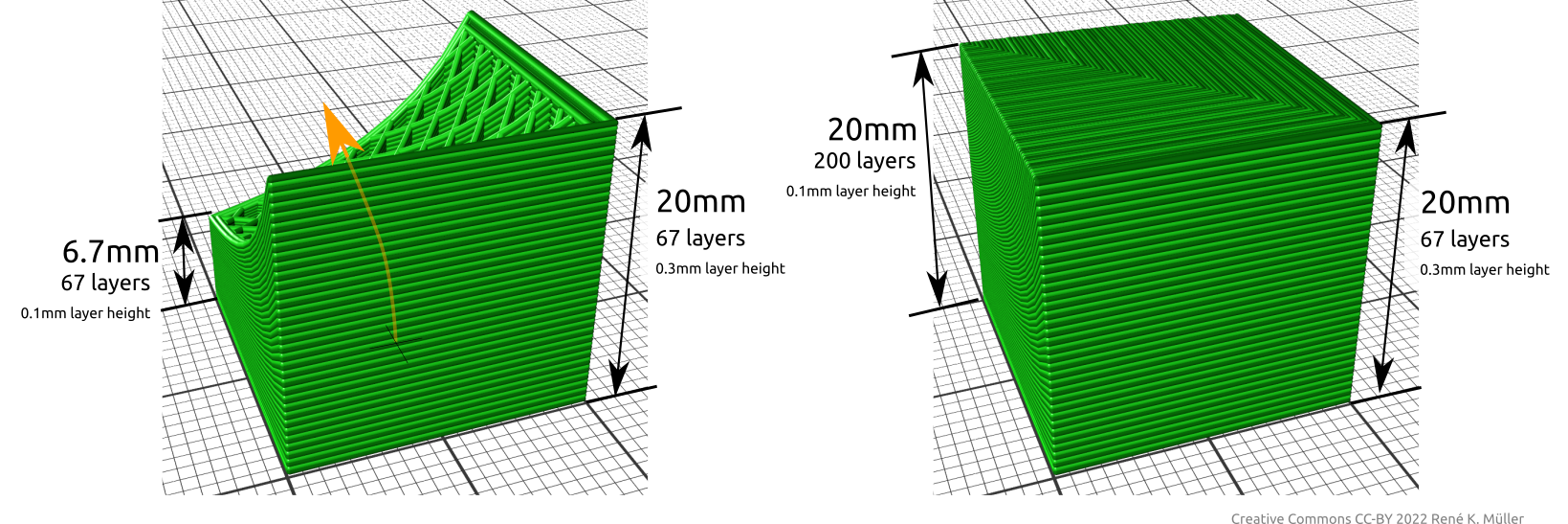
Class 1 Examples

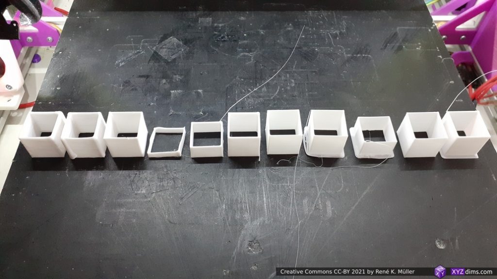
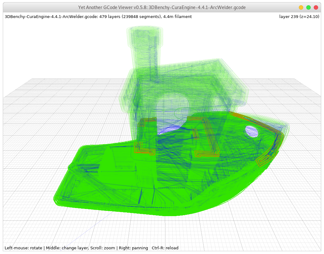
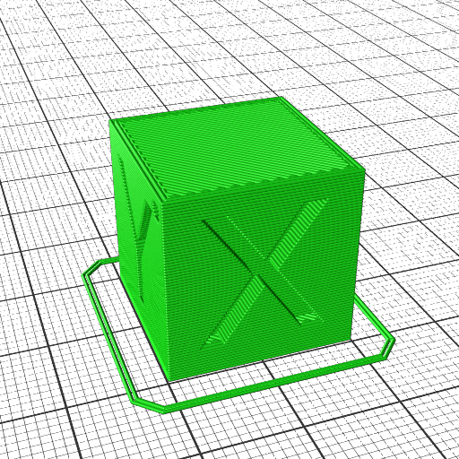
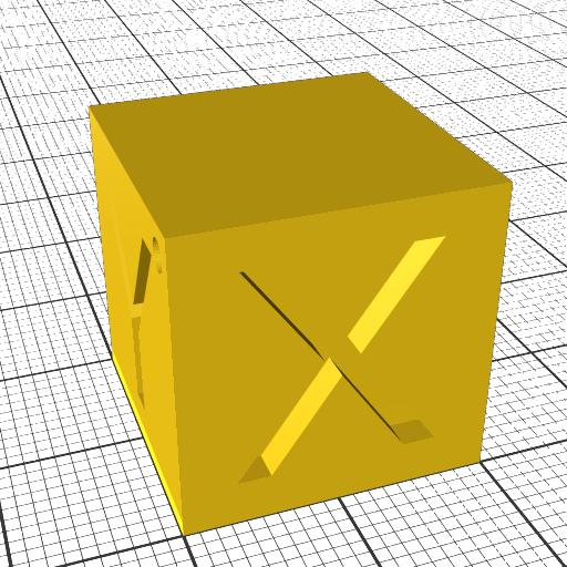
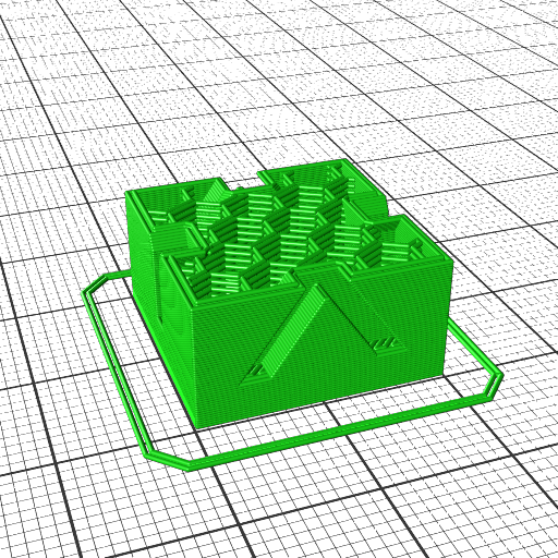
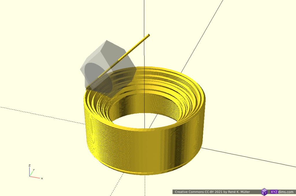
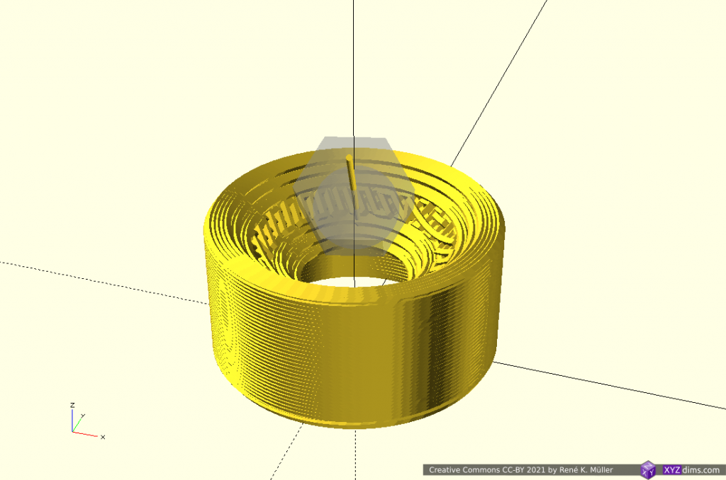
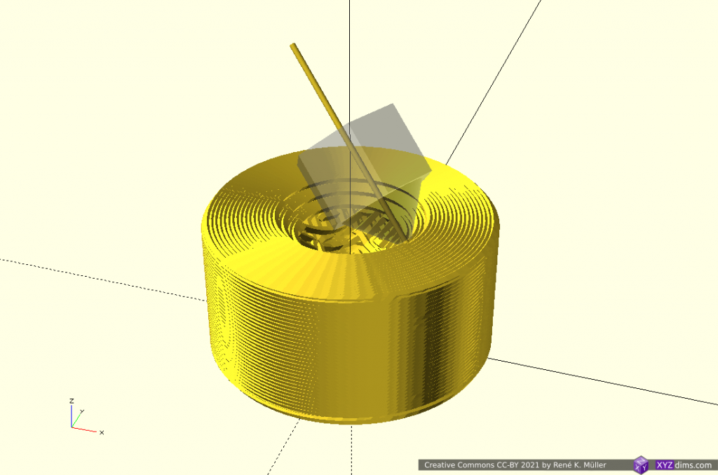
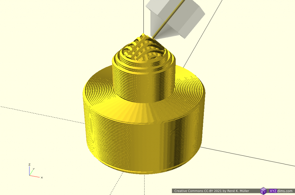
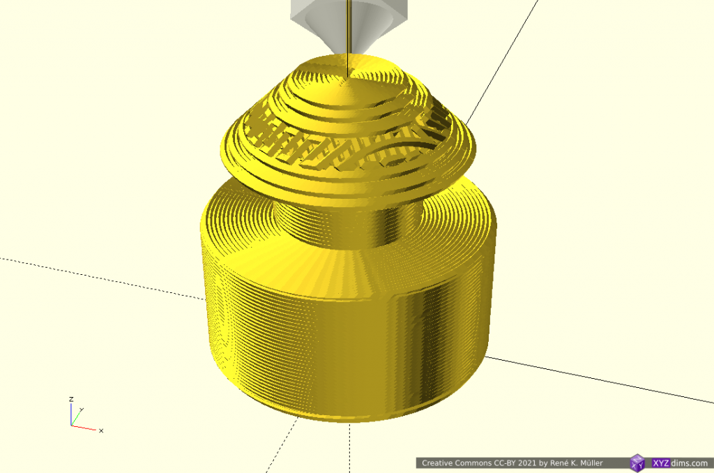
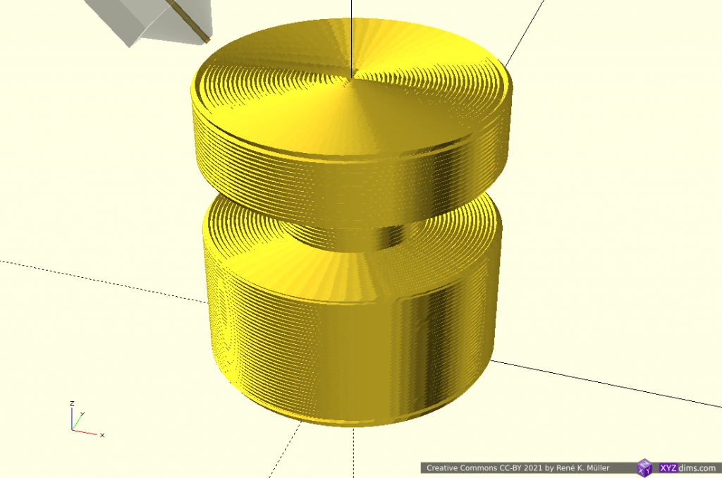
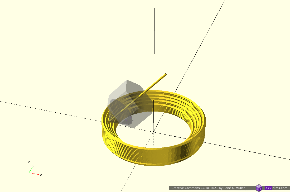
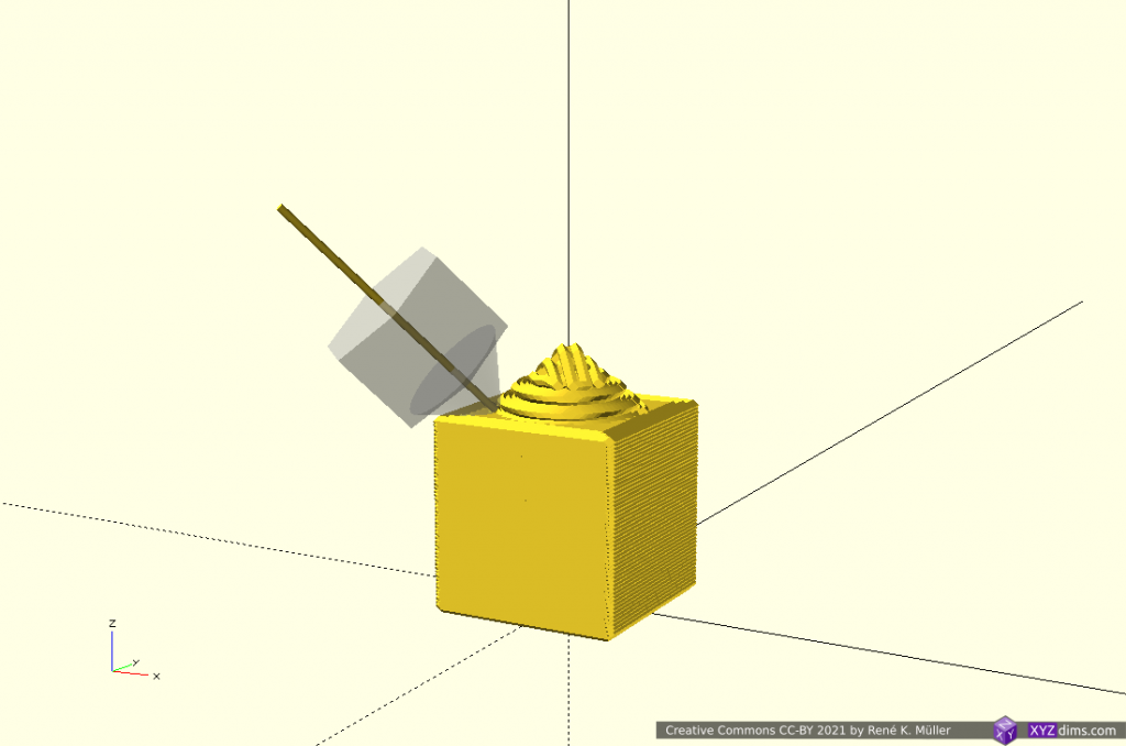
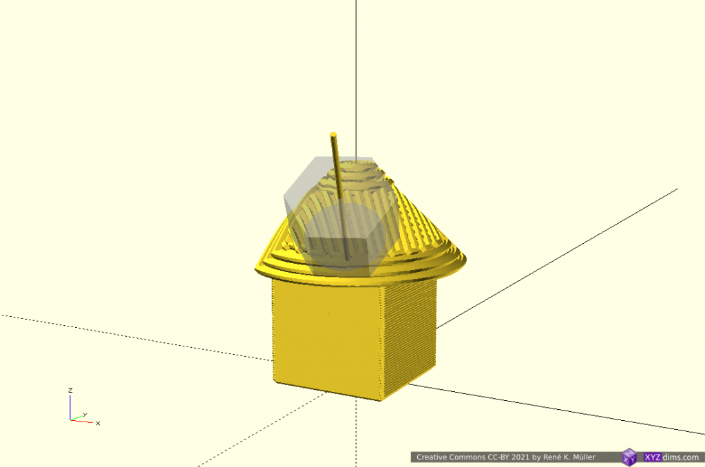
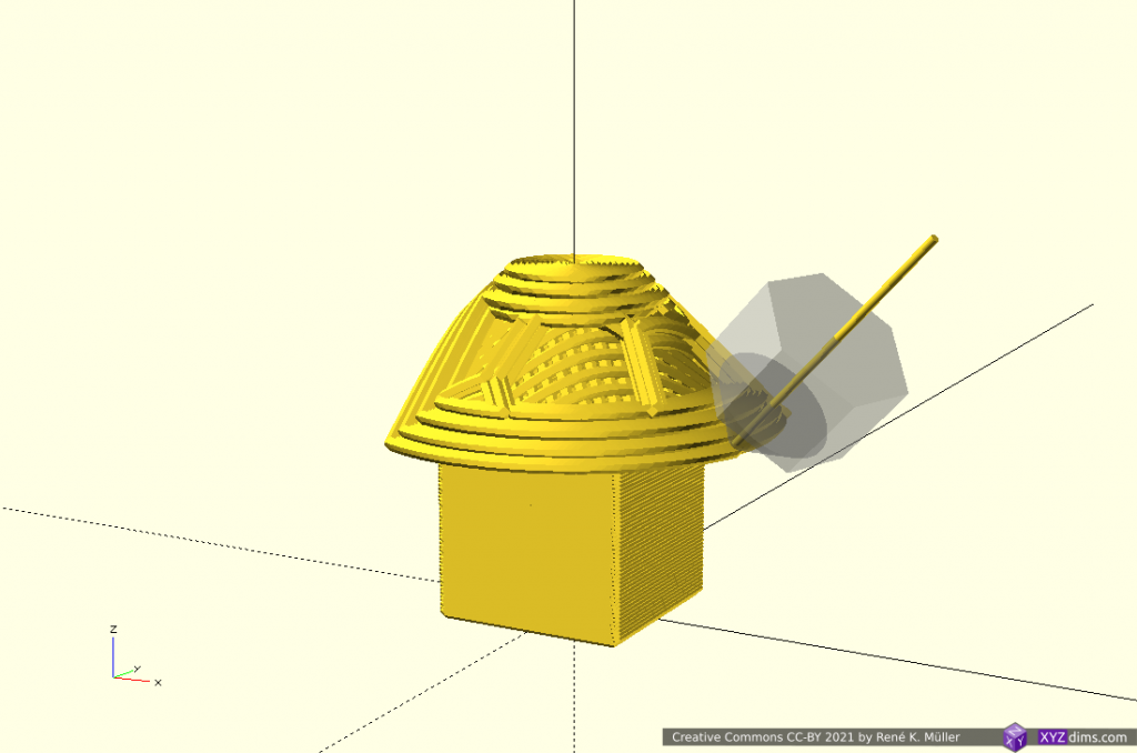
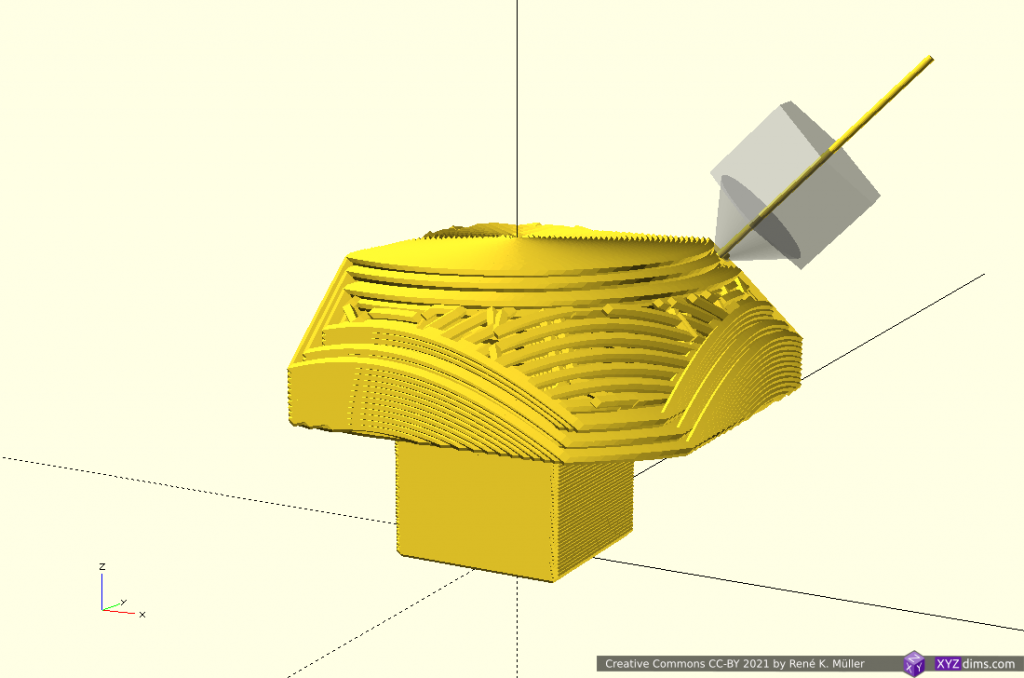
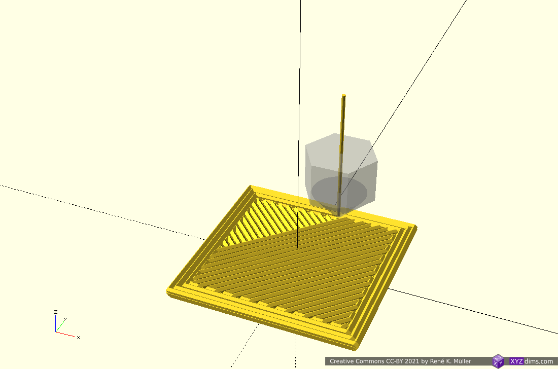
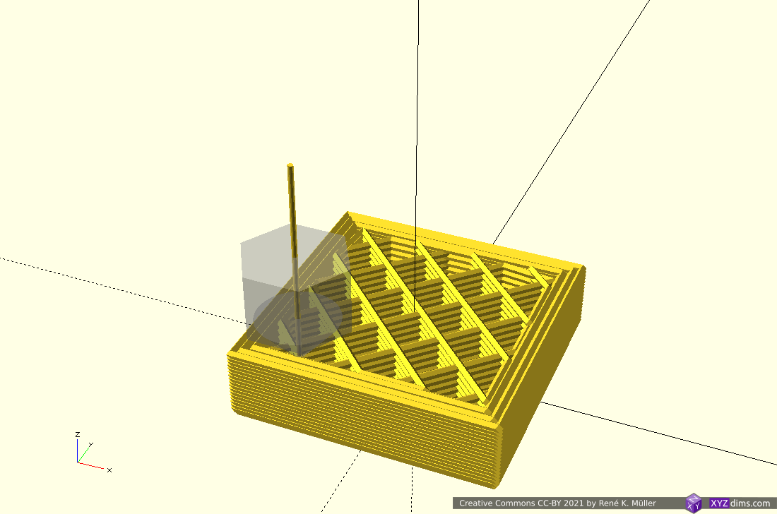
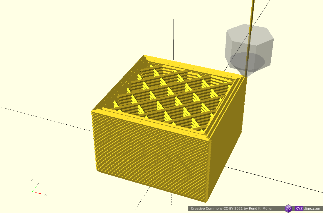
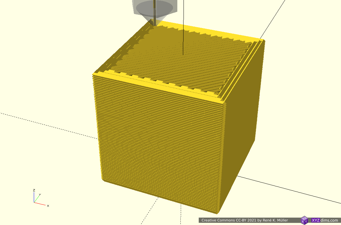
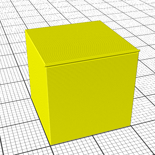
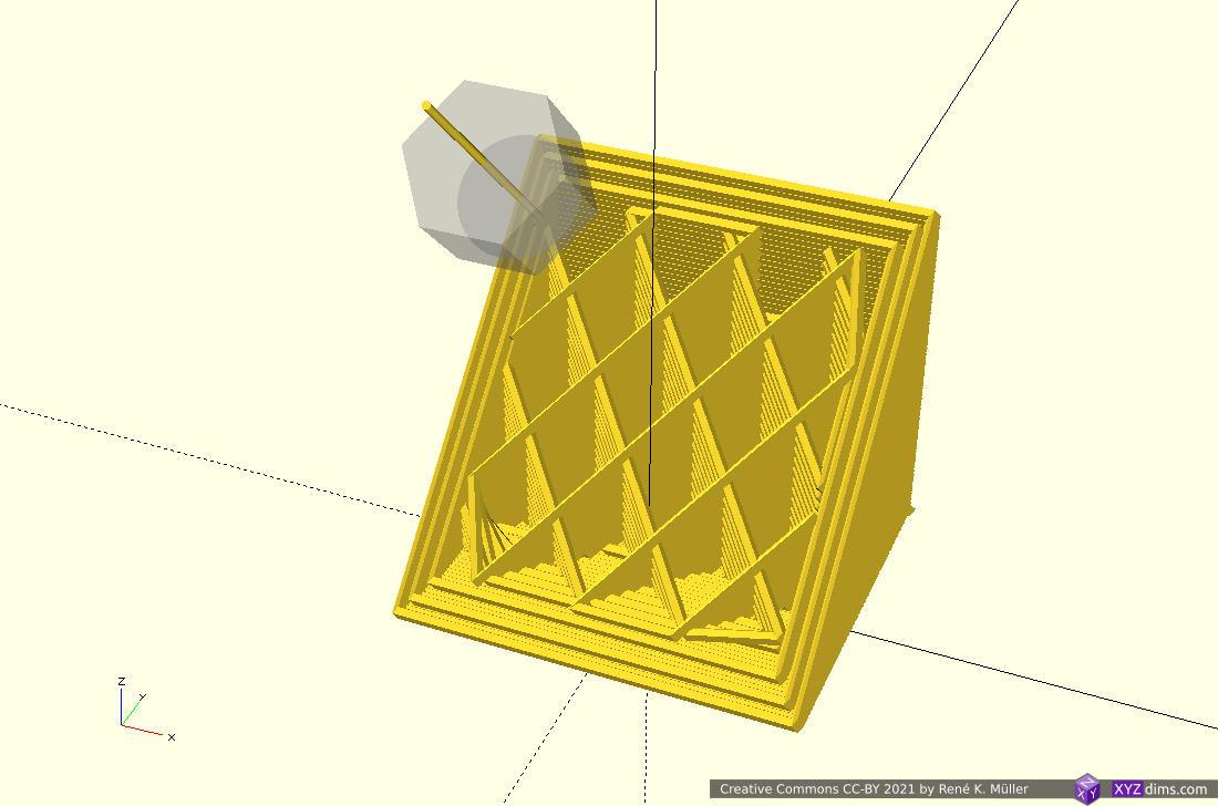
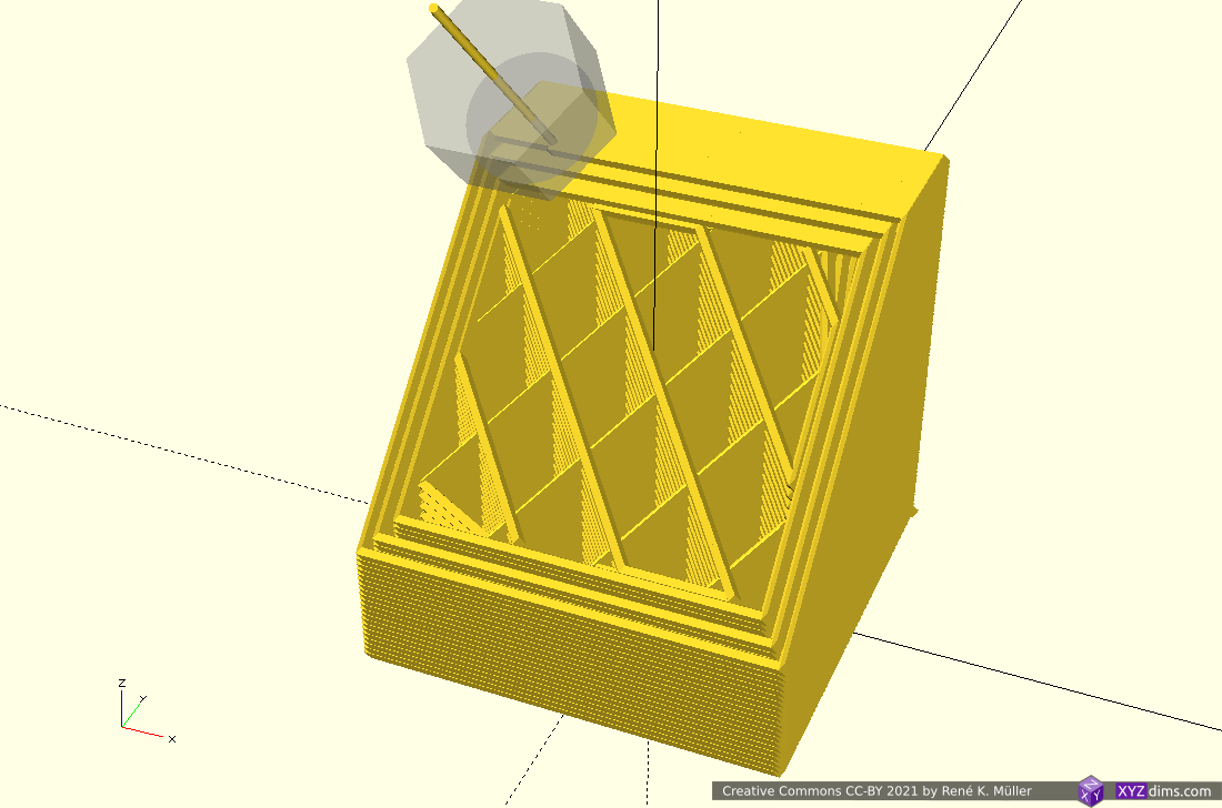
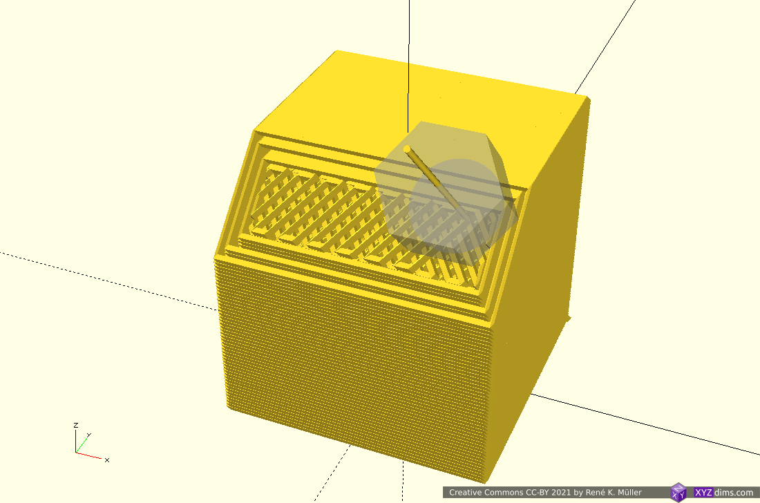
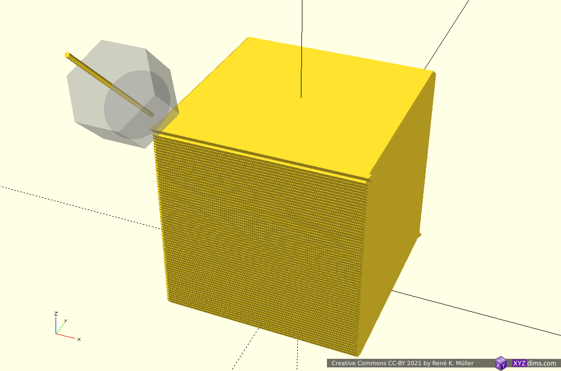
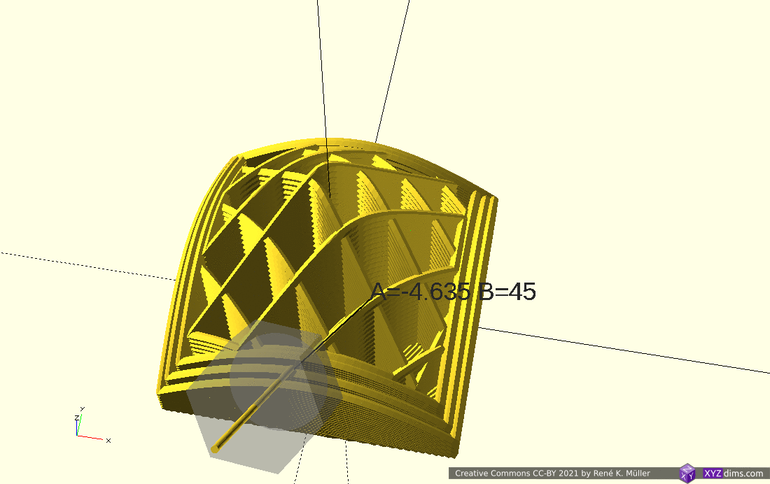
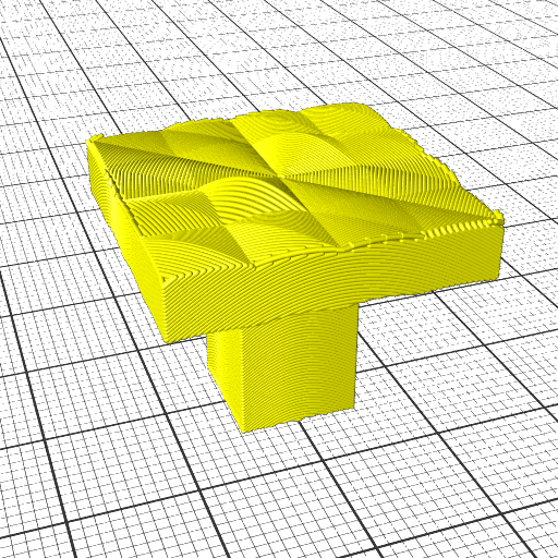
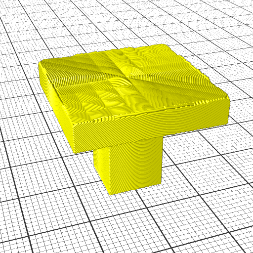
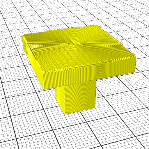
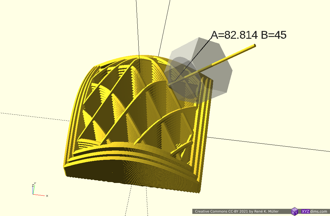
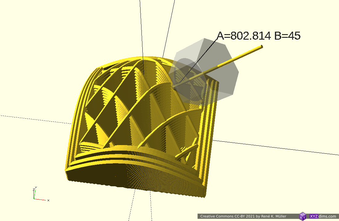
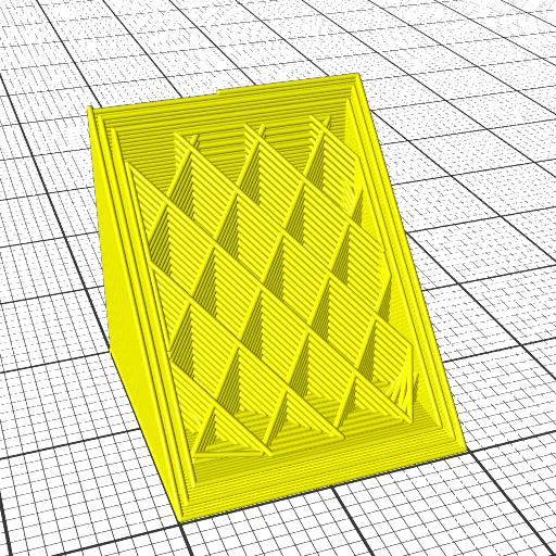
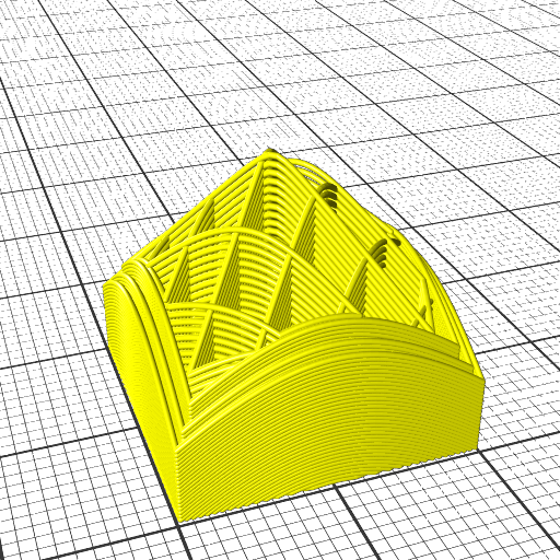
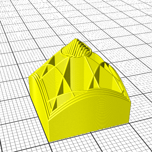
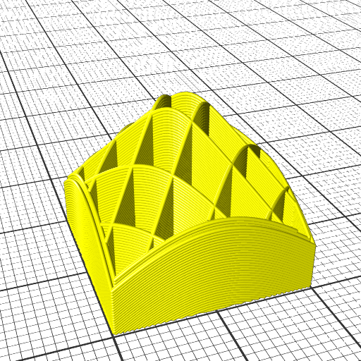
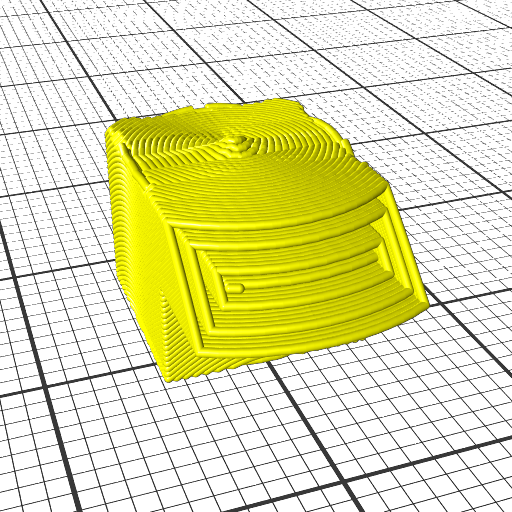
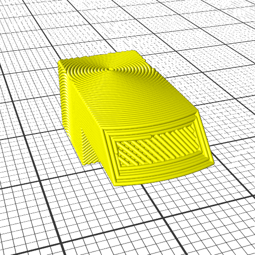
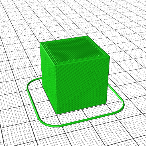
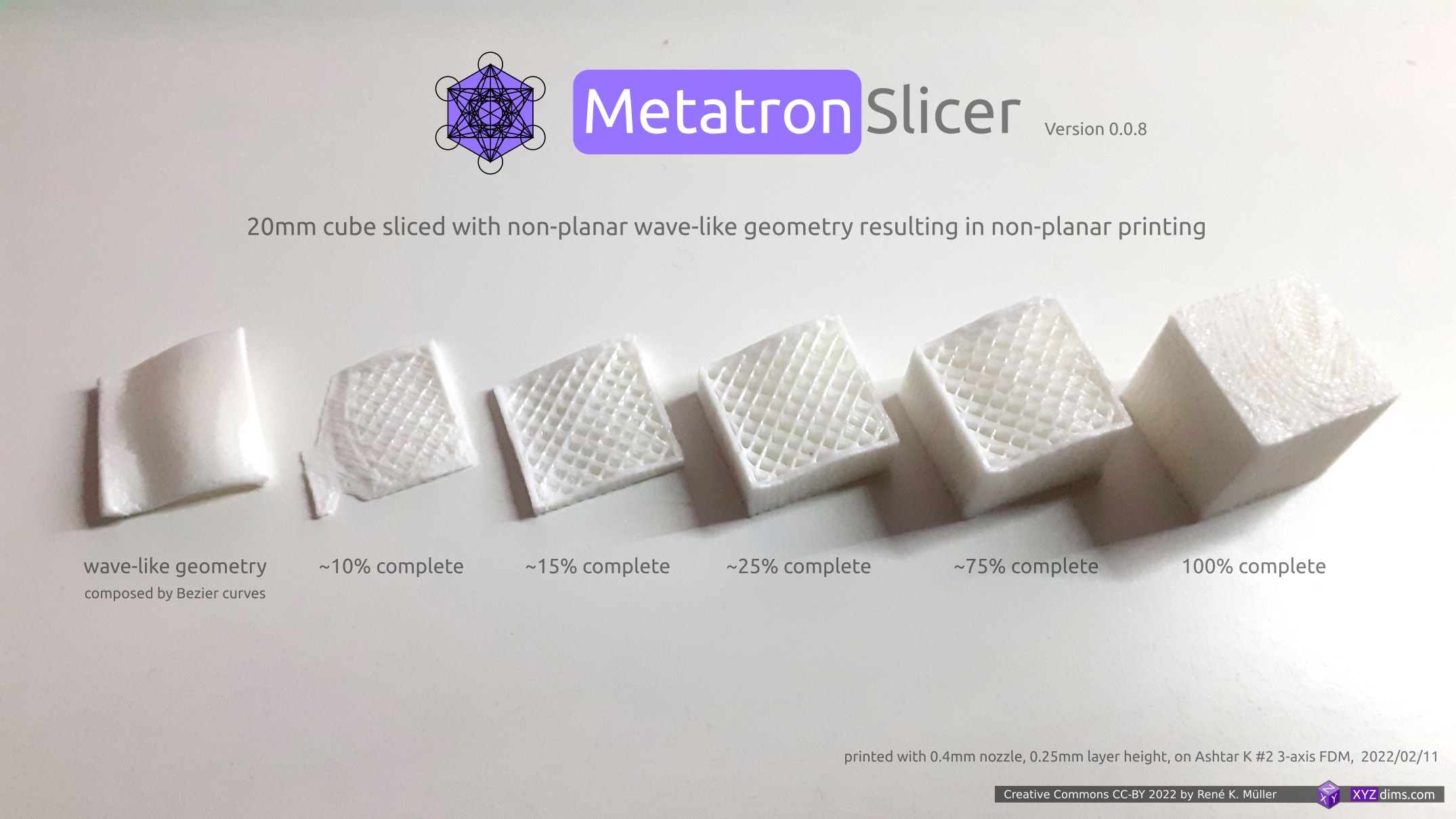
Examples of Class 1 Universal Slicing with planar and non-planar geometries and the respective G-code outputs (produced by MetatronSlicer and EnochSlicer):

Class 1 Universal Slicing: Planar Slicing with Non-Planar Geometries: planar, hemisphere convex, hemisphere concave, conic, wave-like Bezier & NURBS, tilted, pimple-like
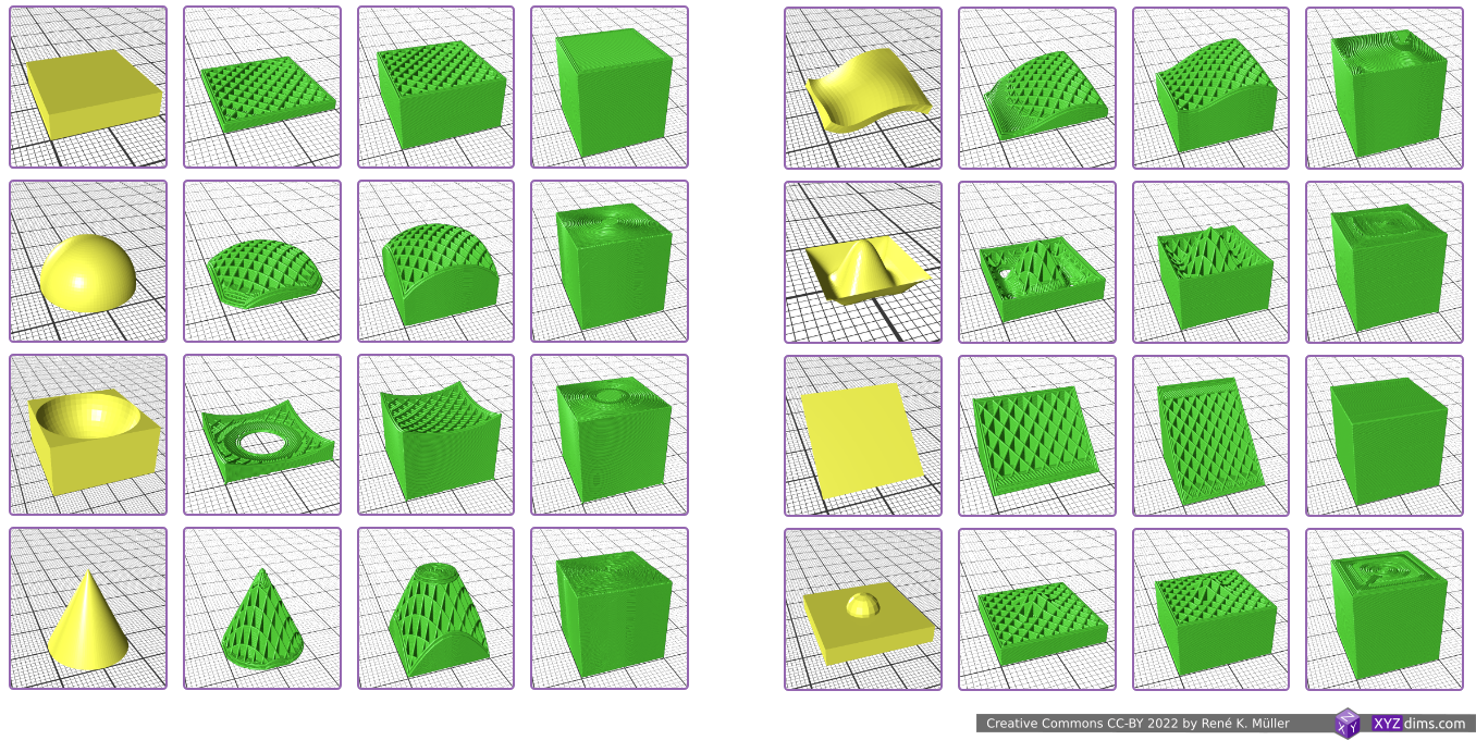
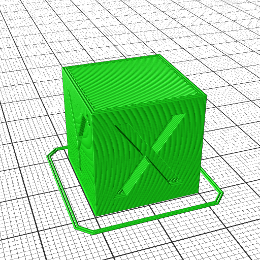
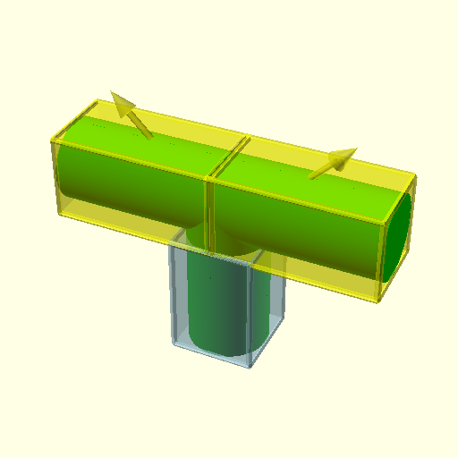
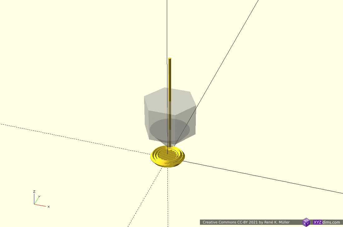
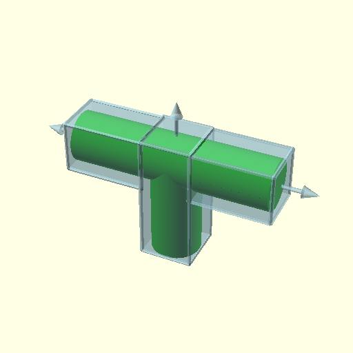
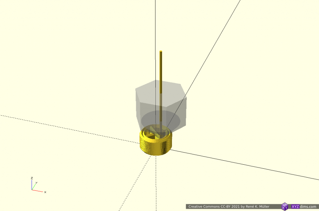
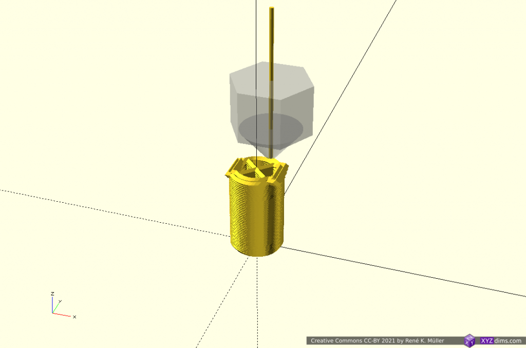
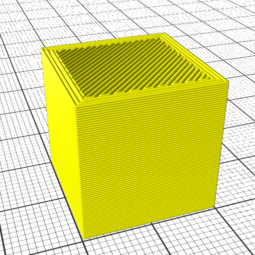
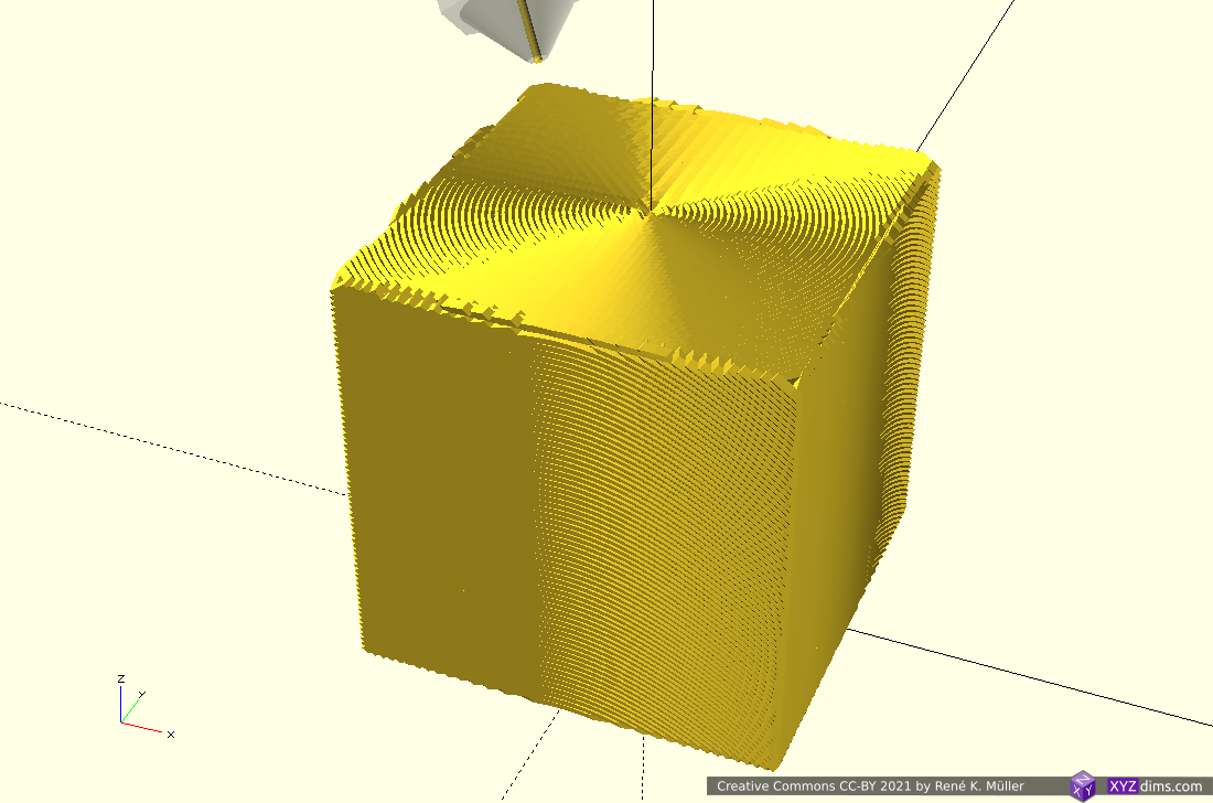
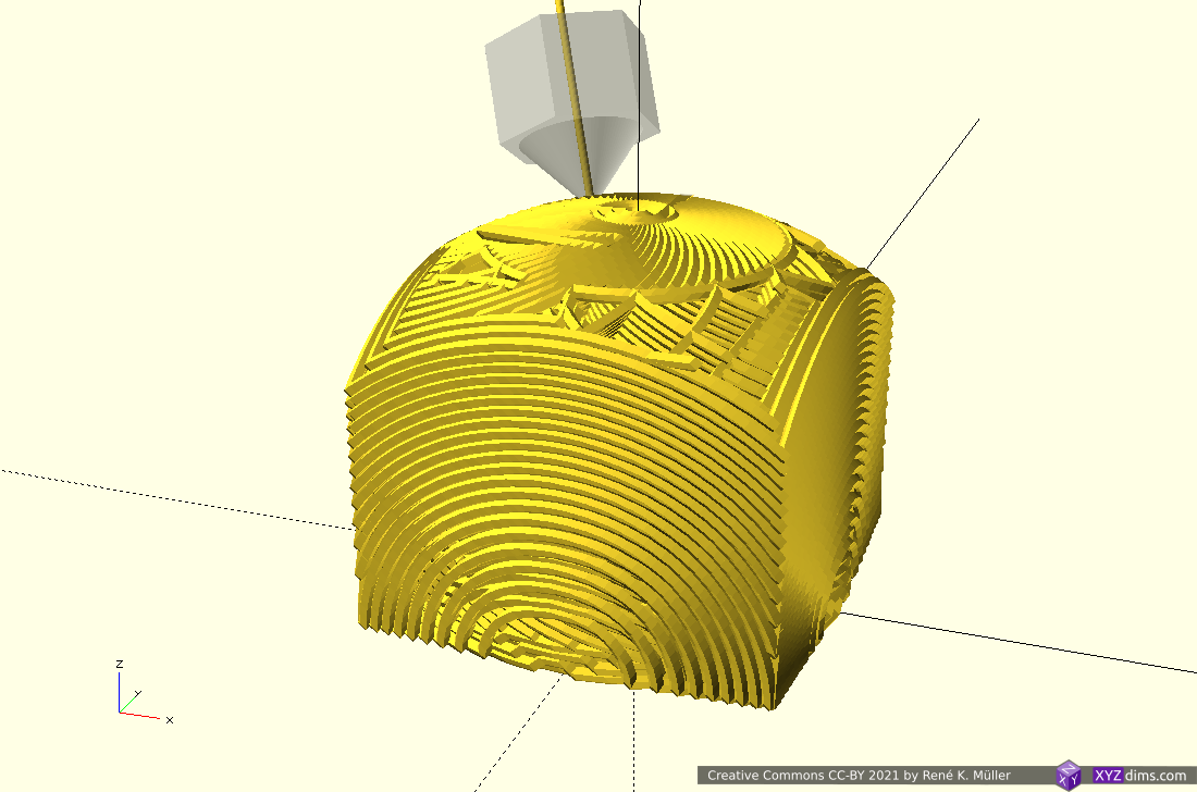
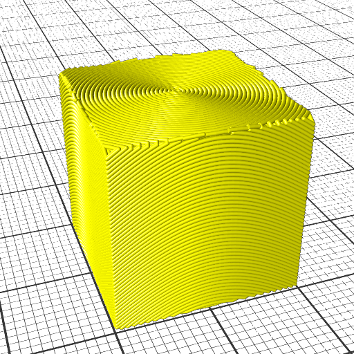
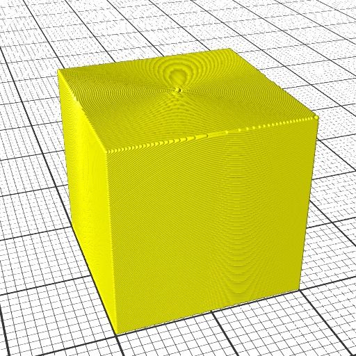
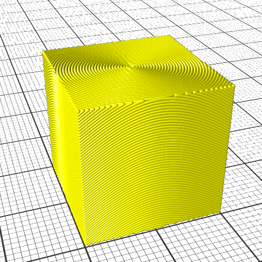
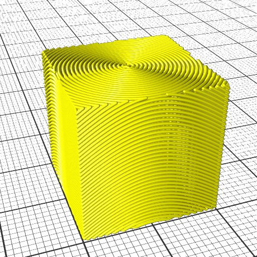
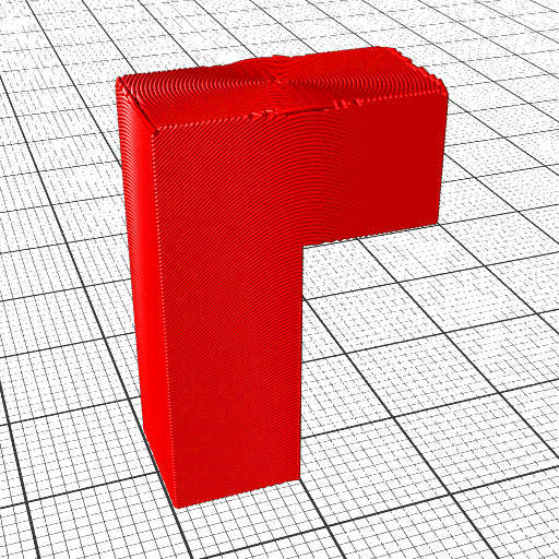
  1. using a block as planar blueprint
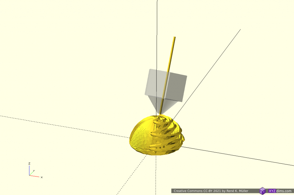
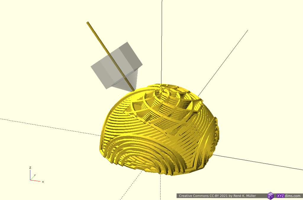
  2. hemisphere, convex
  3. hemisphere reverse, concave
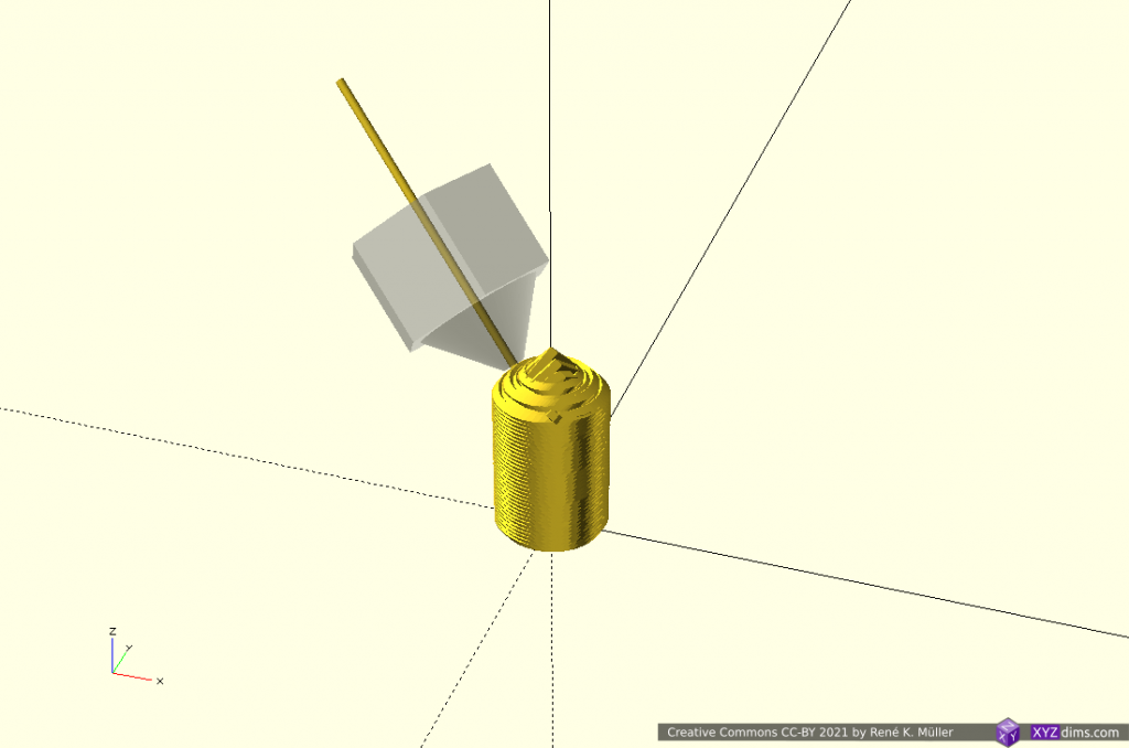
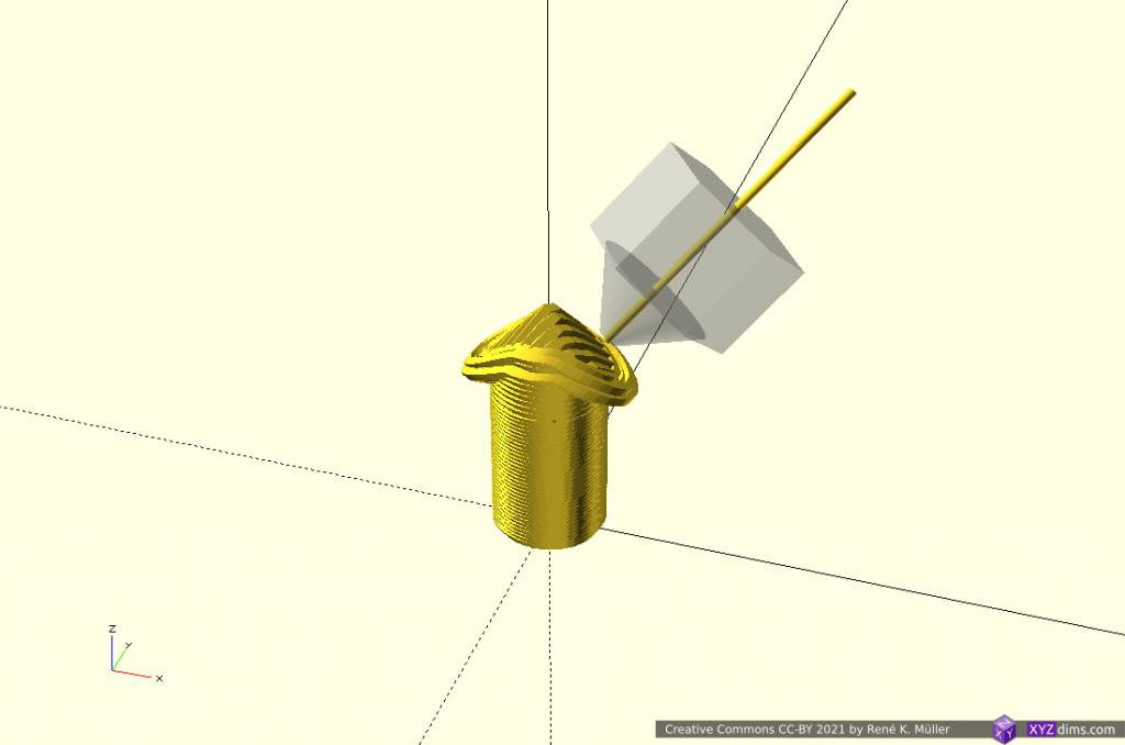
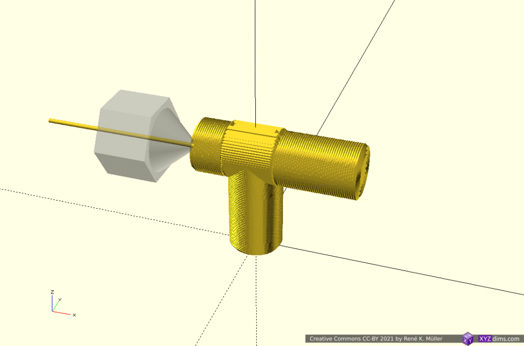
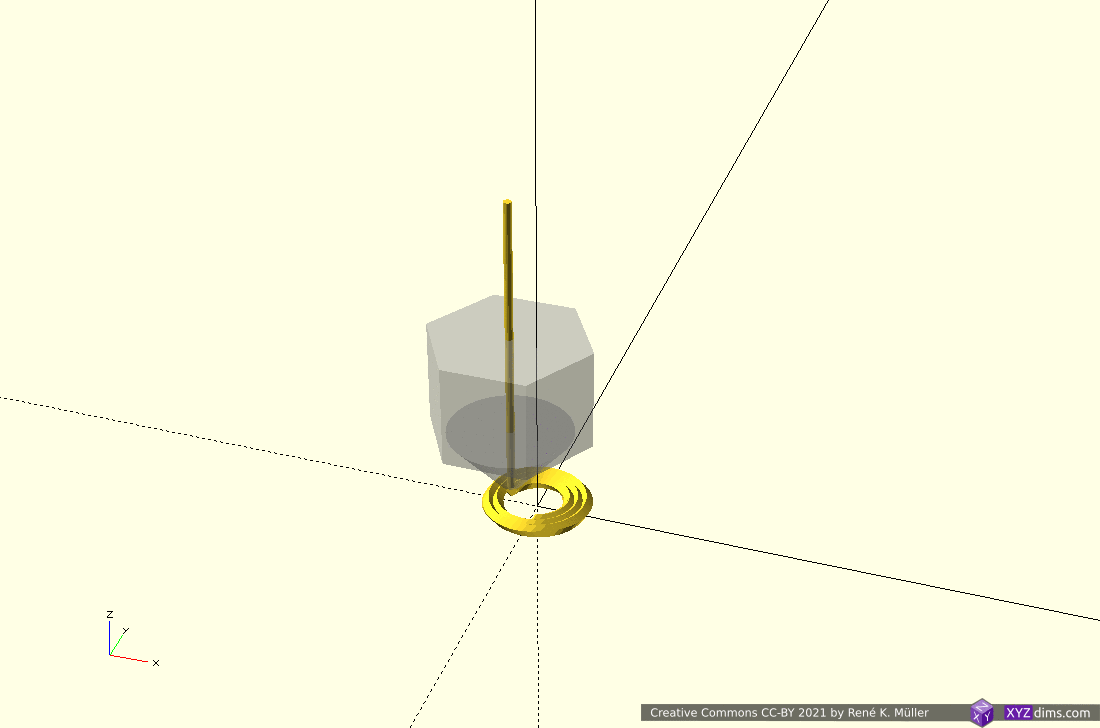
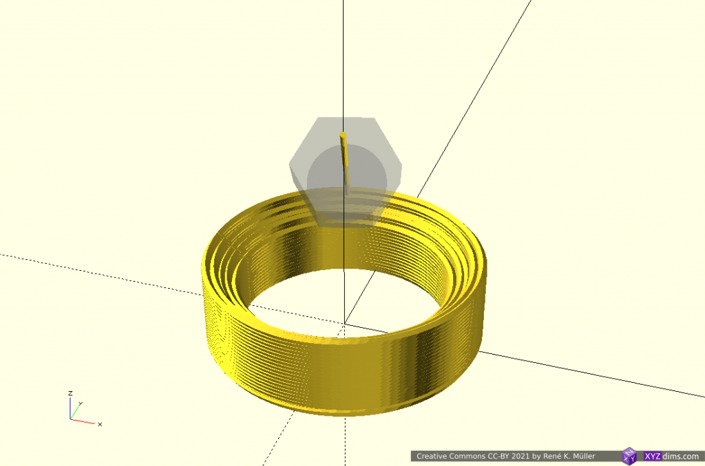
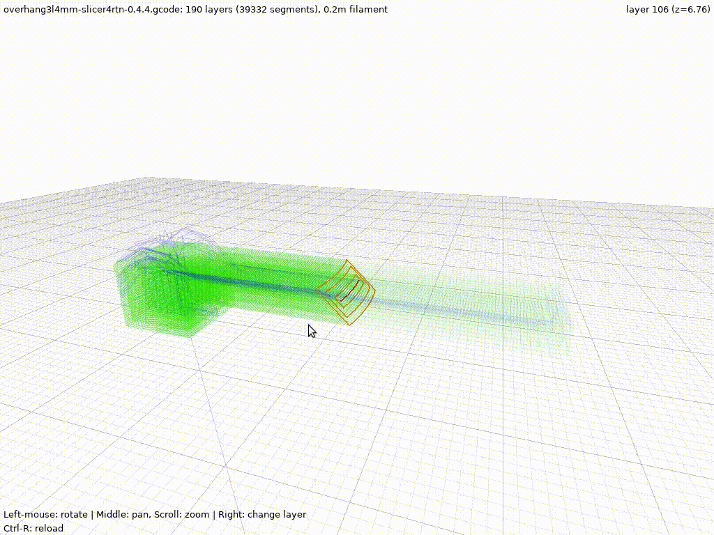
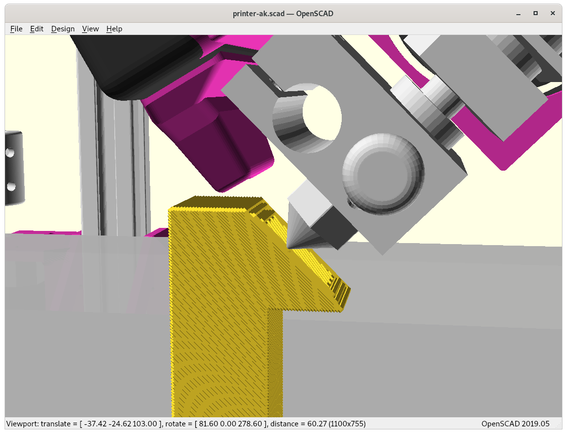
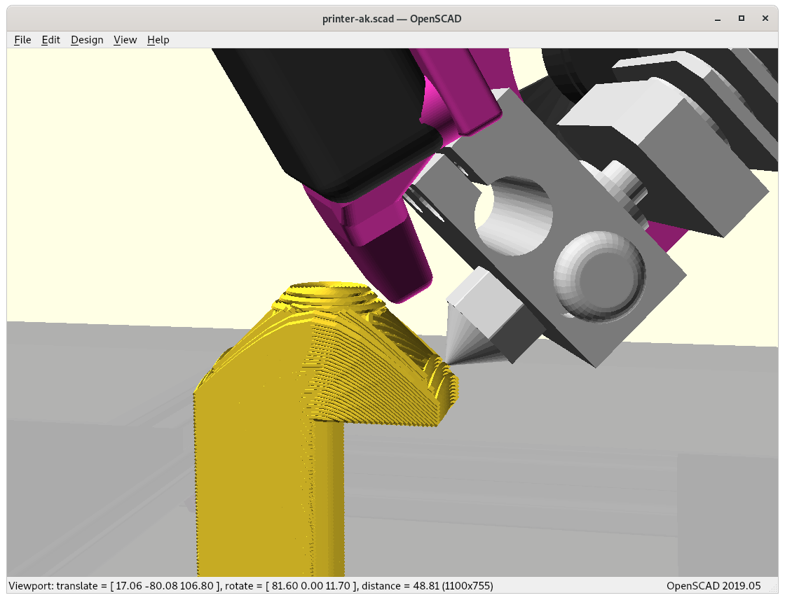
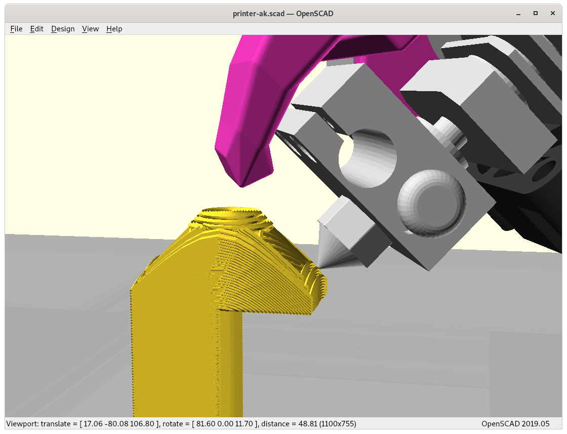
  4. cone, slicing conical like for Rotating Tilted Nozzle
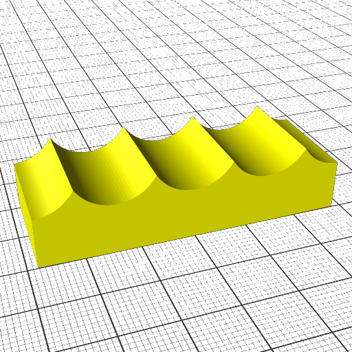
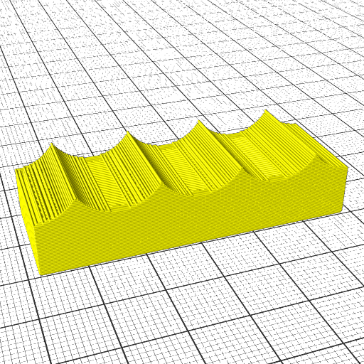
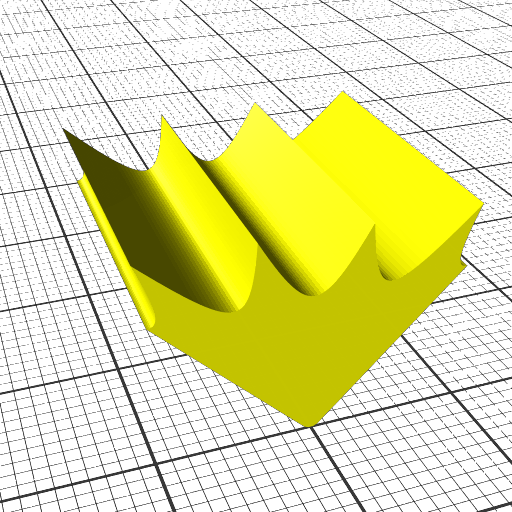
  5. wave-like defined via Bezier curves
  6. wave-like defined via NURBS (Non-Uniform Rational B-Splines) curves
  7. tilted plane, slicing for belt printer with 45° tilted XY frame toward Z belt
  8. pimple-like

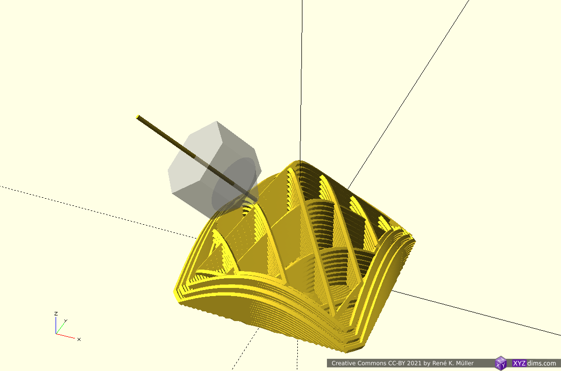
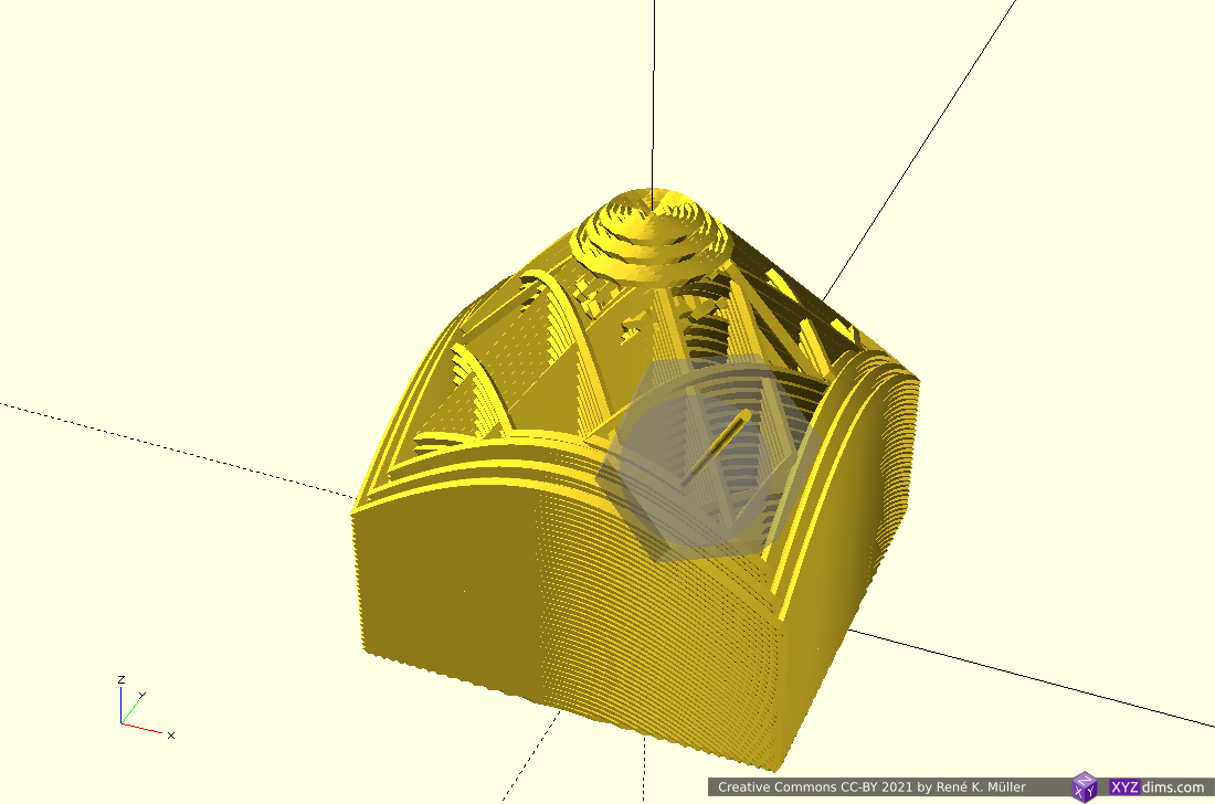
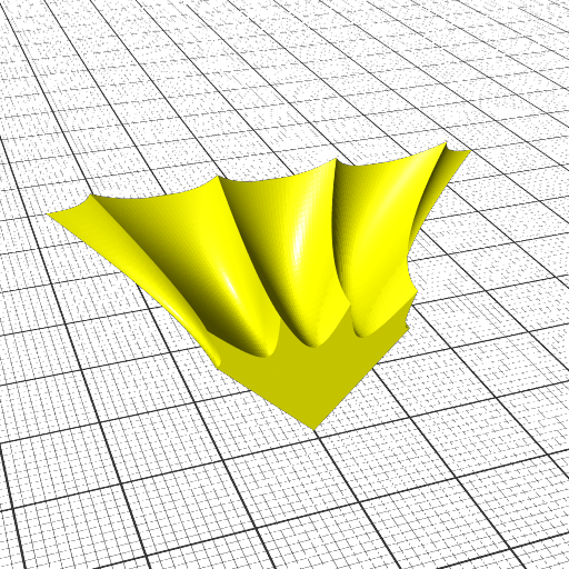
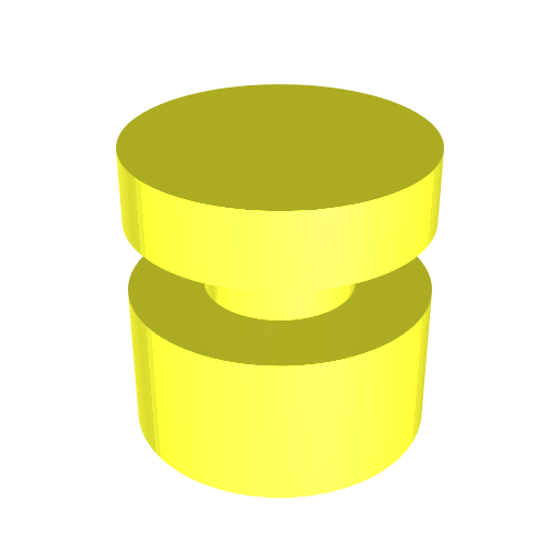
Class 2: Variable Slicing Vector or Variable Slicing Geometry

Variable slicing vector or changing slicing geometry (often refered as “non-planar slicing” without the specifics) means the slice itself has variable layer height or thickness – to be more precise:

  • change of slicing geometry, e.g. transitioning from one slicing geometry to another
  • change of slicing vector, e.g. change in steps, or curvature
Class 2 Universal Slicing: Variable Slicing Geometry, Variable Slicing Vector

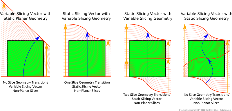
It may not be always clear at first sight whether there is a transition of a slicing geometry or a change of slicing vector, as the changed slicing vector can also be looked as another slicing geometry – yet I think it makes more sense to differentiate between a slicing vector and slicing geometry when laying out a slicing procedure.
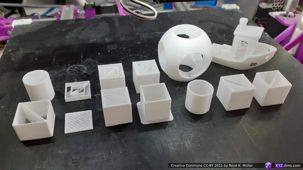
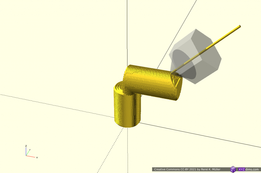
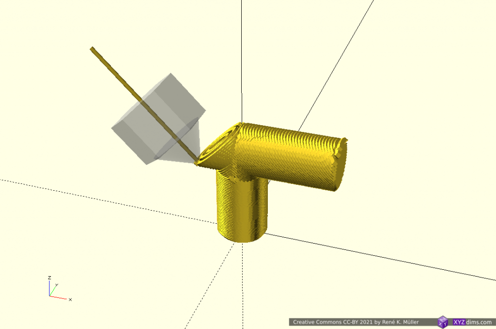
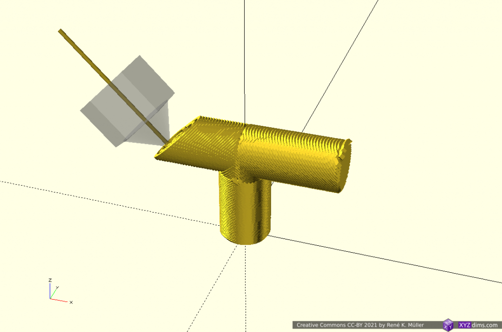
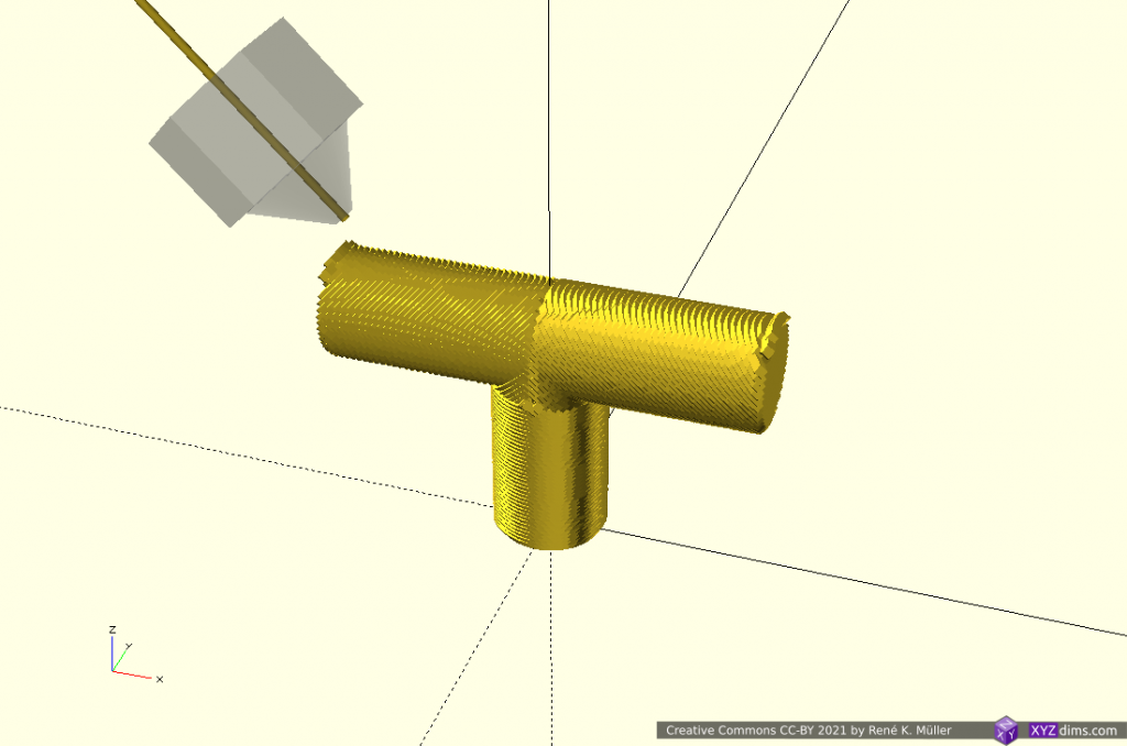
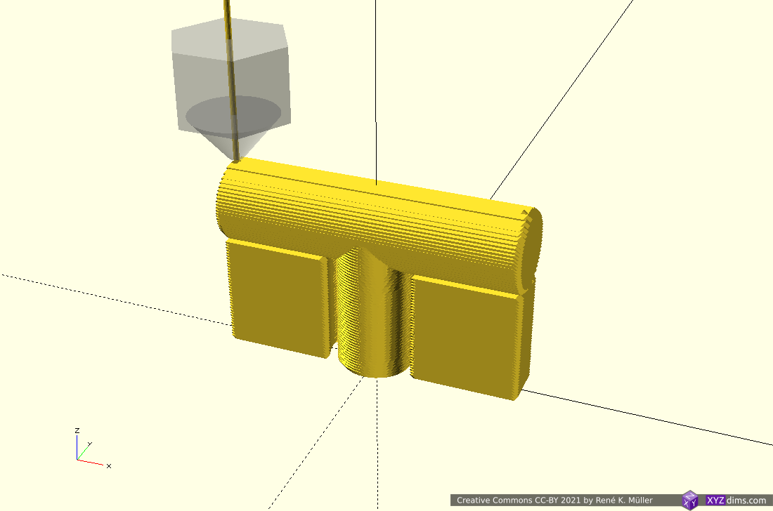
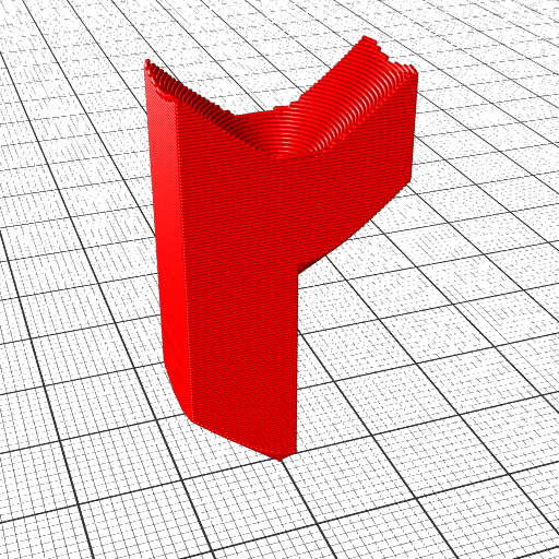
Class 2 Examples

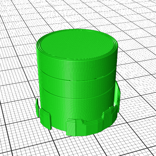
Example of Class 2 of Universal Slicing (produced by EnochSlicer):

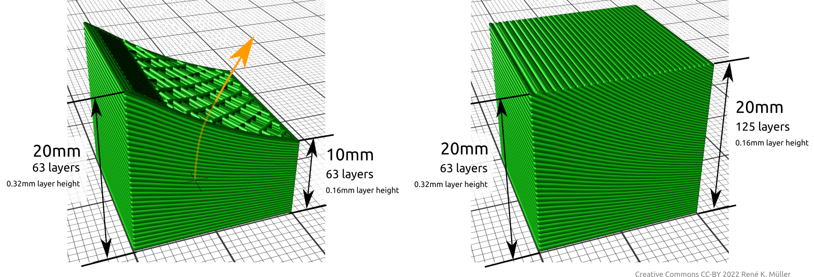
It is important to realize, that change of slicing geometry and/or slicing vector implies the slice or layer has variable thickness, hence, might have to comply with physical limits like maximum layer height printable with FDM and a given nozzle diameter – the actual implementation of an Universal Slicer has to adhere this.

Slicing Vector vs Slicing Geometry

Slicing VectorSlicing GeometrySlices / 3D PrintingSlice Thickness
staticplanarplanarstatic
non-planarnon-planarstatic
variableplanarnon-planarvariable
non-planarnon-planarvariable

Implementing Universal Slicing

The implementation of such Universal Slicing can be achieved in many ways and procedures. It is important to name features and describe what it they mean, such as:

  • Universal Slicing: is the ability to choose slice geometry and slice path freely
  • Universal Slicer: slicer which implements Universal Slicing in parts or fully – if it only implements part it shall be declared so
  • Class 1 Universal Slicing: static slicing path of [ 0, 0, 1 ], but with any kind of slicing geometry, static planar or static non-planar
  • Class 2 Universal Slicing: flexible slicing path, ability to change slicing geometry while slicing
ClassSlicing PathSlicing Geometry
Class 1staticstatic (planar or non-planar)
Class 2flexibleflexible (planar or non-planar)

Universal Slicers

  • MetatronSlicer (in-house XYZdims, status 2022/03):
    • slicing with (non-)planar geometries (Class 1)
    • partial support for slicing with change of slicing geometry (Class 2)
  • EnochSlicer (in-house XYZdims, status 2022/03):
    • slicing with (non-)planar geometries (Class 1)
    • partial support for slicing with change of slicing path & geometry (Class 2)
  • DotXControl 5-Axis Slicer (status 2022/03): supposedly supports Class 1 + 2 based on illustrations on the web-site
  • AI-Build (AI Build): requires NDA to even see a demo (!!) therefore difficult to conclude capabilities, might supports Class 1 + 2 based on illustrations and brief videos
MetatronSlicer: slicing with wave-like geometry a 20mm cube, printed with 3-axis FDM

Benefits of Non-Planar 3D Printing FDM

Layer adhesion tensile and shearing forces of planar and non-planar FDM
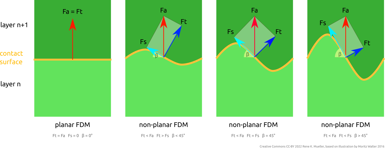
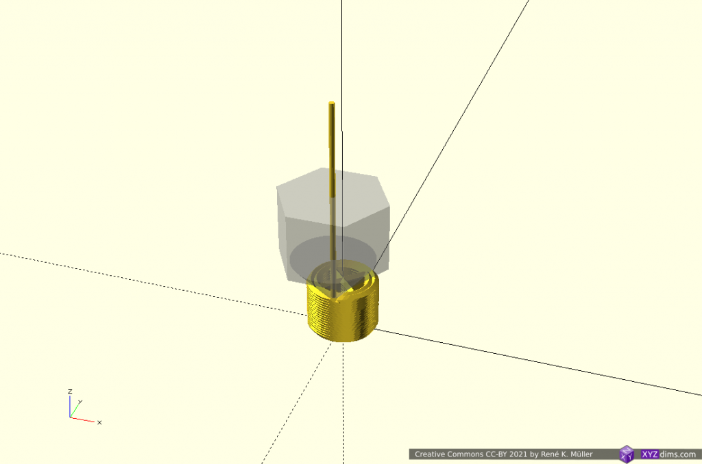
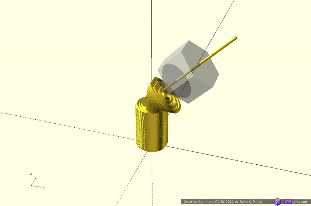
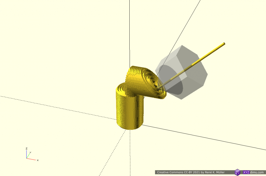
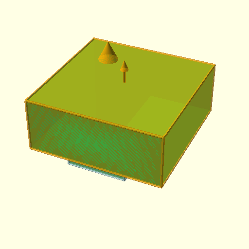
Fa = attacking force; Ft = tensile component of Fa; Fs = shearing component of Fa; β = tangent angle

One advantage resides in the ability to address FDM Z-layer adhesion issues by distributing force or stress vectors along any kind of trajectory and optimize material vs strength of the overall printed piece, e.g. when using continuous fiber filament and lay it along most stressed locations.

Further, the ability to have top layers align to object’s surface directly, no more layer lines. Essentially being able to define and manufacture a piece based on inner structure requirements and its outer form requirements.

References

Misc: XYZdims State 2022/02

Updates:

  • 2022/02/20: finally published
  • 2022/02/08: ready to publish finally with some delay
  • 2022/01/28: not yet published, removed Universal Slicing details for future blog-post, added more photos and illustrations
  • 2022/01/16: starting write-up

Introduction

Aside of the technical detailed filled blog-posts I like to start to post about the larger context of my inner motivations doing XYZdims.com – this is the first post “XYZdims State 2022/02”:

More Slicers

Recent in-house developments having more slicers to experiment with, in regards of slicing techniques as well lay the ground for more complex slicing and mapping/transformation operations to support arbitrary non-planar slicing (coming soon).

LabSlicer: The Mother

Big Picture of XYZdims – State 2022/02
(click on it and then zoom in, it’s a large image)

As I was working with Slicer4RTN and wrappers like Cura-CLI-Wrapper and Kiri:Moto Slicer (CLI wrapper), and adopting Mandoline fork – I realized I need to have my own slicer, so in November 2021 I started from scratch, as I thought I need to know every detail and so I exposed each step or stage:

  • mesh: load mesh, vertices & faces
  • slice: slice layers into sets of polygons
  • route: route the layer polygons with walls, infills etc
  • gcode: convert routes to G-code

A “lab(oratory) slicer” or simply LabSlicer was born – I defined each stage: API and file-format it takes in and spits out.

After a couple of weeks I had slicing into polygons, and routing of walls, basic infills, skirts, brims and eventually intermediary top & bottom layers resolved, and I was able to generate printable gcode:

Meanwhile LabSlicer as of version 0.1.5 has matured to print complex models reliably but rather performs slow compared to Slic3r or Cura.

As of 2022/02 I’m even use LabSlicer and its relatives (featured below) for productive 3D prints.

Vox3lSlicer: Voxels

Aside of LabSlicer I began to develop Vox3lSlicer which utilizes internally the OpenVDB voxel library, in order to slice planar and in the future non-planar as well, and also permit to slice voxel-based models efficiently.

A few tests with OpenSCAD Logo model (~20mm height) with various amount voxel samples, from low resolution to high resolution:

and with defined voxel sizes:

As LabSlicer matured and LabSlicerCore library came to life, Vox3lSlicer (2011/11) utilizes the stage route and gcode of LabSlicerCore to actually produce printable G-code.

Testing the retraction code and settings of Vox3lSlicer, rotating the model in order to avoid support structure altogether:

VoxGLSlicer: OpenGL Slicing

Early VoxGLSlicer tests

As I was looking for other slicing procedures I came across OpenGL-ST-Slicer, which utilizes a clever OpenGL setup with GLSL (Shader Language) to render a mesh to a framebuffer with the volume information, and so slicing is done solely in the GPU almost instantly – I extended this approach and glued it together with LabSlicerCore and I was able to produce also printable G-code – VoxGLSlicer was born (2022/01).

Due the limitation of the internal framebuffer width & height the resolution of the slicing changes with the size of the model aka “relative resolution”:

model width [mm]pixel size [mm] @ 2560 pixels
200.008 or 8 μm
500.019 or 19 μm
1000.039 or 39 μm
2000.078 or 78 μm
5000.19 or 195 μm
10000.39 or 390 μm

and just for illustration about “pixel size” related to a ~20mm model:

3 Slicers

After a few weeks coding (2021/11-2022/01), I was able to raise 3 slicers, each with their unique slicing approaches to create printable G-code, by having a common API and use symbiotic advantage of each other:

LabSlicerVox3lSlicerVoxGLSlicer
meshmesh.py1) multi-format mesh importeropenvdb STL importermesh.py1) multi-format mesh importer
sliceslicing mesh to polygons (vectorizing)slice voxels into polygons (vectorizing)screenbuffer into polygons (vectorizing)
routeroute polygons to routesLabSlicerCore’s routeLabSlicerCore’s route
gcodeconvert routes to G-codeLabSlicerCore’s gcodeLabSlicerCore’s gcode
+ traditional slicer with polygons
+ all stages fully implemented
– slow slicing2)
+ fast slicing
+ flexible resolution
+ reliable
+ fast slicing
– fixed screenbuffer size
– relative resolution

All three slicers are very experimental and play a significant role for the next step – Universal Slicing.

Footnotes:

  1. mesh.py is loading/saving 3d meshs/models and some simple manipulations tuned toward my use cases
  2. mesh slicing not yet optimized

So any optimizing of routing (wall, infill, intermediary top/bottom layers etc) and gcode optimizing all three slicers benefit from.

YAGV & Nautilus Thumbnailer Supporting ArcWelder

After the implementing G2/G3 emulation for gcode2png as part of the G-code thumbnailer, I also added it to G-code viewer yagv fork of mine:

Print3r

And just for sake of giving a bit of context, adding ArcWelderLib in the pipeline of Print3r via the configuration:

# first declare new post-processor named "arcwelder":
post_arcwelder = ArcWelder %i %o
# optionally, define it to be active (all the time):
post = arcwelder

or optionally enable it on the command-line:

% print3r print cube.stl --post=arcwelder

That’s it for now.

References

3D Printing: Mandoline Slicer

Updates:

  • 2021/09/16: publishing this blog-post finally
  • 2021/09/04: 0.8.6: supporting OFF, OBJ, AMF, 3MF and 3MJ in addition to STL
  • 2021/04/11: 0.8.5: more tests and Makefiles added
  • 2021/04/06: 0.8.4: SVG export working with example, various bug fixes
  • 2021/04/04: 0.8.3: first print actually working (extrusion calculation fixed, removed most un/retract for now)
  • 2021/04/02: starting write-up
20mm xyzHollowCalibrationCubeV2 sliced with Mandoline 0.8.5

Introduction

Since I started to develop on the conic slicer slicer4rtn for the RTN, and starting to work on the more complex PAXSlicer for 5-axis printer like PAX option. So I was searching for a slicer to adapt for future projects to have more control of the slicer stage and learn of the actual details and so I came across Mandoline Py, a slicer coded in Python utilizing at its core pyclipper and at first glance it was well thought out, clean code, yet not many comments but function names and variables were explanatory – I was quite impressed by Revar Desmera, who was able to put this together in such a consistent manner.

There wasn’t much information available otherwise, and the author did not reply to my emails, so I looked at past closed issues at github, which gave me a bit background information, and the challenges Revar faced.

So, after a couple of weeks pondering and waiting for Revar to respond, April 4 2021 I began to adopt it and push it forward to become usable for me. I will document all future changes (or possible a fork of it) on this blog-post.

Features

  • purely written in Python, compact source code, easy to read & understand
    • vector.py: base vector operations
    • point3d.py: x,y,z to index to x,y,z
    • line_segment3d.py: two points making a line, with caching
    • facet3d.py: three points making a triangle/facet, with caching
      • facet.slice_at_z(z)
    • geometry2d.py: uses pyclipper
      • provides path operations like offset, union, diff, clip, paths_contain (point in paths)
      • makes infill patterns like lines, grid, triangles, hexagons
    • model3d.py: STL reader & writer, OBJ, OFF, 3MF, AMF, 3MJ reader
      • indexing points, edges and facets
      • model.slice_at_z(z, lh) results in polygons/paths
    • slicer.py: slicing the model
      • generating perimeters
      • generating support
      • generating adhesion (skirt, brim, raft)
      • generating solid & sparse infill
      • pathing: coordinates perimeters, support, adhesion, infill paths
      • converting paths into Gcode (or SVG)
    • __init__.py: main entry point of mandoline program:
      • process arguments
      • load model and relevel, apply model operations (scale), check manifoldness
      • slice model
  • slice model into Gcode to print via FDM 3D printer
  • slice model to SVG slices (very experimental) for debugging purposes and possibly to post-process to pixel-based slices for SLA or SLS 3D printer (not yet tested)
  • load mutiple configs in sequence with -l config.ini, e.g. printer specifics, material settings
  • simple to query features/settings with -Q <term>

Usage

% mandoline
== Mandoline Py 0.8.5 == https://github.com/(Spiritdude|revarbat)/mandoline-py
usage: mandoline [-h] [-o OUTFILE] [-n] [-g] [-v] [-d] [--no-raft] [--raft] [--brim] [--no-support] [--support] [--support-all]
                 [-f MATERIAL,...] [-F FORMAT] [-l OPTNAME] [-M OPTNAME=VALUE] [-S OPTNAME=VALUE] [-Q OPTNAME] [-w]
                 [--help-configs] [--show-configs]
                 [infile]

positional arguments:
  infile                Input model filename (STL).

optional arguments:
  -h, --help            show this help message and exit
  -o OUTFILE, --outfile OUTFILE
                        Slices model (STL) and write GCode or SVGs to file.
  -n, --no-validation   Skip performing model validation.
  -g, --gui-display     Show sliced paths output in GUI.
  -v, --verbose         Show verbose output.
  -d, --debug           Show debug output.
  --no-raft             Force adhesion to not be generated.
  --raft                Force raft generation.
  --brim                Force brim generation.
  --no-support          Force external support structure generation.
  --support             Force external support structure generation.
  --support-all         Force external support structure generation.
  -f MATERIAL,..., --filament MATERIAL,...
                        Configures extruder(s) for given materials, in order. Ex: -f PLA,TPU,PVA
  -F FORMAT, --format FORMAT
                        Set output format (gcode, svg)
  -l OPTNAME, --load OPTNAME
                        Load config file, containing <k>=<v> lines
  -M OPTNAME=VALUE, --model OPTNAME=VALUE
                        Set model manipulation operation(s) (scale).
  -S OPTNAME=VALUE, --set-option OPTNAME=VALUE
                        Set a slicing config option.
  -Q OPTNAME, --query-option OPTNAME
                        Display a slicing config option value.
  -w, --write-configs   Save any changed slicing config options.
  --help-configs        Display help for all slicing options.
  --show-configs        Display values of all slicing options.

examples:
   mandoline cube.stl
   mandoline -l myprinter.ini cube.stl
   mandoline -l myprinter.ini -S layer_height=0.3 cube.stl
   mandoline -l myprinter.ini -l petg.ini -S infill_type=Triangles cube.stl -o test.gcode
   mandoline -Q skirt


Download

https://github.com/Spiritdude/mandoline-py

Formats

Gcode

By default Mandoline slices STL into 3D printable Gcode:

% mandoline -l y3228.ini hollowCube.stl -S layer_height=0.3 -o test.gcode
== Mandoline Py 0.8.4 == https://github.com/revarbat/mandoline-py
Loading model "hollowCube.stl"
Loading configs from "y3228.ini"                                              
Slicing starting
+ Random offset -78,34
- Perimeters
- Support                                                                     
- Raft[ ], Brim[ ], and Skirt[x]                                              
- Infill (Grid)                                                               
- Pathing                                                                     
- Export GCode to "test.gcode"                                                
Took 0.85s total. Estimated build time: 0h 08m, filament used: 1.394m         

SVG

Mandoline (0.8.4+) also supports slicing into SVG, for debugging purpose and possibly can be post-processed into PNG to feed into a SLA or SLS 3D printer (no support-structure included yet).

% mandoline hollowCube.stl -o test.svg
== Mandoline Py 0.8.4 == https://github.com/revarbat/mandoline-py
Loading model "hollowCube.stl"                                              
Slicing starting
- Perimeters
- Export 66x SVGs to "test-*.svg"                                             
Took 0.23s total.       

Issues to Resolve

  • model slicing problems:
    • 3D Benchy incomplete, get more linient or auto-fix regarding non-manifolds:
      • 3DBenchy.stl loaded with manifold checking, 10x “non-manifold hole edges”:
        • Z = 9.087, 5.87
      • when disregarding that check with -n, then it results in various warnings “Incomplete Polygon …” which results in missing slices – major degration of 3D print
      • sliced with many warnings (Incomplete Polygon at z=... => missing layers) @0.2mm layer height: 240 layers, 4.011m with 1.75mm filament
      • sliced with many warnings (=> missing layers) @0.25mm layer height: 192 layers, 4.461m with 1.75mm filament
      • -M scale=0.5 with
        • @0.2mm layer height with warnings (=> missing layers): 120 layers, 0.674m with 1.75mm filament
        • @0.25mm layer height with warnings (=> missing layers): 96 layers, 0.634m with 1.75mm filament- fixing
    • Voron Design Cube v7 wrong sliced layers without warnings
  • random crashs of pyclipper: I noticed a basic model with random_pos=True enabled slices correct and another time when moved to another position fails to slice
  • properly do un/retract:
    • find out if perimeters/walls are crossed, if not, do not un/retract no matter what TYPE of extrusion is done
  • allow case-insensitive settings:
    • infill_type
    • support_type
    • adhesion_type
    • bed_geometry
  • brim, raft and skirt properly done (*_width vs *_lines and *_offset)
  • bottom_layer_extrusion_width
  • bottom_layer_speed
  • top_layer_speed
  • wall/shell/perimeter_speed
  • resolve “shell” vs “wall” vs “perimeter” in source variables, source comments and config
  • infill_type=Hexagons doesn’t work reliable, often infill is missing entirely
  • support 3MF, 3MJ input format beside STL, since 0.8.6: obj, off, amf, 3mf and 3mj
    • properly support multi-volume -> multi-material -> multi-tool
    • 3MF: examples, Debian package: python3-savitar, since 0.8.6 using XML parser
  • clean up multi-nozzle setup, remove GUI, remove material config but hand it over to a collection of .ini files to be selectable with -l my.ini … (not yet finalized how to achieve simple multi-nozzle config easy)
  • testing, testing and testing more
  • future developement
    • integrate geometry3d union, intersection for segmenting sub-volumes
    • analyze geometry from non-planar slicing perspective
    • integrate non-planar slicing: tilted, cyclindrical, conic and spherical at a deeper level
    • mature it to become optional for PAXSlicer 5-axis slicer
    • process metadata from .3mj either piece, sub-volume or face exact within the slicing (tool changing, fill density, slicing settings etc)

Changes

  • 2021/09/04: 0.8.6:
    • experimental OFF, OBJ, 3MF, 3MJ support
  • 2021/04/08: 0.8.5:
    • cli: -S shell_speed=s [mm/s]
  • 2021/04/06: 0.8.4:
    • SVG output: supporting slicing to SVG, using “-o test.svg“, very experimental
    • intern: model.scale([x,y,z]) implemented
    • cli: support for -M scale=s or -M scale=x,y,z
    • intern: fixed vector.py normalize() and __truediv__() supporting STL with bad normals
    • un/retract enabled again in code
  • 2021/04/04: 0.8.3:
    • cli & extending configs:
      • cool_fan_speed_{min/max}
      • cool_fan_full_layer=2, e.g. starting fan after e.g. layer 2 is reached, first layer is 0
      • start_gcode and end_gcode and new config type ‘str‘ as well
      • skirt_lines=3 only considered if skirt_layers != 0
      • gcode_comments=True|False: adding various useful info in Gcode
      • random_pos=True|False: randomize position of model on the build-plate
    • all the config included in Gcode given gcode_comments enabled
    • intern: carrying over ‘typ‘ (‘type’ in python 😉 ) of the extrusion in _raw_add_paths, to refine the retract/unretract, this allowed to
    • have output Gcode more descriptive with ;TYPE:.. like PERIMETER, INFILL, PRIME, BRIM, SKIRT, SUPPORT etc, given gcode_comments is enabled
    • cli: support -l or --load to load more configs (e.g. per printer, or material)
    • cli: support -Q <term> partial match
    • output “filament used …[m]” at the end of slicing
    • most un/retract disabled for now to confirm extrusion calculation working
    • prints simple models like 10/20mm cube and xyzHollowCalibrationCubeV2

References

3D Printing: Sub-Volume Segmenting & (Non-)Planar Slicing

Introduction

In order to take advantage of 4- and 5-axis non-planar FDM1) printing (e.g. tilted, conic, cylindrical, spherical) the model may be segmented and then dedicate slicing methods can be assigned to such sub-volumes.

A few basic examples combining planar and non-planar slicing methods on sub-volume segmented models illustrating the possibilities printing without support structures:

  1. Fused Deposition Modeling (FDM) also known as Fused Filament Fabrication (FFF)

T-Model: 2 Segments: Z-planar & Conic

Utilizing novel conic slicing as introduced by ZHAW researchers in 2020/2021:

T-model segmented into 2 sub-volumes, sliced z-planar and conic (outside-cone mode)

Conic slices can be printed with 4-axis Rotating Tilted Nozzle (RTN) although printing the Z-planar sliced part might not give goods surface results but rather using a 5-axis Penta Axis (PAX) printhead to cover both cases easily.

T-Model: 3 Segments: Z-planar & 2x Tilted

Using non-rotating but tilted sliced (like used with belt-printers) but in two distinct directions:

T-model segmented into 2 sub-volumes, sliced z-planar and twice tilted in opposite directions

Tilted slices can be printed with 4-axis Rotating Tilted Nozzle (RTN) but the first Z-planar part, as mentioned above, might not provide sufficient surface quality, whereas a 5-axis Penta Axis (PAX) printhead can print both segments easily.

T-Model: 3 Segments: Z-planar & 2x X-planar

A more classic planar approach but with different planes as reference, first Z-planar then twice X-planar in different directions:

T-model segmented into 3 sub-volumes, sliced z-planar and twice x-planar

X-planar printing requires either 5-axis Penta Axis (PAX) printhead or the ability to tilt the bed.

Overhang In/Out: 2 Segments: 2x Conic

Lower part is sliced with conic slicing with inside-cone mode to print in-going overhang, whereas the upper part is sliced with outside-cone mode to cover the out-going overhang:

Overhang in/out model segmented into 2 sub-volumes: lower part is sliced conic (inside-cone mode) and upper part conic (outside-cone mode)

This model covers the classic case of 4-axis Rotating Tilted Nozzle (RTN) application: rotating 45° tilted nozzle printing in two different modes (outside-cone and inside-cone); a 5-axis Penta Axis (PAX) printhead also can print such.

Overhang Out No 5: 2 Segments: Z-planar & Conic

Another overhang piece, stretching out into one direction; the lower part Z-planar, and the overhang conic (outside-cone mode) with an offset to align better with the lower segment:

Overhang Out No 5 model segmented into 2 sub-volumes: z-planar at the bottom and overhang segment conic (outside-cone mode)

Overhang Out No 5: 3 Segments: 2x Z-planar & Conic

Perhaps a more realistic approach using the conic part as a “balcony” just for the overhang part sufficiently thick to carry next segment and switching back to Z-planar:

Overhang Out No 5 model segmented into 3 sub-volumes: z-planar first, then conic (outside-cone) building a thin “balcony” as support for the z-planar part on top again

Early tests have shown the thickness of the conic overhang “balcony” depends on the actual length of the in-air overhang, where print speed, part-cooling capacity and extrusion consistency determine the geometrical accuracy. More examples with “balcony” printed with 3-axis FDM printer followed.

Conclusion

Unlike with ordinary Z-planar slicing, it may be suitable to dedicate a particular slicing method and orientation for sub-volumes in order to take advantage of the possibilities like avoiding support structure, particular strength properties or surface quality.

This of course opens a wide-range of possibilities and complexity therefore:

  • where to segment
  • which slicing method to use
  • in which orientation the slicing is performed

but I think it’s worth it, in particular when a piece is printed more than once like with small series manufacturing / production.

The examples have been produced with various slicers and combined with a new application coordinating the segmenting and dedicated slicing methods, which currently (2021/04) is in development; it also involves a new file-format describing the segmenting and its slicing settings. The segment positioning was done manually as a start, but I expect with more experience and research some cases can be detected automatically.

Sub-volume segmenting is just one approach to take advantage of 5-axis FDM printing, another is continuous slicing along the form.

References

See Also

PS: All animations I combined in a short 3min video: Mixing Planar & Non-Planar Slicing Methods for 3D Printing Overhangs without Support Structure (YouTube)

3D Printing: YAGV: Yet Another G-code Viewer Fork

One of the oldest standalone G-code viewers yagv (Yet Another G-code Viewer) I forked and added following features:

  • ported to Python3
  • new color scheme (white background)
  • parsing G-code comments, determining wall, infill, support structure and render with different colors
  • support for Slic3r, PrusaSlicer, Cura/cura-slicer, Mandoline and Slicer4RTN (non-planar)
  • panning implemented (properly works with zoom and rotation)
    • same mouse button layout as OpenSCAD
  • more test G-code included in tests/

Example of non-planar G-code:

Download

https://github.com/Spiritdude/yagv

Note: I opened a Pull Request (PR) but not sure if it’s accepted.

See Also

3D Printing: Non-Planar Slicing with Planar Slicer

Updates:

  • 2021/04/09: spherical slicing redone, slightly better than before
  • 2021/04/03: cylindrical & spherical slices added
  • 2021/03/26: refocusing to non-planar slicing with planar slicing
  • 2021/03/14: starting write-up with basic illustrations

Introduction

After discovering the 4-axis Rotating Tilted Nozzle (RTN) and its prototype of RotBot as developed by ZHAW and their conic slicing method, it became clear to me a 5-axis 3D printer with variable tilting nozzle is the way to go as it is a superset of 4-axis and 3-axis 3D printing.

With that in mind, I realized there was time to explore non-planar slicing with planar slicers in more details.

Slicing Methods

Let’s provide an overview of various slicing methods:

Horizontal Slices

Vertical slicing creates horizontal slices, the traditional aka planar slicing method, so issues and limitations are well known:

  • simple to slice
  • only challenge is to create support structure for overhangs to ensure all printed layers have layers beneath
  • no collision detection needed, as all already printed layers are beneath

Tilted Slices

Tilted slices are kind of new(er) and became known with belt printers, usually 45° tilted:

Transformation is [ x, y, z – y ]

  • simple to slice
  • belt-printer: no collision detection is needed
  • can print 90° overhangs in one direction only

There are patches for Cura available to slice for belt printer, additional the experimental Slicer4RTN also provides tilted slicing.

Conical Slices

New slicing method as introduced by ZHAW researchers and announced in 2021/01 utilizing planar slicer:

  • requires a center of the conic layers
  • can print 90° overhangs, two distinct modes: inside out (outside cone), or outside in (inside cone) depending on direction to a central slicing cone center
  • requires rotating and tilted nozzle aka Rotating Tilted Nozzle (RTN)
  • angle of conic slicing can be changed from 45° to 20° and models become printable with vertical nozzle with reduced print quality

Transformation is [ x, y, z + sqrt(x2 + y2) ]

I implemented a conic slicer named Slicer4RTN in 2021/03. There are more complex conic transformations possible, e.g. map the x/y angle via atan(y/x) but just adding sqrt(x2 + y2) to z does achieve a conic slice.

Cylindrical Slices

Early tests using planar slicers to slice also cylindrical, like this:

Transformation is [ atan(y/x), z, sqrt(x2 + y2) ]

It can be printed on a fixed vertical rod, with a rotating and tilting nozzle, or horizontal rotating rod (like a lathe) and vertical nozzle then:

I came up with this way by myself based on the study on conic(al) slicing but I was made aware researchers Coupek, Friedrich, Battran, Riedel back in 2018 published a paper on this method already.

(Hemi-)Spherical Slices

Early tests using planar slicers to slice also spherical, like this:

Transformation is [ sqrt(x2 + y2 + z2), atan(y/x), atan(z/sqrt(x2 + y2)) ]

It can be printed with a 5-axis like PAX printhead, it’s main advantage is to getting close to print continuous overhangs of any angle.

I suspect at least one more suitable and simpler sphere transformation, as soon I came up with such I add it on this blog-post.

Conclusion

It is possible to slice non-planar with planar slicers by mapping to and from the space of the slicing you like to have; yet in the slicing procedure some margins are introduced which need to be compensated – the planar slicer needs to work reliable, Slic3r 1.2.9 and CuraEngine 4.4.1 / cura-slicer perform reliable, whereas PrusaSlicer 2.1.1 makes assumptions of the printability and exits when no printable G-code can be produced, not recommended for this case therefore.

The simpler the transformation forward and backward, the more precise G-code can be obtained, e.g. tilted and conic slices provide precise G-code, whereas cylindrical and spherical slices are harder to tune with the planar slicer.

References

3D Printing: Cura CLI Wrapper (cura-slicer)

Updates:

  • 2021/05/01: 0.0.7: support legacy Cura and --binary=.. to change binary name
  • 2021/03/24: 0.0.5: public release

Introduction

I’m a great admirer of the Ultimaker Cura slicer since years, yet I predominantly have been using CuraEngine on the command-line via Print3r, which hides all the tedious configuration. But it came the point (2021/03) when I needed to have a simpler interface than CuraEngine – hence I wrote Cura CLI Wrapper, the executable cura-slicer looks like prusa-slicer or slic3r and has similar usage.

Speciality is to query all the settings from cura-slicer directly:

% cura-slicer --help
acceleration_enabled = 0 (default)
acceleration_infill = 3000 [mm/s²] (default)
acceleration_ironing = 3000 [mm/s²] (default)
acceleration_layer_0 = 3000 [mm/s²] (default)
acceleration_prime_tower = 3000 [mm/s²] (default)
acceleration_print = 3000 [mm/s²] (default)
acceleration_print_layer_0 = 3000 [mm/s²] (default)
acceleration_roofing = 3000 [mm/s²] (default)
acceleration_skirt_brim = 3000 [mm/s²] (default)
acceleration_support = 3000 [mm/s²] (default)
acceleration_support_bottom = 3000 [mm/s²] (default)
acceleration_support_infill = 3000 [mm/s²] (default)
acceleration_support_interface = 3000 [mm/s²] (default)
acceleration_support_roof = 3000 [mm/s²] (default)
...

which lists ~570 settings as of CuraEngine 4.4.1 and its defaults and from where the defaults come from (definition defaults, config or cli), and you can query also a term e.g. like ‘brim’:

% cura-slicer --help brim
acceleration_skirt_brim = 3000 [mm/s²] (default)
brim_gap = 0 [mm] (default)
brim_line_count = 0 (config)
brim_outside_only = 1 (default)
brim_replaces_support = 1 (default)
brim_width = 8 [mm] (default)
jerk_skirt_brim = 20 [mm/s] (default)
prime_tower_brim_enable = 0 (default)
skirt_brim_line_width = 0.4 [mm] (default)
skirt_brim_material_flow = 100 [%] (default)
skirt_brim_minimal_length = 250 [mm] (default)
skirt_brim_speed = 30 [mm/s] (default)
support_brim_enable = 0 (default)
support_brim_line_count = 20 (default)
support_brim_width = 8 [mm] (default)

and with -v switch you even get a more descriptive output:

% cura-slicer --help brim -v
== acceleration_skirt_brim (Skirt/Brim Acceleration) ==
   The acceleration with which the skirt and brim are printed. Normally this is done with the initial layer acceleration, but sometimes you might want to print the skirt or brim at a different acceleration.
   acceleration_skirt_brim = 3000 [mm/s²] (default)

== brim_gap (Brim Distance) ==
   The horizontal distance between the first brim line and the outline of the first layer of the print. A small gap can make the brim easier to remove while still providing the thermal benefits.
   brim_gap = 0 [mm] (default)

== brim_line_count (Brim Line Count) ==
   The number of lines used for a brim. More brim lines enhance adhesion to the build plate, but also reduces the effective print area.
   brim_line_count = 0 (config)

== brim_outside_only (Brim Only on Outside) ==
   Only print the brim on the outside of the model. This reduces the amount of brim you need to remove afterwards, while it doesn't reduce the bed adhesion that much.
   brim_outside_only = 1 (default)
....

Essentially it makes Cura and CuraEngine easy to use on the command-line and provides a way to learn of the hundreds of settings available.

Usage

USAGE Cura-Slicer 0.0.7 aka Cura-CLI-Wrapper (CuraEngine 4.4.1): [<opts>] <file.stl> ...
   options:
      -v or --verbose         increase verbosity
      -vv or --verbose=2          "       "
      --version               display version of this program and exit
      --load=<config>         load config file
      --load <config>           "         "
      --output=<fn>           set output filename
      --output <fn>             "         "
      -o <fn>                   "         "
      --binary=<exe>          set executable of CuraEngine (default: CuraEngine)
      --version=<v>           set version of CuraEngine (default: 4)
      --<k>=<v>               set CuraEngine settings (keys with '-' will be converted to '_')
      -h or --help            display all settings
      -h or --help <term> ..  display settings matching term

   examples:
      cura-slicer --help
      cura-slicer --help retract
      cura-slicer -hv retract 
      cura-slicer sphere.stl
      cura-slicer overhang.stl --output=sample.gcode
      cura-slicer overhang.stl --layer-height=0.1 --support-enable=true -o sample.gcode

Settings

The user settings reside in ~/.config/cura-slicer/base.ini and will not be overwritten when upgrading Cura-CLI-Wrapper, make your changes there.

The system-wide settings reside in /usr/share/cura-slicer/base.ini and should not be be changed as it will be overwritten when upgrading Cura-CLI-Wrapper.

Download

https://github.com/Spiritdude/Cura-CLI-Wrapper

Examples

% cura-slicer cube.stl
== Cura-Slicer 0.0.3 aka Cura-CLI-Wrapper (CuraEngine 4.4.1) == 
processing cube.stl, slicing to cube.gcode
   took 0.62 secs total, done.

% cura-slicer --support-enable=true overhang-inout.stl
== Cura-Slicer 0.0.3 aka Cura-CLI-Wrapper (CuraEngine 4.4.1) == 
processing overhang-inout.stl, slicing to overhang-inout.gcode
   took 0.99 secs total, done.

References

Whereever I used CuraEngine before in my existing software packages I will switch to Cura-CLI-Wrapper with cura-slicer.

3D Printing: Slicer4RTN Released 2021/03/22

Just for sake of completeness a blog-post: I just released the source-code for Slicer4RTN. All developments will be documented there.

% slicer4rtn --subdivide=5 --recenter cube.stl
== Slicer4RTN 0.4.5 == https://github.com/Spiritdude/Slicer4RTN
processing 'cube.stl':
   1/5 read stl
      1/5 subdivide (44 vertices)
      2/5 subdivide (188 vertices)
      3/5 subdivide (764 vertices)
      4/5 subdivide (3068 vertices)
      5/5 subdivide (12284 vertices)
   2/5 map vertices
   3/5 write temporary stl
   4/5 slice (slic3r) stl
=> Processing triangulated mesh
=> Generating perimeters
=> Preparing infill
=> Infilling layers
=> Exporting G-code to ./tmp-204390.gcode
Done. Process took 0 minutes and 1.313 seconds
Filament required: 758.4mm (5.4cm3)
   5/5 remap gcode to 'cube.gcode' (18932 lines)
== took 4 secs total, done.

That’s it.

Slicer4RTN

Updates:

  • 2025/03/11: added reference to RotBotSlicer
  • 2021/09/28: added reference to newly published paper by ZHAW
  • 2021/03/22: 0.4.5: source released on github, page published
  • 2021/03/20: 0.4.2: adding more core slicer examples
  • 2021/03/17: 0.3.1: start writing page, provide overview of settings

Introduction

Slicer4RTN aka “Slicer for Rotating Tilted Nozzle (RTN)” is a highly experimental conic slicer utilizing existing planar slicer like Slic3r with pre- and post-processing to create G-code which can be printed with a 4-axis RTN, allowing to print particular overhangs without support:

Some of the conceptual thoughts on Conic Slicing for Rotating Tilted Nozzle (RTN).

Features

  • conic slicing (rotating tilted nozzle)
    • variable angle of cone
    • single rotation or unlimited rotation
    • printing 90° – 110° overhangs without support, given some conditions
  • unidirectional tilted slicing (tilted nozzle)
    • variable tilt angle
    • printing 90° – 110° overhangs in one direction, like possible with a belt printer

And yes you can print non-planar conic sliced G-code with an ordinary 3-axis 3D printer if you dare, something like this:

Just keep your expectation on the print quality low, as you try to print with a vertical nozzle which is meant to be printed with a tilted nozzle, but you will be able to print 90° overhangs without support structure.

Download

https://github.com/Spiritdude/Slicer4RTN

Usage

% slicer4rtn
USAGE Slicer4RTN 0.4.4: [<opts>] <file.stl> ...
   options:
      -v or --verbose      increase verbosity
      --version            display version and exit
      -k or --keep         keep all temporary files (temp.stl, temp.gcode)
      --recenter           recenter model X- & Y-wise
      --subdivide=<n>      set midpoint subdivisions (default: 2)
      --mode=<mode>        set cone mode, either 'outside' or 'inside' (default: 'outside')
      --output=<fname>     override default naming convention file.stl -> file.gcode
      --axis=<axis>        set axis count of printer: 3, 4 or 5 (default: 4)
      --angle=<angle>      set angle of cone (default: 45)
      --center=<cx,cy>     set conic slicing center (default: 0,0)
      --bed-center=<cx,cy> set bed-enter, only affects output G-code (default: 100,100)
      --layer-height=<z>   set conic layer height (default: 0.2)
      --rot-gcode=<v>      set G-code symbol for rotation (default: A)
      --rot-revolv=<mode>  set rotation revolution, 0 = unlimited, 1 = once (default: 1)
      --rot-offset=<a>     set rotation offset (default: -90)
      --rot-fixed=<angle>  set fixed rotation angle, usable if --axis=3 but 4-axis or 5-axis printer is target
      --tilt-gcode=<v>     set G-code symbol for tilt for 5-axis operation (default: B)
      --zoff=<v>           set z-offset, will be added to G1 ... Z<v>
      --erate=<f>          set extrusion rate (multiplier, default: 1)
      --efmin=<v>          set extrusion factor minimum, (default: 0.01)
      --efmax=<v>          set extrusion factor maximum, (default: 3)
      --inter-steps=<n>    set interpolation steps per mm (default: 2)
      --motion-minz=<v>    set minimum Z level for motion (without extrusion) (default: 0.2)
      --max-speed=<s>      set maximum speed (default: 0)
      --slicer=<slicer>    set slicer (default: 'slic3r')
      --slicer.<k>=<v>     add additional slicer arguments, e.g. --slicer.infill-density=0
      --<k>=<v>            all other arguments not for slicer4rtn will be passed to the core slicer (slic3r)

   examples:
      slicer4rtn sphere.stl
      slicer4rtn overhang.stl --output=sample.gcode
      slicer4rtn overhang.stl --axis=5 --output=sample.gcode
      slicer4rtn overhang.stl --axis=3 --output=sample-belt-printer.gcode --fill-density=5
      slicer4rtn model-6.stl --angle=25 --subdivide=5

Options

subdivide

By default the faces of model is 2x subdivided, you can turn it off by --subdivide=0 or increase like --subdivide=5 for a cube. The current algorithm depends on sufficient detailed faces.

So for simple STLs choose subdivide=5 or higher, for already complex STLs with thousands of faces, you may go with the default.

recenter

If you slice a model you did not create yourself, very likely the model might not be properly aligned or centered, with --recenter you can enforce recentering the model X- and Y-wise.

mode

By default outside mode is used, you may change it with --mode=inside which slices for inside-cone printing. Currently slicer4rtn does not segment parts according their required mode, you have to do this manually right now. This may change with a later version.

Needless to say, this mode switch is very basic and only makes sense for very simple models.

axis

By default G-code for 4-axis Rotating Tilted Nozzle (RTN) is generated (--axis=4), which includes rotational information.

  • --axis=3 generates tilted slices at angle 45° (which can be changed with --angle=..) which means overhangs can only be printed in one direction; the G-code can be printed with a 3-axis 3D printer now like a belt-printer; also --rot-fixed=.. one controls the direction of the tilt slicing
  • --axis=4 is the default, a 45° tilted nozzle is implied
  • --axis=5 adds an additional fixed tilt into the G-code like B45 and is printable on a 5-axis Penta Axis (PAX) printer

angle

By default the conic angle is set to 45° and can be changed with --angle=.., e.g. for a 3-axis 3D printer the angle can be set to 15..25° to print conic slices with a vertical nozzle.

If you plan to print conic sliced overhang pieces on your traditional 3-axis 3D printer, then consult the article on 90° Overhangs without Support Structure with Non-Planar Slicing on 3-axis Printer.

center

By default the conic slicing center is set to 0,0 and can be change with --center=x,y

You control the conic slicing center twofold:

  • with the model itself
  • with --center=cx,cy

You may use --recenter switch to force the model be recentered X- & Y-wise; this is recommended if you did not create the model yourself and the STL is not centered properly.

bed-center

The slicer final output will be offsetted by these coordinates, by default it is 100,100 which should work for most 3D printers.

layer-height

By default 0.2mm conic layer height is set, and can be changed with --layer-height=h [mm]

Note: the layer height for the core slicer is calculated and might exceed the hard limits of the core slicer, so reduce the layer height so that slicer4rtn doesn’t stumble.

rot-gcode

By default the rotational angle is passed to G-code with A and can be changed, e.g. the RotBot uses U in the firmware to process the rotation angle, hence using --rot-gcode=U

rot-revolv

By default the printhead can only revolve once (-180°..180°), hence --rot-revolv=1; a more mechanical complex RTN is the RotBot by ZHAW which permits unlimited rotations with a slip ring, then use --rot-revolv=0

Note: rot-revolv=0 resets at layer change the rotation angle to mod(360) again.

rot-offset

The rotation angle of the tilted nozzle is calculated by the traditional X/Y coordinate system; as I designed my Rotating Tilted Nozzle (RTN) I defined the 0° to be in front, and traditional counter-clockwise with increasing angle; so by default rot-offset is equal -90°.

20mm cube conic sliced, printed with 4/5-axis nozzle, rot-offset=-90 rotation angle A, and tilt angle B shown

rot-fixed

In case you like to have non-rotating printing and single direction slicing therefore, then fix the angle with --rot-fixed=angle.

tilt-gcode

In case when targeting 5-axis Penta Axis (PAX) --axis=5 the tilt G-code is added as default as Bangle, you may change the code with --tilt-gcode=V for example.

erate

In case you have trouble with under- or over-extrusion you can change the multiplier with --erate=f for example to reduce extrusion by 10% use --erate=0.9

inter-steps

By default 2 steps per mm are interpolated per planar G1 extrusion, you may refine it by increasing it, e.g. --inter-steps=4; be aware it creates larger G-code outputs.

slicer

By default Slic3r (slic3r) is used as core slicer, an overview of current supported core slicers, selectable with --slicer=...

  • Slic3r 1.2.9 (slic3r): gives good results so far with minimal configuration ★★★★★
  • Prusa Slicer 2.1.1 (prusa-slicer): struggles to slice inverted conic models and fails to create G-code with a message like Empty layers detected, the output would not be printable. It may help to increase --subdivide=n, be aware of immense amount of faces ★★★★★
  • Mandoline (mandoline): fails mostly to slice inverted conic models, but could become relevant in later development ★★★★
  • CuraEngineLegacy 15.10 (CuraEngineLegacy): outdated but surprisingly gives good results, easy to use on command-line ★★★★★
  • CuraEngine 4.4.1 (CuraEngine): gives good results, but is tedious to configure on command-line as requires base configuration in .json, which changes with each new version; it gives warnings & errors for small polygons but makes an effort regardless giving G-code (good behavior, better than Prusa Slicer) ★★★★
    • Cura CLI Wrapper (cura-slicer): same as CuraEngine but easier to configure (allows to query hundreds of possible settings directly with cura-slicer (recommended)

Example of 20mm cube & overhang nr 3 4mm shown at 50% complete:

Slic3r 1.2.9 performs reliable on 20mm cube and overhang nr 3 4mm model, and CuraEngine 4.4.1 gives excellent results as long layer-height is low (below 0.2), whereas older Cura 3.8.x struggles – so definitely use Cura 4.x series.

G-code Size

As conic slices range over X, Y and Z, the G-code becomes quite verbose compared to horizontal slices, for example 20mm cube sliced both times with Slic3r 1.2.1:

  • horizontal slices: 152 KiB (4.7K G1 lines)
  • conic slices: 7,565 KiB (93.6K G1 lines)

which is a significant increase of 50x size of G-code and 20x more G1 statements.

Common Settings

By default

  • /usr/share/slicer4rtn/slicer4rtn.ini (system-wide) and
  • ~/.config/slicer4rtn/slicer4rtn.ini (user)

are considered where all settings can be listed to provide new defaults for slicer4rtn, for example:

# my own settings:
layer-height = 0.15
bed-center = 120,100
rot-offset = 0
rot-resolv = 0

You can use ‘#‘ as a leading indication that the rest of the line is a comment and disregarded.

Note: It is recommended to only list slicer4rtn specific settings there, not slicer specific settings (see below).

Slicer Specific Settings

Each core slicer may have their own base settings, so you don’t need to add it everytime when calling slicer4rtn, so include them in your user settings:

User Slicer Settings

  • ~/.config/slicer4rtn/slic3r.ini
  • ~/.config/slicer4rtn/prusa-slicer.ini
  • ~/.config/slicer4rtn/mandoline.ini
  • ~/.config/slicer4rtn/CuraEngine.ini
  • ~/.config/slicer4rtn/CuraEngineLegacy.ini
  • ~/.config/slicer4rtn/cura-slicer.ini

Make your changes in those files, as they will not be overwritten when you upgrade slicer4rtn in the future, for example slic3r.ini:

external-perimeter-speed = 10%

Note: slic3r and prusa-slicer directly load their slicer specific settings from the file, whereas the other slicers the settings will be parsed by slicer4rtn and passed on via internal command-line execution.

System-Wide Slicer Settings

By default make install installs some base system-wide configs in /usr/share/slicer4rtn with the same filenames as mentioned above, those will be overwritten in future releases of Slicer4RTN, but your user settings will not be overwritten.

When running slicer4rtn is executed first are the system-wide configs loaded, then the user specifics.

Print3r & Slicer4RTN

As of print3r 0.3.2 or later slicer4rtn is supported as well:

  • .config/print3r/printer/<yourprinter>.ini and make a copy like .config/print3r/printer/<yourprinter>-rtn.ini add following lines:
slicer = slicer4rtn
# slicer4rtn specific seeting prepend 'slicer4rtn.' for settings, like:
# slicer4rtn.slicer = prusa-slicer
angle = 25

and alter the start-gcode line with increasing Z motion as well, e.g for my Prusa-i3 clone it has a M6 threaded rod, which means one revolution (200 full steps) 1mm Z motion, hence

start-gcode = ".....\nM203 Z6\n...."

increased Z motion speed to come close to X- and Y- speed, it creates more even extrusions, nicer prints.

Actual use with print3r goes then like this, my Prusa-i3 clone named y3228-rtn now:

% print3r --printer=y3228-rtn --random-placement print overhang4l4mm.stl
% print3r --printer=y3228-rtn --layer-height=0.3 --fill-density=5 print overhang4l4mm.stl
% print3r --printer=y3228-rtn --scad print 'sphere(10)' --fill-density=5

it slices and forwards the G-code according your setup without the requirement to invoke slicer4rtn manually anymore.

References

See Also

3D Printing: GCode File Preview in GNOME

When dealing with a lot of G-code it comes handy to have a small thumbnail preview in the file browser under GNOME, hence I coded this package.

It supports Slic3r, Prusa Slicer and Cura.

Download

https://github.com/Spiritdude/Nautilus_Thumbnailer_GCode

gcode2png

The package includes gcode2png which can be used standalone as well.

20mm cube sliced with Slic3r and converted with gcode2png to PNG
USAGE gcode2png 0.0.7: [<opts>] <file.gcode> ... 
   options:
      --version               print version and exit
      --autolevel             level Z minimum to 0 (default: off)
      --output=<fn>           override .gcode -> .png conversion
      --size=<w>x<h>          set size of image (default: 512x512)
      --rotate=<x>,<y>,<z>    rotate model (default: 30,0,-20)
      --dist=<d>              set distance multiplier (default: 1)
      --color=<r>,<g>,<b>     set color (default: .1,.8,.1)
      --grid=0 or 1           set grid (default: 1)
      --grid_size=<s>         set grid size (default: 10)
      --nozzle=<d>            set nozzle diameter (default: 0.4)
      --complete=<i>          set completeness: 0..1 or 0%..100%
      
   examples:
      gcode2png gcube.gcode
      gcode2png --output=cube-normal.png cube.gcode
      gcode2png --color=1,0,0 3DBenchy.gcode
      gcode2png --complete=50% 3DBenchy.gcode

That’s it.