Author Archives: Rene K. Mueller

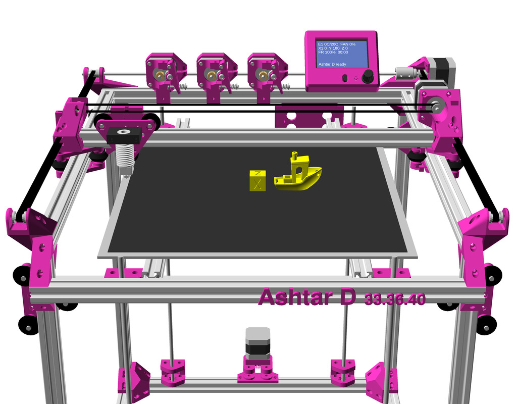
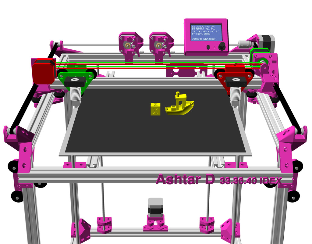
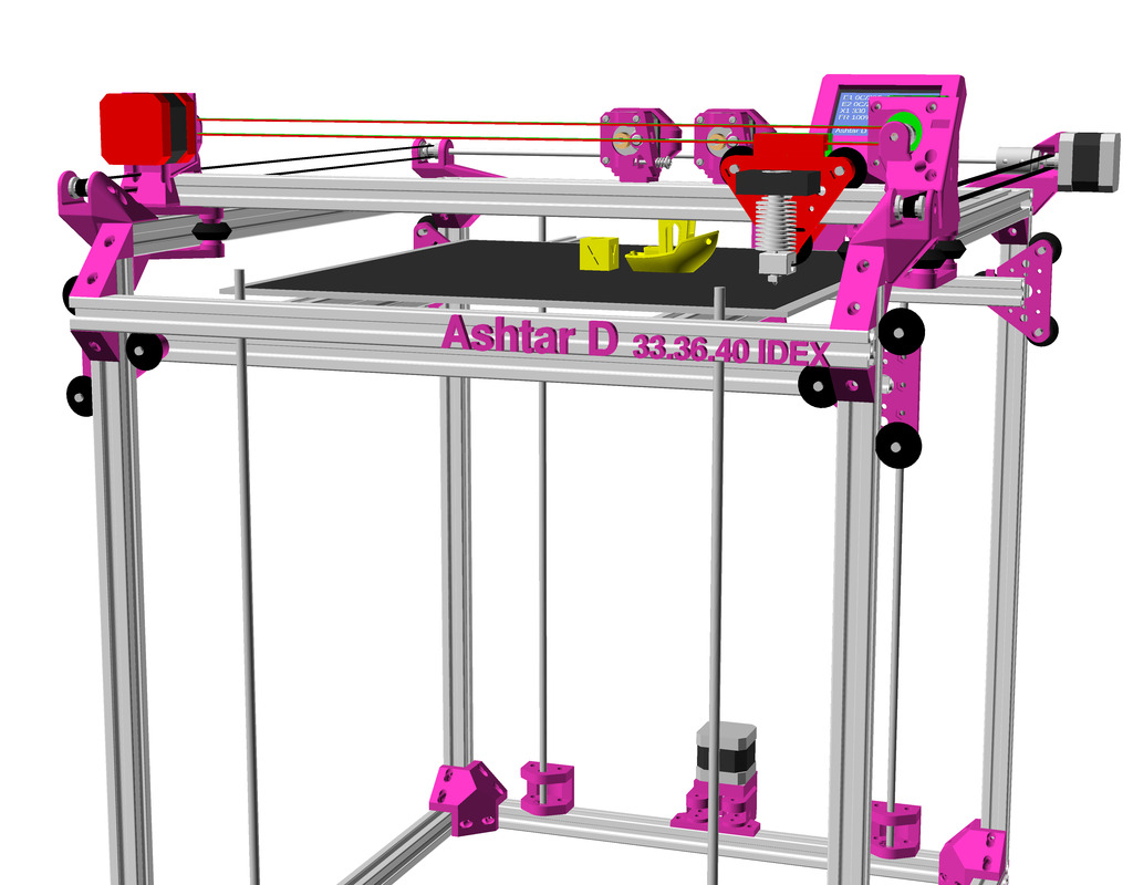
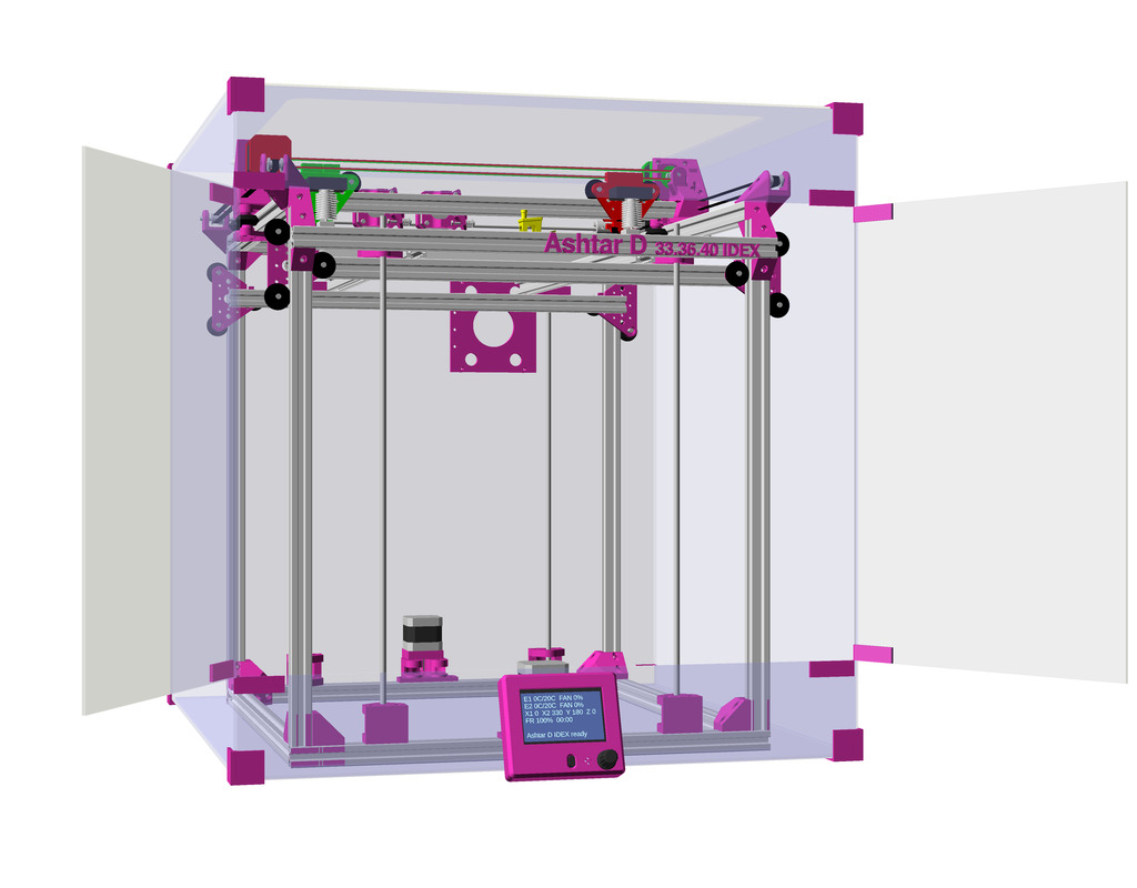
3D Printing: Ashtar D IDEX (Independent Dual Extrusion)

Status: just a draft

Updates:

  • 2021/01/14: starting the draft, very experimental

Introduction

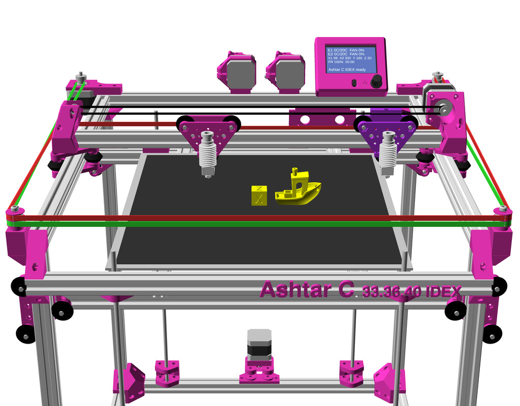
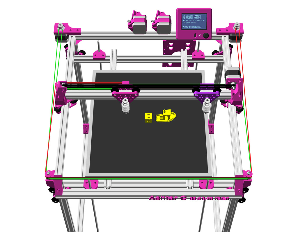
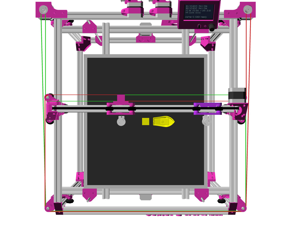
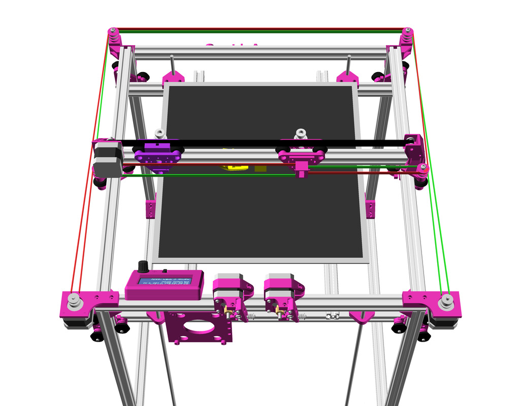
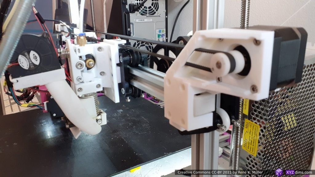
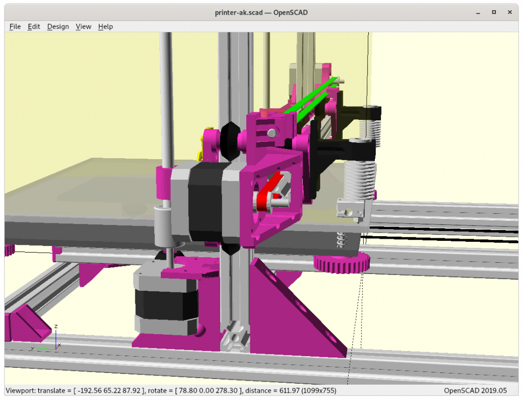
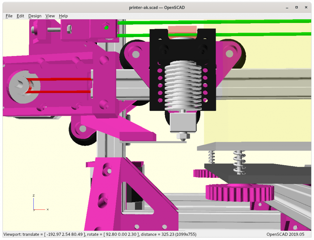
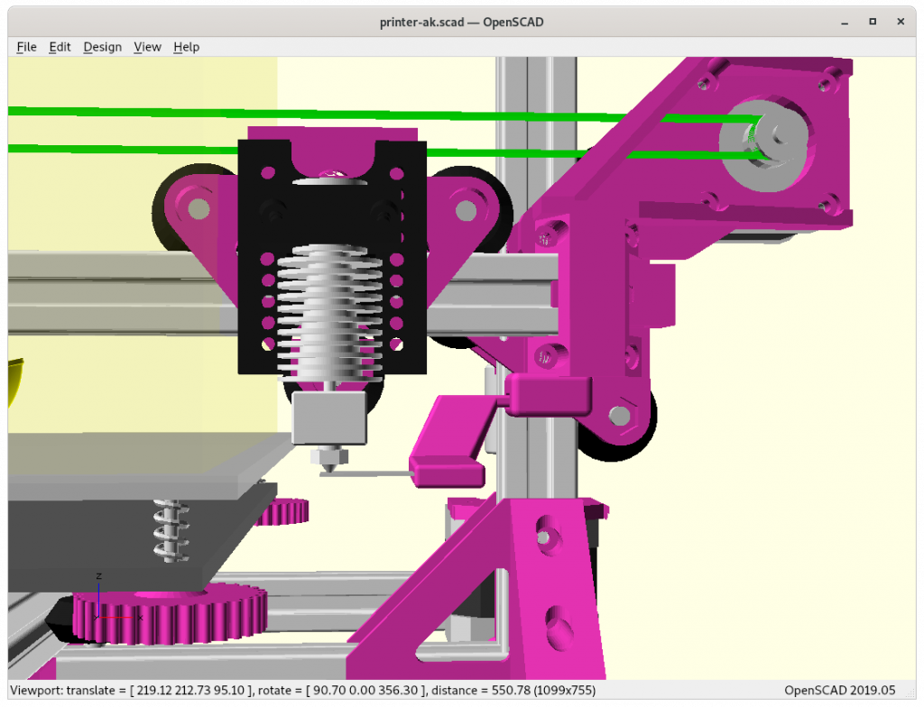
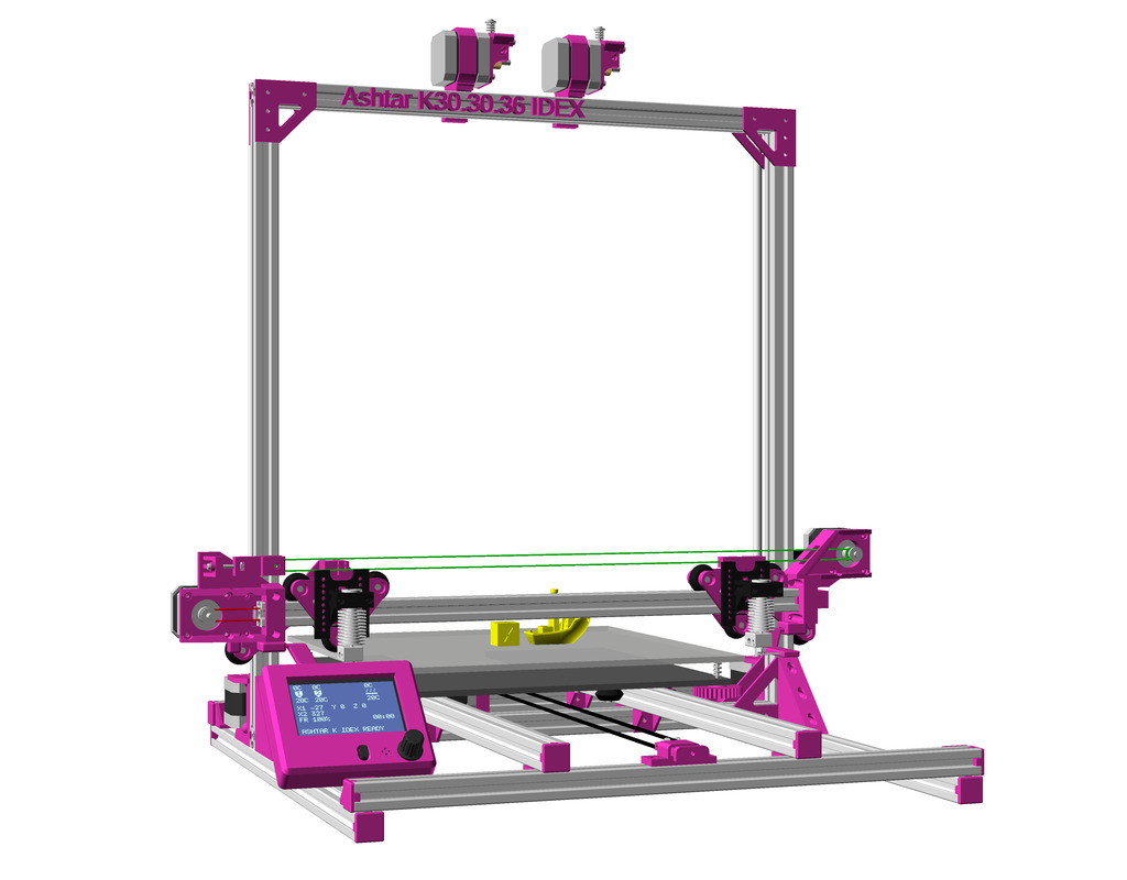
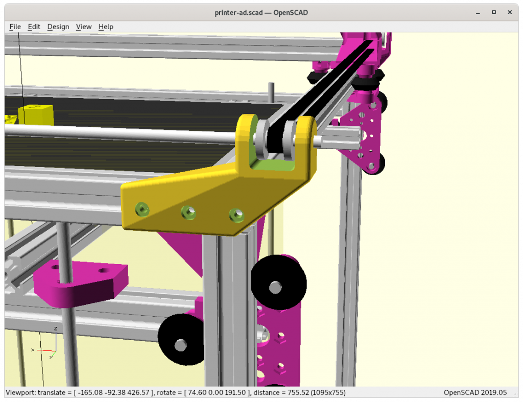
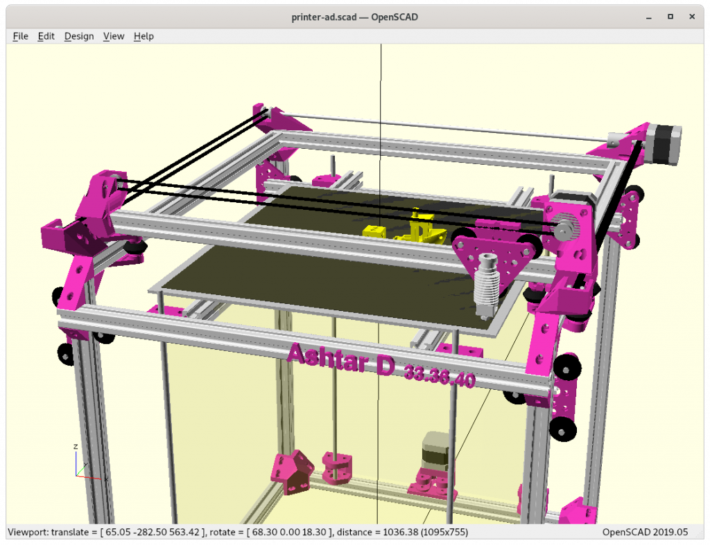
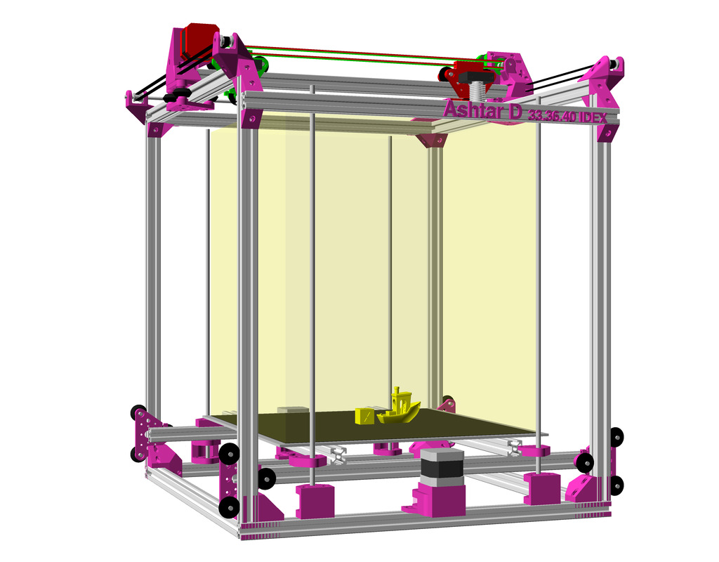
After just few hours working on IDEX option for Ashtar K and Ashtar M, I thought to try myself on doing IDEX on the very delicate Y carriage on Ashtar D – and after an hour roughly I realized, perhaps it is doable.

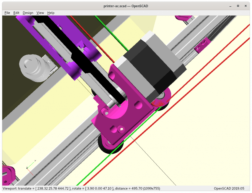
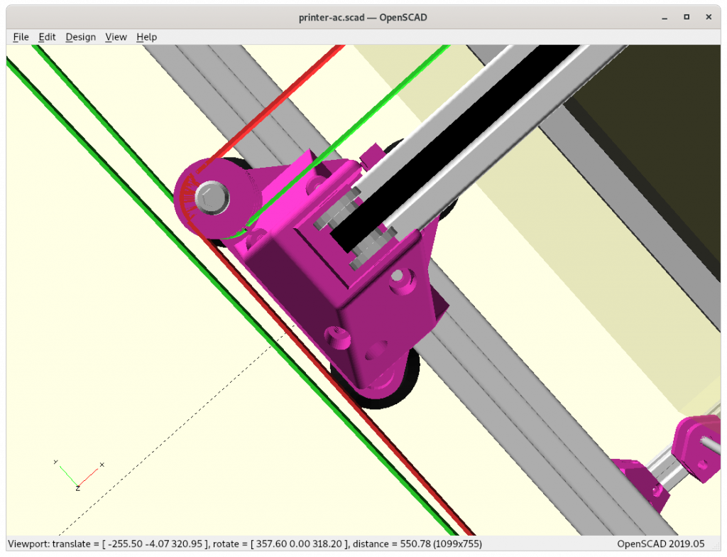
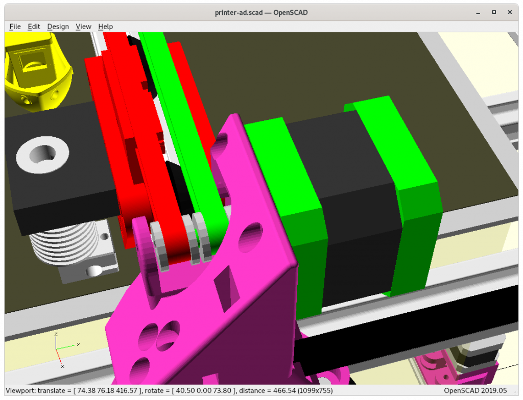
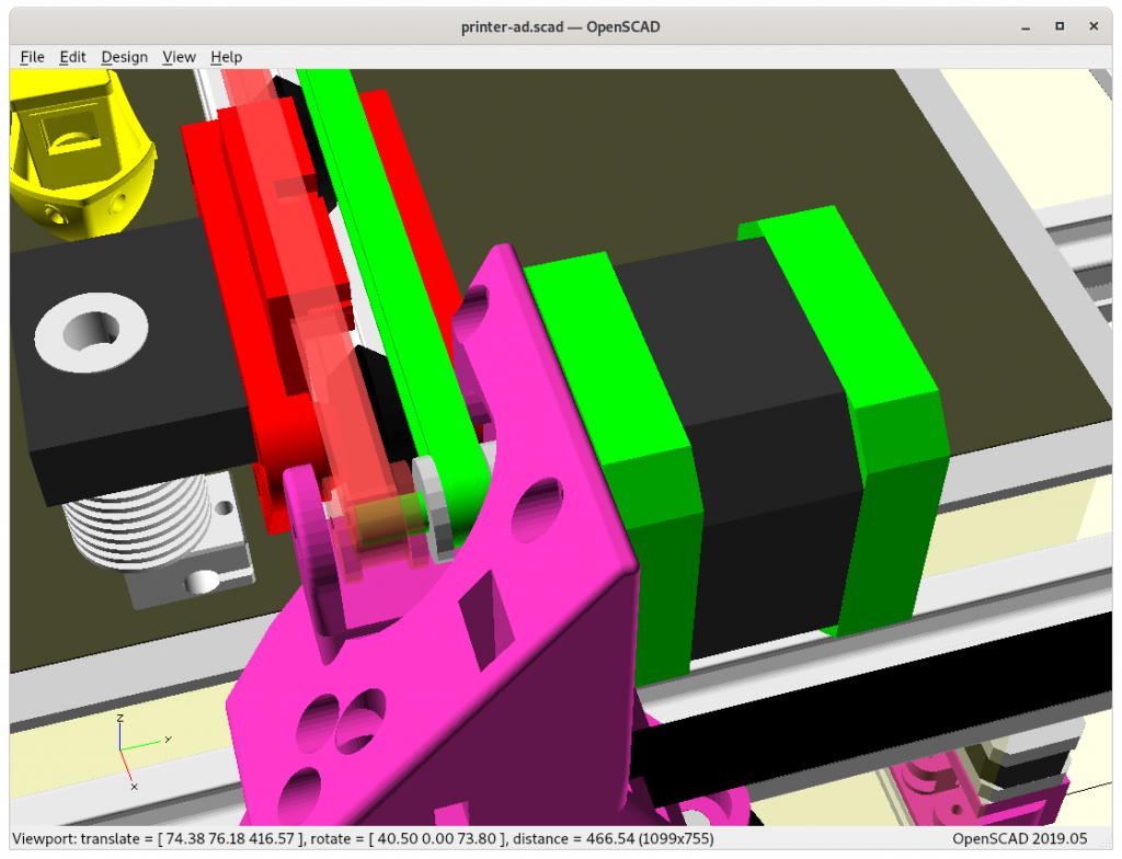
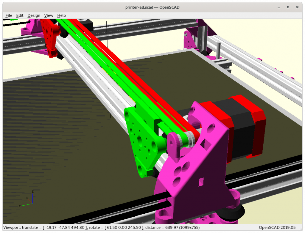
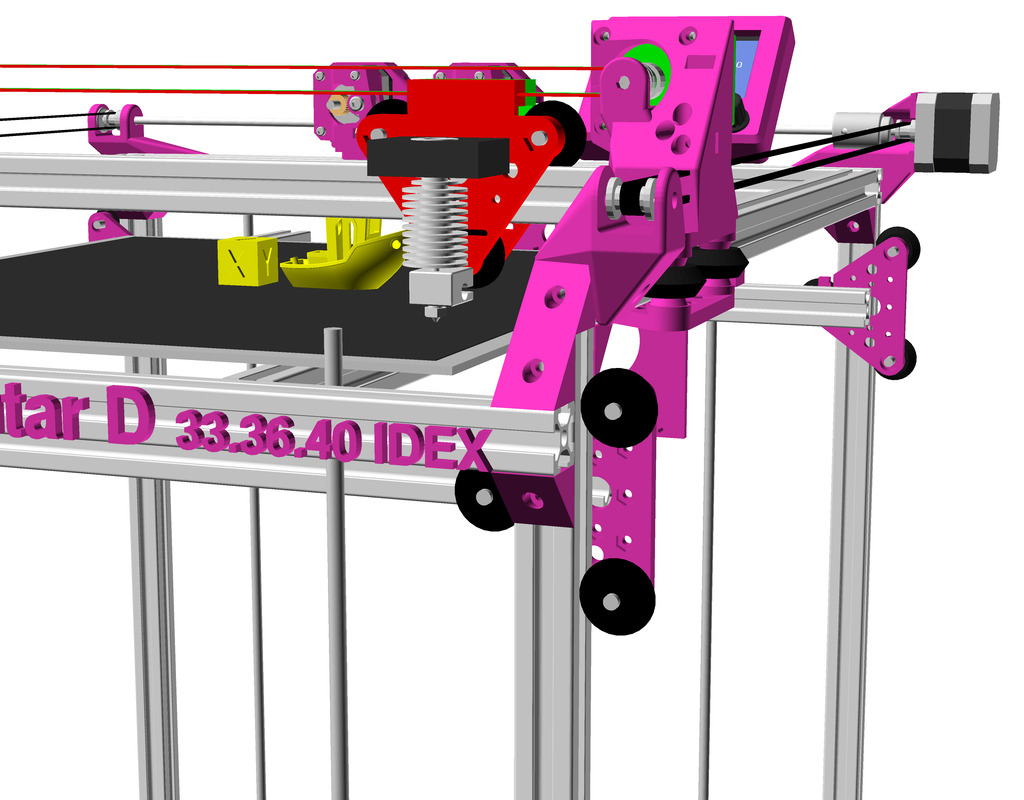
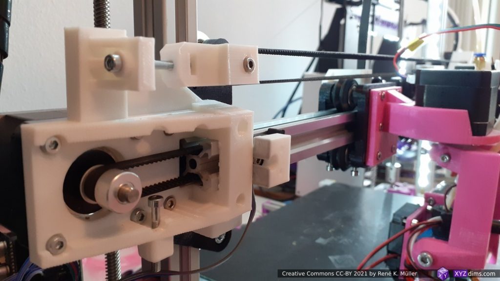
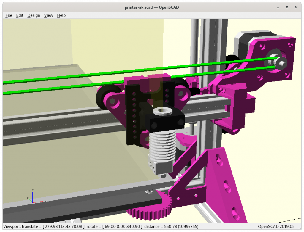
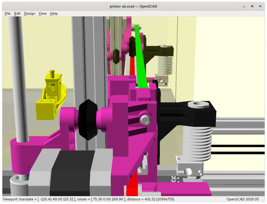
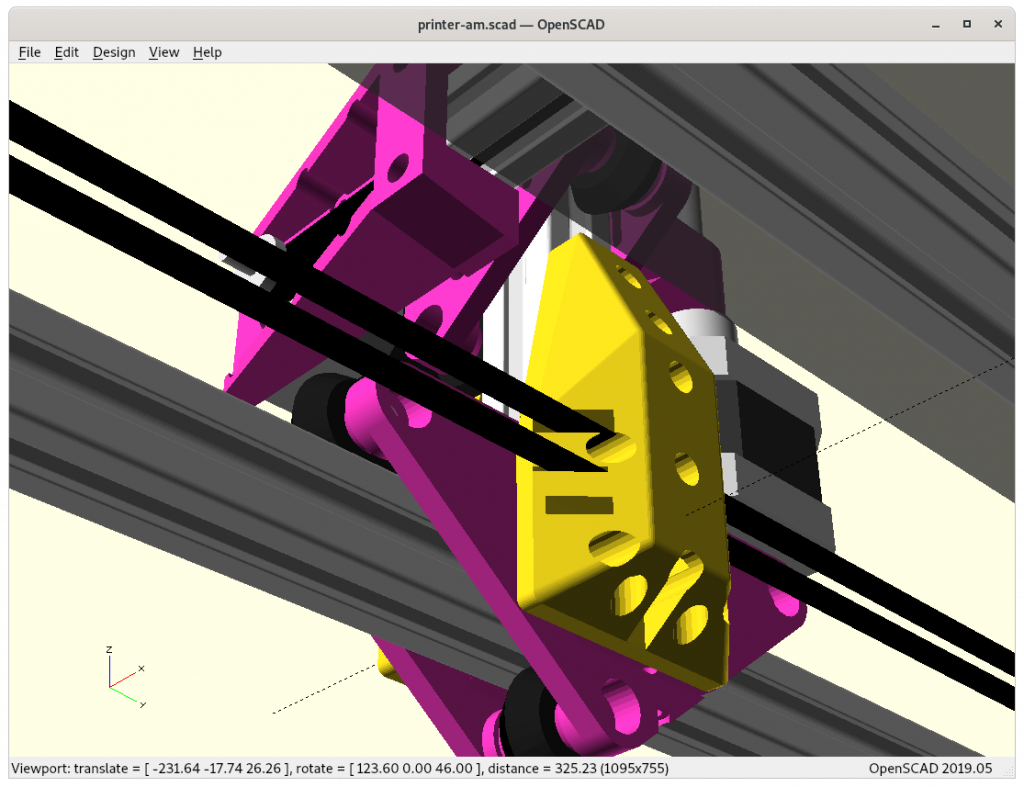
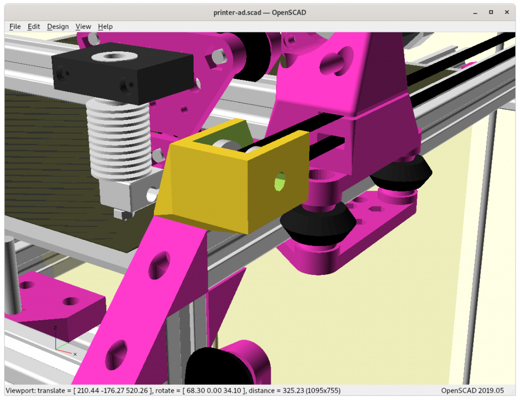
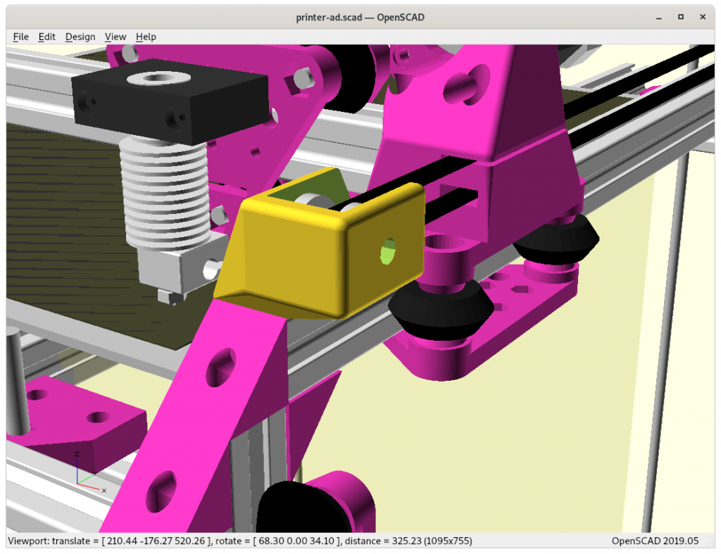
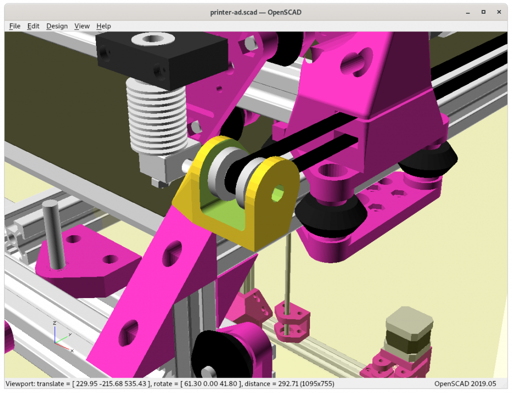
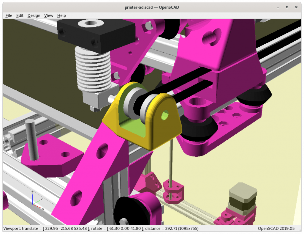
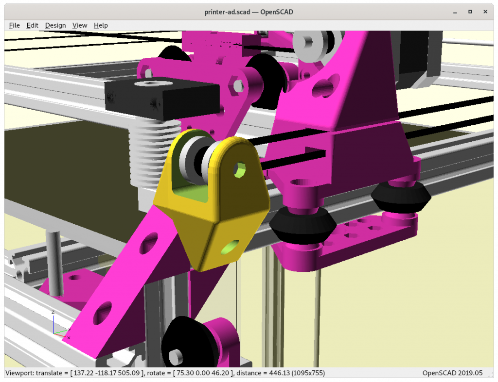
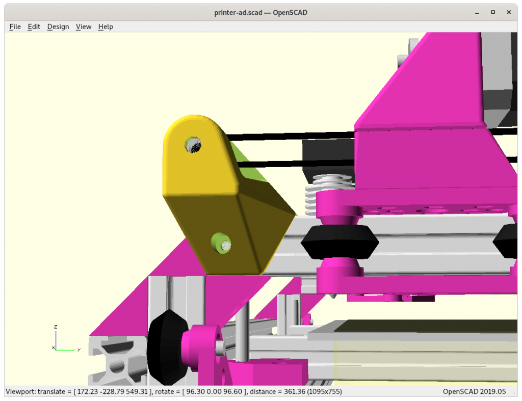
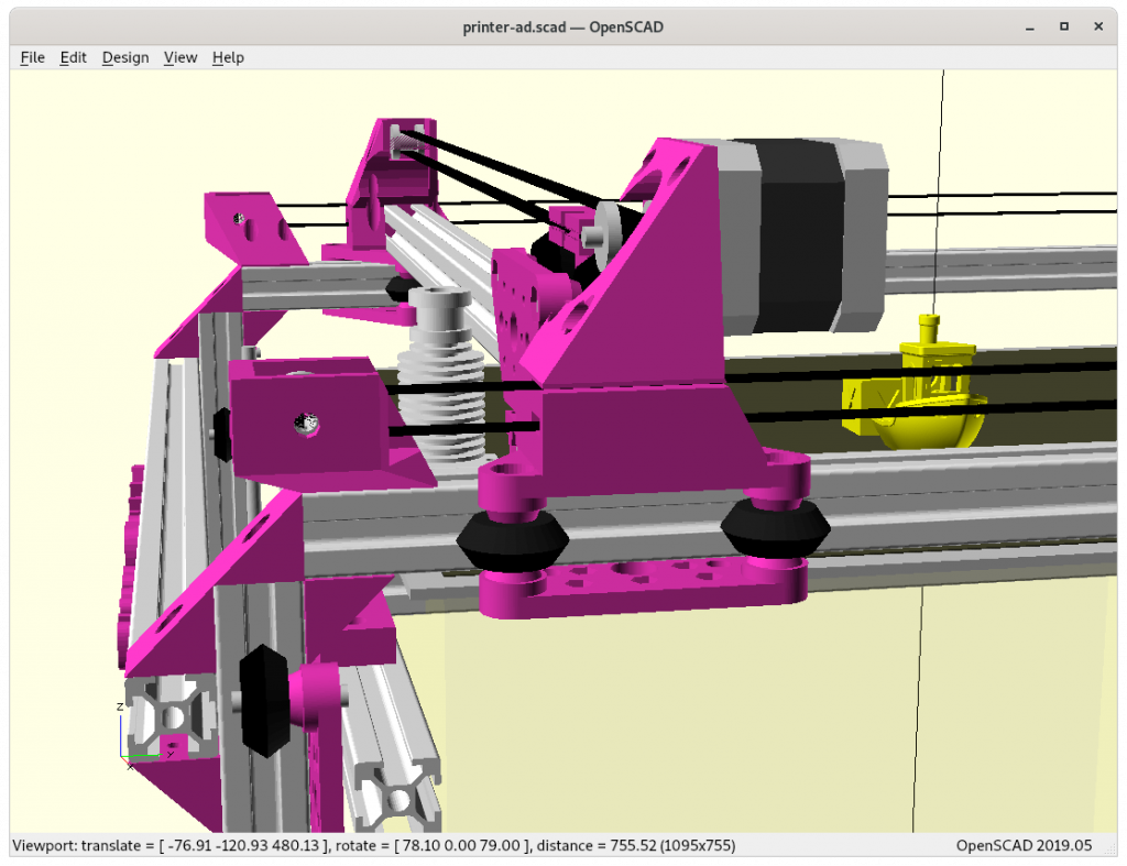
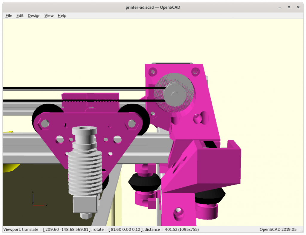
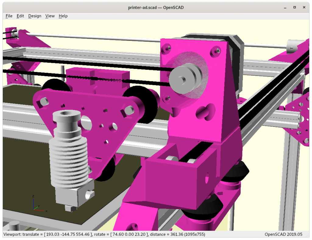
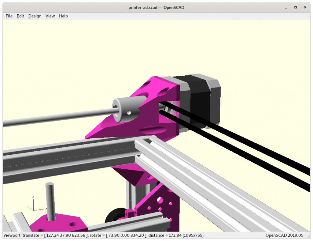
The main idea is to reuse the NEMA17 shaft as axis for the idler of the 2nd belt, and use 3mm diameter shaft with 5-10mm length as extension, and stabilize the extension in the idler itself likely the shaft seems long enough by itself – the most space saving option:

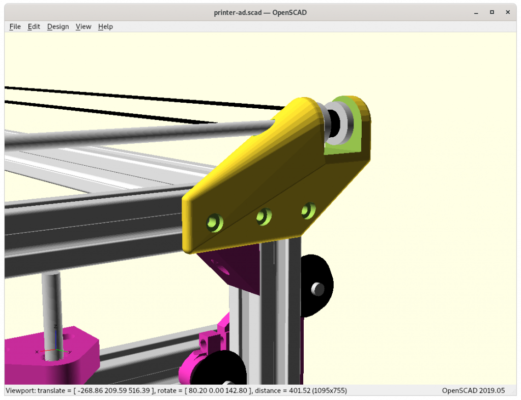
If possible, rotate entire X motor mount / carriage and mount it on the other X side.

Draft

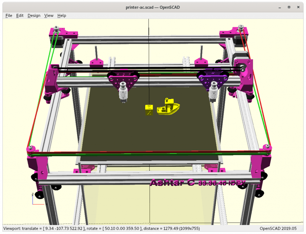
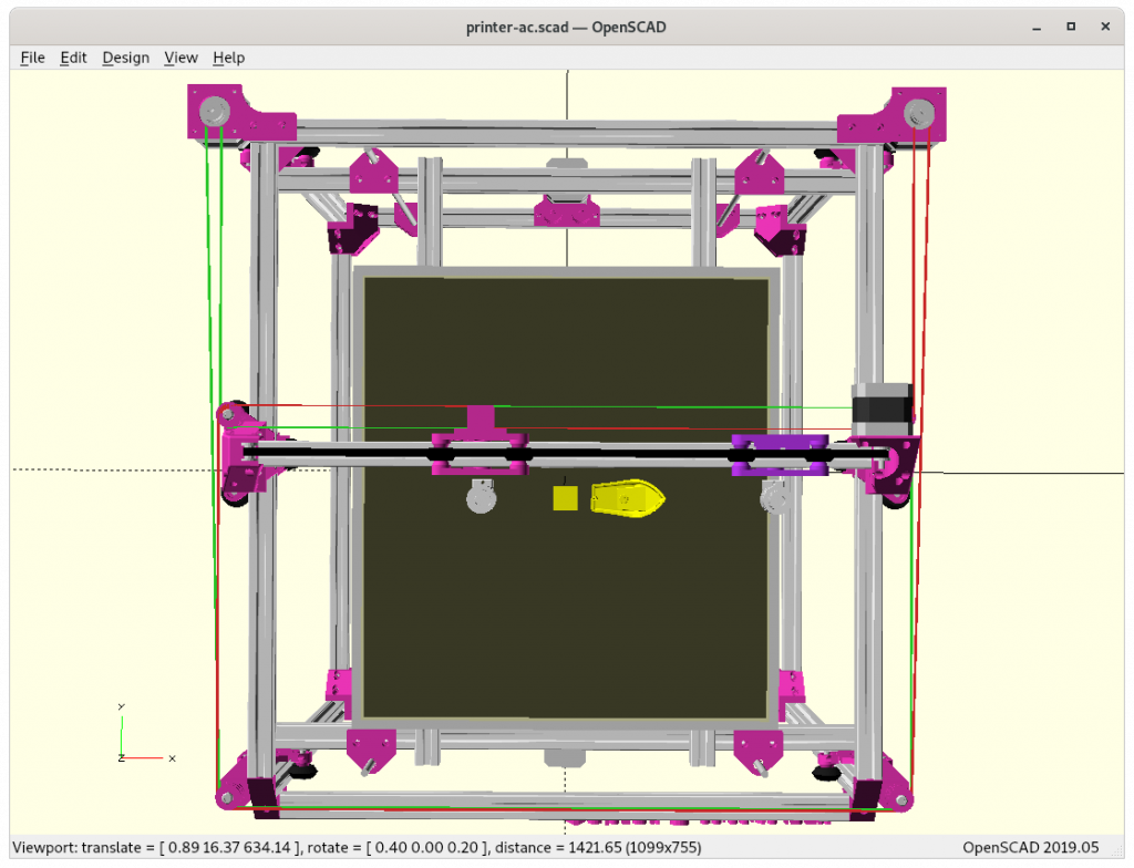
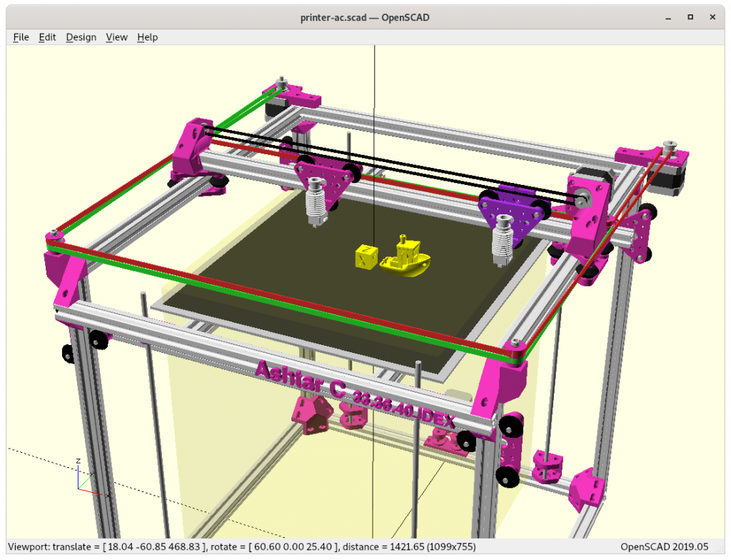
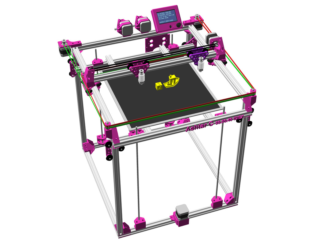
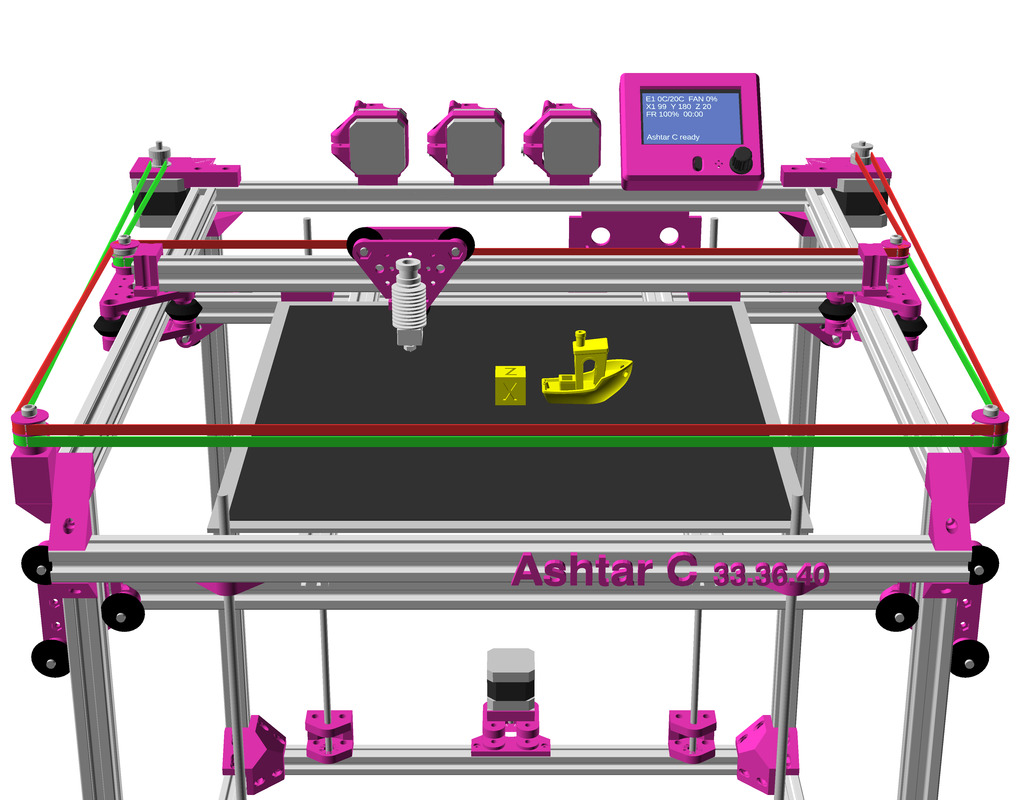
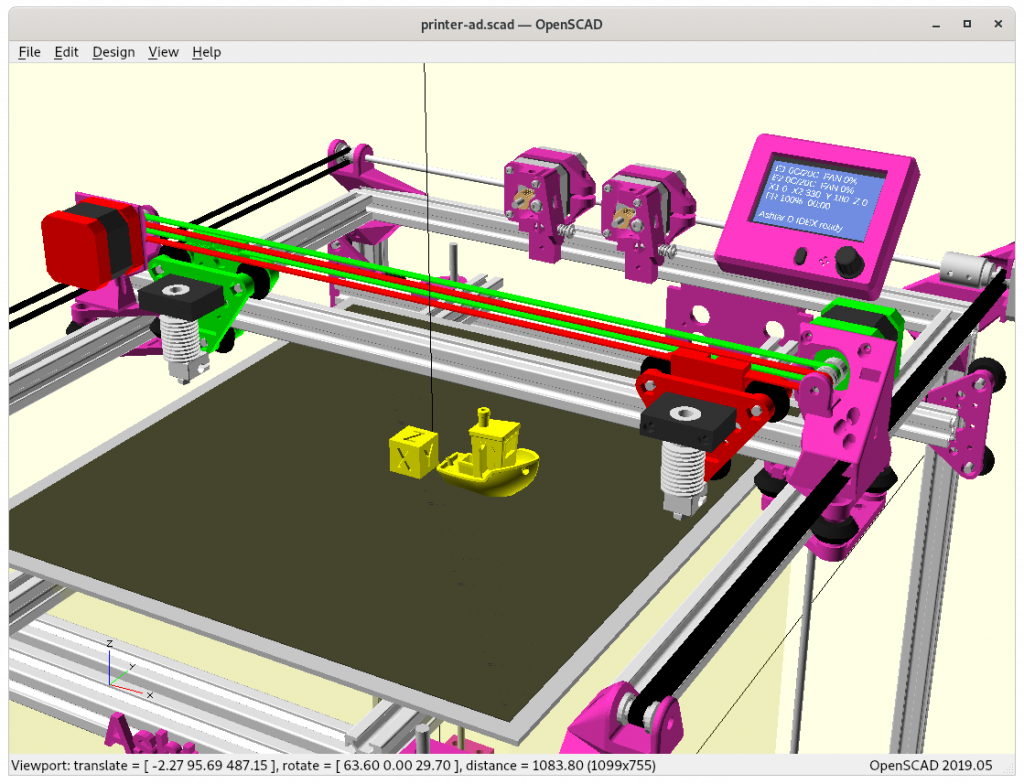
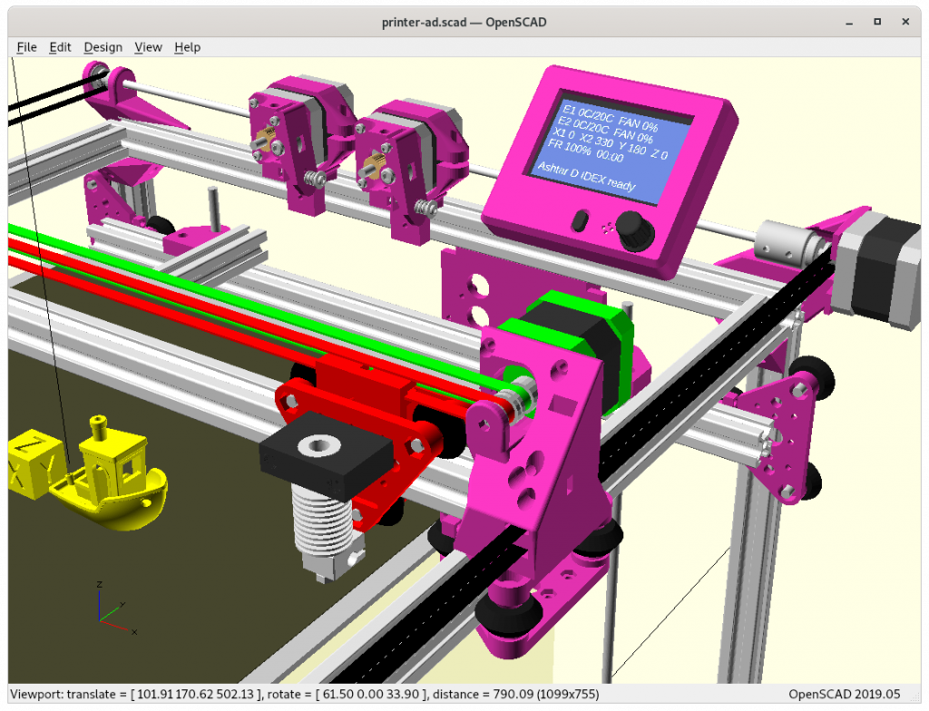
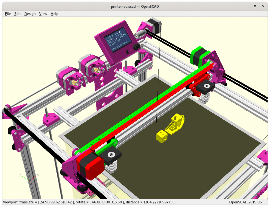
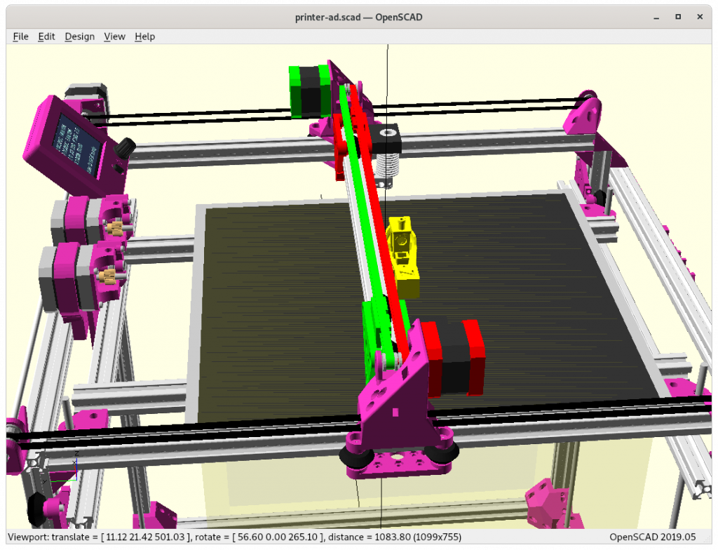
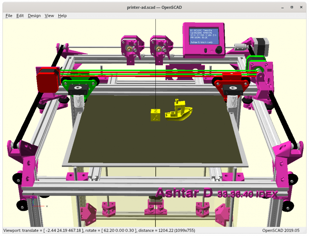
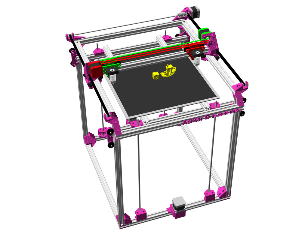
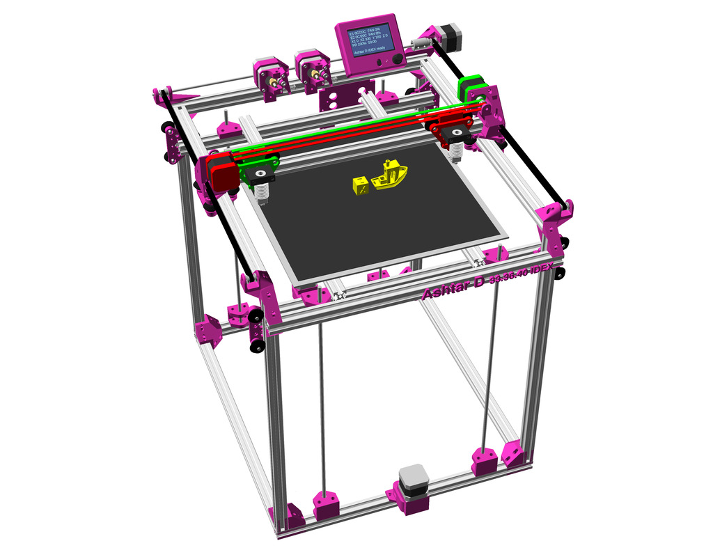
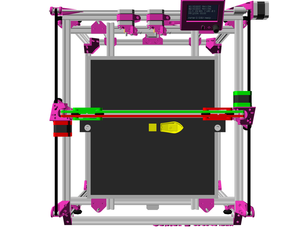
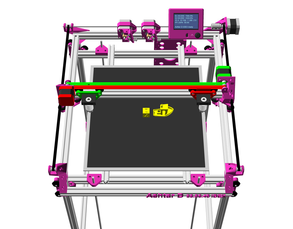
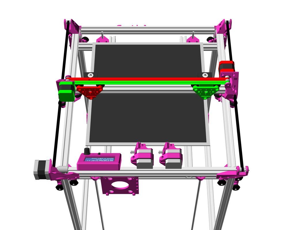
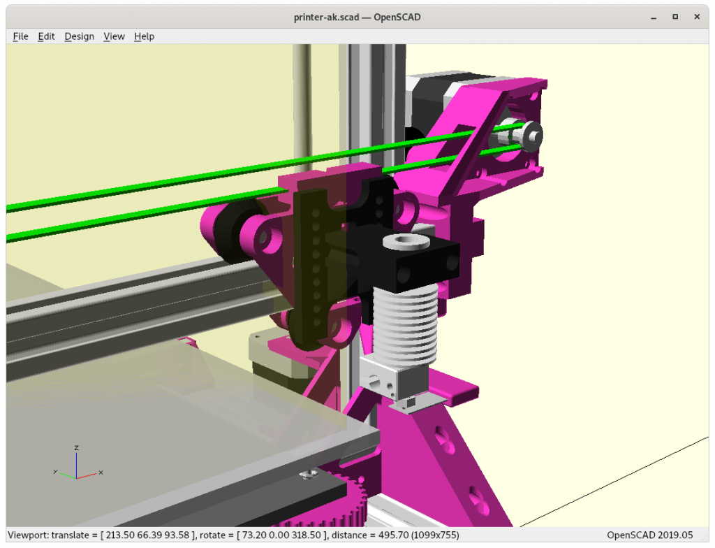
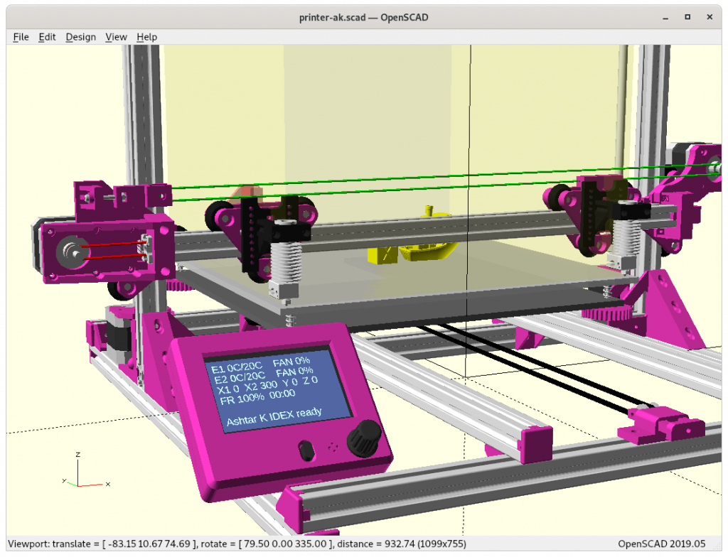
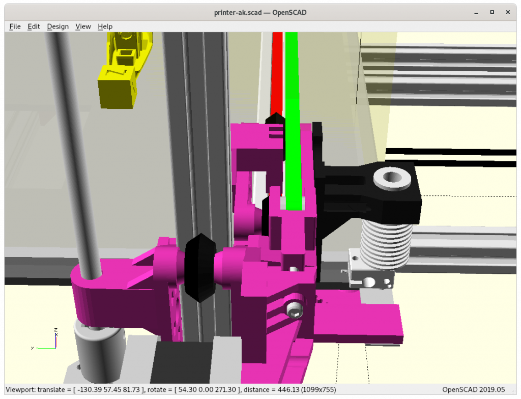
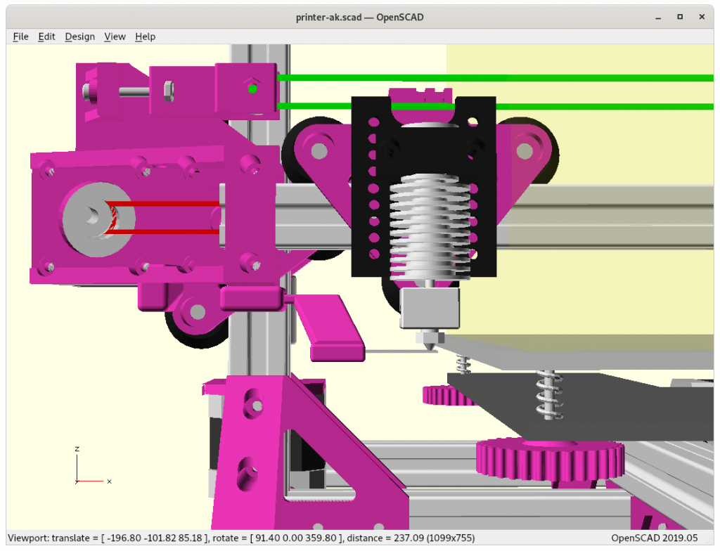
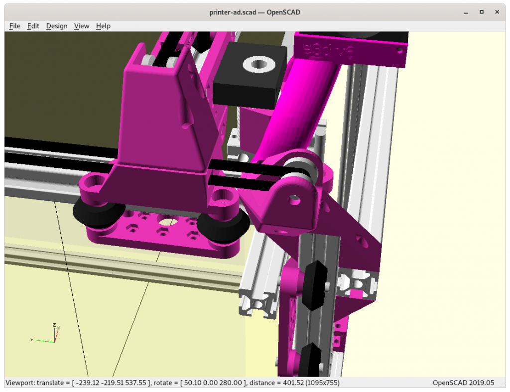
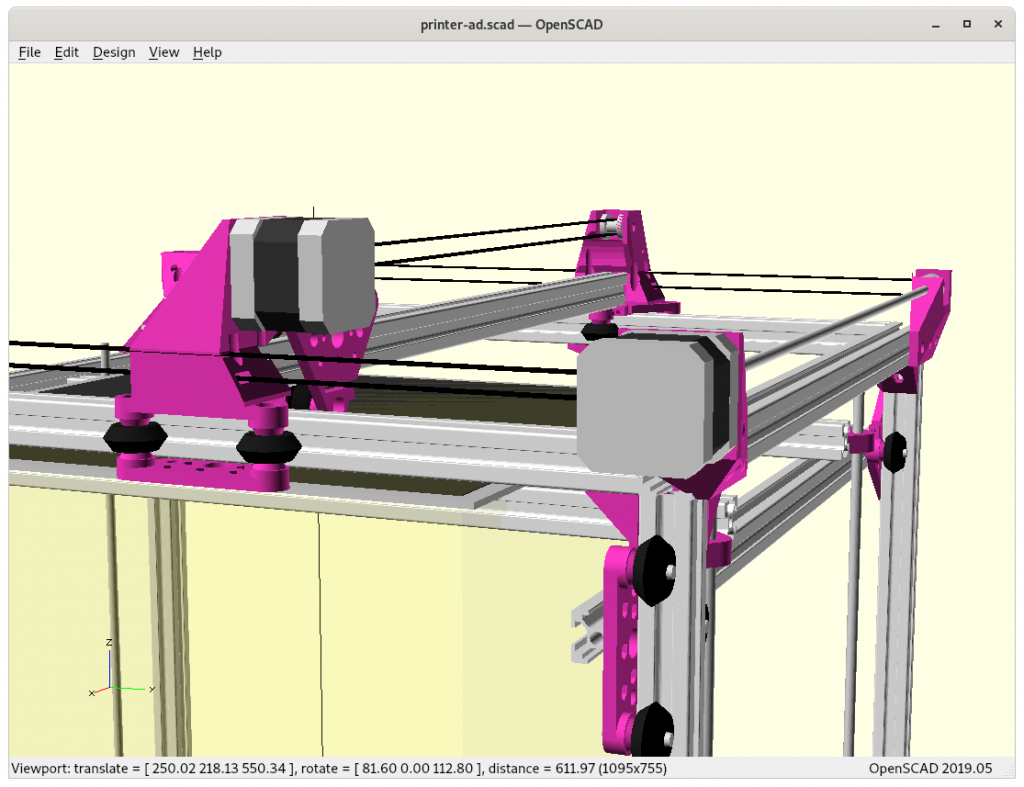
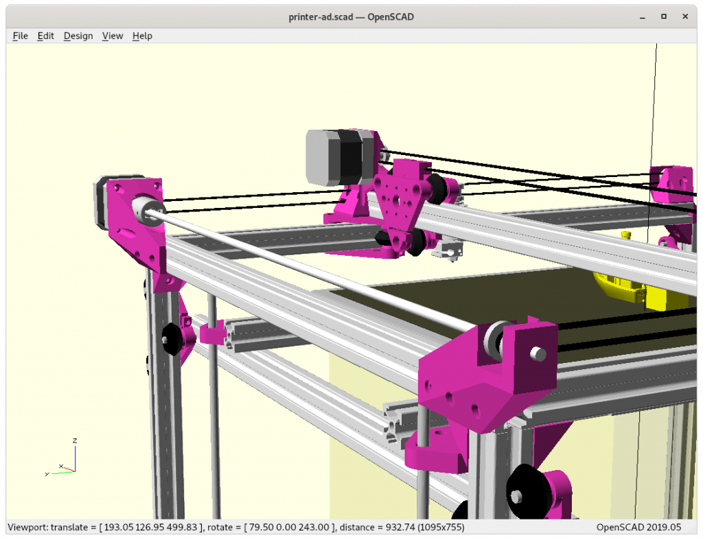
I had to color the belts and V modules, as I otherwise get confused while fine-tuning the design within such narrow margins:

  • X1/E1 in green
  • X2/E2 in red

I just love symmetry!

Gallery

Issues to Resolve

  • X motor-mount isn’t fully Y symmetric yet, it’s off by a few mm; needs some further fine-tuning until X2 motor-mount mounting holes align with V module, resolved
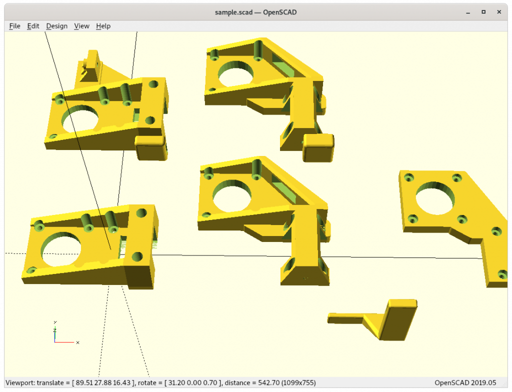
  • V module belt mount for X2 needs be adapted, as I can’t mirror it as that “back” mirrored is the “front” side where the printhead is mounted and occupied already, a new piece is required which mounts within the V module
    • dedicated piece ad_xcarriage_beltmount(idex=true) required
  • ooze prevention in rest position: some sort of metal sheet close by where the printhead’s nozzle can rest
  • mature Ashtar D design sufficiently beyond draft stage

As I progress I will update this blog-post, and update the Ashtar D project page as well.

That’s it.
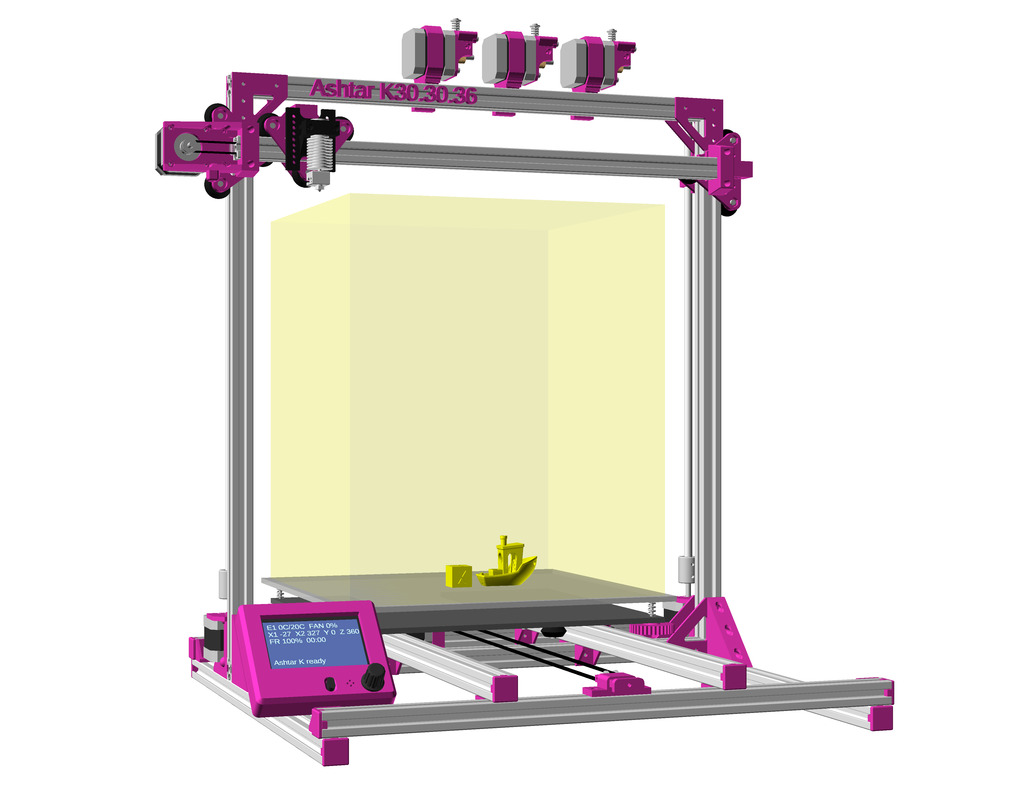
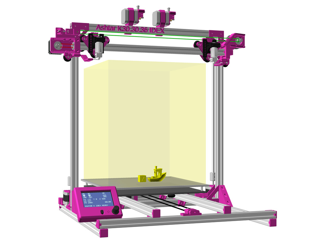
3D Printer: Ashtar K IDEX (Independent Dual Extrusion)


Status
: verified design

Updates:

  • 2021/07/30: design printed and mounted
  • 2021/01/19: improved 2nd X motor mount
  • 2021/01/15: removable/replaceable ooze prevention
  • 2021/01/14: Ashtar M (Moving Gantry – Draft) also with IDEX option now
  • 2021/01/13: ooze prevention at rest position added, mechanical conflict resolved
  • 2021/01/12: starting with a first draft, one mechanical conflict to be resolved

Introduction

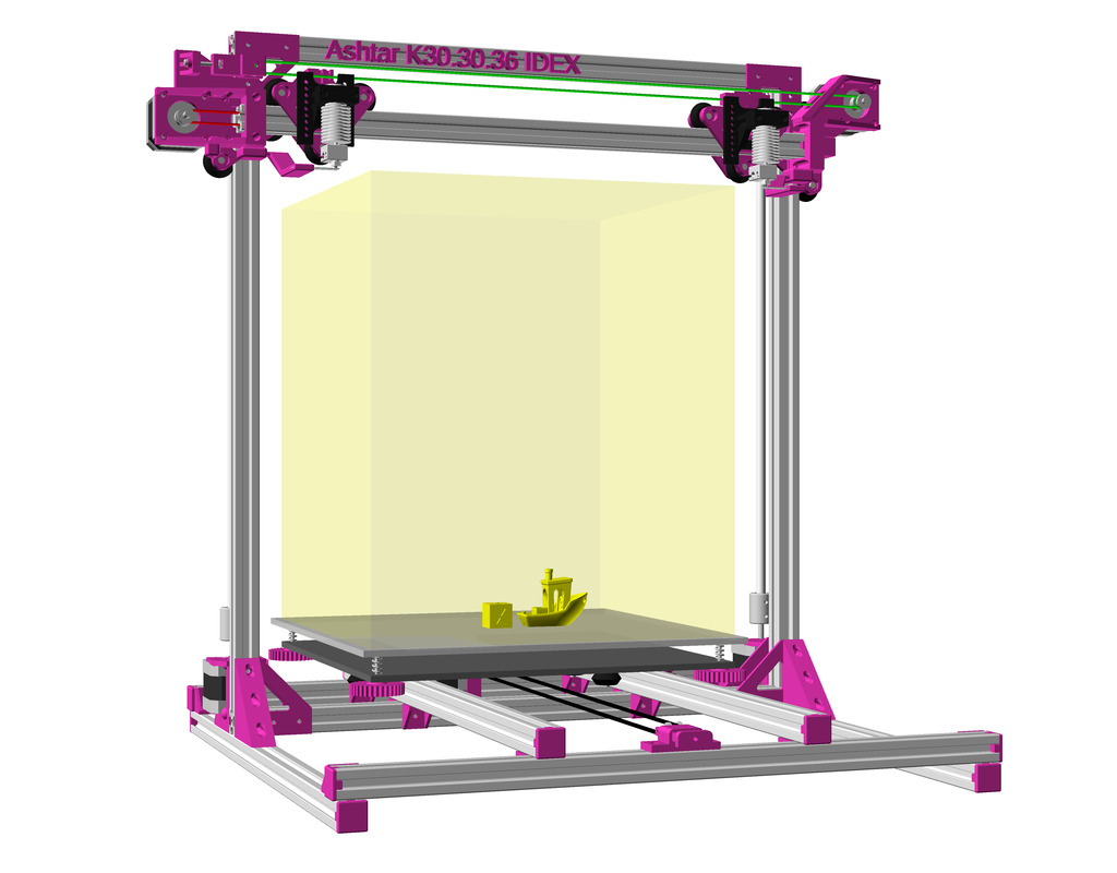
I have been pondering on a dual independent X axis upgrade or option for a while, but the other designs of the Ashtar Series I wanted to do first (Ashtar D and Ashtar M) those matured by now (2021/01), so I decided to get back to IDEX upgrade for Ashtar K:

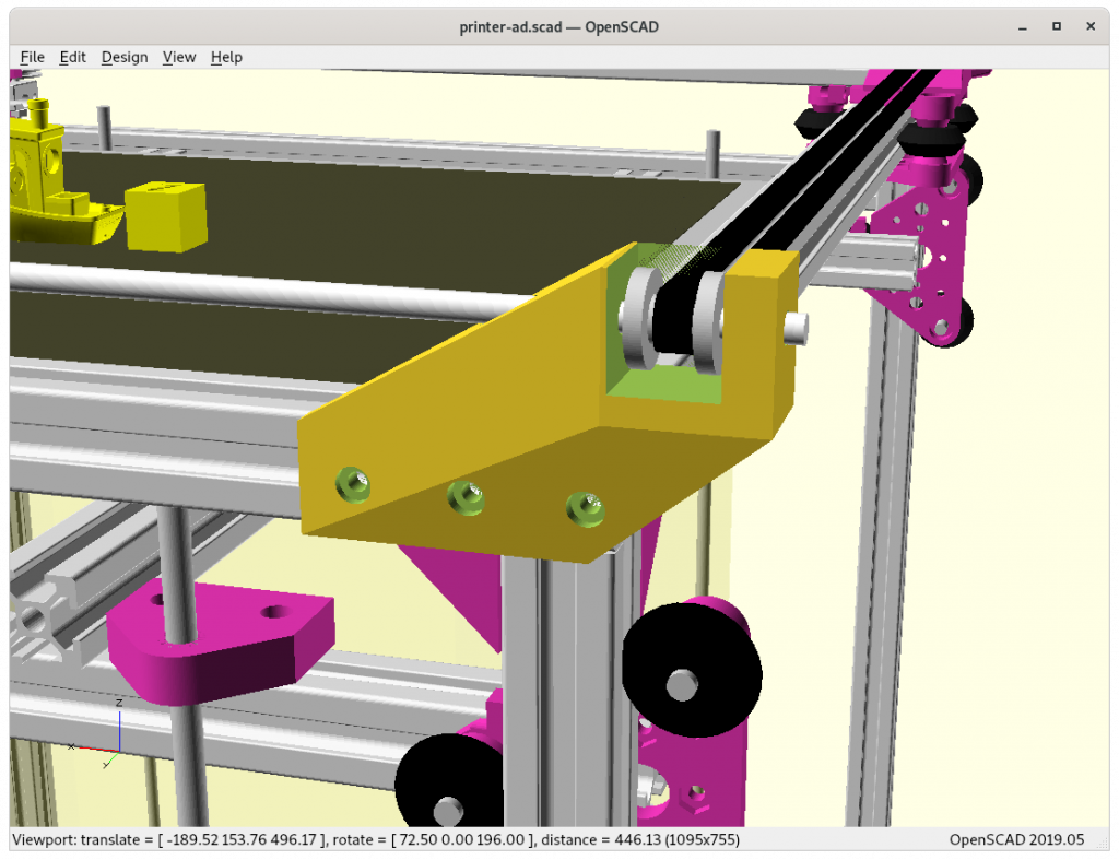
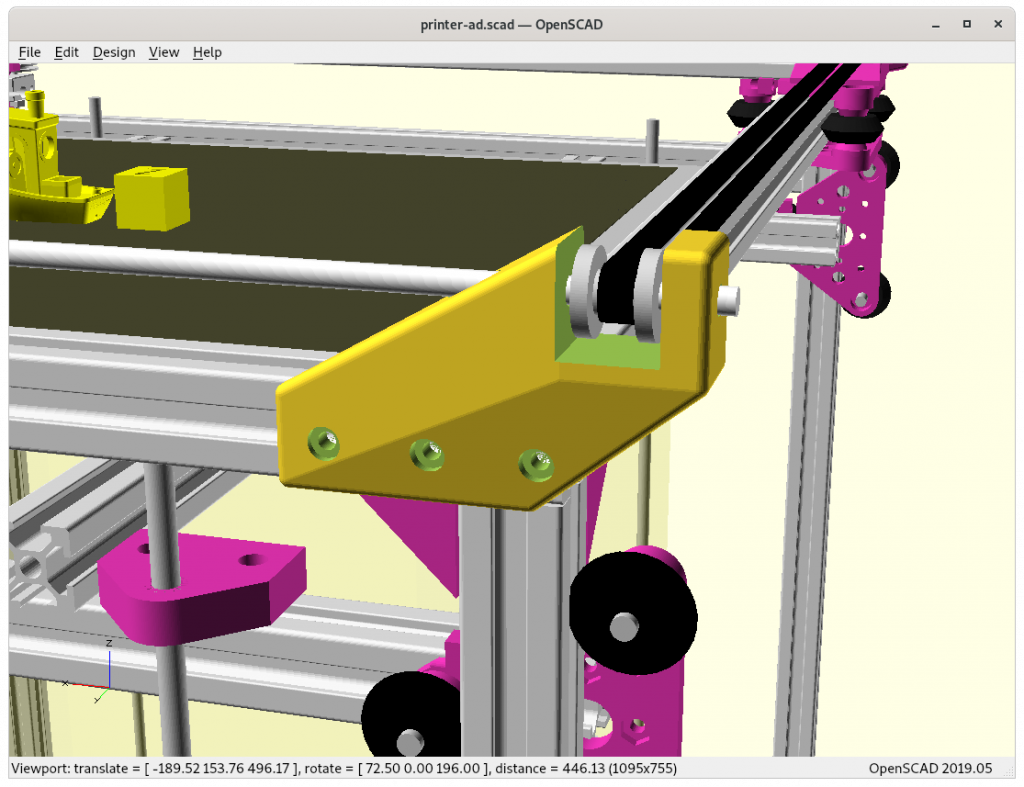
For now I like to keep single 2020 V slot alu extrusion for the X beam where the X carriage rides, and route the 2nd belt above for the 2nd X carriage – and this was a quick solution as earlier version of Ashtar K had the belt routed above the alu profile so I just reused the old pieces again.

“Above routed belt” option with its pieces are weaker and possibly need enforcement improved the strength, so it’s a fast start – just took me 2 hours – but needs definitely some fine-tuning. Alternatively the 2nd belt could be routed at the back of the X carriages, but fastening the 2nd X motor would be challenging.

For now I use the same code base of Ashtar K and introduce IDEX = true flag, and enhance a few existing pieces in parts.scad and optionally add those new pieces when rendering printer-ak.scad.

As I progress with this option or upgrade I update this blog-post.

Draft

Issues to Resolve

  • X carriage #1 belt mount conflicts mechanical with belt 2: redesign xcarriage_beltmount_2020 piece, make it shorted in Z or fasten it inside V module: resolved, shifted 2nd belt a bit Y off, and shorten xcarriage_beltmount_2020(idex=true) by 2mm.
  • “Above routed belt” pieces are weaker: enforcement required, resolved: piece strengthened (2021/01/19):
    • xcarriage_short_hmount_motor_2020 which is the base piece which routes the belt within the 2020, with idex=true option provides idler holder on top
    • X motor #2 is mounted on a x-mirrored version of xcarriage_hmount_motor(20,"left",idex=true) but definitely needs reinforcement, added ooze prevention in case of idex set
  • Nozzle drip prevention:
    • using a piece of sheet metal which the nozzle moves over when in rest position left or right, first attempt done (see below)
    • and/or use purge box with brush to clean nozzle after and before use
    • make extending “nose” detachable/replaceable as it’s expected to break or overheat otherwise entire X motors mount needs replacement, resolved
      • xcarriage_nose-idex-left and xcarriage_nose-idex-right with 10mm wide sheet metal insert
    • how dealing with long resting hot nozzle?
      • drop temperature by 5-10°C in rest position, and heat up when in use again
      • heat creep possible weakening extending printed nose – heat insulation required attaching sheet metal

Gallery

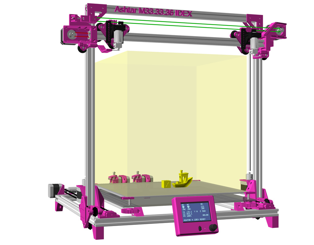
Ashtar M IDEX

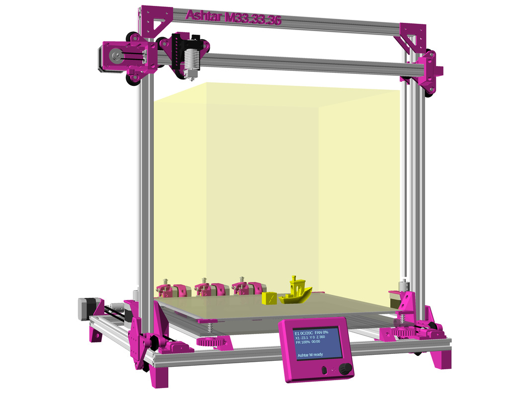
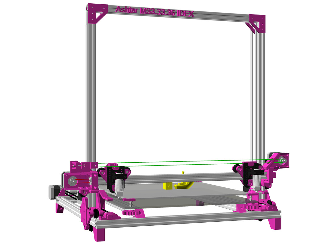
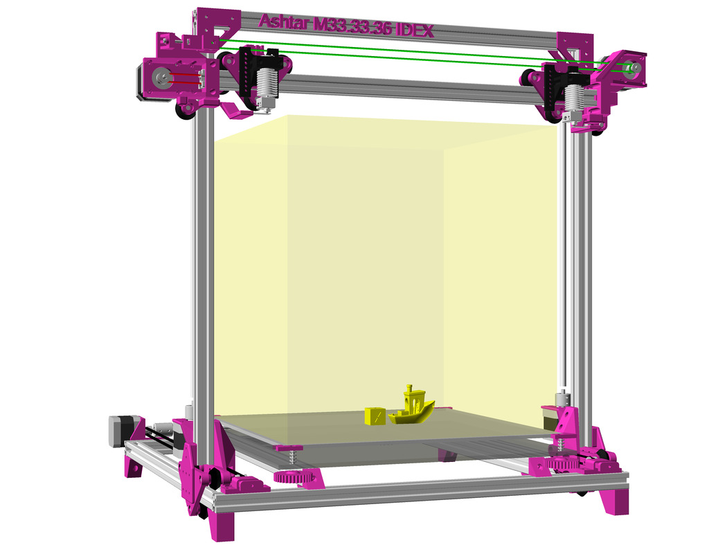
And since Ashtar M (Prusa i3 Moving Gantry – Draft) shares much of the Ashtar K design it took me a few mins to add the IDEX upgrade option as well:

References

3D Modeling: Random Snapshots 2020

3D Printer: Ashtar K History 2018-2020

A brief history of “Ashtar K“, my first designed 3D printer I actually built – documented also for my own sake:

AluX: Prusa i3 Clone

It started with AluX (abbreviation of ALU-extrusion eXtendable) early June 2018, which used CTC i3 Pro B / Prusa i3 Clone pieces as the X carriage, X motor mount and X idler all in STL format. I coded the frame parametric using 2040 alu extrusions/profiles and using smooth rods as rails:

I realized then quickly I need to design and code my own pieces, every single piece I need to control and make it parametric if it makes sense, and not rely on existing STL files, as editing meshes of the STL seemed a waste of time but rather design the piece in OpenSCAD right away and derive new variants if necessary from the geometry itself.

Ashtar X & W Series: Riding on Smooth Rods

Mid June 2018, AluX became Ashtar X (abbreviated as AX), and Ashtar W were using 2040 alu extrusions but differently oriented at the base, still using smooth rods as rails:

At this point I got sufficient experience of the parametric approach and it was obvious to use the frame as rails.

Ashtar T Series: Riding Alu Profiles

Beginning of July 2018, with the Ashtar T series I began to use the frame as rails itself, utilizing 2040 alu extrusions, it also started with the parametric V module (due its shape) composed by 2x V-plates, using 3 wheels which ride on the alu extrusion:

With the parametric V modules the X, Y and Z frame beams became rails as well, simplifying the overall construction compared to earlier designs:

The dual Z motors still residing in the front for sake of accessibility, but then I realized I want them in the back and keep the front dedicated to the printhead.

Ashtar K Series: Riding Alu Profiles, Uni-Length Beams

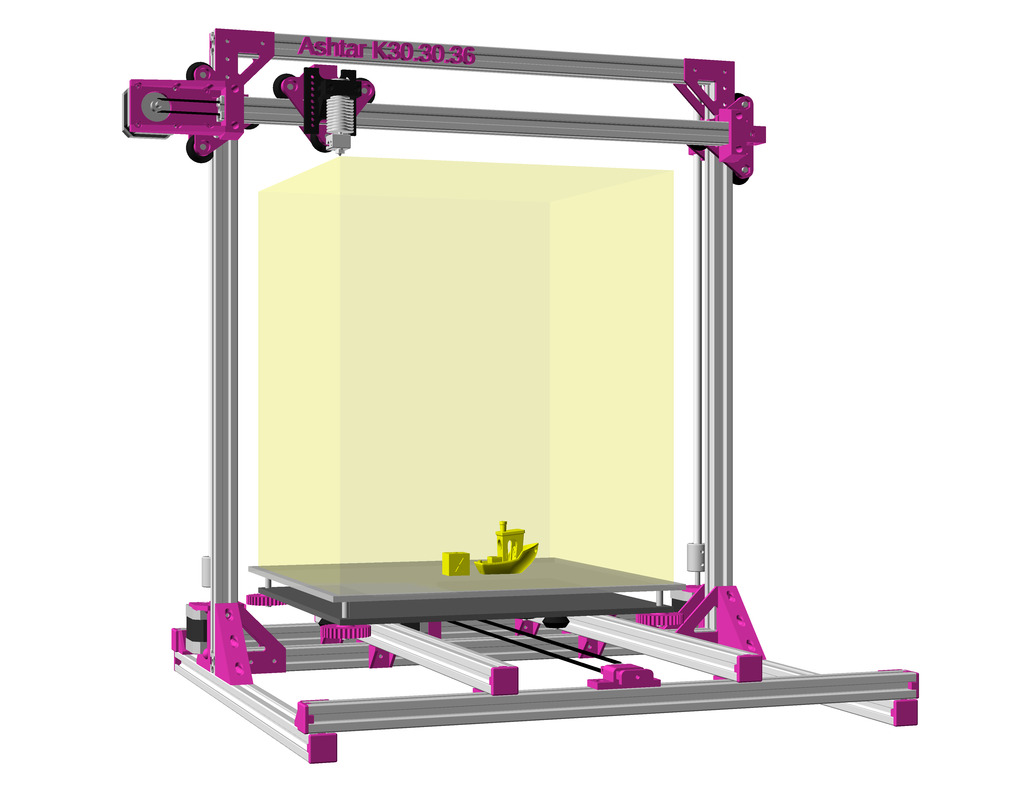
Mid of July 2018 I started the Ashtar K series, I decided to use 2020 alu profiles and focused on the single length of alu profiles, uni-length so I could reuse the beams for other future designs and since all the designs were parametric, it was easy to attain to find an optimum of single length beams and a common build-plate or build-volume:

The 9 beams design turned out too weak when I actually built the printer, so I added two beams back on left and right, and lift up the 9 beam design.

Eventually I decided to use 500mm alu 2020 profiles to achieve ~380x300x360 build volume; Ashtar K #1 used 400×300 build-plate, and Ashtar K #2 300×300 build-plate. Ashtar K #1 was functional in August 2018, and since then became my working horses together with Ashtar K #2, reliably printing.

See more at Ashtar K project page of the current state.

Next Steps

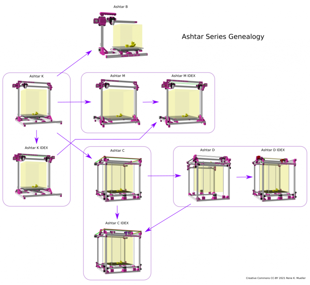
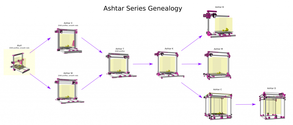
Ashtar Series Genealogy (2018-2020)

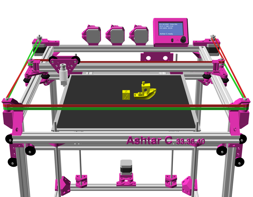
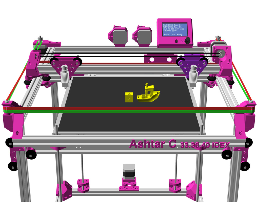
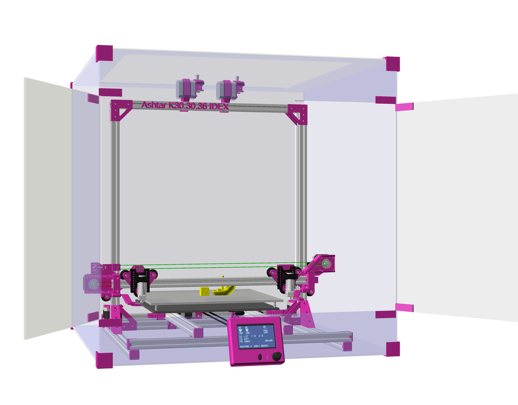
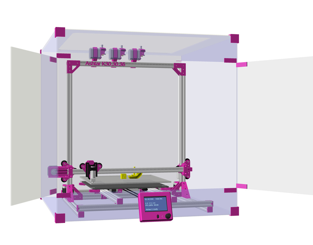
After the Ashtar K I did the Ashtar C Core XY cubic frame also with 2020 alu profiles. Late 2020 I started to design Ashtar M, a derivative of Ashtar K but with a moving gantry and static bed, and Ashtar D with Classic XY alike Ashtar C; and also a draft of a parametric enclosure as well to be adaptable to all of my 3D printer designs.

That’s it.
3D Printing: Simple Compact Extruder with 625ZZ Bearing

Updates:

  • 2021/01/01: sufficiently tested, finally published
  • 2018/12/20: starting with write-up

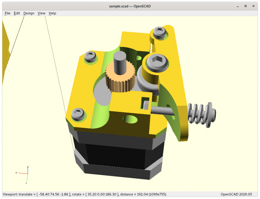
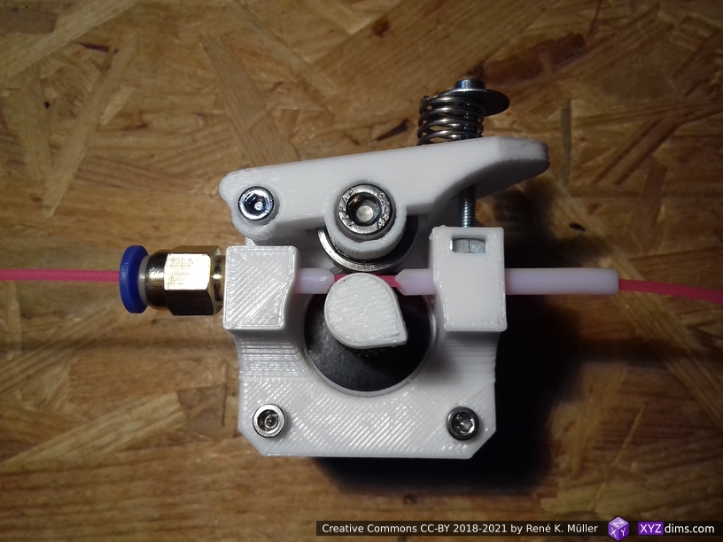
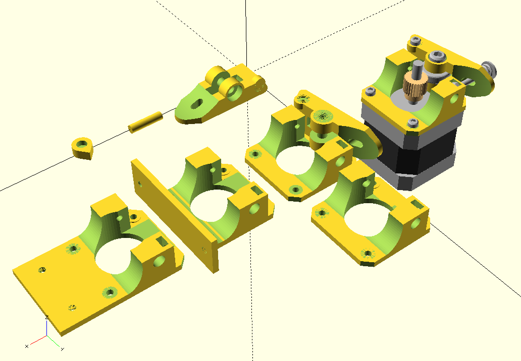
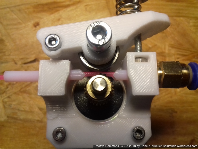
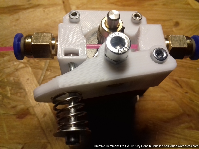
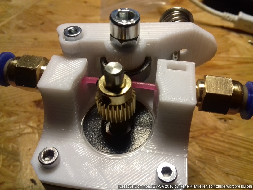
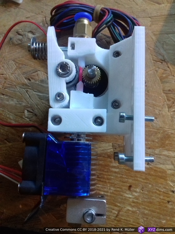
I used some aluminium MK8-based extruders but realized I required my own parametric extruder using 625ZZ bearing and I looked around and found Compact Bowden Extruder by Dominik Scholz which uses 608ZZ and adapted the overall design but coded it from scratch again in OpenSCAD with 625ZZ bearing for the Ashtar Series:

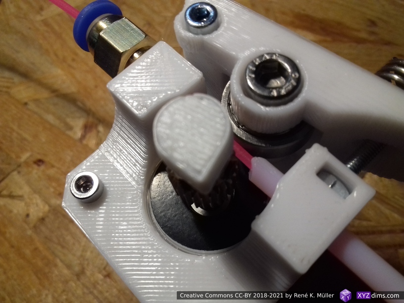
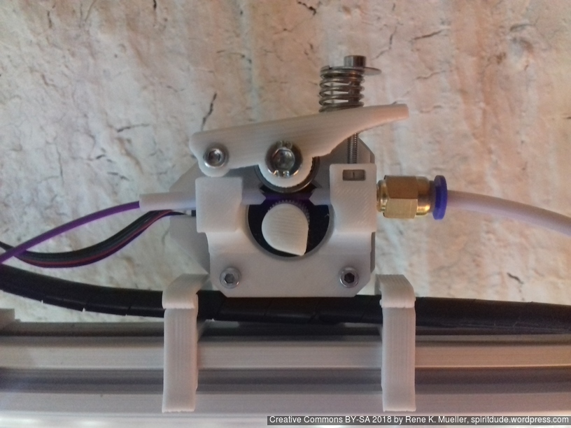
It’s “right handed” by default, but filament can go both directions. The handle is pushed from inside out with a spring, not so elegant, yet it saves space and filament does not have to go through the handle this way, which I prefer.

Bill of Materials (BOM)

  • M5x14 or M5x16: mounting bearing
  • 2x M3x8: mounting base to stepper motor
  • 2x M3x25: mounting handle and spring
  • M3 nut: insert into slot
  • M3 washer (or print it): hold spring
  • 20-25mm long soft spring (ID 3.2-8mm) or alike
  • hubbed gear OD 11mm (MK8)
  • 625ZZ bearing

Recommended further:

  • PTFE OD 4mm, ID 2mm
  • PC4-M6 straight fitting

Building

Software

compact_extruder() takes following parameters, in case you like to recreate the pieces:

  • type:
    • "base": the base attached to the NEMA 17 stepper motor
    • "handle": the push handle with the spring
    • "indicator": small indicator to put on the axis of the stepper motor
  • mount:
    • "none": (default) just attaches to NEMA 17 stepper motor
    • "mount": simple mount (center)
    • "2020": extends flat (lower left version)
  • btd: Bowden tube diameter (default: 0), if 4mm is used, then Bowden PTFE OD 4mm/ID 2mm tube can be inserted on both sides as guides for flexible filament close to the hobbed gear as shown below
  • m5 can be redefined, e.g. 14 then it sinks in

Hardware

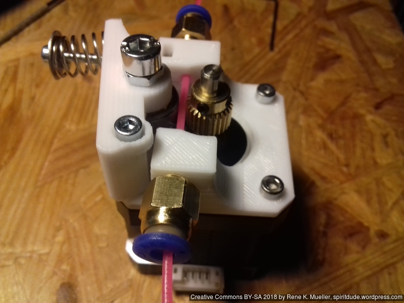
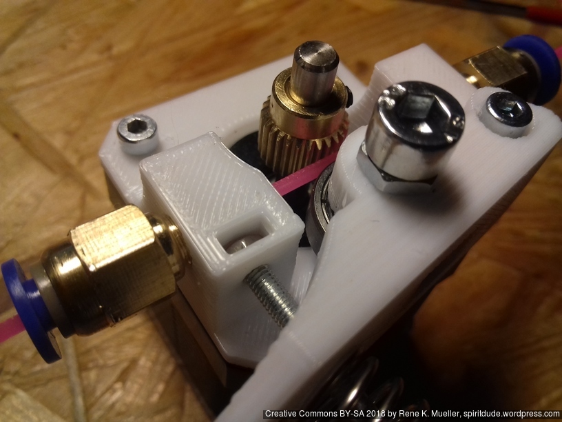
I use PC4-M6 push fit connector with PTFE tube 4mm OD / 2mm ID as guides, and began to use it right away on 3x printers for first tests:

Download

https://www.thingiverse.com/thing:3265864

includes STLs and OpenSCAD source code of the module

Applications

Direct Drive Extruder

A small adapter allows to mount the Compact Extruder close to the printhead to use it as Direct Drive Extruder:

I did not test the Direct Drive approach as I prefer the Bowden setup on my printers, but have it ready when needed, e.g. for flexible filament.

References

See Also

3D Modeling: Elegant Pieces in OpenSCAD with rcube(), rcylinder() and chainhull()

Updates:

  • 2020/12/31: rcube() extended, RCUBE_FLAT{BOTTOM, TOP, FRONT, BACK, LEFT, RIGHT} support added, rcylinder() with RCYLINDER_FLAT{TOP, BOTTOM}
  • 2020/12/30: rcube() source code extended, support RCUBE_FLATX, RCUBE_FLATY, RCUBE_FLATZ
  • 2020/12/28: inital post

While working on Ashtar D (Classic XY) I looked at some pieces I rushed to design with cube() and hull() and they didn’t appeal to me – yes, it kind of hurt my eyes.

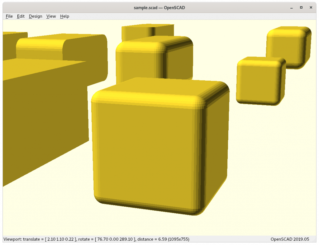
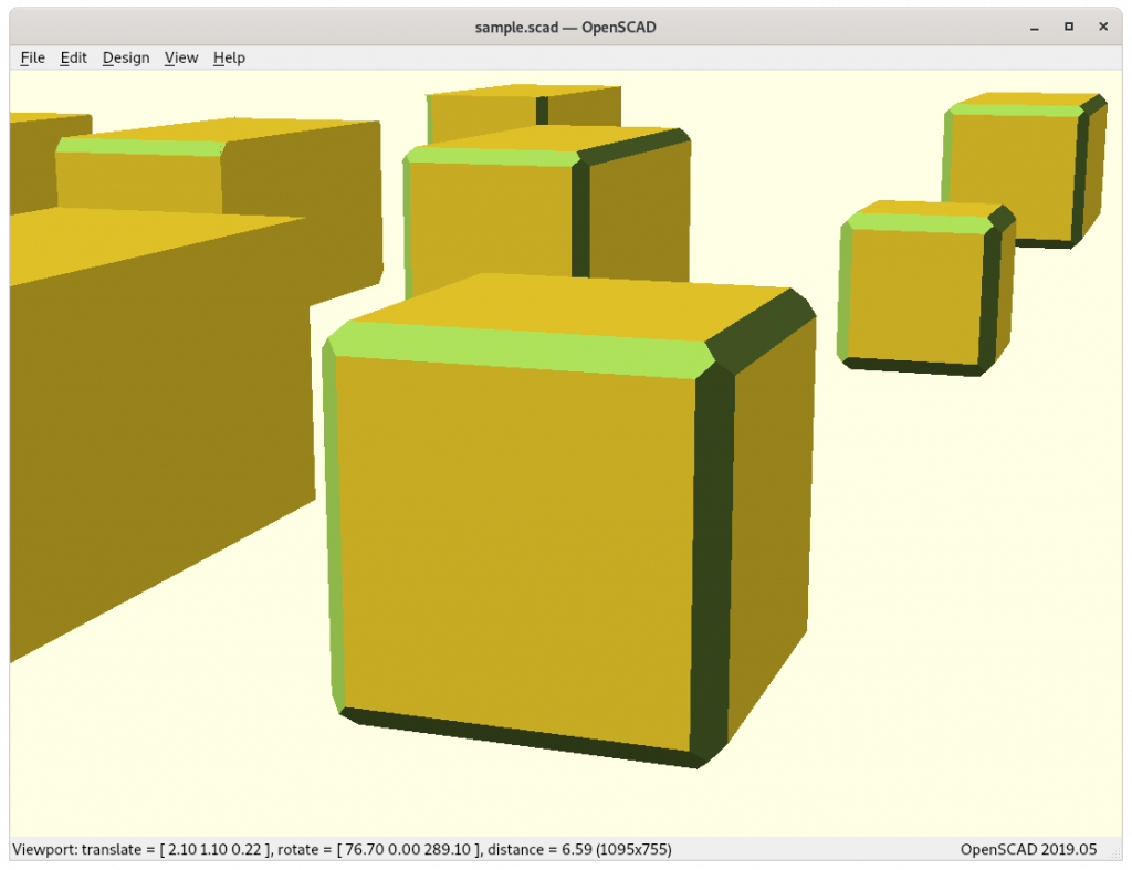
A while back I coded a simple rcube([x,y,z],r) which takes r as a radius for the edges, internally it’s an OpenSCAD module which uses 8 spheres and hulls them together, providing round edges; but I hesitated to actually use it in my designs – until now. Further I thought, let’s do the same with cylinder() using rcylinder(d=10,h=5,r=1) providing round edges by using two torii and hull them together.

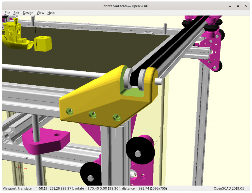
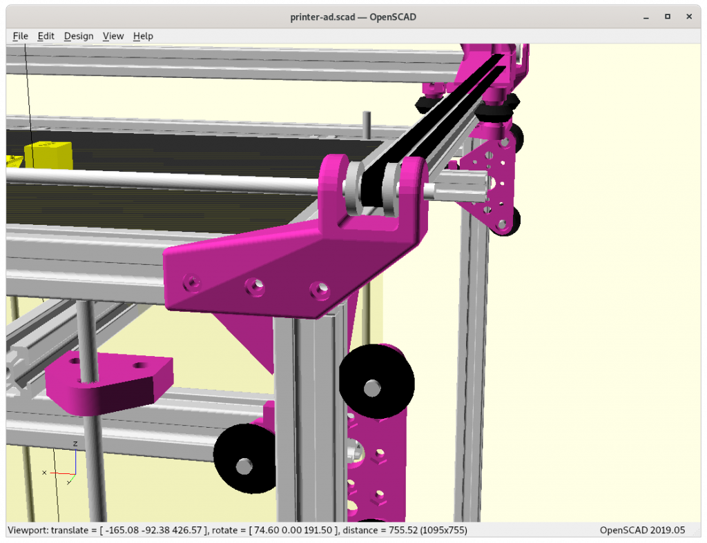
These two new functions, rcube([x,y,z],r) and rcylinder(h,d,r) allow to create more organic and elegant pieces, see for yourself:

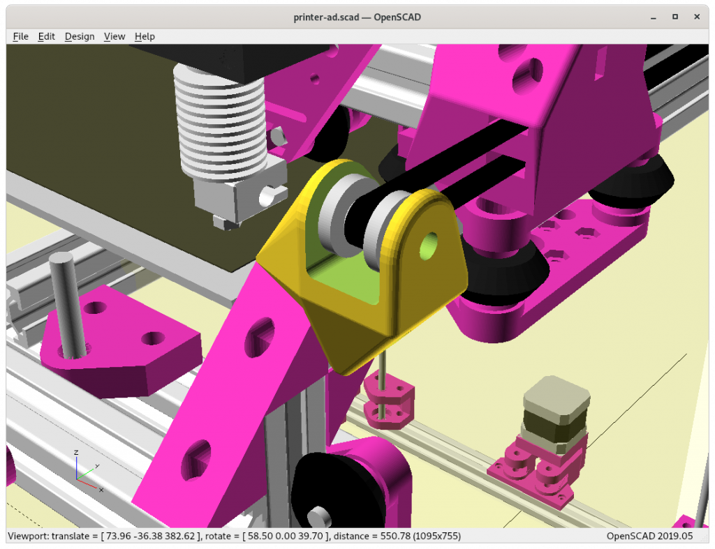
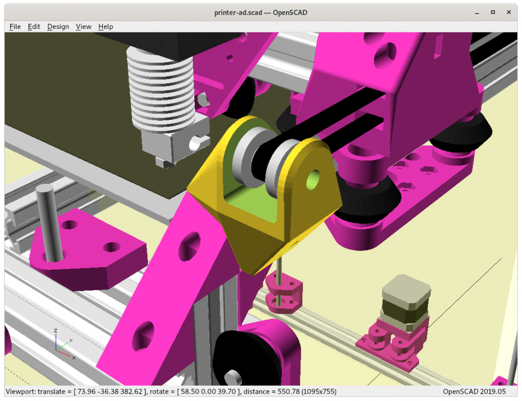
From Bulky To Elegance

The position of the Y pulley mount is given, a bit of an X- & Y-offset to ensure printable area is not sacrificed for the Y carriage:

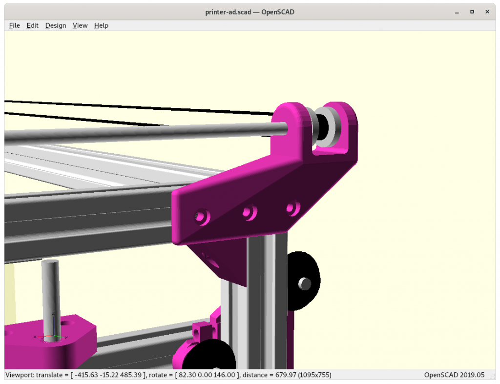
Using Chained Hulls

And another example . . . replacing hull() with chainhull():

The final version is composed by only 3 pieces chain hulled together:

difference() {
   chainhull() {
      rcylinder(...);
      translate([0,0,-20]) rcube(...);
      translate([...,-60]) rcube([5,20,50],2); // 2020 mount plate
   }
   rcube(...);     // pulley cutout
}

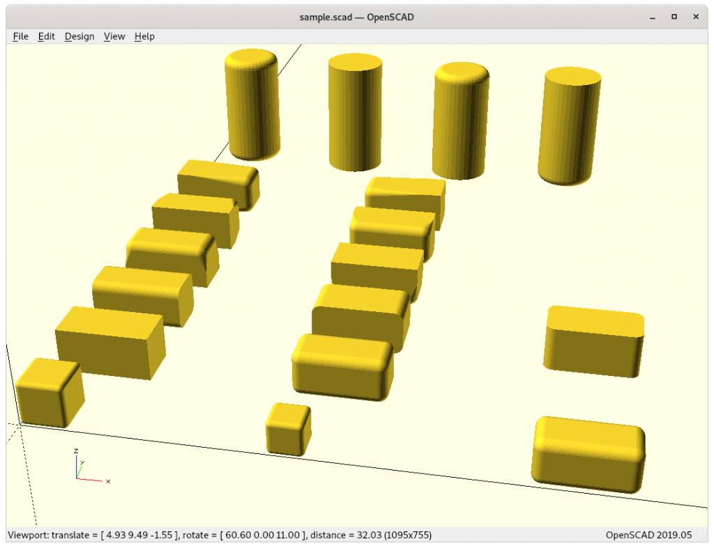
rcube() & rcylinder()

rcube();
translate([5,0,0]) rcube(0.75);
translate([10,0,0]) rcube([2,1,1],0.2);

translate([0,2,0]) rcube([2,1,1],0.2,false);
translate([5,2,0]) rcube([2,1,1],0.2,true);

translate([0,4,0]) rcube([2,1,1],0.2,RCUBE_FLATX);
translate([5,4,0]) rcube([2,1,1],0.2,RCUBE_FLATY);
translate([10,4,0]) rcube([2,1,1],0.2,RCUBE_FLATZ);

translate([0,6,0]) rcube([2,1,1],0.2,RCUBE_FLATBOTTOM);
translate([5,6,0]) rcube([2,1,1],0.2,RCUBE_FLATTOP);

translate([0,8,0]) rcube([2,1,1],0.2,RCUBE_FLATFRONT);
translate([5,8,0]) rcube([2,1,1],0.2,RCUBE_FLATBACK);

translate([0,10,0]) rcube([2,1,1],0.2,RCUBE_FLATLEFT);
translate([5,10,0]) rcube([2,1,1],0.2,RCUBE_FLATRIGHT);

translate([0+1,14,0]) rcylinder(3,1.5,0.2);
translate([3+1,14,0]) rcylinder(3,1.5,0.2,false);
translate([6+1,14,0]) rcylinder(3,1.5,0.2,RCYLINDER_FLATBOTTOM);
translate([9+1,14,0]) rcylinder(3,1.5,0.2,RCYLINDER_FLATTOP);

The library code (I might later release it as a separate library):

// Title: rcube(), rcylinder() & torus()
// Author: Rene K. Mueller
// License: MIT License 2020
// Version: 0.0.2

RCUBE_FLATX = [false,true,true];
RCUBE_FLATY = [true,false,true];
RCUBE_FLATZ = [true,true,false];
RCUBE_FLATBOTTOM = [false,false,false,false,true,true,true,true];
RCUBE_FLATTOP = [true,true,true,true,false,false,false,false];
RCUBE_FLATFRONT = [false,false,true,true,false,false,true,true];
RCUBE_FLATBACK = [true,true,false,false,true,true,false,false];
RCUBE_FLATLEFT = [false,true,true,false,false,true,true,false];
RCUBE_FLATRIGHT = [true,false,false,true,true,false,false,true];

module rcube(a=1,r=0.1,rd=[true,true,true],center=false,$fn=32) {
    if(FAST_RCUBE)
       cube(a);
    else {
       x = len(a) ? a[0] : a;
       y = len(a) ? a[1] : a;
       z = len(a) ? a[2] : a;
       rd = len(rd) ? rd : [rd,rd,rd];

          if((len(rd)==3 && rd[0] && rd[1] && rd[2]) || (len(a)==0 && rd)) // rd=[true,true,true] or true
             hull() {
                translate([r,r,r]) sphere(r);
                translate([x-r,r,r]) sphere(r);
                translate([x-r,y-r,r]) sphere(r);
                translate([r,y-r,r]) sphere(r);
                translate([r,r,z-r]) sphere(r);
                translate([x-r,r,z-r]) sphere(r);
                translate([x-r,y-r,z-r]) sphere(r);
                translate([r,y-r,z-r]) sphere(r);
             } 
          else                                                        // anything else
             hull() {
                translate([r,r,r]) rcube_prim(r,rd,0);
                translate([x-r,r,r]) rcube_prim(r,rd,1);
                translate([x-r,y-r,r]) rcube_prim(r,rd,2);
                translate([r,y-r,r]) rcube_prim(r,rd,3);
                translate([r,r,z-r]) rcube_prim(r,rd,4);
                translate([x-r,r,z-r]) rcube_prim(r,rd,5);
                translate([x-r,y-r,z-r]) rcube_prim(r,rd,6);
                translate([r,y-r,z-r]) rcube_prim(r,rd,7);
             }
    }
 } 

module rcube_prim(r,rd,i) {
    a = len(rd);
    if(a<=3) {
       if(a && rd[0] && rd[1] && rd[2]) 
          sphere(r);
       else if(a && rd[0] && rd[1])
          translate([0,0,-r]) cylinder(r=r,h=r*2);
       else if(a && rd[1] && rd[2])
          translate([-r,0,0]) rotate([0,90,0]) cylinder(r=r,h=r*2);
       else if(a && rd[0] && rd[2])
          translate([0,-r,0]) rotate([-90,0,0]) cylinder(r=r,h=r*2);
       else
          translate([-r,-r,-r]) cube(r*2);
    } else 
       if(rd[i]) 
          sphere(r);
       else 
          translate([-r,-r,-r]) cube(r*2);
 }

RCYLINDER_FLATBOTTOM = [false,true];
RCYLINDER_FLATTOP = [true,false];

module rcylinder(h=2,d=1,r=0.1,rd=[true,true],$fn=40) {
    if(FAST_RCYLINDER)
       cylinder(d=d,h=h);
    else
       hull() { 
          translate([0,0,r]) 
             if(len(rd) && rd[0]) torus(do=d,di=r*2); else translate([0,0,-r]) cylinder(d=d,h=r);          
          translate([0,0,h-r]) 
             if(len(rd) && rd[1]) torus(do=d,di=r*2); else cylinder(d=d,h=r);
       }
 }

 module torus(do=2,di=0.1,a=360) {
    rotate_extrude(convexity=10,angle=a) {
       translate([do/2-di/2,0,0]) circle(d=di,$fn=20);
    }
 }

chainhull()

module chainhull() {
    for(i=[0:1:$children-2])
       hull() {
          children(i);
          children(i+1);
       }
 }

There is one drawback using chainhull() { } as you can’t use conditional if else with { } within as it combines them as a group and becomes a child structure and so it will act as hull(), so you only can list non-conditional pieces within chainhull() as of OpenSCAD 2019.05, perhaps at a later time this limit vanishes.

That’s it.
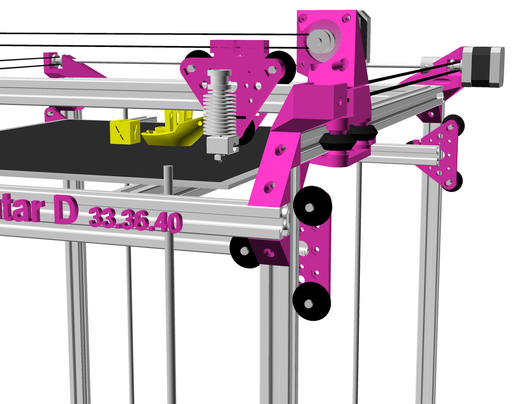
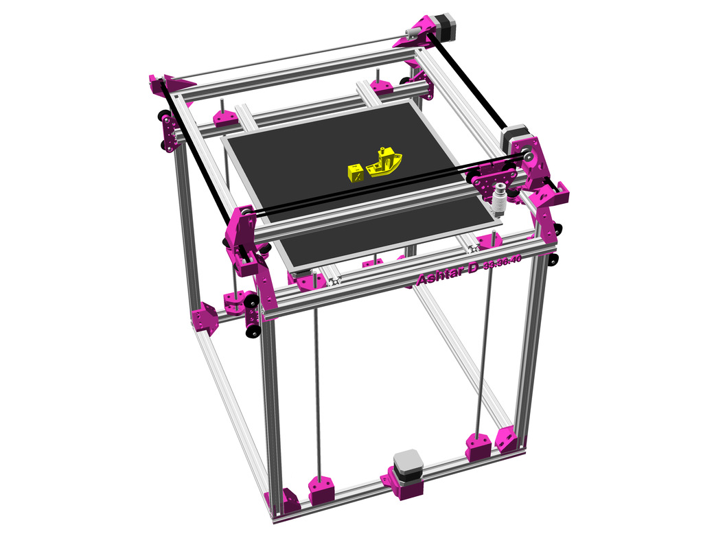
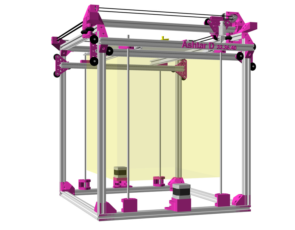
3D Printer Ashtar D: Classic XY, First Draft

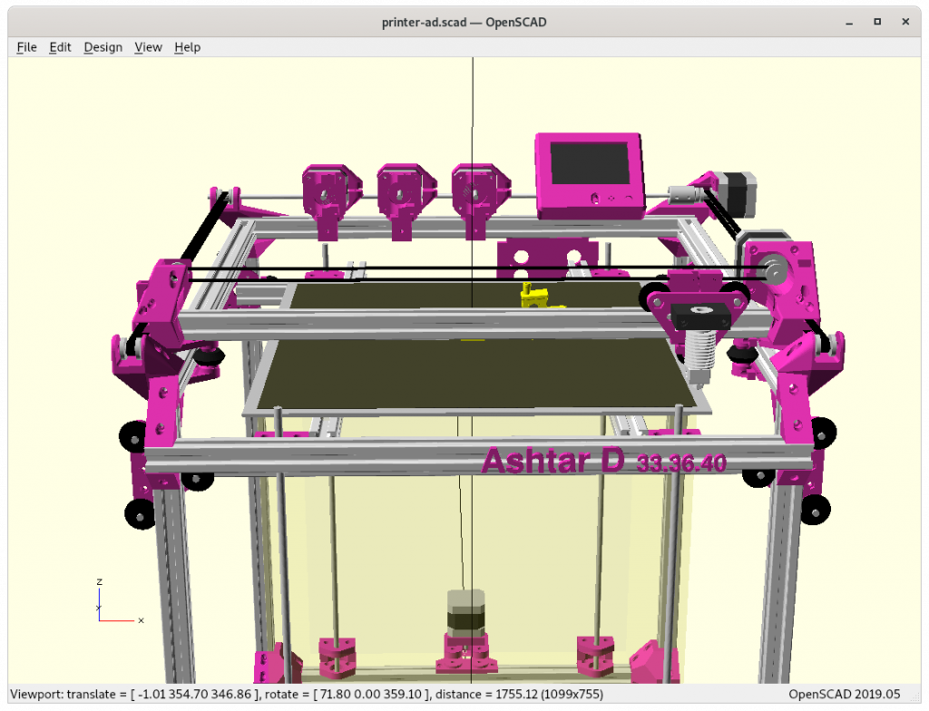
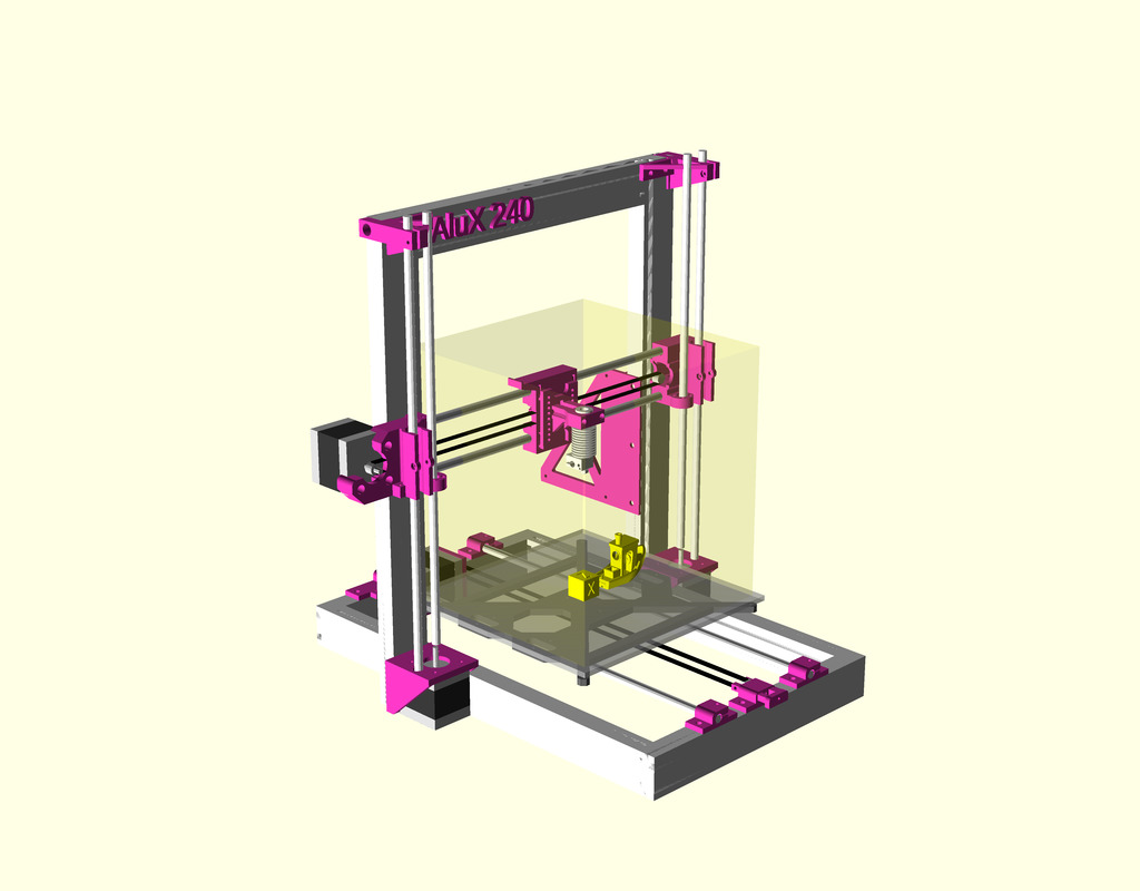
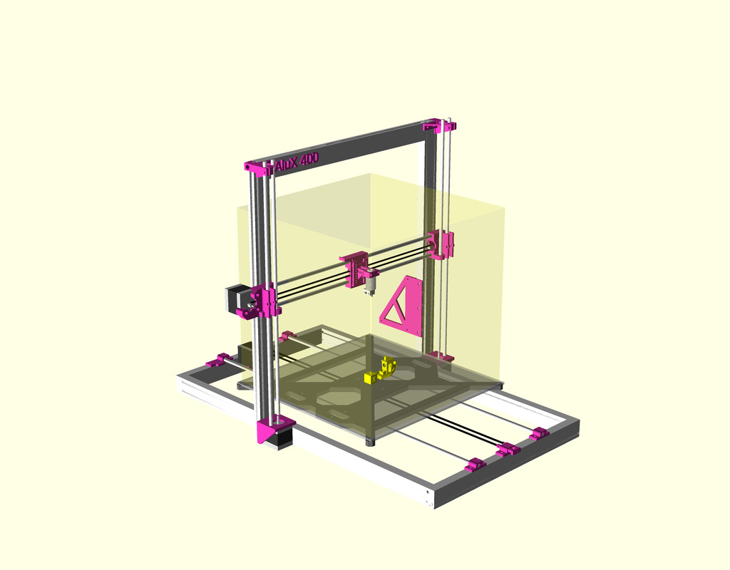
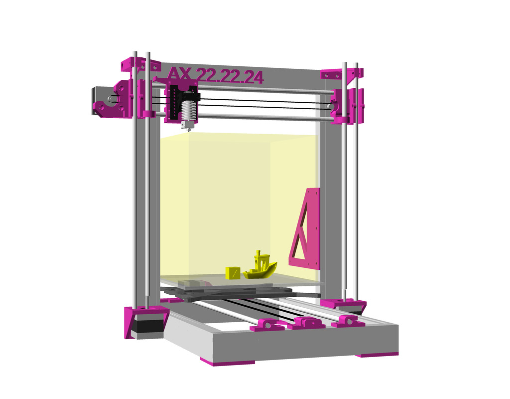
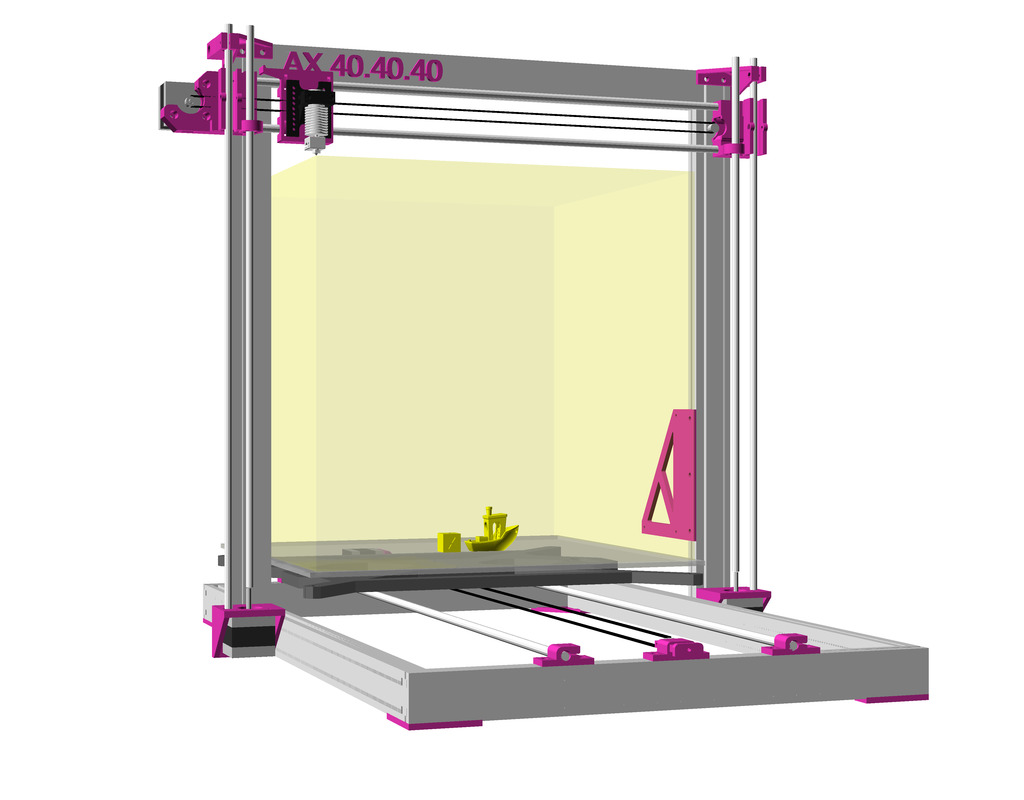
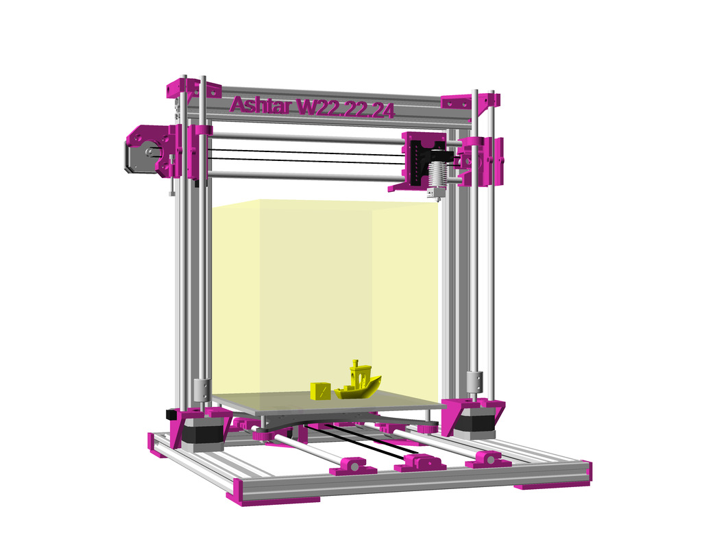
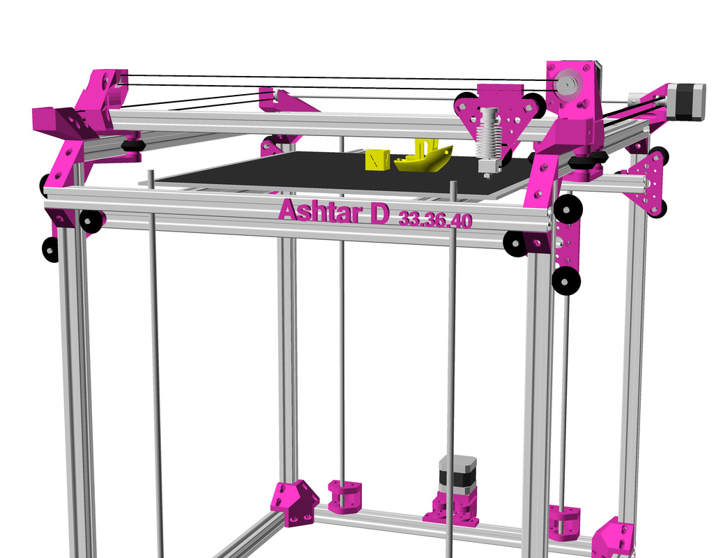
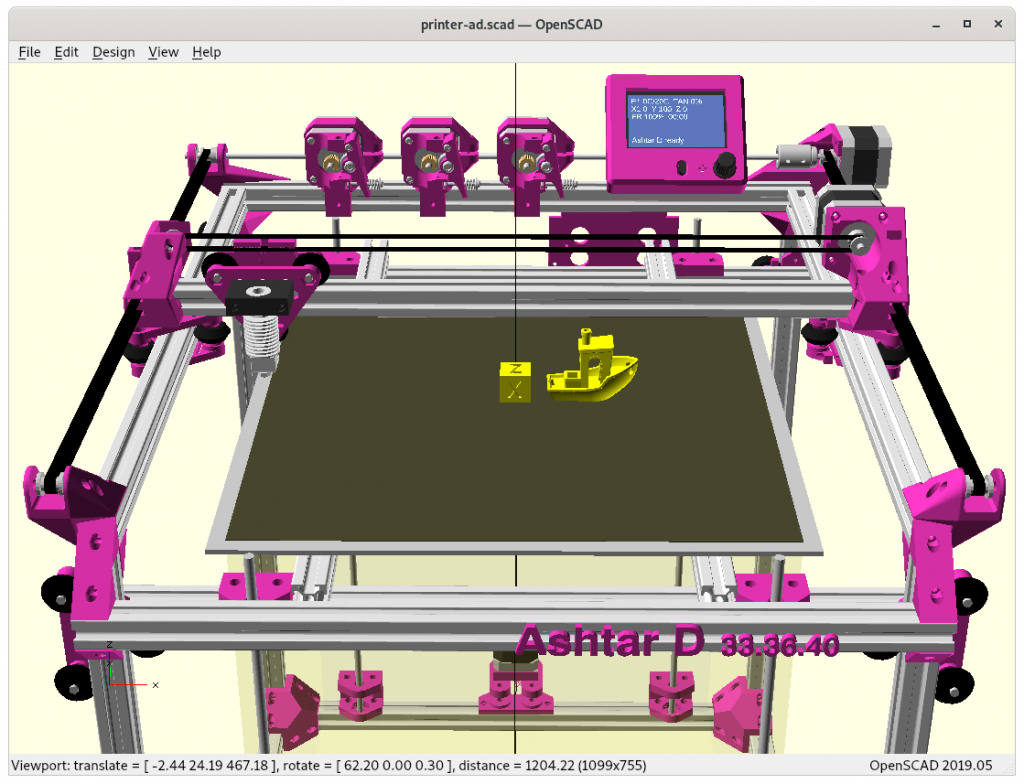
After the Core XY implementation of Ashtar C I pondered on changing the kinematic to a more classic approach to separate X and Y axis motors, but otherwise keep the setup and frame, hence Ashtar D:

Ashtar D: classic independent XY kinematic: head XY, bed Z setup, with 500mm 2020 alu profiles

Draft

Again using 500mm alu profiles, utilizing the frame itself as rails:

  • 1 V-slot beam for X axis with V-carriage/module (triangle shaped carriage) as X carriage with hotend
  • 2 V-slot beams for Y axis, 2 V-carriages/modules with the X beams on it
    • using classic V wheels
  • 14 T-slot beams for the rest of the frame
    • Z bed: white 7.3mm thick Delrin wheels on T-slots

The target is again a 400x400mm printbed, probably 380x400x380mm build volume alike with Ashtar C (Core XY), perhaps a bit less X-wise due the more complex pieces to mount the X motor and pulleys.

More high resolution renderings:

The project page on Ashtar D summarizes the current state of the project.

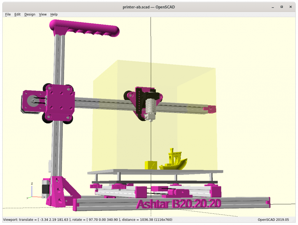
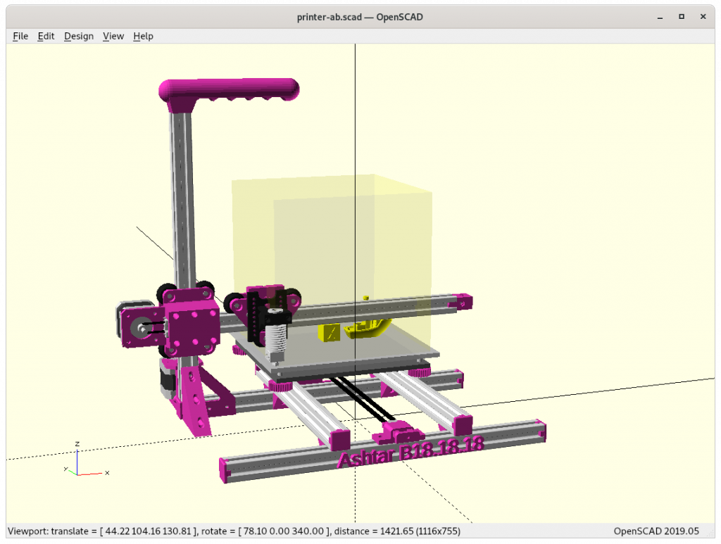
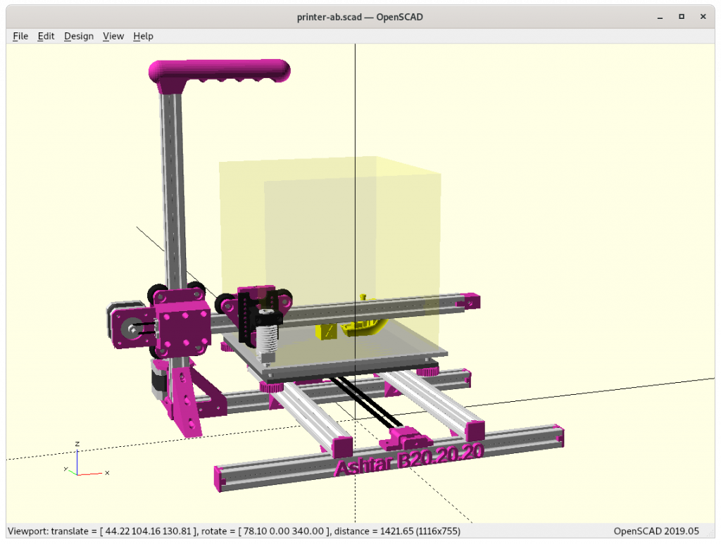
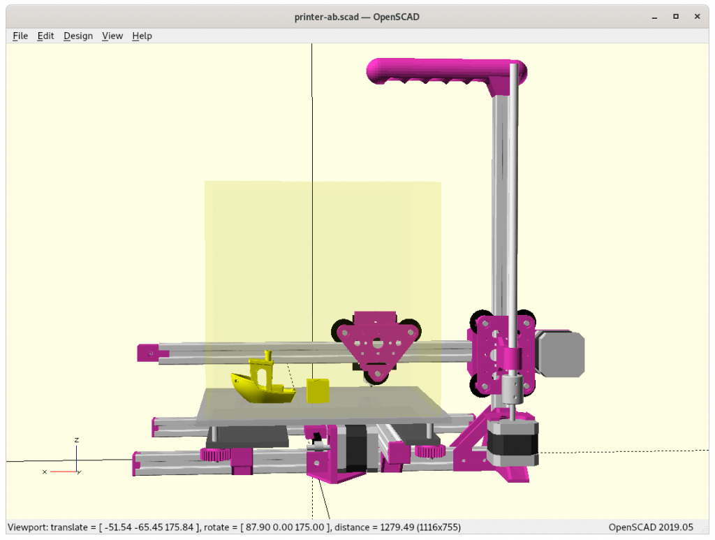
3D Printer Ashtar B: Cantilever, First Draft

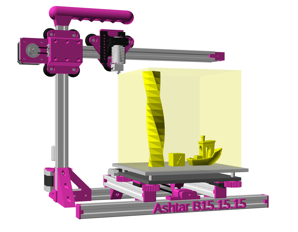
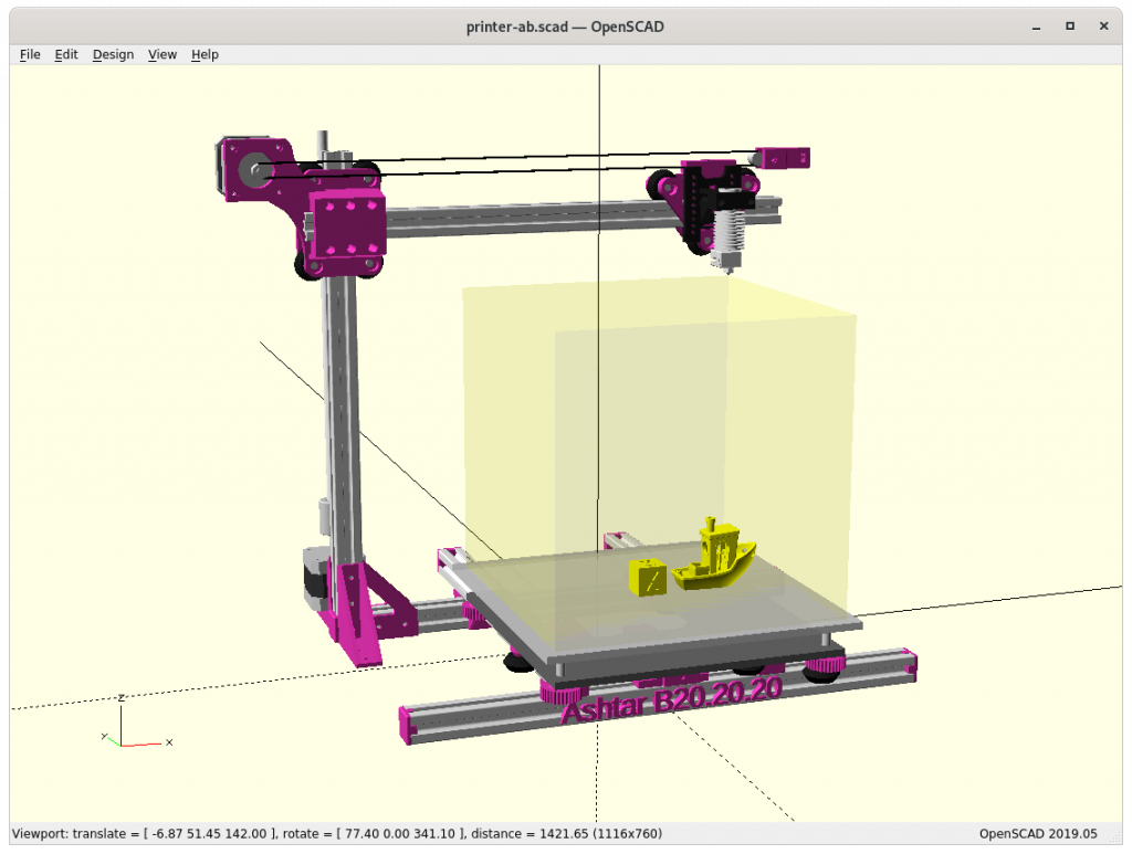
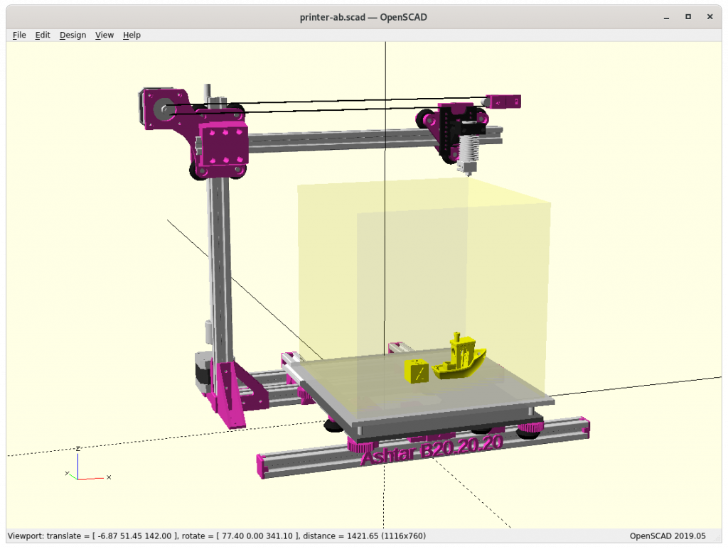
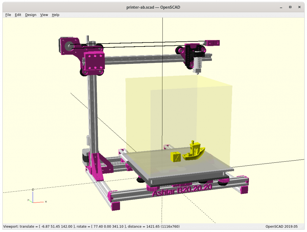
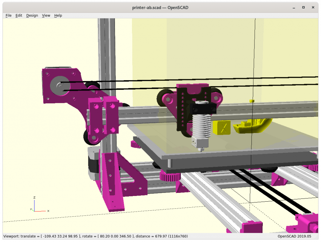
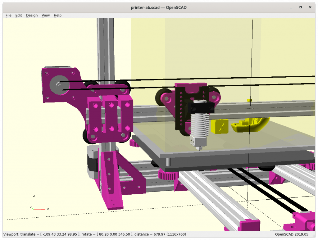
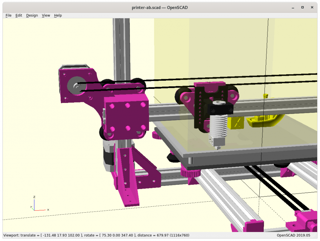
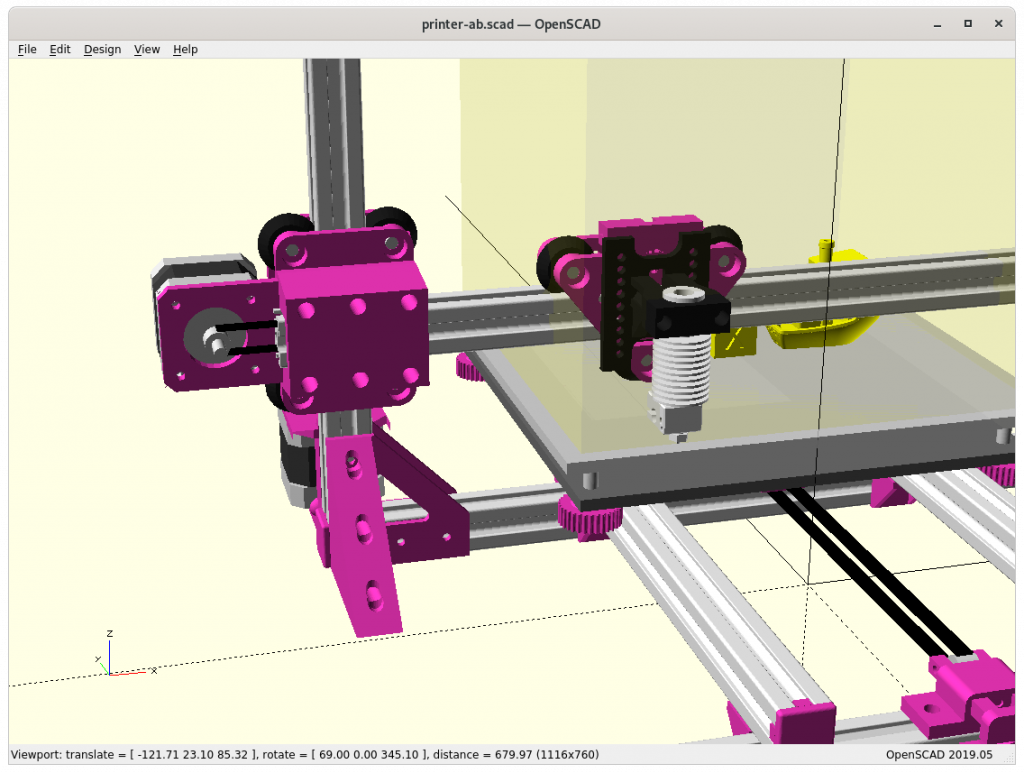
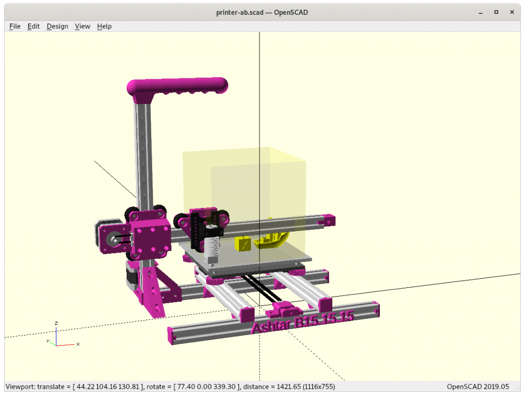
It has been on my mind for quite a while to do a 2020 alu extrusion based Cantilever 3D printer, and so I started in December 2020 with a rough design, starting from the existing Ashtar K design and cut away parts:

  • using Head XZ and Bed Y
  • aiming common build volume (e.g. easy to source print bed)
    • 140mm to 190mm each axis
  • tried 6, 7 and 9 beams options, settling with 6 beams for now
  • aiming for uni-length 2020 alu extrusions, T-slot and V-slot where a carriage rides (X & Z axis) with V wheels.
  • trying to keep as simple as possible

Frame: 6 vs 7 vs 9 beams

The 9 beams give an overall better sturdiness, but not sure how essential at small building volume (less than 220mm each axis). I might be able to remove beam, the last beam at the back at the bottom reducing to only 6 beams, in that case the Y motor is mounted on the remaining beam in the back.

Z Carriage: 3 vs 4 wheels module

The 4 wheels looks best but it also sacrifices some of the X range by apprx. 10mm, the obvious choice is 3-wide mount – actual tests will tell if the X & Z axis are solid enough.

Different Sizes

The 200mm build axis length would be good, but I’m not sure if the XZ carriage will allow it as the max margin or tolerance would be half of a layer-height, e.g. 1mm layer height ⇒ 0.05mm tolerance, at X = 0 .. max the head should not flex more than 0.05mm. At this this early draft stage I don’t know which size is most suitable, I focus on 180mm build axis.

The project page on Ashtar B summarizes the current state.

3D Printer Ashtar M: Moving XZ Frame (Moving Gantry), First Draft

Updates:

  • 2020/12/20: adding XZ arch option
  • 2020/12/14: initial post
Jon Schone: Moving Portal Mod

In April 2020 Jon Schone (@properprinting) showed a “Moving Portal” mod for his CR-10 – a Prusa i3 derivative – and I thought to adapt his approach as “Ashtar M” as moving XZ frame or moving gantry in CNC terms.

On a second thought, this approach makes only sense with larger beds, as the bed weight should exceed the weight of XZ frame and X carriage:

weight(XZ frame + X carriage) < weight(bed)

and as I compose my Ashtar 3D printer series with alu extrusions (beams) I can say:

weight(XZ frame) = beam X * 2 + beam Z * 2 + NEMA17 * 2
weight(bed) = X * Y

and it becomes here clear, the bed weight grows X * Y whereas XZ frame only (X + Z) * 2, but also 2* NEMA17 motors of the Z axis are part of the XZ frame.

Moving Portal / Gantry

A few still images of Jon’s YT video to look at some details of his approach:

First Draft

  • using solely 500mm 2020 alu extrusions (T-slot for general frame and XZ frame, V-slot for carriages: X beam, 2x Y beams)
  • trying to achieve 400x400x400mm build volume as close as possible, alike Ashtar C 38.40.36

Using for Y carriages existing vcarriage2 module with vcarriage2(width=100) to have it wide enough:

The two main new pieces required were connecting the Y carriage with the XZ frame:

  • Piece “A” outside ycarriage_xzframe_mount_a(): has to be printed with 0.1mm layer height in order to stay within the +/- 0.05mm tolerance, otherwise it will introduce tilt and stress on the Y carriage and cause long term damage – tricky part to print.
Adding side pieces “A” & “B”
  • Piece “B” inside ycarriage_xzframe_mount_b(): is quite elaborate already and should be functional, with the Y belt ends fastening with M3 screws and M3 nuts inserts, the belt endings will come out downward:

XZ Arch Option – Removing Lower X Beam

In order to gain some Z build space by lowering the print bed, I may reduce the XZ frame to an XZ arch:

Actual physical tests may reveal if it’s suitable to maintain overall geometrical integrity. Removing the lower X beam also reduces moving mass of the XZ arch/frame/gantry.

Pros

  • gain Z build space
  • reduce XZ gantry weight / inertia

Cons

  • decrease XZ gantry stability

Further Development

As I develop Ashtar M further, I will post updates on the blog here, and also keep documenting the current state at Ashtar M page.

That’s it.
Infinite-Z CR-30 aka 3DPrintMill: Creality Acknowledges Prior Development & Commits to Open Source (2020/12)

As of December 2020, something remarkable has happened: Creality, a big chinese 3D Printer company has openly acknowledged and worked with western developers to bring forth a belt-based 3D printer.

Usually chinese companies have copied without acknowledge or give credit to development done by others like Adrian Bowyer or Josef Prusa, yet with the influence of Naomi Wu, a maker from Shenzen, Creality seemed to have been swayed to give proper attribution and even actively work with Open Source Hardware inventors to mass produce a belt-based 3D Printer.

CR-30 aka 3DPrintMIll by Naomi Wu with Creality (2020)

The past decades “Western Innovation vs Chinese Manufacturing” combo has been operating very well and brought many consumer products at low cost, including 3D printers.

Now, in this particular case, we see Bill Steele and Karl Brown (White Knight Printer) properly attributed in the 3DPrintMill Kickstarter page:

And even giving proper context of the overall lineage:

Lineage

All consumer 3D printers currently sold, build in some way on the work of Adrian Bowyer and his RepRap project- Open Source 3D printing. Some 3D printers iterate more than others, some are simply clones and claim innovations as their own that was in fact the community’s work. Others take only the broad strokes of an idea and build on it, improve it, and allow others to build on it further. For the 3DPrintMill (Creality CR-30) we have taken pains to involve and consult the talented individuals who brought the technology this far, and built on their work with their permission.

Bill Steele, who first demonstrated Infinite-Z FDM and DLP printers, and Karl Brown who created the first practical, Open Source kit so consumers could build their own Infinite-Z printer. Both Karl and Bill have given the project their blessing- and indeed, without them, it would never have been possible.

As said, this is remarkable and probably a new level of cooperation of Open Source Hardware movement and chinese manufacturers.

Back in 2010 I thought that the Open Source Hardware movement should actively seek cooperative alliance with chinese manufacturers instead just to complain – but this did not happen. Now in late 2020 it seems happening, thanks to Naomi Wu (Project Head for the CR-30/3DPrintMill), who made an effort to bridge the western innovation culture and chinese manufacturing culture – without a bridge, a canyon keeps villages apart.

Thanks also to Creality, namely Michael Tang (Co-founder of Creality), Steven Han (Brand Director), Zhou Yong (Product Manager), Lei Congjin (R & D Manager), Yu Xianhong (Project Manager) for the acknowledgment as expressed in the Kickstarter page.

Open Source Hardware Commitment

Additionally, and perhaps even more relevant is their on-going commitment to Open Source Hardware as expressed in this passage:

Bringing the 3DPrintMill (Creality CR-30) to life would need the resources of a full engineering team and a company with substantial 3D printer manufacturing experience. So a deal was struck, Creality would invest the R&D resources necessary to make the 3DPrintMill(Creality CR-30) real, and as soon as that expense was recouped, the entire product would be fully Open Sourced for the benefit of the community. When the 3DPrintMill (Creality CR-30) reaches 5 million USD in crowdfunding, the whole machine- CAD files, BOM, firmware, schematics, will be fully Open Sourced. Anyone in any country can make their own version, iterate and improve on it- leading to vastly accelerated development.

This is probably what many Open Source Hardware (OSHW) enthusiasts have been waiting for, one of the big player like Creality join the common OSHW efforts once more, after having released all plans of the Ender 3 in 2018 and giving an example for other companies.

Bigger Context

And I look at Apple, Microsoft, IBM, ARM, Intel, AMD and I wonder, with the Open Source ISA (Instruction Set Architecture) of RISC-V on the horizon, whether we are going to see the full stack of Open Source Hardware from the CPU design up to the PCB and final assembled computer (GPU, RAM, I/O); and if any of the big players take a moment, and look at what Creality did here?

Naomi Wu ranted away on Twitter with the following, which hits the nail about Open Source and Open Source Hardware is really about:

Software? Fusion360, Adobe Creative Cloud, John Deere tractors- a tradesperson can’t even own their own tools anymore. We’re all sharecroppers. Everything is rented.

Every single thing we own is being taken, put in the cloud, and rented back to us. Willingly. Because no one wants to know how to do anything beyond a narrow scope. We’re a world of carpenters willing to rent sharp chisels and saws rather than learn to sharpen them ourselves.

Although the rant started as people seemingly complained on the non-existing or poor customer support of Creality, her main argument is, rather have Open Source Hardware and a community helping each other, than a Closed Source without any control but good customer support – the rant actually targets the Software- & Hardware Sovereignty, which is behind all of the Open Source movement, that is the core issue: you are allowed, you are given the opportunity to improve what you bought, what you own, you can resolve the needs and requirements of your own use cases – personal evolution – and you contribute and help others by being able to share it again – collective evolution. And the mentioned companies, like Apple, or Microsoft, who have been locking up their hardware and software further and further, to improve usability and simplicity – and believe me, I have been an open critic of poor GUIs in Linux not able to catch up – but the price is high, loss of “digital sovereignty” as of software and hardware.

So, because companies are profit driven, they have to balance their own needs and requirements with the collective interest – and this is done in these statements:

Creality would invest the R&D resources necessary to make the 3DPrintMill(Creality CR-30) real, and as soon as that expense was recouped, the entire product would be fully Open Sourced for the benefit of the community.

When the 3DPrintMill (Creality CR-30) reaches 5 million USD in crowdfunding, the whole machine- CAD files, BOM, firmware, schematics, will be fully Open Sourced.

This is why I consider this an important and significant move, because a profit-driven company has actively and willingly balancing its own needs and requirements with those of the collective of the Open Source Hardware movement, and acknowledged that very product they are about to produce has been possible because of individuals like Adrian Bowyer, Bill Steele and Karl Brown.

Remarkable.


That’s it.
PS: If you are interested in early development 3D printers, see RepRap movement or general 3D Printer History.