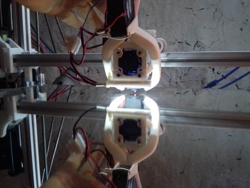
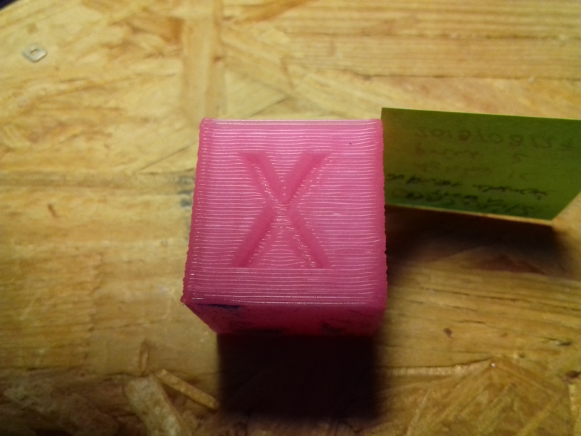
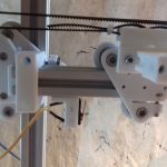
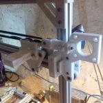
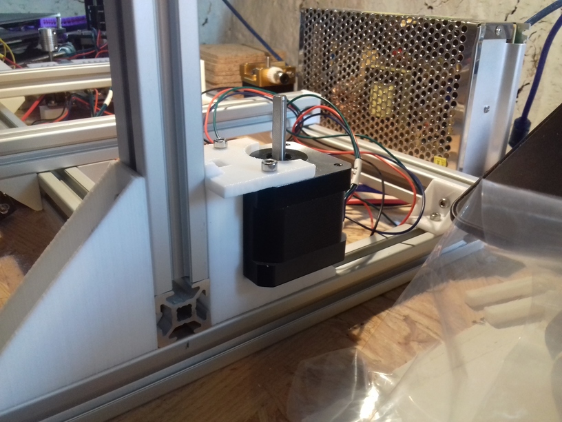
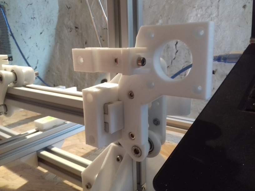
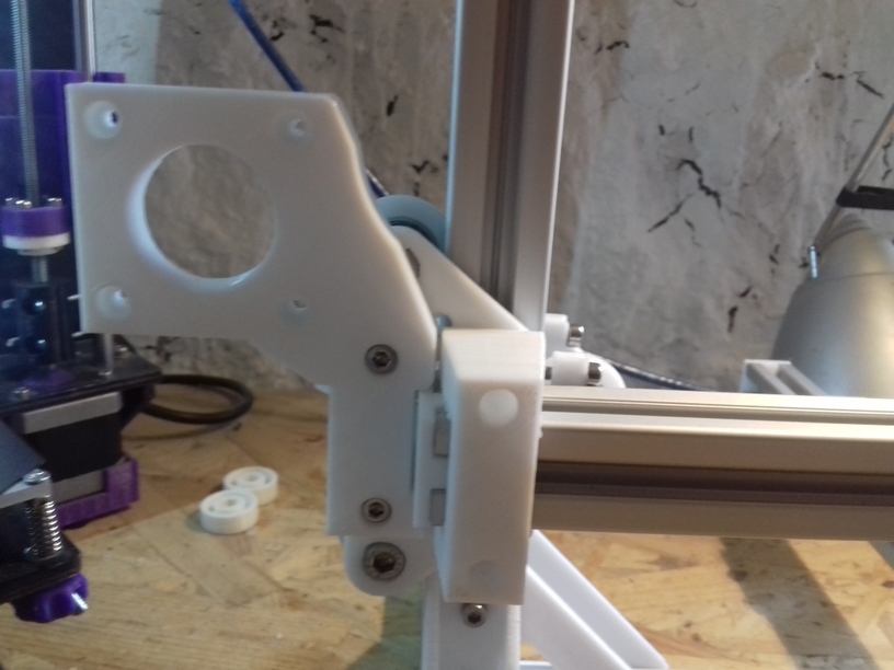
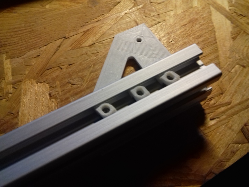
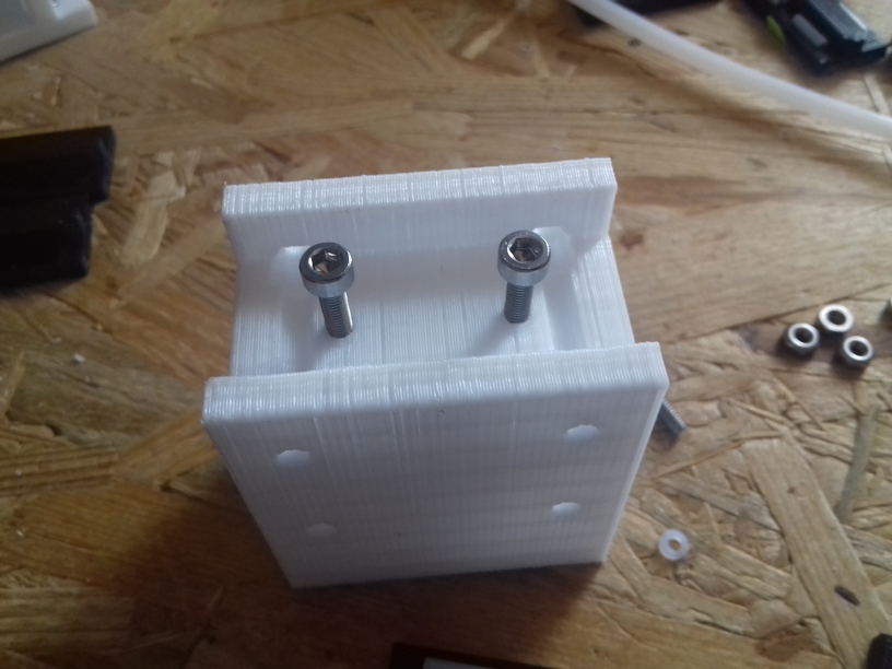
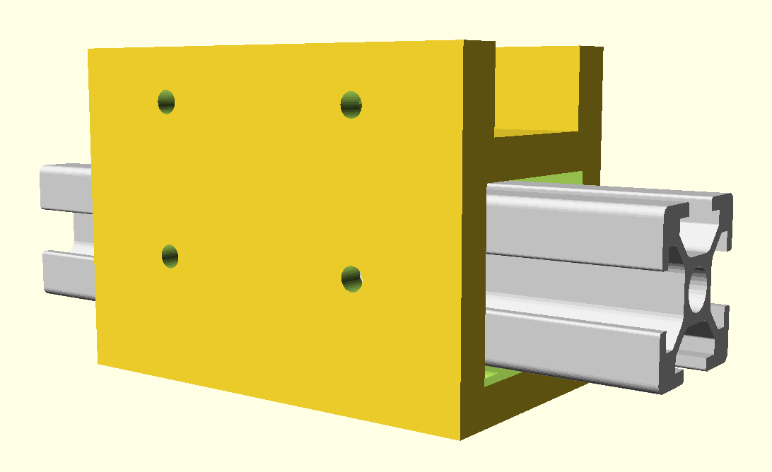
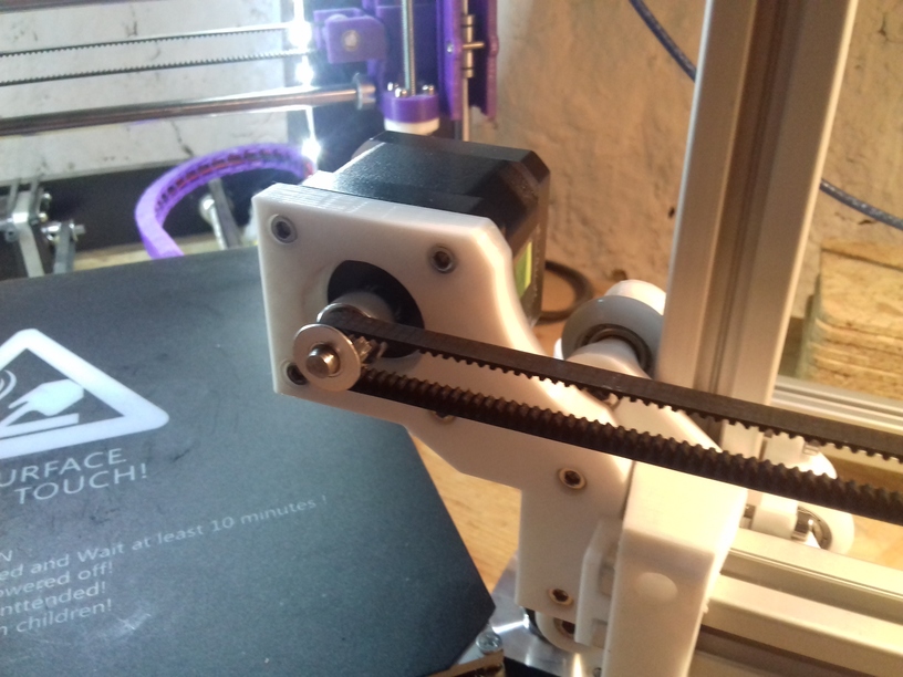
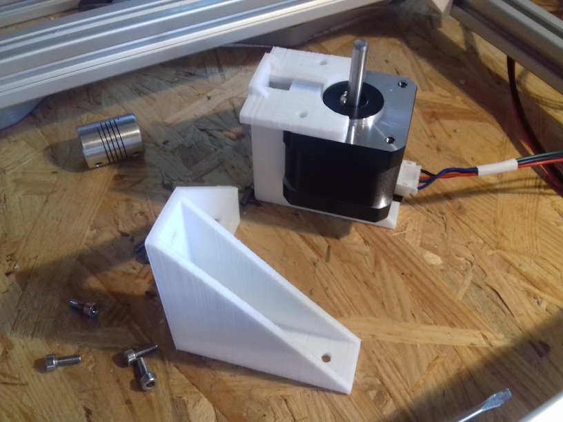
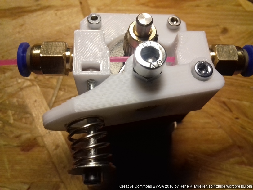
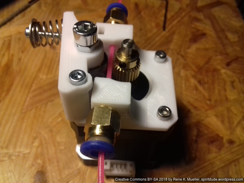
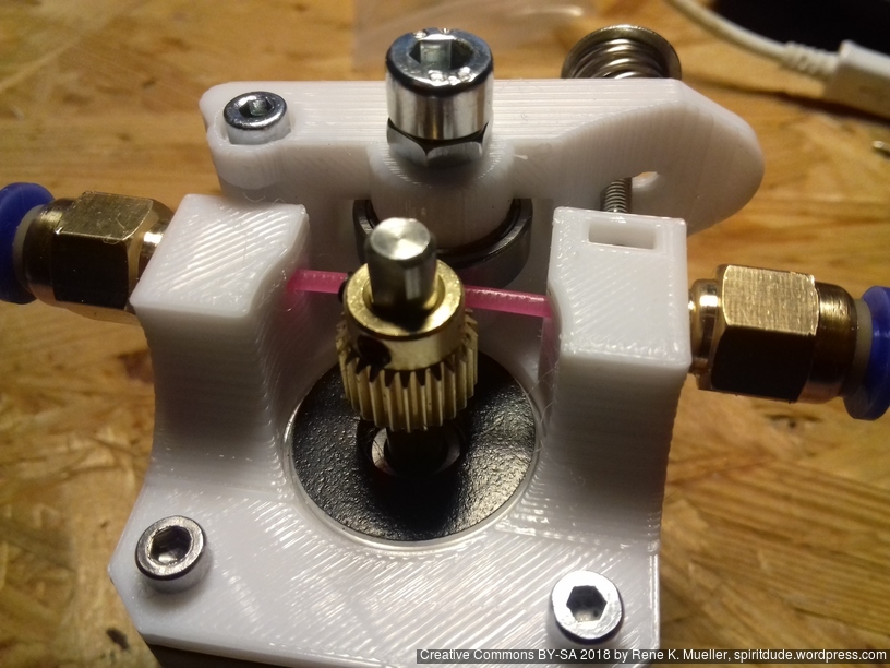
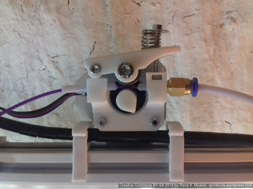
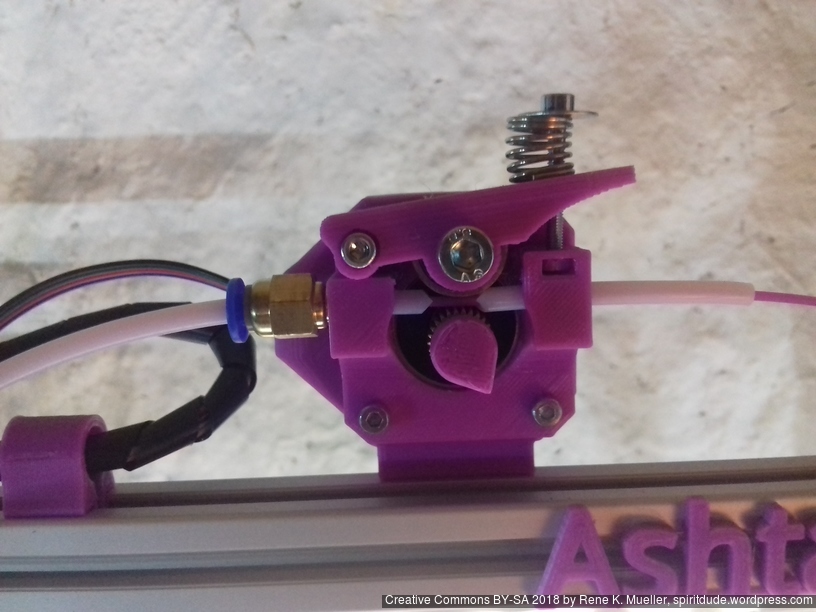
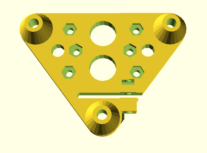
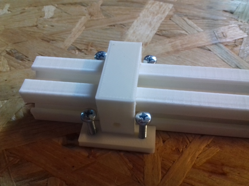
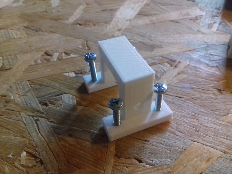
Upgrading X Motor Mount
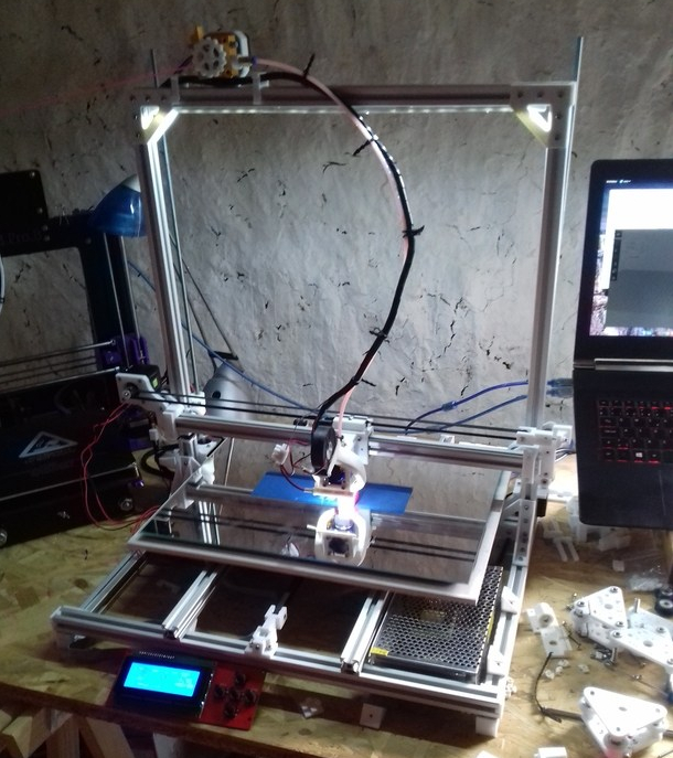
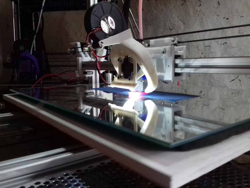
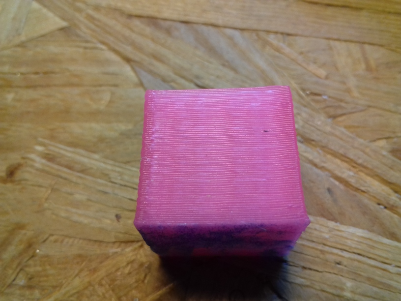
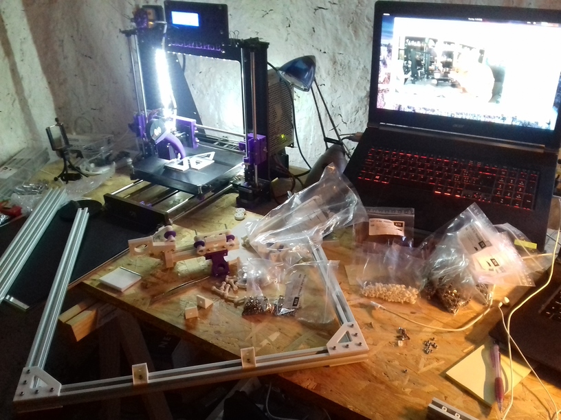
Printing new X motor mount on CTC DIY I3, and replacing it on the new Ashtar K: CTC DIY I3 prints quite reliably – there is nothing to clean up – the piece I attach it right away:
Ashtar K lacked a proper print surface (before I received the black sticker surface), otherwise I would have printed the piece on itself.
Black Sticker as Bed Surface
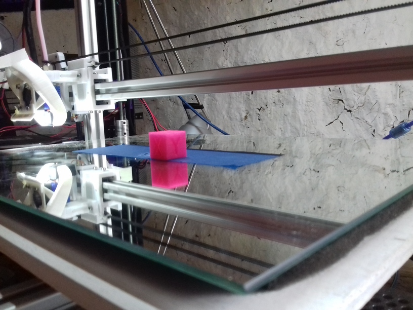
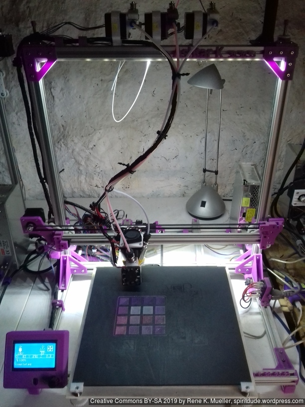
The 400×400 black sticker arrived, and I cut it into 400x300mm and put it on the mirror – which worked well, and so far I can tell the surface is very very flat, much better than on alu heat bed.

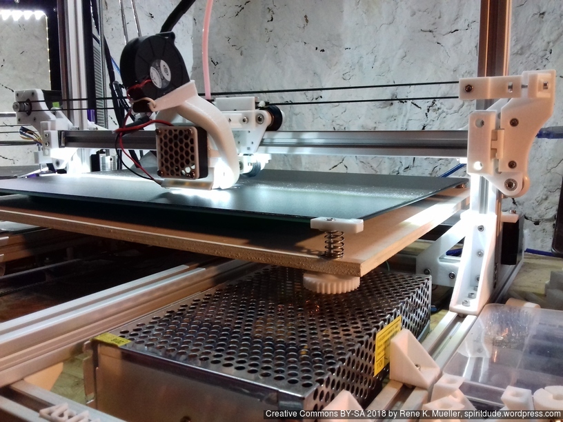

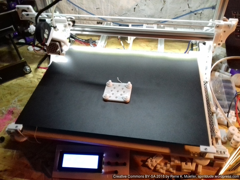
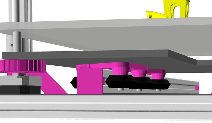
 Current bed setup (top to bottom):
- 400x300mm black sticker (“frosted sticker”), apprx. 0.6mm thick
- 400x300mm 3mm thick mirror
- 210x210mm 12V alu heat bed
- various cork patches under heat bed
- 10mm light black foam material
- 420x320mm 6mm plywood (white painted) as Y carriage
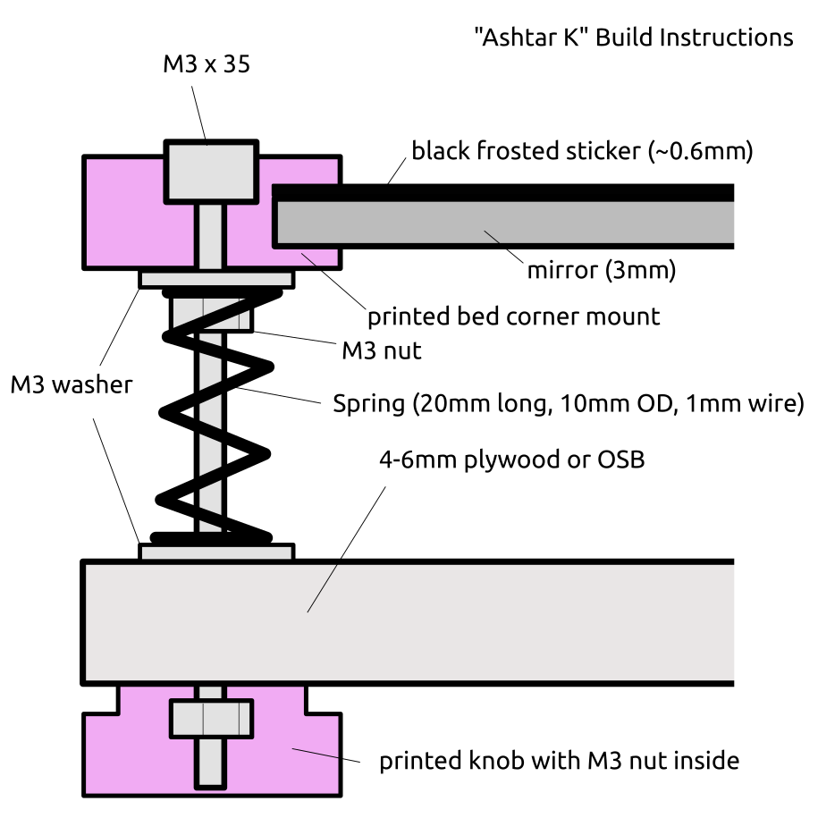
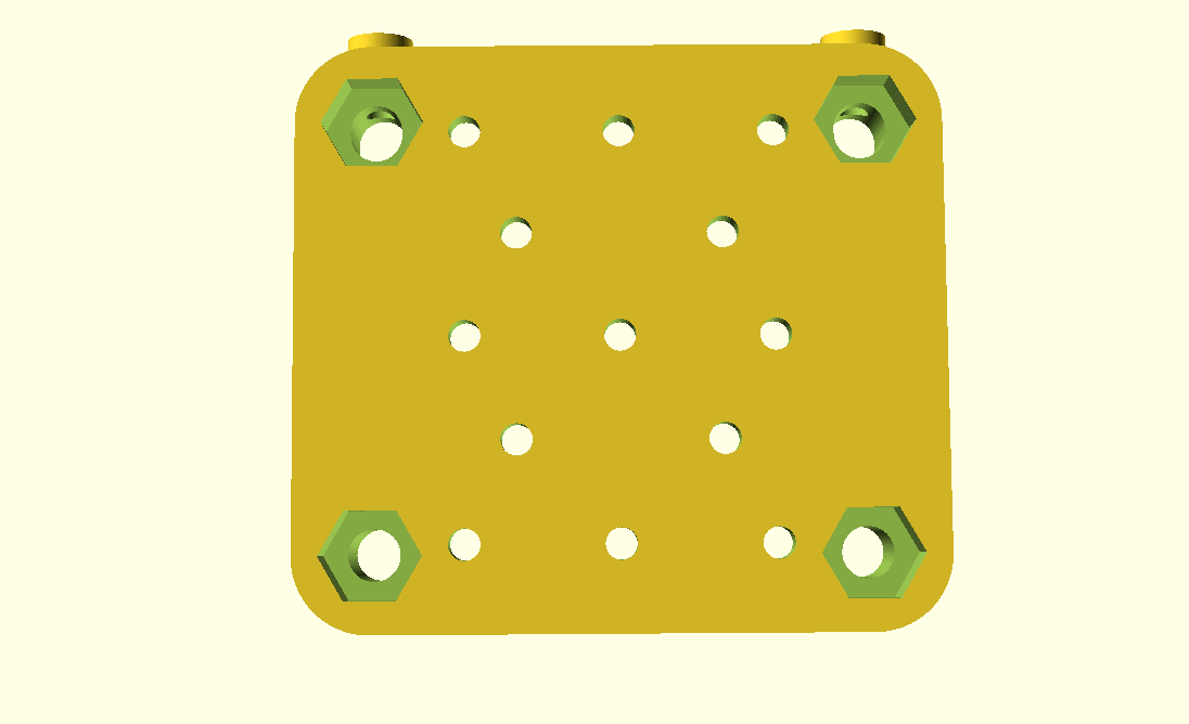
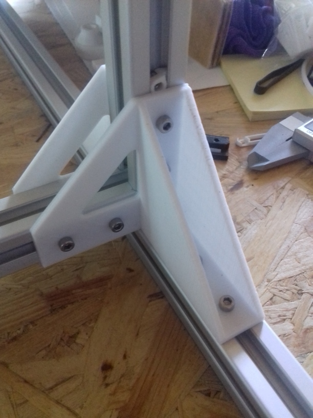
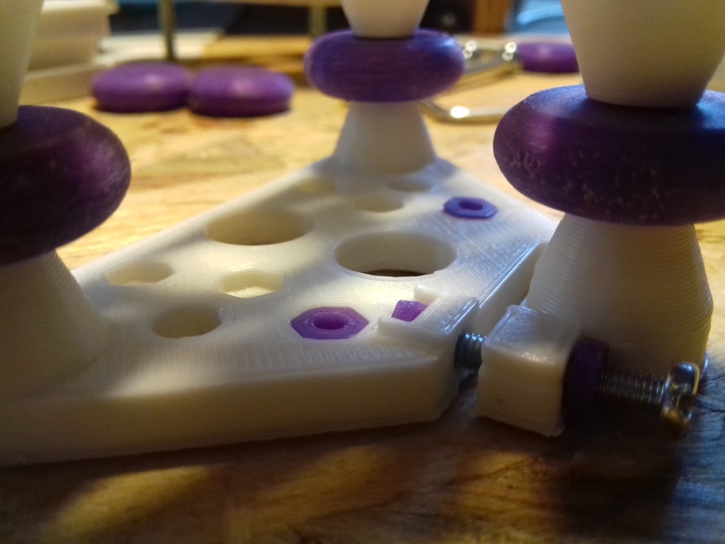
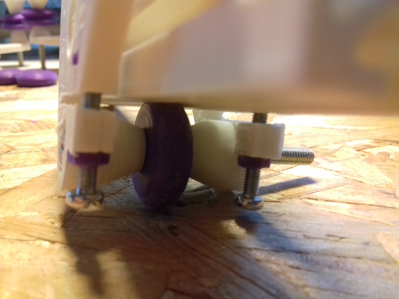
- 4x printed corner mounts holding 3.7mm thick sticker/mirror combo
- M3 x 35
- M3 washer (below printed corner mount)
- Spring (20mm long, ~10mm OD, 1mm wire)
- M3 washer
- printed knob (below plywood), 30mm OD, 8mm thick, M3 nut inserted
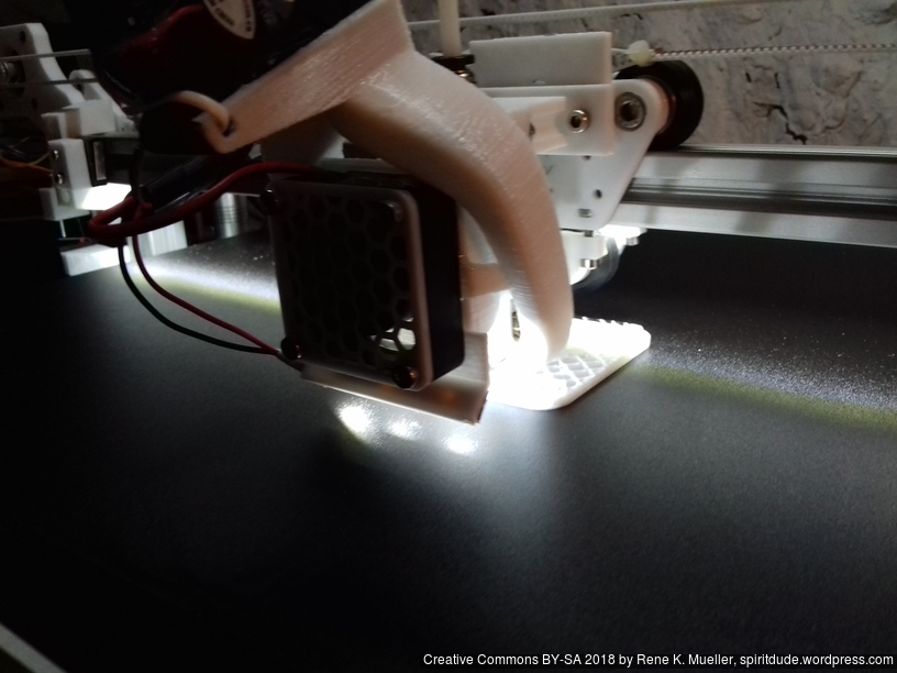
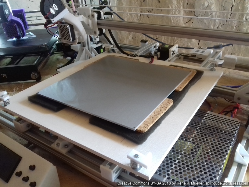
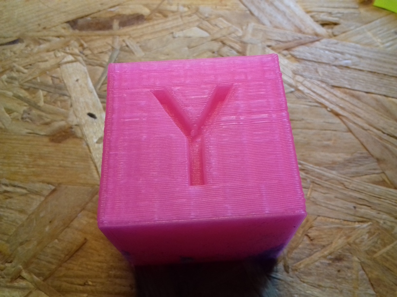
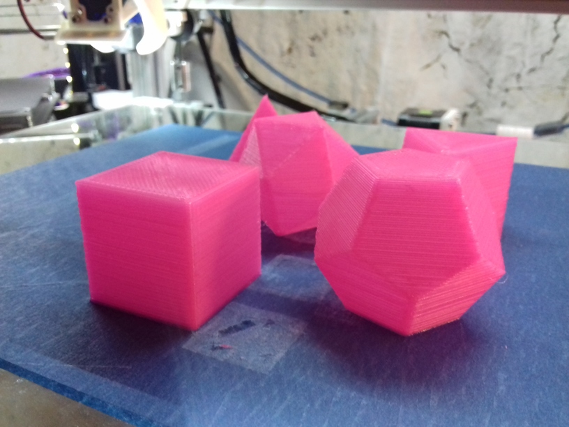
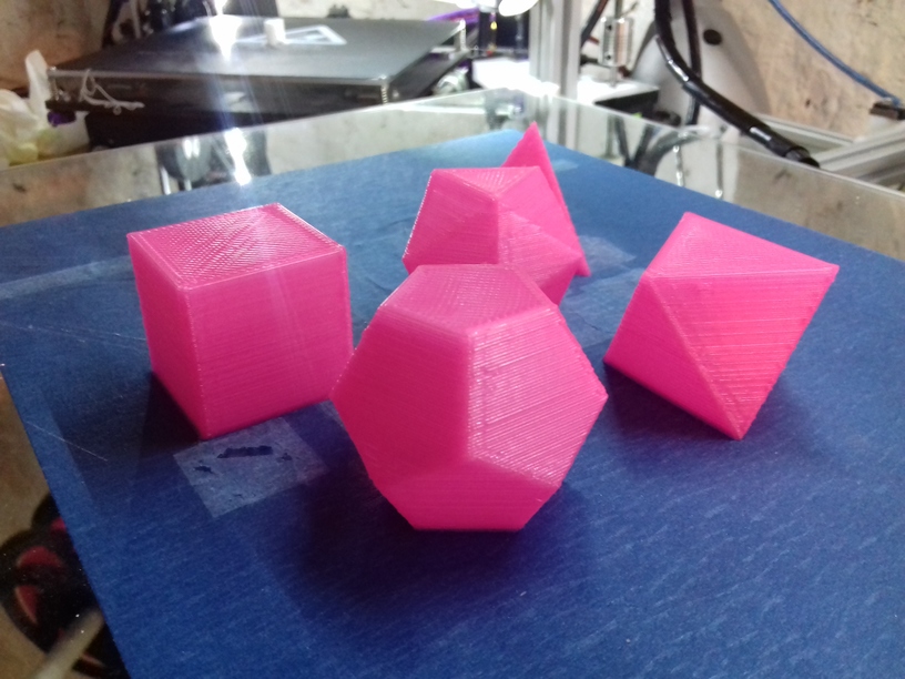
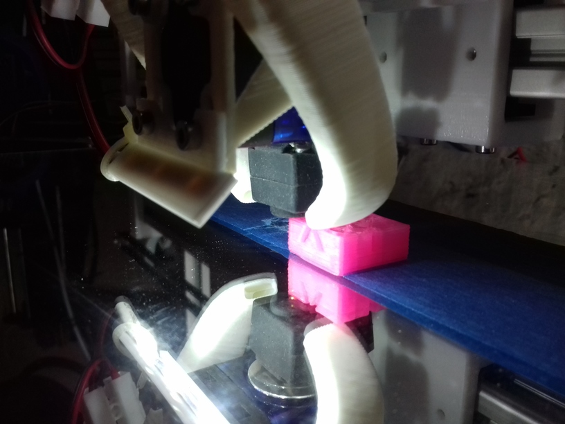
Now that I have a good print surface I finally printed pieces for itself.
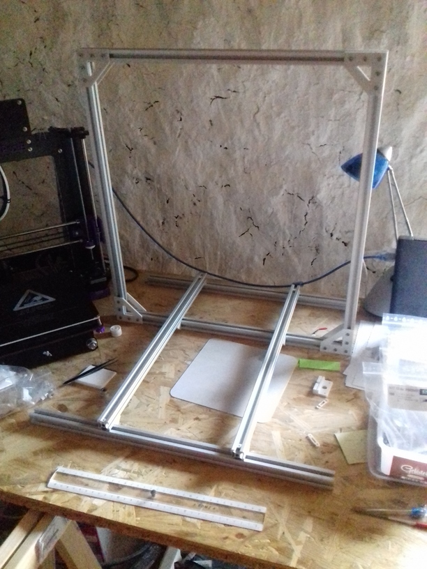
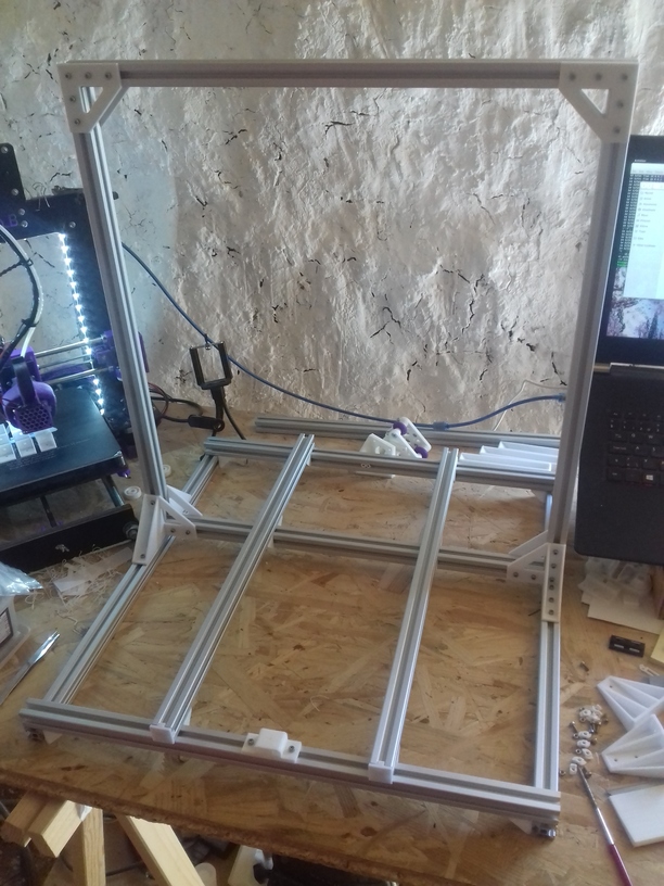
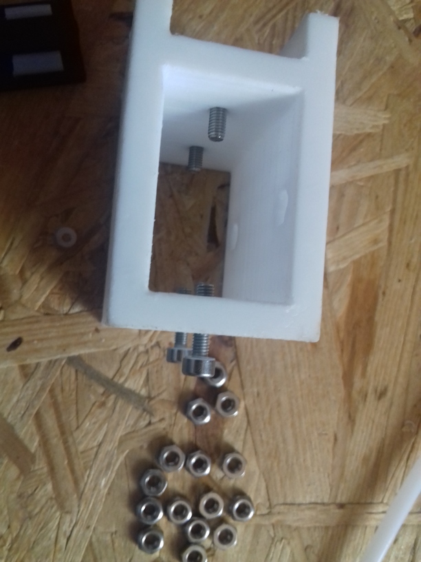
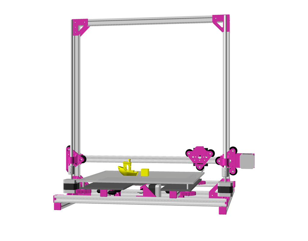
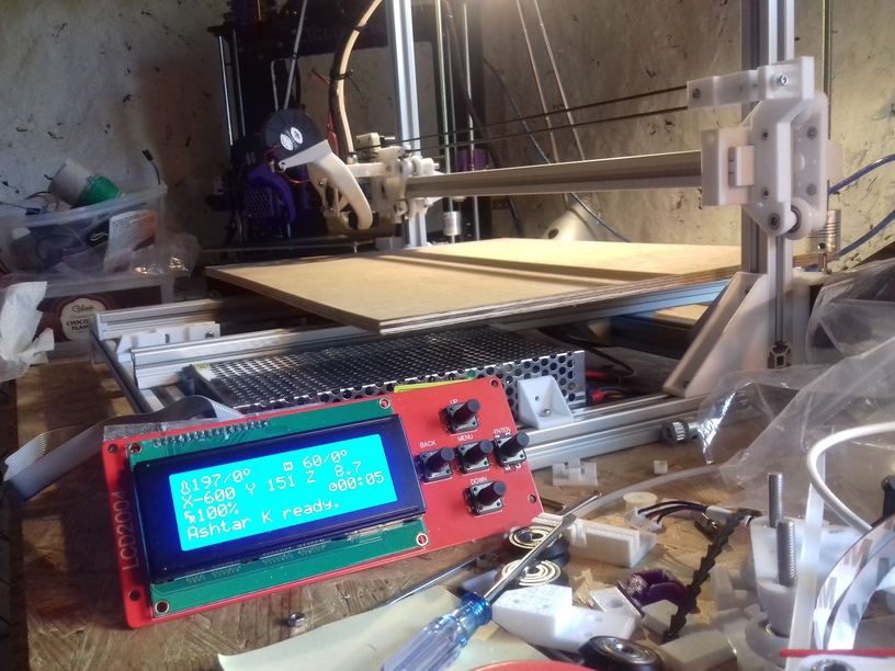
Mounting the 400×300 bed (OSB 6mm, white painted) with 200×200 heat bed (which I hardly use, as I started to print on cold bed):
I currently use the white PU steel enhanced GT2 belts, and it produces hard edges, some ghosting, but more precise prints than the black rubber GT2 belts which just stretch too much – I have to research this more closely – about the type of reinforcement and the use with more heavy beds (Y carriage).
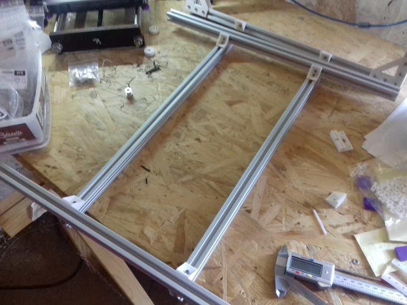
Just for the record regarding Y carriage (2018/09):
420×320 carriage:
- 4mm plywood flexes, but has been quite flat – not recommended
- 6mm plywood hardly flexes, but has been hard to buy truly flat – and so far my attempt to flatten it did not work well – not recommend unless it’s flat
- 6mm OSB quite flat, does not flex much (3 or 4 sliders) – recommended
320×320 carriage (for 300×300 bed):
- 4mm plywood works (3 sliders, 4 sliders recommended)
- 6mm plywood works (3 sliders, 4 sliders possible if plywood is truly flat <0.2mm difference)
- 6mm OSB quite flat, doesn’t flex (not yet tested)
Just to explain my thought or decision process for my setup:
- the mirror should not be bend (of course)
- the support structure should not be the edge mounts, but the foam in between
- the carriage can be bent, but not flex
- revelation: already bent means the springs with screws might extend the bent further with a flexing carriage, and not counter act – as the mirror should stay flat
so, even though the springs/screws and edge mount can adjust, the carriage should be fairly flat, and not flex at all – this way the edge mounts holding the glass/mirror only stabilize position. Main force to hold the glass/mirror, for my setup, is the foam in between. So, there is no “spring” induced vibration back/forth introduced, but the foam neutralizes such vibrations – and hardly adds weight/inertia.
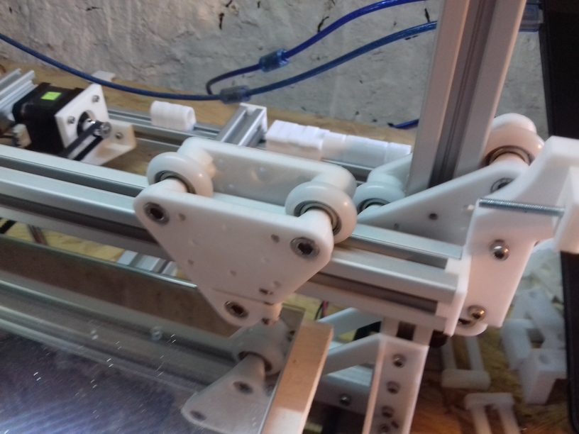
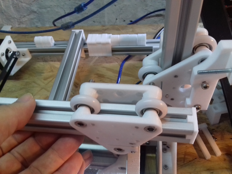
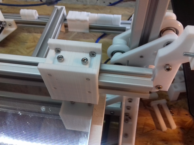
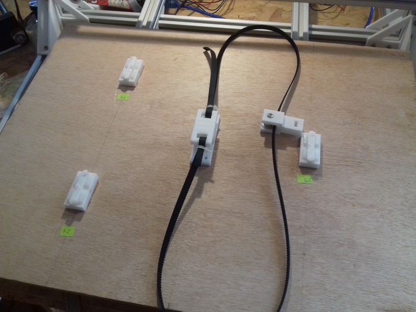
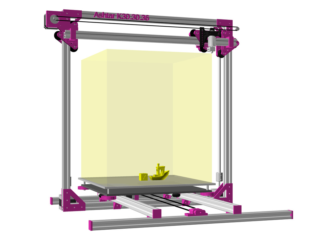
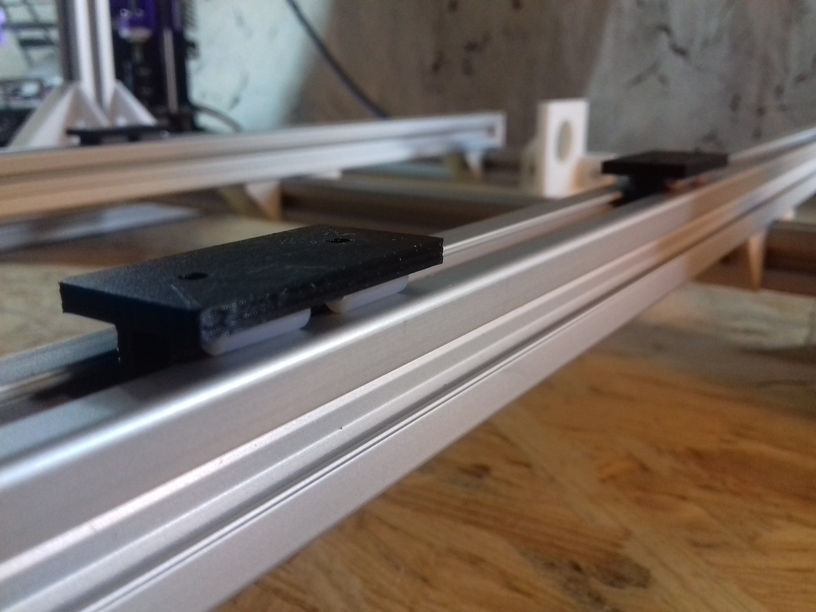
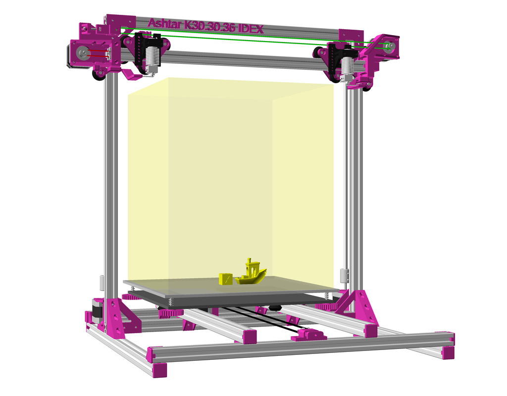
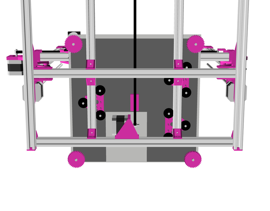
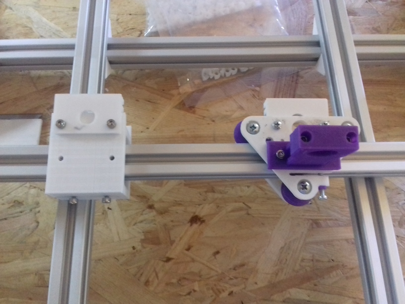
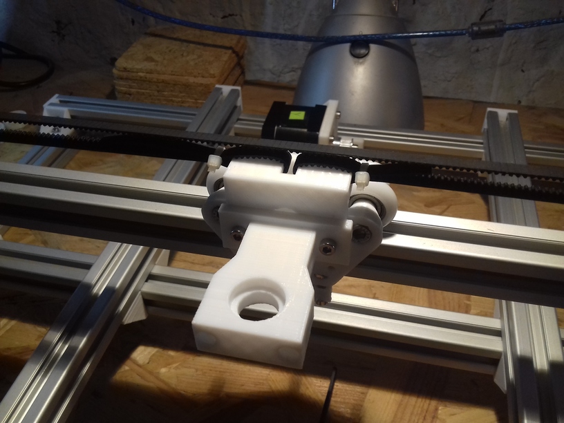
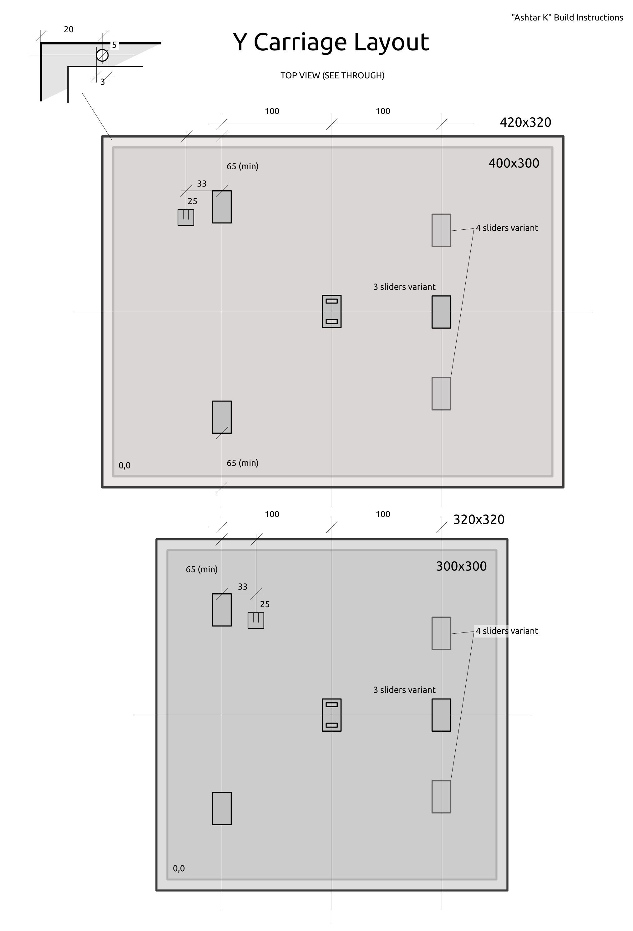
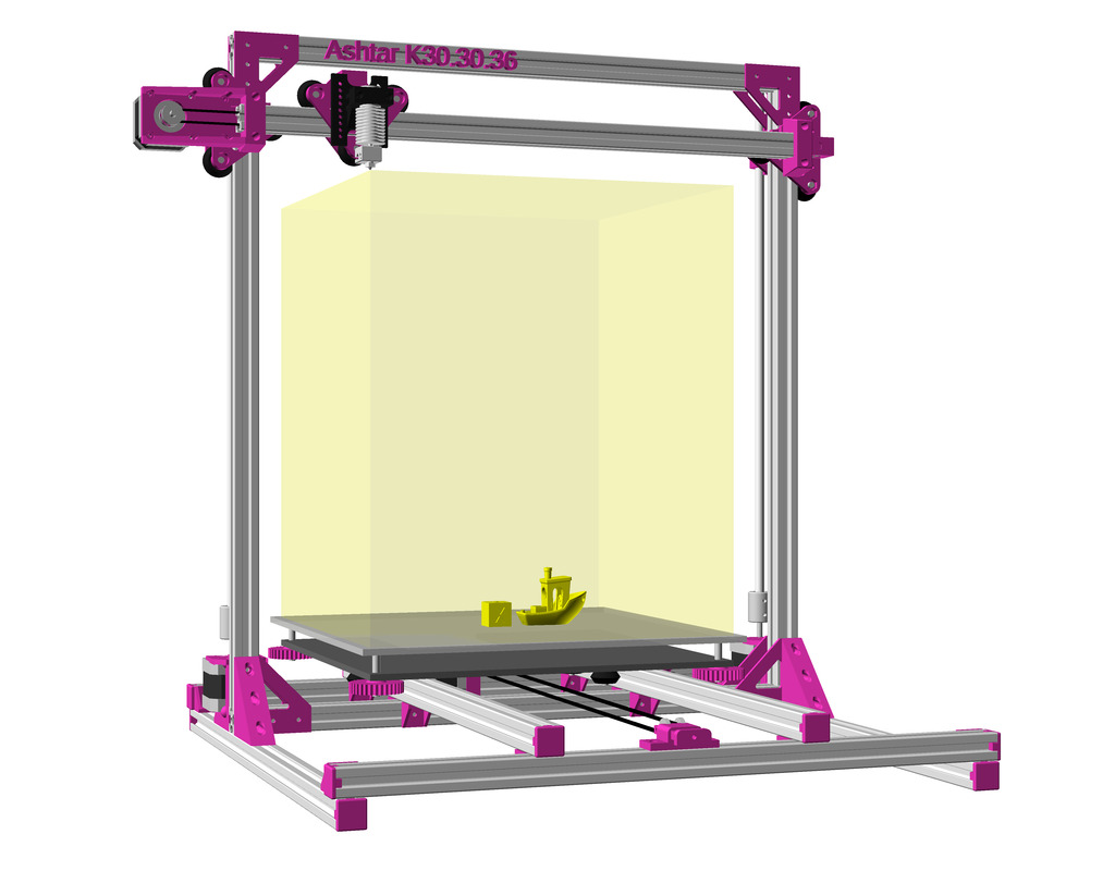
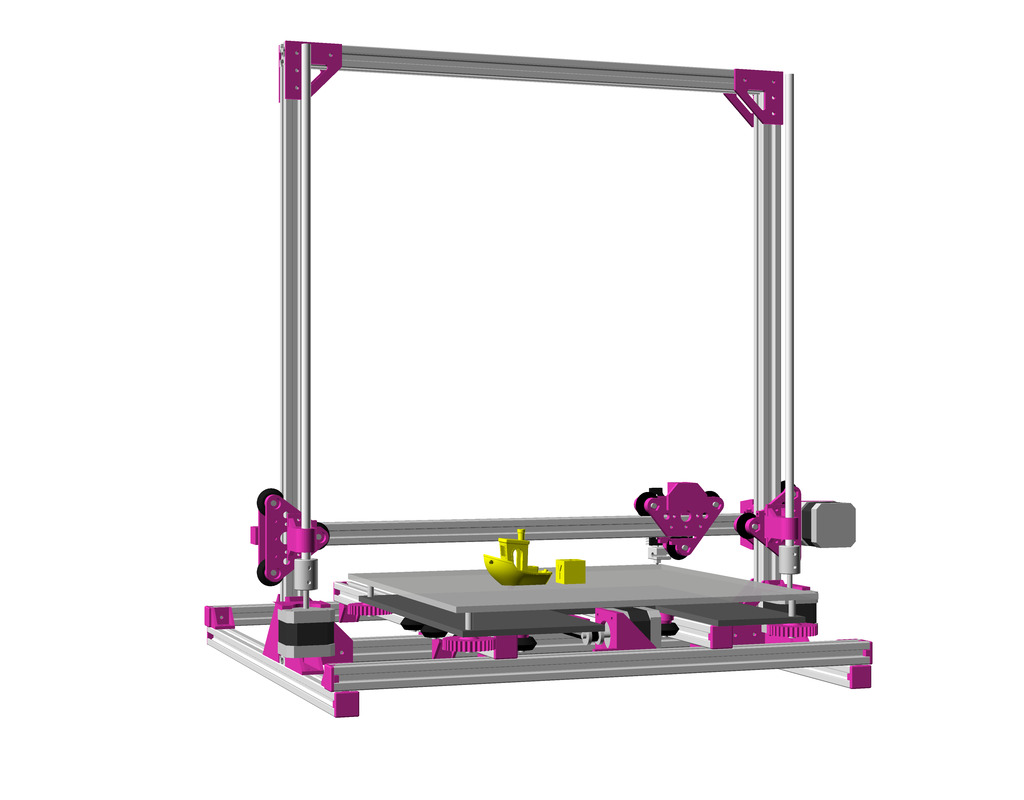
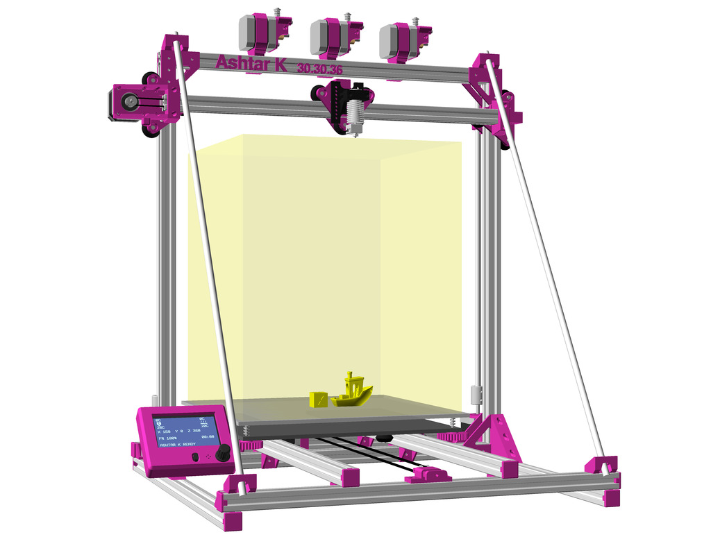
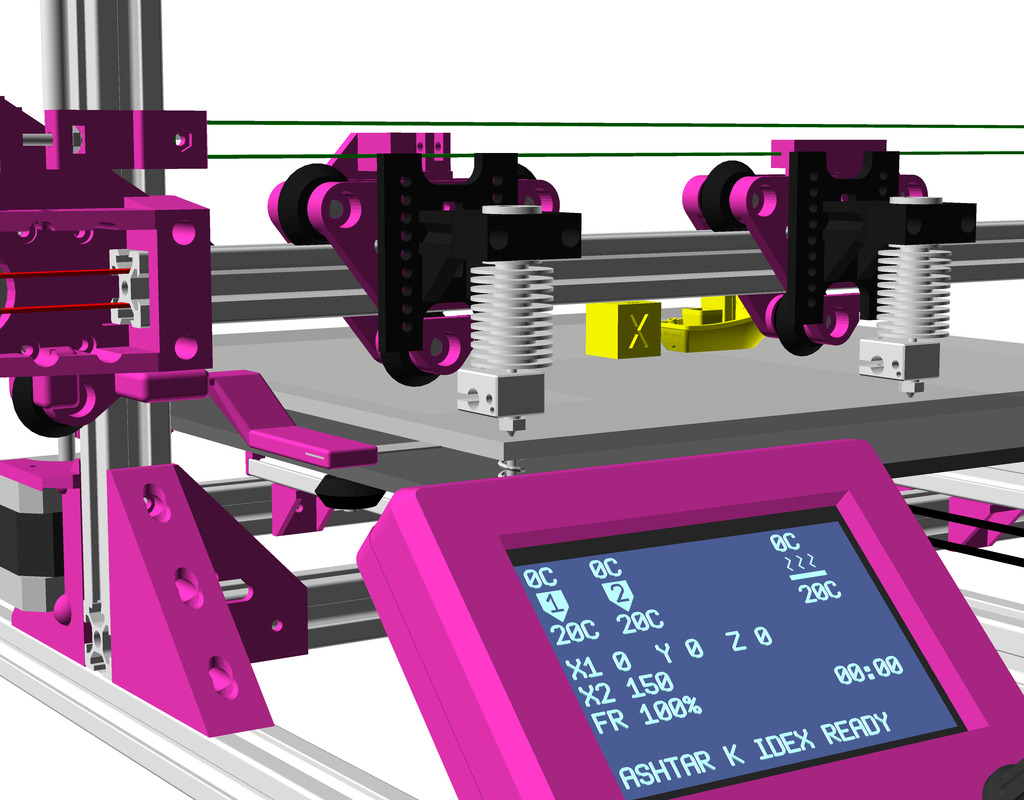
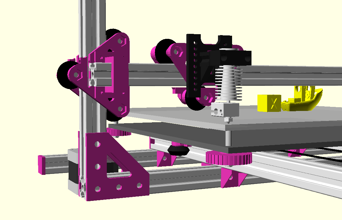
Sliders & Belt Mount Positions
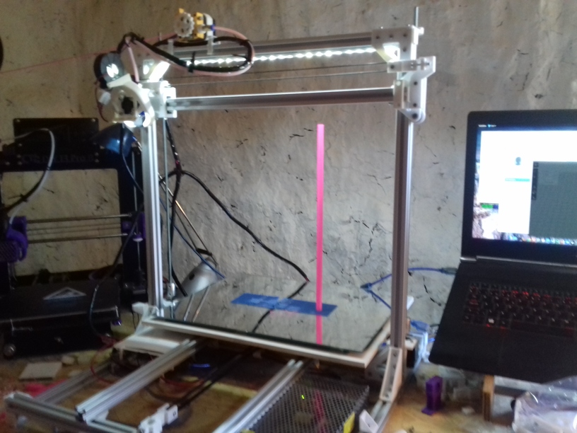
Top view with see-through (best mark “0,0” on both sides to keep reference).

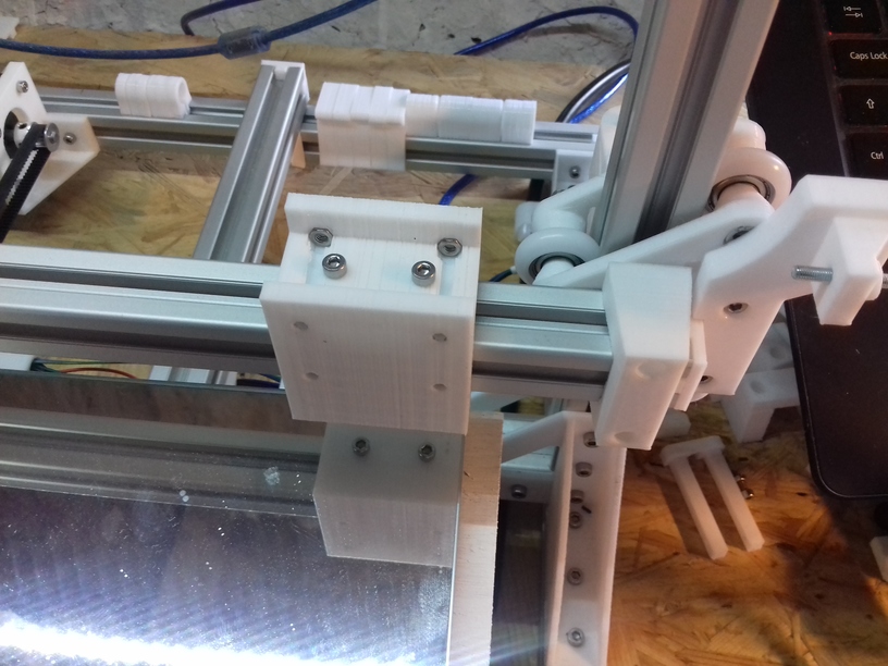
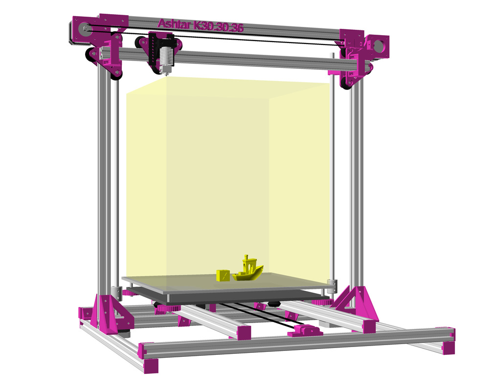
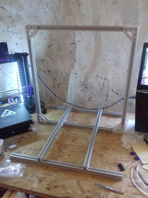
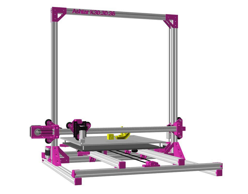
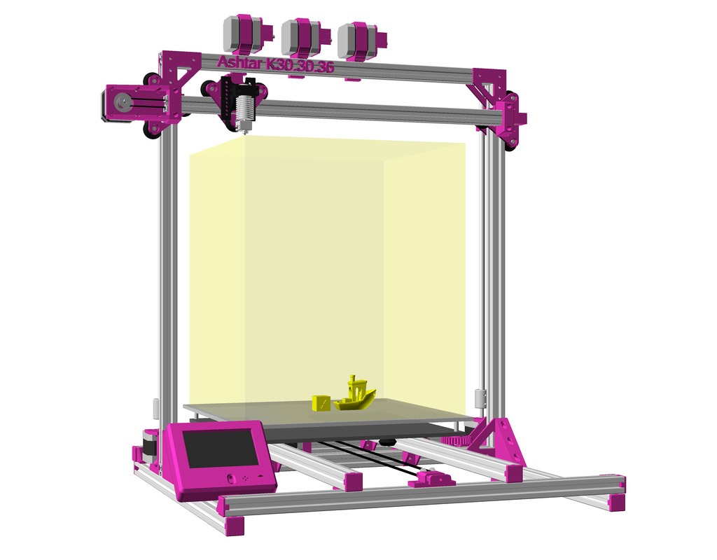
400×300 vs 300×300 Bed
Originally I focused on 300×300 bed at least, with some tweaking and narrow X carriage I was able to reach 380×300 printable bed, so it was suitable to use 400×300 plate as well.
It takes me about 5min to mount new bed, downgrade from 400×300 to 300×300:

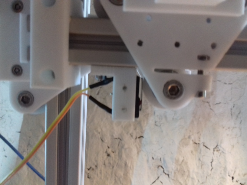
Changes needed:
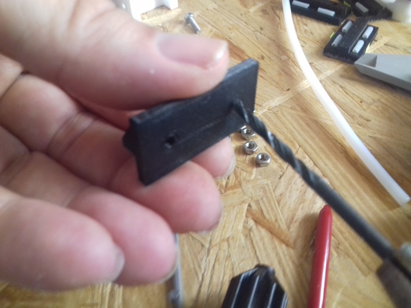
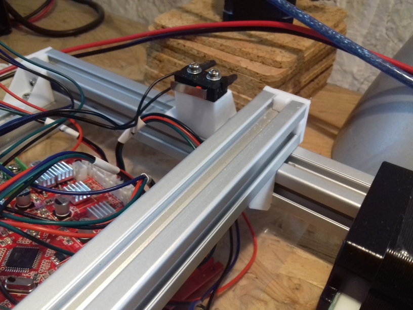
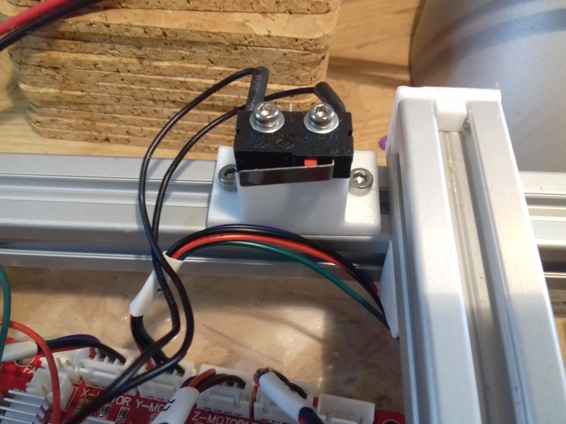
- move Y endstop switch from left to Y carriage extrusion to the right side
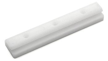
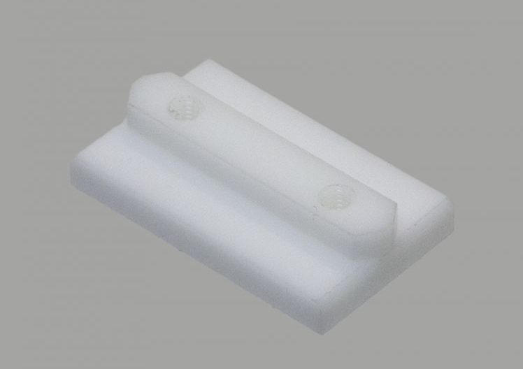
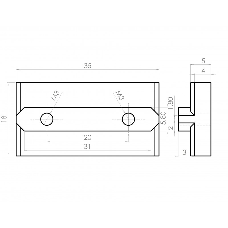
- Y stopper mounted on the bed needs to placed accordingly
With 300×300 bed the 0,0 is now plenty outside of the bed, with 400×300 the 0,0 is near the printed bed mount.
Setting Offsets for 300×300 bed
With 300×300 bed the 0,0 is now +32mm to right and +25mm deeper, hence the Gcode M206 is set like this:
M206 X-32 Y-25
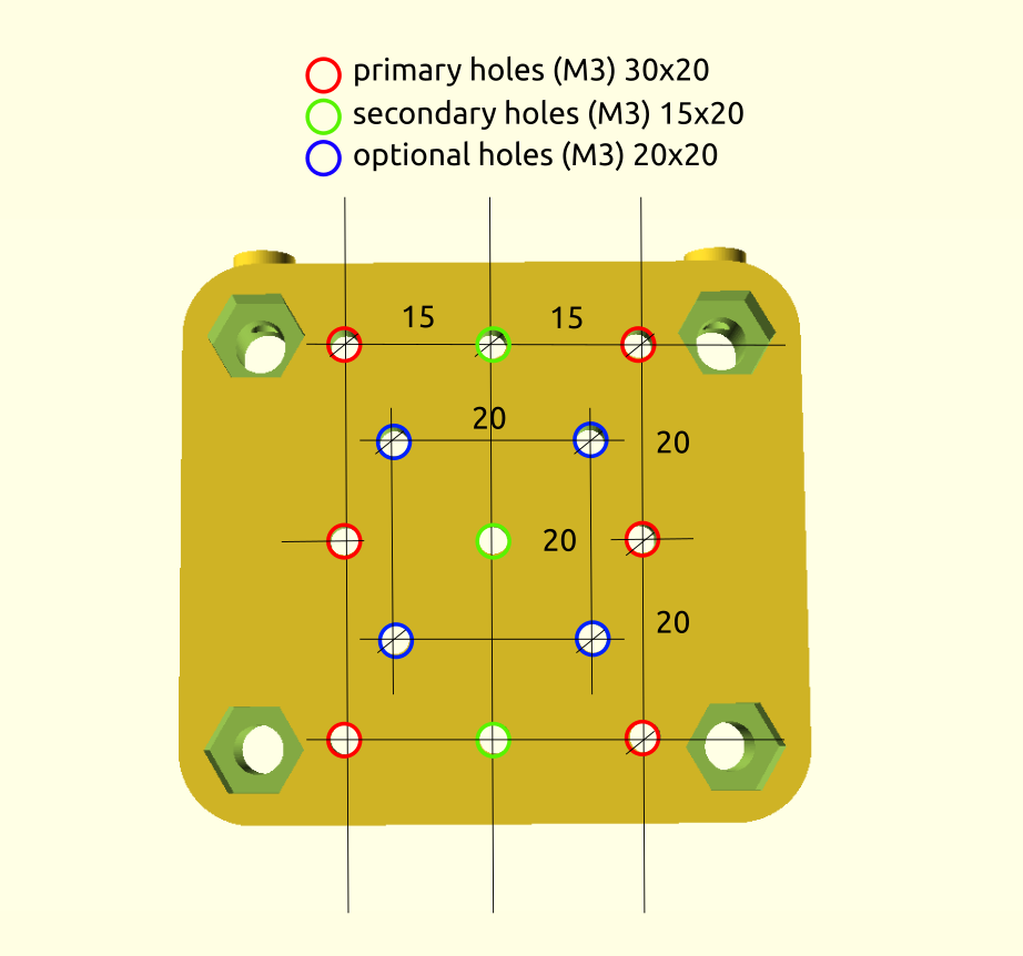
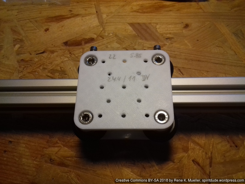
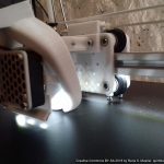
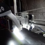
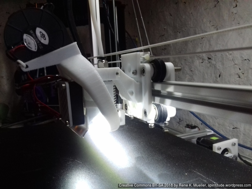
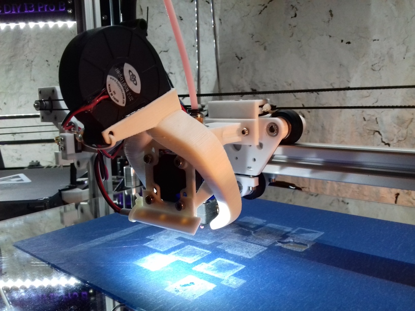
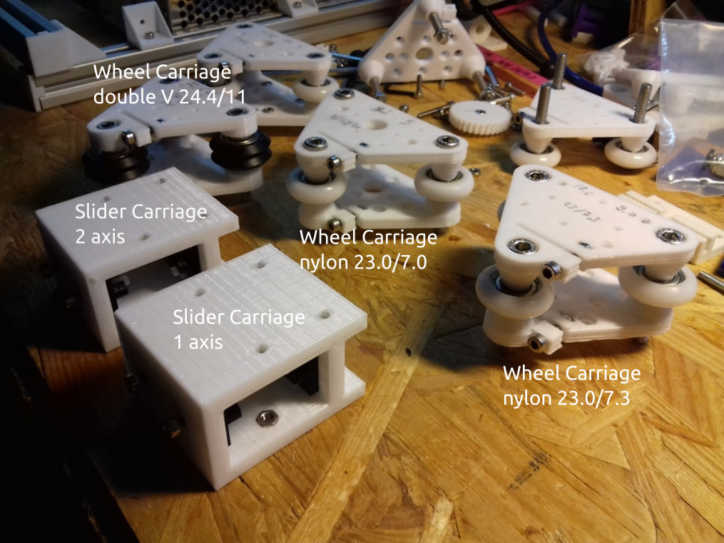
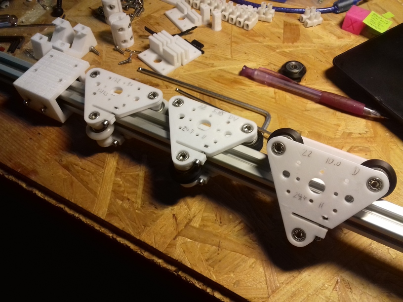
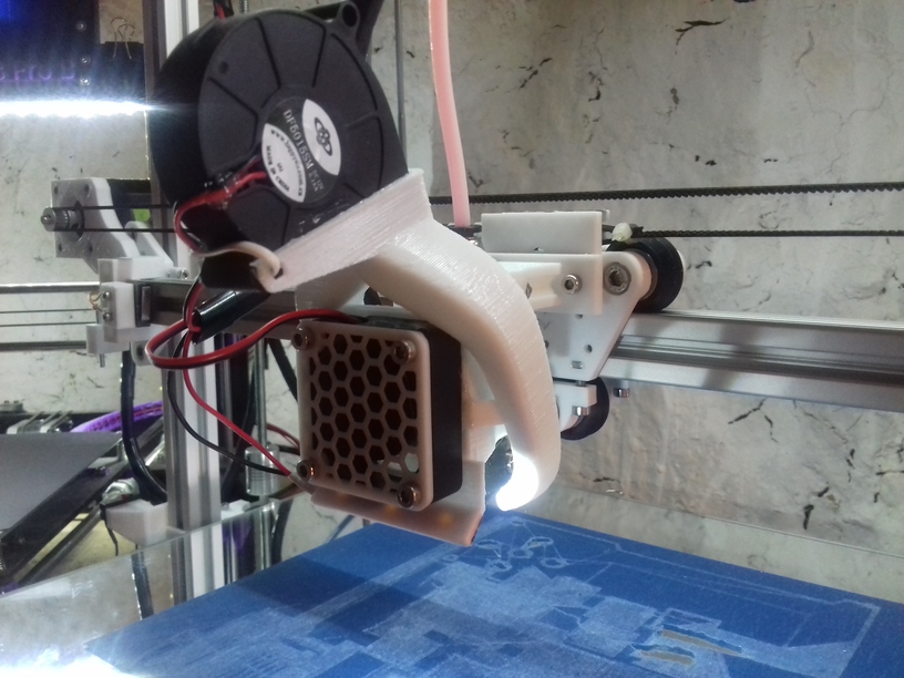
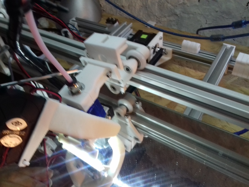
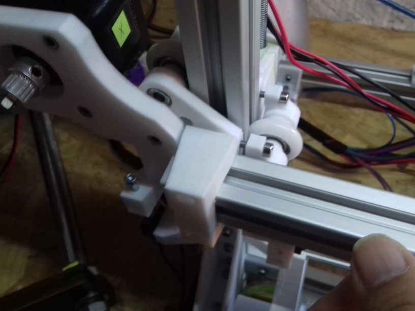
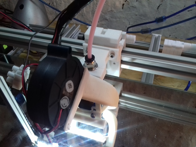
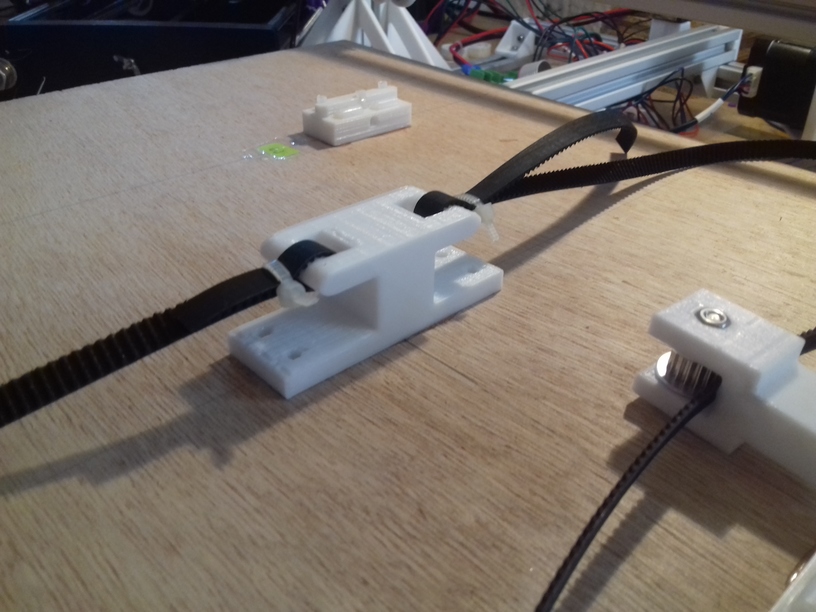
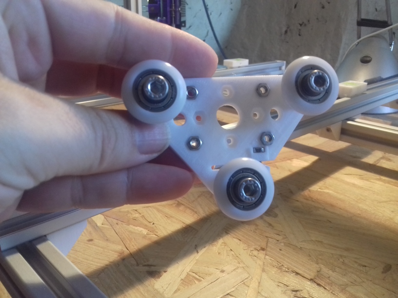
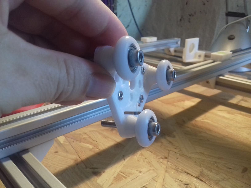
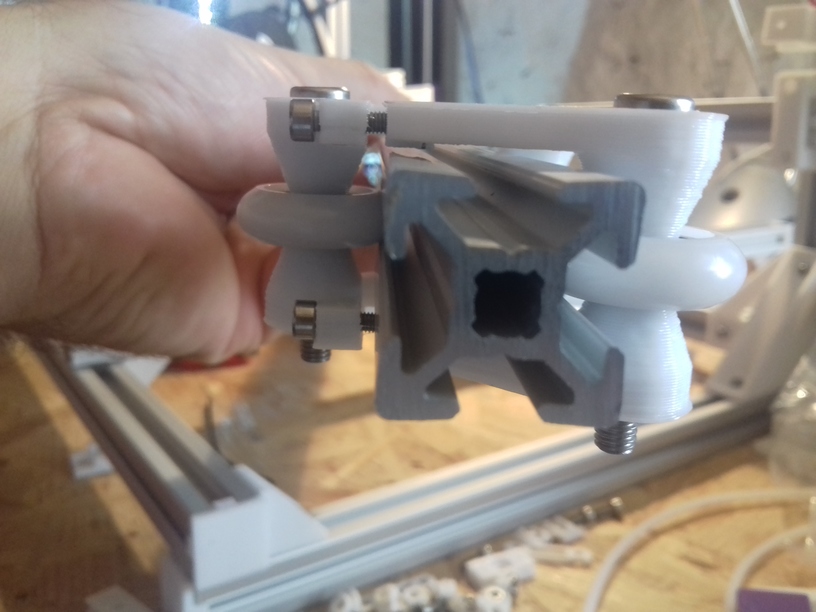
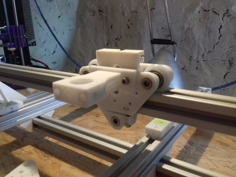
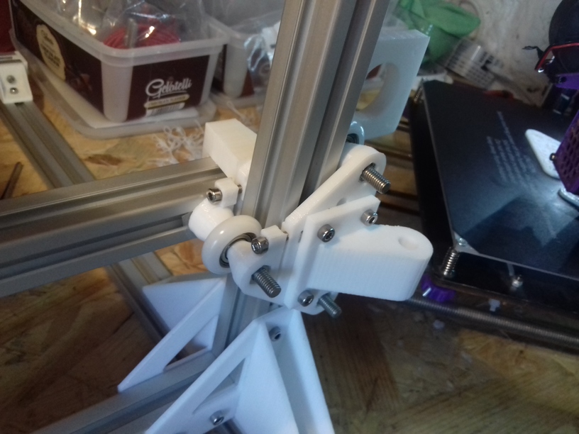
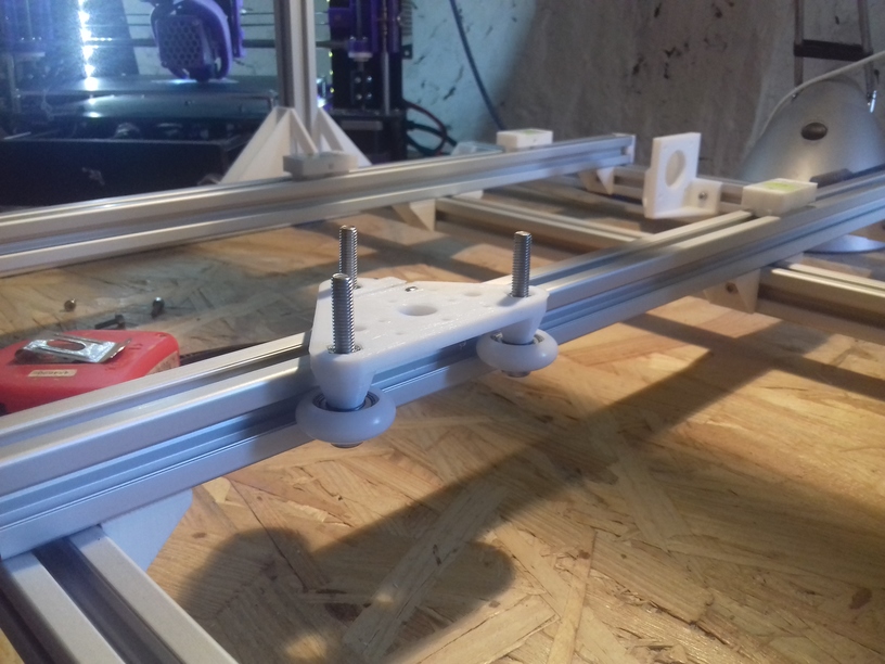
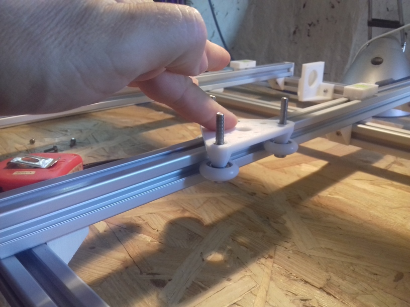
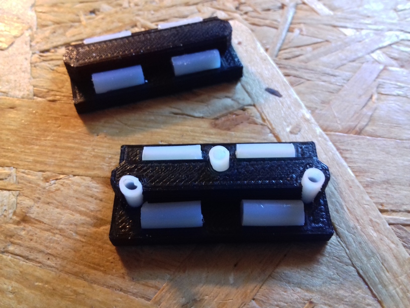
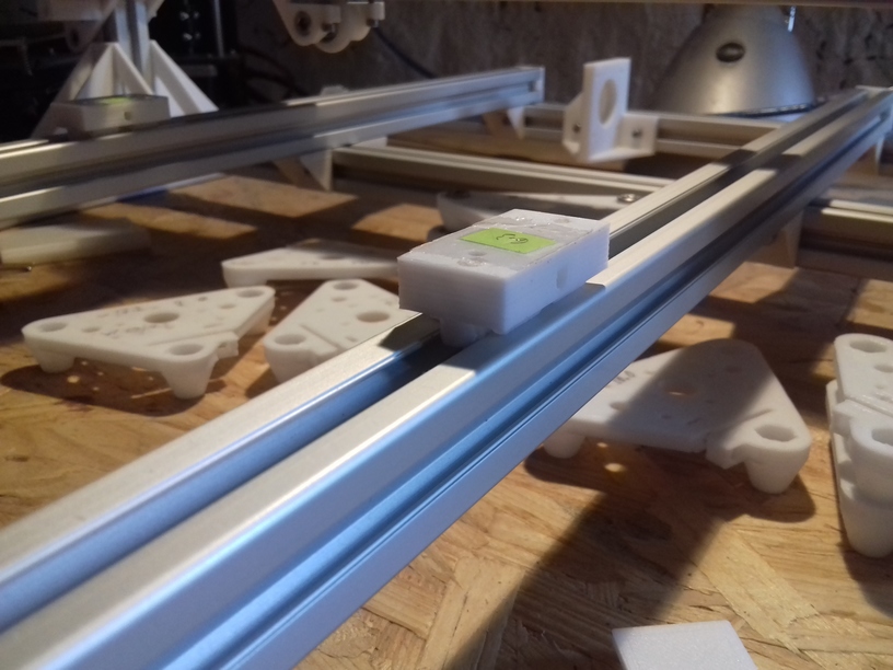
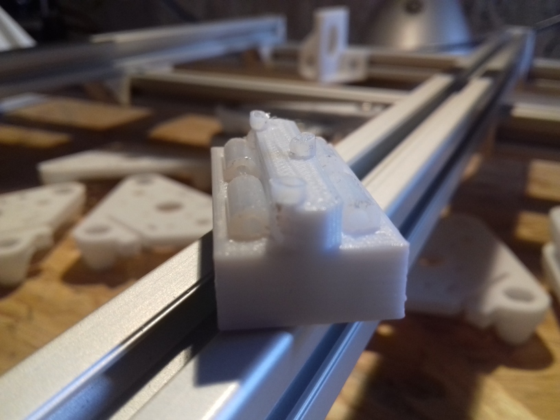
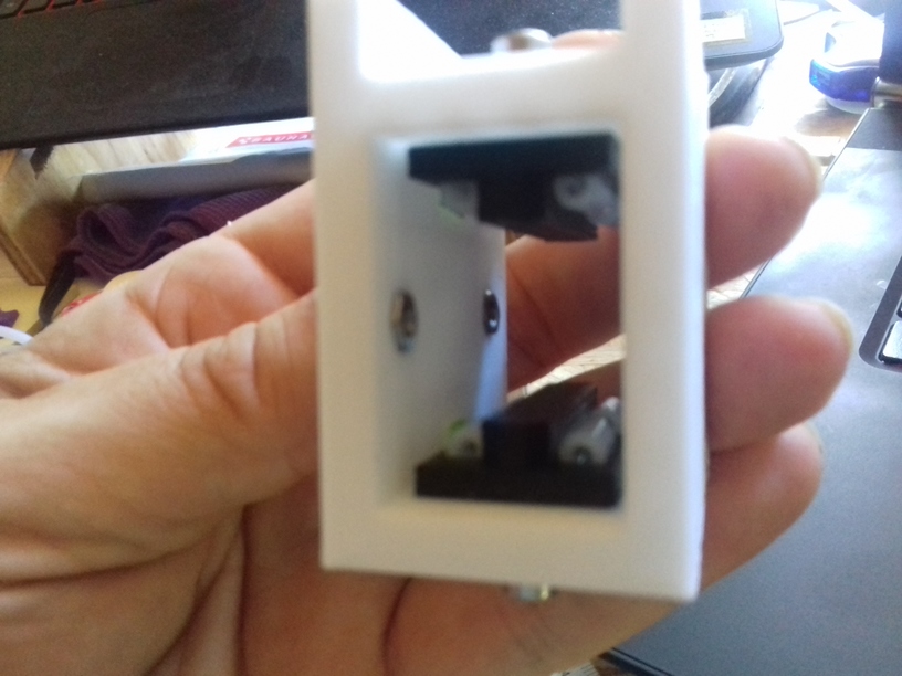
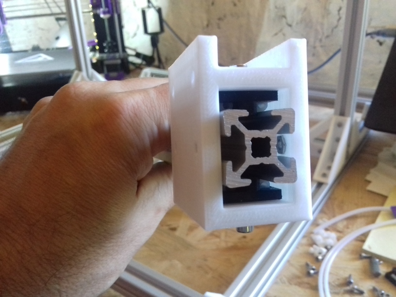
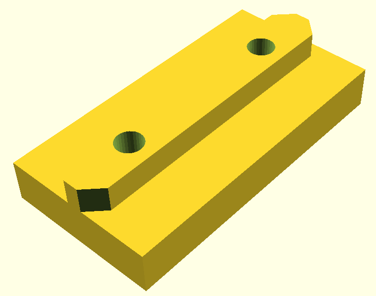
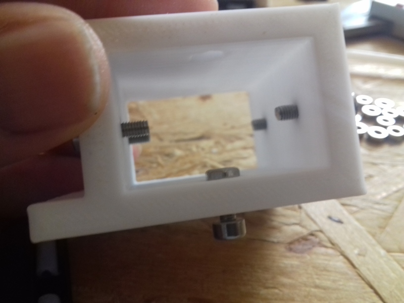
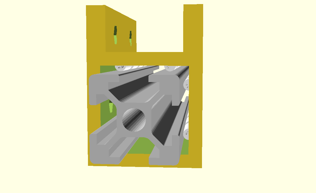
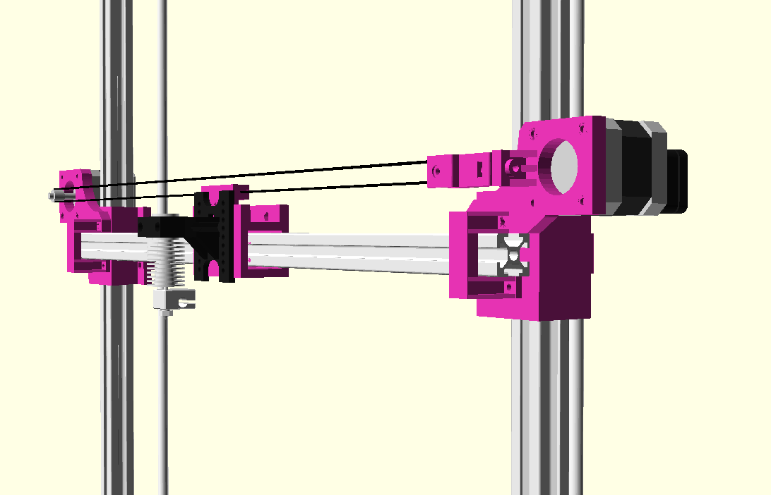
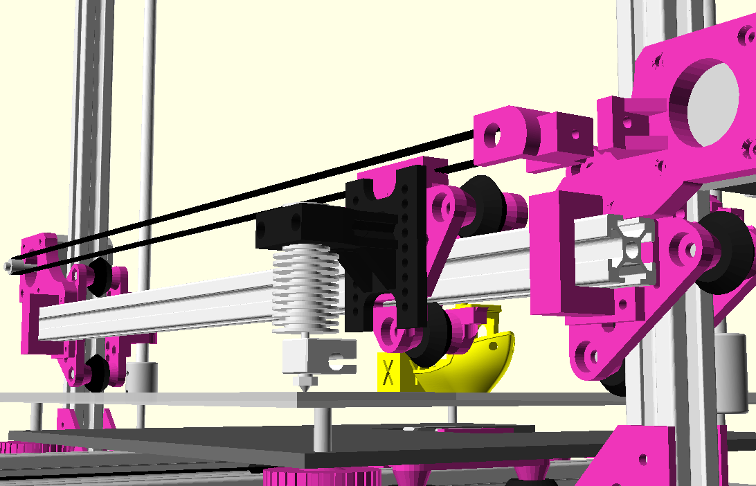
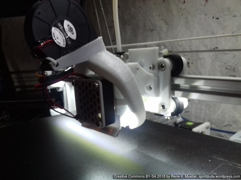
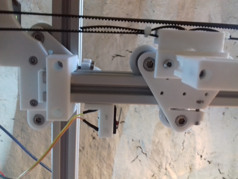
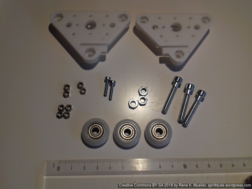
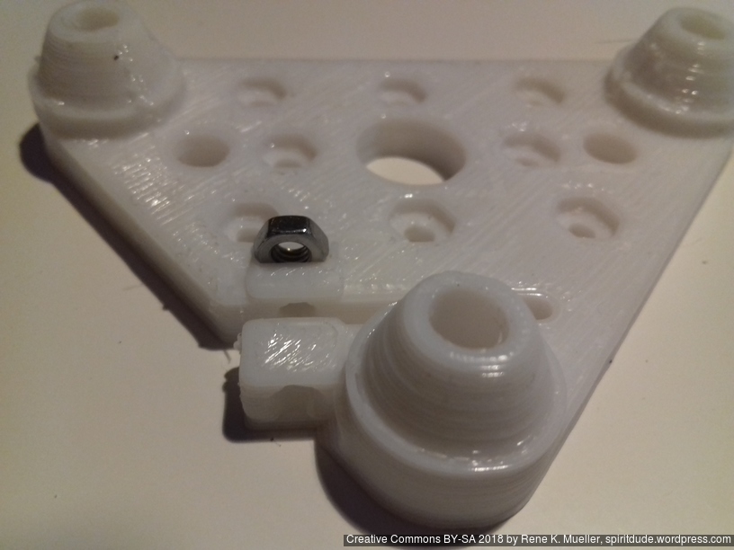
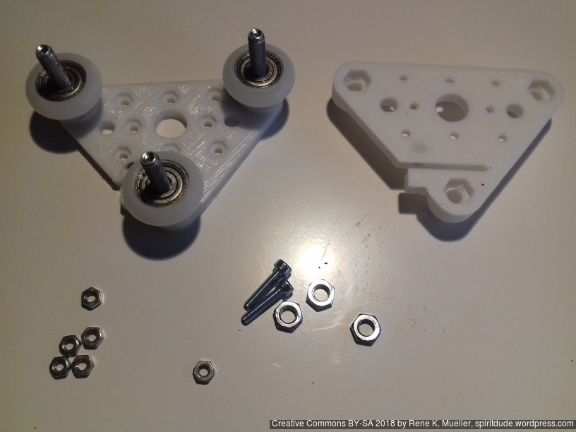
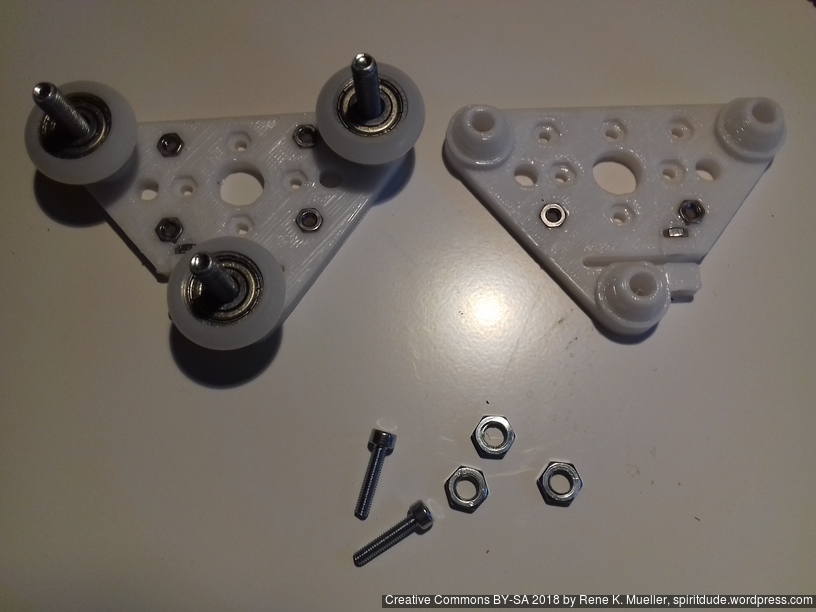
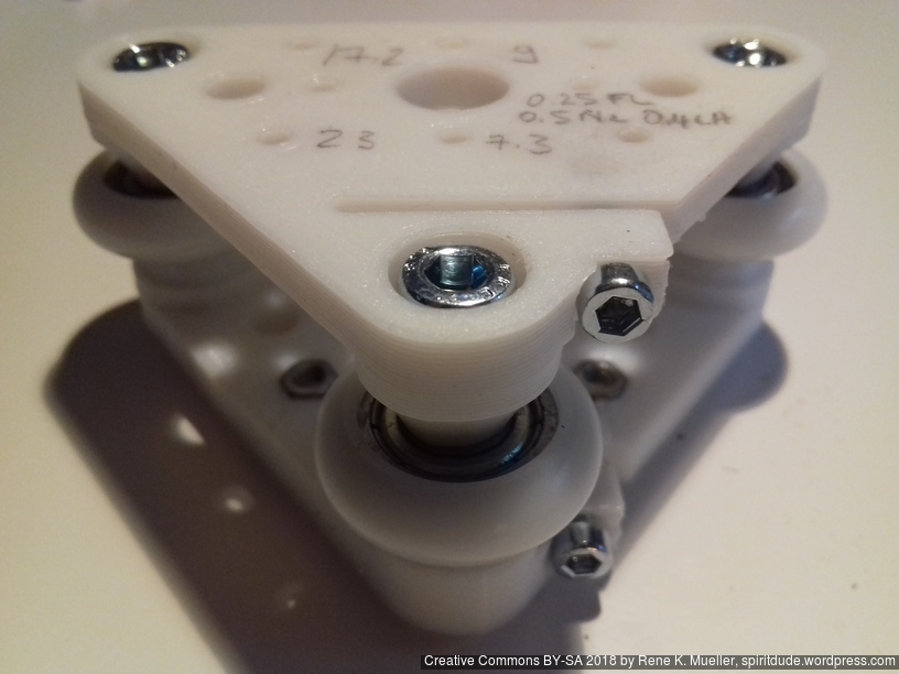
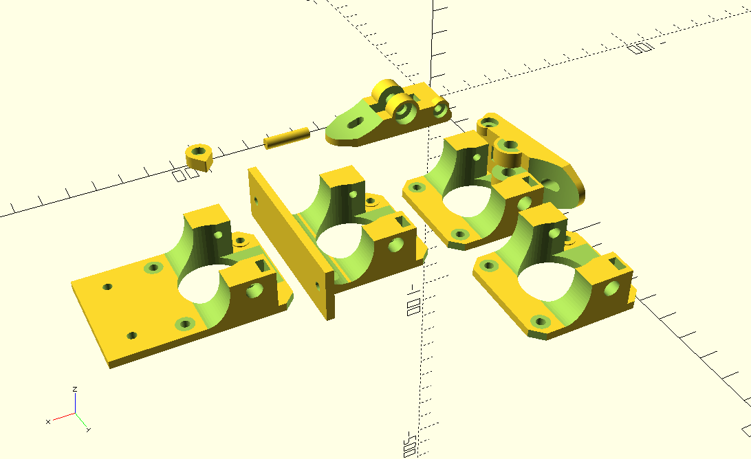
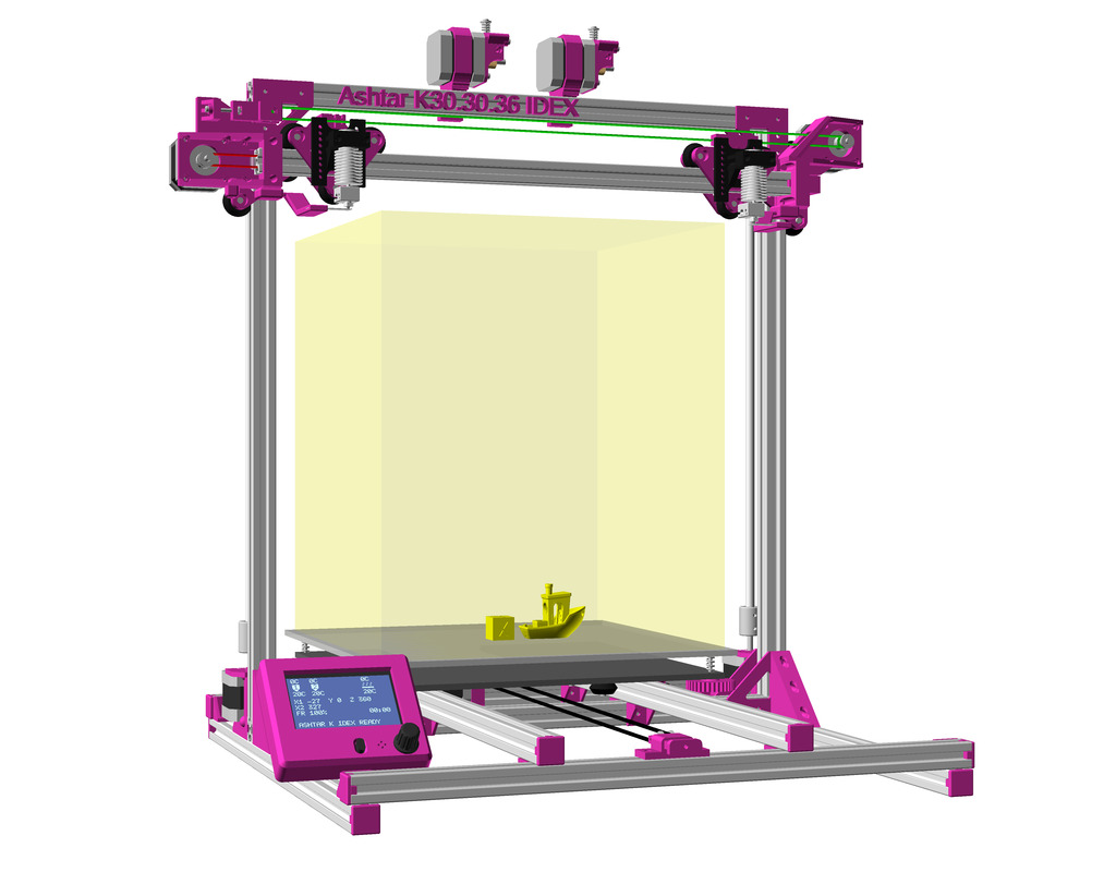
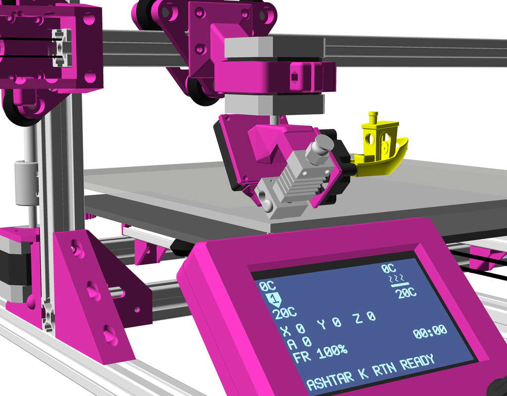
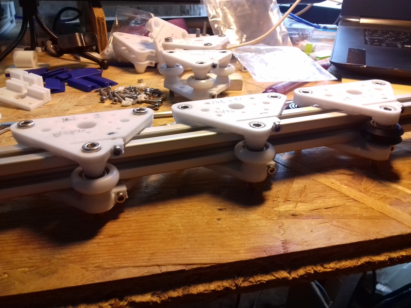
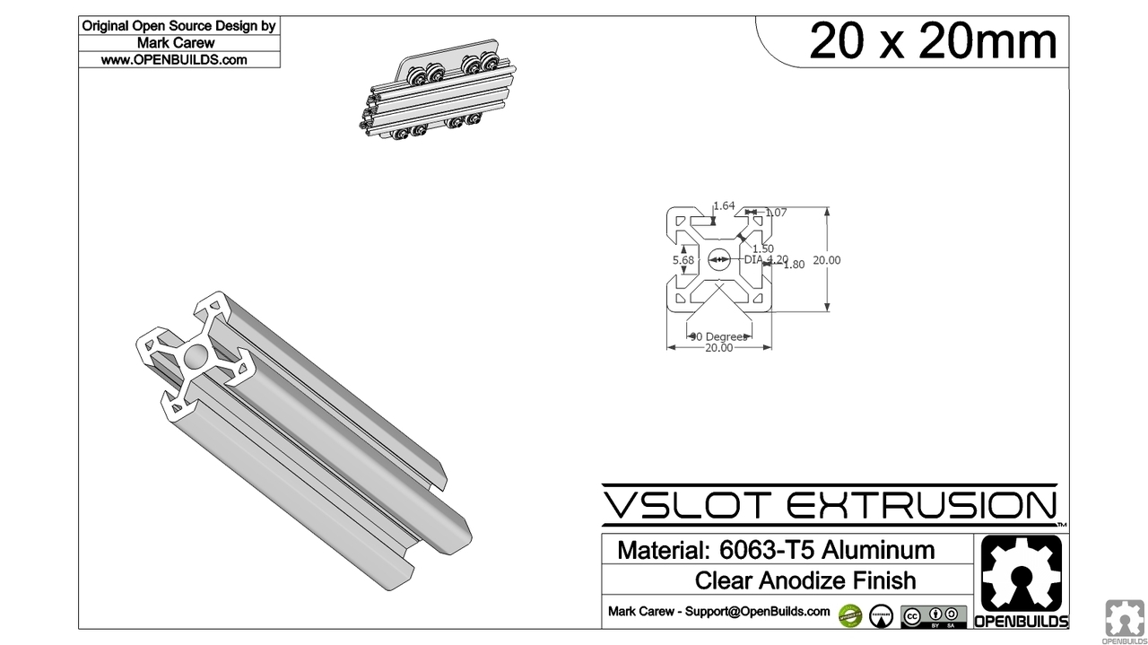
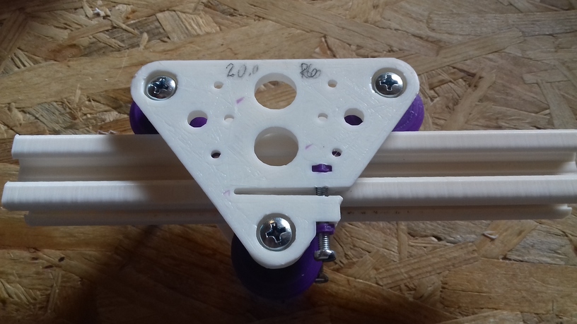
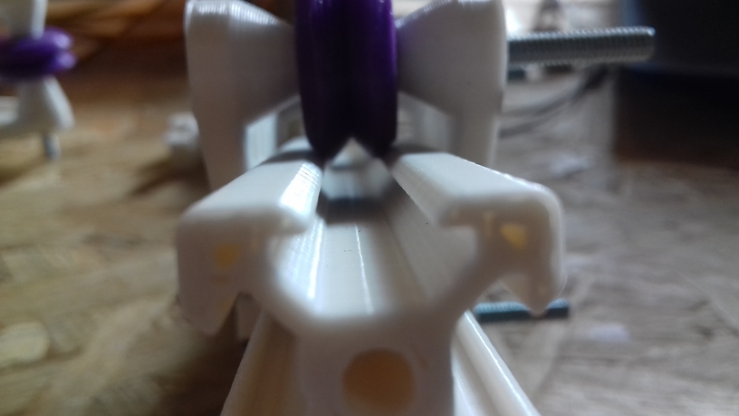
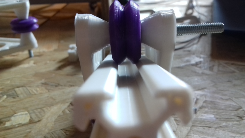
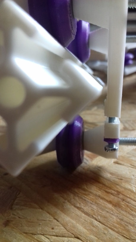
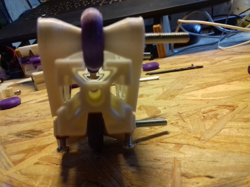
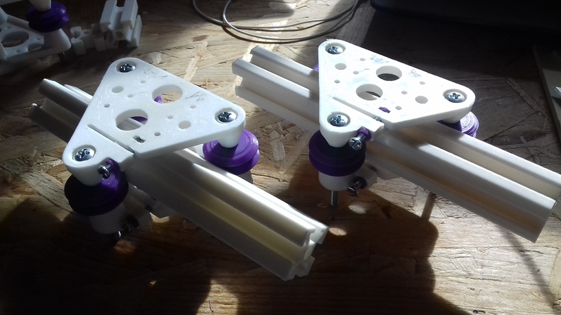
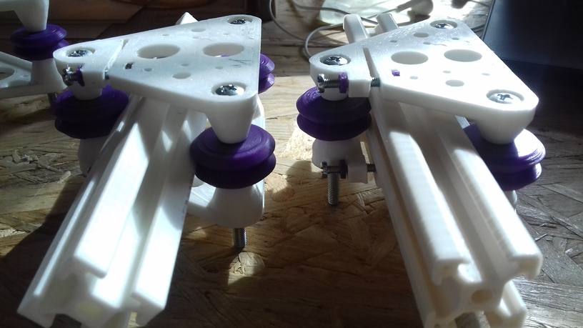
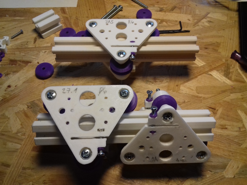
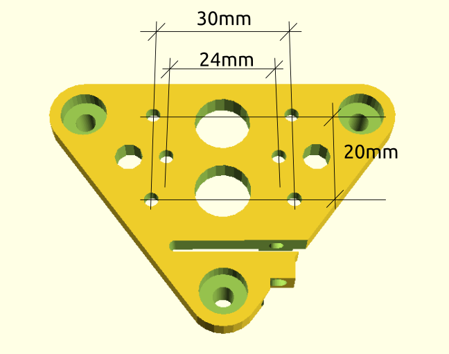
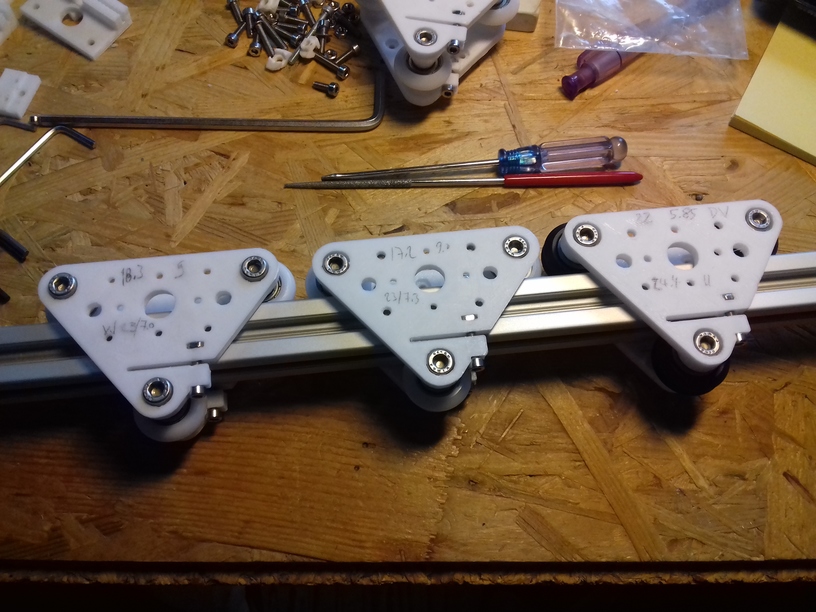
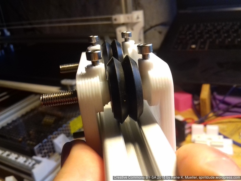
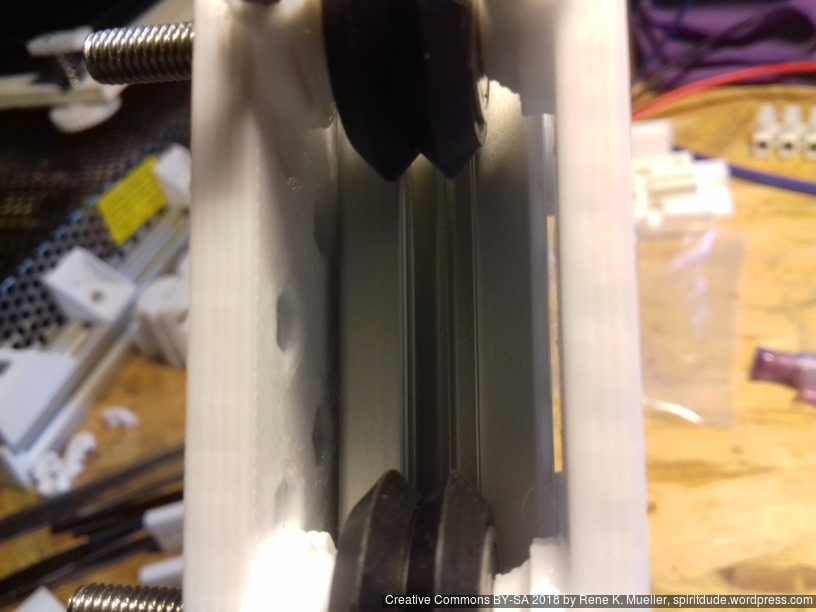
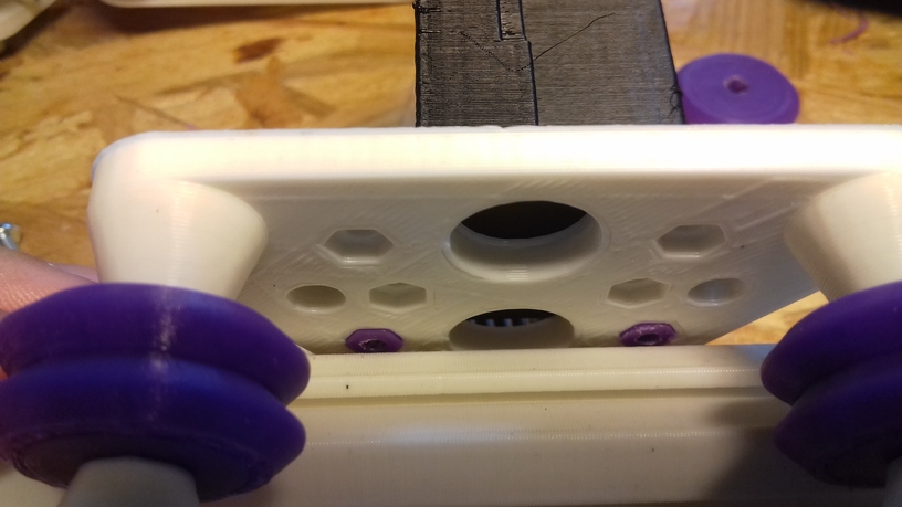
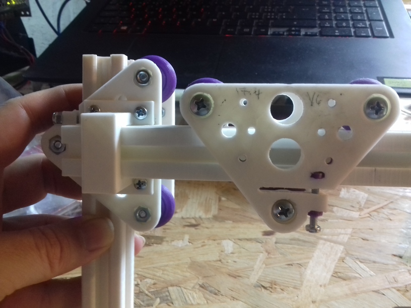
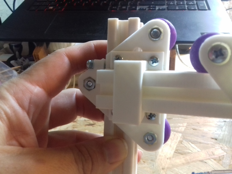
H Plate/Module as X Carriage
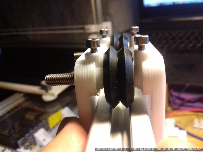
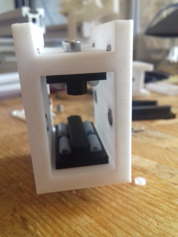
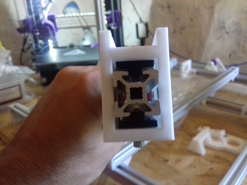
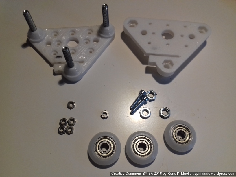
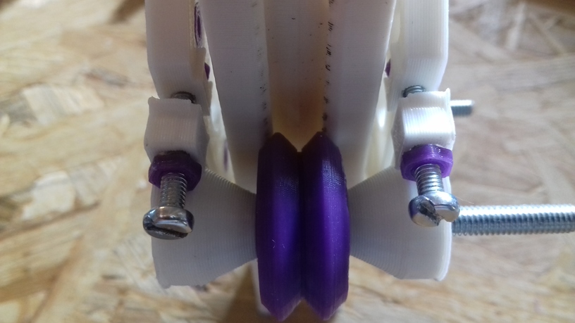
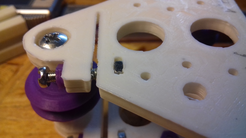
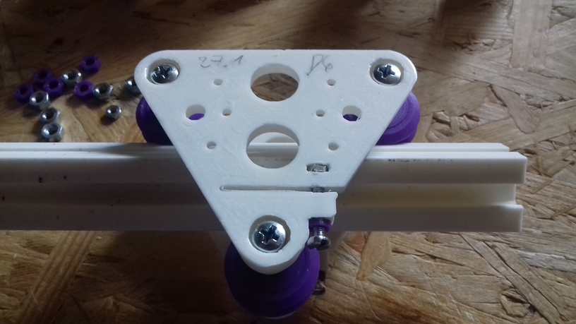
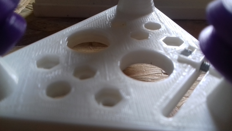
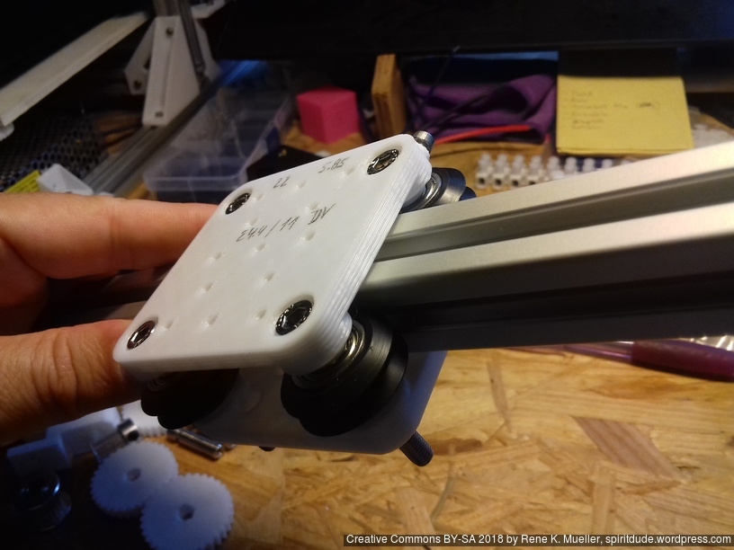
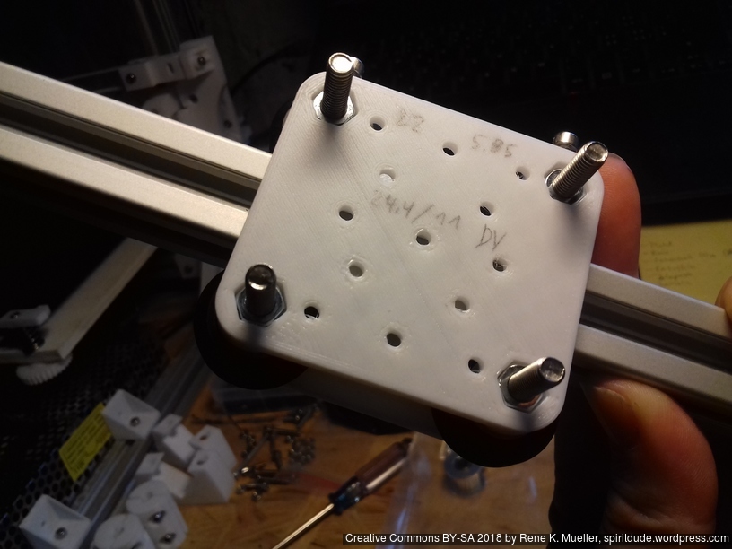
The 3 wheels module riding on the 2020 alu extrusion I named “V plate” due the shape, the 4 wheels module “H plate” providing more stability or rigidity for use as X axis carriage, when the nozzle runs over slightly unclean extrusion and tilts upside. For the X carriage I choose a narrow (48mm wide hole-to-hole) version:
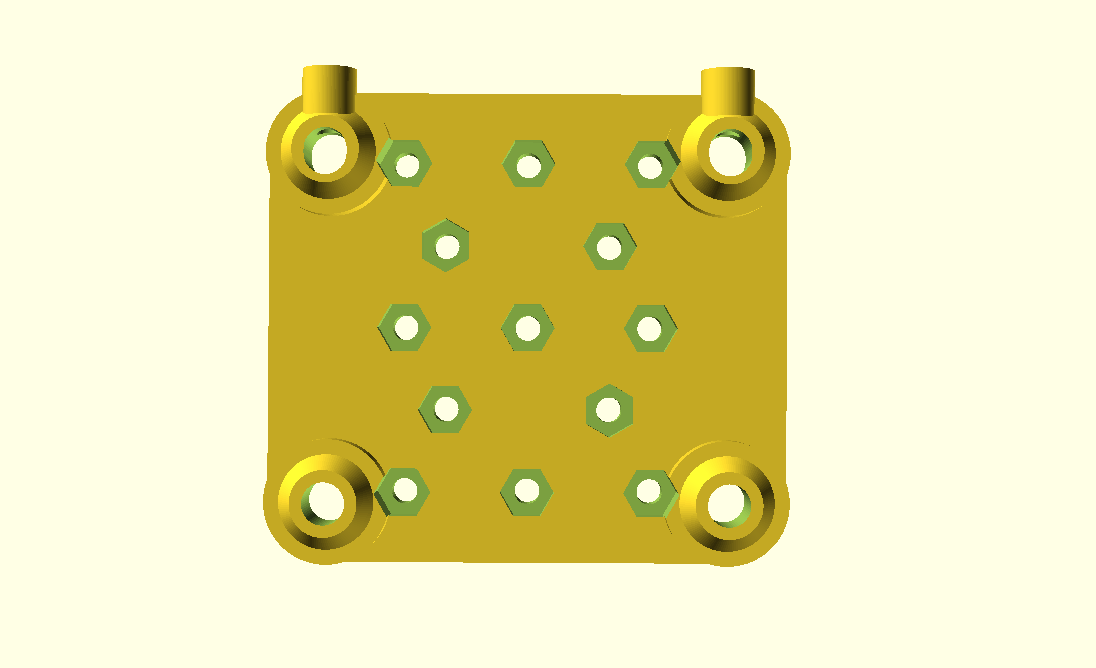

-
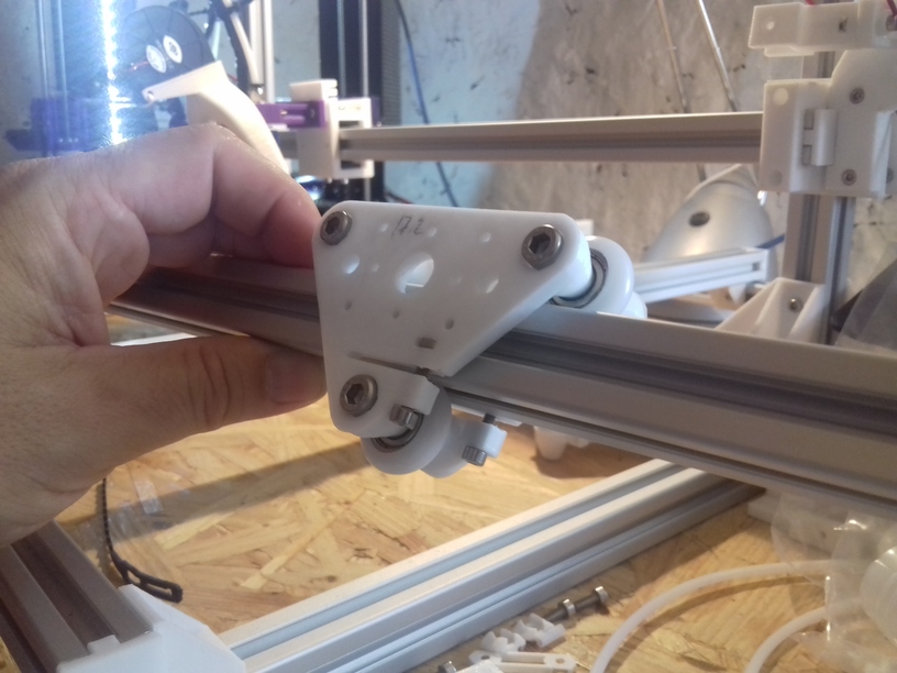
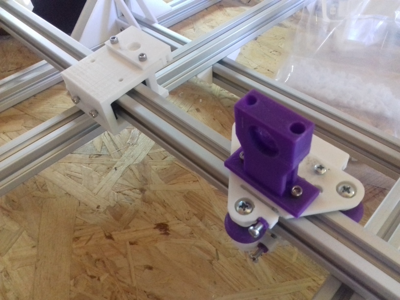
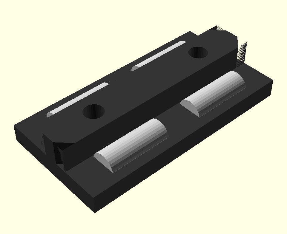
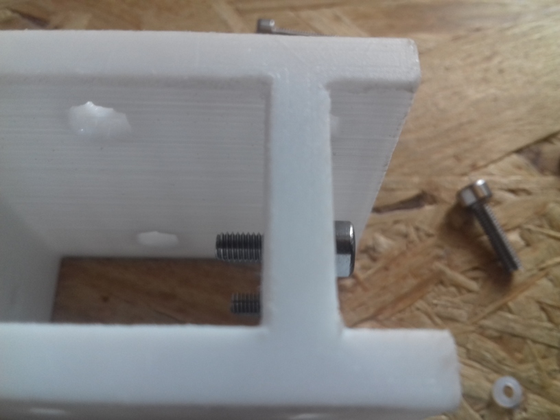
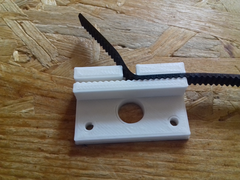
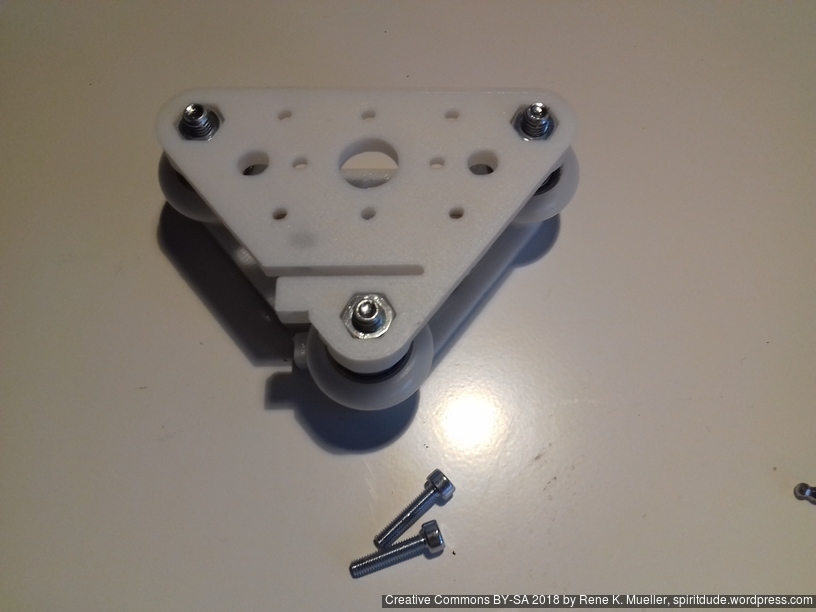
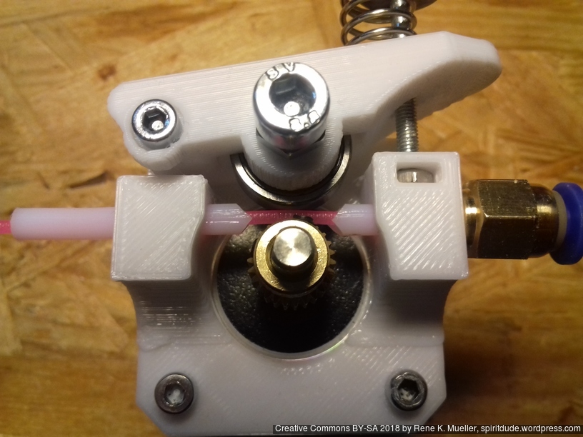
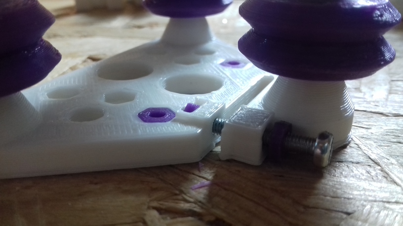
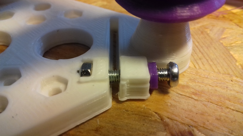
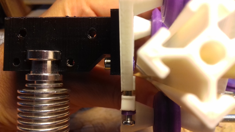
- Belt mount and hotend holder using same mounting holes

It’s the first/early version, the adjustment screws (M3x10) are very or too close to the bed for my taste, next version will use M3x8 and give more spacing. I like to keep the hotend close to the X carriage so not to waste Z space.
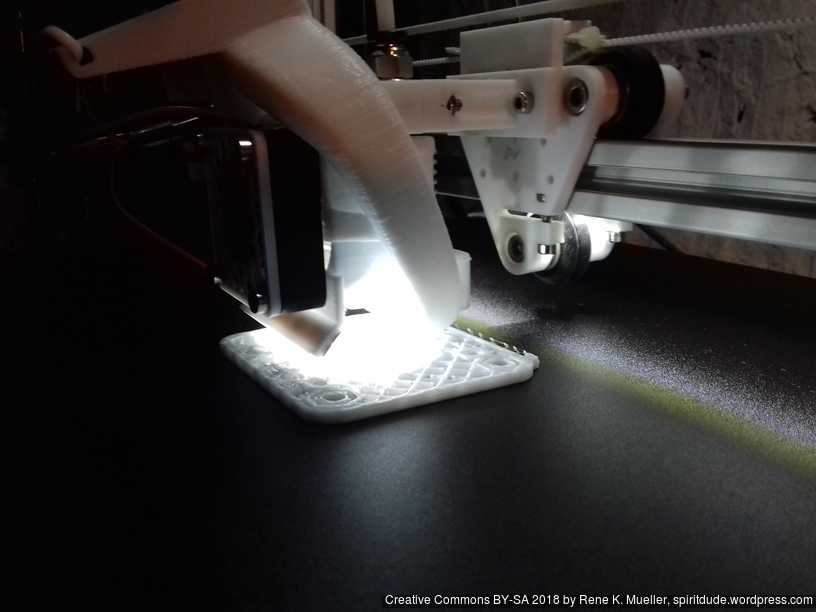
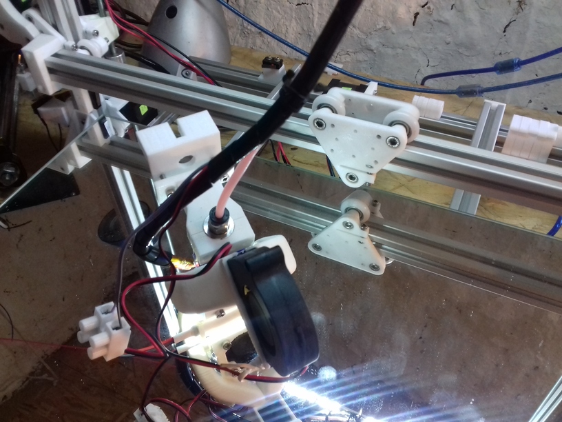
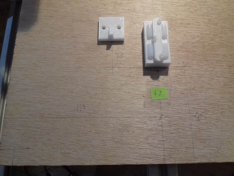
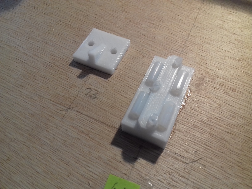
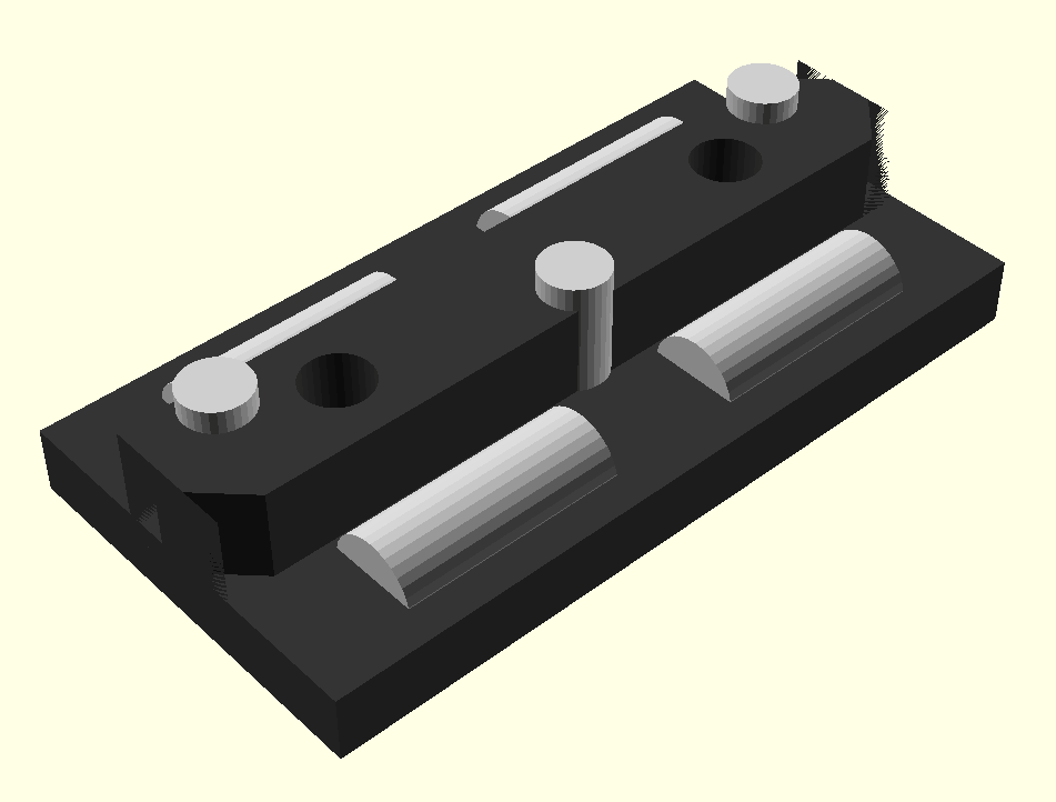
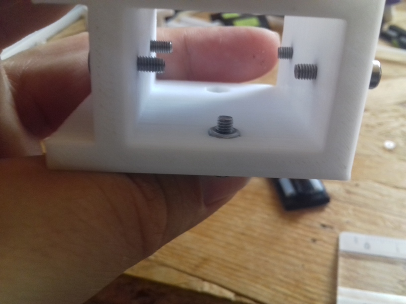
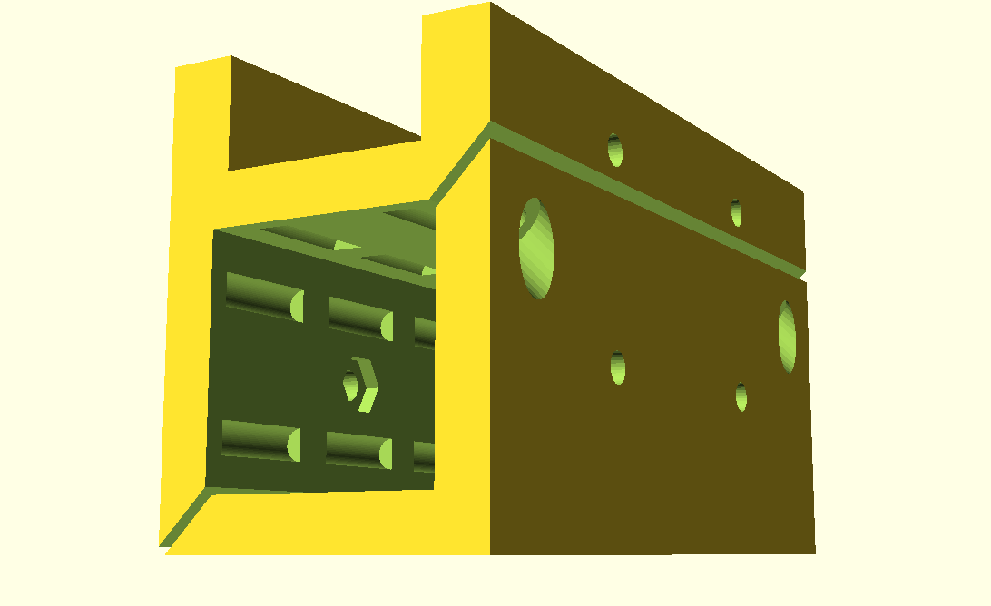
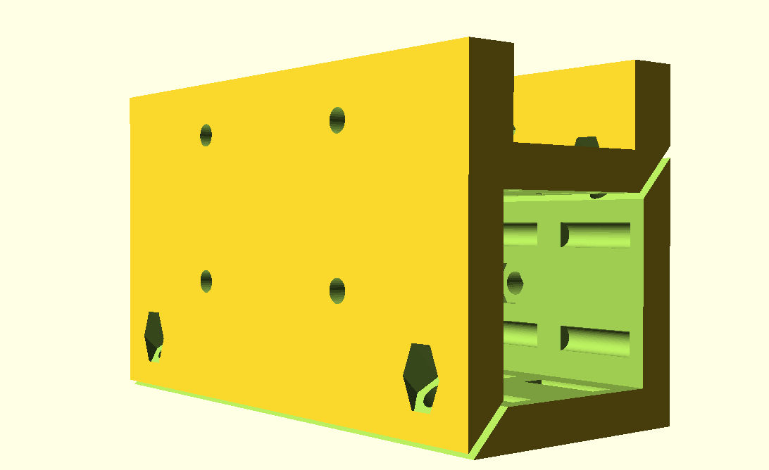
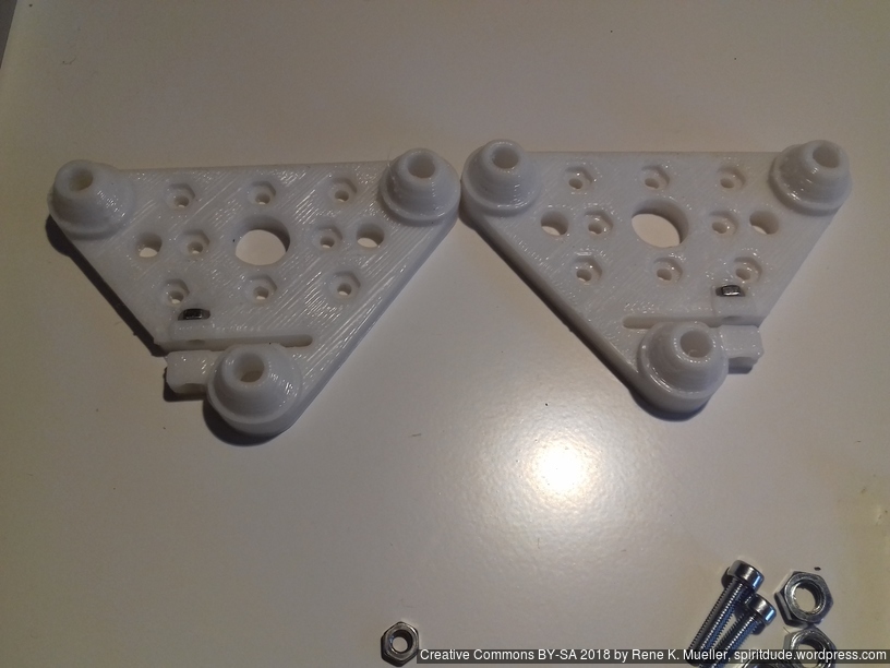
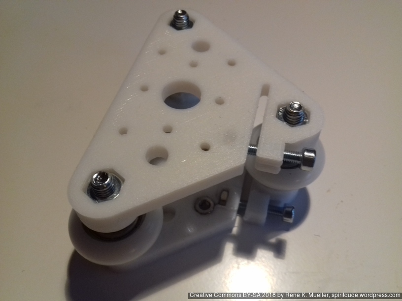
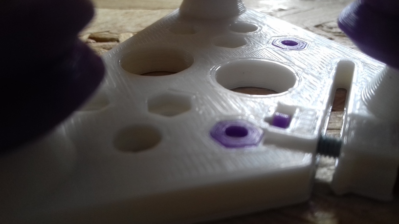
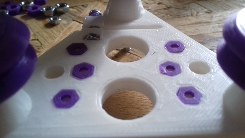
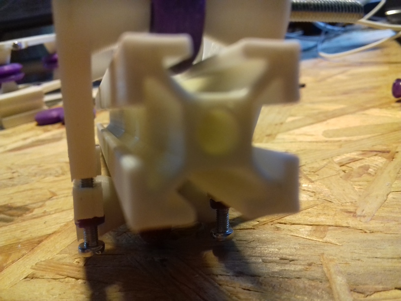
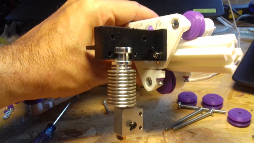
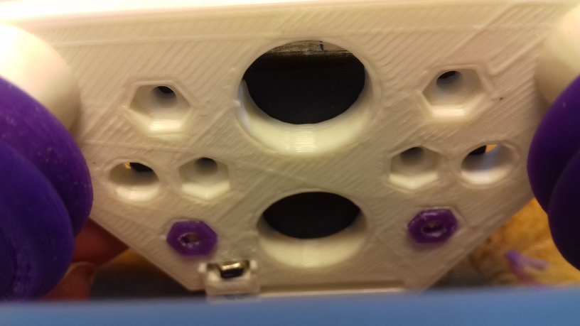
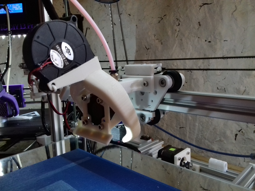
Additionally I made a new hotend mount so it would use another mounting holes than belt mount:
-
- Belt mount and hotend holder using same mounting holes
-
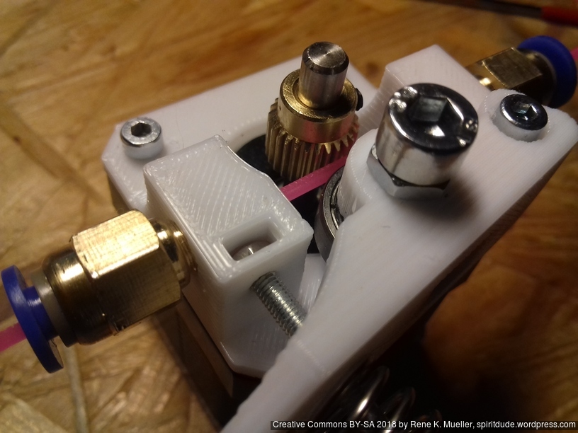
- Belt mount and hotend holder separate
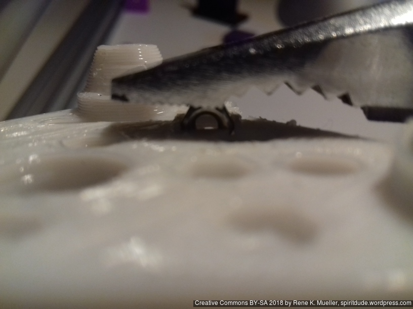
But now it’s harder to reach the hotend mount holes due the part cooler – oh well.
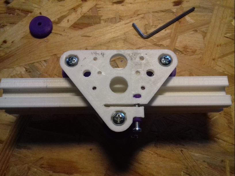
After few days, I noticed one wheel stopped to turn, no longer touching the alu extrusion – I guess the carriage slowly balanced itself and triangulized, no longer use the 4th wheel. I re-tighten the 4th wheel gently so it would roll again.
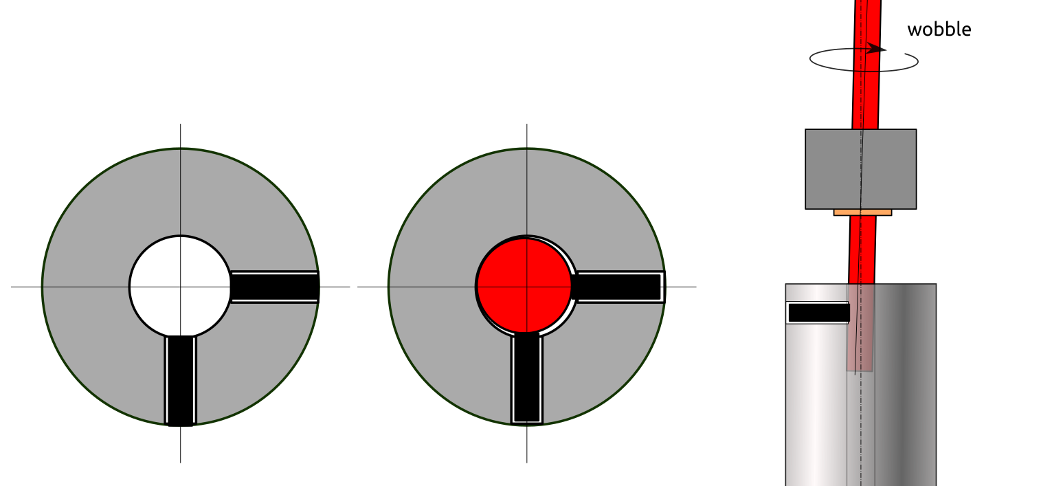
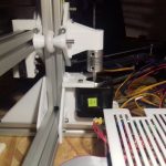
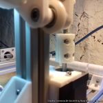
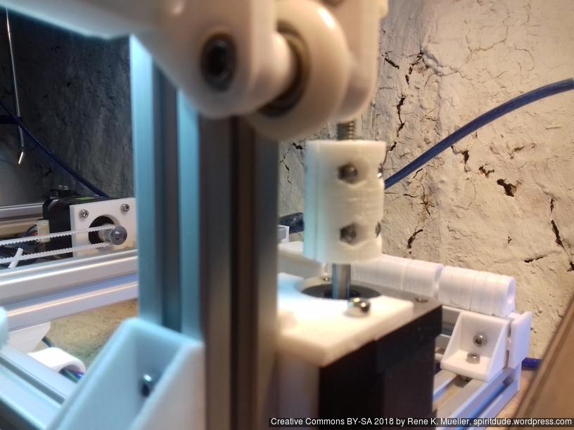
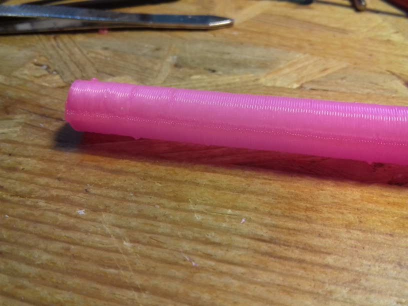
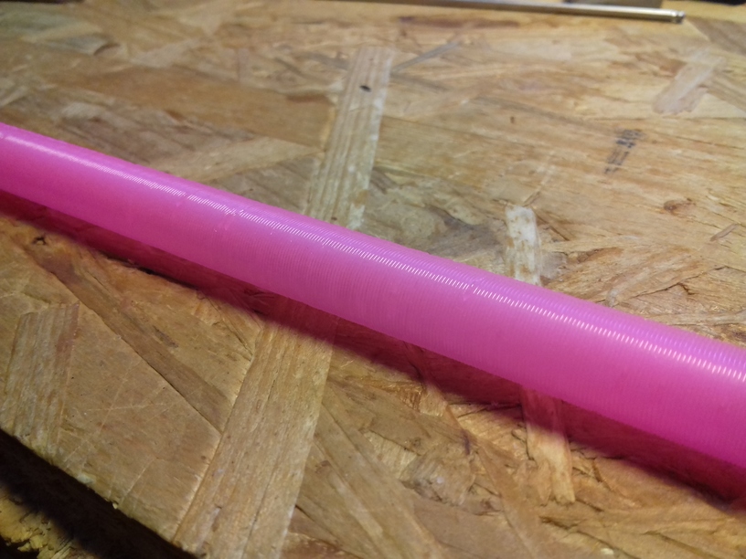
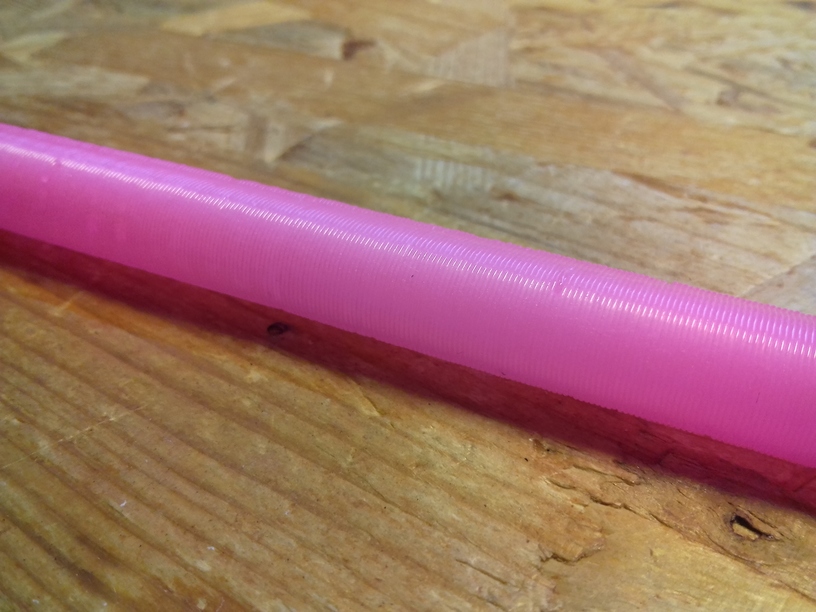
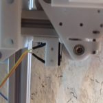
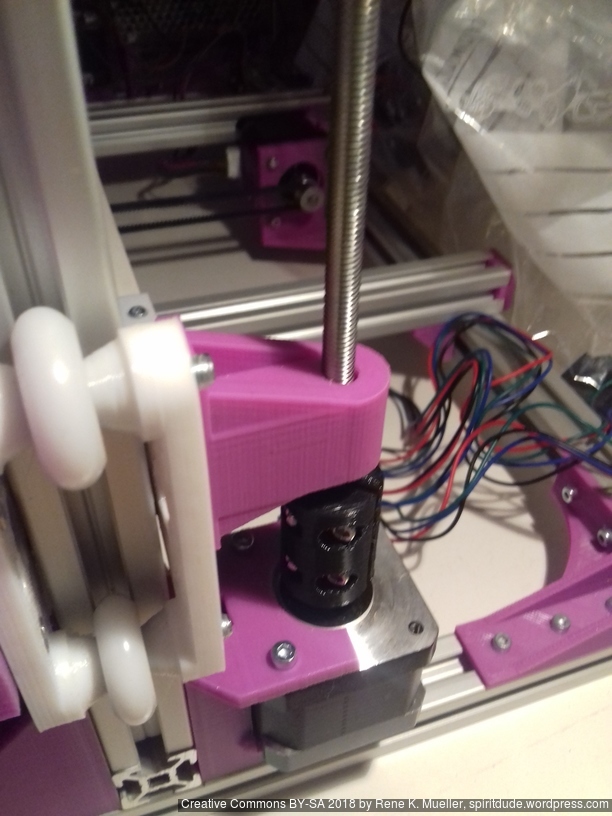
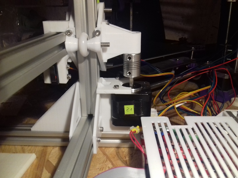
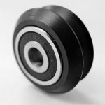
Z Couplers: To Wobble or Not To Wobble
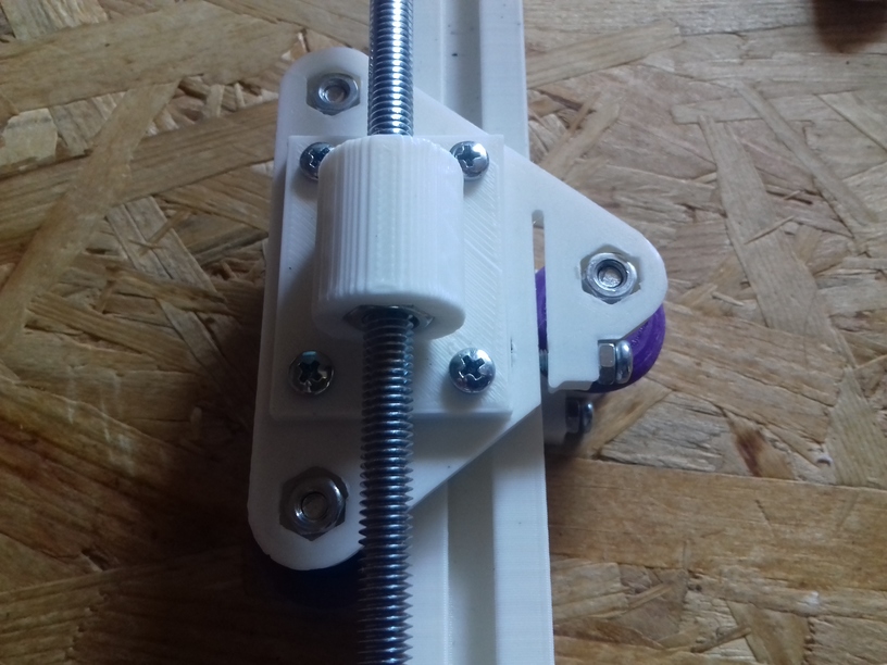
As I posted before, I suspect the Z couplers to be the main source for Z wobbles, as the threaded rods may look and are cheap but they are mostly straight – the wobble actually is caused, after close observation, from the misalignment which happens when you screw the metal couplers on, in particular if you attached the lead screw or threaded rod with uneven surface – the thightening screws may or may not attach cleanly – and thereby push the Z rods out of the center of the Z stepper motor – when the Z thread holding the X axis is fixed, the resulting wobble is worse at low Z heights; and if you fasten the Z rods at the top, the wobble gets even worse.
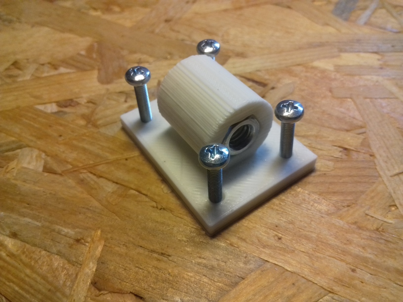
A simple remedy I found is to use printed couplers, two pieces which are screwed together with 4x M3 screws and nuts, a bit of an overkill, and a bit time consuming to fasten: incrementally tighten each screw over and over until all are tight – but I think it’s worth it: the two halves attach evenly and the PLA or ABS or whatever you printed the couplers, is soft enough so the threads of the Z rods carve themselves evenly into the coupler, and self center themselves this way – result is better centric attachment of the Z rods, not perfect but acceptable and better than poorly manufactured metal couplers.
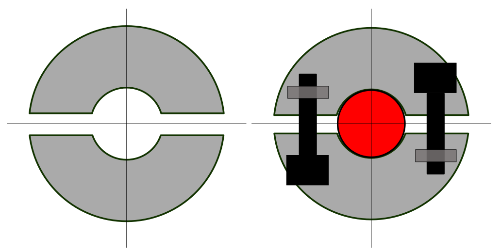
-
- Alu 5mm to 6mm coupler

-
- PLA printed 5mm to 6mm coupler
As mentioned before, I switched from M8 to M6 for the Z axis the M6 provides 1mm movement per full turn, and is more flexible to even out out-of-center wobbles, better than the stiffer M8 threaded rod. If using couplers at all, and likely introduce out-of-center mounting, rather use a more flexible lead-screw or threaded rod than a stiffer one.


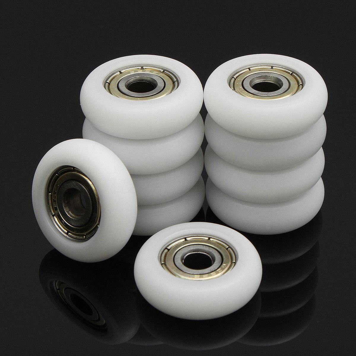
 Commercially manufactured, apprx. cost EUR 2.50 per piece, sold in 10 pieces bag.
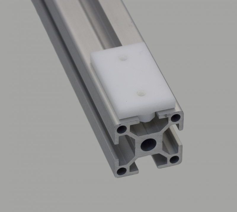


 RepRap Magazine Issue 1