2022/02/08: ready to publish finally with some delay
2022/01/28: not yet published, removed Universal Slicing details for future blog-post, added more photos and illustrations
2022/01/16: starting write-up
Table of Contents
Introduction
Aside of the technical detailed filled blog-posts I like to start to post about the larger context of my inner motivations doing XYZdims.com – this is the first post “XYZdims State 2022/02”:
More Slicers
Recent in-house developments having more slicers to experiment with, in regards of slicing techniques as well lay the ground for more complex slicing and mapping/transformation operations to support arbitrary non-planar slicing (coming soon).
LabSlicer: The Mother
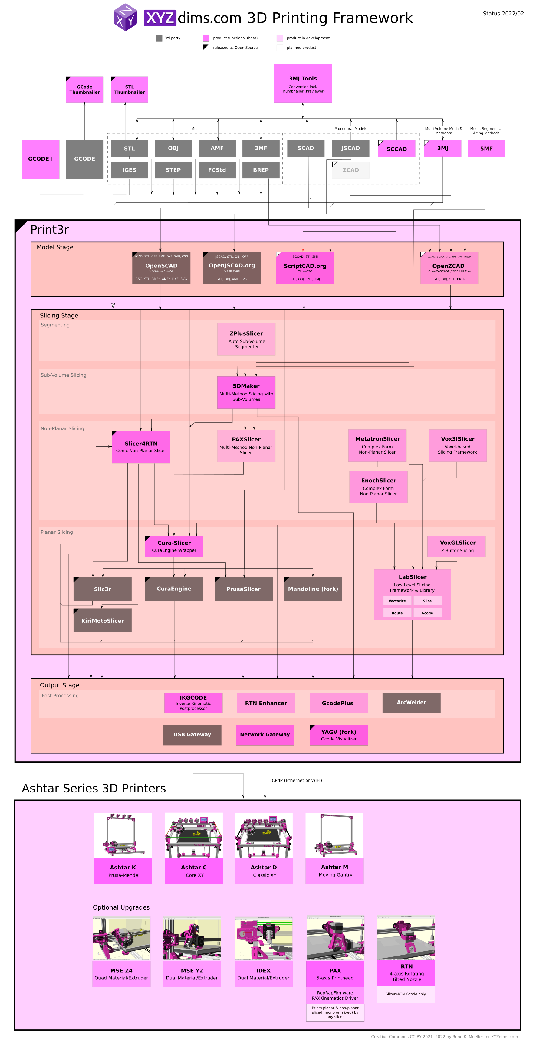
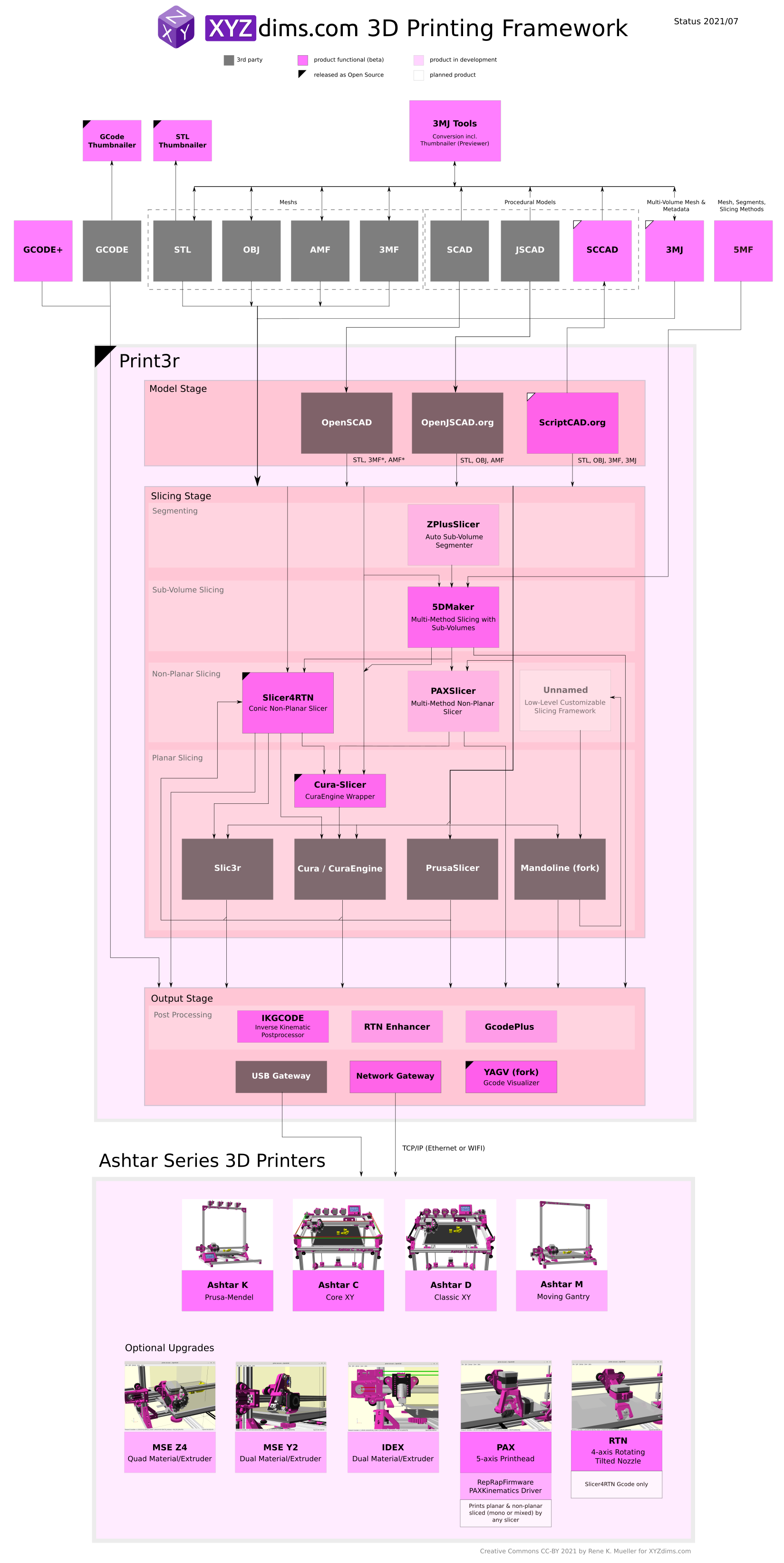
Big Picture of XYZdims – State 2022/02 (click on it and then zoom in, it’s a large image)
As I was working with Slicer4RTN and wrappers like Cura-CLI-Wrapper and Kiri:Moto Slicer (CLI wrapper), and adopting Mandoline fork – I realized I need to have my own slicer, so in November 2021 I started from scratch, as I thought I need to know every detail and so I exposed each step or stage:
mesh: load mesh, vertices & faces
slice: slice layers into sets of polygons
route: route the layer polygons with walls, infills etc
gcode: convert routes to G-code
A “lab(oratory) slicer” or simply LabSlicer was born – I defined each stage: API and file-format it takes in and spits out.
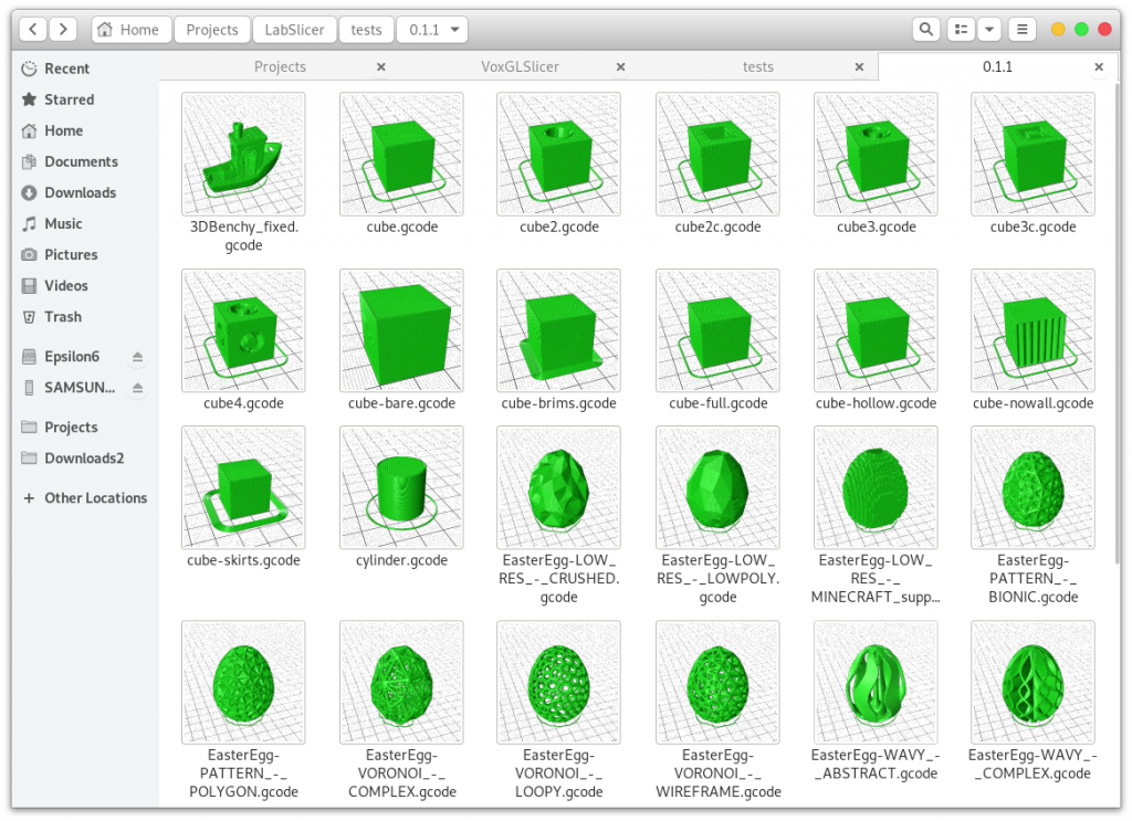
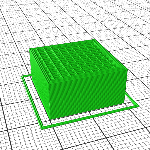
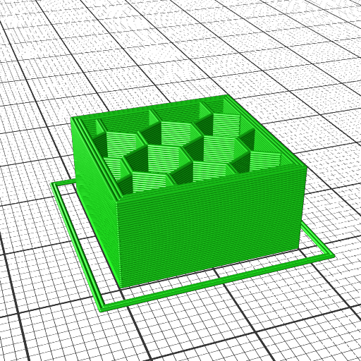
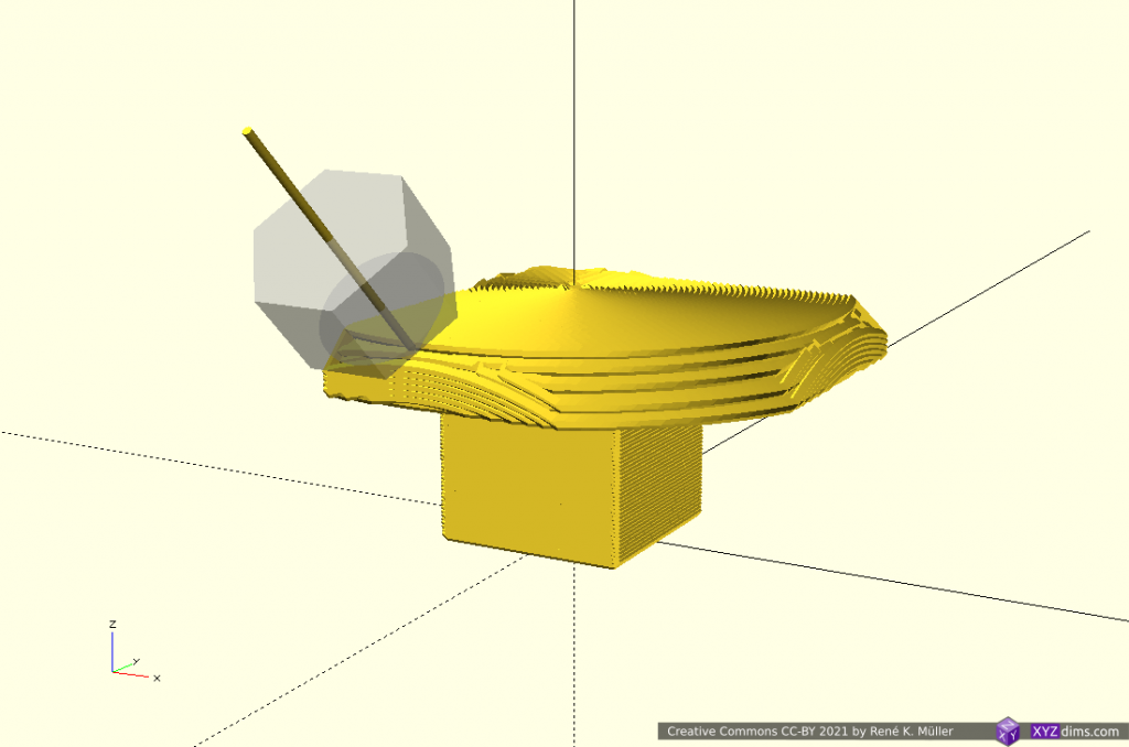
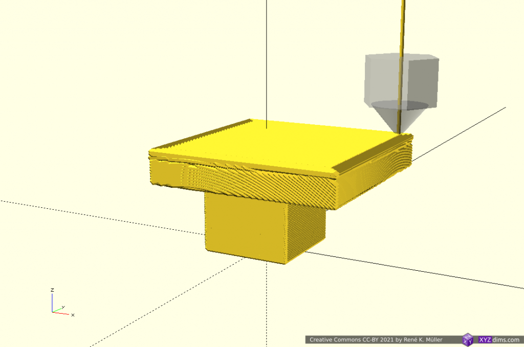
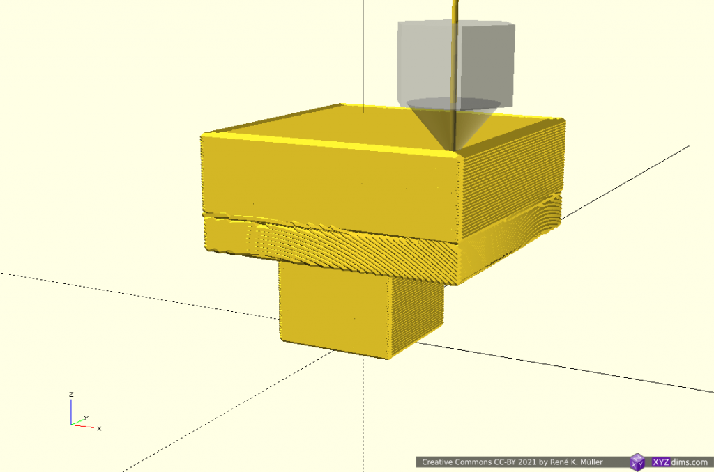
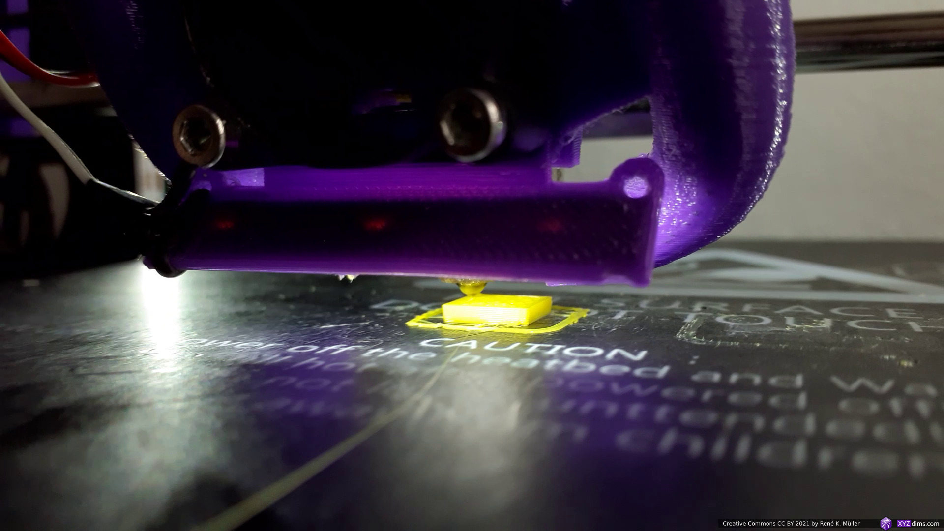
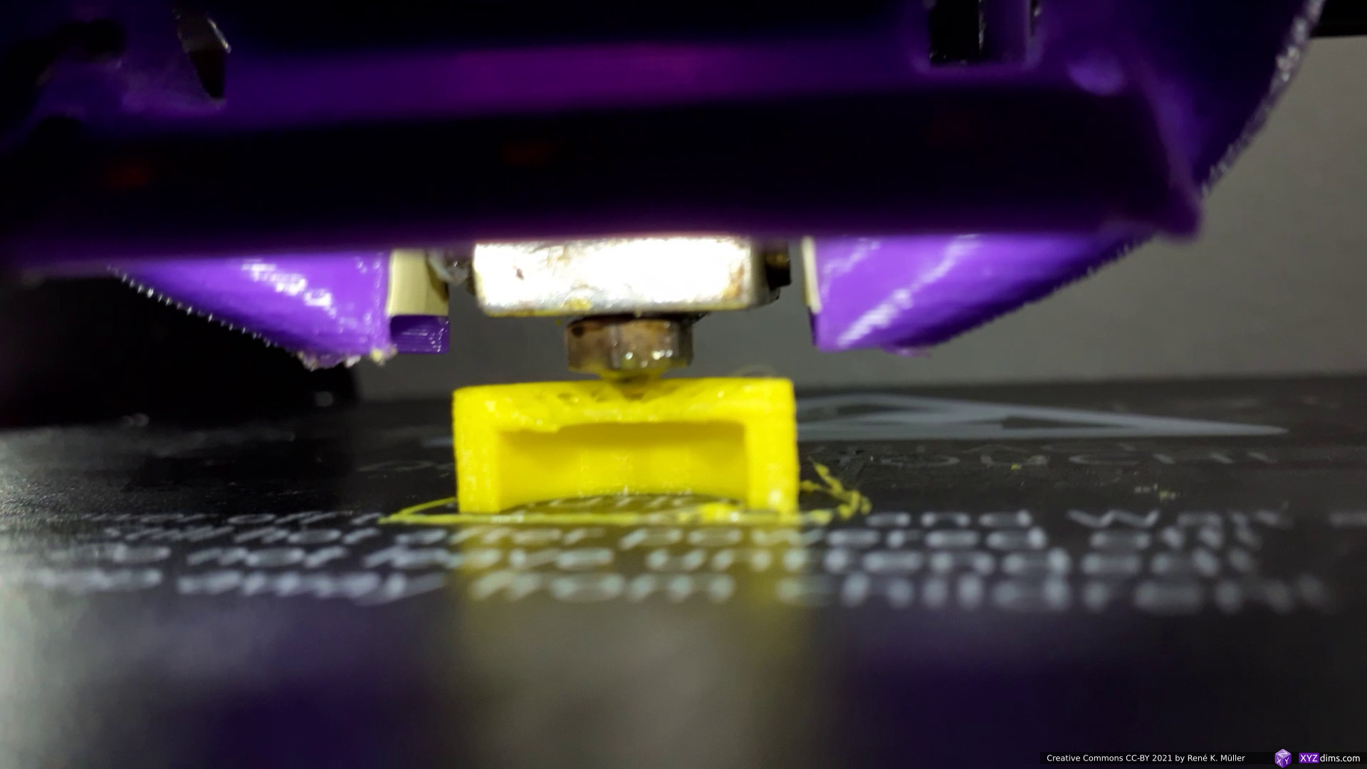
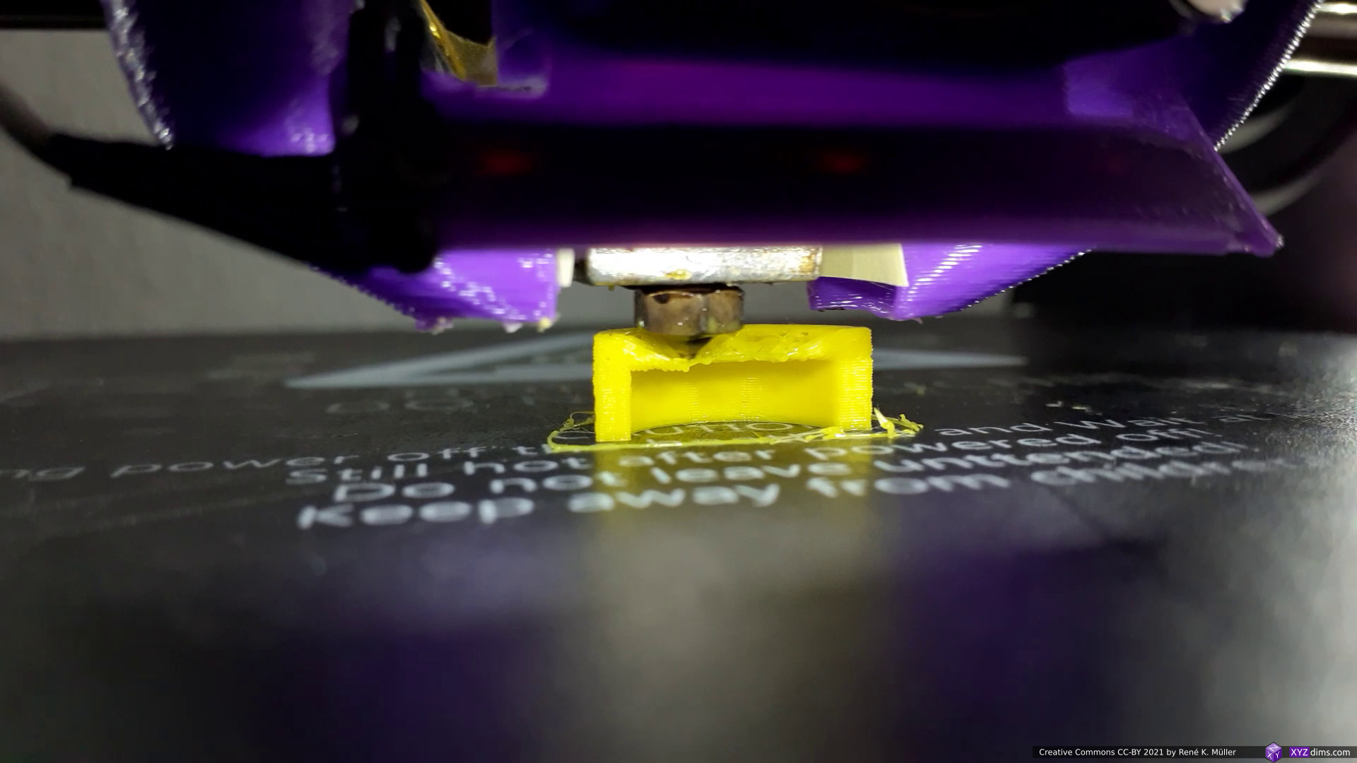
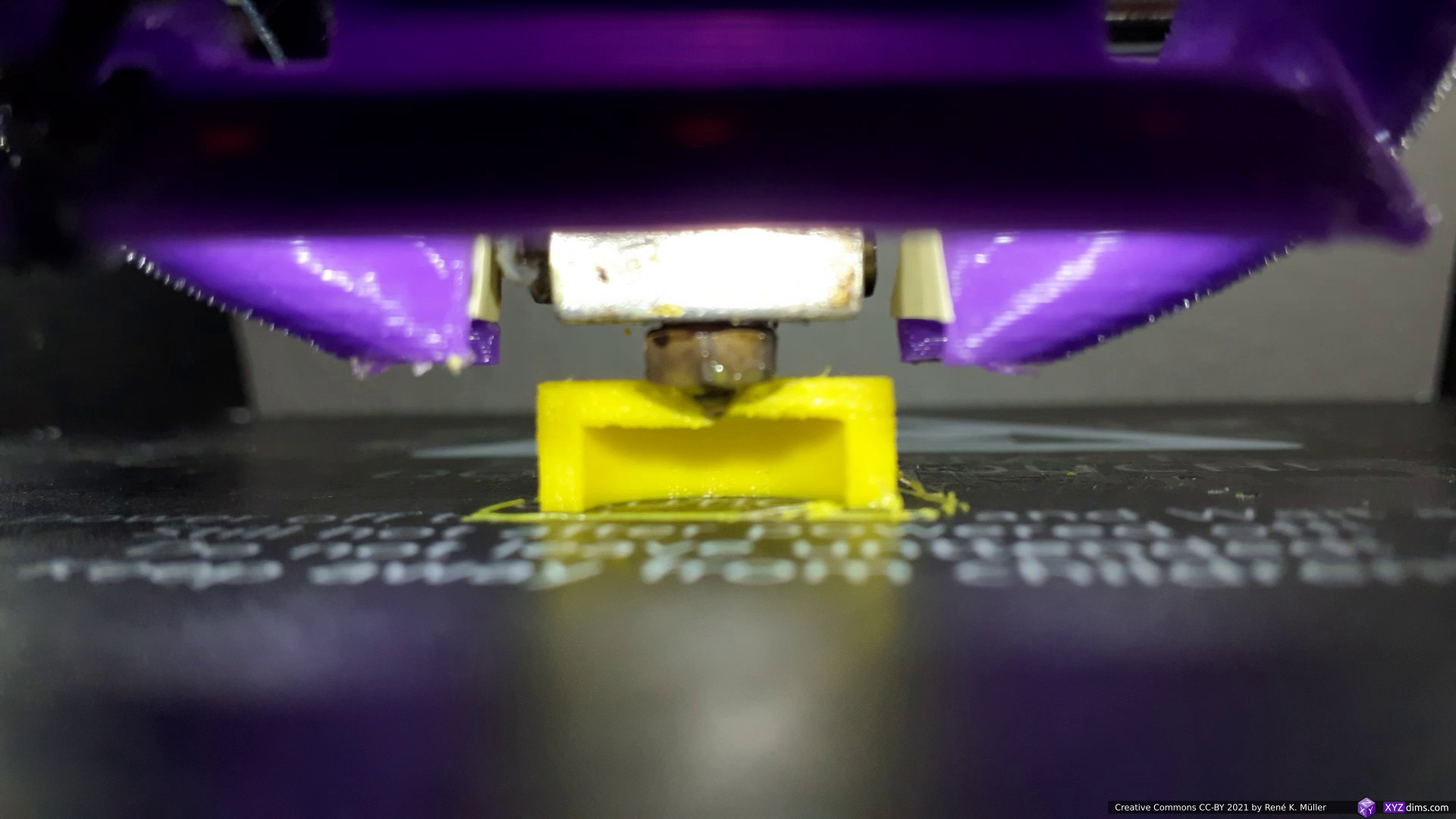
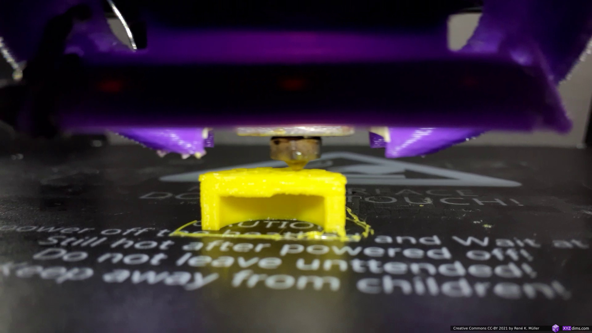
After a couple of weeks I had slicing into polygons, and routing of walls, basic infills, skirts, brims and eventually intermediary top & bottom layers resolved, and I was able to generate printable gcode:
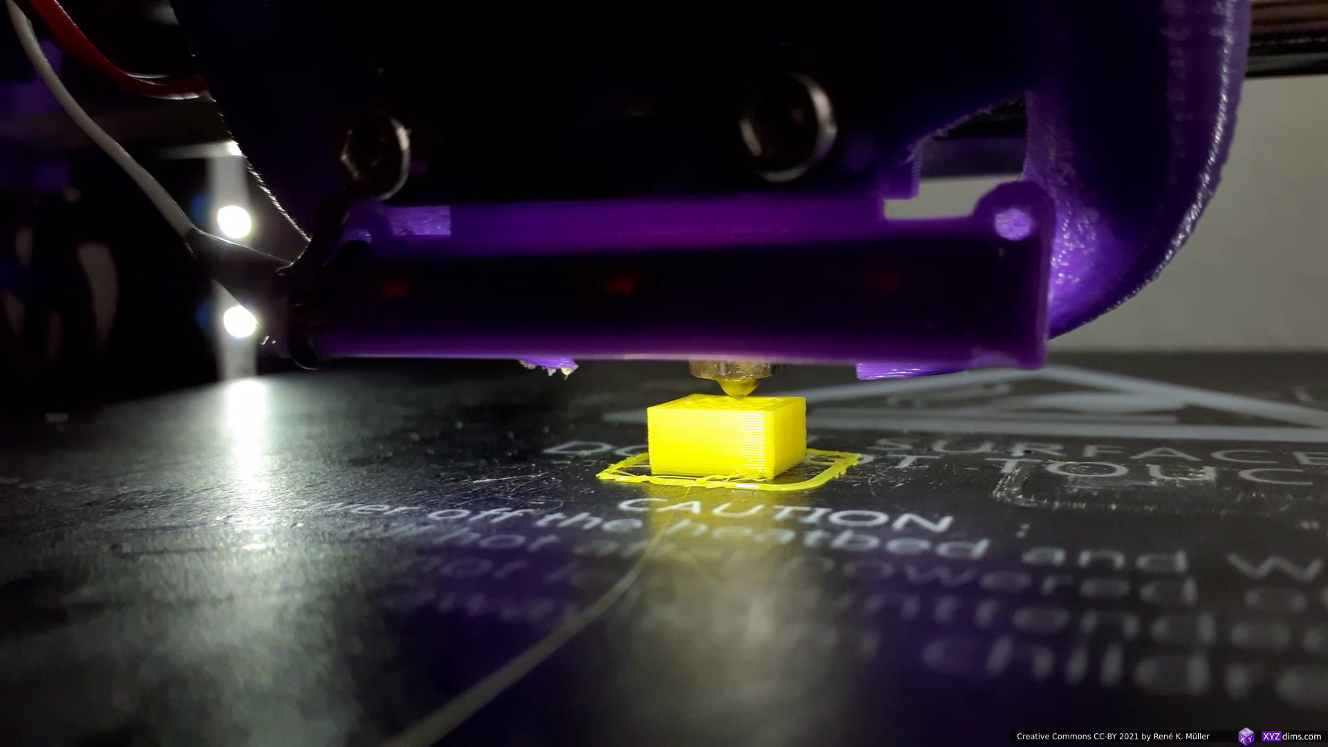
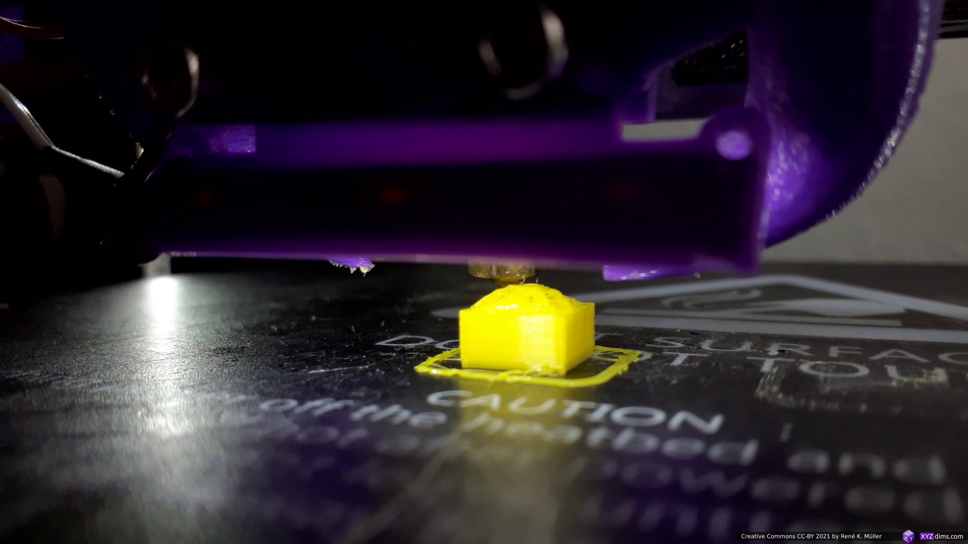
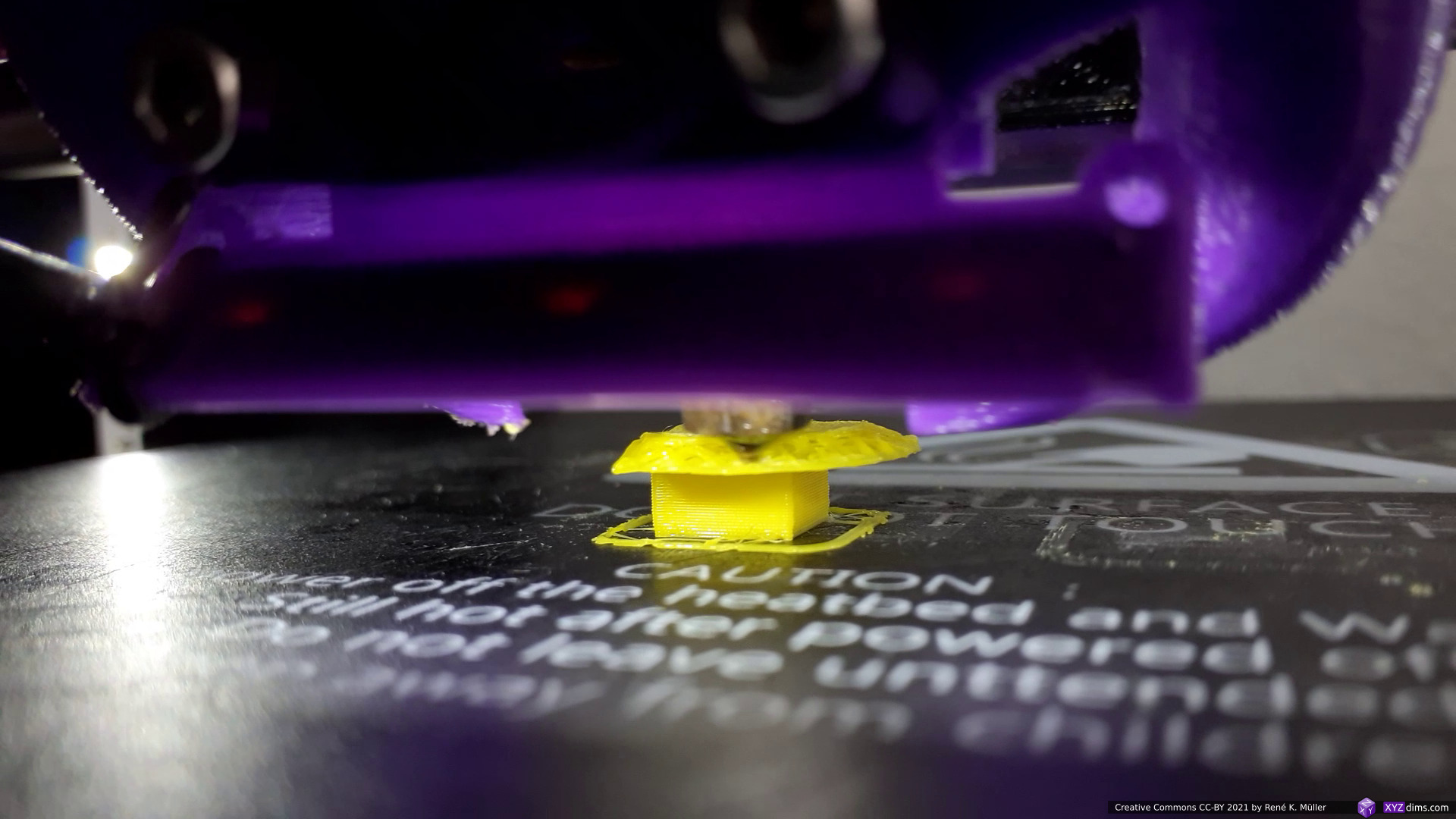
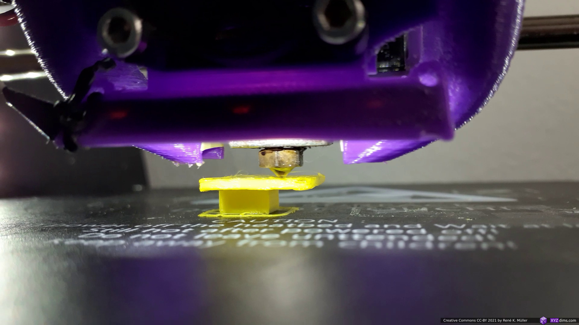
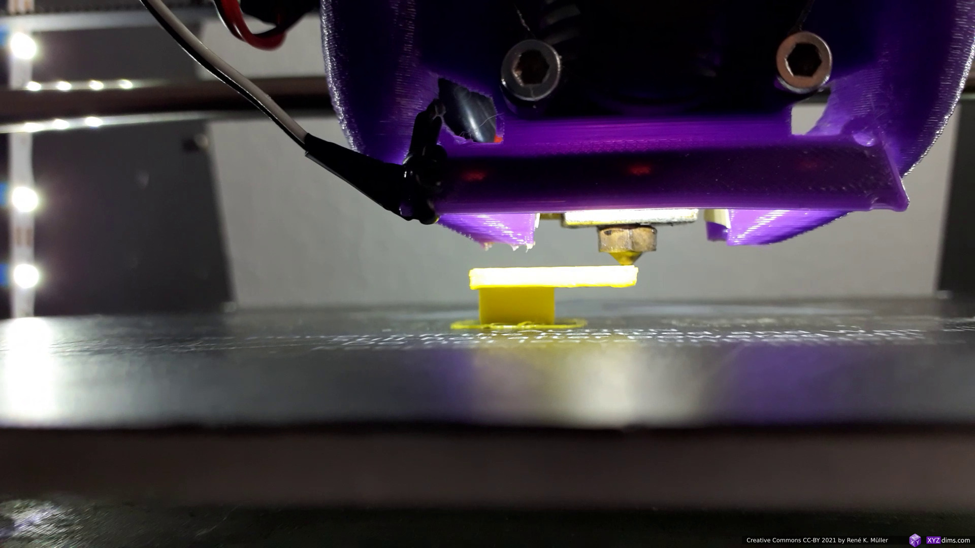
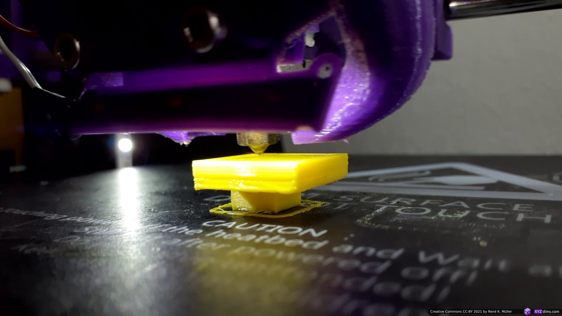
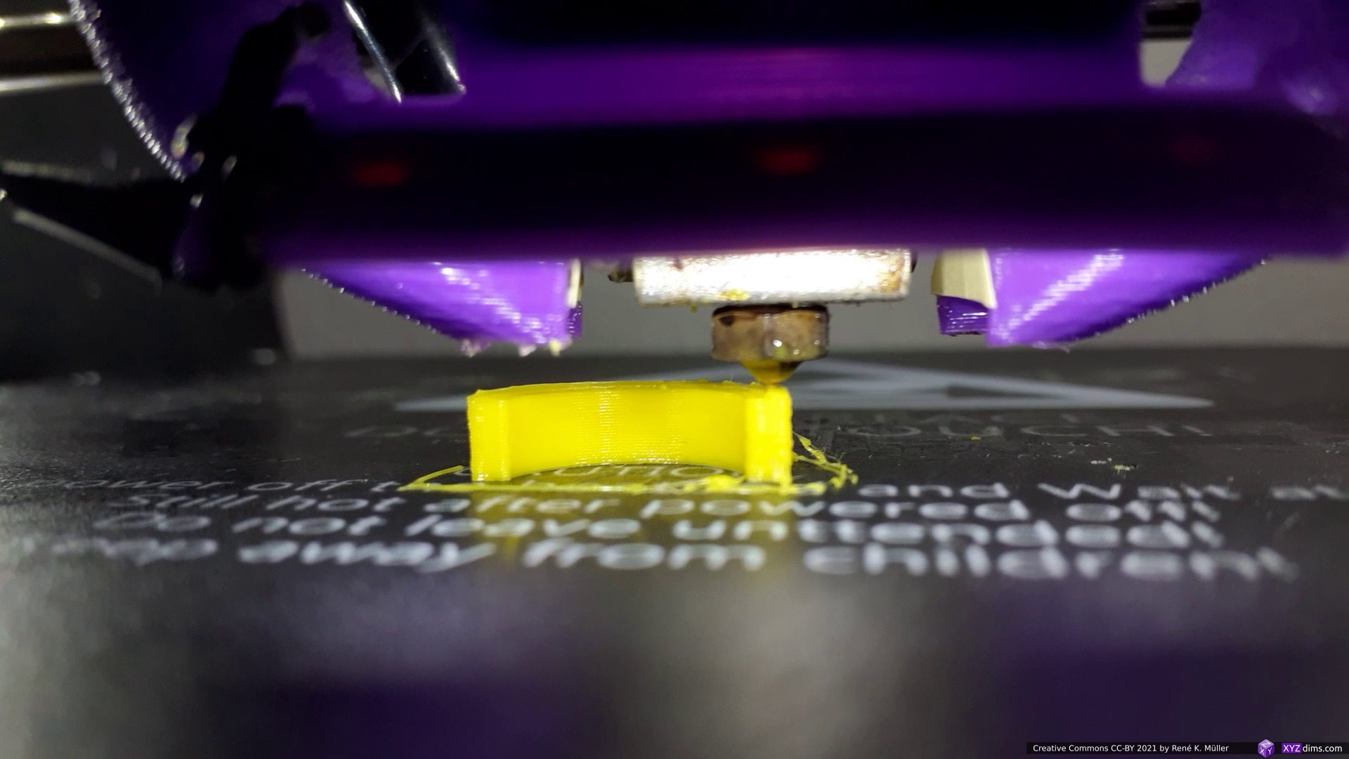
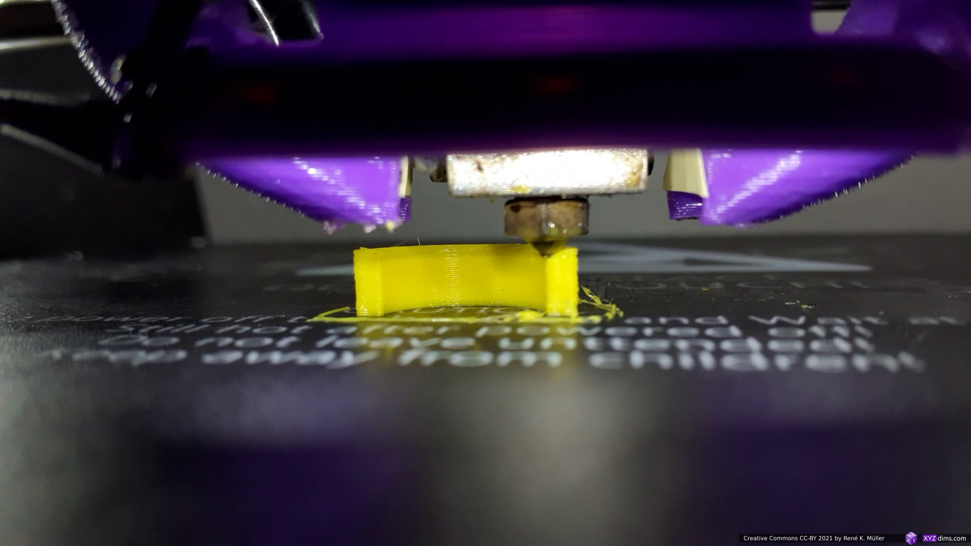
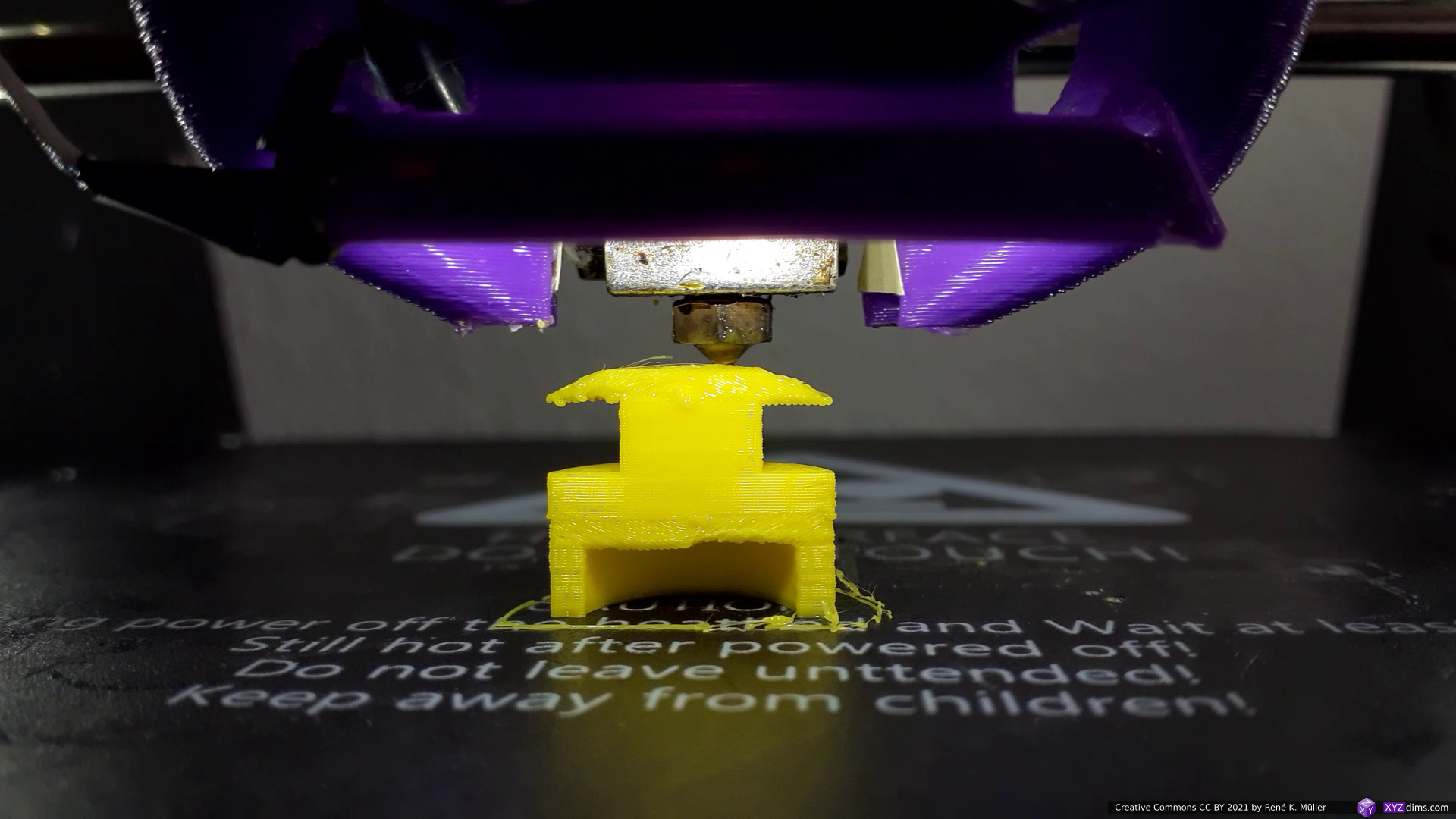
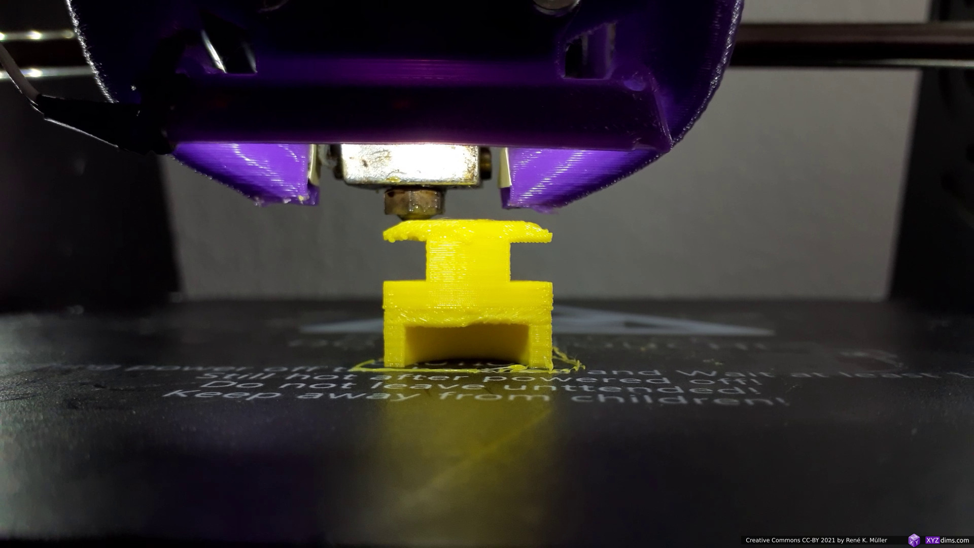
Early tests of LabSlicer 0.0.1, getting extrusion right – static slicing
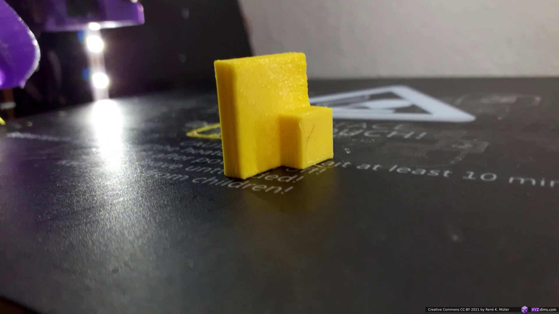
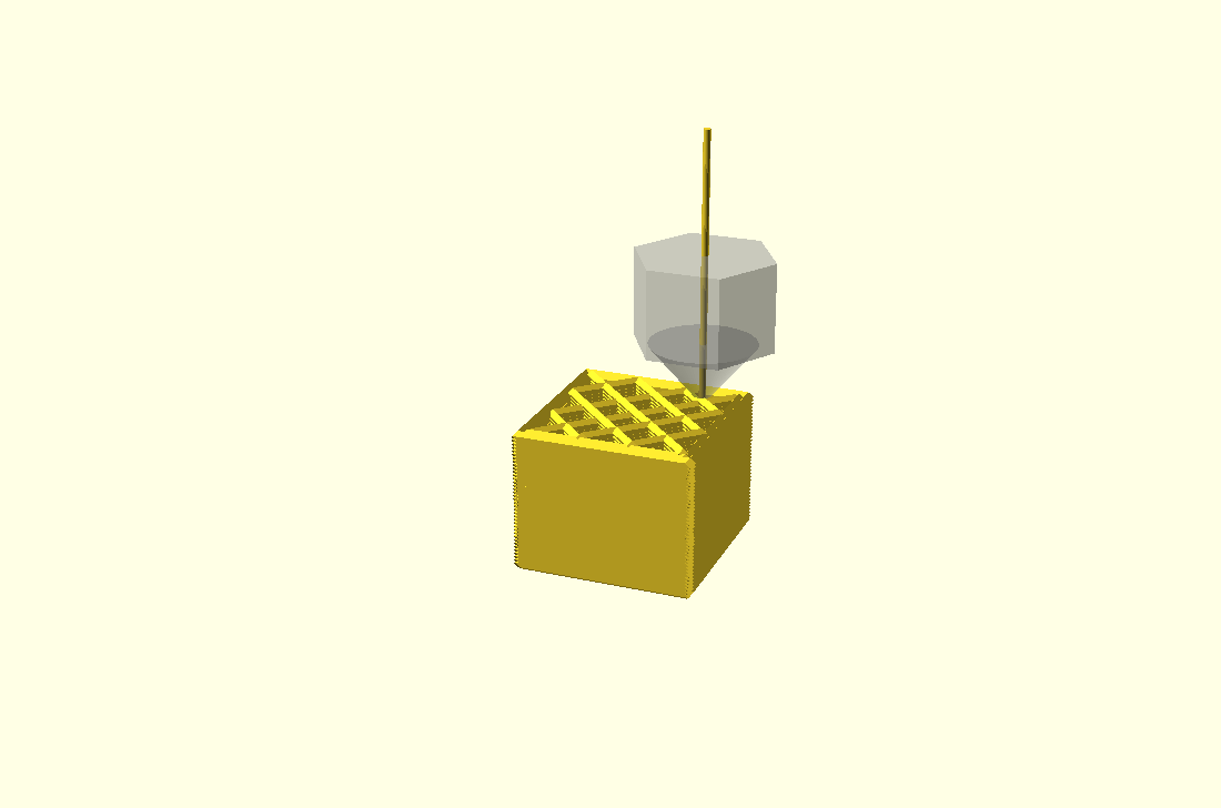
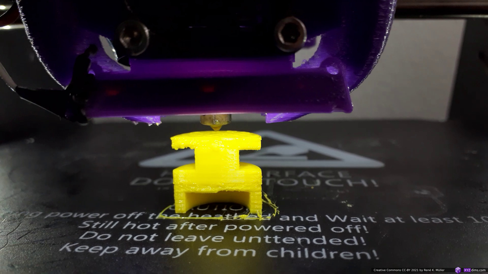
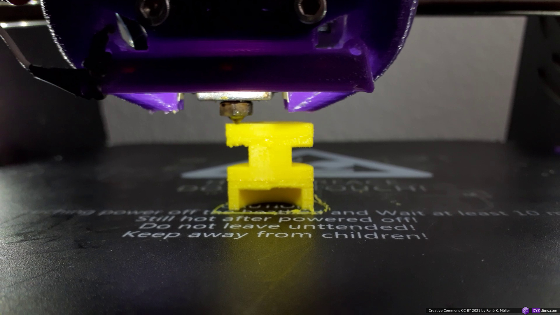
Early progress of LabSlicer 0.0.3: slicing geometries, no top/bottom layers yet
Meanwhile LabSlicer as of version 0.1.5 has matured to print complex models reliably but rather performs slow compared to Slic3r or Cura.
As of 2022/02 I’m even use LabSlicer and its relatives (featured below) for productive 3D prints.
Vox3lSlicer: Voxels
Aside of LabSlicer I began to develop Vox3lSlicer which utilizes internally the OpenVDB voxel library, in order to slice planar and in the future non-planar as well, and also permit to slice voxel-based models efficiently.
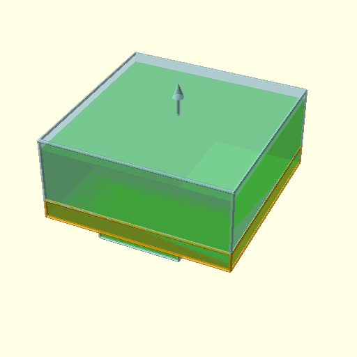
A few tests with OpenSCAD Logo model (~20mm height) with various amount voxel samples, from low resolution to high resolution:
10K samples
100K samples
1M samples
10M samples (default)
100M samples
and with defined voxel sizes:
voxel 0.05mm (default)
voxel 0.1mm
voxel 0.25mm
voxel 0.5mm
voxel 1.0mm
As LabSlicer matured and LabSlicerCore library came to life, Vox3lSlicer (2011/11) utilizes the stage route and gcode of LabSlicerCore to actually produce printable G-code.
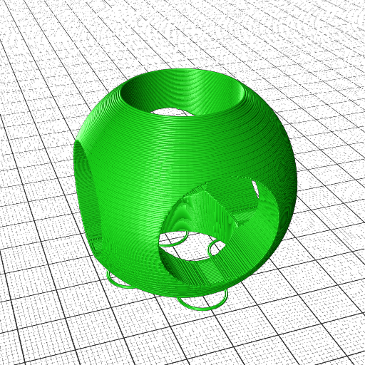
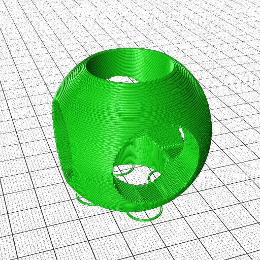
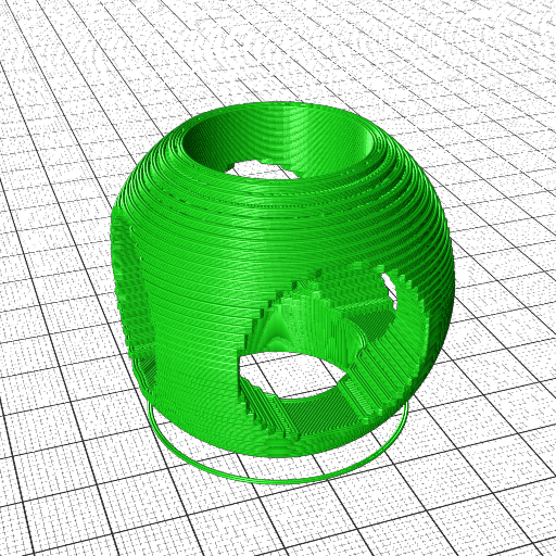
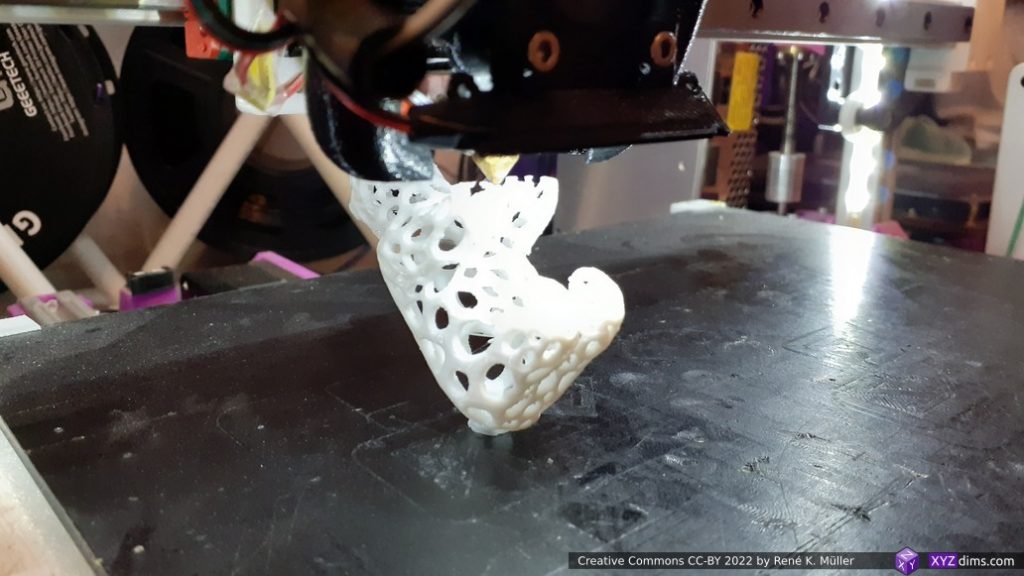
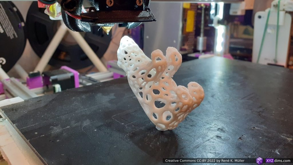
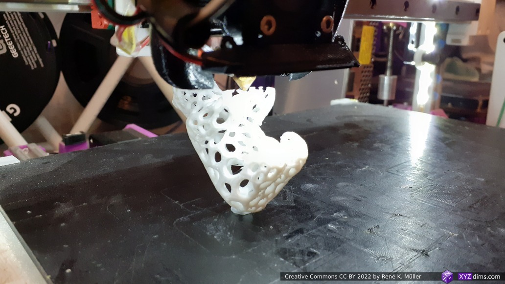
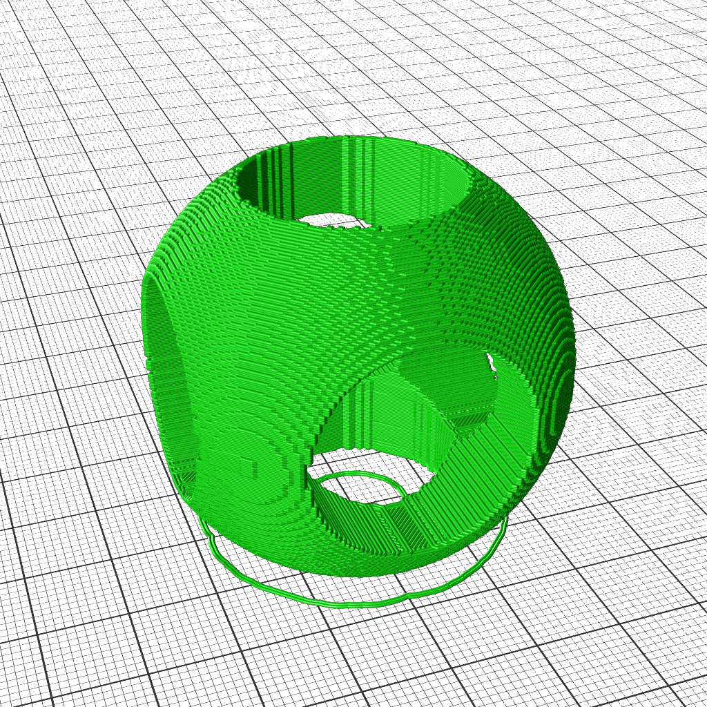
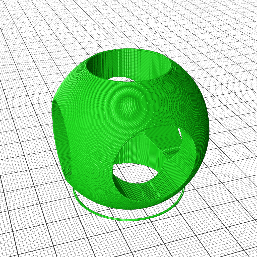
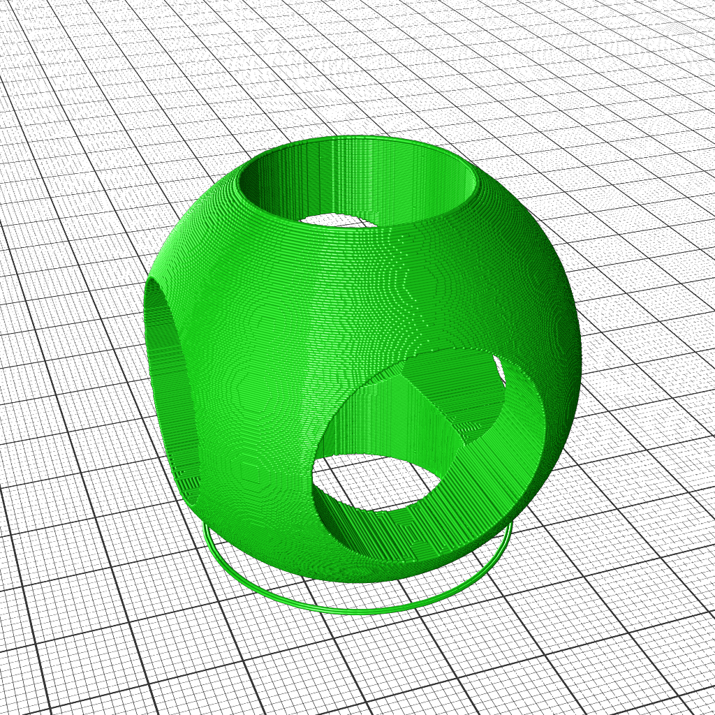
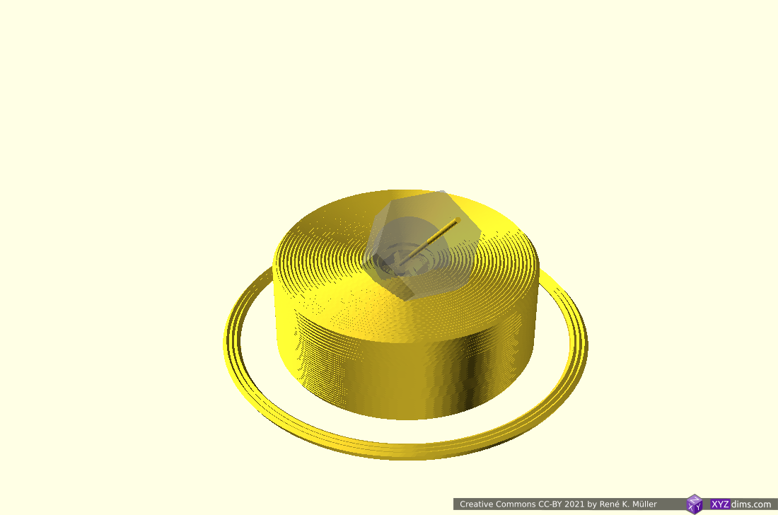
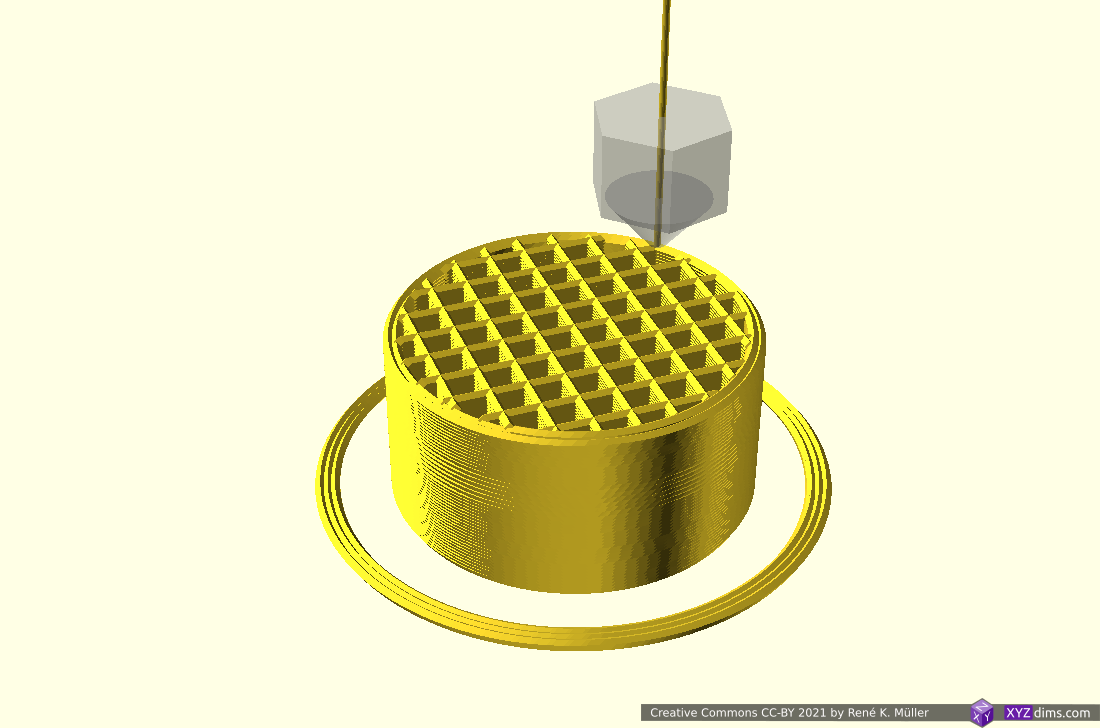
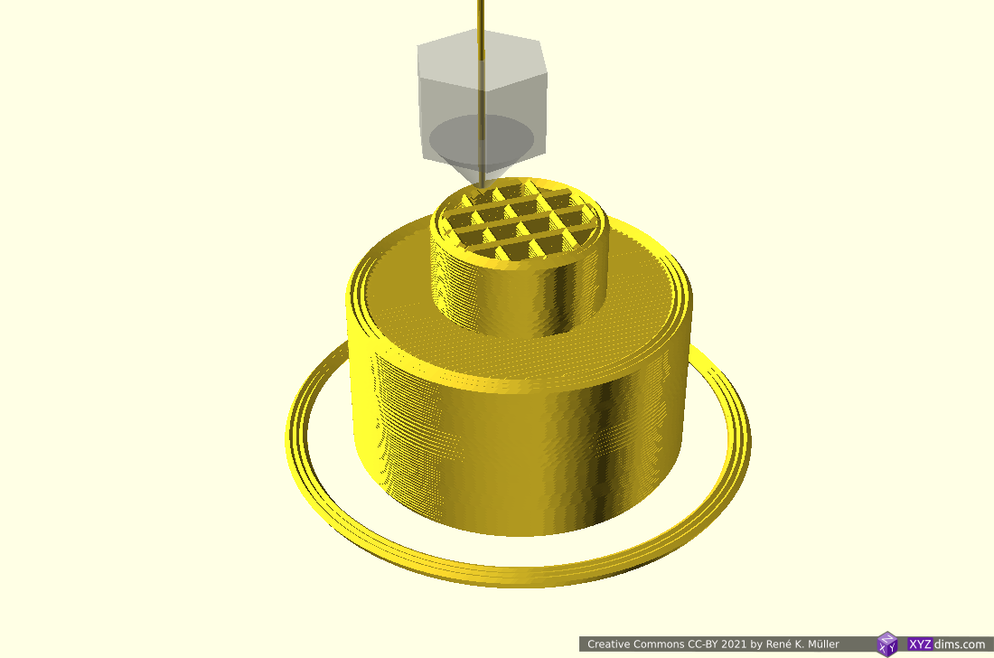
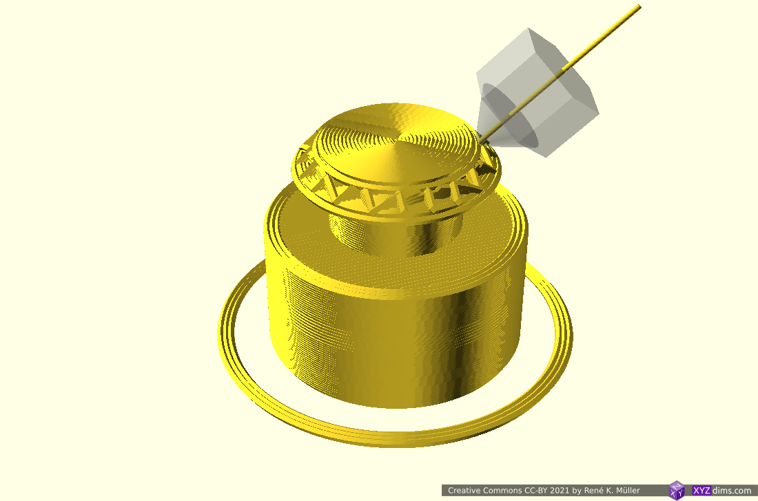
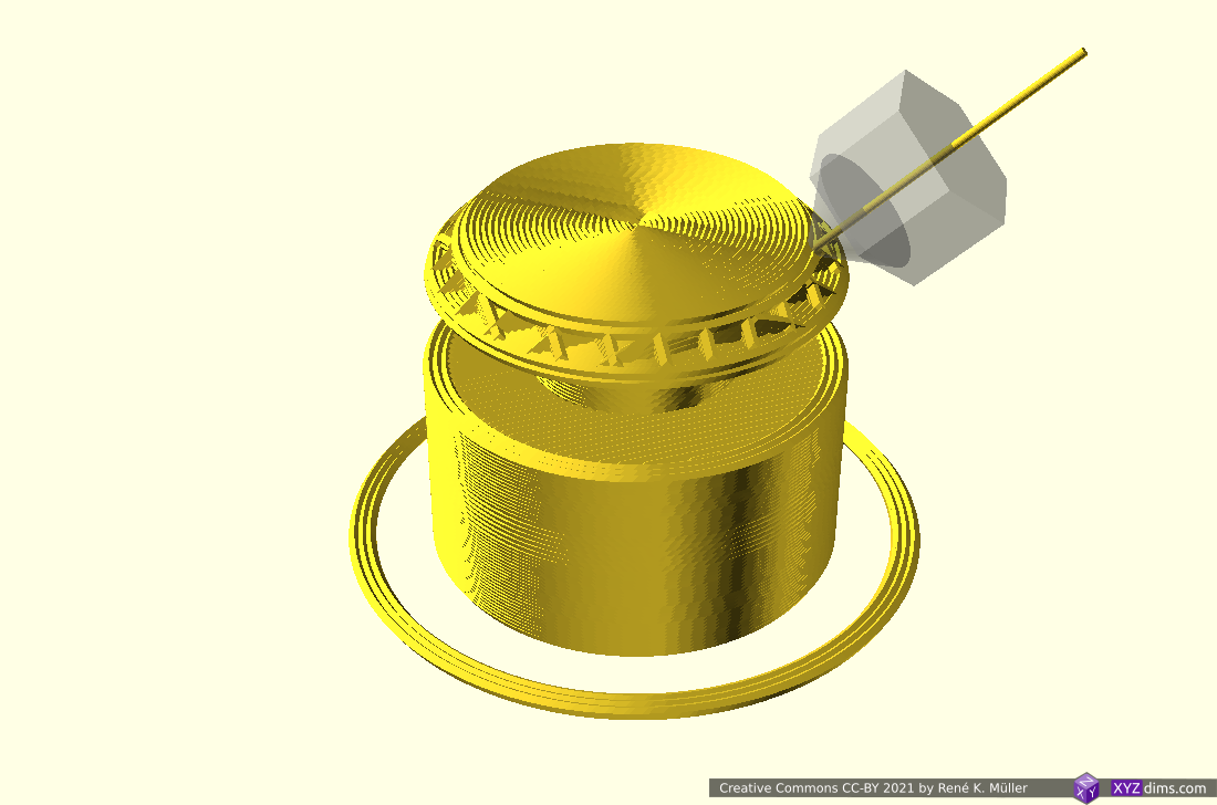
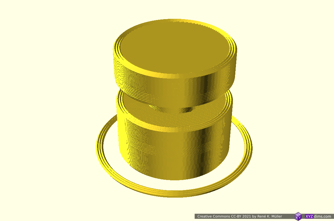
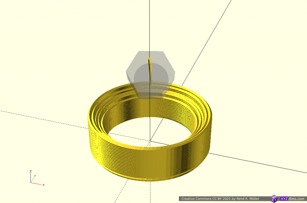
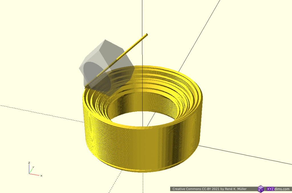
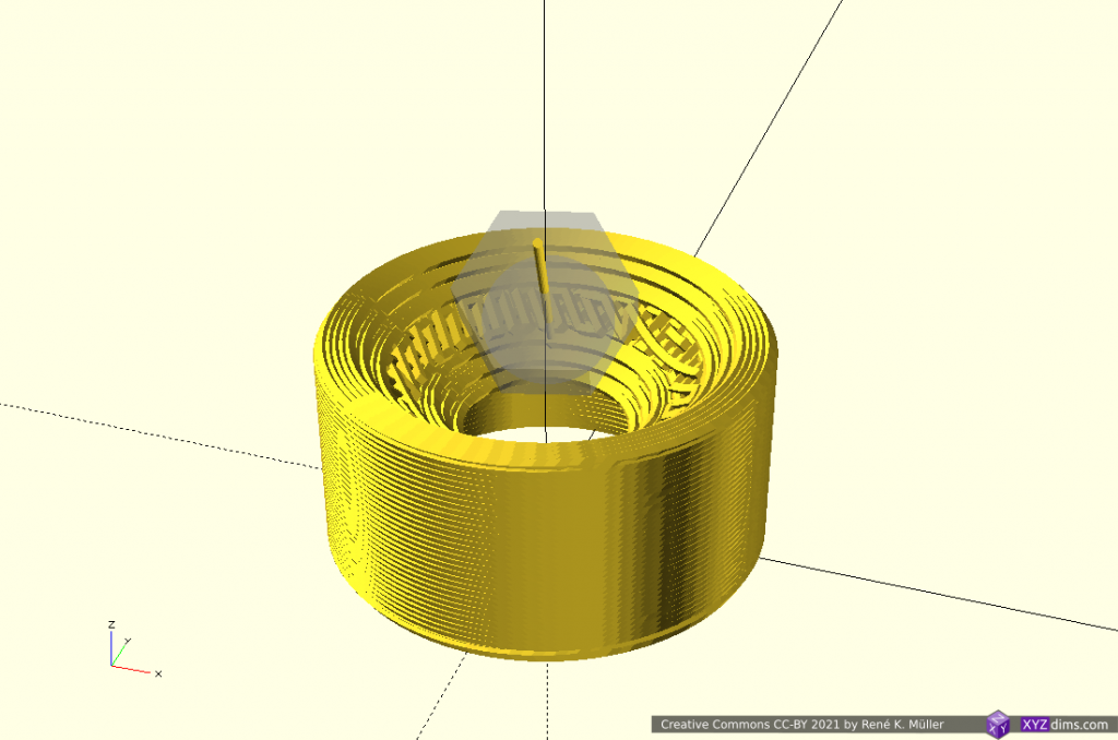
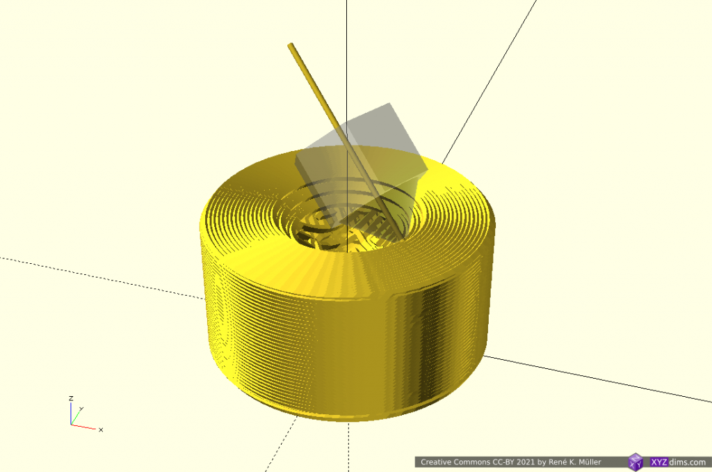
Testing the retraction code and settings of Vox3lSlicer, rotating the model in order to avoid support structure altogether:
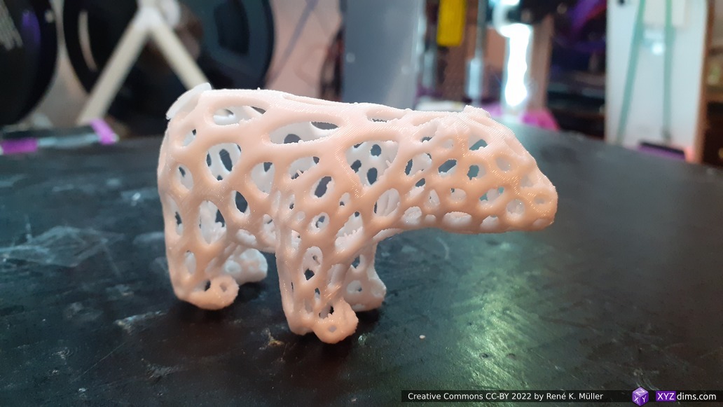
Voronoi Bear, sliced with Vox3lSlicer, printed on Ashtar K #2
Voronoi Bear, sliced with Vox3lSlicer, printed on Ashtar K #2
Voronoi Bear, sliced with Vox3lSlicer, printed on Ashtar K #2 with 0.25mm layer height, 0.4mm nozzle
VoxGLSlicer: OpenGL Slicing
Early VoxGLSlicer tests
As I was looking for other slicing procedures I came across OpenGL-ST-Slicer, which utilizes a clever OpenGL setup with GLSL (Shader Language) to render a mesh to a framebuffer with the volume information, and so slicing is done solely in the GPU almost instantly – I extended this approach and glued it together with LabSlicerCore and I was able to produce also printable G-code – VoxGLSlicer was born (2022/01).
Due the limitation of the internal framebuffer width & height the resolution of the slicing changes with the size of the model aka “relative resolution”:
model width [mm]
pixel size [mm] @ 2560 pixels
20
0.008 or 8 μm
50
0.019 or 19 μm
100
0.039 or 39 μm
200
0.078 or 78 μm
500
0.19 or 195 μm
1000
0.39 or 390 μm
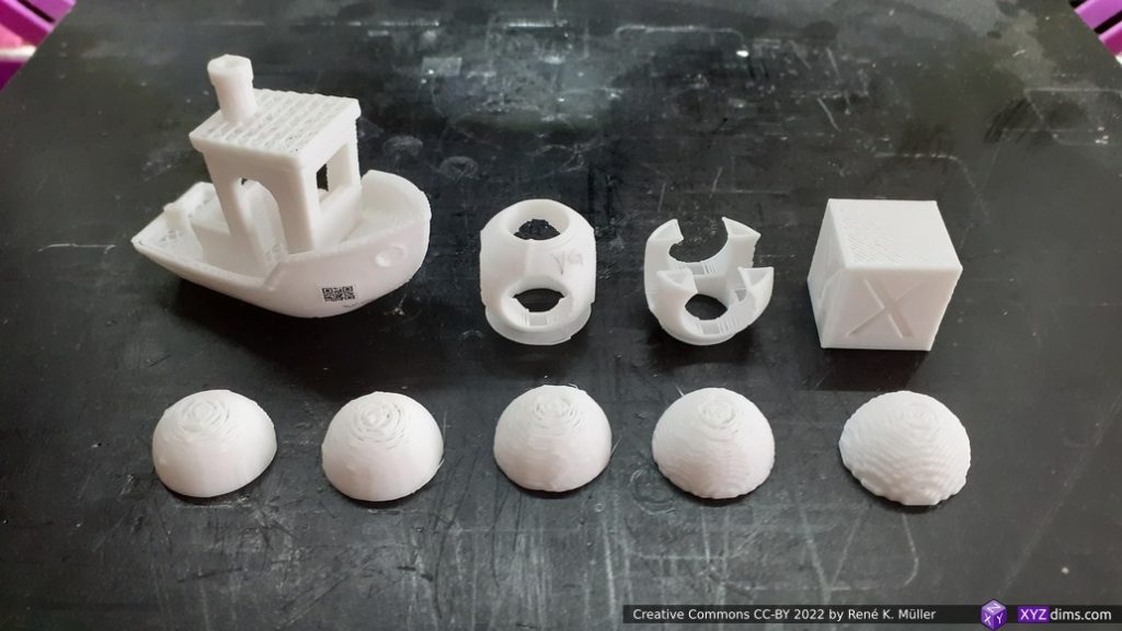
and just for illustration about “pixel size” related to a ~20mm model:
pixel 1mm
pixel 0.5mm
pixel 0.25mm
pixel 0.1mm
pixel 0.05mm (default)
3 Slicers
After a few weeks coding (2021/11-2022/01), I was able to raise 3 slicers, each with their unique slicing approaches to create printable G-code, by having a common API and use symbiotic advantage of each other:
LabSlicer
Vox3lSlicer
VoxGLSlicer
mesh
mesh.py1) multi-format mesh importer
openvdb STL importer
mesh.py1) multi-format mesh importer
slice
slicing mesh to polygons (vectorizing)
slice voxels into polygons (vectorizing)
screenbuffer into polygons (vectorizing)
route
route polygons to routes
LabSlicerCore’s route
LabSlicerCore’s route
gcode
convert routes to G-code
LabSlicerCore’s gcode
LabSlicerCore’s gcode
+ traditional slicer with polygons + all stages fully implemented – slow slicing2)
+ fast slicing + flexible resolution + reliable
+ fast slicing – fixed screenbuffer size – relative resolution
All three slicers are very experimental and play a significant role for the next step – Universal Slicing.
Footnotes:
mesh.py is loading/saving 3d meshs/models and some simple manipulations tuned toward my use cases
mesh slicing not yet optimized
So any optimizing of routing (wall, infill, intermediary top/bottom layers etc) and gcode optimizing all three slicers benefit from.
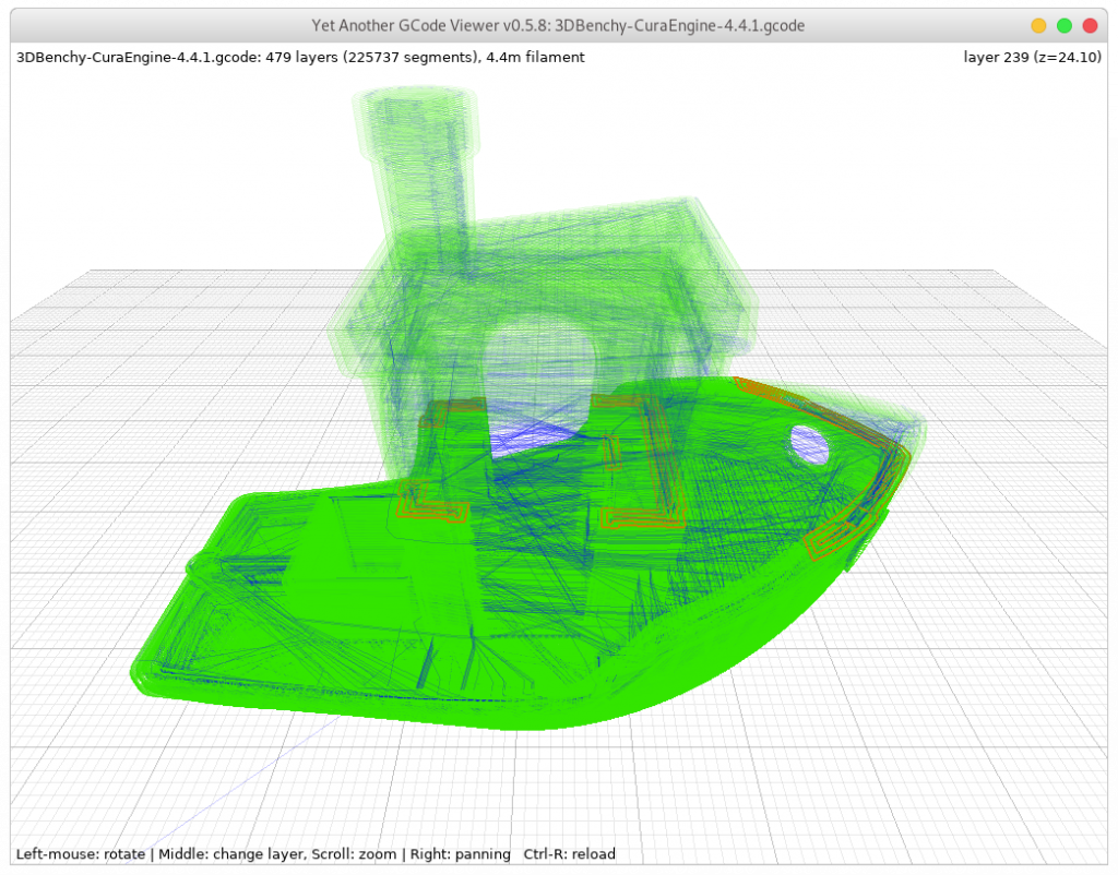
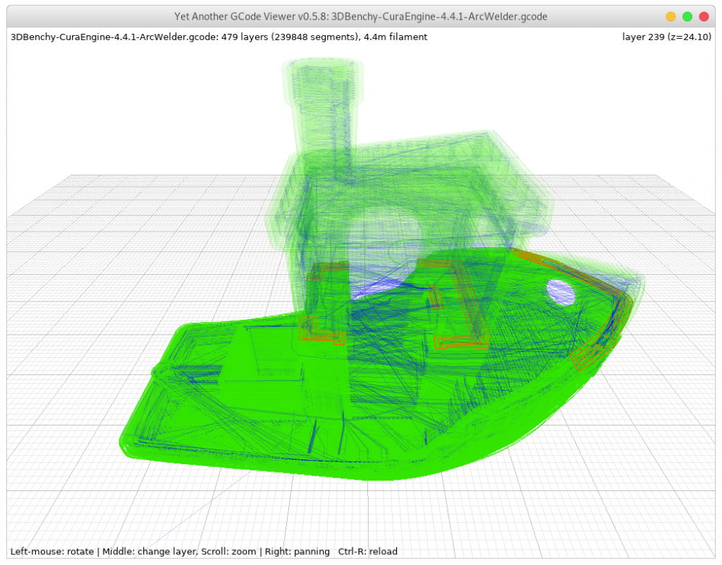
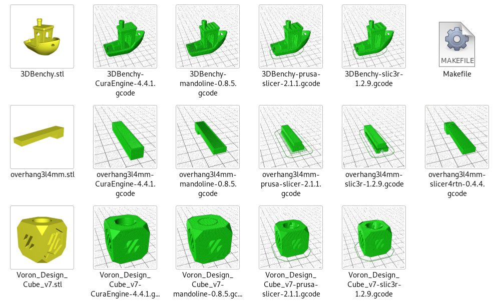
3DBenchy G-code with ArcWelder (Cura 4.4.1): 4MB G-code
Print3r
And just for sake of giving a bit of context, adding ArcWelderLib in the pipeline of Print3r via the configuration:
# first declare new post-processor named "arcwelder":
post_arcwelder = ArcWelder %i %o
# optionally, define it to be active (all the time):
post = arcwelder
or optionally enable it on the command-line:
% print3r print cube.stl --post=arcwelder
That’s it for now.
References
IotaSlicer, OpenGL Z-buffer slicing with multi-color, coded in C++
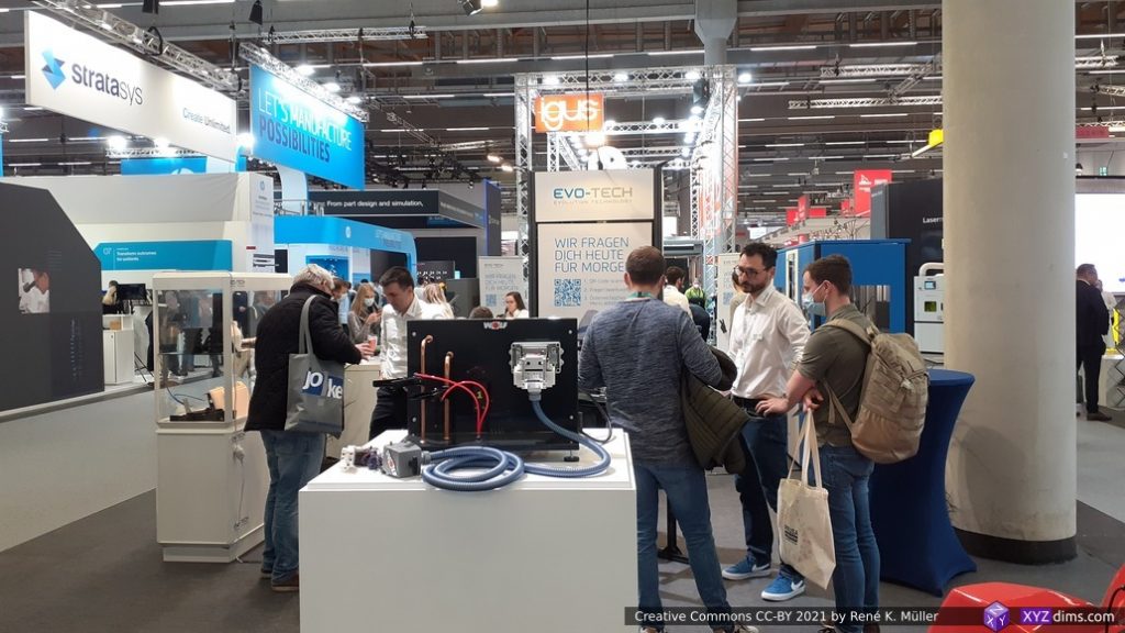
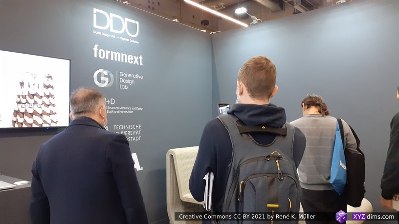
My first Formnext in 2019 I realized there was no way to explore the expo in 1 day only, so I reserved for Formnext 2021 (Frankfurt, Germany) 4 days fully (November 16-19). Although the expo was smaller than in 2019, it was still massive to explore. I’m not even sure I saw all of the 600+ exhibitors despite roaming the two halls (12.0 ground floor, 12.1 first floor and 11.0 ground floor only) multiple times.
Inhouse Developments: ZPlusSlicer & 5DMaker
I presented my inhouse developments of ZPlusSlicer and 5DMaker for the first time in public (otherwise just illustrated in About: Big Picture), as of November 2021, it’s not yet published or otherwise documented.
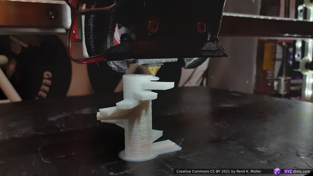
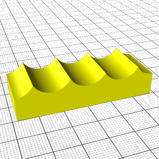
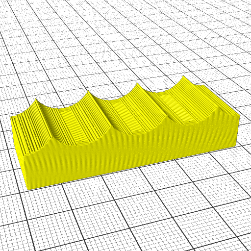
“Overhang stairs” printed without support with ZPlusSlicer & 5DMaker
Formnext 2021 giveaway samples: “overhang stairs”, printed without support, with ZPlusSlicer & 5DMaker
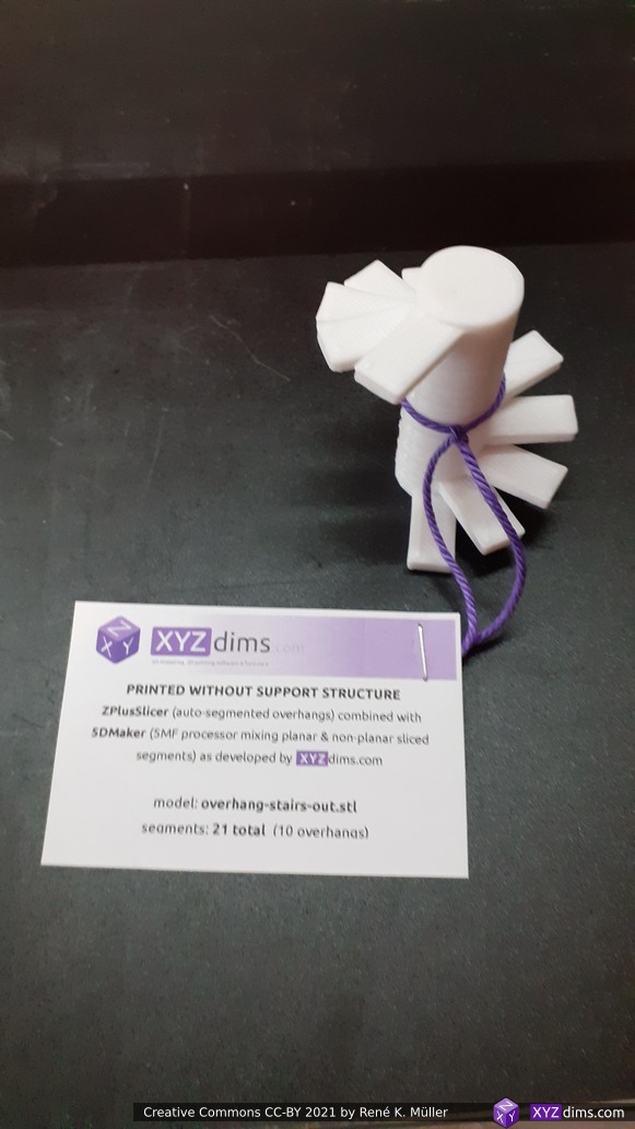
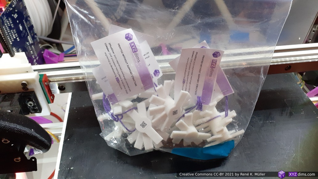
“Overhang stairs” sample prints with labels
About 40+ samples I handed out and alike amount some brief documentation (on paper) on ZPlusSlicer and 5DMaker (5MF processor) – both in early stage of development, and the “overhang stairs” a proof-of-concept of the benefit of both new conceptual layers on top of traditional slicing. By spring 2022 I will publish more publicly on both products once they matured to Beta stage.
Notables
Ultimaker: they didn’t have any booth, yet their machines were placed at many booths, resellers kind of represented them – combination of dominance and absence
Makerbot wasn’t there
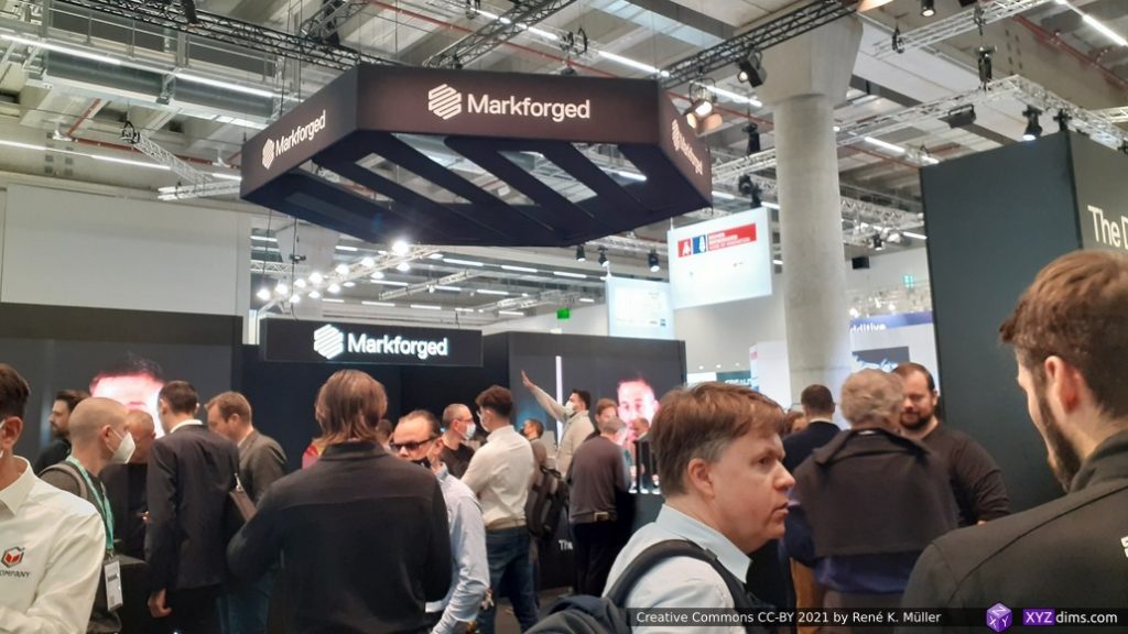
Markforged considers itself as startup but outsiders consider them as big player already – impressive integration of machine, material and slicer, yet, all closed down; hard(er) to integrate with 3rd party software
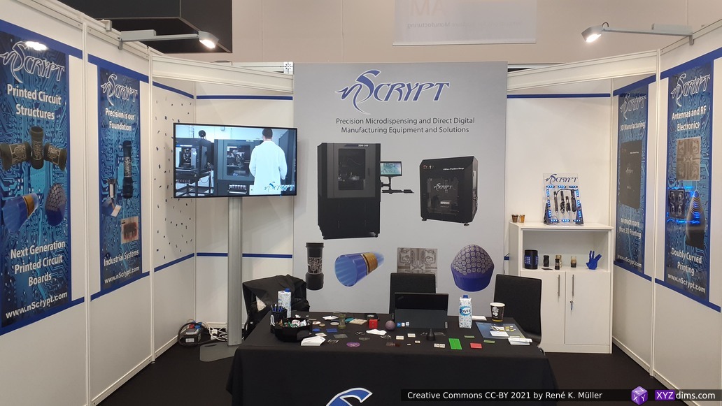
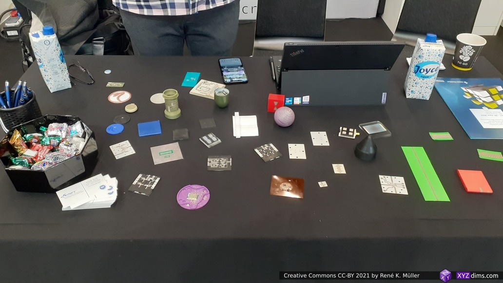
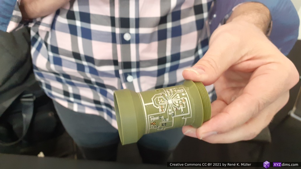
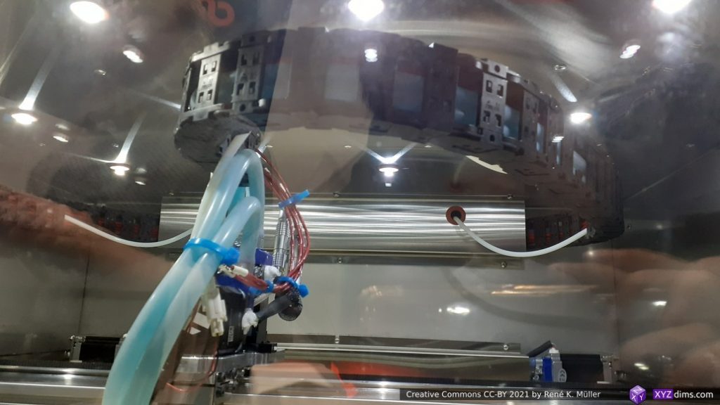
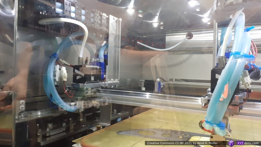
nScrypt micro-dispensing on cylindrical or spherical surfaces, PCB 3d printing and pick-place SMD components:
nScrypt
nScrypt samples
nScrypt: micro-dispensing on surface
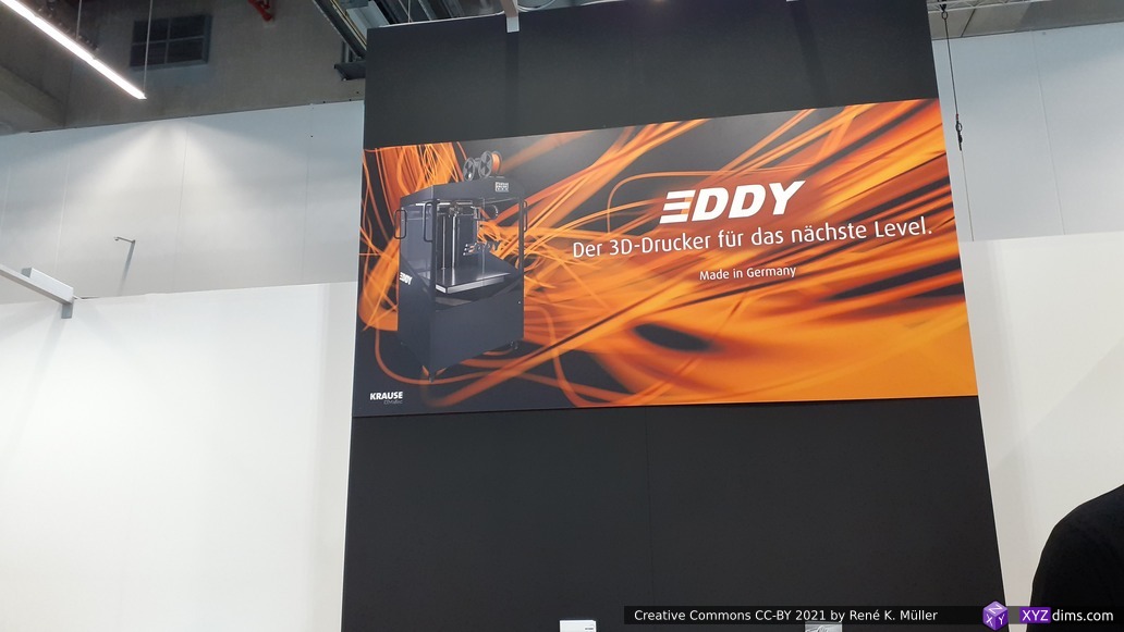
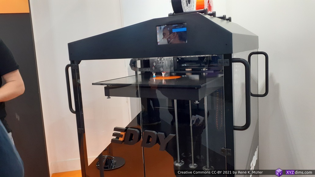
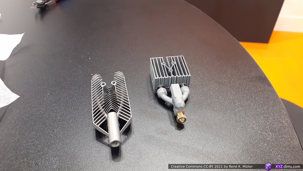
Krause DiMaTec showed its EDDY 3D printer, slow Z axis, but quite affordable at ~8K EUR for the machine with 600 x 600 x 600mm build-volume, and the 3D metal printed hotend was quite an eye-catcher:
Krause: EDDY 3D printer
Krause: EDDY 3D printer
Krause: EDDY, 3D metal printed hotend
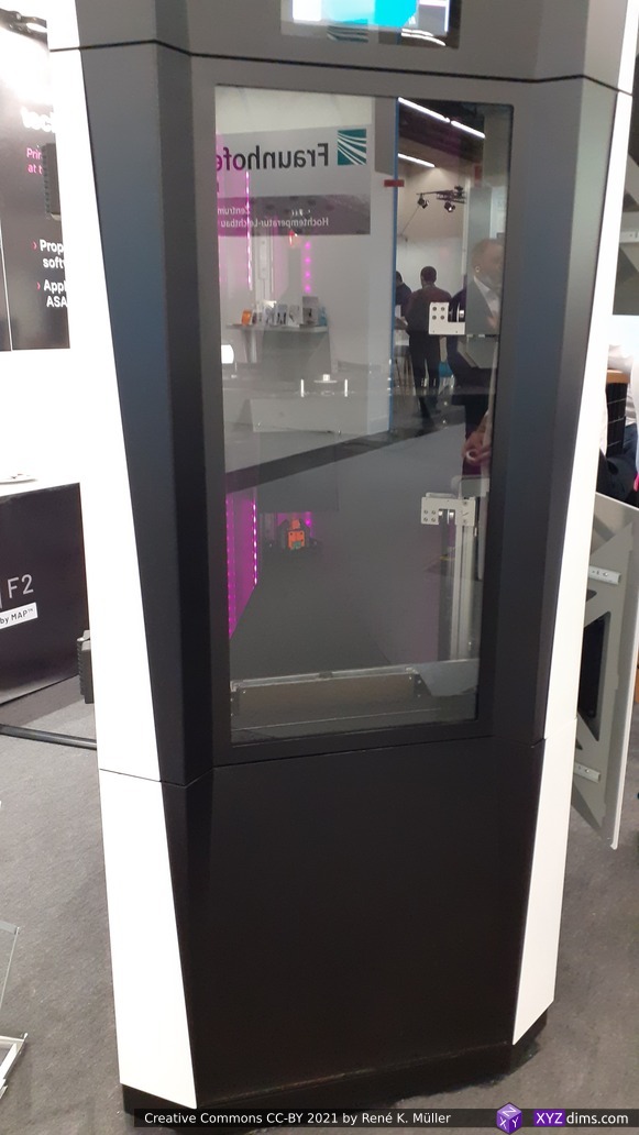
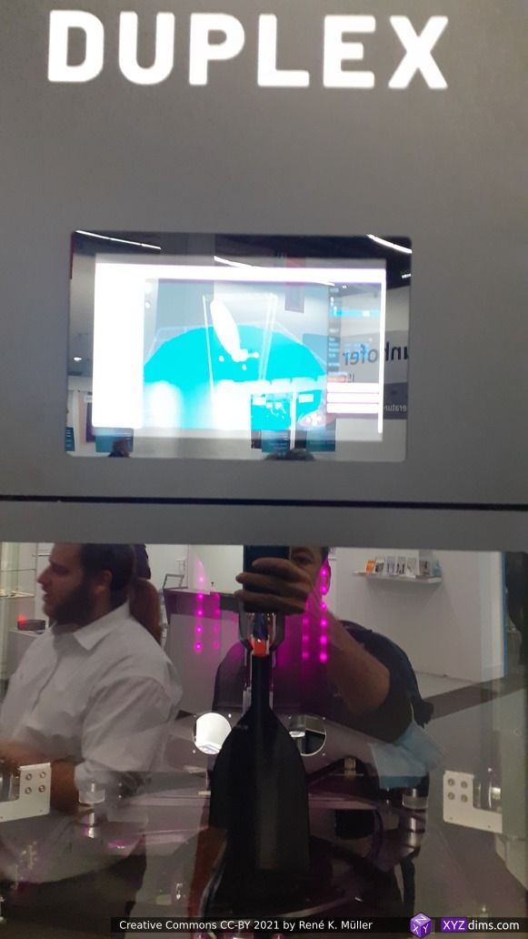
Duplex3D printer: two nozzles starting to print on upper & lower side of the build plate, once reached some distance, the plate is removed (!!) and 3D prints continues in both Z directions (the front glass is very glaring so not many details, also the representatives didn’t want to me to take too close photos):
Duplex 3d printer: prints in both Z directions with 2 nozzles (middle to up, and middle to bottom)
Duplex 3d printer: prints in both Z directions with 2 nozzles (middle to up, and middle to bottom)
Duplex 3d printer: prints in both Z directions with 2 nozzles (middle to up, and middle to bottom)
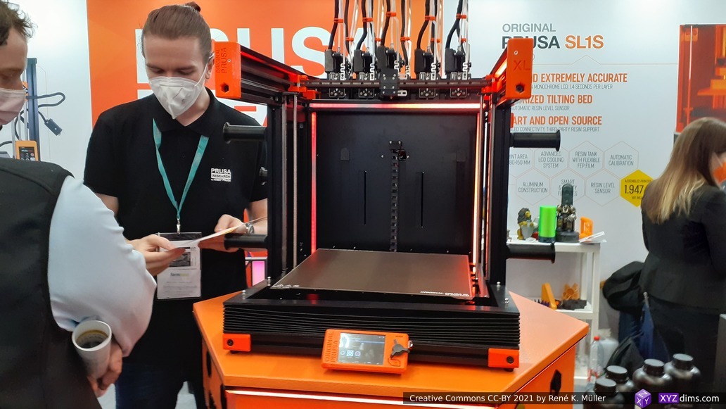
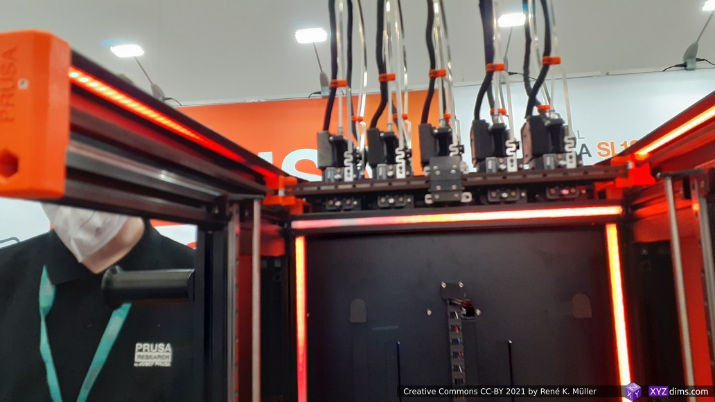
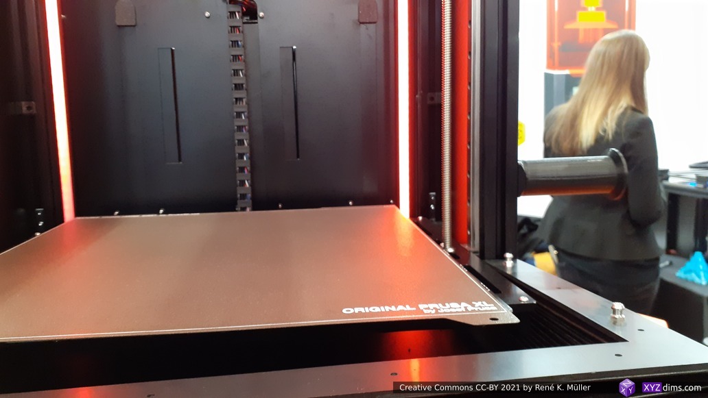
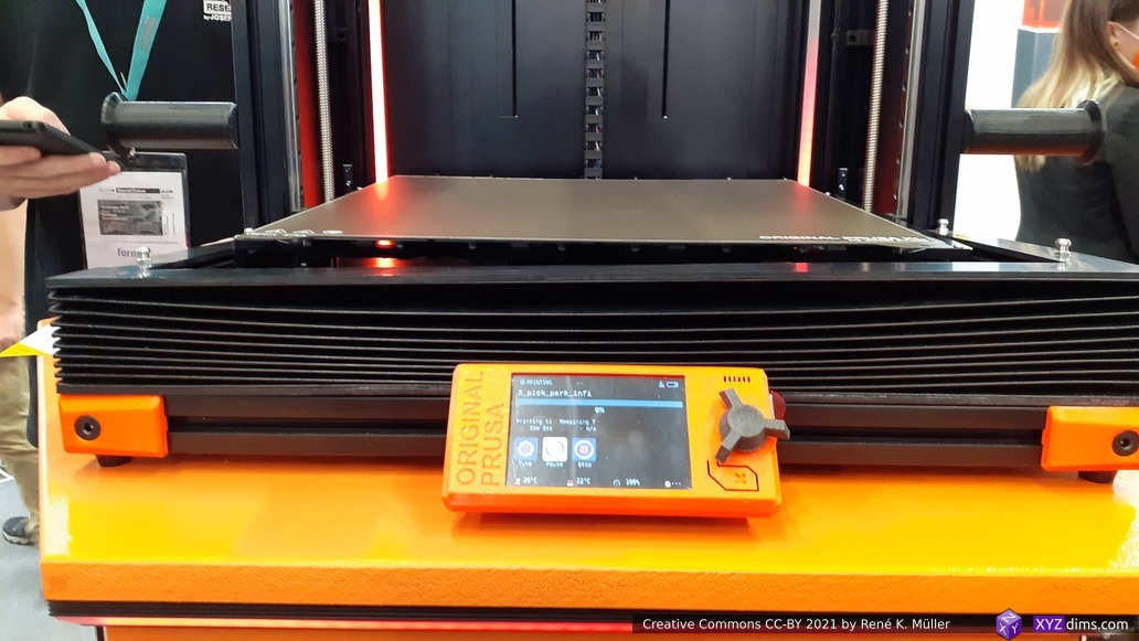
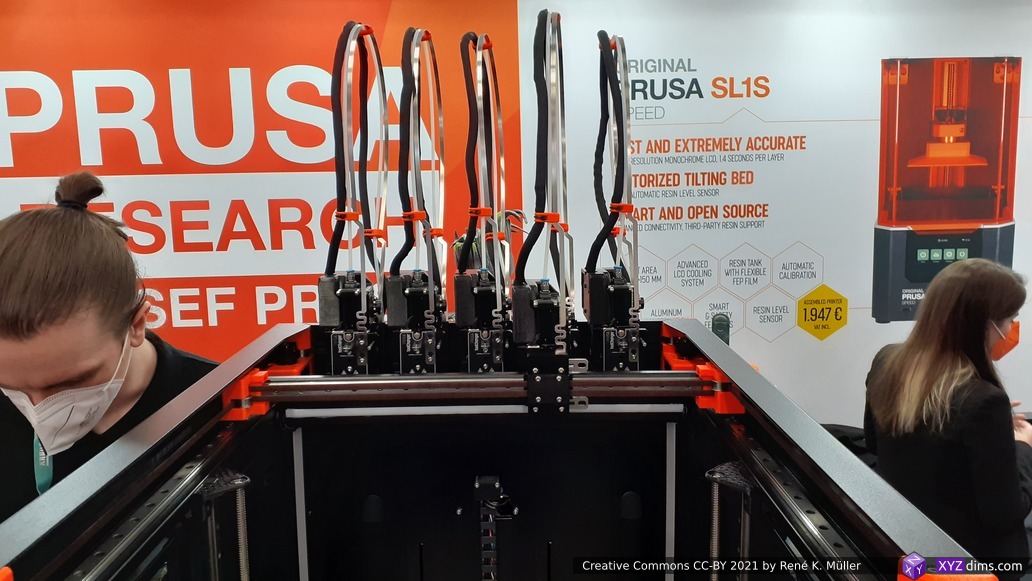
Prusa Research released its Prusa XL – a Core XY based printer, I took a few photos with a lot of small innovations:
360 x 360 x 360 mm build volume
mechanical pressure-based Z calibration built into the printhead (nozzle probes mechanical on the build plate)
segmented heating of build plate, heat there where the part is located
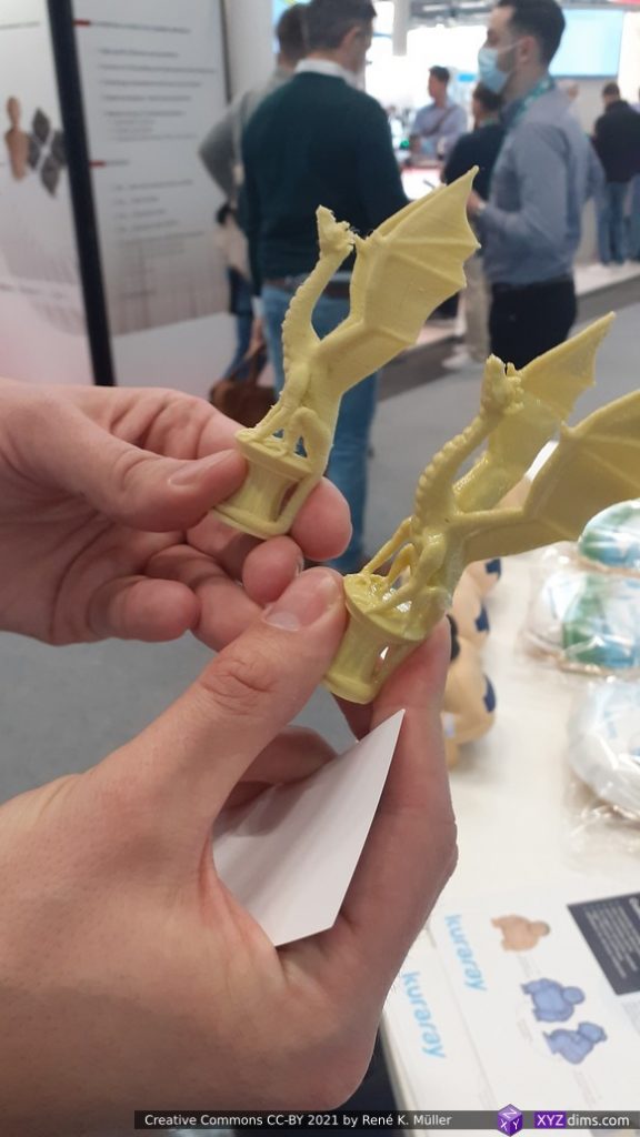
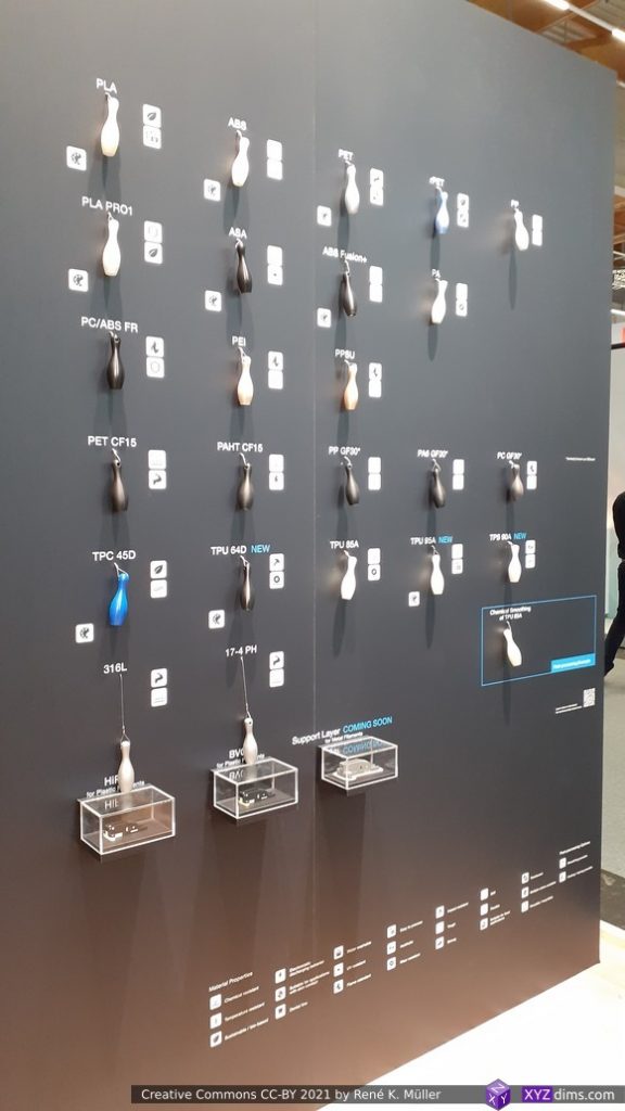
Kimya: materials too, great (paper) catalogue with detailed information on how to print their filaments and use-cases
Formnext 2021 Impressions
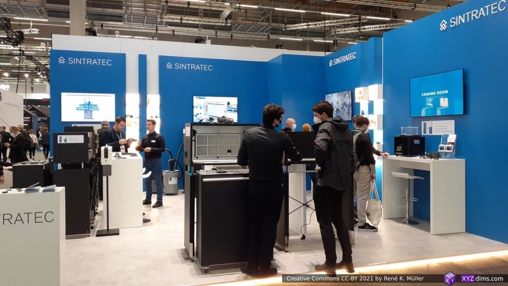
Sintratec
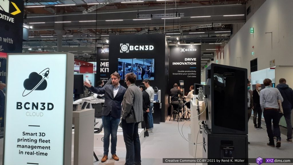
BCN3D
Desktartes
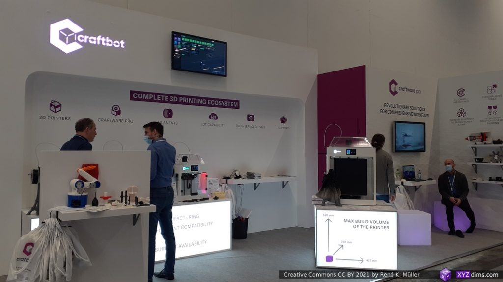
Craftbot Machines & Slicer
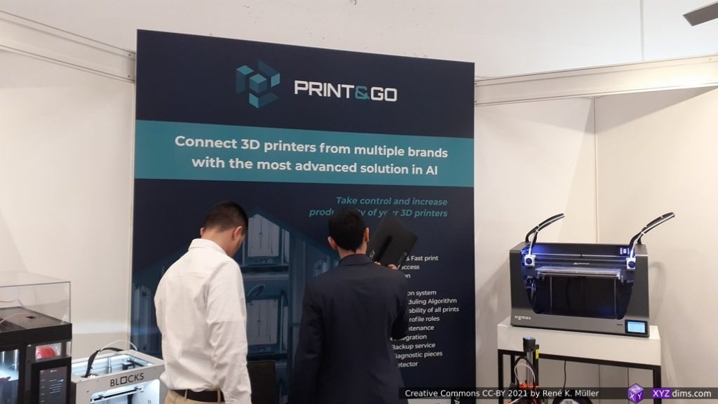
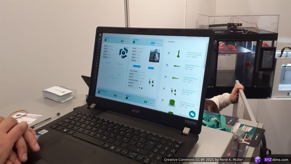
Print&Go
Print&Go GUI
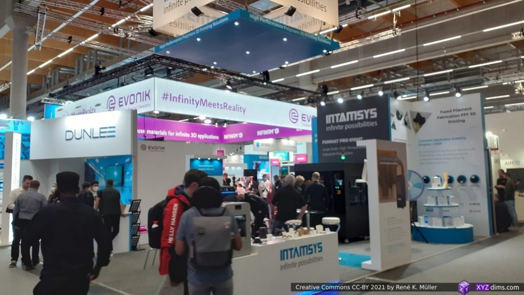
Intamsys & Evonik
AIM3D
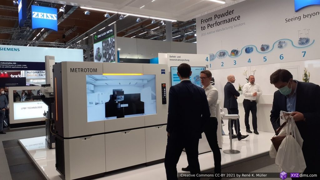
Metrotom 3D Printer
3DGence Element
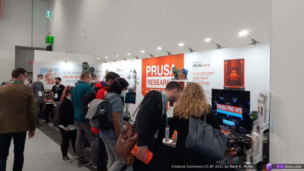
Prusa Research
Prusa Research
3D printed Groot
Prusa Research
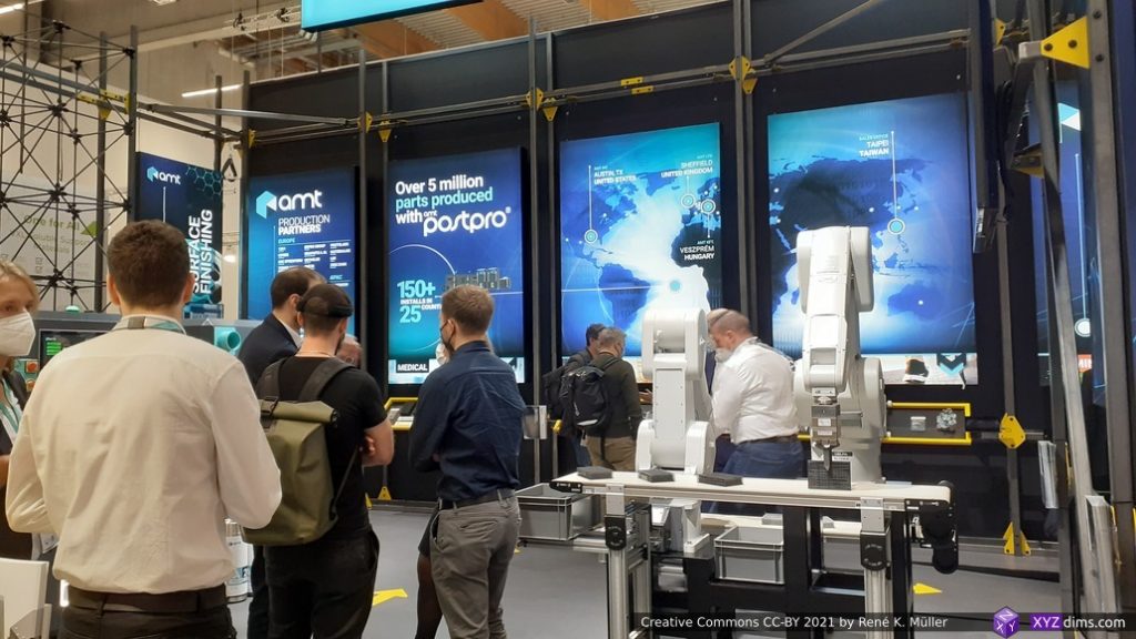
AMT
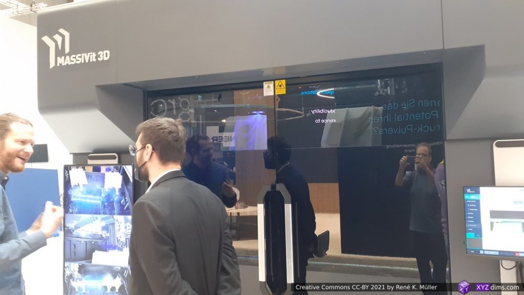
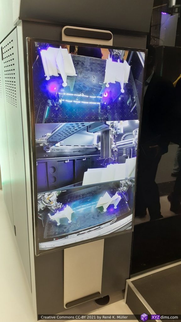
Massivit 3D: curing 3d printed gel
Massivit 3D: multiple cams
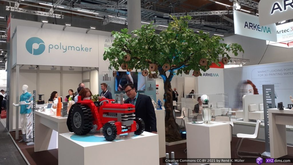
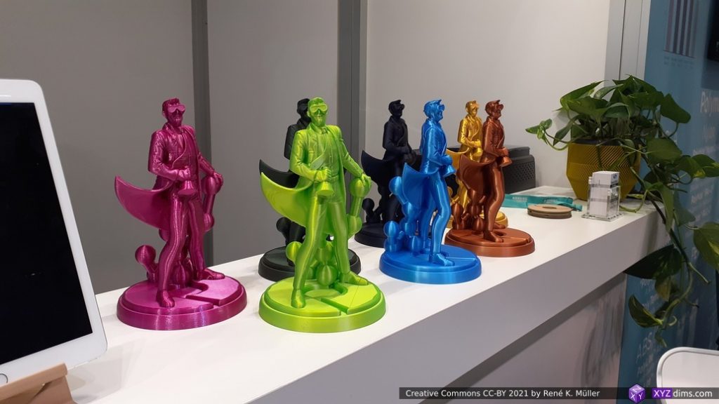
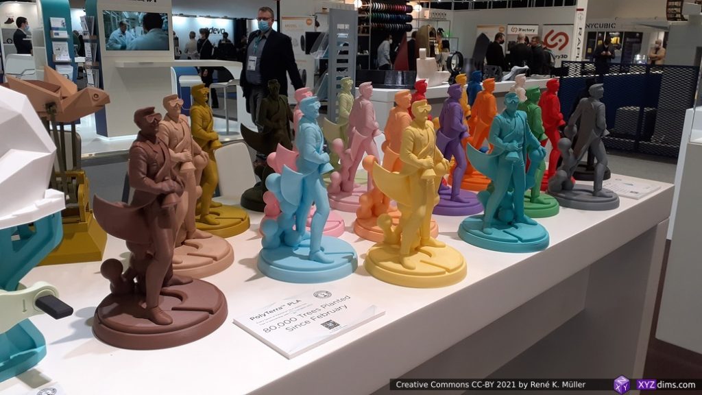
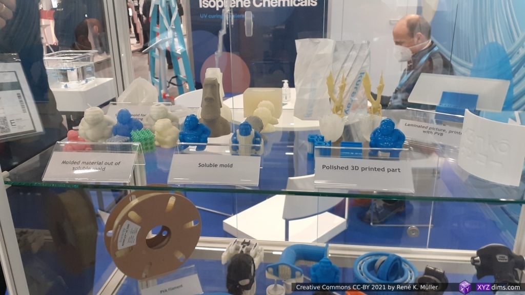
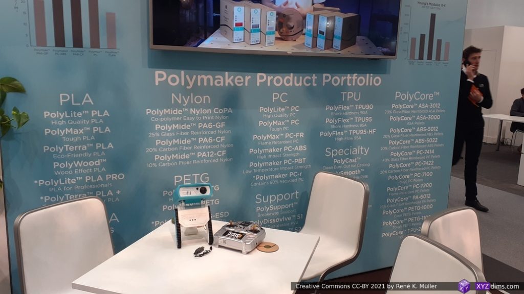
Polymaker
Polymaker colors
More Polymaker colors
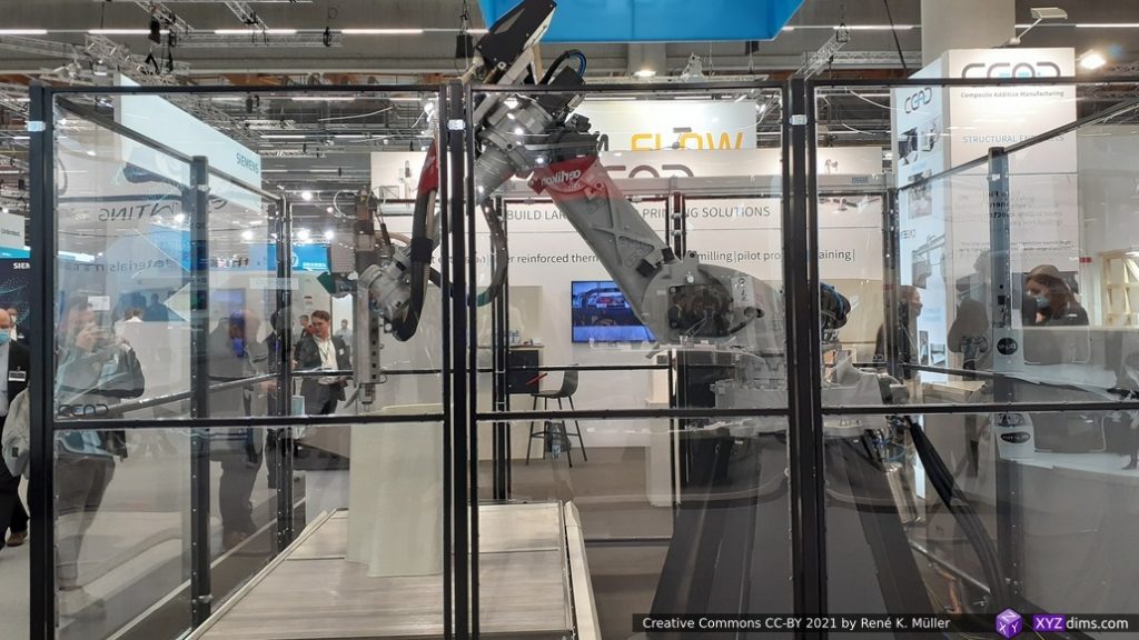
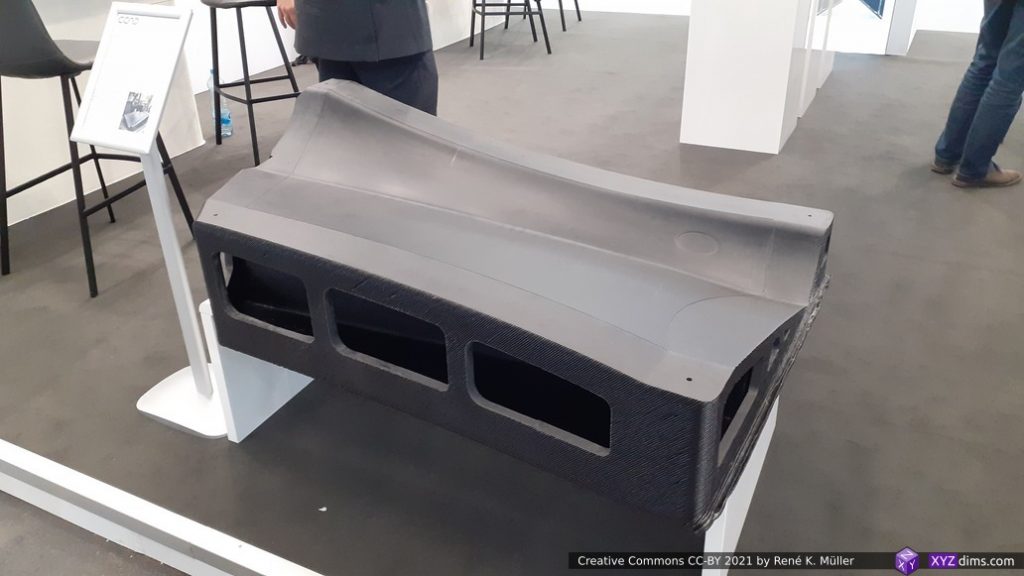
6 Axis FDM
Massive print
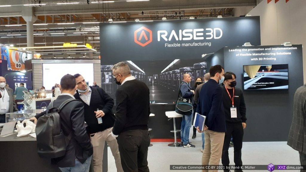
Formnext 2021
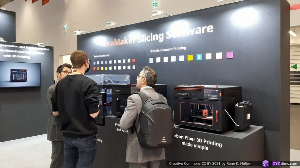
Raise3D
Raise3D IdeaMaker
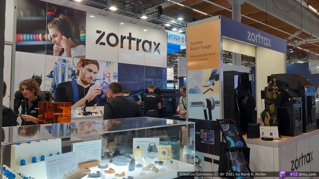
Zotrax
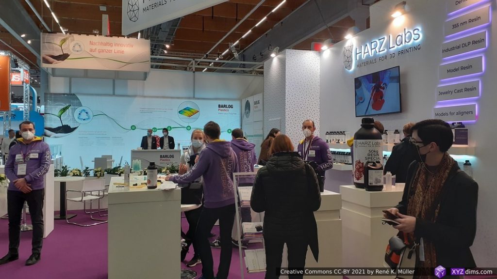
Harz Labs
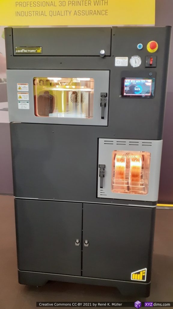
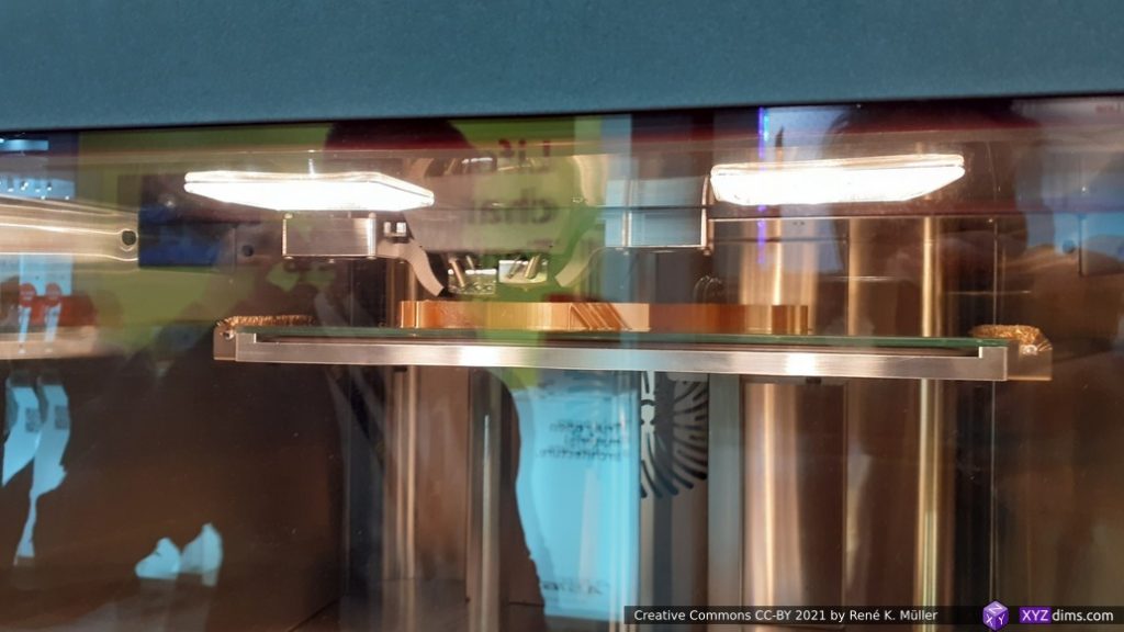
miniFactory
miniFactory
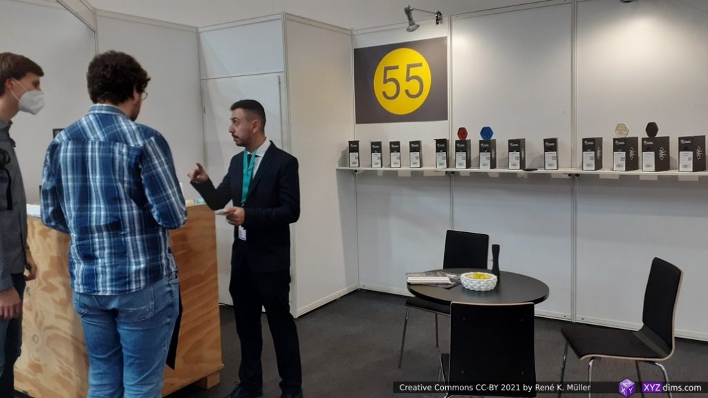
TreeDFilaments: 55 Materials
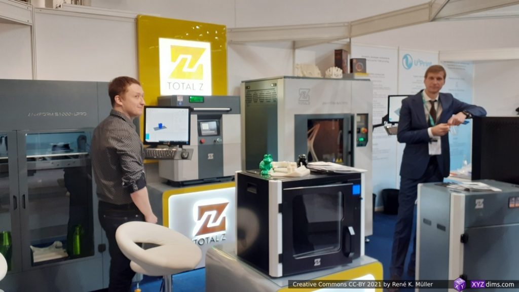
Total Z
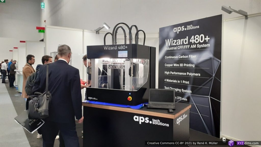
APS tech solutions & Wizard 480+
Wizard 480+ samples
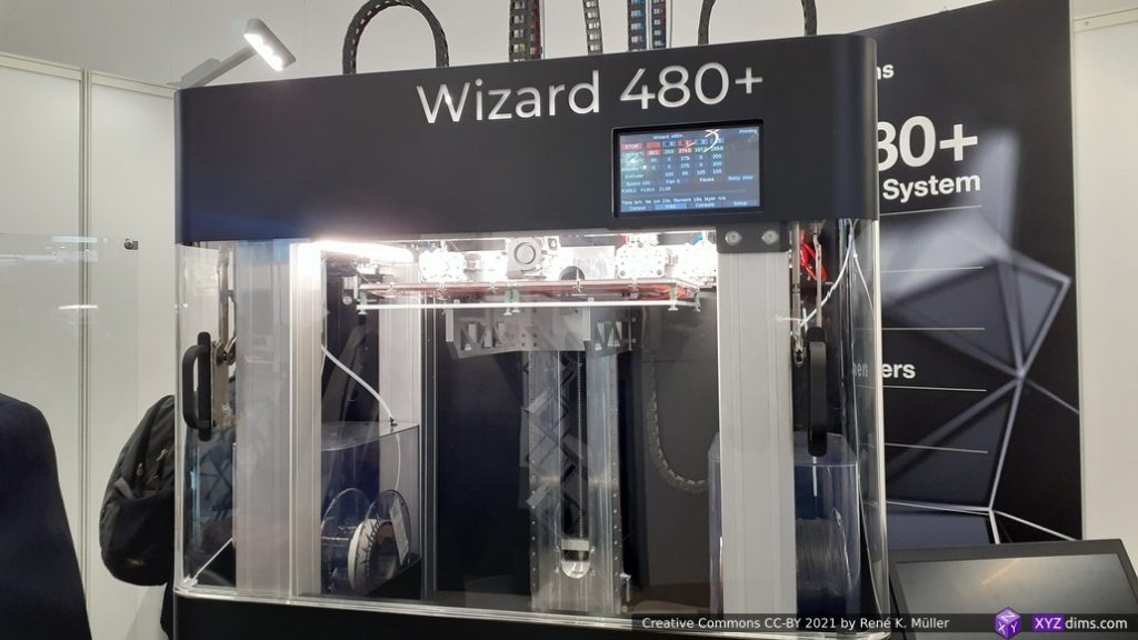
Wizard 480+
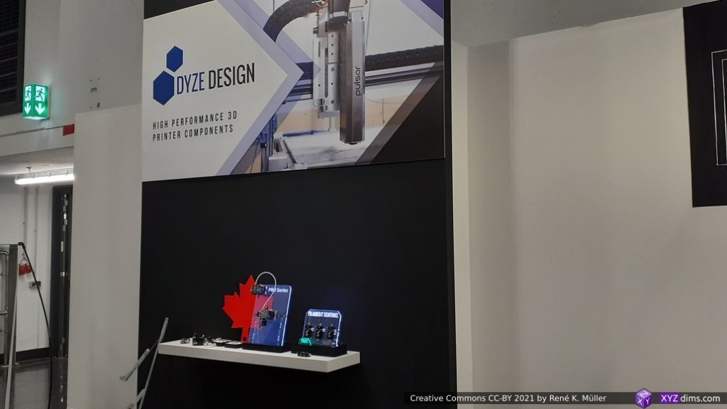
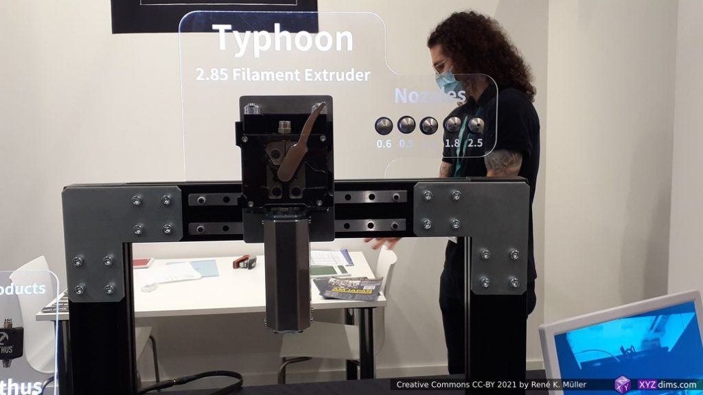
Dyze Design
Dyze Design: Typhoon Hotend
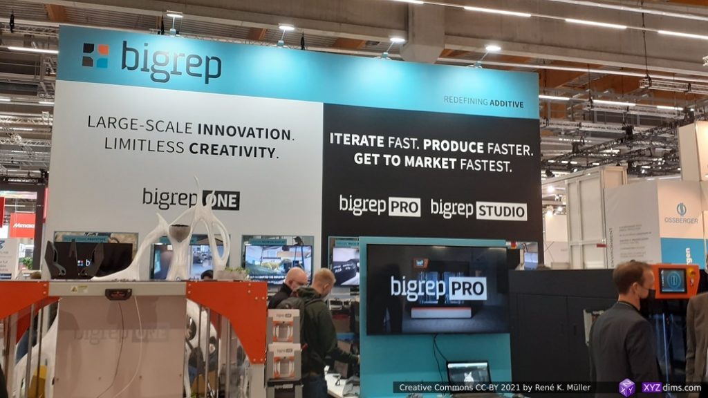
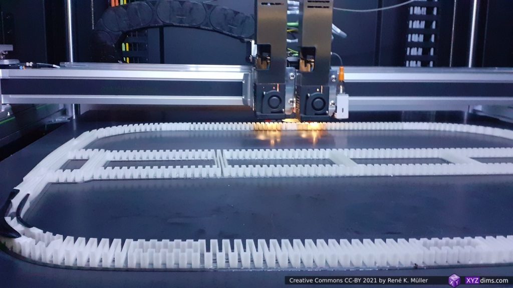
Bigrep
Bigrep Pro
Bigrep Pro
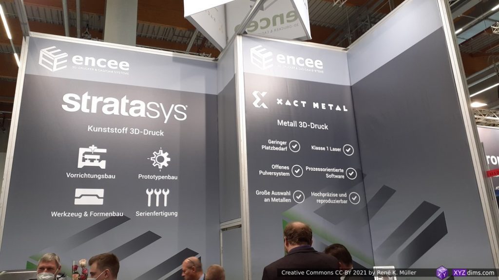
Stratasys
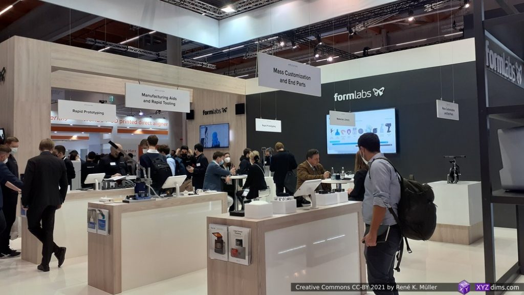
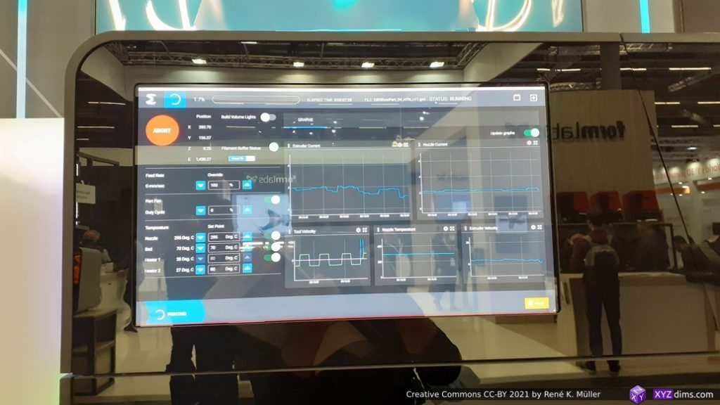
Formlabs
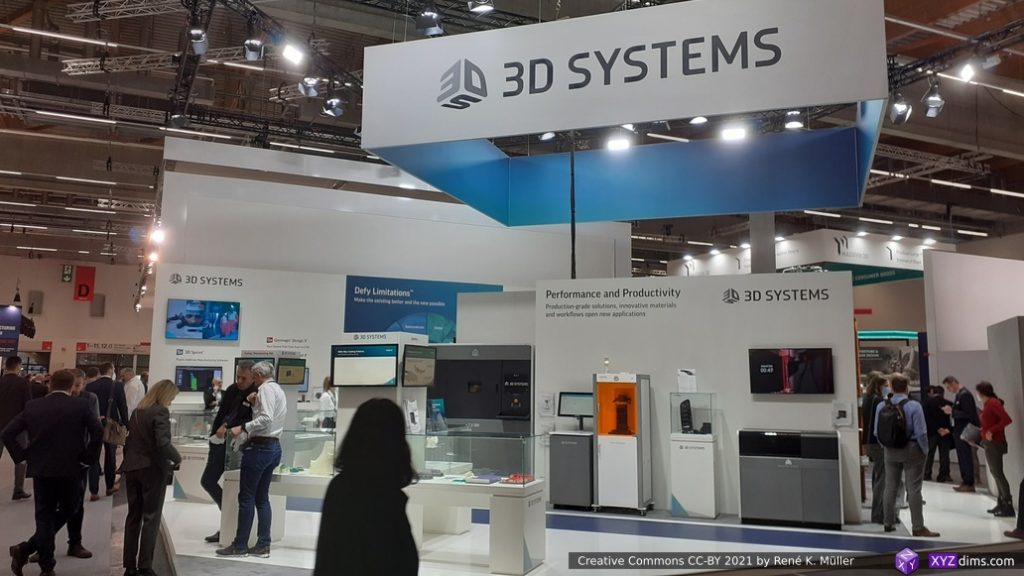
3D Systems
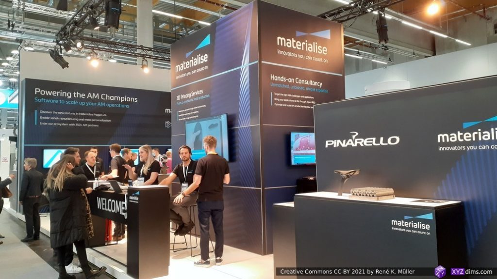
Materialise
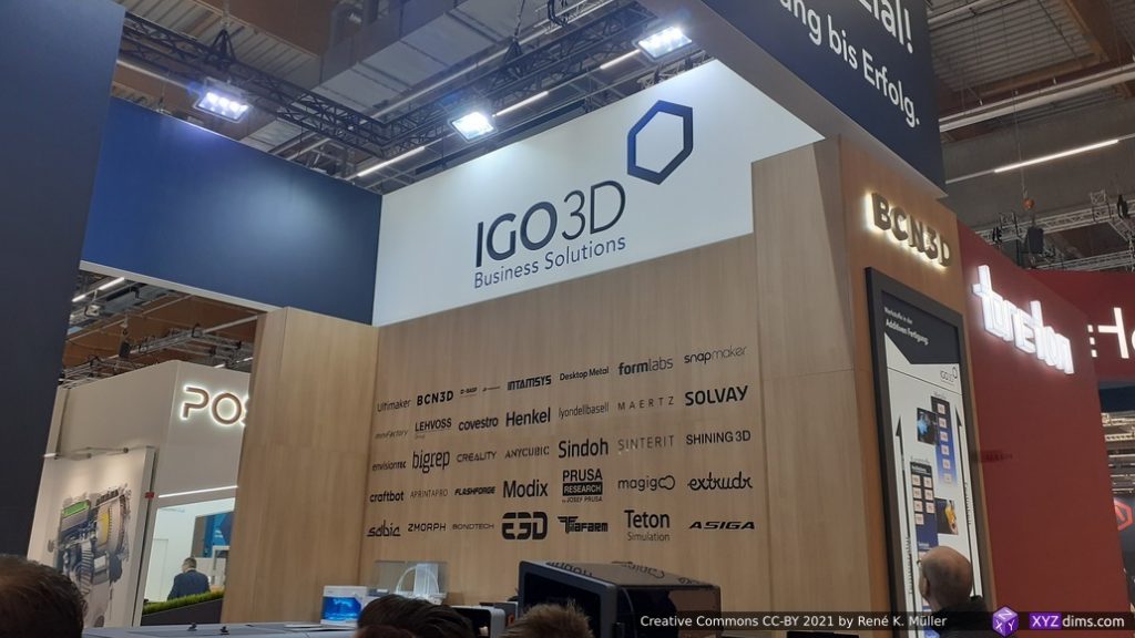
IGO3D
AIM3D: Post processing
AIM3D: post processing
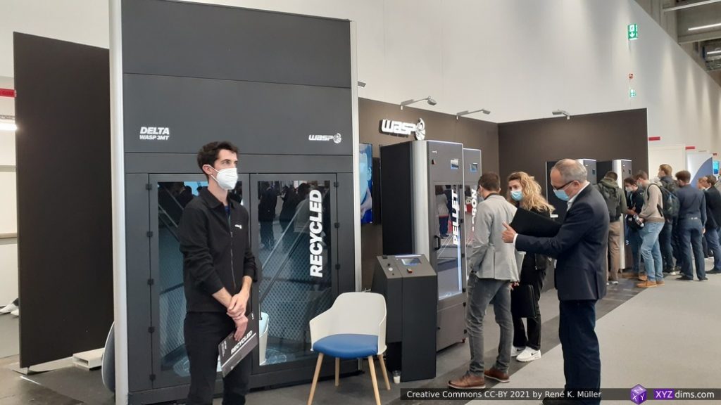
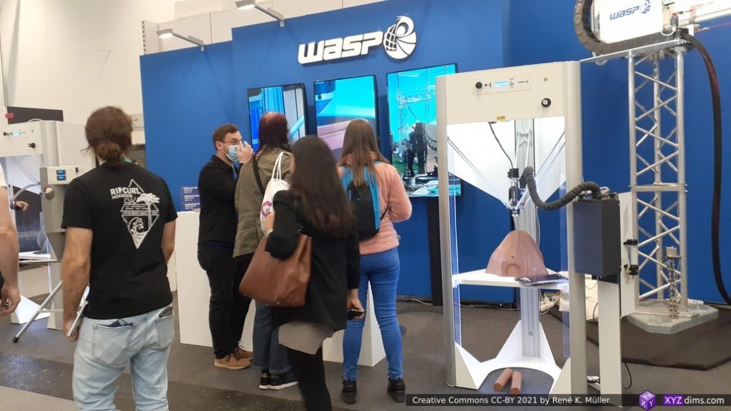
WASP
Polymaker materials
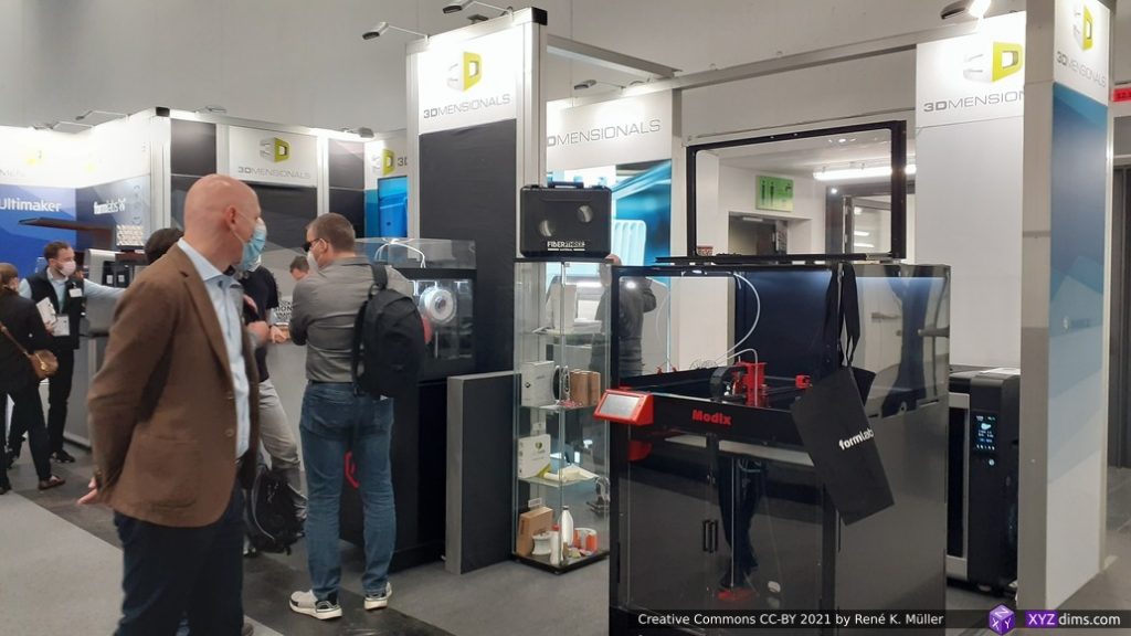
3Dmensionals
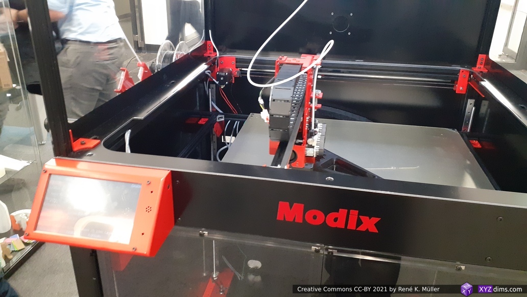
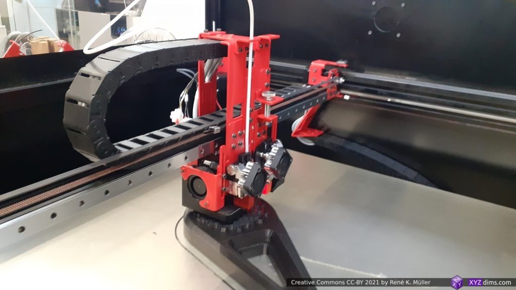
Modix DIY kit
Modix DIY kit
Additive Laser Technology / alt-print.com
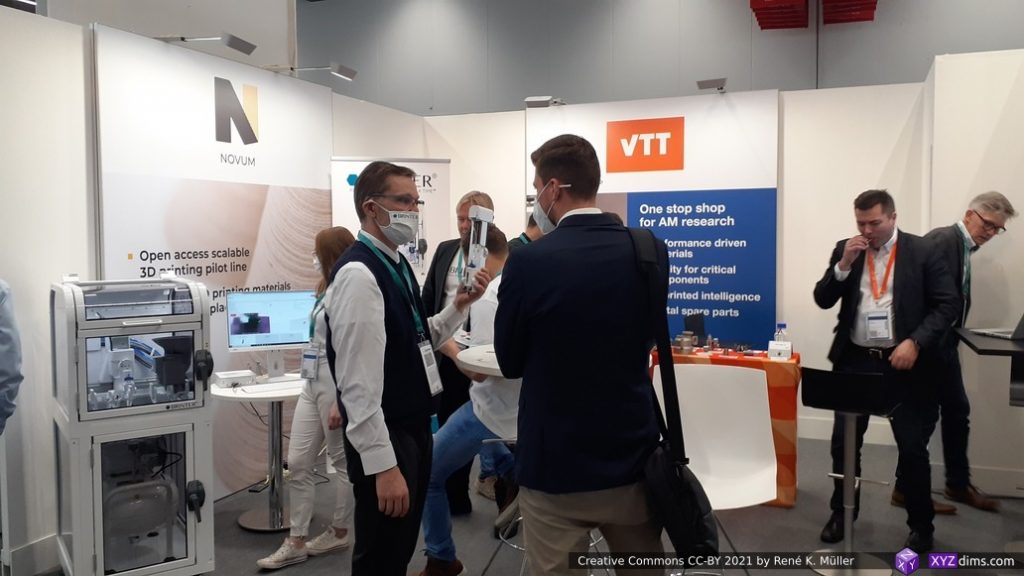
Novum & VTT
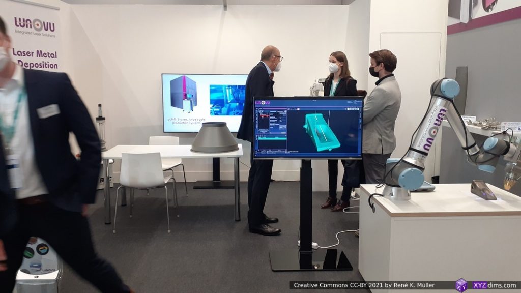
Lunovu
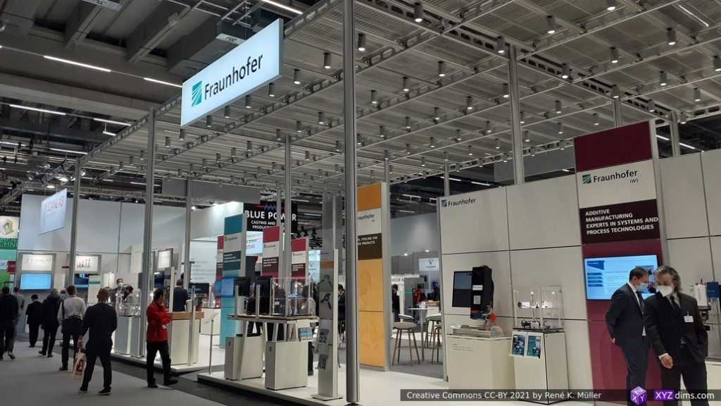
Fraunhofer
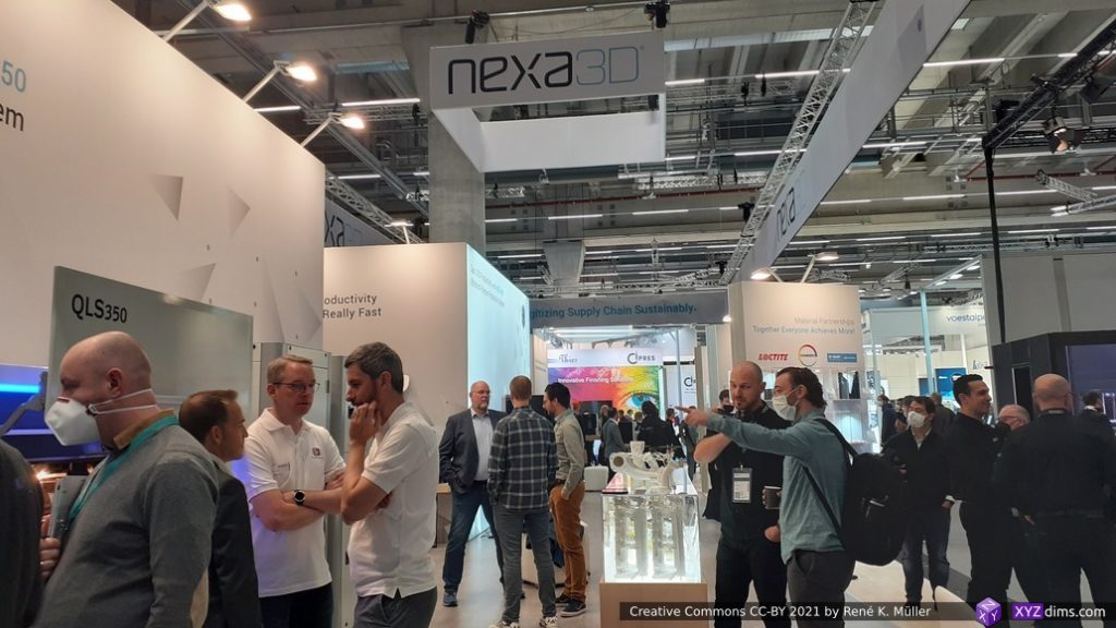
Nexa3D
Markforged
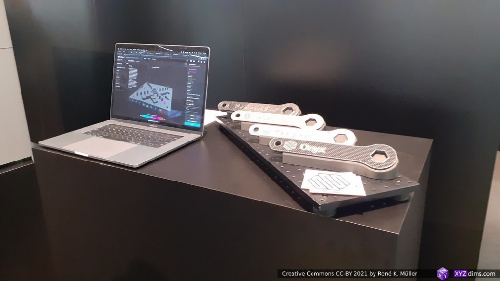
Markforged: Continuous Carbon and Glass Fiber
Markforged: Continuous Carbon Fiber
Autodesk
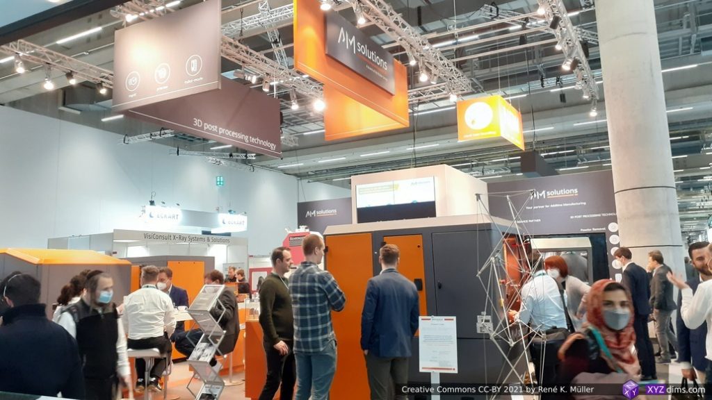
AM Solutions
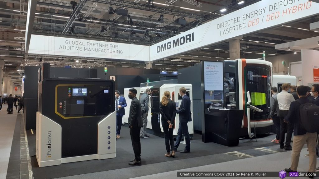
DMG Mori
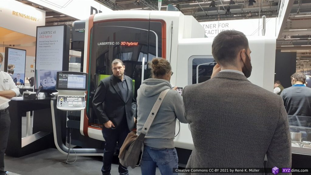
AMG Mori: Lasertec 65 3D Hybrid
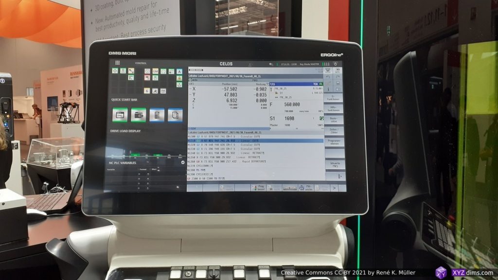
DMG Mori: Lasertec 65 GUI
DMG Mori Lasertec 65 swappable tools
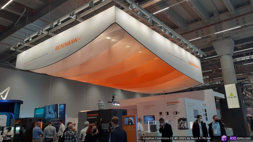
Renishaw
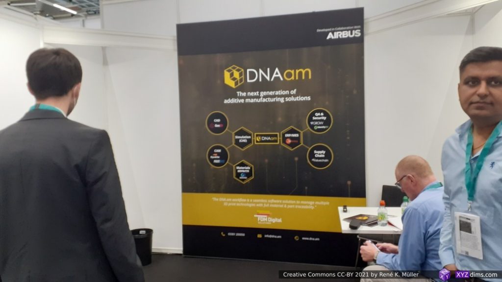
DNAam
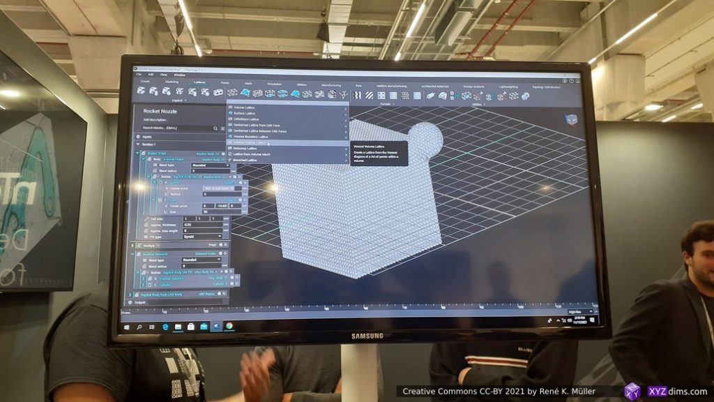
nTopology
nToplogy GUI
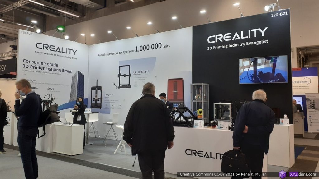
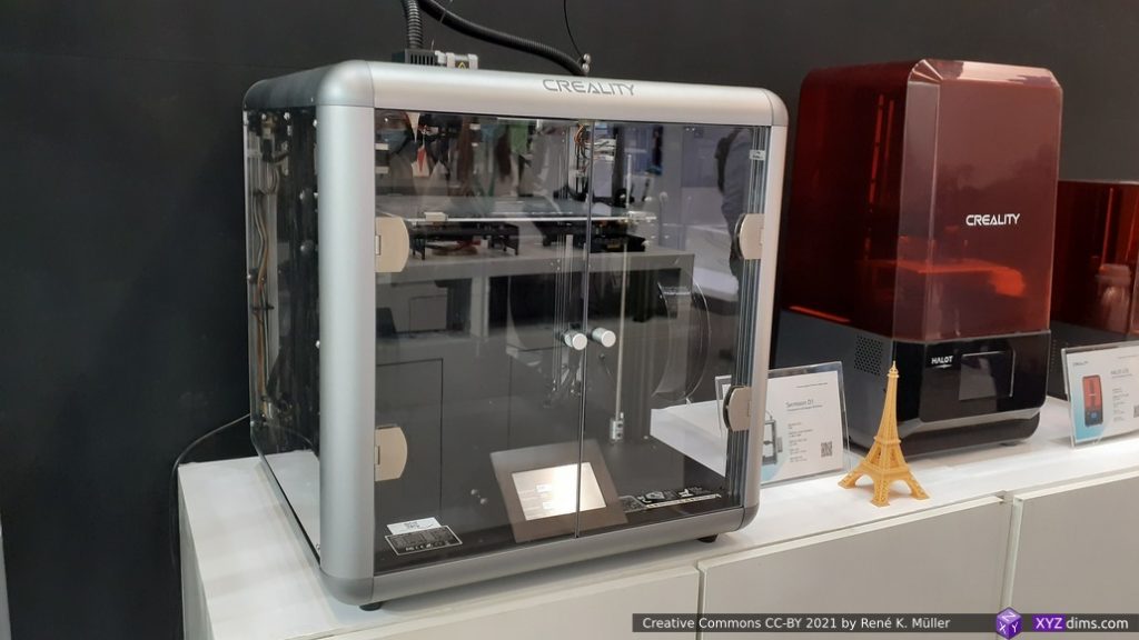
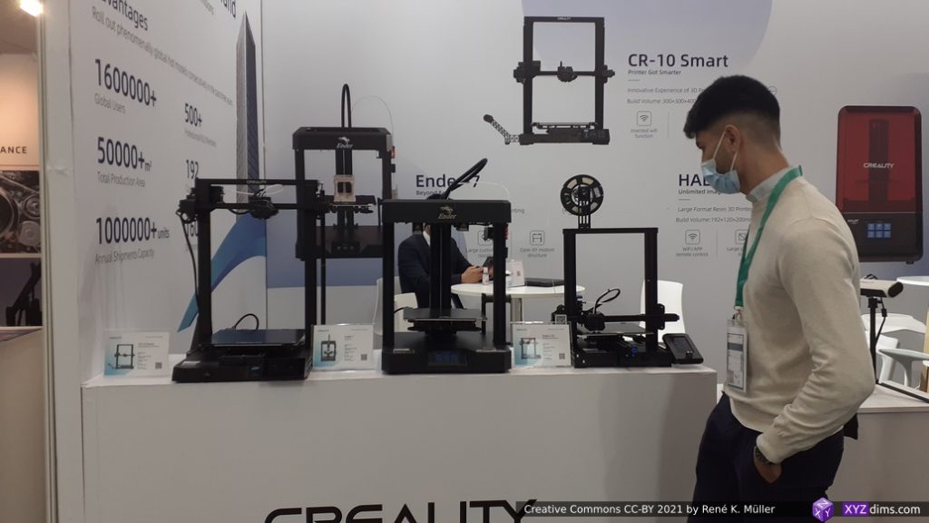
Creality
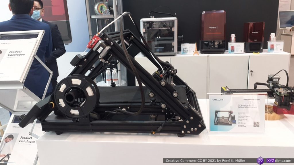
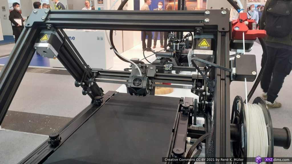
Creality CR30
Creality CR30
Creality
Creality
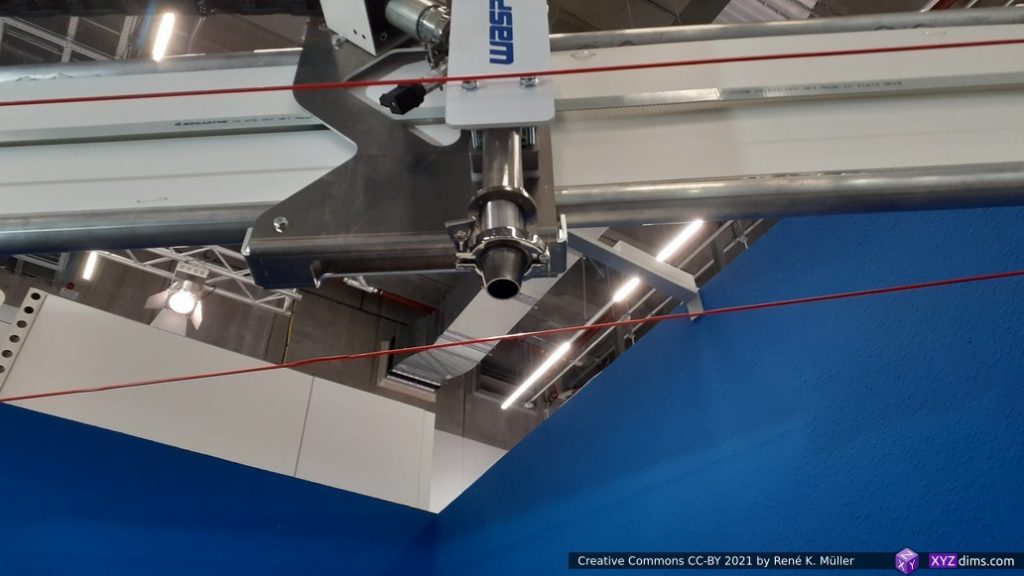
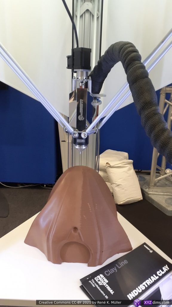
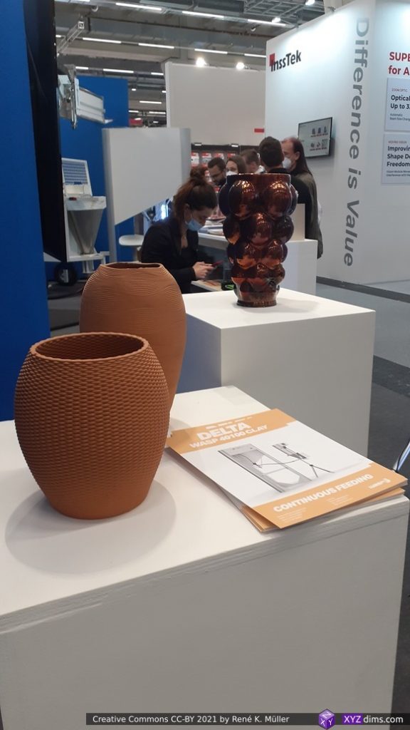
WASP
WASP: huge nozzle
WASP: huge nozzle
WASP: printing clay
WASP: printing clay
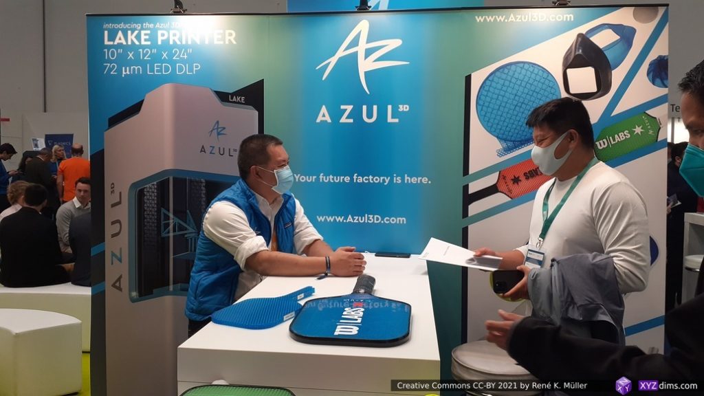
AZUL
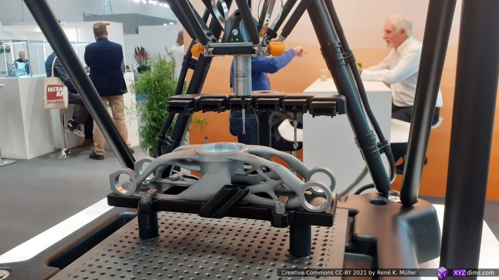
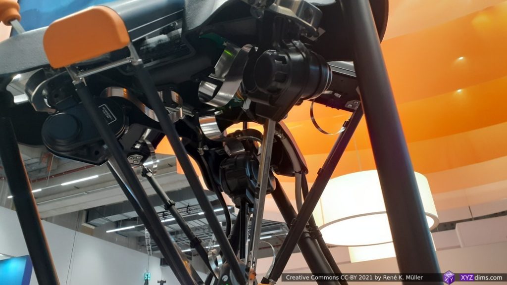
Renishaw: delta-based multi-head calibrator
Renishaw: delta-based multi-head calibrator
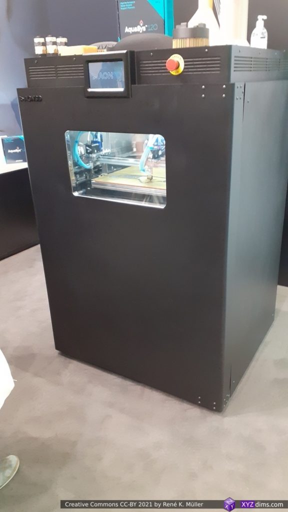
Aon3D
Aon3D printhead
Aon3D
Aon3D
Aon3D print with support
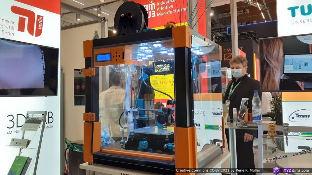
TU Berlin: Prusa Mendel enclosed, certified for schools
TU Berlin: Prusa Mendel enclosed, certified for schools, ventilation
Prusa Resarch: robot dog (remote controlled)
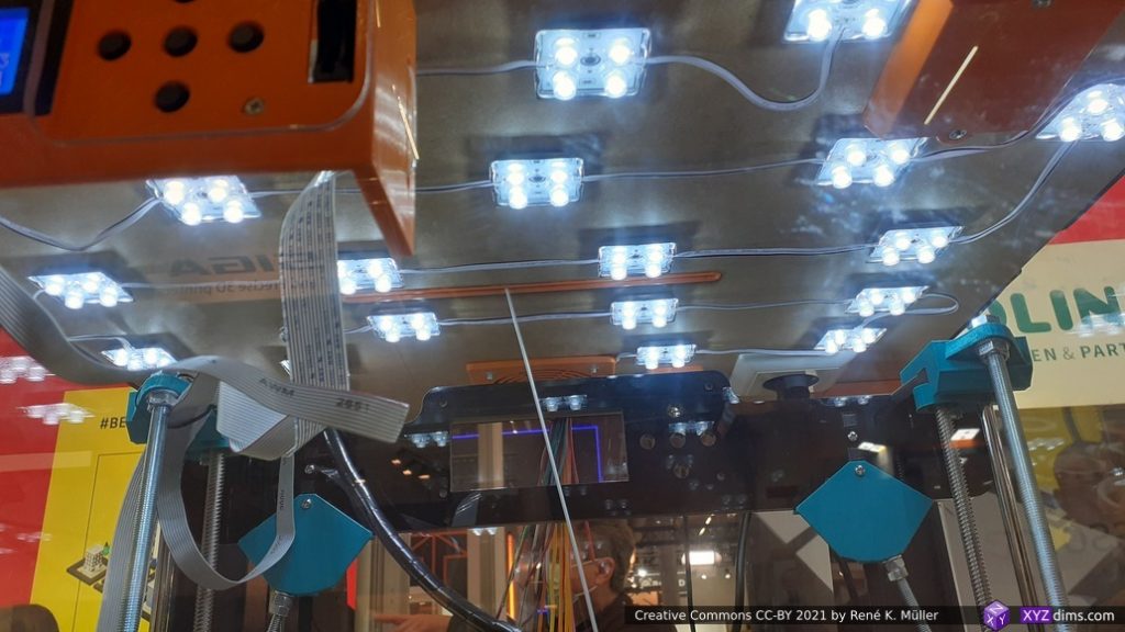
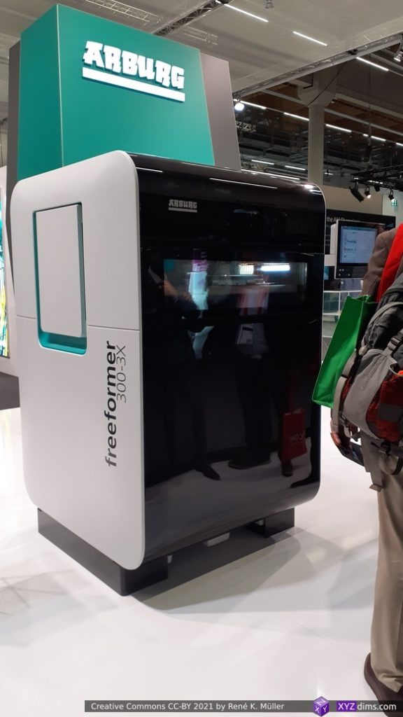
Arburg Freeformer 300-3X
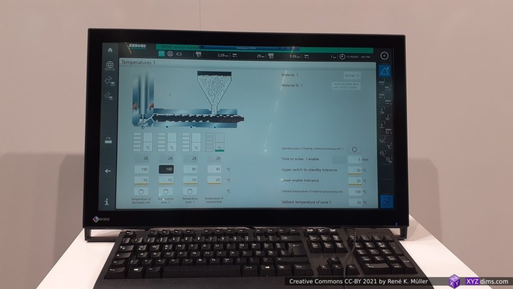
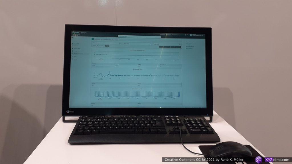
Arburg Freeformer GUI
Arburg Freeformer GUI
No STL
Craftbot
BCN3D
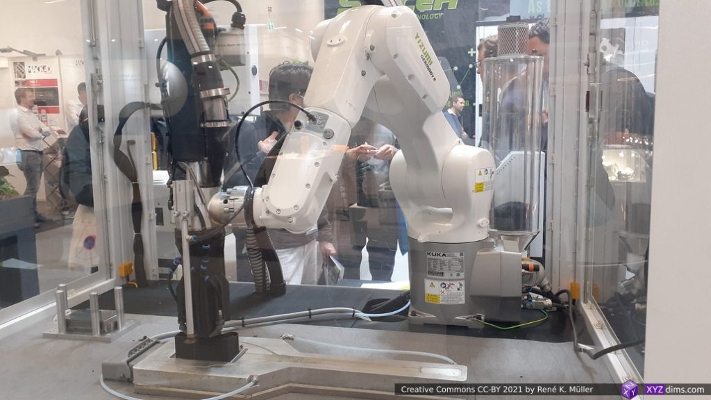
Yizumi / SpaceA
Yizumi
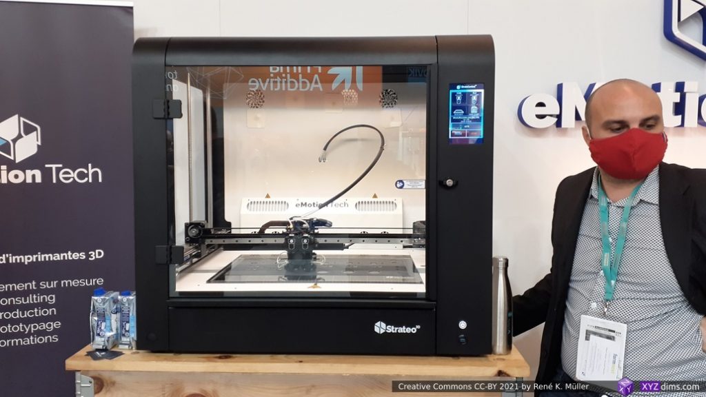
eMotion Tech: Strateo
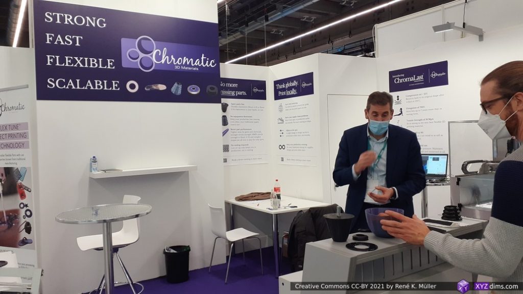
Chromatic: liquid deposition
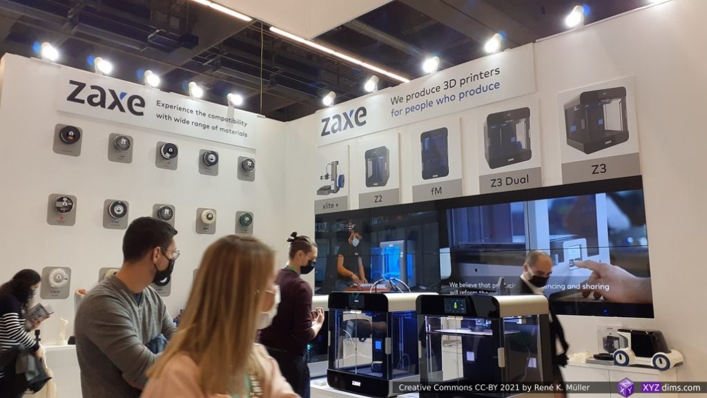
Zaxe
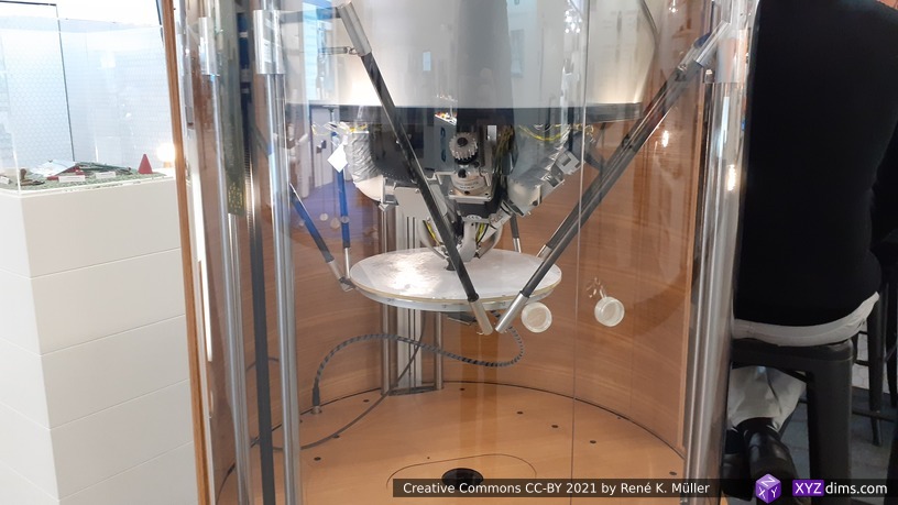
Pollen: delta printers
Pollen: delta printer, moving bed, steady nozzle
3D printed concrete
3D printed concrete
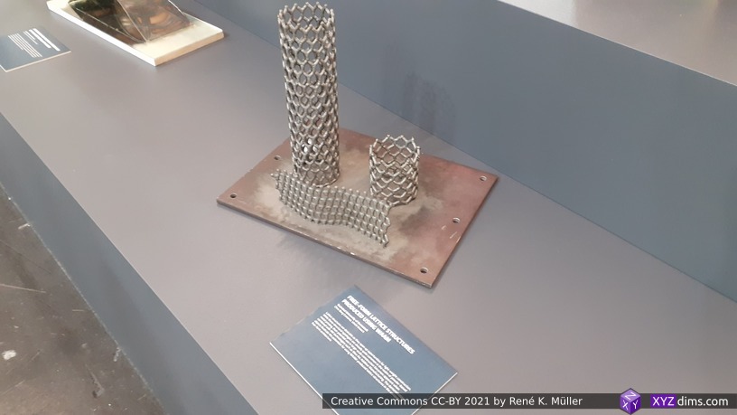
3D printed metal
3D printed concrete
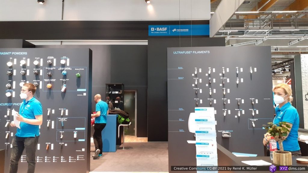
BASF materials
BASF materials
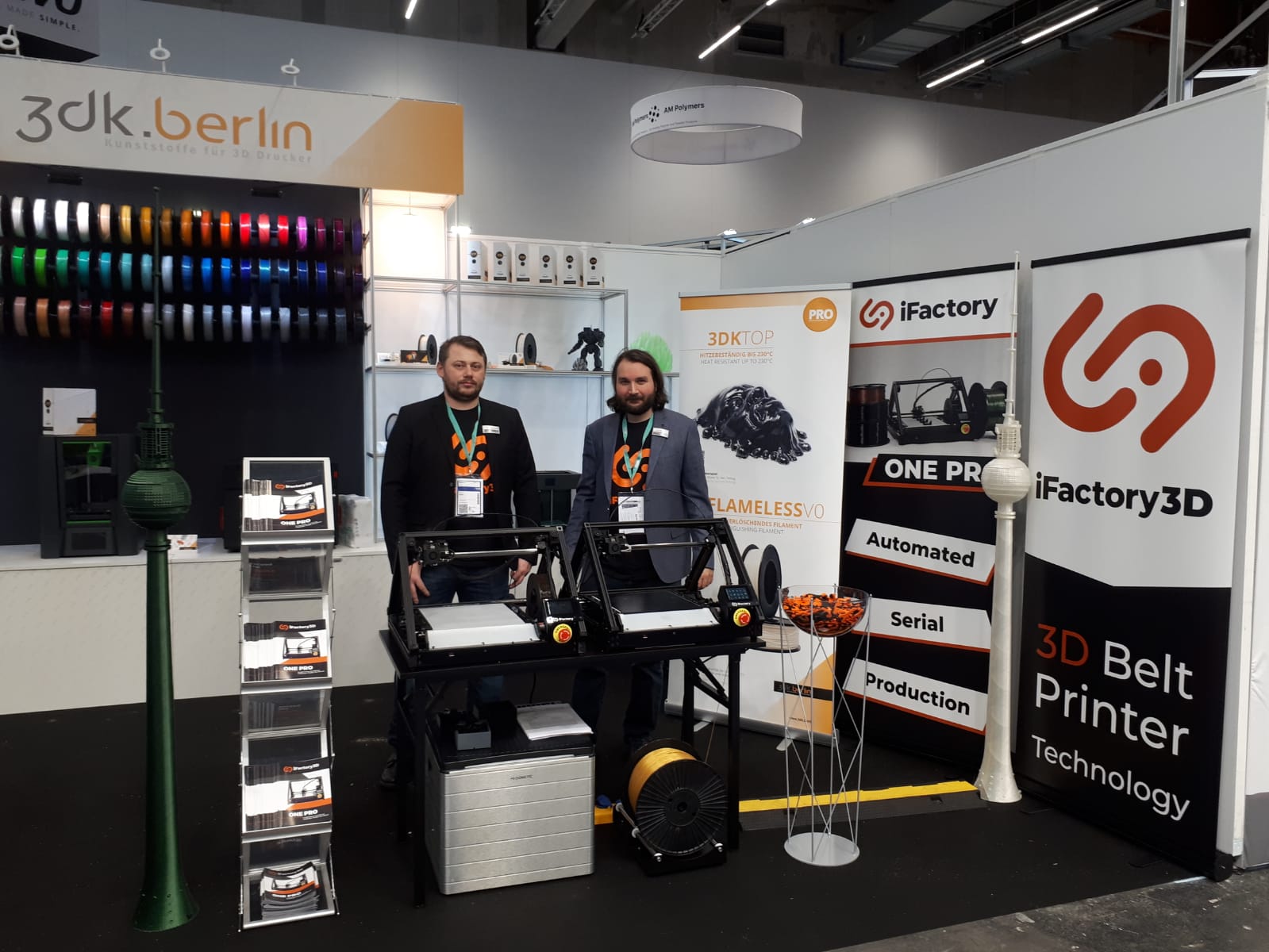
iFactory3D: belt printers made in Germany (photo by iFactory3D)
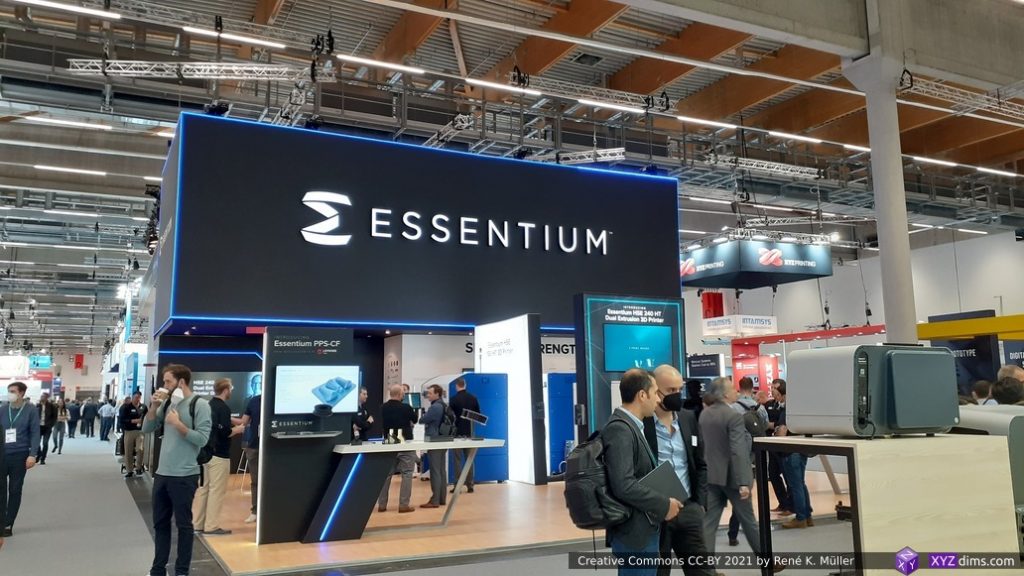
Essentium
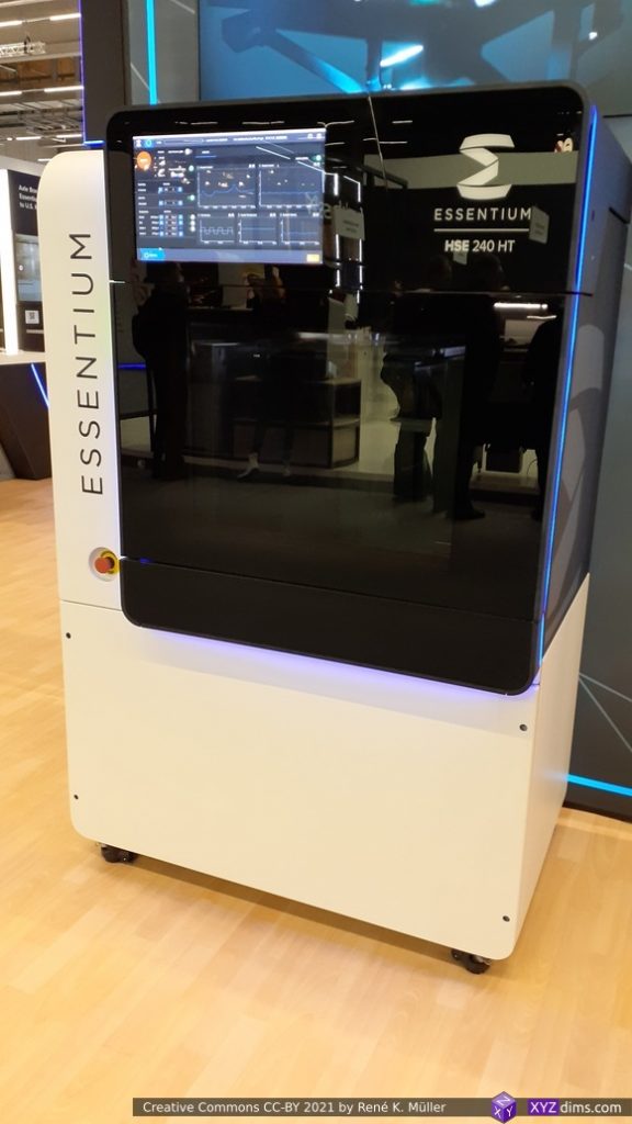
Essentium HSE 240 HT
Essentium HSE 240 HT GUI
People vs Companies
Although all the companies appear quite anonymous, if you spend more than just a few minutes, and are able to talk to some technical skilled people – aside of the sales representative – you will notice “normal” people with the same passion like you and me: 3D printing enthusiasts, who turned their hobby into a professional passion, either as a startup or joining a bigger company to explore 3D printing further.
The most worthwhile and interesting interactions were the ones I had with little business aim but technical exchange on new slicing methods and algorithms, new G-code extensions or pre-/post-processing, and new hardware designs in particular 4-axis approaches by different individuals and companies based on my slicing software and hardware designs they found via my YouTube videos – which was quite a revelation for me.
Covid & Expo
As of November 2021, Covid-19 isn’t over but I was glad to explore Formnext 2021 in person, a “2G event”, means, either one had to be vaccinated or recovered from Covid. The first days most people worn masks, by each day less and less – me included, as it was hard to talk with the mask on and hear each other properly even standing close to each other due the overall noise level in the halls.
Mood
Certainly the overall mood was great among the exhibitors and visitors as well – professional interest, respectful cordial interactions – less noisy than in 2019 which was more hectic due more visitors overall. Tuesday (1st day) and Friday (last day) had less visitors, whereas Wednesday and Thursday was quite overwhelming and significant more visitors.
At last, some impressions of Frankfurt (Germany) itself . . .
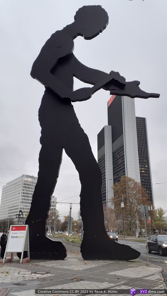
“Hammering Man” (animated) with small sign for Formnext 2021
Alte Oper Frankfurt (Old Opera)
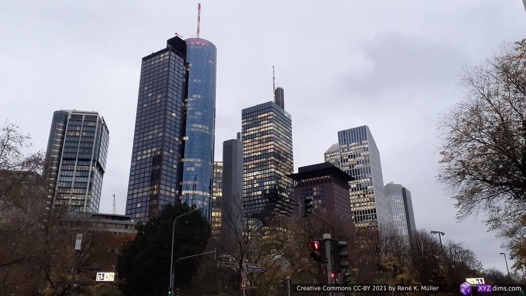
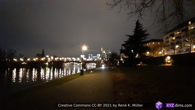
Skyscrapers of Frankfurt
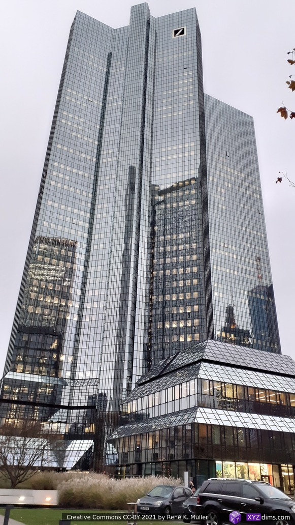
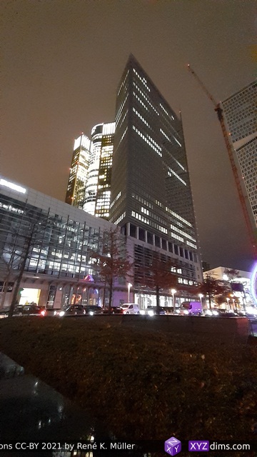
Deutsche Bank, impressive building & architecture
Tower 185 in Frankfurt
Frankfurt
Lightsculpture by Christian Herdeg – “Synergie / Synergy”, Platz der Einheit, Frankfurt
2021/09/04: 0.8.6: supporting OFF, OBJ, AMF, 3MF and 3MJ in addition to STL
2021/04/11: 0.8.5: more tests and Makefiles added
2021/04/06: 0.8.4: SVG export working with example, various bug fixes
2021/04/04: 0.8.3: first print actually working (extrusion calculation fixed, removed most un/retract for now)
2021/04/02: starting write-up
20mm xyzHollowCalibrationCubeV2 sliced with Mandoline 0.8.5
Table of Contents
Introduction
Since I started to develop on the conic slicer slicer4rtn for the RTN, and starting to work on the more complex PAXSlicer for 5-axis printer like PAX option. So I was searching for a slicer to adapt for future projects to have more control of the slicer stage and learn of the actual details and so I came across Mandoline Py, a slicer coded in Python utilizing at its core pyclipper and at first glance it was well thought out, clean code, yet not many comments but function names and variables were explanatory – I was quite impressed by Revar Desmera, who was able to put this together in such a consistent manner.
There wasn’t much information available otherwise, and the author did not reply to my emails, so I looked at past closed issues at github, which gave me a bit background information, and the challenges Revar faced.
So, after a couple of weeks pondering and waiting for Revar to respond, April 4 2021 I began to adopt it and push it forward to become usable for me. I will document all future changes (or possible a fork of it) on this blog-post.
Features
purely written in Python, compact source code, easy to read & understand
vector.py: base vector operations
point3d.py: x,y,z to index to x,y,z
line_segment3d.py: two points making a line, with caching
facet3d.py: three points making a triangle/facet, with caching
__init__.py: main entry point of mandoline program:
process arguments
load model and relevel, apply model operations (scale), check manifoldness
slice model
slice model into Gcode to print via FDM 3D printer
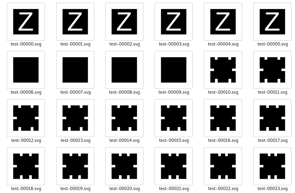
slice model to SVG slices (very experimental) for debugging purposes and possibly to post-process to pixel-based slices for SLA or SLS 3D printer (not yet tested)
load mutiple configs in sequence with -l config.ini, e.g. printer specifics, material settings
simple to query features/settings with-Q <term>
Usage
% mandoline
== Mandoline Py 0.8.5 == https://github.com/(Spiritdude|revarbat)/mandoline-py
usage: mandoline [-h] [-o OUTFILE] [-n] [-g] [-v] [-d] [--no-raft] [--raft] [--brim] [--no-support] [--support] [--support-all]
                 [-f MATERIAL,...] [-F FORMAT] [-l OPTNAME] [-M OPTNAME=VALUE] [-S OPTNAME=VALUE] [-Q OPTNAME] [-w]
                 [--help-configs] [--show-configs]
                 [infile]

positional arguments:
  infile                Input model filename (STL).

optional arguments:
  -h, --help            show this help message and exit
  -o OUTFILE, --outfile OUTFILE
                        Slices model (STL) and write GCode or SVGs to file.
  -n, --no-validation   Skip performing model validation.
  -g, --gui-display     Show sliced paths output in GUI.
  -v, --verbose         Show verbose output.
  -d, --debug           Show debug output.
  --no-raft             Force adhesion to not be generated.
  --raft                Force raft generation.
  --brim                Force brim generation.
  --no-support          Force external support structure generation.
  --support             Force external support structure generation.
  --support-all         Force external support structure generation.
  -f MATERIAL,..., --filament MATERIAL,...
                        Configures extruder(s) for given materials, in order. Ex: -f PLA,TPU,PVA
  -F FORMAT, --format FORMAT
                        Set output format (gcode, svg)
  -l OPTNAME, --load OPTNAME
                        Load config file, containing <k>=<v> lines
  -M OPTNAME=VALUE, --model OPTNAME=VALUE
                        Set model manipulation operation(s) (scale).
  -S OPTNAME=VALUE, --set-option OPTNAME=VALUE
                        Set a slicing config option.
  -Q OPTNAME, --query-option OPTNAME
                        Display a slicing config option value.
  -w, --write-configs   Save any changed slicing config options.
  --help-configs        Display help for all slicing options.
  --show-configs        Display values of all slicing options.

examples:
   mandoline cube.stl
   mandoline -l myprinter.ini cube.stl
   mandoline -l myprinter.ini -S layer_height=0.3 cube.stl
   mandoline -l myprinter.ini -l petg.ini -S infill_type=Triangles cube.stl -o test.gcode
   mandoline -Q skirt
By default Mandoline slices STL into 3D printable Gcode:
% mandoline -l y3228.ini hollowCube.stl -S layer_height=0.3 -o test.gcode
== Mandoline Py 0.8.4 == https://github.com/revarbat/mandoline-py
Loading model "hollowCube.stl"
Loading configs from "y3228.ini"
Slicing starting
+ Random offset -78,34
- Perimeters
- Support
- Raft[ ], Brim[ ], and Skirt[x]
- Infill (Grid)
- Pathing
- Export GCode to "test.gcode"
Took 0.85s total. Estimated build time: 0h 08m, filament used: 1.394m
20mm xyzHollowCalibrationCubeV2 model
20mm xyzHollowCalibrationCubeV2 sliced into Gcode
SVG
Mandoline (0.8.4+) also supports slicing into SVG, for debugging purpose and possibly can be post-processed into PNG to feed into a SLA or SLS 3D printer (no support-structure included yet).
% mandoline hollowCube.stl -o test.svg
== Mandoline Py 0.8.4 == https://github.com/revarbat/mandoline-py
Loading model "hollowCube.stl"
Slicing starting
- Perimeters
- Export 66x SVGs to "test-*.svg"
Took 0.23s total.
20mm xyzHollowCalibrationCubeV2 model
20mm xyzHollowCalibrationCubeV2 model sliced to 66 SVG slices
20mm xyzHollowCalibrationCubeV2 model sliced to 66 SVG slices, combined as animation
Issues to Resolve
model slicing problems:
3D Benchy incomplete, get more linient or auto-fix regarding non-manifolds:
3DBenchy.stl loaded with manifold checking, 10x “non-manifold hole edges”:
Z = 9.087, 5.87
when disregarding that check with -n, then it results in various warnings “Incomplete Polygon …” which results in missing slices – major degration of 3D print
sliced with many warnings (Incomplete Polygon at z=... => missing layers) @0.2mm layer height: 240 layers, 4.011m with 1.75mm filament
sliced with many warnings (=> missing layers) @0.25mm layer height: 192 layers, 4.461m with 1.75mm filament
-M scale=0.5 with
@0.2mm layer height with warnings (=> missing layers): 120 layers, 0.674m with 1.75mm filament
@0.25mm layer height with warnings (=> missing layers): 96 layers, 0.634m with 1.75mm filament- fixing
Voron Design Cube v7 wrong sliced layers without warnings
random crashs of pyclipper: I noticed a basic model with random_pos=True enabled slices correct and another time when moved to another position fails to slice
properly do un/retract:
find out if perimeters/walls are crossed, if not, do not un/retract no matter what TYPE of extrusion is done
allow case-insensitive settings:
infill_type
support_type
adhesion_type
bed_geometry
brim, raft and skirt properly done (*_width vs *_lines and *_offset)
bottom_layer_extrusion_width
bottom_layer_speed
top_layer_speed
wall/shell/perimeter_speed
resolve “shell” vs “wall” vs “perimeter” in source variables, source comments and config
infill_type=Hexagons doesn’t work reliable, often infill is missing entirely
support 3MF, 3MJ input format beside STL, since 0.8.6: obj, off, amf, 3mf and 3mj
properly support multi-volume -> multi-material -> multi-tool
3MF: examples, Debian package: python3-savitar, since 0.8.6 using XML parser
clean up multi-nozzle setup, remove GUI, remove material config but hand it over to a collection of .ini files to be selectable with -l my.ini … (not yet finalized how to achieve simple multi-nozzle config easy)
testing, testing and testing more
future developement
integrate geometry3d union, intersection for segmenting sub-volumes
analyze geometry from non-planar slicing perspective
integrate non-planar slicing: tilted, cyclindrical, conic and spherical at a deeper level
mature it to become optional for PAXSlicer 5-axis slicer
process metadata from .3mj either piece, sub-volume or face exact within the slicing (tool changing, fill density, slicing settings etc)
Changes
2021/09/04: 0.8.6:
experimental OFF, OBJ, 3MF, 3MJ support
2021/04/08: 0.8.5:
cli: -S shell_speed=s [mm/s]
2021/04/06: 0.8.4:
SVG output: supporting slicing to SVG, using “-o test.svg“, very experimental
intern: model.scale([x,y,z]) implemented
cli: support for -M scale=s or -M scale=x,y,z
intern: fixed vector.py normalize() and __truediv__() supporting STL with bad normals
un/retract enabled again in code
2021/04/04: 0.8.3:
cli & extending configs:
cool_fan_speed_{min/max}
cool_fan_full_layer=2, e.g. starting fan after e.g. layer 2 is reached, first layer is 0
start_gcode and end_gcode and new config type ‘str‘ as well
skirt_lines=3 only considered if skirt_layers != 0
gcode_comments=True|False: adding various useful info in Gcode
random_pos=True|False: randomize position of model on the build-plate
all the config included in Gcode given gcode_comments enabled
intern: carrying over ‘typ‘ (‘type’ in python 😉 ) of the extrusion in _raw_add_paths, to refine the retract/unretract, this allowed to
have output Gcode more descriptive with ;TYPE:.. like PERIMETER, INFILL, PRIME, BRIM, SKIRT, SUPPORT etc, given gcode_comments is enabled
cli: support -l or --load to load more configs (e.g. per printer, or material)
cli: support -Q <term> partial match
output “filament used …[m]” at the end of slicing
most un/retract disabled for now to confirm extrusion calculation working
Kiri:Moto is a browser-based slicer, which can be also installed locally using NodeJS. Stewart Allen developed it and even provides a command-line interface (CLI) example as well src/kiri/cli.js. I extended it further into kirimoto-slicer so I could use it in conjunction of Print3r.
Requirements
Node 13 or later (use nvm to switch quickly between different versions)
KiriMotoSlicer 0.0.4 USAGE: [<options>] [file] ...
options:
--help this usage help
--help=<term> show settings matching <term>
-h <term> " "
--version display version and exit
--verbose increase verbosity
-v or -vvv " "
--output=<fn> force output filename
-o <fn> " "
--load=<conf> load configuration (lines of <k>=<v>, or experimental JSON as grid-apps/src/dev/*)
-l <conf> " " "
--setTemperature=<s> include set temperature extruder & bed in gcodePre (default: true)
--bedOrigin=<x>,<y> set origin of bed (use with --outputOriginCenter=true) (default: [0,0])
slice configuration:
--processName=<v> set process name (default: "generic")
--sliceHeight=<v> set slice height (default: 0.25)
--sliceShells=<v> set slice shells (default: 3)
--sliceShellOrder=<v> set slice shell order ["in-out","out-in"] (default: "in-out")
--sliceLayerStart=<v> set slice layer start ["last","center","origin"] (default: "last")
--sliceFillAngle=<v> set slice fill angle (default: 45)
--sliceFillOverlap=<v> set slice fill overlap (default: 0.3)
--sliceFillSparse=<v> set slice fill sparse (default: 0.2)
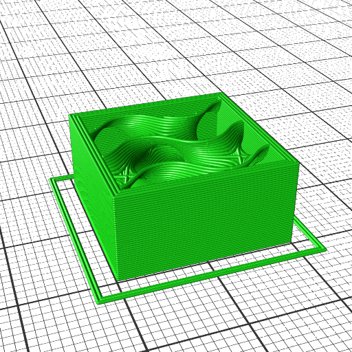
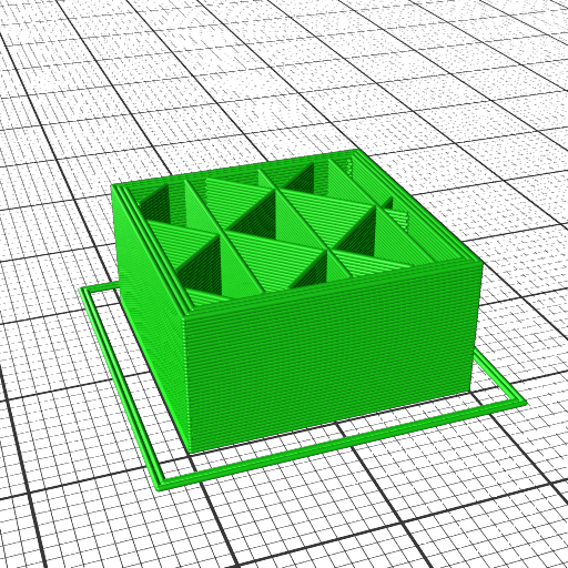
--sliceFillType=<v> set slice fill type ["vase","hex","grid","gyroid","triangle","linear","bubbles"] (default: "gyroid")
--sliceAdaptive=<v> set slice adaptive (default: false)
--sliceMinHeight=<v> set slice min height (default: 0)
--sliceSupportDensity=<v> set slice support density (default: 0.25)
--sliceSupportOffset=<v> set slice support offset (default: 0.4)
--sliceSupportGap=<v> set slice support gap (default: 1)
--sliceSupportSize=<v> set slice support size (default: 6)
--sliceSupportArea=<v> set slice support area (default: 1)
--sliceSupportExtra=<v> set slice support extra (default: 0)
--sliceSupportAngle=<v> set slice support angle (default: 50)
--sliceSupportNozzle=<v> set slice support nozzle (default: 0)
--sliceSolidMinArea=<v> set slice solid min area (default: 10)
--sliceSolidLayers=<v> set slice solid layers (default: 3)
--sliceBottomLayers=<v> set slice bottom layers (default: 3)
--sliceTopLayers=<v> set slice top layers (default: 3)
--firstLayerRate=<v> set first layer rate (default: 10)
--firstLayerPrintMult=<v> set first layer print mult (default: 1.15)
--firstLayerYOffset=<v> set first layer YOffset (default: 0)
--firstLayerBrim=<v> set first layer brim (default: 0)
--firstLayerBeltLead=<v> set first layer belt lead (default: 3)
--sliceSkirtCount=<v> set slice skirt count (default: 0)
--sliceSkirtOffset=<v> set slice skirt offset (default: 2)
--sliceLineWidth=<v> set slice line width (default: 0)
--outputTemp=<v> set output temp (default: 210)
--outputBedTemp=<v> set output bed temp (default: 60)
--outputFeedrate=<v> set output feedrate (default: 50)
--outputFinishrate=<v> set output finishrate (default: 50)
--outputSeekrate=<v> set output seekrate (default: 80)
--outputShellMult=<v> set output shell mult (default: 1.25)
--outputFillMult=<v> set output fill mult (default: 1.25)
--outputSparseMult=<v> set output sparse mult (default: 1.25)
--outputRetractDist=<v> set output retract dist (default: 4)
--outputRetractSpeed=<v> set output retract speed (default: 30)
--outputRetractDwell=<v> set output retract dwell (default: 30)
--outputShortPoly=<v> set output short poly (default: 100)
--outputMinSpeed=<v> set output min speed (default: 10)
--outputCoastDist=<v> set output coast dist (default: 0.1)
--outputLayerRetract=<v> set output layer retract (default: true)
--detectThinWalls=<v> set detect thin walls (default: true)
--zHopDistance=<v> set z hop distance (default: 0)
--antiBacklash=<v> set anti backlash (default: 0)
--outputOriginCenter=<v> set output origin center (default: false)
--sliceFillRate=<v> set slice fill rate (default: 0)
--sliceSupportEnable=<v> set slice support enable (default: false)
--firstSliceHeight=<v> set first slice height (default: 0.25)
--firstLayerFillRate=<v> set first layer fill rate (default: 35)
--firstLayerLineMult=<v> set first layer line mult (default: 1)
--firstLayerNozzleTemp=<v> set first layer nozzle temp (default: 0)
--firstLayerBedTemp=<v> set first layer bed temp (default: 0)
--firstLayerBrimTrig=<v> set first layer brim trig (default: 0)
--outputRaft=<v> set output raft (default: false)
--outputRaftSpacing=<v> set output raft spacing (default: 0.2)
--outputRetractWipe=<v> set output retract wipe (default: 0)
--outputBrimCount=<v> set output brim count (default: 2)
--outputBrimOffset=<v> set output brim offset (default: 2)
--outputLoopLayers=<v> set output loop layers (default: null)
--outputInvertX=<v> set output invert x (default: false)
--outputInvertY=<v> set output invert y (default: false)
--arcTolerance=<v> set arc tolerance (default: 0)
--gcodePause=<v> set gcode pause (default: "")
--ranges=<v> set ranges (default: [])
--firstLayerFanSpeed=<v> set first layer fan speed (default: 0)
--outputFanSpeed=<v> set output fan speed (default: 255)
device configuration:
--noclone=<v> set noclone (default: false)
--mode=<v> set mode ["FDM","SLA","CNC","Laser"] (default: "FDM")
--internal=<v> set internal (default: 0)
--imageURL=<v> set image URL (default: "")
--imageScale=<v> set image scale (default: 0.75)
--imageAnchor=<v> set image anchor (default: 0)
--bedHeight=<v> set bed height (default: 2.5)
--bedWidth=<v> set bed width (default: 220)
--bedDepth=<v> set bed depth (default: 220)
--bedRound=<v> set bed round (default: false)
--bedBelt=<v> set bed belt (default: false)
--maxHeight=<v> set max height (default: 300)
--originCenter=<v> set origin center (default: false)
--extrudeAbs=<v> set extrude abs (default: true)
--spindleMax=<v> set spindle max (default: 0)
--gcodeFan=<v> set gcode fan (default: "M106 S{fan_speed}")
--gcodeTrack=<v> set gcode track (default: "")
--gcodeLayer=<v> set gcode layer (default: ";LAYER:{layer}")
--gcodePre=<v> set gcode pre (default: "M107 ; turn off filament cooling fan\nG90
; set absolute positioning mode\nM82 ; set absolute positioning for extruder\nM104 S{temp} T{tool}
; set extruder temperature\nM140 S{bed_temp} T{tool} ; set bed temperature\nG28 ; home axes\nG92 X0 Y0 Z0 E
0 ; reset all axes positions\nG1 X0 Y0 Z0.25 F180 ; move XY to 0,0 and Z 0.25mm over bed\nG92 E0 ; z
ero the extruded\nM190 S{bed_temp} T{tool} ; wait for bed to reach target temp\nM109 S{temp} T{tool} ; wait for extruder to reac
h target temp\nG92 E0 ; zero the extruded\nG1 F225 ; set feed speed")
--gcodePost=<v> set gcode post (default: "M107 ; turn off filament cooling fan\nM104 S0 T{to
ol} ; turn off right extruder\nM140 S0 T{tool} ; turn off bed\nG1 X0 Y300 F1200 ; end move\nM84
; disable stepper motors")
--gcodeProc=<v> set gcode proc (default: "")
--gcodePause=<v> set gcode pause (default: "")
--gcodeDwell=<v> set gcode dwell (default: "")
--gcodeSpindle=<v> set gcode spindle (default: "")
--gcodeChange=<v> set gcode change (default: "")
--gcodeFExt=<v> set gcode FExt (default: "gcode")
--gcodeSpace=<v> set gcode space (default: true)
--gcodeStrip=<v> set gcode strip (default: false)
--gcodeLaserOn=<v> set gcode laser on (default: "")
--gcodeLaserOff=<v> set gcode laser off (default: "")
--extruders.[0..<n-1>].{extFilament,extNozzle,extSelect,extDeselect,extOffsetX,extOffsetY}=<v> set extruders (default: [{"extFilament":1.75,"extNozzle":0.5,"extSelect":["T0"],"extDeselect":[],"extOffsetX":0,"extOffsetY":0}])
--new=<v> set new (default: false)
--deviceName=<v> set device name (default: "3D Printer")
examples:
kirimoto-slicer cube.stl
kirimoto-slicer cube.stl -o test.gcode
kirimoto-slicer -v cube.stl --sliceHeight=0.1
kirimoto-slicer cube.stl --extruders.0.extNozzle=0.5 --sliceHeight=0.42
kirimoto-slicer -h slice
kirimoto-slicer -h .
Internals
Kiri:Moto distincts:
shells (aka perimeters, walls)
solid fill (like bottom and top layers)
sparse fill (aka fill)
As of 2021/08 Kiri:Moto doesn’t distinct support structures on bed or everywhere, so it can only be enabled or disabled with --sliceSupportEnable=true or false.
Smart Help
KiriMotoSlicer supports ~100 settings (as compared to Cura with over 500 settings) which can be queried with --help=<term> or -h <term>:
% kirimoto-slicer -h slice
query settings for 'slice':
      --sliceHeight=<v>             set slice height (default: 0.25)
      --sliceShells=<v>             set slice shells (default: 3)
      --sliceShellOrder=<v>         set slice shell order ["in-out","out-in"] (default: "in-out")
      --sliceLayerStart=<v>         set slice layer start ["last","center","origin"] (default: "last")
      --sliceFillAngle=<v>          set slice fill angle (default: 45)
      ....

% kirimoto-slicer -h shell
query settings for 'shell':
      --sliceShells=<v>             set slice shells (default: 3)
      --sliceShellOrder=<v>         set slice shell order ["in-out","out-in"] (default: "in-out")
      --outputShellMult=<v>         set output shell mult (default: 1.25)
Examples
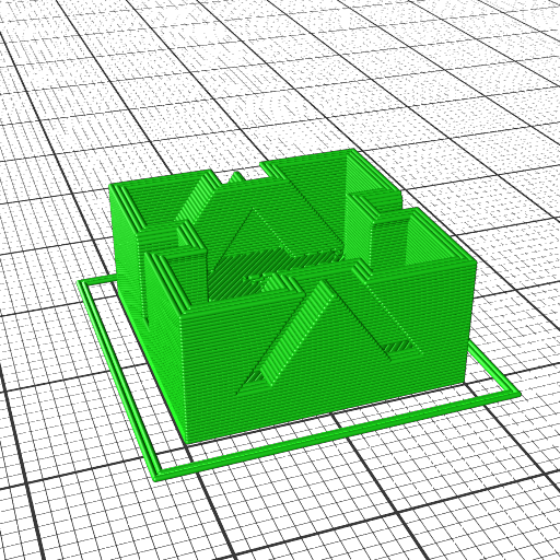
xyzHollowCalibrationCubeV2 (allows 0% infill without support) using --sliceFillSparse=0
Fill type 'vase' and 'bubbles' are listed as available but don’t work yet.
Conclusion
As of 2021/08 I’m quite impressed with Kiri:Moto. It goes different ways than the most other slicers, for example:
first layer outline is printed extremely slow
first layer filling is printed fast
other slicer print first layer outline & filling slow
shells/walls are printed inside out with increased speed, other slicers slow down shells/walls
the result in my case are very clean walls, as the emphasis is on fast contineous extruding than slow extruding
I also noticed there is little retraction done by default, fast motion to continue filling where other slicers retract & unretract more often.
So, the print with basic forms sliced looks good so far, and with just 100 settings it’s easy to learn and memorize, compared to Cura with over 500 settings.
While I like a new and usable slicer be available, the downside is that JavaScript use was once promising, but as of 2020/2021 it has become a mess as Browser JS and Node JS have diverted immensely, and the entire “Async Hell” has just driven forward with async / await / promise / then non-sense – it is really software development gone wrong for a decade. On the upside, JavaScript makes the slicing engine accessible and easier to extend than with verbose C++ or rudimentary C.
Print3r Support
As of version Print3r 0.3.8 the KiriMotoSlicer is supported, using slicer independent settings (write the profile once, use multiple slicers).
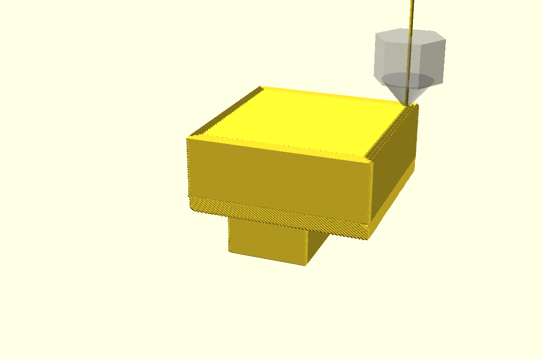
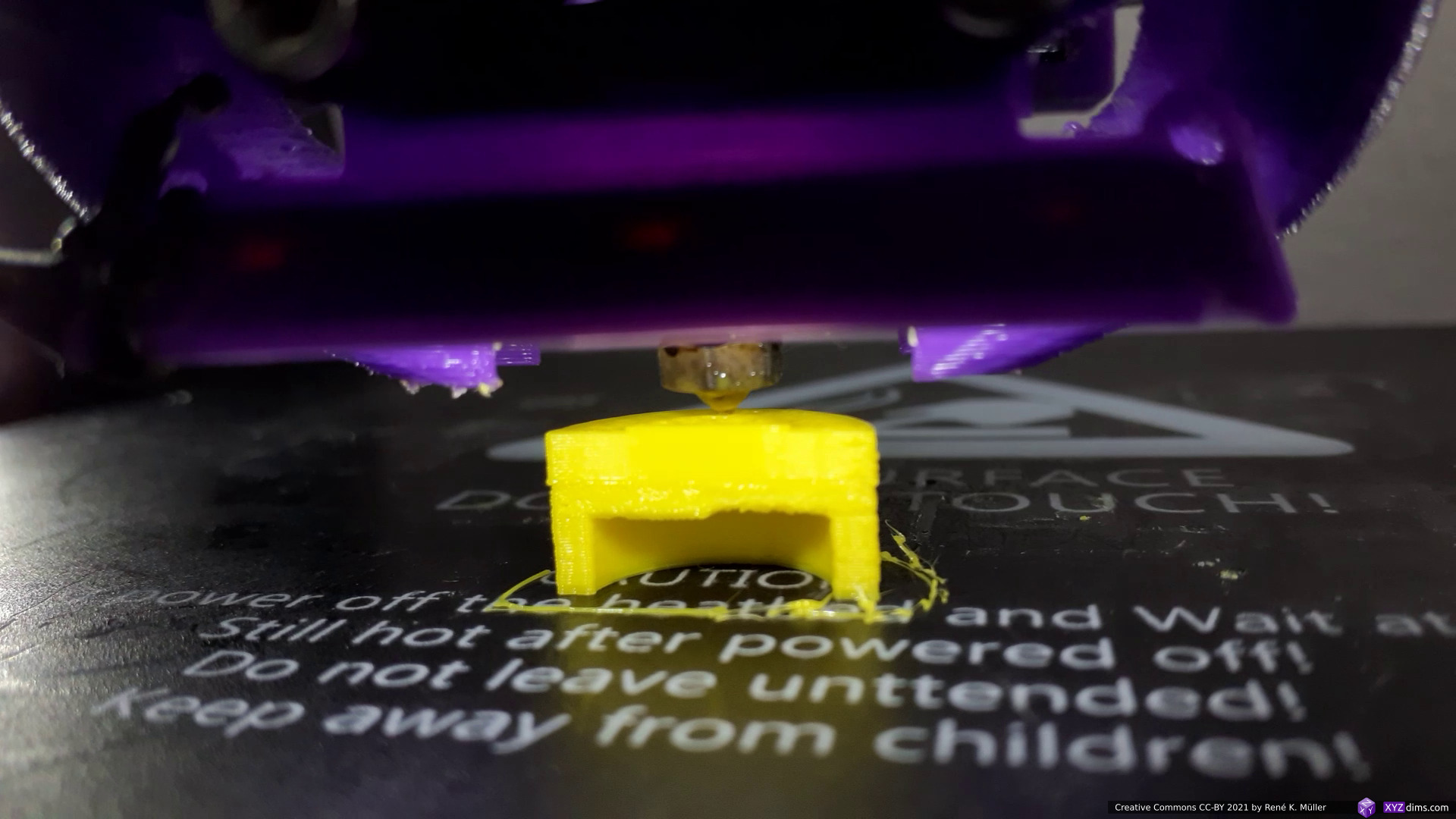
One of the benchmarks are 90° overhangs in different directions, and I printed with vertical nozzle on an ordinary 3-axis FDM printer, therefore I prepared the G-code with a new tool (in-development) which coordinates segmenting and planar/non-planar slicing of sub-volumes, and the conic sliced segment was sliced with 25° conic angle so it remains printable with the vertical nozzle unlike the simulation where a 4- or 5-axis FDM printer is required:
Gallery
Conic Sliced Overhang Segment
The simulation as reference:
3 segments: z-planar, conic and z-planar on top
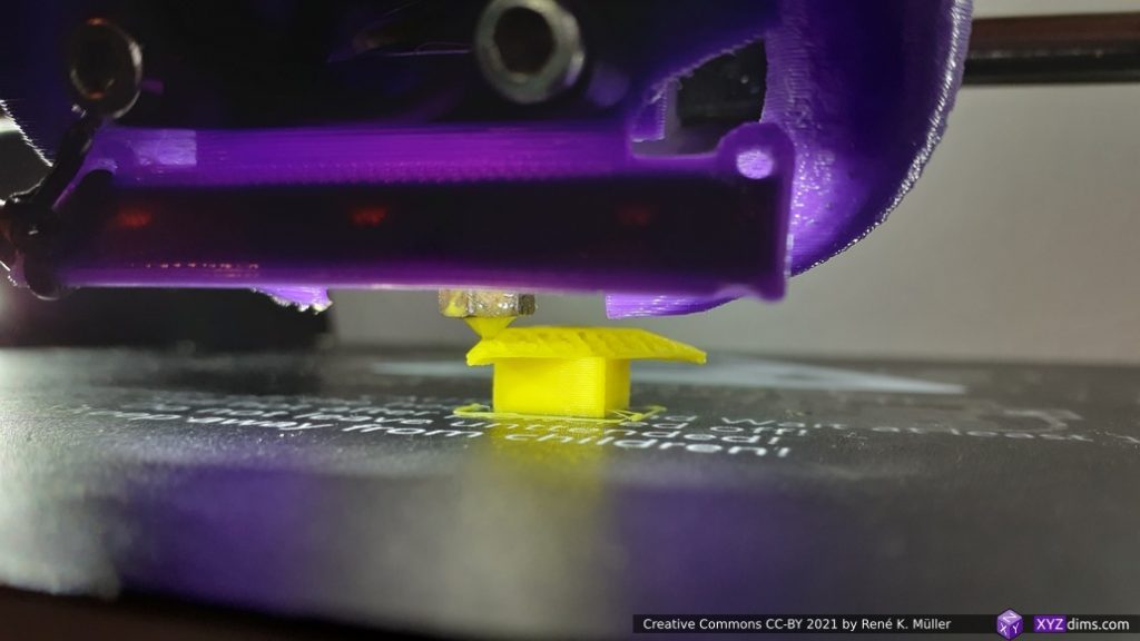
and the actual print process with vertical nozzle on a low-cost 3-axis FDM printer:
starting z-planar
building up fast z-planar
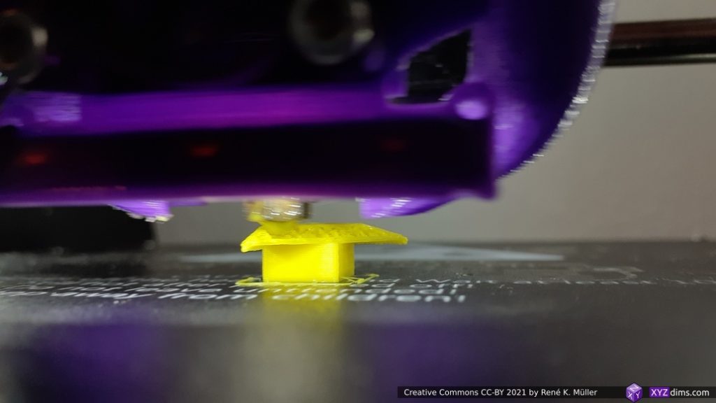
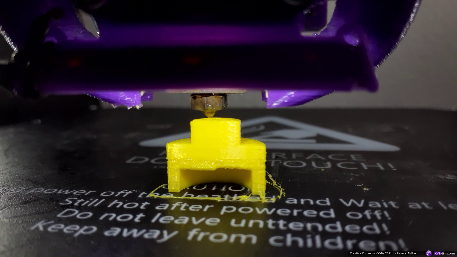
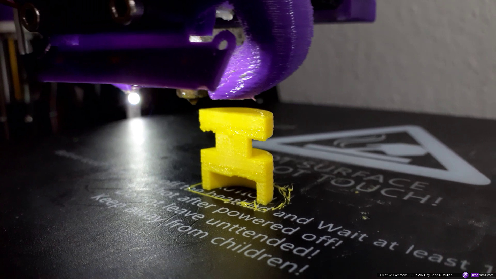
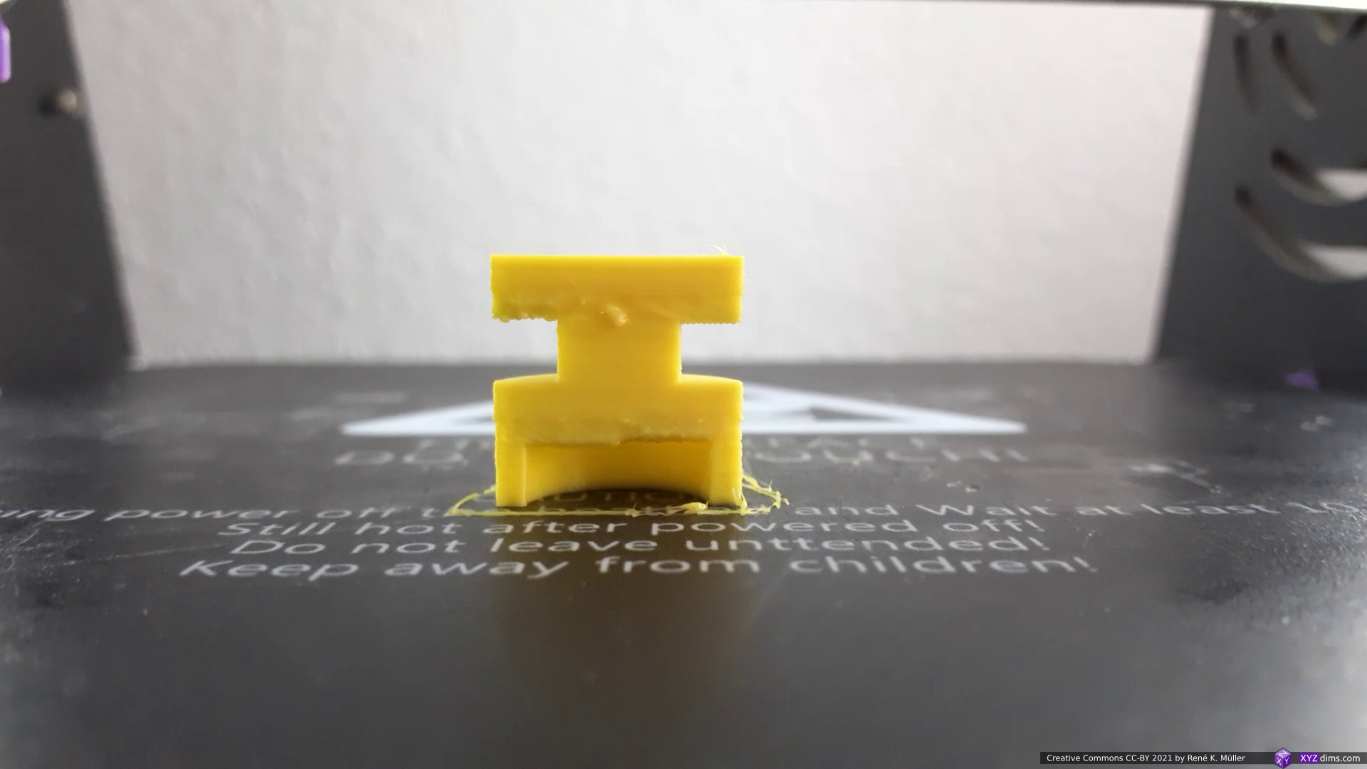
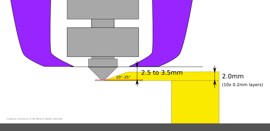
switching to conic sliced “balcony” 2mm thick
building the “balcony” 2mm thick
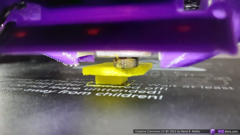
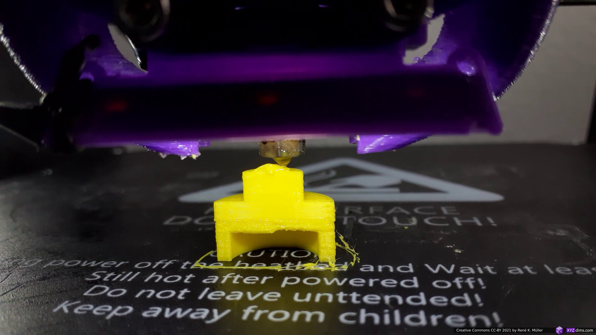
extending further the “balcony”
extending further the “balcony”
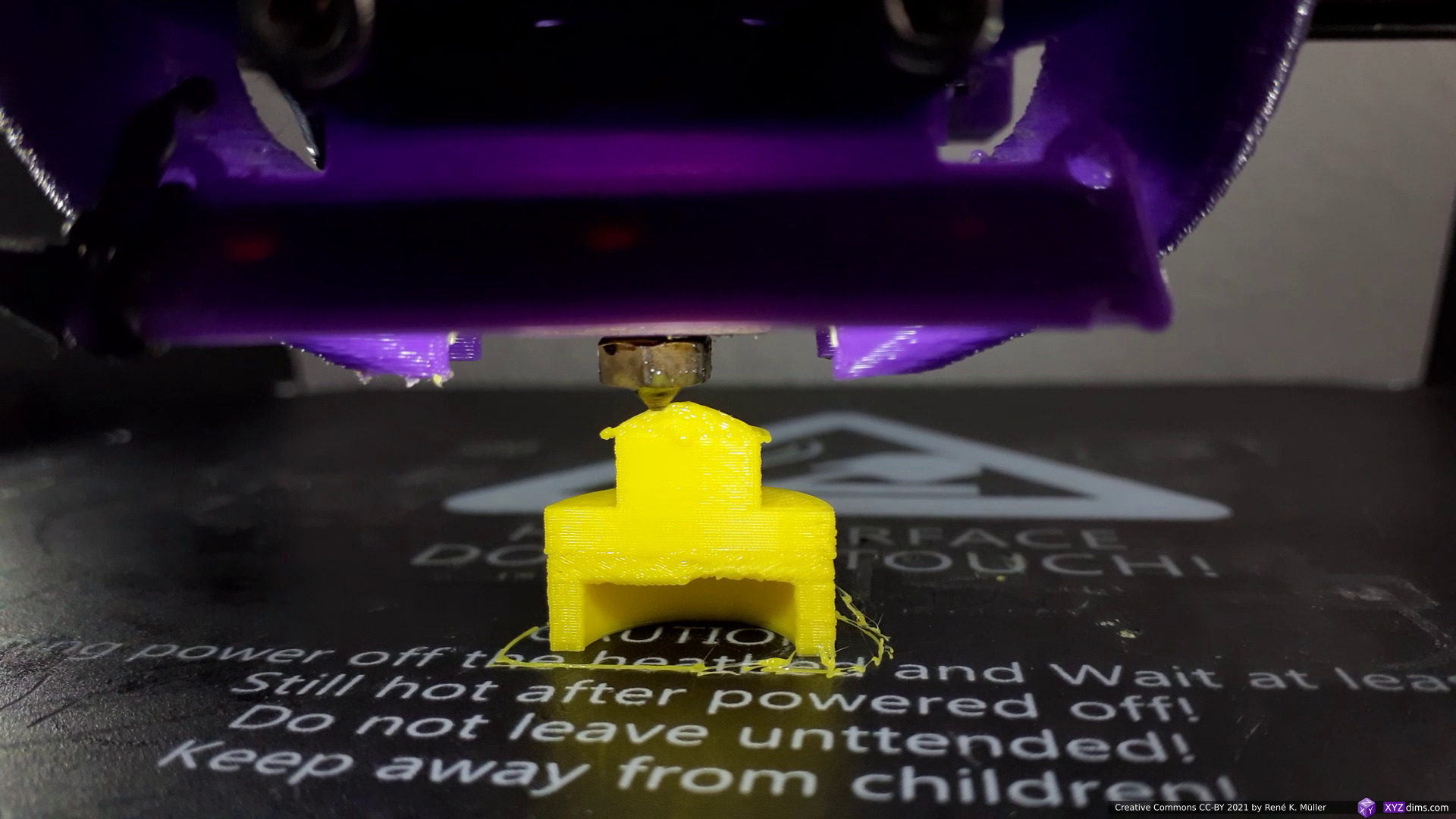
finishing the “balcony”
and switching to z-planar printing again
finishing the piece
finished
circular underside of the overhang
took a few attempts to arrive to something acceptable
Excerpt of the actual printing process with brief annotations:
Tilt Sliced Overhang Segment
Just for sake trying out, instead of conic sliced overhang segment, tilt sliced and 45° Z rotated to nicely extend to the maximum overhang position:
3 segments: z-planar, tilt sliced, and z-planar on top
and the actual print of a slightly lower model but with the same features:
after z-planar switching to tilted slice overhang segment
building the tilt sliced “balcony” 2mm thick
extending the tilt sliced “balcony” 2mm thick
finishing the tilt sliced “balcony”
finished piece
Comparing Tilted Sliced vs Conic Sliced Overhang Underside
And revisiting the Overhang In/Out Model, which features ingoing and outgoing overhang, segmented into 5 sub-volumes:
bottom: z-planar
ingoing1) overhang: conic (inside-cone mode)
middle: z-planar
outgoing1) overhang: conic (outside-code mode)
upper: z-planar
1) when dealing with conic slicing, the direction of overhang matters when deciding the mode of conic slicing, e.g. outside-cone or inside-cone.
and the actual print, a half of the model so the printing of inner overhang on the lower part of the model is visible:
z-planar and now switching to conic (inside-cone)
slowly building up inner overhang with inside-cone segment
building the inside-cone segment
extending the inside-cone segment
closing the inside-cone segment
inner overhang finished
back z-planar on top
building up z-planar
and switching to outside-cone for outgoing overhang
slowly extending
extending to actual overhang
halved model profile
solidifying the overhang
overhang done, switching to z-planar again
and finishing the piece
finished piece
finished piece
Conclusion
It took me a few days to tune the 3-axis FDM printer to print in acceptable quality of this Overhang Model No 5 and also Overhang In/Out Model. A strong part-cooler was mandatory, well adjusted print temperature and slow perimeter as those extrusions align horizontally without vertical support; and it worked: the main idea is to segment and limit the overhang part to ~2mm thickness – a quasi “balcony” – which still allows a classic vertical nozzle with part-cooler to print such, and then switch back to planar printing again.
Vertical nozzle with part-cooler printing conic sliced overhang – a “balcony” – working with narrow margins
Detail settings: the conic overhang was sliced with Slicer4RTN with following settings slicer4rtn --slicer=cura-slicer --speed_wall=10 --speed_wall_0=10 --speed_wall_x=10 ... and since the Z-axis motion is limited to 4mm/s (M6 threaded rod, 1 rotation => 1mm) the overall printing speed is slow enough to provide acceptable print quality.
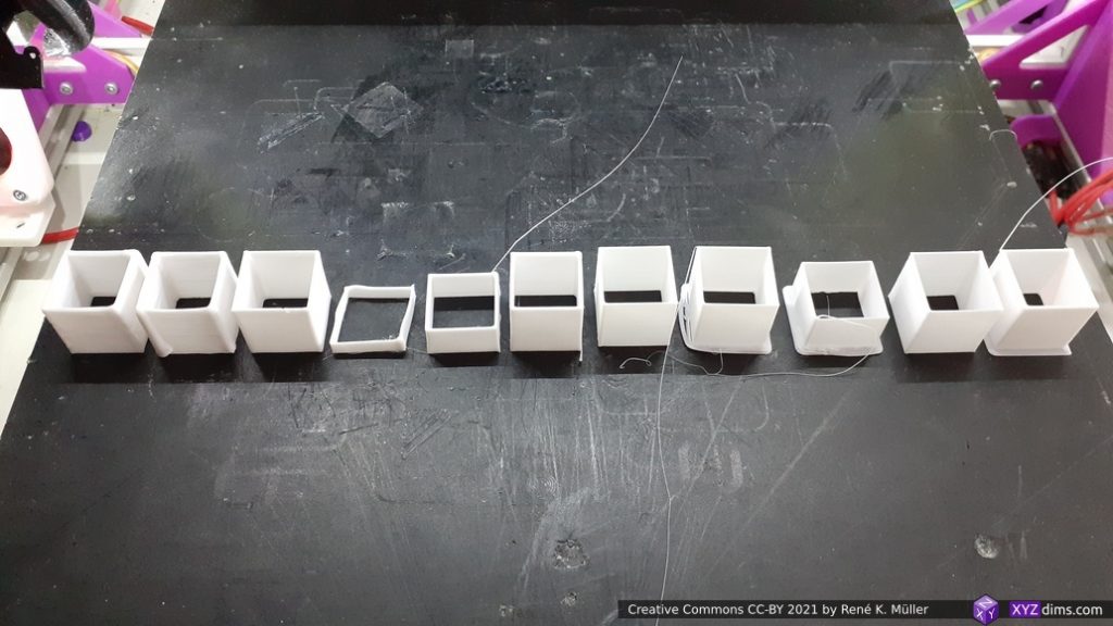
A few basic examples combining planar and non-planar slicing methods on sub-volume segmented models illustrating the possibilities printing without support structures:
Fused Deposition Modeling (FDM) also known as Fused Filament Fabrication (FFF)
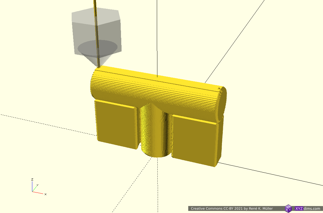
Using non-rotating but tilted sliced (like used with belt-printers) but in two distinct directions:
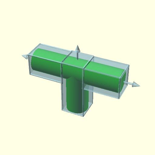
3 segments: z-planar & 2x tilted
starting z-planar
finishing z-planar
starting 2nd segment with tilted slices into one direction
2nd segment tilted continuing
2nd segment tilted finishing
3rd segment tilted into other direction
extending 3rd segment further
finished piece
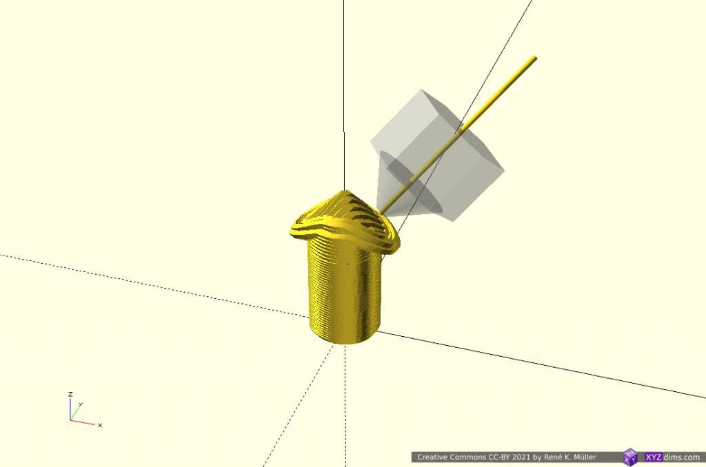
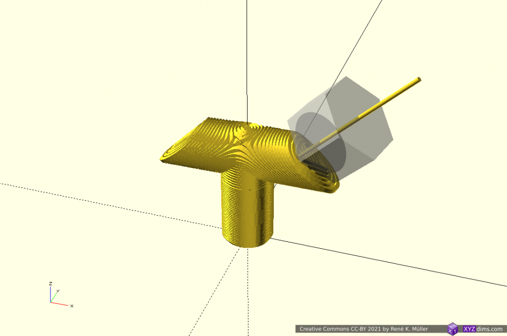
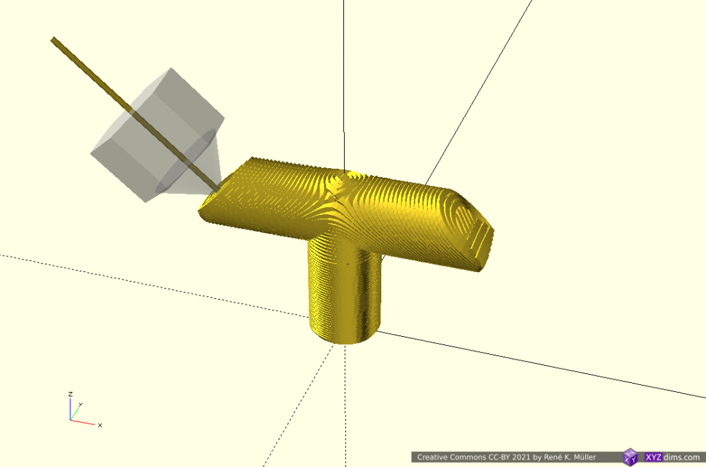
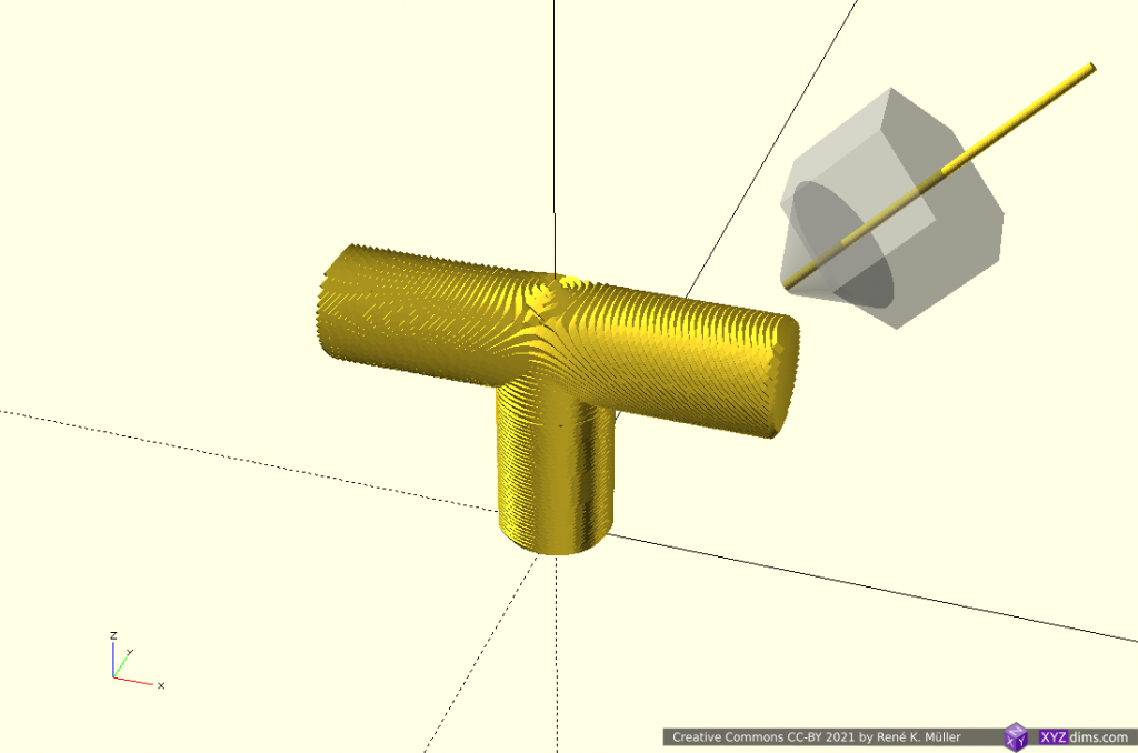
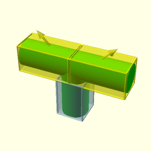
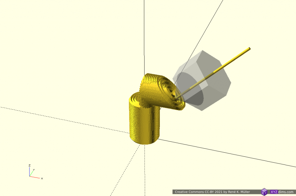
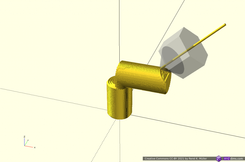
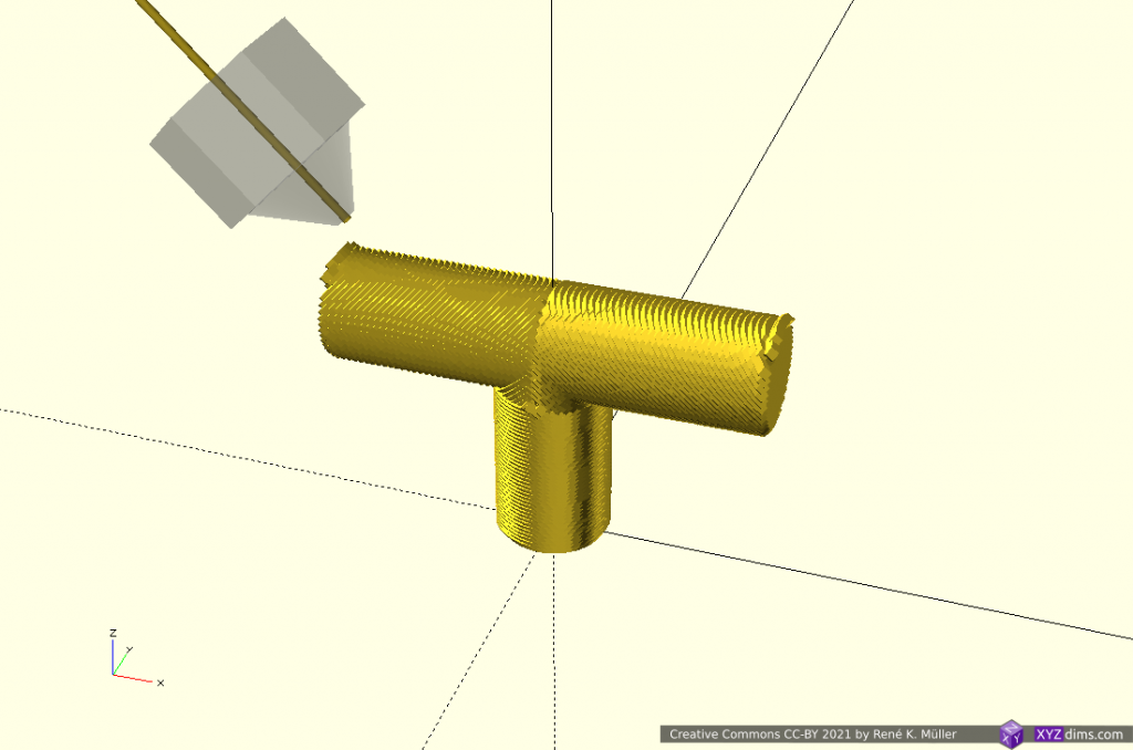
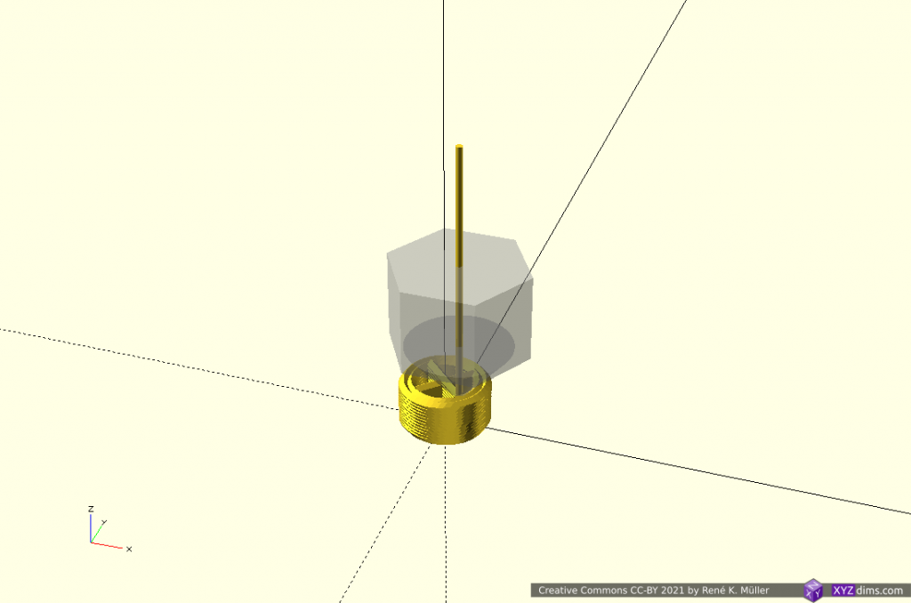
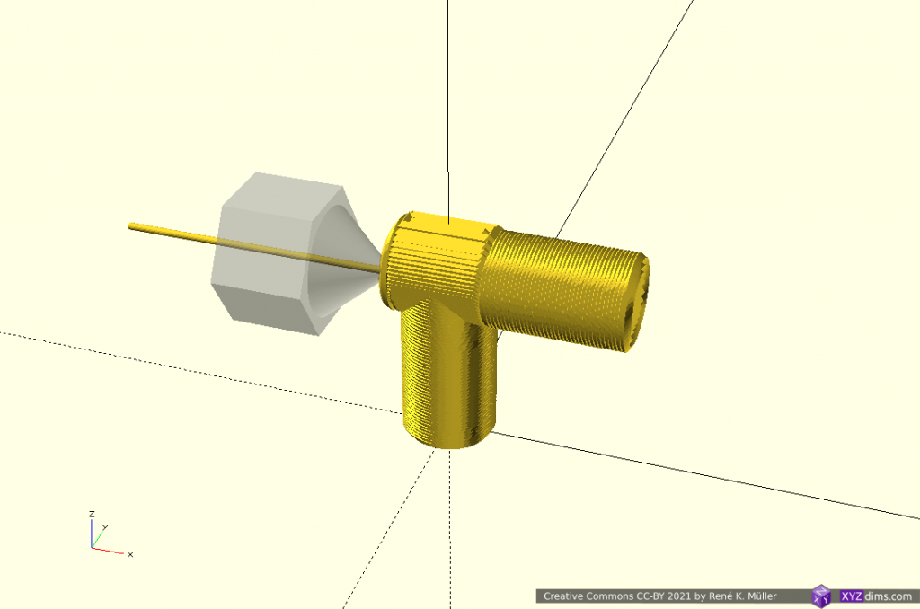
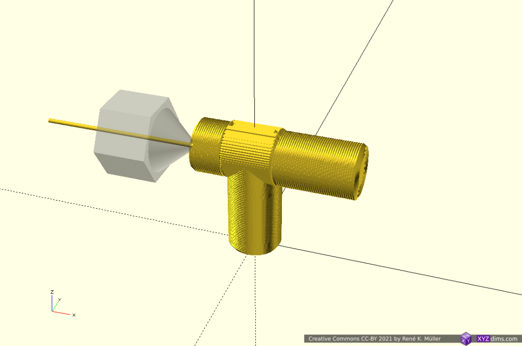
T-model segmented into 2 sub-volumes, sliced z-planar and twice tilted in opposite directions
Tilted slices can be printed with 4-axis Rotating Tilted Nozzle (RTN) but the first Z-planar part, as mentioned above, might not provide sufficient surface quality, whereas a 5-axis Penta Axis (PAX) printhead can print both segments easily.
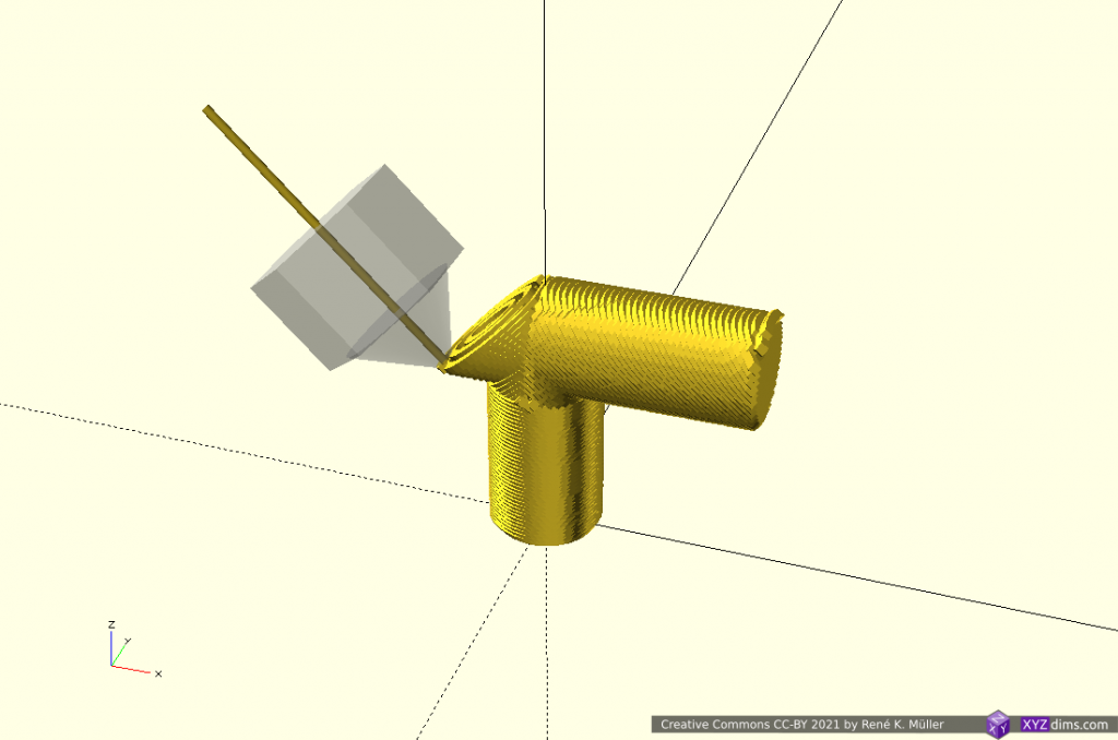
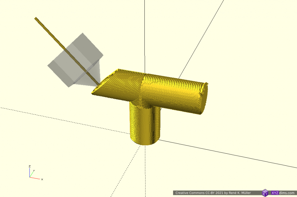
T-Model: 3 Segments: Z-planar & 2x X-planar
A more classic planar approach but with different planes as reference, first Z-planar then twice X-planar in different directions:
3 segments: z-planar, 2x x-planar
building up 1st segment z-planar
finishing z-planar segment
switching to 2nd segment, x-planar
extending x-planar
finish 2nd segment x-planar
switching other side x-planar opposite direction, 3rd segment
extending 3rd segment x-planar
finished piece
T-model segmented into 3 sub-volumes, sliced z-planar and twice x-planar
X-planar printing requires either 5-axis Penta Axis (PAX) printhead or the ability to tilt the bed.
Overhang In/Out: 2 Segments: 2x Conic
Lower part is sliced with conic slicing with inside-cone mode to print in-going overhang, whereas the upper part is sliced with outside-cone mode to cover the out-going overhang:
bottom: inside-cone, top: outside-cone
inside cone mode for 1st segment
inside cone mode
inside cone mode actual inner overhang
finishing inner overhang
switching to outside cone mode
building up 2nd segment
outside cone mode actual outer overhang
extending outer overhang
finished piece
Overhang in/out model segmented into 2 sub-volumes: lower part is sliced conic (inside-cone mode) and upper part conic (outside-cone mode)
Another overhang piece, stretching out into one direction; the lower part Z-planar, and the overhang conic (outside-cone mode) with an offset to align better with the lower segment:
2 segments: planar (bottom), conic with center offset (top)
after z-planar switching to conic (outside cone), conic center align with lower segment
conic part reaching edge of lower segment
full height of overhang segment
extending the overhang further
conic part asymmetrically extending
conic parts reached all horizontal model limits
finishing up the segment
finished piece
Overhang Out No 5 model segmented into 2 sub-volumes: z-planar at the bottom and overhang segment conic (outside-cone mode)
Overhang Out No 5: 3 Segments: 2x Z-planar & Conic
Perhaps a more realistic approach using the conic part as a “balcony” just for the overhang part sufficiently thick to carry next segment and switching back to Z-planar:
3 segments: planar (bottom), conic (middle) and planar (top)
z-planar segment
changing to conic segment
building up the conic overhang segment
actual overhang with conic slices
reaching out the 2mm thick segment
finishing the 2mm thick conic segment
and continuing with z-planar segment
finished piece
Overhang Out No 5 model segmented into 3 sub-volumes: z-planar first, then conic (outside-cone) building a thin “balcony” as support for the z-planar part on top again
Early tests have shown the thickness of the conic overhang “balcony” depends on the actual length of the in-air overhang, where print speed, part-cooling capacity and extrusion consistency determine the geometrical accuracy. More examples with “balcony” printed with 3-axis FDM printer followed.
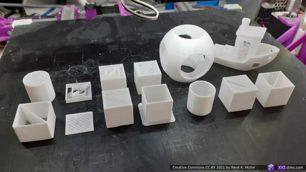
Conclusion
Unlike with ordinary Z-planar slicing, it may be suitable to dedicate a particular slicing method and orientation for sub-volumes in order to take advantage of the possibilities like avoiding support structure, particular strength properties or surface quality.
solely z-planar sliced, support structure required using 3-axis FDM printer
sub-volume segmented, z-planar and conic sliced printable without support structure using 5-axis FDM printer
This of course opens a wide-range of possibilities and complexity therefore:
but I think it’s worth it, in particular when a piece is printed more than once like with small series manufacturing / production.
The examples have been produced with various slicers and combined with a new application coordinating the segmenting and dedicated slicing methods, which currently (2021/04) is in development; it also involves a new file-format describing the segmenting and its slicing settings. The segment positioning was done manually as a start, but I expect with more experience and research some cases can be detected automatically.
Sub-volume segmenting is just one approach to take advantage of 5-axis FDM printing, another is continuous slicing along the form.
can print 90° overhangs, two distinct modes: inside out (outside cone), or outside in (inside cone) depending on direction to a central slicing cone center
angle of conic slicing can be changed from 45° to 20° and models become printable with vertical nozzle with reduced print quality
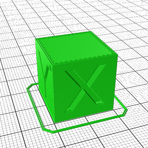
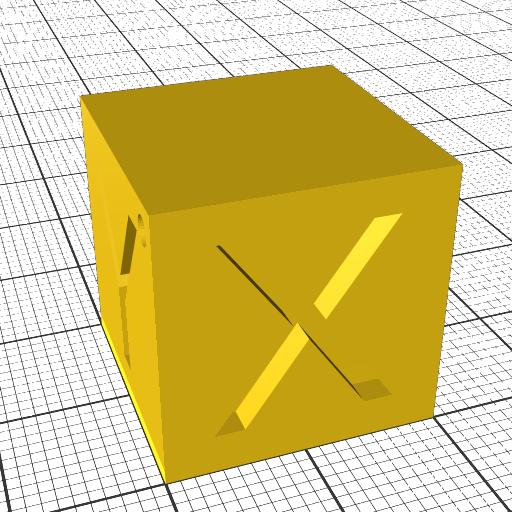
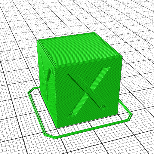
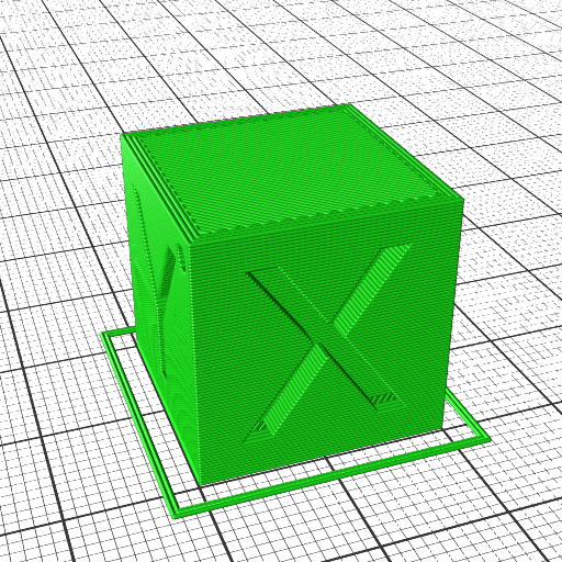
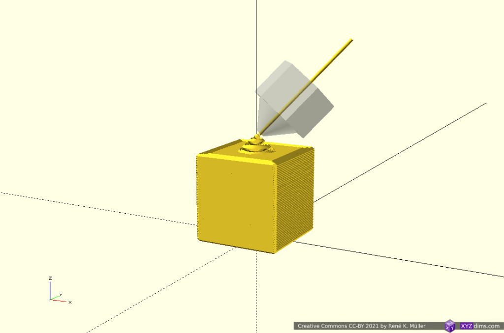
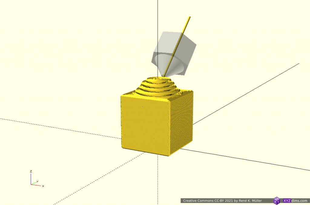
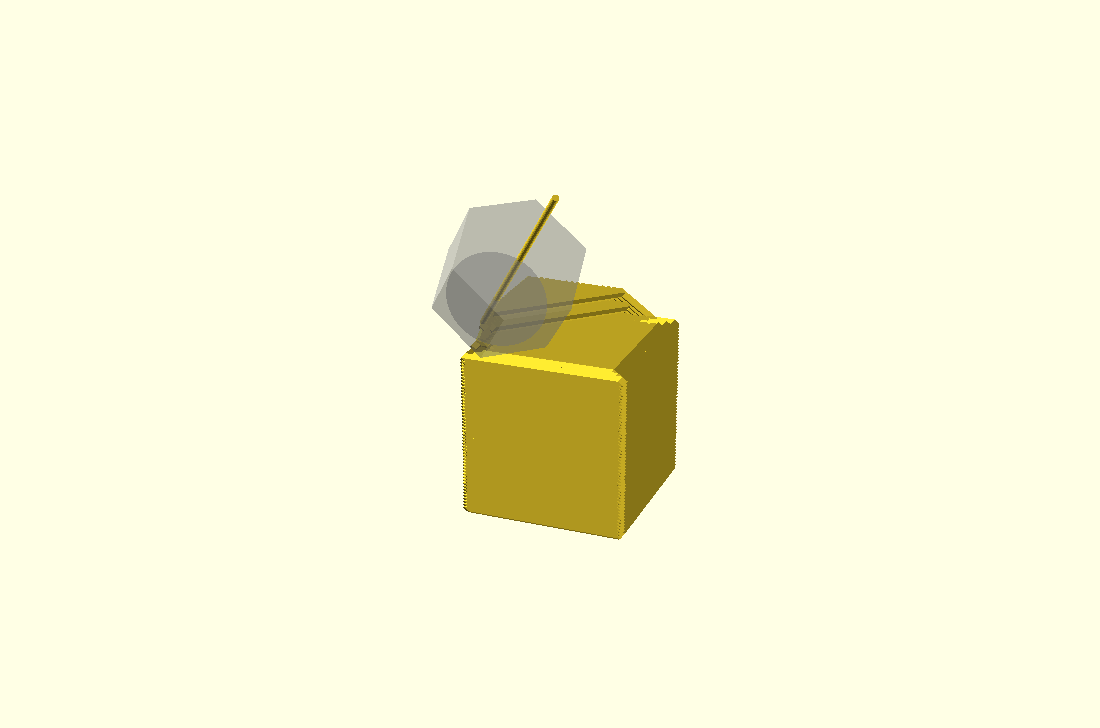
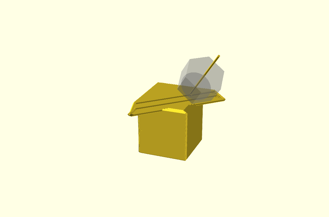
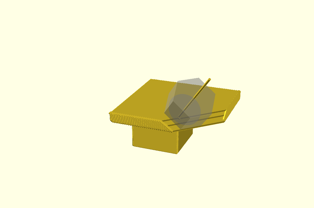
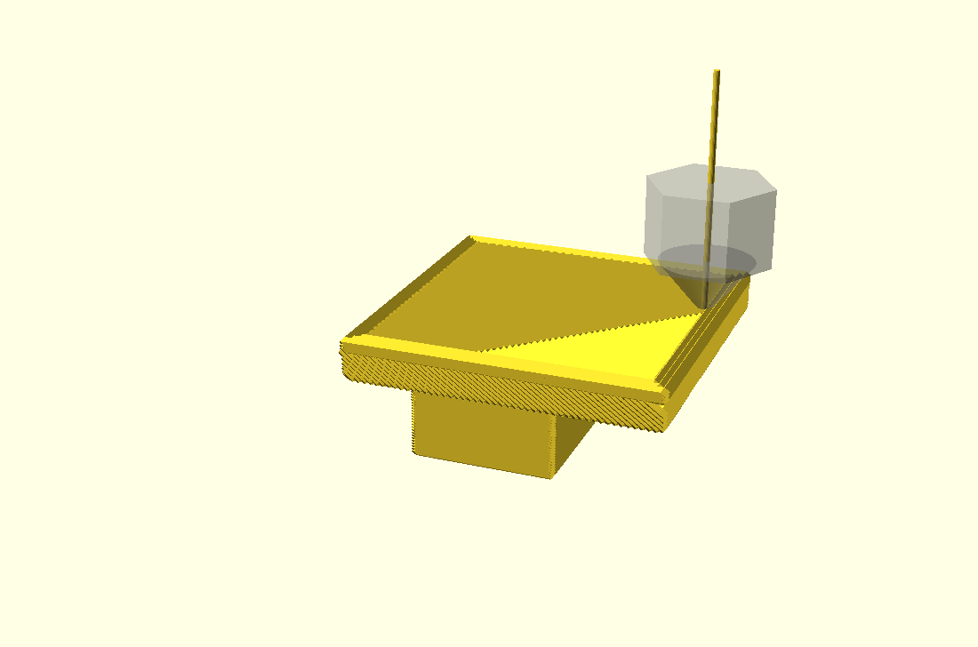
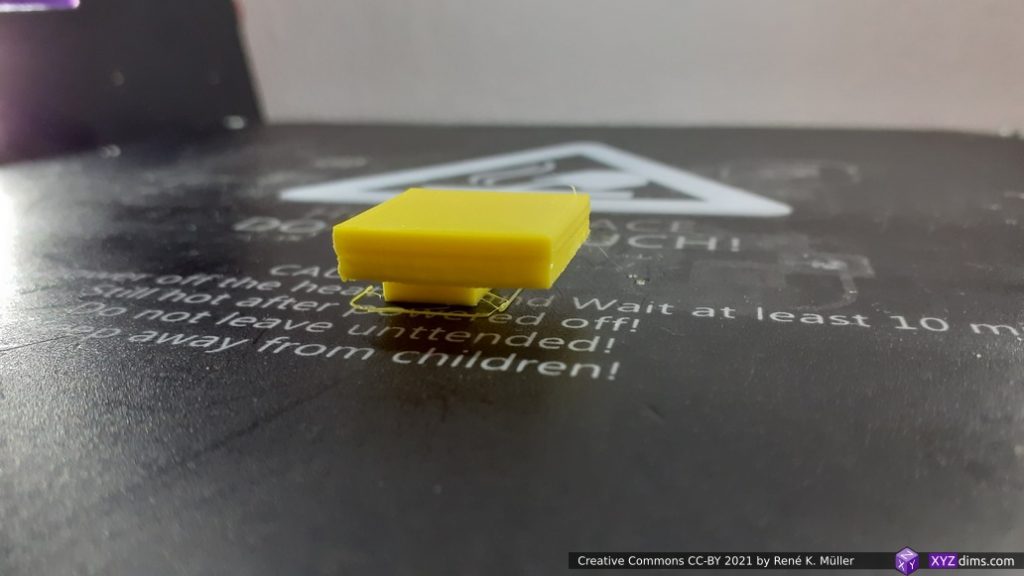
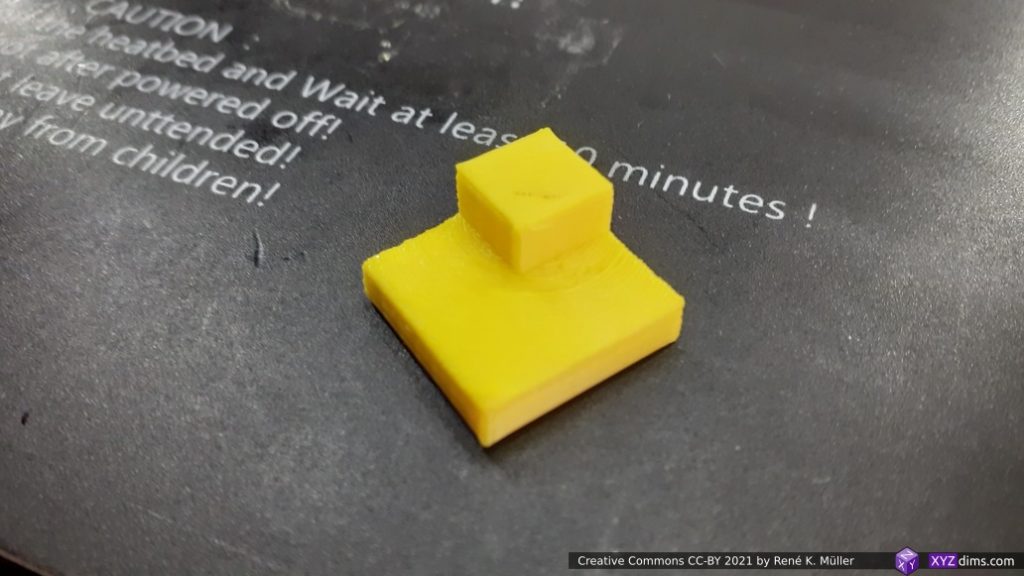
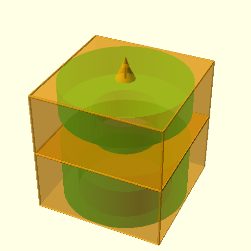
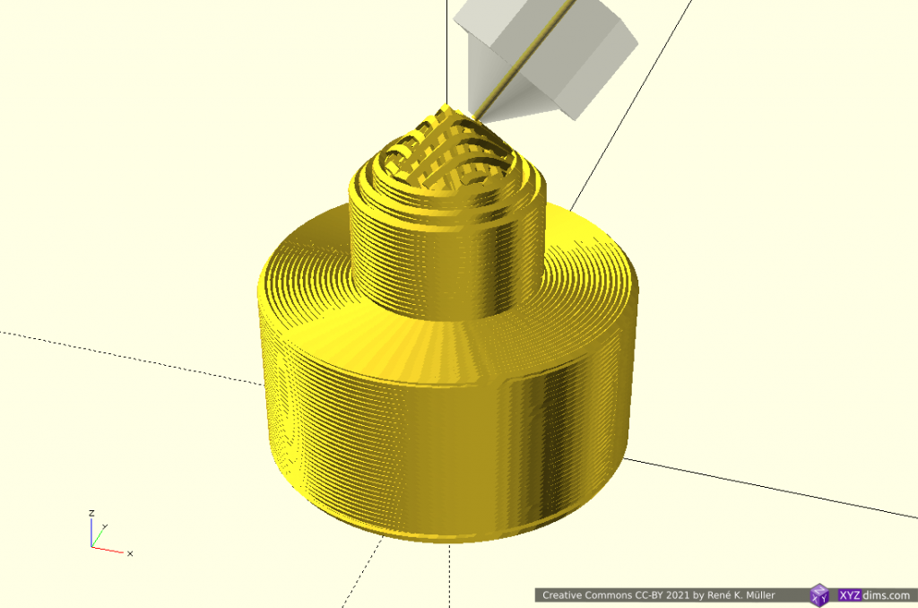
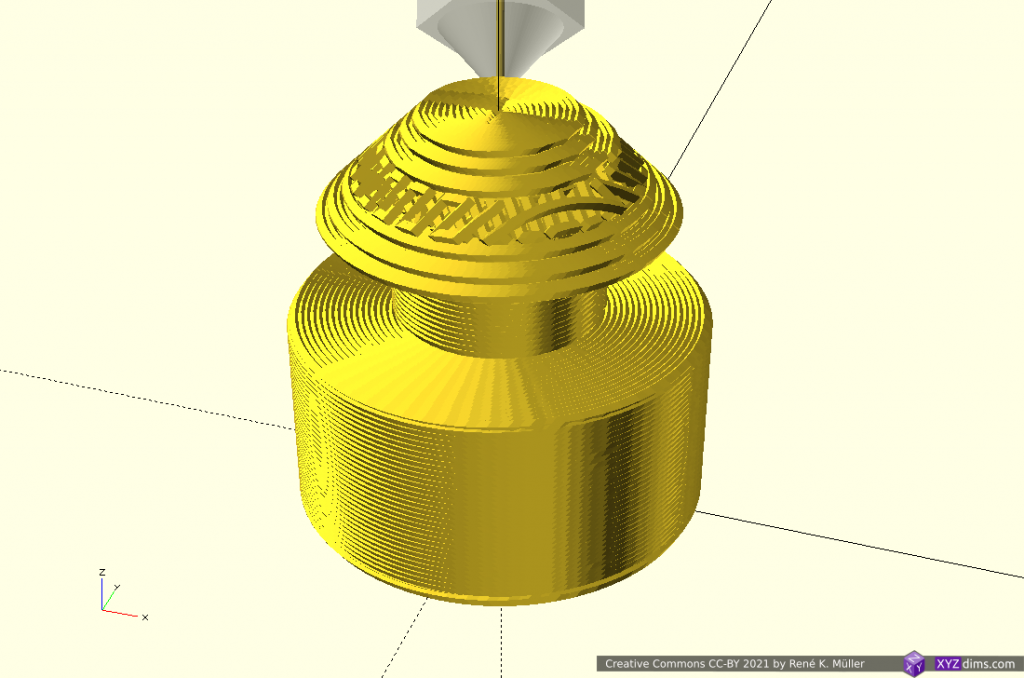
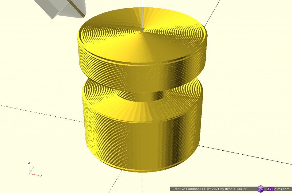
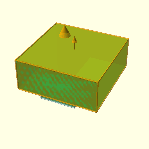
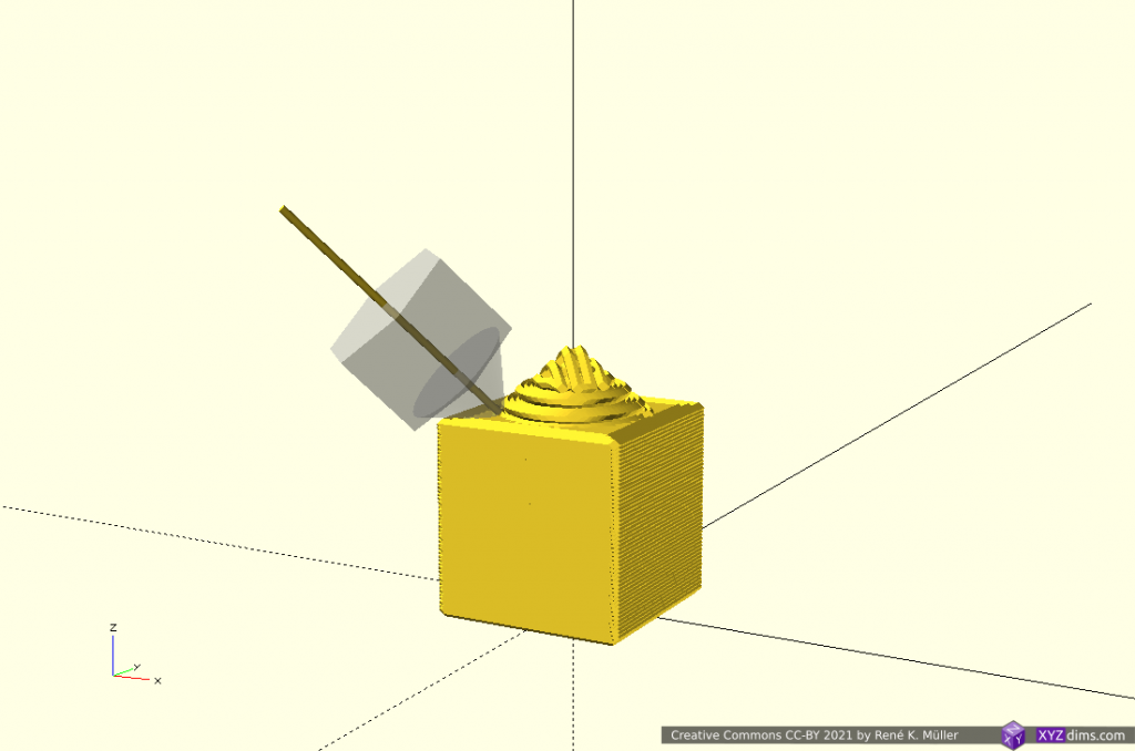
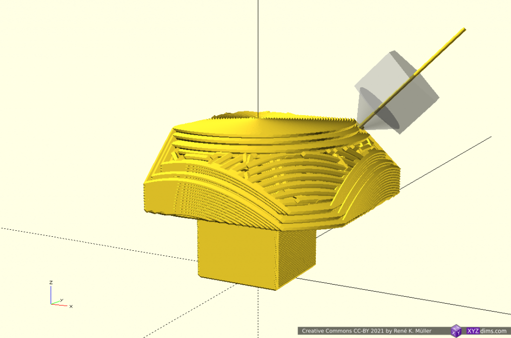
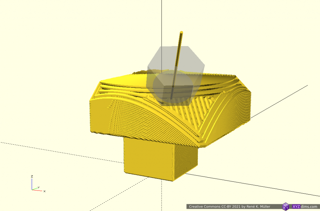
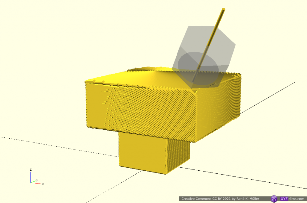
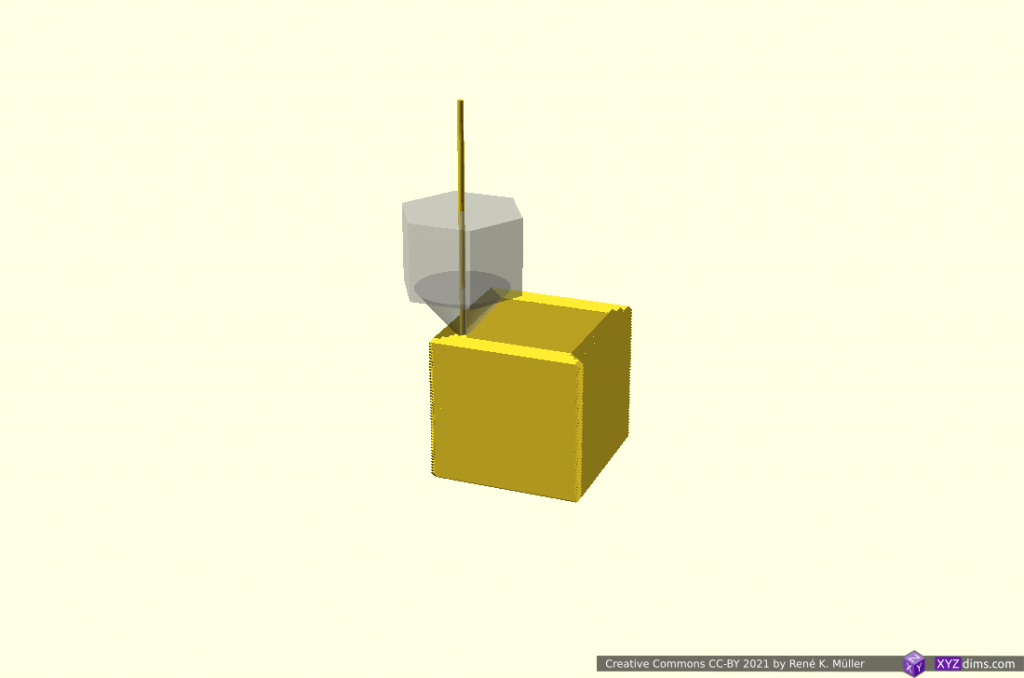
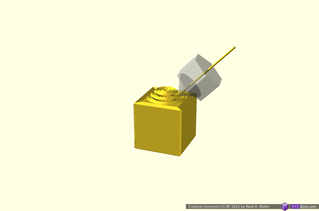
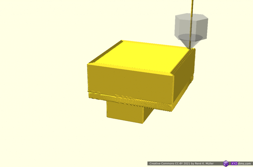
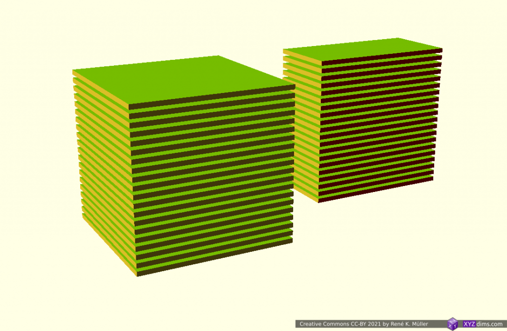
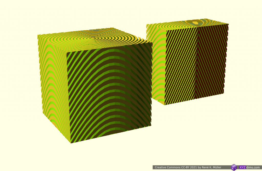
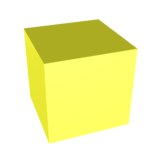
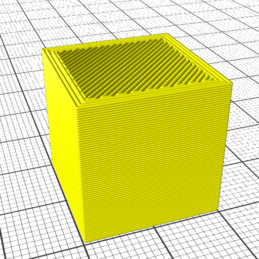
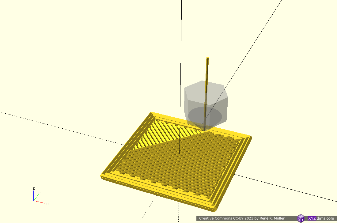
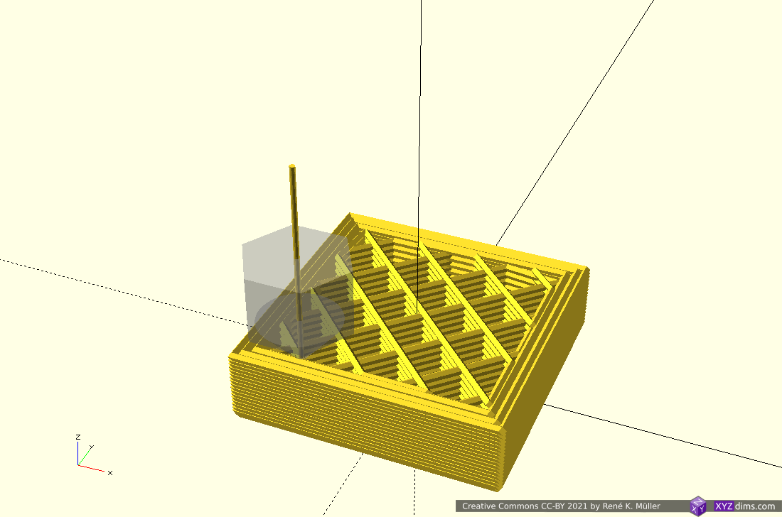
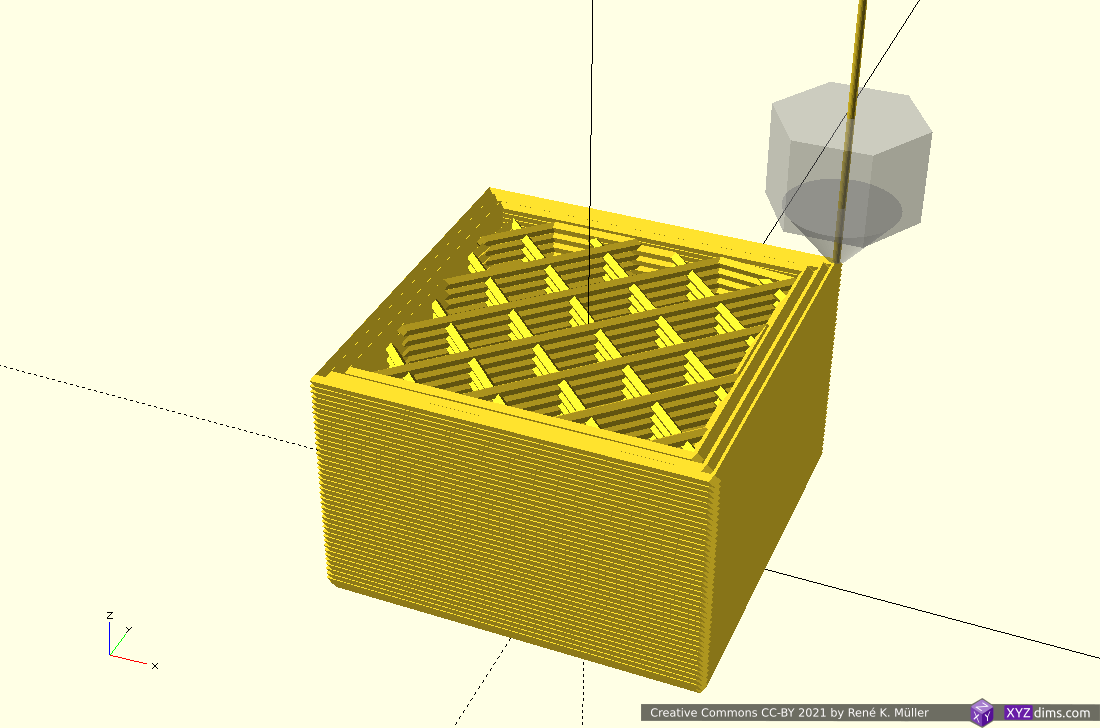
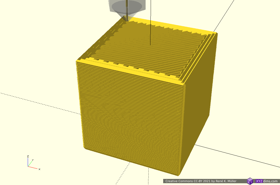
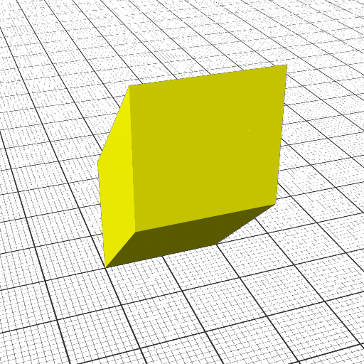
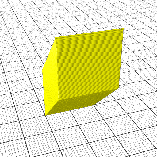
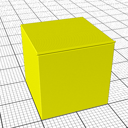
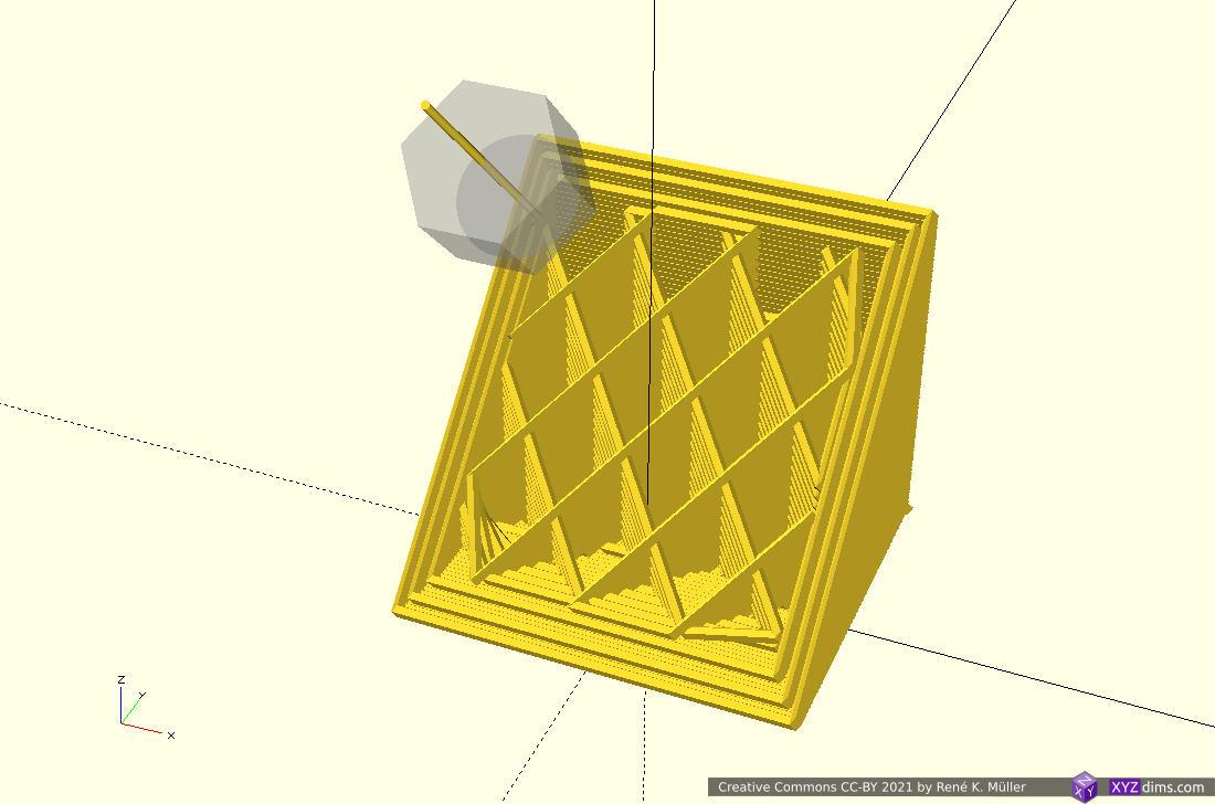
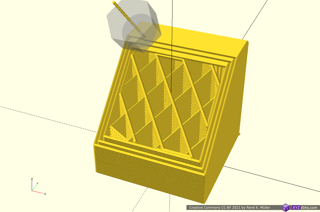
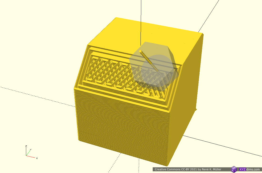
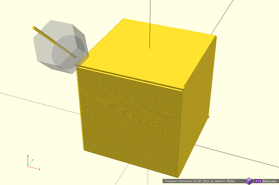
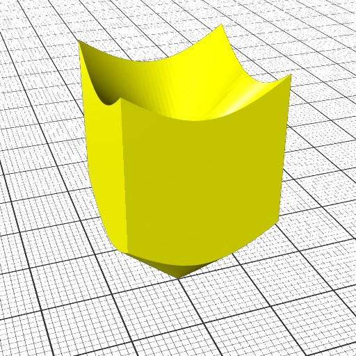
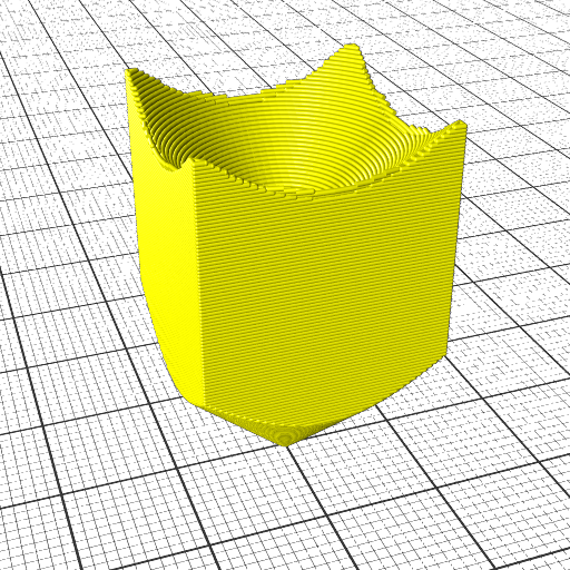
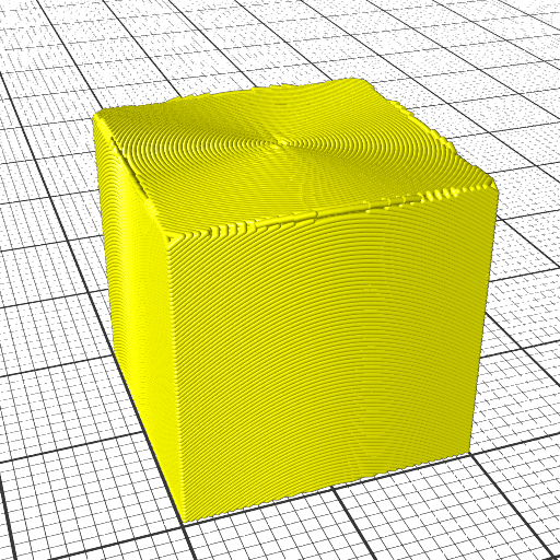
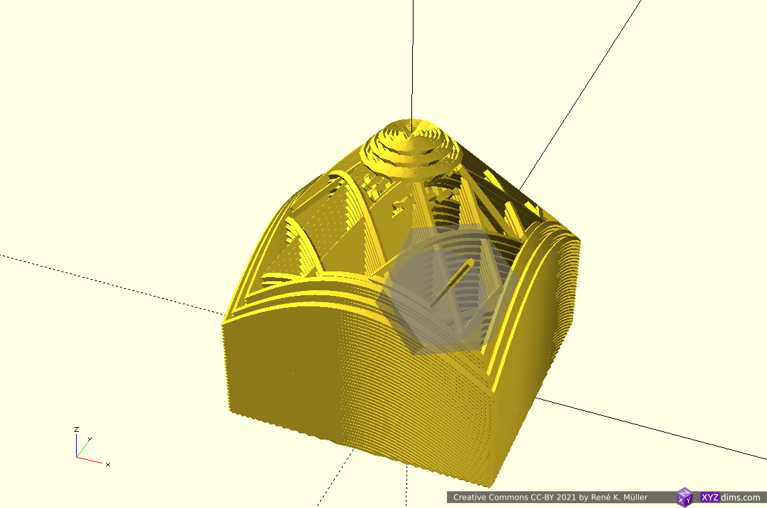
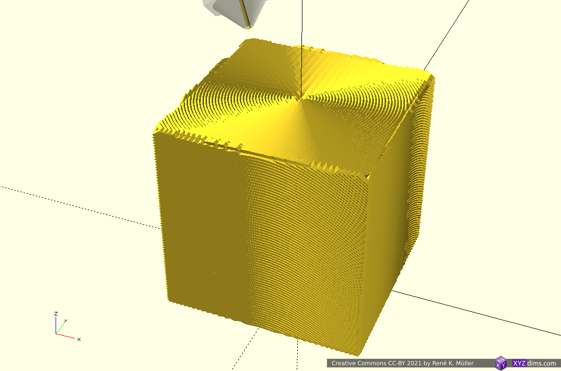
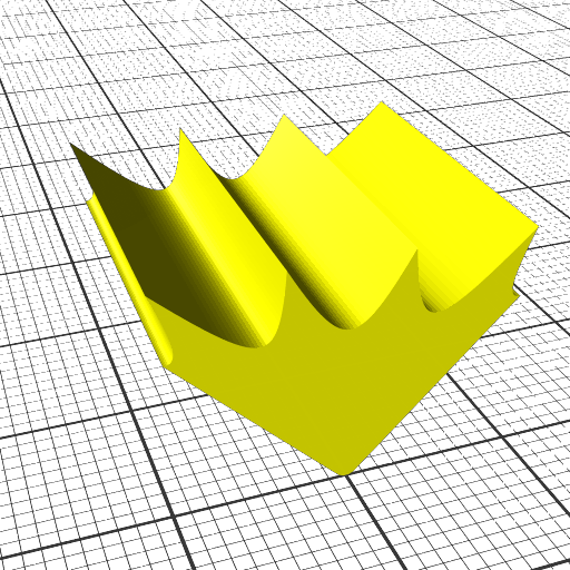
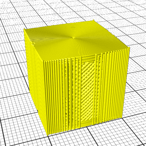
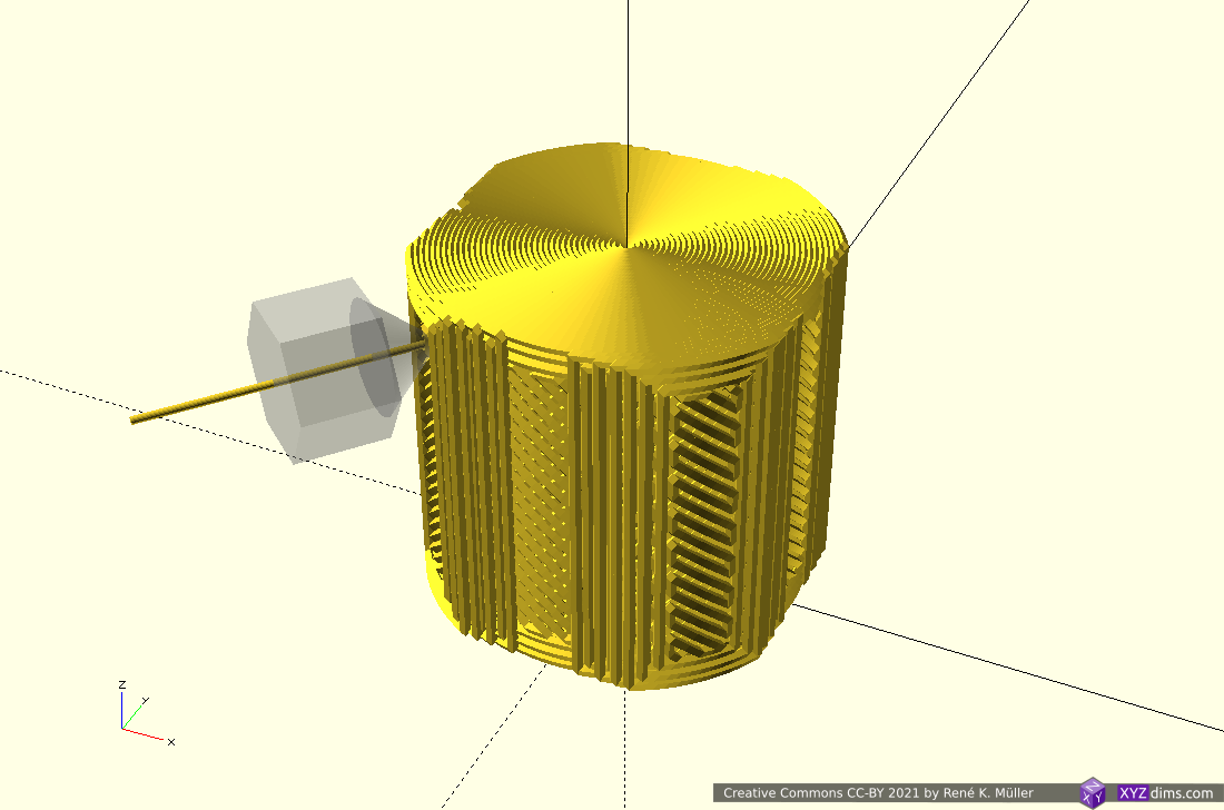
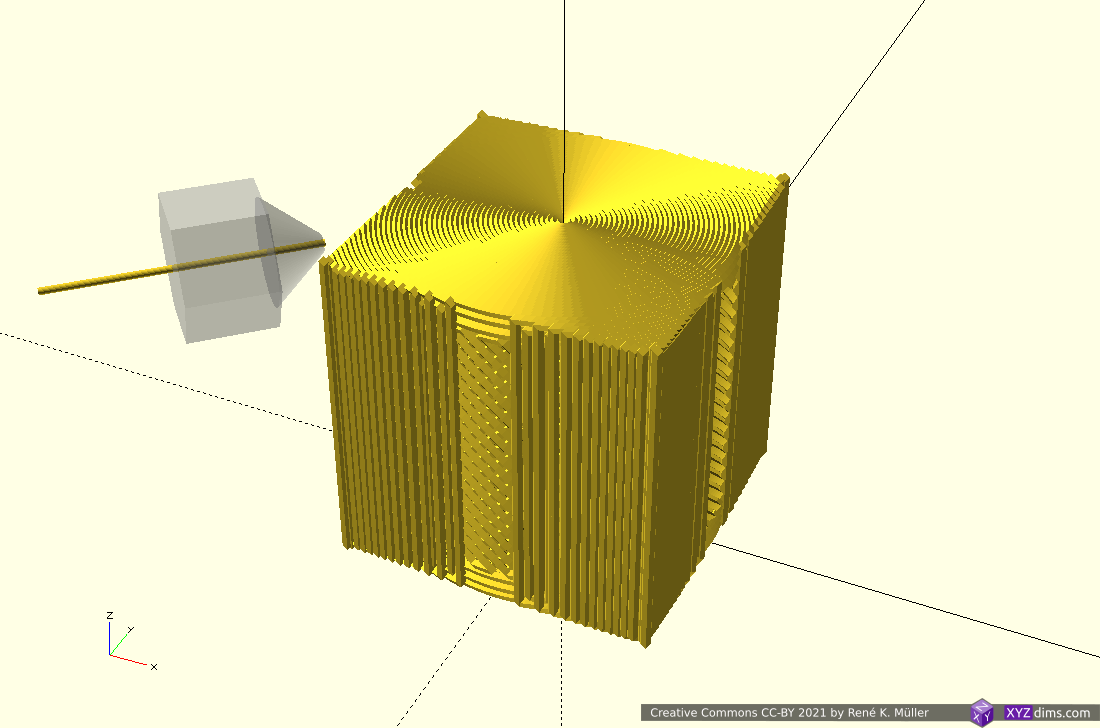
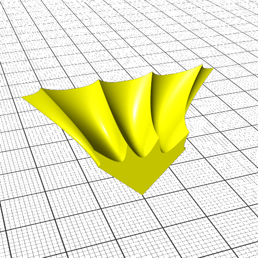
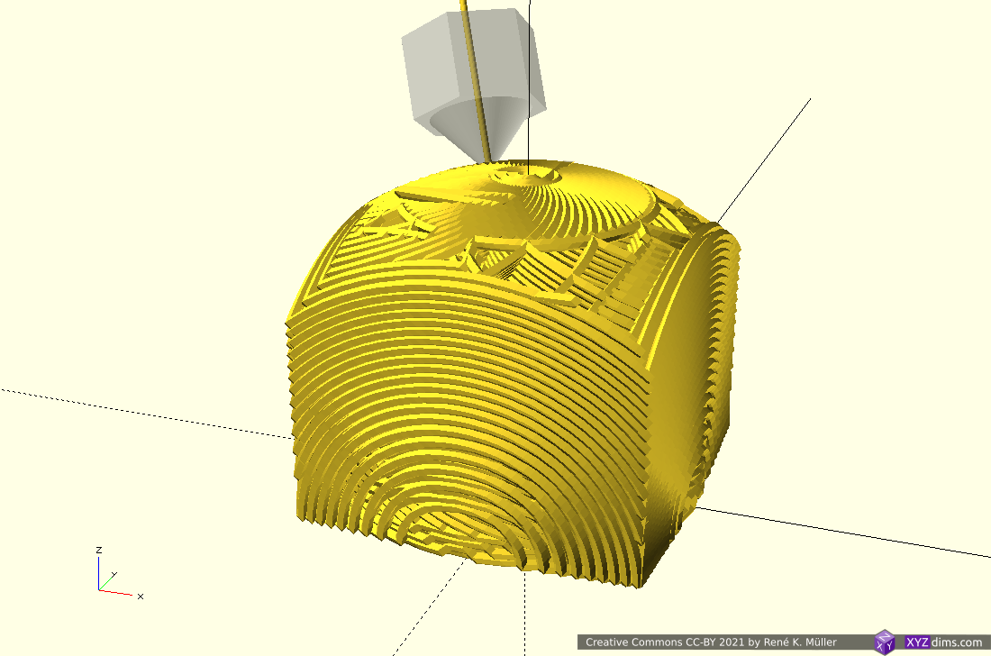
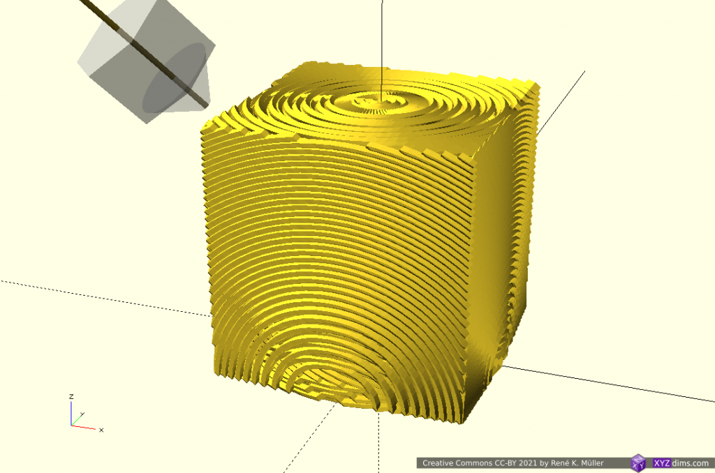
20mm cube
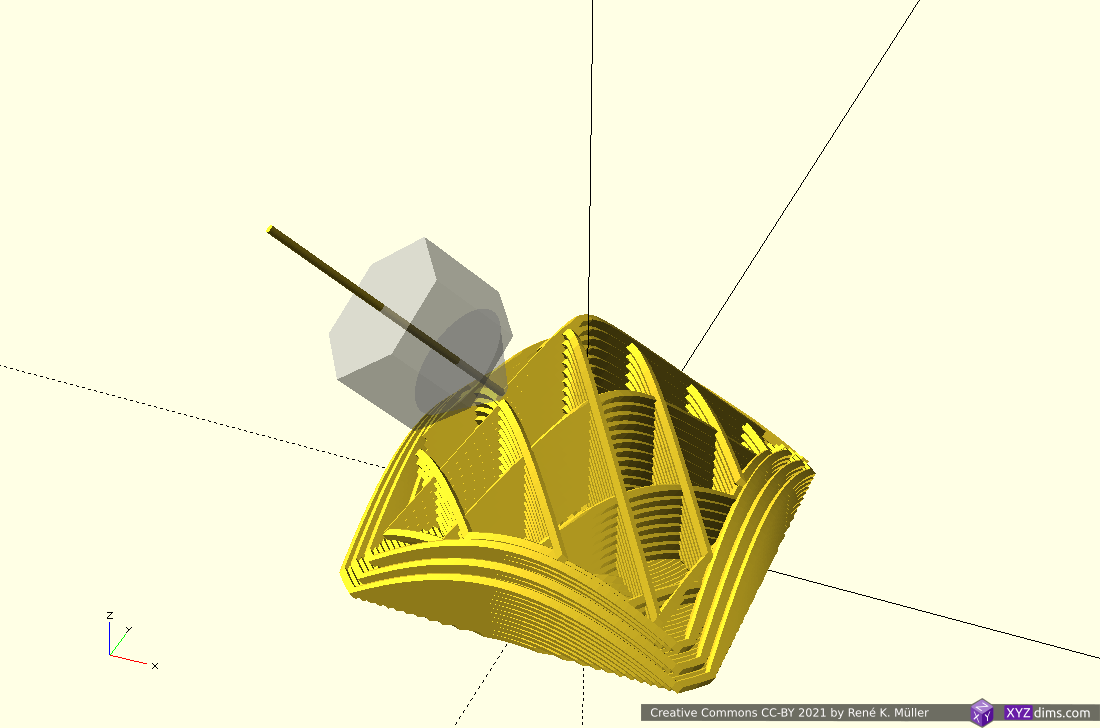
conic mapped
conic mapped sliced
20mm cube conic sliced
Transformation is [ x, y, z + sqrt(x2 + y2) ]
I implemented a conic slicer named Slicer4RTN in 2021/03. There are more complex conic transformations possible, e.g. map the x/y angle via atan(y/x) but just adding sqrt(x2 + y2) to z does achieve a conic slice.
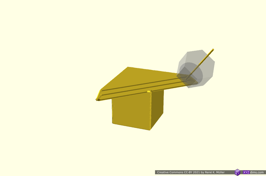
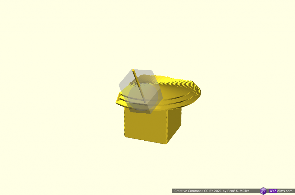
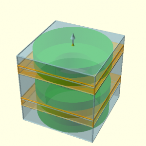
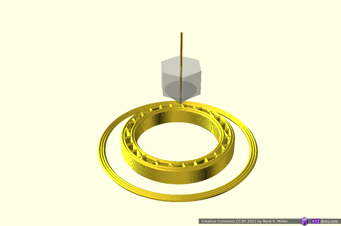
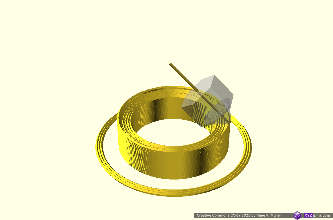
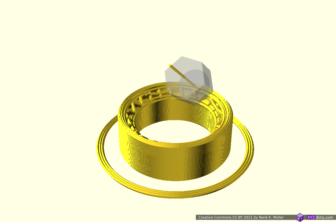
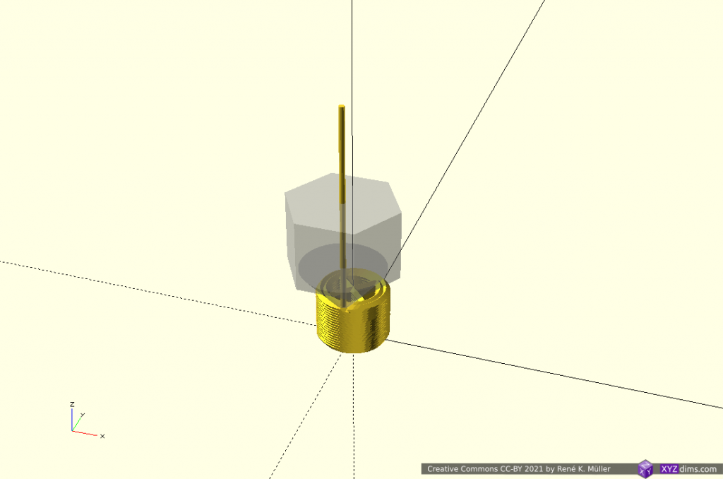
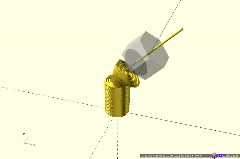
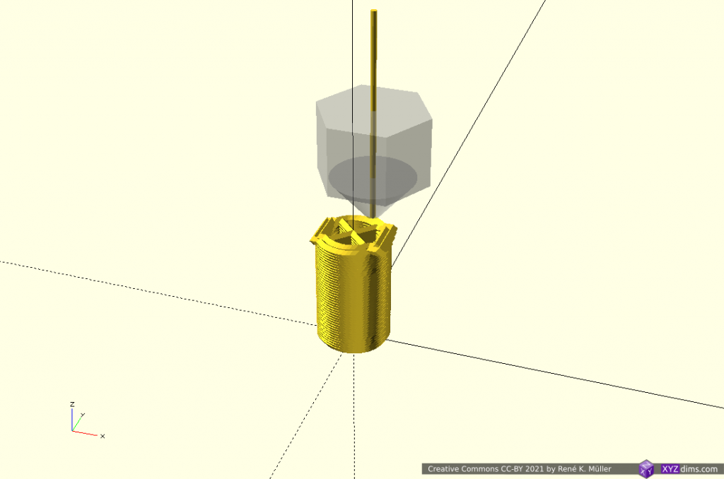
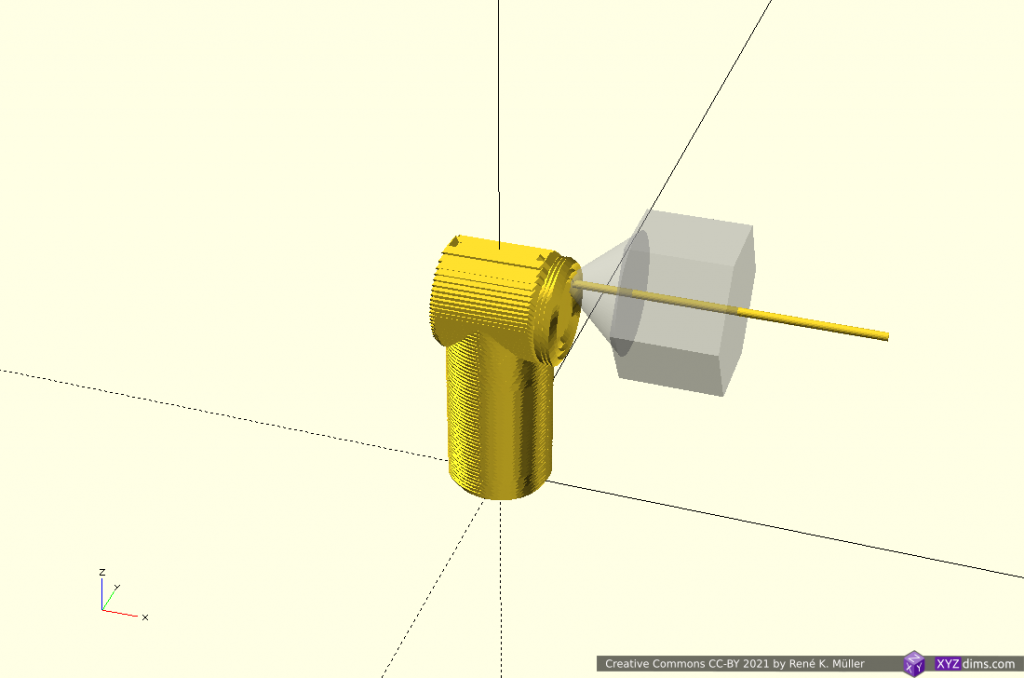
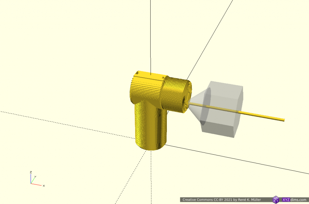
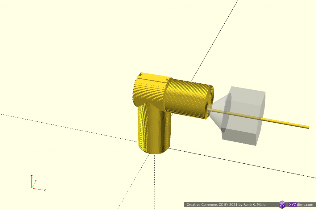
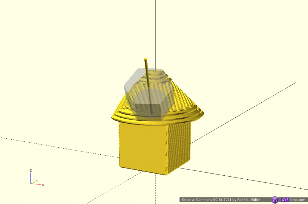
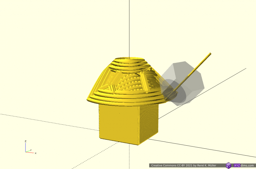
Cylindrical Slices
Early tests using planar slicers to slice also cylindrical, like this:
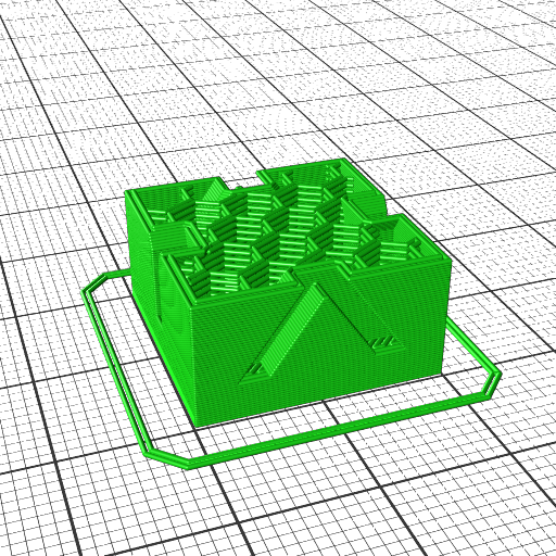
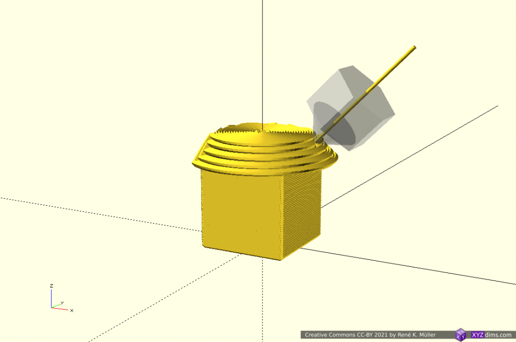
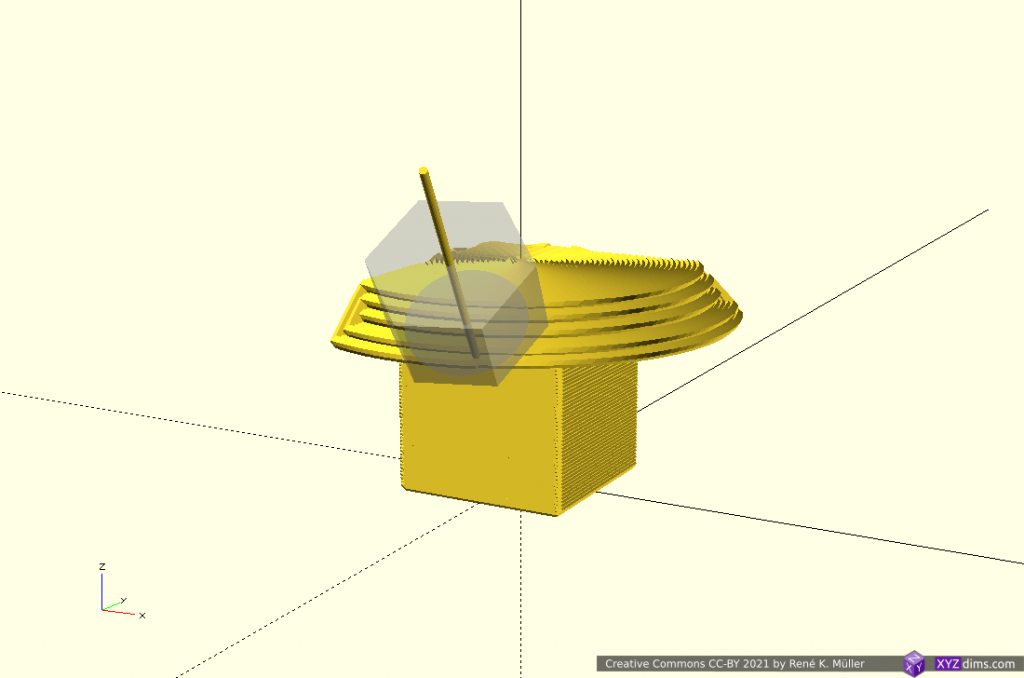
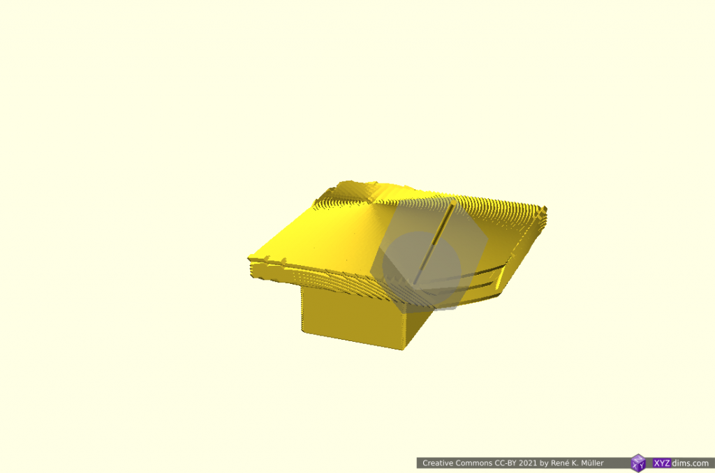
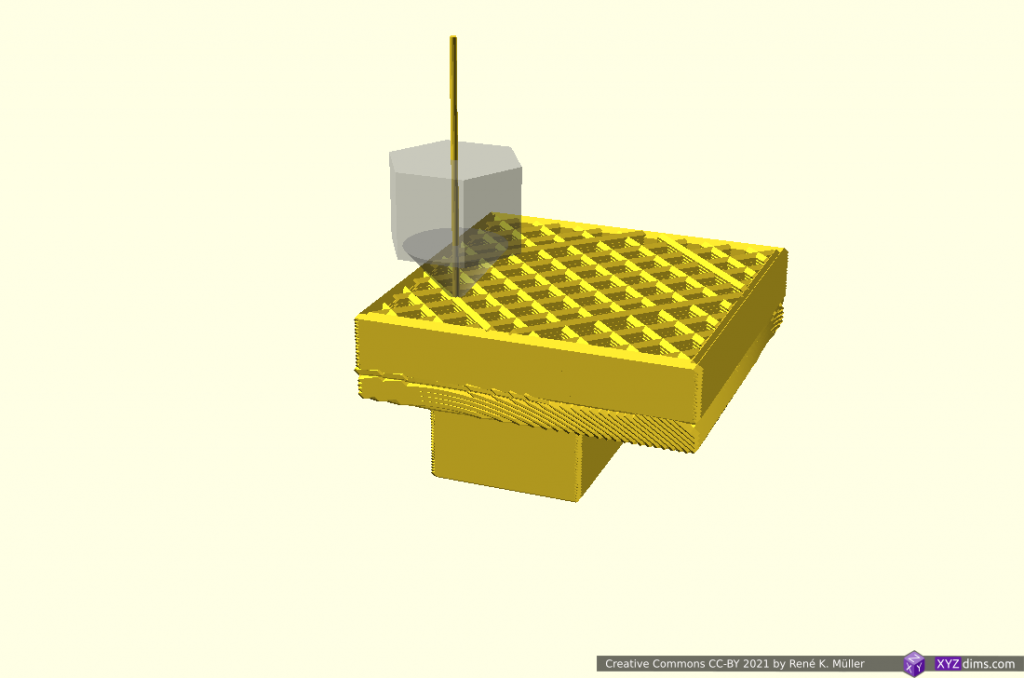
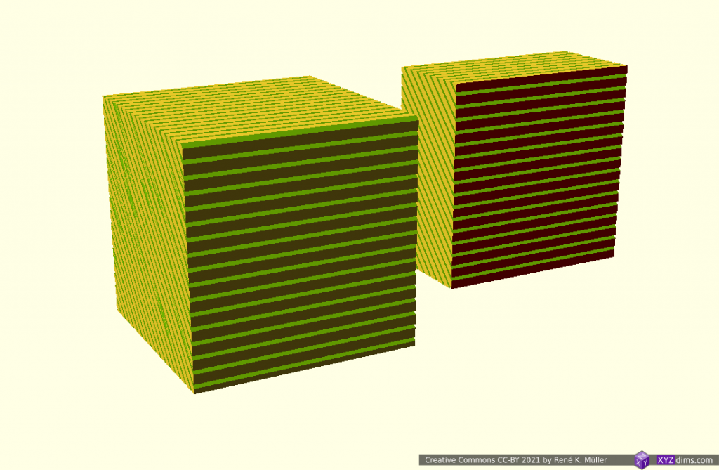
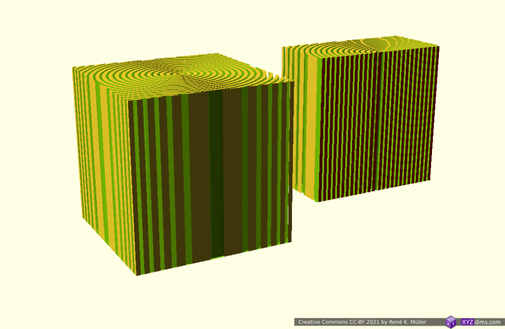
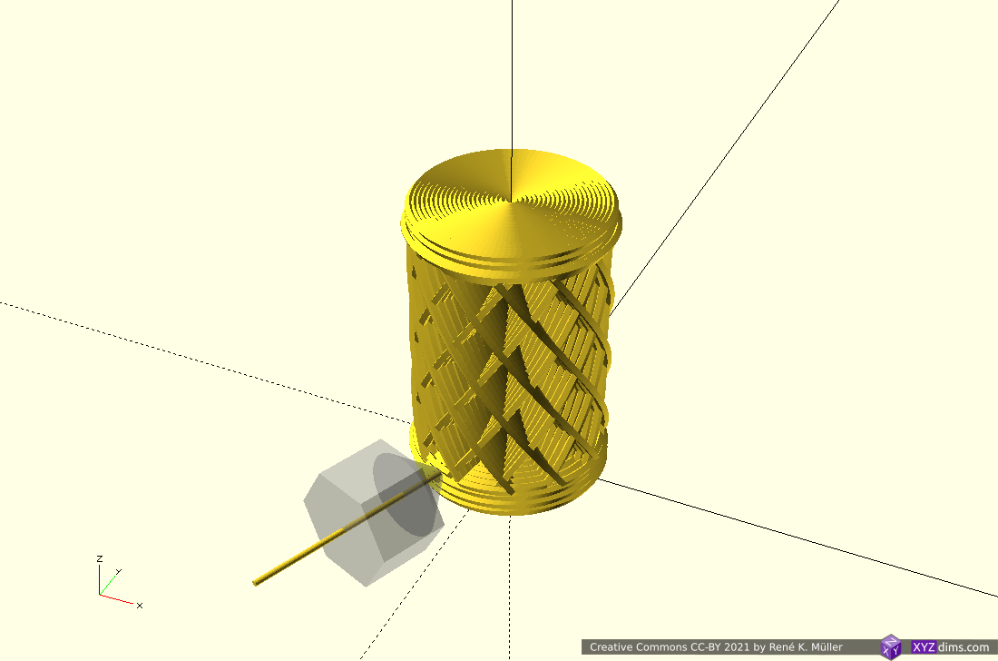
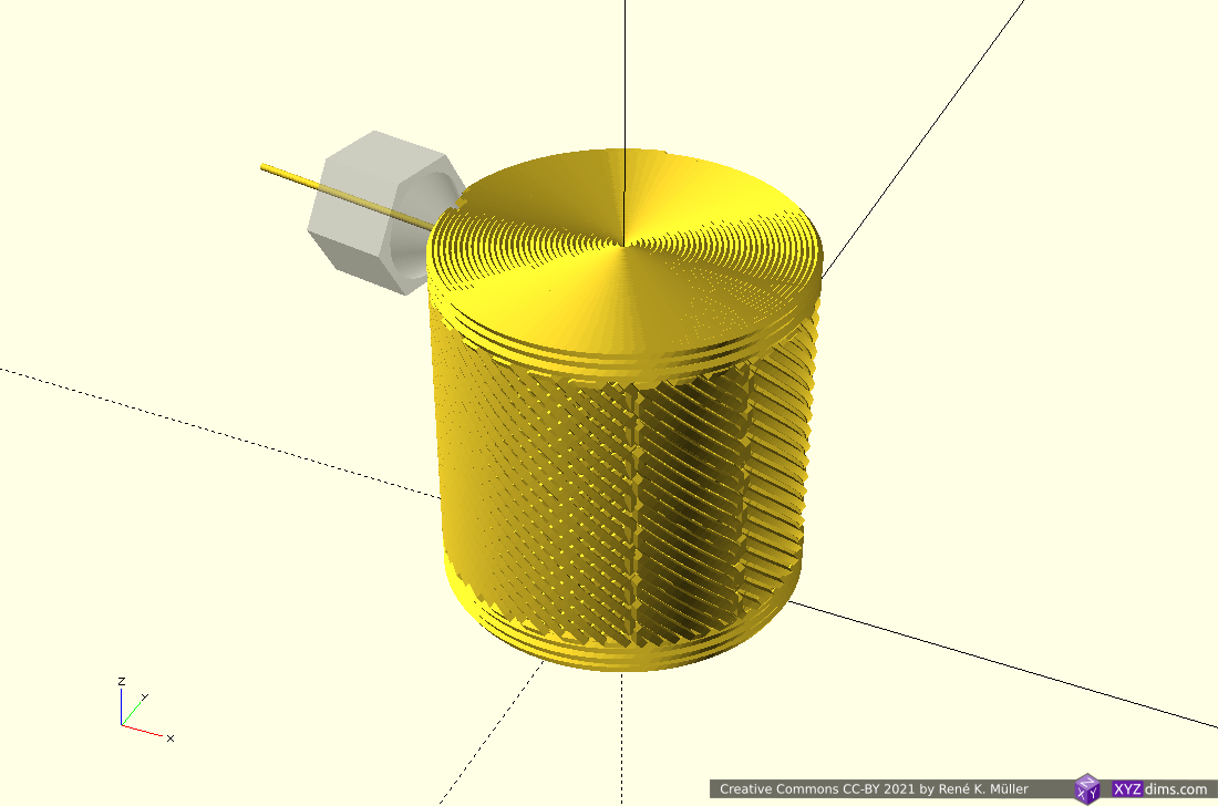
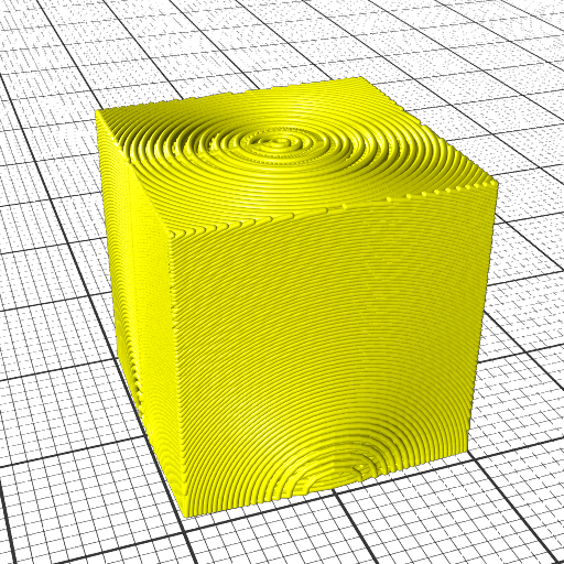
20mm cube
cylinderical mapped
cylinderical mapped planar sliced
cylindrical radius corrected mapped
cylindrical radius corrected planar sliced
20mm cube cylindrical sliced
Transformation is [ atan(y/x), z, sqrt(x2 + y2) ]
It can be printed on a fixed vertical rod, with a rotating and tilting nozzle, or horizontal rotating rod (like a lathe) and vertical nozzle then:
I came up with this way by myself based on the study on conic(al) slicing but I was made aware researchers Coupek, Friedrich, Battran, Riedel back in 2018 published a paper on this method already.
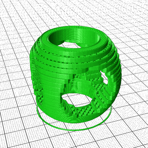
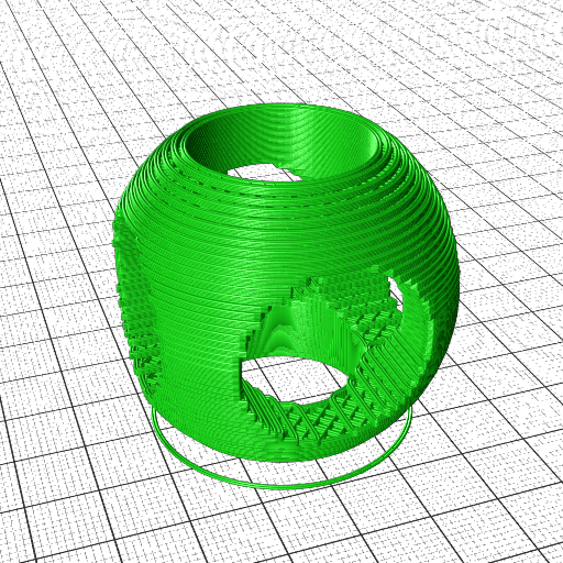
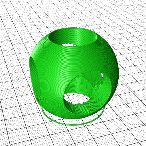
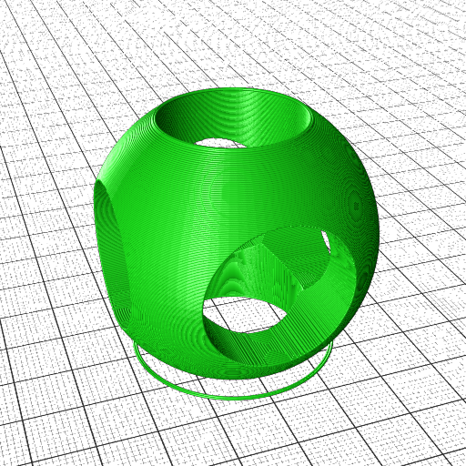
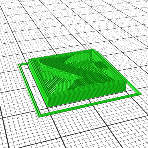
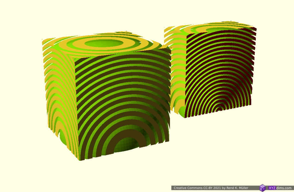
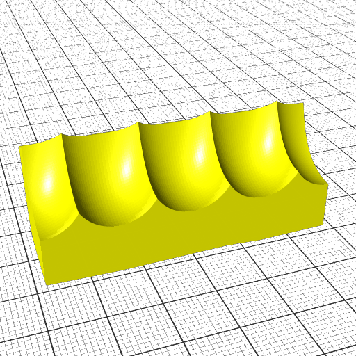
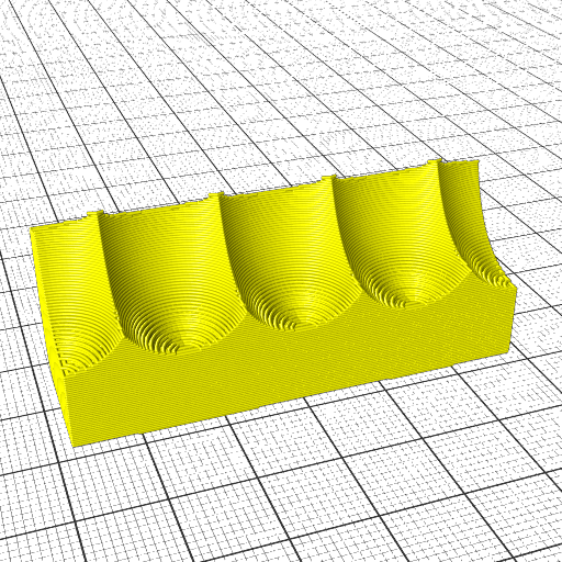
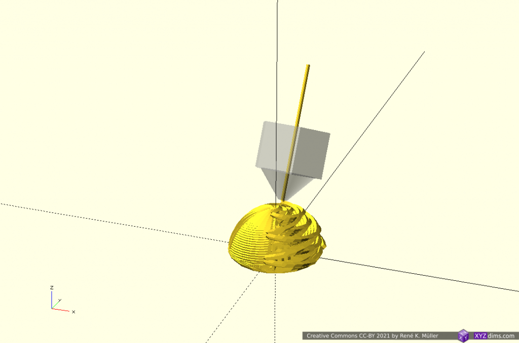
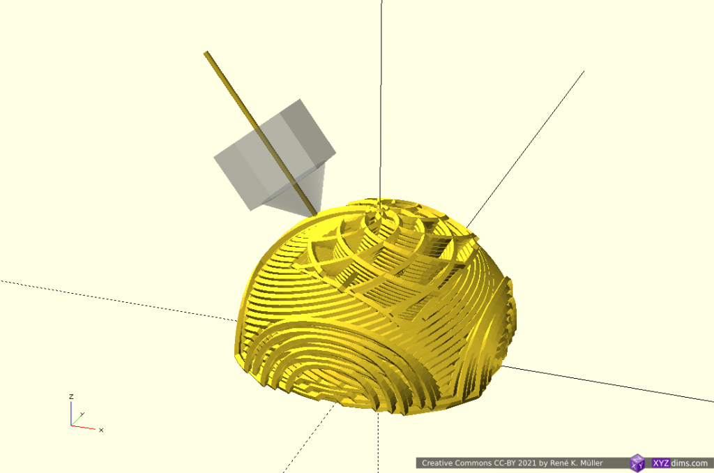
(Hemi-)Spherical Slices
Early tests using planar slicers to slice also spherical, like this:
It can be printed with a 5-axis like PAX printhead, it’s main advantage is to getting close to print continuous overhangs of any angle.
I suspect at least one more suitable and simpler sphere transformation, as soon I came up with such I add it on this blog-post.
Conclusion
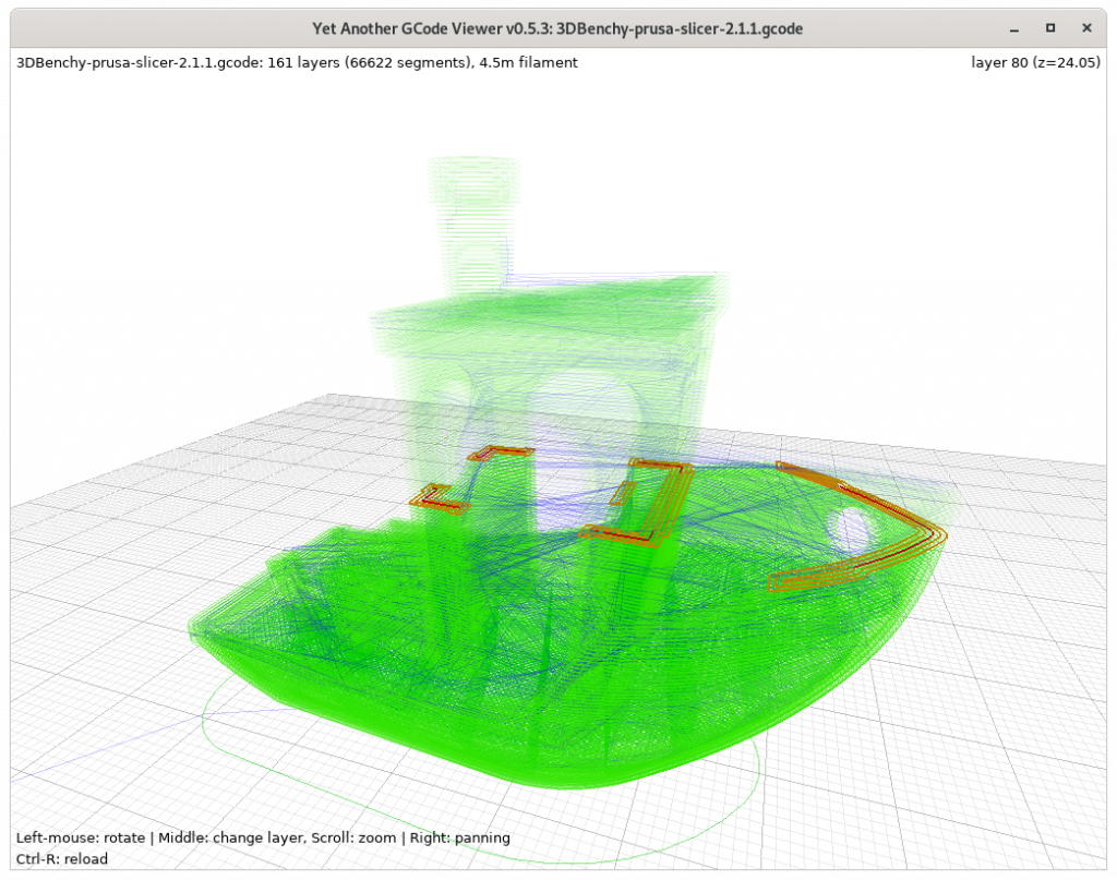
It is possible to slice non-planar with planar slicers by mapping to and from the space of the slicing you like to have; yet in the slicing procedure some margins are introduced which need to be compensated – the planar slicer needs to work reliable, Slic3r1.2.9 and CuraEngine 4.4.1 / cura-slicer perform reliable, whereas PrusaSlicer 2.1.1 makes assumptions of the printability and exits when no printable G-code can be produced, not recommended for this case therefore.
The simpler the transformation forward and backward, the more precise G-code can be obtained, e.g. tilted and conic slices provide precise G-code, whereas cylindrical and spherical slices are harder to tune with the planar slicer.