The workstation from which I print from (design and slice) is also connected via Ethernet. The printed violet PLA case I published a while ago on Thingiverse: Orange Pi Zero Case.
Preparation
On printhub (Orange Pi Zero) starting all the network clients processes:
The CTC I3 Pro B Y3228 low cost printer still runs Marlin 1.0 and 250,000 baudrate which won’t work with ser2net which print3r uses internally to print in network environment, so it needs to be flashed first with newer firmware, so it can be networked as well with common baudrate like 230,400. I upgraded the ~1 year old “CTC DIY I3 Pro B” 3d printer to Marlin 1.1.8 finally, first burning a bootloader with an Arduino Uno, and then properly configured Marlin, and now runs with 115,000 baudrate as well, so it can be networked as well.
Otherwise I stopped using Cura GUI or Slic3r GUI completely, and solely use print3r to first preview the Gcode, sliced with CuraEngine or Slic3r, and then print the parts, and because it runs on the command line, all the previous calls in the terminal are stored as history therefore I can scroll back (cursor-up/down) and repeat a job with slightly changed settings by editing the command line – something which GUI doesn’t offer, unless you save a printjob as .3mf and reload it and click around and change settings and save again as .3mf etc.
Command Inline OpenSCAD
Further, I often code OpenSCAD code directly with print3r for simple parts, e.g. caps for M6 threaded rods, something like:
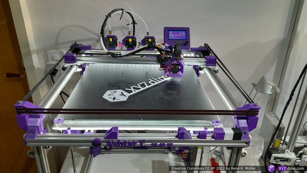
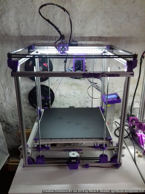
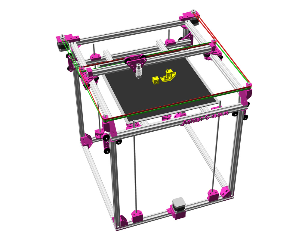
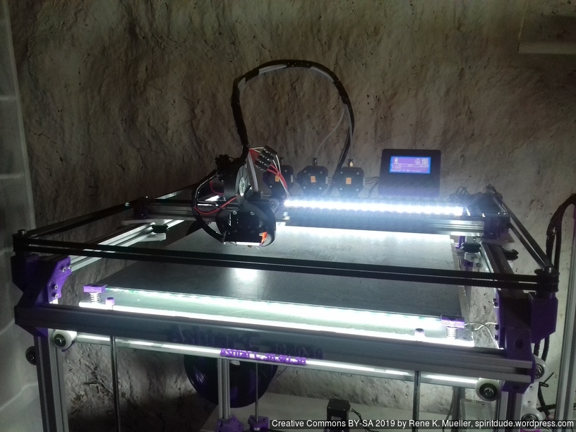
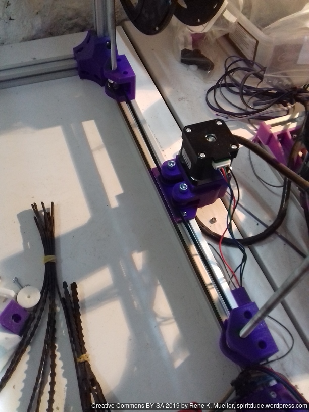
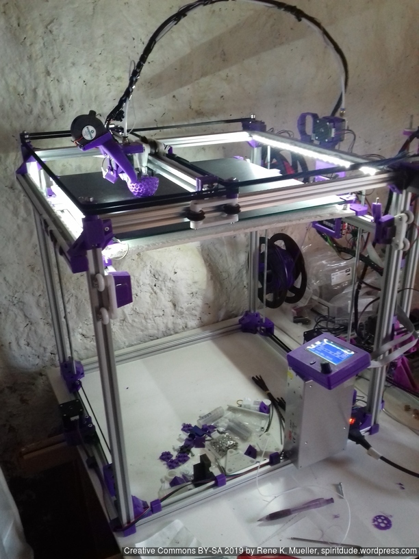
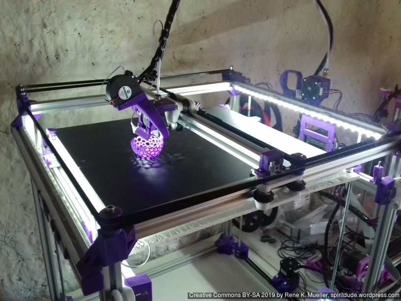
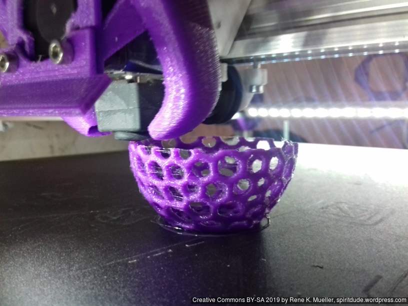
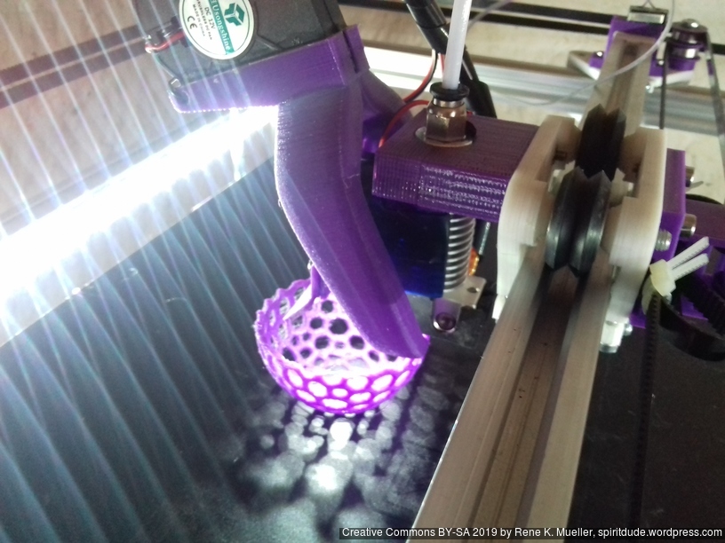
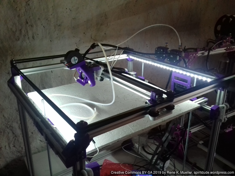
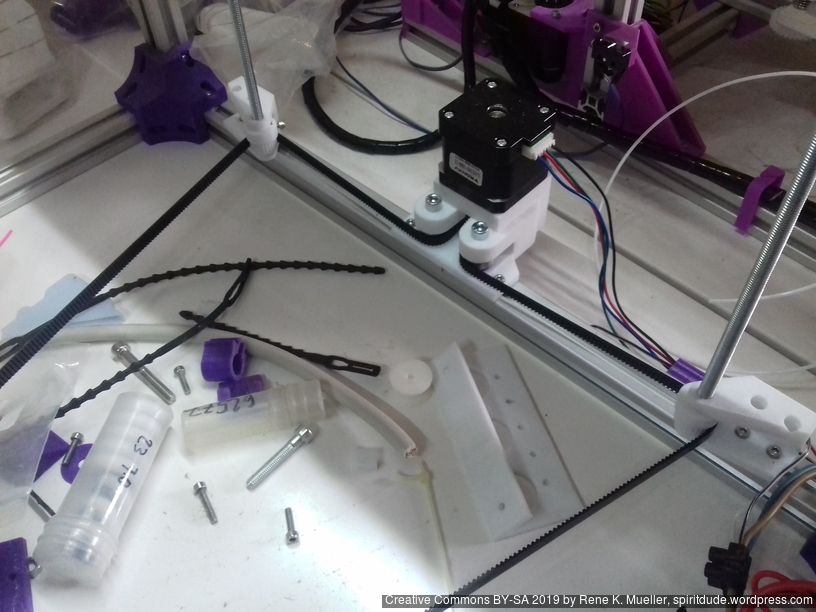
Back in September 2018 I started to code the first parts for Ashtar C, a “Core XY” type 3d printer – finally, after several weeks waiting for the several parts (bearings, closed loop belts), I was able to finalize the bed and Z axis (2018/01/30) and perform the first test prints of Ashtar C #1 composed with 500mm 2020 T-slot and V-slot alu extrusions:
Specifications
CoreXY style
Build Volume: 380 x 400 x 380mm
Frame Size: ~500 x 500 x 500mm
Bed
400 x 400mm black bed sticker (~0.7mm thick)
400 x 400 x 4mm mirror (custom order)
4x bed corner mounts (printed), with M3 x 30 and spring and 4x washers each
420 x 420 x 4mm OSB
residing on 2020 T-slot alu extrusions.
Z Axis
1524mm GT2 closed belt: even though driving 4 threaded rods worked somehow, but not reliably therefore:
Option A
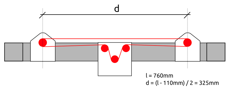
2x Nema17 (45Nm) stepper motor with 18 teeth GT2 pulley 5mm bore
2x 760mm closed belt
Option B
Using 3 or higher : 1 gear box (e.g. 3:1 gearbox could be used, but external shaft isn’t strong enough stabilized versus tilt) or alike to increase torque and still drive 4 threaded rods
4x M6 x 490mm threaded rods
4x M6 nuts with bed mounts (printed)
4x bottom Z rod mount (printed)
8x 606ZZ bearings (each rod has 2 bearings)
4x 18 teeth GT2 pulley 6mm bore
Challenges
Following challenges came up in the first test prints:
CoreXY principle works well, yet, the friction of each idler really matters as it increases risk of missing steps, well greased and well positioning mandatory
X endstop: right now positioned on the left hand side of the X beam, but the cable hangs down – likely need to reposition X endstop on the X carriage itself
the Bowden tube is long and so hangs to the bed, the tube (4mm OD, 2mm ID) isn’t stiff enough to bend upward, so requires some guidance to ensure it doesn’t ride on the bed surface and entangles with print process
E3D V6 clone this time really does not perform well: extrusion is not even, and missing steps of the extruder; requires further investigation.
thermistor seems off, increasing to “220C” print temperature, gave better and cleaner prints
After some delay of parts, I finally was able to finalize the belt routing and configure the firmware for Ashtar C #1:
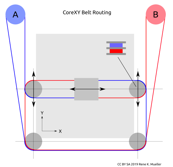
Belt Routing
CoreXY belt routing of Ashtar C
Early on I decided to separate belts of motors A and B in the Z axis, so they would not cross as such, and also hoped one axis of the carriage holding the X beam would allow some idlers to redirect the belts – to save space and keep frame dimension and build (or printable space) dimension close.
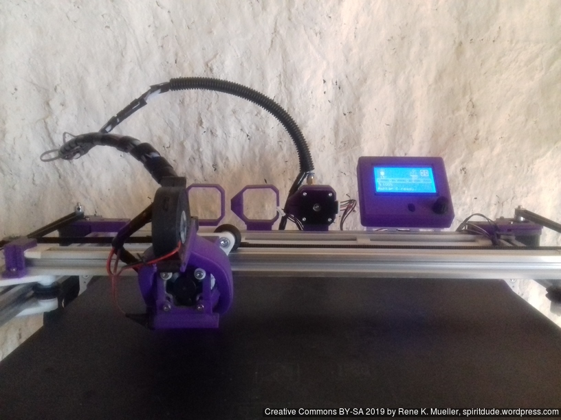
The Bowden tube and the wires of the hotend are preliminary arranged:
Firmware
To configure the Marlin firmware turned out not that simple, as CoreXY has its own interdependencies of A & B motors: first X axis was reversed, whereas Y axis worked correctly, the INVERT_X_DIR setting on Configuration.h of Marlin did not help, it reversed the stepper motor direction, but not the actual X axis direction. After many attempts to use COREYX instead of COREXY I ended up
swap cables of A & B stepper motors
keep #define COREXY
#define INVERT_X_DIR = true and #define INVERT_Y_DIR = true
and X and Y direction worked correctly.
Preflight (no extrusion, just X & Y axis movement testing):
The stepper drivers still need some tuning, as I saw or rather heard a few missed steps at fast movement.
X & Y Endstops
The preliminary positions of the endstop are:
X endstop resides on the X beam left-hand side (USE_XMIN_PLUG)
Y endstop resides on the right-hand backside, (USE_YMAX_PLUG and HOME_DIR_Y 1)
X endstop
Y endstop
Z Axis
I postponed the actual details of the Z axis, as my main concern of the design was to have a good CoreXY setup and then see how I would achieve the Z axis.
In order to use 625ZZ bearings I started to use them as idlers directly (after cleaning the grease off their surfaces) and also use them to increase contact surface when driving a closed belt which drives 3 or 4 threaded rods M6 x 500mm:
Since the surface of the threaded rods is rough, I realized I need dedicated bearings to hold the rods at the bottom, otherwise the friction would wear on the mounts and increase its diameter. So, the Z axis isn’t finalized yet, but close.
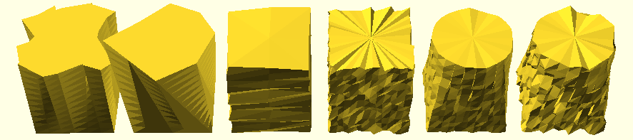
This is aimed to be small OpenSCAD Library which re-implements some of its basic forms in discrete manner so vertices remain accessible in order to manipulate before being transformed into actual polyhedron for CSG operations.
State: very experimental state, not yet released due several drawbacks, code released (e.g. polygons must have same amount of segments to properly extrude, resolved)
Updates:
2021/01/02: 0.0.6: code finally released
2018/12/30: 0.0.5: 3d:dm_merge([]) merge multiple meshes into single one.
2018/12/26: 0.0.4:
3d:dm_extrude_rotate(p,n=4,start=0,end=360) which allows simple dm_torus()
more detailed documentation and illustrations
2018/12/25: 0.0.3:
2d: added dp_translate(), dp_scale(), dp_rotate(), dp_bounds() and dp_center()
3d: added dm_sphere(), dm_cylinder() and dm_cube(), and dm_translate(), dm_scale(), dm_rotate(), dm_bounds() and dm_center() as well
2018/12/24: 0.0.2: dp_morph() as part of dm_extrude() uses dp_nearest() to find nearby point of two polygons to morph smoothly, morph examples added
2018/12/23: 0.0.1: Point Functions, Polygon Functions and Mesh Functions added, code not yet released
Functions
Discrete Point Functions
dpf_ellipse(r1,r2,p,a=0)
dpf_circle(r,p,a=0)
dpf_circle(d,p,a=0) must use d=diameter
dpf_rectangle(w,h,p,a=0)
dpf_square(w,p,a=0)
dpf_npolygon(s,p,a=0) whereas s amount of sides
each function returns single 2d point, whereas
p ranges between 0…1, at any resolution
a is the additional rotate angle (default: 0)
Discrete Polygon Functions
Polygon Functions use Point Functions to create an array/list of 2d points to describe a polygon; n amount of segments:
Creating Polygons
dp_ellipse(r1,r2,n=12,a=0)
dp_circle(r,n=12,a=0)
dp_circle(d,n=12,a=0) must use d=diameter
all above use dpf_ellipse() to construct the polygon
ellipse and circle is approximated with high count of n-sided polygon
dp_rectangle(w,h,n=12,a=0)
dp_square(w,n=12,a=0)
two above use dpf_npolygon(sqrt(2)/2,4) and dp_scale() if required
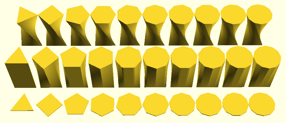
dp_npolygon(r,s,n=12,a=0,start=0,end=360) whereas s = amount of sides of the polygon, s > n * 2 for good approximation
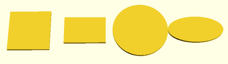
Square, Rectangle, Circle and Ellipse
N-Sided Polygon (s=3..12)
Manipulating Polygons
dp_translate(p,t) where as t is a number or array [x,y]
dp_scale(p,t) where as s is a number or array [x,y]
dp_rotate(p,a)
dp_center(p,center=[true,true])
further:
dp_subdivide(p,n=2)
n amount of subdivisions per segment
dp_distort(a,s=1,f=1)
s amplitude of distortion
f frequency of distortion
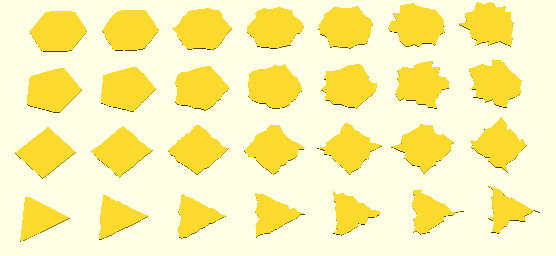
N-Sided Polygon (n=3..6) with Distortion (s=0..3 with 0.5 step)
dp_morph(a,b,p)
morphs between two polygons (a and b), preferably both with same amount of segments and sufficient segments to have smooth transition
p range between 0..1
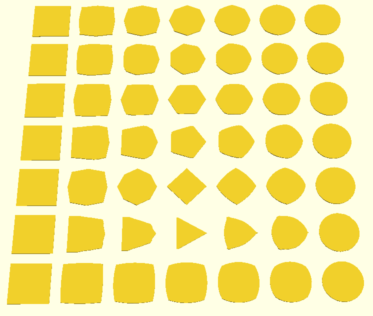
Morphing from square to circle and/or n-polygons in between (n=32 amount of segments)
Query Polygons
[[minx,maxx],[miny,maxy]] = dp_bounds(p)
and finally
dp_polygon(p)
creates an ordinary polygon OpenSCAD object
Note: you no longer can access the individual vertices
Discrete Mesh Functions
Mesh Functions use Polygon Functions to create an array with two elements:
list of 3d points
list of faces using indexes of the 3d points
Creating Meshs
dm_cube(s,center=false)
s = side length or
s = array of [w,d,h] or [x,y,z]
dm_cylinder(r,h=1,center=false,n=12)
dm_cylinder(r1,r2,h=1,center=false,n=12)
dm_cylinder(d,h=1,center=false) must use d=diameter
dm_cylinder(d1,d2,h=1,center=false,n=12) must use d1= and d2=
dm_sphere(r,center=false,n=12)
dm_sphere(d,center=false,n=12) must use d=diameter
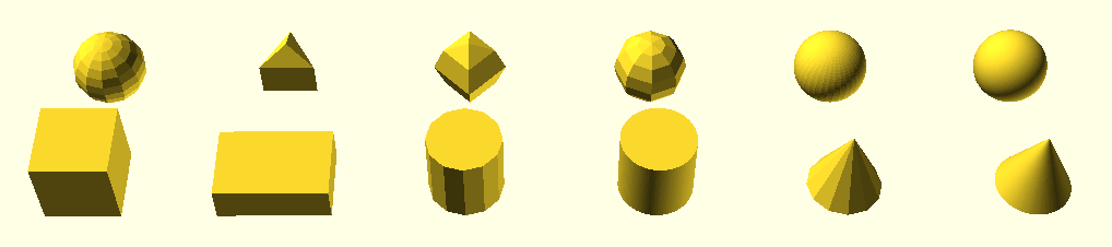
Cubes, Cylinders, Cones and Sphere at different polygon resolutions
Cube and Cylinder are created by extruding dp_rectangle respectively dp_circle, whereas the Sphere is discretely done.
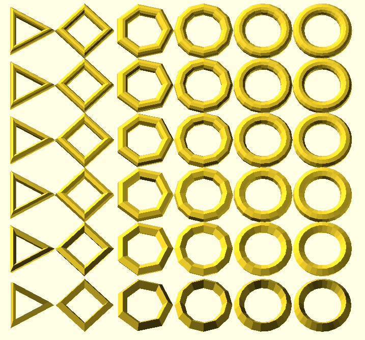
dm_torus(ri=1,ro=4,ni=48,no=48,ai=0,ao=0)
ri inner radius
ro outer radius
ni and no inner and outer n-sided polygon
ai and ao inner and outer angle offsets
Torus with various inner and outer n-sided polygons
dm_extrude(a,b,s,h)
a & b: polygons
s amount of steps
h height (Z wise)
Extruding Triangle (3-Sided Polygon) to N-Sided Polygon (s=3..12) linear and with 45 degree twist
Note: the main aim of this library was to extrude two arbitrary polygons correctly; so dm_extrude() is the center of this entire undertake.
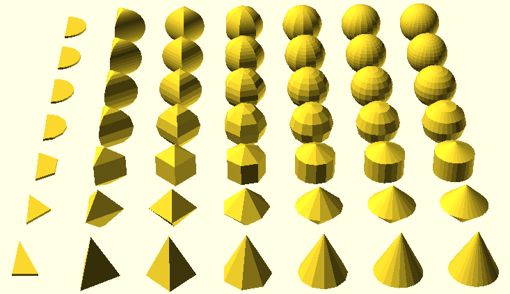
dm_extrude_rotate(p,n=4,a=0,start=0,end=360)
sweep or rotate a 2d polygon, n-sided, used to implement dm_torus()
Triangle and Half Circle Extruded Rotational with N-Sides
Manipulating Meshs
dm_translate(m,t) whereas t = number or array with [x,y,z]
dm_scale(m,s) whereas s = number or array with [x,y,z]
dm_rotate(m,r) whereas r = number or array with [x,y,z]
dm_center(m,center=[true,true,true])
dm_merge(ms) whereas ms is an array of meshes
and more interesting:
dm_distort(m,s=1.0,f=1.0)
distort the mesh, s amplitude, f frequency
Extruding Square to Square with top polygon or mesh distortion; Extruding Square to Circle with light and heavy distortions
Note: you no longer can access vertices for manipulation
Todo
make polygon morph (part of extruding) segment/point count neutral:
using dp_morph() which uses dp_nearest(array,point) to morph between nearest points of polygons
disadvantage: some edges are missed where near-points don’t catch it
consideration: additional strategies might be required, e.g. if polygon A and B segment count difference is huge, rebalance with using dp_subdivide() to achieve this for smoother morphing and extruding
done: walking through max(len(a),len(b)) through all points and align point indexes linearly a[i*len(a)/max] and b[i*len(b)/max]
more examples, more documentation done: most functions properly illustrated with examples
implicit meshes: define objects in implicit form (allows more natural objects with smooth edges), and transform it into meshes, see NodeJS Implicit Mesh as reference
CSG operations on polygon (2d) or mesh (3d) level, quite challenging to do since OpenSCAD are single assignment and for() loops must implemented recursively
A few OpenSCAD sketches I’m currently work on, and later will publish as well:
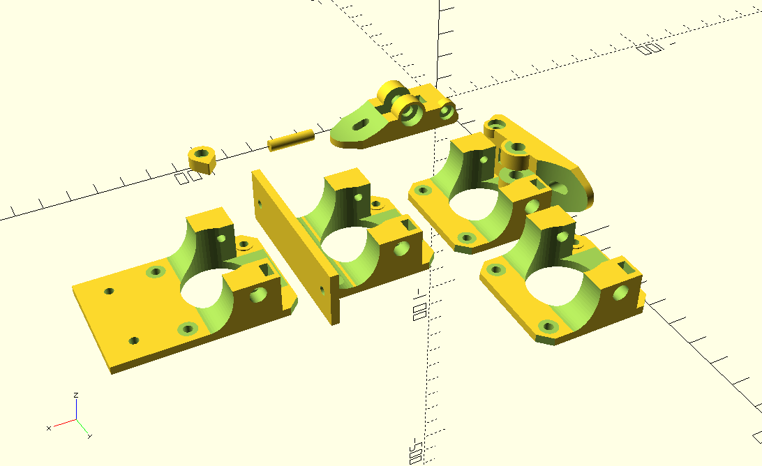
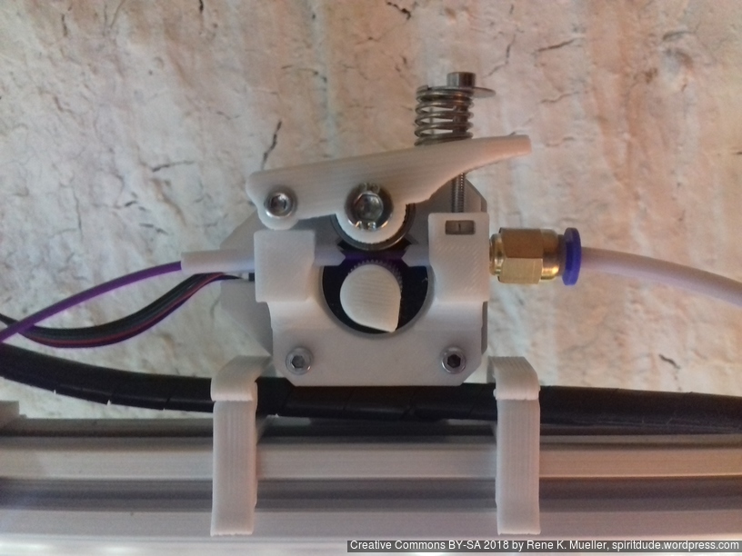
Simple Compact Extruder
I used some aluminium MK8-based extruders but realized I required my own parametric extruder using 625ZZ bearing and I looked around and found “Compact Bowden Extruder“ and adapted the overall design but coded it from scratch again:
It’s “right handed” by default, but filament can go both directions. The handle is pushed from “inward” with a spring, not so elegant, yet it saves space and filament does not have to go through the handle this way, which I prefer.
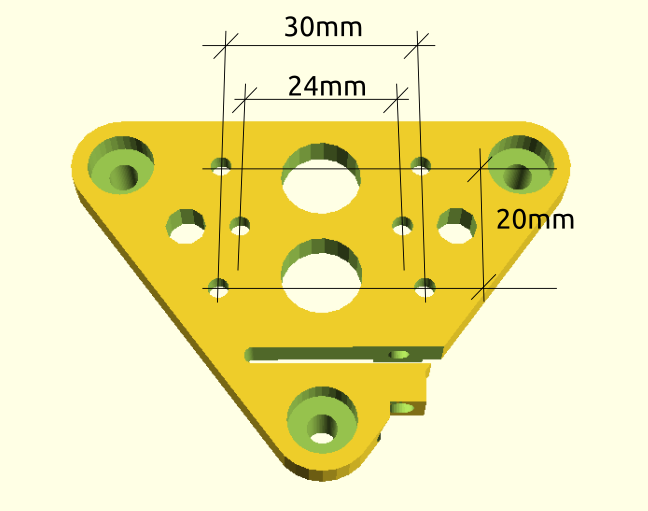
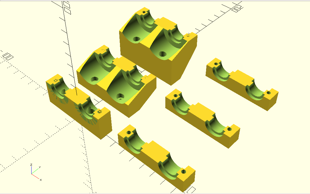
simple_compact_extruder() takes following parameters:
type:
"base": the base attached to the Nema 17 stepper motor
"handle": the push handle with the spring
"indicator": small indicate to put on the axis of the stepper motor
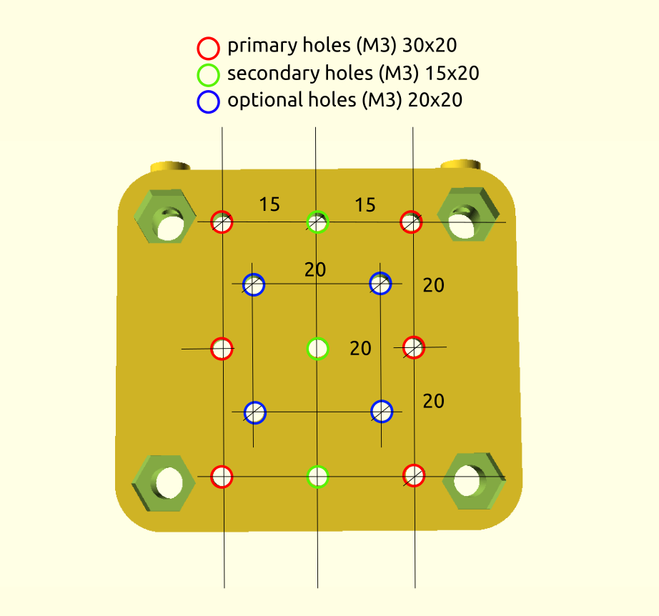
mount:
"none": (default) just attaches to Nema 17 stepper motor
"mount": simple mount (center)
"2020": extends flat (lower left version)
btd: Bowden tube diameter (default: 0mm), if 4mm is used, then Bowden tube can be inserted on both sides as guides for flexible filament close to the hobbed gear as shown below.
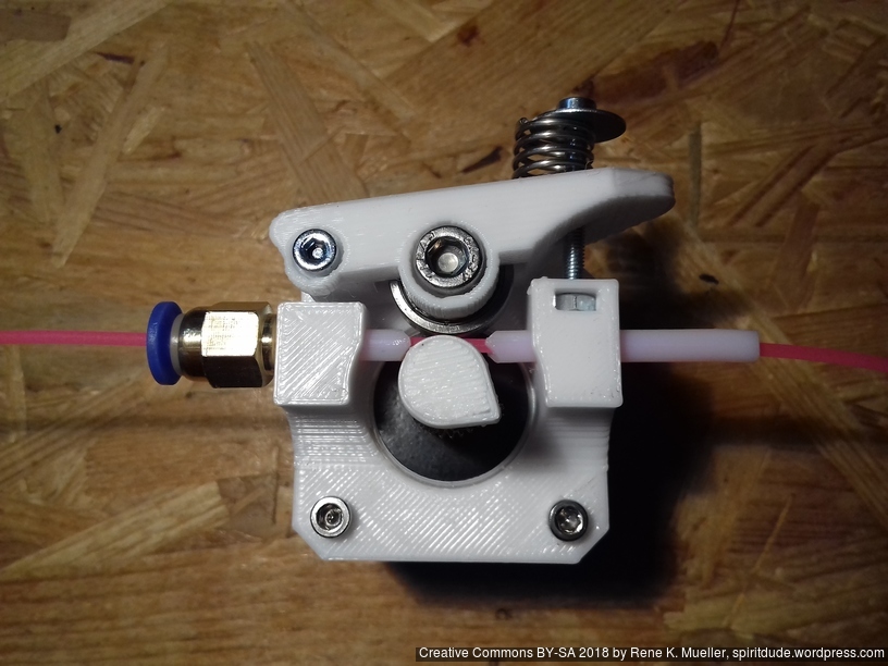
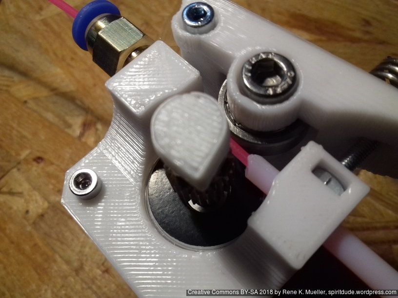
I use PC4-M6 push fit connector with PTFE tube 4mm OD / 2mm ID as guides, and began to use it right away on 3x printers for first tests:
Assembled Simple Extruder (M5 inset)
Assembled Simple Extruder (M5 inset)
Later I likely will integrate this design, once proven reliably working, with a Direct Drive Extruder design as well.
This design has been not yet printed but not yet in use, but soon as alternative to Chimera (dual hotends) or Cyclops (dual to one / mixing) hotends – two main issues:
part cooler needs to be narrow enough to sit aside of each other
part cooler should extend too much Y-wise too much, as the routing belt of the Ashtar C come into the way
The “Dual E3D V6 mount” was derived from preview designs as used for the Ashtar K:
Static Hotend Mount (Y Offset: 35mm, Z Offset: 20mm)
Simple Parametric Hotend Mount (Y-Offset: 0,20)
The first one used two pairs of M3 screws, whereas the other more simple one requires in its base version just one pairs of M3 to mount the E3D V6 hotend and the mount itself to the X carriage; in case a slight Y offset is used, two pairs of M3 are required again.
I will update this post once the designs are published, after thorough testing in real life.
2018/12/05: added MKS Gen L as alternative, for Ashtar C #1
2018/11/25: added RAMPS 1.4 as alternative, for Ashtar K #2
2018/08/28: initial version with CTC DIY I3 Kit
Sourcing Parts
The past months (2018/08) I began to use Aliexpress for ordering electronics – even prior going into 3d printing – and the past weeks my development cycles pretty much were depending on the 20-25 days delay until items arrived from China to Switzerland – and one develops some skill to anticipate what one would require as next – but some things only become known once you really tested parts thoroughly.
Anyway, the CTC DIY I3 Pro B (Geeetech DIY I3 Pro B clone) was still sold via Ebay (2018/08), at a price as low as EUR 80 incl. shipment, which is a true bargain.
Aliexpress (2018/08):
MKS Gen L mainboard (incl. drivers) with LCD (with dialer), 200×200 heatbed, end stops, cables: EUR 50
PSU 12V 240W: EUR 20
5x Nema 17 45Nm stepper motors: EUR 35
Total: EUR 105 (without endstops and various cables to connect all together)
CTC DIY I3 Pro B Kit (2018/08):
Anet 1.0 mainboard, with 2 Lines LCD (4 buttons), 200×200 heatbed, end stop, cables, PSU 12V 240W, 5x Nema 17 45Nm stepper motors
Total EUR 80 (all cables included)
So I decided to get another CTC DIY to source the parts in one go, and likely upgrade later with individually sourced parts to have dual extruder motors (two color or material printing).
In 2018/11, when I started to build a second Ashtar K 38x30x33 #2 I checked Ebay with following prices:
Ebay (2018/11):
MKS Gen L: EUR 28
MKS Gen L mainboard: EUR 16
5x A4988 drivers: EUR 6
RepRap Full Graphic LCD: EUR 11
RAMPS 1.4 with Arduino Mega, 5x A4988 drivers, Full Graphic LCD: EUR 28
5x Nema 17 40-50Nm stepper motors with cables: EUR 26-35
PSU 12V 240W: EUR 20
Total EUR 74 – 83 (missing: endstops and various cables to connect all)
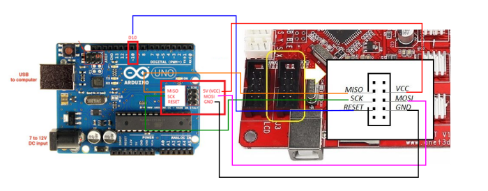
Burning Bootloader on Anet 1.0 Board
For now I use an “Anet V1.0” controller board (Atmel 1284P), as part of a “CTC DIY Kit” as mentioned, and it required some preparation:
using Arduino Uno R3 (clone) and upload “Arduino ISP”
attach Anet V1.0 board (detach all other cables) to Uno R3
run “Burning Bootloader” with “Arduino as ISP” as writer
downloading Marlin and edit main Configuration.h (not yet published) to match my specifications
upload new firmware Marlin to “Anet V1.0” via USB upload
RAMPS 1.4 with RepRap Discount Full Graphic LCD
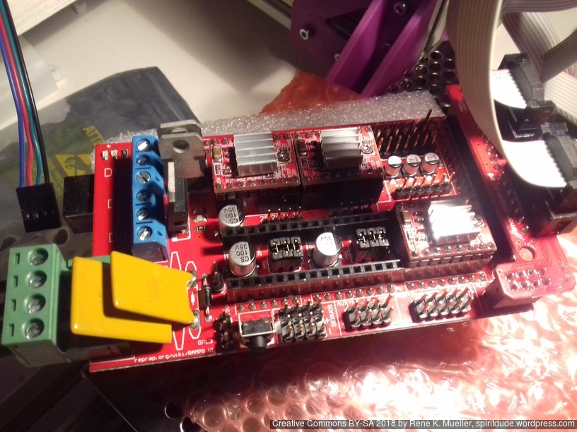
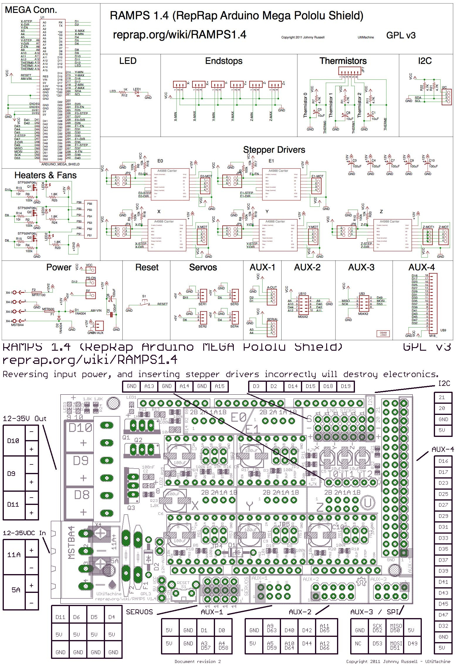
For the 2nd Ashtar K 3D Printer I used (2018/11) RAMPS 1.4 combo with Arduino Mega, which was easy to upload new firmware. RAMPS 1.4 is Open Hardware, the entire schematic and pinout is available or download diagram with pinout as one image (same as on the side) – but it’s also a hassle to plug correctly as the board plug descriptions are tiny or covered by parts so one has to consult documentation in details, and there many ways to do wrong (reverse or misalign plugs) and most of these can and do damage either the RAMPS 1.4 shield and/or the Arduino Mega beneath, including misaligning the endstops.
Endstops
using C and NC on the endstop and the board (power connector on the left) above the 2x Z motor connectors: XMIN, XMAX, YMIN, XMAX, ZMIN, XMAX, each:
top (Signal) -> C
middle (Ground) -> NC
bottom (5V) -> empty
while waiting for proper endstops to arrive, I salvaged microswitches from a faulty computer mouse to work as endstops
commented out #define MENU_HOLLOW_FRAME so selected item is inversed
pin_RAMPS.h:
see #if ENABLED(REPRAP_DISCOUNT_SMART_CONTROLLER) and the following #if ENABLED(CR10_STOCKDISPLAY)after the #else check BTN_EN1 and BTN_EN2 and reverse the pins (31 <-> 33) so clockwise dialing goes down (and not up).
MKS Gen L
Configuration.h:
#define MOTHERBOARD BOARD_MKS_GEN_L
As far I can tell the end-stops take DuPont females and pin order is the same as with RAMPS 1.4, but orientation is crucial – otherwise the GND and VCC is shorted.
Since 0.1.0 also arbitrary baudrate like 250000 (default of Marlin) is supported (Linux only, other platforms not yet), aside the common 115200.
Preview
As external Gcode viewer for preview command yagv is used, a very basic viewer – at a later time it might be replaced.
% print3r preview cube.scad
which converts, slices and preview the Gcode.
Extensive Documentation
Since the functionality of print3r is growing steadily, the requirement for proper documenation demanded its own Print3r Wikiwhere you find up-to-date information.
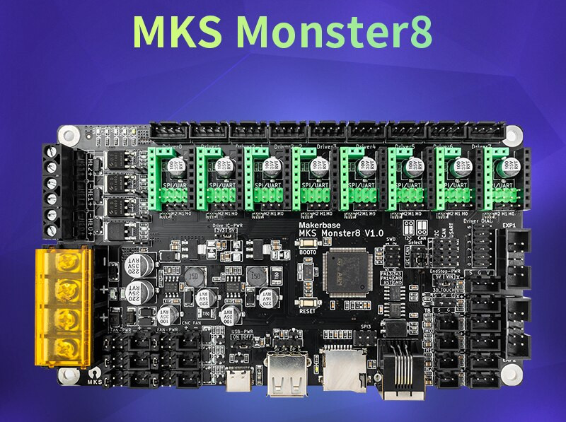
2022/09/19: new board MKS Monster8 with Marlin 2.0.x, 8 drivers
2022/08/01: Refining pieces, belts replaced with GATES LL 2GT
2021/01/14: Adding IDEX option as a draft, untested
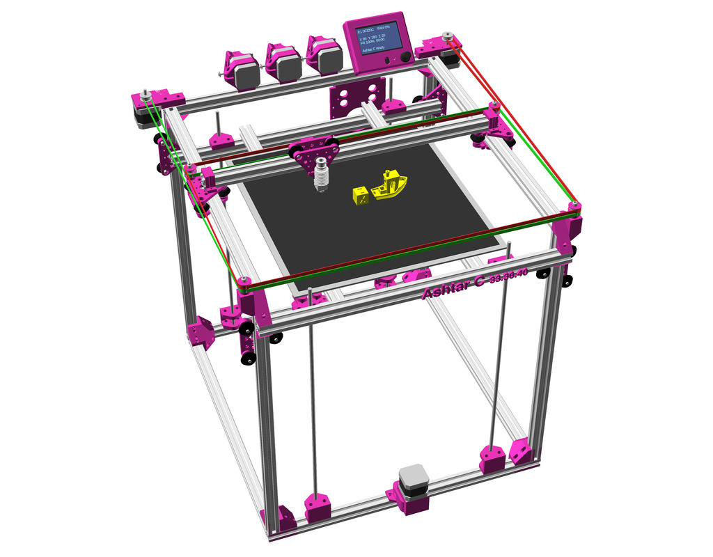
2021/01/10: Finally more detailed and complete renderings with routed belts
2019/05/04: Dual Z + Dual Extruder for MKS Gen L for Chimera/Cyclops hotend
2019/02/08: Added “Maintenance” with first few points what’s important on this Core XY setup, up-to-date OpenSCAD model renderings
2019/01/31: First prints successful, Z axis redone with 2x Z motors with 2x 760 mm closed loop GT2 belts
2019/01/01: CoreXY mechanism complete: belt routing finalized and Marlin firmware configured, brief “preflight” video (no extrusion yet)
2018/12/08: Parts delayed, so development delayed as well, A/B motors installed and Bowden extruder, “Current State” photos uploaded
2018/11/09: Main frame setup with basic belt routing with mockup stepper motor.
2018/10/03: Dedicated corner bracket cci_2020() OpenSCAD module, first scaffolding the frame with printed parts
2018/09/10: First draft, fully parametric approach, detailed routing of belts not yet done (most important)
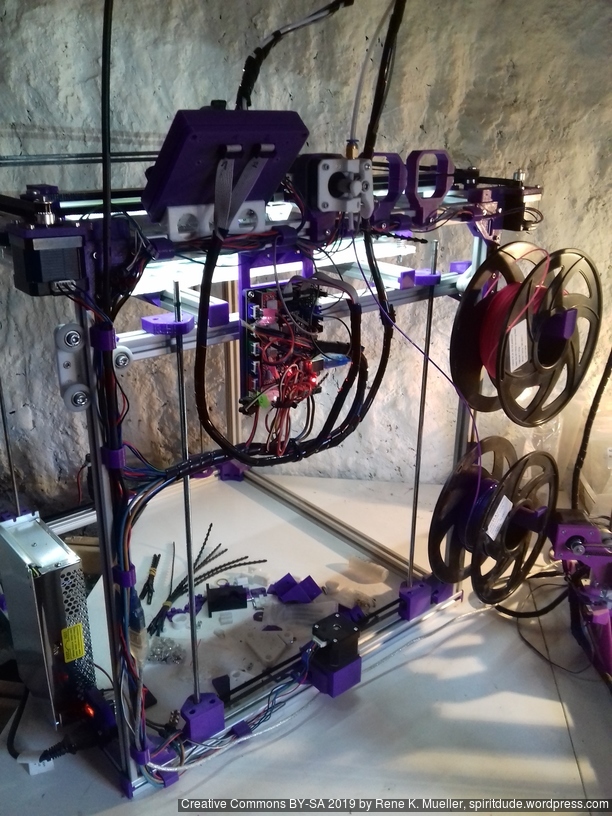
Current State
2022/08/01: corner pieces redone, high quality belts
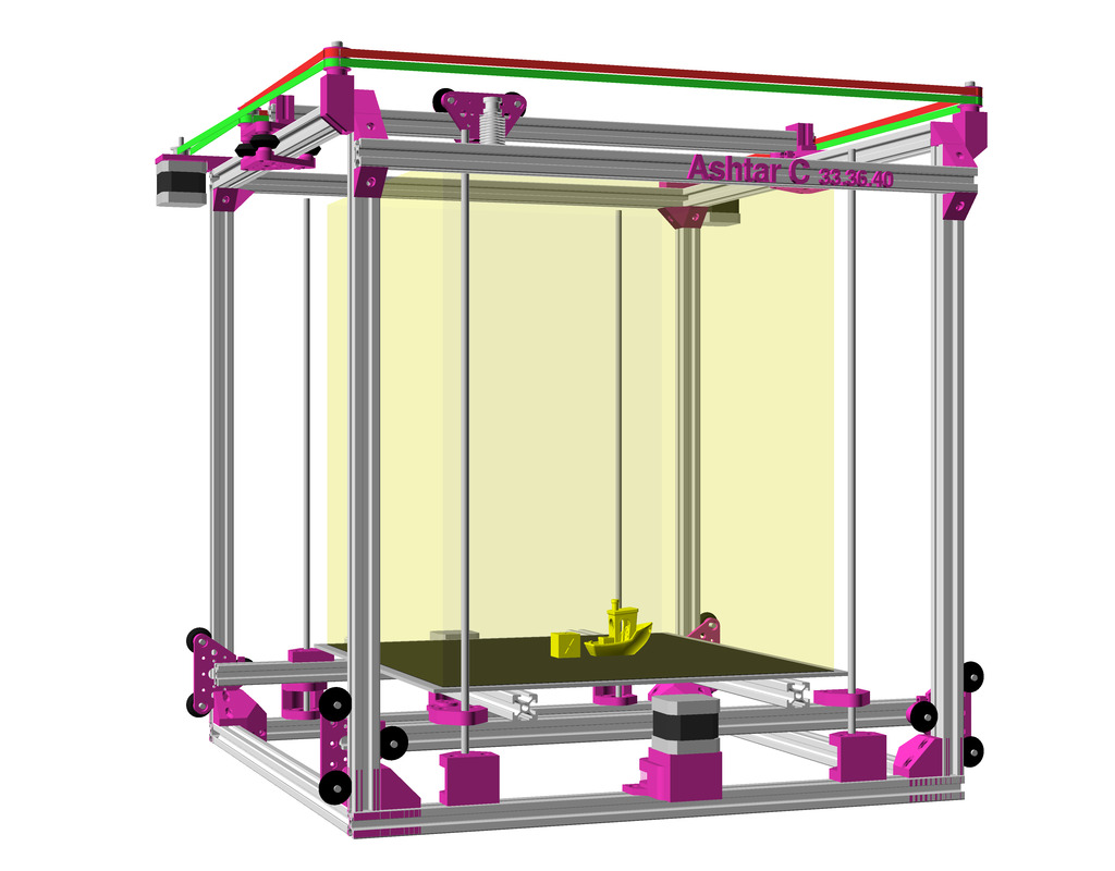
Introduction
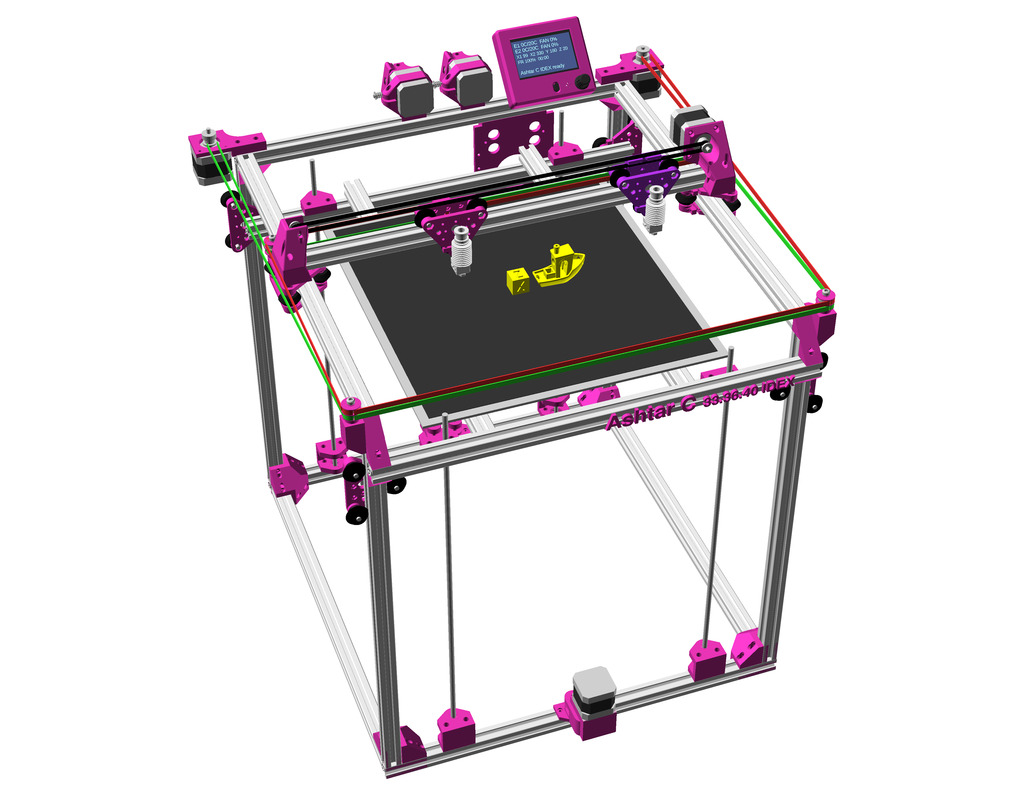
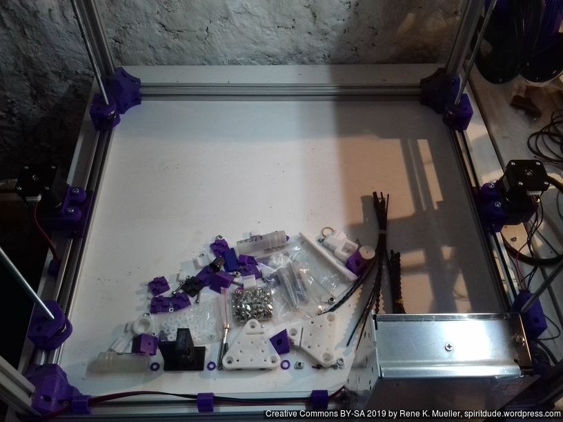
After Ashtar K(Prusa i3-like), I thought to still use single size 2020 T slot 6 (B-Type) alu extrusions to compose CoreXY styled 3d printer, fully parametric designed:
As first study shows, while trying to develop a single sized beam design: 16x beams make up the main geometry including bed mount, plus the X gantry which has to be shorter to lie between the top Y beams (if it sits above the belts also have to be routed above, and Y axis V modules and X axis V module not being on the same plane) and I used the same beam for the X beam where the X carriage rides the same length, using the Z offset to my advantage (instead to shorten it and fit it between the Y carriages): 17x 500mm alu extrusions (14x T slot and 3x V slot for X and 2x Y).
V modules with different kind of wheels.
So far I like to reuse the V modules to ride on the alu extrusions directly, that is X, Y and Z axis.
The Z axis details aren’t defined yet, I tend toward belt implementation, which is a bit more overhead than thread or lead screw implementation. The Z axis is done with 2 stepper motor driving each 2x threaded M6 rods (or lead screws optionally).
Specifications
CoreXY style
~385 x 400 x 380mm build volume (300×300 or 300×400 or 400×400 build plate)
500 x 520 x 520mm frame size with
14x 500mm 2020 T slot alu extrusion
3x 500mm 2020 V (or T slot as well) alu extrusion
Bowden setup for fast X/Y movement and fast printing therefore
MKS Gen L main board + Smart Full Graphic display (with dialer)
Reprap style with many parts to be printed
M3: assemble most parts
M5: idlers of A/B belts
M6: Z axis threaded rods
Electronics
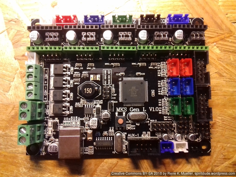
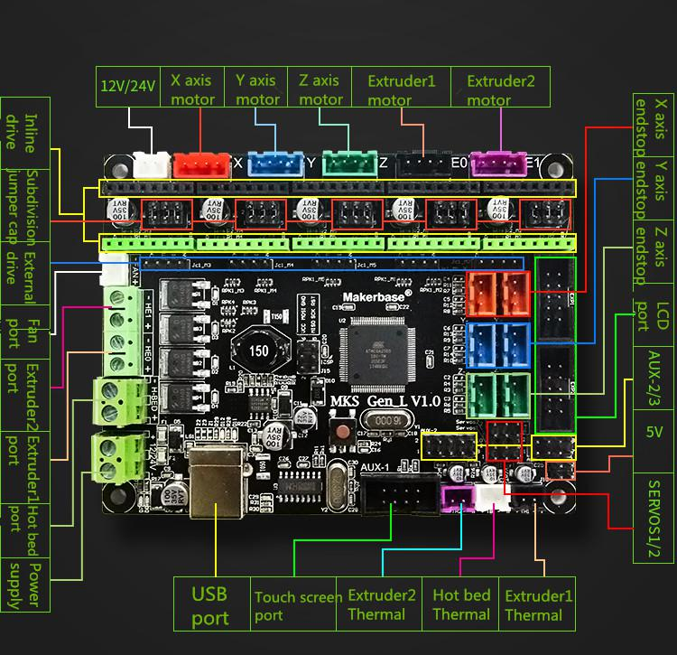
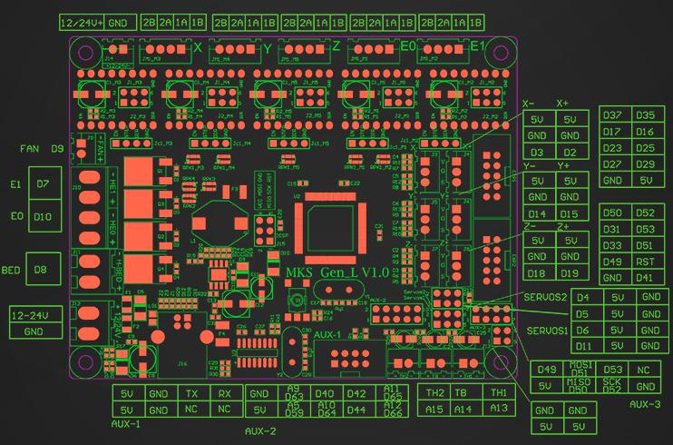
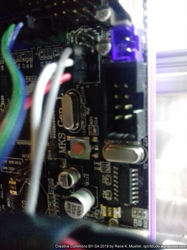
For Ashtar C #1 I use the MKS Gen L V1.0 board:
MKS Gen L V1.0 Controller BoardMKS Gen L V1.0 Controller Board Connectors
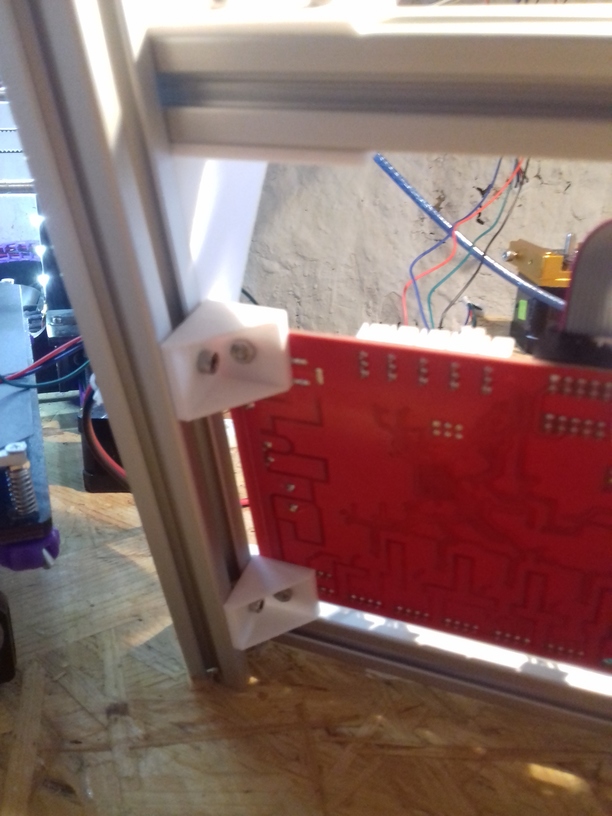
In order to add the RepRap Discount Full Graphics Controller I had to remove the notches and rotate EXP1 and EXP2 by 180 degrees so the display would work. I gonna use 5x A4988 as stepper motor drivers.
Update 2022/09 using MKS Monster8 V1.0 running Marlin 2.0x (requires PlatformIO to compile) with 8x TMC2209 motor drivers, MKS Mini 12864 V3 display (EUR 58):
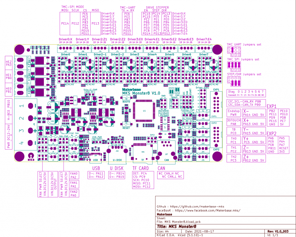
MKS Monster8 (2022)MKS Monster8 Pinout
One has to use SDcard to put firmware on and reboot the board in order to install the firmware, there are firmware uploaders available just not for Linux.
With 8 motor drivers there are plenty extensions possible, especially the Z motor driver has two connectors (e.g. usually 2x Z motors, also in my case with CoreXY I use Z motors):
X, Y and Z(2): 3 drivers occupied
max 5 extruders
The board supports 3 independent hotends, so IDEX or even a 3x tool-changer possible with this board.
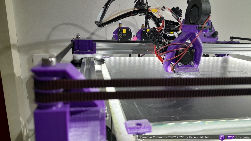
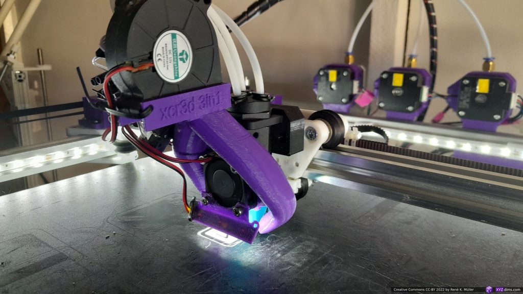
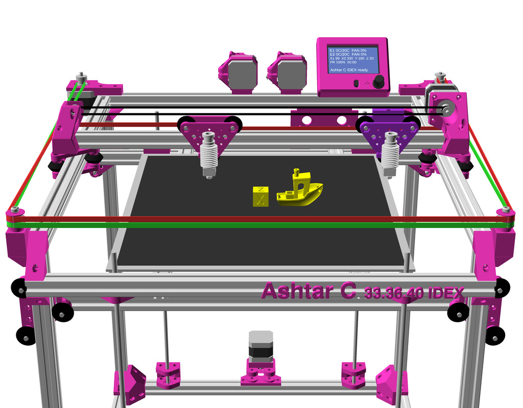
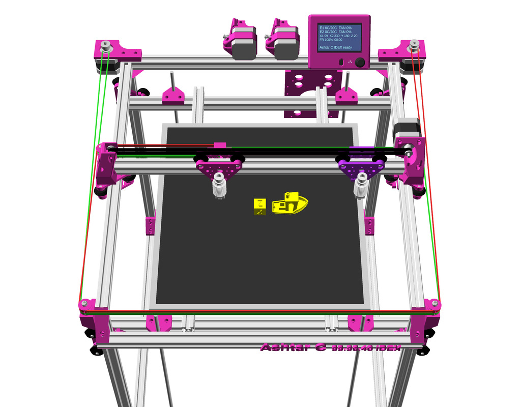
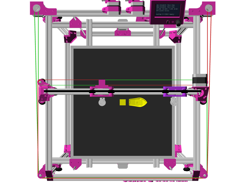
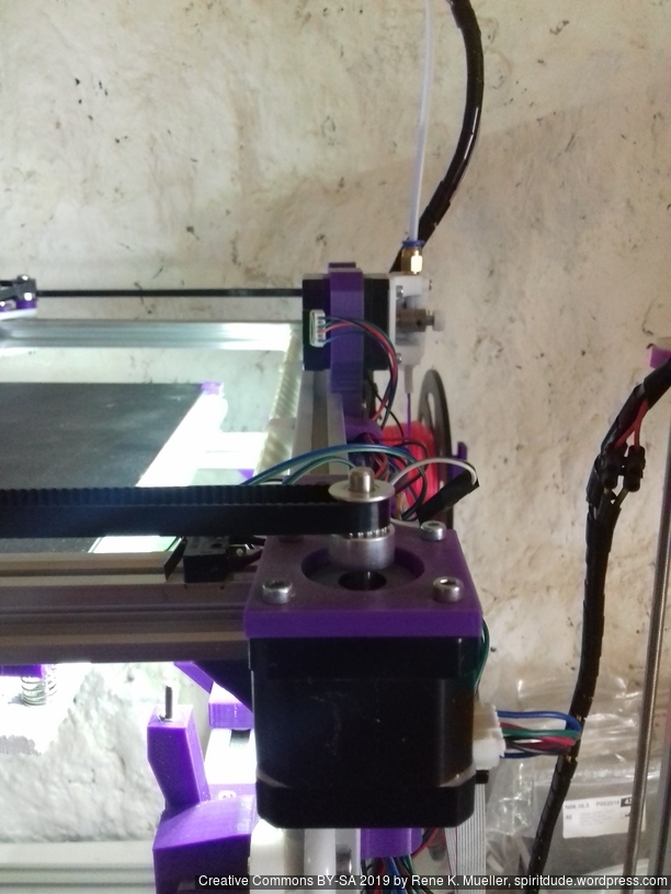
BigTreeTech ZSYong 3-in-1 with 3 materials/colors mounted on Ashtar C #1
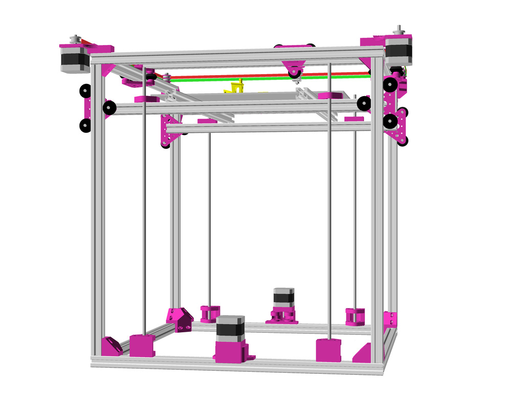
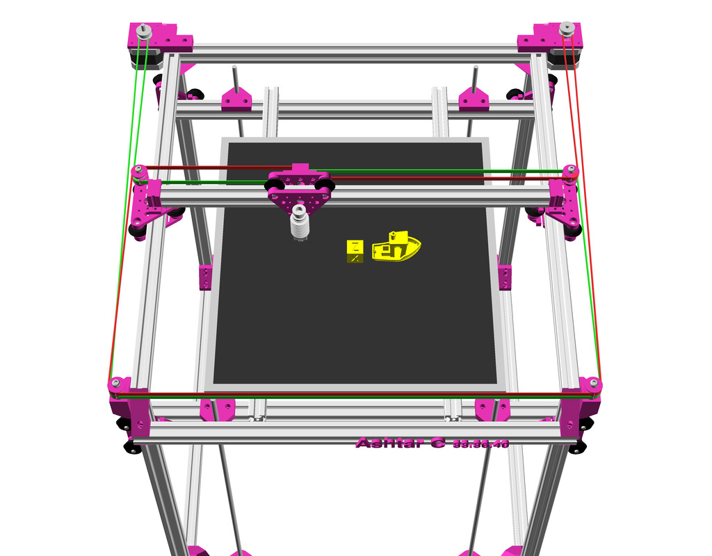
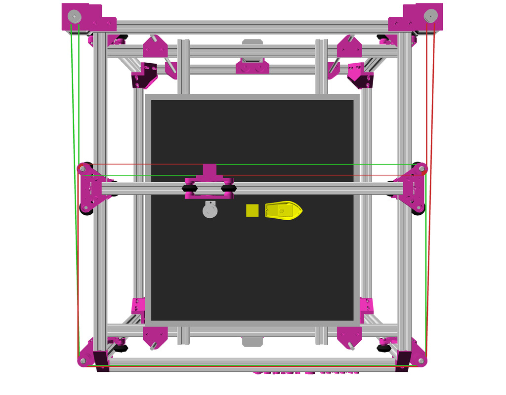
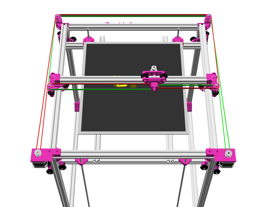
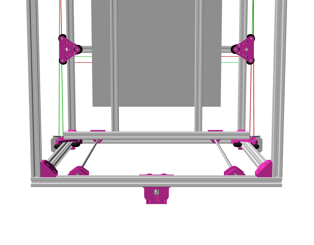
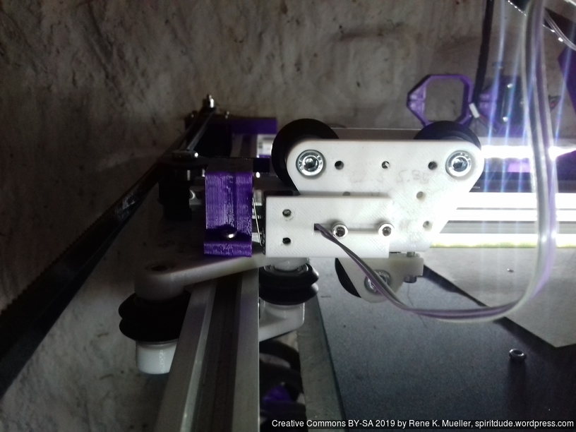
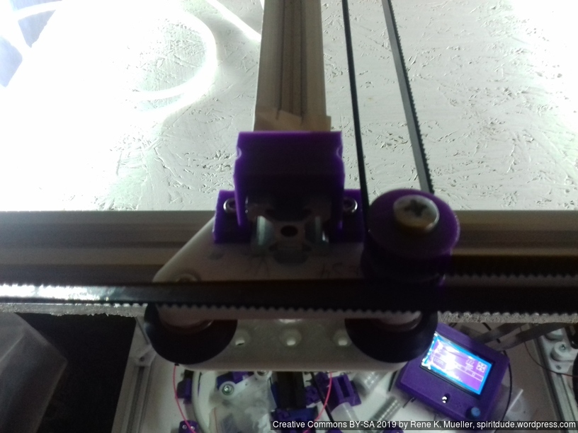
XY Belt Routing
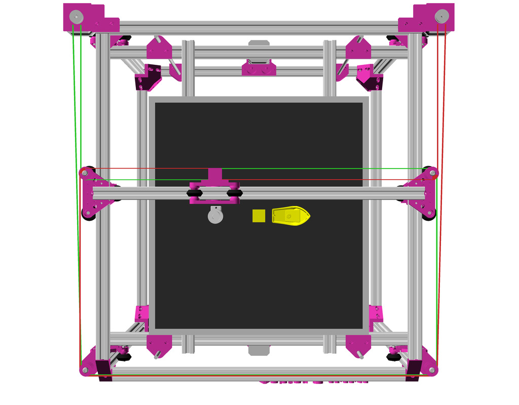
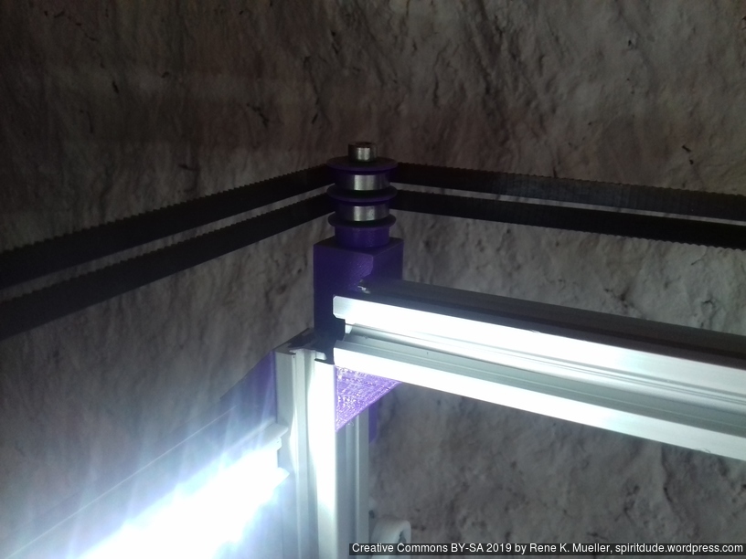
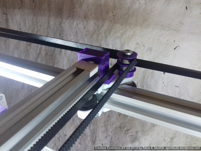
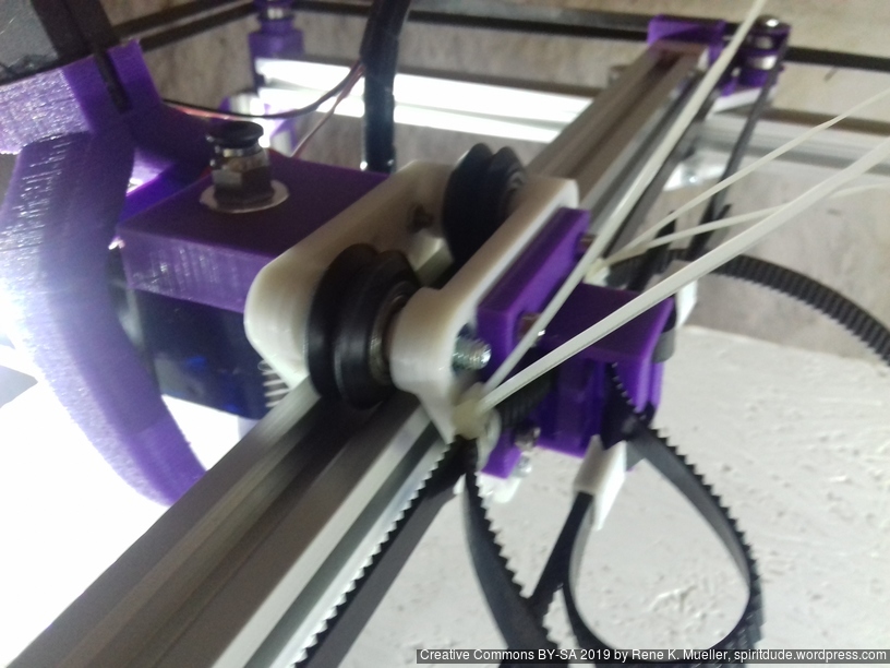
The XY belt routing of CoreXY is more complex than usual, I decided to separate A and B motor belts on the Z axis with two levels, and twist the belts once so the notches would not roll over the redirectional idlers (more detailed photos follow):
CoreXY belt routing of Ashtar C
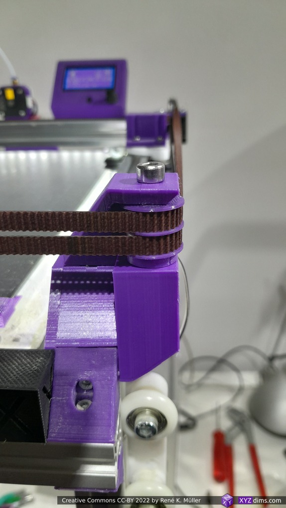
V1.0 corner (simple)V1.1 corner (stronger)
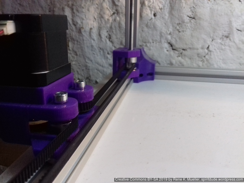
Key features:
V (3 wheels) shaped 2x Y carriages: v_plate(width=54), width=48 was too narrow as the belt would touch the X beam, to ride on 2x “Y” V slot extrusions
using one roller axis to extend for belt routing with 2 idlers made with 625ZZ bearings and a couple of printed washers
attaching belts on the back of the X carriage, very little space wasted
V (3 wheels) shaped X carriage: v_plate(width=48) narrow enough to achieve in X ~385mm range
stepper motors A & B at the back
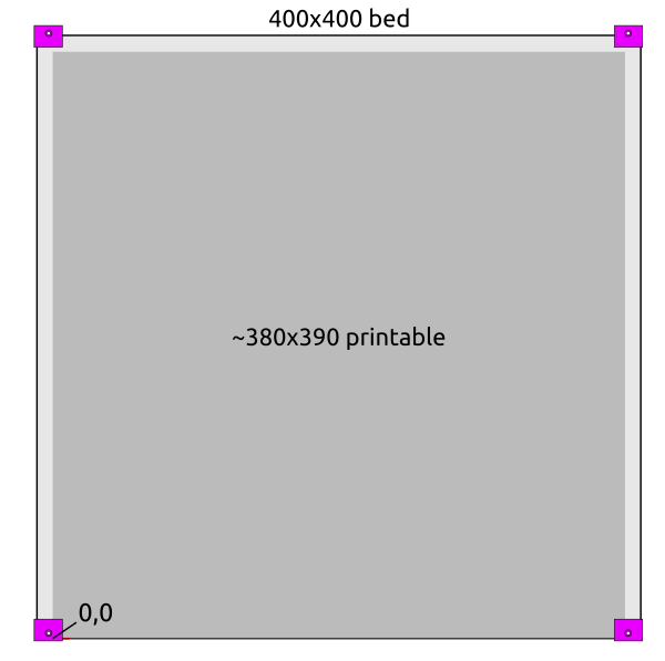
Bed
Alike with Ashtar K I used a mirror as main bed structure for Ashtar C:
400 x 400mm black bed sticker (~0.7mm thick)
400 x 400 x 4mm mirror (custom order)
4x bed corner mounts (printed), with M3 x 30 and spring and 4x washers each
420 x 420 x 4mm OSB
residing on 2020 T-slot alu extrusions.
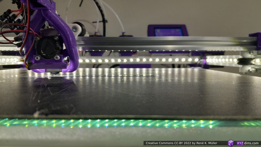
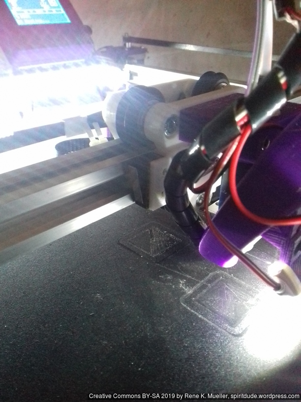
There are few millimeters in front in the left and right corner which cannot be printed on because of the bed mounts; at the back the nozzle won’t touch the bed mounts, but fan shrouds might – so one has to be aware of:
the X stop is at the left (X=0)
the Y stop is at the back (Y=390)
start of print at X = W/2 (e.g. 190), Y = -3, so the oozing of filament will be chopped when moving to the print position.
Z Axis
It took me some research and trial-and-error to determine Z axis in its details:
Option A
2x Nema17 (45Nm) stepper motor with 18 teeth GT2 pulley 5mm bore
2x 760mm closed belt
Option B
Using 3 or higher : 1 gear box (e.g. 3:1 gearbox could be used, but external shaft isn’t strong enough stabilized versus tilt) or alike to increase torque and still drive 4 threaded rods
Option C (not recommended)
1x Nema 17 (45Nm) stepper motor driving 4x M6 threaded rods with 1524mm long closed GT2 belt – even when well greased rods and well aligned, I still experienced occasional skipped steps, which made this option not reliable – so I switched to 2x closed loop belts Option A.
4x M6 x 490mm threaded rods
4x M6 nuts with bed mounts (printed)
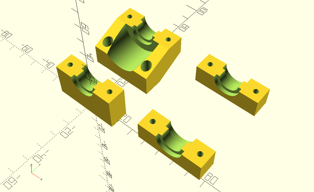
4x bottom Z rod mount (printed)
8x 606ZZ bearings (each rod has 2 bearings)
4x 18 teeth GT2 pulley 6mm bore
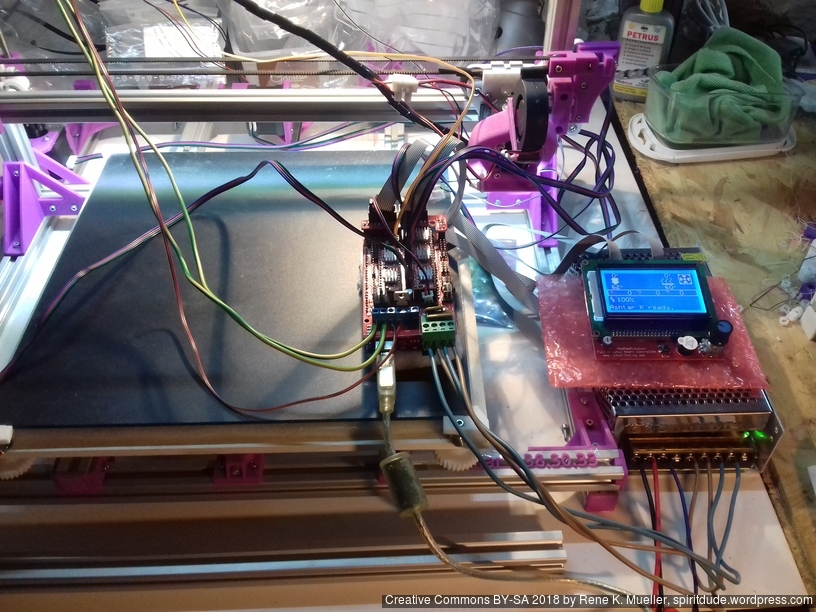
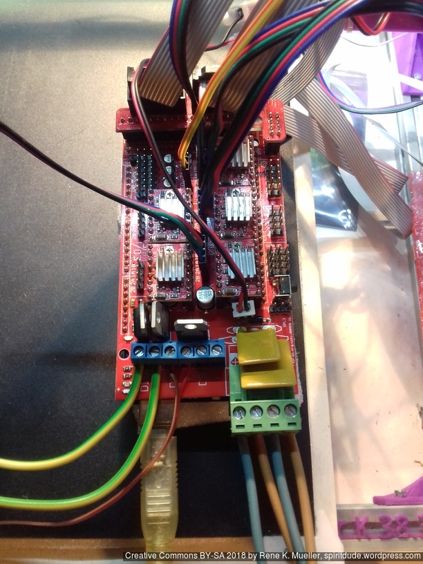
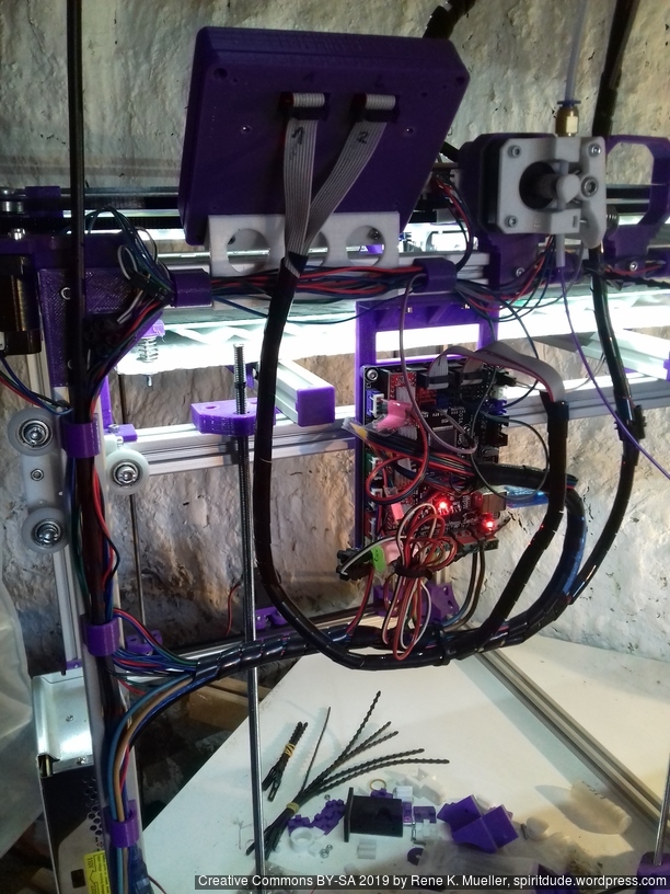
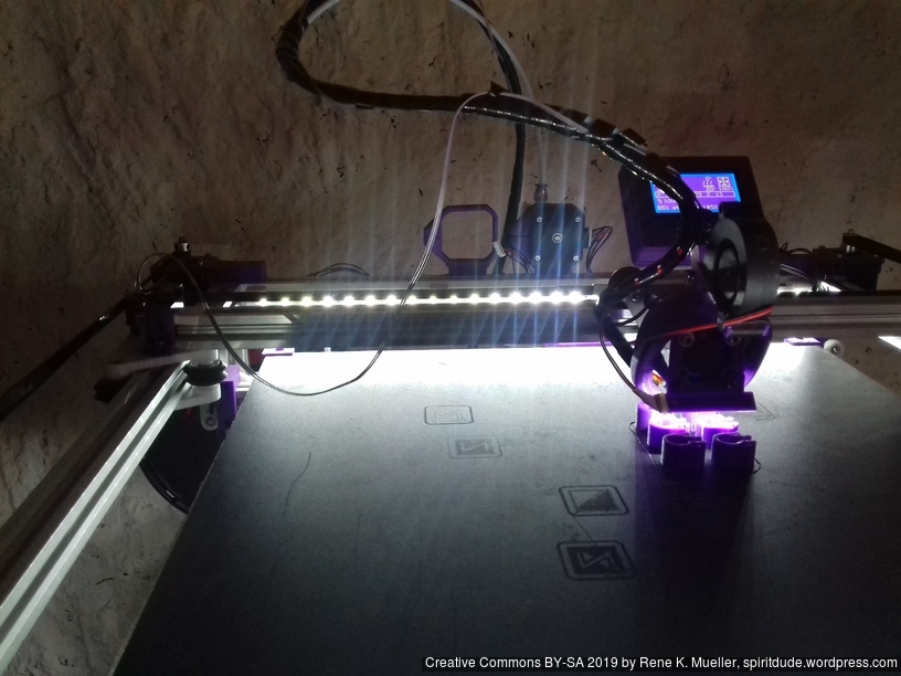
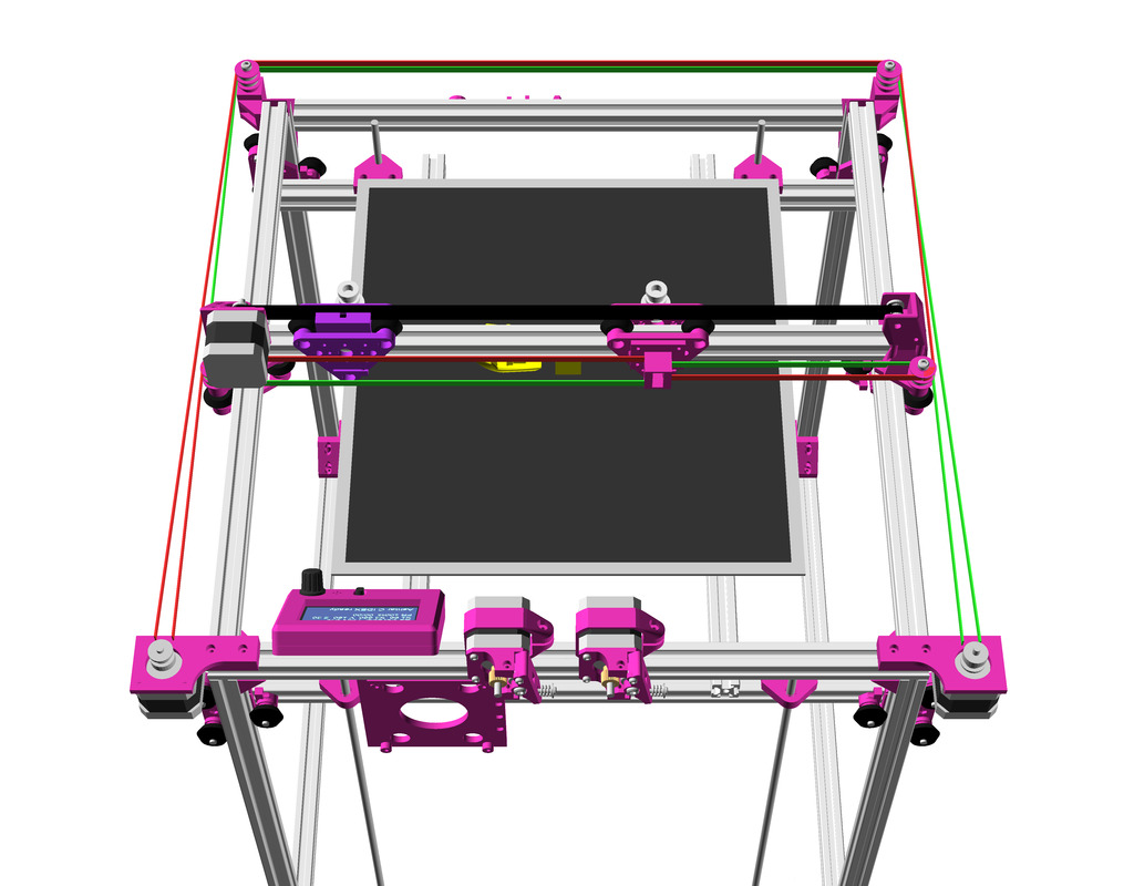
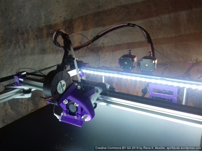
Electrical Wiring
I positioned the main controller board near the A/B stepper motors and the extruder motors at the back of the cubic framework:
advantage: most cables remain short and can be well put together
disadvantage: controller box with display cable too short to mount it in front, so remains on the back as well
Firmware
I’m using Marlin 1.1.8 (for MKS Gen L1), following changes were required
stepper motors A & B reside on the back, left-front will be 0,0
X direction was reversed
Y direction was correct
It was quite complicate to reverse X, as #define INVERT_X_DIR true was not doing it, but just reverse the motor direction, which in CoreXY also affects Y. Solution was, after some back and forth trying #define COREYX as well and failing, was to swap cables of A/B motors and
Configuration.h
#define COREXY
#define INVERT_X_DIR true
#define INVERT_Y_DIR true
Further, Z axis is driven by 2x Z motors, as driven 3 or 4 threaded rods with a single motors lead to various missing steps, so 2x Z motors with MKS Gen L controller board:
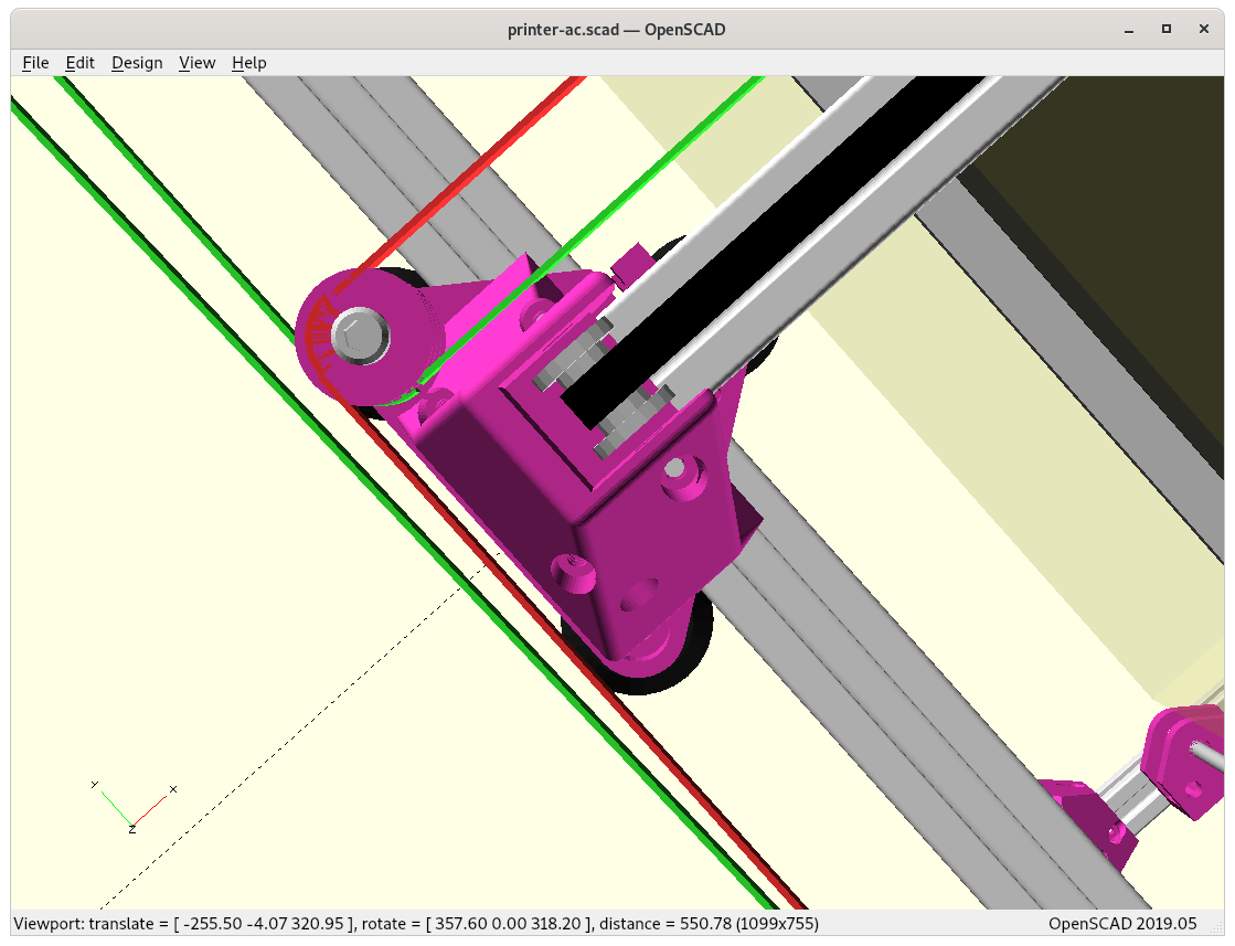
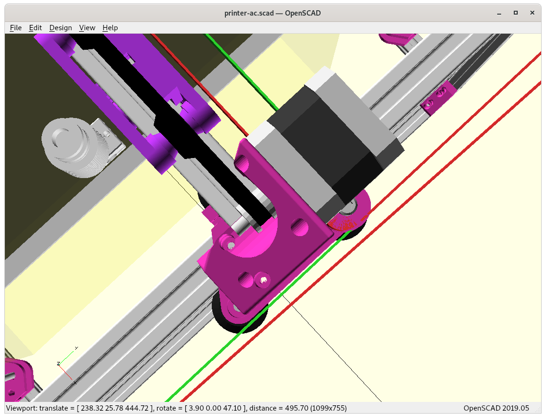
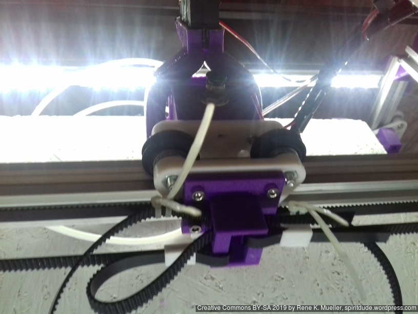
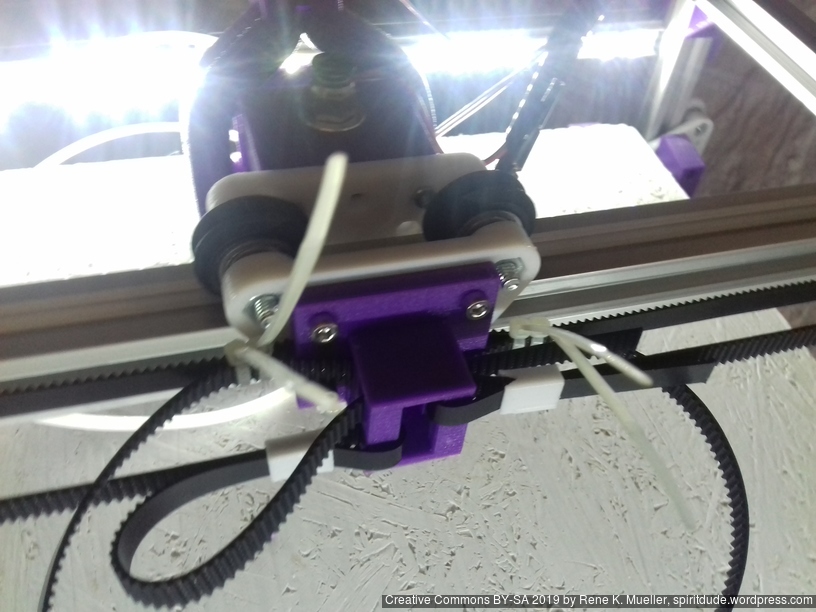
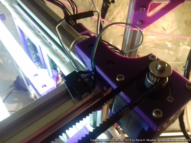
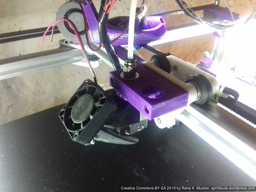
First I had the X stopper at the left-hand side of the X beam (Photo 3), but the cable entangled with other parts, so I moved the X stopper on the X carriage (Photo 1 & 2)
X stopper on the X carriageMounting X stopper on X carriageX stopper on X beam (not recommended)
X stopper: on the X carriage
Y stopper: right-hand back side of the main frame
Z stopper: right-hand back side of the main frame
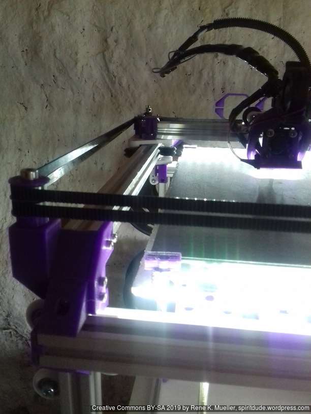
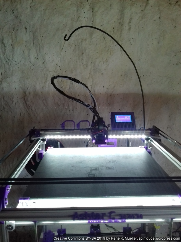
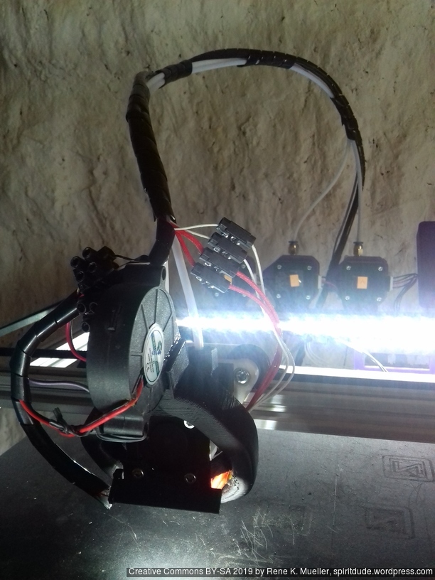
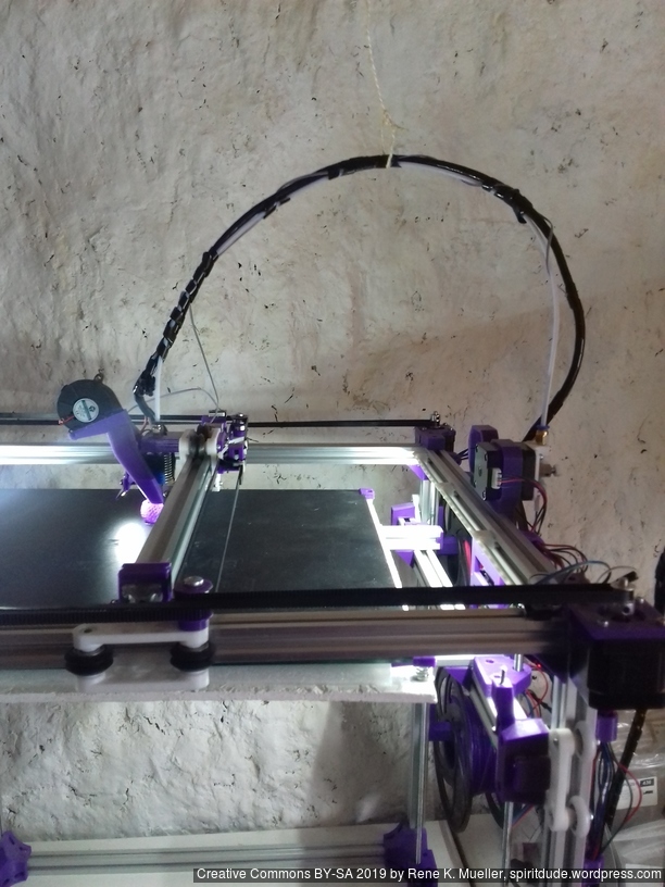
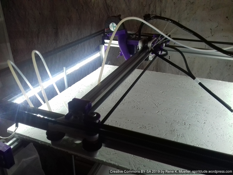
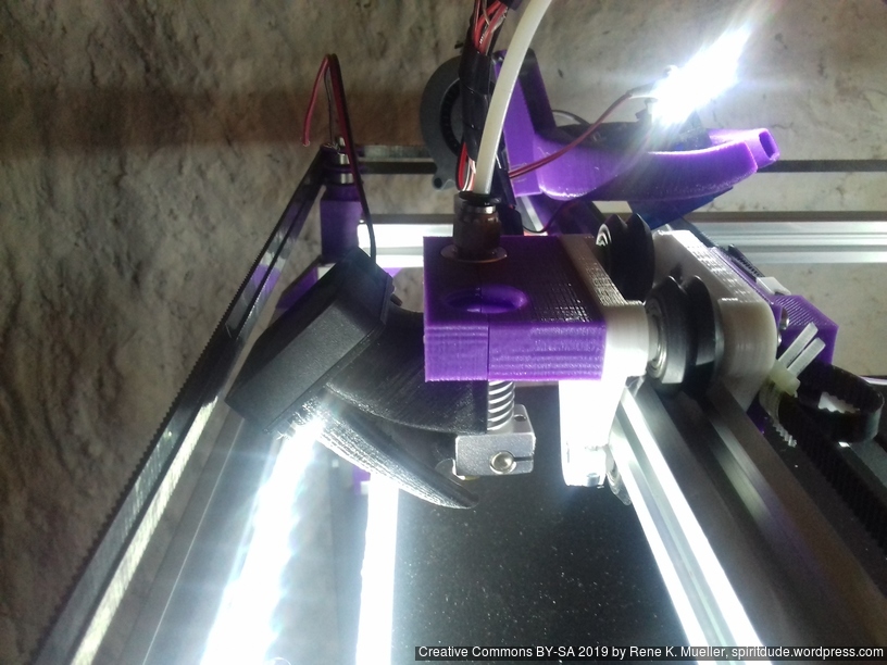
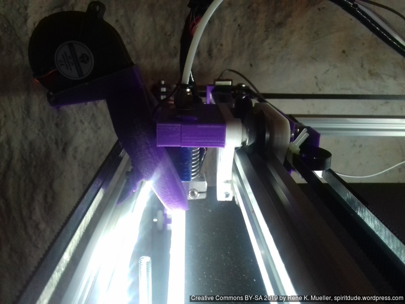
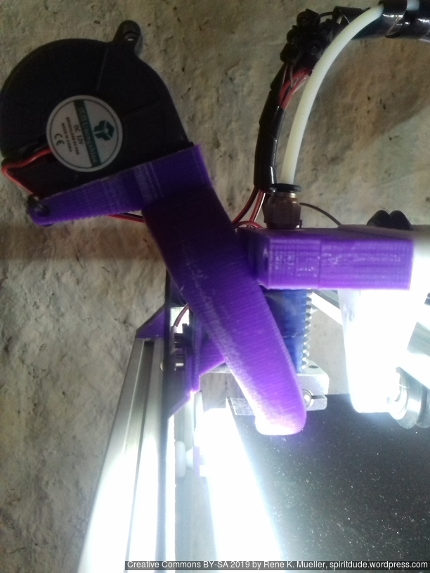
The PTFE 4mm OD / 2mm ID with the cables aren’t stiff enough to support themselves, so I added
Option A: 4mm insulated copper wire as a gantry to keep the cables from falling on the print bed.
Option B: strong plastic bundler near extruder to stiffen part of the cables/tubes.
Option A: thick wire as gantryOption B: stiffen with additional cable bundler
Maintenance
Belt Tension of Core XY
The Core XY mechanism takes some further care:
Parallelism: with the stepper motors off I move the carriage to the front and make sure both carriages of Y axis have the same distance to the end – if not, I tensioned the longer belt so both distances are the same = parallel to front beam.
Missing Steps: I noticed once I tensioned belts to achieve parallelism that the belts got harder to run, and eventually at larger prints with fast and longer positioning movements near 120mm/s I was missing steps in X and/or Y and caused failed prints quickly – so I loosened A/B belts equally to maintain parallelism.
So, there is some learning and experiences required to determine the best equal tension of belt A and B.
Update 2022: I’ve used GATES-LL-2GT belts which resolved all the previous problems with parallelism, as slightly stretching belts caused all kinds of geometrical inaccuracies.
Stiffness of Frame
At first the frame wasn’t as sturdy as possible as the details were not yet determined, but with maturing and defining the details the edges of the frames became more sturdy and the noise of the operational printer increased; yet, the print quality increased significantly. Further, since many parts are printed in PLA, they require re-fastening after few days as PLA gives in under tension, in particular all the edge fastening parts, which as well improved print quality.
Update 2022: I made the corner pieces stronger, to avoid any bending there:
I use M6 x 500mm threaded rods for the Z axis, because they give 1.0mm way per revolution, given 1.8 degree per motor step or 200 steps per revolution, with 16 microsteps there are 3200 microsteps per revolution which gives 0.3um per microstep or 5um per step. Using M8 or M6 for Z axis has a bad reputation in Prusa i3 setup, something I only partially agree with, gives in my setup of Ashtar C no little Z wobble, but it may have introduced some slight non-linearity within the 1mm way which isn’t observable for me. Lead screws would provide excellent linearity but less resolution due higher pitch, often 8mm per revolution, or 40um per step.
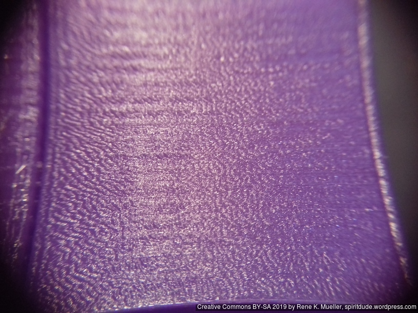
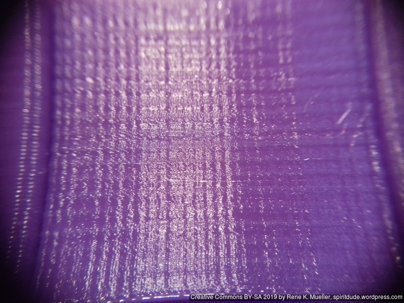
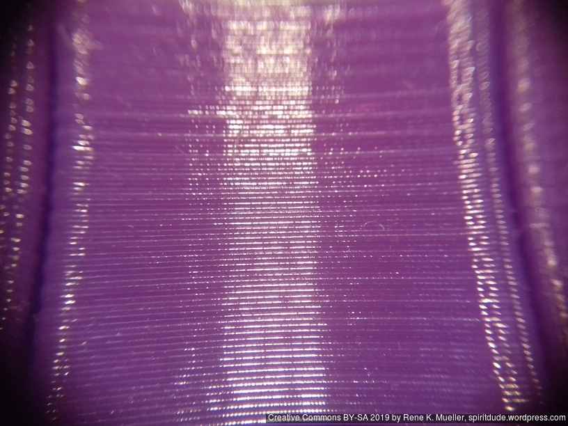
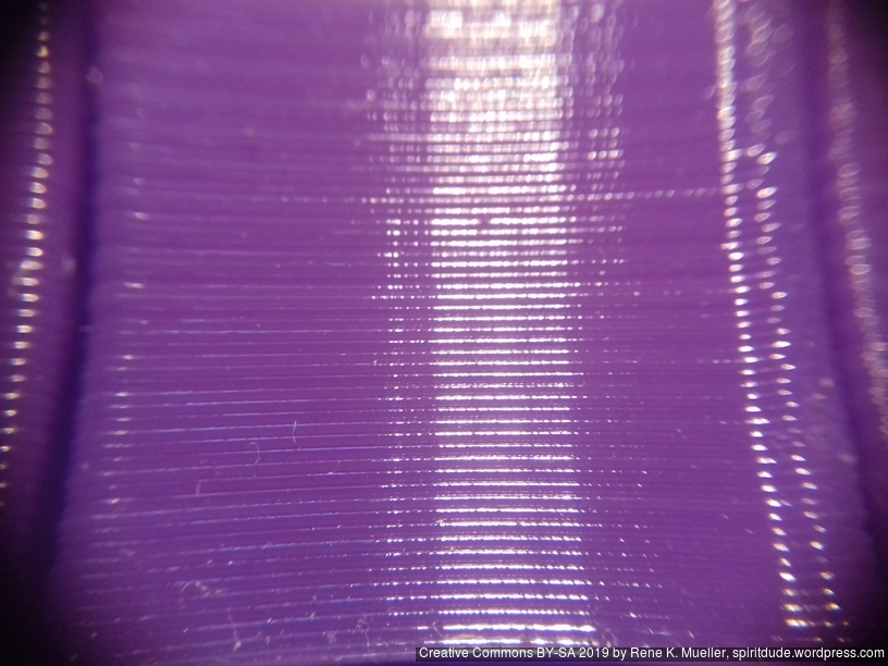
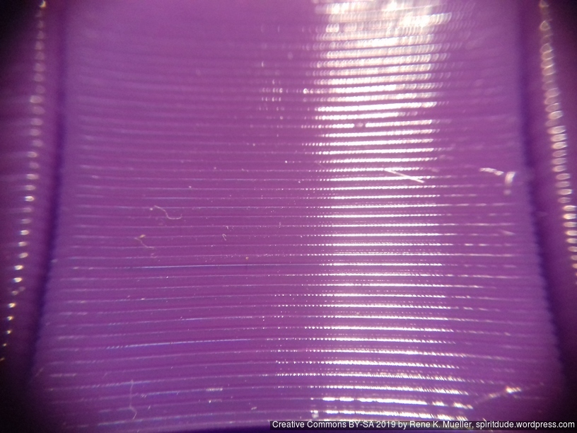
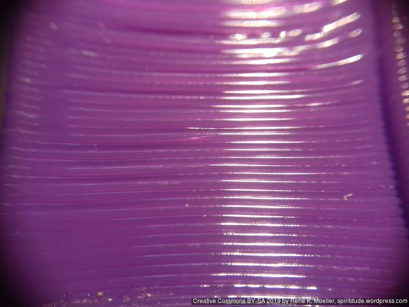
25um (0.025mm) layer height with 0.4mm nozzle50um (0.050mm) layer height with 0.4mm nozzle250um (0.25mm) layer height with 0.4mm nozzle350um (0.35mm) layer height with 0.4mm nozzle450um (0.450mm) layer height with 0.4mm nozzle500um (0.500mm) layer height with 0.4mm nozzle
In my early test, when I ran one stepper motor driving 4 well greased rods for the Z axis, I experienced eventual missing steps due the distributed friction at multiple spots (nut/threaded-rod, threaded-rod/pulley/bearing, etc), and few days in, even more. As a result I used two stepper motors each driving two threaded rods for the Z axis.
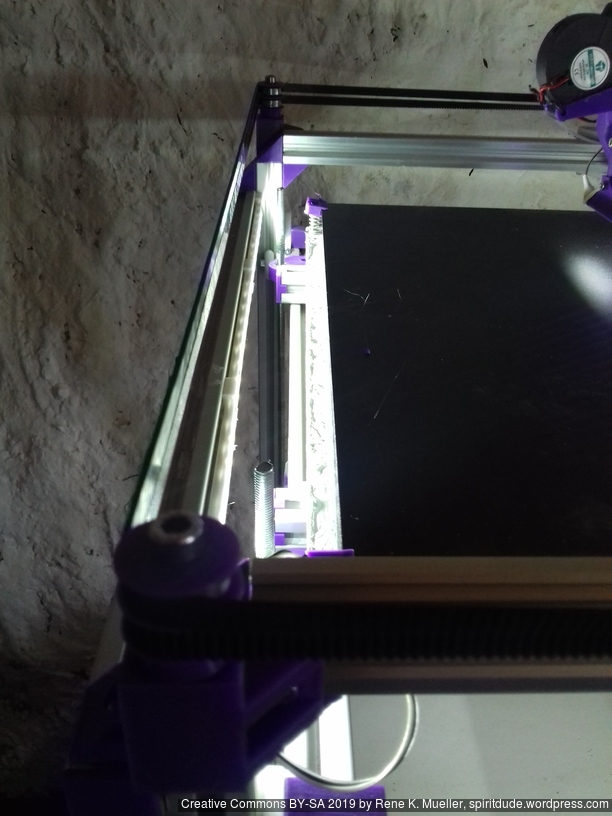
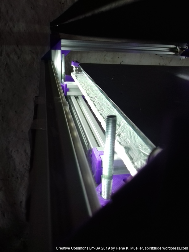
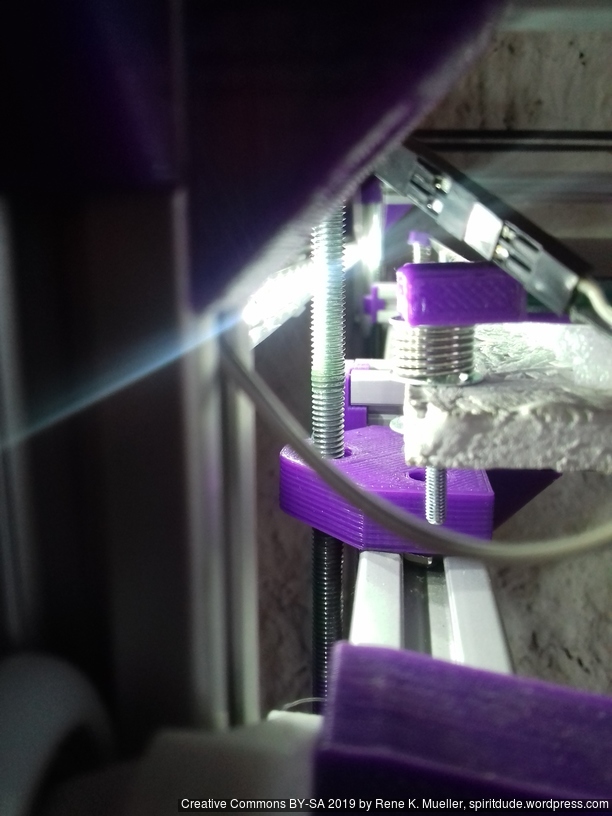
Fixing Z Wobble
Left: 1 out of 4 Z rods tilted; Right: 4 Z rods mostly aligned
While replacing the M6 x 500mm threaded zinc rods with stainless steel ones I noticed that I introduced severe Z wobble, which wasn’t there with lower quality M6 threaded rods – odd enough – and I moved the bed to Z=380 and noticed one rod swinging around due slightly titled rod, and reopen the GT2 pulley on the bottom with that rod, and turned the rod slightly and refasten the GT2 pulley again, the difference is significant: the wobble is nearly gone.
Update 2022: one of the key to resolve wobble is to keep the closed loop belts not too tight, otherwise their un-eveneness translates to the bed – keeping it a bit soft resolves it.
I may use 4x 8mm lead screws as a test as well and see how it performs regarding wobble but also resolution.
Todo
Z axis details (belt vs lead screw vs threaded rod)
1 Z motor with closed loop belt: 1, 2, 3 or 4 threaded rods/leadscrews
2 Z motors with/out closed loop belt: 2 or 4 threaded rods/leadscrews
details of belt redirection idler mounts
moving X endstop to X carriage itself (avoid cable entanglements)
stiffen or stabilize X carriage cables and Bowden tube
controller box positioning
release sources
complete instructions
list all parts properly
Parts
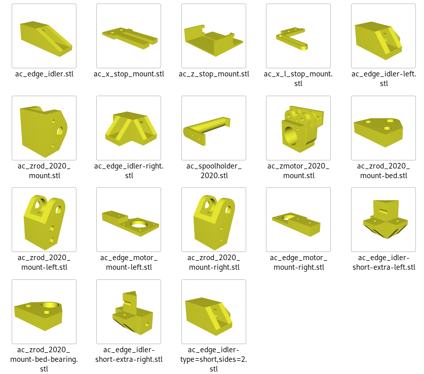
Printed Parts
Not yet defined, reusing most of Ashtar K 2020 parts plus some Ashtar C specifics.
Frame
4x cci_2020 (bottom corner brackets)
2x cci_2020-type=idler2 (top front corner brackets)
2x cci_2020-type=motor (top back corner brackets)
X/Y
1x ac_edge_motor_mount-left
1x ac_edge_motor_mount-right
Z
2x ac_motor_2020_mount
2x ac_zrod_2020_mount-left
2x ac_zrod_2020_mount-right
4x ac_zrod_2020_mount-bed
Axis Modules
1x X Module with black 3 x OpenWheels 24.4/11 on T slot 6 or V slot 6
1x v_plate-2020-double-v-244-110-54w-a
1x v_plate-2020-double-v-244-110-54w-b
1x ac_x_l_stop_mount
1x ac_x_stop_mount
2x Y Modules each with black 3 x OpenWheels 24.4/11 on T slot 6 or V slot 6
1x v_plate-2020-double-v-244-110-48w-a
1x v_plate-2020-double-v-244-110-48w-b
4x Z Modules each with white 3 x Delrin wheels 23.0/7.3 on T slot 6
1x v_plate-2020-delrin-230-73-48w-a
1x v_plate-2020-delrin-230-73-48w-b
Misc
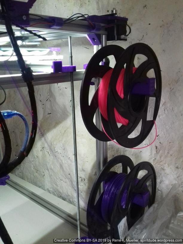
2-3x ac_spoolholder_2020
Non-Printed Parts (aka Vitamins)
Two Frame Options:
A: 16x 500mm T slot 6 (B-Type) 2020 alu extrusions + 1 x 440mm T slot 6 (B-Type) 2020 alu extrusion or
B: 14x 500mm T slot 6 2020 alu extrusion + 3 x 500mm V slot 6 2020 alu extrusions
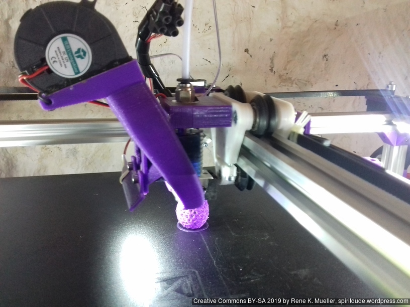
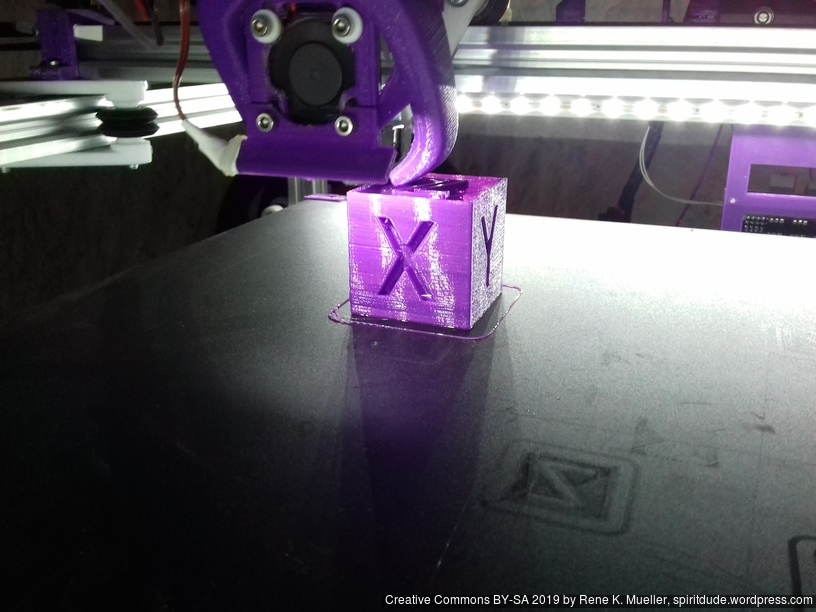
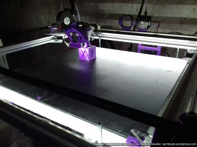
Example Prints
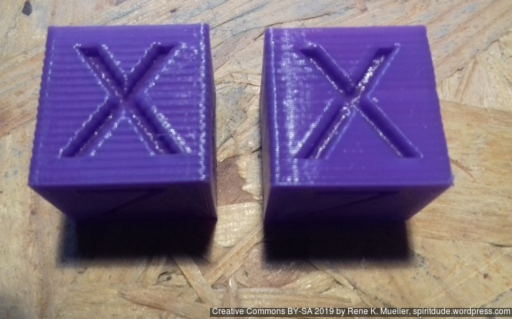
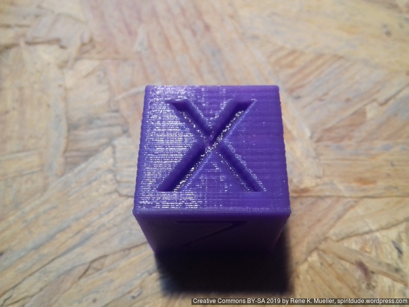
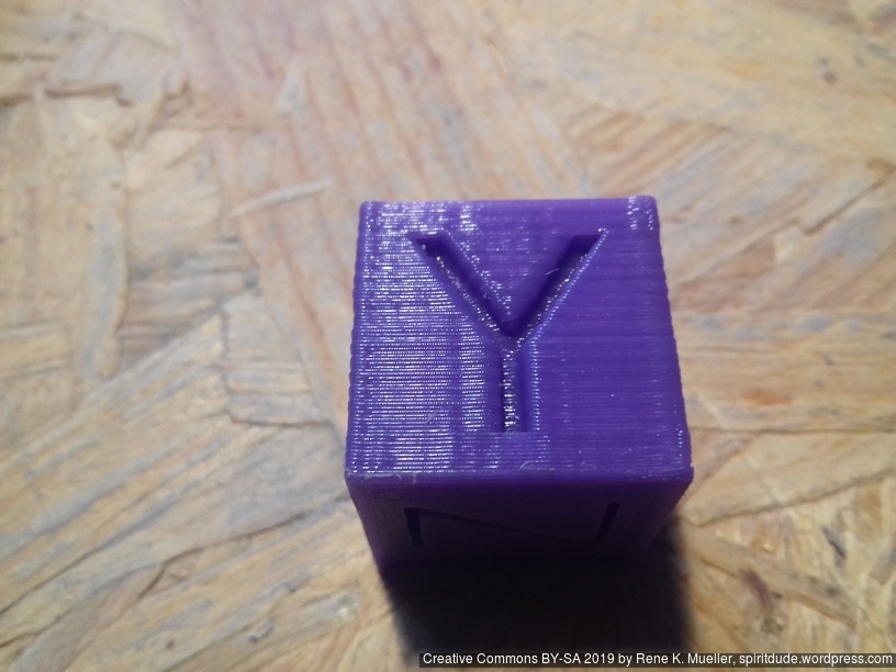
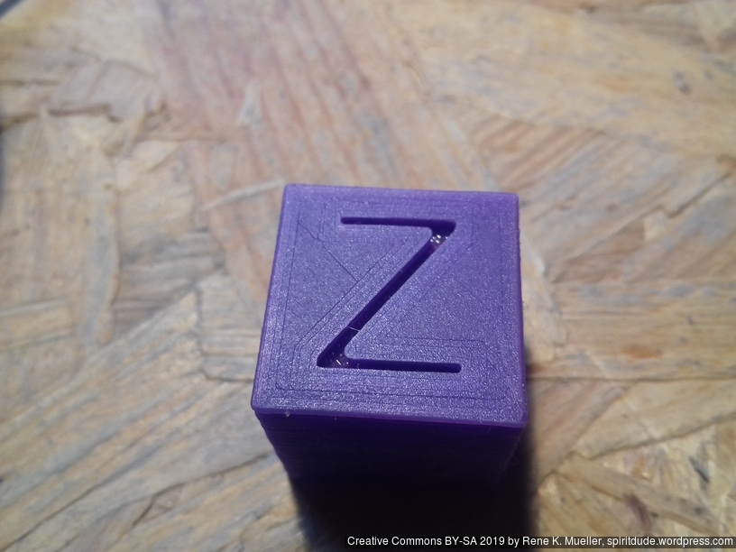
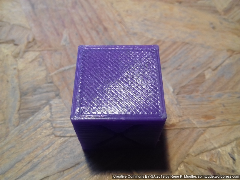
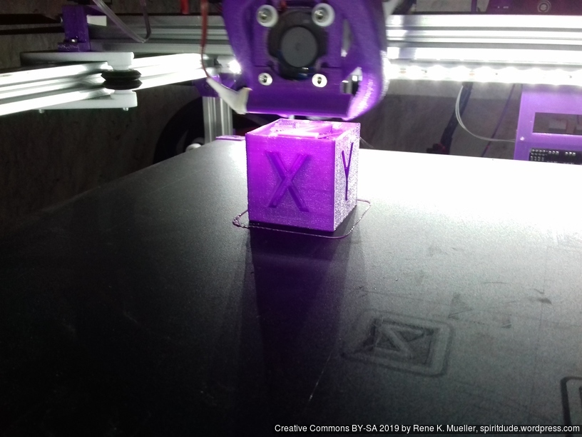
20mm Hollow Calibration Cube
Printed with 0.4mm nozzle at 0.25mm layer height, the “Z” at the bottom, first layer too thin a bit:
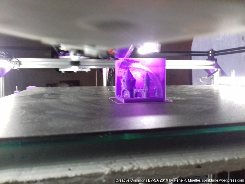
Castle 20mm Cube
200% scaled Castle 20mm Cube:
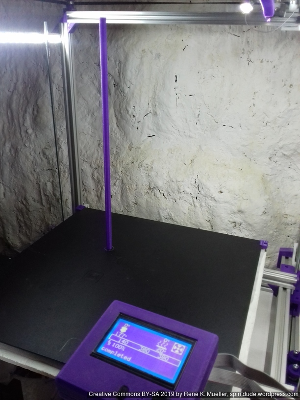
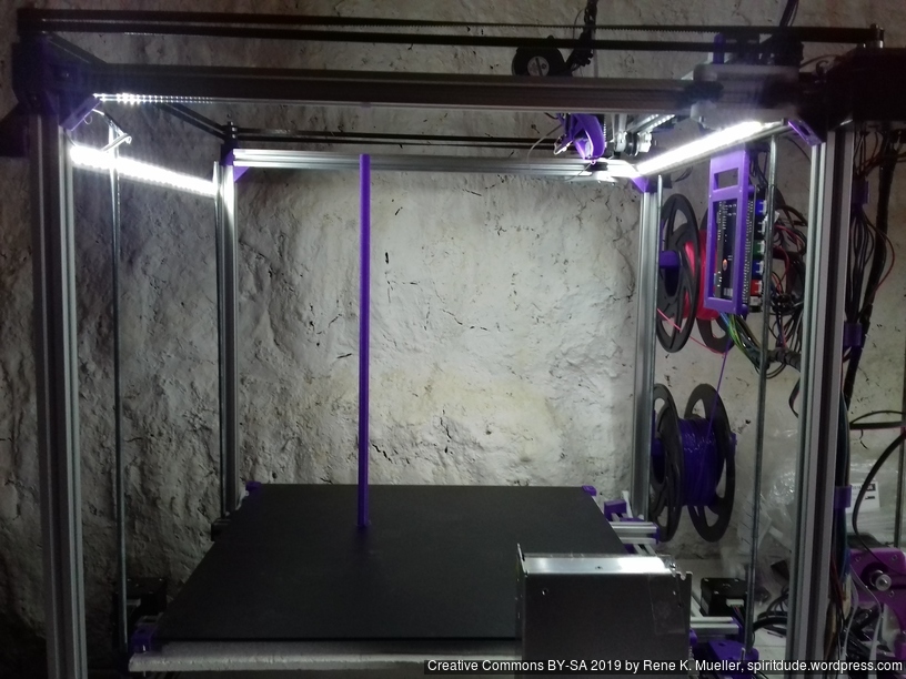
Tall Cylinder
380mm x 10mm hollow cylinder using full height of the printer:
Upgrades
Dual Z & Dual Extruder with MKS Gen L
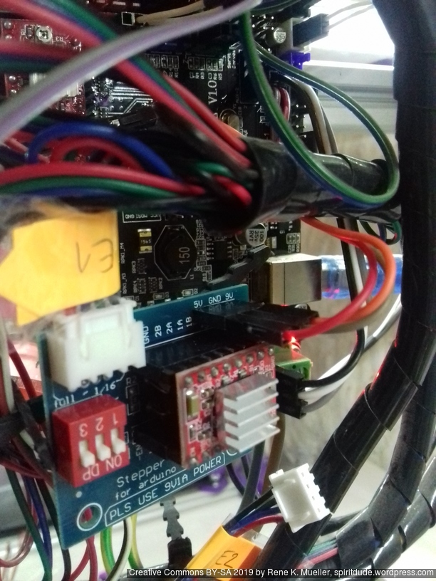
For the Chimera/Cyclops hotend with two filament but single heater and single or double nozzle, I added a stepper expander on AUX 2:
AUX2 / D64 – E1 STEP
AUX2 / D59 – E1 DIR
AUX2 / D63 – E1 ENABLE
and wired 5V, GND, 12V as well.
Additionally made following changes to Marlin 1.1.8:
Configuration.h
#define EXTRUDERS 2

#define SINGLENOZZLE
Configuration_adv.h
#define Z_DUAL_STEPPER_DRIVERS
pins_RAMPS.h
Comment out first E1_* and add Z2_* newly, and new E1_* below:
/*
#define E1_STEP_PIN 36 // this is E1
#define E1_DIR_PIN 34
#define E1_ENABLE_PIN 30
#define E1_CS_PIN 44
*/
#define Z2_STEP_PIN 36 // this is Z2
#define Z2_DIR_PIN 34
#define Z2_ENABLE_PIN 30
#define Z2_CS_PIN 44

#define E1_STEP_PIN 64 // E1 (2nd extruder) via stepper expander
#define E1_DIR_PIN 59
#define E1_ENABLE_PIN 63
The “Z_DUAL_STEPPER_DRIVERS” by default will use “E1_*” and interfere with 2nd extruder, hence the Z2_* definition helps to keep 2nd Z motor at “E1” motor on the MKS Gen L board, and in Marlin E1 is newly defined separately at AUX2 at D64/D59/D63.
To summarize:
MKS Gen L “Z” => Marlin “Z1”
MKS Gen L “E0” => Marlin “E0” (1st extruder)
MKS Gen L “E1” => Marlin “Z2”
MKS Gen L “AUX2”:D64/D59/D63 => Marlin “E1” (2nd extruder)
which then in Gcode the 2 extruders (E0 & E1) are referenced as T0 and T1.
Update 2022/09 I replaced MKS Gen L 1 with MKS Monster8 with 8 drivers, still running Marlin but its 2.0.x series, and since I have 8 drivers, and I possible can attach 5 extruders.
IDEX Option
The independent dual extrusion (IDEX) is an upgrade in draft state – means, it’s untested for now. It provides a 2nd extruder on the same X axis. As of 2021/01 there is only Duet RepRap firmware able to provide support for it as CoreXYU, whereas Marlin 2.x doesn’t provide support yet.
Right now I keep the up-to-date information on Ashtar C IDEX in this blog-post, once things actually are tested all the details will be documented in this document.
Note: The information is outdated as print3r natively supports networked printing, see 3D Printing: Print3r 2.x: Networked Printing (2019/02/27), but this information is still useful bridging USB to TCP in general.
Introduction
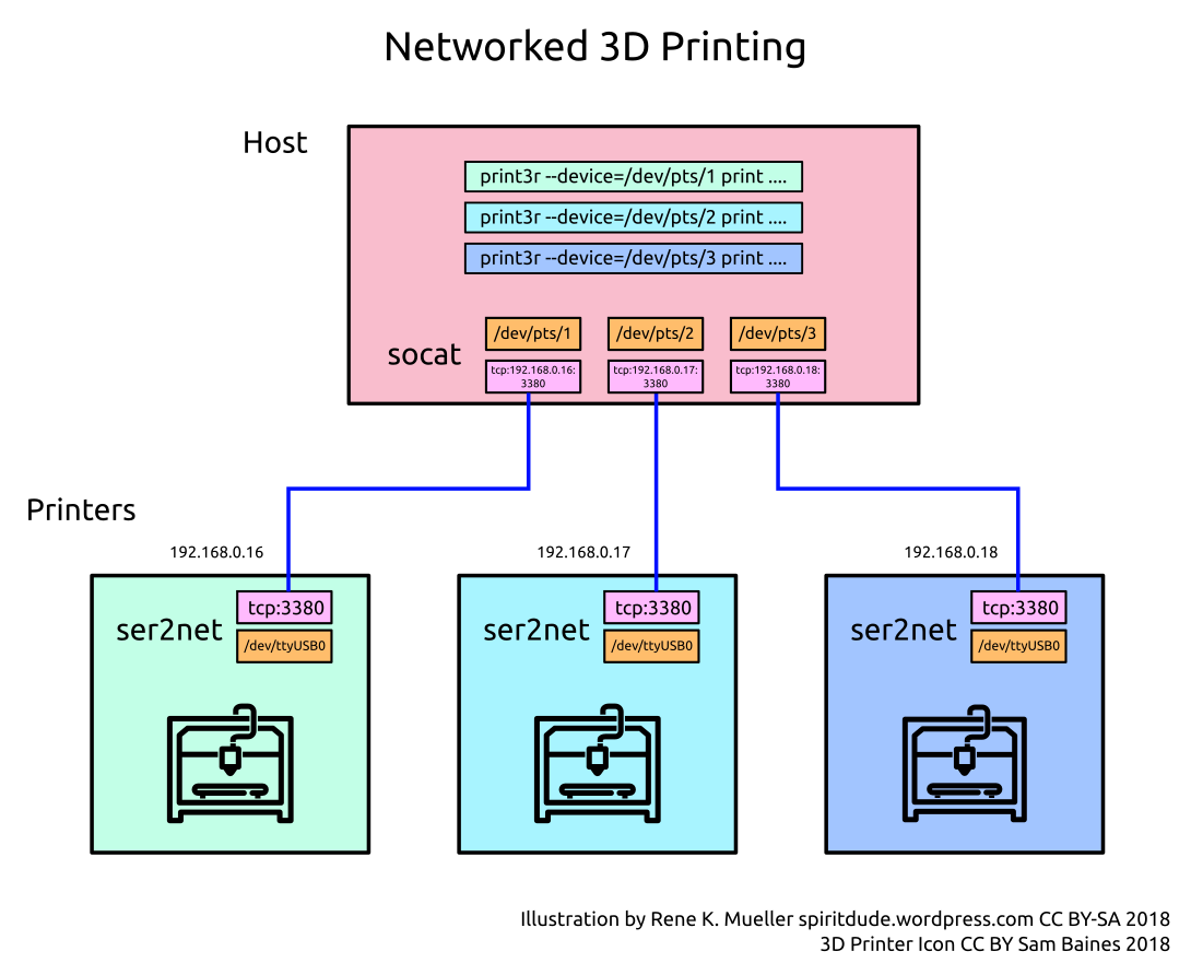
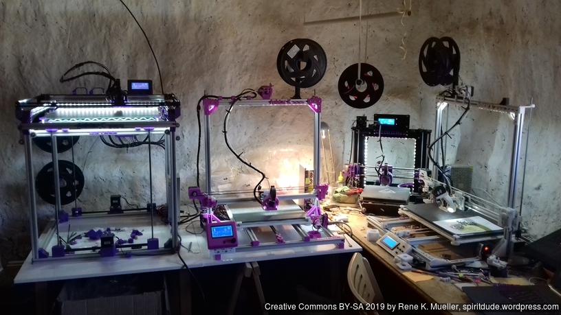
The moment you deal with more than one single 3d printer, but multiples – you want to access those with a single host: creating a cloud 3d printing facility.
After a few minutes researching the net for USB to network bridge, I realized the overhead to print via network is possible without Octoprint or some other solution, but simple ser2net and socat alone, thanks to this Github Issue by Marco E explaining his steps, so I reiterate his solution with some changes:
create USB to network bridge with ser2net per printer
create network to virtual serial per printer with socat on the host
Printers
Each printer you like to network has to have:
Linux OS (like Debian, Ubuntu or alike), e.g. Raspberry Pi or OrangePi or any kind of lowcost ARM-based board
USB connectivity where the 3d printer is wired
Wi-Fi (wireless) or Ethernet (wired) connectivity
Install
As next install ser2net serial to tcp bridge per printer:
% sudo apt install ser2net
Create a file named client.cfg, you may have to change the baudrate and/or the USB device:
3380:raw:600:/dev/ttyUSB0:115200 8DATABITS NONE 1STOPBIT -XONXOFF LOCAL -RTSCTS
Start ser2net on each printer:
% ser2net -c client.cfg
Host
As next prepare the host, where all the printers will be controlled from:
UNIX OS like Linux (Debian, Ubuntu, *BSD, macOS should work too)
2018/11/01: there is a slight drawback using ser2net: only takes common baudrates, but doesn’t support 250,000 which is the default baudrate for Marlin, 115,200 does work though. So, in case you plan to use ser2net reflash the firmware to use 115200 as baudrate.
Although 3d parts need to be seen and visually so much is communicated, but Cura’s user interface feels conceptually skewed (“Prepare” vs “Monitor” tab) – and with the time I thought I want an ordinary command line interface to print parts quickly, easily multiply and random placement so the bed surface is more evenly used and not just the center – I have grown tired to move parts on the virtual bed.
So, I wrote print3r, a command line interface which utilizes Slic3r as backend. Its main features (Version 0.0.6):
command line interface, no GUI
UNIX platform (Linux, *BSD, macOS should work too)
print .scad (OpenSCAD), .stl, .obj, .amf and .3mf directly
it converts and slices depending on file format as needed
takes Slic3r command line arguments
multiply part
random placement
scale, rotate, translate or mirror (.scad or .stl only for now)
slice .stl, .obj, .amf and .3mf to .gcode
print gcode files
send gcode lines direct from command line arguments
send interactively gcode commands from the console
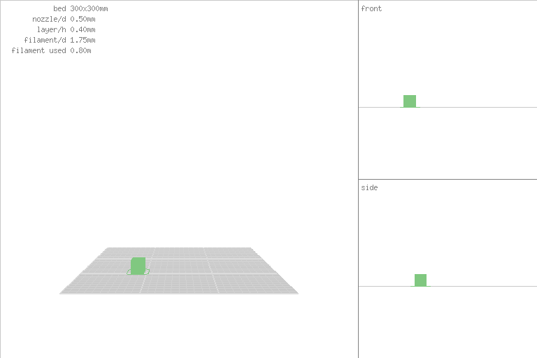
render .scad, .stl and .gcode to PNG for documentation purposes
Example
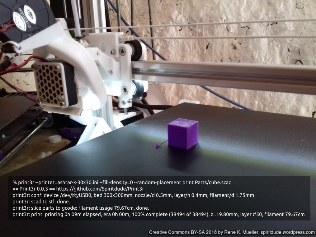
% print3r --printer=ashtar-k-30x30.ini --fill-density=0 --random-placement print Parts/cube.scad
== Print3r 0.0.3 == https://github.com/Spiritdude/Print3r
print3r: conf: device /dev/ttyUSB0, bed 300x300mm, nozzle/d 0.5mm, layer/h 0.4mm, filament/d 1.75mm
print3r: scad to stl: done.
print3r: slice parts to gcode: filament usage 79.67cm, done.
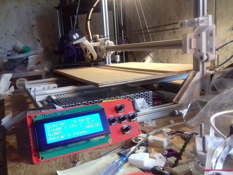
print3r: print: printing 0h 09m elapsed, eta 0h 00m, 100% complete (38494 of 38494), z=19.80mm, layer #50, filament 79.67cm
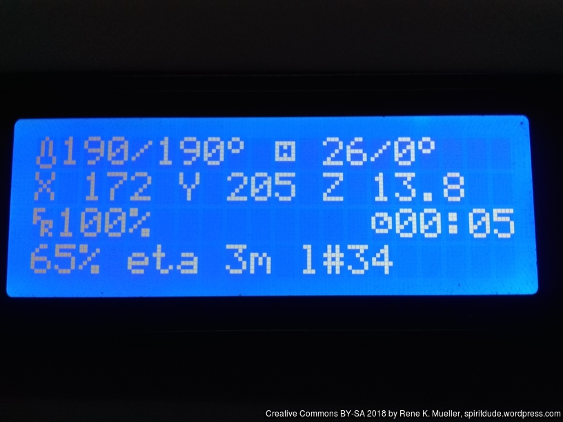
More information on the printer display: progress [%], eta and layer#:

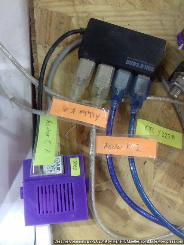 Orange Pi Zero (single board ARM-based computer) named
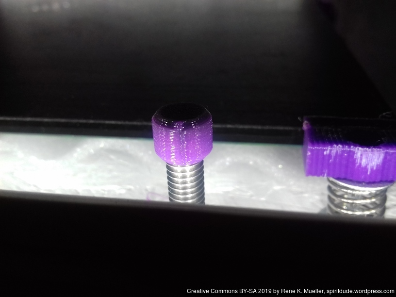


 For the 2nd Ashtar K 3D Printer I used (2018/11) RAMPS 1.4 combo with Arduino Mega, which was easy to upload new firmware. RAMPS 1.4 is Open Hardware,