

That’s it.

That’s it.

It has been a few weeks with the color mixing Diamond Hotend 3-in-1 (there is also an 5-in-1 option) – a few notes:
Pros:
Cons:
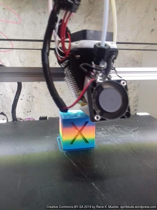
Alike with single extruder, with Diamond Hotend one must build up pressure within the hotend so the print is successful:
This procedure worked for me:
The Gcode looks like this:
G91                    ; relative positioning
M165 A1                ; color A
G1 E15 F100            ; extrude 15mm
M165 B1                ; color B
G1 E15 F100
M165 C1                ; color C
G1 E15 F100
M165 A0.33 B0.33 C0.33 ; all colors each 1/3
G1 E10 F100            ; extrude 10mm
G90                    ; absolute positioning
G92 E0                 ; reset extruding position (to be sure)
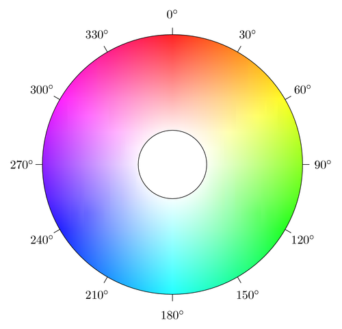
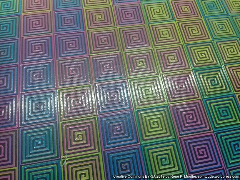
Hue wheel is a simple way to remember the colors, and is part of Hue Saturation Lightness (HSL) representation covering entire human color spectrum (more natural than remembering RGB values).
h: 0 .. 360 degrees
s: 0 .. 1 (ignored)l: 0 .. 1 (ignored)function hsl2cmy(h,s,l) {
r = ((h+180)%360)/360;
c = r < 1/3 ? 1-r*3 : r >= 2/3 ? (r-2/3)*3 : 0; // 1..0..0..1
m = r < 1/3 ? r*3 : r <= 2/3 ? 1 - (r-1/3)*3 : 0; // 0..1..0..0
y = r >= 1/3 && r < 2/3 ? (r-1/3)*3 : r >= 2/3 ? 1 - (r-2/3)*3 : 0; // 0..0..1..0
return (c,m,y);
}
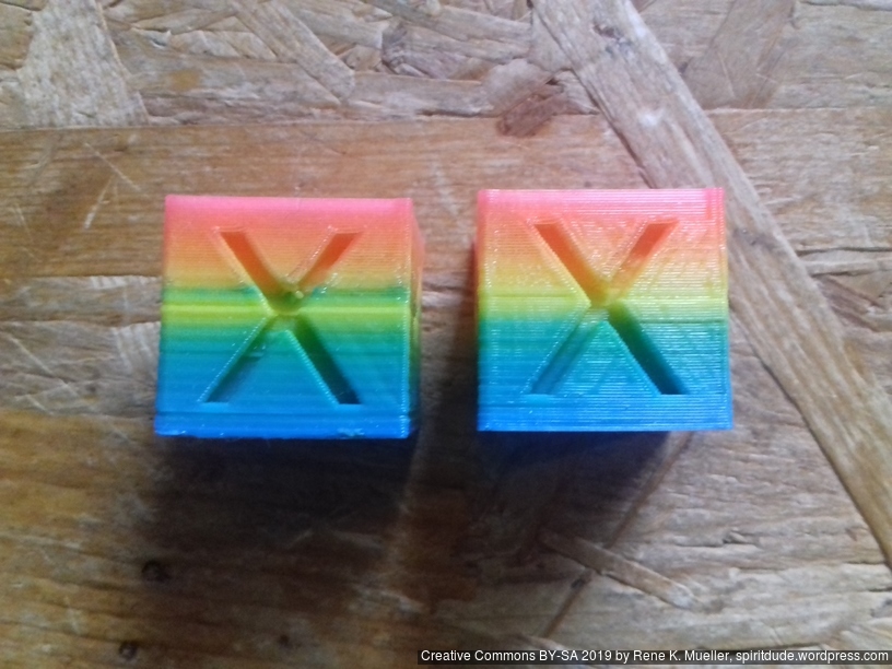
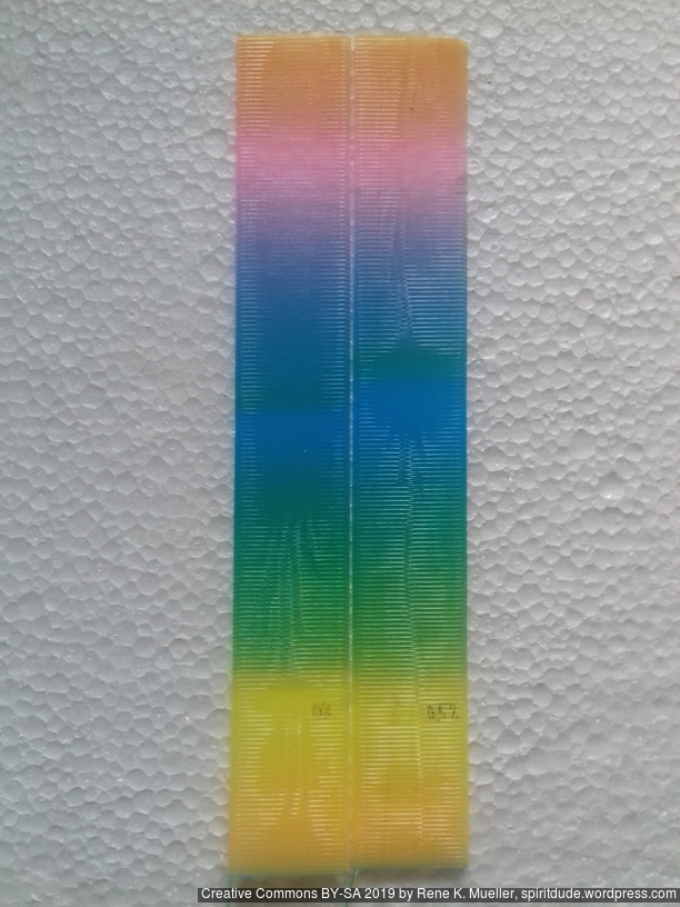
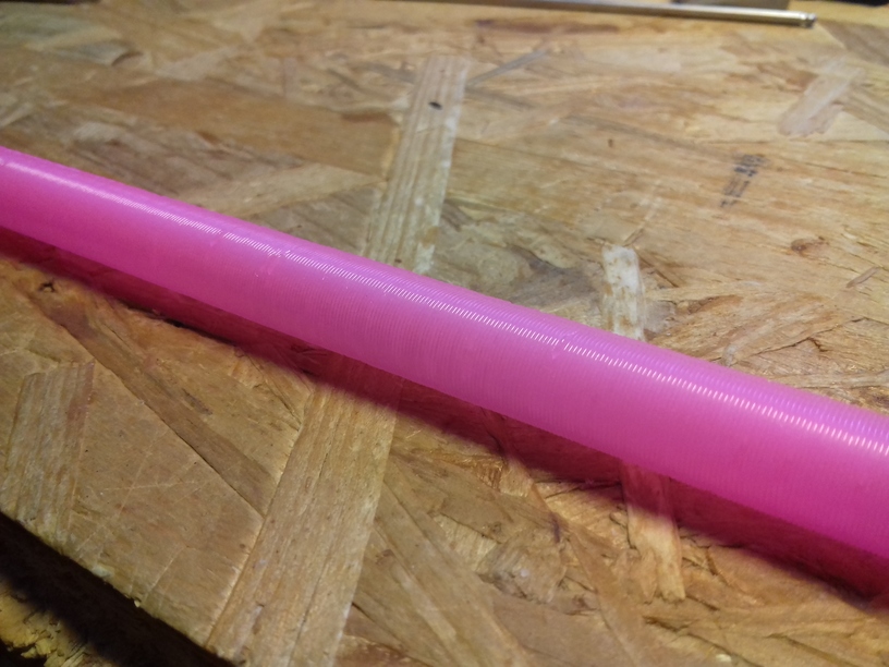
So, in case you use Cyan, Magenta and Yellow filament, you are able to cover some of the Hue wheel – I say “some” as getting Magenta filament seems not that easy – e.g. I used Glowing Magenta (less pigments) vs Rose/Magenta filament, here the two as comparison:
A proper color space mapping is required, e.g. accounting the different pigment density and thereby consider the strength how one color might dominate another in the mixing.
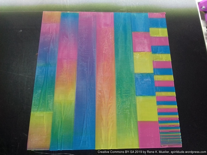
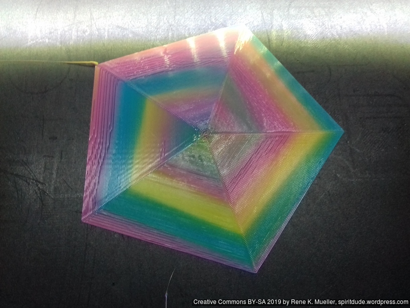
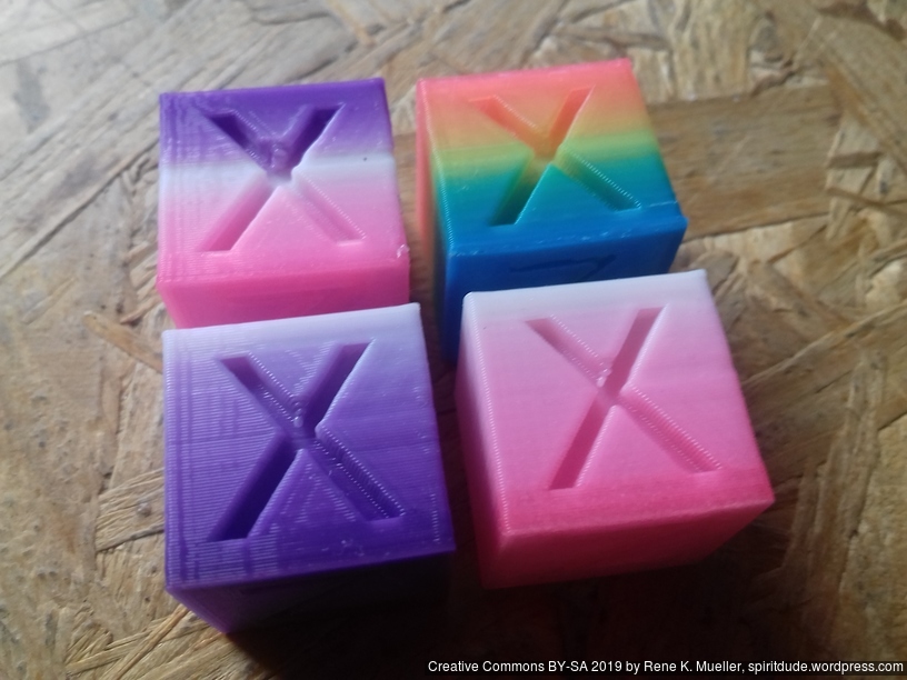
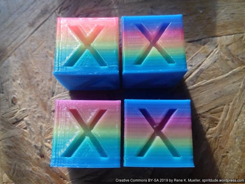
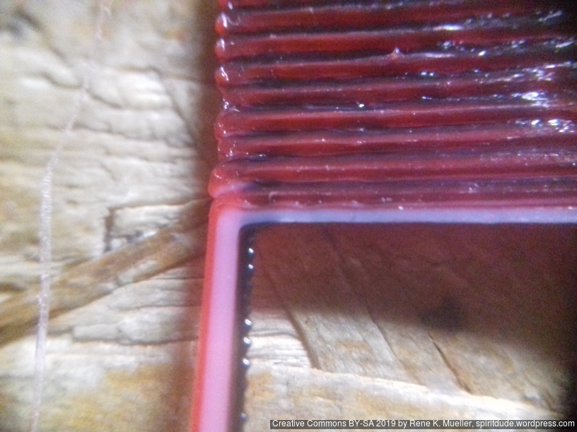
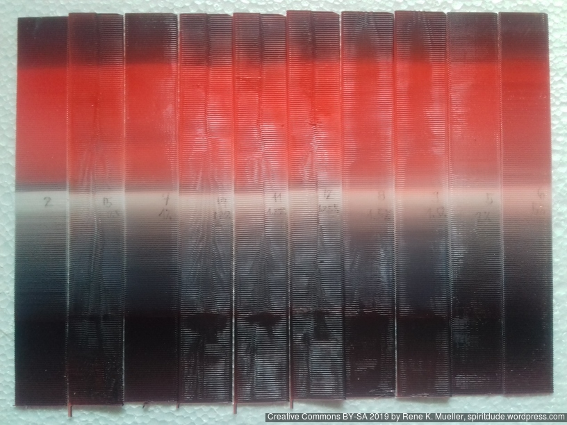
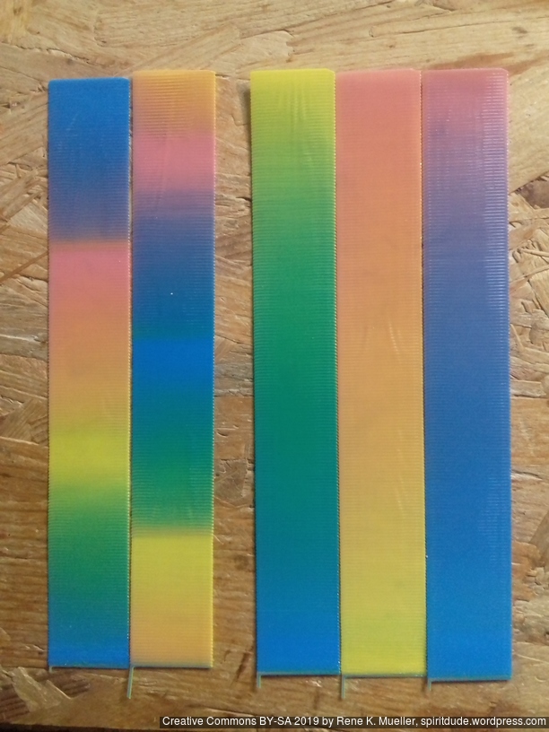
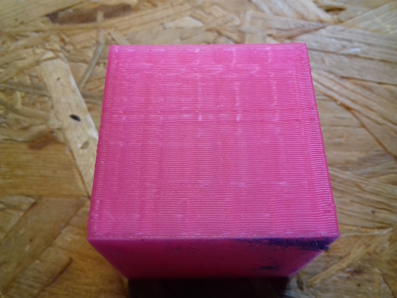
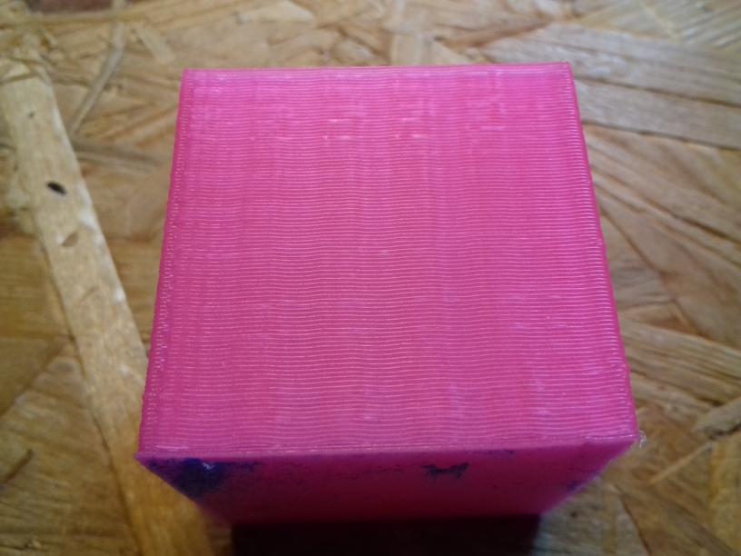
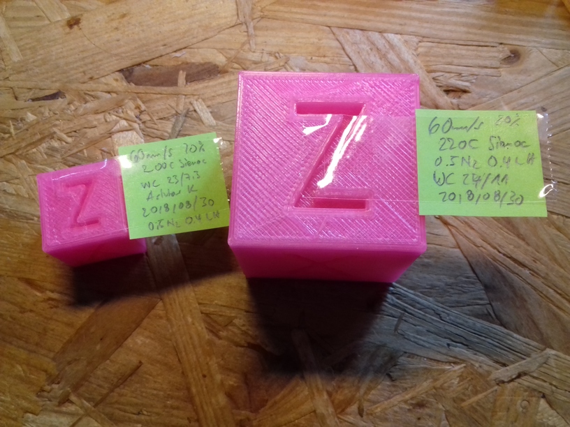
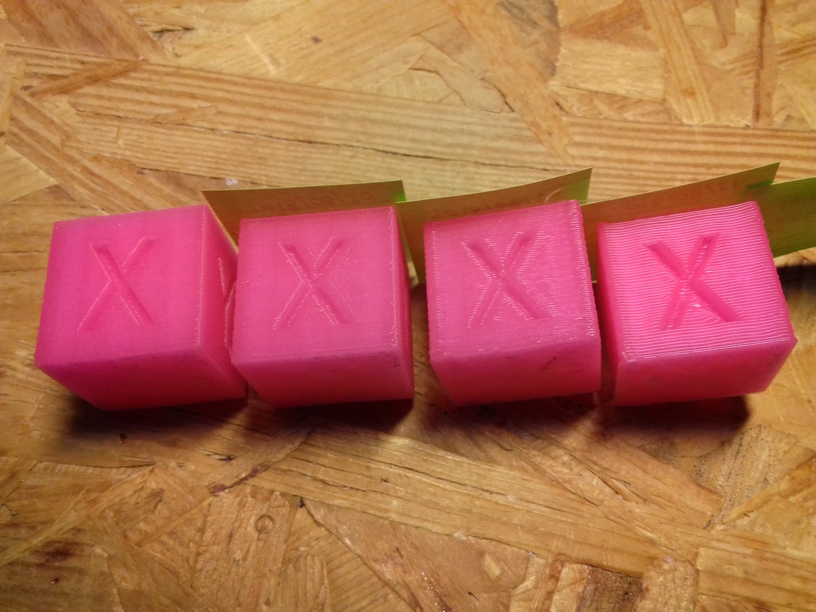
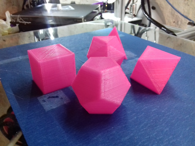
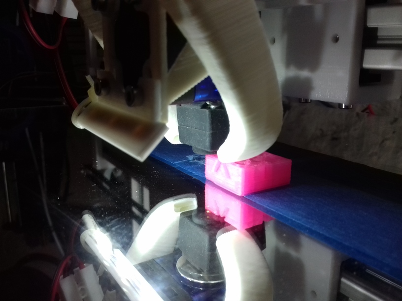
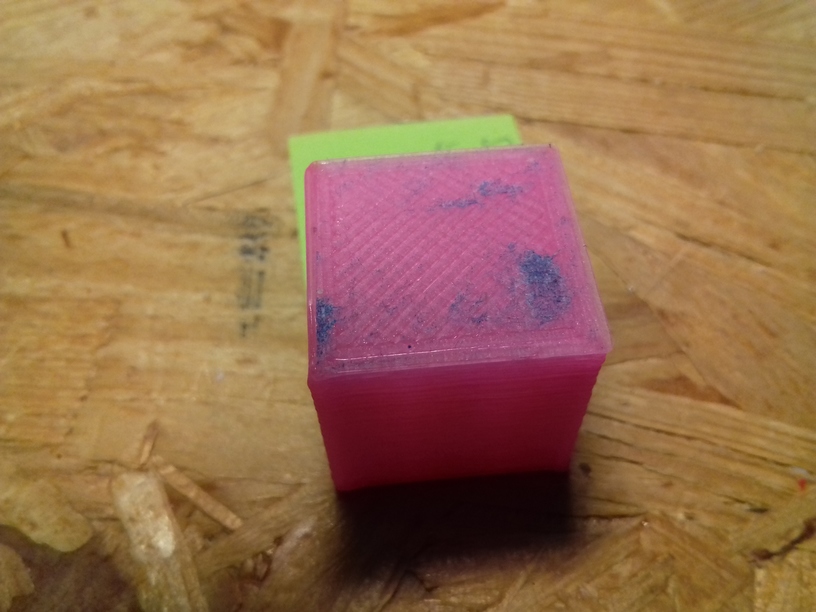
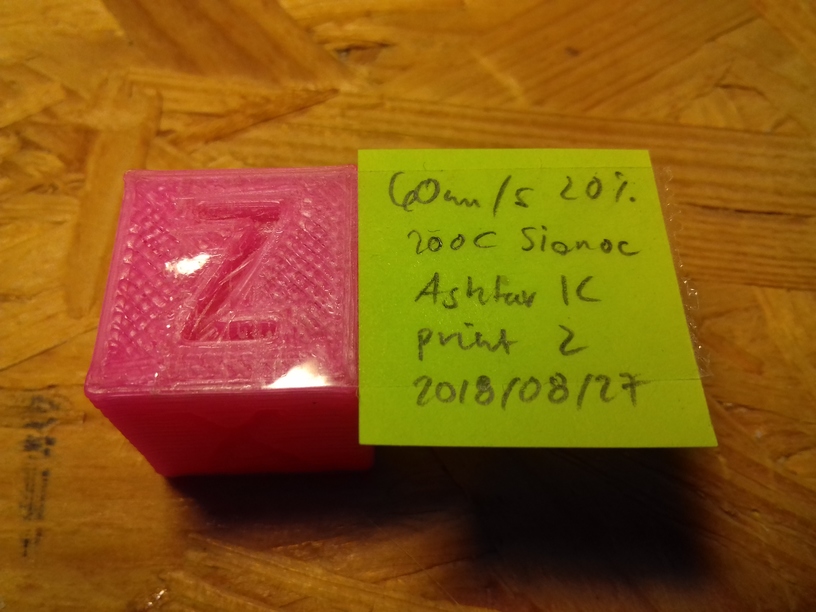
Usually the first print of the day, cooling up from 15-20C room temperature, gives me not a good print, even using my pressure building Gcode, the 2nd and 3rd print color mixing becomes more reliable. Yet, as you can see, color blending/mixing isn’t fully consistent:
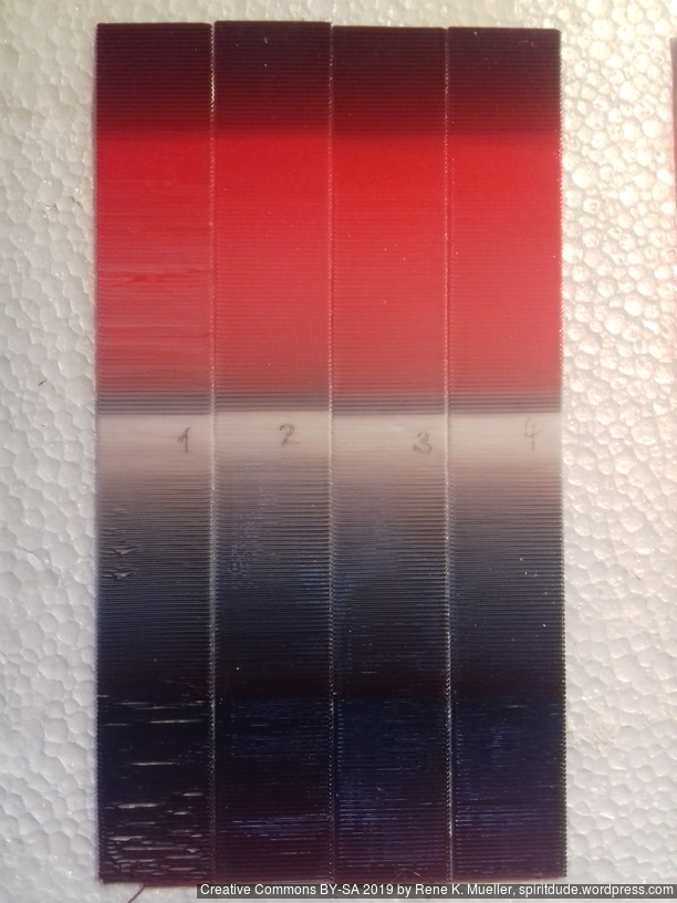
No 1 was 1st print heating up from 15C ambient to 205C – including pre-pressure preparation. No 2-4 were printed with nozzle kept at 205C and not cooling off.
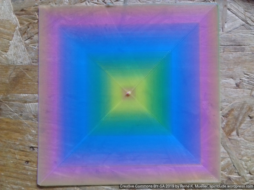
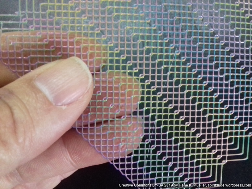
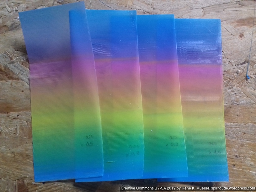
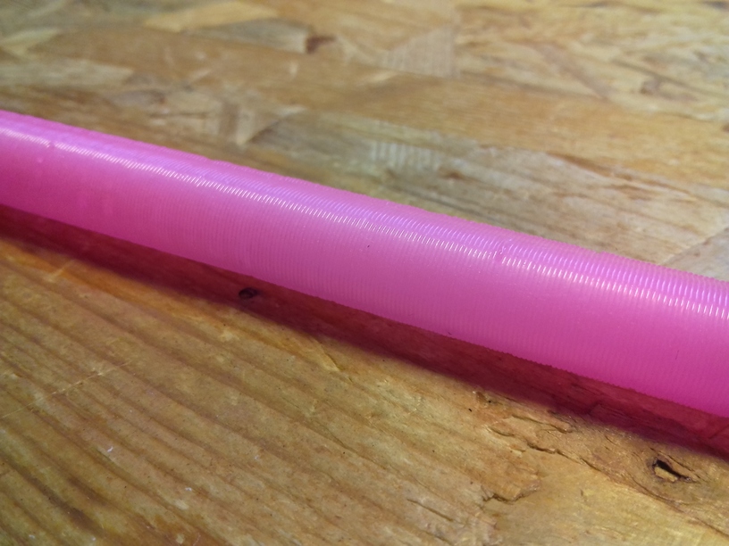
Some wider strips also single layer about 0.25mm thick with 0.4mm nozzle printed with various extrusion multipliers (0.5 – 1.0x):
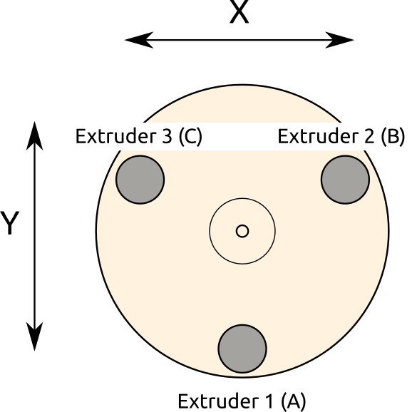
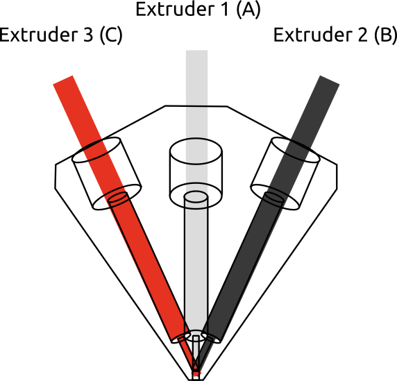
Looking from the top of the Diamond Hotend, you have 3 (or 5) filament intakes, and in case of 3-in-1:
and the following examples I use
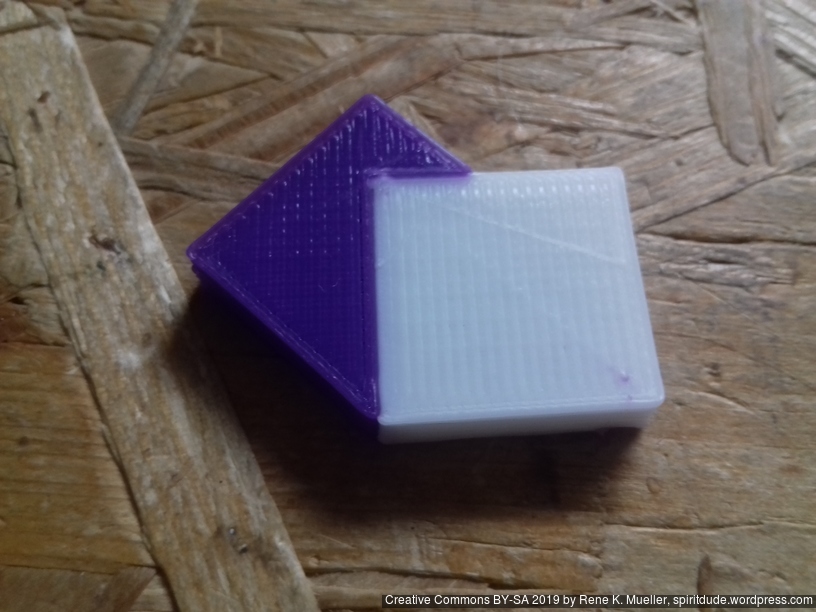
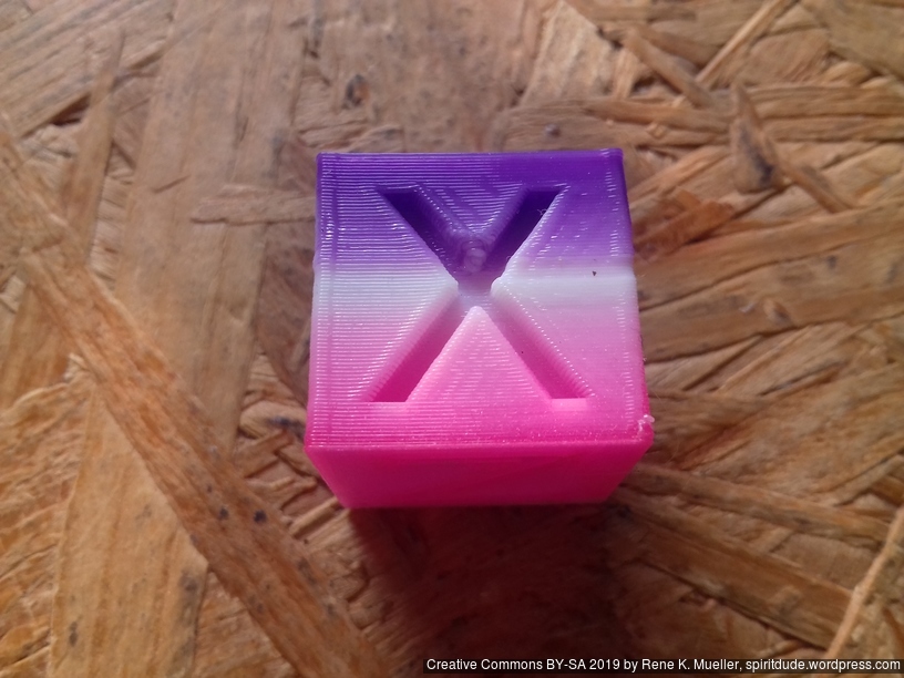
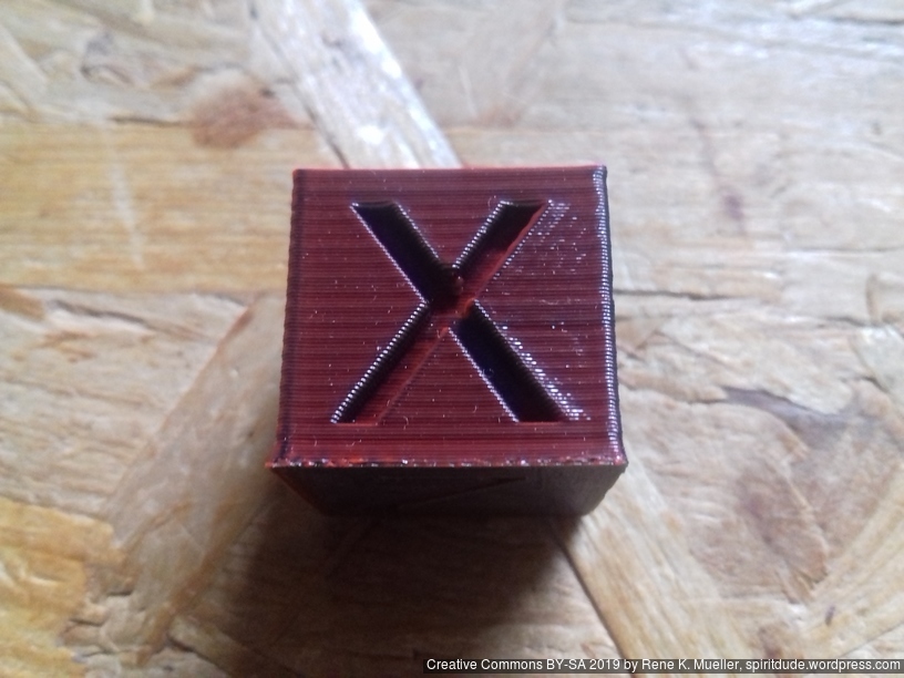
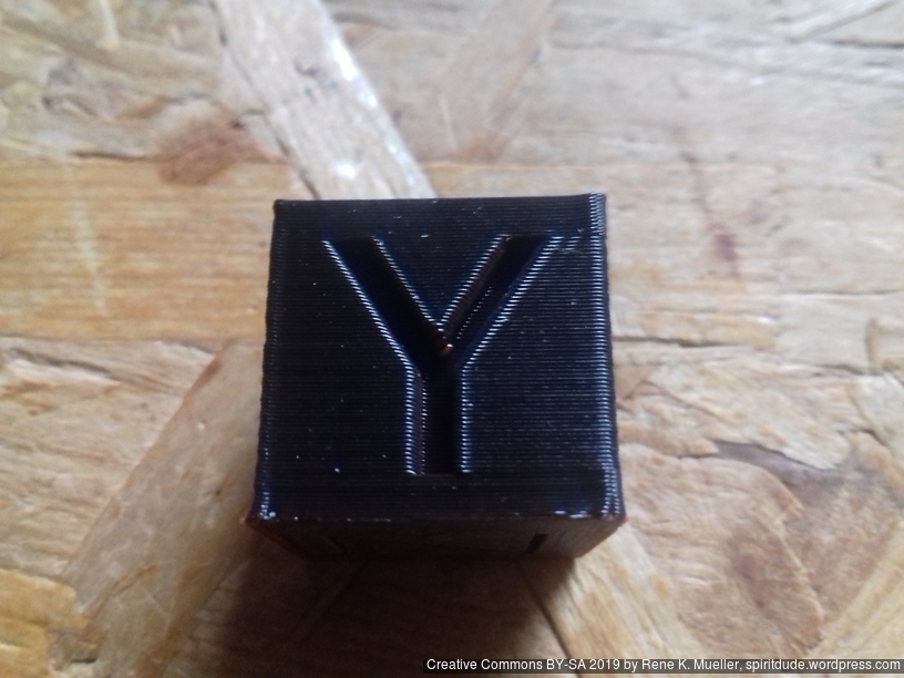
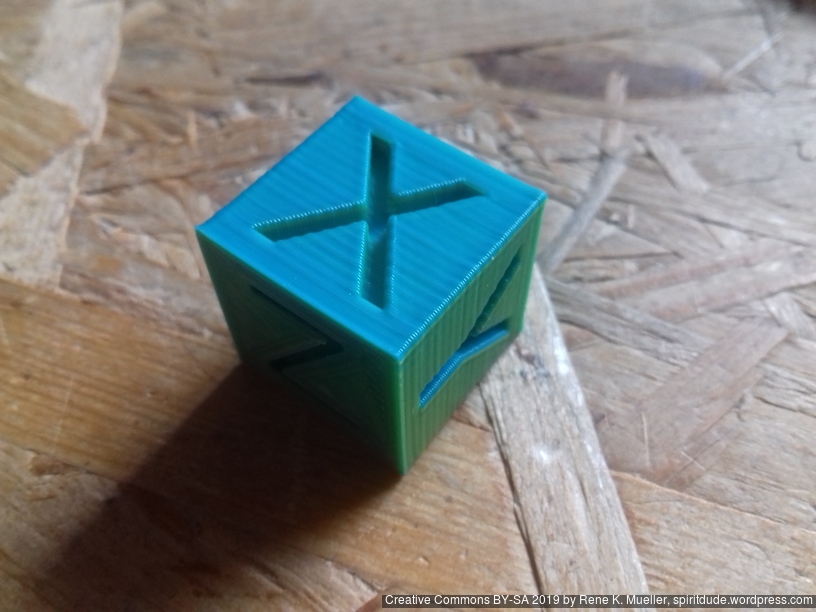
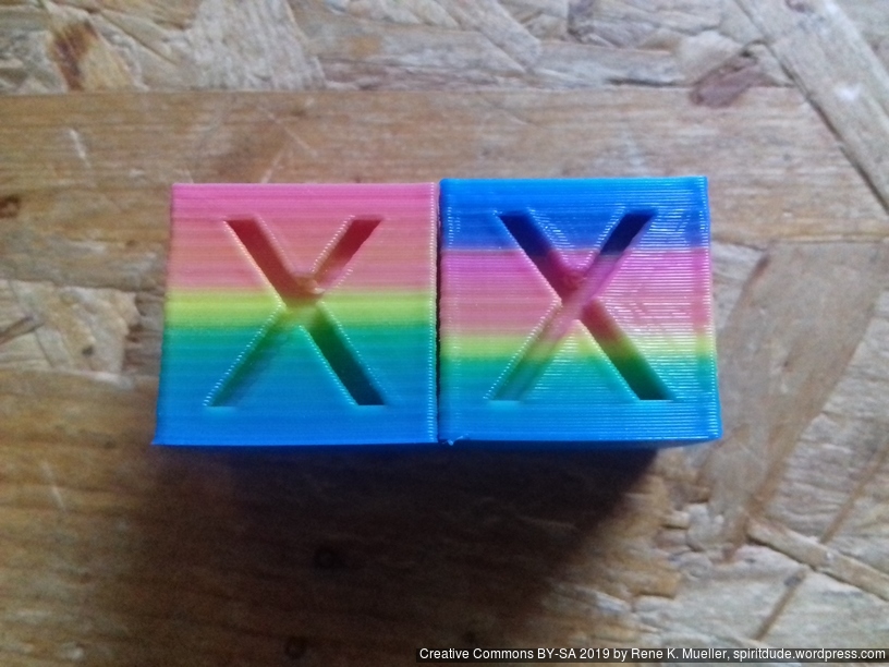
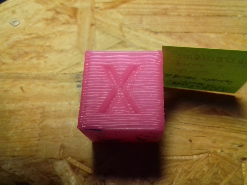
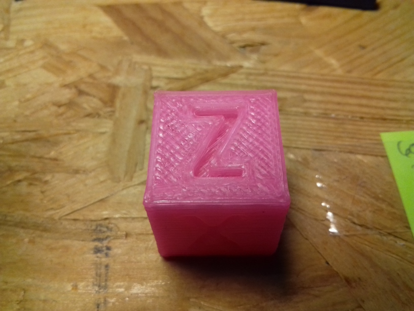
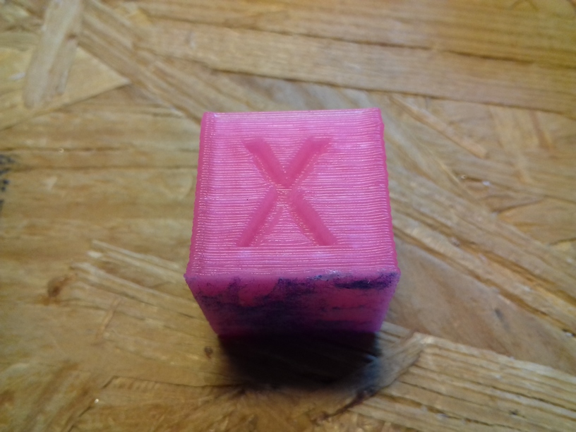
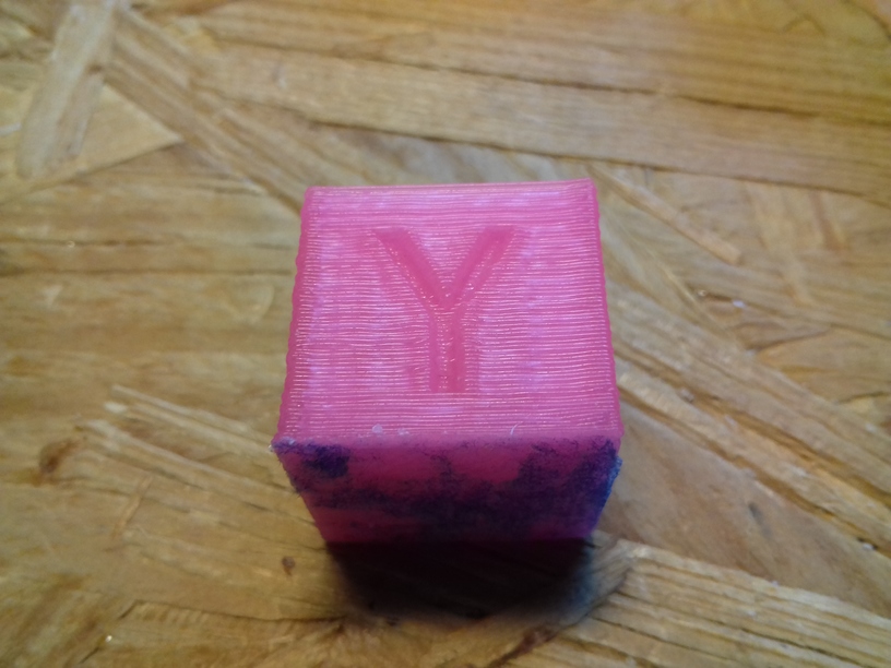
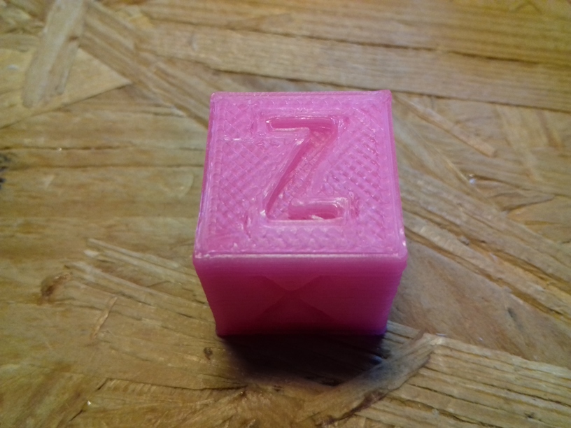
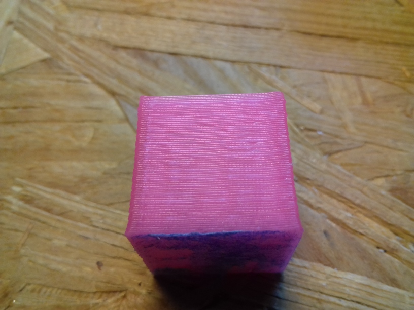
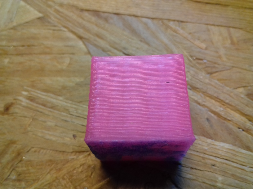
and you clearly see that color mixing is highly dependent on the orientation, using my xyz 20mm Hollow Calibration Cube printed with 0% infill, 2 perimeters, 0.4mm nozzle, 0.25mm layer height:
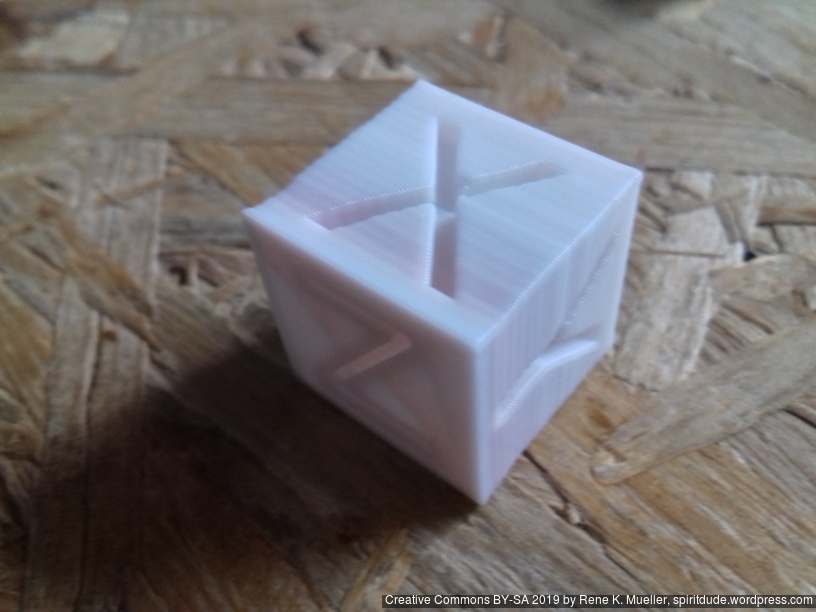

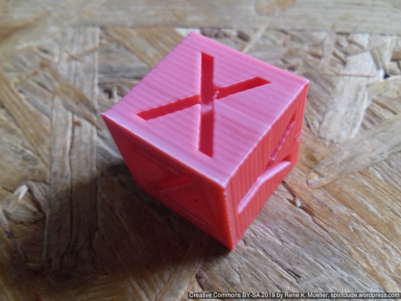


Let me focus on three cases more detailed:
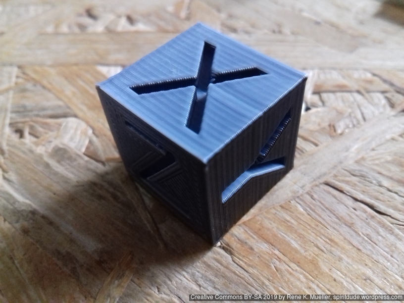
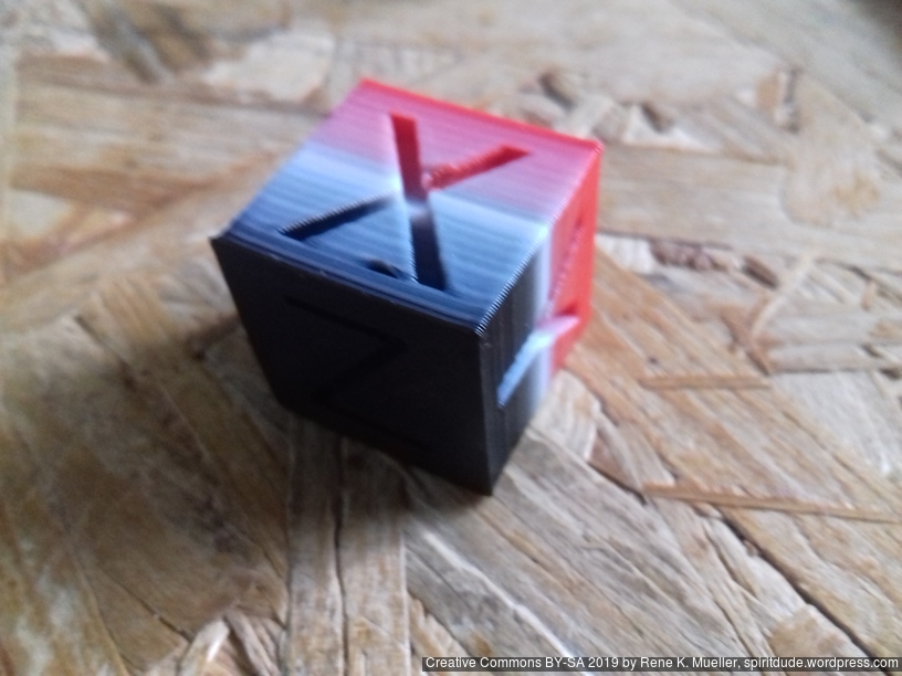
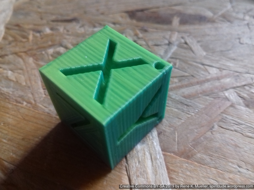
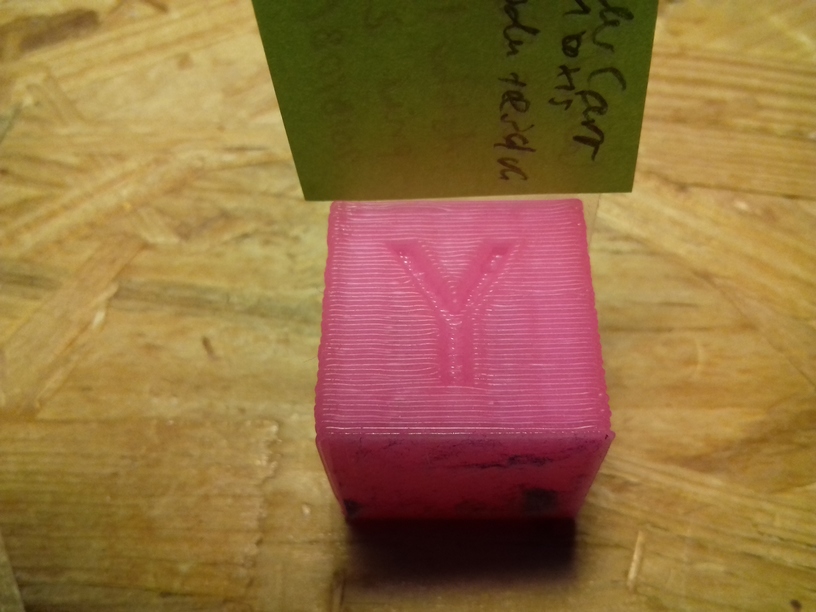
As you can see, white PLA fed 50% through A (front), gives the X face predominent white, whereas the black PLA fed 50% through B (back right) gives the “Y” face predominent black. Ideally, this cube should be mix 50/50 white/black, a shade of grey, but obviously isn’t. The same with red (C) and black (B):
although the mix in front of “X” face is ok, And looking at A (front) 50% white and C (back left) 50% red PLA:
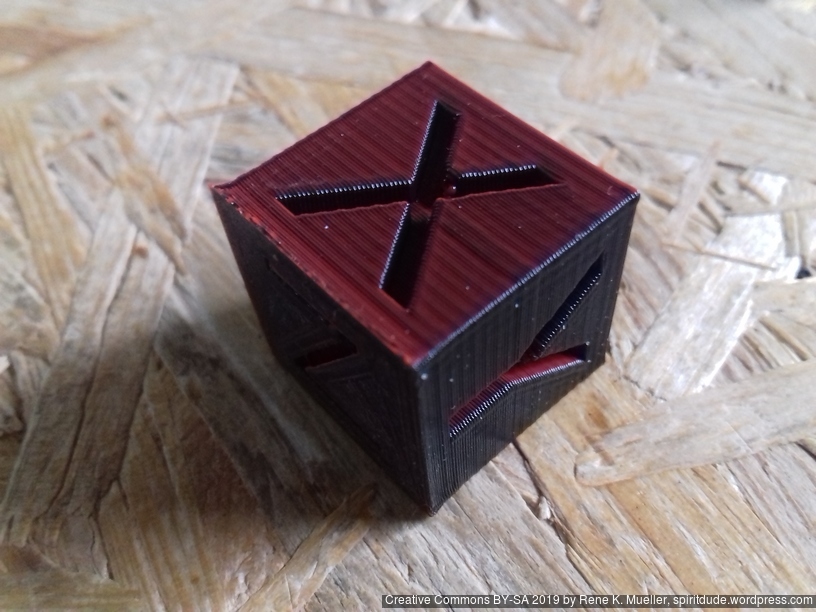
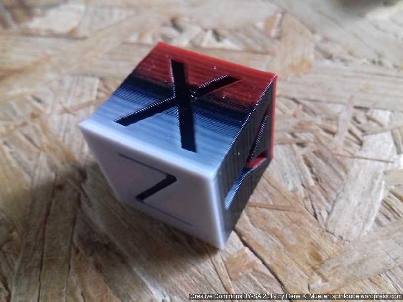
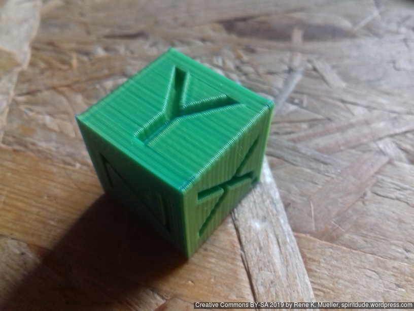
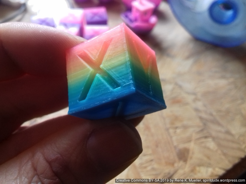
And looking at the 20mm Hollow Calibration Cube with A=0% white, B=50% black and C=50% red:
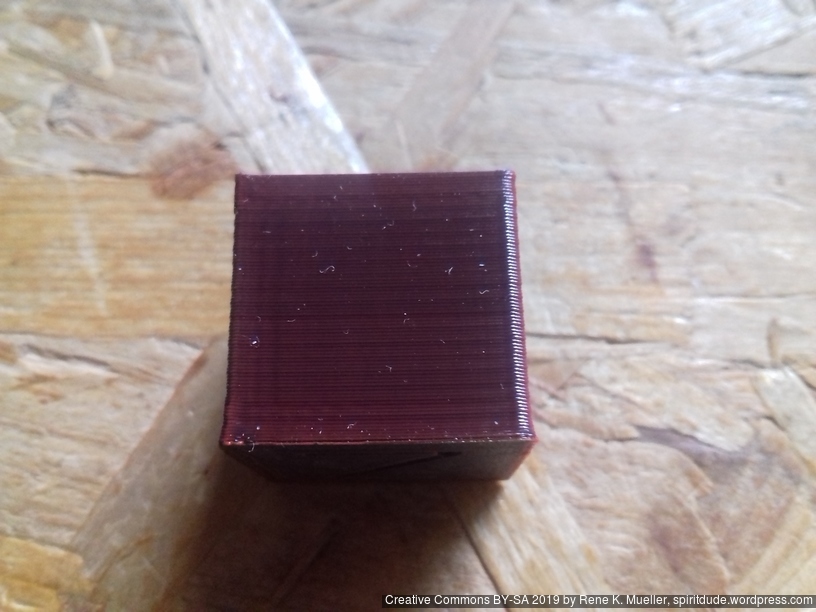
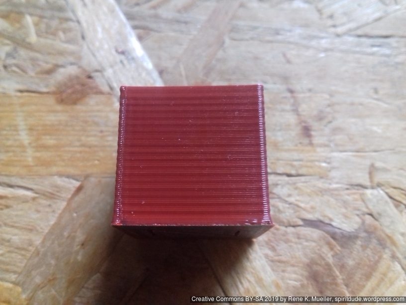
each side has another shade of red, even though 50/50 red/black is defined.
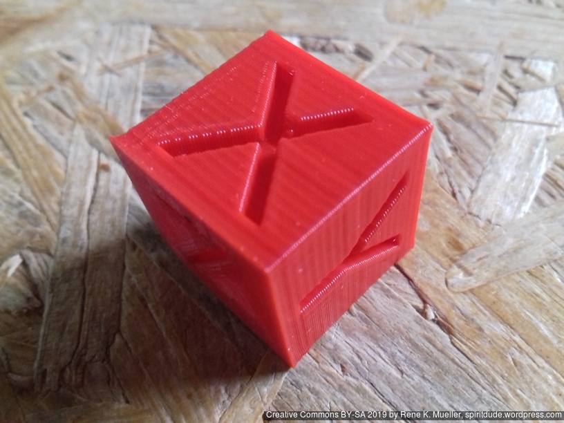
Another example with 50/50 cyan/yellow which should give green:
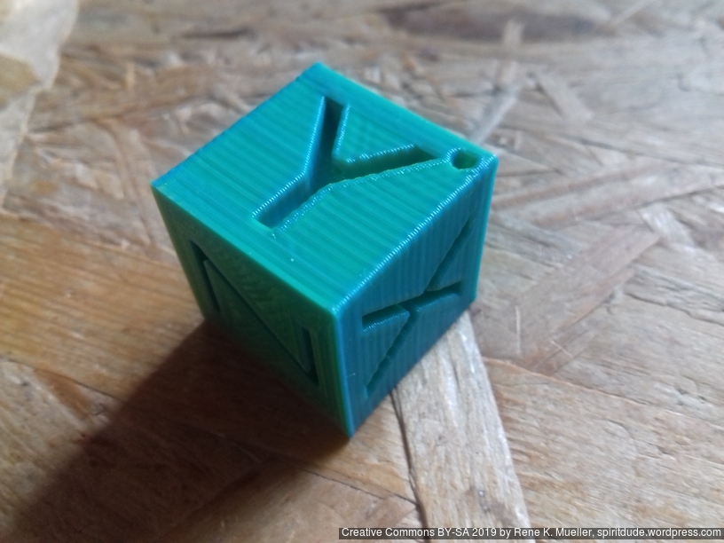
each side has another shade of green (the opposite sides of X or Y have a dot on the right upper corner for orientation).
This issue is a bit more complex so let me explain in a few steps:
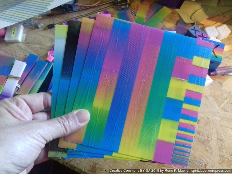
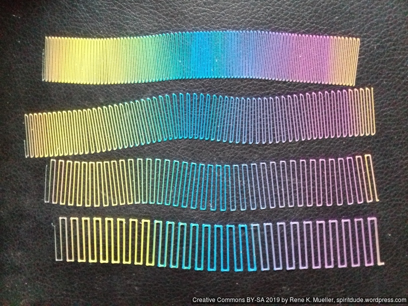
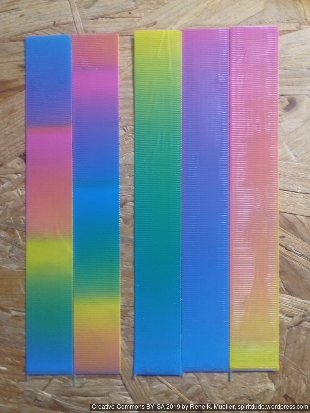
Here the single layer mixing examples, where you can see it clearly:
The width of the strip is 20mm, length is 150mm, making A/B – B – C – A/C transition (equals to Hue wheel to CMY 0..360 degrees transition) where A=white, B=black and C=red PLA, you can see how long the transition is, 2-3 lines equals to 40-60mm printed, which is about 2-3mm filament (ratio is 20x: 0.4mm nozzle vs 1.75mm filament, calculating ratio with circular areas).
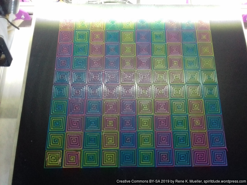
Possible remedy is to extrude all filaments with a minimum, e.g. 0.5%, 1%, 1.25%, 1.5%, 2% and 5% as examples:
In essence you compromise the purity of the colors, but you gain cleaner color change.
So, if color change (without purge tower) is important for the print, and you don’t need pure colors, you may set the minimum for each involved filament to 0.5%, for example:
M165 A0.005 B1 C0.005
Note: If Marlin sees A+B+C > 1, and rescales all parameters to normalized sum of 1.0, I don’t know how other firmware behaves.
Some more tests, using white (W) and black (K) (Netco, purchased via Ebay) on the 3-in-1 to have some idea how 5-in-1 Diamond Hotend will behave:
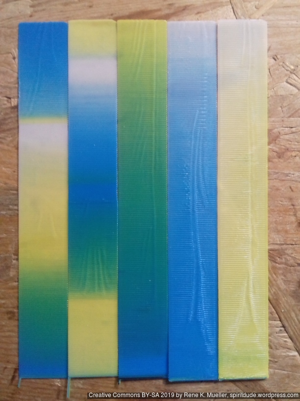
White blends quite well to Yellow or Cyan, given the limitations of the Diamond Hotend as illustrated earlier in this post.
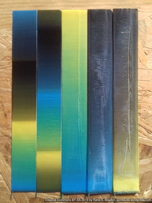
Black dominates very strongly and doesn’t seem to mix well: Dark Yellow didn’t work well as it seems the limited mixing shows Yellow and Black aside of each other; where as Dark Blue worked better.
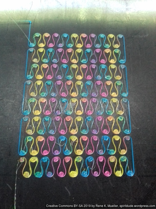
Using Rose filament (Noveste, purchased via Ebay) as “Magenta” gives very good transitions with Cyan and Yellow, yet, no classic Red from the mix, which magenta would or should provide:
Using Raspberry Rose filament (OWL Filament, Germany, purchased via Ebay) blended or mixed with Cyan and Yellow:
Quite good results with this single layer strip: so far much closer to red than before, rather deep saturated Orange, not quite Red, and when I printed calibration cubes, I saw the Raspberry Rose filament dominates Yellow and doesn’t properly mix: the change between Yellow and “Magenta” is rather abrupt:
I will try to acquire better “Magenta” filament, as I haven’t achieved proper Red color by mixing Magenta and Yellow. The Cyan/Yellow mixing works quite well, given both filaments come from the same supplier (Sienoc), one who doesn’t provide Magenta unfortunately, only Glowing Magenta which blends well, but lacks strong color, too translucent.
blue = relevant positive
red = relevant negative
Independent Dual Extrusions (IDEX)
★★★★★
Dual Hotends 2-in-2
★★★★★
Chimera 2-in-2
★★★★★
Cyclops 2-in-1
★★★★★ (clone)
Cyclops NF 2-in-1
★★★★★
Diamond Hotend 3-in-1
★★★★★
Multiple Switching Extrusions (MSE) 2-in-2, 3-in-3, 4-in-4
(rating comes later)
Y Splitter x-in-1
★★★★★
Tool Changer
(rating comes later)
Footnotes
Hints:
That’s it.
A few OpenSCAD sketches I’m currently work on, and later will publish as well:
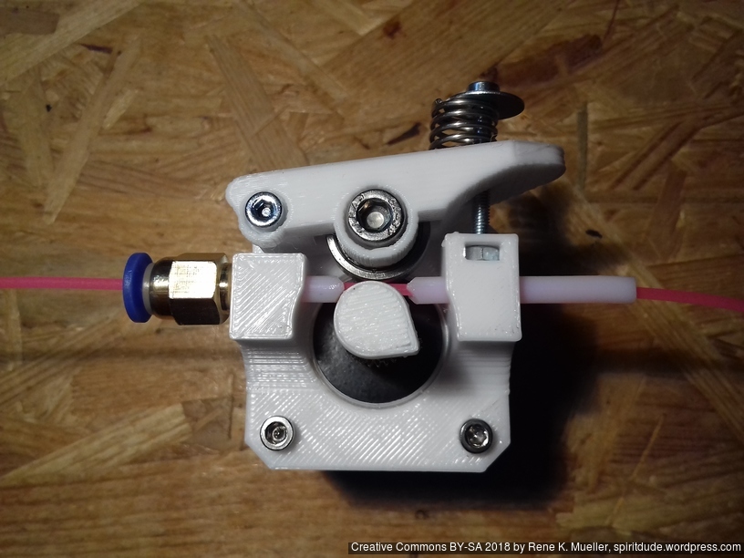
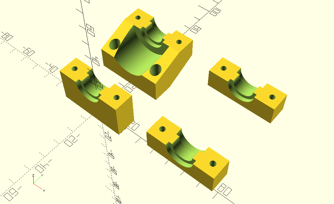
I used some aluminium MK8-based extruders but realized I required my own parametric extruder using 625ZZ bearing and I looked around and found “Compact Bowden Extruder“ and adapted the overall design but coded it from scratch again:
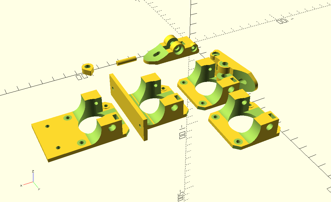
It’s “right handed” by default, but filament can go both directions. The handle is pushed from “inward” with a spring, not so elegant, yet it saves space and filament does not have to go through the handle this way, which I prefer.
simple_compact_extruder() takes following parameters:
type:
"base": the base attached to the Nema 17 stepper motor"handle": the push handle with the spring"indicator": small indicate to put on the axis of the stepper motormount:
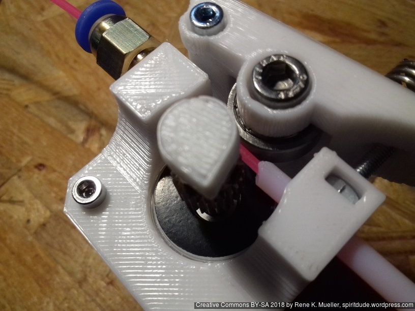
"none": (default) just attaches to Nema 17 stepper motor"mount": simple mount (center)"2020": extends flat (lower left version)btd: Bowden tube diameter (default: 0mm), if 4mm is used, then Bowden tube can be inserted on both sides as guides for flexible filament close to the hobbed gear as shown below.I use PC4-M6 push fit connector with PTFE tube 4mm OD / 2mm ID as guides, and began to use it right away on 3x printers for first tests:
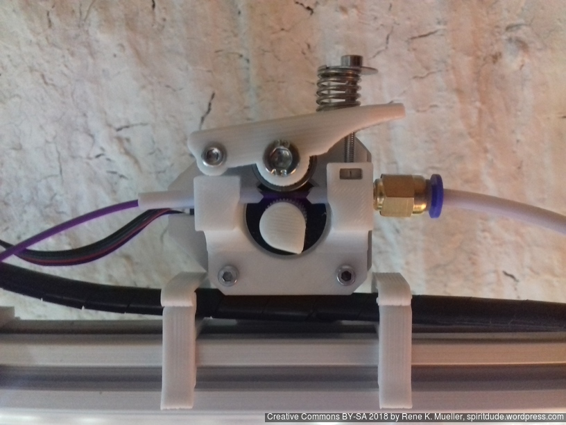


Later I likely will integrate this design, once proven reliably working, with a Direct Drive Extruder design as well.
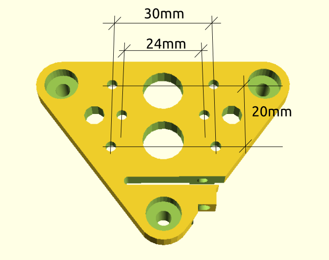
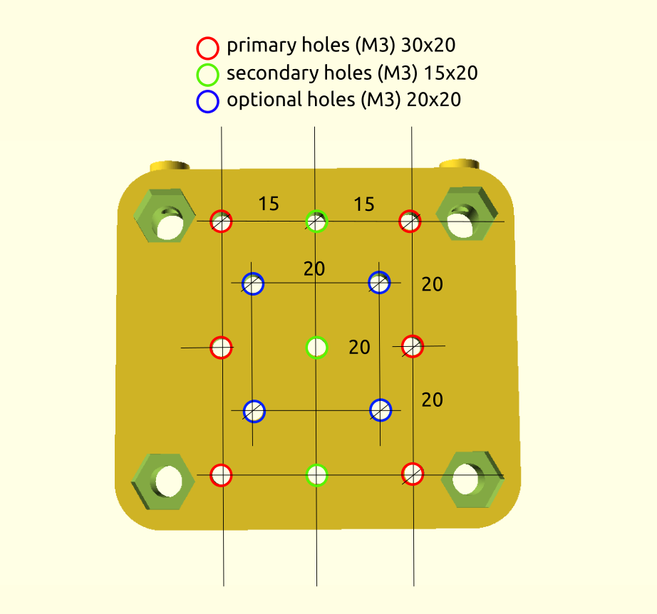
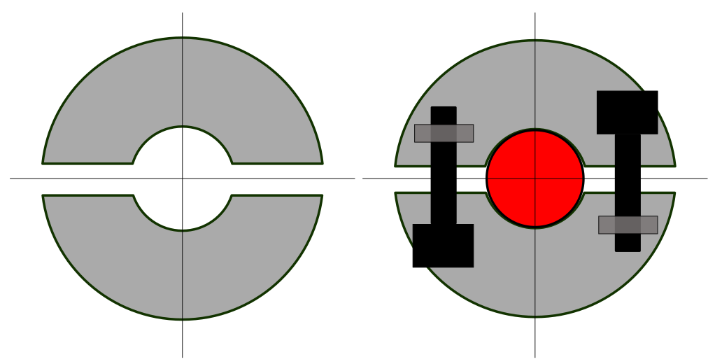
My X carriage maintains 30mm horizontally distanced M3 mounts x 3 rows 20mm apart – the v_plate() (3 wheels) and h_plate() (4 wheels) as example:
and wanted a parametric dual E3D V6 hotend mount to print dual colors or materials for the Ashtar C #1:
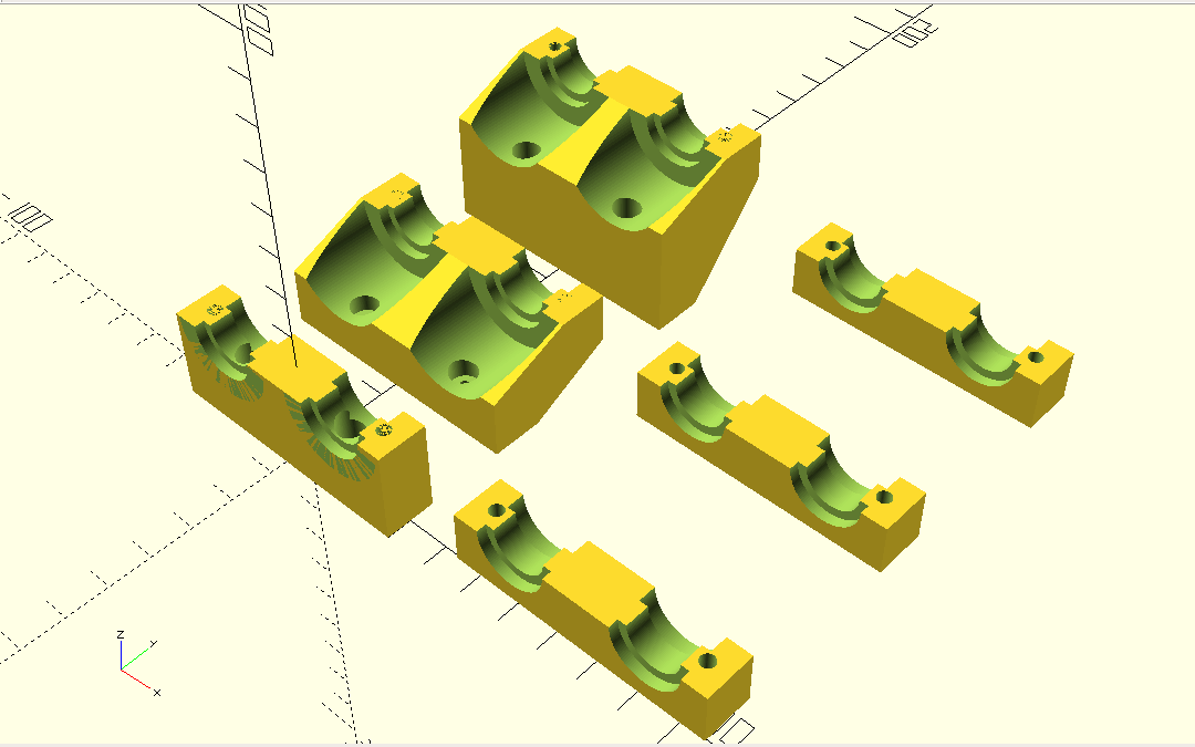
dual_e3d_mount(): there are plenty parameters, but the most important ones:
type: "base" (left) or "clamp" for the clamp (right)yoff: Y offset (when mounted the Z offset up), default: 0 (front one), 20 (middle and top)nd: nozzle distance (Y-wise), default: 22 (most close possible), 35 (top one)First attempt to use it:
This design has been not yet printed but not yet in use, but soon as alternative to Chimera (dual hotends) or Cyclops (dual to one / mixing) hotends – two main issues:
The “Dual E3D V6 mount” was derived from preview designs as used for the Ashtar K:

The first one used two pairs of M3 screws, whereas the other more simple one requires in its base version just one pairs of M3 to mount the E3D V6 hotend and the mount itself to the X carriage; in case a slight Y offset is used, two pairs of M3 are required again.
I will update this post once the designs are published, after thorough testing in real life.
Updates:
The past months (2018/08) I began to use Aliexpress for ordering electronics – even prior going into 3d printing – and the past weeks my development cycles pretty much were depending on the 20-25 days delay until items arrived from China to Switzerland – and one develops some skill to anticipate what one would require as next – but some things only become known once you really tested parts thoroughly.
Anyway, the CTC DIY I3 Pro B (Geeetech DIY I3 Pro B clone) was still sold via Ebay (2018/08), at a price as low as EUR 80 incl. shipment, which is a true bargain.
Aliexpress (2018/08):
CTC DIY I3 Pro B Kit (2018/08):
So I decided to get another CTC DIY to source the parts in one go, and likely upgrade later with individually sourced parts to have dual extruder motors (two color or material printing).
In 2018/11, when I started to build a second Ashtar K 38x30x33 #2 I checked Ebay with following prices:
Ebay (2018/11):
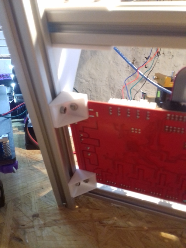
For now I use an “Anet V1.0” controller board (Atmel 1284P), as part of a “CTC DIY Kit” as mentioned, and it required some preparation:
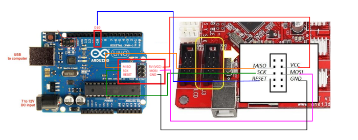

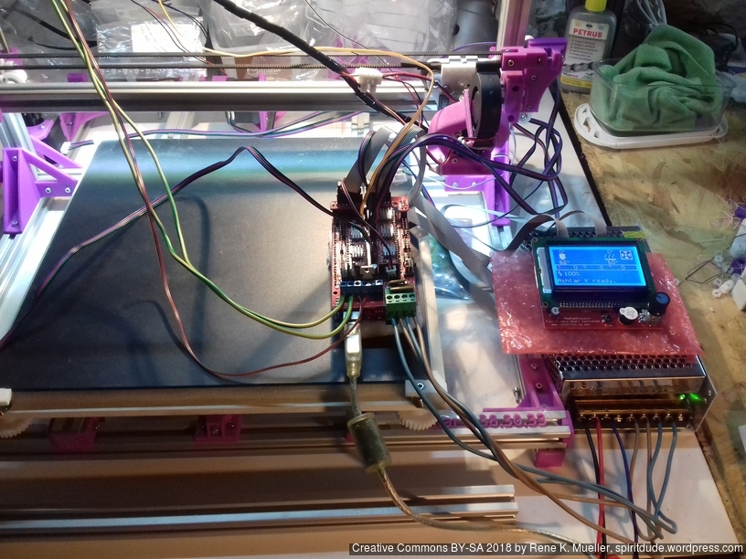
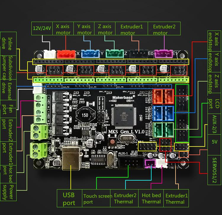
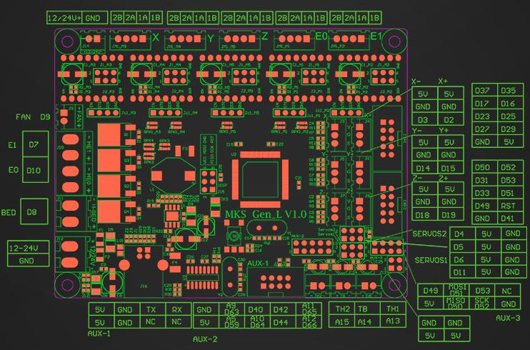
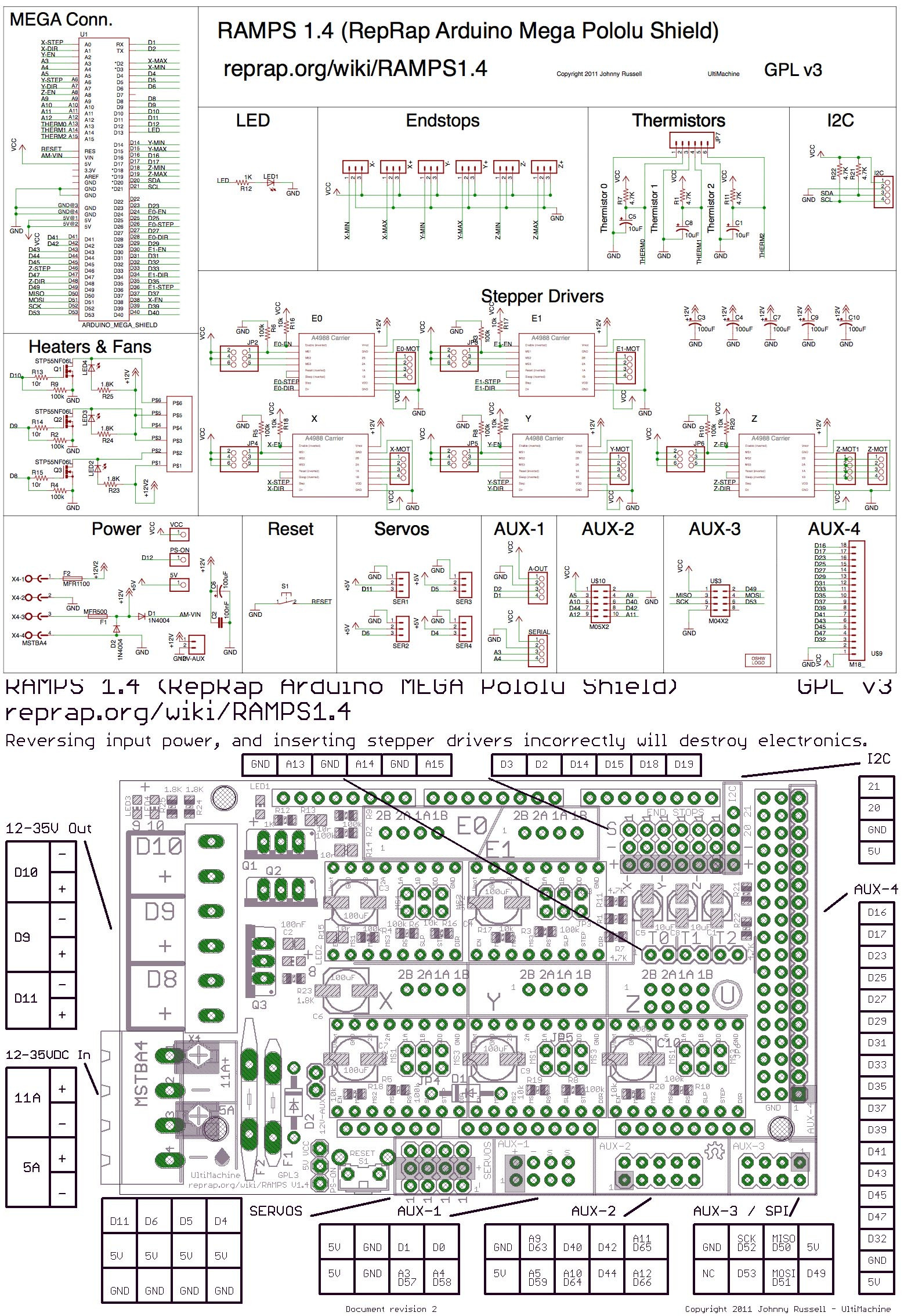 For the 2nd Ashtar K 3D Printer I used (2018/11) RAMPS 1.4 combo with Arduino Mega, which was easy to upload new firmware. RAMPS 1.4 is Open Hardware, the entire schematic and pinout is available or download diagram with pinout as one image (same as on the side) – but it’s also a hassle to plug correctly as the board plug descriptions are tiny or covered by parts so one has to consult documentation in details, and there many ways to do wrong (reverse or misalign plugs) and most of these can and do damage either the RAMPS 1.4 shield and/or the Arduino Mega beneath, including misaligning the endstops.
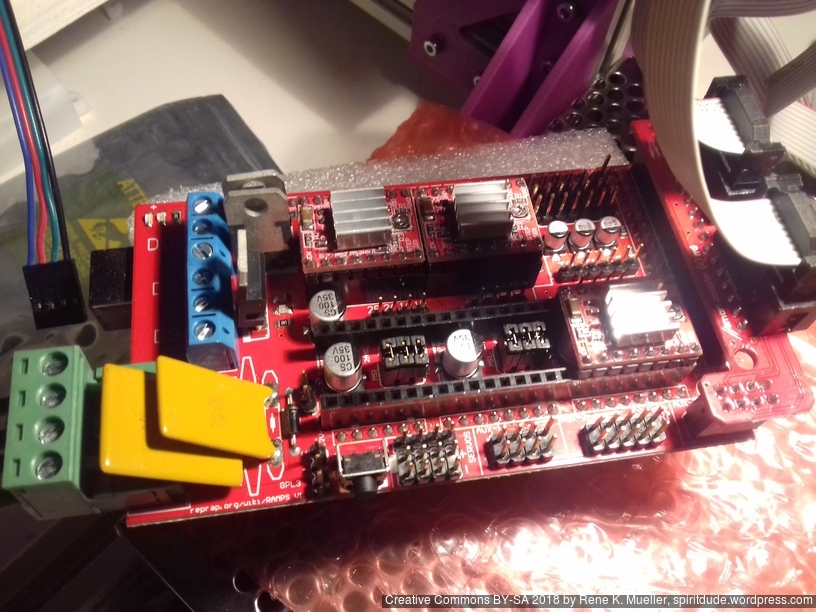

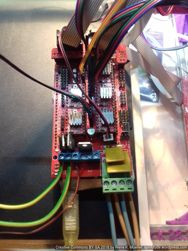
while waiting for proper endstops to arrive, I salvaged microswitches from a faulty computer mouse to work as endstops
Configuration.h:
#define MOTHERBOARD BOARD_RAMPS_14_EFB#define REPRAP_DISCOUNT_FULL_GRAPHIC_SMART_CONTROLLERConfiguration_adv.h:
#define MENU_HOLLOW_FRAME so selected item is inversedpin_RAMPS.h:
#if ENABLED(REPRAP_DISCOUNT_SMART_CONTROLLER) and the following #if ENABLED(CR10_STOCKDISPLAY) after the #else check BTN_EN1 and BTN_EN2 and reverse the pins (31 <-> 33) so clockwise dialing goes down (and not up).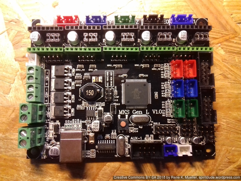
Configuration.h:
#define MOTHERBOARD BOARD_MKS_GEN_LAs far I can tell the end-stops take DuPont females and pin order is the same as with RAMPS 1.4, but orientation is crucial – otherwise the GND and VCC is shorted.
The plan is to use this board for Ashtar C #1.
I update this post as I go along.
Following major changes of 0.0.9 to 0.1.6 regarding Print3r (command line tool for 3d printing):
Now print3r natively supports 4 different Open Source slicers:
slic3r)slic3r-pe)cura-legacy)cura)which can be set with --slicer=<slicer> on the command line.
Starting with 0.1.0 print3r provides a slicer-independent layer with a growing list of settings:
Full list of settings you find at Print3r Github Wiki.
Yet, if you must, you can still use slicer-specific settings to fine-tune settings according your print needs and printer capabilities.
For often used settings like print quality, or filament settings, you can gather those settings and reference them in the command line like:
% print3r @filament/prusament @thin @hollow cube.scad
Quality Presets:
@coarse@medium@fineInfill/Wall/Perimeter Presets:
@heavy@light@featherprint3r already supported to print or slice .scad files,
% print3r print cube.scad
and now since 0.1.6 also following command line code integration is possible:
% print3r --scad print "cube(20)"
% print3r --scadlib=washer.scad --scad print "washer(5)"
% print3r --scadlib=parts.scad --scad "c_2020()" "edge_idler()"
Since 0.1.0 also arbitrary baudrate like 250000 (default of Marlin) is supported (Linux only, other platforms not yet), aside the common 115200.
As external Gcode viewer for preview command yagv is used, a very basic viewer – at a later time it might be replaced.
% print3r preview cube.scad
which converts, slices and preview the Gcode.
Since the functionality of print3r is growing steadily, the requirement for proper documenation demanded its own Print3r Wiki where you find up-to-date information.
Note: The information is outdated as print3r natively supports networked printing, see 3D Printing: Print3r 2.x: Networked Printing (2019/02/27), but this information is still useful bridging USB to TCP in general.
The moment you deal with more than one single 3d printer, but multiples – you want to access those with a single host: creating a cloud 3d printing facility.
After a few minutes researching the net for USB to network bridge, I realized the overhead to print via network is possible without Octoprint or some other solution, but simple ser2net and socat alone, thanks to this Github Issue by Marco E explaining his steps, so I reiterate his solution with some changes:
ser2net per printersocat on the hostEach printer you like to network has to have:
As next install ser2net serial to tcp bridge per printer:
% sudo apt install ser2net
Create a file named client.cfg, you may have to change the baudrate and/or the USB device:
3380:raw:600:/dev/ttyUSB0:115200 8DATABITS NONE 1STOPBIT -XONXOFF LOCAL -RTSCTS
Start ser2net on each printer:
% ser2net -c client.cfg
As next prepare the host, where all the printers will be controlled from:
First make sure you have socat installed:
% sudo apt install socat
For each printer you are creating network back to (virtual) serial port – replace 192.168.0.16 with the IP of your printer(s):
% socat -d -d pty,raw,echo=0,b115200 tcp:192.168.0.16:3380
2018/10/07 10:08:16 socat[31821] N PTY is /dev/pts/29
2018/10/07 10:08:16 socat[31821] N opening connection to AF=2 192.168.0.16:3380
...
The first line reports the new virtual serial port, e.g. /dev/pts/29 or enforce a link of the new device:
% socat pty,raw,echo=0,b115200,link=/tmp/my-printer tcp:192.168.0.16:3380
you can reference /dev/pts/... or the link you defined with Print3r then:
% print3r --device=/tmp/my-printer --scale=2 --random-placement --fill-density=0 --perimeters=1 print xyzHollowCalibrationCube.scad
== Print3r 0.0.8 == https://github.com/Spiritdude/Print3r
print3r: conf: device /tmp/my-printer, bed 380x300mm, nozzle/d 0.5mm, layer/h 0.4mm, filament/d 1.75mm
print3r: scad to stl: done.
print3r: slice part to gcode: position 272,118, filament usage 2.38m, done.
print3r: print: 0h 03m elapsed, eta 0h 16m, 18.9% complete, z=0.60mm, layer #2, filament 0.42m
So you end up with something like this:
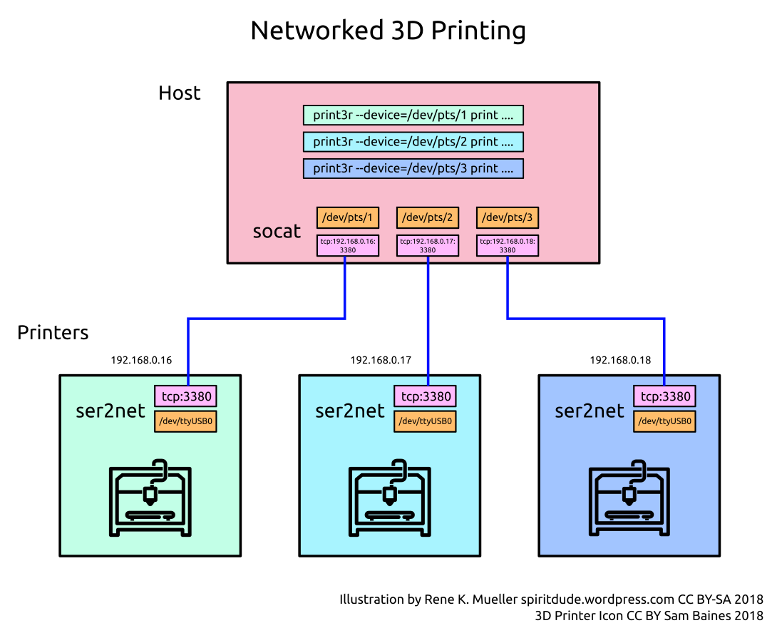
So, that’s it, with ser2net on the printers, and socat on the host you have a rather simple and straight-forward cloud 3d printing facility.
I likely will extend Print3r to support networked printing with a simple all-in-one setup. Implemented since Version 2.0.0, see 3D Printing: Print3r 2.x: Networked Printing.
Update:
ser2net: only takes common baudrates, but doesn’t support 250,000 which is the default baudrate for Marlin, 115,200 does work though. So, in case you plan to use ser2net reflash the firmware to use 115200 as baudrate.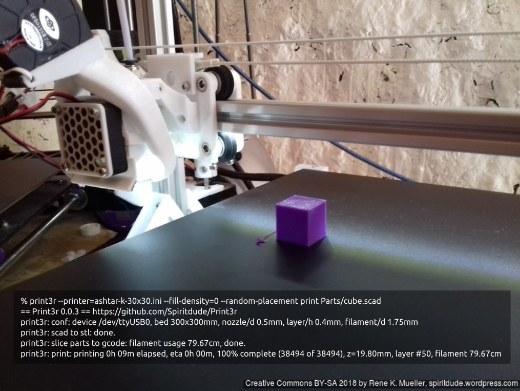
Although 3d parts need to be seen and visually so much is communicated, but Cura’s user interface feels conceptually skewed (“Prepare” vs “Monitor” tab) – and with the time I thought I want an ordinary command line interface to print parts quickly, easily multiply and random placement so the bed surface is more evenly used and not just the center – I have grown tired to move parts on the virtual bed.
So, I wrote print3r, a command line interface which utilizes Slic3r as backend. Its main features (Version 0.0.6):
% print3r --printer=ashtar-k-30x30.ini --fill-density=0 --random-placement print Parts/cube.scad
== Print3r 0.0.3 == https://github.com/Spiritdude/Print3r
print3r: conf: device /dev/ttyUSB0, bed 300x300mm, nozzle/d 0.5mm, layer/h 0.4mm, filament/d 1.75mm
print3r: scad to stl: done.
print3r: slice parts to gcode: filament usage 79.67cm, done.
print3r: print: printing 0h 09m elapsed, eta 0h 00m, 100% complete (38494 of 38494), z=19.80mm, layer #50, filament 79.67cm
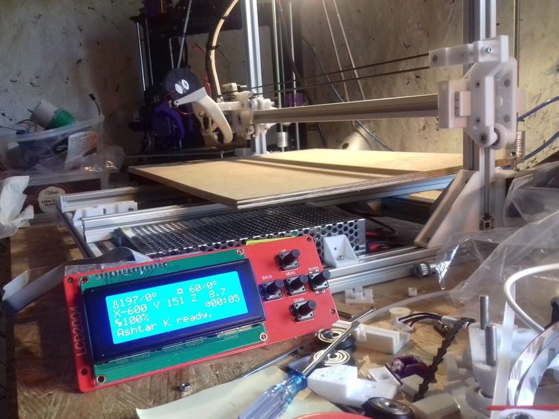
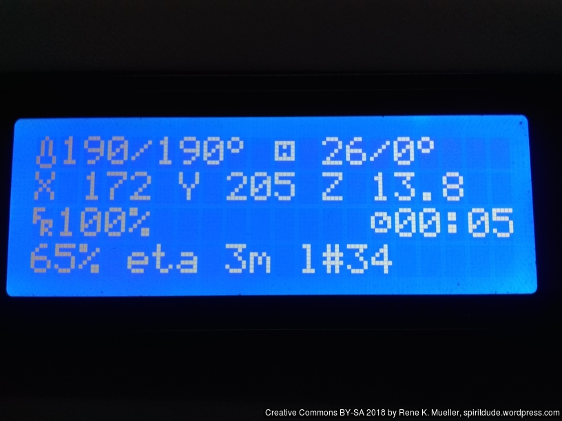
More information on the printer display: progress [%], eta and layer#:
Result:

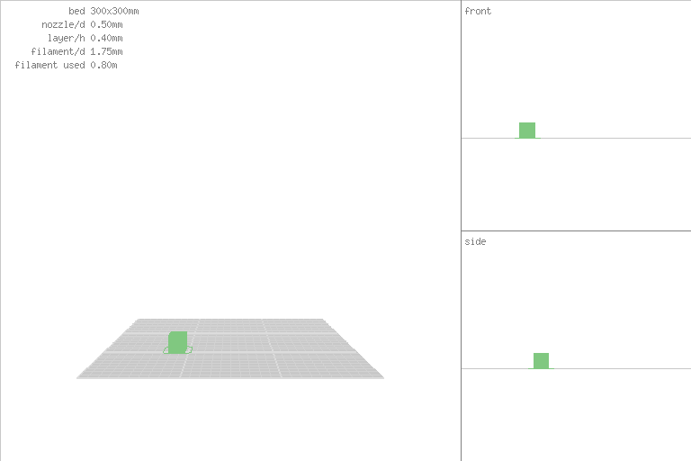
and if you replace ‘print‘ with ‘render‘, like
print3r [...] --output=sample.png render Parts/cube.scad
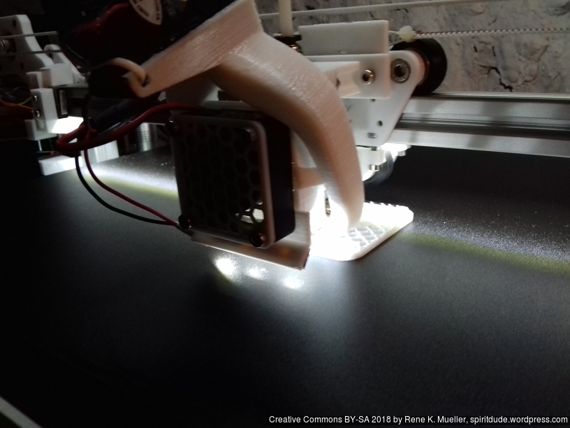
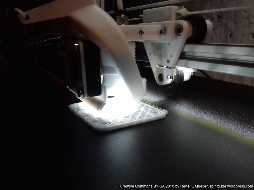
Printing new X motor mount on CTC DIY I3, and replacing it on the new Ashtar K: CTC DIY I3 prints quite reliably – there is nothing to clean up – the piece I attach it right away:
Ashtar K lacked a proper print surface (before I received the black sticker surface), otherwise I would have printed the piece on itself.
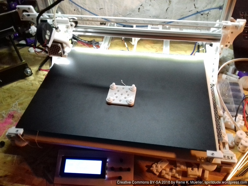
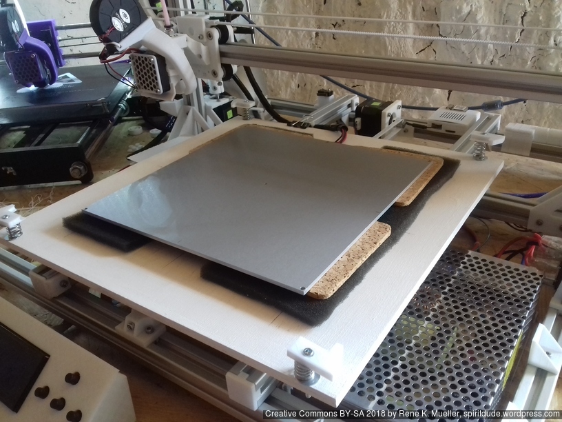
The 400×400 black sticker arrived, and I cut it into 400x300mm and put it on the mirror – which worked well, and so far I can tell the surface is very very flat, much better than on alu heat bed.


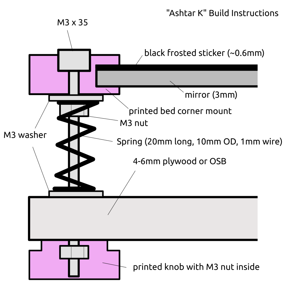 Current bed setup (top to bottom):
Now that I have a good print surface I finally printed pieces for itself.
Mounting the 400×300 bed (OSB 6mm, white painted) with 200×200 heat bed (which I hardly use, as I started to print on cold bed):
I currently use the white PU steel enhanced GT2 belts, and it produces hard edges, some ghosting, but more precise prints than the black rubber GT2 belts which just stretch too much – I have to research this more closely – about the type of reinforcement and the use with more heavy beds (Y carriage).
Just for the record regarding Y carriage (2018/09):
420×320 carriage:
320×320 carriage (for 300×300 bed):
Just to explain my thought or decision process for my setup:
so, even though the springs/screws and edge mount can adjust, the carriage should be fairly flat, and not flex at all – this way the edge mounts holding the glass/mirror only stabilize position. Main force to hold the glass/mirror, for my setup, is the foam in between. So, there is no “spring” induced vibration back/forth introduced, but the foam neutralizes such vibrations – and hardly adds weight/inertia.
Top view with see-through (best mark “0,0” on both sides to keep reference).
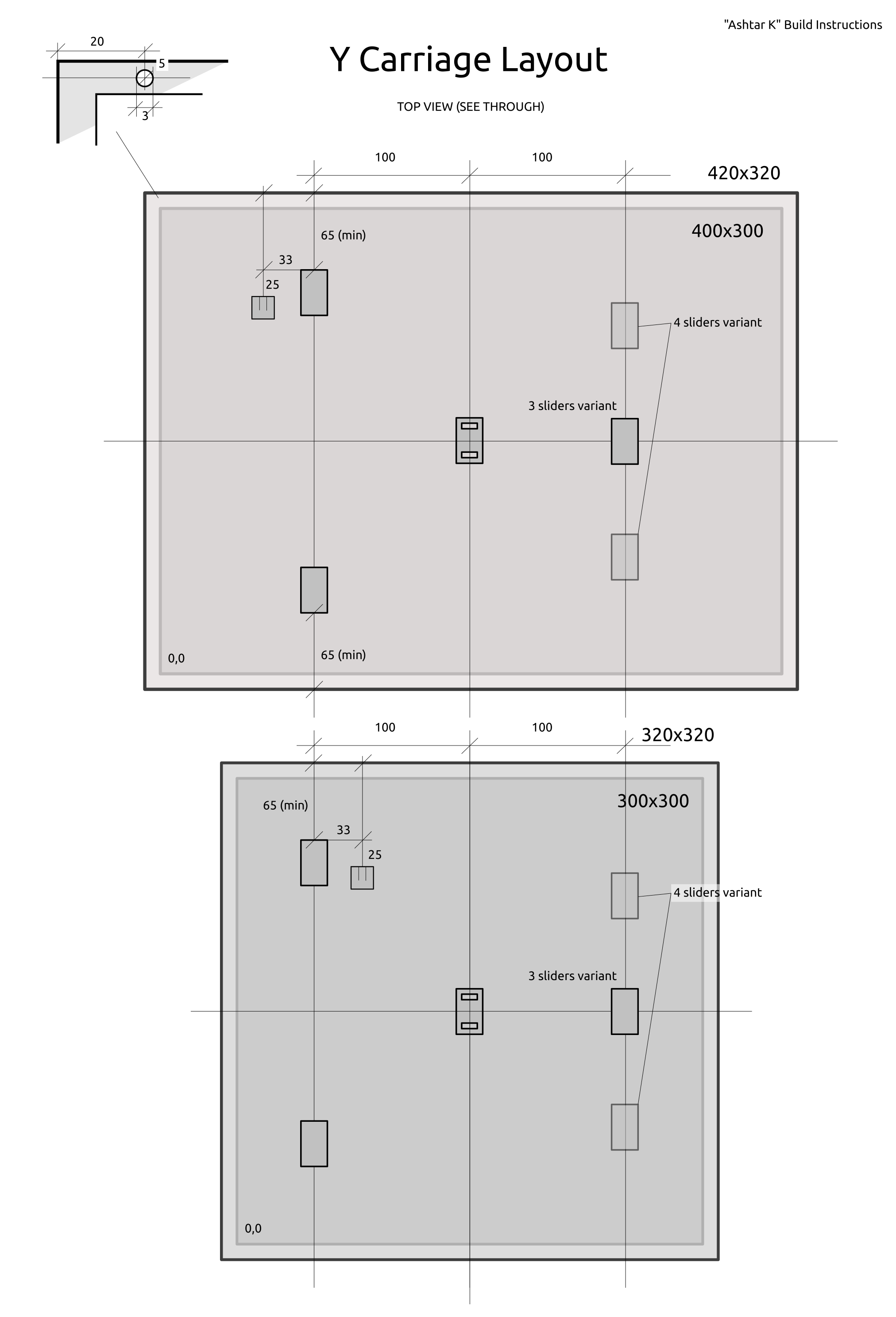
Originally I focused on 300×300 bed at least, with some tweaking and narrow X carriage I was able to reach 380×300 printable bed, so it was suitable to use 400×300 plate as well.
It takes me about 5min to mount new bed, downgrade from 400×300 to 300×300:

Changes needed:
With 300×300 bed the 0,0 is now plenty outside of the bed, with 400×300 the 0,0 is near the printed bed mount.
With 300×300 bed the 0,0 is now +32mm to right and +25mm deeper, hence the Gcode M206 is set like this:
M206 X-32 Y-25
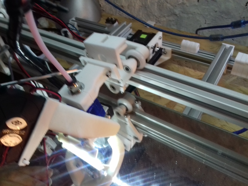
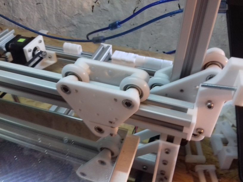
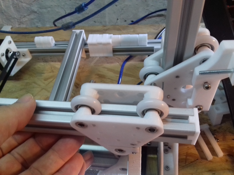
The 3 wheels module riding on the 2020 alu extrusion I named “V plate” due the shape, the 4 wheels module “H plate” providing more stability or rigidity for use as X axis carriage, when the nozzle runs over slightly unclean extrusion and tilts upside. For the X carriage I choose a narrow (48mm wide hole-to-hole) version:
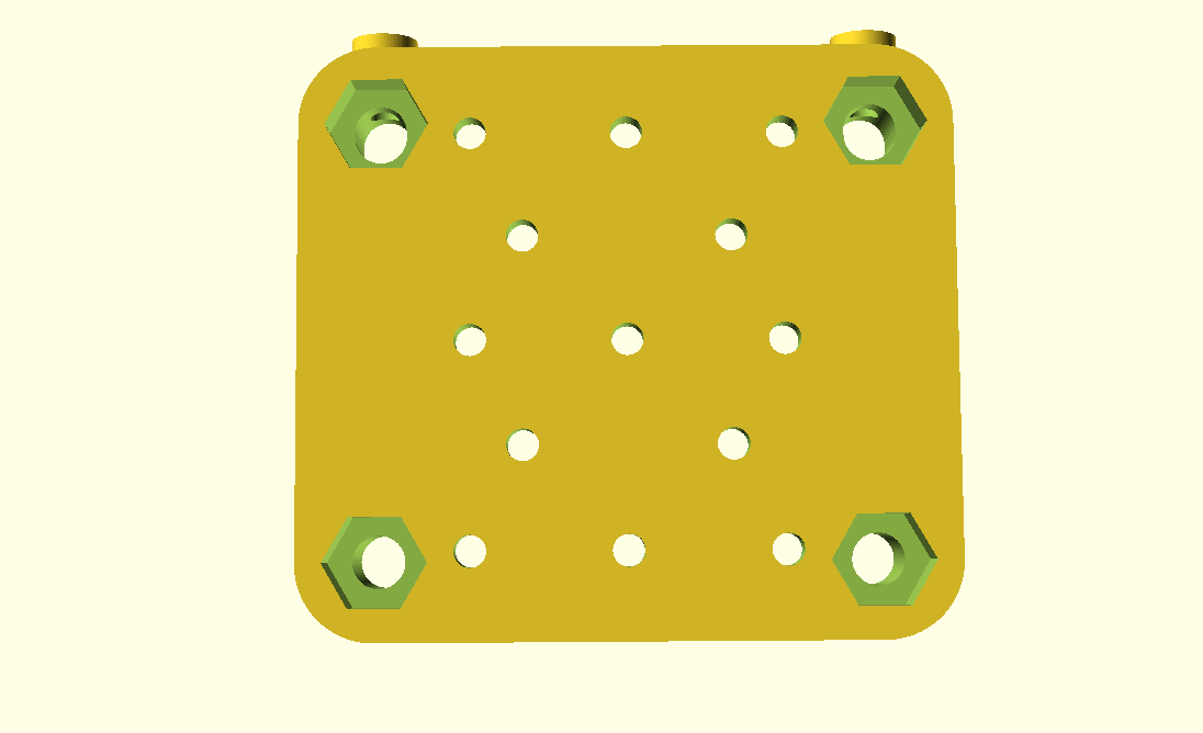
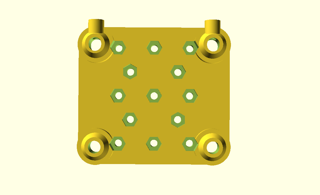
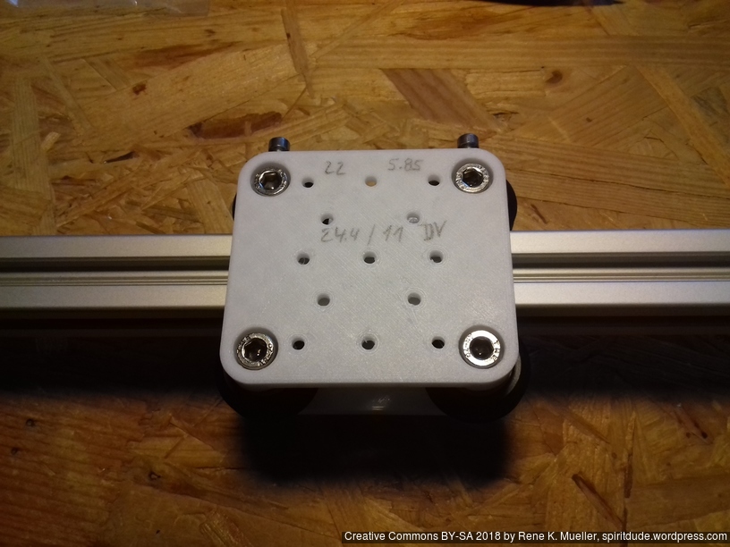


It’s the first/early version, the adjustment screws (M3x10) are very or too close to the bed for my taste, next version will use M3x8 and give more spacing. I like to keep the hotend close to the X carriage so not to waste Z space.
Additionally I made a new hotend mount so it would use another mounting holes than belt mount:
But now it’s harder to reach the hotend mount holes due the part cooler – oh well.
After few days, I noticed one wheel stopped to turn, no longer touching the alu extrusion – I guess the carriage slowly balanced itself and triangulized, no longer use the 4th wheel. I re-tighten the 4th wheel gently so it would roll again.
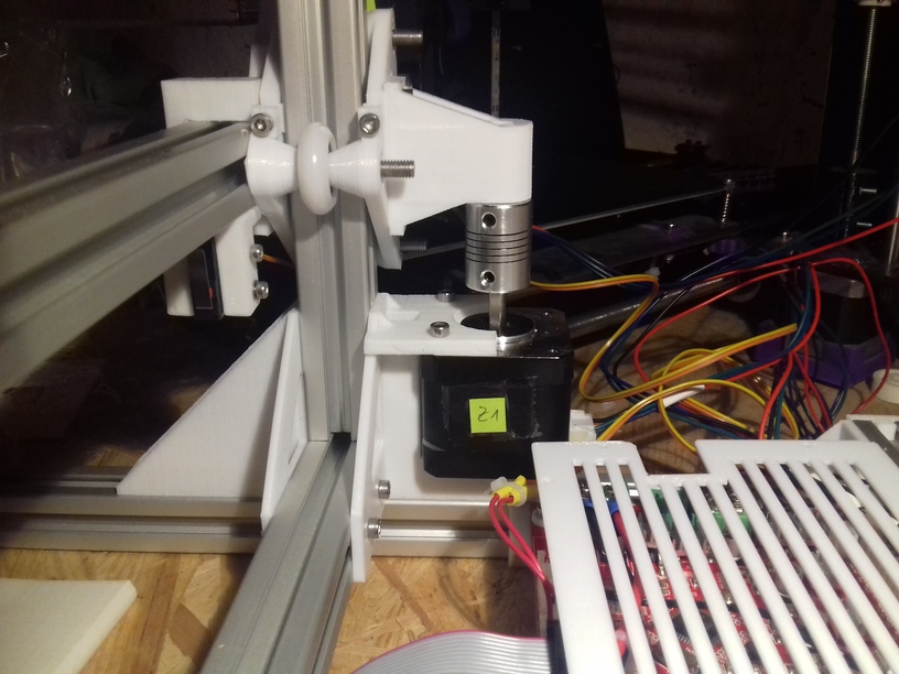
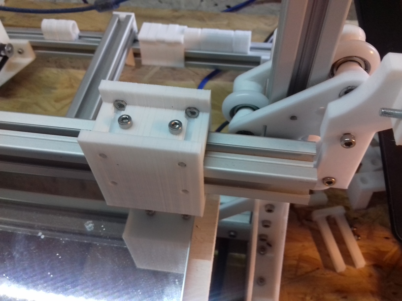
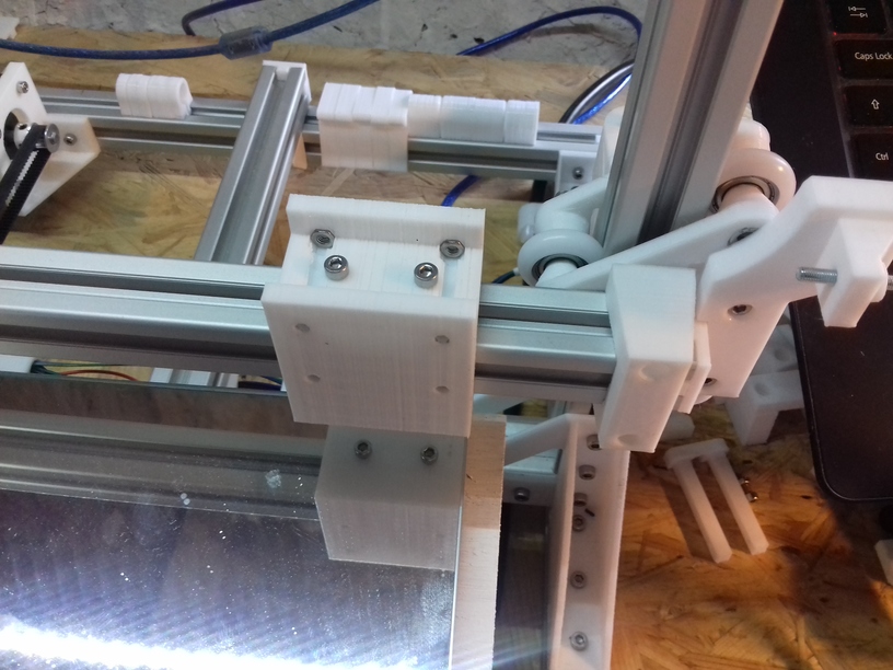
As I posted before, I suspect the Z couplers to be the main source for Z wobbles, as the threaded rods may look and are cheap but they are mostly straight – the wobble actually is caused, after close observation, from the misalignment which happens when you screw the metal couplers on, in particular if you attached the lead screw or threaded rod with uneven surface – the thightening screws may or may not attach cleanly – and thereby push the Z rods out of the center of the Z stepper motor – when the Z thread holding the X axis is fixed, the resulting wobble is worse at low Z heights; and if you fasten the Z rods at the top, the wobble gets even worse.
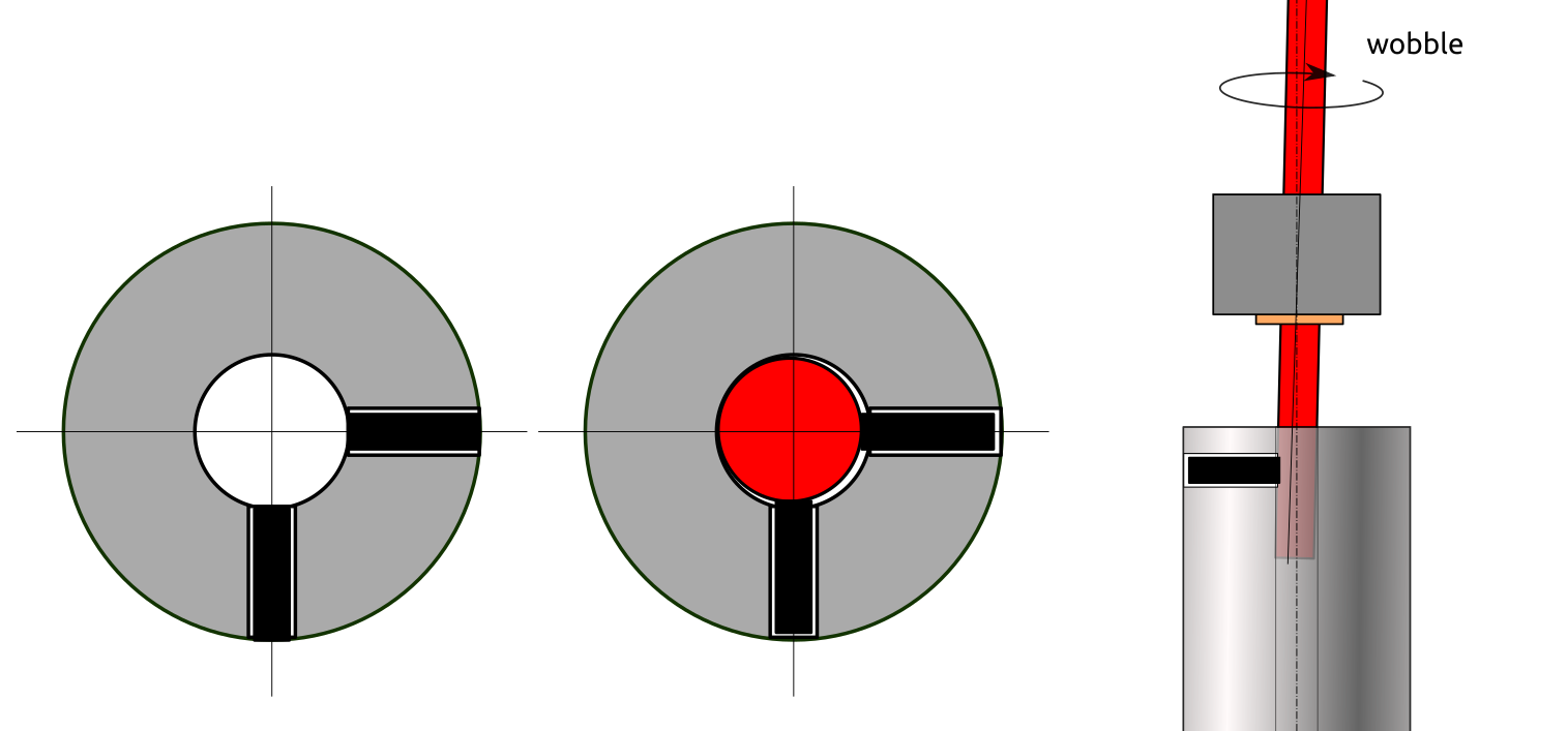
A simple remedy I found is to use printed couplers, two pieces which are screwed together with 4x M3 screws and nuts, a bit of an overkill, and a bit time consuming to fasten: incrementally tighten each screw over and over until all are tight – but I think it’s worth it: the two halves attach evenly and the PLA or ABS or whatever you printed the couplers, is soft enough so the threads of the Z rods carve themselves evenly into the coupler, and self center themselves this way – result is better centric attachment of the Z rods, not perfect but acceptable and better than poorly manufactured metal couplers.
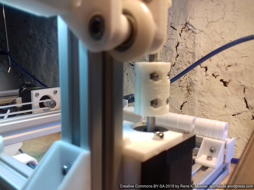
As mentioned before, I switched from M8 to M6 for the Z axis the M6 provides 1mm movement per full turn, and is more flexible to even out out-of-center wobbles, better than the stiffer M8 threaded rod. If using couplers at all, and likely introduce out-of-center mounting, rather use a more flexible lead-screw or threaded rod than a stiffer one.
It has been a few days (2018/09/04), since Ashtar K happen to be able to print, the heat bed still unfinished, some prints illustrated below are done with no leveling screws, the mirror just taped on the Y carriage – don’t laugh – later prints I had proper carriage and leveling screws included; a proper build surface I still wait for in the mail (400×400 black sticker to be cut in shape) – anyway, here some of the early prints:
The original 20mm XYZ Calibration Cube is printed in 8 mins with 0.5mm nozzle at 0.4mm layer height, and so I thought, let’s print it 2x the size with 0.4mm layer height, merely 40 mins later this:

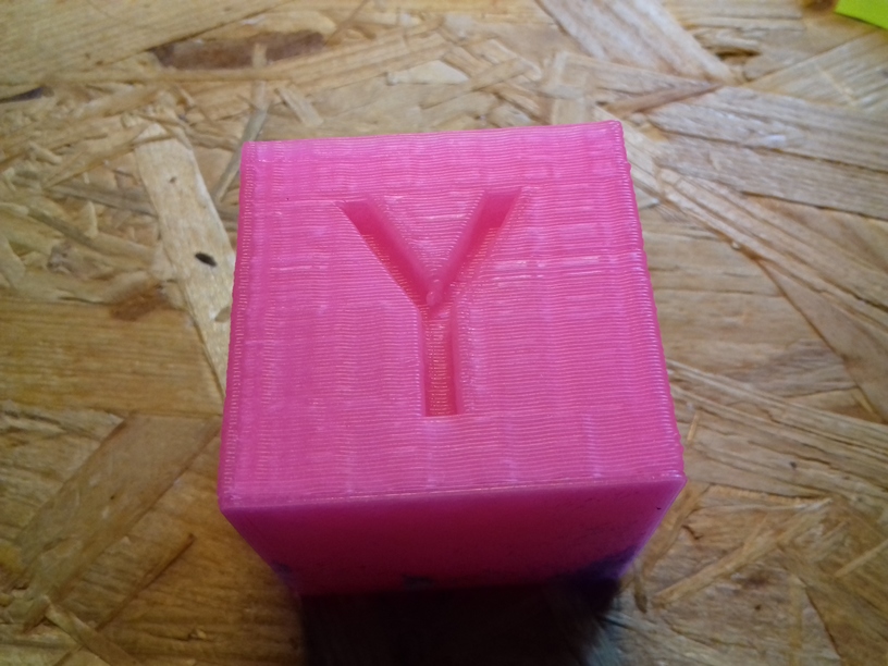
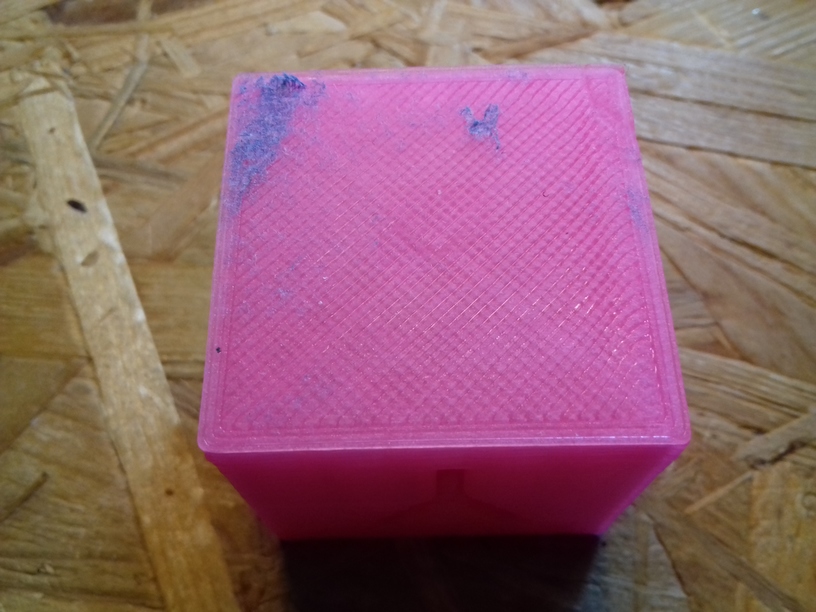
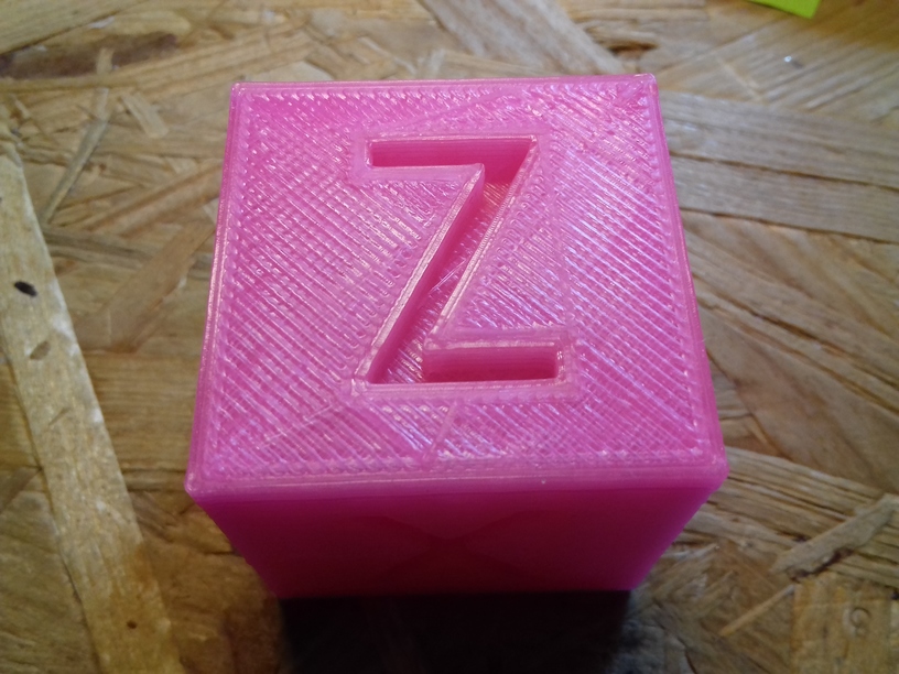
The quality is . . . impressive, this is just tuning a single day – mostly on the extrusion factor and print temperature – and this is what I hoped for: XYZ positioning almost flawless: there is slight ghosting on X axis (which could be resolved) shown on “Y”, and Y axis shown on the “X” which is fine, given the size of the bed and its weight and inertia this is OK.
I had to increase print temperature +20C from 200C to 220C for 80mm/s infill while printing with the 0.5mm nozzle, I otherwise would hear clicking from the extrusion stepper motor missing steps. I still use the classic E3D V6 (clone) heat block, not the Volcano heat block.
Printed with 0.5mm nozzle, left-to-right: 0.1mm, 0.2mm, 0.3mm and 0.4mm layer height, 60mm/s (80mm/s infill), 200C first layer, rest with 210C, pink glowing PLA by Sienoc.
While printing with slider carriage on the X axis, I noticed increased stuttering, and regardless if I thighten or loosen the grip, the stuttering remained, and slight horizontal tilt occured when changing direction on the X axis resulting in too narrow prints in X dimension.
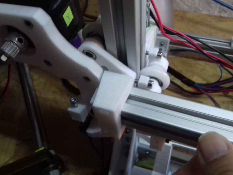
X carriage with white nylon wheels (23.mm OD / 7.3mm width)
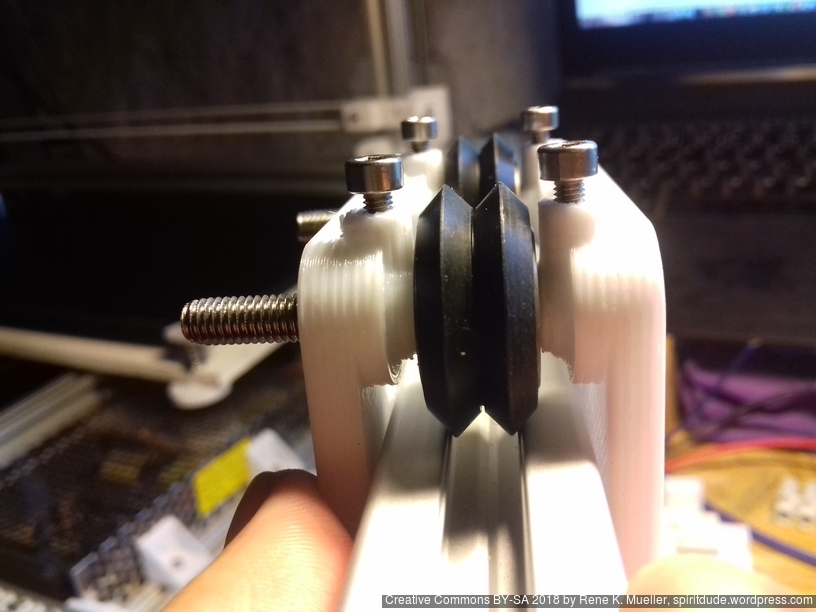
So, I changed back to wheel-based carriage, first again 23/7.3 white nylon wheels (right photo), but when I printed “L” shape with 200mm length in X and Y and 1mm height in Z, I noticed slight Z sinus form as I saw before – while it rolled nicely, there was a wobble . . . and so I printed a new carriage which holds the black OpenRail Double V (clone) 24.4mm OD / 11mm width, and put it on the X carriage:
X carriage with double V black wheels 24.4mm OD / 11mm width
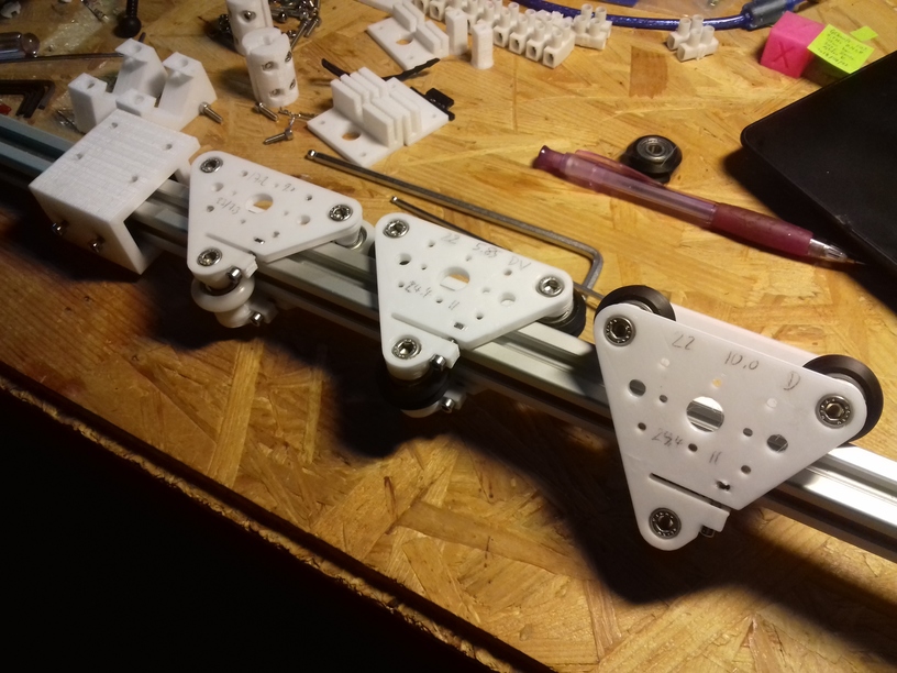
A brief overview of the carriages riding on 2020 T slot (B-Type) alu extrusion:
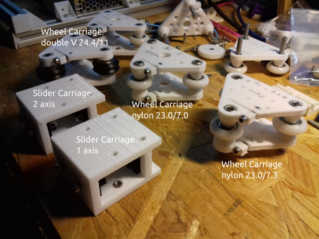
Sliders: on the X axis it did not last, the stuttering was not avoidable; the issue is that the X carriage is one of the hardest axis of the Prusa i3 style geometry to handle: it isn’t just X directional rail, but also pressure on the Z with the weight of the print head, and running over overextruded filament – and it’s hard to pull the X carriage perfectly without the carriage have some vertical tilt as well – anyway, I still use the slider option on the Y carriage – and works fine so far.
White nylon 23/7.3mm wheel: rolls nicely, but gives wobble to the Z height when used on X carriage, apprx. 1mm, also doesn’t stay vertical upright, but tilts a bit with pressure – when the print head moves over overextruded print it doesn’t level it, but jumps over it. I currently use white nylon wheels on the Z carriage successfully.
Black double V delrin 24.4/11mm wheel
As you may have read in the other post(s), I use M6 threaded rods, it’s flexible and rather aligns with the Z axis itself, whereas M8 is stiffer and misalignment – which by the way doesn’t come from the rod itself, but the mounting with the couplers – won’t impose on the X carriage – this is my own view and it happens to come true again with Ashtar K, after I changed my cheap CTC DIY I3 also to M6.
Now, the 1m long M6 threaded rod, enough for two Z axis each 500mm long, did just cost EUR 0.70, made in China but purchased locally in Germany, and the nylon wheel-based Z carriage happen to work perfectly so far – I expected some slight sinus wobble imposed by the nylon wheels as I encountered on the X carriage, but it seems when there is little force applied on the wheel the carriage works good enough.
Printing 330mm high 10mm diameter cylinder (with slider-based X carriage):
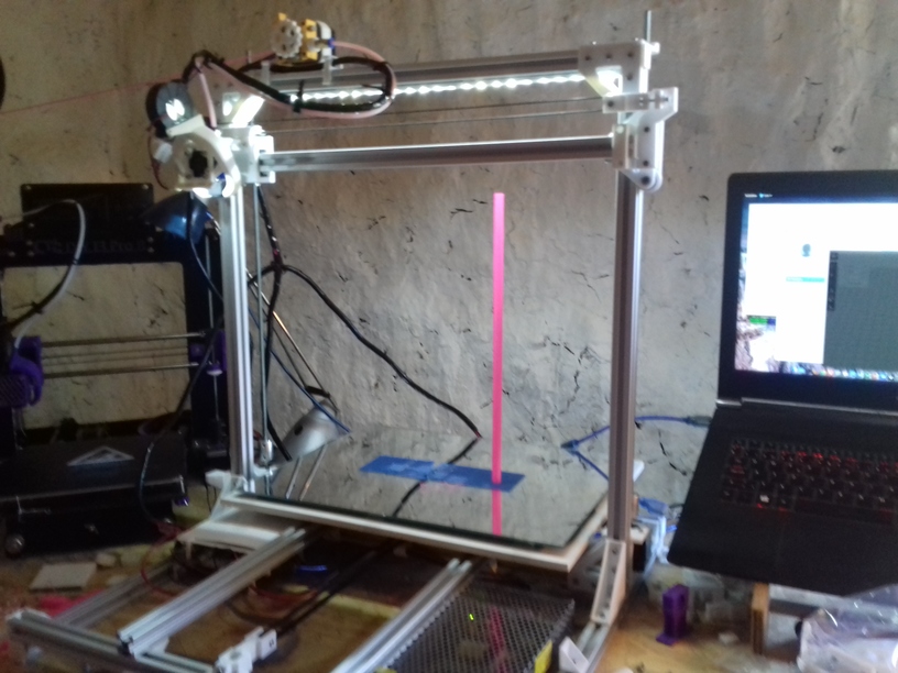
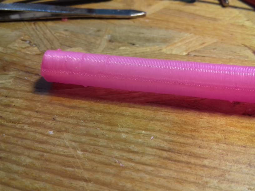

There was some slight extrusion inconsistencies, this is likely due the material, an broken vacuum seal of a newly purchased glowing pink PLA roll, actually, after watching the 2nd print closely, either GCode errors or USB transmission errors, as some segments of the circle (layer of a cylinder) is repeated for some unknown reason and so overextrusion occurs there (needs proper investigation) – but the linearity is very good, and no Z wobble whatsoever.
60mm height “loopy egg”, printed with 0.5mm nozzle, 0.4mm layer height:
The “loopy egg” is a good benchmark for retraction settings, and stressing the extruder motor as the short segments making up the loops require a lot of push / pull on the filament. There was still some slight stringing, which I knew will happen, as the retraction is just set to 2mm at 35mm/s giving very good results. More prints will tell if I can stay with these retraction numbers.
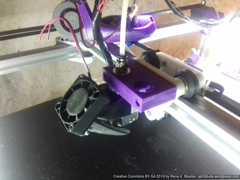
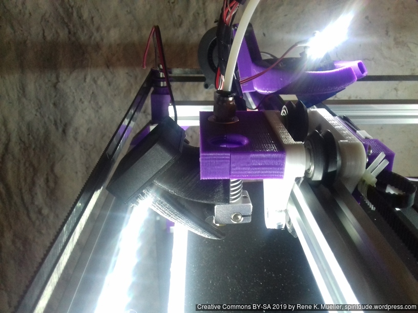
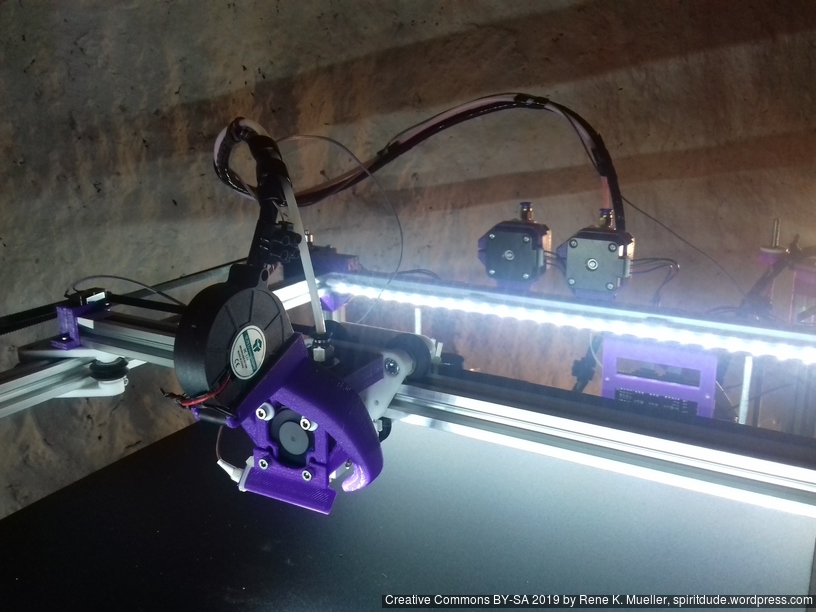
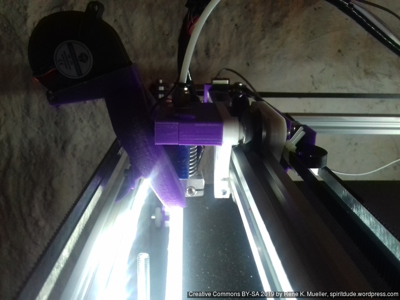
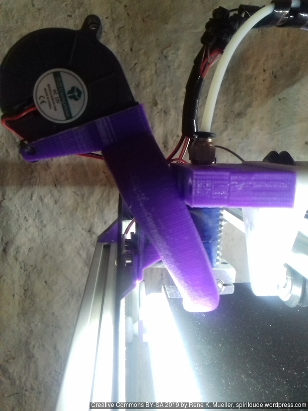
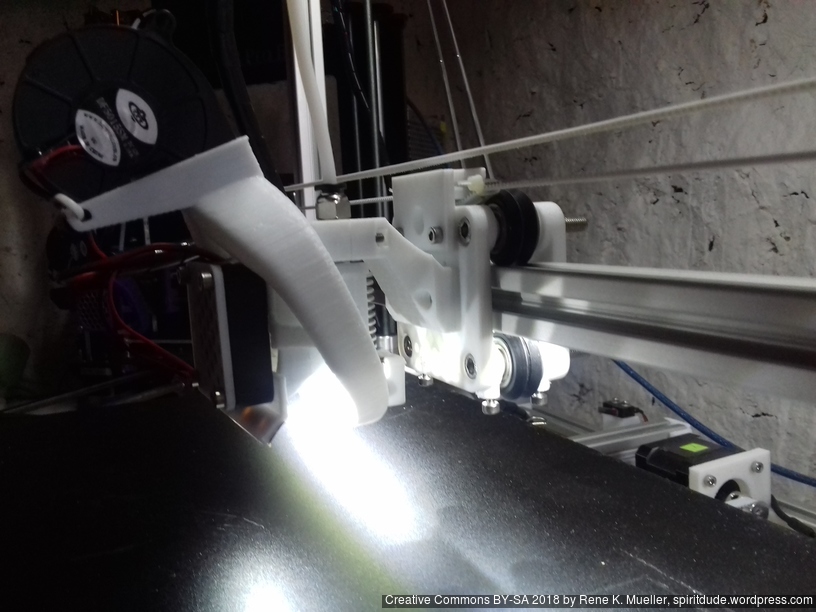
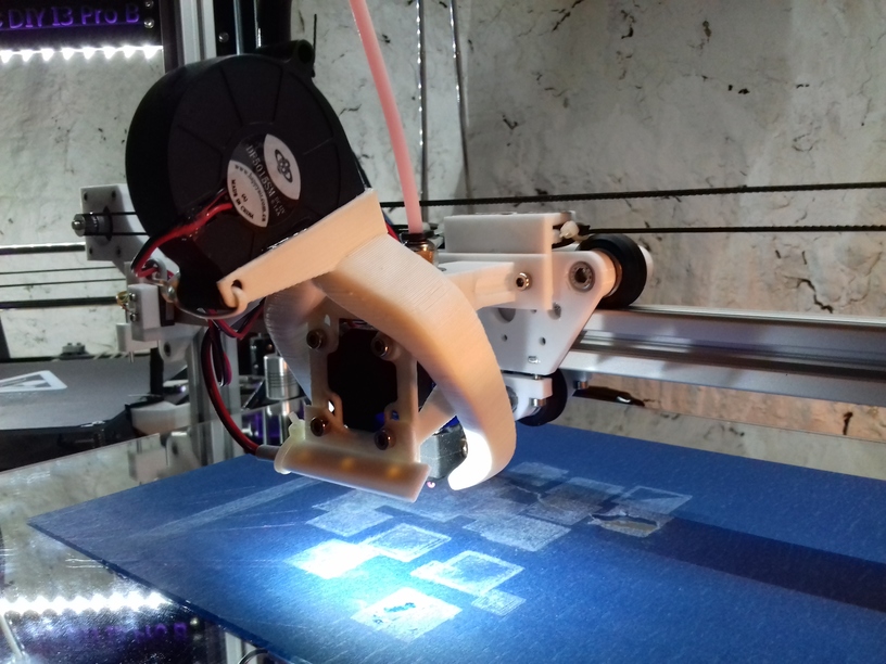
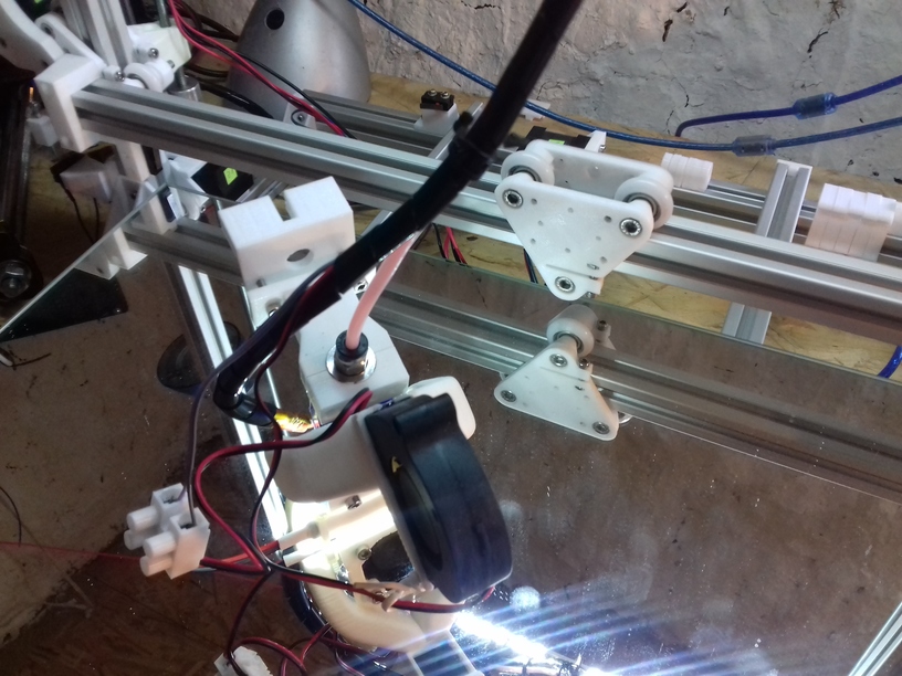
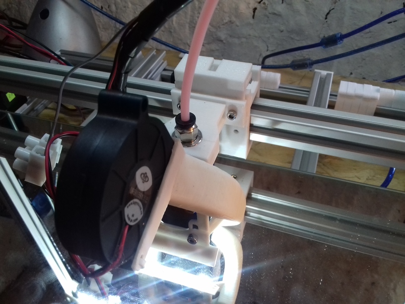
I currently use E3D V6 clones as hotends, one with 30mm “original” fan, and one with 40mm fan. And with the “original” smaller 30mm fan I experienced frequent clogging up within the hotend: some of the filament melted above the heat break and expanded and blocked any further extrusion – that happened now several times.
I tried to reduce the extrusion temperature but which caused decline of print quality. After trying to determine the root cause of the problem, I concluded that it was heat creep and insufficient cooling above the heat break, hence, the hotend fan, and I switched to 40mm fan – and the clogging disappeared, not quite yet . . . update follows.
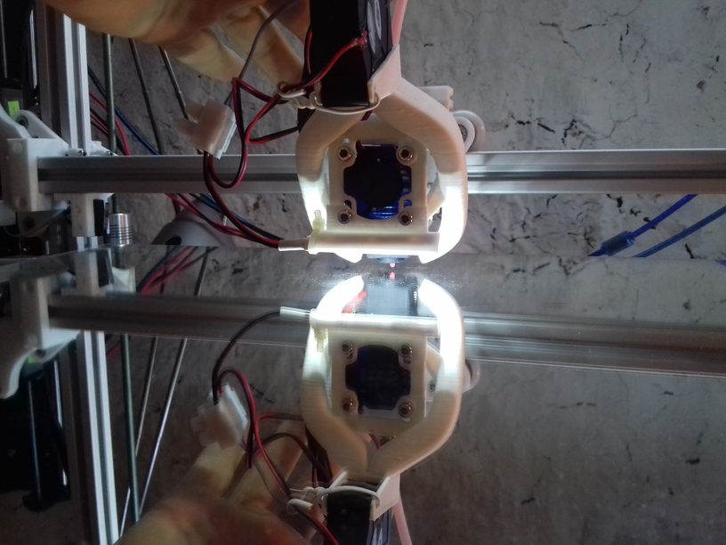
30mm Fan (front facing) with 5015 Fan Fang (top)
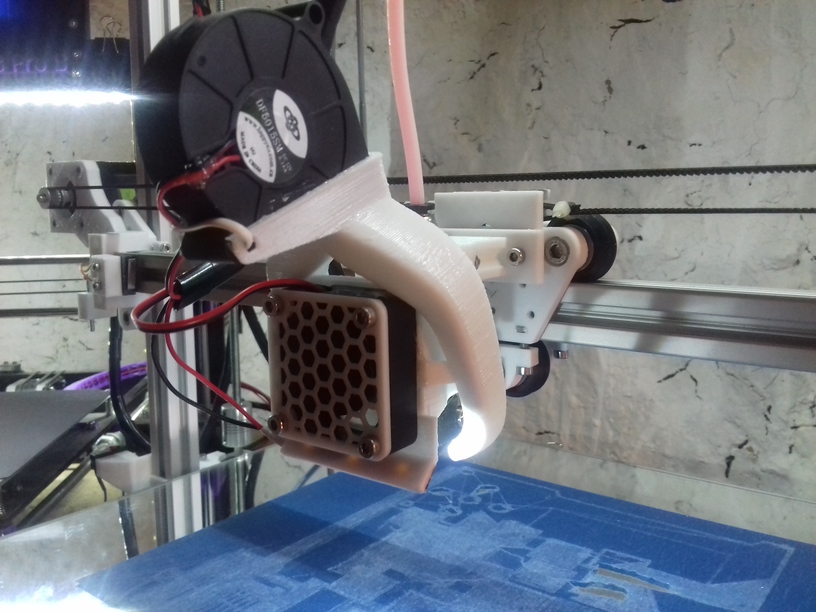
40mm Fan (front facing) with 5015 Fan Fang (top)
Although both setups look very alike, I had to print out another fan fang which can contain 40mm fan.
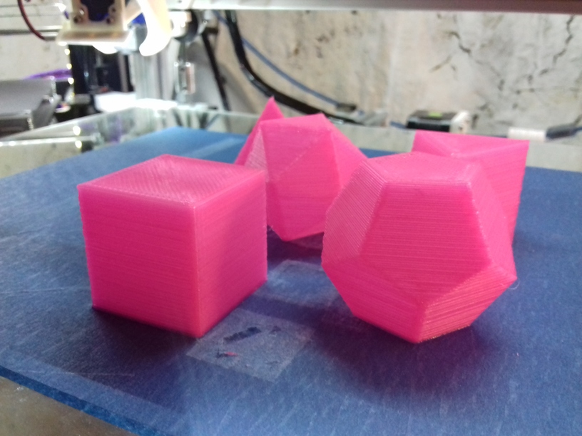
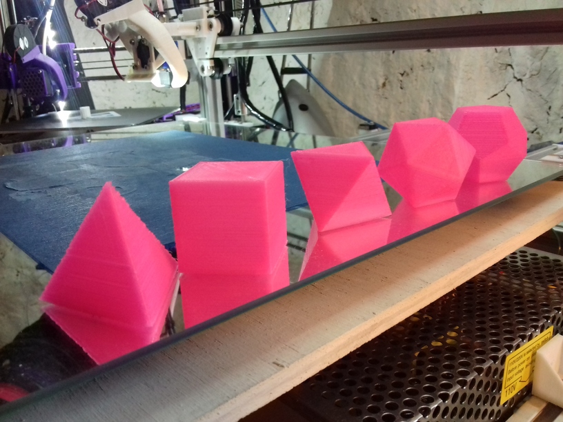
My favorite geometrical forms – aside the sphere – the sacred set:
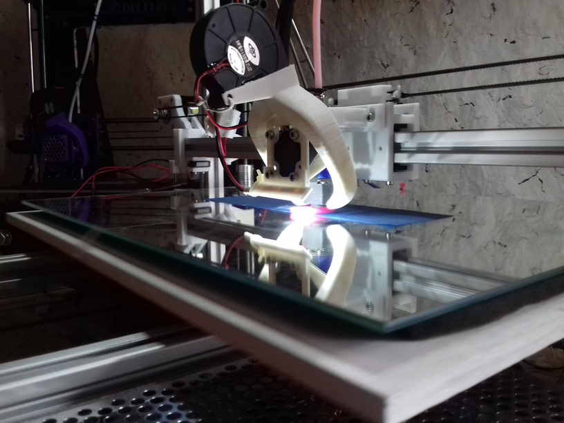
I’ve got 40cm x 30cm mirror which became my bed base, underneath with some tight springs some 6mm multilayered plywood, which was warped 2-3mm on the edge – but it didn’t matter (much). The mirror was the reference, and the Y carriage had to hold the mirror. That turned out to work very well: the mirror is truly flat, I leveled the bed once for tilting, after a week, I only had to tweak the Z endstop screw slightly, but I didn’t touch the screws mounting the mirrors to re-level the bed anymore.
So, using the mirror as bed worked well so far due the flatness – but the glass didn’t turn out to print good on it, the printed parts often detached before finishing the print, and ruin the print – so I used blue tape sheet as temporary solution until the black sticker arrives which I already use on the other 3d printer.
As I designed Ashtar K with larger build volume, I choose 0.5mm nozzle at least, and the max 0.4mm layer really pays off in regards of print speed, while still maintain some details – I’m quite pleased so far.
Well, after merely 3 months (2018/06/06) when I started to code the first lines of OpenSCAD to develop a series of parametric Prusa i3-like designs, and few weeks ago decided to go with the “K” series with 2020 alu profiles: simple 11x 500mm beam T slot (B-Type) alu profiles – the 1st prototype happen to print the 20mm XYZ Calibration Cube as of 2018/08/27:
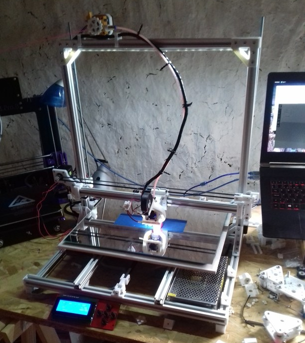
The bed is very temporarly fasten with tape, as I haven’t decided on the actual details of the bed mounting yet and leveling details – but I wanted to see how well the mechanics already works – and it performed quite well so far.
1st print came out mediocre, when I realized I had to tighten X and Y belts more, 2nd print came out much better; 0.5mm nozzle with 0.4mm layer height, merely printed in 8mins with 60mm/s print speed and 80mm/s 20% infill:
And just for the fun of it, 0.2mm layer height with 0.5mm nozzle, at 70mm/s:
Incredible quality: X and Y surface very good, some inconsistency at “X”, on the “Y” side some slight ghosting; but most surprising is the edges on the Z axis – I operate with a simple M6 threaded rod and M6 nut – that’s all – moving nylon wheel-based carriage up and down – sure, I require to print more tests, in particular larger prints to really see how well all axis print up to 300mm.
I had to use blue tape on the mirror otherwise PLA would not stick – eventually I will use the black sticker as I used for the CTC DIY printer which worked quite well.
The past 2-3 weeks, while waiting the nylon wheels to arrive, I decided to check alternatives such as sliders with PTFE tubes – and this paid off: the nylon wheels 23.0mm OD with 7.3mm width sit quite nicely into the T slot (B-type) but when used in real life, like with X carriage, I had some sinus wobble in the vertical – apprx. 0.5mm to 1mm – way too much. So, I exchanged the wheel-based X carriage with the slider-based carriage, remounted the hotend with Bowden setup, and after 5mins the exchange was done:
Current setup:
The next days and weeks I will review my options:
both on T slot alu extrusion – I know ideally would be proper V slot alu extrusions, but I like to find out how good it works with the easily available T slot extrusions. Worst case is, I have to use on X and perhaps Z axis proper V slot alu extrusions, on the Y axis it seems the simple sliders (just a block) work fine.
Since I deal with nearly 3x the bed surface compared to 200×200 I thought I have to use a bigger nozzle as well, as a bigger build volume would imply larger objects to be printed. The increase from 0.4mm to 0.5mm diameter also implies 1.5x or +50% more material being extruded and I still desire to print with 60mm/s average with 80mm/s infill – this means I have to test well the hotend performs with that speed and higher throughput of material.
Current specifications of Ashtar K 3d printer: