Video ID not provided: Please check your shortcode.
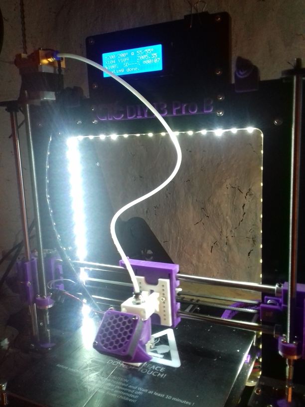
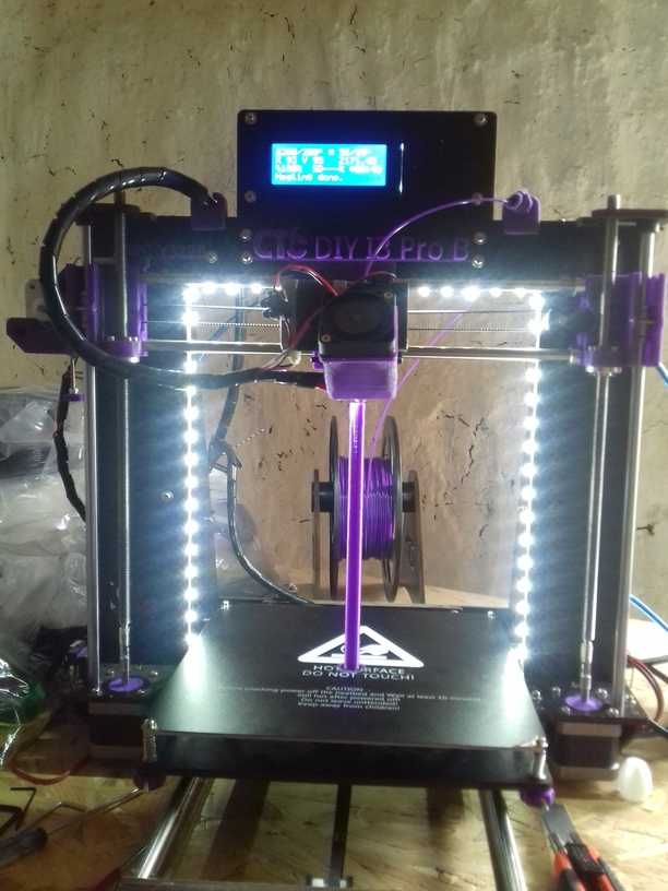
Some further notes using CTC DIY I3 Pro B 3d printer the past 60 days:
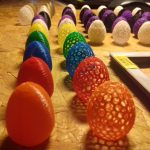
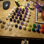
Sample Prints
Propeller Guards
Printing propeller guard at 60mm/s (first started with 40mm/s and then “Tune” -> “Speed” changing from 100% to 150% when I saw first few layers went well) with Kaisertech white PLA @ 210C:
This is quite a hectic print, a lot of motion of the head and relatively narrow infills; 20% infill, 0.3mm layer height with 0.4mm nozzle.
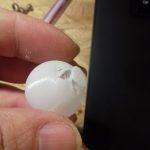
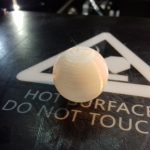
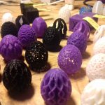
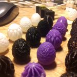
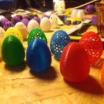
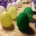
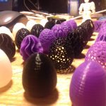
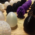
Sphere
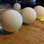
I really like, admire the Platonic Solids, and Johnson Solids, and there is the Sphere – the ultimate archetype of form – and for sake of challenge, I tried to print a 25mm diameter sphere – without support (with it, you won’t get a smooth surface).
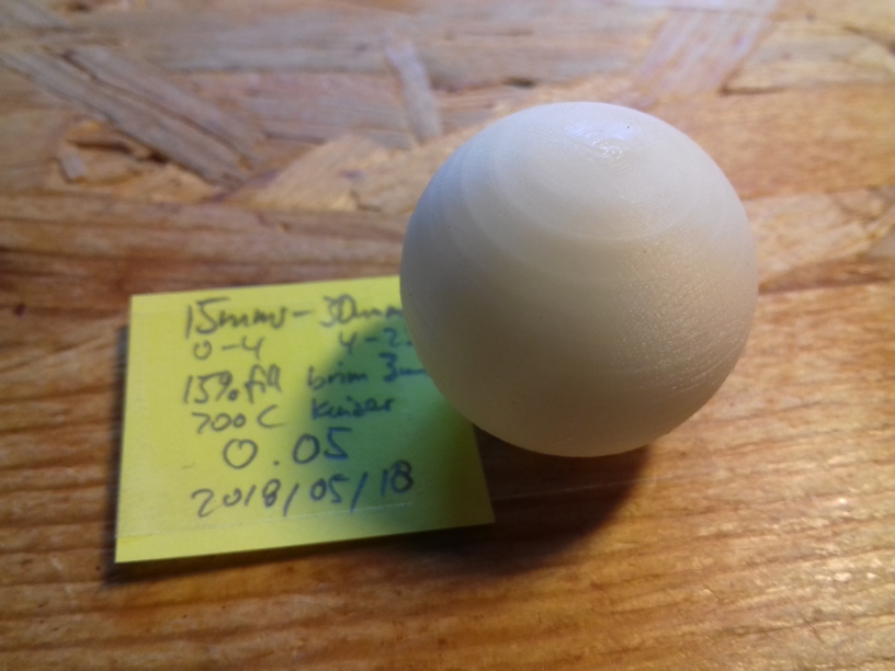
The trick which worked, was printing a brim and 50um layer height with slow speed of 15mm/s at height 0-4mm height and then 30 mm/s for the rest, that allowed to print the slope at the bottom of the sphere somewhat, not perfect but good enough for now – I will keep refining the process though.
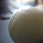
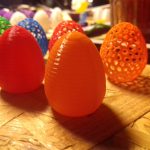
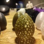
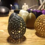
Many Failures
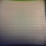
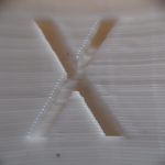
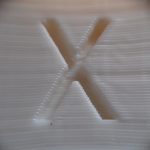
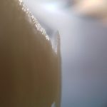
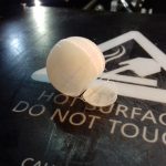
Additional, my one-side blowing part fan showed its weakness, there is a cooling “shadow” (1st photo below) which shows when printing small objects where the nozzle reaches the same point soon and insufficient cooling is happening: the printing curls up, and causes bad surface in the final print.
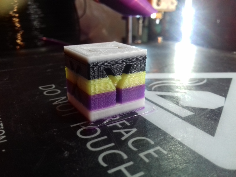
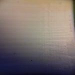
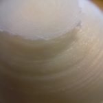
Cura has a special mode called “Spiralize Outer Contour” and it prints circular with a steady increase of Z, smoothly, yet, without infill, the top won’t work (2nd photo), and the bottom was very weak that it broke when I tried to remove it (3rd photo).
A simple way to print a smooth sphere is to break it in two halves, and print both hemispheres and glue them together.
Challenge 1st Layer
The first layer is the challenge in 3d printing, because it can fail based on various reasons:
- not well leveled toward X gantry (level it)
- dusty surface (clean up)
- uneven bed itself (use glass)
- uneven bed while heating up (level in warm/hot bed state)
- uneven bed while hot (let it in hot state for a few mins and level again)
- bad filament (change it, keep records)
and I discovered another reason:
- inconsistent extrusion because of
- missing steps (clicks) of extrusion, too low temperature (increase temperature of extruder +10C)
- bad teflon tube (replace it)
- partially jammed or clogged nozzle (clean it or replace it)
which is hard to determine: one has to observe the first 3 layers closely and if it’s laid down “nicely” (even surface), and see if the width of the laid down filament is consistent, if not and it varies then the filament tends to curl on the nozzle instead to lay down to the bed.
I was in the process printing ~100 pieces, in 12 pieces batch prints, after 5 batches and the first layer failed after 10-11 pieces and I had to abort the print for 10x in sequence (re-level and cleaning bed and otherwise determine the problem) until I realized it was the worn out teflon tube, after I replaced it the following prints worked well again.
The past weeks I discovered the hotter the filament, the more likely a good first layer, but you have to print the next layers a bit cooler, otherwise the final surface come out smooth. So, with Cura you can set “Printing Temperature Initial Layer” and increase +10C to the normal printing temperature.
CTC DIY Bad Print Reasons and Remedies
These are the issues I encountered the past 60 days:
- two screws which hold the “L” with the extruder on the X axis, they tend to get loose and X motion will change Z level, or give bad layers once in a while when it tilts – retighten those two screws
- nozzle gets loose with time giving bad quality prints (e.g. after a few weeks), retighten in hot state (at 215C for example), not too tight
- screws and zip ties of the Y bed get loose giving bad quality prints – remove heatbed and rethighten all screws if necessary and retighten or replace the zip ties
- recheck X belt tension and Y belt tension
- recheck Y motor holding, best fasten entire Y motor at the back with zip ties
- refasten screws which connect XZ frame with Z motors
- recheck the teflon tube whether malformed or has residue (replace)
- clean the nozzle with a fitting drill (e.g. 0.4mm) or cold pull
Changing Filament
Push/pull method:
- preheat nozzle (with LCD Controller manually, or with Cura) to 215C for PLA
- push manually the filament into the extruder ~2cm firmly, if it goes easy then do 3), if not, wait for a few seconds, and push again (it has to go easy)
- swiftly pull out the filament – most of the times the break will happen below heater block; a few times a thin break happens which blocks the extruder wheel
- push in new filament manually and push old filament out the nozzle until new filament shows up
Just for the fun of it: seamless (without interrupting printing) changing filament
Continually or seamless change PLA filament:
- preheat nozzle (with LCD Controller manually, or Cura) to 215C for PLA – or you are in the midst of an existing print job
- cut perpendicular (not pointy) filament few millimeter above the extruder
- cut perpendicular new filament (not pointy)
- extrude more filament (with LCD controller or Cura) until old filament disappears into the feeder
- insert new filament so there is a seamless continuation of filament (too much force screws up Z layer height, too little force doesn’t take up the new filament)
- hopefully the new filament pushes the old one nicely through
Improving CTC DIY Prusa i3 Pro B
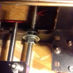
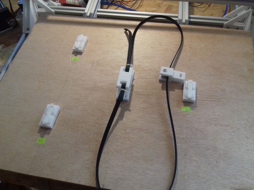
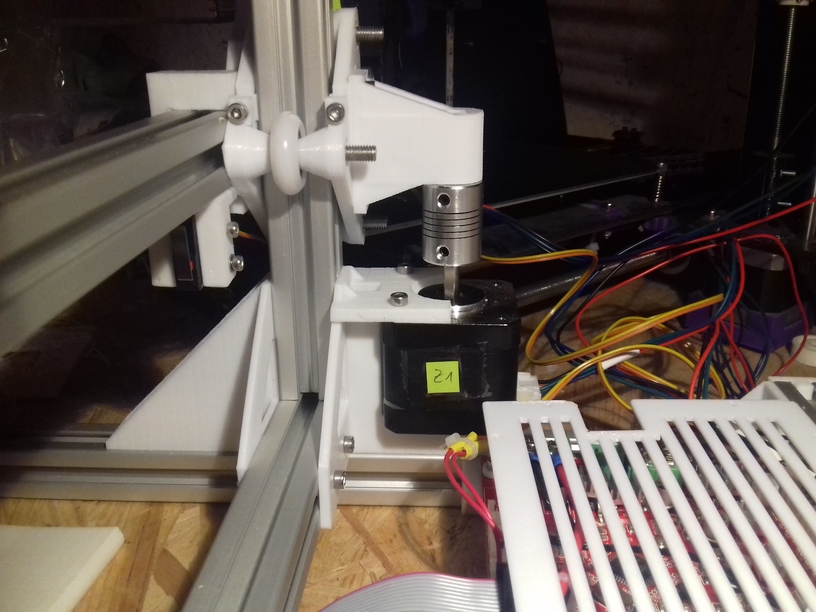
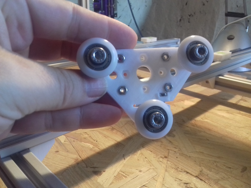
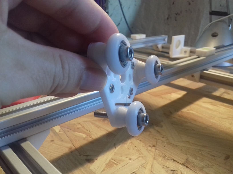
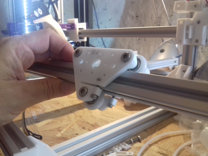
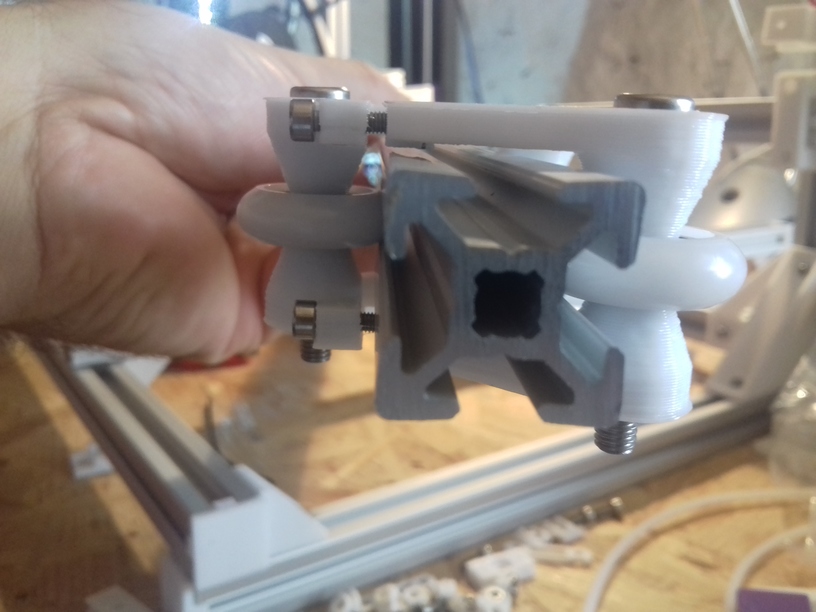
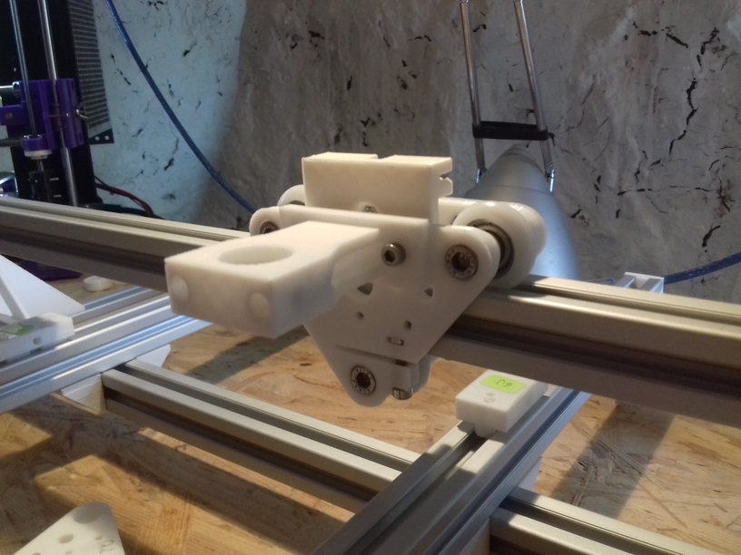
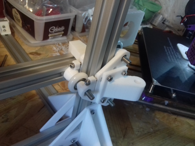
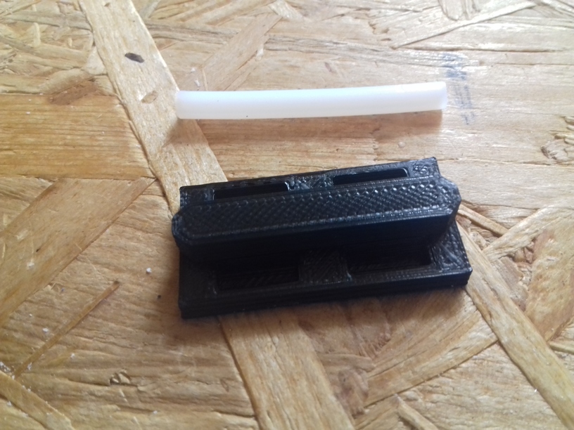
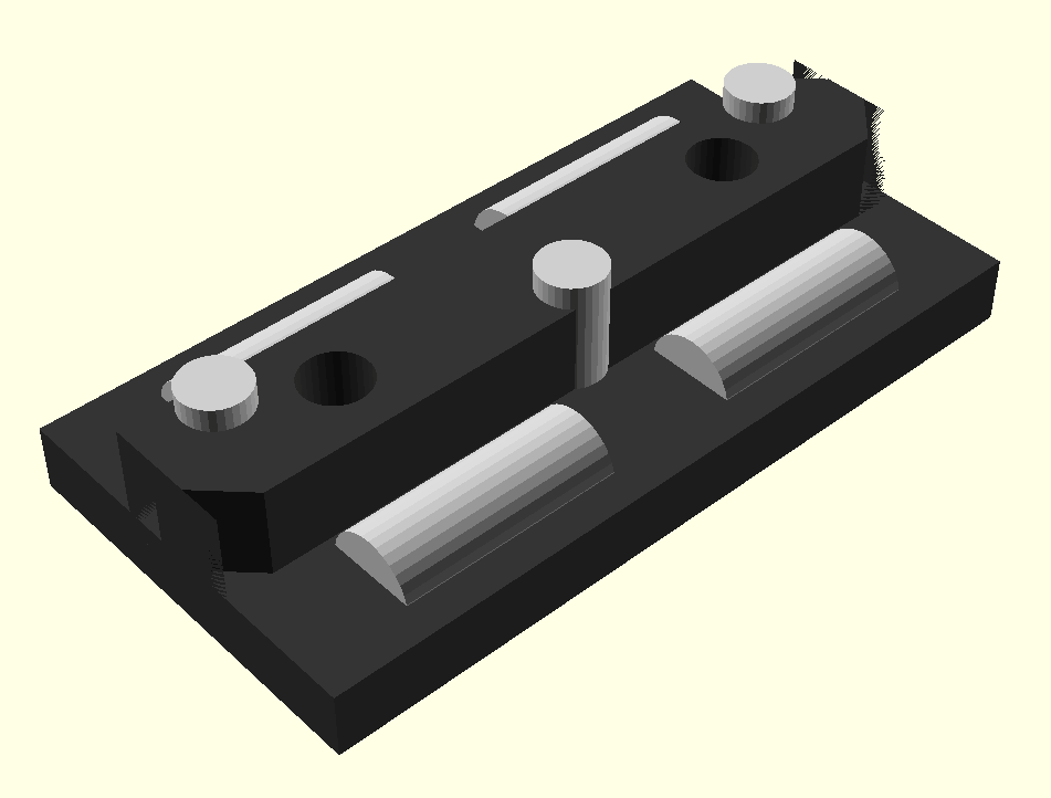
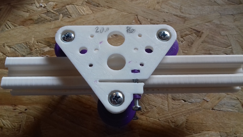
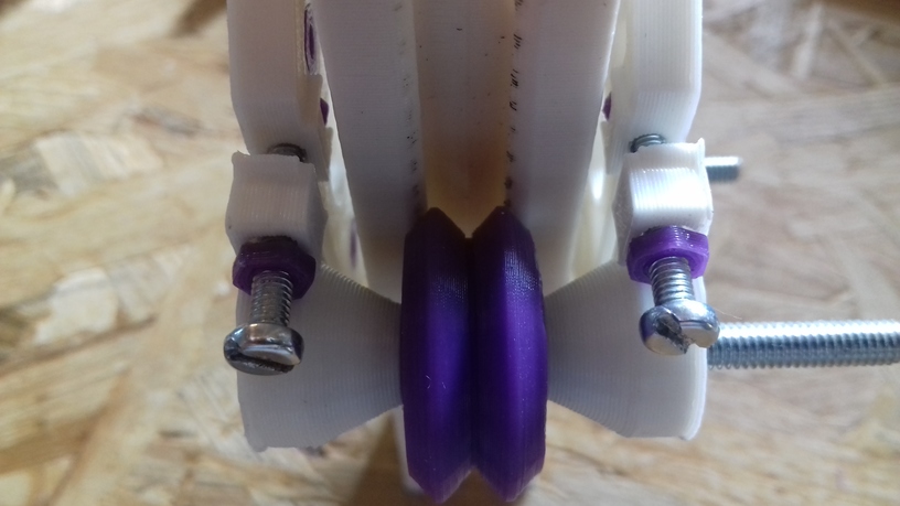
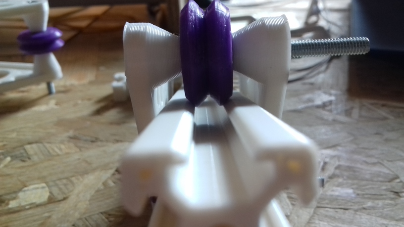
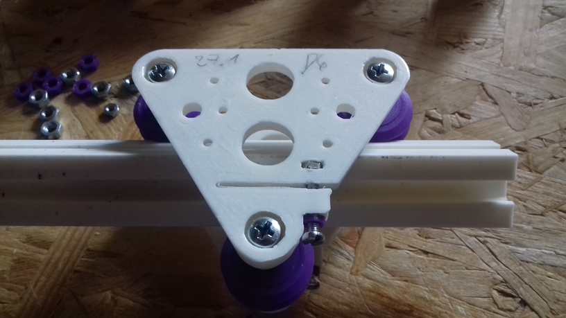
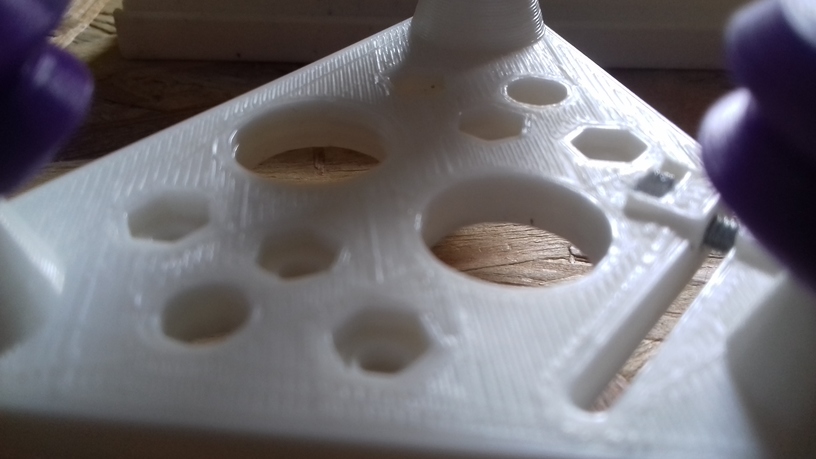
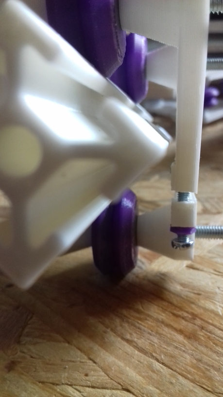
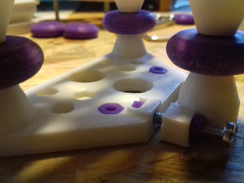
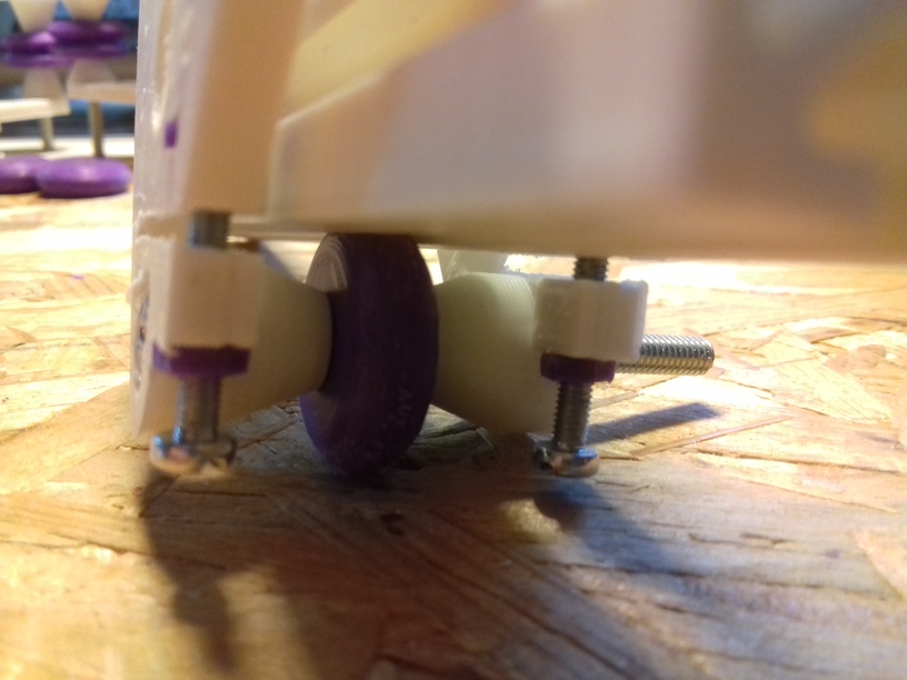
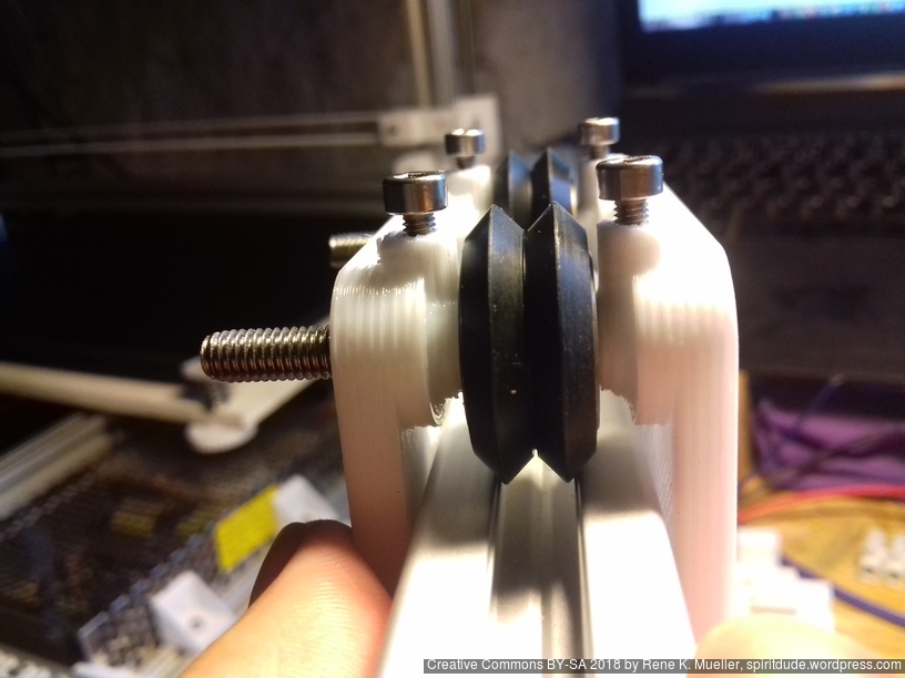
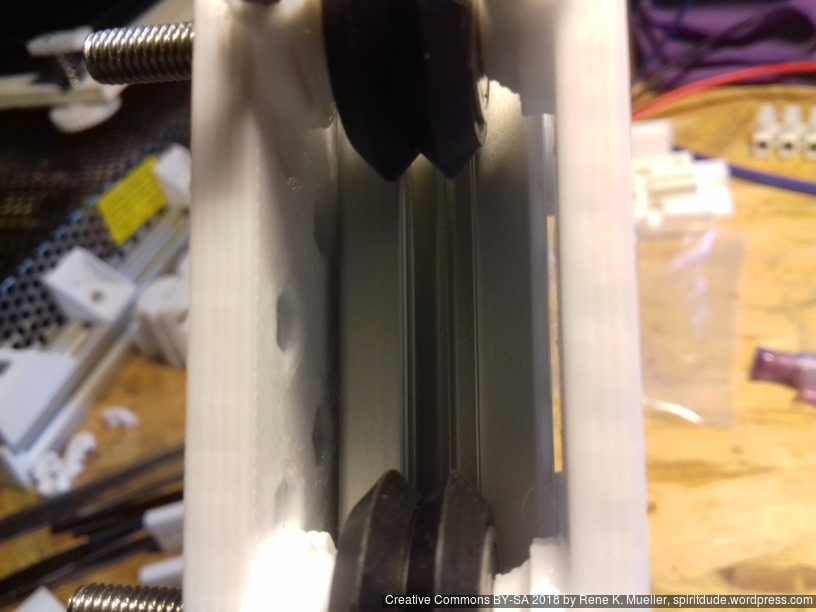
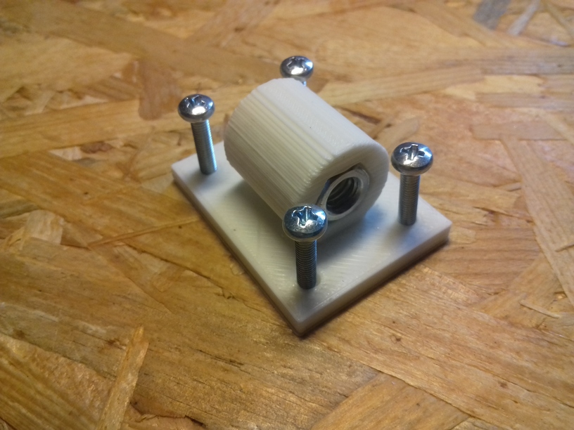
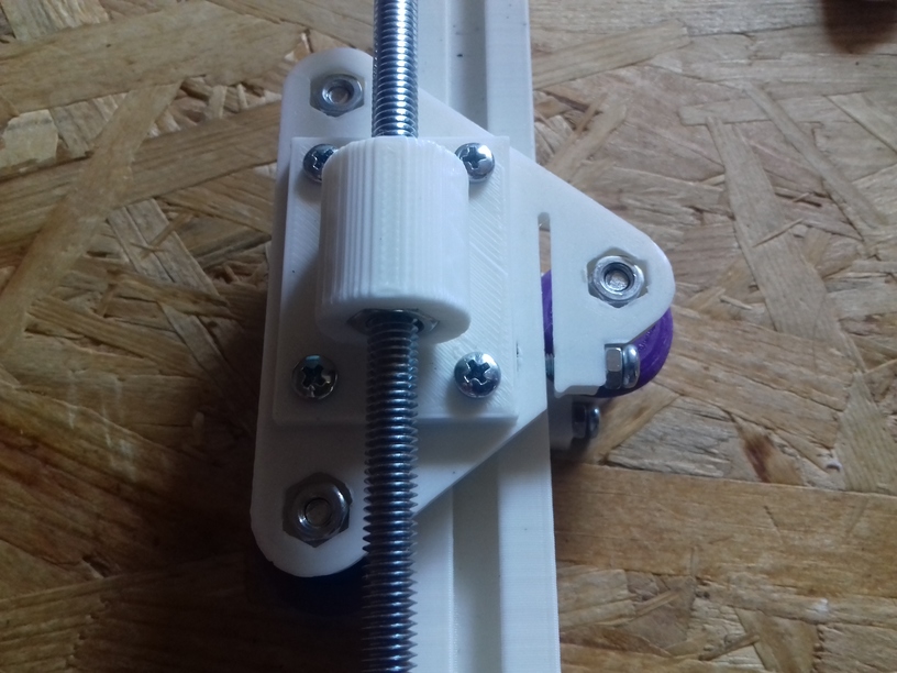
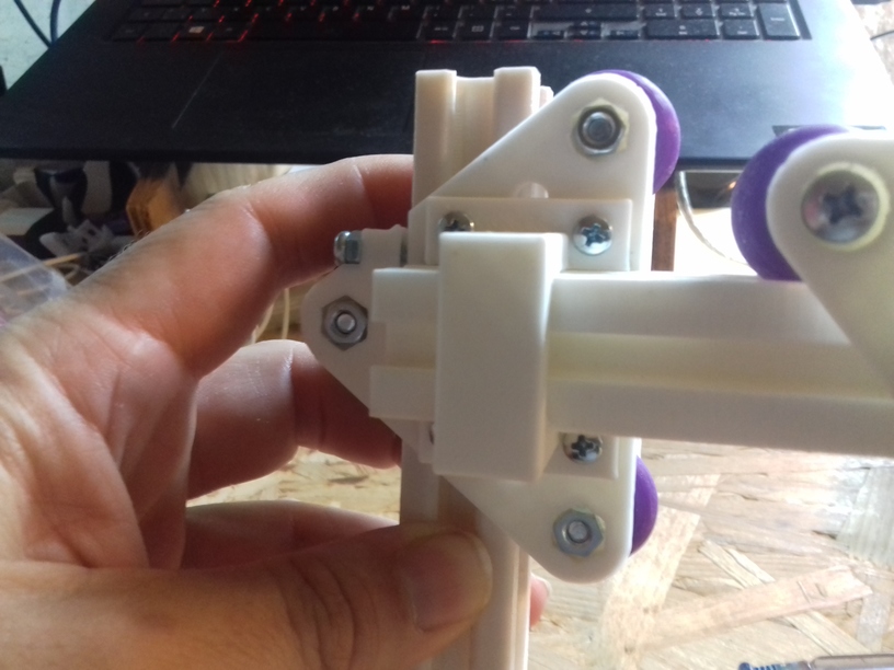
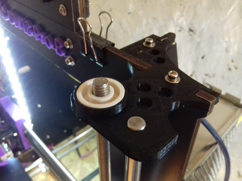
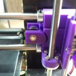
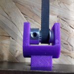
Replacing Pulleys
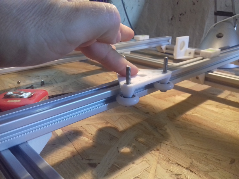
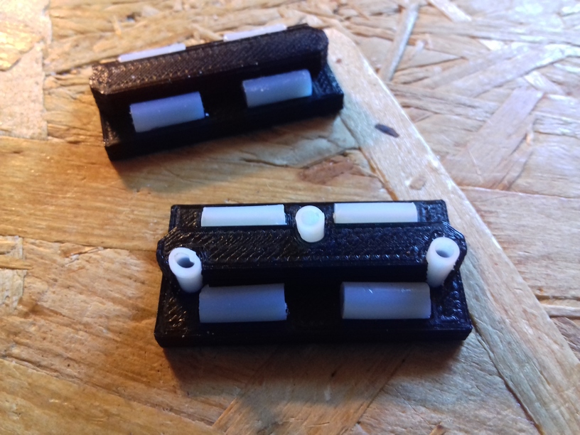
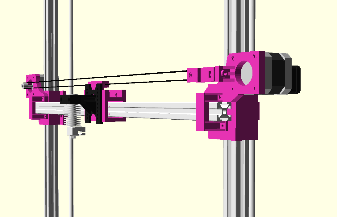
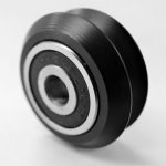
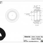
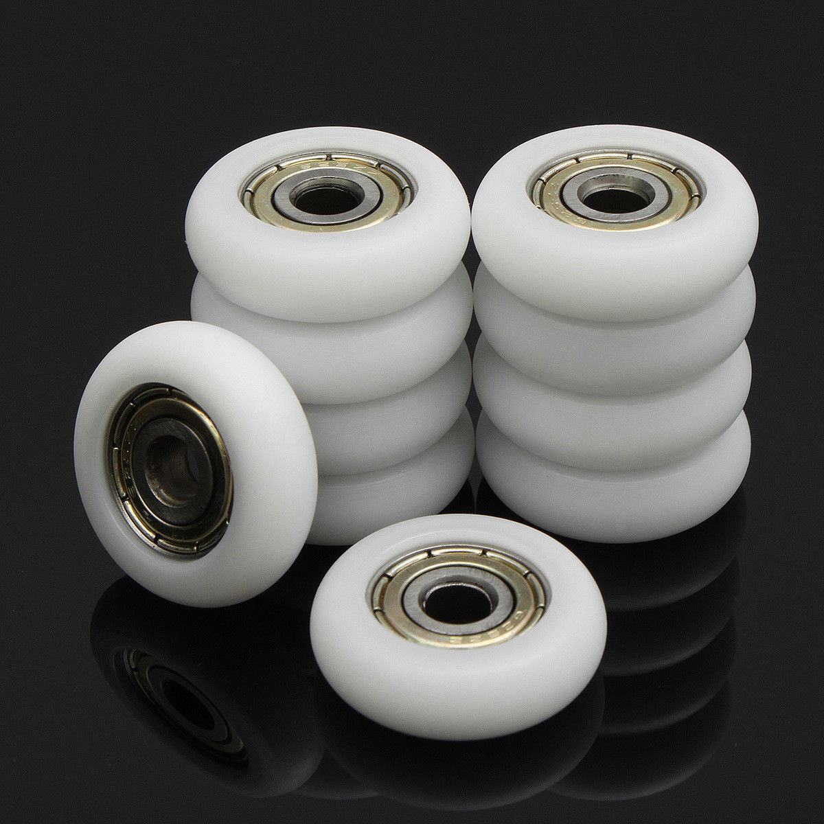
After some hesitation, I replaced the white plastic pulleys and printed pulley holders for the new GT2 metal 16 teeth pulleys, also for the X and Y motor, with the existing bearings (MF85ZZ: 8mm outer diameter, 5mm inner):
I printed a small washer (in white PLA) (8mm outer, 5mm inner, and 2.5mm thick) so the pulley would stay more centered and not move or wobble like the older/original pulley holders.
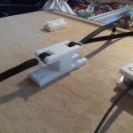
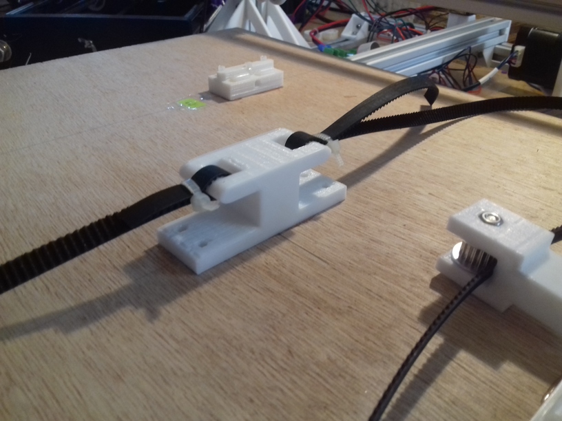
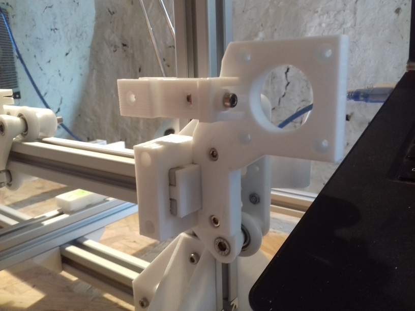
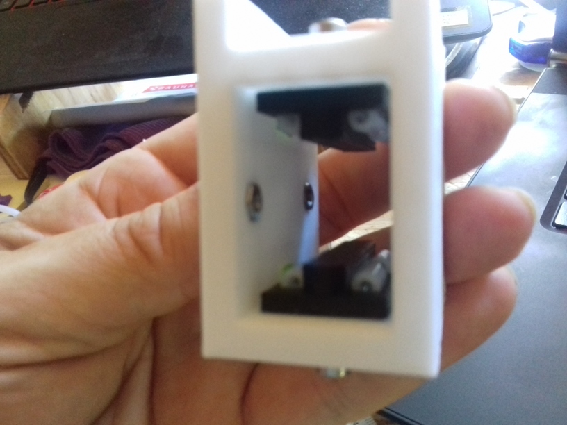
Replacing Y Bed Bracket
Quite an obvious move, when you look at the way the bed it attached with the Y belt it’s not parallel, and I felt this will interfere with precision in Y axis in general – so I used this CTC Prusa Y Belt Holder / Bracket to replace it:
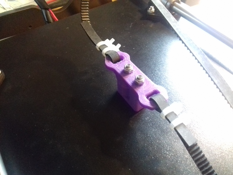
And now the belt is parallel to each other and the smooth rods and threaded rods as you can see.
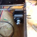
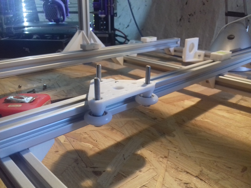
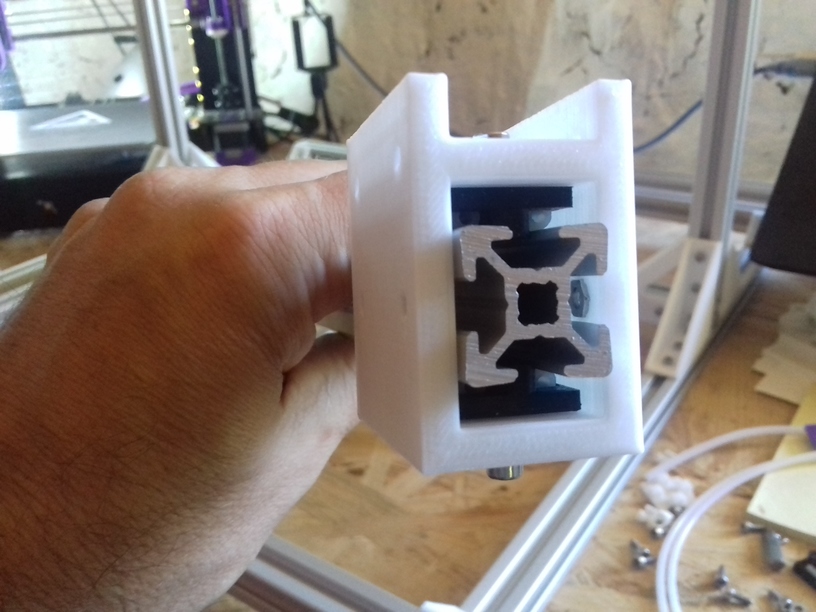
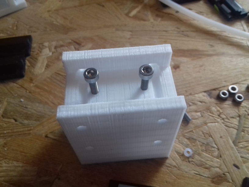
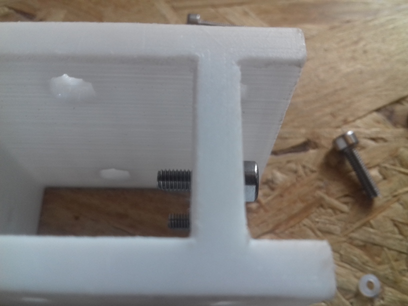
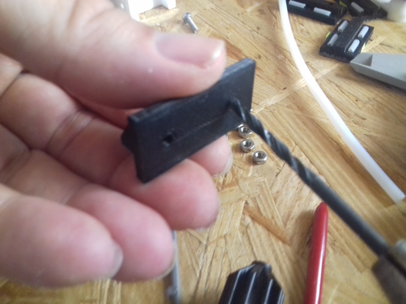
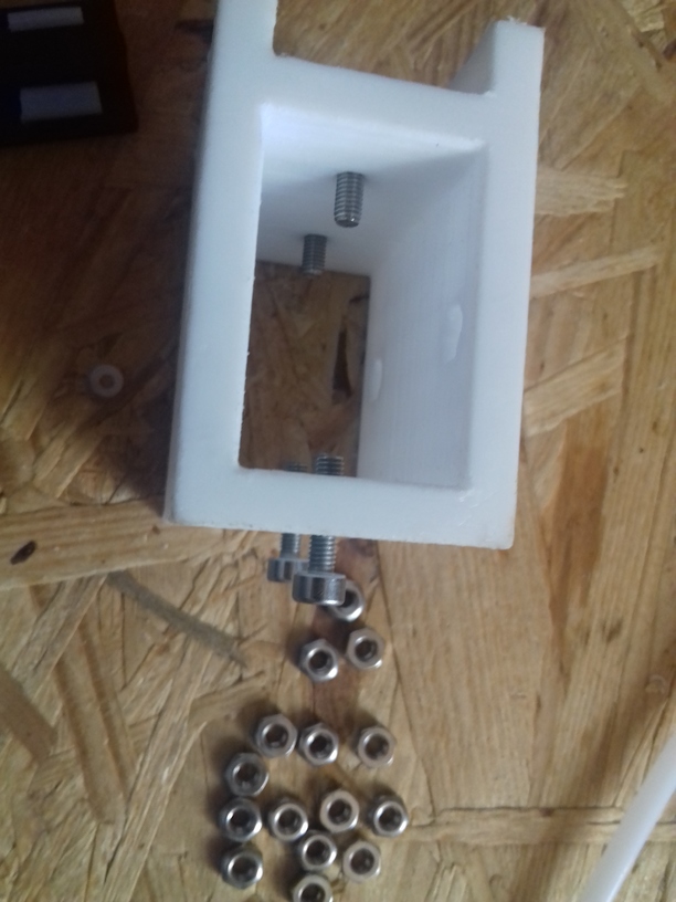
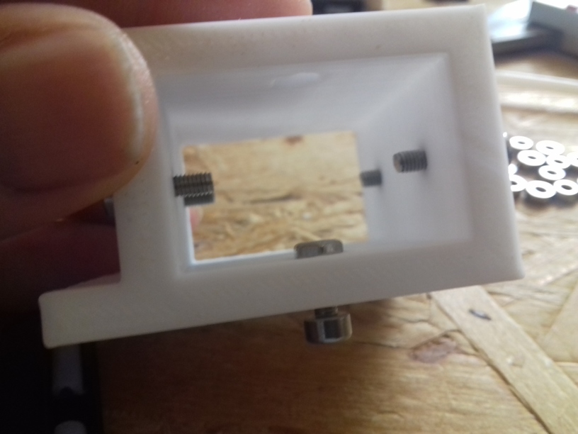
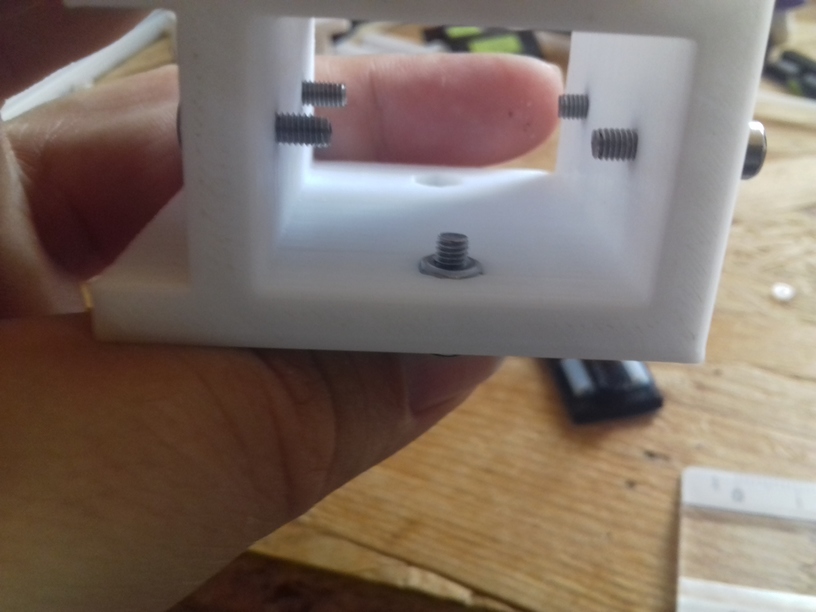
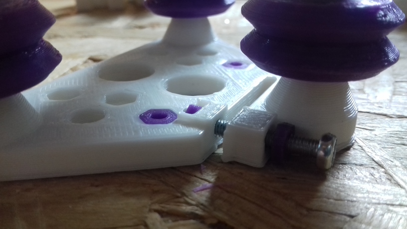
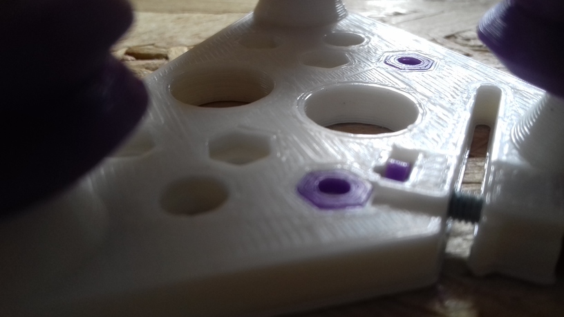
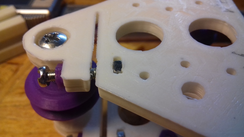
Stabilizing Y Bed on XZ Frame
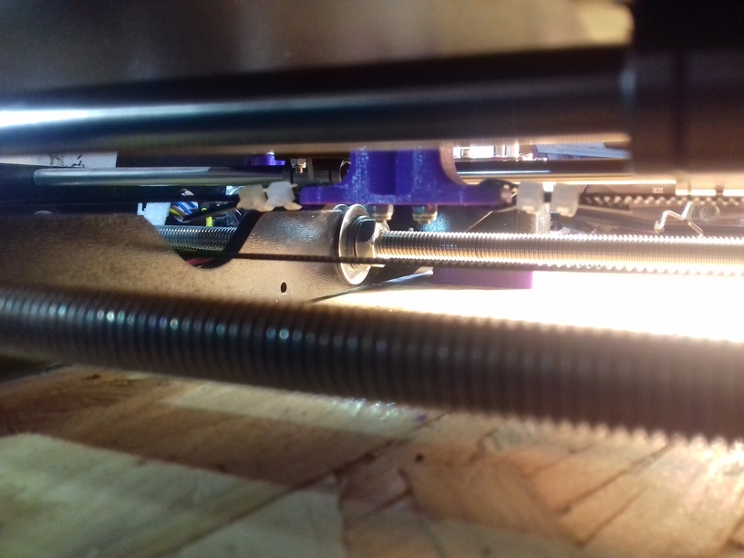
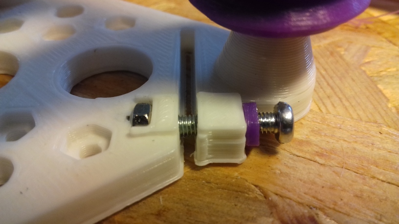
The Y bed is just fastened at the back and in the middle with the XZ frame, and it’s quite wobbly – so I tightly fastened with two more M10 nuts and washers.
-
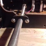
-
Simple Y bed fastening
-
-
Tight fastened Y bed
Note: Although the upgrade looks simple, but it is not: when you fasten the M10 nuts on the XZ frame, do this while the printer sits properly on a table (which is cumbersome) – fastening the nuts in another position will results in a skewed geometry of the printer (happened to me at first).
After this upgrade most flimsyness of the frame has vanished, which otherwise this 3d printer is known for.
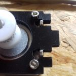
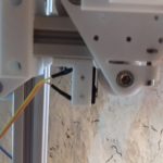
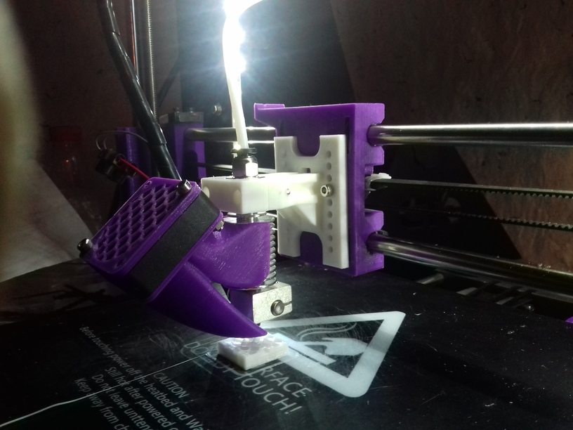
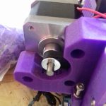
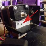
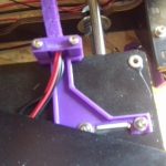
Cooling the Extruder
CTC did a sloppy extruder construction: when you look closely you see a small black screw holding the heating screw but also doesn’t allow the cooler seamless attach the aluminium block – there are several remedies, I choose to give the screw a bit space by drilling a small dent into the cooler (you know where to drill as the screw likely has hinted the position already):
So now the cooler makes good contact to the aluminium block which transfers the heat of the extruder/nozzle.
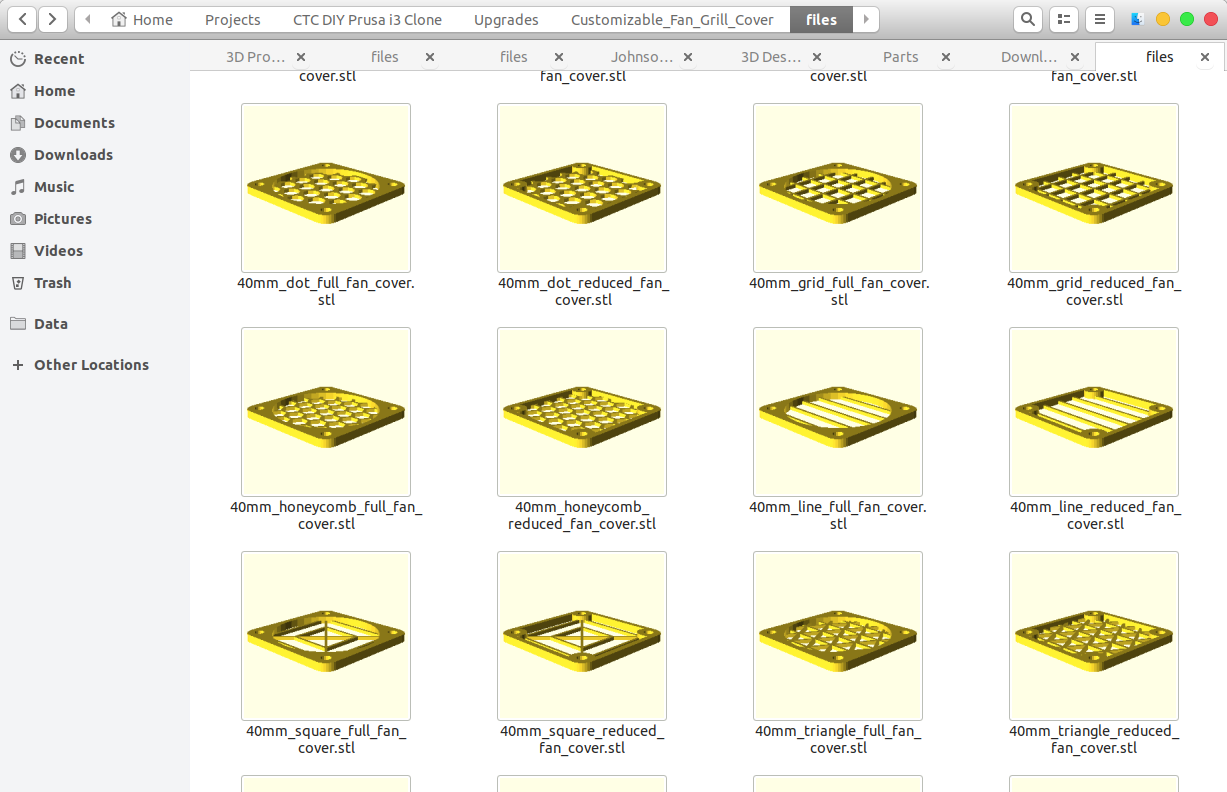
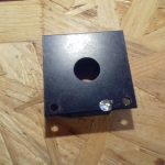
Replacing Fan Blades, Adding Fan Covers
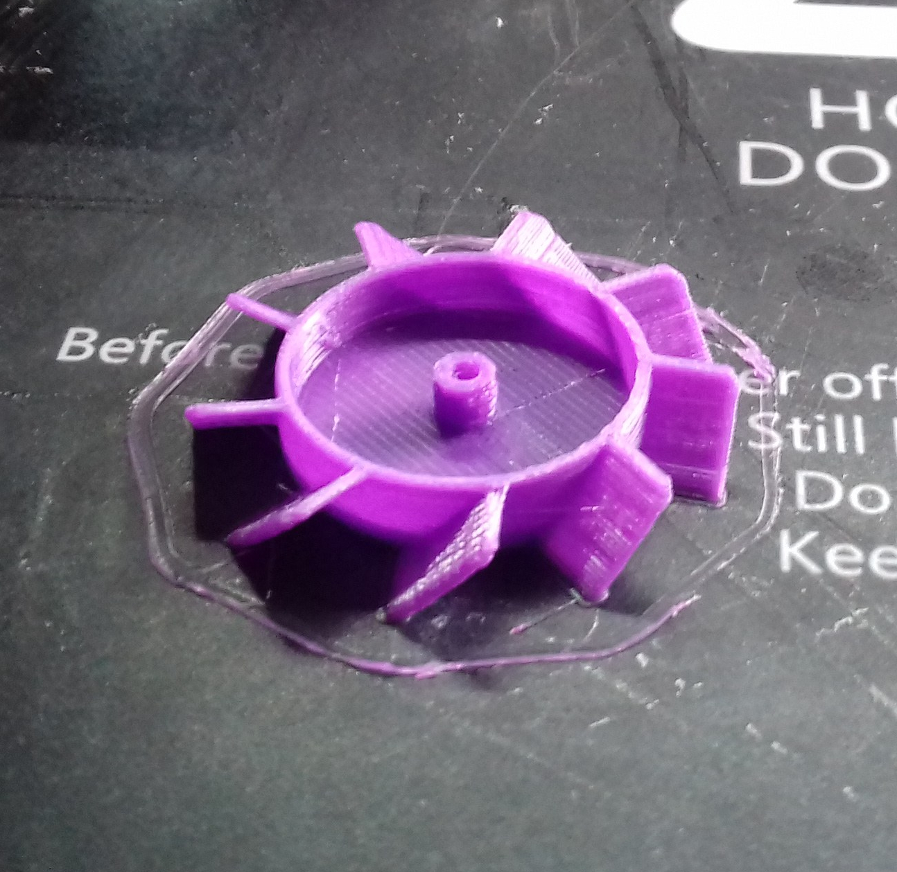
I broke one of the fans and I tried to replace it. Unfortunately to remove the old fan blades is a tricky thing and I broke the fan – the proper way is to remove the label at the back, push the blades on the other side so the pin comes out where the label was – and remove the ring coming out – this allows to remove the blades from the fan.
To secure the blades better, I printed two fan covers for those 40mm x 10mm fans, one for the extruder fan, and one for the part fan.
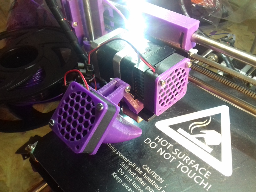
Further, the fast X axis movement doesn’t do good on the fans – and so just after 2 weeks with the new part fan cooler, it already makes noises when starting up – as if the initial tilt of the fan being in resonance and not able to achieve full speed; a gentle tap on the fan cover brings it out of resonance – this isn’t a good solution though.
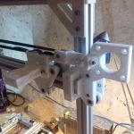
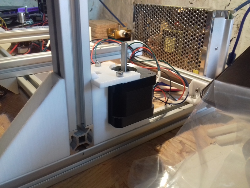
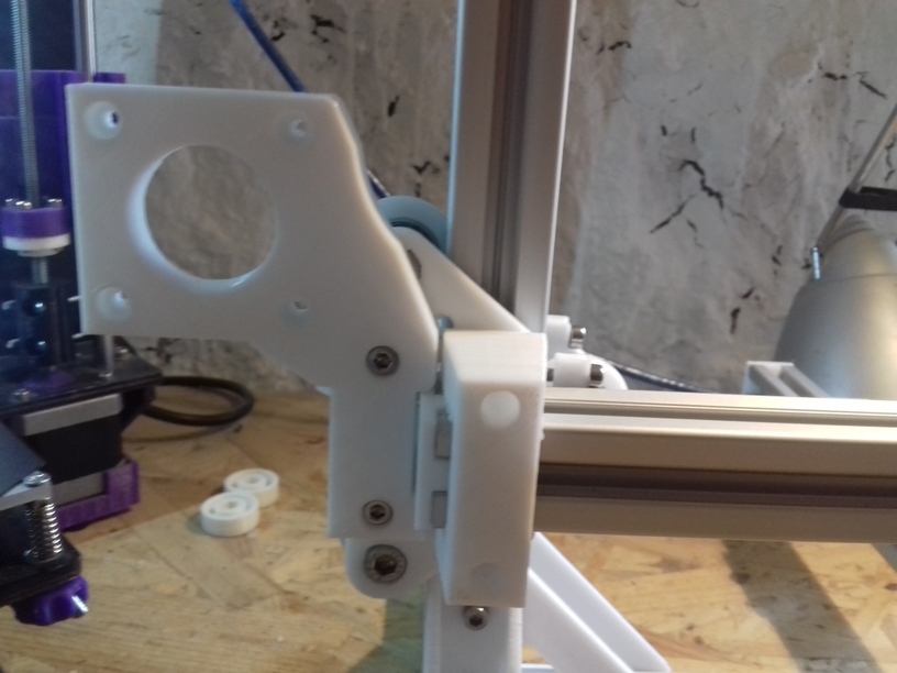
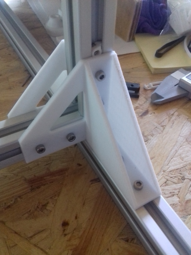
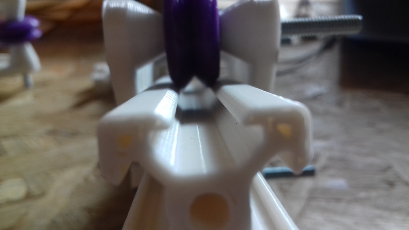
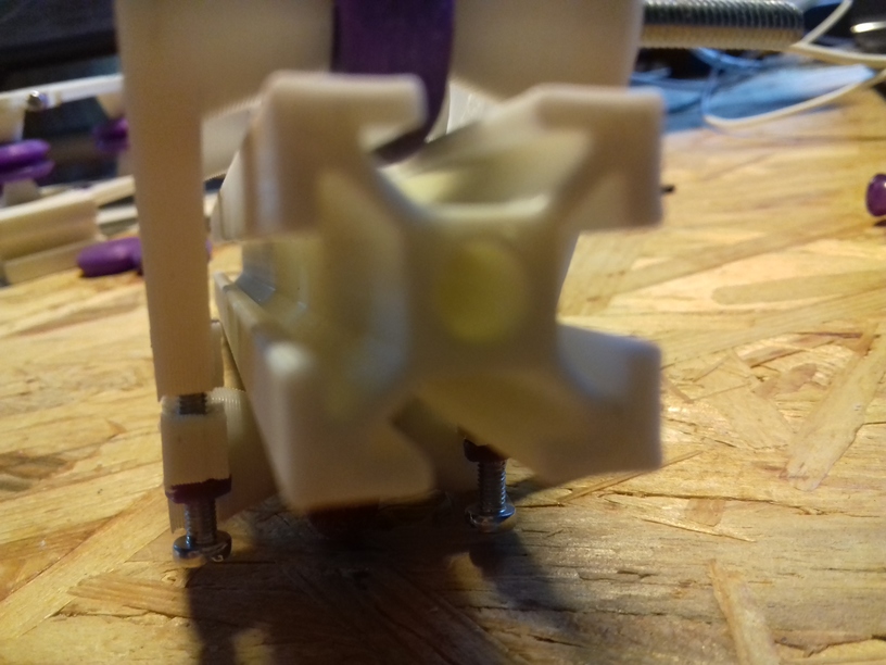
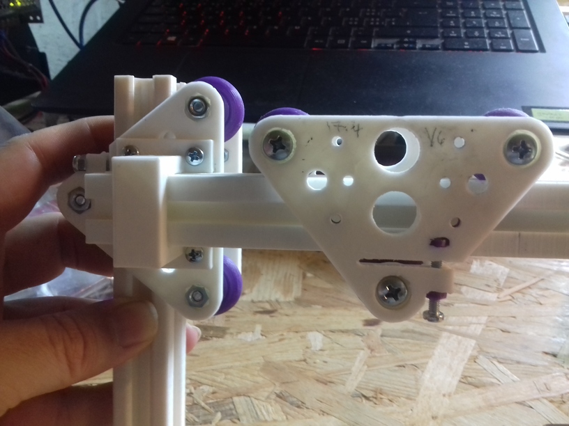
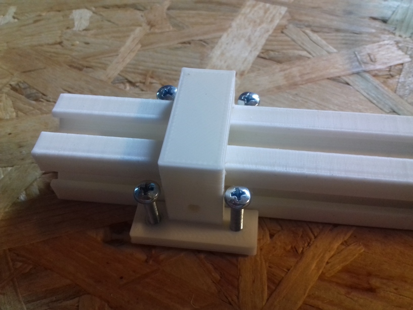
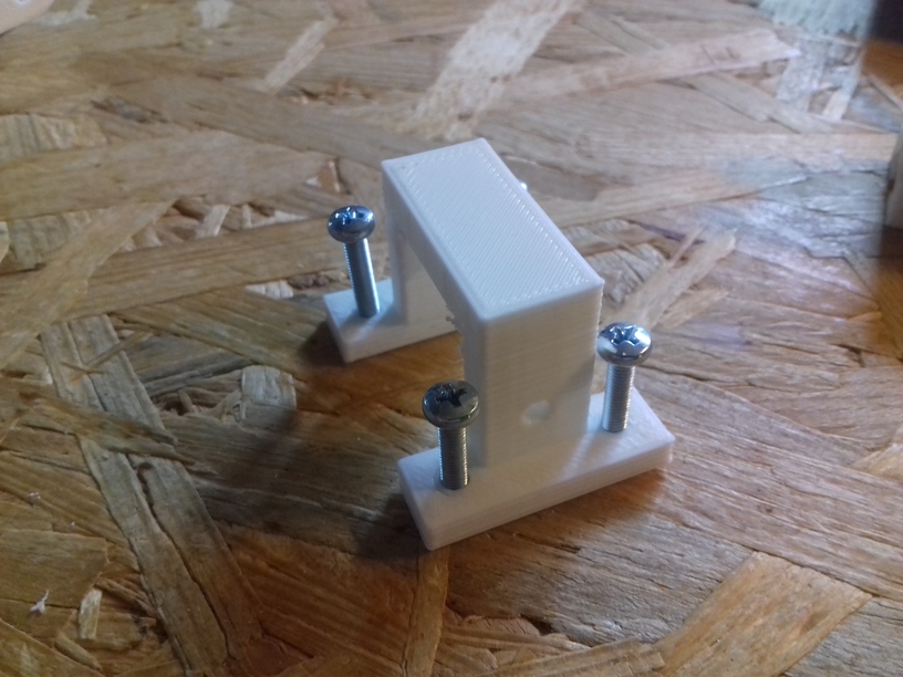
Z Motor Stand
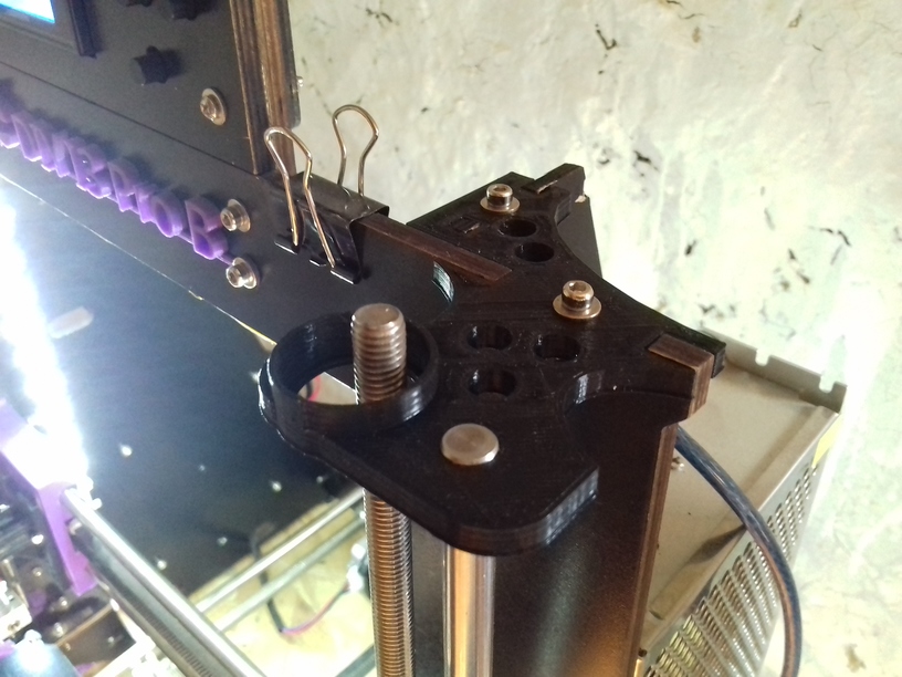
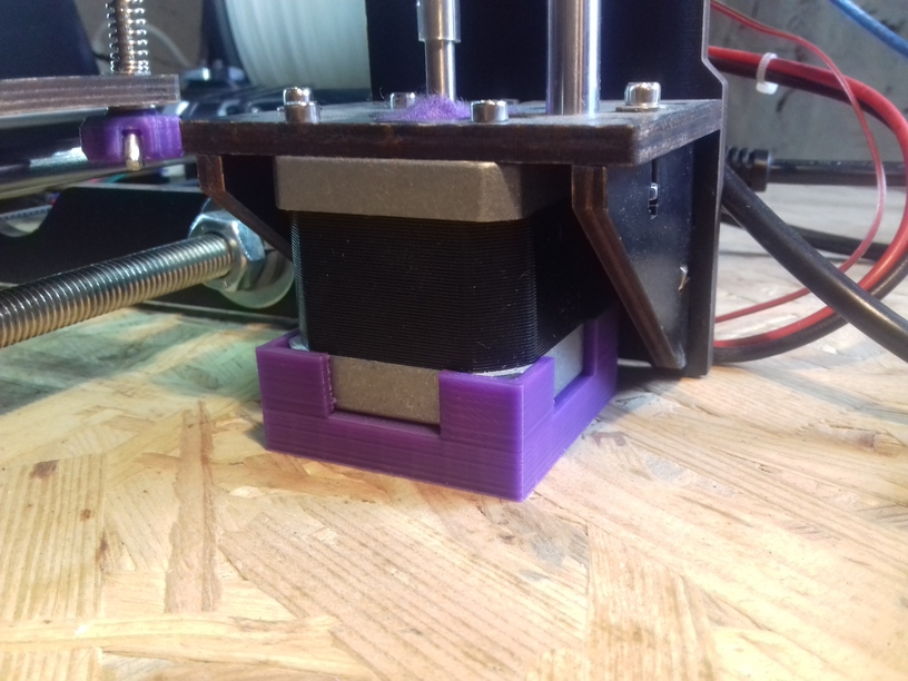 It bothered me at the very beginning, and finally resolved it: the Z Motors are lifted 8mm in air with a bracket, the force from the XZ frame and the smooth rods is distributed between just three screws, whereas the most tear is just on one screw – it’s fairly simple to make some stand so the entire Z motor takes some weight as well and adds stability.
Download the STL of the “Z Motor stand” at thingiverse and print it yourself.
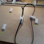
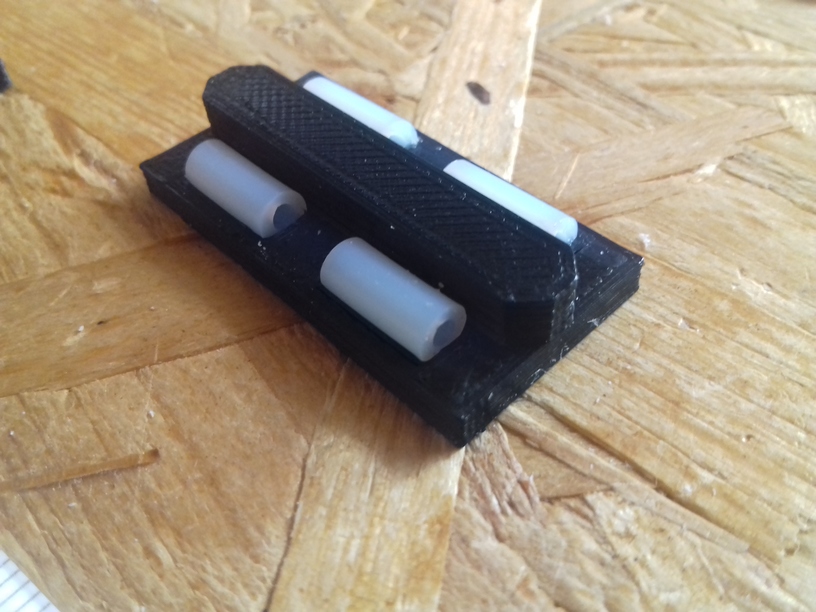
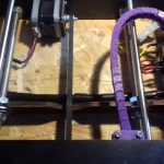
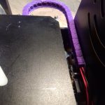
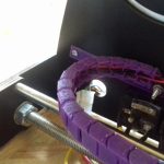
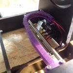
Y Bed Cable Chain
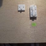
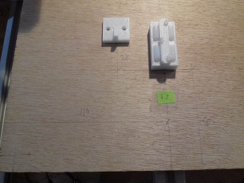
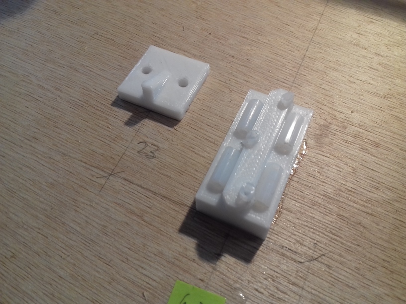
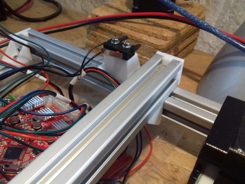
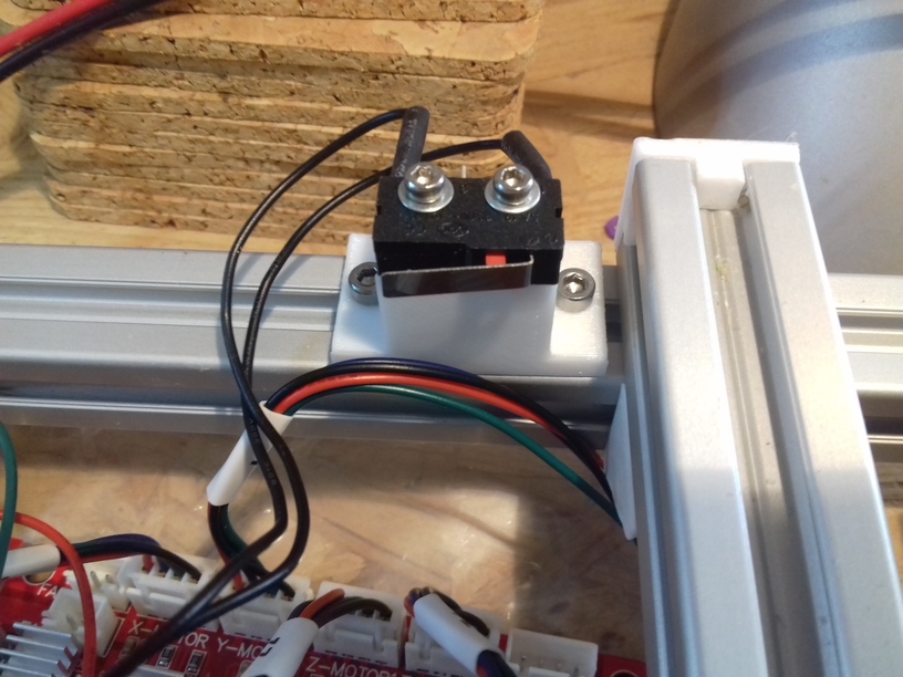
The past weeks I noticed the narrow bending of the cables at the Y heating bed and it eventually will break there. So I searched on Thingiverse for some solution, and I found Cable Chain with a nice cable chain element:
Note: You must mirror both mounts (left <=> right) – within Cura use the Mirror Tool – the mount on the side (CTC_Y_base_mount.stl), and the mount on the bed (CTC_Y_bed_mount_bottom.stl) – because the original setup is meant for the left side, but if you do that you have to switch the back planes of the Y bed to move the Y stopper switch on the other (right) side, but you can avoid this by mirroring both mounts before you print them.
The cables of the heat bed and termsistor were sufficient long to be wired via the right side, and then below the bed to the left side where the controller board resides.
Update: I moved the cable chain mount up ~1cm on the side and not reuse the screw which holds the power connector but drilled a dedicated hole – which makes the cable chain fairly horizontal now.
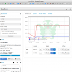
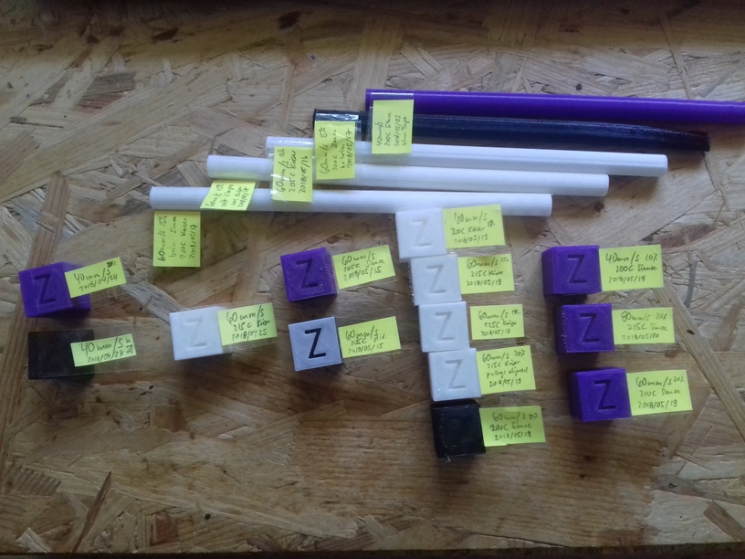
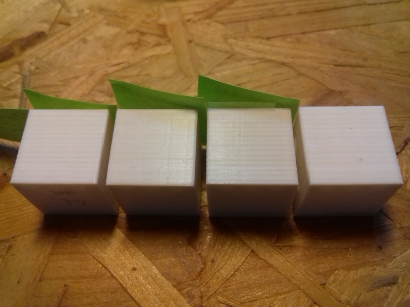
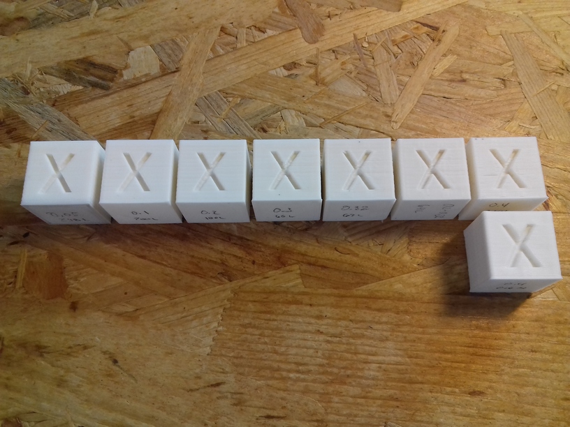
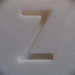
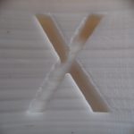
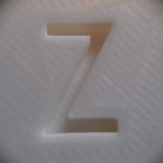
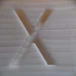
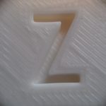
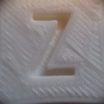
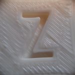
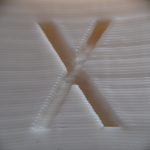
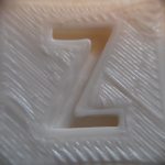
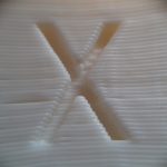
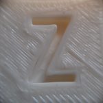
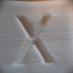
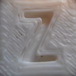
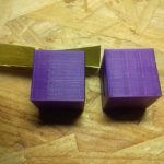
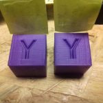
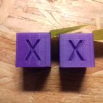
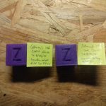
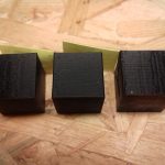
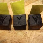
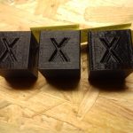
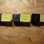
Documenting XYZ Cube and other Prints
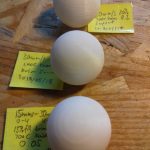
One of my habits is to document things properly through time so I can fine-tune things I did already and review changes, in particular with 3d printing, using the 20mm XYZ calibration cube, writing down
- date
- printing speed [mm/s]
- filament brand
- extruder temperature [C]
- infill [%]
- layer height [mm]
- special features (e.g. brim, raft, etc)
It helps me to review:
- whether my changes on the printer increased or decreased the printing quality
- whether filament from the same source but different color have different settings
- whether filament quality decreased due my own storage
Software Tools
Mostly I use
- OpenJSCAD.org, a local copy of it to be precise (offline), whenever I have a common theme or functionality, when special features become functions and things a composed programmatically,
- OpenSCAD.org, the known scripted CAD approach, and
- for WYSIWYG-like I use TinkerCAD.com for quick and simple models (online) but save all models as STL as backup.
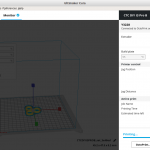
For Linux users, as viewer I use
- MeshLab (
apt install meshlab) and ensured it’s the primary application for .stl files – for Ubuntu 18.04 LTS you have to edit /usr/share/applications/meshlab.desktop, ensure “%f” is added in the “Exec=meshlab” line:
[Desktop Entry]
Version=1.0
Name=MeshLab
Name[en_GB]=MeshLab
GenericName=Mesh processing
GenericName[en_GB]=Mesh processing
Comment=View and process meshes
Type=Application
Exec=meshlab %f
Icon=/usr/share/pixmaps/meshlab.png
Terminal=false
MimeType=model/mesh;application/x-3ds;image/x-3ds;model/x-ply;application/sla;model/x-quad-object;model/x-geomview-off;application/x
-cyclone-ptx;application/x-vmi;application/x-bre;model/vnd.collada+xml;model/openctm;application/x-expe-binary;application/x-expe-as
cii;application/x-xyz;application/x-gts;chemical/x-pdb;application/x-tri;application/x-asc;model/x3d+xml;model/x3d+vrml;model/vrml;m
odel/u3d;model/idtf;
Categories=Graphics;3DGraphics;Viewer;Qt;
and I installed the STL thumbnailer for Nautilus (GNOME default file browser) as well:
From now on I will post smaller blog posts more focuses on particular issues, and tag them with “3d printing” and alike.


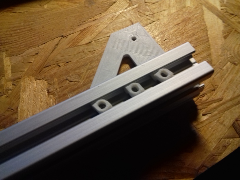


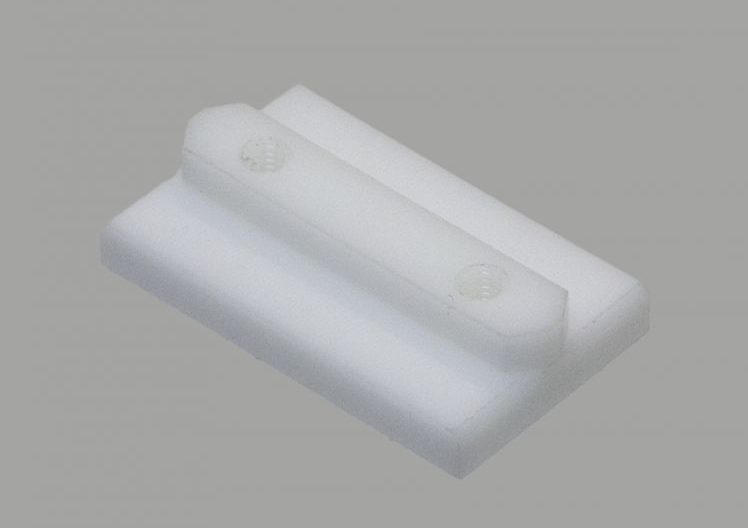
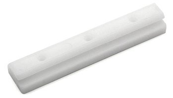 Commercially manufactured, apprx. cost EUR 2.50 per piece, sold in 10 pieces bag.
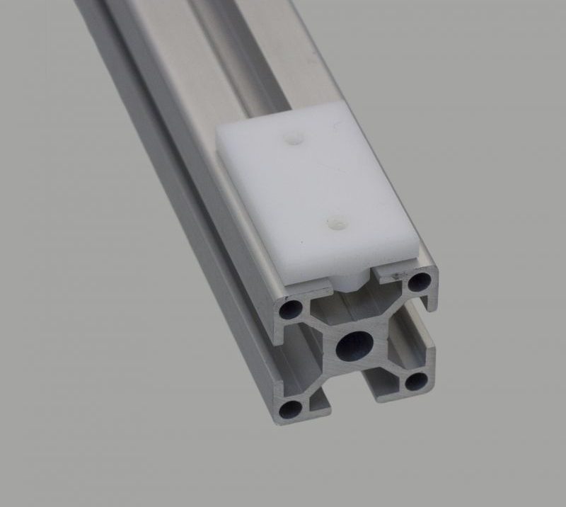


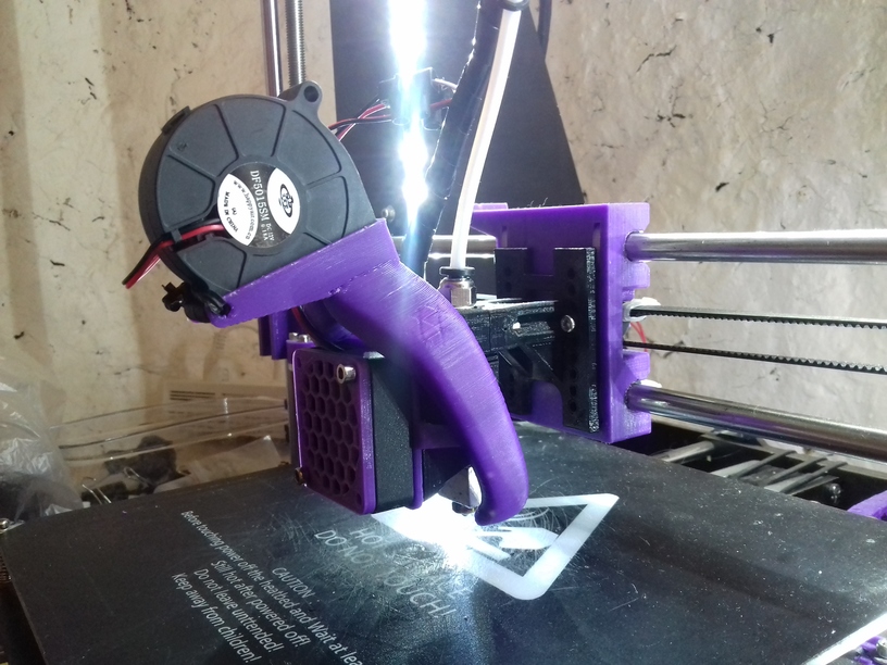
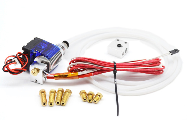 The CTC DIY I3 Pro B, a Geeetech I3 Pro clone, is the very low-end of 3d printers – quality and pricewise, and uses a direct drive to feed the filament aka “MK8 Extruder”. I ordered an E3D V6 clone with 0.2mm-0.4mm short nozzles with optional Volcano hotend for larger diameter nozzles (0.6mm – 1.0mm) from China, at EUR 9 price, as I wanted to
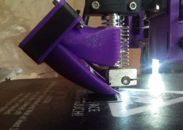
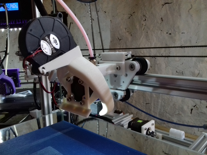
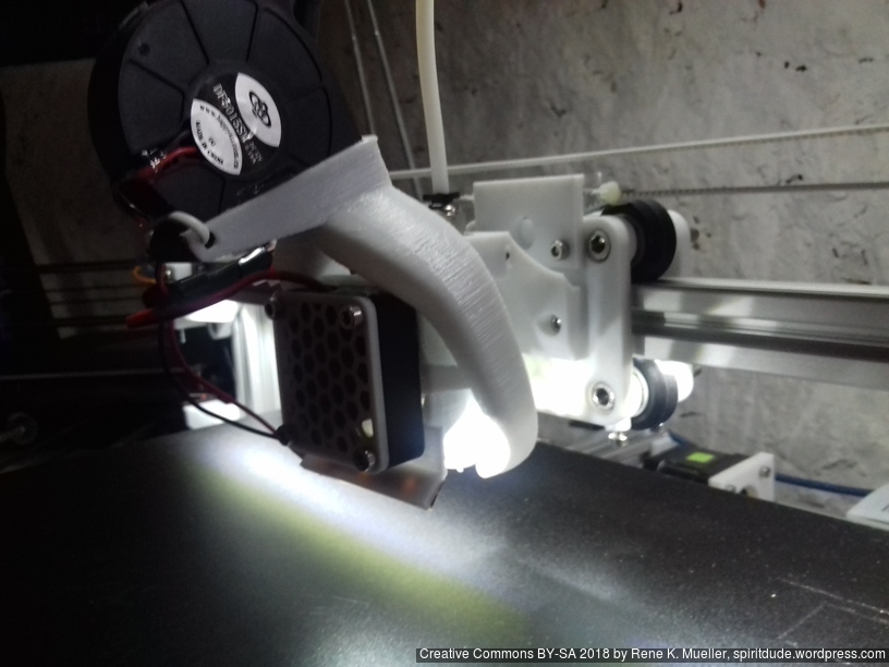
 After some time I switched to
 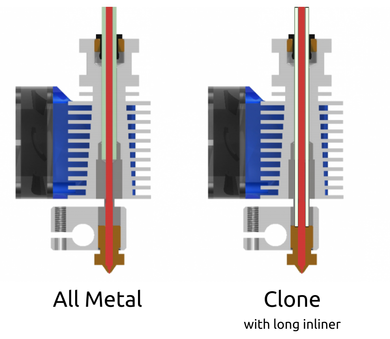 Before I go into the details, let me comment of the overall building quality of those E3D V6 clones: you get what you pay for, a compromise. My hotend leaked like crazy, at the junction of heatblock & nozzle, and heatblock & heatbreak – which is most annoying, and that did not happen with the original MK8 Extruder.
 Update 2: the real problem of leaking was the PTFE/teflon inliner, the end toward the nozzle wasn’t perpendicular sufficiently and likely a bit too short (by less than 1mm) and it was too narrow tube with 3mm OD instead of 4mm and be more tight – so the PLA leaked between the inliner and the threads of the heatbreak and nozzle – so the real remedy is to pay close attention of the length of the inliner (in case the E3D V6 clone comes without it as in my case), and give it 0.5mm to 1mm extend with a clean cut and preferably a conic end which presses then toward the nozzle.
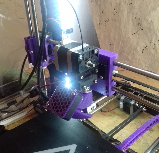
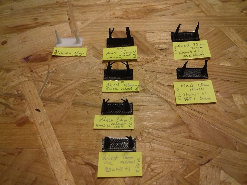
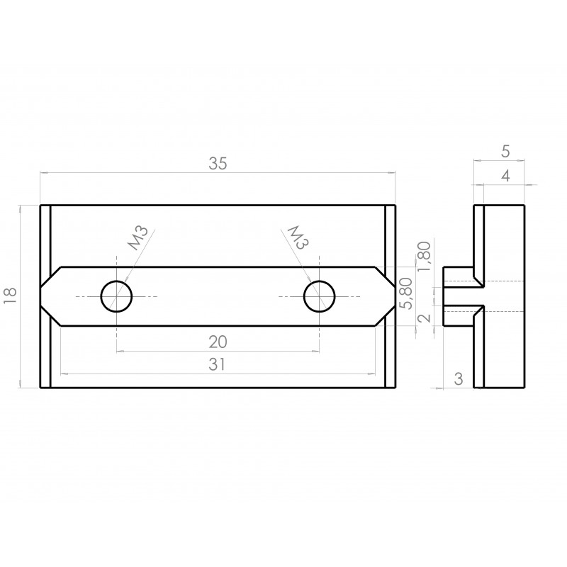
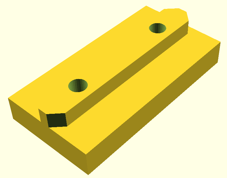
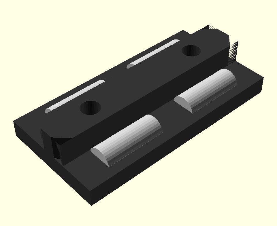
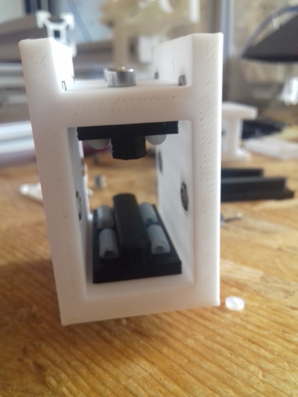
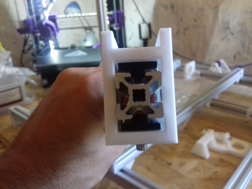
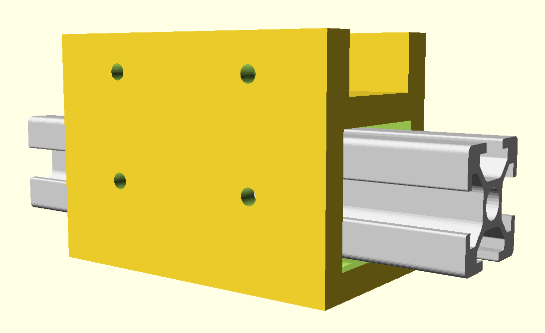
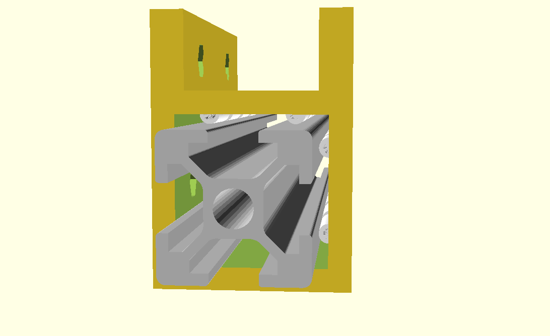
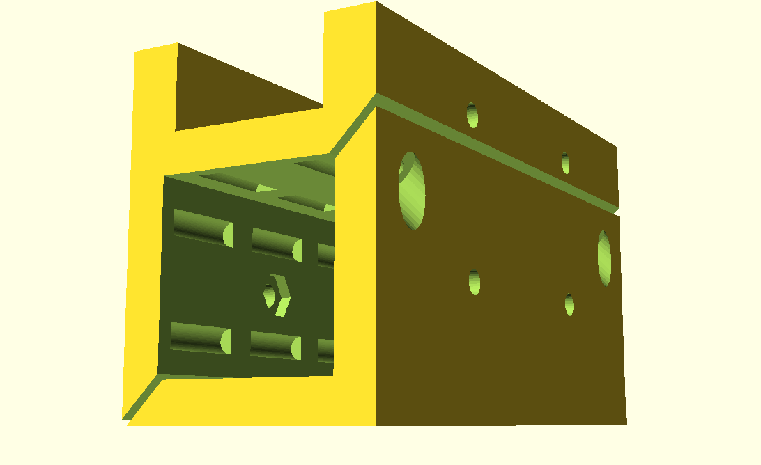
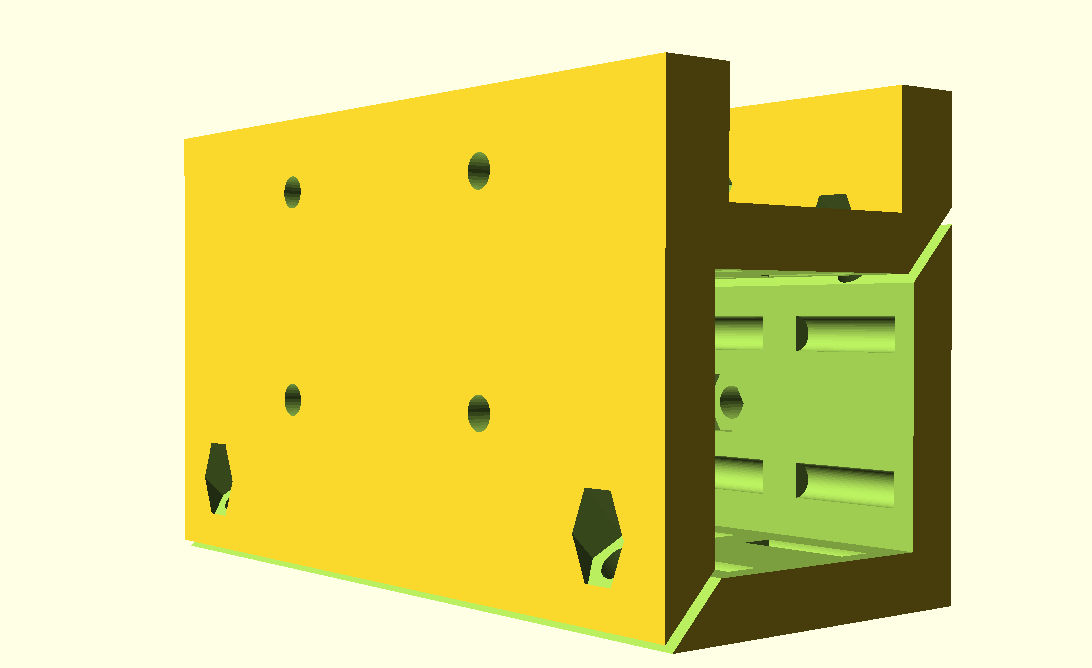
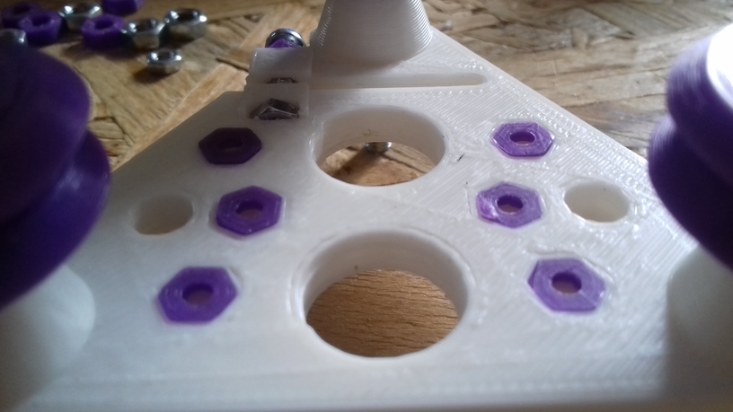
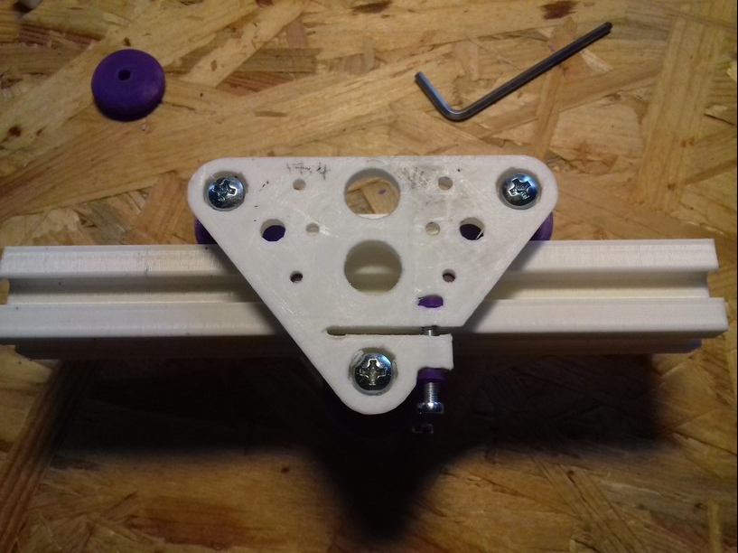
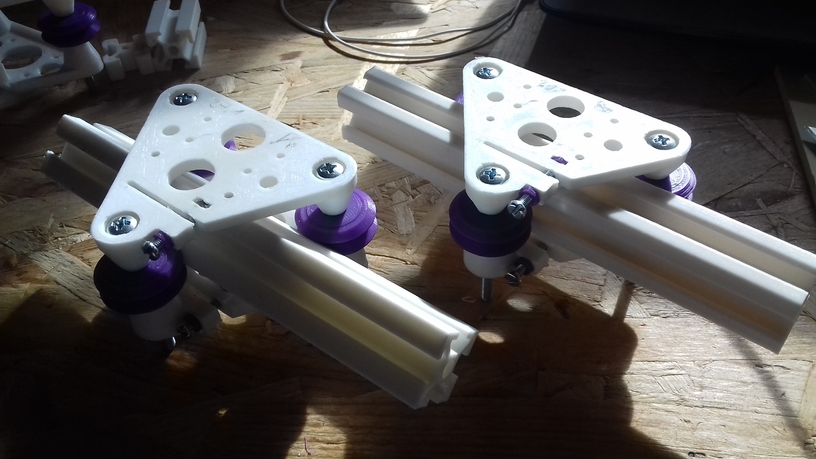
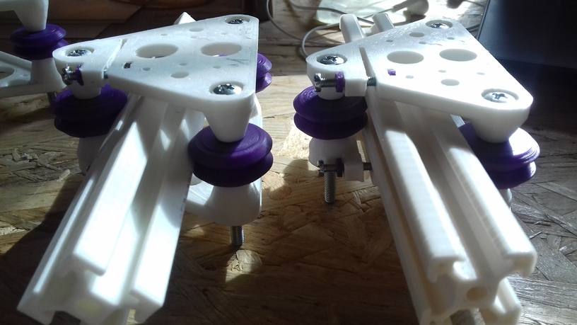
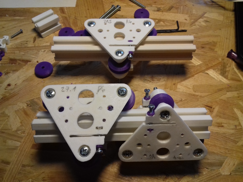
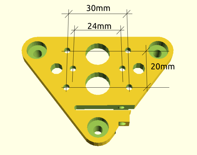
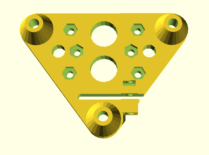
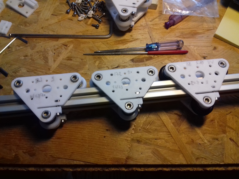
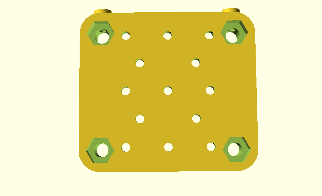
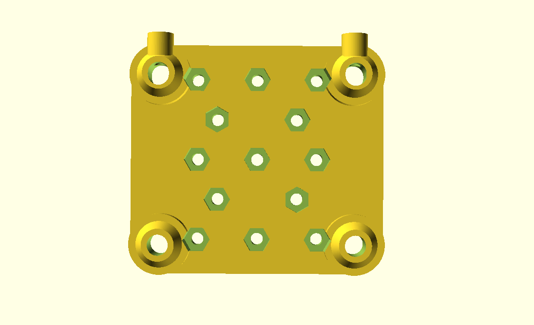
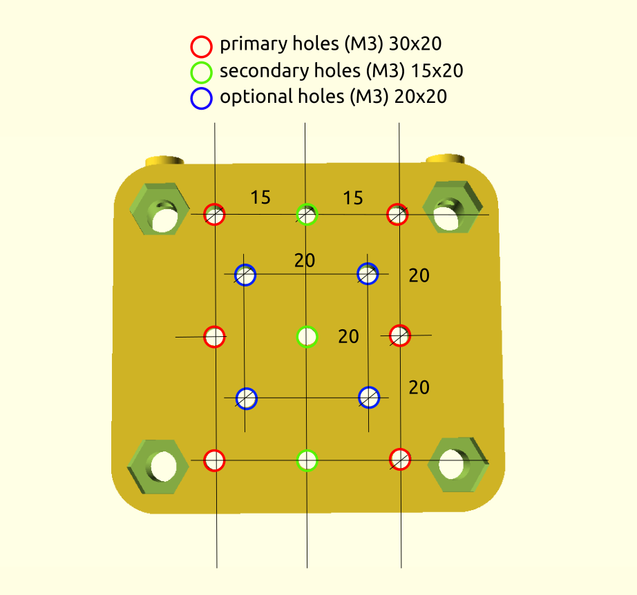
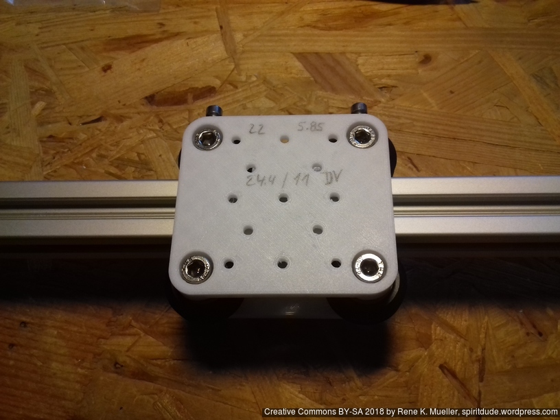
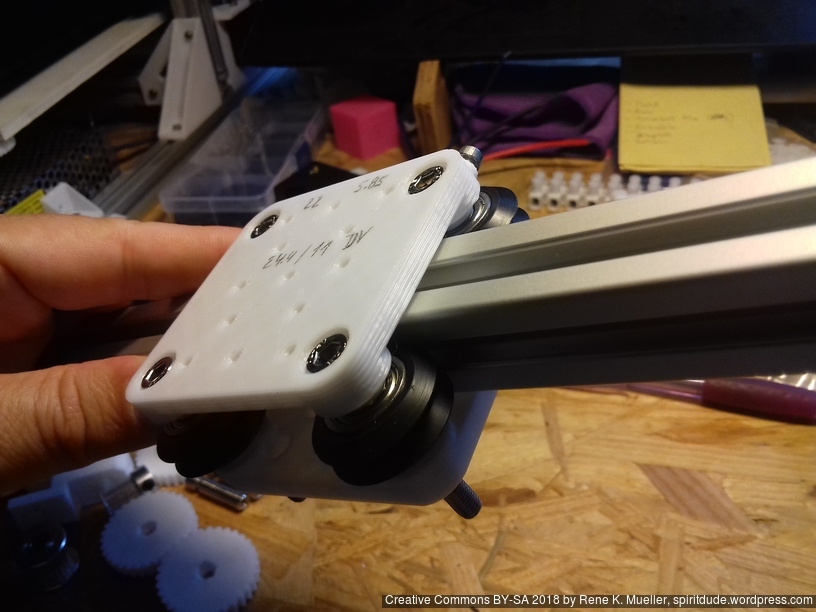
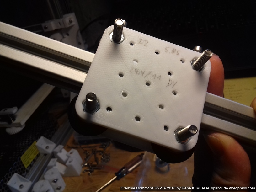
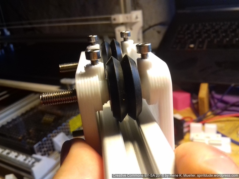
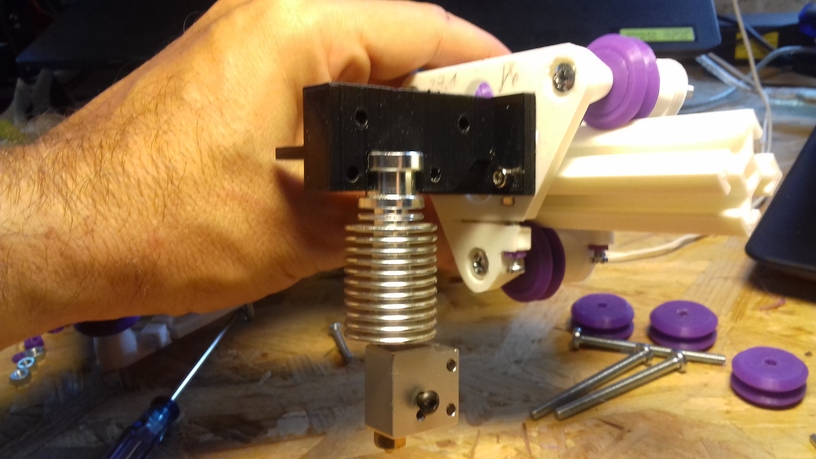
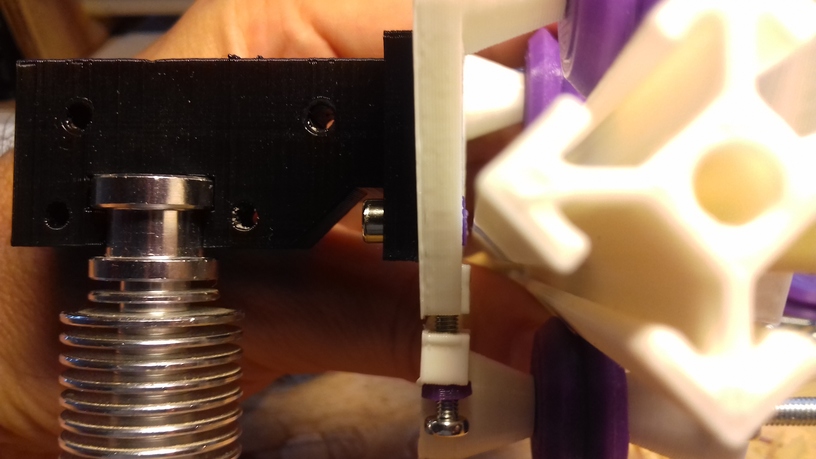
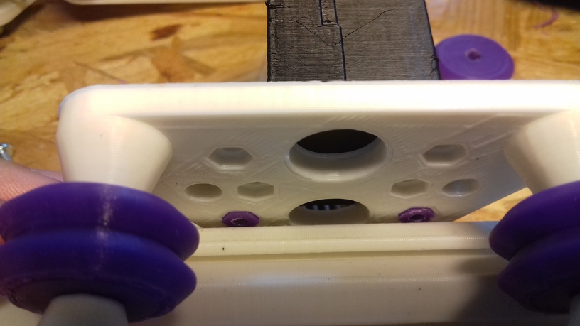
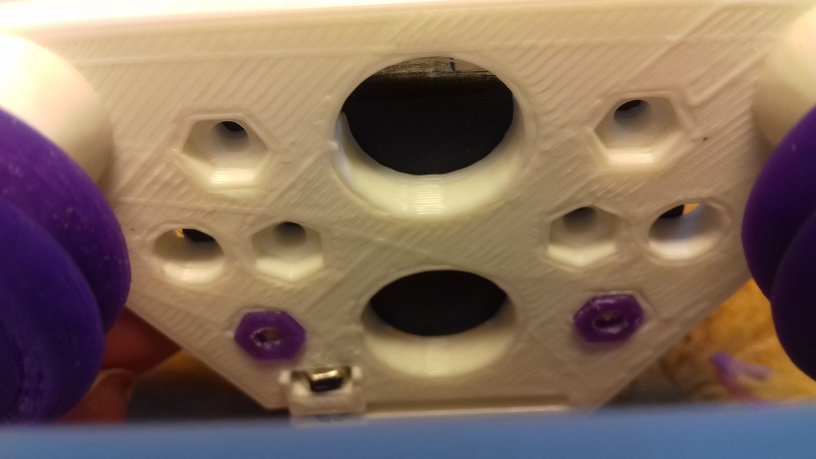
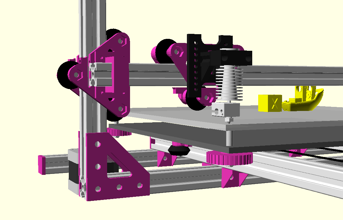
 The two E3D V6 bowden adapters I first printed and used required quite some change in Z height, bringing my Z stopper screw to its limits and also were off in the Y axis – so I designed a more suitable adapter with multiple mounting holes:
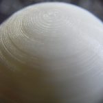


 I used this